EP3868012B1 - Bias power regulator circuit for isolated converters with a wide output voltage range - Google Patents
Bias power regulator circuit for isolated converters with a wide output voltage rangeDownload PDFInfo
- Publication number
- EP3868012B1 EP3868012B1EP19872415.5AEP19872415AEP3868012B1EP 3868012 B1EP3868012 B1EP 3868012B1EP 19872415 AEP19872415 AEP 19872415AEP 3868012 B1EP3868012 B1EP 3868012B1
- Authority
- EP
- European Patent Office
- Prior art keywords
- bias supply
- controller
- mode
- isolated converter
- switch
- Prior art date
- Legal status (The legal status is an assumption and is not a legal conclusion. Google has not performed a legal analysis and makes no representation as to the accuracy of the status listed.)
- Active
Links
Images


Classifications
- H—ELECTRICITY
- H02—GENERATION; CONVERSION OR DISTRIBUTION OF ELECTRIC POWER
- H02M—APPARATUS FOR CONVERSION BETWEEN AC AND AC, BETWEEN AC AND DC, OR BETWEEN DC AND DC, AND FOR USE WITH MAINS OR SIMILAR POWER SUPPLY SYSTEMS; CONVERSION OF DC OR AC INPUT POWER INTO SURGE OUTPUT POWER; CONTROL OR REGULATION THEREOF
- H02M3/00—Conversion of DC power input into DC power output
- H02M3/22—Conversion of DC power input into DC power output with intermediate conversion into AC
- H02M3/24—Conversion of DC power input into DC power output with intermediate conversion into AC by static converters
- H02M3/28—Conversion of DC power input into DC power output with intermediate conversion into AC by static converters using discharge tubes with control electrode or semiconductor devices with control electrode to produce the intermediate AC
- H02M3/325—Conversion of DC power input into DC power output with intermediate conversion into AC by static converters using discharge tubes with control electrode or semiconductor devices with control electrode to produce the intermediate AC using devices of a triode or a transistor type requiring continuous application of a control signal
- H02M3/335—Conversion of DC power input into DC power output with intermediate conversion into AC by static converters using discharge tubes with control electrode or semiconductor devices with control electrode to produce the intermediate AC using devices of a triode or a transistor type requiring continuous application of a control signal using semiconductor devices only
- H02M3/33507—Conversion of DC power input into DC power output with intermediate conversion into AC by static converters using discharge tubes with control electrode or semiconductor devices with control electrode to produce the intermediate AC using devices of a triode or a transistor type requiring continuous application of a control signal using semiconductor devices only with automatic control of the output voltage or current, e.g. flyback converters
- H02M3/33523—Conversion of DC power input into DC power output with intermediate conversion into AC by static converters using discharge tubes with control electrode or semiconductor devices with control electrode to produce the intermediate AC using devices of a triode or a transistor type requiring continuous application of a control signal using semiconductor devices only with automatic control of the output voltage or current, e.g. flyback converters with galvanic isolation between input and output of both the power stage and the feedback loop
- G—PHYSICS
- G06—COMPUTING OR CALCULATING; COUNTING
- G06F—ELECTRIC DIGITAL DATA PROCESSING
- G06F1/00—Details not covered by groups G06F3/00 - G06F13/00 and G06F21/00
- G06F1/26—Power supply means, e.g. regulation thereof
- G06F1/266—Arrangements to supply power to external peripherals either directly from the computer or under computer control, e.g. supply of power through the communication port, computer controlled power-strips
- G—PHYSICS
- G06—COMPUTING OR CALCULATING; COUNTING
- G06F—ELECTRIC DIGITAL DATA PROCESSING
- G06F13/00—Interconnection of, or transfer of information or other signals between, memories, input/output devices or central processing units
- G06F13/38—Information transfer, e.g. on bus
- G06F13/42—Bus transfer protocol, e.g. handshake; Synchronisation
- G06F13/4282—Bus transfer protocol, e.g. handshake; Synchronisation on a serial bus, e.g. I2C bus, SPI bus
- H—ELECTRICITY
- H02—GENERATION; CONVERSION OR DISTRIBUTION OF ELECTRIC POWER
- H02M—APPARATUS FOR CONVERSION BETWEEN AC AND AC, BETWEEN AC AND DC, OR BETWEEN DC AND DC, AND FOR USE WITH MAINS OR SIMILAR POWER SUPPLY SYSTEMS; CONVERSION OF DC OR AC INPUT POWER INTO SURGE OUTPUT POWER; CONTROL OR REGULATION THEREOF
- H02M1/00—Details of apparatus for conversion
- H02M1/0003—Details of control, feedback or regulation circuits
- H02M1/0006—Arrangements for supplying an adequate voltage to the control circuit of converters
- H—ELECTRICITY
- H02—GENERATION; CONVERSION OR DISTRIBUTION OF ELECTRIC POWER
- H02M—APPARATUS FOR CONVERSION BETWEEN AC AND AC, BETWEEN AC AND DC, OR BETWEEN DC AND DC, AND FOR USE WITH MAINS OR SIMILAR POWER SUPPLY SYSTEMS; CONVERSION OF DC OR AC INPUT POWER INTO SURGE OUTPUT POWER; CONTROL OR REGULATION THEREOF
- H02M3/00—Conversion of DC power input into DC power output
- H02M3/02—Conversion of DC power input into DC power output without intermediate conversion into AC
- H02M3/04—Conversion of DC power input into DC power output without intermediate conversion into AC by static converters
- H02M3/10—Conversion of DC power input into DC power output without intermediate conversion into AC by static converters using discharge tubes with control electrode or semiconductor devices with control electrode
- H02M3/145—Conversion of DC power input into DC power output without intermediate conversion into AC by static converters using discharge tubes with control electrode or semiconductor devices with control electrode using devices of a triode or transistor type requiring continuous application of a control signal
- H02M3/155—Conversion of DC power input into DC power output without intermediate conversion into AC by static converters using discharge tubes with control electrode or semiconductor devices with control electrode using devices of a triode or transistor type requiring continuous application of a control signal using semiconductor devices only
- H02M3/156—Conversion of DC power input into DC power output without intermediate conversion into AC by static converters using discharge tubes with control electrode or semiconductor devices with control electrode using devices of a triode or transistor type requiring continuous application of a control signal using semiconductor devices only with automatic control of output voltage or current, e.g. switching regulators
- H—ELECTRICITY
- H05—ELECTRIC TECHNIQUES NOT OTHERWISE PROVIDED FOR
- H05B—ELECTRIC HEATING; ELECTRIC LIGHT SOURCES NOT OTHERWISE PROVIDED FOR; CIRCUIT ARRANGEMENTS FOR ELECTRIC LIGHT SOURCES, IN GENERAL
- H05B45/00—Circuit arrangements for operating light-emitting diodes [LED]
- H05B45/30—Driver circuits
- H05B45/305—Frequency-control circuits
- H—ELECTRICITY
- H05—ELECTRIC TECHNIQUES NOT OTHERWISE PROVIDED FOR
- H05B—ELECTRIC HEATING; ELECTRIC LIGHT SOURCES NOT OTHERWISE PROVIDED FOR; CIRCUIT ARRANGEMENTS FOR ELECTRIC LIGHT SOURCES, IN GENERAL
- H05B45/00—Circuit arrangements for operating light-emitting diodes [LED]
- H05B45/30—Driver circuits
- H05B45/32—Pulse-control circuits
- H05B45/335—Pulse-frequency modulation [PFM]
- H—ELECTRICITY
- H05—ELECTRIC TECHNIQUES NOT OTHERWISE PROVIDED FOR
- H05B—ELECTRIC HEATING; ELECTRIC LIGHT SOURCES NOT OTHERWISE PROVIDED FOR; CIRCUIT ARRANGEMENTS FOR ELECTRIC LIGHT SOURCES, IN GENERAL
- H05B45/00—Circuit arrangements for operating light-emitting diodes [LED]
- H05B45/30—Driver circuits
- H05B45/37—Converter circuits
- H05B45/3725—Switched mode power supply [SMPS]
- H05B45/385—Switched mode power supply [SMPS] using flyback topology
- G—PHYSICS
- G06—COMPUTING OR CALCULATING; COUNTING
- G06F—ELECTRIC DIGITAL DATA PROCESSING
- G06F2213/00—Indexing scheme relating to interconnection of, or transfer of information or other signals between, memories, input/output devices or central processing units
- G06F2213/0042—Universal serial bus [USB]
- H—ELECTRICITY
- H02—GENERATION; CONVERSION OR DISTRIBUTION OF ELECTRIC POWER
- H02M—APPARATUS FOR CONVERSION BETWEEN AC AND AC, BETWEEN AC AND DC, OR BETWEEN DC AND DC, AND FOR USE WITH MAINS OR SIMILAR POWER SUPPLY SYSTEMS; CONVERSION OF DC OR AC INPUT POWER INTO SURGE OUTPUT POWER; CONTROL OR REGULATION THEREOF
- H02M1/00—Details of apparatus for conversion
- H02M1/0003—Details of control, feedback or regulation circuits
- H02M1/0009—Devices or circuits for detecting current in a converter
- H—ELECTRICITY
- H02—GENERATION; CONVERSION OR DISTRIBUTION OF ELECTRIC POWER
- H02M—APPARATUS FOR CONVERSION BETWEEN AC AND AC, BETWEEN AC AND DC, OR BETWEEN DC AND DC, AND FOR USE WITH MAINS OR SIMILAR POWER SUPPLY SYSTEMS; CONVERSION OF DC OR AC INPUT POWER INTO SURGE OUTPUT POWER; CONTROL OR REGULATION THEREOF
- H02M1/00—Details of apparatus for conversion
- H02M1/0003—Details of control, feedback or regulation circuits
- H02M1/0032—Control circuits allowing low power mode operation, e.g. in standby mode
Definitions
- Isolated convertersrefer to converters that provide full galvanic isolation between input and output circuits using a power transformer with a primary winding and a secondary winding. Some isolated converters use a power transformer with an auxiliary winding separate from the secondary winding to supply power (a bias supply voltage) to control circuitry (e.g., a pulse-width modulation controller) for one or more isolated converter switches. For isolated converters with wide output voltage range (e.g., a USB power delivery adapter or light-emitting diode driver), it is challenging to provide a usable bias supply voltage to the control circuitry directly from the auxiliary winding of the power transformer.
- a bias supply voltagee.g., a pulse-width modulation controller
- bias power regulator optionsfor an isolated converter having a power transformer with an auxiliary winding.
- a bias power regulator circuit with a switchis placed between the auxiliary winding and an isolated converter switch controller (to control one or more isolated converter switches), where the bias power regulator circuit supplies a bias supply voltage (referred to V VDD herein) to the isolated converter switch controller based on a bias supply input voltage (referred to V BIN herein) obtained from the auxiliary winding.
- V VDDbias supply voltage
- V BINbias supply input voltage
- the bias power regulator circuituses different modes or options to provide V VDD to the isolated converter switch controller based on its operating conditions, such as V BIN and V VDD .
- mode changesare made by a primary controller based on its operating conditions (e.g., load, survival mode, start-up, etc.).
- a first mode or option of the bias power regulator circuitis referred to herein as a forward mode.
- the switch of the bias power regulator circuitstays off and a forward path between the auxiliary winding and the isolated converter switch controller is used.
- the forward modeis used when V BIN is greater than a bias supply input threshold (VBIN_TH).
- a second mode or option of the bias power regulator circuitis referred to herein as a constant off-time modulation mode.
- the switch of the bias power regulator circuitis on/off modulated using a constant off-time (e.g., 250ns).
- the constant off-time modulation modeis used when V BIN is less than or equal to VBIN_TH and when the isolated converter is in a light load condition.
- the constant off-time modulation modea type of continuous conduction mode
- power delivery for V VDDis quick to avoid V VDD falling below an undervoltage lockout (UVLO) threshold of the isolated converter switch controller.
- UVLOundervoltage lockout
- the isolated converter switch controlleris configured to periodically operate an isolated converter switch to provide energy pulses to the auxiliary winding while the isolated converter is in a light load condition. In this manner, the bias power regulator circuit in the constant off-time modulation mode can keep V VDD above the UVLO off threshold while the isolated converter is in a light load condition.
- survival mode operationsThe operations of the isolated converter switch controller and/or the bias power regulator circuit during a light load condition of the isolated converter are referred to herein as survival mode operations (to ensure V VDD stays above the UVLO off threshold to keep the isolated converter switch controller from shutting down).
- the survival mode operationsinvolve the isolated converter switch controller receiving signals from the bias power regulator circuit to control the timing and/or duration of energy pulses during the light load condition of the isolated converter.
- the survival mode operationsinvolve the isolated converter switch controller being programmed or otherwise adjustable to control the timing and/or duration of energy pulses during the light load condition of the isolated converter without communications from the bias power regulator circuit.
- a third mode or option of the bias power regulator circuitis referred to herein as a constant peak-current modulation mode.
- the switch of the bias power regulator circuitis on/off modulated to maintain V VDD at a target reference voltage.
- the constant peak-current modulation modeis used when V BIN at the auxiliary winding is less than or equal to VBIN_TH and when the isolated converter is not in a light load condition.
- the constant peak-current modulation modethe peak magnetizing current of an inductor included with the bias power regulator circuit is constant.
- the switching frequency of the bias power regulator circuit's switchis a function of V BIN or the output voltage (VOUT) of the isolated converter during constant peak-current modulation mode operations, since V BIN is proportional to VOUT.
- the bias power regulator circuitswitches between the first, second, and third modes to provide V VDD to the isolated converter switch controller.
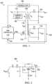
- FIG. 1is a diagram showing an isolated converter 100 in accordance with some examples.
- the isolated converter 100includes a power transformer 105 and switch (Q L ) with a first current terminal, a second current terminal, and a control terminal. More specifically, the first current terminal of Q L is coupled to a primary winding (N P ) of the power transformer 105, and the second current terminal of Q L is coupled to a ground node 118. Also, the control terminal of Q L is coupled to a pulse-width modulation (PWM) controller 110 (an example of an isolated converter switch controller). Also, FIG.
- PWMpulse-width modulation
- VINinput supply voltage
- switch node 112switches the VIN node 114 and a clamping circuit 108 between the VIN node 114 and the switch node 112, where the clamping circuit 108 limits the voltage differential between the VIN node 114 and the switch node 112.
- a feedback loop 106is between an output node 104 of the isolated converter 100 and the PWM controller 110, where the output node 104 is coupled to a secondary winding (N S ) of the power transformer 105 via a diode (D1).
- N Ssecondary winding
- D1diode
- an output capacitor (COUT)stores an output voltage (VOUT) for use by a load (not shown).
- the power transformer 105also includes an auxiliary winding (N AUX ) that is part of a bias supply circuit 102 with bias supply node 116.
- the bias supply circuit 102also includes a capacitor (C VDD ) with a first (e.g., top) plate coupled to the bias supply node 116 and coupled to N AUX via a diode (D2).
- a second (e.g., bottom) plate of C VDDis coupled to a primary ground node.
- the bias supply circuit 102provides a bias supply voltage (V VDD ) to the PWM controller 110.
- V VDDbias supply voltage
- the topology of the isolated converter 100enables the PWM controller 110 to be powered by the bias supply circuit 102. However, for scenarios with VOUT variance, the bias supply circuit 102 may not be able to supply a proper V VDD .
- V VDDmay be too low, resulting in the isolated converter 100 being unable to start (the PWM controller 110 will be off).
- N AUX4 ⁇ N s
- V VDDmay be too high, resulting in damage to standby power and increased cost of the isolated converter switch controller with a higher voltage-rating.
- FIG. 2is a schematic diagram showing a bias supply circuit 200 in accordance with a comparative example which is different than the present invention.
- the bias supply circuit 200provides a linear regulator solution to the VOUT variance issue discussed for FIG. 1 .
- the bias supply circuit 200includes a resistor (R1) and a diode (D3) coupled to an auxiliary winding (N AUX1 ).
- a capacitor (C1)stores the charge received from N AUX1 , and the charge is regulated using pass element (Q LDO ) to provide V VDD at node 202.
- the bias supply circuit 200also includes a second resistor (R2) coupled between the first current terminal and the control terminal of Q LDO .
- a Zener diodeis coupled between the control terminal of Q LDO and a ground node.
- a capacitoris used to store V VDD for use by an isolated converter switch controller. If the bias supply circuit 200 is used instead of the bias supply circuit 102 in an isolated converter such as the isolated converter 100, then VOUT variance becomes tolerable.
- power loss of a linear regulator solutiongreatly impairs system efficiency.
- a large-size for Q LDOis needed to resolve thermal issues, which increases cost and footprint size.
- FIG. 3is a schematic diagram showing another bias supply circuit 300 in accordance with a further comparative example which is different than the present invention.
- the bias supply circuit 300includes two auxiliary windings (N aux1 and N aux2 ) and two regulation paths 304 and 306.
- the first regulation path 304includes the components described for the linear regulator solution of the bias supply circuit 200.
- the second regulation path 306includes a third resistor (R3) and a diode (D4). At node 302, V VDD is available for use by an isolated converter switch controller.
- the bias supply circuit 300regulator losses at high output voltage conditions is reduced, but remain at low output voltage conditions. Also, the transformer winding construction to form N aux1 and N aux2 increases complexity.
- FIG. 4is a diagram showing a system 400 in accordance with the present invention.
- the system 400includes an isolated converter 401 with a topology similar to the topology represented for the isolated converter 100 of FIG. 1 .
- the isolated converter 401includes a power transformer 405 and switch (Q L1 ) with a first current terminal, a second current terminal, and a control terminal. More specifically, the first current terminal of Q L1 is coupled to a primary winding (N P1 ) of the power transformer 405, and the second current terminal of Q L1 is coupled to a ground node 418. Also, the control terminal of Q L1 is coupled to a PWM controller 410 (an example of an isolated converter switch controller). In the example of FIG.
- the PWM controller 410includes a UVLO circuit 413 to shut down the PWM controller 410 if V VDD falls below a UVLO off threshold.
- FIG. 4shows a VIN node 414, a switch node 412, and a clamping circuit 408 between the VIN node 414 and the switch node 412, where the clamping circuit 408 limits the voltage differential between the VIN node 414 and the switch node 412.
- a feedback loop 406is between an output node 404 of the isolated converter 401 and the PWM controller 410, where the output node 404 is coupled to a secondary winding (N S1 ) of the power transformer 405 via a diode (D5).
- N S1secondary winding
- D5diode
- an output capacitor (COUT)stores an output voltage (VOUT) for use by a load (RLOAD).
- RLOADcorresponds to a USB PD adaptor, an LED driver, or another load.
- the power transformer 405also includes an auxiliary winding (N AUX1 ).
- N AUX1is coupled to a bias supply input (V BIN ) node 416 via a diode (D6), where at the V BIN node 416 is stored by a capacitor (CBIN).
- a bias power regulator circuit 422 with a switch (Q1)is coupled between the V BIN node 416 and the PWM controller 410. In operation, the bias power regulator circuit 422 is configured to supply V VDD to the PWM controller 410 based on V BIN and various modes of operation.
- the modes of operation of the bias power regulator circuit 422include a forward mode that uses a forward path 428 of the bias power regulator circuit 422 is when V BIN is greater than a threshold (VBIN_TH). In the forward mode, Q1 stays off and V VDD follows V BIN .
- Another mode of operation of the bias power regulator circuit 422is a constant off-time modulation mode that is used when V BIN is less than or equal to VBIN_TH and the isolated converter 401 is in a light load condition. In the constant off-time modulation mode, Q1 is on/off modulated based on a constant off-time (e.g., 250ns) selected to maintain V VDD above the UVLO off threshold of the PWM controller 410.
- the constant off-time modulationis a type of continuous conduction mode (CCM) that is used to quickly pass energy to a V VDD node 430 of the bias power regulator circuit 422 so that V VDD stays above the UVLO off threshold.
- CCMcontinuous conduction mode
- the PWM controller 410 of isolated converter 401provides periodic control pulses to Q L1 so that N AUX1 receives energy and V BIN is sufficiently high.
- survival mode operations of the PWM controller 410involve communications from the bias power regulator circuit 422 (e.g., to direct the timing and/or duration of the control pulses provided by the PWM controller 410 during survival mode operations).
- the operations of the PWM controller 410are programmed or adjusted so that the timing and/or duration of the control pulses provided by the PWM controller 410 during the survival mode keeps V VDD above the UVLO off threshold.
- a third mode of operation of the bias power regulator circuit 422is a constant peak-current modulation mode that is used when V BIN is less than or equal to VBIN_TH and the isolated converter 401 is not in a light load condition.
- V VDDis regulated to a target reference voltage.
- This third mode of operationis a type of discontinuous conduction mode (DCM).
- the forward path 428 used for the forward modeincludes an inductor (L B ) with a first end coupled to the V BIN node 416 and a second end coupled to the anode of a diode (D B ).
- the cathode of D Bis coupled to a V VDD node 430 of the bias power regulator circuit 422, where a capacitor (C VDD ) stores V VDD at the V VDD node 430 for use by the PWM controller 410.
- V BINis higher than VBIN_TH
- the forward path 428is used, Q1 stays off, and V VDD follows V BIN with a diode drop.
- the bias power regulator circuit 422includes a control circuit 423.
- the control circuit 423includes modulation circuitry 424 and a mode controller 426.
- the modulation circuitry 424is coupled to the control terminal of Q1.
- the first current terminal of Q1is coupled to the anode of D B and to the second end of L B .
- the second current terminal of Q1is coupled to a ground node via a resistor (R4).
- the control circuit 423is configured to control Q1 using the supported modes (the forward mode, the constant off-time modulation mode, and the constant peak-current modulation mode), where selection of the different supported modes depends on V BIN , V VDD , and a load condition of the isolated converter 401.
- the forward modeis used when V BIN is greater than VBIN_TH.
- the constant off-time modulation modeis used when V BIN is less than or equal to VBIN_TH, and when the isolated converter 401 is in a light load condition.
- the constant peak-current modulation modeis used when V BIN is less than or equal to VBIN_TH, and when the isolated converter 401 is not in a light load condition.
- the mode controller 426performs various operations during a constant peak-current modulation mode including receiving a light load signal from the PWM controller 410 and sending pulse request signals to the PWM controller 410. Because the constant peak-current modulation mode is used to keep V VDD above a UVLO off threshold of the PWM controller 410, the operations of the mode controller 426 and/or the PWM controller 410 during the constant off-time modulation mode are referred to as survival mode operations (the PWM controller 410 will turn off without the survival mode operations). In other examples, the PWM controller 410 may be programmed to provide survival mode operations without pulse request signals from the mode controller 426.
- the constant peak-current modulation mode operationsare a function of V VDD and a current sensed at the second current terminal of Q1.
- a current sense circuit 432is placed between the second current terminal of Q1 and R4 to provide a current sense voltage value (V BCS ) that is used by the modulation circuitry 424 during constant peak-current modulation mode operations.
- the PWM controller 410 and the bias power regulator circuit 422are packaged or otherwise combined as a commercial product (e.g., an integrated circuit die or packaged chip). In other examples, the PWM controller 410 and the bias power regulator circuit 422 are separate commercial products (e.g., integrated circuit dies or packaged chips).
- FIG. 5is a diagram showing a bias power regulator circuit 500 (an example of the bias power regulator circuit 422 in FIG. 4 ) in accordance with the present invention.
- the bias power regulator circuit 500includes L B and D B to provide the forward path 428 discussed in FIG. 4 .
- the bias power regulator circuit 500also includes Q1, which is coupled to a switch node 540 between L B and D B .
- the bias power regulator circuit 500also includes a control circuit 423A (an example of the control circuit 423 in FIG. 4 ) to control Q1.
- the control circuit 423Ais configured to select the forward mode (Q1 off), the constant off-time modulation mode (Q1 on/off modulated using a constant off-time), or the constant peak-current modulation (Q1 on/off modulated using a target reference and current sense value), where the selection of the different modes is based on V BIN relative to a threshold (VBIN_TH) and based on a load condition of the associated isolated converter.
- the control circuit 423A of FIG. 5includes a modulation on/off controller 534 coupled to a V BIN node 538 (an example of the V BIN node 416).
- V BINis higher than VBIN_TH
- the enable signal 544 output from the modulation on/off controller 534is de-asserted, resulting in Q1 being turned off. While Q1 stays off and V BIN is higher than VBIN_TH, the forward mode of the bias power regulator circuit 500 is used.
- the control circuit 423Aalso includes a constant off-time modulation circuit 502 and a constant peak-current modulation circuit 512 for use when V BIN is not higher than VBIN_TH. In such case, the modulation on/off controller 534 outputs an asserted enable signal 544. Comparing FIG. 5 with FIG. 4 , the constant off-time modulation circuit 502, the constant peak-current modulation circuit 512, and the modulation on/off controller 534 correspond to the modulation circuitry 424 of FIG. 4 . Also, other components represented in the control circuit 423A of FIG. 5 (e.g., the AND gate 532, the driver 536, the S-R latch 530, and the OR gate 514) also may be considered part of the modulation circuitry 424 of FIG. 4 .
- the AND gate 532, the driver 536, the S-R latch 530, and the OR gate 514also may be considered part of the modulation circuitry 424 of FIG. 4 .
- the enable signal 544 output from the modulation on/off controller 534is input to an AND gate 532.
- the other input to the AND gate 532is a control signal 542 from either the constant off-time modulation circuit 502 or the constant peak-current modulation circuit 512.
- the output of the AND gate 532is high and corresponds to a bias PWM (BPWM) signal, which is fed into a driver 536.
- BPWMbias PWM
- the driver 536provides a drive signal to Q1 based on a reference voltage (V REF ), where the timing of the drive signal is based on BPWM.
- the control signal 542is a latched control signal provided by an S-R latch 530.
- the R input for the S-R latch 530is provided by a first output 550 (indicating sufficient current flow is available) of the constant peak-current modulation circuit 512
- the S input for the S-R latch 530is provided by an OR gate 514 with a first input coupled to a second output 552 of the constant peak-current modulation circuit 512 and with a second input coupled to an output 554 of the constant off-time modulation circuit 502.
- the first output 550 of the constant peak-current modulation circuit 512is generated by a comparator 522 and an AND gate 520. More specifically, the comparator 522 compares a sense current value (V BCS ) (indicating a current flow through Q1) with a sense current threshold (V BCST ), where V BCS is provided a current sense circuit 537. When V BCS is greater than V BCST the output of the comparator 522 is high. Otherwise, the output of the comparator 522 is low. As shown, the output of comparator 522 is one of the inputs to the AND gate 520.
- V BCSsense current value
- V BCSTsense current threshold
- the other input to the AND gate 520is a control signal (t BLEB ), where tBLEB is a one-shot pulse derived from the BPWM pulse used to blank the output of the comparator 522 for the duration of tBLEB.
- the output of the AND gate 520is the first output 550 of the constant peak-current modulation circuit 512.
- the second output 552 of the constant peak-current modulation circuit 512is generated by a VDD feedback circuit 518 and voltage controlled oscillator (VCO) 516.
- the inputs to the VDD feedback circuit 518include V VDD (from a V VDD node 560 of the bias power regulator circuit 500) and a reference voltage (k ⁇ V REF , where k is a scaling factor).
- the output of the VDD feedback circuit 518is a comparison result (V COMP ), which is used to adjust the frequency of the second output 552 provided by the VCO 516.
- the output of the constant off-time modulation circuit 502is provided using an inverter 508, an off-time (T OFF ) delay circuit 506 and an AND gate 504.
- the input to the inverter 508is the BPWM signal.
- the T OFF delay circuit 506receives the output of the inverter 508 and provides an output based on a predetermined T OFF value.
- the output of the T OFF delay circuit 506is one of the inputs to the AND gate 504.
- the other input to the AND gate 504is provided by the mode controller 426A. More specifically, in the example of FIG. 5 , the mode controller 426A includes an AND gate 562 and a comparator 564.
- the inputs to the comparator 564include V VDD from the V VDD node 560 and a V VDD threshold (V VDD(TH) ).
- the output signal (INT_STOP) of the comparator 564indicates when V VDD falls below V VDD(TH) and thus a pulse is needed to keep V VDD above a UVLO off threshold as described herein.
- INT_STOPis high and there is a light load condition for the isolated converter
- the output signal 566 of the AND gate 562is high.
- the output signal 566 of the AND gate 562is provided to the AND gate 504, which controls when the output of the constant off-time modulation circuit 502 is high.
- a "Vx" nodeis labeled, and a representative V X signal corresponding to the V X node is illustrated in FIG. 9 .
- the constant off-time modulation circuit 502controls modulation of Q1 when there is light load condition for the isolated converter and V BIN is equal to or less than VBIN_TH. For example, if a light load signal input to the AND gate 562 of the mode controller 426A is high and V BIN is equal to or less than VBIN_TH, then the constant off-time modulation circuit 502 is the active modulation controller for Q1. Otherwise, if a light load signal input to the AND gate 562 of the mode controller 426A is low and V BIN is equal to or less than VBIN_TH, then the constant peak-current modulation circuit 512 is the active modulation controller for Q1.
- the mode controller 426Ais in communication with the PWM controller (e.g., the PWM controller 410 of FIG. 4 ) for an isolated converter to perform survival mode operations.
- survival mode operationsmay involve receipt of the light load signal from a PWM controller as well as submission of pulse request signals to the PWM controller.
- FIG. 6is a set of graphs 600A-600C and 610A-610C showing characteristics of a constant peak-current modulation mode of a bias power regulator circuit (e.g., the bias power regulator circuit 422 in FIG. 4 , or the bias power regulator circuit 500 in FIG. 5 ) in accordance with some examples.
- a bias power regulator circuite.g., the bias power regulator circuit 422 in FIG. 4 , or the bias power regulator circuit 500 in FIG. 5
- I BCSTrelative to V BIN
- Ibcstis the boost's peak current, i.e. the peak current that is reached in the boost switch at the time the switch is turned off - a characteristic of both the described constant peak-current and constant off-time modulation modes.
- I BCSTstays at a first constant value (e.g., 0.3A) during the constant peak-current modulation mode) and drops to zero once V BIN is greater than VBIN_TH (once the forward mode starts).
- a first constant valuee.g., 0.3A
- f BSWswitch frequency
- the value of I BCST relative to I VDDis represented. As shown, I BCST stays at a constant value (e.g., 0.3A) as I VDD increases.
- the value of f BSW relative to I VDDis represented. As shown, f BSW linearly increases (e.g., from a minimum value to a maximum value) as I VDD increases.
- the value of V VDD relative to I VDDis represented. As shown, V VDD stays steady (e.g., at 15V in this example) as I VDD increases.
- I VDDis represented as varying between a minimum and a maximum. In different examples, the range of I VDD may vary.
- FIG. 7is a timing diagram 700 showing waveforms related to a constant peak-current modulation mode in accordance with some examples.
- the represented waveformsare for V BPWM , V BSW , I BCST and V BCS .
- the waveform for V BPWMrepresents a pulse-width modulated signal with a period based on f BSW .
- V BSWe.g., the voltage at the switch node 540 in FIG. 5
- V BSWis low when V BPWM is high and oscillates when V BPWM is low.
- V BPWMWhen V BPWM initially goes low, the current in the boost switch turns off and V BSW rises to a small voltage above V VDD as the current in the boost inductor transfers from the boost switch to the boost diode.
- the inductor currentdecays to zero as a function of the difference in voltage between V VDD and V BIN . Once the current decays to zero the voltage on V BSW will begin to resonant.
- V BCSis represented as linearly increasing when V BPWM is high, and staying low when V BPWM is low.
- small pulses in V BCSare represented at each low-to-high transition of V BPWM .
- FIG. 8is a timing diagram 800 showing waveforms related to survival mode operations of a bias power regulator circuit (e.g., the bias power regulator circuit 422 in FIG. 4 , or the bias power regulator circuit 500 in FIG. 5 ) in accordance with some examples.
- a bias power regulator circuite.g., the bias power regulator circuit 422 in FIG. 4 , or the bias power regulator circuit 500 in FIG. 5
- IOUTisolated converter output current
- VOUT of the isolated converterbegins to increase.
- V FBdecreases linearly from a high level to a low level below a threshold 802. Once V FB is below the threshold 802, a light load signal is asserted.
- the timing diagram 800shows spaced PWM signals. Initially, the timing of the PWM signals are based on a feedback loop (e.g., the feedback loop 406). Once the light load condition is reached, PWM signals based on the feedback loop stop until the light load condition ends. During the light load condition, PWM signals are periodically asserted as part of the survival mode operations described herein (e.g., to pass energy to N AUX1 , which is then regulated by the bias power regulator circuit to keep the PWM controller 410 on). Also, the timing diagram 800 shows a V BIN waveform, which stays low throughout the time duration represented. Also, V VDD starts high before dropping during the light load condition.
- V VDDis forced to stay above V VDD(TH) , which is set above a UVLO off threshold.
- pulse request signals (INT_STOP) related to the survival modeare represented in the timing diagram 800.
- the INT_STOP pulsesare provided, for example, by a mode controller (e.g., the mode controller 426 in FIG. 4 , or the mode controller 426A in FIG. 5 ) to a PWM controller (e.g., the PWM controller 410 in FIG. 4 ) to direct the PWM controller to temporarily turn on a switch (e.g., Q L1 ) to provide energy pulses for survival mode operations, even though there is a light load condition for the isolated converter.
- a mode controllere.g., the mode controller 426 in FIG. 4 , or the mode controller 426A in FIG. 5
- PWM controllere.g., the PWM controller 410 in FIG. 4
- Q L1e.g., Q L1
- FIG. 9is a timing diagram 900 showing waveforms related to a constant off-time modulation mode of a bias power regulator circuit (e.g., the bias power regulator circuit 422 in FIG. 4 , or the bias power regulator circuit 500 in FIG. 5 ) in accordance with some examples.
- a forced CCM scenario with constant off-time modulation modeis represented. More specifically, an isolated converter PWM waveform is represented along with an INT_STOP waveform, a V x waveform, a V BSW waveform, a V VDD waveform, a UVLO off threshold, a V BIN waveform, and an I LB waveform.
- V xcorresponds to the output of the AND gate 504 in FIG. 5 .
- V BSWcorrespond to the voltage at a switch node (e.g., the switch node 540) of a bias supply modulation circuit.
- V VDDis represented as dropping below V VDD(TH) , but not below the UVLO off threshold.
- constant off-time modulation mode operationsare used to keep V VDD above the UVLO off threshold. Over time, V BIN increases due to the PWM pulses.
- I LBrepresents the current in forward path inductor (e.g., L B ) of a bias power regulator circuit (e.g., L B in FIGS. 4 and 5 ). As shown, I LB on average stays higher during constant off-time modulation mode to quickly provide energy to maintain V VDD above the UVLO off threshold.
Landscapes
- Engineering & Computer Science (AREA)
- Power Engineering (AREA)
- Theoretical Computer Science (AREA)
- General Engineering & Computer Science (AREA)
- Physics & Mathematics (AREA)
- General Physics & Mathematics (AREA)
- Computer Hardware Design (AREA)
- Dc-Dc Converters (AREA)
Description
- Isolated converters refer to converters that provide full galvanic isolation between input and output circuits using a power transformer with a primary winding and a secondary winding. Some isolated converters use a power transformer with an auxiliary winding separate from the secondary winding to supply power (a bias supply voltage) to control circuitry (e.g., a pulse-width modulation controller) for one or more isolated converter switches. For isolated converters with wide output voltage range (e.g., a USB power delivery adapter or light-emitting diode driver), it is challenging to provide a usable bias supply voltage to the control circuitry directly from the auxiliary winding of the power transformer. This is because some regulation circuitry is needed to provide a usable bias supply voltage in a wide output voltage range scenario, which undesirably increases cost, size, and power consumption of the converter. Previous regulation circuitry options to supply power to control circuitry of an isolated converter using an auxiliary winding of the power transformer are lossy and increase the controller cost with a higher voltage rating in order to handle the higher rectified positive auxiliary winding voltage at the high output voltage condition
US 8,289,731 discloses a flyback converter. A boost converter is used to a constant power voltage for the flyback controller.US 2009/0190379 A1 discloses a switching regulator with boosted auxiliary winding supply, wherein activation of the boost switch is turned off if the auxiliary power supply voltage exceeds an overvoltage limit value. - The invention is defined by the features of the appended claims.
FIG. 1 is a diagram showing an isolated converter in accordance with some examples.FIG. 2 is a schematic diagram showing a bias power regulator circuit in accordance with a comparative example.FIG. 3 is a schematic diagram showing another bias power regulator circuit in accordance with a comparative example.FIG. 4 is a diagram showing a system in accordance with the present invention.FIG. 5 is a diagram showing a bias power regulator circuit and isolated converter components in accordance with the present invention.FIG. 6 is a set of graphs showing characteristics of a constant peak-current modulation mode of a bias power regulator circuit in accordance with the present invention.FIG. 7 is a timing diagram showing waveforms related to a constant peak-current modulation mode in accordance with the present invention.FIG. 8 is a timing diagram showing waveforms related to survival mode operations of a bias power regulator circuit in accordance with the present invention.FIG. 9 is a timing diagram showing waveforms related to a constant off-time modulation mode of a bias power regulator circuit in accordance with the present invention.- Described herein are bias power regulator options for an isolated converter having a power transformer with an auxiliary winding. In the described examples, a bias power regulator circuit with a switch is placed between the auxiliary winding and an isolated converter switch controller (to control one or more isolated converter switches), where the bias power regulator circuit supplies a bias supply voltage (referred to VVDD herein) to the isolated converter switch controller based on a bias supply input voltage (referred to VBIN herein) obtained from the auxiliary winding. In accordance with the present invention, the bias power regulator circuit uses different modes or options to provide VVDD to the isolated converter switch controller based on its operating conditions, such as VBIN and VVDD. In accordance with the present invention, mode changes are made by a primary controller based on its operating conditions (e.g., load, survival mode, start-up, etc.).
- A first mode or option of the bias power regulator circuit is referred to herein as a forward mode. In the forward mode, the switch of the bias power regulator circuit stays off and a forward path between the auxiliary winding and the isolated converter switch controller is used. The forward mode is used when VBIN is greater than a bias supply input threshold (VBIN_TH).
- A second mode or option of the bias power regulator circuit is referred to herein as a constant off-time modulation mode. In the constant off-time modulation mode, the switch of the bias power regulator circuit is on/off modulated using a constant off-time (e.g., 250ns). The constant off-time modulation mode is used when VBIN is less than or equal to VBIN_TH and when the isolated converter is in a light load condition. With the constant off-time modulation mode (a type of continuous conduction mode), power delivery for VVDD is quick to avoid VVDD falling below an undervoltage lockout (UVLO) threshold of the isolated converter switch controller. In order for the constant off-time modulation mode to keep VVDD above the UVLO off threshold, some VBIN (e.g., greater than a minimum VBIN level and less than VBIN_TH) at the auxiliary winding is needed. Accordingly, in some examples, the isolated converter switch controller is configured to periodically operate an isolated converter switch to provide energy pulses to the auxiliary winding while the isolated converter is in a light load condition. In this manner, the bias power regulator circuit in the constant off-time modulation mode can keep VVDD above the UVLO off threshold while the isolated converter is in a light load condition.
- The operations of the isolated converter switch controller and/or the bias power regulator circuit during a light load condition of the isolated converter are referred to herein as survival mode operations (to ensure VVDD stays above the UVLO off threshold to keep the isolated converter switch controller from shutting down). In one example, the survival mode operations involve the isolated converter switch controller receiving signals from the bias power regulator circuit to control the timing and/or duration of energy pulses during the light load condition of the isolated converter. In another example, the survival mode operations involve the isolated converter switch controller being programmed or otherwise adjustable to control the timing and/or duration of energy pulses during the light load condition of the isolated converter without communications from the bias power regulator circuit.
- A third mode or option of the bias power regulator circuit is referred to herein as a constant peak-current modulation mode. In the constant peak-current modulation mode, the switch of the bias power regulator circuit is on/off modulated to maintain VVDD at a target reference voltage. The constant peak-current modulation mode is used when VBIN at the auxiliary winding is less than or equal to VBIN_TH and when the isolated converter is not in a light load condition. With the constant peak-current modulation mode, the peak magnetizing current of an inductor included with the bias power regulator circuit is constant. Thus, the switching frequency of the bias power regulator circuit's switch is a function of VBIN or the output voltage (VOUT) of the isolated converter during constant peak-current modulation mode operations, since VBIN is proportional to VOUT. As needed, the bias power regulator circuit switches between the first, second, and third modes to provide VVDD to the isolated converter switch controller. Various isolated converter and bias power regulator circuit options and related waveforms are described below with reference to the drawings.
FIG. 1 is a diagram showing anisolated converter 100 in accordance with some examples. As shown, theisolated converter 100 includes apower transformer 105 and switch (QL) with a first current terminal, a second current terminal, and a control terminal. More specifically, the first current terminal of QL is coupled to a primary winding (NP) of thepower transformer 105, and the second current terminal of QL is coupled to aground node 118. Also, the control terminal of QL is coupled to a pulse-width modulation (PWM) controller 110 (an example of an isolated converter switch controller). Also,FIG. 1 shows an input supply voltage (VIN)node 114, aswitch node 112, and aclamping circuit 108 between theVIN node 114 and theswitch node 112, where theclamping circuit 108 limits the voltage differential between theVIN node 114 and theswitch node 112. Also, afeedback loop 106 is between anoutput node 104 of theisolated converter 100 and thePWM controller 110, where theoutput node 104 is coupled to a secondary winding (NS) of thepower transformer 105 via a diode (D1). At theoutput node 104, an output capacitor (COUT) stores an output voltage (VOUT) for use by a load (not shown).- In the example of
FIG. 1 , thepower transformer 105 also includes an auxiliary winding (NAUX) that is part of abias supply circuit 102 withbias supply node 116. As shown, thebias supply circuit 102 also includes a capacitor (CVDD) with a first (e.g., top) plate coupled to thebias supply node 116 and coupled to NAUX via a diode (D2). A second (e.g., bottom) plate of CVDD is coupled to a primary ground node. In operation, thebias supply circuit 102 provides a bias supply voltage (VVDD) to thePWM controller 110. The topology of theisolated converter 100 enables thePWM controller 110 to be powered by thebias supply circuit 102. However, for scenarios with VOUT variance, thebias supply circuit 102 may not be able to supply a proper VVDD. - As an example, if the
PWM controller 110 has a UVLO off threshold of 10V, NAUX=Ns, and VVDD = VOUT = 3.3V to 21V, then VVDD may be too low, resulting in theisolated converter 100 being unable to start (thePWM controller 110 will be off). In another example, if NAUX=4∗Ns, and VVDD = 13.2V to 84V for VOUT=3.3V to 21V, then VVDD may be too high, resulting in damage to standby power and increased cost of the isolated converter switch controller with a higher voltage-rating. FIG. 2 is a schematic diagram showing abias supply circuit 200 in accordance with a comparative example which is different than the present invention. Thebias supply circuit 200 provides a linear regulator solution to the VOUT variance issue discussed forFIG. 1 . As shown, thebias supply circuit 200 includes a resistor (R1) and a diode (D3) coupled to an auxiliary winding (NAUX1). A capacitor (C1) stores the charge received from NAUX1, and the charge is regulated using pass element (QLDO) to provide VVDD atnode 202. As shown, thebias supply circuit 200 also includes a second resistor (R2) coupled between the first current terminal and the control terminal of QLDO. Also, a Zener diode (ZD1) is coupled between the control terminal of QLDO and a ground node. Atnode 202, a capacitor (CVDD) is used to store VVDD for use by an isolated converter switch controller. If thebias supply circuit 200 is used instead of thebias supply circuit 102 in an isolated converter such as theisolated converter 100, then VOUT variance becomes tolerable. However, power loss of a linear regulator solution greatly impairs system efficiency. Also, a large-size for QLDO is needed to resolve thermal issues, which increases cost and footprint size.FIG. 3 is a schematic diagram showing anotherbias supply circuit 300 in accordance with a further comparative example which is different than the present invention. As shown, thebias supply circuit 300 includes two auxiliary windings (Naux1 and Naux2) and tworegulation paths first regulation path 304 includes the components described for the linear regulator solution of thebias supply circuit 200. Thesecond regulation path 306 includes a third resistor (R3) and a diode (D4). Atnode 302, VVDD is available for use by an isolated converter switch controller. With thebias supply circuit 300, regulator losses at high output voltage conditions is reduced, but remain at low output voltage conditions. Also, the transformer winding construction to form Naux1 and Naux2 increases complexity.FIG. 4 is a diagram showing asystem 400 in accordance with the present invention. InFIG. 4 , thesystem 400 includes anisolated converter 401 with a topology similar to the topology represented for theisolated converter 100 ofFIG. 1 . As shown, theisolated converter 401 includes apower transformer 405 and switch (QL1) with a first current terminal, a second current terminal, and a control terminal. More specifically, the first current terminal of QL1 is coupled to a primary winding (NP1) of thepower transformer 405, and the second current terminal of QL1 is coupled to aground node 418. Also, the control terminal of QL1 is coupled to a PWM controller 410 (an example of an isolated converter switch controller). In the example ofFIG. 4 , thePWM controller 410 includes aUVLO circuit 413 to shut down thePWM controller 410 if VVDD falls below a UVLO off threshold. Also,FIG. 4 shows aVIN node 414, aswitch node 412, and aclamping circuit 408 between theVIN node 414 and theswitch node 412, where theclamping circuit 408 limits the voltage differential between theVIN node 414 and theswitch node 412. Also, afeedback loop 406 is between anoutput node 404 of theisolated converter 401 and thePWM controller 410, where theoutput node 404 is coupled to a secondary winding (NS1) of thepower transformer 405 via a diode (D5). At theoutput node 404, an output capacitor (COUT) stores an output voltage (VOUT) for use by a load (RLOAD). In different examples, RLOAD corresponds to a USB PD adaptor, an LED driver, or another load.- In
FIG. 4 , thepower transformer 405 also includes an auxiliary winding (NAUX1). As shown, NAUX1 is coupled to a bias supply input (VBIN)node 416 via a diode (D6), where at the VBIN node 416 is stored by a capacitor (CBIN). In thesystem 400, a bias power regulator circuit 422 with a switch (Q1) is coupled between the VBIN node 416 and thePWM controller 410. In operation, the bias power regulator circuit 422 is configured to supply VVDD to thePWM controller 410 based on VBIN and various modes of operation. - The modes of operation of the bias power regulator circuit 422 include a forward mode that uses a
forward path 428 of the bias power regulator circuit 422 is when VBIN is greater than a threshold (VBIN_TH). In the forward mode, Q1 stays off and VVDD follows VBIN. Another mode of operation of the bias power regulator circuit 422 is a constant off-time modulation mode that is used when VBIN is less than or equal to VBIN_TH and theisolated converter 401 is in a light load condition. In the constant off-time modulation mode, Q1 is on/off modulated based on a constant off-time (e.g., 250ns) selected to maintain VVDD above the UVLO off threshold of thePWM controller 410. The constant off-time modulation is a type of continuous conduction mode (CCM) that is used to quickly pass energy to a VVDD node 430 of the bias power regulator circuit 422 so that VVDD stays above the UVLO off threshold. When the constant off-time modulation mode is used, thePWM controller 410 ofisolated converter 401 provides periodic control pulses to QL1 so that NAUX1 receives energy and VBIN is sufficiently high. These operations of thePWM controller 410 are separate from VOUT regulation and are referred to herein as survival mode operations. In some examples, survival mode operations of thePWM controller 410 involve communications from the bias power regulator circuit 422 (e.g., to direct the timing and/or duration of the control pulses provided by thePWM controller 410 during survival mode operations). In other examples, the operations of thePWM controller 410 are programmed or adjusted so that the timing and/or duration of the control pulses provided by thePWM controller 410 during the survival mode keeps VVDD above the UVLO off threshold. - A third mode of operation of the bias power regulator circuit 422 is a constant peak-current modulation mode that is used when VBIN is less than or equal to VBIN_TH and the
isolated converter 401 is not in a light load condition. In the constant peak-current modulation mode, VVDD is regulated to a target reference voltage. This third mode of operation (the constant peak-current modulation mode) is a type of discontinuous conduction mode (DCM). - In
FIG. 4 , theforward path 428 used for the forward mode includes an inductor (LB) with a first end coupled to the VBIN node 416 and a second end coupled to the anode of a diode (DB). The cathode of DB is coupled to a VVDD node 430 of the bias power regulator circuit 422, where a capacitor (CVDD) stores VVDD at the VVDD node 430 for use by thePWM controller 410. When VBIN is higher than VBIN_TH, theforward path 428 is used, Q1 stays off, and VVDD follows VBIN with a diode drop. - To support the forward mode and the other modes (e.g., the constant off-time modulation mode and the constant peak-current modulation mode), the bias power regulator circuit 422 includes a
control circuit 423. InFIG. 4 , thecontrol circuit 423 includesmodulation circuitry 424 and amode controller 426. As shown, themodulation circuitry 424 is coupled to the control terminal of Q1. Meanwhile, the first current terminal of Q1 is coupled to the anode of DB and to the second end of LB. Also, the second current terminal of Q1 is coupled to a ground node via a resistor (R4). - In
FIG. 4 , thecontrol circuit 423 is configured to control Q1 using the supported modes (the forward mode, the constant off-time modulation mode, and the constant peak-current modulation mode), where selection of the different supported modes depends on VBIN, VVDD, and a load condition of theisolated converter 401. As described herein, the forward mode is used when VBIN is greater than VBIN_TH. Also, the constant off-time modulation mode is used when VBIN is less than or equal to VBIN_TH, and when theisolated converter 401 is in a light load condition. Also, the constant peak-current modulation mode is used when VBIN is less than or equal to VBIN_TH, and when theisolated converter 401 is not in a light load condition. - In
FIG. 4 , themode controller 426 performs various operations during a constant peak-current modulation mode including receiving a light load signal from thePWM controller 410 and sending pulse request signals to thePWM controller 410. Because the constant peak-current modulation mode is used to keep VVDD above a UVLO off threshold of thePWM controller 410, the operations of themode controller 426 and/or thePWM controller 410 during the constant off-time modulation mode are referred to as survival mode operations (thePWM controller 410 will turn off without the survival mode operations). In other examples, thePWM controller 410 may be programmed to provide survival mode operations without pulse request signals from themode controller 426. - In
FIG. 4 , the constant peak-current modulation mode operations are a function of VVDD and a current sensed at the second current terminal of Q1. In some examples, acurrent sense circuit 432 is placed between the second current terminal of Q1 and R4 to provide a current sense voltage value (VBCS) that is used by themodulation circuitry 424 during constant peak-current modulation mode operations. - In some examples the
PWM controller 410 and the bias power regulator circuit 422 are packaged or otherwise combined as a commercial product (e.g., an integrated circuit die or packaged chip). In other examples, thePWM controller 410 and the bias power regulator circuit 422 are separate commercial products (e.g., integrated circuit dies or packaged chips). FIG. 5 is a diagram showing a bias power regulator circuit 500 (an example of the bias power regulator circuit 422 inFIG. 4 ) in accordance with the present invention. As shown, the biaspower regulator circuit 500 includes LB and DB to provide theforward path 428 discussed inFIG. 4 . The biaspower regulator circuit 500 also includes Q1, which is coupled to aswitch node 540 between LB and DB. The biaspower regulator circuit 500 also includes a control circuit 423A (an example of thecontrol circuit 423 inFIG. 4 ) to control Q1. The control circuit 423A is configured to select the forward mode (Q1 off), the constant off-time modulation mode (Q1 on/off modulated using a constant off-time), or the constant peak-current modulation (Q1 on/off modulated using a target reference and current sense value), where the selection of the different modes is based on VBIN relative to a threshold (VBIN_TH) and based on a load condition of the associated isolated converter.- As shown, the control circuit 423A of
FIG. 5 includes a modulation on/offcontroller 534 coupled to a VBIN node 538 (an example of the VBIN node 416). When VBIN is higher than VBIN_TH, the enable signal 544 output from the modulation on/offcontroller 534 is de-asserted, resulting in Q1 being turned off. While Q1 stays off and VBIN is higher than VBIN_TH, the forward mode of the biaspower regulator circuit 500 is used. - The control circuit 423A also includes a constant off-
time modulation circuit 502 and a constant peak-current modulation circuit 512 for use when VBIN is not higher than VBIN_TH. In such case, the modulation on/offcontroller 534 outputs an asserted enablesignal 544. ComparingFIG. 5 withFIG. 4 , the constant off-time modulation circuit 502, the constant peak-current modulation circuit 512, and the modulation on/offcontroller 534 correspond to themodulation circuitry 424 ofFIG. 4 . Also, other components represented in the control circuit 423A ofFIG. 5 (e.g., the ANDgate 532, thedriver 536, theS-R latch 530, and the OR gate 514) also may be considered part of themodulation circuitry 424 ofFIG. 4 . - In the example of
FIG. 5 , the enable signal 544 output from the modulation on/offcontroller 534 is input to an ANDgate 532. The other input to the ANDgate 532 is acontrol signal 542 from either the constant off-time modulation circuit 502 or the constant peak-current modulation circuit 512. When the enable signal 544 and thecontrol signal 542 are high, the output of the ANDgate 532 is high and corresponds to a bias PWM (BPWM) signal, which is fed into adriver 536. InFIG. 5 , thedriver 536 provides a drive signal to Q1 based on a reference voltage (VREF), where the timing of the drive signal is based on BPWM. - In the example of
FIG. 5 , thecontrol signal 542 is a latched control signal provided by anS-R latch 530. As shown, the R input for theS-R latch 530 is provided by a first output 550 (indicating sufficient current flow is available) of the constant peak-current modulation circuit 512, while the S input for theS-R latch 530 is provided by anOR gate 514 with a first input coupled to asecond output 552 of the constant peak-current modulation circuit 512 and with a second input coupled to anoutput 554 of the constant off-time modulation circuit 502. - As shown, the
first output 550 of the constant peak-current modulation circuit 512 is generated by acomparator 522 and an ANDgate 520. More specifically, thecomparator 522 compares a sense current value (VBCS) (indicating a current flow through Q1) with a sense current threshold (VBCST), where VBCS is provided acurrent sense circuit 537. When VBCS is greater than VBCST the output of thecomparator 522 is high. Otherwise, the output of thecomparator 522 is low. As shown, the output ofcomparator 522 is one of the inputs to the ANDgate 520. The other input to the ANDgate 520 is a control signal (tBLEB), where tBLEB is a one-shot pulse derived from the BPWM pulse used to blank the output of thecomparator 522 for the duration of tBLEB. The output of the ANDgate 520 is thefirst output 550 of the constant peak-current modulation circuit 512. - The
second output 552 of the constant peak-current modulation circuit 512 is generated by aVDD feedback circuit 518 and voltage controlled oscillator (VCO) 516. As shown, the inputs to theVDD feedback circuit 518 include VVDD (from a VVDD node 560 of the bias power regulator circuit 500) and a reference voltage (k × VREF, where k is a scaling factor). The output of theVDD feedback circuit 518 is a comparison result (VCOMP), which is used to adjust the frequency of thesecond output 552 provided by theVCO 516. - In the example of
FIG. 5 , the output of the constant off-time modulation circuit 502 is provided using aninverter 508, an off-time (TOFF)delay circuit 506 and an ANDgate 504. As shown, the input to theinverter 508 is the BPWM signal. The TOFF delay circuit 506 receives the output of theinverter 508 and provides an output based on a predetermined TOFF value. The output of the TOFF delay circuit 506 is one of the inputs to the ANDgate 504. The other input to the ANDgate 504 is provided by themode controller 426A. More specifically, in the example ofFIG. 5 , themode controller 426A includes an ANDgate 562 and acomparator 564. As shown, the inputs to thecomparator 564 include VVDD from the VVDD node 560 and a VVDD threshold (VVDD(TH)). The output signal (INT_STOP) of thecomparator 564 indicates when VVDD falls below VVDD(TH) and thus a pulse is needed to keep VVDD above a UVLO off threshold as described herein. When INT_STOP is high and there is a light load condition for the isolated converter, theoutput signal 566 of the ANDgate 562 is high. As shown, theoutput signal 566 of the ANDgate 562 is provided to the ANDgate 504, which controls when the output of the constant off-time modulation circuit 502 is high. At the output of the ANDgate 504, a "Vx" node is labeled, and a representative VX signal corresponding to the VX node is illustrated inFIG. 9 . - In the example of
FIG. 5 , the constant off-time modulation circuit 502 controls modulation of Q1 when there is light load condition for the isolated converter and VBIN is equal to or less than VBIN_TH. For example, if a light load signal input to the ANDgate 562 of themode controller 426A is high and VBIN is equal to or less than VBIN_TH, then the constant off-time modulation circuit 502 is the active modulation controller for Q1. Otherwise, if a light load signal input to the ANDgate 562 of themode controller 426A is low and VBIN is equal to or less than VBIN_TH, then the constant peak-current modulation circuit 512 is the active modulation controller for Q1. - In the example of
FIG. 5 , themode controller 426A is in communication with the PWM controller (e.g., thePWM controller 410 ofFIG. 4 ) for an isolated converter to perform survival mode operations. As shown, such survival mode operations may involve receipt of the light load signal from a PWM controller as well as submission of pulse request signals to the PWM controller. FIG. 6 is a set ofgraphs 600A-600C and 610A-610C showing characteristics of a constant peak-current modulation mode of a bias power regulator circuit (e.g., the bias power regulator circuit 422 inFIG. 4 , or the biaspower regulator circuit 500 inFIG. 5 ) in accordance with some examples. Ingraph 600A, the value of IBCST relative to VBIN is represented. As used herein, Ibcst is the boost's peak current, i.e. the peak current that is reached in the boost switch at the time the switch is turned off - a characteristic of both the described constant peak-current and constant off-time modulation modes.- As shown, IBCST stays at a first constant value (e.g., 0.3A) during the constant peak-current modulation mode) and drops to zero once VBIN is greater than VBIN_TH (once the forward mode starts). In
graph 600B, the value of the switch frequency (fBSW) for Q1 relative to VBIN is represented. As shown, fBSW linearly decreases as VBIN increases. Once VBIN is greater than VBIN_TH (once the forward mode starts), fBSW drops to zero. Ingraph 600C, the value of VVDD relative to VBIN is represented. As shown, VVDD is steady as VBIN increases. Once VBIN is greater than VBIN_TH (once the forward mode starts), VBIN increases linearly. In the examples ofgraphs 600A-600C, VBIN is represented as varying between 3V and 21V. In other examples, the range of VBIN may vary. - In
graph 610A, the value of IBCST relative to IVDD is represented. As shown, IBCST stays at a constant value (e.g., 0.3A) as IVDD increases. Ingraph 610B, the value of fBSW relative to IVDD is represented. As shown, fBSW linearly increases (e.g., from a minimum value to a maximum value) as IVDD increases. Ingraph 610C, the value of VVDD relative to IVDD is represented. As shown, VVDD stays steady (e.g., at 15V in this example) as IVDD increases. In the examples ofgraphs 610A-610C, IVDD is represented as varying between a minimum and a maximum. In different examples, the range of IVDD may vary. FIG. 7 is a timing diagram 700 showing waveforms related to a constant peak-current modulation mode in accordance with some examples. The represented waveforms are for VBPWM, VBSW, IBCST and VBCS. As shown in the timing diagram 700, the waveform for VBPWM represents a pulse-width modulated signal with a period based on fBSW. Also, VBSW (e.g., the voltage at theswitch node 540 inFIG. 5 ) is low when VBPWM is high and oscillates when VBPWM is low. When VBPWM initially goes low, the current in the boost switch turns off and VBSW rises to a small voltage above VVDD as the current in the boost inductor transfers from the boost switch to the boost diode. The inductor current decays to zero as a function of the difference in voltage between VVDD and VBIN. Once the current decays to zero the voltage on VBSW will begin to resonant.- Also, IBCST is represented as staying steady. Finally, VBCS is represented as linearly increasing when VBPWM is high, and staying low when VBPWM is low. Also, small pulses in VBCS are represented at each low-to-high transition of VBPWM. With the constant peak-current modulation mode, the peak magnetizing current of the inductor is constant, so the on time is constant for a given regulator input voltage (VBIN). Also, fBSW will vary depending on the output load of the isolated converter.
FIG. 8 is a timing diagram 800 showing waveforms related to survival mode operations of a bias power regulator circuit (e.g., the bias power regulator circuit 422 inFIG. 4 , or the biaspower regulator circuit 500 inFIG. 5 ) in accordance with some examples. In the timing diagram 800, an isolated converter output current (IOUT) is represented as going from high (heavy load) to low (light load), which corresponds to a light load condition. In response to the light load condition, VOUT of the isolated converter begins to increase. Also, VFB decreases linearly from a high level to a low level below athreshold 802. Once VFB is below thethreshold 802, a light load signal is asserted.- Also, the timing diagram 800 shows spaced PWM signals. Initially, the timing of the PWM signals are based on a feedback loop (e.g., the feedback loop 406). Once the light load condition is reached, PWM signals based on the feedback loop stop until the light load condition ends. During the light load condition, PWM signals are periodically asserted as part of the survival mode operations described herein (e.g., to pass energy to NAUX1, which is then regulated by the bias power regulator circuit to keep the
PWM controller 410 on). Also, the timing diagram 800 shows a VBIN waveform, which stays low throughout the time duration represented. Also, VVDD starts high before dropping during the light load condition. During the survival mode operations, VVDD is forced to stay above VVDD(TH), which is set above a UVLO off threshold. Also, pulse request signals (INT_STOP) related to the survival mode are represented in the timing diagram 800. The INT_STOP pulses are provided, for example, by a mode controller (e.g., themode controller 426 inFIG. 4 , or themode controller 426A inFIG. 5 ) to a PWM controller (e.g., thePWM controller 410 inFIG. 4 ) to direct the PWM controller to temporarily turn on a switch (e.g., QL1) to provide energy pulses for survival mode operations, even though there is a light load condition for the isolated converter. FIG. 9 is a timing diagram 900 showing waveforms related to a constant off-time modulation mode of a bias power regulator circuit (e.g., the bias power regulator circuit 422 inFIG. 4 , or the biaspower regulator circuit 500 inFIG. 5 ) in accordance with some examples. In the timing diagram 900, a forced CCM scenario with constant off-time modulation mode is represented. More specifically, an isolated converter PWM waveform is represented along with an INT_STOP waveform, a Vx waveform, a VBSW waveform, a VVDD waveform, a UVLO off threshold, a VBIN waveform, and an ILB waveform.- As shown, the three PWM pulses are represented in the timing diagram 900, which occur while INT_STOP is asserted. In the diagram 900, Vx corresponds to the output of the AND
gate 504 inFIG. 5 . Meanwhile, VBSW correspond to the voltage at a switch node (e.g., the switch node 540) of a bias supply modulation circuit. In the timing diagram 900, VVDD is represented as dropping below VVDD(TH) , but not below the UVLO off threshold. In response to VVDD dropping below VVDD(TH), constant off-time modulation mode operations are used to keep VVDD above the UVLO off threshold. Over time, VBIN increases due to the PWM pulses. Also, ILB represents the current in forward path inductor (e.g., LB) of a bias power regulator circuit (e.g., LB inFIGS. 4 and5 ). As shown, ILB on average stays higher during constant off-time modulation mode to quickly provide energy to maintain VVDD above the UVLO off threshold.
Claims (12)
- An integrated circuit, comprising:a bias supply input (416) for receiving power from a bias supply circuit (102) coupled to an auxiliary winding of an isolated converter (401);a bias supply output (430) for supplying power to an isolated converter switch controller (410) arranged to control a switch (QL1) coupled to a primary winding (Np) of said isolated converter (401);a bias power regulator circuit connected between the bias supply input node and the bias supply output node,wherein the bias power regulator circuit comprises a boost switch (Q1), andwherein the bias power regulator circuit is configured to provide a bias supply output voltage to the bias supply output node based on modulating a switching frequency of the boost switch (Q1) if a voltage level at the bias supply input node is not greater than a bias supply input threshold, and based on using a forward path with the boost switch off if the voltage level at the bias supply input node is greater than the bias supply input threshold, wherein the bias power regulator circuit comprises:modulation circuitry configured to provide a plurality of modulation modes to modulate the switching frequency of the boost switch (Q1); anda mode controller configured to receive a light load signal and to select one of the plurality of modulation modes; wherein one of the plurality of modulation modes is a) a constant off-time modulation mode, and wherein the mode controller is configured to select the constant off-time modulation mode when the light load signal indicates that an isolated converter load condition is lighter than a load threshold and while a bias supply input voltage at the bias supply input node is less than the bias supply input threshold; or b) a constant peak-current modulation mode, and wherein the mode controller is configured to select the constant peak-current modulation mode when the light load signal indicates that while an isolated converter load condition is not lighter than a load threshold and a bias supply input voltage at the bias supply input node is less than the bias supply input threshold.
- The integrated circuit of claim 1 comprising said isolated converter switch controller, wherein the isolated converter switch controller is configured to provide the light load signal to the mode controller, and wherein the mode controller is configured to provide periodic pulse requests to an isolated converter switch controller while the light load signal is asserted.
- A system, comprising:a load;an isolated converter coupled to the load, wherein the isolated converter comprises:a power transformer with a primary winding, a secondary winding, and an auxiliary winding;a first switch coupled to the primary winding;a switch controller coupled to the first switch; andan integrated circuit according to claim 1, wherein the bias supply input node is coupled to the auxiliary winding and the bias supply output node is coupled to the switch controller.
- The system of claim 3, wherein the integrated circuit is configured to use the constant off-time modulation option to keep the bias supply output voltage above an undervoltage lockout UVLO off threshold for the switch controller.
- The system of claim 4, wherein the switch controller is configured to provide the light load signal to the mode controller, and wherein the mode controller is configured to provide periodic pulse requests to the switch controller while the light load signal is asserted.
- The system of claim 3, wherein the mode controller is configured to select the constant peak-current modulation option when the isolated converter is not in a light load condition, wherein the bias power regulator circuit is configured to adjust a switching frequency of the boost switch while using the constant peak-current modulation option to maintain the bias supply output voltage at a target reference.
- The system of claim 3, wherein the load is a) a USB power delivery adapter; or b) a light-emitting diode (LED) driver.
- A control circuit for an isolated converter with a power transformer having an auxiliary winding, the control circuit comprising:an integrated circuit according to claim 1,a pulse-width modulation PWM controller coupled to the bias supply output node.
- The control circuit of claim 8, wherein the mode controller is coupled to the PWM controller and is configured to receive the light load signal from the PWM controller.
- The control circuit of claim 9, wherein the mode controller is configured to send pulse requests to the PWM controller while the light load signal is asserted.
- The control circuit of claim 9, wherein the mode controller is configured to use a constant off-time in the constant off-time modulation mode to keep a bias supply output voltage at the bias supply output node greater than an undervoltage lockout UVLO off threshold for the PWM controller.
- The control circuit of claim 9, wherein the bias power regulator circuit is configured to adjust the switching frequency of the boost switch while using the constant peak-current modulation mode to maintain a bias supply output voltage at the bias supply output node at a target reference.
Priority Applications (2)
| Application Number | Priority Date | Filing Date | Title |
|---|---|---|---|
| EP23165384.1AEP4243574A3 (en) | 2018-10-17 | 2019-10-17 | Bias power regulator circuit for isolated converters with a wide output voltage range |
| EP24174618.9AEP4436317A3 (en) | 2018-10-17 | 2019-10-17 | Bias power regulator circuit for isolated converters with a wide output voltage range |
Applications Claiming Priority (3)
| Application Number | Priority Date | Filing Date | Title |
|---|---|---|---|
| US201862746876P | 2018-10-17 | 2018-10-17 | |
| US16/596,954US11271483B2 (en) | 2018-10-17 | 2019-10-09 | Bias power regulator circuit for isolated converters with a wide output voltage range |
| PCT/US2019/056648WO2020081760A1 (en) | 2018-10-17 | 2019-10-17 | Bias power regulator circuit for isolated converters with a wide output voltage range |
Related Child Applications (2)
| Application Number | Title | Priority Date | Filing Date |
|---|---|---|---|
| EP23165384.1ADivisionEP4243574A3 (en) | 2018-10-17 | 2019-10-17 | Bias power regulator circuit for isolated converters with a wide output voltage range |
| EP24174618.9ADivisionEP4436317A3 (en) | 2018-10-17 | 2019-10-17 | Bias power regulator circuit for isolated converters with a wide output voltage range |
Publications (3)
| Publication Number | Publication Date |
|---|---|
| EP3868012A1 EP3868012A1 (en) | 2021-08-25 |
| EP3868012A4 EP3868012A4 (en) | 2021-11-24 |
| EP3868012B1true EP3868012B1 (en) | 2023-04-05 |
Family
ID=70278980
Family Applications (3)
| Application Number | Title | Priority Date | Filing Date |
|---|---|---|---|
| EP24174618.9APendingEP4436317A3 (en) | 2018-10-17 | 2019-10-17 | Bias power regulator circuit for isolated converters with a wide output voltage range |
| EP19872415.5AActiveEP3868012B1 (en) | 2018-10-17 | 2019-10-17 | Bias power regulator circuit for isolated converters with a wide output voltage range |
| EP23165384.1AWithdrawnEP4243574A3 (en) | 2018-10-17 | 2019-10-17 | Bias power regulator circuit for isolated converters with a wide output voltage range |
Family Applications Before (1)
| Application Number | Title | Priority Date | Filing Date |
|---|---|---|---|
| EP24174618.9APendingEP4436317A3 (en) | 2018-10-17 | 2019-10-17 | Bias power regulator circuit for isolated converters with a wide output voltage range |
Family Applications After (1)
| Application Number | Title | Priority Date | Filing Date |
|---|---|---|---|
| EP23165384.1AWithdrawnEP4243574A3 (en) | 2018-10-17 | 2019-10-17 | Bias power regulator circuit for isolated converters with a wide output voltage range |
Country Status (5)
| Country | Link |
|---|---|
| US (3) | US11271483B2 (en) |
| EP (3) | EP4436317A3 (en) |
| JP (1) | JP7425792B2 (en) |
| CN (1) | CN112840548A (en) |
| WO (1) | WO2020081760A1 (en) |
Families Citing this family (8)
| Publication number | Priority date | Publication date | Assignee | Title |
|---|---|---|---|---|
| CN111884513B (en)* | 2018-07-09 | 2021-12-03 | 华为数字能源技术有限公司 | Control circuit applied to power adapter and power adapter |
| US11509227B2 (en) | 2019-07-19 | 2022-11-22 | Texas Instruments Incorporated | Active clamp flyback converter |
| US11886264B2 (en)* | 2020-09-15 | 2024-01-30 | Cypress Semiconductor Corporation | Load transient detection circuit and method |
| CN112290776B (en)* | 2020-12-31 | 2021-06-08 | 江苏时代新能源科技有限公司 | Control method and device of voltage converter and voltage control system |
| CN114362534A (en)* | 2021-04-29 | 2022-04-15 | 无锡芯朋微电子股份有限公司 | Power supply control circuit of switching power supply converter and power supply control method applying same |
| CN115208186A (en)* | 2022-07-20 | 2022-10-18 | 昂宝电子(上海)有限公司 | Boost switching power supply and boost controller thereof |
| US12418233B2 (en)* | 2022-08-19 | 2025-09-16 | Cypress Semiconductor Corporation | Boost inductor recirculation protection based on switch node detection method |
| US12122251B2 (en) | 2022-09-28 | 2024-10-22 | BorgWarner US Technologies LLC | Systems and methods for bidirectional message architecture for inverter for electric vehicle |
Family Cites Families (38)
| Publication number | Priority date | Publication date | Assignee | Title |
|---|---|---|---|---|
| US4837670A (en) | 1988-09-20 | 1989-06-06 | Zenith Electronics Corporation | Bias source for a switchmode converter |
| US5089947A (en) | 1990-06-29 | 1992-02-18 | International Business Machines Corporation | Power supply circuit featuring minimum parts count |
| JP3132614B2 (en)* | 1993-09-13 | 2001-02-05 | 富士電機株式会社 | DC-DC converter |
| US5638262A (en) | 1995-09-07 | 1997-06-10 | Dell Usa L.P. | Method and apparatus for providing isolated power sourced from bleeder current |
| JP3391384B2 (en)* | 2000-12-04 | 2003-03-31 | サンケン電気株式会社 | DC-DC converter |
| KR20040018489A (en) | 2001-07-20 | 2004-03-03 | 코닌클리케 필립스 일렉트로닉스 엔.브이. | Oscillating circuit, converter with such oscillating circuit, and preconditioner with such converter |
| JP3494223B2 (en) | 2001-12-03 | 2004-02-09 | サンケン電気株式会社 | DC-DC converter |
| JP3647811B2 (en) | 2002-01-22 | 2005-05-18 | 東北パイオニア株式会社 | DC-DC converter circuit |
| US6944034B1 (en)* | 2003-06-30 | 2005-09-13 | Iwatt Inc. | System and method for input current shaping in a power converter |
| JP4210850B2 (en) | 2004-03-12 | 2009-01-21 | サンケン電気株式会社 | Switching power supply |
| GB2438465B (en)* | 2006-05-23 | 2008-05-21 | Cambridge Semiconductor Ltd | Switch mode power supply controllers |
| US8289731B2 (en)* | 2007-06-05 | 2012-10-16 | O2Micro Inc. | Converter controller |
| US8008898B2 (en)* | 2008-01-30 | 2011-08-30 | Cirrus Logic, Inc. | Switching regulator with boosted auxiliary winding supply |
| JP2011109854A (en) | 2009-11-19 | 2011-06-02 | Shihen Tech Corp | Led lighting apparatus |
| TWI427909B (en)* | 2010-06-21 | 2014-02-21 | Niko Semiconductor Co Ltd | Flyback power converter with multi-output and a secondary side post regulator thereof |
| JP5785710B2 (en) | 2010-12-14 | 2015-09-30 | ローム株式会社 | DC / DC converter, power supply device using the same, and electronic device |
| JP5785814B2 (en) | 2011-08-18 | 2015-09-30 | ローム株式会社 | Switching power supply control circuit, control method, and switching power supply and electronic device using the same |
| US9419527B2 (en)* | 2012-03-07 | 2016-08-16 | Dialog Semiconductor Inc. | Regulation for power supply mode transition to low-load operation |
| US8780590B2 (en)* | 2012-05-03 | 2014-07-15 | Hong Kong Applied Science & Technology Research Institute Company, Ltd. | Output current estimation for an isolated flyback converter with variable switching frequency control and duty cycle adjustment for both PWM and PFM modes |
| US9444364B2 (en)* | 2013-03-15 | 2016-09-13 | Dialog Semiconductor Inc. | Adaptive peak power control |
| JP6329344B2 (en) | 2013-06-25 | 2018-05-23 | ローム株式会社 | Power supply device and electronic device |
| US9515545B2 (en)* | 2014-02-14 | 2016-12-06 | Infineon Technologies Austria Ag | Power conversion with external parameter detection |
| US10177838B2 (en)* | 2014-09-30 | 2019-01-08 | Skyworks Solutions, Inc. | Shared integrated DC-DC supply regulator |
| US9882500B2 (en)* | 2014-12-07 | 2018-01-30 | Alpha & Omega Semiconductor (Cayman), Ltd. | Power supply device |
| CN104660054B (en)* | 2015-02-11 | 2017-01-25 | 东南大学 | A pulse-skipping mode PSM control method suitable for primary-side feedback flyback converter |
| US9991732B2 (en)* | 2015-04-10 | 2018-06-05 | Enovate Medical Llc | Contactless battery system utilizing a bidirectional power converter |
| JP6554888B2 (en) | 2015-04-15 | 2019-08-07 | 富士電機株式会社 | Switching power supply |
| US10050533B2 (en)* | 2016-07-26 | 2018-08-14 | Raytheon Company | High voltage high frequency transformer |
| US9935559B2 (en)* | 2016-08-25 | 2018-04-03 | Dialog Semiconductors Inc. | Efficient power supply voltage regulation for synchronous rectifier controller |
| US10250252B2 (en)* | 2016-11-03 | 2019-04-02 | Semiconductor Components Industries, Llc | Control circuit and method therefor |
| CN108155799B (en)* | 2016-12-06 | 2020-09-11 | 台达电子企业管理(上海)有限公司 | Control method and control device for flyback converter circuit |
| US10291113B2 (en)* | 2017-07-05 | 2019-05-14 | Richtek Technology Corporation | Flyback power converter circuit and primary side controller circuit thereof |
| US10644607B2 (en)* | 2017-08-03 | 2020-05-05 | Futurewei Technologies, Inc. | Auxiliary power supply apparatus and method for isolated power converters |
| US10601329B2 (en)* | 2018-07-04 | 2020-03-24 | Richtek Technology Corporation | Switching regulator and power switch controller circuit thereof |
| CN111884513B (en) | 2018-07-09 | 2021-12-03 | 华为数字能源技术有限公司 | Control circuit applied to power adapter and power adapter |
| US10503187B1 (en)* | 2018-11-01 | 2019-12-10 | Silanna Asia Pte Ltd | Apparatus for regulating a bias-voltage of a switching power supply |
| WO2021059174A1 (en) | 2019-09-24 | 2021-04-01 | Empower Electronic Limited | Power switching apparatus and power supplies |
| WO2021059074A1 (en) | 2019-09-27 | 2021-04-01 | 株式会社半導体エネルギー研究所 | Memory device |
- 2019
- 2019-10-09USUS16/596,954patent/US11271483B2/enactiveActive
- 2019-10-17WOPCT/US2019/056648patent/WO2020081760A1/ennot_activeCeased
- 2019-10-17JPJP2021521426Apatent/JP7425792B2/enactiveActive
- 2019-10-17CNCN201980067475.3Apatent/CN112840548A/enactivePending
- 2019-10-17EPEP24174618.9Apatent/EP4436317A3/enactivePending
- 2019-10-17EPEP19872415.5Apatent/EP3868012B1/enactiveActive
- 2019-10-17EPEP23165384.1Apatent/EP4243574A3/ennot_activeWithdrawn
- 2022
- 2022-03-03USUS17/686,376patent/US11955896B2/enactiveActive
- 2024
- 2024-02-28USUS18/590,329patent/US20240204671A1/enactivePending
Non-Patent Citations (1)
| Title |
|---|
| "Product Specification SG6859 - Low Cost Green-Mode PWM Controller for Flyback Converters", 28 September 2007 (2007-09-28), XP002517272, Retrieved from the Internet <URL:http://www.fairchildsemi.com/ds/SG/SG6859.pdf>* |
Also Published As
| Publication number | Publication date |
|---|---|
| US11955896B2 (en) | 2024-04-09 |
| US20200127575A1 (en) | 2020-04-23 |
| EP4436317A3 (en) | 2024-12-04 |
| US20240204671A1 (en) | 2024-06-20 |
| JP7425792B2 (en) | 2024-01-31 |
| JP2022509909A (en) | 2022-01-25 |
| US20220190730A1 (en) | 2022-06-16 |
| EP4243574A2 (en) | 2023-09-13 |
| EP4243574A3 (en) | 2023-11-08 |
| EP4436317A2 (en) | 2024-09-25 |
| EP3868012A1 (en) | 2021-08-25 |
| CN112840548A (en) | 2021-05-25 |
| EP3868012A4 (en) | 2021-11-24 |
| WO2020081760A1 (en) | 2020-04-23 |
| US11271483B2 (en) | 2022-03-08 |
Similar Documents
| Publication | Publication Date | Title |
|---|---|---|
| EP3868012B1 (en) | Bias power regulator circuit for isolated converters with a wide output voltage range | |
| US10658934B2 (en) | Quasi-resonant converter with efficient light-load operation and method therefor | |
| US10355605B1 (en) | Adjustable frequency curve for flyback converter at green mode | |
| US8289732B2 (en) | Controller for switching power converter driving BJT based on primary side adaptive digital control | |
| US7826237B2 (en) | Method and system for efficient power control with multiple modes | |
| US7768801B2 (en) | Current resonant DC-DC converter of multi-output type | |
| US6972969B1 (en) | System and method for controlling current limit with primary side sensing | |
| US7852640B2 (en) | System and method for providing control for switch-mode power supply | |
| US8363430B2 (en) | Flyback DC-DC converter with feedback control | |
| KR101168588B1 (en) | Power supply apparatus and image forming apparatus | |
| US8754617B2 (en) | Reverse shunt regulator | |
| US20170222565A1 (en) | Switching power supply device | |
| JP2005117814A (en) | Switching power supply | |
| US20080304295A1 (en) | Switching Power Converter with a Secondary-Side Control | |
| US9001533B2 (en) | Feedback circuit and power supply device including the same | |
| JP3475888B2 (en) | Switching power supply | |
| US9985532B1 (en) | Pulse frequency modulation mode transitions for single stage power converter | |
| JP6682930B2 (en) | Power supply | |
| JP2000209855A (en) | Power supply | |
| JP2000069752A (en) | Power supply | |
| JP2003037977A (en) | Switching power device |
Legal Events
| Date | Code | Title | Description |
|---|---|---|---|
| STAA | Information on the status of an ep patent application or granted ep patent | Free format text:STATUS: THE INTERNATIONAL PUBLICATION HAS BEEN MADE | |
| PUAI | Public reference made under article 153(3) epc to a published international application that has entered the european phase | Free format text:ORIGINAL CODE: 0009012 | |
| STAA | Information on the status of an ep patent application or granted ep patent | Free format text:STATUS: REQUEST FOR EXAMINATION WAS MADE | |
| 17P | Request for examination filed | Effective date:20210517 | |
| AK | Designated contracting states | Kind code of ref document:A1 Designated state(s):AL AT BE BG CH CY CZ DE DK EE ES FI FR GB GR HR HU IE IS IT LI LT LU LV MC MK MT NL NO PL PT RO RS SE SI SK SM TR | |
| A4 | Supplementary search report drawn up and despatched | Effective date:20211021 | |
| RIC1 | Information provided on ipc code assigned before grant | Ipc:H05B 45/385 20200101ALI20211015BHEP Ipc:H05B 45/335 20200101ALI20211015BHEP Ipc:H05B 45/305 20200101ALI20211015BHEP Ipc:H02M 3/335 20060101ALI20211015BHEP Ipc:H02M 3/156 20060101ALI20211015BHEP Ipc:H02M 7/155 20060101AFI20211015BHEP | |
| DAV | Request for validation of the european patent (deleted) | ||
| DAX | Request for extension of the european patent (deleted) | ||
| GRAP | Despatch of communication of intention to grant a patent | Free format text:ORIGINAL CODE: EPIDOSNIGR1 | |
| STAA | Information on the status of an ep patent application or granted ep patent | Free format text:STATUS: GRANT OF PATENT IS INTENDED | |
| INTG | Intention to grant announced | Effective date:20221014 | |
| RAP3 | Party data changed (applicant data changed or rights of an application transferred) | Owner name:TEXAS INSTRUMENTS INCORPORATED | |
| GRAS | Grant fee paid | Free format text:ORIGINAL CODE: EPIDOSNIGR3 | |
| GRAA | (expected) grant | Free format text:ORIGINAL CODE: 0009210 | |
| STAA | Information on the status of an ep patent application or granted ep patent | Free format text:STATUS: THE PATENT HAS BEEN GRANTED | |
| AK | Designated contracting states | Kind code of ref document:B1 Designated state(s):AL AT BE BG CH CY CZ DE DK EE ES FI FR GB GR HR HU IE IS IT LI LT LU LV MC MK MT NL NO PL PT RO RS SE SI SK SM TR | |
| REG | Reference to a national code | Ref country code:GB Ref legal event code:FG4D | |
| REG | Reference to a national code | Ref country code:CH Ref legal event code:EP | |
| REG | Reference to a national code | Ref country code:AT Ref legal event code:REF Ref document number:1559008 Country of ref document:AT Kind code of ref document:T Effective date:20230415 | |
| REG | Reference to a national code | Ref country code:DE Ref legal event code:R096 Ref document number:602019027333 Country of ref document:DE | |
| REG | Reference to a national code | Ref country code:IE Ref legal event code:FG4D | |
| P01 | Opt-out of the competence of the unified patent court (upc) registered | Effective date:20230523 | |
| REG | Reference to a national code | Ref country code:LT Ref legal event code:MG9D | |
| REG | Reference to a national code | Ref country code:NL Ref legal event code:MP Effective date:20230405 | |
| REG | Reference to a national code | Ref country code:AT Ref legal event code:MK05 Ref document number:1559008 Country of ref document:AT Kind code of ref document:T Effective date:20230405 | |
| PG25 | Lapsed in a contracting state [announced via postgrant information from national office to epo] | Ref country code:NL Free format text:LAPSE BECAUSE OF FAILURE TO SUBMIT A TRANSLATION OF THE DESCRIPTION OR TO PAY THE FEE WITHIN THE PRESCRIBED TIME-LIMIT Effective date:20230405 | |
| PG25 | Lapsed in a contracting state [announced via postgrant information from national office to epo] | Ref country code:SE Free format text:LAPSE BECAUSE OF FAILURE TO SUBMIT A TRANSLATION OF THE DESCRIPTION OR TO PAY THE FEE WITHIN THE PRESCRIBED TIME-LIMIT Effective date:20230405 Ref country code:PT Free format text:LAPSE BECAUSE OF FAILURE TO SUBMIT A TRANSLATION OF THE DESCRIPTION OR TO PAY THE FEE WITHIN THE PRESCRIBED TIME-LIMIT Effective date:20230807 Ref country code:NO Free format text:LAPSE BECAUSE OF FAILURE TO SUBMIT A TRANSLATION OF THE DESCRIPTION OR TO PAY THE FEE WITHIN THE PRESCRIBED TIME-LIMIT Effective date:20230705 Ref country code:ES Free format text:LAPSE BECAUSE OF FAILURE TO SUBMIT A TRANSLATION OF THE DESCRIPTION OR TO PAY THE FEE WITHIN THE PRESCRIBED TIME-LIMIT Effective date:20230405 Ref country code:AT Free format text:LAPSE BECAUSE OF FAILURE TO SUBMIT A TRANSLATION OF THE DESCRIPTION OR TO PAY THE FEE WITHIN THE PRESCRIBED TIME-LIMIT Effective date:20230405 | |
| PG25 | Lapsed in a contracting state [announced via postgrant information from national office to epo] | Ref country code:RS Free format text:LAPSE BECAUSE OF FAILURE TO SUBMIT A TRANSLATION OF THE DESCRIPTION OR TO PAY THE FEE WITHIN THE PRESCRIBED TIME-LIMIT Effective date:20230405 Ref country code:PL Free format text:LAPSE BECAUSE OF FAILURE TO SUBMIT A TRANSLATION OF THE DESCRIPTION OR TO PAY THE FEE WITHIN THE PRESCRIBED TIME-LIMIT Effective date:20230405 Ref country code:LV Free format text:LAPSE BECAUSE OF FAILURE TO SUBMIT A TRANSLATION OF THE DESCRIPTION OR TO PAY THE FEE WITHIN THE PRESCRIBED TIME-LIMIT Effective date:20230405 Ref country code:LT Free format text:LAPSE BECAUSE OF FAILURE TO SUBMIT A TRANSLATION OF THE DESCRIPTION OR TO PAY THE FEE WITHIN THE PRESCRIBED TIME-LIMIT Effective date:20230405 Ref country code:IS Free format text:LAPSE BECAUSE OF FAILURE TO SUBMIT A TRANSLATION OF THE DESCRIPTION OR TO PAY THE FEE WITHIN THE PRESCRIBED TIME-LIMIT Effective date:20230805 Ref country code:HR Free format text:LAPSE BECAUSE OF FAILURE TO SUBMIT A TRANSLATION OF THE DESCRIPTION OR TO PAY THE FEE WITHIN THE PRESCRIBED TIME-LIMIT Effective date:20230405 Ref country code:GR Free format text:LAPSE BECAUSE OF FAILURE TO SUBMIT A TRANSLATION OF THE DESCRIPTION OR TO PAY THE FEE WITHIN THE PRESCRIBED TIME-LIMIT Effective date:20230706 Ref country code:AL Free format text:LAPSE BECAUSE OF FAILURE TO SUBMIT A TRANSLATION OF THE DESCRIPTION OR TO PAY THE FEE WITHIN THE PRESCRIBED TIME-LIMIT Effective date:20230405 | |
| PG25 | Lapsed in a contracting state [announced via postgrant information from national office to epo] | Ref country code:FI Free format text:LAPSE BECAUSE OF FAILURE TO SUBMIT A TRANSLATION OF THE DESCRIPTION OR TO PAY THE FEE WITHIN THE PRESCRIBED TIME-LIMIT Effective date:20230405 | |
| REG | Reference to a national code | Ref country code:DE Ref legal event code:R097 Ref document number:602019027333 Country of ref document:DE | |
| PG25 | Lapsed in a contracting state [announced via postgrant information from national office to epo] | Ref country code:SK Free format text:LAPSE BECAUSE OF FAILURE TO SUBMIT A TRANSLATION OF THE DESCRIPTION OR TO PAY THE FEE WITHIN THE PRESCRIBED TIME-LIMIT Effective date:20230405 | |
| PG25 | Lapsed in a contracting state [announced via postgrant information from national office to epo] | Ref country code:SM Free format text:LAPSE BECAUSE OF FAILURE TO SUBMIT A TRANSLATION OF THE DESCRIPTION OR TO PAY THE FEE WITHIN THE PRESCRIBED TIME-LIMIT Effective date:20230405 Ref country code:SK Free format text:LAPSE BECAUSE OF FAILURE TO SUBMIT A TRANSLATION OF THE DESCRIPTION OR TO PAY THE FEE WITHIN THE PRESCRIBED TIME-LIMIT Effective date:20230405 Ref country code:RO Free format text:LAPSE BECAUSE OF FAILURE TO SUBMIT A TRANSLATION OF THE DESCRIPTION OR TO PAY THE FEE WITHIN THE PRESCRIBED TIME-LIMIT Effective date:20230405 Ref country code:EE Free format text:LAPSE BECAUSE OF FAILURE TO SUBMIT A TRANSLATION OF THE DESCRIPTION OR TO PAY THE FEE WITHIN THE PRESCRIBED TIME-LIMIT Effective date:20230405 Ref country code:DK Free format text:LAPSE BECAUSE OF FAILURE TO SUBMIT A TRANSLATION OF THE DESCRIPTION OR TO PAY THE FEE WITHIN THE PRESCRIBED TIME-LIMIT Effective date:20230405 Ref country code:CZ Free format text:LAPSE BECAUSE OF FAILURE TO SUBMIT A TRANSLATION OF THE DESCRIPTION OR TO PAY THE FEE WITHIN THE PRESCRIBED TIME-LIMIT Effective date:20230405 | |
| PLBE | No opposition filed within time limit | Free format text:ORIGINAL CODE: 0009261 | |
| STAA | Information on the status of an ep patent application or granted ep patent | Free format text:STATUS: NO OPPOSITION FILED WITHIN TIME LIMIT | |
| 26N | No opposition filed | Effective date:20240108 | |
| PG25 | Lapsed in a contracting state [announced via postgrant information from national office to epo] | Ref country code:SI Free format text:LAPSE BECAUSE OF FAILURE TO SUBMIT A TRANSLATION OF THE DESCRIPTION OR TO PAY THE FEE WITHIN THE PRESCRIBED TIME-LIMIT Effective date:20230405 | |
| PG25 | Lapsed in a contracting state [announced via postgrant information from national office to epo] | Ref country code:SI Free format text:LAPSE BECAUSE OF FAILURE TO SUBMIT A TRANSLATION OF THE DESCRIPTION OR TO PAY THE FEE WITHIN THE PRESCRIBED TIME-LIMIT Effective date:20230405 Ref country code:IT Free format text:LAPSE BECAUSE OF FAILURE TO SUBMIT A TRANSLATION OF THE DESCRIPTION OR TO PAY THE FEE WITHIN THE PRESCRIBED TIME-LIMIT Effective date:20230405 Ref country code:MC Free format text:LAPSE BECAUSE OF FAILURE TO SUBMIT A TRANSLATION OF THE DESCRIPTION OR TO PAY THE FEE WITHIN THE PRESCRIBED TIME-LIMIT Effective date:20230405 | |
| REG | Reference to a national code | Ref country code:CH Ref legal event code:PL | |
| REG | Reference to a national code | Ref country code:BE Ref legal event code:MM Effective date:20231031 | |
| PG25 | Lapsed in a contracting state [announced via postgrant information from national office to epo] | Ref country code:LU Free format text:LAPSE BECAUSE OF NON-PAYMENT OF DUE FEES Effective date:20231017 | |
| PG25 | Lapsed in a contracting state [announced via postgrant information from national office to epo] | Ref country code:LU Free format text:LAPSE BECAUSE OF NON-PAYMENT OF DUE FEES Effective date:20231017 | |
| PG25 | Lapsed in a contracting state [announced via postgrant information from national office to epo] | Ref country code:CH Free format text:LAPSE BECAUSE OF NON-PAYMENT OF DUE FEES Effective date:20231031 | |
| PG25 | Lapsed in a contracting state [announced via postgrant information from national office to epo] | Ref country code:CH Free format text:LAPSE BECAUSE OF NON-PAYMENT OF DUE FEES Effective date:20231031 | |
| PG25 | Lapsed in a contracting state [announced via postgrant information from national office to epo] | Ref country code:BE Free format text:LAPSE BECAUSE OF NON-PAYMENT OF DUE FEES Effective date:20231031 | |
| PG25 | Lapsed in a contracting state [announced via postgrant information from national office to epo] | Ref country code:IE Free format text:LAPSE BECAUSE OF NON-PAYMENT OF DUE FEES Effective date:20231017 | |
| PGFP | Annual fee paid to national office [announced via postgrant information from national office to epo] | Ref country code:GB Payment date:20240919 Year of fee payment:6 | |
| PGFP | Annual fee paid to national office [announced via postgrant information from national office to epo] | Ref country code:FR Payment date:20240919 Year of fee payment:6 | |
| PG25 | Lapsed in a contracting state [announced via postgrant information from national office to epo] | Ref country code:IE Free format text:LAPSE BECAUSE OF NON-PAYMENT OF DUE FEES Effective date:20231017 | |
| PG25 | Lapsed in a contracting state [announced via postgrant information from national office to epo] | Ref country code:BG Free format text:LAPSE BECAUSE OF FAILURE TO SUBMIT A TRANSLATION OF THE DESCRIPTION OR TO PAY THE FEE WITHIN THE PRESCRIBED TIME-LIMIT Effective date:20230405 | |
| PG25 | Lapsed in a contracting state [announced via postgrant information from national office to epo] | Ref country code:BG Free format text:LAPSE BECAUSE OF FAILURE TO SUBMIT A TRANSLATION OF THE DESCRIPTION OR TO PAY THE FEE WITHIN THE PRESCRIBED TIME-LIMIT Effective date:20230405 | |
| PGFP | Annual fee paid to national office [announced via postgrant information from national office to epo] | Ref country code:DE Payment date:20240919 Year of fee payment:6 | |
| PG25 | Lapsed in a contracting state [announced via postgrant information from national office to epo] | Ref country code:CY Free format text:LAPSE BECAUSE OF FAILURE TO SUBMIT A TRANSLATION OF THE DESCRIPTION OR TO PAY THE FEE WITHIN THE PRESCRIBED TIME-LIMIT; INVALID AB INITIO Effective date:20191017 | |
| PG25 | Lapsed in a contracting state [announced via postgrant information from national office to epo] | Ref country code:HU Free format text:LAPSE BECAUSE OF FAILURE TO SUBMIT A TRANSLATION OF THE DESCRIPTION OR TO PAY THE FEE WITHIN THE PRESCRIBED TIME-LIMIT; INVALID AB INITIO Effective date:20191017 |