EP3866632B1 - Visor carrier assembly - Google Patents
Visor carrier assemblyDownload PDFInfo
- Publication number
- EP3866632B1 EP3866632B1EP19787386.2AEP19787386AEP3866632B1EP 3866632 B1EP3866632 B1EP 3866632B1EP 19787386 AEP19787386 AEP 19787386AEP 3866632 B1EP3866632 B1EP 3866632B1
- Authority
- EP
- European Patent Office
- Prior art keywords
- visor
- coupling
- elongate arm
- safety helmet
- helmet
- Prior art date
- Legal status (The legal status is an assumption and is not a legal conclusion. Google has not performed a legal analysis and makes no representation as to the accuracy of the status listed.)
- Active
Links
Images


Classifications
- A—HUMAN NECESSITIES
- A42—HEADWEAR
- A42B—HATS; HEAD COVERINGS
- A42B3/00—Helmets; Helmet covers ; Other protective head coverings
- A42B3/04—Parts, details or accessories of helmets
- A42B3/18—Face protection devices
- A42B3/22—Visors
- A42B3/221—Attaching visors to helmet shells, e.g. on motorcycle helmets
- A42B3/222—Attaching visors to helmet shells, e.g. on motorcycle helmets in an articulated manner, e.g. hinge devices
- A—HUMAN NECESSITIES
- A42—HEADWEAR
- A42B—HATS; HEAD COVERINGS
- A42B1/00—Hats; Caps; Hoods
- A42B1/018—Hats; Caps; Hoods with means for protecting the eyes, ears or nape, e.g. sun or rain shields; with air-inflated pads or removable linings
- A42B1/0186—Hats; Caps; Hoods with means for protecting the eyes, ears or nape, e.g. sun or rain shields; with air-inflated pads or removable linings with means for protecting the ears or nape
- A42B1/0188—Protection for the ears, e.g. removable ear muffs
- A—HUMAN NECESSITIES
- A42—HEADWEAR
- A42B—HATS; HEAD COVERINGS
- A42B3/00—Helmets; Helmet covers ; Other protective head coverings
- A42B3/04—Parts, details or accessories of helmets
- A42B3/18—Face protection devices
- A42B3/22—Visors
- A42B3/221—Attaching visors to helmet shells, e.g. on motorcycle helmets
- A42B3/222—Attaching visors to helmet shells, e.g. on motorcycle helmets in an articulated manner, e.g. hinge devices
- A42B3/223—Attaching visors to helmet shells, e.g. on motorcycle helmets in an articulated manner, e.g. hinge devices with means for locking the visor in a fully open, intermediate or closed position
- A—HUMAN NECESSITIES
- A42—HEADWEAR
- A42B—HATS; HEAD COVERINGS
- A42B3/00—Helmets; Helmet covers ; Other protective head coverings
- A42B3/04—Parts, details or accessories of helmets
- A42B3/18—Face protection devices
- A42B3/22—Visors
- A42B3/225—Visors with full face protection, e.g. for industrial safety applications
Definitions
- This inventionrelates generally to a visor carrier assembly for a safety helmet.
- an operativemay wear a safety helmet assembly comprising a helmet shell and a transparent visor mounted on the helmet shell so as to be selectively movable between a raised/stowed position and a lowered operable position over the user's eyes and face.
- opposing pivot pinsmay be mounted on respective sides of a helmet shell and engage with opposing side edges of a visor such that it can be pivoted up and down, about a horizontal axis, as required.
- US Patent Publication No. 2013/0031693describes a so-called dual-pivot face shield or visor assembly.
- the dual-pivot assemblyis configured to allow a user to adjust the visor relative to the helmet between three positions. In a first position, the visor is fully down and over a user's face. The configuration of the assembly is such that, in this position, the visor is angled inwardly from the upper brim to the lower edge. Whilst this may contribute to the facial protection provided, it can also be detrimental to the user's ability to see properly through the visor. Ideally, in the operable position, the visor should be substantially at right angles to the user's eyeline to optimise its optical performance.
- the visorIn order to move the visor to the second position, they need to lift the visor relative to the helmet, causing it to pivot about a first horizontal axis, thereby moving it up and over the crown of the helmet shell. In this position, the visor can be temporarily stowed, where short periods of time between use and non-use is envisaged. However, in this position, the visor position changes the centre of gravity of the assembly, which can be detrimental to the balance of the overall helmet assembly and cause discomfort to the user.
- the usercan pull the visor forward (from the above-referenced second position) such that it is caused, by the double-pivot mechanism, to pivot about a second horizontal axis located rearwardly of the first horizontal axis (relative to the helmet), and in a direction opposite to the first pivoting action, so as to lower the visor closer to the crown of the helmet and, thereby reducing the centre of gravity and perceived weight, improving balance and, thereby, comfort to the user.
- the proposed assemblyis bulky, with several moving parts and potential points of wear, weakness and failure.
- the elasticated strapwhich secures the visor assembly to the helmet for use, is unsightly and can be difficult to fit. Furthermore, the strap is susceptible to wear.
- US Patent No. 5,012,528describes a visor attachment for use in combination with a conventional safety helmet wherein the visor is pivotally mounted at the back of the helmet; when used, such helmet is thus worn front-to-back.
- the attachment bodyhas two side extensions which are adapted to fit into rim slots usually provided in opposite sides of a conventional helmet. These extensions each include a manually releasable connecting member which engages the slot, allowing the visor attachment to be removed from the helmet.
- EP Patent Publication No. 2628402discloses a movement device for a helmet for moving a first element of the helmet with respect to a second element of the helmet.
- the movement deviceincludes a pivot element for pivoting the first element of the helmet with respect to the second element of the helmet about an axis of rotation, and a pivot seat, in which the pivot element is arranged.
- the pivot elementincludes an eccentric portion or cam
- said seatincludes a first seat region adapted to receive said eccentric portion and a second seat region adapted to receive said eccentric portion.
- the first seat regionis in a position angularly offset and linearly translated with respect to said second seat region.
- a first position of the pivot elementcorresponds to said first seat region and a second position of the pivot element corresponds to a second seat region, such that, when the eccentric portion of the pivot element passes from the first seat region to the second seat region, the pivot element performs both a rotation in order to compensate for angular offsetting between the second seat region and the first seat region and a translation to compensate for linear offsetting between the second seat region and the first seat region.
- GB Patent No. 1523990discloses a plastic face shield that is secured to a frame of a helmet by means of a cam that is rotatably mounted on the frame.
- the camprojects into an elongated slot in the shield and the dimensions of the cam are such that its maximum length is slightly greater than the minor dimension of the slot.
- a visor carrier assembly for a safety helmetcomprising: a visor; and an attachment device for attaching the visor to a safety helmet for use, the attachment device including a double-pivot mechanism attachable to each side of a safety helmet and configured to enable the visor to be selectively pivoted relative to said safety helmet, in use, between at least first, second and third visor positions, as defined in claim 1.
- the double pivot mechanismcomprises a second elongate arm configured to be fixedly mounted at a respective side edge of a safety helmet for use, wherein a said coupling region is provided in or on the second elongate arm.
- the coupling regioncan be provided integrally with the second elongate arm, beneficially at an end thereof.
- the first pivotal couplingcan be located toward the front of the safety helmet relative to the second pivotal coupling, in use.
- the configuration of the double-pivot mechanismis such that the weight and bulk of the assembly is minimised. Still further, the configuration of the double pivot mechanism enables accessories, such as ear defenders, to be used in conjunction therewith, and also stowed over the crown of the helmet shell, without interference from the visor carrier assembly.
- the two pivotal couplingscan be substantially horizontally aligned relative to the helmet, when oriented for use, in at least a first visor position in which said visor is fully deployed over a user's face.
- the coupling between the mechanism and the visortends to be below the brim of the helmet when in the fully lowered position, which introduces a point of weakness and can also be a hazard, especially if it protrudes significantly from the side of the visor.
- a safety helmet 10is illustrated, on which a visor carrier assembly 12 is mounted.
- the safety helmet 10can comprise any known configuration and can be formed of a hard outer shell 10a which is generally dome shaped so as to fit over the head of a user when worn, and the rim is generally oval in shape.
- the shellcan be constructed of plastic materials typical of such safety helmets although it will be appreciated that the shell 10 can be constructed of any suitable material as will be apparent to those skilled in the art and the present invention is not necessarily intended to be limited in this regard.
- the safety helmet 10further comprises an integral brim 10b that extends around the front edge of the shell 10a.
- a universal slot 10cis provided on opposing side edges of the shell 10a to receive further protective equipment, such as ear defenders 14.
- the visor carrier assembly 12comprises a transparent visor 17, in the form of a faceshield, and an attachment device 18 for attaching the visor 17 to the safety helmet 10 for use.
- the faceshieldis formed of a curved piece of transparent material substantially large enough to protect the wearer from flying particulates and debris which might otherwise strike the wearer's face and cause injury or irritation.
- Figures 1 and 2illustrate the faceshield in the operable position, wherein the faceshield extends downwardly from the brim 10b of the safety helmet 10 and effectively covers the user's face during use.
- the faceshield 17In the operable position, the faceshield 17 is angled or oriented so that the part of the faceshield adjacent the wearer's eyes is substantially perpendicular to the wearer's eyeline.
- the faceshield 17is curved along its lateral axis, so that the faceshield 17 protects the side of the wearers face during use.
- the attachment devicecomprises a double pivot mechanism 20, attached or otherwise provided on each side of the visor 17, at its upper edge when oriented for use.
- the term, 'double pivot mechanism'refers to a mechanism that allows the visor to be pivoted about two separate but parallel horizontal axes. More specifically, it enables the visor 17 to be pivoted about a first axis, upward, away from the user's face and over the top of the safety helmet 10 (see Figure 5 ), and then about a second axis, downward and toward the helmet shell 10a so that it can be stowed close to the top of the helmet (as illustrated in Figure 6 ), without significantly affecting the centre of gravity and balance of the helmet/visor carrier assembly.
- each double pivot mechanism 20comprises a first elongate arm 22 and a second elongate arm 24.
- the first elongate arm 22is generally linear along its length and has a rounded first end 26.
- the longitudinally opposing second endterminates in a wider coupling region 28 defining a profiled aperture 30.
- the second elongate arm 24is generally arcuate along its length having a concave recess or 'cap' 32 at one end. The longitudinally opposing other end terminates in a coupling region 34 defining a profiled aperture 36.
- the first and second elongate arms 22, 24can be formed of any suitable material, such as hard plastic or rubber, and the present invention is not intended to be in any way limited in this regard.
- each coupling region 28, 34 of a double pivot mechanism 20i.e. the profiled edge of the respective aperture 30, 36 nearest the main body of the respective elongate arm 22, 24
- a respective notch 38, 40Referring to the coupling region 28 of the first elongate arm 22, the profiled edge of the aperture 30 opposite the notch 38, defines two laterally spaced apart rounded notches 39a, 39b and a generally arcuate wall therebetween.
- the profiled edge of the aperture 36has two spaced-apart ridges 42a, 42b and rounded wall sections between the notch 40 and the ridges 42a, 42b and a generally arcuate wall section between the ridges 42a, 42b.
- the visor 17is pivotally coupled to the second elongate arm 24 by a coupling peg 50 which is received within the aperture 36 of the coupling region 34 of the second elongate arm 24 (see Figure 8A ).
- the coupling peg 50is generally elongate and of a length substantially equal to the distance between the notch 40 and the opposing profiled wall of the aperture.
- the coupling peg 50comprises two generally circular locating members 52a, 52b with an integral short, narrower linear portion 54 therebetween.
- One of the locating members 52a of the coupling peg 50is received within the notch 40 and defines a first fixed pivot point (i.e. the 'front' pivot point) of the mechanism.
- the other locating member 52bsits against the opposing profiled wall so that, as the mechanism is pivoted about the first fixed pivot point defined by the first locating member 52a, the second locating member 52b can slide along the profiled wall.
- the second elongate arm 24is pivotally coupled, at the end including the cap 32, to the first elongate arm 22 by a coupling peg 56 which is received in the aperture 30 of the coupling region 28 of the first elongate arm (see Figure 8B ).
- the coupling peg 56is generally elongate and of a length substantially equal to the distance between the notch 38 and the opposing profiled wall of the aperture 30.
- the coupling peg 56comprises two generally circular locating members 58a, 58b with an integral narrower linear portion 60 therebetween. One of the locating members 58a is received within the notch 38 and defines a second fixed pivot point of the mechanism.
- the other locating member 58bsits against the opposing profiled wall so that, as the mechanism is pivoted about the second fixed pivot point (i.e. the 'rear' pivot point) defined by the first locating member 58a, the second locating member 58b can slide along the profiled wall.
- the two pivot mechanismsthat define two separate but substantially parallel horizontal pivotal axes, provide a visor carrier assembly with five defined visor positions, as will now be described with reference to Figures 9A to 9E and Figures 10A to 10E of the drawings.
- the first elongate arm 22is fixedly attached on the safety helmet
- the second elongate arm 24is configured to be selectively pivoted relative to the first elongate arm 22 about the rear pivot point
- the visor 17can be selectively pivoted relative to the second elongate arm 24 (at the opposite end) about the front pivot point, relative thereto in order to move the visor into a selected one of the five defined visor positions.
- a first visor positionis defined when the coupling peg 50 (coupling the visor 17 to the second elongate arm 24 at one end) is in Position A (the locating member 52b of the coupling peg 50 is located in the ridge 42b) abutting a first side edge (i.e. horizontal / uppermost edge) of the aperture 36 defining the coupling region 34 of the second elongate arm 24, and the second coupling peg 56 (coupling the second elongate arm 24 at the other end - i.e.
- the visor 17In the operable position, the visor 17 is angled or oriented so that the part of the visor 17 adjacent the wearer's eyes is substantially perpendicular to the wearer's eyeline.
- the coupling peg 50 and the visor 17can be described as being at an angle of 0° from horizontal.
- the visor 17if the visor 17 is pushed upward, away from the user's face, it can pivot about the second (rear) fixed pivot point until the respective coupling peg 56 reaches Position 4 (the locating member 58b of the coupling peg 56 is located in the notch 39b), having respectively passed Positions 2 and 3 (the locating member 58b of the coupling peg 56 is located at the generally arcuate wall section between notches 39a and 39b), abutting the opposing side wall/edge (i.e. lowermost edge) of the aperture 30 defining the coupling region 28 of the first elongate arm 22.
- the other pivotal couplingi.e.
- the coupling peg 50remains stationary in Position A and, when the rear pivot reaches Position 4, the visor 17 is fully up, over the user's head and over the top of the safety helmet 10, as illustrated in Figures 9B and 10C .
- the coupling peg 50 and the visor 17can be described as being at about an angle of 100° from the operable position, when the visor is fully down and locked for use.
- the visor 17can be pivoted (relative to the second elongate arm 24) about the front pivot (with the rear pivot remaining stationary in Position 4), through Position B of the front pivot (the second locating member 52b of the coupling peg 50 is located in the generally arcuate wall section between the ridges 42a, 42b) - see Figures 9C and 10D ; to position C (the second locating member 52b of the coupling peg 50 is located in ridge 42a) with the coupling peg 50 abutting the opposing side wall/edge (i.e. lowermost edge) of the aperture 30 (see Figure 9D ), thereby moving the visor 17 to a fully stowed and locked configuration, as shown in Figure 10E .
- the 'cap' 32 of the second elongate arm 24arcs over the existing universal slot 10c of the safety helmet 10, thus enabling both the visor assembly and other mountable components to be attached to the safety helmet 10 and function independently without compromising the function of the visor assembly and the mountable component.
- ear defenders 14can be attached to the safety helmet 10 with the visor assembly, and both can function independently without compromising either element of face and/or ear protection.
- the ear defenders 14, with their standard universal attachment means,are not interfered with, either in use or, indeed, when not in use, because the pivot mechanism enables ear defenders 14 and the visor 17 to be stored together above the helmet 10.
- the double pivot designenables the visor 17 to be stowed close to the crown of the helmet 10, thus reducing the centre of gravity, perceived weight and improving balance, thus increasing comfort. All of these benefits are provided whilst still providing a useful range of 'locked' visor positions.
Landscapes
- Helmets And Other Head Coverings (AREA)
Description
- This invention relates generally to a visor carrier assembly for a safety helmet.
- Operatives working in potentially hazardous environments, such as construction sites and the like, are required by statute in most jurisdictions worldwide to wear a safety helmet or "hard hat" to prevent severe head trauma in the event of an accident. Numerous different types of such safety helmets are widely known and extensively used throughout various industries.
- For some activities, where there is a risk of facial injury or where eye protection is required, an operative may wear a safety helmet assembly comprising a helmet shell and a transparent visor mounted on the helmet shell so as to be selectively movable between a raised/stowed position and a lowered operable position over the user's eyes and face.
- Many different such visor-equipped helmet assemblies are known and widely used. For example, in its simplest form, opposing pivot pins may be mounted on respective sides of a helmet shell and engage with opposing side edges of a visor such that it can be pivoted up and down, about a horizontal axis, as required.
- However, simply pivoting the visor up and down is considered undesirable because the stowed configuration disrupts the balance of the helmet, and may be uncomfortable, especially for prolonged use. In addition, it is becoming increasingly desirable to provide a removable visor carrier that can be fitted to a standard safety helmet, such that the same helmet can be used for multiple purposes.
US Patent Publication No. 2013/0031693 describes a so-called dual-pivot face shield or visor assembly. The dual-pivot assembly is configured to allow a user to adjust the visor relative to the helmet between three positions. In a first position, the visor is fully down and over a user's face. The configuration of the assembly is such that, in this position, the visor is angled inwardly from the upper brim to the lower edge. Whilst this may contribute to the facial protection provided, it can also be detrimental to the user's ability to see properly through the visor. Ideally, in the operable position, the visor should be substantially at right angles to the user's eyeline to optimise its optical performance.- In order to move the visor to the second position, they need to lift the visor relative to the helmet, causing it to pivot about a first horizontal axis, thereby moving it up and over the crown of the helmet shell. In this position, the visor can be temporarily stowed, where short periods of time between use and non-use is envisaged. However, in this position, the visor position changes the centre of gravity of the assembly, which can be detrimental to the balance of the overall helmet assembly and cause discomfort to the user. Finally, for longer term 'storage', the user can pull the visor forward (from the above-referenced second position) such that it is caused, by the double-pivot mechanism, to pivot about a second horizontal axis located rearwardly of the first horizontal axis (relative to the helmet), and in a direction opposite to the first pivoting action, so as to lower the visor closer to the crown of the helmet and, thereby reducing the centre of gravity and perceived weight, improving balance and, thereby, comfort to the user.
- However, the proposed assembly is bulky, with several moving parts and potential points of wear, weakness and failure. The elasticated strap, which secures the visor assembly to the helmet for use, is unsightly and can be difficult to fit. Furthermore, the strap is susceptible to wear.
US Patent No. 5,012,528 describes a visor attachment for use in combination with a conventional safety helmet wherein the visor is pivotally mounted at the back of the helmet; when used, such helmet is thus worn front-to-back. The attachment body has two side extensions which are adapted to fit into rim slots usually provided in opposite sides of a conventional helmet. These extensions each include a manually releasable connecting member which engages the slot, allowing the visor attachment to be removed from the helmet.EP Patent Publication No. 2628402 discloses a movement device for a helmet for moving a first element of the helmet with respect to a second element of the helmet. The movement device includes a pivot element for pivoting the first element of the helmet with respect to the second element of the helmet about an axis of rotation, and a pivot seat, in which the pivot element is arranged. The pivot element includes an eccentric portion or cam, and said seat includes a first seat region adapted to receive said eccentric portion and a second seat region adapted to receive said eccentric portion. The first seat region is in a position angularly offset and linearly translated with respect to said second seat region. A first position of the pivot element corresponds to said first seat region and a second position of the pivot element corresponds to a second seat region, such that, when the eccentric portion of the pivot element passes from the first seat region to the second seat region, the pivot element performs both a rotation in order to compensate for angular offsetting between the second seat region and the first seat region and a translation to compensate for linear offsetting between the second seat region and the first seat region.GB Patent No. 1523990 - There is an ongoing desire to improve visor carrier assemblies, and the present invention seeks to address one or more of the above-mentioned issues.
- In accordance with an aspect of the present invention, there is provided a visor carrier assembly for a safety helmet, comprising: a visor; and an attachment device for attaching the visor to a safety helmet for use, the attachment device including a double-pivot mechanism attachable to each side of a safety helmet and configured to enable the visor to be selectively pivoted relative to said safety helmet, in use, between at least first, second and third visor positions, as defined in claim 1.
- There are numerous advantages associated with various aspects of the present invention. Firstly, because the configuration of the double-pivot mechanism allows attachment thereof to the side of the helmet, the centre of gravity is improved, compared with prior art arrangements, thereby improving balance and comfort. The double-pivot mechanism can be connected directly to the visor, eliminating the need for a separate visor carrier element and, thereby, reducing the weight (and cost) of the assembly, in comparison to prior art arrangements. The double pivot mechanism comprises a second elongate arm configured to be fixedly mounted at a respective side edge of a safety helmet for use, wherein a said coupling region is provided in or on the second elongate arm. The coupling region can be provided integrally with the second elongate arm, beneficially at an end thereof. The first pivotal coupling can be located toward the front of the safety helmet relative to the second pivotal coupling, in use.
- No spring loaded struts, or other relatively complex components are required, which reduces the points of wear and potential failure, as well as reducing weight. Indeed, the configuration of the double-pivot mechanism is such that the weight and bulk of the assembly is minimised. Still further, the configuration of the double pivot mechanism enables accessories, such as ear defenders, to be used in conjunction therewith, and also stowed over the crown of the helmet shell, without interference from the visor carrier assembly.
- The two pivotal couplings can be substantially horizontally aligned relative to the helmet, when oriented for use, in at least a first visor position in which said visor is fully deployed over a user's face. In prior art arrangements, the coupling between the mechanism and the visor tends to be below the brim of the helmet when in the fully lowered position, which introduces a point of weakness and can also be a hazard, especially if it protrudes significantly from the side of the visor.
- These and other aspects of the present invention will be apparent from the following detailed description.
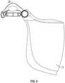
Figure 1 is a perspective view of a safety helmet assembly including a visor carrier assembly, wherein the visor is in a fully lowered position;Figure 2 is a side view of the safety helmet assembly ofFigure 1 ;Figure 3 is a perspective view of the visor carrier assembly ofFigure 1 ;Figure 4 is a side view of the visor carrier assembly ofFigure 3 ;Figure 5 is a side view of the safety helmet and visor carrier assembly ofFigure 1 , with the visor in the fully raised position;Figure 6 is a side view of the safety helmet and visor carrier assembly ofFigure 1 , with the visor in the fully stowed and locked position;Figure 7 is a front view of the first and second elongate arms of a double pivot mechanism included in a visor carrier assembly;Figure 8A is a close-up view of the 'front' pivot of a double pivot mechanism included in a visor carrier assembly;Figure 8B is a close-up view of the 'rear' pivot of a double pivot mechanism included in a visor carrier assembly;Figures 9A to 9E are schematic close-up views of the front and rear pivots of a double pivot mechanism included in a visor carrier assembly, for various respective visor positions; andFigures 10A to10E are illustrative of the five respective visor positions provided by a visor carrier assembly.- In the preceding and following description, directional descriptors such as upper, lower, inner, outer, vertical, horizontal, etc. are used to describe the invention when in the preferred orientation. It will be understood that the orientation can change during use, and therefore the corresponding descriptors will change.
- Referring to
Figures 1 and2 of the drawings, asafety helmet 10 is illustrated, on which avisor carrier assembly 12 is mounted. Thesafety helmet 10 can comprise any known configuration and can be formed of a hardouter shell 10a which is generally dome shaped so as to fit over the head of a user when worn, and the rim is generally oval in shape. The shell can be constructed of plastic materials typical of such safety helmets although it will be appreciated that theshell 10 can be constructed of any suitable material as will be apparent to those skilled in the art and the present invention is not necessarily intended to be limited in this regard. Thesafety helmet 10 further comprises anintegral brim 10b that extends around the front edge of theshell 10a. Auniversal slot 10c is provided on opposing side edges of theshell 10a to receive further protective equipment, such asear defenders 14. - The
visor carrier assembly 12 comprises atransparent visor 17, in the form of a faceshield, and anattachment device 18 for attaching thevisor 17 to thesafety helmet 10 for use. The faceshield is formed of a curved piece of transparent material substantially large enough to protect the wearer from flying particulates and debris which might otherwise strike the wearer's face and cause injury or irritation.Figures 1 and2 illustrate the faceshield in the operable position, wherein the faceshield extends downwardly from thebrim 10b of thesafety helmet 10 and effectively covers the user's face during use. In the operable position, thefaceshield 17 is angled or oriented so that the part of the faceshield adjacent the wearer's eyes is substantially perpendicular to the wearer's eyeline. Thefaceshield 17 is curved along its lateral axis, so that thefaceshield 17 protects the side of the wearers face during use. - Referring additionally to
Figures 3 and4 of the drawings, the attachment device comprises adouble pivot mechanism 20, attached or otherwise provided on each side of thevisor 17, at its upper edge when oriented for use. The term, 'double pivot mechanism' refers to a mechanism that allows the visor to be pivoted about two separate but parallel horizontal axes. More specifically, it enables thevisor 17 to be pivoted about a first axis, upward, away from the user's face and over the top of the safety helmet 10 (seeFigure 5 ), and then about a second axis, downward and toward thehelmet shell 10a so that it can be stowed close to the top of the helmet (as illustrated inFigure 6 ), without significantly affecting the centre of gravity and balance of the helmet/visor carrier assembly. - Referring now to
Figure 7 , eachdouble pivot mechanism 20 comprises a firstelongate arm 22 and a secondelongate arm 24. The firstelongate arm 22 is generally linear along its length and has a roundedfirst end 26. The longitudinally opposing second end terminates in awider coupling region 28 defining a profiledaperture 30. - The second
elongate arm 24 is generally arcuate along its length having a concave recess or 'cap' 32 at one end. The longitudinally opposing other end terminates in acoupling region 34 defining a profiledaperture 36. The first and secondelongate arms - The inner edge of each
coupling region respective aperture elongate arm 22, 24) defines arespective notch coupling region 28 of the firstelongate arm 22, the profiled edge of theaperture 30 opposite thenotch 38, defines two laterally spaced apart roundednotches coupling region 34 of the secondelongate arm 24, the profiled edge of theaperture 36 has two spaced-apart ridges notch 40 and theridges ridges - Referring to
Figures 8A and 8B of the drawings, thevisor 17 is pivotally coupled to the secondelongate arm 24 by acoupling peg 50 which is received within theaperture 36 of thecoupling region 34 of the second elongate arm 24 (seeFigure 8A ). Thecoupling peg 50 is generally elongate and of a length substantially equal to the distance between thenotch 40 and the opposing profiled wall of the aperture. Thecoupling peg 50 comprises two generallycircular locating members linear portion 54 therebetween. One of the locatingmembers 52a of thecoupling peg 50 is received within thenotch 40 and defines a first fixed pivot point (i.e. the 'front' pivot point) of the mechanism. The other locatingmember 52b sits against the opposing profiled wall so that, as the mechanism is pivoted about the first fixed pivot point defined by the first locatingmember 52a, the second locatingmember 52b can slide along the profiled wall. - The second
elongate arm 24 is pivotally coupled, at the end including thecap 32, to the firstelongate arm 22 by a coupling peg 56 which is received in theaperture 30 of thecoupling region 28 of the first elongate arm (seeFigure 8B ). Once again, the coupling peg 56 is generally elongate and of a length substantially equal to the distance between thenotch 38 and the opposing profiled wall of theaperture 30. The coupling peg 56 comprises two generallycircular locating members linear portion 60 therebetween. One of the locatingmembers 58a is received within thenotch 38 and defines a second fixed pivot point of the mechanism. The other locatingmember 58b sits against the opposing profiled wall so that, as the mechanism is pivoted about the second fixed pivot point (i.e. the 'rear' pivot point) defined by the first locatingmember 58a, the second locatingmember 58b can slide along the profiled wall. - Together, the two pivot mechanisms, that define two separate but substantially parallel horizontal pivotal axes, provide a visor carrier assembly with five defined visor positions, as will now be described with reference to
Figures 9A to 9E andFigures 10A to 10E of the drawings. When the visor carrier assembly is mounted on the safety helmet for use, the firstelongate arm 22 is fixedly attached on the safety helmet, the secondelongate arm 24 is configured to be selectively pivoted relative to the firstelongate arm 22 about the rear pivot point, and thevisor 17 can be selectively pivoted relative to the second elongate arm 24 (at the opposite end) about the front pivot point, relative thereto in order to move the visor into a selected one of the five defined visor positions. - Referring to
Figure 9A of the drawings, a first visor position is defined when the coupling peg 50 (coupling thevisor 17 to the secondelongate arm 24 at one end) is in Position A (the locatingmember 52b of thecoupling peg 50 is located in theridge 42b) abutting a first side edge (i.e. horizontal / uppermost edge) of theaperture 36 defining thecoupling region 34 of the secondelongate arm 24, and the second coupling peg 56 (coupling the secondelongate arm 24 at the other end - i.e. the end opposing the end of the secondelongate arm 24 with the coupling region 34 - to the fixed first elongate arm 22) is in Position 1 (the locatingmember 58b of the coupling peg 56 is located in thenotch 39a) abutting a first side edge (i.e. uppermost edge) of theaperture 30 of thecoupling region 28 of the firstelongate arm 22. As shown inFigure 10A , when the double pivot mechanism is in this configuration, in use, thevisor 17 is fully down and locked for use. In other words, thevisor 17 is in the operable position, described above, when thevisor 17 extends downwardly from thebrim 10b of thesafety helmet 10 and effectively covers the user's face during use. In the operable position, thevisor 17 is angled or oriented so that the part of thevisor 17 adjacent the wearer's eyes is substantially perpendicular to the wearer's eyeline. In this configuration, thecoupling peg 50 and thevisor 17 can be described as being at an angle of 0° from horizontal. - From this configuration, if the
visor 17 is pushed upward, away from the user's face, it can pivot about the second (rear) fixed pivot point until the respective coupling peg 56 reaches Position 4 (the locatingmember 58b of the coupling peg 56 is located in thenotch 39b), having respectively passedPositions 2 and 3 (the locatingmember 58b of the coupling peg 56 is located at the generally arcuate wall section betweennotches aperture 30 defining thecoupling region 28 of the firstelongate arm 22. During this process, the other pivotal coupling (i.e. the coupling peg 50) remains stationary in Position A and, when the rear pivot reaches Position 4, thevisor 17 is fully up, over the user's head and over the top of thesafety helmet 10, as illustrated inFigures 9B and10C . In this configuration, thecoupling peg 50 and thevisor 17 can be described as being at about an angle of 100° from the operable position, when the visor is fully down and locked for use. - From this configuration, the
visor 17 can be pivoted (relative to the second elongate arm 24) about the front pivot (with the rear pivot remaining stationary in Position 4), through Position B of the front pivot (the second locatingmember 52b of thecoupling peg 50 is located in the generally arcuate wall section between theridges Figures 9C and10D ; to position C (the second locatingmember 52b of thecoupling peg 50 is located inridge 42a) with thecoupling peg 50 abutting the opposing side wall/edge (i.e. lowermost edge) of the aperture 30 (seeFigure 9D ), thereby moving thevisor 17 to a fully stowed and locked configuration, as shown inFigure 10E . - As illustrated by
Figure 10B , thevisor 17, when being pivoted down for use, from the fully up position illustrated inFigure 10C , the front pivot remains stationary at Position A and the rear pivot moves through Position 3 (at which the angle of thevisor 17 and thecoupling peg 50 is around 30° from the operable position; and the locatingmember 58b is located at the end of the generally arcuate wall section , betweennotches visor 17 and thecoupling peg 50 is around 90° from the operable position; and the locatingmember 58b is located at the end of the generally arcuate wall section, betweennotches Figure 9E , and, from there, can be moved to Position 1 for use(Figures 9A and10A ). - The 'cap' 32 of the second
elongate arm 24 arcs over the existinguniversal slot 10c of thesafety helmet 10, thus enabling both the visor assembly and other mountable components to be attached to thesafety helmet 10 and function independently without compromising the function of the visor assembly and the mountable component. For example,ear defenders 14 can be attached to thesafety helmet 10 with the visor assembly, and both can function independently without compromising either element of face and/or ear protection. Theear defenders 14, with their standard universal attachment means, are not interfered with, either in use or, indeed, when not in use, because the pivot mechanism enablesear defenders 14 and thevisor 17 to be stored together above thehelmet 10. - The lightweight and streamlined arrangement, together with the fact that both pivots remain above the brim of the
safety helmet 10 at all times, irrespective of the visor position, results in significantly reduced weight and improved balance and comfort. - The double pivot design enables the
visor 17 to be stowed close to the crown of thehelmet 10, thus reducing the centre of gravity, perceived weight and improving balance, thus increasing comfort. All of these benefits are provided whilst still providing a useful range of 'locked' visor positions. - Further changes can be made within the scope of this invention as defined by the appended claims.
Claims (7)
- A visor carrier assembly (12) for a safety helmet (10), comprising:a visor (17); andan attachment device (18) for attaching the visor (17) to the safety helmet (10), the attachment device (18) including double-pivot mechanisms (20) for attachment to each side of the safety helmet (10) to enable the visor (17) to be selectively pivoted relative to the safety helmet (10), between first, second and third visor positions;characterised in that:each double pivot mechanism (20) comprises first and second elongate arms (22, 24);the first elongate arm (22) is to be fixedly mounted at a respective side edge of the safety helmet (10) and a coupling region (28) is provided in or on the first elongate arm (22);the second elongate arm (24) is:coupled at one end to a respective side region of the visor (17) by a first pivotal coupling comprising a coupling member (50) and a coupling region (34), andcoupled at a second end to the coupling region (28) of the first elongate arm (22) by a second pivotal coupling comprising a coupling member (56) and a coupling region (28);each coupling member comprises a fixed elongate pin (50, 56) having a rounded portion (52a, 52b, 58a, 58b) at each end;each coupling region (28, 34) comprises an aperture (30, 36) defining a first notch or aperture (38, 40) along its inner edge within which one of the rounded portions (52a, 58a) of a respective coupling member is received to define a fixed pivot point, and an arcuate guide wall with which the opposite rounded portion (52b, 58b) of said respective coupling member engages and having ridges defining grooves or notches (39a, 39b, 42a, 42b) for receiving the opposite rounded portion (52b, 58b) as a respective pivotal coupling is pivoted about the fixed pivot point; andeach groove or notch (39a, 39b, 42a, 42b) defines a respective visor position.
- A visor carrier assembly (12) according to claim 1, wherein the second elongate arm (24) is directly coupled to the visor (17) by the first pivotal coupling (34, 36, 50).
- A visor carrier assembly (12) according to claim 1 or 2, wherein the coupling region (28) is provided integrally with the first elongate arm (22).
- A visor carrier assembly (12) according to claim 1, 2, or 3, wherein the coupling region (28) is provided at one end of the first elongate arm (22).
- A visor carrier assembly (12) according to claim 4, wherein the other end (26) of the first elongate arm (22) is configured to be inserted through a recess provided on the safety helmet (10) so as to fixedly mount the visor carrier (12) assembly to the safety helmet (10).
- A visor carrier assembly (12) according to any of the preceding claims, wherein the two pivotal couplings (28, 30, 56; 34, 36, 50) are substantially horizontally aligned relative to the helmet (10), when oriented in the first visor position, such that, when worn by a user, the visor (17) is deployed over the user's face.
- A visor carrier (12) according to any of the preceding claims, wherein a coupling region (34) is provided integrally with the second elongate arm (24).
Applications Claiming Priority (3)
| Application Number | Priority Date | Filing Date | Title |
|---|---|---|---|
| GBGB1816840.1AGB201816840D0 (en) | 2018-10-16 | 2018-10-16 | Improved visor carrier assembly |
| GB1913836.1AGB2579271B (en) | 2018-10-16 | 2019-09-25 | Visor carrier assembly |
| PCT/GB2019/052813WO2020079397A1 (en) | 2018-10-16 | 2019-10-04 | Visor carrier assembly |
Publications (2)
| Publication Number | Publication Date |
|---|---|
| EP3866632A1 EP3866632A1 (en) | 2021-08-25 |
| EP3866632B1true EP3866632B1 (en) | 2024-09-11 |
Family
ID=64397646
Family Applications (1)
| Application Number | Title | Priority Date | Filing Date |
|---|---|---|---|
| EP19787386.2AActiveEP3866632B1 (en) | 2018-10-16 | 2019-10-04 | Visor carrier assembly |
Country Status (6)
| Country | Link |
|---|---|
| US (1) | US11160323B2 (en) |
| EP (1) | EP3866632B1 (en) |
| AU (1) | AU2019363349B2 (en) |
| ES (1) | ES2989937T3 (en) |
| GB (3) | GB201816840D0 (en) |
| WO (1) | WO2020079397A1 (en) |
Families Citing this family (13)
| Publication number | Priority date | Publication date | Assignee | Title |
|---|---|---|---|---|
| USD985850S1 (en)* | 2019-10-31 | 2023-05-09 | Uvex Arbeitsschutz Gmbh | Face guard |
| AU2021328139A1 (en) | 2020-08-17 | 2023-03-09 | Milwaukee Electric Tool Corporation | Hard hat attachment system and sun visor |
| EP4195970A4 (en) | 2020-08-17 | 2024-10-16 | Milwaukee Electric Tool Corporation | SAFETY HEADGEAR AND ACCESSORIES |
| US11583026B2 (en)* | 2021-02-09 | 2023-02-21 | LIFT Airborne Technologies LLC | Automatic visor locking system |
| JP2022129389A (en)* | 2021-02-24 | 2022-09-05 | 株式会社重松製作所 | helmet face shield |
| USD1089862S1 (en)* | 2021-03-15 | 2025-08-19 | Paulson Manufacturing Corporation | Bracket for face shield |
| US11617408B2 (en)* | 2021-05-11 | 2023-04-04 | Chien-Hung Lu | Pivoting shield assembly for hat |
| US11805839B2 (en)* | 2022-01-27 | 2023-11-07 | Chien-Hung Lu | Headwear with a protective shield |
| US12016419B2 (en)* | 2022-03-24 | 2024-06-25 | Paulson Manufacturing Corporation | Weight compensating bracket |
| USD971508S1 (en)* | 2022-07-13 | 2022-11-29 | Ruiyin Cao | Safety helmet |
| DE102023201935A1 (en)* | 2023-03-03 | 2024-09-05 | Uvex Arbeitsschutz Gmbh | arrangement |
| US12274323B2 (en)* | 2023-06-20 | 2025-04-15 | Ourad Safety Co., Ltd. | Device for connecting lens and earmuff to safety helmet |
| US12108823B1 (en)* | 2024-03-19 | 2024-10-08 | Larry Milder | Ear muffs for hats |
Family Cites Families (24)
| Publication number | Priority date | Publication date | Assignee | Title |
|---|---|---|---|---|
| US2410256A (en) | 1943-07-26 | 1946-10-29 | Sellstrom Mfg Company | Welders' helmet |
| FR2373979A1 (en)* | 1975-12-30 | 1978-07-13 | Norton Co | PROTECTIVE HELMET WITH VISOR |
| SE408851B (en)* | 1977-07-01 | 1979-07-16 | T G Palmaer | DEVICE IN THE SAFETY HELMET OR A SIMILAR CARRYING BODY |
| DE3006596A1 (en)* | 1979-02-26 | 1980-09-04 | Kangol Helmets Ltd | PROTECTIVE HELMET |
| US4479738A (en)* | 1983-04-27 | 1984-10-30 | Sellstrom Manufacturing Company | Attaching assembly |
| GB8628864D0 (en)* | 1986-12-03 | 1987-01-28 | Helmets Ltd | Helmets |
| DE3728619A1 (en) | 1987-08-27 | 1989-03-09 | Bosch Gmbh Robert | WIPING DEVICE FOR WINDOWS OF MOTOR VEHICLES |
| US5012528A (en)* | 1990-03-01 | 1991-05-07 | Institut De Recherche En Sante Et En . . . | Visor attachment for safety helmet |
| SE468234B (en)* | 1991-09-11 | 1992-11-30 | Peltor Ab | VISOR DEVICE |
| US5177816A (en)* | 1991-12-10 | 1993-01-12 | The United States Of America As Represented By The Secretary Of The Navy | Helmet visor support apparatus |
| US5257417A (en)* | 1992-08-17 | 1993-11-02 | E. D. Bullard Company | Fire fighter's face shield assembly |
| US6047409A (en)* | 1998-05-02 | 2000-04-11 | Simpson; Elwood J. B. | Adjustable safety lock for helmet face shield |
| US7895678B2 (en)* | 2007-08-06 | 2011-03-01 | Bell Sports, Inc. | Helmet with improved shield mount and precision shield control |
| CH700540A2 (en)* | 2009-03-02 | 2010-09-15 | Sperian Welding Prot Ag | Adapter system and adapter for mask. |
| US8656519B2 (en)* | 2011-05-10 | 2014-02-25 | Kin Yong Lung Industrial Co., Ltd. | Position control mechanism for a full-faced and open-faced helmet |
| US8434167B2 (en)* | 2011-08-03 | 2013-05-07 | Honeywell International Inc. | Universal dual-pivot face shield assembly for a hard hat |
| ITVR20120022A1 (en)* | 2012-02-20 | 2013-08-21 | Agv Spa | HANDLING DEVICE FOR A HELMET TO MOVE A FIRST ELEMENT OF THE HELMET COMPARED TO A SECOND HELMET ELEMENT. |
| GB2541672B (en)* | 2015-08-25 | 2019-12-11 | Jsp Ltd | A powered air respirator kit |
| DE102016205448B4 (en) | 2016-04-01 | 2019-02-07 | Uvex Arbeitsschutz Gmbh | helmet |
| CN105901820B (en)* | 2016-06-08 | 2019-01-29 | 江门市鹏程头盔有限公司 | A kind of variable jaw structure protecting type helmet based on gear constraint |
| GB2560005B (en)* | 2017-02-24 | 2019-03-13 | Greene Andrew | A spectacle mounting for a visor on a helmet |
| JP6842993B2 (en)* | 2017-05-22 | 2021-03-17 | 株式会社Shoei | Helmet |
| CN107432520A (en)* | 2017-08-14 | 2017-12-05 | 江门市鹏程头盔有限公司 | A kind of protective cover of helmet raises mechanism and the variable chin bar helmet of mechanism is raised equipped with this |
| US11213089B2 (en)* | 2019-06-04 | 2022-01-04 | Msa Technology, Llc | Protective helmet with face protection shield and linkage mechanism |
- 2018
- 2018-10-16GBGBGB1816840.1Apatent/GB201816840D0/ennot_activeCeased
- 2019
- 2019-09-25GBGB1913836.1Apatent/GB2579271B/enactiveActive
- 2019-09-25GBGB2104207.2Apatent/GB2590875B/enactiveActive
- 2019-10-04USUS17/285,626patent/US11160323B2/enactiveActive
- 2019-10-04EPEP19787386.2Apatent/EP3866632B1/enactiveActive
- 2019-10-04ESES19787386Tpatent/ES2989937T3/enactiveActive
- 2019-10-04WOPCT/GB2019/052813patent/WO2020079397A1/ennot_activeCeased
- 2019-10-04AUAU2019363349Apatent/AU2019363349B2/enactiveActive
Also Published As
| Publication number | Publication date |
|---|---|
| ES2989937T3 (en) | 2024-11-28 |
| GB201913836D0 (en) | 2019-11-06 |
| GB2579271B (en) | 2021-05-26 |
| EP3866632A1 (en) | 2021-08-25 |
| AU2019363349B2 (en) | 2021-08-19 |
| AU2019363349A1 (en) | 2021-05-27 |
| GB201816840D0 (en) | 2018-11-28 |
| US20210307448A1 (en) | 2021-10-07 |
| GB2579271A (en) | 2020-06-17 |
| GB202104207D0 (en) | 2021-05-12 |
| GB2590875A (en) | 2021-07-07 |
| GB2590875B (en) | 2021-09-29 |
| US11160323B2 (en) | 2021-11-02 |
| WO2020079397A1 (en) | 2020-04-23 |
Similar Documents
| Publication | Publication Date | Title |
|---|---|---|
| EP3866632B1 (en) | Visor carrier assembly | |
| AU2024200280B2 (en) | Safety Helmet | |
| US8321962B2 (en) | Adapter system for coupling a protective mask to a helmet | |
| US9578916B2 (en) | Appliance mounting device and system for head gear | |
| AU2021273565B2 (en) | Helmet accessory mount system | |
| JP4531305B2 (en) | Helmet with face protection plate | |
| US20250228323A1 (en) | Hard Hat Attachment System and Safety Equipment | |
| US20210345721A1 (en) | Non-Impact Construction Face Shield | |
| HK40032408A (en) | Visor carrier assembly | |
| US20240423310A1 (en) | Hard Hat with AR/VR Goggles | |
| WO2024263956A1 (en) | Hard hat with ar/vr goggles | |
| WO2024218266A1 (en) | Protecting device for protecting the front of the head of a welder | |
| WO2021226459A1 (en) | Non-impact construction face shield |
Legal Events
| Date | Code | Title | Description |
|---|---|---|---|
| STAA | Information on the status of an ep patent application or granted ep patent | Free format text:STATUS: UNKNOWN | |
| STAA | Information on the status of an ep patent application or granted ep patent | Free format text:STATUS: THE INTERNATIONAL PUBLICATION HAS BEEN MADE | |
| PUAI | Public reference made under article 153(3) epc to a published international application that has entered the european phase | Free format text:ORIGINAL CODE: 0009012 | |
| STAA | Information on the status of an ep patent application or granted ep patent | Free format text:STATUS: REQUEST FOR EXAMINATION WAS MADE | |
| 17P | Request for examination filed | Effective date:20210430 | |
| AK | Designated contracting states | Kind code of ref document:A1 Designated state(s):AL AT BE BG CH CY CZ DE DK EE ES FI FR GB GR HR HU IE IS IT LI LT LU LV MC MK MT NL NO PL PT RO RS SE SI SK SM TR | |
| DAV | Request for validation of the european patent (deleted) | ||
| DAX | Request for extension of the european patent (deleted) | ||
| STAA | Information on the status of an ep patent application or granted ep patent | Free format text:STATUS: EXAMINATION IS IN PROGRESS | |
| 17Q | First examination report despatched | Effective date:20230307 | |
| P01 | Opt-out of the competence of the unified patent court (upc) registered | Effective date:20230612 | |
| GRAP | Despatch of communication of intention to grant a patent | Free format text:ORIGINAL CODE: EPIDOSNIGR1 | |
| STAA | Information on the status of an ep patent application or granted ep patent | Free format text:STATUS: GRANT OF PATENT IS INTENDED | |
| INTG | Intention to grant announced | Effective date:20240606 | |
| GRAS | Grant fee paid | Free format text:ORIGINAL CODE: EPIDOSNIGR3 | |
| GRAA | (expected) grant | Free format text:ORIGINAL CODE: 0009210 | |
| STAA | Information on the status of an ep patent application or granted ep patent | Free format text:STATUS: THE PATENT HAS BEEN GRANTED | |
| AK | Designated contracting states | Kind code of ref document:B1 Designated state(s):AL AT BE BG CH CY CZ DE DK EE ES FI FR GR HR HU IE IS IT LI LT LU LV MC MK MT NL NO PL PT RO RS SE SI SK SM TR | |
| RBV | Designated contracting states (corrected) | Designated state(s):AL AT BE BG CH CY CZ DE DK EE ES FI FR GR HR HU IE IS IT LI LT LU LV MC MK MT NL NO PL PT RO RS SE SI SK SM TR | |
| REG | Reference to a national code | Ref country code:CH Ref legal event code:EP | |
| REG | Reference to a national code | Ref country code:DE Ref legal event code:R096 Ref document number:602019058759 Country of ref document:DE | |
| REG | Reference to a national code | Ref country code:IE Ref legal event code:FG4D | |
| PGFP | Annual fee paid to national office [announced via postgrant information from national office to epo] | Ref country code:FR Payment date:20240924 Year of fee payment:6 | |
| REG | Reference to a national code | Ref country code:ES Ref legal event code:FG2A Ref document number:2989937 Country of ref document:ES Kind code of ref document:T3 Effective date:20241128 | |
| REG | Reference to a national code | Ref country code:LT Ref legal event code:MG9D | |
| PG25 | Lapsed in a contracting state [announced via postgrant information from national office to epo] | Ref country code:NO Free format text:LAPSE BECAUSE OF FAILURE TO SUBMIT A TRANSLATION OF THE DESCRIPTION OR TO PAY THE FEE WITHIN THE PRESCRIBED TIME-LIMIT Effective date:20241211 | |
| REG | Reference to a national code | Ref country code:NL Ref legal event code:MP Effective date:20240911 | |
| PG25 | Lapsed in a contracting state [announced via postgrant information from national office to epo] | Ref country code:FI Free format text:LAPSE BECAUSE OF FAILURE TO SUBMIT A TRANSLATION OF THE DESCRIPTION OR TO PAY THE FEE WITHIN THE PRESCRIBED TIME-LIMIT Effective date:20240911 Ref country code:GR Free format text:LAPSE BECAUSE OF FAILURE TO SUBMIT A TRANSLATION OF THE DESCRIPTION OR TO PAY THE FEE WITHIN THE PRESCRIBED TIME-LIMIT Effective date:20241212 | |
| PG25 | Lapsed in a contracting state [announced via postgrant information from national office to epo] | Ref country code:BG Free format text:LAPSE BECAUSE OF FAILURE TO SUBMIT A TRANSLATION OF THE DESCRIPTION OR TO PAY THE FEE WITHIN THE PRESCRIBED TIME-LIMIT Effective date:20240911 | |
| PG25 | Lapsed in a contracting state [announced via postgrant information from national office to epo] | Ref country code:LV Free format text:LAPSE BECAUSE OF FAILURE TO SUBMIT A TRANSLATION OF THE DESCRIPTION OR TO PAY THE FEE WITHIN THE PRESCRIBED TIME-LIMIT Effective date:20240911 | |
| PG25 | Lapsed in a contracting state [announced via postgrant information from national office to epo] | Ref country code:HR Free format text:LAPSE BECAUSE OF FAILURE TO SUBMIT A TRANSLATION OF THE DESCRIPTION OR TO PAY THE FEE WITHIN THE PRESCRIBED TIME-LIMIT Effective date:20240911 | |
| PGFP | Annual fee paid to national office [announced via postgrant information from national office to epo] | Ref country code:IE Payment date:20241015 Year of fee payment:6 | |
| PG25 | Lapsed in a contracting state [announced via postgrant information from national office to epo] | Ref country code:RS Free format text:LAPSE BECAUSE OF FAILURE TO SUBMIT A TRANSLATION OF THE DESCRIPTION OR TO PAY THE FEE WITHIN THE PRESCRIBED TIME-LIMIT Effective date:20241211 | |
| PGFP | Annual fee paid to national office [announced via postgrant information from national office to epo] | Ref country code:ES Payment date:20241104 Year of fee payment:6 | |
| PG25 | Lapsed in a contracting state [announced via postgrant information from national office to epo] | Ref country code:RS Free format text:LAPSE BECAUSE OF FAILURE TO SUBMIT A TRANSLATION OF THE DESCRIPTION OR TO PAY THE FEE WITHIN THE PRESCRIBED TIME-LIMIT Effective date:20241211 Ref country code:NO Free format text:LAPSE BECAUSE OF FAILURE TO SUBMIT A TRANSLATION OF THE DESCRIPTION OR TO PAY THE FEE WITHIN THE PRESCRIBED TIME-LIMIT Effective date:20241211 Ref country code:LV Free format text:LAPSE BECAUSE OF FAILURE TO SUBMIT A TRANSLATION OF THE DESCRIPTION OR TO PAY THE FEE WITHIN THE PRESCRIBED TIME-LIMIT Effective date:20240911 Ref country code:HR Free format text:LAPSE BECAUSE OF FAILURE TO SUBMIT A TRANSLATION OF THE DESCRIPTION OR TO PAY THE FEE WITHIN THE PRESCRIBED TIME-LIMIT Effective date:20240911 Ref country code:GR Free format text:LAPSE BECAUSE OF FAILURE TO SUBMIT A TRANSLATION OF THE DESCRIPTION OR TO PAY THE FEE WITHIN THE PRESCRIBED TIME-LIMIT Effective date:20241212 Ref country code:FI Free format text:LAPSE BECAUSE OF FAILURE TO SUBMIT A TRANSLATION OF THE DESCRIPTION OR TO PAY THE FEE WITHIN THE PRESCRIBED TIME-LIMIT Effective date:20240911 Ref country code:BG Free format text:LAPSE BECAUSE OF FAILURE TO SUBMIT A TRANSLATION OF THE DESCRIPTION OR TO PAY THE FEE WITHIN THE PRESCRIBED TIME-LIMIT Effective date:20240911 | |
| REG | Reference to a national code | Ref country code:AT Ref legal event code:MK05 Ref document number:1721876 Country of ref document:AT Kind code of ref document:T Effective date:20240911 | |
| PG25 | Lapsed in a contracting state [announced via postgrant information from national office to epo] | Ref country code:NL Free format text:LAPSE BECAUSE OF FAILURE TO SUBMIT A TRANSLATION OF THE DESCRIPTION OR TO PAY THE FEE WITHIN THE PRESCRIBED TIME-LIMIT Effective date:20240911 | |
| PG25 | Lapsed in a contracting state [announced via postgrant information from national office to epo] | Ref country code:IS Free format text:LAPSE BECAUSE OF FAILURE TO SUBMIT A TRANSLATION OF THE DESCRIPTION OR TO PAY THE FEE WITHIN THE PRESCRIBED TIME-LIMIT Effective date:20250111 Ref country code:PT Free format text:LAPSE BECAUSE OF FAILURE TO SUBMIT A TRANSLATION OF THE DESCRIPTION OR TO PAY THE FEE WITHIN THE PRESCRIBED TIME-LIMIT Effective date:20250113 | |
| PGFP | Annual fee paid to national office [announced via postgrant information from national office to epo] | Ref country code:DE Payment date:20241219 Year of fee payment:6 | |
| PG25 | Lapsed in a contracting state [announced via postgrant information from national office to epo] | Ref country code:RO Free format text:LAPSE BECAUSE OF FAILURE TO SUBMIT A TRANSLATION OF THE DESCRIPTION OR TO PAY THE FEE WITHIN THE PRESCRIBED TIME-LIMIT Effective date:20240911 Ref country code:SM Free format text:LAPSE BECAUSE OF FAILURE TO SUBMIT A TRANSLATION OF THE DESCRIPTION OR TO PAY THE FEE WITHIN THE PRESCRIBED TIME-LIMIT Effective date:20240911 | |
| PG25 | Lapsed in a contracting state [announced via postgrant information from national office to epo] | Ref country code:EE Free format text:LAPSE BECAUSE OF FAILURE TO SUBMIT A TRANSLATION OF THE DESCRIPTION OR TO PAY THE FEE WITHIN THE PRESCRIBED TIME-LIMIT Effective date:20240911 Ref country code:AT Free format text:LAPSE BECAUSE OF FAILURE TO SUBMIT A TRANSLATION OF THE DESCRIPTION OR TO PAY THE FEE WITHIN THE PRESCRIBED TIME-LIMIT Effective date:20240911 | |
| PG25 | Lapsed in a contracting state [announced via postgrant information from national office to epo] | Ref country code:PL Free format text:LAPSE BECAUSE OF FAILURE TO SUBMIT A TRANSLATION OF THE DESCRIPTION OR TO PAY THE FEE WITHIN THE PRESCRIBED TIME-LIMIT Effective date:20240911 Ref country code:CZ Free format text:LAPSE BECAUSE OF FAILURE TO SUBMIT A TRANSLATION OF THE DESCRIPTION OR TO PAY THE FEE WITHIN THE PRESCRIBED TIME-LIMIT Effective date:20240911 | |
| PG25 | Lapsed in a contracting state [announced via postgrant information from national office to epo] | Ref country code:IT Free format text:LAPSE BECAUSE OF FAILURE TO SUBMIT A TRANSLATION OF THE DESCRIPTION OR TO PAY THE FEE WITHIN THE PRESCRIBED TIME-LIMIT Effective date:20240911 Ref country code:SK Free format text:LAPSE BECAUSE OF FAILURE TO SUBMIT A TRANSLATION OF THE DESCRIPTION OR TO PAY THE FEE WITHIN THE PRESCRIBED TIME-LIMIT Effective date:20240911 | |
| REG | Reference to a national code | Ref country code:CH Ref legal event code:PL | |
| REG | Reference to a national code | Ref country code:DE Ref legal event code:R097 Ref document number:602019058759 Country of ref document:DE | |
| PG25 | Lapsed in a contracting state [announced via postgrant information from national office to epo] | Ref country code:MC Free format text:LAPSE BECAUSE OF FAILURE TO SUBMIT A TRANSLATION OF THE DESCRIPTION OR TO PAY THE FEE WITHIN THE PRESCRIBED TIME-LIMIT Effective date:20240911 | |
| PG25 | Lapsed in a contracting state [announced via postgrant information from national office to epo] | Ref country code:DK Free format text:LAPSE BECAUSE OF FAILURE TO SUBMIT A TRANSLATION OF THE DESCRIPTION OR TO PAY THE FEE WITHIN THE PRESCRIBED TIME-LIMIT Effective date:20240911 | |
| PG25 | Lapsed in a contracting state [announced via postgrant information from national office to epo] | Ref country code:LU Free format text:LAPSE BECAUSE OF NON-PAYMENT OF DUE FEES Effective date:20241004 Ref country code:BE Free format text:LAPSE BECAUSE OF NON-PAYMENT OF DUE FEES Effective date:20241031 | |
| PLBE | No opposition filed within time limit | Free format text:ORIGINAL CODE: 0009261 | |
| STAA | Information on the status of an ep patent application or granted ep patent | Free format text:STATUS: NO OPPOSITION FILED WITHIN TIME LIMIT | |
| PG25 | Lapsed in a contracting state [announced via postgrant information from national office to epo] | Ref country code:CH Free format text:LAPSE BECAUSE OF NON-PAYMENT OF DUE FEES Effective date:20241031 | |
| REG | Reference to a national code | Ref country code:BE Ref legal event code:MM Effective date:20241031 | |
| 26N | No opposition filed | Effective date:20250612 | |
| PG25 | Lapsed in a contracting state [announced via postgrant information from national office to epo] | Ref country code:SE Free format text:LAPSE BECAUSE OF FAILURE TO SUBMIT A TRANSLATION OF THE DESCRIPTION OR TO PAY THE FEE WITHIN THE PRESCRIBED TIME-LIMIT Effective date:20240911 |