EP3866541B1 - Network node, user device and methods thereof - Google Patents
Network node, user device and methods thereofDownload PDFInfo
- Publication number
- EP3866541B1 EP3866541B1EP20209662.4AEP20209662AEP3866541B1EP 3866541 B1EP3866541 B1EP 3866541B1EP 20209662 AEP20209662 AEP 20209662AEP 3866541 B1EP3866541 B1EP 3866541B1
- Authority
- EP
- European Patent Office
- Prior art keywords
- sub
- band
- frequency resources
- region
- contiguous
- Prior art date
- Legal status (The legal status is an assumption and is not a legal conclusion. Google has not performed a legal analysis and makes no representation as to the accuracy of the status listed.)
- Active
Links
Images


Classifications
- H—ELECTRICITY
- H04—ELECTRIC COMMUNICATION TECHNIQUE
- H04W—WIRELESS COMMUNICATION NETWORKS
- H04W72/00—Local resource management
- H04W72/04—Wireless resource allocation
- H04W72/044—Wireless resource allocation based on the type of the allocated resource
- H04W72/0453—Resources in frequency domain, e.g. a carrier in FDMA
- H—ELECTRICITY
- H04—ELECTRIC COMMUNICATION TECHNIQUE
- H04W—WIRELESS COMMUNICATION NETWORKS
- H04W72/00—Local resource management
- H04W72/20—Control channels or signalling for resource management
- H04W72/23—Control channels or signalling for resource management in the downlink direction of a wireless link, i.e. towards a terminal
- H—ELECTRICITY
- H04—ELECTRIC COMMUNICATION TECHNIQUE
- H04L—TRANSMISSION OF DIGITAL INFORMATION, e.g. TELEGRAPHIC COMMUNICATION
- H04L5/00—Arrangements affording multiple use of the transmission path
- H04L5/003—Arrangements for allocating sub-channels of the transmission path
- H—ELECTRICITY
- H04—ELECTRIC COMMUNICATION TECHNIQUE
- H04L—TRANSMISSION OF DIGITAL INFORMATION, e.g. TELEGRAPHIC COMMUNICATION
- H04L5/00—Arrangements affording multiple use of the transmission path
- H04L5/0091—Signalling for the administration of the divided path, e.g. signalling of configuration information
- H04L5/0094—Indication of how sub-channels of the path are allocated
- H—ELECTRICITY
- H04—ELECTRIC COMMUNICATION TECHNIQUE
- H04W—WIRELESS COMMUNICATION NETWORKS
- H04W72/00—Local resource management
- H04W72/04—Wireless resource allocation
- H04W72/044—Wireless resource allocation based on the type of the allocated resource
- H04W72/0473—Wireless resource allocation based on the type of the allocated resource the resource being transmission power
- H—ELECTRICITY
- H04—ELECTRIC COMMUNICATION TECHNIQUE
- H04W—WIRELESS COMMUNICATION NETWORKS
- H04W72/00—Local resource management
- H04W72/20—Control channels or signalling for resource management
- H04W72/21—Control channels or signalling for resource management in the uplink direction of a wireless link, i.e. towards the network
- H—ELECTRICITY
- H04—ELECTRIC COMMUNICATION TECHNIQUE
- H04W—WIRELESS COMMUNICATION NETWORKS
- H04W72/00—Local resource management
- H04W72/50—Allocation or scheduling criteria for wireless resources
- H04W72/51—Allocation or scheduling criteria for wireless resources based on terminal or device properties
Definitions
- the inventionrelates to a network node and a user device for a wireless communication system. Furthermore, the invention also relates to corresponding methods and a computer-readable medium.
- a Single-Carrier - Frequency Division Multiple Access (SC-FDMA) waveformis used and the time-frequency resources for the Physical Uplink Shared Channel (PUSCH) can be allocated by a single or dual cluster of frequency resources, where each cluster (i.e., set of frequency resources) is localized in frequency within a slot and consists of a number of frequency-consecutive Physical Resource Blocks (PRBs).
- a single Discrete Fourier Transform (DFT)-precoderis applied for the one or two clusters.
- DFTDiscrete Fourier Transform
- CMCubic Metric
- PAPRPeak-to-Average-Power Ratio
- Dynamic PUSCH resource allocationis conveyed by a resource allocation field in the associated uplink grant sent in the downlink control channel, where PUSCH resource allocation type 0 is used for single cluster PUSCH, and PUSCH resource allocation type 1 is for dual cluster PUSCH.
- LTE Rel-13can also be deployed for downlink transmissions in unlicensed spectrum, i.e., utilizing Licensed Assisted Access (LAA) where an unlicensed carrier is operated as a Secondary Cell (SCell) in conjunction with a Primary Cell (PCell) located in licensed spectrum. It is desirable to extend the functionality of LAA by including uplink (UL) transmissions.
- LAALicensed Assisted Access
- SCellSecondary Cell
- PCellPrimary Cell
- ULuplink
- LTErelies on E-UTRAN NodeB or evolved NodeB (eNodeBs) to perform uplink scheduling, which allows multiple User Equipments (UEs) in a cell to transmit PUSCH on orthogonal resources within a subframe.
- UEsUser Equipments
- LTEis not constrained to wideband scheduling for one user at a time, as is the case for many WiFi systems, and could leverage the frequency selectivity of the channels for the UEs into scheduling gains.
- the schedulercould also schedule UEs on the same time-frequency resource within a cell and utilize spatial suppression to separate the UEs at the receiver, i.e., Multi-User MIMO (MU-MIMO).
- MU-MIMOMulti-User MIMO
- a first regulatory requirementis that the occupied channel bandwidth shall be between 80% and 100% of the declared nominal channel bandwidth.
- the occupied channel bandwidthis the bandwidth containing 99% of the power of the signal. This requirement does not mandate that only a single UE can occupy 80-100% of the carrier bandwidth. For example, it would be possible to multiplex PUSCH from several UEs in an UL subframe over the whole carrier bandwidth using interleaved Frequency Division Multiplexing (FDM) allocation, while fulfilling the occupied channel bandwidth requirement.
- FDMFrequency Division Multiplexing
- a second regulatory requirementis the transmission power in a narrow band.
- the power spectral density for transmissionsshall be limited to a maximum mean Equivalent Isotropically Radiated Power (EIRP) density of 10 mW/MHz in any 1 MHz band. This implies that, in order not to limit the transmit power, it is beneficial to allocate the resources in as many '1 MHz' bands as possible.
- EIRPEquivalent Isotropically Radiated Power
- an efficient resource allocation schemeshould allow UEs to be allocated with different amount of resources, e.g., different number of PRBs.
- the starting resource index, i.e., PRB index, and the number of allocated resources, i.e., number of PRBsare represented by a single integer value which is signalled to the UE.
- PUSCH resource allocation type 0, i.e., single-cluster PUSCHcomprises encoding through the resource index, a starting PRB index and the number of allocated PRBs.
- PUSCH resource allocation type 1, i.e., dual-cluster PUSCHcomprises encoding through the resource index, four RBG indices, where the first two RBG indices are used for the starting RBG index and the ending RBG index of one cluster, and the last two RBG indices are used for the other cluster in the same way.
- N _PRB2 ⁇ 2 ⁇ 3 ⁇ 3 ⁇ 5 ⁇ 5 ⁇ N RB UL , where ⁇ 2 , ⁇ 3 , ⁇ 5 are non-negative integers and N RB UL is the number of available PRBs.
- the multi-cluster PUSCHis indicated using 10 clusters with 1 PRB per cluster and an inter-cluster spacing of 1.8 MHz (10 PRBs), i.e., every 10 th PRB is allocated.
- 10 PRBs1.8 MHz
- the UEmay be allocated from 1 to 10 of these PRB allocations, yielding from 10 to 100 PRBs in total.
- the exact assignment of which resource allocation to be usedis left to eNB, e.g., by signalling via a 10-bit bitmap in the UL grant.
- the signalling overheadis thus 10 bits to indicate the multi-cluster PUSCH.
- US 2014/0341126 A1discusses a method and apparatus for allocating quasi-contiguous uplink data resources for a user device.
- Transmission of datacomprise at least two data clusters of sub carriers expanding over gaps reserved for uplink control channel in order, for example, to mitigate transmission power reductions due to multi-cluster transmission.
- US 2015/0181608 A1discusses a method and apparatus for resource allocation.
- An apparatusutilizes a tree structure with more than one branch in the resource allocation of physical resource blocks, each branch including one or more legal starting positions for resource allocation. Each starting position is associated with a cluster of physical resource blocks, the number of starting positions being different on each branch. The size of the resource clusters of each branch is different.
- Each resource clusteris denoted with a predefined index, and one or more clusters are allocated to user equipment uplink connection.
- An objective of embodiments of the inventionis to provide a solution which mitigates or solves the drawbacks and problems of conventional solutions.
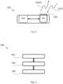
- Fig. 1shows a network node 100 according to an embodiment of the invention.
- the network node 100comprises a processor 102 communicably coupled to a transceiver 104. Further, an optional antenna 106 is shown in Fig. 1 .
- the antenna 106is coupled to the transceiver 104 and is configured to transmit and/or receive wireless communication signals in a wireless communication system 500.
- the processor 102 of the network node 100is configured to determine a resource indicator 110 comprising a first start index 11 and a first number of frequency resources N1.
- the first start index I1 and the first number of frequency resources N1are used for allocating a first set of contiguous frequency resources R1 within a first sub-band, and further used for allocating a corresponding first set of contiguous frequency resources R1' within a second sub-band.
- the first sub-band and the second sub-bandare non-overlapping and comprise equal number of frequency resources.
- the transceiver 104is configured to transmit a transmission grant 120 comprising the resource indicator 110 to a user device 300 (not shown in Fig. 1 , see Fig. 3 ). It is noted that the first set of frequency resources can allocated in further sub-bands.
- a network node 100may refer to a network control node or a network access node or an access point or a base station, e.g., a Radio Base Station (RBS), which in some networks may be referred to as transmitter, "eNB”, “eNodeB”, “NodeB” or “B node”, depending on the technology and terminology used.
- the network nodesmay be of different classes such as, e.g., macro eNodeB, home eNodeB or pico base station, based on transmission power and thereby also cell size.
- the network nodecan be an 802.11 access point or a Station (STA), which is any device that contains an IEEE 802.11-conformant Media Access Control (MAC) and Physical Layer (PHY) interface to the Wireless Medium (WM).
- STAStation
- MACMedia Access Control
- PHYPhysical Layer
- the network node 100is however not limited to the above mentioned communication devices.
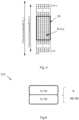
- Fig. 2shows a corresponding method which may be executed in a network node 100, such as the one described in Fig. 1 .
- the method 200comprises determining 202 a resource indicator 110 comprising a first start index I1 and a first number of frequency resources N1.
- the first start index I1 and the first number of frequency resources N1are used for allocating a first set of contiguous frequency resources R1 within a first sub-band, and further used for allocating a corresponding first set of contiguous frequency resources R1' within a second sub-band.
- the first sub-band and the second sub-bandare non-overlapping and comprise equal number of frequency resources.
- the method 200further comprises transmitting 204 a transmission grant 120 comprising the resource indicator 110 to a user device 300.
- the first start index I1indicates a position in the time-frequency plane of the resource.
- resourcescould be denoted as PRBs (e.g., comprising Resource Elements (REs) located within 180 kHz and 0.5 ms) and PRBs could be indexed, e.g., in an ascending order in frequency.
- PRBse.g., comprising Resource Elements (REs) located within 180 kHz and 0.5 ms
- PRBscould be indexed, e.g., in an ascending order in frequency.
- a set or cluster of frequency resourcesrefers to one or several frequency contiguous resources, e.g., one or several REs/PRBs, and clusters may or may not be consecutively located.
- the clustersare non-overlapping, i.e., they have no resources in common.
- Corresponding first set of contiguous frequency resources R1'means that an allocation using this set implies that the resource allocation is the same within the second sub-band as within the first sub-band. For example, if R1 includes the x:th PRB in the first sub-band, R1' includes the x:th PRB in the second sub-band, and so on.
- the transceiver 104is configured to receive user device information 130 (see Fig. 11 ) associated with the user device 300.
- the user device informationcomprises at least one of:
- the reference signals sent from the user device 300allows the network node 100 to estimate the channel quality which is useful for determining the amount of resources and the best location of the resources to be assigned.
- the network node 100may also utilize information about the amount of data which the user device 300 can transmit. This is useful for determining the amount of resources for the resource allocation to match the actual demand.
- the network node 100may further utilize information about the available transmit power in the user device 300. This is useful for determining the amount of resources for the resource allocation such that it can be accommodated within the available transmit power.
- the processor 102is configured to determine the resource indicator 110 based on the received user device information.
- the user device informationmay be received directly from the user device 300. However, all or parts of the user device information may be received via one or more intermediate network nodes.
- the transceiver 104is configured to receive data from the user device 300 in response to the transmission of the transmission grant 120 to the user device 300. Therefore, the user device 300 is configured to use the allocated first set of contiguous frequency resources R1 and the corresponding first set of contiguous frequency resources R1 ' for transmitting data to the network node 300.
- Fig. 3shows a user device 300 according to an embodiment of the invention.
- the user device 300comprises a processor 304 communicably coupled to a transceiver 302. Further, an optional antenna 306 is shown in Fig. 3 .
- the antenna 306is coupled to the transceiver 302 and is configured to transmit and/or receive wireless communication signals in a wireless communication system 500.
- Fig. 4shows a corresponding method which may be executed in a user device, such as the one described in Fig. 1 .
- the method 400comprises receiving 402 a transmission grant 120 comprising a resource indicator 110 from a network node 100.
- the resource indicator 110comprises a first start index I1 and a first number of frequency resources N1.
- the first start index I1 and a first number of frequency resources N1are used for allocating a first set of contiguous frequency resources R1 within a first sub-band, and further used for allocating a corresponding first set of contiguous frequency resources R1' within a second sub-band.
- the first sub-band and the second sub-bandare non-overlapping and comprise equal number of frequency resources.
- the method 400further comprises deriving 404 the first start index I1 and the first number of frequency resources N1 based on the resource indicator 110.
- the method 400further comprises transmitting 406 data symbols to the network node 100 using the first set of contiguous frequency resources R1 and the corresponding first set of contiguous frequency resources R1'.
- the user device 300which may be any of a User Equipment (UE), mobile station (MS), wireless terminal or mobile terminal, is enabled to communicate wirelessly in a wireless communication system, sometimes also referred to as a cellular radio system.
- the UEmay further be referred to as mobile telephones, cellular telephones, computer tablets or laptops with wireless capability.
- the UEs in the present contextmay be, for example, portable, pocket-storable, hand-held, computer-comprised, or vehicle-mounted mobile devices, enabled to communicate voice or data, via the radio access network, with another entity, such as another receiver or a server.
- the UEcan be a Station (STA), which is any device that contains an IEEE 802.11-conformant Media Access Control (MAC) and Physical Layer (PHY) interface to the Wireless Medium (WM).
- STAStation
- MACMedia Access Control
- PHYPhysical Layer
- frequency resource allocationis based on a sub-band level, where the total transmission bandwidth of a wireless communication system is divided into several equal sub-bands in the frequency domain.
- the frequency resource allocationis the same in all sub-bands of the transmission bandwidth.
- the network node 100indicates the frequency resource allocation for the user device 300 within a sub-band.
- the user device 300applies the same frequency resource allocation in each sub-band.
- Fig. 6illustrates different embodiments of the resource indicator 110.
- the resource indicator 110comprises a first start index I1 and a first number of frequency resources N1.
- the first start index I1 and a first number of frequency resources N1may be represented as a single value V which is more explained below in relation to Table 1.
- the resource indicator 110comprises, in an embodiment, a second start index I2 and a second number of frequency resources N2 which are used for allocating a second set of contiguous frequency resources R2 within the first sub-band and a corresponding second set of contiguous frequency resources R2' within the second sub-band.
- the first start index I1 and the first number of frequency resources N1may be represented with a first value V1.
- the second start index I2 and the second number of frequency resources N2may be represented with a second value V2.
- the number of allocated resourcesmay be explicitly indicated or implicitly indicated.
- the resource indicator 110comprises a first end resource index associated with the first start resource index. Therefore, the first number of allocated resources N1 for the first set can be derived from the difference between the first end resource index and the first start resource index. This method is also applicable for indicating the second (and further) number of frequency resources N2.
- the first set of contiguous frequency resources R1is allocated within a first sub-region of the first sub-band and within a corresponding first sub-region of the second sub-band
- the second set of contiguous frequency resources R2'is allocated within a second sub-region of the first sub-band and within a corresponding second sub-region of the second sub-band.
- the first sub-region and the second sub-regionare non-overlapping and comprise equal number of frequency resources. This embodiment therefore assumes the division of each sub-bands into two or more sub-regions.
- LTE terminology and expressionsare used, such as PUSCH, uplink grant, UE (corresponds to the present user device 300), etc.
- Embodiments of the inventionare, however, not limited to such LTE systems, which is well understood by the skilled person.
- time-frequency resourcesare allocated for transmission of an uplink shared data channel.
- the allocation of time-frequency resourcesmay be on subcarrier level, e.g., Resource Elements (REs), or groups of subcarriers, e.g., PRBs or Resource Block Groups (RBGs).
- REsResource Elements
- RBGsResource Block Groups
- One RBGmay comprise several PRBs, and the detailed mapping between RBG and PRB is related to the transmission bandwidth as defined in 3GPP TS 36.213.
- the time-frequency resourcesare defined by subcarriers, indexed from 0 to K - 1.
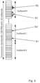
- Fig. 7shows the allocation of the first cluster/set of frequency resources R1 and the corresponding first cluster/set of frequency resources R1' in all sub-bands of the transmission bandwidth.
- N _PRBmay not fulfil the condition of being a multiple of 2, 3 and 5 as described previously.
- the corresponding signalling states of a Resource Indication Valuecould be used to indicate other information or other values of N _ PRB .
- the value of 70could be replaced by another valid value, e.g., 64, 72, or 75.
- a skilled readerwill further be able to apply the disclosed method in only a subset of the sub-bands.
- 4 sub-bandscould comprise 7 PRBs
- 6 sub-bandscould comprise 6 PRBs.
- Resourcescould be indicated for 6 PRBs per sub-band as disclosed above and below, and it could be pre-determined which 4 sub-bands are allocated 7 PRBs and the position of the additional PRB in such a sub-band.
- the wireless communication system 500comprises
- a resource allocation field in the resource indicator 110comprises of a resource indication value ( RIV ) corresponding to a starting resource block ( RB START ) index and a length in terms of contiguously allocated resource blocks ( L CRBs ), within a sub-band.
- the RIV valuecould be represented, and signalled, in binary form, e.g., '010101'.
- N _PRB10 L CRBs as shown in Table 1.
- N _PRB10 L CRBs as shown in Table 1.
- N _PRBRIV RB START , N _ PRB / 10 Table 1.
- the joint encoding in a sub-band for multi-cluster resource allocation with 10 PRBs per cluster for N RB UL100 PRB transmission bandwidth consisting of 10 sub-band each of 10 PRBs.
- Resource indication valueRIV Number of PRBs N_PRB Number of allocated frequency resources within a sub-band L CRBs (RB) Starting position within a sub-band RB START (RB) 0 10 1 0 1 10 1 1 2 10 1 2 3 10 1 3 4 10 1 4 5 10 1 5 6 10 1 6 7 10 1 7 8 10 1 8 9 10 1 9 10 20 2 0 11 20 2 1 12 20 2 2 13 20 2 3 14 20 2 4 15 20 2 5 16 20 2 6 17 20 2 7 18 20 2 8 20 30 2 0 21 30 3 1 22 30 3 2 23 30 3 3 24 30 3 4 25 30 3 5 26 30 3 6 27 30 3 7 30 40 4 0 31 40 4 1 32 40 4 2 33 40 4 3 34 40 4 35 40 4 5 36 40 4 6 40 50 5 0 41 50 5 1 42 50 5 2 43 50 5 3 44 50 5 4 45 50 5 5 50 60 6 0 51 60 6 1 52 60 6 2 53 60 6 3 54 60 6 4 49 70 7 0 48 70 7 1 47 70 7 2 46 70 7 3 39 80 8
- Reduction of the signalling overheadis beneficial as it improves the detection performance of the downlink control channel, which needs to be received correctly prior to transmitting the PUSCH.
- the PUSCH resource allocation type 0 single cluster indicationcan be reused with the change of the indication is restricted in a sub-band, which reduces the specification and implementation effort.
- a general signalling procedure between the network node 100 and the user device 300is illustrated in Fig. 8 in a LTE system.
- the network node 100transmits an uplink grant 120 comprising the present resource indicator 110 to the user device 300.
- the user device 300Upon receiving the uplink grant 120 and therefore the resource indicator 110, the user device 300 derives the frequency allocation for UL transmissions and transmits data in the PUSCH to the network node 300.
- the resource indicator 110may at least comprise any of the information elements illustrated in Fig. 6 .
- the embodiment in which the user device 300 transmits user device information 130 directly to the network node 100is illustrated with the dashed arrow in Fig. 6 .
- the network node 100Upon receiving the user device information 130 the network node 100 based on the user device information 130 determines the resource indicator 110. Also, further information may be considered by the network node 100 when determining the resource indicator 110, such as traffic information, mobility information, etc.
- Fig. 9shows the allocation of the first set of frequency resources R1 and the corresponding first set of frequency resources R1'. Further, the allocation of the second set of frequency resources R2 and the corresponding second set of frequency resources R2 is shown in Fig. 9 .
- This embodimentis advantageous since it can allow maximum transmit power from the user device 300. For example, considering the regulatory requirement on the power spectral density given per each 1 MHz, the resource allocation could provide two clusters in two different 1 MHz parts of the band. For example, suppose the sub-band has a bandwidth of 2 MHz, then a dual-cluster allocation could provide one cluster in each 1 MHz part of the sub-band.
- V11 when sub-band bandwidth is 10 PRB for the case of the transmission bandwidth is 100 PRB and divided into 10 sub-bands. It shall be noted that, in this way, the number of resources allocated for a set is implicitly indicated.
- the number of resources allocated for set 1is s 1 - s 0 RBs.
- Fig. 9One example of this embodiment is provided in Fig. 9 .
- the PUSCH resource allocation type 2dual set indication can be reused with the change of the indication is restricted in a sub-band, which reduces the specification and implementation effort.
- the resource indicator 110further comprises a second start index I2 and a second number of frequency resources N2 used for allocating a second set of contiguous frequency resources R2 within the first sub-band, and a corresponding second set of contiguous frequency resources R2' within the second sub-band.
- the first set of contiguous frequency resources R1is allocated within a first sub-region of the first sub-band and within a corresponding first sub-region of the second sub-band.
- the second set of contiguous frequency resources R2'is allocated within a second sub-region of the first sub-band and within a corresponding second sub-region of the second sub-band.
- the first sub-region and the second sub-regionare non-overlapping and comprise equal number of frequency resources.
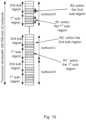
- FIG. 10This embodiment is illustrated in Fig. 10 , in which resource allocation for multi-cluster structure with dual cluster in each sub-band and single cluster in each sub-region.
- a sub-bandcomprises 10 PRBs and each sub-band is divided into 2 equally sized sub-regions, each corresponding to 5 PRBs.
- Fig. 10shows the allocation of the first set of frequency resources R1 and the corresponding first set of frequency resources R1' in the first sub-region. Further, the allocation of the second set of frequency resources R2 and the corresponding second set of frequency resources R2 in the second sub-region is shown in Fig. 9 .
- This embodimentis advantageous as there is flexibility within each sub-band that a dual-cluster PUSCH resource allocation is allowed, supporting more flexible resource allocation and UE multiplexing. It shall be noted that the PUSCH resource allocation is the same in each sub-band.
- a resource allocation field in the UL grant 110comprises of two resource indication values ( RIV ) where one value represents the starting resource index and the number of allocated resources for the cluster within the first sub-region of a sub-band, and the other value represents resource index and the number of allocated resources for the cluster within the second sub-region of a sub-band.
- RIVresource indication values
- There are in total 2 ⁇ ⁇ log 2 N RB SubRegion + 1 N RB SubRegion 2 ⁇8 bits used for two resource indication values, where the first 4 bits are for one sub-region, and the second 4 bits are for the other sub-region.
- the joint encoding of the allocation of two clusters within the sub-bandis advantageous as the total signalling overhead is 8 bits, which is less than 10 bits as needed in conventional methods, e.g., utilizing bitmaps.
- the PUSCH resource allocation type 0, single cluster indicationcan be reused with the change of two single cluster indications needed, where each indication is restricted in a sub-region (half a sub-band), which reduces the specification and implementation effort.
- One statee.g., the state with all ones, i.e., '1111', could correspond to that no PUSCH is allocated in this sub-region.
- Resource indication valueRIV Number of frequency resources within a sub-region L CRBs (RB) Starting position within a sub-band RB START (RB) 0 1 0 1 1 1 1 2 1 2 3 1 3 4 1 4 5 2 0 6 2 1 7 2 2 8 2 3 10 3 0 11 3 1 12 3 2 14 4 0 13 4 1 9 5 0 15 0 Not Applicable
- Fig. 11shows a wireless communication system 500 comprising at least one network node 100 and at least one user device 300 according to an embodiment of the present invention.
- the user device 300receives a transmission grant 120 comprising a resource indicator 110 from the network node 100. After deriving the frequency allocation(s) in the resource indicator 110, the user device 300 transmits data to the network node 100 in the allocated frequency resources.
- any methods according to embodiments of the inventionmay be implemented in a computer program, having code means, which when run by processing means causes the processing means to execute the steps of the method.
- the computer programis included in a computer readable medium of a computer program product.
- the computer readable mediummay comprises of essentially any memory, such as a ROM (Read-Only Memory), a PROM (Programmable Read-Only Memory), an EPROM (Erasable PROM), a Flash memory, an EEPROM (Electrically Erasable PROM), or a hard disk drive.
- the network node 100 and user device 300comprise the necessary communication capabilities in the form of e.g., functions, means, units, elements, etc., for performing the present solution.
- means, units, elements and functionsare: processors, memory, buffers, control logic, encoders, decoders, rate matchers, de-rate matchers, mapping units, multipliers, decision units, selecting units, switches, interleavers, de-interleavers, modulators, demodulators, inputs, outputs, antennas, amplifiers, receiver units, transmitter units, DSPs, MSDs, TCM encoder, TCM decoder, power supply units, power feeders, communication interfaces, communication protocols, etc. which are suitably arranged together for performing the present solution.
- the processors of the present network node 100 and user device 300may comprise, e.g., one or more instances of a Central Processing Unit (CPU), a processing unit, a processing circuit, a processor, an Application Specific Integrated Circuit (ASIC), a microprocessor, or other processing logic that may interpret and execute instructions.
- CPUCentral Processing Unit
- ASICApplication Specific Integrated Circuit
- the expression "processor”may thus represent a processing circuitry comprising a plurality of processing circuits, such as, e.g., any, some or all of the ones mentioned above.
- the processing circuitrymay further perform data processing functions for inputting, outputting, and processing of data comprising data buffering and device control functions, such as call processing control, user interface control, or the like.
Landscapes
- Engineering & Computer Science (AREA)
- Signal Processing (AREA)
- Computer Networks & Wireless Communication (AREA)
- Mobile Radio Communication Systems (AREA)
Description
- The invention relates to a network node and a user device for a wireless communication system. Furthermore, the invention also relates to corresponding methods and a computer-readable medium.
- In Long Term Evolution (LTE) uplink, a Single-Carrier - Frequency Division Multiple Access (SC-FDMA) waveform is used and the time-frequency resources for the Physical Uplink Shared Channel (PUSCH) can be allocated by a single or dual cluster of frequency resources, where each cluster (i.e., set of frequency resources) is localized in frequency within a slot and consists of a number of frequency-consecutive Physical Resource Blocks (PRBs). A single Discrete Fourier Transform (DFT)-precoder is applied for the one or two clusters. Hence, a single cluster achieves the lowest Cubic Metric (CM) and Peak-to-Average-Power Ratio (PAPR) performance, while a dual cluster allocation provides slightly more freedom for the scheduler, albeit at potentially larger CM/PAPR. Dynamic PUSCH resource allocation is conveyed by a resource allocation field in the associated uplink grant sent in the downlink control channel, where PUSCH
resource allocation type 0 is used for single cluster PUSCH, and PUSCHresource allocation type 1 is for dual cluster PUSCH. - LTE Rel-13 can also be deployed for downlink transmissions in unlicensed spectrum, i.e., utilizing Licensed Assisted Access (LAA) where an unlicensed carrier is operated as a Secondary Cell (SCell) in conjunction with a Primary Cell (PCell) located in licensed spectrum. It is desirable to extend the functionality of LAA by including uplink (UL) transmissions. In particular, LTE relies on E-UTRAN NodeB or evolved NodeB (eNodeBs) to perform uplink scheduling, which allows multiple User Equipments (UEs) in a cell to transmit PUSCH on orthogonal resources within a subframe. That is, LTE is not constrained to wideband scheduling for one user at a time, as is the case for many WiFi systems, and could leverage the frequency selectivity of the channels for the UEs into scheduling gains. The scheduler could also schedule UEs on the same time-frequency resource within a cell and utilize spatial suppression to separate the UEs at the receiver, i.e., Multi-User MIMO (MU-MIMO).
- For LAA, a first regulatory requirement is that the occupied channel bandwidth shall be between 80% and 100% of the declared nominal channel bandwidth. The occupied channel bandwidth is the bandwidth containing 99% of the power of the signal. This requirement does not mandate that only a single UE can occupy 80-100% of the carrier bandwidth. For example, it would be possible to multiplex PUSCH from several UEs in an UL subframe over the whole carrier bandwidth using interleaved Frequency Division Multiplexing (FDM) allocation, while fulfilling the occupied channel bandwidth requirement. In addition, a second regulatory requirement is the transmission power in a narrow band. For example, in the frequency band 5250-5350 MHz, the power spectral density for transmissions shall be limited to a maximum mean Equivalent Isotropically Radiated Power (EIRP) density of 10 mW/MHz in any 1 MHz band. This implies that, in order not to limit the transmit power, it is beneficial to allocate the resources in as many '1 MHz' bands as possible.
- In principle, using a large single cluster in PUSCH resource allocation could guarantee that the channel bandwidth occupancy requirement is met for a UE as well as the maximum mean EIRP is not exceeded. However, this would result in an inefficient system operation since it may imply either that only one UE could be scheduled at a time or that the code rate will be very low since a large amount of contiguous resources has to be allocated. In order to efficiently support UE multiplexing of PUSCH, extending the current single and dual-cluster allocation to allow multi-cluster (>2) allocation (e.g., PRBs/subcarriers spaced uniformly in frequency) has been identified as a candidate waveform that satisfies regulatory requirements. Furthermore, an efficient resource allocation scheme should allow UEs to be allocated with different amount of resources, e.g., different number of PRBs. At the same time, it is important that the resource allocation information can be signalled to the UE with few bits, in order to reduce the overhead on the downlink control channel. It is therefore an open issue to define multi-cluster allocation for PUSCH transmission for LAA and the corresponding encoding of the allocation information.
- In LTE, the starting resource index, i.e., PRB index, and the number of allocated resources, i.e., number of PRBs, are represented by a single integer value which is signalled to the UE. PUSCH
resource allocation type 0, i.e., single-cluster PUSCH, comprises encoding through the resource index, a starting PRB index and the number of allocated PRBs. PUSCHresource allocation type 1, i.e., dual-cluster PUSCH, comprises encoding through the resource index, four RBG indices, where the first two RBG indices are used for the starting RBG index and the ending RBG index of one cluster, and the last two RBG indices are used for the other cluster in the same way. These methods cannot support a multi-cluster PUSCH, as the current PUSCH resource allocation only supports up to two clusters. Furthermore, the number of allocated resource blocks,N _PRB, is constrained by

- In one conventional solution, the multi-cluster PUSCH is indicated using 10 clusters with 1 PRB per cluster and an inter-cluster spacing of 1.8 MHz (10 PRBs), i.e., every 10th PRB is allocated. Thus, there are 10 different PRB allocations, each comprising 10 PRBs. The UE may be allocated from 1 to 10 of these PRB allocations, yielding from 10 to 100 PRBs in total. The exact assignment of which resource allocation to be used is left to eNB, e.g., by signalling via a 10-bit bitmap in the UL grant. The signalling overhead is thus 10 bits to indicate the multi-cluster PUSCH.
US 2014/0341126 A1 discusses a method and apparatus for allocating quasi-contiguous uplink data resources for a user device. Transmission of data comprise at least two data clusters of sub carriers expanding over gaps reserved for uplink control channel in order, for example, to mitigate transmission power reductions due to multi-cluster transmission.US 2015/0181608 A1 discusses a method and apparatus for resource allocation. An apparatus utilizes a tree structure with more than one branch in the resource allocation of physical resource blocks, each branch including one or more legal starting positions for resource allocation. Each starting position is associated with a cluster of physical resource blocks, the number of starting positions being different on each branch. The size of the resource clusters of each branch is different. Each resource cluster is denoted with a predefined index, and one or more clusters are allocated to user equipment uplink connection.- An objective of embodiments of the invention is to provide a solution which mitigates or solves the drawbacks and problems of conventional solutions.
- The invention is set out in the appended independent claims. Further advantageous implementation forms of the invention are defined by the dependent claims.
- The appended drawings are intended to clarify and explain different embodiments of the invention, in which:
Fig. 1 shows a network node;Fig. 2 shows a corresponding method;Fig. 3 shows a user device;Fig. 4 shows a corresponding method;Fig. 5 illustrates time-frequency resources for multi-carrier waveform;Fig. 6 illustrates different resource indicators;Fig. 7 illustrates an embodiment of the invention;Fig. 8 illustrates signalling aspects;Fig. 9 illustrates a further embodiment of the invention;Fig. 10 illustrates a further embodiment of the invention; andFig. 11 illustrates a wireless communication system.Fig. 1 shows anetwork node 100 according to an embodiment of the invention. Thenetwork node 100 comprises aprocessor 102 communicably coupled to atransceiver 104. Further, anoptional antenna 106 is shown inFig. 1 . Theantenna 106 is coupled to thetransceiver 104 and is configured to transmit and/or receive wireless communication signals in awireless communication system 500.- The
processor 102 of thenetwork node 100 is configured to determine aresource indicator 110 comprising afirst start index 11 and a first number of frequency resources N1. The first start index I1 and the first number of frequency resources N1 are used for allocating a first set of contiguous frequency resources R1 within a first sub-band, and further used for allocating a corresponding first set of contiguous frequency resources R1' within a second sub-band. The first sub-band and the second sub-band are non-overlapping and comprise equal number of frequency resources. Thetransceiver 104 is configured to transmit atransmission grant 120 comprising theresource indicator 110 to a user device 300 (not shown inFig. 1 , seeFig. 3 ). It is noted that the first set of frequency resources can allocated in further sub-bands. - In this disclosure, a
network node 100 may refer to a network control node or a network access node or an access point or a base station, e.g., a Radio Base Station (RBS), which in some networks may be referred to as transmitter, "eNB", "eNodeB", "NodeB" or "B node", depending on the technology and terminology used. The network nodes may be of different classes such as, e.g., macro eNodeB, home eNodeB or pico base station, based on transmission power and thereby also cell size. The network node can be an 802.11 access point or a Station (STA), which is any device that contains an IEEE 802.11-conformant Media Access Control (MAC) and Physical Layer (PHY) interface to the Wireless Medium (WM). Thenetwork node 100 is however not limited to the above mentioned communication devices. Fig. 2 shows a corresponding method which may be executed in anetwork node 100, such as the one described inFig. 1 . Themethod 200 comprises determining 202 aresource indicator 110 comprising a first start index I1 and a first number of frequency resources N1. The first start index I1 and the first number of frequency resources N1 are used for allocating a first set of contiguous frequency resources R1 within a first sub-band, and further used for allocating a corresponding first set of contiguous frequency resources R1' within a second sub-band. The first sub-band and the second sub-band are non-overlapping and comprise equal number of frequency resources. Themethod 200 further comprises transmitting 204 atransmission grant 120 comprising theresource indicator 110 to auser device 300.- The first start index I1 indicates a position in the time-frequency plane of the resource. For example, resources could be denoted as PRBs (e.g., comprising Resource Elements (REs) located within 180 kHz and 0.5 ms) and PRBs could be indexed, e.g., in an ascending order in frequency.
- In this disclosure, the expressions "set" and "cluster" can be used interchangeably. A set or cluster of frequency resources refers to one or several frequency contiguous resources, e.g., one or several REs/PRBs, and clusters may or may not be consecutively located. The clusters are non-overlapping, i.e., they have no resources in common.
- Corresponding first set of contiguous frequency resources R1' means that an allocation using this set implies that the resource allocation is the same within the second sub-band as within the first sub-band. For example, if R1 includes the x:th PRB in the first sub-band, R1' includes the x:th PRB in the second sub-band, and so on.
- In one embodiment of the invention, the
transceiver 104 is configured to receive user device information 130 (seeFig. 11 ) associated with theuser device 300. The user device information comprises at least one of: - reference signals associated with the
user device 300; - total number of bits in a transmission buffer of the
user device 300 which is also known as standard buffer status report; and - available transmission power at the
user device 300 also known as power headroom. - The reference signals sent from the
user device 300, allows thenetwork node 100 to estimate the channel quality which is useful for determining the amount of resources and the best location of the resources to be assigned. Thenetwork node 100 may also utilize information about the amount of data which theuser device 300 can transmit. This is useful for determining the amount of resources for the resource allocation to match the actual demand. Thenetwork node 100 may further utilize information about the available transmit power in theuser device 300. This is useful for determining the amount of resources for the resource allocation such that it can be accommodated within the available transmit power. - The
processor 102 is configured to determine theresource indicator 110 based on the received user device information. The user device information may be received directly from theuser device 300. However, all or parts of the user device information may be received via one or more intermediate network nodes. - In another embodiment of the invention, the
transceiver 104 is configured to receive data from theuser device 300 in response to the transmission of thetransmission grant 120 to theuser device 300. Therefore, theuser device 300 is configured to use the allocated first set of contiguous frequency resources R1 and the corresponding first set of contiguous frequency resources R1 ' for transmitting data to thenetwork node 300. Fig. 3 shows auser device 300 according to an embodiment of the invention. Theuser device 300 comprises aprocessor 304 communicably coupled to atransceiver 302. Further, anoptional antenna 306 is shown inFig. 3 . Theantenna 306 is coupled to thetransceiver 302 and is configured to transmit and/or receive wireless communication signals in awireless communication system 500.Fig. 4 shows a corresponding method which may be executed in a user device, such as the one described inFig. 1 . Themethod 400 comprises receiving 402 atransmission grant 120 comprising aresource indicator 110 from anetwork node 100. Theresource indicator 110 comprises a first start index I1 and a first number of frequency resources N1. The first start index I1 and a first number of frequency resources N1 are used for allocating a first set of contiguous frequency resources R1 within a first sub-band, and further used for allocating a corresponding first set of contiguous frequency resources R1' within a second sub-band. The first sub-band and the second sub-band are non-overlapping and comprise equal number of frequency resources. Themethod 400 further comprises deriving 404 the first start index I1 and the first number of frequency resources N1 based on theresource indicator 110. Themethod 400 further comprises transmitting 406 data symbols to thenetwork node 100 using the first set of contiguous frequency resources R1 and the corresponding first set of contiguous frequency resources R1'.- The
user device 300, which may be any of a User Equipment (UE), mobile station (MS), wireless terminal or mobile terminal, is enabled to communicate wirelessly in a wireless communication system, sometimes also referred to as a cellular radio system. The UE may further be referred to as mobile telephones, cellular telephones, computer tablets or laptops with wireless capability. The UEs in the present context may be, for example, portable, pocket-storable, hand-held, computer-comprised, or vehicle-mounted mobile devices, enabled to communicate voice or data, via the radio access network, with another entity, such as another receiver or a server. The UE can be a Station (STA), which is any device that contains an IEEE 802.11-conformant Media Access Control (MAC) and Physical Layer (PHY) interface to the Wireless Medium (WM). - An idea of embodiments of the invention is that frequency resource allocation is based on a sub-band level, where the total transmission bandwidth of a wireless communication system is divided into several equal sub-bands in the frequency domain. In one embodiment, the frequency resource allocation is the same in all sub-bands of the transmission bandwidth. The
network node 100 indicates the frequency resource allocation for theuser device 300 within a sub-band. Theuser device 300 applies the same frequency resource allocation in each sub-band. Fig. 6 illustrates different embodiments of theresource indicator 110. Theresource indicator 110 comprises a first start index I1 and a first number of frequency resources N1. The first start index I1 and a first number of frequency resources N1 may be represented as a single value V which is more explained below in relation to Table 1.- However, the
resource indicator 110 comprises, in an embodiment, a second start index I2 and a second number of frequency resources N2 which are used for allocating a second set of contiguous frequency resources R2 within the first sub-band and a corresponding second set of contiguous frequency resources R2' within the second sub-band. According to this embodiment, the first start index I1 and the first number of frequency resources N1 may be represented with a first value V1. The second start index I2 and the second number of frequency resources N2 may be represented with a second value V2. - The number of allocated resources may be explicitly indicated or implicitly indicated. In an embodiment, the
resource indicator 110 comprises a first end resource index associated with the first start resource index. Therefore, the first number of allocated resources N1 for the first set can be derived from the difference between the first end resource index and the first start resource index. This method is also applicable for indicating the second (and further) number of frequency resources N2. - In one particular case, the first set of contiguous frequency resources R1 is allocated within a first sub-region of the first sub-band and within a corresponding first sub-region of the second sub-band, and the second set of contiguous frequency resources R2' is allocated within a second sub-region of the first sub-band and within a corresponding second sub-region of the second sub-band. The first sub-region and the second sub-region are non-overlapping and comprise equal number of frequency resources. This embodiment therefore assumes the division of each sub-bands into two or more sub-regions.
- For a deeper understanding of embodiments of the invention, different aspects of the invention are described in LTE system context. Therefore, LTE terminology and expressions are used, such as PUSCH, uplink grant, UE (corresponds to the present user device 300), etc. Embodiments of the invention are, however, not limited to such LTE systems, which is well understood by the skilled person.
- Consider a multi-carrier waveform where time-frequency resources are allocated for transmission of an uplink shared data channel. The allocation of time-frequency resources may be on subcarrier level, e.g., Resource Elements (REs), or groups of subcarriers, e.g., PRBs or Resource Block Groups (RBGs). One RBG may comprise several PRBs, and the detailed mapping between RBG and PRB is related to the transmission bandwidth as defined in 3GPP TS 36.213.
Fig. 5 illustrates a general case with OFDM symbols, indexed fromI = 0, where a channel bandwidth (B_1) is defined for uplink transmission on a carrier and a transmission bandwidth (B_2) excludes the guard bands of the carrier and defines the maximum bandwidth (or maximum number of PRBs) which can be allocated for transmission. The time-frequency resources are defined by subcarriers, indexed from 0 toK - 1. - In an exemplary embodiment, the following properties hold:
- i. The total transmission bandwidth of the wireless communication system is divided into several equal sub-bands in the frequency domain;
- ii. In each sub-band, there is one set of frequency resources allocated for PUSCH of a UE, where resource elements in each set are allocated in contiguous manner;
- iii. The resource allocation in each sub-band is the same;
- iv. The resource allocation is indicated by a single value representing the starting resource index and the number of allocated resources for the set within the sub-band.
- This embodiment is illustrated in
Fig. 7 , in which resource allocation for multi-cluster structure with 3 PRB single cluster in each sub-band, where a sub-band comprises 10 PRBs.Fig. 7 shows the allocation of the first cluster/set of frequency resources R1 and the corresponding first cluster/set of frequency resources R1' in all sub-bands of the transmission bandwidth. - This embodiment is advantageous because:
- The PUSCH resource allocation is indicated in a sub-band level instead of the entire bandwidth, which reduces the signalling overhead.
- Support of a variable number of PRB allocations which improves the scheduling flexibility.
- Support of frequency division multiplexing of UEs by assigning disjoint contiguous clusters to the UEs.
- The same resource allocation is made in every sub-band, which reduces the power dynamics of the PUSCH, e.g., the peak-to-average-power ratio (PAPR) or the cubic metric (CM).
- One example of such indication using a single value is given in Table 1 below, for multi-set PUSCH with 10 PRBs per set for

- It should be noted from Table 1 that not all the values ofN _PRB are supported, since they may not fulfil the condition of being a multiple of 2, 3 and 5 as described previously. Thus, in one embodiment of the invention, the corresponding signalling states of a Resource Indication Value (RIV) could be used to indicate other information or other values ofN _PRB. For example, the value of 70 could be replaced by another valid value, e.g., 64, 72, or 75.
- A skilled reader will further be able to apply the disclosed method in only a subset of the sub-bands. For example, for the case of 64 PRBs, 4 sub-bands could comprise 7 PRBs, while 6 sub-bands could comprise 6 PRBs. Resources could be indicated for 6 PRBs per sub-band as disclosed above and below, and it could be pre-determined which 4 sub-bands are allocated 7 PRBs and the position of the additional PRB in such a sub-band.
- Therefore, under the condition that if the total number of allocated frequency resources of all sub-bands belongs to a predetermined set of values, the
wireless communication system 500 comprises - a plurality of non-overlapping sub-bands having the same frequency resource allocation; or
- at least one third sub-band having a frequency resource allocation different to the frequency resource allocation in the first sub-band or the second sub-band.
- A resource allocation field in the
resource indicator 110 comprises of a resource indication value (RIV) corresponding to a starting resource block (RBSTART) index and a length in terms of contiguously allocated resource blocks (LCRBs), within a sub-band. The indication can be expressed as:where, in the given example,

Fig. 7 is (LCRBs = 3,RBSTART =1) within a sub-band corresponding toRIV = 21 . TheRIV value could be represented, and signalled, in binary form, e.g., '010101'. - There is one to one mapping from allocated frequency resource within a sub-band and the number of PRBs indicated, i.e.,N _PRB = 10LCRBs as shown in Table 1. One alternative example is the number of PRBs and starting position within a sub-band are indicated. This can be also expressed as:

Table 1. The joint encoding in a sub-band for multi-cluster resource allocation with 10 PRBs per cluster for 
Resource indication valueRIV Number of PRBsN_PRB Number of allocated frequency resources within a sub-bandLCRBs (RB) Starting position within a sub-bandRBSTART (RB) 0 10 1 0 1 10 1 1 2 10 1 2 3 10 1 3 4 10 1 4 5 10 1 5 6 10 1 6 7 10 1 7 8 10 1 8 9 10 1 9 10 20 2 0 11 20 2 1 12 20 2 2 13 20 2 3 14 20 2 4 15 20 2 5 16 20 2 6 17 20 2 7 18 20 2 8 20 30 2 0 21 30 3 1 22 30 3 2 23 30 3 3 24 30 3 4 25 30 3 5 26 30 3 6 27 30 3 7 30 40 4 0 31 40 4 1 32 40 4 2 33 40 4 3 34 40 4 4 35 40 4 5 36 40 4 6 40 50 5 0 41 50 5 1 42 50 5 2 43 50 5 3 44 50 5 4 45 50 5 5 50 60 6 0 51 60 6 1 52 60 6 2 53 60 6 3 54 60 6 4 49 70 7 0 48 70 7 1 47 70 7 2 46 70 7 3 39 80 8 0 38 80 8 1 37 80 8 2 29 90 9 0 28 90 9 1 19 100 10 0 - The joint encoding of starting position and the number of PRBs within the sub-band is advantageous as the total signalling overhead is

- In addition, the PUSCH
resource allocation type 0, single cluster indication can be reused with the change of the indication is restricted in a sub-band, which reduces the specification and implementation effort. - A general signalling procedure between the
network node 100 and theuser device 300 is illustrated inFig. 8 in a LTE system. Thenetwork node 100 transmits anuplink grant 120 comprising thepresent resource indicator 110 to theuser device 300. Upon receiving theuplink grant 120 and therefore theresource indicator 110, theuser device 300 derives the frequency allocation for UL transmissions and transmits data in the PUSCH to thenetwork node 300. As understood by the skilled person theresource indicator 110 may at least comprise any of the information elements illustrated inFig. 6 . - Further, the embodiment in which the
user device 300 transmitsuser device information 130 directly to thenetwork node 100 is illustrated with the dashed arrow inFig. 6 . Upon receiving theuser device information 130 thenetwork node 100 based on theuser device information 130 determines theresource indicator 110. Also, further information may be considered by thenetwork node 100 when determining theresource indicator 110, such as traffic information, mobility information, etc. - In another exemplary embodiment, the following properties hold:
- i. The total transmission bandwidth of the wireless communication system is divided into several equal sub-bands in the frequency domain;
- ii. In each sub-band, there are two different clusters allocated for PUSCH of a UE, where resource elements in each cluster are allocated in contiguous manner;
- iii. The resource allocation in each sub-band is the same;
- iv. The resource allocation is indicated by a single value representing a start index I1 and the number of allocated resources N1 for the first cluster (set 1) within a sub-band, and a start index I2 and a second number of allocated resources N2 for the second cluster (set 2) within a sub-band.
- This embodiment is illustrated in
Fig. 9 , in which resource allocation for multi-cluster structure with dual cluster in each sub-band, where a sub-band comprises 10 PRBs, set 1 comprises 3 PRBs and set 2 comprises 2 PRBs.Fig. 9 shows the allocation of the first set of frequency resources R1 and the corresponding first set of frequency resources R1'. Further, the allocation of the second set of frequency resources R2 and the corresponding second set of frequency resources R2 is shown inFig. 9 . This embodiment is advantageous since it can allow maximum transmit power from theuser device 300. For example, considering the regulatory requirement on the power spectral density given per each 1 MHz, the resource allocation could provide two clusters in two different 1 MHz parts of the band. For example, suppose the sub-band has a bandwidth of 2 MHz, then a dual-cluster allocation could provide one cluster in each 1 MHz part of the sub-band. - One example is when the
resource indicator 110, e.g., as a resource allocation field in thetransmission grant 120, comprises of one resource indication value (RIV ) where the resource indication corresponds to a starting and ending RB index ofset 1,s0 ands1 -1 , and set 2,s2 ands3 -1 respectively, whereRIV is given by equation


- Therefore V = 11 when sub-band bandwidth is 10 PRB for the case of the transmission bandwidth is 100 PRB and divided into 10 sub-bands. It shall be noted that, in this way, the number of resources allocated for a set is implicitly indicated. The number of resources allocated for
set 1 iss1 -s0 RBs. - One example of this embodiment is provided in
Fig. 9 . The resource allocation inFig. 9 is (s0 =1,s1 =4) corresponding to set 1 in a sub-band, (s2 = 5,s3 = 7) corresponding to set 2 in a sub-band. Therefore, the resource indication
- This form of encoding is advantageous as the total signalling overhead is

resource allocation type 2, dual set indication can be reused with the change of the indication is restricted in a sub-band, which reduces the specification and implementation effort. - In yet another exemplary embodiment, the following properties hold:
- i. The total transmission bandwidth of the wireless communication system is divided into several equal sub-bands in the frequency domain;
- ii. Each sub-band is further divided into two sub-regions in the frequency domain;
- iii. In each sub-region, there is at most one cluster allocated for PUSCH of a UE, where resource elements in each cluster are allocated in contiguous manner;
- iv. The resource allocation in each sub-band is the same;
- v. The resource allocation is indicated by two values, where a first value V1 represents the starting resource index and the number of allocated resources for the cluster (set) within the first sub-region of a sub-band, and a second value V2 represents resource index and the number of allocated resources for the cluster (set) within the second sub-region of a sub-band.
- Therefore, the
resource indicator 110 according to this embodiment further comprises a second start index I2 and a second number of frequency resources N2 used for allocating a second set of contiguous frequency resources R2 within the first sub-band, and a corresponding second set of contiguous frequency resources R2' within the second sub-band. Further, the first set of contiguous frequency resources R1 is allocated within a first sub-region of the first sub-band and within a corresponding first sub-region of the second sub-band. The second set of contiguous frequency resources R2' is allocated within a second sub-region of the first sub-band and within a corresponding second sub-region of the second sub-band. The first sub-region and the second sub-region are non-overlapping and comprise equal number of frequency resources. - This embodiment is illustrated in
Fig. 10 , in which resource allocation for multi-cluster structure with dual cluster in each sub-band and single cluster in each sub-region. A sub-band comprises 10 PRBs and each sub-band is divided into 2 equally sized sub-regions, each corresponding to 5 PRBs.Fig. 10 shows the allocation of the first set of frequency resources R1 and the corresponding first set of frequency resources R1' in the first sub-region. Further, the allocation of the second set of frequency resources R2 and the corresponding second set of frequency resources R2 in the second sub-region is shown inFig. 9 . - This embodiment is advantageous as there is flexibility within each sub-band that a dual-cluster PUSCH resource allocation is allowed, supporting more flexible resource allocation and UE multiplexing. It shall be noted that the PUSCH resource allocation is the same in each sub-band.
- One example of the indication is given in Table 2, for multi-cluster PUSCH with 10 PRBs per set for

- A resource allocation field in the
UL grant 110 comprises of two resource indication values (RIV ) where one value represents the starting resource index and the number of allocated resources for the cluster within the first sub-region of a sub-band, and the other value represents resource index and the number of allocated resources for the cluster within the second sub-region of a sub-band. There are in total where in the given example,

- The resource allocation in
Fig. 10 is (LCRBs = 3,RBSTART = 1) corresponding toRIV = 11 for the first sub-region, (LCRBs = 2,RBSTART = 0) corresponding toRIV = 5 for the second sub-region. Therefore, the resource indication could be represented, and signalled, in binary form '10110101'. It is further realized that the total number of allocated PRBs,N _PRB, can be determined from the values ofLCRBs and the number of sub-bands. - The joint encoding of the allocation of two clusters within the sub-band is advantageous as the total signalling overhead is 8 bits, which is less than 10 bits as needed in conventional methods, e.g., utilizing bitmaps. In addition, the PUSCH
resource allocation type 0, single cluster indication can be reused with the change of two single cluster indications needed, where each indication is restricted in a sub-region (half a sub-band), which reduces the specification and implementation effort. - One state, e.g., the state with all ones, i.e., '1111', could correspond to that no PUSCH is allocated in this sub-region. By allocating no PUSCH in the first sub-region while allocating PUSCH in the other sub-region, it provides a fall back to a single cluster PUSCH within a sub-band. It is advantageous as a fall back to single cluster PUSCH within each sub-band is supported which provides reduced CM performance.
Table 2. The joint encoding in a sub-region for multi-cluster resource allocation with 10 PRBs per cluster for 
Resource indication valueRIV Number of frequency resources within a sub-regionLCRBs (RB) Starting position within a sub-bandRBSTART (RB) 0 1 0 1 1 1 2 1 2 3 1 3 4 1 4 5 2 0 6 2 1 7 2 2 8 2 3 10 3 0 11 3 1 12 3 2 14 4 0 13 4 1 9 5 0 15 0 Not Applicable Fig. 11 shows awireless communication system 500 comprising at least onenetwork node 100 and at least oneuser device 300 according to an embodiment of the present invention. Theuser device 300 receives atransmission grant 120 comprising aresource indicator 110 from thenetwork node 100. After deriving the frequency allocation(s) in theresource indicator 110, theuser device 300 transmits data to thenetwork node 100 in the allocated frequency resources.- Furthermore, any methods according to embodiments of the invention may be implemented in a computer program, having code means, which when run by processing means causes the processing means to execute the steps of the method. The computer program is included in a computer readable medium of a computer program product. The computer readable medium may comprises of essentially any memory, such as a ROM (Read-Only Memory), a PROM (Programmable Read-Only Memory), an EPROM (Erasable PROM), a Flash memory, an EEPROM (Electrically Erasable PROM), or a hard disk drive.
- Moreover, it is realized by the skilled person that the
network node 100 anduser device 300 comprise the necessary communication capabilities in the form of e.g., functions, means, units, elements, etc., for performing the present solution. Examples of other such means, units, elements and functions are: processors, memory, buffers, control logic, encoders, decoders, rate matchers, de-rate matchers, mapping units, multipliers, decision units, selecting units, switches, interleavers, de-interleavers, modulators, demodulators, inputs, outputs, antennas, amplifiers, receiver units, transmitter units, DSPs, MSDs, TCM encoder, TCM decoder, power supply units, power feeders, communication interfaces, communication protocols, etc. which are suitably arranged together for performing the present solution. - Especially, the processors of the
present network node 100 anduser device 300 may comprise, e.g., one or more instances of a Central Processing Unit (CPU), a processing unit, a processing circuit, a processor, an Application Specific Integrated Circuit (ASIC), a microprocessor, or other processing logic that may interpret and execute instructions. The expression "processor" may thus represent a processing circuitry comprising a plurality of processing circuits, such as, e.g., any, some or all of the ones mentioned above. The processing circuitry may further perform data processing functions for inputting, outputting, and processing of data comprising data buffering and device control functions, such as call processing control, user interface control, or the like. - Finally, it should be understood that the invention is not limited to the embodiments described above, but also relates to and incorporates all embodiments within the scope of the appended independent claims.


Claims (14)
- A network node for a wireless communication system (500), the network node (100) comprising:a processor (102) configured to determine a resource indicator (110), the resource indicator (110) comprising a single resource allocation value indicative of a first start index and a first number of frequency resource blocks; anda transceiver (104) configured to transmit a transmission grant (120) comprising the resource indicator (110) to a user device (300),wherein the first start index and the first number of frequency resource blocks are configured to be used for allocating a first set of contiguous frequency resources within a first sub-band and a corresponding first set of contiguous frequency resources within a second sub-band, andwherein the first sub-band and the second sub-band are non-overlapping;characterized in thatthe allocation of the first set of contiguous frequency resources within the first sub-band is identical to the allocation of the corresponding first set of contiguous frequency resources within the second sub-band.
- The network node according to claim 1, wherein the transceiver (104) is further configured to receive user device information (130) comprising at least one element selected from a group of: a reference signal associated with the user device (300), a total number of bits in a transmission buffer of the user device (300), and an available transmission power at the user device (300), and
wherein the processor (102) is configured to determine the resource indicator (110) based on the received user device information (130). - The network node according to claim 1 or 2, wherein a total number of allocated frequency resources of all sub-bands belongs to a predetermined set of values, and
wherein the wireless communication system (500) comprises at least one of:a plurality of non-overlapping sub-bands having a same frequency resource allocation, andat least one third sub-band having a frequency resource allocation different than the frequency resource allocation in the first sub-band or the second sub-band. - The network node according to any of the preceding claims, wherein the resource indicator (110) is further indicative of a second start index and a second number of frequency resource blocks,
wherein the second start index and the second number of frequency resource blocks are configured to be used for allocating a second set of contiguous frequency resources within the first sub-band and a corresponding second set of contiguous frequency resources within the second sub-band. - The network node according to claim 4, wherein the first set of contiguous frequency resources is allocated within a first sub-region of the first sub-band and the corresponding first set of contiguous frequency resources is allocated within a corresponding first sub-region of the second sub-band,wherein the second set of contiguous frequency resources is allocated within a second sub-region of the first sub-band and the corresponding second set of contiguous frequency resources is allocated within a corresponding second sub-region of the second sub-band, andwherein the first sub-region and the second sub-region are non-overlapping and comprise an equal number of frequency resources.
- The network node according to claim 5, wherein the resource indicator (110) comprises a first allocation value and a second allocation value,wherein the first allocation value is the single resource allocation value indicative of the first start index and the first number of frequency resource blocks or an allocation value indicative of an empty set of frequency resources within the first sub-region and the corresponding first sub-region, andwherein the second allocation value is indicative of either the second start index and the second number of frequency resource block or an empty set of frequency resources within the second sub-region and the corresponding second sub-region.
- A user device for a wireless communication system (500), the user device (300) comprising:a transceiver (302) configured to:receive, from a network node (100), a transmission grant (120) comprising a resource indicator (110), the resource indicator (110) comprising a single allocation value indicative of a first start index and a first number of frequency resource blocks, andtransmit data symbols to the network node (100) using a first set of contiguous frequency resources within a first sub-band and a corresponding first set of contiguous frequency resources within a second sub-band; anda processor (304) configured to derive, based on the resource indicator (110), the first start index and the first number of frequency resource blocks,wherein the first start index and the first number of frequency resource blocks are configured to be used for allocating the first set of contiguous frequency resources within the first sub-band and the corresponding first set of contiguous frequency resources within the second sub-band, andwherein the first sub-band and the second sub-band are non-overlapping;characterized in thatthe allocation of the first set of contiguous frequency resources within the first sub-band is identical to the allocation of the corresponding first set of contiguous frequency resources within the second sub-band.
- The user device according to claim 7, wherein the resource indicator (110) is further indicative of a second start index and a second number of frequency resource blocks,wherein the second start index and the second number of frequency resource blocks are configured to be used for allocating a second set of contiguous frequency resources within the first sub-band and a corresponding second set of contiguous frequency resources within the second sub-band,wherein the processor (304) is further configured to derive the second start index and the second number of frequency resource blocks based on the resource indicator (110), andwherein the transceiver (302) is further configured to transmit data symbols to the network node (100) using the second set of contiguous frequency resources within the first sub-band and the corresponding second set of contiguous frequency resources within the second sub-band.
- The user device according to claim 8, wherein the first set of contiguous frequency resources is allocated within a first sub-region of the first sub-band and the corresponding first set of contiguous frequency resources is allocated within a corresponding first sub-region of the second sub-band,wherein the second set of contiguous frequency resources is allocated within a second sub-region of the first sub-band and the corresponding second set of contiguous frequency resources is allocated within a corresponding second sub-region of the second sub-band, andwherein the first sub-region and the second sub-region are non-overlapping and comprise an equal number of frequency resources.
- The user device according to claim 9, wherein the resource indicator (110) comprises a first allocation value and a second allocation value,wherein the first allocation value is the single resource allocation value indicative of the first start index and the first number of frequency resource blocks or an allocation value indicative of an empty set of frequency resources within the first sub-region and the corresponding first sub-region,wherein the second allocation value is indicative of either the second start index and the second number of frequency resource blocks or an empty set of frequency resources within the second sub-region and the corresponding second sub-region, andwherein the processor (304) is further configured to:derive the first start index and the first number of frequency resource blocks based on the first allocation value, andderive the second start index and the second number of frequency resource blocks based on the second allocation value, andwherein the transceiver (302) is further configured to:transmit data symbols to the network node (100) using the first set of contiguous frequency resources and the corresponding first set of contiguous frequency resources, andtransmit data symbols to the network node (100) using the second set of contiguous frequency resources and the corresponding second set of contiguous frequency resources.
- The user device according to claim 9 or 10, wherein the processor (304) is configured to derive, based on the single allocation value, at least one of:the first start index and the first number of frequency resource blocks; andthe second start index and the second number of frequency resource blocks.
- A method, comprising:determining (202) a resource indicator (110) comprising a single allocation value indicative of a first start index and a first number of frequency resource blocks; andtransmitting (204) a transmission grant (120) comprising the resource indicator (110) to a user device (300),wherein the first start index and the first number of frequency resource blocks are used for allocating a first set of contiguous frequency resources within a first sub-band and a corresponding first set of contiguous frequency resources within a second sub-band, andwherein the first sub-band and the second sub-band are non-overlapping;characterized in thatthe allocation of the first set of contiguous frequency resources within the first sub-band is identical to the allocation of the corresponding first set of contiguous frequency resources within the second sub-band.
- A method, comprising:receiving (402), from a network node (100), a transmission grant (120) comprising a resource indicator (110), the resource indicator (110) comprising a single allocation value indicative of a first start index and a first number of frequency resource blocks;deriving (404) the first start index and the first number of frequency resource blocks based on the resource indicator (110); andtransmitting (406) data symbols to the network node (100) using a first set of contiguous frequency resources within a first sub-band and a corresponding first set of contiguous frequency resources within a second sub-band,wherein the first start index and the first number of frequency resource blocks are used for allocating the first set of contiguous frequency resources within the first sub-band and the corresponding first set of contiguous frequency resources within the second sub-band, andwherein the first sub-band and the second sub-band are non-overlapping;characterized in thatthe allocation of the first set of contiguous frequency resources within the first sub-band is identical to the allocation of the corresponding first set of contiguous frequency resources within the second sub-band.
- A computer-readable medium storing computer-executable code that, when executed by a processor, causes the processor to perform the method according to claim 12 or 13.
Priority Applications (1)
| Application Number | Priority Date | Filing Date | Title |
|---|---|---|---|
| EP20209662.4AEP3866541B1 (en) | 2016-03-18 | 2016-03-18 | Network node, user device and methods thereof |
Applications Claiming Priority (3)
| Application Number | Priority Date | Filing Date | Title |
|---|---|---|---|
| PCT/EP2016/055998WO2017157466A1 (en) | 2016-03-18 | 2016-03-18 | Network node, user device and methods thereof |
| EP20209662.4AEP3866541B1 (en) | 2016-03-18 | 2016-03-18 | Network node, user device and methods thereof |
| EP16710466.0AEP3403453B1 (en) | 2016-03-18 | 2016-03-18 | Network node, user device and methods thereof |
Related Parent Applications (1)
| Application Number | Title | Priority Date | Filing Date |
|---|---|---|---|
| EP16710466.0ADivisionEP3403453B1 (en) | 2016-03-18 | 2016-03-18 | Network node, user device and methods thereof |
Publications (2)
| Publication Number | Publication Date |
|---|---|
| EP3866541A1 EP3866541A1 (en) | 2021-08-18 |
| EP3866541B1true EP3866541B1 (en) | 2023-12-27 |
Family
ID=55542681
Family Applications (2)
| Application Number | Title | Priority Date | Filing Date |
|---|---|---|---|
| EP20209662.4AActiveEP3866541B1 (en) | 2016-03-18 | 2016-03-18 | Network node, user device and methods thereof |
| EP16710466.0AActiveEP3403453B1 (en) | 2016-03-18 | 2016-03-18 | Network node, user device and methods thereof |
Family Applications After (1)
| Application Number | Title | Priority Date | Filing Date |
|---|---|---|---|
| EP16710466.0AActiveEP3403453B1 (en) | 2016-03-18 | 2016-03-18 | Network node, user device and methods thereof |
Country Status (6)
| Country | Link |
|---|---|
| US (2) | US10736135B2 (en) |
| EP (2) | EP3866541B1 (en) |
| JP (1) | JP6699917B2 (en) |
| KR (1) | KR102139309B1 (en) |
| CN (2) | CN108702744B (en) |
| WO (1) | WO2017157466A1 (en) |
Families Citing this family (13)
| Publication number | Priority date | Publication date | Assignee | Title |
|---|---|---|---|---|
| US10595315B2 (en)* | 2016-07-19 | 2020-03-17 | Qualcomm Incorporated | Enabling multi-cluster transmissions |
| US11622381B2 (en)* | 2017-05-03 | 2023-04-04 | Qualcomm Incorporated | Control information update for dynamic time-division duplexing (TDD) |
| US20180367193A1 (en)* | 2017-06-16 | 2018-12-20 | Nokia Technologies Oy | Determination of sub-band allocation parameters for wireless networks |
| JP7430630B2 (en)* | 2017-08-10 | 2024-02-13 | 富士通株式会社 | Frequency domain resource allocation and reception method, device and communication system |
| KR102357325B1 (en)* | 2017-09-28 | 2022-02-08 | 노키아 테크놀로지스 오와이 | Indication of contiguous resource allocation |
| CN114710233B (en)* | 2017-11-17 | 2024-08-20 | 华为技术有限公司 | Method for determining downlink control information and communication device |
| CN115243375A (en)* | 2018-04-04 | 2022-10-25 | 华为技术有限公司 | Communication method and device |
| EP3833125B1 (en)* | 2018-08-03 | 2024-07-10 | Fujitsu Limited | Resource scheduling indication method and apparatus, and communication system |
| EP3697154A1 (en)* | 2019-02-14 | 2020-08-19 | Panasonic Intellectual Property Corporation of America | Transceiver device and scheduling device |
| US12192781B2 (en) | 2019-04-23 | 2025-01-07 | Ntt Docomo, Inc. | User terminal and radio communication method |
| CN113940018A (en)* | 2019-10-07 | 2022-01-14 | 奥罗佩法国有限责任公司 | A method of allocating frequency resources in a broadband system |
| CN113056003B (en)* | 2019-12-26 | 2024-03-22 | 大唐移动通信设备有限公司 | Communication method and device |
| US12413459B2 (en) | 2020-04-22 | 2025-09-09 | Telefonaktiebolaget Lm Ericsson (Publ) | Methods, network node, wireless device, media for 16-QAM based communication |
Family Cites Families (27)
| Publication number | Priority date | Publication date | Assignee | Title |
|---|---|---|---|---|
| JP4531722B2 (en)* | 2006-05-01 | 2010-08-25 | 株式会社エヌ・ティ・ティ・ドコモ | User device, transmission method, and mobile communication system |
| US8369424B2 (en)* | 2006-07-14 | 2013-02-05 | Qualcomm Incorporated | Frequency selective and frequency diversity transmissions in a wireless communication system |
| JP5389020B2 (en)* | 2007-06-21 | 2014-01-15 | テレフオンアクチーボラゲット エル エム エリクソン(パブル) | Method and user equipment in telecommunications system |
| US8792426B2 (en)* | 2008-03-24 | 2014-07-29 | Qualcomm Incorporated | Method and apparatus for resource management in a wireless communication system |
| KR101565417B1 (en)* | 2008-08-08 | 2015-11-03 | 엘지전자 주식회사 | Method and apparatus for resource allocation in a multi-frequency band system |
| KR101318920B1 (en)* | 2009-05-08 | 2013-10-17 | 노키아 지멘스 네트웍스 오와이 | Method, apparatus and computer readable medium embodying a program for resource allocation |
| KR20110003813A (en)* | 2009-07-06 | 2011-01-13 | 삼성전자주식회사 | Resource allocation method and device in broadband wireless communication system |
| US8239231B2 (en)* | 2009-07-27 | 2012-08-07 | Jie Lian | Method for optimizing resource allocation |
| EP2285036A1 (en)* | 2009-08-12 | 2011-02-16 | Alcatel Lucent | Method of reporting scheduling information |
| KR101650749B1 (en)* | 2009-08-18 | 2016-08-24 | 삼성전자주식회사 | Method and apparatus for allocation and indication of control channel in backhaul subframe for relay |
| CN101932114B (en)* | 2009-12-14 | 2014-10-22 | 中兴通讯股份有限公司 | Sending method of uplink scheduling authorization control signaling and base station |
| CN102111878B (en) | 2009-12-28 | 2014-12-10 | 中兴通讯股份有限公司 | Resource index coding method and base station in wireless communication system |
| PH12012501374A1 (en)* | 2010-01-15 | 2019-11-29 | Ericsson Telefon Ab L M | Methods and apparatus for contention-based granting in a wireless communication network |
| KR101615985B1 (en)* | 2010-05-24 | 2016-05-12 | 엘지전자 주식회사 | Method and apparatus for allocation of discontinuous uplink resource |
| US8737344B2 (en)* | 2010-09-14 | 2014-05-27 | Lg Electronics Inc. | Method and device for uplink resource allocation |
| EP2503835A1 (en) | 2011-03-23 | 2012-09-26 | Panasonic Corporation | Resouce assignment for single and multiple cluster transmission |
| US9185705B2 (en)* | 2012-06-19 | 2015-11-10 | Samsung Electronics Co., Ltd. | Apparatus and methods for flexible RF configuration in multi-antenna wireless systems |
| EP3379879B1 (en)* | 2012-09-28 | 2022-01-05 | Telefonaktiebolaget LM Ericsson (publ) | Method and user equipment for communicating an epdcch |
| US9426785B2 (en)* | 2013-05-20 | 2016-08-23 | Nokia Technologies Oy | Contiguous intra-band carrier aggregation (CA), PUCCH, and quasi-contiguous uplink resource allocation |
| CN103702430A (en)* | 2013-12-28 | 2014-04-02 | 杨学志 | Method for multi-stage soft time-frequency multiplexing and resource allocation, equipment and a system |
| US10327263B2 (en)* | 2014-02-16 | 2019-06-18 | Lg Electronics Inc. | Method and apparatus for transmitting scheduling request using contention-based resources in wireless communication system |
| US10313960B2 (en)* | 2014-09-18 | 2019-06-04 | Lg Electronics Inc. | Method and apparatus for using smaller bandwidth for low cost user equipment in wireless communication system |
| US9844072B2 (en)* | 2014-09-26 | 2017-12-12 | Qualcomm Incorporated | Ultra-low latency LTE uplink frame structure |
| SG11201708244QA (en)* | 2015-04-08 | 2017-11-29 | Interdigital Patent Holdings Inc | Method and device of multi-subband based transmission for a wireless transmit/receive unit (wtru) with reduced capability and coverage enhancement |
| WO2016161630A1 (en)* | 2015-04-10 | 2016-10-13 | Mediatek Singapore Pte. Ltd. | Resource allocation design for low cost machine-type communication ue |
| WO2016165126A1 (en)* | 2015-04-17 | 2016-10-20 | Panasonic Intellectual Property Corporation Of America | Rate matching for a machine type communication channel in time division duplex |
| EP3131225B1 (en)* | 2015-08-14 | 2019-03-13 | Sun Patent Trust | Modulation order adaptation for partial subframes |
- 2016
- 2016-03-18CNCN201680082346.8Apatent/CN108702744B/enactiveActive
- 2016-03-18EPEP20209662.4Apatent/EP3866541B1/enactiveActive
- 2016-03-18CNCN202110223299.7Apatent/CN113347716B/enactiveActive
- 2016-03-18JPJP2018538823Apatent/JP6699917B2/enactiveActive
- 2016-03-18EPEP16710466.0Apatent/EP3403453B1/enactiveActive
- 2016-03-18KRKR1020187024179Apatent/KR102139309B1/enactiveActive
- 2016-03-18WOPCT/EP2016/055998patent/WO2017157466A1/ennot_activeCeased
- 2018
- 2018-08-13USUS16/102,059patent/US10736135B2/enactiveActive
- 2020
- 2020-07-13USUS16/927,511patent/US11464041B2/enactiveActive
Also Published As
| Publication number | Publication date |
|---|---|
| JP2019512180A (en) | 2019-05-09 |
| CN108702744B (en) | 2021-03-23 |
| US20180352571A1 (en) | 2018-12-06 |
| EP3403453A1 (en) | 2018-11-21 |
| KR20180104092A (en) | 2018-09-19 |
| CN113347716A (en) | 2021-09-03 |
| BR112018016224A2 (en) | 2018-12-18 |
| US10736135B2 (en) | 2020-08-04 |
| EP3866541A1 (en) | 2021-08-18 |
| CN113347716B (en) | 2024-03-29 |
| US20200413437A1 (en) | 2020-12-31 |
| EP3403453B1 (en) | 2020-12-23 |
| WO2017157466A1 (en) | 2017-09-21 |
| KR102139309B1 (en) | 2020-07-29 |
| CN108702744A (en) | 2018-10-23 |
| JP6699917B2 (en) | 2020-05-27 |
| US11464041B2 (en) | 2022-10-04 |
Similar Documents
| Publication | Publication Date | Title |
|---|---|---|
| US11464041B2 (en) | Network node, user device and methods thereof | |
| US11985576B2 (en) | Multiplexing of physical sidelink control channel (PSCCH) and physical sidelink shared channel (PSSCH) | |
| CN109391448B (en) | An information transmission method and device | |
| CA2750580C (en) | Control signaling for transmissions over contiguous and non-contiguous frequency bands | |
| US11310812B2 (en) | Data sending method, data receiving method, user equipment, and base station | |
| CN113170479B (en) | Downlink control of unlicensed subbands | |
| CN107113810A (en) | Method, device and equipment for resource scheduling | |
| WO2021189394A1 (en) | Method and apparatus for resource allocation for sidelink communication | |
| US9445427B2 (en) | Downlink resource allocation in OFDM networks | |
| EP4580284A2 (en) | Transmitting device, receiving device, transmitting method and receiving method | |
| KR20190051065A (en) | Method and transmitter for resource allocation in a carrier | |
| US11588670B2 (en) | Method and device for indicating numerology | |
| CN108476114B (en) | Method of interleaving mode selection for low CM/PAPR transmission | |
| EP3836684B1 (en) | Resource allocation method, and related device and apparatus | |
| RU2801312C9 (en) | Transmitting device, receiver, transmission method and reception method | |
| RU2801312C2 (en) | Transmitting device, receiver, transmission method and reception method | |
| BR112018016224B1 (en) | NETWORK NODE, USER DEVICE, COMPUTER READABLE MEDIA AND METHODS THEREOF |
Legal Events
| Date | Code | Title | Description |
|---|---|---|---|
| PUAI | Public reference made under article 153(3) epc to a published international application that has entered the european phase | Free format text:ORIGINAL CODE: 0009012 | |
| STAA | Information on the status of an ep patent application or granted ep patent | Free format text:STATUS: THE APPLICATION HAS BEEN PUBLISHED | |
| AC | Divisional application: reference to earlier application | Ref document number:3403453 Country of ref document:EP Kind code of ref document:P | |
| AK | Designated contracting states | Kind code of ref document:A1 Designated state(s):AL AT BE BG CH CY CZ DE DK EE ES FI FR GB GR HR HU IE IS IT LI LT LU LV MC MK MT NL NO PL PT RO RS SE SI SK SM TR | |
| STAA | Information on the status of an ep patent application or granted ep patent | Free format text:STATUS: REQUEST FOR EXAMINATION WAS MADE | |
| 17P | Request for examination filed | Effective date:20220216 | |
| RBV | Designated contracting states (corrected) | Designated state(s):AL AT BE BG CH CY CZ DE DK EE ES FI FR GB GR HR HU IE IS IT LI LT LU LV MC MK MT NL NO PL PT RO RS SE SI SK SM TR | |
| REG | Reference to a national code | Ref legal event code:R079 Free format text:PREVIOUS MAIN CLASS: H04W0072040000 Ipc:H04W0072045300 Ref country code:DE Ref legal event code:R079 Ref document number:602016085087 Country of ref document:DE Free format text:PREVIOUS MAIN CLASS: H04W0072040000 Ipc:H04W0072045300 | |
| GRAP | Despatch of communication of intention to grant a patent | Free format text:ORIGINAL CODE: EPIDOSNIGR1 | |
| STAA | Information on the status of an ep patent application or granted ep patent | Free format text:STATUS: GRANT OF PATENT IS INTENDED | |
| RIC1 | Information provided on ipc code assigned before grant | Ipc:H04W 72/51 20230101ALN20230629BHEP Ipc:H04W 72/23 20230101ALI20230629BHEP Ipc:H04W 72/0453 20230101AFI20230629BHEP | |
| INTG | Intention to grant announced | Effective date:20230714 | |
| GRAS | Grant fee paid | Free format text:ORIGINAL CODE: EPIDOSNIGR3 | |
| GRAA | (expected) grant | Free format text:ORIGINAL CODE: 0009210 | |
| STAA | Information on the status of an ep patent application or granted ep patent | Free format text:STATUS: THE PATENT HAS BEEN GRANTED | |
| AC | Divisional application: reference to earlier application | Ref document number:3403453 Country of ref document:EP Kind code of ref document:P | |
| AK | Designated contracting states | Kind code of ref document:B1 Designated state(s):AL AT BE BG CH CY CZ DE DK EE ES FI FR GB GR HR HU IE IS IT LI LT LU LV MC MK MT NL NO PL PT RO RS SE SI SK SM TR | |
| P01 | Opt-out of the competence of the unified patent court (upc) registered | Effective date:20231121 | |
| REG | Reference to a national code | Ref country code:GB Ref legal event code:FG4D | |
| REG | Reference to a national code | Ref country code:CH Ref legal event code:EP | |
| REG | Reference to a national code | Ref country code:DE Ref legal event code:R096 Ref document number:602016085087 Country of ref document:DE | |
| REG | Reference to a national code | Ref country code:IE Ref legal event code:FG4D | |
| PG25 | Lapsed in a contracting state [announced via postgrant information from national office to epo] | Ref country code:GR Free format text:LAPSE BECAUSE OF FAILURE TO SUBMIT A TRANSLATION OF THE DESCRIPTION OR TO PAY THE FEE WITHIN THE PRESCRIBED TIME-LIMIT Effective date:20240328 | |
| REG | Reference to a national code | Ref country code:LT Ref legal event code:MG9D | |
| PG25 | Lapsed in a contracting state [announced via postgrant information from national office to epo] | Ref country code:LT Free format text:LAPSE BECAUSE OF FAILURE TO SUBMIT A TRANSLATION OF THE DESCRIPTION OR TO PAY THE FEE WITHIN THE PRESCRIBED TIME-LIMIT Effective date:20231227 | |
| PG25 | Lapsed in a contracting state [announced via postgrant information from national office to epo] | Ref country code:ES Free format text:LAPSE BECAUSE OF FAILURE TO SUBMIT A TRANSLATION OF THE DESCRIPTION OR TO PAY THE FEE WITHIN THE PRESCRIBED TIME-LIMIT Effective date:20231227 | |
| PG25 | Lapsed in a contracting state [announced via postgrant information from national office to epo] | Ref country code:LT Free format text:LAPSE BECAUSE OF FAILURE TO SUBMIT A TRANSLATION OF THE DESCRIPTION OR TO PAY THE FEE WITHIN THE PRESCRIBED TIME-LIMIT Effective date:20231227 Ref country code:GR Free format text:LAPSE BECAUSE OF FAILURE TO SUBMIT A TRANSLATION OF THE DESCRIPTION OR TO PAY THE FEE WITHIN THE PRESCRIBED TIME-LIMIT Effective date:20240328 Ref country code:FI Free format text:LAPSE BECAUSE OF FAILURE TO SUBMIT A TRANSLATION OF THE DESCRIPTION OR TO PAY THE FEE WITHIN THE PRESCRIBED TIME-LIMIT Effective date:20231227 Ref country code:ES Free format text:LAPSE BECAUSE OF FAILURE TO SUBMIT A TRANSLATION OF THE DESCRIPTION OR TO PAY THE FEE WITHIN THE PRESCRIBED TIME-LIMIT Effective date:20231227 Ref country code:BG Free format text:LAPSE BECAUSE OF FAILURE TO SUBMIT A TRANSLATION OF THE DESCRIPTION OR TO PAY THE FEE WITHIN THE PRESCRIBED TIME-LIMIT Effective date:20240327 | |
| REG | Reference to a national code | Ref country code:NL Ref legal event code:MP Effective date:20231227 | |
| REG | Reference to a national code | Ref country code:AT Ref legal event code:MK05 Ref document number:1645731 Country of ref document:AT Kind code of ref document:T Effective date:20231227 | |
| PG25 | Lapsed in a contracting state [announced via postgrant information from national office to epo] | Ref country code:NL Free format text:LAPSE BECAUSE OF FAILURE TO SUBMIT A TRANSLATION OF THE DESCRIPTION OR TO PAY THE FEE WITHIN THE PRESCRIBED TIME-LIMIT Effective date:20231227 | |
| PG25 | Lapsed in a contracting state [announced via postgrant information from national office to epo] | Ref country code:SE Free format text:LAPSE BECAUSE OF FAILURE TO SUBMIT A TRANSLATION OF THE DESCRIPTION OR TO PAY THE FEE WITHIN THE PRESCRIBED TIME-LIMIT Effective date:20231227 Ref country code:RS Free format text:LAPSE BECAUSE OF FAILURE TO SUBMIT A TRANSLATION OF THE DESCRIPTION OR TO PAY THE FEE WITHIN THE PRESCRIBED TIME-LIMIT Effective date:20231227 Ref country code:NO Free format text:LAPSE BECAUSE OF FAILURE TO SUBMIT A TRANSLATION OF THE DESCRIPTION OR TO PAY THE FEE WITHIN THE PRESCRIBED TIME-LIMIT Effective date:20240327 Ref country code:NL Free format text:LAPSE BECAUSE OF FAILURE TO SUBMIT A TRANSLATION OF THE DESCRIPTION OR TO PAY THE FEE WITHIN THE PRESCRIBED TIME-LIMIT Effective date:20231227 Ref country code:LV Free format text:LAPSE BECAUSE OF FAILURE TO SUBMIT A TRANSLATION OF THE DESCRIPTION OR TO PAY THE FEE WITHIN THE PRESCRIBED TIME-LIMIT Effective date:20231227 Ref country code:HR Free format text:LAPSE BECAUSE OF FAILURE TO SUBMIT A TRANSLATION OF THE DESCRIPTION OR TO PAY THE FEE WITHIN THE PRESCRIBED TIME-LIMIT Effective date:20231227 | |
| PG25 | Lapsed in a contracting state [announced via postgrant information from national office to epo] | Ref country code:IS Free format text:LAPSE BECAUSE OF FAILURE TO SUBMIT A TRANSLATION OF THE DESCRIPTION OR TO PAY THE FEE WITHIN THE PRESCRIBED TIME-LIMIT Effective date:20240427 | |
| PG25 | Lapsed in a contracting state [announced via postgrant information from national office to epo] | Ref country code:CZ Free format text:LAPSE BECAUSE OF FAILURE TO SUBMIT A TRANSLATION OF THE DESCRIPTION OR TO PAY THE FEE WITHIN THE PRESCRIBED TIME-LIMIT Effective date:20231227 Ref country code:AT Free format text:LAPSE BECAUSE OF FAILURE TO SUBMIT A TRANSLATION OF THE DESCRIPTION OR TO PAY THE FEE WITHIN THE PRESCRIBED TIME-LIMIT Effective date:20231227 | |
| PG25 | Lapsed in a contracting state [announced via postgrant information from national office to epo] | Ref country code:SK Free format text:LAPSE BECAUSE OF FAILURE TO SUBMIT A TRANSLATION OF THE DESCRIPTION OR TO PAY THE FEE WITHIN THE PRESCRIBED TIME-LIMIT Effective date:20231227 | |
| PG25 | Lapsed in a contracting state [announced via postgrant information from national office to epo] | Ref country code:SM Free format text:LAPSE BECAUSE OF FAILURE TO SUBMIT A TRANSLATION OF THE DESCRIPTION OR TO PAY THE FEE WITHIN THE PRESCRIBED TIME-LIMIT Effective date:20231227 Ref country code:SK Free format text:LAPSE BECAUSE OF FAILURE TO SUBMIT A TRANSLATION OF THE DESCRIPTION OR TO PAY THE FEE WITHIN THE PRESCRIBED TIME-LIMIT Effective date:20231227 Ref country code:RO Free format text:LAPSE BECAUSE OF FAILURE TO SUBMIT A TRANSLATION OF THE DESCRIPTION OR TO PAY THE FEE WITHIN THE PRESCRIBED TIME-LIMIT Effective date:20231227 Ref country code:IS Free format text:LAPSE BECAUSE OF FAILURE TO SUBMIT A TRANSLATION OF THE DESCRIPTION OR TO PAY THE FEE WITHIN THE PRESCRIBED TIME-LIMIT Effective date:20240427 Ref country code:EE Free format text:LAPSE BECAUSE OF FAILURE TO SUBMIT A TRANSLATION OF THE DESCRIPTION OR TO PAY THE FEE WITHIN THE PRESCRIBED TIME-LIMIT Effective date:20231227 Ref country code:CZ Free format text:LAPSE BECAUSE OF FAILURE TO SUBMIT A TRANSLATION OF THE DESCRIPTION OR TO PAY THE FEE WITHIN THE PRESCRIBED TIME-LIMIT Effective date:20231227 Ref country code:AT Free format text:LAPSE BECAUSE OF FAILURE TO SUBMIT A TRANSLATION OF THE DESCRIPTION OR TO PAY THE FEE WITHIN THE PRESCRIBED TIME-LIMIT Effective date:20231227 | |
| PG25 | Lapsed in a contracting state [announced via postgrant information from national office to epo] | Ref country code:PL Free format text:LAPSE BECAUSE OF FAILURE TO SUBMIT A TRANSLATION OF THE DESCRIPTION OR TO PAY THE FEE WITHIN THE PRESCRIBED TIME-LIMIT Effective date:20231227 Ref country code:PT Free format text:LAPSE BECAUSE OF FAILURE TO SUBMIT A TRANSLATION OF THE DESCRIPTION OR TO PAY THE FEE WITHIN THE PRESCRIBED TIME-LIMIT Effective date:20240429 | |
| PG25 | Lapsed in a contracting state [announced via postgrant information from national office to epo] | Ref country code:PT Free format text:LAPSE BECAUSE OF FAILURE TO SUBMIT A TRANSLATION OF THE DESCRIPTION OR TO PAY THE FEE WITHIN THE PRESCRIBED TIME-LIMIT Effective date:20240429 Ref country code:PL Free format text:LAPSE BECAUSE OF FAILURE TO SUBMIT A TRANSLATION OF THE DESCRIPTION OR TO PAY THE FEE WITHIN THE PRESCRIBED TIME-LIMIT Effective date:20231227 | |
| REG | Reference to a national code | Ref country code:DE Ref legal event code:R097 Ref document number:602016085087 Country of ref document:DE | |
| PG25 | Lapsed in a contracting state [announced via postgrant information from national office to epo] | Ref country code:DK Free format text:LAPSE BECAUSE OF FAILURE TO SUBMIT A TRANSLATION OF THE DESCRIPTION OR TO PAY THE FEE WITHIN THE PRESCRIBED TIME-LIMIT Effective date:20231227 | |
| PG25 | Lapsed in a contracting state [announced via postgrant information from national office to epo] | Ref country code:DK Free format text:LAPSE BECAUSE OF FAILURE TO SUBMIT A TRANSLATION OF THE DESCRIPTION OR TO PAY THE FEE WITHIN THE PRESCRIBED TIME-LIMIT Effective date:20231227 | |
| REG | Reference to a national code | Ref country code:CH Ref legal event code:PL | |
| PLBE | No opposition filed within time limit | Free format text:ORIGINAL CODE: 0009261 | |
| STAA | Information on the status of an ep patent application or granted ep patent | Free format text:STATUS: NO OPPOSITION FILED WITHIN TIME LIMIT | |
| PG25 | Lapsed in a contracting state [announced via postgrant information from national office to epo] | Ref country code:LU Free format text:LAPSE BECAUSE OF NON-PAYMENT OF DUE FEES Effective date:20240318 | |
| PG25 | Lapsed in a contracting state [announced via postgrant information from national office to epo] | Ref country code:MC Free format text:LAPSE BECAUSE OF FAILURE TO SUBMIT A TRANSLATION OF THE DESCRIPTION OR TO PAY THE FEE WITHIN THE PRESCRIBED TIME-LIMIT Effective date:20231227 | |
| PG25 | Lapsed in a contracting state [announced via postgrant information from national office to epo] | Ref country code:MC Free format text:LAPSE BECAUSE OF FAILURE TO SUBMIT A TRANSLATION OF THE DESCRIPTION OR TO PAY THE FEE WITHIN THE PRESCRIBED TIME-LIMIT Effective date:20231227 Ref country code:LU Free format text:LAPSE BECAUSE OF NON-PAYMENT OF DUE FEES Effective date:20240318 | |
| 26N | No opposition filed | Effective date:20240930 | |
| REG | Reference to a national code | Ref country code:BE Ref legal event code:MM Effective date:20240331 | |
| PG25 | Lapsed in a contracting state [announced via postgrant information from national office to epo] | Ref country code:BE Free format text:LAPSE BECAUSE OF NON-PAYMENT OF DUE FEES Effective date:20240331 | |
| PG25 | Lapsed in a contracting state [announced via postgrant information from national office to epo] | Ref country code:IE Free format text:LAPSE BECAUSE OF NON-PAYMENT OF DUE FEES Effective date:20240318 | |
| PG25 | Lapsed in a contracting state [announced via postgrant information from national office to epo] | Ref country code:IE Free format text:LAPSE BECAUSE OF NON-PAYMENT OF DUE FEES Effective date:20240318 Ref country code:BE Free format text:LAPSE BECAUSE OF NON-PAYMENT OF DUE FEES Effective date:20240331 Ref country code:CH Free format text:LAPSE BECAUSE OF NON-PAYMENT OF DUE FEES Effective date:20240331 | |
| PGFP | Annual fee paid to national office [announced via postgrant information from national office to epo] | Ref country code:DE Payment date:20250204 Year of fee payment:10 | |
| PG25 | Lapsed in a contracting state [announced via postgrant information from national office to epo] | Ref country code:SI Free format text:LAPSE BECAUSE OF FAILURE TO SUBMIT A TRANSLATION OF THE DESCRIPTION OR TO PAY THE FEE WITHIN THE PRESCRIBED TIME-LIMIT Effective date:20231227 | |
| PGFP | Annual fee paid to national office [announced via postgrant information from national office to epo] | Ref country code:FR Payment date:20250210 Year of fee payment:10 | |
| PGFP | Annual fee paid to national office [announced via postgrant information from national office to epo] | Ref country code:IT Payment date:20250211 Year of fee payment:10 Ref country code:GB Payment date:20250130 Year of fee payment:10 | |
| PG25 | Lapsed in a contracting state [announced via postgrant information from national office to epo] | Ref country code:CY Free format text:LAPSE BECAUSE OF FAILURE TO SUBMIT A TRANSLATION OF THE DESCRIPTION OR TO PAY THE FEE WITHIN THE PRESCRIBED TIME-LIMIT; INVALID AB INITIO Effective date:20160318 | |
| PG25 | Lapsed in a contracting state [announced via postgrant information from national office to epo] | Ref country code:HU Free format text:LAPSE BECAUSE OF FAILURE TO SUBMIT A TRANSLATION OF THE DESCRIPTION OR TO PAY THE FEE WITHIN THE PRESCRIBED TIME-LIMIT; INVALID AB INITIO Effective date:20160318 |