EP3864475B1 - Method and system for monitoring tool wear to estimate rul of tool in machining - Google Patents
Method and system for monitoring tool wear to estimate rul of tool in machiningDownload PDFInfo
- Publication number
- EP3864475B1 EP3864475B1EP19871110.3AEP19871110AEP3864475B1EP 3864475 B1EP3864475 B1EP 3864475B1EP 19871110 AEP19871110 AEP 19871110AEP 3864475 B1EP3864475 B1EP 3864475B1
- Authority
- EP
- European Patent Office
- Prior art keywords
- tool
- wear
- rul
- machining
- flank
- Prior art date
- Legal status (The legal status is an assumption and is not a legal conclusion. Google has not performed a legal analysis and makes no representation as to the accuracy of the status listed.)
- Active
Links
Images


Classifications
- G—PHYSICS
- G05—CONTROLLING; REGULATING
- G05B—CONTROL OR REGULATING SYSTEMS IN GENERAL; FUNCTIONAL ELEMENTS OF SUCH SYSTEMS; MONITORING OR TESTING ARRANGEMENTS FOR SUCH SYSTEMS OR ELEMENTS
- G05B19/00—Programme-control systems
- G05B19/02—Programme-control systems electric
- G05B19/18—Numerical control [NC], i.e. automatically operating machines, in particular machine tools, e.g. in a manufacturing environment, so as to execute positioning, movement or co-ordinated operations by means of programme data in numerical form
- G05B19/406—Numerical control [NC], i.e. automatically operating machines, in particular machine tools, e.g. in a manufacturing environment, so as to execute positioning, movement or co-ordinated operations by means of programme data in numerical form characterised by monitoring or safety
- G05B19/4065—Monitoring tool breakage, life or condition
- G—PHYSICS
- G01—MEASURING; TESTING
- G01N—INVESTIGATING OR ANALYSING MATERIALS BY DETERMINING THEIR CHEMICAL OR PHYSICAL PROPERTIES
- G01N3/00—Investigating strength properties of solid materials by application of mechanical stress
- G01N3/58—Investigating machinability by cutting tools; Investigating the cutting ability of tools
- G—PHYSICS
- G01—MEASURING; TESTING
- G01N—INVESTIGATING OR ANALYSING MATERIALS BY DETERMINING THEIR CHEMICAL OR PHYSICAL PROPERTIES
- G01N2203/00—Investigating strength properties of solid materials by application of mechanical stress
- G01N2203/02—Details not specific for a particular testing method
- G01N2203/0202—Control of the test
- G01N2203/0212—Theories, calculations
- G01N2203/0218—Calculations based on experimental data
- G—PHYSICS
- G05—CONTROLLING; REGULATING
- G05B—CONTROL OR REGULATING SYSTEMS IN GENERAL; FUNCTIONAL ELEMENTS OF SUCH SYSTEMS; MONITORING OR TESTING ARRANGEMENTS FOR SUCH SYSTEMS OR ELEMENTS
- G05B2219/00—Program-control systems
- G05B2219/30—Nc systems
- G05B2219/37—Measurements
- G05B2219/37252—Life of tool, service life, decay, wear estimation
- G—PHYSICS
- G05—CONTROLLING; REGULATING
- G05B—CONTROL OR REGULATING SYSTEMS IN GENERAL; FUNCTIONAL ELEMENTS OF SUCH SYSTEMS; MONITORING OR TESTING ARRANGEMENTS FOR SUCH SYSTEMS OR ELEMENTS
- G05B2219/00—Program-control systems
- G05B2219/30—Nc systems
- G05B2219/41—Servomotor, servo controller till figures
- G05B2219/41376—Tool wear, flank and crater, estimation from cutting force
- G—PHYSICS
- G05—CONTROLLING; REGULATING
- G05B—CONTROL OR REGULATING SYSTEMS IN GENERAL; FUNCTIONAL ELEMENTS OF SUCH SYSTEMS; MONITORING OR TESTING ARRANGEMENTS FOR SUCH SYSTEMS OR ELEMENTS
- G05B2219/00—Program-control systems
- G05B2219/30—Nc systems
- G05B2219/50—Machine tool, machine tool null till machine tool work handling
- G05B2219/50276—Detect wear or defect tool, breakage and change tool
Definitions
- the disclosure hereingenerally relates to monitoring tool wear, and, more particularly, to for a method and system for monitoring tool wear to estimate Remaining Useful Life (RUL) of tool in machining.
- RULRemaining Useful Life
- Machiningrefers to one or more processes in which a piece of raw material is cut into a desired final shape and size by a controlled material-removal process.
- Quality and precision in manufacturing of partsis critical in the machining industry. There are parts to be manufactured that require uncompromising quality with very low acceptable tolerances.
- tool wearis one major factor. The tool wear directly causes poor part quality and inaccuracies in dimensions of a part, also referred as a workpiece. This effectively leads to rejection of the workpiece or the part.
- Tool wearis obvious in machining process, hence, changing the tool at right the time is critical for maintaining quality and precision.
- the existing challenge in achieving high quality and precision in any machining processis that there is no cost-effective and robust technology available to facilitate worn tool change during machining.
- a processor implemented method for monitoring tool wear to estimate Remaining Useful Life (RUL) of a toolcomprising obtaining a plurality of process parameters associated with machining process of a work piece, wherein the plurality of process parameters, comprising a spindle power ( S p ), a radial depth of cut ( w ) of the tool, an axial depth of cut t of the tool, and a cutting velocity V , are obtained directly from a Computer Numerical Control (CNC) machine.
- CNCComputer Numerical Control
- the methodfurther comprises deriving a rate of volumetric wear loss per unit contact area of the tool in terms of a rate of change of flank wear width ( dVB dt ) of the tool.
- the rate of change of flank wear width ( dVB dt )is computed using the spindle power ( S p ), the radial depth of cut ( w ), the axial depth of cut t of the tool, the cutting velocity V , predetermined constants A 1 and B 1 defined in accordance with a combination of the tool and material of the work piece, and a predetermined temperature wear coefficient ( K w ).
- the temperature wear coefficient K wconsiders effect of temperature rise due to friction caused by current tool wear state of the tool during the machining operation.
- the methodcomprises determining, by the one or more hardware processors, a cumulative flank wear growth ( VB ) for a current time instant by summing the rate of change of flank wear width( dVB dt ) for a plurality of cuts performed by the tool for a plurality of parts during the machining operation . Furthermore, the method comprises estimating the RUL of the tool at the current time instant from the determined cumulative flank wear growth ( V B ) and a maximum allowed value for the cumulative flank tool wear predefined for the tool. Furthermore, the method comprises seamlessly indicating the determined RUL to an operator and raising an alarm if the RUL crosses a predefined RUL threshold of the tool.
- a system for monitoring tool wear to estimate Remaining Useful Life (RUL) of a toolcomprising a memory storing instructions; one or more communication interfaces; and one or more hardware processors coupled to the memory via the one or more communication interfaces, wherein the one or more hardware processors are configured by the instructions to obtain a plurality of process parameters associated with machining process of a work piece, wherein the plurality of process parameters, comprising a spindle power ( S p ), a radial depth of cut ( w ) of the tool, an axial depth of cut t of the tool, and a cutting velocity V , are obtained directly from a Computer Numerical Control (CNC) machine (202).
- CNCComputer Numerical Control
- the systemis configured to derive a rate of volumetric wear loss per unit contact area of the tool in terms of a rate of change of flank wear width ( dVB dt ) of the tool, wherein the rate of change of flank wear width( dVB dt ) is computed using the spindle power ( S p ), the radial depth of cut ( w ), the axial depth of cut t of the tool, the cutting velocity V , predetermined constants A 1 and B 1 defined in accordance with a combination of the tool and material of the work piece, and a predetermined temperature wear coefficient ( K w ), wherein the temperature wear coefficient K w considers effect of temperature rise due to friction caused by a current tool wear state of the tool during the machining operation .
- the systemis configured to determine a cumulative flank wear growth ( VB ) for a current time instant by summing the rate of change of flank wear width( dVB dt ) for a plurality of cuts performed by the tool for a plurality of parts during the machining operation. Furthermore, the system is configured to estimate the RUL of the tool at the current time instant from the determined cumulative flank wear growth( V B ) and a maximum allowed value for the cumulative flank tool wear predefined for the tool and seamlessly indicate the determined RUL to an operator and raising an alarm if the RUL crosses a predefined RUL threshold of the tool.
- one or more non-transitory machine readable information storage mediumscomprising one or more instructions which when executed by one or more hardware processors causes a method for monitoring tool wear to estimate Remaining Useful Life (RUL) of a tool.
- the instructionscause obtaining a plurality of process parameters associated with machining process of a work piece, wherein the plurality of process parameters, comprising a spindle power ( S p ), a radial depth of cut ( w ) of the tool, an axial depth of cut t of the tool, and a cutting velocity V , are obtained directly from a Computer Numerical Control (CNC) machine.
- CNCComputer Numerical Control
- the methodfurther comprises deriving a rate of volumetric wear loss per unit contact area of the tool in terms of a rate of change of flank wear width ( dVB dt ) of the tool.
- the rate of change of flank wear width ( dVB dt )is computed using the spindle power ( S p ), the radial depth of cut ( w ), the axial depth of cut t of the tool, the cutting velocity V , predetermined constants A 1 and B 1 defined in accordance with a combination of the tool and material of the work piece, and a predetermined temperature wear coefficient ( K w ).
- the temperature wear coefficient K wconsiders effect of temperature rise due to friction caused by a current tool wear state of the tool during the machining operation.
- the methodcomprises determining, by the one or more hardware processors, a cumulative flank wear growth ( V B ) for a current time instant by summing the rate of change of flank wear width ( dVB dt ) for a plurality of cuts performed by the tool for a plurality of parts during the machining operation. Furthermore, the method comprises estimating the RUL of the tool at the current time instant from the determined cumulative flank wear growth (VB) and a maximum allowed value for the cumulative flank tool wear predefined for the tool. Furthermore, the method comprises seamlessly indicating the determined RUL to an operator and raising an alarm if the RUL crosses a predefined RUL threshold of the tool.
- Embodiments of the present disclosureprovide systems and methods for monitoring tool wear to estimate Remaining Useful Life (RUL) of a tool in machining.
- the method disclosedprovides a tool wear model, which combines tool wear physics with data fitting, capture practical considerations of a machining system, which makes the tool wear prediction and estimated RUL from the tool wear more stable, reliable and robust.
- the methoddoes not require the mounting of an external sensor on a Computer Numerical Control (CNC) machine, providing cost effective and practical solution, hence widely acceptable and implementable solution on large scale for wide variety of industrial use cases.
- CNCComputer Numerical Control
- the disclosed physics based tool wear model for RUL estimationcaptures privilege of physics of tool wear and easily accessible data from CNC controller to monitor and predict tool wear and RUL of the tool in real-time.
- FIGS. 1 through 4where similar reference characters denote corresponding features consistently throughout the figures, there are shown preferred embodiments and these embodiments are described in the context of the following exemplary system and/or method.
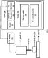
- FIG. 1illustrates an exemplary block diagram of a system 100 for monitoring tool wear to estimate a Remaining Useful Life (RUL) of a tool 118 in machining, in accordance with an embodiment of the present disclosure.
- the system 100includes one or more processors 104, communication interface device(s) or input/output (I/O) interface(s) 106, and one or more data storage devices or memory 102 operatively coupled to the one or more processors 104.
- the one or more processors 104may be one or more software processing modules (not shown) and/or one or more hardware processors as shown in FIG. 1 .
- the hardware processorscan be implemented as one or more microprocessors, microcomputers, microcontrollers, digital signal processors, central processing units, state machines, logic circuitries, and/or any devices that manipulate signals based on operational instructions.
- the processor(s)is configured to fetch and execute computer-readable instructions stored in the memory.
- the device 100can be implemented in a variety of computing systems, such as laptop computers, notebooks, hand-held devices, workstations, mainframe computers, servers, a network cloud and the like.
- the I/O interface device(s) 106can include a variety of software and hardware interfaces, for example, a web interface, a graphical user interface, and the like and can facilitate multiple communications within a wide variety of networks N/W and protocol types, including wired networks, for example, LAN, cable, etc., and wireless networks, such as WLAN, cellular, or satellite.
- the I/O interface device(s)can include one or more ports for connecting a number of devices to one another or to another server.
- the memory 102may include any computer-readable medium known in the art including, for example, volatile memory, such as static random access memory (SRAM) and dynamic random access memory (DRAM), and/or non-volatile memory, such as read only memory (ROM), erasable programmable ROM, flash memories, hard disks, optical disks, and magnetic tapes.
- volatile memorysuch as static random access memory (SRAM) and dynamic random access memory (DRAM)
- non-volatile memorysuch as read only memory (ROM), erasable programmable ROM, flash memories, hard disks, optical disks, and magnetic tapes.
- ROMread only memory
- erasable programmable ROMerasable programmable ROM
- flash memoriessuch as hard disks, optical disks, and magnetic tapes.
- a plurality of modules 108can be stored in the memory 102, wherein the modules 108 may comprise a tool wear module 110 implementing the physics based tool wear model and a RUL estimation module estimating the RUL based
- the tool wear module 110 and the RUL estimation modulewhen executed by the one or more processors 104, are configured to monitor tool wear to estimate the RUL of the tool 118.
- the memory 102may further comprise information pertaining to input(s)/output(s) of each step performed by the tool wear module 110, the RUL estimation module 112 and other modules (not shown) of the system 100 and methods of the present disclosure.
- the system 100, through the I/O interface 106may be coupled to external data sources such as the CNC machine 114 providing a plurality of process parameters associated with machining process of manufacturing a workpiece 120, placed on a table 122, utilizing the tool 118.
- the tool 118is operated on the work piece 120 in conjunction with a spindle 116 controlled by the CNC machine 114.
- the plurality of process parameterscomprise a spindle power ( S p ), a radial depth of cut ( w ) of the tool 118 used in the machining process, an axial depth of cut t of the tool 118, and a cutting velocity V , wherein the plurality of process parameters are obtained directly from the CNC machine 114.
- S pspindle power
- wradial depth of cut
- Vcutting velocity
- FIG. 2illustrates an exemplary flow diagram of a method, implemented by the system of FIG. 1 , for monitoring tool wear to estimate the RUL of the tool in machining, in accordance with an embodiment of the present disclosure.
- the system(s) 100comprises one or more data storage devices or the memory 102 operatively coupled to the one or more hardware processors 104 and is configured to store instructions for execution of steps of the method by the one or more processors 104 in conjunction with various modules such as the tool wear module 110 and the RUL estimation module 112 of the modules 110.
- the steps of the method of the present disclosurewill now be explained with reference to the components of the system 100 as depicted in FIG. 1 , and the steps of flow diagram as depicted in FIG. 2A and FIG. 2B.
- the tool wear module 110is configured to obtain the plurality of process parameters associated with machining process of the work piece 120.
- the plurality of process parametersinclude the spindle power ( S p ) of the spindle 116, the radial depth of cut ( w ) of the tool 118 used in the machining process, the axial depth of cut t of the tool 118, and the cutting velocity V , which are obtained directly from the CNC machine 114.
- the tool wear module 110is configured to derive a rate of volumetric wear loss per unit contact area of the tool 118 in terms of a rate of change of flank wear width ( dVB dt ) of the tool, alternatively referred as rate of change of flank wear growth.
- the rate of change of flank wear width ( dVB dt )is computed using the spindle power ( S p ), the radial depth of cut (w), the axial depth of cut t of the tool, the cutting velocity V, predetermined constants A 1 and B 1 defined in accordance with a combination of the tool 118 and material of the work piece 120.
- the computation of the rate of change of flank wear width( dVB dt )also depends on a predetermined temperature wear coefficient ( K w ). Further, the constants A 1 and B 1 defined in accordance with the combination of the tool 118 and the material of the work piece 120 are predetermined by fitting data for a selected combination of the tool 118, the work piece material and previous machining data using least square fitting technique.
- dVB dtA 1 S p wt exp ⁇ B 1 K w V 1 / 2 t 1 / 2
- dw dtA sin ⁇ + ⁇ ⁇ ⁇ sin 2 ⁇ cos ⁇ ⁇ ⁇ sin 90 + ⁇ ⁇ ⁇ F c V c wt exp ⁇ B T
- T ⁇ U c Vt k ⁇ cT ⁇ U c Vt k ⁇ c
- U cspecific energy of material removal
- Vthe cutting velocity
- tthe uncut chip thickness
- kthe thermal conductivity of cutting material
- ⁇the density of cutting material
- cthe specific heat capacity of the cutting material (tool material).
- the equation 4 abovedoes not take into consideration, the temperature rise due to the current tool wear state. However, it is experimentally observed by analysis in the art that the presence of a tool wear state causes a rise in temperature due to more friction as contact area increases with wear.
- the method and system disclosedintroduces the temperature wear coefficient K w, which considers effect of temperature rise due to friction caused by a current tool wear state of the tool 118 during the machining operation. It is experimentally identified that, the temperature can increase till 40%, before a tool fails.
- the temperature wear coefficient ( K w )is tuned from previous data associated with the machining process and is provided by equation below: T ⁇ K ⁇ K w U c vt 1 k ⁇ c Where K, is constant of proportionality.
- the tool wear module 110is configured to determine a cumulative flank wear growth(VB) for a current time instant by summing the rate of change of flank wear width ( dVB dt ) for a plurality of cuts performed by the tool for a plurality of parts during the machining operation.
- the RUL estimation module 112Upon computation of the cumulative flank wear growth VB ( t ), at step 208 of the method, the RUL estimation module 112 is configured to estimate the RUL of the tool at the current time instant from the determined cumulative flank wear growth ( VB )and a maximum allowed value for the cumulative flank tool wear ( VB max _ allowed ) predefined for the tool.
- the RUL estimation module 112is configured to seamlessly indicating the determined RUL to an operator and raising an alarm if the RUL crosses a predefined RUL threshold of the tool.
- FIG. 4A and Fig 4Billustrate comparison between experimental data available in the art corresponding to the tool wear and predicted tool wear by the system of FIG. 1 data, in accordance with an embodiment of the present disclosure.
- the physics based tool wear model(as in equation 1) developed by the method disclosed is trained using published tool wear data as in table depicted in FIG. 4A .
- the cutting experimentsare carried out on horizontal column-knee type milling machine.
- the data acquisition systemwas composed of a motor power transducer, an A/D converter and a personal computer.
- Flank wear of a carbide insertwas measured using a microscope. Milling experiments is carried out under different cutting conditions.
- the predicted results by the system 100show good agreement with the experimental data as shown in table of FIG. 4A .
- the graphical comparisonis depicted in FIG. 4B .
- the observed Root Mean Square Error (RMSE)is 1.88%, which may increase further if the tool wear model is trained with a large data set with different cutting conditions.
- physics based model disclosed by the methodnot only depends on the machining data but also the associated physics of tool wear which remains same across the machining operations. So by incorporating a minimal changes (By estimating A 1 and B 1 and tuning K w ) the model is ready to predict tool wear and estimate RUL for another set of new job tool combination. So proposed model is completely flexible and extensible from turning to milling operation provided orthogonal machining condition. Also an algorithm can be written to train of model automatically from few set of initial machining data in case of new set of machining condition including change in job and tool. This make system automatic, agile, self-depend and available most of time in changing machining conditions. This leads to better productivity, cost-effective manufacturing process
- the hardware devicecan be any kind of device which can be programmed including e.g. any kind of computer like a server or a personal computer, or the like, or any combination thereof.
- the devicemay also include means which could be e.g. hardware means like e.g. an application-specific integrated circuit (ASIC), a field-programmable gate array (FPGA), or a combination of hardware and software means, e.g.
- ASICapplication-specific integrated circuit
- FPGAfield-programmable gate array
- the meanscan include both hardware means and software means.
- the method embodiments described hereincould be implemented in hardware and software.
- the devicemay also include software means.
- the embodimentsmay be implemented on different hardware devices, e.g. using a plurality of CPUs.
Landscapes
- General Physics & Mathematics (AREA)
- Engineering & Computer Science (AREA)
- Physics & Mathematics (AREA)
- Immunology (AREA)
- Analytical Chemistry (AREA)
- Biochemistry (AREA)
- General Health & Medical Sciences (AREA)
- Chemical & Material Sciences (AREA)
- Life Sciences & Earth Sciences (AREA)
- Pathology (AREA)
- Health & Medical Sciences (AREA)
- Human Computer Interaction (AREA)
- Manufacturing & Machinery (AREA)
- Automation & Control Theory (AREA)
- Automatic Control Of Machine Tools (AREA)
- Numerical Control (AREA)
Description
- The disclosure herein generally relates to monitoring tool wear, and, more particularly, to for a method and system for monitoring tool wear to estimate Remaining Useful Life (RUL) of tool in machining.
- Machining refers to one or more processes in which a piece of raw material is cut into a desired final shape and size by a controlled material-removal process. Quality and precision in manufacturing of parts is critical in the machining industry. There are parts to be manufactured that require uncompromising quality with very low acceptable tolerances. Among a plurality of factors that affect the quality and/or precision of machining process, tool wear is one major factor. The tool wear directly causes poor part quality and inaccuracies in dimensions of a part, also referred as a workpiece. This effectively leads to rejection of the workpiece or the part. Tool wear is obvious in machining process, hence, changing the tool at right the time is critical for maintaining quality and precision. The existing challenge in achieving high quality and precision in any machining process is that there is no cost-effective and robust technology available to facilitate worn tool change during machining.
- Conventionally, in a shop floor, the tool change is based on operator expertise. Further, many existing automated tool wear monitoring techniques are based on sensors and signal processing. These techniques perform satisfactorily in lab scale setup but they are not cost-effective and robust to use on industrial scale. As these systems use signal patterns to identify features and use them to make predictions, they may not be actually capturing the tool wear physics that is happening. This may lead to providing faulty predictions due to the interference of external noise signals. A considerable research is carried out in machine learning techniques for tool wear monitoring. However, machine learning approaches used by existing tool wear monitoring are very specific to machining condition and require a large volume of data to train a tool wear model. Collecting the required large volume of data from the shop floor is not easy as mounting and collecting a lot of sensory data is a major challenge. In addition the machine learning model is specific to the type of machining process and a new model needs to be developed as the job changes in a machining process. Some research works in this domain are entirely dependent on the variation of a single parameter (cutting force, temperature, etc.) to predict the tool wear. These works may not take into consideration, all the main factors that affect the tool wear and hence providing a less accurate model for tool wear. One of the cited prior art article titled "Assessment and visualization of machine tool wear using computer vision" by DAVID KERR ET AL discloses Tool wear monitoring is an integral part of modern CNC machine control. Cutting tools must be periodically checked for possible or actual premature failures, and it is necessary to record the cutting history for a tool's full life of utilization. This means that an on-line monitoring system would be of great benefit to overall process control in manufacturing systems. Computer vision has already shown promise as a candidate technology for this task. In this paper, we describe the use of digital image processing techniques in the analysis of images of worn cutting tools in order to assess their degree of wear and thus remaining useful life. It is shown that a processing strategy using a variety of image texture measures allows for effective visualization and assessment of tool wear, and indicates good correlation with the expected wear characteristics.
- The invention is defined in the appended claims. Embodiments of the present disclosure present technological improvements as solutions to one or more of the above-mentioned technical problems recognized by the inventors in conventional systems. For example, in one aspect, there is provided a processor implemented method for monitoring tool wear to estimate Remaining Useful Life (RUL) of a tool. The method comprising obtaining a plurality of process parameters associated with machining process of a work piece, wherein the plurality of process parameters, comprising a spindle power (Sp), a radial depth of cut (w) of the tool, an axial depth of cutt of the tool, and a cutting velocityV, are obtained directly from a Computer Numerical Control (CNC) machine. The method further comprises deriving a rate of volumetric wear loss per unit contact area of the tool in terms of a rate of change of flank wear width (


- In another aspect, there is provided a system for monitoring tool wear to estimate Remaining Useful Life (RUL) of a tool, the system comprising a memory storing instructions; one or more communication interfaces; and one or more hardware processors coupled to the memory via the one or more communication interfaces, wherein the one or more hardware processors are configured by the instructions to obtain a plurality of process parameters associated with machining process of a work piece, wherein the plurality of process parameters, comprising a spindle power (Sp), a radial depth of cut (w) of the tool, an axial depth of cutt of the tool, and a cutting velocityV, are obtained directly from a Computer Numerical Control (CNC) machine (202). Further, the system is configured to derive a rate of volumetric wear loss per unit contact area of the tool in terms of a rate of change of flank wear width (


- In yet another aspect, there are provided one or more non-transitory machine readable information storage mediums comprising one or more instructions which when executed by one or more hardware processors causes a method for monitoring tool wear to estimate Remaining Useful Life (RUL) of a tool. The instructions cause obtaining a plurality of process parameters associated with machining process of a work piece, wherein the plurality of process parameters, comprising a spindle power (Sp), a radial depth of cut (w) of the tool, an axial depth of cutt of the tool, and a cutting velocityV, are obtained directly from a Computer Numerical Control (CNC) machine. The method further comprises deriving a rate of volumetric wear loss per unit contact area of the tool in terms of a rate of change of flank wear width (


- The accompanying drawings, which are incorporated in and constitute a part of this disclosure, illustrate exemplary embodiments and, together with the description, serve to explain the disclosed principles:
FIG. 1 illustrates an exemplary block diagram of a system for monitoring tool wear to estimate a Remaining Useful Life (RUL) of a tool in machining, in accordance with an embodiment of the present disclosure.FIG. 2 illustrates an exemplary flow diagram of a method, implemented by the system ofFIG. 1 , for monitoring tool wear to estimate the RUL of the tool in machining, in accordance with an embodiment of the present disclosure.FIG. 3 illustrates a standard Velocity Relationship in orthogonal cutting providing the basic equation of sliding velocity.FIG. 4A andFIG. 4B illustrate comparison between experimental data available in the art corresponding to the tool wear and predicted tool wear by the system ofFIG. 1 data, in accordance with an embodiment of the present disclosure.- Exemplary embodiments are described with reference to the accompanying drawings. In the figures, the left-most digit(s) of a reference number identifies the figure in which the reference number first appears. Wherever convenient, the same reference numbers are used throughout the drawings to refer to the same or like parts. While examples and features of disclosed principles are described herein, modifications, adaptations, and other implementations are possible without departing from the scope of the disclosed embodiments. It is intended that the following detailed description be considered as exemplary only, with the scope being indicated by the following claims.
- Embodiments of the present disclosure provide systems and methods for monitoring tool wear to estimate Remaining Useful Life (RUL) of a tool in machining. The method disclosed provides a tool wear model, which combines tool wear physics with data fitting, capture practical considerations of a machining system, which makes the tool wear prediction and estimated RUL from the tool wear more stable, reliable and robust. The method does not require the mounting of an external sensor on a Computer Numerical Control (CNC) machine, providing cost effective and practical solution, hence widely acceptable and implementable solution on large scale for wide variety of industrial use cases. The disclosed physics based tool wear model for RUL estimation captures privilege of physics of tool wear and easily accessible data from CNC controller to monitor and predict tool wear and RUL of the tool in real-time.
- Referring now to the drawings, and more particularly to
FIGS. 1 through 4 , where similar reference characters denote corresponding features consistently throughout the figures, there are shown preferred embodiments and these embodiments are described in the context of the following exemplary system and/or method. FIG. 1 illustrates an exemplary block diagram of asystem 100 for monitoring tool wear to estimate a Remaining Useful Life (RUL) of atool 118 in machining, in accordance with an embodiment of the present disclosure. In an embodiment, thesystem 100 includes one or more processors 104, communication interface device(s) or input/output (I/O) interface(s) 106, and one or more data storage devices or memory 102 operatively coupled to the one or more processors 104. The one or more processors 104 may be one or more software processing modules (not shown) and/or one or more hardware processors as shown inFIG. 1 . In an embodiment, the hardware processors can be implemented as one or more microprocessors, microcomputers, microcontrollers, digital signal processors, central processing units, state machines, logic circuitries, and/or any devices that manipulate signals based on operational instructions. Among other capabilities, the processor(s) is configured to fetch and execute computer-readable instructions stored in the memory. In an embodiment, thedevice 100 can be implemented in a variety of computing systems, such as laptop computers, notebooks, hand-held devices, workstations, mainframe computers, servers, a network cloud and the like.- The I/O interface device(s) 106 can include a variety of software and hardware interfaces, for example, a web interface, a graphical user interface, and the like and can facilitate multiple communications within a wide variety of networks N/W and protocol types, including wired networks, for example, LAN, cable, etc., and wireless networks, such as WLAN, cellular, or satellite. In an embodiment, the I/O interface device(s) can include one or more ports for connecting a number of devices to one another or to another server.
- The memory 102 may include any computer-readable medium known in the art including, for example, volatile memory, such as static random access memory (SRAM) and dynamic random access memory (DRAM), and/or non-volatile memory, such as read only memory (ROM), erasable programmable ROM, flash memories, hard disks, optical disks, and magnetic tapes. In an embodiment, a plurality of
modules 108 can be stored in the memory 102, wherein themodules 108 may comprise atool wear module 110 implementing the physics based tool wear model and a RUL estimation module estimating the RUL based on the predicted tool wear by thetool wear module 110. Thetool wear module 110 and the RUL estimation module, when executed by the one or more processors 104, are configured to monitor tool wear to estimate the RUL of thetool 118. The memory 102 may further comprise information pertaining to input(s)/output(s) of each step performed by thetool wear module 110, theRUL estimation module 112 and other modules ( not shown) of thesystem 100 and methods of the present disclosure. Thesystem 100, through the I/O interface 106 may be coupled to external data sources such as theCNC machine 114 providing a plurality of process parameters associated with machining process of manufacturing aworkpiece 120, placed on a table 122, utilizing thetool 118. Thetool 118 is operated on thework piece 120 in conjunction with aspindle 116 controlled by theCNC machine 114. The plurality of process parameters comprise a spindle power (Sp), a radial depth of cut (w) of thetool 118 used in the machining process, an axial depth of cutt of thetool 118, and a cutting velocityV, wherein the plurality of process parameters are obtained directly from theCNC machine 114. The tool wear computation and the estimation of the RUL in accordance with the physics based model disclosed in explained in conjunction method steps depicted by a flow diagram ofFIG. 2 . FIG. 2 illustrates an exemplary flow diagram of a method, implemented by the system ofFIG. 1 , for monitoring tool wear to estimate the RUL of the tool in machining, in accordance with an embodiment of the present disclosure. In an embodiment, the system(s) 100 comprises one or more data storage devices or the memory 102 operatively coupled to the one or more hardware processors 104 and is configured to store instructions for execution of steps of the method by the one or more processors 104 in conjunction with various modules such as thetool wear module 110 and theRUL estimation module 112 of themodules 110. The steps of the method of the present disclosure will now be explained with reference to the components of thesystem 100 as depicted inFIG. 1 , and the steps of flow diagram as depicted in FIG. 2A and FIG. 2B. Although process steps, method steps, techniques or the like may be described in a sequential order, such processes, methods and techniques may be configured to work in alternate orders. In other words, any sequence or order of steps that may be described does not necessarily indicate a requirement that the steps be performed in that order. The steps of processes described herein may be performed in any order practical. Further, some steps may be performed simultaneously.- In an embodiment, at step 202 of the method, the
tool wear module 110 is configured to obtain the plurality of process parameters associated with machining process of thework piece 120. The plurality of process parameters include the spindle power (Sp) of thespindle 116, the radial depth of cut (w) of thetool 118 used in the machining process, the axial depth of cutt of thetool 118, and the cutting velocityV, which are obtained directly from theCNC machine 114. - At
step 204 of the method, thetool wear module 110 is configured to derive a rate of volumetric wear loss per unit contact area of thetool 118 in terms of a rate of change of flank wear width (

tool 118 and material of thework piece 120. The computation of the rate of change of flank wear width(
tool 118 and the material of thework piece 120 are predetermined by fitting data for a selected combination of thetool 118, the work piece material and previous machining data using least square fitting technique. - The equation defined by the system and method disclosed for the rate of change of flank wear width (

CNC machine 114 is provided below:
- Explained below are steps based on which the method disclosed arrives at equation (1) stated above. The derivation of the disclosed
equation 1 is developed over, known in art, basic tool wear model based on dominant tool wear mechanism, which is abrasion in cutting zone. Accordingly, a tool wear rate, alternatively referred as wear rate, depends upon a sliding velocityVc and the wear rate equation is as provided below:
FIG. 3 - Using
equation 1 andequation 2, the wear rate equation can be modified as below:
- Further, to model temperature effect T present in
equation 2 in tool wear, nature of variation of overall tool-chip interface temperature with the process parameters can be approximately determined through the dimensional analysis as known in the art and provided in equation below:
equation 4 above does not take into consideration, the temperature rise due to the current tool wear state. However, it is experimentally observed by analysis in the art that the presence of a tool wear state causes a rise in temperature due to more friction as contact area increases with wear. The method and system disclosed introduces the temperature wear coefficientKw, which considers effect of temperature rise due to friction caused by a current tool wear state of thetool 118 during the machining operation. It is experimentally identified that, the temperature can increase till 40%, before a tool fails. The temperature wear coefficient (Kw) is tuned from previous data associated with the machining process and is provided by equation below:
- Using the equation 5 in
equation 3 and simplifying in further using a shear model developed in art that provides shear angle relationship, the tool wear rate equation can be written as:
- In the above equationFcV provides instantaneous cutting power which is proportional to the spindle powerSp. Thus, the instantaneous cutting power can be approximated as the spindle powerSp, wherein the constant in
equation 7 takes into account the constant of proportionality. Thus, the wear rate of equation 6 can be represented in terms of spindle powerSp, as in equation 7:
- The tool wear mechanism are of two types, a flank wear and a crater wear. As observed that the flank wear occurs much before the crater wear occurs, hence the flank wear is better and early indication of tool failure. Thus, the analysis hence forth with regards to tool wear rate is analyzed and described in terms of flank wear. Thus the rate of change of flank width or the rate of change of flank wear growth can be written based on
equation 7 above as:
same equation 1, stated above. - Once the computation for rate of change of flank width is known, at
step 206 of the method, thetool wear module 110 is configured to determine a cumulative flank wear growth(VB) for a current time instant by summing the rate of change of flank wear width (

- Upon computation of the cumulative flank wear growthVB(t), at
step 208 of the method, theRUL estimation module 112 is configured to estimate the RUL of the tool at the current time instant from the determined cumulative flank wear growth (VB)and a maximum allowed value for the cumulative flank tool wear (VBmax_allowed) predefined for the tool. The RUL is estimated using the standard RUL equation below:
- At step 210 of the method, the
RUL estimation module 112 is configured to seamlessly indicating the determined RUL to an operator and raising an alarm if the RUL crosses a predefined RUL threshold of the tool. FIG. 4A andFig 4B illustrate comparison between experimental data available in the art corresponding to the tool wear and predicted tool wear by the system ofFIG. 1 data, in accordance with an embodiment of the present disclosure. For the comparative analysis, the physics based tool wear model (as in equation 1) developed by the method disclosed is trained using published tool wear data as in table depicted inFIG. 4A . The cutting experiments, are carried out on horizontal column-knee type milling machine. The data acquisition system was composed of a motor power transducer, an A/D converter and a personal computer. Flank wear of a carbide insert was measured using a microscope. Milling experiments is carried out under different cutting conditions. The tool wear model is trained against the cutting condition V=149m/min, w=3 and t=1mm. The predicted results by thesystem 100, show good agreement with the experimental data as shown in table ofFIG. 4A . The graphical comparison is depicted inFIG. 4B . After training, the constants or coefficientsA1 and B1 in theequation 1 are determined to beA1=0.073441 and B1=2.6829, where the tool wear rate is calculated as in equation 11 below:
- The observed Root Mean Square Error (RMSE) is 1.88%, which may increase further if the tool wear model is trained with a large data set with different cutting conditions. At any point in time during the machining process, the RUL of the tool can be calculated from
equation 10. If assumed that maximum allowable tool wear for a specific machining process is (VBmaxallowed ) = 0.8mm, then actual and predicted RUL after 6the machining cycle is:
- So the predicted RUL after 6 the machining cycle is 40.35% while actual is 38.75%. Since tool wear is directly related to tool wear compensation, the method disclosed, with minimal modifications can automatically correlate between tool wear occurring and tool wear compensation to the provided to reduce part or workpiece dimensional inaccuracy.
- Thus, physics based model disclosed by the method not only depends on the machining data but also the associated physics of tool wear which remains same across the machining operations. So by incorporating a minimal changes (By estimatingA1 and B1 and tuning Kw) the model is ready to predict tool wear and estimate RUL for another set of new job tool combination. So proposed model is completely flexible and extensible from turning to milling operation provided orthogonal machining condition. Also an algorithm can be written to train of model automatically from few set of initial machining data in case of new set of machining condition including change in job and tool. This make system automatic, agile, self-depend and available most of time in changing machining conditions. This leads to better productivity, cost-effective manufacturing process
- The written description describes the subject matter herein to enable any person skilled in the art to make and use the embodiments. The scope of the subject matter embodiments is defined by the claims and may include other modifications that occur to those skilled in the art. Such other modifications are intended to be within the scope of the claims if they have similar elements that do not differ from the literal language of the claims or if they include equivalent elements with insubstantial differences from the literal language of the claims.
- It is to be understood that the scope of the protection is extended to such a program and in addition to a computer-readable means having a message therein; such computer-readable storage means contain program-code means for implementation of one or more steps of the method, when the program runs on a server or mobile device or any suitable programmable device. The hardware device can be any kind of device which can be programmed including e.g. any kind of computer like a server or a personal computer, or the like, or any combination thereof. The device may also include means which could be e.g. hardware means like e.g. an application-specific integrated circuit (ASIC), a field-programmable gate array (FPGA), or a combination of hardware and software means, e.g. an ASIC and an FPGA, or at least one microprocessor and at least one memory with software modules located therein. Thus, the means can include both hardware means and software means. The method embodiments described herein could be implemented in hardware and software. The device may also include software means. Alternatively, the embodiments may be implemented on different hardware devices, e.g. using a plurality of CPUs.


Claims (6)
- A processor implemented method for monitoring tool wear to estimate Remaining Useful Life (RUL) of a tool, the method comprising:obtaining, by one or more hardware processors, a plurality of process parameters associated with machining process of a work piece, wherein the plurality of process parameters, comprising a spindle power (Sp), a radial depth of cut (w) of the tool, an axial depth of cutt of the tool, and a cutting velocityV, are obtained directly from a Computer Numerical Control (CNC) machine (202);deriving, by the one or more hardware processors, a rate of volumetric wear loss per unit contact area of the tool in terms of a rate of change of flank wear width (

 determining, by the one or more hardware processors, a cumulative flank wear growth(VB) for a current time instant by summing the rate of change of flank wear width(
 estimating, by the one or more hardware processors, the RUL of the tool at the current time instant from the determined cumulative flank wear growth(VB) and a maximum allowed value for the cumulative flank tool wear predefined for the tool (208).
 - The method of claim 1, wherein the method further comprises seamlessly indicating the determined RUL to an operator and raising an alarm if the RUL crosses a predefined RUL threshold of the tool (210).
- The method of claim 1, wherein the constantsA1and B1 defined in accordance with the combination of the tool and the material of the work piece are predetermined by fitting data for a selected combination of the tool and work piece material and previous machining data using least square fitting technique.
- The method of claim 1, wherein the temperature wear coefficient (Kw) is tuned from the previous machining data associated with the machining process.
- A system (100) for monitoring tool wear to estimate Remaining Useful Life (RUL) of a tool, the system (100) comprising:a memory (102) storing instructions;one or more Input/Output (I/O) interfaces (106); andone or more hardware processors (104) coupled to the memory (102) via the one or more communication interfaces (106), wherein the one or more hardware processors (104) comprise instructions to execute the steps of the method of claim 1
- One or more non-transitory machine-readable information storage mediums comprising instructions which when executed by one or more hardware processors causes the processors to carry out the steps of the method of claim 1


Applications Claiming Priority (2)
| Application Number | Priority Date | Filing Date | Title |
|---|---|---|---|
| IN201821038822 | 2018-10-12 | ||
| PCT/IN2019/050748WO2020075191A1 (en) | 2018-10-12 | 2019-10-09 | Method and system for monitoring tool wear to estimate rul of tool in machining |
Publications (4)
| Publication Number | Publication Date |
|---|---|
| EP3864475A1 EP3864475A1 (en) | 2021-08-18 |
| EP3864475A4 EP3864475A4 (en) | 2022-06-29 |
| EP3864475B1true EP3864475B1 (en) | 2024-01-03 |
| EP3864475C0 EP3864475C0 (en) | 2024-01-03 |
Family
ID=70164232
Family Applications (1)
| Application Number | Title | Priority Date | Filing Date |
|---|---|---|---|
| EP19871110.3AActiveEP3864475B1 (en) | 2018-10-12 | 2019-10-09 | Method and system for monitoring tool wear to estimate rul of tool in machining |
Country Status (3)
| Country | Link |
|---|---|
| US (1) | US11630435B2 (en) |
| EP (1) | EP3864475B1 (en) |
| WO (1) | WO2020075191A1 (en) |
Families Citing this family (11)
| Publication number | Priority date | Publication date | Assignee | Title |
|---|---|---|---|---|
| JP7342444B2 (en)* | 2019-06-18 | 2023-09-12 | 株式会社ジェイテクト | Processing tool abnormality detection device |
| CN112612250B (en)* | 2020-11-18 | 2021-11-09 | 深圳市裕展精密科技有限公司 | Tool feedback control device and method |
| CN112372372B (en)* | 2020-12-07 | 2022-09-02 | 哈尔滨理工大学 | Efficient milling cutter accumulated friction wear boundary identification and verification method |
| MX2023009599A (en) | 2021-02-16 | 2023-10-12 | Ecolab Usa Inc | Creping process performance tracking and control. |
| CN113798919B (en)* | 2021-09-18 | 2022-07-26 | 清华大学 | Cutting force measuring method and device, electronic equipment and storage medium |
| CN115372192B (en)* | 2022-08-22 | 2025-04-01 | 广东工业大学 | Cutting force prediction method, system, equipment and medium for ultra-precision machining of titanium alloy |
| CN115365890A (en)* | 2022-09-23 | 2022-11-22 | 深圳职业技术学院 | Method, device, intelligent terminal and storage medium for online prediction of tool wear value |
| US20240165764A1 (en)* | 2022-11-23 | 2024-05-23 | Raytheon Technologies Corporation | Adaptive vibration amplitude for impact grinding of ceramic matrix composite components |
| CN116460661A (en)* | 2023-03-11 | 2023-07-21 | 哈尔滨理工大学 | Efficient milling cutter tooth rear cutter surface contact stiffness and wear distribution state identification method |
| CN118664401B (en)* | 2024-08-21 | 2024-10-22 | 洛阳天浩泰轨道装备制造有限公司 | A tool life prediction device for machining |
| CN119988893B (en)* | 2025-04-15 | 2025-07-25 | 中国建筑第五工程局有限公司 | Method and system for predicting cutter abrasion of shield tunneling machine |
Family Cites Families (8)
| Publication number | Priority date | Publication date | Assignee | Title |
|---|---|---|---|---|
| US4442494A (en)* | 1981-11-18 | 1984-04-10 | Westinghouse Electric Corp. | Tool wear and tool failure monitor system |
| CA1243744A (en)* | 1984-06-18 | 1988-10-25 | John M. Fildes | Cutting tool wear monitor |
| US5689062A (en)* | 1996-01-11 | 1997-11-18 | University Of Kentucky Research Foundation | Method of assessing tool-life in grooved tools |
| WO2002045407A2 (en)* | 2000-12-01 | 2002-06-06 | Unova Ip Corp. | Control embedded machine condition monitor |
| CA2662537C (en)* | 2006-09-26 | 2015-01-20 | Oerlikon Trading Ag, Truebbach | Workpiece with hard coating |
| US10401271B2 (en)* | 2013-11-29 | 2019-09-03 | Safran Aircraft Engines | Method and device for determining the wear of a cutting tool flank |
| US10139311B2 (en)* | 2014-09-26 | 2018-11-27 | Palo Alto Research Center Incorporated | Computer-implemented method and system for machine tool damage assessment, prediction, and planning in manufacturing shop floor |
| TWI670672B (en)* | 2017-03-24 | 2019-09-01 | 國立成功大學 | Automated constructing method of cloud manufacturing service, computer program product, and cloud manufacturing system |
- 2019
- 2019-10-09EPEP19871110.3Apatent/EP3864475B1/enactiveActive
- 2019-10-09WOPCT/IN2019/050748patent/WO2020075191A1/ennot_activeCeased
- 2019-10-09USUS16/976,833patent/US11630435B2/enactiveActive
Also Published As
| Publication number | Publication date |
|---|---|
| US20210356934A1 (en) | 2021-11-18 |
| WO2020075191A1 (en) | 2020-04-16 |
| EP3864475A1 (en) | 2021-08-18 |
| US11630435B2 (en) | 2023-04-18 |
| EP3864475A4 (en) | 2022-06-29 |
| EP3864475C0 (en) | 2024-01-03 |
Similar Documents
| Publication | Publication Date | Title |
|---|---|---|
| EP3864475B1 (en) | Method and system for monitoring tool wear to estimate rul of tool in machining | |
| US11237539B2 (en) | System and method for operational-data-based detection of anomaly of a machine tool | |
| US10695884B2 (en) | Tool wear monitoring and predicting method | |
| JP6426667B2 (en) | Apparatus for detecting abnormality of tool of machine tool and method | |
| JP6404893B2 (en) | Tool life estimation device | |
| JP6649684B2 (en) | An improved database for chatter prediction | |
| US10222782B2 (en) | Parameter-based controller for managing tool life considering change in machining conditions | |
| EP2821870B1 (en) | Setting method of revolutions per minute on real time of rotating cutting tool, and control device | |
| US20200004221A1 (en) | Method and system for tool life monitoring and management in a cnc environment | |
| CN114800040A (en) | Cutter wear monitoring method and system based on process-state data correlation | |
| JP2021018537A (en) | Re-learning necessity determination method and re-learning necessity determination device of diagnostic model in machine tool, re-learning necessity determination program | |
| JP2020035260A (en) | Processing environment estimation device | |
| CN110096029B (en) | Thermal displacement correction device | |
| KR101945131B1 (en) | Method and Apparatus for Managing Very Small Fraction of Nonconforming under Non-Normal Process | |
| US10862812B2 (en) | Information processing apparatus, data management system, data management method, and non-transitory computer readable medium storing program | |
| Munaro et al. | A New Architecture Paradigm for Tool Wear Prediction during AISI 9840 Drilling Operation | |
| CN112417701B (en) | Method and device for predicting residual life of numerical control machine tool and network side server | |
| Milner et al. | Condition monitoring for indexable carbide end mill using acceleration data | |
| CN120148220B (en) | Fault warning method and system for CNC machine tools based on industrial Internet of Things | |
| CN112560234B (en) | Calculation method and device of residual life estimation probability of numerical control machine tool and network side server | |
| Ou et al. | MIMO EWMA-CUSUM condition-based statistical process control in manufacturing processes | |
| CN119681696A (en) | Machine tool tool changing method, device, storage medium and electronic equipment | |
| Ogedengbe | Tool condition monitoring on micro milling machine using current signature and radial basis function (RBF) network | |
| Klocke et al. | Detection of Disturbances in Autonomous Production Cells Using Intelligent Evaluation Strategies |
Legal Events
| Date | Code | Title | Description |
|---|---|---|---|
| STAA | Information on the status of an ep patent application or granted ep patent | Free format text:STATUS: THE INTERNATIONAL PUBLICATION HAS BEEN MADE | |
| PUAI | Public reference made under article 153(3) epc to a published international application that has entered the european phase | Free format text:ORIGINAL CODE: 0009012 | |
| STAA | Information on the status of an ep patent application or granted ep patent | Free format text:STATUS: REQUEST FOR EXAMINATION WAS MADE | |
| 17P | Request for examination filed | Effective date:20200827 | |
| AK | Designated contracting states | Kind code of ref document:A1 Designated state(s):AL AT BE BG CH CY CZ DE DK EE ES FI FR GB GR HR HU IE IS IT LI LT LU LV MC MK MT NL NO PL PT RO RS SE SI SK SM TR | |
| DAV | Request for validation of the european patent (deleted) | ||
| DAX | Request for extension of the european patent (deleted) | ||
| A4 | Supplementary search report drawn up and despatched | Effective date:20220531 | |
| RIC1 | Information provided on ipc code assigned before grant | Ipc:G05B 19/406 20060101ALI20220524BHEP Ipc:G05B 19/404 20060101ALI20220524BHEP Ipc:G05B 19/18 20060101ALI20220524BHEP Ipc:G01N 3/58 20060101ALI20220524BHEP Ipc:B23Q 17/09 20060101ALI20220524BHEP Ipc:G05B 19/4065 20060101AFI20220524BHEP | |
| STAA | Information on the status of an ep patent application or granted ep patent | Free format text:STATUS: EXAMINATION IS IN PROGRESS | |
| 17Q | First examination report despatched | Effective date:20221018 | |
| GRAP | Despatch of communication of intention to grant a patent | Free format text:ORIGINAL CODE: EPIDOSNIGR1 | |
| STAA | Information on the status of an ep patent application or granted ep patent | Free format text:STATUS: GRANT OF PATENT IS INTENDED | |
| INTG | Intention to grant announced | Effective date:20230714 | |
| GRAS | Grant fee paid | Free format text:ORIGINAL CODE: EPIDOSNIGR3 | |
| GRAA | (expected) grant | Free format text:ORIGINAL CODE: 0009210 | |
| STAA | Information on the status of an ep patent application or granted ep patent | Free format text:STATUS: THE PATENT HAS BEEN GRANTED | |
| AK | Designated contracting states | Kind code of ref document:B1 Designated state(s):AL AT BE BG CH CY CZ DE DK EE ES FI FR GB GR HR HU IE IS IT LI LT LU LV MC MK MT NL NO PL PT RO RS SE SI SK SM TR | |
| REG | Reference to a national code | Ref country code:GB Ref legal event code:FG4D | |
| REG | Reference to a national code | Ref country code:DE Ref legal event code:R096 Ref document number:602019044645 Country of ref document:DE | |
| REG | Reference to a national code | Ref country code:CH Ref legal event code:EP | |
| REG | Reference to a national code | Ref country code:IE Ref legal event code:FG4D | |
| U01 | Request for unitary effect filed | Effective date:20240131 | |
| U07 | Unitary effect registered | Designated state(s):AT BE BG DE DK EE FI FR IT LT LU LV MT NL PT SE SI Effective date:20240208 | |
| PG25 | Lapsed in a contracting state [announced via postgrant information from national office to epo] | Ref country code:ES Free format text:LAPSE BECAUSE OF FAILURE TO SUBMIT A TRANSLATION OF THE DESCRIPTION OR TO PAY THE FEE WITHIN THE PRESCRIBED TIME-LIMIT Effective date:20240103 | |
| PG25 | Lapsed in a contracting state [announced via postgrant information from national office to epo] | Ref country code:ES Free format text:LAPSE BECAUSE OF FAILURE TO SUBMIT A TRANSLATION OF THE DESCRIPTION OR TO PAY THE FEE WITHIN THE PRESCRIBED TIME-LIMIT Effective date:20240103 | |
| PG25 | Lapsed in a contracting state [announced via postgrant information from national office to epo] | Ref country code:IS Free format text:LAPSE BECAUSE OF FAILURE TO SUBMIT A TRANSLATION OF THE DESCRIPTION OR TO PAY THE FEE WITHIN THE PRESCRIBED TIME-LIMIT Effective date:20240503 | |
| PG25 | Lapsed in a contracting state [announced via postgrant information from national office to epo] | Ref country code:GR Free format text:LAPSE BECAUSE OF FAILURE TO SUBMIT A TRANSLATION OF THE DESCRIPTION OR TO PAY THE FEE WITHIN THE PRESCRIBED TIME-LIMIT Effective date:20240404 | |
| PG25 | Lapsed in a contracting state [announced via postgrant information from national office to epo] | Ref country code:HR Free format text:LAPSE BECAUSE OF FAILURE TO SUBMIT A TRANSLATION OF THE DESCRIPTION OR TO PAY THE FEE WITHIN THE PRESCRIBED TIME-LIMIT Effective date:20240103 Ref country code:RS Free format text:LAPSE BECAUSE OF FAILURE TO SUBMIT A TRANSLATION OF THE DESCRIPTION OR TO PAY THE FEE WITHIN THE PRESCRIBED TIME-LIMIT Effective date:20240403 | |
| PG25 | Lapsed in a contracting state [announced via postgrant information from national office to epo] | Ref country code:CZ Free format text:LAPSE BECAUSE OF FAILURE TO SUBMIT A TRANSLATION OF THE DESCRIPTION OR TO PAY THE FEE WITHIN THE PRESCRIBED TIME-LIMIT Effective date:20240103 | |
| PG25 | Lapsed in a contracting state [announced via postgrant information from national office to epo] | Ref country code:RS Free format text:LAPSE BECAUSE OF FAILURE TO SUBMIT A TRANSLATION OF THE DESCRIPTION OR TO PAY THE FEE WITHIN THE PRESCRIBED TIME-LIMIT Effective date:20240403 Ref country code:NO Free format text:LAPSE BECAUSE OF FAILURE TO SUBMIT A TRANSLATION OF THE DESCRIPTION OR TO PAY THE FEE WITHIN THE PRESCRIBED TIME-LIMIT Effective date:20240403 Ref country code:IS Free format text:LAPSE BECAUSE OF FAILURE TO SUBMIT A TRANSLATION OF THE DESCRIPTION OR TO PAY THE FEE WITHIN THE PRESCRIBED TIME-LIMIT Effective date:20240503 Ref country code:HR Free format text:LAPSE BECAUSE OF FAILURE TO SUBMIT A TRANSLATION OF THE DESCRIPTION OR TO PAY THE FEE WITHIN THE PRESCRIBED TIME-LIMIT Effective date:20240103 Ref country code:GR Free format text:LAPSE BECAUSE OF FAILURE TO SUBMIT A TRANSLATION OF THE DESCRIPTION OR TO PAY THE FEE WITHIN THE PRESCRIBED TIME-LIMIT Effective date:20240404 Ref country code:CZ Free format text:LAPSE BECAUSE OF FAILURE TO SUBMIT A TRANSLATION OF THE DESCRIPTION OR TO PAY THE FEE WITHIN THE PRESCRIBED TIME-LIMIT Effective date:20240103 | |
| PG25 | Lapsed in a contracting state [announced via postgrant information from national office to epo] | Ref country code:PL Free format text:LAPSE BECAUSE OF FAILURE TO SUBMIT A TRANSLATION OF THE DESCRIPTION OR TO PAY THE FEE WITHIN THE PRESCRIBED TIME-LIMIT Effective date:20240103 | |
| PG25 | Lapsed in a contracting state [announced via postgrant information from national office to epo] | Ref country code:PL Free format text:LAPSE BECAUSE OF FAILURE TO SUBMIT A TRANSLATION OF THE DESCRIPTION OR TO PAY THE FEE WITHIN THE PRESCRIBED TIME-LIMIT Effective date:20240103 | |
| REG | Reference to a national code | Ref country code:DE Ref legal event code:R097 Ref document number:602019044645 Country of ref document:DE | |
| PG25 | Lapsed in a contracting state [announced via postgrant information from national office to epo] | Ref country code:SM Free format text:LAPSE BECAUSE OF FAILURE TO SUBMIT A TRANSLATION OF THE DESCRIPTION OR TO PAY THE FEE WITHIN THE PRESCRIBED TIME-LIMIT Effective date:20240103 | |
| PG25 | Lapsed in a contracting state [announced via postgrant information from national office to epo] | Ref country code:SK Free format text:LAPSE BECAUSE OF FAILURE TO SUBMIT A TRANSLATION OF THE DESCRIPTION OR TO PAY THE FEE WITHIN THE PRESCRIBED TIME-LIMIT Effective date:20240103 | |
| PG25 | Lapsed in a contracting state [announced via postgrant information from national office to epo] | Ref country code:SM Free format text:LAPSE BECAUSE OF FAILURE TO SUBMIT A TRANSLATION OF THE DESCRIPTION OR TO PAY THE FEE WITHIN THE PRESCRIBED TIME-LIMIT Effective date:20240103 Ref country code:SK Free format text:LAPSE BECAUSE OF FAILURE TO SUBMIT A TRANSLATION OF THE DESCRIPTION OR TO PAY THE FEE WITHIN THE PRESCRIBED TIME-LIMIT Effective date:20240103 Ref country code:RO Free format text:LAPSE BECAUSE OF FAILURE TO SUBMIT A TRANSLATION OF THE DESCRIPTION OR TO PAY THE FEE WITHIN THE PRESCRIBED TIME-LIMIT Effective date:20240103 | |
| PLBE | No opposition filed within time limit | Free format text:ORIGINAL CODE: 0009261 | |
| STAA | Information on the status of an ep patent application or granted ep patent | Free format text:STATUS: NO OPPOSITION FILED WITHIN TIME LIMIT | |
| U20 | Renewal fee for the european patent with unitary effect paid | Year of fee payment:6 Effective date:20241025 | |
| 26N | No opposition filed | Effective date:20241007 | |
| PGFP | Annual fee paid to national office [announced via postgrant information from national office to epo] | Ref country code:GB Payment date:20241022 Year of fee payment:6 | |
| PGFP | Annual fee paid to national office [announced via postgrant information from national office to epo] | Ref country code:CH Payment date:20241101 Year of fee payment:6 | |
| PG25 | Lapsed in a contracting state [announced via postgrant information from national office to epo] | Ref country code:MC Free format text:LAPSE BECAUSE OF FAILURE TO SUBMIT A TRANSLATION OF THE DESCRIPTION OR TO PAY THE FEE WITHIN THE PRESCRIBED TIME-LIMIT Effective date:20240103 |