EP3847975B1 - Articulating apparatus for endoscopic procedures - Google Patents
Articulating apparatus for endoscopic proceduresDownload PDFInfo
- Publication number
- EP3847975B1 EP3847975B1EP21160816.1AEP21160816AEP3847975B1EP 3847975 B1EP3847975 B1EP 3847975B1EP 21160816 AEP21160816 AEP 21160816AEP 3847975 B1EP3847975 B1EP 3847975B1
- Authority
- EP
- European Patent Office
- Prior art keywords
- assembly
- distal
- tube
- endoscopic
- proximal
- Prior art date
- Legal status (The legal status is an assumption and is not a legal conclusion. Google has not performed a legal analysis and makes no representation as to the accuracy of the status listed.)
- Active
Links
Images


Classifications
- B—PERFORMING OPERATIONS; TRANSPORTING
- B65—CONVEYING; PACKING; STORING; HANDLING THIN OR FILAMENTARY MATERIAL
- B65B—MACHINES, APPARATUS OR DEVICES FOR, OR METHODS OF, PACKAGING ARTICLES OR MATERIALS; UNPACKING
- B65B5/00—Packaging individual articles in containers or receptacles, e.g. bags, sacks, boxes, cartons, cans, jars
- B65B5/10—Filling containers or receptacles progressively or in stages by introducing successive articles, or layers of articles
- A—HUMAN NECESSITIES
- A61—MEDICAL OR VETERINARY SCIENCE; HYGIENE
- A61B—DIAGNOSIS; SURGERY; IDENTIFICATION
- A61B17/00—Surgical instruments, devices or methods
- A61B17/064—Surgical staples, i.e. penetrating the tissue
- A—HUMAN NECESSITIES
- A61—MEDICAL OR VETERINARY SCIENCE; HYGIENE
- A61B—DIAGNOSIS; SURGERY; IDENTIFICATION
- A61B17/00—Surgical instruments, devices or methods
- A61B17/068—Surgical staplers, e.g. containing multiple staples or clamps
- A—HUMAN NECESSITIES
- A61—MEDICAL OR VETERINARY SCIENCE; HYGIENE
- A61B—DIAGNOSIS; SURGERY; IDENTIFICATION
- A61B17/00—Surgical instruments, devices or methods
- A61B2017/00017—Electrical control of surgical instruments
- A61B2017/00115—Electrical control of surgical instruments with audible or visual output
- A—HUMAN NECESSITIES
- A61—MEDICAL OR VETERINARY SCIENCE; HYGIENE
- A61B—DIAGNOSIS; SURGERY; IDENTIFICATION
- A61B17/00—Surgical instruments, devices or methods
- A61B2017/0046—Surgical instruments, devices or methods with a releasable handle; with handle and operating part separable
- A61B2017/00473—Distal part, e.g. tip or head
- A—HUMAN NECESSITIES
- A61—MEDICAL OR VETERINARY SCIENCE; HYGIENE
- A61B—DIAGNOSIS; SURGERY; IDENTIFICATION
- A61B17/00—Surgical instruments, devices or methods
- A61B2017/00477—Coupling
- A—HUMAN NECESSITIES
- A61—MEDICAL OR VETERINARY SCIENCE; HYGIENE
- A61B—DIAGNOSIS; SURGERY; IDENTIFICATION
- A61B17/00—Surgical instruments, devices or methods
- A61B17/064—Surgical staples, i.e. penetrating the tissue
- A61B2017/0647—Surgical staples, i.e. penetrating the tissue having one single leg, e.g. tacks
- A61B2017/0648—Surgical staples, i.e. penetrating the tissue having one single leg, e.g. tacks threaded, e.g. tacks with a screw thread
- A—HUMAN NECESSITIES
- A61—MEDICAL OR VETERINARY SCIENCE; HYGIENE
- A61B—DIAGNOSIS; SURGERY; IDENTIFICATION
- A61B17/00—Surgical instruments, devices or methods
- A61B17/068—Surgical staplers, e.g. containing multiple staples or clamps
- A61B2017/0688—Packages or dispensers for surgical staplers
- A—HUMAN NECESSITIES
- A61—MEDICAL OR VETERINARY SCIENCE; HYGIENE
- A61B—DIAGNOSIS; SURGERY; IDENTIFICATION
- A61B17/00—Surgical instruments, devices or methods
- A61B17/28—Surgical forceps
- A61B17/29—Forceps for use in minimally invasive surgery
- A61B17/2909—Handles
- A61B2017/2912—Handles transmission of forces to actuating rod or piston
- A61B2017/2923—Toothed members, e.g. rack and pinion
- A—HUMAN NECESSITIES
- A61—MEDICAL OR VETERINARY SCIENCE; HYGIENE
- A61B—DIAGNOSIS; SURGERY; IDENTIFICATION
- A61B17/00—Surgical instruments, devices or methods
- A61B17/28—Surgical forceps
- A61B17/29—Forceps for use in minimally invasive surgery
- A61B2017/2926—Details of heads or jaws
- A61B2017/2927—Details of heads or jaws the angular position of the head being adjustable with respect to the shaft
- A—HUMAN NECESSITIES
- A61—MEDICAL OR VETERINARY SCIENCE; HYGIENE
- A61B—DIAGNOSIS; SURGERY; IDENTIFICATION
- A61B90/00—Instruments, implements or accessories specially adapted for surgery or diagnosis and not covered by any of the groups A61B1/00 - A61B50/00, e.g. for luxation treatment or for protecting wound edges
- A61B90/03—Automatic limiting or abutting means, e.g. for safety
- A61B2090/038—Automatic limiting or abutting means, e.g. for safety during shipment
Definitions
- the present disclosurerelates to surgical apparatus, devices and/or systems for performing endoscopic surgical procedures and methods of use thereof. More specifically, the present disclosure relates to surgical apparatus, devices and/or systems for performing endoscopic surgical procedures which includes an articulating endoscopic portion.
- endoscopic surgical devicesDuring laparoscopic or endoscopic surgical procedures, access to a surgical site is achieved through a small incision or through a narrow cannula inserted through a small entrance wound in a patient. Because of limited area to access the surgical site, many endoscopic surgical devices include mechanisms for articulating the tool assembly of the device. Typically, the articulating mechanism is controlled by an actuator which has to be manipulated by a surgeon to properly orient the tool assembly in relation to tissue to be treated.
- EP2777517 A1is an intermediate document according to Art. 54(3) EPC and relates to an endoscopic surgical device which includes a handle assembly including a handle housing and a trigger operatively connected to the handle housing, and a drive mechanism actuatable by the trigger; and an endoscopic anchor retaining/advancing assembly extending from the handle assembly.
- the endoscopic anchor retaining/advancing assemblyincluding a proximal tube portion and a distal tube portion pivotably connected to one another at an articulation joint, each of the proximal tube portion and the distal tube portion defining a central longitudinal axis; a proximal inner shaft rotatably disposed within the proximal tube portion, wherein the proximal inner shaft is relatively rigid, and wherein the proximal inner shaft is mechanically connected to the drive mechanism such that actuation of the trigger results in rotation of the proximal inner shaft; a distal inner shaft rotatably disposed within the distal tube portion, wherein the distal inner shaft is relatively rigid; and an intermediate drive cable mechanically interconnecting the proximal inner shaft and the distal inner shaft, wherein the intermediate drive cable is relatively flexible as compared to the proximal inner shaft and the distal inner shaft, wherein the intermediate drive cable extends from and between the proximal tube portion and the distal tube portion, across the articulation joint, wherein the intermediate
- WO 2013/046115 A1relates to a surgical fastening device adapted to both push tacks and rotate screws into the body.
- US 2011/022065 A1relates to surgical fasteners and their associated applicators, and more particularly to surgically fastening material to tissue and a corresponding method of use.
- endoscopic surgical deviceswhich include features which indicate to the surgeon whether the endoscopic portion of the surgical device, when in the surgical site, is in a non-articulated or articulated orientation.
- the present disclosurerelates to surgical apparatus, devices and/or systems for performing endoscopic surgical procedures which includes an articulating endoscopic portion.
- an endoscopic surgical deviceincludes a handle assembly including a handle housing and a trigger operatively connected to the handle housing, and a drive mechanism actuatable by the trigger; and an endoscopic assembly including a proximal end portion extending from the handle assembly; a distal end portion pivotably connected to the proximal end portion of the endoscopic assembly at a pivot point; and a rotatable inner actuation shaft extending from the handle assembly and into the distal end portion of the endoscopic assembly, the inner actuation shaft including a flexible portion extending across the pivot point, the inner actuation shaft being connected to the drive mechanism of the handle assembly such that an actuation of the trigger results in a rotation of the inner actuation shaft.
- the surgical devicefurther includes an end effector selectively connectable to the distal end portion of the endoscopic assembly and to a distal portion of the rotatable inner actuation shaft.
- the end effectorincludes an outer tube having a helical thread along an inner surface thereof; a splined inner tube rotatably supported in the outer tube, wherein the splined inner tube is defined by a pair of opposed longitudinally extending tines and a pair of opposed longitudinally extending channels, a proximal end of the splined inner tube being configured for non-rotatable selective connection to a distal end of the rotatable inner actuation shaft when the end effector is connected to the distal end portion of the endoscopic assembly; and a plurality of surgical anchors loaded in the inner tube of the end effector, wherein each anchor includes a threaded body portion, and a head portion defining a pair of opposed radially outer threads and a pair of opposed radial recesses, wherein the pair of radi
- the endoscopic assemblyincludes a support tube assembly having a proximal support tube portion extending from the handle assembly, and a distal support tube portion pivotally connected to proximal support tube portion thereby defining an articulation joint therebetween.
- the endoscopic assemblyincludes an articulation tube slidably supported in the support tube assembly, a proximal end of the articulation tube being connected to an articulation actuator supported on the handle assembly, and a distal end of the articulation tube being pivotably connected to an articulation link that is also pivotably connected to the distal support tube portion of the support tube assembly.
- the inner actuation shaftis rotatably supported in the articulation tube.
- the inner actuation shaftincludes a proximal shaft portion operatively connected to the drive mechanism, a distal shaft portion non-rotatably connected to a distal end of the proximal shaft portion, and a coupling member non-rotatably connected to a distal end of the distal shaft portion.
- the distal shaft portion of the inner actuation shaftmay be the flexible portion.
- the flexible portion of the inner actuation shaftmay be relatively more flexible than the proximal shaft portion of the inner actuation shaft.
- an actuation of the triggermay result in a rotation of the inner actuation shaft of the endoscopic assembly.
- the drive mechanismmay transmit the actuation of the trigger into rotation of the inner actuation shaft of the endoscopic assembly.
- the endoscopic assemblymay include an inner articulation tube assembly having the articulation tube defining a proximal end and a distal end, the proximal end of the articulation tube being operatively connected to the articulation actuator.
- the articulation linkmay have a proximal end pivotally connected to the distal end of the articulation tube.
- the handle assemblymay include an articulation knob rotatably supported thereon.
- the articulation knobmay be the articulation actuator.
- the articulation knobmay define an inner helical thread, the proximal end of the articulation tube may be operatively connected to the articulation tube such that rotation of the articulation knob causes the articulation tube to axially translate.
- axial translation of the articulation tubemay cause the distal support tube portion of the support tube assembly to pivot about the pivot point.
- the endoscopic assemblymay include a connection nut fixedly secured to the proximal end of the articulation tube.
- the connection nutmay define an outer helical thread and may meshingly engage the inner helical thread of the articulation knob.
- the endoscopic assemblymay support a ball detent in the distal support tube portion of the support tube assembly.
- the ball detentmay have a projected position wherein the ball detent partially projects radially outward from the distal support tube portion of the support tube assembly.
- the ball detentmay have a retracted position wherein the ball detent does not project radially outward from the distal support tube portion of the support tube assembly as far as when in the projected position.
- the ball detentmay ride along an outer surface of the coupling member of the inner actuation shaft of the endoscopic assembly.
- the inner actuation shaftmay be axially translatable between a proximal position wherein the ball detent is in the retracted position and a distal position wherein the coupling member of the inner actuation shaft holds the ball detent in the projected position.
- the ball detentmay engage a recess in the end effector to secure the end effector to the distal end portion of the endoscopic assembly.
- the inner actuation shaftis axially translatable within the articulation tube.
- a proximal end of the proximal shaft portion of the inner actuation shaftsupports a pair of axially spaced apart radial flanges.
- the handle assemblyincludes a slider supported thereon.
- a stem of the sliderextends between the pair of axially spaced apart radial flanges supported on the inner actuation shaft.
- the slideris movable between a proximal position and a distal position. In use, movement of the slider between the proximal position and the distal position results in movement of the inner actuation shaft between a respective proximal position and a distal position.
- the slidermay be in the proximal position, the end effector is connectable to the to the distal end portion of the endoscopic assembly. In use, when the slider is in the distal position, the end effector may be secured to the to the distal end portion of the endoscopic assembly.
- the endoscopic assemblymay support a ball detent in the distal support tube portion of the support tube assembly.
- the ball detentmay have a projected position wherein the ball detent partially projects radially outward from the distal support tube portion of the support tube assembly.
- the ball detentmay have a retracted position wherein the ball detent does not project radially outward from the distal support tube portion of the support tube assembly as far as when in the projected position.
- the ball detentmay ride along an outer surface of the coupling member of the inner actuation shaft of the endoscopic assembly.
- the ball detentmay be in the retracted position when the inner actuation shaft is in the proximal position.
- the ball detentmay be in the projected position when the inner actuation shaft is in the distal position.
- the ball detentmay engage a recess in the end effector to secure the end effector to the distal end portion of the endoscopic assembly.
- the handle assemblymay include a button supported thereon.
- the buttonmay include a first position wherein the button blocks movement of the slider, and a second position wherein the button permits movement of the slider.
- the buttonmay include a wall extending therefrom.
- the triggerwhen the button is in the first position, the trigger may be actuatable and the slider may be blocked from moving to the proximal position; and when the button is in the second position, the wall of the button may block the actuation of the trigger and the slider may be free to move to the proximal position.
- the handle assemblymay include a biasing member tending to maintain the button in one of the first portion and the second position thereon.
- the buttonmay include a wall extending therefrom. In use, when the button is in the first position, the trigger is actuatable; and when the button is in the second position, the wall of the button blocks actuation of the trigger.
- the distal end portion of the endoscopic assemblymay be pivotable when the button is in the second position.
- the coupling member of the inner actuation shaftmay have a non-circular transverse cross-sectional profile, and wherein the proximal end of the splined inner tube of the end effector may have a splined inner tube rotatably supported in the outer tube.
- the splined inner tubemay be defined by a pair of opposed longitudinally extending tines and a pair of opposed longitudinally extending channels.
- a proximal end of the splined inner tubemay have a transverse cross-sectional profile that complements the non-circular transverse cross-sectional profile of the coupling member.
- the handle assemblymay include an audible/tactile feedback system associated with the trigger.
- the audible/tactile feedback systemmay produce at least one of an audible feedback and a tactile feedback when the trigger is in one of a locked out position for loading and unloading an end effector to the endoscopic assembly, when the trigger has been fully actuated, and when the trigger returns to a home position.
- the distal end portion of the endoscopic assemblymay be articulatable between a non-articulated orientation and a plurality of articulated orientations relative to the proximal end portion thereof.
- an end effectorfor selective connection to a rotatable drive shaft of a surgical handle assembly.
- the end effectorincludes an outer tube having a helical thread along an inner surface thereof; a splined inner tube rotatably supported in the outer tube, wherein the splined inner tube is defined by a pair of opposed longitudinally extending tines and a pair of opposed longitudinally extending channels, a proximal end of the splined inner tube being configured for non-rotatable selective connection to a distal end of the rotatable drive shaft of the surgical handle assembly when the end effector is connected thereto; and a plurality of surgical anchors loaded in the inner tube.
- Each anchorincludes a threaded body portion; and a head portion defining a pair of opposed radially outer threads and a pair of opposed radial recesses, wherein the pair of radial recess of each head portion receive respective tines of the inner tube and wherein the pair of opposed radially outer threads of each head portion project from the pair of opposed longitudinally extending channels of the inner tube and engage the inner helical thread of the outer tube.
- the proximal end of the inner tubemay have a non-circular transverse cross-sectional profile.
- the helical thread of the outer tubemay be defined by a helical coil.
- the inner tubemay be fixed against longitudinal displacement relative to the outer tube.
- Each surgical anchormay be formed from a bioabsorbable material.
- an endoscopic surgical deviceconfigured to fire a surgical anchor into target tissue.
- the surgical deviceincludes a handle assembly including a handle housing; a trigger operatively connected to the handle housing, the trigger including at least a fully un-actuated position; a drive mechanism actuatable by the trigger; and a timing system associating the trigger with the drive mechanism.
- the surgical devicefurther includes an endoscopic assembly including a proximal end portion extending from the handle assembly; a distal end portion configured to support an end effector; and a rotatable inner actuation shaft extending from the handle assembly and into the distal end portion of the endoscopic assembly, the inner actuation shaft being connected to the drive mechanism of the handle assembly such that an actuation of the trigger results in a rotation of the inner actuation shaft to fire a surgical anchor of the surgical device.
- an endoscopic assemblyincluding a proximal end portion extending from the handle assembly; a distal end portion configured to support an end effector; and a rotatable inner actuation shaft extending from the handle assembly and into the distal end portion of the endoscopic assembly, the inner actuation shaft being connected to the drive mechanism of the handle assembly such that an actuation of the trigger results in a rotation of the inner actuation shaft to fire a surgical anchor of the surgical device.
- the timing systemmaintains a timing of an actuation stroke of the trigger with an actuation of the drive mechanism to fire a single surgical anchor upon a single stroke of the trigger from the fully un-actuated position, to a fully actuated position, to the fully un-actuated position.
- the timing systemmay include a raceway formed in a surface of the trigger, the raceway defining a plurality of steps along a length thereof; and a deflectable arm having a first end disposed within the raceway and operatively associated with the steps thereof, and a second end connected to the handle housing.
- the distal end of the deflectable armmay ride through the raceway when the trigger is actuated.
- the distal end of the deflectable armmay ride through the raceway in a single direction during a complete stroke of the trigger.
- the steps of the racewaymay block movement of the distal end of the deflectable arm, in a reverse direction, through the raceway, when the trigger is partially actuated.
- the racewaymay define a home position for the distal end of the deflectable arm when the trigger is in the fully un-actuated position.
- the handle assemblymay include a button supported thereon.
- the buttonmay include a first position wherein the button permits actuation of the trigger, and wherein the bottom may include a second position wherein the button blocks actuation of the trigger.
- the buttonmay include a wall extending therefrom. In use, when the button is in the second position the wall of the button may block actuation of the trigger.
- the triggermay define a notch formed therein.
- the wall of the buttonmay enter the notch of the trigger when the trigger is in the fully un-actuated position and when the button is in the second position.
- the timing systemmay include a raceway formed in a surface of the trigger, the raceway defining a plurality of steps along a length thereof; and a deflectable arm having a first end disposed within the raceway and operatively associated with the steps thereof, and a second end connected to the handle housing.
- the distal end of the deflectable armmay ride through the raceway when the trigger is actuated.
- the distal end of the deflectable armmay ride through the raceway in a single direction during a complete stroke of the trigger.
- the steps of the racewaymay block movement of the distal end of the deflectable arm, in a reverse direction, through the raceway, when the trigger is partially actuated and then un-actuated.
- the racewaymay define a home position for the distal end of the deflectable arm when the trigger is in the fully un-actuated position.
- the endoscopic assemblymay include a support tube assembly having a proximal support tube portion extending from the handle assembly, and a distal support tube portion configured to removably receive the end effector.
- the inner actuation shaftmay be rotatably supported in the support tube, the inner actuation shaft including a proximal portion operatively connected to the drive mechanism, and a distal portion non-rotatably supporting a coupling member.
- an actuation of the triggermay result in an actuation of the drive mechanism to rotate the inner actuation shaft of the endoscopic assembly.
- the endoscopic assemblymay support a ball detent in the distal support tube portion of the support tube assembly.
- the ball detentmay have a projected position wherein the ball detent partially projects radially outward from the distal support tube portion of the support tube assembly.
- the ball detentmay have a retracted position wherein the ball detent does not project radially outward from the distal support tube portion of the support tube assembly as far as when in the projected position.
- the ball detentmay ride along an outer surface of the coupling member of the inner actuation shaft of the endoscopic assembly.
- the inner actuation shaftmay be axially translatable between a proximal position wherein the ball detent is in the retracted position and a distal position wherein the coupling member of the inner actuation shaft holds the ball detent in the projected position.
- the inner actuation shaftmay be axially translatable only when the trigger is in the fully un-actuated position.
- the ball detentmay engage a recess in the end effector to secure the end effector to the distal end portion of the endoscopic assembly.
- distalrefers to that portion of the endoscopic surgical device, that is farther from the user
- proximalrefers to that portion of the endoscopic surgical device that is closer to the user.
- Non-limiting examples of endoscopic surgical deviceswhich may include articulation joints according to the present disclosure include manual, mechanical and/or electromechanical surgical tack appliers (i.e., tackers) and the like.
- anchor 100a surgical anchor for use with the surgical tack applier of the present disclosure is illustrated and generally designated as anchor 100.
- anchor 100includes a head section 110, a mesh retention section 120, and a threaded tissue-snaring section 130.
- Head section 110includes a pair of opposing threaded sections 112a, 112b having respective radially, outer, helical head threads 114a, 114b, and a pair of opposing open or slotted sections 116a, 116b.
- a distal surface of head section 110is formed onto or integral with a proximal end of mesh retention section 120.
- Mesh retention section 120 of anchor 100extends from and between a distal end or surface of head section 110 and a proximal end of tissue-snaring section 130.
- Mesh retention section 120functions to lock, anchor or otherwise retain a surgical mesh (not shown) on to anchor 100 when anchor 100 is screwed into the mesh to a depth past a proximal-most segment 138 of tissue-snaring thread 132 of tissue-snaring section 130. This is achieved because there is no thread located in mesh retention section 120 that would allow anchor 100 to be unscrewed or backed out from the mesh.
- Mesh retention section 120has a cylindrical or conical transverse cross-sectional profile.
- Mesh retention section 120includes a transverse radial dimension, relative to a central longitudinal axis of anchor 100, that is smaller than a transverse radial dimension of head section 110, and smaller than a transverse radial dimension of proximal-most segment 138 of tissue-snaring thread 138.
- Threaded tissue-snaring section 130 of anchor 100includes helical threads 132 formed onto a tapered truncated body section 134.
- a distal point or tip 136defines the terminus of the distal most tissue-snaring thread 132.
- body section 134 of tissue-snaring section 130is tapered, i.e., becoming smaller toward the distal end of threaded tissue-snaring section 130, and terminates or truncates to a distal truncation point "TP", prior to reaching an apex or tip of anchor 100.
- Body section 134includes a concave taper such that, for a given length, a minimum diameter body section 134 is defined upon truncation thereof which is approximately less than 0.01 inches (0,0254mm).
- Anchor 100includes a transverse dimension "D", of a distal-most thread in the threaded tissue-snaring section 130 which is as large as design constraints will allow or approximately greater than 0.040 inches (1,016mm).
- Dtransverse dimension
- the tissue-snaring threads 132terminate at distal tip 136, which is distal of the truncation point "TP" of body section 134.
- a penetration of the mesh, by anchor 100is eased; and an indentation of the mesh into relatively soft tissue, by anchor 100, is minimized, as compared to an anchor having a non-truncated body with tapered threads.
- Anchor 100is non-cannulated and is constructed from a suitable bioabsorbable material, such as, polylactide, polyglycolide.
- Anchor 100is formed from a proprietary biocompatible co-polymer (Lactomer USS L1, Boehringer Ingelheim LR 704 S, or Boehringer Ingelheim LG-857).
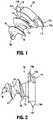
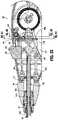
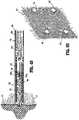
- Tack applier 200includes a handle assembly 210, and an endoscopic assembly 230 extending from handle assembly 210 and configured to store and selectively release or fire a plurality of anchors 100 therefrom and into mesh "M" overlying tissue "T”. (see FIG. 50 ).
- handle assembly 210includes a handle housing 212 formed from a first half-section 212a and a second half section 212b joined to one another.
- First half-section 212a and second half section 212b of handle housing 212may be joined to one another using know methods by those of skill in the art, including and not limited to welding, fasteners (i.e., screws) and the like.
- Handle assembly 210includes a trigger 214 pivotably connected to handle housing 212, at a location remote from endoscopic assembly 230.
- Handle assembly 210includes a biasing member 222 configured for maintaining trigger 214 in an extended or un-actuated position.
- Biasing member 222is also configured to have a spring constant sufficient to return trigger 214 to the un-actuated position.
- Trigger 214defines a gear rack 214a formed thereon at a location opposite or remote from the pivot of trigger 214.
- Gear rack 214a of trigger 214is configured for operative engagement with a pinion gear 216 rotatably supported in handle housing 212.
- Gear rack 214a and pinion gear 216are dimensioned such that one complete squeeze of trigger 214 results in one complete revolution of pinion gear 216.
- handle assembly 210includes a timing system 270 associated therewith.
- Timing system 270includes a raceway 214c formed in a surface of trigger 214.
- Raceway 214cdefines a plurality of steps 214d therealong, and a home position 214e ( FIGS. 9 and 48 ) formed therein.
- Timing system 270includes a resilient and deflectable arm 272 having a first end 272a operative connected or disposed in raceway 214c and that is in contact with steps 214d as first end 272a thereof travels around raceway 214c.
- Deflectable arm 272further includes a second end 272b that is connected to handle housing half 212b.
- Raceway 214c of triggeris configured such that when trigger 214 is in a fully un-actuated position, first end 272a of deflectable arm 272 is located in the home position 214e of raceway 214c.
- first end 272a of deflectable arm 272is located in the home position 214e of raceway 214c. Then, as trigger 214 is actuated, first end 272a of arm 272 rides through and/or along raceway 214c (in a single direction) formed in trigger 214.
- First end 272a of arm 272moves uni-directionally over steps 214d of raceway 214c, such that, if trigger 214 is released after a partial squeeze, first end 272a of arm 272 can not move backwards or in reverse through raceway 214c due to steps 214d and trigger 214 can not return to the fully un-actuated position.
- end effector or SULU 300may only be removed and replaced when trigger 214 is in the fully un-actuated, home and locked position. As such, an end effector or SULU 300 can not be removed or replaced or loaded on/in handle assembly 200 while trigger 214 is in a short-stroked condition (i.e., partially actuated).
- timing system 270includes sufficient steps 214d in raceway 214c so as to create an audible/tactile indication when trigger 214 is in a fully un-actuated home or lockout position (for loading/unloading end effector or SULU 300); after trigger 214 has been fully actuated to fire a singe surgical anchor 100; and when trigger 214 is reset to the fully un-actuated home position (wherein trigger 214 may once again be locked) and ready to fire another surgical anchor 100.
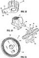
- handle assembly 210includes a pinion gear 216 having an arm 216a extending radially therefrom and a cam or ramp 216b extending/projecting from arm 216a.
- Cam 216bincludes a front end 216c having a height defining a shoulder, and tail end 216d tapering into arm 216a.
- handle assembly 210further includes a first bevel gear 218, in the form of a crown gear, operatively engaged/associated with pinion gear 216.
- First bevel gear 218defines an arcuate slot 218a formed in a face 218d thereof for selectively receiving and engaging cam 216b of pinion gear 216.
- Slot 218aincludes a front end wall 218b configured to engage front end 216c of cam 216b of pinion gear 216, and tapers along a length thereof to be flush with face 218d of first bevel gear 218.
- gear rack 214a thereofis moved in an axial or arcuate first direction to thereby rotate pinion gear 216, meshed therewith, in a first direction.
- pinion gear 216is rotated in the first direction
- front end 216c of cam 216b of pinion gear 216is rotated in a first direction until front end 216c engages or contacts front end wall 218a of slot 218b of first bevel gear 218.
- front end 216c of pinion gear 216engages or contacts front end wall 218a of slot 218b of first bevel gear 218, continued rotation of pinion gear 216 in the first direction results in concomitant rotation of first bevel gear 218 in a first direction.
- first bevel gear 218continues to rotate in the first direction so long as trigger 214 is being actuated and gear rack 214ais moving in the first direction.
- gear rack 214a thereofis moved in a second direction (opposite the first direction) to thereby rotate pinion gear 216 in a second direction.
- pinion gear 216is rotated in the second direction rear end 216d of cam 216b thereof slides along slot 218b of first bevel gear 218, and if the rotation in the second direction is sufficient, slides out of slot 218b of bevel gear 218 and along face 218d of first bevel gear 218.
- handle assembly 210 of tack applier 200is provided with a ratchet mechanism 260 which is configured to inhibit or prevent inner shaft assembly 238 from backing-out or reversing after anchor 100 has been at least partially driven into tissue.
- Ratchet mechanism 260includes, as seen in FIGS. 8 and 11 , a series of ratchet teeth 218f formed on a rear surface 218e of first bevel gear 218.
- Ratchet mechanism 260further includes a spring clip 262 secured within handle assembly 210.
- Spring clip 262includes a resilient finger 262a configured for engagement with ratchet teeth 218f formed on rear surface 218e of first bevel gear 218.
- Each ratchet tooth 218fincludes a shallow angled side and a steep angled side.
- resilient finger 262a of spring clip 262engages with ratchet teeth 218f in such a manner that as first bevel gear 218 is rotated, in a first direction resilient, finger 262a of spring clip 262 cams over the shallow angled side of ratchet teeth 218f.
- resilient finger 262a of spring clip 262stops against the steep angled side of ratchet teeth 218f thereby preventing or inhibiting first bevel gear 218 from rotating in the second direction.
- any reverse rotation or "backing-out" of anchor 100 or inner shaft assembly 238(tending to cause first bevel gear 218 to rotate in the second direction), during a driving or firing stroke, is inhibited or prevented.
- first bevel gear 218may be maintained from rotating in the second or opposite direction, upon the rotation of pinion gear 216, in the second direction, due to a coefficient of static friction between first bevel gear 218 and a surface of handle housing 212, or a coefficient of static friction between first bevel gear 218 and a pin upon which first bevel gear 218 is supported, which will tend to maintain first bevel gear 218 stationary.
- Such a configuration and assemblyfunctions as a ratchet mechanism or the like for tack applier 200.
- handle assembly 210further includes a second or pinion-bevel gear 220 having gear teeth 220a operatively engaged or meshed with gear teeth 218c formed at the outer radial edge and on front face 218d of first bevel gear 218.
- Pinion-bevel gear 220is secured to a proximal end of an inner shaft assembly 238 of anchor retaining/advancing assembly 230 (see FIG. 15 ).
- pinion-bevel gear 220is keyed to proximal end of inner shaft assembly 238 of anchor retaining/advancing assembly 230 such that inner shaft assembly 238 is capable of axial displacement relative to pinion-bevel gear 220 and is prevented from rotation relative to pinion-bevel gear 220.
- gear rack 214a thereofcauses pinion gear 216 to rotate in the first direction.
- Rotation of pinion gear 216, in the first directionresults in rotation of first bevel gear 218 in the first direction and, in turn, rotation of pinion-bevel gear 220 in a first direction.
- pinion-bevel gear 220transmits the rotation to inner shaft assembly 238 of anchor retaining/advancing assembly 230.
- handle assembly 210includes a button 240 supported on handle housing 212 and being configured to permit and inhibit actuation of trigger 214, and for effectuating a loading/retention and a release/removal of an end effector 300 to anchor retaining/advancing assembly 230.
- Button 240includes a pin 240a slidably supported in handle housing 212. Pin 240a is oriented in a direction orthogonal to the longitudinal axis of anchor retaining/advancing assembly 230. As seen in FIGS.
- pin 240ahas a length such that when button 240 is in a first position, a first end of pin 240a extends from a first side of handle housing 212, and when button 240 is in a second position, a second end of pin 240a extends from a second side of handle housing 212.
- button 240includes a plate 240b supported on and connected to pin 240a.
- Plate 240bdefines an elongate slot 240c therein, through which a stem 220a of pinion-bevel gear 220 extends.
- Elongate slot 240c of plate 240bdefines a major axis which is parallel relative to a longitudinal axis of pin 240a. In use, as pin 240a is moved between the first position and the second position, plate 240b is moved between respective first and second positions.
- Button 240includes a first detent or recess 240d defined in plate 240b that is engaged by a biasing member 242 when button 240 is in the first position, and a second detent or recess 240e defined in plate 240b that is engaged by biasing member 242 when button 240 is in the second position.
- the engagement of biasing member 242 in either first detent 240d or second detent 240e of button 240functions to help maintain button 240 in either the first or second position.
- biasing member 242may be in the form of a plunger spring, and, as seen in FIGS. 33 and 42 , in another embodiment, biasing member 242 may be in the form of a torsion spring.
- a torsion springis contemplated over a plunger spring in order to reduce overall costs of surgical tacker 200.
- button 240includes a first wall 240f extending from plate 240b, and a second wall 240g extending from plate 240b.
- first wall 240fblocks or inhibits movement of a load/release slider 244
- button 240is in the second position, first wall 240f thereof permits movement of load/release slider 244.
- second wall 240gwhen button 240 is in the second position (only achievable when trigger 214 is in a fully un-actuated or home position), second wall 240g thereof blocks or inhibits actuation of trigger 214 by second wall 240g extending into a notch 214b of trigger 214; and when button 240 is in the first position, second wall 240f is clear of notch 214b of trigger 214 to permit actuation of trigger 214.
- handle assembly 210includes a load/release slider 244 slidably supported on handle housing 212 and being configured to effectuate a loading/retention and a release/removal of an end effector 300, in the form of a single use loading unit (SULU) or disposable loading unit (DLU), as will be discussed in greater detail below.
- Slider 244includes a first stem 244a extending proximally therefrom and toward button 240. Specifically, first stem 244a of slider 244 is in axial registration with first wall 240f extending from plate 240b of button 240 when button 240 is in the first position (see FIG. 39 ), and out of axial registration with first wall 240f of button 240 when button 240 is in the second position (see FIG. 41 ).
- Slider 244further includes a second stem 244b extending therefrom in a direction toward inner shaft assembly 238 of anchor retaining/advancing assembly 230.
- inner shaft assembly 238supports a pair of axially spaced apart radial flanges 238d, 238e which bookend (i.e., one flange being distal and one flange being proximal of second stem 244b).
- slider 244is free to move between a first or distal position and a second or proximal position.
- second stem 244b of slider 244exerts a force on proximal radial flange 238d of inner shaft assembly 238 to urge inner shaft assembly 238 proximally from a respective first position to a respective second position.
- second stem 244b of slider 244exerts a force on distal radial flange 238e of inner shaft assembly 238 to urge inner shaft assembly 238 distally from the respective second position to the respective first position.
- inner shaft assembly 238is moved between the respective first and second positions thereof, inner shaft assembly 238, being connected to coupling member 238c results in connecting member 238c also moving between a respective first position and a respective second position.
- Slider 244may be biased to the first or distal position by a biasing member 245 (see FIG. 42 ).
- handle assembly 210includes an articulation knob 246 rotatably supported on handle housing 212.
- Articulation knob 246defines an inner helical thread 246a.
- Inner helical thread 246ameshingly receives or engages an outer thread 247a of a connection nut 247 that is non-rotatably connected to proximal tube portion 234a of inner tube assembly 234 of anchor retaining/advancing assembly 230.
- Connection nut 247may be keyed to articulation knob 246 so as to not rotate relative to articulation knob 246 as articulation knob 246 is rotated.
- the surgeonmay manually grip a distal end of connection nut 247 (which is projecting/extending distally of articulation knob 246) as articulation knob 246 is rotated.
- connection nut 247In use, as seen in FIGS. 45 and 46 , with connection nut 247 retained against rotation about the longitudinal axis, as articulation knob 246 is rotated in a first direction, connection nut 247 travels along inner helical thread 246a of articulation knob 246 to cause inner articulation tube assembly 234 to move in a respective first or distal axial direction; and as articulation knob 246 is rotated in a second direction, connection nut 247 travels along inner helical thread 246a of articulation knob 246 to cause inner articulation tube assembly 234 to move in a respective second or proximal axial direction.
- rotation of articulation knob 246 in the respective first and second directionsresults in the articulating and straightening of anchor retaining/advancing assembly 230, as will be discussed in greater detail below.
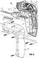
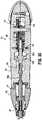
- endoscopic assembly 230includes an outer tube 231, an outer support tube assembly 232 disposed within outer tube 231, an inner articulation tube assembly 234, and an inner shaft assembly 238.
- Outer support tube assembly 232includes a proximal support tube portion 232a secured to and extending from handle housing 212, and a distal support tube portion 232b pivotally connected to proximal tube portion 232a by a pivot pin 232c (see FIGS. 15 and 16 ) at an articulation joint 250.
- distal support tube portion 232bsupports a ball detent 233 in an outer surface thereof.
- Ball detent 233functions to selectively secure and retain end effector 300 to endoscopic assembly 230.
- ball detent 233is acted on by an outer camming surface/relief 238ci of coupling member 238 which acts on ball detent 233 to move ball detent 233 radially outward when inner shaft assembly 238 is a distal position.
- Inner articulation tube assembly 234includes a proximal tube portion 234a concentrically and slidably disposed within proximal tube portion 232a of outer support tube assembly 232. As seen in FIG. 33 , proximal end 234b of proximal tube portion 234a is non-rotatably connected to connection nut 247.
- Inner articulation tube assembly 234includes an articulation link 235 having a proximal end 235a pivotally connected to a distal end of proximal tube portion 234a, and a distal end 235b pivotally connected to distal tube portion 232b of outer support tube assembly 232.
- Distal end 235b of articulation link 235is pivotally connected to distal tube portion 232b of outer support tube assembly 232 at a location offset from the central longitudinal axis of anchor retaining/advancing assembly 230, in a direction substantially away from pivot pin 232c of articulation joint 250.
- proximal tube portion 234aacts or pulls on articulation link 235 to cause articulation link 235 to translate in a proximal direction.
- articulation link 235acts or pulls on distal tube portion 232b of outer support tube assembly 232 to cause distal tube portion 232b to pivot about a pivot axis of pivot pin 232c.
- distal tube portion 232bcauses end effector 300 to be moved to an articulated orientation relative to the central longitudinal axis of anchor retaining/advancing assembly 230.
- proximal tube portion 234aacts or pushes on articulation link 235 to cause articulation link 235 to translate in a distal direction.
- articulation link 235acts or pushes on distal tube portion 232b of outer support tube assembly 232 to cause distal tube portion 232b to pivot about a pivot axis of pivot pin 232c.
- distal tube portion 232bcauses end effector 300 to be returned to a non-articulated orientation relative to the central longitudinal axis of anchor retaining/advancing assembly 230.
- distal tube portion 232b of anchor retaining/advancing assembly 230is pivotable in a single direction relative to proximal tube portion 232a of anchor retaining/advancing assembly 230.
- inner actuation shaft assembly 238includes a proximal rigid shaft portion 238a, a distal flexible shaft portion 238b non-rotatably connected to and extending from a distal end of proximal rigid shaft portion 238a, and a coupling member 238c non-rotatably connected to a distal end of distal flexible shaft portion 238b.
- Second or pinion-bevel gear 220is non-rotatably connected to a proximal end of proximal rigid shaft portion 238a of inner actuation shaft assembly 238.
- Inner actuation shaft assembly 238is configured such that distal flexible shaft portion 238b extends across and beyond articulation joint 250.
- coupling member 238cis rotatably and slidably supported in distal tube portion 232b of outer support tube assembly 232 so as to accommodate and/or account for variations in length of distal flexible shaft portion 238b when distal flexible shaft portion 238b is in a flexed condition.
- Coupling member 238cis substantially tongue shaped and extends in a distal direction distally from distal tube portion 232b of outer support tube assembly 232.
- Coupling member 238cis configured for non-rotatable connection to inner tube 338 of end effector 300, as will be discussed in greater detail below.
- Distal flexible shaft portion 238bis fabricated from a torsionally stiff and flexible material, such as, for example, stainless steel.
- distal flexible shaft portion 238bmay have an outer diameter of about 0.08'(2,44cm).
- anchor retaining/advancing assembly 230has an outer diameter of about 0.22' (6,71cm).
- a ratio of the outer diameter of distal flexible shaft portion 238b to the outer diameter of anchor retaining/advancing assembly 230is about 2.8.
- Inner actuation shaft assembly 238is configured to perform at least a pair of functions, a first function relating to the securing and release of an end effector or SULU 300 to distal tube portion 232b of outer support tube assembly 232 upon an axial translation thereof, and a second function relating to the firing of fasteners 100 from end effector or SULU 300 when end effector or SULU 300 is coupled to distal tube portion 232b of outer support tube assembly 232 upon a rotation thereof.
- trigger 214In order to prepare surgical tacker 200 for receipt of end effector or SULU 300 or to replace a spent end effector or SULU 300 with a new end effector or SULU 300, as seen in FIGS. 38-44 , and as mentioned above, trigger 214 must be in a fully un-actuated position. With trigger 214 in the fully un-actuated position, button 240 is moved from the first position to the second position (as described above) such that trigger 214 is prevented from actuation and such that slider 244 is free to move. With button 240 in the second position, slider 244 is moved from the first position to the second position (as described above).
- second stem 244b of slider 244exerts a force on proximal radial flange 238d of inner shaft assembly 238 to urge inner shaft assembly 238, and in turn coupling member 238a thereof, proximally from a respective first position to a respective second position.
- ball detent 233is free to drop or move radially inward of outer tube 231 as outer camming surface/relief 238c 1 of coupling member 238 is moved into axial registration with ball detent 233.
- end effector or SULU 300may be fully coupled to distal support tube portion 232b of anchor retaining/advancing assembly 230.
- end effector or SULU 300may only be removed and replaced when trigger 214 is in the fully un-actuated, home and locked position. As such, end effector or SULU 300 can not be removed or replaced or loaded while trigger 214 is in a short-stroked condition (i.e., partially actuated).
- slider 244With a new end effector or SULU 300 fully coupled to distal support tube portion 232b of anchor retaining/advancing assembly 230, slider 244 is moved from the second position to the first position to secure or lock end effector or SULU 300 to distal support tube portion 232b of anchor retaining/advancing assembly 230.
- second stem 244b of slider 244exerts a force on distal radial flange 238e of inner shaft assembly 238 to urge inner shaft assembly 238, and in turn coupling member 238a thereof, distally from second position to first position.
- ball detent 233is urged by outer camming surface/relief 238c 1 of coupling member 238 to move ball detent 233 radially outward. As ball detent 233 moves radially outward a portion of ball detent 233 enters an aperture 332c of end effector or SULU 300 to secure end effector or SULU 300 to distal support tube portion 232b of anchor retaining/advancing assembly 230.
- button 240With end effector or SULU 300 coupled to distal support tube portion 232b of anchor retaining/advancing assembly 230, button 240 is moved from the second position to the first position (as described above) such that slider 244 is prevented from actuation and such that trigger 214 is free to move.
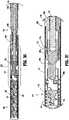
- end effector 300in the form of a SULU or DLU, is shown and will be described herein.
- End effector 300is selectively connectable to distal tube portion 232b of outer support tube assembly 232.
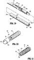
- End effector or SULU 300includes an outer tube 332 defining a lumen 332a therethrough and being configured and dimensioned (i.e., substantially rectangular or dog bone shaped) to receive distal tube portion 232b of outer support tube assembly 232 and coupling member 238c of anchor retaining/advancing assembly 230 therein.
- outer tube 332defines a proximal key slot 332b for engagement with a key 232c formed in distal tube portion 232b of outer support tube assembly 232.
- end effector or SULU 300In use, when end effector or SULU 300 is connected to distal tube portion 232b of outer support tube assembly 232 key slot 332b and key 232c engage with one another to properly align end effector or SULU 300 and anchor retaining/advancing assembly 230 to one another.
- End effector or SULU 300further includes a spiral or coil 336 fixedly disposed within a distal portion of outer tube 332.
- a pair of axially spaced apart retention rings 337a, 337bare also fixedly disposed within outer tube 332 at a location proximal of coil 336.
- End effector or SULU 300also includes an inner tube 338 rotatably disposed within coil 336.
- Inner tube 338defines a lumen therethrough, and includes a proximal end portion 338a and a splined distal end portion 338b.
- Proximal end portion 338a of inner tube 338is configured and dimensioned to slidably receive coupling member 238c of anchor retaining/advancing assembly 230 therein.
- Inner tube 338includes a plurality of retention tabs 338c projecting radially outward therefrom and which snap beyond one of the pair of retention rings 337a, 337b, when inner tube 338 is assembled with outer tube 332. In this manner, outer tube 332 and inner tube 338 are axially fixed and yet rotatable relative to one another.
- Distal end portion 338a of inner tube 338is slotted, defining a pair of tines 338a 1 and a pair of channels 338a 2 .
- Distal end portion 338a of inner tube 338is capable of accepting a plurality of anchors 100 within inner tube 338.
- anchors 100arc loaded into end effector or SULU 300 such that the pair of opposing threaded sections 112a, 112b of anchors 100 extend through respective channels 338a 2 of distal end portion 338a of inner tube 338 and are slidably disposed within the groove of coil 336, and the pair of tines 338a 1 of distal end portion 338a of inner tube 338 are disposed within the pair of slotted sections 116a, 116b of anchors 100.
- Each anchor 100is loaded into end effector or SULU 300 such that adjacent anchors 100 are not in contact with one another so as to not damage distal tips 136.
- the pair of tines 338a 1 of inner tube 338transmit the rotation to anchors 100 and advance anchors 100 distally owing to head threads 114a, 114b of anchors 100 engaging with coil 336.
- the pair of tines 338a 1 of inner tube 338transmit the rotation to the entire stack of anchors 100 and advance the entire stack of anchors 100 distally, owing to head threads 114a, 114b of anchors 100 engaging with coil 336.
- the components of surgical tacker 200, and anchors 100are dimensioned such that a single complete and full actuation of trigger 214 results in a firing of a single anchor 100 (i.e., the distal-most anchor of the stack of anchors 100 loaded in end effector or SULU 300) from end effector or SULU 300.
- Surgical tacker 200may be repeatedly fired to fire anchors from end effector 300 until the surgical procedure is complete or until end effector or SULU 300 is spent of anchors 100. If end effector or SULU 300 is spent of anchors 100, and if additional anchors 100 are required to complete the surgical procedure, spent end effector or SULU 300 may be replaced with a new (i.e., loaded with anchors 100) end effector or SULU 300.
- end effector or SULU 300may only be connected or coupled to distal tube portion 232b of outer support tube assembly 232 of anchor retaining/advancing assembly 230 while anchor retaining/advancing assembly 230 is in the non-articulated condition.
- articulation knob 246is rotated or held in place such that anchor retaining/advancing assembly 230 is in a non-articulated condition.
- end effector or SULU 300is introduced into a target surgical site while in the non-articulated condition.
- end effector or SULU 300disposed within the target surgical site, the surgeon may remotely articulate end effector or SULU 300 relative to anchor retaining/advancing assembly 230.
- the surgeonrotates articulation knob 246 to axially displace connection nut 247 and proximal tube portion 234a of inner articulation tube assembly 234 to move in the proximal axial direction.
- proximal tube portion 234aacts or pulls on articulation link 235 to cause articulation link 235 to translate in a proximal direction.
- articulation link 235acts or pulls on distal tube portion 232b of outer support tube assembly 232 to cause distal tube portion 232b to pivot about a pivot axis of pivot pin 232c.
- distal tube portion 232bis pivoted, distal tube portion 232b causes end effector 300 to be moved to an articulated orientation relative to the central longitudinal axis of anchor retaining/advancing assembly 230.
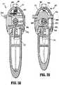
- a shipping wedge 400may be provided which is configured and dimensioned to releasably connect to end effector or SULU 300, to inhibit premature rotation of inner tube 338 of end effector or SULU 300, and to help facilitate loading/unloading of end effector or SULU 300 to/from distal tube portion 232b of anchor retaining/advancing assembly 230.
- Shipping wedge 400includes a handle portion 402 and a coupling member 404 integrally formed with or secured to handle portion 402.
- Coupling member 404is substantially tubular having a substantially C-shaped transverse cross-sectional profile.
- Coupling member 404defines a longitudinally extending opening or gap 404a therealong.
- Handle portion 404defines a longitudinal axis that is substantially orthogonal to the longitudinal axis of coupling member 404.
- Coupling member 404has a diameter sufficient to accommodate end effector or SULU 300 therein and along. Also, gap 404a of coupling member 404 has a dimension, which together with the materials of construction of at least coupling member 404, allows for coupling member 404 to be snapped-over end effector or SULU 300. It is envisioned that at least coupling member 404 may be fabricated from a polymeric or other substantially rigid and resilient material.
- shipping wedge 400includes a wedge, spike or nub 406 extending radially into coupling member 404.
- wedge 406extends or projects in a direction substantially parallel to the longitudinal axis of handle portion 402.
- Wedge 406has a length sufficient such that, when shipping wedge 400 is attached to end effector or SULU 300, wedge 406 enters an aperture 332d (see FIGS. 19 , 22 , 29 and 30 ) formed in outer tube 332 of end effector or SULU 300.
- wedge 406when shipping wedge 400 is attached to end effector or SULU 300, wedge 406 extends to be in close proximity to or in contact with proximal end portion 338a of inner tube 338 of end effector or SULU 300. By extending this amount, wedge 406 inhibits rotation of inner tube 338 relative to outer tube 332 by blocking or contacting proximal end portion 338a of inner tube 338 if inner tube 338 experiences any rotation relative to outer tube 332.
- shipping wedge 400when shipping wedge 400 is attached to end effector or SULU 300, and with wedge 406 blocking rotation of inner tube 338 of end effector or SULU 300, shipping wedge 400 facilitates a loading/unloading of end effector or SULU 300 to/from distal tube portion 232b of anchor retaining/advancing assembly 230.
- shipping wedge 400functions to fix an angular orientation of proximal end portion 338a of inner tube 338 for proper alignment and orientation with coupling member 238c of anchor retaining/advancing assembly 230.
- handle assembly 100may be replaced by an electromechanical control module configured and adapted to drive the flexible drive cables to fire or actuate the surgical device.
- the electromechanical control modulemay include at least one microprocessor, at least one drive motor controllable by the at least one microprocessor, and a source of power for energizing the at least one microprocessor and the at least one drive motor.
- the length of the linear row of staples or fastenersmay be modified to meet the requirements of a particular surgical procedure.
- the length of the linear row of staples and/or fasteners within a staple cartridge assemblymay be varied accordingly. Therefore, the above description should not be construed as limiting, but merely as exemplifications of various embodiments.
Landscapes
- Health & Medical Sciences (AREA)
- Surgery (AREA)
- Life Sciences & Earth Sciences (AREA)
- Engineering & Computer Science (AREA)
- Molecular Biology (AREA)
- Biomedical Technology (AREA)
- Heart & Thoracic Surgery (AREA)
- Medical Informatics (AREA)
- Nuclear Medicine, Radiotherapy & Molecular Imaging (AREA)
- Animal Behavior & Ethology (AREA)
- General Health & Medical Sciences (AREA)
- Public Health (AREA)
- Veterinary Medicine (AREA)
- Mechanical Engineering (AREA)
- Surgical Instruments (AREA)
- Endoscopes (AREA)
Description
- The present disclosure relates to surgical apparatus, devices and/or systems for performing endoscopic surgical procedures and methods of use thereof. More specifically, the present disclosure relates to surgical apparatus, devices and/or systems for performing endoscopic surgical procedures which includes an articulating endoscopic portion.
- During laparoscopic or endoscopic surgical procedures, access to a surgical site is achieved through a small incision or through a narrow cannula inserted through a small entrance wound in a patient. Because of limited area to access the surgical site, many endoscopic surgical devices include mechanisms for articulating the tool assembly of the device. Typically, the articulating mechanism is controlled by an actuator which has to be manipulated by a surgeon to properly orient the tool assembly in relation to tissue to be treated.
EP2777517 A1 is an intermediate document according to Art. 54(3) EPC and relates to an endoscopic surgical device which includes a handle assembly including a handle housing and a trigger operatively connected to the handle housing, and a drive mechanism actuatable by the trigger; and an endoscopic anchor retaining/advancing assembly extending from the handle assembly. The endoscopic anchor retaining/advancing assembly including a proximal tube portion and a distal tube portion pivotably connected to one another at an articulation joint, each of the proximal tube portion and the distal tube portion defining a central longitudinal axis; a proximal inner shaft rotatably disposed within the proximal tube portion, wherein the proximal inner shaft is relatively rigid, and wherein the proximal inner shaft is mechanically connected to the drive mechanism such that actuation of the trigger results in rotation of the proximal inner shaft; a distal inner shaft rotatably disposed within the distal tube portion, wherein the distal inner shaft is relatively rigid; and an intermediate drive cable mechanically interconnecting the proximal inner shaft and the distal inner shaft, wherein the intermediate drive cable is relatively flexible as compared to the proximal inner shaft and the distal inner shaft, wherein the intermediate drive cable extends from and between the proximal tube portion and the distal tube portion, across the articulation joint, wherein the intermediate drive cable defines a central longitudinal axis and wherein the central longitudinal axis of the intermediate drive cable is off-set a radial distance from the central longitudinal axis of the proximal tube portion and the distal tube portion.WO 2013/046115 A1 relates to a surgical fastening device adapted to both push tacks and rotate screws into the body.US 2011/022065 A1 relates to surgical fasteners and their associated applicators, and more particularly to surgically fastening material to tissue and a corresponding method of use.- Accordingly, a need exists for endoscopic surgical devices which include features which indicate to the surgeon whether the endoscopic portion of the surgical device, when in the surgical site, is in a non-articulated or articulated orientation.
- The present invention is defined by the features of the independent claim. Embodiments of the invention are defined in the dependent claims.
- The present disclosure relates to surgical apparatus, devices and/or systems for performing endoscopic surgical procedures which includes an articulating endoscopic portion.
- According to an aspect of the present disclosure, an endoscopic surgical device is provided. The surgical device includes a handle assembly including a handle housing and a trigger operatively connected to the handle housing, and a drive mechanism actuatable by the trigger; and an endoscopic assembly including a proximal end portion extending from the handle assembly; a distal end portion pivotably connected to the proximal end portion of the endoscopic assembly at a pivot point; and a rotatable inner actuation shaft extending from the handle assembly and into the distal end portion of the endoscopic assembly, the inner actuation shaft including a flexible portion extending across the pivot point, the inner actuation shaft being connected to the drive mechanism of the handle assembly such that an actuation of the trigger results in a rotation of the inner actuation shaft.
- The surgical device further includes an end effector selectively connectable to the distal end portion of the endoscopic assembly and to a distal portion of the rotatable inner actuation shaft. The end effector includes an outer tube having a helical thread along an inner surface thereof; a splined inner tube rotatably supported in the outer tube, wherein the splined inner tube is defined by a pair of opposed longitudinally extending tines and a pair of opposed longitudinally extending channels, a proximal end of the splined inner tube being configured for non-rotatable selective connection to a distal end of the rotatable inner actuation shaft when the end effector is connected to the distal end portion of the endoscopic assembly; and a plurality of surgical anchors loaded in the inner tube of the end effector, wherein each anchor includes a threaded body portion, and a head portion defining a pair of opposed radially outer threads and a pair of opposed radial recesses, wherein the pair of radial recess of each head portion receive respective tines of the inner tube and wherein the pair of opposed radially outer threads of each head portion project from the pair of opposed longitudinally extending channels of the inner tube and engage the inner helical thread of the outer tube.
- The endoscopic assembly includes a support tube assembly having a proximal support tube portion extending from the handle assembly, and a distal support tube portion pivotally connected to proximal support tube portion thereby defining an articulation joint therebetween.
- The endoscopic assembly includes an articulation tube slidably supported in the support tube assembly, a proximal end of the articulation tube being connected to an articulation actuator supported on the handle assembly, and a distal end of the articulation tube being pivotably connected to an articulation link that is also pivotably connected to the distal support tube portion of the support tube assembly.
- The inner actuation shaft is rotatably supported in the articulation tube. The inner actuation shaft includes a proximal shaft portion operatively connected to the drive mechanism, a distal shaft portion non-rotatably connected to a distal end of the proximal shaft portion, and a coupling member non-rotatably connected to a distal end of the distal shaft portion.
- The distal shaft portion of the inner actuation shaft may be the flexible portion.
- The flexible portion of the inner actuation shaft may be relatively more flexible than the proximal shaft portion of the inner actuation shaft.
- In use, an actuation of the trigger may result in a rotation of the inner actuation shaft of the endoscopic assembly.
- The drive mechanism may transmit the actuation of the trigger into rotation of the inner actuation shaft of the endoscopic assembly.
- The endoscopic assembly may include an inner articulation tube assembly having the articulation tube defining a proximal end and a distal end, the proximal end of the articulation tube being operatively connected to the articulation actuator. The articulation link may have a proximal end pivotally connected to the distal end of the articulation tube.
- The handle assembly may include an articulation knob rotatably supported thereon. The articulation knob may be the articulation actuator. The articulation knob may define an inner helical thread, the proximal end of the articulation tube may be operatively connected to the articulation tube such that rotation of the articulation knob causes the articulation tube to axially translate.
- In use, axial translation of the articulation tube may cause the distal support tube portion of the support tube assembly to pivot about the pivot point.
- The endoscopic assembly may include a connection nut fixedly secured to the proximal end of the articulation tube. The connection nut may define an outer helical thread and may meshingly engage the inner helical thread of the articulation knob.
- The endoscopic assembly may support a ball detent in the distal support tube portion of the support tube assembly. The ball detent may have a projected position wherein the ball detent partially projects radially outward from the distal support tube portion of the support tube assembly. The ball detent may have a retracted position wherein the ball detent does not project radially outward from the distal support tube portion of the support tube assembly as far as when in the projected position.
- The ball detent may ride along an outer surface of the coupling member of the inner actuation shaft of the endoscopic assembly.
- The inner actuation shaft may be axially translatable between a proximal position wherein the ball detent is in the retracted position and a distal position wherein the coupling member of the inner actuation shaft holds the ball detent in the projected position.
- In use, when the end effector is connected to the distal end portion of the endoscopic assembly, and when the ball detent is in the projected position, the ball detent may engage a recess in the end effector to secure the end effector to the distal end portion of the endoscopic assembly.
- The inner actuation shaft is axially translatable within the articulation tube.
- A proximal end of the proximal shaft portion of the inner actuation shaft supports a pair of axially spaced apart radial flanges.
- The handle assembly includes a slider supported thereon. A stem of the slider extends between the pair of axially spaced apart radial flanges supported on the inner actuation shaft.
- The slider is movable between a proximal position and a distal position. In use, movement of the slider between the proximal position and the distal position results in movement of the inner actuation shaft between a respective proximal position and a distal position.
- The slider may be in the proximal position, the end effector is connectable to the to the distal end portion of the endoscopic assembly. In use, when the slider is in the distal position, the end effector may be secured to the to the distal end portion of the endoscopic assembly.
- The endoscopic assembly may support a ball detent in the distal support tube portion of the support tube assembly. The ball detent may have a projected position wherein the ball detent partially projects radially outward from the distal support tube portion of the support tube assembly. The ball detent may have a retracted position wherein the ball detent does not project radially outward from the distal support tube portion of the support tube assembly as far as when in the projected position.
- The ball detent may ride along an outer surface of the coupling member of the inner actuation shaft of the endoscopic assembly.
- The ball detent may be in the retracted position when the inner actuation shaft is in the proximal position. The ball detent may be in the projected position when the inner actuation shaft is in the distal position.
- In use, when the end effector is connected to the distal end portion of the endoscopic assembly, and when the ball detent is in the projected position, the ball detent may engage a recess in the end effector to secure the end effector to the distal end portion of the endoscopic assembly.
- The handle assembly may include a button supported thereon. The button may include a first position wherein the button blocks movement of the slider, and a second position wherein the button permits movement of the slider.
- The button may include a wall extending therefrom. In use, when the button is in the first position, the trigger may be actuatable and the slider may be blocked from moving to the proximal position; and when the button is in the second position, the wall of the button may block the actuation of the trigger and the slider may be free to move to the proximal position.
- The handle assembly may include a biasing member tending to maintain the button in one of the first portion and the second position thereon.
- The button may include a wall extending therefrom. In use, when the button is in the first position, the trigger is actuatable; and when the button is in the second position, the wall of the button blocks actuation of the trigger.
- The distal end portion of the endoscopic assembly may be pivotable when the button is in the second position.
- The coupling member of the inner actuation shaft may have a non-circular transverse cross-sectional profile, and wherein the proximal end of the splined inner tube of the end effector may have a splined inner tube rotatably supported in the outer tube. The splined inner tube may be defined by a pair of opposed longitudinally extending tines and a pair of opposed longitudinally extending channels. A proximal end of the splined inner tube may have a transverse cross-sectional profile that complements the non-circular transverse cross-sectional profile of the coupling member.
- The handle assembly may include an audible/tactile feedback system associated with the trigger. The audible/tactile feedback system may produce at least one of an audible feedback and a tactile feedback when the trigger is in one of a locked out position for loading and unloading an end effector to the endoscopic assembly, when the trigger has been fully actuated, and when the trigger returns to a home position.
- The distal end portion of the endoscopic assembly may be articulatable between a non-articulated orientation and a plurality of articulated orientations relative to the proximal end portion thereof.
- According to the invention, an end effector for selective connection to a rotatable drive shaft of a surgical handle assembly is provided. The end effector includes an outer tube having a helical thread along an inner surface thereof; a splined inner tube rotatably supported in the outer tube, wherein the splined inner tube is defined by a pair of opposed longitudinally extending tines and a pair of opposed longitudinally extending channels, a proximal end of the splined inner tube being configured for non-rotatable selective connection to a distal end of the rotatable drive shaft of the surgical handle assembly when the end effector is connected thereto; and a plurality of surgical anchors loaded in the inner tube.
- Each anchor includes a threaded body portion; and a head portion defining a pair of opposed radially outer threads and a pair of opposed radial recesses, wherein the pair of radial recess of each head portion receive respective tines of the inner tube and wherein the pair of opposed radially outer threads of each head portion project from the pair of opposed longitudinally extending channels of the inner tube and engage the inner helical thread of the outer tube.
- The proximal end of the inner tube may have a non-circular transverse cross-sectional profile.
- The helical thread of the outer tube may be defined by a helical coil.
- The inner tube may be fixed against longitudinal displacement relative to the outer tube.
- Each surgical anchor may be formed from a bioabsorbable material.
- According to still a further aspect of the present disclosure, an endoscopic surgical device configured to fire a surgical anchor into target tissue is provided. The surgical device includes a handle assembly including a handle housing; a trigger operatively connected to the handle housing, the trigger including at least a fully un-actuated position; a drive mechanism actuatable by the trigger; and a timing system associating the trigger with the drive mechanism.
- The surgical device further includes an endoscopic assembly including a proximal end portion extending from the handle assembly; a distal end portion configured to support an end effector; and a rotatable inner actuation shaft extending from the handle assembly and into the distal end portion of the endoscopic assembly, the inner actuation shaft being connected to the drive mechanism of the handle assembly such that an actuation of the trigger results in a rotation of the inner actuation shaft to fire a surgical anchor of the surgical device.
- In use, the timing system maintains a timing of an actuation stroke of the trigger with an actuation of the drive mechanism to fire a single surgical anchor upon a single stroke of the trigger from the fully un-actuated position, to a fully actuated position, to the fully un-actuated position.
- The timing system may include a raceway formed in a surface of the trigger, the raceway defining a plurality of steps along a length thereof; and a deflectable arm having a first end disposed within the raceway and operatively associated with the steps thereof, and a second end connected to the handle housing.
- The distal end of the deflectable arm may ride through the raceway when the trigger is actuated. The distal end of the deflectable arm may ride through the raceway in a single direction during a complete stroke of the trigger.
- The steps of the raceway may block movement of the distal end of the deflectable arm, in a reverse direction, through the raceway, when the trigger is partially actuated.
- The raceway may define a home position for the distal end of the deflectable arm when the trigger is in the fully un-actuated position.
- The handle assembly may include a button supported thereon. The button may include a first position wherein the button permits actuation of the trigger, and wherein the bottom may include a second position wherein the button blocks actuation of the trigger.
- The button may include a wall extending therefrom. In use, when the button is in the second position the wall of the button may block actuation of the trigger.
- The trigger may define a notch formed therein. In use, the wall of the button may enter the notch of the trigger when the trigger is in the fully un-actuated position and when the button is in the second position.
- The timing system may include a raceway formed in a surface of the trigger, the raceway defining a plurality of steps along a length thereof; and a deflectable arm having a first end disposed within the raceway and operatively associated with the steps thereof, and a second end connected to the handle housing.
- The distal end of the deflectable arm may ride through the raceway when the trigger is actuated.
- The distal end of the deflectable arm may ride through the raceway in a single direction during a complete stroke of the trigger.
- The steps of the raceway may block movement of the distal end of the deflectable arm, in a reverse direction, through the raceway, when the trigger is partially actuated and then un-actuated.
- The raceway may define a home position for the distal end of the deflectable arm when the trigger is in the fully un-actuated position.
- The endoscopic assembly may include a support tube assembly having a proximal support tube portion extending from the handle assembly, and a distal support tube portion configured to removably receive the end effector. The inner actuation shaft may be rotatably supported in the support tube, the inner actuation shaft including a proximal portion operatively connected to the drive mechanism, and a distal portion non-rotatably supporting a coupling member.
- In use, an actuation of the trigger may result in an actuation of the drive mechanism to rotate the inner actuation shaft of the endoscopic assembly.
- The endoscopic assembly may support a ball detent in the distal support tube portion of the support tube assembly. The ball detent may have a projected position wherein the ball detent partially projects radially outward from the distal support tube portion of the support tube assembly. The ball detent may have a retracted position wherein the ball detent does not project radially outward from the distal support tube portion of the support tube assembly as far as when in the projected position.
- The ball detent may ride along an outer surface of the coupling member of the inner actuation shaft of the endoscopic assembly.
- The inner actuation shaft may be axially translatable between a proximal position wherein the ball detent is in the retracted position and a distal position wherein the coupling member of the inner actuation shaft holds the ball detent in the projected position.
- In use, the inner actuation shaft may be axially translatable only when the trigger is in the fully un-actuated position.
- In use, when the end effector is connected to the distal end portion of the endoscopic assembly, and when the ball detent is in the projected position, the ball detent may engage a recess in the end effector to secure the end effector to the distal end portion of the endoscopic assembly.
- Further details and aspects of exemplary embodiments of the present invention are described in more detail below with reference to the appended figures.
- Embodiments of the present disclosure are described herein with reference to the accompanying drawings, wherein:
FIG. 1 is a perspective view of a surgical anchor for use in an endoscopic surgical device in accordance with the present disclosure;FIG. 2 is a side, elevational view of the surgical anchor ofFIG. 1 ;FIG. 3 is a distal, end view of the surgical anchor ofFIGS. 1 and 2 ;FIG. 4 is a side, elevational view, partially broken away, of the surgical anchor ofFIGS. 1-3 ;FIG. 5 is an endoscopic surgical device according to an aspect of the present disclosure;FIG. 6 is a perspective view, with parts separated, of the endoscopic surgical device ofFIG. 5 ;FIG. 7 is an enlarged view of the indicated area of detail ofFIG. 6 ;FIG. 8 is a rear perspective view, with a first housing half-section removed therefrom, of a handle assembly of the endoscopic surgical device ofFIG. 5 ;FIG. 9 is a front perspective view, with a second housing half-section removed therefrom, of a handle assembly of the endoscopic surgical device ofFIG. 5 ;FIG. 10 is a rear perspective view, with a second housing half-section and trigger removed therefrom, of the handle assembly of the endoscopic surgical device ofFIG. 5 ;FIG. 11 is a rear perspective view, with parts separated, and with a second housing half-section removed therefrom, of the handle assembly of the endoscopic surgical device ofFIG. 5 ;FIG. 12 is a perspective view of a pinion gear of the handle assembly ofFIGS. 8-11 ;FIG. 13 is a perspective view of a button and slider of the handle assembly ofFIGS. 8-11 ;FIG. 14 is a perspective view of a bevel gear of the handle assembly ofFIGS. 8-11 ;FIG. 15 is a front perspective view, with parts separated, of an endoscopic assembly of the endoscopic surgical device ofFIG. 5 ;FIG. 16 is an enlarged view of the indicated area of detail ofFIG. 15 ;FIG. 17 is a rear perspective view of the endoscopic surgical device ofFIG. 5 ;FIG. 18 is an enlarged view of the indicated area of detail ofFIG. 17 ;FIG. 19 is a perspective view of the distal end of the endoscopic surgical device ofFIG. 5 with an end effector shown separated therefrom;FIG. 20 is a rear perspective view of the end effector ofFIG. 19 ;FIG. 21 is a rear perspective view of the end effector ofFIG. 20 , with an outer tube removed therefrom;FIG. 22 is a perspective view of the end effector ofFIGS. 20 and 21 , with an outer tube separated therefrom;FIG. 23 is a perspective view of the end effector ofFIGS. 20-22 , with an outer tube removed therefrom and with parts partially separated;FIG. 24 is a perspective view of an inner tube of the end effector ofFIGS. 20-23 , with a plurality of anchors ofFIGS. 1-4 shown separated therefrom;FIG. 25 is a cross-sectional view, as taken along 25-25 ofFIG. 22 ;FIG. 26 is a cross-sectional view, as taken along 26-26 ofFIG. 22 ;FIG. 27 is a cross-sectional view, as taken along 27-27 ofFIG. 22 ;FIG. 28 is a perspective view of the end effector ofFIGS. 20-27 with a shipping wedge shown attached thereto;FIG. 29 is a cross-sectional view as taken through 29-29 ofFIG. 28 ;FIG. 30 is a cross-sectional view as taken through 30-30 ofFIG. 29 ;FIG. 31 is a longitudinal, cross-sectional, elevational view of the endoscopic surgical device ofFIG. 5 ;FIG. 32 is an enlarged view of the indicated area of detail ofFIG. 31 ;FIG. 33 is an enlarged view of the indicated area of detail ofFIG. 31 ;FIG. 34 is a cross-sectional view as taken though 34-34 ofFIG. 31 ;FIG. 35 is an enlarged view of the indicated area of detail ofFIG. 34 ;FIG. 36 is an enlarged view of the indicated area of detail ofFIG. 34 ;FIG. 37 is an enlarged view of the indicated area of detail ofFIG. 36 ;FIG. 38 is a cross-sectional view as taken though 34-34 ofFIG. 33 ;FIG. 39 is a cross-sectional view as taken though 34-34 ofFIG. 33 ;FIG. 40 is a cross-sectional view as taken though 34-34 ofFIG. 33 ;FIG. 41 is a cross-sectional view as taken though 34-34 ofFIG. 33 ;FIG. 42 is an enlarged elevational view of the handle assembly shown inFIGS. 9 and 10 , illustrating an operation of the slider;FIG. 43 is a longitudinal, cross-sectional view the end effector and the endoscopic assembly of the endoscopic surgical device ofFIG. 5 , illustrating a first step in the decoupling thereof;FIG. 44 is a longitudinal, cross-sectional view the end effector and the endoscopic assembly of the endoscopic surgical device ofFIG. 5 , illustrating a second step in the decoupling thereof;FIG. 45 is a longitudinal, cross-sectional view an articulation knob of the handle assembly ofFIGS. 5-11 , illustrating a rotation thereof;FIG. 46 is a longitudinal, cross-sectional view of a distal end of the endoscopic surgical device illustrating an articulation of the end effector relative to the endoscopic assembly due to a rotation of the articulation knob;FIG. 47 is an enlarged elevational view of the handle assembly shown inFIGS. 9 and 10 , illustrating an operation of an audible/tactile feedback member of the handle assembly, shown in an position following an initial actuation of a trigger;FIG. 48 is an enlarged elevational view of the handle assembly shown inFIGS. 9 and 10 , illustrating an operation of the audible/tactile feedback member of the handle assembly, shown in an position following a complete actuation of the trigger;FIG. 49 is a longitudinal, cross-sectional view of the end effector and a distal end of endoscopic assembly, illustrating an implanting of a surgical anchor through a surgical mesh and into underlying tissue; andFIG. 50 is a perspective illustration showing the anchoring and/or fixation of a surgical mesh to underlying tissue with a plurality of surgical fasteners.- Embodiments of the presently disclosed endoscopic surgical device is described in detail with reference to the drawings, in which like reference numerals designate identical or corresponding elements in each of the several views. As used herein the term "distal" refers to that portion of the endoscopic surgical device, that is farther from the user, while the term "proximal" refers to that portion of the endoscopic surgical device that is closer to the user.
- Non-limiting examples of endoscopic surgical devices which may include articulation joints according to the present disclosure include manual, mechanical and/or electromechanical surgical tack appliers (i.e., tackers) and the like.
- Referring initially to
FIGS. 1-4 , a surgical anchor for use with the surgical tack applier of the present disclosure is illustrated and generally designated asanchor 100. As seen inFIGS. 1-4 ,anchor 100 includes ahead section 110, amesh retention section 120, and a threaded tissue-snaringsection 130.Head section 110 includes a pair of opposing threadedsections helical head threads sections head section 110 is formed onto or integral with a proximal end ofmesh retention section 120. Mesh retention section 120 ofanchor 100 extends from and between a distal end or surface ofhead section 110 and a proximal end of tissue-snaringsection 130.Mesh retention section 120 functions to lock, anchor or otherwise retain a surgical mesh (not shown) on to anchor 100 whenanchor 100 is screwed into the mesh to a depth past aproximal-most segment 138 of tissue-snaringthread 132 of tissue-snaringsection 130. This is achieved because there is no thread located inmesh retention section 120 that would allowanchor 100 to be unscrewed or backed out from the mesh.Mesh retention section 120 has a cylindrical or conical transverse cross-sectional profile.Mesh retention section 120 includes a transverse radial dimension, relative to a central longitudinal axis ofanchor 100, that is smaller than a transverse radial dimension ofhead section 110, and smaller than a transverse radial dimension ofproximal-most segment 138 of tissue-snaringthread 138.- Threaded tissue-snaring
section 130 ofanchor 100 includeshelical threads 132 formed onto a taperedtruncated body section 134. A distal point ortip 136 defines the terminus of the distal most tissue-snaringthread 132. - As seen in
FIG. 4 ,body section 134 of tissue-snaringsection 130 is tapered, i.e., becoming smaller toward the distal end of threaded tissue-snaringsection 130, and terminates or truncates to a distal truncation point "TP", prior to reaching an apex or tip ofanchor 100.Body section 134 includes a concave taper such that, for a given length, a minimumdiameter body section 134 is defined upon truncation thereof which is approximately less than 0.01 inches (0,0254mm). Anchor 100 includes a transverse dimension "D", of a distal-most thread in the threaded tissue-snaringsection 130 which is as large as design constraints will allow or approximately greater than 0.040 inches (1,016mm). In accordance with the present disclosure, a small truncated body diameter and a large value of "D" minimizes tissue indentation. The tissue-snaringthreads 132 terminate atdistal tip 136, which is distal of the truncation point "TP" ofbody section 134.- By providing a
distal tip 136 extending distally of truncation point "TP" of tissue-snaringsection 130, a penetration of the mesh, byanchor 100, is eased; and an indentation of the mesh into relatively soft tissue, byanchor 100, is minimized, as compared to an anchor having a non-truncated body with tapered threads. - For a given force applied to a surgical mesh by the surgeon, exerting a distal force on a tack applier the larger the dimension "D" of
anchor 100 the less the pressure exerted to cause indentation of an underlying tissue and surgical mesh. Anchor 100 is non-cannulated and is constructed from a suitable bioabsorbable material, such as, polylactide, polyglycolide.Anchor 100 is formed from a proprietary biocompatible co-polymer (Lactomer USS L1, Boehringer Ingelheim LR 704 S, or Boehringer Ingelheim LG-857).- Turning now to
FIGS. 5-49 , an endoscopic surgical device, in the form of an endoscopic surgical tack applier or tacker, is shown generally as 200.Tack applier 200 includes ahandle assembly 210, and anendoscopic assembly 230 extending fromhandle assembly 210 and configured to store and selectively release or fire a plurality ofanchors 100 therefrom and into mesh "M" overlying tissue "T". (seeFIG. 50 ). - As seen in
FIGS. 5-14 ,handle assembly 210 includes ahandle housing 212 formed from a first half-section 212a and asecond half section 212b joined to one another. First half-section 212a andsecond half section 212b ofhandle housing 212 may be joined to one another using know methods by those of skill in the art, including and not limited to welding, fasteners (i.e., screws) and the like. Handle assembly 210 includes atrigger 214 pivotably connected to handlehousing 212, at a location remote fromendoscopic assembly 230.Handle assembly 210 includes a biasingmember 222 configured for maintainingtrigger 214 in an extended or un-actuated position.Biasing member 222 is also configured to have a spring constant sufficient to returntrigger 214 to the un-actuated position.Trigger 214 defines agear rack 214a formed thereon at a location opposite or remote from the pivot oftrigger 214.Gear rack 214a oftrigger 214 is configured for operative engagement with apinion gear 216 rotatably supported inhandle housing 212.Gear rack 214a andpinion gear 216 are dimensioned such that one complete squeeze oftrigger 214 results in one complete revolution ofpinion gear 216.- As seen in
FIGS. 7 ,9 ,11 ,47 and48 ,handle assembly 210 includes atiming system 270 associated therewith.Timing system 270 includes araceway 214c formed in a surface oftrigger 214.Raceway 214c defines a plurality ofsteps 214d therealong, and ahome position 214e (FIGS. 9 and48 ) formed therein. Timing system 270 includes a resilient anddeflectable arm 272 having afirst end 272a operative connected or disposed inraceway 214c and that is in contact withsteps 214d asfirst end 272a thereof travels aroundraceway 214c.Deflectable arm 272 further includes asecond end 272b that is connected to handlehousing half 212b.Raceway 214c of trigger is configured such that whentrigger 214 is in a fully un-actuated position,first end 272a ofdeflectable arm 272 is located in thehome position 214e ofraceway 214c.- In operation, as seen in
FIGS. 47 and48 , whentrigger 214 is in the fully un-actuated position, as mentioned above,first end 272a ofdeflectable arm 272 is located in thehome position 214e ofraceway 214c. Then, astrigger 214 is actuated,first end 272a ofarm 272 rides through and/or alongraceway 214c (in a single direction) formed intrigger 214.First end 272a ofarm 272 moves uni-directionally oversteps 214d ofraceway 214c, such that, iftrigger 214 is released after a partial squeeze,first end 272a ofarm 272 can not move backwards or in reverse throughraceway 214c due tosteps 214d and trigger 214 can not return to the fully un-actuated position. - As so configured and operable, and as will be described in detail below, end effector or
SULU 300 may only be removed and replaced whentrigger 214 is in the fully un-actuated, home and locked position. As such, an end effector orSULU 300 can not be removed or replaced or loaded on/inhandle assembly 200 whiletrigger 214 is in a short-stroked condition (i.e., partially actuated). - Additionally, as
first end 272a ofarm 272 moves oversteps 214d ofraceway 214c,first end 272a ofarm 272 snaps oversteps 214d and creates an audible sound/click and/or a tactile vibration for the surgeon. It is contemplated thattiming system 270 includessufficient steps 214d inraceway 214c so as to create an audible/tactile indication whentrigger 214 is in a fully un-actuated home or lockout position (for loading/unloading end effector or SULU 300); aftertrigger 214 has been fully actuated to fire a singesurgical anchor 100; and whentrigger 214 is reset to the fully un-actuated home position (whereintrigger 214 may once again be locked) and ready to fire anothersurgical anchor 100. - As seen in
FIG. 7 and9-12 ,handle assembly 210 includes apinion gear 216 having anarm 216a extending radially therefrom and a cam orramp 216b extending/projecting fromarm 216a.Cam 216b includes afront end 216c having a height defining a shoulder, andtail end 216d tapering intoarm 216a. - As seen in
FIGS. 7-11 and14 ,handle assembly 210 further includes afirst bevel gear 218, in the form of a crown gear, operatively engaged/associated withpinion gear 216.First bevel gear 218 defines anarcuate slot 218a formed in aface 218d thereof for selectively receiving and engagingcam 216b ofpinion gear 216.Slot 218a includes afront end wall 218b configured to engagefront end 216c ofcam 216b ofpinion gear 216, and tapers along a length thereof to be flush withface 218d offirst bevel gear 218. - In use, as
trigger 214 is actuated,gear rack 214a thereof is moved in an axial or arcuate first direction to thereby rotatepinion gear 216, meshed therewith, in a first direction. Aspinion gear 216 is rotated in the first direction,front end 216c ofcam 216b ofpinion gear 216 is rotated in a first direction untilfront end 216c engages or contactsfront end wall 218a ofslot 218b offirst bevel gear 218. Afterfront end 216c ofpinion gear 216 engages or contactsfront end wall 218a ofslot 218b offirst bevel gear 218, continued rotation ofpinion gear 216 in the first direction results in concomitant rotation offirst bevel gear 218 in a first direction. At this point,first bevel gear 218 continues to rotate in the first direction so long astrigger 214 is being actuated and gear rack 214ais moving in the first direction. - When actuation of
trigger 214 is stopped, either prior to complete actuation or following complete actuation, rotation offirst bevel gear 218, in the first direction, is also stopped. - Upon the completion of a partial or complete actuation of
trigger 214 and a release thereof,gear rack 214a thereof is moved in a second direction (opposite the first direction) to thereby rotatepinion gear 216 in a second direction. Aspinion gear 216 is rotated in the second directionrear end 216d ofcam 216b thereof slides alongslot 218b offirst bevel gear 218, and if the rotation in the second direction is sufficient, slides out ofslot 218b ofbevel gear 218 and alongface 218d offirst bevel gear 218. - If
trigger 214 was fully actuated, a complete release oftrigger 214, and return to the fully un-actuated position, whereinfirst end 272a ofdeflectable arm 272 is returned to thehome position 214e ofraceway 214c, will result inpinion gear 216 making a complete revolution, in the second direction, untilfront end 216c ofcam 216b ofpinion gear 216 clearsfront end wall 218a ofslot 218b offirst bevel gear 218 to thereby re-enterslot 218b offirst bevel gear 218. - As seen in
FIGS. 8 and11 ,handle assembly 210 oftack applier 200 is provided with a ratchet mechanism 260 which is configured to inhibit or preventinner shaft assembly 238 from backing-out or reversing afteranchor 100 has been at least partially driven into tissue. Ratchet mechanism 260 includes, as seen inFIGS. 8 and11 , a series ofratchet teeth 218f formed on arear surface 218e offirst bevel gear 218. - Ratchet mechanism 260 further includes a
spring clip 262 secured withinhandle assembly 210.Spring clip 262 includes aresilient finger 262a configured for engagement withratchet teeth 218f formed onrear surface 218e offirst bevel gear 218. - Each
ratchet tooth 218f includes a shallow angled side and a steep angled side. In this manner,resilient finger 262a ofspring clip 262 engages withratchet teeth 218f in such a manner that asfirst bevel gear 218 is rotated, in a first direction resilient,finger 262a ofspring clip 262 cams over the shallow angled side ofratchet teeth 218f. Also, iffirst bevel gear 218 is rotated in a second direction (opposite to the first direction),resilient finger 262a ofspring clip 262 stops against the steep angled side ofratchet teeth 218f thereby preventing or inhibitingfirst bevel gear 218 from rotating in the second direction. As such, any reverse rotation or "backing-out" ofanchor 100 or inner shaft assembly 238 (tending to causefirst bevel gear 218 to rotate in the second direction), during a driving or firing stroke, is inhibited or prevented. - In an alternate embodiment,
first bevel gear 218 may be maintained from rotating in the second or opposite direction, upon the rotation ofpinion gear 216, in the second direction, due to a coefficient of static friction betweenfirst bevel gear 218 and a surface ofhandle housing 212, or a coefficient of static friction betweenfirst bevel gear 218 and a pin upon whichfirst bevel gear 218 is supported, which will tend to maintainfirst bevel gear 218 stationary. Such a configuration and assembly functions as a ratchet mechanism or the like fortack applier 200. - With reference to
FIGS. 6 ,7 and9-11 ,handle assembly 210 further includes a second or pinion-bevel gear 220 havinggear teeth 220a operatively engaged or meshed with gear teeth 218c formed at the outer radial edge and onfront face 218d offirst bevel gear 218. Pinion-bevel gear 220 is secured to a proximal end of aninner shaft assembly 238 of anchor retaining/advancing assembly 230 (seeFIG. 15 ). In an embodiment, pinion-bevel gear 220 is keyed to proximal end ofinner shaft assembly 238 of anchor retaining/advancingassembly 230 such thatinner shaft assembly 238 is capable of axial displacement relative to pinion-bevel gear 220 and is prevented from rotation relative to pinion-bevel gear 220. - In use, as described above, upon squeezing of
trigger 214,gear rack 214a thereof causespinion gear 216 to rotate in the first direction. Rotation ofpinion gear 216, in the first direction, results in rotation offirst bevel gear 218 in the first direction and, in turn, rotation of pinion-bevel gear 220 in a first direction. As pinion-bevel gear 220 is rotated in the first direction, pinion-bevel gear 220 transmits the rotation toinner shaft assembly 238 of anchor retaining/advancingassembly 230. - As seen in
FIGS. 5-11 and13 ,handle assembly 210 includes abutton 240 supported onhandle housing 212 and being configured to permit and inhibit actuation oftrigger 214, and for effectuating a loading/retention and a release/removal of anend effector 300 to anchor retaining/advancingassembly 230.Button 240 includes apin 240a slidably supported inhandle housing 212.Pin 240a is oriented in a direction orthogonal to the longitudinal axis of anchor retaining/advancingassembly 230. As seen inFIGS. 38-41 ,pin 240a has a length such that whenbutton 240 is in a first position, a first end ofpin 240a extends from a first side ofhandle housing 212, and whenbutton 240 is in a second position, a second end ofpin 240a extends from a second side ofhandle housing 212. - As seen in
FIGS. 13 and38-41 ,button 240 includes aplate 240b supported on and connected to pin 240a.Plate 240b defines anelongate slot 240c therein, through which astem 220a of pinion-bevel gear 220 extends.Elongate slot 240c ofplate 240b defines a major axis which is parallel relative to a longitudinal axis ofpin 240a. In use, aspin 240a is moved between the first position and the second position,plate 240b is moved between respective first and second positions. Button 240 includes a first detent orrecess 240d defined inplate 240b that is engaged by a biasingmember 242 whenbutton 240 is in the first position, and a second detent orrecess 240e defined inplate 240b that is engaged by biasingmember 242 whenbutton 240 is in the second position. The engagement of biasingmember 242 in eitherfirst detent 240d orsecond detent 240e ofbutton 240 functions to help maintainbutton 240 in either the first or second position.- In an embodiment, biasing
member 242 may be in the form of a plunger spring, and, as seen inFIGS. 33 and42 , in another embodiment, biasingmember 242 may be in the form of a torsion spring. A torsion spring is contemplated over a plunger spring in order to reduce overall costs ofsurgical tacker 200. - As seen in
FIGS. 8 ,13 ,33 and38-42 ,button 240 includes afirst wall 240f extending fromplate 240b, and asecond wall 240g extending fromplate 240b. In use, whenbutton 240 is in the first position,first wall 240f thereof blocks or inhibits movement of a load/release slider 244, and whenbutton 240 is in the second position,first wall 240f thereof permits movement of load/release slider 244. Similarly, in use, whenbutton 240 is in the second position (only achievable whentrigger 214 is in a fully un-actuated or home position),second wall 240g thereof blocks or inhibits actuation oftrigger 214 bysecond wall 240g extending into anotch 214b oftrigger 214; and whenbutton 240 is in the first position,second wall 240f is clear ofnotch 214b oftrigger 214 to permit actuation oftrigger 214. - As seen in
FIGS. 5-11 ,13 and38-42 ,handle assembly 210 includes a load/release slider 244 slidably supported onhandle housing 212 and being configured to effectuate a loading/retention and a release/removal of anend effector 300, in the form of a single use loading unit (SULU) or disposable loading unit (DLU), as will be discussed in greater detail below.Slider 244 includes afirst stem 244a extending proximally therefrom and towardbutton 240. Specifically,first stem 244a ofslider 244 is in axial registration withfirst wall 240f extending fromplate 240b ofbutton 240 whenbutton 240 is in the first position (seeFIG. 39 ), and out of axial registration withfirst wall 240f ofbutton 240 whenbutton 240 is in the second position (seeFIG. 41 ). Slider 244 further includes asecond stem 244b extending therefrom in a direction towardinner shaft assembly 238 of anchor retaining/advancingassembly 230. As seen inFIGS. 15 and42 ,inner shaft assembly 238 supports a pair of axially spaced apartradial flanges second stem 244b).- In use, as seen in
FIGS. 41 and 42 , whenbutton 240 is in the second position (whereintrigger 214 is locked in the fully un-actuated position) such thatfirst stem 244a ofslider 244 is out of axial registration withfirst wall 240f ofbutton 240,slider 244 is free to move between a first or distal position and a second or proximal position. Asslider 244 is moved from the first position to the second position thereof,second stem 244b ofslider 244 exerts a force on proximalradial flange 238d ofinner shaft assembly 238 to urgeinner shaft assembly 238 proximally from a respective first position to a respective second position. It follows that asslider 244 is moved from the second position to the first position thereof,second stem 244b ofslider 244 exerts a force on distalradial flange 238e ofinner shaft assembly 238 to urgeinner shaft assembly 238 distally from the respective second position to the respective first position. - In accordance with the present disclosure, as
inner shaft assembly 238 is moved between the respective first and second positions thereof,inner shaft assembly 238, being connected tocoupling member 238c results in connectingmember 238c also moving between a respective first position and a respective second position. Slider 244 may be biased to the first or distal position by a biasing member 245 (seeFIG. 42 ).- As seen in
FIGS. 5 ,6 ,8 ,15 ,17 ,33-35 and45 ,handle assembly 210 includes anarticulation knob 246 rotatably supported onhandle housing 212.Articulation knob 246 defines an innerhelical thread 246a. Innerhelical thread 246a meshingly receives or engages anouter thread 247a of aconnection nut 247 that is non-rotatably connected toproximal tube portion 234a ofinner tube assembly 234 of anchor retaining/advancingassembly 230.Connection nut 247 may be keyed toarticulation knob 246 so as to not rotate relative toarticulation knob 246 asarticulation knob 246 is rotated. Alternatively, the surgeon may manually grip a distal end of connection nut 247 (which is projecting/extending distally of articulation knob 246) asarticulation knob 246 is rotated. - In use, as seen in
FIGS. 45 and 46 , withconnection nut 247 retained against rotation about the longitudinal axis, asarticulation knob 246 is rotated in a first direction,connection nut 247 travels along innerhelical thread 246a ofarticulation knob 246 to cause innerarticulation tube assembly 234 to move in a respective first or distal axial direction; and asarticulation knob 246 is rotated in a second direction,connection nut 247 travels along innerhelical thread 246a ofarticulation knob 246 to cause innerarticulation tube assembly 234 to move in a respective second or proximal axial direction. In accordance with the present disclosure, rotation ofarticulation knob 246 in the respective first and second directions results in the articulating and straightening of anchor retaining/advancingassembly 230, as will be discussed in greater detail below. - Turning now to
FIGS. 15 ,16 ,32 ,33 and42-46 , as seen therein,endoscopic assembly 230 includes anouter tube 231, an outersupport tube assembly 232 disposed withinouter tube 231, an innerarticulation tube assembly 234, and aninner shaft assembly 238. Outersupport tube assembly 232 includes a proximalsupport tube portion 232a secured to and extending fromhandle housing 212, and a distalsupport tube portion 232b pivotally connected toproximal tube portion 232a by apivot pin 232c (seeFIGS. 15 and16 ) at an articulation joint 250. - As seen in
FIGS. 15 ,16 ,43 and 44 , distalsupport tube portion 232b supports aball detent 233 in an outer surface thereof.Ball detent 233 functions to selectively secure and retainend effector 300 toendoscopic assembly 230. In use, as will be discussed in greater detail below, as seen inFIGS. 37 and42 ,ball detent 233 is acted on by an outer camming surface/relief 238ci ofcoupling member 238 which acts onball detent 233 to moveball detent 233 radially outward wheninner shaft assembly 238 is a distal position. - Inner
articulation tube assembly 234 includes aproximal tube portion 234a concentrically and slidably disposed withinproximal tube portion 232a of outersupport tube assembly 232. As seen inFIG. 33 ,proximal end 234b ofproximal tube portion 234a is non-rotatably connected toconnection nut 247. - Inner
articulation tube assembly 234 includes anarticulation link 235 having aproximal end 235a pivotally connected to a distal end ofproximal tube portion 234a, and adistal end 235b pivotally connected todistal tube portion 232b of outersupport tube assembly 232.Distal end 235b ofarticulation link 235 is pivotally connected todistal tube portion 232b of outersupport tube assembly 232 at a location offset from the central longitudinal axis of anchor retaining/advancingassembly 230, in a direction substantially away frompivot pin 232c of articulation joint 250. - In operation, as seen in
FIGS. 45 and 46 , upon an axial translation ofproximal tube portion 234a, for example in a proximal direction, due to a rotation ofarticulation knob 246 and proximal axial movement ofconnection nut 247 as described above,proximal tube portion 234a acts or pulls onarticulation link 235 to cause articulation link 235 to translate in a proximal direction. As articulation link 235 is axially translated in a proximal direction, articulation link 235 acts or pulls ondistal tube portion 232b of outersupport tube assembly 232 to causedistal tube portion 232b to pivot about a pivot axis ofpivot pin 232c. Asdistal tube portion 232b is pivoted,distal tube portion 232b causesend effector 300 to be moved to an articulated orientation relative to the central longitudinal axis of anchor retaining/advancingassembly 230. - It follows that upon an axial translation of
proximal tube portion 234a in a distal direction, due to a distal movement ofslider 244, as described above,proximal tube portion 234a acts or pushes onarticulation link 235 to cause articulation link 235 to translate in a distal direction. As articulation link 235 is axially translated in a distal direction, articulation link 235 acts or pushes ondistal tube portion 232b of outersupport tube assembly 232 to causedistal tube portion 232b to pivot about a pivot axis ofpivot pin 232c. Asdistal tube portion 232b is pivoted,distal tube portion 232b causesend effector 300 to be returned to a non-articulated orientation relative to the central longitudinal axis of anchor retaining/advancingassembly 230. - In accordance with the present disclosure,
distal tube portion 232b of anchor retaining/advancingassembly 230 is pivotable in a single direction relative toproximal tube portion 232a of anchor retaining/advancingassembly 230. - With reference to
FIGS. 15 ,19 ,32 ,33 and35-46 , inneractuation shaft assembly 238 includes a proximalrigid shaft portion 238a, a distalflexible shaft portion 238b non-rotatably connected to and extending from a distal end of proximalrigid shaft portion 238a, and acoupling member 238c non-rotatably connected to a distal end of distalflexible shaft portion 238b. Second or pinion-bevel gear 220 is non-rotatably connected to a proximal end of proximalrigid shaft portion 238a of inneractuation shaft assembly 238. Inneractuation shaft assembly 238 is configured such that distalflexible shaft portion 238b extends across and beyond articulation joint 250. - Desirably,
coupling member 238c is rotatably and slidably supported indistal tube portion 232b of outersupport tube assembly 232 so as to accommodate and/or account for variations in length of distalflexible shaft portion 238b when distalflexible shaft portion 238b is in a flexed condition. Couplingmember 238c is substantially tongue shaped and extends in a distal direction distally fromdistal tube portion 232b of outersupport tube assembly 232. Couplingmember 238c is configured for non-rotatable connection toinner tube 338 ofend effector 300, as will be discussed in greater detail below. - Distal
flexible shaft portion 238b is fabricated from a torsionally stiff and flexible material, such as, for example, stainless steel. - It is contemplated that distal
flexible shaft portion 238b may have an outer diameter of about 0.08'(2,44cm). Meanwhile, anchor retaining/advancingassembly 230 has an outer diameter of about 0.22' (6,71cm). A ratio of the outer diameter of distalflexible shaft portion 238b to the outer diameter of anchor retaining/advancingassembly 230 is about 2.8. - Inner
actuation shaft assembly 238 is configured to perform at least a pair of functions, a first function relating to the securing and release of an end effector orSULU 300 todistal tube portion 232b of outersupport tube assembly 232 upon an axial translation thereof, and a second function relating to the firing offasteners 100 from end effector orSULU 300 when end effector orSULU 300 is coupled todistal tube portion 232b of outersupport tube assembly 232 upon a rotation thereof. - In order to prepare
surgical tacker 200 for receipt of end effector orSULU 300 or to replace a spent end effector orSULU 300 with a new end effector orSULU 300, as seen inFIGS. 38-44 , and as mentioned above, trigger 214 must be in a fully un-actuated position. Withtrigger 214 in the fully un-actuated position,button 240 is moved from the first position to the second position (as described above) such thattrigger 214 is prevented from actuation and such thatslider 244 is free to move. Withbutton 240 in the second position,slider 244 is moved from the first position to the second position (as described above). Asslider 244 is moved to the second position,second stem 244b ofslider 244 exerts a force on proximalradial flange 238d ofinner shaft assembly 238 to urgeinner shaft assembly 238, and inturn coupling member 238a thereof, proximally from a respective first position to a respective second position. Ascoupling member 238a is moved from the first position to the second position,ball detent 233 is free to drop or move radially inward ofouter tube 231 as outer camming surface/relief 238c1 ofcoupling member 238 is moved into axial registration withball detent 233. Withball detent 233 free to drop or move radially inward, end effector orSULU 300 may be fully coupled to distalsupport tube portion 232b of anchor retaining/advancingassembly 230. - Once again, as mentioned above, as so configured and operable, end effector or
SULU 300 may only be removed and replaced whentrigger 214 is in the fully un-actuated, home and locked position. As such, end effector orSULU 300 can not be removed or replaced or loaded whiletrigger 214 is in a short-stroked condition (i.e., partially actuated). - With a new end effector or
SULU 300 fully coupled to distalsupport tube portion 232b of anchor retaining/advancingassembly 230,slider 244 is moved from the second position to the first position to secure or lock end effector orSULU 300 to distalsupport tube portion 232b of anchor retaining/advancingassembly 230. In particular, asslider 244 is moved to the first position,second stem 244b ofslider 244 exerts a force on distalradial flange 238e ofinner shaft assembly 238 to urgeinner shaft assembly 238, and inturn coupling member 238a thereof, distally from second position to first position. Ascoupling member 238a is moved from the second position to the first position,ball detent 233 is urged by outer camming surface/relief 238c1 ofcoupling member 238 to moveball detent 233 radially outward. Asball detent 233 moves radially outward a portion ofball detent 233 enters anaperture 332c of end effector orSULU 300 to secure end effector orSULU 300 to distalsupport tube portion 232b of anchor retaining/advancingassembly 230. With end effector orSULU 300 coupled to distalsupport tube portion 232b of anchor retaining/advancingassembly 230,button 240 is moved from the second position to the first position (as described above) such thatslider 244 is prevented from actuation and such thattrigger 214 is free to move. - Turning now to
FIGS. 5 ,6 ,15 ,17-27 ,32 ,36 ,37 ,43 ,44 and46 ,end effector 300, in the form of a SULU or DLU, is shown and will be described herein.End effector 300, as mentioned above, is selectively connectable todistal tube portion 232b of outersupport tube assembly 232. - End effector or
SULU 300 includes anouter tube 332 defining alumen 332a therethrough and being configured and dimensioned (i.e., substantially rectangular or dog bone shaped) to receivedistal tube portion 232b of outersupport tube assembly 232 andcoupling member 238c of anchor retaining/advancingassembly 230 therein. As seen inFIG. 19 ,outer tube 332 defines a proximalkey slot 332b for engagement with a key 232c formed indistal tube portion 232b of outersupport tube assembly 232. In use, when end effector orSULU 300 is connected todistal tube portion 232b of outersupport tube assembly 232key slot 332b and key 232c engage with one another to properly align end effector orSULU 300 and anchor retaining/advancingassembly 230 to one another. - End effector or
SULU 300 further includes a spiral orcoil 336 fixedly disposed within a distal portion ofouter tube 332. A pair of axially spaced apartretention rings outer tube 332 at a location proximal ofcoil 336. - End effector or
SULU 300 also includes aninner tube 338 rotatably disposed withincoil 336.Inner tube 338 defines a lumen therethrough, and includes aproximal end portion 338a and a splineddistal end portion 338b.Proximal end portion 338a ofinner tube 338 is configured and dimensioned to slidably receivecoupling member 238c of anchor retaining/advancingassembly 230 therein.Inner tube 338 includes a plurality ofretention tabs 338c projecting radially outward therefrom and which snap beyond one of the pair ofretention rings inner tube 338 is assembled withouter tube 332. In this manner,outer tube 332 andinner tube 338 are axially fixed and yet rotatable relative to one another. Distal end portion 338a ofinner tube 338 is slotted, defining a pair oftines 338a1 and a pair ofchannels 338a2.Distal end portion 338a ofinner tube 338 is capable of accepting a plurality ofanchors 100 withininner tube 338. In particular, anchors 100 arc loaded into end effector orSULU 300 such that the pair of opposing threadedsections anchors 100 extend throughrespective channels 338a2 ofdistal end portion 338a ofinner tube 338 and are slidably disposed within the groove ofcoil 336, and the pair of tines 338a1 ofdistal end portion 338a ofinner tube 338 are disposed within the pair of slottedsections anchors 100. Eachanchor 100 is loaded into end effector orSULU 300 such thatadjacent anchors 100 are not in contact with one another so as to not damagedistal tips 136.- In use, as
inner tube 338 is rotated, about its longitudinal axis, with respect tocoil 336, the pair of tines 338a1 ofinner tube 338 transmit the rotation toanchors 100 and advance anchors 100 distally owing tohead threads anchors 100 engaging withcoil 336. - In an operation of
surgical tacker 200, as seen inFIG. 49 , with end effector orSULU 300 operatively connected todistal tube portion 232b of outersupport tube assembly 232 of anchor retaining/advancingassembly 230, asinner shaft assembly 238 is rotated due to an actuation oftrigger 214, as described above, said rotation is transmitted toinner tube 338 of end effector orSULU 300 viacoupling member 238c of anchor retaining/advancingassembly 230. Again, asinner tube 338 is rotated, about its longitudinal axis, with respect tocoil 336, the pair of tines 338a1 ofinner tube 338 transmit the rotation to the entire stack ofanchors 100 and advance the entire stack ofanchors 100 distally, owing tohead threads anchors 100 engaging withcoil 336. - In accordance with the present disclosure, the components of
surgical tacker 200, and anchors 100 are dimensioned such that a single complete and full actuation oftrigger 214 results in a firing of a single anchor 100 (i.e., the distal-most anchor of the stack ofanchors 100 loaded in end effector or SULU 300) from end effector orSULU 300. Surgical tacker 200 may be repeatedly fired to fire anchors fromend effector 300 until the surgical procedure is complete or until end effector orSULU 300 is spent ofanchors 100. If end effector orSULU 300 is spent ofanchors 100, and ifadditional anchors 100 are required to complete the surgical procedure, spent end effector orSULU 300 may be replaced with a new (i.e., loaded with anchors 100) end effector orSULU 300.- As seen in
FIGS. 40-44 , in order to replace spent end effector orSULU 300 with a new end effector orSULU 300, withtrigger 214 in the fully un-actuated position (as described above, the surgeon actuates or slidesbutton 244 to release the spent end effector orSULU 300, decouples end effector orSULU 300 from anchor retaining/advancingassembly 230, loads or connects a new end effector orSULU 300 to anchor retaining/advancing assembly 230 (by fittingproximal end portion 338a ofinner tube 338 overcoupling member 238c of anchor retaining/advancing assembly 230), and releasesbutton 244 to retain the new end effector orSULU 300 on anchor retaining/advancingassembly 230. Sincetrigger 214 is in the fully un-actuated position with the loading of a new end effector orSULU 300,timing system 270 is reset such that each fully actuation oftrigger 214 results in the firing of asingle anchor 100. - It is contemplated that end effector or
SULU 300 may only be connected or coupled todistal tube portion 232b of outersupport tube assembly 232 of anchor retaining/advancingassembly 230 while anchor retaining/advancingassembly 230 is in the non-articulated condition. - In accordance with the present disclosure, with end effector or
SULU 300 connected or coupled todistal tube portion 232b of outersupport tube assembly 232 of anchor retaining/advancingassembly 230,articulation knob 246 is rotated or held in place such that anchor retaining/advancingassembly 230 is in a non-articulated condition. - Additionally, in accordance with the present disclosure, with end effector or
SULU 300 connected or coupled todistal tube portion 232b of outersupport tube assembly 232 of anchor retaining/advancingassembly 230, end effector orSULU 300 is introduced into a target surgical site while in the non-articulated condition. With end effector orSULU 300 disposed within the target surgical site, the surgeon may remotely articulate end effector orSULU 300 relative to anchor retaining/advancingassembly 230. Specifically, as seen inFIGS. 45 and 46 , the surgeon rotatesarticulation knob 246 to axially displaceconnection nut 247 andproximal tube portion 234a of innerarticulation tube assembly 234 to move in the proximal axial direction. Asproximal tube portion 234a is moved in the proximal axial direction,proximal tube portion 234a acts or pulls onarticulation link 235 to cause articulation link 235 to translate in a proximal direction. As articulation link 235 is axially translated in a proximal direction, articulation link 235 acts or pulls ondistal tube portion 232b of outersupport tube assembly 232 to causedistal tube portion 232b to pivot about a pivot axis ofpivot pin 232c. Asdistal tube portion 232b is pivoted,distal tube portion 232b causesend effector 300 to be moved to an articulated orientation relative to the central longitudinal axis of anchor retaining/advancingassembly 230. - Turning now to
FIGS. 28-30 , in accordance with the present disclosure, ashipping wedge 400 may be provided which is configured and dimensioned to releasably connect to end effector orSULU 300, to inhibit premature rotation ofinner tube 338 of end effector orSULU 300, and to help facilitate loading/unloading of end effector orSULU 300 to/fromdistal tube portion 232b of anchor retaining/advancingassembly 230. Shipping wedge 400 includes ahandle portion 402 and acoupling member 404 integrally formed with or secured to handleportion 402. Couplingmember 404 is substantially tubular having a substantially C-shaped transverse cross-sectional profile. Couplingmember 404 defines a longitudinally extending opening orgap 404a therealong.Handle portion 404 defines a longitudinal axis that is substantially orthogonal to the longitudinal axis ofcoupling member 404.- Coupling
member 404 has a diameter sufficient to accommodate end effector orSULU 300 therein and along. Also,gap 404a ofcoupling member 404 has a dimension, which together with the materials of construction of at least couplingmember 404, allows forcoupling member 404 to be snapped-over end effector orSULU 300. It is envisioned that at least couplingmember 404 may be fabricated from a polymeric or other substantially rigid and resilient material. - As seen in
FIGS. 29 and30 ,shipping wedge 400 includes a wedge, spike ornub 406 extending radially intocoupling member 404. In particular,wedge 406 extends or projects in a direction substantially parallel to the longitudinal axis ofhandle portion 402.Wedge 406 has a length sufficient such that, when shippingwedge 400 is attached to end effector orSULU 300,wedge 406 enters anaperture 332d (seeFIGS. 19 ,22 ,29 and30 ) formed inouter tube 332 of end effector orSULU 300. - Additionally, when shipping
wedge 400 is attached to end effector orSULU 300,wedge 406 extends to be in close proximity to or in contact withproximal end portion 338a ofinner tube 338 of end effector orSULU 300. By extending this amount,wedge 406 inhibits rotation ofinner tube 338 relative toouter tube 332 by blocking or contactingproximal end portion 338a ofinner tube 338 ifinner tube 338 experiences any rotation relative toouter tube 332. - Also, when shipping
wedge 400 is attached to end effector orSULU 300, and withwedge 406 blocking rotation ofinner tube 338 of end effector orSULU 300,shipping wedge 400 facilitates a loading/unloading of end effector orSULU 300 to/fromdistal tube portion 232b of anchor retaining/advancingassembly 230. During loading of end effector orSULU 300 todistal tube portion 232b of anchor retaining/advancingassembly 230,shipping wedge 400 functions to fix an angular orientation ofproximal end portion 338a ofinner tube 338 for proper alignment and orientation withcoupling member 238c of anchor retaining/advancingassembly 230. - In accordance with the present disclosure, it is contemplated that
handle assembly 100 may be replaced by an electromechanical control module configured and adapted to drive the flexible drive cables to fire or actuate the surgical device. The electromechanical control module may include at least one microprocessor, at least one drive motor controllable by the at least one microprocessor, and a source of power for energizing the at least one microprocessor and the at least one drive motor. - Additionally, while the present disclosure describes a surgical tacker that includes a timing system, as described above and shown herein,
- It will be understood that various modifications may be made to the embodiments disclosed herein. For example, the length of the linear row of staples or fasteners may be modified to meet the requirements of a particular surgical procedure. Thus, the length of the linear row of staples and/or fasteners within a staple cartridge assembly may be varied accordingly. Therefore, the above description should not be construed as limiting, but merely as exemplifications of various embodiments.
Claims (13)
- An endoscopic surgical device (200), comprising;a handle assembly (210) including a handle housing (212) and a trigger (214) operatively connected to the handle housing, and a drive mechanism actuatable by the trigger;an endoscopic assembly (230) including:a proximal end portion extending from the handle assembly;a distal end portion pivotably connected to the proximal end portion of the endoscopic assembly at a pivot point (232c); anda rotatable inner actuation shaft (238) extending from the handle assembly and into the distal end portion of the endoscopic assembly, the inner actuation shaft including a flexible portion (238b) extending across the pivot point, the inner actuation shaft being connected to the drive mechanism of the handle assembly such that an actuation of the trigger results in a rotation of the inner actuation shaft; andan end effector (300) selectively connectable to the distal end portion of the endoscopic assembly and to a distal portion of the rotatable inner actuation shaft, the end effector includes:an outer tube (332) having a helical thread along an inner surface thereof:a splined inner tube (338) rotatably supported in the outer tube, wherein the splined inner tube is defined by a pair of opposed longitudinally extending tines (338a1) and a pair of opposed longitudinally extending channels (338a2),a proximal end of the splined inner tube being configured for non-rotatable selective connection to a distal end of the rotatable inner actuation shaft when the end effector is connected to the distal end portion of the endoscopic assembly; anda plurality of surgical anchors (100) loaded in the inner tube of the end effector, wherein each anchor includes a threaded body portion (130), and a head portion (110) defining a pair of opposed radially outer threads (114a, 114b) and a pair of opposed radial recesses (116a, 116b), wherein the pair of radial recess of each head portion receive respective tines of the inner tube and wherein the pair of opposed radially outer threads of each head portion project from the pair of opposed longitudinally extending channels of the inner tube and engage the inner helical thread of the outer tube;wherein the endoscopic assembly includes:a support tube assembly (232) having a proximal support tube portion (232a) extending from the handle assembly, and a distal support tube portion (232b) pivotally connected to proximal support tube portion thereby defining an articulation joint therebetween;an articulation tube (234) slidably supported in the support tube assembly, a proximal end of the articulation tube being connected to an articulation actuator supported on the handle assembly, and a distal end of the articulation tube being pivotably connected to an articulation link (235) that is also pivotably connected to the distal support tube portion of the support tube assembly;the inner actuation shaft which is rotatably supported in the articulation tube, the inner actuation shaft including a proximal shaft portion operatively connected to the drive mechanism, a distal shaft portion non-rotatably connected to a distal end of the proximal shaft portion, and a coupling member non-rotatably connected to a distal end of the distal shaft portion, wherein the distal shaft portion of the inner actuation shaft is the flexible portion; andwherein the inner actuation shaft is axially translatable within the articulation tube and a proximal end of the proximal shaft portion of the inner actuation shaft supports a pair of axially spaced apart radial flanges (238d, 238e);wherein the handle assembly includes a slider (244) supported thereon, wherein a stem (220A) of the slider extends between the pair of axially spaced apart radial flanges supported on the inner actuation shaft, wherein the slider is movable between a proximal position and a distal position, and wherein movement of the slider between the proximal position and the distal position results in movement of the inner actuation shaft between a respective proximal position and a distal position.
- The endoscopic surgical device according to claim 1, wherein the flexible portion of the inner actuation shaft is relatively more flexible than the proximal shaft portion of the inner actuation shaft and/or wherein an actuation of the trigger results in a rotation of the inner actuation shaft of the endoscopic assembly, preferably wherein the drive mechanism transmits the actuation of the trigger into rotation of the inner actuation shaft of the endoscopic assembly.
- The endoscopic surgical device according to claim 1, , wherein the handle assembly includes an articulation knob (246) rotatably supported thereon, wherein the articulation knob is the articulation actuator, and wherein the articulation knob defines an inner helical thread (246A), the proximal end of the articulation tube being operatively connected to the articulation tube such that rotation of the articulation knob causes the articulation tube to axially translate; preferably still wherein axial translation of the articulation tube causes the distal support tube portion of the support tube assembly to pivot about the pivot point; and/or wherein the endoscopic assembly includes a connection nut (247) fixedly secured to the proximal end of the articulation tube, wherein the connection nut defines an outer helical thread and meshingly engages the inner helical thread of the articulation knob.
- The endoscopic surgical device according to claim 1, wherein the endoscopic assembly supports a ball detent (233) in the distal support tube portion of the support tube assembly, the ball detent has a projected position wherein the ball detent partially projects radially outward from the distal support tube portion of the support tube assembly, and the ball detent has a retracted position wherein the ball detent does not project radially outward from the distal support tube portion of the support tube assembly as far as when in the projected position.
- The endoscopic surgical device according to claim 4, wherein the ball detent rides along an outer surface of the coupling member of the inner actuation shaft of the endoscopic assembly, preferably still wherein the inner actuation shaft is axially translatable between a proximal position wherein the ball detent is in the retracted position and a distal position wherein the coupling member of the inner actuation shaft holds the ball detent in the projected position.
- The endoscopic surgical device according to claim 4 or claim 5, wherein when the end effector is connected to the distal end portion of the endoscopic assembly, and when the ball detent is in the projected position, the ball detent engages a recess (332c) in the end effector to secure the end effector to the distal end portion of the endoscopic assembly.
- The endoscopic surgical device according to claim 1, wherein when the slider is in the proximal position, the end effector is connectable to the distal end portion of the endoscopic assembly; and when the slider is in the distal position, the end effector is secured to the distal end portion of the endoscopic assembly, further preferably still wherein the endoscopic assembly supports a ball detent in the distal support tube portion of the support tube assembly, the ball detent has a projected position wherein the ball detent partially projects radially outward from the distal support tube portion of the support tube assembly, and the ball detent has a retracted position wherein the ball detent does not project radially outward from the distal support tube portion of the support tube assembly as far as when in the projected position.
- The endoscopic surgical device according to claim 7, wherein the ball detent rides along an outer surface of the coupling member of the inner actuation shaft of the endoscopic assembly.
- The endoscopic surgical device according to claim 8, wherein the ball detent is in the retracted position when the inner actuation shaft is in the proximal position; and the ball detent is in the projected position when the inner actuation shaft is in the distal position; preferably wherein when the end effector is connected to the distal end portion of the endoscopic assembly, and when the ball detent is in the projected position, the ball detent engages a recess in the end effector to secure the end effector to the distal end portion of the endoscopic assembly.
- The endoscopic surgical device according to claim 3, wherein the handle assembly includes a button (240) supported thereon, the button includes a first position wherein the button blocks movement of the slider, and wherein the bottom includes a second position wherein the button permits movement of the slider, preferably wherein the handle assembly includes a biasing member (242) tending to maintain the button in one of the first portion and the second position thereon; preferably still wherein the button includes a wall (240g) extending therefrom, wherein: when the button is in the first position, the trigger is actuatable; and when the button is in the second position, the wall of the button blocks actuation of the trigger, further preferably wherein the distal end portion of the endoscopic assembly is pivotable when the button is in the second position.
- The endoscopic surgical device according to claim 1, wherein the coupling member of the inner actuation shaft has a non-circular transverse cross-sectional profile, and wherein the proximal end of the splined inner tube has a transverse cross-sectional profile that complements the non-circular transverse cross-sectional profile of the coupling member.
- The endoscopic surgical device according to any preceding claim, wherein the handle assembly includes an audible/tactile feedback system associated with the trigger, wherein the audible/tactile feedback system produces at least one of an audible feedback and a tactile feedback when the trigger is in one of a locked out position for loading and unloading an end effector to the endoscopic assembly, when the trigger has been fully actuated, and when the trigger returns to a home position; and/or wherein the distal end portion of the endoscopic assembly is articulatable between a non-articulated orientation and a plurality of articulated orientations relative to the proximal end portion thereof.
- The endoscopic surgical device according to claim 12, wherein the proximal end of the inner tube has a non-circular transverse cross-sectional profile; and/or wherein the helical thread of the outer tube is defined by a helical coil; and/or wherein the inner tube is fixed against longitudinal displacement relative to the outer tube; and/or wherein each surgical anchor is formed from a bioabsorbable material.
Applications Claiming Priority (3)
| Application Number | Priority Date | Filing Date | Title |
|---|---|---|---|
| US13/930,770US9351728B2 (en) | 2013-06-28 | 2013-06-28 | Articulating apparatus for endoscopic procedures |
| EP14817036.8AEP3013269B1 (en) | 2013-06-28 | 2014-06-25 | Articulating apparatus for endoscopic procedures |
| PCT/US2014/043981WO2014210088A1 (en) | 2013-06-28 | 2014-06-25 | Articulating apparatus for endoscopic procedures |
Related Parent Applications (2)
| Application Number | Title | Priority Date | Filing Date |
|---|---|---|---|
| EP14817036.8ADivisionEP3013269B1 (en) | 2013-06-28 | 2014-06-25 | Articulating apparatus for endoscopic procedures |
| EP14817036.8ADivision-IntoEP3013269B1 (en) | 2013-06-28 | 2014-06-25 | Articulating apparatus for endoscopic procedures |
Publications (2)
| Publication Number | Publication Date |
|---|---|
| EP3847975A1 EP3847975A1 (en) | 2021-07-14 |
| EP3847975B1true EP3847975B1 (en) | 2022-07-27 |
Family
ID=52116315
Family Applications (2)
| Application Number | Title | Priority Date | Filing Date |
|---|---|---|---|
| EP14817036.8AActiveEP3013269B1 (en) | 2013-06-28 | 2014-06-25 | Articulating apparatus for endoscopic procedures |
| EP21160816.1AActiveEP3847975B1 (en) | 2013-06-28 | 2014-06-25 | Articulating apparatus for endoscopic procedures |
Family Applications Before (1)
| Application Number | Title | Priority Date | Filing Date |
|---|---|---|---|
| EP14817036.8AActiveEP3013269B1 (en) | 2013-06-28 | 2014-06-25 | Articulating apparatus for endoscopic procedures |
Country Status (7)
| Country | Link |
|---|---|
| US (2) | US9351728B2 (en) |
| EP (2) | EP3013269B1 (en) |
| KR (1) | KR102256787B1 (en) |
| CN (2) | CN105358081B (en) |
| AU (1) | AU2014302551B2 (en) |
| CA (1) | CA2915984C (en) |
| WO (1) | WO2014210088A1 (en) |
Families Citing this family (477)
| Publication number | Priority date | Publication date | Assignee | Title |
|---|---|---|---|---|
| ES2279156T3 (en) | 2002-06-11 | 2007-08-16 | Tyco Healthcare Group Lp | MALE TIGHTS FOR HERNIAS. |
| US9060770B2 (en) | 2003-05-20 | 2015-06-23 | Ethicon Endo-Surgery, Inc. | Robotically-driven surgical instrument with E-beam driver |
| US20070084897A1 (en) | 2003-05-20 | 2007-04-19 | Shelton Frederick E Iv | Articulating surgical stapling instrument incorporating a two-piece e-beam firing mechanism |
| US7670362B2 (en) | 2003-06-13 | 2010-03-02 | Tyco Healthcare Group Lp | Multiple member interconnect for surgical instrument and absorbable screw fastener |
| US8926637B2 (en) | 2003-06-13 | 2015-01-06 | Covidien Lp | Multiple member interconnect for surgical instrument and absorbable screw fastener |
| US10478179B2 (en) | 2004-04-27 | 2019-11-19 | Covidien Lp | Absorbable fastener for hernia mesh fixation |
| US11998198B2 (en) | 2004-07-28 | 2024-06-04 | Cilag Gmbh International | Surgical stapling instrument incorporating a two-piece E-beam firing mechanism |
| US8215531B2 (en) | 2004-07-28 | 2012-07-10 | Ethicon Endo-Surgery, Inc. | Surgical stapling instrument having a medical substance dispenser |
| US9072535B2 (en) | 2011-05-27 | 2015-07-07 | Ethicon Endo-Surgery, Inc. | Surgical stapling instruments with rotatable staple deployment arrangements |
| US11890012B2 (en) | 2004-07-28 | 2024-02-06 | Cilag Gmbh International | Staple cartridge comprising cartridge body and attached support |
| US7669746B2 (en) | 2005-08-31 | 2010-03-02 | Ethicon Endo-Surgery, Inc. | Staple cartridges for forming staples having differing formed staple heights |
| US11484312B2 (en) | 2005-08-31 | 2022-11-01 | Cilag Gmbh International | Staple cartridge comprising a staple driver arrangement |
| US7934630B2 (en) | 2005-08-31 | 2011-05-03 | Ethicon Endo-Surgery, Inc. | Staple cartridges for forming staples having differing formed staple heights |
| US9237891B2 (en) | 2005-08-31 | 2016-01-19 | Ethicon Endo-Surgery, Inc. | Robotically-controlled surgical stapling devices that produce formed staples having different lengths |
| US10159482B2 (en) | 2005-08-31 | 2018-12-25 | Ethicon Llc | Fastener cartridge assembly comprising a fixed anvil and different staple heights |
| US11246590B2 (en) | 2005-08-31 | 2022-02-15 | Cilag Gmbh International | Staple cartridge including staple drivers having different unfired heights |
| US20070106317A1 (en) | 2005-11-09 | 2007-05-10 | Shelton Frederick E Iv | Hydraulically and electrically actuated articulation joints for surgical instruments |
| US8186555B2 (en) | 2006-01-31 | 2012-05-29 | Ethicon Endo-Surgery, Inc. | Motor-driven surgical cutting and fastening instrument with mechanical closure system |
| US8820603B2 (en) | 2006-01-31 | 2014-09-02 | Ethicon Endo-Surgery, Inc. | Accessing data stored in a memory of a surgical instrument |
| US11793518B2 (en) | 2006-01-31 | 2023-10-24 | Cilag Gmbh International | Powered surgical instruments with firing system lockout arrangements |
| US11278279B2 (en) | 2006-01-31 | 2022-03-22 | Cilag Gmbh International | Surgical instrument assembly |
| US8708213B2 (en) | 2006-01-31 | 2014-04-29 | Ethicon Endo-Surgery, Inc. | Surgical instrument having a feedback system |
| US7753904B2 (en) | 2006-01-31 | 2010-07-13 | Ethicon Endo-Surgery, Inc. | Endoscopic surgical instrument with a handle that can articulate with respect to the shaft |
| US20120292367A1 (en) | 2006-01-31 | 2012-11-22 | Ethicon Endo-Surgery, Inc. | Robotically-controlled end effector |
| US20110295295A1 (en) | 2006-01-31 | 2011-12-01 | Ethicon Endo-Surgery, Inc. | Robotically-controlled surgical instrument having recording capabilities |
| US20110024477A1 (en) | 2009-02-06 | 2011-02-03 | Hall Steven G | Driven Surgical Stapler Improvements |
| US7845537B2 (en) | 2006-01-31 | 2010-12-07 | Ethicon Endo-Surgery, Inc. | Surgical instrument having recording capabilities |
| US11224427B2 (en) | 2006-01-31 | 2022-01-18 | Cilag Gmbh International | Surgical stapling system including a console and retraction assembly |
| US8992422B2 (en) | 2006-03-23 | 2015-03-31 | Ethicon Endo-Surgery, Inc. | Robotically-controlled endoscopic accessory channel |
| US8322455B2 (en) | 2006-06-27 | 2012-12-04 | Ethicon Endo-Surgery, Inc. | Manually driven surgical cutting and fastening instrument |
| US10568652B2 (en) | 2006-09-29 | 2020-02-25 | Ethicon Llc | Surgical staples having attached drivers of different heights and stapling instruments for deploying the same |
| US7506791B2 (en) | 2006-09-29 | 2009-03-24 | Ethicon Endo-Surgery, Inc. | Surgical stapling instrument with mechanical mechanism for limiting maximum tissue compression |
| US11980366B2 (en) | 2006-10-03 | 2024-05-14 | Cilag Gmbh International | Surgical instrument |
| US11291441B2 (en) | 2007-01-10 | 2022-04-05 | Cilag Gmbh International | Surgical instrument with wireless communication between control unit and remote sensor |
| US8684253B2 (en) | 2007-01-10 | 2014-04-01 | Ethicon Endo-Surgery, Inc. | Surgical instrument with wireless communication between a control unit of a robotic system and remote sensor |
| US8652120B2 (en) | 2007-01-10 | 2014-02-18 | Ethicon Endo-Surgery, Inc. | Surgical instrument with wireless communication between control unit and sensor transponders |
| US8632535B2 (en) | 2007-01-10 | 2014-01-21 | Ethicon Endo-Surgery, Inc. | Interlock and surgical instrument including same |
| US20080169333A1 (en) | 2007-01-11 | 2008-07-17 | Shelton Frederick E | Surgical stapler end effector with tapered distal end |
| US11039836B2 (en) | 2007-01-11 | 2021-06-22 | Cilag Gmbh International | Staple cartridge for use with a surgical stapling instrument |
| US7673782B2 (en) | 2007-03-15 | 2010-03-09 | Ethicon Endo-Surgery, Inc. | Surgical stapling instrument having a releasable buttress material |
| US8893946B2 (en) | 2007-03-28 | 2014-11-25 | Ethicon Endo-Surgery, Inc. | Laparoscopic tissue thickness and clamp load measuring devices |
| US11564682B2 (en) | 2007-06-04 | 2023-01-31 | Cilag Gmbh International | Surgical stapler device |
| US8931682B2 (en) | 2007-06-04 | 2015-01-13 | Ethicon Endo-Surgery, Inc. | Robotically-controlled shaft based rotary drive systems for surgical instruments |
| US7753245B2 (en) | 2007-06-22 | 2010-07-13 | Ethicon Endo-Surgery, Inc. | Surgical stapling instruments |
| US11849941B2 (en) | 2007-06-29 | 2023-12-26 | Cilag Gmbh International | Staple cartridge having staple cavities extending at a transverse angle relative to a longitudinal cartridge axis |
| US11986183B2 (en) | 2008-02-14 | 2024-05-21 | Cilag Gmbh International | Surgical cutting and fastening instrument comprising a plurality of sensors to measure an electrical parameter |
| US7819298B2 (en) | 2008-02-14 | 2010-10-26 | Ethicon Endo-Surgery, Inc. | Surgical stapling apparatus with control features operable with one hand |
| US8636736B2 (en) | 2008-02-14 | 2014-01-28 | Ethicon Endo-Surgery, Inc. | Motorized surgical cutting and fastening instrument |
| US8758391B2 (en) | 2008-02-14 | 2014-06-24 | Ethicon Endo-Surgery, Inc. | Interchangeable tools for surgical instruments |
| US7866527B2 (en) | 2008-02-14 | 2011-01-11 | Ethicon Endo-Surgery, Inc. | Surgical stapling apparatus with interlockable firing system |
| US8573465B2 (en) | 2008-02-14 | 2013-11-05 | Ethicon Endo-Surgery, Inc. | Robotically-controlled surgical end effector system with rotary actuated closure systems |
| JP5410110B2 (en) | 2008-02-14 | 2014-02-05 | エシコン・エンド−サージェリィ・インコーポレイテッド | Surgical cutting / fixing instrument with RF electrode |
| US9179912B2 (en) | 2008-02-14 | 2015-11-10 | Ethicon Endo-Surgery, Inc. | Robotically-controlled motorized surgical cutting and fastening instrument |
| US11272927B2 (en) | 2008-02-15 | 2022-03-15 | Cilag Gmbh International | Layer arrangements for surgical staple cartridges |
| US9585657B2 (en) | 2008-02-15 | 2017-03-07 | Ethicon Endo-Surgery, Llc | Actuator for releasing a layer of material from a surgical end effector |
| US8733611B2 (en)* | 2008-03-12 | 2014-05-27 | Covidien Lp | Ratcheting mechanism for surgical stapling device |
| US9386983B2 (en) | 2008-09-23 | 2016-07-12 | Ethicon Endo-Surgery, Llc | Robotically-controlled motorized surgical instrument |
| US8210411B2 (en) | 2008-09-23 | 2012-07-03 | Ethicon Endo-Surgery, Inc. | Motor-driven surgical cutting instrument |
| US9005230B2 (en) | 2008-09-23 | 2015-04-14 | Ethicon Endo-Surgery, Inc. | Motorized surgical instrument |
| US11648005B2 (en) | 2008-09-23 | 2023-05-16 | Cilag Gmbh International | Robotically-controlled motorized surgical instrument with an end effector |
| US8608045B2 (en) | 2008-10-10 | 2013-12-17 | Ethicon Endo-Sugery, Inc. | Powered surgical cutting and stapling apparatus with manually retractable firing system |
| US8517239B2 (en) | 2009-02-05 | 2013-08-27 | Ethicon Endo-Surgery, Inc. | Surgical stapling instrument comprising a magnetic element driver |
| US8444036B2 (en) | 2009-02-06 | 2013-05-21 | Ethicon Endo-Surgery, Inc. | Motor driven surgical fastener device with mechanisms for adjusting a tissue gap within the end effector |
| RU2525225C2 (en) | 2009-02-06 | 2014-08-10 | Этикон Эндо-Серджери, Инк. | Improvement of drive surgical suturing instrument |
| US8851354B2 (en) | 2009-12-24 | 2014-10-07 | Ethicon Endo-Surgery, Inc. | Surgical cutting instrument that analyzes tissue thickness |
| US8220688B2 (en) | 2009-12-24 | 2012-07-17 | Ethicon Endo-Surgery, Inc. | Motor-driven surgical cutting instrument with electric actuator directional control assembly |
| US8783543B2 (en) | 2010-07-30 | 2014-07-22 | Ethicon Endo-Surgery, Inc. | Tissue acquisition arrangements and methods for surgical stapling devices |
| US11298125B2 (en) | 2010-09-30 | 2022-04-12 | Cilag Gmbh International | Tissue stapler having a thickness compensator |
| US11925354B2 (en) | 2010-09-30 | 2024-03-12 | Cilag Gmbh International | Staple cartridge comprising staples positioned within a compressible portion thereof |
| US11812965B2 (en) | 2010-09-30 | 2023-11-14 | Cilag Gmbh International | Layer of material for a surgical end effector |
| US9232941B2 (en) | 2010-09-30 | 2016-01-12 | Ethicon Endo-Surgery, Inc. | Tissue thickness compensator comprising a reservoir |
| US10945731B2 (en) | 2010-09-30 | 2021-03-16 | Ethicon Llc | Tissue thickness compensator comprising controlled release and expansion |
| US9351730B2 (en) | 2011-04-29 | 2016-05-31 | Ethicon Endo-Surgery, Llc | Tissue thickness compensator comprising channels |
| US9788834B2 (en) | 2010-09-30 | 2017-10-17 | Ethicon Llc | Layer comprising deployable attachment members |
| US9364233B2 (en) | 2010-09-30 | 2016-06-14 | Ethicon Endo-Surgery, Llc | Tissue thickness compensators for circular surgical staplers |
| US12213666B2 (en) | 2010-09-30 | 2025-02-04 | Cilag Gmbh International | Tissue thickness compensator comprising layers |
| US9016542B2 (en) | 2010-09-30 | 2015-04-28 | Ethicon Endo-Surgery, Inc. | Staple cartridge comprising compressible distortion resistant components |
| US9629814B2 (en) | 2010-09-30 | 2017-04-25 | Ethicon Endo-Surgery, Llc | Tissue thickness compensator configured to redistribute compressive forces |
| US9386988B2 (en) | 2010-09-30 | 2016-07-12 | Ethicon End-Surgery, LLC | Retainer assembly including a tissue thickness compensator |
| US8695866B2 (en) | 2010-10-01 | 2014-04-15 | Ethicon Endo-Surgery, Inc. | Surgical instrument having a power control circuit |
| AU2012250197B2 (en) | 2011-04-29 | 2017-08-10 | Ethicon Endo-Surgery, Inc. | Staple cartridge comprising staples positioned within a compressible portion thereof |
| US11207064B2 (en) | 2011-05-27 | 2021-12-28 | Cilag Gmbh International | Automated end effector component reloading system for use with a robotic system |
| US9044230B2 (en) | 2012-02-13 | 2015-06-02 | Ethicon Endo-Surgery, Inc. | Surgical cutting and fastening instrument with apparatus for determining cartridge and firing motion status |
| BR112014024098B1 (en) | 2012-03-28 | 2021-05-25 | Ethicon Endo-Surgery, Inc. | staple cartridge |
| MX358135B (en) | 2012-03-28 | 2018-08-06 | Ethicon Endo Surgery Inc | Tissue thickness compensator comprising a plurality of layers. |
| JP6224070B2 (en) | 2012-03-28 | 2017-11-01 | エシコン・エンド−サージェリィ・インコーポレイテッドEthicon Endo−Surgery,Inc. | Retainer assembly including tissue thickness compensator |
| US9101358B2 (en) | 2012-06-15 | 2015-08-11 | Ethicon Endo-Surgery, Inc. | Articulatable surgical instrument comprising a firing drive |
| US20140005718A1 (en) | 2012-06-28 | 2014-01-02 | Ethicon Endo-Surgery, Inc. | Multi-functional powered surgical device with external dissection features |
| US11278284B2 (en) | 2012-06-28 | 2022-03-22 | Cilag Gmbh International | Rotary drive arrangements for surgical instruments |
| JP6290201B2 (en) | 2012-06-28 | 2018-03-07 | エシコン・エンド−サージェリィ・インコーポレイテッドEthicon Endo−Surgery,Inc. | Lockout for empty clip cartridge |
| US12383267B2 (en) | 2012-06-28 | 2025-08-12 | Cilag Gmbh International | Robotically powered surgical device with manually-actuatable reversing system |
| US9282974B2 (en) | 2012-06-28 | 2016-03-15 | Ethicon Endo-Surgery, Llc | Empty clip cartridge lockout |
| US9289256B2 (en) | 2012-06-28 | 2016-03-22 | Ethicon Endo-Surgery, Llc | Surgical end effectors having angled tissue-contacting surfaces |
| BR112014032776B1 (en) | 2012-06-28 | 2021-09-08 | Ethicon Endo-Surgery, Inc | SURGICAL INSTRUMENT SYSTEM AND SURGICAL KIT FOR USE WITH A SURGICAL INSTRUMENT SYSTEM |
| US20140001231A1 (en) | 2012-06-28 | 2014-01-02 | Ethicon Endo-Surgery, Inc. | Firing system lockout arrangements for surgical instruments |
| US9408606B2 (en) | 2012-06-28 | 2016-08-09 | Ethicon Endo-Surgery, Llc | Robotically powered surgical device with manually-actuatable reversing system |
| US9351733B2 (en) | 2013-01-18 | 2016-05-31 | Covidien Lp | Surgical fastener applier |
| RU2672520C2 (en) | 2013-03-01 | 2018-11-15 | Этикон Эндо-Серджери, Инк. | Hingedly turnable surgical instruments with conducting ways for signal transfer |
| BR112015021082B1 (en) | 2013-03-01 | 2022-05-10 | Ethicon Endo-Surgery, Inc | surgical instrument |
| US9358010B2 (en) | 2013-03-12 | 2016-06-07 | Covidien Lp | Flex cable and spring-loaded tube for tacking device |
| US9629629B2 (en) | 2013-03-14 | 2017-04-25 | Ethicon Endo-Surgey, LLC | Control systems for surgical instruments |
| US9808244B2 (en) | 2013-03-14 | 2017-11-07 | Ethicon Llc | Sensor arrangements for absolute positioning system for surgical instruments |
| US9867620B2 (en) | 2013-03-14 | 2018-01-16 | Covidien Lp | Articulation joint for apparatus for endoscopic procedures |
| US9474530B2 (en) | 2013-03-14 | 2016-10-25 | C.R. Bard, Inc. | Handling of fasteners within a surgical instrument |
| US9427230B2 (en) | 2013-03-14 | 2016-08-30 | C.R. Bard, Inc. | Handling of fasteners within a surgical instrument |
| US9655621B2 (en) | 2013-03-15 | 2017-05-23 | Covidien Lp | Surgical instrument for dispensing tacks and solution |
| US9826976B2 (en) | 2013-04-16 | 2017-11-28 | Ethicon Llc | Motor driven surgical instruments with lockable dual drive shafts |
| BR112015026109B1 (en) | 2013-04-16 | 2022-02-22 | Ethicon Endo-Surgery, Inc | surgical instrument |
| US9358004B2 (en) | 2013-06-28 | 2016-06-07 | Covidien Lp | Articulating apparatus for endoscopic procedures |
| US9351728B2 (en) | 2013-06-28 | 2016-05-31 | Covidien Lp | Articulating apparatus for endoscopic procedures |
| US9668730B2 (en) | 2013-06-28 | 2017-06-06 | Covidien Lp | Articulating apparatus for endoscopic procedures with timing system |
| US10085746B2 (en) | 2013-06-28 | 2018-10-02 | Covidien Lp | Surgical instrument including rotating end effector and rotation-limiting structure |
| US20150032130A1 (en) | 2013-07-24 | 2015-01-29 | Covidien Lp | Expanding absorbable tack |
| MX369362B (en) | 2013-08-23 | 2019-11-06 | Ethicon Endo Surgery Llc | Firing member retraction devices for powered surgical instruments. |
| US9775609B2 (en) | 2013-08-23 | 2017-10-03 | Ethicon Llc | Tamper proof circuit for surgical instrument battery pack |
| US9526498B2 (en) | 2013-09-17 | 2016-12-27 | Covidien Lp | Surgical device with a trigger lockout mechanism device |
| US9962161B2 (en) | 2014-02-12 | 2018-05-08 | Ethicon Llc | Deliverable surgical instrument |
| US11033182B2 (en) | 2014-02-21 | 2021-06-15 | 3Dintegrated Aps | Set comprising a surgical instrument |
| JP6462004B2 (en) | 2014-02-24 | 2019-01-30 | エシコン エルエルシー | Fastening system with launcher lockout |
| US20150272580A1 (en) | 2014-03-26 | 2015-10-01 | Ethicon Endo-Surgery, Inc. | Verification of number of battery exchanges/procedure count |
| US12232723B2 (en) | 2014-03-26 | 2025-02-25 | Cilag Gmbh International | Systems and methods for controlling a segmented circuit |
| US10013049B2 (en) | 2014-03-26 | 2018-07-03 | Ethicon Llc | Power management through sleep options of segmented circuit and wake up control |
| US10004497B2 (en) | 2014-03-26 | 2018-06-26 | Ethicon Llc | Interface systems for use with surgical instruments |
| BR112016021943B1 (en) | 2014-03-26 | 2022-06-14 | Ethicon Endo-Surgery, Llc | SURGICAL INSTRUMENT FOR USE BY AN OPERATOR IN A SURGICAL PROCEDURE |
| US10335146B2 (en)* | 2014-04-02 | 2019-07-02 | Coviden Lp | Surgical fastener applying apparatus, kits and methods for endoscopic procedures |
| CN106456159B (en) | 2014-04-16 | 2019-03-08 | 伊西康内外科有限责任公司 | Fastener Cartridge Assembly and Nail Retainer Cover Arrangement |
| CN106456176B (en) | 2014-04-16 | 2019-06-28 | 伊西康内外科有限责任公司 | Fastener Cartridge Including Extensions With Different Configurations |
| US10470768B2 (en) | 2014-04-16 | 2019-11-12 | Ethicon Llc | Fastener cartridge including a layer attached thereto |
| US20150297225A1 (en) | 2014-04-16 | 2015-10-22 | Ethicon Endo-Surgery, Inc. | Fastener cartridges including extensions having different configurations |
| US10327764B2 (en) | 2014-09-26 | 2019-06-25 | Ethicon Llc | Method for creating a flexible staple line |
| BR112016023825B1 (en) | 2014-04-16 | 2022-08-02 | Ethicon Endo-Surgery, Llc | STAPLE CARTRIDGE FOR USE WITH A SURGICAL STAPLER AND STAPLE CARTRIDGE FOR USE WITH A SURGICAL INSTRUMENT |
| US11311294B2 (en) | 2014-09-05 | 2022-04-26 | Cilag Gmbh International | Powered medical device including measurement of closure state of jaws |
| US10135242B2 (en) | 2014-09-05 | 2018-11-20 | Ethicon Llc | Smart cartridge wake up operation and data retention |
| BR112017004361B1 (en) | 2014-09-05 | 2023-04-11 | Ethicon Llc | ELECTRONIC SYSTEM FOR A SURGICAL INSTRUMENT |
| US10105142B2 (en) | 2014-09-18 | 2018-10-23 | Ethicon Llc | Surgical stapler with plurality of cutting elements |
| CN107427300B (en) | 2014-09-26 | 2020-12-04 | 伊西康有限责任公司 | Surgical suture buttresses and auxiliary materials |
| US11523821B2 (en) | 2014-09-26 | 2022-12-13 | Cilag Gmbh International | Method for creating a flexible staple line |
| US10076325B2 (en) | 2014-10-13 | 2018-09-18 | Ethicon Llc | Surgical stapling apparatus comprising a tissue stop |
| US9924944B2 (en) | 2014-10-16 | 2018-03-27 | Ethicon Llc | Staple cartridge comprising an adjunct material |
| US10517594B2 (en) | 2014-10-29 | 2019-12-31 | Ethicon Llc | Cartridge assemblies for surgical staplers |
| US11141153B2 (en) | 2014-10-29 | 2021-10-12 | Cilag Gmbh International | Staple cartridges comprising driver arrangements |
| USD751196S1 (en)* | 2014-11-05 | 2016-03-08 | Stryker European Holdings, I, Llc | Surgical instrument |
| US9844376B2 (en) | 2014-11-06 | 2017-12-19 | Ethicon Llc | Staple cartridge comprising a releasable adjunct material |
| US10736636B2 (en) | 2014-12-10 | 2020-08-11 | Ethicon Llc | Articulatable surgical instrument system |
| US9987000B2 (en) | 2014-12-18 | 2018-06-05 | Ethicon Llc | Surgical instrument assembly comprising a flexible articulation system |
| US10085748B2 (en) | 2014-12-18 | 2018-10-02 | Ethicon Llc | Locking arrangements for detachable shaft assemblies with articulatable surgical end effectors |
| US9943309B2 (en) | 2014-12-18 | 2018-04-17 | Ethicon Llc | Surgical instruments with articulatable end effectors and movable firing beam support arrangements |
| MX389118B (en) | 2014-12-18 | 2025-03-20 | Ethicon Llc | SURGICAL INSTRUMENT WITH AN ANVIL THAT CAN BE SELECTIVELY MOVED ON A DISCRETE, NON-MOBILE AXIS RELATIVE TO A STAPLE CARTRIDGE. |
| US9844374B2 (en) | 2014-12-18 | 2017-12-19 | Ethicon Llc | Surgical instrument systems comprising an articulatable end effector and means for adjusting the firing stroke of a firing member |
| US9844375B2 (en) | 2014-12-18 | 2017-12-19 | Ethicon Llc | Drive arrangements for articulatable surgical instruments |
| US11154301B2 (en) | 2015-02-27 | 2021-10-26 | Cilag Gmbh International | Modular stapling assembly |
| US10159483B2 (en) | 2015-02-27 | 2018-12-25 | Ethicon Llc | Surgical apparatus configured to track an end-of-life parameter |
| US10548504B2 (en) | 2015-03-06 | 2020-02-04 | Ethicon Llc | Overlaid multi sensor radio frequency (RF) electrode system to measure tissue compression |
| US10245033B2 (en) | 2015-03-06 | 2019-04-02 | Ethicon Llc | Surgical instrument comprising a lockable battery housing |
| US9993248B2 (en) | 2015-03-06 | 2018-06-12 | Ethicon Endo-Surgery, Llc | Smart sensors with local signal processing |
| US10617412B2 (en) | 2015-03-06 | 2020-04-14 | Ethicon Llc | System for detecting the mis-insertion of a staple cartridge into a surgical stapler |
| JP2020121162A (en) | 2015-03-06 | 2020-08-13 | エシコン エルエルシーEthicon LLC | Time dependent evaluation of sensor data to determine stability element, creep element and viscoelastic element of measurement |
| US9808246B2 (en) | 2015-03-06 | 2017-11-07 | Ethicon Endo-Surgery, Llc | Method of operating a powered surgical instrument |
| US9924961B2 (en) | 2015-03-06 | 2018-03-27 | Ethicon Endo-Surgery, Llc | Interactive feedback system for powered surgical instruments |
| US9901342B2 (en) | 2015-03-06 | 2018-02-27 | Ethicon Endo-Surgery, Llc | Signal and power communication system positioned on a rotatable shaft |
| US10687806B2 (en) | 2015-03-06 | 2020-06-23 | Ethicon Llc | Adaptive tissue compression techniques to adjust closure rates for multiple tissue types |
| US10441279B2 (en) | 2015-03-06 | 2019-10-15 | Ethicon Llc | Multiple level thresholds to modify operation of powered surgical instruments |
| US20160262754A1 (en)* | 2015-03-12 | 2016-09-15 | Nir Altman | Flexible tack guide |
| US11090097B2 (en) | 2015-03-17 | 2021-08-17 | Covidien Lp | Connecting end effectors to surgical devices |
| US10433844B2 (en) | 2015-03-31 | 2019-10-08 | Ethicon Llc | Surgical instrument with selectively disengageable threaded drive systems |
| US20160287248A1 (en)* | 2015-03-31 | 2016-10-06 | Shalom Levin | Gear mechanism for rotating drive shaft |
| US10299789B2 (en)* | 2015-05-05 | 2019-05-28 | Covidie LP | Adapter assembly for surgical stapling devices |
| US10117650B2 (en) | 2015-05-05 | 2018-11-06 | Covidien Lp | Adapter assembly and loading units for surgical stapling devices |
| CN108024806B (en) | 2015-07-21 | 2022-07-01 | 3D集成公司 | Cannula assembly kit, trocar assembly kit, sleeve assembly, minimally invasive surgical system and method thereof |
| US11020144B2 (en) | 2015-07-21 | 2021-06-01 | 3Dintegrated Aps | Minimally invasive surgery system |
| US10835249B2 (en) | 2015-08-17 | 2020-11-17 | Ethicon Llc | Implantable layers for a surgical instrument |
| US10327769B2 (en) | 2015-09-23 | 2019-06-25 | Ethicon Llc | Surgical stapler having motor control based on a drive system component |
| US10105139B2 (en) | 2015-09-23 | 2018-10-23 | Ethicon Llc | Surgical stapler having downstream current-based motor control |
| US10238386B2 (en) | 2015-09-23 | 2019-03-26 | Ethicon Llc | Surgical stapler having motor control based on an electrical parameter related to a motor current |
| US10363036B2 (en) | 2015-09-23 | 2019-07-30 | Ethicon Llc | Surgical stapler having force-based motor control |
| US10299878B2 (en) | 2015-09-25 | 2019-05-28 | Ethicon Llc | Implantable adjunct systems for determining adjunct skew |
| US10433846B2 (en) | 2015-09-30 | 2019-10-08 | Ethicon Llc | Compressible adjunct with crossing spacer fibers |
| US10980539B2 (en) | 2015-09-30 | 2021-04-20 | Ethicon Llc | Implantable adjunct comprising bonded layers |
| US11890015B2 (en) | 2015-09-30 | 2024-02-06 | Cilag Gmbh International | Compressible adjunct with crossing spacer fibers |
| US10478188B2 (en) | 2015-09-30 | 2019-11-19 | Ethicon Llc | Implantable layer comprising a constricted configuration |
| DK178899B1 (en) | 2015-10-09 | 2017-05-08 | 3Dintegrated Aps | A depiction system |
| WO2017079970A1 (en)* | 2015-11-13 | 2017-05-18 | Covidien Lp | Circular stapler with audible indicator mechanism |
| US10292702B2 (en)* | 2015-11-17 | 2019-05-21 | Ethicon, Inc. | Applicator instruments for dispensing surgical fasteners having articulating shafts and articulation control elements |
| US10265068B2 (en) | 2015-12-30 | 2019-04-23 | Ethicon Llc | Surgical instruments with separable motors and motor control circuits |
| US10368865B2 (en) | 2015-12-30 | 2019-08-06 | Ethicon Llc | Mechanisms for compensating for drivetrain failure in powered surgical instruments |
| US10292704B2 (en) | 2015-12-30 | 2019-05-21 | Ethicon Llc | Mechanisms for compensating for battery pack failure in powered surgical instruments |
| US11213293B2 (en) | 2016-02-09 | 2022-01-04 | Cilag Gmbh International | Articulatable surgical instruments with single articulation link arrangements |
| BR112018016098B1 (en)* | 2016-02-09 | 2023-02-23 | Ethicon Llc | SURGICAL INSTRUMENT |
| US10413291B2 (en)* | 2016-02-09 | 2019-09-17 | Ethicon Llc | Surgical instrument articulation mechanism with slotted secondary constraint |
| US11224426B2 (en) | 2016-02-12 | 2022-01-18 | Cilag Gmbh International | Mechanisms for compensating for drivetrain failure in powered surgical instruments |
| US10448948B2 (en) | 2016-02-12 | 2019-10-22 | Ethicon Llc | Mechanisms for compensating for drivetrain failure in powered surgical instruments |
| US10258331B2 (en) | 2016-02-12 | 2019-04-16 | Ethicon Llc | Mechanisms for compensating for drivetrain failure in powered surgical instruments |
| JP6769047B2 (en)* | 2016-03-04 | 2020-10-14 | 株式会社ジェイテクト | Steering control device |
| US10413297B2 (en) | 2016-04-01 | 2019-09-17 | Ethicon Llc | Surgical stapling system configured to apply annular rows of staples having different heights |
| US10617413B2 (en) | 2016-04-01 | 2020-04-14 | Ethicon Llc | Closure system arrangements for surgical cutting and stapling devices with separate and distinct firing shafts |
| US10335145B2 (en) | 2016-04-15 | 2019-07-02 | Ethicon Llc | Modular surgical instrument with configurable operating mode |
| US10492783B2 (en) | 2016-04-15 | 2019-12-03 | Ethicon, Llc | Surgical instrument with improved stop/start control during a firing motion |
| US10357247B2 (en) | 2016-04-15 | 2019-07-23 | Ethicon Llc | Surgical instrument with multiple program responses during a firing motion |
| US11607239B2 (en) | 2016-04-15 | 2023-03-21 | Cilag Gmbh International | Systems and methods for controlling a surgical stapling and cutting instrument |
| US11179150B2 (en) | 2016-04-15 | 2021-11-23 | Cilag Gmbh International | Systems and methods for controlling a surgical stapling and cutting instrument |
| US10828028B2 (en) | 2016-04-15 | 2020-11-10 | Ethicon Llc | Surgical instrument with multiple program responses during a firing motion |
| US10426467B2 (en) | 2016-04-15 | 2019-10-01 | Ethicon Llc | Surgical instrument with detection sensors |
| US10456137B2 (en) | 2016-04-15 | 2019-10-29 | Ethicon Llc | Staple formation detection mechanisms |
| US10405859B2 (en) | 2016-04-15 | 2019-09-10 | Ethicon Llc | Surgical instrument with adjustable stop/start control during a firing motion |
| US20170296173A1 (en) | 2016-04-18 | 2017-10-19 | Ethicon Endo-Surgery, Llc | Method for operating a surgical instrument |
| US10363037B2 (en) | 2016-04-18 | 2019-07-30 | Ethicon Llc | Surgical instrument system comprising a magnetic lockout |
| US11317917B2 (en) | 2016-04-18 | 2022-05-03 | Cilag Gmbh International | Surgical stapling system comprising a lockable firing assembly |
| US10500000B2 (en) | 2016-08-16 | 2019-12-10 | Ethicon Llc | Surgical tool with manual control of end effector jaws |
| US11298123B2 (en) | 2016-10-21 | 2022-04-12 | Covidien Lp | Surgical end effectors |
| US10617409B2 (en) | 2016-10-21 | 2020-04-14 | Covidien Lp | Surgical end effectors |
| US10743859B2 (en) | 2016-10-21 | 2020-08-18 | Covidien Lp | Surgical end effectors |
| US10568625B2 (en) | 2016-12-21 | 2020-02-25 | Ethicon Llc | Staple cartridges and arrangements of staples and staple cavities therein |
| US10980536B2 (en) | 2016-12-21 | 2021-04-20 | Ethicon Llc | No-cartridge and spent cartridge lockout arrangements for surgical staplers |
| CN110087565A (en) | 2016-12-21 | 2019-08-02 | 爱惜康有限责任公司 | Surgical stapling system |
| US10542982B2 (en) | 2016-12-21 | 2020-01-28 | Ethicon Llc | Shaft assembly comprising first and second articulation lockouts |
| JP7010957B2 (en) | 2016-12-21 | 2022-01-26 | エシコン エルエルシー | Shaft assembly with lockout |
| US10758229B2 (en) | 2016-12-21 | 2020-09-01 | Ethicon Llc | Surgical instrument comprising improved jaw control |
| JP2020501815A (en) | 2016-12-21 | 2020-01-23 | エシコン エルエルシーEthicon LLC | Surgical stapling system |
| US10426471B2 (en) | 2016-12-21 | 2019-10-01 | Ethicon Llc | Surgical instrument with multiple failure response modes |
| MX2019007442A (en)* | 2016-12-21 | 2019-11-18 | Ethicon Llc | Articulatable surgical instrument with independent pivotable linkage distal of an articulation lock. |
| US10813638B2 (en) | 2016-12-21 | 2020-10-27 | Ethicon Llc | Surgical end effectors with expandable tissue stop arrangements |
| US10695055B2 (en) | 2016-12-21 | 2020-06-30 | Ethicon Llc | Firing assembly comprising a lockout |
| US10973516B2 (en) | 2016-12-21 | 2021-04-13 | Ethicon Llc | Surgical end effectors and adaptable firing members therefor |
| US11090048B2 (en) | 2016-12-21 | 2021-08-17 | Cilag Gmbh International | Method for resetting a fuse of a surgical instrument shaft |
| US10582928B2 (en) | 2016-12-21 | 2020-03-10 | Ethicon Llc | Articulation lock arrangements for locking an end effector in an articulated position in response to actuation of a jaw closure system |
| MX2019007295A (en) | 2016-12-21 | 2019-10-15 | Ethicon Llc | Surgical instrument system comprising an end effector lockout and a firing assembly lockout. |
| JP7010956B2 (en) | 2016-12-21 | 2022-01-26 | エシコン エルエルシー | How to staple tissue |
| US11419606B2 (en) | 2016-12-21 | 2022-08-23 | Cilag Gmbh International | Shaft assembly comprising a clutch configured to adapt the output of a rotary firing member to two different systems |
| US11134942B2 (en) | 2016-12-21 | 2021-10-05 | Cilag Gmbh International | Surgical stapling instruments and staple-forming anvils |
| US10898186B2 (en) | 2016-12-21 | 2021-01-26 | Ethicon Llc | Staple forming pocket arrangements comprising primary sidewalls and pocket sidewalls |
| US20180168625A1 (en) | 2016-12-21 | 2018-06-21 | Ethicon Endo-Surgery, Llc | Surgical stapling instruments with smart staple cartridges |
| US20180168615A1 (en) | 2016-12-21 | 2018-06-21 | Ethicon Endo-Surgery, Llc | Method of deforming staples from two different types of staple cartridges with the same surgical stapling instrument |
| JP6983893B2 (en) | 2016-12-21 | 2021-12-17 | エシコン エルエルシーEthicon LLC | Lockout configuration for surgical end effectors and replaceable tool assemblies |
| US10485543B2 (en) | 2016-12-21 | 2019-11-26 | Ethicon Llc | Anvil having a knife slot width |
| US10888309B2 (en) | 2017-01-31 | 2021-01-12 | Covidien Lp | Surgical fastener devices with geometric tubes |
| GB2599325B (en)* | 2017-02-07 | 2022-08-03 | Cmr Surgical Ltd | Mounting an endoscope to a surgical robot |
| WO2018223324A1 (en)* | 2017-06-08 | 2018-12-13 | Covidien Lp | Adjustable rotation assembly for surgical instruments |
| US11090046B2 (en) | 2017-06-20 | 2021-08-17 | Cilag Gmbh International | Systems and methods for controlling displacement member motion of a surgical stapling and cutting instrument |
| US10624633B2 (en) | 2017-06-20 | 2020-04-21 | Ethicon Llc | Systems and methods for controlling motor velocity of a surgical stapling and cutting instrument |
| US10980537B2 (en) | 2017-06-20 | 2021-04-20 | Ethicon Llc | Closed loop feedback control of motor velocity of a surgical stapling and cutting instrument based on measured time over a specified number of shaft rotations |
| US10646220B2 (en) | 2017-06-20 | 2020-05-12 | Ethicon Llc | Systems and methods for controlling displacement member velocity for a surgical instrument |
| US10779820B2 (en) | 2017-06-20 | 2020-09-22 | Ethicon Llc | Systems and methods for controlling motor speed according to user input for a surgical instrument |
| US11382638B2 (en) | 2017-06-20 | 2022-07-12 | Cilag Gmbh International | Closed loop feedback control of motor velocity of a surgical stapling and cutting instrument based on measured time over a specified displacement distance |
| US10881396B2 (en) | 2017-06-20 | 2021-01-05 | Ethicon Llc | Surgical instrument with variable duration trigger arrangement |
| US10390841B2 (en) | 2017-06-20 | 2019-08-27 | Ethicon Llc | Control of motor velocity of a surgical stapling and cutting instrument based on angle of articulation |
| US11517325B2 (en) | 2017-06-20 | 2022-12-06 | Cilag Gmbh International | Closed loop feedback control of motor velocity of a surgical stapling and cutting instrument based on measured displacement distance traveled over a specified time interval |
| USD879809S1 (en) | 2017-06-20 | 2020-03-31 | Ethicon Llc | Display panel with changeable graphical user interface |
| CN111225604A (en)* | 2017-06-20 | 2020-06-02 | 穆罕默德.阿波拉哈德 | Real-time label-free analyzer for in vitro and in vivo detection of cancer suspicious regions |
| US11179077B2 (en)* | 2017-06-20 | 2021-11-23 | Mohammad Abdolahad | Apparatus for in-vivo measuring of H2O2 oxidation |
| US10327767B2 (en) | 2017-06-20 | 2019-06-25 | Ethicon Llc | Control of motor velocity of a surgical stapling and cutting instrument based on angle of articulation |
| US10881399B2 (en) | 2017-06-20 | 2021-01-05 | Ethicon Llc | Techniques for adaptive control of motor velocity of a surgical stapling and cutting instrument |
| US10307170B2 (en) | 2017-06-20 | 2019-06-04 | Ethicon Llc | Method for closed loop control of motor velocity of a surgical stapling and cutting instrument |
| US11653914B2 (en) | 2017-06-20 | 2023-05-23 | Cilag Gmbh International | Systems and methods for controlling motor velocity of a surgical stapling and cutting instrument according to articulation angle of end effector |
| US10786188B1 (en)* | 2017-06-20 | 2020-09-29 | Mohammad Abdolahad | Real-time and label free analyzer for in-vitro and in-vivo detection of cancer |
| US11071554B2 (en) | 2017-06-20 | 2021-07-27 | Cilag Gmbh International | Closed loop feedback control of motor velocity of a surgical stapling and cutting instrument based on magnitude of velocity error measurements |
| US10813639B2 (en) | 2017-06-20 | 2020-10-27 | Ethicon Llc | Closed loop feedback control of motor velocity of a surgical stapling and cutting instrument based on system conditions |
| US10888321B2 (en) | 2017-06-20 | 2021-01-12 | Ethicon Llc | Systems and methods for controlling velocity of a displacement member of a surgical stapling and cutting instrument |
| USD879808S1 (en) | 2017-06-20 | 2020-03-31 | Ethicon Llc | Display panel with graphical user interface |
| USD890784S1 (en) | 2017-06-20 | 2020-07-21 | Ethicon Llc | Display panel with changeable graphical user interface |
| US10368864B2 (en) | 2017-06-20 | 2019-08-06 | Ethicon Llc | Systems and methods for controlling displaying motor velocity for a surgical instrument |
| US10993716B2 (en) | 2017-06-27 | 2021-05-04 | Ethicon Llc | Surgical anvil arrangements |
| US10856869B2 (en) | 2017-06-27 | 2020-12-08 | Ethicon Llc | Surgical anvil arrangements |
| US11090049B2 (en) | 2017-06-27 | 2021-08-17 | Cilag Gmbh International | Staple forming pocket arrangements |
| US11324503B2 (en) | 2017-06-27 | 2022-05-10 | Cilag Gmbh International | Surgical firing member arrangements |
| US10772629B2 (en) | 2017-06-27 | 2020-09-15 | Ethicon Llc | Surgical anvil arrangements |
| US11266405B2 (en) | 2017-06-27 | 2022-03-08 | Cilag Gmbh International | Surgical anvil manufacturing methods |
| US10211586B2 (en) | 2017-06-28 | 2019-02-19 | Ethicon Llc | Surgical shaft assemblies with watertight housings |
| USD906355S1 (en) | 2017-06-28 | 2020-12-29 | Ethicon Llc | Display screen or portion thereof with a graphical user interface for a surgical instrument |
| EP3420947B1 (en) | 2017-06-28 | 2022-05-25 | Cilag GmbH International | Surgical instrument comprising selectively actuatable rotatable couplers |
| US10716614B2 (en) | 2017-06-28 | 2020-07-21 | Ethicon Llc | Surgical shaft assemblies with slip ring assemblies with increased contact pressure |
| US11484310B2 (en) | 2017-06-28 | 2022-11-01 | Cilag Gmbh International | Surgical instrument comprising a shaft including a closure tube profile |
| USD851762S1 (en) | 2017-06-28 | 2019-06-18 | Ethicon Llc | Anvil |
| US10758232B2 (en) | 2017-06-28 | 2020-09-01 | Ethicon Llc | Surgical instrument with positive jaw opening features |
| US10765427B2 (en) | 2017-06-28 | 2020-09-08 | Ethicon Llc | Method for articulating a surgical instrument |
| USD854151S1 (en) | 2017-06-28 | 2019-07-16 | Ethicon Llc | Surgical instrument shaft |
| US11259805B2 (en) | 2017-06-28 | 2022-03-01 | Cilag Gmbh International | Surgical instrument comprising firing member supports |
| US11564686B2 (en) | 2017-06-28 | 2023-01-31 | Cilag Gmbh International | Surgical shaft assemblies with flexible interfaces |
| US10903685B2 (en) | 2017-06-28 | 2021-01-26 | Ethicon Llc | Surgical shaft assemblies with slip ring assemblies forming capacitive channels |
| US11246592B2 (en) | 2017-06-28 | 2022-02-15 | Cilag Gmbh International | Surgical instrument comprising an articulation system lockable to a frame |
| USD869655S1 (en) | 2017-06-28 | 2019-12-10 | Ethicon Llc | Surgical fastener cartridge |
| US10932772B2 (en) | 2017-06-29 | 2021-03-02 | Ethicon Llc | Methods for closed loop velocity control for robotic surgical instrument |
| US10258418B2 (en) | 2017-06-29 | 2019-04-16 | Ethicon Llc | System for controlling articulation forces |
| US10398434B2 (en) | 2017-06-29 | 2019-09-03 | Ethicon Llc | Closed loop velocity control of closure member for robotic surgical instrument |
| US10898183B2 (en) | 2017-06-29 | 2021-01-26 | Ethicon Llc | Robotic surgical instrument with closed loop feedback techniques for advancement of closure member during firing |
| US11007022B2 (en) | 2017-06-29 | 2021-05-18 | Ethicon Llc | Closed loop velocity control techniques based on sensed tissue parameters for robotic surgical instrument |
| US11974742B2 (en) | 2017-08-03 | 2024-05-07 | Cilag Gmbh International | Surgical system comprising an articulation bailout |
| US11304695B2 (en) | 2017-08-03 | 2022-04-19 | Cilag Gmbh International | Surgical system shaft interconnection |
| US11471155B2 (en) | 2017-08-03 | 2022-10-18 | Cilag Gmbh International | Surgical system bailout |
| US11944300B2 (en) | 2017-08-03 | 2024-04-02 | Cilag Gmbh International | Method for operating a surgical system bailout |
| AU201811484S (en)* | 2017-09-12 | 2018-04-23 | Gripple Lmited | Fastener |
| US10835341B2 (en)* | 2017-09-12 | 2020-11-17 | Covidien Lp | Endoscopic surgical clip applier and handle assemblies for use therewith |
| USD854921S1 (en)* | 2017-09-12 | 2019-07-30 | Gripple Limited | Helical anchor |
| USD917500S1 (en) | 2017-09-29 | 2021-04-27 | Ethicon Llc | Display screen or portion thereof with graphical user interface |
| US10729501B2 (en) | 2017-09-29 | 2020-08-04 | Ethicon Llc | Systems and methods for language selection of a surgical instrument |
| USD907648S1 (en) | 2017-09-29 | 2021-01-12 | Ethicon Llc | Display screen or portion thereof with animated graphical user interface |
| US11399829B2 (en) | 2017-09-29 | 2022-08-02 | Cilag Gmbh International | Systems and methods of initiating a power shutdown mode for a surgical instrument |
| USD907647S1 (en) | 2017-09-29 | 2021-01-12 | Ethicon Llc | Display screen or portion thereof with animated graphical user interface |
| US10796471B2 (en) | 2017-09-29 | 2020-10-06 | Ethicon Llc | Systems and methods of displaying a knife position for a surgical instrument |
| US10765429B2 (en) | 2017-09-29 | 2020-09-08 | Ethicon Llc | Systems and methods for providing alerts according to the operational state of a surgical instrument |
| US10743872B2 (en) | 2017-09-29 | 2020-08-18 | Ethicon Llc | System and methods for controlling a display of a surgical instrument |
| US11134944B2 (en) | 2017-10-30 | 2021-10-05 | Cilag Gmbh International | Surgical stapler knife motion controls |
| US11090075B2 (en) | 2017-10-30 | 2021-08-17 | Cilag Gmbh International | Articulation features for surgical end effector |
| US10779903B2 (en) | 2017-10-31 | 2020-09-22 | Ethicon Llc | Positive shaft rotation lock activated by jaw closure |
| US10842490B2 (en) | 2017-10-31 | 2020-11-24 | Ethicon Llc | Cartridge body design with force reduction based on firing completion |
| US11006955B2 (en) | 2017-12-15 | 2021-05-18 | Ethicon Llc | End effectors with positive jaw opening features for use with adapters for electromechanical surgical instruments |
| US10743875B2 (en) | 2017-12-15 | 2020-08-18 | Ethicon Llc | Surgical end effectors with jaw stiffener arrangements configured to permit monitoring of firing member |
| US11197670B2 (en) | 2017-12-15 | 2021-12-14 | Cilag Gmbh International | Surgical end effectors with pivotal jaws configured to touch at their respective distal ends when fully closed |
| US10869666B2 (en) | 2017-12-15 | 2020-12-22 | Ethicon Llc | Adapters with control systems for controlling multiple motors of an electromechanical surgical instrument |
| US10828033B2 (en) | 2017-12-15 | 2020-11-10 | Ethicon Llc | Handheld electromechanical surgical instruments with improved motor control arrangements for positioning components of an adapter coupled thereto |
| US10687813B2 (en) | 2017-12-15 | 2020-06-23 | Ethicon Llc | Adapters with firing stroke sensing arrangements for use in connection with electromechanical surgical instruments |
| US11071543B2 (en) | 2017-12-15 | 2021-07-27 | Cilag Gmbh International | Surgical end effectors with clamping assemblies configured to increase jaw aperture ranges |
| US10779826B2 (en) | 2017-12-15 | 2020-09-22 | Ethicon Llc | Methods of operating surgical end effectors |
| US10966718B2 (en) | 2017-12-15 | 2021-04-06 | Ethicon Llc | Dynamic clamping assemblies with improved wear characteristics for use in connection with electromechanical surgical instruments |
| US10743874B2 (en) | 2017-12-15 | 2020-08-18 | Ethicon Llc | Sealed adapters for use with electromechanical surgical instruments |
| US10779825B2 (en) | 2017-12-15 | 2020-09-22 | Ethicon Llc | Adapters with end effector position sensing and control arrangements for use in connection with electromechanical surgical instruments |
| US11033267B2 (en) | 2017-12-15 | 2021-06-15 | Ethicon Llc | Systems and methods of controlling a clamping member firing rate of a surgical instrument |
| US11020112B2 (en) | 2017-12-19 | 2021-06-01 | Ethicon Llc | Surgical tools configured for interchangeable use with different controller interfaces |
| US10835330B2 (en) | 2017-12-19 | 2020-11-17 | Ethicon Llc | Method for determining the position of a rotatable jaw of a surgical instrument attachment assembly |
| US11045270B2 (en) | 2017-12-19 | 2021-06-29 | Cilag Gmbh International | Robotic attachment comprising exterior drive actuator |
| USD910847S1 (en) | 2017-12-19 | 2021-02-16 | Ethicon Llc | Surgical instrument assembly |
| US10716565B2 (en) | 2017-12-19 | 2020-07-21 | Ethicon Llc | Surgical instruments with dual articulation drivers |
| US10729509B2 (en) | 2017-12-19 | 2020-08-04 | Ethicon Llc | Surgical instrument comprising closure and firing locking mechanism |
| US12336705B2 (en) | 2017-12-21 | 2025-06-24 | Cilag Gmbh International | Continuous use self-propelled stapling instrument |
| US11076853B2 (en) | 2017-12-21 | 2021-08-03 | Cilag Gmbh International | Systems and methods of displaying a knife position during transection for a surgical instrument |
| US11129680B2 (en) | 2017-12-21 | 2021-09-28 | Cilag Gmbh International | Surgical instrument comprising a projector |
| US11179151B2 (en) | 2017-12-21 | 2021-11-23 | Cilag Gmbh International | Surgical instrument comprising a display |
| US11311290B2 (en) | 2017-12-21 | 2022-04-26 | Cilag Gmbh International | Surgical instrument comprising an end effector dampener |
| US11298126B2 (en) | 2018-05-02 | 2022-04-12 | Covidien Lp | Shipping wedge for end effector installation onto surgical devices |
| US11116500B2 (en)* | 2018-06-28 | 2021-09-14 | Covidien Lp | Surgical fastener applying device, kits and methods for endoscopic procedures |
| US11272948B2 (en)* | 2018-07-10 | 2022-03-15 | Covidien Lp | Hand-held surgical instruments |
| CN112384155B (en) | 2018-07-12 | 2024-08-23 | 达沃有限公司 | Surgical instrument with fastener preload lockout |
| WO2020027979A1 (en) | 2018-07-31 | 2020-02-06 | Boston Scientific Scimed, Inc. | Medical handle |
| USD914878S1 (en) | 2018-08-20 | 2021-03-30 | Ethicon Llc | Surgical instrument anvil |
| US11083458B2 (en) | 2018-08-20 | 2021-08-10 | Cilag Gmbh International | Powered surgical instruments with clutching arrangements to convert linear drive motions to rotary drive motions |
| US10912559B2 (en) | 2018-08-20 | 2021-02-09 | Ethicon Llc | Reinforced deformable anvil tip for surgical stapler anvil |
| US10779821B2 (en) | 2018-08-20 | 2020-09-22 | Ethicon Llc | Surgical stapler anvils with tissue stop features configured to avoid tissue pinch |
| US11324501B2 (en) | 2018-08-20 | 2022-05-10 | Cilag Gmbh International | Surgical stapling devices with improved closure members |
| US10856870B2 (en) | 2018-08-20 | 2020-12-08 | Ethicon Llc | Switching arrangements for motor powered articulatable surgical instruments |
| US11039834B2 (en) | 2018-08-20 | 2021-06-22 | Cilag Gmbh International | Surgical stapler anvils with staple directing protrusions and tissue stability features |
| US11045192B2 (en) | 2018-08-20 | 2021-06-29 | Cilag Gmbh International | Fabricating techniques for surgical stapler anvils |
| US11253256B2 (en) | 2018-08-20 | 2022-02-22 | Cilag Gmbh International | Articulatable motor powered surgical instruments with dedicated articulation motor arrangements |
| US10842492B2 (en) | 2018-08-20 | 2020-11-24 | Ethicon Llc | Powered articulatable surgical instruments with clutching and locking arrangements for linking an articulation drive system to a firing drive system |
| US11207065B2 (en) | 2018-08-20 | 2021-12-28 | Cilag Gmbh International | Method for fabricating surgical stapler anvils |
| US20200054321A1 (en) | 2018-08-20 | 2020-02-20 | Ethicon Llc | Surgical instruments with progressive jaw closure arrangements |
| US11291440B2 (en) | 2018-08-20 | 2022-04-05 | Cilag Gmbh International | Method for operating a powered articulatable surgical instrument |
| US11395655B2 (en) | 2019-12-06 | 2022-07-26 | Covidien Lp | Hand-held surgical instruments |
| US11871924B2 (en) | 2018-09-21 | 2024-01-16 | Covidien Lp | Hand-held surgical instruments |
| KR20210126590A (en)* | 2019-01-11 | 2021-10-20 | 드래곤플라이 엔도스코피 엘엘씨 | Endoscopic device and method of use thereof |
| US11172929B2 (en) | 2019-03-25 | 2021-11-16 | Cilag Gmbh International | Articulation drive arrangements for surgical systems |
| US11147553B2 (en) | 2019-03-25 | 2021-10-19 | Cilag Gmbh International | Firing drive arrangements for surgical systems |
| US11147551B2 (en) | 2019-03-25 | 2021-10-19 | Cilag Gmbh International | Firing drive arrangements for surgical systems |
| US11696761B2 (en) | 2019-03-25 | 2023-07-11 | Cilag Gmbh International | Firing drive arrangements for surgical systems |
| US12029416B2 (en) | 2019-04-17 | 2024-07-09 | Davol Inc. | Surgical instrument with fastener preload lock-out |
| US11471157B2 (en) | 2019-04-30 | 2022-10-18 | Cilag Gmbh International | Articulation control mapping for a surgical instrument |
| US11253254B2 (en) | 2019-04-30 | 2022-02-22 | Cilag Gmbh International | Shaft rotation actuator on a surgical instrument |
| US11452528B2 (en) | 2019-04-30 | 2022-09-27 | Cilag Gmbh International | Articulation actuators for a surgical instrument |
| US11648009B2 (en) | 2019-04-30 | 2023-05-16 | Cilag Gmbh International | Rotatable jaw tip for a surgical instrument |
| US11903581B2 (en) | 2019-04-30 | 2024-02-20 | Cilag Gmbh International | Methods for stapling tissue using a surgical instrument |
| US11426251B2 (en) | 2019-04-30 | 2022-08-30 | Cilag Gmbh International | Articulation directional lights on a surgical instrument |
| US11432816B2 (en) | 2019-04-30 | 2022-09-06 | Cilag Gmbh International | Articulation pin for a surgical instrument |
| US11523817B2 (en) | 2019-06-27 | 2022-12-13 | Covidien Lp | Endoluminal pursestring device |
| US11219455B2 (en) | 2019-06-28 | 2022-01-11 | Cilag Gmbh International | Surgical instrument including a lockout key |
| US11298132B2 (en) | 2019-06-28 | 2022-04-12 | Cilag GmbH Inlernational | Staple cartridge including a honeycomb extension |
| US11771419B2 (en) | 2019-06-28 | 2023-10-03 | Cilag Gmbh International | Packaging for a replaceable component of a surgical stapling system |
| US11291451B2 (en) | 2019-06-28 | 2022-04-05 | Cilag Gmbh International | Surgical instrument with battery compatibility verification functionality |
| US11376098B2 (en) | 2019-06-28 | 2022-07-05 | Cilag Gmbh International | Surgical instrument system comprising an RFID system |
| US11051807B2 (en) | 2019-06-28 | 2021-07-06 | Cilag Gmbh International | Packaging assembly including a particulate trap |
| US11553971B2 (en) | 2019-06-28 | 2023-01-17 | Cilag Gmbh International | Surgical RFID assemblies for display and communication |
| US12004740B2 (en) | 2019-06-28 | 2024-06-11 | Cilag Gmbh International | Surgical stapling system having an information decryption protocol |
| US11241235B2 (en) | 2019-06-28 | 2022-02-08 | Cilag Gmbh International | Method of using multiple RFID chips with a surgical assembly |
| US11627959B2 (en) | 2019-06-28 | 2023-04-18 | Cilag Gmbh International | Surgical instruments including manual and powered system lockouts |
| US11478241B2 (en) | 2019-06-28 | 2022-10-25 | Cilag Gmbh International | Staple cartridge including projections |
| US11660163B2 (en) | 2019-06-28 | 2023-05-30 | Cilag Gmbh International | Surgical system with RFID tags for updating motor assembly parameters |
| US11523822B2 (en) | 2019-06-28 | 2022-12-13 | Cilag Gmbh International | Battery pack including a circuit interrupter |
| US11298127B2 (en) | 2019-06-28 | 2022-04-12 | Cilag GmbH Interational | Surgical stapling system having a lockout mechanism for an incompatible cartridge |
| US11426167B2 (en) | 2019-06-28 | 2022-08-30 | Cilag Gmbh International | Mechanisms for proper anvil attachment surgical stapling head assembly |
| US11464601B2 (en) | 2019-06-28 | 2022-10-11 | Cilag Gmbh International | Surgical instrument comprising an RFID system for tracking a movable component |
| US11638587B2 (en) | 2019-06-28 | 2023-05-02 | Cilag Gmbh International | RFID identification systems for surgical instruments |
| US11246678B2 (en) | 2019-06-28 | 2022-02-15 | Cilag Gmbh International | Surgical stapling system having a frangible RFID tag |
| US11224497B2 (en) | 2019-06-28 | 2022-01-18 | Cilag Gmbh International | Surgical systems with multiple RFID tags |
| US11684434B2 (en) | 2019-06-28 | 2023-06-27 | Cilag Gmbh International | Surgical RFID assemblies for instrument operational setting control |
| US11497492B2 (en) | 2019-06-28 | 2022-11-15 | Cilag Gmbh International | Surgical instrument including an articulation lock |
| US11399837B2 (en) | 2019-06-28 | 2022-08-02 | Cilag Gmbh International | Mechanisms for motor control adjustments of a motorized surgical instrument |
| US11259803B2 (en) | 2019-06-28 | 2022-03-01 | Cilag Gmbh International | Surgical stapling system having an information encryption protocol |
| CN120323894A (en)* | 2019-09-24 | 2025-07-18 | 波士顿科学医学有限公司 | Medical system |
| US11197675B2 (en) | 2019-12-19 | 2021-12-14 | Covidien Lp | Positioning guide for surgical instruments and surgical instrument systems |
| US11446029B2 (en) | 2019-12-19 | 2022-09-20 | Cilag Gmbh International | Staple cartridge comprising projections extending from a curved deck surface |
| US11931033B2 (en) | 2019-12-19 | 2024-03-19 | Cilag Gmbh International | Staple cartridge comprising a latch lockout |
| USD944985S1 (en) | 2019-12-19 | 2022-03-01 | Covidien Lp | Positioning guide cuff |
| US11844520B2 (en) | 2019-12-19 | 2023-12-19 | Cilag Gmbh International | Staple cartridge comprising driver retention members |
| USD944984S1 (en) | 2019-12-19 | 2022-03-01 | Covidien Lp | Tubular positioning guide |
| US11529137B2 (en) | 2019-12-19 | 2022-12-20 | Cilag Gmbh International | Staple cartridge comprising driver retention members |
| US11291447B2 (en) | 2019-12-19 | 2022-04-05 | Cilag Gmbh International | Stapling instrument comprising independent jaw closing and staple firing systems |
| US11559304B2 (en) | 2019-12-19 | 2023-01-24 | Cilag Gmbh International | Surgical instrument comprising a rapid closure mechanism |
| US11504122B2 (en) | 2019-12-19 | 2022-11-22 | Cilag Gmbh International | Surgical instrument comprising a nested firing member |
| US11576672B2 (en) | 2019-12-19 | 2023-02-14 | Cilag Gmbh International | Surgical instrument comprising a closure system including a closure member and an opening member driven by a drive screw |
| US11529139B2 (en) | 2019-12-19 | 2022-12-20 | Cilag Gmbh International | Motor driven surgical instrument |
| US11234698B2 (en) | 2019-12-19 | 2022-02-01 | Cilag Gmbh International | Stapling system comprising a clamp lockout and a firing lockout |
| US11607219B2 (en) | 2019-12-19 | 2023-03-21 | Cilag Gmbh International | Staple cartridge comprising a detachable tissue cutting knife |
| US11304696B2 (en) | 2019-12-19 | 2022-04-19 | Cilag Gmbh International | Surgical instrument comprising a powered articulation system |
| US11911032B2 (en) | 2019-12-19 | 2024-02-27 | Cilag Gmbh International | Staple cartridge comprising a seating cam |
| US11701111B2 (en) | 2019-12-19 | 2023-07-18 | Cilag Gmbh International | Method for operating a surgical stapling instrument |
| US12035913B2 (en) | 2019-12-19 | 2024-07-16 | Cilag Gmbh International | Staple cartridge comprising a deployable knife |
| US11464512B2 (en) | 2019-12-19 | 2022-10-11 | Cilag Gmbh International | Staple cartridge comprising a curved deck surface |
| US11937794B2 (en)* | 2020-05-11 | 2024-03-26 | Covidien Lp | Powered handle assembly for surgical devices |
| USD976401S1 (en) | 2020-06-02 | 2023-01-24 | Cilag Gmbh International | Staple cartridge |
| USD975851S1 (en) | 2020-06-02 | 2023-01-17 | Cilag Gmbh International | Staple cartridge |
| USD974560S1 (en) | 2020-06-02 | 2023-01-03 | Cilag Gmbh International | Staple cartridge |
| USD967421S1 (en) | 2020-06-02 | 2022-10-18 | Cilag Gmbh International | Staple cartridge |
| USD975850S1 (en) | 2020-06-02 | 2023-01-17 | Cilag Gmbh International | Staple cartridge |
| USD966512S1 (en) | 2020-06-02 | 2022-10-11 | Cilag Gmbh International | Staple cartridge |
| USD975278S1 (en) | 2020-06-02 | 2023-01-10 | Cilag Gmbh International | Staple cartridge |
| US11871925B2 (en) | 2020-07-28 | 2024-01-16 | Cilag Gmbh International | Surgical instruments with dual spherical articulation joint arrangements |
| US11452526B2 (en) | 2020-10-29 | 2022-09-27 | Cilag Gmbh International | Surgical instrument comprising a staged voltage regulation start-up system |
| US11534259B2 (en) | 2020-10-29 | 2022-12-27 | Cilag Gmbh International | Surgical instrument comprising an articulation indicator |
| US11717289B2 (en) | 2020-10-29 | 2023-08-08 | Cilag Gmbh International | Surgical instrument comprising an indicator which indicates that an articulation drive is actuatable |
| US11617577B2 (en) | 2020-10-29 | 2023-04-04 | Cilag Gmbh International | Surgical instrument comprising a sensor configured to sense whether an articulation drive of the surgical instrument is actuatable |
| USD980425S1 (en) | 2020-10-29 | 2023-03-07 | Cilag Gmbh International | Surgical instrument assembly |
| US11844518B2 (en) | 2020-10-29 | 2023-12-19 | Cilag Gmbh International | Method for operating a surgical instrument |
| US12053175B2 (en) | 2020-10-29 | 2024-08-06 | Cilag Gmbh International | Surgical instrument comprising a stowed closure actuator stop |
| US11517390B2 (en) | 2020-10-29 | 2022-12-06 | Cilag Gmbh International | Surgical instrument comprising a limited travel switch |
| US11896217B2 (en) | 2020-10-29 | 2024-02-13 | Cilag Gmbh International | Surgical instrument comprising an articulation lock |
| US11779330B2 (en) | 2020-10-29 | 2023-10-10 | Cilag Gmbh International | Surgical instrument comprising a jaw alignment system |
| US11931025B2 (en) | 2020-10-29 | 2024-03-19 | Cilag Gmbh International | Surgical instrument comprising a releasable closure drive lock |
| USD1013170S1 (en) | 2020-10-29 | 2024-01-30 | Cilag Gmbh International | Surgical instrument assembly |
| US11653915B2 (en) | 2020-12-02 | 2023-05-23 | Cilag Gmbh International | Surgical instruments with sled location detection and adjustment features |
| US11744581B2 (en) | 2020-12-02 | 2023-09-05 | Cilag Gmbh International | Powered surgical instruments with multi-phase tissue treatment |
| US11653920B2 (en) | 2020-12-02 | 2023-05-23 | Cilag Gmbh International | Powered surgical instruments with communication interfaces through sterile barrier |
| US11737751B2 (en) | 2020-12-02 | 2023-08-29 | Cilag Gmbh International | Devices and methods of managing energy dissipated within sterile barriers of surgical instrument housings |
| US11678882B2 (en) | 2020-12-02 | 2023-06-20 | Cilag Gmbh International | Surgical instruments with interactive features to remedy incidental sled movements |
| US11890010B2 (en) | 2020-12-02 | 2024-02-06 | Cllag GmbH International | Dual-sided reinforced reload for surgical instruments |
| US11944296B2 (en) | 2020-12-02 | 2024-04-02 | Cilag Gmbh International | Powered surgical instruments with external connectors |
| US11849943B2 (en) | 2020-12-02 | 2023-12-26 | Cilag Gmbh International | Surgical instrument with cartridge release mechanisms |
| US11627960B2 (en) | 2020-12-02 | 2023-04-18 | Cilag Gmbh International | Powered surgical instruments with smart reload with separately attachable exteriorly mounted wiring connections |
| US12108951B2 (en) | 2021-02-26 | 2024-10-08 | Cilag Gmbh International | Staple cartridge comprising a sensing array and a temperature control system |
| US11730473B2 (en) | 2021-02-26 | 2023-08-22 | Cilag Gmbh International | Monitoring of manufacturing life-cycle |
| US11980362B2 (en) | 2021-02-26 | 2024-05-14 | Cilag Gmbh International | Surgical instrument system comprising a power transfer coil |
| US11751869B2 (en) | 2021-02-26 | 2023-09-12 | Cilag Gmbh International | Monitoring of multiple sensors over time to detect moving characteristics of tissue |
| US11925349B2 (en) | 2021-02-26 | 2024-03-12 | Cilag Gmbh International | Adjustment to transfer parameters to improve available power |
| US11696757B2 (en) | 2021-02-26 | 2023-07-11 | Cilag Gmbh International | Monitoring of internal systems to detect and track cartridge motion status |
| US11793514B2 (en) | 2021-02-26 | 2023-10-24 | Cilag Gmbh International | Staple cartridge comprising sensor array which may be embedded in cartridge body |
| US11950777B2 (en) | 2021-02-26 | 2024-04-09 | Cilag Gmbh International | Staple cartridge comprising an information access control system |
| US11744583B2 (en) | 2021-02-26 | 2023-09-05 | Cilag Gmbh International | Distal communication array to tune frequency of RF systems |
| US11701113B2 (en) | 2021-02-26 | 2023-07-18 | Cilag Gmbh International | Stapling instrument comprising a separate power antenna and a data transfer antenna |
| US11950779B2 (en) | 2021-02-26 | 2024-04-09 | Cilag Gmbh International | Method of powering and communicating with a staple cartridge |
| US11723657B2 (en) | 2021-02-26 | 2023-08-15 | Cilag Gmbh International | Adjustable communication based on available bandwidth and power capacity |
| US12324580B2 (en) | 2021-02-26 | 2025-06-10 | Cilag Gmbh International | Method of powering and communicating with a staple cartridge |
| US11812964B2 (en) | 2021-02-26 | 2023-11-14 | Cilag Gmbh International | Staple cartridge comprising a power management circuit |
| US11749877B2 (en) | 2021-02-26 | 2023-09-05 | Cilag Gmbh International | Stapling instrument comprising a signal antenna |
| US11806011B2 (en) | 2021-03-22 | 2023-11-07 | Cilag Gmbh International | Stapling instrument comprising tissue compression systems |
| US11826012B2 (en) | 2021-03-22 | 2023-11-28 | Cilag Gmbh International | Stapling instrument comprising a pulsed motor-driven firing rack |
| US11826042B2 (en) | 2021-03-22 | 2023-11-28 | Cilag Gmbh International | Surgical instrument comprising a firing drive including a selectable leverage mechanism |
| US11737749B2 (en) | 2021-03-22 | 2023-08-29 | Cilag Gmbh International | Surgical stapling instrument comprising a retraction system |
| US11723658B2 (en) | 2021-03-22 | 2023-08-15 | Cilag Gmbh International | Staple cartridge comprising a firing lockout |
| US11717291B2 (en) | 2021-03-22 | 2023-08-08 | Cilag Gmbh International | Staple cartridge comprising staples configured to apply different tissue compression |
| US11759202B2 (en) | 2021-03-22 | 2023-09-19 | Cilag Gmbh International | Staple cartridge comprising an implantable layer |
| US11786243B2 (en) | 2021-03-24 | 2023-10-17 | Cilag Gmbh International | Firing members having flexible portions for adapting to a load during a surgical firing stroke |
| US11849945B2 (en) | 2021-03-24 | 2023-12-26 | Cilag Gmbh International | Rotary-driven surgical stapling assembly comprising eccentrically driven firing member |
| US11786239B2 (en) | 2021-03-24 | 2023-10-17 | Cilag Gmbh International | Surgical instrument articulation joint arrangements comprising multiple moving linkage features |
| US11793516B2 (en) | 2021-03-24 | 2023-10-24 | Cilag Gmbh International | Surgical staple cartridge comprising longitudinal support beam |
| US11896219B2 (en) | 2021-03-24 | 2024-02-13 | Cilag Gmbh International | Mating features between drivers and underside of a cartridge deck |
| US11832816B2 (en) | 2021-03-24 | 2023-12-05 | Cilag Gmbh International | Surgical stapling assembly comprising nonplanar staples and planar staples |
| US11849944B2 (en) | 2021-03-24 | 2023-12-26 | Cilag Gmbh International | Drivers for fastener cartridge assemblies having rotary drive screws |
| US11944336B2 (en) | 2021-03-24 | 2024-04-02 | Cilag Gmbh International | Joint arrangements for multi-planar alignment and support of operational drive shafts in articulatable surgical instruments |
| US11857183B2 (en) | 2021-03-24 | 2024-01-02 | Cilag Gmbh International | Stapling assembly components having metal substrates and plastic bodies |
| US12102323B2 (en) | 2021-03-24 | 2024-10-01 | Cilag Gmbh International | Rotary-driven surgical stapling assembly comprising a floatable component |
| US11744603B2 (en) | 2021-03-24 | 2023-09-05 | Cilag Gmbh International | Multi-axis pivot joints for surgical instruments and methods for manufacturing same |
| US11903582B2 (en) | 2021-03-24 | 2024-02-20 | Cilag Gmbh International | Leveraging surfaces for cartridge installation |
| US11896218B2 (en) | 2021-03-24 | 2024-02-13 | Cilag Gmbh International | Method of using a powered stapling device |
| US11826047B2 (en) | 2021-05-28 | 2023-11-28 | Cilag Gmbh International | Stapling instrument comprising jaw mounts |
| US11877745B2 (en) | 2021-10-18 | 2024-01-23 | Cilag Gmbh International | Surgical stapling assembly having longitudinally-repeating staple leg clusters |
| US12239317B2 (en) | 2021-10-18 | 2025-03-04 | Cilag Gmbh International | Anvil comprising an arrangement of forming pockets proximal to tissue stop |
| US11980363B2 (en) | 2021-10-18 | 2024-05-14 | Cilag Gmbh International | Row-to-row staple array variations |
| US11957337B2 (en) | 2021-10-18 | 2024-04-16 | Cilag Gmbh International | Surgical stapling assembly with offset ramped drive surfaces |
| US11937816B2 (en) | 2021-10-28 | 2024-03-26 | Cilag Gmbh International | Electrical lead arrangements for surgical instruments |
| US12089841B2 (en) | 2021-10-28 | 2024-09-17 | Cilag CmbH International | Staple cartridge identification systems |
| US12432790B2 (en) | 2021-10-28 | 2025-09-30 | Cilag Gmbh International | Method and device for transmitting UART communications over a security short range wireless communication |
Family Cites Families (218)
| Publication number | Priority date | Publication date | Assignee | Title |
|---|---|---|---|---|
| US2720969A (en)* | 1953-12-10 | 1955-10-18 | Becton Dickinson Co | Package and mounting for hypodermic syringe assembly |
| US3367488A (en)* | 1966-11-16 | 1968-02-06 | Pharmaseal Lab | Hypodermic syringe package |
| US3866510A (en) | 1967-06-05 | 1975-02-18 | Carl B H Eibes | Self-tapping threaded bushings |
| DE1816949B1 (en) | 1968-12-24 | 1970-05-27 | Piv Antrieb Reimers Kg Werner | Conical pulley belt drive |
| DE2910546C3 (en) | 1979-03-17 | 1982-05-27 | P.I.V. Antrieb Werner Reimers GmbH & Co KG, 6380 Bad Homburg | Conical pulley belt drive |
| US4884572A (en) | 1986-05-20 | 1989-12-05 | Concept, Inc. | Tack and applicator for treating torn bodily material in vivo |
| US4730726A (en)* | 1987-04-21 | 1988-03-15 | United States Surgical Corporation | Sealed sterile package |
| CH681273A5 (en) | 1988-12-16 | 1993-02-26 | Sulzer Ag | |
| US5382254A (en) | 1989-07-18 | 1995-01-17 | United States Surgical Corporation | Actuating handle for surgical instruments |
| US5129906A (en) | 1989-09-08 | 1992-07-14 | Linvatec Corporation | Bioabsorbable tack for joining bodily tissue and in vivo method and apparatus for deploying same |
| US5236563A (en) | 1990-06-18 | 1993-08-17 | Advanced Surface Technology Inc. | Surface-modified bioabsorbables |
| US5085661A (en) | 1990-10-29 | 1992-02-04 | Gerald Moss | Surgical fastener implantation device |
| DE4108952A1 (en) | 1991-03-19 | 1992-09-24 | Beiersdorf Ag | DEVICE FOR SETTING WIND CLASPS |
| US5144942A (en)* | 1991-03-21 | 1992-09-08 | United States Surgical Corporation | Endoscopic instrumentation kit and package therefor |
| US5171247A (en) | 1991-04-04 | 1992-12-15 | Ethicon, Inc. | Endoscopic multiple ligating clip applier with rotating shaft |
| US5171249A (en) | 1991-04-04 | 1992-12-15 | Ethicon, Inc. | Endoscopic multiple ligating clip applier |
| US5199567A (en)* | 1991-05-08 | 1993-04-06 | Centrix, Inc. | Single patient dose dental cartridge tray and organizing system |
| US5156267A (en)* | 1991-06-14 | 1992-10-20 | Dynamic Bio-Apparatuses, Inc. | Syringe inhibiting container |
| US5293993A (en)* | 1991-06-14 | 1994-03-15 | Dynamic Bio-Apparatuses, Inc. | Syringe sealing container |
| US5207697A (en) | 1991-06-27 | 1993-05-04 | Stryker Corporation | Battery powered surgical handpiece |
| US5228256A (en) | 1991-10-02 | 1993-07-20 | Ross Dreveny | Anchor means and apparatus for installing same |
| US5312023A (en) | 1991-10-18 | 1994-05-17 | United States Surgical Corporation | Self contained gas powered surgical apparatus |
| US5356064A (en) | 1991-10-18 | 1994-10-18 | United States Surgical Corporation | Apparatus and method for applying surgical staples to attach an object to body tissue |
| US5397046A (en) | 1991-10-18 | 1995-03-14 | United States Surgical Corporation | Lockout mechanism for surgical apparatus |
| US5433721A (en) | 1992-01-17 | 1995-07-18 | Ethicon, Inc. | Endoscopic instrument having a torsionally stiff drive shaft for applying fasteners to tissue |
| CA2088883A1 (en) | 1992-02-13 | 1993-08-14 | David T. Green | Endoscopic ligating instrument |
| US5246450A (en) | 1992-03-10 | 1993-09-21 | Edward Weck Incorporated | High capacity medical clip feeding and dispensing mechanism |
| US5342373A (en) | 1992-09-14 | 1994-08-30 | Ethicon, Inc. | Sterile clips and instrument for their placement |
| US5601224A (en) | 1992-10-09 | 1997-02-11 | Ethicon, Inc. | Surgical instrument |
| US5662662A (en) | 1992-10-09 | 1997-09-02 | Ethicon Endo-Surgery, Inc. | Surgical instrument and method |
| US5381943A (en)* | 1992-10-09 | 1995-01-17 | Ethicon, Inc. | Endoscopic surgical stapling instrument with pivotable and rotatable staple cartridge |
| US5330487A (en) | 1992-12-17 | 1994-07-19 | Tfi Acquistion Corp. | Drive mechanism for surgical instruments |
| US5403327A (en) | 1992-12-31 | 1995-04-04 | Pilling Weck Incorporated | Surgical clip applier |
| US5398861A (en) | 1993-04-16 | 1995-03-21 | United States Surgical Corporation | Device for driving surgical fasteners |
| US5353929A (en)* | 1993-04-19 | 1994-10-11 | United States Surgical Corporation | Package for surgical instrument |
| DE69403271T2 (en) | 1993-04-27 | 1997-09-18 | American Cyanamid Co | Automatic laparoscopic applicator for ligation clips |
| US5467911A (en) | 1993-04-27 | 1995-11-21 | Olympus Optical Co., Ltd. | Surgical device for stapling and fastening body tissues |
| US5439468A (en) | 1993-05-07 | 1995-08-08 | Ethicon Endo-Surgery | Surgical clip applier |
| US5522844A (en) | 1993-06-22 | 1996-06-04 | Johnson; Lanny L. | Suture anchor, suture anchor installation device and method for attaching a suture to a bone |
| US5792165A (en)* | 1993-07-21 | 1998-08-11 | Charles H. Klieman | Endoscopic instrument with detachable end effector |
| KR100203955B1 (en) | 1993-08-03 | 1999-06-15 | 스피겔 알렌 제이 | Implant and ratcheting compression device |
| US5344061A (en) | 1993-08-03 | 1994-09-06 | Lawrence Crainich | Ratchet assembly for medical instrument |
| US5407070A (en)* | 1993-08-18 | 1995-04-18 | Bascos; Christine M. | One-time resealable package for needled medical devices |
| US5381896A (en)* | 1993-10-06 | 1995-01-17 | Ethicon, Inc. | Presentation tray for surgical instruments |
| US5607436A (en)* | 1993-10-08 | 1997-03-04 | United States Surgical Corporation | Apparatus for applying surgical clips |
| AU1011595A (en) | 1994-01-13 | 1995-07-20 | Ethicon Inc. | Spiral surgical tack |
| US5466243A (en) | 1994-02-17 | 1995-11-14 | Arthrex, Inc. | Method and apparatus for installing a suture anchor through a hollow cannulated grasper |
| US5681330A (en) | 1994-03-02 | 1997-10-28 | Ethicon Endo-Surgery, Inc. | Sterile occlusion fasteners and instrument and method for their placement |
| CA2143560C (en) | 1994-03-02 | 2007-01-16 | Mark Fogelberg | Sterile occlusion fasteners and instrument and method for their placement |
| US5474566A (en) | 1994-05-05 | 1995-12-12 | United States Surgical Corporation | Self-contained powered surgical apparatus |
| US5601571A (en) | 1994-05-17 | 1997-02-11 | Moss; Gerald | Surgical fastener implantation device |
| EP0699418A1 (en) | 1994-08-05 | 1996-03-06 | United States Surgical Corporation | Self-contained powered surgical apparatus |
| US5582616A (en) | 1994-08-05 | 1996-12-10 | Origin Medsystems, Inc. | Surgical helical fastener with applicator |
| US5562685A (en) | 1994-09-16 | 1996-10-08 | General Surgical Innovations, Inc. | Surgical instrument for placing suture or fasteners |
| US5730744A (en) | 1994-09-27 | 1998-03-24 | Justin; Daniel F. | Soft tissue screw, delivery device, and method |
| US5685474A (en) | 1994-10-04 | 1997-11-11 | United States Surgical Corporation | Tactile indicator for surgical instrument |
| DE19509966A1 (en) | 1995-03-18 | 1996-09-19 | Frank Ullrich Schuetz | Stapler and nail for surgery |
| US5553765A (en) | 1995-04-28 | 1996-09-10 | Ethicon Endo-Surgery, Inc. | Surgical stapler with improved operating lever mounting arrangement |
| US5626613A (en) | 1995-05-04 | 1997-05-06 | Arthrex, Inc. | Corkscrew suture anchor and driver |
| US5697935A (en) | 1995-09-12 | 1997-12-16 | Medex Marketing, Inc. | Device and method for removing fastening implements from bone |
| US5997552A (en) | 1995-10-20 | 1999-12-07 | United States Surgical Corporation | Meniscal fastener applying device |
| US5582615A (en) | 1995-10-30 | 1996-12-10 | Pilling Weck, Incorporated | Handle for surgical clip applicator systems |
| JPH09149906A (en) | 1995-11-29 | 1997-06-10 | Nagoya Rashi Seisakusho:Kk | Tool for curing bone disease |
| US5649931A (en) | 1996-01-16 | 1997-07-22 | Zimmer, Inc. | Orthopaedic apparatus for driving and/or removing a bone screw |
| US5762255A (en) | 1996-02-20 | 1998-06-09 | Richard-Allan Medical Industries, Inc. | Surgical instrument with improvement safety lockout mechanisms |
| US6099537A (en) | 1996-02-26 | 2000-08-08 | Olympus Optical Co., Ltd. | Medical treatment instrument |
| US5782844A (en) | 1996-03-05 | 1998-07-21 | Inbae Yoon | Suture spring device applicator |
| US5747953A (en) | 1996-03-29 | 1998-05-05 | Stryker Corporation | Cordless, battery operated surical tool |
| US5732806A (en) | 1996-03-29 | 1998-03-31 | Pilling Weck, Incorporated | Compensator to prevent backlash in a surgical instrument |
| EP0800796A1 (en) | 1996-04-12 | 1997-10-15 | Caron, Philippe | Screwdriving device incorporating a screw loader, particularly for use in maxillo-facial surgery |
| US7611521B2 (en)* | 1996-09-13 | 2009-11-03 | Tendon Technology, Ltd. | Apparatus and methods for tendon or ligament repair |
| DE69736601T2 (en) | 1996-09-20 | 2007-12-27 | United States Surgical Corporation, Norwalk | Surgical device for attaching spiral clips |
| US5830221A (en) | 1996-09-20 | 1998-11-03 | United States Surgical Corporation | Coil fastener applier |
| CA2217435C (en) | 1996-10-04 | 2006-08-29 | United States Surgical Corporation | Tissue fastener implantation apparatus and method |
| US5928252A (en) | 1997-01-21 | 1999-07-27 | Regen Biologics, Inc. | Device and method for driving a needle and meniscal repair |
| US5843087A (en) | 1997-01-30 | 1998-12-01 | Ethicon, Inc. | Suture anchor installation tool |
| US5897564A (en) | 1997-04-08 | 1999-04-27 | Ethicon Endo-Surgery, Inc. | Endoscopic instrument assembly for fastening tissue |
| US5910105A (en) | 1997-04-14 | 1999-06-08 | C.R. Bard, Inc. | Control handle for an endoscope |
| US5941439A (en) | 1997-05-14 | 1999-08-24 | Mitek Surgical Products, Inc. | Applicator and method for deploying a surgical fastener in tissue |
| US5957924A (en) | 1997-05-22 | 1999-09-28 | Bionx Implants Oy | Installation tool for suture anchor |
| US6010513A (en) | 1997-11-26 | 2000-01-04 | Bionx Implants Oy | Device for installing a tissue fastener |
| US6457625B1 (en) | 1998-02-17 | 2002-10-01 | Bionx Implants, Oy | Device for installing a tissue fastener |
| US5961524A (en) | 1998-03-11 | 1999-10-05 | Stryker Technologies Corporation | Screw and method of attachment to a substrate |
| US8075570B2 (en) | 2001-11-28 | 2011-12-13 | Aptus Endosystems, Inc. | Intraluminal prosthesis attachment systems and methods |
| US7591842B2 (en) | 1998-03-13 | 2009-09-22 | Aptus Endosystems, Inc. | Endovascular prosthesis with suture holder |
| US7491232B2 (en) | 1998-09-18 | 2009-02-17 | Aptus Endosystems, Inc. | Catheter-based fastener implantation apparatus and methods with implantation force resolution |
| US5931844A (en) | 1998-03-31 | 1999-08-03 | Smith & Nephew, Inc. | Surgical drive tool |
| US5976160A (en) | 1998-03-31 | 1999-11-02 | Design Standards Corporation | Handle mechanism with two distinct pivot points |
| WO1999058074A2 (en) | 1998-05-12 | 1999-11-18 | Scimed Life Systems, Inc. | Manual bone anchor placement devices |
| US6261302B1 (en) | 1998-06-26 | 2001-07-17 | Ethicon Endo-Surgery, Inc. | Applier for implantable surgical marker |
| US6228098B1 (en) | 1998-07-10 | 2001-05-08 | General Surgical Innovations, Inc. | Apparatus and method for surgical fastening |
| US6039753A (en) | 1998-07-16 | 2000-03-21 | Meislin; Robert | Single unit surgical fastener and method |
| US5911722A (en) | 1998-07-23 | 1999-06-15 | Millenium Devices Llc | Leban/Gordon surgical hand driver |
| US6146387A (en) | 1998-08-26 | 2000-11-14 | Linvatec Corporation | Cannulated tissue anchor system |
| WO2000016701A1 (en) | 1998-09-18 | 2000-03-30 | United States Surgical Corporation | Endovascular fastener applicator |
| US6235058B1 (en) | 1998-10-19 | 2001-05-22 | Douglas B. Huene | Bone plug anchoring device and methods for anchoring one or more tendons or other grafts using the bone plug anchoring device |
| US6887244B1 (en) | 1998-12-16 | 2005-05-03 | Medtronic, Inc. | Cordless surgical handpiece with disposable battery; and method |
| US6126670A (en) | 1998-12-16 | 2000-10-03 | Medtronic, Inc. | Cordless surgical handpiece with disposable battery; and method |
| CA2358387C (en) | 1998-12-31 | 2007-11-13 | Jeffrey E. Yeung | Tissue fastening devices and delivery means |
| US6074395A (en) | 1999-02-02 | 2000-06-13 | Linvatec Corporation | Cannulated tissue anchor insertion system |
| US6387113B1 (en) | 1999-02-02 | 2002-05-14 | Biomet, Inc. | Method and apparatus for repairing a torn meniscus |
| US6402757B1 (en) | 1999-03-12 | 2002-06-11 | Biomet, Inc. | Cannulated fastener system for repair of bone fracture |
| US20050222665A1 (en)* | 1999-04-23 | 2005-10-06 | Ernest Aranyi | Endovascular fastener applicator |
| FR2795301B1 (en) | 1999-06-25 | 2001-08-31 | Prec | ENDOSCOPIC SURGERY INSTRUMENT |
| US6132435A (en) | 1999-09-14 | 2000-10-17 | Synthes (Usa) | Torque limiting device for surgical use |
| DE59901090D1 (en) | 1999-12-23 | 2002-05-02 | Storz Karl Gmbh & Co Kg | Decentralized drive screw |
| US6942674B2 (en) | 2000-01-05 | 2005-09-13 | Integrated Vascular Systems, Inc. | Apparatus and methods for delivering a closure device |
| US6440136B1 (en) | 2000-05-24 | 2002-08-27 | Medtronic Ps Medical, Inc. | Apparatus for attaching to bone |
| US7204847B1 (en) | 2000-07-28 | 2007-04-17 | C. R. Bard, Inc. | Implant anchor systems |
| US6632228B2 (en) | 2000-08-23 | 2003-10-14 | Scimed Life System, Inc. | System, method, and apparatus for accurately deploying particular medical appliances at a target site |
| CA2441883A1 (en) | 2000-09-01 | 2002-03-07 | Onux Medical, Inc. | Multi-fastener surgical apparatus and method |
| WO2002024081A1 (en) | 2000-09-22 | 2002-03-28 | Codman & Shurtleff, Inc. | Self centering bone drill |
| US6551333B2 (en) | 2000-10-19 | 2003-04-22 | Ethicon Endo-Surgery, Inc. | Method for attaching hernia mesh |
| US6572626B1 (en) | 2000-10-19 | 2003-06-03 | Ethicon Endo-Surgery, Inc. | Surgical instrument having a fastener delivery mechanism |
| US6773438B1 (en) | 2000-10-19 | 2004-08-10 | Ethicon Endo-Surgery | Surgical instrument having a rotary lockout mechanism |
| US6425900B1 (en) | 2000-10-19 | 2002-07-30 | Ethicon Endo-Surgery | Method for attaching hernia mesh |
| CA2692564C (en) | 2000-10-23 | 2013-08-27 | Tyco Healthcare Group Lp | Absorbable fastener and applying apparatus |
| US6733506B1 (en) | 2000-11-16 | 2004-05-11 | Ethicon, Inc. | Apparatus and method for attaching soft tissue to bone |
| US6439446B1 (en) | 2000-12-01 | 2002-08-27 | Stephen J. Perry | Safety lockout for actuator shaft |
| US6716226B2 (en) | 2001-06-25 | 2004-04-06 | Inscope Development, Llc | Surgical clip |
| US6695867B2 (en) | 2002-02-21 | 2004-02-24 | Integrated Vascular Systems, Inc. | Plunger apparatus and methods for delivering a closure device |
| US6915901B2 (en)* | 2000-12-11 | 2005-07-12 | Marc Feinberg | Packaging assembly for surgical use |
| US6663656B2 (en) | 2001-02-26 | 2003-12-16 | Arthrex, Inc. | Torque driver for interference screw |
| AU783705B2 (en) | 2001-07-02 | 2005-11-24 | Depuy France | Device for securing bits of bone together |
| AU2002348033B2 (en) | 2001-10-23 | 2008-05-29 | Covidien Lp | Surgical fasteners |
| AU2002353807B2 (en) | 2001-11-28 | 2008-08-14 | Aptus Endosystems, Inc. | Endovascular aneurysm repair system |
| US7128754B2 (en) | 2001-11-28 | 2006-10-31 | Aptus Endosystems, Inc. | Catheter-based fastener implantation apparatus and methods |
| US8231639B2 (en) | 2001-11-28 | 2012-07-31 | Aptus Endosystems, Inc. | Systems and methods for attaching a prosthesis within a body lumen or hollow organ |
| US20050177180A1 (en) | 2001-11-28 | 2005-08-11 | Aptus Endosystems, Inc. | Devices, systems, and methods for supporting tissue and/or structures within a hollow body organ |
| US7637932B2 (en) | 2001-11-28 | 2009-12-29 | Aptus Endosystems, Inc. | Devices, systems, and methods for prosthesis delivery and implantation |
| US7147657B2 (en) | 2003-10-23 | 2006-12-12 | Aptus Endosystems, Inc. | Prosthesis delivery systems and methods |
| US6929661B2 (en) | 2001-11-28 | 2005-08-16 | Aptus Endosystems, Inc. | Multi-lumen prosthesis systems and methods |
| US7122028B2 (en) | 2001-12-19 | 2006-10-17 | Allegiance Corporation | Reconfiguration surgical apparatus |
| US6869435B2 (en) | 2002-01-17 | 2005-03-22 | Blake, Iii John W | Repeating multi-clip applier |
| FI118172B (en)* | 2002-04-22 | 2007-08-15 | Inion Ltd | Surgical implant |
| ES2279156T3 (en) | 2002-06-11 | 2007-08-16 | Tyco Healthcare Group Lp | MALE TIGHTS FOR HERNIAS. |
| US6966919B2 (en) | 2002-09-20 | 2005-11-22 | Id, Llc | Instrument for applying a surgical fastener particularly for the transoral treatment of gastroesophageal reflux disease (GERD) |
| US7811312B2 (en) | 2002-12-04 | 2010-10-12 | Morphographics, Lc | Bone alignment implant and method of use |
| US6755836B1 (en) | 2002-12-20 | 2004-06-29 | High Plains Technology Group, Llc | Bone screw fastener and apparatus for inserting and removing same |
| DE10300787B4 (en) | 2003-01-13 | 2016-06-09 | A.M.I (Agency for Medical Innovations GmbH) | Device for attaching a mesh to human or animal tissue |
| US7070601B2 (en) | 2003-01-16 | 2006-07-04 | Triage Medical, Inc. | Locking plate for bone anchors |
| US7461574B2 (en) | 2003-04-28 | 2008-12-09 | Biomet Microfixation, Llc | Multiple screw delivery apparatus |
| US7670362B2 (en) | 2003-06-13 | 2010-03-02 | Tyco Healthcare Group Lp | Multiple member interconnect for surgical instrument and absorbable screw fastener |
| US8926637B2 (en) | 2003-06-13 | 2015-01-06 | Covidien Lp | Multiple member interconnect for surgical instrument and absorbable screw fastener |
| JP2007518446A (en) | 2003-07-11 | 2007-07-12 | エンドグン・メディカル・システムズ・リミテッド | Surgical fasteners and surgical fixation devices |
| US6905057B2 (en) | 2003-09-29 | 2005-06-14 | Ethicon Endo-Surgery, Inc. | Surgical stapling instrument incorporating a firing mechanism having a linked rack transmission |
| US7000819B2 (en) | 2003-09-29 | 2006-02-21 | Ethicon Endo-Surgery, Inc. | Surgical stapling instrument having multistroke firing incorporating a traction-biased ratcheting mechanism |
| US6988650B2 (en) | 2003-12-30 | 2006-01-24 | Ethicon Endo-Surgery, Inc. | Retaining pin lever advancement mechanism for a curved cutter stapler |
| US8181840B2 (en)* | 2004-03-19 | 2012-05-22 | Tyco Healthcare Group Lp | Tissue tensioner assembly and approximation mechanism for surgical stapling device |
| US7758612B2 (en) | 2004-04-27 | 2010-07-20 | Tyco Healthcare Group Lp | Surgery delivery device and mesh anchor |
| US10478179B2 (en) | 2004-04-27 | 2019-11-19 | Covidien Lp | Absorbable fastener for hernia mesh fixation |
| US20060129152A1 (en) | 2004-12-10 | 2006-06-15 | Shipp John I | Absorbable Anchor for Hernia Mesh Fixation |
| US8114099B2 (en) | 2004-04-27 | 2012-02-14 | Tyco Healthcare Group Lp | Absorbable anchor for hernia mesh fixation |
| US20090118776A1 (en) | 2004-09-24 | 2009-05-07 | Biomec, Inc. | Tissue anchors |
| EP2641548B1 (en) | 2004-10-08 | 2015-08-19 | Covidien LP | Endoscopic surgical clip applier |
| US8333776B2 (en) | 2005-05-20 | 2012-12-18 | Neotract, Inc. | Anchor delivery system |
| US8216254B2 (en) | 2005-05-20 | 2012-07-10 | Neotract, Inc. | Anchor delivery system with replaceable cartridge |
| US7357287B2 (en)* | 2005-09-29 | 2008-04-15 | Ethicon Endo-Surgery, Inc. | Surgical stapling instrument having preloaded firing assistance mechanism |
| CN101466316B (en) | 2005-10-20 | 2012-06-27 | 阿普特斯内系统公司 | Devices systems and methods for prosthesis delivery and implantation including the use of a fastener tool |
| US20070162030A1 (en) | 2006-01-06 | 2007-07-12 | Ernest Aranyi | Multi-pronged compressive absorbable tack |
| US7862573B2 (en) | 2006-04-21 | 2011-01-04 | Darois Roger E | Method and apparatus for surgical fastening |
| WO2008010948A2 (en) | 2006-07-18 | 2008-01-24 | Davol Inc. | Method and apparatus for surgical fastening |
| US7648519B2 (en)* | 2006-09-13 | 2010-01-19 | Cambridge Endoscopic Devices, Inc. | Surgical instrument |
| US9017345B2 (en) | 2006-10-06 | 2015-04-28 | Covidien Lp | Coil fastener applier with flexible shaft |
| JP5225996B2 (en)* | 2006-10-06 | 2013-07-03 | タイコ ヘルスケア グループ リミテッド パートナーシップ | Endoscopic vessel sealer and divider with flexible articulation shaft |
| US7967178B2 (en)* | 2006-10-06 | 2011-06-28 | Tyco Healthcare Group Lp | Grasping jaw mechanism |
| US9456877B2 (en) | 2006-12-01 | 2016-10-04 | Boston Scientific Scimed, Inc. | Direct drive instruments and methods of use |
| US8062306B2 (en) | 2006-12-14 | 2011-11-22 | Ethicon Endo-Surgery, Inc. | Manually articulating devices |
| EP2157920B1 (en)* | 2007-03-26 | 2017-09-27 | Covidien LP | Endoscopic surgical clip applier |
| US8377044B2 (en) | 2007-03-30 | 2013-02-19 | Ethicon Endo-Surgery, Inc. | Detachable end effectors |
| US7931660B2 (en) | 2007-05-10 | 2011-04-26 | Tyco Healthcare Group Lp | Powered tacker instrument |
| US7832408B2 (en) | 2007-06-04 | 2010-11-16 | Ethicon Endo-Surgery, Inc. | Surgical instrument having a directional switching mechanism |
| JP2008307383A (en) | 2007-06-12 | 2008-12-25 | Tyco Healthcare Group Lp | Surgical fastener |
| US7798331B2 (en)* | 2007-08-20 | 2010-09-21 | Suros Surgical Systems, Inc. | Tissue collection tray |
| US8257386B2 (en)* | 2007-09-11 | 2012-09-04 | Cambridge Endoscopic Devices, Inc. | Surgical instrument |
| CN102793571B (en) | 2007-09-21 | 2014-12-17 | 柯惠Lp公司 | Surgical device |
| US20090112234A1 (en) | 2007-10-31 | 2009-04-30 | Lawrence Crainich | Reloadable laparoscopic fastener deploying device for use in a gastric volume reduction procedure |
| US8006365B2 (en) | 2008-01-30 | 2011-08-30 | Easylap Ltd. | Device and method for applying rotary tacks |
| MX2010009586A (en)* | 2008-03-14 | 2011-02-22 | Safestitch Medical Inc | Hernia stapler with integrated mesh manipulator. |
| US8152820B2 (en)* | 2008-06-26 | 2012-04-10 | Dai-Z, Llc | Medical device and method for human tissue and foreign body extraction |
| US8087142B2 (en) | 2008-07-02 | 2012-01-03 | Easylap Ltd. | Pivoting tacker |
| US9386983B2 (en) | 2008-09-23 | 2016-07-12 | Ethicon Endo-Surgery, Llc | Robotically-controlled motorized surgical instrument |
| FR2941144B1 (en)* | 2009-01-22 | 2012-04-27 | Sofradim Production | SURGICAL STAPLER FOR PREPOSITIONING AND ATTACHING TEXTILE PROSTHESIS, METHOD OF LOADING THE SAME, AND SELF-AGRIPPTING SURGICAL STRAIN |
| US20100270354A1 (en) | 2009-04-22 | 2010-10-28 | Ofir Rimer | Ergonomic rotary tacker |
| US8579920B2 (en) | 2009-05-12 | 2013-11-12 | Ethicon, Inc. | Surgical fasteners, applicator instruments, and methods for deploying surgical fasteners |
| US8728098B2 (en) | 2009-05-12 | 2014-05-20 | Ethicon, Inc. | Surgical fasteners, applicator instruments, and methods for deploying surgical fasteners |
| US8920439B2 (en) | 2009-05-12 | 2014-12-30 | Ethicon, Inc. | Applicator instruments having curved and articulating shafts for deploying surgical fasteners and methods therefor |
| US8894669B2 (en) | 2009-05-12 | 2014-11-25 | Ethicon, Inc. | Surgical fasteners, applicator instruments, and methods for deploying surgical fasteners |
| US8728099B2 (en) | 2009-05-12 | 2014-05-20 | Ethicon, Inc. | Surgical fasteners, applicator instruments, and methods for deploying surgical fasteners |
| US8821514B2 (en) | 2009-06-08 | 2014-09-02 | Covidien Lp | Powered tack applier |
| US8474679B2 (en) | 2009-07-13 | 2013-07-02 | C.R. Bard, Inc. | Instrument for applying a surgical fastener |
| US8225979B2 (en)* | 2009-10-30 | 2012-07-24 | Tyco Healthcare Group Lp | Locking shipping wedge |
| US8672209B2 (en) | 2010-02-25 | 2014-03-18 | Design Standards Corporation | Laproscopic stapler |
| DE102010015009A1 (en) | 2010-04-14 | 2011-10-20 | Olympus Winter & Ibe Gmbh | Bend controllable tubular shaft for laparoscopic instrument, has outer tube formed as screw element that traverses bendable and rigid sections, where screw element is rigidly reinforced in rigid sections |
| US20110295282A1 (en) | 2010-05-26 | 2011-12-01 | Tyco Healthcare Group Lp | Fastener and drive method for soft tissue repair |
| US9028495B2 (en) | 2010-06-23 | 2015-05-12 | Covidien Lp | Surgical instrument with a separable coaxial joint |
| US9283020B2 (en)* | 2011-01-03 | 2016-03-15 | Warsaw Orthopedic, Inc. | Surgical tack delivery system, method and kit |
| AU2012202752A1 (en)* | 2011-06-21 | 2013-01-17 | Ethicon Endo-Surgery, Inc. | A surgical fastener having a safety feature |
| FR2977471B1 (en) | 2011-07-07 | 2013-07-05 | Aspide Medical | DEVICE COMPRISING A PLURALITY OF IMPLANTS FOR FIXING PROTHETIC EQUIPMENT |
| CA2849887A1 (en) | 2011-09-26 | 2013-04-04 | Artack Medical (2013) Ltd. | Surgical fastening device and method |
| US9364231B2 (en) | 2011-10-27 | 2016-06-14 | Covidien Lp | System and method of using simulation reload to optimize staple formation |
| US8968311B2 (en) | 2012-05-01 | 2015-03-03 | Covidien Lp | Surgical instrument with stamped double-flag jaws and actuation mechanism |
| US9351733B2 (en) | 2013-01-18 | 2016-05-31 | Covidien Lp | Surgical fastener applier |
| US9358010B2 (en) | 2013-03-12 | 2016-06-07 | Covidien Lp | Flex cable and spring-loaded tube for tacking device |
| US9867620B2 (en) | 2013-03-14 | 2018-01-16 | Covidien Lp | Articulation joint for apparatus for endoscopic procedures |
| US9655621B2 (en) | 2013-03-15 | 2017-05-23 | Covidien Lp | Surgical instrument for dispensing tacks and solution |
| US10085746B2 (en) | 2013-06-28 | 2018-10-02 | Covidien Lp | Surgical instrument including rotating end effector and rotation-limiting structure |
| US9351728B2 (en) | 2013-06-28 | 2016-05-31 | Covidien Lp | Articulating apparatus for endoscopic procedures |
| US9668730B2 (en) | 2013-06-28 | 2017-06-06 | Covidien Lp | Articulating apparatus for endoscopic procedures with timing system |
| US9358004B2 (en) | 2013-06-28 | 2016-06-07 | Covidien Lp | Articulating apparatus for endoscopic procedures |
| US20150032130A1 (en) | 2013-07-24 | 2015-01-29 | Covidien Lp | Expanding absorbable tack |
| AU2014203843B2 (en) | 2013-08-23 | 2019-01-03 | Covidien Lp | Articulating apparatus for endoscopic procedures |
| US20140014707A1 (en)* | 2013-09-16 | 2014-01-16 | Ethicon Endo-Surgery, Inc. | Surgical Stapling Instrument Having An Improved Coating |
| US9526498B2 (en) | 2013-09-17 | 2016-12-27 | Covidien Lp | Surgical device with a trigger lockout mechanism device |
| US9445814B2 (en) | 2013-11-08 | 2016-09-20 | C.R. Bard, Inc. | Surgical fastener |
| US10368870B2 (en) | 2013-11-08 | 2019-08-06 | C.R. Bard, Inc. | Surgical fastener |
| US9615830B2 (en) | 2013-11-08 | 2017-04-11 | C.R. Bard, Inc. | Surgical fastener |
| US11090097B2 (en) | 2015-03-17 | 2021-08-17 | Covidien Lp | Connecting end effectors to surgical devices |
- 2013
- 2013-06-28USUS13/930,770patent/US9351728B2/enactiveActive
- 2013-08-23USUS13/974,371patent/US9783329B2/enactiveActive
- 2014
- 2014-06-25EPEP14817036.8Apatent/EP3013269B1/enactiveActive
- 2014-06-25EPEP21160816.1Apatent/EP3847975B1/enactiveActive
- 2014-06-25CACA2915984Apatent/CA2915984C/ennot_activeExpired - Fee Related
- 2014-06-25KRKR1020167002340Apatent/KR102256787B1/enactiveActive
- 2014-06-25AUAU2014302551Apatent/AU2014302551B2/ennot_activeCeased
- 2014-06-25CNCN201480037169.2Apatent/CN105358081B/enactiveActive
- 2014-06-25WOPCT/US2014/043981patent/WO2014210088A1/enactiveApplication Filing
- 2014-06-25CNCN201810042802.7Apatent/CN108095787B/enactiveActive
Also Published As
| Publication number | Publication date |
|---|---|
| EP3847975A1 (en) | 2021-07-14 |
| CN108095787A (en) | 2018-06-01 |
| US20150005788A1 (en) | 2015-01-01 |
| US9783329B2 (en) | 2017-10-10 |
| US20150005748A1 (en) | 2015-01-01 |
| CN105358081B (en) | 2018-01-30 |
| EP3013269A4 (en) | 2017-03-08 |
| WO2014210088A1 (en) | 2014-12-31 |
| CN108095787B (en) | 2021-04-27 |
| EP3013269B1 (en) | 2021-04-14 |
| AU2014302551A1 (en) | 2015-12-24 |
| KR20160027054A (en) | 2016-03-09 |
| CA2915984A1 (en) | 2014-12-31 |
| CN105358081A (en) | 2016-02-24 |
| CA2915984C (en) | 2022-01-11 |
| US9351728B2 (en) | 2016-05-31 |
| AU2014302551B2 (en) | 2019-02-14 |
| EP3013269A1 (en) | 2016-05-04 |
| KR102256787B1 (en) | 2021-05-27 |
Similar Documents
| Publication | Publication Date | Title |
|---|---|---|
| EP3847975B1 (en) | Articulating apparatus for endoscopic procedures | |
| US11266401B2 (en) | Articulating apparatus for endoscopic procedures with timing system | |
| EP3207881B1 (en) | Surgical instrument including rotating end effector and rotation-limiting structure | |
| EP2853202B1 (en) | Articulating apparatus for endoscopic procedures | |
| US10188387B2 (en) | Articulating apparatus for endoscopic procedures |
Legal Events
| Date | Code | Title | Description |
|---|---|---|---|
| PUAI | Public reference made under article 153(3) epc to a published international application that has entered the european phase | Free format text:ORIGINAL CODE: 0009012 | |
| STAA | Information on the status of an ep patent application or granted ep patent | Free format text:STATUS: THE APPLICATION HAS BEEN PUBLISHED | |
| AC | Divisional application: reference to earlier application | Ref document number:3013269 Country of ref document:EP Kind code of ref document:P | |
| AK | Designated contracting states | Kind code of ref document:A1 Designated state(s):AL AT BE BG CH CY CZ DE DK EE ES FI FR GB GR HR HU IE IS IT LI LT LU LV MC MK MT NL NO PL PT RO RS SE SI SK SM TR | |
| STAA | Information on the status of an ep patent application or granted ep patent | Free format text:STATUS: REQUEST FOR EXAMINATION WAS MADE | |
| 17P | Request for examination filed | Effective date:20211125 | |
| RBV | Designated contracting states (corrected) | Designated state(s):AL AT BE BG CH CY CZ DE DK EE ES FI FR GB GR HR HU IE IS IT LI LT LU LV MC MK MT NL NO PL PT RO RS SE SI SK SM TR | |
| GRAP | Despatch of communication of intention to grant a patent | Free format text:ORIGINAL CODE: EPIDOSNIGR1 | |
| STAA | Information on the status of an ep patent application or granted ep patent | Free format text:STATUS: GRANT OF PATENT IS INTENDED | |
| INTG | Intention to grant announced | Effective date:20220120 | |
| GRAS | Grant fee paid | Free format text:ORIGINAL CODE: EPIDOSNIGR3 | |
| GRAA | (expected) grant | Free format text:ORIGINAL CODE: 0009210 | |
| STAA | Information on the status of an ep patent application or granted ep patent | Free format text:STATUS: THE PATENT HAS BEEN GRANTED | |
| AC | Divisional application: reference to earlier application | Ref document number:3013269 Country of ref document:EP Kind code of ref document:P | |
| AK | Designated contracting states | Kind code of ref document:B1 Designated state(s):AL AT BE BG CH CY CZ DE DK EE ES FI FR GB GR HR HU IE IS IT LI LT LU LV MC MK MT NL NO PL PT RO RS SE SI SK SM TR | |
| REG | Reference to a national code | Ref country code:CH Ref legal event code:EP | |
| REG | Reference to a national code | Ref country code:AT Ref legal event code:REF Ref document number:1506535 Country of ref document:AT Kind code of ref document:T Effective date:20220815 | |
| REG | Reference to a national code | Ref country code:DE Ref legal event code:R096 Ref document number:602014084465 Country of ref document:DE | |
| REG | Reference to a national code | Ref country code:IE Ref legal event code:FG4D | |
| REG | Reference to a national code | Ref country code:LT Ref legal event code:MG9D | |
| REG | Reference to a national code | Ref country code:NL Ref legal event code:MP Effective date:20220727 | |
| PG25 | Lapsed in a contracting state [announced via postgrant information from national office to epo] | Ref country code:SE Free format text:LAPSE BECAUSE OF FAILURE TO SUBMIT A TRANSLATION OF THE DESCRIPTION OR TO PAY THE FEE WITHIN THE PRESCRIBED TIME-LIMIT Effective date:20220727 Ref country code:RS Free format text:LAPSE BECAUSE OF FAILURE TO SUBMIT A TRANSLATION OF THE DESCRIPTION OR TO PAY THE FEE WITHIN THE PRESCRIBED TIME-LIMIT Effective date:20220727 Ref country code:PT Free format text:LAPSE BECAUSE OF FAILURE TO SUBMIT A TRANSLATION OF THE DESCRIPTION OR TO PAY THE FEE WITHIN THE PRESCRIBED TIME-LIMIT Effective date:20221128 Ref country code:NO Free format text:LAPSE BECAUSE OF FAILURE TO SUBMIT A TRANSLATION OF THE DESCRIPTION OR TO PAY THE FEE WITHIN THE PRESCRIBED TIME-LIMIT Effective date:20221027 Ref country code:NL Free format text:LAPSE BECAUSE OF FAILURE TO SUBMIT A TRANSLATION OF THE DESCRIPTION OR TO PAY THE FEE WITHIN THE PRESCRIBED TIME-LIMIT Effective date:20220727 Ref country code:LV Free format text:LAPSE BECAUSE OF FAILURE TO SUBMIT A TRANSLATION OF THE DESCRIPTION OR TO PAY THE FEE WITHIN THE PRESCRIBED TIME-LIMIT Effective date:20220727 Ref country code:LT Free format text:LAPSE BECAUSE OF FAILURE TO SUBMIT A TRANSLATION OF THE DESCRIPTION OR TO PAY THE FEE WITHIN THE PRESCRIBED TIME-LIMIT Effective date:20220727 Ref country code:FI Free format text:LAPSE BECAUSE OF FAILURE TO SUBMIT A TRANSLATION OF THE DESCRIPTION OR TO PAY THE FEE WITHIN THE PRESCRIBED TIME-LIMIT Effective date:20220727 Ref country code:ES Free format text:LAPSE BECAUSE OF FAILURE TO SUBMIT A TRANSLATION OF THE DESCRIPTION OR TO PAY THE FEE WITHIN THE PRESCRIBED TIME-LIMIT Effective date:20220727 | |
| REG | Reference to a national code | Ref country code:AT Ref legal event code:MK05 Ref document number:1506535 Country of ref document:AT Kind code of ref document:T Effective date:20220727 | |
| PG25 | Lapsed in a contracting state [announced via postgrant information from national office to epo] | Ref country code:PL Free format text:LAPSE BECAUSE OF FAILURE TO SUBMIT A TRANSLATION OF THE DESCRIPTION OR TO PAY THE FEE WITHIN THE PRESCRIBED TIME-LIMIT Effective date:20220727 Ref country code:IS Free format text:LAPSE BECAUSE OF FAILURE TO SUBMIT A TRANSLATION OF THE DESCRIPTION OR TO PAY THE FEE WITHIN THE PRESCRIBED TIME-LIMIT Effective date:20221127 Ref country code:HR Free format text:LAPSE BECAUSE OF FAILURE TO SUBMIT A TRANSLATION OF THE DESCRIPTION OR TO PAY THE FEE WITHIN THE PRESCRIBED TIME-LIMIT Effective date:20220727 Ref country code:GR Free format text:LAPSE BECAUSE OF FAILURE TO SUBMIT A TRANSLATION OF THE DESCRIPTION OR TO PAY THE FEE WITHIN THE PRESCRIBED TIME-LIMIT Effective date:20221028 | |
| PG25 | Lapsed in a contracting state [announced via postgrant information from national office to epo] | Ref country code:SM Free format text:LAPSE BECAUSE OF FAILURE TO SUBMIT A TRANSLATION OF THE DESCRIPTION OR TO PAY THE FEE WITHIN THE PRESCRIBED TIME-LIMIT Effective date:20220727 Ref country code:RO Free format text:LAPSE BECAUSE OF FAILURE TO SUBMIT A TRANSLATION OF THE DESCRIPTION OR TO PAY THE FEE WITHIN THE PRESCRIBED TIME-LIMIT Effective date:20220727 Ref country code:DK Free format text:LAPSE BECAUSE OF FAILURE TO SUBMIT A TRANSLATION OF THE DESCRIPTION OR TO PAY THE FEE WITHIN THE PRESCRIBED TIME-LIMIT Effective date:20220727 Ref country code:CZ Free format text:LAPSE BECAUSE OF FAILURE TO SUBMIT A TRANSLATION OF THE DESCRIPTION OR TO PAY THE FEE WITHIN THE PRESCRIBED TIME-LIMIT Effective date:20220727 Ref country code:AT Free format text:LAPSE BECAUSE OF FAILURE TO SUBMIT A TRANSLATION OF THE DESCRIPTION OR TO PAY THE FEE WITHIN THE PRESCRIBED TIME-LIMIT Effective date:20220727 | |
| REG | Reference to a national code | Ref country code:DE Ref legal event code:R097 Ref document number:602014084465 Country of ref document:DE | |
| PG25 | Lapsed in a contracting state [announced via postgrant information from national office to epo] | Ref country code:SK Free format text:LAPSE BECAUSE OF FAILURE TO SUBMIT A TRANSLATION OF THE DESCRIPTION OR TO PAY THE FEE WITHIN THE PRESCRIBED TIME-LIMIT Effective date:20220727 Ref country code:EE Free format text:LAPSE BECAUSE OF FAILURE TO SUBMIT A TRANSLATION OF THE DESCRIPTION OR TO PAY THE FEE WITHIN THE PRESCRIBED TIME-LIMIT Effective date:20220727 | |
| PLBE | No opposition filed within time limit | Free format text:ORIGINAL CODE: 0009261 | |
| STAA | Information on the status of an ep patent application or granted ep patent | Free format text:STATUS: NO OPPOSITION FILED WITHIN TIME LIMIT | |
| PG25 | Lapsed in a contracting state [announced via postgrant information from national office to epo] | Ref country code:AL Free format text:LAPSE BECAUSE OF FAILURE TO SUBMIT A TRANSLATION OF THE DESCRIPTION OR TO PAY THE FEE WITHIN THE PRESCRIBED TIME-LIMIT Effective date:20220727 | |
| 26N | No opposition filed | Effective date:20230502 | |
| PG25 | Lapsed in a contracting state [announced via postgrant information from national office to epo] | Ref country code:SI Free format text:LAPSE BECAUSE OF FAILURE TO SUBMIT A TRANSLATION OF THE DESCRIPTION OR TO PAY THE FEE WITHIN THE PRESCRIBED TIME-LIMIT Effective date:20220727 | |
| PGFP | Annual fee paid to national office [announced via postgrant information from national office to epo] | Ref country code:GB Payment date:20230523 Year of fee payment:10 | |
| PG25 | Lapsed in a contracting state [announced via postgrant information from national office to epo] | Ref country code:MC Free format text:LAPSE BECAUSE OF FAILURE TO SUBMIT A TRANSLATION OF THE DESCRIPTION OR TO PAY THE FEE WITHIN THE PRESCRIBED TIME-LIMIT Effective date:20220727 | |
| PG25 | Lapsed in a contracting state [announced via postgrant information from national office to epo] | Ref country code:MC Free format text:LAPSE BECAUSE OF FAILURE TO SUBMIT A TRANSLATION OF THE DESCRIPTION OR TO PAY THE FEE WITHIN THE PRESCRIBED TIME-LIMIT Effective date:20220727 | |
| REG | Reference to a national code | Ref country code:CH Ref legal event code:PL | |
| REG | Reference to a national code | Ref country code:BE Ref legal event code:MM Effective date:20230630 | |
| PG25 | Lapsed in a contracting state [announced via postgrant information from national office to epo] | Ref country code:LU Free format text:LAPSE BECAUSE OF NON-PAYMENT OF DUE FEES Effective date:20230625 | |
| REG | Reference to a national code | Ref country code:IE Ref legal event code:MM4A | |
| PG25 | Lapsed in a contracting state [announced via postgrant information from national office to epo] | Ref country code:LU Free format text:LAPSE BECAUSE OF NON-PAYMENT OF DUE FEES Effective date:20230625 | |
| PG25 | Lapsed in a contracting state [announced via postgrant information from national office to epo] | Ref country code:IE Free format text:LAPSE BECAUSE OF NON-PAYMENT OF DUE FEES Effective date:20230625 | |
| PG25 | Lapsed in a contracting state [announced via postgrant information from national office to epo] | Ref country code:IE Free format text:LAPSE BECAUSE OF NON-PAYMENT OF DUE FEES Effective date:20230625 Ref country code:CH Free format text:LAPSE BECAUSE OF NON-PAYMENT OF DUE FEES Effective date:20230630 | |
| PG25 | Lapsed in a contracting state [announced via postgrant information from national office to epo] | Ref country code:IT Free format text:LAPSE BECAUSE OF FAILURE TO SUBMIT A TRANSLATION OF THE DESCRIPTION OR TO PAY THE FEE WITHIN THE PRESCRIBED TIME-LIMIT Effective date:20220727 Ref country code:BE Free format text:LAPSE BECAUSE OF NON-PAYMENT OF DUE FEES Effective date:20230630 | |
| PG25 | Lapsed in a contracting state [announced via postgrant information from national office to epo] | Ref country code:BG Free format text:LAPSE BECAUSE OF FAILURE TO SUBMIT A TRANSLATION OF THE DESCRIPTION OR TO PAY THE FEE WITHIN THE PRESCRIBED TIME-LIMIT Effective date:20220727 | |
| PG25 | Lapsed in a contracting state [announced via postgrant information from national office to epo] | Ref country code:BG Free format text:LAPSE BECAUSE OF FAILURE TO SUBMIT A TRANSLATION OF THE DESCRIPTION OR TO PAY THE FEE WITHIN THE PRESCRIBED TIME-LIMIT Effective date:20220727 | |
| GBPC | Gb: european patent ceased through non-payment of renewal fee | Effective date:20240625 | |
| PG25 | Lapsed in a contracting state [announced via postgrant information from national office to epo] | Ref country code:GB Free format text:LAPSE BECAUSE OF NON-PAYMENT OF DUE FEES Effective date:20240625 | |
| PGFP | Annual fee paid to national office [announced via postgrant information from national office to epo] | Ref country code:DE Payment date:20250520 Year of fee payment:12 | |
| PGFP | Annual fee paid to national office [announced via postgrant information from national office to epo] | Ref country code:FR Payment date:20250520 Year of fee payment:12 | |
| PG25 | Lapsed in a contracting state [announced via postgrant information from national office to epo] | Ref country code:CY Free format text:LAPSE BECAUSE OF FAILURE TO SUBMIT A TRANSLATION OF THE DESCRIPTION OR TO PAY THE FEE WITHIN THE PRESCRIBED TIME-LIMIT; INVALID AB INITIO Effective date:20140625 | |
| PG25 | Lapsed in a contracting state [announced via postgrant information from national office to epo] | Ref country code:HU Free format text:LAPSE BECAUSE OF FAILURE TO SUBMIT A TRANSLATION OF THE DESCRIPTION OR TO PAY THE FEE WITHIN THE PRESCRIBED TIME-LIMIT; INVALID AB INITIO Effective date:20140625 |