EP3845420B1 - Vehicle and roof construction including a display device for use therein - Google Patents
Vehicle and roof construction including a display device for use thereinDownload PDFInfo
- Publication number
- EP3845420B1 EP3845420B1EP19220029.3AEP19220029AEP3845420B1EP 3845420 B1EP3845420 B1EP 3845420B1EP 19220029 AEP19220029 AEP 19220029AEP 3845420 B1EP3845420 B1EP 3845420B1
- Authority
- EP
- European Patent Office
- Prior art keywords
- display device
- vehicle
- display
- vehicle according
- guide
- Prior art date
- Legal status (The legal status is an assumption and is not a legal conclusion. Google has not performed a legal analysis and makes no representation as to the accuracy of the status listed.)
- Active
Links
Images


Classifications
- B—PERFORMING OPERATIONS; TRANSPORTING
- B60—VEHICLES IN GENERAL
- B60R—VEHICLES, VEHICLE FITTINGS, OR VEHICLE PARTS, NOT OTHERWISE PROVIDED FOR
- B60R11/00—Arrangements for holding or mounting articles, not otherwise provided for
- B60R11/02—Arrangements for holding or mounting articles, not otherwise provided for for radio sets, television sets, telephones, or the like; Arrangement of controls thereof
- B60R11/0229—Arrangements for holding or mounting articles, not otherwise provided for for radio sets, television sets, telephones, or the like; Arrangement of controls thereof for displays, e.g. cathodic tubes
- B60R11/0235—Arrangements for holding or mounting articles, not otherwise provided for for radio sets, television sets, telephones, or the like; Arrangement of controls thereof for displays, e.g. cathodic tubes of flat type, e.g. LCD
- B—PERFORMING OPERATIONS; TRANSPORTING
- B60—VEHICLES IN GENERAL
- B60R—VEHICLES, VEHICLE FITTINGS, OR VEHICLE PARTS, NOT OTHERWISE PROVIDED FOR
- B60R13/00—Elements for body-finishing, identifying, or decorating; Arrangements or adaptations for advertising purposes
- B60R13/02—Internal Trim mouldings ; Internal Ledges; Wall liners for passenger compartments; Roof liners
- B60R13/0212—Roof or head liners
- B60R13/0231—Roof or head liners specially adapted for roofs with openings
- B—PERFORMING OPERATIONS; TRANSPORTING
- B60—VEHICLES IN GENERAL
- B60R—VEHICLES, VEHICLE FITTINGS, OR VEHICLE PARTS, NOT OTHERWISE PROVIDED FOR
- B60R11/00—Arrangements for holding or mounting articles, not otherwise provided for
- B60R2011/0001—Arrangements for holding or mounting articles, not otherwise provided for characterised by position
- B60R2011/0003—Arrangements for holding or mounting articles, not otherwise provided for characterised by position inside the vehicle
- B60R2011/0028—Ceiling, e.g. roof rails
- B—PERFORMING OPERATIONS; TRANSPORTING
- B60—VEHICLES IN GENERAL
- B60R—VEHICLES, VEHICLE FITTINGS, OR VEHICLE PARTS, NOT OTHERWISE PROVIDED FOR
- B60R11/00—Arrangements for holding or mounting articles, not otherwise provided for
- B60R2011/0042—Arrangements for holding or mounting articles, not otherwise provided for characterised by mounting means
- B60R2011/0049—Arrangements for holding or mounting articles, not otherwise provided for characterised by mounting means for non integrated articles
- B60R2011/005—Connection with the vehicle part
- B—PERFORMING OPERATIONS; TRANSPORTING
- B60—VEHICLES IN GENERAL
- B60R—VEHICLES, VEHICLE FITTINGS, OR VEHICLE PARTS, NOT OTHERWISE PROVIDED FOR
- B60R11/00—Arrangements for holding or mounting articles, not otherwise provided for
- B60R2011/0042—Arrangements for holding or mounting articles, not otherwise provided for characterised by mounting means
- B60R2011/0049—Arrangements for holding or mounting articles, not otherwise provided for characterised by mounting means for non integrated articles
- B60R2011/0064—Connection with the article
- B—PERFORMING OPERATIONS; TRANSPORTING
- B60—VEHICLES IN GENERAL
- B60R—VEHICLES, VEHICLE FITTINGS, OR VEHICLE PARTS, NOT OTHERWISE PROVIDED FOR
- B60R11/00—Arrangements for holding or mounting articles, not otherwise provided for
- B60R2011/0042—Arrangements for holding or mounting articles, not otherwise provided for characterised by mounting means
- B60R2011/008—Adjustable or movable supports
- B60R2011/0082—Adjustable or movable supports collapsible, e.g. for storing after use
- B—PERFORMING OPERATIONS; TRANSPORTING
- B60—VEHICLES IN GENERAL
- B60R—VEHICLES, VEHICLE FITTINGS, OR VEHICLE PARTS, NOT OTHERWISE PROVIDED FOR
- B60R11/00—Arrangements for holding or mounting articles, not otherwise provided for
- B60R2011/0042—Arrangements for holding or mounting articles, not otherwise provided for characterised by mounting means
- B60R2011/008—Adjustable or movable supports
- B60R2011/0084—Adjustable or movable supports with adjustment by linear movement in their operational position
- B—PERFORMING OPERATIONS; TRANSPORTING
- B60—VEHICLES IN GENERAL
- B60R—VEHICLES, VEHICLE FITTINGS, OR VEHICLE PARTS, NOT OTHERWISE PROVIDED FOR
- B60R11/00—Arrangements for holding or mounting articles, not otherwise provided for
- B60R2011/0042—Arrangements for holding or mounting articles, not otherwise provided for characterised by mounting means
- B60R2011/008—Adjustable or movable supports
- B60R2011/0085—Adjustable or movable supports with adjustment by rotation in their operational position
- B—PERFORMING OPERATIONS; TRANSPORTING
- B60—VEHICLES IN GENERAL
- B60R—VEHICLES, VEHICLE FITTINGS, OR VEHICLE PARTS, NOT OTHERWISE PROVIDED FOR
- B60R11/00—Arrangements for holding or mounting articles, not otherwise provided for
- B60R2011/0042—Arrangements for holding or mounting articles, not otherwise provided for characterised by mounting means
- B60R2011/008—Adjustable or movable supports
- B60R2011/0092—Adjustable or movable supports with motorization
Definitions
- the inventionrelates to a vehicle having a roof construction according to the preamble of claim 1.
- Display devices in vehiclesare known from the prior art for instance in which display devices are attached to the interior side of the roof of a vehicle and which displays can easily be pivoted from a storage position into an operational position in which the display screen is readable to the occupants of the vehicle.
- the display devicemay be moved from a stored position into an operational position in a different way. In that case, the display device is positioned overhead in a horizontal plane with the display screen facing downwards, the display device may be moved horizontally to the front and at the same time may be rotated downwards whereby the front part of the display device rotates downward first towards the operational position. In this way a protrusion of the display device in the facial region of the occupant is avoided.
- Document KR20190140806 Adiscloses a vehicle with a roof construction according to the preamble of claim 1.
- the display deviceDue to the position of the display device above the headliner when in its storage position, it is protected against damage which may be caused by moving objects in the interior space. As the headliner also hides the display device from view, it does not attract the attention of thieves.
- the headlinermay surround the circumventing edge of the at least one semi-transparent panel and leaves an opening to enable the display device to enter and exit the cavity.
- This exit and entry openingmay be
- the display deviceis moved by the drive system out of its storage position in a substantially horizontal movement and is rotated along a substantially horizontal axis into an operational position whereby the front end of the display device rotates from the substantially horizontal moving plane downwardly and the rearward end of the display device substantially stays in the substantially horizontal moving plane.
- the movement of the display deviceis made in such a way that the occupants are not bothered in the facial region by the display device moving from the stored position towards the operational position.
- the drive systemcomprises at least one drive motor, capable of driving at least one pair of flexible drive cables, said drive cables guided in at least a pair of guide tubes, said drive cables being connected to at least a pair of mechanism devices, slidably guided to at least one pair of guides, said guides being attached to the stationary frame.
- the movement of the display deviceis done by a drive system, which is driven by an electric drive motor.
- the electric drive motoris electronically controlled by means of a control unit (not shown in the drawings) and a control switch (not shown). The occupant can push the control switch and thus the display device is moved from its stored position to the operational position and vice versa. Also it is possible to adjust the display device such that the display screen is moved just slightly to obtain the optimal position with regard to the occupants' line of viewing.
- each of the mechanism devicescomprises a driven slider guided in a guide channel, said driven slider being driven by the drive cable, a locking slider being guided in the guide channel, said locking slider being connected to the driven slider at least in the storage position, a locking lever being connected to the locking slider and biased by a leaf spring as such capable of locking the locking slider to the guide, a display lever being connected, on one end to the locking slider and on another end to the display device for rotating the display device from a substantial horizontal plane towards a substantial vertical plane.
- the mechanism deviceseach may comprise a front rotation pin connected to the display device and engaged into the guide channel and further a rear rotation pin connected to the drive cable.
- the guide channelhas a sharp bend in a downward direction and at the end of the bend the channel has an exit opening, so the front rotation pin and therewith the lower end of the display device follows this channel path and moves in a downward direction.
- the opposite end of the display leveris connected somewhere halfway the lateral side of the display device and guides the lower end of the display devices in a curved movement to its lowest position. To reach this position the drive cable is stopped by the control unit. Meanwhile, in this movement the rear rotation pin has allowed the display device to rotate and holds the upper end of the display device in place.
- the display devicehas now arrived in its operational position and the device is held in position in a rigid way such that vibrations caused by the road surface when driving the vehicle may not lead to an unreadable vibrating display screen.
- each of the display devicesis guided by guides attached to opposite lateral sides of the stationary frame.
- the display devicemay be a large device which extends in transverse direction across the vehicle interior roughly of the size of the width of the semi-transparent panel.
- the display devicemay be used by more than one occupant whereby on one display screen two or more different images are displayed adjacent to each other.
- two display devicesare positioned adjacent to each other seen in a transverse direction of the vehicle and can be adjusted independently from each other, wherein each of the display devices is guided by a guide attached to the lateral side of the stationary frame and an opposite central guide positioned substantially in a central plane in the vehicle.
- each of the display devicesis capable of being adjusted individually to the line of view of the occupant viewing it, because each of the display devices is equipped with a control unit and a control switch.
- the central guideis connected to the stationary frame by means of the front beam and a rear beam and optionally a middle beam. It is required to support the central guide such that it offers a rigid support to each of the display devices.
- the semi-transparent panelhas two see through areas which are separated by a centre console to cover the central guide from view of the occupants. This centre console may also be used for other purposes, such as providing storage room.
- the central guideis attached to a movable display carrier.
- a movable display carrier for the display devicesis conceivable.
- the central guidecan be mounted on this movable display carrier and the carrier may be moved in a longitudinal direction such that central guide is moved into a position by means of a separate drive system in which the display device is able to be moved from the storage position towards the operational position in the same way as described above.
- the display devicesare positioned adjacent to each other seen in a longitudinal direction and whereby the display screen of each of the display devices is pointing in an opposite direction. It is conceivable that an interior of a vehicle is used in such a way that the occupants not only are seated adjacent to each other in lateral direction of the vehicle, but also opposite to each other and facing each other in longitudinal direction.
- the display devicesfor those occupants seated with their faces pointing towards the longitudinal front end of the vehicle, the storage and operational positions of which are as per description of above. However when the occupants are faced towards the longitudinal rear of the vehicle, the storage and operational positions of the display devices are in an opposite sense, meaning that the storage positions of the display devices lie longitudinally seen in front of the operational position.
- the at least one semi-transparent panelcan be covered from the interior side by a sunscreen to avoid light coming through, independently from the position of the display device.
- a sunscreenmay be a rollo device having a flexible cloth or may be a rigid panel such as a sunshade. All of the functionalities of the sunscreen can be used as well as the functionalities of the roof construction, which may be a fixed panel roof construction or an openable panel roof construction.
- the inventionalso relates to a roof construction for a vehicle according to claim 15. All features claimed in relation to the vehicle are also applicable to the roof construction.
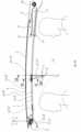
- Fig. 1illustrates a vehicle, in this case a passenger car, having a fixed roof 3 and therein an opening 2 which is covered by a roof construction.
- the roof construction of Fig. 1includes a, preferably, semi-transparent panel 1.
- Fig. 1shows a fixed panel, however the roof construction may also be equipped with one or more movable panels or with a combination of a fixed panel in the rear and a movable panel in the front of the roof opening 2.
- a display device 7is illustrated which is shown in an operational position 11.
- the operational position 11 of the display device 7is the position in which the occupant has the optimum line of view on the display screen 8.
- a display device 7is shown for the rear occupants. It is conceivable that the display device 7 is available for one or both occupants in the front of the vehicle.
- Fig. 2shows an exploded view of the roof construction showing the semi-transparent panel 1, here a fixed panel, a sunscreen 6, here a rollable (rollo) flexible sunscreen is shown, a display device 7 and attached to it a mechanism device 18, 18' and further a pair of drive cables 16, 16' and an electric drive motor 15 fixed to a front beam of a stationary frame 4.
- the stationary frame 4further comprises a pair of guides 19, 19' extending in longitudinal direction.
- the guides 19, 19', drive cable tubes 17, 17', the mechanism devices 18, 18' and the detailed parts of itare placed on each lateral edge of the stationary frame 4 and each of these respective left and right parts are shaped mirror imaged. Each of these parts is numbered with the mirror imaged part number given an quotation mark.
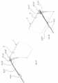
- Fig. 3Ait is shown that the display device 7 is positioned in its storage position 10 at the longitudinal rear end of the stationary frame 4 in a substantially horizontal plane.
- the stationary frame 4may extend substantially horizontally, which means, for instance as is shown in Fig 4A , that the guides 19, 19' extend in a curved manner with a large radius, whereby a line connecting the front end and the rear end of the guides 19, 19', will extend approximately in a horizontal plane.
- the curvature and the vertical position of the front end and rear end of the guides 19, 19' relative to each other in the stationary frame 4may vary depending on the shape of the vehicle.
- Fig. 3Bthe display device 7 is shown in a longitudinal forward position while being still in a substantially horizontal plane.
- the display device 7is shown in an operational position 11 in which occupants (in this case in the rear seats of the vehicle) can observe the display screen 8 and be able to see images on the display screen 8.
- the display device 7slides from its storage position 10 in a substantially horizontal direction and in a substantially horizontal position along the guides 19, 19' of the stationary frame 4 in a forward direction.
- the display device 7is then moved in a pivotal manner, with its front end part in a downward direction, until the display device 7 arrives in its operational position 11, which is more or less vertical.
- Fig. 4A , 4B and Fig. 4Dthe display device 7 is drawn in a side view in the same positions as described above for Figs. 3A, 3B and 3C .
- Fig. 4Can intermediate pivotal position of the display device 7 is added.
- Fig. 4Athe display device 7 is drawn in its storage position 10 behind/above a headliner 13.
- the headliner 13is an interior cover part that covers the fixed roof 3, and in this case also the frame 4, on the interior side of the vehicle at least in the area that surrounds the semi-transparent panels 1.
- the headliner 13in general has a (semi)rigid shell which may be covered on its visible lower side with any material.
- the headlinercan be attached to the fixed roof and/or to the stationary frame 4 (in Figs. 6 and 8 it is shown that a clip 35 is hooked to the guide 19, 19').
- a cavity 14is formed the lower side by the headliner 13 and on the upper side by the sunscreen 6, or in this case by a cassette containing a winding shaft 36 and the sunscreen 6 in its non-extended condition.
- the cavity 14is big enough to store substantially the complete display device 7 (the parts of mechanism device 18, 18' protruding in Fig. 4A will be above or within guide 19, 19').
- a rectangular opening 14'( Fig. 4B - 4D ) between an edge of the headliner 13 and the sunscreen 6, which is positioned above the display device 7, is formed to enable the display device 7 to slide into and out of its storage position 10 within the cavity 14.
- This opening 14' of the cavity 14may be closable or remain open. Due to the small thickness of modern display devices 7 the opening 14' may have a very small height.
- Fig. 4Bthe display device 7 is shown in a position forward of the storage position 10.
- the display device 7is connected to the guides 19, 19' by means of a mechanism device 18, 18'.
- the guides 19, 19'extend in longitudinal direction and form part of the stationary frame 4.
- the display device 7is moved from its storage position forward in a substantial horizontal plane along the guides 19, 19' by means of a drive system 9.
- the display device 7moves from its storage position 10 along the guides 19, 19' up to the position of Fig 4B .
- the mechanism device 18, 18'locks a part of the mechanism 18, 18' to the guide 19, 19'. This means that part of the mechanism device 18, 18' is stopped but another part of the mechanism device 18, 18' continues to move under the driving force of the drive system 9.
- the display device 7gradually rotates and moves downwardly, as can be seen in Fig. 4C towards the substantially vertical operational position 11 in Fig. 4D .
- the downward movement of the display device 7, as can be seen from a comparison of Figs. 4C and Dis made such that the display device 7 is not entering the facial area of the occupant and neither protrudes into the area of the headrest of the seat in front of the occupant.
- control unit 27which unit comprises an antitrap system with which pinches or collisions are detected occurring between the display device 7 and/or the mechanism device 18, 18' and other objects in the interior space 12 of the vehicle, in order to prevent injuries to occupants.
- the control unit 27may detect a collision/pinch situation and, based on this, will reverse or stop the movement of the display device 7.
- a part of the display device 7 and the mechanism device 18, 18'is shown from two viewing sides.
- the display device 7is drawn in the operational position 11 in both Figs. 5A and 5B .
- the guides 19, 19'have been omitted to get a better view of the detailed parts of the mechanism device 18, 18'.
- a part of the drive cables 16, 16' coming from the front of the stationary frame 4 and being guided in a channel 21, 21' of the guides 19,19'(not shown here, but in Figs. 7 and 8 ) is shown at the left hand side of the drawing.
- This part of the drive cables 16, 16'is attached to a driven slider 20, 20'.
- a display lever 25, 25'extends from approximately halfway the lateral side of the display device 7 to the locking slider 22, 22'.
- the display lever 25, 25'is pivotally connected to the display device 7 and pivotally connected to the locking slider 22, 22'.
- the locking slider 22, 22' in this operational position 11 of the display device 7is locked to the guide channel 21, 21'.
- This firm connectionis made by a part of the locking slider 22, 22' which is a locking lever 23, 23'.
- the locking lever 23, 23'is pivotally connected to the locking slider 22, 22' and is biased by a leaf spring 24, 24' ( Fig. 7 ), such that the locking lever 23, 23' tends to be pushed in a downward direction.
- the locking lever 23, 23'locks the locking slider 22, 22' in the guide 19, 19' in that the locking lever 23, 23' protrudes into a hole in the flange of the channel 21, 21' in the guide 19, 19'. So the locking lever 23, 23' and therewith the locking slider 22, 22' are locked to the guide 19, 19' and form the rotation axis for the display lever 25, 25'.
- Fig. 6the display device 7 is shown in the operational position. Adjacent to it the display lever 25, 25' extends from its pivotal connection to the locking slider 22, 22'. Just in the centre of the locking slider 22, 22' the locking lever 23, 23' is shown with the nose of the locking lever 23, 23' protruding through a hole in the guides 19, 19'.
- the locking slider 22, 22'is slidably mounted in the channel 21, 21' in the guides 19, 19'.
- the drive cables 16, 16'are shown in its drive cable section of guide channel 21, 21'.
- Fig. 7the locking slider 22, 22' is shown in more detail on the right side of Fig. 7 .
- the locking lever 23, 23'rotates around a locking lever pivot and the leaf spring 24, 24' is shown biasing the locking lever 23, 23' from above in a downward direction.
- the locking lever noseprotrudes through a locking lever hole in the guide channel 21, 21'.
- the driven slider 20, 20'is shown. In case the display device 7 is moved from its operational position 11 to the stored position 10 the drive cables 16, 16' (not shown in Fig. 7 ) will move towards the rear of the vehicle, in Fig. 7 towards the right side.
- the driven slider 20, 20' connected to the drive cables 16, 16'will move to the right side too and eventually be engaged with the locking slider 22, 22'.
- the protruding part of the driven slider 20, 20'will move into the locking slider 22, 22' and will move the locking lever 23, 23' upwards against the biasing force of the leaf spring 24, 24'.
- the nose of the locking lever 23, 23'will be lifted out of the locking lever hole in the guide 19, 19'.
- the locking slider 22, 22'is unlocked from the guide 19, 19' and is moved along the channel 21, 21' in the guide 19, 19' together with the driven slider 20, 20' in a rearward movement to the storage position 10 of the display unit 7.
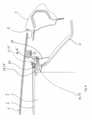
- Fig. 8a section along line VIII-VIII in Fig. 4D is shown.
- the sectionshows the rear rotation pin 28, 28' attached to the lateral side of the display device 7 and its connection to the drive cable 16, 16'.
- the electrical connection of the display device 7 with the electrical installation of the vehicleis made by means of a so called flat cable 34.
- the flat cableextends in the guide channel 21, 21' from the display device 7 to a position rearward of the operational position 11 of the display device 7 where the flat cable 34 is connected to the electrical installation of the vehicle.
- the flat cable 34may follow the movements of the display device 7 by folding itself along the length of the distance between the momentary position of the display device 7 and the fixed position of the connection with the electrical installation of the vehicle.
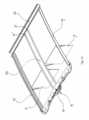
- FIGs. 9 , 10 and 11two other embodiments are shown. These embodiments may be advantageous in case instead of one display device 7 two or more display devices are placed adjacent to each other seen in a transverse direction. In case for instance two display devices 7 are placed adjacent to each other, one for each occupant, each of the display devices 7 needs to able to be adjusted independently to the optimal line of view of the occupant. This would be difficult with the system described above having a guide with a mechanism 18, 18' on each lateral side of the stationary frame 4.
- this central guide 29is a stationary guide having multiple channels 21, 21' for the guidance of the drive cables 16, 16' and the mechanism devices 18, 18' (not shown) that are required for the driving guidance of the display device 7 from the left and right centre area sides, whereas for the lateral left and right outboard sides the above described guides 19, 19' mounted on the stationary frame 4 and mechanism devices 18, 18' can be used.
- the central guide 29in this case is attached to the front beam and a rear beam 32 of frame 4. There may also be provided a middle beam for support of the centre guide 29.
- the central guide 29 in the embodiment of Figs. 9 and 10is placed on a display carrier 33.
- the display carrier 33is moved in its forward position.
- the display device(s) 7is/are first pivoted to their substantially horizontal position in which it lies flat against the lower side of the display carrier 33 and then the display carrier 33 together with the display devices 7 is moved rearwardly above the headliner 13.
- the display carrier 33is not obstructing the view through the panel 1, nor obstructing the light entering through the panel 1.
- the display carrier 33may be provided with its own drive mechanisms to independently pivot the display devices 7, whereas the drive motor 15 and drive cables 16. 16' may be used to slide the display carrier 33.
- the display carrier 33will then have also have channels 21, 21' on the outboard sides. Other mechanisms for driving the display devices 7 and display carrier 33 are conceivable.
- Fig. 12an embodiment is shown whereby the occupants not only are seated adjacent to each other facing a longitudinal forward direction but are also seated opposite to each other and thus facing each other.
- the display devices 7 of the occupants facing rearwardsmay be stored in a similar way behind a front portion of the headliner 13 and each of these display devices 7 may be moved into an operational position 11 in a mirror imaged way compared to the moving operation of the display devices 7 for the occupants facing a forward direction.
- the inventionis not limited to the examples described above and shown in the drawings and may be varied in different other ways.
- the motor 15is drawn at the front transverse end of the stationary frame 4, however alternatively the motor 15 may be placed at the rearward transverse side of the stationary frame 4.
- the sun screen 6 in the drawingsis a rollable flexible sunscreen but can also be some type of rigid sunshade or can be a darkening layer incorporated into a so called switchable panel 1.
- the display devices 7can be of any type available on the market.
Landscapes
- Engineering & Computer Science (AREA)
- Mechanical Engineering (AREA)
- Fittings On The Vehicle Exterior For Carrying Loads, And Devices For Holding Or Mounting Articles (AREA)
- Devices For Indicating Variable Information By Combining Individual Elements (AREA)
Description
- The invention relates to a vehicle having a roof construction according to the preamble of
claim 1. - Display devices in vehicles are known from the prior art for instance in which display devices are attached to the interior side of the roof of a vehicle and which displays can easily be pivoted from a storage position into an operational position in which the display screen is readable to the occupants of the vehicle.
- In case a vehicle is equipped with a roof construction having a fixed semi-transparent panel or a roof construction having a semi-transparent panel which is openable, the use of a display devices becomes more complicated, especially in case when the roof construction is equipped with more than one semi-transparent panel. In case of a multi panel roof construction, a larger area of the fixed roof of the vehicle is covered by these panels. In such case the use of display devices attached to the roof is difficult because of the presence of the display devices in the storage positions which would obstruct the view through the semi-transparent panels and the amount of light that may reach the interior. Also such display devices in their storage positions would influence other functionalities of the roof construction, for instance interfere or completely cover the semi-transparent panels from the interior side, or obstruct ventilation in case of an opened panel.
- From a customer point of view there is a tendency to enlarge the size of the display devices such that the occupants can view larger images. Such larger display devices are not suitable to be simply rotated downwards from a stored position into an operational position, because the rotating display device will move close towards or even may be within the facial region of the occupant. To avoid this, the display device may be moved from a stored position into an operational position in a different way. In that case, the display device is positioned overhead in a horizontal plane with the display screen facing downwards, the display device may be moved horizontally to the front and at the same time may be rotated downwards whereby the front part of the display device rotates downward first towards the operational position. In this way a protrusion of the display device in the facial region of the occupant is avoided. Nevertheless also with this improved movement of the display device still the display device interferes with the functions of the roof construction. Next to this, when the display screen is facing downwards when the display screen is in its stored position, there may be a risk of damaging the display screen for instance by objects being moved in the interior. And when the display device is visible in the interior of the vehicle in their stored position, there may be an incentive for theft of the display device. Document
KR20190140806 A claim 1. - It is one of the objects of the present invention to provide for a vehicle having a roof construction to be used in combination with a display device which can be used independent from the functions of the roof construction and which protects the display device against damages and theft.
- The object is achieved in a roof construction and a vehicle having the features of the characterizing portion of
claim 1. - Due to the position of the display device above the headliner when in its storage position, it is protected against damage which may be caused by moving objects in the interior space. As the headliner also hides the display device from view, it does not attract the attention of thieves.
- The headliner may surround the circumventing edge of the at least one semi-transparent panel and leaves an opening to enable the display device to enter and exit the cavity. This exit and entry opening may be According to another aspect of the invention, to establish the operational position, the display device is moved by the drive system out of its storage position in a substantially horizontal movement and is rotated along a substantially horizontal axis into an operational position whereby the front end of the display device rotates from the substantially horizontal moving plane downwardly and the rearward end of the display device substantially stays in the substantially horizontal moving plane. The movement of the display device is made in such a way that the occupants are not bothered in the facial region by the display device moving from the stored position towards the operational position.
- According to another aspect, the drive system comprises at least one drive motor, capable of driving at least one pair of flexible drive cables, said drive cables guided in at least a pair of guide tubes, said drive cables being connected to at least a pair of mechanism devices, slidably guided to at least one pair of guides, said guides being attached to the stationary frame. In this embodiment the movement of the display device is done by a drive system, which is driven by an electric drive motor. The electric drive motor is electronically controlled by means of a control unit (not shown in the drawings) and a control switch (not shown). The occupant can push the control switch and thus the display device is moved from its stored position to the operational position and vice versa. Also it is possible to adjust the display device such that the display screen is moved just slightly to obtain the optimal position with regard to the occupants' line of viewing.
- According to another aspect of the invention each of the mechanism devices comprises a driven slider guided in a guide channel, said driven slider being driven by the drive cable, a locking slider being guided in the guide channel, said locking slider being connected to the driven slider at least in the storage position, a locking lever being connected to the locking slider and biased by a leaf spring as such capable of locking the locking slider to the guide, a display lever being connected, on one end to the locking slider and on another end to the display device for rotating the display device from a substantial horizontal plane towards a substantial vertical plane. The mechanism devices each may comprise a front rotation pin connected to the display device and engaged into the guide channel and further a rear rotation pin connected to the drive cable. With this type of mechanism device it is possible to move the display device from a storage position in which the display device is stored in a substantially horizontal plane towards the operational position, first by moving the display device via the driven slider, moved by the drive cable in a guide channel, in a substantial horizontal plane, in a longitudinally forward direction until the point is reached where the locking lever locks the locking slider in the guide channel to the guide. At this position the front rotation pin and the display lever with its pivotal connection to the locking slider is held in position and does not move further. The drive cable continues to move further in the direction forwardly and via the rear rotation pin the display device follows this movement, however the front rotation pin engaged in the guide channel follows a different path. The guide channel has a sharp bend in a downward direction and at the end of the bend the channel has an exit opening, so the front rotation pin and therewith the lower end of the display device follows this channel path and moves in a downward direction. The opposite end of the display lever is connected somewhere halfway the lateral side of the display device and guides the lower end of the display devices in a curved movement to its lowest position. To reach this position the drive cable is stopped by the control unit. Meanwhile, in this movement the rear rotation pin has allowed the display device to rotate and holds the upper end of the display device in place. The display device has now arrived in its operational position and the device is held in position in a rigid way such that vibrations caused by the road surface when driving the vehicle may not lead to an unreadable vibrating display screen.
- According to another aspect, each of the display devices is guided by guides attached to opposite lateral sides of the stationary frame. As such the display device may be a large device which extends in transverse direction across the vehicle interior roughly of the size of the width of the semi-transparent panel. The display device may be used by more than one occupant whereby on one display screen two or more different images are displayed adjacent to each other.
- According to another embodiment two display devices are positioned adjacent to each other seen in a transverse direction of the vehicle and can be adjusted independently from each other, wherein each of the display devices is guided by a guide attached to the lateral side of the stationary frame and an opposite central guide positioned substantially in a central plane in the vehicle. In such case each of the display devices is capable of being adjusted individually to the line of view of the occupant viewing it, because each of the display devices is equipped with a control unit and a control switch.
- According to another aspect of the invention, the central guide is connected to the stationary frame by means of the front beam and a rear beam and optionally a middle beam. It is required to support the central guide such that it offers a rigid support to each of the display devices. As such in this aspect the semi-transparent panel has two see through areas which are separated by a centre console to cover the central guide from view of the occupants. This centre console may also be used for other purposes, such as providing storage room.
- According to another embodiment of the invention, the central guide is attached to a movable display carrier. When it is required to avoid a centre console, a movable display carrier for the display devices is conceivable. The central guide can be mounted on this movable display carrier and the carrier may be moved in a longitudinal direction such that central guide is moved into a position by means of a separate drive system in which the display device is able to be moved from the storage position towards the operational position in the same way as described above.
- According to yet another embodiment the display devices are positioned adjacent to each other seen in a longitudinal direction and whereby the display screen of each of the display devices is pointing in an opposite direction. It is conceivable that an interior of a vehicle is used in such a way that the occupants not only are seated adjacent to each other in lateral direction of the vehicle, but also opposite to each other and facing each other in longitudinal direction. The display devices, for those occupants seated with their faces pointing towards the longitudinal front end of the vehicle, the storage and operational positions of which are as per description of above. However when the occupants are faced towards the longitudinal rear of the vehicle, the storage and operational positions of the display devices are in an opposite sense, meaning that the storage positions of the display devices lie longitudinally seen in front of the operational position.
- In yet another aspect of the invention, the at least one semi-transparent panel can be covered from the interior side by a sunscreen to avoid light coming through, independently from the position of the display device. Such a sunscreen may be a rollo device having a flexible cloth or may be a rigid panel such as a sunshade. All of the functionalities of the sunscreen can be used as well as the functionalities of the roof construction, which may be a fixed panel roof construction or an openable panel roof construction.
- The invention also relates to a roof construction for a vehicle according to
claim 15. All features claimed in relation to the vehicle are also applicable to the roof construction. - The invention will be further explained with reference to the drawings showing exemplary embodiments of the roof construction and vehicle according to the invention.
Fig. 1 shows a perspective partial view of a vehicle with a roof construction.Fig. 2 shows an exploded view of the roof construction.Figs. 3A-3C show schematic perspective views of the roof construction in 3 different positions of the display device.Figs. 4A-4D show schematic side views of the vehicle roof and roof construction illustrating 4 different positions of the display device.Figs. 5A-5B show perspective views of the mechanism device on one side of the display device.Fig. 6 shows a cross section along line VI-VI inFig. 4D .Fig. 7 shows a cross section along line VII-VII inFig. 6 Fig. 8 shows a cross section along line VIII-VIII inFig. 4D Fig. 9 shows a schematic side view of a vehicle roof and an embodiment of the roof construction including a movable carrier for the display devices.Fig. 10 shows a schematic plan view of the embodiment of the roof construction ofFig. 9 .Fig. 11 shows an schematic perspective view of an embodiment of the roof construction having a central guide.Fig. 12 shows a schematic side view of a vehicle roof and an embodiment of the roof construction having multiple display devices which are placed oppositely towards each other.Fig. 1 illustrates a vehicle, in this case a passenger car, having a fixedroof 3 and therein anopening 2 which is covered by a roof construction. The roof construction ofFig. 1 includes a, preferably,semi-transparent panel 1.Fig. 1 shows a fixed panel, however the roof construction may also be equipped with one or more movable panels or with a combination of a fixed panel in the rear and a movable panel in the front of theroof opening 2. Further adisplay device 7 is illustrated which is shown in an operational position 11. The operational position 11 of thedisplay device 7 is the position in which the occupant has the optimum line of view on thedisplay screen 8. InFig. 1 adisplay device 7 is shown for the rear occupants. It is conceivable that thedisplay device 7 is available for one or both occupants in the front of the vehicle.Fig. 2 shows an exploded view of the roof construction showing thesemi-transparent panel 1, here a fixed panel, asunscreen 6, here a rollable (rollo) flexible sunscreen is shown, adisplay device 7 and attached to it amechanism device 18, 18' and further a pair ofdrive cables 16, 16' and anelectric drive motor 15 fixed to a front beam of astationary frame 4. Thestationary frame 4 further comprises a pair ofguides 19, 19' extending in longitudinal direction. As can be seen from the drawing, theguides 19, 19', drivecable tubes 17, 17', themechanism devices 18, 18' and the detailed parts of it are placed on each lateral edge of thestationary frame 4 and each of these respective left and right parts are shaped mirror imaged. Each of these parts is numbered with the mirror imaged part number given an quotation mark.- In
Fig. 3A it is shown that thedisplay device 7 is positioned in itsstorage position 10 at the longitudinal rear end of thestationary frame 4 in a substantially horizontal plane. Thestationary frame 4 may extend substantially horizontally, which means, for instance as is shown inFig 4A , that theguides 19, 19' extend in a curved manner with a large radius, whereby a line connecting the front end and the rear end of theguides 19, 19', will extend approximately in a horizontal plane. The curvature and the vertical position of the front end and rear end of theguides 19, 19' relative to each other in thestationary frame 4 may vary depending on the shape of the vehicle. However it is anticipated within this definition of substantially horizontal that a line through the front end and the rear end of theguides 19, 19' measured in the vehicle grid will lie within an angle of plus or minus 15 degrees with an exactly horizontal plane. Theguides 19, 19' will extend in rearward direction to such extent that it allows thedisplay device 7 to lie in its storage position substantially completely above aheadliner 13, which is described further below. - In
Fig. 3B thedisplay device 7 is shown in a longitudinal forward position while being still in a substantially horizontal plane. And inFig 3C thedisplay device 7 is shown in an operational position 11 in which occupants (in this case in the rear seats of the vehicle) can observe thedisplay screen 8 and be able to see images on thedisplay screen 8. Thedisplay device 7 slides from itsstorage position 10 in a substantially horizontal direction and in a substantially horizontal position along theguides 19, 19' of thestationary frame 4 in a forward direction. Thedisplay device 7 is then moved in a pivotal manner, with its front end part in a downward direction, until thedisplay device 7 arrives in its operational position 11, which is more or less vertical. - In
Fig. 4A ,4B andFig. 4D thedisplay device 7 is drawn in a side view in the same positions as described above forFigs. 3A, 3B and 3C . InFig. 4C an intermediate pivotal position of thedisplay device 7 is added. - In
Fig. 4A thedisplay device 7 is drawn in itsstorage position 10 behind/above aheadliner 13. Theheadliner 13 is an interior cover part that covers the fixedroof 3, and in this case also theframe 4, on the interior side of the vehicle at least in the area that surrounds thesemi-transparent panels 1. Theheadliner 13 in general has a (semi)rigid shell which may be covered on its visible lower side with any material. The headliner can be attached to the fixed roof and/or to the stationary frame 4 (inFigs. 6 and8 it is shown that aclip 35 is hooked to theguide 19, 19'). Acavity 14 is formed the lower side by theheadliner 13 and on the upper side by thesunscreen 6, or in this case by a cassette containing a windingshaft 36 and thesunscreen 6 in its non-extended condition. Thecavity 14 is big enough to store substantially the complete display device 7 (the parts ofmechanism device 18, 18' protruding inFig. 4A will be above or withinguide 19, 19'). Furthermore a rectangular opening 14' (Fig. 4B - 4D ) between an edge of theheadliner 13 and thesunscreen 6, which is positioned above thedisplay device 7, is formed to enable thedisplay device 7 to slide into and out of itsstorage position 10 within thecavity 14. This opening 14' of thecavity 14 may be closable or remain open. Due to the small thickness ofmodern display devices 7 the opening 14' may have a very small height. - In
Fig. 4B thedisplay device 7 is shown in a position forward of thestorage position 10. Thedisplay device 7 is connected to theguides 19, 19' by means of amechanism device 18, 18'. Theguides 19, 19' extend in longitudinal direction and form part of thestationary frame 4. Thedisplay device 7 is moved from its storage position forward in a substantial horizontal plane along theguides 19, 19' by means of adrive system 9. Thedisplay device 7 moves from itsstorage position 10 along theguides 19, 19' up to the position ofFig 4B . In this position, themechanism device 18, 18' locks a part of themechanism 18, 18' to theguide 19, 19'. This means that part of themechanism device 18, 18' is stopped but another part of themechanism device 18, 18' continues to move under the driving force of thedrive system 9. Thedisplay device 7 gradually rotates and moves downwardly, as can be seen inFig. 4C towards the substantially vertical operational position 11 inFig. 4D . The downward movement of thedisplay device 7, as can be seen from a comparison ofFigs. 4C andD , is made such that thedisplay device 7 is not entering the facial area of the occupant and neither protrudes into the area of the headrest of the seat in front of the occupant. - It may also be conceivable that the
drive motor 15 is controlled by acontrol unit 27 which unit comprises an antitrap system with which pinches or collisions are detected occurring between thedisplay device 7 and/or themechanism device 18, 18' and other objects in theinterior space 12 of the vehicle, in order to prevent injuries to occupants. Thecontrol unit 27 may detect a collision/pinch situation and, based on this, will reverse or stop the movement of thedisplay device 7. - In
Fig 5A and 5B a part of thedisplay device 7 and themechanism device 18, 18' is shown from two viewing sides. Thedisplay device 7 is drawn in the operational position 11 in bothFigs. 5A and 5B . For clarity, theguides 19, 19' have been omitted to get a better view of the detailed parts of themechanism device 18, 18'. In both Figs. a part of thedrive cables 16, 16' coming from the front of thestationary frame 4 and being guided in achannel 21, 21' of theguides 19,19' (not shown here, but inFigs. 7 and8 ) is shown at the left hand side of the drawing. This part of thedrive cables 16, 16' is attached to a driven slider 20, 20'. Between the driven slider 20, 20' and the connection to the display device 7 a second piece of thedrive cables 16, 16' is shown, which is guided like the first piece of thedrive cables 16, 16' in thechannel 21, 21' of theguides 19, 19', and connecting the driven slider 20, 20' to a rear rotation pin 28, 28' which is positioned on the lateral side of thedisplay device 7. A display lever 25, 25' extends from approximately halfway the lateral side of thedisplay device 7 to the locking slider 22, 22'. The display lever 25, 25' is pivotally connected to thedisplay device 7 and pivotally connected to the locking slider 22, 22'. The locking slider 22, 22' in this operational position 11 of thedisplay device 7 is locked to theguide channel 21, 21'. This firm connection is made by a part of the locking slider 22, 22' which is a locking lever 23, 23'. The locking lever 23, 23' is pivotally connected to the locking slider 22, 22' and is biased by a leaf spring 24, 24' (Fig. 7 ), such that the locking lever 23, 23' tends to be pushed in a downward direction. In the operational position 11 of thedisplay device 7 the locking lever 23, 23' locks the locking slider 22, 22' in theguide 19, 19' in that the locking lever 23, 23' protrudes into a hole in the flange of thechannel 21, 21' in theguide 19, 19'. So the locking lever 23, 23' and therewith the locking slider 22, 22' are locked to theguide 19, 19' and form the rotation axis for the display lever 25, 25'. - The construction of the locking slider 22, 22' and locking lever 23, 23' is further explained with the help of
Figs. 6 and 7 . InFig. 6 , thedisplay device 7 is shown in the operational position. Adjacent to it the display lever 25, 25' extends from its pivotal connection to the locking slider 22, 22'. Just in the centre of the locking slider 22, 22' the locking lever 23, 23' is shown with the nose of the locking lever 23, 23' protruding through a hole in theguides 19, 19'. The locking slider 22, 22' is slidably mounted in thechannel 21, 21' in theguides 19, 19'. In this section also thedrive cables 16, 16' are shown in its drive cable section ofguide channel 21, 21'. - In
Fig. 7 the locking slider 22, 22' is shown in more detail on the right side ofFig. 7 . The locking lever 23, 23' rotates around a locking lever pivot and the leaf spring 24, 24' is shown biasing the locking lever 23, 23' from above in a downward direction. Also here, it is clearly shown that the locking lever nose protrudes through a locking lever hole in theguide channel 21, 21'. To the left side, the driven slider 20, 20' is shown. In case thedisplay device 7 is moved from its operational position 11 to the storedposition 10 thedrive cables 16, 16' (not shown inFig. 7 ) will move towards the rear of the vehicle, inFig. 7 towards the right side. The driven slider 20, 20' connected to thedrive cables 16, 16' will move to the right side too and eventually be engaged with the locking slider 22, 22'. The protruding part of the driven slider 20, 20' will move into the locking slider 22, 22' and will move the locking lever 23, 23' upwards against the biasing force of the leaf spring 24, 24'. As such the nose of the locking lever 23, 23' will be lifted out of the locking lever hole in theguide 19, 19'. With the locking lever nose lifted out of the hole in upward direction, the locking slider 22, 22' is unlocked from theguide 19, 19' and is moved along thechannel 21, 21' in theguide 19, 19' together with the driven slider 20, 20' in a rearward movement to thestorage position 10 of thedisplay unit 7. - In
Fig. 8 a section along line VIII-VIII inFig. 4D is shown. The section shows the rear rotation pin 28, 28' attached to the lateral side of thedisplay device 7 and its connection to thedrive cable 16, 16'. Also here is shown the electrical connection of thedisplay device 7 with the electrical installation of the vehicle. This connection is made by means of a so calledflat cable 34. The flat cable extends in theguide channel 21, 21' from thedisplay device 7 to a position rearward of the operational position 11 of thedisplay device 7 where theflat cable 34 is connected to the electrical installation of the vehicle. Theflat cable 34 may follow the movements of thedisplay device 7 by folding itself along the length of the distance between the momentary position of thedisplay device 7 and the fixed position of the connection with the electrical installation of the vehicle. - In
Figs. 9 ,10 and11 two other embodiments are shown. These embodiments may be advantageous in case instead of onedisplay device 7 two or more display devices are placed adjacent to each other seen in a transverse direction. In case for instance twodisplay devices 7 are placed adjacent to each other, one for each occupant, each of thedisplay devices 7 needs to able to be adjusted independently to the optimal line of view of the occupant. This would be difficult with the system described above having a guide with amechanism 18, 18' on each lateral side of thestationary frame 4. - Instead in the earlier embodiment, a
central guide 29 is now proposed which extends in longitudinal direction in the centre of the vehicle. - In the embodiment of
Fig. 11 thiscentral guide 29 is a stationary guide havingmultiple channels 21, 21' for the guidance of thedrive cables 16, 16' and themechanism devices 18, 18' (not shown) that are required for the driving guidance of thedisplay device 7 from the left and right centre area sides, whereas for the lateral left and right outboard sides the above described guides 19, 19' mounted on thestationary frame 4 andmechanism devices 18, 18' can be used. Thecentral guide 29 in this case is attached to the front beam and arear beam 32 offrame 4. There may also be provided a middle beam for support of thecentre guide 29. - To avoid that the
central guide 29 block the vision towards the exterior through thesemi-transparent panels 1 or block a part of the light coming in through thepanels 1, thecentral guide 29 in the embodiment ofFigs. 9 and10 is placed on adisplay carrier 33. When thedisplay device 7 is in its operational position 11, thedisplay carrier 33 is moved in its forward position. When thedisplay device 7 should be moved to its stored position, the display device(s) 7 is/are first pivoted to their substantially horizontal position in which it lies flat against the lower side of thedisplay carrier 33 and then thedisplay carrier 33 together with thedisplay devices 7 is moved rearwardly above theheadliner 13. As such when thedisplay devices 7 are not used, thedisplay carrier 33 is not obstructing the view through thepanel 1, nor obstructing the light entering through thepanel 1. Thedisplay carrier 33 may be provided with its own drive mechanisms to independently pivot thedisplay devices 7, whereas thedrive motor 15 and drivecables 16. 16' may be used to slide thedisplay carrier 33. Thedisplay carrier 33 will then have also havechannels 21, 21' on the outboard sides. Other mechanisms for driving thedisplay devices 7 anddisplay carrier 33 are conceivable. - In
Fig. 12 an embodiment is shown whereby the occupants not only are seated adjacent to each other facing a longitudinal forward direction but are also seated opposite to each other and thus facing each other. Thedisplay devices 7 of the occupants facing rearwards may be stored in a similar way behind a front portion of theheadliner 13 and each of thesedisplay devices 7 may be moved into an operational position 11 in a mirror imaged way compared to the moving operation of thedisplay devices 7 for the occupants facing a forward direction. - The invention is not limited to the examples described above and shown in the drawings and may be varied in different other ways. For instance the
motor 15 is drawn at the front transverse end of thestationary frame 4, however alternatively themotor 15 may be placed at the rearward transverse side of thestationary frame 4. Thesun screen 6 in the drawings is a rollable flexible sunscreen but can also be some type of rigid sunshade or can be a darkening layer incorporated into a so calledswitchable panel 1. Thedisplay devices 7 can be of any type available on the market.
Claims (15)
- Vehicle having a (roof construction, comprising:at least one semi-transparent panel (1) fitted in an opening (2) in the fixed roof (3) of the vehicle,a stationary frame (4) to which the at least one semi-transparent panel (1) is connected,a headliner on the interior side of the fixed roof for hiding the fixed roof and stationary frame from view,at least one display device (7) capable of showing images from its display screen (8) to occupants in the vehicle, anda drive system (9) for moving the display device (7) at least into a storage position (10), and into an operational position (11) in which the display screen (8) is visible for occupants in an interior space (12) of the vehicle,characterized in that the display device (7), in its storage position (10), is moved into a cavity (14) above the headliner (13) and is thus hidden from view and protected by the headliner.
- Vehicle according to claim 1, wherein the headliner (13) surrounds the circumventing edge of the at least one semi-transparent panel (1) and leaves an opening to enable the display device to enter and exit the cavity.
- Vehicle according to claim 1, wherein, to establish the operational position (11), the display device (7) is moved by the drive system (9) out of its storage position (10) in a substantially horizontal plane and is then rotated around a substantially horizontal axis into an operational position (11) whereby the leading end of the display device (7) moves from the substantially horizontal plane downwardly and the trailing end of the display device (7) substantially stays in the substantially horizontal plane.
- Vehicle according to claim 3, wherein the drive system (9) comprises at least one drive motor (15), capable of driving at least one pair of flexible drive cables (16, 16'), said drive cables being guided in at least a pair of guide tubes (17, 17'), said drive cables being connected to at least a pair of mechanism devices (18, 18'), slidably guided to at least one pair of guides (19, 19'), said guides being attached to the stationary frame (4).
- Vehicle according to claim 4, wherein each of the mechanism devices (18, 18') comprises a driven slider (20, 20') guided in a guide channel (21, 21'), said driven slider (20, 20') being driven by the drive cable (16, 16').
- Vehicle according to claim 5, wherein each of the mechanism devices (18, 18') further comprises a locking slider (22, 22') guided in the guide channel (21, 21'), said locking slider (22, 22') being connected to the driven slider (20, 20') at least in the storage position (10), a locking lever (23, 23') being connected to the locking slider (22, 22') and biased by a leaf spring (24, 24') capable of locking the locking slider (22, 22') to the guide.
- Vehicle according to claim 6, wherein each of the mechanism devices (18, 18') further comprises a display lever (25, 25') connected on one end to the locking slider (22, 22') and on another end to the display device (7) for rotating the display device (7) from a substantial horizontal plane towards a substantial vertical plane.
- Vehicle according to claim 7, wherein each of the mechanism devices (18, 18') further comprises a front rotation pin (26, 26') connected to the display device (7) and engaged into the guide channel (21, 21') and further a rear rotation pin (28, 28') connected to the drive cable (16, 16').
- Vehicle according to claim 4, wherein each of the display devices (7) is guided by guides (19, 19') attached to opposite lateral sides of the stationary frame (4).
- Vehicle according to claim 1, wherein two display devices (7) are positioned adjacent to each other seen in a transverse direction of the vehicle and can be adjusted independently from each other.
- Vehicle according to claim 10, wherein each of the display devices (7) is guided by a guide (19, 19') at the lateral side of the stationary frame (4) and an opposite central guide (29) positioned substantially in a central plane (30) of the vehicle.
- Vehicle according to claim 11, wherein the central guide (29) is connected to the stationary frame (4) by means of a front beam and a rear beam (32), or the central guide (29) is attached to a movable display carrier (33).
- Vehicle according to claim 10, wherein the display devices (7) are positioned adjacent to each other seen in a longitudinal direction and whereby the display screens (8) of each of the display devices (7) is pointing in an opposite direction.
- Vehicle according to claim 1, wherein the at least one semi-transparent panel (1) can be covered from the interior side by a sunscreen (6) to block light coming through the panel, independently from the position of the display device (7), the sunscreen preferably being in the form of a rollo screen which can be rolled-on or -off from a winding shaft which can be positioned above the cavity for the at least one display device.
- Roof construction for a vehicle, comprising:at least one panel (1) fitted in an opening (2) in the fixed roof (3) of the vehicle,a stationary frame (4) to which the at least one semi-transparent panel (1) is connected,at least one display device (7) capable of showing images from its display screen (8) to occupants in the vehicle,a drive system (9) for moving the display device (7) at least into a substantially horizontal storage position (10), and into an operational position (11) in which the display screen (8) is visible for occupants in an interior space (12) of the vehicle,wherein the stationary frame (4) comprises longitudinal guide rails (19, 19') for the display device (7) to enable the drive system (9) to move the display device into its storage position (10) at ends of the guide rails,characterized inthat after mounting the roof construction into the vehicle, the display device will be covered in its storage position from below by a headliner of the vehicle.
Priority Applications (3)
| Application Number | Priority Date | Filing Date | Title |
|---|---|---|---|
| EP19220029.3AEP3845420B1 (en) | 2019-12-30 | 2019-12-30 | Vehicle and roof construction including a display device for use therein |
| CN202011507426.8ACN113119873B (en) | 2019-12-30 | 2020-12-18 | Vehicle and roof structure including display device for use therein |
| US17/135,039US11673513B2 (en) | 2019-12-30 | 2020-12-28 | Vehicle and roof construction including a display device for use therein |
Applications Claiming Priority (1)
| Application Number | Priority Date | Filing Date | Title |
|---|---|---|---|
| EP19220029.3AEP3845420B1 (en) | 2019-12-30 | 2019-12-30 | Vehicle and roof construction including a display device for use therein |
Publications (2)
| Publication Number | Publication Date |
|---|---|
| EP3845420A1 EP3845420A1 (en) | 2021-07-07 |
| EP3845420B1true EP3845420B1 (en) | 2023-05-24 |
Family
ID=69055847
Family Applications (1)
| Application Number | Title | Priority Date | Filing Date |
|---|---|---|---|
| EP19220029.3AActiveEP3845420B1 (en) | 2019-12-30 | 2019-12-30 | Vehicle and roof construction including a display device for use therein |
Country Status (3)
| Country | Link |
|---|---|
| US (1) | US11673513B2 (en) |
| EP (1) | EP3845420B1 (en) |
| CN (1) | CN113119873B (en) |
Families Citing this family (14)
| Publication number | Priority date | Publication date | Assignee | Title |
|---|---|---|---|---|
| DE102018212604A1 (en)* | 2018-07-27 | 2020-01-30 | Bayerische Motoren Werke Aktiengesellschaft | Display device and vehicle |
| EP3670233B1 (en)* | 2018-12-19 | 2023-08-23 | Audi Ag | Vehicle with a display device |
| CN114604183A (en) | 2020-12-03 | 2022-06-10 | 英纳法天窗系统集团有限公司 | Roof structure including display device and vehicle |
| DE102021119546A1 (en)* | 2021-07-28 | 2023-02-02 | Webasto SE | Device for operating a screen arrangement for a vehicle roof and vehicle roof for a motor vehicle |
| DE102021119561A1 (en)* | 2021-07-28 | 2023-02-02 | Webasto SE | Device for operating a screen arrangement for a vehicle roof and vehicle roof for a motor vehicle |
| DE102021119547A1 (en)* | 2021-07-28 | 2023-02-02 | Webasto SE | Device for operating a screen arrangement for a vehicle roof and vehicle roof for a motor vehicle |
| DE102021119555B3 (en)* | 2021-07-28 | 2023-01-12 | Webasto SE | Device for operating a screen arrangement for a vehicle roof and vehicle roof for a motor vehicle |
| DE102021119550A1 (en)* | 2021-07-28 | 2023-02-02 | Webasto SE | Device for operating a screen arrangement for a vehicle roof and vehicle roof for a motor vehicle |
| EP4385824A1 (en)* | 2022-12-12 | 2024-06-19 | Inalfa Roof Systems Group B.V. | Vehicle and a display device for use therein |
| DE102022133351B3 (en) | 2022-12-14 | 2024-03-21 | Audi Aktiengesellschaft | Display device for a motor vehicle and motor vehicle with a display device |
| EP4420935A1 (en)* | 2023-02-23 | 2024-08-28 | Inalfa Roof Systems Group B.V. | Vehicle and a foldable display device for use therein |
| DE102023109244A1 (en) | 2023-04-12 | 2024-10-17 | Audi Aktiengesellschaft | display system |
| DE102023109445B3 (en) | 2023-04-14 | 2024-08-22 | Webasto SE | Device for operating a display arrangement for a vehicle roof and vehicle roof for a motor vehicle |
| WO2025105667A1 (en)* | 2023-11-15 | 2025-05-22 | 네이버 주식회사 | Method and system for providing vehicle driving state |
Family Cites Families (9)
| Publication number | Priority date | Publication date | Assignee | Title |
|---|---|---|---|---|
| US5946055A (en)* | 1996-08-16 | 1999-08-31 | Rosen Product Development, Inc. | Display unit |
| KR19980055077U (en)* | 1996-12-31 | 1998-10-07 | 박병재 | Vehicle video device installation structure |
| KR100830752B1 (en)* | 2007-04-19 | 2008-05-19 | 한국철도공사 | Car screen device |
| US9442688B2 (en)* | 2013-11-18 | 2016-09-13 | Atieva, Inc. | Synchronized display system |
| EP3162603B1 (en)* | 2015-10-29 | 2019-04-17 | Inalfa Roof Systems Group B.V. | Open roof construction for a vehicle |
| EP3176016B1 (en)* | 2015-12-03 | 2019-04-03 | Inalfa Roof Systems Group B.V. | Rollo assembly |
| KR102094956B1 (en)* | 2018-05-21 | 2020-03-30 | 주식회사 브이터치 | Display device for autonomous vehicle |
| CN108773329B (en)* | 2018-05-29 | 2020-09-04 | 苏州极普智能科技有限公司 | Method for improving space utilization rate of unmanned automobile |
| DE102018212604A1 (en)* | 2018-07-27 | 2020-01-30 | Bayerische Motoren Werke Aktiengesellschaft | Display device and vehicle |
- 2019
- 2019-12-30EPEP19220029.3Apatent/EP3845420B1/enactiveActive
- 2020
- 2020-12-18CNCN202011507426.8Apatent/CN113119873B/enactiveActive
- 2020-12-28USUS17/135,039patent/US11673513B2/enactiveActive
Also Published As
| Publication number | Publication date |
|---|---|
| US11673513B2 (en) | 2023-06-13 |
| CN113119873A (en) | 2021-07-16 |
| EP3845420A1 (en) | 2021-07-07 |
| CN113119873B (en) | 2025-08-08 |
| US20210197731A1 (en) | 2021-07-01 |
Similar Documents
| Publication | Publication Date | Title |
|---|---|---|
| EP3845420B1 (en) | Vehicle and roof construction including a display device for use therein | |
| US6672658B2 (en) | Vehicle with a vehicle roof that can be opened | |
| EP4008590B1 (en) | Vehicle and roof construction including a display device for use therein | |
| US7537265B2 (en) | Vehicle rear structure | |
| JP5050793B2 (en) | Sun visor device for vehicle | |
| US6508502B2 (en) | Convertible roof and tonneau cover system | |
| US7963580B2 (en) | Cargo space cover for a motor vehicle | |
| US7967362B2 (en) | Motor vehicle with a protective sunscreen for the windowpane | |
| US7461887B1 (en) | Automatic sun visor system | |
| US20190047381A1 (en) | Shading system for a vehicle passenger compartment | |
| EP1939041B1 (en) | Structure of rear part in vehicle body | |
| US20170106728A1 (en) | Sun visor system for a motor vehicle | |
| US5645311A (en) | Sun and wind screen arrangement for open motor vehicles | |
| EP3543071B1 (en) | Guide rail arrangement | |
| JP2008544891A (en) | Roller blind device with improved guide device | |
| US8226160B2 (en) | Vehicular roof structure | |
| CN108312817B (en) | Structure of electric sunshade and skylight | |
| EP2004433B1 (en) | A motor vehicle | |
| CN217425915U (en) | Vehicle-mounted projection system and vehicle | |
| KR20170087911A (en) | Arrangement for opening and closing an opening in an interior trim piece of a vehicle | |
| US20030070775A1 (en) | Retractable window shades for an automobile | |
| JP5146042B2 (en) | Vehicle roof device | |
| EP3964399B1 (en) | Device for counteracting motion sickness in a vehicle | |
| US20070152467A1 (en) | Motor vehicle with movable roof part | |
| KR20060049782A (en) | Control device for tilting the moving loop of a convertible vehicle |
Legal Events
| Date | Code | Title | Description |
|---|---|---|---|
| PUAI | Public reference made under article 153(3) epc to a published international application that has entered the european phase | Free format text:ORIGINAL CODE: 0009012 | |
| STAA | Information on the status of an ep patent application or granted ep patent | Free format text:STATUS: THE APPLICATION HAS BEEN PUBLISHED | |
| AK | Designated contracting states | Kind code of ref document:A1 Designated state(s):AL AT BE BG CH CY CZ DE DK EE ES FI FR GB GR HR HU IE IS IT LI LT LU LV MC MK MT NL NO PL PT RO RS SE SI SK SM TR | |
| STAA | Information on the status of an ep patent application or granted ep patent | Free format text:STATUS: REQUEST FOR EXAMINATION WAS MADE | |
| 17P | Request for examination filed | Effective date:20220105 | |
| RBV | Designated contracting states (corrected) | Designated state(s):AL AT BE BG CH CY CZ DE DK EE ES FI FR GB GR HR HU IE IS IT LI LT LU LV MC MK MT NL NO PL PT RO RS SE SI SK SM TR | |
| RIN1 | Information on inventor provided before grant (corrected) | Inventor name:TEN-JET-FOEI, SUYANTO TERI WAHIYU Inventor name:ALBERS, THOMAS ANTON MARTIJNSZOON Inventor name:LOJKO, SERGEEVIC | |
| GRAP | Despatch of communication of intention to grant a patent | Free format text:ORIGINAL CODE: EPIDOSNIGR1 | |
| STAA | Information on the status of an ep patent application or granted ep patent | Free format text:STATUS: GRANT OF PATENT IS INTENDED | |
| INTG | Intention to grant announced | Effective date:20221209 | |
| RIN1 | Information on inventor provided before grant (corrected) | Inventor name:TEN-JET-FOEI, SUYANTO TERI WAHIYU Inventor name:ALBERS, THOMAS ANTON MARTIJNSZOON Inventor name:LOJKO, SERGEEVIC | |
| GRAS | Grant fee paid | Free format text:ORIGINAL CODE: EPIDOSNIGR3 | |
| GRAA | (expected) grant | Free format text:ORIGINAL CODE: 0009210 | |
| STAA | Information on the status of an ep patent application or granted ep patent | Free format text:STATUS: THE PATENT HAS BEEN GRANTED | |
| AK | Designated contracting states | Kind code of ref document:B1 Designated state(s):AL AT BE BG CH CY CZ DE DK EE ES FI FR GB GR HR HU IE IS IT LI LT LU LV MC MK MT NL NO PL PT RO RS SE SI SK SM TR | |
| REG | Reference to a national code | Ref country code:GB Ref legal event code:FG4D | |
| REG | Reference to a national code | Ref country code:CH Ref legal event code:EP | |
| REG | Reference to a national code | Ref country code:DE Ref legal event code:R096 Ref document number:602019029231 Country of ref document:DE | |
| REG | Reference to a national code | Ref country code:AT Ref legal event code:REF Ref document number:1569326 Country of ref document:AT Kind code of ref document:T Effective date:20230615 | |
| REG | Reference to a national code | Ref country code:IE Ref legal event code:FG4D | |
| REG | Reference to a national code | Ref country code:LT Ref legal event code:MG9D | |
| REG | Reference to a national code | Ref country code:NL Ref legal event code:MP Effective date:20230524 | |
| REG | Reference to a national code | Ref country code:AT Ref legal event code:MK05 Ref document number:1569326 Country of ref document:AT Kind code of ref document:T Effective date:20230524 | |
| PG25 | Lapsed in a contracting state [announced via postgrant information from national office to epo] | Ref country code:SE Free format text:LAPSE BECAUSE OF FAILURE TO SUBMIT A TRANSLATION OF THE DESCRIPTION OR TO PAY THE FEE WITHIN THE PRESCRIBED TIME-LIMIT Effective date:20230524 Ref country code:PT Free format text:LAPSE BECAUSE OF FAILURE TO SUBMIT A TRANSLATION OF THE DESCRIPTION OR TO PAY THE FEE WITHIN THE PRESCRIBED TIME-LIMIT Effective date:20230925 Ref country code:NO Free format text:LAPSE BECAUSE OF FAILURE TO SUBMIT A TRANSLATION OF THE DESCRIPTION OR TO PAY THE FEE WITHIN THE PRESCRIBED TIME-LIMIT Effective date:20230824 Ref country code:NL Free format text:LAPSE BECAUSE OF FAILURE TO SUBMIT A TRANSLATION OF THE DESCRIPTION OR TO PAY THE FEE WITHIN THE PRESCRIBED TIME-LIMIT Effective date:20230524 Ref country code:ES Free format text:LAPSE BECAUSE OF FAILURE TO SUBMIT A TRANSLATION OF THE DESCRIPTION OR TO PAY THE FEE WITHIN THE PRESCRIBED TIME-LIMIT Effective date:20230524 Ref country code:AT Free format text:LAPSE BECAUSE OF FAILURE TO SUBMIT A TRANSLATION OF THE DESCRIPTION OR TO PAY THE FEE WITHIN THE PRESCRIBED TIME-LIMIT Effective date:20230524 | |
| PG25 | Lapsed in a contracting state [announced via postgrant information from national office to epo] | Ref country code:RS Free format text:LAPSE BECAUSE OF FAILURE TO SUBMIT A TRANSLATION OF THE DESCRIPTION OR TO PAY THE FEE WITHIN THE PRESCRIBED TIME-LIMIT Effective date:20230524 Ref country code:PL Free format text:LAPSE BECAUSE OF FAILURE TO SUBMIT A TRANSLATION OF THE DESCRIPTION OR TO PAY THE FEE WITHIN THE PRESCRIBED TIME-LIMIT Effective date:20230524 Ref country code:LV Free format text:LAPSE BECAUSE OF FAILURE TO SUBMIT A TRANSLATION OF THE DESCRIPTION OR TO PAY THE FEE WITHIN THE PRESCRIBED TIME-LIMIT Effective date:20230524 Ref country code:LT Free format text:LAPSE BECAUSE OF FAILURE TO SUBMIT A TRANSLATION OF THE DESCRIPTION OR TO PAY THE FEE WITHIN THE PRESCRIBED TIME-LIMIT Effective date:20230524 Ref country code:IS Free format text:LAPSE BECAUSE OF FAILURE TO SUBMIT A TRANSLATION OF THE DESCRIPTION OR TO PAY THE FEE WITHIN THE PRESCRIBED TIME-LIMIT Effective date:20230924 Ref country code:HR Free format text:LAPSE BECAUSE OF FAILURE TO SUBMIT A TRANSLATION OF THE DESCRIPTION OR TO PAY THE FEE WITHIN THE PRESCRIBED TIME-LIMIT Effective date:20230524 Ref country code:GR Free format text:LAPSE BECAUSE OF FAILURE TO SUBMIT A TRANSLATION OF THE DESCRIPTION OR TO PAY THE FEE WITHIN THE PRESCRIBED TIME-LIMIT Effective date:20230825 | |
| PG25 | Lapsed in a contracting state [announced via postgrant information from national office to epo] | Ref country code:FI Free format text:LAPSE BECAUSE OF FAILURE TO SUBMIT A TRANSLATION OF THE DESCRIPTION OR TO PAY THE FEE WITHIN THE PRESCRIBED TIME-LIMIT Effective date:20230524 | |
| PG25 | Lapsed in a contracting state [announced via postgrant information from national office to epo] | Ref country code:SK Free format text:LAPSE BECAUSE OF FAILURE TO SUBMIT A TRANSLATION OF THE DESCRIPTION OR TO PAY THE FEE WITHIN THE PRESCRIBED TIME-LIMIT Effective date:20230524 | |
| PG25 | Lapsed in a contracting state [announced via postgrant information from national office to epo] | Ref country code:SM Free format text:LAPSE BECAUSE OF FAILURE TO SUBMIT A TRANSLATION OF THE DESCRIPTION OR TO PAY THE FEE WITHIN THE PRESCRIBED TIME-LIMIT Effective date:20230524 Ref country code:SK Free format text:LAPSE BECAUSE OF FAILURE TO SUBMIT A TRANSLATION OF THE DESCRIPTION OR TO PAY THE FEE WITHIN THE PRESCRIBED TIME-LIMIT Effective date:20230524 Ref country code:RO Free format text:LAPSE BECAUSE OF FAILURE TO SUBMIT A TRANSLATION OF THE DESCRIPTION OR TO PAY THE FEE WITHIN THE PRESCRIBED TIME-LIMIT Effective date:20230524 Ref country code:EE Free format text:LAPSE BECAUSE OF FAILURE TO SUBMIT A TRANSLATION OF THE DESCRIPTION OR TO PAY THE FEE WITHIN THE PRESCRIBED TIME-LIMIT Effective date:20230524 Ref country code:DK Free format text:LAPSE BECAUSE OF FAILURE TO SUBMIT A TRANSLATION OF THE DESCRIPTION OR TO PAY THE FEE WITHIN THE PRESCRIBED TIME-LIMIT Effective date:20230524 Ref country code:CZ Free format text:LAPSE BECAUSE OF FAILURE TO SUBMIT A TRANSLATION OF THE DESCRIPTION OR TO PAY THE FEE WITHIN THE PRESCRIBED TIME-LIMIT Effective date:20230524 | |
| REG | Reference to a national code | Ref country code:DE Ref legal event code:R097 Ref document number:602019029231 Country of ref document:DE | |
| PLBE | No opposition filed within time limit | Free format text:ORIGINAL CODE: 0009261 | |
| STAA | Information on the status of an ep patent application or granted ep patent | Free format text:STATUS: NO OPPOSITION FILED WITHIN TIME LIMIT | |
| 26N | No opposition filed | Effective date:20240227 | |
| PG25 | Lapsed in a contracting state [announced via postgrant information from national office to epo] | Ref country code:SI Free format text:LAPSE BECAUSE OF FAILURE TO SUBMIT A TRANSLATION OF THE DESCRIPTION OR TO PAY THE FEE WITHIN THE PRESCRIBED TIME-LIMIT Effective date:20230524 | |
| PG25 | Lapsed in a contracting state [announced via postgrant information from national office to epo] | Ref country code:SI Free format text:LAPSE BECAUSE OF FAILURE TO SUBMIT A TRANSLATION OF THE DESCRIPTION OR TO PAY THE FEE WITHIN THE PRESCRIBED TIME-LIMIT Effective date:20230524 Ref country code:IT Free format text:LAPSE BECAUSE OF FAILURE TO SUBMIT A TRANSLATION OF THE DESCRIPTION OR TO PAY THE FEE WITHIN THE PRESCRIBED TIME-LIMIT Effective date:20230524 | |
| REG | Reference to a national code | Ref country code:CH Ref legal event code:PL | |
| PG25 | Lapsed in a contracting state [announced via postgrant information from national office to epo] | Ref country code:LU Free format text:LAPSE BECAUSE OF NON-PAYMENT OF DUE FEES Effective date:20231230 | |
| PG25 | Lapsed in a contracting state [announced via postgrant information from national office to epo] | Ref country code:MC Free format text:LAPSE BECAUSE OF FAILURE TO SUBMIT A TRANSLATION OF THE DESCRIPTION OR TO PAY THE FEE WITHIN THE PRESCRIBED TIME-LIMIT Effective date:20230524 | |
| GBPC | Gb: european patent ceased through non-payment of renewal fee | Effective date:20231230 | |
| REG | Reference to a national code | Ref country code:BE Ref legal event code:MM Effective date:20231231 | |
| PG25 | Lapsed in a contracting state [announced via postgrant information from national office to epo] | Ref country code:MC Free format text:LAPSE BECAUSE OF FAILURE TO SUBMIT A TRANSLATION OF THE DESCRIPTION OR TO PAY THE FEE WITHIN THE PRESCRIBED TIME-LIMIT Effective date:20230524 Ref country code:LU Free format text:LAPSE BECAUSE OF NON-PAYMENT OF DUE FEES Effective date:20231230 | |
| REG | Reference to a national code | Ref country code:IE Ref legal event code:MM4A | |
| PG25 | Lapsed in a contracting state [announced via postgrant information from national office to epo] | Ref country code:IE Free format text:LAPSE BECAUSE OF NON-PAYMENT OF DUE FEES Effective date:20231230 | |
| PG25 | Lapsed in a contracting state [announced via postgrant information from national office to epo] | Ref country code:GB Free format text:LAPSE BECAUSE OF NON-PAYMENT OF DUE FEES Effective date:20231230 | |
| PG25 | Lapsed in a contracting state [announced via postgrant information from national office to epo] | Ref country code:BE Free format text:LAPSE BECAUSE OF NON-PAYMENT OF DUE FEES Effective date:20231231 | |
| PG25 | Lapsed in a contracting state [announced via postgrant information from national office to epo] | Ref country code:CH Free format text:LAPSE BECAUSE OF NON-PAYMENT OF DUE FEES Effective date:20231231 | |
| PG25 | Lapsed in a contracting state [announced via postgrant information from national office to epo] | Ref country code:IE Free format text:LAPSE BECAUSE OF NON-PAYMENT OF DUE FEES Effective date:20231230 Ref country code:GB Free format text:LAPSE BECAUSE OF NON-PAYMENT OF DUE FEES Effective date:20231230 Ref country code:CH Free format text:LAPSE BECAUSE OF NON-PAYMENT OF DUE FEES Effective date:20231231 Ref country code:BE Free format text:LAPSE BECAUSE OF NON-PAYMENT OF DUE FEES Effective date:20231231 | |
| PG25 | Lapsed in a contracting state [announced via postgrant information from national office to epo] | Ref country code:BG Free format text:LAPSE BECAUSE OF FAILURE TO SUBMIT A TRANSLATION OF THE DESCRIPTION OR TO PAY THE FEE WITHIN THE PRESCRIBED TIME-LIMIT Effective date:20230524 | |
| PG25 | Lapsed in a contracting state [announced via postgrant information from national office to epo] | Ref country code:BG Free format text:LAPSE BECAUSE OF FAILURE TO SUBMIT A TRANSLATION OF THE DESCRIPTION OR TO PAY THE FEE WITHIN THE PRESCRIBED TIME-LIMIT Effective date:20230524 | |
| PGFP | Annual fee paid to national office [announced via postgrant information from national office to epo] | Ref country code:FR Payment date:20241226 Year of fee payment:6 | |
| PGFP | Annual fee paid to national office [announced via postgrant information from national office to epo] | Ref country code:DE Payment date:20241227 Year of fee payment:6 | |
| PG25 | Lapsed in a contracting state [announced via postgrant information from national office to epo] | Ref country code:CY Free format text:LAPSE BECAUSE OF FAILURE TO SUBMIT A TRANSLATION OF THE DESCRIPTION OR TO PAY THE FEE WITHIN THE PRESCRIBED TIME-LIMIT; INVALID AB INITIO Effective date:20191230 | |
| PG25 | Lapsed in a contracting state [announced via postgrant information from national office to epo] | Ref country code:HU Free format text:LAPSE BECAUSE OF FAILURE TO SUBMIT A TRANSLATION OF THE DESCRIPTION OR TO PAY THE FEE WITHIN THE PRESCRIBED TIME-LIMIT; INVALID AB INITIO Effective date:20191230 |