EP3844893B1 - Fast beam tracking - Google Patents
Fast beam trackingDownload PDFInfo
- Publication number
- EP3844893B1 EP3844893B1EP19769937.4AEP19769937AEP3844893B1EP 3844893 B1EP3844893 B1EP 3844893B1EP 19769937 AEP19769937 AEP 19769937AEP 3844893 B1EP3844893 B1EP 3844893B1
- Authority
- EP
- European Patent Office
- Prior art keywords
- communication
- air interface
- tracking
- user equipment
- interface resource
- Prior art date
- Legal status (The legal status is an assumption and is not a legal conclusion. Google has not performed a legal analysis and makes no representation as to the accuracy of the status listed.)
- Active
Links
Images


Classifications
- H—ELECTRICITY
- H04—ELECTRIC COMMUNICATION TECHNIQUE
- H04W—WIRELESS COMMUNICATION NETWORKS
- H04W72/00—Local resource management
- H04W72/20—Control channels or signalling for resource management
- H04W72/23—Control channels or signalling for resource management in the downlink direction of a wireless link, i.e. towards a terminal
- H—ELECTRICITY
- H04—ELECTRIC COMMUNICATION TECHNIQUE
- H04B—TRANSMISSION
- H04B7/00—Radio transmission systems, i.e. using radiation field
- H04B7/02—Diversity systems; Multi-antenna system, i.e. transmission or reception using multiple antennas
- H04B7/04—Diversity systems; Multi-antenna system, i.e. transmission or reception using multiple antennas using two or more spaced independent antennas
- H04B7/0413—MIMO systems
- H04B7/0417—Feedback systems
- H—ELECTRICITY
- H04—ELECTRIC COMMUNICATION TECHNIQUE
- H04B—TRANSMISSION
- H04B7/00—Radio transmission systems, i.e. using radiation field
- H04B7/02—Diversity systems; Multi-antenna system, i.e. transmission or reception using multiple antennas
- H04B7/04—Diversity systems; Multi-antenna system, i.e. transmission or reception using multiple antennas using two or more spaced independent antennas
- H04B7/06—Diversity systems; Multi-antenna system, i.e. transmission or reception using multiple antennas using two or more spaced independent antennas at the transmitting station
- H04B7/0613—Diversity systems; Multi-antenna system, i.e. transmission or reception using multiple antennas using two or more spaced independent antennas at the transmitting station using simultaneous transmission
- H04B7/0615—Diversity systems; Multi-antenna system, i.e. transmission or reception using multiple antennas using two or more spaced independent antennas at the transmitting station using simultaneous transmission of weighted versions of same signal
- H04B7/0617—Diversity systems; Multi-antenna system, i.e. transmission or reception using multiple antennas using two or more spaced independent antennas at the transmitting station using simultaneous transmission of weighted versions of same signal for beam forming
- H—ELECTRICITY
- H04—ELECTRIC COMMUNICATION TECHNIQUE
- H04L—TRANSMISSION OF DIGITAL INFORMATION, e.g. TELEGRAPHIC COMMUNICATION
- H04L5/00—Arrangements affording multiple use of the transmission path
- H04L5/0001—Arrangements for dividing the transmission path
- H04L5/0014—Three-dimensional division
- H04L5/0023—Time-frequency-space
- H—ELECTRICITY
- H04—ELECTRIC COMMUNICATION TECHNIQUE
- H04L—TRANSMISSION OF DIGITAL INFORMATION, e.g. TELEGRAPHIC COMMUNICATION
- H04L5/00—Arrangements affording multiple use of the transmission path
- H04L5/003—Arrangements for allocating sub-channels of the transmission path
- H04L5/0053—Allocation of signalling, i.e. of overhead other than pilot signals
- H—ELECTRICITY
- H04—ELECTRIC COMMUNICATION TECHNIQUE
- H04W—WIRELESS COMMUNICATION NETWORKS
- H04W72/00—Local resource management
- H04W72/12—Wireless traffic scheduling
- H04W72/1263—Mapping of traffic onto schedule, e.g. scheduled allocation or multiplexing of flows
- H04W72/1273—Mapping of traffic onto schedule, e.g. scheduled allocation or multiplexing of flows of downlink data flows
- H—ELECTRICITY
- H04—ELECTRIC COMMUNICATION TECHNIQUE
- H04L—TRANSMISSION OF DIGITAL INFORMATION, e.g. TELEGRAPHIC COMMUNICATION
- H04L5/00—Arrangements affording multiple use of the transmission path
- H04L5/0001—Arrangements for dividing the transmission path
- H04L5/0003—Two-dimensional division
- H04L5/0005—Time-frequency
- H04L5/0007—Time-frequency the frequencies being orthogonal, e.g. OFDM(A) or DMT
- H—ELECTRICITY
- H04—ELECTRIC COMMUNICATION TECHNIQUE
- H04L—TRANSMISSION OF DIGITAL INFORMATION, e.g. TELEGRAPHIC COMMUNICATION
- H04L5/00—Arrangements affording multiple use of the transmission path
- H04L5/003—Arrangements for allocating sub-channels of the transmission path
- H04L5/0048—Allocation of pilot signals, i.e. of signals known to the receiver
Definitions
- a communication between two endpointsusually has both a wireless portion and a wired portion.
- a portion of the communication that is near one partyis instituted using a wireless connection between a user equipment (e.g., a smartphone) and a base station, which is part of a cellular or other radio access network of a larger communication network.
- This wireless connectiontypically extends from a few feet to a few miles.
- the communication networkalso includes or is coupled to a wired network.
- the base stationcan therefore continue or forward the communication using a wired connection over the wired network.
- the wired networkcan extend from dozens of feet to thousands of miles. If the other party is also using a mobile phone, the communication can be converted back to another wireless portion and routed to the other party using another wireless connection.
- wireless networksare already expected to handle immense quantities of data with little to no appreciable delays.
- newer servicesare primed to demand even more from cellular and other wireless networks. Users will expect greater data bandwidth and even less delay, which is called latency, to accommodate such services.
- These new servicesinclude high-bandwidth applications like ultra-high definition (UHD) video that is delivered wirelessly from a streaming video service to a mobile device.
- UHDultra-high definition
- Such servicesalso include low-latency applications like autonomous-driving vehicles that communicate with each other to avoid accidents and that can therefore operate more safely if provided nearly instantaneous data communication capabilities.
- Some applicationslike virtual reality (VR), will demand data delivery that provides a combination of both high-bandwidth and low-latency.
- VRvirtual reality
- IoTInternet of Things
- This Fifth Generation (5G) wireless network technologywill adopt higher frequency EM waves (e.g., 6 GHz to 300 GHz for millimeter wave (mmW) wireless connections) to attain higher data bandwidth in conjunction with lower latency.
- EM wavese.g., 6 GHz to 300 GHz for millimeter wave (mmW) wireless connections
- mmWmillimeter wave
- the EM spectrum that is allocated to cellular wireless usagewill be shared among many more wireless connection endpoints.
- wireless signalsare attenuated more quickly. More specifically, mmW EM signals are attenuated more quickly by air molecules and other environmental factors, such as humidity or physical obstructions, as compared to those signaling frequencies used in earlier generations of wireless networks. Consequently, mmW EM signals are incapable of traveling as far through the atmosphere before their quality is reduced to a level at which the information in the wireless signal is lost or otherwise becomes unusable.
- engineers and manufacturersare striving to create new wireless signaling technologies that can enable utilization of these GHz frequencies in a cellular or other wireless network, including those operating in accordance with a 5G wireless network standard.
- US2014/0211739A1relates to methods and devices for transmitting/receiving downlink signals in a wireless communication system.
- WO2018/028579A1describes a PDSCH region of a subframe which includes a reference signal (RS) section that includes one or more of a beam-scanning subsection, a TX beam-tracking subsection, a RX beam-tracking subsection, and a channel state information (CSI) subsection.
- RSreference signal
- CSIchannel state information
- one wireless devicecan train a beamformer using a signal that is being received from another wireless device.
- the trained beamformercan then communicate with the other device via a signal beam, at least until changes to channel conditions render the trained beamformer ineffective. Movement by a user equipment, for instance, can cause such changes to channel conditions. Other causes of changing channel conditions include inclement weather and objects moving between a base station and the user equipment. If changes to the channel conditions are happening quickly, beamforming parameters can become stale equally quickly. Using stale beamforming parameters can result in a signal beam that is emanated by a base station failing to reach a user equipment.
- a base stationIn conjunction with allocating a first air interface resource unit (e.g., an intersection of electromagnetic spectrum and elapsed time) for delivery of downlink data, a base station also reserves a second air interface resource unit for beamformer training.
- the second air interface resource unitis based on the first air interface resource unit. For example, their respective frequency ranges may be at least partially overlapping, and a second time for the second air interface resource unit may precede and be relatively proximate to a first time for the first air interface resource unit.
- the user equipmenttransmits an uplink tracking communication to the base station for beamformer training purposes.
- a signal beam determined for a reception from the user equipmentis likewise appropriate for a transmission to the user equipment. Accordingly, the base station then uses the recently-trained beamformer to transmit the downlink data via a signal beam in accordance with the first air interface resource unit. In these manners, beamforming parameters can be updated to be relatively fresh before each delivery of downlink data.
- cellular wireless networksthat operate in accordance with a 4G standard, such as LTE or LTE-Advanced.
- cellular wireless networkswill be asked to handle newer applications that are technologically more difficult to provide to end users.
- Such applicationsmay include watching ultra-HD (UHD) video or wirelessly coupling hundreds of billions more communication endpoints to the internet to support IoT devices.
- UHDultra-HD
- Such applicationsmay also entail providing a safer sharing of the roadways by empowering self-driving vehicles or exchanging three-dimensional (3D) virtual reality (VR) data for games, professional training, and educational activities.
- 3Dthree-dimensional
- VRvirtual reality
- current cellular wireless networksare expected to be upgraded from 4G technology.
- next-generation 5G networksTo upgrade from current 4G wireless networks, various goals have been established for next-generation 5G networks. These goals involve adopting higher electromagnetic (EM) frequencies for wireless signaling in 5G networks than are used in 4G networks. For example, instead of operating in the 100s of MHz to a few GHz like in 4G networks, 5G networks are expected to operate in the 10s of GHz (e.g., from 6 GHz to 300 GHz for mmW signaling). These higher frequencies offer some advantages, such as the potential for greater communication bandwidth in conjunction with lower latency. However, there are many challenges to working with these higher frequencies, and some of these challenges have yet to be met by the telecommunications industry. In other words, although a high-frequency goal has been established for 5G networks, the technology to reach this high-frequency destination with an efficient, feasible 5G wireless network has not yet been developed.
- EMelectromagnetic
- an antenna arrayemanates a signal in a particular direction or in a particular pattern instead of omnidirectionally-i.e., instead of equally in all directions from a single antenna. This enables the resulting signal beam to be directed away from an object that might block a high-frequency EM signal. Moreover, the emanated power can be concentrated in a specific direction that extends from a transmitter in a direction that aims toward a receiver. Consequently, a signal transmitted at a given power level can travel farther through the air on a signal beam, even at the higher frequencies of mmW signals that attenuate more quickly in the earth's atmosphere.
- Antenna beamformingoffers another advantage: an increased or more-efficient sharing of the EM spectrum.
- the first signalis less likely to cause interference in other directions.
- a second signal on the same frequencycan be reused by a second transmitter and a second receiver in a spatial area that is close to that occupied by the first transmitter and receiver.
- This spatially-based frequency-reuse techniqueenables more devices to communicate wirelessly in a particular geographic region using a given frequency range allocation.
- Antenna beamformingcan therefore offer a number of advantages, including some that pertain specially to wireless communication with the mmW signals that are earmarked for 5G wireless networks.
- wireless communication with beamformingis more complicated than wireless communication without it.
- a transmitting devicecan simply emanate an EM signal omnidirectionally and/or from one antenna element.
- antenna beamformingon the other hand, a transmitting device determines a direction at which to aim a beam of a signal; otherwise, the intended recipient device may not receive the signal beam. The determination of an appropriate direction for a signal beam is called antenna beamforming training.
- This beamformer trainingcan be accomplished in different manners, but each manner occupies some period of time, consumes air interface resources, and depletes resources such as battery power or processing bandwidth at the transmitting device and/or at the receiving device.
- antenna beamformingis beneficial, it is inadvisable to constantly engage in beam training.
- beamforming parameters of a trained beamformcannot be effectively used indefinitely because they can eventually become stale.
- a time over which the beamforming parameters grow stalebecomes shorter if a channel condition between a base station and a user equipment is changing rapidly, and channel conditions can change rapidly if a user equipment is in motion.
- beamforming parameterscan grow more and more stale until the corresponding signal beam is no longer effective at providing coverage to the targeted user equipment.
- a base station and/or a user equipment in a wireless systemis configured to maintain relatively fresh beamforming parameters in a manner that is responsive to the likely utilization of the fresh beamforming parameters.
- opportunities to train a beamformerare paired with the delivery of downlink (DL) data by scheduling a training period prior to the delivery of the DL data.
- a respective fast beam-tracking manager at both a base station (BS) and a user equipment (UE)can interoperate to provide an uplink (UL) beam-tracking signal to facilitate beamforming on the downlink from the BS to the UE.
- the resulting beamformingenables a signal transmitted in a wireless system to travel farther in a targeted direction than a comparable signal would travel if transmitted omnidirectionally.
- a signal beamis reciprocal and can therefore be aimed from one device to another device from both a transmission perspective and a reception perspective.
- a BScan direct a signal beam toward a UE.
- the UEcan transmit a tracking signal toward the BS to train the beamforming of the BS.
- the beamforming information learned from the trainingcan grow stale quickly if the UE is moving rapidly such that a directional beam no longer properly aims at the UE when the BS transmits another beamformed signal using the beamforming information.
- a BSassigns an UL beam-tracking pilot channel (UBTPC) to a UE in association with a grant of a first air interface resource unit for a forthcoming DL data communication.
- the UBTPCis assigned frequency resources at a time that is prior to and proximate to the allocated first air interface resource unit to increase the likelihood that the beamforming information is still fresh when the first air interface resource unit is used for the DL data communication.
- a BScommunicates a DL data grant of at least one first air interface resource unit in a DL control channel communication, such as part of a Physical Downlink Control Channel (PDCCH).
- the DL data grantis for an allocation of some frequency range over a particular time period.
- the communication of the DL data grantimplicitly or explicitly indicates an assignment of at least one second air interface resource unit for an UL tracking communication corresponding to the UBTPC.
- the UEtransmits the UL tracking communication, which can include a pilot-tracking code, to the BS for the UBTPC in accordance with the assigned second air interface resource unit.
- the BStrains a beamform using the UBTPC to learn beamforming parameters to use to communicate with the UE on the DL.
- the BSthen transmits a DL data channel communication, which can be part of a Physical Downlink Shared Channel (PDSCH), via a DL beam that is formed using the learned beamforming parameters.
- PDSCHPhysical Downlink Shared Channel
- a temporal position assigned to the second air interface resource unit for the UL tracking communicationcan be indicated relative to the DL control channel communication or the DL data channel communication using a temporal offset. Alternatively, the temporal position for the tracking communication can be indicated by specifying a particular symbol, including a slot or frame that includes the particular symbol.
- Example implementations in various levels of detailare discussed below with reference to the associated figures. The discussion below first sets forth an example operating environment and then describes example schemes, techniques, and hardware. Example methods are described thereafter with reference to various flow diagrams.
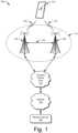
- FIG. 1illustrates an example environment 100 which includes a user equipment 102 (UE 102) that communicates with a base station 104 that acts as a serving cell (serving base station 104) through a wireless communication link 106 (wireless link 106).
- the user equipment 102is depicted as a smartphone.
- the user equipment 102may be implemented as any suitable computing or electronic device, such as a mobile communication device, modem, cellular or mobile phone, mobile station, gaming device, navigation device, media or entertainment device, laptop computer, desktop computer, tablet computer, smart appliance, vehicle-based communication system, wearable computer, Internet of Things (IoTs) device, wireless interface for a machine, and the like.
- IoTsInternet of Things
- the base station 104may be implemented in a macrocell, microcell, small cell, picocell, and the like, or any combination thereof.
- the base station 104communicates with the user equipment 102 via the wireless link 106, which may be implemented as any suitable type of wireless link.
- the wireless link 106can include a downlink (DL) of data and control information communicated from the base station 104 to the user equipment 102, an uplink (UL) of other data and control information communicated from the user equipment 102 to the base station 104, or both.
- the wireless link 106may include one or more wireless links or bearers implemented using any suitable communication protocol or standard, or combination of communication protocols or standards, such as 3rd Generation Partnership Project Long-Term Evolution (3GPP LTE), Fifth Generation New Radio (5G NR), and so forth.
- 3GPP LTE3rd Generation Partnership Project Long-Term Evolution
- 5G NRFifth Generation New Radio
- the user equipment 102communicates with another base station 104 (a neighbor base station 108) via a wireless link 110.
- the wireless link 110may be implemented using the same communication protocol or standard as, or a different communication protocol or standard than, that of the wireless link 106.
- the wireless link 106can be implemented a 5G NR link while the wireless link 110 is implemented as an LTE link.
- the base station 104, the neighbor base station 108, and any additional base stationscollectively form a Radio Access Network 112 (RAN 112, Evolved Universal Terrestrial Radio Access Network 112, E-UTRAN 112), which is connected via an Evolved Packet Core 114 (EPC 114) network to realize a wireless operator network.
- RAN 112Radio Access Network 112
- EPC 114Evolved Packet Core 114
- the base station 104 and the neighbor base station 108can communicate using an Xn Application Protocol (XnAP), as indicated at 116, to exchange user-plane and control-plane data.
- XnAPXn Application Protocol
- the user equipment 102may connect, via the Evolved Packet Core 114, to one or more public networks, such as the Internet 118, to interact with a remote service 120.
- Fig. 2is a diagram 200 illustrating example wireless devices, such as a user equipment (UE) 102 and a base station (BS) 104.
- the UE 102 and the base station 104may include additional functions and interfaces that are omitted from Fig. 2 for the sake of clarity.
- the UE 102includes antennas 202, at least one radio frequency front end 204 (RF front end 204), at least one LTE transceiver 206, and at least one 5G NR transceiver 208 for communicating with the base station 104.
- the RF front end 204 of the UE 102can couple or connect the LTE transceiver 206 and the 5G NR transceiver 208 to the antennas 202 to facilitate various types of wireless communication.
- the antennas 202 of the UE 102may include an array of multiple antennas that are configured similar to or differently from each other.
- the antennas 202 and the RF front end 204can be tuned to, and/or be tunable to, one or more frequency bands defined by the 3GPP LTE or the 5G NR communication standards and implemented by the LTE transceiver 206 or the 5G NR transceiver 208, respectively.
- the antennas 202, the RF front end 204, the LTE transceiver 206, and/or the 5G NR transceiver 208may be configured to support beamforming for the transmission and reception of communications with the base station 104. Example approaches to beamforming are described below with reference to Fig. 4 .
- the antennas 202 and the RF front end 204can be implemented for operation in sub-gigahertz bands, sub-6 GHZ bands, and/or above-6 GHz bands that are defined by the 3GPP LTE and 5G NR communication standards.
- the UE 102also includes one or more processors 210 and computer-readable storage media 212 (CRM 212).
- the processor 210may be a single core processor or a multiple core processor composed of a variety of materials, such as silicon, polysilicon, high-K dielectric, copper, and so on.
- the CRM 212may include any suitable memory or storage device, such as random-access memory (RAM), static RAM (SRAM), dynamic RAM (DRAM), non-volatile RAM (NVRAM), read-only memory (ROM), or Flash memory, useable to store device data 214 of the UE 102.
- the device data 214includes user data, multimedia data, beamforming codebooks, applications, and/or an operating system of the UE 102.
- Applications (not explicitly shown) and the device data 214are executable by the processor(s) 210 to enable user-plane communication, control-plane signaling, and user interaction with the UE 102.
- the CRM 212also includes a fast beam-tracking manager 216.
- the fast beam-tracking manager 216may be implemented in whole or part as hardware logic or circuitry integrated with or separate from other components of the UE 102.
- the fast beam-tracking manager 216configures the RF front end 204, the LTE transceiver 206, and/or the 5G NR transceiver 208 to implement the techniques for fast beam tracking as described herein with regard to UEs, possibly in conjunction with other components, such as a communications processor or modem.
- the base station 104can correspond to any of the example types of base stations set forth above.
- the functionality of the base station 104may be distributed across multiple network nodes or devices and may be distributed in any fashion suitable to perform the functions described herein.
- the base station 104include antennas 252, at least one radio frequency front end 254 (RF front end 254), one or more LTE transceivers 256, and/or one or more 5G NR transceivers 258 for communicating with the UE 102.
- the RF front end 254 of the base station 104can couple or connect the LTE transceivers 256 and the 5G NR transceivers 258 to the antennas 252 to facilitate various types of wireless communication.
- the antennas 252 of the base station 104may include an array of multiple antennas that are configured similar to or differently from each other.
- the antennas 252 and the RF front end 254can be tuned to, and/or be tunable to, one or more frequency bands defined by the 3GPP LTE and 5G NR communication standards and implemented by the LTE transceivers 256 and the 5G NR transceivers 258, respectively.
- the antennas 252, the RF front end 254, the LTE transceivers 256, and/or the 5G NR transceivers 258may be configured to support beamforming, such as massive multiple-input multiple-output (e.g., Massive-MIMO), for the transmission and reception of communications with the UE 102 or multiple UEs.
- massive multiple-input multiple-outpute.g., Massive-MIMO
- the base station 104also includes one or more processors 260 and computer-readable storage media 262 (CRM 262).
- the processor 260may be a single core processor or a multiple core processor composed of a variety of materials, such as silicon, polysilicon, high-K dielectric, copper, and so on.
- the CRM 262may include any suitable memory or storage device, such as random-access memory (RAM), static RAM (SRAM), dynamic RAM (DRAM), non-volatile RAM (NVRAM), read-only memory (ROM), or Flash memory, useable to store device data 264 of the base station 104.
- the device data 264includes network scheduling data, radio resource management data, beamforming codebooks, applications, and/or an operating system of the base station 104. Applications (not explicitly shown) and the device data 264 are executable by the processors 260 to enable communication with the UE 102.
- the CRM 262also includes a fast beam-tracking manager 266.
- the fast beam-tracking manager 266may be implemented in whole or part as hardware logic or circuitry integrated with or separate from other components of the base station 104.
- the fast beam-tracking manager 266configures the RF front end 254, the LTE transceivers 256, and/or the 5G NR transceivers 258 to implement the techniques for fast beam tracking as described herein with regard to base stations, possibly in conjunction with other components, such as a communications processor or modem.
- the base station 104also includes an inter-base station interface 268, such as an Xn and/or X2 interface, as shown at 116 in Fig. 1 .
- the inter-base station interface 268can be used to exchange user-plane and control-plane data with another base station 108 (of Fig. 1 ) to manage communications between the base station 104 and the UE 102 with respect to the other base station 108, such as for handovers or cooperative bandwidth delivery.
- the base station 104further includes a core network interface 270 to exchange user-plane and control-plane data with core network functions and entities, such as those of the Evolved Packet Core 114 of Fig. 1 .
- Fig. 3illustrates an air interface resource 302 that extends between a user equipment 102 and a base station 104 and with which various aspects of fast beam tracking can be implemented.
- the air interface resource 302can be divided into air interface resource units 320, including example resource units 321, 322, 323, ... 325.
- Each air interface resource unit 320occupies some intersection of frequency spectrum and elapsed time.
- a portion of the air interface resource 302is illustrated graphically in a grid or matrix having multiple resource blocks 310, including example resource blocks 311, 312, 313, 314.
- An example of a resource unit 320therefore includes at least one resource block 310.
- time 334is depicted along the horizontal dimension as the abscissa axis
- frequency 332is depicted along the vertical dimension as the ordinate axis.
- the air interface resource 302, as defined by a given communication protocol or standard,may span any suitable specified available frequency range, and/or may be divided into intervals of any specified duration.
- Increments of timecan correspond to, for example, microseconds ( ⁇ Sec) or milliseconds (mSec).
- mSecmilliseconds
- frequencycan correspond to, for example, kilohertz (KHz) or megahertz (MHz).
- the base station 104allocates portions (e.g., resource units 320) of the air interface resource 302 for uplink and downlink communications.
- Each resource block 310such as a Physical Resource Block (PRB), of network access resources may be allocated to support a respective wireless communication link 106 corresponding to a particular user equipment 102.
- the resource block 311may span, as defined by a given communication protocol, a specified frequency range 306 as a carrier and may include multiple subcarriers or frequency sub-bands.
- the resource block 311may include any suitable number of subcarriers (e.g., 12) that each correspond to a respective portion (e.g., 15 kHz) of the specified frequency range 306 (e.g., 180 kHz).
- the resource block 311may also span, as defined by the given communication protocol, a specified time interval 308 or subframe or time slot (e.g., lasting approximately one millisecond with 14 orthogonal frequency-division multiplexing (OFDM) symbols at 15 kHz).
- the time interval 308includes subintervals that may each correspond to a mini-slot of multiple symbols or to a symbol, such as an OFDM symbol.
- each resource block 310may include multiple resource elements 330 (REs) that correspond to, or are defined by, a subcarrier of the frequency range 306 and a subinterval (e.g., a symbol) of the time interval 308.
- REsresource elements 330
- an air interface resource unit 320may include at least one resource block 310, at least one resource element 330, and so forth.
- multiple user equipments 102are communicating with the base station 104 through access provided by portions of the air interface resource 302 that the base station 104 allocates with air interface resource units 320.
- the fast beam-tracking manager 266(as shown in Fig. 2 ) may determine a respective type or amount of information (e.g., data or control information) to be communicated (e.g., transmitted or received) by the user equipment 102.
- the fast beam-tracking manager 266may determine that the user equipment 102 is to receive a block of data on the downlink.
- This downlinkcan be realized as part of a downlink data channel, such as the Physical Downlink Shared Channel (PDSCH).
- PDSCHPhysical Downlink Shared Channel
- the fast beam-tracking manager 266then allocates at least one resource unit 320 to the user equipment 102 based on the determined amount or desired timing of the information.
- the fast beam-tracking manager 266 of the base station 104can notify the user equipment 102 of the allocation using a downlink control channel, such as the Physical Downlink Control Channel (PDCCH).
- the fast beam-tracking manager 216 (of Fig. 2 ) of the user equipment 102receives an indication of the resource unit allocation 320 and controls the user equipment accordingly. Example approaches to interactions and cooperative communications between the base station 104 and the user equipment 102 for fast beam-tracking are described herein.
- portions-e.g., resource units 320-of the air interface resource 302can be granted at a block level-e.g., using resource blocks 310.
- the fast beam-tracking manager 266may allocate resource units 320 at different levels, such as at an element-level. Accordingly, the fast beam-tracking manager 266 may allocate one or more resource elements 330 or individual subcarriers to different user equipments 102. By so doing, one resource block 310 can be allocated to facilitate network access for multiple user equipments 102.
- the fast beam-tracking manager 266may allocate, at various granularities, one or up to all subcarriers or resource elements 330 of a resource block 310 to one user equipment 102 or divided across multiple user equipments 102, thereby enabling higher network utilization or increased spectrum efficiency.
- the air interface resource 302can also be used to transmit from the user equipment 102 and to receive at the base station 104 UL tracking communications, which are described below starting at Fig. 6 .
- the fast beam-tracking manager 266can therefore allocate air interface resource 302 by resource unit 320, resource block 310, frequency carrier, time interval, resource element 330, frequency subcarrier, time subinterval, frame or slot, symbol, spreading code, some combination thereof, and so forth. Based on respective allocations of resource units 320, the fast beam-tracking manager 266 can transmit respective messages or other communications to the multiple user equipments 102 indicating the respective allocation of resource units 320 to each user equipment 102. Each communication indicative of at least one allocated resource unit 320 may enable a respective user equipment 102 to queue the information or configure the LTE transceiver 206, the 5G NR transceiver 208, or both to communicate via the allocated resource units 320 of the air interface resource 302.
- the user equipment 102can prepare an antenna beamformer to steer a signal beam toward the base station 104. To do so, the user equipment 102 can train the beamformer responsive to receipt of a signal transmitted from the base station 104. Beamforming is described next with reference to Fig. 4 .
- Fig. 4illustrates an example beamforming scenario 400 including a transmitting device 402 and a receiving device 404.
- the transmitting device 402includes an example of a communication unit 430 that is configured to implement antenna beamforming to generate multiple signal beams 420.
- the communication unit 430can transmit multiple signal beams 420, examples of which include four signal beams 421, 422, 423, and 424; however, more or fewer signal beams 420 can be generated.
- the multiple signal beams 420are formed such that a first signal beam 421 extends farther in a particular direction than the other signal beams.
- the communication unit 430 of the transmitting device 402can aim the first signal beam 421 in a direction toward the receiving device 404.
- a user equipment 102functions as the transmitting device 402
- a base station 104functions as the receiving device 404.
- the base station 104functions as the transmitting device 402
- the user equipment 102functions as the receiving device 404.
- the communication unit 430 of the transmitting device 402corresponds to the user equipment 102, but the communication unit 430 of the transmitting device 402 corresponds to the base station 104 in the latter situations.
- the communication unit 430is configured to transmit information 460 (e.g., data or control information) or receive information 460.
- the communication unit 430includes a baseband (BB) part 432, a radio frequency (RF) transceiver 434 (e.g., a transmitter and/or a receiver), and an RF front end (RFFE) 436.
- the RFFE 436includes an antenna array 440 that includes multiple antenna elements 410, examples of which are antenna elements 411, 412, ... 414. Thus, the multiple antenna elements 410 may jointly form or function as the antenna array 440.
- an "antenna"may refer to an antenna array or an antenna element.
- each signal beam 420can have a different height, shape along the beam, width, shape of incidence on the earth's surface, length, and so forth.
- the baseband part 432includes at least one baseband processor to modulate or apply the information 460 to a baseband signal as part of a transmission operation.
- the transceiver 434includes one or more lowpass filters and processes the baseband signal to upconvert or down-convert the frequency using at least one mixer for transmission or reception operations, respectively.
- the RFFE 436in addition to the multiple antenna elements 410, includes one or more bandpass filters.
- the transceiver 434 or the RFFE 436also includes one or more low-noise amplifiers (LNAs) for receiving signals and one or more power amplifiers (PAs) for transmitting signals.
- LNAslow-noise amplifiers
- PAspower amplifiers
- the transceiver 434 or the RFFE 436can include one or more phase shifters to delay a signal in time or change a phase thereof.
- the communication unit 430generates different patterns for the signal beams 420 by adjusting one or more beamforming parameters 450.
- the beamforming parameters 450can also be referred to as beamforming weights.
- the beamforming parameters 450establish different amplitudes 452, phases 454, and so forth for each signal version that is provided to one of the multiple antenna elements 410. By changing aspects of the signals emanating from the multiple antenna elements 410, the manners and geospatial locations at which the RF signals interact change, which produces different signal beam patterns.
- Beamforming parameters 450can be implemented at any portion of the communication unit 430.
- the baseband part 432can implement beamforming parameters 450 using precoding at a baseband processor.
- the transceiver 434 or the RFFE 436can implement beamforming parameters 450 using, for instance, phase shifters to shift the phase of one signal version relative to that of other signal versions.
- a hybrid approachcan be implemented in which beamforming parameters 450 are established partially at the baseband part 432 and partially at the transceiver 434 or the RFFE 436.
- the receiving device 404also includes a communication unit (CU) 430.
- the receiving device 404can therefore use the communication unit 430 to transmit or receive beamformed signals.
- the communication unit 430 of the transmitting device 402is described above primarily in terms of transmitting a signal beam 420, each communication unit 430 can also receive signals using antenna beamforming. In other words, the inverse or reciprocal beamforming process can be implemented by the receiving device 404 to increase a sensitivity to propagating EM signals using signal beams 420.
- the communication unit 430 at the receiving device 404receives multiple RF signals or signal versions at multiple antenna elements 410, such as antenna elements 416, 417, and processes the multiple RF signal versions using different beamforming parameters 450 until a received signal beam 420 is detected that has a sufficiently strong signal.
- This process of searching for beamforming parameters 450 that are at least acceptable for receiving a signal beam 420is called training the communication unit 430 to receive the signal beam 420 or training the beamformer.
- a beamforming training module(not separately shown) of a user equipment 102 or a beamforming training module of a base station 104 can implement beamforming training. Because RF propagation is at least partially reciprocal in nature, the beamforming parameters 450 that are determined as part of a receive operation at the receiving device 404 can be used for transmission as well when that device becomes the transmitting device. In other words, beamforming parameters 450 that are good for receiving a signal beam 420 from one device can then be used for transmitting another signal beam 420 back to that device. Similarly, beamforming parameters 450 that have been confirmed as being good for transmitting can be used for receiving, as long as channel conditions have not appreciably changed.
- antenna beamforming during transmission to a given devicecan train the beamformer (e.g., by determining appropriate beamforming parameters 450) for subsequent reception from the given device, and antenna beamforming during reception from the given device can train the beamformer for subsequent transmission to the given device.
- Training a beamformer by receiving a communication on a signal beam to determine beamforming parameters 450can therefore increase a quality of a subsequent transmission, as long as the beamforming parameters 450 remain fresh. This is especially pertinent if the transmitting or receiving device is moving or the signal propagation channel is otherwise rapidly changing.
- Fast beam tracking as described hereincan therefore be used to enhance beamforming by helping to train a beamformer as channel conditions change (e.g., because the location of at least one device that is party to a communication is moving). For example, a beamformed signal received at a base station from a given user equipment helps to train the beamformer at the base station for sending a signal beam back to the given user equipment. This situation is depicted in Fig. 5 .
- Fig. 5illustrates an example beamforming environment 500 for implementing fast beam tracking between two wireless devices, such as a base station 104 and a user equipment 102.
- the user equipment 102 and the base station 104can communicate using one or more signal beams 420, as described above with reference to Fig. 4 .
- Two additional examples of a signal beamare an uplink beam 525 (UL beam 525) and a downlink beam 526 (DL beam 526).
- Messages 510can be communicated on the uplink or the downlink.
- Two example message types that can be communicated via a DL beam 526are depicted in Fig. 5 . These are a radio resource message 511 and a DL information message 512.
- the radio resource message 511is transmitted by the base station 104 to multiple user equipments 102 to disseminate general system or cell-level information that is applicable to multiple user equipments 102.
- the DL information message 512is transmitted by the base station 104 to as few as a single user equipment 102 to provide device-specific information for interacting with the base station 104.
- a radio resource message 511can be implemented as a Radio Resource Control (RRC) message
- a DL information message 512can be implemented as a Downlink Control Information (DCI) message.
- RRCRadio Resource Control
- DCIDownlink Control Information
- a channel condition 521represents different traits or characteristics realizing or impacting a wireless communication between the user equipment 102 and the base station 104.
- factors related to the channel condition 521include: weather or atmospheric conditions, other (potentially-interfering) wireless signals, objects located between the two devices or along a path of a signal propagating between the two devices, movement of such objects, translational movement of the user equipment 102 that changes a location thereof, rotational movement of the user equipment 102 that changes an orientation thereof, combinations thereof, and so forth. If changes to any one or more of these characteristics change the channel condition 521, the beamforming between the two devices can be impacted.
- the user equipment 102transmits an uplink (UL) communication 504, which may be transmitted via a beamformed signal, to the base station 104.
- ULuplink
- the base station 104can train its beamforming mechanism to learn one or more beamforming parameters 450, as is described above with reference to Fig. 4 .
- the base station 104can then transmit a signal beam 4220 (e.g., as a DL beam 526) back to the user equipment 102 as some DL communication.
- the signal beam 422is well-aimed at the user equipment 102 at time t1. In this situation, the DL data transmitted to the user equipment 102 via the signal beam 422 is ordinarily received successfully.
- the user equipment 102is in motion along a path 502.
- the user equipment 102has started to leave a location covered by the signal beam 422. Consequently, the DL data transmitted to the user equipment 102 via the signal beam 422 at time t2 may still be received, but possibly with a lower bandwidth or accuracy level.
- the user equipment 102has traveled farther along the path 502. As depicted in this example, the user equipment 102 has departed the area covered by the signal beam 422 at time t3.
- the DL data transmitted to the user equipment 102 via the signal beam 422 at time t3is unlikely to be received, at least at a satisfactory level of quality.
- a user equipment 102 that is in motioncan "outrun" an unchanging or static signal beam 422 relatively quickly, which reduces communication throughput or bandwidth.
- the user equipment 102transmits an UL communication 505 around time t3 but prior to a time at which the base station 104 is scheduled to transmit DL data via a signal beam 423.
- the base station 104can therefore learn beamforming parameters 450 from the UL communication 505 at time t3 and use the learned beamforming parameters 450 to form an appropriately-shaped and directed signal beam 423 for a DL data communication. If the time interval between the UL communication 505 used for beamform training and the subsequent transmission of the signal beam 423 (e.g., as a DL beam 526) used for DL data delivery is sufficiently small, the likelihood of the user equipment 102 being present within a coverage area of the signal beam 423 increases appreciably.
- Example approaches to allocating portions of the air interface resource 302 of Fig. 3 to this endare described below for fast beam tracking. Although some of the description herein focuses on a movement of the user equipment 102 causing changes to the channel condition 521, the described principles are applicable to counteracting changes to the channel condition 521 from other causes.
- Fig. 6is a sequence diagram 600 illustrating examples of operations and multiple communications between a base station 104 and a user equipment 102 to implement fast beam tracking in accordance with a wireless signaling protocol.
- the operations or communicationscan be performed by a fast beam-tracking manager 216 (as shown in Fig. 2 ) of the user equipment 102 or by a fast beam-tracking manager 266 of the base station 104.
- time 334increases in a downward direction.
- Three examples of communication exchanges that relate to fast beam trackingare shown: a downlink (DL) control channel communication 602, an uplink (UL) tracking communication 604, and a downlink (DL) data channel communication 606.
- the base station 104is responsible for allocating portions of the air interface resource 302 (of Fig. 3 ) to the various user equipments in a cell or other area that is associated with the base station 104. Accordingly, at an operation 601, the base station 104 formulates a DL data grant for the user equipment 102 responsive to receipt at the base station 104 of DL data that is destined for the user equipment 102.
- the DL data grantcorresponds to at least one first air interface resource unit 321 (e.g., of Figs. 3 , 7 , and 8 ).
- the base station 104transmits to the user equipment 102 the DL control channel communication 602 including a DL data grant for the user equipment 102.
- the DL control channel communication 602may be implemented using, for example, a Physical Downlink Control Channel (PDCCH).
- the DL data grantis indicative of the at least one first air interface resource unit 321 allocated to the DL data grant.
- the first air interface resource unit 321 allocated to the DL data grantmay correspond to a portion of, for example, a Physical Downlink Shared Channel (PDSCH).
- PDSCHPhysical Downlink Shared Channel
- the user equipment 102receives from the base station 104 the DL control channel communication 602 including the DL data grant for the user equipment 102.
- the user equipment 102is therefore informed of the at least one first air interface resource unit 321 that is allocated to it.
- the first air interface resource unit 321can correspond to an allocated frequency range and allocated time for the DL data communication.
- the user equipment 102transmits to the base station 104 the UL tracking communication 604 via an UL beam 525 and in accordance with at least one second air interface resource unit 322 (e.g., of Figs. 3 , 7 , and 8 ).
- the UL tracking communication 604may be implemented using, for example, a channel designated to include beam-tracking information, such as an UL beam-tracking pilot channel (UBTPC).
- UBTPCUL beam-tracking pilot channel
- the at least one second air interface resource unit 322 for the UL tracking communication 604is based on the at least one first allocated air interface resource unit 321.
- the UL tracking communication 604can be communicated over a frequency that at least overlaps the allocated frequency range of the first air interface resource unit 321 or at a time that is shortly prior to and proximate to the allocated time for the DL data communication.
- the base station 104receives from the user equipment 102 the UL tracking communication 604 via the UL beam 525 (e.g., using the UBTPC) in accordance with the second air interface resource unit 322.
- the UL tracking communication 604may include beam-tracking information, such as a pilot sequence known to the base station 104.
- the base station 104trains for a DL beam using the UL tracking communication 604.
- the base station 104can learn one or more beamforming parameters 450 that are currently appropriate for beam-based communication with the user equipment 102 using the UL tracking communication 604 by searching for a known pilot signal over a set of different beamforming parameters 450.
- the base station 104transmits to the user equipment 102 the DL data channel communication 606 via a DL beam 526 (e.g., using the PDSCH).
- the DL beam 526is formed using the beamforming parameters 450 learned during reception of the UL tracking communication 604.
- the DL data channel communication 606includes the DL data corresponding to the DL data grant and is transmitted in accordance with the at least one first air interface resource 321-e.g., at the allocated frequency range and the allocated communication time.
- the user equipment 102receives from the base station 104 the DL data channel communication 606 via the DL beam 526 (e.g., using the PDSCH) in accordance with the at least one first air interface resource unit 321.
- the user equipment 102Because the DL beam 526 is generated relatively recently after beamformer training and there is less time for changes to the channel condition 521, the user equipment 102 has a greater likelihood of successfully receiving the DL data included in the DL data channel communication 606, as compared to if more time had elapsed between beamformer training and DL data transmission.
- Fig. 7illustrates, for a portion 700 of an air interface resource 302, an example scheduling of communications to implement fast beam tracking.
- the portion 700includes multiple air interface resource units 320.
- any amount of time or any range of frequencycan occur before, between, or after the explicitly-depicted air interface resource units 320.
- Three specific air interface resource units 321, 322, and 323are depicted for the following communications.
- the DL control channel communication 602, such as a PDCCHis propagated in accordance with a third air interface resource unit 323.
- the UL tracking communication 604, such as a UBTPCis propagated in accordance with a second air interface resource unit 322.
- the DL control channel communication 602includes a DL data grant 702
- the UL tracking communication 604includes tracking information 704 (TI 704)
- the DL data channel communication 606includes DL data 706.
- the first air interface resource unit 321 for the DL data channel communication 606corresponds to a frequency range 722 ( FR 722 ) and a communication time 724.
- the base station 104transmits the DL data 706 to the user equipment 102 over the frequency range 722 and at the communication time 724 in accordance with the first air interface resource unit 321 specified in the DL data grant 702.
- the DL beam used to transmit the DL data channel communication 606can be trained using the previously-exchanged UL tracking communication 604.
- the tracking information 704enables a receiving device (e.g., a base station 104) to focus or direct a signal beam by searching for the tracking information 704.
- the tracking information 704can include any information that is known or determinable by both the transmitting and receiving devices involved in a training operation.
- the tracking information 704can include, for example, a pilot-tracking code (e.g., a bit sequence) assigned to each user equipment 102 by the base station 104.
- the UL tracking communication 604has a transmission time 744. Relative to the base station 104, the UL tracking communication 604 has a reception time 742. However, the transmission time 744 and the reception time 742 correspond to a same time along the time dimension 334 (discounting signal propagation time), and these times are jointly denoted as a tracking time 740. Similarly, relative to the base station 104, the DL control channel communication 602 has a transmission time 732. And relative to the user equipment 102, the DL control channel communication 602 has a reception time 734. Depending on implementation, any of these times can correspond to a beginning, an end, a middle, and so forth of a given communication or corresponding air interface resource unit 320, as long as the wireless devices are operating under a common understanding.
- the base station 104provides an indication 730 of a tracking time 740 that is associated with the UL tracking communication 604 and corresponds to the second air interface resource unit 322.
- the tracking time 740corresponds to the transmission time 744 for the user equipment 102 and to the reception time 742 for the base station 104.
- the indication 730can be provided in any one or more of multiple formats or mechanisms.
- the indication 730can identify a particular symbol or slot position for the UL tracking communication 604.
- the indication 730can include a temporal offset 710, such as a temporal offset 711 or 712.
- the temporal offset 710is an indication that is relative to another time, such as a time of the DL control channel communication 602 or the DL data channel communication 606, with the latter corresponding to the allocation provided by the DL data grant 702.
- the tracking time 740can be determined using either temporal offset 711 or temporal offset 712.
- the tracking time 740e.g., the reception time 742 and the transmission time 744
- the indication 730can be provided implicitly or explicitly.
- the base station 104can establish the temporal offset 710 or other indication 730 using a radio resource message 511.
- the base station 104can configure the tracking time 740 for each user equipment 102 by providing the temporal offset 710 or other indication 730 using a DL information message 512.
- the base station 104can select the tracking time 740 to facilitate having fresh beamforming parameters 450 at the start of the DL data channel communication 606.
- the tracking time 740can be selected such that an end of the UL tracking communication 604 and the beginning of the DL data channel communication 606 has a desired duration.
- the desired durationmay vary based on a rate at which the channel condition 521 is changing. If the channel condition 521 is changing rapidly, the desired duration between the two communications can be reduced. Moreover, if the channel conditions 521 are changing slowly, the use of UL tracking communications 604 can be disabled, as is explained with reference to Fig. 9 .
- Fig. 8illustrates, for a portion 800 of an air interface resource 302, other example aspects for implementing fast beam tracking.
- the DL data grant 702can include or correspond to an allocated frequency range 822 and an allocated communication time 824 for delivery of the DL data 706 as part of the DL data channel communication 606.
- the DL data grant 702can therefore inform the user equipment 102 of the allocated first air interface resource unit 321 for the DL data channel communication 606.
- the allocated communication time 824corresponds to the communication time 724
- the allocated frequency range 822corresponds to the frequency range 722.
- the DL data 706 of the DL data channel communication 606may occupy each subcarrier of the frequency range 722 as per the DL data grant 702.
- the UL tracking communication 604propagates on a frequency band that is at least proximate to that of the DL data channel communication 606 to facilitate accurate beamforming because channel conditions 521 can vary by frequency. More specifically, the UL tracking communication 604 can have a frequency that at least overlaps the frequency range 722 of the DL data channel communication 606.
- the UL tracking communication 604need not occupy each subcarrier of the frequency range 722 to provide useful beam training. Instead, the UL tracking communication 604 can cover a frequency perforation 830 of the frequency range 722.
- a frequency perforation 830 across the frequency range 722can be more spectrally efficient, if the unoccupied subcarriers are allocated to other user equipments.
- This frequency perforation 830corresponds to covering some, but not all, subcarriers of the frequency range 722.
- the frequency perforation 830can cover the two outer subcarriers and at least one inner subcarrier, can cover every other subcarrier, and so forth.
- Fig. 9illustrates an example multiple-input, multiple-output (MIMO) environment in which fast beam tracking can be implemented.
- a communication unit 430(of Fig. 4 ) includes or is coupled to multiple transceivers and multiple antenna arrays that are configured to establish and manage multiple different wireless links in an overlapped or substantially-simultaneous manner. This technique is referred to as a multiple-input, multiple-output (MIMO) operation of a wireless device.
- MIMOmultiple-input, multiple-output
- the user equipment 102 and the base station 104may communicate using a MIMO technique to increase throughput.
- the user equipment 102 and the base station 104may communicate using multiple MIMO layers 910, such as the example MIMO layers 911 and 912.
- a quantity of MIMO layersmay be "n," with "n” representing some positive integer greater than one.
- Each MIMO layer 910is typically transceived using a different set of physical antennas. Consequently, each respective MIMO layer 910 likely employs a different respective signal beam for higher quality signal exchange.
- one or more DL data grantsare indicative of multiple allocated air interface resource units 320 respectively corresponding to the multiple MIMO layers 910.
- the BS 104allocates at least one respective second air interface resource unit 322 for each respective UL tracking communication 604 for each respective MIMO layer 910.
- Each respective UL tracking communication 604is transmitted by the user equipment 102 on a respective MIMO layer 910 so that the base station 104 can learn at least one beamforming parameter 450 for use during the corresponding DL data channel communication 606 of the respective MIMO layer 910.
- Fig. 9illustrates other example aspects of fast beam tracking.
- the base station 104can enable/disable fast beam tracking as indicated at 922.
- the enabling or disablingcan be performed on a cell-level or on a per-device level. For example, if a particular user equipment 102 has a slowly-changing set of channel conditions 521 such that beamforming parameters 450 grow stale slowly, the base station 104 can disable fast beam tracking at least for that particular user equipment 102.
- Enable/disable commandscan be implicitly made by a base station 104 by ceasing the provision of an explicit indication 730 (of Fig. 7 ).
- a base station 104can explicitly make enable/disable commands by sending out a radio resource message 511 or a DL information message 512.
- the user equipment 102can maintain a record of whether fast beam tracking is enabled or disabled.
- the user equipment 102includes at least one transceiver 902 (TRX 902) (e.g., a UE implementation of a transceiver 434 of Fig. 4 ).
- the at least one transceiver 902includes at least one transmit chain 904 (TX chain 904) and at least one receive chain 906 (RX chain 906).
- the base station 104is notified of a transceiver configuration possessed by the user equipment 102, such as when the user equipment 102 registers with the base station 104.
- the base station 104is aware of a quantity of transmit or receive chains 904 or 906 present at the user equipment 102. This knowledge, with respect to transmit chains 904, is represented by the transmit chain presence characteristic 924 that is stored at the base station 104.
- a quantity of transmit chains 904affects how many UL transmissions the user equipment 102 can make at any given moment. For example, if the user equipment 102 has a single transmit chain 904, the user equipment 102 cannot send regular UL data traffic and an UL tracking communication 604 (e.g., of Figs. 6-8 ) at the same time. Accordingly, the base station 104 schedules allocations of the air interface resource 302 so that the user equipment 102 can transmit the UL data and the UL tracking communication 604 at different times by implementing time-division multiplexing (TDM).
- TDMtime-division multiplexing
- the base station 104allocates portions of the air interface resource 302 to implement a TDM scheme to accommodate both UL data traffic of the user equipment 102 and UL tracking communications 604.
- Example methodsare described below with reference to various flow diagrams of Figs. 10 and 11 . These methods relate to fast beam tracking for a base station and for a user equipment, respectively. Aspects of these methods may be implemented in, for example, hardware (e.g., fixed logic circuitry, communication-oriented processors such as a modem, or general-purpose processors), firmware, or some combination thereof. These techniques may be realized using one or more of the wireless devices or components shown in Figs. 1-9 , which devices or components may be further divided, combined, and so on. The electronic devices and components of these figures generally represent firmware, hardware, IC chips, circuits, or a combination thereof. Thus, these figures illustrate some of the many possible systems or apparatuses capable of implementing the described techniques.
- Fig. 10illustrates at a flow diagram 1000 example methods for implementing fast beam tracking using a base station 104.
- the existence of DL data 706 that is present at the base station 104 and destined for a user equipment 102triggers the process.
- the base stationtransmits, to a user equipment, a downlink (DL) control channel communication including a DL data grant for the user equipment, with the DL data grant indicative of at least one first air interface resource unit allocated to the DL data grant.
- a downlink (DL) control channel communicationincluding a DL data grant for the user equipment, with the DL data grant indicative of at least one first air interface resource unit allocated to the DL data grant.
- the base station 104can transmit, to a user equipment 102, a DL control channel communication 602 including a DL data grant 702 for the user equipment 102.
- the DL data grant 702is indicative of at least one first air interface resource unit 321 that is allocated to the DL data grant 702.
- the first air interface resource unit 321may be defined in terms of time and frequency, such as a frame or slot and at least one subcarrier.
- the base stationreceives, from the user equipment, an uplink (UL) tracking communication in accordance with at least one second air interface resource unit, with the at least one second air interface resource unit based on the at least one first air interface resource unit.
- the base station 104can receive, from the user equipment 102, an UL tracking communication 604 in accordance with at least one second air interface resource unit 322.
- the at least one second air interface resource unit 322is based on the at least one first air interface resource unit 321.
- at least one frequency or subcarrier of the second air interface resource unit 322may overlap a frequency range 722 of the first air interface resource unit 321.
- the second air interface resource unit 322may precede the first air interface resource unit 321 in time.
- the base stationtrains for a DL beam using the UL tracking communication 604.
- the base station 104can train for a DL beam 526 using the UL tracking communication 604.
- the base station 104may search for known tracking information 704 (e.g., a pilot signal including a pilot-tracking code) included in the UL tracking communication 604 by adjusting beamforming parameters 450 until a strong signal is demodulated to determine a signal beam 420.
- known tracking information 704e.g., a pilot signal including a pilot-tracking code
- the base stationtransmits, to the user equipment via the DL beam, a DL data channel communication corresponding to the DL data grant in accordance with the at least one first air interface resource.
- the base station 104can transmit, to the user equipment 102 via the DL beam 526, a DL data channel communication 606 corresponding to the DL data grant 702 in accordance with the at least one first air interface resource unit 321.
- the base station 104may form the DL beam 526 using the determined beamforming parameters 450 and send DL data 706 to the user equipment 102.
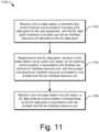
- Fig. 11illustrates at a flow diagram 1100 example methods for implementing fast beam tracking with a user equipment 102.
- the base station 104may have actively enabled fast beam tracking with the user equipment 102 in a direct message or a broadcast message.
- the user equipmentreceives, from a base station, a downlink (DL) control channel communication including a DL data grant for the user equipment, with the DL data grant indicative of at least one first air interface resource unit allocated to the DL data grant.
- a downlink (DL) control channel communicationincluding a DL data grant for the user equipment, with the DL data grant indicative of at least one first air interface resource unit allocated to the DL data grant.
- the user equipment 102can receive, from the base station 104, a downlink (DL) control channel communication 602 including a DL data grant 702 for the user equipment 102.
- the DL data grant 702is indicative of at least one first air interface resource unit 321 allocated to the DL data grant 702.
- the DL data grant 702may, for instance, include an allocated frequency range 822 and an allocated communication time 824.
- the user equipmenttransmits, to the base station via an uplink (UL) beam, an UL tracking communication in accordance with at least one second air interface resource unit, with the at least one second air interface resource unit based on the at least one first air interface resource unit.
- the user equipment 102can transmit, to the base station 104 via an UL beam 525, an UL tracking communication 604 in accordance with at least one second air interface resource unit 322.
- the at least one second air interface resource unit 322is based on the at least one first air interface resource unit 321.
- the second air interface resource unit 322may have at least one overlapping frequency or subcarrier relative to the allocated frequency range 822.
- a transmission time 744 of the UL tracking communication 604may be established relative to at least one of a reception time 734 of the DL control channel communication 602 or the allocated communication time 824 for the DL data channel communication 606.
- the user equipmentreceives, from the base station via a DL beam, a DL data channel communication corresponding to the DL data grant in accordance with the at least one first air interface resource unit.
- the user equipment 102can receive, from the base station 104 via a DL beam 526, a DL data channel communication 606 corresponding to the DL data grant 702 in accordance with the at least one first air interface resource unit 321.
- the DL beam 526has been trained by the base station 104 using the UL tracking communication 604.
- the user equipment 102Due to the base station 104 having been able to recently train a beamformer using the UL tracking communication 604 to generate fresh beamforming parameters 450, the user equipment 102 is more likely to be able to receive the DL data 706 of the DL data channel communication 606 via the DL beam 526.
- "at least one of: a, b, or c”can cover a, b, c, a-b, a-c, b-c, and a-b-c, as well as any combination with multiples of the same element (e.g., a-a, a-a-a, a-a-b, a-a-c, a-b-b, a-c-c, b-b, b-b-b, b-b-c, c-c, and c-c-c, or any other ordering of a, b, and c).
Landscapes
- Engineering & Computer Science (AREA)
- Signal Processing (AREA)
- Computer Networks & Wireless Communication (AREA)
- Mobile Radio Communication Systems (AREA)
Description
- With cellular communications technology, a communication between two endpoints usually has both a wireless portion and a wired portion. A portion of the communication that is near one party is instituted using a wireless connection between a user equipment (e.g., a smartphone) and a base station, which is part of a cellular or other radio access network of a larger communication network. This wireless connection typically extends from a few feet to a few miles. The communication network also includes or is coupled to a wired network. The base station can therefore continue or forward the communication using a wired connection over the wired network. The wired network can extend from dozens of feet to thousands of miles. If the other party is also using a mobile phone, the communication can be converted back to another wireless portion and routed to the other party using another wireless connection.
- To provide voice, image, video, and other services, wireless networks are already expected to handle immense quantities of data with little to no appreciable delays. However, newer services are primed to demand even more from cellular and other wireless networks. Users will expect greater data bandwidth and even less delay, which is called latency, to accommodate such services. These new services include high-bandwidth applications like ultra-high definition (UHD) video that is delivered wirelessly from a streaming video service to a mobile device. Such services also include low-latency applications like autonomous-driving vehicles that communicate with each other to avoid accidents and that can therefore operate more safely if provided nearly instantaneous data communication capabilities. Some applications, like virtual reality (VR), will demand data delivery that provides a combination of both high-bandwidth and low-latency. Further, there is the ongoing development of the Internet of Things (IoT), which involves providing wireless communication capabilities to everything from medical devices to security hardware, from refrigerators to speakers, and to nearly ubiquitous sensors designed for safety and convenience. The deployment of IoT devices means hundreds of billions to trillions of new devices will soon be trying to communicate wirelessly.
- Current 4G wireless networks are not expected to be able to handle the data bandwidth and latency targets for these new applications. Accordingly, to enjoy these new applications, new wireless technology is being developed. This Fifth Generation (5G) wireless network technology will adopt higher frequency EM waves (e.g., 6 GHz to 300 GHz for millimeter wave (mmW) wireless connections) to attain higher data bandwidth in conjunction with lower latency. These new applications and higher EM frequencies, however, introduce new and different challenges that are yet to be overcome by current wireless technologies.
- For example, with the multitude of IoT devices that are coming on-line, the EM spectrum that is allocated to cellular wireless usage will be shared among many more wireless connection endpoints. Also, with the mmW EM signaling that will be used in some wireless networks, including 5G cellular networks, wireless signals are attenuated more quickly. More specifically, mmW EM signals are attenuated more quickly by air molecules and other environmental factors, such as humidity or physical obstructions, as compared to those signaling frequencies used in earlier generations of wireless networks. Consequently, mmW EM signals are incapable of traveling as far through the atmosphere before their quality is reduced to a level at which the information in the wireless signal is lost or otherwise becomes unusable. To address these issues, engineers and manufacturers are striving to create new wireless signaling technologies that can enable utilization of these GHz frequencies in a cellular or other wireless network, including those operating in accordance with a 5G wireless network standard.
US2014/0211739A1 relates to methods and devices for transmitting/receiving downlink signals in a wireless communication system.WO2018/028579A1 describes a PDSCH region of a subframe which includes a reference signal (RS) section that includes one or more of a beam-scanning subsection, a TX beam-tracking subsection, a RX beam-tracking subsection, and a channel state information (CSI) subsection. "Tracking mm-Wave Channel Dynamics: Fast Beam Training Strategies under Mobility" by Joan Palacioset al. describes smart beam training and tracking strategies for fast mm-wave link establishment and maintenance under node mobility.- This background description is provided to generally present the context of the disclosure. Unless otherwise indicated herein, material described in this section is neither expressly nor impliedly admitted to be prior art to the present disclosure or the appended claims.
- This summary is provided to introduce simplified concepts of fast beam tracking. The simplified concepts are further described below in the Detailed Description. Accordingly, this summary is not intended to identify essential features of the claimed subject matter nor is it intended for use in determining the scope of the claimed subject matter.
- Methods and apparatuses for fast beam tracking are described. Using signal beams to communicate wirelessly can increase both spectrum usage efficiency and attainable signaling distances, especially at higher frequencies. To employ antenna beamforming, one wireless device can train a beamformer using a signal that is being received from another wireless device. The trained beamformer can then communicate with the other device via a signal beam, at least until changes to channel conditions render the trained beamformer ineffective. Movement by a user equipment, for instance, can cause such changes to channel conditions. Other causes of changing channel conditions include inclement weather and objects moving between a base station and the user equipment. If changes to the channel conditions are happening quickly, beamforming parameters can become stale equally quickly. Using stale beamforming parameters can result in a signal beam that is emanated by a base station failing to reach a user equipment.
- In contrast, for example implementations, relatively fresh beamforming parameters are maintained. In conjunction with allocating a first air interface resource unit (e.g., an intersection of electromagnetic spectrum and elapsed time) for delivery of downlink data, a base station also reserves a second air interface resource unit for beamformer training. The second air interface resource unit is based on the first air interface resource unit. For example, their respective frequency ranges may be at least partially overlapping, and a second time for the second air interface resource unit may precede and be relatively proximate to a first time for the first air interface resource unit. In accordance with the second air interface resource unit, the user equipment transmits an uplink tracking communication to the base station for beamformer training purposes. Because reception and transmission operations are substantially reciprocal, a signal beam determined for a reception from the user equipment is likewise appropriate for a transmission to the user equipment. Accordingly, the base station then uses the recently-trained beamformer to transmit the downlink data via a signal beam in accordance with the first air interface resource unit. In these manners, beamforming parameters can be updated to be relatively fresh before each delivery of downlink data.
- The invention is defined by the features of the appended claims.
- Apparatuses of and techniques for implementing fast beam tracking are described with reference to the following drawings. The same numbers are used throughout the drawings to reference like features and components:
Fig. 1 illustrates an example wireless network environment in which different devices interoperate and can implement fast beam tracking.Fig. 2 is a schematic diagram illustrating example devices, such as a user equipment (UE) and a base station (BS), that can implement various aspects of fast beam tracking in a wireless network.Fig. 3 illustrates an air interface resource that extends between a UE and a BS and with which various aspects of fast beam tracking can be implemented.Fig. 4 illustrates an example of a communication unit for a wireless device in which the communication unit can implement beamforming to generate signal beams for transmission or reception functionality.Fig. 5 illustrates an example beamforming environment for implementing fast beam tracking between two wireless devices, such as a BS and a UE.Fig. 6 is a sequence diagram illustrating examples of operations and multiple communications between a BS and a UE to implement fast beam tracking in accordance with a wireless signaling protocol.Fig. 7 illustrates, for a portion of an air interface resource, an example scheduling of communications to implement fast beam tracking.Fig. 8 illustrates, for a portion of an air interface resource, other example aspects for implementing fast beam tracking.Fig. 9 illustrates an example multiple-input, multiple-output (MIMO) environment in which fast beam tracking can be implemented.Fig. 10 illustrates example methods for a BS to implement fast beam tracking.Fig. 11 illustrates example methods for a UE to implement fast beam tracking.- Today, users can watch HD video, monitor social network feeds, and participate in video conferences using cellular wireless networks that operate in accordance with a 4G standard, such as LTE or LTE-Advanced. Soon, cellular wireless networks will be asked to handle newer applications that are technologically more difficult to provide to end users. Such applications may include watching ultra-HD (UHD) video or wirelessly coupling hundreds of billions more communication endpoints to the internet to support IoT devices. Such applications may also entail providing a safer sharing of the roadways by empowering self-driving vehicles or exchanging three-dimensional (3D) virtual reality (VR) data for games, professional training, and educational activities. To enable these newer applications, current cellular wireless networks are expected to be upgraded from 4G technology.
- To upgrade from current 4G wireless networks, various goals have been established for next-
generation 5G networks. These goals involve adopting higher electromagnetic (EM) frequencies for wireless signaling in 5G networks than are used in 4G networks. For example, instead of operating in the 100s of MHz to a few GHz like in 4G networks, 5G networks are expected to operate in the 10s of GHz (e.g., from 6 GHz to 300 GHz for mmW signaling). These higher frequencies offer some advantages, such as the potential for greater communication bandwidth in conjunction with lower latency. However, there are many challenges to working with these higher frequencies, and some of these challenges have yet to be met by the telecommunications industry. In other words, although a high-frequency goal has been established for 5G networks, the technology to reach this high-frequency destination with an efficient, feasible 5G wireless network has not yet been developed. - Thus, there are existing challenges for attaining a cost-effective, high-
frequency wireless 5G network. For example, with the frequencies to be used for mmW signaling for 5G wireless networks, signal strength rapidly attenuates, or reduces, as an EM signal travels through the earth's atmosphere, especially in humid or wet weather. Consequently, the supportable distance between a transmitter and a receiver is reduced for mmW signals as compared to signals of larger wavelengths and lower frequencies. As another example, at some of these higher frequencies, EM signals are blocked by walls and relatively thin layers of metal. Antenna beamforming may at least partially address both these issues. - With antenna beamforming, an antenna array emanates a signal in a particular direction or in a particular pattern instead of omnidirectionally-i.e., instead of equally in all directions from a single antenna. This enables the resulting signal beam to be directed away from an object that might block a high-frequency EM signal. Moreover, the emanated power can be concentrated in a specific direction that extends from a transmitter in a direction that aims toward a receiver. Consequently, a signal transmitted at a given power level can travel farther through the air on a signal beam, even at the higher frequencies of mmW signals that attenuate more quickly in the earth's atmosphere.
- Antenna beamforming offers another advantage: an increased or more-efficient sharing of the EM spectrum. By concentrating a first signal that is sent from a first transmitter to a first receiver in one direction, the first signal is less likely to cause interference in other directions. As a result, a second signal on the same frequency can be reused by a second transmitter and a second receiver in a spatial area that is close to that occupied by the first transmitter and receiver. This spatially-based frequency-reuse technique enables more devices to communicate wirelessly in a particular geographic region using a given frequency range allocation.
- Antenna beamforming can therefore offer a number of advantages, including some that pertain specially to wireless communication with the mmW signals that are earmarked for 5G wireless networks. However, wireless communication with beamforming is more complicated than wireless communication without it. Without antenna beamforming, a transmitting device can simply emanate an EM signal omnidirectionally and/or from one antenna element. With antenna beamforming, on the other hand, a transmitting device determines a direction at which to aim a beam of a signal; otherwise, the intended recipient device may not receive the signal beam. The determination of an appropriate direction for a signal beam is called antenna beamforming training.
- This beamformer training can be accomplished in different manners, but each manner occupies some period of time, consumes air interface resources, and depletes resources such as battery power or processing bandwidth at the transmitting device and/or at the receiving device. Thus, although antenna beamforming is beneficial, it is inadvisable to constantly engage in beam training. However, beamforming parameters of a trained beamform cannot be effectively used indefinitely because they can eventually become stale. Further, a time over which the beamforming parameters grow stale becomes shorter if a channel condition between a base station and a user equipment is changing rapidly, and channel conditions can change rapidly if a user equipment is in motion. Thus, especially with rapidly-changing channel conditions, beamforming parameters can grow more and more stale until the corresponding signal beam is no longer effective at providing coverage to the targeted user equipment.
- To address this problem, a base station and/or a user equipment in a wireless system is configured to maintain relatively fresh beamforming parameters in a manner that is responsive to the likely utilization of the fresh beamforming parameters. In some implementations, opportunities to train a beamformer are paired with the delivery of downlink (DL) data by scheduling a training period prior to the delivery of the DL data.
- Thus, techniques and apparatuses are described for fast beam tracking. These techniques and apparatuses enable wireless communications to be made in environments that are hostile to signal propagation or with rapidly-moving devices. A respective fast beam-tracking manager at both a base station (BS) and a user equipment (UE) can interoperate to provide an uplink (UL) beam-tracking signal to facilitate beamforming on the downlink from the BS to the UE. The resulting beamforming enables a signal transmitted in a wireless system to travel farther in a targeted direction than a comparable signal would travel if transmitted omnidirectionally. A signal beam is reciprocal and can therefore be aimed from one device to another device from both a transmission perspective and a reception perspective. For example, a BS can direct a signal beam toward a UE. To enable the BS to know how to direct a signal beam towards the UE, the UE can transmit a tracking signal toward the BS to train the beamforming of the BS. However, the beamforming information learned from the training can grow stale quickly if the UE is moving rapidly such that a directional beam no longer properly aims at the UE when the BS transmits another beamformed signal using the beamforming information.
- To address this problem, in some implementations, a BS assigns an UL beam-tracking pilot channel (UBTPC) to a UE in association with a grant of a first air interface resource unit for a forthcoming DL data communication. The UBTPC is assigned frequency resources at a time that is prior to and proximate to the allocated first air interface resource unit to increase the likelihood that the beamforming information is still fresh when the first air interface resource unit is used for the DL data communication. For example, a BS communicates a DL data grant of at least one first air interface resource unit in a DL control channel communication, such as part of a Physical Downlink Control Channel (PDCCH). The DL data grant is for an allocation of some frequency range over a particular time period. The communication of the DL data grant implicitly or explicitly indicates an assignment of at least one second air interface resource unit for an UL tracking communication corresponding to the UBTPC.
- In response to receiving the DL data grant communication, the UE transmits the UL tracking communication, which can include a pilot-tracking code, to the BS for the UBTPC in accordance with the assigned second air interface resource unit. The BS trains a beamform using the UBTPC to learn beamforming parameters to use to communicate with the UE on the DL. The BS then transmits a DL data channel communication, which can be part of a Physical Downlink Shared Channel (PDSCH), via a DL beam that is formed using the learned beamforming parameters. A temporal position assigned to the second air interface resource unit for the UL tracking communication can be indicated relative to the DL control channel communication or the DL data channel communication using a temporal offset. Alternatively, the temporal position for the tracking communication can be indicated by specifying a particular symbol, including a slot or frame that includes the particular symbol.
- Example implementations in various levels of detail are discussed below with reference to the associated figures. The discussion below first sets forth an example operating environment and then describes example schemes, techniques, and hardware. Example methods are described thereafter with reference to various flow diagrams.
FIG. 1 illustrates anexample environment 100 which includes a user equipment 102 (UE 102) that communicates with abase station 104 that acts as a serving cell (serving base station 104) through a wireless communication link 106 (wireless link 106). In this example, theuser equipment 102 is depicted as a smartphone. Although illustrated as a smartphone, theuser equipment 102 may be implemented as any suitable computing or electronic device, such as a mobile communication device, modem, cellular or mobile phone, mobile station, gaming device, navigation device, media or entertainment device, laptop computer, desktop computer, tablet computer, smart appliance, vehicle-based communication system, wearable computer, Internet of Things (IoTs) device, wireless interface for a machine, and the like. The base station 104 (e.g., an Evolved Universal Terrestrial Radio Access Network Node B, E-UTRAN Node B, evolved Node B, eNodeB, eNB, Next Generation Node B, gNode B, gNB, or the like) may be implemented in a macrocell, microcell, small cell, picocell, and the like, or any combination thereof.- The
base station 104 communicates with theuser equipment 102 via thewireless link 106, which may be implemented as any suitable type of wireless link. Thewireless link 106 can include a downlink (DL) of data and control information communicated from thebase station 104 to theuser equipment 102, an uplink (UL) of other data and control information communicated from theuser equipment 102 to thebase station 104, or both. Thewireless link 106 may include one or more wireless links or bearers implemented using any suitable communication protocol or standard, or combination of communication protocols or standards, such as 3rd Generation Partnership Project Long-Term Evolution (3GPP LTE), Fifth Generation New Radio (5G NR), and so forth. - In some aspects, the
user equipment 102 communicates with another base station 104 (a neighbor base station 108) via awireless link 110. Thewireless link 110 may be implemented using the same communication protocol or standard as, or a different communication protocol or standard than, that of thewireless link 106. For example, thewireless link 106 can be implemented a 5G NR link while thewireless link 110 is implemented as an LTE link. Thebase station 104, theneighbor base station 108, and any additional base stations (not illustrated for clarity) collectively form a Radio Access Network 112 (RAN 112, Evolved Universal TerrestrialRadio Access Network 112, E-UTRAN 112), which is connected via an Evolved Packet Core 114 (EPC 114) network to realize a wireless operator network. Thebase station 104 and theneighbor base station 108 can communicate using an Xn Application Protocol (XnAP), as indicated at 116, to exchange user-plane and control-plane data. Using theRadio Access Network 112, theuser equipment 102 may connect, via the EvolvedPacket Core 114, to one or more public networks, such as theInternet 118, to interact with aremote service 120. Fig. 2 is a diagram 200 illustrating example wireless devices, such as a user equipment (UE) 102 and a base station (BS) 104. TheUE 102 and thebase station 104 may include additional functions and interfaces that are omitted fromFig. 2 for the sake of clarity. TheUE 102 includesantennas 202, at least one radio frequency front end 204 (RF front end 204), at least oneLTE transceiver 206, and at least one5G NR transceiver 208 for communicating with thebase station 104. The RFfront end 204 of theUE 102 can couple or connect theLTE transceiver 206 and the5G NR transceiver 208 to theantennas 202 to facilitate various types of wireless communication. Theantennas 202 of theUE 102 may include an array of multiple antennas that are configured similar to or differently from each other. Theantennas 202 and the RFfront end 204 can be tuned to, and/or be tunable to, one or more frequency bands defined by the 3GPP LTE or the 5G NR communication standards and implemented by theLTE transceiver 206 or the5G NR transceiver 208, respectively. Additionally, theantennas 202, the RFfront end 204, theLTE transceiver 206, and/or the5G NR transceiver 208 may be configured to support beamforming for the transmission and reception of communications with thebase station 104. Example approaches to beamforming are described below with reference toFig. 4 . By way of example and not limitation, theantennas 202 and the RFfront end 204 can be implemented for operation in sub-gigahertz bands, sub-6 GHZ bands, and/or above-6 GHz bands that are defined by the 3GPP LTE and 5G NR communication standards.- The
UE 102 also includes one ormore processors 210 and computer-readable storage media 212 (CRM 212). Theprocessor 210 may be a single core processor or a multiple core processor composed of a variety of materials, such as silicon, polysilicon, high-K dielectric, copper, and so on. The computer-readable storage media described herein excludes propagating signals. TheCRM 212 may include any suitable memory or storage device, such as random-access memory (RAM), static RAM (SRAM), dynamic RAM (DRAM), non-volatile RAM (NVRAM), read-only memory (ROM), or Flash memory, useable to store device data 214 of theUE 102. The device data 214 includes user data, multimedia data, beamforming codebooks, applications, and/or an operating system of theUE 102. Applications (not explicitly shown) and the device data 214 are executable by the processor(s) 210 to enable user-plane communication, control-plane signaling, and user interaction with theUE 102. - The
CRM 212 also includes a fast beam-tracking manager 216. Alternately or additionally, the fast beam-tracking manager 216 may be implemented in whole or part as hardware logic or circuitry integrated with or separate from other components of theUE 102. In at least some aspects, the fast beam-tracking manager 216 configures the RFfront end 204, theLTE transceiver 206, and/or the5G NR transceiver 208 to implement the techniques for fast beam tracking as described herein with regard to UEs, possibly in conjunction with other components, such as a communications processor or modem. - The
base station 104, as shown inFig. 2 , can correspond to any of the example types of base stations set forth above. The functionality of thebase station 104 may be distributed across multiple network nodes or devices and may be distributed in any fashion suitable to perform the functions described herein. Thebase station 104 includeantennas 252, at least one radio frequency front end 254 (RF front end 254), one ormore LTE transceivers 256, and/or one or more5G NR transceivers 258 for communicating with theUE 102. The RFfront end 254 of thebase station 104 can couple or connect theLTE transceivers 256 and the5G NR transceivers 258 to theantennas 252 to facilitate various types of wireless communication. Theantennas 252 of thebase station 104 may include an array of multiple antennas that are configured similar to or differently from each other. Theantennas 252 and the RFfront end 254 can be tuned to, and/or be tunable to, one or more frequency bands defined by the 3GPP LTE and 5G NR communication standards and implemented by theLTE transceivers 256 and the5G NR transceivers 258, respectively. Additionally, theantennas 252, the RFfront end 254, theLTE transceivers 256, and/or the5G NR transceivers 258 may be configured to support beamforming, such as massive multiple-input multiple-output (e.g., Massive-MIMO), for the transmission and reception of communications with theUE 102 or multiple UEs. - The
base station 104 also includes one ormore processors 260 and computer-readable storage media 262 (CRM 262). Theprocessor 260 may be a single core processor or a multiple core processor composed of a variety of materials, such as silicon, polysilicon, high-K dielectric, copper, and so on. TheCRM 262 may include any suitable memory or storage device, such as random-access memory (RAM), static RAM (SRAM), dynamic RAM (DRAM), non-volatile RAM (NVRAM), read-only memory (ROM), or Flash memory, useable to storedevice data 264 of thebase station 104. Thedevice data 264 includes network scheduling data, radio resource management data, beamforming codebooks, applications, and/or an operating system of thebase station 104. Applications (not explicitly shown) and thedevice data 264 are executable by theprocessors 260 to enable communication with theUE 102. - The
CRM 262 also includes a fast beam-tracking manager 266. Alternately or additionally, the fast beam-tracking manager 266 may be implemented in whole or part as hardware logic or circuitry integrated with or separate from other components of thebase station 104. In at least some aspects, the fast beam-tracking manager 266 configures the RFfront end 254, theLTE transceivers 256, and/or the5G NR transceivers 258 to implement the techniques for fast beam tracking as described herein with regard to base stations, possibly in conjunction with other components, such as a communications processor or modem. - The
base station 104 also includes aninter-base station interface 268, such as an Xn and/or X2 interface, as shown at 116 inFig. 1 . Theinter-base station interface 268 can be used to exchange user-plane and control-plane data with another base station 108 (ofFig. 1 ) to manage communications between thebase station 104 and theUE 102 with respect to theother base station 108, such as for handovers or cooperative bandwidth delivery. Thebase station 104 further includes acore network interface 270 to exchange user-plane and control-plane data with core network functions and entities, such as those of the EvolvedPacket Core 114 ofFig. 1 . Fig. 3 illustrates anair interface resource 302 that extends between auser equipment 102 and abase station 104 and with which various aspects of fast beam tracking can be implemented. Theair interface resource 302 can be divided into airinterface resource units 320, includingexample resource units interface resource unit 320 occupies some intersection of frequency spectrum and elapsed time. A portion of theair interface resource 302 is illustrated graphically in a grid or matrix having multiple resource blocks 310, including example resource blocks 311, 312, 313, 314. An example of aresource unit 320 therefore includes at least oneresource block 310. As shown,time 334 is depicted along the horizontal dimension as the abscissa axis, andfrequency 332 is depicted along the vertical dimension as the ordinate axis. Theair interface resource 302, as defined by a given communication protocol or standard, may span any suitable specified available frequency range, and/or may be divided into intervals of any specified duration. Increments of time can correspond to, for example, microseconds (µSec) or milliseconds (mSec). Increments of frequency can correspond to, for example, kilohertz (KHz) or megahertz (MHz).- In example operations generally, the
base station 104 allocates portions (e.g., resource units 320) of theair interface resource 302 for uplink and downlink communications. Eachresource block 310, such as a Physical Resource Block (PRB), of network access resources may be allocated to support a respectivewireless communication link 106 corresponding to aparticular user equipment 102. In the lower left corner of the grid, theresource block 311 may span, as defined by a given communication protocol, a specifiedfrequency range 306 as a carrier and may include multiple subcarriers or frequency sub-bands. Theresource block 311 may include any suitable number of subcarriers (e.g., 12) that each correspond to a respective portion (e.g., 15 kHz) of the specified frequency range 306 (e.g., 180 kHz). - The
resource block 311 may also span, as defined by the given communication protocol, a specifiedtime interval 308 or subframe or time slot (e.g., lasting approximately one millisecond with 14 orthogonal frequency-division multiplexing (OFDM) symbols at 15 kHz). Thetime interval 308 includes subintervals that may each correspond to a mini-slot of multiple symbols or to a symbol, such as an OFDM symbol. As shown inFig. 3 , eachresource block 310 may include multiple resource elements 330 (REs) that correspond to, or are defined by, a subcarrier of thefrequency range 306 and a subinterval (e.g., a symbol) of thetime interval 308. Alternatively, a givenresource element 330 may span more than one subcarrier in thefrequency 332 domain or more than one symbol along thetime 334 domain. Thus, an airinterface resource unit 320 may include at least oneresource block 310, at least oneresource element 330, and so forth. - In example implementations, multiple user equipments 102 (one of which is shown in
Fig. 3 ) are communicating with thebase station 104 through access provided by portions of theair interface resource 302 that thebase station 104 allocates with airinterface resource units 320. The fast beam-tracking manager 266 (as shown inFig. 2 ) may determine a respective type or amount of information (e.g., data or control information) to be communicated (e.g., transmitted or received) by theuser equipment 102. For example, the fast beam-tracking manager 266 may determine that theuser equipment 102 is to receive a block of data on the downlink. This downlink can be realized as part of a downlink data channel, such as the Physical Downlink Shared Channel (PDSCH). The fast beam-tracking manager 266 then allocates at least oneresource unit 320 to theuser equipment 102 based on the determined amount or desired timing of the information. The fast beam-tracking manager 266 of thebase station 104 can notify theuser equipment 102 of the allocation using a downlink control channel, such as the Physical Downlink Control Channel (PDCCH). The fast beam-tracking manager 216 (ofFig. 2 ) of theuser equipment 102 receives an indication of theresource unit allocation 320 and controls the user equipment accordingly. Example approaches to interactions and cooperative communications between thebase station 104 and theuser equipment 102 for fast beam-tracking are described herein. - Thus, portions-e.g., resource units 320-of the
air interface resource 302 can be granted at a block level-e.g., using resource blocks 310. Additionally or in the alternative to block-level resource grants, the fast beam-tracking manager 266 may allocateresource units 320 at different levels, such as at an element-level. Accordingly, the fast beam-tracking manager 266 may allocate one ormore resource elements 330 or individual subcarriers todifferent user equipments 102. By so doing, oneresource block 310 can be allocated to facilitate network access formultiple user equipments 102. Generally, the fast beam-tracking manager 266 may allocate, at various granularities, one or up to all subcarriers orresource elements 330 of aresource block 310 to oneuser equipment 102 or divided acrossmultiple user equipments 102, thereby enabling higher network utilization or increased spectrum efficiency. Theair interface resource 302 can also be used to transmit from theuser equipment 102 and to receive at thebase station 104 UL tracking communications, which are described below starting atFig. 6 . - The fast beam-
tracking manager 266 can therefore allocateair interface resource 302 byresource unit 320,resource block 310, frequency carrier, time interval,resource element 330, frequency subcarrier, time subinterval, frame or slot, symbol, spreading code, some combination thereof, and so forth. Based on respective allocations ofresource units 320, the fast beam-tracking manager 266 can transmit respective messages or other communications to themultiple user equipments 102 indicating the respective allocation ofresource units 320 to eachuser equipment 102. Each communication indicative of at least one allocatedresource unit 320 may enable arespective user equipment 102 to queue the information or configure theLTE transceiver 206, the5G NR transceiver 208, or both to communicate via the allocatedresource units 320 of theair interface resource 302. For example, theuser equipment 102 can prepare an antenna beamformer to steer a signal beam toward thebase station 104. To do so, theuser equipment 102 can train the beamformer responsive to receipt of a signal transmitted from thebase station 104. Beamforming is described next with reference toFig. 4 . Fig. 4 illustrates anexample beamforming scenario 400 including atransmitting device 402 and areceiving device 404. The transmittingdevice 402 includes an example of acommunication unit 430 that is configured to implement antenna beamforming to generate multiple signal beams 420. As shown, thecommunication unit 430 can transmitmultiple signal beams 420, examples of which include foursignal beams multiple signal beams 420 are formed such that afirst signal beam 421 extends farther in a particular direction than the other signal beams. After training as described below, thecommunication unit 430 of the transmittingdevice 402 can aim thefirst signal beam 421 in a direction toward the receivingdevice 404.- In some situations, a user equipment 102 (e.g., of
Figs. 1-3 ) functions as the transmittingdevice 402, and abase station 104 functions as the receivingdevice 404. In other situations, thebase station 104 functions as the transmittingdevice 402, and theuser equipment 102 functions as the receivingdevice 404. Thus, in the former situations, thecommunication unit 430 of the transmittingdevice 402 corresponds to theuser equipment 102, but thecommunication unit 430 of the transmittingdevice 402 corresponds to thebase station 104 in the latter situations. - The
communication unit 430 is configured to transmit information 460 (e.g., data or control information) or receiveinformation 460. Thecommunication unit 430 includes a baseband (BB)part 432, a radio frequency (RF) transceiver 434 (e.g., a transmitter and/or a receiver), and an RF front end (RFFE) 436. TheRFFE 436 includes anantenna array 440 that includesmultiple antenna elements 410, examples of which areantenna elements multiple antenna elements 410 may jointly form or function as theantenna array 440. Generally, as used herein, an "antenna" may refer to an antenna array or an antenna element. An RF signal that is transmitted from different ones of themultiple antenna elements multiple signal beams 420 that provide different spatial patterns for the resulting signal beams 420. In addition to direction, eachsignal beam 420 can have a different height, shape along the beam, width, shape of incidence on the earth's surface, length, and so forth. - In some implementations, the
baseband part 432 includes at least one baseband processor to modulate or apply theinformation 460 to a baseband signal as part of a transmission operation. Thetransceiver 434 includes one or more lowpass filters and processes the baseband signal to upconvert or down-convert the frequency using at least one mixer for transmission or reception operations, respectively. TheRFFE 436, in addition to themultiple antenna elements 410, includes one or more bandpass filters. Thetransceiver 434 or theRFFE 436 also includes one or more low-noise amplifiers (LNAs) for receiving signals and one or more power amplifiers (PAs) for transmitting signals. Thetransceiver 434 or theRFFE 436 can include one or more phase shifters to delay a signal in time or change a phase thereof. - The
communication unit 430 generates different patterns for the signal beams 420 by adjusting one ormore beamforming parameters 450. Thebeamforming parameters 450 can also be referred to as beamforming weights. Thebeamforming parameters 450 establishdifferent amplitudes 452, phases 454, and so forth for each signal version that is provided to one of themultiple antenna elements 410. By changing aspects of the signals emanating from themultiple antenna elements 410, the manners and geospatial locations at which the RF signals interact change, which produces different signal beam patterns. Beamforming parameters 450 can be implemented at any portion of thecommunication unit 430. For example, thebaseband part 432 can implementbeamforming parameters 450 using precoding at a baseband processor. Thetransceiver 434 or theRFFE 436 can implementbeamforming parameters 450 using, for instance, phase shifters to shift the phase of one signal version relative to that of other signal versions. Alternatively, a hybrid approach can be implemented in which beamformingparameters 450 are established partially at thebaseband part 432 and partially at thetransceiver 434 or theRFFE 436.- As shown in
Fig. 4 , the receivingdevice 404 also includes a communication unit (CU) 430. The receivingdevice 404 can therefore use thecommunication unit 430 to transmit or receive beamformed signals. Further, although thecommunication unit 430 of the transmittingdevice 402 is described above primarily in terms of transmitting asignal beam 420, eachcommunication unit 430 can also receive signals using antenna beamforming. In other words, the inverse or reciprocal beamforming process can be implemented by the receivingdevice 404 to increase a sensitivity to propagating EM signals using signal beams 420. To do so, thecommunication unit 430 at the receivingdevice 404 receives multiple RF signals or signal versions atmultiple antenna elements 410, such asantenna elements different beamforming parameters 450 until a receivedsignal beam 420 is detected that has a sufficiently strong signal. - This process of searching for
beamforming parameters 450 that are at least acceptable for receiving asignal beam 420 is called training thecommunication unit 430 to receive thesignal beam 420 or training the beamformer. A beamforming training module (not separately shown) of auser equipment 102 or a beamforming training module of abase station 104 can implement beamforming training. Because RF propagation is at least partially reciprocal in nature, thebeamforming parameters 450 that are determined as part of a receive operation at the receivingdevice 404 can be used for transmission as well when that device becomes the transmitting device. In other words,beamforming parameters 450 that are good for receiving asignal beam 420 from one device can then be used for transmitting anothersignal beam 420 back to that device. Similarly,beamforming parameters 450 that have been confirmed as being good for transmitting can be used for receiving, as long as channel conditions have not appreciably changed. - Thus, antenna beamforming during transmission to a given device can train the beamformer (e.g., by determining appropriate beamforming parameters 450) for subsequent reception from the given device, and antenna beamforming during reception from the given device can train the beamformer for subsequent transmission to the given device. Training a beamformer by receiving a communication on a signal beam to determine
beamforming parameters 450 can therefore increase a quality of a subsequent transmission, as long as thebeamforming parameters 450 remain fresh. This is especially pertinent if the transmitting or receiving device is moving or the signal propagation channel is otherwise rapidly changing. Fast beam tracking as described herein can therefore be used to enhance beamforming by helping to train a beamformer as channel conditions change (e.g., because the location of at least one device that is party to a communication is moving). For example, a beamformed signal received at a base station from a given user equipment helps to train the beamformer at the base station for sending a signal beam back to the given user equipment. This situation is depicted inFig. 5 . Fig. 5 illustrates anexample beamforming environment 500 for implementing fast beam tracking between two wireless devices, such as abase station 104 and auser equipment 102. Theuser equipment 102 and thebase station 104 can communicate using one ormore signal beams 420, as described above with reference toFig. 4 . Two additional examples of a signal beam are an uplink beam 525 (UL beam 525) and a downlink beam 526 (DL beam 526).Messages 510 can be communicated on the uplink or the downlink. Two example message types that can be communicated via aDL beam 526 are depicted inFig. 5 . These are aradio resource message 511 and aDL information message 512.- In some implementations, the
radio resource message 511 is transmitted by thebase station 104 tomultiple user equipments 102 to disseminate general system or cell-level information that is applicable tomultiple user equipments 102. In contrast, theDL information message 512 is transmitted by thebase station 104 to as few as asingle user equipment 102 to provide device-specific information for interacting with thebase station 104. In some aspects, aradio resource message 511 can be implemented as a Radio Resource Control (RRC) message, and aDL information message 512 can be implemented as a Downlink Control Information (DCI) message. - As shown in
Fig. 5 , achannel condition 521 represents different traits or characteristics realizing or impacting a wireless communication between theuser equipment 102 and thebase station 104. Examples of factors related to thechannel condition 521 include: weather or atmospheric conditions, other (potentially-interfering) wireless signals, objects located between the two devices or along a path of a signal propagating between the two devices, movement of such objects, translational movement of theuser equipment 102 that changes a location thereof, rotational movement of theuser equipment 102 that changes an orientation thereof, combinations thereof, and so forth. If changes to any one or more of these characteristics change thechannel condition 521, the beamforming between the two devices can be impacted. - Consider, for instance, translational movement of the
user equipment 102. At time t1, theuser equipment 102 transmits an uplink (UL)communication 504, which may be transmitted via a beamformed signal, to thebase station 104. By receiving theUL communication 504, thebase station 104 can train its beamforming mechanism to learn one ormore beamforming parameters 450, as is described above with reference toFig. 4 . Using thesebeamforming parameters 450, thebase station 104 can then transmit a signal beam 4220 (e.g., as a DL beam 526) back to theuser equipment 102 as some DL communication. As shown inFig. 5 , thesignal beam 422 is well-aimed at theuser equipment 102 at time t1. In this situation, the DL data transmitted to theuser equipment 102 via thesignal beam 422 is ordinarily received successfully. - The
user equipment 102, however, is in motion along apath 502. At time t2, theuser equipment 102 has started to leave a location covered by thesignal beam 422. Consequently, the DL data transmitted to theuser equipment 102 via thesignal beam 422 at time t2 may still be received, but possibly with a lower bandwidth or accuracy level. At time t3, however, theuser equipment 102 has traveled farther along thepath 502. As depicted in this example, theuser equipment 102 has departed the area covered by thesignal beam 422 at time t3. As a result, the DL data transmitted to theuser equipment 102 via thesignal beam 422 at time t3 is unlikely to be received, at least at a satisfactory level of quality. Thus, auser equipment 102 that is in motion can "outrun" an unchanging orstatic signal beam 422 relatively quickly, which reduces communication throughput or bandwidth. - To counteract this situation, in some implementations the
user equipment 102 transmits anUL communication 505 around time t3 but prior to a time at which thebase station 104 is scheduled to transmit DL data via asignal beam 423. Thebase station 104 can therefore learnbeamforming parameters 450 from theUL communication 505 at time t3 and use the learnedbeamforming parameters 450 to form an appropriately-shaped and directedsignal beam 423 for a DL data communication. If the time interval between theUL communication 505 used for beamform training and the subsequent transmission of the signal beam 423 (e.g., as a DL beam 526) used for DL data delivery is sufficiently small, the likelihood of theuser equipment 102 being present within a coverage area of thesignal beam 423 increases appreciably. Example approaches to allocating portions of theair interface resource 302 ofFig. 3 to this end (e.g., scheduling UL communications) are described below for fast beam tracking. Although some of the description herein focuses on a movement of theuser equipment 102 causing changes to thechannel condition 521, the described principles are applicable to counteracting changes to thechannel condition 521 from other causes. Fig. 6 is a sequence diagram 600 illustrating examples of operations and multiple communications between abase station 104 and auser equipment 102 to implement fast beam tracking in accordance with a wireless signaling protocol. The operations or communications can be performed by a fast beam-tracking manager 216 (as shown inFig. 2 ) of theuser equipment 102 or by a fast beam-tracking manager 266 of thebase station 104. In the example sequence diagram 600,time 334 increases in a downward direction. Three examples of communication exchanges that relate to fast beam tracking are shown: a downlink (DL)control channel communication 602, an uplink (UL) trackingcommunication 604, and a downlink (DL)data channel communication 606.- In example implementations, the
base station 104 is responsible for allocating portions of the air interface resource 302 (ofFig. 3 ) to the various user equipments in a cell or other area that is associated with thebase station 104. Accordingly, at anoperation 601, thebase station 104 formulates a DL data grant for theuser equipment 102 responsive to receipt at thebase station 104 of DL data that is destined for theuser equipment 102. The DL data grant corresponds to at least one first air interface resource unit 321 (e.g., ofFigs. 3 ,7 , and8 ). - The
base station 104 transmits to theuser equipment 102 the DLcontrol channel communication 602 including a DL data grant for theuser equipment 102. The DLcontrol channel communication 602 may be implemented using, for example, a Physical Downlink Control Channel (PDCCH). The DL data grant is indicative of the at least one first airinterface resource unit 321 allocated to the DL data grant. The first airinterface resource unit 321 allocated to the DL data grant may correspond to a portion of, for example, a Physical Downlink Shared Channel (PDSCH). Thus, theuser equipment 102 receives from thebase station 104 the DLcontrol channel communication 602 including the DL data grant for theuser equipment 102. Theuser equipment 102 is therefore informed of the at least one first airinterface resource unit 321 that is allocated to it. The first airinterface resource unit 321 can correspond to an allocated frequency range and allocated time for the DL data communication. - Responsive to the DL data grant, the
user equipment 102 transmits to thebase station 104 theUL tracking communication 604 via anUL beam 525 and in accordance with at least one second air interface resource unit 322 (e.g., ofFigs. 3 ,7 , and8 ). TheUL tracking communication 604 may be implemented using, for example, a channel designated to include beam-tracking information, such as an UL beam-tracking pilot channel (UBTPC). The at least one second airinterface resource unit 322 for theUL tracking communication 604 is based on the at least one first allocated airinterface resource unit 321. For example, theUL tracking communication 604 can be communicated over a frequency that at least overlaps the allocated frequency range of the first airinterface resource unit 321 or at a time that is shortly prior to and proximate to the allocated time for the DL data communication. Thebase station 104 receives from theuser equipment 102 theUL tracking communication 604 via the UL beam 525 (e.g., using the UBTPC) in accordance with the second airinterface resource unit 322. TheUL tracking communication 604 may include beam-tracking information, such as a pilot sequence known to thebase station 104. At anoperation 605, thebase station 104 trains for a DL beam using theUL tracking communication 604. For example, thebase station 104 can learn one ormore beamforming parameters 450 that are currently appropriate for beam-based communication with theuser equipment 102 using theUL tracking communication 604 by searching for a known pilot signal over a set ofdifferent beamforming parameters 450. - After the beamforming training is at least partially performed, the
base station 104 transmits to theuser equipment 102 the DLdata channel communication 606 via a DL beam 526 (e.g., using the PDSCH). TheDL beam 526 is formed using thebeamforming parameters 450 learned during reception of theUL tracking communication 604. The DLdata channel communication 606 includes the DL data corresponding to the DL data grant and is transmitted in accordance with the at least one first air interface resource 321-e.g., at the allocated frequency range and the allocated communication time. Theuser equipment 102 receives from thebase station 104 the DLdata channel communication 606 via the DL beam 526 (e.g., using the PDSCH) in accordance with the at least one first airinterface resource unit 321. Because theDL beam 526 is generated relatively recently after beamformer training and there is less time for changes to thechannel condition 521, theuser equipment 102 has a greater likelihood of successfully receiving the DL data included in the DLdata channel communication 606, as compared to if more time had elapsed between beamformer training and DL data transmission. Fig. 7 illustrates, for aportion 700 of anair interface resource 302, an example scheduling of communications to implement fast beam tracking. Theportion 700 includes multiple airinterface resource units 320. As represented by the ellipses, any amount of time or any range of frequency (including as little as none for either or both) can occur before, between, or after the explicitly-depicted airinterface resource units 320. Three specific airinterface resource units control channel communication 602, such as a PDCCH, is propagated in accordance with a third airinterface resource unit 323. TheUL tracking communication 604, such as a UBTPC, is propagated in accordance with a second airinterface resource unit 322. The DLdata channel communication 606, such as a PDSCH, is propagated in accordance with a first airinterface resource unit 321. As shown, the DLcontrol channel communication 602 includes aDL data grant 702, theUL tracking communication 604 includes tracking information 704 (TI 704), and the DLdata channel communication 606 includesDL data 706.- In some implementations, the first air
interface resource unit 321 for the DLdata channel communication 606 corresponds to a frequency range 722 (FR 722 communication time 724. Thus, thebase station 104 transmits theDL data 706 to theuser equipment 102 over thefrequency range 722 and at thecommunication time 724 in accordance with the first airinterface resource unit 321 specified in theDL data grant 702. The DL beam used to transmit the DLdata channel communication 606 can be trained using the previously-exchangedUL tracking communication 604. The trackinginformation 704 enables a receiving device (e.g., a base station 104) to focus or direct a signal beam by searching for the trackinginformation 704. Accordingly, the trackinginformation 704 can include any information that is known or determinable by both the transmitting and receiving devices involved in a training operation. The trackinginformation 704 can include, for example, a pilot-tracking code (e.g., a bit sequence) assigned to eachuser equipment 102 by thebase station 104. - Relative to the
user equipment 102, theUL tracking communication 604 has atransmission time 744. Relative to thebase station 104, theUL tracking communication 604 has areception time 742. However, thetransmission time 744 and thereception time 742 correspond to a same time along the time dimension 334 (discounting signal propagation time), and these times are jointly denoted as atracking time 740. Similarly, relative to thebase station 104, the DLcontrol channel communication 602 has atransmission time 732. And relative to theuser equipment 102, the DLcontrol channel communication 602 has areception time 734. Depending on implementation, any of these times can correspond to a beginning, an end, a middle, and so forth of a given communication or corresponding airinterface resource unit 320, as long as the wireless devices are operating under a common understanding. - In some aspects, the
base station 104 provides anindication 730 of atracking time 740 that is associated with theUL tracking communication 604 and corresponds to the second airinterface resource unit 322. As noted above, thetracking time 740 corresponds to thetransmission time 744 for theuser equipment 102 and to thereception time 742 for thebase station 104. Theindication 730 can be provided in any one or more of multiple formats or mechanisms. For example, theindication 730 can identify a particular symbol or slot position for theUL tracking communication 604. Alternatively, theindication 730 can include a temporal offset 710, such as a temporal offset 711 or 712. The temporal offset 710 is an indication that is relative to another time, such as a time of the DLcontrol channel communication 602 or the DLdata channel communication 606, with the latter corresponding to the allocation provided by theDL data grant 702. Thus, thetracking time 740 can be determined using either temporal offset 711 or temporal offset 712. As shown inFig. 7 , the tracking time 740 (e.g., thereception time 742 and the transmission time 744) can be determined using the temporal offset 711 relative to the DL control channel communication 602 (e.g., relative to thetransmission time 732 or thereception time 734 thereof) or can be determined using the temporal offset 712 relative to the DL data channel communication 606 (e.g., relative to thecommunication time 724 thereof). - The
indication 730 can be provided implicitly or explicitly. For example, for a semi-static interval formultiple user equipments 102, thebase station 104 can establish the temporal offset 710 orother indication 730 using aradio resource message 511. For dynamically adjusted intervals for as few as asingle user equipment 102, thebase station 104 can configure thetracking time 740 for eachuser equipment 102 by providing the temporal offset 710 orother indication 730 using aDL information message 512. - The
base station 104 can select thetracking time 740 to facilitate havingfresh beamforming parameters 450 at the start of the DLdata channel communication 606. Thus, thetracking time 740 can be selected such that an end of theUL tracking communication 604 and the beginning of the DLdata channel communication 606 has a desired duration. The desired duration may vary based on a rate at which thechannel condition 521 is changing. If thechannel condition 521 is changing rapidly, the desired duration between the two communications can be reduced. Moreover, if thechannel conditions 521 are changing slowly, the use ofUL tracking communications 604 can be disabled, as is explained with reference toFig. 9 . Fig. 8 illustrates, for aportion 800 of anair interface resource 302, other example aspects for implementing fast beam tracking. As shown, the DL data grant 702 can include or correspond to an allocatedfrequency range 822 and an allocatedcommunication time 824 for delivery of theDL data 706 as part of the DLdata channel communication 606. The DL data grant 702 can therefore inform theuser equipment 102 of the allocated first airinterface resource unit 321 for the DLdata channel communication 606. Here, the allocatedcommunication time 824 corresponds to thecommunication time 724, and the allocatedfrequency range 822 corresponds to thefrequency range 722.- As illustrated, the
DL data 706 of the DLdata channel communication 606 may occupy each subcarrier of thefrequency range 722 as per theDL data grant 702. Generally, theUL tracking communication 604 propagates on a frequency band that is at least proximate to that of the DLdata channel communication 606 to facilitate accurate beamforming becausechannel conditions 521 can vary by frequency. More specifically, theUL tracking communication 604 can have a frequency that at least overlaps thefrequency range 722 of the DLdata channel communication 606. Thus, theUL tracking communication 604 need not occupy each subcarrier of thefrequency range 722 to provide useful beam training. Instead, theUL tracking communication 604 can cover afrequency perforation 830 of thefrequency range 722. Implementing afrequency perforation 830 across thefrequency range 722 can be more spectrally efficient, if the unoccupied subcarriers are allocated to other user equipments. Thisfrequency perforation 830 corresponds to covering some, but not all, subcarriers of thefrequency range 722. For example, thefrequency perforation 830 can cover the two outer subcarriers and at least one inner subcarrier, can cover every other subcarrier, and so forth. Fig. 9 illustrates an example multiple-input, multiple-output (MIMO) environment in which fast beam tracking can be implemented. In some cases, a communication unit 430 (ofFig. 4 ) includes or is coupled to multiple transceivers and multiple antenna arrays that are configured to establish and manage multiple different wireless links in an overlapped or substantially-simultaneous manner. This technique is referred to as a multiple-input, multiple-output (MIMO) operation of a wireless device. As shown inFig. 9 , theuser equipment 102 and thebase station 104 may communicate using a MIMO technique to increase throughput.- In some implementations, the
user equipment 102 and thebase station 104 may communicate using multiple MIMO layers 910, such as the example MIMO layers 911 and 912. A quantity of MIMO layers may be "n," with "n" representing some positive integer greater than one. EachMIMO layer 910 is typically transceived using a different set of physical antennas. Consequently, eachrespective MIMO layer 910 likely employs a different respective signal beam for higher quality signal exchange. In such cases, one or more DL data grants are indicative of multiple allocated airinterface resource units 320 respectively corresponding to the multiple MIMO layers 910. To accommodate this MIMO scenario, theBS 104 allocates at least one respective second airinterface resource unit 322 for each respectiveUL tracking communication 604 for eachrespective MIMO layer 910. Each respectiveUL tracking communication 604 is transmitted by theuser equipment 102 on arespective MIMO layer 910 so that thebase station 104 can learn at least onebeamforming parameter 450 for use during the corresponding DLdata channel communication 606 of therespective MIMO layer 910. Fig. 9 illustrates other example aspects of fast beam tracking. For example, at least thebase station 104 can enable/disable fast beam tracking as indicated at 922. The enabling or disabling can be performed on a cell-level or on a per-device level. For example, if aparticular user equipment 102 has a slowly-changing set ofchannel conditions 521 such thatbeamforming parameters 450 grow stale slowly, thebase station 104 can disable fast beam tracking at least for thatparticular user equipment 102. Enable/disable commands can be implicitly made by abase station 104 by ceasing the provision of an explicit indication 730 (ofFig. 7 ). Alternatively, abase station 104 can explicitly make enable/disable commands by sending out aradio resource message 511 or aDL information message 512. Theuser equipment 102 can maintain a record of whether fast beam tracking is enabled or disabled.- As shown at the top left of
Fig. 9 , theuser equipment 102 includes at least one transceiver 902 (TRX 902) (e.g., a UE implementation of atransceiver 434 ofFig. 4 ). The at least onetransceiver 902 includes at least one transmit chain 904 (TX chain 904) and at least one receive chain 906 (RX chain 906). In operation, thebase station 104 is notified of a transceiver configuration possessed by theuser equipment 102, such as when theuser equipment 102 registers with thebase station 104. Thus, thebase station 104 is aware of a quantity of transmit or receivechains user equipment 102. This knowledge, with respect to transmitchains 904, is represented by the transmit chain presence characteristic 924 that is stored at thebase station 104. - A quantity of transmit
chains 904 affects how many UL transmissions theuser equipment 102 can make at any given moment. For example, if theuser equipment 102 has a single transmitchain 904, theuser equipment 102 cannot send regular UL data traffic and an UL tracking communication 604 (e.g., ofFigs. 6-8 ) at the same time. Accordingly, thebase station 104 schedules allocations of theair interface resource 302 so that theuser equipment 102 can transmit the UL data and theUL tracking communication 604 at different times by implementing time-division multiplexing (TDM). Generally, based on a determined quantity of transmit chains 904 (as represented at thebase station 104 by the transmit chain presence characteristic 924), thebase station 104 allocates portions of theair interface resource 302 to implement a TDM scheme to accommodate both UL data traffic of theuser equipment 102 andUL tracking communications 604. - Having generally described schemes and apparatuses for fast beam tracking, this discussion now turns to example methods.
- Example methods are described below with reference to various flow diagrams of
Figs. 10 and11 . These methods relate to fast beam tracking for a base station and for a user equipment, respectively. Aspects of these methods may be implemented in, for example, hardware (e.g., fixed logic circuitry, communication-oriented processors such as a modem, or general-purpose processors), firmware, or some combination thereof. These techniques may be realized using one or more of the wireless devices or components shown inFigs. 1-9 , which devices or components may be further divided, combined, and so on. The electronic devices and components of these figures generally represent firmware, hardware, IC chips, circuits, or a combination thereof. Thus, these figures illustrate some of the many possible systems or apparatuses capable of implementing the described techniques. - For these flow diagrams, the orders in which operations are shown and/or described are not intended to be construed as a limitation. Any number or combination of the described method operations can be combined in any order to implement a given method, or an alternative method. Also, operations may be omitted or added to the described techniques. Further, described operations can be implemented in fully or partially overlapping manners.
Fig. 10 illustrates at a flow diagram 1000 example methods for implementing fast beam tracking using abase station 104. In example implementations, the existence ofDL data 706 that is present at thebase station 104 and destined for auser equipment 102 triggers the process.- At 1002, the base station transmits, to a user equipment, a downlink (DL) control channel communication including a DL data grant for the user equipment, with the DL data grant indicative of at least one first air interface resource unit allocated to the DL data grant. For example, the
base station 104 can transmit, to auser equipment 102, a DLcontrol channel communication 602 including a DL data grant 702 for theuser equipment 102. The DL data grant 702 is indicative of at least one first airinterface resource unit 321 that is allocated to theDL data grant 702. The first airinterface resource unit 321 may be defined in terms of time and frequency, such as a frame or slot and at least one subcarrier. - At 1004, the base station receives, from the user equipment, an uplink (UL) tracking communication in accordance with at least one second air interface resource unit, with the at least one second air interface resource unit based on the at least one first air interface resource unit. For example, the
base station 104 can receive, from theuser equipment 102, anUL tracking communication 604 in accordance with at least one second airinterface resource unit 322. Here, the at least one second airinterface resource unit 322 is based on the at least one first airinterface resource unit 321. For instance, at least one frequency or subcarrier of the second airinterface resource unit 322 may overlap afrequency range 722 of the first airinterface resource unit 321. Additionally, the second airinterface resource unit 322 may precede the first airinterface resource unit 321 in time. - At 1006, the base station trains for a DL beam using the
UL tracking communication 604. For example, thebase station 104 can train for aDL beam 526 using theUL tracking communication 604. In some aspects, thebase station 104 may search for known tracking information 704 (e.g., a pilot signal including a pilot-tracking code) included in theUL tracking communication 604 by adjustingbeamforming parameters 450 until a strong signal is demodulated to determine asignal beam 420. - At 1008, the base station transmits, to the user equipment via the DL beam, a DL data channel communication corresponding to the DL data grant in accordance with the at least one first air interface resource. For example, the
base station 104 can transmit, to theuser equipment 102 via theDL beam 526, a DLdata channel communication 606 corresponding to the DL data grant 702 in accordance with the at least one first airinterface resource unit 321. To do so, thebase station 104 may form theDL beam 526 using thedetermined beamforming parameters 450 and sendDL data 706 to theuser equipment 102. Fig. 11 illustrates at a flow diagram 1100 example methods for implementing fast beam tracking with auser equipment 102. In example implementations, thebase station 104 may have actively enabled fast beam tracking with theuser equipment 102 in a direct message or a broadcast message.- At 1102, the user equipment receives, from a base station, a downlink (DL) control channel communication including a DL data grant for the user equipment, with the DL data grant indicative of at least one first air interface resource unit allocated to the DL data grant. For example, the
user equipment 102 can receive, from thebase station 104, a downlink (DL)control channel communication 602 including a DL data grant 702 for theuser equipment 102. The DL data grant 702 is indicative of at least one first airinterface resource unit 321 allocated to theDL data grant 702. To indicate the first airinterface resource unit 321, the DL data grant 702 may, for instance, include an allocatedfrequency range 822 and an allocatedcommunication time 824. - At 1104, responsive to the DL data grant, the user equipment transmits, to the base station via an uplink (UL) beam, an UL tracking communication in accordance with at least one second air interface resource unit, with the at least one second air interface resource unit based on the at least one first air interface resource unit. For example, responsive to the
DL data grant 702, theuser equipment 102 can transmit, to thebase station 104 via anUL beam 525, anUL tracking communication 604 in accordance with at least one second airinterface resource unit 322. The at least one second airinterface resource unit 322 is based on the at least one first airinterface resource unit 321. In some aspects, the second airinterface resource unit 322 may have at least one overlapping frequency or subcarrier relative to the allocatedfrequency range 822. Further, atransmission time 744 of theUL tracking communication 604 may be established relative to at least one of areception time 734 of the DLcontrol channel communication 602 or the allocatedcommunication time 824 for the DLdata channel communication 606. - At 1106, the user equipment receives, from the base station via a DL beam, a DL data channel communication corresponding to the DL data grant in accordance with the at least one first air interface resource unit. For example, the
user equipment 102 can receive, from thebase station 104 via aDL beam 526, a DLdata channel communication 606 corresponding to the DL data grant 702 in accordance with the at least one first airinterface resource unit 321. Here, theDL beam 526 has been trained by thebase station 104 using theUL tracking communication 604. Due to thebase station 104 having been able to recently train a beamformer using theUL tracking communication 604 to generatefresh beamforming parameters 450, theuser equipment 102 is more likely to be able to receive theDL data 706 of the DLdata channel communication 606 via theDL beam 526. - Unless context dictates otherwise, use herein of the word "or" may be considered use of an "inclusive or," or a term that permits inclusion or application of one or more items that are linked by the word "or" (e.g., a phrase "A or B" may be interpreted as permitting just "A," as permitting just "B," or as permitting both "A" and "B"). Also, as used herein, a phrase referring to "at least one of" a list of items refers to any combination of those items, including single members. For instance, "at least one of: a, b, or c" can cover a, b, c, a-b, a-c, b-c, and a-b-c, as well as any combination with multiples of the same element (e.g., a-a, a-a-a, a-a-b, a-a-c, a-b-b, a-c-c, b-b, b-b-b, b-b-c, c-c, and c-c-c, or any other ordering of a, b, and c). Further, items represented in the accompanying figures and terms discussed herein may be indicative of one or more items or terms, and thus reference may be made interchangeably to single or plural forms of the items and terms in this written description. Although implementations for fast beam tracking have been described in language specific to certain features and/or methods, the subject of the appended claims is not necessarily limited to the specific features or methods described. Rather, the specific features and methods are disclosed as example implementations for fast beam tracking.
Claims (15)
- A method (1000) for a base station (104) comprising:transmitting (1002), to a user equipment (102), a downlink, DL, control channel communication (602) including a DL data grant (702) for the user equipment (102), the DL data grant (702) indicative of at least one first air interface resource unit (321) allocated to the DL data grant (702), the at least one first air interface resource unit (321) corresponding to an allocated frequency range (722) and an allocated communication time (724);receiving (1004), from the user equipment (102), an uplink, UL, tracking communication (604) on at least one frequency and at a reception time (742) in accordance with at least one second air interface resource unit (322), the at least one second air interface resource unit (322) based on the at least one first air interface resource unit (321) with the at least one frequency at least partially overlapping the allocated frequency range (722) and with the reception time (742) preceding the allocated communication time (724);training (1006) for a DL beam (526) using the UL tracking communication (604); andtransmitting (1008), to the user equipment (102) via the DL beam (526), a DL data channel communication (606) corresponding to the DL data grant (702) in accordance with the at least one first air interface resource unit (321).
- The method (1000) of claim 1, wherein:
the at least one frequency of the at least one second air interface resource unit (322) perforates the allocated frequency range (722) of the at least one first air resource unit (321). - The method (1000) of claim 1 or claim 2, further comprising:
dynamically enabling and disabling use of UL tracking communications for the user equipment (102) based on a channel condition between the base station (104) and the user equipment (102). - The method (1000) of any one of claims 1-3, further comprising:
transmitting an indication (730) of the reception time (742), the indication (730) comprising a temporal offset (710) relative to at least one of a transmission time (732) for the transmitting of the DL control channel communication (602) or the allocated communication time (724) of the at least one first air interface resource unit (321). - The method (1000) of claim 4, wherein the transmitting of the indication (730) of the reception time (742) comprises at least one of:transmitting, to multiple user equipments including the user equipment (102), a general indication of the reception time (742) using a radio resource message (511); ortransmitting, to the user equipment (102), a user-equipment-specific indication of the reception time (742) using a DL information message (512).
- The method (1000) of claim 5, wherein:the DL control channel communication (602) comprises part of a Physical Downlink Control Channel, PDCCH;the UL tracking communication (604) comprises part of an Uplink Beam-Tracking Pilot Channel, UBTPC;the DL data channel communication (606) comprises part of a Physical Downlink Shared Channel, PDSCH; andat least one of:the radio resource message (511) comprises a Radio Resource Control, RRC, message; orthe DL information message (512) comprises a Downlink Control Information, DCI, message.
- The method (1000) of any one of claims 1-6, wherein:the UL tracking communication (604) includes tracking information (704) for beam training;the training (1006) comprises learning one or more beamforming parameters (450) using the tracking information (704) received from the UL tracking communication (604); andthe transmitting (1008) of the DL data channel communication (606) comprises forming the DL beam (526) using the one or more beamforming parameters (450).
- The method (1000) of any one of claims 1-7, further comprising:receiving, from the user equipment (102), multiple UL tracking communications each per a respective multiple-input, multiple-output, MIMO, layer of multiple MIMO layers (910);training for multiple DL beams using the multiple UL tracking communications; andtransmitting, to the user equipment (102) via the multiple DL beams, multiple DL data channel communications.
- A base station (104) comprising:at least one processor (260); andone or more computer-readable storage media (262) including instructions configured to be executed by the at least one processor (260) to perform the method (1000) of any one of claims 1 to 8.
- A method (1100) for a user equipment (102) comprising:receiving (1102), from a base station (104), a downlink, DL, control channel communication (602) including a DL data grant (702) for the user equipment (102), the DL data grant (702) indicative of at least one first air interface resource unit (321) allocated to the DL data grant (702), the at least one first air interface resource unit (321) corresponding to an allocated frequency range (722) and an allocated communication time (724);responsive to the DL data grant (702), transmitting (1104), to the base station (104) via an uplink, UL, beam (525), an UL tracking communication (604) on at least one frequency and at a transmission time (744) in accordance with at least one second air interface resource unit (322), the at least one second air interface resource unit (322) based on the at least one first air interface resource unit (321) with the at least one frequency at least partially overlapping the allocated frequency range (722) and with the transmission time (744) preceding the allocated communication time (724); andreceiving (1106), from the base station (104) via a DL beam (526), a DL data channel communication (606) corresponding to the DL data grant (702) in accordance with the at least one first air interface resource unit (321).
- The method (1100) of claim 10, wherein:
the at least one frequency of the at least one second air interface resource unit (322) perforates the allocated frequency range (722) of the at least one first air interface resource unit (321). - The method (1100) of claim 10 or claim 11, wherein:the at least one first air interface resource unit (321) corresponds to a first carrier;the at least one second air interface resource unit (322) corresponds to the first carrier;the receiving (1102) of the DL control channel communication (602) comprises receiving the DL control channel communication (602) on a second carrier;the transmitting (1104) of the UL tracking communication (604) comprises transmitting the UL tracking communication (604) on at least a portion of the first carrier; andthe receiving (1106) of the DL data channel communication (606) comprises receiving the DL data channel communication (606) on the first carrier.
- The method (1100) of any one of claims 10-12, further comprising:
determining the transmission time (744) based on a temporal offset (710) that is relative to at least one of the allocated communication time (724) or a reception time (734) of the DL control channel communication (602). - The method (1100) of any one of claims 10-13, wherein:the DL data grant (702) is indicative of multiple allocated air interface resource units (320) respectively corresponding to multiple multiple-input, multiple-output, MIMO, layers (910); andthe method (1100) further comprises transmitting, to the base station (104) via multiple UL beams, multiple UL tracking communications based on the multiple allocated air interface resource units (320).
- A user equipment (102) comprising:at least one processor (210); andone or more computer-readable storage media (212) including instructions configured to be executed by the at least one processor (210) to perform the method (1100) of any one of claims 10 to 14.
Applications Claiming Priority (2)
| Application Number | Priority Date | Filing Date | Title |
|---|---|---|---|
| US201862729374P | 2018-09-10 | 2018-09-10 | |
| PCT/US2019/048811WO2020055602A1 (en) | 2018-09-10 | 2019-08-29 | Fast beam tracking |
Publications (2)
| Publication Number | Publication Date |
|---|---|
| EP3844893A1 EP3844893A1 (en) | 2021-07-07 |
| EP3844893B1true EP3844893B1 (en) | 2024-05-29 |
Family
ID=67989064
Family Applications (1)
| Application Number | Title | Priority Date | Filing Date |
|---|---|---|---|
| EP19769937.4AActiveEP3844893B1 (en) | 2018-09-10 | 2019-08-29 | Fast beam tracking |
Country Status (4)
| Country | Link |
|---|---|
| US (1) | US11233548B2 (en) |
| EP (1) | EP3844893B1 (en) |
| CN (1) | CN112640327B (en) |
| WO (1) | WO2020055602A1 (en) |
Families Citing this family (4)
| Publication number | Priority date | Publication date | Assignee | Title |
|---|---|---|---|---|
| US11246143B2 (en) | 2017-12-15 | 2022-02-08 | Google Llc | Beamforming enhancement via strategic resource utilization |
| US11251847B2 (en) | 2018-03-28 | 2022-02-15 | Google Llc | User device beamforming |
| EP3844893B1 (en) | 2018-09-10 | 2024-05-29 | Google LLC | Fast beam tracking |
| CN112823556B (en)* | 2018-09-24 | 2023-05-16 | 华为技术有限公司 | System and method for beam management |
Family Cites Families (211)
| Publication number | Priority date | Publication date | Assignee | Title |
|---|---|---|---|---|
| US5543811A (en) | 1995-02-07 | 1996-08-06 | Loral Aerospace Corp. | Triangular pyramid phased array antenna |
| US6711224B1 (en) | 2000-03-27 | 2004-03-23 | Lucent Technologies Inc. | Timing acquisition algorithm for an adaptive antenna array |
| US7453946B2 (en) | 2003-09-03 | 2008-11-18 | Intel Corporation | Communication system and method for channel estimation and beamforming using a multi-element array antenna |
| US7587171B2 (en) | 2005-03-09 | 2009-09-08 | Atc Technologies, Llc | Reducing interference in a wireless communications signal in the frequency domain |
| US7523329B2 (en) | 2006-07-19 | 2009-04-21 | Texas Instruments Incorporated | Apparatus for and method of reducing power consumption in a cable modem |
| CN101316435B (en) | 2007-05-31 | 2012-08-08 | 华为技术有限公司 | Call control method and IMS circuit switching control device and terminal unit |
| US8588694B2 (en) | 2007-07-19 | 2013-11-19 | Telefonaktiebolaget Lm Ericsson | Antenna weights calculation based on users' interference rejection capabilities |
| US8057949B2 (en)* | 2007-08-16 | 2011-11-15 | Ford Global Technologies, Llc | Fuel cell stack flow diversion |
| US7817088B2 (en) | 2007-10-19 | 2010-10-19 | Cisco Technology, Inc. | Beamforming multiple-input multiple-output hybrid automatic repeat request retransmission |
| US8542762B2 (en) | 2007-11-05 | 2013-09-24 | Cisco Technology, Inc. | Bi-directional beamforming multiple-input multiple-output wireless communication |
| US20090180451A1 (en) | 2008-01-10 | 2009-07-16 | Comsys Communication & Signal Processing Ltd. | Apparatus for and method of coordinating transmission and reception opportunities in a communications device incorporating multiple radios |
| KR20090097754A (en) | 2008-03-11 | 2009-09-16 | 엘지전자 주식회사 | Beam tracking method in wireless communication network |
| KR100860050B1 (en) | 2008-03-26 | 2008-09-24 | 주식회사 아이에스에스 | Satellite relay system for disaster and disaster emergency communication |
| US8605644B2 (en) | 2009-02-12 | 2013-12-10 | Nokia Siemens Networks Oy | Transmission power control for sounding signal for wireless networks |
| CN102405603B (en) | 2009-04-21 | 2015-04-29 | 马维尔国际贸易有限公司 | Method, device and system for beamforming with selective beam attenuation |
| US8254844B2 (en) | 2009-05-29 | 2012-08-28 | Motorola Solutions, Inc. | Method and apparatus for utilizing a transmission polarization to reduce interference with a primary incumbent signal |
| US20110205981A1 (en) | 2009-08-13 | 2011-08-25 | Changsoo Koo | Multiplexing uplink l1/l2 control and data |
| KR101206432B1 (en) | 2009-08-25 | 2012-11-29 | 한국전자통신연구원 | Method for paging in broadband wireless communication system |
| US8588086B2 (en) | 2009-11-30 | 2013-11-19 | Qualcomm Incorporated | Reverse link data rate indication for satellite-enabled communications systems |
| US20120295623A1 (en) | 2010-02-11 | 2012-11-22 | Telefonaktiebolaget Lm Ericcsson (Publ) | Methods and apparatuses for positioning a node in a wireless communications system using different ran/rats |
| US8958382B2 (en)* | 2010-05-11 | 2015-02-17 | Lg Electronics Inc. | Method and device for receiving downlink signals |
| CN102256339B (en) | 2010-05-17 | 2014-03-19 | 中兴通讯股份有限公司 | Service data transmission method, receiver, mobile terminal, transmitter and base station |
| US8315185B2 (en) | 2010-06-07 | 2012-11-20 | Hong Kong Applied Science and Technology Research Institute Company Limited | ACK/NACK detection in LTE PUSCH |
| TWI462622B (en) | 2010-06-18 | 2014-11-21 | Mediatek Inc | Sounding mechanism under carrier aggregation and user equipment |
| US8559294B2 (en)* | 2010-07-29 | 2013-10-15 | Motorola Mobility Llc | Method and apparatus for major group scheduling in a fixed beam communication system |
| US9106419B2 (en) | 2010-08-16 | 2015-08-11 | Qualcomm Incorporated | ACK/NACK transmission for multi-carrier operation with downlink assignment index |
| EP2647259B1 (en) | 2010-12-03 | 2018-01-03 | Interdigital Patent Holdings, Inc. | Methods and apparatus for performing multi-radio access technology carrier aggregation |
| US8681809B2 (en)* | 2011-01-10 | 2014-03-25 | Qualcomm Incorporated | Dynamic enabling and disabling of CLTD operation via HS SCCH orders |
| US8995400B2 (en) | 2011-02-11 | 2015-03-31 | Qualcomm Incorporated | Method and apparatus for enabling channel and interference estimations in macro/RRH system |
| US9060324B1 (en) | 2011-03-01 | 2015-06-16 | Sprint Communications Company L.P. | Frequency selection for exchanging wireless communications |
| WO2012124996A2 (en) | 2011-03-15 | 2012-09-20 | 엘지전자 주식회사 | Method for transmitting/receiving signal and device therefor |
| US8504005B2 (en)* | 2011-06-06 | 2013-08-06 | At&T Intellectual Property I, L.P. | Controlling and mitigating dropped communications |
| KR101586318B1 (en) | 2011-06-28 | 2016-01-18 | 엘지전자 주식회사 | Method for transmitting and receiving uplink signal, user equipment, and base station |
| CN103703708B (en) | 2011-07-22 | 2016-11-09 | Lg电子株式会社 | For setting the method for subframe in a wireless communication system |
| CN110366255B (en) | 2011-07-29 | 2023-08-18 | 交互数字专利控股公司 | Method and apparatus for radio resource management in a multi-radio access technology wireless system |
| KR101839386B1 (en) | 2011-08-12 | 2018-03-16 | 삼성전자주식회사 | Apparatus and method for adaptively beam-forming in wireless communication system |
| US10205569B2 (en)* | 2011-08-26 | 2019-02-12 | Lg Electronics Inc. | Method and user equipment for receiving downlink signals, and method and base station for transmitting downlink signals |
| EP2590350A1 (en)* | 2011-11-07 | 2013-05-08 | Panasonic Corporation | Enhanced PDCCH overlapping with the PDCCH region |
| EP2777207B1 (en) | 2011-11-07 | 2018-05-09 | Telefonaktiebolaget LM Ericsson (publ) | Channel spacing determination for carrier aggregation |
| US8885569B2 (en)* | 2011-12-19 | 2014-11-11 | Ofinno Technologies, Llc | Beamforming signaling in a wireless network |
| KR101957698B1 (en)* | 2012-02-06 | 2019-03-14 | 삼성전자주식회사 | Method and apparatus for allocating uplink resources in beam-formed wireless communiations system |
| US9137698B2 (en) | 2012-02-24 | 2015-09-15 | Samsung Electronics Co., Ltd. | Beam management for wireless communication |
| US20130286960A1 (en) | 2012-04-30 | 2013-10-31 | Samsung Electronics Co., Ltd | Apparatus and method for control channel beam management in a wireless system with a large number of antennas |
| US9204441B2 (en) | 2012-05-02 | 2015-12-01 | Qualcomm Incorporated | Method and apparatus for classifying femto node users |
| KR101984754B1 (en) | 2012-05-08 | 2019-09-24 | 한국전자통신연구원 | Power control and link adaptation methods in LTE based mobile communications |
| EP2849357B1 (en) | 2012-05-09 | 2021-09-08 | Samsung Electronics Co., Ltd. | Method and apparatus for transmitting and receiving data using plurality of carriers in mobile communication system |
| KR20130127347A (en) | 2012-05-10 | 2013-11-22 | 삼성전자주식회사 | Method and apparatus for communication on analog and digital hybrid beam-forming |
| WO2013179095A1 (en) | 2012-05-31 | 2013-12-05 | Nokia Corporation | Coexistence of lte operated in unlicensed band |
| CN104641569B (en) | 2012-07-27 | 2018-06-12 | 诺基亚通信公司 | A kind of method and apparatus used in a communications system |
| EP2901740B1 (en) | 2012-09-28 | 2019-03-06 | Intel Corporation | Discontinuous reception (drx) enhancements in lte systems |
| US9258798B2 (en) | 2012-11-05 | 2016-02-09 | Samsung Electronics Co., Ltd. | Apparatus and method for paging in communication systems with large number of antennas |
| EP2920890A1 (en) | 2012-11-09 | 2015-09-23 | Interdigital Patent Holdings, Inc. | Beamforming methods and methods for using beams |
| US9985771B2 (en) | 2012-11-27 | 2018-05-29 | Qualcomm Incorporated | Methods and apparatus for cooperating between wireless wide area network radios and wireless local area network radios |
| US9692459B2 (en) | 2012-11-28 | 2017-06-27 | Intel Corporation | Using multiple frequency bands with beamforming assistance in a wireless network |
| US10491282B2 (en) | 2012-12-17 | 2019-11-26 | Ethertronics, Inc. | Communication load balancing using distributed antenna beam steering techniques |
| CN117856836A (en) | 2013-01-25 | 2024-04-09 | 交互数字专利控股公司 | Method for determining resources and wireless transmit/receive unit |
| US9288717B2 (en) | 2013-01-29 | 2016-03-15 | Telefonaktiebolaget L M Ericsson (Publ) | Inter-rat systems access network (AN) load balance and congestion control mechanism |
| US8774150B1 (en) | 2013-02-13 | 2014-07-08 | Magnolia Broadband Inc. | System and method for reducing side-lobe contamination effects in Wi-Fi access points |
| EP2782409A1 (en) | 2013-03-20 | 2014-09-24 | Panasonic Intellectual Property Corporation of America | Deterministic UE behaviour for CSI/SRS Reporting during DRX |
| WO2014169418A1 (en) | 2013-04-15 | 2014-10-23 | Qualcomm Incorporated | Flexible elevation beamforming |
| US9497682B2 (en) | 2013-06-07 | 2016-11-15 | Intel Corporation | Central processing unit and methods for supporting coordinated multipoint transmission in an LTE network |
| WO2015000157A1 (en) | 2013-07-04 | 2015-01-08 | Qualcomm Incorporated | Improving communications associated with user equipment capable of communicating with multiple radio access technologies |
| US9414430B2 (en) | 2013-08-16 | 2016-08-09 | Qualcomm, Incorporated | Techniques for managing radio link failure recovery for a user equipment connected to a WWAN and a WLAN |
| US9491678B2 (en) | 2013-09-04 | 2016-11-08 | At&T Mobility Ii Llc | Cell broadcast for smart traffic steering across radio technologies with improved radio efficiency |
| KR102039535B1 (en) | 2013-10-22 | 2019-11-01 | 삼성전자 주식회사 | Method and apparatus for allocating radio resource |
| US10348541B2 (en) | 2013-11-27 | 2019-07-09 | Telefonaktiebolaget Lm Ericsson (Publ) | Sending and detecting synchronization signals and an associated information message |
| US9307548B2 (en) | 2013-12-12 | 2016-04-05 | Nokia Solutions And Networks Oy | Band and channel selection in 5G |
| US9621310B2 (en) | 2013-12-23 | 2017-04-11 | Apple Inc. | TTI bundling for downlink communication |
| EP3095288A1 (en)* | 2014-01-17 | 2016-11-23 | Idac Holding, Inc. | 3gpp mmw access link system architecture |
| US10149176B2 (en) | 2014-01-28 | 2018-12-04 | Softbank Corp. | Mobile communication system and base station control apparatus |
| WO2015139255A1 (en) | 2014-03-20 | 2015-09-24 | Huawei Technologies Co., Ltd. | Method and apparatus for transmitting pattern information |
| EP4002951B1 (en) | 2014-03-25 | 2024-10-23 | Telefonaktiebolaget LM Ericsson (publ) | System and method for beam-based physical random-access |
| EP2924908B1 (en) | 2014-03-28 | 2019-08-28 | Sony Corporation | Pilot time slot allocation for a MIMO system |
| KR102171561B1 (en)* | 2014-04-07 | 2020-10-29 | 삼성전자주식회사 | Method and apparatus for uplink beam tracking in beamforming based cellular systems |
| CN106797640B (en) | 2014-04-09 | 2020-06-26 | Idac控股公司 | MMW physical layer downlink channel scheduling and control signaling |
| US9414285B2 (en) | 2014-06-30 | 2016-08-09 | Qualcomm Incorporated | Handover with integrated antenna beam training in wireless networks |
| CN105471487B (en) | 2014-07-01 | 2020-07-24 | 索尼公司 | Communication apparatus, base station, and communication method |
| US20160014664A1 (en) | 2014-07-10 | 2016-01-14 | Sprint Communications Company L.P. | Hand-over control between wireless fidelity (wifi) systems and long term evolution (lte) systems |
| EP3618515B1 (en) | 2014-07-23 | 2022-03-09 | Samsung Electronics Co., Ltd. | Method and apparatus for generating and transmitting power headroom report in mobile communication system |
| CN106664131A (en) | 2014-07-25 | 2017-05-10 | 株式会社Ntt都科摩 | Base station, user equipment and radio communication network |
| US9712217B2 (en) | 2014-09-08 | 2017-07-18 | Intel Corporation | Parallel channel training in multi-user multiple-input and multiple-output system |
| US10355761B2 (en)* | 2014-10-07 | 2019-07-16 | Mediatek Inc. | Beam administration methods for cellular/wireless networks |
| US9681451B1 (en)* | 2014-10-08 | 2017-06-13 | Sprint Spectrum L.P. | Reducing PDCCH interference |
| TWI573412B (en) | 2014-10-23 | 2017-03-01 | 財團法人工業技術研究院 | Method of controlling communication modes for wireless entity and user equipment, and communication system using the same |
| US10405278B2 (en) | 2014-10-31 | 2019-09-03 | Qualcomm Incorporated | Low power scheduling |
| US10396930B2 (en) | 2014-11-04 | 2019-08-27 | Lg Electronics Inc. | NOMA scheme data receiving method and user equipment |
| EP3238480A1 (en) | 2014-12-23 | 2017-11-01 | Interdigital Patent Holdings, Inc. | Methods for wifi integration in cellular systems |
| US10411780B2 (en) | 2014-12-31 | 2019-09-10 | Samsung Electronics Co., Ltd. | Fast association in millimeter wave wireless local area network systems |
| US10219256B2 (en) | 2015-01-13 | 2019-02-26 | Qualcomm Incorporated | Control information feedback for eCC on PCell |
| WO2016119882A1 (en) | 2015-01-30 | 2016-08-04 | Nokia Solutions And Networks Oy | Carrier aggregation with cross-carrier scheduling |
| US10200920B2 (en) | 2015-02-10 | 2019-02-05 | Qualcomm Incorporated | On-demand system information |
| EP3059877B1 (en) | 2015-02-17 | 2021-01-27 | Industrial Technology Research Institute | Beamforming method of millimeter wave communication and base station and user equipment using the same |
| US10263733B2 (en) | 2015-02-20 | 2019-04-16 | Ntt Docomo, Inc. | User apparatus and transmittal acknowledgement information transmission method |
| EP3262887B1 (en) | 2015-02-26 | 2019-03-27 | Intel IP Corporation | Systems, methods and devices for radio access technology coordination |
| US10382972B2 (en) | 2015-03-06 | 2019-08-13 | Nec Corporation | Coverage control method, base station apparatus, wireless communication system, and non-transitory computer readable medium having base station control program stored thereon |
| US10051601B2 (en) | 2015-03-15 | 2018-08-14 | Qualcomm Incorporated | Flexible paging and on-demand page indicator |
| US9894637B2 (en) | 2015-03-23 | 2018-02-13 | Qualcomm Incorporated | Low cost paging |
| EP3267713B1 (en) | 2015-03-31 | 2019-07-24 | Huawei Technologies Co., Ltd. | Spectrum sharing method and apparatus |
| CN106304091B (en) | 2015-05-15 | 2022-06-14 | 索尼公司 | Method and apparatus for frequency allocation of unlicensed frequency bands |
| CN106304299A (en) | 2015-05-15 | 2017-01-04 | 北京三星通信技术研究有限公司 | A method for allocating uplink power and user equipment |
| US20160345234A1 (en) | 2015-05-18 | 2016-11-24 | Qualcomm Incorporated | Fast return failure handling in a wireless network |
| US10148332B2 (en) | 2015-05-28 | 2018-12-04 | Futurewei Technologies, Inc. | System and method for multi-level beamformed non-orthogonal multiple access communications |
| EP3304763A4 (en) | 2015-06-01 | 2019-01-23 | Telefonaktiebolaget LM Ericsson (publ) | METHOD AND COMMUNICATION DEVICE FOR CONTROLLING BEAM CONFORMATION MONITORING |
| US10560229B2 (en) | 2015-06-17 | 2020-02-11 | Apple Inc. | ACK/NACK signals for next generation LTE devices and systems |
| KR102278389B1 (en) | 2015-06-26 | 2021-07-16 | 삼성전자 주식회사 | Method and apparatus for transmission and reception with reduced transmission time interval in wirelss cellular communication system |
| US10530447B2 (en)* | 2015-07-08 | 2020-01-07 | Intel IP Corporation | User equipment (UE) and methods for communication using directional transmission and reception |
| KR102355728B1 (en) | 2015-07-16 | 2022-01-25 | 지티이 위스트론 텔레콤 에이비 | Measurement-based random access configuration |
| KR101922250B1 (en) | 2015-07-17 | 2018-11-26 | 주식회사 케이티 | Method allocating resources for subframe and communication apparatus |
| US20170026962A1 (en) | 2015-07-23 | 2017-01-26 | Futurewei Technologies, Inc. | Beam detection and tracking in wireless networks |
| EP3637919A1 (en) | 2015-08-11 | 2020-04-15 | Sony Corporation | Apparatuses and methods for flexible multiplexing of users with difference requirements in a 5g frame structure |
| WO2017030601A1 (en) | 2015-08-20 | 2017-02-23 | Intel IP Corporation | Transmit beamforming |
| US10080244B2 (en) | 2015-08-28 | 2018-09-18 | Qualcomm Incorporated | Random access channel design for narrowband wireless communication |
| US9686667B2 (en) | 2015-09-10 | 2017-06-20 | T-Mobile Usa, Inc. | Distributed paging in a cellular telecommunication system |
| CN106549738B (en)* | 2015-09-17 | 2020-02-14 | 华为技术有限公司 | Transmission method and device of physical downlink control channel |
| WO2017079530A1 (en) | 2015-11-04 | 2017-05-11 | Interdigital Patent Holdings, Inc. | Device and methods for multiplexing transmissions with different tti duration |
| TW201728207A (en) | 2015-11-10 | 2017-08-01 | Idac控股公司 | Downlink control channel design and communication in beamforming system |
| US10237746B2 (en) | 2015-11-14 | 2019-03-19 | Avago Technologies International Sales Pte. Ltd. | Coexistence management via scheduling |
| WO2017086922A1 (en)* | 2015-11-17 | 2017-05-26 | Intel IP Corporation | Devices for and methods of beam tracking for 5g high frequency bands |
| US11101851B2 (en) | 2015-11-23 | 2021-08-24 | Nokia Solutions And Networks Oy | User device beamforming training in wireless networks |
| WO2017105305A1 (en) | 2015-12-16 | 2017-06-22 | Telefonaktiebolaget Lm Ericsson (Publ) | Paging a wireless device |
| WO2017111987A1 (en) | 2015-12-22 | 2017-06-29 | Intel IP Corporation | Lte assisted prach transmission in 5g systems |
| WO2017111517A1 (en) | 2015-12-22 | 2017-06-29 | Samsung Electronics Co., Ltd. | Method and apparatus for operating narrow bandwidth communications in wireless communication system |
| EP3394991B1 (en) | 2015-12-23 | 2021-10-20 | Telefonaktiebolaget LM Ericsson (publ) | Method and apparatus for controlling beam transmission to grouped user equipments |
| EP3398258A1 (en) | 2015-12-30 | 2018-11-07 | IDAC Holdings, Inc. | Handling interference in multi-rat wtru |
| US9991942B2 (en) | 2015-12-30 | 2018-06-05 | Samsung Electronics Co., Ltd. | Method and apparatus for channel state information reference signal (CSI-RS) |
| WO2017123286A1 (en) | 2016-01-11 | 2017-07-20 | Intel IP Corporation | Apparatus and method for iot control channel |
| US11109372B2 (en) | 2016-01-11 | 2021-08-31 | Qualcomm Incorporated | Narrow-band physical control channel design |
| HK1258283A1 (en) | 2016-01-19 | 2019-11-08 | 苹果公司 | Devices and methods for providing 5g uplink request |
| CN107041012B (en) | 2016-02-03 | 2022-11-22 | 北京三星通信技术研究有限公司 | Differential beam based random access method, base station equipment and user equipment |
| US10110644B2 (en) | 2016-02-17 | 2018-10-23 | Qualcomm, Incorporated | Methods and apparatus for dedicated bearer establishment handling during call setup for LTE |
| CN108605298A (en) | 2016-02-26 | 2018-09-28 | 英特尔Ip公司 | Power Control of Links in Beamforming Systems |
| EP3410798B1 (en) | 2016-02-26 | 2024-06-19 | LG Electronics Inc. | Method and apparatus for transmitting and receiving wireless signal in wireless communication system |
| EP3809791B1 (en) | 2016-02-29 | 2023-02-22 | Samsung Electronics Co., Ltd. | Apparatus and method for signaling system information |
| JP2019509689A (en) | 2016-03-10 | 2019-04-04 | インターデイジタル パテント ホールディングス インコーポレイテッド | Simultaneous MIMO beamforming training in mmW WLAN system |
| US10141994B2 (en) | 2016-03-10 | 2018-11-27 | Qualcomm Incorporated | Technique for reducing responding sector sweep time for millimeter-wave devices |
| EP3435715A4 (en) | 2016-03-23 | 2020-04-15 | Ntt Docomo, Inc. | USER TERMINAL, WIRELESS BASE STATION AND WIRELESS COMMUNICATION METHOD |
| US10412755B2 (en) | 2016-03-25 | 2019-09-10 | Qualcomm Incorporated | Techniques for configuring uplink transmissions in a shared radio frequency spectrum band |
| US20170295578A1 (en) | 2016-04-06 | 2017-10-12 | Qualcomm Incorporated | Bandwidth expansion in channel coexistence |
| WO2017190273A1 (en) | 2016-05-03 | 2017-11-09 | Qualcomm Incorporated | Dynamic csi-rs transmission for enhanced fd-mimo |
| JP2017204741A (en) | 2016-05-11 | 2017-11-16 | ソニー株式会社 | Terminal device, base station device, communication method, and program |
| US10367677B2 (en) | 2016-05-13 | 2019-07-30 | Telefonaktiebolaget Lm Ericsson (Publ) | Network architecture, methods, and devices for a wireless communications network |
| US10630410B2 (en) | 2016-05-13 | 2020-04-21 | Telefonaktiebolaget Lm Ericsson (Publ) | Network architecture, methods, and devices for a wireless communications network |
| US10148329B2 (en) | 2016-05-19 | 2018-12-04 | Futurewei Technologies, Inc. | Adaptively grouped user equipment multicasting and beamforming |
| US9832754B1 (en) | 2016-05-27 | 2017-11-28 | Qualcomm Incorporated | High frequency wireless communication system paging |
| US10367620B2 (en) | 2016-06-15 | 2019-07-30 | Convida Wireless, Llc | Upload control signaling for new radio |
| EP3836411B1 (en) | 2016-06-21 | 2024-02-28 | Samsung Electronics Co., Ltd. | System and method of paging in next generation wireless communication system |
| US10462739B2 (en) | 2016-06-21 | 2019-10-29 | Samsung Electronics Co., Ltd. | Transmissions of physical downlink control channels in a communication system |
| US20190230607A1 (en) | 2016-06-22 | 2019-07-25 | Lg Electronics Inc. | Method and terminal for determining transmission power of uplink channel |
| US10397864B2 (en) | 2016-07-05 | 2019-08-27 | Qualcomm Incorporated | Enabling low power mode in a mobile device |
| EP3482505B1 (en) | 2016-08-08 | 2021-10-06 | Huawei Technologies Co., Ltd. | Systems and methods for ue-specific beam management for high frequency wireless communication |
| EP3497812A1 (en) | 2016-08-11 | 2019-06-19 | Convida Wireless, LLC | Beamforming sweeping and training in a flexible frame structure for new radio |
| US10536955B2 (en) | 2016-08-12 | 2020-01-14 | Qualcomm Incorporated | Capability coordination across radio access technologies |
| US11026261B2 (en) | 2016-08-12 | 2021-06-01 | Qualcomm Incorporated | Rach conveyance of DL synchronization beam information for various DL-UL correspondence states |
| US10582523B2 (en) | 2016-08-13 | 2020-03-03 | Qualcomm Incorporated | Method and apparatus for secondary base station mobility |
| US10285107B2 (en) | 2016-09-08 | 2019-05-07 | Apple Inc. | Dynamic coverage mode switching and communication bandwidth adjustment |
| CN107872267A (en)* | 2016-09-28 | 2018-04-03 | 北京信威通信技术股份有限公司 | A kind of method and device of wave beam tracking |
| EP3520551B1 (en) | 2016-09-28 | 2025-03-05 | Sharp Kabushiki Kaisha | User equipment and method |
| CN107888267B (en) | 2016-09-30 | 2023-11-10 | 华为技术有限公司 | Uplink power control method and device |
| WO2018064799A1 (en) | 2016-10-07 | 2018-04-12 | Qualcomm Incorporated | Power allocation for uplink transmissions |
| US10440645B2 (en) | 2016-10-11 | 2019-10-08 | Verizon Patent And Licensing Inc. | Extending signal coverage and charge duration of a user equipment |
| US10154514B2 (en) | 2016-10-18 | 2018-12-11 | Qualcomm Incorporated | Scheduling request transmission for directional beam access |
| US10848977B2 (en) | 2016-11-02 | 2020-11-24 | Comcast Cable Communications, Llc | Dual connectivity with licensed assisted access |
| CN108024268B (en) | 2016-11-03 | 2023-04-18 | 中兴通讯股份有限公司 | Transmission configuration method, transmission configuration determining method, base station and terminal |
| CN109891772B (en) | 2016-11-03 | 2022-10-04 | 康维达无线有限责任公司 | Frame structure in NR |
| EP3536005B1 (en) | 2016-11-04 | 2023-07-12 | Telefonaktiebolaget L M Ericsson (publ) | Cooperation between nodes operating in licensed and unlicensed spectrum for channel access in unlicensed spectrum |
| PL3696988T3 (en) | 2016-11-04 | 2023-01-23 | Telefonaktiebolaget Lm Ericsson (Publ) | Methods and systems for beam tracking process management using indices and corresponding systems |
| KR20180062979A (en) | 2016-11-05 | 2018-06-11 | 애플 인크. | Asymmetric bandwidth support and dynamic bandwidth tuning |
| US10250312B2 (en) | 2016-11-23 | 2019-04-02 | Huawei Technologies Canada Co., Ltd. | Methods and systems for multi-user beamforming |
| US10390379B2 (en) | 2016-12-21 | 2019-08-20 | Huawei Tehcnologies Co., Ltd. | System and method for network-assisted distributed user equipment cooperation in unlicensed spectrum |
| US20180184422A1 (en) | 2016-12-28 | 2018-06-28 | Intel Corporation | Multi-channel time synchronized mesh networking |
| US10164697B2 (en) | 2016-12-29 | 2018-12-25 | Intel Corporation | Resource allocation techniques for beamforming training |
| EP3549379A1 (en) | 2017-01-05 | 2019-10-09 | Sony Corporation | Communications devices and methods |
| US10200967B2 (en) | 2017-01-06 | 2019-02-05 | Qualcomm Incorporated | Systems and methods for limiting a message size for a positioning protocol |
| ES2948486T3 (en) | 2017-01-09 | 2023-09-13 | Beijing Xiaomi Mobile Software Co Ltd | Method and apparatus for acquiring and sending system information |
| CN110168952B (en) | 2017-01-10 | 2023-04-11 | 瑞典爱立信有限公司 | Adaptive parameter set for beamforming training |
| US10568132B2 (en) | 2017-01-13 | 2020-02-18 | Sony Corporation | Contention-based random access with receive beamforming in wireless networks |
| KR102544376B1 (en) | 2017-01-13 | 2023-06-15 | 후아웨이 테크놀러지 컴퍼니 리미티드 | Method, apparatus and system for adjusting radio resource configuration |
| US10194446B2 (en) | 2017-02-07 | 2019-01-29 | Qualcomm Incorporated | Techniques and apparatuses for concurrent resource usage for WWAN and WLAN |
| US10716157B2 (en) | 2017-02-09 | 2020-07-14 | Apple Inc. | 5G/LTE dual connectivity |
| WO2018153465A1 (en) | 2017-02-23 | 2018-08-30 | Sony Mobile Communications Inc. | Slotted transmission for battery recovery |
| US10674522B2 (en) | 2017-03-23 | 2020-06-02 | Qualcomm Incorporated | Scheduling request for one or more uplink transmissions using narrowband communications |
| US10165565B2 (en) | 2017-03-24 | 2018-12-25 | Qualcomm Incorporated | Legacy and new radio coexistence frame and control design |
| US10218422B2 (en) | 2017-03-24 | 2019-02-26 | Qualcomm Incorporated | Methods for beam switching in millimeter wave systems to manage thermal constraints |
| US11076331B2 (en) | 2017-04-11 | 2021-07-27 | Qualcomm Incorporated | Inter-radio access technology (RAT), inter-band, or inter-carrier switching base on power consumption |
| US10084535B1 (en) | 2017-04-26 | 2018-09-25 | UbiquitiLink, Inc. | Method and apparatus for handling communications between spacecraft operating in an orbital environment and terrestrial telecommunications devices that use terrestrial base station communications |
| US10541768B2 (en) | 2017-06-15 | 2020-01-21 | Apple Inc. | MAC and RRC multiplexing for inter-RAT dual connectivity UE |
| US11026255B2 (en) | 2017-06-30 | 2021-06-01 | Qualcomm Incorporated | Discontinuous scheduling |
| US10813118B2 (en) | 2017-07-10 | 2020-10-20 | Lg Electronics Inc. | Method for transmitting and receiving uplink control information and devices supporting the same |
| US11006360B2 (en) | 2017-07-27 | 2021-05-11 | Qualcomm Incorporated | Multi-beam physical downlink control channel (PDCCH) monitoring during connected mode discontinuous reception (CDRX) operation |
| US20190037560A1 (en) | 2017-07-31 | 2019-01-31 | Qualcomm Incorporated | Power headroom report for lte-nr co-existence |
| US11032036B2 (en) | 2017-08-11 | 2021-06-08 | Qualcomm Incorporated | Carrier aggregation (CA) of mixed numerologies |
| US11678332B2 (en) | 2017-08-22 | 2023-06-13 | Qualcomm Incorporated | Control and data multiplexing in uplink wireless transmissions |
| US10523300B2 (en) | 2017-09-19 | 2019-12-31 | Qualcomm Incorporated | Beam refinement techniques in millimeter wave systems |
| US10524266B2 (en) | 2017-10-20 | 2019-12-31 | Google Llc | Switching transmission technologies within a spectrum based on network load |
| US20190141767A1 (en) | 2017-11-08 | 2019-05-09 | Google Llc | Interleaving Radio Access Technologies |
| US10708865B2 (en) | 2017-11-17 | 2020-07-07 | Qualcomm Incorporated | Techniques for power control using carrier aggregation in wireless communications |
| ES2965510T3 (en) | 2017-12-01 | 2024-04-15 | Ericsson Telefon Ab L M | Dual Connectivity Maximum Transmit Power Settings |
| US20190173626A1 (en) | 2017-12-05 | 2019-06-06 | Google Llc | Inter-Radio Access Technology Carrier Aggregation |
| US11006413B2 (en) | 2017-12-06 | 2021-05-11 | Google Llc | Narrow-band communication |
| US10779303B2 (en) | 2017-12-12 | 2020-09-15 | Google Llc | Inter-radio access technology carrier aggregation |
| US20190190641A1 (en) | 2017-12-14 | 2019-06-20 | Google Llc | Reciprocal Beamforming |
| US10608721B2 (en) | 2017-12-14 | 2020-03-31 | Google Llc | Opportunistic beamforming |
| US10868654B2 (en) | 2017-12-15 | 2020-12-15 | Google Llc | Customizing transmission of a system information message |
| US11246143B2 (en) | 2017-12-15 | 2022-02-08 | Google Llc | Beamforming enhancement via strategic resource utilization |
| WO2019118020A1 (en) | 2017-12-15 | 2019-06-20 | Google Llc | Satellite-based narrow-band communication |
| US10375671B2 (en) | 2017-12-22 | 2019-08-06 | Google Llc | Paging with enhanced beamforming |
| WO2019159002A1 (en) | 2018-02-16 | 2019-08-22 | Lenovo (Singapore) Pte. Ltd. | Method and apparatus having power control for grant-free uplink transmission |
| US11251847B2 (en) | 2018-03-28 | 2022-02-15 | Google Llc | User device beamforming |
| EP3780797A4 (en) | 2018-04-06 | 2021-12-08 | Ntt Docomo, Inc. | User terminal and wireless base station |
| US12081316B2 (en) | 2018-08-09 | 2024-09-03 | Qualcomm Incorporated | Intra-satellite handover |
| EP3844893B1 (en) | 2018-09-10 | 2024-05-29 | Google LLC | Fast beam tracking |
- 2019
- 2019-08-29EPEP19769937.4Apatent/EP3844893B1/enactiveActive
- 2019-08-29USUS16/963,426patent/US11233548B2/enactiveActive
- 2019-08-29CNCN201980057253.3Apatent/CN112640327B/enactiveActive
- 2019-08-29WOPCT/US2019/048811patent/WO2020055602A1/ennot_activeCeased
Also Published As
| Publication number | Publication date |
|---|---|
| CN112640327B (en) | 2024-04-09 |
| EP3844893A1 (en) | 2021-07-07 |
| CN112640327A (en) | 2021-04-09 |
| US11233548B2 (en) | 2022-01-25 |
| WO2020055602A1 (en) | 2020-03-19 |
| US20200403658A1 (en) | 2020-12-24 |
Similar Documents
| Publication | Publication Date | Title |
|---|---|---|
| US11950262B2 (en) | Sidelink beam management | |
| JP7014803B2 (en) | Base station controlled beam management | |
| US10841057B2 (en) | Systems and methods for UE-specific beam management for high frequency wireless communication | |
| EP3844893B1 (en) | Fast beam tracking | |
| US11576061B2 (en) | Beam report for multi-stream communication | |
| JP6572305B2 (en) | Access node and beamforming method for receiving and transmitting signals in a wireless communication network | |
| EP3482505B1 (en) | Systems and methods for ue-specific beam management for high frequency wireless communication | |
| US12401412B2 (en) | Iterative transmit refinement | |
| JP2019531627A (en) | System and method for user equipment operation management | |
| US11985617B2 (en) | Full duplex timing advance enhancements | |
| US11871404B2 (en) | Interference mitigation for wireless communication | |
| CN114902579B (en) | Millimeter wave multi-beam | |
| US20190387515A1 (en) | Post-Grant Beam Tracking | |
| US20210007117A1 (en) | Interference coordination region configuration | |
| WO2022198428A1 (en) | Techniques for full-duplex operation on sidelink and downlink in wireless communications systems | |
| US12401407B2 (en) | Facilitating explicit latency mode determination in beam switching | |
| US11856568B2 (en) | Assisted beam management between frequency bands | |
| US12388187B2 (en) | Lens communication with multiple antenna arrays | |
| EP4302547A1 (en) | Cellular assisted sidelink discovery | |
| WO2022198435A1 (en) | Techniques for full-duplex sidelink and uplink transmissions | |
| US20240235768A1 (en) | Sounding reference signal resource allocation and opportunistic beamforming preparation for a user device | |
| JP2025532949A (en) | UE reporting for uplink simultaneous multiple panel transmissions | |
| KR20160073512A (en) | Method and apparatus for data transmission in millimeter based wireless mobile communication |
Legal Events
| Date | Code | Title | Description |
|---|---|---|---|
| STAA | Information on the status of an ep patent application or granted ep patent | Free format text:STATUS: UNKNOWN | |
| STAA | Information on the status of an ep patent application or granted ep patent | Free format text:STATUS: THE INTERNATIONAL PUBLICATION HAS BEEN MADE | |
| STAA | Information on the status of an ep patent application or granted ep patent | Free format text:STATUS: REQUEST FOR EXAMINATION WAS MADE | |
| PUAI | Public reference made under article 153(3) epc to a published international application that has entered the european phase | Free format text:ORIGINAL CODE: 0009012 | |
| 17P | Request for examination filed | Effective date:20210329 | |
| AK | Designated contracting states | Kind code of ref document:A1 Designated state(s):AL AT BE BG CH CY CZ DE DK EE ES FI FR GB GR HR HU IE IS IT LI LT LU LV MC MK MT NL NO PL PT RO RS SE SI SK SM TR | |
| DAV | Request for validation of the european patent (deleted) | ||
| DAX | Request for extension of the european patent (deleted) | ||
| GRAP | Despatch of communication of intention to grant a patent | Free format text:ORIGINAL CODE: EPIDOSNIGR1 | |
| STAA | Information on the status of an ep patent application or granted ep patent | Free format text:STATUS: GRANT OF PATENT IS INTENDED | |
| INTG | Intention to grant announced | Effective date:20231221 | |
| GRAS | Grant fee paid | Free format text:ORIGINAL CODE: EPIDOSNIGR3 | |
| GRAA | (expected) grant | Free format text:ORIGINAL CODE: 0009210 | |
| STAA | Information on the status of an ep patent application or granted ep patent | Free format text:STATUS: THE PATENT HAS BEEN GRANTED | |
| AK | Designated contracting states | Kind code of ref document:B1 Designated state(s):AL AT BE BG CH CY CZ DE DK EE ES FI FR GB GR HR HU IE IS IT LI LT LU LV MC MK MT NL NO PL PT RO RS SE SI SK SM TR | |
| REG | Reference to a national code | Ref country code:CH Ref legal event code:EP | |
| P01 | Opt-out of the competence of the unified patent court (upc) registered | Effective date:20240515 | |
| REG | Reference to a national code | Ref country code:IE Ref legal event code:FG4D | |
| REG | Reference to a national code | Ref country code:DE Ref legal event code:R096 Ref document number:602019052956 Country of ref document:DE | |
| REG | Reference to a national code | Ref country code:LT Ref legal event code:MG9D | |
| REG | Reference to a national code | Ref country code:NL Ref legal event code:MP Effective date:20240529 | |
| PG25 | Lapsed in a contracting state [announced via postgrant information from national office to epo] | Ref country code:IS Free format text:LAPSE BECAUSE OF FAILURE TO SUBMIT A TRANSLATION OF THE DESCRIPTION OR TO PAY THE FEE WITHIN THE PRESCRIBED TIME-LIMIT Effective date:20240929 | |
| PG25 | Lapsed in a contracting state [announced via postgrant information from national office to epo] | Ref country code:BG Free format text:LAPSE BECAUSE OF FAILURE TO SUBMIT A TRANSLATION OF THE DESCRIPTION OR TO PAY THE FEE WITHIN THE PRESCRIBED TIME-LIMIT Effective date:20240529 | |
| PG25 | Lapsed in a contracting state [announced via postgrant information from national office to epo] | Ref country code:FI Free format text:LAPSE BECAUSE OF FAILURE TO SUBMIT A TRANSLATION OF THE DESCRIPTION OR TO PAY THE FEE WITHIN THE PRESCRIBED TIME-LIMIT Effective date:20240529 Ref country code:HR Free format text:LAPSE BECAUSE OF FAILURE TO SUBMIT A TRANSLATION OF THE DESCRIPTION OR TO PAY THE FEE WITHIN THE PRESCRIBED TIME-LIMIT Effective date:20240529 | |
| PGFP | Annual fee paid to national office [announced via postgrant information from national office to epo] | Ref country code:DE Payment date:20240828 Year of fee payment:6 | |
| PG25 | Lapsed in a contracting state [announced via postgrant information from national office to epo] | Ref country code:GR Free format text:LAPSE BECAUSE OF FAILURE TO SUBMIT A TRANSLATION OF THE DESCRIPTION OR TO PAY THE FEE WITHIN THE PRESCRIBED TIME-LIMIT Effective date:20240830 | |
| PGFP | Annual fee paid to national office [announced via postgrant information from national office to epo] | Ref country code:GB Payment date:20240827 Year of fee payment:6 | |
| REG | Reference to a national code | Ref country code:AT Ref legal event code:MK05 Ref document number:1691502 Country of ref document:AT Kind code of ref document:T Effective date:20240529 | |
| PG25 | Lapsed in a contracting state [announced via postgrant information from national office to epo] | Ref country code:ES Free format text:LAPSE BECAUSE OF FAILURE TO SUBMIT A TRANSLATION OF THE DESCRIPTION OR TO PAY THE FEE WITHIN THE PRESCRIBED TIME-LIMIT Effective date:20240529 | |
| PG25 | Lapsed in a contracting state [announced via postgrant information from national office to epo] | Ref country code:AT Free format text:LAPSE BECAUSE OF FAILURE TO SUBMIT A TRANSLATION OF THE DESCRIPTION OR TO PAY THE FEE WITHIN THE PRESCRIBED TIME-LIMIT Effective date:20240529 | |
| PG25 | Lapsed in a contracting state [announced via postgrant information from national office to epo] | Ref country code:PL Free format text:LAPSE BECAUSE OF FAILURE TO SUBMIT A TRANSLATION OF THE DESCRIPTION OR TO PAY THE FEE WITHIN THE PRESCRIBED TIME-LIMIT Effective date:20240529 | |
| PG25 | Lapsed in a contracting state [announced via postgrant information from national office to epo] | Ref country code:LV Free format text:LAPSE BECAUSE OF FAILURE TO SUBMIT A TRANSLATION OF THE DESCRIPTION OR TO PAY THE FEE WITHIN THE PRESCRIBED TIME-LIMIT Effective date:20240529 | |
| PG25 | Lapsed in a contracting state [announced via postgrant information from national office to epo] | Ref country code:PL Free format text:LAPSE BECAUSE OF FAILURE TO SUBMIT A TRANSLATION OF THE DESCRIPTION OR TO PAY THE FEE WITHIN THE PRESCRIBED TIME-LIMIT Effective date:20240529 Ref country code:NO Free format text:LAPSE BECAUSE OF FAILURE TO SUBMIT A TRANSLATION OF THE DESCRIPTION OR TO PAY THE FEE WITHIN THE PRESCRIBED TIME-LIMIT Effective date:20240829 Ref country code:LV Free format text:LAPSE BECAUSE OF FAILURE TO SUBMIT A TRANSLATION OF THE DESCRIPTION OR TO PAY THE FEE WITHIN THE PRESCRIBED TIME-LIMIT Effective date:20240529 Ref country code:IS Free format text:LAPSE BECAUSE OF FAILURE TO SUBMIT A TRANSLATION OF THE DESCRIPTION OR TO PAY THE FEE WITHIN THE PRESCRIBED TIME-LIMIT Effective date:20240929 Ref country code:HR Free format text:LAPSE BECAUSE OF FAILURE TO SUBMIT A TRANSLATION OF THE DESCRIPTION OR TO PAY THE FEE WITHIN THE PRESCRIBED TIME-LIMIT Effective date:20240529 Ref country code:GR Free format text:LAPSE BECAUSE OF FAILURE TO SUBMIT A TRANSLATION OF THE DESCRIPTION OR TO PAY THE FEE WITHIN THE PRESCRIBED TIME-LIMIT Effective date:20240830 Ref country code:FI Free format text:LAPSE BECAUSE OF FAILURE TO SUBMIT A TRANSLATION OF THE DESCRIPTION OR TO PAY THE FEE WITHIN THE PRESCRIBED TIME-LIMIT Effective date:20240529 Ref country code:ES Free format text:LAPSE BECAUSE OF FAILURE TO SUBMIT A TRANSLATION OF THE DESCRIPTION OR TO PAY THE FEE WITHIN THE PRESCRIBED TIME-LIMIT Effective date:20240529 Ref country code:BG Free format text:LAPSE BECAUSE OF FAILURE TO SUBMIT A TRANSLATION OF THE DESCRIPTION OR TO PAY THE FEE WITHIN THE PRESCRIBED TIME-LIMIT Effective date:20240529 Ref country code:AT Free format text:LAPSE BECAUSE OF FAILURE TO SUBMIT A TRANSLATION OF THE DESCRIPTION OR TO PAY THE FEE WITHIN THE PRESCRIBED TIME-LIMIT Effective date:20240529 Ref country code:RS Free format text:LAPSE BECAUSE OF FAILURE TO SUBMIT A TRANSLATION OF THE DESCRIPTION OR TO PAY THE FEE WITHIN THE PRESCRIBED TIME-LIMIT Effective date:20240829 | |
| PG25 | Lapsed in a contracting state [announced via postgrant information from national office to epo] | Ref country code:NL Free format text:LAPSE BECAUSE OF FAILURE TO SUBMIT A TRANSLATION OF THE DESCRIPTION OR TO PAY THE FEE WITHIN THE PRESCRIBED TIME-LIMIT Effective date:20240529 | |
| PG25 | Lapsed in a contracting state [announced via postgrant information from national office to epo] | Ref country code:NL Free format text:LAPSE BECAUSE OF FAILURE TO SUBMIT A TRANSLATION OF THE DESCRIPTION OR TO PAY THE FEE WITHIN THE PRESCRIBED TIME-LIMIT Effective date:20240529 | |
| PG25 | Lapsed in a contracting state [announced via postgrant information from national office to epo] | Ref country code:DK Free format text:LAPSE BECAUSE OF FAILURE TO SUBMIT A TRANSLATION OF THE DESCRIPTION OR TO PAY THE FEE WITHIN THE PRESCRIBED TIME-LIMIT Effective date:20240529 | |
| PG25 | Lapsed in a contracting state [announced via postgrant information from national office to epo] | Ref country code:EE Free format text:LAPSE BECAUSE OF FAILURE TO SUBMIT A TRANSLATION OF THE DESCRIPTION OR TO PAY THE FEE WITHIN THE PRESCRIBED TIME-LIMIT Effective date:20240529 | |
| PG25 | Lapsed in a contracting state [announced via postgrant information from national office to epo] | Ref country code:CZ Free format text:LAPSE BECAUSE OF FAILURE TO SUBMIT A TRANSLATION OF THE DESCRIPTION OR TO PAY THE FEE WITHIN THE PRESCRIBED TIME-LIMIT Effective date:20240529 | |
| PG25 | Lapsed in a contracting state [announced via postgrant information from national office to epo] | Ref country code:SK Free format text:LAPSE BECAUSE OF FAILURE TO SUBMIT A TRANSLATION OF THE DESCRIPTION OR TO PAY THE FEE WITHIN THE PRESCRIBED TIME-LIMIT Effective date:20240529 Ref country code:RO Free format text:LAPSE BECAUSE OF FAILURE TO SUBMIT A TRANSLATION OF THE DESCRIPTION OR TO PAY THE FEE WITHIN THE PRESCRIBED TIME-LIMIT Effective date:20240529 | |
| PG25 | Lapsed in a contracting state [announced via postgrant information from national office to epo] | Ref country code:SM Free format text:LAPSE BECAUSE OF FAILURE TO SUBMIT A TRANSLATION OF THE DESCRIPTION OR TO PAY THE FEE WITHIN THE PRESCRIBED TIME-LIMIT Effective date:20240529 | |
| PG25 | Lapsed in a contracting state [announced via postgrant information from national office to epo] | Ref country code:SM Free format text:LAPSE BECAUSE OF FAILURE TO SUBMIT A TRANSLATION OF THE DESCRIPTION OR TO PAY THE FEE WITHIN THE PRESCRIBED TIME-LIMIT Effective date:20240529 Ref country code:SK Free format text:LAPSE BECAUSE OF FAILURE TO SUBMIT A TRANSLATION OF THE DESCRIPTION OR TO PAY THE FEE WITHIN THE PRESCRIBED TIME-LIMIT Effective date:20240529 Ref country code:RO Free format text:LAPSE BECAUSE OF FAILURE TO SUBMIT A TRANSLATION OF THE DESCRIPTION OR TO PAY THE FEE WITHIN THE PRESCRIBED TIME-LIMIT Effective date:20240529 Ref country code:EE Free format text:LAPSE BECAUSE OF FAILURE TO SUBMIT A TRANSLATION OF THE DESCRIPTION OR TO PAY THE FEE WITHIN THE PRESCRIBED TIME-LIMIT Effective date:20240529 Ref country code:DK Free format text:LAPSE BECAUSE OF FAILURE TO SUBMIT A TRANSLATION OF THE DESCRIPTION OR TO PAY THE FEE WITHIN THE PRESCRIBED TIME-LIMIT Effective date:20240529 Ref country code:CZ Free format text:LAPSE BECAUSE OF FAILURE TO SUBMIT A TRANSLATION OF THE DESCRIPTION OR TO PAY THE FEE WITHIN THE PRESCRIBED TIME-LIMIT Effective date:20240529 | |
| PG25 | Lapsed in a contracting state [announced via postgrant information from national office to epo] | Ref country code:IT Free format text:LAPSE BECAUSE OF FAILURE TO SUBMIT A TRANSLATION OF THE DESCRIPTION OR TO PAY THE FEE WITHIN THE PRESCRIBED TIME-LIMIT Effective date:20240529 | |
| REG | Reference to a national code | Ref country code:DE Ref legal event code:R097 Ref document number:602019052956 Country of ref document:DE | |
| REG | Reference to a national code | Ref country code:CH Ref legal event code:PL | |
| PLBE | No opposition filed within time limit | Free format text:ORIGINAL CODE: 0009261 | |
| STAA | Information on the status of an ep patent application or granted ep patent | Free format text:STATUS: NO OPPOSITION FILED WITHIN TIME LIMIT | |
| PG25 | Lapsed in a contracting state [announced via postgrant information from national office to epo] | Ref country code:LU Free format text:LAPSE BECAUSE OF NON-PAYMENT OF DUE FEES Effective date:20240829 | |
| PG25 | Lapsed in a contracting state [announced via postgrant information from national office to epo] | Ref country code:MC Free format text:LAPSE BECAUSE OF FAILURE TO SUBMIT A TRANSLATION OF THE DESCRIPTION OR TO PAY THE FEE WITHIN THE PRESCRIBED TIME-LIMIT Effective date:20240529 Ref country code:CH Free format text:LAPSE BECAUSE OF NON-PAYMENT OF DUE FEES Effective date:20240831 Ref country code:SI Free format text:LAPSE BECAUSE OF FAILURE TO SUBMIT A TRANSLATION OF THE DESCRIPTION OR TO PAY THE FEE WITHIN THE PRESCRIBED TIME-LIMIT Effective date:20240529 | |
| 26N | No opposition filed | Effective date:20250303 | |
| REG | Reference to a national code | Ref country code:BE Ref legal event code:MM Effective date:20240831 | |
| PG25 | Lapsed in a contracting state [announced via postgrant information from national office to epo] | Ref country code:BE Free format text:LAPSE BECAUSE OF NON-PAYMENT OF DUE FEES Effective date:20240831 | |
| PG25 | Lapsed in a contracting state [announced via postgrant information from national office to epo] | Ref country code:FR Free format text:LAPSE BECAUSE OF NON-PAYMENT OF DUE FEES Effective date:20240831 | |
| PG25 | Lapsed in a contracting state [announced via postgrant information from national office to epo] | Ref country code:IE Free format text:LAPSE BECAUSE OF NON-PAYMENT OF DUE FEES Effective date:20240829 | |
| PG25 | Lapsed in a contracting state [announced via postgrant information from national office to epo] | Ref country code:SE Free format text:LAPSE BECAUSE OF FAILURE TO SUBMIT A TRANSLATION OF THE DESCRIPTION OR TO PAY THE FEE WITHIN THE PRESCRIBED TIME-LIMIT Effective date:20240529 |