EP3841354B1 - Electromagnetic gyroscopic stabilizing propulsion system method and apparatus - Google Patents
Electromagnetic gyroscopic stabilizing propulsion system method and apparatusDownload PDFInfo
- Publication number
- EP3841354B1 EP3841354B1EP19875012.7AEP19875012AEP3841354B1EP 3841354 B1EP3841354 B1EP 3841354B1EP 19875012 AEP19875012 AEP 19875012AEP 3841354 B1EP3841354 B1EP 3841354B1
- Authority
- EP
- European Patent Office
- Prior art keywords
- thrust
- gimbal
- flywheel
- spokes
- axle
- Prior art date
- Legal status (The legal status is an assumption and is not a legal conclusion. Google has not performed a legal analysis and makes no representation as to the accuracy of the status listed.)
- Active
Links
Images


Classifications
- H—ELECTRICITY
- H02—GENERATION; CONVERSION OR DISTRIBUTION OF ELECTRIC POWER
- H02K—DYNAMO-ELECTRIC MACHINES
- H02K7/00—Arrangements for handling mechanical energy structurally associated with dynamo-electric machines, e.g. structural association with mechanical driving motors or auxiliary dynamo-electric machines
- H02K7/02—Additional mass for increasing inertia, e.g. flywheels
- B—PERFORMING OPERATIONS; TRANSPORTING
- B64—AIRCRAFT; AVIATION; COSMONAUTICS
- B64C—AEROPLANES; HELICOPTERS
- B64C11/00—Propellers, e.g. of ducted type; Features common to propellers and rotors for rotorcraft
- B64C11/001—Shrouded propellers
- B—PERFORMING OPERATIONS; TRANSPORTING
- B64—AIRCRAFT; AVIATION; COSMONAUTICS
- B64C—AEROPLANES; HELICOPTERS
- B64C17/00—Aircraft stabilisation not otherwise provided for
- B64C17/02—Aircraft stabilisation not otherwise provided for by gravity or inertia-actuated apparatus
- B64C17/06—Aircraft stabilisation not otherwise provided for by gravity or inertia-actuated apparatus by gyroscopic apparatus
- B—PERFORMING OPERATIONS; TRANSPORTING
- B64—AIRCRAFT; AVIATION; COSMONAUTICS
- B64C—AEROPLANES; HELICOPTERS
- B64C27/00—Rotorcraft; Rotors peculiar thereto
- B64C27/20—Rotorcraft characterised by having shrouded rotors, e.g. flying platforms
- B—PERFORMING OPERATIONS; TRANSPORTING
- B64—AIRCRAFT; AVIATION; COSMONAUTICS
- B64C—AEROPLANES; HELICOPTERS
- B64C29/00—Aircraft capable of landing or taking-off vertically, e.g. vertical take-off and landing [VTOL] aircraft
- B64C29/0008—Aircraft capable of landing or taking-off vertically, e.g. vertical take-off and landing [VTOL] aircraft having its flight directional axis horizontal when grounded
- B64C29/0016—Aircraft capable of landing or taking-off vertically, e.g. vertical take-off and landing [VTOL] aircraft having its flight directional axis horizontal when grounded the lift during taking-off being created by free or ducted propellers or by blowers
- B—PERFORMING OPERATIONS; TRANSPORTING
- B64—AIRCRAFT; AVIATION; COSMONAUTICS
- B64D—EQUIPMENT FOR FITTING IN OR TO AIRCRAFT; FLIGHT SUITS; PARACHUTES; ARRANGEMENT OR MOUNTING OF POWER PLANTS OR PROPULSION TRANSMISSIONS IN AIRCRAFT
- B64D27/00—Arrangement or mounting of power plants in aircraft; Aircraft characterised by the type or position of power plants
- B64D27/02—Aircraft characterised by the type or position of power plants
- B64D27/24—Aircraft characterised by the type or position of power plants using steam or spring force
- B—PERFORMING OPERATIONS; TRANSPORTING
- B64—AIRCRAFT; AVIATION; COSMONAUTICS
- B64D—EQUIPMENT FOR FITTING IN OR TO AIRCRAFT; FLIGHT SUITS; PARACHUTES; ARRANGEMENT OR MOUNTING OF POWER PLANTS OR PROPULSION TRANSMISSIONS IN AIRCRAFT
- B64D27/00—Arrangement or mounting of power plants in aircraft; Aircraft characterised by the type or position of power plants
- B64D27/02—Aircraft characterised by the type or position of power plants
- B64D27/30—Aircraft characterised by electric power plants
- B64D27/34—All-electric aircraft
- B—PERFORMING OPERATIONS; TRANSPORTING
- B64—AIRCRAFT; AVIATION; COSMONAUTICS
- B64D—EQUIPMENT FOR FITTING IN OR TO AIRCRAFT; FLIGHT SUITS; PARACHUTES; ARRANGEMENT OR MOUNTING OF POWER PLANTS OR PROPULSION TRANSMISSIONS IN AIRCRAFT
- B64D27/00—Arrangement or mounting of power plants in aircraft; Aircraft characterised by the type or position of power plants
- B64D27/02—Aircraft characterised by the type or position of power plants
- B64D27/30—Aircraft characterised by electric power plants
- B64D27/35—Arrangements for on-board electric energy production, distribution, recovery or storage
- B64D27/357—Arrangements for on-board electric energy production, distribution, recovery or storage using batteries
- H—ELECTRICITY
- H02—GENERATION; CONVERSION OR DISTRIBUTION OF ELECTRIC POWER
- H02K—DYNAMO-ELECTRIC MACHINES
- H02K21/00—Synchronous motors having permanent magnets; Synchronous generators having permanent magnets
- H02K21/02—Details
- H02K21/10—Rotating armatures
- H—ELECTRICITY
- H02—GENERATION; CONVERSION OR DISTRIBUTION OF ELECTRIC POWER
- H02K—DYNAMO-ELECTRIC MACHINES
- H02K21/00—Synchronous motors having permanent magnets; Synchronous generators having permanent magnets
- H02K21/12—Synchronous motors having permanent magnets; Synchronous generators having permanent magnets with stationary armatures and rotating magnets
- H02K21/14—Synchronous motors having permanent magnets; Synchronous generators having permanent magnets with stationary armatures and rotating magnets with magnets rotating within the armatures
- H02K21/16—Synchronous motors having permanent magnets; Synchronous generators having permanent magnets with stationary armatures and rotating magnets with magnets rotating within the armatures having annular armature cores with salient poles
- H—ELECTRICITY
- H02—GENERATION; CONVERSION OR DISTRIBUTION OF ELECTRIC POWER
- H02K—DYNAMO-ELECTRIC MACHINES
- H02K7/00—Arrangements for handling mechanical energy structurally associated with dynamo-electric machines, e.g. structural association with mechanical driving motors or auxiliary dynamo-electric machines
- H02K7/08—Structural association with bearings
- H02K7/086—Structural association with bearings radially supporting the rotor around a fixed spindle; radially supporting the rotor directly
- H02K7/088—Structural association with bearings radially supporting the rotor around a fixed spindle; radially supporting the rotor directly radially supporting the rotor directly
- Y—GENERAL TAGGING OF NEW TECHNOLOGICAL DEVELOPMENTS; GENERAL TAGGING OF CROSS-SECTIONAL TECHNOLOGIES SPANNING OVER SEVERAL SECTIONS OF THE IPC; TECHNICAL SUBJECTS COVERED BY FORMER USPC CROSS-REFERENCE ART COLLECTIONS [XRACs] AND DIGESTS
- Y02—TECHNOLOGIES OR APPLICATIONS FOR MITIGATION OR ADAPTATION AGAINST CLIMATE CHANGE
- Y02E—REDUCTION OF GREENHOUSE GAS [GHG] EMISSIONS, RELATED TO ENERGY GENERATION, TRANSMISSION OR DISTRIBUTION
- Y02E60/00—Enabling technologies; Technologies with a potential or indirect contribution to GHG emissions mitigation
- Y02E60/16—Mechanical energy storage, e.g. flywheels or pressurised fluids
- Y—GENERAL TAGGING OF NEW TECHNOLOGICAL DEVELOPMENTS; GENERAL TAGGING OF CROSS-SECTIONAL TECHNOLOGIES SPANNING OVER SEVERAL SECTIONS OF THE IPC; TECHNICAL SUBJECTS COVERED BY FORMER USPC CROSS-REFERENCE ART COLLECTIONS [XRACs] AND DIGESTS
- Y02—TECHNOLOGIES OR APPLICATIONS FOR MITIGATION OR ADAPTATION AGAINST CLIMATE CHANGE
- Y02T—CLIMATE CHANGE MITIGATION TECHNOLOGIES RELATED TO TRANSPORTATION
- Y02T50/00—Aeronautics or air transport
- Y02T50/60—Efficient propulsion technologies, e.g. for aircraft
Definitions
- the inventionrelates to the field of electric propulsion systems used for propelling vertical takeoff and landing (VTOL) or very short takeoff and landing (VSTOL) air vehicles. More specifically, the invention comprises an electric gimbal mounted thrust producing gyroscope that is inherently stable and efficient when powering VTOL/VSTOL aircraft.
- VTOLvertical takeoff and landing
- VSTOLvery short takeoff and landing
- VTOL/VSTOL electric aircraft balanceis enhanced by altering thrust between its motors/rotors.
- the motor's speedis controlled through avionics that include 3 axis accelerometers, magnetometers, and rate gyros.
- the present inventionis directed to a novel self-driven propulsion system for PAV's that is powerful, compact, efficient, and self-stabilizing, and which greatly reduces or eliminates the fallibilities in existing technologies.
- Document US2004061022 A1discloses, according to its abstract, an omni-directional air vehicle having a pod with a connected turbofan system, the pod having a body that contains a power source for generating electrical power and a ducted fan with spherical articulation mechanism having a projecting arm with counter-rotating propellers and a ducted shroud around the periphery of the counter rotating propellers and containing drive motors for electrically driving the propellers.
- the present inventioncomprises a thrust-producing gimbal-mounted gyroscopic system for propelling VTOL and VSTOL capable electric PAV's.
- the inventionis configured to be connected to an airframe in the position customarily occupied by a motor/propeller.
- the inventionincludes a rotating assembly consisting of a flywheel that produces thrust when rotated because its spokes have an airfoil cross-section with positive incidence.
- the flywheelis surrounded by permanent magnets adding an armature function to the freewheeling flywheel. Additionally, the magnets increase potential angular momentum strength because of the weight they add to the perimeter of the gyroscope flywheel.
- a gimbal mountallows the flywheel to maintain a vertical orientation to the horizon due to the gyroscopic precession of the flywheel.
- a statorwith field coils that act upon the magnets surrounding the flywheel creating the drive.
- protective guardsserve to both center the flywheel in the gimbal and keep the pilot and surroundings from accidentally coming into contact with the rotating assembly.
- controlling the field coils on the stator inside of the gimbalare individual microprocessors, one for each coil, allowing for unlimited switching of the motor's phasing.
- FIGURE 4depicts a side cross-section view of elements that may comprise a self-driven air vehicle gyroscope propulsion system device (the “device") according to various embodiments of the present invention.
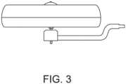
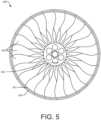
- the general assembly FIGURE 1 top, FIGURE 2 bottom and FIGURE 3 sidecontains each of the elements of the device configured with at least one central gyroscope flywheel 400, as shown in FIGURE 5 .
- the flywheel 400includes a perimeter ring 401, a central hub 402, and a plurality of spokes 403, which may be made of lightweight composite, aluminum, or another suitable material.
- the peripheral ring 401is configured to accept a plurality of permanent magnets 404 along the flywheel's exterior perimeter.
- vertical protrusionsseparate the magnets to split the surface area of the gyroscope's perimeter equally.
- the magnetswhich may be made of neodymium or other suitable magnetic material, may be secured to the flywheel perimeter with appropriate adhesives or retaining structure. The magnets create the armature function of the flywheel in the drive.
- the central hub 402is configured to accept a plurality of roller bearings 106 to allow rotation about an axle 103.
- the flywheelis supported around its perimeter with intersecting bearings for a hub-less design. Thrust is created by the spokes 403 due to their airfoil cross-section with positive incidence causing directional airflow when the flywheel is rotated.
- the spokescan be rotated either directly or by servomechanism about their longitudinal axis to increase or decrease the incidence of the spokes/blades to vary thrust without changing rotational speed. If the incidence angle is set to zero, the present invention stops producing thrust but keeps the gyroscopic effect for stabilization of connected structures.
- the spokes and hubmay be removed entirely when supported in a hub-less design.
- the stabilizing systemcould be used as a belt component to help stabilize geriatric or disabled patients to prevent falls without the use of a vehicle.
- the stabilizing systemcould be used to stabilize any current non-airborne transportation or recreational vehicles.
- the stabilizer systemcould be used to stabilize static structures including buildings.
- the articulating jointwould be unnecessary with the gimbal having a rigid mount.
- the various parts of the flywheel including the rim 401, spokes/blades 403 and hub 402can be composed of or impregnated with magnetic materials including composites.
- the configurationcould concentrate the weight of the magnetic material near or at the outside edge of the parts for greater gyroscopic effect.
- the spokesare magnetized, the perimeter rim can be eliminated in some designs.
- the elements of the gimbalinclude a threaded gimbal axle 103 used to support the rigidly mounted components of the gimbal and roller bearings 106 that allow the flywheel 400 to freely rotate around the axle.
- An inner flywheel lower guard 201integrates a plurality of spokes 201a used to support the hub 402.
- an inner flywheel upper guard 202integrates a plurality of spokes 202a and a plurality of hoops 202b, and when attached to a spinner 203 centers and supports the hub.
- the guardsnot only center and support the flywheel at its hub, they also serve as protection for the immediate environment surrounding the invention by shielding the spokes/blades 403.
- the perimeter of the upper and lower guardsconnects the upper perimeter section 204 and lower perimeter section 205 to form the gimbal body.
- the gimbal body upper section 204 with spinner 203are preferably shaped to direct incoming airflow into the flywheel spokes/blades 403 creating additional lift.
- the gimbalaligns the gyroscope thrust with its precession allowing for a separation of the thrust vector from the aircrafts attitude for stability and ease of control of the VTOL/VSTOL personal air vehicle.
- the inner flywheel guard upper 202 and inner flywheel guard lower 201integrate the minimum spokes and hoops necessary to support the outer gimbal body and inner hub allowing greater exposure of the flywheel spokes/blades 403 to the immediate environment where the extra protection may not be necessary, for example in racing applications.
- the gimbalmay be constructed from lightweight composite materials, aluminum or any other suitable material.
- FIGURES 12, 13 and 14show the elements that comprise a stator assembly 300 located in the gimbal body according to various embodiments of the present invention.
- the stator assemblyincludes a stator 301, which may be made from composite materials containing ferrous elements, iron or another suitable material, and field coils 302 that produce magnetic fields.
- penetrations 303enable hardware 304 to secure the stator assembly to the lower perimeter section 205, which hardware may include bolts, screws, rivets, or suitable bonding adhesive.
- Field coils 302are individually controlled by microprocessors to create phasing magnetic fields that cause rotation of the fly wheel/armature when acting upon its integrated permanent magnets 404. Because each of the field coils are controlled independently, phase changes can be made during the operation of the invention, for example from 3 to 4 phases based on the needs of the drive.
- a single controllermay be used to create either a 3 or 4 phase alternating current field.
- bias driveBy energizing a singular or proximate group of field coils, an imbalance could be created in the operation of the device that would yield a singular vectored force more commonly known as a bias drive.
- This bias drive forcecan be created with or without (embodiment which is however outside the scope of the appended claims) the thrust-producing spokes/blades of the flywheel.
- the bias drive configurationcould be supported through a central hub or external bearings in a hub-less design (embodiment which is however outside the scope of the appended claims).
- Regenerative coilsmay be located proximate to the field coils to add efficiency by harnessing unused magnetic energy created by the field coils and converting this into electrical energy that is circulated back to the batteries. These regenerative coils can be coiled around the field coils or bonded alongside of the field coils to create a two stranded field coil, one strand for energy input and a second strand for energy output, similar to the double helix of DNA. Another solution is to have the regenerative coils oriented in any location so that it can be affected by the field coil that creates a magnetic field.
- statorAll or some of the elements of the stator may be encased in a resin matrix carbon fiber composite or similar material, allowing for the stator to be constructed as layers into innumerable shapes and sizes.
- the layerswould integrate the various components either as solids or as particles in the resin matrix.
- the axle assemblyis preferably made from lightweight composite materials, aluminum or any other suitable material, and the hardware that may be used to connect to the gimbal and rotor preferably includes bolts 104, lower tubular spacers 105a and upper tubular spacers 105b, roller bearings 106, nose cone support 107 and retainer circlip 108.
- FIG. 1A gimbal mount 600 according to various embodiments of the present invention is shown.
- threaded axle 103connects the gimbal body to a joint ball swivel 102a that allows the gimbal to maintain the gyroscope's vertical orientation regardless of the orientation of the air frame.
- the joint ball swivelis housed in a rigid casing that allows freedom of movement.
- Connecting the gimbal mount to the airframeis a suspension arm 500.
- the maximum angle between the gimbal and the airframeis controlled by a bump mount shown with reference to FIGURES 15-18 , which is preferably made of rubber, composite, or another suitable material, and restricts movement based on inner cone dimensions.
- the propulsion systemBy having the propulsion system mounted in a gimbal with the gimbal mounted to an articulated joint in a suspension arm that is further connected to a vehicle, for example a PAV, the angular momentum created by the gyroscopic propulsion causes the propulsion system to remain vertically oriented, which in turn causes the thrust to maintain a vertical orientation regardless of the orientation of the vehicle to which it is connected.
- a vehiclefor example a PAV
- the vertical orientation of the centralized axle that passes through the articulated jointmay be tilted by servomechanism or by direct connection from a driver (not shown) that forces the propulsion system out of its most natural balanced state, which results in directional or vectored thrust.
- the articulating jointcan be locked against rotation or elements can be added to the gimbal that would impact either the wing or mount (not shown) to eliminate this possibility.
- the gimbal bodyis suspended from its perimeter rather than a central axle in a plurality of locations that allows the device to pivot and rotate in 360 degrees.
- the electromagnetic gyroscopic stabilizing propulsion method and apparatuscan be used to generate electricity when wind or water causes the un-powered flywheel to spin.
Landscapes
- Engineering & Computer Science (AREA)
- Aviation & Aerospace Engineering (AREA)
- Power Engineering (AREA)
- Mechanical Engineering (AREA)
- Motorcycle And Bicycle Frame (AREA)
- Magnetic Bearings And Hydrostatic Bearings (AREA)
- Connection Of Motors, Electrical Generators, Mechanical Devices, And The Like (AREA)
Description
- This application claims the benefit of priority from
U.S. Provisional Patent Application No. 62/722,968 filed August 26, 2018 - The invention relates to the field of electric propulsion systems used for propelling vertical takeoff and landing (VTOL) or very short takeoff and landing (VSTOL) air vehicles. More specifically, the invention comprises an electric gimbal mounted thrust producing gyroscope that is inherently stable and efficient when powering VTOL/VSTOL aircraft.
- There are several known electric aircraft propulsion systems. Most of these connect multiple electric motors to rotors/propellers that are rigidly mounted to their airframe. VTOL/VSTOL electric aircraft balance is enhanced by altering thrust between its motors/rotors. The motor's speed is controlled through avionics that include 3 axis accelerometers, magnetometers, and rate gyros.
- Previously, electric propulsion systems used in airframes with VTOL/VSTOL capabilities were primarily used in unmanned aerial vehicles more commonly called quadcopters or multi-rotor drones. Because of advancements in battery technology allowing for greater energy density, larger electric motors with larger rotors/propellers can be used to create enough thrust to lift a pilot. The higher thrust propulsion system's motors consume energy at an extremely high rate where frequently the total thrust of the propulsion systems only slightly exceeds the overall weight of the aircraft and pilot. The low margin of thrust to weight necessitates exposed propellers/rotors. If a guard was placed above or below the propellers/rotors, overall thrust would be reduced so that the aircraft could not maintain reasonable flight times and may not create enough lift for take-off. Varying atmospheric conditions including wind, air temperature, and altitude can greatly affect the aircraft's ability to maintain stability, which further reduces flight time because the aircraft must fight to maintain control.
- While advancements in batteries and avionics have created the opportunity for electric personal air vehicles (PAV's), the motors and rotors/propellers trail technologically behind these advancements. The present invention is directed to a novel self-driven propulsion system for PAV's that is powerful, compact, efficient, and self-stabilizing, and which greatly reduces or eliminates the fallibilities in existing technologies.
- Document
US2004061022 A1 discloses, according to its abstract, an omni-directional air vehicle having a pod with a connected turbofan system, the pod having a body that contains a power source for generating electrical power and a ducted fan with spherical articulation mechanism having a projecting arm with counter-rotating propellers and a ducted shroud around the periphery of the counter rotating propellers and containing drive motors for electrically driving the propellers. - The present invention comprises a thrust-producing gimbal-mounted gyroscopic system for propelling VTOL and VSTOL capable electric PAV's. The invention is configured to be connected to an airframe in the position customarily occupied by a motor/propeller. The invention includes a rotating assembly consisting of a flywheel that produces thrust when rotated because its spokes have an airfoil cross-section with positive incidence. The flywheel is surrounded by permanent magnets adding an armature function to the freewheeling flywheel. Additionally, the magnets increase potential angular momentum strength because of the weight they add to the perimeter of the gyroscope flywheel.
- A gimbal mount allows the flywheel to maintain a vertical orientation to the horizon due to the gyroscopic precession of the flywheel. Integrated into the gimbal is a stator with field coils that act upon the magnets surrounding the flywheel creating the drive.
- In one embodiment, protective guards serve to both center the flywheel in the gimbal and keep the pilot and surroundings from accidentally coming into contact with the rotating assembly.
- In one embodiment, controlling the field coils on the stator inside of the gimbal are individual microprocessors, one for each coil, allowing for unlimited switching of the motor's phasing.
- These and other features and advantages of the present invention will become more readily appreciated as the same becomes better understood by reference to the following detailed description when considered in connection with the accompanying drawings, wherein:
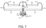
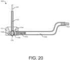
FIGURE 1 is a top view showing the present invention.FIGURE 2 illustrates a bottom view of the present invention.FIGURE 3 presents a side view of the present invention.FIGURE 4 presents a side cross-section view of the present invention.FIGURE 5 presents a top view showing the invention's flywheel with attached magnets.FIGURE 6 illustrates a perspective view of the gimbal.FIGURE 7 presents a cross-section of the gimbal.FIGURE 8 is a top view of the upper guard in the gimbal.FIGURE 9 is a top view of the lower guard in the gimbal.FIGURE 10 depicts an exploded view of the axle.FIGURE 11 depicts an exploded detail view of the spinner mount section of the axle.FIGURE 12 is a top view of the stator assembly.FIGURE 13 is a section view of the stator assembly.FIGURE 14 illustrates a top view of a flywheel/armature and stator.FIGURE 15 presents a perspective view of a bump stop in the gimbal assembly.FIGURE 16 depicts a top view of a bump stop in the gimbal assembly.FIGURE 17 illustrates a bottom view of a bump stop in the gimbal assembly.FIGURE 18 is a cross-section view of a bump stop in the gimbal assembly.FIGURE 19 is a top view of a suspension arm.FIGURE 20 is a cross-section view of the gimbal mount.- The terminology used herein is for describing particular embodiments only and is not intended to be limiting for the invention. As used herein, the term "and/or" includes any and all combinations of one or more of the associated listed items. As used herein, the singular forms "a," "an" and "the" are intended to include the plural forms as well as the singular forms, unless the context clearly indicates otherwise. It will be further understood that the terms "comprises" and/or "comprising" when used in this specification, specify the presence of stated features, steps, operations, elements, and/or components, but do not preclude the addition of one or more other features, steps, operations, elements, components, and/or groups thereof.
- Unless otherwise defined, all terms used herein, including technical and scientific terms, used herein have the same meaning as commonly understood by one having ordinary skill in the art to which the invention belongs. It will be further understood that terms, such as those defined in commonly used dictionaries, should be interpreted as having a meaning that is consistent with their meaning in the one context of the relevant art and the present disclosure and will not be interpreted in an idealized or overly formal sense unless expressly so defined, herein.
- In describing the invention, it will be understood that several techniques and steps are disclosed. Each of these has individual benefit and each can also be used in conjunction with one or more (or in some cases all) of the other disclosed techniques. Accordingly, for the sake of clarity, this description will refrain from repeating every possible combination of the individual steps in an unnecessary fashion.
- New air vehicle gyroscopic propulsion system method and apparatus for creating a self-leveling, stable and efficient propulsion system are discussed herein. In the following description, for the purposes of explanation, numerous specific details are set forth in order to provide a thorough understanding of the present invention. It will be evident, however, to one skilled in the art that the present invention may be practiced without these specific details.
- The present disclosure is to be considered as an exemplification of the invention and is not intended to limit the invention to the specific embodiments illustrated by the figures or description below.
- The present invention will now be described by referencing the appended figures representing preferred embodiments.
FIGURE 4 depicts a side cross-section view of elements that may comprise a self-driven air vehicle gyroscope propulsion system device (the "device") according to various embodiments of the present invention. In preferred embodiments, the general assemblyFIGURE 1 top,FIGURE 2 bottom andFIGURE 3 side contains each of the elements of the device configured with at least onecentral gyroscope flywheel 400, as shown inFIGURE 5 . As shown with reference toFIGURES 4 and5 , theflywheel 400 includes aperimeter ring 401, acentral hub 402, and a plurality ofspokes 403, which may be made of lightweight composite, aluminum, or another suitable material. Theperipheral ring 401 is configured to accept a plurality ofpermanent magnets 404 along the flywheel's exterior perimeter. In some embodiments, vertical protrusions separate the magnets to split the surface area of the gyroscope's perimeter equally. The magnets, which may be made of neodymium or other suitable magnetic material, may be secured to the flywheel perimeter with appropriate adhesives or retaining structure. The magnets create the armature function of the flywheel in the drive. - The
central hub 402 is configured to accept a plurality ofroller bearings 106 to allow rotation about anaxle 103. In an alternate embodiment, the flywheel is supported around its perimeter with intersecting bearings for a hub-less design. Thrust is created by thespokes 403 due to their airfoil cross-section with positive incidence causing directional airflow when the flywheel is rotated. In an alternate embodiment not shown, the spokes can be rotated either directly or by servomechanism about their longitudinal axis to increase or decrease the incidence of the spokes/blades to vary thrust without changing rotational speed. If the incidence angle is set to zero, the present invention stops producing thrust but keeps the gyroscopic effect for stabilization of connected structures. - In an alternate embodiment, which is outside the scope of the appended claims, the spokes and hub may be removed entirely when supported in a hub-less design. In this configuration the stabilizing system could be used as a belt component to help stabilize geriatric or disabled patients to prevent falls without the use of a vehicle. In addition, the stabilizing system could be used to stabilize any current non-airborne transportation or recreational vehicles. Further, the stabilizer system could be used to stabilize static structures including buildings. In this alternate embodiment, the articulating joint would be unnecessary with the gimbal having a rigid mount.
- In an alternate embodiment, which is outside the scope of the appended claims, the various parts of the flywheel including the
rim 401, spokes/blades 403 andhub 402 can be composed of or impregnated with magnetic materials including composites. The configuration could concentrate the weight of the magnetic material near or at the outside edge of the parts for greater gyroscopic effect. When the spokes are magnetized, the perimeter rim can be eliminated in some designs. - As shown further with reference to
FIGURES 6 ,7 and9 , in a preferred embodiment of agimbal assembly 200 of the present invention, the elements of the gimbal include a threadedgimbal axle 103 used to support the rigidly mounted components of the gimbal androller bearings 106 that allow theflywheel 400 to freely rotate around the axle. An inner flywheellower guard 201 integrates a plurality ofspokes 201a used to support thehub 402. As shown with further reference toFIGURE 8 , an inner flywheelupper guard 202 integrates a plurality ofspokes 202a and a plurality ofhoops 202b, and when attached to aspinner 203 centers and supports the hub. The guards not only center and support the flywheel at its hub, they also serve as protection for the immediate environment surrounding the invention by shielding the spokes/blades 403. The perimeter of the upper and lower guards connects theupper perimeter section 204 andlower perimeter section 205 to form the gimbal body. The gimbal bodyupper section 204 withspinner 203 are preferably shaped to direct incoming airflow into the flywheel spokes/blades 403 creating additional lift. The gimbal aligns the gyroscope thrust with its precession allowing for a separation of the thrust vector from the aircrafts attitude for stability and ease of control of the VTOL/VSTOL personal air vehicle. - In an alternate embodiment, the inner flywheel guard upper 202 and inner flywheel guard lower 201 integrate the minimum spokes and hoops necessary to support the outer gimbal body and inner hub allowing greater exposure of the flywheel spokes/
blades 403 to the immediate environment where the extra protection may not be necessary, for example in racing applications. - The gimbal may be constructed from lightweight composite materials, aluminum or any other suitable material.
FIGURES 12, 13 and14 show the elements that comprise astator assembly 300 located in the gimbal body according to various embodiments of the present invention. The stator assembly includes astator 301, which may be made from composite materials containing ferrous elements, iron or another suitable material, and field coils 302 that produce magnetic fields. As shown further with reference toFIGURE 4 ,penetrations 303 enablehardware 304 to secure the stator assembly to thelower perimeter section 205, which hardware may include bolts, screws, rivets, or suitable bonding adhesive. Field coils 302 are individually controlled by microprocessors to create phasing magnetic fields that cause rotation of the fly wheel/armature when acting upon its integratedpermanent magnets 404. Because each of the field coils are controlled independently, phase changes can be made during the operation of the invention, for example from 3 to 4 phases based on the needs of the drive.- In an alternate embodiment, a single controller may be used to create either a 3 or 4 phase alternating current field.
- By energizing a singular or proximate group of field coils, an imbalance could be created in the operation of the device that would yield a singular vectored force more commonly known as a bias drive. This bias drive force can be created with or without (embodiment which is however outside the scope of the appended claims) the thrust-producing spokes/blades of the flywheel. The bias drive configuration could be supported through a central hub or external bearings in a hub-less design (embodiment which is however outside the scope of the appended claims).
- Regenerative coils may be located proximate to the field coils to add efficiency by harnessing unused magnetic energy created by the field coils and converting this into electrical energy that is circulated back to the batteries. These regenerative coils can be coiled around the field coils or bonded alongside of the field coils to create a two stranded field coil, one strand for energy input and a second strand for energy output, similar to the double helix of DNA. Another solution is to have the regenerative coils oriented in any location so that it can be affected by the field coil that creates a magnetic field.
- All or some of the elements of the stator may be encased in a resin matrix carbon fiber composite or similar material, allowing for the stator to be constructed as layers into innumerable shapes and sizes. The layers would integrate the various components either as solids or as particles in the resin matrix.
- An exploded view of a preferred axle assembly is shown with reference to
FIGURES 10 and 11 . The axle assembly is preferably made from lightweight composite materials, aluminum or any other suitable material, and the hardware that may be used to connect to the gimbal and rotor preferably includesbolts 104, lowertubular spacers 105a and uppertubular spacers 105b,roller bearings 106,nose cone support 107 andretainer circlip 108. - Various embodiments of the present invention are described with further reference to
FIGURES 15-20 . Agimbal mount 600 according to various embodiments of the present invention is shown. In preferred embodiments, threadedaxle 103 connects the gimbal body to ajoint ball swivel 102a that allows the gimbal to maintain the gyroscope's vertical orientation regardless of the orientation of the air frame. The joint ball swivel is housed in a rigid casing that allows freedom of movement. Connecting the gimbal mount to the airframe is asuspension arm 500. The maximum angle between the gimbal and the airframe is controlled by a bump mount shown with reference toFIGURES 15-18 , which is preferably made of rubber, composite, or another suitable material, and restricts movement based on inner cone dimensions. - By having the propulsion system mounted in a gimbal with the gimbal mounted to an articulated joint in a suspension arm that is further connected to a vehicle, for example a PAV, the angular momentum created by the gyroscopic propulsion causes the propulsion system to remain vertically oriented, which in turn causes the thrust to maintain a vertical orientation regardless of the orientation of the vehicle to which it is connected.
- The vertical orientation of the centralized axle that passes through the articulated joint may be tilted by servomechanism or by direct connection from a driver (not shown) that forces the propulsion system out of its most natural balanced state, which results in directional or vectored thrust.
- To eliminate spin of the gimbal because of rotational torque, the articulating joint can be locked against rotation or elements can be added to the gimbal that would impact either the wing or mount (not shown) to eliminate this possibility.
- In an alternate embodiment, which is outside the scope of the appended claims, the gimbal body is suspended from its perimeter rather than a central axle in a plurality of locations that allows the device to pivot and rotate in 360 degrees.
- In an alternate embodiment, which is outside the scope of the appended claims, the electromagnetic gyroscopic stabilizing propulsion method and apparatus can be used to generate electricity when wind or water causes the un-powered flywheel to spin.
Claims (4)
- A thrust-producing gimbal-mounted gyroscopic system, comprising:
a flywheel (400) comprising:a perimeter section (204, 205) having an inside face and an outside face, wherein a plurality of magnets (404) are positioned along the outside face;a hub section (402) having an inside face and an outside face;a plurality of spokes (403) extending outward from the outside face of the hub section to connect to the inside face of the perimeter section, wherein the spokes (403) are configured to produce thrust when rotated;the thrust-producing gimbal-mounted gyroscopic system further comprising:
an axle (103);a plurality of roller bearings (106) configured to allow rotation of the hub section about the axle (103); anda stator (301) having a plurality of field coils (302) along its inside diameter, wherein the plurality of field coils are positioned to act upon the magnets of the perimeter section of the flywheel to create rotation of the plurality of spokes (403) to produce thrust;
anda suspension arm (500),wherein the hub section is mounted to the suspension arm such that the thrust produced when the plurality of spokes (403) are rotated causes the gimbal to remain vertically oriented;wherein the suspension arm further comprises a joint ball swivel (102a, 102b, 102c) to which the axle (103) is movably connected, wherein the joint ball swivel is housed in a rigid casing (101)that allows freedom of movement of the axle (103), wherein the movement is restricted based on inner cone dimensions of a bump mount of the casing; andthe thrust-producing gimbal-mounted gyroscopic system further comprises a drive configured to tilt the axle, which movement results in directional or vectored thrust from the plurality of spokes (403). - The thrust-producing gimbal-mounted gyroscopic system of claim 1, wherein the plurality of magnets is positioned to split a surface area of the perimeter section of the flywheel equally.
- The thrust-producing gimbal-mounted gyroscopic system of claim 1, further comprising upper (202) and lower (201) guards configured to center and support the flywheel at the hub section.
- The thrust-producing gimbal-mounted gyroscopic system of claim 1, wherein the plurality of field coils are, in use, individually controlled by separate microprocessors.
Applications Claiming Priority (2)
| Application Number | Priority Date | Filing Date | Title |
|---|---|---|---|
| US201862722968P | 2018-08-26 | 2018-08-26 | |
| PCT/US2019/048191WO2020086151A2 (en) | 2018-08-26 | 2019-08-26 | Electromagnetic gyroscopic stabilizing propulsion system method and apparatus |
Publications (4)
| Publication Number | Publication Date |
|---|---|
| EP3841354A2 EP3841354A2 (en) | 2021-06-30 |
| EP3841354A4 EP3841354A4 (en) | 2022-05-18 |
| EP3841354C0 EP3841354C0 (en) | 2024-03-13 |
| EP3841354B1true EP3841354B1 (en) | 2024-03-13 |
Family
ID=70332269
Family Applications (1)
| Application Number | Title | Priority Date | Filing Date |
|---|---|---|---|
| EP19875012.7AActiveEP3841354B1 (en) | 2018-08-26 | 2019-08-26 | Electromagnetic gyroscopic stabilizing propulsion system method and apparatus |
Country Status (6)
| Country | Link |
|---|---|
| US (3) | US11230386B2 (en) |
| EP (1) | EP3841354B1 (en) |
| JP (1) | JP7417292B2 (en) |
| KR (1) | KR20210048534A (en) |
| CN (1) | CN112912691A (en) |
| WO (1) | WO2020086151A2 (en) |
Families Citing this family (9)
| Publication number | Priority date | Publication date | Assignee | Title |
|---|---|---|---|---|
| KR20210034071A (en) | 2018-07-27 | 2021-03-29 | 에어본 모터 워크스 인코포레이티드 | Thrust generation split flywheel gyroscope method and apparatus |
| EP3841354B1 (en) | 2018-08-26 | 2024-03-13 | Airborne Motor Works Inc. | Electromagnetic gyroscopic stabilizing propulsion system method and apparatus |
| EP3911290A4 (en) | 2019-01-20 | 2022-10-26 | Airborne Motors, LLC | METHOD AND APPARATUS FOR THE MANUFACTURE OF A MEDICAL STABILIZER |
| JP7293701B2 (en)* | 2019-02-08 | 2023-06-20 | 株式会社デンソー | Rotating electric machine |
| JP7210409B2 (en)* | 2019-09-26 | 2023-01-23 | 三菱重工業株式会社 | Motor-integrated fluid machine and vertical take-off and landing aircraft |
| JP7413013B2 (en)* | 2019-12-27 | 2024-01-15 | 三菱重工業株式会社 | Design method for motor-integrated fluid machinery, vertical take-off and landing aircraft, and motor-integrated fluid machinery |
| EP4111053A4 (en) | 2020-02-28 | 2024-03-06 | Airborne Motor Works Inc. | METHOD AND DEVICE FOR LIMITING THE FRICTION OF A TURBINE GENERATOR CYCLE |
| US12145753B2 (en)* | 2022-08-09 | 2024-11-19 | Pete Bitar | Compact and lightweight drone delivery device called an ArcSpear electric jet drone system having an electric ducted air propulsion system and being relatively difficult to track in flight |
| WO2024226657A2 (en)* | 2023-04-27 | 2024-10-31 | Airborne Motorworks Inc. | Self propelled thrust-producing controlled moment gyroscope |
Family Cites Families (110)
| Publication number | Priority date | Publication date | Assignee | Title |
|---|---|---|---|---|
| US2279690A (en) | 1939-11-07 | 1942-04-14 | Z T Lindsey | Combination motor generator |
| US3142455A (en) | 1962-12-17 | 1964-07-28 | Wilford Edward Burke | Rotary vertical take-off and landing aircraft |
| US3265329A (en) | 1963-08-27 | 1966-08-09 | Postelson Steven | Flying platform-automobile-boat and air suspension car combination |
| US3396391A (en) | 1963-12-20 | 1968-08-06 | North American Rockwell | Terrain-following system |
| US3327538A (en) | 1964-03-19 | 1967-06-27 | Gen Precision Inc | Two-axis case rotating gyroscope |
| DE2210995C2 (en) | 1972-03-08 | 1974-02-21 | Teldix Gmbh, 6900 Heidelberg | Magnetic device, especially for a flywheel |
| US3991487A (en) | 1974-09-16 | 1976-11-16 | Bede James R | Flight training assembly |
| US4459087A (en) | 1982-06-02 | 1984-07-10 | Aciers Et Outillage Peugeot | Fan unit for an internal combustion engine of automobile vehicle |
| SU1211449A1 (en) | 1984-04-02 | 1986-02-15 | Chernopyatov Boris | Wind power plant |
| US4720640A (en) | 1985-09-23 | 1988-01-19 | Turbostar, Inc. | Fluid powered electrical generator |
| US5331245A (en) | 1986-01-13 | 1994-07-19 | Papst Licensing Gmbh | Permanent magnet excited electric motor with improved torque ripple |
| US4953811A (en) | 1988-10-19 | 1990-09-04 | The United States Of America As Represented By The Secretary Of The Army | Self-driving helicopter tail rotor |
| JP2580329B2 (en) | 1989-06-14 | 1997-02-12 | 三菱重工業株式会社 | Filling processing equipment |
| US5514923A (en) | 1990-05-03 | 1996-05-07 | Gossler; Scott E. | High efficiency DC motor with generator and flywheel characteristics |
| JPH05505750A (en)* | 1990-08-24 | 1993-08-26 | アニノス,フォティオス | Electronic device for smoothing the dysfunction of the central nervous system in connection with the use of biomagnetometers |
| WO1994018052A1 (en) | 1993-02-05 | 1994-08-18 | Digi Sens Ag Digitale Messtechnik | Anti-skidding process and device for vehicles |
| US5454531A (en) | 1993-04-19 | 1995-10-03 | Melkuti; Attila | Ducted propeller aircraft (V/STOL) |
| DE19509628A1 (en) | 1995-03-21 | 1996-10-10 | Teldix Gmbh | Magnetically mounted, stabilizable flywheel |
| JP3029792B2 (en) | 1995-12-28 | 2000-04-04 | 日本サーボ株式会社 | Multi-phase permanent magnet type rotating electric machine |
| JP3029792U (en) | 1996-04-03 | 1996-10-11 | 彩子 濱田 | Improvement of the grill inside the grill of the gas table |
| DE19842543A1 (en) | 1998-09-17 | 1999-05-20 | Kurt Dipl Ing Bluemel | Craft with hovering capabilities |
| US6270038B1 (en) | 1999-04-22 | 2001-08-07 | Sikorsky Aircraft Corporation | Unmanned aerial vehicle with counter-rotating ducted rotors and shrouded pusher-prop |
| US6616094B2 (en)* | 1999-05-21 | 2003-09-09 | Vortex Holding Company | Lifting platform |
| US6392370B1 (en) | 2000-01-13 | 2002-05-21 | Bedini Technology, Inc. | Device and method of a back EMF permanent electromagnetic motor generator |
| US6465902B1 (en) | 2001-04-18 | 2002-10-15 | The United States Of America As Represented By The Secretary Of The Navy | Controllable camber windmill blades |
| US6431494B1 (en) | 2001-07-17 | 2002-08-13 | Sikorsky Aircraft Corporation | Flight control system for a hybrid aircraft in the roll axis |
| US6921042B1 (en) | 2001-09-24 | 2005-07-26 | Carl L. Goodzeit | Concentric tilted double-helix dipoles and higher-order multipole magnets |
| US6886776B2 (en) | 2001-10-02 | 2005-05-03 | Karl F. Milde, Jr. | VTOL personal aircraft |
| US20040094662A1 (en) | 2002-01-07 | 2004-05-20 | Sanders John K. | Vertical tale-off landing hovercraft |
| US7032861B2 (en) | 2002-01-07 | 2006-04-25 | Sanders Jr John K | Quiet vertical takeoff and landing aircraft using ducted, magnetic induction air-impeller rotors |
| US6845942B2 (en)* | 2002-02-21 | 2005-01-25 | Marius A. Paul | Omni-directional air vehicle personal transportation system |
| ATE311030T1 (en) | 2002-03-22 | 2005-12-15 | Ebm Papst St Georgen Gmbh & Co | INNER ROTOR MOTOR |
| CA2382382A1 (en)* | 2002-04-16 | 2003-10-16 | Universite De Sherbrooke | Continuous rotary motor powered by shockwave induced combustion |
| US7135799B2 (en) | 2003-03-19 | 2006-11-14 | Pacsci Motion Control, Inc. | Method for winding a stator of multi-phase motors |
| EA200602209A1 (en)* | 2004-06-04 | 2007-04-27 | Линн П. Тессье | OPTIMAL COMMUNICATED REACTIVE SYNCHRONOUS MOTOR AND ITS APPLICATION AS A TOP DRIVE FOR A ROTARY PUMP |
| JP4161944B2 (en)* | 2004-07-01 | 2008-10-08 | セイコーエプソン株式会社 | Display controller and electronic device |
| US7032859B2 (en) | 2004-07-23 | 2006-04-25 | The United States Of America As Represented By The Secretary Of The Navy | Counter rotating ducted fan having a permanent magnet drive |
| US20060070646A1 (en) | 2004-10-05 | 2006-04-06 | Kenyon Laboratories Llc | System for improving the balance of a person |
| US8227941B2 (en)* | 2009-07-23 | 2012-07-24 | C.E. Niehoff & Co. | System and method for generator phase signal monitoring and control |
| US8181902B2 (en) | 2005-03-15 | 2012-05-22 | Entecho Pty Ltd. | Aerodynamic lifting device and airborne craft |
| US8251390B2 (en)* | 2005-06-30 | 2012-08-28 | The Gyrobike, Inc. | System and method for providing gyroscopic stabilization to a wheeled vehicle |
| US8074922B2 (en) | 2005-08-22 | 2011-12-13 | Dumitru Bojiuc | Discoidal flying craft |
| US7825554B2 (en) | 2005-09-20 | 2010-11-02 | Bastian Family Holdings, Inc. | Stabilizing power source for a vehicle |
| US7874513B1 (en) | 2005-10-18 | 2011-01-25 | Smith Frick A | Apparatus and method for vertical take-off and landing aircraft |
| US7274529B2 (en)* | 2006-02-10 | 2007-09-25 | Hitachi Global Storage Technologies Netherlands B.V. | Disk drive with adaptive actuator braking upon unexpected power loss |
| RU2321765C1 (en) | 2006-08-10 | 2008-04-10 | Сергей Иванович Малафеев | Starter-generator |
| WO2008021569A2 (en) | 2006-08-18 | 2008-02-21 | Maglev Technologies, Llc | Rotational apparatus including a passive magnetic bearing |
| RU2333866C2 (en) | 2006-08-30 | 2008-09-20 | Эдуард Николаевич Григорьев | Method of helicopter control in failure of power plant with propeller mechanical drive (versions) |
| US8083557B2 (en) | 2008-01-18 | 2011-12-27 | Steven Sullivan | Method and apparatus for powering of amphibious craft |
| EP2081276A1 (en)* | 2008-01-21 | 2009-07-22 | Marco Cipriani | Electro-magnetical device with reversible generator-motor operation |
| HUE049223T2 (en) | 2008-08-15 | 2020-09-28 | Millennial Res Corporation | Regenerative motor and coil |
| DE102008047152A1 (en) | 2008-09-12 | 2010-05-12 | Schäfer KFZ Tuning GmbH | Ring-shaped energy converter with motor effect |
| RU2435707C2 (en) | 2008-10-31 | 2011-12-10 | Вячеслав Анатольевич Павликов | Vertical take-off and landing aircraft |
| DE102008058029B3 (en) | 2008-11-18 | 2010-01-07 | Deutsches Zentrum für Luft- und Raumfahrt e.V. | helicopter |
| GB0904875D0 (en) | 2009-03-20 | 2009-05-06 | Geola Technologies Ltd | Electric vtol aircraft |
| US20120037750A1 (en)* | 2009-04-24 | 2012-02-16 | Valery Vyacheslavovich Dvoeglazov | Airlift |
| US20100282528A1 (en)* | 2009-05-05 | 2010-11-11 | Yoram Palti | Electro-Mechanical Battery |
| US20100307290A1 (en)* | 2009-06-09 | 2010-12-09 | Konstantinos Porfiropoulos | Apparatus, system and method for gyroscopic propulsion and/or steering |
| US9018891B2 (en) | 2009-07-09 | 2015-04-28 | Clifford R. Rabal | Direct current brushless motor |
| CN101693470B (en) | 2009-10-30 | 2013-03-27 | 北京工业大学 | Magnetic suspension electromotive force rotary wing flying saucer |
| CN102166928A (en) | 2010-06-02 | 2011-08-31 | 孙风举 | Hybrid vertically lifting type three-purpose vehicle for land, water and air |
| TWI459234B (en) | 2010-07-14 | 2014-11-01 | Hon Hai Prec Ind Co Ltd | Handheld device and method for controlling unmanned aerial vehicle |
| RU112152U1 (en) | 2011-02-10 | 2012-01-10 | Олег Валентинович Шевяков | AUTO-FIRM ROTOR SPIN SYSTEM |
| RU109740U1 (en) | 2011-03-17 | 2011-10-27 | Владимир Михайлович Иванов | HELICOPTER RESCUE DEVICE |
| FR2973962B1 (en) | 2011-04-06 | 2013-05-31 | Peugeot Citroen Automobiles Sa | CHARGE SYSTEM FOR AN ELECTRIC OR HYBRID VEHICLE |
| US8723382B2 (en)* | 2011-04-19 | 2014-05-13 | Matthew A. Lebenbom | Electromagnetic motor-generator unit |
| TWI538852B (en) | 2011-07-19 | 2016-06-21 | 季航空股份有限公司 | Personal aircraft |
| US20120112461A1 (en) | 2011-12-21 | 2012-05-10 | Earth Sure Renewable Energy Corporation | Dual use fan assembly for hvac systems and automotive systems to generate clean alternative elecric energy |
| WO2013098736A2 (en)* | 2011-12-29 | 2013-07-04 | Alma Mater Studiorum - Universita' Di Bologna | A four-rotor helicopter |
| US8698365B2 (en) | 2012-04-03 | 2014-04-15 | The Boeing Company | Lightweight composite safety containment for flywheel energy storage |
| US20150209212A1 (en) | 2012-09-14 | 2015-07-30 | James R. Duguid | Method and apparatus for treating, assessing and/or diagnosing balance disorders using a control moment gyroscopic perturbation device |
| FR3000813B1 (en) | 2013-01-04 | 2016-04-15 | Parrot | ROTARY SAILING DRONE COMPRISING MEANS FOR AUTONOMOUS POSITION DETERMINATION IN AN ABSOLUTE FLOOR - RELATED MARK. |
| RU2538737C9 (en) | 2013-02-11 | 2016-12-20 | Сергей Юрьевич Кузиков | Rotor "air wheel", gyrostabilised aircraft and wind-driven electric plant using rotor "air wheel", surface/deck devices for their start-up |
| US10265237B2 (en) | 2013-03-06 | 2019-04-23 | Udaya Sankar Devanaboyina | Systems and methods for exerting force on bodies |
| US20140260714A1 (en) | 2013-03-14 | 2014-09-18 | Khalifa University of Science, Technology & Research (KUSTAR) | Gyroscopic-assisted device to control balance |
| RU2527248C1 (en)* | 2013-04-17 | 2014-08-27 | Дмитрий Сергеевич Дуров | Drone with hybrid power plant (versions) |
| NL2011128C2 (en) | 2013-07-09 | 2015-01-12 | Eco Logical Entpr B V | ROTATING DEVICE, FOR EXAMPLE A AIR MOUNT, SUCH AS A FAN, A PROPELLER OR LIFT SCREW, A WATER TURBINE OR A WIND TURBINE. |
| DE102013109392A1 (en) | 2013-08-29 | 2015-03-05 | Airbus Defence and Space GmbH | Fast-flying, vertically launchable aircraft |
| DE102013016216A1 (en)* | 2013-09-28 | 2015-04-02 | Andreas Stihl Ag & Co. Kg | "Method for braking an electric drive motor" |
| US20150188400A1 (en)* | 2013-12-31 | 2015-07-02 | Robert Louis Kemp | Magnetic Flywheel Induction Engine-Motor-Generator |
| US10523074B2 (en) | 2014-01-16 | 2019-12-31 | Maestra Energy, Llc | Electrical energy conversion system in the form of an induction motor or generator with variable coil winding patterns exhibiting multiple and differently gauged wires according to varying braid patterns |
| US9649242B2 (en) | 2014-01-17 | 2017-05-16 | Honda Motor Co., Ltd. | Wearable scissor-paired control moment gyroscope (SP-CMG) for human balance assist |
| US20150226086A1 (en) | 2014-02-03 | 2015-08-13 | Devin Glenn Samuelson | Rotational ducted fan (rdf) propulsion system |
| CN104980001A (en) | 2014-04-09 | 2015-10-14 | 舒圣玉 | Electric generator |
| US10432079B2 (en) | 2014-08-12 | 2019-10-01 | Thou M. Ny | Electrical energy generating brushless DC motor |
| CN107000835B (en)* | 2014-08-26 | 2023-07-21 | 谢尔盖·约尔维奇·库兹科夫 | "wheel" rotor |
| AU2015309162B2 (en) | 2014-08-28 | 2018-10-04 | Pascal Chretien | Electromagnetic distributed direct drive for aircraft |
| CN204165558U (en)* | 2014-11-05 | 2015-02-18 | 金华中科机电研究所 | A kind of single shaft double tops systems stabilisation |
| CN104316038B (en)* | 2014-11-05 | 2017-02-01 | 衢州职业技术学院 | Single-shaft double-gyro stabilization system and control method thereof |
| US10138866B2 (en) | 2014-11-14 | 2018-11-27 | Riamwind Co., Ltd. | Fluid power generation method and fluid power generation device |
| US10040544B2 (en) | 2015-01-02 | 2018-08-07 | Jesse Antoine Marcel | Multi-rotor personal air vehicle with a central lifting fan |
| DE102015114819B3 (en) | 2015-09-04 | 2016-12-22 | Rockwell Collins Deutschland Gmbh | Spin wheel device for position stabilization of a spacecraft |
| US9637227B2 (en) | 2015-09-16 | 2017-05-02 | Qualcomm Incorporated | Unmanned aerial vehicle hybrid rotor drive |
| US20170104385A1 (en) | 2015-10-08 | 2017-04-13 | Adam C. Salamon | Reduced Complexity Ring Motor Design for Propeller Driven Vehicles |
| US10084365B1 (en) | 2016-02-04 | 2018-09-25 | Harivallabh Pandya | Electromagnetic machinery systems, device, assemblies, methods, processes, uses, and apparatus operable as a motor or generator with one or more stator coils, at least one permanent magnet rotor, and associated circuitry |
| US10836512B2 (en) | 2016-05-06 | 2020-11-17 | Honeywell International Inc. | Energy efficient spherical momentum control devices |
| KR101716430B1 (en)* | 2016-06-15 | 2017-03-15 | 최기현 | Flying vehicle |
| US10381886B2 (en) | 2016-08-01 | 2019-08-13 | Hamilton Sundstrand Corporation | Motor-generator with radial-flux double-sided stator |
| EP3296199B1 (en)* | 2016-09-19 | 2020-04-08 | Lockheed Martin Corporation | Wind-powered recharging for a weight-shifting coaxial helicopter |
| DE102016012801A1 (en) | 2016-10-26 | 2018-04-26 | Man Truck & Bus Ag | axial fan |
| CN106516127B (en) | 2016-11-30 | 2019-01-22 | 中国直升机设计研究所 | A kind of magnetic suspension rotor system and the helicopter with it |
| US10630137B2 (en) | 2016-12-14 | 2020-04-21 | Bendix Commerical Vehicle Systems Llc | Front end motor-generator system and modular generator drive apparatus |
| EP3477080A1 (en) | 2017-10-30 | 2019-05-01 | Siemens Aktiengesellschaft | Method of controlling a gas turbine engine |
| US10473107B1 (en)* | 2017-11-29 | 2019-11-12 | Stephen Thomas Newton | Variable performance axial flow ducted fan with high efficiency and reduced current drawn |
| US20190300165A1 (en) | 2018-03-28 | 2019-10-03 | Airborne Motors, Llc | Self propelled thrust-producing controlled moment gyroscope |
| KR20210034071A (en) | 2018-07-27 | 2021-03-29 | 에어본 모터 워크스 인코포레이티드 | Thrust generation split flywheel gyroscope method and apparatus |
| EP3841354B1 (en) | 2018-08-26 | 2024-03-13 | Airborne Motor Works Inc. | Electromagnetic gyroscopic stabilizing propulsion system method and apparatus |
| JP7269722B2 (en)* | 2018-12-13 | 2023-05-09 | 三菱重工業株式会社 | Motor-integrated fluid machine and vertical take-off and landing aircraft |
| EP3911290A4 (en) | 2019-01-20 | 2022-10-26 | Airborne Motors, LLC | METHOD AND APPARATUS FOR THE MANUFACTURE OF A MEDICAL STABILIZER |
| US12132358B2 (en)* | 2021-10-11 | 2024-10-29 | Airborne Motorworks Inc. | Apparatus for facilitating propulsion of a vehicle |
- 2019
- 2019-08-26EPEP19875012.7Apatent/EP3841354B1/enactiveActive
- 2019-08-26USUS16/550,891patent/US11230386B2/enactiveActive
- 2019-08-26CNCN201980070149.8Apatent/CN112912691A/enactivePending
- 2019-08-26KRKR1020217009035Apatent/KR20210048534A/ennot_activeCeased
- 2019-08-26JPJP2021510413Apatent/JP7417292B2/enactiveActive
- 2019-08-26WOPCT/US2019/048191patent/WO2020086151A2/ennot_activeCeased
- 2022
- 2022-01-25USUS17/584,256patent/US11760496B2/enactiveActive
- 2023
- 2023-09-18USUS18/369,831patent/US20240002063A1/ennot_activeAbandoned
Also Published As
| Publication number | Publication date |
|---|---|
| EP3841354C0 (en) | 2024-03-13 |
| CN112912691A (en) | 2021-06-04 |
| EP3841354A2 (en) | 2021-06-30 |
| WO2020086151A2 (en) | 2020-04-30 |
| KR20210048534A (en) | 2021-05-03 |
| US20200140102A1 (en) | 2020-05-07 |
| JP7417292B2 (en) | 2024-01-18 |
| WO2020086151A3 (en) | 2020-07-16 |
| WO2020086151A9 (en) | 2020-06-11 |
| US20220144441A1 (en) | 2022-05-12 |
| JP2021535033A (en) | 2021-12-16 |
| US11230386B2 (en) | 2022-01-25 |
| EP3841354A4 (en) | 2022-05-18 |
| US11760496B2 (en) | 2023-09-19 |
| US20240002063A1 (en) | 2024-01-04 |
Similar Documents
| Publication | Publication Date | Title |
|---|---|---|
| EP3841354B1 (en) | Electromagnetic gyroscopic stabilizing propulsion system method and apparatus | |
| US11603193B2 (en) | Aircraft convertible between fixed-wing and hovering orientations | |
| US9902493B2 (en) | VTOL aerodyne with supporting axial blower(s) | |
| US10315759B2 (en) | Multi-rotor vehicle with yaw control and autorotation | |
| EP3354560B1 (en) | A thrust producing unit with at least two rotor assemblies and a shrouding | |
| US7410123B2 (en) | Aircraft and hybrid with magnetic airfoil suspension and drive | |
| US11945610B2 (en) | Aircraft, in particular a drone or an aircraft for personal air mobility, with high efficiency propeller rotors | |
| ES2912732T3 (en) | Aerial vehicles with decoupled degrees of freedom | |
| JP5421503B2 (en) | Private aircraft | |
| US6575401B1 (en) | Vertical-lift and horizontal flight aircraft | |
| US9145207B2 (en) | Remotely controlled micro/nanoscale aerial vehicle comprising a system for traveling on the ground, vertical takeoff, and landing | |
| US7032861B2 (en) | Quiet vertical takeoff and landing aircraft using ducted, magnetic induction air-impeller rotors | |
| US20140103158A1 (en) | AirShip Endurance VTOL UAV and Solar Turbine Clean Tech Propulsion | |
| EP1775214A1 (en) | Rapid air quantity generating and wind direction changing device and aircraft having the device mounted on side face of airframe | |
| CN103552686B (en) | A kind of compound type duct aerial reconnaissance machine people | |
| JP2015501751A (en) | Method and apparatus for vertical / short-range take-off and landing | |
| CN109533310B (en) | A mobile launch foldable miniature coaxial double rotor suspension device | |
| CN106892115A (en) | A dish-shaped manned flight device | |
| EP3414159B1 (en) | A rotor system and an air vehicle equipped with such a rotor | |
| EP4157716B1 (en) | Aircraft thrust and control system | |
| CN206634210U (en) | A dish-shaped manned flight device | |
| EP1247737B1 (en) | Lift generating means for aircraft | |
| CN109774986A (en) | A magnetic levitation cube aerostat | |
| US20230257111A1 (en) | Self propelled thrust-producing controlled moment gyroscope | |
| WO2024209496A1 (en) | Electric coaxial rotor aircraft |
Legal Events
| Date | Code | Title | Description |
|---|---|---|---|
| STAA | Information on the status of an ep patent application or granted ep patent | Free format text:STATUS: THE INTERNATIONAL PUBLICATION HAS BEEN MADE | |
| PUAI | Public reference made under article 153(3) epc to a published international application that has entered the european phase | Free format text:ORIGINAL CODE: 0009012 | |
| STAA | Information on the status of an ep patent application or granted ep patent | Free format text:STATUS: REQUEST FOR EXAMINATION WAS MADE | |
| 17P | Request for examination filed | Effective date:20210319 | |
| AK | Designated contracting states | Kind code of ref document:A2 Designated state(s):AL AT BE BG CH CY CZ DE DK EE ES FI FR GB GR HR HU IE IS IT LI LT LU LV MC MK MT NL NO PL PT RO RS SE SI SK SM TR | |
| DAV | Request for validation of the european patent (deleted) | ||
| DAX | Request for extension of the european patent (deleted) | ||
| REG | Reference to a national code | Ref country code:HK Ref legal event code:DE Ref document number:40054962 Country of ref document:HK | |
| A4 | Supplementary search report drawn up and despatched | Effective date:20220422 | |
| RIC1 | Information provided on ipc code assigned before grant | Ipc:B64C 27/20 20060101ALI20220414BHEP Ipc:G01C 19/24 20060101AFI20220414BHEP | |
| REG | Reference to a national code | Ref country code:DE Free format text:PREVIOUS MAIN CLASS: G01C0019240000 Ref country code:DE Ref legal event code:R079 Ref document number:602019048391 Country of ref document:DE Free format text:PREVIOUS MAIN CLASS: G01C0019240000 Ipc:B64C0011000000 | |
| GRAP | Despatch of communication of intention to grant a patent | Free format text:ORIGINAL CODE: EPIDOSNIGR1 | |
| STAA | Information on the status of an ep patent application or granted ep patent | Free format text:STATUS: GRANT OF PATENT IS INTENDED | |
| RIC1 | Information provided on ipc code assigned before grant | Ipc:H02K 21/16 20060101ALI20230906BHEP Ipc:H02K 7/02 20060101ALI20230906BHEP Ipc:B64D 27/24 20060101ALI20230906BHEP Ipc:B64C 27/20 20060101ALI20230906BHEP Ipc:B64C 17/06 20060101ALI20230906BHEP Ipc:B64C 11/00 20060101AFI20230906BHEP | |
| INTG | Intention to grant announced | Effective date:20230925 | |
| GRAS | Grant fee paid | Free format text:ORIGINAL CODE: EPIDOSNIGR3 | |
| GRAA | (expected) grant | Free format text:ORIGINAL CODE: 0009210 | |
| STAA | Information on the status of an ep patent application or granted ep patent | Free format text:STATUS: THE PATENT HAS BEEN GRANTED | |
| AK | Designated contracting states | Kind code of ref document:B1 Designated state(s):AL AT BE BG CH CY CZ DE DK EE ES FI FR GB GR HR HU IE IS IT LI LT LU LV MC MK MT NL NO PL PT RO RS SE SI SK SM TR | |
| REG | Reference to a national code | Ref country code:GB Ref legal event code:FG4D | |
| REG | Reference to a national code | Ref country code:CH Ref legal event code:EP | |
| REG | Reference to a national code | Ref country code:DE Ref legal event code:R096 Ref document number:602019048391 Country of ref document:DE | |
| REG | Reference to a national code | Ref country code:IE Ref legal event code:FG4D | |
| U01 | Request for unitary effect filed | Effective date:20240409 | |
| U07 | Unitary effect registered | Designated state(s):AT BE BG DE DK EE FI FR IT LT LU LV MT NL PT SE SI Effective date:20240417 | |
| PG25 | Lapsed in a contracting state [announced via postgrant information from national office to epo] | Ref country code:GR Free format text:LAPSE BECAUSE OF FAILURE TO SUBMIT A TRANSLATION OF THE DESCRIPTION OR TO PAY THE FEE WITHIN THE PRESCRIBED TIME-LIMIT Effective date:20240614 | |
| PG25 | Lapsed in a contracting state [announced via postgrant information from national office to epo] | Ref country code:HR Free format text:LAPSE BECAUSE OF FAILURE TO SUBMIT A TRANSLATION OF THE DESCRIPTION OR TO PAY THE FEE WITHIN THE PRESCRIBED TIME-LIMIT Effective date:20240313 Ref country code:RS Free format text:LAPSE BECAUSE OF FAILURE TO SUBMIT A TRANSLATION OF THE DESCRIPTION OR TO PAY THE FEE WITHIN THE PRESCRIBED TIME-LIMIT Effective date:20240613 | |
| PG25 | Lapsed in a contracting state [announced via postgrant information from national office to epo] | Ref country code:ES Free format text:LAPSE BECAUSE OF FAILURE TO SUBMIT A TRANSLATION OF THE DESCRIPTION OR TO PAY THE FEE WITHIN THE PRESCRIBED TIME-LIMIT Effective date:20240313 | |
| PG25 | Lapsed in a contracting state [announced via postgrant information from national office to epo] | Ref country code:RS Free format text:LAPSE BECAUSE OF FAILURE TO SUBMIT A TRANSLATION OF THE DESCRIPTION OR TO PAY THE FEE WITHIN THE PRESCRIBED TIME-LIMIT Effective date:20240613 Ref country code:NO Free format text:LAPSE BECAUSE OF FAILURE TO SUBMIT A TRANSLATION OF THE DESCRIPTION OR TO PAY THE FEE WITHIN THE PRESCRIBED TIME-LIMIT Effective date:20240613 Ref country code:HR Free format text:LAPSE BECAUSE OF FAILURE TO SUBMIT A TRANSLATION OF THE DESCRIPTION OR TO PAY THE FEE WITHIN THE PRESCRIBED TIME-LIMIT Effective date:20240313 Ref country code:GR Free format text:LAPSE BECAUSE OF FAILURE TO SUBMIT A TRANSLATION OF THE DESCRIPTION OR TO PAY THE FEE WITHIN THE PRESCRIBED TIME-LIMIT Effective date:20240614 Ref country code:ES Free format text:LAPSE BECAUSE OF FAILURE TO SUBMIT A TRANSLATION OF THE DESCRIPTION OR TO PAY THE FEE WITHIN THE PRESCRIBED TIME-LIMIT Effective date:20240313 | |
| PG25 | Lapsed in a contracting state [announced via postgrant information from national office to epo] | Ref country code:IS Free format text:LAPSE BECAUSE OF FAILURE TO SUBMIT A TRANSLATION OF THE DESCRIPTION OR TO PAY THE FEE WITHIN THE PRESCRIBED TIME-LIMIT Effective date:20240713 | |
| U20 | Renewal fee for the european patent with unitary effect paid | Year of fee payment:6 Effective date:20240902 | |
| PG25 | Lapsed in a contracting state [announced via postgrant information from national office to epo] | Ref country code:SM Free format text:LAPSE BECAUSE OF FAILURE TO SUBMIT A TRANSLATION OF THE DESCRIPTION OR TO PAY THE FEE WITHIN THE PRESCRIBED TIME-LIMIT Effective date:20240313 | |
| PGFP | Annual fee paid to national office [announced via postgrant information from national office to epo] | Ref country code:GB Payment date:20240923 Year of fee payment:6 | |
| PG25 | Lapsed in a contracting state [announced via postgrant information from national office to epo] | Ref country code:CZ Free format text:LAPSE BECAUSE OF FAILURE TO SUBMIT A TRANSLATION OF THE DESCRIPTION OR TO PAY THE FEE WITHIN THE PRESCRIBED TIME-LIMIT Effective date:20240313 | |
| PG25 | Lapsed in a contracting state [announced via postgrant information from national office to epo] | Ref country code:PL Free format text:LAPSE BECAUSE OF FAILURE TO SUBMIT A TRANSLATION OF THE DESCRIPTION OR TO PAY THE FEE WITHIN THE PRESCRIBED TIME-LIMIT Effective date:20240313 | |
| PG25 | Lapsed in a contracting state [announced via postgrant information from national office to epo] | Ref country code:SK Free format text:LAPSE BECAUSE OF FAILURE TO SUBMIT A TRANSLATION OF THE DESCRIPTION OR TO PAY THE FEE WITHIN THE PRESCRIBED TIME-LIMIT Effective date:20240313 | |
| PG25 | Lapsed in a contracting state [announced via postgrant information from national office to epo] | Ref country code:SM Free format text:LAPSE BECAUSE OF FAILURE TO SUBMIT A TRANSLATION OF THE DESCRIPTION OR TO PAY THE FEE WITHIN THE PRESCRIBED TIME-LIMIT Effective date:20240313 Ref country code:SK Free format text:LAPSE BECAUSE OF FAILURE TO SUBMIT A TRANSLATION OF THE DESCRIPTION OR TO PAY THE FEE WITHIN THE PRESCRIBED TIME-LIMIT Effective date:20240313 Ref country code:RO Free format text:LAPSE BECAUSE OF FAILURE TO SUBMIT A TRANSLATION OF THE DESCRIPTION OR TO PAY THE FEE WITHIN THE PRESCRIBED TIME-LIMIT Effective date:20240313 Ref country code:PL Free format text:LAPSE BECAUSE OF FAILURE TO SUBMIT A TRANSLATION OF THE DESCRIPTION OR TO PAY THE FEE WITHIN THE PRESCRIBED TIME-LIMIT Effective date:20240313 Ref country code:IS Free format text:LAPSE BECAUSE OF FAILURE TO SUBMIT A TRANSLATION OF THE DESCRIPTION OR TO PAY THE FEE WITHIN THE PRESCRIBED TIME-LIMIT Effective date:20240713 Ref country code:CZ Free format text:LAPSE BECAUSE OF FAILURE TO SUBMIT A TRANSLATION OF THE DESCRIPTION OR TO PAY THE FEE WITHIN THE PRESCRIBED TIME-LIMIT Effective date:20240313 | |
| REG | Reference to a national code | Ref country code:DE Ref legal event code:R097 Ref document number:602019048391 Country of ref document:DE | |
| PLBE | No opposition filed within time limit | Free format text:ORIGINAL CODE: 0009261 | |
| STAA | Information on the status of an ep patent application or granted ep patent | Free format text:STATUS: NO OPPOSITION FILED WITHIN TIME LIMIT | |
| 26N | No opposition filed | Effective date:20241216 | |
| REG | Reference to a national code | Ref country code:CH Ref legal event code:PL | |
| PG25 | Lapsed in a contracting state [announced via postgrant information from national office to epo] | Ref country code:MC Free format text:LAPSE BECAUSE OF FAILURE TO SUBMIT A TRANSLATION OF THE DESCRIPTION OR TO PAY THE FEE WITHIN THE PRESCRIBED TIME-LIMIT Effective date:20240313 Ref country code:CH Free format text:LAPSE BECAUSE OF NON-PAYMENT OF DUE FEES Effective date:20240831 | |
| PG25 | Lapsed in a contracting state [announced via postgrant information from national office to epo] | Ref country code:IE Free format text:LAPSE BECAUSE OF NON-PAYMENT OF DUE FEES Effective date:20240826 | |
| U20 | Renewal fee for the european patent with unitary effect paid | Year of fee payment:7 Effective date:20250828 |