EP3838760B1 - Deployable table assembly - Google Patents
Deployable table assemblyDownload PDFInfo
- Publication number
- EP3838760B1 EP3838760B1EP21157043.7AEP21157043AEP3838760B1EP 3838760 B1EP3838760 B1EP 3838760B1EP 21157043 AEP21157043 AEP 21157043AEP 3838760 B1EP3838760 B1EP 3838760B1
- Authority
- EP
- European Patent Office
- Prior art keywords
- deployable table
- support arm
- deployable
- arm
- holder
- Prior art date
- Legal status (The legal status is an assumption and is not a legal conclusion. Google has not performed a legal analysis and makes no representation as to the accuracy of the status listed.)
- Active
Links
Images


Classifications
- B—PERFORMING OPERATIONS; TRANSPORTING
- B64—AIRCRAFT; AVIATION; COSMONAUTICS
- B64D—EQUIPMENT FOR FITTING IN OR TO AIRCRAFT; FLIGHT SUITS; PARACHUTES; ARRANGEMENT OR MOUNTING OF POWER PLANTS OR PROPULSION TRANSMISSIONS IN AIRCRAFT
- B64D11/00—Passenger or crew accommodation; Flight-deck installations not otherwise provided for
- B64D11/06—Arrangements of seats, or adaptations or details specially adapted for aircraft seats
- B64D11/0638—Arrangements of seats, or adaptations or details specially adapted for aircraft seats with foldable tables, trays or cup holders
- A—HUMAN NECESSITIES
- A47—FURNITURE; DOMESTIC ARTICLES OR APPLIANCES; COFFEE MILLS; SPICE MILLS; SUCTION CLEANERS IN GENERAL
- A47B—TABLES; DESKS; OFFICE FURNITURE; CABINETS; DRAWERS; GENERAL DETAILS OF FURNITURE
- A47B3/00—Folding or stowable tables
- B—PERFORMING OPERATIONS; TRANSPORTING
- B60—VEHICLES IN GENERAL
- B60N—SEATS SPECIALLY ADAPTED FOR VEHICLES; VEHICLE PASSENGER ACCOMMODATION NOT OTHERWISE PROVIDED FOR
- B60N3/00—Arrangements or adaptations of other passenger fittings, not otherwise provided for
- B60N3/001—Arrangements or adaptations of other passenger fittings, not otherwise provided for of tables or trays
- B60N3/002—Arrangements or adaptations of other passenger fittings, not otherwise provided for of tables or trays of trays
- B60N3/004—Arrangements or adaptations of other passenger fittings, not otherwise provided for of tables or trays of trays of foldable trays mounted on the back-rest
- B—PERFORMING OPERATIONS; TRANSPORTING
- B64—AIRCRAFT; AVIATION; COSMONAUTICS
- B64D—EQUIPMENT FOR FITTING IN OR TO AIRCRAFT; FLIGHT SUITS; PARACHUTES; ARRANGEMENT OR MOUNTING OF POWER PLANTS OR PROPULSION TRANSMISSIONS IN AIRCRAFT
- B64D11/00—Passenger or crew accommodation; Flight-deck installations not otherwise provided for
- B64D11/06—Arrangements of seats, or adaptations or details specially adapted for aircraft seats
- B64D11/0602—Seat modules, i.e. seat systems including furniture separate from the seat itself
- B64D11/0605—Seat modules, i.e. seat systems including furniture separate from the seat itself including tables or desks
- A—HUMAN NECESSITIES
- A47—FURNITURE; DOMESTIC ARTICLES OR APPLIANCES; COFFEE MILLS; SPICE MILLS; SUCTION CLEANERS IN GENERAL
- A47B—TABLES; DESKS; OFFICE FURNITURE; CABINETS; DRAWERS; GENERAL DETAILS OF FURNITURE
- A47B23/00—Bed-tables; Trays; Reading-racks; Book-rests, i.e. items used in combination with something else
- A47B23/04—Bed-tables; Trays; Reading-racks; Book-rests, i.e. items used in combination with something else supported from table, floor or wall
- A47B23/042—Book-rests or note-book holders resting on tables
- A47B23/043—Book-rests or note-book holders resting on tables adjustable, foldable
- H—ELECTRICITY
- H04—ELECTRIC COMMUNICATION TECHNIQUE
- H04M—TELEPHONIC COMMUNICATION
- H04M1/00—Substation equipment, e.g. for use by subscribers
- H04M1/02—Constructional features of telephone sets
- H04M1/04—Supports for telephone transmitters or receivers
Definitions
- the present disclosurerelates to deployable table assemblies.
- the present inventionconcerns a deployable table assembly. More particularly, but not exclusively, this invention concerns a deployable table assembly comprising a holder for a personal electronic device, such as a mobile phone, tablet or pad.
- the present inventionseeks to mitigate the above-mentioned problems. Alternatively or additionally, the present invention seeks to provide an improved deployable table assembly.
- FR 3011783 A1discloses a support device (D) fitted to a rear face (FR) of a folding backrest (DS) of a first vehicle seat (S1).
- This device (D)comprises i) a holding part (PM) fixedly secured to the rear face (FR) of the backrest (DS) and comprising two grooves (R) substantially parallel to the longitudinal direction of the vehicle, ii) a plate ( PS) suitable for supporting objects once the backrest (DS) is folded down, and mounted for rotation on an axis (AX), and iii) a cross member (T) suitable for sliding in the grooves (R) and to which is coupled the 'axis (AX), in order to allow a rotational drive and / or a sliding in the longitudinal direction of the plate (PS), between a stowed position, in which it is placed entirely on the rear face (FR), and deployed positions in which it extends over a longitudinal side (CL1) and / or an upper transverse side (CTS) of the backrest (
- the present inventionprovides a deployable table assembly comprising a deployable table, and a support arm, wherein the deployable table is moveably mounted to the support arm and is moveable in relation to the support arm between a stowed position and a deployed position, wherein the support arm comprises a coverable region that is covered by the deployable table when the deployable table is in the stowed position, and not covered by the deployable table when the deployable table is in the deployed position, wherein the deployable table assembly further comprises a holder for a personal electronic device mounted at least partially over the coverable region of the support arm such that the holder is at least partially covered by the deployable table element when the deployable table is in the stowed position, and at least partially exposed when the deployable table is in the deployed position.
- the holderis translatably mounted to the support arm and translatable in relation to the support arm from a first translation position to a second translation position and the support arm is configured to support the deployable table and to support the holder in use.
- This assemblyhas the advantage that the holder is integral with the assembly, including the table and support arm. This prevents it from becoming separated from the other items of the assembly.
- the support arm used to support the deployable tableis also used to support the holder. Hence, no separate support arm is required for the holder.
- having the holder mounted over the coverable region of the support armmeans that the holder is only exposed for use when the table is deployed. This prevents damage to the holder as it is protected when the table is stowed. This also provides for a neater, cleaner, uncluttered look of the assembly when the table is stowed.
- such an assemblyhas the advantage that the stowage of the holder makes use of unused space under the table. Again, this is especially useful when the assembly is mounted as part of an aircraft, for example as part of an aircraft seat unit, for use by an aircraft passenger.
- the holderis mounted to the coverable region of the support arm.
- the holderis the holder is mounted fully over the coverable region of the support arm.
- the holderis fully covered by the deployable table element when the deployable table is in the stowed position, and fully exposed when the deployable table is in the deployed position.
- movement of the deployable table between the stowed and deployed positionsis a movement within the plane of the deployable table. This provides a compact deployment arrangement.
- the movement of the deployable tableis by rotating or sliding. Even more preferably, the movement is by rotating.
- the movement of the deployable tableis by folding and unfolding.
- the deployable tablemay be moved towards a user when moving from the stowed position to the deployed position (so that more table area is nearer the user) and wherein the coverable region of the arm, as viewed by the user, is behind the deployed position of the deployable table.
- the movement of the table towards the usermay be provided by a telescoping action.
- the telescoping actionmay be provided by the support arm being telescopic.
- the support armmay comprise a support rail and a slidable arm portion, the slidable arm portion being slidably mounted on the support rail.
- the holdercomprises a pivotable arm that is rotatably mounted by a first end to the support arm and wherein a second, opposite end of the pivotable arm provides a first support surface for the electronic device.
- a pivotable armthat is rotatably mounted by a first end to the support arm and wherein a second, opposite end of the pivotable arm provides a first support surface for the electronic device.
- the first support surfacemay comprise a high friction material to prevent sliding of the electronic device on the first support surface.
- the first support surfacemay comprise a malleable material to allow the electronic device to be supported by a surface moulded to its angle/shape.
- the armmay have a width of between 2cm and 30cm to allow for the electronic device to be held and prevented from wobbling on the pivotable arm.
- the pivotable armis rotatable between a stowed position, preferably where the pivotable arm is substantially or completely flush with the support arm, and at least one deployed position, where the pivotable arm projects at an angle from the support arm.
- the deployable table assemblycomprises a table locking mechanism that prevents the table from moving towards the stowed position when the pivotable arm is not in the stowed position. This prevents the table from damaging the holder (or any electronic device being held by it) which may otherwise occur by it being stowed whilst the holder is deployed.
- a second support surface for the electronic devicePreferably, there is also provided a second support surface for the electronic device. This allows the electronic device to be held by two supports; the combination of supports preventing it sliding forwards and maintaining an appropriate angle for viewing.
- the second support surfacemay comprise a high friction material to prevent sliding of the electronic device on the second support surface.
- the second support surfacemay comprise a malleable material to allow the electronic device to be supported by a surface moulded to its angle/shape.
- the second support surfacemay comprise an edge of the deployed table.
- the second support surfaceis provided by a retaining edge mounted on the support arm. This provides an actual edge for the electronic device to abut against, which helps to prevent sliding forwards.
- retaining edgesmounted on the support arm at different positions along the support arm. This allows for a number of different positions, especially angle positions, of the holder (and any electronic device being held by it).
- the pivotable armmay be able to provide many angle positions from its stowed position of 0 degrees (preferably substantially or completely flush against the support arm) to a fully deployed position of, for example, 60 degrees or 120 degrees angled backwards from the support arm. Each angle position may be maintained by the pivotable arm being mounted by a friction hinge to the support arm.
- the holderis translatably mounted to the support arm and translatable in relation to the support arm from a first translation position to a second translation position.
- This assemblyalso has the advantage that the holder (and therefore the electronic device being held by the holder) is able to move, preferably laterally or alternatively or additionally forwards and backwards, in relation to the support arm. When considering the lateral movement, this allows for different devices, of different widths, to be centred with respect to the user. This is especially useful if the deployed table is not centred (i.e. is "off-centre") with respect to the support arm.
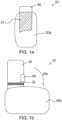
- Figure 1ashows a plan view of a deployable table assembly 10 according to a first embodiment of the invention, in a "stowed table" configuration.
- the table 20is in a stowed position 20a. It is supported underneath by a support arm 30.
- the tableis mounted so as to be rotatable on the support arm.
- the support arm 30can be mounted on a structure (not shown).
- Figure 1bshows a plan view of the deployable table assembly 10 of Figure 1a , in a "deployed table” configuration.
- the table 20has been rotated with respect to the support arm 30 (shown by arrow 20c) to a deployed position 20b.
- the table 20has moved from a "portrait” orientation to a "landscape” orientation. This movement exposes a region 31 of the support arm that is shown in hatched lines in Figure 1a . This region is covered by the table in the stowed position and not covered (exposed) by the table when then table is in the deployed position.
- a holder 40for holding a personal electronic device of a user of the table 20.
- the holdercomprises a pivotable arm 41 with a width, extending across the support arm, of 10 cm. This pivotable arm 41 will be described in more detail later. Also, in the region 31 is a retaining edge region 32. Again, this will be described in more detail later.
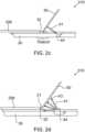
- FIG 2ashows a side view of the deployable table assembly of Figures 1a and 1b , in a "deployed table” configuration and also showing the pivotable arm 41 in a variety of positions.
- the pivotable arm 41sits flush so as to not protrude above the upper surface of the support arm 30 when it is in its stowed position (designated as 42a). It can then be pivoted (shown by arrow 45) from its first end at a friction hinge 44 into a variety of other angles from the support arm 30.
- three other positions 42b (at approximately 20 degrees), 42c (at approximately 45 degrees) and 42d (at approximately 70 degrees)are shown.
- the arm 41may be pivoted even further as far as an angle of 120 degrees from the front support arm surface.
- a rubber tip 43which acts as a support surface for an electronic device on the holder 40. The angle of a supported electronic device can be adjusted by altering the angle of the pivotable arm 41.
- the retaining region 32 in front of the pivotable arm 41can be seen more clearly.
- itcomprises a retaining lip 33 that protrudes up from the surface of the support arm 30. It is also angled backwards towards the pivotable arm 41. This acts as a second support surface for an electronic device on the holder 40.
- the retaining lip 33is made of a rubber material.
- Figure 2bshows a side view of a deployable table assembly 110 according to a second embodiment of the invention, in a "deployed table” configuration, also showing the pivotable arm 41 in a deployed position and also showing a personal electronic device 50 on the pivotable arm 41.
- This second embodimentis very similar to the first embodiment and the same reference numerals will be used for like elements. Where elements have not been described, it can be assumed they are the same as, or substantially similar to, before.
- the retaining region 32comprises two lips 34a, 34b, each of them very similar to lip 33. They are spaced apart along the length of the support arm 30 so that different height personal electronic devices can be supported in two different locations and at different angles.
- the electronic device 50comprises a front viewing surface 52, a back surface 51 and a bottom edge 53. It can be seen that the bottom edge 53 abuts against one of the retaining lips 34b and is so prevented from slipping forwards.
- the back surface 51 of the device 50rests on the deployed pivotable arm 41. Hence, the device 50 is held at the required angle by the holder 40.
- Figure 2cshows a side view of a deployable table assembly 210 according to a third embodiment of the invention, in a "deployed table” configuration, also showing the pivotable arm 41 in a deployed position and also showing a personal electronic device 50 on the pivotable arm 41.
- This third embodimentis very similar to the first and second embodiments and the same reference numerals will be used for like elements. Where elements have not been described, it can be assumed they are the same as, or substantially similar to, before.
- the retaining region 32comprises four lips 35a, 35b, 35c and 35d, each of them very similar to lip 33 or lips 34a and 34b. They are spaced apart along the length of the support arm 30 so that different height personal electronic devices can be supported in four different locations and at different angles.
- Figure 2dshows a side view of a deployable table assembly 310 according to a fourth embodiment of the invention, in a "deployed table” configuration, also showing the pivotable arm 41 in a variety of positions and also showing a personal electronic device 50 on the pivotable arm 41.
- This fourth embodimentis very similar to the first, second and third embodiments and the same reference numerals will be used for like elements. Where elements have not been described, it can be assumed they are the same as, or substantially similar to, before.
- the electronic device 50is simply able to abut against a back edge 21 of the table 20.
- the back edge 21 of the table 20acts as a retaining lip.
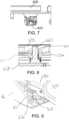
- Figure 3shows a plan view the deployable table assembly 10 of Figures 1a and 1b , in a "deployed table” configuration and also showing the lateral movement of the pivotable arm 41 and retaining edge region 32.
- the pivotable arm 41When the table 20 is in the deployed position 20b, the pivotable arm 41 can be pulled in and out laterally (shown by arrows 46) so as to centre the holder 40 (and electronic device 50) with respect to the table 20 or user. It is noted that the retaining region 32 also moves at the same time as the pivotable arm 41 (by use of a mechanical linkage, not shown). A spring 36 acts to hold the pivotable arm 41 and retaining region 32 in the required place.
- Figure 4shows a perspective view of a deployable table assembly 410 according to an example not forming part of the invention, showing the assembly in situ as part of an aircraft seat unit 60, mounted to a seat console 61and useable by a passenger in the seat behind 62.
- the support arm 30is mounted to the seat console 61 under a TV monitor 63.
- This consoleis in front of the passenger seat 62 so the passenger in seat 62 can use the table 20 and holder 40.
- the consoleis located above a footwell for the passenger.
- Figure 5shows a plan view of the deployable table assembly 410.
- the support arm 430comprises a support arm portion 430a and a rail 430b.
- the support arm portion 430ais slidably mounted to the rail 430b.
- the rail 430bis slidably mounted to a mounting plate 64 that is mounted in the seat console 61.
- the support arm 430is able to slide out in a telescopic manner.
- FIG 6shows a perspective view of the deployable table assembly 410, in a "stowed table” configuration.
- the table 420has a latch button 422 at the front that a passenger can press to release a latch 423 and enable the table to be deployed.
- the latchis located in the circled area of Figure 6 and is shown enlarged in Figure 7 . This latch 423 is released by the action of the pressing on the latch button 422. Once de-latched, the table can be pulled forwards so that the table 420, support arm portion 430a and rail 430b are slid in relation to the mounting plate 64.
- Figure 8shows an enlarged cross-sectional side view of the deployable table assembly 410, in the "stowed table” configuration, showing a retaining pin 440.
- This pin 440forms part of the support arm portion 430a and acts to retaining the table leaf 420 in relation to the support arm portion 430a. This is done by the retaining pin 440 extending through a through hole 437 in the support arm portion 430a into a closed hole 441 on the underside of the table leaf and thus, preventing the table leaf 420 from being rotated in relation to the support arm portion 430a.
- the pin 440extends upwards from a sliding lock arm 438 of the support arm portion 430a. The height of the sliding lock arm 438 in relation to the hole 437 varies, as the sliding lock arm can move up and down, depending on the orientation of the table 420, as will be described in more detail later.
- FIG 9shows an enlarged perspective view of a cam follower 450 and cam track 451 used in the deployment of the table 420.
- the cam follower 450is connected to the support arm portion 430a.
- the support arm portion 430amoves in relation to the mounting plate 64.
- Thiscauses the cam follower 450 to run along the cam track 451 that is located on the mounting plate 64.
- the cam track 451is "stepped" so that the cam follower 450 travelling along it moves downwards at a first step 451a.
- the cam follower 450is connected to the retaining pin 440 and so the downwards movement of the cam follower 450 causes the retaining pin 440 to drop.
- the dropping of the pin 440corresponds to the cam follower 450 reaching a certain position (the first step 451a) on the cam track 451.
- rotation of the table leaf 420does not cause abutting or knocking into any of the console furniture etc.
- the profile of the underside of the table 420is shaped (i.e. has a depth that varies) so that as the table 420 rotates in relation to the retaining pin 440, the pin 440 is pushed downwards. Therefore, between the angles of 45 and 90 degrees, the pin 440 is being pushed downwards by the table 420.
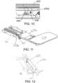
- Figure 11shows a perspective view of the deployable table assembly 410, in this rotated (to 90 degrees) configuration.
- the table 420can be pulled further forwards from the configuration in Figure 11 , and this causes the support arm portion 430a to slide in relation to the rail 430b. In the fully deployed position, the table 420 is very close to the passenger in the seat, at a total distance away from the console of approximately 650mm (i.e. a further 210mm).
- the retaining pin 440is located in a different hole 442 in the underside of the table leaf 420 and so rotation of the table leaf 420 is not possible. Hence, the travel can only occur when the table is in the 90 degree rotated position. Otherwise, the pin 440 hits the underside of the table 420 and prevents the cam follower 450 stepping up the step 451a on the cam track 451.
- the cam follower 450 stepping up on the cam track 451causes the retaining pin 440 to be pushed up into a second hole 442 in the table 420, as shown in Figure 13 .
- This hole 442is shallower than hole 441 and thus prevents the movement of the table 420 in relation to the support arm portion 430a by preventing the cam following 450 being able to move further up the cam track 451 (up another step). This, this prevents any further stowage movement of the table 420 towards the console or mounting plate 64.
- cam follower 450drops down the step in the cam track 451 and the pin 440 is dropped down away from hole 442. This allows the table to be rotated back into its original (0 degrees) orientation. Then, when the table 420 is pushed back and cam follower 450 travels up the cam track 451, the cam follower 450 is not prevented from lifting up with the steps in the cam track 451. This is because pin 440 is now located in hole 441, which is deeper than hole 442.
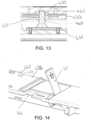
- Figure 14shows a perspective view of the deployable table assembly 410 in the "fully deployed" configuration, showing the pivotable arm in a 60 degree position.
- the pivotable arm 41is stopped from rotating any further by the bottom of the arm abutting the support arm portion 430a.
- This Figurealso shows a gap 41a in the support arm portion 430 that also a passenger to easily push the pivotable arm 41 up from underneath the support arm potion 430a.
- the width of the pivotable arm 40can be any suitable width, depending on the type/size of personal electronic device expected to be used with it.
- the tip 43 of the pivotable arm 41 and/or the retaining lips 33, 34, 35do not have to be rubber and could be any suitable material that has a high friction surface and/or is resilient or malleable.
Landscapes
- Engineering & Computer Science (AREA)
- Aviation & Aerospace Engineering (AREA)
- Transportation (AREA)
- Mechanical Engineering (AREA)
- Chair Legs, Seat Parts, And Backrests (AREA)
- Passenger Equipment (AREA)
Description
- The present disclosure relates to deployable table assemblies.
- The present invention concerns a deployable table assembly. More particularly, but not exclusively, this invention concerns a deployable table assembly comprising a holder for a personal electronic device, such as a mobile phone, tablet or pad.
- There are many holders available for holding personal electronic devices. Generally speaking these are designed to be used on their own and are free-standing. An example is a cushioned tablet holder that may be placed on a table or on a user's lap, and holds the tablet in an angled position for use, especially for viewing.
- However, these examples are not suitable for, for example, being provided by an airline for an aircraft passenger. Such a holder would be likely to become separated form an associated seat over time and is not integrated with the seat unit, for example.
- The present invention seeks to mitigate the above-mentioned problems. Alternatively or additionally, the present invention seeks to provide an improved deployable table assembly.
FR 3011783 A1 US 5 092 652 A ,WO 2017/048319 A1 ,US 5 370 060 A ,FR 2 911 548 A1 DE 43 43 242 A1 ,CN 102 114 796 B , andUS 2005/178297 A1 all disclose deployable table assemblies which form part of the state of the art.- The present invention provides a deployable table assembly comprising a deployable table, and a support arm, wherein the deployable table is moveably mounted to the support arm and is moveable in relation to the support arm between a stowed position and a deployed position, wherein the support arm comprises a coverable region that is covered by the deployable table when the deployable table is in the stowed position, and not covered by the deployable table when the deployable table is in the deployed position, wherein the deployable table assembly further comprises a holder for a personal electronic device mounted at least partially over the coverable region of the support arm such that the holder is at least partially covered by the deployable table element when the deployable table is in the stowed position, and at least partially exposed when the deployable table is in the deployed position. According to the invention, the holder is translatably mounted to the support arm and translatable in relation to the support arm from a first translation position to a second translation position and the support arm is configured to support the deployable table and to support the holder in use.
- This assembly has the advantage that the holder is integral with the assembly, including the table and support arm. This prevents it from becoming separated from the other items of the assembly. In addition, the support arm used to support the deployable table is also used to support the holder. Hence, no separate support arm is required for the holder. These advantages are especially useful when the assembly is mounted as part of an aircraft, for example as part of an aircraft seat unit, for use by an aircraft passenger.
- Furthermore, having the holder mounted over the coverable region of the support arm means that the holder is only exposed for use when the table is deployed. This prevents damage to the holder as it is protected when the table is stowed. This also provides for a neater, cleaner, uncluttered look of the assembly when the table is stowed. These advantages are especially useful when the assembly is mounted as part of an aircraft, for example as part of an aircraft seat unit, for use by an aircraft passenger.
- It is also noted that such an assembly has the advantage that the stowage of the holder makes use of unused space under the table. Again, this is especially useful when the assembly is mounted as part of an aircraft, for example as part of an aircraft seat unit, for use by an aircraft passenger.
- Preferably, the holder is mounted to the coverable region of the support arm. Preferably, the holder is the holder is mounted fully over the coverable region of the support arm. In other words, preferably, the holder is fully covered by the deployable table element when the deployable table is in the stowed position, and fully exposed when the deployable table is in the deployed position.
- Preferably, movement of the deployable table between the stowed and deployed positions is a movement within the plane of the deployable table. This provides a compact deployment arrangement.
- More preferably, the movement of the deployable table is by rotating or sliding. Even more preferably, the movement is by rotating.
- Alternatively, the movement of the deployable table is by folding and unfolding.
- Preferably, the deployable table may be moved towards a user when moving from the stowed position to the deployed position (so that more table area is nearer the user) and wherein the coverable region of the arm, as viewed by the user, is behind the deployed position of the deployable table. This means that access to the table (and any objects on it) is not obstructed by the holder or any electronic device being held by it. This means that an aircraft passenger could use the table for eating a meal, whilst still being able to view the electronic device, to watch a film, for example. The movement of the table towards the user may be provided by a telescoping action. The telescoping action may be provided by the support arm being telescopic. For example, the support arm may comprise a support rail and a slidable arm portion, the slidable arm portion being slidably mounted on the support rail.
- Preferably, the holder comprises a pivotable arm that is rotatably mounted by a first end to the support arm and wherein a second, opposite end of the pivotable arm provides a first support surface for the electronic device. This provides a simple, intuitive operation of the holder that does not interfere with the table.
- The first support surface may comprise a high friction material to prevent sliding of the electronic device on the first support surface. The first support surface may comprise a malleable material to allow the electronic device to be supported by a surface moulded to its angle/shape. The arm may have a width of between 2cm and 30cm to allow for the electronic device to be held and prevented from wobbling on the pivotable arm.
- More preferably, the pivotable arm is rotatable between a stowed position, preferably where the pivotable arm is substantially or completely flush with the support arm, and at least one deployed position, where the pivotable arm projects at an angle from the support arm. This allows for the holder to be effectively stowed flush against the support arm (and hence, not prevent the table from moving back to its stowed position) but also allows the holder to be easily deployed.
- Preferably, the deployable table assembly comprises a table locking mechanism that prevents the table from moving towards the stowed position when the pivotable arm is not in the stowed position. This prevents the table from damaging the holder (or any electronic device being held by it) which may otherwise occur by it being stowed whilst the holder is deployed.
- Preferably, there is also provided a second support surface for the electronic device. This allows the electronic device to be held by two supports; the combination of supports preventing it sliding forwards and maintaining an appropriate angle for viewing.
- The second support surface may comprise a high friction material to prevent sliding of the electronic device on the second support surface. The second support surface may comprise a malleable material to allow the electronic device to be supported by a surface moulded to its angle/shape. The second support surface may comprise an edge of the deployed table.
- More preferably, the second support surface is provided by a retaining edge mounted on the support arm. This provides an actual edge for the electronic device to abut against, which helps to prevent sliding forwards.
- More preferably, there are a plurality of retaining edges mounted on the support arm at different positions along the support arm. This allows for a number of different positions, especially angle positions, of the holder (and any electronic device being held by it).
- The pivotable arm may be able to provide many angle positions from its stowed position of 0 degrees (preferably substantially or completely flush against the support arm) to a fully deployed position of, for example, 60 degrees or 120 degrees angled backwards from the support arm. Each angle position may be maintained by the pivotable arm being mounted by a friction hinge to the support arm.
- The holder is translatably mounted to the support arm and translatable in relation to the support arm from a first translation position to a second translation position. This assembly also has the advantage that the holder (and therefore the electronic device being held by the holder) is able to move, preferably laterally or alternatively or additionally forwards and backwards, in relation to the support arm. When considering the lateral movement, this allows for different devices, of different widths, to be centred with respect to the user. This is especially useful if the deployed table is not centred (i.e. is "off-centre") with respect to the support arm.
- Embodiments of the present invention will now be described by way of example only with reference to the accompanying schematic drawings of which:
Figure 1a shows a plan view of a deployable table assembly according to a first embodiment of the invention, in a "stowed table" configuration;Figure 1b shows a plan view of the deployable table assembly ofFigure 1a , in a "deployed table" configuration;Figure 2a shows a side view of the deployable table assembly ofFigures 1a and 1b , in a "deployed table" configuration and also showing the pivotable arm in a variety of positions;Figure 2b shows a side view of a deployable table assembly according to a second embodiment of the invention, in a "deployed table" configuration, also showing the pivotable arm in a deployed position and also showing a personal electronic device on the pivotable arm;Figure 2c shows a side view of a deployable table assembly according to a third embodiment of the invention, in a "deployed table" configuration, also showing the pivotable arm in a deployed position and also showing a personal electronic device on the pivotable arm;Figure 2d shows a side view of a deployable table assembly according to a fourth embodiment of the invention, in a "deployed table" configuration, also showing the pivotable arm in a variety of positions and also showing a personal electronic device on the pivotable arm;Figure 3 shows a plan view the deployable table assembly ofFigures 1a and 1b , in a "deployed table" configuration and also showing the lateral movement of the pivotable arm and retaining edge region;Figure 4 shows a perspective view of a deployable table assembly according to an example not forming part of the invention, showing the assembly in situ as part of an aircraft seat unit, mounted to a seat console and useable by a passenger in the seat behind;Figure 5 shows a plan view of the deployable table assembly ofFigure 4 , showing the telescoped nature of the support arm;Figure 6 shows a perspective view of the deployable table assembly of the example not forming part of the invention, in a "stowed table" configuration;Figure 7 shows an enlarged side view of the circled area inFigure 6 , showing a release latch;Figure 8 shows an enlarged cross-sectional side view of the deployable table assembly of the example not forming part of the invention, in the "stowed table" configuration, showing a retaining pin;Figure 9 shows an enlarged perspective view of a cam follower and cam track used in the deployment of the table of the example not forming part of the invention;Figure 10 shows an enlarged side view of the deployable table assembly of the example not forming part of the invention, in a "partly deployed" configuration, showing the retaining pin;Figure 11 shows a perspective view of the deployable table assembly of the example not forming part of the invention, in the "rotated" configuration;Figure 12 shows an enlarged perspective view of the cam follower and cam track ofFigure 9 , used to allow movement of the table but not rotation of the table;Figure 13 shows an enlarged side view of the deployable table assembly ofFigure 6 , in a "partly deployed" configuration, showing the retaining pin; andFigure 14 shows a perspective view of the deployable table assembly in the "fully deployed" configuration, showing the pivotable arm in a 60 degree position.Figure 1a shows a plan view of adeployable table assembly 10 according to a first embodiment of the invention, in a "stowed table" configuration.- Here it can be seen that the table 20 is in a stowed
position 20a. It is supported underneath by asupport arm 30. The table is mounted so as to be rotatable on the support arm. Thesupport arm 30 can be mounted on a structure (not shown). Figure 1b shows a plan view of thedeployable table assembly 10 ofFigure 1a , in a "deployed table" configuration.- Here it can be seen that the table 20 has been rotated with respect to the support arm 30 (shown by
arrow 20c) to a deployedposition 20b. The table 20 has moved from a "portrait" orientation to a "landscape" orientation. This movement exposes aregion 31 of the support arm that is shown in hatched lines inFigure 1a . This region is covered by the table in the stowed position and not covered (exposed) by the table when then table is in the deployed position. - In this
region 31 is aholder 40 for holding a personal electronic device of a user of the table 20. The holder comprises apivotable arm 41 with a width, extending across the support arm, of 10 cm. Thispivotable arm 41 will be described in more detail later. Also, in theregion 31 is a retainingedge region 32. Again, this will be described in more detail later. Figure 2a shows a side view of the deployable table assembly ofFigures 1a and 1b , in a "deployed table" configuration and also showing thepivotable arm 41 in a variety of positions. As can be seen, thepivotable arm 41 sits flush so as to not protrude above the upper surface of thesupport arm 30 when it is in its stowed position (designated as 42a). It can then be pivoted (shown by arrow 45) from its first end at afriction hinge 44 into a variety of other angles from thesupport arm 30. Here, threeother positions 42b (at approximately 20 degrees), 42c (at approximately 45 degrees) and 42d (at approximately 70 degrees) are shown. Thearm 41 may be pivoted even further as far as an angle of 120 degrees from the front support arm surface. At the second, distal end of thepivotable arm 41 is arubber tip 43, which acts as a support surface for an electronic device on theholder 40. The angle of a supported electronic device can be adjusted by altering the angle of thepivotable arm 41.- Also, in
Figure 2a the retainingregion 32 in front of thepivotable arm 41 can be seen more clearly. Here is can be seen that it comprises a retaininglip 33 that protrudes up from the surface of thesupport arm 30. It is also angled backwards towards thepivotable arm 41. This acts as a second support surface for an electronic device on theholder 40. The retaininglip 33 is made of a rubber material. Figure 2b shows a side view of adeployable table assembly 110 according to a second embodiment of the invention, in a "deployed table" configuration, also showing thepivotable arm 41 in a deployed position and also showing a personalelectronic device 50 on thepivotable arm 41. This second embodiment is very similar to the first embodiment and the same reference numerals will be used for like elements. Where elements have not been described, it can be assumed they are the same as, or substantially similar to, before.- Here, the retaining
region 32 comprises twolips lip 33. They are spaced apart along the length of thesupport arm 30 so that different height personal electronic devices can be supported in two different locations and at different angles. - The
electronic device 50 comprises afront viewing surface 52, aback surface 51 and abottom edge 53. It can be seen that thebottom edge 53 abuts against one of the retaininglips 34b and is so prevented from slipping forwards. Theback surface 51 of thedevice 50 rests on the deployedpivotable arm 41. Hence, thedevice 50 is held at the required angle by theholder 40. Figure 2c shows a side view of adeployable table assembly 210 according to a third embodiment of the invention, in a "deployed table" configuration, also showing thepivotable arm 41 in a deployed position and also showing a personalelectronic device 50 on thepivotable arm 41. This third embodiment is very similar to the first and second embodiments and the same reference numerals will be used for like elements. Where elements have not been described, it can be assumed they are the same as, or substantially similar to, before.- Here, the retaining
region 32 comprises four lips 35a, 35b, 35c and 35d, each of them very similar tolip 33 orlips support arm 30 so that different height personal electronic devices can be supported in four different locations and at different angles. Figure 2d shows a side view of adeployable table assembly 310 according to a fourth embodiment of the invention, in a "deployed table" configuration, also showing thepivotable arm 41 in a variety of positions and also showing a personalelectronic device 50 on thepivotable arm 41. This fourth embodiment is very similar to the first, second and third embodiments and the same reference numerals will be used for like elements. Where elements have not been described, it can be assumed they are the same as, or substantially similar to, before.- Here, there is no specific elements to the retaining
region 32. Instead, theelectronic device 50 is simply able to abut against aback edge 21 of the table 20. Hence, theback edge 21 of the table 20 acts as a retaining lip. - This Figure also shown that the
rubber tip 43 of thepivotable arm 41 is squashable/malleable so as to "mould" to the angle of theelectronic device 50 resting on it. Figure 3 shows a plan view thedeployable table assembly 10 ofFigures 1a and 1b , in a "deployed table" configuration and also showing the lateral movement of thepivotable arm 41 and retainingedge region 32.- When the table 20 is in the deployed
position 20b, thepivotable arm 41 can be pulled in and out laterally (shown by arrows 46) so as to centre the holder 40 (and electronic device 50) with respect to the table 20 or user. It is noted that the retainingregion 32 also moves at the same time as the pivotable arm 41 (by use of a mechanical linkage, not shown). Aspring 36 acts to hold thepivotable arm 41 and retainingregion 32 in the required place. Figure 4 shows a perspective view of adeployable table assembly 410 according to an example not forming part of the invention, showing the assembly in situ as part of anaircraft seat unit 60, mounted to a seat console 61and useable by a passenger in the seat behind 62. Thesupport arm 30 is mounted to theseat console 61 under aTV monitor 63. This console is in front of thepassenger seat 62 so the passenger inseat 62 can use the table 20 andholder 40. The console is located above a footwell for the passenger.Figure 5 shows a plan view of thedeployable table assembly 410. Here, it can be seen that thesupport arm 430 comprises asupport arm portion 430a and arail 430b. Thesupport arm portion 430a is slidably mounted to therail 430b. Therail 430b is slidably mounted to a mountingplate 64 that is mounted in theseat console 61. Hence, thesupport arm 430 is able to slide out in a telescopic manner.Figure 6 shows a perspective view of thedeployable table assembly 410, in a "stowed table" configuration. The table 420 has alatch button 422 at the front that a passenger can press to release alatch 423 and enable the table to be deployed. The latch is located in the circled area ofFigure 6 and is shown enlarged inFigure 7 . Thislatch 423 is released by the action of the pressing on thelatch button 422. Once de-latched, the table can be pulled forwards so that the table 420,support arm portion 430a andrail 430b are slid in relation to the mountingplate 64.Figure 8 shows an enlarged cross-sectional side view of thedeployable table assembly 410, in the "stowed table" configuration, showing a retainingpin 440. Thispin 440 forms part of thesupport arm portion 430a and acts to retaining thetable leaf 420 in relation to thesupport arm portion 430a. This is done by the retainingpin 440 extending through a throughhole 437 in thesupport arm portion 430a into aclosed hole 441 on the underside of the table leaf and thus, preventing thetable leaf 420 from being rotated in relation to thesupport arm portion 430a. Thepin 440 extends upwards from a slidinglock arm 438 of thesupport arm portion 430a. The height of the slidinglock arm 438 in relation to thehole 437 varies, as the sliding lock arm can move up and down, depending on the orientation of the table 420, as will be described in more detail later.Figure 9 shows an enlarged perspective view of acam follower 450 andcam track 451 used in the deployment of the table 420. Thecam follower 450 is connected to thesupport arm portion 430a. When thetable leaf 420 is pulled forwards, thesupport arm portion 430a moves in relation to the mountingplate 64. This causes thecam follower 450 to run along thecam track 451 that is located on the mountingplate 64. Thecam track 451 is "stepped" so that thecam follower 450 travelling along it moves downwards at a first step 451a. Thecam follower 450 is connected to the retainingpin 440 and so the downwards movement of thecam follower 450 causes the retainingpin 440 to drop. This means that the retainingpin 440 drops out of thehole 441 in the table 420 and thus allows the table 420 to be able to be rotated in relation to thesupport arm portion 430a. This dropped position of the retainingpin 440 is shown inFigure 10 .- It is noted that the dropping of the
pin 440 corresponds to thecam follower 450 reaching a certain position (the first step 451a) on thecam track 451. This corresponds to the table 420,support arm portion 430a andrail 430b being pulled forwards by a distance of approximately 440mm. At this distance, rotation of thetable leaf 420 does not cause abutting or knocking into any of the console furniture etc. As the table 420 is rotated, it rotates in relation to thepin 440. The profile of the underside of the table 420 is shaped (i.e. has a depth that varies) so that as the table 420 rotates in relation to the retainingpin 440, thepin 440 is pushed downwards. Therefore, between the angles of 45 and 90 degrees, thepin 440 is being pushed downwards by the table 420. Figure 11 shows a perspective view of thedeployable table assembly 410, in this rotated (to 90 degrees) configuration.- With the table 420 rotated between 45 degrees and 90 degrees, the retaining
pin 440 push up against the underside of the table 420 if the table 420 was attempted to be stowed. Hence, thecam follower 450 would not be able to go back up thecam track 451. Hence, stowage of the table 420 is prevented when it is rotated past 45 degrees. - The table 420 can be pulled further forwards from the configuration in
Figure 11 , and this causes thesupport arm portion 430a to slide in relation to therail 430b. In the fully deployed position, the table 420 is very close to the passenger in the seat, at a total distance away from the console of approximately 650mm (i.e. a further 210mm). - If a passenger then wants to exit their seat without having to rotate the table 420 back to its original orientation, the passenger can push against the table 420. This causes the
rail 430b andsupport arm portion 430a to both be pushed towards the mountingplate 64. This provides for an extra approximately 82.5mm of space (i.e. a total distance of 567.5mm). At the end of this travel, thecam follower 450 has stepped up on thecam track 451, as shown inFigure 12 . - During this travel, the retaining
pin 440 is located in adifferent hole 442 in the underside of thetable leaf 420 and so rotation of thetable leaf 420 is not possible. Hence, the travel can only occur when the table is in the 90 degree rotated position. Otherwise, thepin 440 hits the underside of the table 420 and prevents thecam follower 450 stepping up the step 451a on thecam track 451. - The
cam follower 450 stepping up on thecam track 451 causes the retainingpin 440 to be pushed up into asecond hole 442 in the table 420, as shown inFigure 13 . Thishole 442 is shallower thanhole 441 and thus prevents the movement of the table 420 in relation to thesupport arm portion 430a by preventing the cam following 450 being able to move further up the cam track 451 (up another step). This, this prevents any further stowage movement of the table 420 towards the console or mountingplate 64. - When a passenger wishes to fully stow the table, they need to pull it back towards them, away from the console, so that
cam follower 450 drops down the step in thecam track 451 and thepin 440 is dropped down away fromhole 442. This allows the table to be rotated back into its original (0 degrees) orientation. Then, when the table 420 is pushed back andcam follower 450 travels up thecam track 451, thecam follower 450 is not prevented from lifting up with the steps in thecam track 451. This is becausepin 440 is now located inhole 441, which is deeper thanhole 442. Figure 14 shows a perspective view of thedeployable table assembly 410 in the "fully deployed" configuration, showing the pivotable arm in a 60 degree position. Here, thepivotable arm 41 is stopped from rotating any further by the bottom of the arm abutting thesupport arm portion 430a. This Figure also shows agap 41a in thesupport arm portion 430 that also a passenger to easily push thepivotable arm 41 up from underneath thesupport arm potion 430a.- The width of the
pivotable arm 40 can be any suitable width, depending on the type/size of personal electronic device expected to be used with it. - As another example, the
tip 43 of thepivotable arm 41 and/or the retaininglips 33, 34, 35 do not have to be rubber and could be any suitable material that has a high friction surface and/or is resilient or malleable.
Claims (13)
- A deployable table assembly comprising:- a deployable table (20), and- a support arm (30),wherein the deployable table (20) is moveably mounted to the support arm (30) and is moveable in relation to the support arm (30) between a stowed position (20a) and a deployed position (20b),wherein the support arm comprises a coverable region that is:- covered by the deployable table (20) when the deployable table (20) is in the stowed position, and- not covered by the deployable table (20) when the deployable table (20) is in the deployed position,wherein the deployable table assembly further comprises:- a holder (40) for a personal electronic device mounted at least partially over the coverable region (31) of the support arm (30) such that the holder is:- at least partially covered by the deployable table element (20) when the deployable table is in the stowed position (20a), and- at least partially exposed when the deployable table (20) is in the deployed position (20b)characterised in that the holder (40) is translatably mounted to the support arm (30) and translatable in relation to the support arm (30) from a first translation position to a second translation position and
in that the support arm is configured to support the deployable table and to support the holder in use. - A deployable table assembly as claimed in claim 1, wherein the holder is (40) translatably mounted to the support arm (30) to such that it can move laterally, or alternatively or additionally forwards and backwards, in relation to the support arm (30).
- A deployable table assembly as claimed in any of claims 1 to 2, wherein movement of the deployable table (20) between the stowed (20a) and deployed (20b) positions is a movement within the plane of the deployable table (20).
- A deployable table assembly as claimed in claim 3, wherein the movement of the deployable table (20) is by rotating or sliding.
- A deployable table assembly as claimed in any preceding claim, wherein the deployable table (20) may be moved in use towards a user when moving from the stowed (20a) position to the deployed position (20b) and wherein the coverable region (31) of the arm, as viewed by the user, is behind the deployed position (20b) of the deployable table (20).
- A deployable table assembly as claimed in any preceding claim, wherein the holder comprises a pivotable arm (41) that is rotatably mounted by a first end to the support arm (30) and wherein a second, opposite end of the pivotable arm provides a first support surface for the electronic device.
- A deployable table assembly as claimed in claim 6, wherein the pivotable arm is rotatable between a stowed position (42a), where the pivotable arm is substantially flush with the support arm (30), and at least one deployed position (42b), where the pivotable arm projects at an angle from the support arm (30).
- A deployable table assembly as claimed in claim 6 or claim 7, wherein the deployable table assembly comprises a table locking mechanism that prevents the table from moving towards the stowed position when the pivotable arm (41) is not in the stowed position (42a).
- A deployable table assembly as claimed in any of claims 6 to 8, wherein there is also provided a second support surface for the electronic device.
- A deployable table assembly as claimed in claim 9, wherein the second support surface is provided by a retaining edge (34a) mounted on the support arm (30).
- A deployable table assembly as claimed in any preceding claim, wherein the holder (40) is slidably mounted to the support arm (30).
- A deployable table assembly as claimed any preceding claim, wherein the holder (40) is slidable laterally in relation to the support arm (30).
- A deployable table assembly as claimed in any preceding claim, wherein the deployable table assembly is suitable for mounting to an aircraft interior structure, such as the back of a passenger seat (62) or a console unit (61), for use by a passenger behind.
Applications Claiming Priority (2)
| Application Number | Priority Date | Filing Date | Title |
|---|---|---|---|
| GBGB1713813.2AGB201713813D0 (en) | 2017-08-29 | 2017-08-29 | Deployable table assembly |
| EP18191122.3AEP3450318B1 (en) | 2017-08-29 | 2018-08-28 | Deployable table assembly |
Related Parent Applications (2)
| Application Number | Title | Priority Date | Filing Date |
|---|---|---|---|
| EP18191122.3ADivisionEP3450318B1 (en) | 2017-08-29 | 2018-08-28 | Deployable table assembly |
| EP18191122.3ADivision-IntoEP3450318B1 (en) | 2017-08-29 | 2018-08-28 | Deployable table assembly |
Publications (2)
| Publication Number | Publication Date |
|---|---|
| EP3838760A1 EP3838760A1 (en) | 2021-06-23 |
| EP3838760B1true EP3838760B1 (en) | 2024-11-06 |
Family
ID=60037278
Family Applications (2)
| Application Number | Title | Priority Date | Filing Date |
|---|---|---|---|
| EP21157043.7AActiveEP3838760B1 (en) | 2017-08-29 | 2018-08-28 | Deployable table assembly |
| EP18191122.3AActiveEP3450318B1 (en) | 2017-08-29 | 2018-08-28 | Deployable table assembly |
Family Applications After (1)
| Application Number | Title | Priority Date | Filing Date |
|---|---|---|---|
| EP18191122.3AActiveEP3450318B1 (en) | 2017-08-29 | 2018-08-28 | Deployable table assembly |
Country Status (3)
| Country | Link |
|---|---|
| US (1) | US10696408B2 (en) |
| EP (2) | EP3838760B1 (en) |
| GB (1) | GB201713813D0 (en) |
Families Citing this family (15)
| Publication number | Priority date | Publication date | Assignee | Title |
|---|---|---|---|---|
| US11305876B2 (en)* | 2018-07-10 | 2022-04-19 | Rockwell Collins, Inc. | Aircraft cabin apparatus including personal electronic device holder |
| US10864991B2 (en)* | 2019-03-20 | 2020-12-15 | B/E Aerospace, Inc. | Adjustable cantilevered table assembly |
| DE102019003355A1 (en)* | 2019-05-13 | 2020-11-19 | Daimler Ag | Table device for a vehicle and a vehicle |
| US11420747B2 (en)* | 2019-09-10 | 2022-08-23 | Inflight Holdings | Console mounted pilot tray assembly |
| DE102019124550A1 (en)* | 2019-09-12 | 2021-03-18 | Airbus Operations Gmbh | Table arrangement and passenger cabin area |
| US11091267B1 (en) | 2019-11-19 | 2021-08-17 | B/E Aerospace, Inc. | Actuatable tray assembly for an aircraft passenger compartment |
| US11577837B1 (en) | 2019-11-19 | 2023-02-14 | B/E Aerospace, Inc. | Actuatable tray assembly for an aircraft passenger compartment |
| US11465749B1 (en) | 2019-11-19 | 2022-10-11 | B/E Aerospace, Inc. | Actuatable tray assembly for an aircraft passenger compartment |
| US11565818B2 (en)* | 2020-04-13 | 2023-01-31 | Adient Aerospace, Llc | Tray table apparatus for a console element, console element and seat unit |
| CN114408187A (en)* | 2020-09-25 | 2022-04-29 | 安道拓航空航天公司 | Slide-out tray table with interlocking assembly |
| WO2022067119A1 (en)* | 2020-09-25 | 2022-03-31 | Adient Aerospace, Llc | Slide-out tray table with interlock assembly |
| FR3116809B1 (en)* | 2020-11-30 | 2023-11-17 | Safran Seats | CONSOLE FOR A SEAT UNIT PROVIDED WITH A SUPPORT ARM FOR A PORTABLE ELECTRONIC DEVICE |
| EP4465857A4 (en)* | 2022-01-19 | 2025-10-15 | S&S Numerical Control Inc | TRAY TABLE WITH MAGNETIC LOCKING AND/OR LOCKING |
| CN118843406A (en)* | 2022-01-19 | 2024-10-25 | S&S 数控股份有限公司 | Tray table with braking mechanism |
| US12134472B2 (en)* | 2023-03-17 | 2024-11-05 | B/E Aerospace, Inc. | System including stowable tablet holder apparatus |
Family Cites Families (36)
| Publication number | Priority date | Publication date | Assignee | Title |
|---|---|---|---|---|
| US528488A (en)* | 1894-10-30 | Book-holder for desks | ||
| US593935A (en)* | 1897-11-16 | Book or manuscript holder | ||
| US1203659A (en)* | 1914-05-08 | 1916-11-07 | Underwood Typewriter Co | Copy-holder. |
| US1483421A (en)* | 1921-10-07 | 1924-02-12 | Helen G Farnham | Bookrest |
| US1739643A (en)* | 1928-02-16 | 1929-12-17 | Clara F Lowry | Bookholder and table |
| US2795473A (en)* | 1952-06-21 | 1957-06-11 | Carrom Ind Inc | Hospital bed accessory |
| US3176947A (en)* | 1962-04-19 | 1965-04-06 | Inverso Albert | Safety rest steam and flat iron holder |
| US3475052A (en)* | 1967-05-29 | 1969-10-28 | George Kaposi | Portable arm chair table |
| US4043530A (en)* | 1976-11-10 | 1977-08-23 | Edward Eric May | Book support |
| US5092652A (en)* | 1990-10-30 | 1992-03-03 | Macaluso Raymond R | Extendable airline turbulence tray |
| US5370060A (en) | 1993-06-11 | 1994-12-06 | Wang; Liwen Y. | Multipurpose automobile foldaway table |
| US5516191A (en) | 1993-10-12 | 1996-05-14 | Mckee; Carl B. | Desk structure |
| DE4343242C2 (en) | 1993-12-17 | 1997-05-15 | Bayerische Motoren Werke Ag | Stowable table furniture on one seat |
| US5839780A (en)* | 1997-01-31 | 1998-11-24 | Cauffiel; Ford B. | Cabinet and table assembly for use with seating apparatus |
| US6382745B1 (en)* | 2000-09-08 | 2002-05-07 | Avis V. Adkins | Laptop workstation |
| US7311354B2 (en)* | 2003-04-30 | 2007-12-25 | 3861589 Canada Inc. | Seat for aircraft |
| US7073449B2 (en)* | 2004-02-13 | 2006-07-11 | Marc Calvin Pipkin | Seat supported reading tray |
| US7455016B2 (en)* | 2005-06-29 | 2008-11-25 | Honda Motor Co., Ltd. | Expandable writing panel for a vehicle console |
| US20070283855A1 (en)* | 2006-03-27 | 2007-12-13 | Alexander Pozzi | Tray tables principally for use in passenger vehicles |
| US8474384B2 (en)* | 2006-10-12 | 2013-07-02 | University Of South Florida | Folding armrest tray for wheelchairs |
| FR2911548B1 (en) | 2007-01-19 | 2009-04-17 | Renault Sas | MOTOR VEHICLE SEAT COMPRISING A FOLDING BACKREST COMPRISING A TABLET ELEMENT AND MOTOR VEHICLE COMPRISING SUCH A SEAT |
| US7735644B2 (en)* | 2007-06-06 | 2010-06-15 | Belkin International, Inc. | Case for electrical device and method of using same |
| CN201160623Y (en) | 2007-08-03 | 2008-12-10 | 付玉勤 | Multi-angle slant vertical reading tablet |
| TWI362919B (en)* | 2008-08-15 | 2012-05-01 | Primax Electronics Ltd | Portable frame for supporting a document |
| US8328008B2 (en)* | 2010-08-10 | 2012-12-11 | Incase Designs Corp. | Case for electronic tablet |
| CN102114796B (en) | 2010-10-25 | 2012-07-04 | 浙江吉利汽车研究院有限公司 | Folding table used inside car |
| US8934063B2 (en) | 2011-03-18 | 2015-01-13 | Skycast Solutions Inc. | In-flight entertainment system |
| US9067682B2 (en) | 2011-10-13 | 2015-06-30 | Nick Pajic | Electronic device support for vehicles |
| US20140116299A1 (en)* | 2012-10-31 | 2014-05-01 | Columbia Manufacturing, Inc. | Stand for an electronic device |
| CN202966025U (en) | 2012-11-14 | 2013-06-05 | 重庆市双桥区危思科技有限公司 | Novel central handrail of sedan |
| WO2015013661A1 (en)* | 2013-07-26 | 2015-01-29 | Aerocents, Llc | Seat-mounted supports for personal electronic devices |
| FR3011783A1 (en) | 2013-10-14 | 2015-04-17 | Peugeot Citroen Automobiles Sa | SUPPORT PLATE SUPPORT PLATE MAY BE TRANSLATED AND / OR DRAWN IN ROTATION, FOR A FOLDING BACK OF VEHICLE SEAT |
| CN204378352U (en) | 2015-01-13 | 2015-06-10 | 范文娟 | A kind of multimedia teaching servicing unit |
| US20160286953A1 (en)* | 2015-02-04 | 2016-10-06 | Carlos A. Castro | Multi-Angle Supports for Portable Electronic Devices |
| WO2017048319A1 (en) | 2015-09-15 | 2017-03-23 | Zodiac Seats Us Llc | Portable electronic device holder for tray tables |
| TWM554689U (en)* | 2017-07-14 | 2018-01-21 | Fan Eagle Yu Xiong | Notebook computer stand |
- 2017
- 2017-08-29GBGBGB1713813.2Apatent/GB201713813D0/ennot_activeCeased
- 2018
- 2018-08-23USUS16/110,384patent/US10696408B2/enactiveActive
- 2018-08-28EPEP21157043.7Apatent/EP3838760B1/enactiveActive
- 2018-08-28EPEP18191122.3Apatent/EP3450318B1/enactiveActive
Also Published As
| Publication number | Publication date |
|---|---|
| EP3450318B1 (en) | 2021-04-07 |
| US10696408B2 (en) | 2020-06-30 |
| EP3450318A1 (en) | 2019-03-06 |
| US20190061954A1 (en) | 2019-02-28 |
| GB201713813D0 (en) | 2017-10-11 |
| EP3838760A1 (en) | 2021-06-23 |
Similar Documents
| Publication | Publication Date | Title |
|---|---|---|
| EP3838760B1 (en) | Deployable table assembly | |
| CN108215969B (en) | Operable tray table for armrest of vehicle | |
| US9820568B2 (en) | Integral tray table personal electronic device holder and tray table | |
| EP3552968B1 (en) | Mechanism to achieve expandable tray table | |
| US7044550B2 (en) | Rear seat having a backrest implemented with a back board | |
| JP6040305B2 (en) | Cantilever tray table and aircraft special cabin equipped with it | |
| CN107531327B (en) | Portable device holder for an aircraft seat | |
| JP6240749B2 (en) | Support structure for mounting passenger seat to tray table, passenger seat tray table and passenger seat | |
| JP6483853B2 (en) | Portable electronic device holder | |
| US20170283067A1 (en) | Tray Table Deployable from Lower Seatback Area | |
| US11427325B2 (en) | Table apparatus | |
| US20170021931A1 (en) | Laterally-expanding tray table | |
| US20070145791A1 (en) | Locking device for a tray table system in a seat, in particular an aircraft passenger seat | |
| US9399409B2 (en) | Easy-entry vehicle seat with cover assembly | |
| WO2016092509A1 (en) | Retractable device holder for an aircraft seat | |
| US10538333B1 (en) | Seat system | |
| CN107000626B (en) | Lockable folding table with comfort equipment | |
| WO2017147620A1 (en) | Tray table with adjustable media support surface | |
| CN113492983A (en) | Cup holder assembly and table including same | |
| EP4051586B1 (en) | Adjustable device holder | |
| WO2018151664A1 (en) | Portable electronic device holder for a passenger seat | |
| CN210431502U (en) | Support device for a mobile electronic device and decorative element for a vehicle | |
| CZ36460U1 (en) | Pull-out table assembly | |
| FR2976875A1 (en) | Retractable support shelf arrangement for use in dashboard of car for placing e.g. cellphone, has housing moved from retracted position to holding position such that cover is suspended in front of housing so as to retain shelf | |
| CA2374056C (en) | Extendable swivel mounting bracket |
Legal Events
| Date | Code | Title | Description |
|---|---|---|---|
| PUAI | Public reference made under article 153(3) epc to a published international application that has entered the european phase | Free format text:ORIGINAL CODE: 0009012 | |
| STAA | Information on the status of an ep patent application or granted ep patent | Free format text:STATUS: THE APPLICATION HAS BEEN PUBLISHED | |
| AC | Divisional application: reference to earlier application | Ref document number:3450318 Country of ref document:EP Kind code of ref document:P | |
| AK | Designated contracting states | Kind code of ref document:A1 Designated state(s):AL AT BE BG CH CY CZ DE DK EE ES FI FR GB GR HR HU IE IS IT LI LT LU LV MC MK MT NL NO PL PT RO RS SE SI SK SM TR | |
| STAA | Information on the status of an ep patent application or granted ep patent | Free format text:STATUS: REQUEST FOR EXAMINATION WAS MADE | |
| 17P | Request for examination filed | Effective date:20211209 | |
| RBV | Designated contracting states (corrected) | Designated state(s):AL AT BE BG CH CY CZ DE DK EE ES FI FR GB GR HR HU IE IS IT LI LT LU LV MC MK MT NL NO PL PT RO RS SE SI SK SM TR | |
| STAA | Information on the status of an ep patent application or granted ep patent | Free format text:STATUS: EXAMINATION IS IN PROGRESS | |
| 17Q | First examination report despatched | Effective date:20230627 | |
| GRAP | Despatch of communication of intention to grant a patent | Free format text:ORIGINAL CODE: EPIDOSNIGR1 | |
| STAA | Information on the status of an ep patent application or granted ep patent | Free format text:STATUS: GRANT OF PATENT IS INTENDED | |
| RIC1 | Information provided on ipc code assigned before grant | Ipc:F16M 11/04 20060101ALN20240523BHEP Ipc:F16M 13/00 20060101ALN20240523BHEP Ipc:H04M 1/04 20060101ALN20240523BHEP Ipc:A47B 23/04 20060101ALN20240523BHEP Ipc:B60N 3/00 20060101ALI20240523BHEP Ipc:A47B 3/00 20060101ALI20240523BHEP Ipc:B64D 11/06 20060101AFI20240523BHEP | |
| INTG | Intention to grant announced | Effective date:20240605 | |
| GRAS | Grant fee paid | Free format text:ORIGINAL CODE: EPIDOSNIGR3 | |
| GRAA | (expected) grant | Free format text:ORIGINAL CODE: 0009210 | |
| STAA | Information on the status of an ep patent application or granted ep patent | Free format text:STATUS: THE PATENT HAS BEEN GRANTED | |
| AC | Divisional application: reference to earlier application | Ref document number:3450318 Country of ref document:EP Kind code of ref document:P | |
| AK | Designated contracting states | Kind code of ref document:B1 Designated state(s):AL AT BE BG CH CY CZ DE DK EE ES FI FR GB GR HR HU IE IS IT LI LT LU LV MC MK MT NL NO PL PT RO RS SE SI SK SM TR | |
| REG | Reference to a national code | Ref country code:GB Ref legal event code:FG4D | |
| REG | Reference to a national code | Ref country code:CH Ref legal event code:EP | |
| REG | Reference to a national code | Ref country code:DE Ref legal event code:R096 Ref document number:602018076453 Country of ref document:DE | |
| REG | Reference to a national code | Ref country code:IE Ref legal event code:FG4D | |
| REG | Reference to a national code | Ref country code:LT Ref legal event code:MG9D | |
| REG | Reference to a national code | Ref country code:NL Ref legal event code:MP Effective date:20241106 | |
| PG25 | Lapsed in a contracting state [announced via postgrant information from national office to epo] | Ref country code:IS Free format text:LAPSE BECAUSE OF FAILURE TO SUBMIT A TRANSLATION OF THE DESCRIPTION OR TO PAY THE FEE WITHIN THE PRESCRIBED TIME-LIMIT Effective date:20250306 Ref country code:PT Free format text:LAPSE BECAUSE OF FAILURE TO SUBMIT A TRANSLATION OF THE DESCRIPTION OR TO PAY THE FEE WITHIN THE PRESCRIBED TIME-LIMIT Effective date:20250306 Ref country code:HR Free format text:LAPSE BECAUSE OF FAILURE TO SUBMIT A TRANSLATION OF THE DESCRIPTION OR TO PAY THE FEE WITHIN THE PRESCRIBED TIME-LIMIT Effective date:20241106 | |
| PG25 | Lapsed in a contracting state [announced via postgrant information from national office to epo] | Ref country code:FI Free format text:LAPSE BECAUSE OF FAILURE TO SUBMIT A TRANSLATION OF THE DESCRIPTION OR TO PAY THE FEE WITHIN THE PRESCRIBED TIME-LIMIT Effective date:20241106 Ref country code:NL Free format text:LAPSE BECAUSE OF FAILURE TO SUBMIT A TRANSLATION OF THE DESCRIPTION OR TO PAY THE FEE WITHIN THE PRESCRIBED TIME-LIMIT Effective date:20241106 | |
| REG | Reference to a national code | Ref country code:AT Ref legal event code:MK05 Ref document number:1739139 Country of ref document:AT Kind code of ref document:T Effective date:20241106 | |
| PG25 | Lapsed in a contracting state [announced via postgrant information from national office to epo] | Ref country code:BG Free format text:LAPSE BECAUSE OF FAILURE TO SUBMIT A TRANSLATION OF THE DESCRIPTION OR TO PAY THE FEE WITHIN THE PRESCRIBED TIME-LIMIT Effective date:20241106 | |
| PG25 | Lapsed in a contracting state [announced via postgrant information from national office to epo] | Ref country code:ES Free format text:LAPSE BECAUSE OF FAILURE TO SUBMIT A TRANSLATION OF THE DESCRIPTION OR TO PAY THE FEE WITHIN THE PRESCRIBED TIME-LIMIT Effective date:20241106 | |
| PG25 | Lapsed in a contracting state [announced via postgrant information from national office to epo] | Ref country code:NO Free format text:LAPSE BECAUSE OF FAILURE TO SUBMIT A TRANSLATION OF THE DESCRIPTION OR TO PAY THE FEE WITHIN THE PRESCRIBED TIME-LIMIT Effective date:20250206 | |
| PG25 | Lapsed in a contracting state [announced via postgrant information from national office to epo] | Ref country code:LV Free format text:LAPSE BECAUSE OF FAILURE TO SUBMIT A TRANSLATION OF THE DESCRIPTION OR TO PAY THE FEE WITHIN THE PRESCRIBED TIME-LIMIT Effective date:20241106 Ref country code:GR Free format text:LAPSE BECAUSE OF FAILURE TO SUBMIT A TRANSLATION OF THE DESCRIPTION OR TO PAY THE FEE WITHIN THE PRESCRIBED TIME-LIMIT Effective date:20250207 Ref country code:AT Free format text:LAPSE BECAUSE OF FAILURE TO SUBMIT A TRANSLATION OF THE DESCRIPTION OR TO PAY THE FEE WITHIN THE PRESCRIBED TIME-LIMIT Effective date:20241106 | |
| PG25 | Lapsed in a contracting state [announced via postgrant information from national office to epo] | Ref country code:PL Free format text:LAPSE BECAUSE OF FAILURE TO SUBMIT A TRANSLATION OF THE DESCRIPTION OR TO PAY THE FEE WITHIN THE PRESCRIBED TIME-LIMIT Effective date:20241106 | |
| PG25 | Lapsed in a contracting state [announced via postgrant information from national office to epo] | Ref country code:RS Free format text:LAPSE BECAUSE OF FAILURE TO SUBMIT A TRANSLATION OF THE DESCRIPTION OR TO PAY THE FEE WITHIN THE PRESCRIBED TIME-LIMIT Effective date:20250206 | |
| PG25 | Lapsed in a contracting state [announced via postgrant information from national office to epo] | Ref country code:SM Free format text:LAPSE BECAUSE OF FAILURE TO SUBMIT A TRANSLATION OF THE DESCRIPTION OR TO PAY THE FEE WITHIN THE PRESCRIBED TIME-LIMIT Effective date:20241106 | |
| PG25 | Lapsed in a contracting state [announced via postgrant information from national office to epo] | Ref country code:DK Free format text:LAPSE BECAUSE OF FAILURE TO SUBMIT A TRANSLATION OF THE DESCRIPTION OR TO PAY THE FEE WITHIN THE PRESCRIBED TIME-LIMIT Effective date:20241106 | |
| PG25 | Lapsed in a contracting state [announced via postgrant information from national office to epo] | Ref country code:EE Free format text:LAPSE BECAUSE OF FAILURE TO SUBMIT A TRANSLATION OF THE DESCRIPTION OR TO PAY THE FEE WITHIN THE PRESCRIBED TIME-LIMIT Effective date:20241106 | |
| PG25 | Lapsed in a contracting state [announced via postgrant information from national office to epo] | Ref country code:RO Free format text:LAPSE BECAUSE OF FAILURE TO SUBMIT A TRANSLATION OF THE DESCRIPTION OR TO PAY THE FEE WITHIN THE PRESCRIBED TIME-LIMIT Effective date:20241106 | |
| PG25 | Lapsed in a contracting state [announced via postgrant information from national office to epo] | Ref country code:SK Free format text:LAPSE BECAUSE OF FAILURE TO SUBMIT A TRANSLATION OF THE DESCRIPTION OR TO PAY THE FEE WITHIN THE PRESCRIBED TIME-LIMIT Effective date:20241106 | |
| PG25 | Lapsed in a contracting state [announced via postgrant information from national office to epo] | Ref country code:CZ Free format text:LAPSE BECAUSE OF FAILURE TO SUBMIT A TRANSLATION OF THE DESCRIPTION OR TO PAY THE FEE WITHIN THE PRESCRIBED TIME-LIMIT Effective date:20241106 | |
| PG25 | Lapsed in a contracting state [announced via postgrant information from national office to epo] | Ref country code:IT Free format text:LAPSE BECAUSE OF FAILURE TO SUBMIT A TRANSLATION OF THE DESCRIPTION OR TO PAY THE FEE WITHIN THE PRESCRIBED TIME-LIMIT Effective date:20241106 | |
| REG | Reference to a national code | Ref country code:DE Ref legal event code:R097 Ref document number:602018076453 Country of ref document:DE | |
| PG25 | Lapsed in a contracting state [announced via postgrant information from national office to epo] | Ref country code:SE Free format text:LAPSE BECAUSE OF FAILURE TO SUBMIT A TRANSLATION OF THE DESCRIPTION OR TO PAY THE FEE WITHIN THE PRESCRIBED TIME-LIMIT Effective date:20241106 | |
| PLBE | No opposition filed within time limit | Free format text:ORIGINAL CODE: 0009261 | |
| STAA | Information on the status of an ep patent application or granted ep patent | Free format text:STATUS: NO OPPOSITION FILED WITHIN TIME LIMIT |