EP3836858B1 - Spinal implant system - Google Patents
Spinal implant systemDownload PDFInfo
- Publication number
- EP3836858B1 EP3836858B1EP18929944.9AEP18929944AEP3836858B1EP 3836858 B1EP3836858 B1EP 3836858B1EP 18929944 AEP18929944 AEP 18929944AEP 3836858 B1EP3836858 B1EP 3836858B1
- Authority
- EP
- European Patent Office
- Prior art keywords
- spinal
- rod
- recited
- spinal rod
- construct
- Prior art date
- Legal status (The legal status is an assumption and is not a legal conclusion. Google has not performed a legal analysis and makes no representation as to the accuracy of the status listed.)
- Active
Links
Images


Classifications
- A—HUMAN NECESSITIES
- A61—MEDICAL OR VETERINARY SCIENCE; HYGIENE
- A61B—DIAGNOSIS; SURGERY; IDENTIFICATION
- A61B17/00—Surgical instruments, devices or methods
- A61B17/56—Surgical instruments or methods for treatment of bones or joints; Devices specially adapted therefor
- A61B17/58—Surgical instruments or methods for treatment of bones or joints; Devices specially adapted therefor for osteosynthesis, e.g. bone plates, screws or setting implements
- A61B17/68—Internal fixation devices, including fasteners and spinal fixators, even if a part thereof projects from the skin
- A61B17/70—Spinal positioners or stabilisers, e.g. stabilisers comprising fluid filler in an implant
- A61B17/7049—Connectors, not bearing on the vertebrae, for linking longitudinal elements together
- A61B17/7052—Connectors, not bearing on the vertebrae, for linking longitudinal elements together of variable angle or length
- A—HUMAN NECESSITIES
- A61—MEDICAL OR VETERINARY SCIENCE; HYGIENE
- A61B—DIAGNOSIS; SURGERY; IDENTIFICATION
- A61B17/00—Surgical instruments, devices or methods
- A61B17/56—Surgical instruments or methods for treatment of bones or joints; Devices specially adapted therefor
- A61B17/58—Surgical instruments or methods for treatment of bones or joints; Devices specially adapted therefor for osteosynthesis, e.g. bone plates, screws or setting implements
- A61B17/68—Internal fixation devices, including fasteners and spinal fixators, even if a part thereof projects from the skin
- A61B17/70—Spinal positioners or stabilisers, e.g. stabilisers comprising fluid filler in an implant
- A61B17/7074—Tools specially adapted for spinal fixation operations other than for bone removal or filler handling
- A61B17/7083—Tools for guidance or insertion of tethers, rod-to-anchor connectors, rod-to-rod connectors, or longitudinal elements
- A61B17/7085—Tools for guidance or insertion of tethers, rod-to-anchor connectors, rod-to-rod connectors, or longitudinal elements for insertion of a longitudinal element down one or more hollow screw or hook extensions, i.e. at least a part of the element within an extension has a component of movement parallel to the extension's axis
- A—HUMAN NECESSITIES
- A61—MEDICAL OR VETERINARY SCIENCE; HYGIENE
- A61B—DIAGNOSIS; SURGERY; IDENTIFICATION
- A61B17/00—Surgical instruments, devices or methods
- A61B17/56—Surgical instruments or methods for treatment of bones or joints; Devices specially adapted therefor
- A61B17/58—Surgical instruments or methods for treatment of bones or joints; Devices specially adapted therefor for osteosynthesis, e.g. bone plates, screws or setting implements
- A61B17/88—Osteosynthesis instruments; Methods or means for implanting or extracting internal or external fixation devices
- A61B17/8863—Apparatus for shaping or cutting osteosynthesis equipment by medical personnel
- A—HUMAN NECESSITIES
- A61—MEDICAL OR VETERINARY SCIENCE; HYGIENE
- A61B—DIAGNOSIS; SURGERY; IDENTIFICATION
- A61B90/00—Instruments, implements or accessories specially adapted for surgery or diagnosis and not covered by any of the groups A61B1/00 - A61B50/00, e.g. for luxation treatment or for protecting wound edges
- A61B90/03—Automatic limiting or abutting means, e.g. for safety
- A—HUMAN NECESSITIES
- A61—MEDICAL OR VETERINARY SCIENCE; HYGIENE
- A61B—DIAGNOSIS; SURGERY; IDENTIFICATION
- A61B90/00—Instruments, implements or accessories specially adapted for surgery or diagnosis and not covered by any of the groups A61B1/00 - A61B50/00, e.g. for luxation treatment or for protecting wound edges
- A61B90/06—Measuring instruments not otherwise provided for
- A—HUMAN NECESSITIES
- A61—MEDICAL OR VETERINARY SCIENCE; HYGIENE
- A61B—DIAGNOSIS; SURGERY; IDENTIFICATION
- A61B17/00—Surgical instruments, devices or methods
- A61B17/56—Surgical instruments or methods for treatment of bones or joints; Devices specially adapted therefor
- A61B17/58—Surgical instruments or methods for treatment of bones or joints; Devices specially adapted therefor for osteosynthesis, e.g. bone plates, screws or setting implements
- A61B17/68—Internal fixation devices, including fasteners and spinal fixators, even if a part thereof projects from the skin
- A61B17/70—Spinal positioners or stabilisers, e.g. stabilisers comprising fluid filler in an implant
- A61B17/7001—Screws or hooks combined with longitudinal elements which do not contact vertebrae
- A61B17/7002—Longitudinal elements, e.g. rods
- A61B17/7004—Longitudinal elements, e.g. rods with a cross-section which varies along its length
- A—HUMAN NECESSITIES
- A61—MEDICAL OR VETERINARY SCIENCE; HYGIENE
- A61B—DIAGNOSIS; SURGERY; IDENTIFICATION
- A61B17/00—Surgical instruments, devices or methods
- A61B17/56—Surgical instruments or methods for treatment of bones or joints; Devices specially adapted therefor
- A61B17/58—Surgical instruments or methods for treatment of bones or joints; Devices specially adapted therefor for osteosynthesis, e.g. bone plates, screws or setting implements
- A61B17/68—Internal fixation devices, including fasteners and spinal fixators, even if a part thereof projects from the skin
- A61B17/70—Spinal positioners or stabilisers, e.g. stabilisers comprising fluid filler in an implant
- A61B17/7074—Tools specially adapted for spinal fixation operations other than for bone removal or filler handling
- A61B17/7076—Tools specially adapted for spinal fixation operations other than for bone removal or filler handling for driving, positioning or assembling spinal clamps or bone anchors specially adapted for spinal fixation
- A61B17/7077—Tools specially adapted for spinal fixation operations other than for bone removal or filler handling for driving, positioning or assembling spinal clamps or bone anchors specially adapted for spinal fixation for moving bone anchors attached to vertebrae, thereby displacing the vertebrae
- A61B17/708—Tools specially adapted for spinal fixation operations other than for bone removal or filler handling for driving, positioning or assembling spinal clamps or bone anchors specially adapted for spinal fixation for moving bone anchors attached to vertebrae, thereby displacing the vertebrae with tubular extensions coaxially mounted on the bone anchors
- A—HUMAN NECESSITIES
- A61—MEDICAL OR VETERINARY SCIENCE; HYGIENE
- A61B—DIAGNOSIS; SURGERY; IDENTIFICATION
- A61B90/00—Instruments, implements or accessories specially adapted for surgery or diagnosis and not covered by any of the groups A61B1/00 - A61B50/00, e.g. for luxation treatment or for protecting wound edges
- A61B90/03—Automatic limiting or abutting means, e.g. for safety
- A61B2090/037—Automatic limiting or abutting means, e.g. for safety with a frangible part, e.g. by reduced diameter
- A—HUMAN NECESSITIES
- A61—MEDICAL OR VETERINARY SCIENCE; HYGIENE
- A61B—DIAGNOSIS; SURGERY; IDENTIFICATION
- A61B90/00—Instruments, implements or accessories specially adapted for surgery or diagnosis and not covered by any of the groups A61B1/00 - A61B50/00, e.g. for luxation treatment or for protecting wound edges
- A61B90/06—Measuring instruments not otherwise provided for
- A61B2090/061—Measuring instruments not otherwise provided for for measuring dimensions, e.g. length
Definitions
- the present disclosuregenerally relates to a spinal construct for the treatment of spinal disorders.
- Spinal pathologies and disorderssuch as scoliosis and other curvature abnormalities, kyphosis, degenerative disc disease, disc herniation, osteoporosis, spondylolisthesis, stenosis, tumor, and fracture may result from factors including trauma, disease and degenerative conditions caused by injury and aging.
- Spinal disorderstypically result in symptoms including deformity, pain, nerve damage, and partial or complete loss of mobility.
- Non-surgical treatmentssuch as medication, rehabilitation and exercise can be effective, however, may fail to relieve the symptoms associated with these disorders.
- Surgical treatment of these spinal disordersincludes fusion, fixation, correction, discectomy, laminectomy and implantable prosthetics.
- spinal constructssuch as, for example, bone fasteners, spinal rods, connectors and plates can be used to provide stability to a treated region.
- one or more rodsmay be attached via fasteners to the exterior of two or more vertebral members to provide stability to a treated region.
- a spinal fixation deviceincludes a device body configured for implantation in a human body and a clamp that is formed from shape memory material and attached to the device body.
- a cross-connector assembly construct and a method of lockingcomprises a flexible clip contacting a longitudinal member; a housing component contacting the flexible clip, wherein the housing component comprises a conical ramp towards a bottom end of the housing component; a locking mechanism contacting the housing component and adapted to engage the flexible clip; and a connecting member contacting the housing component
- US 2017/281247 A1discloses connector assemblies, systems, and methods thereof.
- an instrumentis adapted for placing a cross-member between a pair of bone screws.
- a rod connector for transversely connecting two vertebral column rodshas two clamps and a transverse bridge that fixes the clamps to each other.
- WO 2014/151037 A1discloses a hook with a rotating saddle and a rotatable mono axial pedicle screw.
- US 2016/143665 A1discloses a receiving part for coupling a bone anchor to a rod and a bone anchoring device with such a receiving part.
- the inventionprovides a spinal construct according to claim 1. Further embodiments are described in the dependent claims.
- the surgical system and related methods of use disclosedare discussed in terms of medical devices for the treatment of musculoskeletal disorders and more particularly, in terms of a surgical system and method for treatment of a spine disorder.
- the systems and methods of the present disclosureare employed with a spinal joint fusion, for example, with a cervical, thoracic, lumbar and/or sacral region of a spine.
- the present surgical systemcomprises a spinal construct including a connector and a cross-link spinal rod configured for percutaneous insertion.
- the connectorincludes a hook portion configured for engagement with a lateral and/or a contra-lateral spinal rod.
- the connectorincludes a tab extender configured to facilitate percutaneous insertion.
- the connectorincludes a temporary locking mechanism, such as, for example, a provisional locking element to facilitate connection with a lateral and/or a contra-lateral spinal rod.
- the surgical systemincludes a lateral connector and a contra-lateral connector to fix a cross-link spinal rod with a lateral and a contra-lateral spinal rod.
- the present surgical systemis employed with a method of use that includes the step of connecting tab extenders with a connector.
- the surgical systemis employed with a method of use that includes the step of percutaneously delivering the connector along a surgical pathway for connection with a lateral and/or a contra-lateral spinal rod.
- a hook portion of the connectoris engaged with a lateral and/or a contra-lateral spinal rod.
- the connectoris provisionally fixed with a lateral and/or a contra-lateral spinal rod.
- the surgical systemis employed with a method of use that includes the step of engaging a measuring device, such as, for example, a caliper or a ruler with tab extenders to determine a length of a cross-link spinal rod by measuring a distance between a lateral and/or a contra-lateral spinal rod.
- a measuring devicesuch as, for example, a caliper or a ruler with tab extenders to determine a length of a cross-link spinal rod by measuring a distance between a lateral and/or a contra-lateral spinal rod.
- the present surgical systemis employed with a method of use that includes the step of inserting a dilator via a lateral approach to provide a passageway for insertion of a cross-link spinal rod.
- a trocar and/or a chiselare engaged with a dilator to cut and/or disrupt tissue surfaces of vertebrae for passage of the cross-link spinal rod.
- the trocar and/or chiselare configured to cut and/or disrupt tissue to clear a passageway through tissue, such as, for example, a spinous process and/or a supraspinatus ligament.
- the present surgical systemis employed with a method of use that includes the step of engaging a rod inserter with a cross-link spinal rod to direct and/or guide the cross-link spinal rod into engagement with the connectors.
- the cross-link spinal rodis rotated, for example, 180 degrees.
- the surgical systemis employed with a method of use that includes the step of engaging a driver to a set screw with connectors to fix the cross-link spinal rod with the connectors.
- an instrumentis engaged with the connectors to break off tabs from the connectors.
- the present surgical systemincludes a spinal construct that is employed with methods of connection to a multi-axial screw and rod interconnection.
- the interconnectionis within the rod slot or rod accepting feature of a multi-axial screw, hook, or other bony attachment anchor and can be below or on top of the rod, or around a set screw or locking member of the interconnection.
- the spinal constructhas a low profile and axial size configuration of the connection, which reduces the size of the spinal construct while providing versatility in connection.
- the spinal constructreduces stress on a rod construct by removing an extra point of fixation on the segmental construct because the interconnection is within an existing interconnection. In some examples, this connection is useful when crosslinking and extending from a construct, and/or for screw extension connectors.
- FIGS. 1-5there are illustrated components of a surgical system, such as, for example, a spinal implant system 10.
- the components of spinal implant system 10can be fabricated from biologically acceptable materials suitable for medical applications, including metals, synthetic polymers, ceramics and bone material and/or their composites.
- the components of spinal implant system 10individually or collectively, can be fabricated from materials such as stainless steel alloys, aluminum, commercially pure titanium, titanium alloys, Grade 5 titanium, super-elastic titanium alloys, cobalt-chrome alloys, superelastic metallic alloys (e.g., Nitinol, super elasto-plastic metals, such as GUM METAL ® ), ceramics and composites thereof such as calcium phosphate (e.g., SKELITE TM ), thermoplastics such as polyaryletherketone (PAEK) including polyetheretherketone (PEEK), polyetherketoneketone (PEKK) and polyetherketone (PEK), carbon-PEEK composites, PEEK-BaSO 4 polymeric rubbers, polyethylene terephthalate (PET), fabric, silicone, polyurethane, silicone
- Various components of spinal implant system 10may have material composites, including the above materials, to achieve various desired characteristics such as strength, rigidity, elasticity, compliance, biomechanical performance, durability and radiolucency or imaging preference.
- the components of spinal implant system 10, individually or collectively,may also be fabricated from a heterogeneous material such as a combination of two or more of the above-described materials.
- the components of spinal implant system 10may be monolithically formed, integrally connected or include fastening elements and/or instruments, as described herein.
- Spinal implant system 10may be employed, for example, with minimally invasive procedures, including percutaneous techniques, mini-open surgical techniques and/or open surgical techniques to deliver and introduce instrumentation and/or implants, such as, for example, a spinal construct, at a surgical site within a subject body of a patient, which includes, for example, a spine having vertebrae V, as shown, for example, in FIGS. 6-31 .
- the spinal constructscan include one or more bone fasteners, spinal rods, connectors and/or plates.
- Spinal implant system 10includes a spinal construct 11 comprising a member, such as, for example, a connector 12.
- Spinal implant system 10includes a lateral connector 12 engageable with a lateral spinal rod 150 and a contra-lateral connector 12a, similar to connector 12 described herein, which is engageable with a contra-lateral spinal rod 150a ( FIG. 6 ).
- a transverse spinal rod 152is configured to connect connectors 12, 12a and link lateral spinal rod 150 and contra-lateral spinal rod 150a, as described herein.
- spinal rod 152reduces stress on one or more components of the spinal construct including spinal rods 150, 150a by removing one or more points of fixation with vertebrae V because the interconnection of spinal rods 150, 150a with rod 152 is within an existing interconnection of spinal rods 150, 150a with vertebrae V.
- the spinal constructcan include one or a plurality of members.
- Connector 12includes a surface 14 that defines an implant cavity 16, as shown in FIG. 1 .
- Surface 14includes a protrusion, such as, for example, a hook 18 extending from surface 14.
- Hook 18defines a passageway 20 configured to capture a spinal implant, such as, for example, spinal rod 150 within cavity 16.
- Passageway 20extends along an axis A1.
- cavity 16may have various cross section configurations, such as, for example, oval, oblong, triangular, rectangular, square, polygonal, irregular, uniform, non-uniform, variable, tubular and/or tapered.
- rod 150is in co-axial or parallel alignment with axis A1 when rod 150 is disposed in cavity 16.
- rod 150is disposed transverse to axis A1 when rod 150 is disposed in cavity 16.
- Connector 12includes a pair of spaced apart arms 30, 32. Arms 30, 32 define a U-shaped implant cavity 34 therebetween configured for disposal of a spinal implant, such as, for example, spinal rod 152. Cavity 34 extends along an axis A2 and extends transverse to axis A1, as shown in FIG. 2 . In some embodiments, arm 30, arm 32 and/or cavity 34 may be disposed at alternate orientations, relative to axis A1, such as, for example, perpendicular and/or other angular orientations such as acute or obtuse, co-axial and/or may be offset or staggered.
- cavity 34may have various cross section configurations, such as, for example, oval, oblong, triangular, rectangular, square, polygonal, irregular, uniform, non-uniform, variable, tubular and/or tapered.
- rod 152is in co-axial or parallel alignment with axis A2 when rod 152 is disposed in cavity 34. In some embodiments, rod 152 is disposed transverse to axis A2 when rod 152 is disposed in cavity 34.
- Arms 30, 32each include a thread form 38 configured for engagement with a coupling member, such as, for example, a setscrew 802 to retain spinal rod 152 within cavity 34, as shown in FIG. 5 .
- arms 30, 32may be disposed with the coupling member in alternate fixation configurations, such as, for example, friction fit, pressure fit, locking protrusion/recess, locking keyway and/or adhesive.
- Arm 30extends between a surface 40 and a surface 42.
- Surface 40includes a break away tab 44 that is frangibly connected to arm 30 at a portion 46.
- Portion 46is fabricated from a fracturing and/or frangible material such that manipulation of tab 44 relative to arm 30 can fracture and separate tab 44 from arm 30 along portion 46 at a predetermined force and/or torque limit, as described herein.
- Arm 32extends between a surface 50 and a surface 52.
- Surface 50includes a break away tab 54 that is frangibly connected to arm 32 at a portion 56.
- Portion 56is fabricated from a fracturing and/or frangible material such that manipulation of tab 54 relative to arm 32 can fracture and separate tab 54 from arm 32 along portion 56 at a predetermined force and/or torque limit, as described herein.
- tab 44 and/or tab 54are configured to facilitate reduction of one or more spinal rods, as described herein, with a bone fastener and/or vertebrae.
- Tabs 44, 54are configured to extend an overall height of bone connector 12 and facilitate disposal of one or more spinal rods with cavity 34.
- tabs 44, 54can fracture and separate at a predetermined force or torque limit, which may be in a range of approximately 2 Newton meters (N-m) to 8 Nm.
- tabs 44, 54 and arms 30, 32may have the same or alternate cross section configurations, may be fabricated from a homogenous material or heterogeneously fabricated from different materials, and/or alternately formed of a material having a greater degree, characteristic or attribute of plastic deformability, frangible property and/or break away quality to facilitate fracture and separation of tabs 44, 54 from arms 30, 32.
- Surface 42includes a lock, that is, a spring tab 60 configured to provisionally lock spinal rod 150 with connector 12, as described herein.
- Tab 60includes a surface, such as, for example, a tip 62 configured to deflect, snap and/or bias into engagement with spinal rod 150 to form a friction fit between a surface 160 of spinal rod 150 and tip 62.
- Tab 60extends from surface 42 into cavity 16. Tab 60 is deflected inward upon engagement with spinal rod 150 such that the resultant bias forms a friction fit between surface 160 and tip 62.
- Surface 52includes a lock, that is, a spring tab 70 configured to provisionally lock spinal rod 150 with connector 12, as described herein.
- Tab 70includes a surface, such as, for example, a tip 72 configured to deflect, snap and/or bias into engagement with spinal rod 150 to form a friction fit between a surface 160 of spinal rod 150 and tip 72.
- Tab 70extends from surface 52 into cavity 16.
- Tab 70is deflected inward upon engagement with spinal rod 150 such that the resultant bias forms a friction fit between surface 160 and tip 72.
- Tabs 60, 70provisionally lock connector 12 with spinal rod 150.
- Tabs 60, 70temporarily fix connector 12 with spinal rod 150 to maintain a position of connector 12 during insertion and/or engagement of spinal rod 152 with cavity 34. After spinal rod 152 is disposed with cavity 34, set screw 802 is engaged with connector 12 to fix connector 12 with spinal rod 150.
- Tabs 60, 70are monolithically formed with connector 12. In some embodiments, tabs 60, 70 may have various lengths. In some embodiments, all or only a portion of tabs 60, 70 may have a semi-rigid, flexible or elastic configuration and/or have elastic and/or flexible properties similar to the properties from materials, such as, for example, fabric, silicone, polyurethane, silicone-polyurethane, copolymers, rubbers, polyolefin rubber, elastomers, thermoplastic elastomers, thermoset elastomers and elastomeric composites. In some embodiments, tabs 60, 70 provide a selective amount of flexion relative to spinal rod 150.
- tabs 60, 70may have a flexible configuration, which includes movement in an upwards and/or downwards direction. In some embodiments, tabs 60, 70 may be compressible. In some embodiments, tabs 60, 70 can include a plurality of separately attachable or connectable portions or sections, such as bands or loops, or may be monolithically formed as a single continuous element.
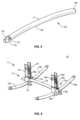
- Spinal rod 152extends between an end 154 and an end 156, as shown in FIG. 4 .
- End 154includes a surface 170 that defines a groove 172.
- Groove 172is configured to facilitate connection of a surgical instrument, such as, for example, a rod inserter 700, as described herein.
- Spinal rod 152includes a curvature C.
- spinal rod 152may have various cross sectional configurations, such as, for example, circular, oval, oblong, rectangular, triangular, square, polygonal, irregular, uniform, non-uniform, variable, tubular and/or tapered.
- the thickness defined by spinal rod 152may be uniformly increasing or decreasing, or have alternate diameter dimensions along its length.
- spinal rod 152may have various cross section configurations, such as, for example, oval, oblong, triangular, rectangular, square, polygonal, irregular, uniform, non-uniform, variable and/or tapered.
- spinal rod 152may extend in various configurations, such as, for example, linear, arcuate, curved, angular and/or pre-bent according to a selected configuration of vertebrae.
- spinal rod 152may have a semi-rigid, flexible or elastic configuration and/or have elastic and/or flexible properties similar to the properties from materials, such as, for example, fabric, silicone, polyurethane, silicone-polyurethane, copolymers, rubbers, polyolefin rubber, elastomers, thermoplastic elastomers, thermoset elastomers and elastomeric composites.
- spinal rod 152can include a plurality of separately attachable or connectable portions or sections, such as bands or loops, or may be monolithically formed as a single continuous element.
- spinal implant system 10In assembly, operation and use, spinal implant system 10, similar to the systems and methods described herein, is employed with a surgical procedure, as described herein, for treatment of a condition or injury of an affected section of the spine including vertebrae V, as shown in FIGS. 6-31 .
- Spinal implant system 10may be used in any existing surgical method or technique including open surgery, mini-open surgery, minimally invasive surgery and percutaneous surgical implantation, whereby vertebrae V are accessed through a micro-incision, or sleeve that provides a protected passageway to the area. Once access to the surgical site is obtained, the particular surgical procedure is performed for treating the spinal disorder. Spinal implant system 10 is then employed to augment the surgical treatment.
- a cutting instrument(not shown) creates a surgical pathway to access vertebrae V.
- the surgical pathwayis utilized for implantation of components of spinal implant system 10.
- a preparation instrument(not shown) can be employed to prepare tissue surfaces of vertebrae V, as well as for aspiration and irrigation of a surgical region.
- Bone fasteners 200are engaged with vertebrae V along a lateral side L of vertebrae V, as show in FIG. 6 .
- Spinal rod 150is delivered along the surgical pathway to a surgical site adjacent vertebrae V.
- Spinal rod 150is disposed with receivers 202 of bone fastener 200 along vertebrae V.
- spinal implant system 10includes a second set of bone fasteners 200a and spinal rod 150a delivered along the surgical pathway to the surgical site adjacent a contra-lateral side CL of vertebrae V.
- Spinal rod 150ais disposed with receivers 202a of bone fastener 200a along vertebrae V.
- Bone fasteners 200 and bone fasteners 200aare fixed with vertebrae V in a side by side orientation and/or a bi-lateral arrangement to stabilize vertebrae V and affect growth for a correction treatment to treat spine pathologies, as described herein.
- one or all of the components of spinal implant system 10can be delivered or implanted as a pre-assembled device or can be assembled in situ, in a selected order of assembly or the order of assembly of the particular components of spinal implant system 10 can be varied according to practitioner preference, patient anatomy or surgical procedure parameters.
- tab extenders 300are connected with tabs 44, 54, described herein.
- An extender cap 302is engaged with tab extenders 300, as shown in FIG. 7 .
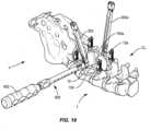
- Connector 12is delivered along the surgical pathway for connection with spinal rod 150, as shown in FIGS. 8-10 .
- Spinal rod 150is translated into cavity 16.
- Surface 160compresses tabs 60, 70 such that spinal rod 150 is snap fit with hook 18.
- Tips 62, 72form a friction fit between surface 160 and tips 60, 70 to provisionally fix spinal rod 150 with hook 16.
- the ruler 500may also be used under fluoroscopy, X-ray or similar imaging techniques to determine a length of rod 152.
- Tab extenders 300aare connected with tabs 44a, 54a, as shown in FIG. 9 .
- An extender cap 302ais engaged with tab extenders 300a.
- Connector 12ais delivered along the surgical pathway for connection with spinal rod 150a.
- Spinal rod 150ais translated into cavity 16a of connector 12a, similar to the components of connector 12 described herein.
- Surface 160acompresses tabs 60a, 70a such that spinal rod 150a is snap fit with hook 18a.
- Tips 62a, 72aform a friction fit between surface 160a and tips 60a, 70a to provisionally fix spinal rod 150a with hook 16a.
- a measuring devicesuch as, for example, a caliper 400 is utilized to determine a length of spinal rod 152, as shown in FIGS. 11 and 12 .
- Caliper 400is engaged with tab extenders 300, 300a such that a distance D1 between connectors 12, 12a can be determined, as shown in FIG. 12 . Determining distance D1 provides a length of rod 152 to link rods 150, 150a via connectors 12, 12a.
- a ruler 500is utilized to determine a length of spinal rod 152, as shown in FIGS. 13 and 14 .
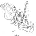
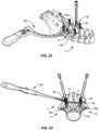
- a dilator 600is disposed with vertebrae V though a lateral approach, as shown in FIGS. 17-20 .
- Dilator 600is configured to provide a passageway for spinal rod 152 for engagement with connectors 12, 12a.
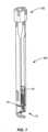
- a trocar 602, as shown in FIG. 15 , and/or a chisel 604, as shown in FIG. 16are engaged with dilator 600 to cut and/or disrupt tissue surfaces of vertebrae V for passage of spinal rod 152.
- trocar 602 and/or chisel 604are configured to cut and/or disrupt tissue to clear passageway through tissue, such as, for example, a spinous process and/or a supraspinatus ligament.
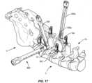
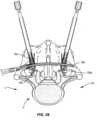
- a rod inserter 700is engaged with groove 172 of spinal rod 152, as shown in FIGS. 21-26 .
- Rod inserter 700directs and/or guides spinal rod 152 into cavity 34 of connector 12, laterally across vertebrae V, and into cavity 34a of connector 12a.
- a percutaneous endoscopic lumbar discectomyis utilized.
- End 154 of spinal rod 152is disposed with cavity 34 and end 156 of spinal rod 152 is disposed with cavity 34a, as shown in FIG. 23 .
- Spinal rod 152is initially inserted such that an apex of curvature C is oriented towards the spinal canal, as shown in FIGS. 22 and 23 .
- rod inserter 700Upon disposal of spinal rod 152 with cavities 34, 34a, rod inserter 700 is rotated, for example, 180 degrees to direct the apex of curvature away from the spinal canal to resist and/or prevent impingement of spinal rod 152 in the spinal canal, as shown in FIGS. 24-26 .
- a driver 800is utilized to engage a set screw 802 with connectors 12, 12a.
- Driver 802directs and/or guides set screw 802 through each of extender caps 302, 302a and tab extenders 300, 300a into engagement with connectors 12, 12a.
- Set screw 802engages arms 30, 32 and arms 30a, 32a to fix spinal rod 152 within each of cavities 34, 34a, as shown in FIGS. 27 and 28 .
- a tab hook counter torque handle 900 and a tab hook counter torque sleeve 901are engaged with tab extenders 300, 300a, as shown in FIG. 29 .
- Handle 900 and sleeve 901are configured to provide additional leverage to facilitate removing and/or separating a frangible or break off portion of set screw 802 at a selected torque limit.
- a break off handle 902is disposed with driver 800 and is manipulated to apply a force to set screw 802 for tightening and the torque limit for break off, as shown in FIG. 30 .
- Handle 902, sleeve 901 and/or handle 900are removed from each of extenders 300, 300a.
- a tab breaker 904is disposed with each of extenders 300, 300a, as shown in FIG. 31 .
- Tab breaker 904and is manipulated to apply a force to tabs 44, 54 and tabs 44a, 54a. As the force applied reaches a selected torque limit, tab breaker 902 breaks off tabs 44, 54 and tabs 44a, 54a from connectors 12, 12a, respectively.
- connectors 12, 12amay be employed in a surgical treatment such as a revision surgery to revise, repair and/or extend an existing spinal construct including, for example, bone fasteners 200, 200a, lateral spinal rod 150 and contra-lateral spinal rod 150a, as described herein.
- spinal implant system 10includes connectors 12, 12a employed in a revision surgery to connect with the existing spinal construct.
- the existing spinal constructmay include one or more implants connected or fixed with tissue in a prior or different surgical procedure, separate in time and/or over a duration of time in the same surgical procedure.
- spinal implant system 10may be completely or partially revised, removed or replaced.
- Spinal implant system 10can be made of radiolucent materials such as polymers. Radiomarkers may be included for identification under x-ray, fluoroscopy, CT or other imaging techniques. In some examples, the use of surgical navigation, microsurgical and image guided technologies may be employed to access, view and repair spinal deterioration or damage, with the aid of spinal implant system 10.
- spinal implant system 10may include one or a plurality of plates, connectors and/or bone fasteners for use with a single vertebral level or a plurality of vertebral levels.
- spinal implant system 10includes one or more fasteners, not shown, for attaching a spinal construct with tissue, as described herein.
- the fastenersmay be engaged with tissue in various orientations, such as, for example, series, parallel, offset, staggered and/or alternate vertebral levels.
- one or more of the fastenersmay comprise multi-axial screws, sagittal angulation screws, pedicle screws, mono-axial screws, uni-planar screws, facet screws, fixed screws, tissue penetrating screws, conventional screws, expanding screws, wedges, anchors, buttons, clips, snaps, friction fittings, compressive fittings, expanding rivets, staples, nails, adhesives, posts, fixation plates and/or posts.
- spinal implant system 10includes an agent, which may be disposed, packed, coated or layered within, on or about the components and/or surfaces of spinal implant system 10.
- the agentmay include bone growth promoting material, such as, for example, bone graft to enhance fixation of the components and/or surfaces of spinal implant system 10 with vertebrae.
- the agentmay include one or a plurality of therapeutic agents and/or pharmacological agents for release, including sustained release, to treat, for example, pain, inflammation and degeneration.
Landscapes
- Health & Medical Sciences (AREA)
- Orthopedic Medicine & Surgery (AREA)
- Life Sciences & Earth Sciences (AREA)
- Surgery (AREA)
- Neurology (AREA)
- Heart & Thoracic Surgery (AREA)
- General Health & Medical Sciences (AREA)
- Biomedical Technology (AREA)
- Nuclear Medicine, Radiotherapy & Molecular Imaging (AREA)
- Medical Informatics (AREA)
- Molecular Biology (AREA)
- Animal Behavior & Ethology (AREA)
- Engineering & Computer Science (AREA)
- Public Health (AREA)
- Veterinary Medicine (AREA)
- Oral & Maxillofacial Surgery (AREA)
- Pathology (AREA)
- Surgical Instruments (AREA)
- Prostheses (AREA)
Description
- The present disclosure generally relates to a spinal construct for the treatment of spinal disorders.
- Spinal pathologies and disorders such as scoliosis and other curvature abnormalities, kyphosis, degenerative disc disease, disc herniation, osteoporosis, spondylolisthesis, stenosis, tumor, and fracture may result from factors including trauma, disease and degenerative conditions caused by injury and aging. Spinal disorders typically result in symptoms including deformity, pain, nerve damage, and partial or complete loss of mobility.
- Non-surgical treatments, such as medication, rehabilitation and exercise can be effective, however, may fail to relieve the symptoms associated with these disorders. Surgical treatment of these spinal disorders includes fusion, fixation, correction, discectomy, laminectomy and implantable prosthetics. As part of these surgical treatments, spinal constructs, such as, for example, bone fasteners, spinal rods, connectors and plates can be used to provide stability to a treated region. During surgical treatment, one or more rods may be attached via fasteners to the exterior of two or more vertebral members to provide stability to a treated region. This disclosure describes an improvement over these prior technologies.
- According to
US 2016/058478 A1 , a spinal fixation device includes a device body configured for implantation in a human body and a clamp that is formed from shape memory material and attached to the device body. - According to
US 2007/213723 A1 , a cross-connector assembly construct and a method of locking comprises a flexible clip contacting a longitudinal member; a housing component contacting the flexible clip, wherein the housing component comprises a conical ramp towards a bottom end of the housing component; a locking mechanism contacting the housing component and adapted to engage the flexible clip; and a connecting member contacting the housing component US 2017/281247 A1 discloses connector assemblies, systems, and methods thereof.- According to
US 2007/173831 A1 , an instrument is adapted for placing a cross-member between a pair of bone screws. - According to
US 2012/253397 A1 , a rod connector for transversely connecting two vertebral column rods has two clamps and a transverse bridge that fixes the clamps to each other. WO 2014/151037 A1 discloses a hook with a rotating saddle and a rotatable mono axial pedicle screw.US 2016/143665 A1 discloses a receiving part for coupling a bone anchor to a rod and a bone anchoring device with such a receiving part.- The invention provides a spinal construct according to claim 1. Further embodiments are described in the dependent claims.
- Associated surgical methods are also described herein to aid understanding the invention.
- These methods do not form part of the claimed invention.
- The present disclosure will become more readily apparent from the specific description accompanied by the following drawings, in which:
FIG. 1 is a perspective view of components of one embodiment of a system in accordance with the principles of the present disclosure;FIG. 2 is a side view of the components shown inFIG. 1 ;FIG. 3 is a side view of the components shown inFIG. 1 ;FIG. 4 is a perspective view of components of one embodiment of a system in accordance with the principles of the present disclosure;FIG. 5 is a perspective view of components of one embodiment of a system in accordance with the principles of the present disclosure;FIG. 6 is a perspective view of components of one embodiment of a system in accordance with the principles of the present disclosure disposed with vertebrae;FIG. 7 is a perspective view of components of one embodiment of a system in accordance with the principles of the present disclosure;FIG. 8 is a plan view of components of one embodiment of a system in accordance with the principles of the present disclosure disposed with vertebrae;FIG. 9 is a plan view of components of one embodiment of a system in accordance with the principles of the present disclosure disposed with vertebrae;FIG. 10 is a perspective view of components of one embodiment of a system in accordance with the principles of the present disclosure disposed with vertebrae;FIG. 11 is a plan view of components of one embodiment of a system in accordance with the principles of the present disclosure disposed with vertebrae;FIG. 12 is a perspective view of the components and vertebrae shown inFIG. 11 ;FIG. 13 is a plan view of components of one embodiment of a system in accordance with the principles of the present disclosure disposed with vertebrae;FIG. 14 is a perspective view of the components and vertebrae shown inFIG. 13 ;FIG. 15 is a perspective view of components of one embodiment of a system in accordance with the principles of the present disclosure;FIG. 16 is a perspective view of components of one embodiment of a system in accordance with the principles of the present disclosure;FIG. 17 is a perspective view of components of one embodiment of a system in accordance with the principles of the present disclosure disposed with vertebrae;FIG. 18 is a side view of the components and vertebrae shown inFIG. 17 ;FIG. 19 is a perspective view of components of one embodiment of a system in accordance with the principles of the present disclosure disposed with vertebrae;FIG. 20 is a plan view of the components and vertebrae shown inFIG. 19 ;FIG. 21 is a plan view of components of one embodiment of a system in accordance with the principles of the present disclosure disposed with vertebrae;FIG. 22 is a perspective view of the components and vertebrae shown inFIG. 21 ;FIG. 23 is a plan view, in part cross section, of the components and vertebrae shown inFIG. 21 ;FIG. 24 is a plan view of the components and vertebrae shown inFIG. 21 ;FIG. 25 is a perspective view of the components and vertebrae shown inFIG. 21 ;FIG. 26 is a plan view, in part cross section, of the components and vertebrae shown inFIG. 21 ;FIG. 27 is a perspective view of components of one embodiment of a system in accordance with the principles of the present disclosure;FIG. 28 is a perspective view of components of one embodiment of a system in accordance with the principles of the present disclosure disposed with vertebrae;FIG. 29 is a perspective view of components of one embodiment of a system in accordance with the principles of the present disclosure disposed with vertebrae;FIG. 30 is a perspective view of components of one embodiment of a system in accordance with the principles of the present disclosure disposed with vertebrae; andFIG. 31 is a perspective view of components of one embodiment of a system in accordance with the principles of the present disclosure disposed with vertebrae.- The examples of the surgical system and related methods of use disclosed are discussed in terms of medical devices for the treatment of musculoskeletal disorders and more particularly, in terms of a surgical system and method for treatment of a spine disorder. In some examples, the systems and methods of the present disclosure are employed with a spinal joint fusion, for example, with a cervical, thoracic, lumbar and/or sacral region of a spine.
- In some embodiments, the present surgical system comprises a spinal construct including a connector and a cross-link spinal rod configured for percutaneous insertion. In some embodiments, the connector includes a hook portion configured for engagement with a lateral and/or a contra-lateral spinal rod. In some embodiments, the connector includes a tab extender configured to facilitate percutaneous insertion. In some embodiments, the connector includes a temporary locking mechanism, such as, for example, a provisional locking element to facilitate connection with a lateral and/or a contra-lateral spinal rod. In some embodiments, the surgical system includes a lateral connector and a contra-lateral connector to fix a cross-link spinal rod with a lateral and a contra-lateral spinal rod.
- In some examples, the present surgical system is employed with a method of use that includes the step of connecting tab extenders with a connector. In some examples, the surgical system is employed with a method of use that includes the step of percutaneously delivering the connector along a surgical pathway for connection with a lateral and/or a contra-lateral spinal rod. In some examples, a hook portion of the connector is engaged with a lateral and/or a contra-lateral spinal rod. In some examples, the connector is provisionally fixed with a lateral and/or a contra-lateral spinal rod. In some examples, the surgical system is employed with a method of use that includes the step of engaging a measuring device, such as, for example, a caliper or a ruler with tab extenders to determine a length of a cross-link spinal rod by measuring a distance between a lateral and/or a contra-lateral spinal rod.
- In some examples, the present surgical system is employed with a method of use that includes the step of inserting a dilator via a lateral approach to provide a passageway for insertion of a cross-link spinal rod. In some examples, a trocar and/or a chisel are engaged with a dilator to cut and/or disrupt tissue surfaces of vertebrae for passage of the cross-link spinal rod. In some examples, the trocar and/or chisel are configured to cut and/or disrupt tissue to clear a passageway through tissue, such as, for example, a spinous process and/or a supraspinatus ligament.
- In some examples, the present surgical system is employed with a method of use that includes the step of engaging a rod inserter with a cross-link spinal rod to direct and/or guide the cross-link spinal rod into engagement with the connectors. In some examples, the cross-link spinal rod is rotated, for example, 180 degrees. In some examples, the surgical system is employed with a method of use that includes the step of engaging a driver to a set screw with connectors to fix the cross-link spinal rod with the connectors. In some examples, an instrument is engaged with the connectors to break off tabs from the connectors.
- In some examples, the present surgical system includes a spinal construct that is employed with methods of connection to a multi-axial screw and rod interconnection. In some examples, the interconnection is within the rod slot or rod accepting feature of a multi-axial screw, hook, or other bony attachment anchor and can be below or on top of the rod, or around a set screw or locking member of the interconnection. In some examples, the spinal construct has a low profile and axial size configuration of the connection, which reduces the size of the spinal construct while providing versatility in connection. In some examples, the spinal construct reduces stress on a rod construct by removing an extra point of fixation on the segmental construct because the interconnection is within an existing interconnection. In some examples, this connection is useful when crosslinking and extending from a construct, and/or for screw extension connectors.
- The present disclosure may be understood more readily by reference to the following detailed description of the embodiments taken in connection with the accompanying drawing figures, which form a part of this disclosure.
- The following discussion includes a description of a surgical system and related methods (not claimed) of employing the surgical system in accordance with the principles of the present disclosure. Alternate embodiments are also disclosed. Reference is made in detail to the exemplary embodiments of the present disclosure, which are illustrated in the accompanying figures. Turning to
FIGS. 1-5 , there are illustrated components of a surgical system, such as, for example, aspinal implant system 10. - The components of
spinal implant system 10 can be fabricated from biologically acceptable materials suitable for medical applications, including metals, synthetic polymers, ceramics and bone material and/or their composites. For example, the components of spinal implant system 10, individually or collectively, can be fabricated from materials such as stainless steel alloys, aluminum, commercially pure titanium, titanium alloys, Grade 5 titanium, super-elastic titanium alloys, cobalt-chrome alloys, superelastic metallic alloys (e.g., Nitinol, super elasto-plastic metals, such as GUM METAL®), ceramics and composites thereof such as calcium phosphate (e.g., SKELITE™), thermoplastics such as polyaryletherketone (PAEK) including polyetheretherketone (PEEK), polyetherketoneketone (PEKK) and polyetherketone (PEK), carbon-PEEK composites, PEEK-BaSO4 polymeric rubbers, polyethylene terephthalate (PET), fabric, silicone, polyurethane, silicone-polyurethane copolymers, polymeric rubbers, polyolefin rubbers, hydrogels, semi-rigid and rigid materials, elastomers, rubbers, thermoplastic elastomers, thermoset elastomers, elastomeric composites, rigid polymers including polyphenylene, polyamide, polyimide, polyetherimide, polyethylene, epoxy, bone material including autograft, allograft, xenograft or transgenic cortical and/or corticocancellous bone, and tissue growth or differentiation factors, partially resorbable materials, such as, for example, composites of metals and calcium-based ceramics, composites of PEEK and calcium based ceramics, composites of PEEK with resorbable polymers, totally resorbable materials, such as, for example, calcium based ceramics such as calcium phosphate, tri-calcium phosphate (TCP), hydroxyapatite (HA)-TCP, calcium sulfate, or other resorbable polymers such as polyaetide, polyglycolide, polytyrosine carbonate, polycaroplaetohe and their combinations. - Various components of
spinal implant system 10 may have material composites, including the above materials, to achieve various desired characteristics such as strength, rigidity, elasticity, compliance, biomechanical performance, durability and radiolucency or imaging preference. The components ofspinal implant system 10, individually or collectively, may also be fabricated from a heterogeneous material such as a combination of two or more of the above-described materials. The components ofspinal implant system 10 may be monolithically formed, integrally connected or include fastening elements and/or instruments, as described herein. Spinal implant system 10 may be employed, for example, with minimally invasive procedures, including percutaneous techniques, mini-open surgical techniques and/or open surgical techniques to deliver and introduce instrumentation and/or implants, such as, for example, a spinal construct, at a surgical site within a subject body of a patient, which includes, for example, a spine having vertebrae V, as shown, for example, inFIGS. 6-31 . In some embodiments, the spinal constructs can include one or more bone fasteners, spinal rods, connectors and/or plates.Spinal implant system 10 includes aspinal construct 11 comprising a member, such as, for example, aconnector 12.Spinal implant system 10 includes alateral connector 12 engageable with a lateralspinal rod 150 and a contra-lateral connector 12a, similar toconnector 12 described herein, which is engageable with a contra-lateralspinal rod 150a (FIG. 6 ). A transversespinal rod 152 is configured to connectconnectors spinal rod 150 and contra-lateralspinal rod 150a, as described herein. In some embodiments,spinal rod 152 reduces stress on one or more components of the spinal construct includingspinal rods spinal rods rod 152 is within an existing interconnection ofspinal rods Connector 12 includes asurface 14 that defines animplant cavity 16, as shown inFIG. 1 .Surface 14 includes a protrusion, such as, for example, ahook 18 extending fromsurface 14.Hook 18 defines apassageway 20 configured to capture a spinal implant, such as, for example,spinal rod 150 withincavity 16.Passageway 20 extends along an axis A1. In some embodiments,cavity 16 may have various cross section configurations, such as, for example, oval, oblong, triangular, rectangular, square, polygonal, irregular, uniform, non-uniform, variable, tubular and/or tapered. In some embodiments,rod 150 is in co-axial or parallel alignment with axis A1 whenrod 150 is disposed incavity 16. In some embodiments,rod 150 is disposed transverse to axis A1 whenrod 150 is disposed incavity 16.Connector 12 includes a pair of spaced apartarms Arms U-shaped implant cavity 34 therebetween configured for disposal of a spinal implant, such as, for example,spinal rod 152.Cavity 34 extends along an axis A2 and extends transverse to axis A1, as shown inFIG. 2 . In some embodiments,arm 30,arm 32 and/orcavity 34 may be disposed at alternate orientations, relative to axis A1, such as, for example, perpendicular and/or other angular orientations such as acute or obtuse, co-axial and/or may be offset or staggered. In some embodiments,cavity 34 may have various cross section configurations, such as, for example, oval, oblong, triangular, rectangular, square, polygonal, irregular, uniform, non-uniform, variable, tubular and/or tapered. In some embodiments,rod 152 is in co-axial or parallel alignment with axis A2 whenrod 152 is disposed incavity 34. In some embodiments,rod 152 is disposed transverse to axis A2 whenrod 152 is disposed incavity 34.Arms thread form 38 configured for engagement with a coupling member, such as, for example, asetscrew 802 to retainspinal rod 152 withincavity 34, as shown inFIG. 5 . In some embodiments,arms Arm 30 extends between asurface 40 and asurface 42.Surface 40 includes a break awaytab 44 that is frangibly connected toarm 30 at aportion 46.Portion 46 is fabricated from a fracturing and/or frangible material such that manipulation oftab 44 relative toarm 30 can fracture andseparate tab 44 fromarm 30 alongportion 46 at a predetermined force and/or torque limit, as described herein.Arm 32 extends between asurface 50 and asurface 52.Surface 50 includes a break awaytab 54 that is frangibly connected toarm 32 at aportion 56.Portion 56 is fabricated from a fracturing and/or frangible material such that manipulation oftab 54 relative toarm 32 can fracture andseparate tab 54 fromarm 32 alongportion 56 at a predetermined force and/or torque limit, as described herein.- In some embodiments, as force and/or torque is applied to
tab 44, and/ortab 54 and resistance increases, for example, the predetermined torque and force limit is approached. In some embodiments,tab 44 and/ortab 54 are configured to facilitate reduction of one or more spinal rods, as described herein, with a bone fastener and/or vertebrae.Tabs bone connector 12 and facilitate disposal of one or more spinal rods withcavity 34. In some embodiments,tabs tabs arms tabs arms Surface 42 includes a lock, that is, aspring tab 60 configured to provisionally lockspinal rod 150 withconnector 12, as described herein.Tab 60 includes a surface, such as, for example, atip 62 configured to deflect, snap and/or bias into engagement withspinal rod 150 to form a friction fit between asurface 160 ofspinal rod 150 andtip 62.Tab 60 extends fromsurface 42 intocavity 16.Tab 60 is deflected inward upon engagement withspinal rod 150 such that the resultant bias forms a friction fit betweensurface 160 andtip 62.Surface 52 includes a lock, that is, aspring tab 70 configured to provisionally lockspinal rod 150 withconnector 12, as described herein.Tab 70 includes a surface, such as, for example, atip 72 configured to deflect, snap and/or bias into engagement withspinal rod 150 to form a friction fit between asurface 160 ofspinal rod 150 andtip 72.Tab 70 extends fromsurface 52 intocavity 16.Tab 70 is deflected inward upon engagement withspinal rod 150 such that the resultant bias forms a friction fit betweensurface 160 andtip 72.Tabs connector 12 withspinal rod 150.Tabs connector 12 withspinal rod 150 to maintain a position ofconnector 12 during insertion and/or engagement ofspinal rod 152 withcavity 34. Afterspinal rod 152 is disposed withcavity 34, setscrew 802 is engaged withconnector 12 to fixconnector 12 withspinal rod 150.Tabs connector 12. In some embodiments,tabs tabs tabs spinal rod 150. In some embodiments,tabs tabs tabs Spinal rod 152 extends between anend 154 and anend 156, as shown inFIG. 4 .End 154 includes asurface 170 that defines agroove 172.Groove 172 is configured to facilitate connection of a surgical instrument, such as, for example, arod inserter 700, as described herein.Spinal rod 152 includes a curvature C. In some embodiments,spinal rod 152 may have various cross sectional configurations, such as, for example, circular, oval, oblong, rectangular, triangular, square, polygonal, irregular, uniform, non-uniform, variable, tubular and/or tapered. In some embodiments, the thickness defined byspinal rod 152 may be uniformly increasing or decreasing, or have alternate diameter dimensions along its length. In some embodiments,spinal rod 152 may have various cross section configurations, such as, for example, oval, oblong, triangular, rectangular, square, polygonal, irregular, uniform, non-uniform, variable and/or tapered. In some embodiments,spinal rod 152 may extend in various configurations, such as, for example, linear, arcuate, curved, angular and/or pre-bent according to a selected configuration of vertebrae.- In some examples, all or only a portion of
spinal rod 152 may have a semi-rigid, flexible or elastic configuration and/or have elastic and/or flexible properties similar to the properties from materials, such as, for example, fabric, silicone, polyurethane, silicone-polyurethane, copolymers, rubbers, polyolefin rubber, elastomers, thermoplastic elastomers, thermoset elastomers and elastomeric composites. In some embodiments,spinal rod 152 can include a plurality of separately attachable or connectable portions or sections, such as bands or loops, or may be monolithically formed as a single continuous element. - In assembly, operation and use,
spinal implant system 10, similar to the systems and methods described herein, is employed with a surgical procedure, as described herein, for treatment of a condition or injury of an affected section of the spine including vertebrae V, as shown inFIGS. 6-31 . - In use, to treat the affected section of the spine, a medical practitioner obtains access to a surgical site including vertebrae V in any appropriate manner, such as through incision and retraction of tissues.
Spinal implant system 10, includingspinal construct 11 described herein, may be used in any existing surgical method or technique including open surgery, mini-open surgery, minimally invasive surgery and percutaneous surgical implantation, whereby vertebrae V are accessed through a micro-incision, or sleeve that provides a protected passageway to the area. Once access to the surgical site is obtained, the particular surgical procedure is performed for treating the spinal disorder.Spinal implant system 10 is then employed to augment the surgical treatment. - An incision is made in the body of a patient and a cutting instrument (not shown) creates a surgical pathway to access vertebrae V. The surgical pathway is utilized for implantation of components of
spinal implant system 10. A preparation instrument (not shown) can be employed to prepare tissue surfaces of vertebrae V, as well as for aspiration and irrigation of a surgical region. Bone fasteners 200 are engaged with vertebrae V along a lateral side L of vertebrae V, as show inFIG. 6 .Spinal rod 150 is delivered along the surgical pathway to a surgical site adjacent vertebraeV. Spinal rod 150 is disposed withreceivers 202 ofbone fastener 200 along vertebrae V. In some examples,spinal implant system 10 includes a second set ofbone fasteners 200a andspinal rod 150a delivered along the surgical pathway to the surgical site adjacent a contra-lateral side CL of vertebraeV. Spinal rod 150a is disposed withreceivers 202a ofbone fastener 200a along vertebrae V.Bone fasteners 200 andbone fasteners 200a are fixed with vertebrae V in a side by side orientation and/or a bi-lateral arrangement to stabilize vertebrae V and affect growth for a correction treatment to treat spine pathologies, as described herein. In some examples, one or all of the components ofspinal implant system 10 can be delivered or implanted as a pre-assembled device or can be assembled in situ, in a selected order of assembly or the order of assembly of the particular components ofspinal implant system 10 can be varied according to practitioner preference, patient anatomy or surgical procedure parameters.- In some examples,
tab extenders 300 are connected withtabs extender cap 302 is engaged withtab extenders 300, as shown inFIG. 7 .Connector 12 is delivered along the surgical pathway for connection withspinal rod 150, as shown inFIGS. 8-10 .Spinal rod 150 is translated intocavity 16.Surface 160 compressestabs spinal rod 150 is snap fit withhook 18.Tips surface 160 andtips spinal rod 150 withhook 16. Theruler 500 may also be used under fluoroscopy, X-ray or similar imaging techniques to determine a length ofrod 152. Tab extenders 300a are connected withtabs FIG. 9 . Anextender cap 302a is engaged withtab extenders 300a.Connector 12a is delivered along the surgical pathway for connection withspinal rod 150a.Spinal rod 150a is translated intocavity 16a ofconnector 12a, similar to the components ofconnector 12 described herein.Surface 160a compressestabs 60a, 70a such thatspinal rod 150a is snap fit withhook 18a. Tips 62a, 72a form a friction fit betweensurface 160a andtips 60a, 70a to provisionally fixspinal rod 150a withhook 16a.- In some embodiments, a measuring device, such as, for example, a
caliper 400 is utilized to determine a length ofspinal rod 152, as shown inFIGS. 11 and12 .Caliper 400 is engaged withtab extenders connectors FIG. 12 . Determining distance D1 provides a length ofrod 152 to linkrods connectors ruler 500 is utilized to determine a length ofspinal rod 152, as shown inFIGS. 13 and14 . - In some examples, a
dilator 600 is disposed with vertebrae V though a lateral approach, as shown inFIGS. 17-20 .Dilator 600 is configured to provide a passageway forspinal rod 152 for engagement withconnectors trocar 602, as shown inFIG. 15 , and/or achisel 604, as shown inFIG. 16 , are engaged withdilator 600 to cut and/or disrupt tissue surfaces of vertebrae V for passage ofspinal rod 152. In some examples,trocar 602 and/or chisel 604 are configured to cut and/or disrupt tissue to clear passageway through tissue, such as, for example, a spinous process and/or a supraspinatus ligament. - In some examples, a
rod inserter 700 is engaged withgroove 172 ofspinal rod 152, as shown inFIGS. 21-26 .Rod inserter 700 directs and/or guidesspinal rod 152 intocavity 34 ofconnector 12, laterally across vertebrae V, and intocavity 34a ofconnector 12a. In some examples, a percutaneous endoscopic lumbar discectomy is utilized.End 154 ofspinal rod 152 is disposed withcavity 34 and end 156 ofspinal rod 152 is disposed withcavity 34a, as shown inFIG. 23 .Spinal rod 152 is initially inserted such that an apex of curvature C is oriented towards the spinal canal, as shown inFIGS. 22 and 23 . Upon disposal ofspinal rod 152 withcavities rod inserter 700 is rotated, for example, 180 degrees to direct the apex of curvature away from the spinal canal to resist and/or prevent impingement ofspinal rod 152 in the spinal canal, as shown inFIGS. 24-26 . - In some examples, a
driver 800 is utilized to engage aset screw 802 withconnectors Driver 802 directs and/or guides setscrew 802 through each of extender caps 302, 302a andtab extenders connectors screw 802 engagesarms spinal rod 152 within each ofcavities FIGS. 27 and 28 . In some examples, a tab hookcounter torque handle 900 and a tab hookcounter torque sleeve 901 are engaged withtab extenders FIG. 29 . Handle 900 andsleeve 901 are configured to provide additional leverage to facilitate removing and/or separating a frangible or break off portion ofset screw 802 at a selected torque limit. A break offhandle 902 is disposed withdriver 800 and is manipulated to apply a force to setscrew 802 for tightening and the torque limit for break off, as shown inFIG. 30 . - Handle 902,
sleeve 901 and/or handle 900 are removed from each ofextenders tab breaker 904 is disposed with each ofextenders FIG. 31 .Tab breaker 904 and is manipulated to apply a force totabs tabs tab breaker 902 breaks offtabs tabs connectors - In some examples,
connectors bone fasteners spinal rod 150 and contra-lateralspinal rod 150a, as described herein. In some examples,spinal implant system 10 includesconnectors spinal implant system 10 may be completely or partially revised, removed or replaced. - Upon completion of the procedure, the surgical instruments, assemblies and non-implanted components of
spinal implant system 10 are removed and the incision is closed.Spinal implant system 10 can be made of radiolucent materials such as polymers. Radiomarkers may be included for identification under x-ray, fluoroscopy, CT or other imaging techniques. In some examples, the use of surgical navigation, microsurgical and image guided technologies may be employed to access, view and repair spinal deterioration or damage, with the aid ofspinal implant system 10. In some examples,spinal implant system 10 may include one or a plurality of plates, connectors and/or bone fasteners for use with a single vertebral level or a plurality of vertebral levels. - In some examples,
spinal implant system 10 includes one or more fasteners, not shown, for attaching a spinal construct with tissue, as described herein. In some examples, the fasteners may be engaged with tissue in various orientations, such as, for example, series, parallel, offset, staggered and/or alternate vertebral levels. In some examples, one or more of the fasteners may comprise multi-axial screws, sagittal angulation screws, pedicle screws, mono-axial screws, uni-planar screws, facet screws, fixed screws, tissue penetrating screws, conventional screws, expanding screws, wedges, anchors, buttons, clips, snaps, friction fittings, compressive fittings, expanding rivets, staples, nails, adhesives, posts, fixation plates and/or posts. - In one example,
spinal implant system 10 includes an agent, which may be disposed, packed, coated or layered within, on or about the components and/or surfaces ofspinal implant system 10. In some examples, the agent may include bone growth promoting material, such as, for example, bone graft to enhance fixation of the components and/or surfaces ofspinal implant system 10 with vertebrae. In some examples, the agent may include one or a plurality of therapeutic agents and/or pharmacological agents for release, including sustained release, to treat, for example, pain, inflammation and degeneration.
Claims (11)
- A spinal construct (11) comprising:at least one member (12) that defines a first implant cavity (16) and a second implant cavity (34) oriented transverse to the first implant cavity (16),the at least one member (12) having a surface that includes a lock disposed with the first implant cavity (16),wherein the lock comprises a first spring tab (60) and a second spring tab (70) engageable with a spinal rod (150) and extending into the first implant cavity (16),wherein the at least one member (12) includes spaced apart arms (30, 32), including a first arm (30) and a second arm (32), that define the second implant cavity (34), andwherein the first arm (30) includes the first spring tab (60) and the second arm (32) includes the second spring tab (70).
- A spinal construct (11) as recited in Claim 1, wherein the at least one member (12) includes a hook configuration that defines the first implant cavity (16).
- A spinal construct (11) as recited in either Claim 1 or 2, wherein the lock comprises a provisional locking element.
- A spinal construct (11) as recited in any of Claims 1 through 3, wherein the lock comprises a resiliently biased element.
- A spinal construct (11) as recited in any of Claims 1 through 4, wherein the lock is monolithically formed with the at least one member (12).
- A spinal construct (11) as recited in any of Claims 1 through 5, each of the arms (30, 32) including a break away tab (44, 54).
- A spinal construct (11) as recited in any of Claims 1 through 6, wherein the at least one member (12) includes a lateral member (12) and a contra-lateral member (12a).
- A spinal construct (11) as recited in any of Claims 1 through 7, further comprising an existing spinal rod provisionally locked with the first implant cavity (16) and a transverse spinal rod (152) disposable with the second implant cavity (34).
- A spinal construct (11) as recited in Claim 8, further comprising a coupling member engageable with the at least one member (12) and the transverse spinal rod (152) to fix the spinal rods with the at least one member (12).
- A spinal construct (11) as recited in any of Claims 1 through 9, further comprising a measuring device configured to measure a distance between a pair of spinal rods.
- A spinal construct (11) as recited in Claim 10, wherein the measuring device is configured to measure the distance under various imaging techniques.
Applications Claiming Priority (1)
| Application Number | Priority Date | Filing Date | Title |
|---|---|---|---|
| PCT/JP2018/031057WO2020035958A1 (en) | 2018-08-16 | 2018-08-16 | Spinal implant system and method |
Publications (3)
| Publication Number | Publication Date |
|---|---|
| EP3836858A1 EP3836858A1 (en) | 2021-06-23 |
| EP3836858A4 EP3836858A4 (en) | 2022-04-13 |
| EP3836858B1true EP3836858B1 (en) | 2024-08-14 |
Family
ID=69525342
Family Applications (1)
| Application Number | Title | Priority Date | Filing Date |
|---|---|---|---|
| EP18929944.9AActiveEP3836858B1 (en) | 2018-08-16 | 2018-08-16 | Spinal implant system |
Country Status (5)
| Country | Link |
|---|---|
| US (1) | US11602381B2 (en) |
| EP (1) | EP3836858B1 (en) |
| JP (1) | JP2022501089A (en) |
| CN (1) | CN112804953B (en) |
| WO (1) | WO2020035958A1 (en) |
Families Citing this family (1)
| Publication number | Priority date | Publication date | Assignee | Title |
|---|---|---|---|---|
| US20250072939A1 (en)* | 2023-08-29 | 2025-03-06 | Oluwatodimu Richard Raji | Percutaneous Minimally Invasive Cross Connector System |
Family Cites Families (28)
| Publication number | Priority date | Publication date | Assignee | Title |
|---|---|---|---|---|
| FR2659225B1 (en)* | 1990-03-08 | 1995-09-08 | Sofamor | TRANSVERSE FIXING DEVICE FOR PROVIDING A RIGID CROSS-LINK BETWEEN TWO RODS OF A SPINAL OSTEOSYNTHESIS SYSTEM. |
| US5676665A (en)* | 1995-06-23 | 1997-10-14 | Bryan; Donald W. | Spinal fixation apparatus and method |
| FR2749156B1 (en)* | 1996-06-03 | 1998-12-04 | Stryker France Sa | DEVICE FOR RIGID TRANSVERSE CONNECTION BETWEEN TWO RODS OF OSTEOSYNTHESIS OF THE RACHIS |
| US6740089B2 (en)* | 2002-01-10 | 2004-05-25 | Thomas T. Haider | Orthopedic hook system |
| US20070225713A1 (en)* | 2004-10-20 | 2007-09-27 | Moti Altarac | Systems and methods for posterior dynamic stabilization of the spine |
| US8226689B2 (en)* | 2005-09-23 | 2012-07-24 | Zimmer Spine, Inc. | Apparatus and methods for spinal implant with variable link mechanism |
| US20070173831A1 (en) | 2005-11-14 | 2007-07-26 | Abdou M S | Device and method for the placement of spinal fixators |
| US7833248B2 (en) | 2006-03-10 | 2010-11-16 | Custom Spine, Inc. | Spinal cross-connector |
| US8313514B2 (en)* | 2006-05-15 | 2012-11-20 | Warsaw Orthopedic, Inc. | Device for interconnection of components in a spinal implant assembly |
| WO2011069963A2 (en) | 2009-12-10 | 2011-06-16 | Kilian Kraus | Rod connector |
| US9381044B2 (en)* | 2010-01-26 | 2016-07-05 | Pioneer Surgical Technology, Inc. | Posterior spinal stabilization plate device |
| EP2684533B1 (en)* | 2012-07-09 | 2016-03-16 | Zimmer Spine | Anchor for attachment to a bony structure |
| US9023087B2 (en)* | 2012-11-09 | 2015-05-05 | Blackstone Medical, Inc. | Percutaneous modular head-to-head cross connector |
| US9827020B2 (en) | 2013-03-14 | 2017-11-28 | Stryker European Holdings I, Llc | Percutaneous spinal cross link system and method |
| US9801664B2 (en)* | 2013-03-15 | 2017-10-31 | Blackstone Medical, Inc. | Hook with rotating saddle and rotatable mono axial pedicle screw |
| WO2014176507A1 (en)* | 2013-04-25 | 2014-10-30 | The University Of Toledo | Stabilized spinal fixation device |
| JP2016539762A (en)* | 2013-10-31 | 2016-12-22 | ザ ユニバーシティ オブ アイオワ リサーチ ファウンデーションThe University of Iowa Research Foundation | Transcutaneous lateral connector system |
| EP3023064B1 (en) | 2014-11-20 | 2019-01-09 | Biedermann Technologies GmbH & Co. KG | Receiving part for coupling a bone anchor to a rod and bone anchoring device with such a receiving part |
| US9603634B1 (en)* | 2015-11-13 | 2017-03-28 | Amendia, Inc. | Percutaneous rod-to-rod cross connector |
| ITUB20156292A1 (en)* | 2015-12-03 | 2017-06-03 | Medacta Int Sa | CONNECTION ELEMENT BETWEEN BARS IN A SPINOSY RECONSTRUCTION SYSTEM |
| US9895235B2 (en)* | 2015-12-18 | 2018-02-20 | Warsaw Orthopedic, Inc. | Spinal implant system and method |
| US10905473B2 (en)* | 2016-02-15 | 2021-02-02 | Asro Medical | Transverse, and surgical instrument |
| WO2017156382A1 (en)* | 2016-03-10 | 2017-09-14 | Nuvasive, Inc. | Bone anchor with deployable purchase element |
| US10383663B2 (en) | 2016-03-29 | 2019-08-20 | Globus Medical, Inc. | Revision connectors, systems and methods thereof |
| US10624679B2 (en)* | 2016-03-29 | 2020-04-21 | Globus Medical, Inc. | Revision connectors, systems and methods thereof |
| US10478233B2 (en)* | 2016-11-16 | 2019-11-19 | Alphatec Spine, Inc. | Adjustable hook |
| WO2018187797A1 (en)* | 2017-04-07 | 2018-10-11 | K2M, Inc. | Transverse connector |
| US11344333B2 (en)* | 2017-08-10 | 2022-05-31 | Mizuho Corporation | Bone fixation device |
- 2018
- 2018-08-16WOPCT/JP2018/031057patent/WO2020035958A1/ennot_activeCeased
- 2018-08-16EPEP18929944.9Apatent/EP3836858B1/enactiveActive
- 2018-08-16CNCN201880096591.3Apatent/CN112804953B/enactiveActive
- 2018-08-16USUS17/268,868patent/US11602381B2/enactiveActive
- 2018-08-16JPJP2021506003Apatent/JP2022501089A/enactivePending
Also Published As
| Publication number | Publication date |
|---|---|
| WO2020035958A1 (en) | 2020-02-20 |
| CN112804953B (en) | 2025-05-16 |
| US20210298798A1 (en) | 2021-09-30 |
| US11602381B2 (en) | 2023-03-14 |
| EP3836858A1 (en) | 2021-06-23 |
| CN112804953A (en) | 2021-05-14 |
| EP3836858A4 (en) | 2022-04-13 |
| JP2022501089A (en) | 2022-01-06 |
Similar Documents
| Publication | Publication Date | Title |
|---|---|---|
| EP3525700B1 (en) | Spinal implant system | |
| US10172650B2 (en) | Spinal implant system and method | |
| US9872711B2 (en) | Spinal implant system and method | |
| US8016832B2 (en) | Installation systems for spinal stabilization system and related methods | |
| EP2884923B1 (en) | Spinal implant system | |
| EP3829467B1 (en) | Spinal implant system | |
| EP2804551B1 (en) | Vertebral fastener system | |
| EP3352692B1 (en) | Spinal implant system and method | |
| US20210106364A1 (en) | Spinal implant system and method | |
| EP3958760B1 (en) | Surgical system | |
| EP3958757B1 (en) | Surgical system | |
| EP3876850B1 (en) | Spinal implant system | |
| EP3958766B1 (en) | Spinal implant system | |
| US9848919B2 (en) | Spinal construct and methods of use | |
| EP3955838B1 (en) | Spinal implant system | |
| EP3836858B1 (en) | Spinal implant system | |
| EP3952766B1 (en) | Spinal implant | |
| EP3826560B1 (en) | Spinal implant system | |
| US9693809B2 (en) | Spinal correction implant system and method | |
| EP4088675B1 (en) | Top loading quick lock construct | |
| US20160324557A1 (en) | Surgical implant system and method of use | |
| US20150157362A1 (en) | Spinal implant system and method | |
| US20170209183A1 (en) | Surgical implant and method of use | |
| US9848928B2 (en) | Spinal implant system and methods of use | |
| CN113164194A (en) | Surgical implant and method of use |
Legal Events
| Date | Code | Title | Description |
|---|---|---|---|
| STAA | Information on the status of an ep patent application or granted ep patent | Free format text:STATUS: THE INTERNATIONAL PUBLICATION HAS BEEN MADE | |
| PUAI | Public reference made under article 153(3) epc to a published international application that has entered the european phase | Free format text:ORIGINAL CODE: 0009012 | |
| STAA | Information on the status of an ep patent application or granted ep patent | Free format text:STATUS: REQUEST FOR EXAMINATION WAS MADE | |
| 17P | Request for examination filed | Effective date:20210311 | |
| AK | Designated contracting states | Kind code of ref document:A1 Designated state(s):AL AT BE BG CH CY CZ DE DK EE ES FI FR GB GR HR HU IE IS IT LI LT LU LV MC MK MT NL NO PL PT RO RS SE SI SK SM TR | |
| DAV | Request for validation of the european patent (deleted) | ||
| DAX | Request for extension of the european patent (deleted) | ||
| A4 | Supplementary search report drawn up and despatched | Effective date:20220311 | |
| RIC1 | Information provided on ipc code assigned before grant | Ipc:A61B 90/00 20160101ALI20220305BHEP Ipc:A61B 17/88 20060101ALI20220305BHEP Ipc:A61B 17/70 20060101AFI20220305BHEP | |
| GRAP | Despatch of communication of intention to grant a patent | Free format text:ORIGINAL CODE: EPIDOSNIGR1 | |
| STAA | Information on the status of an ep patent application or granted ep patent | Free format text:STATUS: GRANT OF PATENT IS INTENDED | |
| INTG | Intention to grant announced | Effective date:20240304 | |
| GRAS | Grant fee paid | Free format text:ORIGINAL CODE: EPIDOSNIGR3 | |
| GRAA | (expected) grant | Free format text:ORIGINAL CODE: 0009210 | |
| STAA | Information on the status of an ep patent application or granted ep patent | Free format text:STATUS: THE PATENT HAS BEEN GRANTED | |
| AK | Designated contracting states | Kind code of ref document:B1 Designated state(s):AL AT BE BG CH CY CZ DE DK EE ES FI FR GB GR HR HU IE IS IT LI LT LU LV MC MK MT NL NO PL PT RO RS SE SI SK SM TR | |
| REG | Reference to a national code | Ref country code:GB Ref legal event code:FG4D | |
| REG | Reference to a national code | Ref country code:CH Ref legal event code:EP | |
| REG | Reference to a national code | Ref country code:DE Ref legal event code:R096 Ref document number:602018073237 Country of ref document:DE | |
| REG | Reference to a national code | Ref country code:IE Ref legal event code:FG4D | |
| PGFP | Annual fee paid to national office [announced via postgrant information from national office to epo] | Ref country code:DE Payment date:20240819 Year of fee payment:7 | |
| PGFP | Annual fee paid to national office [announced via postgrant information from national office to epo] | Ref country code:FR Payment date:20240919 Year of fee payment:7 | |
| REG | Reference to a national code | Ref country code:LT Ref legal event code:MG9D | |
| REG | Reference to a national code | Ref country code:NL Ref legal event code:MP Effective date:20240814 | |
| PG25 | Lapsed in a contracting state [announced via postgrant information from national office to epo] | Ref country code:NO Free format text:LAPSE BECAUSE OF FAILURE TO SUBMIT A TRANSLATION OF THE DESCRIPTION OR TO PAY THE FEE WITHIN THE PRESCRIBED TIME-LIMIT Effective date:20241114 | |
| REG | Reference to a national code | Ref country code:AT Ref legal event code:MK05 Ref document number:1712545 Country of ref document:AT Kind code of ref document:T Effective date:20240814 | |
| PG25 | Lapsed in a contracting state [announced via postgrant information from national office to epo] | Ref country code:FI Free format text:LAPSE BECAUSE OF FAILURE TO SUBMIT A TRANSLATION OF THE DESCRIPTION OR TO PAY THE FEE WITHIN THE PRESCRIBED TIME-LIMIT Effective date:20240814 Ref country code:NL Free format text:LAPSE BECAUSE OF FAILURE TO SUBMIT A TRANSLATION OF THE DESCRIPTION OR TO PAY THE FEE WITHIN THE PRESCRIBED TIME-LIMIT Effective date:20240814 Ref country code:GR Free format text:LAPSE BECAUSE OF FAILURE TO SUBMIT A TRANSLATION OF THE DESCRIPTION OR TO PAY THE FEE WITHIN THE PRESCRIBED TIME-LIMIT Effective date:20241115 Ref country code:PT Free format text:LAPSE BECAUSE OF FAILURE TO SUBMIT A TRANSLATION OF THE DESCRIPTION OR TO PAY THE FEE WITHIN THE PRESCRIBED TIME-LIMIT Effective date:20241216 Ref country code:PL Free format text:LAPSE BECAUSE OF FAILURE TO SUBMIT A TRANSLATION OF THE DESCRIPTION OR TO PAY THE FEE WITHIN THE PRESCRIBED TIME-LIMIT Effective date:20240814 | |
| PG25 | Lapsed in a contracting state [announced via postgrant information from national office to epo] | Ref country code:BG Free format text:LAPSE BECAUSE OF FAILURE TO SUBMIT A TRANSLATION OF THE DESCRIPTION OR TO PAY THE FEE WITHIN THE PRESCRIBED TIME-LIMIT Effective date:20240814 | |
| PG25 | Lapsed in a contracting state [announced via postgrant information from national office to epo] | Ref country code:LV Free format text:LAPSE BECAUSE OF FAILURE TO SUBMIT A TRANSLATION OF THE DESCRIPTION OR TO PAY THE FEE WITHIN THE PRESCRIBED TIME-LIMIT Effective date:20240814 | |
| PG25 | Lapsed in a contracting state [announced via postgrant information from national office to epo] | Ref country code:IS Free format text:LAPSE BECAUSE OF FAILURE TO SUBMIT A TRANSLATION OF THE DESCRIPTION OR TO PAY THE FEE WITHIN THE PRESCRIBED TIME-LIMIT Effective date:20241214 Ref country code:AT Free format text:LAPSE BECAUSE OF FAILURE TO SUBMIT A TRANSLATION OF THE DESCRIPTION OR TO PAY THE FEE WITHIN THE PRESCRIBED TIME-LIMIT Effective date:20240814 | |
| PG25 | Lapsed in a contracting state [announced via postgrant information from national office to epo] | Ref country code:HR Free format text:LAPSE BECAUSE OF FAILURE TO SUBMIT A TRANSLATION OF THE DESCRIPTION OR TO PAY THE FEE WITHIN THE PRESCRIBED TIME-LIMIT Effective date:20240814 | |
| PG25 | Lapsed in a contracting state [announced via postgrant information from national office to epo] | Ref country code:RS Free format text:LAPSE BECAUSE OF FAILURE TO SUBMIT A TRANSLATION OF THE DESCRIPTION OR TO PAY THE FEE WITHIN THE PRESCRIBED TIME-LIMIT Effective date:20241114 Ref country code:ES Free format text:LAPSE BECAUSE OF FAILURE TO SUBMIT A TRANSLATION OF THE DESCRIPTION OR TO PAY THE FEE WITHIN THE PRESCRIBED TIME-LIMIT Effective date:20240814 | |
| PG25 | Lapsed in a contracting state [announced via postgrant information from national office to epo] | Ref country code:RS Free format text:LAPSE BECAUSE OF FAILURE TO SUBMIT A TRANSLATION OF THE DESCRIPTION OR TO PAY THE FEE WITHIN THE PRESCRIBED TIME-LIMIT Effective date:20241114 Ref country code:PT Free format text:LAPSE BECAUSE OF FAILURE TO SUBMIT A TRANSLATION OF THE DESCRIPTION OR TO PAY THE FEE WITHIN THE PRESCRIBED TIME-LIMIT Effective date:20241216 Ref country code:PL Free format text:LAPSE BECAUSE OF FAILURE TO SUBMIT A TRANSLATION OF THE DESCRIPTION OR TO PAY THE FEE WITHIN THE PRESCRIBED TIME-LIMIT Effective date:20240814 Ref country code:NO Free format text:LAPSE BECAUSE OF FAILURE TO SUBMIT A TRANSLATION OF THE DESCRIPTION OR TO PAY THE FEE WITHIN THE PRESCRIBED TIME-LIMIT Effective date:20241114 Ref country code:NL Free format text:LAPSE BECAUSE OF FAILURE TO SUBMIT A TRANSLATION OF THE DESCRIPTION OR TO PAY THE FEE WITHIN THE PRESCRIBED TIME-LIMIT Effective date:20240814 Ref country code:LV Free format text:LAPSE BECAUSE OF FAILURE TO SUBMIT A TRANSLATION OF THE DESCRIPTION OR TO PAY THE FEE WITHIN THE PRESCRIBED TIME-LIMIT Effective date:20240814 Ref country code:IS Free format text:LAPSE BECAUSE OF FAILURE TO SUBMIT A TRANSLATION OF THE DESCRIPTION OR TO PAY THE FEE WITHIN THE PRESCRIBED TIME-LIMIT Effective date:20241214 Ref country code:HR Free format text:LAPSE BECAUSE OF FAILURE TO SUBMIT A TRANSLATION OF THE DESCRIPTION OR TO PAY THE FEE WITHIN THE PRESCRIBED TIME-LIMIT Effective date:20240814 Ref country code:GR Free format text:LAPSE BECAUSE OF FAILURE TO SUBMIT A TRANSLATION OF THE DESCRIPTION OR TO PAY THE FEE WITHIN THE PRESCRIBED TIME-LIMIT Effective date:20241115 Ref country code:FI Free format text:LAPSE BECAUSE OF FAILURE TO SUBMIT A TRANSLATION OF THE DESCRIPTION OR TO PAY THE FEE WITHIN THE PRESCRIBED TIME-LIMIT Effective date:20240814 Ref country code:ES Free format text:LAPSE BECAUSE OF FAILURE TO SUBMIT A TRANSLATION OF THE DESCRIPTION OR TO PAY THE FEE WITHIN THE PRESCRIBED TIME-LIMIT Effective date:20240814 Ref country code:BG Free format text:LAPSE BECAUSE OF FAILURE TO SUBMIT A TRANSLATION OF THE DESCRIPTION OR TO PAY THE FEE WITHIN THE PRESCRIBED TIME-LIMIT Effective date:20240814 Ref country code:AT Free format text:LAPSE BECAUSE OF FAILURE TO SUBMIT A TRANSLATION OF THE DESCRIPTION OR TO PAY THE FEE WITHIN THE PRESCRIBED TIME-LIMIT Effective date:20240814 | |
| REG | Reference to a national code | Ref country code:CH Ref legal event code:PL | |
| PG25 | Lapsed in a contracting state [announced via postgrant information from national office to epo] | Ref country code:SM Free format text:LAPSE BECAUSE OF FAILURE TO SUBMIT A TRANSLATION OF THE DESCRIPTION OR TO PAY THE FEE WITHIN THE PRESCRIBED TIME-LIMIT Effective date:20240814 Ref country code:RO Free format text:LAPSE BECAUSE OF FAILURE TO SUBMIT A TRANSLATION OF THE DESCRIPTION OR TO PAY THE FEE WITHIN THE PRESCRIBED TIME-LIMIT Effective date:20240814 Ref country code:DK Free format text:LAPSE BECAUSE OF FAILURE TO SUBMIT A TRANSLATION OF THE DESCRIPTION OR TO PAY THE FEE WITHIN THE PRESCRIBED TIME-LIMIT Effective date:20240814 | |
| PG25 | Lapsed in a contracting state [announced via postgrant information from national office to epo] | Ref country code:LU Free format text:LAPSE BECAUSE OF NON-PAYMENT OF DUE FEES Effective date:20240816 | |
| PG25 | Lapsed in a contracting state [announced via postgrant information from national office to epo] | Ref country code:CH Free format text:LAPSE BECAUSE OF NON-PAYMENT OF DUE FEES Effective date:20240831 Ref country code:EE Free format text:LAPSE BECAUSE OF FAILURE TO SUBMIT A TRANSLATION OF THE DESCRIPTION OR TO PAY THE FEE WITHIN THE PRESCRIBED TIME-LIMIT Effective date:20240814 | |
| PG25 | Lapsed in a contracting state [announced via postgrant information from national office to epo] | Ref country code:CZ Free format text:LAPSE BECAUSE OF FAILURE TO SUBMIT A TRANSLATION OF THE DESCRIPTION OR TO PAY THE FEE WITHIN THE PRESCRIBED TIME-LIMIT Effective date:20240814 | |
| PG25 | Lapsed in a contracting state [announced via postgrant information from national office to epo] | Ref country code:SK Free format text:LAPSE BECAUSE OF FAILURE TO SUBMIT A TRANSLATION OF THE DESCRIPTION OR TO PAY THE FEE WITHIN THE PRESCRIBED TIME-LIMIT Effective date:20240814 Ref country code:IT Free format text:LAPSE BECAUSE OF FAILURE TO SUBMIT A TRANSLATION OF THE DESCRIPTION OR TO PAY THE FEE WITHIN THE PRESCRIBED TIME-LIMIT Effective date:20240814 | |
| REG | Reference to a national code | Ref country code:DE Ref legal event code:R097 Ref document number:602018073237 Country of ref document:DE | |
| PLBE | No opposition filed within time limit | Free format text:ORIGINAL CODE: 0009261 | |
| STAA | Information on the status of an ep patent application or granted ep patent | Free format text:STATUS: NO OPPOSITION FILED WITHIN TIME LIMIT | |
| REG | Reference to a national code | Ref country code:BE Ref legal event code:MM Effective date:20240831 | |
| PG25 | Lapsed in a contracting state [announced via postgrant information from national office to epo] | Ref country code:MC Free format text:LAPSE BECAUSE OF FAILURE TO SUBMIT A TRANSLATION OF THE DESCRIPTION OR TO PAY THE FEE WITHIN THE PRESCRIBED TIME-LIMIT Effective date:20240814 | |
| PG25 | Lapsed in a contracting state [announced via postgrant information from national office to epo] | Ref country code:BE Free format text:LAPSE BECAUSE OF NON-PAYMENT OF DUE FEES Effective date:20240831 | |
| 26N | No opposition filed | Effective date:20250515 | |
| GBPC | Gb: european patent ceased through non-payment of renewal fee | Effective date:20241114 | |
| PG25 | Lapsed in a contracting state [announced via postgrant information from national office to epo] | Ref country code:IE Free format text:LAPSE BECAUSE OF NON-PAYMENT OF DUE FEES Effective date:20240816 | |
| PG25 | Lapsed in a contracting state [announced via postgrant information from national office to epo] | Ref country code:SE Free format text:LAPSE BECAUSE OF FAILURE TO SUBMIT A TRANSLATION OF THE DESCRIPTION OR TO PAY THE FEE WITHIN THE PRESCRIBED TIME-LIMIT Effective date:20240814 |