EP3835718B1 - Apparatus for providing micro-optical coherence tomography inside a respiratory system - Google Patents
Apparatus for providing micro-optical coherence tomography inside a respiratory systemDownload PDFInfo
- Publication number
- EP3835718B1 EP3835718B1EP21151195.1AEP21151195AEP3835718B1EP 3835718 B1EP3835718 B1EP 3835718B1EP 21151195 AEP21151195 AEP 21151195AEP 3835718 B1EP3835718 B1EP 3835718B1
- Authority
- EP
- European Patent Office
- Prior art keywords
- exemplary
- μoct
- mucus
- sample
- image
- Prior art date
- Legal status (The legal status is an assumption and is not a legal conclusion. Google has not performed a legal analysis and makes no representation as to the accuracy of the status listed.)
- Active
Links
Images


Classifications
- G—PHYSICS
- G01—MEASURING; TESTING
- G01N—INVESTIGATING OR ANALYSING MATERIALS BY DETERMINING THEIR CHEMICAL OR PHYSICAL PROPERTIES
- G01N21/00—Investigating or analysing materials by the use of optical means, i.e. using sub-millimetre waves, infrared, visible or ultraviolet light
- G01N21/17—Systems in which incident light is modified in accordance with the properties of the material investigated
- G01N21/47—Scattering, i.e. diffuse reflection
- G01N21/4795—Scattering, i.e. diffuse reflection spatially resolved investigating of object in scattering medium
- G—PHYSICS
- G01—MEASURING; TESTING
- G01B—MEASURING LENGTH, THICKNESS OR SIMILAR LINEAR DIMENSIONS; MEASURING ANGLES; MEASURING AREAS; MEASURING IRREGULARITIES OF SURFACES OR CONTOURS
- G01B9/00—Measuring instruments characterised by the use of optical techniques
- G01B9/02—Interferometers
- G01B9/02041—Interferometers characterised by particular imaging or detection techniques
- G01B9/02044—Imaging in the frequency domain, e.g. by using a spectrometer
- G—PHYSICS
- G01—MEASURING; TESTING
- G01B—MEASURING LENGTH, THICKNESS OR SIMILAR LINEAR DIMENSIONS; MEASURING ANGLES; MEASURING AREAS; MEASURING IRREGULARITIES OF SURFACES OR CONTOURS
- G01B9/00—Measuring instruments characterised by the use of optical techniques
- G01B9/02—Interferometers
- G01B9/02049—Interferometers characterised by particular mechanical design details
- G01B9/0205—Interferometers characterised by particular mechanical design details of probe head
- G—PHYSICS
- G01—MEASURING; TESTING
- G01B—MEASURING LENGTH, THICKNESS OR SIMILAR LINEAR DIMENSIONS; MEASURING ANGLES; MEASURING AREAS; MEASURING IRREGULARITIES OF SURFACES OR CONTOURS
- G01B9/00—Measuring instruments characterised by the use of optical techniques
- G01B9/02—Interferometers
- G01B9/0209—Low-coherence interferometers
- G01B9/02091—Tomographic interferometers, e.g. based on optical coherence
- G—PHYSICS
- G01—MEASURING; TESTING
- G01J—MEASUREMENT OF INTENSITY, VELOCITY, SPECTRAL CONTENT, POLARISATION, PHASE OR PULSE CHARACTERISTICS OF INFRARED, VISIBLE OR ULTRAVIOLET LIGHT; COLORIMETRY; RADIATION PYROMETRY
- G01J3/00—Spectrometry; Spectrophotometry; Monochromators; Measuring colours
- G01J3/28—Investigating the spectrum
- G01J3/45—Interferometric spectrometry
- G—PHYSICS
- G01—MEASURING; TESTING
- G01J—MEASUREMENT OF INTENSITY, VELOCITY, SPECTRAL CONTENT, POLARISATION, PHASE OR PULSE CHARACTERISTICS OF INFRARED, VISIBLE OR ULTRAVIOLET LIGHT; COLORIMETRY; RADIATION PYROMETRY
- G01J9/00—Measuring optical phase difference; Determining degree of coherence; Measuring optical wavelength
- G01J9/02—Measuring optical phase difference; Determining degree of coherence; Measuring optical wavelength by interferometric methods
- G—PHYSICS
- G01—MEASURING; TESTING
- G01N—INVESTIGATING OR ANALYSING MATERIALS BY DETERMINING THEIR CHEMICAL OR PHYSICAL PROPERTIES
- G01N15/00—Investigating characteristics of particles; Investigating permeability, pore-volume or surface-area of porous materials
- G01N15/02—Investigating particle size or size distribution
- G01N15/0205—Investigating particle size or size distribution by optical means
- G—PHYSICS
- G01—MEASURING; TESTING
- G01N—INVESTIGATING OR ANALYSING MATERIALS BY DETERMINING THEIR CHEMICAL OR PHYSICAL PROPERTIES
- G01N21/00—Investigating or analysing materials by the use of optical means, i.e. using sub-millimetre waves, infrared, visible or ultraviolet light
- G01N21/17—Systems in which incident light is modified in accordance with the properties of the material investigated
- G01N21/25—Colour; Spectral properties, i.e. comparison of effect of material on the light at two or more different wavelengths or wavelength bands
- G01N21/31—Investigating relative effect of material at wavelengths characteristic of specific elements or molecules, e.g. atomic absorption spectrometry
- G01N21/35—Investigating relative effect of material at wavelengths characteristic of specific elements or molecules, e.g. atomic absorption spectrometry using infrared light
- G—PHYSICS
- G01—MEASURING; TESTING
- G01N—INVESTIGATING OR ANALYSING MATERIALS BY DETERMINING THEIR CHEMICAL OR PHYSICAL PROPERTIES
- G01N21/00—Investigating or analysing materials by the use of optical means, i.e. using sub-millimetre waves, infrared, visible or ultraviolet light
- G01N21/17—Systems in which incident light is modified in accordance with the properties of the material investigated
- G01N21/41—Refractivity; Phase-affecting properties, e.g. optical path length
- G01N21/45—Refractivity; Phase-affecting properties, e.g. optical path length using interferometric methods; using Schlieren methods
- G—PHYSICS
- G01—MEASURING; TESTING
- G01N—INVESTIGATING OR ANALYSING MATERIALS BY DETERMINING THEIR CHEMICAL OR PHYSICAL PROPERTIES
- G01N21/00—Investigating or analysing materials by the use of optical means, i.e. using sub-millimetre waves, infrared, visible or ultraviolet light
- G01N21/17—Systems in which incident light is modified in accordance with the properties of the material investigated
- G01N21/47—Scattering, i.e. diffuse reflection
- G01N21/4788—Diffraction
- G—PHYSICS
- G01—MEASURING; TESTING
- G01N—INVESTIGATING OR ANALYSING MATERIALS BY DETERMINING THEIR CHEMICAL OR PHYSICAL PROPERTIES
- G01N21/00—Investigating or analysing materials by the use of optical means, i.e. using sub-millimetre waves, infrared, visible or ultraviolet light
- G01N21/62—Systems in which the material investigated is excited whereby it emits light or causes a change in wavelength of the incident light
- G01N21/63—Systems in which the material investigated is excited whereby it emits light or causes a change in wavelength of the incident light optically excited
- G01N21/64—Fluorescence; Phosphorescence
- G01N21/6486—Measuring fluorescence of biological material, e.g. DNA, RNA, cells
- G—PHYSICS
- G01—MEASURING; TESTING
- G01N—INVESTIGATING OR ANALYSING MATERIALS BY DETERMINING THEIR CHEMICAL OR PHYSICAL PROPERTIES
- G01N29/00—Investigating or analysing materials by the use of ultrasonic, sonic or infrasonic waves; Visualisation of the interior of objects by transmitting ultrasonic or sonic waves through the object
- G—PHYSICS
- G01—MEASURING; TESTING
- G01J—MEASUREMENT OF INTENSITY, VELOCITY, SPECTRAL CONTENT, POLARISATION, PHASE OR PULSE CHARACTERISTICS OF INFRARED, VISIBLE OR ULTRAVIOLET LIGHT; COLORIMETRY; RADIATION PYROMETRY
- G01J3/00—Spectrometry; Spectrophotometry; Monochromators; Measuring colours
- G01J3/12—Generating the spectrum; Monochromators
- G01J3/18—Generating the spectrum; Monochromators using diffraction elements, e.g. grating
- G—PHYSICS
- G01—MEASURING; TESTING
- G01J—MEASUREMENT OF INTENSITY, VELOCITY, SPECTRAL CONTENT, POLARISATION, PHASE OR PULSE CHARACTERISTICS OF INFRARED, VISIBLE OR ULTRAVIOLET LIGHT; COLORIMETRY; RADIATION PYROMETRY
- G01J3/00—Spectrometry; Spectrophotometry; Monochromators; Measuring colours
- G01J3/28—Investigating the spectrum
- G01J3/30—Measuring the intensity of spectral lines directly on the spectrum itself
- G01J3/36—Investigating two or more bands of a spectrum by separate detectors
- G—PHYSICS
- G01—MEASURING; TESTING
- G01J—MEASUREMENT OF INTENSITY, VELOCITY, SPECTRAL CONTENT, POLARISATION, PHASE OR PULSE CHARACTERISTICS OF INFRARED, VISIBLE OR ULTRAVIOLET LIGHT; COLORIMETRY; RADIATION PYROMETRY
- G01J3/00—Spectrometry; Spectrophotometry; Monochromators; Measuring colours
- G01J3/28—Investigating the spectrum
- G01J3/44—Raman spectrometry; Scattering spectrometry ; Fluorescence spectrometry
- G—PHYSICS
- G01—MEASURING; TESTING
- G01J—MEASUREMENT OF INTENSITY, VELOCITY, SPECTRAL CONTENT, POLARISATION, PHASE OR PULSE CHARACTERISTICS OF INFRARED, VISIBLE OR ULTRAVIOLET LIGHT; COLORIMETRY; RADIATION PYROMETRY
- G01J3/00—Spectrometry; Spectrophotometry; Monochromators; Measuring colours
- G01J3/28—Investigating the spectrum
- G01J3/45—Interferometric spectrometry
- G01J3/453—Interferometric spectrometry by correlation of the amplitudes
- G—PHYSICS
- G01—MEASURING; TESTING
- G01N—INVESTIGATING OR ANALYSING MATERIALS BY DETERMINING THEIR CHEMICAL OR PHYSICAL PROPERTIES
- G01N11/00—Investigating flow properties of materials, e.g. viscosity, plasticity; Analysing materials by determining flow properties
- G01N11/10—Investigating flow properties of materials, e.g. viscosity, plasticity; Analysing materials by determining flow properties by moving a body within the material
- G—PHYSICS
- G01—MEASURING; TESTING
- G01N—INVESTIGATING OR ANALYSING MATERIALS BY DETERMINING THEIR CHEMICAL OR PHYSICAL PROPERTIES
- G01N15/00—Investigating characteristics of particles; Investigating permeability, pore-volume or surface-area of porous materials
- G01N15/10—Investigating individual particles
- G01N15/14—Optical investigation techniques, e.g. flow cytometry
- G—PHYSICS
- G01—MEASURING; TESTING
- G01N—INVESTIGATING OR ANALYSING MATERIALS BY DETERMINING THEIR CHEMICAL OR PHYSICAL PROPERTIES
- G01N11/00—Investigating flow properties of materials, e.g. viscosity, plasticity; Analysing materials by determining flow properties
- G01N2011/006—Determining flow properties indirectly by measuring other parameters of the system
- G01N2011/008—Determining flow properties indirectly by measuring other parameters of the system optical properties
- G—PHYSICS
- G01—MEASURING; TESTING
- G01N—INVESTIGATING OR ANALYSING MATERIALS BY DETERMINING THEIR CHEMICAL OR PHYSICAL PROPERTIES
- G01N21/00—Investigating or analysing materials by the use of optical means, i.e. using sub-millimetre waves, infrared, visible or ultraviolet light
- G01N21/62—Systems in which the material investigated is excited whereby it emits light or causes a change in wavelength of the incident light
- G01N21/63—Systems in which the material investigated is excited whereby it emits light or causes a change in wavelength of the incident light optically excited
- G01N21/65—Raman scattering
- G01N2021/653—Coherent methods [CARS]
- G01N2021/655—Stimulated Raman
- G—PHYSICS
- G01—MEASURING; TESTING
- G01N—INVESTIGATING OR ANALYSING MATERIALS BY DETERMINING THEIR CHEMICAL OR PHYSICAL PROPERTIES
- G01N21/00—Investigating or analysing materials by the use of optical means, i.e. using sub-millimetre waves, infrared, visible or ultraviolet light
- G01N21/62—Systems in which the material investigated is excited whereby it emits light or causes a change in wavelength of the incident light
- G01N21/63—Systems in which the material investigated is excited whereby it emits light or causes a change in wavelength of the incident light optically excited
- G01N21/64—Fluorescence; Phosphorescence
- G01N21/645—Specially adapted constructive features of fluorimeters
- G01N21/6456—Spatial resolved fluorescence measurements; Imaging
- G01N21/6458—Fluorescence microscopy
Definitions
- Exemplary embodiments of the present disclosurerelate to methods, systems, arrangements and computer-accessible medium for providing micro-optical coherence tomography procedures, and more particularly to exemplary methods, systems, arrangements and computer-accessible medium for analyzing respiratory airways and other ciliated tissues using micro-optical coherence tomography procedures.
- the human lungis suited for providing gas exchange from the atmosphere to the body: with every breath, oxygen enters the bloodstream, and carbon dioxide is removed.
- This constant environmental exposuremakes the defense systems of the lung extremely important in maintaining health and preventing disease.
- the surface epithelial cells which line the lungare protected by a tightly regulated layer of mucus which functions to entrap pathogens and inhaled particulates. These cells also contain tiny hair-like projections called cilia which propel the semi-liquid mucus gel layer out of the lung.
- This systemcommonly called the mucociliary clearance (MCC) apparatus, facilitates the lung to entrap and clear particles and pathogens which enter the lung from the environment.
- MCCmucociliary clearance
- Ciliaare complex in structure, with outer and inner rings of microtubules which propel the cilia in specific beat patterns that are also coordinated with one another.
- Other parts of the apparatusare similarly complex, including the content and molecular makeup and the electrolyte and water content of the mucus gel layer, which determine its physical characteristics and transportability.
- cystic fibrosisis the most common lethal genetic disease in the Caucasian population, and is a significant cause of morbidity and early mortality from progressive lung disease.
- CFTRcystic fibrosis transmembrane regulator
- MCCmucociliary clearance
- ASLairway surface liquid
- PCLpericiliary liquid layer
- PCDprimary ciliary dyskinesia
- COPDchronic obstructive pulmonary disease
- Other common lung diseasesare also affected by dysfunction of the epithelial surface, including, but not limited to, types of interstitial lung disease such as its most common form idiopathic pulmonary fibrosis which are characterized by abnormal function of the surface mucins, the proteins that form the mucus gel.
- Mucus itselfcan be characterized in part by its viscosity, or its resistance to physical flow. Thicker, more viscous mucus is more difficult for the mucociliary apparatus to clear, contributing to disease.
- the study of viscosity by rheology measurementsallows for characterizing mucus physical properties, understanding mechanisms of human disease, and evaluating the effect of therapeutics to address abnormal mucus. May studies have shown that expectorated sputa from CF patients are abnormal, demonstrating a highly viscous nature and increased percentage of solid content.
- Mucusis also characterized by its adherence. Abnormal adherence to the surface structures of the airway are thought to substantially contribute to clinical disease.
- ASL heightcan be measured in vitro using confocal microscopy by aid of fluorescent staining, but is technically challenging, difficult to achieve the high axial resolution required to accurately assess ASL/PCL, and prone to artifacts caused by interference or removal of the native fluid and flow by the exogenous contrast agents.
- MCTmucociliary transport
- CBFciliary beat frequency
- ASLciliary beat frequency
- PCLciliary beat frequency
- OCToptical coherence tomography
- the technologyuses the reflectance signature of near-infrared light to permit real-time imaging with cellular level detail, and has been employed successfully for microscopic analysis of coronary artery and esophageal mucosa by the endoscopic approach in living human subjects.
- OCTuses coherence gating for optical sectioning to attain an axial resolution or section thickness ranging from 1-10 ⁇ m.
- OCTis not reliant on a high numerical aperture lens, it can employ an imaging lens with a relatively large confocal parameter, facilitating a greater penetration depth (about 1 mm) and a cross-sectional display format.
- OCTis particularly well suited for non-invasive microscopy in cells and tissues since it can be implemented via small, flexible probes, does not require contact with the cell surface or use of contrast medium, and acquires high resolution images with very rapid acquisition times and flexible focal range.
- micro-OCTmicro-OCT
- ⁇ OCTWith ⁇ OCT, high-resolution ranging is conducted in tissue by detecting spectrally resolved interference between the tissue sample and a reference.
- ⁇ OCTcan utilize a high-speed linear camera, it is capable of capturing images at more than 50 million pixels per second, which is approximately two orders of magnitude faster than conventional time-domain OCT systems.
- Wojtkowski M. et al.“Three-dimensional Retinal Imaging with High-Speed Ultrahigh-Resolution Optical Coherence Tomography", Ophthalmology 2005 ).
- ⁇ OCT imagescan be obtained in vivo with an axial resolution of approximately 2 ⁇ m, which is adequate to visualize the PCL, beating cilia, and mucosal glands.
- High throughput screening (HTS) for exemplary modulators of epithelial functionhas been successful as a drug discovery modality, identifying certain small molecules, biologics, and pathways relevant to human airway disease. While this is been particularly successful in CF to identify modulators of CFTR, the assay systems typically used are limited in scope, and cannot directly interrogate epithelial function relevant to mucociliary transport in humans. Rather, these approaches are reductionist towards specific pathways that may or may not be directly relevant to a broad array of human diseases. For example, almost all HTS technologies for CF attempt to identify alterations in chloride, halide, or sodium transport, and can only probe one of these pathways depending on the specific probe. This reductionist approach makes the assay limited in scope, and is relevant only to diseases where that ion transport pathway is relevant.
- ⁇ OCT arrangementFor example, with the use of ⁇ OCT arrangement, one can provide a high spatial resolution and frame rate reported to date.
- Cross-sectional images of tissuecan be acquired at about 44 frames per second (fps) at an axial resolution of 1.5 ⁇ m and a transverse resolution of 2 ⁇ m.
- the size of a typical ⁇ OCT imagecan be about 3 mm ⁇ 0.6 mm.
- Such arrangementcan facilitate, e.g., a simultaneous and high-resolution acquisition of ciliary beating (respiratory epithelium as well as other tissue types), ASL and PCL depths, and mucus transport in living, full thickness airway cells and tissues, and provides a quantitative measurement while also visualizing anatomy, without use of contrast dyes or other experimental manipulations.
- Such arrangementcan also be used simultaneously with dual fluorescence imaging. It is possible to acquire both fluorescence and structural/functional ⁇ OCT information simultaneously, from the same location on the sample.
- chloride and bicarbonate influxcan be measured and related to co-localized ASL, CBF, MCT and mucus rheology.
- the exemplary ⁇ OCT arrangement in accordance with the inventionis using natural particles facilitating tracking for mucus microrheology which can be significant; and also providing for the measurement to be obtained for in living subjects in situ.
- the mucus propertiescan be determined simultaneously and co-localized with the structural functional parameters of MCC, and the findings are not subject to artifacts caused by adding exogenous particles to the mucus.
- the ⁇ OCT arrangementcan provide a more robust assay that identifies multiple epithelial functions simultaneously.
- Each of these functionscan be directly relevant to human physiology, thus is much more likely to translate effectively to a broader array of human disease.
- screenscan be established for ciliary function, altered mucus viscosity, or hydrators of the mucus, depending on the purpose of the screen. This represents a major advantage over prior screens.
- the assaycan also be established as a robust means to provide secondary characterization of drugs, molecules, or biologics and their effects on human physiology. At present, there may not be secondary assay that directly correlates with key functions of the epithelial surface. The direct assessment of surface epithelial functional testing can provide much greater predictive accuracy regarding the success of a novel agent in clinical testing. Because the ⁇ OCT arrangement can be suitable for use in cell culture, tissue culture, or in vivo use in animal models or humans (see also below), the assay can provide secondary evaluation in a variety of primary, secondary, and tertiary model systems, and is unique in this regard. Additionally, it can be suitable for human proof of concept testing, providing an approach with unprecedented experimental continuity across model systems.
- the exemplary ⁇ OCT arrangement according to the inventioncan be used in vivo in human subjects. It is possible to provide an exemplary pulmonary ⁇ OCT probe that can have a high enough resolution to visualize respiratory cells, cilia, and native microparticle motion to determine mucus viscosity. For these purposes, the exemplary ⁇ OCT arrangement in accordance with the invention can use a transverse resolution of 2-3 ⁇ m over an extended depth-of-field, or focal range. Using conventional optics, this focal range can be maintained by no greater than 50 ⁇ m.
- This focal rangecan be too small for cross-sectional imaging of the airways in vivo, which generally requires a focal range of approximately 500 ⁇ m in order to accommodate the diversity of probe-to-tissue distances across a reasonable field of view on a typically uneven surface of an in vivo subject.
- the exemplary embodiments of imaging probes described hereincan illuminate an extended axial focus and contain a reference mirror for the interferometer.
- certain exemplary embodiments of the probe optics according to the present disclosurecan be coupled to the subject via an exemplary balloon or wire baskets associated with the outer sheath of the probe.
- the exemplary ⁇ OCT arrangementcan be used for investigating ciliary function disclosed herein are also applicable in organ systems inside and outside of the respiratory system in both humans and animals. Many other tissues contain ciliated cells, including but not limited to the Fallopian tubes of the female reproductive tract, sperm produced by the male reproductive tract, the ependyma of the brain, the photoreceptor cells of the eye, the renal tubules within the kidney, and embryonic cells which regulate organ formation and development.
- ciliary abnormalitiesinclude, among others, human disease such as infertility (both male- and female-related causes), hydrocephalus and other congenital malformations of the brain including neuronal migration disorders, Bardet-Biedl syndrome and other causes of blindness, polycystic kidney disease, situs inversus and associated congenital heart diseases, and many other identified or suspected ciliopathies.
- ⁇ OCTcan be applied to these other ciliated tissue structures as well, leading to new understanding and potential therapies for many devastating diseases.
- the exemplary imaging platformcan utilize optical reflectance depth profiles, images, volumes, or movies of respiratory and/or ciliated cells, tissues, or organs, including their secretions and immediate environment, using the exemplary ⁇ OCT technology.
- such technologycan facilitate functional dynamic movements of cellular components, including cilia.
- An exemplary ⁇ OCT arrangementcan be used for high throughput screening (HTS).
- HTSis a procedure of drug discovery in which a library of compounds is studied using automated methods to determine which, if any, are active for the outcome being studied.
- the exemplary underlying properties of ⁇ OCTincluding its rapid acquisition time, non-invasive technique, and wide focal range make it a highly suitable technology for medium to high throughput screening methods.
- Further therapeutic drug screening programshave been provided that can use airway surface liquid depth as a principal readout, and agents that target CFTR or other ion transport pathways are prioritized based on preclinical use of this exemplary measurement.
- the exemplary high throughput screening platformcan also be combinable with simultaneous and co-registered fluorescence confocal imaging.
- Fluorescent markersenable dynamic assays of intracellular ion concentrations such as calcium and bicarbonate, which complements the exemplary ⁇ OCT data to provide an even more powerful tool for interrogation of epithelial physiology and evaluation of ciliary disease treatments.
- Exemplary computer procedures developed for the analysis of ⁇ OCT high throughput screening output imagesare employed to extract relevant parameters such as airway surface liquid depth, mucociliary transport rate, and ciliary beat frequency. These measurements are performed automatically with minimal user intervention to maximize throughput.
- a quality control procedurecan remove spurious measurements and outliers, while the measurements from unrejected trials are aggregated, yielding final results.
- the exemplary ⁇ OCT arrangementcan also be well suited for secondary characterization of agents preliminarily identified to be active in airway epithelia. Results will help elucidate the relationship between ASL regulation, cilia beating, and mucus propulsion, and establish functional profiles for compounds identified by earlier drug screening programs. Secondary evaluation of ion transport agents known to be active in airway epithelia assist to clarify relationship(s) between sodium and chloride channel activity, airway surface liquid regulation, ciliary activity, and mucus transport.
- the exemplary equipmentcan be suitable for imaging explanted lung tissues for validation in the intact airway.
- Tissuescan be derived from donated human lung tissue, or from experimental animal models of both lung health and various lung diseases.
- ex vivo tissuesallows for environmental control and direct applications of various agents, allowing for proof of concept work prior to direct in vivo human applications.
- Mucus rheologyis analyzed using the exemplary ⁇ OCT arrangement in accordance with the invention.
- CF sputumgenerally exhibits increased viscosity when monitored by exogenous particle tracking microrheology, an exemplary technique in which the mean squared displacements (MSD) of fluorescent microparticles are measured and converted to viscosity by the generalized Stokes-Einstein relation (GSER).
- MSDmean squared displacements
- GSERgeneralized Stokes-Einstein relation
- the ⁇ OCT probescan be used in vivo to monitor the earliest features of pulmonary decline in disease such as cystic fibrosis. Monitoring patients before disease progression occurs can provide key information in the study of disease including key information regarding the anatomic and physical relationships of mucociliary clearance. Additionally, the exemplary ⁇ OCT probe can be used in context of suspicion of known and unknown diseases to evaluate for disorders affecting the functional airway microanatomy, and to precisely characterize specific abnormalities seen in individual patients.
- exemplary apparatuscan be provided for obtaining data regarding a plurality of samples. For example, using at least one arrangement, it is possible to receive interferometric information that is based on radiations provided from a reference and the samples that are provided in respective chambers.
- the arrangement(s)can comprise at least one optical configuration which is configured to focus at least one electromagnetic radiation on the samples.
- a depth range of the focus of the electromagnetic radiation(s) caused by the optical configuration(s)can be greater than a confocal parameter associated with a spot size of the focus.
- the optical configuration(s)can include an axicon lens arrangement, a binary apodization element, a phase apodization element, a refractive optical element, an annulus, and/or a diffractive element.
- the arrangement(s)can also comprise a confocal arrangement, a florescence arrangement, Raman arrangement, an infrared arrangement, spectrascopicn arrangement, a multiphoton arrangement, a multiharmonic arrangement, a nonlinear microscopy arrangement, a CARS SRS arrangement, or an ultrasound arrangement.
- each of the respective chamberscan have an agent which can be different from or same as another one of the agents.
- the arrangement(s)can be further configured to obtain the data using the interferometric information based on an interaction of the agents with the samples.
- One of the agents and another one of the agents (i)can differ from one another in a quantity or a concentration thereof, and/or (ii) are applied at different time periods within the respective chambers.
- At least one of the samplescan include a living cell, and/or a cilia.
- a methodcan be provided for obtaining data regarding a plurality of samples. For example, it is possible to receive interferometric information that is based on radiation provided from a reference and the samples that are provided in respective chambers. Further, based on the interferometric information, it is possible to discriminate between agents to identify a particular agent that effects a particular function within at least one of the samples.
- the particular functioncan include motion, and/or the particular agent can have at least one characteristic that is beneficial for a treatment of cystic fibrosis.
- a methodcan be provided for reviewing therapeutic agents.
- samplescan be prepared, and manipulated to increase amount or viability thereof.
- At least one of the samplescan be placed in at least one respective chamber.
- the chamberscan be scanned using at least one arrangement which can be configured to receive interferometric information that is based on radiation provided from a reference and the at least one sample.
- At least one of the agentscan be selected based on the scanning and the interferometric information.
- At least one of the samplescan includes epithelial cells that have been dissected from a whole lung sample and expanded in flasks.
- the apparatusis provided for obtaining data regarding at least one sample.
- the apparatusincludes at least one arrangement which can receive interferometric information that is based on radiation provided from a reference and the sample.
- This exemplary arrangementis configured to (i) obtain dynamic tracking data regarding particles associated with the sample(s) using the interferometric information, and (ii) determine biomechanical properties of the sample(s) using the dynamic tracking data .
- the particlescan (i) include added and intrinsic particles to the at least one sample, and/or have a diameter that is less than 1 micron, 2 microns, or 5 microns.
- the sample(s)includes mucus, and the particles include inclusions in the mucus.
- the dynamic tracking datacan include a measurement of a displacement and/or a size of at least one of the particles.
- FIG. 1An exemplary ⁇ OCT system is shown in Figure 1 .
- light, beam and/or other electro-magnetic radiation from a broadband source 100can be collimated by a lens 105 and attenuated by a neutral density filter 110.
- the collimated, attenuated light/beam/radiationcan pass through a beam splitter 115 before it is focused by a lens 120 onto a single mode fiber optic patch cable 125, and transmitted to an interferometer where it is re-collimated with lens 130.
- the center of the collimated beamcan be redirected with, e.g., a 45° rod mirror 135 through a neutral density filter 140 and objective lens 145 where it is focused onto a reference mirror 150.
- the light/beam/radiation not redirected by the rod mirror 135can form an annulus 155, and can pass through a transparent window 160 and a two dimensional scanning galvanometer 165 before being focused by an objective lens 170 onto a sample.
- Light/beam/radiation reflected back from the sample 175can be collected in the objective lens 170, passes back through the galvanometer 160 and the window 165 before being recombined with light reflected from the reference mirror 150.
- the recombined light/beam/radiationcan now contain interferometric information.
- the returning light/beam/radiationcan be focused onto the single mode fiber optic cable 125 by a lens 130.
- the light/beam/radiationcan be transmitted through the cable 125 and re-collimated by a lens 120 where it then passes through a beam splitter 115.
- the collimated light/beam/radiationcan be separated into its spectral components by a diffraction grating 180 and focused by a lens 185 onto a detection array 190, thus likely creating one A-line of interferometric information.
- Such interferometric informationcan be transmitted from the detector 190 to an image acquisition device 191, and then to a computer 192 where the data can undergo processing for a display 195 and storage 194.
- the computer 192can additionally output analog and/or digital signals 193 to control various parts of the device including the light source 100, the galvanometers 160, and the camera 192, and/or other peripheral devices not shown.
- Figures 2a-2dshow exemplary imaging results from the exemplary ⁇ OCT procedure applied to respiratory epithelial cells.
- HBEnormal human bronchial epithelial
- FIGs. 2a-2din a time-averaged image of normal human bronchial epithelial (HBE) cells, e.g., distinct layers of air (203), mucus (206), cilia (209), PCL (215) and epithelium (218) can be visualized, and the morphology matches the inset image 221, a H&E stained sample of the same type.
- HBEnormal human bronchial epithelial
- the ASL depth (200) and PCL depth (209)can be measured.
- a scan of CF-afflicted newborn piglet tracheashows similar features, including the lumen (269), cilia (266), epithelium (278), lamina intestinal (284), and gland duct (281), but measured PCL depth (269) and ASL depth (272) are depleted.
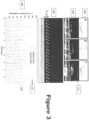
- Figure 3shows a set of illustrations which indicates the capacity of the exemplary ⁇ OCT arrangements to analyze an active ciliary motion.
- the top row (300) of Figure 3illustrates a schematic of stages of ciliary motion during the full ciliary beat cycle.
- Exemplary cross-sectional ⁇ OCT images of a cilium at two positionsare presented in row 310 in columns A and B, as well as a time-averaged (4 seconds) recording in column C showing an arc indicating the effective strokes (312) and bilobular pattern of the recovery stroke (314).
- Scale barsare 10 ⁇ m.
- the ciliary motion patterncan be easily identified in the M-mode image of the active epithelial area shown at 320.
- Corresponding time-lapse intensity analysis (330)reveals triphasic pattern of the ciliary beat cycle: the recovery stroke (blue line, 350), the effective stroke (orange line, 340) and the rest phase in between the effective stroke and next effective stroke.
- FIGs 4a -4dshow additional exemplary results from the exemplary ⁇ OCT arrangements applied to ciliary motion, as well as illustrative diagrams.
- each ciliary beat cyclecan start with a recovery stroke followed by an effective stroke.
- a bendcan be propagated up the cilium causing the cilium to rotate backwards in a clockwise sweep in a zone beneath the mucus as depicted in a schematic (see Figure 4a , 400) from a perspective view.
- the ciliumcan progress immediately into the effective stroke, in which the cilia describes an arc of almost 110° in the cross-sectional plane and in the mucus transport direction (see Figures 4b and 4c, top panels) before reaching the rest phase.
- Alteration in duration of cilia in the effective stroke, the recovery stroke or the resting statecan reflect response to stimulation and has significant effect on mucociliary clearance in addition to CBF itself.
- the exemplary ⁇ OCT imagescan provide a way to analyse the relative state of ciliary activity.
- cilia tipsappears as high intensity aggregated point scatterers, and because of the bend, the cilia tips appears at lower (e.g., 3-5 ⁇ m from the apical cell surface) position during the recovery stroke (see Figure 4a , 410) than in the effective stroke (see Figure 4b, 410) when cilia extend to their full length of ⁇ 7 ⁇ m and described an arc of 109° with radius about 7 ⁇ m along the direction of the mucus transport.
- An exemplary time-averaged cross-sectional ⁇ OCT image - see Figure 4c, 410 -demonstrates typical ciliary beat pattern seen in the exemplary ⁇ OCT images, which is characterized by an arc pattern 412 with a peak about 7 ⁇ m above the apical cell surface (see light arrow) and a bilobular pattern 414 with about 3-5 ⁇ m above the apical cell surface and just below the arc, indicating recovery strokes .
- M-mode view of the exemplary ⁇ OCT cilia images 420time-lapse ciliary motion can be clearly seen which can be used to characterize metachony wave of the ciliary motion.
- the exemplary signal intensity and duration 430 of the effective stroke and recovery strokemight reflect the status of the exemplary ciliary activity or ciliary load.
- FIG. 5shows exemplary results of images from the exemplary ⁇ OCT imaging procedure of non-respiratory tissue in murine and porcine animal models.
- Cilia 500appear as high intensity aggregated point scatterers in the low intensity background representing cerebrospinal fluid 510.
- the ependymal epithelium 520has a lower intensity than that of cilia but higher than that of the cerebrospinal fluid.
- oviduct cilia 530can appear as high intensity aggregated point scatterers.
- the oviduct epithelium 540can have a lower intensity than that of the oviduct cilia.
- Figure 6shows exemplary results of images from the exemplary ⁇ OCT imaging procedure of ex vivo porcine trachea tissue.
- mucus gland and gland duct 610 within lamina intestinal 620can also be seen in the exemplary ⁇ OCT images.
- a thin liquid layer 630 at the duct surfacecan be seen surrounding the mucus 650.
- 3D reconstruction of the exemplary ⁇ OCT imageallows estimation of the gland duct cross-sectional area in the mucus transport, so that mucus transport rates of luminal contents can be estimated by multiplying the gland duct cross-sectional area with the longitudinal extrusion rates of mucus estimated from the real-time cross-sectional images.
- animal modelsincluding but not limited to genetic or exposure induced models of disease are generated.
- studies involving human subjects in the context of proof of concept clinical trialsare obtained and/or utilized.
- a treatment with compounds selected for secondary evaluation and/or mechanistic studiesis performed.
- experimental treatmentis conducted, and in block 750, ⁇ OCT imaging can be performed.
- Block 750can be performed in vivo (via an endoscopic or rigid ⁇ OCT probe) or ex vivo (in the case of animal studies requiring sacrifice and extraction of tissues) imaging.
- exemplary ⁇ OCT based endpointscan then be derived, and in block 770, data can then be prioritized and analyzed based on the biological question to be addressed and an informatics system to handle redundant data, ultimately resulting in final results in block 780.
- an exemplary probeshould be used to provide imaging access to the tissue of analysis.
- a diagram of an exemplary embodiment of a ⁇ OCT probeis shown in Figure 8 .
- This exemplary probecan be used in the human nose (rhinoscopy).
- the exemplary probecan be contained within an outer tube (815) that remains statically positioned relative to the object or tissue to be imaged.
- the optical components of the exemplary probecan be mounted within an inner shuttle tube (805), and mechanically driven in a longitudinal fashion relative to the outer tube via a rigid drive shaft (800).
- the optical fiber (830)can deliver illumination into and collects reflected light from the imaging probe.
- the fibercan be mechanically fixed to the drive shaft by the ferrule (810).
- a 2mm spacer (835)can facilitate a divergence of the light from the fiber before collimation and focusing by the gradient-index lens (840).
- the beam splitter (845)can comprise a glass cube with a diagonal reflective surface with a small elliptical region in the center that transmits light. This transmitted portion can be incident on a reflector (850), which can serve as the reference mirror for OCT.
- the light reflected from the beamsplittercan be directed through a transparent window in the outer tube (820) towards the object or tissue to be imaged.
- FIG. 9A diagram of another exemplary embodiment of the ⁇ OCT probe is shown in Figure 9 .
- This exemplary probe of Figure 9can also be used in human or animal airways.
- the optical componentscan be contained within a sheath (930) and stabilized against the lumen of the airway to be imaged by a wire basket (905).
- An optical fiber (940)can deliver illumination into and collects reflected light from the imaging probe.
- the fibercan be mechanically fixed to a drive shaft (935), which can provide longitudinal scanning of the optics within the sheath.
- the illumination from the fiber 940can be collimated in a hollow-centered pattern by means of a double-axicon GRIN lens (900), and then focused by a conventional GRIN lens (910).
- a beamsplitter (915)can reflect a portion of the illumination light towards the object or tissue to be imaged, and can facilitate the remaining light to be transmitted to a reference mirror (945), which can be attached to a linear actuator (920) to facilitate for a positional adjustment.
- the beamsplittercan also combine the light/beam/radiation reflected from the reference mirror and the sample.
- FIG. 10A diagram of yet another exemplary embodiment of the ⁇ OCT probe is shown in Figure 10 .
- This exemplary probe of Figure 10can also be used in human or animal airways, and contains the added features of a perfusion channel and electrode for performing electrical potential difference measurements.
- the optical componentscan be contained within an insulating sheath (1055).
- An optical fiber (1010)can deliver illumination into and collects reflected light from the imaging probe.
- the fibercan be mechanically fixed to a drive shaft (1015), which provides longitudinal scanning of the optics within the sheath.
- a bearing (1020)can center the shaft while enabling smooth linear motion of the shaft within the sheath.
- the illumination from the fiberis collimated in a hollow-centered pattern using a double-axicon GRIN lens (1045), and then focused by a conventional GRIN lens (1025).
- a beamsplitter (1030)can reflect a portion of the illumination light towards the object or tissue to be imaged, and can facilitate the remaining light to be transmitted to a reference mirror (1050). The beamsplitter can also combine the light reflected from the reference mirror and the sample.
- a perfusion channel (1000)can facilitate liquid solutions to be delivered to the end of the probe, and an electrode channel (1005) can facilitate electrical recordings to be made.
- One of the exemplary applications of the exemplary ⁇ OCT arrangement not covered by the claimsis a high-throughput drug screening to analyze the effects of treatment compounds on respiratory epithelium.
- a high-throughput flow diagram of such exemplary applicationis shown in Figure 11 and described as follows.
- a growth of differentiated airway cells on air liquid interfaceis followed.
- cellsare treated with 1130 compound libraries, biologic libraries (e.g. siRNA, miRNA, etc.), alone and in combination with other agents.
- compoundsare selected which are chosen for known or proposed effects, prior screening hits, or mechanistic characterization.
- cellsare non-invasively imaged with the exemplary ⁇ OCT procedure using the exemplary HTS apparatus, with and without addition of known acute acting stimulants/inhibitors of ion transport for an additional test of additivity or specificity.
- output of the exemplary ⁇ OCT automated proceduresare used - which are multiple distinct but complementary measures of functional microanatomy, including ASL depth, PCL depth, CBF, MCT, microrheology properties (including but not limited to viscosity), effective stroke to recovery stroke ratio of loaded cilia, and estimates of cell viability.
- fluorescent probescan also be assayed as an indicator of a molecular target, such as ion transport.
- the cell culture platecan be transferred to a separate ion transport assay instrument, capable of measuring transepithelial voltage, transepithelial resistance, and calculating equivalent current, each traditional measures of transepithelial ion transport, which can be combined with OCT-based studies as an independent test in the same wells.
- a separate ion transport assay instrumentcapable of measuring transepithelial voltage, transepithelial resistance, and calculating equivalent current, each traditional measures of transepithelial ion transport, which can be combined with OCT-based studies as an independent test in the same wells.
- datacan then be prioritized and analyzed based on the biological question to be addressed and an informatics system to handle redundant data, ultimately resulting in final results in block 1195.
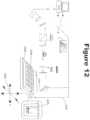
- Figure 12shows a diagram of a high-throughput screening configuration using the exemplary ⁇ OCT system illustrated in Figure 1 .
- the apodized light from the galvanometer scanning mirrors 1200can be focused by an objective lens 1210 onto a sample on the apical side of a growth substrate insert such as a filter 1220 placed in an m x n multi-chambered plate 1230.
- the m x n platecan be supported by an automated plate moving system 1240 which is motorized and capable of moving the multi-chambered plate in three physical dimensions 1250 such that the light focused by the objective lens 1210 can interrogate multiple samples contained in the multi-chambered plate 1230.
- Output signals 1260 from a computer 1270can be used to control the movement of automated plate mover 1215.
- the computer 1270can be used to process images according to an exemplary procedure and grade the effectiveness of each compound added to the biological sample.
- Figure 13shows a diagram of another high-throughput screening system which can utilize the exemplary system of Figure 1 .
- the apodized light from the galvanometer scanning mirrors 1300can be focused by an objective lens 1310 onto a sample on the basolateral side of a growth substrate insert, such as a filter 1320 placed in an m x n multi-chambered plate 1330.
- the m x n platecan be support by an automated plate moving system 1340 which can be motorized and capable of moving the multi-chambered plate in three physical dimensions 1350 such that the light focused by the objective lens 1310 interrogates multiple samples contained in the multi-chambered plate 1330.
- Output signals 1360 from a computer 1370can be used to control the movement of automated plate mover 1315.
- the computer 1370can be used to process images according to an exemplary procedure and grade the effectiveness of each compound added to the biological sample.
- Figure 14illustrates a diagram of the exemplary system shown in Figure 12 and modified such that an additional optical path is implemented to provide fluorescence excitation light to a biological sample.
- the additional pathbegins with broadband light/beam/radiation 1400 having been transmitted through the beam splitter 1405 and directed by a mirror 1410 through an excitation filter 1415 before being focused by a lens 1420 onto a single mode fiber optic patch cable 1425.
- the light/beam/radiation transmitted by the fiber optic cable 1425can be re-collimated by a lens 1430 and directed by dichroic mirrors 1435 and 1440 into a common optical path as the exemplary embodiment in Figure 12 .
- the combined lightcan be directed by a scanning galvanometer 1450 through a focusing objective lens 1460 onto the apical side of a biological sample 1465 as in the system shown in Figure 12 .
- the light/beam/radiation reflected by the samplecan be collected by the objective lens 1460 and separated into a fluorescence path 1470 and ⁇ OCT path by dichroic mirror 1440.
- the fluorescence light/beam/radiationcan be further separated from the source light by dichroic mirror 1435 before passing through emission filters 1475 and being focused by lens 1480 onto the entrance pupil of fiber optic patch cable 1482.
- Fluorescence light/beam/radiation transmitted by the fiber optic patch cable 1482can be re-collimated by a lens 1484 and split into its component spectral frequencies by a diffraction grating 1486 which are then focused by a lens 1488 onto a detection array 1490.
- Information from the detection array 1490can be transmitted to a computer 1492 that processes the fluorescence information for display 1494 and storage 1496.
- FIG. 15Another configuration of a dual-modality fluorescence ⁇ OCT system is shown in Figure 15 , which illustrates an alternate exemplary configuration of the system shown in Figure 14 as an inverted imaging system (which is also a modification of the exemplary system in Figure 13 ).
- an additional optical pathcan be implemented to provide fluorescence excitation light to a biological sample.
- the additional pathbegins with broadband light/beam/radiation 1500 having been transmitted through the beam splitter 1505 and directed by a mirror 1510 through an excitation filter 1515 before being focused by a lens 1520 onto the entrance pupil of a single mode fiber optic patch cable 1525.
- the light/beam/radiation transmitted by the fiber optic cable 1525can be re-collimated by a lens 1530 and directed by dichroic mirrors 1535 and 1540 into a common optical path as the system shown in Figure 13 .
- the combined light/beam/radiationcan be directed by a scanning galvanometer 1545 through a focusing objective lens 1550 onto the basolateral side of a biological sample 1555, similarly to the system shown in Figure 13 .
- the light/beam/radiation reflected by the samplecan be collected by the objective lens 1550, and separated into a fluorescence path 1560 and ⁇ OCT path by dichroic mirror 1540.
- the fluorescence light/beam/radiationcan further be separated from the source light by dichroic mirror 1535 before passing through emission filters 1565 and being focused by lens 1570 onto the entrance pupil of fiber optic patch cable 1575.
- Fluorescence light/beam/radiation transmitted by the fiber optic patch cable 1575can be re-collimated by a lens 1580, and split into its component spectral frequencies by a diffraction grating 1585 which are then focused by a lens 1590 onto a detection array 1592.
- Information from the detection array 1592can be transmitted to a computer 1594 that processes the fluorescence information for display 1596 and storage 1598.
- FIG. 16aA graph of exemplary results combining data from both fluorescence microscopy and ⁇ OCT in a dual-modality configuration is shown in Figure 16a .
- An experimentwas conducted on a HBE cell culture in which the unloaded cells receive a sudden impact of mucus (1600) while imaged simultaneously with ⁇ OCT and fluorescence microscopy.
- the ⁇ OCT imageswere used to determine ciliary beat frequency (1610) and PCL depth reduction (1630), while intracellular calcium ion concentration is revealed by a fluorescent assay. From 1-5 seconds, the PCL height, CBF and calcium were at the basal condition. Between 6-7 sec, 10 ⁇ L of mucus acquired from a normal subject reached the epithelial surface.
- the exemplary high-throughput screening described hereincan include a computer workstation for system control and image acquisition.
- An exemplary interface of the user control and display systemis shown in Figure 17 .
- the usercan regulate the automated scanning process with a series of controls 1700.
- the location of the scanning light/beam/radiation relative to an arbitrary home position 1710is displayed and the user can provide manual commands with position controls 1720.
- the progress 1730 of the automated scanningis also provided to the user.
- Exemplary ⁇ OCT imagescan be displayed in one or more viewing windows 1740 in which additional information about the sample being scanned can be displayed 1750.
- analysiscan be performed on the series of images from each position to produce the metrics relevant to the evaluation of the compound under study.
- This disclosurecan include automated procedures employed to determine airway surface liquid depth, mucociliary transport rate, and ciliary beat frequency from the exemplary ⁇ OCT image data.
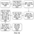
- Figure 18shows a flow diagram of a method and a procedure for an automated airway surface liquid (ASL) depth measurement.
- the ASL depthis the distance in microns from the apical border of the cell layer to the top of the mucus secretion.
- the first block 1800can be to load a sequence of 20 consecutive images of the HBE cells.
- the second block 1810can be to create a new image which has the minimum value at each pixel over these 20 frames. This exemplary step can mitigate the possibility of transient noise and flowing microparticles incorrectly being classified as edges.
- Steps 1820 and 1830can perform a Laplacian of Gaussian (LoG) operation on the processed image, a standard edge detection algorithm.
- LiGLaplacian of Gaussian
- each axial line in the resultant LoG imageis considered independently and a peak detection procedure can be applied.
- the 5 highest unique peaks detectedare labeled from top to bottom as the top of mucus layer, apical border of cell layer, top border of filter media, bottom border of filter media and bottom petri dish (block 1850).
- the ASL depth for each axial linecan be calculated as the distance between the top of mucus layer and the apical border of the cell layer via the known conversion between pixels and microns, using the approximation that mucus has the same refractive index as water.
- the overall ASL depthcan be computed as the median value across all axial lines in the image.
- an image 1900is an exemplary minimum intensity image over 20 frames.
- the intensity and number of flowing microparticles in the mucuscan be greatly reduced by the minimum operation.
- An image 1910is an exemplary result of a Laplacian of Gaussian operation.
- the high intensity regions of this imagenow correspond to edges in the previous image.
- the values of an exemplary single axial line of the Laplacian of Gaussian imageare plotted, showing, e.g., 5 distinct peaks corresponding to the 5 repeatable edges in the original image.
- the exemplary distance between the apical cell border and top of mucus peaksis measured and collated in a procedure 1930, showing a distribution of ASL depths.
- the final exemplary ASL depth 1940can be recorded as the median of this distribution.
- Figure 20illustrates a flow diagram of an exemplary method and/or procedure for automated mucociliary transport rate (MCT) measurement.
- the imagecan be cropped to limit the region of interest to the mucus between these two borders.
- the weighting function usedcan be a Gaussian kernel.
- images 2110, 2120 and 2130can demonstrate the characteristic mucus heterogeneity that allows for tracking.
- the exemplary images 2110, 2120 and 2130are three exemplary frames of the same image sequence of wild-type HBE cells, separated by 1 second each.
- a section 2115can be identified as the region of greatest variation within 2110, and can be thus chosen as the reference image.
- Weighted cross-correlationcan identify sections 2125 and 2135 as the most likely locations for reference image 2115 within the exemplary images 2120 and 2130, respectively.
- Performing this exemplary calculation for every frame between sections 2110 and 2130facilitates a reconstruction of the path of reference image 2110, shown in image 2140.
- the exemplary MCTcan then be extracted from this path using the known conversion from pixels to microns.
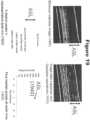
- Figure 22shows a flow diagram of exemplary method and/or procedure for automated ciliary beat frequency (CBF) measurement.
- the first block 2200is to locate the apical surface of the cell layer, utilizing the exemplary ASL procedure described herein with reference to Figure 18 .
- This exemplary bordercan be used in block 2210 to crop to region of interest to, e.g., the 10 micron area immediately above the apical epithelial border, where we expect to find beating cilia.
- an FFTcan be performed on the intensity value over 4 seconds for each pixel in this region.
- Pixels that are displaying regular ciliary motionwill have distinct peaks in their FFT at the ciliary beat frequency, while pixels uninvolved with ciliary motion can have unremarkable FFTs.
- the FFT resultscan be averaged over every 10 micron transverse section in this region of interest (step 2230).
- a peak detection procedurecan be applied to the resulting averaged FFT to determine whether this region has consistent ciliary motion. If no peak is found, the section can be ignored.
- the peak frequencye.g., for all sections that have valid frequency peaks can be recorded, and the final outputted CBF can be the median of these peak frequencies (blocks 2250 and 2260).
- image 2300can be an exemplary initial image
- image 2310can be the cropped region of interest following image segmentation.
- Sections 2320, 2330 and 2340can be, e.g., three exemplary 10 micron transverse sections and their corresponding averaged FFTs are shown in exemplary graphs 2350, 2360 and 2370, respectively.
- the graphs 2350 and 2370illustrate distinct peaks at 8Hz and 8.25Hz, respectively, while there is no notable peak in graph 2360. Therefore, the sections 2320 and 2340 can be used as valid regions to determine CBF, while graph 2330 can be ignored.
- Figure 24shows exemplary images providing image quality control. Each exemplary automated procedure can have rejection criteria to force a repeat imaging and/or flag for manual review.
- Illustration 2400shows an exemplary acceptable image.
- Illustration 2410shows an exemplary image that has no endogenous microparticles visualized, so MCT or viscosity measurement cannot be performed. This exemplary criterion is implemented by rejecting images, where the pixel intensity variation within the mucus region is below a specified threshold.
- Illustration 2420can be an exemplary image of irregular cell shapes in the cell layer, indicating an issue with the cell culture. This can be detected by flagging images where the variation in the axial position of the apical cell layer is higher than a specified threshold.
- Illustration 2430can be an exemplary case in which the mucus layer is nonexistent or negligible as a result of cell culture error or defective cells producing highly dehydrated mucus.
- the exemplary casescan be detected when the ASL depth is below a specified threshold.
- Other reasons for flagging an image for manual reviewcan include lack of repeatable ciliary motion or inability to segment the filter layer, indicating that the cell culture is not in the proper focus plane.
- An exemplary consequence of a high-throughput systemcan be a generation of large amounts of data.
- a management schemecan be provided for the copious volumes of image data and derived metrics generated by the exemplary ⁇ OCT system, as shown in a flow diagram and configuration of Figure 25 . This exemplary management approach is described as follows.
- datais obtained from the exemplary ⁇ OCT imaging, including the use of airway surface functional microanatomy in block 2520 (which may include airway surface liquid depth, periciliary liquid depth, ciliary beat frequency, and mucociliary transport), in block 2530 properties of mucus can be determined by particle tracking microrheology, and in block 2540, indicators of cell and tissue viability can be combined with additional imaging modality data including in block 2550, data from fluorescent probe indicators and in block 2560, transepithelial voltage/resistance testing. In block 2570, these data can then be subjected to data cleaning to remove data affected by toxicity (e.g. indicators of poor cell and tissue viability) or unreliable data (e.g. data outside reasonable parameters).
- toxicitye.g. indicators of poor cell and tissue viability
- unreliable datae.g. data outside reasonable parameters
- datacan be prioritized and a scoring system can be provided based on the specific biological question to be addressed by the screen or secondary characterization. Examples are shown of relative priority of various ⁇ OCT parameters, and prioritization scheme is not limited to the examples shown in Figure 25 .
- exemplary resultscan be calculated based on implementation of the informatics scheme, yielding final results in block 2595.
- Another exemplary ⁇ OCT applicationcan be used to perform rheology by the tracking of endogenous particles in mucus to determine the dynamic viscoelastic properties of the medium.
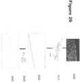
- Figure 26shows a diagram of an exemplary process from which dynamic viscosity can be calculated using the exemplary ⁇ OCT images.
- section 2600an exemplary image of cystic fibrosis mucus are provided, which are imaged using the exemplary embodiment(s) of the apparatus according to the present invention.
- Endogenous microparticlescan be seen in this exemplary image. Both endogenous and exogenous particles can be localized using a standard commercially available centroid-locating algorithm.
- Particle positioncan be tracked in one, two, or three dimensions over time; full three-dimensional tracking allows the measurement of viscosity along all spatial coordinates and captures any anisotropic diffusion behavior.
- Section 2610shows an exemplary two-dimensional particle track taken by the highlighted particle over the image sequence.
- the path of each particlecan be a function of both the bulk motion of the mucus and the random Brownian motion of each particle.
- the mean velocity vector of all tracked particlescan be subtracted from each individual particle path to remove the effect of bulk motion, a process further illustrated in Figure 27 .
- the mean squared displacement (MSD) over time of each particle due to Brownian motioncan be calculated using this modified path. Accurate estimation of the expected MSD requires averaging the MSD of multiple particles.
- Section 2620shows a plot of MSD averaged over about 30 particles fit to a linear regression. For example, MSD as a function of time can be converted to dynamic viscosity using the Stokes Einstein relationship shown in section 2630. The resulting dynamic viscosity plot is shown in section 2640.
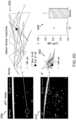
- Figure 27illustrates a set of graphs providing the bulk motion subtraction from an exemplary dataset, a component of the process shown in Figure 26 .
- Graphs 2700 and 2710are x- and y-direction displacements, respectively, of 19 particles tracked over 1.2 seconds.
- the bulk motioncan be recognizable as a drift away from 0 common to all tracks, with the mean displacement of all tracks superimposed on the plots (portions 2705 and 2715).
- Subtraction of the mean displacement in both x and y directionsyields particle tracks with the bulk motion eliminated (portions 2720 and 2730).
- the effectiveness of bulk motion subtractionwas validated by comparing the measured the MSD of natural inclusions in mucus in the absence versus presence of bulk motion.
- Graph 2740shows MSDs from collected mucus measured without motion, with induced motion in the axial direction, and with induced motion in the transverse direction.
- Graph 2750shows MSDs from epithelial mucus with no ciliary motion present and with active ciliary clearance (which causes bulk motion of the mucus layer). The equivalence of each static and in-motion mucus MSD measurements can indicate a successful removal of the bulk motion component.
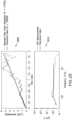
- Exemplary results from ⁇ OCT rheology in a validation testappear in exemplary graphs illustrated in Figure 28 , which show the mean squared displacement and calculated dynamic viscosity of a solution of phosphate buffer solution (PBS) with exogenous microparticles.
- PBSphosphate buffer solution
- Graph 2800indicates the mean squared displacement of the aggregated tracks with a linear regression versus the calculated theoretical displacement from the known viscosity of PBS.
- Graph 2810indicates the resulting computed dynamic viscosity over a range of frequencies.
- An exemplary standard method for optical particle-tracking rheologyis fluorescence microscopy, which can be compared to the exemplary ⁇ OCT results as shown in Figure 29 using samples from the same expectorated sputum.
- Traditional fluorescence exogenous particle tracking (line 2900) and the exemplary ⁇ OCT-based endogenous particle tracking (line 2910)can produce similar results, thus validating the potential of ⁇ OCT for measuring the mechanical properties of mucus.
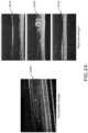
- Exemplary results from the exemplary ⁇ OCT rheology procedure on normal and CF sputumare shown in Figure 30 .
- the exemplary ⁇ OCT images of normal (image 3000) and CF (image 3010) mucusindicate natural inclusions (e.g., diameter ⁇ 700 nm, yellow circles).
- Corresponding two-dimensional trajectoriesare shown for normal (illustration 3020) and CF (illustration 3030).
- Bar chart 3040indicates MSDs of natural particles in the respective cases, and statistical significance in this 5-measurement sample is demonstrated with p ⁇ 0.05.
Landscapes
- Physics & Mathematics (AREA)
- General Physics & Mathematics (AREA)
- Health & Medical Sciences (AREA)
- General Health & Medical Sciences (AREA)
- Life Sciences & Earth Sciences (AREA)
- Chemical & Material Sciences (AREA)
- Analytical Chemistry (AREA)
- Biochemistry (AREA)
- Immunology (AREA)
- Pathology (AREA)
- Spectroscopy & Molecular Physics (AREA)
- Nuclear Medicine, Radiotherapy & Molecular Imaging (AREA)
- Optics & Photonics (AREA)
- Radiology & Medical Imaging (AREA)
- Engineering & Computer Science (AREA)
- Biomedical Technology (AREA)
- Molecular Biology (AREA)
- Dispersion Chemistry (AREA)
- Investigating, Analyzing Materials By Fluorescence Or Luminescence (AREA)
- Investigating Or Analysing Materials By Optical Means (AREA)
- Investigating Or Analysing Biological Materials (AREA)
Description
- This application is based upon and claims the benefit of priority from
U.S. Patent Application Serial No. 61/527,446 filed August 25, 2011 U.S. Patent Application Serial No. 61/527,701 filed August 26, 2011 - The invention was made with the U.S. Government support under Grant Number DAMD17-99-2-9001 awarded by the U.S. Department of the Army and Grant Number BES-0086789 awarded by the National Science Foundation. Thus, the U.S. Government has certain rights in the invention.
- Exemplary embodiments of the present disclosure relate to methods, systems, arrangements and computer-accessible medium for providing micro-optical coherence tomography procedures, and more particularly to exemplary methods, systems, arrangements and computer-accessible medium for analyzing respiratory airways and other ciliated tissues using micro-optical coherence tomography procedures.
- The human lung is suited for providing gas exchange from the atmosphere to the body: with every breath, oxygen enters the bloodstream, and carbon dioxide is removed. This constant environmental exposure makes the defense systems of the lung extremely important in maintaining health and preventing disease. Specifically, the surface epithelial cells which line the lung are protected by a tightly regulated layer of mucus which functions to entrap pathogens and inhaled particulates. These cells also contain tiny hair-like projections called cilia which propel the semi-liquid mucus gel layer out of the lung. This system, commonly called the mucociliary clearance (MCC) apparatus, facilitates the lung to entrap and clear particles and pathogens which enter the lung from the environment. Cilia are complex in structure, with outer and inner rings of microtubules which propel the cilia in specific beat patterns that are also coordinated with one another. Other parts of the apparatus are similarly complex, including the content and molecular makeup and the electrolyte and water content of the mucus gel layer, which determine its physical characteristics and transportability. When the mucociliary clearance apparatus is impaired, whether due to malformation or dysfunction of cilia, dysregulation of the ion and water transport, abnormalities of the mucus itself, or other insults, lung disease can result.
- Many diseases are affected by dysfunction of the functional microanatomy of the airway and consequently the mucociliary clearance apparatus. For example, cystic fibrosis (CF) is the most common lethal genetic disease in the Caucasian population, and is a significant cause of morbidity and early mortality from progressive lung disease. (See Rowe SM, et al., Cystic fibrosis, N Engl J Med 2005;352:1992-2001.) About 30,000 children and adults in the United States are affected by CF and the prevalence is estimated at 70,000 worldwide. Further, mild diseases due to partial abnormalities in the causative CF protein, termed cystic fibrosis transmembrane regulator (CFTR), are about 10-fold more common than typical forms of the disease. It is well established that the primary defect in CF, dysfunction of the CFTR protein, results in abnormal mucociliary clearance (MCC) due to the absence of chloride and bicarbonate transport, and is associated with dysregulation of the airway surface liquid (ASL) and periciliary liquid layer (PCL) depths. As another example, primary ciliary dyskinesia (PCD) is a disorder in which structural ciliary defects result in abnormal ciliary motion, which in turn leads to impaired mucociliary clearance and susceptibility to recurrent sinopulmonary infections. (See Bush A et al. "Primary ciliary dyskinesia: current state of the art. Archives of disease in childhood", 2007; 92:1136-40). Chronic obstructive pulmonary disease (COPD), recently the third leading cause of death in the U.S., is also characterized by mucus stasis and impaired mucociliary clearance. Other common lung diseases are also affected by dysfunction of the epithelial surface, including, but not limited to, types of interstitial lung disease such as its most common form idiopathic pulmonary fibrosis which are characterized by abnormal function of the surface mucins, the proteins that form the mucus gel.
- Even people with normal epithelial function and a normally functioning cellular mucociliary clearance apparatus during health can also be impacted by difficulty with impaired mucus clearance and increased mucus production. For example, individuals with neuromuscular weakness caused by congenital or genetic conditions, such as, but not limited to, muscular dystrophy, spinal muscular atrophy, and amyotrophic lateral sclerosis, suffer with recurrent pneumonia due to poor cough clearance which leads to mucous stasis. In addition, individuals with acquired anatomic problems resulting in muscular weakness, such as but not limited to, paraplegia, quadriplegia, diaphragmatic paralysis and the like, suffer the same fate. Other subjects, such as those suffering from excess mucus production due to conditions such as, but not limited to, asthma and status asthmaticus, those suffering from impaired immunity due to conditions such as, but not limited to, immunoglobulin deficiency, SCID, hyper-IgE syndrome, and similar conditions, those suffering from anatomic respiratory abnormalities impairing mucus clearance, those suffering from recurrent pneumonia for unclear causes and those suffering from oropharnygeal abnormalities, suffer from atelectasis and/or pneumonia due to excess mucus production that overwhelms the capacity of the mucociliary clearance apparatus to transport it effectively. These disorders due to impaired mucous clearance and/or excess mucous production has been a serious recurrent problem causing considerable morbidity and are also a contributing cause to mortality.
- Mucus itself can be characterized in part by its viscosity, or its resistance to physical flow. Thicker, more viscous mucus is more difficult for the mucociliary apparatus to clear, contributing to disease. The study of viscosity by rheology measurements allows for characterizing mucus physical properties, understanding mechanisms of human disease, and evaluating the effect of therapeutics to address abnormal mucus. May studies have shown that expectorated sputa from CF patients are abnormal, demonstrating a highly viscous nature and increased percentage of solid content. (See Serisier DJ et al., "Macrorheology of cystic fibrosis, chronic obstructive pulmonary disease & normal sputum", Respiratory research 2009;10:63;Chernick WS and Barbero GJ, "Composition of tracheobronchial secretions in cystic fibrosis of the pancreas and bronchiectasis", Pediatrics 1959;24:739-45; Matsui H et al., "Reduced three-dimensional motility in dehydrated airway mucus prevents neutrophil capture and killing bacteria on airway epithelial surfaces", J Immunol 2005;175:1090-9; Dawson M at al., "Enhanced viscoelasticity of human cystic fibrotic sputum correlates with increasing microheterogeneity in particle transport", J Biol Chem 2003;278:50393-401; andMartens CJ et al., "Mucous Solids and Liquid Secretion by Airways: Studies with Normal Pig, Cystic Fibrosis Human, and Non-Cystic Fibrosis Human Bronchi", American journal of physiology Lung cellular and molecular physiology 2011) Prior studies have also suggested that COPD sputum has increased viscosity. (SeeRedding GJ et al. "Physical and transport properties of sputum from children with idiopathic bronchiectasis", Chest 2008;134:1129-34). Mucus is also characterized by its adherence. Abnormal adherence to the surface structures of the airway are thought to substantially contribute to clinical disease.
- Certain methods for investigating the functional microanatomy of the airway surface in natural, untreated airway epithelia, including cell and tissue culture systems andin vivo methods, are limited. Current knowledge of respiratory cilia and PCL morphology is based on electron microscopy. (Matsui H. et al., "Evidence for periciliary liquid layer depletion, not abnormal ion composition, in the pathogenesis of cystic fibrosis airways disease", Cell 1998;95:1005-15; andSanderson MJ and Sleigh MA, "Ciliary activity of cultured rabbit tracheal epithelium - beat pattern and metachrony", Journal of Cell Science 1981;47:331-47.) These methods only provide static images of epithelia when they are not functioning; fixation and harsh processing are likely to alter cilia and PCL morphology, and could account for disparities in the conclusions on the role of ASL/PCL in CF and other lung diseases. ASL height can be measuredin vitro using confocal microscopy by aid of fluorescent staining, but is technically challenging, difficult to achieve the high axial resolution required to accurately assess ASL/PCL, and prone to artifacts caused by interference or removal of the native fluid and flow by the exogenous contrast agents. (See also Randell SH, and Boucher RC, "Univ NCVLG. Effective mucus clearance is essential for respiratory health", American Journal of Respiratory Cell and Molecular Biology 2006;35:20-8). Measuring mucociliary transport (MCT) by tracking fluorescent beads is problematic because the beads are known to cause the mucus to agglomerate and significantly slow transport rates. In addition to these limitations, spatial and temporal correlation are very difficult with these assays, as measurement of ciliary beat frequency (CBF), ASL, PCL and MCT are generally done at different time points with different imaging modalities, processing methods, and cells. Likely, none of these methods are suitable for usein vivo, including both human testing and experimental animals to characterize the effect of drugs. Since these parameters are closely interrelated and can influence each other, it is essential to monitor these parameters simultaneously to gain a full understanding of the functional airway.
- Accordingly, it may be beneficial to address at least some of the above-described deficiencies.
- Techniques for reflectance microscopyin vivo have recently been introduced for the visualization of tissue microstructure at architectural and cellular levels. These include optical coherence tomography (OCT) which has been developed to provide unprecedented cellular detail and live motion capture. (SeeTearney GJ et al., "In vivo endoscopic optical biopsy with optical coherence tomography", Science 1997;276:2037-9; Fujimoto JG et al., "Optical coherence tomography: An emerging technology for biomedical imaging and optical biopsy", Neoplasia 2000;2:9-25;Drexler W et al., "In vivo ultrahigh-resolution optical coherence tomography", Optics Letters 1999;24: 1221-3; Gabriele ML et al., "Peripapillary nerve fiber layer thickness profile determined with high speed, ultrahigh resolution optical coherence tomography high-density scanning", Investigative Ophthalmology & Visual Science 2007;48:3154-60;Srinivasan VJ et al., "Noninvasive volumetric Imaging and morphometry of the rodent retina with high-speed, ultrahigh-resolution optical coherence tomography", Investigative Ophthalmology & Visual Science 2006;47:5522-8;Wojtkowski M. et al., "Three-dimensional retinal imaging with high-speed ultrahigh-resolution optical coherence tomography", Ophthalmology 2005;112:1734-46; Tearney GJ et al., "In vivo endoscopic optical biopsy with optical coherence tomography", Science 1997;276:2037-9; andVakoc BJ et al.. "Three-dimensional microscopy of the tumor microenvironment in vivo using optical frequency domain imaging", Nat Med 2009;15:1219-23). The technology uses the reflectance signature of near-infrared light to permit real-time imaging with cellular level detail, and has been employed successfully for microscopic analysis of coronary artery and esophageal mucosa by the endoscopic approach in living human subjects. OCT uses coherence gating for optical sectioning to attain an axial resolution or section thickness ranging from 1-10 µm. (See Yun SH et al., "Comprehensive volumetric optical microscopy in vivo", Nat Med 2006;12:1429-33; Jang IK et al., "Visualization of coronary atherosclerotic plaques in patients using optical coherence tomography: Comparison with intravascular ultrasound", Journal of the American College of Cardiology 2002;39:604-9;Yabushita H. et al., "Characterization of human atherosclerosis by optical coherence tomography", Circulation 2002;106:1640-5;Tearney GJ et al., "Quantification of macrophage content in atherosclerotic plaques by optical coherence tomography", Circulation 2003;107:113-9;MacNeill BD et al., "Focal and multi-focal plaque distributions in patients with macrophage acute and stable presentations of coronary artery disease", Journal of the American College of Cardiology 2004;44:972-9;Jang IK et al., "In vivo characterization of coronary atherosclerotic plaque by use of optical coherence tomography", Circulation 2005;111:1551-5;Vakoc BJ et al., "Comprehensive esophageal microscopy by using optical frequency-domain imaging (with video)", Gastrointestinal Endoscopy 2007;65:898-905;Yun SH et al., "Comprehensive volumetric optical microscopy in vivo", Nature Medicine 2006;12:1429-33; Poneros JM et al., "Diagnosis of specialized intestinal metaplasia by optical coherence tomography", Gastroenterology 2001;120:7-12; andEvans JA et al., "Mino-Kenudson M, Nishioka NS, Tearney GJ. Optical coherence tomography to identify intramucosal carcinoma and high-grade dysplasia in Barrett's esophagus", Clinical Gastroenterology and Hepatology 2006;4:38-43). Viscoelasticity measurements on breast tissues using OCT imaging is known from Xing Liang: "COHERENCE IMAGING TECHNOLOGIES FOR THE MEASUREMENT OF TISSUE AND CELL BIOMECHANICS", 2010, XP055333440, Retrieved from the Internet: URL:https://www.ideals.illinois.edu/bitstream/ handle/2142/16859/1_Liang_Xing.pdf?sequence=3&isAllowed=y.
- Since OCT is not reliant on a high numerical aperture lens, it can employ an imaging lens with a relatively large confocal parameter, facilitating a greater penetration depth (about 1 mm) and a cross-sectional display format. OCT is particularly well suited for non-invasive microscopy in cells and tissues since it can be implemented via small, flexible probes, does not require contact with the cell surface or use of contrast medium, and acquires high resolution images with very rapid acquisition times and flexible focal range.
- An acquisition of the OCT signal in the wavelength domain as opposed to the time domain can provide orders of magnitude improvement in imaging speed while maintaining excellent image quality. One such second-generation imaging technology is termed micro-OCT (µOCT). (Seede Boer JF et al., "Improved signal-to-noise ratio in spectral-domain compared with time-domain optical coherence tomography", Optics Letters 2003;28:2067-9;Choma MA et al., "Sensitivity advantage of swept source and Fourier domain optical coherence tomography", Optics Express 2003;11:2183-9;Nassif N. et al., "In vivo human retinal imaging by ultrahigh-speed spectral domain optical coherence tomography" Optics Letters 2004;29:480-2; and Yun SH et al., "High-speed wavelength-swept semiconductor laser with a polygon-scanner-based wavelength filter", Optics Letters 2003;28:1981-3).
- With µOCT, high-resolution ranging is conducted in tissue by detecting spectrally resolved interference between the tissue sample and a reference. (See alsoWojtkowski M. et al., "In vivo human retinal imaging by Fourier domain optical coherence tomography", J Biomed Opt 2002;7:457-63). Since µOCT can utilize a high-speed linear camera, it is capable of capturing images at more than 50 million pixels per second, which is approximately two orders of magnitude faster than conventional time-domain OCT systems. (See also Wojtkowski M. et al., "Three-dimensional Retinal Imaging with High-Speed Ultrahigh-Resolution Optical Coherence Tomography", Ophthalmology 2005). By using light sources with large spectral bandwidths (∼150 nm), recent studies have shown that µOCT images can be obtainedin vivo with an axial resolution of approximately 2 µm, which is adequate to visualize the PCL, beating cilia, and mucosal glands. (See Gabriele ML et al., "Peripapillary nerve fiber layer thickness profile determined with high speed, ultrahigh resolution optical coherence tomography high-density scanning", Invest Ophthalmol Vis Sci 2007;48:3154-60;Srinivasan VJ et al., "Noninvasive volumetric imaging and morphometry of the rodent retina with high-speed, ultrahigh-resolution optical coherence tomography", Invest Ophthalmol Vis Sci 2006;47:5522-8; andWojtkowski M et al., "Three-dimensional retinal imaging with high-speed ultrahigh-resolution optical coherence tomography", Ophthalmology 2005;112:1734-46). With this acquisition rate and resolution, µOCT is a very powerful tool for investigating the respiratory mucosa.
- High throughput screening (HTS) for exemplary modulators of epithelial function has been successful as a drug discovery modality, identifying certain small molecules, biologics, and pathways relevant to human airway disease. While this is been particularly successful in CF to identify modulators of CFTR, the assay systems typically used are limited in scope, and cannot directly interrogate epithelial function relevant to mucociliary transport in humans. Rather, these approaches are reductionist towards specific pathways that may or may not be directly relevant to a broad array of human diseases. For example, almost all HTS technologies for CF attempt to identify alterations in chloride, halide, or sodium transport, and can only probe one of these pathways depending on the specific probe. This reductionist approach makes the assay limited in scope, and is relevant only to diseases where that ion transport pathway is relevant.
- Accordingly, there is a need to address and/or at least some of the deficiencies described herein above.
- Thus, at least some of the above-described issues and/or deficiencies can be addressed with the exemplary embodiments of the by providing exemplary methods, systems, arrangements and computer-accessible medium for providing micro-optical coherence tomography procedures. The invention is defined in
claim 1. - For example, with the use of µOCT arrangement, one can provide a high spatial resolution and frame rate reported to date. Cross-sectional images of tissue can be acquired at about 44 frames per second (fps) at an axial resolution of 1.5 µm and a transverse resolution of 2 µm. The size of a typical µOCT image can be about 3 mm × 0.6 mm. Such arrangement can facilitate, e.g., a simultaneous and high-resolution acquisition of ciliary beating (respiratory epithelium as well as other tissue types), ASL and PCL depths, and mucus transport in living, full thickness airway cells and tissues, and provides a quantitative measurement while also visualizing anatomy, without use of contrast dyes or other experimental manipulations.
- Such arrangement can also be used simultaneously with dual fluorescence imaging. It is possible to acquire both fluorescence and structural/functional µOCT information simultaneously, from the same location on the sample. Using state-of-the-art fluorescence assays of ion transport, chloride and bicarbonate influx can be measured and related to co-localized ASL, CBF, MCT and mucus rheology.
- It is possible to process of the µOCT datasets to provide robust and simultaneous measures of ASL, PCL, CBF, and MCT. The rapid, automated acquisition of these exemplary parameters facilitates an understanding of the physical interactions of cilia, ASL, PCL and mucus, and their collective influence on epithelial function. With the invention, one identifies and tracks natural particles/inclusions in µOCT images of mucus to recover mucus viscosity. Compared with prior methods for measuring mucus properties, the exemplary µOCT arrangement in accordance with the invention is using natural particles facilitating tracking for mucus microrheology which can be significant; and also providing for the measurement to be obtained for in living subjectsin situ. For example, the mucus properties can be determined simultaneously and co-localized with the structural functional parameters of MCC, and the findings are not subject to artifacts caused by adding exogenous particles to the mucus.
- Further, the µOCT arrangement can provide a more robust assay that identifies multiple epithelial functions simultaneously. Each of these functions can be directly relevant to human physiology, thus is much more likely to translate effectively to a broader array of human disease. For example, it is now possible to screen for compounds that improve mucociliary transport, a core physiologic function that may or may not depend on chloride transport. Alternatively, screens can be established for ciliary function, altered mucus viscosity, or hydrators of the mucus, depending on the purpose of the screen. This represents a major advantage over prior screens.
- The assay can also be established as a robust means to provide secondary characterization of drugs, molecules, or biologics and their effects on human physiology. At present, there may not be secondary assay that directly correlates with key functions of the epithelial surface. The direct assessment of surface epithelial functional testing can provide much greater predictive accuracy regarding the success of a novel agent in clinical testing. Because the µOCT arrangement can be suitable for use in cell culture, tissue culture, orin vivo use in animal models or humans (see also below), the assay can provide secondary evaluation in a variety of primary, secondary, and tertiary model systems, and is unique in this regard. Additionally, it can be suitable for human proof of concept testing, providing an approach with unprecedented experimental continuity across model systems.
- The exemplary µOCT arrangement according to the invention can be used in vivo in human subjects. It is possible to provide an exemplary pulmonary µOCT probe that can have a high enough resolution to visualize respiratory cells, cilia, and native microparticle motion to determine mucus viscosity. For these purposes, the exemplary µOCT arrangement in accordance with the invention can use a transverse resolution of 2-3 µm over an extended depth-of-field, or focal range. Using conventional optics, this focal range can be maintained by no greater than 50 µm. This focal range can be too small for cross-sectional imaging of the airwaysin vivo, which generally requires a focal range of approximately 500 µm in order to accommodate the diversity of probe-to-tissue distances across a reasonable field of view on a typically uneven surface of an in vivo subject. The exemplary embodiments of imaging probes described herein can illuminate an extended axial focus and contain a reference mirror for the interferometer. In order to facilitate stable imaging in the presence of subject motion, certain exemplary embodiments of the probe optics according to the present disclosure can be coupled to the subject via an exemplary balloon or wire baskets associated with the outer sheath of the probe.
- The exemplary µOCT arrangement can be used for investigating ciliary function disclosed herein are also applicable in organ systems inside and outside of the respiratory system in both humans and animals. Many other tissues contain ciliated cells, including but not limited to the Fallopian tubes of the female reproductive tract, sperm produced by the male reproductive tract, the ependyma of the brain, the photoreceptor cells of the eye, the renal tubules within the kidney, and embryonic cells which regulate organ formation and development. Manifestations of these ciliary abnormalities include, among others, human disease such as infertility (both male- and female-related causes), hydrocephalus and other congenital malformations of the brain including neuronal migration disorders, Bardet-Biedl syndrome and other causes of blindness, polycystic kidney disease, situs inversus and associated congenital heart diseases, and many other identified or suspected ciliopathies. µOCT can be applied to these other ciliated tissue structures as well, leading to new understanding and potential therapies for many devastating diseases.
- The exemplary imaging platform can utilize optical reflectance depth profiles, images, volumes, or movies of respiratory and/or ciliated cells, tissues, or organs, including their secretions and immediate environment, using the exemplary µOCT technology. In particular, such technology can facilitate functional dynamic movements of cellular components, including cilia.
- An exemplary µOCT arrangement, can be used for high throughput screening (HTS). HTS is a procedure of drug discovery in which a library of compounds is studied using automated methods to determine which, if any, are active for the outcome being studied. The exemplary underlying properties of µOCT, including its rapid acquisition time, non-invasive technique, and wide focal range make it a highly suitable technology for medium to high throughput screening methods. Further therapeutic drug screening programs have been provided that can use airway surface liquid depth as a principal readout, and agents that target CFTR or other ion transport pathways are prioritized based on preclinical use of this exemplary measurement.
- The exemplary high throughput screening platform can also be combinable with simultaneous and co-registered fluorescence confocal imaging. Fluorescent markers enable dynamic assays of intracellular ion concentrations such as calcium and bicarbonate, which complements the exemplary µOCT data to provide an even more powerful tool for interrogation of epithelial physiology and evaluation of ciliary disease treatments.
- Exemplary computer procedures developed for the analysis of µOCT high throughput screening output images are employed to extract relevant parameters such as airway surface liquid depth, mucociliary transport rate, and ciliary beat frequency. These measurements are performed automatically with minimal user intervention to maximize throughput. A quality control procedure can remove spurious measurements and outliers, while the measurements from unrejected trials are aggregated, yielding final results.
- The exemplary µOCT arrangement can also be well suited for secondary characterization of agents preliminarily identified to be active in airway epithelia. Results will help elucidate the relationship between ASL regulation, cilia beating, and mucus propulsion, and establish functional profiles for compounds identified by earlier drug screening programs. Secondary evaluation of ion transport agents known to be active in airway epithelia assist to clarify relationship(s) between sodium and chloride channel activity, airway surface liquid regulation, ciliary activity, and mucus transport.
- Furthermore, the exemplary equipment can be suitable for imaging explanted lung tissues for validation in the intact airway. Tissues can be derived from donated human lung tissue, or from experimental animal models of both lung health and various lung diseases. The use ofex vivo tissues allows for environmental control and direct applications of various agents, allowing for proof of concept work prior to directin vivo human applications.
- Mucus rheology is analyzed using the exemplary µOCT arrangement in accordance with the invention. CF sputum generally exhibits increased viscosity when monitored by exogenous particle tracking microrheology, an exemplary technique in which the mean squared displacements (MSD) of fluorescent microparticles are measured and converted to viscosity by the generalized Stokes-Einstein relation (GSER). (SeeDawson M. et al., "Enhanced viscoelasticity of human cystic fibrotic sputum correlates with increasing microheterogeneity in particle transport", J Biol Chem 2003;278:50393-401). Since similarly sized natural particles or inclusions present in mucus scatter light and can be visible using µOCT, and because µOCT can have the resolution to determine the sizes of these natural particles (through straightforward deconvolution procedures), estimates of MSD have been recapitulated by tracking endogenous microparticles within mucus. When comparing conventional fluorescence particle tracking methods to exemplary µOCT-based endogenous particle tracking procedures on the same expectorated sputum samples, MSD results were very similar, thus, facilitating the exemplary µOCT arrangement to measure the mechanical properties of unaltered mucusin situ.
- The µOCT probes can be usedin vivo to monitor the earliest features of pulmonary decline in disease such as cystic fibrosis. Monitoring patients before disease progression occurs can provide key information in the study of disease including key information regarding the anatomic and physical relationships of mucociliary clearance. Additionally, the exemplary µOCT probe can be used in context of suspicion of known and unknown diseases to evaluate for disorders affecting the functional airway microanatomy, and to precisely characterize specific abnormalities seen in individual patients.
- Thus, according to certain examples not covered by the claims, exemplary apparatus can be provided for obtaining data regarding a plurality of samples. For example, using at least one arrangement, it is possible to receive interferometric information that is based on radiations provided from a reference and the samples that are provided in respective chambers.
- For example, the arrangement(s) can comprise at least one optical configuration which is configured to focus at least one electromagnetic radiation on the samples. A depth range of the focus of the electromagnetic radiation(s) caused by the optical configuration(s) can be greater than a confocal parameter associated with a spot size of the focus. The optical configuration(s) can include an axicon lens arrangement, a binary apodization element, a phase apodization element, a refractive optical element, an annulus, and/or a diffractive element. The arrangement(s) can also comprise a confocal arrangement, a florescence arrangement, Raman arrangement, an infrared arrangement, spectrascopicn arrangement, a multiphoton arrangement, a multiharmonic arrangement, a nonlinear microscopy arrangement, a CARS SRS arrangement, or an ultrasound arrangement. Further, each of the respective chambers can have an agent which can be different from or same as another one of the agents. The arrangement(s) can be further configured to obtain the data using the interferometric information based on an interaction of the agents with the samples. One of the agents and another one of the agents (i) can differ from one another in a quantity or a concentration thereof, and/or (ii) are applied at different time periods within the respective chambers. At least one of the samples can include a living cell, and/or a cilia.
- According to still another example not covered by the claims, a method can be provided for obtaining data regarding a plurality of samples. For example, it is possible to receive interferometric information that is based on radiation provided from a reference and the samples that are provided in respective chambers. Further, based on the interferometric information, it is possible to discriminate between agents to identify a particular agent that effects a particular function within at least one of the samples. The particular function can include motion, and/or the particular agent can have at least one characteristic that is beneficial for a treatment of cystic fibrosis.
- In yet another example not covered by the claims, a method can be provided for reviewing therapeutic agents. For example, in this method, samples can be prepared, and manipulated to increase amount or viability thereof. At least one of the samples can be placed in at least one respective chamber. The chambers can be scanned using at least one arrangement which can be configured to receive interferometric information that is based on radiation provided from a reference and the at least one sample. At least one of the agents can be selected based on the scanning and the interferometric information. At least one of the samples can includes epithelial cells that have been dissected from a whole lung sample and expanded in flasks.
- In the invention, the apparatus is provided for obtaining data regarding at least one sample. The apparatus includes at least one arrangement which can receive interferometric information that is based on radiation provided from a reference and the sample. This exemplary arrangement is configured to (i) obtain dynamic tracking data regarding particles associated with the sample(s) using the interferometric information, and (ii) determine biomechanical properties of the sample(s) using the dynamic tracking data .
- The particles can (i) include added and intrinsic particles to the at least one sample, and/or have a diameter that is less than 1 micron, 2 microns, or 5 microns. The sample(s) includes mucus, and the particles include inclusions in the mucus. The dynamic tracking data can include a measurement of a displacement and/or a size of at least one of the particles.
- These and other objects, features and advantages of the present invention will become apparent upon reading the following detailed description of embodiments of the disclosure, when taken in conjunction with the appended claims.
- Further objects, features and advantages of the present disclosure will become apparent from the following detailed description taken in conjunction with the accompanying drawings showing illustrative embodiments of the present disclosure, in which:
Figure 1 is a diagram of an exemplary embodiment of a micron resolution Optical Coherence Tomography (µOCT) imaging platform according to the present disclosure;Figure 2a is an exemplary µOCT image of normal human bronchial epithelial cells, averaged over time, showing distinguishable air, mucus, periciliary, and epithelial layers;Figure 2b is an exemplary µOCT image of CF human bronchial epithelial cells, showing depleted periciliary and mucus layers;Figure 2c is an exemplary µOCT image of intact normal newborn piglet trachea ex vivo, showing mucus, periciliary, and epithelial layers, as well as subsurface glandular structures;Figure 2d is an exemplary µOCT image of intact CF newborn piglet trachea ex vivo, showing depleted periciliary and mucus layers;Figure 3 is set of images providing illustrative diagrams of ciliary motion and exemplary µOCT images of ciliary motion showing distinguishable phases of the ciliary stroke;Figure 4a is a diagram of an exemplary experiment utilizing exemplary µOCT arrangements to investigate ciliary motion under mucus loading;- Figures 4b-4d are exemplary imaging results from a particular experiment using the exemplary µOCT arrangements;
Figure 5 is a set of exemplary µOCT images of cilia in non-respiratory murine and porcine tissue;Figure 6 is an exemplary µOCT image of porcine trachea showing mucus extrusion in progress;Figure 7 is a flow diagram for analyzing intact tissue using the µOCT arrangements;Figure 8 is a diagram of an exemplary embodiment of a probe used to perform the µOCT procedure on airway tissue, such as in the nose (rhinoscopy) according to the present disclosure;Figure 9 is a diagram of another exemplary embodiment of the probe used to perform the µOCT procedure on airway tissue that is stabilized against the airway lumen using a wire basket according to the present disclosure;Figure 10 is a diagram of still another exemplary embodiment of the probe used to perform the µOCT procedure on airway tissue, and includes a perfusion channel and an electrode for the purpose of potential difference (PD) measurement according to the present disclosure;Figure 11 is an overall flow diagram and configurational illustration for high throughput screening or secondary characterization application of the exemplary µOCT procedure not covered by the claims;Figure 12 is a diagram of an exemplary embodiment of an upright µOCT imaging system for high-throughput screening of biological compounds;Figure 13 is a diagram of an exemplary embodiment of an inverted µOCT imaging system for high-throughput screening of biological compounds;Figure 14 is a diagram of an exemplary embodiment of an upright dual-modality µOCT/Fluorescence microscopy imaging system for high-throughput screening of biological compounds;Figure 15 is a diagram of an exemplary embodiment of an inverted dual-modality µOCT/Fluorescence microscopy imaging system for high-throughput screening of biological compounds;Figures 16a and 16b are graphs of exemplary results from a dual-modality µOCT/Fluorescence microscopy imaging system that demonstrate simultaneously combinable measurements based on both modalities;Figure 17 is an illustration of an exemplary embodiment of high-throughput drug screening device software graphical user interface of a µOCT imaging system high-throughput drug screening device;Figure 18 is a flow diagram of a procedure for determining airway surface liquid depth in µOCT images of respiratory epithelium;Figure 19 are certain exemplary intermediate processing procedures and exemplary results from exemplary automated ASL depth finding procedure;Figure 20 is a flow diagram of a procedure used to determine a mucociliary transport rate (MCT) from µOCT images of respiratory epithelium;Figure 21 are a set of exemplary results from the exemplary automated MCT procedure ofFigure 20 ;Figure 22 is a flow diagram of a procedure used to determine ciliary beat frequency (CBF) from µOCT images of respiratory epithelium;Figure 23 demonstrates exemplary results from the exemplary automated CBF procedure ofFigure 22 ;Figure 24 is a set of exemplary images generated using exemplary quality control procedures utilized to reject invalid or unusable data;Figure 25 is a flow diagram/configuration of exemplary informatics strategies for managing high-throughput screening output data, including exemplary procedures for combining multiple metrics into a prioritization score;Figure 26 is a flow diagram of the µOCT rheology procedure employed to analyze images of particle-containing mucus to extract mean squared displacement and viscosity values according to an exemplary embodiment of the invention, as well as exemplary validation results from the exemplary µOCT rheology on phosphate buffer solution, a medium with known viscosity;Figure 27 are illustrations and graphs of exemplary intermediate results from the exemplary µOCT rheology particle tracking procedure that illustrate the bulk motion vector subtraction procedure according to an exemplary embodiment of the invention;Figure 28 is a set of graphs providing exemplary viscosity measurements data from phosphate buffer solution using the exemplary µOCT rheology, illustrating close agreement with theoretical expectations;Figure 29 is a graph pf exemplary viscosity measurements from expectorated sputum using the exemplary µOCT rheology compared to results of the optical standard of fluorescence microscopy; andFigure 30 is a set of exemplary images of normal and CF mucus containing traceable inclusions, exemplary particle trajectories from normal and CF mucus, and resulting mean squared displacement values that demonstrate a statistically significant difference between normal and CF mucus.- Throughout the figures, the same reference numerals and characters, unless otherwise stated, are used to denote like features, elements, components or portions of the illustrated embodiments. Moreover, while the subject invention will now be described in detail with reference to the figures, it is done so in connection with the illustrative embodiments. It is intended that changes and modifications can be made to the described embodiments without departing from the true scope of the subject disclosure as defined by the appended claims.
- An exemplary µOCT system is shown in
Figure 1 . For example, light, beam and/or other electro-magnetic radiation from abroadband source 100 can be collimated by alens 105 and attenuated by aneutral density filter 110. The collimated, attenuated light/beam/radiation can pass through abeam splitter 115 before it is focused by alens 120 onto a single mode fiberoptic patch cable 125, and transmitted to an interferometer where it is re-collimated withlens 130. The center of the collimated beam can be redirected with, e.g., a 45°rod mirror 135 through aneutral density filter 140 andobjective lens 145 where it is focused onto areference mirror 150. The light/beam/radiation not redirected by therod mirror 135 can form anannulus 155, and can pass through atransparent window 160 and a twodimensional scanning galvanometer 165 before being focused by anobjective lens 170 onto a sample. Light/beam/radiation reflected back from thesample 175 can be collected in theobjective lens 170, passes back through thegalvanometer 160 and thewindow 165 before being recombined with light reflected from thereference mirror 150. The recombined light/beam/radiation can now contain interferometric information. The returning light/beam/radiation can be focused onto the single modefiber optic cable 125 by alens 130. The light/beam/radiation can be transmitted through thecable 125 and re-collimated by alens 120 where it then passes through abeam splitter 115. The collimated light/beam/radiation can be separated into its spectral components by adiffraction grating 180 and focused by alens 185 onto adetection array 190, thus likely creating one A-line of interferometric information. Such interferometric information can be transmitted from thedetector 190 to animage acquisition device 191, and then to acomputer 192 where the data can undergo processing for adisplay 195 andstorage 194. Thecomputer 192 can additionally output analog and/ordigital signals 193 to control various parts of the device including thelight source 100, thegalvanometers 160, and thecamera 192, and/or other peripheral devices not shown. Figures 2a-2d show exemplary imaging results from the exemplary µOCT procedure applied to respiratory epithelial cells. As shown inFigs. 2a-2d , in a time-averaged image of normal human bronchial epithelial (HBE) cells, e.g., distinct layers of air (203), mucus (206), cilia (209), PCL (215) and epithelium (218) can be visualized, and the morphology matches theinset image 221, a H&E stained sample of the same type. From the exemplary µOCT image, the ASL depth (200) and PCL depth (209) can be measured. In CF diseased HBE cells, air (233), mucus (236), cilia (224), and the epithelium (239) are seen, although the PCL depth (227) and ASL depth (230) are reduced. The exemplary H&E image ininset 242 corroborates the morphology. The exemplary imaging of intact tissue ex vivo can also be demonstrated with the exemplary µOCT arrangement. For example, a scan of healthy newborn piglet trachea reveals clearly distinguishable lumen (245), cilia (248), epithelium (254), lamina propria (257), gland (263), and gland duct (260). PCL depth (251) and ASL depth (252) are easily measured. A scan of CF-afflicted newborn piglet trachea shows similar features, including the lumen (269), cilia (266), epithelium (278), lamina propria (284), and gland duct (281), but measured PCL depth (269) and ASL depth (272) are depleted.Figure 3 shows a set of illustrations which indicates the capacity of the exemplary µOCT arrangements to analyze an active ciliary motion. For example, the top row (300) ofFigure 3 illustrates a schematic of stages of ciliary motion during the full ciliary beat cycle. Exemplary cross-sectional µOCT images of a cilium at two positions are presented inrow 310 in columns A and B, as well as a time-averaged (4 seconds) recording in column C showing an arc indicating the effective strokes (312) and bilobular pattern of the recovery stroke (314). Scale bars are 10 µm. The ciliary motion pattern can be easily identified in the M-mode image of the active epithelial area shown at 320. Corresponding time-lapse intensity analysis (330) reveals triphasic pattern of the ciliary beat cycle: the recovery stroke (blue line, 350), the effective stroke (orange line, 340) and the rest phase in between the effective stroke and next effective stroke.Figures 4a -4d show additional exemplary results from the exemplary µOCT arrangements applied to ciliary motion, as well as illustrative diagrams. For example, each ciliary beat cycle can start with a recovery stroke followed by an effective stroke. During the recovery stroke, a bend can be propagated up the cilium causing the cilium to rotate backwards in a clockwise sweep in a zone beneath the mucus as depicted in a schematic (seeFigure 4a , 400) from a perspective view. At the end of the recovery stroke, the cilium can progress immediately into the effective stroke, in which the cilia describes an arc of almost 110° in the cross-sectional plane and in the mucus transport direction (see Figures 4b and 4c, top panels) before reaching the rest phase. Alteration in duration of cilia in the effective stroke, the recovery stroke or the resting state can reflect response to stimulation and has significant effect on mucociliary clearance in addition to CBF itself.- The exemplary µOCT images can provide a way to analyse the relative state of ciliary activity. In the exemplary µOCT images, cilia tips appears as high intensity aggregated point scatterers, and because of the bend, the cilia tips appears at lower (e.g., 3-5 µm from the apical cell surface) position during the recovery stroke (see
Figure 4a , 410) than in the effective stroke (see Figure 4b, 410) when cilia extend to their full length of ~7 µm and described an arc of 109° with radius about 7 µm along the direction of the mucus transport. An exemplary time-averaged cross-sectional µOCT image - see Figure 4c, 410 - demonstrates typical ciliary beat pattern seen in the exemplary µOCT images, which is characterized by an arc pattern 412 with a peak about 7 µm above the apical cell surface (see light arrow) and a bilobular pattern 414 with about 3-5 µm above the apical cell surface and just below the arc, indicating recovery strokes . In M-mode view of the exemplaryµOCT cilia images 420, time-lapse ciliary motion can be clearly seen which can be used to characterize metachony wave of the ciliary motion. The exemplary signal intensity andduration 430 of the effective stroke and recovery stroke might reflect the status of the exemplary ciliary activity or ciliary load. Figure 5 shows exemplary results of images from the exemplary µOCT imaging procedure of non-respiratory tissue in murine and porcine animal models.Cilia 500 appear as high intensity aggregated point scatterers in the low intensity background representingcerebrospinal fluid 510. Theependymal epithelium 520 has a lower intensity than that of cilia but higher than that of the cerebrospinal fluid. Additionally, in the exemplary µOCT images,oviduct cilia 530 can appear as high intensity aggregated point scatterers. Theoviduct epithelium 540 can have a lower intensity than that of the oviduct cilia.Figure 6 shows exemplary results of images from the exemplary µOCT imaging procedure ofex vivo porcine trachea tissue. Besides functional anatomy at airway surface, mucus gland andgland duct 610 within lamina propria 620 can also be seen in the exemplary µOCT images. A thin liquid layer 630 at the duct surface can be seen surrounding the mucus 650. 3D reconstruction of the exemplary µOCT image allows estimation of the gland duct cross-sectional area in the mucus transport, so that mucus transport rates of luminal contents can be estimated by multiplying the gland duct cross-sectional area with the longitudinal extrusion rates of mucus estimated from the real-time cross-sectional images.- An exemplary application of µOCT technology for intact tissue analysis is illustrated in
Figure 7 , the exemplary procedures of which are provided below. - For example, in
block 710, animal models, including but not limited to genetic or exposure induced models of disease are generated. Inblock 720, studies involving human subjects in the context of proof of concept clinical trials are obtained and/or utilized. Inblock 730, a treatment with compounds selected for secondary evaluation and/or mechanistic studies is performed. Inblock 740, experimental treatment is conducted, and inblock 750, µOCT imaging can be performed. Block 750 can be performedin vivo (via an endoscopic or rigid µOCT probe) orex vivo (in the case of animal studies requiring sacrifice and extraction of tissues) imaging. Inblock 760, exemplary µOCT based endpoints can then be derived, and inblock 770, data can then be prioritized and analyzed based on the biological question to be addressed and an informatics system to handle redundant data, ultimately resulting in final results inblock 780. - For the exemplaryin vivo µOCT imaging, an exemplary probe should be used to provide imaging access to the tissue of analysis. A diagram of an exemplary embodiment of a µOCT probe is shown in
Figure 8 . This exemplary probe can be used in the human nose (rhinoscopy). The exemplary probe can be contained within an outer tube (815) that remains statically positioned relative to the object or tissue to be imaged. The optical components of the exemplary probe can be mounted within an inner shuttle tube (805), and mechanically driven in a longitudinal fashion relative to the outer tube via a rigid drive shaft (800). The optical fiber (830) can deliver illumination into and collects reflected light from the imaging probe. The fiber can be mechanically fixed to the drive shaft by the ferrule (810). A 2mm spacer (835) can facilitate a divergence of the light from the fiber before collimation and focusing by the gradient-index lens (840). The beam splitter (845) can comprise a glass cube with a diagonal reflective surface with a small elliptical region in the center that transmits light. This transmitted portion can be incident on a reflector (850), which can serve as the reference mirror for OCT. The light reflected from the beamsplitter can be directed through a transparent window in the outer tube (820) towards the object or tissue to be imaged. - A diagram of another exemplary embodiment of the µOCT probe is shown in
Figure 9 . This exemplary probe ofFigure 9 can also be used in human or animal airways. The optical components can be contained within a sheath (930) and stabilized against the lumen of the airway to be imaged by a wire basket (905). An optical fiber (940) can deliver illumination into and collects reflected light from the imaging probe. The fiber can be mechanically fixed to a drive shaft (935), which can provide longitudinal scanning of the optics within the sheath. The illumination from thefiber 940 can be collimated in a hollow-centered pattern by means of a double-axicon GRIN lens (900), and then focused by a conventional GRIN lens (910). A beamsplitter (915) can reflect a portion of the illumination light towards the object or tissue to be imaged, and can facilitate the remaining light to be transmitted to a reference mirror (945), which can be attached to a linear actuator (920) to facilitate for a positional adjustment. The beamsplitter can also combine the light/beam/radiation reflected from the reference mirror and the sample. - A diagram of yet another exemplary embodiment of the µOCT probe is shown in
Figure 10 . This exemplary probe ofFigure 10 can also be used in human or animal airways, and contains the added features of a perfusion channel and electrode for performing electrical potential difference measurements. The optical components can be contained within an insulating sheath (1055). An optical fiber (1010) can deliver illumination into and collects reflected light from the imaging probe. The fiber can be mechanically fixed to a drive shaft (1015), which provides longitudinal scanning of the optics within the sheath. A bearing (1020) can center the shaft while enabling smooth linear motion of the shaft within the sheath. The illumination from the fiber is collimated in a hollow-centered pattern using a double-axicon GRIN lens (1045), and then focused by a conventional GRIN lens (1025). A beamsplitter (1030) can reflect a portion of the illumination light towards the object or tissue to be imaged, and can facilitate the remaining light to be transmitted to a reference mirror (1050). The beamsplitter can also combine the light reflected from the reference mirror and the sample. A perfusion channel (1000) can facilitate liquid solutions to be delivered to the end of the probe, and an electrode channel (1005) can facilitate electrical recordings to be made. - One of the exemplary applications of the exemplary µOCT arrangement not covered by the claims is a high-throughput drug screening to analyze the effects of treatment compounds on respiratory epithelium. A high-throughput flow diagram of such exemplary application is shown in
Figure 11 and described as follows. - For example, in
block 1110, a growth of differentiated airway cells on air liquid interface is followed. Inblock 1120, cells are treated with 1130 compound libraries, biologic libraries (e.g. siRNA, miRNA, etc.), alone and in combination with other agents. In addition, or in stead ofblock 1130, inblock 1140, compounds are selected which are chosen for known or proposed effects, prior screening hits, or mechanistic characterization. Inblock 1150, following appropriate incubation period with test compounds, cells are non-invasively imaged with the exemplary µOCT procedure using the exemplary HTS apparatus, with and without addition of known acute acting stimulants/inhibitors of ion transport for an additional test of additivity or specificity. Inblock 1160, output of the exemplary µOCT automated procedures are used - which are multiple distinct but complementary measures of functional microanatomy, including ASL depth, PCL depth, CBF, MCT, microrheology properties (including but not limited to viscosity), effective stroke to recovery stroke ratio of loaded cilia, and estimates of cell viability. Forblock 1170, in the case of dual modality imaging, fluorescent probes can also be assayed as an indicator of a molecular target, such as ion transport. Inblock 1180, subsequently, the cell culture plate can be transferred to a separate ion transport assay instrument, capable of measuring transepithelial voltage, transepithelial resistance, and calculating equivalent current, each traditional measures of transepithelial ion transport, which can be combined with OCT-based studies as an independent test in the same wells. Inblock 1190, data can then be prioritized and analyzed based on the biological question to be addressed and an informatics system to handle redundant data, ultimately resulting in final results inblock 1195. Figure 12 shows a diagram of a high-throughput screening configuration using the exemplary µOCT system illustrated inFigure 1 . In this exemplary embodiment, the apodized light from the galvanometer scanning mirrors 1200 can be focused by anobjective lens 1210 onto a sample on the apical side of a growth substrate insert such as afilter 1220 placed in an m x nmulti-chambered plate 1230. The m x n plate can be supported by an automatedplate moving system 1240 which is motorized and capable of moving the multi-chambered plate in threephysical dimensions 1250 such that the light focused by theobjective lens 1210 can interrogate multiple samples contained in themulti-chambered plate 1230. Output signals 1260 from acomputer 1270 can be used to control the movement of automated plate mover 1215. Thecomputer 1270 can be used to process images according to an exemplary procedure and grade the effectiveness of each compound added to the biological sample.Figure 13 shows a diagram of another high-throughput screening system which can utilize the exemplary system ofFigure 1 . InFigure 13 , the apodized light from the galvanometer scanning mirrors 1300 can be focused by anobjective lens 1310 onto a sample on the basolateral side of a growth substrate insert, such as afilter 1320 placed in an m x nmulti-chambered plate 1330. The m x n plate can be support by an automatedplate moving system 1340 which can be motorized and capable of moving the multi-chambered plate in threephysical dimensions 1350 such that the light focused by theobjective lens 1310 interrogates multiple samples contained in themulti-chambered plate 1330.Output signals 1360 from acomputer 1370 can be used to control the movement of automated plate mover 1315. Thecomputer 1370 can be used to process images according to an exemplary procedure and grade the effectiveness of each compound added to the biological sample.Figure 14 illustrates a diagram of the exemplary system shown inFigure 12 and modified such that an additional optical path is implemented to provide fluorescence excitation light to a biological sample. In particular, the additional path begins with broadband light/beam/radiation 1400 having been transmitted through thebeam splitter 1405 and directed by amirror 1410 through anexcitation filter 1415 before being focused by alens 1420 onto a single mode fiberoptic patch cable 1425. The light/beam/radiation transmitted by thefiber optic cable 1425 can be re-collimated by alens 1430 and directed bydichroic mirrors Figure 12 . The combined light can be directed by ascanning galvanometer 1450 through a focusingobjective lens 1460 onto the apical side of abiological sample 1465 as in the system shown inFigure 12 . The light/beam/radiation reflected by the sample can be collected by theobjective lens 1460 and separated into afluorescence path 1470 and µOCT path bydichroic mirror 1440. The fluorescence light/beam/radiation can be further separated from the source light bydichroic mirror 1435 before passing throughemission filters 1475 and being focused bylens 1480 onto the entrance pupil of fiberoptic patch cable 1482. Fluorescence light/beam/radiation transmitted by the fiberoptic patch cable 1482 can be re-collimated by alens 1484 and split into its component spectral frequencies by adiffraction grating 1486 which are then focused by alens 1488 onto adetection array 1490. Information from thedetection array 1490 can be transmitted to acomputer 1492 that processes the fluorescence information fordisplay 1494 andstorage 1496.- Another configuration of a dual-modality fluorescence µOCT system is shown in
Figure 15 , which illustrates an alternate exemplary configuration of the system shown inFigure 14 as an inverted imaging system (which is also a modification of the exemplary system inFigure 13 ). For example, an additional optical path can be implemented to provide fluorescence excitation light to a biological sample. The additional path begins with broadband light/beam/radiation 1500 having been transmitted through thebeam splitter 1505 and directed by amirror 1510 through anexcitation filter 1515 before being focused by alens 1520 onto the entrance pupil of a single mode fiberoptic patch cable 1525. The light/beam/radiation transmitted by thefiber optic cable 1525 can be re-collimated by alens 1530 and directed bydichroic mirrors Figure 13 . The combined light/beam/radiation can be directed by ascanning galvanometer 1545 through a focusingobjective lens 1550 onto the basolateral side of abiological sample 1555, similarly to the system shown inFigure 13 . The light/beam/radiation reflected by the sample can be collected by theobjective lens 1550, and separated into afluorescence path 1560 and µOCT path bydichroic mirror 1540. The fluorescence light/beam/radiation can further be separated from the source light bydichroic mirror 1535 before passing throughemission filters 1565 and being focused bylens 1570 onto the entrance pupil of fiberoptic patch cable 1575. Fluorescence light/beam/radiation transmitted by the fiberoptic patch cable 1575 can be re-collimated by alens 1580, and split into its component spectral frequencies by adiffraction grating 1585 which are then focused by alens 1590 onto adetection array 1592. Information from thedetection array 1592 can be transmitted to acomputer 1594 that processes the fluorescence information fordisplay 1596 andstorage 1598. - A graph of exemplary results combining data from both fluorescence microscopy and µOCT in a dual-modality configuration is shown in
Figure 16a . An experiment was conducted on a HBE cell culture in which the unloaded cells receive a sudden impact of mucus (1600) while imaged simultaneously with µOCT and fluorescence microscopy. The µOCT images were used to determine ciliary beat frequency (1610) and PCL depth reduction (1630), while intracellular calcium ion concentration is revealed by a fluorescent assay. From 1-5 seconds, the PCL height, CBF and calcium were at the basal condition. Between 6-7 sec, 10 µL of mucus acquired from a normal subject reached the epithelial surface. For CBF measurements, N = 5 per time point, with error bars showing the standard error of the mean (SEM). For the PCL height reduction measurements, N = 6 / time point, ±SEM. These results demonstrate that PCL height reduction by the exogenous mucus load increases intracellular calcium concentration and ciliary beat frequency in these cell cultures.Figure 16b illustrates an exemplary graph of a correlation between the normalized CBF (1640) and normalized intracellular calcium concentration (1650) with respect to PCL height reduction. N = 322 observations were made during five mucus invasion experiments each lasting 50∼100 sec. Each observation was normalized to the mean baseline value of the experiment. - The exemplary high-throughput screening described herein can include a computer workstation for system control and image acquisition. An exemplary interface of the user control and display system is shown in
Figure 17 . For example, the user can regulate the automated scanning process with a series ofcontrols 1700. The location of the scanning light/beam/radiation relative to anarbitrary home position 1710 is displayed and the user can provide manual commands with position controls 1720. Theprogress 1730 of the automated scanning is also provided to the user. Exemplary µOCT images can be displayed in one ormore viewing windows 1740 in which additional information about the sample being scanned can be displayed 1750. - After the exemplary acquisition, analysis can be performed on the series of images from each position to produce the metrics relevant to the evaluation of the compound under study. This disclosure can include automated procedures employed to determine airway surface liquid depth, mucociliary transport rate, and ciliary beat frequency from the exemplary µOCT image data.
Figure 18 shows a flow diagram of a method and a procedure for an automated airway surface liquid (ASL) depth measurement. The ASL depth is the distance in microns from the apical border of the cell layer to the top of the mucus secretion. Thefirst block 1800 can be to load a sequence of 20 consecutive images of the HBE cells. Thesecond block 1810 can be to create a new image which has the minimum value at each pixel over these 20 frames. This exemplary step can mitigate the possibility of transient noise and flowing microparticles incorrectly being classified as edges.Steps - Exemplary results from the exemplary ASL depth automated procedure are shown in
Figure 19 . For example, inFigure 19 , animage 1900 is an exemplary minimum intensity image over 20 frames. The intensity and number of flowing microparticles in the mucus can be greatly reduced by the minimum operation. An image 1910 is an exemplary result of a Laplacian of Gaussian operation. The high intensity regions of this image now correspond to edges in the previous image. In a procedure 1920, the values of an exemplary single axial line of the Laplacian of Gaussian image are plotted, showing, e.g., 5 distinct peaks corresponding to the 5 repeatable edges in the original image. The exemplary distance between the apical cell border and top of mucus peaks is measured and collated in aprocedure 1930, showing a distribution of ASL depths. The finalexemplary ASL depth 1940 can be recorded as the median of this distribution. Figure 20 illustrates a flow diagram of an exemplary method and/or procedure for automated mucociliary transport rate (MCT) measurement. For example, the first block 2000 is provided to locate the apical surface of the cell layer and top of mucus layer of the image at time t=0, utilizing the exemplary ASL procedure described herein with respect toFigure 18 . The image can be cropped to limit the region of interest to the mucus between these two borders. Within this mucus, the image can be sampled in, e.g., 40×40 pixel regions to find the region that exhibits the greatest variance in pixel intensity (block 2010). Regions of greatest variance are the easiest to track across multiple frames. This region from time t=0 is called the reference image. In block 2020, a 2d cross-correlation can be performed between the reference image and all possible locations within the mucus region of interests at time t=1. Positive values of the cross-correlation matrix can indicate high similarity between the reference image at time t=0 and the new location at time t=1.- This exemplary cross-correlation matrix can be modified by multiplying each value by a weighting function representing the distance between the reference image and the new location, as the position of the reference image at time t=1 is likely to be close to its position at t=0. The weighting function used can be a Gaussian kernel. The location corresponding to the maximum value of this weighting cross-correlation matrix can be chosen at the most likely position for the reference image at time t=1 (step 2040). This process can be repeated in
block 2050 to time t=n, where n is at most 2 seconds. (If the desired tracking length is longer than 2 seconds, a new reference image is found, repeating the algorithm from block 2010 due to the tendency for particles to move out of plane.) Inblock 2060, the exemplary MCT can be calculated as the transverse distance traveled from time t=0 to t=n divided by the time elapsed over that period. This process can be repeated using, e.g., 5 different initial reference images at different starting times (block 2070). If results are not comparable (within 80%), a manual review may be needed. - Exemplary results from the exemplary automated MCT calculation are shown in
Figure 21 . For example,images exemplary images section 2115 can be identified as the region of greatest variation within 2110, and can be thus chosen as the reference image. Weighted cross-correlation can identifysections reference image 2115 within theexemplary images sections reference image 2110, shown inimage 2140. The exemplary MCT can then be extracted from this path using the known conversion from pixels to microns. Figure 22 shows a flow diagram of exemplary method and/or procedure for automated ciliary beat frequency (CBF) measurement. For example, the first block 2200 is to locate the apical surface of the cell layer, utilizing the exemplary ASL procedure described herein with reference toFigure 18 . This exemplary border can be used inblock 2210 to crop to region of interest to, e.g., the 10 micron area immediately above the apical epithelial border, where we expect to find beating cilia. Inblock 2220, an FFT can be performed on the intensity value over 4 seconds for each pixel in this region. Pixels that are displaying regular ciliary motion will have distinct peaks in their FFT at the ciliary beat frequency, while pixels uninvolved with ciliary motion can have unremarkable FFTs. To mitigate the effect of noise within individual pixels, the FFT results can be averaged over every 10 micron transverse section in this region of interest (step 2230). A peak detection procedure can be applied to the resulting averaged FFT to determine whether this region has consistent ciliary motion. If no peak is found, the section can be ignored. The peak frequency, e.g., for all sections that have valid frequency peaks can be recorded, and the final outputted CBF can be the median of these peak frequencies (blocks 2250 and 2260).- Exemplary results from the automated CBF calculation are shown in
Figure 23 . For example,image 2300 can be an exemplary initial image, whileimage 2310 can be the cropped region of interest following image segmentation. Sections 2320, 2330 and 2340 can be, e.g., three exemplary 10 micron transverse sections and their corresponding averaged FFTs are shown inexemplary graphs graphs graph 2360. Therefore, the sections 2320 and 2340 can be used as valid regions to determine CBF, while graph 2330 can be ignored. Figure 24 shows exemplary images providing image quality control. Each exemplary automated procedure can have rejection criteria to force a repeat imaging and/or flag for manual review.Illustration 2400 shows an exemplary acceptable image.Illustration 2410 shows an exemplary image that has no endogenous microparticles visualized, so MCT or viscosity measurement cannot be performed. This exemplary criterion is implemented by rejecting images, where the pixel intensity variation within the mucus region is below a specified threshold.Illustration 2420 can be an exemplary image of irregular cell shapes in the cell layer, indicating an issue with the cell culture. This can be detected by flagging images where the variation in the axial position of the apical cell layer is higher than a specified threshold.Illustration 2430 can be an exemplary case in which the mucus layer is nonexistent or negligible as a result of cell culture error or defective cells producing highly dehydrated mucus. The exemplary cases can be detected when the ASL depth is below a specified threshold. Other reasons for flagging an image for manual review can include lack of repeatable ciliary motion or inability to segment the filter layer, indicating that the cell culture is not in the proper focus plane.- An exemplary consequence of a high-throughput system can be a generation of large amounts of data. A management scheme can be provided for the copious volumes of image data and derived metrics generated by the exemplary µOCT system, as shown in a flow diagram and configuration of
Figure 25 . This exemplary management approach is described as follows. - For example, in
block 2510, data is obtained from the exemplary µOCT imaging, including the use of airway surface functional microanatomy in block 2520 (which may include airway surface liquid depth, periciliary liquid depth, ciliary beat frequency, and mucociliary transport), inblock 2530 properties of mucus can be determined by particle tracking microrheology, and inblock 2540, indicators of cell and tissue viability can be combined with additional imaging modality data including inblock 2550, data from fluorescent probe indicators and inblock 2560, transepithelial voltage/resistance testing. Inblock 2570, these data can then be subjected to data cleaning to remove data affected by toxicity (e.g. indicators of poor cell and tissue viability) or unreliable data (e.g. data outside reasonable parameters). Inblock 2580, subsequently, data can be prioritized and a scoring system can be provided based on the specific biological question to be addressed by the screen or secondary characterization. Examples are shown of relative priority of various µOCT parameters, and prioritization scheme is not limited to the examples shown inFigure 25 . Inblock 2590, exemplary results can be calculated based on implementation of the informatics scheme, yielding final results inblock 2595. - Another exemplary µOCT application can be used to perform rheology by the tracking of endogenous particles in mucus to determine the dynamic viscoelastic properties of the medium.
- For example,
Figure 26 shows a diagram of an exemplary process from which dynamic viscosity can be calculated using the exemplary µOCT images. For example, insection 2600, an exemplary image of cystic fibrosis mucus are provided, which are imaged using the exemplary embodiment(s) of the apparatus according to the present invention. Endogenous microparticles can be seen in this exemplary image. Both endogenous and exogenous particles can be localized using a standard commercially available centroid-locating algorithm. Particle position can be tracked in one, two, or three dimensions over time; full three-dimensional tracking allows the measurement of viscosity along all spatial coordinates and captures any anisotropic diffusion behavior.Section 2610 shows an exemplary two-dimensional particle track taken by the highlighted particle over the image sequence. The path of each particle can be a function of both the bulk motion of the mucus and the random Brownian motion of each particle. The mean velocity vector of all tracked particles can be subtracted from each individual particle path to remove the effect of bulk motion, a process further illustrated inFigure 27 . The mean squared displacement (MSD) over time of each particle due to Brownian motion can be calculated using this modified path. Accurate estimation of the expected MSD requires averaging the MSD of multiple particles.Section 2620 shows a plot of MSD averaged over about 30 particles fit to a linear regression. For example, MSD as a function of time can be converted to dynamic viscosity using the Stokes Einstein relationship shown insection 2630. The resulting dynamic viscosity plot is shown insection 2640. Figure 27 illustrates a set of graphs providing the bulk motion subtraction from an exemplary dataset, a component of the process shown inFigure 26 .Graphs portions 2705 and 2715). Subtraction of the mean displacement in both x and y directions yields particle tracks with the bulk motion eliminated (portions 2720 and 2730). The effectiveness of bulk motion subtraction was validated by comparing the measured the MSD of natural inclusions in mucus in the absence versus presence of bulk motion.Graph 2740 shows MSDs from collected mucus measured without motion, with induced motion in the axial direction, and with induced motion in the transverse direction.Graph 2750 shows MSDs from epithelial mucus with no ciliary motion present and with active ciliary clearance (which causes bulk motion of the mucus layer). The equivalence of each static and in-motion mucus MSD measurements can indicate a successful removal of the bulk motion component.- Exemplary results from µOCT rheology in a validation test appear in exemplary graphs illustrated in
Figure 28 , which show the mean squared displacement and calculated dynamic viscosity of a solution of phosphate buffer solution (PBS) with exogenous microparticles. For example, the sample was imaged using the exemplary µOCT procedure and individual particles tracked using the methods described herein with respect toFigure 26 .Graph 2800 indicates the mean squared displacement of the aggregated tracks with a linear regression versus the calculated theoretical displacement from the known viscosity of PBS.Graph 2810 indicates the resulting computed dynamic viscosity over a range of frequencies. - An exemplary standard method for optical particle-tracking rheology is fluorescence microscopy, which can be compared to the exemplary µOCT results as shown in
Figure 29 using samples from the same expectorated sputum. Traditional fluorescence exogenous particle tracking (line 2900) and the exemplary µOCT-based endogenous particle tracking (line 2910) can produce similar results, thus validating the potential of µOCT for measuring the mechanical properties of mucus. - Exemplary results from the exemplary µOCT rheology procedure on normal and CF sputum are shown in
Figure 30 . For example, the exemplary µOCT images of normal (image 3000) and CF (image 3010) mucus indicate natural inclusions (e.g., diameter ~700 nm, yellow circles). Corresponding two-dimensional trajectories are shown for normal (illustration 3020) and CF (illustration 3030).Bar chart 3040 indicates MSDs of natural particles in the respective cases, and statistical significance in this 5-measurement sample is demonstrated with p<0.05. - The foregoing merely illustrates the principles of the present disclosure. Various modifications and alterations to the described embodiments will be apparent to those skilled in the art in view of the teachings herein. Indeed, the arrangements, systems and methods according to the exemplary embodiments of the present disclosure can be used with and/or implement any OCT system, OFDI system, SD-OCT system or other imaging systems, and for example with those described in International Patent Application
PCT/US2004/029148, filed September 8, 2004 which published as International Patent Publication No.WO 2005/047813 on May 26, 2005,U.S. Patent Application No. 11/266,779, filed November 2, 2005 U.S. Patent Publication No. 2006/0093276 on May 4, 2006 , andU.S. Patent Application No. 10/501,276, filed July 9, 2004 U.S. Patent Publication No. 2005/0018201 on January 27, 2005 ,U.S. Patent Publication No. 2002/0122246, published on May 9, 2002 ,US Patent Application No.61/649,546 U.S. Patent Application No. 11/625,135 , andU.S. Patent Application No. 61/589,083
Claims (6)
- An Optical Coherence Tomography, OCT, apparatus applicable in an organ system inside a respiratory system in both humans and animals, and the apparatus configured for obtaining data regarding at least one sample of the respiratory system, the apparatus comprising:a pulmonary µOCT probe,at least one computer arrangement which receives interferometric information that is based on radiation provided from a reference and the sample,wherein the at least one computer arrangement is configured to:a. obtain dynamic tracking data regarding particles associated with the at least one sample using the interferometric information, wherein the at least one sample include mucus, and the particles include inclusions in the mucus, andb. determine biomechanical properties of the at least one sample using the dynamic tracking data .
- The apparatus according to claim 1, wherein the particles include also added particles to the at least one sample.
- The apparatus according to claim 1, wherein said apparatus is configured to obtain dynamic tracking data regarding inclusions having a diameter that is less than 1 micron.
- The apparatus according to claim 1, wherein said apparatus is configured to obtain dynamic tracking data regarding inclusions having a diameter that is less than 2 microns.
- The apparatus according to claim 1, wherein said apparatus is configured to obtain dynamic tracking data regarding inclusions having a diameter that is less than 5 microns.
- The apparatus according to claim 1, wherein the dynamic tracking data include a measurement of at least one of a displacement or a size of at least one of the particles.
Applications Claiming Priority (4)
| Application Number | Priority Date | Filing Date | Title |
|---|---|---|---|
| US201161527446P | 2011-08-25 | 2011-08-25 | |
| US201161527701P | 2011-08-26 | 2011-08-26 | |
| EP12826303.5AEP2748587B1 (en) | 2011-08-25 | 2012-08-27 | Methods and arrangements for providing micro-optical coherence tomography procedures |
| PCT/US2012/052553WO2013029047A1 (en) | 2011-08-25 | 2012-08-27 | Methods, systems, arrangements and computer-accessible medium for providing micro-optical coherence tomography procedures |
Related Parent Applications (1)
| Application Number | Title | Priority Date | Filing Date |
|---|---|---|---|
| EP12826303.5ADivisionEP2748587B1 (en) | 2011-08-25 | 2012-08-27 | Methods and arrangements for providing micro-optical coherence tomography procedures |
Publications (2)
| Publication Number | Publication Date |
|---|---|
| EP3835718A1 EP3835718A1 (en) | 2021-06-16 |
| EP3835718B1true EP3835718B1 (en) | 2023-07-26 |
Family
ID=47746926
Family Applications (2)
| Application Number | Title | Priority Date | Filing Date |
|---|---|---|---|
| EP21151195.1AActiveEP3835718B1 (en) | 2011-08-25 | 2012-08-27 | Apparatus for providing micro-optical coherence tomography inside a respiratory system |
| EP12826303.5AActiveEP2748587B1 (en) | 2011-08-25 | 2012-08-27 | Methods and arrangements for providing micro-optical coherence tomography procedures |
Family Applications After (1)
| Application Number | Title | Priority Date | Filing Date |
|---|---|---|---|
| EP12826303.5AActiveEP2748587B1 (en) | 2011-08-25 | 2012-08-27 | Methods and arrangements for providing micro-optical coherence tomography procedures |
Country Status (3)
| Country | Link |
|---|---|
| US (2) | US10241028B2 (en) |
| EP (2) | EP3835718B1 (en) |
| WO (1) | WO2013029047A1 (en) |
Families Citing this family (30)
| Publication number | Priority date | Publication date | Assignee | Title |
|---|---|---|---|---|
| TWI654419B (en) | 2011-08-29 | 2019-03-21 | 美商安美基公司 | Method and apparatus for non-destructive detection - undissolved particles in a fluid |
| US9664606B2 (en)* | 2012-09-17 | 2017-05-30 | The General Hospital Corporation | Compensation for causes of temporal fluctuations of backscattered speckle patterns in laser speckle rheology of biological fluids |
| US9431788B2 (en)* | 2014-04-21 | 2016-08-30 | Ofs Fitel, Llc | Mode converter for high power, higher-order mode optical fiber amplifiers |
| KR102251245B1 (en)* | 2014-04-30 | 2021-05-12 | 삼성전자주식회사 | Apparatus and method for providing additional information according to each region of interest |
| AT515521B1 (en)* | 2014-07-23 | 2015-10-15 | Trumpf Maschinen Austria Gmbh | Bending angle measuring device and method for measuring a bending angle by means of the bending angle measuring device |
| WO2016054408A2 (en)* | 2014-10-01 | 2016-04-07 | Purdue Research Foundation | Organism identificaton |
| US10939864B2 (en) | 2015-02-03 | 2021-03-09 | Arizona Board Of Regents On Behalf Of The University Of Arizona | Falloposcope and method for ovarian cancer detection |
| US12144642B2 (en)* | 2015-02-03 | 2024-11-19 | Arizona Board Of Regents On Behalf Of The University Of Arizona | Cell-collecting falloposcope and method for ovarian cancer detection |
| CN105548018B (en)* | 2015-11-30 | 2018-11-06 | 临沂大学 | The measuring device and measuring method of solid content in a kind of solid-liquid system |
| US10285761B2 (en)* | 2016-02-05 | 2019-05-14 | Synaptive Medical (Barbados) Inc. | System and method for providing surgical guidance based on polarization-sensitive optical coherence tomography |
| JP2019534069A (en) | 2016-09-23 | 2019-11-28 | キヤノン ユーエスエイ, インコーポレイテッドCanon U.S.A., Inc | Spectral-coded endoscopy apparatus and method |
| US12339114B2 (en)* | 2016-12-31 | 2025-06-24 | Nokia Of America Corporation | Hybrid Raman and optical coherence tomography imaging |
| GB201701686D0 (en) | 2017-02-01 | 2017-03-15 | Illunina Inc | System & method with fiducials having offset layouts |
| SG11201906442TA (en) | 2017-02-01 | 2019-08-27 | Illumina Inc | System and method with fiducials responding to multiple excitation frequencies |
| GB201701691D0 (en)* | 2017-02-01 | 2017-03-15 | Illumina Inc | System and method with reflective fiducials |
| GB201701688D0 (en) | 2017-02-01 | 2017-03-15 | Illumia Inc | System and method with fiducials in non-recliner layouts |
| GB201701689D0 (en) | 2017-02-01 | 2017-03-15 | Illumia Inc | System and method with fiducials of non-closed shapes |
| US10088660B2 (en) | 2017-02-10 | 2018-10-02 | Amgen Inc. | Imaging system for counting and sizing particles in fluid-filled vessels |
| CA3049524A1 (en)* | 2017-02-10 | 2018-08-16 | Amgen Inc. | Imaging system for counting and sizing particles in fluid-filled vessels |
| US11467108B2 (en)* | 2017-05-30 | 2022-10-11 | Nanolockin Gmbh | Method for characterizing particles producing heat when exposed to light and device for carrying out the method |
| DE102017115922C5 (en)* | 2017-07-14 | 2023-03-23 | Precitec Gmbh & Co. Kg | Method and device for measuring and setting a distance between a machining head and a workpiece and associated method for regulation |
| JP7121606B2 (en)* | 2018-09-11 | 2022-08-18 | 浜松ホトニクス株式会社 | Optical measurement device |
| IL282493B2 (en)* | 2018-10-29 | 2025-03-01 | Lyseonics BV | A method and system for detection of electromagnetic radiation |
| WO2021041712A1 (en)* | 2019-08-28 | 2021-03-04 | Lundquist Institute For Biomedical Innovation At Harbor-Ucla Medical Center | Optical coherence tomography based sperm detection method and devices and systems for performing the same |
| US12239287B2 (en) | 2019-09-09 | 2025-03-04 | Arizona Board Of Regents On Behalf Of The University Of Arizona | Cell-collecting falloposcope and method for ovarian cancer detection |
| US12329444B2 (en) | 2019-11-05 | 2025-06-17 | Industrial Technology Research Institute | Tissue imaging method |
| IL278987A (en)* | 2019-12-05 | 2021-06-30 | Continuse Biometrics Ltd | System and method for passively monitoring a sample |
| EP3896432A1 (en)* | 2020-04-15 | 2021-10-20 | HighFly Therapeutics (HK) Limited | A system and a method for fluorescence detection |
| US12076118B2 (en) | 2021-10-01 | 2024-09-03 | Canon U.S.A., Inc. | Devices, systems, and methods for detecting external elastic lamina (EEL) from intravascular OCT images |
| TWI828160B (en)* | 2022-05-24 | 2024-01-01 | 國立陽明交通大學 | Analyzing method of cilia images |
Family Cites Families (524)
| Publication number | Priority date | Publication date | Assignee | Title |
|---|---|---|---|---|
| US2339754A (en) | 1941-03-04 | 1944-01-25 | Westinghouse Electric & Mfg Co | Supervisory apparatus |
| US3090753A (en) | 1960-08-02 | 1963-05-21 | Exxon Research Engineering Co | Ester oil compositions containing acid anhydride |
| US3601480A (en) | 1968-07-10 | 1971-08-24 | Physics Int Co | Optical tunnel high-speed camera system |
| JPS4932484U (en) | 1972-06-19 | 1974-03-20 | ||
| US3872407A (en) | 1972-09-01 | 1975-03-18 | Us Navy | Rapidly tunable laser |
| JPS584481Y2 (en) | 1973-06-23 | 1983-01-26 | オリンパス光学工業株式会社 | Naishikiyoushiyahenkankogakkei |
| FR2253410A5 (en) | 1973-12-03 | 1975-06-27 | Inst Nat Sante Rech Med | |
| US3941121A (en) | 1974-12-20 | 1976-03-02 | The University Of Cincinnati | Focusing fiber-optic needle endoscope |
| US3983507A (en) | 1975-01-06 | 1976-09-28 | Research Corporation | Tunable laser systems and method |
| US3973219A (en) | 1975-04-24 | 1976-08-03 | Cornell Research Foundation, Inc. | Very rapidly tuned cw dye laser |
| US4030831A (en) | 1976-03-22 | 1977-06-21 | The United States Of America As Represented By The Secretary Of The Navy | Phase detector for optical figure sensing |
| US4141362A (en) | 1977-05-23 | 1979-02-27 | Richard Wolf Gmbh | Laser endoscope |
| US4224929A (en) | 1977-11-08 | 1980-09-30 | Olympus Optical Co., Ltd. | Endoscope with expansible cuff member and operation section |
| GB2047894B (en) | 1978-03-09 | 1982-11-03 | Nat Res Dev | Speckle interferometric measurement of small oscillatory movements |
| GB2030313A (en) | 1978-06-29 | 1980-04-02 | Wolf Gmbh Richard | Endoscopes |
| FR2448728A1 (en) | 1979-02-07 | 1980-09-05 | Thomson Csf | ROTATING JOINT DEVICE FOR OPTICAL CONDUCTOR CONNECTION AND SYSTEM COMPRISING SUCH A DEVICE |
| US4295738A (en) | 1979-08-30 | 1981-10-20 | United Technologies Corporation | Fiber optic strain sensor |
| US4300816A (en) | 1979-08-30 | 1981-11-17 | United Technologies Corporation | Wide band multicore optical fiber |
| US4428643A (en) | 1981-04-08 | 1984-01-31 | Xerox Corporation | Optical scanning system with wavelength shift correction |
| US5065331A (en) | 1981-05-18 | 1991-11-12 | Vachon Reginald I | Apparatus and method for determining the stress and strain in pipes, pressure vessels, structural members and other deformable bodies |
| GB2106736B (en) | 1981-09-03 | 1985-06-12 | Standard Telephones Cables Ltd | Optical transmission system |
| US4479499A (en) | 1982-01-29 | 1984-10-30 | Alfano Robert R | Method and apparatus for detecting the presence of caries in teeth using visible light |
| US5302025A (en) | 1982-08-06 | 1994-04-12 | Kleinerman Marcos Y | Optical systems for sensing temperature and other physical parameters |
| US4601036A (en) | 1982-09-30 | 1986-07-15 | Honeywell Inc. | Rapidly tunable laser |
| HU187188B (en) | 1982-11-25 | 1985-11-28 | Koezponti Elelmiszeripari | Device for generating radiation of controllable spectral structure |
| CH663466A5 (en) | 1983-09-12 | 1987-12-15 | Battelle Memorial Institute | METHOD AND DEVICE FOR DETERMINING THE POSITION OF AN OBJECT IN RELATION TO A REFERENCE. |
| US4639999A (en) | 1984-11-02 | 1987-02-03 | Xerox Corporation | High resolution, high efficiency I.R. LED printing array fabrication method |
| US4763977A (en) | 1985-01-09 | 1988-08-16 | Canadian Patents And Development Limited-Societe | Optical fiber coupler with tunable coupling ratio and method of making |
| EP0590268B1 (en) | 1985-03-22 | 1998-07-01 | Massachusetts Institute Of Technology | Fiber Optic Probe System for Spectrally Diagnosing Tissue |
| US5318024A (en) | 1985-03-22 | 1994-06-07 | Massachusetts Institute Of Technology | Laser endoscope for spectroscopic imaging |
| DE3610165A1 (en) | 1985-03-27 | 1986-10-02 | Olympus Optical Co., Ltd., Tokio/Tokyo | OPTICAL SCAN MICROSCOPE |
| US4607622A (en) | 1985-04-11 | 1986-08-26 | Charles D. Fritch | Fiber optic ocular endoscope |
| US4631498A (en) | 1985-04-26 | 1986-12-23 | Hewlett-Packard Company | CW Laser wavemeter/frequency locking technique |
| US4650327A (en) | 1985-10-28 | 1987-03-17 | Oximetrix, Inc. | Optical catheter calibrating assembly |
| US5040889A (en) | 1986-05-30 | 1991-08-20 | Pacific Scientific Company | Spectrometer with combined visible and ultraviolet sample illumination |
| CA1290019C (en) | 1986-06-20 | 1991-10-01 | Hideo Kuwahara | Dual balanced optical signal receiver |
| US4770492A (en) | 1986-10-28 | 1988-09-13 | Spectran Corporation | Pressure or strain sensitive optical fiber |
| JPH0824665B2 (en) | 1986-11-28 | 1996-03-13 | オリンパス光学工業株式会社 | Endoscope device |
| US4744656A (en) | 1986-12-08 | 1988-05-17 | Spectramed, Inc. | Disposable calibration boot for optical-type cardiovascular catheter |
| US4751706A (en) | 1986-12-31 | 1988-06-14 | The United States Of America As Represented By The Secretary Of The Army | Laser for providing rapid sequence of different wavelengths |
| US4834111A (en) | 1987-01-12 | 1989-05-30 | The Trustees Of Columbia University In The City Of New York | Heterodyne interferometer |
| CA1339426C (en) | 1987-09-01 | 1997-09-02 | Michael R. Layton | Hydrophone demodulator circuit and method |
| US5202931A (en) | 1987-10-06 | 1993-04-13 | Cell Analysis Systems, Inc. | Methods and apparatus for the quantitation of nuclear protein |
| US4909631A (en) | 1987-12-18 | 1990-03-20 | Tan Raul Y | Method for film thickness and refractive index determination |
| US4890901A (en) | 1987-12-22 | 1990-01-02 | Hughes Aircraft Company | Color corrector for embedded prisms |
| US4892406A (en) | 1988-01-11 | 1990-01-09 | United Technologies Corporation | Method of and arrangement for measuring vibrations |
| FR2626367B1 (en) | 1988-01-25 | 1990-05-11 | Thomson Csf | MULTI-POINT FIBER OPTIC TEMPERATURE SENSOR |
| FR2626383B1 (en) | 1988-01-27 | 1991-10-25 | Commissariat Energie Atomique | EXTENDED FIELD SCAN AND DEPTH CONFOCAL OPTICAL MICROSCOPY AND DEVICES FOR CARRYING OUT THE METHOD |
| US4925302A (en) | 1988-04-13 | 1990-05-15 | Hewlett-Packard Company | Frequency locking device |
| US4998972A (en) | 1988-04-28 | 1991-03-12 | Thomas J. Fogarty | Real time angioscopy imaging system |
| US5730731A (en) | 1988-04-28 | 1998-03-24 | Thomas J. Fogarty | Pressure-based irrigation accumulator |
| US4905169A (en) | 1988-06-02 | 1990-02-27 | The United States Of America As Represented By The United States Department Of Energy | Method and apparatus for simultaneously measuring a plurality of spectral wavelengths present in electromagnetic radiation |
| US5242437A (en) | 1988-06-10 | 1993-09-07 | Trimedyne Laser Systems, Inc. | Medical device applying localized high intensity light and heat, particularly for destruction of the endometrium |
| DE02012428T1 (en) | 1988-07-13 | 2005-12-15 | Optiscan Pty. Ltd., Toorak | Confocal scanning microscope |
| US5214538A (en) | 1988-07-25 | 1993-05-25 | Keymed (Medical And Industrial Equipment) Limited | Optical apparatus |
| GB8817672D0 (en) | 1988-07-25 | 1988-09-01 | Sira Ltd | Optical apparatus |
| US4868834A (en) | 1988-09-14 | 1989-09-19 | The United States Of America As Represented By The Secretary Of The Army | System for rapidly tuning a low pressure pulsed laser |
| DE3833602A1 (en) | 1988-10-03 | 1990-02-15 | Krupp Gmbh | SPECTROMETER FOR SIMULTANEOUS INTENSITY MEASUREMENT IN DIFFERENT SPECTRAL AREAS |
| US4940328A (en) | 1988-11-04 | 1990-07-10 | Georgia Tech Research Corporation | Optical sensing apparatus and method |
| US4966589A (en) | 1988-11-14 | 1990-10-30 | Hemedix International, Inc. | Intravenous catheter placement device |
| DE68925586T2 (en) | 1988-12-21 | 1996-10-24 | Massachusetts Inst Technology | METHOD FOR LASER-INDUCED FLUORESCENCE OF TISSUE |
| US5046501A (en) | 1989-01-18 | 1991-09-10 | Wayne State University | Atherosclerotic identification |
| US5085496A (en) | 1989-03-31 | 1992-02-04 | Sharp Kabushiki Kaisha | Optical element and optical pickup device comprising it |
| US5317389A (en) | 1989-06-12 | 1994-05-31 | California Institute Of Technology | Method and apparatus for white-light dispersed-fringe interferometric measurement of corneal topography |
| US4965599A (en) | 1989-11-13 | 1990-10-23 | Eastman Kodak Company | Scanning apparatus for halftone image screen writing |
| US5133035A (en) | 1989-11-14 | 1992-07-21 | Hicks John W | Multifiber endoscope with multiple scanning modes to produce an image free of fixed pattern noise |
| US4984888A (en) | 1989-12-13 | 1991-01-15 | Imo Industries, Inc. | Two-dimensional spectrometer |
| KR930003307B1 (en) | 1989-12-14 | 1993-04-24 | 주식회사 금성사 | Stereoscopic projector |
| US5251009A (en) | 1990-01-22 | 1993-10-05 | Ciba-Geigy Corporation | Interferometric measuring arrangement for refractive index measurements in capillary tubes |
| DD293205B5 (en) | 1990-03-05 | 1995-06-29 | Zeiss Carl Jena Gmbh | Optical fiber guide for a medical observation device |
| US5039193A (en) | 1990-04-03 | 1991-08-13 | Focal Technologies Incorporated | Fibre optic single mode rotary joint |
| US5262644A (en) | 1990-06-29 | 1993-11-16 | Southwest Research Institute | Remote spectroscopy for raman and brillouin scattering |
| US5197470A (en) | 1990-07-16 | 1993-03-30 | Eastman Kodak Company | Near infrared diagnostic method and instrument |
| GB9015793D0 (en) | 1990-07-18 | 1990-09-05 | Medical Res Council | Confocal scanning optical microscope |
| US5127730A (en) | 1990-08-10 | 1992-07-07 | Regents Of The University Of Minnesota | Multi-color laser scanning confocal imaging system |
| US5845639A (en) | 1990-08-10 | 1998-12-08 | Board Of Regents Of The University Of Washington | Optical imaging methods |
| US5305759A (en) | 1990-09-26 | 1994-04-26 | Olympus Optical Co., Ltd. | Examined body interior information observing apparatus by using photo-pulses controlling gains for depths |
| US5241364A (en) | 1990-10-19 | 1993-08-31 | Fuji Photo Film Co., Ltd. | Confocal scanning type of phase contrast microscope and scanning microscope |
| US5250186A (en) | 1990-10-23 | 1993-10-05 | Cetus Corporation | HPLC light scattering detector for biopolymers |
| US5202745A (en) | 1990-11-07 | 1993-04-13 | Hewlett-Packard Company | Polarization independent optical coherence-domain reflectometry |
| US5275594A (en) | 1990-11-09 | 1994-01-04 | C. R. Bard, Inc. | Angioplasty system having means for identification of atherosclerotic plaque |
| JP3035336B2 (en) | 1990-11-27 | 2000-04-24 | 興和株式会社 | Blood flow measurement device |
| US5228001A (en) | 1991-01-23 | 1993-07-13 | Syracuse University | Optical random access memory |
| US5784162A (en) | 1993-08-18 | 1998-07-21 | Applied Spectral Imaging Ltd. | Spectral bio-imaging methods for biological research, medical diagnostics and therapy |
| US6198532B1 (en) | 1991-02-22 | 2001-03-06 | Applied Spectral Imaging Ltd. | Spectral bio-imaging of the eye |
| US5293872A (en) | 1991-04-03 | 1994-03-15 | Alfano Robert R | Method for distinguishing between calcified atherosclerotic tissue and fibrous atherosclerotic tissue or normal cardiovascular tissue using Raman spectroscopy |
| US6111645A (en) | 1991-04-29 | 2000-08-29 | Massachusetts Institute Of Technology | Grating based phase control optical delay line |
| US5956355A (en) | 1991-04-29 | 1999-09-21 | Massachusetts Institute Of Technology | Method and apparatus for performing optical measurements using a rapidly frequency-tuned laser |
| US5748598A (en) | 1995-12-22 | 1998-05-05 | Massachusetts Institute Of Technology | Apparatus and methods for reading multilayer storage media using short coherence length sources |
| US5465147A (en) | 1991-04-29 | 1995-11-07 | Massachusetts Institute Of Technology | Method and apparatus for acquiring images using a ccd detector array and no transverse scanner |
| US6564087B1 (en) | 1991-04-29 | 2003-05-13 | Massachusetts Institute Of Technology | Fiber optic needle probes for optical coherence tomography imaging |
| US6485413B1 (en) | 1991-04-29 | 2002-11-26 | The General Hospital Corporation | Methods and apparatus for forward-directed optical scanning instruments |
| JP3479069B2 (en) | 1991-04-29 | 2003-12-15 | マサチューセッツ・インステチュート・オブ・テクノロジー | Method and apparatus for optical imaging and measurement |
| US6134003A (en) | 1991-04-29 | 2000-10-17 | Massachusetts Institute Of Technology | Method and apparatus for performing optical measurements using a fiber optic imaging guidewire, catheter or endoscope |
| US6501551B1 (en) | 1991-04-29 | 2002-12-31 | Massachusetts Institute Of Technology | Fiber optic imaging endoscope interferometer with at least one faraday rotator |
| US5441053A (en) | 1991-05-03 | 1995-08-15 | University Of Kentucky Research Foundation | Apparatus and method for multiple wavelength of tissue |
| US5281811A (en) | 1991-06-17 | 1994-01-25 | Litton Systems, Inc. | Digital wavelength division multiplex optical transducer having an improved decoder |
| US5208651A (en) | 1991-07-16 | 1993-05-04 | The Regents Of The University Of California | Apparatus and method for measuring fluorescence intensities at a plurality of wavelengths and lifetimes |
| WO1993003672A1 (en) | 1991-08-20 | 1993-03-04 | Redd Douglas C B | Optical histochemical analysis, in vivo detection and real-time guidance for ablation of abnormal tissues using a raman spectroscopic detection system |
| DE4128744C1 (en) | 1991-08-29 | 1993-04-22 | Siemens Ag, 8000 Muenchen, De | |
| ATE150573T1 (en) | 1991-12-30 | 1997-04-15 | Philips Electronics Nv | OPTICAL DEVICE AND DEVICE PROVIDED WITH SUCH AN OPTICAL DEVICE FOR SCANNING AN INFORMATION PLANE |
| US5353790A (en) | 1992-01-17 | 1994-10-11 | Board Of Regents, The University Of Texas System | Method and apparatus for optical measurement of bilirubin in tissue |
| US5212667A (en) | 1992-02-03 | 1993-05-18 | General Electric Company | Light imaging in a scattering medium, using ultrasonic probing and speckle image differencing |
| US5217456A (en) | 1992-02-24 | 1993-06-08 | Pdt Cardiovascular, Inc. | Device and method for intra-vascular optical radial imaging |
| US5248876A (en) | 1992-04-21 | 1993-09-28 | International Business Machines Corporation | Tandem linear scanning confocal imaging system with focal volumes at different heights |
| US5283795A (en) | 1992-04-21 | 1994-02-01 | Hughes Aircraft Company | Diffraction grating driven linear frequency chirped laser |
| US5486701A (en) | 1992-06-16 | 1996-01-23 | Prometrix Corporation | Method and apparatus for measuring reflectance in two wavelength bands to enable determination of thin film thickness |
| US5716324A (en) | 1992-08-25 | 1998-02-10 | Fuji Photo Film Co., Ltd. | Endoscope with surface and deep portion imaging systems |
| US5348003A (en) | 1992-09-03 | 1994-09-20 | Sirraya, Inc. | Method and apparatus for chemical analysis |
| US5772597A (en) | 1992-09-14 | 1998-06-30 | Sextant Medical Corporation | Surgical tool end effector |
| US5698397A (en) | 1995-06-07 | 1997-12-16 | Sri International | Up-converting reporters for biological and other assays using laser excitation techniques |
| ATE151615T1 (en) | 1992-11-18 | 1997-05-15 | Spectrascience Inc | DIAGNOSTIC IMAGE DEVICE |
| US5383467A (en) | 1992-11-18 | 1995-01-24 | Spectrascience, Inc. | Guidewire catheter and apparatus for diagnostic imaging |
| JPH06222242A (en) | 1993-01-27 | 1994-08-12 | Shin Etsu Chem Co Ltd | Optical fiber coupler and manufacturing method thereof |
| US5987346A (en) | 1993-02-26 | 1999-11-16 | Benaron; David A. | Device and method for classification of tissue |
| JP3112595B2 (en) | 1993-03-17 | 2000-11-27 | 安藤電気株式会社 | Optical fiber strain position measuring device using optical frequency shifter |
| FI93781C (en) | 1993-03-18 | 1995-05-26 | Wallac Oy | Biospecific multiparametric method of determination |
| DE4309056B4 (en) | 1993-03-20 | 2006-05-24 | Häusler, Gerd, Prof. Dr. | Method and device for determining the distance and scattering intensity of scattering points |
| US5485079A (en) | 1993-03-29 | 1996-01-16 | Matsushita Electric Industrial Co., Ltd. | Magneto-optical element and optical magnetic field sensor |
| DE4310209C2 (en) | 1993-03-29 | 1996-05-30 | Bruker Medizintech | Optical stationary imaging in strongly scattering media |
| US5424827A (en) | 1993-04-30 | 1995-06-13 | Litton Systems, Inc. | Optical system and method for eliminating overlap of diffraction spectra |
| DE4314189C1 (en) | 1993-04-30 | 1994-11-03 | Bodenseewerk Geraetetech | Device for the examination of optical fibres made of glass by means of heterodyne Brillouin spectroscopy |
| SE501932C2 (en) | 1993-04-30 | 1995-06-26 | Ericsson Telefon Ab L M | Apparatus and method for dispersion compensation in a fiber optic transmission system |
| US5454807A (en) | 1993-05-14 | 1995-10-03 | Boston Scientific Corporation | Medical treatment of deeply seated tissue using optical radiation |
| EP0627643B1 (en) | 1993-06-03 | 1999-05-06 | Hamamatsu Photonics K.K. | Laser scanning optical system using axicon |
| JP3234353B2 (en) | 1993-06-15 | 2001-12-04 | 富士写真フイルム株式会社 | Tomographic information reader |
| US5803082A (en) | 1993-11-09 | 1998-09-08 | Staplevision Inc. | Omnispectramammography |
| US5983125A (en) | 1993-12-13 | 1999-11-09 | The Research Foundation Of City College Of New York | Method and apparatus for in vivo examination of subcutaneous tissues inside an organ of a body using optical spectroscopy |
| US5450203A (en) | 1993-12-22 | 1995-09-12 | Electroglas, Inc. | Method and apparatus for determining an objects position, topography and for imaging |
| US5411016A (en) | 1994-02-22 | 1995-05-02 | Scimed Life Systems, Inc. | Intravascular balloon catheter for use in combination with an angioscope |
| US5590660A (en) | 1994-03-28 | 1997-01-07 | Xillix Technologies Corp. | Apparatus and method for imaging diseased tissue using integrated autofluorescence |
| DE4411017C2 (en) | 1994-03-30 | 1995-06-08 | Alexander Dr Knuettel | Optical stationary spectroscopic imaging in strongly scattering objects through special light focusing and signal detection of light of different wavelengths |
| TW275570B (en) | 1994-05-05 | 1996-05-11 | Boehringer Mannheim Gmbh | |
| US5459325A (en) | 1994-07-19 | 1995-10-17 | Molecular Dynamics, Inc. | High-speed fluorescence scanner |
| US6159445A (en) | 1994-07-20 | 2000-12-12 | Nycomed Imaging As | Light imaging contrast agents |
| EP1231496B1 (en) | 1994-08-18 | 2004-12-29 | Carl Zeiss AG | Optical coherence tomography assisted surgical apparatus |
| US5491524A (en) | 1994-10-05 | 1996-02-13 | Carl Zeiss, Inc. | Optical coherence tomography corneal mapping apparatus |
| US5740808A (en) | 1996-10-28 | 1998-04-21 | Ep Technologies, Inc | Systems and methods for guilding diagnostic or therapeutic devices in interior tissue regions |
| US5817144A (en) | 1994-10-25 | 1998-10-06 | Latis, Inc. | Method for contemporaneous application OF laser energy and localized pharmacologic therapy |
| US6033721A (en) | 1994-10-26 | 2000-03-07 | Revise, Inc. | Image-based three-axis positioner for laser direct write microchemical reaction |
| US5566267A (en) | 1994-12-15 | 1996-10-15 | Ceram Optec Industries Inc. | Flat surfaced optical fibers and diode laser medical delivery devices |
| US5600486A (en) | 1995-01-30 | 1997-02-04 | Lockheed Missiles And Space Company, Inc. | Color separation microlens |
| US5648848A (en) | 1995-02-01 | 1997-07-15 | Nikon Precision, Inc. | Beam delivery apparatus and method for interferometry using rotatable polarization chucks |
| DE19506484C2 (en) | 1995-02-24 | 1999-09-16 | Stiftung Fuer Lasertechnologie | Method and device for selective non-invasive laser myography (LMG) |
| RU2100787C1 (en) | 1995-03-01 | 1997-12-27 | Геликонов Валентин Михайлович | Fibre-optical interferometer and fiber-optical piezoelectric transducer |
| WO1996028212A1 (en) | 1995-03-09 | 1996-09-19 | Innotech Usa, Inc. | Laser surgical device and method of its use |
| US5526338A (en) | 1995-03-10 | 1996-06-11 | Yeda Research & Development Co. Ltd. | Method and apparatus for storage and retrieval with multilayer optical disks |
| US5697373A (en) | 1995-03-14 | 1997-12-16 | Board Of Regents, The University Of Texas System | Optical method and apparatus for the diagnosis of cervical precancers using raman and fluorescence spectroscopies |
| US5735276A (en) | 1995-03-21 | 1998-04-07 | Lemelson; Jerome | Method and apparatus for scanning and evaluating matter |
| DE19681304T1 (en) | 1995-03-24 | 1998-04-16 | Optiscan Pty Ltd | Confocal imaging system with optical fiber and variable close confocal control |
| US5565983A (en) | 1995-05-26 | 1996-10-15 | The Perkin-Elmer Corporation | Optical spectrometer for detecting spectra in separate ranges |
| US5785651A (en) | 1995-06-07 | 1998-07-28 | Keravision, Inc. | Distance measuring confocal microscope |
| US5621830A (en) | 1995-06-07 | 1997-04-15 | Smith & Nephew Dyonics Inc. | Rotatable fiber optic joint |
| WO1997001167A1 (en) | 1995-06-21 | 1997-01-09 | Massachusetts Institute Of Technology | Apparatus and method for accessing data on multilayered optical media |
| ATA107495A (en) | 1995-06-23 | 1996-06-15 | Fercher Adolf Friedrich Dr | COHERENCE BIOMETRY AND TOMOGRAPHY WITH DYNAMIC COHERENT FOCUS |
| AU1130797A (en) | 1995-08-24 | 1997-03-19 | Purdue Research Foundation | Fluorescence lifetime-based imaging and spectroscopy in tissues and other random media |
| US6016197A (en) | 1995-08-25 | 2000-01-18 | Ceramoptec Industries Inc. | Compact, all-optical spectrum analyzer for chemical and biological fiber optic sensors |
| FR2738343B1 (en) | 1995-08-30 | 1997-10-24 | Cohen Sabban Joseph | OPTICAL MICROSTRATIGRAPHY DEVICE |
| US6615071B1 (en) | 1995-09-20 | 2003-09-02 | Board Of Regents, The University Of Texas System | Method and apparatus for detecting vulnerable atherosclerotic plaque |
| US6763261B2 (en) | 1995-09-20 | 2004-07-13 | Board Of Regents, The University Of Texas System | Method and apparatus for detecting vulnerable atherosclerotic plaque |
| WO1997010748A1 (en) | 1995-09-20 | 1997-03-27 | Texas Heart Institute | Detecting thermal discrepancies in vessel walls |
| DE19542955C2 (en) | 1995-11-17 | 1999-02-18 | Schwind Gmbh & Co Kg Herbert | endoscope |
| US5719399A (en) | 1995-12-18 | 1998-02-17 | The Research Foundation Of City College Of New York | Imaging and characterization of tissue based upon the preservation of polarized light transmitted therethrough |
| JP3699761B2 (en) | 1995-12-26 | 2005-09-28 | オリンパス株式会社 | Epifluorescence microscope |
| US5748318A (en) | 1996-01-23 | 1998-05-05 | Brown University Research Foundation | Optical stress generator and detector |
| US5840023A (en) | 1996-01-31 | 1998-11-24 | Oraevsky; Alexander A. | Optoacoustic imaging for medical diagnosis |
| US5642194A (en) | 1996-02-05 | 1997-06-24 | The Regents Of The University Of California | White light velocity interferometer |
| US5862273A (en) | 1996-02-23 | 1999-01-19 | Kaiser Optical Systems, Inc. | Fiber optic probe with integral optical filtering |
| US5843000A (en) | 1996-05-07 | 1998-12-01 | The General Hospital Corporation | Optical biopsy forceps and method of diagnosing tissue |
| ATA84696A (en) | 1996-05-14 | 1998-03-15 | Adolf Friedrich Dr Fercher | METHOD AND ARRANGEMENTS FOR INCREASING CONTRAST IN OPTICAL COHERENCE TOMOGRAPHY |
| US6020963A (en) | 1996-06-04 | 2000-02-01 | Northeastern University | Optical quadrature Interferometer |
| US5795295A (en) | 1996-06-25 | 1998-08-18 | Carl Zeiss, Inc. | OCT-assisted surgical microscope with multi-coordinate manipulator |
| US5842995A (en) | 1996-06-28 | 1998-12-01 | Board Of Regents, The Univerisity Of Texas System | Spectroscopic probe for in vivo measurement of raman signals |
| US6245026B1 (en) | 1996-07-29 | 2001-06-12 | Farallon Medsystems, Inc. | Thermography catheter |
| US5840075A (en) | 1996-08-23 | 1998-11-24 | Eclipse Surgical Technologies, Inc. | Dual laser device for transmyocardial revascularization procedures |
| US6396941B1 (en) | 1996-08-23 | 2002-05-28 | Bacus Research Laboratories, Inc. | Method and apparatus for internet, intranet, and local viewing of virtual microscope slides |
| US6544193B2 (en) | 1996-09-04 | 2003-04-08 | Marcio Marc Abreu | Noninvasive measurement of chemical substances |
| JPH1090603A (en) | 1996-09-18 | 1998-04-10 | Olympus Optical Co Ltd | Endscopic optical system |
| US5801831A (en) | 1996-09-20 | 1998-09-01 | Institute For Space And Terrestrial Science | Fabry-Perot spectrometer for detecting a spatially varying spectral signature of an extended source |
| US6249349B1 (en) | 1996-09-27 | 2001-06-19 | Vincent Lauer | Microscope generating a three-dimensional representation of an object |
| DE19640495C2 (en) | 1996-10-01 | 1999-12-16 | Leica Microsystems | Device for confocal surface measurement |
| US5843052A (en) | 1996-10-04 | 1998-12-01 | Benja-Athon; Anuthep | Irrigation kit for application of fluids and chemicals for cleansing and sterilizing wounds |
| US5752518A (en) | 1996-10-28 | 1998-05-19 | Ep Technologies, Inc. | Systems and methods for visualizing interior regions of the body |
| US6044288A (en) | 1996-11-08 | 2000-03-28 | Imaging Diagnostics Systems, Inc. | Apparatus and method for determining the perimeter of the surface of an object being scanned |
| US5872879A (en) | 1996-11-25 | 1999-02-16 | Boston Scientific Corporation | Rotatable connecting optical fibers |
| US6517532B1 (en) | 1997-05-15 | 2003-02-11 | Palomar Medical Technologies, Inc. | Light energy delivery head |
| US6437867B2 (en) | 1996-12-04 | 2002-08-20 | The Research Foundation Of The City University Of New York | Performing selected optical measurements with optical coherence domain reflectometry |
| US6249630B1 (en) | 1996-12-13 | 2001-06-19 | Imra America, Inc. | Apparatus and method for delivery of dispersion-compensated ultrashort optical pulses with high peak power |
| US5871449A (en) | 1996-12-27 | 1999-02-16 | Brown; David Lloyd | Device and method for locating inflamed plaque in an artery |
| US5991697A (en) | 1996-12-31 | 1999-11-23 | The Regents Of The University Of California | Method and apparatus for optical Doppler tomographic imaging of fluid flow velocity in highly scattering media |
| US5760901A (en) | 1997-01-28 | 1998-06-02 | Zetetic Institute | Method and apparatus for confocal interference microscopy with background amplitude reduction and compensation |
| US5801826A (en) | 1997-02-18 | 1998-09-01 | Williams Family Trust B | Spectrometric device and method for recognizing atomic and molecular signatures |
| US5836877A (en) | 1997-02-24 | 1998-11-17 | Lucid Inc | System for facilitating pathological examination of a lesion in tissue |
| US6120516A (en) | 1997-02-28 | 2000-09-19 | Lumend, Inc. | Method for treating vascular occlusion |
| US6010449A (en) | 1997-02-28 | 2000-01-04 | Lumend, Inc. | Intravascular catheter system for treating a vascular occlusion |
| US5968064A (en) | 1997-02-28 | 1999-10-19 | Lumend, Inc. | Catheter system for treating a vascular occlusion |
| JP2001515382A (en) | 1997-03-06 | 2001-09-18 | マサチューセッツ インスティチュート オブ テクノロジー | Equipment for optical scanning of living tissue |
| US6201989B1 (en) | 1997-03-13 | 2001-03-13 | Biomax Technologies Inc. | Methods and apparatus for detecting the rejection of transplanted tissue |
| US6078047A (en) | 1997-03-14 | 2000-06-20 | Lucent Technologies Inc. | Method and apparatus for terahertz tomographic imaging |
| US5994690A (en) | 1997-03-17 | 1999-11-30 | Kulkarni; Manish D. | Image enhancement in optical coherence tomography using deconvolution |
| GB9707414D0 (en) | 1997-04-11 | 1997-05-28 | Imperial College | Anatomical probe |
| DE69820867T2 (en) | 1997-04-29 | 2004-11-18 | Amersham Health As | LIGHT IMAGING CONTRAST AGENTS |
| JP2001526650A (en) | 1997-04-29 | 2001-12-18 | ニユコメド・イメージング・アクシエセルカペト | Optical contrast agent |
| US6117128A (en) | 1997-04-30 | 2000-09-12 | Kenton W. Gregory | Energy delivery catheter and method for the use thereof |
| US5887009A (en) | 1997-05-22 | 1999-03-23 | Optical Biopsy Technologies, Inc. | Confocal optical scanning system employing a fiber laser |
| JP4138027B2 (en) | 1997-06-02 | 2008-08-20 | イザット,ジョーゼフ,エイ. | Imaging Doppler flow using optical coherence tomography |
| US6002480A (en) | 1997-06-02 | 1999-12-14 | Izatt; Joseph A. | Depth-resolved spectroscopic optical coherence tomography |
| US6208415B1 (en) | 1997-06-12 | 2001-03-27 | The Regents Of The University Of California | Birefringence imaging in biological tissue using polarization sensitive optical coherent tomography |
| US5920390A (en) | 1997-06-26 | 1999-07-06 | University Of North Carolina | Fiberoptic interferometer and associated method for analyzing tissue |
| US6048349A (en) | 1997-07-09 | 2000-04-11 | Intraluminal Therapeutics, Inc. | Systems and methods for guiding a medical instrument through a body |
| US6058352A (en) | 1997-07-25 | 2000-05-02 | Physical Optics Corporation | Accurate tissue injury assessment using hybrid neural network analysis |
| US5921926A (en) | 1997-07-28 | 1999-07-13 | University Of Central Florida | Three dimensional optical imaging colposcopy |
| US5892583A (en) | 1997-08-21 | 1999-04-06 | Li; Ming-Chiang | High speed inspection of a sample using superbroad radiation coherent interferometer |
| US6014214A (en) | 1997-08-21 | 2000-01-11 | Li; Ming-Chiang | High speed inspection of a sample using coherence processing of scattered superbroad radiation |
| US6069698A (en) | 1997-08-28 | 2000-05-30 | Olympus Optical Co., Ltd. | Optical imaging apparatus which radiates a low coherence light beam onto a test object, receives optical information from light scattered by the object, and constructs therefrom a cross-sectional image of the object |
| US6297018B1 (en) | 1998-04-17 | 2001-10-02 | Ljl Biosystems, Inc. | Methods and apparatus for detecting nucleic acid polymorphisms |
| US5920373A (en) | 1997-09-24 | 1999-07-06 | Heidelberg Engineering Optische Messysteme Gmbh | Method and apparatus for determining optical characteristics of a cornea |
| US5951482A (en) | 1997-10-03 | 1999-09-14 | Intraluminal Therapeutics, Inc. | Assemblies and methods for advancing a guide wire through body tissue |
| US6193676B1 (en) | 1997-10-03 | 2001-02-27 | Intraluminal Therapeutics, Inc. | Guide wire assembly |
| US6091984A (en) | 1997-10-10 | 2000-07-18 | Massachusetts Institute Of Technology | Measuring tissue morphology |
| US5955737A (en) | 1997-10-27 | 1999-09-21 | Systems & Processes Engineering Corporation | Chemometric analysis for extraction of individual fluorescence spectrum and lifetimes from a target mixture |
| US6134010A (en) | 1997-11-07 | 2000-10-17 | Lucid, Inc. | Imaging system using polarization effects to enhance image quality |
| US6037579A (en) | 1997-11-13 | 2000-03-14 | Biophotonics Information Laboratories, Ltd. | Optical interferometer employing multiple detectors to detect spatially distorted wavefront in imaging of scattering media |
| US6107048A (en) | 1997-11-20 | 2000-08-22 | Medical College Of Georgia Research Institute, Inc. | Method of detecting and grading dysplasia in epithelial tissue |
| GB2349730B (en) | 1998-01-28 | 2003-04-09 | Ht Medical Systems Inc | Interface device and method for interfacing instruments to medical procedure simulation system |
| US6165170A (en) | 1998-01-29 | 2000-12-26 | International Business Machines Corporation | Laser dermablator and dermablation |
| US6048742A (en) | 1998-02-26 | 2000-04-11 | The United States Of America As Represented By The Secretary Of The Air Force | Process for measuring the thickness and composition of thin semiconductor films deposited on semiconductor wafers |
| JP4709969B2 (en) | 1998-02-26 | 2011-06-29 | ザ ジェネラル ホスピタル コーポレイション | Confocal microscopy using multispectral coding |
| US6134033A (en) | 1998-02-26 | 2000-10-17 | Tyco Submarine Systems Ltd. | Method and apparatus for improving spectral efficiency in wavelength division multiplexed transmission systems |
| US6831781B2 (en) | 1998-02-26 | 2004-12-14 | The General Hospital Corporation | Confocal microscopy with multi-spectral encoding and system and apparatus for spectroscopically encoded confocal microscopy |
| US6066102A (en) | 1998-03-09 | 2000-05-23 | Spectrascience, Inc. | Optical biopsy forceps system and method of diagnosing tissue |
| US6174291B1 (en) | 1998-03-09 | 2001-01-16 | Spectrascience, Inc. | Optical biopsy system and methods for tissue diagnosis |
| US6151522A (en) | 1998-03-16 | 2000-11-21 | The Research Foundation Of Cuny | Method and system for examining biological materials using low power CW excitation raman spectroscopy |
| DE19814057B4 (en) | 1998-03-30 | 2009-01-02 | Carl Zeiss Meditec Ag | Arrangement for optical coherence tomography and coherence topography |
| US6384915B1 (en) | 1998-03-30 | 2002-05-07 | The Regents Of The University Of California | Catheter guided by optical coherence domain reflectometry |
| US6175669B1 (en) | 1998-03-30 | 2001-01-16 | The Regents Of The Universtiy Of California | Optical coherence domain reflectometry guidewire |
| WO1999057507A1 (en) | 1998-05-01 | 1999-11-11 | Board Of Regents, The University Of Texas System | Method and apparatus for subsurface imaging |
| US6996549B2 (en) | 1998-05-01 | 2006-02-07 | Health Discovery Corporation | Computer-aided image analysis |
| JPH11326826A (en) | 1998-05-13 | 1999-11-26 | Sony Corp | Illuminating method and illuminator |
| US6053613A (en) | 1998-05-15 | 2000-04-25 | Carl Zeiss, Inc. | Optical coherence tomography with new interferometer |
| US5995223A (en) | 1998-06-01 | 1999-11-30 | Power; Joan Fleurette | Apparatus for rapid phase imaging interferometry and method therefor |
| JPH11352409A (en) | 1998-06-05 | 1999-12-24 | Olympus Optical Co Ltd | Fluorescence detector |
| US6549801B1 (en) | 1998-06-11 | 2003-04-15 | The Regents Of The University Of California | Phase-resolved optical coherence tomography and optical doppler tomography for imaging fluid flow in tissue with fast scanning speed and high velocity sensitivity |
| AU5101699A (en) | 1998-07-15 | 2000-02-07 | Corazon Technologies, Inc. | Methods and devices for reducing the mineral content of vascular calcified lesions |
| US6166373A (en) | 1998-07-21 | 2000-12-26 | The Institute For Technology Development | Focal plane scanner with reciprocating spatial window |
| WO2000019889A1 (en) | 1998-10-08 | 2000-04-13 | University Of Kentucky Research Foundation | Methods and apparatus for in vivo identification and characterization of vulnerable atherosclerotic plaques |
| US6274871B1 (en) | 1998-10-22 | 2001-08-14 | Vysis, Inc. | Method and system for performing infrared study on a biological sample |
| US6324419B1 (en) | 1998-10-27 | 2001-11-27 | Nejat Guzelsu | Apparatus and method for non-invasive measurement of stretch |
| US6516014B1 (en) | 1998-11-13 | 2003-02-04 | The Research And Development Institute, Inc. | Programmable frequency reference for laser frequency stabilization, and arbitrary optical clock generator, using persistent spectral hole burning |
| DE69932485T2 (en) | 1998-11-20 | 2007-01-11 | Fuji Photo Film Co. Ltd., Minamiashigara | Blood vessel imaging system |
| US5975697A (en) | 1998-11-25 | 1999-11-02 | Oti Ophthalmic Technologies, Inc. | Optical mapping apparatus with adjustable depth resolution |
| US6352502B1 (en) | 1998-12-03 | 2002-03-05 | Lightouch Medical, Inc. | Methods for obtaining enhanced spectroscopic information from living tissue, noninvasive assessment of skin condition and detection of skin abnormalities |
| US6191862B1 (en) | 1999-01-20 | 2001-02-20 | Lightlab Imaging, Llc | Methods and apparatus for high speed longitudinal scanning in imaging systems |
| US6272376B1 (en) | 1999-01-22 | 2001-08-07 | Cedars-Sinai Medical Center | Time-resolved, laser-induced fluorescence for the characterization of organic material |
| US6445944B1 (en) | 1999-02-01 | 2002-09-03 | Scimed Life Systems | Medical scanning system and related method of scanning |
| US6615072B1 (en) | 1999-02-04 | 2003-09-02 | Olympus Optical Co., Ltd. | Optical imaging device |
| US6185271B1 (en) | 1999-02-16 | 2001-02-06 | Richard Estyn Kinsinger | Helical computed tomography with feedback scan control |
| DE19908883A1 (en) | 1999-03-02 | 2000-09-07 | Rainer Heintzmann | Process for increasing the resolution of optical imaging |
| CA2367804A1 (en) | 1999-03-29 | 2000-10-05 | Mark A. Hamm | Single mode optical fiber coupling systems |
| US6859275B2 (en) | 1999-04-09 | 2005-02-22 | Plain Sight Systems, Inc. | System and method for encoded spatio-spectral information processing |
| US6264610B1 (en) | 1999-05-05 | 2001-07-24 | The University Of Connecticut | Combined ultrasound and near infrared diffused light imaging system |
| US6353693B1 (en) | 1999-05-31 | 2002-03-05 | Sanyo Electric Co., Ltd. | Optical communication device and slip ring unit for an electronic component-mounting apparatus |
| US6611833B1 (en) | 1999-06-23 | 2003-08-26 | Tissueinformatics, Inc. | Methods for profiling and classifying tissue using a database that includes indices representative of a tissue population |
| US6993170B2 (en) | 1999-06-23 | 2006-01-31 | Icoria, Inc. | Method for quantitative analysis of blood vessel structure |
| US6208887B1 (en) | 1999-06-24 | 2001-03-27 | Richard H. Clarke | Catheter-delivered low resolution Raman scattering analyzing system for detecting lesions |
| US7426409B2 (en) | 1999-06-25 | 2008-09-16 | Board Of Regents, The University Of Texas System | Method and apparatus for detecting vulnerable atherosclerotic plaque |
| GB9915082D0 (en) | 1999-06-28 | 1999-08-25 | Univ London | Optical fibre probe |
| US6359692B1 (en) | 1999-07-09 | 2002-03-19 | Zygo Corporation | Method and system for profiling objects having multiple reflective surfaces using wavelength-tuning phase-shifting interferometry |
| DE60020566T2 (en) | 1999-07-30 | 2006-05-04 | Boston Scientific Ltd., St. Michael | CATHETER WITH DRIVE AND CLUTCH FOR TURNING AND LENGTH SHIFTING |
| CA2381223C (en) | 1999-07-30 | 2009-11-24 | Ceramoptec Industries, Inc. | Dual wavelength medical diode laser system |
| US6445939B1 (en) | 1999-08-09 | 2002-09-03 | Lightlab Imaging, Llc | Ultra-small optical probes, imaging optics, and methods for using same |
| JP2001046321A (en) | 1999-08-09 | 2001-02-20 | Asahi Optical Co Ltd | Endoscope device |
| JP3869589B2 (en) | 1999-09-02 | 2007-01-17 | ペンタックス株式会社 | Fiber bundle and endoscope apparatus |
| US6687010B1 (en) | 1999-09-09 | 2004-02-03 | Olympus Corporation | Rapid depth scanning optical imaging device |
| US6198956B1 (en) | 1999-09-30 | 2001-03-06 | Oti Ophthalmic Technologies Inc. | High speed sector scanning apparatus having digital electronic control |
| US6393312B1 (en) | 1999-10-13 | 2002-05-21 | C. R. Bard, Inc. | Connector for coupling an optical fiber tissue localization device to a light source |
| US6308092B1 (en) | 1999-10-13 | 2001-10-23 | C. R. Bard Inc. | Optical fiber tissue localization device |
| WO2001027679A1 (en) | 1999-10-15 | 2001-04-19 | Cellavision Ab | Microscope and method for manufacturing a composite image with a high resolution |
| US6538817B1 (en) | 1999-10-25 | 2003-03-25 | Aculight Corporation | Method and apparatus for optical coherence tomography with a multispectral laser source |
| JP2001125009A (en) | 1999-10-28 | 2001-05-11 | Asahi Optical Co Ltd | Endoscope device |
| CA2392228A1 (en) | 1999-11-19 | 2001-05-25 | Ming Xiao | Compact spectrofluorometer |
| WO2001038820A1 (en) | 1999-11-24 | 2001-05-31 | Haag-Streit Ag | Method and device for measuring the optical properties of at least two regions located at a distance from one another in a transparent and/or diffuse object |
| US7236637B2 (en) | 1999-11-24 | 2007-06-26 | Ge Medical Systems Information Technologies, Inc. | Method and apparatus for transmission and display of a compressed digitized image |
| US6738144B1 (en) | 1999-12-17 | 2004-05-18 | University Of Central Florida | Non-invasive method and low-coherence apparatus system analysis and process control |
| US6680780B1 (en) | 1999-12-23 | 2004-01-20 | Agere Systems, Inc. | Interferometric probe stabilization relative to subject movement |
| US6445485B1 (en) | 2000-01-21 | 2002-09-03 | At&T Corp. | Micro-machine polarization-state controller |
| AU2001229916A1 (en) | 2000-01-27 | 2001-08-07 | National Research Council Of Canada | Visible-near infrared spectroscopy in burn injury assessment |
| US6475210B1 (en) | 2000-02-11 | 2002-11-05 | Medventure Technology Corp | Light treatment of vulnerable atherosclerosis plaque |
| US6556305B1 (en) | 2000-02-17 | 2003-04-29 | Veeco Instruments, Inc. | Pulsed source scanning interferometer |
| US6618143B2 (en) | 2000-02-18 | 2003-09-09 | Idexx Laboratories, Inc. | High numerical aperture flow cytometer and method of using same |
| US6751490B2 (en) | 2000-03-01 | 2004-06-15 | The Board Of Regents Of The University Of Texas System | Continuous optoacoustic monitoring of hemoglobin concentration and hematocrit |
| US6687013B2 (en) | 2000-03-28 | 2004-02-03 | Hitachi, Ltd. | Laser interferometer displacement measuring system, exposure apparatus, and electron beam lithography apparatus |
| AU2001251114A1 (en) | 2000-03-28 | 2001-10-08 | Board Of Regents, The University Of Texas System | Enhancing contrast in biological imaging |
| US6567585B2 (en) | 2000-04-04 | 2003-05-20 | Optiscan Pty Ltd | Z sharpening for fibre confocal microscopes |
| US6692430B2 (en) | 2000-04-10 | 2004-02-17 | C2Cure Inc. | Intra vascular imaging apparatus |
| AU2001259188A1 (en) | 2000-04-27 | 2001-11-07 | Iridex Corporation | Method and apparatus for real-time detection, control and recording of sub-clinical therapeutic laser lesions during ocular laser photocoagulation |
| AU2001259435A1 (en) | 2000-05-03 | 2001-11-12 | Stephen T Flock | Optical imaging of subsurface anatomical structures and biomolecules |
| US6301048B1 (en) | 2000-05-19 | 2001-10-09 | Avanex Corporation | Tunable chromatic dispersion and dispersion slope compensator utilizing a virtually imaged phased array |
| US6441959B1 (en) | 2000-05-19 | 2002-08-27 | Avanex Corporation | Method and system for testing a tunable chromatic dispersion, dispersion slope, and polarization mode dispersion compensator utilizing a virtually imaged phased array |
| US6560259B1 (en) | 2000-05-31 | 2003-05-06 | Applied Optoelectronics, Inc. | Spatially coherent surface-emitting, grating coupled quantum cascade laser with unstable resonance cavity |
| JP4460117B2 (en) | 2000-06-29 | 2010-05-12 | 独立行政法人理化学研究所 | Grism |
| US6757467B1 (en) | 2000-07-25 | 2004-06-29 | Optical Air Data Systems, Lp | Optical fiber system |
| US6441356B1 (en) | 2000-07-28 | 2002-08-27 | Optical Biopsy Technologies | Fiber-coupled, high-speed, angled-dual-axis optical coherence scanning microscopes |
| US6882432B2 (en) | 2000-08-08 | 2005-04-19 | Zygo Corporation | Frequency transform phase shifting interferometry |
| AU2001279603A1 (en) | 2000-08-11 | 2002-02-25 | Crystal Fibre A/S | Optical wavelength converter |
| US7625335B2 (en) | 2000-08-25 | 2009-12-01 | 3Shape Aps | Method and apparatus for three-dimensional optical scanning of interior surfaces |
| DE10042840A1 (en) | 2000-08-30 | 2002-03-14 | Leica Microsystems | Device and method for exciting fluorescence microscope markers in multiphoton scanning microscopy |
| US6459487B1 (en) | 2000-09-05 | 2002-10-01 | Gang Paul Chen | System and method for fabricating components of precise optical path length |
| US7231243B2 (en) | 2000-10-30 | 2007-06-12 | The General Hospital Corporation | Optical methods for tissue analysis |
| AU1210502A (en) | 2000-10-31 | 2002-05-15 | Forskningsct Riso | Optical amplification in coherent optical frequency modulated continuous wave reflectometry |
| JP3842101B2 (en) | 2000-10-31 | 2006-11-08 | 富士写真フイルム株式会社 | Endoscope device |
| US6687036B2 (en) | 2000-11-03 | 2004-02-03 | Nuonics, Inc. | Multiplexed optical scanner technology |
| US9295391B1 (en) | 2000-11-10 | 2016-03-29 | The General Hospital Corporation | Spectrally encoded miniature endoscopic imaging probe |
| AU2002216035A1 (en) | 2000-11-13 | 2002-05-21 | Gnothis Holding Sa | Detection of nucleic acid polymorphisms |
| US6665075B2 (en) | 2000-11-14 | 2003-12-16 | Wm. Marshurice University | Interferometric imaging system and method |
| DE10057539B4 (en) | 2000-11-20 | 2008-06-12 | Robert Bosch Gmbh | Interferometric measuring device |
| US6558324B1 (en) | 2000-11-22 | 2003-05-06 | Siemens Medical Solutions, Inc., Usa | System and method for strain image display |
| US6856712B2 (en) | 2000-11-27 | 2005-02-15 | University Of Washington | Micro-fabricated optical waveguide for use in scanning fiber displays and scanned fiber image acquisition |
| US7027633B2 (en) | 2000-11-30 | 2006-04-11 | Foran David J | Collaborative diagnostic systems |
| JP4786027B2 (en) | 2000-12-08 | 2011-10-05 | オリンパス株式会社 | Optical system and optical apparatus |
| US6501878B2 (en) | 2000-12-14 | 2002-12-31 | Nortel Networks Limited | Optical fiber termination |
| US6687007B1 (en) | 2000-12-14 | 2004-02-03 | Kestrel Corporation | Common path interferometer for spectral image generation |
| WO2002054046A1 (en) | 2000-12-28 | 2002-07-11 | Dmitri Olegovich Lapotko | Method and device for photothermal examination of microinhomogeneities |
| EP1700573A3 (en) | 2000-12-28 | 2010-12-01 | Palomar Medical Technologies, Inc. | Apparatus for therapeutic EMR treatment of the skin |
| US6515752B2 (en) | 2000-12-28 | 2003-02-04 | Coretek, Inc. | Wavelength monitoring system |
| EP1221581A1 (en) | 2001-01-04 | 2002-07-10 | Universität Stuttgart | Interferometer |
| CA2433797A1 (en) | 2001-01-11 | 2002-07-18 | The Johns Hopkins University | Assessment of tooth structure using laser based ultrasonics |
| US7177491B2 (en) | 2001-01-12 | 2007-02-13 | Board Of Regents The University Of Texas System | Fiber-based optical low coherence tomography |
| US6697652B2 (en) | 2001-01-19 | 2004-02-24 | Massachusetts Institute Of Technology | Fluorescence, reflectance and light scattering spectroscopy for measuring tissue |
| EP1358443A2 (en) | 2001-01-22 | 2003-11-05 | Jonathan E. Roth | Method and apparatus for polarization-sensitive optical coherence tomography |
| US20020140942A1 (en) | 2001-02-17 | 2002-10-03 | Fee Michale Sean | Acousto-optic monitoring and imaging in a depth sensitive manner |
| US6654127B2 (en) | 2001-03-01 | 2003-11-25 | Carl Zeiss Ophthalmic Systems, Inc. | Optical delay line |
| US6721094B1 (en) | 2001-03-05 | 2004-04-13 | Sandia Corporation | Long working distance interference microscope |
| IL142773A (en) | 2001-03-08 | 2007-10-31 | Xtellus Inc | Fiber optical attenuator |
| US6563995B2 (en) | 2001-04-02 | 2003-05-13 | Lightwave Electronics | Optical wavelength filtering apparatus with depressed-index claddings |
| US6552796B2 (en) | 2001-04-06 | 2003-04-22 | Lightlab Imaging, Llc | Apparatus and method for selective data collection and signal to noise ratio enhancement using optical coherence tomography |
| US7139598B2 (en) | 2002-04-04 | 2006-11-21 | Veralight, Inc. | Determination of a measure of a glycation end-product or disease state using tissue fluorescence |
| US20020158211A1 (en) | 2001-04-16 | 2002-10-31 | Dakota Technologies, Inc. | Multi-dimensional fluorescence apparatus and method for rapid and highly sensitive quantitative analysis of mixtures |
| DE10118760A1 (en) | 2001-04-17 | 2002-10-31 | Med Laserzentrum Luebeck Gmbh | Procedure for determining the runtime distribution and arrangement |
| WO2002088684A1 (en) | 2001-04-30 | 2002-11-07 | The General Hospital Corporation | Method and apparatus for improving image clarity and sensitivity in optical coherence tomography using dynamic feedback to control focal properties and coherence gating |
| US7616986B2 (en) | 2001-05-07 | 2009-11-10 | University Of Washington | Optical fiber scanner for performing multimodal optical imaging |
| US6615062B2 (en) | 2001-05-31 | 2003-09-02 | Infraredx, Inc. | Referencing optical catheters |
| US6701181B2 (en) | 2001-05-31 | 2004-03-02 | Infraredx, Inc. | Multi-path optical catheter |
| DE60219627T2 (en) | 2001-06-04 | 2008-02-07 | The General Hospital Corp., Boston | IDENTIFICATION AND THERAPY OF SENSITIVE PLAQUE WITH PHOTODYNAMIC COMPOUNDS |
| US6879851B2 (en) | 2001-06-07 | 2005-04-12 | Lightlab Imaging, Llc | Fiber optic endoscopic gastrointestinal probe |
| DE10129651B4 (en) | 2001-06-15 | 2010-07-08 | Carl Zeiss Jena Gmbh | Method for compensation of the dispersion in signals of short-coherence and / or OCT interferometers |
| US6702744B2 (en) | 2001-06-20 | 2004-03-09 | Advanced Cardiovascular Systems, Inc. | Agents that stimulate therapeutic angiogenesis and techniques and devices that enable their delivery |
| US6685885B2 (en) | 2001-06-22 | 2004-02-03 | Purdue Research Foundation | Bio-optical compact dist system |
| US20040166593A1 (en) | 2001-06-22 | 2004-08-26 | Nolte David D. | Adaptive interferometric multi-analyte high-speed biosensor |
| DE10137530A1 (en) | 2001-08-01 | 2003-02-13 | Presens Prec Sensing Gmbh | Arrangement and method for multiple fluorescence measurement |
| AU2002337666A1 (en) | 2001-08-03 | 2003-02-17 | Joseph A. Izatt | Aspects of basic oct engine technologies for high speed optical coherence tomography and light source and other improvements in oct |
| US20030030816A1 (en) | 2001-08-11 | 2003-02-13 | Eom Tae Bong | Nonlinearity error correcting method and phase angle measuring method for displacement measurement in two-freqency laser interferometer and displacement measurement system using the same |
| US6900899B2 (en) | 2001-08-20 | 2005-05-31 | Agilent Technologies, Inc. | Interferometers with coated polarizing beam splitters that are rotated to optimize extinction ratios |
| US20030045798A1 (en) | 2001-09-04 | 2003-03-06 | Richard Hular | Multisensor probe for tissue identification |
| EP1293925A1 (en) | 2001-09-18 | 2003-03-19 | Agfa-Gevaert | Radiographic scoring method |
| US6961123B1 (en) | 2001-09-28 | 2005-11-01 | The Texas A&M University System | Method and apparatus for obtaining information from polarization-sensitive optical coherence tomography |
| DE10150934A1 (en) | 2001-10-09 | 2003-04-10 | Zeiss Carl Jena Gmbh | Depth resolved measurement and imaging of biological samples using laser scanning microscopy, whereby heterodyne detection and optical modulation is used to allow imaging of deep sample regions |
| US6980299B1 (en) | 2001-10-16 | 2005-12-27 | General Hospital Corporation | Systems and methods for imaging a sample |
| US6658278B2 (en) | 2001-10-17 | 2003-12-02 | Terumo Cardiovascular Systems Corporation | Steerable infrared imaging catheter having steering fins |
| US7006231B2 (en) | 2001-10-18 | 2006-02-28 | Scimed Life Systems, Inc. | Diffraction grating based interferometric systems and methods |
| US6661513B1 (en) | 2001-11-21 | 2003-12-09 | Roygbiv, Llc | Refractive-diffractive spectrometer |
| EP1463441A4 (en) | 2001-12-11 | 2009-01-21 | C2Cure Inc | Apparatus, method and system for intravascular photographic imaging |
| US20030216719A1 (en) | 2001-12-12 | 2003-11-20 | Len Debenedictis | Method and apparatus for treating skin using patterns of optical energy |
| US20040246583A1 (en) | 2001-12-14 | 2004-12-09 | Emmerich Mueller | Retro-reflecting device in particular for tunable lasers |
| US7365858B2 (en) | 2001-12-18 | 2008-04-29 | Massachusetts Institute Of Technology | Systems and methods for phase measurements |
| US7736301B1 (en) | 2001-12-18 | 2010-06-15 | Advanced Cardiovascular Systems, Inc. | Rotatable ferrules and interfaces for use with an optical guidewire |
| US6947787B2 (en) | 2001-12-21 | 2005-09-20 | Advanced Cardiovascular Systems, Inc. | System and methods for imaging within a body lumen |
| US6975891B2 (en) | 2001-12-21 | 2005-12-13 | Nir Diagnostics Inc. | Raman spectroscopic system with integrating cavity |
| EP1324051A1 (en) | 2001-12-26 | 2003-07-02 | Kevin R. Forrester | Motion measuring device |
| US20080154090A1 (en) | 2005-01-04 | 2008-06-26 | Dune Medical Devices Ltd. | Endoscopic System for In-Vivo Procedures |
| EP1468245B1 (en) | 2002-01-11 | 2011-03-30 | The General Hospital Corporation | Apparatus for OCT imaging with axial line focus for improved resolution and depth of field |
| US7072045B2 (en) | 2002-01-16 | 2006-07-04 | The Regents Of The University Of California | High resolution optical coherence tomography with an improved depth range using an axicon lens |
| JP2005516187A (en) | 2002-01-24 | 2005-06-02 | ザ ジェネラル ホスピタル コーポレーション | Apparatus and method for ranging with parallel detection of spectral bands and noise reduction of low coherence interferometry (LCI) and optical coherence tomography (OCT) signals |
| US7355716B2 (en) | 2002-01-24 | 2008-04-08 | The General Hospital Corporation | Apparatus and method for ranging and noise reduction of low coherence interferometry LCI and optical coherence tomography OCT signals by parallel detection of spectral bands |
| US20040115683A1 (en)* | 2002-01-28 | 2004-06-17 | Medford June Iris | Analysis of gene expression and biological function using optical imaging |
| EP1475606A4 (en) | 2002-02-14 | 2007-04-04 | Imalux Corp | Method for studying an object and an optical interferometer for carrying out said method |
| US20030165263A1 (en) | 2002-02-19 | 2003-09-04 | Hamer Michael J. | Histological assessment |
| US7116887B2 (en) | 2002-03-19 | 2006-10-03 | Nufern | Optical fiber |
| US7006232B2 (en) | 2002-04-05 | 2006-02-28 | Case Western Reserve University | Phase-referenced doppler optical coherence tomography |
| US7113818B2 (en) | 2002-04-08 | 2006-09-26 | Oti Ophthalmic Technologies Inc. | Apparatus for high resolution imaging of moving organs |
| US7016048B2 (en) | 2002-04-09 | 2006-03-21 | The Regents Of The University Of California | Phase-resolved functional optical coherence tomography: simultaneous imaging of the stokes vectors, structure, blood flow velocity, standard deviation and birefringence in biological samples |
| US20030236443A1 (en) | 2002-04-19 | 2003-12-25 | Cespedes Eduardo Ignacio | Methods and apparatus for the identification and stabilization of vulnerable plaque |
| US7503904B2 (en) | 2002-04-25 | 2009-03-17 | Cardiac Pacemakers, Inc. | Dual balloon telescoping guiding catheter |
| JP4135551B2 (en) | 2002-05-07 | 2008-08-20 | 松下電工株式会社 | Position sensor |
| JP3834789B2 (en) | 2002-05-17 | 2006-10-18 | 独立行政法人科学技術振興機構 | Autonomous ultra-short optical pulse compression, phase compensation, waveform shaping device |
| WO2003105678A2 (en) | 2002-06-12 | 2003-12-24 | Advanced Research And Technology Institute, Inc. | Method and apparatus for improving both lateral and axial resolution in ophthalmoscopy |
| US7272252B2 (en) | 2002-06-12 | 2007-09-18 | Clarient, Inc. | Automated system for combining bright field and fluorescent microscopy |
| WO2004006751A2 (en) | 2002-07-12 | 2004-01-22 | Volker Westphal | Method and device for quantitative image correction for optical coherence tomography |
| JP3950378B2 (en) | 2002-07-19 | 2007-08-01 | 新日本製鐵株式会社 | Synchronous machine |
| US7283247B2 (en) | 2002-09-25 | 2007-10-16 | Olympus Corporation | Optical probe system |
| US20040110206A1 (en) | 2002-09-26 | 2004-06-10 | Bio Techplex Corporation | Waveform modulated light emitting diode (LED) light source for use in a method of and apparatus for screening to identify drug candidates |
| US6842254B2 (en) | 2002-10-16 | 2005-01-11 | Fiso Technologies Inc. | System and method for measuring an optical path difference in a sensing interferometer |
| EP1551273A4 (en) | 2002-10-18 | 2011-04-06 | Arieh Sher | Atherectomy system with imaging guidewire |
| JP4246986B2 (en) | 2002-11-18 | 2009-04-02 | 株式会社町田製作所 | Vibration object observation system and vocal cord observation processing apparatus |
| US6847449B2 (en) | 2002-11-27 | 2005-01-25 | The United States Of America As Represented By The Secretary Of The Navy | Method and apparatus for reducing speckle in optical coherence tomography images |
| EP1426799A3 (en) | 2002-11-29 | 2005-05-18 | Matsushita Electric Industrial Co., Ltd. | Optical demultiplexer, optical multi-/demultiplexer, and optical device |
| DE10260256B9 (en) | 2002-12-20 | 2007-03-01 | Carl Zeiss | Interferometer system and measuring / machining tool |
| GB0229734D0 (en) | 2002-12-23 | 2003-01-29 | Qinetiq Ltd | Grading oestrogen and progesterone receptors expression |
| JP4148771B2 (en) | 2002-12-27 | 2008-09-10 | 株式会社トプコン | Laser device for medical machine |
| US7123363B2 (en) | 2003-01-03 | 2006-10-17 | Rose-Hulman Institute Of Technology | Speckle pattern analysis method and system |
| US7075658B2 (en) | 2003-01-24 | 2006-07-11 | Duke University | Method for optical coherence tomography imaging with molecular contrast |
| US8054468B2 (en) | 2003-01-24 | 2011-11-08 | The General Hospital Corporation | Apparatus and method for ranging and noise reduction of low coherence interferometry LCI and optical coherence tomography OCT signals by parallel detection of spectral bands |
| CA2514189A1 (en) | 2003-01-24 | 2004-08-12 | The General Hospital Corporation | System and method for identifying tissue using low-coherence interferometry |
| US6943892B2 (en) | 2003-01-29 | 2005-09-13 | Sarnoff Corporation | Instrument having a multi-mode optical element and method |
| JP4338412B2 (en) | 2003-02-24 | 2009-10-07 | Hoya株式会社 | Confocal probe and confocal microscope |
| US7271918B2 (en) | 2003-03-06 | 2007-09-18 | Zygo Corporation | Profiling complex surface structures using scanning interferometry |
| EP2436307B1 (en) | 2003-03-31 | 2015-10-21 | The General Hospital Corporation | Speckle reduction in optical coherence tomography by path length encoded angular compounding |
| JP4135550B2 (en) | 2003-04-18 | 2008-08-20 | 日立電線株式会社 | Semiconductor light emitting device |
| US7110109B2 (en) | 2003-04-18 | 2006-09-19 | Ahura Corporation | Raman spectroscopy system and method and specimen holder therefor |
| WO2004098396A2 (en) | 2003-05-01 | 2004-11-18 | The Cleveland Clinic Foundation | Method and apparatus for measuring a retinal sublayer characteristic |
| JP4571625B2 (en) | 2003-05-05 | 2010-10-27 | ディーフォーディー テクノロジーズ エルエルシー | Imaging by optical tomography |
| CN100522043C (en) | 2003-05-12 | 2009-08-05 | 富士能株式会社 | Air bag type endoscope |
| US7376455B2 (en) | 2003-05-22 | 2008-05-20 | Scimed Life Systems, Inc. | Systems and methods for dynamic optical imaging |
| WO2004111929A2 (en) | 2003-05-28 | 2004-12-23 | Duke University | Improved system for fourier domain optical coherence tomography |
| WO2004111661A2 (en) | 2003-05-30 | 2004-12-23 | Duke University | System and method for low coherence broadband quadrature interferometry |
| US6943881B2 (en) | 2003-06-04 | 2005-09-13 | Tomophase Corporation | Measurements of optical inhomogeneity and other properties in substances using propagation modes of light |
| US7263394B2 (en) | 2003-06-04 | 2007-08-28 | Tomophase Corporation | Coherence-gated optical glucose monitor |
| KR101386971B1 (en) | 2003-06-06 | 2014-04-18 | 더 제너럴 하스피탈 코포레이션 | Process and apparatus for a wavelength tunning source |
| US7458683B2 (en) | 2003-06-16 | 2008-12-02 | Amo Manufacturing Usa, Llc | Methods and devices for registering optical measurement datasets of an optical system |
| US7170913B2 (en) | 2003-06-19 | 2007-01-30 | Multiwave Photonics, Sa | Laser source with configurable output beam characteristics |
| US20040260182A1 (en) | 2003-06-23 | 2004-12-23 | Zuluaga Andres F. | Intraluminal spectroscope with wall contacting probe |
| US7307734B2 (en) | 2003-08-14 | 2007-12-11 | University Of Central Florida | Interferometric sensor for characterizing materials |
| US7539530B2 (en) | 2003-08-22 | 2009-05-26 | Infraredx, Inc. | Method and system for spectral examination of vascular walls through blood during cardiac motion |
| US20050083534A1 (en) | 2003-08-28 | 2005-04-21 | Riza Nabeel A. | Agile high sensitivity optical sensor |
| JP2005077964A (en) | 2003-09-03 | 2005-03-24 | Fujitsu Ltd | Spectroscope apparatus |
| US20050057680A1 (en) | 2003-09-16 | 2005-03-17 | Agan Martin J. | Method and apparatus for controlling integration time in imagers |
| US20050059894A1 (en) | 2003-09-16 | 2005-03-17 | Haishan Zeng | Automated endoscopy device, diagnostic method, and uses |
| US7935055B2 (en) | 2003-09-19 | 2011-05-03 | Siemens Medical Solutions Usa, Inc. | System and method of measuring disease severity of a patient before, during and after treatment |
| US6949072B2 (en) | 2003-09-22 | 2005-09-27 | Infraredx, Inc. | Devices for vulnerable plaque detection |
| US7142835B2 (en) | 2003-09-29 | 2006-11-28 | Silicon Laboratories, Inc. | Apparatus and method for digital image correction in a receiver |
| EP2280256B1 (en) | 2003-10-27 | 2016-11-16 | The General Hospital Corporation | Method and apparatus for performing optical imaging using frequency-domain interferometry |
| DE10351319B4 (en) | 2003-10-31 | 2005-10-20 | Med Laserzentrum Luebeck Gmbh | Interferometer for optical coherence tomography |
| US7130320B2 (en) | 2003-11-13 | 2006-10-31 | Mitutoyo Corporation | External cavity laser with rotary tuning element |
| JP5214883B2 (en) | 2003-11-28 | 2013-06-19 | ザ ジェネラル ホスピタル コーポレイション | Method and apparatus for three-dimensional spectrally encoded imaging |
| US7359062B2 (en) | 2003-12-09 | 2008-04-15 | The Regents Of The University Of California | High speed spectral domain functional optical coherence tomography and optical doppler tomography for in vivo blood flow dynamics and tissue structure |
| DE10358735B4 (en) | 2003-12-15 | 2011-04-21 | Siemens Ag | Catheter device comprising a catheter, in particular an intravascular catheter |
| US7145661B2 (en) | 2003-12-31 | 2006-12-05 | Carl Zeiss Meditec, Inc. | Efficient optical coherence tomography (OCT) system and method for rapid imaging in three dimensions |
| EP1722669A4 (en) | 2004-02-27 | 2009-05-27 | Optiscan Pty Ltd | Optical element |
| US7190464B2 (en) | 2004-05-14 | 2007-03-13 | Medeikon Corporation | Low coherence interferometry for detecting and characterizing plaques |
| US7242480B2 (en) | 2004-05-14 | 2007-07-10 | Medeikon Corporation | Low coherence interferometry for detecting and characterizing plaques |
| US20050254059A1 (en)* | 2004-05-14 | 2005-11-17 | Alphonse Gerard A | Low coherence interferometric system for optical metrology |
| KR101239250B1 (en) | 2004-05-29 | 2013-03-05 | 더 제너럴 하스피탈 코포레이션 | Process, system and software arrangement for a chromatic dispersion compensation using reflective layers in optical coherence tomography (oct) imaging |
| AU2005270037B2 (en) | 2004-07-02 | 2012-02-09 | The General Hospital Corporation | Endoscopic imaging probe comprising dual clad fibre |
| DE102004035269A1 (en) | 2004-07-21 | 2006-02-16 | Rowiak Gmbh | Laryngoscope with OCT |
| US7365859B2 (en) | 2004-09-10 | 2008-04-29 | The General Hospital Corporation | System and method for optical coherence imaging |
| KR101257100B1 (en) | 2004-09-29 | 2013-04-22 | 더 제너럴 하스피탈 코포레이션 | System and Method for Optical Coherence Imaging |
| US7113625B2 (en) | 2004-10-01 | 2006-09-26 | U.S. Pathology Labs, Inc. | System and method for image analysis of slides |
| SE0402435L (en) | 2004-10-08 | 2006-04-09 | Trajan Badju | Process and system for generating three-dimensional images |
| JP2008517281A (en) | 2004-10-22 | 2008-05-22 | ファーミスカン・オーストラリア・ピーティーワイ・リミテッド | Analysis method and apparatus |
| WO2006050320A2 (en) | 2004-10-29 | 2006-05-11 | The General Hospital Corporation | Polarization-sensitive optical coherence tomography |
| WO2006050453A1 (en) | 2004-11-02 | 2006-05-11 | The General Hospital Corporation | Fiber-optic rotational device, optical system and method for imaging a sample |
| US7417740B2 (en) | 2004-11-12 | 2008-08-26 | Medeikon Corporation | Single trace multi-channel low coherence interferometric sensor |
| GB0425419D0 (en) | 2004-11-18 | 2004-12-22 | Sira Ltd | Interference apparatus and method and probe |
| WO2006058187A2 (en) | 2004-11-23 | 2006-06-01 | Robert Eric Betzig | Optical lattice microscopy |
| GB0426609D0 (en) | 2004-12-03 | 2005-01-05 | Ic Innovations Ltd | Analysis |
| JP2006162366A (en) | 2004-12-06 | 2006-06-22 | Fujinon Corp | Optical tomographic imaging system |
| US7450242B2 (en) | 2004-12-10 | 2008-11-11 | Fujifilm Corporation | Optical tomography apparatus |
| US7336366B2 (en) | 2005-01-20 | 2008-02-26 | Duke University | Methods and systems for reducing complex conjugate ambiguity in interferometric data |
| US7342659B2 (en) | 2005-01-21 | 2008-03-11 | Carl Zeiss Meditec, Inc. | Cross-dispersed spectrometer in a spectral domain optical coherence tomography system |
| US7330270B2 (en) | 2005-01-21 | 2008-02-12 | Carl Zeiss Meditec, Inc. | Method to suppress artifacts in frequency-domain optical coherence tomography |
| HU227859B1 (en) | 2005-01-27 | 2012-05-02 | E Szilveszter Vizi | Real-time 3d nonlinear microscope measuring system and its application |
| US7267494B2 (en) | 2005-02-01 | 2007-09-11 | Finisar Corporation | Fiber stub for cladding mode coupling reduction |
| US7860555B2 (en) | 2005-02-02 | 2010-12-28 | Voyage Medical, Inc. | Tissue visualization and manipulation system |
| US7664300B2 (en) | 2005-02-03 | 2010-02-16 | Sti Medical Systems, Llc | Uterine cervical cancer computer-aided-diagnosis (CAD) |
| WO2006086700A2 (en)* | 2005-02-10 | 2006-08-17 | Lightlab Imaging, Inc. | Optical coherence tomography apparatus and methods |
| WO2006090320A1 (en) | 2005-02-23 | 2006-08-31 | Lyncee Tec S.A. | Wave front sensing method and apparatus |
| JP4628820B2 (en) | 2005-02-25 | 2011-02-09 | サンテック株式会社 | Wavelength scanning fiber laser light source |
| US7530948B2 (en) | 2005-02-28 | 2009-05-12 | University Of Washington | Tethered capsule endoscope for Barrett's Esophagus screening |
| KR20080013919A (en) | 2005-04-22 | 2008-02-13 | 더 제너럴 하스피탈 코포레이션 | Apparatus, Systems and Methods for Providing Spectral Domain Polarization Sensitive Optical Coherence Tomography |
| US9599611B2 (en) | 2005-04-25 | 2017-03-21 | Trustees Of Boston University | Structured substrates for optical surface profiling |
| JP2008541096A (en) | 2005-05-13 | 2008-11-20 | ザ ジェネラル ホスピタル コーポレイション | Apparatus, system, and method capable of performing spectral domain optical coherence reflectometry for sensitive detection of chemical and biological samples |
| US7859679B2 (en) | 2005-05-31 | 2010-12-28 | The General Hospital Corporation | System, method and arrangement which can use spectral encoding heterodyne interferometry techniques for imaging |
| US9060689B2 (en) | 2005-06-01 | 2015-06-23 | The General Hospital Corporation | Apparatus, method and system for performing phase-resolved optical frequency domain imaging |
| US7391520B2 (en) | 2005-07-01 | 2008-06-24 | Carl Zeiss Meditec, Inc. | Fourier domain optical coherence tomography employing a swept multi-wavelength laser and a multi-channel receiver |
| JP4376837B2 (en) | 2005-08-05 | 2009-12-02 | サンテック株式会社 | Wavelength scanning laser light source |
| US7668342B2 (en) | 2005-09-09 | 2010-02-23 | Carl Zeiss Meditec, Inc. | Method of bioimage data processing for revealing more meaningful anatomic features of diseased tissues |
| KR100743591B1 (en) | 2005-09-23 | 2007-07-27 | 한국과학기술원 | Confocal self-interference microscope with side lobe removed |
| US7843572B2 (en) | 2005-09-29 | 2010-11-30 | The General Hospital Corporation | Method and apparatus for optical imaging via spectral encoding |
| US7400410B2 (en) | 2005-10-05 | 2008-07-15 | Carl Zeiss Meditec, Inc. | Optical coherence tomography for eye-length measurement |
| US7545504B2 (en) | 2005-10-07 | 2009-06-09 | Biotigen, Inc. | Imaging systems using unpolarized light and related methods and controllers |
| US7636168B2 (en) | 2005-10-11 | 2009-12-22 | Zygo Corporation | Interferometry method and system including spectral decomposition |
| CA2967964A1 (en) | 2005-10-11 | 2007-04-19 | Duke University | Systems and method for endoscopic angle-resolved low coherence interferometry |
| US7408649B2 (en) | 2005-10-26 | 2008-08-05 | Kla-Tencor Technologies Corporation | Method and apparatus for optically analyzing a surface |
| US20070223006A1 (en) | 2006-01-19 | 2007-09-27 | The General Hospital Corporation | Systems and methods for performing rapid fluorescence lifetime, excitation and emission spectral measurements |
| DK1973466T3 (en) | 2006-01-19 | 2021-02-01 | Massachusetts Gen Hospital | BALLOON IMAGING CATHETER |
| US8145018B2 (en) | 2006-01-19 | 2012-03-27 | The General Hospital Corporation | Apparatus for obtaining information for a structure using spectrally-encoded endoscopy techniques and methods for producing one or more optical arrangements |
| GB0601183D0 (en) | 2006-01-20 | 2006-03-01 | Perkinelmer Ltd | Improvements in and relating to imaging |
| US9777053B2 (en) | 2006-02-08 | 2017-10-03 | The General Hospital Corporation | Methods, arrangements and systems for obtaining information associated with an anatomical sample using optical microscopy |
| US20070191682A1 (en)* | 2006-02-15 | 2007-08-16 | Jannick Rolland | Optical probes for imaging narrow vessels or lumens |
| US8184367B2 (en) | 2006-02-15 | 2012-05-22 | University Of Central Florida Research Foundation | Dynamically focused optical instrument |
| DE102006008990B4 (en) | 2006-02-23 | 2008-05-21 | Atmos Medizintechnik Gmbh & Co. Kg | Method and arrangement for generating a signal corresponding to the opening state of the vocal folds of the larynx |
| US9561078B2 (en)* | 2006-03-03 | 2017-02-07 | University Of Washington | Multi-cladding optical fiber scanner |
| JP2007271761A (en) | 2006-03-30 | 2007-10-18 | Fujitsu Ltd | Spectroscopic device and wavelength dispersion control device |
| JP5135324B2 (en) | 2006-04-05 | 2013-02-06 | ザ ジェネラル ホスピタル コーポレイション | Method, arrangement and system for polarization sensitive optical frequency domain imaging of samples |
| WO2007127395A2 (en) | 2006-04-28 | 2007-11-08 | Bioptigen, Inc. | Methods, systems and computer program products for optical coherence tomography (oct) using automatic dispersion compensation |
| US7782464B2 (en) | 2006-05-12 | 2010-08-24 | The General Hospital Corporation | Processes, arrangements and systems for providing a fiber layer thickness map based on optical coherence tomography images |
| EP1859727A1 (en) | 2006-05-26 | 2007-11-28 | Stichting voor de Technische Wetenschappen | optical triggering system for stroboscopy and a stroboscopic system |
| US7599074B2 (en) | 2006-06-19 | 2009-10-06 | The Board Of Trustees Of The Leland Stanford Junior University | Grating angle magnification enhanced angular sensor and scanner |
| US20070291277A1 (en) | 2006-06-20 | 2007-12-20 | Everett Matthew J | Spectral domain optical coherence tomography system |
| EP2057582A4 (en) | 2006-08-28 | 2011-08-31 | Thermo Electron Scient Instr | Spectroscopic Microscopy with Image Controlled Analysis |
| US8838213B2 (en) | 2006-10-19 | 2014-09-16 | The General Hospital Corporation | Apparatus and method for obtaining and providing imaging information associated with at least one portion of a sample, and effecting such portion(s) |
| US8554035B2 (en) | 2006-10-26 | 2013-10-08 | Cornell Research Foundation, Inc. | Production of optical pulses at a desired wavelength using soliton self-frequency shift in higher-order-mode fiber |
| US20080204762A1 (en) | 2007-01-17 | 2008-08-28 | Duke University | Methods, systems, and computer program products for removing undesired artifacts in fourier domain optical coherence tomography (FDOCT) systems using integrating buckets |
| EP2133423B1 (en) | 2007-03-26 | 2013-01-09 | National University Corporation Tokyo University of Marine Science And Technology | Germ cell marker using fish vasa gene |
| JP5683946B2 (en) | 2007-04-10 | 2015-03-11 | ユニヴァーシティー オブ サザン カリフォルニア | Method and system for blood flow measurement using Doppler optical coherence tomography |
| US7799558B1 (en) | 2007-05-22 | 2010-09-21 | Dultz Shane C | Ligand binding assays on microarrays in closed multiwell plates |
| WO2009039303A1 (en)* | 2007-09-19 | 2009-03-26 | State University Of New York At Stony Brook | Optical coherence tomography systems and methods |
| WO2009049296A2 (en)* | 2007-10-12 | 2009-04-16 | The General Hospital Corporation | Systems and processes for optical imaging of luminal anatomic structures |
| US7751057B2 (en) | 2008-01-18 | 2010-07-06 | The Board Of Trustees Of The University Of Illinois | Magnetomotive optical coherence tomography |
| US8983580B2 (en)* | 2008-01-18 | 2015-03-17 | The Board Of Trustees Of The University Of Illinois | Low-coherence interferometry and optical coherence tomography for image-guided surgical treatment of solid tumors |
| US9332942B2 (en)* | 2008-01-28 | 2016-05-10 | The General Hospital Corporation | Systems, processes and computer-accessible medium for providing hybrid flourescence and optical coherence tomography imaging |
| JP5192247B2 (en) | 2008-01-29 | 2013-05-08 | 並木精密宝石株式会社 | OCT probe |
| US7898656B2 (en) | 2008-04-30 | 2011-03-01 | The General Hospital Corporation | Apparatus and method for cross axis parallel spectroscopy |
| US8184298B2 (en) | 2008-05-21 | 2012-05-22 | The Board Of Trustees Of The University Of Illinois | Spatial light interference microscopy and fourier transform light scattering for cell and tissue characterization |
| JP5324839B2 (en) | 2008-06-19 | 2013-10-23 | 株式会社トプコン | Optical image measuring device |
| JP5546112B2 (en) | 2008-07-07 | 2014-07-09 | キヤノン株式会社 | Ophthalmic imaging apparatus and ophthalmic imaging method |
| US8133127B1 (en) | 2008-07-21 | 2012-03-13 | Synder Terrance W | Sports training device and methods of use |
| US8599383B2 (en)* | 2009-05-06 | 2013-12-03 | The Regents Of The University Of California | Optical cytometry |
| JP5819823B2 (en)* | 2009-07-14 | 2015-11-24 | ザ ジェネラル ホスピタル コーポレイション | Device for measuring the flow and pressure inside a blood vessel and method of operating the device |
| EP2521934A2 (en)* | 2010-01-06 | 2012-11-14 | Ecole Polytechnique Fédérale de Lausanne (EPFL) | Dark field optical coherence microscopy |
| KR101522850B1 (en) | 2010-01-14 | 2015-05-26 | 삼성전자주식회사 | Method and apparatus for encoding/decoding motion vector |
| US8792102B2 (en)* | 2010-10-28 | 2014-07-29 | General Electric Company | Interferometric spectral imaging of a two-dimensional array of samples using surface plasmon resonance |
| CN103201116B (en) | 2010-10-29 | 2016-04-20 | 惠普发展公司,有限责任合伙企业 | photo paper |
| JP2015530951A (en) | 2012-08-14 | 2015-10-29 | ゾディアック エアロテクニクス | Improved utilization of air steer space for aircraft and integration of fuel cell systems |
- 2012
- 2012-08-27EPEP21151195.1Apatent/EP3835718B1/enactiveActive
- 2012-08-27EPEP12826303.5Apatent/EP2748587B1/enactiveActive
- 2012-08-27USUS14/240,938patent/US10241028B2/enactiveActive
- 2012-08-27WOPCT/US2012/052553patent/WO2013029047A1/enactiveApplication Filing
- 2019
- 2019-03-26USUS16/365,188patent/US10942112B2/enactiveActive
Also Published As
| Publication number | Publication date |
|---|---|
| EP3835718A1 (en) | 2021-06-16 |
| EP2748587A1 (en) | 2014-07-02 |
| US20150253240A1 (en) | 2015-09-10 |
| US10241028B2 (en) | 2019-03-26 |
| EP2748587B1 (en) | 2021-01-13 |
| EP2748587A4 (en) | 2015-05-27 |
| WO2013029047A1 (en) | 2013-02-28 |
| US20190285539A1 (en) | 2019-09-19 |
| US10942112B2 (en) | 2021-03-09 |
Similar Documents
| Publication | Publication Date | Title |
|---|---|---|
| US10942112B2 (en) | Methods, systems, arrangements and computer-accessible medium for providing micro-optical coherence tomography procedures | |
| Chua et al. | Optical coherence tomography angiography in diabetes and diabetic retinopathy | |
| Thiberville et al. | Human in vivo fluorescence microimaging of the alveolar ducts and sacs during bronchoscopy | |
| Walther et al. | Optical coherence tomography in biomedical research | |
| AU2019397494B2 (en) | Multi-channel orthogonal convolutional neural networks | |
| Jing et al. | Visualization and detection of ciliary beating pattern and frequency in the upper airway using phase resolved Doppler optical coherence tomography | |
| US20180017487A1 (en) | Biological tissue analysis by inverse spectroscopic optical coherence tomography | |
| US11445941B2 (en) | Mapping ciliary activity using phase resolved spectrally encoded interferometric microscopy | |
| Baugh et al. | Non-destructive two-photon excited fluorescence imaging identifies early nodules in calcific aortic-valve disease | |
| McLaughlin et al. | Optical coherence tomography in respiratory science and medicine: from airways to alveoli | |
| JP2009502393A (en) | Improvement of optical coherence tomography technology and related improvements | |
| US20230280271A1 (en) | System and method of dynamic micro-optical coherence tomography for mapping cellular functions | |
| Quansah et al. | Intestinal epithelial barrier integrity investigated by label-free techniques in ulcerative colitis patients | |
| Li et al. | Blood vessel tail artifacts suppression in optical coherence tomography angiography | |
| Winkler et al. | Quantitative tool for rapid disease mapping using optical coherence tomography images of azoxymethane-treated mouse colon | |
| He et al. | Spatial mapping of tracheal ciliary beat frequency using real time phase-resolved Doppler spectrally encoded interferometric microscopy | |
| Wittig et al. | Optical coherence tomography for tissue classification of the larynx in an outpatient setting‐a translational challenge on the verge of a resolution? | |
| Miao et al. | Phase-resolved dynamic wavefront imaging of cilia metachronal waves | |
| Long et al. | Light-sheet laser speckle imaging for cilia motility assessment | |
| Pham et al. | Computational analysis of six optical coherence tomography systems for vocal fold imaging: A comparison study | |
| Mohan et al. | Longitudinal Monitoring of Inflammatory Bowel Disease in Mice Using Endoscopic Optical Coherence Tomography | |
| Ahmed et al. | Polarization optical coherence tomography optoretinography: verifying light-induced photoreceptor outer segment shrinkage and subretinal space expansion | |
| Meira-Freitas et al. | Advances in the structural evaluation of glaucoma with optical coherence tomography | |
| Alam et al. | SSOCT/A reveals cerebrovascular activity during ischemic stroke in zebrafish | |
| Igarashi et al. | Characterization of the depolarization contrast line in the outer retina using polarization-sensitive optical coherence tomography |
Legal Events
| Date | Code | Title | Description |
|---|---|---|---|
| PUAI | Public reference made under article 153(3) epc to a published international application that has entered the european phase | Free format text:ORIGINAL CODE: 0009012 | |
| STAA | Information on the status of an ep patent application or granted ep patent | Free format text:STATUS: THE APPLICATION HAS BEEN PUBLISHED | |
| AC | Divisional application: reference to earlier application | Ref document number:2748587 Country of ref document:EP Kind code of ref document:P | |
| AK | Designated contracting states | Kind code of ref document:A1 Designated state(s):AL AT BE BG CH CY CZ DE DK EE ES FI FR GB GR HR HU IE IS IT LI LT LU LV MC MK MT NL NO PL PT RO RS SE SI SK SM TR | |
| STAA | Information on the status of an ep patent application or granted ep patent | Free format text:STATUS: REQUEST FOR EXAMINATION WAS MADE | |
| 17P | Request for examination filed | Effective date:20211216 | |
| RBV | Designated contracting states (corrected) | Designated state(s):AL AT BE BG CH CY CZ DE DK EE ES FI FR GB GR HR HU IE IS IT LI LT LU LV MC MK MT NL NO PL PT RO RS SE SI SK SM TR | |
| GRAP | Despatch of communication of intention to grant a patent | Free format text:ORIGINAL CODE: EPIDOSNIGR1 | |
| STAA | Information on the status of an ep patent application or granted ep patent | Free format text:STATUS: GRANT OF PATENT IS INTENDED | |
| INTG | Intention to grant announced | Effective date:20230316 | |
| GRAS | Grant fee paid | Free format text:ORIGINAL CODE: EPIDOSNIGR3 | |
| GRAA | (expected) grant | Free format text:ORIGINAL CODE: 0009210 | |
| STAA | Information on the status of an ep patent application or granted ep patent | Free format text:STATUS: THE PATENT HAS BEEN GRANTED | |
| P01 | Opt-out of the competence of the unified patent court (upc) registered | Effective date:20230526 | |
| AC | Divisional application: reference to earlier application | Ref document number:2748587 Country of ref document:EP Kind code of ref document:P | |
| AK | Designated contracting states | Kind code of ref document:B1 Designated state(s):AL AT BE BG CH CY CZ DE DK EE ES FI FR GB GR HR HU IE IS IT LI LT LU LV MC MK MT NL NO PL PT RO RS SE SI SK SM TR | |
| REG | Reference to a national code | Ref country code:CH Ref legal event code:EP | |
| REG | Reference to a national code | Ref country code:IE Ref legal event code:FG4D | |
| REG | Reference to a national code | Ref country code:DE Ref legal event code:R096 Ref document number:602012079905 Country of ref document:DE | |
| REG | Reference to a national code | Ref country code:LT Ref legal event code:MG9D | |
| REG | Reference to a national code | Ref country code:NL Ref legal event code:MP Effective date:20230726 | |
| REG | Reference to a national code | Ref country code:AT Ref legal event code:MK05 Ref document number:1592375 Country of ref document:AT Kind code of ref document:T Effective date:20230726 | |
| PG25 | Lapsed in a contracting state [announced via postgrant information from national office to epo] | Ref country code:NL Free format text:LAPSE BECAUSE OF FAILURE TO SUBMIT A TRANSLATION OF THE DESCRIPTION OR TO PAY THE FEE WITHIN THE PRESCRIBED TIME-LIMIT Effective date:20230726 | |
| PG25 | Lapsed in a contracting state [announced via postgrant information from national office to epo] | Ref country code:GR Free format text:LAPSE BECAUSE OF FAILURE TO SUBMIT A TRANSLATION OF THE DESCRIPTION OR TO PAY THE FEE WITHIN THE PRESCRIBED TIME-LIMIT Effective date:20231027 | |
| PG25 | Lapsed in a contracting state [announced via postgrant information from national office to epo] | Ref country code:IS Free format text:LAPSE BECAUSE OF FAILURE TO SUBMIT A TRANSLATION OF THE DESCRIPTION OR TO PAY THE FEE WITHIN THE PRESCRIBED TIME-LIMIT Effective date:20231126 | |
| PG25 | Lapsed in a contracting state [announced via postgrant information from national office to epo] | Ref country code:SE Free format text:LAPSE BECAUSE OF FAILURE TO SUBMIT A TRANSLATION OF THE DESCRIPTION OR TO PAY THE FEE WITHIN THE PRESCRIBED TIME-LIMIT Effective date:20230726 Ref country code:RS Free format text:LAPSE BECAUSE OF FAILURE TO SUBMIT A TRANSLATION OF THE DESCRIPTION OR TO PAY THE FEE WITHIN THE PRESCRIBED TIME-LIMIT Effective date:20230726 Ref country code:PT Free format text:LAPSE BECAUSE OF FAILURE TO SUBMIT A TRANSLATION OF THE DESCRIPTION OR TO PAY THE FEE WITHIN THE PRESCRIBED TIME-LIMIT Effective date:20231127 Ref country code:NO Free format text:LAPSE BECAUSE OF FAILURE TO SUBMIT A TRANSLATION OF THE DESCRIPTION OR TO PAY THE FEE WITHIN THE PRESCRIBED TIME-LIMIT Effective date:20231026 Ref country code:LV Free format text:LAPSE BECAUSE OF FAILURE TO SUBMIT A TRANSLATION OF THE DESCRIPTION OR TO PAY THE FEE WITHIN THE PRESCRIBED TIME-LIMIT Effective date:20230726 Ref country code:LT Free format text:LAPSE BECAUSE OF FAILURE TO SUBMIT A TRANSLATION OF THE DESCRIPTION OR TO PAY THE FEE WITHIN THE PRESCRIBED TIME-LIMIT Effective date:20230726 Ref country code:IS Free format text:LAPSE BECAUSE OF FAILURE TO SUBMIT A TRANSLATION OF THE DESCRIPTION OR TO PAY THE FEE WITHIN THE PRESCRIBED TIME-LIMIT Effective date:20231126 Ref country code:HR Free format text:LAPSE BECAUSE OF FAILURE TO SUBMIT A TRANSLATION OF THE DESCRIPTION OR TO PAY THE FEE WITHIN THE PRESCRIBED TIME-LIMIT Effective date:20230726 Ref country code:GR Free format text:LAPSE BECAUSE OF FAILURE TO SUBMIT A TRANSLATION OF THE DESCRIPTION OR TO PAY THE FEE WITHIN THE PRESCRIBED TIME-LIMIT Effective date:20231027 Ref country code:FI Free format text:LAPSE BECAUSE OF FAILURE TO SUBMIT A TRANSLATION OF THE DESCRIPTION OR TO PAY THE FEE WITHIN THE PRESCRIBED TIME-LIMIT Effective date:20230726 Ref country code:AT Free format text:LAPSE BECAUSE OF FAILURE TO SUBMIT A TRANSLATION OF THE DESCRIPTION OR TO PAY THE FEE WITHIN THE PRESCRIBED TIME-LIMIT Effective date:20230726 | |
| PG25 | Lapsed in a contracting state [announced via postgrant information from national office to epo] | Ref country code:PL Free format text:LAPSE BECAUSE OF FAILURE TO SUBMIT A TRANSLATION OF THE DESCRIPTION OR TO PAY THE FEE WITHIN THE PRESCRIBED TIME-LIMIT Effective date:20230726 | |
| REG | Reference to a national code | Ref country code:CH Ref legal event code:PL | |
| PG25 | Lapsed in a contracting state [announced via postgrant information from national office to epo] | Ref country code:LU Free format text:LAPSE BECAUSE OF NON-PAYMENT OF DUE FEES Effective date:20230827 | |
| PG25 | Lapsed in a contracting state [announced via postgrant information from national office to epo] | Ref country code:ES Free format text:LAPSE BECAUSE OF FAILURE TO SUBMIT A TRANSLATION OF THE DESCRIPTION OR TO PAY THE FEE WITHIN THE PRESCRIBED TIME-LIMIT Effective date:20230726 | |
| REG | Reference to a national code | Ref country code:DE Ref legal event code:R097 Ref document number:602012079905 Country of ref document:DE | |
| PG25 | Lapsed in a contracting state [announced via postgrant information from national office to epo] | Ref country code:SM Free format text:LAPSE BECAUSE OF FAILURE TO SUBMIT A TRANSLATION OF THE DESCRIPTION OR TO PAY THE FEE WITHIN THE PRESCRIBED TIME-LIMIT Effective date:20230726 Ref country code:RO Free format text:LAPSE BECAUSE OF FAILURE TO SUBMIT A TRANSLATION OF THE DESCRIPTION OR TO PAY THE FEE WITHIN THE PRESCRIBED TIME-LIMIT Effective date:20230726 Ref country code:LU Free format text:LAPSE BECAUSE OF NON-PAYMENT OF DUE FEES Effective date:20230827 Ref country code:ES Free format text:LAPSE BECAUSE OF FAILURE TO SUBMIT A TRANSLATION OF THE DESCRIPTION OR TO PAY THE FEE WITHIN THE PRESCRIBED TIME-LIMIT Effective date:20230726 Ref country code:EE Free format text:LAPSE BECAUSE OF FAILURE TO SUBMIT A TRANSLATION OF THE DESCRIPTION OR TO PAY THE FEE WITHIN THE PRESCRIBED TIME-LIMIT Effective date:20230726 Ref country code:DK Free format text:LAPSE BECAUSE OF FAILURE TO SUBMIT A TRANSLATION OF THE DESCRIPTION OR TO PAY THE FEE WITHIN THE PRESCRIBED TIME-LIMIT Effective date:20230726 Ref country code:CZ Free format text:LAPSE BECAUSE OF FAILURE TO SUBMIT A TRANSLATION OF THE DESCRIPTION OR TO PAY THE FEE WITHIN THE PRESCRIBED TIME-LIMIT Effective date:20230726 Ref country code:SK Free format text:LAPSE BECAUSE OF FAILURE TO SUBMIT A TRANSLATION OF THE DESCRIPTION OR TO PAY THE FEE WITHIN THE PRESCRIBED TIME-LIMIT Effective date:20230726 Ref country code:CH Free format text:LAPSE BECAUSE OF NON-PAYMENT OF DUE FEES Effective date:20230831 Ref country code:MC Free format text:LAPSE BECAUSE OF FAILURE TO SUBMIT A TRANSLATION OF THE DESCRIPTION OR TO PAY THE FEE WITHIN THE PRESCRIBED TIME-LIMIT Effective date:20230726 | |
| REG | Reference to a national code | Ref country code:BE Ref legal event code:MM Effective date:20230831 | |
| REG | Reference to a national code | Ref country code:IE Ref legal event code:MM4A | |
| PG25 | Lapsed in a contracting state [announced via postgrant information from national office to epo] | Ref country code:IT Free format text:LAPSE BECAUSE OF FAILURE TO SUBMIT A TRANSLATION OF THE DESCRIPTION OR TO PAY THE FEE WITHIN THE PRESCRIBED TIME-LIMIT Effective date:20230726 | |
| PLBE | No opposition filed within time limit | Free format text:ORIGINAL CODE: 0009261 | |
| STAA | Information on the status of an ep patent application or granted ep patent | Free format text:STATUS: NO OPPOSITION FILED WITHIN TIME LIMIT | |
| 26N | No opposition filed | Effective date:20240429 | |
| PG25 | Lapsed in a contracting state [announced via postgrant information from national office to epo] | Ref country code:IE Free format text:LAPSE BECAUSE OF NON-PAYMENT OF DUE FEES Effective date:20230827 | |
| PG25 | Lapsed in a contracting state [announced via postgrant information from national office to epo] | Ref country code:IE Free format text:LAPSE BECAUSE OF NON-PAYMENT OF DUE FEES Effective date:20230827 Ref country code:SI Free format text:LAPSE BECAUSE OF FAILURE TO SUBMIT A TRANSLATION OF THE DESCRIPTION OR TO PAY THE FEE WITHIN THE PRESCRIBED TIME-LIMIT Effective date:20230726 | |
| PG25 | Lapsed in a contracting state [announced via postgrant information from national office to epo] | Ref country code:BE Free format text:LAPSE BECAUSE OF NON-PAYMENT OF DUE FEES Effective date:20230831 | |
| PGFP | Annual fee paid to national office [announced via postgrant information from national office to epo] | Ref country code:DE Payment date:20240828 Year of fee payment:13 | |
| PGFP | Annual fee paid to national office [announced via postgrant information from national office to epo] | Ref country code:GB Payment date:20240827 Year of fee payment:13 | |
| PGFP | Annual fee paid to national office [announced via postgrant information from national office to epo] | Ref country code:FR Payment date:20240826 Year of fee payment:13 | |
| PG25 | Lapsed in a contracting state [announced via postgrant information from national office to epo] | Ref country code:BG Free format text:LAPSE BECAUSE OF FAILURE TO SUBMIT A TRANSLATION OF THE DESCRIPTION OR TO PAY THE FEE WITHIN THE PRESCRIBED TIME-LIMIT Effective date:20230726 | |
| PG25 | Lapsed in a contracting state [announced via postgrant information from national office to epo] | Ref country code:BG Free format text:LAPSE BECAUSE OF FAILURE TO SUBMIT A TRANSLATION OF THE DESCRIPTION OR TO PAY THE FEE WITHIN THE PRESCRIBED TIME-LIMIT Effective date:20230726 | |
| PG25 | Lapsed in a contracting state [announced via postgrant information from national office to epo] | Ref country code:CY Free format text:LAPSE BECAUSE OF FAILURE TO SUBMIT A TRANSLATION OF THE DESCRIPTION OR TO PAY THE FEE WITHIN THE PRESCRIBED TIME-LIMIT; INVALID AB INITIO Effective date:20120827 | |
| PG25 | Lapsed in a contracting state [announced via postgrant information from national office to epo] | Ref country code:HU Free format text:LAPSE BECAUSE OF FAILURE TO SUBMIT A TRANSLATION OF THE DESCRIPTION OR TO PAY THE FEE WITHIN THE PRESCRIBED TIME-LIMIT; INVALID AB INITIO Effective date:20120827 |