EP3834913B1 - Multi-level gas scrubber with multiple flooded scrubber heads - Google Patents
Multi-level gas scrubber with multiple flooded scrubber headsDownload PDFInfo
- Publication number
- EP3834913B1 EP3834913B1EP20192513.8AEP20192513AEP3834913B1EP 3834913 B1EP3834913 B1EP 3834913B1EP 20192513 AEP20192513 AEP 20192513AEP 3834913 B1EP3834913 B1EP 3834913B1
- Authority
- EP
- European Patent Office
- Prior art keywords
- head
- scrubbing
- gas
- flooded
- scrubbing fluid
- Prior art date
- Legal status (The legal status is an assumption and is not a legal conclusion. Google has not performed a legal analysis and makes no representation as to the accuracy of the status listed.)
- Active
Links
Images


Classifications
- B—PERFORMING OPERATIONS; TRANSPORTING
- B01—PHYSICAL OR CHEMICAL PROCESSES OR APPARATUS IN GENERAL
- B01D—SEPARATION
- B01D53/00—Separation of gases or vapours; Recovering vapours of volatile solvents from gases; Chemical or biological purification of waste gases, e.g. engine exhaust gases, smoke, fumes, flue gases, aerosols
- B01D53/34—Chemical or biological purification of waste gases
- B01D53/74—General processes for purification of waste gases; Apparatus or devices specially adapted therefor
- B01D53/77—Liquid phase processes
- B01D53/78—Liquid phase processes with gas-liquid contact
- B—PERFORMING OPERATIONS; TRANSPORTING
- B01—PHYSICAL OR CHEMICAL PROCESSES OR APPARATUS IN GENERAL
- B01D—SEPARATION
- B01D47/00—Separating dispersed particles from gases, air or vapours by liquid as separating agent
- B01D47/02—Separating dispersed particles from gases, air or vapours by liquid as separating agent by passing the gas or air or vapour over or through a liquid bath
- B01D47/021—Separating dispersed particles from gases, air or vapours by liquid as separating agent by passing the gas or air or vapour over or through a liquid bath by bubbling the gas through a liquid bath
- B—PERFORMING OPERATIONS; TRANSPORTING
- B01—PHYSICAL OR CHEMICAL PROCESSES OR APPARATUS IN GENERAL
- B01D—SEPARATION
- B01D47/00—Separating dispersed particles from gases, air or vapours by liquid as separating agent
- B01D47/06—Spray cleaning
- B—PERFORMING OPERATIONS; TRANSPORTING
- B01—PHYSICAL OR CHEMICAL PROCESSES OR APPARATUS IN GENERAL
- B01D—SEPARATION
- B01D53/00—Separation of gases or vapours; Recovering vapours of volatile solvents from gases; Chemical or biological purification of waste gases, e.g. engine exhaust gases, smoke, fumes, flue gases, aerosols
- B01D53/14—Separation of gases or vapours; Recovering vapours of volatile solvents from gases; Chemical or biological purification of waste gases, e.g. engine exhaust gases, smoke, fumes, flue gases, aerosols by absorption
- B01D53/1406—Multiple stage absorption
- B—PERFORMING OPERATIONS; TRANSPORTING
- B01—PHYSICAL OR CHEMICAL PROCESSES OR APPARATUS IN GENERAL
- B01D—SEPARATION
- B01D53/00—Separation of gases or vapours; Recovering vapours of volatile solvents from gases; Chemical or biological purification of waste gases, e.g. engine exhaust gases, smoke, fumes, flue gases, aerosols
- B01D53/14—Separation of gases or vapours; Recovering vapours of volatile solvents from gases; Chemical or biological purification of waste gases, e.g. engine exhaust gases, smoke, fumes, flue gases, aerosols by absorption
- B01D53/1456—Removing acid components
- B—PERFORMING OPERATIONS; TRANSPORTING
- B01—PHYSICAL OR CHEMICAL PROCESSES OR APPARATUS IN GENERAL
- B01D—SEPARATION
- B01D53/00—Separation of gases or vapours; Recovering vapours of volatile solvents from gases; Chemical or biological purification of waste gases, e.g. engine exhaust gases, smoke, fumes, flue gases, aerosols
- B01D53/14—Separation of gases or vapours; Recovering vapours of volatile solvents from gases; Chemical or biological purification of waste gases, e.g. engine exhaust gases, smoke, fumes, flue gases, aerosols by absorption
- B01D53/18—Absorbing units; Liquid distributors therefor
- B—PERFORMING OPERATIONS; TRANSPORTING
- B01—PHYSICAL OR CHEMICAL PROCESSES OR APPARATUS IN GENERAL
- B01D—SEPARATION
- B01D53/00—Separation of gases or vapours; Recovering vapours of volatile solvents from gases; Chemical or biological purification of waste gases, e.g. engine exhaust gases, smoke, fumes, flue gases, aerosols
- B01D53/34—Chemical or biological purification of waste gases
- B01D53/74—General processes for purification of waste gases; Apparatus or devices specially adapted therefor
- B01D53/75—Multi-step processes
- B—PERFORMING OPERATIONS; TRANSPORTING
- B01—PHYSICAL OR CHEMICAL PROCESSES OR APPARATUS IN GENERAL
- B01D—SEPARATION
- B01D2247/00—Details relating to the separation of dispersed particles from gases, air or vapours by liquid as separating agent
- B01D2247/08—Means for controlling the separation process
- B—PERFORMING OPERATIONS; TRANSPORTING
- B01—PHYSICAL OR CHEMICAL PROCESSES OR APPARATUS IN GENERAL
- B01D—SEPARATION
- B01D2257/00—Components to be removed
- B01D2257/20—Halogens or halogen compounds
- B01D2257/204—Inorganic halogen compounds
- B01D2257/2045—Hydrochloric acid
- B—PERFORMING OPERATIONS; TRANSPORTING
- B01—PHYSICAL OR CHEMICAL PROCESSES OR APPARATUS IN GENERAL
- B01D—SEPARATION
- B01D2257/00—Components to be removed
- B01D2257/20—Halogens or halogen compounds
- B01D2257/204—Inorganic halogen compounds
- B01D2257/2047—Hydrofluoric acid
- B—PERFORMING OPERATIONS; TRANSPORTING
- B01—PHYSICAL OR CHEMICAL PROCESSES OR APPARATUS IN GENERAL
- B01D—SEPARATION
- B01D2257/00—Components to be removed
- B01D2257/30—Sulfur compounds
- B01D2257/302—Sulfur oxides
- B—PERFORMING OPERATIONS; TRANSPORTING
- B01—PHYSICAL OR CHEMICAL PROCESSES OR APPARATUS IN GENERAL
- B01D—SEPARATION
- B01D2257/00—Components to be removed
- B01D2257/40—Nitrogen compounds
- B01D2257/404—Nitrogen oxides other than dinitrogen oxide
- B—PERFORMING OPERATIONS; TRANSPORTING
- B01—PHYSICAL OR CHEMICAL PROCESSES OR APPARATUS IN GENERAL
- B01D—SEPARATION
- B01D2257/00—Components to be removed
- B01D2257/50—Carbon oxides
- B01D2257/504—Carbon dioxide
- B—PERFORMING OPERATIONS; TRANSPORTING
- B01—PHYSICAL OR CHEMICAL PROCESSES OR APPARATUS IN GENERAL
- B01D—SEPARATION
- B01D2258/00—Sources of waste gases
- B01D2258/02—Other waste gases
- B01D2258/0283—Flue gases
- B—PERFORMING OPERATIONS; TRANSPORTING
- B01—PHYSICAL OR CHEMICAL PROCESSES OR APPARATUS IN GENERAL
- B01D—SEPARATION
- B01D53/00—Separation of gases or vapours; Recovering vapours of volatile solvents from gases; Chemical or biological purification of waste gases, e.g. engine exhaust gases, smoke, fumes, flue gases, aerosols
- B01D53/34—Chemical or biological purification of waste gases
- B01D53/38—Removing components of undefined structure
- B01D53/40—Acidic components
- Y—GENERAL TAGGING OF NEW TECHNOLOGICAL DEVELOPMENTS; GENERAL TAGGING OF CROSS-SECTIONAL TECHNOLOGIES SPANNING OVER SEVERAL SECTIONS OF THE IPC; TECHNICAL SUBJECTS COVERED BY FORMER USPC CROSS-REFERENCE ART COLLECTIONS [XRACs] AND DIGESTS
- Y02—TECHNOLOGIES OR APPLICATIONS FOR MITIGATION OR ADAPTATION AGAINST CLIMATE CHANGE
- Y02P—CLIMATE CHANGE MITIGATION TECHNOLOGIES IN THE PRODUCTION OR PROCESSING OF GOODS
- Y02P70/00—Climate change mitigation technologies in the production process for final industrial or consumer products
- Y02P70/10—Greenhouse gas [GHG] capture, material saving, heat recovery or other energy efficient measures, e.g. motor control, characterised by manufacturing processes, e.g. for rolling metal or metal working
Definitions
- the inventionrelates to the removal of air pollution emissions and particularly relates to an apparatus for scrubbing multiple contaminants from gases.
- the emissions resulting from the combustion of diesel fuels in marine and power generation applicationsare also sources of regulated emissions.
- General cargo and container ships that carry the goods of international tradeare burning bunker grade fuels that contain in the range of 2.5% to 2.7% sulphur.
- these marine diesel enginesproduce large amounts of ash, soot and unburned fuel that are emitted to the atmosphere on the world's oceans.
- the sulphur and particulate emissionsare greater than permitted by the environmental regulations for land based operations. Regulations for these emissions in territorial waters as well as dockside are being implemented by regional and national environmental agencies and in international waters by the International Marine Organization.
- the options available to meet the demands of these regulationinclude adding scrubbing technologies or changing the fuel supply for ships to low sulphur fuels.
- Dry systemsutilize different technologies to address the removal of acid gases and particulate. Dry flue gas desulphurization is commonly accomplished by devices such as a spray dryer tower. Common among the dry particulate systems are bag filters and electrostatic precipitators.
- Wet systems used in conjunction with combustion flue gasescommonly use aqueous based slurry containing an alkaline material such as limestone, lime, hydrated lime or enhanced lime as a neutralizing agent.
- Wet scrubbing systemsemploy several methods to create an interaction between the aqueous slurry and the contaminated flue gas.
- a simple approachuses sprayers in a spray tower or similar device to distribute the slurry into the flue gas to remove sulphur dioxide, hydrogen chloride and hydrogen fluoride through reaction with the slurry to form calcium based compounds.
- the interaction between the flue gas and the sprayed slurryis general in nature and is not as efficient or effective as forced wet scrubbing systems.
- Forced wet scrubbing systemsemploy design approaches which force the flue gas into alkaline reagents contained in an aqueous slurry.
- the design of these systemscreates a turbulent reaction zone that increases reaction time, and ensures complete interaction between the flue gas and alkaline slurry which improves acid gas removal efficiency.
- the turbulent zonecreates an environment for the transfer of particulate matter from the flue gas to the scrubbing solution.
- These turbulent zonesare generated by scrubbing heads containing ports submerged in a body of scrubbing fluid. The flue gas passes through the ports at high velocity which creates a turbulent zone in the scrubbing solution that transfers the particulate and provides a reaction zone for chemical interactions.
- this form of wet systemhas the capacity to remove multiple pollutants in a single pass. It is however, limited to operating with a single interaction in the scrubbing fluid reservoir, typically located at the base of the scrubber. Its approach does not allow stacking the scrubbing heads so as to attain multiple scrubbing zones as the gas rises through the scrubber.
- a scrubber for removing contaminants from a gas streamcomprising a tank, a submerged head extending horizontally, wherein the submerged head comprises a plate having slots extending throughout, four solid joined vertical walls inset from the walls of the tank below the plate to form an open ended box under the plate, and openings along each edge of the plate between the walls of the tank and the vertical walls of the submerged head; a first baffle above the submerged head and means for spraying scrubbing fluid.
- a thin-hole sieve-plate-typed bubble columncomprises a cylinder body, a gas inlet, a gas outlet, a micro-channel thin-hole sieve plate, an imbibing breathable net and a downflow apparatus.
- a liquid phaseis fed to the imbibing breathable net and is carried by a gas fed into the bubble column to form a gas-liquid mixture.
- the gas-liquid mixturepasses through the micro-channel thin holes in the sieve plate to form a bubbling layer above a column plate.
- the micro-channel thin-hole sieve plate and the imbibing breathable netare employed and a method of supplying the liquid from under the plate is employed so that the gas-liquid flow is formed and is passed through the micro channels, thereby significantly increasing a gas-liquid contacting area and enhancing a mass transfer process.
- Document US 2010/0139488 A1discloses an apparatus and process for removing acidic gases from flue gases produced by, for example, utility and industrial facilities.
- the acidic gasesare removed as the flue gas flows upward through a contact zone within a passage, where the flue gas is contacted with an ammonium sulfate-containing scrubbing solution to absorb the acidic gases from the flue gas.
- the scrubbing solution and absorbed acidic gases thereinare then accumulated, and ammonia and an oxygen-containing gas are injected into the accumulated scrubbing solution to react the absorbed acidic gases and produce ammonium sulfate.
- An acid solutionis flowed across the passage above the contact zone of the passage, and the scrubbed flue gas is flowed upward through the acid solution to remove unreacted ammonia from the scrubbed flue gas.
- the acid solutionis then removed from the passage after the acid solution has been contacted by the scrubbed flue gas.
- Document WO 2015/030352 A1discloses an exhaust gas desulfurization apparatus for a ship for performing desulfurization treatment on exhaust gas by using sea water.
- the apparatuscomprises a body having a gas supply pipe for introducing the exhaust gas therein and a gas discharge pipe for discharging the exhaust gas; a swirling treatment unit for swirling the exhaust gas introduced into the body; a dissolution treatment unit for enabling the exhaust gas to pass through the sea water; a collection treatment unit having a filling material for collecting pollutants from the exhaust gas; a spray pipe for spraying and supplying the sea water to the swirling treatment unit, the dissolution treatment unit, and the collection treatment unit; and a discharge pipe for discharging the sea water to the swirling treatment unit, the dissolution treatment unit, and the collection treatment unit, and the sea water of the spray pipe is directly supplied from the sea water and the sea water of the discharge pipe is not reused.
- Document US 3,395,510discloses a gas scrubber comprising a closed vessel having an inlet opening to admit a particle-contaminated gas and an outlet opening to deliver scrubbed gas; and a plurality of serially arranged scrubbing stages, each stage comprising injection means disposed between the inlet and outlet openings for injecting steam into the gas, cooling means disposed between the injection means and the outlet opening for cooling the mixed gas and steam whereby the steam condenses in water droplets around the particles which serve as condensation nuclei, a first temperature sensor disposed between the inlet opening and the injection means, a second temperature sensor disposed between the injection means and the cooling means, a controller connected to the first and second temperature sensors, a valve connected to the controller for controlling the amount of steam reaching the injection means, and filter means disposed between the cooling means and the outlet opening for filtering the gas to remove the droplets and the particles entrained in the droplets.
- the scrubber apparatusmay have one or more additional flooded heads extending horizontally across the entire cross-section of the scrubber vessel and stacked vertically above the other heads, each defining an additional velum in relation to the head below; one or more additional scrubbing fluid reaction zone volumes, each disposed above a corresponding flooded head to a desired level, each additional scrubbing fluid selected to remove a desired additional group of contaminants from the contaminated gas stream; and one or more additional scrubbing fluid inlets extending through the wall into the corresponding additional velum above the corresponding additional flooded head, additional corresponding spraying means in fluid connection with the additional scrubbing fluid inlet for spraying the additional scrubbing fluid into the corresponding additional scrubbing fluid reaction zone volume, and one or more corresponding additional scrubbing fluid outlets above the corresponding flooded head passing through the wall of the scrubber vessel.
- the gas inletmay be located at the top end of the vessel and a gas inlet duct conducts the gas to a position below the lowermost head; or at the side of the vessel and a gas inlet duct conducts the gas to a position below the lowermost head; or below the lowermost head of the vessel.
- the apparatusmay further comprise a mist eliminator consisting of an absorbent mesh extending across the scrubber vessel.
- Each of the spraying meansmay be one or more spray nozzles.
- the size of the slots in the flooded headsmay be selected to prevent passage therethrough of scrubbing fluid in the presence of pressurized gas below the head.
- Such a scrubber apparatusremove multiple contaminants from a contaminated gas stream according to a method comprising the steps of introducing a first scrubbing fluid into the apparatus to a desired fluid level above the lowermost scrubber head; introducing a second scrubbing fluid into the apparatus to a desired level above the next highest scrubber head; cooling a contaminated process gas using a prior art gas conditioner; introducing the cooled contaminated gas under pressure from an induced draft fan into the apparatus at a position below the lowermost scrubber head; allowing the gas to pass upwardly through the lowermost scrubber head to transfer a first group of contaminants from the contaminated gas into the first scrubbing fluid in a first scrubbing fluid reaction zone volume above the lowermost scrubber head; allowing the gas to continue passing upwardly through the next highest scrubber head to transfer a second group of contaminants from the contaminated gas into the second scrubbing fluid in a second scrubbing fluid reaction zone volume above the next highest scrubber head; spraying the exiting gas to remove additional contaminants
- Another embodimentprovides a scrubber apparatus for removing multiple contaminants from a contaminated gas stream, comprising a scrubber vessel having a series of vertically-stacked scrubber heads, each scrubber head flooded with a different scrubbing fluid, each scrubbing fluid selected to remove a desired group of contaminants from the contaminated gas stream, wherein the contaminated gas flows under pressure from below the lowermost scrubber head upwardly through the series of flooded scrubber heads.
- the apparatusmay be used to remove from a contaminated gas stream multiple contaminants selected from the group of contaminants comprising particulate matter, metals, hydrogen chloride, hydrogen fluoride, nitrous oxide, nitric oxide, carbon dioxide, and sulfur dioxide.
- the present inventionemploys a proprietary flooded horizontal scrubbing head that occupies the entire scrubber cross section.
- the polluted gaspasses from below to above the head through an array of ports cut into the head.
- Scrubbing fluidis supported above the head by the gas as the gas passes through ports at high velocity to create a turbulent reaction zone within the supported scrubbing fluid.
- the level of scrubbing fluidis controlled by overflow pipes or troughs and fluid is constantly added by distribution nozzles located above the turbulent zone.
- Further flooded horizontal headscan be added above the initial head at vertical intervals in the scrubber's cross-section.
- the present inventionallows complete wet scrubbing at multiple levels, each level capable of operating with different neutralizing reagents.
- the capacity for multiple scrubbing zonesprovides the opportunity to improve overall removal efficiencies by adding polishing reaction zones for particulate and acid gas removal or by broadening the range of pollutants being removed by operating with a different neutralizing solution, or a combination of these operating conditions.
- the present inventiontakes a novel approach to the creation of a turbulent scrubbing reaction zone at each of multiple levels with the capacity to use different neutralizing reagents at each level.
- traditional approachesuse pressure differential across a scrubbing head to force gas through an array of ports submerged in a body of fluid
- the present inventionuses pressure differential to support the scrubbing fluid on top of a horizontal scrubbing head.
- the horizontal scrubbing headcontains an array of ports through which the gas passes vertically upward into the flooded zone.
- the pressure differential and port designaccelerates the gas sufficiently to create the desired highly turbulent reaction in the flooded zone above the head.
- the horizontal orientation of the scrubbing headallows multiple heads to be stacked within the same scrubber body.
- the flooded scrubber headsoccupy the entire cross section of the scrubber body which devotes 100% of the scrubber's cross sectional area to scrubbing and the transit of gas.
- the horizontal orientationallows the scrubbing head to be any shape required by the space available for the scrubbing equipment. Because it has the capacity to remove multiple pollutants in a single pass the system has a smaller footprint than the accumulation of equipment that it replaces and as a single unit it is more cost-effective than multiple single purpose units.
- the flooded headcan be incorporated into new scrubber designs or retrofitted into existing wet scrubbers using a submerged head design approach at its lowest level.
- the flooded scrubbing head systemis based upon a vertical orientation of the scrubber body and the horizontal orientation of the flooded scrubbing heads.
- the gasenters a plenum area above the scrubbing fluid reservoir in the base of the scrubber body and below the first flooded head.
- the gasis moved to the plenum by an induced draft fan capable of providing the volume required for the flue gas emission and pressure differential required to support the multiple reaction zones above the scrubbing head levels in the design.
- the pressure in the plenumis sufficient to force the gas through ports in the head and into a turbulent reaction zone above the head.
- the size, shape and plurality of the ports in the headare such that the gas is sufficiently accelerated to create the desired depth and vigor of turbulence above the head.
- the fluid on each headis continuously circulated.
- the scrubbing fluidis pumped from a fluid reservoir to a network of fluid distribution nozzles that deliver scrubbing fluid to the area above each head.
- Return to the reservoiris provided by fluid level controls such as overflow troughs or standpipes that pipe the fluid back to the reservoir.
- the condition of the returning fluidis monitored for control factors such as pH and the reservoir is conditioned with additional neutralizing reagents to return the fluid to its optimum reaction condition before redistribution above the head.
- the fluidmay be processed by solids removal devices such as hydrocyclones to remove particulate matter collected by the scrubbing fluid.
- the gasAs the gas continues to rise in the flooded head scrubber it encounters additional flooded scrubbing heads with the same configuration of ports, fluid distribution and overflows to fluid reservoirs. In cases where different scrubbing fluids are employed, the overflows direct the alternative scrubbing Upon exiting the turbulent zone of the final head the gas rises through demisters or similar devices to remove free water from the gas. The gas is available to be ducted to the stack or further processes if required.
- the flooded head systemcan also be used in conjunction with submerged scrubbing heads at the base level of the scrubber. After exiting the turbulent zone above the submerged scrubbing head the gas rises under pressure to a flooded head(s) that operate in the full cross section of the scrubber in the same manner as described above.
- the present inventionprovides a means of creating multiple wet scrubbing interaction levels 2, 4 within a single scrubber vessel 11, each level of which is capable of scrubbing 100% of the gas flow with a different scrubbing fluid.
- the present inventionuses a scrubber head design whose horizontal orientation and flooded operating characteristics allow the stacking of multiple heads within a single wet scrubber body.
- the ability to incorporate additional scrubbing interaction zones in a single systemprovides the opportunity to increase overall removal efficiency for pollutants such as particulate matter, acid gases or metals by adding polishing steps or to remove additional regulated pollutants by utilizing other neutralizing reagents.
- pollutantssuch as particulate matter, acid gases or metals
- the resulting systemwill have lower capital costs, a smaller footprint and higher efficiency removal of multiple pollutants.
- the scrubbing head 50is shown as a generic form to demonstrate the elements of the head.
- the head 50operates in a horizontal orientation.
- the headmay be manufactured from any sheet or plate material with sufficient strength, stiffness, and thermal and chemical resistance properties. Typical materials are metal plate with the preferred materials being stainless steel.
- the horizontal cross-sectional shape of the headconforms to the shape of the scrubber body so as to allow a sealed fit between the periphery of the scrubber head and the inner circumference of the scrubber vessel.
- the headcontains a plurality of ports 61 that may be in any shape, number and orientation to the head.
- the preferred port shapeis a slot with length in the range of 125 to 200mm with a preferred width of 2mm.
- the spacing 63 of the portsis typically in the range of 20 to 25mm.
- the margins 65 between the ports and the edge of the headare uniform with a preferred distance of 40mm.
- the headmay contain accelerator plates 71 oriented at right angles to the head. The accelerator plates equally divide the space between the rows of ports 61.
- the margin 65 between the accelerator plates and the ports 61is maintained at a preferred distance of 40mm.
- the accelerator platesare typically 150mm in height and contain scuppers at the head deck level to allow the lateral transfer of scrubbing fluid.
- the accelerator plateis of the same material as the scrubber head. Other parameters for the ports, margins, and accelerator plates are permitted within the scope of the invention.
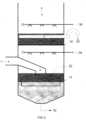
- FIG. 2there is depicted an example of a scrubber system incorporating the flooded scrubber heads of the present invention which is comprised of a scrubbing vessel (11) containing two flooded heads 12, 14.
- the process of gas contamination removal using the system of Figure 2begins with introduction of the contaminated gas 1 from a combustion or industrial process that generates particulate matter, acid gases and metals that require removal.
- the gasenters a lowermost plenum 3 bounded by a reservoir of a first scrubbing fluid 31 (or a solid membrane) below and a flooded head 12 above.
- the gasenters under positive pressure created by an induced draft fan (not shown).
- the gas pressureis sufficient to support a desired depth of a first scrubbing fluid on the heads 12, 14 and to overcome the pressure drop incurred by the gas as it passes through the ports in the heads.
- Preferred pressure at the lowermost plenum 3is 450mm of water.
- the gasrises through the ports in the lowermost head 12 at a velocity in the range of 20 to 25 meters per second.
- the gasenters a turbulent first scrubbing fluid reaction zone volume 33 where the gas and first scrubbing fluid are aggressively mixed.
- the first scrubbing fluidis selected for it reactivity with a first group of contaminants targeted for removal.
- the first scrubbing fluid level on the lowermost head 12is controlled by overflow tubes that pass through the head to the first scrubbing fluid reservoir 31 that is typically located in the base of the scrubber vessel 11.
- the overflow first scrubbing fluid 37is replaced by conditioned first scrubbing fluid 34 from a first scrubbing fluid inlet distribution header 13 in order to maintain fluid level and reactivity with the contaminants being removed.
- the aggressive turbulence created in the wet scrubberwill efficiently remove particulate matter from the gas and transfer it to the scrubbing fluid.
- the gasrises under the remaining pressure to repeat the process, passing through a second flooded head 14 into a turbulent second scrubbing fluid reaction zone volume 35.
- the depth of the second scrubbing fluid reaction zone volume 35is controlled by a second scrubbing fluid outlet, which may be a plurality of overflow troughs 23 that transfer the second scrubbing fluid from the scrubber vessel and route it to a second scrubbing fluid reservoir not shown.
- the second scrubbing fluid on head 14can be a different scrubbing fluid than that on head 12, thus allowing polishing or alternative contaminants to be removed.
- Second scrubbing fluid on head 14is constantly replaced with conditioned scrubbing fluid 36.
- the decontaminated gas 7 exiting the second scrubbing fluid reaction zone volume 35can be ducted to the stack or further processes.
- additional flooded scrubbing headsmay be serially added vertically within the scrubber body for further polishing or removal of other air pollutants as required by the process.
- FIG. 3there is shown an example of a system comprising a scrubbing vessel 11 containing a submerged lowermost head 22 beneath a flooded head 14 functioning as a second scrubbing head.
- the process in Figure 3begins with the contaminated gas 1 from a combustion or industrial process that generates particulate matter, acid gases and metals that require removal.
- the gasis ducted to the submerged scrubber head 22.
- the gasenters under positive pressure created by an induced draft fan (not shown).
- the gas pressureis sufficient to overcome the pressure created by the depth of a first scrubbing fluid on the lowermost head 22 and support the depth of a second scrubbing fluid to be supported on the second flooded head 14.
- Additional gas pressureis incorporated into the design to overcome the pressure drop incurred by the gas as it passes through the ports in the heads and losses incurred in the ducting of the gas.
- Preferred pressure at the lowermost plenum 3is 450mm of water.
- the gasrises through the ports in the submerged head 22 at a velocity determined by the design of the head.
- the gasenters a turbulent first scrubbing fluid reaction zone volume 33 where the gas and first scrubbing fluid are aggressively mixed in a turbulent first scrubbing fluid reaction zone volume.
- the first scrubbing fluidis selected for its reactivity with a first group of contaminants targeted for removal.
- the first scrubbing fluid level on the submerged head 22is controlled by sensors such as differential pressure sensors which activate control valves to regulate the flow of fluid exiting for recirculation via a first scrubbing fluid outlet 32 in the floor of the vessel.
- Conditioned first scrubbing fluid 34is added through a first scrubbing fluid inlet distribution header 13 in order to maintain reactivity with the contaminants being removed. In addition to chemical reactivity, the aggressive turbulence created in the wet scrubber will efficiently remove particulate matter from the gas and transfer it to the scrubbing fluid. After exiting the turbulent first scrubbing fluid reaction zone volume 33 the gas rises under the remaining pressure to repeat the process, passing through flooded head 14 into a turbulent second scrubbing fluid reaction zone volume 35.
- the depth of the second scrubbing fluid reaction zone volume 35is controlled by a second scrubbing fluid outlet, which may be a plurality of overflow troughs 23 that transfer the second scrubbing fluid from the scrubber vessel and route it to a second scrubbing fluid reservoir (not shown).
- a second scrubbing fluid outletwhich may be a plurality of overflow troughs 23 that transfer the second scrubbing fluid from the scrubber vessel and route it to a second scrubbing fluid reservoir (not shown).
- the upper flooded head 14can operate with a different scrubbing fluid than is used on the submerged head 22 thus allowing polishing or the addition of alternative reagents to remove other regulated contaminants.
- Second scrubbing fluid on the flooded head 14is constantly replaced with conditioned second scrubbing fluid 36 carried by second scrubbing fluid inlet distribution header 15.
- the decontaminated gas 7 exiting the second scrubbing fluid reaction zone volumecan be ducted to the stack or further processes.
- additional flooded scrubbing headsmay be serially added vertically within the scrubber vessel for further polishing or removal of other air pollutants as required by the process.
- One or more flooded scrubbing heads as embodied in the present inventionoffer advantages over the current art represented by submerged scrubbing heads. Among the advantages is the ability to supply wet scrubbing of 100% of the gas at multiple levels of interaction zones with different neutralizing reagents within a single scrubbing body. This attribute allows a single scrubbing device to remove a broader range of pollutants at higher removal efficiencies. Scrubbers utilizing the flooded head design will have a smaller and highly flexible footprint, lower capital cost, scalability and capacity to remove multiple pollutants in a single device.
- the flooded headhas application in combustion processes including coal, biomass and municipal solid waste where the primary pollutants targeted for removal are particulate matter, acid gases including sulphur dioxide, hydrogen chloride and hydrogen fluoride, metals including mercury.
- scrubbers used in chemical and industrial processes requiring the removal of dust, odors and acid gasesare candidates for flooded head designs in both new and retrofit installations.
Landscapes
- Chemical & Material Sciences (AREA)
- Engineering & Computer Science (AREA)
- Chemical Kinetics & Catalysis (AREA)
- Analytical Chemistry (AREA)
- General Chemical & Material Sciences (AREA)
- Oil, Petroleum & Natural Gas (AREA)
- Environmental & Geological Engineering (AREA)
- Health & Medical Sciences (AREA)
- Biomedical Technology (AREA)
- Treating Waste Gases (AREA)
- Gas Separation By Absorption (AREA)
- Separation Of Particles Using Liquids (AREA)
Description
- The invention relates to the removal of air pollution emissions and particularly relates to an apparatus for scrubbing multiple contaminants from gases.
- The air pollution emissions resulting from the combustion of coal, municipal solid waste and biomass, and air emissions from chemical and industrial processes have been increasingly restricted by governmental environmental agencies as a result of greater public demand for environmental protection coupled with advancements in pollution abatement technologies which allow more restrictive standards to be implemented. The restrictions vary by nation, region and proximity of the air pollution source to population centers. The regulations target a wide range of combustion by-products including particulate matter; acid gases such as sulphur dioxide, hydrogen chloride and hydrogen fluoride and metals such as mercury and metal groups known for their detrimental effects on human health. Many of the pollution abatement systems in use today by utilities and industrial processes have a history of development dating from the establishment of the first environmental regulations. These devices employ known chemical and mechanical processes to remove the regulated pollution components from gas streams. The stringent emission limits in force today and those more stringent limits pending implementation require alternative approaches. These alternative approaches include adding refinements to existing technologies to enhance their pollutant removal efficiency.
- The emissions resulting from the combustion of diesel fuels in marine and power generation applications are also sources of regulated emissions. General cargo and container ships that carry the goods of international trade are burning bunker grade fuels that contain in the range of 2.5% to 2.7% sulphur. In addition, these marine diesel engines produce large amounts of ash, soot and unburned fuel that are emitted to the atmosphere on the world's oceans. The sulphur and particulate emissions are greater than permitted by the environmental regulations for land based operations. Regulations for these emissions in territorial waters as well as dockside are being implemented by regional and national environmental agencies and in international waters by the International Marine Organization. The options available to meet the demands of these regulation include adding scrubbing technologies or changing the fuel supply for ships to low sulphur fuels.
- Emission technologies for the combustion processes noted above generally can be divided into wet and dry systems. Dry systems utilize different technologies to address the removal of acid gases and particulate. Dry flue gas desulphurization is commonly accomplished by devices such as a spray dryer tower. Common among the dry particulate systems are bag filters and electrostatic precipitators.
- Wet systems used in conjunction with combustion flue gases commonly use aqueous based slurry containing an alkaline material such as limestone, lime, hydrated lime or enhanced lime as a neutralizing agent. Wet scrubbing systems employ several methods to create an interaction between the aqueous slurry and the contaminated flue gas. A simple approach uses sprayers in a spray tower or similar device to distribute the slurry into the flue gas to remove sulphur dioxide, hydrogen chloride and hydrogen fluoride through reaction with the slurry to form calcium based compounds. The interaction between the flue gas and the sprayed slurry is general in nature and is not as efficient or effective as forced wet scrubbing systems.
- Forced wet scrubbing systems employ design approaches which force the flue gas into alkaline reagents contained in an aqueous slurry. The design of these systems creates a turbulent reaction zone that increases reaction time, and ensures complete interaction between the flue gas and alkaline slurry which improves acid gas removal efficiency. In addition, the turbulent zone creates an environment for the transfer of particulate matter from the flue gas to the scrubbing solution. These turbulent zones are generated by scrubbing heads containing ports submerged in a body of scrubbing fluid. The flue gas passes through the ports at high velocity which creates a turbulent zone in the scrubbing solution that transfers the particulate and provides a reaction zone for chemical interactions.
- Thus, this form of wet system has the capacity to remove multiple pollutants in a single pass. It is however, limited to operating with a single interaction in the scrubbing fluid reservoir, typically located at the base of the scrubber. Its approach does not allow stacking the scrubbing heads so as to attain multiple scrubbing zones as the gas rises through the scrubber.
- Document
US 2012/0097031 A1 discloses a scrubber for removing contaminants from a gas stream, comprising a tank, a submerged head extending horizontally, wherein the submerged head comprises a plate having slots extending throughout, four solid joined vertical walls inset from the walls of the tank below the plate to form an open ended box under the plate, and openings along each edge of the plate between the walls of the tank and the vertical walls of the submerged head; a first baffle above the submerged head and means for spraying scrubbing fluid. - Document
CN 104324587 A relates to gas-liquid mass transfer devices in the technical fields of chemical engineering and environmental protection. A thin-hole sieve-plate-typed bubble column comprises a cylinder body, a gas inlet, a gas outlet, a micro-channel thin-hole sieve plate, an imbibing breathable net and a downflow apparatus. A liquid phase is fed to the imbibing breathable net and is carried by a gas fed into the bubble column to form a gas-liquid mixture. The gas-liquid mixture passes through the micro-channel thin holes in the sieve plate to form a bubbling layer above a column plate. In the thin-hole sieve-plate-typed bubble column, the micro-channel thin-hole sieve plate and the imbibing breathable net are employed and a method of supplying the liquid from under the plate is employed so that the gas-liquid flow is formed and is passed through the micro channels, thereby significantly increasing a gas-liquid contacting area and enhancing a mass transfer process. - Document
US 2010/0139488 A1 discloses an apparatus and process for removing acidic gases from flue gases produced by, for example, utility and industrial facilities. The acidic gases are removed as the flue gas flows upward through a contact zone within a passage, where the flue gas is contacted with an ammonium sulfate-containing scrubbing solution to absorb the acidic gases from the flue gas. The scrubbing solution and absorbed acidic gases therein are then accumulated, and ammonia and an oxygen-containing gas are injected into the accumulated scrubbing solution to react the absorbed acidic gases and produce ammonium sulfate. An acid solution is flowed across the passage above the contact zone of the passage, and the scrubbed flue gas is flowed upward through the acid solution to remove unreacted ammonia from the scrubbed flue gas. The acid solution is then removed from the passage after the acid solution has been contacted by the scrubbed flue gas. - Document
WO 2015/030352 A1 discloses an exhaust gas desulfurization apparatus for a ship for performing desulfurization treatment on exhaust gas by using sea water. The apparatus comprises a body having a gas supply pipe for introducing the exhaust gas therein and a gas discharge pipe for discharging the exhaust gas; a swirling treatment unit for swirling the exhaust gas introduced into the body; a dissolution treatment unit for enabling the exhaust gas to pass through the sea water; a collection treatment unit having a filling material for collecting pollutants from the exhaust gas; a spray pipe for spraying and supplying the sea water to the swirling treatment unit, the dissolution treatment unit, and the collection treatment unit; and a discharge pipe for discharging the sea water to the swirling treatment unit, the dissolution treatment unit, and the collection treatment unit, and the sea water of the spray pipe is directly supplied from the sea water and the sea water of the discharge pipe is not reused. - Document
US 3,395,510 discloses a gas scrubber comprising a closed vessel having an inlet opening to admit a particle-contaminated gas and an outlet opening to deliver scrubbed gas; and a plurality of serially arranged scrubbing stages, each stage comprising injection means disposed between the inlet and outlet openings for injecting steam into the gas, cooling means disposed between the injection means and the outlet opening for cooling the mixed gas and steam whereby the steam condenses in water droplets around the particles which serve as condensation nuclei, a first temperature sensor disposed between the inlet opening and the injection means, a second temperature sensor disposed between the injection means and the cooling means, a controller connected to the first and second temperature sensors, a valve connected to the controller for controlling the amount of steam reaching the injection means, and filter means disposed between the cooling means and the outlet opening for filtering the gas to remove the droplets and the particles entrained in the droplets. - The more restrictive emission limits being imposed on industry to control air pollutants from combustion, industrial and chemical processes require enhanced approaches in order to provide high efficiency and cost-effective abatement systems.
- It is a problem to provide a highly efficient and cost-effective scrubber apparatus and method for removing a plurality of distinct contaminants from a contaminated gas stream.
- This problem is solved by the vertically-oriented scrubber apparatus having the features disclosed in
claim 1, and by the method having the features disclosed in claim 6. Preferred embodiments are defined in the dependent claims. - The scrubber apparatus may have one or more additional flooded heads extending horizontally across the entire cross-section of the scrubber vessel and stacked vertically above the other heads, each defining an additional velum in relation to the head below; one or more additional scrubbing fluid reaction zone volumes, each disposed above a corresponding flooded head to a desired level, each additional scrubbing fluid selected to remove a desired additional group of contaminants from the contaminated gas stream; and one or more additional scrubbing fluid inlets extending through the wall into the corresponding additional velum above the corresponding additional flooded head, additional corresponding spraying means in fluid connection with the additional scrubbing fluid inlet for spraying the additional scrubbing fluid into the corresponding additional scrubbing fluid reaction zone volume, and one or more corresponding additional scrubbing fluid outlets above the corresponding flooded head passing through the wall of the scrubber vessel.
- The gas inlet may be located at the top end of the vessel and a gas inlet duct conducts the gas to a position below the lowermost head; or at the side of the vessel and a gas inlet duct conducts the gas to a position below the lowermost head; or below the lowermost head of the vessel.
- The apparatus may further comprise a mist eliminator consisting of an absorbent mesh extending across the scrubber vessel. Each of the spraying means may be one or more spray nozzles. The size of the slots in the flooded heads may be selected to prevent passage therethrough of scrubbing fluid in the presence of pressurized gas below the head.
- There is further provided the use of such a scrubber apparatus remove multiple contaminants from a contaminated gas stream according to a method comprising the steps of introducing a first scrubbing fluid into the apparatus to a desired fluid level above the lowermost scrubber head; introducing a second scrubbing fluid into the apparatus to a desired level above the next highest scrubber head; cooling a contaminated process gas using a prior art gas conditioner; introducing the cooled contaminated gas under pressure from an induced draft fan into the apparatus at a position below the lowermost scrubber head; allowing the gas to pass upwardly through the lowermost scrubber head to transfer a first group of contaminants from the contaminated gas into the first scrubbing fluid in a first scrubbing fluid reaction zone volume above the lowermost scrubber head; allowing the gas to continue passing upwardly through the next highest scrubber head to transfer a second group of contaminants from the contaminated gas into the second scrubbing fluid in a second scrubbing fluid reaction zone volume above the next highest scrubber head; spraying the exiting gas to remove additional contaminants and slow the gas flow velocity; allowing the exiting gas to exit the scrubbing apparatus; separately removing first and second scrubbing fluids from the scrubber vessel to maintain a desired level of each scrubbing fluid; and cleaning drained scrubbing fluids for reuse in the scrubbing apparatus.
- Another embodiment provides a scrubber apparatus for removing multiple contaminants from a contaminated gas stream, comprising a scrubber vessel having a series of vertically-stacked scrubber heads, each scrubber head flooded with a different scrubbing fluid, each scrubbing fluid selected to remove a desired group of contaminants from the contaminated gas stream, wherein the contaminated gas flows under pressure from below the lowermost scrubber head upwardly through the series of flooded scrubber heads.
- The apparatus may be used to remove from a contaminated gas stream multiple contaminants selected from the group of contaminants comprising particulate matter, metals, hydrogen chloride, hydrogen fluoride, nitrous oxide, nitric oxide, carbon dioxide, and sulfur dioxide.
- The present invention employs a proprietary flooded horizontal scrubbing head that occupies the entire scrubber cross section. The polluted gas passes from below to above the head through an array of ports cut into the head. Scrubbing fluid is supported above the head by the gas as the gas passes through ports at high velocity to create a turbulent reaction zone within the supported scrubbing fluid. The level of scrubbing fluid is controlled by overflow pipes or troughs and fluid is constantly added by distribution nozzles located above the turbulent zone. Further flooded horizontal heads can be added above the initial head at vertical intervals in the scrubber's cross-section. Using the flooded head approach, the present invention allows complete wet scrubbing at multiple levels, each level capable of operating with different neutralizing reagents. The capacity for multiple scrubbing zones provides the opportunity to improve overall removal efficiencies by adding polishing reaction zones for particulate and acid gas removal or by broadening the range of pollutants being removed by operating with a different neutralizing solution, or a combination of these operating conditions.
- The present invention takes a novel approach to the creation of a turbulent scrubbing reaction zone at each of multiple levels with the capacity to use different neutralizing reagents at each level. Whereas traditional approaches use pressure differential across a scrubbing head to force gas through an array of ports submerged in a body of fluid, the present invention uses pressure differential to support the scrubbing fluid on top of a horizontal scrubbing head. The horizontal scrubbing head contains an array of ports through which the gas passes vertically upward into the flooded zone. The pressure differential and port design accelerates the gas sufficiently to create the desired highly turbulent reaction in the flooded zone above the head. The horizontal orientation of the scrubbing head allows multiple heads to be stacked within the same scrubber body. The flooded scrubber heads occupy the entire cross section of the scrubber body which devotes 100% of the scrubber's cross sectional area to scrubbing and the transit of gas. The horizontal orientation allows the scrubbing head to be any shape required by the space available for the scrubbing equipment. Because it has the capacity to remove multiple pollutants in a single pass the system has a smaller footprint than the accumulation of equipment that it replaces and as a single unit it is more cost-effective than multiple single purpose units. The flooded head can be incorporated into new scrubber designs or retrofitted into existing wet scrubbers using a submerged head design approach at its lowest level.
- The flooded scrubbing head system is based upon a vertical orientation of the scrubber body and the horizontal orientation of the flooded scrubbing heads. The gas enters a plenum area above the scrubbing fluid reservoir in the base of the scrubber body and below the first flooded head. The gas is moved to the plenum by an induced draft fan capable of providing the volume required for the flue gas emission and pressure differential required to support the multiple reaction zones above the scrubbing head levels in the design. The pressure in the plenum is sufficient to force the gas through ports in the head and into a turbulent reaction zone above the head. The size, shape and plurality of the ports in the head are such that the gas is sufficiently accelerated to create the desired depth and vigor of turbulence above the head.
- The fluid on each head is continuously circulated. The scrubbing fluid is pumped from a fluid reservoir to a network of fluid distribution nozzles that deliver scrubbing fluid to the area above each head. Return to the reservoir is provided by fluid level controls such as overflow troughs or standpipes that pipe the fluid back to the reservoir. The condition of the returning fluid is monitored for control factors such as pH and the reservoir is conditioned with additional neutralizing reagents to return the fluid to its optimum reaction condition before redistribution above the head. In addition, the fluid may be processed by solids removal devices such as hydrocyclones to remove particulate matter collected by the scrubbing fluid.
- As the gas continues to rise in the flooded head scrubber it encounters additional flooded scrubbing heads with the same configuration of ports, fluid distribution and overflows to fluid reservoirs. In cases where different scrubbing fluids are employed, the overflows direct the alternative scrubbing Upon exiting the turbulent zone of the final head the gas rises through demisters or similar devices to remove free water from the gas. The gas is available to be ducted to the stack or further processes if required.
- The flooded head system can also be used in conjunction with submerged scrubbing heads at the base level of the scrubber. After exiting the turbulent zone above the submerged scrubbing head the gas rises under pressure to a flooded head(s) that operate in the full cross section of the scrubber in the same manner as described above.
- A detailed description of the preferred embodiment is provided below by way of example only and with reference to the following drawings in which:
Figure 1A is a top view of a schematic drawing of one embodiment of the flooded scrubber head of the present invention;- Figure IB is a lateral cross-sectional view through 1B-1B of the flooded scrubber head depicted in
Fig. 1A ; Figure 1C is a blow-up schematic view of one corner of the embodiment of a flooded scrubber head shown inFig. 1A ;Figure 2 is a cross-sectional view of a multiple level scrubber having the flooded scrubber head of the present invention at each scrubbing level; andFigure 3 is a schematic of an embodiment of a system (not according to the invention) where initial scrubbing is performed by a submerged scrubbing head and the flooded scrubber head is used for scrubbing on subsequent levels above the initial head.- The present invention provides a means of creating multiple wet
scrubbing interaction levels single scrubber vessel 11, each level of which is capable of scrubbing 100% of the gas flow with a different scrubbing fluid. The present invention uses a scrubber head design whose horizontal orientation and flooded operating characteristics allow the stacking of multiple heads within a single wet scrubber body. The ability to incorporate additional scrubbing interaction zones in a single system provides the opportunity to increase overall removal efficiency for pollutants such as particulate matter, acid gases or metals by adding polishing steps or to remove additional regulated pollutants by utilizing other neutralizing reagents. By incorporating the flooded scrubber heads of the present invention in wet scrubber designs the resulting system will have lower capital costs, a smaller footprint and higher efficiency removal of multiple pollutants. - Referring to
Figures 1A to 1C , the scrubbinghead 50 is shown as a generic form to demonstrate the elements of the head. Thehead 50 operates in a horizontal orientation. The head may be manufactured from any sheet or plate material with sufficient strength, stiffness, and thermal and chemical resistance properties. Typical materials are metal plate with the preferred materials being stainless steel. The horizontal cross-sectional shape of the head conforms to the shape of the scrubber body so as to allow a sealed fit between the periphery of the scrubber head and the inner circumference of the scrubber vessel. The head contains a plurality ofports 61 that may be in any shape, number and orientation to the head. The preferred port shape is a slot with length in the range of 125 to 200mm with a preferred width of 2mm. The spacing 63 of the ports is typically in the range of 20 to 25mm. Themargins 65 between the ports and the edge of the head are uniform with a preferred distance of 40mm. The head may containaccelerator plates 71 oriented at right angles to the head. The accelerator plates equally divide the space between the rows ofports 61. Themargin 65 between the accelerator plates and theports 61 is maintained at a preferred distance of 40mm. The accelerator plates are typically 150mm in height and contain scuppers at the head deck level to allow the lateral transfer of scrubbing fluid. The accelerator plate is of the same material as the scrubber head. Other parameters for the ports, margins, and accelerator plates are permitted within the scope of the invention. - Referring to
Figure 2 , there is depicted an example of a scrubber system incorporating the flooded scrubber heads of the present invention which is comprised of a scrubbing vessel (11) containing two floodedheads - The process of gas contamination removal using the system of
Figure 2 begins with introduction of the contaminatedgas 1 from a combustion or industrial process that generates particulate matter, acid gases and metals that require removal. The gas enters alowermost plenum 3 bounded by a reservoir of a first scrubbing fluid 31 (or a solid membrane) below and a floodedhead 12 above. The gas enters under positive pressure created by an induced draft fan (not shown). The gas pressure is sufficient to support a desired depth of a first scrubbing fluid on theheads lowermost plenum 3 is 450mm of water. The gas rises through the ports in thelowermost head 12 at a velocity in the range of 20 to 25 meters per second. The gas enters a turbulent first scrubbing fluid reaction zone volume 33 where the gas and first scrubbing fluid are aggressively mixed. The first scrubbing fluid is selected for it reactivity with a first group of contaminants targeted for removal. The first scrubbing fluid level on thelowermost head 12 is controlled by overflow tubes that pass through the head to the firstscrubbing fluid reservoir 31 that is typically located in the base of thescrubber vessel 11. The overflow first scrubbingfluid 37 is replaced by conditioned first scrubbingfluid 34 from a first scrubbing fluidinlet distribution header 13 in order to maintain fluid level and reactivity with the contaminants being removed. In addition to chemical reactivity, the aggressive turbulence created in the wet scrubber will efficiently remove particulate matter from the gas and transfer it to the scrubbing fluid. After exiting the turbulent first scrubbing fluid reaction zone volume the gas rises under the remaining pressure to repeat the process, passing through a second floodedhead 14 into a turbulent second scrubbing fluidreaction zone volume 35. For illustrative purposes the depth of the second scrubbing fluidreaction zone volume 35 is controlled by a second scrubbing fluid outlet, which may be a plurality ofoverflow troughs 23 that transfer the second scrubbing fluid from the scrubber vessel and route it to a second scrubbing fluid reservoir not shown. Using this approach, the second scrubbing fluid onhead 14 can be a different scrubbing fluid than that onhead 12, thus allowing polishing or alternative contaminants to be removed. Second scrubbing fluid onhead 14 is constantly replaced with conditioned scrubbingfluid 36. The decontaminatedgas 7 exiting the second scrubbing fluidreaction zone volume 35 can be ducted to the stack or further processes. Using this same approach, additional flooded scrubbing heads may be serially added vertically within the scrubber body for further polishing or removal of other air pollutants as required by the process. - Referring to
Figure 3 , there is shown an example of a system comprising a scrubbingvessel 11 containing a submergedlowermost head 22 beneath a floodedhead 14 functioning as a second scrubbing head. - The process in
Figure 3 begins with the contaminatedgas 1 from a combustion or industrial process that generates particulate matter, acid gases and metals that require removal. The gas is ducted to the submergedscrubber head 22. The gas enters under positive pressure created by an induced draft fan (not shown). The gas pressure is sufficient to overcome the pressure created by the depth of a first scrubbing fluid on thelowermost head 22 and support the depth of a second scrubbing fluid to be supported on the second floodedhead 14. Additional gas pressure is incorporated into the design to overcome the pressure drop incurred by the gas as it passes through the ports in the heads and losses incurred in the ducting of the gas. Preferred pressure at thelowermost plenum 3 is 450mm of water. The gas rises through the ports in the submergedhead 22 at a velocity determined by the design of the head. The gas enters a turbulent first scrubbing fluid reaction zone volume 33 where the gas and first scrubbing fluid are aggressively mixed in a turbulent first scrubbing fluid reaction zone volume. The first scrubbing fluid is selected for its reactivity with a first group of contaminants targeted for removal. The first scrubbing fluid level on the submergedhead 22 is controlled by sensors such as differential pressure sensors which activate control valves to regulate the flow of fluid exiting for recirculation via a firstscrubbing fluid outlet 32 in the floor of the vessel. Conditioned first scrubbingfluid 34 is added through a first scrubbing fluidinlet distribution header 13 in order to maintain reactivity with the contaminants being removed. In addition to chemical reactivity, the aggressive turbulence created in the wet scrubber will efficiently remove particulate matter from the gas and transfer it to the scrubbing fluid. After exiting the turbulent first scrubbing fluid reaction zone volume 33 the gas rises under the remaining pressure to repeat the process, passing through floodedhead 14 into a turbulent second scrubbing fluidreaction zone volume 35. For illustrative purposes the depth of the second scrubbing fluidreaction zone volume 35 is controlled by a second scrubbing fluid outlet, which may be a plurality ofoverflow troughs 23 that transfer the second scrubbing fluid from the scrubber vessel and route it to a second scrubbing fluid reservoir (not shown). Using this approach, the upper floodedhead 14 can operate with a different scrubbing fluid than is used on the submergedhead 22 thus allowing polishing or the addition of alternative reagents to remove other regulated contaminants. Second scrubbing fluid on the floodedhead 14 is constantly replaced with conditioned second scrubbingfluid 36 carried by second scrubbing fluidinlet distribution header 15. The decontaminatedgas 7 exiting the second scrubbing fluid reaction zone volume can be ducted to the stack or further processes. Using this same approach, additional flooded scrubbing heads may be serially added vertically within the scrubber vessel for further polishing or removal of other air pollutants as required by the process. - One or more flooded scrubbing heads as embodied in the present invention offer advantages over the current art represented by submerged scrubbing heads. Among the advantages is the ability to supply wet scrubbing of 100% of the gas at multiple levels of interaction zones with different neutralizing reagents within a single scrubbing body. This attribute allows a single scrubbing device to remove a broader range of pollutants at higher removal efficiencies. Scrubbers utilizing the flooded head design will have a smaller and highly flexible footprint, lower capital cost, scalability and capacity to remove multiple pollutants in a single device. The flooded head has application in combustion processes including coal, biomass and municipal solid waste where the primary pollutants targeted for removal are particulate matter, acid gases including sulphur dioxide, hydrogen chloride and hydrogen fluoride, metals including mercury. In addition, scrubbers used in chemical and industrial processes requiring the removal of dust, odors and acid gases are candidates for flooded head designs in both new and retrofit installations.
- From the foregoing, it will be seen that this invention is one well adapted to attain all of the ends and objectives herein set forth, together with other advantages which are obvious and which are inherent to the system. It will be understood that certain features and sub-combinations are of utility and may be employed with reference to other features and sub-combinations. This is contemplated by and is within the scope of the claims. Many possible embodiments may be made of the invention without departing from the scope of the claims. It is to be understood that all matter herein set forth and shown in the accompanying drawings is to be interpreted as illustrative and not in a limiting sense. It will be appreciated by those skilled in the art that other variations of the preferred embodiment may also be practiced without departing from the scope of the invention.
Claims (7)
- A vertically-oriented scrubber apparatus for removing a plurality of distinct contaminants from a contaminated gas stream, comprising:a) a scrubber vessel (11) having a ceiling, a floor, a cylindrical wall connecting the ceiling to the floor, a plurality of vertically-spaced heads (12, 14), a volume above each head (2, 4), a gas inlet (22), an induced draft fan, and a gas outlet;b) a first scrubbing fluid reservoir (31) disposed within the bottom end of the scrubber vessel (11) to a desired level, the first scrubbing fluid (34) selected to remove a first group of contaminants from the contaminated gas stream;c) a first flooded head (12) extending horizontally across the scrubber vessel (11) at a position above the gas inlet, defining a first volume (3) between the first scrubbing fluid reservoir (31) and the first flooded head (12), wherein the first flooded head (12) comprises a plate (50) having a plurality of narrow slots (61) extending throughout;d) a first scrubbing fluid reaction zone volume (33) disposed to a desired level above the first flooded head (12), the reaction zone volume (33) in fluid connection with the reservoir (31) via one or more overflow tubes (21), each extending from the first scrubbing fluid reservoir (31) through the first flooded head (12) to a desired level above the first flooded head (12);f) a first scrubbing fluid inlet extending through the wall into a second volume (5) above the first flooded head (13), first spraying means (13) in fluid connection with the first scrubbing fluid inlet for spraying the first scrubbing fluid (34) into the first scrubbing fluid reaction zone volume (33), and a first scrubbing fluid outlet (32) in the floor;g) a second flooded head (14) extending horizontally across the entire cross-section of the scrubber vessel (11) at a position above the first flooded head (12), defining a second volume (5) between the first scrubbing fluid reaction zone volume (33) and the second flooded head (14), wherein the second flooded head (14) comprises a plate (50) having a plurality of narrow slots (61) extending throughout;h) a second scrubbing fluid reaction zone volume (35) disposed above the second flooded head (14) to a desired level, the second scrubbing fluid (36) selected to remove a second group of contaminants from the contaminated gas stream; andi) a second scrubbing fluid inlet extending into a third volume above the second flooded head (14), second spraying means (15) in fluid connection with the second scrubbing fluid inlet for spraying the second scrubbing fluid (36) into the second scrubbing fluid reaction zone volume, and a second scrubbing fluid outlet (35) above the second flooded head (14) passing through the wall of the scrubber vessel.
- The scrubber apparatus of claim 1, further comprising:a) one or more additional flooded heads extending horizontally across the entire cross-section of the scrubber vessel (11) and serially stacked vertically above the other heads, each defining an additional volume in relation to the head below;b) one or more additional scrubbing fluid reaction zone volumes, each disposed above a corresponding flooded head to a desired level, each additional scrubbing fluid selected to remove a desired additional group of contaminants from the contaminated gas stream; andc) one or more additional scrubbing fluid inlets extending through the wall into the corresponding additional volume above the corresponding additional flooded head, additional corresponding spraying means in fluid connection with the additional scrubbing fluid inlet for spraying the additional scrubbing fluid into the corresponding additional scrubbing fluid reaction zone volume, and one or more corresponding additional scrubbing fluid outlets above the corresponding flooded head passing through the wall of the scrubber vessel (11).
- The scrubber apparatus of claim 1, wherein the gas inlet is fed by a gas inlet duct which conducts the gas from an intake at the top end of the vessel (11) to the gas inlet.
- The scrubber apparatus of claim 1, wherein a gas inlet duct is located at the side of the vessel and conducts the gas to the gas inlet at a position below the lowermost head.
- The scrubber apparatus of claim 1, wherein the size of the slots (61) in the flooded heads (12, 14) are selected to prevent passage therethrough of scrubbing fluid in the presence of pressurized gas below the flooded heads (12, 14).
- A method of removing multiple contaminants from a contaminated gas stream, the method comprising the steps of:a) introducing a first scrubbing fluid (34) into the apparatus of claim 1 to a desired fluid level above the first flooded scrubber head (12);b) introducing a second scrubbing fluid (36) into the apparatus of claim 1 to a desired level above the second flooded scrubber head (14);c) cooling a contaminated process gas (1) using a prior art gas conditioner;d) introducing the cooled contaminated gas (1) under pressure from an induced draft fan into the apparatus of claim 1 at a position below the first flooded scrubber head (12);e) allowing the gas (1) to pass upwardly through the first flooded head (12) to transfer a first group of contaminants from the contaminated gas (1) into the first scrubbing fluid (34) in a first scrubbing fluid reaction zone volume (33) above the first flooded head (12);f) allowing the gas (1) to continue passing upwardly through the second flooded head (14) to transfer a second group of contaminants from the contaminated gas (1) into the second scrubbing fluid (36) in a second scrubbing fluid reaction zone volume (35) above the second flooded head (14);g) spraying the exiting gas (7) to remove additional contaminants and slow the gas flow velocity;h) allowing the exiting gas (7) to exit the scrubbing apparatus;i) separately removing first and second scrubbing fluids (34, 36) from the scrubber vessel (11) to maintain a desired level of each scrubbing fluid (34, 36); andj) cleaning drained scrubbing fluids (34, 36) for reuse in the scrubbing apparatus.
- The method of claim 6, further comprising the additional step (ff) after step (f) of:
ff) allowing the gas (1) to continue passing upwardly through one or more serially vertically stacked additional flooded heads to transfer one or more additional groups of contaminants from the contaminated gas (1) into one or more additional scrubbing fluids in each of one or more additional scrubbing fluid reaction zone volumes above each of the corresponding flooded heads.
Priority Applications (4)
| Application Number | Priority Date | Filing Date | Title |
|---|---|---|---|
| SM20240248TSMT202400248T1 (en) | 2015-06-02 | 2015-11-02 | Multi-level gas scrubber with multiple flooded scrubber heads |
| RS20240593ARS65650B1 (en) | 2015-06-02 | 2015-11-02 | Multi-level gas scrubber with multiple flooded scrubber heads |
| HRP20240710TTHRP20240710T1 (en) | 2015-06-02 | 2015-11-02 | Multi-level gas scrubber with multiple flooded scrubber heads |
| SI201532016TSI3834913T1 (en) | 2015-06-02 | 2015-11-02 | Multi-level gas scrubber with multiple flooded scrubber heads |
Applications Claiming Priority (3)
| Application Number | Priority Date | Filing Date | Title |
|---|---|---|---|
| US201562169856P | 2015-06-02 | 2015-06-02 | |
| PCT/CA2015/000563WO2016191846A1 (en) | 2015-06-02 | 2015-11-02 | Multi-level gas scrubber with multiple flooded scrubber heads |
| EP15893558.5AEP3302759B1 (en) | 2015-06-02 | 2015-11-02 | Multi-level gas scrubber with multiple flooded scrubber heads |
Related Parent Applications (1)
| Application Number | Title | Priority Date | Filing Date |
|---|---|---|---|
| EP15893558.5ADivisionEP3302759B1 (en) | 2015-06-02 | 2015-11-02 | Multi-level gas scrubber with multiple flooded scrubber heads |
Publications (2)
| Publication Number | Publication Date |
|---|---|
| EP3834913A1 EP3834913A1 (en) | 2021-06-16 |
| EP3834913B1true EP3834913B1 (en) | 2024-02-28 |
Family
ID=57439719
Family Applications (2)
| Application Number | Title | Priority Date | Filing Date |
|---|---|---|---|
| EP20192513.8AActiveEP3834913B1 (en) | 2015-06-02 | 2015-11-02 | Multi-level gas scrubber with multiple flooded scrubber heads |
| EP15893558.5AActiveEP3302759B1 (en) | 2015-06-02 | 2015-11-02 | Multi-level gas scrubber with multiple flooded scrubber heads |
Family Applications After (1)
| Application Number | Title | Priority Date | Filing Date |
|---|---|---|---|
| EP15893558.5AActiveEP3302759B1 (en) | 2015-06-02 | 2015-11-02 | Multi-level gas scrubber with multiple flooded scrubber heads |
Country Status (42)
| Country | Link |
|---|---|
| US (1) | US20180169577A1 (en) |
| EP (2) | EP3834913B1 (en) |
| JP (2) | JP2018516171A (en) |
| KR (1) | KR102505327B1 (en) |
| CN (1) | CN108290104A (en) |
| AU (1) | AU2015397599B2 (en) |
| BR (1) | BR112017025888A2 (en) |
| CA (1) | CA3022784C (en) |
| CO (1) | CO2018000047A2 (en) |
| CR (1) | CR20170606A (en) |
| CU (1) | CU20170150A7 (en) |
| CY (1) | CY1124047T1 (en) |
| DK (2) | DK3834913T3 (en) |
| DO (1) | DOP2017000276A (en) |
| EA (1) | EA033991B1 (en) |
| EC (1) | ECSP18000110A (en) |
| ES (2) | ES2833049T3 (en) |
| FI (1) | FI3834913T3 (en) |
| GE (1) | GEP20207091B (en) |
| HR (2) | HRP20240710T1 (en) |
| HU (2) | HUE053263T2 (en) |
| IL (1) | IL256002B (en) |
| LT (2) | LT3834913T (en) |
| MA (1) | MA41734B1 (en) |
| MX (1) | MX381354B (en) |
| MY (1) | MY199938A (en) |
| NI (1) | NI201700146A (en) |
| NZ (1) | NZ738724A (en) |
| PE (1) | PE20180735A1 (en) |
| PH (1) | PH12018500022A1 (en) |
| PL (2) | PL3834913T3 (en) |
| PT (2) | PT3834913T (en) |
| RS (2) | RS61211B1 (en) |
| SA (1) | SA517390460B1 (en) |
| SG (1) | SG10201902717YA (en) |
| SI (2) | SI3302759T1 (en) |
| SM (2) | SMT202400248T1 (en) |
| SV (1) | SV2017005576A (en) |
| TN (1) | TN2017000504A1 (en) |
| UA (1) | UA123726C2 (en) |
| WO (1) | WO2016191846A1 (en) |
| ZA (1) | ZA201802022B (en) |
Families Citing this family (7)
| Publication number | Priority date | Publication date | Assignee | Title |
|---|---|---|---|---|
| RU2669821C1 (en)* | 2018-01-22 | 2018-10-16 | Анастасия Игоревна Понкратова | Scrubber with movable nozzle |
| KR101895192B1 (en) | 2018-05-23 | 2018-09-04 | 서민수 | Scrubber equipment with inside venturi |
| KR101955862B1 (en) | 2018-11-21 | 2019-03-07 | 서민수 | Scrubber equipment with inside venturi |
| CN110327761A (en)* | 2019-06-28 | 2019-10-15 | 苏州仕净环保科技股份有限公司 | The technique of NOx in a kind of removing flue gas |
| KR102374527B1 (en)* | 2021-07-23 | 2022-03-16 | 주식회사 삼원카본써큘레이션 | Flue Gas Treatment Device Using Flooding in Scrubber Equipped with Packing |
| CN113648775A (en)* | 2021-09-17 | 2021-11-16 | 华东理工大学 | Gas cooling-washing device and method |
| CN117160177B (en)* | 2023-10-09 | 2024-02-13 | 江苏木易鑫雨塑胶科技有限公司 | Waste gas purification device for casting film production equipment |
Family Cites Families (18)
| Publication number | Priority date | Publication date | Assignee | Title |
|---|---|---|---|---|
| US2926754A (en)* | 1956-02-29 | 1960-03-01 | Edw G Ragatz Co | Method for improved mechanical effectiveness and efficiency of component interchangeon a vapor liquid contacting tray |
| GB794389A (en)* | 1956-03-27 | 1958-04-30 | Universal Oil Prod Co | Improvements in or relating to removing an acidic component from a fluid stream |
| US3233881A (en)* | 1962-12-10 | 1966-02-08 | Peabody Engineering Corp | Gas scrubber |
| US3395510A (en)* | 1965-10-23 | 1968-08-06 | Gen Electric | Gas scrubber |
| JPS4892266A (en)* | 1972-03-07 | 1973-11-30 | ||
| US3843789A (en)* | 1973-02-26 | 1974-10-22 | Air Prod & Chem | Removal of sulfur oxides from stack gas |
| JPS5144898B2 (en)* | 1974-03-16 | 1976-12-01 | ||
| SE434468B (en)* | 1982-05-10 | 1984-07-30 | Flaekt Ab | ABSORPTION TOWER FOR GAS WASHING |
| JPS61204022A (en)* | 1985-02-12 | 1986-09-10 | Taiyo Sanso Kk | Method and device for removing acid content in gas |
| EP0267961A4 (en)* | 1986-05-29 | 1990-01-26 | Uk Nii Prirodnykh Gazov | MASS EXCHANGER. |
| DE4201033A1 (en)* | 1992-01-17 | 1993-07-22 | Ingenieurbetrieb Anlagenbau Le | Aerosol sepn. from gas esp. hydrogen@ or oxygen@ stream from water electrolysis - in which supply pipe is surrounded by tube which forms bubble column space and separates space from scrubbing liq. outlet region |
| BE1014869A3 (en)* | 2002-06-06 | 2004-05-04 | Four Industriel Belge | Cooling and / or flushing son and / or |
| US8353980B2 (en)* | 2008-12-05 | 2013-01-15 | Marsulex Environmental Technologies Corporation | Flue gas scrubbing apparatus and process |
| NZ597780A (en)* | 2009-06-25 | 2014-01-31 | Sichel Ltd | Improved gas scrubber apparatus and method |
| JP5966565B2 (en)* | 2012-04-24 | 2016-08-10 | 株式会社Ihi | Carbon dioxide recovery method and recovery apparatus |
| US9700837B2 (en)* | 2013-07-18 | 2017-07-11 | General Electric Technology Gmbh | Wet scrubber nozzle system and method of use for cleaning a process gas |
| KR20150024071A (en)* | 2013-08-26 | 2015-03-06 | (주) 세아그린텍 | Exhaust gas desulfurization apparatus for marine diesel engines |
| CN104324587B (en)* | 2014-09-26 | 2016-08-24 | 常州友达环保科技有限公司 | The board-like bubble tower of fine ga(u)ge screen |
- 2015
- 2015-11-02WOPCT/CA2015/000563patent/WO2016191846A1/ennot_activeCeased
- 2015-11-02CRCR20170606Apatent/CR20170606A/enunknown
- 2015-11-02EAEA201792678Apatent/EA033991B1/enunknown
- 2015-11-02BRBR112017025888Apatent/BR112017025888A2/ennot_activeApplication Discontinuation
- 2015-11-02PLPL20192513.8Tpatent/PL3834913T3/enunknown
- 2015-11-02AUAU2015397599Apatent/AU2015397599B2/ennot_activeCeased
- 2015-11-02MXMX2017015612Apatent/MX381354B/enunknown
- 2015-11-02RSRS20201397Apatent/RS61211B1/enunknown
- 2015-11-02HRHRP20240710TTpatent/HRP20240710T1/enunknown
- 2015-11-02HUHUE15893558Apatent/HUE053263T2/enunknown
- 2015-11-02SISI201531429Tpatent/SI3302759T1/enunknown
- 2015-11-02SMSM20240248Tpatent/SMT202400248T1/enunknown
- 2015-11-02USUS15/579,061patent/US20180169577A1/ennot_activeAbandoned
- 2015-11-02CNCN201580082143.4Apatent/CN108290104A/enactivePending
- 2015-11-02HRHRP20201858TTpatent/HRP20201858T1/enunknown
- 2015-11-02ESES15893558Tpatent/ES2833049T3/enactiveActive
- 2015-11-02CUCU2017000150Apatent/CU20170150A7/enunknown
- 2015-11-02PTPT201925138Tpatent/PT3834913T/enunknown
- 2015-11-02FIFIEP20192513.8Tpatent/FI3834913T3/enactive
- 2015-11-02LTLTEP20192513.8Tpatent/LT3834913T/enunknown
- 2015-11-02EPEP20192513.8Apatent/EP3834913B1/enactiveActive
- 2015-11-02MAMA41734Apatent/MA41734B1/enunknown
- 2015-11-02EPEP15893558.5Apatent/EP3302759B1/enactiveActive
- 2015-11-02SGSG10201902717YApatent/SG10201902717YA/enunknown
- 2015-11-02UAUAA201713022Apatent/UA123726C2/enunknown
- 2015-11-02KRKR1020177037865Apatent/KR102505327B1/enactiveActive
- 2015-11-02GEGEAP201514659Apatent/GEP20207091B/enunknown
- 2015-11-02SISI201532016Tpatent/SI3834913T1/enunknown
- 2015-11-02DKDK20192513.8Tpatent/DK3834913T3/enactive
- 2015-11-02RSRS20240593Apatent/RS65650B1/enunknown
- 2015-11-02CACA3022784Apatent/CA3022784C/enactiveActive
- 2015-11-02MYMYPI2017704581Apatent/MY199938A/enunknown
- 2015-11-02PEPE2017002513Apatent/PE20180735A1/enunknown
- 2015-11-02NZNZ738724Apatent/NZ738724A/ennot_activeIP Right Cessation
- 2015-11-02ESES20192513Tpatent/ES2980559T3/enactiveActive
- 2015-11-02SMSM20200629Tpatent/SMT202000629T1/enunknown
- 2015-11-02HUHUE20192513Apatent/HUE066893T2/enunknown
- 2015-11-02JPJP2017563120Apatent/JP2018516171A/enactivePending
- 2015-11-02PTPT158935585Tpatent/PT3302759T/enunknown
- 2015-11-02TNTNP/2017/000504Apatent/TN2017000504A1/enunknown
- 2015-11-02PLPL15893558Tpatent/PL3302759T3/enunknown
- 2015-11-02LTLTEP15893558.5Tpatent/LT3302759T/enunknown
- 2015-11-02ILIL256002Apatent/IL256002B/enunknown
- 2015-11-02DKDK15893558.5Tpatent/DK3302759T3/enactive
- 2017
- 2017-11-30DODO2017000276Apatent/DOP2017000276A/enunknown
- 2017-12-01NINI201700146Apatent/NI201700146A/enunknown
- 2017-12-01SVSV2017005576Apatent/SV2017005576A/enunknown
- 2017-12-02SASA517390460Apatent/SA517390460B1/enunknown
- 2018
- 2018-01-02COCONC2018/0000047Apatent/CO2018000047A2/enunknown
- 2018-01-02ECECIEPI2018110Apatent/ECSP18000110A/enunknown
- 2018-01-03PHPH12018500022Apatent/PH12018500022A1/enunknown
- 2018-03-27ZAZA2018/02022Apatent/ZA201802022B/enunknown
- 2020
- 2020-10-15JPJP2020173664Apatent/JP2021007947A/enactivePending
- 2020-11-19CYCY20201101098Tpatent/CY1124047T1/enunknown
Also Published As
Similar Documents
| Publication | Publication Date | Title |
|---|---|---|
| EP3834913B1 (en) | Multi-level gas scrubber with multiple flooded scrubber heads | |
| US10143957B2 (en) | High-efficiency gradient hierarchy complex desulfurizing tower | |
| EP2509701B1 (en) | Gas scrubber apparatus and method | |
| US6402816B1 (en) | Gas scrubber | |
| EP2826541B1 (en) | Wet scrubber nozzle system and method of use for cleaning a process gas | |
| US20080173176A1 (en) | Fluid scrubber | |
| HK40051892B (en) | Multi-level gas scrubber with multiple flooded scrubber heads | |
| US20220134272A1 (en) | Compact venturi scrubber and method to treat gas streams utilizing the compact venturi scrubber | |
| HK40051892A (en) | Multi-level gas scrubber with multiple flooded scrubber heads | |
| KR101908561B1 (en) | SCR system comprising with multi-reactor and direct straight connector | |
| HK1253790B (en) | Multi-level gas scrubber with multiple flooded scrubber heads | |
| HK1253790A1 (en) | Multi-level gas scrubber with multiple flooded scrubber heads | |
| CN107921361A (en) | Flue gas desulfurization with seawater absorbers combination | |
| CN206793352U (en) | Absorption tower for flue gas desulphurization system | |
| OA18500A (en) | Multi-level gas scrubber with multiple flooded scrubber heads. | |
| RU140855U1 (en) | FOAM UNIT WITH TURBULENCE GENERATOR FOR WET GAS CLEANING | |
| WO2008088347A1 (en) | Fluid scrubber |
Legal Events
| Date | Code | Title | Description |
|---|---|---|---|
| STAA | Information on the status of an ep patent application or granted ep patent | Free format text:STATUS: UNKNOWN | |
| PUAI | Public reference made under article 153(3) epc to a published international application that has entered the european phase | Free format text:ORIGINAL CODE: 0009012 | |
| STAA | Information on the status of an ep patent application or granted ep patent | Free format text:STATUS: REQUEST FOR EXAMINATION WAS MADE | |
| 17P | Request for examination filed | Effective date:20200824 | |
| AC | Divisional application: reference to earlier application | Ref document number:3302759 Country of ref document:EP Kind code of ref document:P | |
| AK | Designated contracting states | Kind code of ref document:A1 Designated state(s):AL AT BE BG CH CY CZ DE DK EE ES FI FR GB GR HR HU IE IS IT LI LT LU LV MC MK MT NL NO PL PT RO RS SE SI SK SM TR | |
| REG | Reference to a national code | Ref country code:HK Ref legal event code:DE Ref document number:40051892 Country of ref document:HK | |
| REG | Reference to a national code | Ref country code:DE Ref legal event code:R079 Free format text:PREVIOUS MAIN CLASS: B01D0047020000 Ipc:B01D0053140000 Ref country code:DE Ref legal event code:R079 Ref document number:602015087772 Country of ref document:DE Free format text:PREVIOUS MAIN CLASS: B01D0047020000 Ipc:B01D0053140000 | |
| RIC1 | Information provided on ipc code assigned before grant | Ipc:B01D 47/02 20060101ALI20230517BHEP Ipc:B01D 53/78 20060101ALI20230517BHEP Ipc:B01D 53/18 20060101ALI20230517BHEP Ipc:B01D 53/14 20060101AFI20230517BHEP | |
| GRAP | Despatch of communication of intention to grant a patent | Free format text:ORIGINAL CODE: EPIDOSNIGR1 | |
| STAA | Information on the status of an ep patent application or granted ep patent | Free format text:STATUS: GRANT OF PATENT IS INTENDED | |
| INTG | Intention to grant announced | Effective date:20230919 | |
| RIN1 | Information on inventor provided before grant (corrected) | Inventor name:MCCLELLAND, KENNETH JAMES | |
| GRAS | Grant fee paid | Free format text:ORIGINAL CODE: EPIDOSNIGR3 | |
| GRAA | (expected) grant | Free format text:ORIGINAL CODE: 0009210 | |
| STAA | Information on the status of an ep patent application or granted ep patent | Free format text:STATUS: THE PATENT HAS BEEN GRANTED | |
| AC | Divisional application: reference to earlier application | Ref document number:3302759 Country of ref document:EP Kind code of ref document:P | |
| AK | Designated contracting states | Kind code of ref document:B1 Designated state(s):AL AT BE BG CH CY CZ DE DK EE ES FI FR GB GR HR HU IE IS IT LI LT LU LV MC MK MT NL NO PL PT RO RS SE SI SK SM TR | |
| REG | Reference to a national code | Ref country code:GB Ref legal event code:FG4D | |
| REG | Reference to a national code | Ref country code:CH Ref legal event code:EP | |
| REG | Reference to a national code | Ref country code:DE Ref legal event code:R096 Ref document number:602015087772 Country of ref document:DE | |
| REG | Reference to a national code | Ref country code:IE Ref legal event code:FG4D | |
| REG | Reference to a national code | Ref country code:FI Ref legal event code:FGE | |
| REG | Reference to a national code | Ref country code:PT Ref legal event code:SC4A Ref document number:3834913 Country of ref document:PT Date of ref document:20240603 Kind code of ref document:T Free format text:AVAILABILITY OF NATIONAL TRANSLATION Effective date:20240527 Ref country code:DK Ref legal event code:T3 Effective date:20240529 | |
| REG | Reference to a national code | Ref country code:SE Ref legal event code:TRGR | |
| REG | Reference to a national code | Ref country code:NL Ref legal event code:FP | |
| REG | Reference to a national code | Ref country code:GR Ref legal event code:EP Ref document number:20240401223 Country of ref document:GR Effective date:20240716 | |
| REG | Reference to a national code | Ref country code:EE Ref legal event code:FG4A Ref document number:E024315 Country of ref document:EE Effective date:20240527 | |
| REG | Reference to a national code | Ref country code:HR Ref legal event code:T1PR Ref document number:P20240710 Country of ref document:HR | |
| REG | Reference to a national code | Ref country code:SK Ref legal event code:T3 Ref document number:E 44454 Country of ref document:SK | |
| REG | Reference to a national code | Ref country code:AT Ref legal event code:UEP Ref document number:1660733 Country of ref document:AT Kind code of ref document:T Effective date:20240228 | |
| REG | Reference to a national code | Ref country code:HU Ref legal event code:AG4A Ref document number:E066893 Country of ref document:HU | |
| REG | Reference to a national code | Ref country code:ES Ref legal event code:FG2A Ref document number:2980559 Country of ref document:ES Kind code of ref document:T3 Effective date:20241002 | |
| REG | Reference to a national code | Ref country code:DE Ref legal event code:R097 Ref document number:602015087772 Country of ref document:DE | |
| PLBE | No opposition filed within time limit | Free format text:ORIGINAL CODE: 0009261 | |
| STAA | Information on the status of an ep patent application or granted ep patent | Free format text:STATUS: NO OPPOSITION FILED WITHIN TIME LIMIT | |
| 26N | No opposition filed | Effective date:20241129 | |
| REG | Reference to a national code | Ref country code:HR Ref legal event code:PBON Ref document number:P20240710 Country of ref document:HR Effective date:20241102 | |
| REG | Reference to a national code | Ref country code:LT Ref legal event code:MM4D Effective date:20241102 | |
| REG | Reference to a national code | Ref country code:DE Ref legal event code:R119 Ref document number:602015087772 Country of ref document:DE | |
| PG25 | Lapsed in a contracting state [announced via postgrant information from national office to epo] | Ref country code:RS Free format text:LAPSE BECAUSE OF NON-PAYMENT OF DUE FEES Effective date:20241102 | |
| REG | Reference to a national code | Ref country code:EE Ref legal event code:MM4A Ref document number:E024315 Country of ref document:EE Effective date:20241130 | |
| REG | Reference to a national code | Ref country code:DK Ref legal event code:EBP Effective date:20241130 | |
| REG | Reference to a national code | Ref country code:CH Ref legal event code:PL | |
| REG | Reference to a national code | Ref country code:SE Ref legal event code:EUG | |
| PG25 | Lapsed in a contracting state [announced via postgrant information from national office to epo] | Ref country code:MC Free format text:LAPSE BECAUSE OF FAILURE TO SUBMIT A TRANSLATION OF THE DESCRIPTION OR TO PAY THE FEE WITHIN THE PRESCRIBED TIME-LIMIT Effective date:20240228 | |
| PG25 | Lapsed in a contracting state [announced via postgrant information from national office to epo] | Ref country code:FI Free format text:LAPSE BECAUSE OF NON-PAYMENT OF DUE FEES Effective date:20241102 | |
| REG | Reference to a national code | Ref country code:NL Ref legal event code:MM Effective date:20241201 | |
| PG25 | Lapsed in a contracting state [announced via postgrant information from national office to epo] | Ref country code:LT Free format text:LAPSE BECAUSE OF NON-PAYMENT OF DUE FEES Effective date:20241102 | |
| PG25 | Lapsed in a contracting state [announced via postgrant information from national office to epo] | Ref country code:NO Free format text:LAPSE BECAUSE OF NON-PAYMENT OF DUE FEES Effective date:20241130 | |
| PG25 | Lapsed in a contracting state [announced via postgrant information from national office to epo] | Ref country code:LU Free format text:LAPSE BECAUSE OF NON-PAYMENT OF DUE FEES Effective date:20241102 | |
| REG | Reference to a national code | Ref country code:CH Ref legal event code:PL | |
| PG25 | Lapsed in a contracting state [announced via postgrant information from national office to epo] | Ref country code:HR Free format text:LAPSE BECAUSE OF NON-PAYMENT OF DUE FEES Effective date:20241102 | |
| REG | Reference to a national code | Ref country code:SK Ref legal event code:MM4A Ref document number:E 44454 Country of ref document:SK Effective date:20241102 | |
| PG25 | Lapsed in a contracting state [announced via postgrant information from national office to epo] | Ref country code:LV Free format text:LAPSE BECAUSE OF NON-PAYMENT OF DUE FEES Effective date:20241102 | |
| PG25 | Lapsed in a contracting state [announced via postgrant information from national office to epo] | Ref country code:EE Free format text:LAPSE BECAUSE OF NON-PAYMENT OF DUE FEES Effective date:20241130 | |
| PG25 | Lapsed in a contracting state [announced via postgrant information from national office to epo] | Ref country code:GR Free format text:LAPSE BECAUSE OF NON-PAYMENT OF DUE FEES Effective date:20250610 Ref country code:BG Free format text:LAPSE BECAUSE OF NON-PAYMENT OF DUE FEES Effective date:20241102 | |
| GBPC | Gb: european patent ceased through non-payment of renewal fee | Effective date:20241102 | |
| PG25 | Lapsed in a contracting state [announced via postgrant information from national office to epo] | Ref country code:CH Free format text:LAPSE BECAUSE OF NON-PAYMENT OF DUE FEES Effective date:20241130 | |
| PG25 | Lapsed in a contracting state [announced via postgrant information from national office to epo] | Ref country code:RO Free format text:LAPSE BECAUSE OF NON-PAYMENT OF DUE FEES Effective date:20240228 | |
| PG25 | Lapsed in a contracting state [announced via postgrant information from national office to epo] | Ref country code:CY Free format text:LAPSE BECAUSE OF NON-PAYMENT OF DUE FEES Effective date:20241102 Ref country code:SK Free format text:LAPSE BECAUSE OF NON-PAYMENT OF DUE FEES Effective date:20241102 | |
| PG25 | Lapsed in a contracting state [announced via postgrant information from national office to epo] | Ref country code:CZ Free format text:LAPSE BECAUSE OF NON-PAYMENT OF DUE FEES Effective date:20241102 | |
| PG25 | Lapsed in a contracting state [announced via postgrant information from national office to epo] | Ref country code:HU Free format text:LAPSE BECAUSE OF NON-PAYMENT OF DUE FEES Effective date:20241103 | |
| PG25 | Lapsed in a contracting state [announced via postgrant information from national office to epo] | Ref country code:NL Free format text:LAPSE BECAUSE OF NON-PAYMENT OF DUE FEES Effective date:20241201 | |
| REG | Reference to a national code | Ref country code:BE Ref legal event code:MM Effective date:20241130 | |
| PG25 | Lapsed in a contracting state [announced via postgrant information from national office to epo] | Ref country code:SM Free format text:LAPSE BECAUSE OF NON-PAYMENT OF DUE FEES Effective date:20250703 | |
| PG25 | Lapsed in a contracting state [announced via postgrant information from national office to epo] | Ref country code:PT Free format text:LAPSE BECAUSE OF NON-PAYMENT OF DUE FEES Effective date:20250804 |