EP3834039B1 - Camera and camera mount - Google Patents
Camera and camera mountDownload PDFInfo
- Publication number
- EP3834039B1 EP3834039B1EP19753593.3AEP19753593AEP3834039B1EP 3834039 B1EP3834039 B1EP 3834039B1EP 19753593 AEP19753593 AEP 19753593AEP 3834039 B1EP3834039 B1EP 3834039B1
- Authority
- EP
- European Patent Office
- Prior art keywords
- finger members
- camera
- mount
- base
- finger
- Prior art date
- Legal status (The legal status is an assumption and is not a legal conclusion. Google has not performed a legal analysis and makes no representation as to the accuracy of the status listed.)
- Active
Links
Images


Classifications
- G—PHYSICS
- G03—PHOTOGRAPHY; CINEMATOGRAPHY; ANALOGOUS TECHNIQUES USING WAVES OTHER THAN OPTICAL WAVES; ELECTROGRAPHY; HOLOGRAPHY
- G03B—APPARATUS OR ARRANGEMENTS FOR TAKING PHOTOGRAPHS OR FOR PROJECTING OR VIEWING THEM; APPARATUS OR ARRANGEMENTS EMPLOYING ANALOGOUS TECHNIQUES USING WAVES OTHER THAN OPTICAL WAVES; ACCESSORIES THEREFOR
- G03B17/00—Details of cameras or camera bodies; Accessories therefor
- G03B17/56—Accessories
- G03B17/561—Support related camera accessories
- G—PHYSICS
- G03—PHOTOGRAPHY; CINEMATOGRAPHY; ANALOGOUS TECHNIQUES USING WAVES OTHER THAN OPTICAL WAVES; ELECTROGRAPHY; HOLOGRAPHY
- G03B—APPARATUS OR ARRANGEMENTS FOR TAKING PHOTOGRAPHS OR FOR PROJECTING OR VIEWING THEM; APPARATUS OR ARRANGEMENTS EMPLOYING ANALOGOUS TECHNIQUES USING WAVES OTHER THAN OPTICAL WAVES; ACCESSORIES THEREFOR
- G03B17/00—Details of cameras or camera bodies; Accessories therefor
- G03B17/56—Accessories
- G03B17/566—Accessory clips, holders, shoes to attach accessories to camera
- H—ELECTRICITY
- H04—ELECTRIC COMMUNICATION TECHNIQUE
- H04N—PICTORIAL COMMUNICATION, e.g. TELEVISION
- H04N23/00—Cameras or camera modules comprising electronic image sensors; Control thereof
- H04N23/57—Mechanical or electrical details of cameras or camera modules specially adapted for being embedded in other devices
- F—MECHANICAL ENGINEERING; LIGHTING; HEATING; WEAPONS; BLASTING
- F16—ENGINEERING ELEMENTS AND UNITS; GENERAL MEASURES FOR PRODUCING AND MAINTAINING EFFECTIVE FUNCTIONING OF MACHINES OR INSTALLATIONS; THERMAL INSULATION IN GENERAL
- F16M—FRAMES, CASINGS OR BEDS OF ENGINES, MACHINES OR APPARATUS, NOT SPECIFIC TO ENGINES, MACHINES OR APPARATUS PROVIDED FOR ELSEWHERE; STANDS; SUPPORTS
- F16M11/00—Stands or trestles as supports for apparatus or articles placed thereon ; Stands for scientific apparatus such as gravitational force meters
- F16M11/02—Heads
- F16M11/04—Means for attachment of apparatus; Means allowing adjustment of the apparatus relatively to the stand
- F16M11/06—Means for attachment of apparatus; Means allowing adjustment of the apparatus relatively to the stand allowing pivoting
- F16M11/12—Means for attachment of apparatus; Means allowing adjustment of the apparatus relatively to the stand allowing pivoting in more than one direction
- F16M11/121—Means for attachment of apparatus; Means allowing adjustment of the apparatus relatively to the stand allowing pivoting in more than one direction constituted of several dependent joints
- F—MECHANICAL ENGINEERING; LIGHTING; HEATING; WEAPONS; BLASTING
- F16—ENGINEERING ELEMENTS AND UNITS; GENERAL MEASURES FOR PRODUCING AND MAINTAINING EFFECTIVE FUNCTIONING OF MACHINES OR INSTALLATIONS; THERMAL INSULATION IN GENERAL
- F16M—FRAMES, CASINGS OR BEDS OF ENGINES, MACHINES OR APPARATUS, NOT SPECIFIC TO ENGINES, MACHINES OR APPARATUS PROVIDED FOR ELSEWHERE; STANDS; SUPPORTS
- F16M13/00—Other supports for positioning apparatus or articles; Means for steadying hand-held apparatus or articles
- F16M13/04—Other supports for positioning apparatus or articles; Means for steadying hand-held apparatus or articles for supporting on, or holding steady relative to, a person, e.g. by chains, e.g. rifle butt or pistol grip supports, supports attached to the chest or head
- G—PHYSICS
- G03—PHOTOGRAPHY; CINEMATOGRAPHY; ANALOGOUS TECHNIQUES USING WAVES OTHER THAN OPTICAL WAVES; ELECTROGRAPHY; HOLOGRAPHY
- G03B—APPARATUS OR ARRANGEMENTS FOR TAKING PHOTOGRAPHS OR FOR PROJECTING OR VIEWING THEM; APPARATUS OR ARRANGEMENTS EMPLOYING ANALOGOUS TECHNIQUES USING WAVES OTHER THAN OPTICAL WAVES; ACCESSORIES THEREFOR
- G03B17/00—Details of cameras or camera bodies; Accessories therefor
- G03B17/02—Bodies
- G03B17/08—Waterproof bodies or housings
- G—PHYSICS
- G03—PHOTOGRAPHY; CINEMATOGRAPHY; ANALOGOUS TECHNIQUES USING WAVES OTHER THAN OPTICAL WAVES; ELECTROGRAPHY; HOLOGRAPHY
- G03B—APPARATUS OR ARRANGEMENTS FOR TAKING PHOTOGRAPHS OR FOR PROJECTING OR VIEWING THEM; APPARATUS OR ARRANGEMENTS EMPLOYING ANALOGOUS TECHNIQUES USING WAVES OTHER THAN OPTICAL WAVES; ACCESSORIES THEREFOR
- G03B17/00—Details of cameras or camera bodies; Accessories therefor
- G03B17/56—Accessories
- H—ELECTRICITY
- H04—ELECTRIC COMMUNICATION TECHNIQUE
- H04N—PICTORIAL COMMUNICATION, e.g. TELEVISION
- H04N23/00—Cameras or camera modules comprising electronic image sensors; Control thereof
- H04N23/50—Constructional details
- H—ELECTRICITY
- H04—ELECTRIC COMMUNICATION TECHNIQUE
- H04N—PICTORIAL COMMUNICATION, e.g. TELEVISION
- H04N23/00—Cameras or camera modules comprising electronic image sensors; Control thereof
- H04N23/50—Constructional details
- H04N23/51—Housings
- H—ELECTRICITY
- H04—ELECTRIC COMMUNICATION TECHNIQUE
- H04N—PICTORIAL COMMUNICATION, e.g. TELEVISION
- H04N23/00—Cameras or camera modules comprising electronic image sensors; Control thereof
- H04N23/50—Constructional details
- H04N23/54—Mounting of pick-up tubes, electronic image sensors, deviation or focusing coils
- H—ELECTRICITY
- H04—ELECTRIC COMMUNICATION TECHNIQUE
- H04N—PICTORIAL COMMUNICATION, e.g. TELEVISION
- H04N23/00—Cameras or camera modules comprising electronic image sensors; Control thereof
- H04N23/50—Constructional details
- H04N23/55—Optical parts specially adapted for electronic image sensors; Mounting thereof
Definitions
- This disclosurerelates to electronic devices and, in particular, mounting systems for cameras.
- JP2004221775Adiscloses an information terminal equipment with enhanced handleability.
- the information terminal equipmentis provided with shafts for freely turnably supporting a camera apparatus to a main body section comprising first and second cases.
- US2017176843A1discloses a document camera including a base, a first arm assembled to the base, a second arm assembled to the first arm, and a camera head assembled to the second arm.
- the first armis pivotable between a parallel extending position and a raised position.
- the second armis pivotable between a juxtaposed position and a raised position and between the raised position and a parallel extending position.
- the camera headis pivotable between a juxtaposed position and a position where the camera head is raised from the second arm.
- JP2005142671Adiscloses a stand for a mobile communication terminal which is small in size and light in weight, can easily be carried at all times, and also can surely be held in a state of being directed in an optional direction without inhibiting the downsizing of the configuration of the mobile communication terminal.
- the standis configured of a pair of leg members pivotally supported with each other so as to be turnable and connected to each other and a pair of foot members respectively fitted to the leg members so as to be turnable
- an electronic deviceincludes a body, electronic components contained in the body, and two finger members.
- the two finger membersmovable relative to the body between an extended state and a collapsed state.
- the two finger membersIn the extended state, the two finger members extend outward from the body for receipt by a mount of an external support.
- the collapsed statethe two finger members are collapsed toward the body.
- the two finger membersIn the extended state, the two finger members may extend parallel with each other for receipt in parallel slots of the mount of the external support.
- a mount for an electronic deviceincludes a base and two finger members.
- the baseis configured to couple to the electronic device.
- the two finger membersare movable relative to the base between an extended state and a collapsed state. In the extended state, the two finger members extend parallel with each other to be insertable into parallel slots a support mount of an external support. In the collapsed state, the two finger members are biased away from each other.
- a mount for a cameraincludes two protrusions and a base.
- the two protrusionseach include opposed planar surfaces that define a thickness of the protrusion, which is less than a width and a length of the protrusion.
- the protrusionsare rotatably coupled to the base.
- the two protrusionsare movable relative to the base between respective extended positions and collapsed positions. When the two protrusions are in the extended positions, the two protrusions extend parallel with each other in a common direction to define a slot therebetween.
- a camera mountincludes two finger members that are coupleable to a camera.
- Each of the two finger membersincludes opposed planar surfaces that are parallel with and define a thickness of thereof and an aperture extending through the thickness.
- the two finger membersare rotatable relative to the camera about different respective axes of rotation between respective extended positions and respective collapsed positions.
- the camera mountis in an extended state with the finger members extending parallel with each other in a common direction and the apertures being coaxial with each other.
- the camera mountis in a collapsed state.
- a cameramay include a body, a lens coupled to the body, and the mount coupled to the body.
- a camerain an implementation, includes a body, electronic components contained in the body and including an image sensor, and two finger members coupled to and movable relative to the body between an extended state and a non-extended state. In the extended state, the two finger members extend away from the body for receipt by a mount of an external support. In the non-extended state, the two finger members are biased toward the body relative to the extended state.
- the cameramay further include a mount assembly that includes a base and the two finger members rotatably coupled to the base.
- the basemay be removably coupled to the body with the two finger members being coupled to the body of the camera by the base of the mount assembly.
- the two finger membersmay each include opposed planar surfaces that define a thickness thereof with the thickness being less than a width and a length thereof.
- the two finger membersmay be rotatable relative to the body about different axes to move between the extended state and the non-extended state.
- the two finger membersmay rotate toward each other when moving from the non-extended state to the extended state. In the extended state, the finger members may be parallel parallel and extend in a common direction away from the body.
- the finger membersIn the non-extended state, the finger members may be parallel and extend in opposite directions.
- the two finger membersmay be retainable in each of the extended state and the non-extended state.
- each of the finger membersIn the non-extended state, each of the finger members may be contained substantially within a recess of the body. In the extended state, each of the finger members may protrude outward from the recess.
- a mount for a cameraincludes a base configured to couple to the camera, and two fingers that are movable relative to the base between an extended state and a non-extended state.
- the two fingersIn the extended state, the two fingers extend parallel with each other to be insertable into parallel slots of a support mount of an external support.
- the two fingersIn the non-extended state, the two fingers are biased away from each other as compared to the extended state.
- the two fingersmay be rotatable relative to the base about parallel axes independent of each other.
- the mountmay retain the fingers frictionally in the extended state and magnetically in the non-extended state.
- the two fingersmay each include opposed planar surfaces that define a thickness thereof and an aperture extending through the thickness with the thickness being less than a width and a length thereof.
- a mount for a cameraincludes two protrusions and a base.
- Each of the protrusionsincludes opposed planar surfaces that define a thickness of the protrusion and an aperture extending through the thickness with thickness being less than a width and a length of the protrusion.
- the protrusionsare coupled to the base and rotatable between respective first positions and respective second positions. When the two protrusions are in the respective first positions, the two protrusions extend parallel with each other in a common direction to define a slot therebetween.
- a camera mountincludes a finger member that is coupleable to a camera.
- the finger memberincludes a proximal portion, a distal portion, an axis of rotation, and an aperture.
- the distal portionextends from the proximal portion and includes opposed planar surfaces that are parallel with each other and define a thickness thereof.
- the axis of rotationextends through the proximal portion and about which the finger member is rotatable relative to the camera when coupled thereto.
- the apertureextends through the distal portion. An end of the distal portion is rounded about the aperture and includes a finger pick for a user to rotate the finger member about the axis of rotation.
- FIGS. 1A-Care perspective views of an example of an image capture device 100.
- the image capture device 100may include a body 102 having a lens 104 structured on a front surface of the body 102, various indicators on the front of the surface of the body 102 (such as LEDs, displays, and the like), various input mechanisms (such as buttons, switches, and touch-screen mechanisms), and electronics (e.g., imaging electronics, power electronics, etc.) internal to the body 102 for capturing images via the lens 104 and/or performing other functions.
- the image capture device 100may be configured to capture images and video and to store captured images and video for subsequent display or playback.
- the image capture device 100may include various indicators, including LED lights 106 and LCD display 108.
- the image capture device 100may also include buttons 110 configured to allow a user of the image capture device 100 to interact with the image capture device 100, to turn the image capture device 100 on, to operate latches or hinges associated with doors of the image capture device 100, and/or to otherwise configure the operating mode of the image capture device 100.
- the image capture device 100may also include a microphone 112 configured to receive and record audio signals in conjunction with recording video.
- the image capture device 100may include an I/O interface 114 (e.g., hidden as indicated using dotted lines). As best shown in FIG. 1B , the I/O interface 114 can be covered and sealed by a removable door 115 of the image capture device 100. The removable door 115 can be secured, for example, using a latch mechanism 115a (e.g., hidden as indicated using dotted lines) that is opened by engaging the associated button 110 as shown.
- a latch mechanism 115ae.g., hidden as indicated using dotted lines
- the removable door 115can also be secured to the image capture device 100 using a hinge mechanism 115b, allowing the removable door 115 to pivot between an open position allowing access to the I/O interface 114 and a closed position blocking access to the I/O interface 114.
- the removable door 115can also have a removed position (not shown) where the entire removable door 115 is separated from the image capture device 100, that is, where both the latch mechanism 115a and the hinge mechanism 115b allow the removable door 115 to be removed from the image capture device 100.
- the image capture device 100may also include another microphone integrated into the body 102 or housing.
- the front surface of the image capture device 100may include two drainage ports as part of a drainage channel.
- the image capture device 100may include an interactive display 120 that allows for interaction with the image capture device 100 while simultaneously displaying information on a surface of the image capture device 100.
- the image capture device 100may include the lens 104 that is configured to receive light incident upon the lens 104 and to direct received light onto an image sensor internal to the lens 104.
- the image capture device 100 of FIGS. 1A-Cincludes an exterior that encompasses and protects internal electronics.
- the exteriorincludes six surfaces (i.e. a front face, a left face, a right face, a back face, a top face, and a bottom face) that form a rectangular cuboid.
- both the front and rear surfaces of the image capture device 100are rectangular.
- the exteriormay have a different shape.
- the image capture device 100may be made of a rigid material such as plastic, aluminum, steel, or fiberglass.
- the image capture device 100may include features other than those described here.
- the image capture device 100may include additional buttons or different interface features, such as interchangeable lenses, cold shoes and hot shoes that can add functional features to the image capture device 100, etc.
- the image capture device 100may include various types of image sensors, such as a charge-coupled device (CCD) sensors, active pixel sensors (APS), complementary metal-oxide-semiconductor (CMOS) sensors, N-type metal-oxide-semiconductor (NMOS) sensors, and/or any other image sensor or combination of image sensors.
- CCDcharge-coupled device
- APSactive pixel sensors
- CMOScomplementary metal-oxide-semiconductor
- NMOSN-type metal-oxide-semiconductor
- the image capture device 100may include other additional electrical components (e.g., an image processor, camera SoC (system-on-chip), etc.), which may be included on one or more circuit boards within the body 102 of the image capture device 100.
- additional electrical componentse.g., an image processor, camera SoC (system-on-chip), etc.
- the image capture device 100may interface with or communicate with an external device, such as an external user interface device, via a wired or wireless computing communication link (e.g., the I/O interface 114).
- the user interface devicemay, for example, be the personal computing device 360 described below with respect to FIG. 3B . Any number of computing communication links may be used.
- the computing communication linkmay be a direct computing communication link or an indirect computing communication link, such as a link including another device or a network, such as the internet, may be used.
- the computing communication linkmay be a Wi-Fi link, an infrared link, a Bluetooth (BT) link, a cellular link, a ZigBee link, a near field communications (NFC) link, such as an ISO/IEC 20643 protocol link, an Advanced Network Technology interoperability (ANT+) link, and/or any other wireless communications link or combination of links.
- BTBluetooth
- NFCnear field communications
- the computing communication linkmay be an HDMI link, a USB link, a digital video interface link, a display port interface link, such as a Video Electronics Standards Association (VESA) digital display interface link, an Ethernet link, a Thunderbolt link, and/or other wired computing communication link.
- VESAVideo Electronics Standards Association
- the image capture device 100may transmit images, such as panoramic images, or portions thereof, to the user interface device (not shown) via the computing communication link, and the user interface device may store, process, display, or a combination thereof the panoramic images.
- the user interface devicemay be a computing device, such as a smartphone, a tablet computer, a phablet, a smart watch, a portable computer, and/or another device or combination of devices configured to receive user input, communicate information with the image capture device 100 via the computing communication link, or receive user input and communicate information with the image capture device 100 via the computing communication link.
- the user interface devicemay display, or otherwise present, content, such as images or video, acquired by the image capture device 100.
- contentsuch as images or video
- a display of the user interface devicemay be a viewport into the three-dimensional space represented by the panoramic images or video captured or created by the image capture device 100.
- the user interface devicemay communicate information, such as metadata, to the image capture device 100.
- the user interface devicemay send orientation information of the user interface device with respect to a defined coordinate system to the image capture device 100, such that the image capture device 100 may determine an orientation of the user interface device relative to the image capture device 100.
- the image capture device 100may identify a portion of the panoramic images or video captured by the image capture device 100 for the image capture device 100 to send to the user interface device for presentation as the viewport. In some implementations, based on the determined orientation, the image capture device 100 may determine the location of the user interface device and/or the dimensions for viewing of a portion of the panoramic images or video.
- the user interface devicemay implement or execute one or more applications to manage or control the image capture device 100.
- the user interface devicemay include an application for controlling camera configuration, video acquisition, video display, or any other configurable or controllable aspect of the image capture device 100.
- the user interface devicemay generate and share, such as via a cloud-based or social media service, one or more images, or short video clips, such as in response to user input.
- the user interface devicemay remotely control the image capture device 100 such as in response to user input.
- the user interface devicemay display unprocessed or minimally processed images or video captured by the image capture device 100 contemporaneously with capturing the images or video by the image capture device 100, such as for shot framing, which may be referred to herein as a live preview, and which may be performed in response to user input.
- the user interface devicemay mark one or more key moments contemporaneously with capturing the images or video by the image capture device 100, such as with a tag, such as in response to user input.
- the user interface devicemay display, or otherwise present, marks or tags associated with images or video, such as in response to user input.
- marksmay be presented in a camera roll application for location review and/or playback of video highlights.
- the user interface devicemay wirelessly control camera software, hardware, or both.
- the user interface devicemay include a web-based graphical interface accessible by a user for selecting a live or previously recorded video stream from the image capture device 100 for display on the user interface device.
- the user interface devicemay receive information indicating a user setting, such as an image resolution setting (e.g., 3840 pixels by 2160 pixels), a frame rate setting (e.g., 60 frames per second (fps)), a location setting, and/or a context setting, which may indicate an activity, such as mountain biking, in response to user input, and may communicate the settings, or related information, to the image capture device 100.
- a user settingsuch as an image resolution setting (e.g., 3840 pixels by 2160 pixels), a frame rate setting (e.g., 60 frames per second (fps)), a location setting, and/or a context setting, which may indicate an activity, such as mountain biking, in response to user input, and may communicate the settings, or related information, to the image capture device 100.
- a user settingsuch as an image resolution setting (e.g., 3840 pixels by 2160 pixels), a frame rate setting (e.g., 60 frames per second (fps)), a location setting, and/or a context
- FIGS. 2A-Billustrate another example of an image capture device 200.
- the image capture device 200includes a body 202 and two camera lenses 204, 206 disposed on opposing surfaces of the body 202, for example, in a back-to-back or Janus configuration.
- the image capture devicemay include electronics (e.g., imaging electronics, power electronics, etc.) internal to the body 202 for capturing images via the lenses 204, 206 and/or performing other functions.
- the image capture devicemay include various indicators such as an LED light 212 and an LCD display 214.
- the image capture device 200may include various input mechanisms such as buttons, switches, and touchscreen mechanisms.
- the image capture device 200may include buttons 216 configured to allow a user of the image capture device 200 to interact with the image capture device 200, to turn the image capture device 200 on, and to otherwise configure the operating mode of the image capture device 200.
- the image capture device 200includes a shutter button and a mode button. It should be appreciated, however, that, in alternate embodiments, the image capture device 200 may include additional buttons to support and/or control additional functionality.
- the image capture device 200may also include one or more microphones 218 configured to receive and record audio signals (e.g., voice or other audio commands) in conjunction with recording video.
- audio signalse.g., voice or other audio commands
- the image capture device 200may include an I/O interface 220 and an interactive display 222 that allows for interaction with the image capture device 200 while simultaneously displaying information on a surface of the image capture device 200.
- the image capture device 200may be made of a rigid material such as plastic, aluminum, steel, or fiberglass.
- the image capture device 200 described hereinincludes features other than those described.
- the image capture device 200may include additional interfaces or different interface features.
- the image capture device 200may include additional buttons or different interface features, such as interchangeable lenses, cold shoes and hot shoes that can add functional features to the image capture device 200, etc.
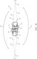
- FIG. 2Cis a cross-sectional view of the image capture device 200 of FIGS. 2A-B .
- the image capture device 200is configured to capture spherical images, and accordingly, includes a first image capture device 224 and a second image capture device 226.
- the first image capture device 224defines a first field-of-view 228 as shown in FIG. 2C and includes the lens 204 that receives and directs light onto a first image sensor 230.
- the second image capture device 226defines a second field-of-view 232 as shown in FIG. 2C and includes the lens 206 that receives and directs light onto a second image sensor 234.
- the image capture devices 224, 226may be arranged in a back-to-back (Janus) configuration such that the lenses 204, 206 face in generally opposite directions.
- the fields-of-view 228, 232 of the lenses 204, 206are shown above and below boundaries 236, 238, respectively.
- the first image sensor 230may capture a first hyper-hemispherical image plane from light entering the first lens 204
- the second image sensor 234may capture a second hyper-hemispherical image plane from light entering the second lens 206.
- One or more areas, such as blind spots 240, 242may be outside of the fields-of-view 228, 232 of the lenses 204, 206 so as to define a "dead zone.” In the dead zone, light may be obscured from the lenses 204, 206 and the corresponding image sensors 230, 234, and content in the blind spots 240, 242 may be omitted from capture. In some implementations, the image capture devices 224, 226 may be configured to minimize the blind spots 240, 242.
- the fields-of-view 228, 232may overlap.
- Stitch points 244, 246, proximal to the image capture device 200, at which the fields-of-view 228, 232 overlapmay be referred to herein as overlap points or stitch points.
- Content captured by the respective lenses 204, 206, distal to the stitch points 244, 246,may overlap.
- Images contemporaneously captured by the respective image sensors 230, 234may be combined to form a combined image.
- Combining the respective imagesmay include correlating the overlapping regions captured by the respective image sensors 230, 234, aligning the captured fields-of-view 228, 232, and stitching the images together to form a cohesive combined image.
- a slight change in the alignment, such as position and/or tilt, of the lenses 204, 206, the image sensors 230, 234, or both,may change the relative positions of their respective fields-of-view 228, 232 and the locations of the stitch points 244, 246.
- a change in alignmentmay affect the size of the blind spots 240, 242, which may include changing the size of the blind spots 240, 242 unequally.
- Incomplete or inaccurate information indicating the alignment of the image capture devices 224, 226, such as the locations of the stitch points 244, 246,may decrease the accuracy, efficiency, or both of generating a combined image.
- the image capture device 200may maintain information indicating the location and orientation of the lenses 204, 206 and the image sensors 230, 234 such that the fields-of view 228, 232, stitch points 244, 246, or both may be accurately determined, which may improve the accuracy, efficiency, or both of generating a combined image.
- the lenses 204, 206may be laterally offset from each other, may be off-center from a central axis of the image capture device 200, or may be laterally offset and off-center from the central axis.
- image capture devices including laterally offset lensesmay include substantially reduced thickness relative to the lengths of the lens barrels securing the lenses.
- the overall thickness of the image capture device 200may be close to the length of a single lens barrel as opposed to twice the length of a single lens barrel as in a back-to-back configuration. Reducing the lateral distance between the lenses 204, 206 may improve the overlap in the fields-of-view 228, 232.
- Images or frames captured by the image capture devices 224, 226may be combined, merged, or stitched together to produce a combined image, such as a spherical or panoramic image, which may be an equirectangular planar image.
- a combined imagesuch as a spherical or panoramic image, which may be an equirectangular planar image.
- generating a combined imagemay include three-dimensional, or spatiotemporal, noise reduction (3DNR).
- 3DNRthree-dimensional, or spatiotemporal, noise reduction
- pixels along the stitch boundarymay be matched accurately to minimize boundary discontinuities.
- FIGS. 3A-Bare block diagrams of examples of image capture systems.
- the image capture system 300includes an image capture device 310 (e.g., a camera or a drone), which may, for example, be the image capture device 200 shown in FIGS. 2A-C .
- an image capture device 310e.g., a camera or a drone
- FIGS. 2A-Cthe image capture device 200 shown in FIGS. 2A-C .
- the image capture device 310includes a processing apparatus 312 that is configured to receive a first image from a first image sensor 314 and receive a second image from a second image sensor 316.
- the image capture device 310includes a communications interface 318 for transferring images to other devices.
- the image capture device 310includes a user interface 320 to allow a user to control image capture functions and/or view images.
- the image capture device 310includes a battery 322 for powering the image capture device 310.
- the components of the image capture device 310may communicate with each other via the bus 324.
- the processing apparatus 312may be configured to perform image signal processing (e.g., filtering, tone mapping, stitching, and/or encoding) to generate output images based on image data from the image sensors 314 and 316.
- the processing apparatus 312may include one or more processors having single or multiple processing cores.
- the processing apparatus 312may include memory, such as a random-access memory device (RAM), flash memory, or another suitable type of storage device such as a non-transitory computer-readable memory.
- the memory of the processing apparatus 312may include executable instructions and data that can be accessed by one or more processors of the processing apparatus 312.
- the processing apparatus 312may include one or more dynamic random access memory (DRAM) modules, such as double data rate synchronous dynamic random-access memory (DDR SDRAM).
- DRAMdynamic random access memory
- DDR SDRAMdouble data rate synchronous dynamic random-access memory
- the processing apparatus 312may include a digital signal processor (DSP).
- DSPdigital signal processor
- the processing apparatus 312may include an application specific integrated circuit (ASIC).
- ASICapplication specific integrated circuit
- the processing apparatus 312may include a custom image signal processor.
- the first image sensor 314 and the second image sensor 316may be configured to detect light of a certain spectrum (e.g., the visible spectrum or the infrared spectrum) and convey information constituting an image as electrical signals (e.g., analog or digital signals).
- the image sensors 314 and 316may include CCDs or active pixel sensors in a CMOS.
- the image sensors 314 and 316may detect light incident through a respective lens (e.g., a fisheye lens).
- the image sensors 314 and 316include digital-to-analog converters.
- the image sensors 314 and 316are held in a fixed orientation with respective fields of view that overlap.
- the communications interface 318may enable communications with a personal computing device (e.g., a smartphone, a tablet, a laptop computer, or a desktop computer).
- a personal computing devicee.g., a smartphone, a tablet, a laptop computer, or a desktop computer.
- the communications interface 318may be used to receive commands controlling image capture and processing in the image capture device 310.
- the communications interface 318may be used to transfer image data to a personal computing device.
- the communications interface 318may include a wired interface, such as a high-definition multimedia interface (HDMI), a universal serial bus (USB) interface, or a FireWire interface.
- the communications interface 318may include a wireless interface, such as a Bluetooth interface, a ZigBee interface, and/or a Wi-Fi interface.
- the user interface 320may include an LCD display for presenting images and/or messages to a user.
- the user interface 320may include a button or switch enabling a person to manually turn the image capture device 310 on and off.
- the user interface 320may include a shutter button for snapping pictures.
- the battery 322may power the image capture device 310 and/or its peripherals.
- the battery 322may be charged wirelessly or through a micro-USB interface.
- the image capture system 330includes an image capture device 340 and a personal computing device 360 that communicate via a communications link 350.
- the image capture device 340may, for example, be the image capture device 100 shown in FIGS. 1A-C .
- the personal computing device 360may, for example, be the user interface device described with respect to FIGS. 1A-C .
- the image capture device 340includes an image sensor 342 that is configured to capture images.
- the image capture device 340includes a communications interface 344 configured to transfer images via the communication link 350 to the personal computing device 360.
- the personal computing device 360includes a processing apparatus 362 that is configured to receive, using a communications interface 366, images from the image sensor 342.
- the processing apparatus 362may be configured to perform image signal processing (e.g., filtering, tone mapping, stitching, and/or encoding) to generate output images based on image data from the image sensor 342.
- image signal processinge.g., filtering, tone mapping, stitching, and/or encoding
- the image sensor 342is configured to detect light of a certain spectrum (e.g., the visible spectrum or the infrared spectrum) and convey information constituting an image as electrical signals (e.g., analog or digital signals).
- the image sensor 342may include CCDs or active pixel sensors in a CMOS.
- the image sensor 342may detect light incident through a respective lens (e.g., a fisheye lens).
- the image sensor 342includes digital-to-analog converters. Image signals from the image sensor 342 may be passed to other components of the image capture device 340 via a bus 346.
- the communications link 350may be a wired communications link or a wireless communications link.
- the communications interface 344 and the communications interface 366may enable communications over the communications link 350.
- the communications interface 344 and the communications interface 366may include an HDMI port or other interface, a USB port or other interface, a FireWire interface, a Bluetooth interface, a ZigBee interface, and/or a Wi-Fi interface.
- the communications interface 344 and the communications interface 366may be used to transfer image data from the image capture device 340 to the personal computing device 360 for image signal processing (e.g., filtering, tone mapping, stitching, and/or encoding) to generate output images based on image data from the image sensor 342.
- image signal processinge.g., filtering, tone mapping, stitching, and/or encoding
- the processing apparatus 362may include one or more processors having single or multiple processing cores.
- the processing apparatus 362may include memory, such as RAM, flash memory, or another suitable type of storage device such as a non-transitory computer-readable memory.
- the memory of the processing apparatus 362may include executable instructions and data that can be accessed by one or more processors of the processing apparatus 362.
- the processing apparatus 362may include one or more DRAM modules, such as DDR SDRAM.
- the processing apparatus 362may include a DSP. In some implementations, the processing apparatus 362 may include an integrated circuit, for example, an ASIC. For example, the processing apparatus 362 may include a custom image signal processor. The processing apparatus 362 may exchange data (e.g., image data) with other components of the personal computing device 360 via a bus 368.
- datae.g., image data
- the personal computing device 360may include a user interface 364.
- the user interface 364may include a touchscreen display for presenting images and/or messages to a user and receiving commands from a user.
- the user interface 364may include a button or switch enabling a person to manually turn the personal computing device 360 on and off.
- commandse.g., start recording video, stop recording video, or capture photo
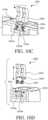
- a camera 400such as one of the image capture device 100, the image capture device 200, or a variation thereof, includes a body 410 and a mount 420 by which the camera 400 is coupled to another mount 442 of an external support 440.
- the mount 420 of the camera 400is referred to herein as the device mount 420, but may also be referred to as a camera mount when used with a camera.
- the other mount 442 of the external support 440is referred to herein as the support mount 442.
- the device mount 420 and the support mount 442may be referred to as a mounting system.
- another type of electronic devicemay be similarly configured with the device mount 420 described herein, such an output device (e.g., an electronic display, or speaker), an input device (e.g., a microphone), a control device (e.g., a remote control), a peripheral device (e.g., a battery, or communications interface, hub, or dock with which other devices are in communication), which may or may not be associate with the camera 400 or another image capture device.
- the external support 440may be a tripod (as shown), or another type of mounting device, such as a bar mount (e.g., for handle bars of a bicycle), an elongated arm (e.g., a "selfie stick"), or a helmet mount.
- the device mount 420may also be referred to as a mount assembly.
- the camera 400includes one or more lenses 412 facing outward from the body 410 and electronic components suitable for capturing images contained therein (e.g., image sensor, image processor, memory, and/or power storage, such as a battery).
- the body 410may, for example, be a housing that contains the electronic components therein and may be waterproof.
- the body 410may, as shown, have a rectilinear shape having a bottom side 410a, an upper side opposite the bottom side 410a (not labeled in FIG. 4A ), a front side 410b, a rear side opposite the front side 410b (not labeled in FIG. 4A ), a right side 410c, and a left side opposite the right side 410c (not labeled in FIG. 4A ).
- the one or more lenses 412face outward, for example, from the front side 410b and the rear side.
- the body 410may have any other suitable shape, such as having a rounded or irregular shape.
- the device mount 420 and the support mount 442include interlocking fingers by which the device mount 420 and the support mount 442 couple to each other.
- the support mount 442includes three finger members 444 that define two parallel slots 446 therebetween, which receive finger members 422 of the device mount 420 corresponding thereto.
- the support mount 442may also be referred to as a three-finger mount, while the device mount 420 may also be referred to as a two-finger mount.
- the finger members 422 of the device mount 420are thin, flat planar structures having opposed planar faces that define a thickness thereof that is less than a width and a length thereof (e.g., less than one quarter of the width and/or the length).
- the finger members 444 of the support mount 442define the parallel slots 446 with corresponding dimensions for interfitment (e.g., receipt) therein of the finger members 422 of the device mount 420.
- the finger members 422, 444may also be referred to as fingers, arms, protrusions, planar protrusions, or members.
- the three finger members 444include a first outer finger member 444a, a second outer finger member 444b, and a central finger member 444c that is positioned between the first outer finger member 444a and the second outer finger member 444b.
- the central finger member 444cincludes two planar surfaces 444c' that are parallel with and face away from each other and which may be referred to as opposed planar surfaces.
- the central finger member 444chas a thickness that is measured between and perpendicular to the two planar surfaces 444c' thereof.
- the first outer finger member 444aincludes a planar surface 444a' that faces and is parallel with one of the two planar surfaces 444c' of the central finger member 444c.
- a first of the slots 446is defined between the planar surface 444a' of the first outer finger member 444a and a first of the planar surfaces 444c' of the central finger member 444c.
- the first slot 446has a width that is measured between and perpendicular to the planar surface 444a' of the first outer finger member 444a and the first planar surface 444c' of the central finger member 444c.
- the second outer finger member 444bincludes a planar surface 444b' that faces and is parallel with a second of the two planar surfaces 444c' of the central finger member 444c.
- the planar surface 444b of the second outer finger member 444bis also parallel with the first of the two planar surfaces 444c' of the central finger member 444c and the planar surface 444a' of the first outer finger member 444a.
- a second of the slots 446is defined between the planar surface 444b' of the second outer finger member 444b and the second of the planar surfaces 444c' of the central finger member 444c.
- the second slot 446has a width that is measured between and perpendicular to the planar surface 444b' of the second outer finger member 444b and the second planar surface 444c' of the central finger member 444c.
- the widths of the two slots 446are the same.
- the three finger members 444may be an integrally formed structure, such as being an injection molded plastic structure or a machined metal structure.
- the finger members 444may also terminate at a common height (e.g., having rounded ends) and/or have a common width.
- the support mount 442also includes a shaft 448, which functions to retain the device mount 420 of the camera 400 to the support mount 442.
- the three finger members 444include apertures (not labeled) that are aligned with each other and through which the shaft 448 is positioned.
- the shaft 448extends perpendicular to the finger members 444 and the slots 446.
- the shaft 448is removable from the support mount 442, for example, being a threaded shaft (e.g., a thumb screw) having a threaded end that is received by a nut 450 of the support mount 442.
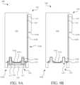
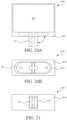
- the device mount 420is reconfigurable (e.g., is collapsible, movable, or foldable) between a first configuration and a second configuration.
- the device mount 420In the first configuration (shown in FIG. 4B ), the device mount 420 is arranged for being coupled to the support mount 442 of the external support 440 and, in particular, extends away from the body 410 for receipt by the support mount 442.
- the first configurationmay also be referred to as an extended, protruding, unfolded, deployed, or mounting state or configuration.
- the device mount 420is collapsed toward the body 410, for example, to use the camera 400 without the external support 440.
- the device mount 420is collapsed toward the body 410, such that the camera 400 is more compact than in the extended state, for example, such that the camera 400 has a lesser height when the device mount 420 is collapsed than when extended.
- the device mountmay be configured to not be receivable (e.g., not be fully receivable) by the support mount 442 of the external support 440 for retention thereto (e.g., with the shaft 448).
- the second configurationmay also be referred to as a collapsed, recessed, folded, non-deployed, non-extended, or non-mounting state or configuration.
- the device mount 420is also removable from the body 410 (shown in FIG. 4D ), or may alternatively be permanently coupled thereto.
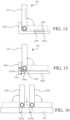
- the device mount 420generally includes the two finger members 422, referenced above, and a base 424.
- the two finger members 422correspond to the two slots 446 of the support mount 442 and, when the device mount 420 is in the extended state, are insertable into the slots 446 of the support mount 442.
- the finger members 422are coupled to and movable relative to the base 424. As shown, the finger members 422 rotate relative to the base 424 between respective extended positions (shown in FIG. 8 ; see also FIG. 4B ) and collapsed positions (shown in FIG. 7 ; see also FIG. 4C ). For example, the finger members 422 may rotate substantially 90 degrees between the extended and collapsed positions and/or in opposite directions from each other (e.g., as indicated by the arrows in FIG. 8 ). The finger members 422 may rotate independent of each other, for example, such that one of the finger members 422 may be in the extended position, while the other of the finger members 422 may simultaneously be in the collapsed position.
- the base 424is in turn coupled to the camera 400 along the bottom side 410a of the body 410, such that the finger members 422 are also rotatable relative to the body 410.
- the device mount 420When the finger members 422 are in the respective extended positions, the device mount 420 is in the first or extended state, and when finger members 422 are in the respective collapsed positions, the device mount 420 is in the second or collapsed state.
- the finger members 422In the extended positions, the finger members 422 extend parallel with each other in a common direction, for example, with the planar surfaces 422a of the two finger members 422 being parallel with each other.
- the finger members 422are simultaneously receivable in the slots 446 (i.e., between the finger members 444) of the support mount.
- the finger members 422extend away from each other.
- the finger members 422may extend away from each other in parallel, for example, with the planar surfaces 422a of the two finger members 422 being parallel with each other and/or in a common plane (e.g., with the one of the planar surfaces 422a of each of the two finger members 422 being coplanar).
- the finger members 422are not simultaneously receivable in the slots 446 of the support mount.
- the base 424may be omitted with the finger members 422 being coupled directly to the body 410 of the camera 400.
- the finger members 422are biased away from each other and/or toward (e.g., are closer to) the body 410 of the camera 400 when in the collapsed state or positions.
- the two finger members 422are flat, elongated members configured to be received in one of the slots 446 of the support mount 442 of the external support 440.
- Each finger member 422includes a proximal portion 422b and a distal portion 422c having two planar surfaces 422a (e.g., opposed planar surfaces).
- the proximal portion 422bis proximal to and rotatably coupled to the base 424.
- the distal portion 422cextends from the proximal portion 422b and is configured to be inserted into one of the slots 446 of the external support 440. As each finger member 422 is rotated from the extended position to the collapsed position, the distal portion 422c is moved toward the body 410.
- the distal portion 422cmay have an end shape that is rounded (e.g., semi-circular) to facilitate pivoting of the finger members 422 when coupled to the support mount 442 (e.g., about the shaft 448).
- the two planar surfaces 422a of the distal portion 422c of each finger member 422are parallel with and face away from each other.
- the distal portion 422c of the finger member 422has a thickness that is measured between and perpendicular to the two planar surfaces 422a thereof.
- the thickness of distal portion 422c of each finger member 422is approximately equal to the width of each slot 446 of the external support 440 into which the finger member 422 is received.
- the planar surfaces 422a of the finger members 422engage the planar surfaces 444a', 444b', and 444c' of the finger members 444, which may create friction therebetween to hinder movement of the device mount 420 of the camera 400 relative to the external support 440.
- the thicknesses of the distal portions 422c of the two finger members 422are the same as each other, for example, such that either finger member 422 of the device mount 420 may be inserted into either of the slots 446 of the support mount 442.
- one of the planar surfaces 422a of each of the finger members 422are parallel with each other and spaced apart facing each other to define a slot 426 in which the central finger member 444c of the external support 440 is receivable.
- a width of the slot 426 of the device mount 420is measured between and perpendicular to the two planar surfaces 422a of the two finger members 422 facing each other in the extended states.
- the width of the slot 426 of the device mount 420is approximately equal to the thickness of the central finger member 444c of the external support 440 for receipt thereof.
- the width of the slot 426 of the device mount 420may, as shown, also be approximately equal to the thickness of the two finger members 422 (e.g., within 35%, 25%, 15%, or 10% of the thickness thereof).
- the finger members 422additionally include apertures 429 extending therethrough (e.g., through the planar surfaces 422a thereof), which are configured to receive the shaft 448 of the support mount 442 therethrough.
- the shaft 448may be inserted through the apertures 429 of the finger members 422 and the apertures (not shown) of the support mount 442, so as to retain the device mount 420 to the support mount 442.
- the camera 400may, thereby, be coupled and retained to the external support 440.
- the shaft 448may be tightened (e.g., into the nut 450), so as to press the finger members 422 of the device mount 420 and the finger members 444 of the support mount 442 against each other to increase friction therebetween.
- the finger members 422may, for example, be made of a metal material (e.g., aluminum, steel) according to any suitable manufacturing process or combination of processes (e.g., casting and/or machining).
- the finger members 422may be made of a polymer (e.g., injection molded plastic), composite (e.g., glass-filled nylon), or combination of metal and polymer materials (e.g., a metal inner structure hingedly coupled to the base 424 and overmolded or otherwise covered with a polymer (e.g., plastic or elastomer)).
- the finger members 422are formed of a metal material (e.g., machine aluminum) that is coated with one or more additional layers (e.g., metal plating, polymer coatings, phobic coatings, paint or color, anodizing, among others).
- a metal materiale.g., machine aluminum
- additional layerse.g., metal plating, polymer coatings, phobic coatings, paint or color, anodizing, among others.
- the polymer materialmay insulate the planar surfaces 422a from heat conducted from the body 410 to the base 424.
- the two finger members 422are rotatably coupled to the base 424, which is in turn coupled to the camera 400 along the bottom side 410a of the body 410.
- the base 424may generally include a central portion 424a that is rotatably coupled to the two finger members 422, and two outer portions 424b that extend outward from the central portion 424a and are coupled to or otherwise interface with the body 410 of the camera 400.
- the central portion 424a and the outer portions 424bmay form a unitary structure, for example, formed of metal (e.g., aluminum), polymer (e.g., injection molded plastic), composite, or combination of metal and polymer materials., or may be formed of multiple components that are coupled together.
- the finger members 422are rotatable relative to the base 424, for example, about different axes of rotation that may, for example, be parallel (as shown), intersection, or skew. To distinguish between the different axes of rotation of the finger members 422, the axes of rotation may be referred to, for example, as respective axes, different respective axes, parallel axes, or first and second axes.
- Each of the finger members 422is coupled to the base 424, such as with a hinge pin 428.
- the hinge pin 428extends through the proximal portion 422b of the finger member 422 (e.g., through a bore thereof) and the central portion 424a of the base 424.
- the proximal portion 422b of the finger member 422may, for example, receive therein part of the central portion 424a of the base 424.
- the proximal portion 422b of the finger member 422may include end segments 422b' that are spaced apart to form a recess (e.g., a slot or gap) in which is received an outwardly-extending segment 424a' of the central portion 424a of the base 424 and through which the axes of rotation extend.
- the hinge pin 428 and, thereby, the axis of rotation of each finger member 422is generally perpendicular to the direction that the apertures 429 extend through the finger member 422.
- the proximal portion 422b(e.g., the end segments 422b') may be rounded about the hinge pin 428 (e.g., the axis thereof).
- the end of the distal portion 422cmay be rounded about the aperture 429 (e.g., an axis thereof).
- the end of the proximal portion 422bmay be rounded about an axis that is perpendicular to the aperture 429 and/or the end of the distal portion 422c may be rounded about an axis that is perpendicular to the hinge pin 428 (e.g., the axis about which the finger member 422 rotates).
- the radius of the end of the distal portion 422cmay be larger than the radius of the end of the proximal portion 422b or otherwise larger than a distance from the axis of rotation to the surface of the end of the proximal portion 422b (e.g., being at least three, four, or five times greater than).
- the outwardly-extending segments 424a' of the central portion 424a of the base 424extend laterally outward (e.g., left and right) from a central segment 424a" of the central portion 424a of the base 424.
- the outwardly-extending segments 424a' and the central segment 424a"may cooperatively form a cross-shape, such as with the outwardly-extending segments 424a' of the central portion 424a having a width (i.e., measured front to back) that is less than a width of the central segment 424a".
- slotsmay be defined between central segment 424a" and the outer portion 424b in which the end segments 422b' of the finger member 422 are positioned, which may result in no portion of the base 424 being positioned between the proximal portions 422b of the finger member 422 and the body 410 of the camera 400.
- a sum of widths of the end segments 422b' of the finger members 422 and the width of the outwardly-extending segments 424a'may be approximately equal to a width of the central segment 424a" .
- the base 424may be configured to be arranged between the proximal portions 422b of the finger members 422 and the external housing 419.
- the base 424may not define slots between the central segment 424a" of the central portion 424a and the outer portion 424b of the base 424 (e.g., with the base 424 having a generally constant thickness and/or width).
- the base 424may instead include a generally planar portion of generally constant thickness and a cross-shaped portion (e.g., similar to that formed by the outwardly-extending segments 424a' and the central segment 424a" extending downward therefrom).
- proximal portion 422b of the finger members 422may have a thickness (e.g., measured top to bottom in the collapsed state) that is approximately equal to a thickness of the central portion 424a of the base 424 (e.g., outwardly-extending segments 424a' and/or the central segment 424a" thereof).
- the thickness of the distal portion 422ci.e., between the planar surfaces 422a is less than the thickness of the end segments 422b' of the finger member 422.
- a sum of the thicknesses of the distal portion 422c of the finger member 422 and the outer portion 424b of the basemay be approximately equal to the thickness of the end segments 422b' of the finger member 422, the outwardly-extending segments 424a', and/or the central segment 424a" of the central portion 424a.
- the finger members 422When in the extended state, the finger members 422 (e.g., the proximal portion 422b and/or one of the planar surfaces 422a thereof) may abut the central portion 424a of the base 424 (e.g., the central segment 424a") to prevent further rotation toward each other.
- the apertures 429 of the finger members 422share a common axis (e.g., of the shaft 448), which may extend perpendicular to both axes of rotation of the finger members 422 and may also be spaced below the bottom side 410a of the body 410.
- the apertures 429When in the collapsed state, the apertures 429 have different axes, which may be parallel with each other and perpendicular to both axes of rotation of the finger members 422.
- the finger members 422When in the collapsed state, the finger members 422 abut the outer portions 424b of the base 424. A sum of a thickness of the distal portion 422c of the finger member 422 and the outer portion 424b of the base 424 may be approximately equal to the thickness of the proximal portion 422b of the finger member 422 and/or the central portion 424a of the base 424. When in the collapsed state, those planar surfaces 422a of the two finger members 422 that define the slot 426 face away from the body 410 and may be coplanar with each other.
- the apertures 429 of the finger members 422have different axes that, for example, are parallel and spaced apart from each other (e.g., extending through the bottom side 410a and the top side of the body 410 of the camera 400).
- the finger member 422may be configured differently, such as having a generally constant thickness and/or being substantially planar (e.g., with planar parallel surfaces), as is illustrated with the finger members 10A-10D and 18A-18E.
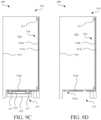
- the base 424is coupled to the camera 400 at the bottom side 410a thereof.
- the bottom side 410a of the body 410may define a recess 414 in which is received the base 424 of the device mount 420.
- the base 424is receivable by the recess 414 in a direction generally opposed to the side to which the base 424 is coupled (e.g., being received upward into the recess 414 on the bottom side 410a of the body 410 of the camera 400).
- the recess 414may also receive the finger members 422, wholly or partially, in the collapsed positions. For example, as shown in FIG. 4C and additionally in FIGS.
- the finger members 422may not protrude from the recess 414 when in the collapsed state (e.g., are flush with or preferably recessed relative to surrounding surfaces of the bottom side 410a).
- the bottom side 410amay define a flat surface that allows the camera 400 to rest in a stable manner on a flat support surface (e.g., a table).
- the recess 414may have multiple depths for receipt of the base 424 of the device mount 420 and for receipt of the finger members 422 when in the collapsed state.
- the recess 414may have an inner region 414a and an outer region 414b, the inner region 414a being positioned inward (e.g., laterally and vertically) of the outer region 414b relative to the body 410.
- the inner region 414a of the recess 414has a depth relative to the surrounding surfaces of the bottom side 410a that is greater than a depth of the outer region 414b of the recess 414.
- the base 424 of the device mount 420is received in the inner region 414a of the recess 414.
- the finger members 422 of the device mount 420are received in the outer region 414b of the recess 414 when in the collapsed state.
- the thickness of the finger members 422e.g., of the distal portion 422c
- An overall thickness of the device mount 420 formed cooperatively by the thickness of the outer portion 424b of the base 424 and the thickness of the finger members 422 (e.g., the distal portion 422c between the planar surfaces 422a)may be approximately equal to or preferably less than (as shown in FIGS. 9A-9D ) the depth of the inner region 414a of the recess 414. Further, the thickness of the finger members 422 (e.g., of the distal portion 422c between the planar surfaces 422a) may be approximately equal to or preferably less than (as shown in FIGS. 9A-9D ) the depth of the outer region 414b of the recess 414.
- the outer portions 424b of the base 424extend outward from the central portion 424a.
- the base 424may be considered elongated.
- the base 424may have a length (e.g., measured left-to-right relative to the body 410), which extends at least a majority (e.g., greater than 75%) of an overall length of the device mount 420 (e.g., measured between ends of the distal portions 422c of the finger members 422).
- the base 424may be sufficiently long to overlap the apertures 429 of the finger members 422.
- the base 424may distribute loading from the device mount 420 to the camera 400 (e.g., to the body 410 or an internal structure thereof, such as a chassis) over a large area.
- the outer portions 424b of the base 424may be connected to the body 410 with fasteners (e.g., screws) at outer ends of the device mount 420 (e.g., two of the fasteners 417 on each of the left and right ends).
- the length of the base 424may be shorter, for example, less than half the overall length of the device mount 420, or sufficiently short to not overlap the apertures of the finger members 422 (see, e.g., FIGS. 18A-18E ).
- the finger members 422when in the collapsed positions, may block access to the fasteners (e.g., cover the fasteners). As a result, the device mount 420 may not be removable from the body 410 when the finger members 422 are the collapsed state.
- the overall length of the device mount 420may be slightly less than a length of the outer region 414b of the recess 414. By having a shorter length, ends of the distal portions 422c of the finger members 422 may be accessible within the recess 414 for a user to fold the finger members 422 outward from the collapsed state to the extended state.
- the distal portions 422c of the finger members 422may further include indentations 422d (e.g., finger picks) on the ends thereof, which allow the user to pull the finger members 422 out of the recess 414 into the extended positions.
- the recess 414may omit one or both ends thereof providing unrestricted access to the ends (e.g., the indentations 422d) of the finger members 422.
- the device mount 420is configured to couple to a chassis 418 of the body 410 of the camera 400.
- the body 410includes the chassis 418, which is a generally rigid structure to which the internal components of the camera 400 (e.g., the electronics, battery, etc., such as the processing apparatus 312, image sensors 314, 316, etc.) are coupled, and an external housing 419 that contains the chassis 418 and the electronic components.
- the external housing 419may include one or more components formed of one or more polymer materials (e.g., elastomer overmolded to plastic) that define a compartment 416 that is waterproof, so as to protect the electronics therein.
- the external housing 419may include two external housing components that are coupled to each other with a seal therebetween and which define a waterproof cavity therein. Any apertures in the external housing components, such as for any input/output (I/O) components (e.g., microphones, speakers, displays, power, etc.) are sealed.
- the chassis 418is formed of a metal material (e.g., one or more cast aluminum components) and also functions as a heat sink to conduct heat away from the electronic components.
- the chassis 418is stiffer than the external housing 419.
- the compartment 416is not waterproof.
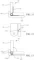
- the chassis 418includes a bottom segment 418a at the bottom side 410a of the body 410 and an upright segment 418b (e.g., front or rear) extending upward from the bottom segment 418a at the front side 410b or the rear side of the body 410.
- the chassis 418may be generally L-shaped.
- the bottom segment 418asufficiently spans the thickness and/or the width of the camera 400 for being coupled to the device mount 420, such as a majority of the thickness and/or the width of the camera 400. In the case of the device mount 1820, the bottom segment 418a may instead span less than a majority of the width of the camera 400.
- the upright segment 418bmay span a majority of the width and/or height of the camera 400 (e.g., having a forward surface area that is greater than a majority of the surface area on the front side of the camera 400).
- the external housing 419similarly includes a bottom segment 419a at the bottom side 410a of the body 410 and outward of the bottom segment 418a of the chassis 418, as well as a front segment 419b at the front side 410b of the body 410 and outward of the upright segment 418b of the chassis 418.
- the bottom segment 419a of the external housing 419defines the recess 414 and, further, allows the fasteners 417 (e.g., screws) to couple the base 424 of the device mount 420 directly to the chassis 418.
- the bottom segment 418a of the chassis 418includes four screw holes 418a' that threadably receive the fasteners 417, while the bottom segment 419a of the external housing 419 includes four corresponding through holes 419a' (labeled in FIG. 6 ) through which the fasteners 417 extend.
- Seals 415e.g., O-rings
- the screw holes 418a'are blind screw holes or are otherwise sealed, such that water does not leak through the screw holes 418a' themselves into body 410.
- the fasteners 417are covered, such that the fasteners 417 are not accessible and the device mount 420 is not removable from the camera 400.
- the fasteners 417are uncovered and accessible with a suitable tool (e.g., a screw driver) and the device mount 420 is, thereby, removable from the camera 400.
- a variation of the body 410includes a chassis 918 and a housing component 919 that cooperatively define a compartment 916 in which the various electronic components are positioned.
- the chassis 918forms a surface that itself defines an interior surface of the compartment 916. Any apertures in the chassis 918 and the housing component 919 (e.g., for I/O components) are sealed to ensure that the compartment 916 is waterproof. In a variation, the compartment 916 is not waterproof.
- the chassis 918generally includes a lower segment 918a and an upright segment 918a (e.g., a front or rear segment or portion) extending upward therefrom.
- the chassis 918may be generally L-shaped.
- the lower segment 918asufficiently spans the thickness and/or the width of the camera 400 for being coupled to the device mount 420, such as a majority of the thickness and and/or the width of the camera 400. In the case of the device mount 1820, the lower segment 918a may span less than a majority of the width of the camera 400.
- the upright segment 918bmay span a majority of the width and/or the height of the camera 400 (e.g., having a surface area that is greater than a majority of the surface area on the corresponding side of the camera 400).
- a cover 919amay be positioned over and/or cover from view the upright segment 918a, for example, having the same or complementary aesthetic and/or tactile properties as the housing component 919.
- the chassis 918 and the housing component 919are coupled to each other with a peripheral seal 917 therebetween, such as a gasket.
- the lower segment 918ais positioned outside the compartment 916, for example, being positioned below peripheral seal 917 and extending between the housing component 919 and the device mount 420 coupled thereto.
- the device mount 420may be coupled to the chassis 918 (i.e., the lower segment 918b thereof) without further waterproofing (e.g., without the seals 415 shown in FIGS. 9A-9B ).
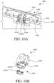
- a variation of the device mount 1020is removable from a variation of the camera 1000 without a tool.
- the camera 1000is configured similar to the camera 400 but is configured to couple to the device mount 1020 by including a stud 1016 that engages a spring clip 1027 of the device mount 1020.
- the stud 1016includes a base 1016a (e.g., a plate) and a boss 1016b coupled thereto and protruding therefrom.
- the base 1016ais coupled to the bottom side 410a of the camera 1000, for example, being embedded in material forming the bottom segment 419a of the external housing 419.
- the base 1016amay be coupled to the chassis 418, for example, in the manner by which the base 424 is coupled to the chassis 418 (e.g., with fasteners 417, such as threaded screws).
- the bottom segment 419a of external housingdefines a recess 414 in which the device mount 1020 is received, including an inner region 414a for receiving the base 1016a, which is deeper than an outer region 414b of the recess 414 for receiving the finger members 1022.
- the boss 1016b of the stud 1016has an outer surface with a generally constant diameter and includes opposed slots 1016c recessed into the outer surface. In an axial region that includes the slots 1016c, the boss 1016b has a variable diameter that increases moving circumferentially from a minimum diameter in the opposed slots 1016c to a maximum diameter (e.g., the generally constant diameter) at positions between the slots 1016c (e.g., rotated 90 degrees).
- the device mount 1020includes finger members 1022, a base 1024, and a spring clip 1027.
- the finger members 1022are pivotally coupled to the base 1024 in substantially the same manner as the finger members 422 (e.g., within hinge pins extending therethrough).
- the base 1024is a tubular member having an inner surface with a generally constant diameter that is larger than the diameter of the outer surface of the boss 1016b and having an outer surface with a generally constant diameter that is smaller than a dimension (e.g., diameter) of the inner region 414a of the recess 414.
- the base 1024additionally includes slots 1024a that are opposed to each other and extend radially outward into the inner surface of the base 1024 (e.g., being an aperture extending entirely through the wall thereof).
- the spring clip 1027is configured to releasably couple the base 1024 to the boss 1016b of the camera 1000.
- the spring clip 1027is configured to be received by both the slots 1016c of the boss 1016b and the slots 1024a of the base 1024.
- the spring clip 1027is a generally ring-shaped member having an end portion (e.g., a lower end) with flanges 1027a that are positioned within the slots 1024a of the base 1024 and which are receivable by the slots 1016c of the boss 1016b.
- a central portion of the spring clip 1027extends axially between (e.g., along) the inner surface of the base 1024 and the outer surface of the boss 1016b, and another end portion (e.g., an upper end) of the spring clip 1027 extends radially outward between an axial end of the base 1024 and the base 1016a of the stud 1016.
- the device mount 1020is coupled to and retained on the stud 1016 of the camera 400, which may be referred to as a connected state.
- the flanges 1027a of the spring clip 1027are positioned in both the slots 1016c of the stud 1016 (protruding radially inward therein) and the slots 1024a of the base 1024 (protruding radially outward therein), so as to prevent relative axial movement between the stud 1016 (i.e., the camera 1000) and the base 1024 (i.e., the device mount 1020).
- the device mount 1020is axially removable from the stud 1016, which may be referred to as a disconnected or disconnectable state. More particularly, the device mount 1020 is rotated by 90 degrees relative to the stud 1016 in the connected state, such that the flanges 1027a of the spring clip 1027 are not aligned with the slots 1016c of the boss 1016b but are instead aligned with those regions therebetween in which the outer surface of the boss 1016a has the maximum diameter.
- the finger members 1022are in the extended state (discussed above with the respect to the finger members 422) and rotated 90 degrees relative to the outer region 414b of the recess 414.
- the boss 1016bpresses the flanges 1027a of the spring clip 1027 outward further into the slots 1024c of the base.
- the device mount 1020is subsequently rotated by 90 degrees into the connected state (e.g., by a user grasping the finger members 1022), such that the flanges 1027a of the spring clip 1027 bias inward (e.g., spring inward) for receipt into the slots 1016c on the boss 1016b.
- the finger members 1022may then be pivoted into the outer region 414b of the recess 414 into the collapsed stated.
- the finger members 1022are pivoted out of the recess 414, and the device mount 1020 is rotated by 90 degrees, such that the flanges 1027a of the spring clip 1027 are rotated out of the slots 1016c of the boss 1016b and biased outward as the diameter of the outer surface of the boss 1016b engaged thereby increases.
- the device mount 1020may then be removed axially from the boss 1016b of the stud 1016, since the flanges 1027a of the spring clip 1027 are no longer retained in the slots 1016c of the boss 1016b.
- the camera 400 and the device mount 420may be configured to hold (e.g., retain or maintain) the two finger members 422 in the extended state and/or in the collapsed state.
- the finger members 422may form an interference fit with the recess 414.
- outer surfaces of the finger members 422e.g., those extending between the planar surface 422a thereof
- the device mount 420may include one or more retention mechanisms by which the finger member 422 is held in the extended position or the collapsed position relative to the base 424.
- a spring 1130e.g., a torsion spring biases one of the finger members 422 about the axis of rotation into the extended state.
- the spring 1130may bias the finger members 422 against the central segment 424a" of the central portion 424a of the base 424 into the extended state (shown in solid lines) from the collapsed state (shown in dashed lines).
- the spring 1130may alternatively normally bias the finger member 422 to the collapsed state.
- the retention mechanismmay also be referred to as retainers and components thereof may be referred to as retaining components.
- a retention mechanismis configured as a latch 1232 that retains the finger member 422 in the collapsed state.
- the latch 1232includes a sprung protrusion 1232a on an edge of the finger member 422, which engages and is received by a detent 1232b in the body 410 (e.g., in the recess 414 of the body 410 as shown).
- the sprung protrusion 1232amay itself be elastic (e.g., being formed of an elastomer) or may include a biasing spring that presses the sprung protrusion 1232a into the detent 1232b.
- the structure surrounding and defining the detent 1232bapplies a lateral force (e.g., generally parallel with the axis of rotation) against the sprung protrusion 1232a, thereby biasing the sprung protrusion 1232a out of the detent 1232b for release thereof and of the finger member 422.
- the sprung protrusion 1232a and the detent 1232bmay be arranged in an opposite configuration with the sprung member 1232a as part of the body 410 of the electronic device and the detent 1232b on the finger member 422.
- the latch 1232may include a latch release interface, such as a button, that may be pressed by the user to release the finger member 422 for movement.
- the proximal portion 422b of the finger member 422may engage detents in the base 424 the extended and/or collapsed states (both as shown).
- the finger member 422includes a sprung protrusion 1334 that moves longitudinally (e.g., generally parallel with the finger member 422).
- the base 424includes two detents 1336a, 1336b in the central portion 424a and the outer portion 424b, respectively, which receive and hold the sprung protrusion 1334a and, thereby, the finger member 422 in the collapsed and the extended positions, respectively.
- the finger member 422is retained in the collapsed position magnetically.
- the finger member 422includes a magnetic component 1438 (e.g., a permanent magnet or an attractor plate), while the base 424 includes another magnetic component 1440 attracted thereby (e.g., an attractor plate or a permanent magnet).
- the base 424may itself form the other magnetic component 1440 (e.g., being formed of steel or other ferromagnetic material).
- the magnetic component 1438may instead be incorporated into the body 410 (e.g., in the external housing 419 and/or the chassis 418 therein).
- the finger member 422is retained in the collapsed and extend positions with an over-center device 1542.
- the over-center device 1542includes sprung surface that engages the proximal portion 422b of the finger member 422 (e.g., a protrusion 1540 thereof).
- the sprung surfaceis biased generally toward the pivot axis to apply spring force to the proximal portion 422b of the finger member 422, which generates torque about the pivot axis that biases the distal portion 422c into either the collapsed or extended position.
- the torque generated by the spring forcechanges direction so as to bias the finger member 422 toward the other of the collapsed or extended position.
- the over-center device 1542includes a spring surface 1542a that is normally biased by a spring 1542b toward the pivot axis.
- the spring surface 1542amay be a plate member, while the spring 1542b may be a coil spring that applies force between the base 424 and the plate member.
- the spring surface 1542a and the spring 1542bmay be cooperatively formed by a single spring element (e.g., a flat torsion spring).
- movement of one of the finger members 422causes movement of the other finger member 422.
- a right finger member 422R and a left finger member 422Linclude proximal portions 1622b that overlap each other. As the user moves one of the finger members 422, the proximal portions 422b engage each other such that the other of the finger members 422 moves.
- the finger member 422is retained in the collapsed, extended, and/or intermediate positions frictionally.
- the finger member 422includes the hinge pin 428.
- the finger member 422 and the hinge pin 428are rotationally fixed, for example, with the hinge pin 428 being tightly received by the proximal portion 422b of the finger member 422 (e.g., being press-fit into apertures thereof).
- the hinge pin 428is in turn frictionally engaged with the base 424 to prevent rotation therebetween.
- the friction between the hinge pin 428 and the base 424may be sufficient to prevent rotation of the finger member 422 relative to the base 424 due to the force of gravity.
- the friction between the hinge pin 428 and the base 424may be provided by a friction pad 1730 (e.g., a friction component).
- a friction pad 1730e.g., a friction component
- the hinge pin 428may be received by and rotate within apertures of the base 424 (not shown), while the friction pad 1730 presses against the hinge pin 428 in a radial direction to generate friction therebetween.
- the friction pad 1730may also press the hinge pin 428 against the base 424 (e.g., those portions defining the apertures in which the hinge pin 428 is received), such that additional friction is generated between the hinge pin 428 and the base 424.
- the friction pad 1730may, for example, be an elastic material (e.g., an elastomer, such as rubber, or other polymer).
- proximal portion 422b(e.g., an end thereof) may be frictionally engaged, such as with friction pad similar to the friction pad 1730 or portion of the body 410 of the camera 400 engaging the end thereof, for example, with the end have a rounded surface concentric with the axis of rotation (e.g., of the hinge pin 428).
- FIGS. 11-17may be used in any suitable combinations with each other.
- the spring 1130 of FIG. 11may be used in combination with the latch 1232 of FIG. 12 or the magnetic components 1438, 1440 of FIG. 14 .
- the finger member 422may be retained both frictionally (e.g., as describe with respect to FIG. 17 ) and magnetically (e.g., described with respect to FIG. 14 ).
- a variation of the device mount 1820is includes two finger members 1822, a base 1824, and hinge pins 1826.
- the finger members 1822may have a substantially planar configuration with opposed planar surfaces 1822a that extend parallel with each other from a proximal end 1822b to a distal end 1822c thereof (e.g., similar to the finger member 1022).
- the finger member 1822includes an aperture 1822d that extends therethrough (e.g., in a normal direction to the planar surfaces 1822a).
- the aperture 1828dis for receiving the shaft 448 for coupling the device mount 1820 to the support mount 442.
- the finger members 1822when extended, are inserted into the slots 446 of the support mount 442, while the shaft 448 is inserted through the apertures 1822d of the finger member 1822 and the apertures (not shown) of the support mount 442.
- the distal end 1822c of the finger member 1822may be rounded, for example, having a semicircular cross-sectional shape about the aperture 1822d to permit rotation of the finger member 1822 when coupled o the support mount 442.
- the distal end 1822c of the finger member 1822may include an indentation 1822g, which forms a finger pick to facilitate the user removing the finger member 1822 from a recess of the external housing 419 of the camera 400 in which the device mount 1820 is positioned and for rotating the finger member 1822 (see FIG. 18E ).
- the proximal end 1822b of the finger member 1822includes end segments 1822b' that are spaced apart to form a recess 1822e (e.g., a gap or slot) in which is received a hinge portion of the base 1824 as described below.
- the proximal end 1822bfurther includes apertures 1822f extending through the end segments 1822b' in each of which is received one of the hinge pins 1826.
- the apertures 1822f and the hinge pin 1826are configured to be rotationally fixed to each other (e.g., to rotate with each other), for example, with the hinge pin 1826 being press-fit into the apertures 1822f.
- the proximal end 1822b of the finger member 1822may be rounded (e.g., being semi-circular in cross-section along the axis of the hinge pin 1826) to permit rotation, while being in close proximity to other structures (e.g., the base 1824).
- the base 1824generally includes a coupling portion 1824a (e.g., plate portion) and a hinge portion 1824b.
- the coupling portion 1824ais configured to couple to the camera 400.
- the coupling portion 1824ais a generally planar structure having apertures 1824c through which fasteners (not shown; see, e.g., fasteners 417) extend to couple the base 1824 to the camera 400 (e.g., similar to the base 424 of the device mount 420).
- the base 1824may have a length that is relatively short as compared to the base 424, for example, being positioned between the apertures 1822d (e.g., not overlapping the apertures 1822d) of the finger members 1822 when in the collapsed position. As shown in FIG.
- the base 1824may be received in the recess 414 of the external housing 419 of the camera 400.
- the finger members 1822may be flush against or otherwise contact the external housing 419 when in the collapsed position.
- the finger members 1822 and the base 1824may be slightly recessed relative to the external housing 419, such that when the finger members 1822 are collapsed, the camera 400 may rest stably on a surface without the interference from the finger members 1822 engaging the surface.
- the hinge portion 1824bprotrudes from the coupling portion 1824a for the finger members 1822 to hingedly couple thereto.
- the hinge portion 1824bgenerally includes a central segment 1824b' and two outwardly extending segments 1824b". Each of the two outwardly extending segments 1824b" is received by the recess 1822e of one of the finger members 1822 and includes an aperture 1824c for receiving the hinge pin 1826 therein.
- the aperture 1824c and the hinge pin 1826are cooperatively configured to permit the finger member 1822 to rotate about an axis formed thereby (e.g., about the hinge portion 1824b of the base 1824).
- the central segment 1824b'is positioned between the two outwardly extending segments 1824b" and the finger members 1822. As the finger members 1822 are rotated from the collapsed positions to the extended positions, the central segment 1824b' may engage the finger members 1822 (e.g., the planar surfaces 1822a thereof) to maintain proper spacing between the finger members 1822 for receipt thereof into the slots 446 of the support mount 442 and to receive the central finger member 444c of the support mount 442 therebetween.
- the finger members 1822e.g., the planar surfaces 1822a thereof
- the base 1824may include a base member 1824e and a base cap 1824f.
- the base member 1824eis a structure that forms the coupling portion 1824a and first part of the hinge portion 1824b, while the base cap 1824f forms a remaining part of the hinge portion 1824b. More particularly, the base member 1824e and the base cap 1824f cooperatively define the apertures 1824c, for example, each forming a semi-circular half thereof.
- the hinge pins 1826are coupled to the finger members 1822 (e.g., being press fit therein), the hinge pins 1826 are placed in the semi-circular half of the aperture formed by the base member 1824e of the base 1824, and the base cap 1824f is then coupled to the base member 1824e, capturing the hinge pins 1826 therebetween.
- the base cap 1824fmay be coupled to the base member 1824e, for example, with fasteners.
- the base member 1824eis formed of a metal material (e.g., steel or other ferromagnetic material or aluminum), while the base cap 1824f is formed of metal, plastic, or other polymer material.
- the base cap 1824fbeing formed of plastic or other polymer may be advantageous by being a heat insulator, so as to hinder conduction of heat generated by the camera 400 to an exposed surface of the camera 400.
- the base 1824may be a unitary structure with the hinge pins 1826 being received axially by the apertures 1824c.
- a base 1824' and a base member 1824e' thereofwhich are variations of the base 1824 and the base member 1824e, may itself define the apertures 1824c in which are positioned the hinge pins 1826 (i.e., without the base cap 1824f).
- the hinge pins 1826may be inserted axially through the apertures 1822f of each of the finger members 1822 of the aperture 1824c of the base member 1824e' of the base 1824, so as to couple the finger members 1822 to the base member 1824e'.
- An outer surface of the base member 1824e'may be exposed, such that heat is conducted from the chassis (e.g., the chassis 418 or 918) of the body 410 of the camera 400 to the surface of the base member 1824e' (e.g., by the metal structure formed thereby).
- an insulative cap(not shown) or other heat insulative layer or material, which may not function to retain the hinge pin 1826 to the base, may be coupled to the base member 1824e' to insulate heat conducted through the base member 1824e'.
- the device mount 1820may additionally be configured to hold the finger members 1822 in the extended and/or collapsed states magnetically and/or fictionally.
- the finger members 1822may be held frictionally in the extended state, and may be held magnetically in the collapsed state.
- the device mount 1820frictionally maintains the finger members 1822 in the extended state generally described above with respect to FIG. 17 .
- the device mount 1820includes a friction pad 1828, which may be considered part of the base 1824.
- the friction pad 1828presses against one or both of the hinge pins 1826 to generate friction therebetween for holding one or both of the finger members 1822 in the extended position.
- the friction pad 1828may further press the hinge pins 1826 against the base 1824 (e.g., the hinge portion 1824b, which may be formed by the base cap 1824f) to generate friction therebetween for holding one or both of the finger members 1822 in the extended position.
- the friction between the base 1824 (e.g., the friction pad 1828 and/or the hinge portion 1824b) and each hinge pin 1826is sufficient to at least overcome the force of gravity acting on the finger members 1822 to maintain the finger member 1822 in the extended position.
- the hinge pins 1826are pressed between the friction pad 1828 and the hinge portion 1824b of the base 1824 (e.g., against the surface defining the aperture 1824c, such as the base cap 1824f).
- the base 1824defines a cavity 1824g (e.g., a recess) through which the hinge pins 1826 extend and in which the friction pad 1828 is positioned against the hinge pins 1826.
- the cavity 1824ghas a depth, which is less than the cumulative height of the friction pad 1828 and the hinge pins 1826, such that the friction pad 1828 is compressed by the hinge pins 1826. As shown in FIG.
- the cavity 1824ghas an upper opening from which the friction pad 1828 protrudes, so as to engage a surface of the external housing 419 of the camera 400 (see FIG. 18E ).
- the cavity 1824gmay be closed at an upper end (e.g., the coupling portion 1824a being continuous), while the friction pad 1828 is received by a lower opening that is enclosed by the base cap 1824f.
- the device mount 1820magnetically maintains the finger members 1822 in the collapsed state as generally described above with respect to FIG. 14 .
- the finger member 1822includes a magnetic feature 1822h, which forms a magnetic coupling with the base 1824.
- the magnetic feature 1822his arranged between the hinge pin 1826 and the aperture 1822d of the finger member 1822.
- the magnetic feature 1822hmay, for example, be a permanent magnet that is embedded into the material forming the finger member 1822, for example, to be flush with or recessed relative to the planar surface 1822a nearest the base 1824.
- the base 1824has a length sufficient to overlap the magnetic feature 1822h and, as referenced above, may be made of steel, another ferromagnetic material, or may include a permanent magnet of suitable orientation to form a magnetic coupling with the magnetic feature 1822h.
- the magnetic feature 1822h of the finger member 1822may be an attractor plate or otherwise include a ferromagnetic material, while the base 1824 includes a permanent magnet that forms the magnetic coupling with the magnetic feature 1822h.
- the magnetic feature 1822h of the finger member 1822may instead magnetically couple to the camera 400, which includes a complementary magnetic feature for forming a magnetic coupling therewith.
- the device mount 420may instead or additionally be coupleable to or integrated with a detachable housing 1990 that is adapted to releasably contain a camera therein.
- the detachable housing 1990(or 2090 below) may be considered to form the device mount 420, 1020, 1820, or variations thereof.
- the detachable housing 1990(e.g., an open frame or waterproof housing) is configured to couple to the device mount 420 or variations thereof (e.g., the device mount 1820 as shown), or may otherwise include the finger members 422 (or others) that are rotatably coupled thereto.
- the detachable housing 1990is configured to couple to or otherwise contain a camera 400 therein, or other image capture device or system 100, 200, 300 therein.
- the detachable housing 1990may be a waterproof housing, which includes an outer housing structure that defines a receptacle 1992 for containing the camera 400 therein.
- the outer housing structuremay tightly engage the camera 400 therein, so as to couple the detachable housing 1990 to the camera 400.
- the detachable housing 1990may be a frame having one or more open sides to the receptacle 1992.
- the framemay have an open front face and/or an open rear face that allow a substantial majority of a front side and/or a rear side, respectively of the camera mounted therein to be exposed.
- Such a framemay be coupled to the camera, for example, by being clamped around left, top, right, and bottom sides of the camera and/or engaging edges of the front and/or rear sides of the camera.
- the combination of the camera (e.g., 400), the detachable housing (e.g., 1990), and the device mountmay be referred to cooperatively as a camera system.
- the outer housing structure 1991may further include a recess 1994 in which the device mount 1820 (as shown) is positioned and that may be configured substantially similar to the recess 414.
- the finger members 422may be substantially contained in the recess in the collapsed state (e.g., being flush or recessed relative to the surrounding surfaces of the outer housing structure 1991) and extend therefrom in the extended state.
- a housing 2090is provided for the camera 400 having the device mount 420 and which allows for simultaneous use of the device mount 420, 1020, 1820 and the housing 2090 with the camera 400.
- the housing 2090includes an outer housing structure that defines a receptacle (shown; not labeled) for receiving the camera 400 therein and may tightly engage outer surfaces of the camera 400 or otherwise couple to the camera 400.
- the housing 2090includes one or more apertures 2092 on a bottom surface 2093 thereof, which allow the finger members 422 (or variations thereof, such as the finger members 1022 or 1822) to protrude through the bottom surface 2093 of the housing 2090 for coupling to the external support 440 (or variation thereof).
- the aperture 2092permits the finger members 422 to be moved (e.g., to be rotated) between the extended and retracted states thereof.
- the aperture 2092has a length and a width that are greater than the length and width of the device mount 420 in the extended state (e.g., the cooperative width of the finger members 422).
- the aperture 2092has a length and a width that are greater than the length and width of the device mount 420 in the extended state (e.g., the cooperative width of the finger members 422).
- a housing 2190is otherwise configured similar to the housing 2090, but instead of the aperture 2092, instead includes an aperture 2192 that permits the finger members 422 (or variations thereof, such as the finger members 1022 or 1822) to protrude therethrough, while inhibiting movement of the finger members 422 (e.g., rotation thereof) between the extended and retracted states thereof.
- the aperturehas a width that is greater than the distance between the planar surfaces faces 422a of the finger members 422 in the extended state but less than the width of the device mount 420 in the extended state (e.g., the cooperative width of the finger members 422).
Landscapes
- Engineering & Computer Science (AREA)
- General Engineering & Computer Science (AREA)
- Multimedia (AREA)
- Signal Processing (AREA)
- Physics & Mathematics (AREA)
- General Physics & Mathematics (AREA)
- Mechanical Engineering (AREA)
- Studio Devices (AREA)
- Camera Bodies And Camera Details Or Accessories (AREA)
Description
- This disclosure relates to electronic devices and, in particular, mounting systems for cameras.
JP2004221775A US2017176843A1 discloses a document camera including a base, a first arm assembled to the base, a second arm assembled to the first arm, and a camera head assembled to the second arm. The first arm is pivotable between a parallel extending position and a raised position. The second arm is pivotable between a juxtaposed position and a raised position and between the raised position and a parallel extending position. The camera head is pivotable between a juxtaposed position and a position where the camera head is raised from the second arm.JP2005142671A - The scope of the invention is defined by the included claims.
- Disclosed herein are implementations of electronic devices and mounts thereof.
- In one implementation, an electronic device includes a body, electronic components contained in the body, and two finger members. The two finger members movable relative to the body between an extended state and a collapsed state. In the extended state, the two finger members extend outward from the body for receipt by a mount of an external support. in the collapsed state, the two finger members are collapsed toward the body. In the extended state, the two finger members may extend parallel with each other for receipt in parallel slots of the mount of the external support.
- In one implementation, a mount for an electronic device includes a base and two finger members. The base is configured to couple to the electronic device. The two finger members are movable relative to the base between an extended state and a collapsed state. In the extended state, the two finger members extend parallel with each other to be insertable into parallel slots a support mount of an external support. In the collapsed state, the two finger members are biased away from each other.
- In one implementation, a mount for a camera includes two protrusions and a base. The two protrusions each include opposed planar surfaces that define a thickness of the protrusion, which is less than a width and a length of the protrusion. The protrusions are rotatably coupled to the base. The two protrusions are movable relative to the base between respective extended positions and collapsed positions. When the two protrusions are in the extended positions, the two protrusions extend parallel with each other in a common direction to define a slot therebetween.
- In an implementation, a camera mount includes two finger members that are coupleable to a camera. Each of the two finger members includes opposed planar surfaces that are parallel with and define a thickness of thereof and an aperture extending through the thickness. The two finger members are rotatable relative to the camera about different respective axes of rotation between respective extended positions and respective collapsed positions. When the finger members are in the respective extended positions, the camera mount is in an extended state with the finger members extending parallel with each other in a common direction and the apertures being coaxial with each other. When the finger members are in the respective collapsed positions, the camera mount is in a collapsed state. A camera may include a body, a lens coupled to the body, and the mount coupled to the body.
- In an implementation, a camera includes a body, electronic components contained in the body and including an image sensor, and two finger members coupled to and movable relative to the body between an extended state and a non-extended state. In the extended state, the two finger members extend away from the body for receipt by a mount of an external support. In the non-extended state, the two finger members are biased toward the body relative to the extended state.
- The camera may further include a mount assembly that includes a base and the two finger members rotatably coupled to the base. The base may be removably coupled to the body with the two finger members being coupled to the body of the camera by the base of the mount assembly. The two finger members may each include opposed planar surfaces that define a thickness thereof with the thickness being less than a width and a length thereof. The two finger members may be rotatable relative to the body about different axes to move between the extended state and the non-extended state. The two finger members may rotate toward each other when moving from the non-extended state to the extended state. In the extended state, the finger members may be parallel parallel and extend in a common direction away from the body. In the non-extended state, the finger members may be parallel and extend in opposite directions. The two finger members may be retainable in each of the extended state and the non-extended state. In the non-extended state, each of the finger members may be contained substantially within a recess of the body. In the extended state, each of the finger members may protrude outward from the recess.
- In an implementation, a mount for a camera includes a base configured to couple to the camera, and two fingers that are movable relative to the base between an extended state and a non-extended state. In the extended state, the two fingers extend parallel with each other to be insertable into parallel slots of a support mount of an external support. In the non-extended state, the two fingers are biased away from each other as compared to the extended state. The two fingers may be rotatable relative to the base about parallel axes independent of each other. The mount may retain the fingers frictionally in the extended state and magnetically in the non-extended state. The two fingers may each include opposed planar surfaces that define a thickness thereof and an aperture extending through the thickness with the thickness being less than a width and a length thereof.
- In an implementation, a mount for a camera includes two protrusions and a base. Each of the protrusions includes opposed planar surfaces that define a thickness of the protrusion and an aperture extending through the thickness with thickness being less than a width and a length of the protrusion. The protrusions are coupled to the base and rotatable between respective first positions and respective second positions. When the two protrusions are in the respective first positions, the two protrusions extend parallel with each other in a common direction to define a slot therebetween.
- In an implementation, a camera mount includes a finger member that is coupleable to a camera. The finger member includes a proximal portion, a distal portion, an axis of rotation, and an aperture. The distal portion extends from the proximal portion and includes opposed planar surfaces that are parallel with each other and define a thickness thereof. The axis of rotation extends through the proximal portion and about which the finger member is rotatable relative to the camera when coupled thereto. The aperture extends through the distal portion. An end of the distal portion is rounded about the aperture and includes a finger pick for a user to rotate the finger member about the axis of rotation.
- The disclosure is best understood from the following detailed description when read in conjunction with the accompanying drawings. It is emphasized that, according to common practice, the various features of the drawings are not to-scale. On the contrary, the dimensions of the various features are arbitrarily expanded or reduced for clarity.
FIGS. 1A-C are perspective views of an example of an image capture device.FIGS. 2A-B are perspective views of another example of an image capture device.FIG. 2C is a cross-sectional view of the image capture device ofFIGS. 2A-B .FIGS. 3A-B are block diagrams of examples of image capture systems.FIG. 4A is a bottom perspective view of a camera having a mount coupled to an external mount.FIG. 4B is a bottom perspective view of the camera ofFIG. 1 with the mount in an extended state.FIG. 4C is a bottom perspective view of the camera ofFIG. 1 with the mount in a collapsed state.FIG. 4D is a bottom perspective view of the camera ofFIG. 1 without the mount.FIG. 5 is an upper perspective view of the external mount ofFIG. 4A .FIG. 6 is a partial side view of the external mount.FIG. 7 is an upper perspective view of the mount in the collapsed state.FIG. 8 is an upper perspective view of the mount in the extended state.FIG. 9A is a cross-sectional view of the camera taken along line 9-9 inFIG. 4C .FIG. 9B is the cross-sectional view of the camera taken along line 9-9 inFIG. 4C without the mount.FIG. 9C is a cross-sectional view of a variation of the camera taken along line 9-9 inFIG. 4C .FIG. 9D is the cross-sectional view of the variation of the camera ofFIG. 9C .FIG. 10A is an upside down, bottom perspective, cross-sectional view of a camera having another embodiment of a mount.FIG. 10B is an upside down, bottom perspective, exploded view of the mount ofFIG. 10B .FIG. 10C is an upside down, bottom perspective, cross-sectional view of the camera with the mount ofFIG. 10A in an extended and connected state.FIG. 10C is an upside down, bottom perspective, cross-sectional view of the camera with the mount ofFIG. 10B in an extended and disconnected state.FIG. 11 is a partial, upside down view of the mount having a retention mechanism.FIG. 12 is a partial view of the mount having another retention mechanism.FIG. 13 is a partial view of the mount having another retention mechanism.FIG. 14 is a partial view of the mount having another retention mechanism.FIG. 15 is a partial view of the mount having another retention mechanism.FIG. 16 is a partial view of the mount having another retention mechanism.FIG. 17 is a partial view of the mount having another retention mechanism.FIG. 18A is a bottom perspective view of another embodiment of a mount in a collapsed state.FIG. 18B is a bottom perspective view of the mount ofFIG. 18A in an extended state.FIG. 18C is a bottom perspective, exploded view of the mount ofFIG. 18A in the extended state.FIG. 18D is a top perspective, partial exploded view of the mount ofFIG. 18A in the collapsed state.FIG. 18E is a simplified cross-sectional view of the mount taken alongline 18E-18E inFIG. 18D .FIG. 18F is a bottom perspective view of a variation of the mount ofFIG. 18A .FIG. 18G is a bottom perspective view of a base of the variation of the mount ofFIG. 18F .FIG. 19 is a schematic view of a housing with a mount.FIG. 20A is a side view of the camera ofFIG. 4A with a housing.FIG. 20B is a bottom view of the camera ofFIG. 4A with the housing ofFIG. 20A .FIG. 21 is a bottom view of a variation of the housing ofFIG. 20A .- Disclosed herein are embodiments of electronic devices (e.g., cameras) and mounts therefor, which are configured to connect to an external mount for supporting the electronic device.
FIGS. 1A-C are perspective views of an example of animage capture device 100. Theimage capture device 100 may include abody 102 having alens 104 structured on a front surface of thebody 102, various indicators on the front of the surface of the body 102 (such as LEDs, displays, and the like), various input mechanisms (such as buttons, switches, and touch-screen mechanisms), and electronics (e.g., imaging electronics, power electronics, etc.) internal to thebody 102 for capturing images via thelens 104 and/or performing other functions. Theimage capture device 100 may be configured to capture images and video and to store captured images and video for subsequent display or playback. - The
image capture device 100 may include various indicators, includingLED lights 106 andLCD display 108. Theimage capture device 100 may also includebuttons 110 configured to allow a user of theimage capture device 100 to interact with theimage capture device 100, to turn theimage capture device 100 on, to operate latches or hinges associated with doors of theimage capture device 100, and/or to otherwise configure the operating mode of theimage capture device 100. Theimage capture device 100 may also include amicrophone 112 configured to receive and record audio signals in conjunction with recording video. - The
image capture device 100 may include an I/O interface 114 (e.g., hidden as indicated using dotted lines). As best shown inFIG. 1B , the I/O interface 114 can be covered and sealed by aremovable door 115 of theimage capture device 100. Theremovable door 115 can be secured, for example, using alatch mechanism 115a (e.g., hidden as indicated using dotted lines) that is opened by engaging the associatedbutton 110 as shown. - The
removable door 115 can also be secured to theimage capture device 100 using ahinge mechanism 115b, allowing theremovable door 115 to pivot between an open position allowing access to the I/O interface 114 and a closed position blocking access to the I/O interface 114. Theremovable door 115 can also have a removed position (not shown) where the entireremovable door 115 is separated from theimage capture device 100, that is, where both thelatch mechanism 115a and thehinge mechanism 115b allow theremovable door 115 to be removed from theimage capture device 100. - The
image capture device 100 may also include another microphone integrated into thebody 102 or housing. The front surface of theimage capture device 100 may include two drainage ports as part of a drainage channel. Theimage capture device 100 may include aninteractive display 120 that allows for interaction with theimage capture device 100 while simultaneously displaying information on a surface of theimage capture device 100. As illustrated, theimage capture device 100 may include thelens 104 that is configured to receive light incident upon thelens 104 and to direct received light onto an image sensor internal to thelens 104. - The
image capture device 100 ofFIGS. 1A-C includes an exterior that encompasses and protects internal electronics. In the present example, the exterior includes six surfaces (i.e. a front face, a left face, a right face, a back face, a top face, and a bottom face) that form a rectangular cuboid. Furthermore, both the front and rear surfaces of theimage capture device 100 are rectangular. In other embodiments, the exterior may have a different shape. Theimage capture device 100 may be made of a rigid material such as plastic, aluminum, steel, or fiberglass. Theimage capture device 100 may include features other than those described here. For example, theimage capture device 100 may include additional buttons or different interface features, such as interchangeable lenses, cold shoes and hot shoes that can add functional features to theimage capture device 100, etc. - The
image capture device 100 may include various types of image sensors, such as a charge-coupled device (CCD) sensors, active pixel sensors (APS), complementary metal-oxide-semiconductor (CMOS) sensors, N-type metal-oxide-semiconductor (NMOS) sensors, and/or any other image sensor or combination of image sensors. - Although not illustrated, in various embodiments, the
image capture device 100 may include other additional electrical components (e.g., an image processor, camera SoC (system-on-chip), etc.), which may be included on one or more circuit boards within thebody 102 of theimage capture device 100. - The
image capture device 100 may interface with or communicate with an external device, such as an external user interface device, via a wired or wireless computing communication link (e.g., the I/O interface 114). The user interface device may, for example, be thepersonal computing device 360 described below with respect toFIG. 3B . Any number of computing communication links may be used. The computing communication link may be a direct computing communication link or an indirect computing communication link, such as a link including another device or a network, such as the internet, may be used. - In some implementations, the computing communication link may be a Wi-Fi link, an infrared link, a Bluetooth (BT) link, a cellular link, a ZigBee link, a near field communications (NFC) link, such as an ISO/IEC 20643 protocol link, an Advanced Network Technology interoperability (ANT+) link, and/or any other wireless communications link or combination of links.
- In some implementations, the computing communication link may be an HDMI link, a USB link, a digital video interface link, a display port interface link, such as a Video Electronics Standards Association (VESA) digital display interface link, an Ethernet link, a Thunderbolt link, and/or other wired computing communication link.
- The
image capture device 100 may transmit images, such as panoramic images, or portions thereof, to the user interface device (not shown) via the computing communication link, and the user interface device may store, process, display, or a combination thereof the panoramic images. - The user interface device may be a computing device, such as a smartphone, a tablet computer, a phablet, a smart watch, a portable computer, and/or another device or combination of devices configured to receive user input, communicate information with the
image capture device 100 via the computing communication link, or receive user input and communicate information with theimage capture device 100 via the computing communication link.22 - The user interface device may display, or otherwise present, content, such as images or video, acquired by the
image capture device 100. For example, a display of the user interface device may be a viewport into the three-dimensional space represented by the panoramic images or video captured or created by theimage capture device 100. - The user interface device may communicate information, such as metadata, to the
image capture device 100. For example, the user interface device may send orientation information of the user interface device with respect to a defined coordinate system to theimage capture device 100, such that theimage capture device 100 may determine an orientation of the user interface device relative to theimage capture device 100. - Based on the determined orientation, the
image capture device 100 may identify a portion of the panoramic images or video captured by theimage capture device 100 for theimage capture device 100 to send to the user interface device for presentation as the viewport. In some implementations, based on the determined orientation, theimage capture device 100 may determine the location of the user interface device and/or the dimensions for viewing of a portion of the panoramic images or video. - The user interface device may implement or execute one or more applications to manage or control the
image capture device 100. For example, the user interface device may include an application for controlling camera configuration, video acquisition, video display, or any other configurable or controllable aspect of theimage capture device 100. - The user interface device, such as via an application, may generate and share, such as via a cloud-based or social media service, one or more images, or short video clips, such as in response to user input. In some implementations, the user interface device, such as via an application, may remotely control the
image capture device 100 such as in response to user input. - The user interface device, such as via an application, may display unprocessed or minimally processed images or video captured by the
image capture device 100 contemporaneously with capturing the images or video by theimage capture device 100, such as for shot framing, which may be referred to herein as a live preview, and which may be performed in response to user input. In some implementations, the user interface device, such as via an application, may mark one or more key moments contemporaneously with capturing the images or video by theimage capture device 100, such as with a tag, such as in response to user input. - The user interface device, such as via an application, may display, or otherwise present, marks or tags associated with images or video, such as in response to user input. For example, marks may be presented in a camera roll application for location review and/or playback of video highlights.
- The user interface device, such as via an application, may wirelessly control camera software, hardware, or both. For example, the user interface device may include a web-based graphical interface accessible by a user for selecting a live or previously recorded video stream from the
image capture device 100 for display on the user interface device. - The user interface device may receive information indicating a user setting, such as an image resolution setting (e.g., 3840 pixels by 2160 pixels), a frame rate setting (e.g., 60 frames per second (fps)), a location setting, and/or a context setting, which may indicate an activity, such as mountain biking, in response to user input, and may communicate the settings, or related information, to the
image capture device 100. FIGS. 2A-B illustrate another example of animage capture device 200. Theimage capture device 200 includes abody 202 and twocamera lenses body 202, for example, in a back-to-back or Janus configuration.- The image capture device may include electronics (e.g., imaging electronics, power electronics, etc.) internal to the
body 202 for capturing images via thelenses LED light 212 and anLCD display 214. - The
image capture device 200 may include various input mechanisms such as buttons, switches, and touchscreen mechanisms. For example, theimage capture device 200 may includebuttons 216 configured to allow a user of theimage capture device 200 to interact with theimage capture device 200, to turn theimage capture device 200 on, and to otherwise configure the operating mode of theimage capture device 200. In an implementation, theimage capture device 200 includes a shutter button and a mode button. It should be appreciated, however, that, in alternate embodiments, theimage capture device 200 may include additional buttons to support and/or control additional functionality. - The
image capture device 200 may also include one ormore microphones 218 configured to receive and record audio signals (e.g., voice or other audio commands) in conjunction with recording video. - The
image capture device 200 may include an I/O interface 220 and aninteractive display 222 that allows for interaction with theimage capture device 200 while simultaneously displaying information on a surface of theimage capture device 200. - The
image capture device 200 may be made of a rigid material such as plastic, aluminum, steel, or fiberglass. In some embodiments, theimage capture device 200 described herein includes features other than those described. For example, instead of the I/O interface 220 and theinteractive display 222, theimage capture device 200 may include additional interfaces or different interface features. For example, theimage capture device 200 may include additional buttons or different interface features, such as interchangeable lenses, cold shoes and hot shoes that can add functional features to theimage capture device 200, etc. FIG. 2C is a cross-sectional view of theimage capture device 200 ofFIGS. 2A-B . Theimage capture device 200 is configured to capture spherical images, and accordingly, includes a firstimage capture device 224 and a secondimage capture device 226. The firstimage capture device 224 defines a first field-of-view 228 as shown inFIG. 2C and includes thelens 204 that receives and directs light onto afirst image sensor 230.- Similarly, the second
image capture device 226 defines a second field-of-view 232 as shown inFIG. 2C and includes thelens 206 that receives and directs light onto asecond image sensor 234. To facilitate the capture of spherical images, theimage capture devices 224, 226 (and related components) may be arranged in a back-to-back (Janus) configuration such that thelenses - The fields-of-
view lenses boundaries first lens 204, thefirst image sensor 230 may capture a first hyper-hemispherical image plane from light entering thefirst lens 204, and behind thesecond lens 206, thesecond image sensor 234 may capture a second hyper-hemispherical image plane from light entering thesecond lens 206. - One or more areas, such as
blind spots view lenses lenses corresponding image sensors blind spots image capture devices blind spots - The fields-of-
view image capture device 200, at which the fields-of-view respective lenses - Images contemporaneously captured by the
respective image sensors respective image sensors view - A slight change in the alignment, such as position and/or tilt, of the
lenses image sensors view blind spots blind spots - Incomplete or inaccurate information indicating the alignment of the
image capture devices image capture device 200 may maintain information indicating the location and orientation of thelenses image sensors view - The
lenses image capture device 200, or may be laterally offset and off-center from the central axis. As compared to image capture devices with back-to-back lenses, such as lenses aligned along the same axis, image capture devices including laterally offset lenses may include substantially reduced thickness relative to the lengths of the lens barrels securing the lenses. For example, the overall thickness of theimage capture device 200 may be close to the length of a single lens barrel as opposed to twice the length of a single lens barrel as in a back-to-back configuration. Reducing the lateral distance between thelenses view - Images or frames captured by the
image capture devices FIGS. 3A-B are block diagrams of examples of image capture systems.- Referring first to
FIG. 3A , animage capture system 300 is shown. Theimage capture system 300 includes an image capture device 310 (e.g., a camera or a drone), which may, for example, be theimage capture device 200 shown inFIGS. 2A-C . - The
image capture device 310 includes aprocessing apparatus 312 that is configured to receive a first image from afirst image sensor 314 and receive a second image from asecond image sensor 316. Theimage capture device 310 includes acommunications interface 318 for transferring images to other devices. Theimage capture device 310 includes auser interface 320 to allow a user to control image capture functions and/or view images. Theimage capture device 310 includes abattery 322 for powering theimage capture device 310. The components of theimage capture device 310 may communicate with each other via thebus 324. - The
processing apparatus 312 may be configured to perform image signal processing (e.g., filtering, tone mapping, stitching, and/or encoding) to generate output images based on image data from theimage sensors processing apparatus 312 may include one or more processors having single or multiple processing cores. Theprocessing apparatus 312 may include memory, such as a random-access memory device (RAM), flash memory, or another suitable type of storage device such as a non-transitory computer-readable memory. The memory of theprocessing apparatus 312 may include executable instructions and data that can be accessed by one or more processors of theprocessing apparatus 312. - For example, the
processing apparatus 312 may include one or more dynamic random access memory (DRAM) modules, such as double data rate synchronous dynamic random-access memory (DDR SDRAM). In some implementations, theprocessing apparatus 312 may include a digital signal processor (DSP). In some implementations, theprocessing apparatus 312 may include an application specific integrated circuit (ASIC). For example, theprocessing apparatus 312 may include a custom image signal processor. - The
first image sensor 314 and thesecond image sensor 316 may be configured to detect light of a certain spectrum (e.g., the visible spectrum or the infrared spectrum) and convey information constituting an image as electrical signals (e.g., analog or digital signals). For example, theimage sensors image sensors image sensors image sensors - The
communications interface 318 may enable communications with a personal computing device (e.g., a smartphone, a tablet, a laptop computer, or a desktop computer). For example, thecommunications interface 318 may be used to receive commands controlling image capture and processing in theimage capture device 310. For example, thecommunications interface 318 may be used to transfer image data to a personal computing device. For example, thecommunications interface 318 may include a wired interface, such as a high-definition multimedia interface (HDMI), a universal serial bus (USB) interface, or a FireWire interface. For example, thecommunications interface 318 may include a wireless interface, such as a Bluetooth interface, a ZigBee interface, and/or a Wi-Fi interface. - The
user interface 320 may include an LCD display for presenting images and/or messages to a user. For example, theuser interface 320 may include a button or switch enabling a person to manually turn theimage capture device 310 on and off. For example, theuser interface 320 may include a shutter button for snapping pictures. - The
battery 322 may power theimage capture device 310 and/or its peripherals. For example, thebattery 322 may be charged wirelessly or through a micro-USB interface. - Referring to
FIG. 3B , anotherimage capture system 330 is shown. Theimage capture system 330 includes animage capture device 340 and apersonal computing device 360 that communicate via acommunications link 350. Theimage capture device 340 may, for example, be theimage capture device 100 shown inFIGS. 1A-C . Thepersonal computing device 360 may, for example, be the user interface device described with respect toFIGS. 1A-C . - The
image capture device 340 includes animage sensor 342 that is configured to capture images. Theimage capture device 340 includes acommunications interface 344 configured to transfer images via thecommunication link 350 to thepersonal computing device 360. - The
personal computing device 360 includes aprocessing apparatus 362 that is configured to receive, using acommunications interface 366, images from theimage sensor 342. Theprocessing apparatus 362 may be configured to perform image signal processing (e.g., filtering, tone mapping, stitching, and/or encoding) to generate output images based on image data from theimage sensor 342. - The
image sensor 342 is configured to detect light of a certain spectrum (e.g., the visible spectrum or the infrared spectrum) and convey information constituting an image as electrical signals (e.g., analog or digital signals). For example, theimage sensor 342 may include CCDs or active pixel sensors in a CMOS. Theimage sensor 342 may detect light incident through a respective lens (e.g., a fisheye lens). In some implementations, theimage sensor 342 includes digital-to-analog converters. Image signals from theimage sensor 342 may be passed to other components of theimage capture device 340 via abus 346. - The communications link 350 may be a wired communications link or a wireless communications link. The
communications interface 344 and thecommunications interface 366 may enable communications over the communications link 350. For example, thecommunications interface 344 and thecommunications interface 366 may include an HDMI port or other interface, a USB port or other interface, a FireWire interface, a Bluetooth interface, a ZigBee interface, and/or a Wi-Fi interface. For example, thecommunications interface 344 and thecommunications interface 366 may be used to transfer image data from theimage capture device 340 to thepersonal computing device 360 for image signal processing (e.g., filtering, tone mapping, stitching, and/or encoding) to generate output images based on image data from theimage sensor 342. - The
processing apparatus 362 may include one or more processors having single or multiple processing cores. Theprocessing apparatus 362 may include memory, such as RAM, flash memory, or another suitable type of storage device such as a non-transitory computer-readable memory. The memory of theprocessing apparatus 362 may include executable instructions and data that can be accessed by one or more processors of theprocessing apparatus 362. For example, theprocessing apparatus 362 may include one or more DRAM modules, such as DDR SDRAM. - In some implementations, the
processing apparatus 362 may include a DSP. In some implementations, theprocessing apparatus 362 may include an integrated circuit, for example, an ASIC. For example, theprocessing apparatus 362 may include a custom image signal processor. Theprocessing apparatus 362 may exchange data (e.g., image data) with other components of thepersonal computing device 360 via abus 368. - The
personal computing device 360 may include auser interface 364. For example, theuser interface 364 may include a touchscreen display for presenting images and/or messages to a user and receiving commands from a user. For example, theuser interface 364 may include a button or switch enabling a person to manually turn thepersonal computing device 360 on and off. In some implementations, commands (e.g., start recording video, stop recording video, or capture photo) received via theuser interface 364 may be passed on to theimage capture device 340 via the communications link 350. - Referring to
FIGS. 4A-6 , acamera 400, such as one of theimage capture device 100, theimage capture device 200, or a variation thereof, includes abody 410 and amount 420 by which thecamera 400 is coupled to anothermount 442 of anexternal support 440. Themount 420 of thecamera 400 is referred to herein as thedevice mount 420, but may also be referred to as a camera mount when used with a camera. Theother mount 442 of theexternal support 440 is referred to herein as thesupport mount 442. Cooperatively, thedevice mount 420 and thesupport mount 442 may be referred to as a mounting system. Instead of acamera 400, another type of electronic device may be similarly configured with thedevice mount 420 described herein, such an output device (e.g., an electronic display, or speaker), an input device (e.g., a microphone), a control device (e.g., a remote control), a peripheral device (e.g., a battery, or communications interface, hub, or dock with which other devices are in communication), which may or may not be associate with thecamera 400 or another image capture device.. Theexternal support 440 may be a tripod (as shown), or another type of mounting device, such as a bar mount (e.g., for handle bars of a bicycle), an elongated arm (e.g., a "selfie stick"), or a helmet mount. Thedevice mount 420 may also be referred to as a mount assembly. - The
camera 400 includes one ormore lenses 412 facing outward from thebody 410 and electronic components suitable for capturing images contained therein (e.g., image sensor, image processor, memory, and/or power storage, such as a battery). Thebody 410 may, for example, be a housing that contains the electronic components therein and may be waterproof. Thebody 410 may, as shown, have a rectilinear shape having abottom side 410a, an upper side opposite thebottom side 410a (not labeled inFIG. 4A ), afront side 410b, a rear side opposite thefront side 410b (not labeled inFIG. 4A ), aright side 410c, and a left side opposite theright side 410c (not labeled inFIG. 4A ). The one ormore lenses 412 face outward, for example, from thefront side 410b and the rear side. Thebody 410 may have any other suitable shape, such as having a rounded or irregular shape. - Referring additionally to
FIGS. 5 and 6 , thedevice mount 420 and thesupport mount 442 include interlocking fingers by which thedevice mount 420 and thesupport mount 442 couple to each other. Thesupport mount 442 includes threefinger members 444 that define twoparallel slots 446 therebetween, which receivefinger members 422 of thedevice mount 420 corresponding thereto. Thesupport mount 442 may also be referred to as a three-finger mount, while thedevice mount 420 may also be referred to as a two-finger mount. As discussed in further detail below, thefinger members 422 of thedevice mount 420 are thin, flat planar structures having opposed planar faces that define a thickness thereof that is less than a width and a length thereof (e.g., less than one quarter of the width and/or the length). Thefinger members 444 of thesupport mount 442 define theparallel slots 446 with corresponding dimensions for interfitment (e.g., receipt) therein of thefinger members 422 of thedevice mount 420. Thefinger members - Referring first to the
support mount 442 of theexternal support 440, the threefinger members 444 include a firstouter finger member 444a, a secondouter finger member 444b, and acentral finger member 444c that is positioned between the firstouter finger member 444a and the secondouter finger member 444b. Thecentral finger member 444c includes twoplanar surfaces 444c' that are parallel with and face away from each other and which may be referred to as opposed planar surfaces. Thecentral finger member 444c has a thickness that is measured between and perpendicular to the twoplanar surfaces 444c' thereof. - The first
outer finger member 444a includes aplanar surface 444a' that faces and is parallel with one of the twoplanar surfaces 444c' of thecentral finger member 444c. A first of theslots 446 is defined between theplanar surface 444a' of the firstouter finger member 444a and a first of theplanar surfaces 444c' of thecentral finger member 444c. Thefirst slot 446 has a width that is measured between and perpendicular to theplanar surface 444a' of the firstouter finger member 444a and the firstplanar surface 444c' of thecentral finger member 444c. - The second
outer finger member 444b includes aplanar surface 444b' that faces and is parallel with a second of the twoplanar surfaces 444c' of thecentral finger member 444c. Theplanar surface 444b of the secondouter finger member 444b is also parallel with the first of the twoplanar surfaces 444c' of thecentral finger member 444c and theplanar surface 444a' of the firstouter finger member 444a. A second of theslots 446 is defined between theplanar surface 444b' of the secondouter finger member 444b and the second of theplanar surfaces 444c' of thecentral finger member 444c. Thesecond slot 446 has a width that is measured between and perpendicular to theplanar surface 444b' of the secondouter finger member 444b and the secondplanar surface 444c' of thecentral finger member 444c. The widths of the twoslots 446 are the same. The threefinger members 444 may be an integrally formed structure, such as being an injection molded plastic structure or a machined metal structure. Thefinger members 444 may also terminate at a common height (e.g., having rounded ends) and/or have a common width. - The
support mount 442 also includes ashaft 448, which functions to retain thedevice mount 420 of thecamera 400 to thesupport mount 442. The threefinger members 444 include apertures (not labeled) that are aligned with each other and through which theshaft 448 is positioned. Theshaft 448 extends perpendicular to thefinger members 444 and theslots 446. Theshaft 448 is removable from thesupport mount 442, for example, being a threaded shaft (e.g., a thumb screw) having a threaded end that is received by anut 450 of thesupport mount 442. - Referring to
FIGS. 4B-4D , thedevice mount 420 is reconfigurable (e.g., is collapsible, movable, or foldable) between a first configuration and a second configuration. In the first configuration (shown inFIG. 4B ), thedevice mount 420 is arranged for being coupled to thesupport mount 442 of theexternal support 440 and, in particular, extends away from thebody 410 for receipt by thesupport mount 442. The first configuration may also be referred to as an extended, protruding, unfolded, deployed, or mounting state or configuration. In the second configuration (shown inFIG. 4C ), thedevice mount 420 is collapsed toward thebody 410, for example, to use thecamera 400 without theexternal support 440. In the second configuration, thedevice mount 420 is collapsed toward thebody 410, such that thecamera 400 is more compact than in the extended state, for example, such that thecamera 400 has a lesser height when thedevice mount 420 is collapsed than when extended. In the collapsed state, the device mount may be configured to not be receivable (e.g., not be fully receivable) by thesupport mount 442 of theexternal support 440 for retention thereto (e.g., with the shaft 448). The second configuration may also be referred to as a collapsed, recessed, folded, non-deployed, non-extended, or non-mounting state or configuration. Thedevice mount 420 is also removable from the body 410 (shown inFIG. 4D ), or may alternatively be permanently coupled thereto. - Referring additionally to
FIGS. 7-8 , thedevice mount 420 generally includes the twofinger members 422, referenced above, and abase 424. The twofinger members 422 correspond to the twoslots 446 of thesupport mount 442 and, when thedevice mount 420 is in the extended state, are insertable into theslots 446 of thesupport mount 442. - The
finger members 422 are coupled to and movable relative to thebase 424. As shown, thefinger members 422 rotate relative to the base 424 between respective extended positions (shown inFIG. 8 ; see alsoFIG. 4B ) and collapsed positions (shown inFIG. 7 ; see alsoFIG. 4C ). For example, thefinger members 422 may rotate substantially 90 degrees between the extended and collapsed positions and/or in opposite directions from each other (e.g., as indicated by the arrows inFIG. 8 ). Thefinger members 422 may rotate independent of each other, for example, such that one of thefinger members 422 may be in the extended position, while the other of thefinger members 422 may simultaneously be in the collapsed position. Thebase 424 is in turn coupled to thecamera 400 along thebottom side 410a of thebody 410, such that thefinger members 422 are also rotatable relative to thebody 410. When thefinger members 422 are in the respective extended positions, thedevice mount 420 is in the first or extended state, and whenfinger members 422 are in the respective collapsed positions, thedevice mount 420 is in the second or collapsed state. In the extended positions, thefinger members 422 extend parallel with each other in a common direction, for example, with theplanar surfaces 422a of the twofinger members 422 being parallel with each other. In the extended state, thefinger members 422 are simultaneously receivable in the slots 446 (i.e., between the finger members 444) of the support mount. In the collapsed positions, thefinger members 422 extend away from each other. For example, thefinger members 422 may extend away from each other in parallel, for example, with theplanar surfaces 422a of the twofinger members 422 being parallel with each other and/or in a common plane (e.g., with the one of theplanar surfaces 422a of each of the twofinger members 422 being coplanar). When either of thefinger members 422 is in the collapsed position, thefinger members 422 are not simultaneously receivable in theslots 446 of the support mount. In other embodiments, thebase 424 may be omitted with thefinger members 422 being coupled directly to thebody 410 of thecamera 400. As compared to the extended state or positions, thefinger members 422 are biased away from each other and/or toward (e.g., are closer to) thebody 410 of thecamera 400 when in the collapsed state or positions. - The two
finger members 422 are flat, elongated members configured to be received in one of theslots 446 of thesupport mount 442 of theexternal support 440. Eachfinger member 422 includes aproximal portion 422b and adistal portion 422c having twoplanar surfaces 422a (e.g., opposed planar surfaces). Theproximal portion 422b is proximal to and rotatably coupled to thebase 424. Thedistal portion 422c extends from theproximal portion 422b and is configured to be inserted into one of theslots 446 of theexternal support 440. As eachfinger member 422 is rotated from the extended position to the collapsed position, thedistal portion 422c is moved toward thebody 410. As the twofinger members 422 are rotated from the respective extended positions to the collapsed positions, thedistal portions 422c of the two finger members are moved away from each other. Thedistal portion 422c may have an end shape that is rounded (e.g., semi-circular) to facilitate pivoting of thefinger members 422 when coupled to the support mount 442 (e.g., about the shaft 448). - The two
planar surfaces 422a of thedistal portion 422c of eachfinger member 422 are parallel with and face away from each other. Thedistal portion 422c of thefinger member 422 has a thickness that is measured between and perpendicular to the twoplanar surfaces 422a thereof. The thickness ofdistal portion 422c of eachfinger member 422 is approximately equal to the width of eachslot 446 of theexternal support 440 into which thefinger member 422 is received. As a result, theplanar surfaces 422a of thefinger members 422 engage theplanar surfaces 444a', 444b', and 444c' of thefinger members 444, which may create friction therebetween to hinder movement of thedevice mount 420 of thecamera 400 relative to theexternal support 440. The thicknesses of thedistal portions 422c of the twofinger members 422 are the same as each other, for example, such that eitherfinger member 422 of thedevice mount 420 may be inserted into either of theslots 446 of thesupport mount 442. - When the
finger members 422 are in the respective extended positions, one of theplanar surfaces 422a of each of the finger members 422 (i.e., those of theplanar surfaces 422a that face away from thebody 410 in the collapsed positions) are parallel with each other and spaced apart facing each other to define aslot 426 in which thecentral finger member 444c of theexternal support 440 is receivable. A width of theslot 426 of thedevice mount 420 is measured between and perpendicular to the twoplanar surfaces 422a of the twofinger members 422 facing each other in the extended states. The width of theslot 426 of thedevice mount 420 is approximately equal to the thickness of thecentral finger member 444c of theexternal support 440 for receipt thereof. The width of theslot 426 of thedevice mount 420 may, as shown, also be approximately equal to the thickness of the two finger members 422 (e.g., within 35%, 25%, 15%, or 10% of the thickness thereof). - The
finger members 422 additionally includeapertures 429 extending therethrough (e.g., through theplanar surfaces 422a thereof), which are configured to receive theshaft 448 of thesupport mount 442 therethrough. When thedevice mount 420 is inserted into the support mount 442 (i.e., with thefinger members 422 inserted into the slots 446), theshaft 448 may be inserted through theapertures 429 of thefinger members 422 and the apertures (not shown) of thesupport mount 442, so as to retain thedevice mount 420 to thesupport mount 442. Thecamera 400 may, thereby, be coupled and retained to theexternal support 440. Furthermore, theshaft 448 may be tightened (e.g., into the nut 450), so as to press thefinger members 422 of thedevice mount 420 and thefinger members 444 of thesupport mount 442 against each other to increase friction therebetween. - The
finger members 422 may, for example, be made of a metal material (e.g., aluminum, steel) according to any suitable manufacturing process or combination of processes (e.g., casting and/or machining). Alternatively, thefinger members 422 may be made of a polymer (e.g., injection molded plastic), composite (e.g., glass-filled nylon), or combination of metal and polymer materials (e.g., a metal inner structure hingedly coupled to thebase 424 and overmolded or otherwise covered with a polymer (e.g., plastic or elastomer)). In some examples, thefinger members 422 are formed of a metal material (e.g., machine aluminum) that is coated with one or more additional layers (e.g., metal plating, polymer coatings, phobic coatings, paint or color, anodizing, among others). When using a polymer, composite, or combination of materials, the polymer material may insulate theplanar surfaces 422a from heat conducted from thebody 410 to thebase 424. - As referenced above, the two
finger members 422 are rotatably coupled to thebase 424, which is in turn coupled to thecamera 400 along thebottom side 410a of thebody 410. For example, referring toFIG. 7 , thebase 424 may generally include acentral portion 424a that is rotatably coupled to the twofinger members 422, and twoouter portions 424b that extend outward from thecentral portion 424a and are coupled to or otherwise interface with thebody 410 of thecamera 400. Thecentral portion 424a and theouter portions 424b may form a unitary structure, for example, formed of metal (e.g., aluminum), polymer (e.g., injection molded plastic), composite, or combination of metal and polymer materials., or may be formed of multiple components that are coupled together. - The
finger members 422 are rotatable relative to thebase 424, for example, about different axes of rotation that may, for example, be parallel (as shown), intersection, or skew. To distinguish between the different axes of rotation of thefinger members 422, the axes of rotation may be referred to, for example, as respective axes, different respective axes, parallel axes, or first and second axes. Each of thefinger members 422 is coupled to thebase 424, such as with ahinge pin 428. Thehinge pin 428 extends through theproximal portion 422b of the finger member 422 (e.g., through a bore thereof) and thecentral portion 424a of thebase 424. Theproximal portion 422b of thefinger member 422 may, for example, receive therein part of thecentral portion 424a of thebase 424. For example, theproximal portion 422b of thefinger member 422 may includeend segments 422b' that are spaced apart to form a recess (e.g., a slot or gap) in which is received an outwardly-extendingsegment 424a' of thecentral portion 424a of thebase 424 and through which the axes of rotation extend. As shown thehinge pin 428 and, thereby, the axis of rotation of eachfinger member 422 is generally perpendicular to the direction that theapertures 429 extend through thefinger member 422. Theproximal portion 422b (e.g., theend segments 422b') may be rounded about the hinge pin 428 (e.g., the axis thereof). The end of thedistal portion 422c may be rounded about the aperture 429 (e.g., an axis thereof). As a result, the end of theproximal portion 422b may be rounded about an axis that is perpendicular to theaperture 429 and/or the end of thedistal portion 422c may be rounded about an axis that is perpendicular to the hinge pin 428 (e.g., the axis about which thefinger member 422 rotates). Further, the radius of the end of thedistal portion 422c may be larger than the radius of the end of theproximal portion 422b or otherwise larger than a distance from the axis of rotation to the surface of the end of theproximal portion 422b (e.g., being at least three, four, or five times greater than). - The outwardly-extending
segments 424a' of thecentral portion 424a of the base 424 extend laterally outward (e.g., left and right) from acentral segment 424a" of thecentral portion 424a of thebase 424. For example, as shown, the outwardly-extendingsegments 424a' and thecentral segment 424a" may cooperatively form a cross-shape, such as with the outwardly-extendingsegments 424a' of thecentral portion 424a having a width (i.e., measured front to back) that is less than a width of thecentral segment 424a". Further, slots may be defined betweencentral segment 424a" and theouter portion 424b in which theend segments 422b' of thefinger member 422 are positioned, which may result in no portion of the base 424 being positioned between theproximal portions 422b of thefinger member 422 and thebody 410 of thecamera 400. A sum of widths of theend segments 422b' of thefinger members 422 and the width of the outwardly-extendingsegments 424a' may be approximately equal to a width of thecentral segment 424a" . - Alternatively, as shown in
FIGS. 18A-18E , thebase 424 may be configured to be arranged between theproximal portions 422b of thefinger members 422 and theexternal housing 419. For example, thebase 424 may not define slots between thecentral segment 424a" of thecentral portion 424a and theouter portion 424b of the base 424 (e.g., with the base 424 having a generally constant thickness and/or width). For example, as described in further detail below with respect toFIGS. 18A-18E , thebase 424 may instead include a generally planar portion of generally constant thickness and a cross-shaped portion (e.g., similar to that formed by the outwardly-extendingsegments 424a' and thecentral segment 424a" extending downward therefrom). - Further, the
proximal portion 422b of the finger members 422 (e.g., theend segments 422b' thereof) may have a thickness (e.g., measured top to bottom in the collapsed state) that is approximately equal to a thickness of thecentral portion 424a of the base 424 (e.g., outwardly-extendingsegments 424a' and/or thecentral segment 424a" thereof). The thickness of thedistal portion 422c (i.e., between theplanar surfaces 422a) is less than the thickness of theend segments 422b' of thefinger member 422. A sum of the thicknesses of thedistal portion 422c of thefinger member 422 and theouter portion 424b of the base (e.g., measured top to bottom in the collapsed state) may be approximately equal to the thickness of theend segments 422b' of thefinger member 422, the outwardly-extendingsegments 424a', and/or thecentral segment 424a" of thecentral portion 424a. - When in the extended state, the finger members 422 (e.g., the
proximal portion 422b and/or one of theplanar surfaces 422a thereof) may abut thecentral portion 424a of the base 424 (e.g., thecentral segment 424a") to prevent further rotation toward each other. Thefinger members 422, thereby, remain spaced apart to define theslot 426 of thedevice mount 420 between thefinger members 422. When in the extended state, theapertures 429 of thefinger members 422 share a common axis (e.g., of the shaft 448), which may extend perpendicular to both axes of rotation of thefinger members 422 and may also be spaced below thebottom side 410a of thebody 410. When in the collapsed state, theapertures 429 have different axes, which may be parallel with each other and perpendicular to both axes of rotation of thefinger members 422. - When in the collapsed state, the
finger members 422 abut theouter portions 424b of thebase 424. A sum of a thickness of thedistal portion 422c of thefinger member 422 and theouter portion 424b of the base 424 may be approximately equal to the thickness of theproximal portion 422b of thefinger member 422 and/or thecentral portion 424a of thebase 424. When in the collapsed state, thoseplanar surfaces 422a of the twofinger members 422 that define theslot 426 face away from thebody 410 and may be coplanar with each other. Further, when in the collapsed state, theapertures 429 of thefinger members 422 have different axes that, for example, are parallel and spaced apart from each other (e.g., extending through thebottom side 410a and the top side of thebody 410 of the camera 400). - While the
proximal portion 422b (e.g., theend segments 422b') have a thickness that is greater than thedistal portion 422c, in other configurations, thefinger member 422 may be configured differently, such as having a generally constant thickness and/or being substantially planar (e.g., with planar parallel surfaces), as is illustrated with the finger members 10A-10D and 18A-18E. - Referring again to
FIGS. 4B-4D , thebase 424 is coupled to thecamera 400 at thebottom side 410a thereof. For example, referring toFIG. 4D , thebottom side 410a of thebody 410 may define arecess 414 in which is received thebase 424 of thedevice mount 420. Thebase 424 is receivable by therecess 414 in a direction generally opposed to the side to which thebase 424 is coupled (e.g., being received upward into therecess 414 on thebottom side 410a of thebody 410 of the camera 400). Therecess 414 may also receive thefinger members 422, wholly or partially, in the collapsed positions. For example, as shown inFIG. 4C and additionally inFIGS. 9A-9D , thefinger members 422 may not protrude from therecess 414 when in the collapsed state (e.g., are flush with or preferably recessed relative to surrounding surfaces of thebottom side 410a). With thedevice mount 420 being recessed relative to the surrounding surfaces of thebottom side 410a of thebody 410 of thecamera 400, thebottom side 410a may define a flat surface that allows thecamera 400 to rest in a stable manner on a flat support surface (e.g., a table). - The
recess 414 may have multiple depths for receipt of thebase 424 of thedevice mount 420 and for receipt of thefinger members 422 when in the collapsed state. For example, therecess 414 may have aninner region 414a and anouter region 414b, theinner region 414a being positioned inward (e.g., laterally and vertically) of theouter region 414b relative to thebody 410. Theinner region 414a of therecess 414 has a depth relative to the surrounding surfaces of thebottom side 410a that is greater than a depth of theouter region 414b of therecess 414. - The
base 424 of thedevice mount 420 is received in theinner region 414a of therecess 414. Thefinger members 422 of thedevice mount 420 are received in theouter region 414b of therecess 414 when in the collapsed state. For example, the thickness of the finger members 422 (e.g., of thedistal portion 422c) may be approximately the same as, or preferably less than, the depth of theouter region 414b of therecess 414. An overall thickness of thedevice mount 420 formed cooperatively by the thickness of theouter portion 424b of thebase 424 and the thickness of the finger members 422 (e.g., thedistal portion 422c between theplanar surfaces 422a) may be approximately equal to or preferably less than (as shown inFIGS. 9A-9D ) the depth of theinner region 414a of therecess 414. Further, the thickness of the finger members 422 (e.g., of thedistal portion 422c between theplanar surfaces 422a) may be approximately equal to or preferably less than (as shown inFIGS. 9A-9D ) the depth of theouter region 414b of therecess 414. - As referenced above, the
outer portions 424b of the base 424 extend outward from thecentral portion 424a. As a result, thebase 424 may be considered elongated. For example, thebase 424 may have a length (e.g., measured left-to-right relative to the body 410), which extends at least a majority (e.g., greater than 75%) of an overall length of the device mount 420 (e.g., measured between ends of thedistal portions 422c of the finger members 422). For example, as shown, thebase 424 may be sufficiently long to overlap theapertures 429 of thefinger members 422. By being elongated, thebase 424 may distribute loading from thedevice mount 420 to the camera 400 (e.g., to thebody 410 or an internal structure thereof, such as a chassis) over a large area. For example, as shown, theouter portions 424b of the base 424 may be connected to thebody 410 with fasteners (e.g., screws) at outer ends of the device mount 420 (e.g., two of thefasteners 417 on each of the left and right ends). Alternatively, the length of the base 424 may be shorter, for example, less than half the overall length of thedevice mount 420, or sufficiently short to not overlap the apertures of the finger members 422 (see, e.g.,FIGS. 18A-18E ). - The
finger members 422, when in the collapsed positions, may block access to the fasteners (e.g., cover the fasteners). As a result, thedevice mount 420 may not be removable from thebody 410 when thefinger members 422 are the collapsed state. - The overall length of the
device mount 420 may be slightly less than a length of theouter region 414b of therecess 414. By having a shorter length, ends of thedistal portions 422c of thefinger members 422 may be accessible within therecess 414 for a user to fold thefinger members 422 outward from the collapsed state to the extended state. Thedistal portions 422c of thefinger members 422 may further includeindentations 422d (e.g., finger picks) on the ends thereof, which allow the user to pull thefinger members 422 out of therecess 414 into the extended positions. Alternatively, therecess 414 may omit one or both ends thereof providing unrestricted access to the ends (e.g., theindentations 422d) of thefinger members 422. - Referring to the cross-sectional view
FIGS. 9A-9B , thedevice mount 420 is configured to couple to achassis 418 of thebody 410 of thecamera 400. Thebody 410 includes thechassis 418, which is a generally rigid structure to which the internal components of the camera 400 (e.g., the electronics, battery, etc., such as theprocessing apparatus 312,image sensors external housing 419 that contains thechassis 418 and the electronic components. For example, theexternal housing 419 may include one or more components formed of one or more polymer materials (e.g., elastomer overmolded to plastic) that define acompartment 416 that is waterproof, so as to protect the electronics therein. For example, theexternal housing 419 may include two external housing components that are coupled to each other with a seal therebetween and which define a waterproof cavity therein. Any apertures in the external housing components, such as for any input/output (I/O) components (e.g., microphones, speakers, displays, power, etc.) are sealed. Thechassis 418 is formed of a metal material (e.g., one or more cast aluminum components) and also functions as a heat sink to conduct heat away from the electronic components. Thechassis 418 is stiffer than theexternal housing 419. In a variation of thebody 410, thecompartment 416 is not waterproof. - The
chassis 418 includes abottom segment 418a at thebottom side 410a of thebody 410 and anupright segment 418b (e.g., front or rear) extending upward from thebottom segment 418a at thefront side 410b or the rear side of thebody 410. For example, thechassis 418 may be generally L-shaped. Thebottom segment 418a sufficiently spans the thickness and/or the width of thecamera 400 for being coupled to thedevice mount 420, such as a majority of the thickness and/or the width of thecamera 400. In the case of thedevice mount 1820, thebottom segment 418a may instead span less than a majority of the width of thecamera 400. Theupright segment 418b may span a majority of the width and/or height of the camera 400 (e.g., having a forward surface area that is greater than a majority of the surface area on the front side of the camera 400). Theexternal housing 419 similarly includes abottom segment 419a at thebottom side 410a of thebody 410 and outward of thebottom segment 418a of thechassis 418, as well as afront segment 419b at thefront side 410b of thebody 410 and outward of theupright segment 418b of thechassis 418. Thebottom segment 419a of theexternal housing 419 defines therecess 414 and, further, allows the fasteners 417 (e.g., screws) to couple thebase 424 of thedevice mount 420 directly to thechassis 418. For example, thebottom segment 418a of thechassis 418 includes fourscrew holes 418a' that threadably receive thefasteners 417, while thebottom segment 419a of theexternal housing 419 includes four corresponding throughholes 419a' (labeled inFIG. 6 ) through which thefasteners 417 extend. Seals 415 (e.g., O-rings) extend around the screw holes 418a' and the throughholes 419a' and are positioned (e.g., compressed) between thechassis 418 and theexternal housing 419 to prevent water leakage therebetween. Further, thescrew holes 418a' are blind screw holes or are otherwise sealed, such that water does not leak through thescrew holes 418a' themselves intobody 410. - As referenced above, when the
finger members 422 of thedevice mount 420 are in the collapsed positions, thefasteners 417 are covered, such that thefasteners 417 are not accessible and thedevice mount 420 is not removable from thecamera 400. When thefinger members 422 are moved to the extended positions, thefasteners 417 are uncovered and accessible with a suitable tool (e.g., a screw driver) and thedevice mount 420 is, thereby, removable from thecamera 400. - Referring to
FIGS. 9C-9D , a variation of thebody 410 includes achassis 918 and ahousing component 919 that cooperatively define acompartment 916 in which the various electronic components are positioned. Thus, rather than thechassis 918 being positioned within thecompartment 416 as is thechassis 418, thechassis 918 forms a surface that itself defines an interior surface of thecompartment 916. Any apertures in thechassis 918 and the housing component 919 (e.g., for I/O components) are sealed to ensure that thecompartment 916 is waterproof. In a variation, thecompartment 916 is not waterproof. - The
chassis 918 generally includes alower segment 918a and anupright segment 918a (e.g., a front or rear segment or portion) extending upward therefrom. For example, thechassis 918 may be generally L-shaped. Thelower segment 918a sufficiently spans the thickness and/or the width of thecamera 400 for being coupled to thedevice mount 420, such as a majority of the thickness and and/or the width of thecamera 400. In the case of thedevice mount 1820, thelower segment 918a may span less than a majority of the width of thecamera 400. Theupright segment 918b may span a majority of the width and/or the height of the camera 400 (e.g., having a surface area that is greater than a majority of the surface area on the corresponding side of the camera 400). Acover 919a may be positioned over and/or cover from view theupright segment 918a, for example, having the same or complementary aesthetic and/or tactile properties as thehousing component 919. - The
chassis 918 and thehousing component 919 are coupled to each other with aperipheral seal 917 therebetween, such as a gasket. Thelower segment 918a is positioned outside thecompartment 916, for example, being positioned belowperipheral seal 917 and extending between thehousing component 919 and thedevice mount 420 coupled thereto. With the lower segment 919b positioned outside thecompartment 916, thedevice mount 420 may be coupled to the chassis 918 (i.e., thelower segment 918b thereof) without further waterproofing (e.g., without theseals 415 shown inFIGS. 9A-9B ). - Referring to
FIGS. 10A-10D , a variation of thedevice mount 1020 is removable from a variation of thecamera 1000 without a tool. Thecamera 1000 is configured similar to thecamera 400 but is configured to couple to thedevice mount 1020 by including astud 1016 that engages aspring clip 1027 of thedevice mount 1020. Thestud 1016 includes abase 1016a (e.g., a plate) and aboss 1016b coupled thereto and protruding therefrom. Thebase 1016a is coupled to thebottom side 410a of thecamera 1000, for example, being embedded in material forming thebottom segment 419a of theexternal housing 419. Alternatively, thebase 1016a may be coupled to thechassis 418, for example, in the manner by which thebase 424 is coupled to the chassis 418 (e.g., withfasteners 417, such as threaded screws). Thebottom segment 419a of external housing defines arecess 414 in which thedevice mount 1020 is received, including aninner region 414a for receiving thebase 1016a, which is deeper than anouter region 414b of therecess 414 for receiving thefinger members 1022. - The
boss 1016b of thestud 1016 has an outer surface with a generally constant diameter and includesopposed slots 1016c recessed into the outer surface. In an axial region that includes theslots 1016c, theboss 1016b has a variable diameter that increases moving circumferentially from a minimum diameter in theopposed slots 1016c to a maximum diameter (e.g., the generally constant diameter) at positions between theslots 1016c (e.g., rotated 90 degrees). - The
device mount 1020 includesfinger members 1022, abase 1024, and aspring clip 1027. Thefinger members 1022 are pivotally coupled to thebase 1024 in substantially the same manner as the finger members 422 (e.g., within hinge pins extending therethrough). Thebase 1024 is a tubular member having an inner surface with a generally constant diameter that is larger than the diameter of the outer surface of theboss 1016b and having an outer surface with a generally constant diameter that is smaller than a dimension (e.g., diameter) of theinner region 414a of therecess 414. Thebase 1024 additionally includesslots 1024a that are opposed to each other and extend radially outward into the inner surface of the base 1024 (e.g., being an aperture extending entirely through the wall thereof). - The
spring clip 1027 is configured to releasably couple the base 1024 to theboss 1016b of thecamera 1000. In particular, thespring clip 1027 is configured to be received by both theslots 1016c of theboss 1016b and theslots 1024a of thebase 1024. Thespring clip 1027 is a generally ring-shaped member having an end portion (e.g., a lower end) withflanges 1027a that are positioned within theslots 1024a of thebase 1024 and which are receivable by theslots 1016c of theboss 1016b. A central portion of thespring clip 1027 extends axially between (e.g., along) the inner surface of thebase 1024 and the outer surface of theboss 1016b, and another end portion (e.g., an upper end) of thespring clip 1027 extends radially outward between an axial end of thebase 1024 and thebase 1016a of thestud 1016. - In
FIGS. 10A and10C , thedevice mount 1020 is coupled to and retained on thestud 1016 of thecamera 400, which may be referred to as a connected state. In particular, theflanges 1027a of thespring clip 1027 are positioned in both theslots 1016c of the stud 1016 (protruding radially inward therein) and theslots 1024a of the base 1024 (protruding radially outward therein), so as to prevent relative axial movement between the stud 1016 (i.e., the camera 1000) and the base 1024 (i.e., the device mount 1020). - In
FIG. 10D , thedevice mount 1020 is axially removable from thestud 1016, which may be referred to as a disconnected or disconnectable state. More particularly, thedevice mount 1020 is rotated by 90 degrees relative to thestud 1016 in the connected state, such that theflanges 1027a of thespring clip 1027 are not aligned with theslots 1016c of theboss 1016b but are instead aligned with those regions therebetween in which the outer surface of theboss 1016a has the maximum diameter. In the disconnected state, thefinger members 1022 are in the extended state (discussed above with the respect to the finger members 422) and rotated 90 degrees relative to theouter region 414b of therecess 414. As thebase 1024 of thedevice mount 1020 is received on thestud 1016 of thecamera 400, theboss 1016b presses theflanges 1027a of thespring clip 1027 outward further into the slots 1024c of the base. Thedevice mount 1020 is subsequently rotated by 90 degrees into the connected state (e.g., by a user grasping the finger members 1022), such that theflanges 1027a of thespring clip 1027 bias inward (e.g., spring inward) for receipt into theslots 1016c on theboss 1016b. Thefinger members 1022 may then be pivoted into theouter region 414b of therecess 414 into the collapsed stated. - To remove the
device mount 1020, thefinger members 1022 are pivoted out of therecess 414, and thedevice mount 1020 is rotated by 90 degrees, such that theflanges 1027a of thespring clip 1027 are rotated out of theslots 1016c of theboss 1016b and biased outward as the diameter of the outer surface of theboss 1016b engaged thereby increases. Thedevice mount 1020 may then be removed axially from theboss 1016b of thestud 1016, since theflanges 1027a of thespring clip 1027 are no longer retained in theslots 1016c of theboss 1016b. - Referring to
FIG. 5 andFIGS. 11-17 thecamera 400 and thedevice mount 420, or variations thereof, may be configured to hold (e.g., retain or maintain) the twofinger members 422 in the extended state and/or in the collapsed state. For example, as shown inFIG. 4C , thefinger members 422 may form an interference fit with therecess 414. For example, outer surfaces of the finger members 422 (e.g., those extending between theplanar surface 422a thereof) may engage inner surfaces of thebottom side 410a of thebody 410, which define therecess 414, such that friction therebetween retains thefinger members 422 in the recess (i.e., in the collapsed position). - As shown in
FIGS. 11-17 , thedevice mount 420 may include one or more retention mechanisms by which thefinger member 422 is held in the extended position or the collapsed position relative to thebase 424. In an example shown inFIG. 11 , a spring 1130 (e.g., a torsion spring) biases one of thefinger members 422 about the axis of rotation into the extended state. For example, thespring 1130 may bias thefinger members 422 against thecentral segment 424a" of thecentral portion 424a of the base 424 into the extended state (shown in solid lines) from the collapsed state (shown in dashed lines). Thespring 1130 may alternatively normally bias thefinger member 422 to the collapsed state. The retention mechanism may also be referred to as retainers and components thereof may be referred to as retaining components. - As shown in
FIG. 12 , a retention mechanism is configured as alatch 1232 that retains thefinger member 422 in the collapsed state. For example, thelatch 1232 includes a sprungprotrusion 1232a on an edge of thefinger member 422, which engages and is received by adetent 1232b in the body 410 (e.g., in therecess 414 of thebody 410 as shown). The sprungprotrusion 1232a may itself be elastic (e.g., being formed of an elastomer) or may include a biasing spring that presses the sprungprotrusion 1232a into thedetent 1232b. As the user forces thefinger member 422 to move between the collapsed and extended states, the structure surrounding and defining thedetent 1232b applies a lateral force (e.g., generally parallel with the axis of rotation) against the sprungprotrusion 1232a, thereby biasing the sprungprotrusion 1232a out of thedetent 1232b for release thereof and of thefinger member 422. The sprungprotrusion 1232a and thedetent 1232b may be arranged in an opposite configuration with the sprungmember 1232a as part of thebody 410 of the electronic device and thedetent 1232b on thefinger member 422. In a further alternative, thelatch 1232 may include a latch release interface, such as a button, that may be pressed by the user to release thefinger member 422 for movement. - In another example shown in
FIG. 13 , theproximal portion 422b of thefinger member 422 may engage detents in the base 424 the extended and/or collapsed states (both as shown). Thefinger member 422 includes a sprungprotrusion 1334 that moves longitudinally (e.g., generally parallel with the finger member 422). Thebase 424 includes twodetents central portion 424a and theouter portion 424b, respectively, which receive and hold the sprung protrusion 1334a and, thereby, thefinger member 422 in the collapsed and the extended positions, respectively. - In another example shown in
FIG. 14 , thefinger member 422 is retained in the collapsed position magnetically. For example, thefinger member 422 includes a magnetic component 1438 (e.g., a permanent magnet or an attractor plate), while thebase 424 includes anothermagnetic component 1440 attracted thereby (e.g., an attractor plate or a permanent magnet). The base 424 may itself form the other magnetic component 1440 (e.g., being formed of steel or other ferromagnetic material). Themagnetic component 1438 may instead be incorporated into the body 410 (e.g., in theexternal housing 419 and/or thechassis 418 therein). - In another example shown in
FIG. 15 , thefinger member 422 is retained in the collapsed and extend positions with anover-center device 1542. Theover-center device 1542 includes sprung surface that engages theproximal portion 422b of the finger member 422 (e.g., aprotrusion 1540 thereof). The sprung surface is biased generally toward the pivot axis to apply spring force to theproximal portion 422b of thefinger member 422, which generates torque about the pivot axis that biases thedistal portion 422c into either the collapsed or extended position. As thefinger member 422 is pivoted between the collapsed and extended positions and crosses a mid-point in the angular range of travel, the torque generated by the spring force changes direction so as to bias thefinger member 422 toward the other of the collapsed or extended position. - As illustrated schematically, the
over-center device 1542 includes aspring surface 1542a that is normally biased by aspring 1542b toward the pivot axis. Thespring surface 1542a may be a plate member, while thespring 1542b may be a coil spring that applies force between the base 424 and the plate member. Alternatively, thespring surface 1542a and thespring 1542b may be cooperatively formed by a single spring element (e.g., a flat torsion spring). - In another example shown in
FIG. 16 , movement of one of thefinger members 422 causes movement of theother finger member 422. As illustrated, a right finger member 422R and aleft finger member 422L includeproximal portions 1622b that overlap each other. As the user moves one of thefinger members 422, theproximal portions 422b engage each other such that the other of thefinger members 422 moves. - In another example shown in
FIG. 17 , thefinger member 422 is retained in the collapsed, extended, and/or intermediate positions frictionally. For example, thefinger member 422 includes thehinge pin 428. Thefinger member 422 and thehinge pin 428 are rotationally fixed, for example, with thehinge pin 428 being tightly received by theproximal portion 422b of the finger member 422 (e.g., being press-fit into apertures thereof). Thehinge pin 428 is in turn frictionally engaged with the base 424 to prevent rotation therebetween. For example, the friction between thehinge pin 428 and the base 424 may be sufficient to prevent rotation of thefinger member 422 relative to thebase 424 due to the force of gravity. - The friction between the
hinge pin 428 and the base 424 may be provided by a friction pad 1730 (e.g., a friction component). For example, thehinge pin 428 may be received by and rotate within apertures of the base 424 (not shown), while thefriction pad 1730 presses against thehinge pin 428 in a radial direction to generate friction therebetween. Thefriction pad 1730 may also press thehinge pin 428 against the base 424 (e.g., those portions defining the apertures in which thehinge pin 428 is received), such that additional friction is generated between thehinge pin 428 and thebase 424. Thefriction pad 1730 may, for example, be an elastic material (e.g., an elastomer, such as rubber, or other polymer). Instead or additionally, theproximal portion 422b (e.g., an end thereof) may be frictionally engaged, such as with friction pad similar to thefriction pad 1730 or portion of thebody 410 of thecamera 400 engaging the end thereof, for example, with the end have a rounded surface concentric with the axis of rotation (e.g., of the hinge pin 428). - It should be noted that the retention mechanisms disclosed in
FIGS. 11-17 may be used in any suitable combinations with each other. For example, thespring 1130 ofFIG. 11 may be used in combination with thelatch 1232 ofFIG. 12 or themagnetic components FIG. 14 . In another example, thefinger member 422 may be retained both frictionally (e.g., as describe with respect toFIG. 17 ) and magnetically (e.g., described with respect toFIG. 14 ). - Referring to
FIGS. 18A-18E , a variation of thedevice mount 1820 is includes twofinger members 1822, abase 1824, and hinge pins 1826. - The
finger members 1822 may have a substantially planar configuration with opposedplanar surfaces 1822a that extend parallel with each other from aproximal end 1822b to adistal end 1822c thereof (e.g., similar to the finger member 1022). As with thefinger member 422, thefinger member 1822 includes anaperture 1822d that extends therethrough (e.g., in a normal direction to theplanar surfaces 1822a). The aperture 1828d is for receiving theshaft 448 for coupling thedevice mount 1820 to thesupport mount 442. Thefinger members 1822, when extended, are inserted into theslots 446 of thesupport mount 442, while theshaft 448 is inserted through theapertures 1822d of thefinger member 1822 and the apertures (not shown) of thesupport mount 442. - The
distal end 1822c of thefinger member 1822 may be rounded, for example, having a semicircular cross-sectional shape about theaperture 1822d to permit rotation of thefinger member 1822 when coupled o thesupport mount 442. Thedistal end 1822c of thefinger member 1822 may include anindentation 1822g, which forms a finger pick to facilitate the user removing thefinger member 1822 from a recess of theexternal housing 419 of thecamera 400 in which thedevice mount 1820 is positioned and for rotating the finger member 1822 (seeFIG. 18E ). - The
proximal end 1822b of thefinger member 1822 includesend segments 1822b' that are spaced apart to form arecess 1822e (e.g., a gap or slot) in which is received a hinge portion of the base 1824 as described below. Theproximal end 1822b further includesapertures 1822f extending through theend segments 1822b' in each of which is received one of the hinge pins 1826. Theapertures 1822f and thehinge pin 1826 are configured to be rotationally fixed to each other (e.g., to rotate with each other), for example, with thehinge pin 1826 being press-fit into theapertures 1822f. Theproximal end 1822b of thefinger member 1822 may be rounded (e.g., being semi-circular in cross-section along the axis of the hinge pin 1826) to permit rotation, while being in close proximity to other structures (e.g., the base 1824). - The
base 1824 generally includes acoupling portion 1824a (e.g., plate portion) and ahinge portion 1824b. Thecoupling portion 1824a is configured to couple to thecamera 400. As shown, thecoupling portion 1824a is a generally planar structure having apertures 1824c through which fasteners (not shown; see, e.g., fasteners 417) extend to couple the base 1824 to the camera 400 (e.g., similar to thebase 424 of the device mount 420). Thebase 1824 may have a length that is relatively short as compared to thebase 424, for example, being positioned between the apertures 1822d (e.g., not overlapping theapertures 1822d) of thefinger members 1822 when in the collapsed position. As shown inFIG. 18E , thebase 1824 may be received in therecess 414 of theexternal housing 419 of thecamera 400. As a result, thefinger members 1822 may be flush against or otherwise contact theexternal housing 419 when in the collapsed position. Furthermore, as also shown inFIG. 18E , thefinger members 1822 and thebase 1824 may be slightly recessed relative to theexternal housing 419, such that when thefinger members 1822 are collapsed, thecamera 400 may rest stably on a surface without the interference from thefinger members 1822 engaging the surface. - The
hinge portion 1824b protrudes from thecoupling portion 1824a for thefinger members 1822 to hingedly couple thereto. Thehinge portion 1824b generally includes acentral segment 1824b' and two outwardly extendingsegments 1824b". Each of the two outwardly extendingsegments 1824b" is received by therecess 1822e of one of thefinger members 1822 and includes an aperture 1824c for receiving thehinge pin 1826 therein. The aperture 1824c and thehinge pin 1826 are cooperatively configured to permit thefinger member 1822 to rotate about an axis formed thereby (e.g., about thehinge portion 1824b of the base 1824). - The
central segment 1824b' is positioned between the two outwardly extendingsegments 1824b" and thefinger members 1822. As thefinger members 1822 are rotated from the collapsed positions to the extended positions, thecentral segment 1824b' may engage the finger members 1822 (e.g., theplanar surfaces 1822a thereof) to maintain proper spacing between thefinger members 1822 for receipt thereof into theslots 446 of thesupport mount 442 and to receive thecentral finger member 444c of thesupport mount 442 therebetween. - To facilitate coupling of the
finger members 1822 to thebase 1824, thebase 1824 may include abase member 1824e and abase cap 1824f. Thebase member 1824e is a structure that forms thecoupling portion 1824a and first part of thehinge portion 1824b, while thebase cap 1824f forms a remaining part of thehinge portion 1824b. More particularly, thebase member 1824e and thebase cap 1824f cooperatively define the apertures 1824c, for example, each forming a semi-circular half thereof. Thus, to assemble thedevice mount 1820, the hinge pins 1826 are coupled to the finger members 1822 (e.g., being press fit therein), the hinge pins 1826 are placed in the semi-circular half of the aperture formed by thebase member 1824e of thebase 1824, and thebase cap 1824f is then coupled to thebase member 1824e, capturing thehinge pins 1826 therebetween. Thebase cap 1824f may be coupled to thebase member 1824e, for example, with fasteners. In one embodiment, thebase member 1824e is formed of a metal material (e.g., steel or other ferromagnetic material or aluminum), while thebase cap 1824f is formed of metal, plastic, or other polymer material. Thebase cap 1824f being formed of plastic or other polymer may be advantageous by being a heat insulator, so as to hinder conduction of heat generated by thecamera 400 to an exposed surface of thecamera 400. - Alternatively, the
base 1824 may be a unitary structure with the hinge pins 1826 being received axially by the apertures 1824c. For example, as shown inFIGS. 18F-18G , a base 1824' and abase member 1824e' thereof, which are variations of thebase 1824 and thebase member 1824e, may itself define the apertures 1824c in which are positioned the hinge pins 1826 (i.e., without thebase cap 1824f). For example, the hinge pins 1826 may be inserted axially through theapertures 1822f of each of thefinger members 1822 of the aperture 1824c of thebase member 1824e' of thebase 1824, so as to couple thefinger members 1822 to thebase member 1824e'. An outer surface of thebase member 1824e' may be exposed, such that heat is conducted from the chassis (e.g., thechassis 418 or 918) of thebody 410 of thecamera 400 to the surface of thebase member 1824e' (e.g., by the metal structure formed thereby). Alternatively, an insulative cap (not shown) or other heat insulative layer or material, which may not function to retain thehinge pin 1826 to the base, may be coupled to thebase member 1824e' to insulate heat conducted through thebase member 1824e'. - The
device mount 1820 may additionally be configured to hold thefinger members 1822 in the extended and/or collapsed states magnetically and/or fictionally. For example, thefinger members 1822 may be held frictionally in the extended state, and may be held magnetically in the collapsed state. - The
device mount 1820 frictionally maintains thefinger members 1822 in the extended state generally described above with respect toFIG. 17 . In particular, thedevice mount 1820 includes afriction pad 1828, which may be considered part of thebase 1824. Thefriction pad 1828 presses against one or both of the hinge pins 1826 to generate friction therebetween for holding one or both of thefinger members 1822 in the extended position. Thefriction pad 1828 may further press the hinge pins 1826 against the base 1824 (e.g., thehinge portion 1824b, which may be formed by thebase cap 1824f) to generate friction therebetween for holding one or both of thefinger members 1822 in the extended position. The friction between the base 1824 (e.g., thefriction pad 1828 and/or thehinge portion 1824b) and eachhinge pin 1826 is sufficient to at least overcome the force of gravity acting on thefinger members 1822 to maintain thefinger member 1822 in the extended position. - As illustrated in
FIGS. 18D and 18E , the hinge pins 1826 are pressed between thefriction pad 1828 and thehinge portion 1824b of the base 1824 (e.g., against the surface defining the aperture 1824c, such as thebase cap 1824f). As shown, thebase 1824 defines acavity 1824g (e.g., a recess) through which the hinge pins 1826 extend and in which thefriction pad 1828 is positioned against the hinge pins 1826. Thecavity 1824g has a depth, which is less than the cumulative height of thefriction pad 1828 and the hinge pins 1826, such that thefriction pad 1828 is compressed by the hinge pins 1826. As shown inFIG. 18D , thecavity 1824g has an upper opening from which thefriction pad 1828 protrudes, so as to engage a surface of theexternal housing 419 of the camera 400 (seeFIG. 18E ). Alternatively, thecavity 1824g may be closed at an upper end (e.g., thecoupling portion 1824a being continuous), while thefriction pad 1828 is received by a lower opening that is enclosed by thebase cap 1824f. - The
device mount 1820 magnetically maintains thefinger members 1822 in the collapsed state as generally described above with respect toFIG. 14 . In particular, thefinger member 1822 includes amagnetic feature 1822h, which forms a magnetic coupling with thebase 1824. As shown, themagnetic feature 1822h is arranged between thehinge pin 1826 and theaperture 1822d of thefinger member 1822. Themagnetic feature 1822h may, for example, be a permanent magnet that is embedded into the material forming thefinger member 1822, for example, to be flush with or recessed relative to theplanar surface 1822a nearest thebase 1824. Thebase 1824 has a length sufficient to overlap themagnetic feature 1822h and, as referenced above, may be made of steel, another ferromagnetic material, or may include a permanent magnet of suitable orientation to form a magnetic coupling with themagnetic feature 1822h. Alternatively, themagnetic feature 1822h of thefinger member 1822 may be an attractor plate or otherwise include a ferromagnetic material, while thebase 1824 includes a permanent magnet that forms the magnetic coupling with themagnetic feature 1822h. As a further alternative, themagnetic feature 1822h of thefinger member 1822 may instead magnetically couple to thecamera 400, which includes a complementary magnetic feature for forming a magnetic coupling therewith. - Referring to
FIG. 19 , in addition to each of thedevice mount 420 and the variations thereof (e.g., 1020, 1820, and variations thereof) being couplable to acamera 400, thedevice mount 420 may instead or additionally be coupleable to or integrated with adetachable housing 1990 that is adapted to releasably contain a camera therein. Thus, the detachable housing 1990 (or 2090 below) may be considered to form thedevice mount device mount 420 or variations thereof (e.g., thedevice mount 1820 as shown), or may otherwise include the finger members 422 (or others) that are rotatably coupled thereto. Thedetachable housing 1990 is configured to couple to or otherwise contain acamera 400 therein, or other image capture device orsystem detachable housing 1990 may be a waterproof housing, which includes an outer housing structure that defines areceptacle 1992 for containing thecamera 400 therein. For example, the outer housing structure may tightly engage thecamera 400 therein, so as to couple thedetachable housing 1990 to thecamera 400. Alternatively, thedetachable housing 1990 may be a frame having one or more open sides to thereceptacle 1992. For example, the frame may have an open front face and/or an open rear face that allow a substantial majority of a front side and/or a rear side, respectively of the camera mounted therein to be exposed. Such a frame may be coupled to the camera, for example, by being clamped around left, top, right, and bottom sides of the camera and/or engaging edges of the front and/or rear sides of the camera. The combination of the camera (e.g., 400), the detachable housing (e.g., 1990), and the device mount may be referred to cooperatively as a camera system. - The
outer housing structure 1991 may further include arecess 1994 in which the device mount 1820 (as shown) is positioned and that may be configured substantially similar to therecess 414. For example, thefinger members 422 may be substantially contained in the recess in the collapsed state (e.g., being flush or recessed relative to the surrounding surfaces of the outer housing structure 1991) and extend therefrom in the extended state. - Referring to
FIGS. 20A-20B , ahousing 2090 is provided for thecamera 400 having thedevice mount 420 and which allows for simultaneous use of thedevice mount housing 2090 with thecamera 400. More particularly, thehousing 2090 includes an outer housing structure that defines a receptacle (shown; not labeled) for receiving thecamera 400 therein and may tightly engage outer surfaces of thecamera 400 or otherwise couple to thecamera 400. Thehousing 2090 includes one ormore apertures 2092 on abottom surface 2093 thereof, which allow the finger members 422 (or variations thereof, such as thefinger members 1022 or 1822) to protrude through thebottom surface 2093 of thehousing 2090 for coupling to the external support 440 (or variation thereof). In one example, theaperture 2092 permits thefinger members 422 to be moved (e.g., to be rotated) between the extended and retracted states thereof. For example, as shown inFIG. 20B , theaperture 2092 has a length and a width that are greater than the length and width of thedevice mount 420 in the extended state (e.g., the cooperative width of the finger members 422). Alternatively, as shown inFIG. 21 , ahousing 2190 is otherwise configured similar to thehousing 2090, but instead of theaperture 2092, instead includes anaperture 2192 that permits the finger members 422 (or variations thereof, such as thefinger members 1022 or 1822) to protrude therethrough, while inhibiting movement of the finger members 422 (e.g., rotation thereof) between the extended and retracted states thereof. For example. The aperture has a width that is greater than the distance between the planar surfaces faces 422a of thefinger members 422 in the extended state but less than the width of thedevice mount 420 in the extended state (e.g., the cooperative width of the finger members 422).
Claims (15)
- A camera mount (420) comprising:
two finger members (422) coupleable to a camera (400), each of the two finger members (422) having opposed planar surfaces (422a) that are parallel with and define a thickness of thereof and an aperture (429) extending through the thickness;
characterized in that:the two finger members (422) are rotatable relative to the camera (400) about different respective axes of rotation between respective extended positions and respective collapsed positions, wherein each axis of rotation is generally perpendicular to a direction that the aperture (429) extends through the finger member (422);wherein when the finger members (422) are in the respective extended positions, the camera mount (420) is in an extended state with the finger members (422) extending parallel with each other in a common direction outward from a body (410) of the camera (400) and the apertures (429) being coaxial with each other; andwherein when the finger members (422) are in the respective collapsed positions, the camera mount (420) is in a collapsed state. - The camera mount (420) according to Claim 1, wherein when the camera mount (420) is in the collapsed state, the finger members (422) extend away from each other in parallel.
- The camera mount (420) according to any of the preceding claims, wherein each of the two finger members (422) includes a proximal portion (422b) and a distal portion (422c), the axis of rotation thereof extends through the proximal portion (422b), and the aperture (429) extends through the distal portion (422c).
- The camera mount (420) according to Claim 3, wherein the distal portion (422c) of each of the finger members (422) includes an indentation (422d) on an end thereof that forms a finger pick to pull the finger members (422).
- The camera mount (420) according to any of the preceding claims, wherein the two finger members (422) are retainable at least one of the respective extended positions or the respective collapsed positions.
- The camera mount (420) according to Claim 5, wherein the two finger members (422) are retainable magnetically in the respective collapsed positions, and each of the two finger members (422) includes a magnetic component (1438).
- The camera mount (420) according to Claim 6, wherein the magnetic component (1438) of each of the two finger members (422) is positioned between the axis of rotation and the aperture (429).
- The camera mount (420) according to any of Claims 5-7, wherein the two finger members (422) are retainable frictionally in the respective extended positions.
- The camera mount according to Claim 8, further comprising a base (424) having a friction pad (1730), wherein each of the finger members (422) includes a hinge pin (428), each of finger members (422) and the hinge pin (428) thereof are rotationally fixed, and the friction pad (1730) presses against the hinge pin (428) in a radial direction to generate friction therebetween.
- The camera mount (420) according to any of Claims 1-8, further comprising a base (424);wherein the two finger members (422) are coupled to the base (424) and rotate relative to the base (424) between the respective extended positions and the respective collapsed positions;wherein the base (424) is coupleable to the camera (400), such that the two finger members (422) are in turn coupleable and rotatable relative to the camera (400); andwherein the camera mount (420) is in the collapsed state, the camera mount (420) is not removable from the camera (400).
- The camera mount (420) according to Claim 10, wherein the base (424) is connectable to the body (410) of the camera (400) with fasteners (417), and when in the collapsed positions, the finger members (422) block access to the fasteners (417).
- A detachable housing (1990) comprising the camera mount (420) according to any of Claims 1-9;
wherein the detachable housing (1990) is one of a waterproof housing or a frame, and the two finger members (422) are rotatably coupled to the detachable housing (1990). - A camera (400) comprising:a body (410);a lens (412) coupled to the body (410); andthe camera mount (420) according to any of Claims 1-11 coupled to the body (410).
- The camera (400) according to Claim 13, wherein the body (410) defines a recess (414) that receives the finger members (422) when the finger members (422) are in the respective collapsed positions.
- The camera (400) according to Claim 14, wherein the camera (400) includes a bottom side (410a) that defines the recess (414), and when the finger members (422) are in the respective collapsed positions, the finger members (422) are flush or recessed relative to surrounding surfaces of the bottom side (410a).
Priority Applications (1)
| Application Number | Priority Date | Filing Date | Title |
|---|---|---|---|
| EP24164959.9AEP4365476B1 (en) | 2018-08-07 | 2019-08-06 | Camera and camera mount |
Applications Claiming Priority (5)
| Application Number | Priority Date | Filing Date | Title |
|---|---|---|---|
| US201862715794P | 2018-08-07 | 2018-08-07 | |
| US201862786059P | 2018-12-28 | 2018-12-28 | |
| US201962868099P | 2019-06-28 | 2019-06-28 | |
| US201962881023P | 2019-07-31 | 2019-07-31 | |
| PCT/US2019/045281WO2020033389A1 (en) | 2018-08-07 | 2019-08-06 | Camera and camera mount |
Related Child Applications (1)
| Application Number | Title | Priority Date | Filing Date |
|---|---|---|---|
| EP24164959.9ADivisionEP4365476B1 (en) | 2018-08-07 | 2019-08-06 | Camera and camera mount |
Publications (2)
| Publication Number | Publication Date |
|---|---|
| EP3834039A1 EP3834039A1 (en) | 2021-06-16 |
| EP3834039B1true EP3834039B1 (en) | 2024-03-27 |
Family
ID=67660029
Family Applications (2)
| Application Number | Title | Priority Date | Filing Date |
|---|---|---|---|
| EP19753593.3AActiveEP3834039B1 (en) | 2018-08-07 | 2019-08-06 | Camera and camera mount |
| EP24164959.9AActiveEP4365476B1 (en) | 2018-08-07 | 2019-08-06 | Camera and camera mount |
Family Applications After (1)
| Application Number | Title | Priority Date | Filing Date |
|---|---|---|---|
| EP24164959.9AActiveEP4365476B1 (en) | 2018-08-07 | 2019-08-06 | Camera and camera mount |
Country Status (5)
| Country | Link |
|---|---|
| US (3) | US10928711B2 (en) |
| EP (2) | EP3834039B1 (en) |
| CN (3) | CN210807405U (en) |
| DE (1) | DE202019107267U1 (en) |
| WO (1) | WO2020033389A1 (en) |
Families Citing this family (36)
| Publication number | Priority date | Publication date | Assignee | Title |
|---|---|---|---|---|
| USD757842S1 (en) | 2015-05-05 | 2016-05-31 | Gopro, Inc. | Camera mount |
| USD830446S1 (en) | 2015-12-15 | 2018-10-09 | Gopro, Inc. | Multi-lens camera |
| USD841722S1 (en) | 2017-06-13 | 2019-02-26 | Gopro, Inc. | Camera mount |
| USD861592S1 (en) | 2017-09-28 | 2019-10-01 | Gopro, Inc. | Battery |
| USD890835S1 (en) | 2017-12-28 | 2020-07-21 | Gopro, Inc. | Camera |
| EP3834039B1 (en) | 2018-08-07 | 2024-03-27 | GoPro, Inc. | Camera and camera mount |
| USD907101S1 (en) | 2019-06-11 | 2021-01-05 | Gopro, Inc. | Camera |
| USD905786S1 (en) | 2018-08-31 | 2020-12-22 | Gopro, Inc. | Camera mount |
| USD907680S1 (en)* | 2018-08-31 | 2021-01-12 | Gopro, Inc. | Camera |
| USD903740S1 (en) | 2018-09-14 | 2020-12-01 | Gopro, Inc. | Camera |
| USD920419S1 (en) | 2019-09-17 | 2021-05-25 | Gopro, Inc. | Camera |
| USD1029745S1 (en) | 2019-09-13 | 2024-06-04 | Gopro, Inc. | Camera battery |
| US12066748B2 (en) | 2019-09-18 | 2024-08-20 | Gopro, Inc. | Door assemblies for image capture devices |
| DE212020000722U1 (en) | 2019-09-18 | 2022-04-26 | Gopro, Inc. | door assemblies for imaging devices |
| CN113551133B (en)* | 2020-04-24 | 2023-04-07 | 杭州海康威视数字技术股份有限公司 | A hide line support for camera device |
| CN212413565U (en)* | 2020-06-17 | 2021-01-26 | 深圳市大疆创新科技有限公司 | Electronic equipment's casing, electronic equipment and movable platform |
| USD982065S1 (en) | 2020-06-30 | 2023-03-28 | Gopro, Inc. | Camera mount |
| WO2022000417A1 (en) | 2020-07-02 | 2022-01-06 | Gopro, Inc. | Removable battery door assemblies for image capture devices |
| USD1029746S1 (en) | 2020-07-31 | 2024-06-04 | Gopro, Inc. | Battery |
| USD946074S1 (en) | 2020-08-14 | 2022-03-15 | Gopro, Inc. | Camera |
| WO2022034694A1 (en)* | 2020-08-14 | 2022-02-17 | 日本電気株式会社 | Photographing apparatus, photographing unit, image analysis apparatus, and three-dimensional shape measuring system |
| USD1050227S1 (en) | 2020-08-14 | 2024-11-05 | Gopro, Inc. | Camera door |
| USD975767S1 (en)* | 2020-09-27 | 2023-01-17 | Shenzhen Jiechuang Design Co., Ltd. | Action camera case |
| USD1066462S1 (en) | 2021-02-12 | 2025-03-11 | Gopro, Inc. | Camera door |
| WO2023086563A1 (en)* | 2021-11-15 | 2023-05-19 | Gopro, Inc. | Multi-support accessory with integrated power supply for image capture devices |
| US12436452B2 (en)* | 2022-04-07 | 2025-10-07 | Gopro, Inc. | Interconnect mechanisms for use with image capture devices and accessories |
| USD1034742S1 (en)* | 2022-05-20 | 2024-07-09 | Shenzhen Apeman Innovations Technology Co., Ltd. | Camera mount |
| WO2024030151A1 (en)* | 2022-08-01 | 2024-02-08 | Google Llc | Video-recording doorbell |
| USD1061682S1 (en) | 2022-08-04 | 2025-02-11 | Gopro, Inc. | Camera door |
| US12321084B2 (en)* | 2022-08-12 | 2025-06-03 | Gopro, Inc. | Interconnect mechanism for image capture device |
| US12379650B2 (en) | 2023-02-15 | 2025-08-05 | Gopro, Inc. | Reinforced image capture devices including interconnect mechanisms with a threaded accessory interface |
| USD1093470S1 (en) | 2023-03-10 | 2025-09-16 | Annex Products Pty Ltd | Tripod |
| USD1038205S1 (en)* | 2023-06-01 | 2024-08-06 | Shenzhen Jingxingcheng Technology Co., Ltd. | Building block camera |
| CN116538397B (en)* | 2023-06-02 | 2024-05-10 | 河南省焦作生态环境监测中心 | Carbon neutralization energy regulation and control environment detection device |
| US12055842B1 (en) | 2024-01-30 | 2024-08-06 | Greatest Generation, LLC | Cold-weather resilience cover for electronics assembly |
| USD1096914S1 (en) | 2024-03-15 | 2025-10-07 | Gopro, Inc. | Camera mount |
Family Cites Families (478)
| Publication number | Priority date | Publication date | Assignee | Title |
|---|---|---|---|---|
| US1467556A (en) | 1920-10-08 | 1923-09-11 | Nagel August | Camera case |
| US1612277A (en) | 1922-11-03 | 1926-12-28 | Drop Head Projector Company | Housing for portable motion-picture machines |
| US2651981A (en) | 1950-11-30 | 1953-09-15 | Paul W Calhoun | Camera support |
| US2890067A (en) | 1954-03-22 | 1959-06-09 | Louis H Morin | Universal lamp swivel connectors |
| US3073227A (en) | 1954-06-29 | 1963-01-15 | Rollei Werke Franke Heidecke | Protective housing for photographic cameras |
| NL108031C (en) | 1957-11-29 | |||
| US3508482A (en) | 1967-10-30 | 1970-04-28 | Eastman Kodak Co | Handle and battery compartment for photographic apparatus |
| CH535916A (en) | 1971-01-14 | 1973-04-15 | Contraves Ag | Adjustable tripod with an optical observation device |
| US3776649A (en) | 1972-08-23 | 1973-12-04 | Barnes Eng Co | Locking ball joint |
| US3860937A (en) | 1973-12-13 | 1975-01-14 | Clifford Wolfe | Submersible camera housing and operating mechanism therefor |
| US4208028A (en) | 1974-09-16 | 1980-06-17 | Garrett Brown | Support apparatus |
| USD243655S (en) | 1975-05-19 | 1977-03-15 | Whitey Research Tool Co. | Adaptor plate |
| US4025930A (en) | 1976-01-12 | 1977-05-24 | Clifford Wolff | Submersible camera |
| US4091402A (en) | 1976-12-20 | 1978-05-23 | Philip Siegel | Camera support bracket and flash unit mounting device |
| US4197781A (en) | 1978-04-18 | 1980-04-15 | Giannuzzi Louis | Screw anchor |
| US4417796A (en) | 1980-11-06 | 1983-11-29 | Canon Kabushiki Kaisha | Single lens reflex camera body |
| USD272392S (en) | 1982-05-24 | 1984-01-31 | Bigelow Frank S | Shim for front wheel drive vehicle |
| US4573239A (en) | 1984-08-17 | 1986-03-04 | The Stanley Works | Three knuckle hinge with bushing inserts in center knuckle and method of making same |
| NL8500219A (en) | 1985-01-28 | 1986-08-18 | Philips Nv | TELEVISION CAMERA. |
| JPS62171267U (en) | 1986-04-18 | 1987-10-30 | ||
| US4733259A (en) | 1987-03-16 | 1988-03-22 | Ng Chong Y | Tiltable tripod attachment for a camera |
| US4763151A (en) | 1987-05-14 | 1988-08-09 | Klinger Joseph K | Universal tripod head |
| US4887161A (en) | 1987-05-28 | 1989-12-12 | Fuji Photo Film Co., Ltd. | Memory cartridge and digital electronic still video camera in which said memory cartridge is freely loadable/unloadable |
| US4888795A (en) | 1987-06-30 | 1989-12-19 | Nec Corporation | Videotelephone apparatus for transmitting high and low resolution video signals over telephone exchange lines |
| US5014136A (en) | 1987-10-29 | 1991-05-07 | Asahi Kogaku Kogyo Kabushiki Kaisha | Electronic still camera device |
| US4864335A (en) | 1988-09-12 | 1989-09-05 | Corrales Richard C | Panoramic camera |
| JPH0543571Y2 (en) | 1988-09-30 | 1993-11-02 | ||
| EP0366474B1 (en) | 1988-10-27 | 1994-12-28 | Canon Kabushiki Kaisha | Solid-state camera and solid-state memory apparatus |
| JP2712497B2 (en) | 1989-03-02 | 1998-02-10 | キヤノン株式会社 | Solid camera |
| JP2921879B2 (en) | 1989-09-29 | 1999-07-19 | 株式会社東芝 | Image data processing device |
| JPH0427280A (en) | 1990-05-22 | 1992-01-30 | Canon Inc | Camera integrated video recorder device |
| JP2811921B2 (en) | 1990-06-20 | 1998-10-15 | ソニー株式会社 | Camera mounting structure in camera waterproof case |
| US5021813A (en) | 1990-08-29 | 1991-06-04 | Corrales Richard C | Manually operated handle for panoramic camera |
| US5294988A (en) | 1990-09-21 | 1994-03-15 | Hitachi, Ltd. | Electronic apparatus with a watertight housing |
| JP2849219B2 (en)* | 1991-01-10 | 1999-01-20 | 株式会社リコー | Color image processing equipment |
| JP2811234B2 (en) | 1991-01-14 | 1998-10-15 | キヤノン株式会社 | Camera waterproof case |
| JPH05304625A (en) | 1992-04-24 | 1993-11-16 | Sony Corp | Video camera |
| US5327265A (en) | 1992-05-01 | 1994-07-05 | Mcdonald Bruce A | Modem accessable image database system for on-demand printing |
| US5244326A (en) | 1992-05-19 | 1993-09-14 | Arne Henriksen | Closed end ridged neck threaded fastener |
| JP3397345B2 (en) | 1992-08-31 | 2003-04-14 | キヤノン株式会社 | Recording medium loading mechanism |
| US5563661A (en) | 1993-04-05 | 1996-10-08 | Canon Kabushiki Kaisha | Image processing apparatus |
| USD363562S (en) | 1993-06-24 | 1995-10-24 | Eddie Schildt | Mouth supported flashlight |
| JP2613166B2 (en) | 1993-07-02 | 1997-05-21 | 永山電子工業株式会社 | T nut |
| US5336086A (en) | 1993-11-05 | 1994-08-09 | Coltene/Whaledent, Inc. | Dental impression tray |
| US5400234A (en) | 1994-03-09 | 1995-03-21 | Yu; Abraham | Light |
| US5946501A (en) | 1994-05-24 | 1999-08-31 | Asahi Kogaku Kogyo Kabushiki Kaisha | Waterproof and/or water-resistant camera |
| US5485357A (en) | 1994-06-30 | 1996-01-16 | Zolninger; Gregory C. | Flashlight with mouth support and associated controls |
| US5505424A (en) | 1994-08-04 | 1996-04-09 | Health Care Information Corp. | Swivel support for an article |
| JPH08139980A (en) | 1994-11-08 | 1996-05-31 | Canon Inc | Imaging device and display device |
| JP2658935B2 (en)* | 1994-12-30 | 1997-09-30 | 日本電気株式会社 | Electronic device having hinge structure |
| USD373947S (en) | 1995-01-26 | 1996-09-24 | Parduhn A Philip | Balance adjuster eyebolt |
| US5978609A (en) | 1995-02-13 | 1999-11-02 | Asahi Kogaku Kogyo Kabushiki Kaisha | Electronic still video camera having electro-developing recording medium |
| JPH08221525A (en) | 1995-02-14 | 1996-08-30 | Nikon Corp | Device that can be loaded with recording media |
| US5769370A (en) | 1995-12-29 | 1998-06-23 | Javad Positioning, Llc | Knock-down satellite positioning system antenna supporting tripod |
| JP3902806B2 (en) | 1996-01-26 | 2007-04-11 | キヤノン株式会社 | Video camera |
| US5926218A (en) | 1996-06-04 | 1999-07-20 | Eastman Kodak Company | Electronic camera with dual resolution sensors |
| JPH1056586A (en) | 1996-08-13 | 1998-02-24 | Nikon Corp | Imaging device |
| US6035147A (en) | 1996-09-03 | 2000-03-07 | Asahi Kogaku Kogyo Kabushiki Kaisha | CCD mounting structure for exchangeable camera back |
| US5969750A (en) | 1996-09-04 | 1999-10-19 | Winbcnd Electronics Corporation | Moving picture camera with universal serial bus interface |
| US5775558A (en) | 1996-10-23 | 1998-07-07 | Montalbano; Isabella | Harness-type securing system for personal equipment |
| US6042080A (en) | 1996-11-21 | 2000-03-28 | Shepherd; Thomas Jefferson | Multi-purpose rest having magnetic base |
| JP2872166B2 (en) | 1996-11-29 | 1999-03-17 | 建一 今野 | Monitor camera transport device using compressed air |
| US6034728A (en) | 1996-12-30 | 2000-03-07 | Arena; Luigi | Snapshot adapter for video cameras |
| US5808663A (en) | 1997-01-21 | 1998-09-15 | Dell Computer Corporation | Multimedia carousel for video conferencing and multimedia presentation applications |
| USD391217S (en) | 1997-02-25 | 1998-02-24 | Pingel Enterprise, Inc. | Bracket for motorcycle electric button |
| JP3214665B2 (en) | 1997-07-08 | 2001-10-02 | 船井電機株式会社 | Electronic still camera |
| US6321231B1 (en) | 1997-08-11 | 2001-11-20 | Marshall, O'toole, Gerstein, Murray & Borun | Data management and order delivery system |
| US6315180B1 (en) | 1997-08-28 | 2001-11-13 | D. Scott Watkins | Camera mount |
| US5887375A (en) | 1997-11-19 | 1999-03-30 | Watson; Jerry Wade | Camera mount for firearms |
| US5938492A (en) | 1998-01-02 | 1999-08-17 | Carlini; Anthony J. | Reel for surfboard leash |
| US6138826A (en) | 1998-02-02 | 2000-10-31 | Fuji Photo Film Co., Ltd. | Waterproof case for camera |
| JP3004618B2 (en) | 1998-02-27 | 2000-01-31 | キヤノン株式会社 | Image input device, image input system, image transmission / reception system, image input method, and storage medium |
| JP3360809B2 (en) | 1998-04-15 | 2003-01-07 | ペンタックス株式会社 | Lens hood |
| USD441386S1 (en) | 1998-04-23 | 2001-05-01 | Fujitsu General Limited | Body of a video camera |
| US6522352B1 (en) | 1998-06-22 | 2003-02-18 | Motorola, Inc. | Self-contained wireless camera device, wireless camera system and method |
| US6727954B1 (en) | 1998-08-12 | 2004-04-27 | Minolta Co., Ltd. | Electronic camera and image processing system |
| US20020097322A1 (en) | 2000-11-29 | 2002-07-25 | Monroe David A. | Multiple video display configurations and remote control of multiple video signals transmitted to a monitoring station over a network |
| USD418044S (en) | 1998-09-25 | 1999-12-28 | Schoeneweis, L.L.C. | Trophy mount hanger |
| US20070242134A1 (en) | 1998-11-05 | 2007-10-18 | Zernov Jeffrey P | Submersible video viewing system |
| US6317141B1 (en) | 1998-12-31 | 2001-11-13 | Flashpoint Technology, Inc. | Method and apparatus for editing heterogeneous media objects in a digital imaging device |
| JP3851465B2 (en) | 1999-03-10 | 2006-11-29 | ペンタックス株式会社 | Electronic still camera |
| US20020046218A1 (en) | 1999-06-23 | 2002-04-18 | Scott Gilbert | System for digitally capturing and recording panoramic movies |
| KR100611957B1 (en)* | 1999-09-14 | 2006-08-11 | 삼성전자주식회사 | Display coupling structure of electronic products |
| US6439518B2 (en) | 1999-11-22 | 2002-08-27 | Plastics Engineering Co. | Apparatus for camera mount on tripod platform |
| USD437772S1 (en) | 2000-01-19 | 2001-02-20 | Erwin Industries, Inc. | Mounting bracket for railing |
| US6654235B2 (en) | 2000-01-25 | 2003-11-25 | Bruce Imsand | Portable workstation computer |
| USD442982S1 (en) | 2000-02-14 | 2001-05-29 | Elmo Company Limited | Surveillance camera body |
| US7370983B2 (en) | 2000-03-02 | 2008-05-13 | Donnelly Corporation | Interior mirror assembly with display |
| US20020005907A1 (en) | 2000-04-25 | 2002-01-17 | Alten Brett G. | Remote control unit with visual display device for cameras and video recorders |
| GB2363028B (en) | 2000-04-26 | 2002-06-12 | Geoffrey Stubbs | IRIS Intelligent Remote Intruder Surveillance |
| WO2001089221A1 (en) | 2000-05-18 | 2001-11-22 | Imove Inc. | Multiple camera video system which displays selected images |
| EP1160499A1 (en) | 2000-05-22 | 2001-12-05 | Frank Lemieux | Camera-to-tripod quick-release mounting |
| US6809759B1 (en) | 2000-06-19 | 2004-10-26 | Benq Corporation | Remote control unit with previewing device for an image-capturing device |
| JP2002006381A (en) | 2000-06-21 | 2002-01-09 | Canon Inc | camera |
| US6360928B1 (en) | 2000-11-01 | 2002-03-26 | Gerard Russo | Universal holder device |
| TW460005U (en) | 2000-12-30 | 2001-10-11 | Inventec Multimedia & Telecom | Expanding apparatus of digital camera |
| USD462893S1 (en) | 2001-03-02 | 2002-09-17 | Robbin Sung | Angled hinged bracket for hanging display devices onto vertical surfaces with smooth side wheels |
| CA2448480A1 (en) | 2001-03-05 | 2002-09-12 | Underwater Systems & Technology Pty Ltd. | Watertight universal housing |
| JP4107810B2 (en) | 2001-03-21 | 2008-06-25 | 株式会社リコー | Waterproof case for mobile devices |
| US20040201774A1 (en) | 2001-05-15 | 2004-10-14 | Gennetten K. Douglas | Docked camera becomes electronic picture frame |
| US20020178116A1 (en) | 2001-05-22 | 2002-11-28 | Masafumi Yamasaki | Imaging system, imaging method, image service system and image service method |
| JP2002354329A (en) | 2001-05-30 | 2002-12-06 | Minolta Co Ltd | Photographing device and photographing system |
| JP2003029330A (en) | 2001-07-12 | 2003-01-29 | Hideo Horii | Camera installation device using magnetic force |
| USD467605S1 (en) | 2001-07-12 | 2002-12-24 | Scott D. Dordick | Camera mount |
| USD596658S1 (en) | 2001-07-12 | 2009-07-21 | Dordick Scott D | Camera mount |
| US20030035052A1 (en) | 2001-08-20 | 2003-02-20 | Baron John M. | User selection device for camera navigation |
| USD460474S1 (en) | 2001-09-14 | 2002-07-16 | Eastman Kodak Company | Digital camera back |
| US20040201745A1 (en) | 2001-09-28 | 2004-10-14 | Eastman Kodak Company | Camera using a memory card with an integrated electronic imager for digital capture |
| US6889878B2 (en) | 2001-11-08 | 2005-05-10 | Armament Systems And Procedures, Inc. | Baton carrier |
| US7609512B2 (en) | 2001-11-19 | 2009-10-27 | Otter Products, Llc | Protective enclosure for electronic device |
| US7539504B2 (en) | 2001-12-05 | 2009-05-26 | Espre Solutions, Inc. | Wireless telepresence collaboration system |
| US6701535B2 (en) | 2001-12-21 | 2004-03-09 | Itt Industries | Adjustment mechanism for a headmount apparatus |
| JP2003244529A (en) | 2002-02-20 | 2003-08-29 | Minolta Co Ltd | Digital camera |
| US6637904B2 (en) | 2002-02-25 | 2003-10-28 | Refugio E. Hernandez | Wireless quick release lighting system with supports, mounting brackets, lights, and accessories |
| US20030179306A1 (en) | 2002-03-20 | 2003-09-25 | Kinpo Electronics, Inc. | Image display remote control device for digital camera or video camera |
| US7327396B2 (en) | 2002-04-10 | 2008-02-05 | National Instruments Corporation | Smart camera with a plurality of slots for modular expansion capability through a variety of function modules connected to the smart camera |
| JP2003330090A (en) | 2002-05-16 | 2003-11-19 | Fuji Photo Film Co Ltd | Camera |
| US6792323B2 (en) | 2002-06-27 | 2004-09-14 | Openpeak Inc. | Method, system, and computer program product for managing controlled residential or non-residential environments |
| US7129981B2 (en) | 2002-06-27 | 2006-10-31 | International Business Machines Corporation | Rendering system and method for images having differing foveal area and peripheral view area resolutions |
| JP3919632B2 (en) | 2002-08-14 | 2007-05-30 | キヤノン株式会社 | Camera server device and image transmission method of camera server device |
| JP2004096166A (en) | 2002-08-29 | 2004-03-25 | Nikon Corp | Electronic camera and electronic camera system |
| USD483789S1 (en) | 2002-09-05 | 2003-12-16 | Scott D. Dordick | Camera mount clamp |
| AU2003261591B2 (en) | 2002-09-17 | 2009-01-08 | Sharp Kabushiki Kaisha | Thin display device |
| US20040066457A1 (en) | 2002-10-04 | 2004-04-08 | Silverstein D. Amnon | System and method for remote controlled photography |
| US20040095506A1 (en) | 2002-11-18 | 2004-05-20 | Scott David Alan | Generic, non-mechanical control of cameras in hostile environments |
| CN1507268A (en) | 2002-12-09 | 2004-06-23 | �ʼҷ����ֵ��ӹɷ�����˾ | Digital camera with dismountable display screen as remote-controller |
| JP3950062B2 (en)* | 2003-01-10 | 2007-07-25 | ソニー・エリクソン・モバイルコミュニケーションズ株式会社 | Information terminal equipment |
| JP4112394B2 (en) | 2003-02-12 | 2008-07-02 | 株式会社リコー | Image processing device |
| US6955484B2 (en) | 2003-04-10 | 2005-10-18 | Woodman Nicholas D | Harness system for attaching camera to user |
| USD491968S1 (en) | 2003-04-23 | 2004-06-22 | Kabushiki Kaisha Toshiba | Television camera for monitoring |
| USD502956S1 (en) | 2003-04-24 | 2005-03-15 | Joseph T. Holmes | Webcam mount for flexible positioning |
| US20040212687A1 (en) | 2003-04-25 | 2004-10-28 | Srinivas Patwari | System for controlling a camera resource in a portable device |
| US7204650B2 (en) | 2003-05-05 | 2007-04-17 | Amir Saied Ghanouni | Accessory assembly for photographic equipment |
| US7663666B2 (en) | 2003-06-23 | 2010-02-16 | Canon Kabushiki Kaisha | Operation at mobile terminal when communicating with remote camera |
| US8896725B2 (en) | 2007-06-21 | 2014-11-25 | Fotonation Limited | Image capture device with contemporaneous reference image capture mechanism |
| KR100694925B1 (en)* | 2003-07-24 | 2007-03-14 | 교세라 가부시키가이샤 | Portable terminal equipment |
| USD494450S1 (en) | 2003-07-29 | 2004-08-17 | Bell Helicopter Textron, Inc. | Hydraulic hose pair grommet |
| JP3870183B2 (en) | 2003-08-01 | 2007-01-17 | キヤノン株式会社 | Intermediate adapter and camera system |
| US7077582B2 (en) | 2003-08-20 | 2006-07-18 | Johnson Joseph M | Quick-release clamp for photographic equipment |
| USD504904S1 (en) | 2003-09-02 | 2005-05-10 | Ikegami Tsushinki Co., Ltd. | Surveillance camera |
| JP3988051B2 (en) | 2003-10-14 | 2007-10-10 | ソニー株式会社 | Imaging device |
| JP2005142671A (en)* | 2003-11-04 | 2005-06-02 | Sony Ericsson Mobilecommunications Japan Inc | Stand for mobile communication terminal |
| USD515121S1 (en) | 2003-11-07 | 2006-02-14 | Scimeasure Analytical Systems, Inc. | CCD camera |
| US7543327B1 (en) | 2003-11-21 | 2009-06-02 | Arecont Vision Llc | Video surveillance system based on high resolution network cameras capable of concurrent transmission of multiple image formats at video rates |
| US7551225B2 (en) | 2003-12-09 | 2009-06-23 | Sony Ericsson Mobile Communications Ab | Positioning accessory for camera-equipped wireless terminals |
| USD492893S1 (en) | 2003-12-15 | 2004-07-13 | Innovative Office Products, Inc. | Dual mounting bracket |
| US7496293B2 (en) | 2004-01-14 | 2009-02-24 | Elbit Systems Ltd. | Versatile camera for various visibility conditions |
| US7011460B1 (en) | 2004-02-09 | 2006-03-14 | Aigis Mechtronics, Llc | Surveillance system |
| USD511960S1 (en) | 2004-03-16 | 2005-11-29 | Casio Keisanki Kabushiki Kaisha | Stand for portable device |
| US7905667B2 (en) | 2004-03-17 | 2011-03-15 | Trek Technologies, Llc | Compactible walking staff having tripod base and adaptable mount |
| US20080023607A1 (en) | 2004-03-17 | 2008-01-31 | Trek Technologies, Llc, Dba Trek Tech | Magnetic-based releasable, adjustable camera or other device mount apparatus |
| JP4279185B2 (en) | 2004-03-29 | 2009-06-17 | 富士フイルム株式会社 | Multi card |
| WO2005096760A2 (en) | 2004-04-02 | 2005-10-20 | Kurzweil Technologies, Inc. | Portable reading device with mode processing |
| CZ2004475A3 (en) | 2004-04-09 | 2005-11-16 | Metrie Spol. S R. O. | Positioning device, particularly for setting horizontal position |
| US7463304B2 (en) | 2004-05-06 | 2008-12-09 | Sony Ericsson Mobile Communications Ab | Remote control accessory for a camera-equipped wireless communications device |
| US20050251597A1 (en) | 2004-05-10 | 2005-11-10 | Guobiao Zhang | Wireless Smart Hard-Disk Drive |
| US7448812B2 (en) | 2004-05-27 | 2008-11-11 | Heibel Thomas S | Camera mount |
| US7285879B2 (en) | 2004-08-09 | 2007-10-23 | Mitsumi Electric Co., Ltd. | Autofocus actuator |
| JP4192865B2 (en) | 2004-08-25 | 2008-12-10 | ソニー株式会社 | Camera waterproof case |
| US7060921B2 (en) | 2004-08-25 | 2006-06-13 | Sony Corporation | Water-resistant case for electronic devices |
| KR20060026228A (en) | 2004-09-20 | 2006-03-23 | 삼성테크윈 주식회사 | Digital camera using touch screen display panel as remote controller and its driving method |
| US7728871B2 (en) | 2004-09-30 | 2010-06-01 | Smartvue Corporation | Wireless video surveillance system & method with input capture and data transmission prioritization and adjustment |
| US7791638B2 (en) | 2004-09-29 | 2010-09-07 | Immersive Media Co. | Rotating scan camera |
| EP1653423A1 (en) | 2004-10-27 | 2006-05-03 | Sony Ericsson Mobile Communications AB | Remote control in mobile telecommunication network |
| DE602005015663D1 (en) | 2004-11-08 | 2009-09-10 | Sony Corp | Waterproof electronic device |
| JP2006140677A (en) | 2004-11-11 | 2006-06-01 | Matsushita Electric Ind Co Ltd | Camera device |
| US8371729B2 (en) | 2004-11-15 | 2013-02-12 | Streamlight, Inc. | Light with keying arrangement mountable on a mounting rail |
| US7658556B2 (en) | 2005-01-07 | 2010-02-09 | Joseph Johnson | Panoramic camera mount |
| DE202005004068U1 (en) | 2005-03-07 | 2005-06-02 | Arnold & Richter Cine Technik Gmbh & Co Betriebs Kg | Lens hood for a film camera comprises lateral wings made from support plates which pivot about the vertical pivoting axles, and wing segments which pivot about a rotating point lying next to one of the pivoting axles |
| US7643056B2 (en) | 2005-03-14 | 2010-01-05 | Aptina Imaging Corporation | Motion detecting camera system |
| USD515910S1 (en) | 2005-04-20 | 2006-02-28 | All Rite Producs, Inc. | Mounting bracket |
| US7782365B2 (en) | 2005-06-02 | 2010-08-24 | Searete Llc | Enhanced video/still image correlation |
| KR100689480B1 (en) | 2005-05-09 | 2007-03-02 | 삼성전자주식회사 | How to convert image size of mobile terminal |
| US7684694B2 (en) | 2005-05-10 | 2010-03-23 | Fromm Wayne G | Apparatus for supporting a camera and method for using the apparatus |
| US20060257137A1 (en) | 2005-05-10 | 2006-11-16 | Fromm Wayne G | Apparatus for supporting a camera by hand |
| JP4612866B2 (en) | 2005-05-20 | 2011-01-12 | キヤノン株式会社 | Imaging method and imaging system |
| JP4759322B2 (en) | 2005-06-08 | 2011-08-31 | キヤノン株式会社 | Cradle device, imaging system control method, and computer program |
| JP2006352661A (en) | 2005-06-17 | 2006-12-28 | Fujitsu Ltd | Videophone terminal, photographing method and photographing program |
| JP2007003648A (en) | 2005-06-22 | 2007-01-11 | Sanyo Electric Co Ltd | Camera equipment provided with tripod mounting shoe, and method for mounting the tripod mount shoe |
| USD551969S1 (en) | 2005-06-28 | 2007-10-02 | The Procter & Gamble Company | Carton |
| WO2007014216A2 (en) | 2005-07-22 | 2007-02-01 | Cernium Corporation | Directed attention digital video recordation |
| US7379664B2 (en) | 2005-07-26 | 2008-05-27 | Tinkers & Chance | Remote view and controller for a camera |
| CA2618214A1 (en) | 2005-08-01 | 2007-02-08 | The Video Works, Inc. | Two-part camera system |
| US20070071423A1 (en) | 2005-09-27 | 2007-03-29 | Fantone Stephen J | Underwater adaptive camera housing |
| US7185862B1 (en) | 2005-10-04 | 2007-03-06 | Jen Yu Yang | Mounting platform assembly for a stand device |
| JP2007101886A (en) | 2005-10-04 | 2007-04-19 | Fujifilm Corp | Imaging device |
| US20070109417A1 (en) | 2005-11-16 | 2007-05-17 | Per Hyttfors | Methods, devices and computer program products for remote control of an image capturing device |
| US8368748B2 (en) | 2005-11-21 | 2013-02-05 | Kenneth Kam-Sing Ho | Protector of handheld electronic devices |
| US7295388B2 (en) | 2005-11-23 | 2007-11-13 | E-Pin International Co., Ltd. | Lens module |
| US7616232B2 (en) | 2005-12-02 | 2009-11-10 | Fujifilm Corporation | Remote shooting system and camera system |
| US7226261B1 (en) | 2005-12-08 | 2007-06-05 | Bristol Steven L | Toggle assembly |
| JP4828221B2 (en) | 2005-12-14 | 2011-11-30 | 富士フイルム株式会社 | Digital camera |
| US7632023B2 (en) | 2005-12-19 | 2009-12-15 | Fujifilm Corporation | Camera |
| US7617246B2 (en) | 2006-02-21 | 2009-11-10 | Geopeg, Inc. | System and method for geo-coding user generated content |
| US20070154254A1 (en) | 2006-01-03 | 2007-07-05 | Bevirt Joeben | Mounting apparatus using ball and socket joints with gripping features |
| JP4890880B2 (en) | 2006-02-16 | 2012-03-07 | キヤノン株式会社 | Image transmitting apparatus, image transmitting method, program, and storage medium |
| JP4804962B2 (en) | 2006-03-03 | 2011-11-02 | 富士通株式会社 | Imaging device |
| US8144257B2 (en) | 2006-04-05 | 2012-03-27 | Studio One Entertainment, Inc. | Studio booth with preliminary low resolution transmission and subsequent high resolution transmission |
| USD555699S1 (en) | 2006-04-13 | 2007-11-20 | Creative Technology Ltd | Camera stand |
| US20070254640A1 (en) | 2006-04-27 | 2007-11-01 | Bliss Stephen J | Remote control and viewfinder for mobile camera phone |
| WO2007128317A1 (en) | 2006-05-09 | 2007-11-15 | Stobbe Tech A/S | Remote control system for camera or projector |
| US7956921B2 (en) | 2006-05-16 | 2011-06-07 | Canon Kabushiki Kaisha | Imaging apparatus including a separable monitor and capable of wireless communication, and method for controlling the imaging apparatus |
| DE202006008370U1 (en) | 2006-05-18 | 2006-08-31 | Arnold & Richter Cine Technik Gmbh & Co. Betriebs Kg | Back light screen for camera, has screen wing that is swivellable about vertical or horizontal swivelling axis and is fastened at three dimensional frame and fastening unit swivellably formed about axis |
| US7752732B2 (en) | 2006-05-18 | 2010-07-13 | International Patent Development Group, Llc | Anchoring fastener with movable binding member and method for anchoring an object |
| US20080005269A1 (en) | 2006-06-29 | 2008-01-03 | Knighton Mark S | Method and apparatus to share high quality images in a teleconference |
| US7612821B1 (en) | 2006-07-19 | 2009-11-03 | Team Research, Inc. | Modular camcorder |
| KR101200866B1 (en) | 2006-07-20 | 2012-11-13 | 삼성전자주식회사 | camera |
| GB2440339A (en) | 2006-07-21 | 2008-01-30 | Artform Internat Ltd | Means for securing an electrical device |
| US7414529B2 (en) | 2006-08-04 | 2008-08-19 | International Business Machines Corporation | Disablement of camera functionality for a portable device |
| EP1901548B1 (en) | 2006-09-12 | 2013-07-31 | Samsung Electronics Co., Ltd. | Photography apparatus |
| US7990338B2 (en) | 2006-09-14 | 2011-08-02 | Spring Design Co., Ltd | Electronic devices having complementary dual displays |
| USD577731S1 (en) | 2006-09-15 | 2008-09-30 | Innovative Office Products, Inc. | Boom extension arm |
| USD577729S1 (en) | 2006-10-06 | 2008-09-30 | Innovative Office Products, Inc. | Boom extension arm |
| US7674081B2 (en) | 2006-09-19 | 2010-03-09 | Stafast Products, Inc. | Hopper fed tee-nut having counterbore with nylon lock |
| JP2008109364A (en) | 2006-10-25 | 2008-05-08 | Opt Kk | Camera server system, processing method for data, and camera server |
| US20080100712A1 (en) | 2006-10-29 | 2008-05-01 | Sony Ericsson Mobile Communications Ab | Camera with Integrated Wireless Interface |
| US7614805B2 (en) | 2006-11-07 | 2009-11-10 | Joseph Showalter | Image capture device mounting assembly for firearm |
| US20080180537A1 (en) | 2006-11-14 | 2008-07-31 | Uri Weinberg | Camera system and methods |
| US8050206B2 (en) | 2006-11-20 | 2011-11-01 | Micropower Technologies, Inc. | Wireless network camera systems |
| US20080117328A1 (en) | 2006-11-21 | 2008-05-22 | Michael Daoud | Retractable camera arm |
| US8061920B2 (en) | 2006-11-29 | 2011-11-22 | Wimberley, Inc. | Pivoting ball mount having four equally spaced contact points |
| US8792005B2 (en) | 2006-11-29 | 2014-07-29 | Honeywell International Inc. | Method and system for automatically determining the camera field of view in a camera network |
| JP2008158143A (en) | 2006-12-22 | 2008-07-10 | Nikon Corp | camera |
| USD559083S1 (en) | 2007-01-26 | 2008-01-08 | Arkon Resources, Inc. | Adapter plate |
| US8218025B2 (en) | 2007-02-15 | 2012-07-10 | Fujifilm Corporation | Image capturing apparatus, image capturing method, and computer program product |
| USD571188S1 (en) | 2007-02-22 | 2008-06-17 | Arkon Resources, Inc. | Adapter plate |
| CN101276650B (en) | 2007-03-30 | 2010-09-29 | 群康科技(深圳)有限公司 | Height regulating device and display device using the same |
| US7484468B2 (en) | 2007-04-09 | 2009-02-03 | Sean Russell | Buoyant mount for supporting cinematographic apparatus |
| US8031222B2 (en) | 2007-04-25 | 2011-10-04 | Microsoft Corporation | Multiple resolution capture in real time communications |
| US8197149B2 (en) | 2007-04-27 | 2012-06-12 | Tocad America, Inc. | Apparatuses and systems for supporting and positioning cameras and other equipment |
| US7513660B2 (en) | 2007-06-20 | 2009-04-07 | Eveready Battery Company, Inc. | Lighting device having forward directed heat sink assembly |
| KR101475412B1 (en) | 2007-06-27 | 2014-12-22 | 삼성전자주식회사 | Grip apparatus and image taking apparatus including the same |
| WO2009012412A1 (en) | 2007-07-17 | 2009-01-22 | Carnegie Mellon University | Multiple resolution video network with context based control |
| DE102007035562A1 (en) | 2007-07-28 | 2009-01-29 | Philippe Vogt | Mounting arrangement for optical devices |
| USD616006S1 (en) | 2008-07-30 | 2010-05-18 | Twenty20, Inc. | Portable digital video camera |
| JP4478894B2 (en) | 2007-08-03 | 2010-06-09 | ソニー株式会社 | Waterproof case for electronic equipment |
| JP4424398B2 (en) | 2007-09-05 | 2010-03-03 | ソニー株式会社 | Imaging device |
| USD576486S1 (en) | 2007-10-18 | 2008-09-09 | Sony Corporation | Headphone cork packaging block |
| US8267361B1 (en) | 2007-10-18 | 2012-09-18 | Acratech, Inc. | Attachment to a long lens support device which functions as both a ball head and a gimble head |
| US7801425B2 (en) | 2007-10-30 | 2010-09-21 | Optikos Corporation | Underwater adaptive camera housing |
| US8120651B2 (en) | 2007-10-31 | 2012-02-21 | Motocam 360, L.L.C. | Video capture assembly |
| CN101426039A (en) | 2007-10-31 | 2009-05-06 | 鸿富锦精密工业(深圳)有限公司 | Portable electronic device protection case |
| USD582955S1 (en) | 2007-12-20 | 2008-12-16 | Panasonic Corporation | Network camera |
| USD616742S1 (en) | 2008-02-01 | 2010-06-01 | Target Brands, Inc. | Cover |
| US20090206077A1 (en) | 2008-02-19 | 2009-08-20 | Daymen Photo Marketing Lp, A Canadian Limited Partnership | Protective Camera Enclosure |
| USD581255S1 (en) | 2008-02-29 | 2008-11-25 | Edmund Calvin | Cord retainer |
| USD596217S1 (en) | 2008-04-30 | 2009-07-14 | Samsung Techwin Co., Ltd. | Digital camera |
| USD591325S1 (en) | 2008-05-09 | 2009-04-28 | Scott Dordick | Camera mount |
| KR100848786B1 (en) | 2008-05-16 | 2008-07-28 | 한선영 | Bar-type terminal cover with elastic hinge |
| US20090321483A1 (en) | 2008-06-30 | 2009-12-31 | Walt Froloff | Universal wrist-forearm docking station for mobile electronic devices |
| WO2010005976A1 (en) | 2008-07-07 | 2010-01-14 | Woodman Labs | Mount system for attaching camera to a sport board |
| WO2010005975A1 (en) | 2008-07-07 | 2010-01-14 | Woodman Labs | Camera housing with integrated expansion module |
| KR101445612B1 (en) | 2008-07-17 | 2014-09-29 | 삼성전자주식회사 | Digital photographing device |
| US8485910B2 (en) | 2008-08-18 | 2013-07-16 | Stafast Products, Inc. | Sealed end t-nut |
| US8013932B2 (en) | 2008-08-27 | 2011-09-06 | Raymond Chan | Waterproof electronic recording device |
| US8011080B2 (en) | 2008-09-14 | 2011-09-06 | International Patent Development Group, Llc | Hinged wall and ceiling anchor with fins and hinge |
| WO2010038970A2 (en) | 2008-09-30 | 2010-04-08 | Samsung Electronics Co., Ltd. | Method and system for managing an imaging device by an electronic device located remotely to the imaging device |
| US8593570B2 (en) | 2008-11-07 | 2013-11-26 | Looxcie, Inc. | Video recording camera headset |
| USD616480S1 (en) | 2008-12-10 | 2010-05-25 | Panasonic Corporation | Network camera |
| US20100229450A1 (en) | 2009-01-12 | 2010-09-16 | Novatac, Inc. | Quick release weapon mount and accessories for use therewith |
| CN102405439B (en) | 2009-02-19 | 2014-10-22 | 株式会社理光 | Camera body, imaging unit attachable/detachable to/from camera body, and imaging device |
| US8194174B2 (en) | 2009-02-27 | 2012-06-05 | Third Iris Corp. | Internet-based camera focusing method and apparatus |
| US9986175B2 (en) | 2009-03-02 | 2018-05-29 | Flir Systems, Inc. | Device attachment with infrared imaging sensor |
| USD616286S1 (en) | 2009-03-09 | 2010-05-25 | Robert Foresman | Wire tang casting |
| US20100246669A1 (en) | 2009-03-25 | 2010-09-30 | Syclipse Technologies, Inc. | System and method for bandwidth optimization in data transmission using a surveillance device |
| JP5404140B2 (en) | 2009-04-01 | 2014-01-29 | 株式会社東芝 | Template and semiconductor device manufacturing method |
| US8184195B2 (en) | 2009-04-01 | 2012-05-22 | Aptina Imaging Corporation | Lens shielding structures for digital image sensors |
| USD625750S1 (en) | 2009-04-14 | 2010-10-19 | Milestone Av Technologies Llc | Projector mount |
| CA2700462A1 (en) | 2009-04-20 | 2010-10-20 | Dennis Wood | Matte box assembly |
| US20100289904A1 (en) | 2009-05-15 | 2010-11-18 | Microsoft Corporation | Video capture device providing multiple resolution video feeds |
| GB2539107B (en) | 2009-06-01 | 2017-04-05 | Wilcox Ind Corp | Helmet mount for viewing device |
| US8374495B2 (en) | 2009-06-04 | 2013-02-12 | Sanwa Technologies Limited | User-configurable waterproof camera case |
| US20100333155A1 (en) | 2009-06-30 | 2010-12-30 | Philip David Royall | Selectively using local non-volatile storage in conjunction with transmission of content |
| US8300099B2 (en) | 2009-07-03 | 2012-10-30 | Stephanie Herrell | Four-sided photography camera |
| US20110042530A1 (en) | 2009-08-19 | 2011-02-24 | Mark Phillips | Flexipod with flexible bendable legs with a gripping surface |
| USD646313S1 (en) | 2009-08-26 | 2011-10-04 | Woodman Labs | Camera housing |
| US20110064401A1 (en) | 2009-09-11 | 2011-03-17 | Desorbo Alexander P | Coupling and accessory system for electronic devices |
| US20110067322A1 (en) | 2009-09-21 | 2011-03-24 | Taschek Richard S | Porthole Retrofit Apparatus for a Monopole Tower |
| US20110129210A1 (en) | 2009-12-01 | 2011-06-02 | Dr. Elliot McGucken | Heros journey 9shooter bracket and totem potem pole micro mini mount apparatus, system, and method for connecting multiple cameras, stills cameras, video cameras, DSLRs, monitors, microphones, flashes, radio receivers, recording devices, mounts, power packs, and more |
| US8499485B2 (en) | 2009-12-15 | 2013-08-06 | Mark A. Deros | Sliding mount adapter device |
| US8544643B2 (en) | 2009-12-21 | 2013-10-01 | Zear Corporation Limited | Waterproof camera case with a lock mechanism |
| US8749966B1 (en) | 2009-12-22 | 2014-06-10 | Emc Corporation | Data storage drive carrier |
| JP4910039B2 (en) | 2009-12-25 | 2012-04-04 | 東芝テリー株式会社 | Industrial small electronic imaging camera |
| US8328055B1 (en) | 2010-01-19 | 2012-12-11 | Zenda Snyder | Wrist holder for a smartphone or personal digital assistant |
| JP5691188B2 (en) | 2010-02-12 | 2015-04-01 | ソニー株式会社 | Camera device |
| JP5521649B2 (en) | 2010-03-05 | 2014-06-18 | 株式会社リコー | Imaging device and in-vehicle camera |
| US8425618B2 (en) | 2010-03-09 | 2013-04-23 | James Thompson Caillouette | Hip replacement process |
| JP5494051B2 (en) | 2010-03-15 | 2014-05-14 | オムロン株式会社 | Imaging device |
| US8745317B2 (en) | 2010-04-07 | 2014-06-03 | Densbits Technologies Ltd. | System and method for storing information in a multi-level cell memory |
| US8282057B2 (en) | 2010-04-27 | 2012-10-09 | Hung-Wei Lin | Sucker attachment device having direction adjustable function |
| US9204710B1 (en) | 2010-05-12 | 2015-12-08 | Hand E Holder Products, Inc. | Rotational supporting device and system |
| US20130331976A1 (en) | 2010-06-03 | 2013-12-12 | Minute Key Inc. | Key duplicating system |
| US8655422B2 (en) | 2010-06-04 | 2014-02-18 | Apple Inc. | Ring-shaped cover for portable electronic device |
| US8665364B2 (en) | 2010-06-25 | 2014-03-04 | Omnivision Technologies, Inc. | Reinforcement structure for wafer-level camera module |
| US20120017922A1 (en) | 2010-07-23 | 2012-01-26 | Jr286 Technologies, Inc. | Mouthguard having breathing cavities and breathing holes incorporated into the body of the mouthguard |
| US9369615B1 (en) | 2010-08-03 | 2016-06-14 | Drake R. Rice | Camera for handheld device |
| US8640867B2 (en) | 2010-08-23 | 2014-02-04 | Peter Szucs | Mobile device vessel |
| CN201796220U (en) | 2010-08-25 | 2011-04-13 | 上海龙达胜宝利光电有限公司 | Lock latch applied on hunting digital camera |
| USD663350S1 (en) | 2010-08-27 | 2012-07-10 | Contour, Inc. | Camera mount |
| US9655419B2 (en) | 2010-09-07 | 2017-05-23 | Michael J. Nash | Data signal blocking personal communication device holder |
| JP4906954B1 (en) | 2010-10-25 | 2012-03-28 | 株式会社ホンダエレシス | In-vehicle structure of camera |
| TWI416244B (en) | 2010-11-16 | 2013-11-21 | Kye Systems Corp | Internet camera |
| US9239512B2 (en) | 2010-11-30 | 2016-01-19 | Light & Motion Industries | Underwater camera control |
| US9297616B2 (en) | 2010-12-31 | 2016-03-29 | Daniel Defense, Inc. | Systems and methods for associating an accessory with a firearm |
| US20120195585A1 (en) | 2011-02-01 | 2012-08-02 | Cole & Ashcroft | Mounting Assembly and Systems for Attachment of Objects to a Tripod |
| CN202003118U (en) | 2011-03-04 | 2011-10-05 | 鸿富锦精密工业(深圳)有限公司 | Camera module |
| WO2012138455A1 (en) | 2011-03-10 | 2012-10-11 | Bowles Fluidics Corporation | Integrated automotive system, nozzle assembly and remote control method for cleaning an image sensor's lens |
| US20120228346A1 (en)* | 2011-03-10 | 2012-09-13 | Yu Kuen Technology Ltd., Co. | Handheld accessory for tablet computers |
| US8888545B2 (en) | 2011-03-11 | 2014-11-18 | William Thomas ROSSINI | Float attachment device for providing buoyancy to objects |
| CA2772210C (en) | 2011-03-24 | 2015-11-24 | Kabushiki Kaisha Topcon | Omnidirectional camera and lens hood |
| US8793917B2 (en) | 2011-03-25 | 2014-08-05 | Robert Wayne Russell | Camera mount apparatus and system for a scope |
| US20120262618A1 (en) | 2011-04-14 | 2012-10-18 | Amphibian Labs Llc | Waterproof case for hand held computing device |
| US20120287268A1 (en) | 2011-05-13 | 2012-11-15 | Justin Jensen | Systems and Methods for Capturing Images in Conjunction with Motion |
| JP5773762B2 (en) | 2011-06-03 | 2015-09-02 | キヤノン株式会社 | Electronics |
| US8459267B2 (en) | 2011-06-08 | 2013-06-11 | Edgar S. Zimmerman | Mouthguard and method of manufacture therefor |
| USD679576S1 (en) | 2011-06-15 | 2013-04-09 | Lisus Technology Pte. Ltd. | Curve arm for spider clamp |
| US8702339B2 (en) | 2011-06-24 | 2014-04-22 | Manic Nomad, LLC | Clamp |
| TW201306402A (en) | 2011-07-27 | 2013-02-01 | Excel Cell Elect Co Ltd | USB3.0 connector and manufacturing method thereof |
| USD672751S1 (en) | 2011-07-27 | 2012-12-18 | Gp Acoustics International Limited | Loudspeaker |
| USD700166S1 (en) | 2011-08-19 | 2014-02-25 | Brookstone Purchasing, Inc. | Audio speaker |
| CN103034382B (en) | 2011-10-03 | 2016-03-02 | 朱敏芳 | Waterproof housing for digital device with capacitive touch screen and its actuating mechanism |
| US8807849B2 (en) | 2011-10-12 | 2014-08-19 | Padcaster Llc | Frame and insert for mounting mobile device to a tripod |
| USD671394S1 (en) | 2011-10-13 | 2012-11-27 | Innovative Office Products, Inc. | Center mount for pole arm |
| US8970689B2 (en) | 2011-11-02 | 2015-03-03 | Gopro, Inc. | Camera mounting assembly |
| CN202353622U (en) | 2011-11-04 | 2012-07-25 | 东莞祥富五金制品有限公司 | A buckle-type mobile phone protective frame |
| WO2013070091A2 (en) | 2011-11-09 | 2013-05-16 | Mark Ross Hampton | Improvements in and in relation to a lens system for a camera |
| US8827219B2 (en) | 2011-12-09 | 2014-09-09 | Kessler Crane, Inc. | Quick release plate |
| CN102478147A (en) | 2011-12-13 | 2012-05-30 | 深圳一电科技有限公司 | Camera fixing device and camera device |
| US20130170823A1 (en) | 2011-12-30 | 2013-07-04 | David Arien McDonald | Mounting System for Electronics Device |
| USD690280S1 (en) | 2012-01-09 | 2013-09-24 | Imation Corp. | Combined audio player and speaker |
| US9071675B2 (en) | 2012-01-15 | 2015-06-30 | Fellowes, Inc. | Point of view video mounting system |
| US8671847B2 (en) | 2012-01-24 | 2014-03-18 | Dimitrios Lymberis | Hunting utility tray and folding arm assembly |
| USD687384S1 (en) | 2012-01-31 | 2013-08-06 | Christina Kazakia | Flexible connector |
| US9749515B2 (en) | 2012-02-19 | 2017-08-29 | Jack J. McCauley | System and methods for wireless remote control over cameras with audio processing to generate a refined audio signal |
| US20130263865A1 (en) | 2012-04-05 | 2013-10-10 | Julian Omidi | Sleep apnea prevention assembly |
| US9038870B2 (en) | 2012-05-15 | 2015-05-26 | August A. JOHNSON | Head mount apparatus for hands-free video recording with an electronic device |
| US8718457B2 (en) | 2012-05-24 | 2014-05-06 | Unruly, LLC | Camera case |
| US9243739B2 (en) | 2012-05-30 | 2016-01-26 | Annex Products Pty. Ltd. | System and method for mounting a handheld electronic device |
| US8718728B2 (en) | 2012-05-31 | 2014-05-06 | Voxer Ip Llc | Smart case for mobile communication devices |
| US9077877B2 (en) | 2012-07-12 | 2015-07-07 | Fountain, Inc. | Active headwear for detachably mounting an imaging device |
| US8831415B2 (en) | 2012-07-12 | 2014-09-09 | Nitroworks Corporation | Rotating camera mount with counterweight |
| TW201405279A (en) | 2012-07-20 | 2014-02-01 | Ta Er Innovation Co Ltd | Mobile communication device protection retaining frame with power/release dual-function button |
| CN103575944A (en) | 2012-07-26 | 2014-02-12 | 鸿富锦精密工业(深圳)有限公司 | Anechoic chamber |
| US8675359B2 (en) | 2012-08-01 | 2014-03-18 | Tsan-Nien Chen | Protective cover structure |
| US9164362B2 (en) | 2012-08-15 | 2015-10-20 | Black Rapid, Inc. | Swivel tether |
| US20140066144A1 (en) | 2012-09-05 | 2014-03-06 | Uncommon Llc | Waterproof Phone Case |
| US20140069824A1 (en) | 2012-09-11 | 2014-03-13 | Andrey Kalashnikov | Protective bumper case |
| US20140090205A1 (en) | 2012-09-28 | 2014-04-03 | Gem Products, Inc. | Reduced Barrel Hinge |
| US9097962B2 (en) | 2012-10-04 | 2015-08-04 | Joseph M. JOHNSON, SR. | Extendible L-plate for camera equipment |
| US9699365B2 (en) | 2012-10-04 | 2017-07-04 | Jigabot, LLC. | Compact, rugged, intelligent tracking apparatus and method |
| USD699277S1 (en) | 2012-10-10 | 2014-02-11 | Woodman Labs, Inc. | Camera housing |
| USD699276S1 (en) | 2012-10-10 | 2014-02-11 | Woodman Labs, Inc. | Camera housing |
| US9033596B2 (en) | 2012-10-15 | 2015-05-19 | Gopro, Inc. | Camera mount vibration dampener |
| USD683207S1 (en) | 2012-10-24 | 2013-05-28 | Gustave Papadopoulos | Hook |
| DE102013005766A1 (en) | 2012-10-26 | 2014-05-15 | Tormaxx Gmbh | Support structure of support assembly for e.g. camera, has flexible hinge system including connecting link which is interchangeably connected with upper and lower bracket elements, and camera holder arranged in upper bracket element |
| CA2890174A1 (en) | 2012-11-05 | 2014-05-08 | 360 Heros, Inc. | 360 degree camera mount and related photographic and video system |
| US9244337B2 (en) | 2012-11-08 | 2016-01-26 | Orion Innovations, Llc | Sports camera mounting apparatus |
| CA2892274C (en) | 2012-11-23 | 2021-05-25 | Compucage International Inc. | Security system for displaying objects |
| US9268201B1 (en) | 2012-12-24 | 2016-02-23 | John Montgomery | Breakaway magnetic mount |
| US9854900B2 (en) | 2013-01-16 | 2018-01-02 | Christian Keene Donnelly | Wearable utility carrying strap |
| USD718617S1 (en) | 2013-02-02 | 2014-12-02 | Sweet Concepts Limited | Confection container |
| USD729059S1 (en) | 2013-02-02 | 2015-05-12 | Sweet Concepts Limited | Confection container |
| CA2842561A1 (en)* | 2013-02-13 | 2014-08-13 | Dennis Wood | Handheld camera balancing apparatus |
| US9423671B2 (en) | 2013-02-14 | 2016-08-23 | Olloclip, Llc | Accessories for communication devices |
| US9772543B2 (en) | 2013-02-25 | 2017-09-26 | iOgrapher, LLC | Receptacle for a computing device that performs image capture |
| US9400082B2 (en) | 2013-03-10 | 2016-07-26 | Marc W. Webster | Camera mounting system |
| US8727642B1 (en)* | 2013-03-11 | 2014-05-20 | Wilson Tse | Quick-release camera mounting system |
| US9030606B2 (en) | 2013-03-14 | 2015-05-12 | Gopro, Inc. | Wireless camera housing illuminators |
| US9155367B2 (en) | 2013-03-14 | 2015-10-13 | Incipio Technologies, Inc. | Biometric and proximity sensor compatible protective case for mobile device |
| JP2014191189A (en) | 2013-03-27 | 2014-10-06 | Canon Inc | Tripod mounted equipment and imaging apparatus |
| US9300345B2 (en) | 2013-04-05 | 2016-03-29 | Really Right Stuff, Llc | Conductive case for electronic camera device |
| US20140310915A1 (en) | 2013-04-17 | 2014-10-23 | Marine Town Inc. | Holding hinge assembly |
| US8825124B1 (en) | 2013-04-22 | 2014-09-02 | Matthew P. Davies | Interactive protective smart case with touchscreen display and laser pointer for the display and broadcast of images, video, and audio respectively from a smartphone |
| US9016961B2 (en) | 2013-04-24 | 2015-04-28 | Tim Hulse | Shoe camera mount |
| US20140353178A1 (en) | 2013-05-29 | 2014-12-04 | Justin Chiwon Kim | Waterproofing device for electronic device |
| DE202013005239U1 (en) | 2013-06-04 | 2013-07-01 | Peter Maass | Camera ball head joint with clevis fitting |
| EP2813810A1 (en) | 2013-06-13 | 2014-12-17 | inos Automationssoftware GmbH | Method for calibrating an optical arrangement comprising a carrier unit, an optical acquiring unit and a light emitting unit both connected to the carrier unit |
| USD713868S1 (en) | 2013-06-19 | 2014-09-23 | Amaryllo International B.V. | Wireless IP camera |
| US9599878B2 (en) | 2013-06-29 | 2017-03-21 | Alpine Laboratories, LLC | Peripherally controllable time-lapse photography device |
| US9344135B2 (en) | 2013-07-08 | 2016-05-17 | Jairo Fiorentino | Holding aid to type on a touch sensitive screen for a mobile phone, personal, hand-held, tablet-shaped, wearable devices and methods of use |
| US8837928B1 (en) | 2013-07-23 | 2014-09-16 | Gopro, Inc. | Camera housing |
| USD729761S1 (en) | 2013-07-31 | 2015-05-19 | Shenzhen Rapoo Technology Co., Ltd. | Audio amplifier |
| USD729762S1 (en) | 2013-07-31 | 2015-05-19 | Shenzhen Rapoo Technology Co., Ltd. | Audio amplifier |
| US20150040917A1 (en) | 2013-08-07 | 2015-02-12 | Safe-T-Gard Corporation | Stabilizing mouthpiece with grips |
| USD722864S1 (en) | 2013-09-13 | 2015-02-24 | Nitroworks Corporation | Knuckle with a receiver for a pivot shaft |
| US9395603B2 (en) | 2013-09-19 | 2016-07-19 | Kenneth John Achenbach | Camera positioning and mounting system with improved mouth adapter |
| US9004783B1 (en) | 2013-10-15 | 2015-04-14 | Gopro, Inc. | Camera mountable arm |
| WO2015058213A1 (en) | 2013-10-19 | 2015-04-23 | Williams Armani | Phone and tablet case |
| US9126663B2 (en) | 2013-11-02 | 2015-09-08 | Russell Jones | Aquatic equipment-mounting headgear |
| US9752604B2 (en) | 2013-11-26 | 2017-09-05 | A.C.E. International | Adapter for protective head gear |
| KR20150069733A (en) | 2013-12-16 | 2015-06-24 | 삼성에스디아이 주식회사 | Battery Module |
| US20150177597A1 (en) | 2013-12-20 | 2015-06-25 | Gopro, Inc. | Temporary Adhesive Camera Mount |
| US10003370B2 (en) | 2013-12-24 | 2018-06-19 | Incipio, Llc | Protective case for mobile device with displaced camera control |
| USD730423S1 (en) | 2014-01-05 | 2015-05-26 | C & A Marketing | Cubic action camera |
| US8992102B1 (en) | 2014-01-06 | 2015-03-31 | Gopro, Inc. | Camera housing for a square-profile camera |
| US8870475B1 (en) | 2014-01-07 | 2014-10-28 | Gopro, Inc. | Camera mount for sports board |
| US9658518B2 (en) | 2014-02-11 | 2017-05-23 | Eskil Nordhaug | Video stabilization device and method |
| JP5564629B1 (en) | 2014-02-20 | 2014-07-30 | 平和精機工業株式会社 | Tripod device |
| JP5568188B1 (en) | 2014-02-20 | 2014-08-06 | 平和精機工業株式会社 | Sliding device for photography |
| US9383630B2 (en) | 2014-03-05 | 2016-07-05 | Mygo, Llc | Camera mouth mount |
| US9964251B2 (en) | 2014-03-13 | 2018-05-08 | Sz Dji Osmo Technology Co., Ltd. | Locking device |
| US20150264226A1 (en) | 2014-03-14 | 2015-09-17 | Eran Gafni | Methods and devices for providing electrical energy and data through a protective case |
| US9372383B2 (en) | 2014-03-14 | 2016-06-21 | Really Right Stuff, Llc | L-plate bracket for camera equipment |
| USD727991S1 (en) | 2014-03-21 | 2015-04-28 | Panasonic Intellectual Property Management Co., Ltd. | Monitoring camera |
| USD727387S1 (en) | 2014-03-21 | 2015-04-21 | Panasonic Intellectual Property Management Co., Ltd. | Monitoring camera |
| US9736376B1 (en) | 2014-04-03 | 2017-08-15 | The Tiffen Company, Llc | Tilt head, camera stage, multi-post monitor mount and camera stabilizer encompassing the same |
| US20150286117A1 (en) | 2014-04-07 | 2015-10-08 | Ermi, Inc. | Portable electronic device mounting system |
| US9229299B1 (en) | 2014-04-09 | 2016-01-05 | Swivit, Inc. | Multi-directional rotational mount |
| US9197793B2 (en) | 2014-04-25 | 2015-11-24 | Travis A. Blackman | Mouth camera |
| US10094513B2 (en) | 2014-05-05 | 2018-10-09 | Gopro, Inc. | Quick release bite mount |
| USD732933S1 (en) | 2014-05-12 | 2015-06-30 | Joseph A. Jansen | Cable Wrap |
| US20150332129A1 (en)* | 2014-05-14 | 2015-11-19 | Richard B. Murphy | Imaging Apparatus |
| US9372384B2 (en) | 2014-05-28 | 2016-06-21 | Andrew John Hudson | Camera quick attachment and release mechanism |
| US20150366093A1 (en)* | 2014-06-16 | 2015-12-17 | Bbd Technologies, Llc | Case For Portable Electronic Device With Integral Detachable Power Converter And USB Connector |
| US9173533B1 (en) | 2014-06-25 | 2015-11-03 | Emerson Electric Co. | Upright vacuum cleaner |
| US9161110B1 (en) | 2014-09-19 | 2015-10-13 | Speaqua Corp. | Loudspeaker mount |
| US9681029B2 (en) | 2014-10-02 | 2017-06-13 | Gopro, Inc. | Swivel camera mount |
| US9661197B2 (en) | 2014-10-22 | 2017-05-23 | Gopro, Inc. | Quick-release ball-and-socket joint camera mount |
| US9423673B2 (en) | 2014-10-22 | 2016-08-23 | Gopro, Inc. | Quick-release ball-and-socket joint camera mount |
| US9551915B2 (en) | 2014-11-07 | 2017-01-24 | Gopro, Inc. | Swivel wrist mount |
| US9372382B2 (en) | 2014-11-14 | 2016-06-21 | Htc Corporation | Rotary mechanism |
| USD749164S1 (en) | 2014-11-24 | 2016-02-09 | Midland Radio Corporation | Camera mount |
| US9426341B1 (en) | 2014-12-15 | 2016-08-23 | Michael K. Baldrige | Mouth-locatable camera mount |
| US20160209733A1 (en) | 2015-01-19 | 2016-07-21 | Yoshiko Akai | Holder for mobile devices to take self-portraits or selfies remotely |
| US9360742B1 (en) | 2015-01-23 | 2016-06-07 | Gopro, Inc. | Swivel camera mount |
| US9467608B2 (en) | 2015-01-27 | 2016-10-11 | Moment Inc | Auxiliary lens for mobile photography |
| US20160216597A1 (en) | 2015-01-28 | 2016-07-28 | Vorztec Pte Ltd | Optical accessory mounting device |
| US10044932B2 (en) | 2015-03-13 | 2018-08-07 | Sensormatic Electronics, LLC | Wide angle fisheye security camera having offset lens and image sensor |
| USD764566S1 (en) | 2015-04-13 | 2016-08-23 | Gopro, Inc. | Camera mount |
| USD764567S1 (en) | 2015-04-13 | 2016-08-23 | Gopro, Inc. | Camera mount |
| USD762536S1 (en) | 2015-04-17 | 2016-08-02 | David T. Wurzer | Clutch extender |
| USD758473S1 (en) | 2015-04-23 | 2016-06-07 | Gopro, Inc. | Camera mount |
| USD757842S1 (en) | 2015-05-05 | 2016-05-31 | Gopro, Inc. | Camera mount |
| US20160355121A1 (en) | 2015-06-03 | 2016-12-08 | Earl Gertsma | Cord Connector |
| USD776746S1 (en) | 2015-07-07 | 2017-01-17 | Gopro, Inc. | Short bite mount |
| USD780249S1 (en) | 2015-07-09 | 2017-02-28 | Steven D. Ramsthaler | Mouthpiece mount |
| USD818517S1 (en) | 2015-08-04 | 2018-05-22 | Steven James Szarawarski | Carry strap bracket for a camera |
| US9738431B2 (en) | 2015-08-17 | 2017-08-22 | Michael Clark | Insulated storage case for electronic equipment |
| CN205005153U (en)* | 2015-08-20 | 2016-01-27 | 宁波舜宇光电信息有限公司 | Module exposure system of making a video recording and exposure supporting mechanism thereof |
| US9933816B2 (en) | 2015-08-28 | 2018-04-03 | Vals Tech, Inc. | Waterproof housing with swing arm actuator for use with digital devices and method |
| US9829772B2 (en) | 2015-09-01 | 2017-11-28 | Gopro, Inc. | Removable camera mount for a helmet |
| US9377672B1 (en) | 2015-09-15 | 2016-06-28 | Gopro, Inc. | Detachable camera mount |
| US9507245B1 (en) | 2015-09-15 | 2016-11-29 | Gopro, Inc. | Detachable camera mount |
| USD841721S1 (en) | 2015-10-14 | 2019-02-26 | Gopro, Inc. | Camera mount |
| US9395031B1 (en) | 2015-10-14 | 2016-07-19 | Gopro, Inc. | Camera mount |
| USD837623S1 (en) | 2015-10-20 | 2019-01-08 | LWE, Inc. | Load beam for press pack clamp |
| USD777240S1 (en) | 2015-12-15 | 2017-01-24 | Gopro, Inc. | Camera socket mount adapter |
| US9880450B2 (en)* | 2015-12-22 | 2018-01-30 | Elmo Co., Ltd. | Document camera |
| US9926029B2 (en)* | 2016-01-04 | 2018-03-27 | Lashundra Rucker | Magnetic purse system |
| US10472148B2 (en) | 2016-02-26 | 2019-11-12 | Stephen LaMont Tribbett | Coupling article |
| CN105782684B (en) | 2016-03-02 | 2018-09-18 | 上海小蚁科技有限公司 | Mounting structure for camera arrangement |
| TWD189462S (en) | 2016-03-18 | 2018-04-01 | 睿能創意公司 | Connectors |
| USD795061S1 (en) | 2016-04-11 | 2017-08-22 | Wal-Mart Stores, Inc. | Bagging station bagging clip |
| US9588407B1 (en) | 2016-04-06 | 2017-03-07 | Gopro, Inc. | Invertible timer mount for camera |
| US10065564B2 (en) | 2016-04-20 | 2018-09-04 | GM Global Technology Operations LLC | Hinge assembly for a cargo system and method of securing a lid to a cargo bin |
| US20170324890A1 (en) | 2016-05-09 | 2017-11-09 | Gopro, Inc. | Smart Frame for Camera System |
| USD799953S1 (en) | 2016-07-19 | 2017-10-17 | Tectran Mfg. Inc. | Two hole swivel clamp |
| US9904148B1 (en) | 2016-08-29 | 2018-02-27 | Gopro, Inc. | Swivel camera mount locking mechanism |
| US9864257B1 (en) | 2016-09-19 | 2018-01-09 | Gopro, Inc. | Camera frame with side door |
| US9823549B1 (en) | 2016-10-27 | 2017-11-21 | Gopro, Inc. | Levered mount adapter |
| US9915855B1 (en) | 2016-10-27 | 2018-03-13 | Gopro, Inc. | Spring loaded mount adapter |
| CN107820705A (en) | 2016-11-04 | 2018-03-20 | 深圳市柔宇科技有限公司 | Self-shooting bar and the method that capture apparatus is controlled by self-shooting bar |
| CN206579852U (en) | 2016-12-08 | 2017-10-24 | 杭州维圣智能科技有限公司 | A kind of cradle head device |
| CN106516141B (en) | 2016-12-08 | 2019-02-01 | 杭州维圣智能科技有限公司 | A kind of cradle head device |
| CN106850883B (en)* | 2016-12-20 | 2020-03-24 | Oppo广东移动通信有限公司 | Bracket component, functional module and mobile terminal |
| USD839946S1 (en) | 2017-01-03 | 2019-02-05 | Secuferro B.V. | Webcam cover |
| USD847609S1 (en) | 2017-06-02 | 2019-05-07 | Nielsen & Bainbridge, Llc. | Hanger bracket for wall-mounted articles |
| USD841722S1 (en) | 2017-06-13 | 2019-02-26 | Gopro, Inc. | Camera mount |
| USD873833S1 (en) | 2017-12-11 | 2020-01-28 | Handstands Promo, Llc | Privacy shutter for computer camera |
| JP1625968S (en) | 2018-06-05 | 2019-03-04 | ||
| EP3834039B1 (en) | 2018-08-07 | 2024-03-27 | GoPro, Inc. | Camera and camera mount |
| USD894256S1 (en) | 2018-08-31 | 2020-08-25 | Gopro, Inc. | Camera mount |
| USD905786S1 (en) | 2018-08-31 | 2020-12-22 | Gopro, Inc. | Camera mount |
| USD874248S1 (en) | 2019-01-30 | 2020-02-04 | Perfectvision Manufacturing, Inc | Open ended cross bracket |
| USD928863S1 (en) | 2019-09-17 | 2021-08-24 | Gopro, Inc. | Camera light |
| USD947357S1 (en) | 2019-11-28 | 2022-03-29 | Chia-Teh Chen | Ceiling fan blade holder |
| CN111120817B (en) | 2020-01-19 | 2025-03-11 | 深圳市优篮子科技有限公司 | Sharp claw quick release |
| CN211375284U (en) | 2020-03-15 | 2020-08-28 | 深圳市优篮子科技有限公司 | Quick assembly disassembly camera switching device |
- 2019
- 2019-08-06EPEP19753593.3Apatent/EP3834039B1/enactiveActive
- 2019-08-06EPEP24164959.9Apatent/EP4365476B1/enactiveActive
- 2019-08-06WOPCT/US2019/045281patent/WO2020033389A1/ennot_activeCeased
- 2019-08-06DEDE202019107267.9Upatent/DE202019107267U1/enactiveActive
- 2019-08-07CNCN201921272047.8Upatent/CN210807405U/ennot_activeCeased
- 2019-08-07CNCN201910726792.3Apatent/CN110830686B/enactiveActive
- 2019-08-07CNCN202020895630.0Upatent/CN213637900U/enactiveActive
- 2019-11-27USUS16/697,947patent/US10928711B2/enactiveActive
- 2021
- 2021-02-22USUS17/181,163patent/US11662651B2/enactiveActive
- 2023
- 2023-03-29USUS18/127,865patent/US12399419B2/enactiveActive
Also Published As
| Publication number | Publication date |
|---|---|
| US12399419B2 (en) | 2025-08-26 |
| EP4365476B1 (en) | 2025-05-21 |
| US20230236481A1 (en) | 2023-07-27 |
| CN110830686B (en) | 2023-05-12 |
| CN110830686A (en) | 2020-02-21 |
| DE202019107267U1 (en) | 2020-02-27 |
| CN210807405U (en) | 2020-06-19 |
| US20210173288A1 (en) | 2021-06-10 |
| EP4365476A2 (en) | 2024-05-08 |
| EP4365476A3 (en) | 2024-06-26 |
| US11662651B2 (en) | 2023-05-30 |
| US10928711B2 (en) | 2021-02-23 |
| EP3834039A1 (en) | 2021-06-16 |
| WO2020033389A1 (en) | 2020-02-13 |
| CN213637900U (en) | 2021-07-06 |
| US20200159091A1 (en) | 2020-05-21 |
Similar Documents
| Publication | Publication Date | Title |
|---|---|---|
| EP3834039B1 (en) | Camera and camera mount | |
| US10768508B1 (en) | Integrated sensor-optical component accessory for image capture device | |
| US11696004B2 (en) | Image capture device | |
| US11245818B2 (en) | Camera expansion frames and modules | |
| US11606488B2 (en) | Integrated sensor and lens assembly mount | |
| US20230236479A1 (en) | Camera mount | |
| US12265317B2 (en) | Multi-support accessory with integrated power supply for image capture devices | |
| US12436452B2 (en) | Interconnect mechanisms for use with image capture devices and accessories | |
| US12353115B2 (en) | Reconfigurable camera mount | |
| US20250126343A1 (en) | Camera with reconfigurable lens assembly | |
| US12321084B2 (en) | Interconnect mechanism for image capture device | |
| US20240004270A1 (en) | Actuator locking mechanism for image capture device | |
| US20240337812A1 (en) | Adjustable-focus optical assemblies for image capture devices |
Legal Events
| Date | Code | Title | Description |
|---|---|---|---|
| STAA | Information on the status of an ep patent application or granted ep patent | Free format text:STATUS: UNKNOWN | |
| STAA | Information on the status of an ep patent application or granted ep patent | Free format text:STATUS: THE INTERNATIONAL PUBLICATION HAS BEEN MADE | |
| PUAI | Public reference made under article 153(3) epc to a published international application that has entered the european phase | Free format text:ORIGINAL CODE: 0009012 | |
| STAA | Information on the status of an ep patent application or granted ep patent | Free format text:STATUS: REQUEST FOR EXAMINATION WAS MADE | |
| 17P | Request for examination filed | Effective date:20210305 | |
| AK | Designated contracting states | Kind code of ref document:A1 Designated state(s):AL AT BE BG CH CY CZ DE DK EE ES FI FR GB GR HR HU IE IS IT LI LT LU LV MC MK MT NL NO PL PT RO RS SE SI SK SM TR | |
| DAV | Request for validation of the european patent (deleted) | ||
| DAX | Request for extension of the european patent (deleted) | ||
| STAA | Information on the status of an ep patent application or granted ep patent | Free format text:STATUS: EXAMINATION IS IN PROGRESS | |
| 17Q | First examination report despatched | Effective date:20221111 | |
| GRAP | Despatch of communication of intention to grant a patent | Free format text:ORIGINAL CODE: EPIDOSNIGR1 | |
| STAA | Information on the status of an ep patent application or granted ep patent | Free format text:STATUS: GRANT OF PATENT IS INTENDED | |
| INTG | Intention to grant announced | Effective date:20231011 | |
| GRAS | Grant fee paid | Free format text:ORIGINAL CODE: EPIDOSNIGR3 | |
| GRAA | (expected) grant | Free format text:ORIGINAL CODE: 0009210 | |
| STAA | Information on the status of an ep patent application or granted ep patent | Free format text:STATUS: THE PATENT HAS BEEN GRANTED | |
| AK | Designated contracting states | Kind code of ref document:B1 Designated state(s):AL AT BE BG CH CY CZ DE DK EE ES FI FR GB GR HR HU IE IS IT LI LT LU LV MC MK MT NL NO PL PT RO RS SE SI SK SM TR | |
| REG | Reference to a national code | Ref country code:GB Ref legal event code:FG4D | |
| REG | Reference to a national code | Ref country code:CH Ref legal event code:EP | |
| REG | Reference to a national code | Ref country code:DE Ref legal event code:R096 Ref document number:602019049040 Country of ref document:DE | |
| REG | Reference to a national code | Ref country code:IE Ref legal event code:FG4D | |
| PG25 | Lapsed in a contracting state [announced via postgrant information from national office to epo] | Ref country code:LT Free format text:LAPSE BECAUSE OF FAILURE TO SUBMIT A TRANSLATION OF THE DESCRIPTION OR TO PAY THE FEE WITHIN THE PRESCRIBED TIME-LIMIT Effective date:20240327 | |
| REG | Reference to a national code | Ref country code:LT Ref legal event code:MG9D | |
| PG25 | Lapsed in a contracting state [announced via postgrant information from national office to epo] | Ref country code:GR Free format text:LAPSE BECAUSE OF FAILURE TO SUBMIT A TRANSLATION OF THE DESCRIPTION OR TO PAY THE FEE WITHIN THE PRESCRIBED TIME-LIMIT Effective date:20240628 | |
| PG25 | Lapsed in a contracting state [announced via postgrant information from national office to epo] | Ref country code:RS Free format text:LAPSE BECAUSE OF FAILURE TO SUBMIT A TRANSLATION OF THE DESCRIPTION OR TO PAY THE FEE WITHIN THE PRESCRIBED TIME-LIMIT Effective date:20240627 Ref country code:HR Free format text:LAPSE BECAUSE OF FAILURE TO SUBMIT A TRANSLATION OF THE DESCRIPTION OR TO PAY THE FEE WITHIN THE PRESCRIBED TIME-LIMIT Effective date:20240327 | |
| PG25 | Lapsed in a contracting state [announced via postgrant information from national office to epo] | Ref country code:RS Free format text:LAPSE BECAUSE OF FAILURE TO SUBMIT A TRANSLATION OF THE DESCRIPTION OR TO PAY THE FEE WITHIN THE PRESCRIBED TIME-LIMIT Effective date:20240627 Ref country code:NO Free format text:LAPSE BECAUSE OF FAILURE TO SUBMIT A TRANSLATION OF THE DESCRIPTION OR TO PAY THE FEE WITHIN THE PRESCRIBED TIME-LIMIT Effective date:20240627 Ref country code:LT Free format text:LAPSE BECAUSE OF FAILURE TO SUBMIT A TRANSLATION OF THE DESCRIPTION OR TO PAY THE FEE WITHIN THE PRESCRIBED TIME-LIMIT Effective date:20240327 Ref country code:HR Free format text:LAPSE BECAUSE OF FAILURE TO SUBMIT A TRANSLATION OF THE DESCRIPTION OR TO PAY THE FEE WITHIN THE PRESCRIBED TIME-LIMIT Effective date:20240327 Ref country code:GR Free format text:LAPSE BECAUSE OF FAILURE TO SUBMIT A TRANSLATION OF THE DESCRIPTION OR TO PAY THE FEE WITHIN THE PRESCRIBED TIME-LIMIT Effective date:20240628 Ref country code:FI Free format text:LAPSE BECAUSE OF FAILURE TO SUBMIT A TRANSLATION OF THE DESCRIPTION OR TO PAY THE FEE WITHIN THE PRESCRIBED TIME-LIMIT Effective date:20240327 Ref country code:BG Free format text:LAPSE BECAUSE OF FAILURE TO SUBMIT A TRANSLATION OF THE DESCRIPTION OR TO PAY THE FEE WITHIN THE PRESCRIBED TIME-LIMIT Effective date:20240327 | |
| REG | Reference to a national code | Ref country code:NL Ref legal event code:MP Effective date:20240327 | |
| PG25 | Lapsed in a contracting state [announced via postgrant information from national office to epo] | Ref country code:SE Free format text:LAPSE BECAUSE OF FAILURE TO SUBMIT A TRANSLATION OF THE DESCRIPTION OR TO PAY THE FEE WITHIN THE PRESCRIBED TIME-LIMIT Effective date:20240327 Ref country code:LV Free format text:LAPSE BECAUSE OF FAILURE TO SUBMIT A TRANSLATION OF THE DESCRIPTION OR TO PAY THE FEE WITHIN THE PRESCRIBED TIME-LIMIT Effective date:20240327 | |
| PG25 | Lapsed in a contracting state [announced via postgrant information from national office to epo] | Ref country code:NL Free format text:LAPSE BECAUSE OF FAILURE TO SUBMIT A TRANSLATION OF THE DESCRIPTION OR TO PAY THE FEE WITHIN THE PRESCRIBED TIME-LIMIT Effective date:20240327 | |
| REG | Reference to a national code | Ref country code:AT Ref legal event code:MK05 Ref document number:1670481 Country of ref document:AT Kind code of ref document:T Effective date:20240327 | |
| PG25 | Lapsed in a contracting state [announced via postgrant information from national office to epo] | Ref country code:NL Free format text:LAPSE BECAUSE OF FAILURE TO SUBMIT A TRANSLATION OF THE DESCRIPTION OR TO PAY THE FEE WITHIN THE PRESCRIBED TIME-LIMIT Effective date:20240327 | |
| PG25 | Lapsed in a contracting state [announced via postgrant information from national office to epo] | Ref country code:IS Free format text:LAPSE BECAUSE OF FAILURE TO SUBMIT A TRANSLATION OF THE DESCRIPTION OR TO PAY THE FEE WITHIN THE PRESCRIBED TIME-LIMIT Effective date:20240727 | |
| PGFP | Annual fee paid to national office [announced via postgrant information from national office to epo] | Ref country code:DE Payment date:20240828 Year of fee payment:6 | |
| PG25 | Lapsed in a contracting state [announced via postgrant information from national office to epo] | Ref country code:SM Free format text:LAPSE BECAUSE OF FAILURE TO SUBMIT A TRANSLATION OF THE DESCRIPTION OR TO PAY THE FEE WITHIN THE PRESCRIBED TIME-LIMIT Effective date:20240327 Ref country code:PT Free format text:LAPSE BECAUSE OF FAILURE TO SUBMIT A TRANSLATION OF THE DESCRIPTION OR TO PAY THE FEE WITHIN THE PRESCRIBED TIME-LIMIT Effective date:20240729 | |
| PGFP | Annual fee paid to national office [announced via postgrant information from national office to epo] | Ref country code:GB Payment date:20240827 Year of fee payment:6 | |
| PGFP | Annual fee paid to national office [announced via postgrant information from national office to epo] | Ref country code:FR Payment date:20240826 Year of fee payment:6 | |
| PG25 | Lapsed in a contracting state [announced via postgrant information from national office to epo] | Ref country code:ES Free format text:LAPSE BECAUSE OF FAILURE TO SUBMIT A TRANSLATION OF THE DESCRIPTION OR TO PAY THE FEE WITHIN THE PRESCRIBED TIME-LIMIT Effective date:20240327 | |
| PG25 | Lapsed in a contracting state [announced via postgrant information from national office to epo] | Ref country code:EE Free format text:LAPSE BECAUSE OF FAILURE TO SUBMIT A TRANSLATION OF THE DESCRIPTION OR TO PAY THE FEE WITHIN THE PRESCRIBED TIME-LIMIT Effective date:20240327 Ref country code:CZ Free format text:LAPSE BECAUSE OF FAILURE TO SUBMIT A TRANSLATION OF THE DESCRIPTION OR TO PAY THE FEE WITHIN THE PRESCRIBED TIME-LIMIT Effective date:20240327 | |
| PG25 | Lapsed in a contracting state [announced via postgrant information from national office to epo] | Ref country code:AT Free format text:LAPSE BECAUSE OF FAILURE TO SUBMIT A TRANSLATION OF THE DESCRIPTION OR TO PAY THE FEE WITHIN THE PRESCRIBED TIME-LIMIT Effective date:20240327 | |
| PG25 | Lapsed in a contracting state [announced via postgrant information from national office to epo] | Ref country code:PL Free format text:LAPSE BECAUSE OF FAILURE TO SUBMIT A TRANSLATION OF THE DESCRIPTION OR TO PAY THE FEE WITHIN THE PRESCRIBED TIME-LIMIT Effective date:20240327 | |
| PG25 | Lapsed in a contracting state [announced via postgrant information from national office to epo] | Ref country code:SK Free format text:LAPSE BECAUSE OF FAILURE TO SUBMIT A TRANSLATION OF THE DESCRIPTION OR TO PAY THE FEE WITHIN THE PRESCRIBED TIME-LIMIT Effective date:20240327 | |
| PG25 | Lapsed in a contracting state [announced via postgrant information from national office to epo] | Ref country code:SM Free format text:LAPSE BECAUSE OF FAILURE TO SUBMIT A TRANSLATION OF THE DESCRIPTION OR TO PAY THE FEE WITHIN THE PRESCRIBED TIME-LIMIT Effective date:20240327 Ref country code:SK Free format text:LAPSE BECAUSE OF FAILURE TO SUBMIT A TRANSLATION OF THE DESCRIPTION OR TO PAY THE FEE WITHIN THE PRESCRIBED TIME-LIMIT Effective date:20240327 Ref country code:RO Free format text:LAPSE BECAUSE OF FAILURE TO SUBMIT A TRANSLATION OF THE DESCRIPTION OR TO PAY THE FEE WITHIN THE PRESCRIBED TIME-LIMIT Effective date:20240327 Ref country code:PT Free format text:LAPSE BECAUSE OF FAILURE TO SUBMIT A TRANSLATION OF THE DESCRIPTION OR TO PAY THE FEE WITHIN THE PRESCRIBED TIME-LIMIT Effective date:20240729 Ref country code:PL Free format text:LAPSE BECAUSE OF FAILURE TO SUBMIT A TRANSLATION OF THE DESCRIPTION OR TO PAY THE FEE WITHIN THE PRESCRIBED TIME-LIMIT Effective date:20240327 Ref country code:IS Free format text:LAPSE BECAUSE OF FAILURE TO SUBMIT A TRANSLATION OF THE DESCRIPTION OR TO PAY THE FEE WITHIN THE PRESCRIBED TIME-LIMIT Effective date:20240727 Ref country code:ES Free format text:LAPSE BECAUSE OF FAILURE TO SUBMIT A TRANSLATION OF THE DESCRIPTION OR TO PAY THE FEE WITHIN THE PRESCRIBED TIME-LIMIT Effective date:20240327 Ref country code:EE Free format text:LAPSE BECAUSE OF FAILURE TO SUBMIT A TRANSLATION OF THE DESCRIPTION OR TO PAY THE FEE WITHIN THE PRESCRIBED TIME-LIMIT Effective date:20240327 Ref country code:CZ Free format text:LAPSE BECAUSE OF FAILURE TO SUBMIT A TRANSLATION OF THE DESCRIPTION OR TO PAY THE FEE WITHIN THE PRESCRIBED TIME-LIMIT Effective date:20240327 Ref country code:AT Free format text:LAPSE BECAUSE OF FAILURE TO SUBMIT A TRANSLATION OF THE DESCRIPTION OR TO PAY THE FEE WITHIN THE PRESCRIBED TIME-LIMIT Effective date:20240327 | |
| PG25 | Lapsed in a contracting state [announced via postgrant information from national office to epo] | Ref country code:IT Free format text:LAPSE BECAUSE OF FAILURE TO SUBMIT A TRANSLATION OF THE DESCRIPTION OR TO PAY THE FEE WITHIN THE PRESCRIBED TIME-LIMIT Effective date:20240327 | |
| PG25 | Lapsed in a contracting state [announced via postgrant information from national office to epo] | Ref country code:IT Free format text:LAPSE BECAUSE OF FAILURE TO SUBMIT A TRANSLATION OF THE DESCRIPTION OR TO PAY THE FEE WITHIN THE PRESCRIBED TIME-LIMIT Effective date:20240327 | |
| REG | Reference to a national code | Ref country code:DE Ref legal event code:R097 Ref document number:602019049040 Country of ref document:DE | |
| PG25 | Lapsed in a contracting state [announced via postgrant information from national office to epo] | Ref country code:DK Free format text:LAPSE BECAUSE OF FAILURE TO SUBMIT A TRANSLATION OF THE DESCRIPTION OR TO PAY THE FEE WITHIN THE PRESCRIBED TIME-LIMIT Effective date:20240327 | |
| PG25 | Lapsed in a contracting state [announced via postgrant information from national office to epo] | Ref country code:DK Free format text:LAPSE BECAUSE OF FAILURE TO SUBMIT A TRANSLATION OF THE DESCRIPTION OR TO PAY THE FEE WITHIN THE PRESCRIBED TIME-LIMIT Effective date:20240327 | |
| PLBE | No opposition filed within time limit | Free format text:ORIGINAL CODE: 0009261 | |
| STAA | Information on the status of an ep patent application or granted ep patent | Free format text:STATUS: NO OPPOSITION FILED WITHIN TIME LIMIT | |
| 26N | No opposition filed | Effective date:20250103 | |
| REG | Reference to a national code | Ref country code:CH Ref legal event code:PL | |
| PG25 | Lapsed in a contracting state [announced via postgrant information from national office to epo] | Ref country code:LU Free format text:LAPSE BECAUSE OF NON-PAYMENT OF DUE FEES Effective date:20240806 | |
| PG25 | Lapsed in a contracting state [announced via postgrant information from national office to epo] | Ref country code:MC Free format text:LAPSE BECAUSE OF FAILURE TO SUBMIT A TRANSLATION OF THE DESCRIPTION OR TO PAY THE FEE WITHIN THE PRESCRIBED TIME-LIMIT Effective date:20240327 Ref country code:SI Free format text:LAPSE BECAUSE OF FAILURE TO SUBMIT A TRANSLATION OF THE DESCRIPTION OR TO PAY THE FEE WITHIN THE PRESCRIBED TIME-LIMIT Effective date:20240327 Ref country code:CH Free format text:LAPSE BECAUSE OF NON-PAYMENT OF DUE FEES Effective date:20240831 | |
| REG | Reference to a national code | Ref country code:BE Ref legal event code:MM Effective date:20240831 | |
| PG25 | Lapsed in a contracting state [announced via postgrant information from national office to epo] | Ref country code:BE Free format text:LAPSE BECAUSE OF NON-PAYMENT OF DUE FEES Effective date:20240831 | |
| PG25 | Lapsed in a contracting state [announced via postgrant information from national office to epo] | Ref country code:IE Free format text:LAPSE BECAUSE OF NON-PAYMENT OF DUE FEES Effective date:20240806 |