EP3827191B1 - Tubular connection device - Google Patents
Tubular connection deviceDownload PDFInfo
- Publication number
- EP3827191B1 EP3827191B1EP19758425.3AEP19758425AEP3827191B1EP 3827191 B1EP3827191 B1EP 3827191B1EP 19758425 AEP19758425 AEP 19758425AEP 3827191 B1EP3827191 B1EP 3827191B1
- Authority
- EP
- European Patent Office
- Prior art keywords
- clip
- female connector
- ramp
- connection device
- tubular connection
- Prior art date
- Legal status (The legal status is an assumption and is not a legal conclusion. Google has not performed a legal analysis and makes no representation as to the accuracy of the status listed.)
- Active
Links
Images


Classifications
- F—MECHANICAL ENGINEERING; LIGHTING; HEATING; WEAPONS; BLASTING
- F16—ENGINEERING ELEMENTS AND UNITS; GENERAL MEASURES FOR PRODUCING AND MAINTAINING EFFECTIVE FUNCTIONING OF MACHINES OR INSTALLATIONS; THERMAL INSULATION IN GENERAL
- F16L—PIPES; JOINTS OR FITTINGS FOR PIPES; SUPPORTS FOR PIPES, CABLES OR PROTECTIVE TUBING; MEANS FOR THERMAL INSULATION IN GENERAL
- F16L37/00—Couplings of the quick-acting type
- F16L37/08—Couplings of the quick-acting type in which the connection between abutting or axially overlapping ends is maintained by locking members
- F16L37/12—Couplings of the quick-acting type in which the connection between abutting or axially overlapping ends is maintained by locking members using hooks, pawls, or other movable or insertable locking members
- F16L37/1225—Couplings of the quick-acting type in which the connection between abutting or axially overlapping ends is maintained by locking members using hooks, pawls, or other movable or insertable locking members using a retaining member the extremities of which, e.g. in the form of a U, engage behind a shoulder of both parts
- F—MECHANICAL ENGINEERING; LIGHTING; HEATING; WEAPONS; BLASTING
- F16—ENGINEERING ELEMENTS AND UNITS; GENERAL MEASURES FOR PRODUCING AND MAINTAINING EFFECTIVE FUNCTIONING OF MACHINES OR INSTALLATIONS; THERMAL INSULATION IN GENERAL
- F16L—PIPES; JOINTS OR FITTINGS FOR PIPES; SUPPORTS FOR PIPES, CABLES OR PROTECTIVE TUBING; MEANS FOR THERMAL INSULATION IN GENERAL
- F16L37/00—Couplings of the quick-acting type
- F16L37/08—Couplings of the quick-acting type in which the connection between abutting or axially overlapping ends is maintained by locking members
- F16L37/084—Couplings of the quick-acting type in which the connection between abutting or axially overlapping ends is maintained by locking members combined with automatic locking
- F16L37/088—Couplings of the quick-acting type in which the connection between abutting or axially overlapping ends is maintained by locking members combined with automatic locking by means of a split elastic ring
- F16L37/0885—Couplings of the quick-acting type in which the connection between abutting or axially overlapping ends is maintained by locking members combined with automatic locking by means of a split elastic ring with access to the split elastic ring from a radial or tangential opening in the coupling
Definitions
- the present inventionrelates to a tubular connector device for connecting pipes or conduits. It finds its application in particular in the automotive field and more particularly in fluid connections of cooling systems.
- This devicehas the disadvantage of not having a visual means of knowing whether the connection has been correctly established.
- the document EP1705417also discloses a tubular connection device.
- An aim of the inventionis to propose an alternative solution to the state of the art. It aims in particular to avoid the configuration where the clip is in the pressed locking position while the male end has not been inserted.
- the aim of the present inventionis achieved by the tubular connection device as worded in claim 1.
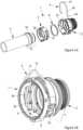
- FIG 1arepresents an exploded view of a tubular connection device 1 according to the present invention.
- the deviceis also shown, on the figure 1b , in overview.
- the tubular connection device 1is composed of a tubular female connector 2, a ring 3 and a locking clip 4. It aims to keep a tubular male end 5 connected to the female connector 2. More particularly, the male end 5 is tubular in shape and has a frustoconical collar 51 provided with an annular groove 52. The male end 5 is inserted along a main axis into the female connector 2 and held locked to the female connector 2 by the clip 3 when this is arranged in the annular groove 52.
- the male end 5can also be provided with at least one guide rib intended to interact with at least one groove of suitable size disposed on the internal surface of the female connector 2 to prevent the rotation of the male end 5 during its insertion into the female connector 2.
- the female connector 2, the male end 5 and the ring 3can be made of a plastic or metallic material.
- the ring 3is housed in the female connector 2, against the internal wall of this connector 2. Notches can be arranged on the external surface of the ring 3 so as to clip into openings present on the internal surface of the female connector 2 to hold the ring 3 secured to the female connector 2.
- the ring 3can also be made secured to the female connector 2 by welding or any other known technique. In order to improve the tightness of the connection device 1, it is advantageous to insert a seal 6 into the female connector 2 before assembling the ring 3 to the female connector 2. The seal 6 is thus held in place between ring 3 and the female connector.
- the clip 4has a U shape. It is formed of a head 41 connected to two branches 42 each ending in a foot 43.
- the two feet 43 of the clip 4form an enlargement of the end of the branches 42 of the clip 4 along the main axis of the connecting device 1.
- the branches 42 and the feet 43 of the clip 4are arranged in an L, that is to say that the feet 43 are oriented according to the 'axis main, when the clip 4 is inserted transversely into the connector 2. They can be formed by folding the end of the branches 42 of the clip 4. It is entirely possible to adapt the connecting device 1 to a other shape of feet than that shown on the figure 1a . Whatever the shape chosen, a foot 43 forms a widening of the end of the branches in the main direction.
- the clip 4is advantageously made of a metallic material.
- the female connector 2is provided with two lateral slots 21 symmetrical with respect to a radial axis A shown on the figures 1b And 2 .
- the ring 3is also provided with two side openings 31 which are also symmetrical with respect to the radial axis A.
- the side slots 21 of the female connector 2 as well as the side openings 31 of the ring 3are arranged opposite each other. others, when the ring 3 is inserted into the female connector 2.
- the width of the slots 21 and the side openings 31is chosen to substantially correspond to the dimension of the branches 42 of the clip 4.
- the clip 4is assembled so as to overlap the female connector 2, the branches 42 of the clip 4 penetrating through the slots 21 and the side openings 31.
- the feet 43 of the clip 4which cannot, due to their dimensions, pass through the lateral slots 21 and openings 31, rest on the exterior surface of the female connector 2.
- the head 41 of the clip 4defines the top of the clip 4. So when we speak, for example, of "top”, “upper part” or “upper part » of a part of the device, we will designate any region or element located in the half of this part closest to the head 41 of the clip 4, the two halves of the part being delimited by a transverse plane perpendicular to the radial axis A. Consequently, we will designate by “bottom”, “lower part” or “lower part” any region or element located in the half furthest from the head 41 of the clip 4.
- the upper outer surface of the female connector 2can be provided with head holding elements 41 so as to limit any longitudinal movement of the clip 4. It can for example be a groove to accommodate the head 41 of the clip 4 or even ribs framing the head 41 of the clip 4 on either side.
- the role of the clip 4is to lock the connection by housing its branches 42, through the side slots 21 and openings 31, in the groove 52 of the male end 5.
- the clip 4also serves as a visual indicator of the connection status. As such, the clip 4 can occupy a raised disconnection position, a depressed locking position as well as an intermediate delivery position. In the intermediate position, the clip 4 is located in elevation between the raised disconnection position and the depressed locking position.
- the tubular connection device 1is provided with guide systems 7 which cooperate with the feet 43 of the clip 4.
- the connecting device 1comprises two guide systems 7 symmetrically arranged with respect to the radial axis A, and located at the lower part of the connecting device 1.
- FIG 1crepresents a zoom of the guidance system 7 of the figure 1b , starting on a transverse cutting plane located after the branches 42 of the clip 4, which explains why we do not visualizes that the foot 43 of said clip 4.
- the figure 2represents a guide system in section in a transverse plane. It will be noted that the figure 1c represents the guiding system 7 when the clip 4 is in the intermediate position and the figure 2 when the clip 4 is in the pressed locking position, these positions will be explained in the remainder of the description.
- the guide system 7includes a notch 71, a plate 72, a first ramp 74 and a second ramp 75 formed on the female connector 2.
- the guide system 7also includes a lug 73 carried by the ring 3.
- the notch 71is formed in the female connector 2 adjoining the side slot 21. In particular, it can be formed by widening the side slot 21. The lower edge of the notch delimits the plate 72. The notch 71 exposes part of the surface of the ring 3. The purpose of the notch 71 is to allow the foot 43 to pass, at least partially, through the female connector 2 so that it can rest on the plate 72. preferably, the lateral opening 31 of the ring 3 does not include a similar notch, in order to hold the foot 43 on the plate 72.
- the plate 72is intended to receive the foot 43 of the clip 4 to maintain the clip 4 in an intermediate delivery position in the absence of the male end 5. This position is shown on the figure 1c .
- the clip 4cannot normally come out of this position in the absence of the end piece 5. In fact, the clip 4 cannot be moved to the lowered position because the foot 43 is supported on the plate 72, and cannot be moved in the raised position either because the foot 43 would come into abutment with the upper part of the notch 71.
- the frustoconical collar 51comes to rest on the two branches 42 of the clip 4 and tends to move them apart from each other, which has the consequence of at least partially removing the foot 42 from the notch 71 and of plate 72.
- the lug 73is arranged on a flexible tongue 32 carried by the ring 3.
- the flexible tongue 32is formed by a portion of the ring 3 adjoining the lateral opening 31.
- the purpose of the lug 73is to fill at least partially the notch 71 and the plate 72 so that the foot 43 of the clip 4 can only partially rest on the plate 72 when the male end is inserted into the female connector 2 in the pre-locking position, its annular groove 52 then being opposite the slots 21.
- the clip 4can no longer maintain its intermediate position because its feet 43 can only partially occupy the plate 72 at best, the clip 4 occupies then a transitional position corresponding to the pre-locking position of the male end 5.
- the clip 4 in the transitional positioncan substantially occupy the same altitude as when it is in the intermediate position, that is to say that the head 41 of the clip 4 is located substantially at the same distance from the female connector 2 in both positions. In the transitional position, however, the clip 4 can go into the depressed position by pressing on the head 41 of the clip 4 or into the raised position by pulling on the head 41 of the clip 4.
- the feet 43 of the clip 4are only partially in contact with the plate 72 (lower part of the notch 71) or with the upper part of the notch 71, and can slide easily out of the notch 71.
- the lug 73when engaged in the notch 71 by the end piece 5 in the pre-locking position, allows the feet 43 to be released from the notch 71 in order to allow the clip 4 to move into a depressed position or a raised position.
- the feet 43 of the clip 4can still rest partly on the plate 72, the branches 42 of the clip 4 can penetrate at least partially into the annular groove 52 and retain the tip male 5 connected to the female connector 2.
- the connectionis established but not definitive because the branches 42 can still be spread apart to take them out of the groove 52.
- the first ramp 74 and the second ramp 75interact with the foot 43 of the clip 4.
- the first ramp 74has the role of guiding the clip 4 between the intermediate position, passing through the transitional position, and the raised position.
- the second ramp 75for its part, has the role of guiding the clip 4 between the intermediate position, passing through the transitional position, and the depressed position.
- the first ramp 74 and the second ramp 75are formed on the female connector 2, adjacent to the lateral slot 21. They are inclined substantially tangentially to the internal wall of the female connector 2 and separated from each other by the notch 71. In other words, the ramps 74 and 75 are inclined downwards and towards the inside of the connection device 1.
- the foot 43 of the clip 4comes entirely out of the plate 72 and slides on the first ramp 74 which, due to its inclination, will force the branches 42 of the clip 4 to move away from one another.
- the branches 42 of the clip 4are spaced apart from each other by so as to be substantially tangent to the female connector 2 and no longer open into its internal volume so as to no longer lock the male end 5 to the female connector 2, the branches 42 no longer being able to interact with the groove 52 of the male end 5.
- the foot 43 of the clip 4comes out entirely from the plate 72 and slides on the second ramp 75 which, due to its inclination, will allow the branches 42 of the clip 4 to come closer to each other.
- the branches 42 of the clip 4are brought together so as to lock the male end 5 to the female connector 2 by penetrating deeper into the annular groove 52 of the male end 5.
- the first ramp 74can be delimited in the upper part by a rim which thus forms a stop for the foot 43 of the clip 4 when the head 41 of the clip 4 is pulled.
- the first ramp 74is delimited in the lower part by the notch 71.
- the first ramp 74can also include a hollow near the edge to form a retaining zone for the foot 43 so as to retain the clip 4 in the raised position.
- the clip 4will tend to descend towards the intermediate position. Indeed, the branches 42 of the clip 4 tend to want to move closer to each other after having been forced to move away from each other, having their feet 43 which slide downwards. on the first ramp 74.
- the second ramp 75is delimited in the upper part by the plate 72 and can, advantageously, be delimited in lower part by a bearing on which the foot 43 of the clip 4 is positioned when the clip 4 is in the depressed position.
- the lug 73 of the flexible tongue 32 of the ring 3can form an inclined ramp substantially tangentially to the internal wall of the female connector 2.
- the lug 73comes to at least partially fill the plate 72, the ramp of the lug 73 can be used to connect the first ramp to the second ramp by completing or extending one of the two ramps, which reduces the effort necessary to pass, from the transitional position, the foot 43 of the clip 4 onto the first or second ramp.
- the guide system 7may also include a blocking element 76 formed on the female connector 2 and configured to block the spacing of the branch 42 of the clip 4, when the clip 4 is in the depressed position.
- a blocking element 76formed on the female connector 2 and configured to block the spacing of the branch 42 of the clip 4, when the clip 4 is in the depressed position.
- the feet 43 of the clip 4find themselves abutting against the blocking element 76 if one tries to move the branches 42 of the clip 4 aside to remove the male end 5.
- This element of blocking 76can, advantageously, be arranged opposite the lower part of the second ramp 75, where the foot 43 of the clip 4 is located when the clip 4 is in the depressed position, such that represented on the figures 2 , 5 And 7 .
- THE figures 3a to 3crepresent alternative embodiments of the guide systems 7 in accordance with the invention showing other means for positioning the clip 4 in a transitional position.
- the junction between the plate 72 and the lug 73forms a V-shaped recess which allows the foot 43 of the clip 4 to rest partially on the end of the plate 72 when the clip 4 is in the transitional position.
- the foot 43 of the clip 4comes out entirely from the plate 72 and rests, when the clip 4 is in the transitional position, on a first shoulder 77a.
- the transitional position of the clip 4is located between the intermediate position and the depressed position, the head 41 of the clip 4 descending slightly to position the foot 43 on the first shoulder 77a.
- Figure 3cis a variant of the configuration of the figure 3b .
- a second shoulder 77bis arranged opposite the first shoulder 77a so that the two shoulders 77a and 77b are separated by a space substantially less than the width of the foot 43.
- this second shoulder 77bis carried by the blocking element 76.
- the crossing of the foot 43 between the two shoulders 77a and 77bproduces an audible click which provides an additional indicator of the passage of the clip 4 into the depressed position.
- THE figures 4 and 5represent two alternative embodiments of a tubular connection device 1.
- the device 1is provided with means to prevent the clip 4 from being placed in the depressed position during insertion of the male end 5 before the latter is in the pre-lock position.
- the exterior surface of the blocking element 76forms a third ramp inclined downwards and towards the outside of the female connector 2.
- the aimis to be able to automatically return the clip to the intermediate position if we manage to lower the clip 4 even though the male end is not positioned correctly in the pre-locking position. Indeed, if the clip 4 comes to descend while the male end 5 is not in the locking position, the foot 43 of the clip 4 comes to bear on the exterior surface of the blocking element 76 and is guided to return the clip 4 to the intermediate position when pressure is no longer exerted on the head 41 of the clip 4.
- the foot 43 of the clip 4 resting on the third ramp which forces the branches 42 to move away from each other, when the clip 4 is lowered,will tend to rise along the third ramp when no support is exerted on the head of the clip 4, to allow the branches 42 to get closer to each other.
- the head 41 of the clip 4has at least one stop 411, cooperating with holes provided in the female connector 2, to prevent the clip 4 from being positioned in the depressed position during insertion of the male end 5 , as long as it does not occupy the pre-lock position.
- the stop 411 of the head 41comes into contact with the male end 5 and its frustoconical collar 51 and prevents the clip 4 from lowering into the locking position as long as the stop 411, and therefore the branches 42 of the clip 4 , are not aligned with the groove 52 of the male end 5.
- the head 41 of the clip 4can have a W shape with the two points of the W forming two distinct stops 411.
- the clip 4Before inserting the male end 5, the clip 4 is initially positioned in the intermediate delivery position. In this position, illustrated on the figure 1c , the feet 43 of the clip 4 can slightly penetrate towards the inside of the connection device 1 by pushing the lugs 73 of the flexible tabs 32 out of the notch 71.
- the clip 4can neither move to the raised disconnection position nor to the depressed locking position in the absence of the male end 5.
- the element blocking 76preventing the spacing of the branches 42 of the clip 4 to allow the passage of the frustoconical collar 51.
- the male end 5is introduced through the connecting device 1, as is illustrated in the Figure 6 .
- the frustoconical collar 51initially comes to rest on the branches 42 of the clip 4 and forces them to move away from each other.
- the feet 43 of the clip 4are pushed at least partially out of the plate 72 and the clip 4 is in a transitional position.
- the frustoconical collar 51comes to rest on the flexible tongues 32 so that the lug 73 can occupy the space left free by the foot 43 of the clip 4 in the notch 71.
- the branches 42 of the clip 4can only partially penetrate into the groove 52 because the lugs 73 are held in the notch 71 by the support of the collar 51 on the flexible tabs 32 so as to at least partially fill the plate 72.
- the clip 4can then only occupy the transitional position illustrated on the figures 3a at 3c. Note that in this position, the branches 42 are partly in the groove 52 and therefore provide a connection which is however not secure.
- the clip 4can then move into the depressed position as shown on the Figure 7 or in the raised position as shown on the figure 8 depending on whether pressure or traction is exerted, respectively, on the head 41 of the clip 4.
- the clip 4could automatically go into the depressed position when the male end 5 is in the pre-locking position. This is particularly the case when the foot 43 completely leaves the plate 72 and there are no shoulders 77a and 77b to retain it in the transitional position. The foot 43 is then directly aligned with the second ramp 75 and automatically slides towards the depressed position.
- the clip 4By exerting pressure on the head 41 of the clip 4, the clip 4 leaves the unstable transition position and the foot 43 of the clip 4 completely leaves the plate 72, and/or the shoulders 77a and 77b if they are present, to follow the second ramp 75 until reaching the depressed position where the head 41 of the clip 4 is likely to abut with the upper part of the female connector 2.
- the feet 43follow the inclination of the second ramp 75 which tends to bring them closer to each other to close the branches 43 on the annular groove 52 of the male end 5.
- the blocking element 76prevents the spreading of the branches 42 of the clip 4 as long as the clip 4 remains in the depressed position.
- the clip 4By exerting traction on the head of the clip 4, the clip 4 leaves the unstable transition position and the foot 43 completely leaves the plate 72, and/or the shoulders 77a and 77b, guided by the first ramp 74 until to reach the raised position where the head 41 of the clip 4 is furthest from the upper part of the female connector 2.
- the feet 43follow the inclination of the first ramp 74 which tends to keep them away from each other.
- the branches 42are therefore spaced apart so that they no longer open inside the internal volume of the connecting device 1 and no longer obstruct the passage of the collar 51.
- This raised position of the clip 4also corresponds to the position disassembly (or disconnection) of the connection device 1.
- this connection device 1makes it possible to obtain a secure connection of a male end 5 in a female connector 2 in two stages, the first step being the insertion of the male end 5 and the second step being the lowering of clip 4 in the pressed locking position.
- the two stepscan only be performed in this specific order. Indeed, if the second step is carried out before the first step it will not be possible to carry out the first step because the branches 42 of the clip 4 cannot move apart when the clip 4 is in the depressed position. It will also be noted that the first step alone can already make it possible to retain the male end 5 in the female connector 2 without however constituting a secure connection.
- the branches 42 of the clip 4whose feet 43 are still at least partially on the plate 72, can partially penetrate into the annular groove 52 and block the male end 5 but nothing prevents however, to separate the branches 42 to remove them from the groove 52 and release the male end 5 in this transitional position.
- the flexible tongue 32 and the guide system 7were located downstream of the openings 31 and lateral slots 21 relative to the direction of insertion of the male end 5. It was also considered that the L shape of the feet 43 of the clip 4 was oriented in this direction of insertion. Obviously, it is entirely possible to modify this arrangement to adapt it to the case where the tongue 32 is located upstream of the side opening 31. To do this, it is sufficient to arrange the guide system 7 upstream of the slot side 21 and arrange the clip 4 so that the L shape of the feet 43 is oriented in the direction of withdrawal of the male end 5.
- the tongues 32which spread the branches 42 in place of the collar 51.
- the collar 51first meets and spreads the flexible tongues 32 which, through the contact of the lugs 73 with the feet 43 of the clip 4, will force the branches 42 to move apart.
- the tongues 32which spread the branches 42 in place of the collar 51.
- the collar 51first meets and spreads the flexible tongues 32 which, through the contact of the lugs 73 with the feet 43 of the clip 4, will force the branches 42 to move apart.
Landscapes
- Engineering & Computer Science (AREA)
- General Engineering & Computer Science (AREA)
- Mechanical Engineering (AREA)
- Quick-Acting Or Multi-Walled Pipe Joints (AREA)
Description
Translated fromFrenchLa présente invention concerne un dispositif de raccord tubulaire pour connecter des tuyaux ou conduits. Elle trouve notamment son application dans le domaine automobile et plus particulièrement dans les connexions fluidiques de système de refroidissement.The present invention relates to a tubular connector device for connecting pipes or conduits. It finds its application in particular in the automotive field and more particularly in fluid connections of cooling systems.
Il existe dans l'état de la technique des dispositifs de raccord tubulaire permettant de connecter entre eux un connecteur femelle et un embout mâle, la connexion entre ces deux éléments étant verrouillée par une agrafe métallique.In the state of the art there are tubular connection devices allowing a female connector and a male end to be connected together, the connection between these two elements being locked by a metal clip.
Par exemple, dans le document
- une position enfoncée dans laquelle la tête de l'agrafe est en contact avec le connecteur femelle ; les branches de l'agrafe traversent le connecteur femelle et débouchent dans son volume intérieur, sensiblement parallèlement à l'axe radial. Lorsque l'embout mâle, présentant un collet tronconique muni d'une rainure annulaire, est inséré dans le connecteur femelle, les branches de l'agrafe sont écartées par le collet, puis bloquées dans la rainure annulaire, lorsque l'embout mâle est totalement inséré dans le connecteur femelle. Dans cette position enfoncée de l'agrafe, la connexion entre le connecteur femelle et l'embout mâle est verrouillée.
- une position relevée dans laquelle la tête de l'agrafe est éloigné du connecteur ; les branches sont maintenues sensiblement tangentes au connecteur et ne débouchent pas dans son volume intérieur. L'embout mâle peut ainsi être séparé du connecteur femelle.
- a depressed position in which the head of the clip is in contact with the female connector; the branches of the clip pass through the female connector and open into its interior volume, substantially parallel to the radial axis. When the male end, having a frustoconical collar provided with an annular groove, is inserted into the female connector, the branches of the clip are separated by the collar, then blocked in the annular groove, when the male end is completely inserted into the female connector. In this depressed position of the clip, the connection between the female connector and the male end is locked.
- a raised position in which the head of the clip is away from the connector; the branches are maintained substantially tangent to the connector and do not open into its interior volume. The male end can thus be separated from the female connector.
Ce dispositif présente l'inconvénient de ne pas disposer d'un moyen visuel permettant de savoir si la connexion a correctement été établie.This device has the disadvantage of not having a visual means of knowing whether the connection has been correctly established.
Pour adresser ce problème, on connaît du document
Le document
Un but de l'invention est de proposer une solution alternative à l'état de la technique. Elle vise notamment à éviter la configuration où l'agrafe est en position enfoncée de verrouillage alors que l'embout mâle n'a pas été inséré.An aim of the invention is to propose an alternative solution to the state of the art. It aims in particular to avoid the configuration where the clip is in the pressed locking position while the male end has not been inserted.
Le but de la présente invention est atteint par le dispositif de raccord tubulaire tel que libellé à la revendication 1.The aim of the present invention is achieved by the tubular connection device as worded in
Notamment, l'invention propose un dispositif de raccord tubulaire comprenant :
- un connecteur femelle, dans lequel un embout mâle muni d'une rainure annulaire est destiné à être inséré, le connecteur femelle étant pourvu de deux fentes latérales symétriques par rapport à un axe radial ;
- une agrafe de verrouillage en forme de U comportant une tête et deux branches, et chevauchant le connecteur femelle, chaque branche s'étendant dans une fente latérale et se terminant par un pied ;
- deux systèmes de guidage latéraux symétriques par rapport à l'axe radial, coopérant avec les pieds de l'agrafe pour maintenir celle-ci dans une position relevée de déconnexion de l'embout mâle ou dans une position enfoncée de verrouillage de l'embout mâle dans le connecteur femelle.
- a female connector, into which a male end provided with an annular groove is intended to be inserted, the female connector being provided with two lateral slots symmetrical with respect to a radial axis;
- a U-shaped locking clip having a head and two legs, and overlapping the female connector, each leg extending into a side slot and ending in a foot;
- two lateral guide systems symmetrical with respect to the radial axis, cooperating with the feet of the clip to maintain it in a raised position for disconnecting the male end or in a depressed position for locking the male end into the female connector.
Selon l'invention, le dispositif comprend une bague disposée contre une paroi interne du connecteur femelle. De plus, chaque système de guidage comprend :
- une encoche, formée dans le connecteur femelle, attenante à la fente latérale ;
- un plateau délimitant un bord inférieur de l'encoche et sur lequel le pied repose pour maintenir l'agrafe dans une position intermédiaire, entre la position relevée et la position enfoncée, en l'absence d'embout mâle ;
- un ergot disposé sur une languette flexible portée par la bague, et destiné à combler au moins en partie l'encoche et le plateau lorsque l'embout mâle est inséré dans le connecteur, sa rainure annulaire étant en vis-à-vis des fentes, pour permettre à l'agrafe de passer dans une position enfoncée ou dans une position relevée.
- a notch, formed in the female connector, adjoining the side slot;
- a plate delimiting a lower edge of the notch and on which the foot rests to hold the clip in an intermediate position, between the raised position and the depressed position, in the absence of a male end;
- a pin arranged on a flexible tongue carried by the ring, and intended to fill at least partly the notch and the plate when the male end is inserted into the connector, its annular groove being opposite the slots, to allow the staple to move into a depressed position or a raised position.
Selon d'autres caractéristiques avantageuses et non limitatives de l'invention, prises seules ou selon toute combinaison techniquement réalisable :
- chaque système de guidage comprend une première rampe pour guider le pied entre les positions relevée et intermédiaire de l'agrafe, et une deuxième rampe pour guider le pied entre les positions intermédiaire et enfoncée, la première rampe et la deuxième rampe étant formées sur le connecteur femelle ;
- la première rampe et la deuxième rampe sont inclinées sensiblement tangentiellement à la paroi interne du connecteur femelle et séparée entre elles par l'encoche ;
- la première rampe est délimitée en partie basse par l'encoche et en partie haute par un rebord formant une butée pour le pied de l'agrafe ;
- la première rampe comprend un creux à proximité du rebord formant une zone de retenue pour le pied, de manière à retenir l'agrafe en position relevée ;
- la deuxième rampe est délimitée en partie haute par le plateau et en partie basse par un palier sur lequel le pied de l'agrafe se positionne lorsque l'agrafe est en position enfoncée ;
- l'ergot comble en partie le plateau lorsque l'embout mâle est inséré, sa rainure annulaire étant en vis-à-vis des fentes latérales, le pied de l'agrafe reposant sur un bord non comblé du plateau, plaçant l'agrafe dans une position transitoire, entre la position intermédiaire et la position enfoncée ;
- la deuxième rampe comporte un premier épaulement sur lequel le pied de l'agrafe est susceptible de reposer pour placer l'agrafe dans une position transitoire, entre la position intermédiaire et la position enfoncée ;
- chaque système de guidage comprend un élément de blocage formé sur le connecteur femelle et configuré pour bloquer l'écartement de la branche de l'agrafe, lorsque l'agrafe est en position enfoncée ;
- l'élément de blocage comporte un deuxième épaulement en vis-à-vis du premier épaulement, les deux épaulements étant séparés par un espace sensiblement inférieur à une largeur du pied ;
- la surface extérieure de l'élément de blocage forme une troisième rampe inclinée vers le bas et vers l'extérieur du connecteur femelle ;
- l'ergot de la languette flexible forme une rampe inclinée sensiblement tangentiellement à la paroi interne du connecteur femelle ;
- la languette flexible est formée par une portion de la bague attenante à une ouverture latérale formée dans la bague en vis-à-vis d'une fente latérale;
- la tête de l'agrafe présente au moins une butée coopérant avec des trous aménagées dans le connecteur femelle, pour prévenir le positionnement de l'agrafe en position enfoncée lors de l'insertion de l'embout mâle tant que sa rainure annulaire n'est pas en vis-à-vis des fentes latérales ;
- l'encoche est formée par un élargissement de la fente latérale.
- each guidance system includes a first ramp for guiding the foot between the raised and intermediate positions of the clip, and a second ramp for guiding the foot between the intermediate and depressed positions, the first ramp and the second ramp being formed on the female connector;
- the first ramp and the second ramp are inclined substantially tangentially to the internal wall of the female connector and separated from each other by the notch;
- the first ramp is delimited in the lower part by the notch and in the upper part by a rim forming a stop for the foot of the clip;
- the first ramp comprises a hollow near the edge forming a retaining zone for the foot, so as to retain the clip in the raised position;
- the second ramp is delimited in the upper part by the plate and in the lower part by a bearing on which the foot of the clip is positioned when the clip is in the depressed position;
- the lug partially fills the plate when the male end is inserted, its annular groove being opposite the lateral slots, the foot of the clip resting on an unfilled edge of the plate, placing the clip in a transitional position, between the intermediate position and the depressed position;
- the second ramp comprises a first shoulder on which the foot of the clip is capable of resting to place the clip in a transitional position, between the intermediate position and the depressed position;
- each guide system comprises a blocking element formed on the female connector and configured to block the spacing of the branch of the clip, when the clip is in the depressed position;
- the blocking element comprises a second shoulder facing the first shoulder, the two shoulders being separated by a space substantially less than a width of the foot;
- the outer surface of the blocking element forms a third ramp inclined downwards and towards the outside of the female connector;
- the lug of the flexible tab forms an inclined ramp substantially tangentially to the internal wall of the female connector;
- the flexible tongue is formed by a portion of the ring adjoining a lateral opening formed in the ring facing a lateral slot;
- the head of the clip has at least one stop cooperating with holes made in the female connector, to prevent the clip from being positioned in the depressed position during insertion of the male end as long as its annular groove is not not opposite the side slits;
- the notch is formed by a widening of the lateral slot.
D'autres caractéristiques et avantages de l'invention ressortiront de la description détaillée de l'invention qui va suivre, en référence aux figures annexées sur lesquelles :
- les
figures 1a et 1b représentent respectivement un dispositif de raccord tubulaire conforme à l'invention en vue éclatée et en vue assemblée; - la
figure 1c représente un zoom de lafigure 1b au niveau d'un système de guidage conforme à l'invention, l'agrafe étant en position intermédiaire ; - la
figure 2 représente un système de guidage conforme à l'invention en coupe dans un plan transversal, l'agrafe étant en position enfoncée de verrouillage ; - les
figures 3a à 3c représentent des modes de réalisation alternatifs des systèmes de guidage ; - la
figure 4 représente un dispositif de raccord tubulaire conforme à un mode de réalisation de l'invention en coupe dans un plan transversal passant par la fente latérale ; - la
figure 5 représente un dispositif de raccord tubulaire conforme à un autre mode de réalisation de l'invention en perspective et selon une coupe dans un plan transversal passant par la fente ; - la
figure 6 représente un dispositif de raccord tubulaire conforme à l'invention en position intermédiaire en coupe dans un plan longitudinal; - la
figure 7 représente un dispositif de raccord tubulaire conforme à l'invention, l'agrafe étant en position enfoncée en présence de l'embout mâle, en position de verrouillage ; - la
figure 8 représente un dispositif de raccord tubulaire conforme à l'invention, l'agrafe étant en position relevée.
- THE
figures 1a and 1b respectively represent a tubular connection device according to the invention in exploded view and in assembled view; - there
figure 1c represents a zoom of thefigure 1b at the level of a guiding system according to the invention, the clip being in an intermediate position; - there
figure 2 represents a guiding system according to the invention in section in a transverse plane, the clip being in the depressed locking position; - THE
figures 3a to 3c represent alternative embodiments of the guidance systems; - there
Figure 4 represents a tubular connection device according to one embodiment of the invention in section in a transverse plane passing through the lateral slot; - there
figure 5 represents a tubular connection device according to another embodiment of the invention in perspective and in a section in a transverse plane passing through the slot; - there
Figure 6 represents a tubular connection device according to the invention in intermediate position in section in a longitudinal plane; - there
Figure 7 represents a tubular connection device according to the invention, the clip being in the depressed position in the presence of the male end, in the locking position; - there
figure 8 represents a tubular connection device according to the invention, the clip being in the raised position.
Par souci de simplification de la description à venir, les mêmes références sont utilisées pour des éléments identiques ou assurant la même fonction. Les figures sont des représentations schématiques qui, dans un objectif de lisibilité, ne sont pas nécessairement à l'échelle.For the sake of simplification of the future description, the same references are used for identical elements or ensuring the same function. The figures are schematic representations which, for the purposes of readability, are not necessarily to scale.
La
Le dispositif de raccord tubulaire 1 est composé d'un connecteur femelle tubulaire 2, d'une bague 3 et d'une agrafe de verrouillage 4. Il vise à maintenir raccordé un embout mâle tubulaire 5 au connecteur femelle 2. Plus particulièrement, l'embout mâle 5 est de forme tubulaire et présente un collet tronconique 51 dotée d'une rainure annulaire 52. L'embout mâle 5 est inséré selon un axe principal dans le connecteur femelle 2 et maintenu verrouillé au connecteur femelle 2 par l'agrafe 3 lorsque celle-ci est disposée dans la rainure annulaire 52. L'embout mâle 5 peut également être muni d'au moins une nervure de guidage destinée à interagir avec au moins une rainure de dimension adaptée disposée sur la surface interne du connecteur femelle 2 pour empêcher la rotation de l'embout mâle 5 lors de son insertion dans le connecteur femelle 2. Le connecteur femelle 2, l'embout mâle 5 et la bague 3 peuvent être composés d'un matériau plastique ou métallique.The
La bague 3 est logée dans le connecteur femelle 2, contre la paroi interne de ce connecteur 2. Des crans peuvent être disposés sur la surface externe de la bague 3 de façon à se cliper dans des ouvertures présentes sur la surface interne du connecteur femelle 2 pour maintenir la bague 3 solidaire du connecteur femelle 2. La bague 3 peut aussi être rendue solidaire du connecteur femelle 2 par soudure ou tout autre technique connue. Afin d'améliorer l'étanchéité du dispositif de raccord 1, il est avantageux d'insérer un joint d'étanchéité 6 dans le connecteur femelle 2 avant d'assembler la bague 3 au connecteur femelle 2. Le joint d'étanchéité 6 est ainsi maintenu en place entre la bague 3 et le connecteur femelle.The
L'agrafe 4 possède une forme en U. Elle est formée d'une tête 41 reliée à deux branches 42 se terminant chacune par un pied 43. Les deux pieds 43 de l'agrafe 4 forment un élargissement de l'extrémité des branches 42 de l'agrafe 4 selon l'axe principal du dispositif de raccord 1. De manière avantageuse, les branches 42 et les pieds 43 de l'agrafe 4 sont disposés en L, c'est à dire que les pieds 43 sont orientés selon l'axe principal, lorsque l'agrafe 4 est insérée transversalement dans le connecteur 2. Ils peuvent être formés par pliage de l'extrémité des branches 42 de l'agrafe 4. Il est tout à fait envisageable d'adapter le dispositif de raccord 1 à une autre forme de pieds que celle représentée sur la
Le connecteur femelle 2 est pourvu de deux fentes latérales 21 symétriques par rapport à un axe radial A représenté sur les
L'agrafe 4 est assemblée de façon à chevaucher le connecteur femelle 2, les branches 42 de l'agrafe 4 pénétrant à travers les fentes 21 et les ouvertures 31 latérales. Les pieds 43 de l'agrafe 4, ne pouvant pas, du fait de leurs dimensions, traverser les fentes 21 et ouvertures 31 latérales, sont en appui sur la surface extérieure du connecteur femelle 2.The
Dans la suite de la description, on considérera que la tête 41 de l'agrafe 4 définit le haut de l'agrafe 4. Ainsi lorsque l'on parlera, par exemple, de « haut », « partie haute » ou « partie supérieure » d'une partie du dispositif, on désignera toute région ou élément situé dans la moitié de cette partie la plus proche de la tête 41 de l'agrafe 4, les deux moitiés de la partie étant délimitées par un plan transversal perpendiculaire à l'axe radial A. Par conséquent on désignera par « bas », « partie basse » ou « partie inférieure » toute région ou élément se situant dans la moitié la plus éloignée de la tête 41 de l'agrafe 4.In the remainder of the description, we will consider that the
De manière avantageuse, la surface extérieure haute du connecteur femelle 2 peut être munie d'éléments de maintien de la tête 41 de sorte à limiter tout déplacement longitudinal de l'agrafe 4. Il peut par exemple s'agir d'une rainure pour accueillir la tête 41 de l'agrafe 4 ou encore de nervures encadrant de part et d'autres la tête 41 de l'agrafe 4.Advantageously, the upper outer surface of the
L'agrafe 4 a pour rôle de verrouiller la connexion en venant loger ses branches 42, à travers les fentes latérales 21 et ouvertures 31, dans la rainure 52 de l'embout mâle 5. L'agrafe 4 sert aussi de témoin visuel de l'état de connexion. A ce titre, l'agrafe 4 peut occuper une position relevée de déconnexion, une position enfoncée de verrouillage ainsi qu'une position intermédiaire de livraison. Dans la position intermédiaire, l'agrafe 4 se situe en élévation entre la position relevée de déconnexion et la position enfoncée de verrouillage.The role of the
Afin de pouvoir correctement guider l'agrafe 4 et la maintenir dans les positions adéquates pour refléter l'état de la connexion, le dispositif de raccord tubulaire 1 est muni de systèmes de guidage 7 qui coopèrent avec les pieds 43 de l'agrafe 4.In order to be able to correctly guide the
Le dispositif de raccord 1 comprend deux systèmes de guidage 7 symétriquement disposés par rapport à l'axe radial A, et situés au niveau de la partie inférieure du dispositif de raccord 1. Dans la suite de la description, lorsque l'on décrira un système de guidage, il faudra comprendre que la même description s'applique à chacun des systèmes de guidage 7, symétriques l'un de l'autre.The connecting
La
L'encoche 71 est formée dans le connecteur femelle 2 attenante à la fente latérale 21. En particulier, elle peut être formée par un élargissement de la fente latérale 21. Le bord inférieur de l'encoche délimite le plateau 72. L'encoche 71 expose une partie de la surface de la bague 3. L'encoche 71 a pour but de permettre la traversée, au moins partielle, du pied 43 à travers le connecteur femelle 2 pour que celui-ci puisse prendre appui sur le plateau 72. De manière préférentielle, l'ouverture latérale 31 de la bague 3 ne comprend pas d'encoche similaire, afin de maintenir le pied 43 sur le plateau 72.The
Le plateau 72 est destiné à recevoir le pied 43 de l'agrafe 4 pour maintenir l'agrafe 4 dans une position intermédiaire de livraison en l'absence de l'embout mâle 5. Cette position est représentée sur la
Lors de l'insertion de l'embout mâle 5, tel que cela est illustré sur la
Revenant à la description du système de guidage 7 représenté sur les
L'ergot 73 a pour but de combler au moins en partie l'encoche 71 et le plateau 72 de sorte que le pied 43 de l'agrafe 4 ne puisse reposer que partiellement sur le plateau 72 lorsque l'embout mâle est inséré dans le connecteur femelle 2 en position de pré-verrouillage, sa rainure annulaire 52 étant alors en vis-à-vis des fentes 21.The purpose of the
En l'absence de l'ergot 73, lorsque l'embout mâle 5 est en position de pré-verrouillage, les pieds 43 de l'agrafe 4, encore partiellement sur le plateau 72, auraient tendance à se rapprocher l'un de l'autre, pour reprendre leur place initiale sur le plateau 72 et garder l'agrafe 4 en position intermédiaire. En effet, lorsque le connecteur mâle 5 est en position de pré-verrouillage, le collet 51 n'appuie plus sur les branches 42 pour forcer leur écartement car ces dernières sont alors alignées avec la rainure du collet 52. Les branches 42, ne subissant plus de force visant à les écarter, tendraient donc revenir à leur position précédente.In the absence of the
L'ergot 73 venant combler au moins partiellement l'encoche 71 et le plateau 72, l'agrafe 4 ne peut plus conserver sa position intermédiaire car ses pieds 43 ne peuvent occuper qu'au mieux partiellement le plateau 72, l'agrafe 4 occupe alors une position transitoire correspondant à la position de pré-verrouillage de l'embout mâle 5. L'agrafe 4 en position transitoire peut sensiblement occuper la même altitude que lorsqu'elle est en position intermédiaire, c'est-à-dire que la tête 41 de l'agrafe 4 se trouve sensiblement à une même distance du connecteur femelle 2 dans les deux positions. En position transitoire toutefois l'agrafe 4 peut passer en position enfoncée par appui sur la tête 41 de l'agrafe 4 ou en position relevée en tirant sur la tête 41 de l'agrafe 4. Lorsque l'agrafe 4 est en position transitoire, les pieds 43 de l'agrafe 4 ne sont que partiellement en contact avec le plateau 72 (partie inférieure de l'encoche 71) ou avec la partie supérieure de l'encoche 71, et peuvent glisser facilement hors de l'encoche 71. L'ergot 73, lorsqu'il est engagé dans l'encoche 71 par l'embout 5 en position de pré-verrouillage, permet de dégager les pieds 43 de l'encoche 71 afin de permettre à l'agrafe 4 de passer dans une position enfoncée ou dans une position relevée.The
On notera qu'en position transitoire, les pieds 43 de l'agrafe 4 pouvant encore reposer en partie sur le plateau 72, les branches 42 de l'agrafe 4 peuvent pénétrer en partie au moins dans la rainure annulaire 52 et retenir l'embout mâle 5 connecté au connecteur femelle 2. La connexion est établie mais pas définitive car les branches 42 peuvent encore être écartées pour les sortir de la rainure 52.It will be noted that in the transitional position, the
La première rampe 74 et la deuxième rampe 75 interagissent avec le pied 43 de l'agrafe 4. La première rampe 74 a pour rôle de guider l'agrafe 4 entre la position intermédiaire, en passant par la position transitoire, et la position relevée. La deuxième rampe 75, quant à elle, a pour rôle de guider l'agrafe 4 entre la position intermédiaire, en passant par la position transitoire, et la position enfoncée. La première rampe 74 et la deuxième rampe 75 sont formées sur le connecteur femelle 2, attenantes à la fente latérale 21. Elles sont inclinées sensiblement tangentiellement à la paroi interne du connecteur femelle 2 et séparées entre elles par l'encoche 71. Dit autrement, les rampes 74 et 75 sont inclinées vers le bas et vers l'intérieur du dispositif de raccord 1.The
Ainsi, si l'on tire sur la tête 41 de l'agrafe 4 lorsqu'elle est en position transitoire pour la placer en position relevée de déconnexion, le pied 43 de l'agrafe 4 sort entièrement du plateau 72 et vient glisser sur la première rampe 74 qui, de part son inclinaison, va forcer les branches 42 de l'agrafe 4 à s'écarter l'une de l'autre. En position relevée, les branches 42 de l'agrafe 4 sont écartées l'une de l'autre de façon à être sensiblement tangentes au connecteur femelle 2 et ne plus déboucher dans son volume interne pour ne plus verrouiller l'embout mâle 5 au connecteur femelle 2, les branches 42 ne pouvant plus interagir avec la rainure 52 de l'embout mâle 5.Thus, if we pull on the
De manière similaire, si l'on appuie sur la tête 41 de l'agrafe 4 pour la placer en position enfoncée de verrouillage, le pied 43 de l'agrafe 4 sort entièrement du plateau 72 et vient glisser sur la deuxième rampe 75 qui, de part son inclinaison, va autoriser les branches 42 de l'agrafe 4 à se rapprocher l'une de l'autre. En position enfoncée, les branches 42 de l'agrafe 4 sont rapprochées l'une de l'autre de sorte à verrouiller l'embout mâle 5 au connecteur femelle 2 en pénétrant plus profondément dans la rainure annulaire 52 de l'embout mâle 5.Similarly, if we press on the
Pour éviter que l'on puisse sortir complètement l'agrafe 4 du connecteur femelle 2 lorsque l'on place l'agrafe en position relevée, la première rampe 74 peut être délimitée en partie haute par un rebord qui forme ainsi une butée pour le pied 43 de l'agrafe 4 lorsque l'on tire sur la tête 41 de l'agrafe 4. La première rampe 74 est délimitée en partie basse par l'encoche 71.To prevent the
De manière avantageuse, la première rampe 74 peut également comprendre un creux à proximité du rebord pour former une zone de retenue pour le pied 43 de manière à retenir l'agrafe 4 en position relevée. En l'absence de ce creux, dès lors que l'on arrêtera de tirer sur la tête 41 de l'agrafe 4, l'agrafe 4 aura tendance à redescendre vers la position intermédiaire. En effet, les branches 42 de l'agrafe 4 ont tendance à vouloir se rapprocher l'une de l'autres après avoir été forcées à s'écarter l'une de l'autre, en ayant leur pieds 43 qui glissent vers le bas sur la première rampe 74.Advantageously, the
La deuxième rampe 75 est délimitée en partie haute par le plateau 72 et peut, de manière avantageuse, être délimitée en partie basse par un palier sur lequel le pied 43 de l'agrafe 4 se positionne lorsque l'agrafe 4 est en position enfoncée.The
De manière avantageuse, pour faciliter le passage de l'agrafe 4 de la position intermédiaire, en passant par la position transitoire, à la position enfoncée ou relevée, l'ergot 73 de la languette flexible 32 de la bague 3 peut former une rampe inclinée sensiblement tangentiellement à la paroi interne du connecteur femelle 2. L'ergot 73 venant combler en partie au moins le plateau 72, la rampe de l'ergot 73 peut servir à connecter la première rampe à la deuxième rampe en complétant ou rallongeant l'une des deux rampes, ce qui réduit l'effort nécessaire pour faire passer, depuis la position transitoire, le pied 43 de l'agrafe 4 sur la première ou deuxième rampe.Advantageously, to facilitate the passage of the
On notera qu'il est également possible, dans le cas où l'ergot 73 comble entièrement le plateau 72, que la rampe de l'ergot 73 forme une rampe unique pour permettre le passage entre la position connectée et la position enfoncée sans passer par une position transitoire, comme cela est représenté sur la
Le système de guidage 7 peut également comprendre un élément de blocage 76 formé sur le connecteur femelle 2 et configuré pour bloquer l'écartement de la branche 42 de l'agrafe 4, lorsque l'agrafe 4 est en position enfoncée. Dans cette configuration, les pieds 43 de l'agrafe 4 se retrouvent en butée contre l'élément de blocage 76 si l'on essaye d'écarter les branches 42 de l'agrafe 4 pour retirer l'embout mâle 5. Cet élément de blocage 76 peut, de façon avantageuse, être disposé en vis-à-vis de la partie basse de la deuxième rampe 75, là où se trouve le pied 43 de l'agrafe 4 lorsque l'agrafe 4 est en position enfoncée, tel que représenté sur les
Les
Sur la
Sur la
La figure 3c est une variante de la configuration de la
Les
Sur la
Sur la
Avant l'insertion de l'embout mâle 5, l'agrafe 4 est initialement positionnée en position intermédiaire de livraison. Dans cette position, illustrée sur la
S'il advenait toutefois que l'opérateur positionne l'agrafe 4 en position enfoncée en l'absence de l'embout mâle 5, il serait alors impossible d'insérer l'embout mâle 5 dans le dispositif de raccord 1, l'élément de blocage 76 empêchant l'écartement des branches 42 de l'agrafe 4 pour permettre le passage du collet tronconique 51.If, however, the operator positions the
L'agrafe 4 étant en position intermédiaire de livraison, l'embout mâle 5 est introduit à travers le dispositif de raccord 1, comme cela est illustré sur la
Lorsque l'embout mâle 5 est en position de pré-verrouillage, les branches 42 de l'agrafe 4 ne peuvent pénétrer que partiellement dans la rainure 52 car les ergots 73 sont maintenus dans l'encoche 71 par l'appui du collet 51 sur les languettes flexibles 32 de sorte à combler au moins partiellement le plateau 72. L'agrafe 4 ne peut alors qu'occuper la position transitoire illustrée sur les
Dans cette position, l'agrafe 4 peut alors passer en position enfoncée telle que représentée sur la
On notera qu'il est également possible d'envisager qu'il n'y ait pas de position transitoire. En effet, l'agrafe 4 pourrait passer automatiquement en position enfoncée lorsque l'embout mâle 5 est en position de pré-verrouillage. Cela est notamment le cas quand le pied 43 quitte totalement le plateau 72 et qu'il n'y pas d'épaulements 77a et 77b pour le retenir en position transitoire. Le pied 43 est alors directement alignée avec la deuxième rampe 75 et glisse automatiquement vers la position enfoncée.Note that it is also possible to envisage that there is no transitional position. In fact, the
En exerçant une pression sur la tête 41 de l'agrafe 4, l'agrafe 4 quitte la position de transition instable et le pied 43 de l'agrafe 4 quitte complètement le plateau 72, et/ou les épaulements 77a et 77b s'ils sont présents, pour suivre la deuxième rampe 75 jusqu'à atteindre la position enfoncée où la tête 41 de l'agrafe 4 est susceptible d'être en butée avec la partie supérieure du connecteur femelle 2. Lors de la descente de l'agrafe 4, les pieds 43 suivent l'inclinaison de la deuxième rampe 75 qui tend à les rapprocher l'un de l'autre pour refermer les branches 43 sur la rainure annulaire 52 de l'embout mâle 5. On rappelle que l'élément de blocage 76 empêche l'écartement des branches 42 de l'agrafe 4 tant que l'agrafe 4 reste en position enfoncée. Ainsi l'embout mâle 5 est correctement verrouillé au connecteur femelle 2 lorsque l'agrafe 4 est en position enfoncée, cette position témoignant visuellement de l'état de bon verrouillage de l'embout mâle 5 dans le dispositif de raccord 1.By exerting pressure on the
En exerçant une traction sur la tête de l'agrafe 4, l'agrafe 4 quitte la position de transition instable et le pied 43 quitte complètement le plateau 72, et/ou les épaulements 77a et 77b, guidé par la première rampe 74 jusqu'à atteindre la position relevée où la tête 41 de l'agrafe 4 se trouve le plus éloigné de la partie supérieure du connecteur femelle 2. Lors de la montée de l'agrafe 4, les pieds 43 suivent l'inclinaison de la première rampe 74 qui tend à les écarter l'un de l'autre. Les branches 42 sont donc écartées de sorte qu'elles ne débouchent plus à l'intérieur du volume interne du dispositif de raccord 1 et ne font plus obstacle au passage du collet 51. Cette position relevée de l'agrafe 4 correspond aussi à la position de démontage (ou déconnexion) du dispositif de raccord 1.By exerting traction on the head of the
On notera que tant que l'embout mâle 5 reste en position de pré-verrouillage, il est possible de déplacer facilement l'agrafe 4 de la position enfoncée à la position relevée et vice-versa, l'ergot 73 venant remplacer et/ou compléter la première 74 et le deuxième 75 rampe.Note that as long as the
Ainsi, ce dispositif de raccord 1 permet d'obtenir une connexion sécurisée d'un embout mâle 5 dans un connecteur femelle 2 en deux étapes, la première étape étant l'insertion de l'embout mâle 5 et la deuxième étape étant l'abaissement de l'agrafe 4 en position enfoncée de verrouillage. Les deux étapes ne peuvent être réalisées que dans cet ordre précis. En effet, si la deuxième étape est réalisée avant la première étape il ne sera pas possible de réaliser la première étape car les branches 42 de l'agrafe 4 ne peuvent pas s'écarter lorsque l'agrafe 4 est en position enfoncée. On remarquera de plus que la première étape seule peut déjà permettre de retenir l'embout mâle 5 dans le connecteur femelle 2 sans toutefois constituer une connexion sécurisée. En effet en position transitoire, les branches 42 de l'agrafe 4, dont les pieds 43 sont encore au moins partiellement sur le plateau 72, peuvent pénétrer en partie dans la rainure annulaire 52 et bloquer l'embout mâle 5 mais rien n'empêche toutefois d'écarter les branches 42 pour les sortir de la rainure 52 et libérer l'embout mâle 5 dans cette position transitoire.Thus, this
Bien entendu l'invention n'est pas limitée aux modes de mise en oeuvre décrits et on peut y apporter des variantes de réalisation sans sortir du cadre de l'invention tel que défini par les revendications.Of course the invention is not limited to the modes of implementation described and it is possible to provide variants of realization without departing from the scope of the invention as defined by the claims.
Dans la description détaillée, on a considéré que la languette flexible 32 et le système de guidage 7 se situaient en aval des ouvertures 31 et fentes 21 latérales par rapport au sens d'insertion de l'embout mâle 5. On a également considéré que la forme en L des pieds 43 de l'agrafe 4 était orientée dans ce sens d'insertion. Bien évidemment, il est tout à fait possible de modifier cette disposition pour l'adapter au cas où la languette 32 se trouverait en amont de l'ouverture latérale 31. Il suffit pour cela de disposer le système de guidage 7 en amont de la fente latérale 21 et de disposer l'agrafe 4 de sorte que la forme en L des pieds 43 soit orientée dans le sens de retrait de l'embout mâle 5.In the detailed description, it was considered that the
Dans ce cas, ce sont les languettes 32 qui écartent les branches 42 à la place du collet 51. En effet, le collet 51 rencontre et écarte en premier les languettes flexibles 32 qui, par le biais du contact des ergots 73 avec les pieds 43 de l'agrafe 4, vont forcer les branches 42 à s'écarter. tout à fait possible de modifier cette disposition pour l'adapter au cas où la languette 32 se trouverait en amont de l'ouverture latérale 31. Il suffit pour cela de disposer le système de guidage 7 en amont de la fente latérale 21 et de disposer l'agrafe 4 de sorte que la forme en L des pieds 43 soit orientée dans le sens de retrait de l'embout mâle 5.In this case, it is the
Dans ce cas, ce sont les languettes 32 qui écartent les branches 42 à la place du collet 51. En effet, le collet 51 rencontre et écarte en premier les languettes flexibles 32 qui, par le biais du contact des ergots 73 avec les pieds 43 de l'agrafe 4, vont forcer les branches 42 à s'écarter.In this case, it is the
Claims (15)
- Tubular connection device (1) comprising:• a female connector (2), into which a male end piece (5) provided with an annular groove (52) is intended to be inserted, the female connector (2) being provided with two lateral slits (21) which are symmetrical with respect to a radial axis (A);• a U-shaped locking clip (4), which comprises a head (41) and two branches (42) and straddles the female connector (2), each branch (42) extending into a lateral slit (21) and ending with a foot (43);• two lateral guide systems (7), which are symmetrical with respect to the radial axis (A) and cooperate with the feet (43) of the clip (4) in order to keep it in a raised position of disconnection from the male end piece (5) or in a pressed-in position for locking the male end piece (5) in the female connector (2), each guide system (7) comprising:o a notch (71), which is formed in the female connector (2) adjacent to the lateral slit (21);o a plate (72), which delimits a lower edge of the notch (71) and on which the foot (43) rests in order to keep the clip in an intermediate position between the raised position and the pressed-in position in the absence of a male end piece (5);• a ring (3), which is arranged against an inner wall of the female connector (3); the device (1) beingcharacterized in that each guide system (7) further comprises a lug (73), which is arranged on a flexible tab (32) carried by the ring (3) and is intended to at least partly fill the notch (71) and the plate (72) when the male end piece (5) is inserted into the connector (2), its annular groove (52) being intended to be opposite the lateral slits (21) to allow the clip (4) to pass into a pressed-in position or into a raised position.
- Tubular connection device (1) according to the preceding claim, wherein each guide system (7) comprises a first ramp (74) for guiding the foot (43) between the raised and intermediate positions of the clip (4), and a second ramp (75) for guiding the foot (43) between the intermediate and pressed-in positions, the first ramp (74) and the second ramp (75) being formed on the female connector (2).
- Tubular connection device (1) according to the preceding claim, wherein the first ramp (74) and the second ramp (75) are inclined substantially tangentially to the internal wall of the female connector (2) and separated from one another by the notch (71).
- Tubular connection device according to either claim 2 or claim 3, wherein the first ramp (74) is delimited in the lower part by the notch (71) and in the upper part by a flange forming a stop for the foot (43) of the clip (4).
- Tubular connection device (1) according to the preceding claim, wherein the first ramp (74) comprises a hollow near the flange, which forms a retaining region for the foot (43) so as to keep the clip (4) in the raised position.
- Tubular connection device (1) according to any of claims 2 to 5, wherein the second ramp (75) is delimited in the upper part by the plate (72) and in the lower part by a bearing on which the foot of the clip (43) is positioned when the clip (4) is in the pressed-in position.
- Tubular connection device (1) according to any of the preceding claims, wherein the lug (73) partly fills the plate (72) when the male end piece (5) is inserted, its annular groove (52) being opposite the lateral slits (21), the foot (43) of the clip (4) resting on an unfilled edge of the plate (72), placing the clip (4) in a transitional position between the intermediate position and the pressed-in position.
- Tubular connection device (1) according to any of claims 2 to 7, wherein the second ramp (75) comprises a first shoulder (77a) on which the foot (43) of the clip (4) is able to rest in order to place the clip (4) in a transitional position between the intermediate position and the pressed-in position.
- Tubular connection device (1) according to any of the preceding claims, wherein each guide system (7) comprises a blocking element (76) which is formed on the female connector (2) and is configured to block the separation of the branch (42) of the clip (4) when the clip (4) is in the pressed-in position.
- Tubular connection device (1) according to either claim 8 or claim 9, wherein the blocking element (76) comprises a second shoulder (77b) opposite the first shoulder (77a), the two shoulders being separated by a space which is substantially less than a width of the foot (43).
- Tubular connection device (1) according to either claim 9 or claim 10, wherein the outer surface of the blocking element (76) forms a third ramp which is inclined toward the bottom and the outside of the female connector (2).
- Tubular connection device (1) according to any of the preceding claims, wherein the lug (73) of the flexible tab (32) forms a ramp which is inclined substantially tangentially to the internal wall of the female connector (2).
- Tubular connection device (1) according to any of the preceding claims, wherein the flexible tab (32) is formed by a portion adjacent to a lateral opening (31) of the ring (3), which lateral opening is opposite a lateral slit.
- Tubular connection device (1) according to any of the preceding claims, wherein the head of the clip (41) has at least one stop (411) which cooperates with holes made in the female connector (2) to prevent the positioning of the clip (4) in the pressed-in position during the insertion of the male end piece (5) as long as its annular groove (52) is not opposite the lateral slits (21).
- Tubular connection device (1) according to any of the preceding claims, wherein the notch (71) is formed by an enlargement of the lateral slit (21).
Applications Claiming Priority (2)
| Application Number | Priority Date | Filing Date | Title |
|---|---|---|---|
| FR1856856AFR3084435B1 (en) | 2018-07-24 | 2018-07-24 | TUBULAR CONNECTION DEVICE |
| PCT/FR2019/051647WO2020021179A1 (en) | 2018-07-24 | 2019-07-03 | Tubular connection device |
Publications (2)
| Publication Number | Publication Date |
|---|---|
| EP3827191A1 EP3827191A1 (en) | 2021-06-02 |
| EP3827191B1true EP3827191B1 (en) | 2024-02-14 |
Family
ID=65031502
Family Applications (1)
| Application Number | Title | Priority Date | Filing Date |
|---|---|---|---|
| EP19758425.3AActiveEP3827191B1 (en) | 2018-07-24 | 2019-07-03 | Tubular connection device |
Country Status (5)
| Country | Link |
|---|---|
| US (1) | US11846377B2 (en) |
| EP (1) | EP3827191B1 (en) |
| CN (1) | CN112513508B (en) |
| FR (1) | FR3084435B1 (en) |
| WO (1) | WO2020021179A1 (en) |
Families Citing this family (3)
| Publication number | Priority date | Publication date | Assignee | Title |
|---|---|---|---|---|
| JP7581005B2 (en) | 2020-10-08 | 2024-11-12 | 株式会社東郷製作所 | connector |
| FR3127798B1 (en)* | 2021-10-01 | 2023-09-29 | Akwel Sweden Ab | O-ring seal and fluid connection for fluid transfer circuit comprising such a seal. |
| CN115823380B (en)* | 2022-11-18 | 2025-06-06 | 临海市永恒汽配科技有限公司 | External card type detachable connector and installation and use method thereof |
Family Cites Families (21)
| Publication number | Priority date | Publication date | Assignee | Title |
|---|---|---|---|---|
| DE10024303B4 (en)* | 2000-05-17 | 2005-09-08 | Rasmussen Gmbh | Recording coupling device of a plug-in coupling and plug-in coupling with the receiving coupling device |
| JP4291989B2 (en) | 2002-10-01 | 2009-07-08 | 株式会社パイオラックス | Piping connector |
| JP4663254B2 (en)* | 2004-05-25 | 2011-04-06 | 三桜工業株式会社 | Quick connector |
| JP2006266472A (en)* | 2005-03-25 | 2006-10-05 | Tokai Rubber Ind Ltd | Quick connector |
| US7438328B2 (en)* | 2005-03-25 | 2008-10-21 | Tokai Rubber Industries, Ltd. | Quick connector |
| DE102006002564A1 (en)* | 2006-01-05 | 2007-07-12 | Alfred Kärcher Gmbh & Co. Kg | Plug-in part for connector arrangement |
| DE102008046143A1 (en)* | 2008-09-05 | 2010-03-11 | Bayerische Motoren Werke Aktiengesellschaft | Quick-coupler arrangement for use in cooling circuit of internal-combustion engine of motor vehicle to connect e.g. cooling water hose, has separation force producing device producing force that acts between connecting piece and coupler |
| FR2945100A1 (en)* | 2009-04-30 | 2010-11-05 | Hutchinson | CONNECTING CONNECTION BETWEEN A FLUID CONDUIT AND A RIGID BIT WITH A WIRELESS CONNECTION DEVICE AND A METHOD OF CONTROLLING THE CONNECTION |
| CN201561218U (en)* | 2009-06-15 | 2010-08-25 | 欧特汽车零部件有限公司 | Flat detent type quick connection joint |
| RU2012151833A (en)* | 2010-05-04 | 2014-06-10 | Норма Ю.С. Холдинг Ллк | QUICK CONNECTOR ASSEMBLY |
| JP6131183B2 (en)* | 2010-05-04 | 2017-05-17 | ノーマ・ユー・エス・ホールディング・リミテッド・ライアビリティ・カンパニーNorma U. S. Holding Llc | Connector assembly |
| FR2962188B1 (en) | 2010-06-30 | 2012-08-17 | Hutchinson | LOCKABLE CONNECTION DEVICE FOR FLUID TRANSFER AND LATCHING METHOD THEREOF |
| CN201715160U (en)* | 2010-07-09 | 2011-01-19 | 浙江大福泵业有限公司 | Rapid connection joint |
| EP2597348A1 (en)* | 2011-11-24 | 2013-05-29 | Eaton Germany GmbH | Plug-in connection with a retaining clip |
| FR2983556B1 (en)* | 2011-12-06 | 2013-12-13 | Hutchinson | LOCKING DEVICE OF A CONNECTION DEVICE FOR FLUID TRANSFER, THIS DEVICE AND ITS LATCHING METHOD. |
| AT512397B1 (en)* | 2012-05-07 | 2013-08-15 | Henn Gmbh & Co Kg | Plug connection for connecting lines for pressurized liquids or gases |
| DE202012102801U1 (en)* | 2012-07-26 | 2012-08-23 | Henn Gmbh & Co. Kg | Plug-in connection for secure connection of pipe systems |
| JP5939541B2 (en)* | 2012-09-26 | 2016-06-22 | 株式会社ニフコ | connector |
| KR101509190B1 (en)* | 2013-11-11 | 2015-04-08 | 유신정밀공업 주식회사 | Coupling and clip for coupling |
| FR3021386B1 (en)* | 2014-05-22 | 2017-02-24 | A Raymond Et Cie | TUBULAR CONNECTION WITH AUTOMATIC CONNECTION |
| EP3221626A1 (en)* | 2014-11-20 | 2017-09-27 | Illinois Tool Works Inc. | Quick connector |
- 2018
- 2018-07-24FRFR1856856Apatent/FR3084435B1/enactiveActive
- 2019
- 2019-07-03USUS17/262,679patent/US11846377B2/enactiveActive
- 2019-07-03WOPCT/FR2019/051647patent/WO2020021179A1/ennot_activeCeased
- 2019-07-03EPEP19758425.3Apatent/EP3827191B1/enactiveActive
- 2019-07-03CNCN201980048526.8Apatent/CN112513508B/enactiveActive
Also Published As
| Publication number | Publication date |
|---|---|
| CN112513508B (en) | 2022-05-24 |
| FR3084435B1 (en) | 2020-06-26 |
| EP3827191A1 (en) | 2021-06-02 |
| US11846377B2 (en) | 2023-12-19 |
| WO2020021179A1 (en) | 2020-01-30 |
| CN112513508A (en) | 2021-03-16 |
| FR3084435A1 (en) | 2020-01-31 |
| US20210301961A1 (en) | 2021-09-30 |
Similar Documents
| Publication | Publication Date | Title |
|---|---|---|
| EP2251581B1 (en) | Snap coupling between a fluid pipe and a rigid connecting piece with a device for verifying the connection and method for verifying said connection | |
| EP3827191B1 (en) | Tubular connection device | |
| EP2558763B1 (en) | Device for coupling a tube to a circuit element and method for dismantling such a device | |
| EP1866565B1 (en) | Device for connecting two elements | |
| EP2439440B1 (en) | Coupling device with locking by threaded clamps and coupling including such a device | |
| FR3059756B1 (en) | DEVICE FOR CONNECTING A FLUID CONDUIT AND A MALE CONNECTION, AND ASSEMBLY COMPRISING SUCH DEVICE AND RELATED MALE CONNECTION | |
| FR2923888A1 (en) | Tube connecting device for bore of rigid element i.e. body, of e.g. distributor, has bush that is in form of open ring closed by spear and housing, where ring has portion providing less tensile strength | |
| FR2827364A1 (en) | Quick-fit coupling for fluid circuit has lock ring inside female component to ensure correct fitting and retention of male component | |
| FR2930904A1 (en) | FAST COUPLING ASSEMBLY AND CLEARING TOOL | |
| EP4094003B1 (en) | Device for connecting a tubular element | |
| FR2795156A1 (en) | Snap-on connector with adjustable sleeve used on motor vehicle for fuel line has rigid tubular end piece fitting into end of fuel line and sealed into end of connector piece | |
| FR2910109A1 (en) | Rapid fitting for automobile fluid tube, has secondary bolt arranged on main bolt and locking main bolt, where secondary bolt is not displaced in locking position of main bolt when skirt introduced in fitting passes through main bolt | |
| EP2101097B1 (en) | Connection device for fluid transfer, circuit including said device and assembly/disassembly method thereof | |
| EP4361486B1 (en) | Fluid connector and method of assembling same | |
| FR3072755B1 (en) | TUBULAR CONNECTION DEVICE WITH SECURE RING COMPRISING A MOUNTING STATUS INDICATOR | |
| FR2914043A1 (en) | DEVICE FOR RAPID CONNECTION OF A FLUID LINE, IN PARTICULAR FOR A MOTOR VEHICLE WITH A MALE CONNECTION | |
| EP2112416B1 (en) | Instant connection for at least one tube | |
| EP3855058B1 (en) | Tubular coupling device | |
| FR2527015A1 (en) | Demountable cylindrical connector for single-core cable - has male and female sections which join in snap-action push-fit which can be disconnected without special tool | |
| FR3147345A1 (en) | Female element of a fluid connection device and fluid connection device comprising such an element | |
| EP3999765B1 (en) | Compact and demountable fluid connection device | |
| EP1580478A1 (en) | Lock/Unlock pipe coupling | |
| FR2668811A1 (en) | Female end fitting and quick connector for tubes including it | |
| FR2876613A1 (en) | Connection cartridge extraction method, involves inserting tool between connection cartridge and wall of housing to act on washer, where tool has end portion removing washer`s teeth from wall, and pulling out cartridge from housing | |
| FR2636715A1 (en) | Pipe union |
Legal Events
| Date | Code | Title | Description |
|---|---|---|---|
| STAA | Information on the status of an ep patent application or granted ep patent | Free format text:STATUS: UNKNOWN | |
| STAA | Information on the status of an ep patent application or granted ep patent | Free format text:STATUS: THE INTERNATIONAL PUBLICATION HAS BEEN MADE | |
| PUAI | Public reference made under article 153(3) epc to a published international application that has entered the european phase | Free format text:ORIGINAL CODE: 0009012 | |
| STAA | Information on the status of an ep patent application or granted ep patent | Free format text:STATUS: REQUEST FOR EXAMINATION WAS MADE | |
| 17P | Request for examination filed | Effective date:20201215 | |
| AK | Designated contracting states | Kind code of ref document:A1 Designated state(s):AL AT BE BG CH CY CZ DE DK EE ES FI FR GB GR HR HU IE IS IT LI LT LU LV MC MK MT NL NO PL PT RO RS SE SI SK SM TR | |
| DAV | Request for validation of the european patent (deleted) | ||
| DAX | Request for extension of the european patent (deleted) | ||
| STAA | Information on the status of an ep patent application or granted ep patent | Free format text:STATUS: EXAMINATION IS IN PROGRESS | |
| 17Q | First examination report despatched | Effective date:20220222 | |
| GRAP | Despatch of communication of intention to grant a patent | Free format text:ORIGINAL CODE: EPIDOSNIGR1 | |
| STAA | Information on the status of an ep patent application or granted ep patent | Free format text:STATUS: GRANT OF PATENT IS INTENDED | |
| INTG | Intention to grant announced | Effective date:20230926 | |
| GRAS | Grant fee paid | Free format text:ORIGINAL CODE: EPIDOSNIGR3 | |
| GRAA | (expected) grant | Free format text:ORIGINAL CODE: 0009210 | |
| STAA | Information on the status of an ep patent application or granted ep patent | Free format text:STATUS: THE PATENT HAS BEEN GRANTED | |
| AK | Designated contracting states | Kind code of ref document:B1 Designated state(s):AL AT BE BG CH CY CZ DE DK EE ES FI FR GB GR HR HU IE IS IT LI LT LU LV MC MK MT NL NO PL PT RO RS SE SI SK SM TR | |
| REG | Reference to a national code | Ref country code:GB Ref legal event code:FG4D Free format text:NOT ENGLISH | |
| REG | Reference to a national code | Ref country code:CH Ref legal event code:EP | |
| REG | Reference to a national code | Ref country code:DE Ref legal event code:R096 Ref document number:602019046524 Country of ref document:DE | |
| REG | Reference to a national code | Ref country code:IE Ref legal event code:FG4D Free format text:LANGUAGE OF EP DOCUMENT: FRENCH | |
| REG | Reference to a national code | Ref country code:LT Ref legal event code:MG9D | |
| REG | Reference to a national code | Ref country code:NL Ref legal event code:MP Effective date:20240214 | |
| PG25 | Lapsed in a contracting state [announced via postgrant information from national office to epo] | Ref country code:IS Free format text:LAPSE BECAUSE OF FAILURE TO SUBMIT A TRANSLATION OF THE DESCRIPTION OR TO PAY THE FEE WITHIN THE PRESCRIBED TIME-LIMIT Effective date:20240614 | |
| PG25 | Lapsed in a contracting state [announced via postgrant information from national office to epo] | Ref country code:LT Free format text:LAPSE BECAUSE OF FAILURE TO SUBMIT A TRANSLATION OF THE DESCRIPTION OR TO PAY THE FEE WITHIN THE PRESCRIBED TIME-LIMIT Effective date:20240214 | |
| PG25 | Lapsed in a contracting state [announced via postgrant information from national office to epo] | Ref country code:GR Free format text:LAPSE BECAUSE OF FAILURE TO SUBMIT A TRANSLATION OF THE DESCRIPTION OR TO PAY THE FEE WITHIN THE PRESCRIBED TIME-LIMIT Effective date:20240515 | |
| REG | Reference to a national code | Ref country code:AT Ref legal event code:MK05 Ref document number:1657291 Country of ref document:AT Kind code of ref document:T Effective date:20240214 | |
| PG25 | Lapsed in a contracting state [announced via postgrant information from national office to epo] | Ref country code:RS Free format text:LAPSE BECAUSE OF FAILURE TO SUBMIT A TRANSLATION OF THE DESCRIPTION OR TO PAY THE FEE WITHIN THE PRESCRIBED TIME-LIMIT Effective date:20240514 Ref country code:NL Free format text:LAPSE BECAUSE OF FAILURE TO SUBMIT A TRANSLATION OF THE DESCRIPTION OR TO PAY THE FEE WITHIN THE PRESCRIBED TIME-LIMIT Effective date:20240214 Ref country code:HR Free format text:LAPSE BECAUSE OF FAILURE TO SUBMIT A TRANSLATION OF THE DESCRIPTION OR TO PAY THE FEE WITHIN THE PRESCRIBED TIME-LIMIT Effective date:20240214 | |
| PG25 | Lapsed in a contracting state [announced via postgrant information from national office to epo] | Ref country code:ES Free format text:LAPSE BECAUSE OF FAILURE TO SUBMIT A TRANSLATION OF THE DESCRIPTION OR TO PAY THE FEE WITHIN THE PRESCRIBED TIME-LIMIT Effective date:20240214 | |
| PG25 | Lapsed in a contracting state [announced via postgrant information from national office to epo] | Ref country code:AT Free format text:LAPSE BECAUSE OF FAILURE TO SUBMIT A TRANSLATION OF THE DESCRIPTION OR TO PAY THE FEE WITHIN THE PRESCRIBED TIME-LIMIT Effective date:20240214 | |
| PG25 | Lapsed in a contracting state [announced via postgrant information from national office to epo] | Ref country code:RS Free format text:LAPSE BECAUSE OF FAILURE TO SUBMIT A TRANSLATION OF THE DESCRIPTION OR TO PAY THE FEE WITHIN THE PRESCRIBED TIME-LIMIT Effective date:20240514 Ref country code:NO Free format text:LAPSE BECAUSE OF FAILURE TO SUBMIT A TRANSLATION OF THE DESCRIPTION OR TO PAY THE FEE WITHIN THE PRESCRIBED TIME-LIMIT Effective date:20240514 Ref country code:NL Free format text:LAPSE BECAUSE OF FAILURE TO SUBMIT A TRANSLATION OF THE DESCRIPTION OR TO PAY THE FEE WITHIN THE PRESCRIBED TIME-LIMIT Effective date:20240214 Ref country code:LT Free format text:LAPSE BECAUSE OF FAILURE TO SUBMIT A TRANSLATION OF THE DESCRIPTION OR TO PAY THE FEE WITHIN THE PRESCRIBED TIME-LIMIT Effective date:20240214 Ref country code:IS Free format text:LAPSE BECAUSE OF FAILURE TO SUBMIT A TRANSLATION OF THE DESCRIPTION OR TO PAY THE FEE WITHIN THE PRESCRIBED TIME-LIMIT Effective date:20240614 Ref country code:HR Free format text:LAPSE BECAUSE OF FAILURE TO SUBMIT A TRANSLATION OF THE DESCRIPTION OR TO PAY THE FEE WITHIN THE PRESCRIBED TIME-LIMIT Effective date:20240214 Ref country code:GR Free format text:LAPSE BECAUSE OF FAILURE TO SUBMIT A TRANSLATION OF THE DESCRIPTION OR TO PAY THE FEE WITHIN THE PRESCRIBED TIME-LIMIT Effective date:20240515 Ref country code:FI Free format text:LAPSE BECAUSE OF FAILURE TO SUBMIT A TRANSLATION OF THE DESCRIPTION OR TO PAY THE FEE WITHIN THE PRESCRIBED TIME-LIMIT Effective date:20240214 Ref country code:ES Free format text:LAPSE BECAUSE OF FAILURE TO SUBMIT A TRANSLATION OF THE DESCRIPTION OR TO PAY THE FEE WITHIN THE PRESCRIBED TIME-LIMIT Effective date:20240214 Ref country code:BG Free format text:LAPSE BECAUSE OF FAILURE TO SUBMIT A TRANSLATION OF THE DESCRIPTION OR TO PAY THE FEE WITHIN THE PRESCRIBED TIME-LIMIT Effective date:20240214 Ref country code:AT Free format text:LAPSE BECAUSE OF FAILURE TO SUBMIT A TRANSLATION OF THE DESCRIPTION OR TO PAY THE FEE WITHIN THE PRESCRIBED TIME-LIMIT Effective date:20240214 | |
| PG25 | Lapsed in a contracting state [announced via postgrant information from national office to epo] | Ref country code:PL Free format text:LAPSE BECAUSE OF FAILURE TO SUBMIT A TRANSLATION OF THE DESCRIPTION OR TO PAY THE FEE WITHIN THE PRESCRIBED TIME-LIMIT Effective date:20240214 Ref country code:PT Free format text:LAPSE BECAUSE OF FAILURE TO SUBMIT A TRANSLATION OF THE DESCRIPTION OR TO PAY THE FEE WITHIN THE PRESCRIBED TIME-LIMIT Effective date:20240614 | |
| PG25 | Lapsed in a contracting state [announced via postgrant information from national office to epo] | Ref country code:SE Free format text:LAPSE BECAUSE OF FAILURE TO SUBMIT A TRANSLATION OF THE DESCRIPTION OR TO PAY THE FEE WITHIN THE PRESCRIBED TIME-LIMIT Effective date:20240214 Ref country code:PT Free format text:LAPSE BECAUSE OF FAILURE TO SUBMIT A TRANSLATION OF THE DESCRIPTION OR TO PAY THE FEE WITHIN THE PRESCRIBED TIME-LIMIT Effective date:20240614 Ref country code:PL Free format text:LAPSE BECAUSE OF FAILURE TO SUBMIT A TRANSLATION OF THE DESCRIPTION OR TO PAY THE FEE WITHIN THE PRESCRIBED TIME-LIMIT Effective date:20240214 Ref country code:LV Free format text:LAPSE BECAUSE OF FAILURE TO SUBMIT A TRANSLATION OF THE DESCRIPTION OR TO PAY THE FEE WITHIN THE PRESCRIBED TIME-LIMIT Effective date:20240214 | |
| PGFP | Annual fee paid to national office [announced via postgrant information from national office to epo] | Ref country code:DE Payment date:20240719 Year of fee payment:6 | |
| PG25 | Lapsed in a contracting state [announced via postgrant information from national office to epo] | Ref country code:DK Free format text:LAPSE BECAUSE OF FAILURE TO SUBMIT A TRANSLATION OF THE DESCRIPTION OR TO PAY THE FEE WITHIN THE PRESCRIBED TIME-LIMIT Effective date:20240214 | |
| PG25 | Lapsed in a contracting state [announced via postgrant information from national office to epo] | Ref country code:SM Free format text:LAPSE BECAUSE OF FAILURE TO SUBMIT A TRANSLATION OF THE DESCRIPTION OR TO PAY THE FEE WITHIN THE PRESCRIBED TIME-LIMIT Effective date:20240214 | |
| PGFP | Annual fee paid to national office [announced via postgrant information from national office to epo] | Ref country code:FR Payment date:20240730 Year of fee payment:6 | |
| PG25 | Lapsed in a contracting state [announced via postgrant information from national office to epo] | Ref country code:CZ Free format text:LAPSE BECAUSE OF FAILURE TO SUBMIT A TRANSLATION OF THE DESCRIPTION OR TO PAY THE FEE WITHIN THE PRESCRIBED TIME-LIMIT Effective date:20240214 Ref country code:EE Free format text:LAPSE BECAUSE OF FAILURE TO SUBMIT A TRANSLATION OF THE DESCRIPTION OR TO PAY THE FEE WITHIN THE PRESCRIBED TIME-LIMIT Effective date:20240214 | |
| PG25 | Lapsed in a contracting state [announced via postgrant information from national office to epo] | Ref country code:SK Free format text:LAPSE BECAUSE OF FAILURE TO SUBMIT A TRANSLATION OF THE DESCRIPTION OR TO PAY THE FEE WITHIN THE PRESCRIBED TIME-LIMIT Effective date:20240214 | |
| PG25 | Lapsed in a contracting state [announced via postgrant information from national office to epo] | Ref country code:SM Free format text:LAPSE BECAUSE OF FAILURE TO SUBMIT A TRANSLATION OF THE DESCRIPTION OR TO PAY THE FEE WITHIN THE PRESCRIBED TIME-LIMIT Effective date:20240214 Ref country code:SK Free format text:LAPSE BECAUSE OF FAILURE TO SUBMIT A TRANSLATION OF THE DESCRIPTION OR TO PAY THE FEE WITHIN THE PRESCRIBED TIME-LIMIT Effective date:20240214 Ref country code:RO Free format text:LAPSE BECAUSE OF FAILURE TO SUBMIT A TRANSLATION OF THE DESCRIPTION OR TO PAY THE FEE WITHIN THE PRESCRIBED TIME-LIMIT Effective date:20240214 Ref country code:EE Free format text:LAPSE BECAUSE OF FAILURE TO SUBMIT A TRANSLATION OF THE DESCRIPTION OR TO PAY THE FEE WITHIN THE PRESCRIBED TIME-LIMIT Effective date:20240214 Ref country code:DK Free format text:LAPSE BECAUSE OF FAILURE TO SUBMIT A TRANSLATION OF THE DESCRIPTION OR TO PAY THE FEE WITHIN THE PRESCRIBED TIME-LIMIT Effective date:20240214 Ref country code:CZ Free format text:LAPSE BECAUSE OF FAILURE TO SUBMIT A TRANSLATION OF THE DESCRIPTION OR TO PAY THE FEE WITHIN THE PRESCRIBED TIME-LIMIT Effective date:20240214 | |
| REG | Reference to a national code | Ref country code:DE Ref legal event code:R097 Ref document number:602019046524 Country of ref document:DE | |
| PG25 | Lapsed in a contracting state [announced via postgrant information from national office to epo] | Ref country code:IT Free format text:LAPSE BECAUSE OF FAILURE TO SUBMIT A TRANSLATION OF THE DESCRIPTION OR TO PAY THE FEE WITHIN THE PRESCRIBED TIME-LIMIT Effective date:20240214 | |
| PLBE | No opposition filed within time limit | Free format text:ORIGINAL CODE: 0009261 | |
| STAA | Information on the status of an ep patent application or granted ep patent | Free format text:STATUS: NO OPPOSITION FILED WITHIN TIME LIMIT | |
| PG25 | Lapsed in a contracting state [announced via postgrant information from national office to epo] | Ref country code:IT Free format text:LAPSE BECAUSE OF FAILURE TO SUBMIT A TRANSLATION OF THE DESCRIPTION OR TO PAY THE FEE WITHIN THE PRESCRIBED TIME-LIMIT Effective date:20240214 | |
| 26N | No opposition filed | Effective date:20241115 | |
| PG25 | Lapsed in a contracting state [announced via postgrant information from national office to epo] | Ref country code:MC Free format text:LAPSE BECAUSE OF FAILURE TO SUBMIT A TRANSLATION OF THE DESCRIPTION OR TO PAY THE FEE WITHIN THE PRESCRIBED TIME-LIMIT Effective date:20240214 | |
| REG | Reference to a national code | Ref country code:CH Ref legal event code:PL | |
| PG25 | Lapsed in a contracting state [announced via postgrant information from national office to epo] | Ref country code:LU Free format text:LAPSE BECAUSE OF NON-PAYMENT OF DUE FEES Effective date:20240703 | |
| GBPC | Gb: european patent ceased through non-payment of renewal fee | Effective date:20240703 | |
| PG25 | Lapsed in a contracting state [announced via postgrant information from national office to epo] | Ref country code:LU Free format text:LAPSE BECAUSE OF NON-PAYMENT OF DUE FEES Effective date:20240703 | |
| PG25 | Lapsed in a contracting state [announced via postgrant information from national office to epo] | Ref country code:BE Free format text:LAPSE BECAUSE OF NON-PAYMENT OF DUE FEES Effective date:20240731 Ref country code:SI Free format text:LAPSE BECAUSE OF FAILURE TO SUBMIT A TRANSLATION OF THE DESCRIPTION OR TO PAY THE FEE WITHIN THE PRESCRIBED TIME-LIMIT Effective date:20240214 Ref country code:CH Free format text:LAPSE BECAUSE OF NON-PAYMENT OF DUE FEES Effective date:20240731 | |
| PG25 | Lapsed in a contracting state [announced via postgrant information from national office to epo] | Ref country code:GB Free format text:LAPSE BECAUSE OF NON-PAYMENT OF DUE FEES Effective date:20240703 | |
| REG | Reference to a national code | Ref country code:BE Ref legal event code:MM Effective date:20240731 | |
| PGFP | Annual fee paid to national office [announced via postgrant information from national office to epo] | Ref country code:TR Payment date:20250624 Year of fee payment:7 | |
| PG25 | Lapsed in a contracting state [announced via postgrant information from national office to epo] | Ref country code:IE Free format text:LAPSE BECAUSE OF NON-PAYMENT OF DUE FEES Effective date:20240703 |