EP3826750B1 - Radial seal for spin-on filter - Google Patents
Radial seal for spin-on filterDownload PDFInfo
- Publication number
- EP3826750B1 EP3826750B1EP19773508.7AEP19773508AEP3826750B1EP 3826750 B1EP3826750 B1EP 3826750B1EP 19773508 AEP19773508 AEP 19773508AEP 3826750 B1EP3826750 B1EP 3826750B1
- Authority
- EP
- European Patent Office
- Prior art keywords
- housing
- endplate
- retaining lip
- adapter
- filtration system
- Prior art date
- Legal status (The legal status is an assumption and is not a legal conclusion. Google has not performed a legal analysis and makes no representation as to the accuracy of the status listed.)
- Active
Links
Images


Classifications
- B—PERFORMING OPERATIONS; TRANSPORTING
- B01—PHYSICAL OR CHEMICAL PROCESSES OR APPARATUS IN GENERAL
- B01D—SEPARATION
- B01D29/00—Filters with filtering elements stationary during filtration, e.g. pressure or suction filters, not covered by groups B01D24/00 - B01D27/00; Filtering elements therefor
- B01D29/11—Filters with filtering elements stationary during filtration, e.g. pressure or suction filters, not covered by groups B01D24/00 - B01D27/00; Filtering elements therefor with bag, cage, hose, tube, sleeve or like filtering elements
- B01D29/13—Supported filter elements
- B01D29/23—Supported filter elements arranged for outward flow filtration
- B—PERFORMING OPERATIONS; TRANSPORTING
- B01—PHYSICAL OR CHEMICAL PROCESSES OR APPARATUS IN GENERAL
- B01D—SEPARATION
- B01D46/00—Filters or filtering processes specially modified for separating dispersed particles from gases or vapours
- B01D46/0002—Casings; Housings; Frame constructions
- B01D46/0005—Mounting of filtering elements within casings, housings or frames
- B—PERFORMING OPERATIONS; TRANSPORTING
- B01—PHYSICAL OR CHEMICAL PROCESSES OR APPARATUS IN GENERAL
- B01D—SEPARATION
- B01D17/00—Separation of liquids, not provided for elsewhere, e.g. by thermal diffusion
- B01D17/02—Separation of non-miscible liquids
- B—PERFORMING OPERATIONS; TRANSPORTING
- B01—PHYSICAL OR CHEMICAL PROCESSES OR APPARATUS IN GENERAL
- B01D—SEPARATION
- B01D17/00—Separation of liquids, not provided for elsewhere, e.g. by thermal diffusion
- B01D17/08—Thickening liquid suspensions by filtration
- B01D17/10—Thickening liquid suspensions by filtration with stationary filtering elements
- B—PERFORMING OPERATIONS; TRANSPORTING
- B01—PHYSICAL OR CHEMICAL PROCESSES OR APPARATUS IN GENERAL
- B01D—SEPARATION
- B01D27/00—Cartridge filters of the throw-away type
- B01D27/08—Construction of the casing
- B—PERFORMING OPERATIONS; TRANSPORTING
- B01—PHYSICAL OR CHEMICAL PROCESSES OR APPARATUS IN GENERAL
- B01D—SEPARATION
- B01D29/00—Filters with filtering elements stationary during filtration, e.g. pressure or suction filters, not covered by groups B01D24/00 - B01D27/00; Filtering elements therefor
- B01D29/11—Filters with filtering elements stationary during filtration, e.g. pressure or suction filters, not covered by groups B01D24/00 - B01D27/00; Filtering elements therefor with bag, cage, hose, tube, sleeve or like filtering elements
- B01D29/13—Supported filter elements
- B01D29/15—Supported filter elements arranged for inward flow filtration
- B—PERFORMING OPERATIONS; TRANSPORTING
- B01—PHYSICAL OR CHEMICAL PROCESSES OR APPARATUS IN GENERAL
- B01D—SEPARATION
- B01D35/00—Filtering devices having features not specifically covered by groups B01D24/00 - B01D33/00, or for applications not specifically covered by groups B01D24/00 - B01D33/00; Auxiliary devices for filtration; Filter housing constructions
- B01D35/30—Filter housing constructions
- B—PERFORMING OPERATIONS; TRANSPORTING
- B01—PHYSICAL OR CHEMICAL PROCESSES OR APPARATUS IN GENERAL
- B01D—SEPARATION
- B01D46/00—Filters or filtering processes specially modified for separating dispersed particles from gases or vapours
- B01D46/0002—Casings; Housings; Frame constructions
- B01D46/0004—Details of removable closures, lids, caps or filter heads
- B—PERFORMING OPERATIONS; TRANSPORTING
- B01—PHYSICAL OR CHEMICAL PROCESSES OR APPARATUS IN GENERAL
- B01D—SEPARATION
- B01D46/00—Filters or filtering processes specially modified for separating dispersed particles from gases or vapours
- B01D46/24—Particle separators, e.g. dust precipitators, using rigid hollow filter bodies
- B01D46/2403—Particle separators, e.g. dust precipitators, using rigid hollow filter bodies characterised by the physical shape or structure of the filtering element
- B01D46/2411—Filter cartridges
- B—PERFORMING OPERATIONS; TRANSPORTING
- B01—PHYSICAL OR CHEMICAL PROCESSES OR APPARATUS IN GENERAL
- B01D—SEPARATION
- B01D46/00—Filters or filtering processes specially modified for separating dispersed particles from gases or vapours
- B01D46/52—Particle separators, e.g. dust precipitators, using filters embodying folded corrugated or wound sheet material
- B01D46/521—Particle separators, e.g. dust precipitators, using filters embodying folded corrugated or wound sheet material using folded, pleated material
- B01D46/525—Particle separators, e.g. dust precipitators, using filters embodying folded corrugated or wound sheet material using folded, pleated material which comprises flutes
- B—PERFORMING OPERATIONS; TRANSPORTING
- B01—PHYSICAL OR CHEMICAL PROCESSES OR APPARATUS IN GENERAL
- B01D—SEPARATION
- B01D2201/00—Details relating to filtering apparatus
- B01D2201/30—Filter housing constructions
- B01D2201/301—Details of removable closures, lids, caps, filter heads
- B—PERFORMING OPERATIONS; TRANSPORTING
- B01—PHYSICAL OR CHEMICAL PROCESSES OR APPARATUS IN GENERAL
- B01D—SEPARATION
- B01D2201/00—Details relating to filtering apparatus
- B01D2201/30—Filter housing constructions
- B01D2201/307—Filtering elements contained in an insert body mounted in a filter housing (double casing), e.g. to avoid contamination when removing or replacing the filter element
- B—PERFORMING OPERATIONS; TRANSPORTING
- B01—PHYSICAL OR CHEMICAL PROCESSES OR APPARATUS IN GENERAL
- B01D—SEPARATION
- B01D2201/00—Details relating to filtering apparatus
- B01D2201/34—Seals or gaskets for filtering elements
- B01D2201/347—Radial sealings
- B—PERFORMING OPERATIONS; TRANSPORTING
- B01—PHYSICAL OR CHEMICAL PROCESSES OR APPARATUS IN GENERAL
- B01D—SEPARATION
- B01D2265/00—Casings, housings or mounting for filters specially adapted for separating dispersed particles from gases or vapours
- B01D2265/02—Non-permanent measures for connecting different parts of the filter
- B01D2265/021—Anti-rotational means
- B—PERFORMING OPERATIONS; TRANSPORTING
- B01—PHYSICAL OR CHEMICAL PROCESSES OR APPARATUS IN GENERAL
- B01D—SEPARATION
- B01D2265/00—Casings, housings or mounting for filters specially adapted for separating dispersed particles from gases or vapours
- B01D2265/02—Non-permanent measures for connecting different parts of the filter
- B01D2265/028—Snap, latch or clip connecting means
- B—PERFORMING OPERATIONS; TRANSPORTING
- B01—PHYSICAL OR CHEMICAL PROCESSES OR APPARATUS IN GENERAL
- B01D—SEPARATION
- B01D2265/00—Casings, housings or mounting for filters specially adapted for separating dispersed particles from gases or vapours
- B01D2265/02—Non-permanent measures for connecting different parts of the filter
- B01D2265/029—Special screwing connections, threaded sections
- B—PERFORMING OPERATIONS; TRANSPORTING
- B01—PHYSICAL OR CHEMICAL PROCESSES OR APPARATUS IN GENERAL
- B01D—SEPARATION
- B01D2271/00—Sealings for filters specially adapted for separating dispersed particles from gases or vapours
- B01D2271/02—Gaskets, sealings
- B01D2271/027—Radial sealings
- F—MECHANICAL ENGINEERING; LIGHTING; HEATING; WEAPONS; BLASTING
- F02—COMBUSTION ENGINES; HOT-GAS OR COMBUSTION-PRODUCT ENGINE PLANTS
- F02M—SUPPLYING COMBUSTION ENGINES IN GENERAL WITH COMBUSTIBLE MIXTURES OR CONSTITUENTS THEREOF
- F02M37/00—Apparatus or systems for feeding liquid fuel from storage containers to carburettors or fuel-injection apparatus; Arrangements for purifying liquid fuel specially adapted for, or arranged on, internal-combustion engines
- F02M37/22—Arrangements for purifying liquid fuel specially adapted for, or arranged on, internal-combustion engines, e.g. arrangements in the feeding system
Definitions
- the present applicationrelates to filtration systems.
- Internal combustion enginesgenerally combust a mixture of fuel (e.g., gasoline, diesel, natural gas, etc.) and air.
- Lubrication oilis also supplied to the engine to lubricate the various moving components of the engine.
- the intake air, fuel, lubrication oil, and other fluidsare typically passed through filtration systems to remove contaminants (e.g., dust, water, oil, etc.) from the fluids.
- the filtration systemsinclude filter elements having filter media. As the fluid passes through the filter media, the filter media removes at least a portion of the contaminants in the fluid.
- Typical spin-on fluid filtersare mounted to the mounting head by the use of an internally-threaded metal nut plate. Such nut plates introduce additional parts into the filter assembly and may increase manufacturing complexity and manufacturing cost of such filters. Whether or not the spin-on filter includes a nut plate, sealing must be provided between the head and the filter to prevent leakage outside the filter to environment and provided between the flow inlet and the flow exit to prevent leakage of unfiltered fluid from the inlet to the filtered fluid outlet.
- the spin-on fluid filtersuse facial sealing to seal between the head and the filter, which provides sealing as long as the external gasket is able to keep in place under the pressure applied to the gasket.
- WO 2006/093981 A2 , WO 01/05485 A1 , WO 2012/153430 A1 and EP 1 693 096 A2are relevant prior art documents
- a filtration systemincluding a housing defining an internal volume.
- the housingincludes a housing first end, a housing second end, and a first coupling member formed in the housing.
- the housing first endis an open end.
- the housing second endis a closed end.
- a filter elementis positioned within the internal volume of the housing.
- the filter elementis configured to engage the first coupling member.
- a filter headis provided.
- a seal memberis disposed between the housing first end and the housing second end. The seal member provides a radial seal directly between the housing and the filter head.
- a housingdefines an internal volume, the housing comprising a housing first end, a housing second end, and a first coupling member formed in the housing, the housing first end being an open end and the housing second end being a closed end.
- a filter elementis positioned within the internal volume of the housing, the filter element configured to engage the first coupling member.
- a Seal memberis disposed between the housing first end and the housing second end, the seal member providing a radial seal directly between the housing and the filter head.
- a spin-on filtration systemthat includes a seal member that provides a radial seal directly between the shell housing and the filter head.
- the shell housingmay include a seal member in the form of a radial seal gasket that provides a dedicated interface with the filter head.
- the seal membermay be disposed at a wide variety of locations along the shell housing to sealingly engage the filter head. For example, the seal member may be disposed at a specific height to accommodate various filtration operation pressures.
- the spin-on filter elementincludes a snap feature that allows for ease of service of the filter element.
- the seal memberdoes not require a nut plate or additional parts to provide additional sealing between the shell housing and the filter head and no seaming operation on the shell housing.
- the seal memberallows for the top of the filter element and/or filtration system to be open for fluid passage in some embodiments. Contrary to facial sealing, the pressure limit of the radial seal provided by the seal member is not limited by the ability of the gasket to keep in place under pressure.
- FIG. 1Ais a cross-sectional side view of a filtration system 100.
- FIG. 1Bis cross-sectional view of a portion 150 of the filtration system 100 of FIG. 1A .
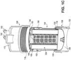
- FIG. 1Cis an exploded perspective view of a filtration system 100.
- the filtration system 100is a fuel filter for the filtration of fuel.
- the filtration system 100is not limited to the filtration of fuel and may be used for the filtration of other fluids, such as lube, oil, air, or the like.
- the filtration system 100may be configured to remove water contained in a fuel, such as a diesel fuel, before the fuel is introduced into an engine, such as a diesel engine.
- the filtration system 100is not limited to the use of a fuel water separator filter and may be alternatively configured to function as different types of filters, including, but not limited to, suction side filters.
- the filtration system 100includes a filter element 104 disposed within a housing 102, with an adapter 106 configured to engage the housing 102 with a filter head 108.
- the filter head 108includes a fluid inlet 140, which allows a fluid to be filtered to flow into the filter element 104, and a fluid outlet 142, which allows a filtered fluid to flow out of the filter element 104.
- the filter head 108includes a filter head base 112 and a filter head sidewall 114 extending from an outer periphery of the filter head base 112.
- the filter head sidewall 114extends from an outer periphery of the filter head base 112 towards the housing 102.
- the filter head 108has first thread 116 on an inner surface of the filter head sidewall 114.
- the first thread 116is structured to removably engage a second thread 118 of the adapter 106, such that the filter head 108 is removably coupled to an adapter first end 120 of the adapter 106.
- the adapter 106is configured to couple the housing 102 to the filter head 108 and the filter element 104.
- the adapter 106includes the second thread 118 disposed externally on an outer surface adjacent to the adapter first end 120, a second coupling member 126 disposed internally around the adapter first end 120, and a plurality of indentations 128 disposed externally on an adapter second end 122.
- the second coupling member 126comprises a male coupling member of a male-female coupling member pair, configured to receive a corresponding female coupling member (e.g., the first coupling member 148) of the housing 102.
- the adapter 106first receives the housing 102, whereby the adapter 106 is positioned circumferentially around the middle portion of the housing 102 (with the middle portion being substantially between the housing first end 136 and housing second end 138).
- the second coupling member 126is structured to couple with the first coupling member 148 of the housing 102.
- the first coupling member 148comprises a complementary angled surface disposed around the middle of the housing 102 on an external wall.
- the second coupling member 126may be formed during injection of the adapter 106.
- the second coupling member 126comprises a male detent element.
- connection between the adapter 106 and the housing 102is not particularly limited to the use of a detent element and may be any other appropriate detachable connections, such as a snap-fit connection or the like.
- the first coupling member 148may be formed during a deep draw machining process used to form the housing 102.
- the second thread 118comprises an externally facing thread disposed on an outer wall of the adapter 106 adjacent to the adapter first end 120 and structured to engage with the first thread 116 of the filter head 108.
- the second thread 118extends radially outward.
- the threaded designis that of a buttress design, whereby the threads are positivity fixed by the threads disposed on the filter head 108.
- the second thread 118may be formed during a deep draw machining process used to form the adapter 106.
- the second thread 118includes two threads per turn.
- the connection between the adapter 106 and the filter head 108is not particularly limited to the use of a threaded connection and may be any other appropriate detachable connections, such as a snap-fit connection or the like.
- the filter element 104is received in a central compartment formed by the housing 102.
- the filter element 104includes a first endplate 130, a second endplate 132, and filter media 110 positioned between the first endplate 130 and the second endplate 132.
- the filter media 110is arranged in a cylindrical manner between the first endplate 130 and the second endplate 132 that is configured to filter the fluid.
- the filter media 110comprises a porous material having a predetermined pore size and is configured to filter particulate matter from a fluid such as air flowing therethrough.
- the filter media 110may comprise pleated media, corrugated media, fluted media, or the like. Disposed within the center of the filter media 110 may be a center tube 124.
- the center tube 124may be configured to support the filter media 110 and/or allow the flow of fluid through the filter media 110.
- the center tube 124may comprise a plurality of apertures so as to allow the fluid (e.g., air, fuel, oil etc.) to flow into the filter channel after passing through the filter media 110.
- the center tube 124may be formed from plastic, metals or any other suitable material.
- the first endplate 130is an open endplate that includes a central opening 146 in fluid communication with the fluid outlet 142.
- the second endplate 132is a closed endplate.
- the first endplate 130includes at least one inlet opening in fluid communication with the fluid inlet 140.
- one or both of the first endplate 130 and second endplate 132may include raised tabs extending from a surface. The tabs may be evenly spaced at the same radius from a center point of the first endplate 130 and second endplate 132 such that the tabs fall along the circle defined by the radius and the center point.
- the first endplate 130includes a top surface 172 and a bottom surface 176.
- the top surface 172 and bottom surface 176are parallel, or substantially parallel to each other, and are displaced from each other.
- the first endplate 130includes a gasket 178 within the inner gasket retaining wall 179 extending from the top surface 172.
- the gasket 178comprises a plastic nut ring with an external thread to attach to a portion of the filter head 108.
- the gasket 178comprises a plastic seal member that is formed with the filter element 104 or the filter head 108.
- a second axially protruding flange 180extends downward from the bottom surface 176.
- a first axially protruding flange 174extends downward from the top surface 172, with a radially protruding wall 182 along the surface of first axially protruding flange 174.
- the first axially protruding flange 174is flexible in the radial direction toward the filter media 110.
- the first axially protruding flange 174 and/or the radially protruding wall 182is continuous around a circumference of the filter element 104.
- the radially protruding wall 182comprises a shape (e.g., triangular, rectangular, obtuse, angled, etc.) that allows for the first endplate 130 to be vertically pressed down, past the endplate retaining lip 190 thereby causing the first axially protruding flange 174 to flex inward until the first endplate 130 engages the housing 102.
- a shapee.g., triangular, rectangular, obtuse, angled, etc.
- the housing 102is substantially cylindrical in shape having an open housing first end 136 (e.g., top end) adjacent to first endplate 130 and a closed housing second end 138 (e.g., bottom end) opposite the open top end.
- housing "first end” 136is intended to refer to the area that includes about twenty percent of the axial distance starting from the boundary that forms the top of the housing 102 towards the boundary that forms the bottom of the housing 102.
- housing "second end” 138is intended to refer to the area that includes about twenty percent of the axial distance starting from the boundary that corresponds to the bottom of the housing 102 towards the boundary that corresponds to the top of the housing 102.
- the "closed" housing second end 138is an open end of the housing 102 that is closed by a separate removable element, such as a fluid collection bowl.
- the separate removable elementmay be attached to the housing end through complementary threaded (e.g., screwed on/off) portions, snap fit features, press-fit feature, or similar attachment features on the housing end and the removable element.
- the housing 102defines an internal volume within which the filter element 104 is positioned.
- the housing 102may be formed from a strong and rigid material, for example plastics (e.g., polypropylene, high density polyethylene, polyvinyl chloride, etc.), metals (e.g., aluminum, stainless steel, etc.), or any other suitable material.
- the housing 102may comprise a cylindrical housing having generally a circular cross-sectional. In other embodiments, the housing 102 may have any suitable shape, for example square, rectangular, polygonal, etc.
- the second end 138may include a biasing member (e.g., a spring) 144 between the housing second end 138 and a location to receive the filter element 104 that is structured to facilitate the "snap-in" installation of the filter element 104 into the housing 102.
- the closed bottom endincludes a closeable drain opening, a sensor port, or another opening that can be selectively sealed.
- the housing 102is structured to engage the adapter 106 such that the adapter 106 snap fits onto the housing 102 and threadedly engage with the filter head 108 of the filtration system 100.
- the housing 102 and the adapter 106are formed as one component. Beneficially, the adapter 106 and the housing 102 are locked together to impede vertical movement and rotation between the adapter 106 and the shell housing 102.
- the middle portion of the housing 102includes the first coupling member 148 on an outer surface thereof.
- the first coupling member 148comprises a female end of a male-female coupling member pair, configured to receive a corresponding male coupling member (e.g., the second coupling member 126 of the adapter 106).
- Disposed between the first coupling member 148 and the housing first end 136is a seal member 152 that provides a radial seal with the housing 102 and the filter head 108.
- the portion 150 of the filtration system 100 that supports the seal member 152is the seal member channel 160.
- the seal member channel 160includes a first retaining lip 166, a retaining wall 162, and a second retaining lip 164.
- the first retaining lip 166, retaining wall 162, and second retaining lip 164form a 90-degree rotated, "U"-shaped channel in the housing 102.
- the seal member 152is a circular (e.g., ring) radial seal member.
- the filter element 104is disposed within the central compartment of the housing 102.
- the seal member 152is disposed within the seal member channel 160 on the housing 102.
- the filter head 108receives the adapter 106, whereby the filter head 108 is circumferentially around the adapter first end 120 and the housing 102 is sealingly engaged with the filter head 108.
- the filter head 108, adapter 106, housing 102, and filter element 104are all removably coupled and form a "leak-tight" seal in various locations to facilitate the intake, filtering, and outflow of a fluid.
- a seal member 152provides a radial seal with the filter head 108 and the housing 102.
- FIG. 2shows a perspective view of the spin-on arrangement of the filter assembly 204 that includes the housing 102 (e.g., shell housing) and the filter element 104.
- the seal member 152extends circumferentially around the housing 102.
- the filter element 104is permanently affixed or installed within the housing 102.
- a plurality of fluid openings 202are disposed around the top surface 172 of the first endplate 130.
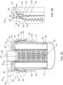
- FIG. 3Aa cross-sectional side view of a filtration system 300 is shown, according to an example embodiment.
- FIG. 3Bis cross-sectional view of a portion 350 of the filtration system 300 of FIG. 3A .
- the filtration system 300may be a fuel filtration system, a lubricant filtration system, a hydraulic fluid filtration system, a water filtration system, or the like.
- the filtration system 300is similar to the filtration system 100 of FIG. 1A .
- a difference between the filtration system 300 and the filtration system 100is the location of the seal member 352 and seal member channel 360. Accordingly, like numbering is used to designate similar components between the filtration system 100 and the components shown in FIGS. 3A and 3B .
- the filter head 308includes a fluid inlet 340, which allows a fluid to be filtered to flow into the filter element 304, and a fluid outlet, which allows a filtered fluid to flow out of the filter element 304.
- the filter head 308includes a filter head base 312 and a filter head sidewall 314 extending from an outer periphery of the filter head base 312.
- the filter head sidewall 314extends from an outer periphery of the filter head base 312 towards the housing 302.
- the filter head 308has first thread 316 on an inner surface of the filter head sidewall 314.
- the first thread 316is structured to removably engage a second thread 318 of the adapter 306, so as to be coupled to an adapter first end 320.
- the adapter 306is configured to couple the housing 302 to the filter head 308 and the filter element 304.
- the adapter 306includes a second thread 318 disposed externally on an outer surface adjacent to the adapter first end 320, a second coupling member 326 disposed internally around the adapter first end 320, and a plurality of indentations 328 disposed externally on an adapter second end 322.
- the second coupling member 326comprises a male coupling member of a male-female coupling member pair, configured to receive a corresponding female coupling member (e.g., the first coupling member 348) of the housing 302.
- the second coupling member 326is structured to couple with the first coupling member 348 of the housing 302.
- the first coupling member 348comprises a complementary angled surface disposed around the housing first end 336 on an external wall.
- the first coupling member 348is disposed below a seal member channel 360 that receives the seal member 352.
- the second coupling member 326comprises a male detent element.
- the second thread 318comprises an externally facing thread disposed on an outer wall of the adapter 306 adjacent to the adapter first end 320 and structured to engage with the first thread 316 of the filter head 308.
- the second thread 318extends radially outward.
- the filter element 304is received in a central compartment formed by the housing 302.
- the filter element 304includes a first endplate 330, a second endplate 332, and filter media 110 positioned between the first endplate 330 and the second endplate 332.
- the filter media 110is arranged in a cylindrical manner between the first endplate 330 and the second endplate 332 that is configured to filter the fluid.
- the filter media 110comprises a porous material having a predetermined pore size and is configured to filter particulate matter from a fluid such as air flowing therethrough.
- the filter media 110may comprise pleated media, corrugated media, fluted media, or the like. Disposed within the center of the filter media 110 may be a center tube 324.
- the center tube 324may be configured to support the filter media 110 and/or allow the flow of fluid through the filter media 110.
- the center tube 324may comprise a plurality of apertures so as to allow the fluid (e.g., air, fuel, oil etc.) to flow into the filter channel after passing through the filter media 110.
- the center tube 324may be formed from plastic, metals or any other suitable material.
- the first endplate 330is an open endplate that includes a central opening 346 in fluid communication with the fluid outlet 342.
- the second endplate 332is a closed endplate.
- the first endplate 330includes at least one inlet opening in fluid communication with the fluid inlet 340.
- one or both of the first endplate 330 and second endplate 332may include raised tabs extending from a surface. The tabs may be evenly spaced at the same radius from a center point of the first endplate 330 and second endplate 332 such that the tabs fall along the circle defined by the radius and the center point.
- the first endplate 330includes a top surface 372 and a bottom surface 376.
- the top surface 372 and bottom surface 376are parallel, or substantially parallel to each other, and are displaced from each other.
- the first endplate 330includes a gasket 378 within the inner gasket retaining wall 379 extending from the top surface 372.
- the gasket 378comprises a plastic nut ring with an external thread to attach to a portion of the filter head 308.
- the gasket 378comprises a plastic seal member that is formed with the filter element 304 or the filter head 308.
- a first axially protruding flange 374extends downward from the bottom surface 376, with a radially protruding wall 382 along the surface of the first axially protruding flange 374.
- the first axially protruding flange 374is flexible in the radial direction toward the filter media 110.
- the first axially protruding flange 374 and/or the radially protruding wall 382is continuous around a circumference of the filter element 304.
- the radially protruding wall 382comprises a shape (e.g., triangular, rectangular, obtuse, angled, etc.) that allows for the first endplate 330 to be vertically pressed down, past the endplate retaining lip 390 thereby causing the first axially protruding flange 374 to flex inward until the first endplate 330 engages the housing 302.
- a shapee.g., triangular, rectangular, obtuse, angled, etc.
- the housing first end 336includes the first coupling member 348 on an outer surface thereof.
- the first coupling member 348comprises a female end of a male-female coupling member pair, configured to receive a corresponding male coupling member (e.g., the second coupling member 326 of the adapter 306.
- a seal member 352Disposed between the first coupling member 348 and the housing first end 336 is a seal member 352 that provides a radial seal with the housing 302 and the filter head 308.
- the portion 350 of the filtration system 300 that supports the seal member 352is the seal member channel 360.
- the seal member channel 360is adjacent to the endplate retaining lip 390 and close to the adapter 306.
- the seal member channel 360includes a second retaining lip 364, a retaining wall 362, and a first retaining lip 366.
- the first retaining lip 366, retaining wall 362, and second retaining lip 364form a 90-degree rotated, "U"-shaped channel in the housing 302.
- the seal member 352is a circular (e.g., ring) radial seal member.
- An axial flange 380extends from the first retaining lip 366 toward the housing first end 336.
- the filter element 304is disposed within the central compartment of the housing 302.
- the seal member 352is disposed within the seal member channel 360 on the housing 302.
- the filter head 308receives the adapter 306, whereby the filter head 308 is circumferentially around the adapter first end 320 and the housing 302 is sealingly engaged with the filter head 308.
- the filter head 308, adapter 306, housing 302, and filter element 304are all removably coupled and form a "leak-tight" seal in various locations to facilitate the intake, filtering, and outflow of a fluid.
- a seal member 352provides a radial seal with the filter head 308 and the housing 302 towards the housing first end 336.
- FIG. 4Aa cross-sectional side view of a filtration system 400 is shown, according to an example embodiment.
- FIG. 4Bis cross-sectional view of a portion 450 of the filtration system 400 of FIG. 4A .
- the filtration system 400may be a fuel filtration system, a lubricant filtration system, a hydraulic fluid filtration system, a water filtration system, or the like.
- the filtration system 400is similar to the filtration system 300 of FIG. 3A .
- a difference between the filtration system 400 and the filtration system 300is the shape of the housing first end 436 and the seal member channel 460. Accordingly, like numbering is used to designate similar components between the filtration system 300 and the components shown in FIGS. 4A and 4B .
- the housing 402has a shorter axial height compared to the housing 302 in FIG. 3A .
- the housing 402does not include the axial flange 380 or first retaining lip 366 of the housing 302.
- the seal member channel 460is formed by the second retaining lip 364, the retaining wall 362, and a bottom edge surface 412 of the first endplate 330.
- the seal member 352may be installed prior to inserting the filter element 304 into the housing 402, thereby removing the need to stretch the seal member 352 around a larger diameter (e.g., the diameter of the first endplate 330) as in the filtration system 300.
- the first endplate 330 of the filtration system 400has a side wall 414 that is adjacent to the filter head 308.
- the seal member 352is a circular (e.g., ring) radial seal member.
- FIG. 5a cross-sectional view of a portion of a filtration system 500 is shown, according to an example embodiment.
- the filtration system 500may be a fuel filtration system, a lubricant filtration system, a hydraulic fluid filtration system, a water filtration system, or the like.
- the filtration system 500is similar to the filtration system 300 of FIG. 3A .
- a difference between the filtration system 500 and the filtration system 300is the shape of the housing first end 536 and the first endplate 530. Accordingly, like numbering is used to designate similar components between the filtration system 300 and the components shown in FIG. 5 .
- the housing 502includes an endplate retaining lip 504 on the housing first end 536.
- the filter element 304cannot be removed from the housing 502.
- the housing 502 retaining and securing the filter element 304provides a "complete servicing filter" for use in the filtration system 500.
- the housing first end 536may be pushed or moved to adjust the filter element 304 within the housing 502.
- the seal member 352is a circular (e.g., ring) radial seal member.
- a difference between the first endplate 330 and the first endplate 530is that the first endplate 530 does not have axial protrusions from the top or bottom surface.
- the first endplate 530does not snap-fit with a ridge on an internal surface of the housing 502. However, the first endplate 530 (and by way the filter element 304) is fixed within the housing 502 due to the endplate retaining lip 504.
- FIG. 6a cross-sectional view of a portion of a filtration system 600 is shown, according to an example embodiment.
- the filtration system 600may be a fuel filtration system, a lubricant filtration system, a hydraulic fluid filtration system, a water filtration system, or the like.
- the filtration system 600is similar to the filtration system 500 of FIG. 5 .
- a difference between the filtration system 600 and the filtration system 500is the shape of the first coupling member 648, the first endplate 630, the adapter 606, and the seal member channel 660 in the filtration system 600. Accordingly, like numbering is used to designate similar components between the filtration system 500 and the components shown in FIG. 6 .
- the adapter 606includes the second thread 318 disposed externally on an outer surface adjacent to the adapter first end 620, a second coupling member 626 disposed internally around the adapter first end 620, and a plurality of indentations 328 disposed externally on an adapter second end 622.
- the second coupling member 626comprises a male coupling member of a male-female coupling member pair, configured to receive a corresponding female coupling member (e.g., the first coupling member 648) of the housing 602. Similar to the adapter 306 of FIG. 3A , the adapter 606 of FIG. 6 is positioned circumferentially around and adjacent to the housing first end 336.
- the second coupling member 626is structured to couple with the first coupling member 648 of the housing 602.
- the first coupling member 648comprises a complementary angled surface disposed around the housing first end 336 on an external wall.
- the second coupling member 626comprises a male detent element.
- the housing 602includes an endplate retaining lip 504 on the housing first end 336.
- the filter element 604cannot be removed from the housing 602.
- the housing 602 retaining and securing the filter element 604provides a "complete servicing filter” for use in the filtration system 600.
- the housing first end 336may be pushed or moved to adjust the filter element 604 within the housing 602.
- An axial flange 380extends from the first retaining lip 666 toward the endplate retaining lip 504.
- the first endplate 630is similar to the first endplate 330. A difference between the first endplate 330 and the first endplate 630 is that the first endplate 630 does not have axial protrusions from the top or bottom surface.
- the first endplate 630does not snap-fit with a ridge on an internal surface of the housing 602. However, the first endplate 630 (and by way the filter element 604) is fixed within the housing 602 due to the endplate retaining lip 504.
- the housing first end 336includes the first coupling member 648 on an outer surface thereof.
- the first coupling member 648comprises a female end of a male-female coupling member pair, configured to receive a corresponding male coupling member (e.g., the second coupling member 626 of the adapter 606).
- Disposed between the first coupling member 648 and the housing first end 336is the seal member 352 that provides a radial seal with the housing 602 and the filter head 308.
- the seal member 352is a circular (e.g., ring) radial seal member.
- a seal member channel 660is adjacent to the endplate retaining lip 690 and the adapter 606 and is configured to receive the seal member 352.
- the seal member channel 660includes the first retaining lip 666 and a retaining wall 662.
- the first retaining lip 666 and the retaining wall 662form an "L"-shaped channel in the housing 602.
- the seal member channel 660may include a stop or similar protrusion to create a constant groove (e.g., constant width) for the seal member 352.
- the first retaining lip 666, the retaining wall 662, and the adapter first end 620form a "U"-shaped channel once the filtration system 600 is assembled.
- the filtration system 700may be a fuel filtration system, a lubricant filtration system, a hydraulic fluid filtration system, a water filtration system, or the like.
- the filtration system 700is similar to the filtration system 600 of FIG. 6 .
- a difference between the filtration system 700 and the filtration system 600,is the shape of the seal member 752 in the filtration system 700. Accordingly, like numbering is used to designate similar components between the filtration system 600 and the components shown in FIG. 7 .
- the seal member 752is a rectangular gasket in place of the O-ring gasket shown in FIGS. 1A-6 .
- a rectangular seal member 752may provide lower manufacturing costs compared to the O-ring seal member 352.
- FIG. 8Aa perspective view of filter assembly 804 including a housing 802 and filter element 304 is shown, according to an example embodiment.
- FIG. 8Bis cross-sectional view of a portion 850 of a filtration system 800 that includes the filter assembly 804 of FIG. 8A .
- the filtration system 800may be a fuel filtration system, a lubricant filtration system, a hydraulic fluid filtration system, a water filtration system, or the like.
- the filtration system 800is similar to the filtration system 600 of FIG. 6 .
- a difference between the filtration system 800 and the filtration system 600is a stopping wall 852 disposed between the housing 802 and the adapter 606. Accordingly, like numbering is used to designate similar components between the filtration system 600 and the components shown in FIGS. 8A and 8B .
- the filtration system 800includes the seal member 752 disposed between the adapter first end 620 and the first retaining lip 666 that provides a radial seal with the housing 802 and the filter head 308.
- the seal member 752is a rectangular radial seal member.
- a seal member channel 660is adjacent to the endplate retaining lip 690 and the adapter 606 and is configured to receive the seal member 752.
- the seal member channel 660includes the first retaining lip 666 and a retaining wall 662. The first retaining lip 666 and the retaining wall 662 form an "L"-shaped channel in the housing 802.
- a "U"-shaped channelis formed once the filtration system 800 is assembled between the first retaining lip 666, the retaining wall 662, and a stopping wall 852.
- the stopping wall 852may include a stop or similar protrusion to create a constant groove (e.g., constant width) for the seal member 752.
- the stopping wall 852may maintain the filter assembly 804 within the filter head 308 and the adapter 606 is configured to compress and maintain the seal member 752.
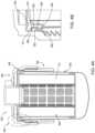
- FIG. 9Aa cross-sectional side view of a filtration system 900 is shown, according to an example embodiment.
- FIG. 9Bis cross-sectional view of a portion 950 of the filtration system 900 of FIG. 9A .
- FIG. 9Cshows a perspective view of the filter assembly 955 that includes the housing 902 and the filter element 904.
- FIG. 9Dshows a cross-sectional, top perspective view of the filter element 904.
- the filtration system 900may be a fuel filtration system, a lubricant filtration system, a hydraulic fluid filtration system, a water filtration system, or the like.
- the filtration system 900is similar to the filtration system 700 of FIG. 7 .
- a difference between the filtration system 900 and the filtration system 700is the housing 902 and filter element 904 and the engagement of the two components. Accordingly, like numbering is used to designate similar components between the filtration system 700 and the components shown in FIGS. 9A-9D .
- the filter head 908includes a fluid inlet, which allows a fluid to be filtered to flow into the filter element 904, and a fluid outlet, which allows a filtered fluid to flow out of the filter element 904.
- the filter head 908includes a filter head base 912 and a filter head sidewall 914 extending from an outer periphery of the filter head base 912.
- the filter head sidewall 914extends from an outer periphery of the filter head base 912 towards the housing 902.
- the filter head 908has first thread 916 on an inner surface of the filter head sidewall 914.
- the first thread 916is structured to removably engage a second thread 918 of the adapter 906, so as to be coupled to an adapter first end 920.
- the adapter 906is configured to couple the housing 902 to the filter head 908 and filter element 904.
- the adapter 906includes a second thread 318 disposed externally on an outer surface adjacent to the adapter first end 920, a second coupling member 926 disposed internally around the adapter first end 920, and a plurality of indentations 928 disposed externally on an adapter second end 922.
- the second coupling member 926comprises a male coupling member of a male-female coupling member pair, configured to receive a corresponding female coupling member (e.g., the first coupling member 948) of the housing 902.
- the second coupling member 926is structured to couple with the first coupling member 948 of the housing 902.
- the first coupling member 948comprises a complementary angled surface disposed around the housing first end 936 on an external wall. Notably, the first coupling member 948 is disposed below a seal member channel 960 that receives the seal member 952.
- the second coupling member 926comprises a male detent element.
- the second thread 318comprises an externally facing thread disposed on an outer wall of the adapter 906 adjacent to the adapter first end 920 and structured to engage with the first thread 316 of the filter head 908. The second thread 318 extends radially outward.
- the filter element 904is received in a central compartment formed by the housing 902.
- the filter element 904includes a first endplate 930, a second endplate 932, and filter media 310 positioned between the first endplate 930 and the second endplate 932.
- One difference between the filter element 904 and the filter element 704is the first axially protruding flange 974 of the filter element 904 engages with an outer surface of the housing 902 and radially protrudes inward.
- the first endplate 930is an open endplate that includes a central opening 946 in fluid communication with the fluid outlet.
- the second endplate 932is a closed endplate.
- the first endplate 930includes at least one inlet opening (e.g., plurality of fluid openings 202) in fluid communication with the fluid inlet.
- one or both of the first endplate 930 and second endplate 932may include raised tabs extending from a surface. The tabs may be evenly spaced at the same radius from a center point of the first endplate 930 and second endplate 932 such that the tabs fall along the circle defined by the radius and the center point.
- the first endplate 930includes a top surface 972 and a bottom surface 976.
- the top surface 972 and bottom surface 976are parallel, or substantially parallel to each other, and are displaced from each other.
- the first endplate 930includes a gasket 978 within the inner gasket retaining wall 979 extending from the top surface 972.
- the gasket 978comprises a plastic nut ring with an external thread to attach to a portion of the filter head 908.
- the gasket 978comprises a plastic seal member that is formed with the filter element 904 or the filter head 908.
- a clip 990is disposed around the periphery of the top surface 972 and a bottom surface 976 of the first endplate 930. The clip 990 may be configured to snap-fit engage a filter head 908 or similar feature.
- a first axially protruding flange 974extends downward from the edge of the top surface 972 such that the first axially protruding flange 974 is outside of the housing 902 when the housing 902 and the filter element 904 are engaged.
- a second axially protruding flange 180extends downward from the bottom surface 976.
- the first axially protruding flange 974includes a radially protruding wall 982 along the surface that protrudes inward to engage a first retaining lip 966 of the housing 902.
- the first axially protruding flange 974is flexible in the radial direction away from the filter media 310.
- the first axially protruding flange 974 and/or the radially protruding wall 982is continuous around a circumference of the filter element 904.
- the radially protruding wall 982comprises a shape (e.g., triangular, rectangular, obtuse, angled, etc.) that allows for the first endplate 930 to be vertically pressed down, past the first retaining lip 966 thereby causing the first axially protruding flange 974 to flex inward until the first endplate 930 engages the housing 902.
- the housing first end 936includes the first coupling member 948 on an outer surface thereof.
- the first coupling member 948comprises a female end of a male-female coupling member pair, configured to receive a corresponding male coupling member (e.g., the second coupling member 926 of the adapter 906).
- Disposed between the first coupling member 948 and the housing first end 936is a seal member 952 that provides a radial seal with the housing 902 and the filter head 908.
- the portion 950 of the filtration system 900 that supports the seal member 952is the seal member channel 960.
- the seal member channel 960includes a first retaining lip 966, a retaining wall 962, and the adapter first end 920.
- the first retaining lip 966, retaining wall 962, and the adapter first end 920form a 90-degree rotated, "U"-shaped channel between the housing 902, filter head 908, and adapter 906.
- the seal member 952is a circular (e.g., ring) radial seal member.
- An axial flange 980extends from the first retaining lip 966 toward the housing first end 936.
- the filter element 904is disposed within the central compartment of the housing 902.
- the filter element 904is snapped on the inner diameter of the housing 902.
- the seal member 952is disposed within the seal member channel 960 on the housing 902.
- the filter head 908receives the adapter 906, whereby the filter head 908 is circumferentially around the adapter first end 920 and the housing 902 is sealingly engaged with the filter head 908.
- the filter head 908, adapter 906, housing 902, and filter element 904are all removably coupled and form a "leak-tight" seal in various locations to facilitate the intake, filtering, and outflow of a fluid.
- a seal member 952provides a radial seal with the filter head 908, adapter 906, and the housing 902 towards the housing first end 936.
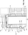
- FIG. 10a cross-sectional view of a portion of a filtration system 1000 that includes a housing 1002, filter head 1008, and filter element 1004 is shown, according to an example embodiment.
- the filtration system 1000may be a fuel filtration system, a lubricant filtration system, a hydraulic fluid filtration system, a water filtration system, or the like.
- the filtration system 1000is similar to the filtration system 100 of FIG. 1A .
- a difference between the filtration system 1000 and the filtration system 100is the housing 1002 includes a threaded member to engage the filter head 1008 (e.g., no adapter 106 needed). Accordingly, like numbering is used to designate similar components between the filtration system 100 and the components shown in FIG. 10 .
- the first endplate 130includes a top surface 172 and a bottom surface 176.
- the top surface 172 and bottom surface 176are parallel, or substantially parallel to each other, and are displaced from each other.
- the first endplate 130includes a gasket 178 within the inner gasket retaining wall 179 extending from the top surface 172.
- the gasket 178comprises a plastic nut ring with an external thread to attach to a portion of the filter head 1008.
- the gasket 178comprises a plastic seal member that is formed with the filter element 1004 or the filter head 1008.
- a second axially protruding flange 180extends downward from the bottom surface 176.
- a first axially protruding flange 174extends downward from the top surface 172, with a radially protruding wall 182 along the surface of the first axially protruding flange 174.
- the first axially protruding flange 174is flexible in the radial direction toward the filter media 110.
- the first axially protruding flange 174 and/or the radially protruding wall 182is continuous around a circumference of the filter element 1004.
- the radially protruding wall 182comprises a shape (e.g., triangular, rectangular, obtuse, angled, etc.) that allows for the first endplate 130 to be vertically pressed down, past the endplate retaining lip 1090 thereby causing the first axially protruding flange 174 to flex inward until the first endplate 130 engages the housing 1002.
- a shapee.g., triangular, rectangular, obtuse, angled, etc.
- the housing 1002includes a second thread 1018 that is directly stamped onto the housing 1002 and configured to engage a complementary first thread 1016 on the filter head 1008.
- the second thread 1018comprises an externally facing thread disposed on an outer wall of the housing 1002 adjacent to the housing first end 1036 and structured to engage with the first thread 1016 of the filter head 1008.
- the second thread 1018extends radially outward.
- the second thread 1018is an undulating pattern.
- the threaded designis that of a buttress design, whereby the threads are positivity fixed by the threads disposed on the filter head 1008.
- the second thread 1018may be formed during a deep draw machining process used to form the housing 1002.
- the second thread 1018includes two threads per turn.
- the connection between the housing 1002 and the filter head 1008, however,is not particularly limited to the use of a threaded connection and may be any other appropriate detachable connections, such as a snap-fit connection or the like.
- the middle portion of the housing 1002includes the first coupling member 148 on an outer surface thereof.
- the first coupling member 148does not engage an adapter.
- Disposed between the first coupling member 148 and the housing first end 1036is a seal member 1052 that provides a radial seal with the housing 1002 and the filter head 1008.
- a seal member channel 1060receives the seal member 1052.
- the seal member channel 1060includes a first retaining lip 1066, a retaining wall 1062, and a second retaining lip 1064. The first retaining lip 1066, retaining wall 1062, and second retaining lip 1064 form a 90-degree rotated, "U"-shaped channel in the housing 1002.
- the seal member 1052is a circular (e.g., ring) radial seal member.
- having the second thread 1018 formed with the housing 1002reduces the components and cost of the filtration system 1000 while maintaining the filter assembly (e.g., housing 1002 and filter element 1004) in the filter head 1008 at high pressure.
- FIG. 11a cross-sectional view of a portion of a filtration system 1100 that includes a housing 1102, filter head 1108, and filter element 1104 is shown, according to an example embodiment.
- the filtration system 1100may be a fuel filtration system, a lubricant filtration system, a hydraulic fluid filtration system, a water filtration system, or the like.
- the filtration system 1100is similar to the filtration system 1000 of FIG. 10 .
- a difference between the filtration system 1100 and the filtration system 1000is the location of the seal member channel 1160 and the first endplate 1130. Accordingly, like numbering is used to designate similar components between the filtration system 1000 and the components shown in FIG. 11 .
- the first endplate 1130includes a top surface 172 and a bottom surface 176.
- the top surface 172 and bottom surface 176are parallel, or substantially parallel to each other, and are displaced from each other.
- the first endplate 1130includes a gasket 178 within the inner gasket retaining wall 179 extending from the top surface 172.
- the gasket 178comprises a plastic nut ring with an external thread to attach to a portion of the filter head 1108.
- the gasket 178comprises a plastic seal member that is formed with the filter element 1104 or the filter head 1108.
- a first axially protruding flange 174extends downward from the top surface 172, with a radially protruding wall 182 along the surface of the first axially protruding flange 174.
- the first axially protruding flange 174is flexible in the radial direction toward the filter media 110.
- the first axially protruding flange 174 and/or the radially protruding wall 182is continuous around a circumference of the filter element 1104.
- the radially protruding wall 182comprises a shape (e.g., triangular, rectangular, obtuse, angled, etc.) that allows for the first endplate 1130 to be vertically pressed down, past the second retaining lip 1164 thereby causing the first axially protruding flange 174 to flex inward until the first endplate 1130 engages the housing 1102.
- a shapee.g., triangular, rectangular, obtuse, angled, etc.
- the housing 1102includes a second thread 1018 that is directly stamped onto the housing 1102 and configured to engage a complementary first thread 1016 on the filter head 1108.
- the second thread 1018comprises an externally facing thread disposed on an outer wall of the housing 1102 adjacent to the housing first end 1136 and structured to engage with the first thread 1016 of the filter head 1108.
- the second thread 1018extends radially outward.
- the second thread 1018is an undulating pattern.
- the threaded designis that of a buttress design, whereby the threads are positivity fixed by the threads disposed on the filter head 1108.
- the second thread 1018may be formed during a deep draw machining process used to form the housing 1102.
- the second thread 1018includes two threads per turn.
- the connection between the housing 1102 and the filter head 1108, however,is not particularly limited to the use of a threaded connection and may be any other appropriate detachable connections, such as a snap-fit connection or the like.
- the middle portion of the housing 1102includes the first coupling member 148 on an outer surface thereof.
- the first coupling member 148does not engage an adapter.
- Disposed between the first coupling member 148 and the housing first end 1136is a seal member 1052 that provides a radial seal with the housing 1102 and the filter head 1108.
- a seal member channel 1160receives the seal member 1052.
- the seal member channel 1160includes a first retaining lip 1166, a retaining wall 1162, and a second retaining lip 1164. The first retaining lip 1166, retaining wall 1162, and second retaining lip 1164 form a 90-degree rotated, "U"-shaped channel in the housing 1102.
- the seal member 1052is a circular (e.g., ring) radial seal member.
- having the second thread 1018 formed with the housing 1102reduces the components and cost of the filtration system 1100 while maintaining the filter assembly (e.g., housing 1102 and filter element 1104) in the filter head 1108 at high pressure.
Landscapes
- Chemical & Material Sciences (AREA)
- Chemical Kinetics & Catalysis (AREA)
- Physics & Mathematics (AREA)
- Thermal Sciences (AREA)
- Geometry (AREA)
- Filtration Of Liquid (AREA)
Description
- The present application relates to filtration systems.
- Internal combustion engines generally combust a mixture of fuel (e.g., gasoline, diesel, natural gas, etc.) and air. Lubrication oil is also supplied to the engine to lubricate the various moving components of the engine. Either prior to entering the engine or during engine operation, the intake air, fuel, lubrication oil, and other fluids are typically passed through filtration systems to remove contaminants (e.g., dust, water, oil, etc.) from the fluids. The filtration systems include filter elements having filter media. As the fluid passes through the filter media, the filter media removes at least a portion of the contaminants in the fluid.
- Typical spin-on fluid filters are mounted to the mounting head by the use of an internally-threaded metal nut plate. Such nut plates introduce additional parts into the filter assembly and may increase manufacturing complexity and manufacturing cost of such filters. Whether or not the spin-on filter includes a nut plate, sealing must be provided between the head and the filter to prevent leakage outside the filter to environment and provided between the flow inlet and the flow exit to prevent leakage of unfiltered fluid from the inlet to the filtered fluid outlet. The spin-on fluid filters use facial sealing to seal between the head and the filter, which provides sealing as long as the external gasket is able to keep in place under the pressure applied to the gasket.
WO 2006/093981 A2 ,WO 01/05485 A1 WO 2012/153430 A1 andEP 1 693 096 A2 are relevant prior art documents - Various example embodiments relate to filter elements and filtration systems. A filtration system including a housing defining an internal volume. The housing includes a housing first end, a housing second end, and a first coupling member formed in the housing. The housing first end is an open end. The housing second end is a closed end. A filter element is positioned within the internal volume of the housing. The filter element is configured to engage the first coupling member. A filter head is provided. A seal member is disposed between the housing first end and the housing second end. The seal member provides a radial seal directly between the housing and the filter head.
- Various other example embodiments relate to a filtration assembly for engagement with a filter head. A housing defines an internal volume, the housing comprising a housing first end, a housing second end, and a first coupling member formed in the housing, the housing first end being an open end and the housing second end being a closed end. A filter element is positioned within the internal volume of the housing, the filter element configured to engage the first coupling member. A Seal member is disposed between the housing first end and the housing second end, the seal member providing a radial seal directly between the housing and the filter head.
- These and other features, together with the organization and manner of operation thereof, will become apparent from the following detailed description when taken in conjunction with the accompanying drawings, wherein like elements have like numerals throughout the several drawings described below.
FIG. 1A shows a cross-sectional side view of a filtration system according to an example embodiment.FIG. 1B shows a cross-sectional view of a portion of the radial seal formed in the filtration system ofFIG. 1A FIG. 1C shows an exploded cross-sectional view of the filtration system ofFIG. 1A .FIG. 2 shows a perspective view of the housing and a seal member ofFIG. 1A .FIG. 3A shows a cross-sectional side view of a filtration system according to another example embodiment.FIG. 3B shows a cross-sectional view of a portion of the radial seal formed in the filtration system ofFIG. 3A .FIG. 4A shows a cross-sectional side view of a filtration system according to yet another example embodiment.FIG. 4B shows a cross-sectional view of a portion of the radial seal formed in the filtration system ofFIG. 4A .FIG. 5 shows a cross-sectional view of a portion of a radial seal formed in a filtration system according to an example embodiment.FIG. 6 shows a cross-sectional view of a portion of a radial seal formed in a filtration system according to yet another example embodiment.FIG. 7 shows a cross-sectional view of a portion of a radial seal formed in a filtration system according to an even further example embodiment.FIG. 8A shows a perspective view of a housing and a seal member according to an example embodiment.FIG. 8B shows a cross-sectional view a radial seal formed in a filtration system that includes the housing ofFIG. 8A .FIG. 9A shows a cross-sectional side view of a filtration system according to a further example embodiment.FIG. 9B shows a cross-sectional view of a portion of a radial seal formed in the filtration system ofFIG. 9A FIG. 9C shows a perspective view of the housing of the filtration system ofFIG. 9A .FIG. 9D shows a top perspective, cross-sectional view of the housing ofFIG. 9C .FIG. 10 shows a cross-sectional view of a portion of a radial seal formed in a filtration system according to another example embodiment.FIG. 11 shows a cross-sectional view of a portion of a radial seal formed in a filtration system according to yet another example embodiment.- Referring to the figures generally, a spin-on filtration system that includes a seal member that provides a radial seal directly between the shell housing and the filter head. The shell housing may include a seal member in the form of a radial seal gasket that provides a dedicated interface with the filter head. The seal member may be disposed at a wide variety of locations along the shell housing to sealingly engage the filter head. For example, the seal member may be disposed at a specific height to accommodate various filtration operation pressures. In some embodiments, the spin-on filter element includes a snap feature that allows for ease of service of the filter element. Beneficially, the seal member does not require a nut plate or additional parts to provide additional sealing between the shell housing and the filter head and no seaming operation on the shell housing. Further, the seal member allows for the top of the filter element and/or filtration system to be open for fluid passage in some embodiments. Contrary to facial sealing, the pressure limit of the radial seal provided by the seal member is not limited by the ability of the gasket to keep in place under pressure.
FIG. 1A is a cross-sectional side view of afiltration system 100.FIG. 1B is cross-sectional view of aportion 150 of thefiltration system 100 ofFIG. 1A .FIG. 1C is an exploded perspective view of afiltration system 100. In the embodiment shown inFIGS. 1A-C , thefiltration system 100 is a fuel filter for the filtration of fuel. However, thefiltration system 100 is not limited to the filtration of fuel and may be used for the filtration of other fluids, such as lube, oil, air, or the like. For example, thefiltration system 100 may be configured to remove water contained in a fuel, such as a diesel fuel, before the fuel is introduced into an engine, such as a diesel engine. In addition, thefiltration system 100 is not limited to the use of a fuel water separator filter and may be alternatively configured to function as different types of filters, including, but not limited to, suction side filters. Thefiltration system 100 includes afilter element 104 disposed within ahousing 102, with anadapter 106 configured to engage thehousing 102 with afilter head 108.- The
filter head 108 includes afluid inlet 140, which allows a fluid to be filtered to flow into thefilter element 104, and afluid outlet 142, which allows a filtered fluid to flow out of thefilter element 104. Thefilter head 108 includes afilter head base 112 and afilter head sidewall 114 extending from an outer periphery of thefilter head base 112. Thefilter head sidewall 114 extends from an outer periphery of thefilter head base 112 towards thehousing 102. Thefilter head 108 hasfirst thread 116 on an inner surface of thefilter head sidewall 114. Thefirst thread 116 is structured to removably engage asecond thread 118 of theadapter 106, such that thefilter head 108 is removably coupled to an adapterfirst end 120 of theadapter 106. - The
adapter 106 is configured to couple thehousing 102 to thefilter head 108 and thefilter element 104. Theadapter 106 includes thesecond thread 118 disposed externally on an outer surface adjacent to the adapterfirst end 120, asecond coupling member 126 disposed internally around the adapterfirst end 120, and a plurality ofindentations 128 disposed externally on an adaptersecond end 122. In some arrangements, thesecond coupling member 126 comprises a male coupling member of a male-female coupling member pair, configured to receive a corresponding female coupling member (e.g., the first coupling member 148) of thehousing 102. - Generally, the
adapter 106 first receives thehousing 102, whereby theadapter 106 is positioned circumferentially around the middle portion of the housing 102 (with the middle portion being substantially between the housingfirst end 136 and housing second end 138). Thesecond coupling member 126 is structured to couple with thefirst coupling member 148 of thehousing 102. Thefirst coupling member 148 comprises a complementary angled surface disposed around the middle of thehousing 102 on an external wall. Thesecond coupling member 126 may be formed during injection of theadapter 106. In some arrangements, thesecond coupling member 126 comprises a male detent element. The connection between theadapter 106 and thehousing 102, however, is not particularly limited to the use of a detent element and may be any other appropriate detachable connections, such as a snap-fit connection or the like. Thefirst coupling member 148 may be formed during a deep draw machining process used to form thehousing 102. - The
second thread 118 comprises an externally facing thread disposed on an outer wall of theadapter 106 adjacent to the adapterfirst end 120 and structured to engage with thefirst thread 116 of thefilter head 108. Thesecond thread 118 extends radially outward. In some arrangements, the threaded design is that of a buttress design, whereby the threads are positivity fixed by the threads disposed on thefilter head 108. Thesecond thread 118 may be formed during a deep draw machining process used to form theadapter 106. In some arrangements, thesecond thread 118 includes two threads per turn. The connection between theadapter 106 and thefilter head 108, however, is not particularly limited to the use of a threaded connection and may be any other appropriate detachable connections, such as a snap-fit connection or the like. - The
filter element 104 is received in a central compartment formed by thehousing 102. Thefilter element 104 includes afirst endplate 130, asecond endplate 132, and filtermedia 110 positioned between thefirst endplate 130 and thesecond endplate 132. Thefilter media 110 is arranged in a cylindrical manner between thefirst endplate 130 and thesecond endplate 132 that is configured to filter the fluid. Thefilter media 110 comprises a porous material having a predetermined pore size and is configured to filter particulate matter from a fluid such as air flowing therethrough. Thefilter media 110 may comprise pleated media, corrugated media, fluted media, or the like. Disposed within the center of thefilter media 110 may be a center tube 124. The center tube 124 may be configured to support thefilter media 110 and/or allow the flow of fluid through thefilter media 110. The center tube 124 may comprise a plurality of apertures so as to allow the fluid (e.g., air, fuel, oil etc.) to flow into the filter channel after passing through thefilter media 110. The center tube 124 may be formed from plastic, metals or any other suitable material. An assembled front plan view of thefiltration system 100 ofFIG. 1A is shown. - As shown in
FIG. 1A , thefirst endplate 130 is an open endplate that includes acentral opening 146 in fluid communication with thefluid outlet 142. Thesecond endplate 132 is a closed endplate. Thefirst endplate 130 includes at least one inlet opening in fluid communication with thefluid inlet 140. In some arrangements, one or both of thefirst endplate 130 andsecond endplate 132 may include raised tabs extending from a surface. The tabs may be evenly spaced at the same radius from a center point of thefirst endplate 130 andsecond endplate 132 such that the tabs fall along the circle defined by the radius and the center point. - The
first endplate 130 includes atop surface 172 and abottom surface 176. Thetop surface 172 andbottom surface 176 are parallel, or substantially parallel to each other, and are displaced from each other. Thefirst endplate 130 includes agasket 178 within the innergasket retaining wall 179 extending from thetop surface 172. In some embodiments, thegasket 178 comprises a plastic nut ring with an external thread to attach to a portion of thefilter head 108. In other embodiments, thegasket 178 comprises a plastic seal member that is formed with thefilter element 104 or thefilter head 108. A second axially protrudingflange 180 extends downward from thebottom surface 176. A first axially protrudingflange 174 extends downward from thetop surface 172, with aradially protruding wall 182 along the surface of firstaxially protruding flange 174. In some embodiments, the firstaxially protruding flange 174 is flexible in the radial direction toward thefilter media 110. In some arrangements, the firstaxially protruding flange 174 and/or theradially protruding wall 182 is continuous around a circumference of thefilter element 104. Theradially protruding wall 182 comprises a shape (e.g., triangular, rectangular, obtuse, angled, etc.) that allows for thefirst endplate 130 to be vertically pressed down, past theendplate retaining lip 190 thereby causing the firstaxially protruding flange 174 to flex inward until thefirst endplate 130 engages thehousing 102. - The
housing 102 is substantially cylindrical in shape having an open housing first end 136 (e.g., top end) adjacent tofirst endplate 130 and a closed housing second end 138 (e.g., bottom end) opposite the open top end. As used herein, housing "first end" 136 is intended to refer to the area that includes about twenty percent of the axial distance starting from the boundary that forms the top of thehousing 102 towards the boundary that forms the bottom of thehousing 102. As used herein, housing "second end" 138 is intended to refer to the area that includes about twenty percent of the axial distance starting from the boundary that corresponds to the bottom of thehousing 102 towards the boundary that corresponds to the top of thehousing 102. In some embodiments, the "closed" housingsecond end 138 is an open end of thehousing 102 that is closed by a separate removable element, such as a fluid collection bowl. In such embodiments, the separate removable element may be attached to the housing end through complementary threaded (e.g., screwed on/off) portions, snap fit features, press-fit feature, or similar attachment features on the housing end and the removable element. Thehousing 102 defines an internal volume within which thefilter element 104 is positioned. Thehousing 102 may be formed from a strong and rigid material, for example plastics (e.g., polypropylene, high density polyethylene, polyvinyl chloride, etc.), metals (e.g., aluminum, stainless steel, etc.), or any other suitable material. In particular embodiments, thehousing 102 may comprise a cylindrical housing having generally a circular cross-sectional. In other embodiments, thehousing 102 may have any suitable shape, for example square, rectangular, polygonal, etc. - The
second end 138 may include a biasing member (e.g., a spring) 144 between the housingsecond end 138 and a location to receive thefilter element 104 that is structured to facilitate the "snap-in" installation of thefilter element 104 into thehousing 102. In some arrangements, the closed bottom end includes a closeable drain opening, a sensor port, or another opening that can be selectively sealed. Thehousing 102 is structured to engage theadapter 106 such that theadapter 106 snap fits onto thehousing 102 and threadedly engage with thefilter head 108 of thefiltration system 100. In some embodiments, thehousing 102 and theadapter 106 are formed as one component. Beneficially, theadapter 106 and thehousing 102 are locked together to impede vertical movement and rotation between theadapter 106 and theshell housing 102. - The middle portion of the
housing 102 includes thefirst coupling member 148 on an outer surface thereof. In some arrangements, thefirst coupling member 148 comprises a female end of a male-female coupling member pair, configured to receive a corresponding male coupling member (e.g., thesecond coupling member 126 of the adapter 106). Disposed between thefirst coupling member 148 and the housingfirst end 136 is aseal member 152 that provides a radial seal with thehousing 102 and thefilter head 108. Theportion 150 of thefiltration system 100 that supports theseal member 152 is theseal member channel 160. Theseal member channel 160 includes afirst retaining lip 166, aretaining wall 162, and asecond retaining lip 164. Thefirst retaining lip 166, retainingwall 162, and second retaininglip 164 form a 90-degree rotated, "U"-shaped channel in thehousing 102. In some embodiments, theseal member 152 is a circular (e.g., ring) radial seal member. - During assembly, the
filter element 104 is disposed within the central compartment of thehousing 102. Theseal member 152 is disposed within theseal member channel 160 on thehousing 102. Thefilter head 108 receives theadapter 106, whereby thefilter head 108 is circumferentially around the adapterfirst end 120 and thehousing 102 is sealingly engaged with thefilter head 108. Upon installation of theadapter 106 into thefilter head 108, thefilter head 108,adapter 106,housing 102, andfilter element 104 are all removably coupled and form a "leak-tight" seal in various locations to facilitate the intake, filtering, and outflow of a fluid. Aseal member 152 provides a radial seal with thefilter head 108 and thehousing 102. FIG. 2 shows a perspective view of the spin-on arrangement of thefilter assembly 204 that includes the housing 102 (e.g., shell housing) and thefilter element 104. Theseal member 152 extends circumferentially around thehousing 102. In some embodiments, thefilter element 104 is permanently affixed or installed within thehousing 102. As shown inFIG. 2 , a plurality offluid openings 202 are disposed around thetop surface 172 of thefirst endplate 130.- Turning to
FIG. 3A , a cross-sectional side view of afiltration system 300 is shown, according to an example embodiment.FIG. 3B is cross-sectional view of aportion 350 of thefiltration system 300 ofFIG. 3A . Thefiltration system 300 may be a fuel filtration system, a lubricant filtration system, a hydraulic fluid filtration system, a water filtration system, or the like. Thefiltration system 300 is similar to thefiltration system 100 ofFIG. 1A . A difference between thefiltration system 300 and thefiltration system 100 is the location of theseal member 352 andseal member channel 360. Accordingly, like numbering is used to designate similar components between thefiltration system 100 and the components shown inFIGS. 3A and 3B . - The
filter head 308 includes afluid inlet 340, which allows a fluid to be filtered to flow into thefilter element 304, and a fluid outlet, which allows a filtered fluid to flow out of thefilter element 304. Thefilter head 308 includes afilter head base 312 and afilter head sidewall 314 extending from an outer periphery of thefilter head base 312. Thefilter head sidewall 314 extends from an outer periphery of thefilter head base 312 towards thehousing 302. Thefilter head 308 hasfirst thread 316 on an inner surface of thefilter head sidewall 314. Thefirst thread 316 is structured to removably engage asecond thread 318 of theadapter 306, so as to be coupled to an adapterfirst end 320. - The
adapter 306 is configured to couple thehousing 302 to thefilter head 308 and thefilter element 304. Theadapter 306 includes asecond thread 318 disposed externally on an outer surface adjacent to the adapterfirst end 320, asecond coupling member 326 disposed internally around the adapterfirst end 320, and a plurality ofindentations 328 disposed externally on an adaptersecond end 322. In some arrangements, thesecond coupling member 326 comprises a male coupling member of a male-female coupling member pair, configured to receive a corresponding female coupling member (e.g., the first coupling member 348) of thehousing 302. A difference between theadapter 106 ofFIG. 1A and theadapter 306 ofFIG. 3A is the adapterfirst end 320 ofFIG. 3A is adjacent to (e.g., near) the housingfirst end 336. Thesecond coupling member 326 is structured to couple with thefirst coupling member 348 of thehousing 302. Thefirst coupling member 348 comprises a complementary angled surface disposed around the housingfirst end 336 on an external wall. Notably, thefirst coupling member 348 is disposed below aseal member channel 360 that receives theseal member 352. In some arrangements, thesecond coupling member 326 comprises a male detent element. Thesecond thread 318 comprises an externally facing thread disposed on an outer wall of theadapter 306 adjacent to the adapterfirst end 320 and structured to engage with thefirst thread 316 of thefilter head 308. Thesecond thread 318 extends radially outward. - The
filter element 304 is received in a central compartment formed by thehousing 302. Thefilter element 304 includes afirst endplate 330, asecond endplate 332, and filtermedia 110 positioned between thefirst endplate 330 and thesecond endplate 332. Thefilter media 110 is arranged in a cylindrical manner between thefirst endplate 330 and thesecond endplate 332 that is configured to filter the fluid. Thefilter media 110 comprises a porous material having a predetermined pore size and is configured to filter particulate matter from a fluid such as air flowing therethrough. Thefilter media 110 may comprise pleated media, corrugated media, fluted media, or the like. Disposed within the center of thefilter media 110 may be acenter tube 324. Thecenter tube 324 may be configured to support thefilter media 110 and/or allow the flow of fluid through thefilter media 110. Thecenter tube 324 may comprise a plurality of apertures so as to allow the fluid (e.g., air, fuel, oil etc.) to flow into the filter channel after passing through thefilter media 110. Thecenter tube 324 may be formed from plastic, metals or any other suitable material. an assembled front plan view of thefiltration system 300 ofFIG. 3A is shown. - As shown in
FIG. 3A , thefirst endplate 330 is an open endplate that includes acentral opening 346 in fluid communication with the fluid outlet 342. Thesecond endplate 332 is a closed endplate. Thefirst endplate 330 includes at least one inlet opening in fluid communication with thefluid inlet 340. In some arrangements, one or both of thefirst endplate 330 andsecond endplate 332 may include raised tabs extending from a surface. The tabs may be evenly spaced at the same radius from a center point of thefirst endplate 330 andsecond endplate 332 such that the tabs fall along the circle defined by the radius and the center point. - The
first endplate 330 includes atop surface 372 and abottom surface 376. Thetop surface 372 andbottom surface 376 are parallel, or substantially parallel to each other, and are displaced from each other. Thefirst endplate 330 includes agasket 378 within the innergasket retaining wall 379 extending from thetop surface 372. In some embodiments, thegasket 378 comprises a plastic nut ring with an external thread to attach to a portion of thefilter head 308. In other embodiments, thegasket 378 comprises a plastic seal member that is formed with thefilter element 304 or thefilter head 308. A first axially protrudingflange 374 extends downward from thebottom surface 376, with aradially protruding wall 382 along the surface of the firstaxially protruding flange 374. In some embodiments, the firstaxially protruding flange 374 is flexible in the radial direction toward thefilter media 110. In some arrangements, the firstaxially protruding flange 374 and/or theradially protruding wall 382 is continuous around a circumference of thefilter element 304. Theradially protruding wall 382 comprises a shape (e.g., triangular, rectangular, obtuse, angled, etc.) that allows for thefirst endplate 330 to be vertically pressed down, past theendplate retaining lip 390 thereby causing the firstaxially protruding flange 374 to flex inward until thefirst endplate 330 engages thehousing 302. - The housing
first end 336 includes thefirst coupling member 348 on an outer surface thereof. In some arrangements, thefirst coupling member 348 comprises a female end of a male-female coupling member pair, configured to receive a corresponding male coupling member (e.g., thesecond coupling member 326 of theadapter 306. Disposed between thefirst coupling member 348 and the housingfirst end 336 is aseal member 352 that provides a radial seal with thehousing 302 and thefilter head 308. Theportion 350 of thefiltration system 300 that supports theseal member 352 is theseal member channel 360. Notably, theseal member channel 360 is adjacent to theendplate retaining lip 390 and close to theadapter 306. Theseal member channel 360 includes asecond retaining lip 364, aretaining wall 362, and afirst retaining lip 366. Thefirst retaining lip 366, retainingwall 362, and second retaininglip 364 form a 90-degree rotated, "U"-shaped channel in thehousing 302. In some embodiments, theseal member 352 is a circular (e.g., ring) radial seal member. Anaxial flange 380 extends from thefirst retaining lip 366 toward the housingfirst end 336. - During assembly, the
filter element 304 is disposed within the central compartment of thehousing 302. Theseal member 352 is disposed within theseal member channel 360 on thehousing 302. Thefilter head 308 receives theadapter 306, whereby thefilter head 308 is circumferentially around the adapterfirst end 320 and thehousing 302 is sealingly engaged with thefilter head 308. Upon installation of theadapter 306 into thefilter head 308, thefilter head 308,adapter 306,housing 302, andfilter element 304 are all removably coupled and form a "leak-tight" seal in various locations to facilitate the intake, filtering, and outflow of a fluid. Aseal member 352 provides a radial seal with thefilter head 308 and thehousing 302 towards the housingfirst end 336. - Turning to
FIG. 4A , a cross-sectional side view of afiltration system 400 is shown, according to an example embodiment.FIG. 4B is cross-sectional view of aportion 450 of thefiltration system 400 ofFIG. 4A . Thefiltration system 400 may be a fuel filtration system, a lubricant filtration system, a hydraulic fluid filtration system, a water filtration system, or the like. Thefiltration system 400 is similar to thefiltration system 300 ofFIG. 3A . A difference between thefiltration system 400 and thefiltration system 300 is the shape of the housingfirst end 436 and theseal member channel 460. Accordingly, like numbering is used to designate similar components between thefiltration system 300 and the components shown inFIGS. 4A and 4B . - Referring to
portion 450, thehousing 402 has a shorter axial height compared to thehousing 302 inFIG. 3A . Specifically, thehousing 402 does not include theaxial flange 380 or first retaininglip 366 of thehousing 302. Theseal member channel 460 is formed by thesecond retaining lip 364, the retainingwall 362, and abottom edge surface 412 of thefirst endplate 330. Beneficially, theseal member 352 may be installed prior to inserting thefilter element 304 into thehousing 402, thereby removing the need to stretch theseal member 352 around a larger diameter (e.g., the diameter of the first endplate 330) as in thefiltration system 300. Additionally, unlike thefirst endplate 330 in thefiltration system 300 that has thehousing 302 between thefirst endplate 330 and thefilter head 308, thefirst endplate 330 of thefiltration system 400 has aside wall 414 that is adjacent to thefilter head 308. In some embodiments, theseal member 352 is a circular (e.g., ring) radial seal member. - Turning to
FIG. 5 , a cross-sectional view of a portion of afiltration system 500 is shown, according to an example embodiment. Thefiltration system 500 may be a fuel filtration system, a lubricant filtration system, a hydraulic fluid filtration system, a water filtration system, or the like. Thefiltration system 500 is similar to thefiltration system 300 ofFIG. 3A . A difference between thefiltration system 500 and thefiltration system 300 is the shape of the housingfirst end 536 and thefirst endplate 530. Accordingly, like numbering is used to designate similar components between thefiltration system 300 and the components shown inFIG. 5 . - The
housing 502 includes anendplate retaining lip 504 on the housingfirst end 536. In these embodiments, thefilter element 304 cannot be removed from thehousing 502. Thehousing 502 retaining and securing thefilter element 304 provides a "complete servicing filter" for use in thefiltration system 500. The housingfirst end 536 may be pushed or moved to adjust thefilter element 304 within thehousing 502. In some embodiments, theseal member 352 is a circular (e.g., ring) radial seal member. A difference between thefirst endplate 330 and thefirst endplate 530 is that thefirst endplate 530 does not have axial protrusions from the top or bottom surface. As will be readily apparent, thefirst endplate 530 does not snap-fit with a ridge on an internal surface of thehousing 502. However, the first endplate 530 (and by way the filter element 304) is fixed within thehousing 502 due to theendplate retaining lip 504. - Turning to
FIG. 6 , a cross-sectional view of a portion of afiltration system 600 is shown, according to an example embodiment. Thefiltration system 600 may be a fuel filtration system, a lubricant filtration system, a hydraulic fluid filtration system, a water filtration system, or the like. Thefiltration system 600 is similar to thefiltration system 500 ofFIG. 5 . A difference between thefiltration system 600 and thefiltration system 500 is the shape of thefirst coupling member 648, thefirst endplate 630, theadapter 606, and theseal member channel 660 in thefiltration system 600. Accordingly, like numbering is used to designate similar components between thefiltration system 500 and the components shown inFIG. 6 . - The
adapter 606 includes thesecond thread 318 disposed externally on an outer surface adjacent to the adapterfirst end 620, asecond coupling member 626 disposed internally around the adapterfirst end 620, and a plurality ofindentations 328 disposed externally on an adapter second end 622. In some arrangements, thesecond coupling member 626 comprises a male coupling member of a male-female coupling member pair, configured to receive a corresponding female coupling member (e.g., the first coupling member 648) of thehousing 602. Similar to theadapter 306 ofFIG. 3A , theadapter 606 ofFIG. 6 is positioned circumferentially around and adjacent to the housingfirst end 336. Thesecond coupling member 626 is structured to couple with thefirst coupling member 648 of thehousing 602. Thefirst coupling member 648 comprises a complementary angled surface disposed around the housingfirst end 336 on an external wall. In some arrangements, thesecond coupling member 626 comprises a male detent element. - The
housing 602 includes anendplate retaining lip 504 on the housingfirst end 336. In these embodiments, thefilter element 604 cannot be removed from thehousing 602. Thehousing 602 retaining and securing thefilter element 604 provides a "complete servicing filter" for use in thefiltration system 600. The housingfirst end 336 may be pushed or moved to adjust thefilter element 604 within thehousing 602. Anaxial flange 380 extends from thefirst retaining lip 666 toward theendplate retaining lip 504. Thefirst endplate 630 is similar to thefirst endplate 330. A difference between thefirst endplate 330 and thefirst endplate 630 is that thefirst endplate 630 does not have axial protrusions from the top or bottom surface. As will be readily apparent, thefirst endplate 630 does not snap-fit with a ridge on an internal surface of thehousing 602. However, the first endplate 630 (and by way the filter element 604) is fixed within thehousing 602 due to theendplate retaining lip 504. - The housing
first end 336 includes thefirst coupling member 648 on an outer surface thereof. In some arrangements, thefirst coupling member 648 comprises a female end of a male-female coupling member pair, configured to receive a corresponding male coupling member (e.g., thesecond coupling member 626 of the adapter 606). Disposed between thefirst coupling member 648 and the housingfirst end 336 is theseal member 352 that provides a radial seal with thehousing 602 and thefilter head 308. In some embodiments, theseal member 352 is a circular (e.g., ring) radial seal member. Aseal member channel 660 is adjacent to the endplate retaining lip 690 and theadapter 606 and is configured to receive theseal member 352. Theseal member channel 660 includes thefirst retaining lip 666 and aretaining wall 662. Thefirst retaining lip 666 and theretaining wall 662 form an "L"-shaped channel in thehousing 602. In some embodiments, theseal member channel 660 may include a stop or similar protrusion to create a constant groove (e.g., constant width) for theseal member 352. Thefirst retaining lip 666, the retainingwall 662, and the adapterfirst end 620 form a "U"-shaped channel once thefiltration system 600 is assembled. - Turning to
FIG. 7 , a cross-sectional view of a portion of a filtration system 700 is shown, according to an example embodiment. The filtration system 700 may be a fuel filtration system, a lubricant filtration system, a hydraulic fluid filtration system, a water filtration system, or the like. The filtration system 700 is similar to thefiltration system 600 ofFIG. 6 . A difference between the filtration system 700 and thefiltration system 600, is the shape of theseal member 752 in the filtration system 700. Accordingly, like numbering is used to designate similar components between thefiltration system 600 and the components shown inFIG. 7 . Theseal member 752 is a rectangular gasket in place of the O-ring gasket shown inFIGS. 1A-6 . Arectangular seal member 752 may provide lower manufacturing costs compared to the O-ring seal member 352. - Turning to
FIG. 8A , a perspective view offilter assembly 804 including ahousing 802 andfilter element 304 is shown, according to an example embodiment.FIG. 8B is cross-sectional view of aportion 850 of afiltration system 800 that includes thefilter assembly 804 ofFIG. 8A . Thefiltration system 800 may be a fuel filtration system, a lubricant filtration system, a hydraulic fluid filtration system, a water filtration system, or the like. Thefiltration system 800 is similar to thefiltration system 600 ofFIG. 6 . A difference between thefiltration system 800 and thefiltration system 600 is a stoppingwall 852 disposed between thehousing 802 and theadapter 606. Accordingly, like numbering is used to designate similar components between thefiltration system 600 and the components shown inFIGS. 8A and 8B . - Similar to the filtration system 700, the
filtration system 800 includes theseal member 752 disposed between the adapterfirst end 620 and thefirst retaining lip 666 that provides a radial seal with thehousing 802 and thefilter head 308. In some embodiments, theseal member 752 is a rectangular radial seal member. Aseal member channel 660 is adjacent to the endplate retaining lip 690 and theadapter 606 and is configured to receive theseal member 752. Theseal member channel 660 includes thefirst retaining lip 666 and aretaining wall 662. Thefirst retaining lip 666 and theretaining wall 662 form an "L"-shaped channel in thehousing 802. A "U"-shaped channel is formed once thefiltration system 800 is assembled between thefirst retaining lip 666, the retainingwall 662, and a stoppingwall 852. The stoppingwall 852 may include a stop or similar protrusion to create a constant groove (e.g., constant width) for theseal member 752. The stoppingwall 852 may maintain thefilter assembly 804 within thefilter head 308 and theadapter 606 is configured to compress and maintain theseal member 752. - Turning to
FIG. 9A , a cross-sectional side view of afiltration system 900 is shown, according to an example embodiment.FIG. 9B is cross-sectional view of aportion 950 of thefiltration system 900 ofFIG. 9A .FIG. 9C shows a perspective view of thefilter assembly 955 that includes thehousing 902 and thefilter element 904.FIG. 9D shows a cross-sectional, top perspective view of thefilter element 904. Thefiltration system 900 may be a fuel filtration system, a lubricant filtration system, a hydraulic fluid filtration system, a water filtration system, or the like. Thefiltration system 900 is similar to the filtration system 700 ofFIG. 7 . A difference between thefiltration system 900 and the filtration system 700 is thehousing 902 andfilter element 904 and the engagement of the two components. Accordingly, like numbering is used to designate similar components between the filtration system 700 and the components shown inFIGS. 9A-9D . - The
filter head 908 includes a fluid inlet, which allows a fluid to be filtered to flow into thefilter element 904, and a fluid outlet, which allows a filtered fluid to flow out of thefilter element 904. Thefilter head 908 includes afilter head base 912 and afilter head sidewall 914 extending from an outer periphery of thefilter head base 912. Thefilter head sidewall 914 extends from an outer periphery of thefilter head base 912 towards thehousing 902. Thefilter head 908 hasfirst thread 916 on an inner surface of thefilter head sidewall 914. Thefirst thread 916 is structured to removably engage asecond thread 918 of theadapter 906, so as to be coupled to an adapterfirst end 920. - The
adapter 906 is configured to couple thehousing 902 to thefilter head 908 andfilter element 904. Theadapter 906 includes asecond thread 318 disposed externally on an outer surface adjacent to the adapterfirst end 920, asecond coupling member 926 disposed internally around the adapterfirst end 920, and a plurality ofindentations 928 disposed externally on an adaptersecond end 922. In some arrangements, thesecond coupling member 926 comprises a male coupling member of a male-female coupling member pair, configured to receive a corresponding female coupling member (e.g., the first coupling member 948) of thehousing 902. Thesecond coupling member 926 is structured to couple with thefirst coupling member 948 of thehousing 902. Thefirst coupling member 948 comprises a complementary angled surface disposed around the housingfirst end 936 on an external wall. Notably, thefirst coupling member 948 is disposed below aseal member channel 960 that receives theseal member 952. In some arrangements, thesecond coupling member 926 comprises a male detent element. Thesecond thread 318 comprises an externally facing thread disposed on an outer wall of theadapter 906 adjacent to the adapterfirst end 920 and structured to engage with thefirst thread 316 of thefilter head 908. Thesecond thread 318 extends radially outward. - The
filter element 904 is received in a central compartment formed by thehousing 902. Thefilter element 904 includes afirst endplate 930, asecond endplate 932, and filtermedia 310 positioned between thefirst endplate 930 and thesecond endplate 932. One difference between thefilter element 904 and the filter element 704 is the firstaxially protruding flange 974 of thefilter element 904 engages with an outer surface of thehousing 902 and radially protrudes inward. As shown inFIG. 9A , thefirst endplate 930 is an open endplate that includes acentral opening 946 in fluid communication with the fluid outlet. Thesecond endplate 932 is a closed endplate. Thefirst endplate 930 includes at least one inlet opening (e.g., plurality of fluid openings 202) in fluid communication with the fluid inlet. In some arrangements, one or both of thefirst endplate 930 andsecond endplate 932 may include raised tabs extending from a surface. The tabs may be evenly spaced at the same radius from a center point of thefirst endplate 930 andsecond endplate 932 such that the tabs fall along the circle defined by the radius and the center point. - The
first endplate 930 includes atop surface 972 and abottom surface 976. Thetop surface 972 andbottom surface 976 are parallel, or substantially parallel to each other, and are displaced from each other. Thefirst endplate 930 includes agasket 978 within the inner gasket retaining wall 979 extending from thetop surface 972. In some embodiments, thegasket 978 comprises a plastic nut ring with an external thread to attach to a portion of thefilter head 908. In other embodiments, thegasket 978 comprises a plastic seal member that is formed with thefilter element 904 or thefilter head 908. Aclip 990 is disposed around the periphery of thetop surface 972 and abottom surface 976 of thefirst endplate 930. Theclip 990 may be configured to snap-fit engage afilter head 908 or similar feature. - A first axially protruding
flange 974 extends downward from the edge of thetop surface 972 such that the firstaxially protruding flange 974 is outside of thehousing 902 when thehousing 902 and thefilter element 904 are engaged. A second axially protrudingflange 180 extends downward from thebottom surface 976. The first axially protrudingflange 974 includes aradially protruding wall 982 along the surface that protrudes inward to engage afirst retaining lip 966 of thehousing 902. In some embodiments, the firstaxially protruding flange 974 is flexible in the radial direction away from thefilter media 310. In some arrangements, the firstaxially protruding flange 974 and/or theradially protruding wall 982 is continuous around a circumference of thefilter element 904. Theradially protruding wall 982 comprises a shape (e.g., triangular, rectangular, obtuse, angled, etc.) that allows for thefirst endplate 930 to be vertically pressed down, past thefirst retaining lip 966 thereby causing the firstaxially protruding flange 974 to flex inward until thefirst endplate 930 engages thehousing 902. - The housing
first end 936 includes thefirst coupling member 948 on an outer surface thereof. In some arrangements, thefirst coupling member 948 comprises a female end of a male-female coupling member pair, configured to receive a corresponding male coupling member (e.g., thesecond coupling member 926 of the adapter 906). Disposed between thefirst coupling member 948 and the housingfirst end 936 is aseal member 952 that provides a radial seal with thehousing 902 and thefilter head 908. Theportion 950 of thefiltration system 900 that supports theseal member 952 is theseal member channel 960. Theseal member channel 960 includes afirst retaining lip 966, aretaining wall 962, and the adapterfirst end 920. Thefirst retaining lip 966, retainingwall 962, and the adapterfirst end 920 form a 90-degree rotated, "U"-shaped channel between thehousing 902,filter head 908, andadapter 906. In some embodiments, theseal member 952 is a circular (e.g., ring) radial seal member. Anaxial flange 980 extends from thefirst retaining lip 966 toward the housingfirst end 936. - During assembly, the
filter element 904 is disposed within the central compartment of thehousing 902. Thefilter element 904 is snapped on the inner diameter of thehousing 902. Theseal member 952 is disposed within theseal member channel 960 on thehousing 902. Thefilter head 908 receives theadapter 906, whereby thefilter head 908 is circumferentially around the adapterfirst end 920 and thehousing 902 is sealingly engaged with thefilter head 908. Upon installation of theadapter 906 into thefilter head 908, thefilter head 908,adapter 906,housing 902, andfilter element 904 are all removably coupled and form a "leak-tight" seal in various locations to facilitate the intake, filtering, and outflow of a fluid. Aseal member 952 provides a radial seal with thefilter head 908,adapter 906, and thehousing 902 towards the housingfirst end 936. - Turning to
FIG. 10 , a cross-sectional view of a portion of afiltration system 1000 that includes ahousing 1002,filter head 1008, andfilter element 1004 is shown, according to an example embodiment. Thefiltration system 1000 may be a fuel filtration system, a lubricant filtration system, a hydraulic fluid filtration system, a water filtration system, or the like. Thefiltration system 1000 is similar to thefiltration system 100 ofFIG. 1A . A difference between thefiltration system 1000 and thefiltration system 100 is thehousing 1002 includes a threaded member to engage the filter head 1008 (e.g., noadapter 106 needed). Accordingly, like numbering is used to designate similar components between thefiltration system 100 and the components shown inFIG. 10 . - The
first endplate 130 includes atop surface 172 and abottom surface 176. Thetop surface 172 andbottom surface 176 are parallel, or substantially parallel to each other, and are displaced from each other. Thefirst endplate 130 includes agasket 178 within the innergasket retaining wall 179 extending from thetop surface 172. In some embodiments, thegasket 178 comprises a plastic nut ring with an external thread to attach to a portion of thefilter head 1008. In other embodiments, thegasket 178 comprises a plastic seal member that is formed with thefilter element 1004 or thefilter head 1008. A second axially protrudingflange 180 extends downward from thebottom surface 176. A first axially protrudingflange 174 extends downward from thetop surface 172, with aradially protruding wall 182 along the surface of the firstaxially protruding flange 174. In some embodiments, the firstaxially protruding flange 174 is flexible in the radial direction toward thefilter media 110. In some arrangements, the firstaxially protruding flange 174 and/or theradially protruding wall 182 is continuous around a circumference of thefilter element 1004. Theradially protruding wall 182 comprises a shape (e.g., triangular, rectangular, obtuse, angled, etc.) that allows for thefirst endplate 130 to be vertically pressed down, past theendplate retaining lip 1090 thereby causing the firstaxially protruding flange 174 to flex inward until thefirst endplate 130 engages thehousing 1002. - The
housing 1002 includes asecond thread 1018 that is directly stamped onto thehousing 1002 and configured to engage a complementaryfirst thread 1016 on thefilter head 1008. Thesecond thread 1018 comprises an externally facing thread disposed on an outer wall of thehousing 1002 adjacent to the housingfirst end 1036 and structured to engage with thefirst thread 1016 of thefilter head 1008. Thesecond thread 1018 extends radially outward. In some embodiments, thesecond thread 1018 is an undulating pattern. In other arrangements, the threaded design is that of a buttress design, whereby the threads are positivity fixed by the threads disposed on thefilter head 1008. Thesecond thread 1018 may be formed during a deep draw machining process used to form thehousing 1002. In some arrangements, thesecond thread 1018 includes two threads per turn. The connection between thehousing 1002 and thefilter head 1008, however, is not particularly limited to the use of a threaded connection and may be any other appropriate detachable connections, such as a snap-fit connection or the like. - The middle portion of the
housing 1002 includes thefirst coupling member 148 on an outer surface thereof. In this embodiment, thefirst coupling member 148 does not engage an adapter. Disposed between thefirst coupling member 148 and the housingfirst end 1036 is aseal member 1052 that provides a radial seal with thehousing 1002 and thefilter head 1008. Aseal member channel 1060 receives theseal member 1052. Theseal member channel 1060 includes afirst retaining lip 1066, aretaining wall 1062, and asecond retaining lip 1064. Thefirst retaining lip 1066, retainingwall 1062, andsecond retaining lip 1064 form a 90-degree rotated, "U"-shaped channel in thehousing 1002. In some embodiments, theseal member 1052 is a circular (e.g., ring) radial seal member. Beneficially, having thesecond thread 1018 formed with the housing 1002 (e.g., no adapter) reduces the components and cost of thefiltration system 1000 while maintaining the filter assembly (e.g.,housing 1002 and filter element 1004) in thefilter head 1008 at high pressure. - Turning to
FIG. 11 , a cross-sectional view of a portion of afiltration system 1100 that includes ahousing 1102,filter head 1108, andfilter element 1104 is shown, according to an example embodiment. Thefiltration system 1100 may be a fuel filtration system, a lubricant filtration system, a hydraulic fluid filtration system, a water filtration system, or the like. Thefiltration system 1100 is similar to thefiltration system 1000 ofFIG. 10 . A difference between thefiltration system 1100 and thefiltration system 1000 is the location of theseal member channel 1160 and thefirst endplate 1130. Accordingly, like numbering is used to designate similar components between thefiltration system 1000 and the components shown inFIG. 11 . - The
first endplate 1130 includes atop surface 172 and abottom surface 176. Thetop surface 172 andbottom surface 176 are parallel, or substantially parallel to each other, and are displaced from each other. Thefirst endplate 1130 includes agasket 178 within the innergasket retaining wall 179 extending from thetop surface 172. In some embodiments, thegasket 178 comprises a plastic nut ring with an external thread to attach to a portion of thefilter head 1108. In other embodiments, thegasket 178 comprises a plastic seal member that is formed with thefilter element 1104 or thefilter head 1108. A first axially protrudingflange 174 extends downward from thetop surface 172, with aradially protruding wall 182 along the surface of the firstaxially protruding flange 174. In some embodiments, the firstaxially protruding flange 174 is flexible in the radial direction toward thefilter media 110. In some arrangements, the firstaxially protruding flange 174 and/or theradially protruding wall 182 is continuous around a circumference of thefilter element 1104. Theradially protruding wall 182 comprises a shape (e.g., triangular, rectangular, obtuse, angled, etc.) that allows for thefirst endplate 1130 to be vertically pressed down, past thesecond retaining lip 1164 thereby causing the firstaxially protruding flange 174 to flex inward until thefirst endplate 1130 engages thehousing 1102. - The
housing 1102 includes asecond thread 1018 that is directly stamped onto thehousing 1102 and configured to engage a complementaryfirst thread 1016 on thefilter head 1108. Thesecond thread 1018 comprises an externally facing thread disposed on an outer wall of thehousing 1102 adjacent to the housingfirst end 1136 and structured to engage with thefirst thread 1016 of thefilter head 1108. Thesecond thread 1018 extends radially outward. In some embodiments, thesecond thread 1018 is an undulating pattern. In other arrangements, the threaded design is that of a buttress design, whereby the threads are positivity fixed by the threads disposed on thefilter head 1108. Thesecond thread 1018 may be formed during a deep draw machining process used to form thehousing 1102. In some arrangements, thesecond thread 1018 includes two threads per turn. The connection between thehousing 1102 and thefilter head 1108, however, is not particularly limited to the use of a threaded connection and may be any other appropriate detachable connections, such as a snap-fit connection or the like. - The middle portion of the
housing 1102 includes thefirst coupling member 148 on an outer surface thereof. In this embodiment, thefirst coupling member 148 does not engage an adapter. Disposed between thefirst coupling member 148 and the housingfirst end 1136 is aseal member 1052 that provides a radial seal with thehousing 1102 and thefilter head 1108. Aseal member channel 1160 receives theseal member 1052. Theseal member channel 1160 includes afirst retaining lip 1166, aretaining wall 1162, and asecond retaining lip 1164. Thefirst retaining lip 1166, retainingwall 1162, andsecond retaining lip 1164 form a 90-degree rotated, "U"-shaped channel in thehousing 1102. In some embodiments, theseal member 1052 is a circular (e.g., ring) radial seal member. Beneficially, having thesecond thread 1018 formed with the housing 1102 (e.g., no adapter) reduces the components and cost of thefiltration system 1100 while maintaining the filter assembly (e.g.,housing 1102 and filter element 1104) in thefilter head 1108 at high pressure.
Claims (15)
- A filtration assembly for engagement with a filter head (108, 308, 908), comprising:a housing (102, 302, 502, 602, 802, 902) defining an internal volume, the housing comprising a housing first end (136, 336, 936), a housing second end (138), a seal member channel (360, 460, 660, 960) formed on an external surface of the housing, a first coupling member (190, 390, 690) formed in the housing, and a first coupling surface comprising a complementary angled surface disposed around the middle of the housing (102) on an external wall or disposed around the housing first end (336, 936) on an external wall, the housing first end being an open end and the housing second end being a closed end;a filter element (104, 304, 704, 904) positioned within the internal volume of the housing, the filter element configured to engage the first coupling member;an adapter (106, 306, 606, 906) positioned circumferentially around the housing, the adapter being configured to be coupled to the filter head, the adapter comprising a second coupling member disposed internally around an adapter first end, the second coupling member defining a second coupling surface configured to engage the first coupling surface; anda seal member (152, 352, 752, 952) disposed in the seal member channel between the housing first end and the first coupling surface, the seal member providing a radial seal directly between the housing and the filter head.
- The filtration assembly of claim 1, wherein the filter element comprises:filter media (110); anda first endplate (130, 330, 530, 630, 930) coupled to a filter media first end of the filter media, the first endplate comprising:a base, anda first endplate flange (174, 374) positioned about a periphery of the base, the first endplate flange extending from the base towards the housing second end and configured to engage the first coupling member; and/orwhereinthe seal member channel is formed by a first retaining lip (166, 366, 666) adjacent to the first coupling member, a second retaining lip (164) disposed axially from the first retaining lip, the second retaining lip substantially parallel to the first retaining lip, and a retaining wall (162, 362, 662) extending from the first retaining lip toward the second retaining lip, the retaining wall substantially perpendicular to the first retaining lip and the second retaining lip.
- The filtration assembly of claim 1, wherein the filter element comprises a first endplate (130, 330, 530, 630, 930) adjacent the housing first end when the filter element is disposed within the internal volume, a second endplate (132, 332, 932) disposed axially away from the first endplate, and filter media (110) extending axially between the first endplate and the second endplate, the first endplate defining a top surface (172, 372, 972) and a bottom surface (176, 376, 976) substantially parallel to the top surface, the first endplate comprising an axially protruding flange (174, 374) extending from the bottom surface away from the top surface, the axially protruding flange comprising a radially protruding wall (182, 382, 982) configured to engage an endplate retaining lip (190, 390, 690) disposed along the first coupling member; wherein optionally
the seal member channel is disposed adjacent to the endplate retaining lip. - The filtration assembly of claim 3, wherein the seal member channel is formed by a first retaining lip (166, 366, 666) adjacent to the first coupling member, a portion of the bottom surface (176, 376, 976) of the first endplate, the portion of the bottom surface substantially parallel to the first retaining lip, and a retaining wall (162, 362, 662) extending from the first retaining lip toward the bottom surface of the first endplate, the retaining wall substantially perpendicular to the first retaining lip and the bottom surface of the first endplate; or
wherein the seal member channel is formed by a first retaining lip (166, 366, 666) adjacent to the first coupling member, a second retaining lip (164) disposed axially from the first retaining lip, the second retaining lip substantially parallel to the first retaining lip, and a retaining wall (162, 362, 662) extending from the first retaining lip toward the second retaining lip, the retaining wall substantially perpendicular to the first retaining lip and the second retaining lip, the housing further comprising a top channel portion extending from the second retaining lip and covering a portion of the top surface of the first endplate. - A filtration system (100), comprising:the filter assembly of claim 1; anda filter head.
- The filtration system of claim 5, wherein:the filter head comprises a first thread (116, 316, 916) formed on a filter head surface thereof,the second coupling surface is formed on an adapter first end (120, 320, 620, 920) of the adapter, the second coupling surface engaging the first coupling surface so as to removably couple the adapter and the housing, and the adapter further comprising:
a second thread (118, 318, 918) formed on the adapter first end, the second thread engaging the first thread formed on the filter head surface so as to removably couple the adapter and the filter head. - The filtration system of claim 6, wherein the second coupling surface is formed on an internal surface on the adapter first end of the adapter, and wherein the first coupling surface is formed on an external surface in the housing first end.
- The filtration system of claim 6, wherein the second thread is formed on an external surface on the adapter first end, and wherein the first thread is formed on an internal surface of the filter head.
- The filtration system of any of claims 5 to 8, wherein the filter element comprises a first endplate (130, 330, 530, 630, 930) adjacent the housing first end when the filter element is disposed within the internal volume, a second endplate (132, 332, 932) disposed axially away from the first endplate, and filter media extending axially between the first endplate and the second endplate, the first endplate defining a top surface (172, 372, 972) and a bottom surface (176, 376, 976) substantially parallel to the top surface, the first endplate comprising an axially protruding flange (174, 374) extending from the bottom surface away from the top surface, the axially protruding flange comprising a radially protruding wall (182, 382, 982) configured to engage an endplate retaining lip (190, 390, 690) disposed along the first coupling member.
- The filtration system of claim 9, wherein the seal member channel is disposed adjacent to the endplate retaining lip.
- The filtration system of claim 10, wherein the seal member channel is formed by a first retaining lip (166, 366, 666) adjacent to the first coupling member, a portion of the bottom surface of the first endplate, the portion of the bottom surface substantially parallel to the first retaining lip, and a retaining wall (162, 362, 662) extending from the first retaining lip toward the bottom surface of the first endplate, the retaining wall substantially perpendicular to the first retaining lip and the bottom surface of the first endplate.
- The filtration system of claim 10, wherein the seal member channel is formed by a first retaining lip (166, 366, 666) adjacent to the first coupling member, a second retaining lip (164) disposed axially from the first retaining lip, the second retaining lip substantially parallel to the first retaining lip, and a retaining wall (162, 362, 662) extending from the first retaining lip toward the second retaining lip, the retaining wall substantially perpendicular to the first retaining lip and the second retaining lip, the housing further comprising a top channel portion extending from the second retaining lip and covering a portion of the top surface of the first endplate.
- The filtration system of claim 10, wherein:the filter head (308) comprises a first thread (316) formed on a filter head surface thereof,the second coupling surface is formed on an adapter first end (620) of the adapter (606), the second coupling surface engaging the first coupling surface so as to removably couple the adapter and the housing (602), the adapter further comprising
a second thread (318) formed on the adapter first end, the second thread engaging the first thread formed on the filter head surface so as to removably couple the adapter and the filter head,wherein the seal member channel (660) is formed by a top portion of the adapter first end adjacent the second coupling surface, a retaining lip (666) disposed axially from the top portion of the adapter first end, the retaining lip substantially parallel to the top portion of the adapter first end, and portion of an external surface of the housing, the portion of the external surface of the housing substantially perpendicular the retaining lip and the top portion of the adapter first end, the housing further comprising a top channel portion extending from the retaining lip and covering a portion of the top surface of the first endplate (630). - The filtration system of claim 13, wherein the seal member is a rectangular seal member (752).
- The filtration system (400) of any of claims 5 to 11, wherein the filter element (404) comprises:filter media (110); anda first endplate (330) coupled to a filter media first end of the filter media, the first endplate comprising:a base, anda first endplate flange positioned about a periphery of the base, the first endplate flange extending from the base towards the housing second end and configured to engage the first coupling member.
Priority Applications (1)
| Application Number | Priority Date | Filing Date | Title |
|---|---|---|---|
| EP22196095.8AEP4122576A1 (en) | 2018-07-23 | 2019-07-19 | Radial seal for spin-on filter |
Applications Claiming Priority (2)
| Application Number | Priority Date | Filing Date | Title |
|---|---|---|---|
| US201862702027P | 2018-07-23 | 2018-07-23 | |
| PCT/IB2019/056208WO2020021418A1 (en) | 2018-07-23 | 2019-07-19 | Radial seal for spin-on filter |
Related Child Applications (2)
| Application Number | Title | Priority Date | Filing Date |
|---|---|---|---|
| EP22196095.8ADivision-IntoEP4122576A1 (en) | 2018-07-23 | 2019-07-19 | Radial seal for spin-on filter |
| EP22196095.8ADivisionEP4122576A1 (en) | 2018-07-23 | 2019-07-19 | Radial seal for spin-on filter |
Publications (2)
| Publication Number | Publication Date |
|---|---|
| EP3826750A1 EP3826750A1 (en) | 2021-06-02 |
| EP3826750B1true EP3826750B1 (en) | 2024-05-29 |
Family
ID=68051834
Family Applications (2)
| Application Number | Title | Priority Date | Filing Date |
|---|---|---|---|
| EP19773508.7AActiveEP3826750B1 (en) | 2018-07-23 | 2019-07-19 | Radial seal for spin-on filter |
| EP22196095.8APendingEP4122576A1 (en) | 2018-07-23 | 2019-07-19 | Radial seal for spin-on filter |
Family Applications After (1)
| Application Number | Title | Priority Date | Filing Date |
|---|---|---|---|
| EP22196095.8APendingEP4122576A1 (en) | 2018-07-23 | 2019-07-19 | Radial seal for spin-on filter |
Country Status (4)
| Country | Link |
|---|---|
| US (2) | US12263428B2 (en) |
| EP (2) | EP3826750B1 (en) |
| CN (1) | CN112469487A (en) |
| WO (1) | WO2020021418A1 (en) |
Families Citing this family (7)
| Publication number | Priority date | Publication date | Assignee | Title |
|---|---|---|---|---|
| WO2018156489A1 (en) | 2017-02-21 | 2018-08-30 | Cummins Filtration Ip, Inc. | Undulated interlocking housing-endplate interface geometry |
| CN112469487A (en) | 2018-07-23 | 2021-03-09 | 康明斯滤清系统公司 | Radial seal for spin-on filter |
| US11565208B2 (en)* | 2021-06-22 | 2023-01-31 | Caterpillar Inc. | Air filter element with pre-cleaning tubes |
| CN113663410A (en)* | 2021-08-27 | 2021-11-19 | 山西潞安太行润滑科技股份有限公司 | Filtration cyclone separation device of useless lubricating oil recovery impurity |
| EP4444442A1 (en)* | 2021-12-08 | 2024-10-16 | Cummins Filtration Inc. | No filter no run filter cartridge |
| WO2025075945A1 (en)* | 2023-10-03 | 2025-04-10 | Cummins Filtration Inc. | Floating trlseal filter element, filtration system, and method of assembly |
| US12434181B1 (en)* | 2024-11-01 | 2025-10-07 | Donaldson Company, Inc. | Air cleaner and filtration assemblies |
Family Cites Families (418)
| Publication number | Priority date | Publication date | Assignee | Title |
|---|---|---|---|---|
| US2025009A (en) | 1933-10-28 | 1935-12-17 | Lagonda Mfg Co | Tube cleaner |
| US2093877A (en) | 1937-01-28 | 1937-09-21 | Pentz Benjamin Von | Filter cartridge |
| US2270969A (en) | 1939-01-16 | 1942-01-27 | Thomas J Robinson | Filter device |
| US2306325A (en) | 1940-05-29 | 1942-12-22 | Simmonds Dev Corp Ltd | Oil filter |
| US2559267A (en) | 1946-09-16 | 1951-07-03 | Winslow Engineering Co | Filter |
| US2955028A (en) | 1955-10-17 | 1960-10-04 | Ethyl Corp | Fuel systems for compression ignition engines |
| US2910332A (en) | 1956-03-15 | 1959-10-27 | Davy Robertsons Maskinfabrik A | Composed packing rings, particularly in piston rings for internal combustion engines |
| US2915188A (en) | 1957-01-30 | 1959-12-01 | Coach & Car Equipment Company | Horizontal line strainer |
| US3025963A (en) | 1958-03-13 | 1962-03-20 | Russell H Curtis | Products useful as filtering devices and methods of making them |
| GB970826A (en) | 1962-07-19 | 1964-09-23 | Lancaster And Tonge Ltd | Improvements in strainers for the removal of extraneous matter from relatively large flows of liquid |
| US3224592A (en) | 1963-09-04 | 1965-12-21 | Robert L Burns | Oil filter for an internal-combustion engine |
| US3384241A (en) | 1966-01-12 | 1968-05-21 | Nefco Filter Corp | Graduated dual density liquid filter element |
| US3383841A (en) | 1966-02-21 | 1968-05-21 | Donaldson Co Inc | Fluid filter |
| GB1205243A (en) | 1966-09-23 | 1970-09-16 | Du Pont | Oil compositions |
| LU54653A1 (en) | 1967-10-11 | 1969-07-03 | ||
| US3494113A (en) | 1968-05-22 | 1970-02-10 | Microtron Corp | Air filter assembly and sub-assemblies |
| GB1244435A (en) | 1968-06-18 | 1971-09-02 | Lubrizol Corp | Oil-soluble graft polymers derived from degraded ethylene-propylene interpolymers |
| US3576095A (en) | 1969-08-29 | 1971-04-27 | American Air Filter Co | Unit filter assembly |
| US3749247A (en) | 1970-09-21 | 1973-07-31 | Phillips Petroleum Co | Addition of oxidation inhibitor to lubricating oil |
| US3645402A (en) | 1970-12-10 | 1972-02-29 | Mack Trucks | Liquid coolant conditioner |
| FR2214505A1 (en) | 1973-01-24 | 1974-08-19 | Cfea | Filter element for air, oil or petrol - is mfd. from folded paper, felt or porous plastics, in cylindrical shape |
| US4061572A (en) | 1974-03-11 | 1977-12-06 | E. I. Du Pont De Nemours And Company | Oil filter |
| US4014794A (en) | 1974-03-11 | 1977-03-29 | E. I. Du Pont De Nemours And Company | Oil filter adapter |
| US4075097A (en) | 1975-04-01 | 1978-02-21 | Monroe Auto Equipment Company | Oil filter with oil improving dissolving body |
| DE7530381U (en) | 1975-09-25 | 1976-04-08 | Fa. Carl Freudenberg, 6940 Weinheim | FILTER KIT |
| US4181313A (en) | 1976-04-30 | 1980-01-01 | Dowty Seals Limited | Seals and gaskets |
| US4144169A (en) | 1977-06-06 | 1979-03-13 | Monroe Auto Equipment Company | Filter unit |
| US4129429A (en) | 1977-06-30 | 1978-12-12 | Wix Corporation | Dual element air filter |
| US4128251A (en) | 1977-09-21 | 1978-12-05 | Champion Laboratories, Inc. | Sealing gasket for air filter |
| US4211543A (en) | 1978-04-24 | 1980-07-08 | Donaldson Company, Inc. | Air cleaner with replaceable filter element |
| JPS5919811Y2 (en) | 1979-05-18 | 1984-06-08 | 株式会社デンソー | Air cleaner support device |
| US4257890A (en) | 1979-07-25 | 1981-03-24 | Hurner Erwin E | Fuel-water separator |
| US4324213A (en) | 1980-01-21 | 1982-04-13 | Cummins Engine Company, Inc. | Lubrication fluid filtering and cooling assembly |
| GB2082932B (en) | 1980-09-02 | 1984-09-05 | Fram Corp | Pleated filter element with integral shield |
| US4364751A (en) | 1980-10-10 | 1982-12-21 | Donaldson Company, Inc. | Self-cleaning pulsed air cleaner |
| US4410427A (en) | 1981-11-02 | 1983-10-18 | Donaldson Company, Inc. | Fluid filtering device |
| US4402912A (en) | 1981-12-23 | 1983-09-06 | Borg-Warner Corporation | Device to automatically add a controlled amount of corrosion inhibitor with a change in spring loading |
| US4473471A (en) | 1982-09-13 | 1984-09-25 | Purolator Inc. | Filter sealing gasket with reinforcement ring |
| US4600420A (en) | 1983-11-23 | 1986-07-15 | Donaldson Company, Inc. | Filter with integral structural framework |
| JPS60112320A (en) | 1983-11-24 | 1985-06-18 | Hitachi Ltd | Tri-state gate protection method |
| US4617122A (en) | 1984-08-01 | 1986-10-14 | Donaldson Company, Inc. | Crimp seal pleated filter assembly |
| US4572522A (en) | 1985-05-06 | 1986-02-25 | Felt Products Mfg. Co. | Interlocking sectional gasket assembly and method of making same |
| US4738776A (en) | 1986-05-23 | 1988-04-19 | Cummins Engine Company, Inc. | Lubricant filter assembly |
| IT1192015B (en) | 1986-06-27 | 1988-03-31 | Tecnocar Spa | FILTER FOR INTERNAL COMBUSTION ENGINE LUBRICANTS WITH RESERVE OF ADDITIVES |
| CA1335643C (en) | 1986-12-23 | 1995-05-23 | Brian Edward Cheadle | Corrosion inhibiting coolant filter |
| JPH01163408A (en) | 1987-12-17 | 1989-06-27 | Sumitomo Metal Ind Ltd | Steam turbine operation control method |
| JPH01171615A (en) | 1987-12-25 | 1989-07-06 | Toyo Roki Seizo Kk | Filter element |
| US4865636A (en) | 1988-01-20 | 1989-09-12 | Farr Company | Interlocking wedge for pleated paper filter element |
| US4925561A (en) | 1988-03-31 | 1990-05-15 | Tsuchiya Mfg. Co., Ltd. | Composite planar and triangularly pleated filter element |
| US4826517A (en) | 1988-04-29 | 1989-05-02 | Bendix Electronics Limited | Disposable air cleaner with one piece housing |
| DE58909710D1 (en) | 1988-06-04 | 1996-09-19 | Herding Entstaubung | Filters for separating solid particles from hot, gaseous or liquid media |
| DE8808632U1 (en) | 1988-07-06 | 1988-09-01 | Ing. Walter Hengst GmbH & Co. KG, 48147 Münster | Air filter insert with cast support frame |
| JPH0225009A (en) | 1988-07-14 | 1990-01-26 | Toshiba Corp | Foil-wound transformer |
| GB2222534B (en) | 1988-09-09 | 1992-11-25 | Process Scient Innovations | Filter assembly and cartridge therefor |
| US4915831A (en) | 1989-01-23 | 1990-04-10 | Cuno, Incorporated | Filter assembly featuring displaceable filter head plunger for locking into filter cartridge detent |
| US4861359A (en) | 1989-02-10 | 1989-08-29 | Allied-Signal Inc. | Dual function air filter |
| US5069799A (en) | 1989-09-07 | 1991-12-03 | Exxon Research & Engineering Company | Method for rejuvenating lubricating oils |
| US5225081A (en) | 1989-09-07 | 1993-07-06 | Exxon Research And Engineering Co. | Method for removing polynuclear aromatics from used lubricating oils |
| US4951834A (en) | 1989-09-12 | 1990-08-28 | John Fluke Mfg. Co., Inc. | Molded gasket for instrument housing |
| DE3934433A1 (en) | 1989-10-14 | 1991-04-25 | Mann & Hummel Filter | AIR FILTER WITH RADIAL SEALING FILTER INSERT |
| US5094745A (en) | 1990-05-04 | 1992-03-10 | Allied-Signal Inc. | Coolant filter with inhibitor pack |
| US5050549A (en) | 1990-06-14 | 1991-09-24 | Sturmon George R | Method of cleaning internal combustion engine cooling system and filter for use therein |
| JP2555491B2 (en) | 1990-08-09 | 1996-11-20 | 日本電装株式会社 | Air cleaner |
| FR2673120B1 (en) | 1991-02-27 | 1993-12-31 | Fleetguard | REUSABLE FILTER FOR FLUID HAVING A FILTERING FUNCTION AND AN ADDITIVE FEEDING FUNCTION. |
| US5171430A (en) | 1991-05-17 | 1992-12-15 | Fleetguard, Inc. | Plastic filter |
| US5120334A (en) | 1991-05-23 | 1992-06-09 | Ford Motor Company | Air cleaner for internal combustion engine |
| US5222488A (en) | 1991-07-11 | 1993-06-29 | Donaldson Company, Inc. | Respirator air filter cartridge with a replaceable filter element |
| US5203994A (en) | 1991-08-16 | 1993-04-20 | Stanadyne Automotive Corp. | Fuel filter retention system |
| US5298160A (en) | 1991-12-13 | 1994-03-29 | Central Illinois Manufacturing Co. | Filter housing with means to prohibit fluid flow |
| US5228891A (en) | 1992-01-07 | 1993-07-20 | Pall Corporation | Regenerable diesel exhaust filter |
| DE4216255A1 (en) | 1992-05-16 | 1993-11-18 | Mann & Hummel Filter | Intake pipe and process for its manufacture |
| DE69305742T2 (en) | 1992-05-18 | 1997-04-10 | Minntech Corp | HOLLOW FIBER FILTER CARTRIDGE AND METHOD FOR THE PRODUCTION THEREOF |
| DE4218396B4 (en) | 1992-06-04 | 2004-04-01 | Mann + Hummel Gmbh | Filter device, in particular for filtering the intake air of an internal combustion engine |
| US5223011A (en) | 1992-09-10 | 1993-06-29 | Farr Company | Air filter assembly |
| US5302284A (en) | 1992-12-23 | 1994-04-12 | Stanadyne Automotive Corp. | Fuel filter with spring-loaded retention system |
| SE9304305L (en) | 1992-12-30 | 1994-07-01 | Hyundai Motor Co Ltd | Air cleaner device for vehicles |
| DE9304391U1 (en) | 1993-03-23 | 1993-05-13 | Handtmann, Thomas, 7950 Biberach | Alluvial head |
| DE9305767U1 (en) | 1993-04-16 | 1993-06-17 | Filterwerk Mann & Hummel Gmbh, 7140 Ludwigsburg | Air filters for the interior of motor vehicles |
| JP3362453B2 (en) | 1993-05-21 | 2003-01-07 | 株式会社デンソー | Filtration element |
| US5342511A (en) | 1993-07-06 | 1994-08-30 | Baldwin Filters, Inc. | Oil filter with inner and outer coaxial filter elements |
| US6113781A (en) | 1993-09-15 | 2000-09-05 | Parker-Hannifin Corporation | Fuel filter with dual flow |
| WO1995007745A1 (en) | 1993-09-15 | 1995-03-23 | Parker Hannifin Corporation | Fuel filter element |
| US5401285A (en) | 1993-09-17 | 1995-03-28 | Donaldson Company, Inc. | Air cleaner having scavenger arrangement for precleaner and filter thereof |
| WO1995009037A1 (en) | 1993-09-29 | 1995-04-06 | Fleetguard Inc. | Fluid filter assembly for vehicles |
| US5382355A (en) | 1994-01-04 | 1995-01-17 | Arlozynski; Daniel A. | Engine coolant filter |
| US5793566A (en) | 1994-01-10 | 1998-08-11 | Micropolis Corporation | Self securing compliant gasket for a disk drive assembly housing |
| US5547480A (en) | 1994-01-21 | 1996-08-20 | Donaldson Company, Inc. | Cylindrical air filter with radially directed seal |
| US5435346A (en) | 1994-02-14 | 1995-07-25 | Alliedsignal Inc. | Device for treating and conditioning engine coolant |
| US5484466A (en) | 1994-02-14 | 1996-01-16 | Baldwin Filters, Inc. | Air filter element with radial seal sealing gasket |
| US5891402A (en) | 1994-03-02 | 1999-04-06 | W. L. Gore & Associates, Inc. | Catalyst retaining apparatus and use in an ozone filter |
| JP3299622B2 (en) | 1994-03-11 | 2002-07-08 | 豊田紡織株式会社 | Air cleaner device |
| US5591330A (en) | 1994-05-25 | 1997-01-07 | T/F Purifiner, Inc. | Oil filter containing an oil soluble thermoplastic additive material therein |
| US5472463A (en) | 1994-06-14 | 1995-12-05 | Cummins Engine Company, Inc. | Pressure side integrated air filter and filtering networks for engines |
| US5459074A (en) | 1994-07-19 | 1995-10-17 | Helsinki University Licensing, Ltd. | Materials and methods for reducing lubricant oil breakdown |
| AUPM711394A0 (en) | 1994-07-28 | 1994-08-18 | Elliott, Jeff | An air flow control system |
| US5512074A (en) | 1994-09-19 | 1996-04-30 | Farr Company | Air filter assembly |
| EP0718021A3 (en) | 1994-12-21 | 1996-11-20 | Fleetguard Inc | Replaceable spin-on filter with molded unitary nutplate |
| JPH0949421A (en) | 1995-05-30 | 1997-02-18 | Sumitomo Electric Ind Ltd | Particulate trap for diesel engine |
| US5569373A (en) | 1995-06-28 | 1996-10-29 | Smith; Gerald F. | Reusable fluid filter and adapter |
| US5605554A (en) | 1995-08-30 | 1997-02-25 | Siemens Electric Limited | Multi-piece air filter housing and closure arrangement |
| DE19540251C2 (en) | 1995-10-28 | 1997-11-20 | Hengst Walter Gmbh & Co Kg | Coolant filter |
| US5753120A (en) | 1995-11-01 | 1998-05-19 | Parker-Hannifin Corporation | Tubular filter element having a sealing arrangement with a housing post |
| US5672399A (en) | 1995-11-17 | 1997-09-30 | Donaldson Company, Inc. | Filter material construction and method |
| US5738785A (en) | 1995-12-20 | 1998-04-14 | Baldwin Filters, Inc. | Oil filter housing |
| US5702602A (en) | 1995-12-20 | 1997-12-30 | Baldwin Filters, Inc. | Filter system with environmentally friendly filter cartridge |
| DE19654188C5 (en) | 1995-12-26 | 2010-09-23 | Toyoda Boshoku Corp., Kariya-shi | Filter element and method for its production |
| US5795361A (en) | 1996-03-12 | 1998-08-18 | Dana Corporation | Filter configuration |
| USD425189S (en) | 1996-04-26 | 2000-05-16 | Donaldson Company, Inc. | Combined filter element and frame therefor |
| US5772883A (en) | 1996-04-26 | 1998-06-30 | Donaldson Company, Inc. | Slanted inline filter |
| US5902364A (en) | 1996-04-26 | 1999-05-11 | Donaldson Company, Inc. | Conical filter |
| US5820646A (en) | 1996-04-26 | 1998-10-13 | Donaldson Company, Inc. | Inline filter apparatus |
| CN1079275C (en) | 1996-04-26 | 2002-02-20 | 唐纳森公司 | Fluted filter media |
| US5753117A (en) | 1996-06-05 | 1998-05-19 | Fleetguard, Inc. | Replaceable filter element and snap-on filter lid assembly |
| US5662799A (en) | 1996-06-21 | 1997-09-02 | Fleetguard, Inc. | Slow release coolant filter |
| DE29613098U1 (en) | 1996-06-27 | 1996-09-19 | H + F Innotech Gesellschaft für umwelttechnischen Anlagenbau mbH, 46145 Oberhausen | Filter device |
| US5725031A (en) | 1996-08-01 | 1998-03-10 | Alliedsignal Inc. | Method for introducing PTFE into a spin-on oil filter |
| FI110483B (en) | 1999-09-20 | 2003-02-14 | Parker Hannifin Oy | filtration plant |
| DE19638790A1 (en) | 1996-09-21 | 1998-03-26 | Mann & Hummel Filter | Air filter |
| US5855772A (en)* | 1996-11-01 | 1999-01-05 | Fleetguard, Inc. | Fuel filter and water separator apparatus with heater |
| US5759217A (en) | 1997-01-10 | 1998-06-02 | Ingersoll-Rand Company | Filter assembly for a fluid compressor |
| DE19706921C2 (en) | 1997-02-20 | 1999-01-14 | Hengst Walter Gmbh & Co Kg | Disc, in particular the face plate of a filter insert |
| CN2296402Y (en) | 1997-03-13 | 1998-11-04 | 呼和浩特铁路局科研所 | Oil and gas separator for diesel engine |
| US5853439A (en) | 1997-06-27 | 1998-12-29 | Donaldson Company, Inc. | Aerosol separator and method |
| US5803024A (en) | 1997-07-18 | 1998-09-08 | Baldwin Filters, Inc. | Coolant filter having a delayed release supplemental coolant additive cartridge |
| US6096208A (en) | 1997-08-19 | 2000-08-01 | Donaldson Company, Inc. | Seal arrangement for spin-on filters |
| US7688074B2 (en) | 1997-11-03 | 2010-03-30 | Midtronics, Inc. | Energy management system for automotive vehicle |
| US5893939A (en) | 1997-12-11 | 1999-04-13 | Holmes Products Corp. | Air purifier and filter assembly therefor |
| US6196019B1 (en) | 1997-12-16 | 2001-03-06 | Showa Aluminum Corporation | Accumulator |
| US6117202A (en) | 1998-03-27 | 2000-09-12 | Floratech Industries, Inc. | Gasket seal for filter unit |
| US5863424A (en) | 1998-05-05 | 1999-01-26 | Dana Corporation | Filter element for oil pans and filter element/oil pan combination |
| JP3298052B2 (en) | 1998-08-21 | 2002-07-02 | 豊田紡織株式会社 | Air filter |
| US6099612A (en) | 1998-09-04 | 2000-08-08 | Filtration Group, Inc. | Side access filter support and sealing system |
| US5985143A (en) | 1998-09-08 | 1999-11-16 | Lin; Maw-Chang | Structure water filter outer shell |
| US6098575A (en) | 1998-10-01 | 2000-08-08 | Navistar International Transportation Corp. | Coolant filter with coolant additive sensor |
| US6264833B1 (en) | 1998-12-14 | 2001-07-24 | Alliedsignal Inc. | Coolant filter assembly for a vehicle |
| US6149700A (en) | 1999-01-29 | 2000-11-21 | Nelson Industries, Inc. | Increased flow capacity filter |
| US6391076B1 (en) | 1999-01-29 | 2002-05-21 | Nelson Industries, Inc. | Full flow filter |
| US6261334B1 (en) | 1999-01-29 | 2001-07-17 | Nelson Industries, Inc. | High flow capacity filter |
| US6190432B1 (en) | 1999-02-26 | 2001-02-20 | Donaldson Company, Inc. | Filter arrangement; sealing system; and methods |
| US6235195B1 (en) | 1999-02-26 | 2001-05-22 | Donaldson Company, Inc. | Filter element incorporating a handle member |
| US6179890B1 (en) | 1999-02-26 | 2001-01-30 | Donaldson Company, Inc. | Air cleaner having sealing arrangement between media arrangement and housing |
| BR0008458B1 (en) | 1999-02-26 | 2010-11-30 | filter sealing system. | |
| US6123746A (en) | 1999-03-04 | 2000-09-26 | Siemens Westinghouse Power Corporation | Filter holder and gasket assembly for candle tube filters |
| CN2372041Y (en) | 1999-04-13 | 2000-04-05 | 梁月超 | Filtering element for air purifier |
| US6676721B1 (en) | 2000-06-02 | 2004-01-13 | Donaldson Company, Inc. | Multistage air cleaner including pulse cleaning system |
| AU5322500A (en) | 1999-06-03 | 2000-12-28 | Donaldson Company Inc. | Multistage air cleaner including pulse cleaning system |
| US6238554B1 (en) | 1999-06-16 | 2001-05-29 | Fleetguard, Inc. | Fuel filter including slow release additive |
| US6860241B2 (en) | 1999-06-16 | 2005-03-01 | Dober Chemical Corp. | Fuel filter including slow release additive |
| US6217627B1 (en) | 1999-06-29 | 2001-04-17 | Siemens Canada Limited | Cam operated drawer style air cleaner |
| US6322697B1 (en)* | 1999-07-19 | 2001-11-27 | Donaldson Company, Inc. | Oil filter assembly |
| DE19934378A1 (en) | 1999-07-22 | 2001-01-25 | Mann & Hummel Filter | Filter for filtering liquids, especially fuels, has riser pipe fixed in housing and provided with runback bore in geodetic upper region and runback channel |
| US6478019B2 (en) | 1999-09-01 | 2002-11-12 | Nelson Industries, Inc. | Flat low profile diesel engine crankcase ventilation filter |
| US6478018B2 (en) | 1999-09-01 | 2002-11-12 | Nelson Industries, Inc. | Multi-peripheral perimeter sealed flat panel coalescing filter element |
| US6238561B1 (en) | 1999-09-24 | 2001-05-29 | Nelson Industries, Inc. | Corrugated axial filter with simple fold pattern and method of making it |
| US6264831B1 (en) | 1999-10-11 | 2001-07-24 | Fleetguard, Inc. | Integrated fuel filter and fuel pump assembly |
| USD437402S1 (en) | 1999-11-05 | 2001-02-06 | Donaldson Company, Inc. | Filter element with centerpiece |
| US6348084B1 (en) | 1999-11-05 | 2002-02-19 | Donaldson Company, Inc. | Filter element, air cleaner, and methods |
| US6348085B1 (en) | 1999-11-10 | 2002-02-19 | Donaldson Company, Inc. | Filter arrangement and methods |
| USD455826S1 (en) | 1999-12-01 | 2002-04-16 | Donaldson Company, Inc. | Filter Apparatus |
| US6969461B2 (en) | 2000-01-19 | 2005-11-29 | Baldwin Filters, Inc. | Combination particulate and acid-neutralizing filter |
| US6478958B1 (en) | 2000-01-19 | 2002-11-12 | Baldwin Filters, Inc. | Apparatus for filtering impurities out of fluid |
| JP2001239121A (en) | 2000-03-02 | 2001-09-04 | Toyobo Co Ltd | Filter unit and method for manufacturing the same |
| US6235194B1 (en) | 2000-03-08 | 2001-05-22 | Parker-Hannifin Corporation | Recharge and filter assembly with replaceable cartridge |
| US6835304B2 (en) | 2000-03-08 | 2004-12-28 | The Penray Companies, Inc. | Device for monitoring of a coolant regeneration system |
| US6379564B1 (en) | 2000-05-08 | 2002-04-30 | Ronald Paul Rohrbach | Multi-stage fluid filter, and methods of making and using same |
| US7182863B2 (en) | 2000-05-08 | 2007-02-27 | Honeywell International, Inc. | Additive dispersing filter and method of making |
| US6623636B2 (en) | 2000-05-08 | 2003-09-23 | Honeywell International Inc. | Staged oil filter incorporating timed release oil conditioner |
| US7018531B2 (en) | 2001-05-30 | 2006-03-28 | Honeywell International Inc. | Additive dispensing cartridge for an oil filter, and oil filter incorporating same |
| US6946012B1 (en) | 2000-05-18 | 2005-09-20 | Fleetguard, Inc. | Filter and forming system |
| US6554139B1 (en) | 2000-06-01 | 2003-04-29 | Parker-Hannifin Corporation | Extension and locking assembly for dripless element, and container therefore |
| USD450828S1 (en) | 2000-06-13 | 2001-11-20 | Donaldson Company, Inc. | Fluted filter element having a handle |
| US6447566B1 (en) | 2000-06-21 | 2002-09-10 | Freudenberg Nonwovens Limited Partnership | Air filtration system with recessed filter and edge banding |
| US6375700B1 (en) | 2000-06-23 | 2002-04-23 | Nelson Industries, Inc. | Direct flow filter |
| US6482247B2 (en) | 2000-06-23 | 2002-11-19 | Nelson Industries, Inc. | Multi-panel fluid filter with equalized contaminant passages |
| AU2001284861C1 (en) | 2000-08-11 | 2006-05-11 | Omnipure Filter Company, Inc. | Keyed system for connection of filter cartridge to filter holder |
| US20020092423A1 (en) | 2000-09-05 | 2002-07-18 | Gillingham Gary R. | Methods for filtering air for a gas turbine system |
| US6673136B2 (en) | 2000-09-05 | 2004-01-06 | Donaldson Company, Inc. | Air filtration arrangements having fluted media constructions and methods |
| US6402798B1 (en) | 2000-09-19 | 2002-06-11 | Nelson Industries, Inc. | Twist and lock filter housing with nontorsional anti-rotation stop |
| JP2002103428A (en) | 2000-09-29 | 2002-04-09 | Toyo Seikan Kaisha Ltd | Multilayered preform and multilayered bottle manufactured using the same |
| EP1326693B1 (en)* | 2000-10-18 | 2006-08-23 | ARGO-HYTOS GmbH | Filter device |
| US6416561B1 (en) | 2000-10-20 | 2002-07-09 | Nelson Industries, Inc. | Open flow filter with safety element |
| DE10052524A1 (en) | 2000-10-23 | 2002-04-25 | Beko Technologies Gmbh | Filter used for removing pollutants from a gas stream has an inlet elbow partially formed in the housing head and in the element head |
| IL139892A (en) | 2000-11-23 | 2006-04-10 | Yigal Tsabari | Inner workings for a water treatment unit |
| DE10058478B4 (en) | 2000-11-24 | 2015-06-11 | Mann + Hummel Gmbh | Flat filter element with molded frame |
| US6652614B2 (en) | 2000-12-04 | 2003-11-25 | Donaldson Company, Inc. | Filter system; element configuration; and methods |
| US6511599B2 (en) | 2000-12-18 | 2003-01-28 | Nelson Industries, Inc. | Multi-element cylindrical filter with equalized flow |
| US6743317B2 (en) | 2000-12-19 | 2004-06-01 | Robert M. Wydeven | Method of sealing, housing and constructing honeycomb filters |
| DE10063789A1 (en) | 2000-12-21 | 2002-06-27 | Mann & Hummel Filter | Filter element for face flow |
| US6996940B2 (en) | 2001-02-02 | 2006-02-14 | Beasley Rex W | Movable wall module |
| DE10106950A1 (en) | 2001-02-15 | 2002-09-05 | Bosch Gmbh Robert | Filter element for fuels |
| MY126005A (en) | 2001-03-23 | 2006-09-29 | Filton Ind Sdn Bhd | Diesel fuel filters containing smoke suppressant, and a method of slow releasing said suppressant |
| US6797027B2 (en) | 2001-04-11 | 2004-09-28 | Donaldson Company, Inc. | Filter assemblies and systems for intake air for fuel cells |
| US6571962B2 (en) | 2001-04-30 | 2003-06-03 | Fleetguard, Inc. | Cartridge filter element with housing seal retainer |
| US6537453B2 (en) | 2001-05-17 | 2003-03-25 | Baldwin Filters, Inc. | Acid-neutralizing filter |
| US20020185454A1 (en) | 2001-05-17 | 2002-12-12 | Beard John H. | Full flow particulate and acid-neutralizing filter |
| US6610126B2 (en) | 2001-06-06 | 2003-08-26 | Donaldson Company, Inc. | Filter element having sealing members and methods |
| US6517598B2 (en) | 2001-06-06 | 2003-02-11 | Donaldson Company, Inc. | Filter element having flange and methods |
| DE10297141T5 (en) | 2001-08-24 | 2004-07-29 | Dober Chemical Corporation, Midlothian | Controlled release of additives in cooling systems |
| JP2005502449A (en) | 2001-08-24 | 2005-01-27 | ドーバー ケミカル コーポレイション | Controlled release of additives in fluid systems. |
| US6827750B2 (en) | 2001-08-24 | 2004-12-07 | Dober Chemical Corp | Controlled release additives in fuel systems |
| WO2003043717A1 (en) | 2001-11-21 | 2003-05-30 | Mitsubishi Heavy Industries, Ltd. | Dust collecting filter, dust collecting device, and intake device of gas turbine |
| USD473637S1 (en) | 2001-12-03 | 2003-04-22 | Donaldson Company, Inc. | Fluted filter element |
| DE10160497A1 (en) | 2001-12-08 | 2003-06-12 | Mann & Hummel Filter | Device for storing water separated from a fuel by a fuel filter comprises an absorber unit joined to the water storage tank of the fuel filter by a connector line |
| DE10203274A1 (en) | 2002-01-29 | 2003-08-07 | Bosch Gmbh Robert | Oil separation |
| WO2003072676A1 (en) | 2002-02-26 | 2003-09-04 | Dober Chemical Corporation | Additive compositions for cooling systems |
| US6740234B1 (en) | 2002-03-05 | 2004-05-25 | Stanadyne Corporation | Key track system |
| US7169302B2 (en) | 2002-03-28 | 2007-01-30 | Entegris, Inc. | Filter cartridge construction |
| JP2003287139A (en) | 2002-03-29 | 2003-10-10 | Uchiyama Mfg Corp | Gasket |
| US6966940B2 (en) | 2002-04-04 | 2005-11-22 | Donaldson Company, Inc. | Air filter cartridge |
| US6823996B2 (en) | 2002-04-26 | 2004-11-30 | Donaldson Company, Inc. | Spin-on filter including improved seal arrangement and methods |
| US7396375B2 (en) | 2002-05-09 | 2008-07-08 | Donaldson Company, Inc. | Air filter having fluted filter media |
| DE10222800B4 (en) | 2002-05-23 | 2013-06-27 | Mann + Hummel Gmbh | Filter in a filter housing |
| US20030223231A1 (en) | 2002-05-28 | 2003-12-04 | Mccarthy Charles A. | Selectively extendable modular lighting fixture, and method of making and assembly |
| GB2389806B (en) | 2002-06-07 | 2005-10-26 | Baldwin Filters Inc | Housing for environmentally friendly filter cartridge |
| GB2390556B (en) | 2002-06-07 | 2005-10-26 | Baldwin Filters Inc | Environmentally friendly acid neutralizing full flow cartridge |
| GB2390825B (en) | 2002-06-07 | 2005-08-17 | Baldwin Filters Inc | Environmentally friendly acid neutralizing cartridge |
| GB2390826B (en) | 2002-06-07 | 2005-10-26 | Baldwin Filters Inc | Acid neutralizing filter canister |
| US6843916B2 (en) | 2002-07-16 | 2005-01-18 | The Lubrizol Corporation | Slow release lubricant additives gel |
| US6902669B2 (en) | 2002-09-13 | 2005-06-07 | Fleetguard, Inc. | Filter cartridge with floating seal |
| CN100443143C (en) | 2002-12-11 | 2008-12-17 | 唐纳森公司 | Z-filter media with reverse-flow cleaning systems and methods |
| RU33328U1 (en) | 2002-12-13 | 2003-10-20 | Олэксандр Андрийовыч Карабач | Oil filter |
| KR20050098922A (en) | 2003-02-11 | 2005-10-12 | 도널드선 컴파니 인코포레이티드 | Air cleaner arrangements; serviceable filter elements;and,method |
| US6902598B2 (en) | 2003-05-02 | 2005-06-07 | Fleetguard, Inc. | Filter with efficiently sealed end |
| US7435341B2 (en) | 2003-05-27 | 2008-10-14 | Wix Filtration Corp Llc | Pressure relief valve for filter assembly |
| BRPI0411504B1 (en) | 2003-07-01 | 2013-09-17 | filter element, cover assembly, filter assembly and process for attaching and removing a filter element | |
| US7217361B2 (en) | 2003-07-29 | 2007-05-15 | Fleetguard, Inc. | Filter with support columns |
| DE202004014559U1 (en) | 2003-09-19 | 2004-12-16 | Mcleod Russel Filter Ag | Air filter unit with exchangeable adsorptive filter elements |
| US7311747B2 (en) | 2003-10-14 | 2007-12-25 | Donaldson Company, Inc. | Filter assembly with pleated media V-packs, and methods |
| WO2005046841A1 (en) | 2003-11-12 | 2005-05-26 | Donaldson Company, Inc. | Air filter with a slide mount for filtering element |
| ATE473793T1 (en) | 2003-11-25 | 2010-07-15 | Mann & Hummel Gmbh | LIQUID FILTER WITH RELEASE OF ADDITIVES |
| US7070641B1 (en) | 2003-12-03 | 2006-07-04 | Fleetguard, Inc. | Carbon media filter element |
| WO2005058461A1 (en) | 2003-12-16 | 2005-06-30 | Donaldson Company, Inc. | Air cleaner arrangement and methods |
| DE602004020925D1 (en) | 2003-12-22 | 2009-06-10 | Donaldson Co Inc | LIQUID FILTER ARRANGEMENT AND METHOD |
| PL2865437T3 (en) | 2003-12-22 | 2021-05-17 | Donaldson Company, Inc. | Filter element comprising a seal arrangement |
| DE102004001983B4 (en) | 2004-01-13 | 2009-02-12 | Mann + Hummel Gmbh | additive filters |
| US7153422B2 (en) | 2004-01-29 | 2006-12-26 | Fleetguard, Inc. | Liquid additive slow-release apparatus driven by a filter pressure gradient |
| US7156991B2 (en) | 2004-01-29 | 2007-01-02 | Fleetguard, Inc. | Liquid additive slow-release apparatus driven by a filter pressure gradient |
| US7297256B2 (en) | 2004-01-29 | 2007-11-20 | Fleet Guard, Inc. | Pressure gradient dosing system for fluid supply |
| WO2005077487A1 (en) | 2004-02-10 | 2005-08-25 | Donaldson Company, Inc. | Media arrangement; filter constructions; and, methods |
| US8177967B2 (en) | 2004-02-16 | 2012-05-15 | Cummins Filtration Ip, Inc. | Spin-on filter with performance enhancement features |
| US7614504B2 (en) | 2004-02-16 | 2009-11-10 | Cummins Filtration Ip Inc. | Open-end flow entrance spin-on filter |
| US6988625B2 (en) | 2004-02-16 | 2006-01-24 | Fleetguard, Inc. | Fluid filter with low-cost housing |
| WO2005079954A1 (en) | 2004-02-17 | 2005-09-01 | Donaldson Company, Inc. | Air cleaner arrangements; serviceable filter elements; and, methods |
| US7311748B2 (en) | 2004-03-02 | 2007-12-25 | Parker-Hannifin Corporation | Air filter assembly system and method |
| US7238285B2 (en) | 2004-03-05 | 2007-07-03 | Donaldson Company, Inc. | Liquid filter assembly for use with treatment agent; and, methods |
| CN103736326B (en) | 2004-03-24 | 2016-01-06 | 唐纳森公司 | Filter cell, air cleaner assembly and method |
| US7494017B2 (en) | 2004-05-17 | 2009-02-24 | Parker-Hannifin Corporation | Filter element with off-axis end cap |
| BRPI0511915B1 (en) | 2004-06-08 | 2016-07-12 | Donaldson Co Inc | air filter cartridge |
| EP2243536B1 (en) | 2004-06-14 | 2013-11-20 | Donaldson Company, Inc. | Air filter arrangement and cartridge |
| CN100563779C (en) | 2004-06-29 | 2009-12-02 | 唐纳森公司 | Liquid filter arrangement and method |
| US7335300B1 (en) | 2004-07-14 | 2008-02-26 | Wix Filtration Corp Llc | Fluid filter element |
| ATE457810T1 (en) | 2004-07-20 | 2010-03-15 | Donaldson Co Inc | Z-FILTER MEDIA PACKING ASSEMBLY, FILTER CARTRIDGE, AIR PURIFICATION DEVICE ASSEMBLY AND METHOD |
| EP1799323B1 (en) | 2004-08-05 | 2012-01-25 | Parker Hannifin Limited | Filter assembly |
| MX2007001427A (en) | 2004-08-06 | 2007-04-02 | Donaldson Co Inc | Air filter arrangement; assembly; and, methods. |
| US7247183B2 (en) | 2004-09-29 | 2007-07-24 | Fleetguard, Inc. | Panel filter with gasket seal |
| US20110197556A1 (en) | 2004-11-02 | 2011-08-18 | Baldwin Filters, Inc. | Filter element |
| DE102004059061B4 (en) | 2004-12-07 | 2021-12-02 | Mann+Hummel Gmbh | Liquid filter and use of the same |
| WO2006076479A1 (en) | 2005-01-13 | 2006-07-20 | Donaldson Company, Inc. | Air filter cartridge and air cleaner assembly |
| CN101163535B (en) | 2005-01-13 | 2012-10-03 | 唐纳森公司 | Air filter device |
| US8714565B1 (en) | 2005-01-27 | 2014-05-06 | Parker-Hannifim Corporation | Seal |
| US8911498B2 (en) | 2005-02-10 | 2014-12-16 | DePuy Synthes Products, LLC | Intervertebral prosthetic disc |
| DE102005007018A1 (en)* | 2005-02-15 | 2006-08-24 | Mann + Hummel Gmbh | liquid filters |
| US20060219626A1 (en) | 2005-02-15 | 2006-10-05 | Mann & Hummel Gmbh | Filter system with canister filter element |
| US8057669B2 (en) | 2005-02-22 | 2011-11-15 | Baldwin Filters, Inc. | Filter element and filter assembly including locking mechanism |
| WO2006093981A2 (en)* | 2005-03-01 | 2006-09-08 | Donaldson Company, Inc. | Containment features for liquid filter arrangements; assemblies; and, methods |
| US20060213139A1 (en) | 2005-03-23 | 2006-09-28 | Stramandinoli S.R.I. | Structural facade having punctually suspended panes and window or wall frame system for said structural facade |
| US7425226B2 (en) | 2005-05-12 | 2008-09-16 | Powell Allan R | Fluid filter with canted fanfold pleats |
| WO2007009039A1 (en) | 2005-07-13 | 2007-01-18 | Donaldson Company, Inc. | Air filter cartridge and air filter |
| DE502005003670D1 (en) | 2005-08-12 | 2008-05-21 | Amphenol Tuchel Elect | Connectors for pyrotechnic applications |
| US7524416B1 (en) | 2005-08-25 | 2009-04-28 | Bergmen Engineering, Inc. | Spin-on oil filter adaptor for engines equipped with internal paper cartridge oil filters |
| US7731753B2 (en) | 2005-09-01 | 2010-06-08 | Spinal Kinetics, Inc. | Prosthetic intervertebral discs |
| US7323106B2 (en) | 2005-09-01 | 2008-01-29 | Fleetguard, Inc. | Multi-element filter with multiple pleat channel height |
| US20080011672A1 (en) | 2005-09-01 | 2008-01-17 | Schwartz Scott W | Direct Flow Filter Including Auxiliary Filter |
| US20070050032A1 (en) | 2005-09-01 | 2007-03-01 | Spinal Kinetics, Inc. | Prosthetic intervertebral discs |
| US7828869B1 (en) | 2005-09-20 | 2010-11-09 | Cummins Filtration Ip, Inc. | Space-effective filter element |
| US7582130B2 (en) | 2006-04-14 | 2009-09-01 | Cummins Filtration Ip Inc. | Coalescing filter assembly |
| US7959714B2 (en) | 2007-11-15 | 2011-06-14 | Cummins Filtration Ip, Inc. | Authorized filter servicing and replacement |
| KR101697469B1 (en) | 2005-10-11 | 2017-01-17 | 도날드슨 컴파니, 인코포레이티드 | Air filter arrangement, assembly, and methods |
| US20070095744A1 (en) | 2005-11-01 | 2007-05-03 | Bagci Ismail C | Fluid filter with open-end flow, replaceable cartridge |
| US7882961B2 (en) | 2005-11-01 | 2011-02-08 | Cummins Filtration Ip, Inc. | Replaceable fuel filter element and fuel filter assembly |
| EP3381534B1 (en) | 2005-11-15 | 2021-05-05 | Donaldson Company, Inc. | Liquid filter arrangement |
| US7540895B2 (en) | 2005-12-16 | 2009-06-02 | Fleetguard, Inc. | Multiple flow filter system |
| US7799108B2 (en) | 2005-12-16 | 2010-09-21 | Cummins Filtration Ip, Inc. | Volume-efficient filter |
| US7992722B2 (en) | 2006-01-27 | 2011-08-09 | Cummins Filtration Ip, Inc. | Radial seal filter with multi-component housing |
| US7931723B2 (en) | 2006-03-09 | 2011-04-26 | Donaldson Company, Inc. | Filter assembly with pleated media pockets, and methods |
| US7662216B1 (en) | 2006-05-05 | 2010-02-16 | Fleetguard, Inc. | In-line filter and service method |
| US7625419B2 (en) | 2006-05-10 | 2009-12-01 | Donaldson Company, Inc. | Air filter arrangement; assembly; and, methods |
| USD600790S1 (en) | 2006-05-10 | 2009-09-22 | Donaldson Company, Inc. | Filter cartridge |
| US20080179263A1 (en) | 2006-07-31 | 2008-07-31 | Wieczorek Mark T | Combined filter apparatus, system, and method |
| US8440081B2 (en) | 2006-08-08 | 2013-05-14 | Cummins Filtration Ip, Inc. | Quick drain filter |
| US8168066B2 (en) | 2006-08-08 | 2012-05-01 | Cummins Filtration Ip, Inc. | Quick-drain filter |
| US7699989B2 (en) | 2006-10-17 | 2010-04-20 | Millipore Corporation | Powered cartridges and other devices within housings |
| US8272418B2 (en) | 2006-10-20 | 2012-09-25 | Cummins Filtration Ip, Inc. | Apparatus, system, and method for manufacturing irregularly shaped panel filters |
| US20080237113A1 (en) | 2007-03-26 | 2008-10-02 | Jensen Russell D | Spin-on filter cartridge |
| WO2008157597A2 (en) | 2007-06-18 | 2008-12-24 | Cummins Filtration Ip, Inc. | Drain valve for filter service and method |
| EP2170522B1 (en) | 2007-06-20 | 2011-10-26 | Waterco Limited | Multi-cyclone sediment filter |
| US9308476B2 (en) | 2007-07-13 | 2016-04-12 | Cummins Filtration Ip, Inc. | Filter with localized flow attachment and filter head |
| US9211488B2 (en) | 2007-07-13 | 2015-12-15 | Cummins Filtration Ip, Inc. | Fluid filter with localized flow attachment |
| US7867387B2 (en) | 2007-07-19 | 2011-01-11 | Cummins Filtration Ip, Inc. | Standpipe with flow restriction valve, and filter cartridge |
| US8220640B2 (en) | 2007-07-23 | 2012-07-17 | Cummins Filtration Ip, Inc. | Stack-disk filter cartridge |
| US8276763B2 (en) | 2007-08-20 | 2012-10-02 | Cummins Filtration Ip, Inc. | Filter cartridge with flow passage in end plate |
| US20090057219A1 (en) | 2007-09-05 | 2009-03-05 | Cummins Filtration Ip, Inc. | Replaceable filter elements including unique interfaces and filtration systems including same |
| US7935255B2 (en) | 2007-09-06 | 2011-05-03 | Cummins Filtration Ip, Inc. | Filter cartridge |
| US8043504B2 (en) | 2007-09-14 | 2011-10-25 | Cummins Filtration Ip, Inc. | Filter cartridge |
| DE202007013822U1 (en) | 2007-10-02 | 2009-02-19 | Mann+Hummel Gmbh | Filter element and filter system |
| US9950288B2 (en) | 2007-10-09 | 2018-04-24 | Cummins Filtration Ip, Inc. | Dripless filter assembly and method for servicing a filtration apparatus with the same |
| US20090095669A1 (en) | 2007-10-15 | 2009-04-16 | Cummins Filtration Ip, Inc. | Filter with inverted threads |
| US8272516B2 (en) | 2007-11-19 | 2012-09-25 | Caterpillar Inc. | Fluid filter system |
| US8419938B2 (en) | 2007-11-19 | 2013-04-16 | Catepillar Inc. | Fluid filter system |
| US7776139B2 (en) | 2008-02-06 | 2010-08-17 | Cummins Filtration Ip, Inc. | Separator with transfer tube drainage |
| DE102008062956A1 (en) | 2008-12-23 | 2010-06-24 | Mann+Hummel Gmbh | Filter element for air filter of internal combustion engine in vehicle, has circular contact surface that has geometry, which has asymmetry inhibiting incorrect installation with respect to axial extending direction |
| US9492773B2 (en) | 2008-02-26 | 2016-11-15 | Mann+Hummel Gmbh | Filter device, especially an air filter |
| US8211199B2 (en) | 2008-03-11 | 2012-07-03 | Parker-Hannifin Corporation | Filter cartridge |
| US7540956B1 (en) | 2008-03-21 | 2009-06-02 | Pentair Filtration, Inc. | Modular drinking water filtration system with removable and replaceable RO spindle |
| US8167966B2 (en) | 2008-04-07 | 2012-05-01 | Cummins Filtration Ip, Inc. | Replaceable filter cartridge with removal feature |
| US9782706B1 (en) | 2008-04-16 | 2017-10-10 | Selecto, Inc. | Flow connector for connecting screw-type filtration head to lug-type sump |
| EP4035754A1 (en)* | 2008-06-03 | 2022-08-03 | Donaldson Company, Inc. | Filter arrangement |
| US20090326657A1 (en) | 2008-06-25 | 2009-12-31 | Alexander Grinberg | Pliable Artificial Disc Endplate |
| US8048187B2 (en) | 2008-06-30 | 2011-11-01 | Baldwin Filters, Inc. | Filter frame attachment and fluted filter having same |
| US8268032B2 (en) | 2008-07-07 | 2012-09-18 | General Electric Company | Gasket for providing a seal between two objects |
| US8236176B2 (en) | 2008-07-29 | 2012-08-07 | Parker-Hannifin Corporation | Replaceable filter cartridge |
| US20100051528A1 (en) | 2008-08-26 | 2010-03-04 | Clark Filter, Inc. | Seal Improvement for Lube Filter |
| US20100065203A1 (en) | 2008-09-18 | 2010-03-18 | Tanbour Emadeddin Y | Sealable water heater manifold doors |
| US8097061B2 (en) | 2008-09-18 | 2012-01-17 | Cummins Filtration Ip, Inc. | Elliptical seal interface for filter assembly |
| US8105412B2 (en) | 2008-10-01 | 2012-01-31 | Cummins Filtration Ip, Inc. | Filter assembly with sealed windowed flow path |
| CN201292900Y (en) | 2008-10-24 | 2009-08-19 | 比亚迪股份有限公司 | Air cleaner |
| BRPI0914349A2 (en) | 2008-10-27 | 2020-10-27 | Cummins Filtration Ip Inc., | filter cartridge and filtration set |
| US8501001B2 (en) | 2008-11-05 | 2013-08-06 | Cummins Filtration Ip, Inc. | Fluid filter with an attachment structure on an endplate of the filtering element |
| WO2010053705A1 (en) | 2008-11-10 | 2010-05-14 | Delphi Technologies, Inc. | Single piece gasket |
| US9011683B2 (en) | 2008-11-14 | 2015-04-21 | Cummins Filtration Ip Inc. | Filter cartridge centering device |
| US8146751B2 (en) | 2008-11-25 | 2012-04-03 | Cummins Filtration Ip, Inc. | Filter element with threaded top endplate |
| CA2688768C (en) | 2008-12-17 | 2017-02-14 | Roper Pump Company | Pump having modular shaft bearings and seals |
| DE202008017059U1 (en) | 2008-12-23 | 2010-05-12 | Mann + Hummel Gmbh | Filter device for internal combustion engines |
| US20100176047A1 (en) | 2009-01-15 | 2010-07-15 | Cummins Filtration Ip Inc. | Fluid filter with nutplate having an end face seal and outer attachment design |
| US8753414B2 (en) | 2009-04-02 | 2014-06-17 | W. L. Gore & Associates, Inc. | Filter assembly and mounting flange extension for gas turbine filter assembly |
| US8061530B2 (en) | 2009-04-09 | 2011-11-22 | Cummins Filtration Ip, Inc. | Filtration sealing system |
| US8517183B2 (en) | 2009-05-04 | 2013-08-27 | Cummins Filtration Ip, Inc. | No filter no run fluid filtration system |
| US8216470B2 (en) | 2009-05-21 | 2012-07-10 | Cummins Filtration Ip, Inc. | Multi-stage filter cartridge with polyurethane endcaps |
| US20100294707A1 (en) | 2009-05-21 | 2010-11-25 | Cummins Filtration Ip Inc. | Multi-stage filter cartridge with snap fit filters |
| DE102009040202B4 (en) | 2009-09-07 | 2015-10-01 | Mann + Hummel Gmbh | filter |
| CN101695616B (en) | 2009-10-30 | 2010-09-22 | 常州市同福车辆配件有限公司 | Air filter |
| WO2011066498A2 (en) | 2009-11-28 | 2011-06-03 | Smartflow Technologies, Inc. | Portable filtration unit |
| CN201696412U (en) | 2010-01-19 | 2011-01-05 | 柯新国 | Expansion screw improved structure |
| US8869991B2 (en) | 2010-06-11 | 2014-10-28 | Wix Filtration Corp Llc | Spin-on filter assembly |
| US20120031271A1 (en) | 2010-08-04 | 2012-02-09 | Haslebacher William J | Arrangement and method for forming a focused clean air zone column |
| US8852310B2 (en) | 2010-09-07 | 2014-10-07 | Cummins Filtration Ip Inc. | Filter and filter media having reduced restriction |
| US8764870B2 (en) | 2010-09-16 | 2014-07-01 | Cummins Filtration Ip, Inc. | V-shaped filter and fixture |
| DE102010043836A1 (en)* | 2010-11-04 | 2012-05-10 | Hengst Gmbh & Co. Kg | Filter with a replaceable filter cartridge |
| US9821258B2 (en) | 2011-01-18 | 2017-11-21 | Parker-Hannifin Corporation | Filter element wave seal gland |
| CN202040173U (en) | 2011-04-22 | 2011-11-16 | 莱特利国际工程有限公司 | Fastening device |
| JP5713289B2 (en) | 2011-05-09 | 2015-05-07 | Smc株式会社 | Case structure of fluid pressure equipment |
| DE102011078057A1 (en) | 2011-06-24 | 2013-01-10 | Mahle International Gmbh | Plate filter element |
| DE102011087526A1 (en) | 2011-12-01 | 2013-06-06 | Mahle International Gmbh | air filter |
| JP6214555B2 (en) | 2012-01-13 | 2017-10-18 | マン ウント フンメル ゲゼルシャフト ミット ベシュレンクテル ハフツング | Air filter element having a retaining shape |
| US8709247B2 (en) | 2012-01-27 | 2014-04-29 | Baldwin Filters, Inc. | Filter apparatus with ejection arrangement |
| CN104023814B (en) | 2012-02-23 | 2017-09-15 | 康明斯过滤Ip公司 | Filter core end plate with integrated form fluidal texture |
| US10118114B2 (en) | 2012-02-23 | 2018-11-06 | Cummins Filtration Ip, Inc. | Filter with shielded internal gasket |
| SE536415C2 (en) | 2012-03-01 | 2013-10-15 | Scania Cv Ab | Filter housing and filter unit |
| ITTO20120185A1 (en) | 2012-03-02 | 2013-09-03 | Cornaglia G Off Met Spa | AIR FILTER CARTRIDGE FOR ENDOTHERMIC ENGINES, ITS METHOD OF MANUFACTURE AND AIR FILTER THAT INCORPORATES THAT CARTRIDGE. |
| WO2013139992A1 (en) | 2012-03-23 | 2013-09-26 | Mann+Hummel Gmbh | Filter element and air filter |
| JP5659185B2 (en) | 2012-04-05 | 2015-01-28 | 豊田鉄工株式会社 | Shock absorbing member for vehicle |
| US9039801B2 (en) | 2012-05-01 | 2015-05-26 | Camfil Usa, Inc. | Filter holding frame with filter gasket |
| US9447759B2 (en) | 2012-06-12 | 2016-09-20 | Cummins Filtration Ip, Inc. | Filter element endplate defining inflow and outflow flow paths |
| FR2993474B1 (en) | 2012-07-19 | 2017-12-22 | Cummins Filtration Sarl | FILTERING ASSEMBLY COMPRISING A REMOVABLE FILTRATION CARTRIDGE |
| US20140027366A1 (en) | 2012-07-27 | 2014-01-30 | Cummins Filtration Ip, Inc. | Top load filter with exterior drain actuation |
| US8926725B2 (en) | 2012-07-31 | 2015-01-06 | Cummins Filtration Ip, Inc. | V-shaped filter with serviceable frames and cartridges |
| US9500167B2 (en) | 2012-08-06 | 2016-11-22 | Cummins Filtration Ip, Inc. | Filter element with a combined endplate/lid with a central hole |
| CN202746046U (en) | 2012-09-11 | 2013-02-20 | 三阳工业股份有限公司 | Air filter |
| US9205359B2 (en) | 2012-10-09 | 2015-12-08 | W.L. Gore & Associates, Inc. | V-panel filters |
| US8852308B2 (en) | 2012-11-19 | 2014-10-07 | Bha Altair, Llc | Reverse V-cell or minipleat filter with pleat pack mechanically sealed |
| US9731234B2 (en) | 2012-12-04 | 2017-08-15 | Whirlpool Corporation | Liquid pitcher including divided fluid filter for inlet and outlet filtering |
| EP2941578A4 (en) | 2013-01-04 | 2016-08-31 | Baldwin Filters Inc | THREE-PART END CAP AND FILTER ELEMENT COMPRISING SAME |
| US20150202556A1 (en) | 2013-01-09 | 2015-07-23 | Cummins Filtration Ip, Inc. | Filter cartridge with flow passage in endplate |
| WO2014111162A1 (en) | 2013-01-18 | 2014-07-24 | Tripleair Technology B.V. | Housing for a pleated filter and method for manufacturing thereof |
| EP2764905A1 (en) | 2013-02-12 | 2014-08-13 | Mann + Hummel Gmbh | Filter body |
| DE102013003753A1 (en) | 2013-03-06 | 2014-09-11 | Mann + Hummel Gmbh | Filter, filter element and filter housing |
| EP3013456B1 (en) | 2013-06-28 | 2020-04-08 | Donaldson Company, Inc. | Filter cartridge for an air cleaner assembly |
| DE102014009887A1 (en) | 2013-07-12 | 2015-01-15 | Mann + Hummel Gmbh | Filter element, filter with a filter element and filter housing of a filter |
| DE102013011609B4 (en) | 2013-07-12 | 2017-08-17 | Mann + Hummel Gmbh | Air filter element and this containing air filter |
| DE102013014494A1 (en) | 2013-09-02 | 2015-03-05 | Mann + Hummel Gmbh | Filter system with seal |
| DE202014104029U1 (en) | 2014-08-28 | 2014-10-20 | Hengst Se & Co. Kg | Filter attachable to a connection flange and filter element |
| WO2015042348A1 (en) | 2013-09-19 | 2015-03-26 | Cummins Filtration Ip, Inc. | Fuel water separator filter |
| US20150090651A1 (en) | 2013-10-02 | 2015-04-02 | Stanadyne Corporation | Fuel Filter Cartridge and Method of Use Thereof |
| DE102014017483A1 (en) | 2013-12-12 | 2015-06-18 | Mann + Hummel Gmbh | Filter housing and filter assembly |
| GB2522219A (en) | 2014-01-16 | 2015-07-22 | Icon Technology Systems Ltd | Fluid filter |
| DE102015000069B4 (en)* | 2014-01-23 | 2023-06-15 | Mann+Hummel Gmbh | Replacement filter of a filter device and filter device |
| DE102014102794B4 (en) | 2014-03-03 | 2018-05-03 | Fsp Fluid Systems Partners Holding Ag | Filter device for filtering a hydraulic fluid |
| FR3018202B1 (en) | 2014-03-04 | 2017-12-01 | Cummins Filtration Sarl | FILTERING ASSEMBLY COMPRISING A FILTRATION CARTRIDGE |
| FR3018203B1 (en) | 2014-03-10 | 2017-12-01 | Cummins Filtration Sarl | FILTERING ASSEMBLY COMPRISING A FILTRATION CARTRIDGE |
| US20150285381A1 (en) | 2014-04-03 | 2015-10-08 | GM Global Technology Operations LLC | Wedge seal gasket |
| US10309078B2 (en) | 2014-05-30 | 2019-06-04 | Donaldson Company, Inc. | High capacity filter element end cap |
| US9409107B2 (en) | 2014-07-28 | 2016-08-09 | Cummins Filtration Ip, Inc. | Filter cartridge end plate for use in removing a filter cartridge from a shell |
| US20160059172A1 (en) | 2014-08-28 | 2016-03-03 | Caterpillar Inc. | Filter element and air cleaner assembly |
| DE102015014482A1 (en) | 2014-12-06 | 2016-06-09 | Mann + Hummel Gmbh | Filter element unit for an air filter with a two-piece bridge-connected seal |
| DE102015008987B4 (en) | 2014-12-12 | 2016-08-11 | Carl Freudenberg Kg | Shock absorber and its use |
| FR3032356B1 (en) | 2015-02-06 | 2018-11-16 | Cummins Filtration Sarl | VARIABLE HARD FILTER END PLATE |
| US10774798B2 (en) | 2015-03-05 | 2020-09-15 | Cummins Filtration Ip, Inc. | Fuel water separator filter |
| US9883351B2 (en) | 2015-03-25 | 2018-01-30 | Shenzhen Institutes Of Advanced Technology Chinese Academy Of Sciences | Indoor positioning device and indoor positioning method |
| US10035086B2 (en) | 2015-05-11 | 2018-07-31 | Cummins Filtration Ip, Inc. | Filter cartridge for clean servicing |
| US10150075B2 (en) | 2015-05-14 | 2018-12-11 | Parker-Hannifin Corporation | Pin filter |
| CN105688498A (en) | 2015-07-23 | 2016-06-22 | 碧克仑(北京)净水科技有限公司 | Water purification filter having filter core cover provided with shunt structure |
| ES2962878T3 (en) | 2015-11-04 | 2024-03-21 | Parker Hannifin Corp | Urethane Corrugated Seal for Filter Element |
| BR112018012466B1 (en) | 2015-12-18 | 2021-12-28 | Donaldson Company, Inc. | FILTER CARTRIDGES AND AIR PURIFIER ASSEMBLIES |
| US20200368653A1 (en) | 2016-01-06 | 2020-11-26 | Cummins Filration IP, Inc. | Adapter For A Filter Assembly |
| US10682597B2 (en) | 2016-04-14 | 2020-06-16 | Baldwin Filters, Inc. | Filter system |
| MX2018013103A (en) | 2016-05-02 | 2019-03-28 | Cummins Filtration Ip Inc | Filter with interlocking housing interface. |
| US11285411B2 (en) | 2016-06-09 | 2022-03-29 | Cummins Filtration Ip, Inc. | Self-adjusting air management valve for a filter assembly |
| EP3528920B1 (en) | 2016-10-21 | 2022-10-19 | Cummins Filtration IP, Inc. | Filter element |
| US10493385B2 (en) | 2017-01-10 | 2019-12-03 | MANN+HUMMEL Filtration Technology Group Inc. | J-hook filter assembly |
| WO2018156489A1 (en) | 2017-02-21 | 2018-08-30 | Cummins Filtration Ip, Inc. | Undulated interlocking housing-endplate interface geometry |
| US10744443B2 (en) | 2017-03-17 | 2020-08-18 | Lincoln Global, Inc. | Fume filter bank with panel filter |
| WO2018175438A1 (en) | 2017-03-20 | 2018-09-27 | Donaldson Company, Inc. | System comprising a connector for coupling to a fluid filter element, fluid filter element, and process for producing same |
| AU2018373393B2 (en) | 2017-11-27 | 2024-03-07 | Donaldson Company, Inc. | Air cleaner assemblies and methods of use |
| DE112019003046T5 (en) | 2018-06-16 | 2021-03-04 | Cummins Filtration Ip, Inc. | SEALING SYSTEMS AND METHODS FOR A FILTRATION SYSTEM |
| CN112469487A (en) | 2018-07-23 | 2021-03-09 | 康明斯滤清系统公司 | Radial seal for spin-on filter |
| CN115103714A (en) | 2020-02-11 | 2022-09-23 | 康明斯滤清系统公司 | Advanced fuel filtration system with interlocking cartridge seal design |
| DE202020104741U1 (en) | 2020-08-14 | 2020-11-26 | Cummins Filtration Inc. | Sealing systems for a filtration system |
| WO2022150130A1 (en) | 2021-01-08 | 2022-07-14 | Cummins Filtration Inc. | Filter assemblies with combined axial and radial sealing |
- 2019
- 2019-07-19CNCN201980048336.6Apatent/CN112469487A/enactivePending
- 2019-07-19EPEP19773508.7Apatent/EP3826750B1/enactiveActive
- 2019-07-19WOPCT/IB2019/056208patent/WO2020021418A1/ennot_activeCeased
- 2019-07-19EPEP22196095.8Apatent/EP4122576A1/enactivePending
- 2019-07-19USUS17/260,628patent/US12263428B2/enactiveActive
- 2025
- 2025-03-03USUS19/068,836patent/US20250196040A1/enactivePending
Also Published As
| Publication number | Publication date |
|---|---|
| EP3826750A1 (en) | 2021-06-02 |
| CN112469487A (en) | 2021-03-09 |
| WO2020021418A1 (en) | 2020-01-30 |
| EP4122576A1 (en) | 2023-01-25 |
| US20210275954A1 (en) | 2021-09-09 |
| US20250196040A1 (en) | 2025-06-19 |
| US12263428B2 (en) | 2025-04-01 |
Similar Documents
| Publication | Publication Date | Title |
|---|---|---|
| EP3826750B1 (en) | Radial seal for spin-on filter | |
| US11198077B2 (en) | Standpipe with flow restriction valve, and filter cartridge | |
| EP1743684B1 (en) | Filter element and filter comprising said filter element | |
| US20100294707A1 (en) | Multi-stage filter cartridge with snap fit filters | |
| US8168066B2 (en) | Quick-drain filter | |
| US8132675B2 (en) | Filter having baseplate with internal gasket location | |
| US20080047132A1 (en) | Quick drain filter | |
| US9546626B2 (en) | Depth coalescing filter with barrier media patch | |
| US11446595B2 (en) | Facial sealing system for a filter | |
| US11607633B2 (en) | Filtration system with automatic drain plug | |
| US20240058734A1 (en) | Filter assemblies with combined axial and radial sealing | |
| US12179131B2 (en) | Filtration element with gradient seal interface | |
| WO2006094065A2 (en) | Improved features for liquid filter arrangements; resulting filter components and assemblies; and, methods | |
| CN110248714B (en) | Expandable threaded adapter for threadless housings | |
| US7410575B1 (en) | Fluid filter and cap member | |
| WO2020185572A1 (en) | Filter element with end cap including coupling features | |
| US20080217237A1 (en) | Spin-On Filter with Base Plate and Gasket and Method of Assembly Thereof | |
| US20250186911A1 (en) | Filter cartridge with offset outlet and integrated bypass | |
| US20240335772A1 (en) | Filter cartridge with expandable endplate seal |
Legal Events
| Date | Code | Title | Description |
|---|---|---|---|
| STAA | Information on the status of an ep patent application or granted ep patent | Free format text:STATUS: UNKNOWN | |
| STAA | Information on the status of an ep patent application or granted ep patent | Free format text:STATUS: THE INTERNATIONAL PUBLICATION HAS BEEN MADE | |
| PUAI | Public reference made under article 153(3) epc to a published international application that has entered the european phase | Free format text:ORIGINAL CODE: 0009012 | |
| STAA | Information on the status of an ep patent application or granted ep patent | Free format text:STATUS: REQUEST FOR EXAMINATION WAS MADE | |
| 17P | Request for examination filed | Effective date:20210122 | |
| AK | Designated contracting states | Kind code of ref document:A1 Designated state(s):AL AT BE BG CH CY CZ DE DK EE ES FI FR GB GR HR HU IE IS IT LI LT LU LV MC MK MT NL NO PL PT RO RS SE SI SK SM TR | |
| DAV | Request for validation of the european patent (deleted) | ||
| DAX | Request for extension of the european patent (deleted) | ||
| STAA | Information on the status of an ep patent application or granted ep patent | Free format text:STATUS: EXAMINATION IS IN PROGRESS | |
| 17Q | First examination report despatched | Effective date:20220328 | |
| P01 | Opt-out of the competence of the unified patent court (upc) registered | Effective date:20230510 | |
| GRAP | Despatch of communication of intention to grant a patent | Free format text:ORIGINAL CODE: EPIDOSNIGR1 | |
| STAA | Information on the status of an ep patent application or granted ep patent | Free format text:STATUS: GRANT OF PATENT IS INTENDED | |
| INTG | Intention to grant announced | Effective date:20231219 | |
| GRAS | Grant fee paid | Free format text:ORIGINAL CODE: EPIDOSNIGR3 | |
| GRAA | (expected) grant | Free format text:ORIGINAL CODE: 0009210 | |
| STAA | Information on the status of an ep patent application or granted ep patent | Free format text:STATUS: THE PATENT HAS BEEN GRANTED | |
| AK | Designated contracting states | Kind code of ref document:B1 Designated state(s):AL AT BE BG CH CY CZ DE DK EE ES FI FR GB GR HR HU IE IS IT LI LT LU LV MC MK MT NL NO PL PT RO RS SE SI SK SM TR | |
| REG | Reference to a national code | Ref country code:CH Ref legal event code:EP | |
| REG | Reference to a national code | Ref country code:IE Ref legal event code:FG4D | |
| REG | Reference to a national code | Ref country code:DE Ref legal event code:R096 Ref document number:602019052958 Country of ref document:DE | |
| REG | Reference to a national code | Ref country code:LT Ref legal event code:MG9D | |
| REG | Reference to a national code | Ref country code:NL Ref legal event code:MP Effective date:20240529 | |
| PG25 | Lapsed in a contracting state [announced via postgrant information from national office to epo] | Ref country code:IS Free format text:LAPSE BECAUSE OF FAILURE TO SUBMIT A TRANSLATION OF THE DESCRIPTION OR TO PAY THE FEE WITHIN THE PRESCRIBED TIME-LIMIT Effective date:20240929 | |
| PG25 | Lapsed in a contracting state [announced via postgrant information from national office to epo] | Ref country code:BG Free format text:LAPSE BECAUSE OF FAILURE TO SUBMIT A TRANSLATION OF THE DESCRIPTION OR TO PAY THE FEE WITHIN THE PRESCRIBED TIME-LIMIT Effective date:20240529 | |
| PG25 | Lapsed in a contracting state [announced via postgrant information from national office to epo] | Ref country code:FI Free format text:LAPSE BECAUSE OF FAILURE TO SUBMIT A TRANSLATION OF THE DESCRIPTION OR TO PAY THE FEE WITHIN THE PRESCRIBED TIME-LIMIT Effective date:20240529 Ref country code:HR Free format text:LAPSE BECAUSE OF FAILURE TO SUBMIT A TRANSLATION OF THE DESCRIPTION OR TO PAY THE FEE WITHIN THE PRESCRIBED TIME-LIMIT Effective date:20240529 | |
| PGFP | Annual fee paid to national office [announced via postgrant information from national office to epo] | Ref country code:DE Payment date:20240729 Year of fee payment:6 | |
| PG25 | Lapsed in a contracting state [announced via postgrant information from national office to epo] | Ref country code:GR Free format text:LAPSE BECAUSE OF FAILURE TO SUBMIT A TRANSLATION OF THE DESCRIPTION OR TO PAY THE FEE WITHIN THE PRESCRIBED TIME-LIMIT Effective date:20240830 | |
| REG | Reference to a national code | Ref country code:AT Ref legal event code:MK05 Ref document number:1690162 Country of ref document:AT Kind code of ref document:T Effective date:20240529 | |
| PGFP | Annual fee paid to national office [announced via postgrant information from national office to epo] | Ref country code:FR Payment date:20240725 Year of fee payment:6 | |
| PG25 | Lapsed in a contracting state [announced via postgrant information from national office to epo] | Ref country code:ES Free format text:LAPSE BECAUSE OF FAILURE TO SUBMIT A TRANSLATION OF THE DESCRIPTION OR TO PAY THE FEE WITHIN THE PRESCRIBED TIME-LIMIT Effective date:20240529 | |
| PG25 | Lapsed in a contracting state [announced via postgrant information from national office to epo] | Ref country code:AT Free format text:LAPSE BECAUSE OF FAILURE TO SUBMIT A TRANSLATION OF THE DESCRIPTION OR TO PAY THE FEE WITHIN THE PRESCRIBED TIME-LIMIT Effective date:20240529 | |
| PG25 | Lapsed in a contracting state [announced via postgrant information from national office to epo] | Ref country code:PL Free format text:LAPSE BECAUSE OF FAILURE TO SUBMIT A TRANSLATION OF THE DESCRIPTION OR TO PAY THE FEE WITHIN THE PRESCRIBED TIME-LIMIT Effective date:20240529 | |
| PG25 | Lapsed in a contracting state [announced via postgrant information from national office to epo] | Ref country code:LV Free format text:LAPSE BECAUSE OF FAILURE TO SUBMIT A TRANSLATION OF THE DESCRIPTION OR TO PAY THE FEE WITHIN THE PRESCRIBED TIME-LIMIT Effective date:20240529 | |
| PG25 | Lapsed in a contracting state [announced via postgrant information from national office to epo] | Ref country code:PL Free format text:LAPSE BECAUSE OF FAILURE TO SUBMIT A TRANSLATION OF THE DESCRIPTION OR TO PAY THE FEE WITHIN THE PRESCRIBED TIME-LIMIT Effective date:20240529 Ref country code:NO Free format text:LAPSE BECAUSE OF FAILURE TO SUBMIT A TRANSLATION OF THE DESCRIPTION OR TO PAY THE FEE WITHIN THE PRESCRIBED TIME-LIMIT Effective date:20240829 Ref country code:LV Free format text:LAPSE BECAUSE OF FAILURE TO SUBMIT A TRANSLATION OF THE DESCRIPTION OR TO PAY THE FEE WITHIN THE PRESCRIBED TIME-LIMIT Effective date:20240529 Ref country code:IS Free format text:LAPSE BECAUSE OF FAILURE TO SUBMIT A TRANSLATION OF THE DESCRIPTION OR TO PAY THE FEE WITHIN THE PRESCRIBED TIME-LIMIT Effective date:20240929 Ref country code:HR Free format text:LAPSE BECAUSE OF FAILURE TO SUBMIT A TRANSLATION OF THE DESCRIPTION OR TO PAY THE FEE WITHIN THE PRESCRIBED TIME-LIMIT Effective date:20240529 Ref country code:GR Free format text:LAPSE BECAUSE OF FAILURE TO SUBMIT A TRANSLATION OF THE DESCRIPTION OR TO PAY THE FEE WITHIN THE PRESCRIBED TIME-LIMIT Effective date:20240830 Ref country code:FI Free format text:LAPSE BECAUSE OF FAILURE TO SUBMIT A TRANSLATION OF THE DESCRIPTION OR TO PAY THE FEE WITHIN THE PRESCRIBED TIME-LIMIT Effective date:20240529 Ref country code:ES Free format text:LAPSE BECAUSE OF FAILURE TO SUBMIT A TRANSLATION OF THE DESCRIPTION OR TO PAY THE FEE WITHIN THE PRESCRIBED TIME-LIMIT Effective date:20240529 Ref country code:BG Free format text:LAPSE BECAUSE OF FAILURE TO SUBMIT A TRANSLATION OF THE DESCRIPTION OR TO PAY THE FEE WITHIN THE PRESCRIBED TIME-LIMIT Effective date:20240529 Ref country code:AT Free format text:LAPSE BECAUSE OF FAILURE TO SUBMIT A TRANSLATION OF THE DESCRIPTION OR TO PAY THE FEE WITHIN THE PRESCRIBED TIME-LIMIT Effective date:20240529 Ref country code:RS Free format text:LAPSE BECAUSE OF FAILURE TO SUBMIT A TRANSLATION OF THE DESCRIPTION OR TO PAY THE FEE WITHIN THE PRESCRIBED TIME-LIMIT Effective date:20240829 | |
| PG25 | Lapsed in a contracting state [announced via postgrant information from national office to epo] | Ref country code:NL Free format text:LAPSE BECAUSE OF FAILURE TO SUBMIT A TRANSLATION OF THE DESCRIPTION OR TO PAY THE FEE WITHIN THE PRESCRIBED TIME-LIMIT Effective date:20240529 | |
| PG25 | Lapsed in a contracting state [announced via postgrant information from national office to epo] | Ref country code:NL Free format text:LAPSE BECAUSE OF FAILURE TO SUBMIT A TRANSLATION OF THE DESCRIPTION OR TO PAY THE FEE WITHIN THE PRESCRIBED TIME-LIMIT Effective date:20240529 | |
| PG25 | Lapsed in a contracting state [announced via postgrant information from national office to epo] | Ref country code:DK Free format text:LAPSE BECAUSE OF FAILURE TO SUBMIT A TRANSLATION OF THE DESCRIPTION OR TO PAY THE FEE WITHIN THE PRESCRIBED TIME-LIMIT Effective date:20240529 | |
| PG25 | Lapsed in a contracting state [announced via postgrant information from national office to epo] | Ref country code:EE Free format text:LAPSE BECAUSE OF FAILURE TO SUBMIT A TRANSLATION OF THE DESCRIPTION OR TO PAY THE FEE WITHIN THE PRESCRIBED TIME-LIMIT Effective date:20240529 | |
| PG25 | Lapsed in a contracting state [announced via postgrant information from national office to epo] | Ref country code:CZ Free format text:LAPSE BECAUSE OF FAILURE TO SUBMIT A TRANSLATION OF THE DESCRIPTION OR TO PAY THE FEE WITHIN THE PRESCRIBED TIME-LIMIT Effective date:20240529 | |
| PG25 | Lapsed in a contracting state [announced via postgrant information from national office to epo] | Ref country code:SK Free format text:LAPSE BECAUSE OF FAILURE TO SUBMIT A TRANSLATION OF THE DESCRIPTION OR TO PAY THE FEE WITHIN THE PRESCRIBED TIME-LIMIT Effective date:20240529 Ref country code:RO Free format text:LAPSE BECAUSE OF FAILURE TO SUBMIT A TRANSLATION OF THE DESCRIPTION OR TO PAY THE FEE WITHIN THE PRESCRIBED TIME-LIMIT Effective date:20240529 | |
| PG25 | Lapsed in a contracting state [announced via postgrant information from national office to epo] | Ref country code:SM Free format text:LAPSE BECAUSE OF FAILURE TO SUBMIT A TRANSLATION OF THE DESCRIPTION OR TO PAY THE FEE WITHIN THE PRESCRIBED TIME-LIMIT Effective date:20240529 | |
| PG25 | Lapsed in a contracting state [announced via postgrant information from national office to epo] | Ref country code:SM Free format text:LAPSE BECAUSE OF FAILURE TO SUBMIT A TRANSLATION OF THE DESCRIPTION OR TO PAY THE FEE WITHIN THE PRESCRIBED TIME-LIMIT Effective date:20240529 Ref country code:SK Free format text:LAPSE BECAUSE OF FAILURE TO SUBMIT A TRANSLATION OF THE DESCRIPTION OR TO PAY THE FEE WITHIN THE PRESCRIBED TIME-LIMIT Effective date:20240529 Ref country code:RO Free format text:LAPSE BECAUSE OF FAILURE TO SUBMIT A TRANSLATION OF THE DESCRIPTION OR TO PAY THE FEE WITHIN THE PRESCRIBED TIME-LIMIT Effective date:20240529 Ref country code:EE Free format text:LAPSE BECAUSE OF FAILURE TO SUBMIT A TRANSLATION OF THE DESCRIPTION OR TO PAY THE FEE WITHIN THE PRESCRIBED TIME-LIMIT Effective date:20240529 Ref country code:DK Free format text:LAPSE BECAUSE OF FAILURE TO SUBMIT A TRANSLATION OF THE DESCRIPTION OR TO PAY THE FEE WITHIN THE PRESCRIBED TIME-LIMIT Effective date:20240529 Ref country code:CZ Free format text:LAPSE BECAUSE OF FAILURE TO SUBMIT A TRANSLATION OF THE DESCRIPTION OR TO PAY THE FEE WITHIN THE PRESCRIBED TIME-LIMIT Effective date:20240529 | |
| PG25 | Lapsed in a contracting state [announced via postgrant information from national office to epo] | Ref country code:IT Free format text:LAPSE BECAUSE OF FAILURE TO SUBMIT A TRANSLATION OF THE DESCRIPTION OR TO PAY THE FEE WITHIN THE PRESCRIBED TIME-LIMIT Effective date:20240529 Ref country code:MC Free format text:LAPSE BECAUSE OF FAILURE TO SUBMIT A TRANSLATION OF THE DESCRIPTION OR TO PAY THE FEE WITHIN THE PRESCRIBED TIME-LIMIT Effective date:20240529 | |
| REG | Reference to a national code | Ref country code:CH Ref legal event code:PL | |
| REG | Reference to a national code | Ref country code:DE Ref legal event code:R097 Ref document number:602019052958 Country of ref document:DE | |
| PG25 | Lapsed in a contracting state [announced via postgrant information from national office to epo] | Ref country code:LU Free format text:LAPSE BECAUSE OF NON-PAYMENT OF DUE FEES Effective date:20240719 | |
| PG25 | Lapsed in a contracting state [announced via postgrant information from national office to epo] | Ref country code:LU Free format text:LAPSE BECAUSE OF NON-PAYMENT OF DUE FEES Effective date:20240719 | |
| PLBE | No opposition filed within time limit | Free format text:ORIGINAL CODE: 0009261 | |
| STAA | Information on the status of an ep patent application or granted ep patent | Free format text:STATUS: NO OPPOSITION FILED WITHIN TIME LIMIT | |
| GBPC | Gb: european patent ceased through non-payment of renewal fee | Effective date:20240829 | |
| PG25 | Lapsed in a contracting state [announced via postgrant information from national office to epo] | Ref country code:SI Free format text:LAPSE BECAUSE OF FAILURE TO SUBMIT A TRANSLATION OF THE DESCRIPTION OR TO PAY THE FEE WITHIN THE PRESCRIBED TIME-LIMIT Effective date:20240529 Ref country code:CH Free format text:LAPSE BECAUSE OF NON-PAYMENT OF DUE FEES Effective date:20240731 Ref country code:BE Free format text:LAPSE BECAUSE OF NON-PAYMENT OF DUE FEES Effective date:20240731 | |
| 26N | No opposition filed | Effective date:20250303 | |
| REG | Reference to a national code | Ref country code:BE Ref legal event code:MM Effective date:20240731 | |
| PG25 | Lapsed in a contracting state [announced via postgrant information from national office to epo] | Ref country code:GB Free format text:LAPSE BECAUSE OF NON-PAYMENT OF DUE FEES Effective date:20240829 | |
| PG25 | Lapsed in a contracting state [announced via postgrant information from national office to epo] | Ref country code:IE Free format text:LAPSE BECAUSE OF NON-PAYMENT OF DUE FEES Effective date:20240719 | |
| PG25 | Lapsed in a contracting state [announced via postgrant information from national office to epo] | Ref country code:SE Free format text:LAPSE BECAUSE OF FAILURE TO SUBMIT A TRANSLATION OF THE DESCRIPTION OR TO PAY THE FEE WITHIN THE PRESCRIBED TIME-LIMIT Effective date:20240529 |