EP3826278B1 - Flexible display with guided plates to support the display in the open position - Google Patents
Flexible display with guided plates to support the display in the open positionDownload PDFInfo
- Publication number
- EP3826278B1 EP3826278B1EP20216976.9AEP20216976AEP3826278B1EP 3826278 B1EP3826278 B1EP 3826278B1EP 20216976 AEP20216976 AEP 20216976AEP 3826278 B1EP3826278 B1EP 3826278B1
- Authority
- EP
- European Patent Office
- Prior art keywords
- display
- support
- supports
- open position
- segment
- Prior art date
- Legal status (The legal status is an assumption and is not a legal conclusion. Google has not performed a legal analysis and makes no representation as to the accuracy of the status listed.)
- Active
Links
Images


Classifications
- H—ELECTRICITY
- H04—ELECTRIC COMMUNICATION TECHNIQUE
- H04M—TELEPHONIC COMMUNICATION
- H04M1/00—Substation equipment, e.g. for use by subscribers
- H04M1/02—Constructional features of telephone sets
- H04M1/0202—Portable telephone sets, e.g. cordless phones, mobile phones or bar type handsets
- H04M1/0206—Portable telephones comprising a plurality of mechanically joined movable body parts, e.g. hinged housings
- H04M1/0208—Portable telephones comprising a plurality of mechanically joined movable body parts, e.g. hinged housings characterized by the relative motions of the body parts
- H04M1/0214—Foldable telephones, i.e. with body parts pivoting to an open position around an axis parallel to the plane they define in closed position
- H04M1/0216—Foldable in one direction, i.e. using a one degree of freedom hinge
- H04M1/022—The hinge comprising two parallel pivoting axes
- G—PHYSICS
- G06—COMPUTING OR CALCULATING; COUNTING
- G06F—ELECTRIC DIGITAL DATA PROCESSING
- G06F1/00—Details not covered by groups G06F3/00 - G06F13/00 and G06F21/00
- G06F1/16—Constructional details or arrangements
- G06F1/1613—Constructional details or arrangements for portable computers
- G06F1/1633—Constructional details or arrangements of portable computers not specific to the type of enclosures covered by groups G06F1/1615 - G06F1/1626
- G06F1/1637—Details related to the display arrangement, including those related to the mounting of the display in the housing
- G06F1/1652—Details related to the display arrangement, including those related to the mounting of the display in the housing the display being flexible, e.g. mimicking a sheet of paper, or rollable
- G—PHYSICS
- G06—COMPUTING OR CALCULATING; COUNTING
- G06F—ELECTRIC DIGITAL DATA PROCESSING
- G06F1/00—Details not covered by groups G06F3/00 - G06F13/00 and G06F21/00
- G06F1/16—Constructional details or arrangements
- G06F1/1613—Constructional details or arrangements for portable computers
- G06F1/1633—Constructional details or arrangements of portable computers not specific to the type of enclosures covered by groups G06F1/1615 - G06F1/1626
- G06F1/1675—Miscellaneous details related to the relative movement between the different enclosures or enclosure parts
- G06F1/1681—Details related solely to hinges
- G—PHYSICS
- G09—EDUCATION; CRYPTOGRAPHY; DISPLAY; ADVERTISING; SEALS
- G09F—DISPLAYING; ADVERTISING; SIGNS; LABELS OR NAME-PLATES; SEALS
- G09F9/00—Indicating arrangements for variable information in which the information is built-up on a support by selection or combination of individual elements
- G09F9/30—Indicating arrangements for variable information in which the information is built-up on a support by selection or combination of individual elements in which the desired character or characters are formed by combining individual elements
- G09F9/301—Indicating arrangements for variable information in which the information is built-up on a support by selection or combination of individual elements in which the desired character or characters are formed by combining individual elements flexible foldable or roll-able electronic displays, e.g. thin LCD, OLED
- H—ELECTRICITY
- H04—ELECTRIC COMMUNICATION TECHNIQUE
- H04M—TELEPHONIC COMMUNICATION
- H04M1/00—Substation equipment, e.g. for use by subscribers
- H04M1/02—Constructional features of telephone sets
- H04M1/0202—Portable telephone sets, e.g. cordless phones, mobile phones or bar type handsets
- H04M1/026—Details of the structure or mounting of specific components
- H04M1/0266—Details of the structure or mounting of specific components for a display module assembly
- H04M1/0268—Details of the structure or mounting of specific components for a display module assembly including a flexible display panel
- H—ELECTRICITY
- H05—ELECTRIC TECHNIQUES NOT OTHERWISE PROVIDED FOR
- H05K—PRINTED CIRCUITS; CASINGS OR CONSTRUCTIONAL DETAILS OF ELECTRIC APPARATUS; MANUFACTURE OF ASSEMBLAGES OF ELECTRICAL COMPONENTS
- H05K5/00—Casings, cabinets or drawers for electric apparatus
- H05K5/02—Details
- H05K5/0217—Mechanical details of casings
- H05K5/0226—Hinges
Definitions
- the present inventiongenerally relates to flexible displays.
- the present inventionspecifically relates to flexible displays provided with display supports.
- US7765644B1discloses a hinge device having a first installation frame (10) installed on a first housing (2); a second installation frame (20) installed on a second housing (3); a third installation frame (30) for rotatably supporting a base end section of each of the frames, the base end sections being supported such that a head section side of each frame is rotatable in a direction to approach to and separate from each other, the base end sections being supported through a first main shaft (40) and a second main shaft (50) that are arranged parallel to each other and to which rotation of the frames is transmitted; a rotation force transmission mechanism (80) disposed between the main shafts (40, 50) and including gears (81, 82) having a function of transmitting reverse rotation force from one to the other and vice versa; and a rotation angle restriction means (60).
- WO 2011/067921A1discloses a folding portable terminal wherein a first housing (3) thereof which has a first display section (2) and a second housing (5) thereof which has a second display device (4) are connected to each other so that, in the process of opening and closing the first housing (3) and the second housing (5), the first and second housings (3, 5) can be opened and closed relative to each other in a folding manner about a hinge section (6).
- WO 2010/019176A1discloses a hinge assembly for a mobile communications device including a first frame member having two spaced-apart portions with a first pair of opposing cam slots defining a first cam path.
- a second frame memberhas two spaced-apart portions with a second pair of opposing cam slots defining a second cam path and a second cam pin in the second pair of opposing cam slots.
- the 'book' conceptis the simplest implementation of a rollable display comprising two hingeably connected support halves with a continuous display.
- In the middle near the hinge mechanismis a hollow space to accommodate the curved segment of the display in the situation where the 'book' is in the closed position.
- the display sizeis at most twice the size of the closed display system. In practice, it will be around 1.8x the size due to the bezel of the support halves needed around the display.
- the 'wrap' conceptcomprises a display, wrapped with its front side to the inside.
- the displayis protected when the 'wrap' is in the closed position.
- the displaycurrently makes one complete turn around the device body when wrapped. Therefore, the size of the display will be about twice the size of the device. For larger displays compared to the device body more turns are required, which adds mechanical complexity.
- the disclosureprovides a display system comprising a continuous flexible display, a support frame comprising two main display supports being hingeable with respect to each other and each structurally configured to support a respective portion of the flexible display, wherein the two main display supports are hingeable between a configuration for fixing the flexible display in a closed storage position and a planar configuration for fixing the flexible display in an open position, wherein at least one additional display support is configured to support substantially a segment of flexible display located between the said respective portions of the flexible display in the open position, said additional display support being movable with respect to the display segment between a non-operational position and a support position when the two main display supports are moved between the storage position and the open position of the flexible display, such that in the open position substantially the whole surface of the display is supported by the respective display supports.
- the disclosureprovides a display system comprising a continuous flexible display and a display support device structurally configured to support the flexible display, wherein the display is movable between a closed storage position and an open position, wherein the display support device comprises at least one display support being movable between a storage position and a support position when the display is moved between the storage position and the open position of the flexible display, such that in the open position substantially the whole surface of the display is supported by the display support.
- This configuration of the display supportis applicable for supporting different kinds of the flexible displays, i.e. of rollable, wrappable or of book type.
- the flexible displayis a rollable display being movable by rolling out from a closed storage position to an open position
- the display supportcomprising a rollable foil, being coupled with the display and movable by said coupling during movement of the display from the non-operational position to the support position, in the support position the foil being at least partly pre-tensioned, facilitating the support of the display over its whole surface.
- the disclosureprovides a display system comprising a continuous flexible display, a support frame comprising two main display supports being hingeable with respect to each other and each structurally configured to support a respective portion of the flexible display, a segment of the flexible display being located between the said respective portions of the flexible display, wherein the two main display supports are hingeable between a closed configuration for fixing the flexible display in a storage position and an open configuration for fixing the flexible display in an open position, in the storage position of the flexible display between the main display supports and the additional display support there is a free space enabling a partial curvature of said display segment without conflicting with the respective main display support wherein at least one additional display support is configured to support substantially said segment of the flexible display in the storage position of the flexible display, the additional display support facilitates the curvature of the display segment with a predefined curvature.
- the additional display supportfacilitates the curvature of the display segment in a combination of circular arches.
- the disclosureprovides a display system with a continuous flexible display, a support frame comprising two display supports located in respective housings being hingeable with respect to each other and each structurally configured to support a respective portion of the flexible display, a segment of the flexible display being located between the said respective portions of the flexible display, wherein the two display support housings are hingeable between a closed configuration for fixing the flexible display in a storage position and an open configuration for fixing the flexible display in an open position, in the storage position of the flexible display between the display supports there is a free space enabling a partial curvature of said display segment without conflicting with the respective display support, wherein in the storage position the flexible display is positioned in the system with its display segment in an asymmetrical configuration with respect to a plane between both display support housings.
- the dimension of the display support housingsis measured perpendicular to the plane between both display support housings is different, in the storage position the display segment being positioned with at least a major part of its curvature in the display support housing with the larger dimension.
- the two display supports located in their respective housingsare hingeably connected by two hinges.
- the inventionfocuses in the different embodiments on the support of the display in parts of the construction where the display cannot be connected to a rigid underground. This can be the case near hinges, guiding mechanisms and other mechanical elements that facilitate the movement of the display and supporting frame between a closed storage and an open position.
- the inventionprovides technical solutions for applying touch functionality in a display system with a flexible/rollable display.
- the advantages of the different embodimentsare that in the open position the display is supported by an additional support when touched. This means that it is less likely to be damaged when touch functionality is added to the display. Another advantage is that the display will feel stiffer and gives a better quality perception of the product.
- the predefined curvature of the display segment in the closed positionis advantageous for the lifetime of the display.
- the display system 1 schematically shown in fig.1A and 1Bis a 'wrap' example as disclosed in WO 2008/054206 A2 . It comprises a flexible display 2 and a display support frame comprising two main display supports 3, 4. These supports 3, 4 are connected via hinges 5, 6 with a body 7 and are each structurally configured to support a respective portion of the flexible display 2. At the other side of the respective hinge 5, 6 each of the display supports 3, 4 show an elongated portion configuring an additional display support 3a, 4a.
- the two main display supports 3, 4are rotatable in the direction of arrows a, b between a configuration shown in fig.1A for fixing the flexible display in a closed storage position and a planar configuration shown in fig.1B for fixing the flexible display in an open position.
- the additional display supports 3a, 4aare moved with respect to a display segment 2a between a non-operational position and a support position when the two main display supports 3, 4 are moved between the storage position and the open position of the flexible display.
- the combined supports 3a, 4asupport in the operational open position substantially the segment 2a of the flexible display located between the said respective main display supports. In the open position the gap created by the hinge mechanism of hinges 5, 6 between the main supports 3,4 is closed by the display supports 3a, 4a and substantially the whole surface of the display is supported.
- the display segment 2ais supported by the additional support 3a, 4a when touched. This means that damage of the display is prevented when touch functionality is added to the display. Another advantage is that sagging of the display is prevented. The display will feel stiffer which gives a better quality perception of the display system.
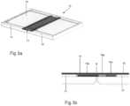
- FIG.2is schematically shown another 'wrap' example.
- an additional display supportis configured as a foil 8 which is attached to the hinges 5, 6 and at least partly tensioned in the support position of fig.2B , facilitating the support behind the whole surface of the display segment 2a in the open position of the display 2. This will give a sufficient stiff underground for the display, enabling a touch functionality.
- the foil 8facilitates the curvature of the display segment 2a in a predefined way, in this example shown as a combination of circular arches.
- This well defined curvatureis advantageous for the lifetime of the display. It enables opening/closing of the display system many times without damaging the display segment 2a. Another advantage of this curvature in the storage position is that the display system can be designed with favourable dimensions.
- a sufficiently stiff underground for the display by using a foil 8is obtained for example by rotating the main display supports 3, 4 around the hinges 5, 6 by more than 90 degrees, thus tensioning the foil 8. If (as shown in fig.2A, 2B ) the main display supports 3, 4 rotate equal or less than 90 degrees, the foil 8 would have a travel difference that is smaller than that of the display 2. This is solved in this example by using a stretchable foil 8 as support of the display segment 2a.
- a gear-actuated solution in the mechanism of the hinges 5 and/or 6is applied for enlarging the travel difference of the foil 8.
- a gear mechanism 5Ais shown in the hinge 5, that can be compared with the mechanism in a ballpoint pen.
- An example of such a mechanismis disclosed in GB 635144 .
- the mechanism 5Acomprises a pin 5E of which the axis coincides with the axis of the hinge 5.
- Gears 5F and 5Gare coaxially arranged around the pin 5E, such that gear 5F is connected with the support 3 whereas gear 5G, connected with the stretchable foil 8, is slidable and rotatable with respect to the pin 5E.
- gearsa series of ratchet-like teeth 5H, 51 respectively is cut.
- the teeth 51are continuously urged by a spring 5J located around the pin 5E in the direction of the teeth 5H and cooperate with the teeth 5H as the teeth of a gear-coupling.
- An abutment 5Klimits the pivotal movement of the supports 3, 4 from the closed to the planar open position to 90 degrees.
- a shaft 5Lis coaxially arranged around and connected with the pin 5E.
- the stretchable foil 8is rolled with its end portion around the shaft 5L and is with its end connected with the shaft 5L.
- the cooperation of the inclined sides of the teeth 5H, 51 under the spring reactionensures that the gear 5G and the shaft 5L rotate over an extra angle and thus tension the foil 8.
- This 90 degrees rotationis by way of example.
- This gear solutionshows the same favorable additional rotation with main display supports 3, 4 rotating by other angles of rotation.
- gears 5B , C and 6B , Care shown another solution with gears 5B , C and 6B , C.
- the axis of gear 5B , 6Bcoincides with the hinge axis of hinge 5, 6 respectively. Due to the connection with the supports 3, 4 respectively, the gear 5B, 6B drives the intermediate gear 5C, 6C respectively during movement of the support.
- the intermediate gear 5C, 6Cdrives an axle 5D, 6D respectively, configured as a shaft.
- the stretchable foil 8is rolled with its end portions around the shaft 5D and 6D and is with its ends connected to the shaft.
- the gear ratios between the gears 5A, 5B and the shaft 5D and between the gears 6A, 6B and the shaft 6Dare chosen in accordance with the required amount of travel difference between the foil 8 and the display 2, rotating the shaft 5D, 6D over an extra angle and thus tensioning the foil during the movement of the display from the closed to the planar open position.
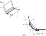
- the example shown in fig.3is a 'book' display system 9. It consists of a flexible display 10 and a support frame, comprising two main display supports 11, 12 being connected by a hinge 13 with respect to each other and each structurally configured to support a respective portion of the flexible display. As shown in fig.3A-3G , the two main display supports 11, 12 are hingeable between a configuration for fixing the flexible display in a closed storage position ( fig.3E and 3F ) and a planar configuration ( fig.3A and 3B ) for fixing the flexible display 10 in an open position.
- the additional display supportsconsist of four support panels 14a, 14b and 15a, 15b. See fig.
- 3D , 3Fshowing pairs of two mutually pivotable connected support panels 14a, 14b and 15a, 15b respectively, with the panels 14a and 15a pivotably connected by pivots 18, 19 with the display support 11,12 respectively.
- the panelsare being positioned under the display when the main display supports are opened. In this open state the support panels are "pulled flat" by bars 16, 17 (see fig. 3D ) at the respective sides of the display.
- the panels 14a, 14b and 15a, 15bin the planar configuration as shown in fig.3A and 3B , a segment 10a of flexible display, located between the said respective main display supports 11, 12 in the open position, is supported in an effective way.
- the pair of panelsis positioned at both respective sides of the curved display segment 10a.
- fig's 3A-3Gis a symmetrical version of a 'book' with equally shaped housings of display support panels and in the storage position with a display segment 10a symmetrically curved with respect to a plane s between both display supports 11, 12 and their housings.
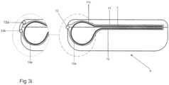
- fig.3His shown an alternative version of this example in the storage state, in which the display support housings have different dimensions measured perpendicular to the plane s between both display support housings.
- the display segmentIn the closed position the display segment is curved into the housing of the support 12.
- This solutioncan be applied in asymmetrical 'book' systems, in which the display segment 10a is asymmetrically curved with respect to the plane s between both display supports 11, 12 and their housings.
- a second asymmetrical versionis shown in fig.3i with a curved profile 11c of the support 11.
- the area of the display 10 supported by the display support 12 in the opened positionis larger than in the symmetrical 'book' system of fig.3G .
- the lower book housing part with the support 12is the housing part with a larger thickness, and thus has a higher volume and weight, enabling a stable positioning of the 'book' in the opened position in the hand or on a desk.
- these versions of a 'book'are provided with display supports 11 and 12 with two hinges 13a, 13b. With the use of two hinges in the opened position the hinges are located favorable in the plane of the surface of the display 10. Further the dimension of the display system 9 in the closed position (measured in the view of fig.3G/3H from the left to the right side) is smaller compared to the dimension of the system with only one hinge 13.
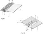
- the example shown in fig.4is a 'book' display system 9 comparable with that of fig.3 but in fig.4 the additional display supports comprise two panels 20, 21 being guided slidably in slots 11a, 12a at both sides of the display support 11, 12. They slide with respect to the display segment 10a during movement of the display 10 between the open position ( fig.4A, B ) via the position shown in fig. 4C , D to the closed storage position ( fig. 4E, F ). In the position of fig.4A , B the panels 20, 21 are in a planar configuration for supporting the surface of the display segment 10a.
- these panels 20, 21are also pivotably connected respectively to an arm 22, 23 that is attached by pivots 22a, 23a respectively to the opposite main display support 11, 12 in order to enable the sliding movement during opening and closing of the system.
- this solutioncan be applied one-sided in an asymmetrical book.
- the example shown in fig.5is a 'book' display system 9 provided with a lifting mechanism 24 comprising an additional display support that consists of a panel 25 that is lifted under the display segment 10a when the system is moved from the closed ( fig.5E, F ) to the opened ( fig.5A, B ) position.
- the lift panel 25is constrained to a linear movement and is guided by a guiding element, comprising a protrusion 26 on the main display support 11 and parallel guiding walls 25a, 25b in a housing 24a of the lift mechanism 24.
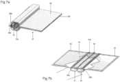
- the example shown in fig.6is a 'book' or 'wrap' display system 27.
- Each of the two main display supports 28, 29comprises a number of extended teeth like parts 28a, 29a, extending parallel to each other and perpendicular to a hinge axis 30 between the display supports 28, 29. Due to the mutually offset positioning of the parts 28a, 29a, when opening the system, from the position of fig. 6A the extended parts 28a, 29a are rotated around the axis 30 and moved to a planar configuration, supporting as an additional display support in the position of fig.6B the display segment 10a for touch events.
- the display system 27has a construction with parts 28b, 29b, used comparable with the extended main display supports parts example of fig.6 .
- a combination of two connected flat panels 31, 32, rotatable around the axis 30, inside main display supports 28, 29is added as an additional display support for touch support.
- these parts 28b, 29bare positioned as shown in fig.7A .
- the flexible display 10has the free space to form a partial curvature without conflicting with the panels 31, 32.
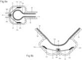
- fig.8AThe detailed transition from the closed position of fig.8A is shown in fig.'s 8B and 8C.
- pivots 31a, 32athe panels 31, 32 are connected with panel parts 31b, 32b.
- this connectionmay be spring loaded.
- the angle of rotationcan be limited so that in open state the panels 31, 32 and their parts 31b, 32b are parallel and therefore support the flexible display segment 10a in the region of the hinge mechanism, see fig.8C .
- the panels 31, 32may fully support the display segment 10a or be located (as shown in fig.8C ) with a minimal play under the display segment in order to be able to compensate tolerances in the support mechanism.
- the two panels 28, 29are integrated into one plastic panel with a living hinge at the location of the axis 30.
- the embodiment shown in fig.9is a 'book' display system 9 comparable with that of fig.3 and fig.4 .
- the display segment 10ais supported by additional display supports comprising a central support plate 33 and two hingeably connected display support plates 34, 35.
- the central support plate 33is used as dual guided hinge part for the two display supports 11, 12 of the system by gear sets 36, 37.
- the central additional support plate 33is separated from the two device halves in which case it is only attached to the two display support plates 34, 35, with a guidance for the central support plate 33.
- the support plates 34, 35each have a pin 34a, 35a that is guided in a slot 11a, 12a in each of the display supports 11, 12 of the device body. These slots 11a, 12a guide the movement of the plates 34, 35 in such a manner that in open position of fig.9A and 9B the display segment 10a is completely supported and in closed position of fig. 9E and 9F the curved display segment 10a is not obstructed.
- Fig.9C and 9Dshow an intermediate situation. In the closed position the plates 33, 34 and 35 facilitate by their positioning a pre-defined curvature of the display segment 10a with the advantages described before for the example of fig.2 .
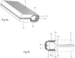
- the example shown in fig. 10is a 'book' or 'wrap' display system 38 with a flexible display 39, a display segment 39a and main display supports 40, 41. These main supports are hingeably connected via hinges 5, 6 like the supports in the example of fig.2 .
- the additional display supportcomprises a support strip 42 which is connected to the display segment 39a.
- the main display supports 40, 41are provided with hooks 40a, 41a and push with the hooks during their movement from the storage position to the open position the support strip 42 with the display segment 39a to the flat position.
- the gap created by the hinge mechanism of hinges 5, 6 between the main supports 40, 41is closed by the display support strip 42 and substantially the whole surface of the display is supported.
- the support strip 42facilitates by its positioning a predefined curvature of the display segment 10a in a way as described before for the example of fig.2
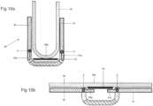
- the example shown in fig. 11A and 11Bis a 'book' or 'wrap' display system 43 with a flexible display 44 and main display supports 45, 46 which are hingeably connected via hinges 5, 6 like the supports in the example of fig.2 .
- the additional display supportcomprises near both sides of the display a strip of spring tape 47, cooperating with rods 47a.
- the tape 47may be of the kind of spring steel measuring tape, or alternatively a plastic spring tape.
- rods 47aare of the kind disclosed in WO 2009/148313 A1 and close in the open position of fig.11B , supported by the tape 47, the gap created by the hinge mechanism of hinges 5, 6 between the main supports 45, 46 and support substantially the whole surface of the display segment 44a in a flat position.
- the display system 48 schematically shown in fig. 12is a 'roll' example of the kind as disclosed in WO 2006/038171 A1 .
- both a rollable display 49 and a pre-tensioned rolled foil 50are provided with a spring 49a, 50a, respectively, on the inside of their roll and accommodated in a housing 51.
- the ends of the display 49 and the foil 50are connected at a hold out mechanism 52 (only shown with its connection wall), enabling a common rolling out of both the display and the foil.
- the force f2of the pre-tensioned foil spring 50ais greater than the force f 1 of the display spring 49a.
- a display 49is extended using a linear actuation mechanism 52a not further described here and of the kind as for example disclosed in WO 2006/038171 A1 , which also functions as the hold out mechanism 52, such that in extended position the force f3exerted by the hold out mechanism 52 is equal to the forces of the pre-tensioned foil 50 and the display 49 added together but oriented in the opposite direction.
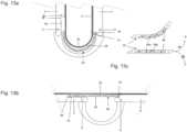
- FIG. 13An alternative solution in a display system for an additional display support 55 for the preceding 'book' or 'wrap' examples is shown in fig.13 for the example of fig.2 in a storage position ( fig. 13A ) and in an open flat position ( fig.13B ), respectively.
- This solutionuses a number of specially designed segments 56, inter-linked by hinges 56a.
- An end segment 56is coupled by a pivot 4c with the display support 4 and an abutment 4b limits the pivotal movement of this end segment.
- These segmentsare substantially parallelogram-shaped with one rounded corner 56b and are mutually configured such that when a segment 56 is locally bent to a radius, its inter-linkage will make sure that other segments follow (see arrow g in fig. 13C ).
- the local radiuscan therefore never become small.
- the configuration and inter-linkage of the segmentsprevent that a segment 56 is bent in the direction of the arrow h in fig. 13C .
- all segments 56are pushed flat by their configuration and inter-linkage.
- a stable positioning towards the flat position of the segmentsis supported due to the length of the gap 3d between the display 2 and the support 3.
- an end segment 56may be stably positioned in an optional hook shaped recess 3b in the support 3.
- an optional recess 3c in the supportmay be applied for extra stabilization of the flat position of the segments 56. Due to this stable positioning the flat position of the whole additional support 55 is ensured. In the flat position the combined segments 56 support substantially the whole surface of the display segment 2a in an effective way.
- a spring(not shown) may be applied between the left side segment 56 and the support 3, urging the end segment 56 into the gap 3d towards its end position.
- the minimum achievable radius of the curvaturewill be determined by the positioning of the individual hinges 56a, the design of end stops near the corners of the segments and the distance between hinge points. This enables in the storage position a facilitation of the curvature of the display segment 2a with a predefined curvature, in this example shown as a combination of circular arches.
Landscapes
- Engineering & Computer Science (AREA)
- Theoretical Computer Science (AREA)
- Computer Hardware Design (AREA)
- Physics & Mathematics (AREA)
- General Physics & Mathematics (AREA)
- Human Computer Interaction (AREA)
- General Engineering & Computer Science (AREA)
- Signal Processing (AREA)
- Microelectronics & Electronic Packaging (AREA)
- Devices For Indicating Variable Information By Combining Individual Elements (AREA)
- Illuminated Signs And Luminous Advertising (AREA)
Description
- The present invention generally relates to flexible displays. The present invention specifically relates to flexible displays provided with display supports.
- Flexible and especially rollable displays are manufactured on an organic substrate and are very thin. This makes it possible to repeatedly bend them with a small radius, a requirement for a rollable display. The advantages of a rollable display are the small volume needed for storing in the closed position and the lack of glass making the display unbreakable and of light weight.
- A number of product concepts have been developed for flexible displays. The most important concepts are the 'book', the 'wrap' and the 'roll'. A 'wrap' concept is shown in
WO 2008/054206 A2 , a 'roll' concept inWO 2006/038171 A1 .US2009/267872A1 discloses an electronic book including a housing defining a card slot on a first face thereof, the housing including first and second housing portions; a spine member pivotally coupling the first and second housing portions, the spine defining a cavity therein.US7765644B1 discloses a hinge device having a first installation frame (10) installed on a first housing (2); a second installation frame (20) installed on a second housing (3); a third installation frame (30) for rotatably supporting a base end section of each of the frames, the base end sections being supported such that a head section side of each frame is rotatable in a direction to approach to and separate from each other, the base end sections being supported through a first main shaft (40) and a second main shaft (50) that are arranged parallel to each other and to which rotation of the frames is transmitted; a rotation force transmission mechanism (80) disposed between the main shafts (40, 50) and including gears (81, 82) having a function of transmitting reverse rotation force from one to the other and vice versa; and a rotation angle restriction means (60).WO 2011/067921A1 discloses a folding portable terminal wherein a first housing (3) thereof which has a first display section (2) and a second housing (5) thereof which has a second display device (4) are connected to each other so that, in the process of opening and closing the first housing (3) and the second housing (5), the first and second housings (3, 5) can be opened and closed relative to each other in a folding manner about a hinge section (6).WO 2010/019176A1 discloses a hinge assembly for a mobile communications device including a first frame member having two spaced-apart portions with a first pair of opposing cam slots defining a first cam path. A second frame member has two spaced-apart portions with a second pair of opposing cam slots defining a second cam path and a second cam pin in the second pair of opposing cam slots. - The 'book' concept is the simplest implementation of a rollable display comprising two hingeably connected support halves with a continuous display. In the middle near the hinge mechanism is a hollow space to accommodate the curved segment of the display in the situation where the 'book' is in the closed position. The display size is at most twice the size of the closed display system. In practice, it will be around 1.8x the size due to the bezel of the support halves needed around the display.
- The 'wrap' concept comprises a display, wrapped with its front side to the inside. Thus the display is protected when the 'wrap' is in the closed position. The display currently makes one complete turn around the device body when wrapped. Therefore, the size of the display will be about twice the size of the device. For larger displays compared to the device body more turns are required, which adds mechanical complexity.
- Instead of rolling the display around the device body, especially if it is more than one turn, it could also be rolled around a tube and stored inside the system. This 'roll' concept has a very different product experience, as the display comes out of the system instead of being wrapped around it.
- There are a lot of possibilities to realize the movement of the display with respect to the display system, but most of them result in an open position with unsupported parts of the display. This can result in problems when touch functionality has to be integrated into the display. The pressure from a touch on the display can result in tearing of the display due to the tensions and it can result in imprints along the edges of the unsupported display part. Another problem is that for the end-user it is important to have a consistent feeling of touch across the whole display. In an unsupported location, touching the display will feel different than in a supported location and this could be confusing to the end-user.
- It is an object of the invention to prevent unsupported locations in the display in its open position. It is also an object to improve the lifetime of the display.
- The invention is defined by the appended claims. Examples falling outside the scope of the claims are included for understanding the scope of the invention.
- According to one aspect the disclosure provides a display system comprising a continuous flexible display, a support frame comprising two main display supports being hingeable with respect to each other and each structurally configured to support a respective portion of the flexible display, wherein the two main display supports are hingeable between a configuration for fixing the flexible display in a closed storage position and a planar configuration for fixing the flexible display in an open position, wherein at least one additional display support is configured to support substantially a segment of flexible display located between the said respective portions of the flexible display in the open position, said additional display support being movable with respect to the display segment between a non-operational position and a support position when the two main display supports are moved between the storage position and the open position of the flexible display, such that in the open position substantially the whole surface of the display is supported by the respective display supports.
- According to another aspect the disclosure provides a display system comprising a continuous flexible display and a display support device structurally configured to support the flexible display, wherein the display is movable between a closed storage position and an open position, wherein the display support device comprises at least one display support being movable between a storage position and a support position when the display is moved between the storage position and the open position of the flexible display, such that in the open position substantially the whole surface of the display is supported by the display support. This configuration of the display support is applicable for supporting different kinds of the flexible displays, i.e. of rollable, wrappable or of book type.
- Preferably, in the display system according to the another aspect of the disclosure, the flexible display is a rollable display being movable by rolling out from a closed storage position to an open position, the display support comprising a rollable foil, being coupled with the display and movable by said coupling during movement of the display from the non-operational position to the support position, in the support position the foil being at least partly pre-tensioned, facilitating the support of the display over its whole surface.
- According to yet another aspect the disclosure provides a display system comprising a continuous flexible display, a support frame comprising two main display supports being hingeable with respect to each other and each structurally configured to support a respective portion of the flexible display, a segment of the flexible display being located between the said respective portions of the flexible display, wherein the two main display supports are hingeable between a closed configuration for fixing the flexible display in a storage position and an open configuration for fixing the flexible display in an open position, in the storage position of the flexible display between the main display supports and the additional display support there is a free space enabling a partial curvature of said display segment without conflicting with the respective main display support wherein at least one additional display support is configured to support substantially said segment of the flexible display in the storage position of the flexible display, the additional display support facilitates the curvature of the display segment with a predefined curvature.
- Preferably, in the display system according to the yet another aspect of the disclosure, the storage position of the flexible display, the additional display support facilitates the curvature of the display segment in a combination of circular arches.
- According to a further aspect the disclosure provides a display system with a continuous flexible display, a support frame comprising two display supports located in respective housings being hingeable with respect to each other and each structurally configured to support a respective portion of the flexible display, a segment of the flexible display being located between the said respective portions of the flexible display, wherein the two display support housings are hingeable between a closed configuration for fixing the flexible display in a storage position and an open configuration for fixing the flexible display in an open position, in the storage position of the flexible display between the display supports there is a free space enabling a partial curvature of said display segment without conflicting with the respective display support, wherein in the storage position the flexible display is positioned in the system with its display segment in an asymmetrical configuration with respect to a plane between both display support housings.
- In an example of the display system according to the further aspect of the disclosure, the dimension of the display support housings is measured perpendicular to the plane between both display support housings is different, in the storage position the display segment being positioned with at least a major part of its curvature in the display support housing with the larger dimension.
- In another example of the display system according to the further aspect of the disclosure, the two display supports located in their respective housings are hingeably connected by two hinges.
- The invention focuses in the different embodiments on the support of the display in parts of the construction where the display cannot be connected to a rigid underground. This can be the case near hinges, guiding mechanisms and other mechanical elements that facilitate the movement of the display and supporting frame between a closed storage and an open position. The invention provides technical solutions for applying touch functionality in a display system with a flexible/rollable display.
- The advantages of the different embodiments are that in the open position the display is supported by an additional support when touched. This means that it is less likely to be damaged when touch functionality is added to the display. Another advantage is that the display will feel stiffer and gives a better quality perception of the product. The predefined curvature of the display segment in the closed position is advantageous for the lifetime of the display.
Fig.1 shows a schematic side view of part of a first 'wrap' example in a storage position (fig.1A ) and an operational position (fig.1B ), respectively, in accordance with an example not forming part of the claimed invention but useful for understanding the scope of the invention;Fig.2 shows a schematic side view of part of a second 'wrap' example in a storage position (fig.2A ) and an operational position (fig.2B ), respectively;fig.2C shows in a storage position a solution with a gear coupling between the display supports, applied in a wrap hinge of this example, whereasfig. 2D, fig.2E show another gear coupled solution applied in the wrap hinges of this example in accordance with an example not forming part of the claimed invention but useful for understanding the scope of the invention;Fig.3 shows a perspective view and a schematic side view of a first 'book' example in an open position (fig.3A/B ), a partial open position (fig.3C/D ) and a storage position (fig.3E/F ), respectively, and a schematic side view of this 'book' example with display supports with one and two hinges respectively in a symmetrical (fig.3G ), a first asymmetrical (fig.3H ) and a second asymmetrical (fig.3I ) version in accordance with an example not forming part of the claimed invention but useful for understanding the scope of the invention;Fig.4 shows a perspective view and a schematic side view of a second 'book' example in an open position (fig.4A/B ), a partial open position (fig.4C/D ) and a storage position (fig.4E/F ), respectively, in accordance with an example not forming part of the claimed invention but useful for understanding the scope of the invention;Fig.5 shows a perspective view and a schematic side view of a third 'book' example in an open position (fig.5A/B ), a partial open position (fig.5C/D ) and a storage position (fig.5E/F ), respectively, in accordance with an example not forming part of the claimed invention but useful for understanding the scope of the invention;Fig.6 shows a perspective view of another 'book' or 'wrap' example in a storage position (fig.6A ) and an open position (fig.6B ), respectively, in accordance with an example not forming part of the claimed invention but useful for understanding the scope of the invention;Fig.7 shows a perspective view of another 'book' example in a storage position (fig.7A ) and an open position (fig.7B ), respectively, in accordance with an example not forming part of the claimed invention but useful for understanding the scope of the invention;Fig.8 shows a schematic side view of a part of the 'book' example ofFig. 7 in a storage position (fig.8A ), an a partial open position (fig.8B ) and open position (fig.8C ), respectively, in accordance with an example not forming part of the claimed invention but useful for understanding the scope of the invention;Fig.9 shows a perspective view and a schematic side view of a 'book' embodiment in an open position (fig.9A/B ), a partial open position (fig.9C/D ) and a storage position (fig.9E/F ), respectively, in accordance with the invention;Fig. 10 shows a schematic side view of a part of still another 'book' or 'wrap' example in a storage position (fig. 10A ) and open position (fig. 10B ), respectively, in accordance with an example not forming part of the claimed invention but useful for understanding the scope of the invention;Fig.11 shows a schematic side view of part of another 'book' or 'wrap' example in a storage position (fig.11A ), and open position (fig. 11B ), respectively, in accordance with an example not forming part of the claimed invention but useful for understanding the scope of the invention;Fig.12 shows a schematic side view of part of a 'roll' example in an open position in four versions (fig.12A, 12B ,12C and 12D ) in accordance with an example not forming part of the claimed invention but useful for understanding the scope of the invention;Fig.13 shows a schematic side view of an additional display support of another 'book' or 'wrap' example in a storage position (fig. 13A ) and an open position (fig.13B ), as well as the positioning of the additional display support (fig.13C ), respectively, in accordance with an example not forming part of the claimed invention but useful for understanding the scope of the invention.- The
display system 1 schematically shown infig.1A and 1B is a 'wrap' example as disclosed inWO 2008/054206 A2 . It comprises aflexible display 2 and a display support frame comprising two main display supports 3, 4. These supports 3, 4 are connected viahinges body 7 and are each structurally configured to support a respective portion of theflexible display 2. At the other side of therespective hinge additional display support fig.1A for fixing the flexible display in a closed storage position and a planar configuration shown infig.1B for fixing the flexible display in an open position. The additional display supports 3a, 4a are moved with respect to adisplay segment 2a between a non-operational position and a support position when the two main display supports 3, 4 are moved between the storage position and the open position of the flexible display. The combined supports 3a, 4a support in the operational open position substantially thesegment 2a of the flexible display located between the said respective main display supports. In the open position the gap created by the hinge mechanism ofhinges main supports 3,4 is closed by the display supports 3a, 4a and substantially the whole surface of the display is supported. - In the storage position of the
flexible display 2 between the main display supports 3,4 and the additional display supports 3a, 4a there is sufficient free space for enabling a partial curvature of thedisplay segment 2a without conflicting with the respective main display supports. - In the open position between the
hinges display segment 2a is supported by theadditional support - In
fig.2 is schematically shown another 'wrap' example. In this example an additional display support is configured as afoil 8 which is attached to thehinges fig.2B , facilitating the support behind the whole surface of thedisplay segment 2a in the open position of thedisplay 2. This will give a sufficient stiff underground for the display, enabling a touch functionality. - In the storage position of the
flexible display 2 shown infig.2A thefoil 8 facilitates the curvature of thedisplay segment 2a in a predefined way, in this example shown as a combination of circular arches. - This well defined curvature is advantageous for the lifetime of the display. It enables opening/closing of the display system many times without damaging the
display segment 2a. Another advantage of this curvature in the storage position is that the display system can be designed with favourable dimensions. - A sufficiently stiff underground for the display by using a
foil 8 is obtained for example by rotating the main display supports 3, 4 around thehinges foil 8. If (as shown infig.2A, 2B ) the main display supports 3, 4 rotate equal or less than 90 degrees, thefoil 8 would have a travel difference that is smaller than that of thedisplay 2. This is solved in this example by using astretchable foil 8 as support of thedisplay segment 2a. - In two alternative 'wrap' examples, respectively shown in
fig.2C and infig.2D, 2E , a gear-actuated solution in the mechanism of thehinges 5 and/or 6 is applied for enlarging the travel difference of thefoil 8. Infig.2C a gear mechanism 5A is shown in thehinge 5, that can be compared with the mechanism in a ballpoint pen. An example of such a mechanism is disclosed inGB 635144 hinge 5. Gears 5F and 5G are coaxially arranged around the pin 5E, such that gear 5F is connected with thesupport 3 whereas gear 5G, connected with thestretchable foil 8, is slidable and rotatable with respect to the pin 5E. In the gears a series of ratchet-like teeth 5H, 51 respectively is cut. Theteeth 51 are continuously urged by a spring 5J located around the pin 5E in the direction of the teeth 5H and cooperate with the teeth 5H as the teeth of a gear-coupling. An abutment 5K limits the pivotal movement of thesupports 3, 4 from the closed to the planar open position to 90 degrees. A shaft 5L is coaxially arranged around and connected with the pin 5E. Thestretchable foil 8 is rolled with its end portion around the shaft 5L and is with its end connected with the shaft 5L. The cooperation of the inclined sides of theteeth 5H, 51 under the spring reaction ensures that the gear 5G and the shaft 5L rotate over an extra angle and thus tension thefoil 8. - This 90 degrees rotation is by way of example. This gear solution shows the same favorable additional rotation with main display supports 3, 4 rotating by other angles of rotation.
- In
fig. 2D, 2E is shown another solution with gears5B ,C and6B , C. The axis of gear5B ,6B coincides with the hinge axis ofhinge supports 3, 4 respectively, the gear 5B, 6B drives the intermediate gear 5C, 6C respectively during movement of the support. The intermediate gear 5C, 6C drives an axle 5D, 6D respectively, configured as a shaft. Thestretchable foil 8 is rolled with its end portions around the shaft 5D and 6D and is with its ends connected to the shaft. The gear ratios between the gears 5A, 5B and the shaft 5D and between the gears 6A, 6B and the shaft 6D are chosen in accordance with the required amount of travel difference between thefoil 8 and thedisplay 2, rotating the shaft 5D, 6D over an extra angle and thus tensioning the foil during the movement of the display from the closed to the planar open position. - The example shown in
fig.3 is a 'book'display system 9. It consists of aflexible display 10 and a support frame, comprising two main display supports 11, 12 being connected by ahinge 13 with respect to each other and each structurally configured to support a respective portion of the flexible display. As shown infig.3A-3G , the two main display supports 11, 12 are hingeable between a configuration for fixing the flexible display in a closed storage position (fig.3E and 3F ) and a planar configuration (fig.3A and 3B ) for fixing theflexible display 10 in an open position. In this example the additional display supports consist of foursupport panels fig. 3D ,3F showing pairs of two mutually pivotableconnected support panels panels pivots display support fig.3B the panels are being positioned under the display when the main display supports are opened. In this open state the support panels are "pulled flat" bybars 16, 17 (seefig. 3D ) at the respective sides of the display. With thepanels fig.3A and 3B , asegment 10a of flexible display, located between the said respective main display supports 11, 12 in the open position, is supported in an effective way. As shown infig.3F in the closed storage position the pair of panels is positioned at both respective sides of thecurved display segment 10a. - The example of fig's 3A-3G is a symmetrical version of a 'book' with equally shaped housings of display support panels and in the storage position with a
display segment 10a symmetrically curved with respect to a plane s between both display supports 11, 12 and their housings. - In
fig.3H is shown an alternative version of this example in the storage state, in which the display support housings have different dimensions measured perpendicular to the plane s between both display support housings. In the closed position the display segment is curved into the housing of thesupport 12. This solution can be applied in asymmetrical 'book' systems, in which thedisplay segment 10a is asymmetrically curved with respect to the plane s between both display supports 11, 12 and their housings. A second asymmetrical version is shown infig.3i with acurved profile 11c of thesupport 11. In the asymmetrical 'book' systems offig.3H and3i the area of thedisplay 10 supported by thedisplay support 12 in the opened position is larger than in the symmetrical 'book' system offig.3G . Another advantage is that the lower book housing part with thesupport 12 is the housing part with a larger thickness, and thus has a higher volume and weight, enabling a stable positioning of the 'book' in the opened position in the hand or on a desk. As shown at the left side infig.3G, 3H and3i in an alternative example these versions of a 'book' are provided with display supports 11 and 12 with twohinges display 10. Further the dimension of thedisplay system 9 in the closed position (measured in the view offig.3G/3H from the left to the right side) is smaller compared to the dimension of the system with only onehinge 13. - The example shown in
fig.4 is a 'book'display system 9 comparable with that offig.3 but infig.4 the additional display supports comprise twopanels slots display support display segment 10a during movement of thedisplay 10 between the open position (fig.4A, B ) via the position shown infig. 4C , D to the closed storage position (fig. 4E, F ). In the position offig.4A , B thepanels display segment 10a. As in the previous example thesepanels arm pivots main display support fig.3H also this solution can be applied one-sided in an asymmetrical book. - The example shown in
fig.5 is a 'book'display system 9 provided with alifting mechanism 24 comprising an additional display support that consists of apanel 25 that is lifted under thedisplay segment 10a when the system is moved from the closed (fig.5E, F ) to the opened (fig.5A, B ) position. Thelift panel 25 is constrained to a linear movement and is guided by a guiding element, comprising aprotrusion 26 on themain display support 11 andparallel guiding walls housing 24a of thelift mechanism 24. - The example shown in
fig.6 is a 'book' or 'wrap'display system 27. Each of the two main display supports 28, 29 comprises a number of extended teeth likeparts hinge axis 30 between the display supports 28, 29. Due to the mutually offset positioning of theparts fig. 6A theextended parts axis 30 and moved to a planar configuration, supporting as an additional display support in the position offig.6B thedisplay segment 10a for touch events. - In the example shown in
fig.7 thedisplay system 27 has a construction withparts fig.6 . However a combination of two connectedflat panels axis 30, inside main display supports 28, 29 is added as an additional display support for touch support. In the closed state theseparts fig.7A . Theflexible display 10 has the free space to form a partial curvature without conflicting with thepanels extended parts flat panels fig.7B . The detailed transition from the closed position offig.8A is shown in fig.'s 8B and 8C. Bypivots panels panel parts flat panels panels parts flexible display segment 10a in the region of the hinge mechanism, seefig.8C . In the opened position thepanels display segment 10a or be located (as shown infig.8C ) with a minimal play under the display segment in order to be able to compensate tolerances in the support mechanism. - It is noted that alternatively the two
panels axis 30. - The embodiment shown in
fig.9 is a 'book'display system 9 comparable with that offig.3 andfig.4 . In this embodiment thedisplay segment 10a is supported by additional display supports comprising acentral support plate 33 and two hingeably connecteddisplay support plates central support plate 33 is used as dual guided hinge part for the two display supports 11, 12 of the system by gear sets 36, 37. Alternatively (not shown) the centraladditional support plate 33 is separated from the two device halves in which case it is only attached to the twodisplay support plates central support plate 33. - The
support plates pin slot slots plates fig.9A and 9B thedisplay segment 10a is completely supported and in closed position offig. 9E and 9F thecurved display segment 10a is not obstructed.Fig.9C and 9D show an intermediate situation. In the closed position theplates display segment 10a with the advantages described before for the example offig.2 . - The example shown in
fig. 10 is a 'book' or 'wrap'display system 38 with aflexible display 39, adisplay segment 39a and main display supports 40, 41. These main supports are hingeably connected viahinges fig.2 . In this example the additional display support comprises asupport strip 42 which is connected to thedisplay segment 39a. The main display supports 40, 41 are provided withhooks support strip 42 with thedisplay segment 39a to the flat position. In the open position the gap created by the hinge mechanism ofhinges main supports display support strip 42 and substantially the whole surface of the display is supported. Preferably in the closed position thesupport strip 42 facilitates by its positioning a predefined curvature of thedisplay segment 10a in a way as described before for the example offig.2 - The example shown in
fig. 11A and 11B is a 'book' or 'wrap'display system 43 with aflexible display 44 and main display supports 45, 46 which are hingeably connected viahinges fig.2 . In this example, instead of thefoil 8, the additional display support comprises near both sides of the display a strip ofspring tape 47, cooperating withrods 47a. Thetape 47 may be of the kind of spring steel measuring tape, or alternatively a plastic spring tape. Theserods 47a are of the kind disclosed inWO 2009/148313 A1 and close in the open position offig.11B , supported by thetape 47, the gap created by the hinge mechanism ofhinges main supports display segment 44a in a flat position. - The
display system 48 schematically shown infig. 12 is a 'roll' example of the kind as disclosed inWO 2006/038171 A1 . In the example shown infig. 12A , both arollable display 49 and a pre-tensioned rolledfoil 50 are provided with aspring housing 51. The ends of thedisplay 49 and thefoil 50 are connected at a hold out mechanism 52 (only shown with its connection wall), enabling a common rolling out of both the display and the foil. In the open position preferably the force f2of thepre-tensioned foil spring 50a is greater than theforce f 1 of thedisplay spring 49a. These forces are indicated by the length of the arrows. In this way in the open position the rollable display is provided with an additional display support acting over its surface as an effective touch-support. - In
fig.12B and12C similar examples are shown but with a different kind or thickness offoil 50 to achieve different levels of support. Also is shown that a force f2smaller than and/or equal to f1could be possible as well, depending on desired level of support. - In the example of
fig. 12C only onespring 53 is used, provided in thedisplay roll 49, further using agear belt 54 or a gear set (not shown) for linking the tworolls fig.12D is shown the combination of thedisplay 49 and thefoil 50 in a single roll with only onespring 53. Thus the dimensions of thehousing 51 may be limited. - In the examples of
fig. 12 adisplay 49 is extended using alinear actuation mechanism 52a not further described here and of the kind as for example disclosed inWO 2006/038171 A1 , which also functions as the hold outmechanism 52, such that in extended position the force f3exerted by the hold outmechanism 52 is equal to the forces of thepre-tensioned foil 50 and thedisplay 49 added together but oriented in the opposite direction. - An alternative solution in a display system for an
additional display support 55 for the preceding 'book' or 'wrap' examples is shown infig.13 for the example offig.2 in a storage position (fig. 13A ) and in an open flat position (fig.13B ), respectively. This solution uses a number of specially designedsegments 56, inter-linked byhinges 56a. Anend segment 56 is coupled by a pivot 4c with the display support 4 and an abutment 4b limits the pivotal movement of this end segment. These segments are substantially parallelogram-shaped with one rounded corner 56b and are mutually configured such that when asegment 56 is locally bent to a radius, its inter-linkage will make sure that other segments follow (see arrow g infig. 13C ). The local radius can therefore never become small. The configuration and inter-linkage of the segments prevent that asegment 56 is bent in the direction of the arrow h infig. 13C . During the movement from the position shown infig. 13A to the flat position shown infig.13B allsegments 56 are pushed flat by their configuration and inter-linkage. A stable positioning towards the flat position of the segments is supported due to the length of the gap 3d between thedisplay 2 and thesupport 3. In addition, in the position shown infig.13A at the left side of the gap 3d anend segment 56 may be stably positioned in an optional hook shapedrecess 3b in thesupport 3. Further in addition, in the area of the gap 3d anoptional recess 3c in the support may be applied for extra stabilization of the flat position of thesegments 56. Due to this stable positioning the flat position of the wholeadditional support 55 is ensured. In the flat position the combinedsegments 56 support substantially the whole surface of thedisplay segment 2a in an effective way. - It is noted that in addition a spring (not shown) may be applied between the
left side segment 56 and thesupport 3, urging theend segment 56 into the gap 3d towards its end position. - The minimum achievable radius of the curvature will be determined by the positioning of the individual hinges 56a, the design of end stops near the corners of the segments and the distance between hinge points. This enables in the storage position a facilitation of the curvature of the
display segment 2a with a predefined curvature, in this example shown as a combination of circular arches. - The detailed drawings, specific examples and particular formulations given, serve the purpose of illustration only.
Claims (3)
- A display system (1) comprising:a continuous flexible display (10),a support frame comprising two main display supports (11, 12) being hinged with respect to each other and each structurally configured to support a respective portion of the flexible display, wherein the two main display supports (11, 12) are hingeable between a configuration for fixing the flexible display in a closed storage position and a planar configuration for fixing the flexible display in an open position,characterised in that the display system (1) further comprises:an additional display support comprising a central support plate (33) and two hingeably connected display support plates (34, 35) and configured to support a display segment (10a) located between the said respective portions of the flexible display in the open position, wherein in the open position the display segment (10a) is completely supported by the plates (34, 35) and the central support plate (33), wherein in the closed storage position the curved display segment (10a) is not obstructed by the plates (34, 35) and the central support plate (33),wherein the display support plates (34, 35) each have a pin (34a, 35a) that is guided in a slot (11a, 12a) in each of the display supports (11, 12) wherein the slots (11a, 12a) are configured to guide the movement of the display support plates (34, 35) as the display supports (11, 12) move between the open position and the closed storage position,a hinge cover configured to cover the central support plate (33),wherein, in the open position, a portion of the hinge cover is placed inside the two slots (11a, 12a) and overlaps the main display supports (11, 12), andwherein, in the closed storage position, the hinge cover is exposed from the main display supports (11, 12), wherein in the closed storage position, between the main display supports (11, 12) and the at least one additional display support there is a free space enabling a partial curvature of the display segment (10a) without conflicting with the respective main display supports (11, 12).
- The display system (1) of claim 1, while moving from the open position to the closed storage position, the portion of the hinge cover is configured to be guided inside the two slots (11a, 12a)
- The display system (1) of claim 1, wherein the two main display supports (11, 12) are hingeably connected with each other by a hinge mechanism comprising two gear sets (36, 37).
Priority Applications (1)
| Application Number | Priority Date | Filing Date | Title |
|---|---|---|---|
| EP24173630.5AEP4386725A3 (en) | 2011-07-11 | 2012-07-06 | Flexible display with guided plates to support the display in the open position |
Applications Claiming Priority (2)
| Application Number | Priority Date | Filing Date | Title |
|---|---|---|---|
| US201161506177P | 2011-07-11 | 2011-07-11 | |
| EP12175310.7AEP2546721B1 (en) | 2011-07-11 | 2012-07-06 | Flexible display with display support |
Related Parent Applications (1)
| Application Number | Title | Priority Date | Filing Date |
|---|---|---|---|
| EP12175310.7ADivisionEP2546721B1 (en) | 2011-07-11 | 2012-07-06 | Flexible display with display support |
Related Child Applications (2)
| Application Number | Title | Priority Date | Filing Date |
|---|---|---|---|
| EP24173630.5ADivisionEP4386725A3 (en) | 2011-07-11 | 2012-07-06 | Flexible display with guided plates to support the display in the open position |
| EP24173630.5ADivision-IntoEP4386725A3 (en) | 2011-07-11 | 2012-07-06 | Flexible display with guided plates to support the display in the open position |
Publications (3)
| Publication Number | Publication Date |
|---|---|
| EP3826278A1 EP3826278A1 (en) | 2021-05-26 |
| EP3826278C0 EP3826278C0 (en) | 2024-06-12 |
| EP3826278B1true EP3826278B1 (en) | 2024-06-12 |
Family
ID=46640551
Family Applications (3)
| Application Number | Title | Priority Date | Filing Date |
|---|---|---|---|
| EP20216976.9AActiveEP3826278B1 (en) | 2011-07-11 | 2012-07-06 | Flexible display with guided plates to support the display in the open position |
| EP12175310.7AActiveEP2546721B1 (en) | 2011-07-11 | 2012-07-06 | Flexible display with display support |
| EP24173630.5APendingEP4386725A3 (en) | 2011-07-11 | 2012-07-06 | Flexible display with guided plates to support the display in the open position |
Family Applications After (2)
| Application Number | Title | Priority Date | Filing Date |
|---|---|---|---|
| EP12175310.7AActiveEP2546721B1 (en) | 2011-07-11 | 2012-07-06 | Flexible display with display support |
| EP24173630.5APendingEP4386725A3 (en) | 2011-07-11 | 2012-07-06 | Flexible display with guided plates to support the display in the open position |
Country Status (3)
| Country | Link |
|---|---|
| US (4) | US9235239B2 (en) |
| EP (3) | EP3826278B1 (en) |
| CN (4) | CN108874040B (en) |
Cited By (1)
| Publication number | Priority date | Publication date | Assignee | Title |
|---|---|---|---|---|
| TWI880857B (en)* | 2024-09-26 | 2025-04-11 | 友達光電股份有限公司 | Foldable electronic device |
Families Citing this family (243)
| Publication number | Priority date | Publication date | Assignee | Title |
|---|---|---|---|---|
| EP3826278B1 (en)* | 2011-07-11 | 2024-06-12 | Samsung Electronics Co., Ltd. | Flexible display with guided plates to support the display in the open position |
| KR101420329B1 (en)* | 2012-06-11 | 2014-07-16 | 삼성디스플레이 주식회사 | A display apparatus |
| KR101386220B1 (en)* | 2012-06-26 | 2014-04-17 | 삼성디스플레이 주식회사 | A flexible display device |
| KR20140002243A (en)* | 2012-06-28 | 2014-01-08 | 삼성디스플레이 주식회사 | A flexible display device |
| US20140029190A1 (en)* | 2012-07-25 | 2014-01-30 | Kabushiki Kaisha Toshiba | Electronic device |
| US8971031B2 (en)* | 2012-08-07 | 2015-03-03 | Creator Technology B.V. | Display system with a flexible display |
| US9854693B2 (en)* | 2013-01-24 | 2017-12-26 | Lg Electronics Inc. | Rear cover and display apparatus including the same |
| US11327626B1 (en) | 2013-01-25 | 2022-05-10 | Steelcase Inc. | Emissive surfaces and workspaces method and apparatus |
| US9759420B1 (en)* | 2013-01-25 | 2017-09-12 | Steelcase Inc. | Curved display and curved display support |
| US9348362B2 (en)* | 2013-02-08 | 2016-05-24 | Samsung Electronics Co., Ltd. | Flexible portable terminal |
| KR102047272B1 (en)* | 2013-02-22 | 2019-11-22 | 엘지전자 주식회사 | Display apparatus |
| KR20140135404A (en)* | 2013-05-16 | 2014-11-26 | 엘지전자 주식회사 | Portable device and controlling method thereof |
| KR102293355B1 (en)* | 2013-05-28 | 2021-08-25 | 삼성디스플레이 주식회사 | Flexible display apparatus |
| KR102150711B1 (en) | 2013-05-28 | 2020-09-02 | 삼성디스플레이 주식회사 | Flexible display apparatus |
| US9395070B2 (en)* | 2013-07-19 | 2016-07-19 | Semiconductor Energy Laboratory Co., Ltd. | Support of flexible component and light-emitting device |
| TWI643056B (en)* | 2013-07-22 | 2018-12-01 | 日商半導體能源研究所股份有限公司 | Illuminating device |
| KR101663728B1 (en)* | 2013-08-26 | 2016-10-07 | 삼성전자주식회사 | foldable electronic device having flexible display |
| CN105637242B (en)* | 2013-10-30 | 2018-10-23 | 惠普发展公司,有限责任合伙企业 | Laptop computer, its dual-rail guide hinge and method of operation of the dual-rail guide hinge |
| US9442530B2 (en)* | 2013-12-04 | 2016-09-13 | Nokia Technologies Oy | Foldable device |
| KR102331956B1 (en)* | 2014-02-10 | 2021-11-29 | 삼성전자주식회사 | User terminal device and method for displaying thereof |
| KR102377785B1 (en) | 2014-02-10 | 2022-03-23 | 삼성전자주식회사 | User terminal device and method for displaying thereof |
| KR102119843B1 (en) | 2014-02-10 | 2020-06-05 | 삼성전자주식회사 | User terminal device and method for displaying thereof |
| KR101727971B1 (en) | 2014-02-21 | 2017-04-18 | 삼성전자주식회사 | Foldable device |
| US9798359B2 (en)* | 2014-02-21 | 2017-10-24 | Samsung Electronics Co., Ltd. | Foldable device |
| US9910458B2 (en)* | 2014-04-24 | 2018-03-06 | Sharp Kabushiki Kaisha | Flexible display device with stoppable hinge |
| KR102261641B1 (en)* | 2014-05-13 | 2021-06-08 | 삼성디스플레이 주식회사 | Foldable display apparatus |
| US9940892B2 (en)* | 2014-05-20 | 2018-04-10 | Lg Display Co., Ltd. | Flexible display device |
| KR102413109B1 (en)* | 2014-05-20 | 2022-06-28 | 엘지디스플레이 주식회사 | Flexible Display Device |
| KR102202228B1 (en)* | 2014-06-11 | 2021-01-13 | 삼성전자 주식회사 | Electronic device comprising a flexible display |
| US10975603B2 (en)* | 2014-06-12 | 2021-04-13 | Microsoft Technology Licensing, Llc | Flexible display computing device |
| US9684343B2 (en) | 2014-06-12 | 2017-06-20 | Microsoft Technology Licensing, Llc | Radius hinge |
| TWI493517B (en) | 2014-06-18 | 2015-07-21 | Au Optronics Corp | Folding display device |
| US9791892B2 (en) | 2014-06-27 | 2017-10-17 | Samsung Electronics Co., Ltd. | Foldable device |
| KR101776262B1 (en)* | 2014-06-27 | 2017-09-11 | 삼성전자주식회사 | Foldable device |
| JP6425114B2 (en) | 2014-07-02 | 2018-11-21 | Tianma Japan株式会社 | Foldable display device and electric device |
| KR102015398B1 (en) | 2014-07-16 | 2019-08-29 | 엘지디스플레이 주식회사 | Foldable display apparatus |
| TWI525421B (en)* | 2014-07-17 | 2016-03-11 | 緯創資通股份有限公司 | Foldable electronic device and limit structure thereof |
| KR102290479B1 (en)* | 2014-08-13 | 2021-08-18 | 삼성디스플레이 주식회사 | Display Device |
| KR102273026B1 (en)* | 2014-08-28 | 2021-07-05 | 삼성전자주식회사 | Foldable electronic device |
| KR102229364B1 (en)* | 2014-09-18 | 2021-03-19 | 삼성디스플레이 주식회사 | Test apparatus of display apparatus and testing method using the same |
| KR102233119B1 (en)* | 2014-09-23 | 2021-03-30 | 삼성디스플레이 주식회사 | Display device |
| US9477269B2 (en)* | 2014-09-23 | 2016-10-25 | Dell Products, Lp | Book-style sliding pivot hinge |
| US9996108B2 (en)* | 2014-09-25 | 2018-06-12 | Dell Products, Lp | Bi-stable hinge |
| US9541962B2 (en)* | 2014-10-16 | 2017-01-10 | Microsoft Technology Licensing, Llc | Mobile computing device having a flexible hinge structure |
| KR102309411B1 (en)* | 2014-10-27 | 2021-10-06 | 엘지전자 주식회사 | Protable electronic device |
| KR102281845B1 (en)* | 2014-11-11 | 2021-07-26 | 삼성디스플레이 주식회사 | Apparatus for supporting display panel |
| KR102315621B1 (en) | 2014-11-24 | 2021-10-22 | 삼성디스플레이 주식회사 | Display apparatus |
| KR102338473B1 (en)* | 2014-12-26 | 2021-12-14 | 삼성전자주식회사 | Window cover and display apparatus having the same and method of manufacturing display apparatus |
| KR102322377B1 (en)* | 2014-12-31 | 2021-11-05 | 엘지디스플레이 주식회사 | Foldable display apparatus |
| KR20160083990A (en)* | 2015-01-02 | 2016-07-13 | 삼성디스플레이 주식회사 | flexible Display Device |
| KR102341879B1 (en)* | 2015-01-14 | 2021-12-23 | 삼성디스플레이 주식회사 | Folderable display device |
| KR102355844B1 (en) | 2015-01-16 | 2022-01-27 | 삼성디스플레이 주식회사 | Display apparatus |
| CN104506688B (en)* | 2015-01-19 | 2017-05-10 | 京东方科技集团股份有限公司 | Folding mobile terminal |
| KR20160089164A (en)* | 2015-01-19 | 2016-07-27 | 삼성전자주식회사 | Flexible device and method for controlling shape of display thereof |
| WO2016125985A1 (en)* | 2015-02-06 | 2016-08-11 | Lg Electronics Inc. | Mobile terminal |
| KR102351038B1 (en)* | 2015-02-09 | 2022-01-13 | 삼성디스플레이 주식회사 | Apparatus for supporting display panel |
| KR102318263B1 (en) | 2015-02-13 | 2021-10-27 | 삼성디스플레이 주식회사 | Stretchable display device |
| KR102309091B1 (en) | 2015-03-02 | 2021-10-07 | 삼성디스플레이 주식회사 | Automotive display device |
| CN104836865B (en)* | 2015-04-01 | 2017-05-17 | 京东方科技集团股份有限公司 | Foldable display device |
| KR102353760B1 (en)* | 2015-04-01 | 2022-01-20 | 삼성디스플레이 주식회사 | Foldable display device |
| KR102288846B1 (en) | 2015-04-07 | 2021-08-11 | 삼성디스플레이 주식회사 | Foldable display device |
| US10883534B2 (en) | 2015-04-09 | 2021-01-05 | Samsung Electronics Co., Ltd. | Foldable device |
| US11268565B2 (en) | 2015-04-09 | 2022-03-08 | Samsung Electronics Co., Ltd. | Foldable device |
| KR101752708B1 (en)* | 2015-04-09 | 2017-07-04 | 삼성전자주식회사 | Foldable device |
| US10310551B2 (en) | 2015-04-09 | 2019-06-04 | Samsung Electronics Co., Ltd. | Foldable device |
| US10365691B2 (en) | 2015-04-09 | 2019-07-30 | Samsung Electronics Co., Ltd. | Foldable device |
| KR102381657B1 (en) | 2015-05-27 | 2022-04-04 | 삼성디스플레이 주식회사 | Hinge module apparatus |
| KR102390738B1 (en) | 2015-05-29 | 2022-04-26 | 삼성전자 주식회사 | Rollabe display device |
| CN104898784B (en)* | 2015-06-16 | 2019-04-02 | 京东方科技集团股份有限公司 | Display device |
| KR102110975B1 (en)* | 2015-06-23 | 2020-06-08 | 삼성전자주식회사 | Foldable display apparatus changing curvature of display |
| US9857832B2 (en)* | 2015-06-23 | 2018-01-02 | Samsung Electronics Co., Ltd. | Foldable electronic apparatus having display panel with variable curvature |
| KR102469741B1 (en) | 2015-08-05 | 2022-11-23 | 삼성디스플레이 주식회사 | Display apparatus and portable terminal |
| KR102383097B1 (en) | 2015-08-27 | 2022-04-07 | 삼성디스플레이 주식회사 | Cover window of flexible display device and flexible display device having the same |
| KR101714902B1 (en)* | 2015-10-01 | 2017-03-09 | 고영상 | Electronic having flexible display panel |
| US10168733B2 (en) | 2015-10-23 | 2019-01-01 | Industrial Technology Research Institute | Foldable body and foldable display apparatus |
| TWI574146B (en)* | 2015-10-23 | 2017-03-11 | 財團法人工業技術研究院 | Foldable body and foldable display apparatus |
| CN105611006B (en)* | 2015-12-29 | 2018-03-27 | 广东欧珀移动通信有限公司 | A kind of collapsible terminal with flexible screen |
| US10296054B2 (en)* | 2016-02-09 | 2019-05-21 | Lenovo (Singapore) Pte. Ltd. | Lobster hinge assembly |
| KR101801192B1 (en)* | 2016-03-03 | 2017-12-20 | 엘지전자 주식회사 | Mobile terminal |
| US10063677B2 (en)* | 2016-03-18 | 2018-08-28 | Motorola Mobility Llc | Electronic device with flexible display and hinged housing, and corresponding systems and methods |
| US9952627B2 (en)* | 2016-04-27 | 2018-04-24 | Dell Products, Lp | Folding computing device with bending display |
| US9857849B1 (en)* | 2016-06-10 | 2018-01-02 | Microsoft Technology Licensing, Llc | Hinged device with wrapped displays |
| US10501973B2 (en) | 2016-06-14 | 2019-12-10 | Microsoft Technology Licensing, Llc | Hinge with free-stop function |
| US10301858B2 (en)* | 2016-06-14 | 2019-05-28 | Microsoft Technology Licensing, Llc | Hinge mechanism |
| JP6261675B1 (en)* | 2016-07-19 | 2018-01-17 | レノボ・シンガポール・プライベート・リミテッド | Portable information equipment |
| CA3034146A1 (en)* | 2016-07-19 | 2018-01-25 | Shenzhen Royole Technologies Co., Ltd. | Flexible device |
| JP6261674B1 (en)* | 2016-07-19 | 2018-01-17 | レノボ・シンガポール・プライベート・リミテッド | Portable information equipment |
| US10061359B2 (en)* | 2016-07-28 | 2018-08-28 | Microsoft Technology Licensing, Llc | Hinged device with living hinge |
| CN206282175U (en)* | 2016-08-25 | 2017-06-27 | 京东方科技集团股份有限公司 | Collapsible display device and display device |
| KR102605289B1 (en) | 2016-09-05 | 2023-11-24 | 엘지전자 주식회사 | Display apparatus |
| KR101838566B1 (en)* | 2016-09-08 | 2018-04-26 | (주)코텍 | Curved type imaging device |
| KR102636648B1 (en) | 2016-09-13 | 2024-02-15 | 삼성전자주식회사 | Flexible Display Electronic device |
| TWI635384B (en)* | 2016-09-20 | 2018-09-11 | 仁寶電腦工業股份有限公司 | Foldable electronic device |
| KR102631840B1 (en)* | 2016-10-06 | 2024-01-31 | 삼성디스플레이 주식회사 | Expandable display device |
| KR102595230B1 (en)* | 2016-10-13 | 2023-10-30 | 삼성전자주식회사 | Foldable electronic device including flexible display |
| US10264213B1 (en) | 2016-12-15 | 2019-04-16 | Steelcase Inc. | Content amplification system and method |
| KR101930533B1 (en)* | 2017-01-06 | 2019-03-11 | 주식회사 이랜텍 | A device including hinge |
| JP6507183B2 (en) | 2017-01-10 | 2019-04-24 | レノボ・シンガポール・プライベート・リミテッド | Portable information equipment |
| JP6535353B2 (en)* | 2017-01-10 | 2019-06-26 | レノボ・シンガポール・プライベート・リミテッド | Portable information equipment |
| US10409332B2 (en) | 2017-01-10 | 2019-09-10 | Lenovo (Singapore) Pte. Ltd. | Portable information device |
| US10268237B2 (en)* | 2017-01-26 | 2019-04-23 | Guangdong Oppo Mobile Telecommunications Corp., Ltd. | Housing assembly and electronic device |
| CN110192165A (en)* | 2017-02-03 | 2019-08-30 | 惠普发展公司,有限责任合伙企业 | hinge assembly |
| CN106710450A (en)* | 2017-02-17 | 2017-05-24 | 武汉华星光电技术有限公司 | Folding mechanism for flexible display screen |
| KR102688971B1 (en)* | 2017-02-22 | 2024-07-25 | 삼성디스플레이 주식회사 | Foldable display device |
| KR101894456B1 (en)* | 2017-03-24 | 2018-09-05 | 주식회사 세네카 | Case |
| US10754377B2 (en) | 2017-04-05 | 2020-08-25 | Microsoft Technology Licensing, Llc | Hinged device |
| JP6513732B2 (en)* | 2017-04-27 | 2019-05-15 | レノボ・シンガポール・プライベート・リミテッド | Portable information equipment |
| WO2018198307A1 (en)* | 2017-04-28 | 2018-11-01 | シャープ株式会社 | Mobile terminal with flexible display |
| EP3627805B1 (en) | 2017-05-17 | 2025-04-09 | Guangdong Oppo Mobile Telecommunications Corp., Ltd. | Foldable mobile terminal |
| WO2018210187A1 (en) | 2017-05-17 | 2018-11-22 | Oppo广东移动通信有限公司 | Folding mechanism, folding mechanism assembly, and foldable mobile terminal |
| EP3627803B1 (en)* | 2017-05-17 | 2023-08-16 | Guangdong Oppo Mobile Telecommunications Corp., Ltd. | Foldable mobile terminal |
| KR102227165B1 (en) | 2017-05-17 | 2021-03-12 | 광동 오포 모바일 텔레커뮤니케이션즈 코포레이션 리미티드 | Foldable mobile terminal |
| WO2018210182A1 (en) | 2017-05-17 | 2018-11-22 | Oppo广东移动通信有限公司 | Foldable mobile terminal |
| EP3627802B1 (en) | 2017-05-17 | 2021-08-04 | Guangdong Oppo Mobile Telecommunications Corp., Ltd. | Foldable mobile terminal |
| CN112860018B (en)* | 2017-05-19 | 2024-12-27 | 伊英克公司 | Foldable electro-optical display with digitization and touch sensing |
| CN107269677B (en)* | 2017-07-06 | 2023-08-15 | 王宁光 | Hinge mechanism of folding display screen |
| KR101837568B1 (en)* | 2017-07-31 | 2018-03-13 | 주식회사 가난한동지들 | A Keyboard Unit and A Folding Display Device with A Keyboard Unit |
| KR102332711B1 (en)* | 2017-07-31 | 2021-11-29 | 엘지디스플레이 주식회사 | Rollable display device |
| JP6453413B1 (en)* | 2017-10-04 | 2019-01-16 | レノボ・シンガポール・プライベート・リミテッド | Portable information equipment |
| WO2019070293A1 (en)* | 2017-10-06 | 2019-04-11 | Hewlett-Packard Development Company, L.P. | Hinge assemblies |
| CN207543155U (en)* | 2017-11-03 | 2018-06-26 | 杭州安费诺飞凤通信部品有限公司 | The hinge of interior flexible screen mobile terminal and interior flexible screen mobile terminal |
| KR102430043B1 (en)* | 2017-12-04 | 2022-08-04 | 엘지디스플레이 주식회사 | Display apparatus |
| CN207777905U (en)* | 2017-12-06 | 2018-08-28 | 杭州安费诺飞凤通信部品有限公司 | A kind of hinge and infolding flexible screen mobile terminal of infolding flexible screen mobile terminal |
| CN109936648B (en) | 2017-12-18 | 2020-08-07 | 华为技术有限公司 | Slewing mechanism and folding terminal |
| KR102497666B1 (en)* | 2017-12-28 | 2023-02-07 | 엘지디스플레이 주식회사 | Fordable display device |
| KR102524651B1 (en)* | 2017-12-29 | 2023-04-21 | 삼성디스플레이 주식회사 | Foldable display device |
| CN108322567B (en)* | 2018-02-01 | 2019-11-08 | 杭州安费诺飞凤通信部品有限公司 | A kind of hinge and infolding flexible screen mobile terminal of infolding flexible screen mobile terminal |
| JP6532972B2 (en)* | 2018-02-27 | 2019-06-19 | レノボ・シンガポール・プライベート・リミテッド | Portable information equipment |
| US10564681B2 (en)* | 2018-03-09 | 2020-02-18 | Microsoft Technology Licensing, Llc | Hinged device |
| WO2019210766A1 (en) | 2018-05-02 | 2019-11-07 | Guangdong Oppo Mobile Telecommunications Corp., Ltd. | Foldable screen assembly and electronic device |
| CN110493386B (en)* | 2018-05-14 | 2020-11-24 | Oppo广东移动通信有限公司 | foldable electronic device |
| CN110473468B (en)* | 2018-05-09 | 2022-02-08 | 仁宝电脑工业股份有限公司 | Bending module and folding display device |
| CN110491285B (en)* | 2018-05-14 | 2021-11-05 | Oppo广东移动通信有限公司 | Foldable screens and electronics |
| CN108667967B (en)* | 2018-05-16 | 2020-01-21 | 维沃移动通信有限公司 | Rotation axis body and electronic equipment |
| US10660221B2 (en)* | 2018-05-21 | 2020-05-19 | Yungu (Gu'an) Technology Co., Ltd. | Display box and display device |
| KR102085235B1 (en)* | 2018-05-28 | 2020-03-05 | (주) 프렉코 | Foldable Display Device |
| CN108538207B (en)* | 2018-05-30 | 2020-12-29 | 云谷(固安)科技有限公司 | Flexible display support device |
| CN108538208B (en)* | 2018-05-31 | 2021-04-23 | 京东方科技集团股份有限公司 | A folding display mechanism and a folding display device |
| US10485115B1 (en)* | 2018-06-22 | 2019-11-19 | Motorola Mobility Llc | Electronic device with hinge defining an asymmetrical service loop for a flexible display and corresponding systems and methods |
| CN108712535A (en)* | 2018-06-28 | 2018-10-26 | 努比亚技术有限公司 | Folding mobile terminal |
| CN108630736B (en)* | 2018-07-06 | 2021-08-03 | 武汉华星光电半导体显示技术有限公司 | Flexible OLED Display |
| KR102549716B1 (en)* | 2018-07-16 | 2023-07-03 | 삼성디스플레이 주식회사 | Display apparatus |
| CN108922404A (en)* | 2018-08-07 | 2018-11-30 | 王希哲 | A kind of folding stand, display and electric appliance |
| KR102657401B1 (en) | 2018-08-20 | 2024-04-17 | 삼성디스플레이 주식회사 | Display device |
| CN108766251B (en)* | 2018-08-28 | 2020-06-26 | 上海天马有机发光显示技术有限公司 | Flexible display device and electronic equipment |
| CN112005187B (en)* | 2018-08-31 | 2024-09-17 | 惠普发展公司,有限责任合伙企业 | Suspension for display |
| US10915149B2 (en) | 2018-09-10 | 2021-02-09 | Motorola Mobility Llc | Dual spring and driver assembly and corresponding electronic devices |
| US10491725B1 (en) | 2018-09-14 | 2019-11-26 | Motorola Mobility Llc | Hinged electronic device with moving support plates for a flexible display and corresponding systems |
| US10791207B2 (en) | 2018-09-14 | 2020-09-29 | Apple Inc. | Method and apparatus for attaching display to enclosure |
| JP2020046541A (en)* | 2018-09-19 | 2020-03-26 | レノボ・シンガポール・プライベート・リミテッド | Portable information appliance |
| TWI687795B (en) | 2018-09-27 | 2020-03-11 | 兆利科技工業股份有限公司 | A hinge module for the foldable type device |
| US10901457B2 (en) | 2018-10-15 | 2021-01-26 | Google Llc | Display device including a hinge mechanism with gear-link and slider |
| CN109448553A (en)* | 2018-11-22 | 2019-03-08 | 京东方科技集团股份有限公司 | Cover board, display device and cover board production method |
| TWI693500B (en)* | 2018-12-06 | 2020-05-11 | 兆利科技工業股份有限公司 | A hinge module for a foldable type device |
| KR102556654B1 (en) | 2018-12-14 | 2023-07-19 | 삼성전자주식회사 | Electronic device including flexible display and hinge structure |
| CN111326070B (en)* | 2018-12-17 | 2022-02-22 | 上海和辉光电股份有限公司 | Flexible display device and mobile terminal |
| US10928863B2 (en) | 2019-01-14 | 2021-02-23 | Dell Products L.P. | Portable information handling system midframe to sliding frame assembly |
| US10817030B2 (en)* | 2019-01-14 | 2020-10-27 | Dell Products L.P. | Portable information handling system flexible display with alternating slide support frame |
| KR102577249B1 (en)* | 2019-01-21 | 2023-09-12 | 삼성전자주식회사 | Electronic device including magnet and magnetic shielding member |
| JP6715359B1 (en)* | 2019-02-01 | 2020-07-01 | レノボ・シンガポール・プライベート・リミテッド | Portable information device and method for manufacturing the portable information device |
| US11023009B2 (en)* | 2019-02-12 | 2021-06-01 | Samsung Display Co., Ltd. | Folding member and display device including the same |
| TWI710308B (en) | 2019-02-16 | 2020-11-11 | 兆利科技工業股份有限公司 | A hinge module for the foldable type device |
| JP6758442B2 (en)* | 2019-02-26 | 2020-09-23 | レノボ・シンガポール・プライベート・リミテッド | Portable information equipment |
| KR102705836B1 (en)* | 2019-02-26 | 2024-09-12 | 삼성디스플레이 주식회사 | Display apparatus |
| US11337321B2 (en)* | 2019-02-28 | 2022-05-17 | Guangdong Oppo Mobile Telecommunications Corp., Ltd. | Foldable terminal |
| CN209671940U (en)* | 2019-03-21 | 2019-11-22 | 云谷(固安)科技有限公司 | A kind of screen body supporting device and folding flexible display apparatus |
| CN110022388B (en)* | 2019-03-25 | 2020-12-15 | Oppo广东移动通信有限公司 | Electronic equipment, display panel assembly and processing method thereof |
| US10761572B1 (en) | 2019-03-25 | 2020-09-01 | Microsoft Technology Licensing, Llc | Hinged device |
| US10564682B1 (en)* | 2019-03-29 | 2020-02-18 | Fositek Corporation | Hinge mechanism and flexible electronic device having the same |
| WO2020209424A1 (en)* | 2019-04-11 | 2020-10-15 | 엘지전자 주식회사 | Flexible display device |
| KR102788927B1 (en)* | 2019-04-12 | 2025-04-03 | 삼성전자주식회사 | Foldable electronic device |
| TWM587285U (en)* | 2019-04-12 | 2019-12-01 | 宏碁股份有限公司 | Electronic device |
| CN110010007B (en)* | 2019-04-25 | 2024-03-08 | 武汉华星光电半导体显示技术有限公司 | Flexible display device and display equipment |
| CN111930177B (en) | 2019-05-13 | 2023-04-04 | 华为技术有限公司 | Foldable electronic equipment |
| WO2020242025A1 (en)* | 2019-05-31 | 2020-12-03 | Samsung Electronics Co., Ltd. | Portable communication device including sealing member |
| PH12021552722A1 (en) | 2019-05-31 | 2022-07-11 | Samsung Electronics Co Ltd | Foldable electronic device including display protection structure |
| KR102723754B1 (en)* | 2019-05-31 | 2024-10-31 | 삼성전자주식회사 | Portable communication device including sealing member |
| CN110401743B (en)* | 2019-06-14 | 2024-11-05 | 深圳市长盈精密技术股份有限公司 | Lifting mechanism, folding display device and communication equipment |
| TWI695666B (en)* | 2019-07-09 | 2020-06-01 | 富世達股份有限公司 | Pivot mechanism and flexible electronic device |
| JP6868064B2 (en)* | 2019-07-12 | 2021-05-12 | レノボ・シンガポール・プライベート・リミテッド | Portable information equipment |
| US11083096B2 (en)* | 2019-07-16 | 2021-08-03 | Au Optronics Corporation | Display device |
| KR102670921B1 (en) | 2019-07-22 | 2024-06-03 | 삼성디스플레이 주식회사 | Foldable display device |
| CN110459131A (en)* | 2019-07-30 | 2019-11-15 | 武汉华星光电半导体显示技术有限公司 | foldable display device |
| TWI723483B (en) | 2019-08-01 | 2021-04-01 | 元太科技工業股份有限公司 | Display device |
| KR102859413B1 (en)* | 2019-08-27 | 2025-09-15 | 삼성디스플레이 주식회사 | Foldable display device and method of operating the same |
| EP4016260B1 (en)* | 2019-09-27 | 2024-04-10 | Wacom Co., Ltd. | Location detection sensor and input device |
| CN110784570B (en)* | 2019-10-29 | 2021-04-09 | Oppo广东移动通信有限公司 | Folding devices and electronic equipment |
| JP6884189B2 (en) | 2019-10-29 | 2021-06-09 | レノボ・シンガポール・プライベート・リミテッド | Portable information devices and their manufacturing methods |
| CN110728913B (en)* | 2019-10-31 | 2021-08-27 | 上海天马有机发光显示技术有限公司 | Display device |
| KR20210055843A (en)* | 2019-11-07 | 2021-05-18 | 삼성디스플레이 주식회사 | Display device |
| KR102784368B1 (en)* | 2019-12-02 | 2025-03-19 | 엘지디스플레이 주식회사 | Foldable display device |
| CN111047988B (en)* | 2019-12-03 | 2021-10-15 | 上海天马有机发光显示技术有限公司 | a display device |
| KR20210072857A (en)* | 2019-12-09 | 2021-06-18 | 삼성디스플레이 주식회사 | Display device |
| KR102696743B1 (en)* | 2019-12-10 | 2024-08-21 | 삼성전자주식회사 | Electronic device including structure for dust |
| US11044825B1 (en)* | 2019-12-18 | 2021-06-22 | Wuhan China Star Optoelectronics Semiconductor Display Technology Co., Ltd. | Foldable display device |
| KR102727844B1 (en)* | 2019-12-23 | 2024-11-08 | 삼성전자주식회사 | Foldable electronic device including a protective layer |
| CN113053237A (en)* | 2019-12-27 | 2021-06-29 | 深圳富泰宏精密工业有限公司 | Electronic device |
| CN111009192A (en)* | 2019-12-31 | 2020-04-14 | 武汉华星光电半导体显示技术有限公司 | Display panel support frame and display device |
| US10932381B1 (en)* | 2019-12-31 | 2021-02-23 | Wuhan China Star Optoelectronics Semiconductor Display Technology Co., Ltd. | Display panel support frame and display device |
| CN114945966A (en) | 2020-01-10 | 2022-08-26 | 株式会社半导体能源研究所 | Angle adjusting device, supporting tool and display device |
| KR20210109086A (en)* | 2020-02-26 | 2021-09-06 | 삼성디스플레이 주식회사 | Display device |
| US10951254B1 (en)* | 2020-02-27 | 2021-03-16 | Eli Altaras | Foldable phone case method and devices |
| CN111210729B (en)* | 2020-02-28 | 2022-08-26 | 上海天马微电子有限公司 | Foldable display device |
| TWI726651B (en)* | 2020-03-11 | 2021-05-01 | 宏碁股份有限公司 | Foldable display and portable electronic device |
| US11599158B2 (en) | 2020-03-27 | 2023-03-07 | Lepton Computing Llc | Peripheral enclosure mechanism for a flexible display device |
| KR20250012728A (en)* | 2020-03-27 | 2025-01-24 | 구글 엘엘씨 | Folding portable display device |
| CN212407305U (en)* | 2020-04-09 | 2021-01-26 | 杭州安费诺飞凤通信部品有限公司 | Hinge of flexible screen mobile electronic terminal of infolding |
| US11202382B2 (en)* | 2020-04-09 | 2021-12-14 | Wuhan China Star Optoelectronics Semiconductor Display Technology Co., Ltd. | Display device |
| KR20210137286A (en)* | 2020-05-07 | 2021-11-17 | 삼성디스플레이 주식회사 | Display device |
| US11768524B2 (en) | 2020-06-22 | 2023-09-26 | Microsoft Technology Licensing, Llc | Electronic device hinge with movable rigid display support |
| CN111765162B (en)* | 2020-06-29 | 2021-10-01 | 合肥维信诺科技有限公司 | Supporting structural part and display device |
| US11181942B1 (en)* | 2020-07-22 | 2021-11-23 | Wuhan China Star Optoelectronics Semiconductor Display Technology Co., Ltd. | Foldable display device |
| CN111911525B (en)* | 2020-08-17 | 2024-12-27 | 京东方科技集团股份有限公司 | Support device and foldable device |
| US11862047B2 (en)* | 2020-08-26 | 2024-01-02 | Samsung Display Co., Ltd. | Display device |
| KR102432703B1 (en)* | 2020-08-26 | 2022-08-17 | 삼성디스플레이 주식회사 | Flexible display apparatus |
| KR102843993B1 (en) | 2020-09-08 | 2025-08-11 | 삼성전자 주식회사 | Foldable electronic device including elastic means |
| KR102299989B1 (en)* | 2020-10-16 | 2021-09-08 | 이경희 | Foldable Hinge Structure for Flexible Display Panel |
| CN115843352B (en)* | 2020-12-10 | 2025-06-17 | 京东方科技集团股份有限公司 | Display device |
| KR20220099182A (en)* | 2021-01-05 | 2022-07-13 | 삼성디스플레이 주식회사 | Display apparatus |
| US11561583B2 (en)* | 2021-02-04 | 2023-01-24 | Dell Products L.P. | Information handling system with scrolling expandable display |
| KR102547956B1 (en)* | 2021-02-08 | 2023-06-27 | 주식회사 에스코넥 | Biaxial Hinge Apparatus |
| JP7046244B1 (en) | 2021-02-12 | 2022-04-01 | レノボ・シンガポール・プライベート・リミテッド | Electronics |
| CN112967611B (en)* | 2021-03-31 | 2023-05-12 | 上海天马微电子有限公司 | Telescopic device |
| JP7170086B2 (en)* | 2021-04-22 | 2022-11-11 | レノボ・シンガポール・プライベート・リミテッド | Electronics |
| CN115551242B (en)* | 2021-06-30 | 2025-09-05 | 宸美(厦门)光电有限公司 | Foldable electronic devices |
| TWI810600B (en)* | 2021-07-02 | 2023-08-01 | 大陸商宸美(廈門)光電有限公司 | Folding electronic device |
| KR102602547B1 (en)* | 2021-08-31 | 2023-11-14 | 김여일 | Hinge device for multi-stage folding display and using method of the hinge device |
| KR20230059922A (en)* | 2021-10-26 | 2023-05-04 | 삼성디스플레이 주식회사 | Display device and method for manufacturing display device |
| WO2023075217A1 (en)* | 2021-10-27 | 2023-05-04 | 삼성전자 주식회사 | Flexible display and electronic device comprising same |
| KR20230102625A (en) | 2021-12-30 | 2023-07-07 | 엘지디스플레이 주식회사 | Display device |
| KR20230102975A (en)* | 2021-12-30 | 2023-07-07 | 엘지디스플레이 주식회사 | Display device |
| KR102426412B1 (en)* | 2022-01-22 | 2022-07-29 | 주식회사 아이피엘랩스 | Hinge apparatus for foldable device |
| KR102560376B1 (en)* | 2022-01-28 | 2023-07-27 | 주식회사 아이피엘랩스 | Hinge apparatus for foldable device |
| KR102492937B1 (en)* | 2022-02-06 | 2023-01-30 | 주식회사 아이피엘랩스 | Hinge apparatus for foldable device |
| US12061499B2 (en)* | 2022-03-28 | 2024-08-13 | Microsoft Technology Licensing, Llc | Computing device hinge with sliding cover |
| CN114885052B (en)* | 2022-04-29 | 2024-12-10 | 维沃移动通信有限公司 | Electronic devices |
| KR102658378B1 (en)* | 2022-07-25 | 2024-04-16 | 윤태중 | Hinge apparatus for foldable device |
| KR102576270B1 (en)* | 2022-07-25 | 2023-09-06 | 윤태중 | Hinge apparatus for foldable device |
| CN217935681U (en)* | 2022-08-25 | 2022-11-29 | 胡海敏 | Folding mobile phone shell |
| CN116071997B (en)* | 2022-10-28 | 2024-08-27 | 厦门天马显示科技有限公司 | Flexible display device |
| US12436576B2 (en)* | 2022-10-31 | 2025-10-07 | Lenovo (Singapore) Pte. Ltd. | Computing device |
| CN118433282A (en)* | 2023-02-01 | 2024-08-02 | 荣耀终端有限公司 | Folding assembly and electronic equipment |
| TWI858921B (en)* | 2023-09-15 | 2024-10-11 | 大陸商宏啟勝精密電子(秦皇島)有限公司 | Flexible display device, stretchable circuit board and method of manufacturing thereof |
Family Cites Families (41)
| Publication number | Priority date | Publication date | Assignee | Title |
|---|---|---|---|---|
| GB635144A (en) | 1947-06-07 | 1950-04-05 | Mabie Todd & Company Ltd | Improvements in or relating to fountain pens |
| JPH09230503A (en)* | 1996-02-21 | 1997-09-05 | Toppan Printing Co Ltd | Projection screen |
| GB9622349D0 (en)* | 1996-10-28 | 1997-01-08 | Therefore Limited | Hand held computer and communications apparatus |
| JPH1115397A (en)* | 1997-06-19 | 1999-01-22 | Toshiba Corp | Foldable display device |
| CN1114898C (en)* | 1997-12-24 | 2003-07-16 | 三菱电机株式会社 | Structure for installing flexible liquid crystal display panel |
| DE19782261C2 (en)* | 1997-12-24 | 2002-12-12 | Mitsubishi Electric Corp | Attachment construction for a flexible liquid crystal display panel |
| US7032984B2 (en) | 2000-08-09 | 2006-04-25 | Si Han Kim | Case for portable display devices |
| US6577496B1 (en)* | 2001-01-18 | 2003-06-10 | Palm, Inc. | Non-rigid mounting of a foldable display |
| US20030043095A1 (en)* | 2001-08-31 | 2003-03-06 | Kia Silverbrook | Scanning electronic book |
| US6798649B1 (en)* | 2002-02-25 | 2004-09-28 | Think Outside, Inc. | Mobile computer with foldable keyboard |
| JP2006072115A (en)* | 2004-09-03 | 2006-03-16 | Fuji Photo Film Co Ltd | Image display device |
| ATE539429T1 (en) | 2004-10-05 | 2012-01-15 | Creator Technology Bv | ROLL-UP DISPLAY DEVICE |
| US7714801B2 (en)* | 2005-01-05 | 2010-05-11 | Nokia Corporation | Foldable electronic device and a flexible display device |
| JP5170950B2 (en)* | 2005-01-25 | 2013-03-27 | 三洋電機株式会社 | Hinge device |
| TWI413036B (en)* | 2005-02-11 | 2013-10-21 | Creator Technology Bv | Wrap display system having a flexible display |
| GB0516710D0 (en) | 2005-08-13 | 2005-09-21 | Newnham Res Ltd | A display device |
| US20070097014A1 (en)* | 2005-10-31 | 2007-05-03 | Solomon Mark C | Electronic device with flexible display screen |
| US20070285337A1 (en)* | 2006-06-12 | 2007-12-13 | Alan Maddock | Visual display screen apparatus |
| TWI370419B (en)* | 2006-10-31 | 2012-08-11 | Creator Technology Bv | Flexible display supported by hinged frame |
| US7787917B2 (en)* | 2006-12-28 | 2010-08-31 | Intel Corporation | Folding electronic device with continuous display |
| TWI468897B (en)* | 2007-04-25 | 2015-01-11 | Creator Technology Bv | Electronic device |
| TWI413037B (en)* | 2007-06-15 | 2013-10-21 | Creator Technology Bv | Electronic device with a variable angulation of a flexible display |
| CN101952873B (en)* | 2007-11-21 | 2014-11-12 | 创造者科技有限公司 | An electronic device with a flexible display |
| WO2009067013A1 (en) | 2007-11-23 | 2009-05-28 | Polymer Vision Limited | An electronic apparatus with improved functionality |
| CN101453854B (en)* | 2007-11-30 | 2012-08-01 | 英业达股份有限公司 | Electronic device structure with flexible screen |
| KR101512873B1 (en) | 2008-06-06 | 2015-04-16 | 크리에이터 테크놀로지 비.브이. | Protection of flexible displays |
| US8064970B2 (en)* | 2008-08-15 | 2011-11-22 | Sony Ericsson Mobile Communications Ab | Hinge assemblies for mobile terminals |
| WO2010041227A1 (en)* | 2008-10-12 | 2010-04-15 | Barit, Efrat | Flexible devices and related methods of use |
| US8385055B2 (en)* | 2008-12-26 | 2013-02-26 | Industrial Technology Research Institute | Electric device and display panel thereof |
| US20100321275A1 (en)* | 2009-06-18 | 2010-12-23 | Microsoft Corporation | Multiple display computing device with position-based operating modes |
| US20120236484A1 (en)* | 2009-12-01 | 2012-09-20 | Hideyuki Miyake | Foldable mobile terminal |
| TWM395340U (en) | 2010-08-04 | 2010-12-21 | Micro Star Int Co Ltd | Foldable electronic apparatus |
| TWI449991B (en)* | 2011-03-21 | 2014-08-21 | Wistron Corp | Display and an electronic device having the same |
| US9176535B2 (en)* | 2011-06-03 | 2015-11-03 | Microsoft Technology Licensing, Llc | Flexible display flexure assembly |
| US20130002114A1 (en)* | 2011-06-29 | 2013-01-03 | Polymer Vision B.V. | Flexible Display With Cover Positioning Means |
| US8787016B2 (en)* | 2011-07-06 | 2014-07-22 | Apple Inc. | Flexible display devices |
| EP3826278B1 (en)* | 2011-07-11 | 2024-06-12 | Samsung Electronics Co., Ltd. | Flexible display with guided plates to support the display in the open position |
| EP2546720B1 (en)* | 2011-07-11 | 2018-09-26 | Samsung Electronics Co., Ltd. | Flexible display with display support |
| US8971031B2 (en)* | 2012-08-07 | 2015-03-03 | Creator Technology B.V. | Display system with a flexible display |
| US9690330B2 (en)* | 2015-06-01 | 2017-06-27 | Lg Electronics Inc. | Mobile terminal |
| TWI764364B (en)* | 2020-11-10 | 2022-05-11 | 仁寶電腦工業股份有限公司 | Flexible display |
- 2012
- 2012-07-06EPEP20216976.9Apatent/EP3826278B1/enactiveActive
- 2012-07-06EPEP12175310.7Apatent/EP2546721B1/enactiveActive
- 2012-07-06EPEP24173630.5Apatent/EP4386725A3/enactivePending
- 2012-07-10USUS13/545,872patent/US9235239B2/enactiveActive
- 2012-07-11CNCN201810628696.0Apatent/CN108874040B/enactiveActive
- 2012-07-11CNCN201210240844.4Apatent/CN103034293B/enactiveActive
- 2012-07-11CNCN201810628678.2Apatent/CN108829187B/enactiveActive
- 2012-07-11CNCN201810629469.XApatent/CN108776508B/enactiveActive
- 2015
- 2015-12-01USUS14/956,323patent/US11406026B2/enactiveActive
- 2022
- 2022-06-17USUS17/843,753patent/US11910541B2/enactiveActive
- 2024
- 2024-01-19USUS18/417,719patent/US20240155779A1/enactivePending
Cited By (1)
| Publication number | Priority date | Publication date | Assignee | Title |
|---|---|---|---|---|
| TWI880857B (en)* | 2024-09-26 | 2025-04-11 | 友達光電股份有限公司 | Foldable electronic device |
Also Published As
| Publication number | Publication date |
|---|---|
| CN108829187A (en) | 2018-11-16 |
| EP3826278C0 (en) | 2024-06-12 |
| US9235239B2 (en) | 2016-01-12 |
| CN103034293A (en) | 2013-04-10 |
| CN108829187B (en) | 2023-03-28 |
| CN108776508A (en) | 2018-11-09 |
| CN108874040A (en) | 2018-11-23 |
| EP4386725A2 (en) | 2024-06-19 |
| EP3826278A1 (en) | 2021-05-26 |
| US11910541B2 (en) | 2024-02-20 |
| EP2546721B1 (en) | 2020-12-30 |
| EP4386725A3 (en) | 2024-10-02 |
| US20160143162A1 (en) | 2016-05-19 |
| CN108776508B (en) | 2022-04-15 |
| EP2546721A2 (en) | 2013-01-16 |
| US20130021762A1 (en) | 2013-01-24 |
| US20240155779A1 (en) | 2024-05-09 |
| CN108874040B (en) | 2022-08-23 |
| EP2546721A3 (en) | 2016-07-06 |
| US20220322543A1 (en) | 2022-10-06 |
| CN103034293B (en) | 2018-07-13 |
| US11406026B2 (en) | 2022-08-02 |
Similar Documents
| Publication | Publication Date | Title |
|---|---|---|
| EP3826278B1 (en) | Flexible display with guided plates to support the display in the open position | |
| US20230376078A1 (en) | Display system with a flexible display | |
| EP2680547B1 (en) | Display System Having a Continuous Flexible Display with Display Supports | |
| KR101941584B1 (en) | Bending Hinge Apparatus and Electronic Device having it | |
| KR101107127B1 (en) | Mobile terminal | |
| EP4586593A2 (en) | Flexible display with display support | |
| US20200329573A1 (en) | Hinge module and electronic device | |
| KR20110082941A (en) | Mobile terminal | |
| JP2004109382A (en) | Foldable display, input device with foldable display and keyboard, and personal computer with the input device | |
| JP2004118803A (en) | Input device with foldable display and keyboard, and personal computer with the input device |
Legal Events
| Date | Code | Title | Description |
|---|---|---|---|
| PUAI | Public reference made under article 153(3) epc to a published international application that has entered the european phase | Free format text:ORIGINAL CODE: 0009012 | |
| STAA | Information on the status of an ep patent application or granted ep patent | Free format text:STATUS: THE APPLICATION HAS BEEN PUBLISHED | |
| AC | Divisional application: reference to earlier application | Ref document number:2546721 Country of ref document:EP Kind code of ref document:P | |
| AK | Designated contracting states | Kind code of ref document:A1 Designated state(s):AL AT BE BG CH CY CZ DE DK EE ES FI FR GB GR HR HU IE IS IT LI LT LU LV MC MK MT NL NO PL PT RO RS SE SI SK SM TR | |
| STAA | Information on the status of an ep patent application or granted ep patent | Free format text:STATUS: REQUEST FOR EXAMINATION WAS MADE | |
| 17P | Request for examination filed | Effective date:20210819 | |
| RBV | Designated contracting states (corrected) | Designated state(s):AL AT BE BG CH CY CZ DE DK EE ES FI FR GB GR HR HU IE IS IT LI LT LU LV MC MK MT NL NO PL PT RO RS SE SI SK SM TR | |
| STAA | Information on the status of an ep patent application or granted ep patent | Free format text:STATUS: EXAMINATION IS IN PROGRESS | |
| 17Q | First examination report despatched | Effective date:20220615 | |
| GRAP | Despatch of communication of intention to grant a patent | Free format text:ORIGINAL CODE: EPIDOSNIGR1 | |
| STAA | Information on the status of an ep patent application or granted ep patent | Free format text:STATUS: GRANT OF PATENT IS INTENDED | |
| INTG | Intention to grant announced | Effective date:20240102 | |
| GRAS | Grant fee paid | Free format text:ORIGINAL CODE: EPIDOSNIGR3 | |
| GRAA | (expected) grant | Free format text:ORIGINAL CODE: 0009210 | |
| STAA | Information on the status of an ep patent application or granted ep patent | Free format text:STATUS: THE PATENT HAS BEEN GRANTED | |
| AC | Divisional application: reference to earlier application | Ref document number:2546721 Country of ref document:EP Kind code of ref document:P | |
| AK | Designated contracting states | Kind code of ref document:B1 Designated state(s):AL AT BE BG CH CY CZ DE DK EE ES FI FR GB GR HR HU IE IS IT LI LT LU LV MC MK MT NL NO PL PT RO RS SE SI SK SM TR | |
| REG | Reference to a national code | Ref country code:GB Ref legal event code:FG4D | |
| REG | Reference to a national code | Ref country code:CH Ref legal event code:EP | |
| REG | Reference to a national code | Ref country code:DE Ref legal event code:R096 Ref document number:602012080868 Country of ref document:DE | |
| REG | Reference to a national code | Ref country code:IE Ref legal event code:FG4D | |
| U01 | Request for unitary effect filed | Effective date:20240626 | |
| U07 | Unitary effect registered | Designated state(s):AT BE BG DE DK EE FI FR IT LT LU LV MT NL PT SE SI Effective date:20240705 | |
| U20 | Renewal fee for the european patent with unitary effect paid | Year of fee payment:13 Effective date:20240724 | |
| PG25 | Lapsed in a contracting state [announced via postgrant information from national office to epo] | Ref country code:HR Free format text:LAPSE BECAUSE OF FAILURE TO SUBMIT A TRANSLATION OF THE DESCRIPTION OR TO PAY THE FEE WITHIN THE PRESCRIBED TIME-LIMIT Effective date:20240612 | |
| PG25 | Lapsed in a contracting state [announced via postgrant information from national office to epo] | Ref country code:GR Free format text:LAPSE BECAUSE OF FAILURE TO SUBMIT A TRANSLATION OF THE DESCRIPTION OR TO PAY THE FEE WITHIN THE PRESCRIBED TIME-LIMIT Effective date:20240913 | |
| PG25 | Lapsed in a contracting state [announced via postgrant information from national office to epo] | Ref country code:ES Free format text:LAPSE BECAUSE OF FAILURE TO SUBMIT A TRANSLATION OF THE DESCRIPTION OR TO PAY THE FEE WITHIN THE PRESCRIBED TIME-LIMIT Effective date:20240612 | |
| PG25 | Lapsed in a contracting state [announced via postgrant information from national office to epo] | Ref country code:NO Free format text:LAPSE BECAUSE OF FAILURE TO SUBMIT A TRANSLATION OF THE DESCRIPTION OR TO PAY THE FEE WITHIN THE PRESCRIBED TIME-LIMIT Effective date:20240912 Ref country code:HR Free format text:LAPSE BECAUSE OF FAILURE TO SUBMIT A TRANSLATION OF THE DESCRIPTION OR TO PAY THE FEE WITHIN THE PRESCRIBED TIME-LIMIT Effective date:20240612 Ref country code:GR Free format text:LAPSE BECAUSE OF FAILURE TO SUBMIT A TRANSLATION OF THE DESCRIPTION OR TO PAY THE FEE WITHIN THE PRESCRIBED TIME-LIMIT Effective date:20240913 Ref country code:ES Free format text:LAPSE BECAUSE OF FAILURE TO SUBMIT A TRANSLATION OF THE DESCRIPTION OR TO PAY THE FEE WITHIN THE PRESCRIBED TIME-LIMIT Effective date:20240612 Ref country code:RS Free format text:LAPSE BECAUSE OF FAILURE TO SUBMIT A TRANSLATION OF THE DESCRIPTION OR TO PAY THE FEE WITHIN THE PRESCRIBED TIME-LIMIT Effective date:20240912 | |
| PG25 | Lapsed in a contracting state [announced via postgrant information from national office to epo] | Ref country code:PL Free format text:LAPSE BECAUSE OF FAILURE TO SUBMIT A TRANSLATION OF THE DESCRIPTION OR TO PAY THE FEE WITHIN THE PRESCRIBED TIME-LIMIT Effective date:20240612 | |
| PG25 | Lapsed in a contracting state [announced via postgrant information from national office to epo] | Ref country code:IS Free format text:LAPSE BECAUSE OF FAILURE TO SUBMIT A TRANSLATION OF THE DESCRIPTION OR TO PAY THE FEE WITHIN THE PRESCRIBED TIME-LIMIT Effective date:20241012 | |
| PG25 | Lapsed in a contracting state [announced via postgrant information from national office to epo] | Ref country code:CZ Free format text:LAPSE BECAUSE OF FAILURE TO SUBMIT A TRANSLATION OF THE DESCRIPTION OR TO PAY THE FEE WITHIN THE PRESCRIBED TIME-LIMIT Effective date:20240612 | |
| PG25 | Lapsed in a contracting state [announced via postgrant information from national office to epo] | Ref country code:RO Free format text:LAPSE BECAUSE OF FAILURE TO SUBMIT A TRANSLATION OF THE DESCRIPTION OR TO PAY THE FEE WITHIN THE PRESCRIBED TIME-LIMIT Effective date:20240612 Ref country code:SK Free format text:LAPSE BECAUSE OF FAILURE TO SUBMIT A TRANSLATION OF THE DESCRIPTION OR TO PAY THE FEE WITHIN THE PRESCRIBED TIME-LIMIT Effective date:20240612 | |
| PG25 | Lapsed in a contracting state [announced via postgrant information from national office to epo] | Ref country code:SM Free format text:LAPSE BECAUSE OF FAILURE TO SUBMIT A TRANSLATION OF THE DESCRIPTION OR TO PAY THE FEE WITHIN THE PRESCRIBED TIME-LIMIT Effective date:20240612 | |
| PG25 | Lapsed in a contracting state [announced via postgrant information from national office to epo] | Ref country code:SM Free format text:LAPSE BECAUSE OF FAILURE TO SUBMIT A TRANSLATION OF THE DESCRIPTION OR TO PAY THE FEE WITHIN THE PRESCRIBED TIME-LIMIT Effective date:20240612 Ref country code:SK Free format text:LAPSE BECAUSE OF FAILURE TO SUBMIT A TRANSLATION OF THE DESCRIPTION OR TO PAY THE FEE WITHIN THE PRESCRIBED TIME-LIMIT Effective date:20240612 Ref country code:RO Free format text:LAPSE BECAUSE OF FAILURE TO SUBMIT A TRANSLATION OF THE DESCRIPTION OR TO PAY THE FEE WITHIN THE PRESCRIBED TIME-LIMIT Effective date:20240612 Ref country code:PL Free format text:LAPSE BECAUSE OF FAILURE TO SUBMIT A TRANSLATION OF THE DESCRIPTION OR TO PAY THE FEE WITHIN THE PRESCRIBED TIME-LIMIT Effective date:20240612 Ref country code:IS Free format text:LAPSE BECAUSE OF FAILURE TO SUBMIT A TRANSLATION OF THE DESCRIPTION OR TO PAY THE FEE WITHIN THE PRESCRIBED TIME-LIMIT Effective date:20241012 Ref country code:CZ Free format text:LAPSE BECAUSE OF FAILURE TO SUBMIT A TRANSLATION OF THE DESCRIPTION OR TO PAY THE FEE WITHIN THE PRESCRIBED TIME-LIMIT Effective date:20240612 | |
| REG | Reference to a national code | Ref country code:CH Ref legal event code:PL | |
| PG25 | Lapsed in a contracting state [announced via postgrant information from national office to epo] | Ref country code:MC Free format text:LAPSE BECAUSE OF FAILURE TO SUBMIT A TRANSLATION OF THE DESCRIPTION OR TO PAY THE FEE WITHIN THE PRESCRIBED TIME-LIMIT Effective date:20240612 | |
| PG25 | Lapsed in a contracting state [announced via postgrant information from national office to epo] | Ref country code:MC Free format text:LAPSE BECAUSE OF FAILURE TO SUBMIT A TRANSLATION OF THE DESCRIPTION OR TO PAY THE FEE WITHIN THE PRESCRIBED TIME-LIMIT Effective date:20240612 | |
| PLBE | No opposition filed within time limit | Free format text:ORIGINAL CODE: 0009261 | |
| STAA | Information on the status of an ep patent application or granted ep patent | Free format text:STATUS: NO OPPOSITION FILED WITHIN TIME LIMIT | |
| PG25 | Lapsed in a contracting state [announced via postgrant information from national office to epo] | Ref country code:CH Free format text:LAPSE BECAUSE OF NON-PAYMENT OF DUE FEES Effective date:20240731 | |
| 26N | No opposition filed | Effective date:20250313 | |
| PGFP | Annual fee paid to national office [announced via postgrant information from national office to epo] | Ref country code:GB Payment date:20250624 Year of fee payment:14 | |
| PG25 | Lapsed in a contracting state [announced via postgrant information from national office to epo] | Ref country code:IE Free format text:LAPSE BECAUSE OF NON-PAYMENT OF DUE FEES Effective date:20240706 | |
| U20 | Renewal fee for the european patent with unitary effect paid | Year of fee payment:14 Effective date:20250723 |