EP3824335B1 - Light-guide optical element employing polarized internal reflectors - Google Patents
Light-guide optical element employing polarized internal reflectorsDownload PDFInfo
- Publication number
- EP3824335B1 EP3824335B1EP19838528.8AEP19838528AEP3824335B1EP 3824335 B1EP3824335 B1EP 3824335B1EP 19838528 AEP19838528 AEP 19838528AEP 3824335 B1EP3824335 B1EP 3824335B1
- Authority
- EP
- European Patent Office
- Prior art keywords
- light
- internal surfaces
- optical element
- guide optical
- polarizer
- Prior art date
- Legal status (The legal status is an assumption and is not a legal conclusion. Google has not performed a legal analysis and makes no representation as to the accuracy of the status listed.)
- Active
Links
Images


Classifications
- G—PHYSICS
- G02—OPTICS
- G02B—OPTICAL ELEMENTS, SYSTEMS OR APPARATUS
- G02B27/00—Optical systems or apparatus not provided for by any of the groups G02B1/00 - G02B26/00, G02B30/00
- G02B27/01—Head-up displays
- G02B27/0101—Head-up displays characterised by optical features
- G—PHYSICS
- G02—OPTICS
- G02B—OPTICAL ELEMENTS, SYSTEMS OR APPARATUS
- G02B27/00—Optical systems or apparatus not provided for by any of the groups G02B1/00 - G02B26/00, G02B30/00
- G02B27/01—Head-up displays
- G02B27/017—Head mounted
- G02B27/0172—Head mounted characterised by optical features
- G—PHYSICS
- G02—OPTICS
- G02B—OPTICAL ELEMENTS, SYSTEMS OR APPARATUS
- G02B27/00—Optical systems or apparatus not provided for by any of the groups G02B1/00 - G02B26/00, G02B30/00
- G02B27/28—Optical systems or apparatus not provided for by any of the groups G02B1/00 - G02B26/00, G02B30/00 for polarising
- G02B27/283—Optical systems or apparatus not provided for by any of the groups G02B1/00 - G02B26/00, G02B30/00 for polarising used for beam splitting or combining
- G—PHYSICS
- G02—OPTICS
- G02B—OPTICAL ELEMENTS, SYSTEMS OR APPARATUS
- G02B5/00—Optical elements other than lenses
- G02B5/30—Polarising elements
- G02B5/3025—Polarisers, i.e. arrangements capable of producing a definite output polarisation state from an unpolarised input state
- G—PHYSICS
- G02—OPTICS
- G02B—OPTICAL ELEMENTS, SYSTEMS OR APPARATUS
- G02B6/00—Light guides; Structural details of arrangements comprising light guides and other optical elements, e.g. couplings
- G02B6/0001—Light guides; Structural details of arrangements comprising light guides and other optical elements, e.g. couplings specially adapted for lighting devices or systems
- G02B6/0011—Light guides; Structural details of arrangements comprising light guides and other optical elements, e.g. couplings specially adapted for lighting devices or systems the light guides being planar or of plate-like form
- G02B6/0013—Means for improving the coupling-in of light from the light source into the light guide
- G02B6/0015—Means for improving the coupling-in of light from the light source into the light guide provided on the surface of the light guide or in the bulk of it
- G—PHYSICS
- G02—OPTICS
- G02B—OPTICAL ELEMENTS, SYSTEMS OR APPARATUS
- G02B6/00—Light guides; Structural details of arrangements comprising light guides and other optical elements, e.g. couplings
- G02B6/0001—Light guides; Structural details of arrangements comprising light guides and other optical elements, e.g. couplings specially adapted for lighting devices or systems
- G02B6/0011—Light guides; Structural details of arrangements comprising light guides and other optical elements, e.g. couplings specially adapted for lighting devices or systems the light guides being planar or of plate-like form
- G02B6/0033—Means for improving the coupling-out of light from the light guide
- G02B6/0035—Means for improving the coupling-out of light from the light guide provided on the surface of the light guide or in the bulk of it
- G—PHYSICS
- G02—OPTICS
- G02B—OPTICAL ELEMENTS, SYSTEMS OR APPARATUS
- G02B6/00—Light guides; Structural details of arrangements comprising light guides and other optical elements, e.g. couplings
- G02B6/0001—Light guides; Structural details of arrangements comprising light guides and other optical elements, e.g. couplings specially adapted for lighting devices or systems
- G02B6/0011—Light guides; Structural details of arrangements comprising light guides and other optical elements, e.g. couplings specially adapted for lighting devices or systems the light guides being planar or of plate-like form
- G02B6/0033—Means for improving the coupling-out of light from the light guide
- G02B6/0056—Means for improving the coupling-out of light from the light guide for producing polarisation effects, e.g. by a surface with polarizing properties or by an additional polarizing elements
- G—PHYSICS
- G02—OPTICS
- G02B—OPTICAL ELEMENTS, SYSTEMS OR APPARATUS
- G02B27/00—Optical systems or apparatus not provided for by any of the groups G02B1/00 - G02B26/00, G02B30/00
- G02B27/01—Head-up displays
- G02B27/0101—Head-up displays characterised by optical features
- G02B2027/0118—Head-up displays characterised by optical features comprising devices for improving the contrast of the display / brillance control visibility
- G—PHYSICS
- G02—OPTICS
- G02B—OPTICAL ELEMENTS, SYSTEMS OR APPARATUS
- G02B5/00—Optical elements other than lenses
- G02B5/30—Polarising elements
- G02B5/3025—Polarisers, i.e. arrangements capable of producing a definite output polarisation state from an unpolarised input state
- G02B5/3058—Polarisers, i.e. arrangements capable of producing a definite output polarisation state from an unpolarised input state comprising electrically conductive elements, e.g. wire grids, conductive particles
- G—PHYSICS
- G02—OPTICS
- G02B—OPTICAL ELEMENTS, SYSTEMS OR APPARATUS
- G02B6/00—Light guides; Structural details of arrangements comprising light guides and other optical elements, e.g. couplings
- G02B6/24—Coupling light guides
- G02B6/26—Optical coupling means
- G02B6/27—Optical coupling means with polarisation selective and adjusting means
- G02B6/2726—Optical coupling means with polarisation selective and adjusting means in or on light guides, e.g. polarisation means assembled in a light guide
Definitions
- the present inventionrelates to display systems and, in particular, it concerns a light-guide optical element suitable for use in a display.
- Certain display technologiesparticularly suitable for head-up displays such as near-eye displays for virtual reality and augmented reality applications, employ a light-guide optical element, also referred to as a "waveguide”, with a series of internal oblique mutually-parallel partially-reflecting planes (or "facets").
- An image projectoris optically coupled to the waveguide and injects light corresponding to a collimated image into the waveguide so as to propagate along the waveguide by internal reflection and to be progressively coupled out of the waveguide towards the observer's eye by reflection at the sequence of facets, thereby expanding the effective aperture optical aperture opposite the eye compared to the projector's output aperture.
- Reflectivity of the facetsis sensitive to polarization and angle.
- Dielectric coatingsare typically used to generate a desired reflectivity pattern.
- TIRTotal Internal Reflection
- US9977244discloses an optical device, including a light waves-transmitting substrate has two major surfaces and edges, optical means for coupling light into the substrate by total internal reflection, and a plurality of partially reflecting surfaces carried by the substrate.
- US2010201953discloses a display system includes and image-guiding substrate with input and/or output structures configured to improve image quality.
- US8848289discloses an eyepiece for a HMD that includes a waveguide, an ambient light polarizer, and a wire grid polarizer with a diffraction lens having a lens function patterned into the wire grid polarizer
- the present inventionis a light-guide optical element according to the appended claim 1 or claim 2. Further developments are defined the dependent claims.
- the present inventionis a light-guide optical element (LOE) and corresponding display systems employing such LOEs.
- LOElight-guide optical element
- a light-guide optical elementincludes a transparent substrate having at least two parallel major external surfaces for guiding light within the substrate by internal reflection at the external surfaces. Deployed within the substrate are a plurality of mutually parallel internal surfaces, which are non-parallel to the major external surfaces. At least part of each of the internal surfaces is provided with a structural polarizer having a primary polarization transmission axis.
- the structural polarizeris substantially transparent (more than 90% transmission) to light polarized parallel to the primary polarization transmission axis, and is at least partially reflective to light polarized perpendicular to the primary polarization transmission axis.
- the embodiments of the present inventionemploy an Orientation Sensitive Polarization Reflector (or "structural polarizer”) that transmits one incident polarization and reflects the orthogonal polarization according the reflector's inherent axis orientation.
- structural polarizersinclude wire-grid film (for example commercially available from Moxtek Inc. of Utah, USA) where the orientation of the wires determines the reflected polarization.
- wire-grid filmfor example commercially available from Moxtek Inc. of Utah, USA
- Another example of a structural polarizeris a birefringent dielectric coating or film commercially available from the 3M Company of Minnesota, USA.
- the "structural polarizer” terminology of the present inventionis not limited to these examples, and refers generically to any and all polarization-selective element which has anisotropic optical properties such that plane-polarized light incident with its electric field vector parallel to a first axis is primarily/majority reflected and plane-polarized light incident with its electric field vector perpendicular to the first axis is primarily/majority transmitted.
- the transmitted polarizationexhibits more than 90% transmission (referred to as “substantially transparent”), and most preferably over 95% transmission.
- the reflected polarization in certain implementationsis “substantially completely reflective" (exhibiting more than 90% reflection), and most preferably over 95% reflection.
- separation between the two polarization axesis substantially complete, with less than 1% of the transmitted polarization being reflected, and less than 1% of the reflected polarization being transmitted.
- a mixed polarization, or a plane-polarized beam with a plane of polarization at an intermediate angle relative to the principle axeswill be resolved into components parallel and perpendicular to the first axis, and will be partially reflected and partially transmitted in proportions corresponding to the cosine of the angle to the corresponding axis.
- the reflectivity of the structural polarizercan be modified for example by changing the conductivity of the wire-grid, the dielectric coating parameters or by rotation of its axis relative to the impinging light polarization.
- a wire-grid polarizer adjusted in this mannermay continue to transmit P polarization but may have a reduced reflectivity for S polarization reduced to a chosen value, such as for example, 80% or 50%, with the remaining S polarization being transmitted.
- a wire-grid polarizer adjusted in this mannermay continue to transmit P polarization but may have a reduced reflectivity for S polarization reduced to a chosen value, such as for example, 80% or 50%, with the remaining S polarization being transmitted.
- a structural polarizeris used as the reflecting mechanism of the facets where its axis differs from the axis of the waveguide, i.e., being non-parallel and non-perpendicular to the major surfaces of the substrate.
- Implementation of the structural polarizer on the facetcan be by application of a film or by direct coating.
- the sequence of facetsare preferably constructed by forming a stack of plates bonded together with suitable films or coatings at their interfaces, and then cutting and polishing the stack at an appropriate angle to form the internal facets, optionally with additional facing layers and/or other layers sandwiching the layer with the internal surfaces (as exemplified below).
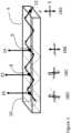
- FIG. 1describes an architecture according to an aspect of this invention.
- the waveguide 4has facets 6, 8 and 10 (only three depicted for clarity).
- Polarized Light ray 12is injected into the waveguide and propagates while being reflected in the waveguide by TIR. As the ray passes through the facets (marked as circular dots), part of the light is reflected and coupled-out of the substrate, illustrated here as ray 14 from facet 6, ray 15 from facet 8 and ray 16 from facet 10.
- Ray 12 and the resulting coupled-out rays 14-16represent a single ray of a collimated image which includes differently angled rays for each pixel of the image, but the same principles apply to each.
- Polarization schemes 18A-18Dshow the polarization orientation of the light as observed from the propagating ray.
- 18Ashow the injected ray P polarization that is vertical to the reflecting waveguide faces where S is polarization horizontal to the waveguide (in this example has no energy). Since only one polarization is exited (P as shown by the double-headed arrow in 18A), this polarization will be maintained during TIR propagation in waveguide 4.
- Scheme 18Bshows the ray's P polarization as it impinges on facet 6 (double-headed arrow) and the dashed line represents schematically the structural polarizer reflecting axis on facet 6 as viewed along the direction of propagation.
- the reflecting axis of facet 6was perpendicular to the polarization of ray P then no light would be reflected out as ray 14, however the reflecting axis (dashed line in 18B) is deliberately slightly tilted (rotated).
- the tilting angledetermines the amount of light coupled out of the waveguide as 14, in a proportion approximating to the sine of the tilt angle.
- Light ray 15is generated with an intensity dictated by the component of polarization of the impinging light (the ellipse) parallel to the structural polarizer reflection axis (dashed line), which is perpendicular to the primary polarization transmission axis.
- the ellipsecomponent of polarization of the impinging light
- the structural polarizer reflection axisdashed line
- the periodic twist of the structural polarizerlimits the drift of the polarization of the propagating light ray and consequently enables uniform light extraction along the waveguide and more efficient extraction of light energy toward the observer.
- the material of the waveguidemay advantageously be uniform and isotropic so no birefringence exists and less polarization deviations are introduced to the light rays.
- these deviationsare filtered out, since every facet out-couples the energy that deviated (by TIR or other), forcing the transmitted light into a plane-polarized configuration according to the axes of the structural polarizer.
- an additional facet 20is introduced having a structural polarizer axis parallel to that of the waveguide 24.
- This additional polarizing facetcan be at any angle (not necessarily reflecting the deviated light to the observer) and can be incorporated in systems not according to the invention where the reflecting facets are dielectric without any structural polarizer.
- Figure 3shows the same architecture as in Figure 1 but with the injection of S polarization and appropriate rotation of the structural polarizer reflection axis.
- the structural polarizeris tilted once again (preferable to a larger angle than 30B and can be in either direction).
- the processrepeats itself in 30E and 30F.
- the polarizationis stabilized and remains constant between the orthogonally-polarizing facet and the subsequent facet.
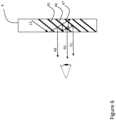
- the structural polarizeralso reflects ambient light, which may in some cases lead to problematic effects, as described in Figure 5A .
- the waveguide 4guides the injected light 12 and the facets transmit the light onto the eye of the observer 32 as previously described.
- a light source from the scenery 34illuminates the waveguide with un-polarized light 36 that will be split by the structural polarizer to two polarizations, one that will be transmitted directly as ray 38 and the perpendicular component which will be reflected before being transmitted as ray 40.
- Figure 5Billustrates an approach for addressing this problem according to an embodiment of the present invention by introducing a polarizer 42 deployed parallel to the outer surface of the LOE for the outside "world".
- the transmission orientation of the polarizeris parallel to the average orientation of the structural polarizer transmission axes, so that reflected polarized ray 40 will be substantially attenuated.
- the axis of the external polarizer 42is preferably chosen to be oriented according to an average of the axes of the facets as projected onto the outer major surface of the light-guide, thereby minimizing misalignment between the axes of the facets and the axis of the external polarizer.
- Figure 6illustrates a configuration according to an embodiment of the present invention with increased image uniformity.
- the facetsare overlapping (for example 45, 46 and 47) with the result that some of the light reflected by these facets will be reflected by the adjacent facet before being reflected out.
- Ray 12propagates within waveguide 4 having a predefined polarization (marked as a dotted line). As it impinges on facet 45, the perpendicular polarization component (marked as a solid line) is reflected directly outward as ray 48. As ray 12 continues to propagate, it impinges on facet 46. The reflection from this facet impinges on the adjacent facet 45, and then reflects once more by 46 before coupling out as 50. The same process generates ray 51.
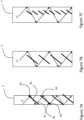
- Figures 7Ashow the propagation of ray 12 within waveguide 4 in a case where the angles of the facets to the waveguide axes are shallower than the angles of the light rays. This results in a geometry in which ray can pass through the facet at opposite angle 60 and pass the same facet at positive angle 62. Same process exist in 64 and 66. Passing the same facet twice may be a source of non-uniformity in the propagating illumination. Furthermore, if the transmission of the structural polarizer is not high (for example, due to absorptive losses), the multiple transitions through the facets will degrade light power.
- Figure 7Bshows a modified architecture where the facets do not extend across the waveguide width. Consequently, the cases of facet double pass are substantially reduced and the passes through the facets (and therefore the structural polarizer) are reduced resulting in more uniform illumination and less attenuation.
- Figure 7Cshows a narrow section with facets to further improve transmission and improve uniformity.
- the facetsmay span less than half, and in some cases less than a third, and in the example shown here, less than a quarter, of the overall thickness of the light guide between the major parallel surfaces.
- the spacing between the facetsis preferably small therefore further reducing the visibility of the non-uniformity to the observer.
- the distance between adjacent facets measured along the direction of propagation parallel to the major surfaces of the light guidemay be no more than 2 mm, and in certain particularly preferred cases, no more than 1 mm.
- the facetsdo not extend to the major surfaces of the substrate, but rather are included in an intermediate layer.
- the margins described in 7B and 7Ccan be generated by attaching a transparent bank to the side (or both sides) of the configuration described in 7A.
- a hybrid facet systememploying a combination of facets with structural polarizers and facets with partially-reflective dielectric coatings, may in some cases combine the advantages of the two technologies and thereby improve uniformity, energy extraction and transmittance.
- the waveguide 60incorporates structural polarizer facets 62 (designated by a single line) and dielectric facets 64 (designated by a double line). As beam 12 propagates within the waveguide, both facets reflect the light toward the observer.
- Figure 8Bshows a configuration that is simple to produce where the dielectric facets are in section 68 and the structural polarizer facets are in section 70.
- the two types of facetsmay be parallel to each other, or may be coplanar as illustrated.
- the second set of (dielectric) facetsmay be differently oriented from the structural polarizer facets, to achieve two-dimensional aperture expansion, for example, according to the teachings of PCT application no. PCT/IL2018/050701 (which does not constitute prior art to this application).
- the structural polarizer facets architecturecan be implemented in either a 1D waveguide, i.e., where the light is guided in 1 dimension by a single pair of parallel major surfaces, or in a 2D waveguide, i.e., where the light is guided by two pairs of orthogonal surfaces, by four-fold internal reflection.
- the waveguide mediumitself can be designed to introduce birefringence and thereby rotate incident polarized light.
- Figure 9shows schematically such an architecture.
- the waveguide 204is rendered birefringent, for example, by stress applied during production or by attaching a birefringent film to its plane face.
- the birefringence axis of the waveguideis shown as a dash-dotted line.
- the lightis injected into the waveguide at some offset from this axis, as shown in 218A.
- the waveguide birefringence and TIRrotate the polarization to be elliptical as shown in 218B.
- the amount of polarization rotationcan be managed by the amount of waveguide birefringence relative to the TIR expected rotation.
- the structural polarizer reflector 206has a tilted polarization reflection axis orientation as shown by the dotted line. As a result, after transmission, the polarization is as shown in 219B after coupling-out of the orthogonal polarization as ray 214.
- the LOEis intended for use as part of a display, typically a head-up display, which is preferably a near-eye display, such as a head-mounted display or glasses-frame supported display, for providing an image to an eye of an observer.
- the displaypreferably includes an image projector generating a collimated image, which is optically coupled to the LOE so as to introduce the collimated image into the light-guide optical element so as to propagate by internal reflection within the light-guide optical element, and being gradually coupled-out by the internal selectively-reflective surfaces to direct the image towards the eye of the observer.
Landscapes
- Physics & Mathematics (AREA)
- General Physics & Mathematics (AREA)
- Optics & Photonics (AREA)
- Polarising Elements (AREA)
- Optical Elements Other Than Lenses (AREA)
- Optical Integrated Circuits (AREA)
- Optical Couplings Of Light Guides (AREA)
Description
- The present invention relates to display systems and, in particular, it concerns a light-guide optical element suitable for use in a display.
- Certain display technologies, particularly suitable for head-up displays such as near-eye displays for virtual reality and augmented reality applications, employ a light-guide optical element, also referred to as a "waveguide", with a series of internal oblique mutually-parallel partially-reflecting planes (or "facets"). An image projector is optically coupled to the waveguide and injects light corresponding to a collimated image into the waveguide so as to propagate along the waveguide by internal reflection and to be progressively coupled out of the waveguide towards the observer's eye by reflection at the sequence of facets, thereby expanding the effective aperture optical aperture opposite the eye compared to the projector's output aperture.
- Reflectivity of the facets is sensitive to polarization and angle. Dielectric coatings are typically used to generate a desired reflectivity pattern.
- As the light propagates within the waveguide, it is reflected by the external faces at angles of Total Internal Reflection (TIR). This type of reflection generates a phase change between the S polarization and the P polarization. Consequently light propagating at S or P polarization will maintain its polarization, while combined polarization (diagonal or elliptical) having components of both polarizations, will change orientation.
US9977244 US2010201953 discloses a display system includes and image-guiding substrate with input and/or output structures configured to improve image quality.US8848289 discloses an eyepiece for a HMD that includes a waveguide, an ambient light polarizer, and a wire grid polarizer with a diffraction lens having a lens function patterned into the wire grid polarizer- The present invention is a light-guide optical element according to the appended claim 1 or claim 2. Further developments are defined the dependent claims.
- The invention is herein described, by way of example only, with reference to the accompanying drawings, wherein:
FIG. 1 is a schematic representation of a light-guide optical element (LOE) used in a display system, constructed and operative according to the teachings of an aspect of the present invention, illustrating the progression of polarization in a ray passing through a sequence of structural polarizer internal facets;FIG. 2 is a schematic representation similar toFIG. 1 , showing the addition of a polarization conditioning internal facet at the beginning of the LOE;FIG. 3 is a schematic representation similar toFIG. 1 , illustrating a case of injection of an S-polarized coupled-in image;FIG. 4 is a schematic representation similar toFIG. 1 , illustrating addition of on-axis structural polarizers to further stabilize polarization of light passing along the LOE;FIG. 5A is a schematic side view illustrating secondary ray paths along which an observer can observe a real-world object, thereby presenting a risk of a ghost image;FIG. 5B is a view similar toFIG. 5A illustrating use of an external polarizer to attenuate the secondary ray paths ofFIG. 5A according to an aspect of the present invention;FIG. 6 is a schematic side view illustrating an LOE according to an aspect of the present invention employing overlapping facets;FIG. 7A is a schematic side view illustrating an implementation of an LOE according to the teachings of the present invention in which relatively shallow-angle facets and higher-angle rays may lead to a ray path undergoing more than one pass through a single facet;FIGS. 7B and 7C are two views similar toFIG. 7A illustrating localization of the structural polarizer reflective surfaces within a layer of the LOE spaced from the major surfaces of the LOE;FIGS. 8A and 8B are schematic side views of LOEs according to the teachings of a further aspect of the present invention integrating structural polarizer internal surfaces with multilayer dielectric-coating partially-reflective internal surfaces within a single LOE, in interleaved and coplanar configurations, respectively; andFIG. 9 is a schematic view similar toFIG. 1 illustrating the progression of polarization in a ray passing along a birefringent waveguide through a sequence of structural polarizer internal facets with the same orientation.- The present invention is a light-guide optical element (LOE) and corresponding display systems employing such LOEs.
- The principles and operation of LOEs according to the present invention may be better understood with reference to the drawings and the accompanying description.
- Before addressing the drawings, in general terms, a light-guide optical element according to an aspect of the present invention includes a transparent substrate having at least two parallel major external surfaces for guiding light within the substrate by internal reflection at the external surfaces. Deployed within the substrate are a plurality of mutually parallel internal surfaces, which are non-parallel to the major external surfaces. At least part of each of the internal surfaces is provided with a structural polarizer having a primary polarization transmission axis. The structural polarizer is substantially transparent (more than 90% transmission) to light polarized parallel to the primary polarization transmission axis, and is at least partially reflective to light polarized perpendicular to the primary polarization transmission axis. By suitable orientation of the polarization axis of successive internal surfaces together with the polarization mixing properties of TIR and/or use of birefringent materials, it is possible to achieve the desired proportion of coupling-out of the image illumination from each successive facet.
- The embodiments of the present invention employ an Orientation Sensitive Polarization Reflector (or "structural polarizer") that transmits one incident polarization and reflects the orthogonal polarization according the reflector's inherent axis orientation. Examples of such structural polarizers include wire-grid film (for example commercially available from Moxtek Inc. of Utah, USA) where the orientation of the wires determines the reflected polarization. Another example of a structural polarizer is a birefringent dielectric coating or film commercially available from the 3M Company of Minnesota, USA. The "structural polarizer" terminology of the present invention is not limited to these examples, and refers generically to any and all polarization-selective element which has anisotropic optical properties such that plane-polarized light incident with its electric field vector parallel to a first axis is primarily/majority reflected and plane-polarized light incident with its electric field vector perpendicular to the first axis is primarily/majority transmitted. Most preferably, the transmitted polarization exhibits more than 90% transmission (referred to as "substantially transparent"), and most preferably over 95% transmission. Conversely, the reflected polarization in certain implementations is "substantially completely reflective" (exhibiting more than 90% reflection), and most preferably over 95% reflection. In certain preferred cases, separation between the two polarization axes is substantially complete, with less than 1% of the transmitted polarization being reflected, and less than 1% of the reflected polarization being transmitted. A mixed polarization, or a plane-polarized beam with a plane of polarization at an intermediate angle relative to the principle axes will be resolved into components parallel and perpendicular to the first axis, and will be partially reflected and partially transmitted in proportions corresponding to the cosine of the angle to the corresponding axis.
- In an alternative set of implementations, the reflectivity of the structural polarizer can be modified for example by changing the conductivity of the wire-grid, the dielectric coating parameters or by rotation of its axis relative to the impinging light polarization. For example, a wire-grid polarizer adjusted in this manner may continue to transmit P polarization but may have a reduced reflectivity for S polarization reduced to a chosen value, such as for example, 80% or 50%, with the remaining S polarization being transmitted. This adds an additional degree of freedom to system design. For example, it would be possible to have the same orientation of some or all of the facets, and then adjust the proportion of S polarization coupled out by using successively increasing reflectivity from facet to facet.
- According to an aspect of the present invention, a structural polarizer is used as the reflecting mechanism of the facets where its axis differs from the axis of the waveguide, i.e., being non-parallel and non-perpendicular to the major surfaces of the substrate. Implementation of the structural polarizer on the facet can be by application of a film or by direct coating. The sequence of facets are preferably constructed by forming a stack of plates bonded together with suitable films or coatings at their interfaces, and then cutting and polishing the stack at an appropriate angle to form the internal facets, optionally with additional facing layers and/or other layers sandwiching the layer with the internal surfaces (as exemplified below).
Figure 1 describes an architecture according to an aspect of this invention. Thewaveguide 4 hasfacets Light ray 12 is injected into the waveguide and propagates while being reflected in the waveguide by TIR. As the ray passes through the facets (marked as circular dots), part of the light is reflected and coupled-out of the substrate, illustrated here asray 14 fromfacet 6,ray 15 fromfacet 8 andray 16 fromfacet 10.Ray 12 and the resulting coupled-out rays 14-16 represent a single ray of a collimated image which includes differently angled rays for each pixel of the image, but the same principles apply to each.Polarization schemes 18A-18D show the polarization orientation of the light as observed from the propagating ray. 18A show the injected ray P polarization that is vertical to the reflecting waveguide faces where S is polarization horizontal to the waveguide (in this example has no energy). Since only one polarization is exited (P as shown by the double-headed arrow in 18A), this polarization will be maintained during TIR propagation inwaveguide 4.Scheme 18B shows the ray's P polarization as it impinges on facet 6 (double-headed arrow) and the dashed line represents schematically the structural polarizer reflecting axis onfacet 6 as viewed along the direction of propagation. If the reflecting axis offacet 6 was perpendicular to the polarization of ray P then no light would be reflected out asray 14, however the reflecting axis (dashed line in 18B) is deliberately slightly tilted (rotated). The tilting angle determines the amount of light coupled out of the waveguide as 14, in a proportion approximating to the sine of the tilt angle.- Most of the light energy continues to propagate within the waveguide as TIR. However since the remaining light polarization is slightly off perpendicular to the waveguide face, it will deviate further from perpendicularity with every TIR. This deviation is represented by the ellipse in 18C. Here, the propagating light ray deviates from perpendicularity to the substrate axes as it impinges on
facet 8. In order to minimize the drift from perpendicularity, in certain cases, it is preferred to tilt the structural polarizer axis of thenext facet 8 in the opposite direction from the original polarization relative tofacet 6, as shown by the dashed line in 18C relative to 18B.Light ray 15 is generated with an intensity dictated by the component of polarization of the impinging light (the ellipse) parallel to the structural polarizer reflection axis (dashed line), which is perpendicular to the primary polarization transmission axis. In other cases, there may be advantages for image uniformity if the rotation between adjacent facet polarization axes advances progressively in the same direction. - The same process described in
scheme 18C is repeated onfacet 10 and described asscheme 18D. - The periodic twist of the structural polarizer limits the drift of the polarization of the propagating light ray and consequently enables uniform light extraction along the waveguide and more efficient extraction of light energy toward the observer.
- As the light 12 propagates within the waveguide, its energy reduces. Therefore, illumination uniformity is improved by increasing the out-coupling of the facets further away from the light injection point. This is achieved by increasing the structural polarizer twisting angle from facet to facet as shown in
figure 1 . The twist of the structural polarizer (dashed line) increases from facet 6 (18B) to facet 8 (18C) to facet 10 (18D). The use of rotation of the structural polarizer relative to the preceding facet to adjust the proportion of out-coupling at each successive facet provides a particularly simple structure for fabrication, since the structural components used at each facet are essentially the same, without requiring fabrication of uniquely layered structures at each successive interface. - In certain implementations, the material of the waveguide may advantageously be uniform and isotropic so no birefringence exists and less polarization deviations are introduced to the light rays. However, in some cases, it may be preferable to form the waveguide of plastic, in which case some birefringence exist. According to certain implementation of the present invention, these deviations are filtered out, since every facet out-couples the energy that deviated (by TIR or other), forcing the transmitted light into a plane-polarized configuration according to the axes of the structural polarizer. In
Figure 2 , anadditional facet 20 is introduced having a structural polarizer axis parallel to that of thewaveguide 24. Consequently, any deviation introduced by material birefringence or inaccurate input coupling (represented as elliptical polarization in 24) will be coupled out and further degradation of polarization orientation is suppressed. This ensures thatfacet 6 receives the nominal polarization as described inFigure 1 . - This additional polarizing facet can be at any angle (not necessarily reflecting the deviated light to the observer) and can be incorporated in systems not according to the invention where the reflecting facets are dielectric without any structural polarizer.
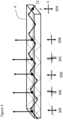
Figure 3 shows the same architecture as inFigure 1 but with the injection of S polarization and appropriate rotation of the structural polarizer reflection axis.- Further stabilization of polarization orientation can be achieved by gradual rotation of the structural polarizer relative orientation between successive facets as shown in
figure 4 . The light is injected at perpendicular polarization (herein assumed to be P polarization) and impinges on the first facet having tiltedstructural polarizer axis 30B (same as 18B). Now the polarization of the light is drifted and the next facet has structural polarizerperpendicular axis 30C. Consequently, the off-axis light is coupled out and the transmitted light is again P polarized as it impinges on thenext facet 30D (the double-headed arrow). In 30D the structural polarizer is tilted once again (preferable to a larger angle than 30B and can be in either direction). The process repeats itself in 30E and 30F. By returning intermittently to polarization parallel to the axes of the substrate, the polarization is stabilized and remains constant between the orthogonally-polarizing facet and the subsequent facet. - Other structural polarizer axis twisting profiles are also possible including maintaining constant angular twist that simplifies production. Where sufficient birefringence exists, it may be possible to employ a sequence of polarizer facets with the same orientation (zero rotation) and relying upon mixing of polarization due to the birefringence between successive facets, as discussed further below.
- The structural polarizer also reflects ambient light, which may in some cases lead to problematic effects, as described in
Figure 5A . Thewaveguide 4 guides the injectedlight 12 and the facets transmit the light onto the eye of theobserver 32 as previously described. A light source from thescenery 34 illuminates the waveguide with un-polarized light 36 that will be split by the structural polarizer to two polarizations, one that will be transmitted directly asray 38 and the perpendicular component which will be reflected before being transmitted asray 40. - Although the two transmitted
rays object 34 is near.Figure 5B illustrates an approach for addressing this problem according to an embodiment of the present invention by introducing apolarizer 42 deployed parallel to the outer surface of the LOE for the outside "world". The transmission orientation of the polarizer is parallel to the average orientation of the structural polarizer transmission axes, so that reflectedpolarized ray 40 will be substantially attenuated. In cases in which the rotation of the structural polarizer axes between successive facets are progressively in the same direction, the axis of theexternal polarizer 42 is preferably chosen to be oriented according to an average of the axes of the facets as projected onto the outer major surface of the light-guide, thereby minimizing misalignment between the axes of the facets and the axis of the external polarizer. Figure 6 illustrates a configuration according to an embodiment of the present invention with increased image uniformity. The facets are overlapping (for example 45, 46 and 47) with the result that some of the light reflected by these facets will be reflected by the adjacent facet before being reflected out.Ray 12 propagates withinwaveguide 4 having a predefined polarization (marked as a dotted line). As it impinges onfacet 45, the perpendicular polarization component (marked as a solid line) is reflected directly outward asray 48. Asray 12 continues to propagate, it impinges onfacet 46. The reflection from this facet impinges on theadjacent facet 45, and then reflects once more by 46 before coupling out as 50. The same process generatesray 51.- It should be noted that these multiple reflections occur in the rays which have already been deflected once for coupling-out of the substrate. These rays are only a small proportion of the overall light energy propagating along the light guide, but have primarily transverse polarization so that they are efficiently reflected to undergo multiple reflections. This maximizes the "mixing" effect to enhance uniformity of the image without disrupting the propagating ray (12), which might result in distorting the propagating image.
Figures 7A show the propagation ofray 12 withinwaveguide 4 in a case where the angles of the facets to the waveguide axes are shallower than the angles of the light rays. This results in a geometry in which ray can pass through the facet atopposite angle 60 and pass the same facet atpositive angle 62. Same process exist in 64 and 66. Passing the same facet twice may be a source of non-uniformity in the propagating illumination. Furthermore, if the transmission of the structural polarizer is not high (for example, due to absorptive losses), the multiple transitions through the facets will degrade light power.Figure 7B shows a modified architecture where the facets do not extend across the waveguide width. Consequently, the cases of facet double pass are substantially reduced and the passes through the facets (and therefore the structural polarizer) are reduced resulting in more uniform illumination and less attenuation.Figure 7C shows a narrow section with facets to further improve transmission and improve uniformity. By way of one non-limiting example, the facets may span less than half, and in some cases less than a third, and in the example shown here, less than a quarter, of the overall thickness of the light guide between the major parallel surfaces. In this case the spacing between the facets is preferably small therefore further reducing the visibility of the non-uniformity to the observer. For example, in the context of a near-eye display, the distance between adjacent facets measured along the direction of propagation parallel to the major surfaces of the light guide may be no more than 2 mm, and in certain particularly preferred cases, no more than 1 mm.- In the preferred but non-limiting examples of
FIGS. 7B and 7C , the facets do not extend to the major surfaces of the substrate, but rather are included in an intermediate layer. The margins described in 7B and 7C can be generated by attaching a transparent bank to the side (or both sides) of the configuration described in 7A. - A hybrid facet system, employing a combination of facets with structural polarizers and facets with partially-reflective dielectric coatings, may in some cases combine the advantages of the two technologies and thereby improve uniformity, energy extraction and transmittance. In
Figure 8A , thewaveguide 60 incorporates structural polarizer facets 62 (designated by a single line) and dielectric facets 64 (designated by a double line). Asbeam 12 propagates within the waveguide, both facets reflect the light toward the observer. Figure 8B shows a configuration that is simple to produce where the dielectric facets are insection 68 and the structural polarizer facets are insection 70. The two types of facets may be parallel to each other, or may be coplanar as illustrated. In an alternative set of implementations, the second set of (dielectric) facets may be differently oriented from the structural polarizer facets, to achieve two-dimensional aperture expansion, for example, according to the teachings of PCT application no.PCT/IL2018/050701 - A range of different structures and implementations can be implemented using this hybrid configuration:
- 1) Both the structural polarizer facets and the dielectric partial reflector facets reflect the S polarization.
- 2) The dielectric facets reflect the S polarization and the structural polarizer are oriented to reflect the P polarization.
- 3) The dielectric partially-reflecting facets may be identical (having a constant reflectivity) along the LOE, while variation of the structural polarizer axes angles is used to provide the required variation in overall coupling-out proportions across the LOE. This significantly reduces the production cost of the LOE.
- 4) Using plastic as the primary material for the light guide (uncontrolled birefringence) where the structural polarizer acts as a polarization stabilizer.
- 5) Overlapping facets with minimal multipath: by alternating structural polarizer and dielectric-coated facets along the waveguide, close overlap of the facets can be achieved while minimizing the cases of a coupled-out ray encountering an adjacent structural polarizer facet before exiting the LOE.
- The structural polarizer facets architecture can be implemented in either a 1D waveguide, i.e., where the light is guided in 1 dimension by a single pair of parallel major surfaces, or in a 2D waveguide, i.e., where the light is guided by two pairs of orthogonal surfaces, by four-fold internal reflection.
- As mentioned above, the waveguide medium itself can be designed to introduce birefringence and thereby rotate incident polarized light.
Figure 9 shows schematically such an architecture. Thewaveguide 204 is rendered birefringent, for example, by stress applied during production or by attaching a birefringent film to its plane face. In this example, the birefringence axis of the waveguide is shown as a dash-dotted line. The light is injected into the waveguide at some offset from this axis, as shown in 218A. As it propagates, the waveguide birefringence and TIR rotate the polarization to be elliptical as shown in 218B. The amount of polarization rotation can be managed by the amount of waveguide birefringence relative to the TIR expected rotation. Thestructural polarizer reflector 206 has a tilted polarization reflection axis orientation as shown by the dotted line. As a result, after transmission, the polarization is as shown in 219B after coupling-out of the orthogonal polarization asray 214. - In this case, it is possible to work with structural polarizers that are set at the same polarization axis angle (orientation) along part or all of the waveguide, so the above process repeats itself with regard to
structural polarizers - Although only the LOE structure is illustrated in most of the drawings, it will be understood that the LOE is intended for use as part of a display, typically a head-up display, which is preferably a near-eye display, such as a head-mounted display or glasses-frame supported display, for providing an image to an eye of an observer. In all such cases, the display preferably includes an image projector generating a collimated image, which is optically coupled to the LOE so as to introduce the collimated image into the light-guide optical element so as to propagate by internal reflection within the light-guide optical element, and being gradually coupled-out by the internal selectively-reflective surfaces to direct the image towards the eye of the observer.
Claims (13)
- A light-guide optical element comprising:(a) a transparent substrate (4, 204, 60, 66) configured to receive polarized light (12) and having at least two parallel major external surfaces for guiding light within the substrate by internal reflection at said external surfaces; and(b) a plurality of mutually parallel internal surfaces (6, 8, 10, 20, 206, 208, 210) deployed within said substrate non-parallel to said major external surfaces, at least part of each of said internal surfaces comprising a structural polarizer having a primary polarization transmission axis, said structural polarizer being substantially transparent to light polarized parallel to said primary polarization transmission axis and being at least partially reflective to light polarized perpendicular to said primary polarization transmission axis,wherein said primary polarization transmission axis is rotated by an acute angle for each successive internal surface (6, 8, 10, 20, 206, 208, 210) relative to a preceding one of said internal surfaces (6, 8, 10, 20, 206, 208, 210)characterized in that said primary polarization transmission axis of said structural polarizer is rotated in a first direction between a first of said internal surfaces (6, 8, 10, 20, 206, 208, 210) and a subsequent one of said internal surfaces (6, 8, 10, 20, 206, 208, 210), and is rotated in a second direction, opposite to said first direction, between said subsequent one of said internal surfaces (6, 8, 10, 20, 206, 208, 210) and a further subsequent one of said internal surfaces (6, 8, 10, 20, 206, 208, 210).wherein said structural polarizer is substantially fully reflective to light polarized perpendicular to said primary polarization transmission axis,
wherein said primary polarization transmission axis of said structural polarizer is rotated through a first angle between a first of said internal surfaces (6, 8, 10, 20, 206, 208, 210) and a subsequent one of said internal surfaces (6, 8, 10, 20, 206, 208, 210), and is rotated through a second angle, greater than said first angle, between said subsequent one of said internal surfaces (6, 8, 10, 20, 206, 208, 210) and a further subsequent one of said internal surfaces (6, 8, 10, 20, 206, 208, 210). - A light-guide optical element comprising:(a) a transparent substrate (4, 204, 60, 66) configured to receive polarized light (12) and having at least two parallel major external surfaces for guiding light within the substrate by internal reflection at said external surfaces; and(b) a plurality of mutually parallel internal surfaces (6, 8, 10, 20, 206, 208, 210) deployed within said substrate non-parallel to said major external surfaces, at least part of each of said internal surfaces comprising a structural polarizer having a primary polarization transmission axis, said structural polarizer being substantially transparent to light polarized parallel to said primary polarization transmission axis and being at least partially reflective to light polarized perpendicular to said primary polarization transmission axis,characterized in that said primary polarization transmission axis is parallel for at least two successive internal surfaces of said plurality of said internal surfaces (6, 8, 10, 20, 206, 208, 210) and tilted at an acute angle relative to the p- and s-axes for said internal surfaces, wherein the p axis is vertical to the major external surfaces and the s axis is horizontal to the major external surfaces.
- The light-guide optical element of any preceding claim, wherein at least part of said substrate (204) is formed from a material exhibiting birefringence.
- The light-guide optical element of any preceding claim, wherein said substrate (4, 204, 60, 66) has a thickness measured between said major external surfaces, and wherein said structural polarizer extends across less than an entirety of said thickness.
- The light-guide optical element of claim 4, wherein said structural polarizer spans less than half of said thickness.
- The light-guide optical element of claim 4, wherein said structural polarizer does not extend to either of said major external surfaces.
- The light-guide optical element of any preceding claim, further comprising an additional set of mutually parallel internal surfaces (62, 64) deployed within said substrate non-parallel to said major external surfaces, at least part of each surface of said additional set of internal surfaces comprising a multilayer partially-reflective dielectric coating.
- The light-guide optical element of claim 7, wherein said additional set of internal surfaces (64) are parallel with said plurality of internal surfaces.
- The light-guide optical element of claim 8, wherein said additional set of internal surfaces (64) are interleaved with said plurality of internal surfaces (62).
- The light-guide optical element of claim 7, wherein a thickness of said substrate (66) is subdivided into a first layer (68) and a second layer, and wherein said plurality of internal surfaces are located within said first layer and said additional set of internal surfaces are located within said second layer (70).
- The light-guide optical element of claim 2, wherein the transparent substrate (4, 204, 60, 66) is configured to introduce birefrigerence such that as the light propagates while being reflected in the transparent substrate by total internal reflection, due to the waveguide birefrigerence and the total internal reflection the polarization is rotated to be elliptical.
- A display for providing an image to an eye of an observer comprising:(a) the light-guide optical element of any preceding claim; and(b) an image projector generating a collimated image of polarized light, said image projector being optically coupled to said light-guide optical element so as to introduce the collimated image into the light-guide optical element so as to propagate by internal reflection within the light-guide optical element,wherein said plurality of internal surfaces (6, 8, 10, 20, 206, 208, 210) are oriented to couple out part of the collimated image towards the eye of the observer.
- The display of claim 12, further comprising an absorbent polarizer deployed on a side of said substrate further from the observer, said absorbent polarizer having an axis of polarization aligned with an average direction of said primary polarization transmission axes of said structural polarizers.
Priority Applications (1)
| Application Number | Priority Date | Filing Date | Title |
|---|---|---|---|
| EP23204171.5AEP4365645A3 (en) | 2018-07-16 | 2019-07-16 | Light-guide optical element employing polarized internal reflectors |
Applications Claiming Priority (2)
| Application Number | Priority Date | Filing Date | Title |
|---|---|---|---|
| US201862698300P | 2018-07-16 | 2018-07-16 | |
| PCT/IB2019/056057WO2020016772A1 (en) | 2018-07-16 | 2019-07-16 | Light-guide optical element employing polarized internal reflectors |
Related Child Applications (1)
| Application Number | Title | Priority Date | Filing Date |
|---|---|---|---|
| EP23204171.5ADivisionEP4365645A3 (en) | 2018-07-16 | 2019-07-16 | Light-guide optical element employing polarized internal reflectors |
Publications (3)
| Publication Number | Publication Date |
|---|---|
| EP3824335A1 EP3824335A1 (en) | 2021-05-26 |
| EP3824335A4 EP3824335A4 (en) | 2021-09-22 |
| EP3824335B1true EP3824335B1 (en) | 2023-10-18 |
Family
ID=69164761
Family Applications (2)
| Application Number | Title | Priority Date | Filing Date |
|---|---|---|---|
| EP19838528.8AActiveEP3824335B1 (en) | 2018-07-16 | 2019-07-16 | Light-guide optical element employing polarized internal reflectors |
| EP23204171.5AWithdrawnEP4365645A3 (en) | 2018-07-16 | 2019-07-16 | Light-guide optical element employing polarized internal reflectors |
Family Applications After (1)
| Application Number | Title | Priority Date | Filing Date |
|---|---|---|---|
| EP23204171.5AWithdrawnEP4365645A3 (en) | 2018-07-16 | 2019-07-16 | Light-guide optical element employing polarized internal reflectors |
Country Status (8)
| Country | Link |
|---|---|
| US (4) | US11409103B2 (en) |
| EP (2) | EP3824335B1 (en) |
| JP (1) | JP7411255B2 (en) |
| KR (2) | KR102786034B1 (en) |
| CN (1) | CN112424670B (en) |
| IL (1) | IL279943B2 (en) |
| TW (1) | TWI830753B (en) |
| WO (1) | WO2020016772A1 (en) |
Families Citing this family (47)
| Publication number | Priority date | Publication date | Assignee | Title |
|---|---|---|---|---|
| US10261321B2 (en) | 2005-11-08 | 2019-04-16 | Lumus Ltd. | Polarizing optical system |
| IL232197B (en) | 2014-04-23 | 2018-04-30 | Lumus Ltd | Compact head-mounted display system |
| IL237337B (en) | 2015-02-19 | 2020-03-31 | Amitai Yaakov | Compact head-mounted display system having uniform image |
| CN110431467A (en) | 2017-01-28 | 2019-11-08 | 鲁姆斯有限公司 | Augmented reality imaging system |
| EP4215980A1 (en) | 2017-07-19 | 2023-07-26 | Lumus Ltd. | Lcos illumination via loe |
| US11513352B2 (en) | 2017-09-29 | 2022-11-29 | Lumus Ltd. | Augmented reality display |
| WO2019077614A1 (en) | 2017-10-22 | 2019-04-25 | Lumus Ltd. | ENHANCED REALITY DEVICE MOUNTED ON THE HEAD AND USING AN OPTICAL BENCH |
| CN111417883B (en) | 2017-12-03 | 2022-06-17 | 鲁姆斯有限公司 | Optical equipment alignment method |
| KR20200102408A (en) | 2018-01-02 | 2020-08-31 | 루머스 리미티드 | Augmented Reality Display with Active Alignment and Corresponding Method |
| US10551544B2 (en) | 2018-01-21 | 2020-02-04 | Lumus Ltd. | Light-guide optical element with multiple-axis internal aperture expansion |
| MY203244A (en) | 2018-04-08 | 2024-06-19 | Lumus Ltd | Optical sample characterization |
| KR102752134B1 (en) | 2018-05-14 | 2025-01-08 | 루머스 리미티드 | Projector configuration with sub-optical aperture for near-eye display and corresponding optical system |
| IL278511B2 (en) | 2018-05-17 | 2025-01-01 | Lumus Ltd | Near-eye display having overlapping projector assemblies |
| IL259518B2 (en) | 2018-05-22 | 2023-04-01 | Lumus Ltd | Optical system and method for improvement of light field uniformity |
| MX2020012512A (en) | 2018-05-23 | 2021-02-16 | Lumus Ltd | Optical system including light-guide optical element with partially-reflective internal surfaces. |
| CN119595595A (en) | 2018-06-21 | 2025-03-11 | 鲁姆斯有限公司 | Technique for measuring refractive index non-uniformity between plates of light-guiding optical element (LOE) |
| EP3824335B1 (en)* | 2018-07-16 | 2023-10-18 | Lumus Ltd. | Light-guide optical element employing polarized internal reflectors |
| CN112601993A (en) | 2018-08-26 | 2021-04-02 | 鲁姆斯有限公司 | Reflection suppression in near-eye displays |
| CN116184666A (en) | 2018-09-09 | 2023-05-30 | 鲁姆斯有限公司 | Optical system comprising a light-guiding optical element with two-dimensional expansion |
| US11947130B2 (en) | 2018-11-08 | 2024-04-02 | Lumus Ltd. | Optical devices and systems with dichroic beamsplitter color combiner |
| TWM642752U (en) | 2018-11-08 | 2023-06-21 | 以色列商魯姆斯有限公司 | Light-guide display with reflector |
| JP3226277U (en) | 2018-11-11 | 2020-05-14 | ルムス エルティーディー. | Near eye display with intermediate window |
| MX2021008808A (en) | 2019-01-24 | 2021-08-24 | Lumus Ltd | Optical systems including loe with three stage expansion. |
| WO2020174433A1 (en) | 2019-02-28 | 2020-09-03 | Lumus Ltd. | Compact collimated image projector |
| TWI800657B (en) | 2019-03-12 | 2023-05-01 | 以色列商魯姆斯有限公司 | Image projector |
| TWI845670B (en)* | 2019-05-06 | 2024-06-21 | 以色列商魯姆斯有限公司 | Transparent lightguide for viewing a scene and a near-eye display |
| US11307347B2 (en) | 2019-05-20 | 2022-04-19 | Facebook Technologies, Llc | Display illumination using a wedge waveguide |
| US11709308B2 (en) | 2019-05-20 | 2023-07-25 | Meta Platforms Technologies, Llc | Optical waveguide beam splitter for directional illumination of display |
| CA3137994A1 (en) | 2019-06-27 | 2020-12-30 | Lumus Ltd | Apparatus and methods for eye tracking based on eye imaging via a light-guide optical element |
| WO2021105982A1 (en) | 2019-11-25 | 2021-06-03 | Lumus Ltd. | Method of polishing a surface of a waveguide |
| IL270991B (en) | 2019-11-27 | 2020-07-30 | Lumus Ltd | Lightguide optical element for polarization scrambling |
| TWI884834B (en) | 2019-12-05 | 2025-05-21 | 以色列商魯姆斯有限公司 | Optical device and method of fabricating optical device |
| US11523092B2 (en) | 2019-12-08 | 2022-12-06 | Lumus Ltd. | Optical systems with compact image projector |
| CN114787687B (en) | 2019-12-25 | 2024-07-30 | 鲁姆斯有限公司 | Systems and methods for eye tracking based on redirection of light from the eye using an optical arrangement associated with a light guide optical element |
| WO2021220267A1 (en) | 2020-04-30 | 2021-11-04 | Lumus Ltd. | Optical sample characterization |
| CN218848473U (en) | 2020-05-12 | 2023-04-11 | 鲁姆斯有限公司 | Equipment including projection optics and light guides |
| AU2021279462B2 (en)* | 2020-05-24 | 2023-06-08 | Lumus Ltd. | Method of fabrication of compound light-guide optical elements |
| AU2021331833A1 (en) | 2020-08-23 | 2023-03-09 | Lumus Ltd. | Optical system for two-dimensional expansion of an image reducing glints and ghosts from the waveguide |
| DE202021104723U1 (en) | 2020-09-11 | 2021-10-18 | Lumus Ltd. | Image projector coupled to an optical light guide element |
| KR20230148324A (en)* | 2021-03-01 | 2023-10-24 | 루머스 리미티드 | Optical system with compact coupling from projector to waveguide |
| KR102676604B1 (en) | 2021-07-04 | 2024-06-18 | 루머스 리미티드 | Display with stacked light guiding elements providing different parts of the field of view |
| US20240094552A1 (en)* | 2022-05-18 | 2024-03-21 | Meta Platforms Technologies, Llc | Geometrical waveguide with partial-coverage beam splitters |
| JPWO2024004287A1 (en)* | 2022-06-29 | 2024-01-04 | ||
| IL318902A (en)* | 2022-09-04 | 2025-04-01 | Lumus Ltd | Lightguide-based display with light recirculation |
| GB202217444D0 (en)* | 2022-11-22 | 2023-01-04 | Vividq Ltd | Reflective image replicating waveguide |
| CN120202432A (en)* | 2022-12-22 | 2025-06-24 | 元平台技术有限公司 | Light guide with polarization selective volume reflector |
| WO2025052392A1 (en)* | 2023-09-10 | 2025-03-13 | Lumus Ltd. | Optical system for conveying an image to an eye of a viewer |
Family Cites Families (104)
| Publication number | Priority date | Publication date | Assignee | Title |
|---|---|---|---|---|
| JPH0827471B2 (en)* | 1984-09-14 | 1996-03-21 | キヤノン株式会社 | Method of manufacturing thin film type optical element |
| US5270748A (en) | 1992-01-30 | 1993-12-14 | Mak Technologies, Inc. | High-speed eye tracking device and method |
| JP3219943B2 (en) | 1994-09-16 | 2001-10-15 | 株式会社東芝 | Planar direct-view display device |
| JPH08313843A (en) | 1995-05-16 | 1996-11-29 | Agency Of Ind Science & Technol | Wide visual field and high resolution video presentation device in line of sight followup system |
| US6404550B1 (en) | 1996-07-25 | 2002-06-11 | Seiko Epson Corporation | Optical element suitable for projection display apparatus |
| GB2329901A (en) | 1997-09-30 | 1999-04-07 | Reckitt & Colman Inc | Acidic hard surface cleaning and disinfecting compositions |
| US6154321A (en) | 1998-01-20 | 2000-11-28 | University Of Washington | Virtual retinal display with eye tracking |
| US6231992B1 (en)* | 1998-09-04 | 2001-05-15 | Yazaki Corporation | Partial reflector |
| US20050024849A1 (en) | 1999-02-23 | 2005-02-03 | Parker Jeffery R. | Methods of cutting or forming cavities in a substrate for use in making optical films, components or wave guides |
| CA2386856A1 (en) | 1999-10-14 | 2001-04-19 | Stratos Product Development Llc | Virtual imaging system |
| ATE473464T1 (en) | 2000-06-05 | 2010-07-15 | Lumus Ltd | OPTICAL BEAM EXPANDER WITH SUBSTRATE LIGHT WAVE GUIDE |
| IL136849A (en) | 2000-06-18 | 2004-09-27 | Beamus Ltd | Optical dynamic devices particularly for beam steering and optical communication |
| IL138895A (en) | 2000-10-05 | 2005-08-31 | Elop Electrooptics Ind Ltd | Optical switching devices |
| US6542307B2 (en) | 2000-10-20 | 2003-04-01 | Three-Five Systems, Inc. | Compact near-eye illumination system |
| IL148804A (en) | 2002-03-21 | 2007-02-11 | Yaacov Amitai | Optical device |
| IL157837A (en) | 2003-09-10 | 2012-12-31 | Yaakov Amitai | Substrate-guided optical device particularly for three-dimensional displays |
| IL157838A (en) | 2003-09-10 | 2013-05-30 | Yaakov Amitai | High brightness optical device |
| IL157836A (en) | 2003-09-10 | 2009-08-03 | Yaakov Amitai | Optical devices particularly for remote viewing applications |
| IL162573A (en) | 2004-06-17 | 2013-05-30 | Lumus Ltd | Substrate-guided optical device with very wide aperture |
| IL163361A (en) | 2004-08-05 | 2011-06-30 | Lumus Ltd | Optical device for light coupling into a guiding substrate |
| CA2526604C (en)* | 2004-11-12 | 2014-01-07 | Robert B. Walker | Optical device incorporating a tilted bragg grating |
| US7724443B2 (en) | 2005-02-10 | 2010-05-25 | Lumus Ltd. | Substrate-guided optical device utilizing thin transparent layer |
| IL166799A (en) | 2005-02-10 | 2014-09-30 | Lumus Ltd | Substrate-guided optical device utilizing beam splitters |
| US10073264B2 (en) | 2007-08-03 | 2018-09-11 | Lumus Ltd. | Substrate-guide optical device |
| JP2008533507A (en) | 2005-02-10 | 2008-08-21 | ラマス リミテッド | Substrate guiding optical device especially for vision enhancement optical system |
| EP1848966A1 (en) | 2005-02-17 | 2007-10-31 | Lumus Ltd | Personal navigation system |
| US8187481B1 (en) | 2005-05-05 | 2012-05-29 | Coho Holdings, Llc | Random texture anti-reflection optical surface treatment |
| US20070155277A1 (en) | 2005-07-25 | 2007-07-05 | Avi Amitai | Mobile/portable and personal pre-recorded sound effects electronic amplifier device/gadget |
| IL171820A (en) | 2005-11-08 | 2014-04-30 | Lumus Ltd | Polarizing optical device for light coupling |
| US10261321B2 (en) | 2005-11-08 | 2019-04-16 | Lumus Ltd. | Polarizing optical system |
| EP1952189B1 (en)* | 2005-11-21 | 2016-06-01 | Microvision, Inc. | Display with image-guiding substrate |
| WO2007085682A1 (en) | 2006-01-26 | 2007-08-02 | Nokia Corporation | Eye tracker device |
| IL173715A0 (en) | 2006-02-14 | 2007-03-08 | Lumus Ltd | Substrate-guided imaging lens |
| IL174170A (en) | 2006-03-08 | 2015-02-26 | Abraham Aharoni | Device and method for binocular alignment |
| IL177618A (en) | 2006-08-22 | 2015-02-26 | Lumus Ltd | Substrate- guided optical device |
| US20080151375A1 (en) | 2006-12-26 | 2008-06-26 | Ching-Bin Lin | Light guide means as dually effected by light concentrating and light diffusing |
| US8643948B2 (en) | 2007-04-22 | 2014-02-04 | Lumus Ltd. | Collimating optical device and system |
| IL183637A (en) | 2007-06-04 | 2013-06-27 | Zvi Lapidot | Distributed head-mounted display |
| JP2009128565A (en) | 2007-11-22 | 2009-06-11 | Toshiba Corp | Display device, display method, and head-up display |
| TW201115231A (en) | 2009-10-28 | 2011-05-01 | Coretronic Corp | Backlight module |
| US20120249797A1 (en) | 2010-02-28 | 2012-10-04 | Osterhout Group, Inc. | Head-worn adaptive display |
| JP5499985B2 (en) | 2010-08-09 | 2014-05-21 | ソニー株式会社 | Display assembly |
| JP5879973B2 (en) | 2011-11-30 | 2016-03-08 | ソニー株式会社 | Light reflecting member, light beam extending device, image display device, and optical device |
| US9297996B2 (en) | 2012-02-15 | 2016-03-29 | Microsoft Technology Licensing, Llc | Laser illumination scanning |
| US8665178B1 (en) | 2012-03-01 | 2014-03-04 | Google, Inc. | Partially-reflective waveguide stack and heads-up display using same |
| US8848289B2 (en)* | 2012-03-15 | 2014-09-30 | Google Inc. | Near-to-eye display with diffractive lens |
| WO2013167864A1 (en) | 2012-05-11 | 2013-11-14 | Milan Momcilo Popovich | Apparatus for eye tracking |
| IL219907A (en) | 2012-05-21 | 2017-08-31 | Lumus Ltd | Head-mounted display eyeball tracker integrated system |
| CN104582639A (en) | 2012-05-29 | 2015-04-29 | Nlt-脊椎有限公司 | Laterally deflectable implant |
| WO2014004228A1 (en)* | 2012-06-27 | 2014-01-03 | 3M Innovative Properties Company | Optical component array |
| US8909985B2 (en) | 2012-07-12 | 2014-12-09 | International Business Machines Corporation | Multiple hyperswap replication sessions |
| CN105358906A (en) | 2013-07-02 | 2016-02-24 | 3M创新有限公司 | Flat light guide |
| WO2015012280A1 (en) | 2013-07-24 | 2015-01-29 | コニカミノルタ株式会社 | Sight line detection device |
| US9423552B2 (en)* | 2014-02-24 | 2016-08-23 | Google Inc. | Lightguide device with outcoupling structures |
| IL232197B (en) | 2014-04-23 | 2018-04-30 | Lumus Ltd | Compact head-mounted display system |
| IL235642B (en) | 2014-11-11 | 2021-08-31 | Lumus Ltd | Compact head-mounted display system protected by a hyperfine structure |
| IL236490B (en) | 2014-12-25 | 2021-10-31 | Lumus Ltd | Optical component on a conductive substrate |
| IL236491B (en) | 2014-12-25 | 2020-11-30 | Lumus Ltd | A method for fabricating substrate-guided optical device |
| IL237337B (en) | 2015-02-19 | 2020-03-31 | Amitai Yaakov | Compact head-mounted display system having uniform image |
| JP6821918B2 (en)* | 2016-02-18 | 2021-01-27 | 大日本印刷株式会社 | Light guide plate and display device |
| IL244181B (en) | 2016-02-18 | 2020-06-30 | Amitai Yaakov | Compact head-mounted display system |
| JP6740366B2 (en) | 2016-05-18 | 2020-08-12 | ルーマス リミテッドLumus Ltd. | Head mount imaging device |
| US20170353714A1 (en) | 2016-06-06 | 2017-12-07 | Navid Poulad | Self-calibrating display system |
| WO2018065975A1 (en) | 2016-10-09 | 2018-04-12 | Lumus Ltd | Aperture multiplier using a rectangular waveguide |
| KR20240160657A (en) | 2016-11-08 | 2024-11-11 | 루머스 리미티드 | Light-guide device with optical cutoff edge and corresponding production methods |
| DE212017000261U1 (en) | 2016-12-02 | 2019-08-05 | Lumus Ltd. | Optical system with compact collimator image projector |
| JP2018109738A (en)* | 2016-12-28 | 2018-07-12 | セイコーエプソン株式会社 | Optical element and display device |
| KR102296369B1 (en) | 2016-12-31 | 2021-09-01 | 루머스 리미티드 | Retinal Imaging-Based Eye Tracker with Light-Guiding Optics |
| WO2018127913A1 (en) | 2017-01-04 | 2018-07-12 | Lumus Ltd. | Optical system for near-eye displays |
| CN108738358B (en) | 2017-02-22 | 2021-03-26 | 鲁姆斯有限公司 | Light guide optics |
| EP3602175A4 (en) | 2017-03-21 | 2021-04-21 | Magic Leap, Inc. | EYE IMAGING DEVICE USING OPTICAL DIFFRACTION ELEMENTS |
| CN109416433B (en) | 2017-03-22 | 2021-06-01 | 鲁姆斯有限公司 | Overlapping Reflector Construction |
| IL251645B (en) | 2017-04-06 | 2018-08-30 | Lumus Ltd | Light-guide optical element and method of its manufacture |
| US10712567B2 (en)* | 2017-06-15 | 2020-07-14 | Microsoft Technology Licensing, Llc | Holographic display system |
| EP4215980A1 (en) | 2017-07-19 | 2023-07-26 | Lumus Ltd. | Lcos illumination via loe |
| US11513352B2 (en) | 2017-09-29 | 2022-11-29 | Lumus Ltd. | Augmented reality display |
| IL255049B (en) | 2017-10-16 | 2022-08-01 | Oorym Optics Ltd | A compact, high-efficiency head-up display system |
| WO2019077614A1 (en) | 2017-10-22 | 2019-04-25 | Lumus Ltd. | ENHANCED REALITY DEVICE MOUNTED ON THE HEAD AND USING AN OPTICAL BENCH |
| WO2019102366A1 (en) | 2017-11-21 | 2019-05-31 | Lumus Ltd. | Optical aperture expansion arrangement for near-eye displays |
| US20190170327A1 (en) | 2017-12-03 | 2019-06-06 | Lumus Ltd. | Optical illuminator device |
| CN111417883B (en) | 2017-12-03 | 2022-06-17 | 鲁姆斯有限公司 | Optical equipment alignment method |
| IL275013B (en) | 2017-12-03 | 2022-08-01 | Lumus Ltd | Method and device for testing an optics device |
| KR102704523B1 (en) | 2017-12-10 | 2024-09-06 | 루머스 리미티드 | Image projector |
| KR20200102408A (en) | 2018-01-02 | 2020-08-31 | 루머스 리미티드 | Augmented Reality Display with Active Alignment and Corresponding Method |
| US10506220B2 (en) | 2018-01-02 | 2019-12-10 | Lumus Ltd. | Augmented reality displays with active alignment and corresponding methods |
| US10551544B2 (en) | 2018-01-21 | 2020-02-04 | Lumus Ltd. | Light-guide optical element with multiple-axis internal aperture expansion |
| MY203244A (en) | 2018-04-08 | 2024-06-19 | Lumus Ltd | Optical sample characterization |
| KR102752134B1 (en) | 2018-05-14 | 2025-01-08 | 루머스 리미티드 | Projector configuration with sub-optical aperture for near-eye display and corresponding optical system |
| IL278511B2 (en) | 2018-05-17 | 2025-01-01 | Lumus Ltd | Near-eye display having overlapping projector assemblies |
| IL259518B2 (en) | 2018-05-22 | 2023-04-01 | Lumus Ltd | Optical system and method for improvement of light field uniformity |
| MX2020012512A (en) | 2018-05-23 | 2021-02-16 | Lumus Ltd | Optical system including light-guide optical element with partially-reflective internal surfaces. |
| TWM587757U (en) | 2018-05-27 | 2019-12-11 | 以色列商魯姆斯有限公司 | Substrate-guide based optical systems with field curvature effect |
| CN119595595A (en) | 2018-06-21 | 2025-03-11 | 鲁姆斯有限公司 | Technique for measuring refractive index non-uniformity between plates of light-guiding optical element (LOE) |
| US11415812B2 (en) | 2018-06-26 | 2022-08-16 | Lumus Ltd. | Compact collimating optical device and system |
| EP3824335B1 (en)* | 2018-07-16 | 2023-10-18 | Lumus Ltd. | Light-guide optical element employing polarized internal reflectors |
| TWI827663B (en) | 2018-09-06 | 2024-01-01 | 以色列商魯姆斯有限公司 | Near-eye display with laser diode illumination |
| CN116184666A (en) | 2018-09-09 | 2023-05-30 | 鲁姆斯有限公司 | Optical system comprising a light-guiding optical element with two-dimensional expansion |
| JP3226277U (en) | 2018-11-11 | 2020-05-14 | ルムス エルティーディー. | Near eye display with intermediate window |
| MX2021008808A (en)* | 2019-01-24 | 2021-08-24 | Lumus Ltd | Optical systems including loe with three stage expansion. |
| TWI845670B (en) | 2019-05-06 | 2024-06-21 | 以色列商魯姆斯有限公司 | Transparent lightguide for viewing a scene and a near-eye display |
| US20200356050A1 (en)* | 2019-05-08 | 2020-11-12 | Facebook Technologies, Llc | Spatial deposition of resins with different functionality |
| US11391950B2 (en)* | 2019-06-26 | 2022-07-19 | Meta Platforms Technologies, Llc | Techniques for controlling effective refractive index of gratings |
| CA3137994A1 (en)* | 2019-06-27 | 2020-12-30 | Lumus Ltd | Apparatus and methods for eye tracking based on eye imaging via a light-guide optical element |
| JP2022540303A (en)* | 2019-07-08 | 2022-09-15 | メタ プラットフォームズ テクノロジーズ, リミテッド ライアビリティ カンパニー | Apodized optics for optical artifact reduction |
- 2019
- 2019-07-16EPEP19838528.8Apatent/EP3824335B1/enactiveActive
- 2019-07-16CNCN201980047071.8Apatent/CN112424670B/enactiveActive
- 2019-07-16WOPCT/IB2019/056057patent/WO2020016772A1/ennot_activeCeased
- 2019-07-16USUS16/982,656patent/US11409103B2/enactiveActive
- 2019-07-16TWTW108125101Apatent/TWI830753B/enactive
- 2019-07-16EPEP23204171.5Apatent/EP4365645A3/ennot_activeWithdrawn
- 2019-07-16KRKR1020217002897Apatent/KR102786034B1/enactiveActive
- 2019-07-16KRKR1020257009113Apatent/KR20250046344A/enactivePending
- 2019-07-16JPJP2021501004Apatent/JP7411255B2/enactiveActive
- 2021
- 2021-01-04ILIL279943Apatent/IL279943B2/enunknown
- 2022
- 2022-08-08USUS17/882,897patent/US20220373810A1/ennot_activeAbandoned
- 2024
- 2024-06-13USUS18/742,121patent/US12253672B2/enactiveActive
- 2025
- 2025-01-16USUS19/024,325patent/US20250155708A1/enactivePending
Also Published As
| Publication number | Publication date |
|---|---|
| IL279943B (en) | 2022-10-01 |
| US20210033862A1 (en) | 2021-02-04 |
| US11409103B2 (en) | 2022-08-09 |
| EP4365645A3 (en) | 2024-08-14 |
| US20220373810A1 (en) | 2022-11-24 |
| KR102786034B1 (en) | 2025-03-24 |
| TW202018347A (en) | 2020-05-16 |
| JP2021531498A (en) | 2021-11-18 |
| CN112424670A (en) | 2021-02-26 |
| KR20210031705A (en) | 2021-03-22 |
| WO2020016772A1 (en) | 2020-01-23 |
| JP7411255B2 (en) | 2024-01-11 |
| KR20250046344A (en) | 2025-04-02 |
| IL279943B2 (en) | 2023-02-01 |
| US20240329395A1 (en) | 2024-10-03 |
| US12253672B2 (en) | 2025-03-18 |
| EP3824335A1 (en) | 2021-05-26 |
| US20250155708A1 (en) | 2025-05-15 |
| CN112424670B (en) | 2023-01-17 |
| TWI830753B (en) | 2024-02-01 |
| EP4365645A2 (en) | 2024-05-08 |
| EP3824335A4 (en) | 2021-09-22 |
| IL279943A (en) | 2021-03-01 |
Similar Documents
| Publication | Publication Date | Title |
|---|---|---|
| EP3824335B1 (en) | Light-guide optical element employing polarized internal reflectors | |
| KR102537642B1 (en) | LCOS lighting via LOE | |
| CA3100472C (en) | Optical system including light-guide optical element with partially-reflective internal surfaces | |
| EP3867696B1 (en) | Optical devices and systems with dichroic beamsplitter color combiner | |
| KR102561362B1 (en) | augmented reality display | |
| CN208953803U (en) | Has the optical system of compact collimated image projector | |
| CN112639592A (en) | Optical stack for privacy display | |
| TWI839640B (en) | Optical systems including light-guide optical elements for two-dimensional expansion with retarder element | |
| EP4184226A2 (en) | Liquid crystal reflective polarizer and pancake lens assembly having the same | |
| CN119522399A (en) | Light guide based displays utilizing light recycling | |
| TWI898485B (en) | Optical systems including light-guide optical elements for two-dimensional expansion with retarder element | |
| US20240210760A1 (en) | Liquid crystal display device and head mounted display |
Legal Events
| Date | Code | Title | Description |
|---|---|---|---|
| STAA | Information on the status of an ep patent application or granted ep patent | Free format text:STATUS: THE INTERNATIONAL PUBLICATION HAS BEEN MADE | |
| PUAI | Public reference made under article 153(3) epc to a published international application that has entered the european phase | Free format text:ORIGINAL CODE: 0009012 | |
| STAA | Information on the status of an ep patent application or granted ep patent | Free format text:STATUS: REQUEST FOR EXAMINATION WAS MADE | |
| 17P | Request for examination filed | Effective date:20210216 | |
| AK | Designated contracting states | Kind code of ref document:A1 Designated state(s):AL AT BE BG CH CY CZ DE DK EE ES FI FR GB GR HR HU IE IS IT LI LT LU LV MC MK MT NL NO PL PT RO RS SE SI SK SM TR | |
| A4 | Supplementary search report drawn up and despatched | Effective date:20210820 | |
| RIC1 | Information provided on ipc code assigned before grant | Ipc:G02B 5/30 20060101ALI20210816BHEP Ipc:G02B 6/26 20060101ALI20210816BHEP Ipc:G02B 6/27 20060101ALI20210816BHEP Ipc:F21V 8/00 20060101ALI20210816BHEP Ipc:G02B 27/09 20060101ALI20210816BHEP Ipc:G02B 27/01 20060101ALI20210816BHEP Ipc:G02B 27/14 20060101ALI20210816BHEP Ipc:G02B 27/00 20060101AFI20210816BHEP | |
| DAV | Request for validation of the european patent (deleted) | ||
| DAX | Request for extension of the european patent (deleted) | ||
| STAA | Information on the status of an ep patent application or granted ep patent | Free format text:STATUS: EXAMINATION IS IN PROGRESS | |
| 17Q | First examination report despatched | Effective date:20221103 | |
| GRAP | Despatch of communication of intention to grant a patent | Free format text:ORIGINAL CODE: EPIDOSNIGR1 | |
| STAA | Information on the status of an ep patent application or granted ep patent | Free format text:STATUS: GRANT OF PATENT IS INTENDED | |
| P01 | Opt-out of the competence of the unified patent court (upc) registered | Effective date:20230527 | |
| INTG | Intention to grant announced | Effective date:20230628 | |
| GRAS | Grant fee paid | Free format text:ORIGINAL CODE: EPIDOSNIGR3 | |
| GRAA | (expected) grant | Free format text:ORIGINAL CODE: 0009210 | |
| STAA | Information on the status of an ep patent application or granted ep patent | Free format text:STATUS: THE PATENT HAS BEEN GRANTED | |
| AK | Designated contracting states | Kind code of ref document:B1 Designated state(s):AL AT BE BG CH CY CZ DE DK EE ES FI FR GB GR HR HU IE IS IT LI LT LU LV MC MK MT NL NO PL PT RO RS SE SI SK SM TR | |
| REG | Reference to a national code | Ref country code:GB Ref legal event code:FG4D | |
| REG | Reference to a national code | Ref country code:CH Ref legal event code:EP | |
| REG | Reference to a national code | Ref country code:IE Ref legal event code:FG4D | |
| REG | Reference to a national code | Ref country code:DE Ref legal event code:R096 Ref document number:602019039772 Country of ref document:DE | |
| REG | Reference to a national code | Ref country code:LT Ref legal event code:MG9D | |
| REG | Reference to a national code | Ref country code:NL Ref legal event code:MP Effective date:20231018 | |
| REG | Reference to a national code | Ref country code:AT Ref legal event code:MK05 Ref document number:1622948 Country of ref document:AT Kind code of ref document:T Effective date:20231018 | |
| PG25 | Lapsed in a contracting state [announced via postgrant information from national office to epo] | Ref country code:NL Free format text:LAPSE BECAUSE OF FAILURE TO SUBMIT A TRANSLATION OF THE DESCRIPTION OR TO PAY THE FEE WITHIN THE PRESCRIBED TIME-LIMIT Effective date:20231018 | |
| PG25 | Lapsed in a contracting state [announced via postgrant information from national office to epo] | Ref country code:GR Free format text:LAPSE BECAUSE OF FAILURE TO SUBMIT A TRANSLATION OF THE DESCRIPTION OR TO PAY THE FEE WITHIN THE PRESCRIBED TIME-LIMIT Effective date:20240119 | |
| PG25 | Lapsed in a contracting state [announced via postgrant information from national office to epo] | Ref country code:IS Free format text:LAPSE BECAUSE OF FAILURE TO SUBMIT A TRANSLATION OF THE DESCRIPTION OR TO PAY THE FEE WITHIN THE PRESCRIBED TIME-LIMIT Effective date:20240218 | |
| PG25 | Lapsed in a contracting state [announced via postgrant information from national office to epo] | Ref country code:LT Free format text:LAPSE BECAUSE OF FAILURE TO SUBMIT A TRANSLATION OF THE DESCRIPTION OR TO PAY THE FEE WITHIN THE PRESCRIBED TIME-LIMIT Effective date:20231018 | |
| PG25 | Lapsed in a contracting state [announced via postgrant information from national office to epo] | Ref country code:AT Free format text:LAPSE BECAUSE OF FAILURE TO SUBMIT A TRANSLATION OF THE DESCRIPTION OR TO PAY THE FEE WITHIN THE PRESCRIBED TIME-LIMIT Effective date:20231018 | |
| PG25 | Lapsed in a contracting state [announced via postgrant information from national office to epo] | Ref country code:ES Free format text:LAPSE BECAUSE OF FAILURE TO SUBMIT A TRANSLATION OF THE DESCRIPTION OR TO PAY THE FEE WITHIN THE PRESCRIBED TIME-LIMIT Effective date:20231018 | |
| PG25 | Lapsed in a contracting state [announced via postgrant information from national office to epo] | Ref country code:LT Free format text:LAPSE BECAUSE OF FAILURE TO SUBMIT A TRANSLATION OF THE DESCRIPTION OR TO PAY THE FEE WITHIN THE PRESCRIBED TIME-LIMIT Effective date:20231018 Ref country code:IS Free format text:LAPSE BECAUSE OF FAILURE TO SUBMIT A TRANSLATION OF THE DESCRIPTION OR TO PAY THE FEE WITHIN THE PRESCRIBED TIME-LIMIT Effective date:20240218 Ref country code:GR Free format text:LAPSE BECAUSE OF FAILURE TO SUBMIT A TRANSLATION OF THE DESCRIPTION OR TO PAY THE FEE WITHIN THE PRESCRIBED TIME-LIMIT Effective date:20240119 Ref country code:ES Free format text:LAPSE BECAUSE OF FAILURE TO SUBMIT A TRANSLATION OF THE DESCRIPTION OR TO PAY THE FEE WITHIN THE PRESCRIBED TIME-LIMIT Effective date:20231018 Ref country code:BG Free format text:LAPSE BECAUSE OF FAILURE TO SUBMIT A TRANSLATION OF THE DESCRIPTION OR TO PAY THE FEE WITHIN THE PRESCRIBED TIME-LIMIT Effective date:20240118 Ref country code:AT Free format text:LAPSE BECAUSE OF FAILURE TO SUBMIT A TRANSLATION OF THE DESCRIPTION OR TO PAY THE FEE WITHIN THE PRESCRIBED TIME-LIMIT Effective date:20231018 Ref country code:PT Free format text:LAPSE BECAUSE OF FAILURE TO SUBMIT A TRANSLATION OF THE DESCRIPTION OR TO PAY THE FEE WITHIN THE PRESCRIBED TIME-LIMIT Effective date:20240219 | |
| PG25 | Lapsed in a contracting state [announced via postgrant information from national office to epo] | Ref country code:SE Free format text:LAPSE BECAUSE OF FAILURE TO SUBMIT A TRANSLATION OF THE DESCRIPTION OR TO PAY THE FEE WITHIN THE PRESCRIBED TIME-LIMIT Effective date:20231018 Ref country code:RS Free format text:LAPSE BECAUSE OF FAILURE TO SUBMIT A TRANSLATION OF THE DESCRIPTION OR TO PAY THE FEE WITHIN THE PRESCRIBED TIME-LIMIT Effective date:20231018 Ref country code:PL Free format text:LAPSE BECAUSE OF FAILURE TO SUBMIT A TRANSLATION OF THE DESCRIPTION OR TO PAY THE FEE WITHIN THE PRESCRIBED TIME-LIMIT Effective date:20231018 Ref country code:NO Free format text:LAPSE BECAUSE OF FAILURE TO SUBMIT A TRANSLATION OF THE DESCRIPTION OR TO PAY THE FEE WITHIN THE PRESCRIBED TIME-LIMIT Effective date:20240118 Ref country code:LV Free format text:LAPSE BECAUSE OF FAILURE TO SUBMIT A TRANSLATION OF THE DESCRIPTION OR TO PAY THE FEE WITHIN THE PRESCRIBED TIME-LIMIT Effective date:20231018 Ref country code:HR Free format text:LAPSE BECAUSE OF FAILURE TO SUBMIT A TRANSLATION OF THE DESCRIPTION OR TO PAY THE FEE WITHIN THE PRESCRIBED TIME-LIMIT Effective date:20231018 | |
| PG25 | Lapsed in a contracting state [announced via postgrant information from national office to epo] | Ref country code:DK Free format text:LAPSE BECAUSE OF FAILURE TO SUBMIT A TRANSLATION OF THE DESCRIPTION OR TO PAY THE FEE WITHIN THE PRESCRIBED TIME-LIMIT Effective date:20231018 | |
| REG | Reference to a national code | Ref country code:DE Ref legal event code:R097 Ref document number:602019039772 Country of ref document:DE | |
| PG25 | Lapsed in a contracting state [announced via postgrant information from national office to epo] | Ref country code:CZ Free format text:LAPSE BECAUSE OF FAILURE TO SUBMIT A TRANSLATION OF THE DESCRIPTION OR TO PAY THE FEE WITHIN THE PRESCRIBED TIME-LIMIT Effective date:20231018 | |
| PG25 | Lapsed in a contracting state [announced via postgrant information from national office to epo] | Ref country code:SK Free format text:LAPSE BECAUSE OF FAILURE TO SUBMIT A TRANSLATION OF THE DESCRIPTION OR TO PAY THE FEE WITHIN THE PRESCRIBED TIME-LIMIT Effective date:20231018 | |
| PG25 | Lapsed in a contracting state [announced via postgrant information from national office to epo] | Ref country code:SM Free format text:LAPSE BECAUSE OF FAILURE TO SUBMIT A TRANSLATION OF THE DESCRIPTION OR TO PAY THE FEE WITHIN THE PRESCRIBED TIME-LIMIT Effective date:20231018 Ref country code:SK Free format text:LAPSE BECAUSE OF FAILURE TO SUBMIT A TRANSLATION OF THE DESCRIPTION OR TO PAY THE FEE WITHIN THE PRESCRIBED TIME-LIMIT Effective date:20231018 Ref country code:RO Free format text:LAPSE BECAUSE OF FAILURE TO SUBMIT A TRANSLATION OF THE DESCRIPTION OR TO PAY THE FEE WITHIN THE PRESCRIBED TIME-LIMIT Effective date:20231018 Ref country code:IT Free format text:LAPSE BECAUSE OF FAILURE TO SUBMIT A TRANSLATION OF THE DESCRIPTION OR TO PAY THE FEE WITHIN THE PRESCRIBED TIME-LIMIT Effective date:20231018 Ref country code:EE Free format text:LAPSE BECAUSE OF FAILURE TO SUBMIT A TRANSLATION OF THE DESCRIPTION OR TO PAY THE FEE WITHIN THE PRESCRIBED TIME-LIMIT Effective date:20231018 Ref country code:DK Free format text:LAPSE BECAUSE OF FAILURE TO SUBMIT A TRANSLATION OF THE DESCRIPTION OR TO PAY THE FEE WITHIN THE PRESCRIBED TIME-LIMIT Effective date:20231018 Ref country code:CZ Free format text:LAPSE BECAUSE OF FAILURE TO SUBMIT A TRANSLATION OF THE DESCRIPTION OR TO PAY THE FEE WITHIN THE PRESCRIBED TIME-LIMIT Effective date:20231018 | |
| PLBE | No opposition filed within time limit | Free format text:ORIGINAL CODE: 0009261 | |
| STAA | Information on the status of an ep patent application or granted ep patent | Free format text:STATUS: NO OPPOSITION FILED WITHIN TIME LIMIT | |
| 26N | No opposition filed | Effective date:20240719 | |
| PGFP | Annual fee paid to national office [announced via postgrant information from national office to epo] | Ref country code:DE Payment date:20240730 Year of fee payment:6 | |
| PGFP | Annual fee paid to national office [announced via postgrant information from national office to epo] | Ref country code:GB Payment date:20240724 Year of fee payment:6 | |
| PGFP | Annual fee paid to national office [announced via postgrant information from national office to epo] | Ref country code:FR Payment date:20240725 Year of fee payment:6 | |
| PG25 | Lapsed in a contracting state [announced via postgrant information from national office to epo] | Ref country code:SI Free format text:LAPSE BECAUSE OF FAILURE TO SUBMIT A TRANSLATION OF THE DESCRIPTION OR TO PAY THE FEE WITHIN THE PRESCRIBED TIME-LIMIT Effective date:20231018 | |
| PG25 | Lapsed in a contracting state [announced via postgrant information from national office to epo] | Ref country code:SI Free format text:LAPSE BECAUSE OF FAILURE TO SUBMIT A TRANSLATION OF THE DESCRIPTION OR TO PAY THE FEE WITHIN THE PRESCRIBED TIME-LIMIT Effective date:20231018 | |
| PG25 | Lapsed in a contracting state [announced via postgrant information from national office to epo] | Ref country code:MC Free format text:LAPSE BECAUSE OF FAILURE TO SUBMIT A TRANSLATION OF THE DESCRIPTION OR TO PAY THE FEE WITHIN THE PRESCRIBED TIME-LIMIT Effective date:20231018 | |
| REG | Reference to a national code | Ref country code:CH Ref legal event code:PL | |
| PG25 | Lapsed in a contracting state [announced via postgrant information from national office to epo] | Ref country code:LU Free format text:LAPSE BECAUSE OF NON-PAYMENT OF DUE FEES Effective date:20240716 | |
| PG25 | Lapsed in a contracting state [announced via postgrant information from national office to epo] | Ref country code:LU Free format text:LAPSE BECAUSE OF NON-PAYMENT OF DUE FEES Effective date:20240716 | |
| PG25 | Lapsed in a contracting state [announced via postgrant information from national office to epo] | Ref country code:BE Free format text:LAPSE BECAUSE OF NON-PAYMENT OF DUE FEES Effective date:20240731 Ref country code:CH Free format text:LAPSE BECAUSE OF NON-PAYMENT OF DUE FEES Effective date:20240731 | |
| REG | Reference to a national code | Ref country code:BE Ref legal event code:MM Effective date:20240731 | |
| PG25 | Lapsed in a contracting state [announced via postgrant information from national office to epo] | Ref country code:IE Free format text:LAPSE BECAUSE OF NON-PAYMENT OF DUE FEES Effective date:20240716 | |
| PG25 | Lapsed in a contracting state [announced via postgrant information from national office to epo] | Ref country code:FI Free format text:LAPSE BECAUSE OF FAILURE TO SUBMIT A TRANSLATION OF THE DESCRIPTION OR TO PAY THE FEE WITHIN THE PRESCRIBED TIME-LIMIT Effective date:20231019 |