EP3824326B1 - Optical system and process for manufacturing same - Google Patents
Optical system and process for manufacturing sameDownload PDFInfo
- Publication number
- EP3824326B1 EP3824326B1EP19740009.6AEP19740009AEP3824326B1EP 3824326 B1EP3824326 B1EP 3824326B1EP 19740009 AEP19740009 AEP 19740009AEP 3824326 B1EP3824326 B1EP 3824326B1
- Authority
- EP
- European Patent Office
- Prior art keywords
- radiation
- layer
- holes
- optical system
- range
- Prior art date
- Legal status (The legal status is an assumption and is not a legal conclusion. Google has not performed a legal analysis and makes no representation as to the accuracy of the status listed.)
- Active
Links
Images

Classifications
- G—PHYSICS
- G02—OPTICS
- G02B—OPTICAL ELEMENTS, SYSTEMS OR APPARATUS
- G02B3/00—Simple or compound lenses
- G02B3/0006—Arrays
- G02B3/0012—Arrays characterised by the manufacturing method
- G—PHYSICS
- G02—OPTICS
- G02B—OPTICAL ELEMENTS, SYSTEMS OR APPARATUS
- G02B3/00—Simple or compound lenses
- G02B3/0006—Arrays
- G02B3/0037—Arrays characterized by the distribution or form of lenses
- G02B3/0056—Arrays characterized by the distribution or form of lenses arranged along two different directions in a plane, e.g. honeycomb arrangement of lenses
- G—PHYSICS
- G02—OPTICS
- G02B—OPTICAL ELEMENTS, SYSTEMS OR APPARATUS
- G02B27/00—Optical systems or apparatus not provided for by any of the groups G02B1/00 - G02B26/00, G02B30/00
- G02B27/30—Collimators
- G—PHYSICS
- G02—OPTICS
- G02B—OPTICAL ELEMENTS, SYSTEMS OR APPARATUS
- G02B5/00—Optical elements other than lenses
- G02B5/003—Light absorbing elements
- G—PHYSICS
- G02—OPTICS
- G02B—OPTICAL ELEMENTS, SYSTEMS OR APPARATUS
- G02B5/00—Optical elements other than lenses
- G02B5/005—Diaphragms
- G—PHYSICS
- G02—OPTICS
- G02B—OPTICAL ELEMENTS, SYSTEMS OR APPARATUS
- G02B5/00—Optical elements other than lenses
- G02B5/20—Filters
- G02B5/201—Filters in the form of arrays
- G—PHYSICS
- G06—COMPUTING OR CALCULATING; COUNTING
- G06V—IMAGE OR VIDEO RECOGNITION OR UNDERSTANDING
- G06V10/00—Arrangements for image or video recognition or understanding
- G06V10/10—Image acquisition
- G06V10/12—Details of acquisition arrangements; Constructional details thereof
- G06V10/14—Optical characteristics of the device performing the acquisition or on the illumination arrangements
- G06V10/143—Sensing or illuminating at different wavelengths
- G—PHYSICS
- G06—COMPUTING OR CALCULATING; COUNTING
- G06V—IMAGE OR VIDEO RECOGNITION OR UNDERSTANDING
- G06V10/00—Arrangements for image or video recognition or understanding
- G06V10/10—Image acquisition
- G06V10/12—Details of acquisition arrangements; Constructional details thereof
- G06V10/14—Optical characteristics of the device performing the acquisition or on the illumination arrangements
- G06V10/147—Details of sensors, e.g. sensor lenses
- G—PHYSICS
- G06—COMPUTING OR CALCULATING; COUNTING
- G06V—IMAGE OR VIDEO RECOGNITION OR UNDERSTANDING
- G06V40/00—Recognition of biometric, human-related or animal-related patterns in image or video data
- G06V40/10—Human or animal bodies, e.g. vehicle occupants or pedestrians; Body parts, e.g. hands
- G06V40/12—Fingerprints or palmprints
- G06V40/13—Sensors therefor
- G06V40/1318—Sensors therefor using electro-optical elements or layers, e.g. electroluminescent sensing
- H—ELECTRICITY
- H10—SEMICONDUCTOR DEVICES; ELECTRIC SOLID-STATE DEVICES NOT OTHERWISE PROVIDED FOR
- H10F—INORGANIC SEMICONDUCTOR DEVICES SENSITIVE TO INFRARED RADIATION, LIGHT, ELECTROMAGNETIC RADIATION OF SHORTER WAVELENGTH OR CORPUSCULAR RADIATION
- H10F39/00—Integrated devices, or assemblies of multiple devices, comprising at least one element covered by group H10F30/00, e.g. radiation detectors comprising photodiode arrays
- H10F39/011—Manufacture or treatment of image sensors covered by group H10F39/12
- H10F39/024—Manufacture or treatment of image sensors covered by group H10F39/12 of coatings or optical elements
- H—ELECTRICITY
- H10—SEMICONDUCTOR DEVICES; ELECTRIC SOLID-STATE DEVICES NOT OTHERWISE PROVIDED FOR
- H10F—INORGANIC SEMICONDUCTOR DEVICES SENSITIVE TO INFRARED RADIATION, LIGHT, ELECTROMAGNETIC RADIATION OF SHORTER WAVELENGTH OR CORPUSCULAR RADIATION
- H10F39/00—Integrated devices, or assemblies of multiple devices, comprising at least one element covered by group H10F30/00, e.g. radiation detectors comprising photodiode arrays
- H10F39/80—Constructional details of image sensors
- H10F39/805—Coatings
- H10F39/8057—Optical shielding
- H—ELECTRICITY
- H10—SEMICONDUCTOR DEVICES; ELECTRIC SOLID-STATE DEVICES NOT OTHERWISE PROVIDED FOR
- H10F—INORGANIC SEMICONDUCTOR DEVICES SENSITIVE TO INFRARED RADIATION, LIGHT, ELECTROMAGNETIC RADIATION OF SHORTER WAVELENGTH OR CORPUSCULAR RADIATION
- H10F39/00—Integrated devices, or assemblies of multiple devices, comprising at least one element covered by group H10F30/00, e.g. radiation detectors comprising photodiode arrays
- H10F39/80—Constructional details of image sensors
- H10F39/806—Optical elements or arrangements associated with the image sensors
- H10F39/8063—Microlenses
- G—PHYSICS
- G02—OPTICS
- G02B—OPTICAL ELEMENTS, SYSTEMS OR APPARATUS
- G02B1/00—Optical elements characterised by the material of which they are made; Optical coatings for optical elements
- G02B1/10—Optical coatings produced by application to, or surface treatment of, optical elements
- G02B1/14—Protective coatings, e.g. hard coatings
- G—PHYSICS
- G02—OPTICS
- G02B—OPTICAL ELEMENTS, SYSTEMS OR APPARATUS
- G02B2207/00—Coding scheme for general features or characteristics of optical elements and systems of subclass G02B, but not including elements and systems which would be classified in G02B6/00 and subgroups
- G02B2207/123—Optical louvre elements, e.g. for directional light blocking
- G—PHYSICS
- G02—OPTICS
- G02B—OPTICAL ELEMENTS, SYSTEMS OR APPARATUS
- G02B5/00—Optical elements other than lenses
- G02B5/20—Filters
- G—PHYSICS
- G03—PHOTOGRAPHY; CINEMATOGRAPHY; ANALOGOUS TECHNIQUES USING WAVES OTHER THAN OPTICAL WAVES; ELECTROGRAPHY; HOLOGRAPHY
- G03F—PHOTOMECHANICAL PRODUCTION OF TEXTURED OR PATTERNED SURFACES, e.g. FOR PRINTING, FOR PROCESSING OF SEMICONDUCTOR DEVICES; MATERIALS THEREFOR; ORIGINALS THEREFOR; APPARATUS SPECIALLY ADAPTED THEREFOR
- G03F7/00—Photomechanical, e.g. photolithographic, production of textured or patterned surfaces, e.g. printing surfaces; Materials therefor, e.g. comprising photoresists; Apparatus specially adapted therefor
- G03F7/0005—Production of optical devices or components in so far as characterised by the lithographic processes or materials used therefor
- H—ELECTRICITY
- H10—SEMICONDUCTOR DEVICES; ELECTRIC SOLID-STATE DEVICES NOT OTHERWISE PROVIDED FOR
- H10K—ORGANIC ELECTRIC SOLID-STATE DEVICES
- H10K39/00—Integrated devices, or assemblies of multiple devices, comprising at least one organic radiation-sensitive element covered by group H10K30/00
- H10K39/30—Devices controlled by radiation
- H10K39/32—Organic image sensors
Definitions
- This descriptionrelates to optical systems and their manufacturing methods.
- An optical systemis a set of optical elements, such as mirrors, lenses, diffraction gratings, etc. allowing to modify the trajectory of the light rays or the properties of the light.
- An example of application of an optical systemrelates to an image acquisition system in which the optical system is interposed between the sensitive part of an image sensor and the object to be imaged, and which makes it possible to form a sharp image of the object to be imaged on the sensitive part of the image sensor.
- Another application exampleconsists of coupling the optical system to a single photodetector, such as a photodiode, in order to monitor the light collected by the photodetector.
- Another example of applicationrelates to a display or projection system in which the optical system covers a light source, for example a display screen, and makes it possible to modify the radiation emitted by the light source, for example collimating the radiation emitted by each display pixel.
- a conventional optical systemit is not possible to use a conventional optical system.
- a conventional optical systembetween the sensitive part of the image sensor and the object to be imaged. This is the case in particular when the image sensor occupies a large surface, greater than one square centimeter and when the distance between the object to be imaged and the sensitive part of the image sensor is less than one centimeter.
- one possibilityconsists in covering the image sensor with an optical system of simple structure playing the role of an angular filter, comprising an opaque layer through which openings pass, and covered with a matrix of optical elements of micrometric size, for example a matrix of lenses of micrometric size, or microlenses, a network of micrometre-sized gradient-index microlenses, or an array of micrometre-sized diffraction gratings, each micrometre-sized optical element being associated with an aperture of the apertured layer.
- an optical system of simple structure playing the role of an angular filtercomprising an opaque layer through which openings pass
- a matrix of optical elements of micrometric sizefor example a matrix of lenses of micrometric size, or microlenses, a network of micrometre-sized gradient-index microlenses, or an array of micrometre-sized diffraction gratings, each micrometre-sized optical element being associated with an aperture of the apertured layer.
- An example of a method of manufacturing such an optical systemincludes manufacturing the apertured layer, manufacturing the micron-sized optical elements and positioning the micrometric-sized optical elements with respect to the apertured layer.
- the step of positioning the optical elements of micrometric size with respect to the apertured layerrequires the use of alignment tools. These alignment tools exist but generate a significant cost for the manufacture of these optical systems and above all do not make it possible to produce these optical systems on a very large scale.
- the apertured layer and/or the micron-sized optical elementsmay include deformations, resulting from thermal and/or mechanical effects, so that the correct alignment of each element micrometer size optics with the corresponding aperture of the apertured layer may not be possible for all micrometer size optical elements.
- a manufacture of the aligned holes, without alignment toolsis known from the documents US2011-A1-233383 , US2006-A1-061861 And US2003-A1-202244 .
- An object of an embodimentis to overcome, in whole or in part, the constraints related to the manufacture of optical systems comprising a layer with apertures and a matrix of optical elements of micrometric size and their manufacturing methods described previously .
- An object of an embodimentis that the positioning of the micrometer-sized optical elements relative to the apertures of the apertured layer can be achieved with sufficient precision.
- Another object of an embodimentis that the method of manufacturing the optical system can be implemented on an industrial scale.
- one embodiment of the claimed inventionprovides a method of manufacturing an optical system as specified in claim 1.
- the filmis made of a resin photosensitive to the second radiation.
- the layeris made of a photosensitive resin positive to the second radiation, the parts removed from the film being the parts exposed to the second radiation.
- the filmis made of a photosensitive resin negative to the second radiation, the parts removed from the film being the parts not exposed to the second radiation.
- the methodcomprises the machining of the layer by a laser beam.
- the optical systemforms an angular filter configured to block the rays of said first radiation whose incidence with respect to a direction orthogonal to the face is in at least a first range of incidences and to allow rays to pass said first radiation whose incidence with respect to a direction orthogonal to the face is in at least one second range of incidences distinct from said at least one first range of incidences.
- the first radiationis different from the second radiation.
- the first radiationis in the visible domain and/or in the infrared domain.
- the second radiationis in the visible range and/or in the ultraviolet range.
- the methodcomprises, at the exposure step, the temporary contacting of the matrix of optical elements of micrometric size with a material, other than air, d index of refraction different from that of optical elements of micrometric size.
- the manufacture of the optical systemis carried out reel to reel.
- the methodcomprises after the holes have been formed, filling the holes with a bonding material and attaching the layer comprising the holes to a device via the bonding material.
- the second radiationis collimated.
- the second radiationhas a divergence angle greater than 1°.
- An embodiment which does not correspond to the claimed inventionalso provides an optical system comprising a face intended to receive a first radiation, a layer comprising through or partially through holes and covered with a matrix of optical elements of micrometric size .
- the layeris made of a material where the holes are filled with said material, said material being photosensitive to a second radiation or machinable by the second radiation.
- the layeris opaque to the first radiation, the system being configured to block the rays of said first radiation whose incidence with respect to a direction orthogonal to the face is in at least a first range of incidences and at allow rays of said first radiation to pass, the incidence of which with respect to in a direction orthogonal to the face is in at least one second range of incidences distinct from said at least one first range of incidences.
- the materialis a resin photosensitive to the second radiation.
- the systemcomprises as many optical elements of micrometric size as there are holes, the pitch between the optical elements of micrometric size being the same as the pitch between the holes.
- the ratio between the height of the hole, measured perpendicular to the face, and the width of the hole, measured parallel to the facevaries from 1 to 10.
- the holesare arranged in rows and in columns, the pitch between adjacent holes of the same row or of the same column varying from 1 ⁇ m to 100 ⁇ m.
- the height of each holemeasured in a direction orthogonal to the face, varies from 1 ⁇ m to 800 ⁇ m, in particular from 10 ⁇ m to 800 ⁇ m or from 1 ⁇ m to 100 ⁇ m.
- the width of each hole, measured parallel to the facevaries from 0.1 ⁇ m to 100 ⁇ m.
- the systemcomprises a stack of said layer comprising said through or partially through holes and an additional layer comprising additional through or partially through holes aligned with said holes.
- An embodimentalso provides an image acquisition system comprising an image sensor and a optical system, as defined previously, covering the image sensor and forming an angular filter.
- the image sensorcomprises a matrix of photodetectors, the pitch between the photodetectors being equal to, greater than or less than the pitch between the holes.
- the optical systemcomprises an auxiliary layer acting as a protective layer for the image sensor.
- the image sensoris at least partly made of organic materials
- the optical systemcomprises a film impermeable to water and/or to oxygen.
- An embodiment which does not correspond to the claimed inventionalso provides a lighting or display system comprising a light source and an optical system, as defined previously, covering the light source.
- a layer or a filmis said to be opaque to radiation when the transmittance of the radiation through the layer or the film is less than 10%.
- a layer or a filmis said to be transparent to radiation when the transmittance of the radiation through the layer or the film is greater than 10%.
- all the elements of the optical system which are opaque to radiationhave a transmittance which is less than half, preferably less than a fifth, more preferably less than a tenth, of the transmittance the weakest of the elements of the optical system transparent to said radiation.
- the term "useful radiation”is used to refer to the electromagnetic radiation passing through the optical system in operation.
- optical element of micrometric sizeis used to refer to an optical element formed on one face of a support whose maximum dimension, measured parallel to said face, is greater than 1 ⁇ m and less than 1 mm.
- a film or a layeris said to be oxygen-tight when the permeability of the film or of the layer to oxygen at 40° C. is less than 1.10 -1 cm 3 / (m 2 *day ).
- Oxygen permeabilitycan be measured according to ASTM D3985 entitled "Standard Test Method for Oxygen Gas Transmission Rate Through Plastic Film and Sheeting Using a Coulometric Sensor".
- a film or a layeris said to be watertight when the permeability of the film or of the layer to water at 40° C. is less than 1.10 -1 g/ (m 2 *day) .
- Water permeabilitycan be measured according to the ASTM F1249 method entitled "Standard Test Method for Water Vapor Transmission Rate Through Plastic Film and Sheeting Using a Modulated Infrared Sensor".
- Embodiments of optical systemswill now be described for optical systems comprising an array of micrometric-sized optical elements in the case where each micrometric-sized optical element corresponds to a micrometric-sized lens, or microlens.
- each optical element of micrometric sizecan also be implemented with other types of optical elements of micrometric size, each optical element of micrometric size being able to correspond to a Fresnel lens of micrometric size, to a lens with micrometric-sized index gradient or to a micrometric-sized diffraction grating.
- the apertured layer 10comprises an opaque layer 24 traversed by holes 26, also called apertures.
- the holes 26are through insofar as they extend over the entire thickness of the layer 24.
- the holes 26may only extend over a part of the thickness of the opaque layer 24, a residual portion of the opaque layer 24 remaining at the bottom of the holes 26.
- the thickness of the residual portion of the opaque layer 24 at the bottom of the hole 26is sufficiently low so that the assembly comprising the hole 26, possibly filled, and the residual portion of the opaque layer 24 at the bottom of the hole 26 can be considered transparent to the useful radiation.
- the thickness of the layer 24is called "h".
- the layer 24is opaque to all or part of the spectrum of the radiation 42.
- the layer 24can be opaque to the useful radiation used in operation, for example absorbing and/or reflective with respect to the useful radiation.
- the layer 24is absorbent in the visible or part of the visible and/or the near infrared and/or the infrared.
- the holes 26are shown with a circular cross section.
- the cross section of the holes 26 in the plan viewcan be arbitrary, for example annular, circular, oval or polygonal, in particular triangular, square or rectangular depending on the manufacturing method used.
- the holes 26are represented with a constant cross section over the entire thickness of the opaque layer 24.
- the cross section of each hole 26can vary over the thickness of the opaque layer 24.
- the shape of the holescan be adjusted by process parameters such as exposure dose and development time as well as by the shape of the microlenses.
- the holes 26are arranged in rows and in columns.
- the holes 26can have substantially the same dimensions.
- Wis the width of a hole 26 measured in the direction of the rows or columns.
- the width wcorresponds to the diameter of the hole 26 in the case of a hole of circular cross section.
- the holes 26are arranged regularly along the rows and along the columns.
- Pis the repetition pitch of the holes 26, that is to say the distance in top view of the centers of two successive holes 26 of a row or of a column.
- the h/w ratiocan vary from 1 to 10, or even is greater than 10.
- the pitch pcan vary from 1 ⁇ m to 100 ⁇ m, for example equal to approximately 15 ⁇ m.
- the height hcan vary from 0.1 ⁇ m to 1 mm, in particular from 1 ⁇ m to 800 ⁇ m, preferably from 10 ⁇ m to 130 ⁇ m or from 1 ⁇ m to 100 ⁇ m.
- the width wcan vary from 0.1 ⁇ m to 100 ⁇ m, for example equal to about 2 ⁇ m.
- the holes 26can all have the same width w. Alternatively, the holes 26 may have different widths w.
- FIG. 3is a sectional view of a variant of the optical system 5 shown in figure 1 in which the coating 16 comprises only layer 18 which corresponds to a film applied against the matrix of microlenses 14.
- the contact zone between the layer 18 and the microlenses 14can be reduced, for example limited to the tops of the microlenses 14.
- FIG 4is a sectional view of another variant of the optical system 5 shown in figure 1 in which the layer with apertures 10 comprises an additional opaque layer 28 covering the opaque layer 24, on the side of the opaque layer 24 opposite the microlenses 14, and through which holes 30 located in the extension of the holes 26 pass.
- An intermediate layer, transparent useful radiation,can be interposed between the opaque layers 24 and 28.
- the apertured layer 10can comprise a stack of more than two opaque layers, each opaque layer being crossed by holes, the opaque layers of each pair adjacent opaque layers being spaced or not by one or more transparent layers.
- the layer 24is entirely made of an absorbing and/or reflecting material at least for the wavelengths to be filtered angularly from the useful radiation.
- the layer 24is made of a positive photosensitive resin, that is to say a photosensitive resin for which the part of the resin layer exposed to radiation becomes soluble in a developer and where the part of the photoresist layer that is not exposed to radiation remains insoluble in the developer.
- the opaque layer 24can be made of colored resin, for example a colored or black DNQ-Novolac resin or a photosensitive resin DUV (English acronym for Deep Ultraviolet).
- DNQ-Novolac resinsare based on a mixture of diazonaphthoquinone (DNQ) and a novolac resin (resin of phenolformaldehyde).
- DUV resinscan include polymers based on polyhydroxystyrenes.
- the layer 24is made of a negative photosensitive resin, that is to say a photosensitive resin for which the part of the resin layer exposed to radiation becomes insoluble to a developer and where the part of the layer of photoresist which is not exposed to the radiation remains soluble in the developer.
- negative photosensitive resinsare epoxy-based polymer resins, for example the resin marketed under the name SU-8, acrylate resins and off-stoichiometry thiol-ene polymers (OSTE, English acronym for Off-Stoichiometry thiol -enes polymer).
- the layer 24is made of a material that can be machined by laser, that is to say a material capable of degrading under the action of laser radiation.
- materials which can be machined by laserare graphite, plastic materials such as poly(methyl methacrylate) (PMMA, acronym for poly(methyl methacrylate)), acrylonitrile butadiene styrene (ABS) or tinted plastic films such as poly(ethylene terephthalate) (PET, acronym polyethylene terephthalate), poly(ethylene naphthalate) (PEN, acronym for Polyethylene naphthalate), cyclic olefin polymers (COP, acronym for Cyclo Olefin Polymer ) and polyimides (PI).
- PMMApoly(methyl methacrylate)
- ABSacrylonitrile butadiene styrene
- PETpoly(ethylene terephthalate)
- PENpoly(ethylene naphthalate)
- COPcyclic olefin polymers
- PI
- the layer 24can be made of a black resin that absorbs in the visible range and/or the near infrared.
- the opaque layer 24can also be made of a colored resin absorbing visible light of a given color, for example blue, green or cyan light. This may be the case when the optical system 5 is used with an image sensor which is sensitive only to light of a given color. This may also be the case when the optical system 5 is used with an image sensor which is sensitive to visible light and when a filter of the given color is interposed between the image sensor and the object to be detected. , for example between the apertured layer 10 and the intermediate layer 12.
- each opaque layercan be in one of the materials mentioned above, the opaque layers possibly being in different materials.
- the holes 26, 30can be filled with air or filled with a material at least partially transparent to the useful radiation, for example polydimethylsiloxane (PDMS).
- PDMSpolydimethylsiloxane
- the holes 26, 30can be filled with a partially absorbing material in order to filter the wavelength of the rays of the useful radiation.
- the optical system 5can then also play the role of a wavelength filter. This makes it possible to reduce the thickness of the system 5 compared to the case where a colored filter distinct from the optical system 5 would be present.
- the partially absorbent filler materialcan be a colored resin or a colored plastic material such as PDMS.
- the filling material of the holes 26, 30can be selected in order to have an adaptation of refractive index with the intermediate layer 12 in contact with the layer with openings 10 or else to stiffen the structure and improve the mechanical strength of the layer. with openings 10.
- the filling materialcan also be a liquid or solid adhesive material allowing the assembly of the optical system 5 on another device, for example an image sensor.
- the filling materialcan also be an epoxy or acrylate adhesive serving to encapsulate the device on one face of which the optical system rests, for example an image sensor, considering that the layer 12 is an encapsulation film.
- the gluefills the holes 26 and is in contact with the face of the image sensor. The glue also makes it possible to laminate the optical system on the image sensor.
- the intermediate layer 12which may not be present, is at least partially transparent to the useful radiation.
- the intermediate layer 12can be made of a transparent polymer, in particular of PET, of PMMA, of COP, of PEN, of polyimide, of a layer of dielectric or inorganic polymers (SiN, SiO 2 ), or of a layer of thin glass.
- the layer 12 and the matrix of microlenses 14can correspond to a monolithic structure.
- layer 12may correspond to a protective layer of the device, for example an image sensor, on which optical system 5 is fixed. If the image sensor is made of organic materials, layer 12 may correspond to a barrier film impermeable to water and oxygen protecting the organic materials.
- this protective layermay correspond to a deposit of SiN of the order of 1 ⁇ m on the face of a film of PET, PEN, COP, and/or PI in contact with the apertured layer 10.
- microlenses 14there are as many microlenses 14 as there are holes 26.
- the arrangement of the microlenses 14follows the arrangement of the holes 26.
- the pitch between the optical centers of adjacent microlenses 14is the same as the pitch p of the holes 26 described above.
- the microlenses 14can be, in top view, with a polygonal base, including square, rectangular, pentagonal or hexagonal. Preferably, the microlenses 14 are, in top view, substantially contiguous. According to another embodiment, the microlenses 14 can be, in top view, with a circular or oval base.
- the focal planes of the microlenses 14coincide.
- the focal planes of the microlenses 14can be located substantially in the thickness of the opaque layer 24 or at a distance from the opaque layer 24.
- the microlenses 14all have the same shape.
- the microlenses 14have different shapes.
- the microlenses 14can be made of silica, of PMMA, of a positive photosensitive resin, of PET, of PEN, of COP, of PDMS/silicone, or of epoxy resin.
- the microlenses 14can be formed by creeping blocks of a photosensitive resin.
- the microlenses 14can also be formed by molding on a layer of PET, PEN, COP, PDMS/silicone or epoxy resin.
- Coating 16is at least partially transparent to useful radiation.
- the coating 16can have a maximum thickness comprised between 0.1 ⁇ m and 10 mm.
- the upper face 22can be substantially planar or have a curved shape.
- the layer 18is a layer which matches the shape of the microlenses 14.
- the layer 18can be obtained from an optically transparent adhesive (OCA, English acronym for Optically Clear Adhesive), in particular an optically transparent adhesive liquid (LOCA, English acronym for Liquid Optically Clear Adhesive), or a material with a low refractive index, or an epoxy/acrylate adhesive, or to a film of a gas or a gas mixture, for example air .
- OCAoptically transparent adhesive
- LOCAoptically transparent adhesive liquid
- layer 18is made of a material having a low refractive index, lower than that of the material of the microlenses 14.
- the layer 18can be made of a filling material which is a non-adhesive transparent material.
- the layer 18corresponds to a film which is applied against the matrix of microlenses 14, for example an OCA film.
- the contact zone between the layer 18 and the microlenses 14can be reduced, for example limited to the tops of the microlenses.
- Layer 18may then be composed of a material having a higher refractive index than in the case where layer 18 matches microlenses 14.
- layer 20may be made of one of the materials indicated above. for layer 18. Layer 20 may not be present.
- the thickness of layer 20is between 1 ⁇ m and 100 ⁇ m.
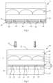
- the image sensor 44comprises a support 47 and a matrix of photon sensors 48, also called photodetectors, arranged between the support 47 and the optical system 5.
- the photodetectors 48can be covered with a transparent protective coating, not shown .
- the image sensor 44further comprises tracks conductors and switching elements, in particular transistors, not shown, allowing the selection of the photodetectors 48. In figure 5 , the photodetectors are shown spaced apart by a substantially constant pitch.
- Photodetectors 48can be made of organic materials.
- the photodetectors 48may correspond to organic photodiodes (OPD, standing for Organic Photodiode), to organic photoresistors, to amorphous silicon photodiodes associated with a matrix of CMOS transistors.
- OPDorganic photodiodes
- the surface of image sensor 44 facing optical system 5 and containing photodetectors 48is greater than 1 cm 2 , preferably greater than 5 cm 2 , more preferably greater than 10 cm 2 , in particular greater than 20 cm 2 .
- Upper face 46 of image sensor 44may be substantially flat.
- each photodetector 48is adapted to detect electromagnetic radiation in a range of wavelengths comprised between 400 nm and 1100 nm. All of the photodetectors 48 can be adapted to detect electromagnetic radiation in the same wavelength range. Alternatively, the photodetectors 48 may be adapted to detect electromagnetic radiation in different wavelength ranges.
- the image acquisition system 40further comprises means, not shown, for processing the signals supplied by the image sensor 44, comprising for example a microprocessor.
- the angular filter 5, covering the image sensor 44is adapted to filter the incident radiation 42 according to the incidence of the radiation 42 with respect to the upper face 22, in particular so that each photodetector 48 receives only the rays whose impact compared to below an axis perpendicular to the upper face 22 is a maximum angle of incidence of less than 45°, preferably less than 30°, more preferably less than 20°, even more preferably less than 10°.
- the angular filter 5is adapted to block the rays of the incident radiation whose incidence with respect to an axis perpendicular to the upper face 22 is greater than the maximum angle of incidence.
- the photodetectors 48can be distributed in rows and in columns.
- the pitch of the photodetectors 48is the same as the pitch of the holes 26.
- the apertured layer 10is then preferably aligned with the image sensor 44 so that each hole 26 faces a photodetector 48.
- the pitch p of the holes 26is smaller than the pitch of the photodetectors 48 of the image sensor 44. In this case, several holes 26 can be located facing the same photodetector 48.
- the pitch p of the holes 26is greater than the pitch of the photodetectors 48 of the image sensor 44. In this case, several photodetectors 48 can be located facing the same hole 26.
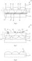
- optical system 5Another example of application of the optical system 5 will now be described for a collimating device of a lighting or display system.
- the emission plane of the light source 52is close to the focal plane of the optical system 5.
- the form factor (height to width ratio) of the holes 26 of the layer 10must be high enough so that no ray emerging from an opening 26 opposite a given microlens 14 passes through a neighboring microlens. Indeed, in this case, the outgoing ray would not be collimated.
- the opening angle of the layer 10can be adjusted by the aspect ratio of the openings 26.
- the optical system 5plays the role of a collimating device which makes it possible to collimate the radiation 54 supplied by the light source 52.
- the light source 52is shown with a substantially planar emissive surface.
- the emissive surface of the light source 52can be curved.
- optical system 5Another example of application of the optical system 5 will now be described for a device for screening a lighting system.
- the layer with apertures 10comprises opaque pads 64, each pad 64 being located opposite a microlens 14 and being surrounded by a hole 26, the holes 26 communicating with each other. others.
- the optical system 5plays the role of a screen configured to block the rays 66 emitted by the light source 62 substantially perpendicular to the emission face of the light source 62 and lets through the rays 68 inclined with respect to the emission surface of the light source 62.
- Such an illumination system 60can be used in particular in microscopy where diffuse light illumination may be desirable.
- optical system 5Another example of application of the optical system 5 comprises the use of the optical system 5 as a mask in a photolithography process.
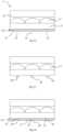
- THE figures 8 to 12are partial and schematic cross-sectional views of structures obtained at successive stages of an embodiment of a manufacturing method of the optical system 5 shown in the figures 1 and 2 .
- the matrix of microlenses 14can be formed on a support different from the intermediate layer 12, this support being removed before the formation of the intermediate layer 12 when the intermediate layer 12 is present, or before the formation of the apertured layer 10 when intermediate layer 12 is not present.
- the manufacture of the microlenses 14comprises the formation of a layer of the material making up the microlenses 14 on the intermediate layer 12 or another support and the deformation of this layer, for example by means of a die to form the microlenses.
- the microlenses 14are formed by molding.
- FIG 10represents the structure obtained after the formation of the opaque layer 24 on the intermediate layer 12, on the opposite side to the array of microlenses 14.
- the opaque layer 24can be deposited by liquid means, by sputtering or by evaporation. These may in particular be processes of the spin coating, spray coating, heliography, slot-die coating, blade-coating, flexography or screen printing type. Depending on the deposition method implemented, a step of drying the deposited material may be provided.
- FIG 11represents the structure obtained during a step of exposure to radiation 70, passing through the microlenses 14 of portions 72 of the opaque layer 24 at the desired locations of the holes 26.
- the radiation used to expose the opaque layer 24depends on the photoresist used.
- the radiation 70is radiation with wavelengths comprised approximately between 300 nm and 450 nm in the case of a DNQ-Novolac resin or ultraviolet radiation for a DUV photosensitive resin.
- the duration of the exposure of the opaque layer 24 to the radiation 70depends in particular on the type of positive photosensitive resin used and is sufficient for the exposed parts 72 of the opaque layer 24 to extend over the entire thickness of the opaque layer 24 .
- the exposure of the opaque layer 24is carried out through the microlenses 14.
- the opaque layer 24is then preferably located in the focal plane of the microlenses 14 or close to the focal plane of the microlenses 14.
- the radiation incident 70 which reaches the microlenses 14is substantially collimated radiation so that it is focused by each microlens 14 substantially at the level of the opaque layer 24 or close to the opaque layer 24.
- the opaque layer 24can be offset with respect to the focal plane of the microlenses 14 so as to obtain spots of desired dimensions on the opaque layer 24 when the opaque layer 24 is exposed to radiation 70 through the microlenses 14.
- the inclination of the radiation 70 with respect to the upper face 22corresponds substantially to the average inclination formed by the radiation 6 captured by the photodetectors 48 with the upper face 22 during normal use of the image acquisition system 5.
- the radiation 70is substantially perpendicular to the layer 24.
- the radiation 70is inclined with respect to a direction perpendicular to the layer 24 thus making it possible to obtain holes 26 offset with respect to the microlenses.
- the holes 26are cylindrical, that is to say that their cross section is constant. However, as previously described, the cross section of the holes 26 may not be constant.
- the holes 26can have a frustoconical shape.
- the incident radiation 70has a divergence, for example with an angle of divergence greater than 1°, the angle of divergence of the incident radiation 70 which reaches the microlenses 14 then being adjusted to modulate the width of the holes 26 made in layer 24.
- a layer of a material of suitable refractive indexis placed temporarily on the matrix of microlenses 14 during the exposure step to modify the focal distance of the microlenses 14 so that the exposed parts 72 have the desired dimensions.
- the light source emitting the exposure radiation 70can be moved relative to the array of microlenses 14 during the exposure step depending on the desired shape of the holes 26.
- the light source emitting the exposure radiation 70can be moved in a loop, which makes it possible to obtain holes 26 of annular cross-section.
- Such a shape of holesallows in particular the production of an angular band-pass filter allowing the passage of rays whose incidence with respect to a direction orthogonal to the face 22 is in at least a first range of incidences and to be allowed to pass rays whose incidence with respect to a direction orthogonal to face 22 is in at least one second range of incidences distinct from said at least one first range of incidences.
- the microlenses 14may have different focal points depending on the wavelength of the exposure radiation 70.
- the photoresist layer 24may be sensitive to these different wavelengths.
- each photosensitive layercan be sensitive to radiation at a particular wavelength.
- the exposure stepcan then comprise the exposure of the photosensitive layer or photosensitive layers to radiation at these different wavelengths to obtain holes 26 of the desired shape.
- FIG 12represents the structure obtained during a step of developing the opaque layer 24 which led to the dissolution, in a developer, of the parts 72 of the opaque layer 24 exposed to the incident radiation 70, thus forming the holes 26.
- the layer to openings 10is thus obtained.
- the composition of the developerdepends on the nature of the positive photoresist that has been used.
- the methodmay include subsequent steps comprising filling the holes 26 with a filling material and fixing the optical system 5 thus obtained to the image sensor 44.
- THE figures 13 and 14are partial and schematic cross-sectional views of structures obtained at successive stages of another embodiment of a method of manufacturing the optical system 5 shown in the figures 1 and 2 .
- the initial steps of this embodiment of the manufacturing processinclude the steps previously described in relation to the figures 8 to 11 with the difference that the layer 24 is replaced by a layer of the material intended to fill the holes 26 of the layer with openings 10 and is made of a negative photosensitive resin which is, moreover, transparent to the useful radiation.
- FIG 13represents the structure obtained during a step of developing the negative photoresist layer which led to the dissolution, in a developer, of the parts of the negative photoresist layer which were not exposed to the radiation 70 used in the exposure step, the parts of the negative photoresist layer exposed in the exposure step thus forming pads 80.
- the composition of the developerdepends on the nature of the negative photoresist which has been used.
- FIG 14represents the structure obtained after the formation of the opaque layer 24 between the pads 80, for example by spin coating, spray coating, heliography, die coating (in English slot-die coating), blade coating (in English blade-coating), flexography or screen printing.
- the studs 80thus delimit the holes 26 in the layer 24.
- the layer with openings 10is therefore thus obtained.
- Another embodiment of a method of manufacturing the optical system 5 shown in the figures 1 and 2includes the steps previously described in relation to the figures 8 to 11 with the difference that the layer 24 is made of a material capable of degrading under the action of the radiation 70 in particular when the radiation 70 corresponds to laser radiation.
- the illumination of this laser radiationis low enough not to damage the matrix of optical elements of micrometric size 14 and sufficiently high after collimation by the matrix of optical elements of micrometric size 14 to degrade the layer 24 at the level of the parts 72
- the parts 72 exposed to the radiation 70are therefore destroyed by this radiation then directly forming the holes 26.
- the apertured layer 10is therefore thus obtained.
- the manufacturing method of the optical systemmay correspond to a roll-to-roll process.
- the manufacturing process of the optical systemcan correspond to a sheet-to-sheet process.
- the apertured layer 10comprises a stack of at least two layers 24, 28 each comprising holes 26, 30, as shown in figure 4
- the first layer 24 with the holes 26is made first and the second layer 28 with the holes 30 is made second, taking into account the presence of the first layer 24, according to any one of the modes for carrying out the manufacturing process described above.
- a transparent intermediate layermay be present between layers 24 and 28.
- the alignment of the holes 26 with respect to the microlenses 14is obtained automatically by the same method of forming the holes 26.
- the apertured layer 10comprises a stack of at least first and second opaque layers each comprising holes
- the alignment of the holes of the second opaque layer with respect to the holes of the first opaque layeris obtained automatically by the same method of forming the holes of the second opaque layer.
Landscapes
- Physics & Mathematics (AREA)
- Engineering & Computer Science (AREA)
- General Physics & Mathematics (AREA)
- Optics & Photonics (AREA)
- Theoretical Computer Science (AREA)
- Multimedia (AREA)
- General Health & Medical Sciences (AREA)
- Vascular Medicine (AREA)
- Health & Medical Sciences (AREA)
- Human Computer Interaction (AREA)
- Manufacturing & Machinery (AREA)
- Solid State Image Pick-Up Elements (AREA)
- Optical Elements Other Than Lenses (AREA)
- Diffracting Gratings Or Hologram Optical Elements (AREA)
- Optical Couplings Of Light Guides (AREA)
- Surface Treatment Of Optical Elements (AREA)
- Laminated Bodies (AREA)
Description
Translated fromFrenchLa présente demande de brevet revendique la priorité de la demande de brevet français
La présente description concerne les systèmes optiques et leurs procédés de fabrication.This description relates to optical systems and their manufacturing methods.
Un système optique est un ensemble d'éléments optiques, tels que des miroirs, des lentilles, des réseaux de diffraction, etc. permettant de modifier la trajectoire des rayons lumineux ou les propriétés de la lumière. Un exemple d'application d'un système optique concerne un système d'acquisition d'images dans lequel le système optique est interposé entre la partie sensible d'un capteur d'images et l'objet à imager, et qui permet de former une image nette de l'objet à imager sur la partie sensible du capteur d'images. Un autre exemple d'application consiste à coupler le système optique à un photodétecteur unique, tel qu'une photodiode, afin de contrôler la lumière collectée par le photodétecteur. Un autre exemple d'application concerne un système d'affichage ou de projection dans lequel le système optique recouvre une source lumineuse, par exemple un écran d'affichage, et permet de modifier le rayonnement émis par la source lumineuse, par exemple collimater le rayonnement émis par chaque pixel d'affichage.An optical system is a set of optical elements, such as mirrors, lenses, diffraction gratings, etc. allowing to modify the trajectory of the light rays or the properties of the light. An example of application of an optical system relates to an image acquisition system in which the optical system is interposed between the sensitive part of an image sensor and the object to be imaged, and which makes it possible to form a sharp image of the object to be imaged on the sensitive part of the image sensor. Another application example consists of coupling the optical system to a single photodetector, such as a photodiode, in order to monitor the light collected by the photodetector. Another example of application relates to a display or projection system in which the optical system covers a light source, for example a display screen, and makes it possible to modify the radiation emitted by the light source, for example collimating the radiation emitted by each display pixel.
Toutefois, dans certains cas, il n'est pas possible d'utiliser un système optique classique. Par exemple, dans le cas d'un système d'acquisition d'images, il peut ne pas être possible de placer un système optique classique entre la partie sensible du capteur d'images et l'objet à imager. C'est le cas notamment lorsque le capteur d'images occupe une surface importante, supérieure au centimètre carré et que la distance entre l'objet à imager et la partie sensible du capteur d'images est inférieure au centimètre.However, in some cases, it is not possible to use a conventional optical system. For example, in the case of an image acquisition system, it may not be possible to place a conventional optical system between the sensitive part of the image sensor and the object to be imaged. This is the case in particular when the image sensor occupies a large surface, greater than one square centimeter and when the distance between the object to be imaged and the sensitive part of the image sensor is less than one centimeter.
Il faudrait alors placer l'objet à imager au plus près du capteur d'images pour que l'image qui se forme sur la partie sensible du capteur d'images soit suffisamment nette. Toutefois, une distance peut être présente entre l'objet et le capteur d'images de sorte que la netteté de l'image qui se forme sur la partie sensible du capteur d'images peut ne pas être suffisante pour certaines applications, par exemple pour la capture d'empreintes digitales.It would then be necessary to place the object to be imaged as close as possible to the image sensor so that the image which is formed on the sensitive part of the image sensor is sufficiently sharp. However, a distance may be present between the object and the image sensor such that the sharpness of the image which forms on the sensitive part of the image sensor may not be sufficient for certain applications, for example for capturing fingerprints.
Pour accroître la netteté de l'image acquise par le capteur d'images d'un système d'acquisition d'images en l'absence de système optique complexe, une possibilité consiste à recouvrir le capteur d'images d'un système optique de structure simple jouant le rôle d'un filtre angulaire, comprenant une couche opaque traversée par des ouvertures, et recouverte d'une matrice d'éléments optiques de taille micrométrique, par exemple une matrice de lentilles de taille micrométrique, ou microlentilles, un réseau de microlentilles à gradient d'indice de taille micrométrique, ou une matrice de réseaux de diffraction de taille micrométrique, chaque élément optique de taille micrométrique étant associé à une ouverture de la couche à ouvertures.To increase the sharpness of the image acquired by the image sensor of an image acquisition system in the absence of a complex optical system, one possibility consists in covering the image sensor with an optical system of simple structure playing the role of an angular filter, comprising an opaque layer through which openings pass, and covered with a matrix of optical elements of micrometric size, for example a matrix of lenses of micrometric size, or microlenses, a network of micrometre-sized gradient-index microlenses, or an array of micrometre-sized diffraction gratings, each micrometre-sized optical element being associated with an aperture of the apertured layer.
Un exemple de procédé de fabrication d'un tel système optique comprend la fabrication de la couche à ouvertures, la fabrication des éléments optiques de taille micrométrique et le positionnement des éléments optiques de taille micrométrique par rapport à la couche à ouvertures. L'étape de positionnement des éléments optiques de taille micrométrique par rapport à la couche à ouvertures requiert l'utilisation d'outils d'alignement. Ces outils d'alignement existent mais engendrent un coût important pour la fabrication de ces systèmes optiques et surtout ne permettent pas de produire ces systèmes optiques à très grande échelle. En outre, de par l'utilisation de matériaux organiques, la couche à ouvertures et/ou les éléments optiques de taille micrométrique peuvent comprendre des déformations, résultant d'effets thermiques et/ou mécaniques, de sorte que l'alignement correct de chaque élément optique de taille micrométrique avec l'ouverture correspondante de la couche à ouvertures peut ne pas être possible pour la totalité des éléments optiques de taille micrométrique. Une fabrication des trous alignés, sans outils d'alignement, est connue des documents
Un objet d'un mode de réalisation est de pallier, en totalité ou en partie, les contraintes liées à la fabrication des systèmes optiques comprenant une couche à ouvertures et une matrice d'éléments optiques de taille micrométrique et de leurs procédés de fabrication décrits précédemment.An object of an embodiment is to overcome, in whole or in part, the constraints related to the manufacture of optical systems comprising a layer with apertures and a matrix of optical elements of micrometric size and their manufacturing methods described previously .
Un objet d'un mode de réalisation est que le positionnement des éléments optiques de taille micrométrique par rapport aux ouvertures de la couche à ouvertures puisse être réalisé avec une précision suffisante.An object of an embodiment is that the positioning of the micrometer-sized optical elements relative to the apertures of the apertured layer can be achieved with sufficient precision.
Un autre objet d'un mode de réalisation est que le procédé de fabrication du système optique puisse être mis en oeuvre à une échelle industrielle.Another object of an embodiment is that the method of manufacturing the optical system can be implemented on an industrial scale.
Dans ce but, un mode de réalisation de l'invention revendiquée prévoit un procédé de fabrication d'un système optique comme spécifié dans la revendication 1.To this end, one embodiment of the claimed invention provides a method of manufacturing an optical system as specified in claim 1.
Selon un mode de réalisation, le film est en une résine photosensible au deuxième rayonnement.According to one embodiment, the film is made of a resin photosensitive to the second radiation.
Selon un mode de réalisation, la couche est en une résine photosensible positive au deuxième rayonnement, les parties retirées du film étant les parties exposées au deuxième rayonnement.According to one embodiment, the layer is made of a photosensitive resin positive to the second radiation, the parts removed from the film being the parts exposed to the second radiation.
Selon un mode de réalisation, le film est en une résine photosensible négative au deuxième rayonnement, les parties retirées du film étant les parties non exposées au deuxième rayonnement.According to one embodiment, the film is made of a photosensitive resin negative to the second radiation, the parts removed from the film being the parts not exposed to the second radiation.
Selon un mode de réalisation, le procédé comprend l'usinage de la couche par un faisceau laser.According to one embodiment, the method comprises the machining of the layer by a laser beam.
Selon un mode de réalisation, le système optique forme un filtre angulaire configuré pour bloquer les rayons dudit premier rayonnement dont l'incidence par rapport à une direction orthogonale à la face est dans au moins une première plage d'incidences et à laisser passer des rayons dudit premier rayonnement dont l'incidence par rapport à une direction orthogonale à la face est dans au moins une deuxième plage d'incidences distincte de ladite au moins une première plage d'incidences.According to one embodiment, the optical system forms an angular filter configured to block the rays of said first radiation whose incidence with respect to a direction orthogonal to the face is in at least a first range of incidences and to allow rays to pass said first radiation whose incidence with respect to a direction orthogonal to the face is in at least one second range of incidences distinct from said at least one first range of incidences.
Selon un mode de réalisation, le premier rayonnement est différent du deuxième rayonnement.According to one embodiment, the first radiation is different from the second radiation.
Selon un mode de réalisation, le premier rayonnement est dans le domaine visible et/ou dans le domaine infrarouge.According to one embodiment, the first radiation is in the visible domain and/or in the infrared domain.
Selon un mode de réalisation, le deuxième rayonnement est dans le domaine visible et/ou dans le domaine ultraviolet.According to one embodiment, the second radiation is in the visible range and/or in the ultraviolet range.
Selon le mode de réalisation correspondant à l'invention revendiquée, le procédé comprend, à l'étape d'exposition, la mise en contact temporaire de la matrice d'éléments optiques de taille micrométrique avec un matériau, différent de l'air, d'indice de réfraction différent de celui des éléments optiques de taille micrométrique.According to the embodiment corresponding to the claimed invention, the method comprises, at the exposure step, the temporary contacting of the matrix of optical elements of micrometric size with a material, other than air, d index of refraction different from that of optical elements of micrometric size.
Selon un mode de réalisation, la fabrication du système optique est réalisée bobine à bobine.According to one embodiment, the manufacture of the optical system is carried out reel to reel.
Selon un mode de réalisation, le procédé comprend après la formation des trous, le remplissage des trous par un matériau de collage et la fixation de la couche comprenant les trous à un dispositif par l'intermédiaire du matériau de collage.According to one embodiment, the method comprises after the holes have been formed, filling the holes with a bonding material and attaching the layer comprising the holes to a device via the bonding material.
Selon un mode de réalisation, le deuxième rayonnement est collimaté.According to one embodiment, the second radiation is collimated.
Selon un mode de réalisation, le deuxième rayonnement a un angle de divergence supérieur à 1°.According to one embodiment, the second radiation has a divergence angle greater than 1°.
Un mode de réalisation qui ne correspond pas à l'invention revendiquée prévoit également un système optique comprenant une face destinée à recevoir un premier rayonnement, une couche comprenant des trous traversants ou partiellement traversants et recouverte d'une matrice d'éléments optiques de taille micrométrique. La couche est en un matériau ou les trous sont remplis dudit matériau, ledit matériau étant photosensible à un deuxième rayonnement ou usinable par le deuxième rayonnement.An embodiment which does not correspond to the claimed invention also provides an optical system comprising a face intended to receive a first radiation, a layer comprising through or partially through holes and covered with a matrix of optical elements of micrometric size . The layer is made of a material where the holes are filled with said material, said material being photosensitive to a second radiation or machinable by the second radiation.
Selon un mode de réalisation, la couche est opaque au premier rayonnement, le système étant configuré pour bloquer les rayons dudit premier rayonnement dont l'incidence par rapport à une direction orthogonale à la face est dans au moins une première plage d'incidences et à laisser passer des rayons dudit premier rayonnement dont l'incidence par rapport à une direction orthogonale à la face est dans au moins une deuxième plage d'incidences distincte de ladite au moins une première plage d'incidences.According to one embodiment, the layer is opaque to the first radiation, the system being configured to block the rays of said first radiation whose incidence with respect to a direction orthogonal to the face is in at least a first range of incidences and at allow rays of said first radiation to pass, the incidence of which with respect to in a direction orthogonal to the face is in at least one second range of incidences distinct from said at least one first range of incidences.
Selon un mode de réalisation, le matériau est une résine photosensible au deuxième rayonnement.According to one embodiment, the material is a resin photosensitive to the second radiation.
Selon un mode de réalisation, le système comprend autant d'éléments optiques de taille micrométrique que de trous, le pas entre les éléments optiques de taille micrométrique étant le même que le pas entre les trous.According to one embodiment, the system comprises as many optical elements of micrometric size as there are holes, the pitch between the optical elements of micrometric size being the same as the pitch between the holes.
Selon un mode de réalisation, pour chaque trou, le rapport entre la hauteur du trou, mesurée perpendiculairement à la face, et la largeur du trou, mesurée parallèlement à la face, varie de 1 à 10.According to one embodiment, for each hole, the ratio between the height of the hole, measured perpendicular to the face, and the width of the hole, measured parallel to the face, varies from 1 to 10.
Selon un mode de réalisation, les trous sont agencés en rangées et en colonnes, le pas entre des trous adjacents d'une même rangée ou d'une même colonne variant de 1 µm à 100 µm.According to one embodiment, the holes are arranged in rows and in columns, the pitch between adjacent holes of the same row or of the same column varying from 1 μm to 100 μm.
Selon un mode de réalisation, la hauteur de chaque trou, mesurée selon une direction orthogonale à la face, varie de 1 µm à 800 µm, notamment de 10 µm à 800 µm ou de 1 µm à 100 µm.According to one embodiment, the height of each hole, measured in a direction orthogonal to the face, varies from 1 μm to 800 μm, in particular from 10 μm to 800 μm or from 1 μm to 100 μm.
Selon un mode de réalisation, la largeur de chaque trou, mesurée parallèlement à la face, varie de 0,1 µm à 100 µm.According to one embodiment, the width of each hole, measured parallel to the face, varies from 0.1 μm to 100 μm.
Selon un mode de réalisation, le système comprend un empilement de ladite couche comprenant lesdits trous traversants ou partiellement traversants et d'une couche supplémentaire comprenant des trous supplémentaires traversants ou partiellement traversants alignés avec lesdits trous.According to one embodiment, the system comprises a stack of said layer comprising said through or partially through holes and an additional layer comprising additional through or partially through holes aligned with said holes.
Un mode de réalisation prévoit également un système d'acquisition d'images comprenant un capteur d'images et un système optique, tel que défini précédemment, recouvrant le capteur d'images et formant un filtre angulaire.An embodiment also provides an image acquisition system comprising an image sensor and a optical system, as defined previously, covering the image sensor and forming an angular filter.
Selon un mode de réalisation, le capteur d'images comprend une matrice de photodétecteurs, le pas entre les photodétecteurs étant égal, supérieur ou inférieur au pas entre les trous.According to one embodiment, the image sensor comprises a matrix of photodetectors, the pitch between the photodetectors being equal to, greater than or less than the pitch between the holes.
Selon un mode de réalisation, le système optique comprend une couche auxiliaire jouant le rôle de couche de protection du capteur d'images.According to one embodiment, the optical system comprises an auxiliary layer acting as a protective layer for the image sensor.
Selon un mode de réalisation, le capteur d'images est au moins en partie réalisé en matériaux organiques, et le système optique comprend un film étanche à l'eau et/ou à l'oxygène.According to one embodiment, the image sensor is at least partly made of organic materials, and the optical system comprises a film impermeable to water and/or to oxygen.
Un mode de réalisation qui ne correspond pas à l'invention revendiquée prévoit également un système d'éclairage ou d'affichage comprenant une source lumineuse et un système optique, tel que défini précédemment, recouvrant la source lumineuse.An embodiment which does not correspond to the claimed invention also provides a lighting or display system comprising a light source and an optical system, as defined previously, covering the light source.
Ces caractéristiques et avantages, ainsi que d'autres, seront exposés en détail dans la description suivante de modes de réalisation particuliers faite à titre non limitatif en relation avec les figures jointes parmi lesquelles :
- la
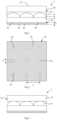
figure 1 est une vue en coupe, partielle et schématique, d'un mode de réalisation d'un système optique comprenant une couche à ouvertures recouverte d'un réseau de microlentilles ; - la
figure 2 est une vue de dessus de la couche à ouvertures du système optique représenté enfigure 1 ; - la
figure 3 est une vue en coupe, partielle et schématique, d'une variante du système optique représenté enfigure 1 ; - la
figure 4 est une vue en coupe, partielle et schématique, d'une autre variante du système optique représenté enfigure 1 ; - la
figure 5 est une vue en coupe, partielle et schématique, d'un mode de réalisation d'un système d'acquisition d'images ; - la
figure 6 est une vue en coupe, partielle et schématique, d'un mode de réalisation d'un système d'éclairage ou de projection ; - la
figure 7 est une vue en coupe, partielle et schématique, d'un autre mode de réalisation d'un système d'éclairage ; - la
figure 8 est une vue en coupe, partielle et schématique, de la structure obtenue à une étape d'un mode de réalisation d'un procédé de fabrication du système optique représenté sur lesfigures 1 et 2 ; - la
figure 9 est une vue en coupe, partielle et schématique, de la structure obtenue à une autre étape d'un mode de réalisation d'un procédé de fabrication du système optique représenté sur lesfigures 1 et 2 ; - la
figure 10 est une vue en coupe, partielle et schématique, de la structure obtenue à une autre étape d'un mode de réalisation d'un procédé de fabrication du système optique représenté sur lesfigures 1 et 2 ; - la
figure 11 est une vue en coupe, partielle et schématique, de la structure obtenue à une autre étape d'un mode de réalisation d'un procédé de fabrication du système optique représenté sur lesfigures 1 et 2 ; - la
figure 12 est une vue en coupe, partielle et schématique, de la structure obtenue à une autre étape d'un mode de réalisation d'un procédé de fabrication du système optique représenté sur lesfigures 1 et 2 ; - la
figure 13 est une vue en coupe, partielle et schématique, de la structure obtenue à une étape d'un autre mode de réalisation d'un procédé de fabrication du système optique représenté sur lesfigures 1 et 2 ; et - la
figure 14 est une vue en coupe, partielle et schématique, de la structure obtenue à une autre étape d'un autre mode de réalisation d'un procédé de fabrication du système optique représenté sur lesfigures 1 et 2 .
- there
figure 1 is a partial and schematic sectional view of an embodiment of an optical system comprising an apertured layer covered with an array of microlenses; - there
figure 2 is a top view of the apertured layer of the optical system shown infigure 1 ; - there
picture 3 is a sectional view, partial and schematic, of a variant of the optical system represented infigure 1 ; - there
figure 4 is a sectional view, partial and schematic, of another variant of the optical system represented infigure 1 ; - there
figure 5 is a partial schematic sectional view of an embodiment of an image acquisition system; - there
figure 6 is a sectional view, partial and schematic, of an embodiment of a lighting or projection system; - there
figure 7 is a sectional, partial and schematic view of another embodiment of a lighting system; - there
figure 8 is a partial and schematic sectional view of the structure obtained at a step of an embodiment of a manufacturing method of the optical system shown in thefigures 1 and 2 ; - there
figure 9 is a partial and schematic sectional view of the structure obtained at another stage of an embodiment of a manufacturing method of the optical system shown in thefigures 1 and 2 ; - there
figure 10 is a partial and schematic sectional view of the structure obtained at another stage of an embodiment of a manufacturing method of the optical system shown in thefigures 1 and 2 ; - there
figure 11 is a partial and schematic sectional view of the structure obtained at another stage of an embodiment of a manufacturing method of the optical system shown in thefigures 1 and 2 ; - there
figure 12 is a partial and schematic sectional view of the structure obtained at another stage of an embodiment of a manufacturing method of the optical system shown in thefigures 1 and 2 ; - there
figure 13 is a partial and schematic sectional view of the structure obtained at a stage of another embodiment of a manufacturing method of the optical system shown in thefigures 1 and 2 ; And - there
figure 14 is a partial and schematic sectional view of the structure obtained at another stage of another embodiment of a manufacturing method of the optical system shown in thefigures 1 and 2 .
De mêmes éléments ont été désignés par de mêmes références dans les différentes figures. En particulier, les éléments structurels et/ou fonctionnels communs aux différents modes de réalisation peuvent présenter les mêmes références et peuvent disposer de propriétés structurelles, dimensionnelles et matérielles identiques.The same elements have been designated by the same references in the various figures. In particular, the structural and/or functional elements common to the various embodiments may have the same references and may have identical structural, dimensional and material properties.
Par souci de clarté, seuls les étapes et éléments utiles à la compréhension des modes de réalisation décrits ont été représentés et sont détaillés. En particulier, la structure d'un capteur d'images est bien connue de l'homme du métier et n'est pas décrite en détail par la suite.For the sake of clarity, only the steps and elements useful for understanding the embodiments described have been represented and are detailed. In particular, the structure of an image sensor is well known to those skilled in the art and is not described in detail below.
Dans la description qui suit, lorsque l'on fait référence à des qualificatifs de position absolue, tels que les termes "avant", "arrière", "haut", "bas", "gauche", "droite", etc., ou relative, tels que les termes "dessus", "dessous", "supérieur", "inférieur", etc., ou à des qualificatifs d'orientation, tels que les termes "horizontal", "vertical", etc., il est fait référence sauf précision contraire à l'orientation des figures ou à un système optique dans une position normale d'utilisation.In the following description, when referring to absolute position qualifiers, such as "front", "rear", "up", "down", "left", "right", etc., or relative, such as the terms "above", "below", "upper", "lower", etc., or to qualifiers of orientation, such as the terms "horizontal", "vertical", etc., it is referred unless otherwise specified to the orientation of the figures or to an optical system in a normal position of use.
Sauf précision contraire, les expressions "environ", "approximativement", "sensiblement", et "de l'ordre de" signifient à 10 % près, de préférence à 5 % près.Unless specified otherwise, the expressions “about”, “approximately”, “substantially”, and “of the order of” mean to within 10%, preferably within 5%.
Dans la suite de la description, une couche ou un film est dit opaque à un rayonnement lorsque la transmittance du rayonnement au travers de la couche ou du film est inférieure à 10 %. Dans la suite de la description, une couche ou un film est dit transparent à un rayonnement lorsque la transmittance du rayonnement au travers de la couche ou du film est supérieure à 10 %. Selon un mode de réalisation, pour un même système optique, tous les éléments du système optique qui sont opaques à un rayonnement ont une transmittance qui est inférieure à la moitié, de préférence inférieure au cinquième, plus préférentiellement inférieure au dixième, de la transmittance la plus faible des éléments du système optique transparents audit rayonnement. Dans la suite de la description, on appelle "rayonnement utile" le rayonnement électromagnétique traversant le système optique en fonctionnement. Dans la suite de la description, on appelle "élément optique de taille micrométrique" un élément optique formé sur une face d'un support dont la dimension maximale, mesurée parallèlement à ladite face, est supérieure à 1 µm et inférieure à 1 mm. Dans la suite de la description, un film ou une couche est dit étanche à l'oxygène lorsque la perméabilité du film ou de la couche à l'oxygène à 40°C est inférieure à 1.10-1cm3/ (m2*jour). La perméabilité à l'oxygène peut être mesurée selon la méthode ASTM D3985 intitulée "Standard Test Method for Oxygen Gas Transmission Rate Through Plastic Film and Sheeting Using a Coulometric Sensor". Dans la suite de la description, un film ou une couche est dit étanche à l'eau lorsque la perméabilité du film ou de la couche à l'eau à 40°C est inférieure à 1.10-1g/ (m2*jour) . La perméabilité à l'eau peut être mesurée selon la méthode ASTM F1249 intitulée "Standard Test Method for Water Vapor Transmission Rate Through Plastic Film and Sheeting Using a Modulated Infrared Sensor".In the rest of the description, a layer or a film is said to be opaque to radiation when the transmittance of the radiation through the layer or the film is less than 10%. In the rest of the description, a layer or a film is said to be transparent to radiation when the transmittance of the radiation through the layer or the film is greater than 10%. According to one embodiment, for the same optical system, all the elements of the optical system which are opaque to radiation have a transmittance which is less than half, preferably less than a fifth, more preferably less than a tenth, of the transmittance the weakest of the elements of the optical system transparent to said radiation. In the remainder of the description, the term "useful radiation" is used to refer to the electromagnetic radiation passing through the optical system in operation. In the remainder of the description, the term “optical element of micrometric size” is used to refer to an optical element formed on one face of a support whose maximum dimension, measured parallel to said face, is greater than 1 μm and less than 1 mm. In the rest of the description, a film or a layer is said to be oxygen-tight when the permeability of the film or of the layer to oxygen at 40° C. is less than 1.10-1 cm3 / (m2 *day ). Oxygen permeability can be measured according to ASTM D3985 entitled "Standard Test Method for Oxygen Gas Transmission Rate Through Plastic Film and Sheeting Using a Coulometric Sensor". In the rest of the description, a film or a layer is said to be watertight when the permeability of the film or of the layer to water at 40° C. is less than 1.10-1 g/ (m2 *day) . Water permeability can be measured according to the ASTM F1249 method entitled "Standard Test Method for Water Vapor Transmission Rate Through Plastic Film and Sheeting Using a Modulated Infrared Sensor".
Des modes de réalisation de systèmes optiques vont maintenant être décrits pour des systèmes optiques comprenant une matrice d'éléments optiques à taille micrométrique dans le cas où chaque élément optique à taille micrométrique correspond à une lentille à taille micrométrique, ou microlentille. Toutefois, il est clair que ces modes de réalisation peuvent également être mis en oeuvre avec d'autres types d'éléments optiques de taille micrométrique, chaque élément optique de taille micrométrique pouvant correspondre à une lentille de Fresnel de taille micrométrique, à une lentille à gradient d'indice de taille micrométrique ou à un réseau de diffraction de taille micrométrique.Embodiments of optical systems will now be described for optical systems comprising an array of micrometric-sized optical elements in the case where each micrometric-sized optical element corresponds to a micrometric-sized lens, or microlens. However, it is clear that these embodiments can also be implemented with other types of optical elements of micrometric size, each optical element of micrometric size being able to correspond to a Fresnel lens of micrometric size, to a lens with micrometric-sized index gradient or to a micrometric-sized diffraction grating.
La
- une couche à ouvertures 10 ;
- une couche intermédiaire 12 recouvrant la couche à ouvertures 10, la couche intermédiaire 12 pouvant ne pas être présente ;
- une matrice d'éléments optiques 14 de taille micrométrique, par exemple une matrice de microlentilles 14 recouvrant la couche intermédiaire 12, la couche intermédiaire 12 et la matrice de microlentilles 14 pouvant correspondre à une structure monolithique ;
un revêtement 16 recouvrant la matrice de microlentilles 14 et comprenant par exemple un empilement de plusieurs couches, parexemple deux couches 18et 20, et comprenant uneface supérieure 22,le revêtement 16 pouvant ne pas être présent,la face supérieure 22 correspondant alors à la face supérieure de la matrice de microlentilles 14.
- an
apertured layer 10; - an
intermediate layer 12 covering theapertured layer 10, theintermediate layer 12 possibly not being present; - a matrix of
optical elements 14 of micrometric size, for example a matrix ofmicrolenses 14 covering theintermediate layer 12, theintermediate layer 12 and the matrix ofmicrolenses 14 possibly corresponding to a monolithic structure; - a
coating 16 covering the matrix ofmicrolenses 14 and comprising for example a stack of several layers, for example twolayers upper face 22, thecoating 16 possibly not being present, theupper face 22 then corresponding to the upper face of the array ofmicrolenses 14.
La
En
Selon un mode de réalisation, les trous 26 sont disposés en rangées et en colonnes. Les trous 26 peuvent avoir sensiblement les mêmes dimensions. On appelle "w" la largeur d'un trou 26 mesurée selon la direction des rangées ou des colonnes. La largeur w correspond au diamètre du trou 26 dans le cas d'un trou de section droite circulaire. Selon un mode de réalisation, les trous 26 sont disposés régulièrement selon les rangées et selon les colonnes. On appelle "p" le pas de répétition des trous 26, c'est-à-dire la distance en vue de dessus des centres de deux trous 26 successifs d'une rangée ou d'une colonne.According to one embodiment, the
La couche à ouvertures 10 laisse seulement passer les rayons du rayonnement utile incident dont l'incidence par rapport à la face supérieure de la couche à ouvertures 10 est inférieure à un angle d'incidence maximale α, qui est défini par la relation (1) suivante :
Le rapport h/w peut varier de 1 à 10, voire est supérieur à 10. Le pas p peut varier de 1 µm à 100 µm, par exemple égal à environ 15 µm. La hauteur h peut varier de 0,1 µm à 1 mm, notamment de 1 µm à 800 µm, de préférence de 10 µm à 130 µm ou de 1 µm à 100 µm. La largeur w peut varier de 0,1 µm à 100 µm, par exemple égale à environ 2 µm. Les trous 26 peuvent avoir tous la même largeur w. A titre de variante, les trous 26 peuvent avoir des largeurs w différentes.The h/w ratio can vary from 1 to 10, or even is greater than 10. The pitch p can vary from 1 μm to 100 μm, for example equal to approximately 15 μm. The height h can vary from 0.1 μm to 1 mm, in particular from 1 μm to 800 μm, preferably from 10 μm to 130 μm or from 1 μm to 100 μm. The width w can vary from 0.1 μm to 100 μm, for example equal to about 2 μm. The
La
La
Selon un mode de réalisation, la couche 24 est en totalité en un matériau absorbant et/ou réfléchissant au moins pour les longueurs d'onde à filtrer angulairement du rayonnement utile.According to one embodiment, the
Selon un mode de réalisation, la couche 24 est en une résine photosensible positive, c'est-à-dire une résine photosensible pour laquelle la partie de la couche de résine exposée à un rayonnement devient soluble à un révélateur et où la partie de la couche de résine photosensible qui n'est pas exposée au rayonnement reste insoluble dans le révélateur. La couche opaque 24 peut être en résine colorée, par exemple une résine DNQ-Novolaque colorée ou noire ou une résine photosensible DUV (sigle anglais pour Deep Ultraviolet). Les résines DNQ-Novolaque sont basées sur un mélange de diazonaphtoquinone (DNQ) et d'une résine novolaque (résine de phénolformaldéhyde). Les résines DUV peuvent comprendre des polymères basés sur les polyhydroxystyrènes.According to one embodiment, the
Selon un autre mode de réalisation, la couche 24 est en une résine photosensible négative, c'est-à-dire une résine photosensible pour laquelle la partie de la couche de résine exposée à un rayonnement devient insoluble à un révélateur et où la partie de la couche de résine photosensible qui n'est pas exposée au rayonnement reste soluble dans le révélateur. Des exemples de résines photosensibles négatives sont des résines polymères à base d'epoxy, par exemple la résine commercialisée sous l'appellation SU-8, des résines acrylates et des polymères thiol-ène hors stoechiométrie (OSTE, sigle anglais pour Off-Stoichiometry thiol-enes polymer).According to another embodiment, the
Selon un autre mode de réalisation, la couche 24 est en un matériau usinable au laser, c'est-à-dire un matériau susceptible de se dégrader sous l'action d'un rayonnement laser. Des exemples de matériaux usinables par laser sont le graphite, des matériaux plastiques tels que le poly(méthacrylate de méthyle) (PMMA, sigle anglais pour poly(methyl methacrylate)), l'acrylonitrile butadiène styrène (ABS) ou des films plastiques teintés comme le poly(téréphtalate d'éthylène) (PET, sigle anglais polyethylene terephthalate), le poly(naphtalate d'éthylène) (PEN, sigle anglais pour Polyethylene naphthalate), les polymères d'oléfine cyclique (COP, sigle anglais pour Cyclo Olefin Polymer) et les polyimides (PI).According to another embodiment, the
En outre, à titre d'exemple, la couche 24 peut être en une résine noire absorbante dans le domaine visible et/ou le proche infrarouge. Selon un autre exemple, la couche opaque 24 peut en outre être en une résine colorée absorbant la lumière visible d'une couleur donnée, par exemple la lumière bleue, verte ou cyan. Ceci peut être le cas lorsque le système optique 5 est utilisé avec un capteur d'images qui est sensible seulement à la lumière de couleur donnée. Ceci peut en outre être le cas lorsque le système optique 5 est utilisé avec un capteur d'images qui est sensible à la lumière visible et qu'un filtre de la couleur donnée est interposé entre le capteur d'image et l'objet à détecter, par exemple entre la couche à ouvertures 10 et la couche intermédiaire 12.In addition, by way of example, the
Lorsque la couche à ouvertures 10 est formée d'un empilement d'au moins deux couches opaques 24, 28, chaque couche opaque peut être dans l'un des matériaux cités précédemment, les couches opaques pouvant être dans des matériaux différents.When the
Les trous 26, 30 peuvent être remplis d'air ou remplis d'un matériau au moins partiellement transparent au rayonnement utile, par exemple du polydiméthylsiloxane (PDMS). A titre de variante, les trous 26, 30 peuvent être remplis par un matériau partiellement absorbant afin de filtrer en longueur d'onde les rayons du rayonnement utile. Le système optique 5 peut alors jouer en outre le rôle d'un filtre en longueur d'onde. Ceci permet de réduire l'épaisseur du système 5 par rapport au cas où un filtre coloré distinct du système optique 5 serait présent. Le matériau de remplissage partiellement absorbant peut être une résine coloré ou un matériau plastique coloré comme le PDMS.The
Le matériau de remplissage des trous 26, 30 peut être sélectionné afin d'avoir une adaptation d'indice de réfraction avec la couche intermédiaire 12 en contact avec la couche à ouvertures 10 ou bien pour rigidifier la structure et améliorer la tenue mécanique de la couche à ouvertures 10. En outre, le matériau de remplissage peut aussi être un matériau adhésif liquide ou solide permettant l'assemblage du système optique 5 sur un autre dispositif, par exemple un capteur d'images. Le matériau de remplissage peut être aussi une colle époxy ou acrylate servant à l'encapsulation du dispositif sur une face duquel repose le système optique, par exemple un capteur d'images, en considérant que la couche 12 est un film d'encapsulation. Dans ce cas, la colle remplit les trous 26 et se trouve au contact de la face du capteur d'images. La colle permet également de laminer le système optique sur le capteur d'images.The filling material of the
La couche intermédiaire 12, qui peut ne pas être présente, est au moins partiellement transparente au rayonnement utile. La couche intermédiaire 12 peut être en un polymère transparent, notamment en PET, en PMMA, en COP, en PEN, en polyimide, en une couche de polymères diélectriques ou inorganiques (SiN, SiO2), ou en une couche de verre mince. Comme cela a été indiqué précédemment, la couche 12 et la matrice de microlentilles 14 peuvent correspondre à une structure monolithique. En outre, la couche 12 peut correspondre à une couche de protection du dispositif, par exemple un capteur d'images, sur lequel le système optique 5 est fixé. Si le capteur d'images est en matériaux organiques, la couche 12 peut correspondre à un film barrière étanche à l'eau et l'oxygène protégeant les matériaux organiques. A titre d'exemple, cette couche de protection peut correspondre un dépôt de SiN de l'ordre de 1 µm sur la face d'un film de PET, PEN, COP, et/ou PI en contact de la couche à ouvertures 10.The
Selon un mode de réalisation, il y a autant de microlentilles 14 que de trous 26. De préférence, la disposition des microlentilles 14 suit la disposition des trous 26. En particulier, le pas entre les centres optiques de microlentilles 14 adjacentes est le même que le pas p des trous 26 décrit précédemment.According to one embodiment, there are as
Selon un autre mode de réalisation, les microlentilles 14 peuvent être, en vue de dessus, à base polygonale, notamment carrée, rectangulaire, pentagonale ou hexagonale. De préférence, les microlentilles 14 sont, en vue de dessus, sensiblement jointives. Selon un autre mode de réalisation, les microlentilles 14 peuvent être, en vue de dessus, à base circulaire ou ovale.According to another embodiment, the
De préférence, les plans focaux des microlentilles 14 sont confondus. Les plans focaux des microlentilles 14 peuvent être situés sensiblement dans l'épaisseur de la couche opaque 24 ou à distance de la couche opaque 24. Selon un mode de réalisation, les microlentilles 14 ont toutes la même forme. Selon un autre mode de réalisation, les microlentilles 14 ont des formes différentes. Les microlentilles 14 peuvent être réalisées en silice, en PMMA, en une résine photosensible positive, en PET, en PEN, en COP, en PDMS/silicone, ou en résine époxy. Les microlentilles 14 peuvent être formées par fluage de blocs d'une résine photosensible. Les microlentilles 14 peuvent en outre être formées par moulage sur une couche de PET, PEN, COP, PDMS/silicone ou résine epoxy.Preferably, the focal planes of the
Le revêtement 16 est au moins partiellement transparent au rayonnement utile. Le revêtement 16 peut avoir une épaisseur maximale comprise en 0,1 µm et 10 mm. La face supérieure 22 peut être sensiblement plane ou avoir une forme courbe.
Selon un mode de réalisation, la couche 18 est une couche qui épouse la forme des microlentilles 14. La couche 18 peut être obtenue à partir d'un adhésif optiquement transparent (OCA, sigle anglais pour Optically Clear Adhesive), notamment un adhésif optiquement transparent liquide (LOCA, sigle anglais pour Liquid Optically Clear Adhesive), ou un matériau à bas indice de réfraction, ou une colle epoxy / acrylate, ou à un film d'un gaz ou d'un mélange gazeux, par exemple de l'air. De préférence, lorsque la couche 18 épouse la forme des microlentilles 14, la couche 18 est en un matériau ayant un bas indice de réfraction, inférieur à celui du matériau des microlentilles 14. La couche 18 peut être en un matériau de remplissage qui est un matériau transparent non adhésif. Selon un autre mode de réalisation, la couche 18 correspond à un film qui est appliqué contre la matrice de microlentilles 14, par exemple un film OCA. Dans ce cas, la zone de contact entre la couche 18 et les microlentilles 14 peut être réduite, par exemple limitée aux sommets des microlentilles. La couche 18 peut être alors composée d'un matériau ayant un indice de réfraction plus élevé que dans le cas où la couche 18 épouse les microlentilles 14. Selon un mode de réalisation, la couche 20 peut être en l'un des matériaux indiqués précédemment pour la couche 18. La couche 20 peut ne pas être présente. L'épaisseur de la couche 20 est comprise entre 1 µm et 100 µm.According to one embodiment, the
Un exemple d'application du système optique va maintenant être décrit pour un filtre angulaire d'un système d'acquisition d'images.An example of application of the optical system will now be described for an angular filter of an image acquisition system.
La
- un capteur d'images 44 ayant une
face supérieure 46 ; et - le système optique 5 formant un filtre angulaire et recouvrant la
face 46.
- an
image sensor 44 having anupper face 46; And - the
optical system 5 forming an angular filter and covering theface 46.
Le capteur d'images 44 comprend un support 47 et une matrice de capteurs de photons 48, également appelés photodétecteurs, disposés entre le support 47 et le système optique 5. Les photodétecteurs 48 peuvent être recouverts d'un revêtement de protection transparent, non représenté. Le capteur d'images 44 comprend, en outre, des pistes conductrices et des éléments de commutation, notamment des transistors, non représentés, permettant la sélection des photodétecteurs 48. En
Selon un mode de réalisation, chaque photodétecteur 48 est adapté à détecter un rayonnement électromagnétique dans une plage de longueurs d'ondes comprises entre 400 nm et 1100 nm. Tous les photodétecteurs 48 peuvent être adaptés à détecter un rayonnement électromagnétique dans la même plage de longueurs d'ondes. A titre de variante, les photodétecteurs 48 peuvent être adaptés à détecter un rayonnement électromagnétique dans des plages de longueurs d'ondes différentes.According to one embodiment, each
Le système d'acquisition d'images 40 comprend, en outre, des moyens non représentés de traitement des signaux fournis par le capteur d'images 44, comprenant par exemple un microprocesseur.The
Le filtre angulaire 5, recouvrant le capteur d'images 44, est adapté à filtrer le rayonnement incident 42 en fonction de l'incidence du rayonnement 42 par rapport à la face supérieure 22, notamment pour que chaque photodétecteur 48 reçoive seulement les rayons dont l'incidence par rapport à un axe perpendiculaire à la face supérieure 22 est inférieure un angle d'incidence maximale inférieur à 45°, de préférence inférieur à 30°, plus préférentiellement inférieur à 20°, encore plus préférentiellement inférieur à 10°. Le filtre angulaire 5 est adapté à bloquer les rayons du rayonnement incident dont l'incidence par rapport à un axe perpendiculaire à la face supérieure 22 est supérieure à l'angle d'incidence maximale.The
Selon un mode de réalisation, les photodétecteurs 48 peuvent être répartis en rangées et en colonnes. En
Un autre exemple d'application du système optique 5 va maintenant être décrit pour un dispositif de collimation d'un système d'éclairage ou d'affichage.Another example of application of the
La
- une source lumineuse 52
émettant un rayonnement 54 non collimaté ; et - le système optique 5 tel que décrit précédemment, recouvrant la source lumineuse 52 et recevant le rayonnement 54 fourni par la source lumineuse 52,
le revêtement 16 n'étant pas présent enfigure 6 , la couche à ouvertures 10 étant interposée entre la source lumineuse 52 et la matrice de microlentilles 14.
- a
light source 52 emittingnon-collimated radiation 54; And - the
optical system 5 as previously described, covering thelight source 52 and receiving theradiation 54 supplied by thelight source 52, thecoating 16 not being present infigure 6 , the layer withapertures 10 being interposed between thelight source 52 and the array ofmicrolenses 14.
De préférence, le plan d'émission de la source lumineuse 52 est proche du plan focal du système optique 5. De plus, selon l'application envisagée, le facteur de forme (rapport hauteur sur largeur) des trous 26 de la couche 10 doit être assez élevé pour qu'aucun rayon sortant d'une ouverture 26 en regard d'une microlentille 14 donnée ne traverse une microlentille voisine. En effet, dans ce cas, le rayon sortant ne serait pas collimaté. Comme mentionné précédemment, l'angle d'ouverture de la couche 10 peut être ajusté par le rapport de forme des ouvertures 26.Preferably, the emission plane of the
Dans le présent mode de réalisation, le système optique 5 joue le rôle d'un dispositif de collimation qui permet de collimater le rayonnement 54 fourni par la source lumineuse 52. En
Un autre exemple d'application du système optique 5 va maintenant être décrit pour un dispositif d'écrantage d'un système d'éclairage.Another example of application of the
La
- une source lumineuse 62 émettant un rayonnement ; et
- le système optique 5 tel que décrit précédemment, recouvrant la source lumineuse 62 et recevant le rayonnement émis par celle-ci, le revêtement 16 n'étant pas présent en
figure 7 , la matrice de microlentilles 14 étant interposée entre la source lumineuse 62 et la couche à ouvertures 10.
- a
light source 62 emitting radiation; And - the
optical system 5 as previously described, covering thelight source 62 and receiving the radiation emitted by the latter, thecoating 16 not being present infigure 7 , the matrix ofmicrolenses 14 being interposed between thelight source 62 and theapertured layer 10.
Dans le présent mode de réalisation, la couche à ouvertures 10 comprend des plots opaques 64, chaque plot 64 étant situé en vis-à-vis d'une microlentille 14 et étant entouré par un trou 26, les trous 26 communiquant les uns avec les autres. Dans le présent mode de réalisation, le système optique 5 joue le rôle d'un écran configuré pour bloquer les rayons 66 émis par la source lumineuse 62 de façon sensiblement perpendiculaire par rapport à la face d'émission de la source lumineuse 62 et laisse passer les rayons 68 inclinés par rapport à la surface d'émission de la source lumineuse 62. Un tel système d'éclairage 60 peut être utilisé notamment en microscopie où un éclairage en lumière diffuse peut être souhaitable.In the present embodiment, the layer with
Un autre exemple d'application du système optique 5 comprend l'utilisation du système optique 5 comme masque dans un procédé de photolithographie.Another example of application of the
Les
La
La
- déposer une couche liquide ou visqueuse du matériau composant la couche 18 sur la matrice de microlentilles 14. La couche liquide épouse ainsi la forme des microlentilles 14. Cette couche est de préférence autoplanarisante, c'est-à-dire qu'elle forme de façon automatique une face libre sensiblement plane ;
- faire durcir la couche liquide pour former la couche 18. Ceci peut comprendre une étape de réticulation du matériau composant la couche 18, notamment par réticulation thermique et/ou par irradiation par un faisceau ultraviolet ; et
- former la couche 20 sur la couche 18, ou au contact de la couche de microlentilles 14 lorsque la couche 18 n'est pas présente, par exemple par laminage d'un film sur la couche 18.
- depositing a liquid or viscous layer of the material making up the
layer 18 on the matrix ofmicrolenses 14. The liquid layer thus matches the shape of themicrolenses 14. This layer is preferably self-planarizing, that is to say that it forms so automatic a substantially flat free face; - causing the liquid layer to harden to form
layer 18. This may comprise a step of crosslinking the material making uplayer 18, in particular by thermal crosslinking and/or by irradiation with an ultraviolet beam; And - forming
layer 20 onlayer 18, or in contact withmicrolens layer 14 whenlayer 18 is not present, for example by laminating a film onlayer 18.
La
La
L'exposition de la couche opaque 24 est réalisée au travers des microlentilles 14. La couche opaque 24 est alors de préférence située dans le plan focal des microlentilles 14 ou à proximité du plan focal des microlentilles 14. Selon un mode de réalisation, le rayonnement incident 70 qui atteint les microlentilles 14 est un rayonnement sensiblement collimaté de sorte qu'il est focalisé par chaque microlentille 14 sensiblement au niveau de la couche opaque 24 ou à proximité de la couche opaque 24. La couche opaque 24 peut être décalée par rapport au plan focal des microlentilles 14 de façon à obtenir des taches de dimensions souhaitées sur la couche opaque 24 lorsque la couche opaque 24 est exposée à un rayonnement 70 au travers des microlentilles 14. De préférence, l'inclinaison du rayonnement 70 par rapport à la face supérieure 22 correspond sensiblement à l'inclinaison moyenne que forme le rayonnement 6 capté par les photodétecteurs 48 avec la face supérieure 22 lors d'une utilisation normale du système d'acquisition d'image 5. Selon un mode de réalisation, le rayonnement 70 est sensiblement perpendiculaire à la couche 24. Selon un autre mode de réalisation, le rayonnement 70 est incliné par rapport à une direction perpendiculaire à la couche 24 permettant ainsi d'obtenir des trous 26 décalées par rapport aux microlentilles. En
Selon le mode de réalisation qui correspond à l'invention revendiquée, notamment lorsque le revêtement 16 n'est pas présent, une couche d'un matériau d'indice de réfraction adapté est disposée de façon temporaire sur la matrice de microlentilles 14 pendant l'étape d'exposition pour modifier la distance focale des microlentilles 14 afin que les parties exposées 72 aient les dimensions souhaitées.According to the embodiment which corresponds to the claimed invention, in particular when the
Selon un mode de réalisation, la source lumineuse émettant le rayonnement d'exposition 70 peut être déplacée par rapport à la matrice de microlentilles 14 au cours de l'étape d'exposition en fonction de la forme souhaitée des trous 26. A titre d'exemple, la source lumineuse émettant le rayonnement d'exposition 70 peut être déplacée selon une boucle, ce qui permet d'obtenir des trous 26 de section droite annulaire. De telle forme de trous permet notamment la réalisation d'un filtre angulaire passe-bande autorisant le passage de rayons dont l'incidence par rapport à une direction orthogonale à la face 22 est dans au moins une première plage d'incidences et à laisser passer des rayons dont l'incidence par rapport à une direction orthogonale à la face 22 est dans au moins une deuxième plage d'incidences distincte de ladite au moins une première plage d'incidences.According to one embodiment, the light source emitting the
Selon un mode de réalisation, les microlentilles 14 peuvent présenter des points de focalisation différents selon la longueur d'onde du rayonnement d'exposition 70. La couche 24 en résine photosensible peut être sensible à ces différentes longueurs d'onde. A titre de variante, lorsque la couche à ouvertures 10 comprend un empilement de plusieurs couches photosensibles, chaque couche photosensible peut être sensible à un rayonnement à une longueur d'onde particulière. L'étape d'exposition peut alors comprendre l'exposition de la couche photosensible ou des couches photosensibles aux rayonnements à ces différentes longueurs d'onde pour obtenir des trous 26 de forme souhaitée.According to one embodiment, the
La
Le procédé peut comprendre des étapes ultérieures comprenant le remplissage des trous 26 par un matériau de remplissage et la fixation du système optique 5 ainsi obtenu au capteur d'images 44.The method may include subsequent steps comprising filling the
Les
Les étapes initiales du présent mode de réalisation du procédé de fabrication comprennent les étapes décrites précédemment en relation avec les
La
La
Un autre mode de réalisation d'un procédé de fabrication du système optique 5 représenté sur les
Selon un mode de réalisation, le procédé de fabrication du système optique peut correspondre à un procédé bobine à bobine (en anglais roll to roll). Selon un autre mode de réalisation, le procédé de fabrication du système optique peut correspondre à un procédé feuille à feuille.According to one embodiment, the manufacturing method of the optical system may correspond to a roll-to-roll process. According to another embodiment, the manufacturing process of the optical system can correspond to a sheet-to-sheet process.
Lorsque la couche à ouvertures 10 comprend un empilement d'au moins deux couches 24, 28 comprenant chacune des trous 26, 30, comme cela est représenté en
De façon avantageuse, l'alignement des trous 26 par rapport aux microlentilles 14 est obtenu de façon automatique par le procédé même de formation des trous 26. En outre, lorsque la couche à ouvertures 10 comprend un empilement d'au moins des première et deuxième couches opaques comprenant chacune des trous, l'alignement des trous de la deuxième couche opaque par rapport aux trous de la première couche opaque est obtenu de façon automatique par le procédé même de formation des trous de la deuxième couche opaque.Advantageously, the alignment of the
Divers modes de réalisation et variantes ont été décrits. L'homme de l'art comprendra que certaines caractéristiques de ces divers modes de réalisation et variantes pourraient être combinées, et d'autres variantes apparaîtront à l'homme de l'art.Various embodiments and variants have been described. Those skilled in the art will understand that certain features of these various embodiments and variations could be combined, and other variations will occur to those skilled in the art.
Enfin, la mise en oeuvre pratique des modes de réalisation et variantes décrits est à la portée de l'homme du métier à partir des indications fonctionnelles données ci-dessus.Finally, the practical implementation of the embodiments and variants described is within the abilities of those skilled in the art based on the functional indications given above.
Claims (13)
- Method of manufacturing an optical system (5) comprising a layer (24) comprising through or partially through holes (26) and covered with an array of micrometer-range optical elements (14), the optical system comprising a surface (22) intended to receive a first radiation (42, 54), the method comprising:- exposing a film (24), made of the same material as the layer or of a material different from that of the layer, to a second radiation (70) through the array of micrometer-range optical elements (14), said material being photosensitive to the second radiation or machinable by the second radiation, the method comprising, at the exposure step, placing into contact the array of micrometer-range optical elements (14) with a material, different from air, having a refraction index different from that of the micrometer-range optical elements andremoving the portions (72) of the film exposed or non-exposed to the second radiation to delimit the holes (26) totally or partially crossing said layer.
- Method according to claim 1, wherein the film (24) is made of resist photosensitive to the second radiation (70) .
- Method according to claim 2, wherein the layer (24) is made of resist positively photosensitive to the second radiation, the removed portions (72) of the film being the portions exposed to the second radiation.
- Method according to claim 2, wherein the film (24) is made of resist negatively photosensitive to the second radiation, the removed portions (72) of the film being the portions non-exposed to the second radiation.
- Method according to claim 1, comprising the machining of the layer (24) by a laser beam.
- Method according to any of claims 1 to 5, wherein the optical system (5) forms an angular filter configured to block the rays of said first radiation (42) having an incidence relative to a direction orthogonal to the surface (22) in at least a first incidence range and to give way to rays of said first radiation having an incidence relative to a direction orthogonal to the surface in at least a second incidence range distinct from said at least one first incidence range.
- Method according to any of claims 1 to 6, wherein the first radiation (42, 54) is different from the second radiation.
- Method according to any of claim 2 to 4, wherein the first radiation (42, 54) is in the visible range and/or in the infrared range.
- Method according to any of claims 2 to 4, wherein the second radiation (70) is in the visible range and/or in the ultraviolet range.
- Method according to any of claims 1 to 9, wherein the manufacturing of the optical system (5) is performed roll to roll.
- Method according to any of claims 1 to 10, comprising, after the forming of the holes (26), the filling of the holes with a bonding material and the bonding of the layer (24) comprising the holes to a device (44) via the bonding material.
- Method according to any of claims 1 to 11, wherein the second radiation (70) is collimated.
- Method according to any of claims 1 to 11, wherein the second radiation (70) has a divergence angle greater than 1°.
Priority Applications (1)
| Application Number | Priority Date | Filing Date | Title |
|---|---|---|---|
| EP23180840.3AEP4235601A3 (en) | 2018-07-19 | 2019-07-18 | Optical system and process for manufacturing same |
Applications Claiming Priority (2)
| Application Number | Priority Date | Filing Date | Title |
|---|---|---|---|
| FR1856709AFR3084207B1 (en) | 2018-07-19 | 2018-07-19 | OPTICAL SYSTEM AND ITS MANUFACTURING PROCESS |
| PCT/EP2019/069453WO2020016391A1 (en) | 2018-07-19 | 2019-07-18 | Optical system and process for manufacturing same |
Related Child Applications (2)
| Application Number | Title | Priority Date | Filing Date |
|---|---|---|---|
| EP23180840.3ADivisionEP4235601A3 (en) | 2018-07-19 | 2019-07-18 | Optical system and process for manufacturing same |
| EP23180840.3ADivision-IntoEP4235601A3 (en) | 2018-07-19 | 2019-07-18 | Optical system and process for manufacturing same |
Publications (2)
| Publication Number | Publication Date |
|---|---|
| EP3824326A1 EP3824326A1 (en) | 2021-05-26 |
| EP3824326B1true EP3824326B1 (en) | 2023-09-06 |
Family
ID=65031474
Family Applications (4)
| Application Number | Title | Priority Date | Filing Date |
|---|---|---|---|
| EP19740011.2AWithdrawnEP3824328A1 (en) | 2018-07-19 | 2019-07-18 | Optical system and process for manufacturing same |
| EP23180840.3AWithdrawnEP4235601A3 (en) | 2018-07-19 | 2019-07-18 | Optical system and process for manufacturing same |
| EP19740010.4AWithdrawnEP3824327A1 (en) | 2018-07-19 | 2019-07-18 | Angular filter and method for manufacturing same |
| EP19740009.6AActiveEP3824326B1 (en) | 2018-07-19 | 2019-07-18 | Optical system and process for manufacturing same |
Family Applications Before (3)
| Application Number | Title | Priority Date | Filing Date |
|---|---|---|---|
| EP19740011.2AWithdrawnEP3824328A1 (en) | 2018-07-19 | 2019-07-18 | Optical system and process for manufacturing same |
| EP23180840.3AWithdrawnEP4235601A3 (en) | 2018-07-19 | 2019-07-18 | Optical system and process for manufacturing same |
| EP19740010.4AWithdrawnEP3824327A1 (en) | 2018-07-19 | 2019-07-18 | Angular filter and method for manufacturing same |
Country Status (7)
| Country | Link |
|---|---|
| US (3) | US20210325576A1 (en) |
| EP (4) | EP3824328A1 (en) |
| JP (3) | JP2022536215A (en) |
| KR (3) | KR20210036935A (en) |
| CN (3) | CN112437891B (en) |
| FR (1) | FR3084207B1 (en) |
| WO (3) | WO2020016392A1 (en) |
Families Citing this family (28)
| Publication number | Priority date | Publication date | Assignee | Title |
|---|---|---|---|---|
| KR102823068B1 (en)* | 2019-01-31 | 2025-06-23 | 도판 홀딩스 가부시키가이샤 | Filters for solid-state imaging devices, and solid-state imaging devices |
| US11626441B2 (en)* | 2020-01-16 | 2023-04-11 | Advanced Semiconductor Engineering, Inc. | Optical module |
| CN113161432A (en)* | 2020-01-23 | 2021-07-23 | 群创光电股份有限公司 | Electronic device |
| KR20210138184A (en)* | 2020-05-11 | 2021-11-19 | 삼성디스플레이 주식회사 | Fingerprint sensor and display device including the same |
| JP7729026B2 (en)* | 2020-08-07 | 2025-08-26 | Toppanホールディングス株式会社 | solid-state imaging device |
| JP7673372B2 (en)* | 2020-08-07 | 2025-05-09 | Toppanホールディングス株式会社 | Solid-state imaging device |
| JP7673370B2 (en)* | 2020-06-30 | 2025-05-09 | Toppanホールディングス株式会社 | Solid-state imaging device |
| CN114093900A (en)* | 2020-08-25 | 2022-02-25 | 凸版印刷株式会社 | Solid-state imaging element and method for manufacturing solid-state imaging element |
| US11876108B2 (en) | 2020-11-17 | 2024-01-16 | Semiconductor Components Industries, Llc | Semiconductor packages with an array of single-photon avalanche diodes split between multiple semiconductor dice |
| FR3117613A1 (en)* | 2020-12-14 | 2022-06-17 | Isorg | Optical angle filter |
| FR3117612A1 (en)* | 2020-12-14 | 2022-06-17 | Isorg | optical filter |
| FR3117611B1 (en)* | 2020-12-14 | 2023-08-04 | Isorg | Optical angle filter |
| FR3117614B1 (en)* | 2020-12-15 | 2023-08-25 | Isorg | Optical angular filter |
| US20240094444A1 (en)* | 2020-12-18 | 2024-03-21 | 3M Innovative Properties Company | Optical construction including lens film and mask |
| JP2023553690A (en)* | 2020-12-18 | 2023-12-25 | スリーエム イノベイティブ プロパティズ カンパニー | Optical structures including lens films and multilayer masks |
| KR20220089180A (en)* | 2020-12-21 | 2022-06-28 | 엘지디스플레이 주식회사 | Light emitting display device |
| EP4040040B1 (en)* | 2021-02-09 | 2023-12-20 | ZKW Group GmbH | Projection device for a motor vehicle headlamp |
| US11574496B2 (en)* | 2021-05-18 | 2023-02-07 | Au Optronics Corporation | Fingerprint recognition device |
| US12105302B2 (en) | 2021-06-30 | 2024-10-01 | 3M Innovative Properties Company | Optical stacks for detection systems |
| CN113419300A (en)* | 2021-07-21 | 2021-09-21 | 上海芯物科技有限公司 | Micro-lens array |
| CN113419301A (en)* | 2021-07-21 | 2021-09-21 | 上海芯物科技有限公司 | Preparation method of micro-lens array and wafer |
| TWI771149B (en)* | 2021-08-13 | 2022-07-11 | 友達光電股份有限公司 | Fingerprint sensing apparatus |
| ES2971924T3 (en)* | 2021-08-24 | 2024-06-10 | Antolin Grupo Ing Sa | Wrapping to cover backlit interior parts of vehicles, procedure and installation for its manufacture |
| CN115881738A (en)* | 2021-09-26 | 2023-03-31 | 群创光电股份有限公司 | Optical sensing device |
| FR3129247B1 (en)* | 2021-11-18 | 2024-03-08 | Isorg | Optical angular filter and method of manufacturing such a filter |
| WO2023111738A1 (en)* | 2021-12-14 | 2023-06-22 | 3M Innovative Properties Company | Optical construction including lens film and mask layer |
| CN218825596U (en)* | 2022-05-11 | 2023-04-07 | 指纹卡安娜卡敦知识产权有限公司 | Optical fingerprint sensor and electronic device |
| TWI851188B (en)* | 2023-05-08 | 2024-08-01 | 友達光電股份有限公司 | Display device |
Family Cites Families (69)
| Publication number | Priority date | Publication date | Assignee | Title |
|---|---|---|---|---|
| NL8503526A (en)* | 1985-12-20 | 1987-07-16 | Philips Nv | TRANSPARENT PROJECTION SCREEN. |
| EP0576144B1 (en)* | 1992-05-22 | 1998-08-05 | Matsushita Electronics Corporation | Solid state image sensor and manufacturing method thereof |
| JPH0645569A (en)* | 1992-05-22 | 1994-02-18 | Matsushita Electron Corp | Solid-state imaging device and manufacturing method thereof |
| US6788460B2 (en)* | 1998-04-15 | 2004-09-07 | Duke University | Projection screen apparatus |
| JPH10270672A (en)* | 1997-03-25 | 1998-10-09 | Sony Corp | Solid-state imaging device |
| US6967779B2 (en)* | 1998-04-15 | 2005-11-22 | Bright View Technologies, Inc. | Micro-lens array with precisely aligned aperture mask and methods of producing same |
| JPH11354763A (en)* | 1998-06-04 | 1999-12-24 | Toshiba Corp | Method for manufacturing solid-state imaging device and color filter array |
| JP2000131506A (en)* | 1998-10-26 | 2000-05-12 | Toshiba Corp | Micro lens array sheet |
| US6171885B1 (en)* | 1999-10-12 | 2001-01-09 | Taiwan Semiconductor Manufacturing Company | High efficiency color filter process for semiconductor array imaging devices |
| US6897911B2 (en)* | 2000-02-14 | 2005-05-24 | Fuji Photo Film Co., Ltd. | Light diffusing plate, liquid crystal display apparatus and rear projection apparatus |
| US6821810B1 (en)* | 2000-08-07 | 2004-11-23 | Taiwan Semiconductor Manufacturing Company | High transmittance overcoat for optimization of long focal length microlens arrays in semiconductor color imagers |
| JP4226329B2 (en) | 2001-02-07 | 2009-02-18 | コーニング インコーポレイテッド | Self-aligned shadow mask with high definition aperture |
| WO2002077672A2 (en)* | 2001-02-07 | 2002-10-03 | Corning Incorporated | High-contrast screen with random microlens array |
| ATE408850T1 (en) | 2001-04-10 | 2008-10-15 | Harvard College | MICRO LENS FOR PROJECTION LITHOGRAPHY AND ITS PRODUCTION PROCESS |
| JP2002350981A (en) | 2001-05-28 | 2002-12-04 | Dainippon Printing Co Ltd | Lenticular lens sheet having light-shielding layer and method for producing the same |
| JP2003004905A (en)* | 2001-06-18 | 2003-01-08 | Toppan Printing Co Ltd | Double-sided lens sheet and rear projection screen and display device using the same |
| JP4161602B2 (en)* | 2002-03-27 | 2008-10-08 | セイコーエプソン株式会社 | Microlens array, manufacturing method thereof, and optical apparatus |
| JP3465705B2 (en)* | 2002-04-02 | 2003-11-10 | ソニー株式会社 | Method of manufacturing cold cathode field emission device and method of manufacturing cold cathode field emission display |
| JP3888223B2 (en)* | 2002-05-13 | 2007-02-28 | ソニー株式会社 | Manufacturing method of liquid crystal display element |
| JP2004134933A (en)* | 2002-10-09 | 2004-04-30 | Konica Minolta Holdings Inc | Digital still camera and manufacturing method thereof |
| JP4097508B2 (en)* | 2002-11-19 | 2008-06-11 | シャープ株式会社 | Microlens substrate manufacturing method and microlens exposure optical system |
| JP4096877B2 (en) | 2003-02-07 | 2008-06-04 | 松下電器産業株式会社 | Information reading element and information reading device using the same |
| US7102819B2 (en)* | 2003-04-24 | 2006-09-05 | Delta Electronics, Inc. | Projection optics apparatus and thereof display device and thereof manufacturing method |
| JP2005010336A (en)* | 2003-06-18 | 2005-01-13 | Fuji Photo Film Co Ltd | Exposure device and exposure method |
| JP3731592B2 (en)* | 2003-09-08 | 2006-01-05 | セイコーエプソン株式会社 | Transmission screen member, transmission screen and rear projector |
| GB2406730A (en)* | 2003-09-30 | 2005-04-06 | Ocuity Ltd | Directional display. |
| US7227692B2 (en)* | 2003-10-09 | 2007-06-05 | Micron Technology, Inc | Method and apparatus for balancing color response of imagers |
| US7476562B2 (en)* | 2003-10-09 | 2009-01-13 | Aptina Imaging Corporation | Gapless microlens array and method of fabrication |
| WO2005040929A2 (en)* | 2003-10-27 | 2005-05-06 | Koninklijke Philips Electronics N.V. | Apparatus for and method of forming optical images |
| KR100629866B1 (en)* | 2003-12-23 | 2006-09-29 | 엘지전자 주식회사 | Method for producing microlens array sheet with controlled aspherical coefficient |
| US7808706B2 (en)* | 2004-02-12 | 2010-10-05 | Tredegar Newco, Inc. | Light management films for displays |
| JP2006010868A (en)* | 2004-06-23 | 2006-01-12 | Sony Corp | Microlens array, liquid crystal display apparatus, and projection type display apparatus |
| US7068432B2 (en)* | 2004-07-27 | 2006-06-27 | Micron Technology, Inc. | Controlling lens shape in a microlens array |
| JP4365743B2 (en)* | 2004-07-27 | 2009-11-18 | 富士通マイクロエレクトロニクス株式会社 | Imaging device |
| US20060061861A1 (en)* | 2004-09-23 | 2006-03-23 | Reflexite Corporation | High performance rear-projection screen |
| KR20060133484A (en)* | 2005-06-20 | 2006-12-26 | 히다치 막셀 가부시키가이샤 | Lighting device, display device, optical sheet and manufacturing method thereof |
| JP2009500662A (en)* | 2005-06-29 | 2009-01-08 | リフレキサイト・コーポレーション | Collimating microlens array |
| DE102006004802B4 (en)* | 2006-01-23 | 2008-09-25 | Fraunhofer-Gesellschaft zur Förderung der angewandten Forschung e.V. | Image acquisition system and method for producing at least one image capture system |
| DE102006005000B4 (en)* | 2006-02-01 | 2016-05-04 | Ovd Kinegram Ag | Multi-layer body with microlens arrangement |
| CN101903824B (en)* | 2007-12-21 | 2012-09-05 | 夏普株式会社 | Liquid crystal display panel, liquid crystal display device and manufacturing method of liquid crystal display panel |
| US7981592B2 (en)* | 2008-04-11 | 2011-07-19 | Sandisk 3D Llc | Double patterning method |
| KR101668833B1 (en)* | 2008-07-16 | 2016-10-25 | 닛산 가가쿠 고교 가부시키 가이샤 | Positive-Type Resist Composition and Method for Production of Microlens |
| JP2010094499A (en)* | 2008-09-16 | 2010-04-30 | Hitachi Maxell Ltd | Image acquisition apparatus and biometric information acquisition apparatus |
| JP2010098055A (en)* | 2008-10-15 | 2010-04-30 | Hitachi Maxell Ltd | Light-shielding structure, imaging apparatus, method for manufacturing the same, and biological information acquisition apparatus |
| DE102009016234B4 (en)* | 2009-04-03 | 2014-03-13 | Fraunhofer-Gesellschaft zur Förderung der angewandten Forschung e.V. | beamformer |
| WO2010149027A1 (en)* | 2009-06-22 | 2010-12-29 | Industrial Technology Research Institute | Light-emitting unit array, method for fabricating the same and projection apparatus |
| US8648948B2 (en)* | 2009-09-30 | 2014-02-11 | Infrared Newco, Inc. | Imaging systems with multiple imaging pixel types and related methods |
| DE102009049387B4 (en)* | 2009-10-14 | 2016-05-25 | Fraunhofer-Gesellschaft zur Förderung der angewandten Forschung e.V. | Apparatus, image processing apparatus and method for optical imaging |
| JP2011203792A (en)* | 2010-03-24 | 2011-10-13 | Hitachi Displays Ltd | Imaging device |
| CN102338895B (en)* | 2011-09-28 | 2013-11-06 | 电子科技大学 | Bifocus micro lens with aspheric surface and adjustable focal length |
| JP6035744B2 (en)* | 2012-01-10 | 2016-11-30 | 凸版印刷株式会社 | Solid-state image sensor |
| US9279919B2 (en)* | 2012-03-28 | 2016-03-08 | Sharp Kabushiki Kaisha | Light diffusing member comprising hollow portions and a plurality of light-shielding layers dotted on one surface of a base material, method for manufacturing the same and display device |
| US10502870B2 (en)* | 2012-10-04 | 2019-12-10 | North Inc. | Optical assembly |
| WO2014164792A1 (en)* | 2013-03-12 | 2014-10-09 | Lpi-Europe, S.L. | Thin luminaire |
| US9215430B2 (en)* | 2013-03-15 | 2015-12-15 | Omnivision Technologies, Inc. | Image sensor with pixels having increased optical crosstalk |
| FR3007148B1 (en)* | 2013-06-17 | 2016-11-25 | Centre Nat De La Rech Scient - Cnrs | ANGULAR OPTICAL FILTERING ELEMENT FOR ANGULAR FILTERING WITH CONTROLLED ANGULAR SELECTIVITY |
| EP2873953A1 (en)* | 2013-11-13 | 2015-05-20 | ams AG | Light sensor arrangement and spectrometer |
| JP2015138180A (en) | 2014-01-23 | 2015-07-30 | 凸版印刷株式会社 | Color filter, liquid crystal display panel, and liquid crystal display device |
| CN104156131B (en)* | 2014-08-20 | 2017-07-28 | 深圳市华星光电技术有限公司 | The manufacture method of touch-screen |
| JP6715829B2 (en)* | 2014-10-07 | 2020-07-01 | コーニング インコーポレイテッド | Direct-view display device and lighting unit for direct-view display device |
| FR3037723B1 (en)* | 2015-06-16 | 2019-07-12 | Commissariat A L'energie Atomique Et Aux Energies Alternatives | METHOD FOR MAKING A STACK OF THE FIRST ELECTRODE / ACTIVE LAYER / SECOND ELECTRODE TYPE. |
| TWI598782B (en)* | 2015-09-01 | 2017-09-11 | 凌巨科技股份有限公司 | Touch panel module |
| US9977152B2 (en)* | 2016-02-24 | 2018-05-22 | Hong Kong Beida Jade Bird Display Limited | Display panels with integrated micro lens array |
| DE102016109193A1 (en) | 2016-05-19 | 2017-11-23 | Ovd Kinegram Ag | Method for producing security elements with a lenticular flip |
| CN107437047A (en)* | 2016-05-25 | 2017-12-05 | 深圳印象认知技术有限公司 | Photosensitive pixel, image acquisition device, fingerprint collecting equipment and display device |
| US10331932B2 (en)* | 2016-06-08 | 2019-06-25 | Novatek Microelectronics Corp. | Optical sensor device and a fingerprint sensor apparatus |
| US10270947B2 (en)* | 2016-09-15 | 2019-04-23 | Microsoft Technology Licensing, Llc | Flat digital image sensor |
| US10304375B2 (en)* | 2016-09-23 | 2019-05-28 | Hong Kong Beida Jade Bird Display Limited | Micro display panels with integrated micro-reflectors |
| CN208298199U (en)* | 2017-12-18 | 2018-12-28 | 深圳市为通博科技有限责任公司 | Optical path modulator, image recognition sensor and electronic equipment |
- 2018
- 2018-07-19FRFR1856709Apatent/FR3084207B1/ennot_activeExpired - Fee Related
- 2019
- 2019-07-18WOPCT/EP2019/069454patent/WO2020016392A1/ennot_activeCeased
- 2019-07-18EPEP19740011.2Apatent/EP3824328A1/ennot_activeWithdrawn
- 2019-07-18USUS17/260,949patent/US20210325576A1/ennot_activeAbandoned
- 2019-07-18CNCN201980048205.8Apatent/CN112437891B/ennot_activeExpired - Fee Related
- 2019-07-18WOPCT/EP2019/069455patent/WO2020016393A1/ennot_activeCeased
- 2019-07-18JPJP2021502934Apatent/JP2022536215A/enactivePending
- 2019-07-18EPEP23180840.3Apatent/EP4235601A3/ennot_activeWithdrawn
- 2019-07-18USUS17/260,961patent/US20210333441A1/ennot_activeAbandoned
- 2019-07-18CNCN201980061135.XApatent/CN112714879A/enactivePending
- 2019-07-18JPJP2021502943Apatent/JP7348263B2/enactiveActive
- 2019-07-18EPEP19740010.4Apatent/EP3824327A1/ennot_activeWithdrawn
- 2019-07-18USUS17/260,955patent/US20210318475A1/ennot_activeAbandoned
- 2019-07-18CNCN201980048208.1Apatent/CN112437892B/ennot_activeExpired - Fee Related
- 2019-07-18KRKR1020217004795Apatent/KR20210036935A/ennot_activeCeased
- 2019-07-18JPJP2021502944Apatent/JP7411630B2/enactiveActive
- 2019-07-18WOPCT/EP2019/069453patent/WO2020016391A1/ennot_activeCeased
- 2019-07-18KRKR1020217004787Apatent/KR20210037680A/ennot_activeCeased
- 2019-07-18KRKR1020217004796Apatent/KR20210036936A/ennot_activeCeased
- 2019-07-18EPEP19740009.6Apatent/EP3824326B1/enactiveActive
Also Published As
| Publication number | Publication date |
|---|---|
| KR20210036935A (en) | 2021-04-05 |
| CN112437891A (en) | 2021-03-02 |
| KR20210037680A (en) | 2021-04-06 |
| WO2020016392A1 (en) | 2020-01-23 |
| EP4235601A2 (en) | 2023-08-30 |
| EP3824326A1 (en) | 2021-05-26 |
| CN112437892B (en) | 2023-02-28 |
| KR20210036936A (en) | 2021-04-05 |
| JP2022536215A (en) | 2022-08-15 |
| CN112437891B (en) | 2022-09-27 |
| CN112714879A (en) | 2021-04-27 |
| EP3824327A1 (en) | 2021-05-26 |
| JP7348263B2 (en) | 2023-09-20 |
| CN112437892A (en) | 2021-03-02 |
| FR3084207B1 (en) | 2021-02-19 |
| FR3084207A1 (en) | 2020-01-24 |
| US20210318475A1 (en) | 2021-10-14 |
| JP2021530745A (en) | 2021-11-11 |
| WO2020016391A1 (en) | 2020-01-23 |
| WO2020016393A1 (en) | 2020-01-23 |
| EP3824328A1 (en) | 2021-05-26 |
| EP4235601A3 (en) | 2023-10-25 |
| JP2022536426A (en) | 2022-08-17 |
| US20210333441A1 (en) | 2021-10-28 |
| JP7411630B2 (en) | 2024-01-11 |
| US20210325576A1 (en) | 2021-10-21 |
Similar Documents
| Publication | Publication Date | Title |
|---|---|---|
| EP3824326B1 (en) | Optical system and process for manufacturing same | |
| TWI638470B (en) | Photoelectric module with shielding to reduce light leakage or diffused light and manufacturing method of the same | |
| FR3063596A1 (en) | SYSTEM FOR ACQUIRING IMAGES | |
| EP4070137A1 (en) | Angular filter | |
| WO2021165089A1 (en) | Structure of an angular filter on a cmos sensor | |
| EP4260104A1 (en) | Optical angular encoder | |
| WO2022038044A1 (en) | System for acquiring high-resolution images | |
| EP4073427A1 (en) | Optical filter suitable for correcting the electronic noise of a sensor | |
| EP4260103A1 (en) | Optical angular encoder | |
| EP4196904A1 (en) | System for acquiring images | |
| EP4196905A1 (en) | Image acquisition device | |
| FR3117613A1 (en) | Optical angle filter | |
| FR3113430A1 (en) | Image acquisition system | |
| WO2023280658A1 (en) | Method for manufacturing an angular filter | |
| WO2023088633A1 (en) | Optical angular filter and method for manufacturing such a filter | |
| EP2791704A1 (en) | Method of producing a radiation imager exhibiting improved detection efficiency |
Legal Events
| Date | Code | Title | Description |
|---|---|---|---|
| STAA | Information on the status of an ep patent application or granted ep patent | Free format text:STATUS: UNKNOWN | |
| STAA | Information on the status of an ep patent application or granted ep patent | Free format text:STATUS: THE INTERNATIONAL PUBLICATION HAS BEEN MADE | |
| PUAI | Public reference made under article 153(3) epc to a published international application that has entered the european phase | Free format text:ORIGINAL CODE: 0009012 | |
| STAA | Information on the status of an ep patent application or granted ep patent | Free format text:STATUS: REQUEST FOR EXAMINATION WAS MADE | |
| 17P | Request for examination filed | Effective date:20210209 | |
| AK | Designated contracting states | Kind code of ref document:A1 Designated state(s):AL AT BE BG CH CY CZ DE DK EE ES FI FR GB GR HR HU IE IS IT LI LT LU LV MC MK MT NL NO PL PT RO RS SE SI SK SM TR | |
| DAV | Request for validation of the european patent (deleted) | ||
| DAX | Request for extension of the european patent (deleted) | ||
| REG | Reference to a national code | Ref country code:DE Free format text:PREVIOUS MAIN CLASS: G02B0003000000 Ipc:G06V0010143000 Ref country code:DE Ref legal event code:R079 Ref document number:602019036800 Country of ref document:DE Free format text:PREVIOUS MAIN CLASS: G02B0003000000 Ipc:G06V0010143000 | |
| GRAP | Despatch of communication of intention to grant a patent | Free format text:ORIGINAL CODE: EPIDOSNIGR1 | |
| STAA | Information on the status of an ep patent application or granted ep patent | Free format text:STATUS: GRANT OF PATENT IS INTENDED | |
| RIC1 | Information provided on ipc code assigned before grant | Ipc:G06V 40/13 20220101ALI20230317BHEP Ipc:G02B 5/00 20060101ALI20230317BHEP Ipc:H01L 27/146 20060101ALI20230317BHEP Ipc:G02B 5/20 20060101ALI20230317BHEP Ipc:G02B 3/00 20060101ALI20230317BHEP Ipc:G06V 10/147 20220101ALI20230317BHEP Ipc:G06V 10/143 20220101AFI20230317BHEP | |
| INTG | Intention to grant announced | Effective date:20230404 | |
| GRAS | Grant fee paid | Free format text:ORIGINAL CODE: EPIDOSNIGR3 | |
| GRAA | (expected) grant | Free format text:ORIGINAL CODE: 0009210 | |
| STAA | Information on the status of an ep patent application or granted ep patent | Free format text:STATUS: THE PATENT HAS BEEN GRANTED | |
| P01 | Opt-out of the competence of the unified patent court (upc) registered | Effective date:20230703 | |
| AK | Designated contracting states | Kind code of ref document:B1 Designated state(s):AL AT BE BG CH CY CZ DE DK EE ES FI FR GB GR HR HU IE IS IT LI LT LU LV MC MK MT NL NO PL PT RO RS SE SI SK SM TR | |
| REG | Reference to a national code | Ref country code:GB Ref legal event code:FG4D Free format text:NOT ENGLISH | |
| REG | Reference to a national code | Ref country code:CH Ref legal event code:EP | |
| REG | Reference to a national code | Ref country code:DE Ref legal event code:R096 Ref document number:602019036800 Country of ref document:DE | |
| REG | Reference to a national code | Ref country code:IE Ref legal event code:FG4D Free format text:LANGUAGE OF EP DOCUMENT: FRENCH | |
| REG | Reference to a national code | Ref country code:LT Ref legal event code:MG9D | |
| REG | Reference to a national code | Ref country code:NL Ref legal event code:MP Effective date:20230906 | |
| PG25 | Lapsed in a contracting state [announced via postgrant information from national office to epo] | Ref country code:GR Free format text:LAPSE BECAUSE OF FAILURE TO SUBMIT A TRANSLATION OF THE DESCRIPTION OR TO PAY THE FEE WITHIN THE PRESCRIBED TIME-LIMIT Effective date:20231207 | |
| PG25 | Lapsed in a contracting state [announced via postgrant information from national office to epo] | Ref country code:SE Free format text:LAPSE BECAUSE OF FAILURE TO SUBMIT A TRANSLATION OF THE DESCRIPTION OR TO PAY THE FEE WITHIN THE PRESCRIBED TIME-LIMIT Effective date:20230906 Ref country code:RS Free format text:LAPSE BECAUSE OF FAILURE TO SUBMIT A TRANSLATION OF THE DESCRIPTION OR TO PAY THE FEE WITHIN THE PRESCRIBED TIME-LIMIT Effective date:20230906 Ref country code:NO Free format text:LAPSE BECAUSE OF FAILURE TO SUBMIT A TRANSLATION OF THE DESCRIPTION OR TO PAY THE FEE WITHIN THE PRESCRIBED TIME-LIMIT Effective date:20231206 Ref country code:LV Free format text:LAPSE BECAUSE OF FAILURE TO SUBMIT A TRANSLATION OF THE DESCRIPTION OR TO PAY THE FEE WITHIN THE PRESCRIBED TIME-LIMIT Effective date:20230906 Ref country code:LT Free format text:LAPSE BECAUSE OF FAILURE TO SUBMIT A TRANSLATION OF THE DESCRIPTION OR TO PAY THE FEE WITHIN THE PRESCRIBED TIME-LIMIT Effective date:20230906 Ref country code:HR Free format text:LAPSE BECAUSE OF FAILURE TO SUBMIT A TRANSLATION OF THE DESCRIPTION OR TO PAY THE FEE WITHIN THE PRESCRIBED TIME-LIMIT Effective date:20230906 Ref country code:GR Free format text:LAPSE BECAUSE OF FAILURE TO SUBMIT A TRANSLATION OF THE DESCRIPTION OR TO PAY THE FEE WITHIN THE PRESCRIBED TIME-LIMIT Effective date:20231207 Ref country code:FI Free format text:LAPSE BECAUSE OF FAILURE TO SUBMIT A TRANSLATION OF THE DESCRIPTION OR TO PAY THE FEE WITHIN THE PRESCRIBED TIME-LIMIT Effective date:20230906 | |
| REG | Reference to a national code | Ref country code:AT Ref legal event code:MK05 Ref document number:1609556 Country of ref document:AT Kind code of ref document:T Effective date:20230906 | |
| PG25 | Lapsed in a contracting state [announced via postgrant information from national office to epo] | Ref country code:NL Free format text:LAPSE BECAUSE OF FAILURE TO SUBMIT A TRANSLATION OF THE DESCRIPTION OR TO PAY THE FEE WITHIN THE PRESCRIBED TIME-LIMIT Effective date:20230906 | |
| PG25 | Lapsed in a contracting state [announced via postgrant information from national office to epo] | Ref country code:IS Free format text:LAPSE BECAUSE OF FAILURE TO SUBMIT A TRANSLATION OF THE DESCRIPTION OR TO PAY THE FEE WITHIN THE PRESCRIBED TIME-LIMIT Effective date:20240106 | |
| PG25 | Lapsed in a contracting state [announced via postgrant information from national office to epo] | Ref country code:AT Free format text:LAPSE BECAUSE OF FAILURE TO SUBMIT A TRANSLATION OF THE DESCRIPTION OR TO PAY THE FEE WITHIN THE PRESCRIBED TIME-LIMIT Effective date:20230906 | |
| PG25 | Lapsed in a contracting state [announced via postgrant information from national office to epo] | Ref country code:ES Free format text:LAPSE BECAUSE OF FAILURE TO SUBMIT A TRANSLATION OF THE DESCRIPTION OR TO PAY THE FEE WITHIN THE PRESCRIBED TIME-LIMIT Effective date:20230906 | |
| PG25 | Lapsed in a contracting state [announced via postgrant information from national office to epo] | Ref country code:SM Free format text:LAPSE BECAUSE OF FAILURE TO SUBMIT A TRANSLATION OF THE DESCRIPTION OR TO PAY THE FEE WITHIN THE PRESCRIBED TIME-LIMIT Effective date:20230906 Ref country code:RO Free format text:LAPSE BECAUSE OF FAILURE TO SUBMIT A TRANSLATION OF THE DESCRIPTION OR TO PAY THE FEE WITHIN THE PRESCRIBED TIME-LIMIT Effective date:20230906 Ref country code:IS Free format text:LAPSE BECAUSE OF FAILURE TO SUBMIT A TRANSLATION OF THE DESCRIPTION OR TO PAY THE FEE WITHIN THE PRESCRIBED TIME-LIMIT Effective date:20240106 Ref country code:ES Free format text:LAPSE BECAUSE OF FAILURE TO SUBMIT A TRANSLATION OF THE DESCRIPTION OR TO PAY THE FEE WITHIN THE PRESCRIBED TIME-LIMIT Effective date:20230906 Ref country code:EE Free format text:LAPSE BECAUSE OF FAILURE TO SUBMIT A TRANSLATION OF THE DESCRIPTION OR TO PAY THE FEE WITHIN THE PRESCRIBED TIME-LIMIT Effective date:20230906 Ref country code:CZ Free format text:LAPSE BECAUSE OF FAILURE TO SUBMIT A TRANSLATION OF THE DESCRIPTION OR TO PAY THE FEE WITHIN THE PRESCRIBED TIME-LIMIT Effective date:20230906 Ref country code:AT Free format text:LAPSE BECAUSE OF FAILURE TO SUBMIT A TRANSLATION OF THE DESCRIPTION OR TO PAY THE FEE WITHIN THE PRESCRIBED TIME-LIMIT Effective date:20230906 Ref country code:SK Free format text:LAPSE BECAUSE OF FAILURE TO SUBMIT A TRANSLATION OF THE DESCRIPTION OR TO PAY THE FEE WITHIN THE PRESCRIBED TIME-LIMIT Effective date:20230906 Ref country code:PT Free format text:LAPSE BECAUSE OF FAILURE TO SUBMIT A TRANSLATION OF THE DESCRIPTION OR TO PAY THE FEE WITHIN THE PRESCRIBED TIME-LIMIT Effective date:20240108 | |
| PG25 | Lapsed in a contracting state [announced via postgrant information from national office to epo] | Ref country code:PL Free format text:LAPSE BECAUSE OF FAILURE TO SUBMIT A TRANSLATION OF THE DESCRIPTION OR TO PAY THE FEE WITHIN THE PRESCRIBED TIME-LIMIT Effective date:20230906 Ref country code:IT Free format text:LAPSE BECAUSE OF FAILURE TO SUBMIT A TRANSLATION OF THE DESCRIPTION OR TO PAY THE FEE WITHIN THE PRESCRIBED TIME-LIMIT Effective date:20230906 | |
| REG | Reference to a national code | Ref country code:DE Ref legal event code:R097 Ref document number:602019036800 Country of ref document:DE | |
| PG25 | Lapsed in a contracting state [announced via postgrant information from national office to epo] | Ref country code:DK Free format text:LAPSE BECAUSE OF FAILURE TO SUBMIT A TRANSLATION OF THE DESCRIPTION OR TO PAY THE FEE WITHIN THE PRESCRIBED TIME-LIMIT Effective date:20230906 | |
| PLBE | No opposition filed within time limit | Free format text:ORIGINAL CODE: 0009261 | |
| STAA | Information on the status of an ep patent application or granted ep patent | Free format text:STATUS: NO OPPOSITION FILED WITHIN TIME LIMIT | |
| PG25 | Lapsed in a contracting state [announced via postgrant information from national office to epo] | Ref country code:DK Free format text:LAPSE BECAUSE OF FAILURE TO SUBMIT A TRANSLATION OF THE DESCRIPTION OR TO PAY THE FEE WITHIN THE PRESCRIBED TIME-LIMIT Effective date:20230906 Ref country code:SI Free format text:LAPSE BECAUSE OF FAILURE TO SUBMIT A TRANSLATION OF THE DESCRIPTION OR TO PAY THE FEE WITHIN THE PRESCRIBED TIME-LIMIT Effective date:20230906 | |
| 26N | No opposition filed | Effective date:20240607 | |
| PG25 | Lapsed in a contracting state [announced via postgrant information from national office to epo] | Ref country code:BG Free format text:LAPSE BECAUSE OF FAILURE TO SUBMIT A TRANSLATION OF THE DESCRIPTION OR TO PAY THE FEE WITHIN THE PRESCRIBED TIME-LIMIT Effective date:20230906 | |
| PG25 | Lapsed in a contracting state [announced via postgrant information from national office to epo] | Ref country code:BG Free format text:LAPSE BECAUSE OF FAILURE TO SUBMIT A TRANSLATION OF THE DESCRIPTION OR TO PAY THE FEE WITHIN THE PRESCRIBED TIME-LIMIT Effective date:20230906 | |
| REG | Reference to a national code | Ref country code:DE Ref legal event code:R119 Ref document number:602019036800 Country of ref document:DE | |
| PG25 | Lapsed in a contracting state [announced via postgrant information from national office to epo] | Ref country code:MC Free format text:LAPSE BECAUSE OF FAILURE TO SUBMIT A TRANSLATION OF THE DESCRIPTION OR TO PAY THE FEE WITHIN THE PRESCRIBED TIME-LIMIT Effective date:20230906 | |
| REG | Reference to a national code | Ref country code:CH Ref legal event code:PL | |
| PG25 | Lapsed in a contracting state [announced via postgrant information from national office to epo] | Ref country code:LU Free format text:LAPSE BECAUSE OF NON-PAYMENT OF DUE FEES Effective date:20240718 | |
| GBPC | Gb: european patent ceased through non-payment of renewal fee | Effective date:20240718 | |
| PG25 | Lapsed in a contracting state [announced via postgrant information from national office to epo] | Ref country code:LU Free format text:LAPSE BECAUSE OF NON-PAYMENT OF DUE FEES Effective date:20240718 | |
| PG25 | Lapsed in a contracting state [announced via postgrant information from national office to epo] | Ref country code:DE Free format text:LAPSE BECAUSE OF NON-PAYMENT OF DUE FEES Effective date:20250201 | |
| PG25 | Lapsed in a contracting state [announced via postgrant information from national office to epo] | Ref country code:BE Free format text:LAPSE BECAUSE OF NON-PAYMENT OF DUE FEES Effective date:20240731 Ref country code:CH Free format text:LAPSE BECAUSE OF NON-PAYMENT OF DUE FEES Effective date:20240731 | |
| PG25 | Lapsed in a contracting state [announced via postgrant information from national office to epo] | Ref country code:FR Free format text:LAPSE BECAUSE OF NON-PAYMENT OF DUE FEES Effective date:20240731 | |
| PG25 | Lapsed in a contracting state [announced via postgrant information from national office to epo] | Ref country code:GB Free format text:LAPSE BECAUSE OF NON-PAYMENT OF DUE FEES Effective date:20240718 | |
| REG | Reference to a national code | Ref country code:BE Ref legal event code:MM Effective date:20240731 | |
| PG25 | Lapsed in a contracting state [announced via postgrant information from national office to epo] | Ref country code:IE Free format text:LAPSE BECAUSE OF NON-PAYMENT OF DUE FEES Effective date:20240718 |