EP3822728B1 - Automated vehicle control with time to take-over compensation - Google Patents
Automated vehicle control with time to take-over compensationDownload PDFInfo
- Publication number
- EP3822728B1 EP3822728B1EP20216120.4AEP20216120AEP3822728B1EP 3822728 B1EP3822728 B1EP 3822728B1EP 20216120 AEP20216120 AEP 20216120AEP 3822728 B1EP3822728 B1EP 3822728B1
- Authority
- EP
- European Patent Office
- Prior art keywords
- operator
- control
- vehicle
- ready
- automated
- Prior art date
- Legal status (The legal status is an assumption and is not a legal conclusion. Google has not performed a legal analysis and makes no representation as to the accuracy of the status listed.)
- Active
Links
Images
Classifications
- G—PHYSICS
- G05—CONTROLLING; REGULATING
- G05D—SYSTEMS FOR CONTROLLING OR REGULATING NON-ELECTRIC VARIABLES
- G05D1/00—Control of position, course, altitude or attitude of land, water, air or space vehicles, e.g. using automatic pilots
- G05D1/0055—Control of position, course, altitude or attitude of land, water, air or space vehicles, e.g. using automatic pilots with safety arrangements
- G05D1/0061—Control of position, course, altitude or attitude of land, water, air or space vehicles, e.g. using automatic pilots with safety arrangements for transition from automatic pilot to manual pilot and vice versa
- B—PERFORMING OPERATIONS; TRANSPORTING
- B60—VEHICLES IN GENERAL
- B60W—CONJOINT CONTROL OF VEHICLE SUB-UNITS OF DIFFERENT TYPE OR DIFFERENT FUNCTION; CONTROL SYSTEMS SPECIALLY ADAPTED FOR HYBRID VEHICLES; ROAD VEHICLE DRIVE CONTROL SYSTEMS FOR PURPOSES NOT RELATED TO THE CONTROL OF A PARTICULAR SUB-UNIT
- B60W60/00—Drive control systems specially adapted for autonomous road vehicles
- B60W60/005—Handover processes
- B60W60/0057—Estimation of the time available or required for the handover
- B—PERFORMING OPERATIONS; TRANSPORTING
- B60—VEHICLES IN GENERAL
- B60W—CONJOINT CONTROL OF VEHICLE SUB-UNITS OF DIFFERENT TYPE OR DIFFERENT FUNCTION; CONTROL SYSTEMS SPECIALLY ADAPTED FOR HYBRID VEHICLES; ROAD VEHICLE DRIVE CONTROL SYSTEMS FOR PURPOSES NOT RELATED TO THE CONTROL OF A PARTICULAR SUB-UNIT
- B60W30/00—Purposes of road vehicle drive control systems not related to the control of a particular sub-unit, e.g. of systems using conjoint control of vehicle sub-units
- B—PERFORMING OPERATIONS; TRANSPORTING
- B60—VEHICLES IN GENERAL
- B60W—CONJOINT CONTROL OF VEHICLE SUB-UNITS OF DIFFERENT TYPE OR DIFFERENT FUNCTION; CONTROL SYSTEMS SPECIALLY ADAPTED FOR HYBRID VEHICLES; ROAD VEHICLE DRIVE CONTROL SYSTEMS FOR PURPOSES NOT RELATED TO THE CONTROL OF A PARTICULAR SUB-UNIT
- B60W50/00—Details of control systems for road vehicle drive control not related to the control of a particular sub-unit, e.g. process diagnostic or vehicle driver interfaces
- B60W50/08—Interaction between the driver and the control system
- B60W50/082—Selecting or switching between different modes of propelling
- B—PERFORMING OPERATIONS; TRANSPORTING
- B60—VEHICLES IN GENERAL
- B60W—CONJOINT CONTROL OF VEHICLE SUB-UNITS OF DIFFERENT TYPE OR DIFFERENT FUNCTION; CONTROL SYSTEMS SPECIALLY ADAPTED FOR HYBRID VEHICLES; ROAD VEHICLE DRIVE CONTROL SYSTEMS FOR PURPOSES NOT RELATED TO THE CONTROL OF A PARTICULAR SUB-UNIT
- B60W50/00—Details of control systems for road vehicle drive control not related to the control of a particular sub-unit, e.g. process diagnostic or vehicle driver interfaces
- B60W50/08—Interaction between the driver and the control system
- B60W50/14—Means for informing the driver, warning the driver or prompting a driver intervention
- B—PERFORMING OPERATIONS; TRANSPORTING
- B60—VEHICLES IN GENERAL
- B60W—CONJOINT CONTROL OF VEHICLE SUB-UNITS OF DIFFERENT TYPE OR DIFFERENT FUNCTION; CONTROL SYSTEMS SPECIALLY ADAPTED FOR HYBRID VEHICLES; ROAD VEHICLE DRIVE CONTROL SYSTEMS FOR PURPOSES NOT RELATED TO THE CONTROL OF A PARTICULAR SUB-UNIT
- B60W60/00—Drive control systems specially adapted for autonomous road vehicles
- B60W60/005—Handover processes
- B60W60/0053—Handover processes from vehicle to occupant
- B—PERFORMING OPERATIONS; TRANSPORTING
- B60—VEHICLES IN GENERAL
- B60W—CONJOINT CONTROL OF VEHICLE SUB-UNITS OF DIFFERENT TYPE OR DIFFERENT FUNCTION; CONTROL SYSTEMS SPECIALLY ADAPTED FOR HYBRID VEHICLES; ROAD VEHICLE DRIVE CONTROL SYSTEMS FOR PURPOSES NOT RELATED TO THE CONTROL OF A PARTICULAR SUB-UNIT
- B60W60/00—Drive control systems specially adapted for autonomous road vehicles
- B60W60/005—Handover processes
- B60W60/0059—Estimation of the risk associated with autonomous or manual driving, e.g. situation too complex, sensor failure or driver incapacity
- G—PHYSICS
- G05—CONTROLLING; REGULATING
- G05B—CONTROL OR REGULATING SYSTEMS IN GENERAL; FUNCTIONAL ELEMENTS OF SUCH SYSTEMS; MONITORING OR TESTING ARRANGEMENTS FOR SUCH SYSTEMS OR ELEMENTS
- G05B13/00—Adaptive control systems, i.e. systems automatically adjusting themselves to have a performance which is optimum according to some preassigned criterion
- G05B13/02—Adaptive control systems, i.e. systems automatically adjusting themselves to have a performance which is optimum according to some preassigned criterion electric
- G05B13/0205—Adaptive control systems, i.e. systems automatically adjusting themselves to have a performance which is optimum according to some preassigned criterion electric not using a model or a simulator of the controlled system
- G05B13/026—Adaptive control systems, i.e. systems automatically adjusting themselves to have a performance which is optimum according to some preassigned criterion electric not using a model or a simulator of the controlled system using a predictor
- B—PERFORMING OPERATIONS; TRANSPORTING
- B60—VEHICLES IN GENERAL
- B60W—CONJOINT CONTROL OF VEHICLE SUB-UNITS OF DIFFERENT TYPE OR DIFFERENT FUNCTION; CONTROL SYSTEMS SPECIALLY ADAPTED FOR HYBRID VEHICLES; ROAD VEHICLE DRIVE CONTROL SYSTEMS FOR PURPOSES NOT RELATED TO THE CONTROL OF A PARTICULAR SUB-UNIT
- B60W2540/00—Input parameters relating to occupants
- B60W2540/223—Posture, e.g. hand, foot, or seat position, turned or inclined
- B—PERFORMING OPERATIONS; TRANSPORTING
- B60—VEHICLES IN GENERAL
- B60W—CONJOINT CONTROL OF VEHICLE SUB-UNITS OF DIFFERENT TYPE OR DIFFERENT FUNCTION; CONTROL SYSTEMS SPECIALLY ADAPTED FOR HYBRID VEHICLES; ROAD VEHICLE DRIVE CONTROL SYSTEMS FOR PURPOSES NOT RELATED TO THE CONTROL OF A PARTICULAR SUB-UNIT
- B60W2540/00—Input parameters relating to occupants
- B60W2540/225—Direction of gaze
- B—PERFORMING OPERATIONS; TRANSPORTING
- B60—VEHICLES IN GENERAL
- B60W—CONJOINT CONTROL OF VEHICLE SUB-UNITS OF DIFFERENT TYPE OR DIFFERENT FUNCTION; CONTROL SYSTEMS SPECIALLY ADAPTED FOR HYBRID VEHICLES; ROAD VEHICLE DRIVE CONTROL SYSTEMS FOR PURPOSES NOT RELATED TO THE CONTROL OF A PARTICULAR SUB-UNIT
- B60W2540/00—Input parameters relating to occupants
- B60W2540/229—Attention level, e.g. attentive to driving, reading or sleeping
Definitions
- This disclosuregenerally relates to a system for control of an automated vehicle, and more particularly relates to determining a take-over-interval for an operator to assume manual-control of the vehicle based on a readiness-state of the operator.
- US 2015/070160 A1discloses a method and arrangement for handover warning in a vehicle having autonomous driving capabilities and a vehicle controller configured to control unmanned autonomous travel.
- a processormay be configured to monitor if there is a need to transition from unmanned autonomous travel to manual control of the vehicle.
- a warning output systemis provided to output a time adapted warning information to a vehicle passenger compartment.
- US 2014/303827 A1discloses methods and systems for adaptive methods for transitioning control to a driver.
- a computing devicemay provide instructions to perform the transition of control of the vehicle from autonomous mode to manual mode.
- US 2015/051780 A1discloses a method for driver support in a vehicle in which a driver assistance system monitors a driving situation of the vehicle. Support takes place after a confirmation or after the absence of an abort instruction, a dialogue about the extent of support the driver wishes being conducted between the driver and the driver assistance system. It is an object of the invention to provide a method and a controller for changing a control-mode of an automated vehicle which provides an improved safety. This object is solved by a method in accordance with claim 1 and by a controller in accordance with claim 10.
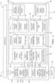
- Fig. 1illustrates a non-limiting example of a system 10 for changing a control-mode 12 of an automated vehicle 14 (hereafter referred to as the vehicle 14) from automated-control 16 to manual-control 18.
- Automated vehiclesare being developed with the goal being that an operator 20 of the vehicle 14 is little more than a passenger.
- a fully-automated or autonomous vehicleis envisioned where the operator 20 does not participate in any aspect of operational-control of the vehicle 14, other than to indicate a destination.
- unexpected circumstancesmay arise whereupon the operator 20 should assume manual-control 18 of the vehicle 14.
- the operator 20is likely to pay less attention to the roadway and objects (e.g. other-vehicles, pedestrians) proximate to the vehicle 14, and will likely engage in activities such as reading, sleeping, or participating in a meeting. It is recognized that it may be necessary to provide substantial advanced warning to the operator 20 if conditions arise that make changing the control-mode 12 from automated-control 16 to manual-control 18, and the operator 20 is, for example, asleep. As such, the amount of time necessary for the operator 20 to prepare for taking manual-control of the vehicle 14 will vary based on a readiness-state 22 of the operator 20. As will be describe in more detail below, the system 10 described herein is an improvement over prior systems because the advanced-warning time necessary for the operator 20 to prepare for taking manual-control of the vehicle 14 will be determined based on the readiness-state 22 of the operator 20.
- the system 10 described hereinis an improvement over prior systems because the advanced-warning time necessary for the operator 20 to prepare for taking manual-control of the vehicle 14 will be determined based on the readiness-state
- the system 10includes an operator-detection device 24 operable to detect the readiness-state 22 of the operator 20 of a vehicle 14 while the control-mode 12 of the vehicle is automated-control 16.
- the operator-detection device 24may include a camera 50 configured to capture images of the operator 20 in the visible light spectrum and/or the infrared light spectrum, and a light source that emits light in a suitable portion of the light spectrum so the camera 50 can see the operator 20 regardless of ambient lighting conditions.
- the images of the operator 20may be processed/analyzed by the operator-detection device 24 or a controller 26 to, for example, determine if the eyes of the operator 20 are closed indicating that the operator 20 is sleeping, determine if the head-pose 28 of the operator 20 varies in a manner that indicates that the operator 20 is tired, and/or determine if the eye-gaze direction of the operator 20 indicates that the operator 20 has or has not seen an object 30 proximate to the vehicle 14.
- Image processing techniques to determine the readiness-state 22 (e.g. ready or not ready) of the operator 20 based on various indicators such as where the operator is looking (eye-gaze direction) and/or if the operator 20 is alert (eye-blinking, head-pose variation)are well-known.
- the operator-detection device 24may include a pedal-proximity sensor 52 configured to determine when the feet of the operator 20 are close to or in contact with the brake-pedal (not shown) and/or the accelerator-pedal (not shown). If the operator's feet are close to or contacting either pedal, then that may be used as an indication that the readiness-state 22 is closer to READY rather than NOT-READY. Alternatively, the position of the operator's feet may be determined optically with a camera, or with an ultrasonic transducer. Similarly, the operator-detection device 24 may include a hand-wheel-proximity sensor 54 configured to determine when one or both hands are close to or in contact with the hand-wheel (i.e. steering-wheel).
- the controller 26may include a processor (not specifically shown) such as a microprocessor or other control circuitry such as analog and/or digital control circuitry including an application specific integrated circuit (ASIC) for processing data as should be evident to those in the art.
- the controller 26may include memory (not specifically shown) including non-volatile memory, such as electrically erasable programmable read-only memory (EEPROM) for storing one or more routines, thresholds and captured data.
- EEPROMelectrically erasable programmable read-only memory
- the one or more routinesmay be executed by the processor to perform steps for processing signals received by the controller 26 for operating the vehicle 14 as described herein.
- the controller 26is also configured to formulate a take-over-forecast 34 to forecast a future-time 32 when the control-mode 12 of the vehicle 14 should change from automated-control 16 to manual-control 18.
- the term 'future-time'is used to indicate how far into the future from the present-time the vehicle 14 should make the change from automated-control 16 to manual-control 18 mode of operation. It is contemplated that situations will arise whereby an anticipated changing of the control-mode 12 (i.e. the take-over-forecast 36) will not be necessary for a relatively long time, several minutes for example.
- the prediction or forecasting of future-time 32 for the mode-changemay be well-anticipated when the destination is past the boundaries of well-defined map-data, or based upon prior encounters of a construction area.
- the controller 26is also configured to determine a take-over-interval 36 that is generally characterized as an expected amount of time necessary for the operator 20 to prepare to assume manual-control 18 of the vehicle 14 once notified, i.e. after the operator 20 is notified.
- the take-over-interval 36may be determined based on, among other things, the readiness-state 22 of the operator 20. While Fig. 1 suggests only two states, READY and NOT-READY, many degrees of readiness are contemplated and the take-over-interval 36 indicates a measure of time with a continuously variable value.
- the NOT-READY statewill includes many different states such as, but not limited to: slightly-distracted, moderately-distracted, very-distracted, out-of-position, sleeping, medical-distress, unconscious, and intoxicated.
- the readiness-state 22in some instances will be such that the operator 20 is unable to or should not assume manual-control 18 of the vehicle 14, so the controller 26 may be configured to, for example, stop the vehicle 14, continue under automated-control 16 but at greatly reduced speeds, or change the destination to the nearest hospital.
- the controller 26is further configured to notify the operator 20 that the control-mode 12 of the vehicle should change from automated-control 16 to manual-control 18 no later than the take-over-interval 36 prior to the future-time 32. That is, given that the controller as formulated the take-over-forecast 34 and determined the future-time 32 that the operator 20 should have manual-control of the vehicle 14, the controller 26 may activate a notification-device 38 at a notification-time 40 at or prior to the take-over-interval 36 before the future-time 32. In other words, the controller 26 determines the notification-time 40 that the notification device 38 is activated so the operator 20 has sufficient time to prepare for manual-control 18, and the notification-time 40 corresponds or is prior to the take-over-interval 36 before the future-time 32.
- the notification-device 38may include, for example, a visible warning device such as an illuminated indicator or a highlighted region of a reconfigurable display, an audible warning device such as a buzzer or speaker, and/or a haptic warning device such as a vibrating device located in a seat or steering wheel of the vehicle 14.
- the controller 26may also determine a notification-intensity 42 that is variable.
- the intensity of a notification provided by the notification-device 38may be increased by, for example, increasing the loudness of an audible warning, increasing the highlighting intensity or vigorous flashing of the visible warning, and/or simultaneously combining two or more of the warning types available from the notification-device 38.
- the notification-intensity 42may be increased if the take-over-forecast 34 did not recognize soon-enough that the control-mode 12 should be switched from automated-control 16 to manual-control 18 to allow the operator 20 to prepare based on the readiness-state 22. For example, if the operator 20 is sleeping, and the normal take-over-interval for this readiness state is fifteen seconds, but the future-time is only twelve seconds from now, the controller may increase the loudness of the audible warning to more quickly wake-up the operator 20.
- the system 10may include an object-detection device 68 operable or useful to detect when the object 30 is proximate to the vehicle 14.
- the object-detection device 68may include, but is not limited to a video camera, a radar unit, and/or a LIDAR unit suitably configured to detect various objects about the vehicle 14.
- a cameramay be used to capture images of objects such as other-vehicles, buildings, roadway signs, pedestrians, lane-markings, roadway hazards, construction area markers, and other objects located proximate to or about the vehicle 14.
- Information from the cameramay be combined with detection information from the radar unit and/or the LIDAR unit to form a two-dimensional or three-dimensional map of various objects in the area surrounding the vehicle 14.
- Information gathered by the operation of the object-detection device 68may be provided to the controller 26 for further analysis. That is, the object-detection device 68 may not by itself actually determine the location of or classification of the object 30. Typically that task falls to the controller 26, but this is not a requirement of the system 10. In other words, either the object-detection device 68 or the controller 26 may perform the data or signal processing necessary to determine a relative location or classification of the object 30.
- the system 10may be configured to classify the object 30 based on signals received from the object-detection device 68. For example, if the object 30 is a pedestrian walking perpendicular to the direction of travel of the vehicle 14, signals from the LIDAR unit or the radar unit may have a unique signature caused by the alternating motion of the legs of the pedestrian. Similarly, radar returns reflected from a moving vehicle may include micro-fluctuations cause by the rotational motion of the wheels of the moving vehicle. This information may optionally be combined with other known image processing techniques to classify the object as, for example, a pedestrian, another-vehicle, a construction-zone marker, an animal, a roadway barrier, etc.
- Information about motion of the object 30may also be used to classify the object 30 and assign motion related parameters such as speed, trajectory, acceleration/deceleration, and the like to the object 30.
- the object-detection device 68is operable to detect when the object 30 is proximate to, i.e. close-by, in the travel-path, or approaching the travel pate of the vehicle 14.
- the readiness-state 22may be determined based on body-orientation 44 of the operator 20.
- the readiness state 22is likely to be set to something other than READY.
- the operator 20may have the readiness-state 22 set to READY if the operator 20 is sitting squarely in the driver's seat, facing forward, attentive to the roadway and surroundings about the vehicle 14, with feet close to but not necessarily touching the brake-pedal and the accelerator-pedal, and hands empty and positioned so the hand-wheel (i.e. steering-wheel) can be quickly grasped if the operator 20 is notified to do so.
- the body-orientation 44is much different that described above, the readiness-state will be set to something other than READY, that is to one of a variety of readiness-states that are related to or lumped under NOT-READY.
- the body-orientation 44may be determined based on a foot-position 46 of a foot of the operator. If the foot-position 46 corresponds to the operator's feet being close to or contacting either pedal, then that may be used as an indication that the readiness-state 22 is closer to READY than NOT-READY. However, if the operator's feet are crossed, or one foot is tucked under the other leg, or one foot is stretched out into the passenger-side foot-well, then that may be used as an indication that the readiness-state 22 is NOT-READY rather than READY.
- the take-over-interval 36 when only the feet are out of positionmay be on the order of four seconds. Other examples of the body-orientation 44 that cause longer and shorter value of the take-over-interval 36 are given below.
- the body-orientation 44may be determined based on a facing-direction 48 of the operator.
- the facing-direction 48is generally determined based on the orientation of the torso/shoulders. If the torso/shoulders are square to, i.e. facing, the hand-wheel, then that may be used as an indication that the readiness-state 22 is closer to READY than NOT-READY. However, if the facing-direction 48 is turned away from the hand-wheel because, for example the operator 20 is sitting sideways in the seat or lying down, then that may be used as an indication that the readiness-state 22 is NOT-READY rather than READY. If the facing-direction 48 is sideways because the operator 20 is sitting sideways in the seat, then the take-over-interval 36 may be on the order of seven seconds.
- the body-orientation 44may be determined based on a head-pose 28 of the operator.
- the head-pose 28is determine based on the orientation of the head or face, and is generally independent of the facing-direction 48. If the head is upright and the face is facing forward, then that may be used as an indication that the readiness-state 22 is closer to READY than NOT-READY. However, if the facing-direction 48 is turned away from the roadway because, for example the operator is looking at a passenger, then that may be used as an indication that the readiness-state 22 is NOT-READY rather than READY. If the head-pose 28 is sideways because the operator 20 is looking at a passenger, but the body-orientation otherwise corresponds to READY, then the take-over-interval 36 may be on the order of only two seconds.
- the system 10may also determine the readiness-state 22 based on a distraction-level 56 of the operator 20. For example, if a child-presence 58 is detected, in combination with a head-pose 28 or a facing-direction 48, then that can be taken as an indication that the operator 20 highly-distracted or very-distracted so the take-over-interval 36 would be increased relative to a situation when the child-presence 58 was not detected and/or the head-pose 28 and the facing-direction 48 corresponded to READY. That is, the distraction-level 56 is increased when the operator 20 attends to a child present in the vehicle 14.
- the controller 26may also be configured to operate the vehicle 14 in accordance with control-parameters 60 when the control-mode 12 of the vehicle is automated-control 16 and the readiness-state 22 of the operator 20 is READY.
- the control-parameters 60may be predetermined and stored in the controller, or may be down-loaded from map data stored on an internet server.
- the control-parameters 60may be modified when the readiness-state of the operator is NOT-READY to allow for an increase of the take-over-interval 36.
- the increase of the take-over-interval 36is realized by one or more of increased following-distance 62 and decreased travel-speed 64.
- control parameter s 60 use to operate the vehicle 14 during automated-control 16may be changed so the controller 26 has more time to formulate the take-over-forecast 34 and a greater safety margin so the future-time 32 is more distant in the future. Then if the readiness-state 22 of the operator is other than READY, it is more likely that the take-over-interval will be too long when compared to the future-time 32.
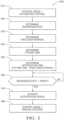
- Fig. 2illustrates a non-limiting example of a method 200 of operating the system 10 described herein.
- Step 210, CONTROL-MODEAUTOMATED-CONTROL, may include the operator instructing the controller 26 to set the control-mode 12 of the vehicle 14 to automated-control 16 so the operator 20 can do something other than manually operate the vehicle 14. Instructing the controller 26 may be by way of operating a switch, or by way of a verbal command, or any other means known to those in the art.
- Step 220DETERMINE READINESS-STATE, may include continuous or periodic monitoring of the operator 20 via the operator-detection device 24. From this information, the controller 26 can determine if the operator 20 is READY to quickly take-over manual control of the vehicle 14 if necessary, or if the operator 20 needs some advanced warning that the take-over is needed because the operator 20 is characterized as NOT-READY.
- Step 230, DETERMINE TAKE-OVER-INTERVALmay include determining the degree to which the operator 20 is NOT-READY. If the operator 20 is READY, the take-over-interval may be relatively short, one second for example. However, if the operator 20 is sound asleep lying across the seat of the vehicle 14, the take-over-interval 36 may be on the order of thirty seconds to allow time for the operator 20 to wake-up and prepare to take control of the vehicle 14. Examples of other degrees of NOT-READY and corresponding values of the take-over-interval 36 were previously described.
- Step 240, DETERMINE FUTURE-TIMEmay include the controller determining when the transition from automated-control 16 to manual-control 18 needs to be completed to continue uninterrupted movement of the vehicle 14
- Step 250DETERMINE NOTIFICATION TIME (FUTURE-TIME - TAKE-OVER-INTERVAL), may include subtracting from the future time 32 the value of the take-over-interval 36 to determine when the notification device 38 should be activated so the operator 20 is not notified too early or too late to prepare to take manual-control of the vehicle 14.
- Step 260ACTIVATE NOTIFICATION DEVICE, may include activating one or more of the notification-device 38 described elsewhere herein. If the timing of the future-time 32 relative to the take-over-interval 36 is close, Step 260 may also include increasing the notification-intensity 42 to get the operator 20 to respond more quickly.
- Step 280, CONTROL-MODEMANUAL-CONTROL, may include the controller 26 stopping automated control of the vehicle 14 and allowing the operator 20 to operate the vehicle-controls 66.
- a non-claimed system 10 for changing a control-mode of an automated vehicle (the vehicle 14) from automated-control 16 to manual-control 18, a controller 26 and a method 200 of operation for the systemis provided.
- the system 10avoids notifying the operator too early that the control-mode 12 of the vehicle should change from automated-control 16 to manual-control 18.
- the control-parameters 60may be varied to provide more time for the take-over-interval 36.
Landscapes
- Engineering & Computer Science (AREA)
- Automation & Control Theory (AREA)
- Transportation (AREA)
- Mechanical Engineering (AREA)
- Human Computer Interaction (AREA)
- Physics & Mathematics (AREA)
- General Physics & Mathematics (AREA)
- Health & Medical Sciences (AREA)
- Artificial Intelligence (AREA)
- Evolutionary Computation (AREA)
- Medical Informatics (AREA)
- Software Systems (AREA)
- Computer Vision & Pattern Recognition (AREA)
- Aviation & Aerospace Engineering (AREA)
- Radar, Positioning & Navigation (AREA)
- Remote Sensing (AREA)
- Traffic Control Systems (AREA)
- Business, Economics & Management (AREA)
- Game Theory and Decision Science (AREA)
- Control Of Vehicle Engines Or Engines For Specific Uses (AREA)
Description
- This disclosure generally relates to a system for control of an automated vehicle, and more particularly relates to determining a take-over-interval for an operator to assume manual-control of the vehicle based on a readiness-state of the operator.
- Passenger vehicles (e.g. automobiles) with various degrees of automation have been proposed. Vehicles equipped with automated speed control, commonly known as cruise control, are well-known. Fully automated or autonomous vehicles where the operator is not engaged with any aspect of operating the vehicle are being developed. However, it is contemplated that unexpected traffic scenarios or situations will arise when it will be preferable to have the operator assume manual control of the vehicle.
US 2015/070160 A1 discloses a method and arrangement for handover warning in a vehicle having autonomous driving capabilities and a vehicle controller configured to control unmanned autonomous travel. A processor may be configured to monitor if there is a need to transition from unmanned autonomous travel to manual control of the vehicle. A warning output system is provided to output a time adapted warning information to a vehicle passenger compartment.US 2014/303827 A1 discloses methods and systems for adaptive methods for transitioning control to a driver. A computing device may provide instructions to perform the transition of control of the vehicle from autonomous mode to manual mode.US 2015/051780 A1 discloses a method for driver support in a vehicle in which a driver assistance system monitors a driving situation of the vehicle. Support takes place after a confirmation or after the absence of an abort instruction, a dialogue about the extent of support the driver wishes being conducted between the driver and the driver assistance system.
It is an object of the invention to provide a method and a controller for changing a control-mode of an automated vehicle which provides an improved safety.
This object is solved by a method in accordance with claim 1 and by a controller in accordance withclaim 10. - Further features and advantages will appear more clearly on a reading of the following detailed description of the preferred embodiment, which is given by way of non-limiting example only and with reference to the accompanying drawings.
- The present invention will now be described, by way of example with reference to the accompanying drawings, in which:
Fig. 1 is a diagram of a system for control of an automated vehicle in accordance with one embodiment; andFig. 2 is a flowchart of a method of operation of the system ofFig. 1 in accordance with one embodiment.Fig. 1 illustrates a non-limiting example of asystem 10 for changing a control-mode 12 of an automated vehicle 14 (hereafter referred to as the vehicle 14) from automated-control 16 to manual-control 18. Automated vehicles are being developed with the goal being that anoperator 20 of thevehicle 14 is little more than a passenger. A fully-automated or autonomous vehicle is envisioned where theoperator 20 does not participate in any aspect of operational-control of thevehicle 14, other than to indicate a destination. However, it is contemplated that, at least in the early development stages, unexpected circumstances may arise whereupon theoperator 20 should assume manual-control 18 of thevehicle 14. For example, it may be safer for theoperator 20 and others around thevehicle 14 if theoperator 20 assumes manual-control while traveling in a construction-area where no roadway or other indications of a travel path are available for the automated-vehicle to use to navigate through the construction-area.- It is also envisioned that as people become accustomed to traveling in an automated or autonomous vehicle, the
operator 20 is likely to pay less attention to the roadway and objects (e.g. other-vehicles, pedestrians) proximate to thevehicle 14, and will likely engage in activities such as reading, sleeping, or participating in a meeting. It is recognized that it may be necessary to provide substantial advanced warning to theoperator 20 if conditions arise that make changing the control-mode 12 from automated-control 16 to manual-control 18, and theoperator 20 is, for example, asleep. As such, the amount of time necessary for theoperator 20 to prepare for taking manual-control of thevehicle 14 will vary based on a readiness-state 22 of theoperator 20. As will be describe in more detail below, thesystem 10 described herein is an improvement over prior systems because the advanced-warning time necessary for theoperator 20 to prepare for taking manual-control of thevehicle 14 will be determined based on the readiness-state 22 of theoperator 20. - The
system 10 includes an operator-detection device 24 operable to detect the readiness-state 22 of theoperator 20 of avehicle 14 while the control-mode 12 of the vehicle is automated-control 16. The operator-detection device 24 may include acamera 50 configured to capture images of theoperator 20 in the visible light spectrum and/or the infrared light spectrum, and a light source that emits light in a suitable portion of the light spectrum so thecamera 50 can see theoperator 20 regardless of ambient lighting conditions. The images of theoperator 20 may be processed/analyzed by the operator-detection device 24 or acontroller 26 to, for example, determine if the eyes of theoperator 20 are closed indicating that theoperator 20 is sleeping, determine if the head-pose 28 of theoperator 20 varies in a manner that indicates that theoperator 20 is tired, and/or determine if the eye-gaze direction of theoperator 20 indicates that theoperator 20 has or has not seen anobject 30 proximate to thevehicle 14. Image processing techniques to determine the readiness-state 22 (e.g. ready or not ready) of theoperator 20 based on various indicators such as where the operator is looking (eye-gaze direction) and/or if theoperator 20 is alert (eye-blinking, head-pose variation) are well-known. - The operator-
detection device 24 may include a pedal-proximity sensor 52 configured to determine when the feet of theoperator 20 are close to or in contact with the brake-pedal (not shown) and/or the accelerator-pedal (not shown). If the operator's feet are close to or contacting either pedal, then that may be used as an indication that the readiness-state 22 is closer to READY rather than NOT-READY. Alternatively, the position of the operator's feet may be determined optically with a camera, or with an ultrasonic transducer. Similarly, the operator-detection device 24 may include a hand-wheel-proximity sensor 54 configured to determine when one or both hands are close to or in contact with the hand-wheel (i.e. steering-wheel). - The
controller 26 may include a processor (not specifically shown) such as a microprocessor or other control circuitry such as analog and/or digital control circuitry including an application specific integrated circuit (ASIC) for processing data as should be evident to those in the art. Thecontroller 26 may include memory (not specifically shown) including non-volatile memory, such as electrically erasable programmable read-only memory (EEPROM) for storing one or more routines, thresholds and captured data. The one or more routines may be executed by the processor to perform steps for processing signals received by thecontroller 26 for operating thevehicle 14 as described herein. - The
controller 26 is also configured to formulate a take-over-forecast 34 to forecast a future-time 32 when the control-mode 12 of thevehicle 14 should change from automated-control 16 to manual-control 18. As used herein, the term 'future-time' is used to indicate how far into the future from the present-time thevehicle 14 should make the change from automated-control 16 to manual-control 18 mode of operation. It is contemplated that situations will arise whereby an anticipated changing of the control-mode 12 (i.e. the take-over-forecast 36) will not be necessary for a relatively long time, several minutes for example. By way of example and not limitation, the prediction or forecasting of future-time 32 for the mode-change may be well-anticipated when the destination is past the boundaries of well-defined map-data, or based upon prior encounters of a construction area. - The
controller 26 is also configured to determine a take-over-interval 36 that is generally characterized as an expected amount of time necessary for theoperator 20 to prepare to assume manual-control 18 of thevehicle 14 once notified, i.e. after theoperator 20 is notified. The take-over-interval 36 may be determined based on, among other things, the readiness-state 22 of theoperator 20. WhileFig. 1 suggests only two states, READY and NOT-READY, many degrees of readiness are contemplated and the take-over-interval 36 indicates a measure of time with a continuously variable value. In particular, it is contemplated that the NOT-READY state will includes many different states such as, but not limited to: slightly-distracted, moderately-distracted, very-distracted, out-of-position, sleeping, medical-distress, unconscious, and intoxicated. Furthermore, it is contemplated that the readiness-state 22 in some instances will be such that theoperator 20 is unable to or should not assume manual-control 18 of thevehicle 14, so thecontroller 26 may be configured to, for example, stop thevehicle 14, continue under automated-control 16 but at greatly reduced speeds, or change the destination to the nearest hospital. - Assuming that the readiness-
state 22 of theoperator 20 is such that theoperator 20 is able to assume manual-control 18 of thevehicle 14 given sufficient advanced warning, thecontroller 26 is further configured to notify theoperator 20 that the control-mode 12 of the vehicle should change from automated-control 16 to manual-control 18 no later than the take-over-interval 36 prior to the future-time 32. That is, given that the controller as formulated the take-over-forecast 34 and determined the future-time 32 that theoperator 20 should have manual-control of thevehicle 14, thecontroller 26 may activate a notification-device 38 at a notification-time 40 at or prior to the take-over-interval 36 before the future-time 32. In other words, thecontroller 26 determines the notification-time 40 that thenotification device 38 is activated so theoperator 20 has sufficient time to prepare for manual-control 18, and the notification-time 40 corresponds or is prior to the take-over-interval 36 before the future-time 32. - The notification-
device 38 that may include, for example, a visible warning device such as an illuminated indicator or a highlighted region of a reconfigurable display, an audible warning device such as a buzzer or speaker, and/or a haptic warning device such as a vibrating device located in a seat or steering wheel of thevehicle 14. Thecontroller 26 may also determine a notification-intensity 42 that is variable. The intensity of a notification provided by the notification-device 38 may be increased by, for example, increasing the loudness of an audible warning, increasing the highlighting intensity or vigorous flashing of the visible warning, and/or simultaneously combining two or more of the warning types available from the notification-device 38. It is contemplated that the notification-intensity 42 may be increased if the take-over-forecast 34 did not recognize soon-enough that the control-mode 12 should be switched from automated-control 16 to manual-control 18 to allow theoperator 20 to prepare based on the readiness-state 22. For example, if theoperator 20 is sleeping, and the normal take-over-interval for this readiness state is fifteen seconds, but the future-time is only twelve seconds from now, the controller may increase the loudness of the audible warning to more quickly wake-up theoperator 20. - The
system 10 may include an object-detection device 68 operable or useful to detect when theobject 30 is proximate to thevehicle 14. The object-detection device 68 may include, but is not limited to a video camera, a radar unit, and/or a LIDAR unit suitably configured to detect various objects about thevehicle 14. By way of further example and not limitation, a camera may be used to capture images of objects such as other-vehicles, buildings, roadway signs, pedestrians, lane-markings, roadway hazards, construction area markers, and other objects located proximate to or about thevehicle 14. - Information from the camera may be combined with detection information from the radar unit and/or the LIDAR unit to form a two-dimensional or three-dimensional map of various objects in the area surrounding the
vehicle 14. Information gathered by the operation of the object-detection device 68 may be provided to thecontroller 26 for further analysis. That is, the object-detection device 68 may not by itself actually determine the location of or classification of theobject 30. Typically that task falls to thecontroller 26, but this is not a requirement of thesystem 10. In other words, either the object-detection device 68 or thecontroller 26 may perform the data or signal processing necessary to determine a relative location or classification of theobject 30. - The
system 10 may be configured to classify theobject 30 based on signals received from the object-detection device 68. For example, if theobject 30 is a pedestrian walking perpendicular to the direction of travel of thevehicle 14, signals from the LIDAR unit or the radar unit may have a unique signature caused by the alternating motion of the legs of the pedestrian. Similarly, radar returns reflected from a moving vehicle may include micro-fluctuations cause by the rotational motion of the wheels of the moving vehicle. This information may optionally be combined with other known image processing techniques to classify the object as, for example, a pedestrian, another-vehicle, a construction-zone marker, an animal, a roadway barrier, etc. Information about motion of theobject 30 may also be used to classify theobject 30 and assign motion related parameters such as speed, trajectory, acceleration/deceleration, and the like to theobject 30. As such, the object-detection device 68 is operable to detect when theobject 30 is proximate to, i.e. close-by, in the travel-path, or approaching the travel pate of thevehicle 14. - Continuing to refer to
Fig. 1 , the readiness-state 22 may be determined based on body-orientation 44 of theoperator 20. In general, if the body-orientation 44 is other than something very close to what would be the case when theoperator 20 was manually operating thevehicle 14, thereadiness state 22 is likely to be set to something other than READY. By way of example and not limitation, theoperator 20 may have the readiness-state 22 set to READY if theoperator 20 is sitting squarely in the driver's seat, facing forward, attentive to the roadway and surroundings about thevehicle 14, with feet close to but not necessarily touching the brake-pedal and the accelerator-pedal, and hands empty and positioned so the hand-wheel (i.e. steering-wheel) can be quickly grasped if theoperator 20 is notified to do so. If the body-orientation 44 is much different that described above, the readiness-state will be set to something other than READY, that is to one of a variety of readiness-states that are related to or lumped under NOT-READY. - By way of example and not limitation, the body-
orientation 44 may be determined based on a foot-position 46 of a foot of the operator. If the foot-position 46 corresponds to the operator's feet being close to or contacting either pedal, then that may be used as an indication that the readiness-state 22 is closer to READY than NOT-READY. However, if the operator's feet are crossed, or one foot is tucked under the other leg, or one foot is stretched out into the passenger-side foot-well, then that may be used as an indication that the readiness-state 22 is NOT-READY rather than READY. By way of further example, the take-over-interval 36 when only the feet are out of position may be on the order of four seconds. Other examples of the body-orientation 44 that cause longer and shorter value of the take-over-interval 36 are given below. - By way of another example and not limitation, the body-
orientation 44 may be determined based on a facing-direction 48 of the operator. As used herein, the facing-direction 48 is generally determined based on the orientation of the torso/shoulders. If the torso/shoulders are square to, i.e. facing, the hand-wheel, then that may be used as an indication that the readiness-state 22 is closer to READY than NOT-READY. However, if the facing-direction 48 is turned away from the hand-wheel because, for example theoperator 20 is sitting sideways in the seat or lying down, then that may be used as an indication that the readiness-state 22 is NOT-READY rather than READY. If the facing-direction 48 is sideways because theoperator 20 is sitting sideways in the seat, then the take-over-interval 36 may be on the order of seven seconds. - By way of another example and not limitation, the body-
orientation 44 may be determined based on a head-pose 28 of the operator. As used herein, the head-pose 28 is determine based on the orientation of the head or face, and is generally independent of the facing-direction 48. If the head is upright and the face is facing forward, then that may be used as an indication that the readiness-state 22 is closer to READY than NOT-READY. However, if the facing-direction 48 is turned away from the roadway because, for example the operator is looking at a passenger, then that may be used as an indication that the readiness-state 22 is NOT-READY rather than READY. If the head-pose 28 is sideways because theoperator 20 is looking at a passenger, but the body-orientation otherwise corresponds to READY, then the take-over-interval 36 may be on the order of only two seconds. - The
system 10 may also determine the readiness-state 22 based on a distraction-level 56 of theoperator 20. For example, if a child-presence 58 is detected, in combination with a head-pose 28 or a facing-direction 48, then that can be taken as an indication that theoperator 20 highly-distracted or very-distracted so the take-over-interval 36 would be increased relative to a situation when the child-presence 58 was not detected and/or the head-pose 28 and the facing-direction 48 corresponded to READY. That is, the distraction-level 56 is increased when theoperator 20 attends to a child present in thevehicle 14. - The
controller 26 may also be configured to operate thevehicle 14 in accordance with control-parameters 60 when the control-mode 12 of the vehicle is automated-control 16 and the readiness-state 22 of theoperator 20 is READY. The control-parameters 60 may be predetermined and stored in the controller, or may be down-loaded from map data stored on an internet server. The control-parameters 60 may be modified when the readiness-state of the operator is NOT-READY to allow for an increase of the take-over-interval 36. For example, the increase of the take-over-interval 36 is realized by one or more of increased following-distance 62 and decreased travel-speed 64. That is, the control parameter s 60 use to operate thevehicle 14 during automated-control 16 may be changed so thecontroller 26 has more time to formulate the take-over-forecast 34 and a greater safety margin so the future-time 32 is more distant in the future. Then if the readiness-state 22 of the operator is other than READY, it is more likely that the take-over-interval will be too long when compared to the future-time 32. Fig. 2 illustrates a non-limiting example of amethod 200 of operating thesystem 10 described herein.Step 210, CONTROL-MODE = AUTOMATED-CONTROL, may include the operator instructing thecontroller 26 to set the control-mode 12 of thevehicle 14 to automated-control 16 so theoperator 20 can do something other than manually operate thevehicle 14. Instructing thecontroller 26 may be by way of operating a switch, or by way of a verbal command, or any other means known to those in the art.- It is recognized that the order of some of the following steps could be changed and still provide useful operation. As such, it is emphasized that the
method 200 is a non-limiting example Step 220, DETERMINE READINESS-STATE, may include continuous or periodic monitoring of theoperator 20 via the operator-detection device 24. From this information, thecontroller 26 can determine if theoperator 20 is READY to quickly take-over manual control of thevehicle 14 if necessary, or if theoperator 20 needs some advanced warning that the take-over is needed because theoperator 20 is characterized as NOT-READY.Step 230, DETERMINE TAKE-OVER-INTERVAL, may include determining the degree to which theoperator 20 is NOT-READY. If theoperator 20 is READY, the take-over-interval may be relatively short, one second for example. However, if theoperator 20 is sound asleep lying across the seat of thevehicle 14, the take-over-interval 36 may be on the order of thirty seconds to allow time for theoperator 20 to wake-up and prepare to take control of thevehicle 14. Examples of other degrees of NOT-READY and corresponding values of the take-over-interval 36 were previously described.Step 240, DETERMINE FUTURE-TIME, may include the controller determining when the transition from automated-control 16 to manual-control 18 needs to be completed to continue uninterrupted movement of thevehicle 14Step 250, DETERMINE NOTIFICATION TIME (FUTURE-TIME - TAKE-OVER-INTERVAL), may include subtracting from the future time 32 the value of the take-over-interval 36 to determine when thenotification device 38 should be activated so theoperator 20 is not notified too early or too late to prepare to take manual-control of thevehicle 14.Step 260, ACTIVATE NOTIFICATION DEVICE, may include activating one or more of the notification-device 38 described elsewhere herein. If the timing of the future-time 32 relative to the take-over-interval 36 is close,Step 260 may also include increasing the notification-intensity 42 to get theoperator 20 to respond more quickly.Step 270, READINESS-STATE = READY?, may include monitoring theoperator 20 until the readiness-state 22 of theoperator 20 is READY. If the readiness-state 22 of theoperator 20 is NOT-READY (i.e. the outcome of the decision is NO), the method loops back and waits until the readiness-state 22 of theoperator 20 is READY (i.e. the outcome of the decision is YES). When YES, themethod 200 proceeds to step 280.Step 280, CONTROL-MODE = MANUAL-CONTROL, may include thecontroller 26 stopping automated control of thevehicle 14 and allowing theoperator 20 to operate the vehicle-controls 66.- Accordingly, a
non-claimed system 10 for changing a control-mode of an automated vehicle (the vehicle 14) from automated-control 16 to manual-control 18, acontroller 26 and amethod 200 of operation for the system is provided. By determining the readiness-state of theoperator 20 and using that information to determine thenotification time 40 and thenotification intensity 42, thesystem 10 avoids notifying the operator too early that the control-mode 12 of the vehicle should change from automated-control 16 to manual-control 18. Also, if the system discovers too late that the control-mode should be changed, the control-parameters 60 may be varied to provide more time for the take-over-interval 36.
Claims (10)
- A method for changing a control mode (12) of an automated vehicle (14) from an automated control (16) to a manual control (18) comprising:operating (210), by a controller (26), based on one or more control parameters (60), a vehicle (14) under the automated control (16);determining (240), by the controller (26), while a control mode of the vehicle (14) is under the automated control (16), a future time (32) when a control mode (12) of the vehicle (14) is to change from the automated control (16) to manual control (18);determining (230), by the controller (26), based on a readiness state (22) of an operator (20) of the vehicle (14) determined (220) by an operator detection device (24) of the vehicle (14), a take over interval (36) during which the control mode (12) is to change from the automated control (16) to the manual control (18); andoutputting (270), during the take over interval (36), a notification that the control mode (12) of the vehicle is to change from the automated control (16) to the manual control (18);characterized byresponsive to determining that the readiness state (22) indicates that the operator (20) is not ready for the manual control (18) (260), modifying the one or more control parameters (60) thereby increasing the take over interval (36), wherein the increased take over interval (36) is realized by an increased following distance (62) of the vehicle (14).
- The method of claim 1, wherein the readiness state (22) is detected by the operator detection device (24) and determined based on a body orientation (44).
- The method of claim 2, wherein body orientation (44) detected by the operator detection device (24) comprises a foot position (46) of the operator (20).
- The method of claim 2 or 3, wherein body orientation (44) detected by the operator detection device (24) comprises a facing direction (48) of the operator (20).
- The method of any of claims 2 through 4, wherein body orientation (44) detected by the operator detection device (24) comprises a head pose (28) of the operator (20).
- The method of any of the preceding claims, wherein the readiness state (22) is determined based on a distraction level (56) of the operator (20).
- The method of claim 6, wherein the distraction level (56) indicates that the operator (20) is not ready for the manual control (18) when a body orientation (44) detected by the operator detection device (24) indicates that the operator (20) is not ready for driving.
- The method of claim 6, wherein the distraction level (56) indicates that the operator (20) is not ready for the manual control (18) when a foot position (46) detected by the operator detection device (24) indicates that the operator (20) is not ready for driving.
- The method of claim 6, wherein the distraction level (56) indicates that the operator (20) is not ready for the manual control (18) when a hand position (46) detected by the operator detection device (24) indicates that the operator (20) is not ready for driving.
- A controller (26) configured to:operate (210), based on one or more control parameters (60), a vehicle (14) under an automated control (16);determine (240), while a control mode of the vehicle (14) is under the automated control (16), a future time (32) when a control mode (12) of the vehicle (14) is to change from the automated control (16) to a manual control (18);determine (230), based on a readiness state (22) of an operator (20) of the vehicle (14) determined (220) by an operator detection device (24) of the vehicle (14), a take over interval (36) during which the control mode (12) is to change from the automated control (16) to the manual control (18); andoutput (270), during the take over interval (36), a notification that the control mode (12) of the vehicle is to change from the automated control (16) to the manual control (18);characterized in thatthe controller (26) is further configured to:
responsive to the determination that the readiness state (22) indicates that the operator (20) is not ready for the manual control (18) (260), modify the one or more control parameters (60) thereby increasing the take over interval (36), wherein the increased take over interval (36) is realized by an increased following distance (62) of the vehicle (14).
Applications Claiming Priority (3)
| Application Number | Priority Date | Filing Date | Title |
|---|---|---|---|
| US14/748,530US9727056B2 (en) | 2015-06-24 | 2015-06-24 | Automated vehicle control with time to take-over compensation |
| EP16814899.7AEP3313703B1 (en) | 2015-06-24 | 2016-05-18 | Automated vehicle control with time to take-over compensation |
| PCT/US2016/032991WO2016209424A1 (en) | 2015-06-24 | 2016-05-18 | Automated vehicle control with time to take-over compensation |
Related Parent Applications (2)
| Application Number | Title | Priority Date | Filing Date |
|---|---|---|---|
| EP16814899.7ADivision-IntoEP3313703B1 (en) | 2015-06-24 | 2016-05-18 | Automated vehicle control with time to take-over compensation |
| EP16814899.7ADivisionEP3313703B1 (en) | 2015-06-24 | 2016-05-18 | Automated vehicle control with time to take-over compensation |
Publications (2)
| Publication Number | Publication Date |
|---|---|
| EP3822728A1 EP3822728A1 (en) | 2021-05-19 |
| EP3822728B1true EP3822728B1 (en) | 2023-04-19 |
Family
ID=57586592
Family Applications (2)
| Application Number | Title | Priority Date | Filing Date |
|---|---|---|---|
| EP20216120.4AActiveEP3822728B1 (en) | 2015-06-24 | 2016-05-18 | Automated vehicle control with time to take-over compensation |
| EP16814899.7AActiveEP3313703B1 (en) | 2015-06-24 | 2016-05-18 | Automated vehicle control with time to take-over compensation |
Family Applications After (1)
| Application Number | Title | Priority Date | Filing Date |
|---|---|---|---|
| EP16814899.7AActiveEP3313703B1 (en) | 2015-06-24 | 2016-05-18 | Automated vehicle control with time to take-over compensation |
Country Status (4)
| Country | Link |
|---|---|
| US (1) | US9727056B2 (en) |
| EP (2) | EP3822728B1 (en) |
| CN (1) | CN107709124B (en) |
| WO (1) | WO2016209424A1 (en) |
Families Citing this family (29)
| Publication number | Priority date | Publication date | Assignee | Title |
|---|---|---|---|---|
| JP6342856B2 (en)* | 2015-07-31 | 2018-06-13 | トヨタ自動車株式会社 | Vehicle control device |
| US9904286B2 (en)* | 2015-10-13 | 2018-02-27 | Nokia Technologies Oy | Method and apparatus for providing adaptive transitioning between operational modes of an autonomous vehicle |
| DE102015223688A1 (en)* | 2015-11-30 | 2017-06-01 | Bayerische Motoren Werke Aktiengesellschaft | Arrangement, means of locomotion and method for assuming a driving task by an occupant of a means of transport located in a highly automated driving state |
| DE102015224555A1 (en)* | 2015-12-08 | 2017-06-08 | Robert Bosch Gmbh | Method for operating a vehicle |
| US9958865B2 (en)* | 2015-12-18 | 2018-05-01 | GM Global Technology Operations LLC | Systems and methods to enable or disable autonomous driving |
| US9989963B2 (en) | 2016-02-25 | 2018-06-05 | Ford Global Technologies, Llc | Autonomous confidence control |
| US10289113B2 (en)* | 2016-02-25 | 2019-05-14 | Ford Global Technologies, Llc | Autonomous occupant attention-based control |
| US10026317B2 (en) | 2016-02-25 | 2018-07-17 | Ford Global Technologies, Llc | Autonomous probability control |
| JP6540983B2 (en)* | 2016-03-16 | 2019-07-10 | 本田技研工業株式会社 | Vehicle control system, vehicle control method, and vehicle control program |
| WO2018109868A1 (en)* | 2016-12-14 | 2018-06-21 | 本田技研工業株式会社 | Vehicle control device |
| JP2019034575A (en)* | 2017-08-10 | 2019-03-07 | オムロン株式会社 | Driver state recognition apparatus, driver state recognition system, and driver state recognition method |
| JP2019034576A (en)* | 2017-08-10 | 2019-03-07 | オムロン株式会社 | Driver state recognition apparatus, driver state recognition system, and driver state recognition method |
| US10635104B2 (en) | 2018-08-21 | 2020-04-28 | International Business Machines Corporation | Intelligent transitioning between autonomous and manual driving modes of a vehicle |
| US11092458B2 (en) | 2018-10-30 | 2021-08-17 | Telenav, Inc. | Navigation system with operation obstacle alert mechanism and method of operation thereof |
| US11358585B2 (en)* | 2019-01-04 | 2022-06-14 | Delphi Technologies Ip Limited | System and method for torque split arbitration |
| US12258049B2 (en) | 2019-04-24 | 2025-03-25 | Walter Steven Rosenbaum | Method and system for analyzing the control of a vehicle |
| EP3960576B1 (en)* | 2019-04-24 | 2024-12-11 | Walter Steven Rosenbaum | Method and system for analysing the control of a vehicle |
| KR20200129351A (en)* | 2019-05-08 | 2020-11-18 | 현대자동차주식회사 | Vehicle and method for controlling thereof |
| KR102860408B1 (en)* | 2019-08-20 | 2025-09-17 | 현대자동차주식회사 | Vehicle and method for controlling thereof |
| JP2021043571A (en)* | 2019-09-09 | 2021-03-18 | ソニーセミコンダクタソリューションズ株式会社 | Information processing device, mobile device, and information process system, method and program |
| EP4470865A3 (en) | 2019-09-17 | 2025-03-05 | Aptiv Technologies AG | Method and device for determining an estimate of the capability of a vehicle driver to take over control of a vehicle |
| US11111895B2 (en)* | 2019-10-16 | 2021-09-07 | GM Cruise Holdings, LLC | Safely initiating an autonomous vehicle ride |
| US11292493B2 (en)* | 2020-01-23 | 2022-04-05 | Ford Global Technologies, Llc | Vehicle operation modes |
| CN111367265A (en)* | 2020-03-11 | 2020-07-03 | 新石器慧通(北京)科技有限公司 | Unmanned vehicle control terminal management method and management system |
| US11554781B2 (en) | 2020-03-23 | 2023-01-17 | Aptiv Technologies Limited | Driver alertness monitoring including a predictive sleep risk factor |
| US11597408B2 (en)* | 2020-07-09 | 2023-03-07 | Aptiv Technologies Limited | Vehicle control system |
| DE112020007491T5 (en)* | 2020-08-05 | 2023-08-10 | Mitsubishi Electric Corporation | NOTIFICATION DEVICE AND NOTIFICATION METHOD |
| US20220204042A1 (en)* | 2020-12-27 | 2022-06-30 | Hyundai Mobis Co., Ltd. | Driver management system and method of operating same |
| CN118189980A (en)* | 2022-12-14 | 2024-06-14 | 通用汽车环球科技运作有限责任公司 | Vehicle navigation system based on simultaneous localization and mapping enhanced by driver interaction |
Citations (1)
| Publication number | Priority date | Publication date | Assignee | Title |
|---|---|---|---|---|
| DE19743024A1 (en)* | 1997-09-29 | 1999-04-08 | Daimler Chrysler Ag | Road vehicle with automatic guidance and communication system |
Family Cites Families (13)
| Publication number | Priority date | Publication date | Assignee | Title |
|---|---|---|---|---|
| JP2970384B2 (en) | 1993-11-24 | 1999-11-02 | トヨタ自動車株式会社 | Drowsy driving detection device |
| DE10148534A1 (en)* | 2001-10-01 | 2003-04-10 | Daimler Chrysler Ag | Driver braking readiness determination method, uses sensor device for monitoring positions of driver's feet and/or legs |
| DE102004051963A1 (en)* | 2004-10-25 | 2006-05-04 | Robert Bosch Gmbh | Method for driver assistance |
| US8352111B2 (en) | 2009-04-06 | 2013-01-08 | GM Global Technology Operations LLC | Platoon vehicle management |
| US8618922B2 (en)* | 2010-03-30 | 2013-12-31 | GM Global Technology Operations LLC | Method and system for ensuring operation of limited-ability autonomous driving vehicles |
| US8698639B2 (en) | 2011-02-18 | 2014-04-15 | Honda Motor Co., Ltd. | System and method for responding to driver behavior |
| US9342074B2 (en) | 2013-04-05 | 2016-05-17 | Google Inc. | Systems and methods for transitioning control of an autonomous vehicle to a driver |
| US9632210B2 (en)* | 2013-05-07 | 2017-04-25 | Google Inc. | Methods and systems for detecting weather conditions using vehicle onboard sensors |
| GB2516934B (en)* | 2013-08-07 | 2017-02-01 | Jaguar Land Rover Ltd | Vehicle speed control system and method |
| DE102013013539A1 (en)* | 2013-08-14 | 2015-02-19 | GM Global Technology Operations, LLC (n.d. Ges. d. Staates Delaware) | Driver assistance system and method for operating a driver assistance system |
| EP2848488B2 (en) | 2013-09-12 | 2022-04-13 | Volvo Car Corporation | Method and arrangement for handover warning in a vehicle having autonomous driving capabilities |
| US10210761B2 (en)* | 2013-09-30 | 2019-02-19 | Sackett Solutions & Innovations, LLC | Driving assistance systems and methods |
| US9767373B2 (en)* | 2014-09-05 | 2017-09-19 | Ford Global Technologies, Llc | Head-mounted display head pose and activity estimation |
- 2015
- 2015-06-24USUS14/748,530patent/US9727056B2/enactiveActive
- 2016
- 2016-05-18EPEP20216120.4Apatent/EP3822728B1/enactiveActive
- 2016-05-18WOPCT/US2016/032991patent/WO2016209424A1/ennot_activeCeased
- 2016-05-18CNCN201680036842.XApatent/CN107709124B/enactiveActive
- 2016-05-18EPEP16814899.7Apatent/EP3313703B1/enactiveActive
Patent Citations (1)
| Publication number | Priority date | Publication date | Assignee | Title |
|---|---|---|---|---|
| DE19743024A1 (en)* | 1997-09-29 | 1999-04-08 | Daimler Chrysler Ag | Road vehicle with automatic guidance and communication system |
Also Published As
| Publication number | Publication date |
|---|---|
| US20160378114A1 (en) | 2016-12-29 |
| WO2016209424A8 (en) | 2017-12-28 |
| EP3313703B1 (en) | 2021-02-17 |
| EP3313703A1 (en) | 2018-05-02 |
| WO2016209424A1 (en) | 2016-12-29 |
| CN107709124B (en) | 2020-08-18 |
| US9727056B2 (en) | 2017-08-08 |
| EP3313703A4 (en) | 2019-02-27 |
| EP3822728A1 (en) | 2021-05-19 |
| CN107709124A (en) | 2018-02-16 |
Similar Documents
| Publication | Publication Date | Title |
|---|---|---|
| EP3822728B1 (en) | Automated vehicle control with time to take-over compensation | |
| CN107810127B (en) | Cognitive driver assistance with variable alerts for automated vehicles | |
| CN107787282B (en) | Cognitive driver assistance with variable assistance for automated vehicles | |
| US10222796B2 (en) | Autonomous driving control apparatus | |
| JP7261065B2 (en) | A driver assistance system for autonomously indicating a vehicle user's intentions in response to predetermined driving situations | |
| US10392027B2 (en) | Driving assistance control apparatus | |
| JP2018180594A (en) | Running support device | |
| KR101511858B1 (en) | Advanced Driver Assistance System(ADAS) and controlling method for the same | |
| JP6733293B2 (en) | Information processing equipment | |
| KR20200017971A (en) | Vehicle and method for controlling thereof | |
| WO2017018133A1 (en) | Automatic driving system for vehicles | |
| JP2014106854A (en) | Automatic driving vehicle control apparatus and method | |
| JP2020164085A (en) | Vehicle control system | |
| JP2005135025A (en) | Collision possibility determination system | |
| JP6468306B2 (en) | Visual assistance device, method and program | |
| KR20190066114A (en) | Vehicle and method for controlling thereof | |
| JP6648551B2 (en) | Automatic driving device | |
| KR20230087117A (en) | Method and apparatus for changing the sensitivity of autonomous driving | |
| JP2018165086A (en) | Driving support method, driving support device using the same, automated driving control device, vehicle, program, and driving support system | |
| KR20230130409A (en) | Collision avoidance method and apparatus based on occupant position | |
| KR20240151533A (en) | Mouse control method and apparatus using gaze recognition | |
| CN117944576A (en) | Blind spot detection system, method and storage medium for a vehicle | |
| KR20150053832A (en) | Driver assistance systems and controlling method for the same |
Legal Events
| Date | Code | Title | Description |
|---|---|---|---|
| PUAI | Public reference made under article 153(3) epc to a published international application that has entered the european phase | Free format text:ORIGINAL CODE: 0009012 | |
| STAA | Information on the status of an ep patent application or granted ep patent | Free format text:STATUS: THE APPLICATION HAS BEEN PUBLISHED | |
| AC | Divisional application: reference to earlier application | Ref document number:3313703 Country of ref document:EP Kind code of ref document:P | |
| AK | Designated contracting states | Kind code of ref document:A1 Designated state(s):AL AT BE BG CH CY CZ DE DK EE ES FI FR GB GR HR HU IE IS IT LI LT LU LV MC MK MT NL NO PL PT RO RS SE SI SK SM TR | |
| RIN1 | Information on inventor provided before grant (corrected) | Inventor name:LAUR, MICHAEL H. Inventor name:LUDONG, SUN Inventor name:VIJAYAN, INDU Inventor name:LAMBERMONT, SERGE Inventor name:MIDDLETON, RYAN S. | |
| STAA | Information on the status of an ep patent application or granted ep patent | Free format text:STATUS: REQUEST FOR EXAMINATION WAS MADE | |
| STAA | Information on the status of an ep patent application or granted ep patent | Free format text:STATUS: EXAMINATION IS IN PROGRESS | |
| 17P | Request for examination filed | Effective date:20211111 | |
| RBV | Designated contracting states (corrected) | Designated state(s):AL AT BE BG CH CY CZ DE DK EE ES FI FR GB GR HR HU IE IS IT LI LT LU LV MC MK MT NL NO PL PT RO RS SE SI SK SM TR | |
| 17Q | First examination report despatched | Effective date:20211208 | |
| GRAP | Despatch of communication of intention to grant a patent | Free format text:ORIGINAL CODE: EPIDOSNIGR1 | |
| STAA | Information on the status of an ep patent application or granted ep patent | Free format text:STATUS: GRANT OF PATENT IS INTENDED | |
| INTG | Intention to grant announced | Effective date:20221123 | |
| GRAS | Grant fee paid | Free format text:ORIGINAL CODE: EPIDOSNIGR3 | |
| GRAA | (expected) grant | Free format text:ORIGINAL CODE: 0009210 | |
| STAA | Information on the status of an ep patent application or granted ep patent | Free format text:STATUS: THE PATENT HAS BEEN GRANTED | |
| RAP3 | Party data changed (applicant data changed or rights of an application transferred) | Owner name:APTIV TECHNOLOGIES LIMITED | |
| AC | Divisional application: reference to earlier application | Ref document number:3313703 Country of ref document:EP Kind code of ref document:P | |
| AK | Designated contracting states | Kind code of ref document:B1 Designated state(s):AL AT BE BG CH CY CZ DE DK EE ES FI FR GB GR HR HU IE IS IT LI LT LU LV MC MK MT NL NO PL PT RO RS SE SI SK SM TR | |
| REG | Reference to a national code | Ref country code:GB Ref legal event code:FG4D | |
| REG | Reference to a national code | Ref country code:DE Ref legal event code:R096 Ref document number:602016079001 Country of ref document:DE | |
| REG | Reference to a national code | Ref country code:CH Ref legal event code:EP | |
| REG | Reference to a national code | Ref country code:IE Ref legal event code:FG4D | |
| REG | Reference to a national code | Ref country code:AT Ref legal event code:REF Ref document number:1561665 Country of ref document:AT Kind code of ref document:T Effective date:20230515 | |
| P01 | Opt-out of the competence of the unified patent court (upc) registered | Effective date:20230424 | |
| REG | Reference to a national code | Ref country code:LT Ref legal event code:MG9D | |
| REG | Reference to a national code | Ref country code:NL Ref legal event code:MP Effective date:20230419 | |
| REG | Reference to a national code | Ref country code:AT Ref legal event code:MK05 Ref document number:1561665 Country of ref document:AT Kind code of ref document:T Effective date:20230419 | |
| PG25 | Lapsed in a contracting state [announced via postgrant information from national office to epo] | Ref country code:NL Free format text:LAPSE BECAUSE OF FAILURE TO SUBMIT A TRANSLATION OF THE DESCRIPTION OR TO PAY THE FEE WITHIN THE PRESCRIBED TIME-LIMIT Effective date:20230419 | |
| PG25 | Lapsed in a contracting state [announced via postgrant information from national office to epo] | Ref country code:SE Free format text:LAPSE BECAUSE OF FAILURE TO SUBMIT A TRANSLATION OF THE DESCRIPTION OR TO PAY THE FEE WITHIN THE PRESCRIBED TIME-LIMIT Effective date:20230419 Ref country code:PT Free format text:LAPSE BECAUSE OF FAILURE TO SUBMIT A TRANSLATION OF THE DESCRIPTION OR TO PAY THE FEE WITHIN THE PRESCRIBED TIME-LIMIT Effective date:20230821 Ref country code:NO Free format text:LAPSE BECAUSE OF FAILURE TO SUBMIT A TRANSLATION OF THE DESCRIPTION OR TO PAY THE FEE WITHIN THE PRESCRIBED TIME-LIMIT Effective date:20230719 Ref country code:ES Free format text:LAPSE BECAUSE OF FAILURE TO SUBMIT A TRANSLATION OF THE DESCRIPTION OR TO PAY THE FEE WITHIN THE PRESCRIBED TIME-LIMIT Effective date:20230419 Ref country code:AT Free format text:LAPSE BECAUSE OF FAILURE TO SUBMIT A TRANSLATION OF THE DESCRIPTION OR TO PAY THE FEE WITHIN THE PRESCRIBED TIME-LIMIT Effective date:20230419 | |
| PG25 | Lapsed in a contracting state [announced via postgrant information from national office to epo] | Ref country code:RS Free format text:LAPSE BECAUSE OF FAILURE TO SUBMIT A TRANSLATION OF THE DESCRIPTION OR TO PAY THE FEE WITHIN THE PRESCRIBED TIME-LIMIT Effective date:20230419 Ref country code:PL Free format text:LAPSE BECAUSE OF FAILURE TO SUBMIT A TRANSLATION OF THE DESCRIPTION OR TO PAY THE FEE WITHIN THE PRESCRIBED TIME-LIMIT Effective date:20230419 Ref country code:LV Free format text:LAPSE BECAUSE OF FAILURE TO SUBMIT A TRANSLATION OF THE DESCRIPTION OR TO PAY THE FEE WITHIN THE PRESCRIBED TIME-LIMIT Effective date:20230419 Ref country code:LT Free format text:LAPSE BECAUSE OF FAILURE TO SUBMIT A TRANSLATION OF THE DESCRIPTION OR TO PAY THE FEE WITHIN THE PRESCRIBED TIME-LIMIT Effective date:20230419 Ref country code:IS Free format text:LAPSE BECAUSE OF FAILURE TO SUBMIT A TRANSLATION OF THE DESCRIPTION OR TO PAY THE FEE WITHIN THE PRESCRIBED TIME-LIMIT Effective date:20230819 Ref country code:HR Free format text:LAPSE BECAUSE OF FAILURE TO SUBMIT A TRANSLATION OF THE DESCRIPTION OR TO PAY THE FEE WITHIN THE PRESCRIBED TIME-LIMIT Effective date:20230419 Ref country code:GR Free format text:LAPSE BECAUSE OF FAILURE TO SUBMIT A TRANSLATION OF THE DESCRIPTION OR TO PAY THE FEE WITHIN THE PRESCRIBED TIME-LIMIT Effective date:20230720 Ref country code:AL Free format text:LAPSE BECAUSE OF FAILURE TO SUBMIT A TRANSLATION OF THE DESCRIPTION OR TO PAY THE FEE WITHIN THE PRESCRIBED TIME-LIMIT Effective date:20230419 | |
| PG25 | Lapsed in a contracting state [announced via postgrant information from national office to epo] | Ref country code:FI Free format text:LAPSE BECAUSE OF FAILURE TO SUBMIT A TRANSLATION OF THE DESCRIPTION OR TO PAY THE FEE WITHIN THE PRESCRIBED TIME-LIMIT Effective date:20230419 | |
| REG | Reference to a national code | Ref country code:CH Ref legal event code:PL | |
| PG25 | Lapsed in a contracting state [announced via postgrant information from national office to epo] | Ref country code:SK Free format text:LAPSE BECAUSE OF FAILURE TO SUBMIT A TRANSLATION OF THE DESCRIPTION OR TO PAY THE FEE WITHIN THE PRESCRIBED TIME-LIMIT Effective date:20230419 | |
| PG25 | Lapsed in a contracting state [announced via postgrant information from national office to epo] | Ref country code:MC Free format text:LAPSE BECAUSE OF FAILURE TO SUBMIT A TRANSLATION OF THE DESCRIPTION OR TO PAY THE FEE WITHIN THE PRESCRIBED TIME-LIMIT Effective date:20230419 | |
| REG | Reference to a national code | Ref country code:DE Ref legal event code:R097 Ref document number:602016079001 Country of ref document:DE | |
| REG | Reference to a national code | Ref country code:BE Ref legal event code:MM Effective date:20230531 | |
| PG25 | Lapsed in a contracting state [announced via postgrant information from national office to epo] | Ref country code:SM Free format text:LAPSE BECAUSE OF FAILURE TO SUBMIT A TRANSLATION OF THE DESCRIPTION OR TO PAY THE FEE WITHIN THE PRESCRIBED TIME-LIMIT Effective date:20230419 Ref country code:SK Free format text:LAPSE BECAUSE OF FAILURE TO SUBMIT A TRANSLATION OF THE DESCRIPTION OR TO PAY THE FEE WITHIN THE PRESCRIBED TIME-LIMIT Effective date:20230419 Ref country code:RO Free format text:LAPSE BECAUSE OF FAILURE TO SUBMIT A TRANSLATION OF THE DESCRIPTION OR TO PAY THE FEE WITHIN THE PRESCRIBED TIME-LIMIT Effective date:20230419 Ref country code:MC Free format text:LAPSE BECAUSE OF FAILURE TO SUBMIT A TRANSLATION OF THE DESCRIPTION OR TO PAY THE FEE WITHIN THE PRESCRIBED TIME-LIMIT Effective date:20230419 Ref country code:LI Free format text:LAPSE BECAUSE OF NON-PAYMENT OF DUE FEES Effective date:20230531 Ref country code:EE Free format text:LAPSE BECAUSE OF FAILURE TO SUBMIT A TRANSLATION OF THE DESCRIPTION OR TO PAY THE FEE WITHIN THE PRESCRIBED TIME-LIMIT Effective date:20230419 Ref country code:DK Free format text:LAPSE BECAUSE OF FAILURE TO SUBMIT A TRANSLATION OF THE DESCRIPTION OR TO PAY THE FEE WITHIN THE PRESCRIBED TIME-LIMIT Effective date:20230419 Ref country code:CZ Free format text:LAPSE BECAUSE OF FAILURE TO SUBMIT A TRANSLATION OF THE DESCRIPTION OR TO PAY THE FEE WITHIN THE PRESCRIBED TIME-LIMIT Effective date:20230419 Ref country code:CH Free format text:LAPSE BECAUSE OF NON-PAYMENT OF DUE FEES Effective date:20230531 Ref country code:LU Free format text:LAPSE BECAUSE OF NON-PAYMENT OF DUE FEES Effective date:20230518 | |
| PLBE | No opposition filed within time limit | Free format text:ORIGINAL CODE: 0009261 | |
| STAA | Information on the status of an ep patent application or granted ep patent | Free format text:STATUS: NO OPPOSITION FILED WITHIN TIME LIMIT | |
| REG | Reference to a national code | Ref country code:IE Ref legal event code:MM4A | |
| 26N | No opposition filed | Effective date:20240122 | |
| PG25 | Lapsed in a contracting state [announced via postgrant information from national office to epo] | Ref country code:IE Free format text:LAPSE BECAUSE OF NON-PAYMENT OF DUE FEES Effective date:20230518 | |
| PG25 | Lapsed in a contracting state [announced via postgrant information from national office to epo] | Ref country code:IE Free format text:LAPSE BECAUSE OF NON-PAYMENT OF DUE FEES Effective date:20230518 | |
| PG25 | Lapsed in a contracting state [announced via postgrant information from national office to epo] | Ref country code:SI Free format text:LAPSE BECAUSE OF FAILURE TO SUBMIT A TRANSLATION OF THE DESCRIPTION OR TO PAY THE FEE WITHIN THE PRESCRIBED TIME-LIMIT Effective date:20230419 | |
| PG25 | Lapsed in a contracting state [announced via postgrant information from national office to epo] | Ref country code:SI Free format text:LAPSE BECAUSE OF FAILURE TO SUBMIT A TRANSLATION OF THE DESCRIPTION OR TO PAY THE FEE WITHIN THE PRESCRIBED TIME-LIMIT Effective date:20230419 Ref country code:IT Free format text:LAPSE BECAUSE OF FAILURE TO SUBMIT A TRANSLATION OF THE DESCRIPTION OR TO PAY THE FEE WITHIN THE PRESCRIBED TIME-LIMIT Effective date:20230419 Ref country code:BE Free format text:LAPSE BECAUSE OF NON-PAYMENT OF DUE FEES Effective date:20230531 | |
| PG25 | Lapsed in a contracting state [announced via postgrant information from national office to epo] | Ref country code:BG Free format text:LAPSE BECAUSE OF FAILURE TO SUBMIT A TRANSLATION OF THE DESCRIPTION OR TO PAY THE FEE WITHIN THE PRESCRIBED TIME-LIMIT Effective date:20230419 | |
| PG25 | Lapsed in a contracting state [announced via postgrant information from national office to epo] | Ref country code:BG Free format text:LAPSE BECAUSE OF FAILURE TO SUBMIT A TRANSLATION OF THE DESCRIPTION OR TO PAY THE FEE WITHIN THE PRESCRIBED TIME-LIMIT Effective date:20230419 | |
| REG | Reference to a national code | Ref country code:DE Ref legal event code:R081 Ref document number:602016079001 Country of ref document:DE Owner name:APTIV TECHNOLOGIES AG, CH Free format text:FORMER OWNER: APTIV TECHNOLOGIES LIMITED, ST. MICHAEL, BB | |
| PGFP | Annual fee paid to national office [announced via postgrant information from national office to epo] | Ref country code:DE Payment date:20250422 Year of fee payment:10 | |
| PGFP | Annual fee paid to national office [announced via postgrant information from national office to epo] | Ref country code:GB Payment date:20250512 Year of fee payment:10 | |
| PGFP | Annual fee paid to national office [announced via postgrant information from national office to epo] | Ref country code:FR Payment date:20250513 Year of fee payment:10 | |
| PG25 | Lapsed in a contracting state [announced via postgrant information from national office to epo] | Ref country code:CY Free format text:LAPSE BECAUSE OF FAILURE TO SUBMIT A TRANSLATION OF THE DESCRIPTION OR TO PAY THE FEE WITHIN THE PRESCRIBED TIME-LIMIT; INVALID AB INITIO Effective date:20160518 | |
| PG25 | Lapsed in a contracting state [announced via postgrant information from national office to epo] | Ref country code:HU Free format text:LAPSE BECAUSE OF FAILURE TO SUBMIT A TRANSLATION OF THE DESCRIPTION OR TO PAY THE FEE WITHIN THE PRESCRIBED TIME-LIMIT; INVALID AB INITIO Effective date:20160518 |