EP3822035A1 - Handle device for a machine tool - Google Patents
Handle device for a machine toolDownload PDFInfo
- Publication number
- EP3822035A1 EP3822035A1EP19209161.9AEP19209161AEP3822035A1EP 3822035 A1EP3822035 A1EP 3822035A1EP 19209161 AEP19209161 AEP 19209161AEP 3822035 A1EP3822035 A1EP 3822035A1
- Authority
- EP
- European Patent Office
- Prior art keywords
- machine tool
- drive
- lever element
- housing
- handle device
- Prior art date
- Legal status (The legal status is an assumption and is not a legal conclusion. Google has not performed a legal analysis and makes no representation as to the accuracy of the status listed.)
- Withdrawn
Links
- 230000005540biological transmissionEffects0.000claimsabstractdescription18
- 230000004913activationEffects0.000description27
- 230000007246mechanismEffects0.000description5
- 238000002485combustion reactionMethods0.000description2
- 239000011449brickSubstances0.000description1
- 230000008859changeEffects0.000description1
- 230000001419dependent effectEffects0.000description1
- 239000002828fuel tankSubstances0.000description1
- 229910052500inorganic mineralInorganic materials0.000description1
- 239000000463materialSubstances0.000description1
- 239000011707mineralSubstances0.000description1
- 230000011664signalingEffects0.000description1
Images


Classifications
- B—PERFORMING OPERATIONS; TRANSPORTING
- B25—HAND TOOLS; PORTABLE POWER-DRIVEN TOOLS; MANIPULATORS
- B25D—PERCUSSIVE TOOLS
- B25D16/00—Portable percussive machines with superimposed rotation, the rotational movement of the output shaft of a motor being modified to generate axial impacts on the tool bit
- B25D16/006—Mode changers; Mechanisms connected thereto
- B—PERFORMING OPERATIONS; TRANSPORTING
- B25—HAND TOOLS; PORTABLE POWER-DRIVEN TOOLS; MANIPULATORS
- B25D—PERCUSSIVE TOOLS
- B25D17/00—Details of, or accessories for, portable power-driven percussive tools
- B25D17/04—Handles; Handle mountings
- B25D17/043—Handles resiliently mounted relative to the hammer housing
- B—PERFORMING OPERATIONS; TRANSPORTING
- B25—HAND TOOLS; PORTABLE POWER-DRIVEN TOOLS; MANIPULATORS
- B25F—COMBINATION OR MULTI-PURPOSE TOOLS NOT OTHERWISE PROVIDED FOR; DETAILS OR COMPONENTS OF PORTABLE POWER-DRIVEN TOOLS NOT PARTICULARLY RELATED TO THE OPERATIONS PERFORMED AND NOT OTHERWISE PROVIDED FOR
- B25F5/00—Details or components of portable power-driven tools not particularly related to the operations performed and not otherwise provided for
- B25F5/02—Construction of casings, bodies or handles
- H—ELECTRICITY
- H03—ELECTRONIC CIRCUITRY
- H03K—PULSE TECHNIQUE
- H03K17/00—Electronic switching or gating, i.e. not by contact-making and –breaking
- H03K17/94—Electronic switching or gating, i.e. not by contact-making and –breaking characterised by the way in which the control signals are generated
- H03K17/945—Proximity switches
- H03K17/95—Proximity switches using a magnetic detector
- H03K17/9517—Proximity switches using a magnetic detector using galvanomagnetic devices
- H—ELECTRICITY
- H03—ELECTRONIC CIRCUITRY
- H03K—PULSE TECHNIQUE
- H03K17/00—Electronic switching or gating, i.e. not by contact-making and –breaking
- H03K17/94—Electronic switching or gating, i.e. not by contact-making and –breaking characterised by the way in which the control signals are generated
- H03K17/965—Switches controlled by moving an element forming part of the switch
- H03K17/97—Switches controlled by moving an element forming part of the switch using a magnetic movable element
- B—PERFORMING OPERATIONS; TRANSPORTING
- B25—HAND TOOLS; PORTABLE POWER-DRIVEN TOOLS; MANIPULATORS
- B25D—PERCUSSIVE TOOLS
- B25D2250/00—General details of portable percussive tools; Components used in portable percussive tools
- B25D2250/195—Regulation means
- B25D2250/201—Regulation means for speed, e.g. drilling or percussion speed
- B—PERFORMING OPERATIONS; TRANSPORTING
- B25—HAND TOOLS; PORTABLE POWER-DRIVEN TOOLS; MANIPULATORS
- B25D—PERCUSSIVE TOOLS
- B25D2250/00—General details of portable percussive tools; Components used in portable percussive tools
- B25D2250/221—Sensors
- B—PERFORMING OPERATIONS; TRANSPORTING
- B25—HAND TOOLS; PORTABLE POWER-DRIVEN TOOLS; MANIPULATORS
- B25D—PERCUSSIVE TOOLS
- B25D2250/00—General details of portable percussive tools; Components used in portable percussive tools
- B25D2250/255—Switches
- B25D2250/265—Trigger mechanism in handle
- H—ELECTRICITY
- H01—ELECTRIC ELEMENTS
- H01H—ELECTRIC SWITCHES; RELAYS; SELECTORS; EMERGENCY PROTECTIVE DEVICES
- H01H9/00—Details of switching devices, not covered by groups H01H1/00 - H01H7/00
- H01H9/02—Bases, casings, or covers
- H01H9/06—Casing of switch constituted by a handle serving a purpose other than the actuation of the switch, e.g. by the handle of a vacuum cleaner
- H01H2009/068—Casing of switch constituted by a handle serving a purpose other than the actuation of the switch, e.g. by the handle of a vacuum cleaner with switches mounted on a handlebar, e.g. for motorcycles, fork lift trucks, etc.
- H—ELECTRICITY
- H03—ELECTRONIC CIRCUITRY
- H03K—PULSE TECHNIQUE
- H03K17/00—Electronic switching or gating, i.e. not by contact-making and –breaking
- H03K17/94—Electronic switching or gating, i.e. not by contact-making and –breaking characterised by the way in which the control signals are generated
- H03K17/965—Switches controlled by moving an element forming part of the switch
- H03K17/97—Switches controlled by moving an element forming part of the switch using a magnetic movable element
- H03K2017/9713—Multiposition, e.g. involving comparison with different thresholds
Definitions
- the present inventionrelates to a handle device on a machine tool, in particular a chisel hammer, with a drive, a control device, a transmission device, the handle device containing a lever element which can be pivoted relative to a housing of the machine tool.
- a prior art chipping hammeris used for working (i.e. tearing, breaking or chiseling) mineral materials such as concrete, brick or the like.
- the chipping hammercan also be referred to as a demolition, demolition or breaker hammer.
- the chisel hammerhas a drive that uses a transmission mechanism to transmit blows to a chisel tool (also called a chisel).
- the drivecan be an electric motor or an internal combustion engine.
- the chipping hammerhas two handles positioned on opposite sides of the housing of the chipping hammer. At least one of the two handles includes an activation switch with which the chipping hammer can be activated or switched on.
- the handlesusually extend at an obtuse angle to a longitudinal axis of the housing of the chipping hammer.
- the activation switchis pressed and the chipping hammer is activated so that blows are transmitted from the drive to the chisel.
- a problem with a chipping hammer according to the prior artis that once the chipping hammer is activated (i.e. switched on), the drive is usually operated at maximum speed and consequently the chipping hammer is operated at full power. If a user does not control the chipping hammer sufficiently at this point, i.e. the user has not yet positioned both hands on the respective handles and holds the chisel hammer, the chipping hammer is inadequately guided and adequate and safe work is not possible.
- a handle device on a machine toolin particular a chisel hammer, with a drive, a control device, a transmission device, the handle device containing a lever element which can be pivoted relative to a housing of the machine tool.
- the lever elementis reversibly movable in one direction relative to the housing of the machine tool by exerting a force and a sensor device is included for detecting at least a first or second position of the lever element relative to the housing of the machine tool, a first speed for the drive is set when the first position of the lever element is detected relative to the housing of the machine tool and a second speed is set for the drive when the second position of the lever element is detected relative to the housing of the machine tool.
- the second speed valueis higher than the first speed value.
- the drivecan be designed as an electric motor.
- the transmission devicecan be designed as a striking mechanism. With the aid of a high speed value, a combination of the drive configured as an electric motor with the transmission device configured as a hammer mechanism can generate a high impact energy on a tool configured as a chisel.
- the lever elementcontains a signal transmitter with at least one magnet and the sensor device contains at least one first and second Hall sensor for detecting the at least one magnet, the signal transmitter being reversibly movable relative to the sensor device is.
- a switch-on devicemay be operated separately to be included on the machine tool. At least the drive of the machine tool can be activated by the switch-on device. The activation of the transmission device does not take place with the aid of the switch-on device.
- Figure 1shows a machine tool 1 according to the invention in the form of a chipping hammer.
- the machine tool 1can, however, also be designed in the form of a hammer drill, a drill, a saw, a grinding device or the like.
- the machine tool 1 configured as a chipping hammeressentially contains a housing 2, a drive 3, a control device 4, a first and second handle device 5, a transmission device 6, an energy supply device 7 and a tool holder 8.
- the drive 3, the control device 4 and the transmission device 6are essentially positioned in the interior of the housing.
- the drive 3is designed as an electric motor.
- the electric motorcan be a brushless electric motor.
- the tool holder 8is positioned at a lower end of the housing 2 of the machine tool 1. With the aid of the tool holder 8, a tool 9 can be picked up and held.
- the tool 9is designed as a chisel.
- the power supply device 7is provided on the first side wall 2a of the housing 2 of the machine tool 1.
- the energy supply device 7is a power supply connection and a power supply cable.
- a free end of the power cordcan be connected to a power connection (also called a socket).
- the machine tool 1 and in particular the drive 3 configured as an electric motorcan be supplied with energy, for example with electrical energy.
- the energy supply device 7can also be designed as a single accumulator or as several accumulators: With the aid of one or more accumulator interfaces, the single or several accumulators are positioned on or in the housing 2 of the machine tool 1.
- the drive 3 in the present embodiment of the machine tool 1is designed as an electric motor.
- the drive 3can also be an internal combustion engine.
- the energy supply device 7is designed as a fuel tank.
- the drive 3can also be configured in the form of a pneumatic drive or compressor.
- the energy supply device 7can be a compressed air connection or compressed air supply on or in the machine tool 1.
- the drive 3 designed as an electric motoris used to generate a torque.
- the torque generated by the drive 3can be transmitted in the form of (hammer) blows to the tool holder 8 and finally to the tool 9 designed as a chisel.
- the transmission device 6can also be referred to as a striking mechanism. The higher the frequency of the impacts, the more impact energy is generated.
- the control device 4is connected to the first and second handle device 5 and to the drive 3. Signals and communication data can thus be sent and received between the handle devices 5, the drive 3 and the control device 4.
- the control device 4is used to control and regulate the various functions of the machine tool 1 and in particular to set the parameters or operating parameters of the drive 3. With the help of the control device 4, the speed of the drive 3, designed as an electric motor, can be set as a parameter or operating parameter .
- the first handle device 5is movably positioned on a first side wall 2 a of the housing 2 and the second handle device 5 is movably positioned on a second side wall 2 b of the housing 2.
- both the first and the second handle device 5each contain a lever element 10 and a handle piece 11.
- the respective lever element 10 of the first and second handle device 5is pivotably mounted in the direction of rotation C or D via a corresponding first pivot point D1.
- the first and second handle device 5is used to hold and guide the machine tool 1 by a user. The user is not shown in the figures.
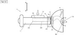
- the handle device 5 according to the inventionis shown in the form of a first embodiment.
- the handle device 5 according to the first exemplary embodimentessentially contains a lever element 10, a handle piece 11, an activation element 12, a sensor device 13 and a signal transmitter 14.
- the activation element 12 designed as an actuation switchis used to activate the drive 3 of the machine tool 1.
- the activation element 12can be activated by exerting a Force in direction S is reversibly brought from a first position to a second position.
- the activation element 12is shown in the first position, ie in a non-pressed state.
- the first positioncorresponds to the top position.
- the drive 3is activated as soon as the activation element 12 is moved away from the first position into the second position.
- Figure 2b and 2cthe activation element 12 is shown in each case in the second position, ie in a pressed state.
- the activation element 12is connected to the control device 4 in such a way that signals can be exchanged between the activation element 12 and the control device 4.
- the connection between the activation element 12 and the control device 4is not shown in the figures.
- the respective position, ie the first or second position, of the activation element 12is transmitted to the control device 4 with the aid of a corresponding signal.
- the transmission device 6 configured as a hammer mechanismis not only activated or started by pressing the activation element 12 in the direction of the arrow S.
- the sensor device 13is connected to the control device 4 in such a way that signals, data and information can be exchanged between the sensor device 13 and the control device 4.
- the lever element 10is designed essentially as an elongated lever arm with a first end 10a and a second end 10b and with an upper and lower side 10c, 10d.
- the lever element 10is mounted with the first end 10a via a first pivot point D1 in a direction of rotation C or D so that it can be reversibly pivoted to the housing 2 of the machine tool 1.
- a force in direction Ais exerted on the upper side 10c of the lever element 10
- the lever element 10pivots about the pivot point D1 in the direction of rotation C.
- the lever element 10pivots about the first pivot point D1 back into the starting position in the direction of rotation D with the aid of a first spring element 15.
- the first spring element 15can be designed in the form of a spiral spring or torsion bar spring.
- the signal transmitter 14is firmly connected to the lever element 10 and is designed in the form of a magnet.
- the magnetcan be a permanent magnet.
- the signal transmitter 14 configured as a magnetis shown positioned on the lever element 10. By positioning it on the lever element 10, the signal transmitter 14 can be moved relative to the housing 2 of the machine tool 1.
- the sensor device 13is positioned on the first side wall 2a of the housing 2 of the machine tool 1 and essentially contains a first, second and third Hall sensor 16a, 16b, 16c. As in the Figures 2a to 2c As shown, the three Hall sensors 16a, 16b, 16c are positioned one below the other in direction A on the housing 2 of the machine tool 1. The Hall sensors 16a, 16b, 16c are positioned on the housing 2 of the machine tool 1 in such a way that at least one of the three Hall sensors 16a, 16b, 16c can always detect the position of the signal transmitter 14 designed as a magnet when the lever element 10 is in Direction of rotation C or D is swiveled.
- more or fewer than three Hall sensorscan also be provided.
- the activation element 12is not pressed in the direction A and the handle device 5 is not pivoted in the direction C by exerting a force.
- the first (ie uppermost) Hall sensor 16a of the sensor device 13detects the proximity of the signal transmitter 14 designed as a magnet.
- the sensor device 13sends a corresponding signal to the control device 4 to inform the control device 4 that no force is being exerted on the handle device 5 .
- neither the drive 3 nor the transmission device 6is activated.
- no impact energyis transmitted to the tool 9.
- a tool changecould be carried out safely in this state.
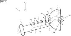
- a first force in direction Ais exerted on the activation element 12 and the handle device 5.
- the activation element 12is brought from the first position into the second position.
- Drive 3is then activated.
- the handle device 5 and thus the lever element 10are pivoted about the first pivot point D1 in the direction of rotation C.
- the signal transmitter 14 designed as a magnetis positioned in such a way that the second (middle) Hall sensor 16b of the sensor device 13 can detect the magnet.
- the sensor device 13thus detects that the handle device 5 is in a central position.
- a corresponding signalis sent to the control device 4 Posted.
- the signalinforms the control device 4 that a medium force is being exerted on the handle device 5 by the user.
- the control device 4controls the drive 3 designed as an electric motor in such a way that a first speed for the drive 3 is set as a function of the average force exerted on the handle device 5.
- the first speed of rotationgives a first value of impact energy from the transmission device 6 to the tool 9.
- a second force in direction Ais exerted on the handle device 5.
- the second forceis greater than the first force.
- the activation element 12is still in the second (ie pressed) position.
- the drive 3is still activated by pressing the activation element 12 in the S direction.
- the lever element 10becomes wider than in FIG Figure 2b swiveled in direction of rotation C.
- the lever element 10is pivoted so far that the signal transmitter 14 positioned on the lever element 10 is at the level of the third (ie deepest) Hall sensor 16c.
- the sensor device 13thus detects that maximum pressure is being exerted on the handle device 5 and the handle device 5 is in a lower (ie lowest) position.
- a corresponding signalis sent to the control device 4.
- the signalinforms the control device 4 that a maximum force is being exerted on the handle device 5 by the user.
- the control device 4controls the drive 3 designed as an electric motor in such a way that a second speed for the drive 3 is set as a function of the maximum force exerted on the handle device 5.
- the second speed valueis higher than the first speed value.
- the second speedgives a second value of impact energy from the transmission device 6 to the tool 9. the second impact energy value is higher than the first impact energy value.
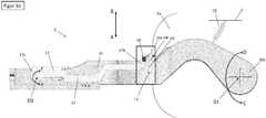
- the handle device 5 according to the inventionis shown in the form of a second embodiment.
- the handle device 5 according to the second exemplary embodimentessentially contains a lever element 10, a handle piece 11, an activation element 12, a sensor device 13 and a signal transmitter 14.
- the activation element 12 and the signal transmitter 14are positioned on a connecting element 17.
- the connecting element 17is designed essentially in an elongated shape and has a first and a second end 17a, 17b.
- the activation element 12is positioned at the first end 17a and the signal transmitter 14 is positioned at the second end 17b of the connecting element 17.
- a pivot bearingis provided at the first end 17a of the connecting element 17, so that the connecting element 17 can be pivoted about a second pivot point D2 in the direction of rotation E or F.
- the connection element 17is pivoted or rotated about the pivot point D2 in the direction of rotation E.
- the signal transmitter 14 positioned at the second endmoves in the direction A.
- the signal transmitter 14, which is designed as a magnet,is thus guided past the three Hall sensors 16a, 16b, 16c of the sensor device 13 .
- the sensor device 13detects the positioning of the signal transmitter 14 designed as a magnet.
- the angle of the handle device 5 and the force with which the handle device 5 is pressed in direction Acan be determined via the positioning of the signal transmitter 14 relative to the sensor device 13 .
- the speed of the drive 3 and thus the output of the impact energy from the transmission device 6 to the tool 9is dependent on the position of the signal transmitter 14 or the position of the lever element 10 to the sensor device 13 or to the housing 2 of the Machine tool 1 set.
- the activation element 12moves in direction B back into the starting position with the aid of a second spring element.
- the connecting element 17is pivoted again in the direction of rotation F about the pivot point D2 with the aid of the second spring element.
- the second spring elementis not shown in the figures.
- more or fewer than three Hall sensorscan also be provided.
Landscapes
- Engineering & Computer Science (AREA)
- Mechanical Engineering (AREA)
- Percussive Tools And Related Accessories (AREA)
Abstract
Translated fromGermanDescription
Translated fromGermanDie vorliegende Erfindung betrifft eine Handgriffvorrichtung an einer Werkzeugmaschine, insbesondere Meißelhammer, mit einem Antrieb, einer Steuerungseinrichtung, einer Übertragungseinrichtung, wobei die Handgriffvorrichtung ein Hebelelement enthält, welches relativ zu einem Gehäuse der Werkzeugmaschine schwenkbar ist.The present invention relates to a handle device on a machine tool, in particular a chisel hammer, with a drive, a control device, a transmission device, the handle device containing a lever element which can be pivoted relative to a housing of the machine tool.
Ein Meißelhammer gemäß dem Stand der Technik wird zum Bearbeiten (d.h. Aufreißen, Abbrechen oder Meißeln) von mineralischen Werkstoffen, wie beispielsweise Beton, Ziegel oder dergleichen verwendet. Der Meißelhammer kann auch als Abbruch-, Abbau- oder Aufbrechhammer bezeichnet werden. Der Meißelhammer verfügt über einen Antrieb, der mit Hilfe eines Übertragungsmechanismus Schläge auf ein Meißelwerkzeug (auch Meißel genannt) überträgt. Bei dem Antrieb kann es sich um einen Elektromotor oder Verbrennungsmotor handeln.A prior art chipping hammer is used for working (i.e. tearing, breaking or chiseling) mineral materials such as concrete, brick or the like. The chipping hammer can also be referred to as a demolition, demolition or breaker hammer. The chisel hammer has a drive that uses a transmission mechanism to transmit blows to a chisel tool (also called a chisel). The drive can be an electric motor or an internal combustion engine.
Für gewöhnlich weist der Meißelhammer zwei Handgriffe auf, welche an gegenüberliegenden Seiten des Gehäuses des Meißelhammers positioniert sind. Wenigstens einer der beiden Handgriffe umfasst einen Aktivierungsschalter, mit dem der Meißelhammer aktiviert bzw. eingeschaltet werden kann. Die Handgriffe erstrecken sich dabei meistens in einem stumpfen Winkel zu einer Längsachse des Gehäuses des Meißelhammers. Zur Verwendung des Meißelhammers wird der Aktivierungsschalter gedrückt und der Meißelhammer wird aktiviert, sodass Schläge von dem Antrieb auf den Meißel übertragen werden.Typically, the chipping hammer has two handles positioned on opposite sides of the housing of the chipping hammer. At least one of the two handles includes an activation switch with which the chipping hammer can be activated or switched on. The handles usually extend at an obtuse angle to a longitudinal axis of the housing of the chipping hammer. To use the chipping hammer, the activation switch is pressed and the chipping hammer is activated so that blows are transmitted from the drive to the chisel.
Ein Problem bei einem Meißelhammer gemäß dem Stand der Technik besteht darin, dass nach der Aktivierung (d.h. Einschalten) des Meißelhammers für gewöhnlich der Antrieb mit einer maximalen Drehzahl und folglich der Meißelhammer mit voller Leistung betrieben wird. Wenn ein Anwender den Meißelhammer zu diesem Zeitpunkt noch nicht in einem ausreichenden Masse kontrolliert, d.h. der Anwender noch nicht beide Hände an den jeweiligen Handgriffen positioniert hat und den Meißelhammer festhält, ist der Meißelhammer unzureichend geführt und ein adäquates sowie sicheres Arbeiten ist nicht möglich.A problem with a chipping hammer according to the prior art is that once the chipping hammer is activated (i.e. switched on), the drive is usually operated at maximum speed and consequently the chipping hammer is operated at full power. If a user does not control the chipping hammer sufficiently at this point, i.e. the user has not yet positioned both hands on the respective handles and holds the chisel hammer, the chipping hammer is inadequately guided and adequate and safe work is not possible.
Es ist somit Aufgabe der vorliegenden Erfindung das vorstehend erwähnte Problem zu lösen und eine Handgriffvorrichtung an einer Werkzeugmaschine, insbesondere an einem Meißelhammer, bereitzustellen, welche ein einfaches sowie sicheres Arbeiten mit einer Werkzeugmaschine, insbesondere mit einem Meißelhammer, ermöglicht.It is therefore the object of the present invention to solve the above-mentioned problem and to provide a handle device on a machine tool, in particular on a chipping hammer, which enables simple and safe working with a machine tool, in particular with a chipping hammer.
Die Aufgabe wird gelöst durch den Gegenstand in Anspruch 1 bzw. durch den Gegenstand in Anspruch 4. Vorteilhafte Ausführungsformen sind in den Unteransprüchen aufgeführt.The object is achieved by the subject matter in
Die Aufgabe wird dabei gelöst durch eine Handgriffvorrichtung an einer Werkzeugmaschine, insbesondere Meißelhammer, mit einem Antrieb, einer Steuerungseinrichtung, einer Übertragungseinrichtung, wobei die Handgriffvorrichtung ein Hebelelement enthält, welches relativ zu einem Gehäuse der Werkzeugmaschine schwenkbar ist.The object is achieved by a handle device on a machine tool, in particular a chisel hammer, with a drive, a control device, a transmission device, the handle device containing a lever element which can be pivoted relative to a housing of the machine tool.
Erfindungsgemäß ist vorgesehen, dass das Hebelelement durch Ausüben einer Kraft in eine Richtung relativ zu dem Gehäuse der Werkzeugmaschine reversibel bewegbar ist und eine Sensoreinrichtung enthalten ist zum Erfassen wenigstens einer ersten oder zweiten Position des Hebelelements relativ zu dem Gehäuse der Werkzeugmaschine, wobei eine erste Drehzahl für den Antrieb eingestellt wird, wenn die erste Position des Hebelelements relativ zu dem Gehäuse der Werkzeugmaschine erfasst wird und eine zweite Drehzahl für den Antrieb eingestellt wird, wenn die zweite Position des Hebelelements relativ zu dem Gehäuse der Werkzeugmaschine erfasst wird.According to the invention it is provided that the lever element is reversibly movable in one direction relative to the housing of the machine tool by exerting a force and a sensor device is included for detecting at least a first or second position of the lever element relative to the housing of the machine tool, a first speed for the drive is set when the first position of the lever element is detected relative to the housing of the machine tool and a second speed is set for the drive when the second position of the lever element is detected relative to the housing of the machine tool.
Der zweite Drehzahlwert ist dabei höher als der erste Drehzahlwert. Der Antrieb kann dabei als Elektromotor ausgestaltet sein. Bei der Ausgestaltung der Werkzeugmaschine als Meißelhammer kann die Übertragungseinrichtung als Schlagwerkseinrichtung gestaltet sein. Mit Hilfe eines hohen Drehzahlwertes kann durch eine Kombination von dem als Elektromotor ausgestalteten Antrieb mit der als Schlagwerkseinrichtung ausgestalteten Übertragungseinrichtung eine hohe Schlagenergie auf ein als Meißel ausgestaltetes Werkzeug erzeugt werden.The second speed value is higher than the first speed value. The drive can be designed as an electric motor. When the machine tool is designed as a chisel hammer, the transmission device can be designed as a striking mechanism. With the aid of a high speed value, a combination of the drive configured as an electric motor with the transmission device configured as a hammer mechanism can generate a high impact energy on a tool configured as a chisel.
Entsprechend einer vorteilhaften Ausgestaltung der vorliegenden Erfindung kann es möglich sein, dass das Hebelelement ein Signalgeber mit wenigstens einem Magneten enthält und die Sensoreinrichtung wenigstens einen ersten sowie zweiten Hall-Sensor zum Erfassen des wenigstens einen Magneten enthält, wobei der Signalgeber relativ zu der Sensoreinrichtung reversibel bewegbar ist.According to an advantageous embodiment of the present invention, it may be possible that the lever element contains a signal transmitter with at least one magnet and the sensor device contains at least one first and second Hall sensor for detecting the at least one magnet, the signal transmitter being reversibly movable relative to the sensor device is.
Gemäß einer vorteilhaften Ausgestaltung der vorliegenden Erfindung kann es möglich sein, dass eine separat zu betätigende Einschalteinrichtung an der Werkzeugmaschine enthalten ist. Durch die Einschalteinrichtung kann wenigstens der Antrieb der Werkzeugmaschine aktiviert werden. Die Aktivierung der Übertragungseinrichtung erfolgt dabei nicht mit Hilfe der Einschalteinrichtung.According to an advantageous embodiment of the present invention, it may be possible for a switch-on device to be operated separately to be included on the machine tool. At least the drive of the machine tool can be activated by the switch-on device. The activation of the transmission device does not take place with the aid of the switch-on device.
Weitere Vorteile ergeben sich aus der folgenden Figurenbeschreibung. In den Figuren sind verschiedene Ausführungsbeispiele der vorliegenden Erfindung dargestellt. Die Figuren, die Beschreibung und die Ansprüche enthalten zahlreiche Merkmale in Kombination. Der Fachmann wird die Merkmale zweckmäßigerweise auch einzeln betrachten und zu sinnvollen weiteren Kombinationen zusammenfassen.Further advantages emerge from the following description of the figures. Various exemplary embodiments of the present invention are shown in the figures. The figures, the description and the claims contain numerous features in combination. The person skilled in the art will expediently also consider the features individually and combine them into meaningful further combinations.
In den Figuren sind gleiche und gleichartige Komponenten mit gleichen Bezugszeichen beziffert. Es zeigen:
Figur 1- eine schematische Vorderansicht auf eine erfindungsgemäße Werkzeugmaschine in Form eines Meißelhammers mit einer erfindungsgemäßen Handgriffvorrichtung;
Figur 2a- eine Detailansicht auf die Handgriffvorrichtung in einer ersten Positionierung gemäß einem ersten Ausführungsbeispiel;
Figur 2b- eine Detailansicht auf die Handgriffvorrichtung in einer zweiten Positionierung gemäß dem ersten Ausführungsbeispiel;
- Figur 2c
- eine Detailansicht auf die Handgriffvorrichtung in einer dritten Positionierung gemäß dem ersten Ausführungsbeispiel;
- Figur 3a
- eine Detailansicht auf die Handgriffvorrichtung in einer ersten Positionierung gemäß einem zweiten Ausführungsbeispiel;
- Figur 3b
- eine Detailansicht auf die Handgriffvorrichtung in einer zweiten Positionierung gemäß dem zweiten Ausführungsbeispiel; und
- Figur 3c
- eine Detailansicht auf die Handgriffvorrichtung in einer dritten Positionierung gemäß dem zweiten Ausführungsbeispiel.
- Figure 1
- a schematic front view of a machine tool according to the invention in the form of a chipping hammer with a handle device according to the invention;
- Figure 2a
- a detailed view of the handle device in a first positioning according to a first embodiment;
- Figure 2b
- a detailed view of the handle device in a second positioning according to the first embodiment;
- Figure 2c
- a detailed view of the handle device in a third positioning according to the first embodiment;
- Figure 3a
- a detailed view of the handle device in a first positioning according to a second embodiment;
- Figure 3b
- a detailed view of the handle device in a second positioning according to the second embodiment; and
- Figure 3c
- a detailed view of the handle device in a third positioning according to the second embodiment.
Wie in
Im Inneren des Gehäuses ist im Wesentlichen der Antrieb 3, die Steuerungseinrichtung 4 und die Übertragungseinrichtung 6 positioniert. Der Antrieb 3 ist dabei als Elektromotor ausgestaltet. Bei dem Elektromotor kann es sich um einen bürstenlosen Elektromotor handeln.The
An einem unteren Ende des Gehäuses 2 der Werkzeugmaschine 1 ist die Werkzeugaufnahme 8 positioniert. Mit Hilfe der Werkzeugaufnahme 8 kann ein Werkzeug 9 aufgenommen und gehalten werden. In den Figuren ist das Werkzeug 9 als Meißel ausgestaltet.The tool holder 8 is positioned at a lower end of the
Darüber hinaus ist an der ersten Seitenwand 2a des Gehäuses 2 der Werkzeugmaschine 1 die Energieversorgungseinrichtung 7 vorgesehen. In dem angeführten Beispiel der Werkzeugmaschine 1 handelt sich bei der Energieversorgungseinrichtung 7 um ein Stromnetzanschluss sowie um ein Stromnetzkabel. Ein freies Ende des Stromnetzkabels kann mit einem Stromnetzanschluss (auch Steckdose genannt) verbunden werden. Mit Hilfe der Energieversorgungseinrichtung 7 kann die Werkzeugmaschine 1 und insbesondere der als Elektromotor ausgestaltete Antrieb 3 mit Energie, beispielsweise mit elektrischer Energie, versorgt werden.In addition, the
Entsprechend einer alternativen Ausgestaltungsform der erfindungsmäßen Werkzeugmaschine 1 kann die Energieversorgungseinrichtung 7 auch als ein einziger Akkumulator oder als mehrere Akkumulatoren ausgestaltet sein: Mit Hilfe einer oder mehreren Akku-Schnittstellen ist der einzelne oder mehrere Akkumulatoren an oder in dem Gehäuse 2 der Werkzeugmaschine 1 positioniert.According to an alternative embodiment of the
Wie bereits vorstehend erwähnt ist der Antrieb 3 in der vorliegenden Ausgestaltungsform der Werkzeugmaschine 1 als Elektromotor ausgestaltet. Alternativ kann es sich bei dem Antrieb 3 auch um einen Verbrennungsmotor handeln. In diesem Falle ist die Energieversorgungseinrichtung 7 als Treibstofftank ausgestaltet.As already mentioned above, the
Gemäß einer weiteren alternativen Ausgestaltungsform der erfindungsgemäßen Werkzeugmaschine 1 kann der Antrieb 3 auch in Form eines pneumatischen Antriebs bzw. Kompressors ausgestaltet sein. Bei der Energieversorgungseinrichtung 7 kann es sich in diesem Fall um einen Druckluftanschluss oder Druckluftvorrat an oder in der Werkzeugmaschine 1 handeln.According to a further alternative embodiment of the
Der als Elektromotor ausgestaltete Antrieb 3 dient zum Erzeugen eines Drehmoments. Mit Hilfe der Übertragungseinrichtung 6 kann das vom Antrieb 3 erzeugte Drehmoment in Form von (Hammer-)Schlägen auf die Werkzeugaufnahme 8 und schließlich auf das als Meißel ausgestaltete Werkzeug 9 übertragen werden. Die Übertragungseinrichtung 6 kann auch als Schlagwerk bezeichnet werden. Je höher die Frequenz der Schläge, desto mehr Schlagenergie wird erzeugt.The
Die Steuerungseinrichtung 4 ist mit der ersten und zweiten Handgriffvorrichtung 5 sowie mit dem Antrieb 3 verbunden. Signale und Kommunikationsdaten können somit zwischen den Handgriffvorrichtungen 5, dem Antrieb 3 und der Steuerungseinrichtung 4 gesendet und empfangen werden. Die Steuerungseinrichtung 4 dient zum Steuern und Regeln der unterschiedlichen Funktionen der Werkzeugmaschine 1 sowie insbesondere zum Einstellen der Parameter bzw. Betriebsparameter des Antriebs 3. Mit Hilfe der Steuerungseinrichtung 4 kann damit speziell die Drehzahl des als Elektromotors ausgestalten Antriebs 3 als Parameter bzw. Betriebsparameter eingestellt werden.The
Die erste Handgriffvorrichtung 5 ist bewegbar an einer ersten Seitenwand 2a des Gehäuses 2 und die zweite Handgriffvorrichtung 5 ist bewegbar an einer zweiten Seitenwand 2b des Gehäuses 2 positioniert. Wie in
In den
Das als Betätigungsschalter ausgestaltete Aktivierungselement 12 dient zum Aktivieren des Antriebs 3 der Werkzeugmaschine 1. Das Aktivierungselement 12 kann durch Ausüben einer Kraft in Richtung S reversibel von einer ersten Position in eine zweite Position gebracht wird. In
Die Sensoreinrichtung 13 ist so mit der Steuerungseinrichtung 4, dass Signale, Daten und Informationen zwischen der Sensoreinrichtung 13 und der Steuerungseinrichtung 4 ausgetauscht werden können.The
Das Hebelelement 10 ist im Wesentlichen als länglicher Hebelarm mit einem ersten Ende 10a und zweiten Ende 10b sowie mit einer Ober- und Unterseite 10c, 10d ausgestaltet. Das Hebelelement 10 ist mit dem ersten Ende 10a über einen ersten Drehpunkt D1 in eine Drehrichtung C oder D reversibel schwenkbar zu dem Gehäuse 2 der Werkzeugmaschine 1 montiert. Wenn eine Kraft in Richtung A auf die Oberseite 10c des Hebelelements 10 ausgeübt wird, schwenkt das Hebelelement 10 um den Drehpunkt D1 in Drehrichtung C. Wenn keine Kraft mehr auf die Oberseite 10c des Hebelelements 10 ausgeübt wird, schwenkt das Hebelelement 10 um den ersten Drehpunkt D1 mit Hilfe eines ersten Federelements 15 in Drehrichtung D in die Ausgangsposition zurück. Das erste Federelement 15 kann dabei in Form einer Spiralfeder oder Drehstabfeder ausgestaltet sein.The
Der Signalgeber 14 ist fest mit dem Hebelelement 10 verbunden und in Form eines Magneten ausgestaltet. Bei dem Magneten kann es sich um einen Permanentmagnet handeln. Wie in den
Die Sensoreinrichtung 13 ist an der ersten Seitenwand 2a des Gehäuses 2 der Werkzeugmaschine 1 positioniert und enthält im Wesentlichen einen ersten, zweiten und dritten Hall-Sensor 16a, 16b, 16c. Wie in den
Gemäß einer alternativen (in den Figuren nicht gezeigten) Ausgestaltungsform können auch mehr oder weniger als drei Hall-Sensoren vorgesehen sein. Entsprechend einer weiteren alternativen Ausgestaltungsform können anstelle der Hall-Sensoren 16a, 16b, 16c auch durch 3D-Sensoren, TOF-Kameras (= Time Of Flight Kameras) und/oder PMD-Sensoren (= Photomischdetektoren) verwendet werden.According to an alternative embodiment (not shown in the figures), more or fewer than three Hall sensors can also be provided. According to a further alternative embodiment, 3D sensors, TOF cameras (= time of flight cameras) and / or PMD sensors (= photo mixer detectors) can also be used instead of the
Wie bereits vorstehend erwähnt, ist in
In
In
In den
Wie in den
As in the
Das Verbindungselement 17 ist im Wesentlichen in länglicher Form ausgestaltet und weist ein erstes und zweites Ende 17a, 17b auf. Das Aktivierungselement 12 ist an dem ersten Ende 17a und der Signalgeber 14 ist an dem zweiten Ende 17b des Verbindungselements 17 positioniert.The connecting
Zusätzlich ist an dem ersten Ende 17a des Verbindungselements 17 ein Drehlager vorgesehen, sodass das Verbindungselement 17 um einen zweiten Drehpunkt D2 in Drehrichtung E oder F geschwenkt werden kann. Durch Ausüben einer Kraft in Richtung A auf das Aktivierungselement 12 wird das Verbindungselement 17 um den Drehpunkt D2 in Drehrichtung E geschwenkt bzw. gedreht.In addition, a pivot bearing is provided at the
Wenn das Verbindungselement 17 um den Drehpunkt D2 in Drehrichtung E geschwenkt, bewegt sich der an dem zweiten Ende positionierte Signalgeber 14 in Richtung A. Der als Magnet ausgestaltete Signalgeber 14 wird damit an den drei Hall-Sensoren 16a, 16b, 16c der Sensoreinrichtung 13 vorbeigeführt.When the connecting
Wie bereist vorstehend erwähnt erfasst die Sensoreinrichtung 13 die Positionierung des als Magnet ausgestalteten Signalgebers 14. Über die Positionierung des Signalgebers 14 relativ zu der Sensoreinrichtung 13 kann der Winkel der Handgriffvorrichtung 5 und die Kraft ermittelt werden, mit der die Handgriffvorrichtung 5 in Richtung A gedrückt wird. Wie ebenfalls bereist vorstehend erwähnt wird die Drehzahl des Antriebs 3 und damit die Abgabe der Schlagenergie von der Übertragungseinrichtung 6 auf das Werkzeug 9 in Abhängigkeit der Position des Signalgebers 14 bzw. der Position des Hebelelements 10 zu der Sensoreinrichtung 13 bzw. zu dem Gehäuse 2 der Werkzeugmaschine 1 eingestellt.As already mentioned above, the
Wenn keine Kraft bzw. kein Druck mehr in Richtung A auf das Aktivierungselement 12 mehr ausgeübt wird, bewegt sich mit Hilfe eines zweiten Federelements das Aktivierungselement 12 in Richtung B wieder in die Ausgangsposition. Das Verbindungselement 17 wird mit Hilfe des zweiten Federelements um den Drehpunkt D2 wieder in Drehrichtung F geschwenkt. Das zweite Federelement ist in den Figuren nicht gezeigt.When no more force or pressure is exerted on the
Gemäß einer alternativen Ausgestaltungsform können auch mehr oder weniger als drei Hall-Sensoren vorgesehen sein. Entsprechend einer weiteren alternativen Ausgestaltungsform können anstelle der Hall-Sensoren 16a, 16b, 16c auch ein einziger oder mehrere 3D-Sensoren, TOF-Kameras (= Time Of Flight Kameras) und/oder PMD-Sensoren (= Photomischdetektoren) verwendet werden.According to an alternative embodiment, more or fewer than three Hall sensors can also be provided. According to a further alternative embodiment, one or more 3D sensors, TOF cameras (= time of flight cameras) and / or PMD sensors (= photo mixer detectors) can be used instead of the
- 11
- WerkzeugmaschineMachine tool
- 22
- Gehäusecasing
- 2a2a
- erste Seite des Gehäusesfirst side of the case
- 2b2 B
- zweite Seite des Gehäusessecond side of the case
- 33
- Antriebdrive
- 44th
- SteuerungseinrichtungControl device
- 55
- HandgriffvorrichtungHandle device
- 66th
- ÜbertragungseinrichtungTransmission facility
- 77th
- EnergieversorgungseinrichtungEnergy supply device
- 88th
- WerkzeugaufnahmeTool holder
- 99
- WerkzeugTool
- 1010
- HebelelementLever element
- 10a10a
- erstes Ende des Hebelelementsfirst end of the lever element
- 10b10b
- zweites Ende des Hebelelementssecond end of the lever element
- 10c10c
- Oberseite des HebelelementsTop of the lever element
- 10d10d
- Unterseite des HebelelementsUnderside of the lever element
- 1111
- GriffstückHandle
- 1212th
- AktivierungselementActivation element
- 1313th
- SensoreinrichtungSensor device
- 1414th
- SignalgeberSignaling device
- 1515th
- erstes Federelementfirst spring element
- 16a16a
- erster Hall-Sensorfirst Hall sensor
- 16b16b
- zweiter Hall-Sensorsecond Hall sensor
- 16c16c
- dritter Hall-Sensorthird Hall sensor
- 1717th
- VerbindungselementConnecting element
- 17a17a
- erstes Ende des Verbindungselementsfirst end of the connecting element
- 17b17b
- zweites Ende des Verbindungselementssecond end of the connector
Claims (2)
Translated fromGermandadurch gekennzeichnet, dass das Hebelelement (10) durch Ausüben einer Kraft in eine Richtung (A) relativ zu dem Gehäuse (2) der Werkzeugmaschine (1) reversibel bewegbar ist und eine Sensoreinrichtung (13) enthalten ist zum Erfassen wenigstens einer ersten oder zweiten Position des Hebelelements (10) relativ zu dem Gehäuse (2) der Werkzeugmaschine (1), wobei eine erste Drehzahl für den Antrieb (3) eingestellt wird, wenn die erste Position des Hebelelements (10) relativ zu dem Gehäuse (2) der Werkzeugmaschine (1) erfasst wird und eine zweite Drehzahl für den Antrieb (3) eingestellt wird, wenn die zweite Position des Hebelelements (10) relativ zu dem Gehäuse (2) der Werkzeugmaschine (1) erfasst wird.Handle device (5) on a machine tool (1), in particular a chisel hammer, with a drive (3), a control device (4), a transmission device (6), the handle device (5) containing a lever element (10) which, relative to a The housing (2) of the machine tool (1) can be pivoted,
characterized in that the lever element (10) is reversibly movable relative to the housing (2) of the machine tool (1) by exerting a force in a direction (A) and a sensor device (13) is included for detecting at least one first or second position of the lever element (10) relative to the housing (2) of the machine tool (1), a first speed for the drive (3) being set when the first position of the lever element (10) relative to the housing (2) of the machine tool ( 1) is detected and a second speed for the drive (3) is set when the second position of the lever element (10) relative to the housing (2) of the machine tool (1) is detected.
dadurch gekennzeichnet, dass das Hebelelement (10) ein Signalgeber (14) mit wenigstens einem Magneten enthält und die Sensoreinrichtung (13) wenigstens einen ersten sowie zweiten Hall-Sensor (16a, 16b) zum Erfassen des wenigstens einen Magneten enthält, wobei der Signalgeber (14) relativ zu der Sensoreinrichtung (13) reversibel bewegbar ist.Handle device (5) according to claim 1,
characterized in that the lever element (10) contains a signal transmitter (14) with at least one magnet and the sensor device (13) contains at least one first and second Hall sensor (16a, 16b) for detecting the at least one magnet, the signal transmitter ( 14) is reversibly movable relative to the sensor device (13).
Priority Applications (5)
| Application Number | Priority Date | Filing Date | Title |
|---|---|---|---|
| EP19209161.9AEP3822035A1 (en) | 2019-11-14 | 2019-11-14 | Handle device for a machine tool |
| CN202080068754.4ACN114502329B (en) | 2019-11-14 | 2020-11-04 | Power tool |
| EP20797795.0AEP4058248A1 (en) | 2019-11-14 | 2020-11-04 | Handle device for a machine tool |
| US17/768,588US20240100673A1 (en) | 2019-11-14 | 2020-11-04 | Handle apparatus for a power tool |
| PCT/EP2020/080899WO2021094155A1 (en) | 2019-11-14 | 2020-11-04 | Handle device for a machine tool |
Applications Claiming Priority (1)
| Application Number | Priority Date | Filing Date | Title |
|---|---|---|---|
| EP19209161.9AEP3822035A1 (en) | 2019-11-14 | 2019-11-14 | Handle device for a machine tool |
Publications (1)
| Publication Number | Publication Date |
|---|---|
| EP3822035A1true EP3822035A1 (en) | 2021-05-19 |
Family
ID=68581598
Family Applications (2)
| Application Number | Title | Priority Date | Filing Date |
|---|---|---|---|
| EP19209161.9AWithdrawnEP3822035A1 (en) | 2019-11-14 | 2019-11-14 | Handle device for a machine tool |
| EP20797795.0APendingEP4058248A1 (en) | 2019-11-14 | 2020-11-04 | Handle device for a machine tool |
Family Applications After (1)
| Application Number | Title | Priority Date | Filing Date |
|---|---|---|---|
| EP20797795.0APendingEP4058248A1 (en) | 2019-11-14 | 2020-11-04 | Handle device for a machine tool |
Country Status (4)
| Country | Link |
|---|---|
| US (1) | US20240100673A1 (en) |
| EP (2) | EP3822035A1 (en) |
| CN (1) | CN114502329B (en) |
| WO (1) | WO2021094155A1 (en) |
Families Citing this family (3)
| Publication number | Priority date | Publication date | Assignee | Title |
|---|---|---|---|---|
| EP3822034A1 (en) | 2019-11-14 | 2021-05-19 | Hilti Aktiengesellschaft | Method for controlling and regulating a machine tool |
| EP3822032A1 (en) | 2019-11-14 | 2021-05-19 | Hilti Aktiengesellschaft | Method for controlling and regulating a machine tool and handle for machine tool |
| EP3822033A1 (en) | 2019-11-14 | 2021-05-19 | Hilti Aktiengesellschaft | Method for controlling and regulating a machine tool |
Citations (4)
| Publication number | Priority date | Publication date | Assignee | Title |
|---|---|---|---|---|
| EP1895555A2 (en)* | 2006-08-30 | 2008-03-05 | Robert Bosch Gmbh | Hand held tool |
| EP2058089A1 (en)* | 2007-11-09 | 2009-05-13 | HILTI Aktiengesellschaft | Hammer hand tool with contactless handswitch in side grip |
| DE102011080374A1 (en)* | 2011-08-03 | 2013-02-07 | Robert Bosch Gmbh | Machine tool e.g. hand tool such as demolition hammer, has load control unit that is provided to directly or indirectly evaluate its contact pressure with workpiece |
| WO2018063978A1 (en)* | 2016-09-28 | 2018-04-05 | Milwaukee Electric Tool Corporation | Trigger assembly |
Family Cites Families (109)
| Publication number | Priority date | Publication date | Assignee | Title |
|---|---|---|---|---|
| CH195398A (en)* | 1936-12-14 | 1938-01-31 | Robert Wacker Fa | Handle arrangement on devices with vibrating and striking forces. |
| US3280924A (en)* | 1961-03-13 | 1966-10-25 | Pavlovich Tatarnikov Boris | Vibrating machine for plunging piles, thin-walled clindrical casings and plates |
| US3383531A (en)* | 1967-07-18 | 1968-05-14 | Mini Transporturilor Aut | Electric one-way unharmonical vibarator |
| US4323127A (en)* | 1977-05-20 | 1982-04-06 | Cunningham James D | Electrically operated impact tool |
| CH648507A5 (en)* | 1982-09-22 | 1985-03-29 | Cerac Inst Sa | ELECTRIC HITCHING MACHINE. |
| EP0115241B1 (en)* | 1983-02-03 | 1988-05-25 | MACO-MEUDON Société dite : | Percussive tool with swinging handles |
| DE3447401A1 (en)* | 1984-12-24 | 1986-07-03 | Wacker-Werke Gmbh & Co Kg, 8077 Reichertshofen | HAMMER WITH COVER |
| DE3883203T2 (en)* | 1988-02-01 | 1994-03-17 | Worktools Inc | Tool with variable torque drive. |
| DE3807881A1 (en)* | 1988-03-10 | 1989-09-21 | Porsche Ag | SWITCHING DEVICE FOR AN AUTOMATIC TRANSMISSION OF A MOTOR VEHICLE |
| KR930004603B1 (en)* | 1988-05-20 | 1993-06-01 | 미쯔비시 지도샤 고교 가부시끼가이샤 | Vehicle Engine Control |
| US5233530A (en)* | 1988-11-28 | 1993-08-03 | Mitsubishi Jidosha Kogyo Kabushiki Kaisha | Engine controlling system which reduces the engine output upon detection of an abnormal condition |
| DE8914926U1 (en)* | 1989-12-19 | 1990-02-01 | Joh. Friedrich Behrens AG, 2070 Ahrensburg | Trigger-protected fastener driver |
| US5060771A (en)* | 1990-05-15 | 1991-10-29 | The Aro Corporation | Adjustable automatic shut-off mechanism for lever or trigger controlled air tool |
| DE4022668A1 (en)* | 1990-07-17 | 1992-01-23 | Bosch Gmbh Robert | ELECTRIC HAND TOOL, IN PARTICULAR ANGLE GRINDING MACHINE |
| DE4102483A1 (en)* | 1991-01-29 | 1992-07-30 | Bosch Gmbh Robert | HAND MACHINE TOOL |
| US5450054A (en)* | 1992-12-08 | 1995-09-12 | Imo Industries, Inc. | Hand-actuatable controller and method for producing control signals using the same |
| JP2542557B2 (en)* | 1993-06-18 | 1996-10-09 | 第一電装部品株式会社 | Unstable position detector for shift lever |
| JPH0891242A (en)* | 1994-07-29 | 1996-04-09 | Shinko Electric Co Ltd | Motor-driven dolly |
| US5736703A (en)* | 1996-09-24 | 1998-04-07 | Ericsson Inc. | Variable speed select key and method |
| US6120362A (en)* | 1997-06-09 | 2000-09-19 | Porter-Cable Corporation | Ergonomic grinder |
| JP4327284B2 (en)* | 1998-04-15 | 2009-09-09 | 株式会社 神崎高級工機製作所 | Four-wheel drive vehicle |
| EP0990245B1 (en)* | 1998-04-15 | 2006-05-31 | Koninklijke Philips Electronics N.V. | Tumbler switch |
| GB9827947D0 (en)* | 1998-12-18 | 1999-02-10 | Black & Decker Inc | Power tool |
| US6443675B1 (en)* | 2000-02-17 | 2002-09-03 | Roto Zip Tool Corporation | Hand-held power tool |
| JP4721535B2 (en)* | 2001-02-28 | 2011-07-13 | 勝行 戸津 | Electric rotary tool |
| EP1759813A3 (en)* | 2002-01-10 | 2008-04-23 | Black & Decker, Inc. | Angle Grinder |
| US7090030B2 (en)* | 2002-09-03 | 2006-08-15 | Microtorq L.L.C. | Tranducerized torque wrench |
| EP2390062B1 (en)* | 2002-09-13 | 2017-03-08 | Black & Decker Inc. | Rotary Tool |
| DE602004027011D1 (en)* | 2003-03-21 | 2010-06-17 | Black & Decker Inc | Uziervorrichtung |
| US7004357B2 (en)* | 2003-05-15 | 2006-02-28 | Alemite, Llc | Grease gun |
| US20090090763A1 (en)* | 2007-10-05 | 2009-04-09 | Tyco Healthcare Group Lp | Powered surgical stapling device |
| DE102004058579A1 (en)* | 2004-12-03 | 2006-06-08 | Robert Bosch Gmbh | Hand tool |
| US8087977B2 (en)* | 2005-05-13 | 2012-01-03 | Black & Decker Inc. | Angle grinder |
| US10705533B1 (en)* | 2005-05-31 | 2020-07-07 | Richard Anthony Bishel | Autonomous lawnmower |
| JP4467501B2 (en)* | 2005-09-30 | 2010-05-26 | 株式会社クボタ | Variable speed transmission for tractor |
| DE102005000207A1 (en)* | 2005-12-23 | 2007-06-28 | Hilti Ag | Hand-held power tool e.g. pneumatic chisel, has handle suspensions arranged in housing in such way that suspensions do not cause additional constructional length, and rings provided between pivot axes and suspensions, respectively |
| US7845537B2 (en)* | 2006-01-31 | 2010-12-07 | Ethicon Endo-Surgery, Inc. | Surgical instrument having recording capabilities |
| US7770775B2 (en)* | 2006-01-31 | 2010-08-10 | Ethicon Endo-Surgery, Inc. | Motor-driven surgical cutting and fastening instrument with adaptive user feedback |
| DE102006029630A1 (en)* | 2006-06-28 | 2008-01-03 | Robert Bosch Gmbh | Hand tool |
| US8807414B2 (en)* | 2006-10-06 | 2014-08-19 | Covidien Lp | System and method for non-contact electronic articulation sensing |
| US20120159916A1 (en)* | 2007-01-15 | 2012-06-28 | Kanzaki Kokyukoki Manufacturing Co., Ltd. | Control sysytem for motor-driven lawnmower vehicle |
| CN101637906A (en)* | 2008-07-31 | 2010-02-03 | 苏州宝时得电动工具有限公司 | Speed changer |
| CN201093036Y (en)* | 2007-08-31 | 2008-07-30 | 苏州宝时得电动工具有限公司 | Speed changing tool |
| DE102007046603A1 (en)* | 2007-09-28 | 2009-04-02 | Wacker Construction Equipment Ag | Implement with speed reduction and working method for it |
| JP5589255B2 (en)* | 2008-02-26 | 2014-09-17 | 日立工機株式会社 | Portable power tools |
| US8407902B2 (en)* | 2008-03-07 | 2013-04-02 | Milwaukee Electric Tool Corporation | Reciprocating power tool having a counterbalance device |
| EP2514568B1 (en)* | 2008-05-30 | 2013-10-02 | Black & Decker Inc. | Fastener driving tool |
| DE102009012181A1 (en)* | 2009-02-27 | 2010-09-02 | Andreas Stihl Ag & Co. Kg | Battery-powered, hand-held implement with a throttle |
| CN101577520A (en)* | 2009-06-24 | 2009-11-11 | 文星毅 | Operating system for portable direct current electric tool |
| DE102009046789A1 (en)* | 2009-11-17 | 2011-05-19 | Robert Bosch Gmbh | Hand machine tool device |
| CN102069481B (en)* | 2009-11-19 | 2012-08-22 | 南京德朔实业有限公司 | a power hammer |
| DE102010002702A1 (en)* | 2010-03-09 | 2011-09-15 | Robert Bosch Gmbh | Electrical appliance, in particular electric hand tool |
| JP5448951B2 (en)* | 2010-03-16 | 2014-03-19 | 株式会社マキタ | Power supply system for power tools with attachments |
| WO2011131031A1 (en)* | 2010-04-21 | 2011-10-27 | 苏州宝时得电动工具有限公司 | Mower and controlling method for controlling its self-driven operation |
| US8689901B2 (en)* | 2010-05-12 | 2014-04-08 | X'pole Precision Tools Inc. | Electric power tool |
| DE102010062894A1 (en)* | 2010-12-13 | 2012-06-14 | Robert Bosch Gmbh | Hand-held power tool i.e. tacker, for driving e.g. clamp, has detection unit for detecting contact at workpiece and comprising sensor e.g. field sensor, where part of sensor is arranged on printed circuit board |
| CN103501965B (en)* | 2011-03-31 | 2016-08-24 | 英格索尔-兰德公司 | The forward/reverse switching device of power tool |
| EP2524773B1 (en)* | 2011-05-19 | 2017-06-21 | Black & Decker Inc. | Electronic power apparatus for a power tool |
| US8493172B2 (en)* | 2011-09-30 | 2013-07-23 | Snap-On Incorporated | Variable speed toggle trigger |
| DE102012002225B4 (en)* | 2012-02-04 | 2025-09-04 | Andreas Stihl Ag & Co. Kg | Hand-held tool |
| US20140100743A1 (en)* | 2012-10-04 | 2014-04-10 | Cnh America Llc | Travel speed control system for work vehicle |
| US9550288B2 (en)* | 2012-10-22 | 2017-01-24 | Illinois Tool Works Inc. | Fastener-driving tool including a reversion trigger |
| US9043058B1 (en)* | 2013-03-14 | 2015-05-26 | Brunswick Corporation | Systems and methods for facilitating shift changes in marine propulsion devices |
| FR3004680B1 (en)* | 2013-04-23 | 2016-02-26 | France Reducteurs | DEVICE FOR CONTROLLING THE SPEED OF AN ELECTRIC PROPULSION ENGINE AND CORRESPONDING EQUIPMENT |
| EP2826599A1 (en)* | 2013-07-16 | 2015-01-21 | HILTI Aktiengesellschaft | Control method and hand tool machine |
| JP6090581B2 (en)* | 2013-09-28 | 2017-03-08 | 日立工機株式会社 | Electric tool |
| JP2015089593A (en)* | 2013-11-05 | 2015-05-11 | 株式会社マキタ | Working tool |
| JP6277042B2 (en)* | 2014-04-01 | 2018-02-07 | 株式会社マキタ | Electric tool |
| US10173311B2 (en)* | 2014-06-30 | 2019-01-08 | Koki Holdings Co., Ltd. | Electric tool |
| US10717179B2 (en)* | 2014-07-28 | 2020-07-21 | Black & Decker Inc. | Sound damping for power tools |
| DE102014214982A1 (en)* | 2014-07-30 | 2016-02-04 | Robert Bosch Gmbh | Power tool |
| FR3029036B1 (en)* | 2014-11-25 | 2016-11-25 | Pellenc Sa | METHOD AND CONTROL DEVICE FOR MOTOR EQUIPMENT. |
| US10357303B2 (en)* | 2015-06-30 | 2019-07-23 | Ethicon Llc | Translatable outer tube for sealing using shielded lap chole dissector |
| GB201518088D0 (en)* | 2015-10-13 | 2015-11-25 | Black & Decker Inc | Pavement Breaker |
| US10373715B2 (en)* | 2015-10-16 | 2019-08-06 | Mako Surgical Corp. | Tool and method for controlling the same |
| JP6577830B2 (en)* | 2015-10-28 | 2019-09-18 | 株式会社マキタ | Electric tool |
| NL2016859B1 (en)* | 2016-05-30 | 2017-12-11 | Engie Electroproject B V | A method of and a device for estimating down hole speed and down hole torque of borehole drilling equipment while drilling, borehole equipment and a computer program product. |
| US10548576B2 (en)* | 2016-07-12 | 2020-02-04 | Medtronic Xomed, Inc. | Control for surgical handpiece |
| US10493577B2 (en)* | 2016-07-21 | 2019-12-03 | Makita Corporation | Dust collection device for electric power tool, electric power tool, and dust collection system |
| US11069936B2 (en)* | 2016-07-22 | 2021-07-20 | Kubota Corporation | Electric work vehicle |
| JP6389489B2 (en)* | 2016-08-01 | 2018-09-12 | 株式会社マキタ | Electric tool |
| US10513005B2 (en)* | 2016-11-02 | 2019-12-24 | Makita Corporation | Power tool |
| US10458736B2 (en)* | 2017-03-08 | 2019-10-29 | Sturm, Ruger & Company, Inc. | Dynamic variable force trigger mechanism for firearms |
| DE202017104073U1 (en)* | 2017-07-07 | 2018-10-09 | Joh. Friedrich Behrens Ag | Pneumatic nailer with automatic operation and a touch probe |
| WO2019046144A1 (en)* | 2017-08-28 | 2019-03-07 | Apex Brands, Inc. | Power tool two-stage trigger |
| JP6953252B2 (en)* | 2017-09-19 | 2021-10-27 | 株式会社マキタ | Rotating tool |
| US11554476B2 (en)* | 2017-12-28 | 2023-01-17 | Koki Holdings Co., Ltd. | Power tool |
| WO2019147919A1 (en)* | 2018-01-26 | 2019-08-01 | Milwaukee Electric Tool Corporation | Percussion tool |
| US11140814B2 (en)* | 2018-05-21 | 2021-10-12 | Kubota Corporation | Work vehicle having display unit |
| US11485003B2 (en)* | 2018-05-23 | 2022-11-01 | Milwaukee Electric Tool Corporation | Powerhead unit for tool |
| US10813284B2 (en)* | 2018-07-02 | 2020-10-27 | Deere & Company | Electric walk behind greens mower |
| SE1850881A1 (en)* | 2018-07-11 | 2020-01-12 | Husqvarna Ab | Power tool |
| JP7154866B2 (en)* | 2018-08-01 | 2022-10-18 | 株式会社マキタ | Switch member and cleaner |
| JP7147871B2 (en)* | 2018-11-30 | 2022-10-05 | 工機ホールディングス株式会社 | work machine |
| WO2020182273A1 (en)* | 2019-03-08 | 2020-09-17 | Mirka Oy | Trigger apparatus for powered device, powered device, and method of controlling an operation of a powered device |
| EP3970175B1 (en)* | 2019-05-13 | 2025-04-30 | Milwaukee Electric Tool Corporation | Contactless trigger with rotational magnetic sensor for a power tool |
| US11400577B2 (en)* | 2019-06-11 | 2022-08-02 | Makita Corporation | Impact tool |
| MX2021014887A (en)* | 2019-06-12 | 2022-01-18 | Milwaukee Electric Tool Corp | Rotary power tool. |
| US11229963B2 (en)* | 2019-06-24 | 2022-01-25 | Black & Decker Inc. | Force and moment canceling reciprocating mechanism and power tool having same |
| EP3766639A1 (en)* | 2019-07-18 | 2021-01-20 | Hilti Aktiengesellschaft | Handheld machine tool |
| EP3822032A1 (en)* | 2019-11-14 | 2021-05-19 | Hilti Aktiengesellschaft | Method for controlling and regulating a machine tool and handle for machine tool |
| EP4063570A4 (en)* | 2019-11-18 | 2024-03-20 | Kubota Corporation | Swiveling working machine |
| CN115427897A (en)* | 2020-01-30 | 2022-12-02 | 米沃奇电动工具公司 | Automatic step drill bit detection |
| JP7531294B2 (en)* | 2020-03-24 | 2024-08-09 | 株式会社クボタ | Work vehicle |
| JP7482228B2 (en)* | 2020-07-10 | 2024-05-13 | 株式会社マキタ | Hand tools and power tools |
| US20220153344A1 (en)* | 2020-11-16 | 2022-05-19 | Excel Industries, Inc. | Steering control neutral calibration for terrain working vehicle |
| US20240050093A1 (en)* | 2021-06-07 | 2024-02-15 | Lxington Medical, Inc. | Motorized surgical handle assembly |
| JP2024530570A (en)* | 2021-08-13 | 2024-08-23 | ストライカー・ユーロピアン・オペレーションズ・リミテッド | Patent application title: POWERED SURGICAL INSTRUMENT INCLUDES AN APPARATUS HOUSING THAT FACILITARILY HANDLING ERGONOMICLY - Patent application |
| US20240081175A1 (en)* | 2022-09-12 | 2024-03-14 | Honda Motor Co., Ltd. | Drive-by-wire system for vehicle, zero-turn-radius lawnmower including same, and drive-by-wire system for lawnmower |
- 2019
- 2019-11-14EPEP19209161.9Apatent/EP3822035A1/ennot_activeWithdrawn
- 2020
- 2020-11-04EPEP20797795.0Apatent/EP4058248A1/enactivePending
- 2020-11-04USUS17/768,588patent/US20240100673A1/enactivePending
- 2020-11-04CNCN202080068754.4Apatent/CN114502329B/enactiveActive
- 2020-11-04WOPCT/EP2020/080899patent/WO2021094155A1/ennot_activeCeased
Patent Citations (4)
| Publication number | Priority date | Publication date | Assignee | Title |
|---|---|---|---|---|
| EP1895555A2 (en)* | 2006-08-30 | 2008-03-05 | Robert Bosch Gmbh | Hand held tool |
| EP2058089A1 (en)* | 2007-11-09 | 2009-05-13 | HILTI Aktiengesellschaft | Hammer hand tool with contactless handswitch in side grip |
| DE102011080374A1 (en)* | 2011-08-03 | 2013-02-07 | Robert Bosch Gmbh | Machine tool e.g. hand tool such as demolition hammer, has load control unit that is provided to directly or indirectly evaluate its contact pressure with workpiece |
| WO2018063978A1 (en)* | 2016-09-28 | 2018-04-05 | Milwaukee Electric Tool Corporation | Trigger assembly |
Also Published As
| Publication number | Publication date |
|---|---|
| CN114502329A (en) | 2022-05-13 |
| US20240100673A1 (en) | 2024-03-28 |
| EP4058248A1 (en) | 2022-09-21 |
| WO2021094155A1 (en) | 2021-05-20 |
| CN114502329B (en) | 2024-07-23 |
Similar Documents
| Publication | Publication Date | Title |
|---|---|---|
| EP3822032A1 (en) | Method for controlling and regulating a machine tool and handle for machine tool | |
| EP3822034A1 (en) | Method for controlling and regulating a machine tool | |
| EP4058250A1 (en) | Method for controlling and regulating a machine tool | |
| EP3822031A1 (en) | Method for controlling and regulating a machine tool | |
| DE102004003202B4 (en) | Handle with detection device | |
| WO2021094155A1 (en) | Handle device for a machine tool | |
| DE102019124134A1 (en) | Work tool | |
| EP2212062B1 (en) | Hand-held power tool | |
| DE102015222152A1 (en) | Electric hand tool | |
| EP4377049A1 (en) | Method for the open-loop and closed-loop control of a machine tool | |
| WO2020058031A1 (en) | Portable power tool and method for operating a portable power tool | |
| WO2020099047A1 (en) | Actuation unit, locking unit and clamping unit for a power hand tool | |
| DE112019005777T5 (en) | Turning tool | |
| DE102020206450A1 (en) | Hand machine tool | |
| EP1632313B1 (en) | Screwdriving tool with axially working hammering mechanism | |
| EP3263288B1 (en) | Handheld machine tool | |
| DE102018219397A1 (en) | Actuating unit, locking unit and clamping unit for a hand machine tool | |
| DE102018201074A1 (en) | Method for controlling an impact wrench | |
| DE102018219401A1 (en) | Actuating unit, locking unit and clamping unit for a hand machine tool | |
| EP4368349A1 (en) | Locking device for a rechargeable battery | |
| EP4382256A1 (en) | Method for indicating the misuse of a machine tool | |
| DE102013219891A1 (en) | Hand tool and method for controlling a torque of a hand tool | |
| EP1293305A1 (en) | Toolholder for Portable Percussion Tool | |
| EP3646992A2 (en) | Hand machine tool | |
| WO2016206829A1 (en) | Hand-held machine tool |
Legal Events
| Date | Code | Title | Description |
|---|---|---|---|
| PUAI | Public reference made under article 153(3) epc to a published international application that has entered the european phase | Free format text:ORIGINAL CODE: 0009012 | |
| STAA | Information on the status of an ep patent application or granted ep patent | Free format text:STATUS: THE APPLICATION HAS BEEN PUBLISHED | |
| AK | Designated contracting states | Kind code of ref document:A1 Designated state(s):AL AT BE BG CH CY CZ DE DK EE ES FI FR GB GR HR HU IE IS IT LI LT LU LV MC MK MT NL NO PL PT RO RS SE SI SK SM TR | |
| STAA | Information on the status of an ep patent application or granted ep patent | Free format text:STATUS: THE APPLICATION IS DEEMED TO BE WITHDRAWN | |
| 18D | Application deemed to be withdrawn | Effective date:20211120 |