EP3820406B1 - Annuloplasty systems and locking tools therefor - Google Patents
Annuloplasty systems and locking tools thereforDownload PDFInfo
- Publication number
- EP3820406B1 EP3820406B1EP19746185.8AEP19746185AEP3820406B1EP 3820406 B1EP3820406 B1EP 3820406B1EP 19746185 AEP19746185 AEP 19746185AEP 3820406 B1EP3820406 B1EP 3820406B1
- Authority
- EP
- European Patent Office
- Prior art keywords
- contracting
- tool
- fastener
- contracting member
- applications
- Prior art date
- Legal status (The legal status is an assumption and is not a legal conclusion. Google has not performed a legal analysis and makes no representation as to the accuracy of the status listed.)
- Active
Links
Images


Classifications
- A—HUMAN NECESSITIES
- A61—MEDICAL OR VETERINARY SCIENCE; HYGIENE
- A61B—DIAGNOSIS; SURGERY; IDENTIFICATION
- A61B17/00—Surgical instruments, devices or methods
- A61B17/04—Surgical instruments, devices or methods for suturing wounds; Holders or packages for needles or suture materials
- A61B17/0467—Instruments for cutting sutures
- A—HUMAN NECESSITIES
- A61—MEDICAL OR VETERINARY SCIENCE; HYGIENE
- A61B—DIAGNOSIS; SURGERY; IDENTIFICATION
- A61B17/00—Surgical instruments, devices or methods
- A61B17/04—Surgical instruments, devices or methods for suturing wounds; Holders or packages for needles or suture materials
- A61B17/0487—Suture clamps, clips or locks, e.g. for replacing suture knots; Instruments for applying or removing suture clamps, clips or locks
- A—HUMAN NECESSITIES
- A61—MEDICAL OR VETERINARY SCIENCE; HYGIENE
- A61F—FILTERS IMPLANTABLE INTO BLOOD VESSELS; PROSTHESES; DEVICES PROVIDING PATENCY TO, OR PREVENTING COLLAPSING OF, TUBULAR STRUCTURES OF THE BODY, e.g. STENTS; ORTHOPAEDIC, NURSING OR CONTRACEPTIVE DEVICES; FOMENTATION; TREATMENT OR PROTECTION OF EYES OR EARS; BANDAGES, DRESSINGS OR ABSORBENT PADS; FIRST-AID KITS
- A61F2/00—Filters implantable into blood vessels; Prostheses, i.e. artificial substitutes or replacements for parts of the body; Appliances for connecting them with the body; Devices providing patency to, or preventing collapsing of, tubular structures of the body, e.g. stents
- A61F2/02—Prostheses implantable into the body
- A61F2/24—Heart valves ; Vascular valves, e.g. venous valves; Heart implants, e.g. passive devices for improving the function of the native valve or the heart muscle; Transmyocardial revascularisation [TMR] devices; Valves implantable in the body
- A61F2/2412—Heart valves ; Vascular valves, e.g. venous valves; Heart implants, e.g. passive devices for improving the function of the native valve or the heart muscle; Transmyocardial revascularisation [TMR] devices; Valves implantable in the body with soft flexible valve members, e.g. tissue valves shaped like natural valves
- A—HUMAN NECESSITIES
- A61—MEDICAL OR VETERINARY SCIENCE; HYGIENE
- A61F—FILTERS IMPLANTABLE INTO BLOOD VESSELS; PROSTHESES; DEVICES PROVIDING PATENCY TO, OR PREVENTING COLLAPSING OF, TUBULAR STRUCTURES OF THE BODY, e.g. STENTS; ORTHOPAEDIC, NURSING OR CONTRACEPTIVE DEVICES; FOMENTATION; TREATMENT OR PROTECTION OF EYES OR EARS; BANDAGES, DRESSINGS OR ABSORBENT PADS; FIRST-AID KITS
- A61F2/00—Filters implantable into blood vessels; Prostheses, i.e. artificial substitutes or replacements for parts of the body; Appliances for connecting them with the body; Devices providing patency to, or preventing collapsing of, tubular structures of the body, e.g. stents
- A61F2/02—Prostheses implantable into the body
- A61F2/24—Heart valves ; Vascular valves, e.g. venous valves; Heart implants, e.g. passive devices for improving the function of the native valve or the heart muscle; Transmyocardial revascularisation [TMR] devices; Valves implantable in the body
- A61F2/2442—Annuloplasty rings or inserts for correcting the valve shape; Implants for improving the function of a native heart valve
- A61F2/2445—Annuloplasty rings in direct contact with the valve annulus
- A—HUMAN NECESSITIES
- A61—MEDICAL OR VETERINARY SCIENCE; HYGIENE
- A61F—FILTERS IMPLANTABLE INTO BLOOD VESSELS; PROSTHESES; DEVICES PROVIDING PATENCY TO, OR PREVENTING COLLAPSING OF, TUBULAR STRUCTURES OF THE BODY, e.g. STENTS; ORTHOPAEDIC, NURSING OR CONTRACEPTIVE DEVICES; FOMENTATION; TREATMENT OR PROTECTION OF EYES OR EARS; BANDAGES, DRESSINGS OR ABSORBENT PADS; FIRST-AID KITS
- A61F2/00—Filters implantable into blood vessels; Prostheses, i.e. artificial substitutes or replacements for parts of the body; Appliances for connecting them with the body; Devices providing patency to, or preventing collapsing of, tubular structures of the body, e.g. stents
- A61F2/02—Prostheses implantable into the body
- A61F2/24—Heart valves ; Vascular valves, e.g. venous valves; Heart implants, e.g. passive devices for improving the function of the native valve or the heart muscle; Transmyocardial revascularisation [TMR] devices; Valves implantable in the body
- A61F2/2442—Annuloplasty rings or inserts for correcting the valve shape; Implants for improving the function of a native heart valve
- A61F2/2463—Implants forming part of the valve leaflets
- A—HUMAN NECESSITIES
- A61—MEDICAL OR VETERINARY SCIENCE; HYGIENE
- A61F—FILTERS IMPLANTABLE INTO BLOOD VESSELS; PROSTHESES; DEVICES PROVIDING PATENCY TO, OR PREVENTING COLLAPSING OF, TUBULAR STRUCTURES OF THE BODY, e.g. STENTS; ORTHOPAEDIC, NURSING OR CONTRACEPTIVE DEVICES; FOMENTATION; TREATMENT OR PROTECTION OF EYES OR EARS; BANDAGES, DRESSINGS OR ABSORBENT PADS; FIRST-AID KITS
- A61F2/00—Filters implantable into blood vessels; Prostheses, i.e. artificial substitutes or replacements for parts of the body; Appliances for connecting them with the body; Devices providing patency to, or preventing collapsing of, tubular structures of the body, e.g. stents
- A61F2/02—Prostheses implantable into the body
- A61F2/24—Heart valves ; Vascular valves, e.g. venous valves; Heart implants, e.g. passive devices for improving the function of the native valve or the heart muscle; Transmyocardial revascularisation [TMR] devices; Valves implantable in the body
- A61F2/2442—Annuloplasty rings or inserts for correcting the valve shape; Implants for improving the function of a native heart valve
- A61F2/2466—Delivery devices therefor
- A—HUMAN NECESSITIES
- A61—MEDICAL OR VETERINARY SCIENCE; HYGIENE
- A61B—DIAGNOSIS; SURGERY; IDENTIFICATION
- A61B17/00—Surgical instruments, devices or methods
- A61B17/00234—Surgical instruments, devices or methods for minimally invasive surgery
- A61B2017/00238—Type of minimally invasive operation
- A61B2017/00243—Type of minimally invasive operation cardiac
- A—HUMAN NECESSITIES
- A61—MEDICAL OR VETERINARY SCIENCE; HYGIENE
- A61B—DIAGNOSIS; SURGERY; IDENTIFICATION
- A61B17/00—Surgical instruments, devices or methods
- A61B2017/00743—Type of operation; Specification of treatment sites
- A61B2017/00778—Operations on blood vessels
- A61B2017/00783—Valvuloplasty
- A—HUMAN NECESSITIES
- A61—MEDICAL OR VETERINARY SCIENCE; HYGIENE
- A61B—DIAGNOSIS; SURGERY; IDENTIFICATION
- A61B17/00—Surgical instruments, devices or methods
- A61B17/04—Surgical instruments, devices or methods for suturing wounds; Holders or packages for needles or suture materials
- A61B17/0401—Suture anchors, buttons or pledgets, i.e. means for attaching sutures to bone, cartilage or soft tissue; Instruments for applying or removing suture anchors
- A61B2017/0446—Means for attaching and blocking the suture in the suture anchor
- A—HUMAN NECESSITIES
- A61—MEDICAL OR VETERINARY SCIENCE; HYGIENE
- A61B—DIAGNOSIS; SURGERY; IDENTIFICATION
- A61B17/00—Surgical instruments, devices or methods
- A61B17/04—Surgical instruments, devices or methods for suturing wounds; Holders or packages for needles or suture materials
- A61B17/0487—Suture clamps, clips or locks, e.g. for replacing suture knots; Instruments for applying or removing suture clamps, clips or locks
- A61B2017/0488—Instruments for applying suture clamps, clips or locks
- A—HUMAN NECESSITIES
- A61—MEDICAL OR VETERINARY SCIENCE; HYGIENE
- A61B—DIAGNOSIS; SURGERY; IDENTIFICATION
- A61B17/00—Surgical instruments, devices or methods
- A61B17/04—Surgical instruments, devices or methods for suturing wounds; Holders or packages for needles or suture materials
- A61B2017/0496—Surgical instruments, devices or methods for suturing wounds; Holders or packages for needles or suture materials for tensioning sutures
- A—HUMAN NECESSITIES
- A61—MEDICAL OR VETERINARY SCIENCE; HYGIENE
- A61B—DIAGNOSIS; SURGERY; IDENTIFICATION
- A61B90/00—Instruments, implements or accessories specially adapted for surgery or diagnosis and not covered by any of the groups A61B1/00 - A61B50/00, e.g. for luxation treatment or for protecting wound edges
- A61B90/06—Measuring instruments not otherwise provided for
- A61B2090/064—Measuring instruments not otherwise provided for for measuring force, pressure or mechanical tension
- A—HUMAN NECESSITIES
- A61—MEDICAL OR VETERINARY SCIENCE; HYGIENE
- A61F—FILTERS IMPLANTABLE INTO BLOOD VESSELS; PROSTHESES; DEVICES PROVIDING PATENCY TO, OR PREVENTING COLLAPSING OF, TUBULAR STRUCTURES OF THE BODY, e.g. STENTS; ORTHOPAEDIC, NURSING OR CONTRACEPTIVE DEVICES; FOMENTATION; TREATMENT OR PROTECTION OF EYES OR EARS; BANDAGES, DRESSINGS OR ABSORBENT PADS; FIRST-AID KITS
- A61F2220/00—Fixations or connections for prostheses classified in groups A61F2/00 - A61F2/26 or A61F2/82 or A61F9/00 or A61F11/00 or subgroups thereof
- A61F2220/0008—Fixation appliances for connecting prostheses to the body
- A61F2220/0016—Fixation appliances for connecting prostheses to the body with sharp anchoring protrusions, e.g. barbs, pins, spikes
- A—HUMAN NECESSITIES
- A61—MEDICAL OR VETERINARY SCIENCE; HYGIENE
- A61F—FILTERS IMPLANTABLE INTO BLOOD VESSELS; PROSTHESES; DEVICES PROVIDING PATENCY TO, OR PREVENTING COLLAPSING OF, TUBULAR STRUCTURES OF THE BODY, e.g. STENTS; ORTHOPAEDIC, NURSING OR CONTRACEPTIVE DEVICES; FOMENTATION; TREATMENT OR PROTECTION OF EYES OR EARS; BANDAGES, DRESSINGS OR ABSORBENT PADS; FIRST-AID KITS
- A61F2230/00—Geometry of prostheses classified in groups A61F2/00 - A61F2/26 or A61F2/82 or A61F9/00 or A61F11/00 or subgroups thereof
- A61F2230/0002—Two-dimensional shapes, e.g. cross-sections
- A61F2230/0004—Rounded shapes, e.g. with rounded corners
- A61F2230/0013—Horseshoe-shaped, e.g. crescent-shaped, C-shaped, U-shaped
- A—HUMAN NECESSITIES
- A61—MEDICAL OR VETERINARY SCIENCE; HYGIENE
- A61F—FILTERS IMPLANTABLE INTO BLOOD VESSELS; PROSTHESES; DEVICES PROVIDING PATENCY TO, OR PREVENTING COLLAPSING OF, TUBULAR STRUCTURES OF THE BODY, e.g. STENTS; ORTHOPAEDIC, NURSING OR CONTRACEPTIVE DEVICES; FOMENTATION; TREATMENT OR PROTECTION OF EYES OR EARS; BANDAGES, DRESSINGS OR ABSORBENT PADS; FIRST-AID KITS
- A61F2250/00—Special features of prostheses classified in groups A61F2/00 - A61F2/26 or A61F2/82 or A61F9/00 or A61F11/00 or subgroups thereof
- A61F2250/0004—Special features of prostheses classified in groups A61F2/00 - A61F2/26 or A61F2/82 or A61F9/00 or A61F11/00 or subgroups thereof adjustable
- A61F2250/001—Special features of prostheses classified in groups A61F2/00 - A61F2/26 or A61F2/82 or A61F9/00 or A61F11/00 or subgroups thereof adjustable for adjusting a diameter
Definitions
- the inventioncomprises a system as defined in independent claim 1. Further developments of this system are defined in the dependent claims.
- another multi-component tubular systemwhich is not a part of the invention, is provided for accessing a heart of a patient.
- the multi-component tubular systemcan comprise one or more steerable guiding catheters (e.g., 1, 2, 3, or more) configured for directing the passage of devices therethrough into the heart.
- the multi-component tubular systemcan be configured to deliver an implant in a desired orientation to an annulus of a cardiac valve of the patient and to facilitate anchoring of the implant to the annulus.
- the guiding systemcan be advanced/advanceable transluminally or transthoracically accessing an atrium of the heart.
- a second portion of the contracting membercan extend away from the primary body portion of the annuloplasty structure and outside the body of the patient.
- contracting-member-snare of a contracting-member-uptake toolwhich contracting-member-uptake tool includes the system of the invention as defined in independent claim 1, is used to ensnare a proximal end portion of the contracting member that is disposed outside of the body of the patient.
- the proximal end portion of the contracting membercan then be fed through a distal portion of a primary tube of the tool and subsequently through a lumen of a secondary tube of the tool.
- the toolcan comprise a handle portion which can comprise a contracting-member-uptake device which uptakes successive portions of the contracting member.
- the handle portioncan comprise a tension meter configured to measure a degree of tension of the contracting member.
- a contracting-member-severing toolin which severing of the contracting member running through the tool is possible only once the contracting member has been locked in place by a fastener coupled thereto.
- the contracting-member-severing toolcan be configured in a variety of ways to apply a cutting surface to the contracting member, e.g., with a sharp edge that moves toward the contracting member; multiple edges and/or surfaces that move relative to each other such as in a scissoring motion or like a wire cutter tool; etc.
- a system and/or an apparatusincluding an implantable annuloplasty structure.
- the annuloplasty structureincluding a primary body portion and a contracting member.
- the contracting membercan have (1) a first portion extending along a longitudinal length of the primary body portion of the annuloplasty structure, and (2) a second portion extending away from the primary portion of the annuloplasty structure.
- the distal snare portionis configured to pull the second portion of the contracting member through the distal tip of the contracting-member-uptake tool and subsequently through the length of the secondary tube.
- the primary tube and/or the secondary tubeis flexible.
- the annuloplasty structuredefines a full annuloplasty ring structure.
- the annuloplasty structuredefines a partial annuloplasty ring structure.
- the secondary tubeis shaped to define a longitudinal slit.
- the contracting-member-uptake toolincludes a handle portion and the first and second tubes are connected to the handle portion.
- the handle portionincludes a contracting-member-uptake device configured to uptake successive portions of the contracting member; and a tension meter configured to measure a degree of tension of the contracting member.
- the contracting-member-uptake deviceis actuatable to increase tension of the contracting member.
- the contracting-member-uptake deviceincludes a knob coupled to a proximal portion of the contracting member, the knob being configured to increase tension of the contracting member by pulling the contracting member proximally.
- the knobis fixedly coupled to the proximal portion of the contracting member.
- the contracting-member-uptake deviceincludes a wheel having a groove configured to couple the contracting member to the wheel.
- the grooveis shaped so as to receive a middle portion of the contracting member.
- the snare portionincludes a flexible loop
- the secondary-tube-lumenis configured to collapse the loop around the contracting member as the elongate flexible body portion is pulled through the secondary-tube-lumen.
- the secondary-tube lumen of the secondary tubehas a diameter of 0.5-1.5 mm.
- the contracting-member-snareincludes a metal wire.
- At least the distal snare portion of the contracting-member-snareis corrugated to increase friction between the snare portion and the contracting member.
- the distal snare portionis configured pull the second portion of the contracting member through an entire length of the secondary tube.
- the toolincludes a moveable cutting element having a sharp edge, and movement of the stop hammers the stop against the moveable cutting element such that movement of the moveable cutting element severs the contracting member extending through the fastener and through the moveable cutting element.
- a methodwhich is not a part of the invention, including advancing toward a heart of a patient an implantable annuloplasty structure including a primary body portion and a contracting member.
- the contracting memberbe the same as or similar to other contracting members herein and can have (1) a first portion extending along a longitudinal length of the primary body portion of the annuloplasty structure, and (2) a second portion extending away from the primary portion of the annuloplasty ring structure.
- the methodfurther includes threading the second portion of the contracting member through a contracting-member-uptake tool.
- the contracting-member-uptake toolcan include a primary tube terminating at a distal end portion of the contracting-member-uptake tool, the distal end portion of the contracting-member-uptake tool having a distal tip and a secondary tube disposed alongside the primary tube, the secondary tube having a secondary-tube lumen being configured for passage therethrough of the contracting member.
- the contracting-member-uptake toolcan also include a contracting-member-snare including a distal snare portion and an elongate flexible body portion coupled to the distal snare portion, the distal snare portion being configured to ensnare a portion of the contracting member and being sized to pass through the secondary-tube lumen of the secondary tube in order to pull the second portion of the contracting member through a length of the secondary tube.
- a contracting-member-snareincluding a distal snare portion and an elongate flexible body portion coupled to the distal snare portion, the distal snare portion being configured to ensnare a portion of the contracting member and being sized to pass through the secondary-tube lumen of the secondary tube in order to pull the second portion of the contracting member through a length of the secondary tube.
- the threadingincludes using the distal snare portion, ensnaring the portion of the contracting member; using the contracting-member-snare, pulling the portion of the contracting member through the secondary tube; and subsequently to the threading, advancing the contracting-member-uptake tool along the contracting member toward the annuloplasty structure.
- threading the second portion of the contracting memberincludes threading the second portion of the contracting member subsequently to the advancing.
- pulling the portion of the contracting member through the secondary tubeincludes pulling the second portion of the contracting member through the distal tip of the contracting-member-uptake tool and subsequently through the length of the secondary tube.
- pulling the portion of the contracting member through the secondary tubeincludes strengthening a coupling between the contracting member and the snare portion.
- the methodfurther includes, subsequently to the advancing of the contracting-member-uptake tool, contracting the annuloplasty structure using the contracting-member-uptake tool.
- contracting the annuloplasty structure using the contracting-member-uptake toolincludes advancing successive portions of the contracting member with respect to a contracting-member-uptake device.
- the methodfurther includes, subsequently to the contracting, maintaining the annuloplasty structure in a contracted state by clamping a contracting-member-fastener around a portion of the contracting member.
- clampingincludes deploying the fastener from within the distal end portion of the contracting-member-uptake tool.
- contracting-member-uptake toolincludes a handle portion including a contracting-member-uptake device configured to uptake successive portions of the contracting member; and a tension meter configured to measure a degree of tension of the contracting member.
- the contracting-member-uptake deviceincludes a wheel and having a groove, and the method further includes coupling the contracting member to the wheel.
- coupling the contracting member to the wheelincludes coupling a middle portion of the contracting member to the wheel.
- a contracting-member-fasteneris disposed within the housing, the contracting-member-fastener including a clamping structure that (a) is biased toward assuming a closed state, in the closed state, the clamping structure is configured to clamp onto the contracting member passed therethrough, and (b) can be flexed to an open state through which the contracting member can move.
- a stopis removably coupled to the fastener and configured to maintain the contracting-member-fastener in the open state.
- the methodfurther includes, subsequently to the converting of the contracting-member-fastener from the open state to the closed state, using a sharp edge of the contracting-member-uptake tool, severing the contracting member.
- a portion of the contracting memberpasses through the static cutting element and through the dynamic cutting element, and once pulled proximally, the stop contacts the cutting element and is configured to push against and move the dynamic cutting element with respect to the static cutting element in order to facilitate severing of the contracting member.
- first and second cutting surfacesare each concave.
- first and second cutting surfacesare each diagonal.
- the toolis arranged such that the tool provides a safety mechanism whereby movement of the dynamic cutting element with respect to the static cutting element is possible only with pushing of the stop against the dynamic cutting element.
- system and/or apparatusfurther includes a housing that houses the fastener and the stop, and the tool is coupled to the housing as the graspers grasp the stop.
- the toolis configured to deliver the housing, the fastener, and the stop to the implantable annuloplasty structure.
- the implantable annuloplasty structureincludes the housing.
- the stopis shaped so as to define an overhang, and the graspers are configured to grip the overhang in order to initially couple the tool to the fastener.
- system and/or apparatusfurther includes an outer sleeve portion configured to surround the graspers in order to lock the graspers with respect to the overhang.
- a system and/or an apparatusincluding a contracting-member fastener configured to fasten to a contracting member.
- a contracting-member fastenerconfigured to fasten to a contracting member.
- at least one contracting-member-fasteneris configured to surround the contracting member.
- the contracting-member-fastenercan include a clamping structure that (a) is biased toward assuming a closed state, in the closed state, the clamping structure is configured to clamp onto the contracting member passed therethrough, and (b) can be flexed to an open state through which the contracting member can move.
- the system and/or apparatusincludes a stop removably coupled to the contracting-member-fastener and configured to maintain the contracting-member-fastener in the open state.
- the toolis arranged such that the tool provides a safety mechanism whereby movement of the cutting element is possible only with pushing of the stop against the cutting element.
- system and/or apparatusfurther includes a housing that houses the fastener and the stop, and the tool is coupled to the housing as the graspers grasp the stop.
- system and/or apparatusfurther includes an implantable annuloplasty structure, the tool is configured to deliver the housing, the fastener, and the stop to the implantable annuloplasty structure.
- system and/or apparatusfurther includes an implantable annuloplasty structure, the implantable annuloplasty structure includes the housing.
- the stopis shaped so as to define an overhang, and the graspers are configured to grip the overhang in order to initially couple the tool to the fastener.
- system and/or apparatusfurther includes an outer sleeve portion configured to surround the graspers in order to lock the graspers with respect to the overhang.
- coupling the tool to the housingincludes coupling the tool the housing that is coupled to an implantable annuloplasty structure.
- the methodfurther includes locking the graspers with respect to the overhang by passing an outer sleeve portion over the graspers.
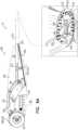
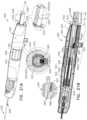
- system 10comprises an attachment mechanism (e.g., anchor(s), adhesive, clamp(s), clip(s), fastener(s), etc.), such as a plurality of anchors 32, which can be, for example, between about 5 and about 20 anchors, such as about 10 or about 16 anchors.
- Each anchor 32can comprise a tissue-engaging element 60 (e.g., a helical tissue-engaging element), and a tool-coupling head 62, fixed to one end of the tissue-engaging element.
- tissue-engaging element 60e.g., a helical tissue-engaging element
- tool-coupling head 62fixed to one end of the tissue-engaging element.
- One anchor 32is shown in Fig. 2 as being reversibly coupled to a deployment element 38 of a rotating anchor driver 36 of an anchor deployment manipulator 61.
- Anchors 32can comprise a biocompatible material, such as stainless steel 316 LVM.
- anchors 32comprise nitinol.
- anchors 32are coated fully or partially with a non-conductive material.
- Deployment manipulator 61as shown in Fig. 2 , comprises anchor driver 36 and deployment element 38.
- sleeve 26is disposed within a lumen of guide catheter 14.
- a forceis applied to a proximal end of sleeve 26 by a distal end of a reference-force tube 19.
- an implant-decoupling channel 18is advanceable within a lumen of reference-force tube 19 and through a lumen of sleeve 26 such that a portion of channel 18 that is disposed within the sleeve is coaxial with the sleeve.
- a distal end 17 of implant-decoupling channel 18is disposed in contact with an inner wall of sleeve 26 at a distal end thereof.
- a distal end portion of channel 18comprises a radiopaque marker 1018.
- tube 19 and sleeve 26are longitudinally and coaxially disposed with respect to each other.
- sleeve 26comprises a plurality of radiopaque markers 25, which are positioned along the sleeve at respective longitudinal sites.
- the markerscan provide an indication in a radiographic image (such as a fluoroscopy image) of how much of the sleeve has been deployed at any given point during an implantation procedure, in order to enable setting a desired distance between anchors 32 along the sleeve.
- the markerscomprise a radiopaque ink.
- the longitudinal sites of the radiopaque markersare longitudinally spaced at a constant interval.
- the longitudinal distance between the distal edges of adjacent markers, and/or the distance between the proximal edges of adjacent markerscan be set equal to the desired distance between adjacent anchors.
- the markerscan comprise first, second, and third markers, which first and second markers are adjacent, and which second and third markers are adjacent, and the distance between the proximal and/or distal edges of the first and second markers equal the corresponding distance between the proximal and/or distal edges of the second and third markers.
- the distancecan be between 3 and 15 mm, such as 6 mm, and the longitudinal length of each marker can be between 0.1 and 14 mm, such as 2 mm. (If, for example, the distance were 6 mm and the length were 2 mm, the longitudinal gaps between adjacent markers would have lengths of 4 mm.)
- Anchor driver 36comprises an elongate tube having at least a flexible distal end portion.
- the elongate tube of driver 36extends within a lumen of channel 18, through system 10 toward a proximal end of a proximal handle portion 101 of system 10.
- the tube of anchor driver 36provides a lumen for slidable advancement therethrough of an elongate rod 130.
- Rod 130facilitates the locking and unlocking of anchor 32 to deployment element 38, as is described hereinbelow.
- a proximal end of rod 130is coupled to a component of an anchor-release mechanism 28 at a proximal end of system 10.
- Mechanism 28comprises a housing 135 and a finger-engager 131 that is coupled to the proximal end of rod 130.
- Finger-engager 131is coupled to a housing 135 via a spring 133 (section E-E of Fig. 2 ).
- a proximal end of the tube of anchor driver 36is coupled to housing 135.
- the usere.g., a physician, health care professional, etc.
- anchor driver 36e.g., rotation and/or proximal-distal movement thereof, and/or release of anchor 32
- anchor driver 36is electronically controllable, such as by using an extracorporeal controller and/or electric motor coupled to a proximal end of the anchor driver and/or housing 135.
- Proximal handle portion 101can be supported by a stand having support legs 91 and a handle-sliding track 90.
- Handle portion 101comprises an outer-catheter handle 22, a guide-catheter handle 24, an implant-manipulating handle 126, and anchor-release mechanism 28.
- Handle 22is coupled to a proximal end of outer catheter 12.
- Handle 24is coupled to a proximal portion of guide catheter 14.
- Handle 126is coupled to a proximal portion of reference-force tube 19, and linear movement of handle 126 with respect to handle 24 moves reference-force tube 19 (and thereby typically structure 222) through catheter 14.
- housing 135 of anchor-release mechanism 28is coupled to a proximal portion of the tube of anchor driver 36.
- the relative positioning of each of the concentrically-disposed components of system 10is shown in the exploded view and sections A-A, B-B, C-C, and D-D of Fig. 2 .
- the stand supporting proximal handle portion 101can be moved distally and proximally to control a position of the entire multi-component system 10, particularly so as to adjust a distance of distal end 102 of catheter 12 from the interatrial septum.
- Handle 22comprises a steering knob 210 that is coupled to pull wires 29a and 29b disposed within respective secondary lumens in the wall of outer catheter 12. Rotation of knob 210 adjusts a degree of tension of wires 29a and 29b which, in turn, apply a force to pull ring 11 at the distal end portion of outer catheter 12.
- Such forcesteers the distal end portion of catheter 12 within the atrium of the heart of the patient in a manner in which the distal end portion of catheter 12 is steered in a first plane that is parallel with the plane of the annulus of the valve (e.g., in a direction from the interatrial septum toward surrounding walls of the atrium).
- the distal end portion of catheter 12can be pre-shaped so as to point downward toward the valve.
- the distal end portion of catheter 12can be pulled to assume an orientation in which the distal end portion points downward toward the valve.
- the distal end portion of catheter 12is not made to point downward toward the valve.
- Handle 24can be coupled to track 90 via a first mount 92.
- Mount 92can be slidable proximally and distally along track 90 in order to control an axial position of guide catheter 14 with respect to outer catheter 12.
- Mount 92can be slidable via a control knob 216.
- control knob 216 of mount 92can control the proximal and distal axial movement of the distal steerable portion of guide catheter 14 with respect to distal end 102 of outer catheter 12.
- Handle 24can comprise a steering knob 214 that is coupled to pull wires 31a and 31b disposed within respective secondary lumens in the wall of guide catheter 14.
- Rotation of knob 214adjusts a degree of tension of wires 31a and 31b which, in turn, apply a force to pull ring 13 at the distal end portion of guide catheter 14.
- Such forcesteers the distal end portion of catheter 14 in a second plane within the atrium of the heart of the patient downward and toward the annulus of the cardiac valve.
- the distal end portion of guide catheter 14can be steered in the second plane that is substantially perpendicular with respect to the first plane in which the distal end portion of outer catheter 12 is steered.
- handle 22can be tilted by the user (e.g., an operating physician, etc.), in order to further adjust a position of the distal end of catheter 12.
- handle 22comprises an indicator that indicates a degree of steering (e.g., bending) of the distal end portion of catheter 12 that has been produced using knob 210.
- handle 24comprises an indicator that indicates a degree of steering (e.g., bending) of the distal end portion of catheter 12 that has been produced using knob 214.
- first and second couplings 152 and 154 of outer catheter 12 and guide catheter 14, respectivelyprovide a controlled steerable system in which, during the steering and bending of the distal end portion of guide catheter 14, the distal end portion of outer catheter 12 is maintained in its steered configuration, or in its spatial orientation, without substantially affecting the steering or the bending of the distal end portion of guide catheter 14.
- first and second couplings 152 and 154respectively, minimize the effect of the distal end portion of outer catheter 12 on the steering and bending of catheter 14.
- Contracting member 226exits from the lumen in the wall of guide catheter 14 at a portion of handle portion 101 that is between handles 22 and 24.
- Handle 126can be coupled to track 90 via a second mount 93.
- Mount 93can be slidable proximally and distally along a track, in order to control an axial position of reference-force tube 19 and at least a proximal portion of sleeve 26 with respect to guide catheter 14.
- Mount 93can be slidable via a control knob.
- the control knob of mount 93can control the proximal and distal axial movement of the tube 19 and at least the proximal portion of sleeve 26 with respect to distal end 104 of guide catheter 14.
- channel 18in order to decouple sleeve 26 from a portion of an outer surface of channel 18, (1) channel 18 can be pulled proximally, while (2) reference-force tube 19 is maintained in place. A proximal end of channel 18 can be coupled to a knob 94 which adjusts an axial position of channel 18 proximally and distally with respect to reference-force tube 19 and sleeve 26.
- member 127In order to release sleeve 26 (e.g., to decouple channel 18 from the sleeve), the user (e.g., an operating physician) must disengage member 127, such as by pushing the button, before continuing to withdraw channel 18 proximally. When engaged, member 127 can also inhibit distal movement of channel 18 with respect to tube 19.
- Handle portion 101(comprising handles 22, 24, and 126 and anchor-release mechanism 28) can have a length L1 of between 65 and 85 cm, e.g., 76 cm. As shown, a majority of the body portion of outer-catheter handle 22 can be disposed at a non-zero angle with respect to a longitudinal axis 7 of the multiple components of system 10. The steering mechanism provided by handle 22 in order to steer the distal end portion of catheter 12 is disposed within the portion of handle 22 that is disposed at the non-zero angle with respect to axis 7. Handle 22 comprises an in-line tubular portion 21 which is longitudinally disposed in-line along axis 7 and coaxially with respect to handles 24 and 126 and release mechanism 28.
- Tubular portion 21is shaped so as to define a lumen for inserting guide catheter 14 therethrough and subsequently into the lumen of outer catheter 12.
- Tubular portion 21has a length L24 of between 7 and 11 cm, e.g., 7 cm. Such spatial orientation of the majority of handle 22 at an angle with respect to axis 7 reduces an overall functional length of handle portion 101.
- Annuloplasty structure or annuloplasty ring structure 222can be used to repair a dilated valve annulus of an atrioventricular valve, such as mitral valve 230.
- the annuloplasty structureis configured to be placed only partially around the valve annulus (e.g., to assume a C-shape), and, once anchored or otherwise secured in place, to be contracted so as to circumferentially tighten the valve annulus.
- the annuloplasty structureis configured to be placed fully around the valve annulus (e.g., to assume a closed shape, such as a circle, oval, D-shape, etc.), and, once secured in place, to be contracted so as to circumferentially tighten the valve annulus.
- the annuloplasty structurecan comprise a flexible sleeve 26.
- the annuloplasty structurecan also comprise and/or be used with an attachment means (e.g., anchor(s), fastener(s), clamp(s), suture(s), clip(s), etc.), such as a plurality of anchors 32.
- Anchor deployment manipulator 61is advanced into a lumen of sleeve 26, and, from within the lumen, deploys the anchors through a wall of the sleeve and into cardiac tissue, thereby anchoring the sleeve around a portion of the valve annulus.
- annuloplasty structure or annuloplasty ring structure 222is implemented using techniques described in US Application No.
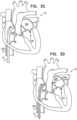
- the procedurecan begin by advancing a semi-rigid guidewire 202 into a right atrium 220 of the patient.
- the procedurecan be performed with the aid of imaging, such as fluoroscopy, transesophageal echo, and/or echocardiography.
- guidewire 202provides a guide for the subsequent advancement of outer catheter 12 therealong and into the right atrium. Once a distal portion of catheter 12 has entered the right atrium, guidewire 202 is retracted from the patient's body.
- Catheter 12can comprise a 14-24 F sheath, although any size may be selected as appropriate for a given patient.
- Catheter 12is advanced through vasculature into the right atrium using a suitable point of origin determined for a given patient. For example:
- Catheter 12can be advanced distally until the sheath reaches the interatrial septum, and guidewire 202 is withdrawn, as shown in Fig. 3C .
- a resilient needle 206 and a dilatorare advanced through catheter 12 and into the heart.
- the dilatorIn order to advance catheter 12 transseptally into left atrium 224, the dilator is advanced to the septum, and needle 206 is pushed from within the dilator and is allowed to puncture the septum to create an opening that facilitates passage of the dilator and subsequently catheter 12 therethrough and into left atrium 224.
- the dilatoris passed through the hole in the septum created by the needle.
- the dilatorcan be shaped to define a hollow shaft for passage along needle 206, and the hollow shaft is shaped to define a tapered distal end.
- This tapered distal endis first advanced through the hole created by needle 206.
- the holeis enlarged when the gradually increasing diameter of the distal end of the dilator is pushed through the hole in the septum.
- a distal end 102 of catheter 12is tapered so as to facilitate passage of the distal portion of catheter 12 through the opening in the septum.
- the advancement of catheter 12 through the septum and into the left atriumcan be followed by the extraction of the dilator and needle 206 from within catheter 12, as shown in Fig. 3E .
- the steerable distal end portion of catheter 12e.g., a bending section 1203 of catheter 12
- the steerable distal end portion of catheter 12can be steered in a first plane that is parallel to a plane of the annulus of mitral valve 230.
- Such steeringmoves the distal end portion of catheter 12 in a direction from the interatrial septum toward surrounding walls of the atrium, as indicated by the arrow in atrium 224.
- steering of the distal portion of catheter 12can be performed via steering knob 210 of handle 22 in handle portion 101 (in Figs. 1 and 2 ).
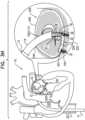
- annuloplasty structure or annuloplasty ring structure 222(not shown for clarity of illustration, with anchor deployment manipulator 61 therein) is advanced through guide catheter 14, which is in turn, advanced through catheter 12 into left atrium 224.
- an exposed distal end portion 114e.g., a bending section 1403 of catheter 14 extends beyond distal end 102 of catheter 12. Exposed distal end portion 114 is then (1) steered toward the annulus of valve 230 along a plane that is perpendicular with respect to the steering plane of catheter 12 and that is perpendicular with respect to valve 230, and is (2) bent, via bending section 1403 toward valve 230.
- steering of the distal portion of catheter 14is performed via steering knob 214 of handle 24 in handle portion 101 (in Figs. 1 and 2 ).
- a distal end 251 of sleeve 26is positioned in a vicinity of a left fibrous trigone 242 of an annulus 240 of mitral valve 230.
- distal end 251 of sleeve 26is shown schematically in the cross-sectional view of the heart, although left trigone 242 is in reality not located in the shown cross-sectional plane, but rather out of the page closer to the viewer.
- the distal end of sleeve 26is positioned in a vicinity of a right fibrous trigone 244 of the mitral valve (configuration not shown).
- deployment manipulator 61deploys a first anchor 32 through the wall of sleeve 26 (by penetrating the wall of the sleeve in a direction in a direction parallel to a central longitudinal axis of deployment manipulator 61, or anchor driver 36, through the distal end of channel 18, and/or parallel to central longitudinal axis of tissue-engaging element 60 of anchor 32) into cardiac tissue near the trigone.
- deployment element 38is decoupled from anchor 32 by moving rod 130 proximally.
- Anchors 32can be deployed from a distal end of manipulator 61 while the distal end is positioned such that a central longitudinal axis through the distal end of manipulator 61 forms an angle with a surface of the cardiac tissue of between about 20 and 90 degrees, e.g., between 45 and 90 degrees, such as between about 75 and 90 degrees, such as about 90 degrees.
- Anchors 32can be deployed from the distal end of manipulator 61 into the cardiac tissue in a direction parallel to the central longitudinal axis through the distal end of manipulator 61. Such an angle can be provided and/or maintained by channel 18 being more rigid than sleeve 26.
- Distal end 17(shown in Fig.
- pushing of distal end 17 against the cardiac tissue (via the wall of the sleeve)temporarily deforms the cardiac tissue at the site of contact. This deformation can facilitate identification of the site of contact using imaging techniques (e.g., by identifying a deformation in the border between cardiac tissue and blood), and thereby can facilitate correct positioning of the anchor.
- anchors 32can be deployed from a lateral portion of manipulator 61.
- An indicator(such as indicator 2120 described in PCT patent application PCT/IL2012/050451 to Sheps et al. , which published as WO/2013/069019 ) on handle 126 provides an indication of how much channel 18 is withdrawn from within sleeve 26 (i.e., how much the delivery tool is decoupled from sleeve 26, and how much the sleeve has advanced off channel 18 and against tissue).
- a proximal end of channel 18is coupled to a knob 94 ( Fig. 2 ) which adjusts an axial position of channel 18 proximally and distally with respect to reference-force tube 19 and sleeve 26.
- deployment manipulator 61is repositioned along annulus 240 to another site selected for deployment of a second anchor 32. Reference is now made to Figs. 1 and 3H . Such repositioning of manipulator 61 is accomplished by:
- the already-deployed first anchor 32holds the anchored end of sleeve 26 in place, so that the sleeve is drawn from the site of the first anchor towards the site of the second anchor.
- deployment manipulator 61can be moved generally laterally along the cardiac tissue, as shown in Fig. 3H .
- Deployment manipulator 61deploys the second anchor through the wall of sleeve 26 into cardiac tissue at the second site.
- the portion of sleeve 26 therebetweencan remain tubular in shape, or can become flattened, which may help reduce any interference of the ring with blood flow.
- deployment manipulator 61can be repositioned along the annulus to additional sites, at which respective anchors are deployed, until the last anchor is deployed in a vicinity of right fibrous trigone 244 (or left fibrous trigone 242 if the anchoring began at the right trigone).
- the last anchoris not deployed in the vicinity of a trigone, but is instead deployed elsewhere in a vicinity of the mitral valve, such as in a vicinity of the anterior or posterior commissure. Then, system 10 is removed, leaving behind implant structure 222 and contracting member 226.
- a contracting-member-uptake toolis then threaded over and advanced along contracting member 226 and toward structure 222, and is used to contract structure 222 by adjusting a degree of tension of contracting member 226 (not shown in Fig. 3I , but (i) advancing of contracting-member-uptake tool over contracting member 226 is described with reference to Figs. 4A-5D , mutatis mutandis, and (ii) applying tension to member 226 is described hereinbelow with reference to Figs. 6A-B ).
- such an anchor-manipulation toolcan comprise an anchor-manipulation tool described in a PCT patent application PCT/IL2013/050861 to Herman et al, titled “Percutaneous tissue anchor techniques", filed on October 23, 2013 .
- Systems, apparatuses, and techniques described in the present patent applicationcan be used in combination with systems, apparatuses, and techniques described in said PCT patent application PCT/IL2013/050861 .
- sleeve 26 of ring structure 222comprises a plurality of radiopaque markers 25, which are positioned along the sleeve at respective longitudinal sites to indicate anchor-designated target areas.
- the markerscan provide an indication in a radiographic image (such as a fluoroscopy image) of how much of sleeve 26 has been deployed at any given point during an implantation procedure, in order to enable setting a desired distance between anchors 32 along the sleeve 26.
- anchors 32are deployed at longitudinal sites of sleeve 26 at which radiopaque markers 25 are disposed (e.g., the anchors are driven through a radiopaque ink of the radiopaque markers).
- anchors 32can be deployed at longitudinal sites of sleeve 26 between markers 25.
- a marker 25 at the distal end of channel 18can indicate that a correct length of sleeve 26 has been dispensed. Subsequent limited movement of the channel with respect to the sleeve may occur.
- the channelwhen channel 18 is placed against the annulus, the channel may tension the portion of sleeve 26 between the previously-deployed anchor and the distal end of the channel, such that when the anchor is deployed, it passes through the sleeve slightly proximally to the marker 25 (e.g., 1-2 mm proximally to the marker).
- an excess portion of sleeve 26may be present at the proximal portion of sleeve.
- a cutting tool(not shown) can be advanced within channel 18 and into the lumen of the excess portions of sleeve 26 (e.g., from within sleeve 26) in order to cut the sleeve proximal to the proximal-most-deployed anchor 32.
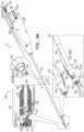
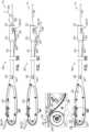
- Figs. 4A-Bare schematic illustrations of an example system 10, which is not a part of the invention, comprising an example contracting-member-uptake tool 300 which is configured to contract contracting member 226 and sever any excess portions of contracting member 226.
- Tool 300comprises a handle portion 320 and an elongate sheath 310 coupled thereto. Sheath 310 encases a primary tube 330 and a secondary tube 340 disposed alongside primary tube 330. Both primary tube 330 and secondary tube 340 are coupled to handle portion 320 at respective proximal ends of tubes 330 and 340.
- Secondary tube 340has a secondary-tube-lumen configured for passage therethrough of contracting member 226.
- Tool 300defines a longitudinal axis 301.
- sheath 310is shaped so as to define a lumen in a wall of sheath 310.
- tool 300does not comprise secondary tube 340, but rather, the lumen in the wall of sheath 310 functions as secondary tube 340 and the primary lumen defined by the wall of sheath 310 functions as primary tube 330.
- Sheath 310, primary tube 330, and secondary tube 340can be flexible such that sheath 310, primary tube 330, and secondary tube 340 are configured for passage through vasculature of the patient during a transvascular, transcatheter procedure.
- sheath 310, primary tube 330, and secondary tube 340comprise silicone.
- sheath 310, primary tube 330, and secondary tube 340comprise polyurethane.
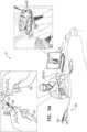
- Tool 300can comprise a distal end portion 333 having a distal tip 331 which defines a distal end of tool 300.
- Primary tube 330terminates at distal end portion 333.
- Distal end portion 333comprises a housing 332 which is shaped so as to hold and be removably coupled to a contracting-member-fastener 360.
- Contracting-member-fastener 360comprises a clamping structure that can be biased toward assuming a closed state or closed position, and in the closed state/position, the clamping structure can be configured to clamp onto the contracting member 226 passed therethrough (not shown).
- the clamping structurecan also be configured such that it can be flexed to an open state through which contracting member 226 (not shown) can move.
- Tool 300can comprise a fastener-ejector 335 movable within distal end portion 333 of contracting-member-uptake tool 300. Movement of fastener-ejector 335 converts contracting-member-fastener 360 (or clamping structure thereof) from its open state to its closed state to clamp onto contracting member 226 passed therethrough, as will be described hereinbelow.
- Tool 300comprises a stop 362 removably coupled to contracting-member-fastener 360 and configured to maintain contracting-member-fastener 360 in the open state, as shown in Section A-A of Fig. 4A .
- Stop 362comprises one or more, e.g., two, prongs 337 which maintain fastener 360 in the open state.
- Ejector 335is coupled to stop 362 and moves stop 362 that is removably coupled to fastener 360 in order to convert fastener 360 from the open state to a closed state, as is described hereinbelow.
- Contracting-member-uptake device 322can optionally comprise a wheel, which can have two opposing wedged portions 325 which together define a groove 326 configured to couple contracting member 226 to the wheel of device 322.
- Wedged portions 325can be shaped so as to receive any portion of contracting member 226, e.g., a proximal end of member 226 and/or a middle portion of member 226.
- opposing wedged portions 325are configured to grip contracting member 226.
- the wheel of device 322can have a numerical indicator to indicate the number of turns of the wheel.
- Handle portion 320can be shaped so as to define a lumen 328 for passage therethrough of snare 350 from within the lumen of secondary tube 340.
- Snare 350passes through lumen 328 and beyond groove 326 of contracting-member-uptake device 322.
- device 322does not uptake snare 350 but rather, snare 350 passes through groove 326.
- pulling on snare 350pulls on contracting member 226 coupled thereto such that contracting member 226 is pulled through secondary tube 340, through lumen 328 and ultimately toward contracting-member-uptake device 322.
- contracting member 226is coupled to contracting-member-uptake device 322 by being fed into groove 326.
- Contracting-member-uptake device 322is then actuated in order to apply tension to contracting member 226, and thereby to annuloplasty structure 222 implanted along the annulus. With each rotation of the wheel of device 322, successive portions of contracting member 226 are wound within groove 326 of device 322.
- Figs. 5A-Dare schematic illustrations of an example contracting-member-uptake tool 300, which is not a part of the invention, useable to uptake contracting member 226.
- annuloplasty structure or annuloplasty ring structure 222has been implanted along annulus 240, as described hereinabove with reference to Figs. 3A-I .
- contracting member 226extends away from structure 222 and through vasculature of the patient such that a proximal end portion of member 226 is disposed outside the body of the patient.
- Contracting member 226can exit sleeve 26 of structure 222 at any suitable location along structure 222.
- contracting member 226can exit sleeve 26 of structure 222 at a portion of structure 222 in a vicinity of a left fibrous trigone of the valve, as shown.
- contracting member 226exits sleeve 26 of structure 222 at a portion of structure 222 in a vicinity of a right fibrous trigone of the valve.
- contracting member 226exits sleeve 26 of structure 222 at a middle portion of structure 222.
- structure 222comprises sleeve 26 which defines the primary body portion of structure 222.
- Contracting member 226has a first portion 420 extending along a longitudinal length of the primary body portion of annuloplasty structure 222. The first portion 420 can extend along the longitudinal length of structure 222 when structure 222 is in a linear state as well as in a curved state, as shown in Fig. 5A . Contracting member 226 also defines a second portion 422 extending away from the primary body portion of annuloplasty structure 222.
- the usere.g., an operating physician, etc.
- the usercan hold a distal end of tool 300 in one hand and a proximal end portion of contracting member 226 in another hand.
- the user or physicianthreads the proximal end portion of contracting member 226 through distal snare portion 352 of contracting-member-snare 350.
- Fig. 5Bshows tool 300 in a state in which distal snare portion 352 ensnares contracting member 226.
- distal snare portion 352is shaped so as to increase the coupling between snare 350 and contracting member 226.
- distal snare portion 352is corrugated to increase friction between snare portion 352 and contracting member 226.
- distal snare portion 352can comprise a coiled section to increase friction between snare portion 352 and contracting member 226.
- snare 350comprises a metal wire.
- snare 350comprises a metal wire comprising stainless steel.
- Snare 350(including distal snare portion 352) can have a variety of sizes, for example, a diameter of 0.15-0.5 mm or 0.15-0.35 mm.
- Figs. 4A and 5BAs shown in Section A-A of Fig. 4A , contracting-member-snare 350 passes through aligned ports 339 and 341 in distal end portion 333 of tool 300.
- Snare 350can be pulled proximally, e.g., by the user or physician holding the proximal exposed end portions 351 of snare 350 proximally away from tool 300. Pulling on snare 350 proximally, as shown in Fig. 5C , pulls distal snare portion 352 and contracting member 226 looped therethrough through distal tip 331 of tool 300, through the fastener disposed within distal end portion 333 of tool 300, through aligned ports 339 and 341 in distal end portion 333 of tool 300, and subsequently, through the lumen of secondary tube 340.
- Snare 350is pulled until distal snare portion 352 enters the lumen of secondary tube 340.
- the looped portion of distal snare portion 352is compressed and collapses around contracting member 226 looped therethrough, in order to maintain coupling between snare portion 352 and contracting member 226 as elongate flexible body portion 354 (shown in Fig. 5B ) is pulled through the lumen of secondary tube 340.
- the looped portion of snare portion 352collapses within the lumen of secondary tube 340, the portion of contracting member 226 ensnared by snare portion 352 bends, and coupling between contracting member 226 and snare portion 352 is strengthened. This strengthening is also brought about as a result of the relatively small diameter of secondary tube 340 of 0.5-1.0 mm.
- snare 350is pulled entirely through secondary tube 340, through lumen 328 of handle portion 320 and beyond groove 326 of contracting-member-uptake device 322 in order to pull contracting member 226 along this path. All the while, sheath 310 of tool 300 is advanced through vasculature and toward annuloplasty structure 222 implanted along annulus 240 of the valve. Once distal snare portion 352 and the portion of contracting member 226 coupled thereto exit lumen 328 of handle portion 320, the portion of contracting member 226 is coupled to contracting-member-uptake device 322 by being positioned within groove 326. For some applications, the proximal end portion of contracting member 226 is fed within groove 326.
- a middle portion of contracting member 226(e.g., a portion in a vicinity of the proximal end of contracting member 226) is fed within groove 326.
- Contracting member 226is then tightened by actuating, e.g., rotating, contracting-member-uptake device 322 such that successive portions of contracting member 226 are wound within contracting-member-uptake device 322 and contracting-member-uptake device 322 uptakes the successive portions.
- snare 350Once snare 350 has been pulled through tool 300, snare 350 can be discarded.
- tension meter 324 of handle portion 320reads a tension of contracting member 226 at zero or close to zero.
- sleeve 26 of annuloplasty structure 222 coupled to annulus 240is in a relaxed, non-tense state.
- tool 300has been sufficiently advanced through vasculature of the patient such that distal tip 331 is in proximity to structure 222 disposed along the annulus, while a proximal portion of contracting member 226 is disposed outside the body of the patient.
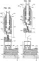
- Fig. 7Ashows annuloplasty structure or annuloplasty ring structure 222 in a non-contracted state.
- Distal tip 331 of tool 300can be brought close to structure 222.
- Contracting member 226can be threaded along sleeve 26 and out of a portion of sleeve 26 of structure 222. As described hereinabove, contracting member 226 can be threaded through tool 300 in a manner in which member 226 passes through distal tip 331, through contracting-member-fastener 360 that can be held in the open state, such as by prongs 337 of stop 362, through aligned ports 339 and 341 in distal end portion 333 of tool 300, and through secondary tube 340.
- Fig. 7Ccontracting member 226 has been pulled tight, and annuloplasty structure 222 has been contracted and in a tense, contracted state. Distal end portion 333 of tool 300 is then used to eject and deploy fastener 360 from within tool 300 in order to lock structure 222 in the contracted state.
- Fastener-ejector 335is coupled to prongs 337 of stop 362 in a manner in which when ejector 335 is moved proximally within portion 333, stop 362 is decoupled from contracting-member-fastener 360 as prongs 337 move proximally away from contracting-member-fastener 360. Once contracting-member-fastener 360 is no longer held in the open state by stop 362, fastener 360 closes, as it tends to do, and clamps around contracting member 226 passing therethrough.
- FIGs. 8A-Dare schematic illustrations of an example of a system 510, which is not a part of the invention, for contracting annulus 240 of the patient using an annuloplasty structure 522 (e.g., an annuloplasty ring structure, a closed annuloplasty structure, a closed annuloplasty ring structure, an open annuloplasty structure, a partial annuloplasty ring structure, etc.), which can comprise a housing 530.
- Housing 530can house a contracting-member-fastener 360.
- annuloplasty structure 522can be the same as or generally similar to annuloplasty structure 222, described hereinabove with reference to Figs. 1-7E and like reference numerals refer to like parts.
- Annuloplasty structure or annuloplasty ring structure 522is implanted as described hereinabove with reference to Figs. 3A-I using the system described hereinabove with reference to Figs. 1-3I .
- Housing 530can be coupled to sleeve 26 of structure 522 at any suitable location along structure 522.
- housing 530can be coupled to sleeve 26 of structure 522 at a portion of structure 522 in a vicinity of a left fibrous trigone of the valve, as shown.
- housing 530can be coupled to sleeve 26 of structure 522 at a portion of structure 522 in a vicinity of a right fibrous trigone of the valve.
- housing 530can be coupled to sleeve 26 of structure 522 at a middle portion of structure 522.
- housing 530can be coupled to a lateral surface of sleeve 26. In such applications, housing 530 does not block them lumen of sleeve 26 of structure 522.
- Fig. 8Bshows a contracting-member-uptake tool 600 through which contracting member 226 has been threaded.
- Contracting member 226can be ensnared by tool 600 using a snare as described herein above with regard to snare 350 with reference to Figs. 4A-5D .
- Tool 600can be advanced along contracting member 226 toward housing 530 of structure 522, in a manner similar to tool 300 advancing along contracting member 226, as described hereinabove with reference to Figs. 4A-5D .
- Tool 600can comprise a distal tip 631 and a distal end portion 633 which is generally similar to distal end portion 533 of tool 300, described hereinabove with reference to Figs. 4A-7E and like reference numerals refer to like parts. Since annuloplasty structure 522 comprises contracting-member-fastener 360 and stop 570 removably coupled to fastener 360, distal end portion 633 of tool 600 is unlike distal end portion 533 of tool 300 of Figs. 4A-7E , remaining parts of tool 600 correspond to the remaining parts of tool 300.
- contracting-member-uptake tool 702can be the same as or generally similar to contracting-member-uptake tools 300 and 600, described hereinabove with reference to Figs. 4A-9D , used to (1) apply tension to the contracting member, (2) deploy a lock in order to secure tension of the contracting member, and (3) subsequently cut and sever the contracting member of any annuloplasty structure, e.g., a full (or closed) annuloplasty ring structure or a partial (or open) annuloplasty ring structure.
- any annuloplasty structuree.g., a full (or closed) annuloplasty ring structure or a partial (or open) annuloplasty ring structure.
- structure 730comprises sleeve 26 which defines the primary body portion of structure 730.
- Contracting member 226has a first portion 732 extending along a longitudinal length of the primary body portion of annuloplasty structure 730. Contracting member 226 also defines a second portion 734 extending away from the primary body portion of annuloplasty structure 730.
- annuloplasty structure 730is implemented using techniques described in US Application No. 12/341,960, filed December 22, 2008 , which issued as US 8,241,351 , US Application No. 12/437,103, filed May 7, 2009 which issued as US 8,715,342 , and/or US Application No. 12/689,635, filed January 19, 2010 which published as US 8,545,553 , both of which are assigned to the assignee of the present application.
- Tool 702is used to deploy one or more (e.g., two as shown) contracting-member-fasteners 360a and 360b.
- Fasteners 360a and 360bare similar to or the same as fasteners 360 described hereinabove with reference to Figs. 4A-9D .
- the use of two fasteners 360a and 360bcan provide redundant and more secure fastening of a perimeter of structure 730 following contraction thereof.
- Fasteners 360a and 360bcan be disposed coaxially around a portion of contracting member 226
- tool 702is used to sever any excess portions of contracting member 226, as described hereinbelow with reference to tools 300 and 600 as described hereinabove with reference to Figs. 4A-9D .
- oversheath 710is not used and tool 702 is coupled to the annuloplasty structure using male and female couplings, as shown hereinbelow with reference to Figs. 12 , 13 , and 15 .
- contracting-member-uptake tool 810can be the same as or generally similar to contracting-member-uptake tools 300 and 600, described hereinabove with reference to Figs. 4A-9D , used to (1) apply tension to the contracting member, (2) deploy a lock in order to secure tension of the contracting member, and (3) subsequently cut and sever the contracting member of any annuloplasty structure, e.g., a full (or closed) annuloplasty ring structure, a partial (or open) annuloplasty structure, etc.
- any annuloplasty structuree.g., a full (or closed) annuloplasty ring structure, a partial (or open) annuloplasty structure, etc.
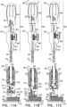
- Fig. 11Ashows annuloplasty structure or annuloplasty ring structure 222 in a non-contracted state.
- Distal tip 331 of tool 810can be brought close to structure 222.
- Contracting member 226can be threaded along sleeve 26 and out of a portion of sleeve 26 of structure 222. As described hereinabove, contracting member 226 can be threaded through tool 810 in a manner in which member 226 passes through distal tip 331, through contracting-member-fastener 360 that can be held in the open state, such as by prongs 337 of stop 362, through aligned ports 339 and 341 in distal end portion 333 of tool 810, and through secondary tube 340.
- the distal end portion of tool 810is similar to the distal end portion of tool 702 as described hereinabove with reference to Figs. 10A-B .
- the distal end portion of tool 810is similar to the distal end portion of tool 920 as shown hereinbelow with reference to Figs. 12 , 13 , and 15 .
- tool 920comprises male coupling 925 and annuloplasty structure 222 comprises housing 930 shaped so as to define female coupling 927.
- Tool 810comprises a proximal handle portion 820.
- Handle portion 820comprises a proximal contraction-facilitating knob 830.
- Knob 830is fixedly coupled to a proximal end 832 of contracting member 226.
- Rotation of contraction-facilitating knob 830 as shown in Fig. 11Amoves knob 830 proximally.
- contracting member 226is pulled proximally.
- annuloplasty structure 222is contracted.
- Tool 810comprise a gauge 834 indicating a level of contraction of the ring responsively to the number of rotations of knob 830.
- tool 810can be used to contract structure 222 by tool 810 pulling on contracting member 226 responsively to rotation of the knob 830 as described hereinabove with reference to Fig. 11A .
- fastener 360is not deployed.
- Fig. 11Ccontracting member 226 has been pulled tight, and annuloplasty structure 222 has been contracted and in a tense, contracted state. Distal end portion 333 of tool 810 is then used to eject and deploy fastener 360 from within tool 810 in order to lock structure 222 in the contracted state.
- Proximal movement of trigger knob 840pulls proximally on actuating wire 842, which, in turn, pulls maximally fastener-ejector 335. Movement of fastener-ejector 335 proximally converts contracting-member-fastener 360 from its open state to its closed state to clamp onto contracting member 226 passed therethrough.
- Fastener-ejector 335is coupled to prongs 337 of stop 362 in a manner in which when ejector 335 is moved proximally within portion 333, stop 362 is decoupled from contracting-member-fastener 360 as prongs 337 move proximally away from contracting-member-fastener 360. Once contracting-member-fastener 360 is no longer held in the open state by stop 362, fastener 360 closes, as it tends to do, and clamps around contracting member 226 passing therethrough.
- Actuating wire 842is disposed within an inner sheath 841 which runs the length of elongate sheath 310.
- elongate sheath 310comprises a multi-lumen sheath defining (1) a first lumen for passage therethrough of inner sheath 841 housing within it actuating wire 842, and (2) a second lumen for passage therethrough of contracting member 226.
- fastener 360has been ejected and deployed from within housing 332 of ejector 335. Subsequently, fastener-ejector 335 is moved further proximally in response to the further pulling proximally of trigger knob 840, in order to sever excess portions of contracting member 226.
- tool 810is shaped so as to define a cutting-facilitating edge 370 in distal end portion 333 of tool 810. For some applications, cutting-facilitating edge 370 defines a sharp edge. While contracting member 226 passes through aligned ports 339 and 341 in distal end portion 333 of tool 810, as shown in Figs.
- tool 810is removed from the body of the patient by being withdrawn proximally, bringing together with it the excess portion of contracting member 226.
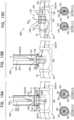
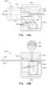
- FIGs. 12A-Care schematic illustrations of an example of a system 900, which is not a part of the invention, comprising an example annuloplasty structure 910 (e.g., an annuloplasty ring structure, a closed annuloplasty structure, a closed annuloplasty ring structure, an open annuloplasty structure, a partial annuloplasty ring structure, etc.) comprising a sleeve 26, a contracting member 226, and a lock 950.
- Implantable annuloplasty structure 910comprises a primary body portion 912.
- Contracting member 226has a first portion 914 extending along a longitudinal length of primary body portion 912 of annuloplasty structure 910, and a second portion 916 extending away from primary body portion 912 of annuloplasty structure 910. Contracting member 226 is configured to adjust a perimeter of annuloplasty structure 910.
- annuloplasty structure 910can be the same as or generally similar to annuloplasty structures 222, 522, and 730 described hereinabove with reference to Figs. 1-11C and like reference numerals refer to like parts.
- Annuloplasty structure 910can be a full (or closed) or partial (or opened) annuloplasty structure.
- Primary body portion 912 of structure 910has a lateral wall and is shaped so as to define a recess 960 having a recess axis 940.
- Recess 960extends from an opening 932 in a first surface 934 of the lateral wall of primary body portion 912 toward an opposite second surface 936 of the lateral wall of the primary body portion 912 (illustrated in Fig 12C ).
- the lateral wall of primary body portion 912extends away from recess 960 along a longitudinal axis 942 that is at a non-zero angle with respect to recess axis 940.
- Contracting member 226extends through recess 960 and away from primary body portion 912 of annuloplasty structure 910 via recess 960.
- Recess 960is shaped so as to define a recess lumen 962.
- Recess lumen 962is disposed along recess axis 940.
- primary body portion 912comprises a housing 930 coupled to sleeve 26.
- housing 930defines at least a portion of the lateral wall and housing 930 defines recess 960.
- Sleeve 26defines the remaining portion of the lateral wall.
- structure 910does not comprise a housing 930, and sleeve 26 defines the lateral wall.
- Recess 960is shaped so as to receive lock 950. Recess 960 is dimensioned so as to compress lock 950 when lock 950 is disposed at least in part within recess 960.
- Lock 950is shaped to as to define a series of tapered segments 951. Each segment 951 having a longest length L1 of 0.2-1.5 mm. A proximal-most section of lock 950 has a length L2 of 0.2-2 mm.
- recess 960corresponds to the shape of lock 950 and is slightly smaller than the shape of lock 950 such that the walls that define recess 960 compress lock 950 as it slides into recess 960. That is, the section of recess 960 that receives longest length L1 of segment 951 has a longest length L3 of 0.2-1.5 mm. A proximal-most section of recess 960 has a length L4 of 0.2-2 mm.
- Lock 950is shaped so as to define a lock lumen configured to surround contracting member 226.
- Lock 950is shaped so as to define a longitudinal slit 952 which extends from a proximal surface of lock 950 toward a distal surface of lock 950.
- slit 952defines the lock lumen of lock 950. Slit 952 enables lock 950 to squeeze into the smaller recess 960 and thereby be compressed.
- slit 952enables lock 950 to close around contracting member 226 and thereby lock 950 to contracting member 226.
- the lock lumenhas a dimension (e.g., a diameter) that is consistent along a length of the lock lumen from the proximal surface of lock 950 to a distal surface of lock 950.
- Lock-ejector 923is movable within a distal end portion of tool 920. Movement of lock-ejector 923 contacts and converts lock 950 from an open state (shown in Fig. 12A ) to a closed state (shown in Fig. 12C ) in order to clamp lock 950 onto contracting member 226 passed therethrough.
- lock 1950is disposed at least in part and retained within recess a 1960.
- a distal-most tapered segment 951is disposed within a proximal section of recess 1960. In such a manner, system 1000 reduces the possibility of embolism and/or clotting.
- a delivery toolcan be used to deliver lock 1110 toward the annuloplasty structure or annuloplasty ring structure.
- the delivery toolcan be the same as or generally similar to tools 300, 600, 702, 810, and 920 described hereinabove with reference to Figs. 4A-13C and like reference numerals refer to like parts.
- the delivery toolcomprises a contracting-member severing section which can comprise elements of tools 300, 600, 702, 810, and 920 described hereinabove with respect to the cutting elements.
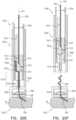
- FIGs. 15A-Care schematic illustrations of an example system 1480 comprising an example annuloplasty structure 910 (e.g., an annuloplasty ring structure, a closed annuloplasty structure, a closed annuloplasty ring structure, an open annuloplasty structure, a partial annuloplasty ring structure, etc.) comprising a sleeve 26, a contracting member 226, and a lock 1490, in accordance with some applications.
- system 1480is the same or generally similar to system 1000 as described hereinabove with reference to Figs. 13A-C with the exception that lock 1490 has a lumen that is narrower at the proximal end portion of lock 1490 and wider at the distal end portion of lock 1490.
- Section A-A of Fig. 15Ashows the lock lumen being wider around contracting member 226 at the proximal end portion of lock 1490 than a width of the lock lumen around contracting member 226 at the distal end portion of lock 1490 shown in Section B-B.
- Fig. 15Conce lock 1490 is disposed entirely within recess 960, the proximal end portion closes tightly around contracting member 226, as shown in Section C-C, while the distal end portion closes around contracting member 226, which may not close as tightly as the proximal end portion closes around contracting member 226, as shown in Section D-D.
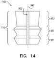
- FIG. 16is a schematic illustration of an example system 1200, which is not a part of the invention, comprising an example annuloplasty structure 1210 (e.g., an annuloplasty ring structure, a closed annuloplasty structure, a closed annuloplasty ring structure, an open annuloplasty structure, a partial annuloplasty ring structure, etc.) comprising a sleeve 26, a contracting member 226, and a lock 1220.
- Implantable annuloplasty structure 1210comprises a primary body portion.
- Contracting member 226has a first portion extending along a longitudinal length of the primary body portion of annuloplasty structure 1210, and a second portion extending away from the primary portion of annuloplasty structure 1210. Contracting member 226 is configured to adjust a perimeter of annuloplasty structure 1210.
- Lock 1220is shaped so as to define a lock lumen 1221 configured to surround contracting member 226.
- Lock 1220is shaped so as to define a longitudinal slit which extends from a proximal surface of lock 1220 toward a distal surface of lock 1220.
- the slitdefines lock lumen 1221 of lock 1220. The slit enables lock 1220 to squeeze into the smaller recess 1230 and thereby be compressed. When lock 1220 is compressed, the slit enables lock 1220 to close around contracting member 226 and thereby lock 1220 to contracting member 226.
- lock lumen 1221has a dimension (e.g., a diameter) that is consistent along a length of lock lumen 1221 from the proximal surface of lock 1220 to a distal surface of lock 1220.
- lock lumen 1221 of lock 1220is shaped so as to define a distal portion that is wider than a proximal portion of lock lumen 1221.
- the proximal-most section of recess 1230can be narrower than any other portion of recess 1230 distal to the proximal-most portion.
- annuloplasty structure 1310can be the same as or generally similar to annuloplasty structures 222, 522, 730, and 910 described hereinabove with reference to Figs. 1-15C and like reference numerals refer to like parts.
- Annuloplasty structure 1310can be a full (or closed) or partial (or opened) annuloplasty structure.
- recess-distal-tapered-portion 1324is configured to compress lock-distal-tapered-portion 1334 which, in turn, is configured to pinch a second portion of contracting member 226 within lock lumen 1321 at recess-distal-tapered-portion 1324 in order to lock contracting member 226 at least a second pinching point 1314.
- Systems 1200 and 1300provide a locking assembly which allows for the operating physician to readjust the perimeter of the annuloplasty structure post-locking. For example, if the physician would like to readjust once locks 1220 and 1320 are in place, the physician is able to unscrew locks 1220 and 1230 respectively in order to readjust the perimeter of the annuloplasty structure by giving slack to or tightening contracting member 226 without disengaging locks 1220 and 1300 from the respective recess 1230 and 1330. Subsequently to the readjusting of contracting member 226, locks 1220 and 1320 are repositioned within the respective recess 1230 and 1330.
- FIG. 18is a schematic illustration of an example of a system 1350, which is not a part of the invention, for contracting annulus 240 of the patient using an annuloplasty structure 522 (e.g., an annuloplasty ring structure, a closed annuloplasty structure, a closed annuloplasty ring structure, an open annuloplasty structure, a partial annuloplasty ring structure, etc.), which can comprise a housing 530.
- Housing 530can house a contracting-member-fastener 1360.
- annuloplasty structure 522can be the same as or generally similar to annuloplasty structure 222, described hereinabove with reference to Figs. 1-7E and like reference numerals refer to like parts.
- Annuloplasty structure or annuloplasty ring structure 522is implanted as described hereinabove with reference to Figs. 3A-I using the system described hereinabove with reference to Figs. 1-3I .
- Housing 530can be coupled to sleeve 26 of structure 522 at any suitable location along structure 522.
- housing 530can be coupled to sleeve 26 of structure 522 at a portion of structure 522 in a vicinity of a left fibrous trigone of the valve, as shown.
- housing 530can be coupled to sleeve 26 of structure 522 at a portion of structure 522 in a vicinity of a right fibrous trigone of the valve.
- housing 530can be coupled to sleeve 26 of structure 522 at a middle portion of structure 522.
- housing 530can be coupled to a lateral surface of sleeve 26. In such applications, housing 530 does not block them lumen of sleeve 26 of structure 522.
- Housing 1430can be coupled to the sleeve 26 of the annuloplasty structure at any suitable location along the annuloplasty structure.
- housing 1430can be coupled to the sleeve 26 of the annuloplasty structure at a portion of the annuloplasty structure in a vicinity of a left fibrous trigone of the valve, as shown.
- housing 1430can be coupled to the sleeve of the annuloplasty structure at a portion of the annuloplasty structure in a vicinity of a right fibrous trigone of the valve.
- housing 1430can be coupled to the sleeve of the annuloplasty structure at a middle portion of the annuloplasty structure.
- housing 1430can be coupled to a lateral surface of the sleeve. In such applications, housing 1430 does not block them lumen of the sleeve of the annuloplasty structure.
- Fastener 1460is shaped so as to define a generally-rectangular, planar clip comprising a super-elastic material, e.g., nitinol.
- Fastener 1460comprises a deformable element shaped so as to define a plurality of slits which are surrounded by a plurality of flexible legs 1462 which enable the clip to transition between slanted ( Fig. 19A ) and straight ( Fig. 19B ) states.
- the contracting-wire-engaging surface of the clipis shaped to define a plurality of teeth 1464. For some applications, teeth 1464 are jagged. For some applications, the upper surface of the clip does not comprise teeth 1464 and is flat. Teeth 1464 are configured to increase friction between contracting member 226 and fastener 1460.
- System 1500is used to contract the annulus of the patient using annuloplasty structure 1522 (e.g., an annuloplasty ring structure, a closed annuloplasty structure, a closed annuloplasty ring structure, an open annuloplasty structure, a partial annuloplasty ring structure, etc.), which can comprise a housing 1530.
- Housing 1530can house a contracting-member-fastener 1560.
- annuloplasty structure 1522can be the same as or generally similar to annuloplasty structure 222, described hereinabove with reference to Figs. 1-7E and like reference numerals refer to like parts.
- Annuloplasty structure or annuloplasty ring structure 1522is implanted as described hereinabove with reference to Figs. 3A-I using the system described hereinabove with reference to Figs. 1-3I .
- Fig. 20Ashows contracting-member-severing tool 1502 through which contracting member 226 has been threaded.
- Contracting member 226can be ensnared by tool 1502 using a snare as described herein above with regard to snare 350 with reference to Figs. 4A-5D .
- Tool 1502can be advanced along contracting member 226 toward housing 1530 of structure 1522, in a manner similar to tool 300 advancing along contracting member 226, as described hereinabove with reference to Figs. 4A-5D .
- contracting member 226extends from sleeve 26, through engager 1574, through the proximal portion of stop 1570, through cutting elements 1510 and 1520 of tool 1502, and through the remaining proximal portion of tool 1502. As such, contracting member 226 is disposed in a vicinity of the cutting elements. Contracting member 226 is disposed along a longitudinal axis 1511 of tool 1502 along the entire length of tool 1502. The relative spatial orientation of the components of tool 1502 enable contracting member 226 to pass straightly and directly though the lumen of tool 1502 and along axis 1511 without taking a winding path through tool 1502.
- Tool 1502comprises a static cutting element 1510 and a moveable, dynamic cutting element 1520.
- Static cutting element 1510is shaped so as to define a concave cutting surface 1512 (i.e., a sharp edge)
- dynamic cutting element 1520is shaped so as to define a concave cutting surface 1521 (i.e., a sharp edge) which opposes concave cutting surface 1512 of static cutting element 1510.
- dynamic cutting element 1520slides proximally and diagonally with respect to static cutting element 1510, along concave cutting surface 1512 of static cutting element 1510.
- outer sleeve portion 1508prevents radial movement of graspers 1505 responsively to application of a proximal pulling force to stop 1570 by tool 1502 during the release of fastener 1560 in order to lock contracting member 226 in place and retain annuloplasty structure 1522 in a tensed state, as will be described hereinbelow.
- Outer sleeve portion 1508thus locks graspers 1505 with respect to overhang 1572 and provides a secondary coupling and locking of tool 1502 to housing 1530.
- Multi-component tubular system 1500is used with an implant comprising an implantable structure and flexible elongated contracting member 226 that extends away from the implantable structure.
- the implantmay comprise any of the implants described herein, such as implantable annuloplasty structure 222, which may, for example, comprise flexible sleeve 26.
- the implantmay comprise another implant known in the art (including those described in the patents and patent application publications referred to hereinbelow), which may or may not comprise a sleeve.
- Contracting-member-uptake tool 1600comprises a handle portion 1620, which optionally may be supported by a stand, such as described hereinabove with reference to Figs. 1-2 .
- Handle portion 1620can comprise one, some, or all of:
- Handle portion 1620is shaped so as to define a handle contracting-member-receiving channel 1650 from a distal end through to a proximal end of handle portion 1620 (as used in the present application, including in the claims, "proximal” means toward the user, i.e., away from the implant; with reference to Figs. 21A-26B , "proximal” means to the right in the drawings).
- Handle contracting-member-receiving channel 1650includes inner-shaft contracting-member-receiving channel 1638, distal-force-applicator contracting-member-receiving channel 1644, and optionally additional contracting-member-receiving channels of handle portion 1620.
- a portion of contracting member 226is threaded through handle contracting-member-receiving channel 1650 either after or before the implantable structure and contracting member 226 are advanced toward the heart of the patient.
- Inner shaft 1636can comprise a lock 1640, which is configured (i) when in an unlocked state, to allow sliding of contracting member 226 with respect to inner-shaft contracting-member-receiving channel 1638, and (ii) when in a locked state, to axially lock contracting member 226 with respect to inner shaft 1636.
- lock 1640applies friction to axially lock contracting member 226 with respect to inner shaft 1636,such as using a set screw or a lever, as is known in the art.
- Handle portion 1620is configured such that actuation of contraction-facilitating knob 1630, when contracting member 226 is disposed passing entirely through handle contracting-member-receiving channel 1650 and lock 1640 is in the locked state, causes handle portion 1620 to uptake successive portions of contracting member 226.
- Figs. 22A-Bshow handle portion 1620 before actuation of contraction-facilitating knob 1630, when contracting member 226 is disposed passing entirely through handle contracting-member-receiving channel 1650 and lock 1640 is in the locked state.
- Figs. 23A-B , 24A-B , and 25A-Bshow handle portion 1620 after successive levels of actuation of contraction-facilitating knob 1630, as described below.
- the portion of contracting member 226 between handle portion 1620 and the implantmay be somewhat slack or at most minimally tensed.
- a proximal end 1652 of tubular shaft 1634 and a proximal end 1654 of inner shaft 1636are disposed at an initial offset distance D1 therebetween, indicative of essentially no tension in contracting member 226, i.e., that contracting member 226 is not tensed.
- the implantcomprises implantable annuloplasty structure 222, which comprises flexible sleeve 26, sleeve 26 (coupled to annulus 240) is in a relaxed, non-tense state. At this point, the tool has been sufficiently advanced through vasculature of the patient such that the distal tip of the tool is in proximity to structure 222 disposed along the annulus.
- contraction-facilitating knob 1630can cause handle portion 1620 to uptake successive portions of contracting member 226 by:
- contracting member 226is relatively slack, as mentioned above, such that inner shaft 1636 offers no or relatively little resistance to the proximally-directed force applied to inner shaft 1636 by spring 1646, and spring 1646 is not, or is only minimally, axially compressed.
- inner shaft 1636advances proximally with respect to the outer housing 1632 to the same, or approximately the same, extent as the tubular shaft 1634 advances proximally with respect to the outer housing 1632, and the offset distance remains at its initial value (D1), indicating that there is still essentially no tension in contracting member 226.
- This initial proximal advancement of tubular shaft 1634 and inner shaft 1636 with respect to outer housing 1632serves to accommodate differing initial levels of slack in contracting member 226.
- contracting member 226becomes tensed (at an initial low level of tension), such that inner shaft 1636 gradually offers increasing resistance to the proximally-directed force applied to inner shaft 1636 by spring 1646, and spring 1646 becomes gradually more compressed.
- contracting member 226is considered to be "tensed” even when tensed at a low level of tension.
- the offset distance between proximal end 1652 of tubular shaft 1634 and proximal end 1654 of inner shaft 1636decreases to a tensed offset distance D2, as shown in Figs. 24A-B .
- the tensed offset distance D2is less than the initial offset distance D1, reflecting the fact that the portion of inner shaft 1636 that protrudes from proximal end 1652 of tubular shaft 1634 has decreased.
- Contraction-facilitating knob 1630can have any shape that enables actuation thereof, and is not necessarily round, tubular, or generally cylindrical.
- contraction-facilitating knob 1630is configured to be actuated by rotation thereof, e.g., about a central longitudinal axis of tubular shaft 1634, such as shown in the drawings.
- contraction-facilitating knob 1630is configured to be actuated by axially sliding thereof with respect to outer housing 1632 (configuration not shown).
- Contraction-facilitating knob 1630can be non-electrical, i.e., entirely mechanical, or may optionally comprise electrical components, including, for example, circuity.
- tubular shaft 1634 and contraction-facilitating knob 1630are in threaded connection with each other, and handle portion 1620 is configured such that actuation of contraction-facilitating knob 1630 rotates tubular shaft 1634, thereby advancing tubular shaft 1634 proximally with respect to outer housing 1632.
- contraction-facilitating knob 1630is configured to be actuated by rotation thereof, e.g., about the central longitudinal axis of tubular shaft 1634, such as shown in the drawings.
- handle portion 1620further comprises an inner stabilization tube 1680, which (a) extends proximally from and is axially fixed to distal force applicator 1642 and (b) defines therethrough a portion of handle contracting-member-receiving channel 1650.
- a portion of inner stabilization tube 1680is disposed within inner-shaft contracting-member-receiving channel 1638; the length of the portion varies with the distance between distal force applicator 1642 and inner shaft 1636.
- Spring 1646can be configured to surround a portion of inner stabilization tube 1680 and be free to move axially with respect to the outer surface of inner stabilization tube 1680.
- inner shaft 1636partially protrudes out of a proximal end 1639 of outer housing 1632, such that a portion of inner shaft 1636 is visible to the user.
- tubular shaft 1634 and inner shaft 1636together provide a non-electrical mechanical force gauge 1624, in which a relative axial position of tubular shaft 1634 with respect to inner shaft 1636 (i.e., the offset distance D between proximal end 1652 of tubular shaft 1634 and proximal end 1654 of inner shaft 1636) provides a visual indication of a measure of the tension in contracting member 226.
- Tubular shaft 1634at least after it begins advancing proximally, can also protrude out of proximal end 1639 of outer housing 1632.
- inner shaft 1636can be marked with a plurality of fiduciary markers 1626, which are arranged along inner shaft 1636 to indicate the relative axial position of the tubular shaft 1634 with respect to the inner shaft 1636.
- fiduciary markers 1626may provide a reading of zero or close to zero when proximal end 1652 of tubular shaft 1634 and proximal end 1654 of inner shaft 1636 are disposed as the initial offset distance D1 therebetween, as shown in Figs. 22A-B . (The force applied to spring 1646 at any given level of compression of the spring equals the tension in contracting member 226.)
- force gauge 1624does not measure the length of contracting member 226 that handle portion 1620 uptakes. (This uptake length is equal to the distance that inner shaft 1636 moves proximally.) As discussed above, an initial portion of the uptake length is sometimes due to proximal movement of inner shaft 1636 while tubular shaft 1634 proximally moves approximately in tandem with inner shaft 1636 before contracting member 226 is tensed. During this optional initial motion, tension in contracting member 226 does not materially increase, even though handle portion 1620 uptakes contracting member 226.
- inner shaft 1636can be considered an axially-movable portion of force gauge 1624.
- the axially-movable portion of force gauge 1624is axially-movable with respect to the outer housing 1632 (and, often, with respect to one or more other portions of force gauge 1624, which themselves may or may not be axially movable with respect to outer housing 1632).
- inner shaft 1636does not protrude out of proximal end 1639 of the outer housing 1632, in which case handle portion 1620 does not provide non-electrical mechanical force gauge 1624.
- Handle portion 1620may nevertheless still be entirely useful for regulating the tension in contracting member 226, such as is configurations in which handle portion 1620 further comprises tension-limiting locking assembly 1658 for limiting the maximum tension that inner shaft 1636 can apply to contracting member 226, as described hereinbelow.
- Figs. 24A-B and 25A-Bare schematic illustrations of a portion of outer housing 1632 and tubular shaft 1634, in accordance with some applications.
- inner shaft 1636is not shown.
- handle portion 1620further comprises a tension-limiting locking assembly 1658, which is configured to axially lock inner shaft 1636 with respect to outer housing 1632 when handle portion 1620 increases the tension in contracting member 226 to a predetermined threshold level, thereby limiting a maximum tension that inner shaft 1636 can apply to contracting member 226.
- Tension-limiting locking assembly 1658can be configured to axially lock inner shaft 1636 with respect to outer housing 1632 when tubular shaft 1634 is disposed at a predetermined relative axial position with respect to inner shaft 1636, thereby limiting the maximum tension that inner shaft 1636 can apply to contracting member 226.
- Tension-limiting locking assembly 1658can also be configured to axially lock tubular shaft 1634 with respect to outer housing 1632 when tubular shaft 1634 is disposed at a predetermined relative axial position with respect to inner shaft 1636.
- tension-limiting locking assembly 1658comprises a detent 1660, which is arranged to axially lock inner shaft 1636 with respect to outer housing 1632 when tubular shaft 1634 is disposed at the predetermined relative axial position with respect to inner shaft 1636, such as shown in Figs. 25A-B , thereby limiting the maximum tension that inner shaft 1636 can apply to contracting member 226.
- sleeve 26 of annuloplasty structure 222 coupled to annulus 240can be in a tense, contracted state.
- Tension-limiting locking assembly 1658optionally obviates the need for non-electrical mechanical force gauge 1624, described hereinabove. In addition, for applications in which force gauge 1624 is provided, tension-limiting locking assembly 1658 obviates the need for the user to repeatedly check the reading of force gauge 1624, thereby allowing the user to focus attention on other aspects of the procedure, such as fluoroscopy images.
- the predetermined relative axial position of tubular shaft 1634 with respect to inner shaft 1636has the effect of setting a predetermined maximum tension that can be applied to contracting member 226 using contracting-member-uptake tool 1600.
- tension-limiting locking assembly 1658often does not axially lock inner shaft 1636 directly in response to the length of contracting member 226 that handle portion 1620 uptakes. (This uptake length is equal to the distance that inner shaft 1636 moves proximally.) In addition, tension-limiting locking assembly 1658 often does not axially lock inner shaft 1636 directly in response to relative axial movement between inner shaft 1636 and outer housing 1632, or directly in response to relative axial movement between tubular shaft 1634 and outer housing 1632. As discussed above, an initial portion of the uptake length is sometimes due to proximal movement of inner shaft 1636 while tubular shaft 1634 proximally moves approximately in tandem with inner shaft 1636 before contracting member 226 is tensed.
- tension-limiting locking assembly 1658is often configured to axially lock inner shaft 1636 with respect to outer housing 1632 when tubular shaft 1634 is disposed at a predetermined relative axial position with respect to inner shaft 1636, tension-limiting locking assembly 1658 is not affected or triggered by any movement of inner shaft 1636 and tubular shaft 1634 in tandem with each other.
- detent 1660is coupled in axial fixation with inner shaft 1636, and is configured to move radially outward so as to engage outer housing 1632 in order to axially lock inner shaft 1636 with respect to outer housing 1632, such as shown in Figs. 24A-B .
- a detent-spring 1684can be provided that applies a radially-outwardly-directed force to detent 1660.
- Handle portion 1620is configured such that when tubular shaft 1634 is not disposed at the predetermined relative axial position with respect to inner shaft 1636, such as shown in Figs. 22A-23B , an element of handle portion 1620 prevents the radially-outward motion of detent 1660, for example as described below.
- radially outwardmeans in a direction farther from a central longitudinal axis of outer housing 1632
- radially inwardmeans in the opposite direction closer to the central longitudinal axis.
- contracting-member-uptake tool 1600locks contracting member 226 so as to maintain a degree of tension in contracting member 226 in order to maintain contracting member 226 (and, optionally, structure 222, if provided) in a contracted state.
- detent 1660 and/or indentations 1662are slightly angled (e.g., between 1 and 45 degrees, such as between 1 and 30 degrees, e.g., between 1 and 15 degrees, such as about 5 degrees) with respect to a direction perpendicular to the central longitudinal axis of handle portion 1620, such that detent 1660 faces slightly in a proximal direction and/or the openings of indentations 1662 face slightly in a distal direction.
- detent 1660moves proximally immediately before engaging one of indentations 1662, this angling eases the catching and engagement of the detent with indentation 1662, and can also ease disengagement if necessary, as discussed above.
- detent 1660 and/or indentations 1662are not angled and are perpendicular to the central longitudinal axis of handle portion 1620.
- spring 1646is preloaded when proximal end 1652 of tubular shaft 1634 and proximal end 1654 of inner shaft 1636 are disposed at the initial offset distance D1 therebetween.
- handle portion 1620is configured to maintain this preload before use of handle portion 1620, by preventing proximal advancement of inner shaft 1636 with respect to tubular shaft 1634 beyond a predetermined maximum distance.
- a proximal end of elongate opening 1664shown, for example, in Fig.
- a radially-inward surface of tubular shaft 1634 near a distal end thereofis shaped so as to define a thread 1682
- a radially-outward surface of distal force applicator 1642is shaped so as to define a corresponding thread 1686.
- the threadsallow the adjustment of the precise axial location of distal force applicator 1642 with respect to tubular shaft 1634 during a calibration procedure during manufacture of handle portion 1620, by rotation of distal force applicator 1642 with respect to tubular shaft 1634.
- this rotationcan be readily performed before insertion into outer housing 1632 of tubular shaft 1634, inner shaft 1636, distal force applicator 1642, spring 1646, and the other elements fixed to inner shaft 1636.
- distal force applicator 1642is rotationally fixed, and thus axially fixed, with respect to tubular shaft 1634.
- the adjustment of the axial location of distal force applicator 1642 with respect to tubular shaft 1634 during the calibration procedureadjusts the preload in spring 1646 (by compression of the spring) to set a desired level of maximum tension that inner shaft 1636 can apply to contracting member 226.
- a distally-directed forcecan be applied to proximal end 1654 of inner shaft 1636 until the offset distance between proximal end 1652 of tubular shaft 1634 and proximal end 1654 of inner shaft 1636 decreases to the maximum-tensed offset distance D3 (at which tension-limiting locking assembly 1658 is triggered during subsequent use).
- Systems 10, 510, 700, 800, 900, 1000, 1100, 1200, 1300, 1350, 1400, 1480, and 1500can be anchored to tissue of the annulus using any of the anchoring devices described in US Patent Application Publication 2015/0272734 to Sheps et al. , including the anchor driver and the deployment manipulator.
- Systems 10, 510, 700, 800, 900, 1000, 1100, 1200, 1300, 1350, 1400, 1480, and 1500 and methods described hereinabovecan be used on any suitable tissue of the patient (e.g., stomach tissue, urinary tract, and prostate tissue).
- suitable tissue of the patiente.g., stomach tissue, urinary tract, and prostate tissue.
- any tool described hereincan be coupled to the annuloplasty structure using any coupling described herein with reference to Figs. 7A-26B .
- any annuloplasty structure described hereincan comprise housing 930 having female coupling 927 and the tools described herein can comprise male coupling 925 tools as described hereinabove with reference to Figs. 12 , 13 , and 15 .
- the annuloplasty structures described hereincan comprise elements and structures as described in PCT Publication WO 10/073246 to Cabiri et al. .
Landscapes
- Health & Medical Sciences (AREA)
- Cardiology (AREA)
- Life Sciences & Earth Sciences (AREA)
- Biomedical Technology (AREA)
- Engineering & Computer Science (AREA)
- General Health & Medical Sciences (AREA)
- Veterinary Medicine (AREA)
- Heart & Thoracic Surgery (AREA)
- Public Health (AREA)
- Animal Behavior & Ethology (AREA)
- Oral & Maxillofacial Surgery (AREA)
- Transplantation (AREA)
- Vascular Medicine (AREA)
- Surgery (AREA)
- Nuclear Medicine, Radiotherapy & Molecular Imaging (AREA)
- Medical Informatics (AREA)
- Molecular Biology (AREA)
- Prostheses (AREA)
- Surgical Instruments (AREA)
- Media Introduction/Drainage Providing Device (AREA)
Description
- The present invention relates in general to valve repair of an atrioventricular valve of a patient.
- Ischemic heart disease can cause valvular regurgitation. For example, mitral regurgitation can be caused by the combination of ischemic dysfunction of the papillary muscles, and the dilatation of the left ventricle that is present in ischemic heart disease, with the subsequent displacement of the papillary muscles and the dilatation of the mitral valve annulus.
- Dilation of the annulus of the mitral valve can prevent the valve leaflets from fully coapting when the valve is closed. Mitral regurgitation of blood from the left ventricle into the left atrium results in increased total stroke volume and decreased cardiac output, and ultimate weakening of the left ventricle secondary to a volume overload and a pressure overload of the left atrium.
US 2018/0177503 A1 shows a suture fastener deployment system. The system can include a deployment device that includes a handle, a shaft extending from the handle, a fastener deployment mechanism disposed at a proximal end of the shaft, and an actuator coupled to the handle and configured to active the deployment mechanism. The system can further include a suture fastener having openings for passing through lines of suture. With the deployment tool, the suture openings can be manipulated from the open configuration to the closed configuration, thereby securing the one or more lines of suture against movement in at least one longitudinal direction of the one or more lines of suture. In some implementations, manipulating the suture openings from the open configuration to the closed configuration can include plastically deforming the suture fastener. In other implementations, manipulating the suture openings from the open configuration to the closed configuration can include elastically deforming the suture fastener during deployment, where the suture openings elastically resume the closed configuration after deployment of the suture fastener about the one or more lines of suture. A sharp corner on a fastener ejector can cooperate with a sharp corner of a side port in the deployment tool shaft to sever the sutures.- This summary is meant to provide some examples and is not intended to be limiting of the scope of the invention in any way. The invention is as defined in the appended claims. For example, any feature included in an example of this summary is not required by the claims, unless the claims explicitly recite the features. Also, the features, components, steps, concepts, etc. described in examples in this summary and elsewhere in this disclosure can be combined in a variety of ways. The description herein relates to systems, assemblies, methods, devices, apparatuses, combinations, etc. that may be utilized for valve repair. Various features and steps as described elsewhere in this disclosure can be included in the examples summarized here.
- The invention comprises a system as defined in
independent claim 1. Further developments of this system are defined in the dependent claims. In some applications of the invention, another multi-component tubular system, which is not a part of the invention, is provided for accessing a heart of a patient. The multi-component tubular system can comprise one or more steerable guiding catheters (e.g., 1, 2, 3, or more) configured for directing the passage of devices therethrough into the heart. The multi-component tubular system can be configured to deliver an implant in a desired orientation to an annulus of a cardiac valve of the patient and to facilitate anchoring of the implant to the annulus. For some applications, the guiding system can be advanced/advanceable transluminally or transthoracically accessing an atrium of the heart. For some applications, the guiding system can be advanced surgically. The system can comprise two or more steerable catheters. A first catheter has a distal portion that is steerable to a first desired spatial orientation. A second catheter is disposed within the first catheter and has a distal portion that is steerable to a second desired spatial orientation. The multi-component tubular system provides techniques and relative-spatial-orientation-controlling devices for controlling the orientation of the distal portion of the second catheter with respect to the first catheter without substantially distorting the first spatial orientation of the distal portion of the first catheter. For some applications, the relative-spatial-orientation-controlling device comprises a rotational locking mechanism provided by components of the catheter system. - The distal portion of the first catheter can be steered in a suitable direction following advancement of the first catheter through vasculature of the patient. Following the advancement of the first catheter and steering of the distal portion of the first catheter in any one or more suitable planes, the second catheter is advanced through the first catheter. The first and second catheters can be rotationally locked in order to enable steering of the distal portion of the second catheter in any one or more suitable planes with respect to the distal portion of the first catheter in a manner which substantially maintains the spatial orientation of the first catheter during the steering of the second catheter. Additionally, the first catheter can be further steered without substantially disrupting the spatial orientation of the distal portion of the second catheter.
- The distal portions and//or distal ends of the first and second catheters can be configured such that once they have been positioned within an atrium of the heart of the patient, an implantable, adjustable annuloplasty structure (e.g., an annuloplasty ring structure, a closed annuloplasty structure, a closed annuloplasty ring structure, an open annuloplasty structure, a partial annuloplasty ring structure, or other annuloplasty device) can be deployed, e.g., from within the second catheter and anchored to the annulus of the cardiac valve of the patient. The annuloplasty structure can comprise a flexible primary body portion and a contracting member having a first portion extending along a longitudinal length of the primary body portion. A second portion of the contracting member can extend away from the primary body portion of the annuloplasty structure and outside the body of the patient. From a location outside the body of the patient, contracting-member-snare of a contracting-member-uptake tool, which contracting-member-uptake tool includes the system of the invention as defined in
independent claim 1, is used to ensnare a proximal end portion of the contracting member that is disposed outside of the body of the patient. Using the snare, the proximal end portion of the contracting member can then be fed through a distal portion of a primary tube of the tool and subsequently through a lumen of a secondary tube of the tool. The contracting-member-uptake-tool can then be advanced toward the annulus of the patient along the contracting member. During the advancing of the tool toward the annulus, the secondary tube of the tool can move distally along the contracting member as the contracting member passes through the lumen of the secondary tube of the tool by being pulled by the snare. - The contracting-member-uptake-tool which comprises the system of the invention has an ejector movable a distal end portion of the tool. The ejector can be removably coupled to a suture fastener which comprises a clamping structure that can be flexed to an open condition through which the contracting member can pass and is biased toward a closed position or closed state which clamps onto the contracting member passed therethrough. The tool which comprises the system of the invention has at least one stop that maintains the suture fastener (e.g., the clamping structure thereof) in its open condition.
- The snare portion can be configured or adapted to capture and pull the contracting member proximally through the suture fastener and out of the aligned ports in the tool. The tool can then be advanced toward the annuloplasty structure implanted along the annulus. The tool can then uptake successive portions of the contracting member in order to contract the annuloplasty structure. Subsequently, the ejector of the tool can be moved and converts the suture fastener (e.g., the clamping structure thereof) from its open condition to its closed condition to clamp onto the contracting member passed therethrough.
- The tool can comprise a handle portion which can comprise a contracting-member-uptake device which uptakes successive portions of the contracting member. The handle portion can comprise a tension meter configured to measure a degree of tension of the contracting member.
- For some applications, an annuloplasty structure (e.g., an annuloplasty ring structure, a closed annuloplasty structure, a closed annuloplasty ring structure, an open annuloplasty structure, a partial annuloplasty ring structure, or other annuloplasty device) comprises a primary body portion comprising a contractible sleeve, a contracting member threaded along the contractible sleeve, and a housing comprising a fastener through which the contracting member passes. Once the annuloplasty structure or annuloplasty ring structure has been contracted, the fastener is deployed within the housing in order to maintain contraction of the annuloplasty structure or annuloplasty ring structure.
- A contracting-member-severing tool according to the invention is provided in which severing of the contracting member running through the tool is possible only once the contracting member has been locked in place by a fastener coupled thereto. The contracting-member-severing tool can be configured in a variety of ways to apply a cutting surface to the contracting member, e.g., with a sharp edge that moves toward the contracting member; multiple edges and/or surfaces that move relative to each other such as in a scissoring motion or like a wire cutter tool; etc.
- There is therefore provided, in accordance with the invention, a system and/or an apparatus, including an implantable annuloplasty structure. The annuloplasty structure including a primary body portion and a contracting member. In some implementations, the contracting member can have (1) a first portion extending along a longitudinal length of the primary body portion of the annuloplasty structure, and (2) a second portion extending away from the primary portion of the annuloplasty structure.
- The system and/or apparatus includes a contracting-member-uptake tool which includes the system of the invention as defined in
independent claim 1. The contracting-member-uptake tool can include a primary tube terminating at a distal end portion of the contracting-member-uptake tool, the distal end portion of the contracting-member-uptake tool having a distal tip, and a secondary tube disposed alongside the primary tube, the secondary tube having a secondary-tube lumen being configured for passage therethrough of the contracting member. In some implementations, the contracting-member-uptake tool also includes a contracting-member snare including a distal snare portion and an elongate flexible body portion coupled to the distal snare portion, the distal snare portion being configured to ensnare a portion of the contracting member. The contracting-member snare can be sized to pass through the secondary-tube lumen of the secondary tube in order to pull the second portion of the contracting member through a length of the secondary tube. - For some applications, the distal snare portion is configured to pull the second portion of the contracting member through the distal tip of the contracting-member-uptake tool and subsequently through the length of the secondary tube.
- For some applications, the contracting-member-snare includes a wire including stainless steel. For some applications, the contracting-member-snare includes a wire having a diameter of 0.2-0.25 mm.
- For some applications, the primary tube and/or the secondary tube is flexible.
- For some applications, the annuloplasty structure defines a full annuloplasty ring structure. For some applications, the annuloplasty structure defines a partial annuloplasty ring structure.
- For some applications, the secondary tube is shaped to define a longitudinal slit.
- For some applications, the contracting-member-uptake tool includes a handle portion and the first and second tubes are connected to the handle portion.
- For some applications, the handle portion includes a contracting-member-uptake device configured to uptake successive portions of the contracting member; and a tension meter configured to measure a degree of tension of the contracting member.
- For some applications, the contracting-member-uptake device is actuatable to increase tension of the contracting member.
- For some applications, the contracting-member-uptake device includes a knob coupled to a proximal portion of the contracting member, the knob being configured to increase tension of the contracting member by pulling the contracting member proximally. For some applications, the knob is fixedly coupled to the proximal portion of the contracting member.
- For some applications, the contracting-member-uptake device includes a wheel having a groove configured to couple the contracting member to the wheel. For some applications, the groove is shaped so as to receive a middle portion of the contracting member.
- For some applications, the secondary-tube lumen of the secondary tube is sized so as to maintain coupling between the distal snare portion and the contracting member.
- For some applications, the snare portion includes a flexible loop, and the secondary-tube-lumen is configured to collapse the loop around the contracting member as the elongate flexible body portion is pulled through the secondary-tube-lumen. For some applications, the secondary-tube lumen of the secondary tube has a diameter of 0.5-1.5 mm.
- For some applications, the contracting-member-snare includes a metal wire.
- For some applications, at least the distal snare portion of the contracting-member-snare is corrugated to increase friction between the snare portion and the contracting member.
- For some applications, the distal snare portion is configured pull the second portion of the contracting member through an entire length of the secondary tube.
- For some applications, the tool includes a moveable cutting element having a sharp edge, and movement of the stop hammers the stop against the moveable cutting element such that movement of the moveable cutting element severs the contracting member extending through the fastener and through the moveable cutting element.
- There is further provided, in accordance with some exemplary applications, a method which is not a part of the invention, including advancing toward a heart of a patient an implantable annuloplasty structure including a primary body portion and a contracting member. The contracting member be the same as or similar to other contracting members herein and can have (1) a first portion extending along a longitudinal length of the primary body portion of the annuloplasty structure, and (2) a second portion extending away from the primary portion of the annuloplasty ring structure.
- The method further includes threading the second portion of the contracting member through a contracting-member-uptake tool. The contracting-member-uptake tool can include a primary tube terminating at a distal end portion of the contracting-member-uptake tool, the distal end portion of the contracting-member-uptake tool having a distal tip and a secondary tube disposed alongside the primary tube, the secondary tube having a secondary-tube lumen being configured for passage therethrough of the contracting member. The contracting-member-uptake tool can also include a contracting-member-snare including a distal snare portion and an elongate flexible body portion coupled to the distal snare portion, the distal snare portion being configured to ensnare a portion of the contracting member and being sized to pass through the secondary-tube lumen of the secondary tube in order to pull the second portion of the contracting member through a length of the secondary tube.
- For some applications, the threading includes using the distal snare portion, ensnaring the portion of the contracting member; using the contracting-member-snare, pulling the portion of the contracting member through the secondary tube; and subsequently to the threading, advancing the contracting-member-uptake tool along the contracting member toward the annuloplasty structure.
- For some applications, threading the second portion of the contracting member includes threading the second portion of the contracting member subsequently to the advancing.
- For some applications, pulling the portion of the contracting member through the secondary tube includes pulling the second portion of the contracting member through the distal tip of the contracting-member-uptake tool and subsequently through the length of the secondary tube.
- For some applications, pulling the portion of the contracting member through the secondary tube includes strengthening a coupling between the contracting member and the snare portion.
- For some applications, the method further includes, subsequently to the advancing of the contracting-member-uptake tool, contracting the annuloplasty structure using the contracting-member-uptake tool.
- For some applications, contracting the annuloplasty structure using the contracting-member-uptake tool includes advancing successive portions of the contracting member with respect to a contracting-member-uptake device.
- For some applications, the method further includes, subsequently to the contracting, maintaining the annuloplasty structure in a contracted state by clamping a contracting-member-fastener around a portion of the contracting member.
- For some applications, clamping includes deploying the fastener from within the distal end portion of the contracting-member-uptake tool.
- For some applications, the method further includes, subsequently to the maintaining the annuloplasty structure in the contracted state, using a sharp edge of the contracting-member-uptake tool, severing the contracting member.
- For some applications, advancing the contracting-member-uptake tool includes advancing the contracting-member-uptake tool through vasculature of the patient.
- For some applications, contracting-member-uptake tool includes a handle portion including a contracting-member-uptake device configured to uptake successive portions of the contracting member; and a tension meter configured to measure a degree of tension of the contracting member.
- For some applications, the method further includes increasing tension of the contracting member using the contracting-member-uptake device.
- For some applications, the contracting-member-uptake device includes a wheel and having a groove, and the method further includes coupling the contracting member to the wheel.
- For some applications, coupling the contracting member to the wheel includes coupling a middle portion of the contracting member to the wheel.
- The method can be performed in a procedure on a living animal or in a simulation/simulated procedure (e.g., on a cadaver, cadaver heart, simulator with a simulated heart, tissue, etc., anthropomorphic ghost, etc.).
- There is further provided, in accordance with some exemplary applications, a method which is not a part of the invention, including advancing toward a heart of a patient an implantable annuloplasty structure. The implantable annuloplasty structure can be the same as or similar to other annuloplasty structures herein or otherwise known, and can include, for example, a primary body portion, a contracting member, and a housing coupled to the primary body portion of the annuloplasty structure. For some applications the contracting member has (1) a first portion extending along a longitudinal length of the primary body portion of the annuloplasty structure, and (2) a second portion extending away from the primary body portion of the annuloplasty structure.
- For some applications, a contracting-member-fastener is disposed within the housing, the contracting-member-fastener including a clamping structure that (a) is biased toward assuming a closed state, in the closed state, the clamping structure is configured to clamp onto the contracting member passed therethrough, and (b) can be flexed to an open state through which the contracting member can move. For some applications, a stop is removably coupled to the fastener and configured to maintain the contracting-member-fastener in the open state.
- For some applications, the method further includes converting the contracting-member-fastener from the open state to the closed state in order to clamp onto the contracting member passed therethrough by moving a fastener-ejector engageable with the stop such that movement of the fastener-ejector moves the stop removably coupled to the fastener.
- For some applications, the method further includes, subsequently to the advancing, contracting the annuloplasty structure using the contracting member, and converting the contracting-member-fastener from the open state to the closed state including converting subsequently to the contracting.
- For some applications, contracting the annuloplasty structure includes contracting the annuloplasty structure using a contracting-member-uptake tool.
- For some applications, contracting the annuloplasty structure using the contracting-member-uptake tool includes advancing successive portions of the contracting member with respect to a contracting-member-uptake device.
- For some applications, the method further includes, subsequently to the converting of the contracting-member-fastener from the open state to the closed state, using a sharp edge of the contracting-member-uptake tool, severing the contracting member.
- The method can be performed in a procedure on a simulation/simulated procedure (e.g., on a cadaver, cadaver heart, simulator with a simulated heart, tissue, etc., anthropomorphic ghost, etc.).
- There is further provided, in accordance with some applications, a system and/or an apparatus according to the invention, including an implantable annuloplasty structure including a primary body portion and a contracting member. The contracting member can be the same as or similar to other contracting members herein or otherwise known, and can, for example, have (1) a first portion extending along a longitudinal length of the primary body portion of the annuloplasty structure, and (2) a second portion extending away from the primary portion of the annuloplasty structure.
- The system and/or apparatus further comprising at least one contracting-member-fastener configured to surround the contracting member. the contracting-member-fastener can include a clamping structure that (a) is biased toward assuming a closed state, in the closed state, the clamping structure is configured to clamp onto the contracting member passed therethrough, and (b) can be flexed to an open state through which the contracting member can move.
- The system and/or apparatus further comprising a stop removably coupled to the contracting-member-fastener and configured to maintain the contracting-member-fastener in the open state and a contracting-member-severing tool. The contracting-member-severing tool can include a static cutting element having a first cutting surface, a dynamic cutting element having a second cutting surface that opposes the first cutting surface, and one or more graspers configured to pull the stop proximally and remove the stop from the contracting-member-fastener. For some applications, a portion of the contracting member passes through the static cutting element and through the dynamic cutting element, and once pulled proximally, the stop contacts the cutting element and is configured to push against and move the dynamic cutting element with respect to the static cutting element in order to facilitate severing of the contracting member.
- For some applications, the first and second cutting surfaces are each concave. For some applications, the first and second cutting surfaces are each diagonal.
- For some applications, the tool is arranged such that the tool provides a safety mechanism whereby movement of the dynamic cutting element with respect to the static cutting element is possible only with pushing of the stop against the dynamic cutting element.
- For some applications, the system and/or apparatus further includes a housing that houses the fastener and the stop, and the tool is coupled to the housing as the graspers grasp the stop.
- For some applications, the tool is configured to deliver the housing, the fastener, and the stop to the implantable annuloplasty structure.
- For some applications, the implantable annuloplasty structure includes the housing.
- For some applications, the stop is shaped so as to define an overhang, and the graspers are configured to grip the overhang in order to initially couple the tool to the fastener.
- For some applications, the system and/or apparatus further includes an outer sleeve portion configured to surround the graspers in order to lock the graspers with respect to the overhang.
- There is further provided, in accordance with some applications, a system and/or an apparatus, including a contracting-member fastener configured to fasten to a contracting member. For some applications, at least one contracting-member-fastener is configured to surround the contracting member. The contracting-member-fastener can include a clamping structure that (a) is biased toward assuming a closed state, in the closed state, the clamping structure is configured to clamp onto the contracting member passed therethrough, and (b) can be flexed to an open state through which the contracting member can move.
- The system and/or apparatus includes a stop removably coupled to the contracting-member-fastener and configured to maintain the contracting-member-fastener in the open state.
- The system and/or apparatus includes a contracting-member-severing tool. The contracting-member-severing tool includes a cutting element configured to cut the contracting member and one or more graspers configured to pull the stop proximally and remove the stop from the contracting-member-fastener. For some applications, once pulled proximally, the stop contacts the cutting element and is configured to push against and move the cutting element in order to facilitate severing of the contracting member by the cutting element.
- For some applications, the tool is arranged such that the tool provides a safety mechanism whereby movement of the cutting element is possible only with pushing of the stop against the cutting element.
- For some applications, the system and/or apparatus further includes a housing that houses the fastener and the stop, and the tool is coupled to the housing as the graspers grasp the stop.
- For some applications, the system and/or apparatus further includes an implantable annuloplasty structure, the tool is configured to deliver the housing, the fastener, and the stop to the implantable annuloplasty structure.
- For some applications, the system and/or apparatus further includes an implantable annuloplasty structure, the implantable annuloplasty structure includes the housing.
- For some applications, the stop is shaped so as to define an overhang, and the graspers are configured to grip the overhang in order to initially couple the tool to the fastener.
- For some applications, the system and/or apparatus further includes an outer sleeve portion configured to surround the graspers in order to lock the graspers with respect to the overhang.
- There is further provided, in accordance with some exemplary applications, a method which is not a part of the invention, including threading a contracting-member-severing tool along a contracting member, the contracting-member-severing tool including a cutting element in proximity with the contracting member during the threading. The method can also include engaging the tool with a stop that is removably coupled to a contracting-member-fastener surrounding a portion of the contracting member, the stop being configured to maintain the contracting-member-fastener in an open state.
- For some applications, the method further includes using the tool, disengaging the stop from the contracting-member-fastener by pulling the stop with the tool, and by the pulling, contacting the stop with the cutting element and facilitating pushing of the stop against the cutting element, and by the pushing, facilitating moving of the cutting element, and thereby facilitating severing of the contracting member by the cutting element.
- For some applications, the tool is arranged such that the tool provides a safety mechanism whereby the moving of the cutting element is possible only by the pushing of the stop against the cutting element.
- For some applications, the method further includes a housing that houses the fastener and the stop, and the method includes coupling the tool to the housing by gasping the stop with the tool.
- For some applications, the method further includes, using the tool, delivering the housing, the fastener, and the stop to an implantable annuloplasty structure.
- For some applications, coupling the tool to the housing includes coupling the tool the housing that is coupled to an implantable annuloplasty structure.
- For some applications, the stop is shaped so as to define an overhang, and engaging the tool with a stop includes initially coupling the tool to the fastener by gripping the overhang with the tool with graspers.
- For some applications, the method further includes locking the graspers with respect to the overhang by passing an outer sleeve portion over the graspers.
- The method can be performed in a procedure on a simulation/simulated procedure (e.g., on a cadaver, cadaver heart, simulator with a simulated heart, tissue, etc., anthropomorphic ghost, etc.)
Figs. 1-2 are schematic illustrations of the invention, showing a multi-component tubular system for delivering and anchoring an implant and for controlling a relative spatial orientation of components of the catheter system;Figs. 3A-I are schematic illustrations of an example procedure for implanting an annuloplasty structure to repair a mitral valve;Figs. 4A-B are schematic illustrations of an example contracting-member-uptake tool which is configured to contract a contracting member of the annuloplasty structure ofFigs. 3A-I and sever any excess portions of the contracting member;Figs. 5A-D are schematic illustrations of the example contracting-member-uptake tool ofFigs. 4A-B used to uptake the contracting member;Figs. 6A-B are schematic illustrations of the example contracting-member-uptake tool ofFigs. 4A-B used to uptake the contracting member in order to contract the annuloplasty structure coupled to the contracting member;Figs. 7A-E are schematic illustrations of the example contracting-member-uptake tool ofFigs. 4A-B used to lock and secure the annuloplasty structure in its contracted state and subsequently, sever excess portions of the contracting member;Figs. 8A-D are schematic illustrations of an example of a system for contracting the annulus of the patient using an annuloplasty structure comprising a housing which houses a contracting-member-fastener;Figs. 9A-D are schematic illustrations of an example contracting-member-uptake tool used to lock and secure the annuloplasty structure ofFigs. 8A-D in its contracted state and subsequently, sever excess portions of the contracting member;Figs. 10A-B are schematic illustrations of an example of a contracting-member-uptake tool useable to engage a contracting member and sever any excess portions of the contracting member;Figs. 11A-C are schematic illustrations of an example of a contracting-member-uptake tool used to lock and secure the annuloplasty structure in its contracted state and subsequently, sever excess portions of the contracting member;Figs. 12A-C are schematic illustrations of an example of a system comprising an example annuloplasty structure comprising a sleeve, a contracting member, and a lock;Figs. 13A-C are schematic illustrations of an example of a system comprising an example annuloplasty structure comprising a sleeve, a contracting member, and a lock;Fig. 14 is a schematic illustration of an example lock useable to lock a perimeter of an annuloplasty structure;Figs. 15A-C are schematic illustrations of an example of a system comprising an example annuloplasty structure comprising a sleeve, a contracting member, and a lock;Fig. 16 is a schematic illustration of an example of a system comprising an example annuloplasty structure comprising a sleeve, a contracting member, and a lock;Fig. 17 is a schematic illustration of an example of a system comprising an example annuloplasty structure comprising a sleeve, a contracting member, and a lock;Fig. 18 is a schematic illustration of an example of a system for contracting the annulus of the patient using an annuloplasty structure comprising a housing which houses a contracting-member-fastener;Figs. 19A-B are schematic illustrations of an example of a system for contracting the annulus of the patient using an annuloplasty structure comprising a housing which houses a contracting-member-fastener;Figs. 20A-F are schematic illustrations of an example of a contracting-member-uptake and contracting-member severing tool for use with an annuloplasty structure comprising a housing which houses a contracting-member-fastener;Figs. 21A-B are schematic illustrations of an example of a contracting-member-uptake tool of the multi-component tubular system ofFigs. 20A-F , before insertion of a flexible elongated contracting member, in accordance with some applications;Figs. 22A-B are schematic illustrations of the contracting-member-uptake tool ofFigs. 21A-B after insertion of the flexible elongated contracting member, in accordance with some applications;Figs. 23A-B ,24A-B , and25A-B are schematic illustrations of the contracting-member-uptake tool ofFigs. 21A-B after successive levels of actuation of a contraction-facilitating knob of the tool, in accordance with some applications; andFigs. 26A-B are schematic illustrations of a portion of an outer housing and a tubular shaft of the contracting-member-uptake tool ofFigs. 21A-B , in accordance with some applications.- Reference is now made to
Figs. 1-2 , which are schematic illustrations of an example of a multi-componenttubular system 10, which is not a part of the invention, providing one or more rotationally-controlled steering catheters configured for delivering an implant to a heart of a patient.System 10 provides an implant-delivery tool.System 10 can comprise a first,outer catheter 12 comprising a sheath configured for advancement through vasculature of a patient. For some applications,outer catheter 12 comprises a sheath configured for advancement through a femoral artery toward an interatrial septum of a heart of a patient. A distal steerable end portion ofouter catheter 12 is configured to pass through the septum and be oriented in a desired spatial orientation.System 10 comprises a second catheter, or guidecatheter 14, comprising a steerable distal end portion.Catheter 14 is configured for advancement through a lumen ofouter catheter 12.Outer catheter 12 provides a first coupling 152 (e.g., a slit 52) at a distal portion thereof (e.g., a portion ofcatheter 12 that is proximal to the steerable distal end portion).Guide catheter 14 can comprise a second coupling 154 (e.g., a depressible engager 54) that is coupled to adisplaceable tab 56 coupled to a base. As is described herein, depressible engager 54 (or the second coupling 154) is configured so as to protrude within slit 52 (or the first coupling 152). Thus, slit 52 defines a second-coupling-receiving element. - In some examples, first coupling 152 of
catheter 12 defines a longer coupling, the second coupling 154 ofcatheter 14 defines a shorter coupling. The first and second couplings 152 and 154 ofouter catheter 12 and guidecatheter 14, respectively, enable axial advancement and rotational motion ofguide catheter 14 through the lumen ofouter catheter 12 untilengager 54 ofcatheter 14 is aligned with and engages slit 52 ofcatheter 12, as will be described hereinbelow. As shown in cross-section A-A ofFig. 1 , guidecatheter 14 is configured to be concentrically disposed within a lumen ofouter catheter 12. In some examples,catheter 12 provides the shorter coupling, andcatheter 14 provides the longer coupling. For example,catheter 14 can be shaped so as to provideslit 52, andcatheter 12 can compriseengager 54, which is configured to engage slit 52 ofcatheter 14. - As shown in the exploded view of view B, first coupling 152 can be shaped so as to define
slit 52. For some applications, slit 52 is provided by ametal frame 50, as shown.Metal frame 50 can have a length L22 of, for example, between 7 and 15 mm, e.g., 13 mm. For such applications, a slit is created in material of catheter 12 (e.g., by creating a slit in the polymer material ofcatheter 12 during manufacturing of catheter 12), andframe 50 is coupled tocatheter 12. Second coupling 154 can comprise an engager 54 which can comprise a protrusion disposed at a distal portion ofdisplaceable tab 56 of a base ofengager 54. The base ofengager 54 can be shaped so as to defineslits 57 whichform tab 56.Engager 54 is depressible when a force is applied thereto, andtab 56 facilitates movement ofengager 54 in response to and in the absence of force applied toengager 54. For some applications, during manufacture ofcatheter 14,catheter 14 is manipulated in order to couple theretoengager 54 andtabs 56, e.g.,engager 54 andtabs 56 are embedded within the polymer ofcatheter 14. - Although
slit 52 and adepressible engager 54 are shown onouter catheter 12 and guidecatheter 14, respectively, at distal portions ofcatheters engager 54 can be provided along any suitable portion ofcatheters catheters 12 and 14). - First and second couplings 152 and 154, respectively, can be provided on any standard catheter. That is, coupling 152 comprises
frame 50 which can be coupled to an external surface of any standard catheter (in which case, a corresponding slit would be made in the standard catheter). Additionally coupling 154 can be coupled to any standard catheter by coupling the base portion of coupling 154 to any standard catheter. Suitable adjustments to the standard catheter would be made to accommodate the displacing oftab 56 andengager 54 in response to pushing forces applied to engager 54. Fig. 2 shows an example concentric relationship between components of tubular system 10 (in an exploded view on the left side ofFig. 2 ). As described hereinabove, a distal end portion ofouter catheter 12 is steerable. The distal end portion ofouter catheter 12 can comprise apull ring 11 that is coupled to two or more steering or pullwires catheter 14 can be configured to be concentrically disposed within the lumen ofcatheter 12. As described hereinabove, the distal end portion ofguide catheter 14 is steerable. The distal end portion ofcatheter 14 can comprise apull ring 13 that is coupled to two ormore pull wires Guide catheter 14 is steerable to a desired spatial orientation in order to facilitate advancing and implantation of an implant in a body cavity of the patient. As shown, the implant comprises an annuloplasty structure 222 (e.g., an annuloplasty ring structure, a closed annuloplasty structure, a closed annuloplasty ring structure, an open annuloplasty structure, a partial annuloplasty ring structure, etc.) comprising a flexible sleeve 26 (shown in the exploded view ofFig. 2 ).Sleeve 26 can comprise a braided fabric mesh, e.g., comprising DACRON (TM).Sleeve 26 can be configured to be placed only partially around a cardiac valve annulus (i.e., to assume a C-shape), and, once anchored in place, to be contracted so as to circumferentially tighten the valve annulus. Although, the ring structure can also be configured to be placed entirely around the valve annulus. In order to tighten the annulus, annuloplasty structure orannuloplasty ring structure 222 comprises a flexibleelongate contracting member 226 that extends alongsleeve 26.Elongate contracting member 226 can comprise a wire, a ribbon, a rope, or a band, which can comprise one or more of a variety of materials, for example, a flexible and/or superelastic material, e.g., nitinol, polyester, stainless steel, or cobalt chrome. For some applications, the wire comprises a radiopaque material. For some applications,contracting member 226 comprises a braided polyester suture (e.g., Ticron). For some applications,contracting member 226 is coated with polytetrafluoroethylene (PTFE). For some applications,contracting member 226 comprises a plurality of wires that are intertwined to form a rope structure.- For applications in which
system 10 is used to deliver an implant to the mitral valve of the patient,outer catheter 12 can be configured for initial advancement through vasculature of the patient until a distal end 102 (which can be a distal-most end or tip) ofcatheter 12 is positioned in the left atrium. The distal steerable end portion ofcatheter 12 is then steered such thatdistal end 102 ofcatheter 12 is positioned in a desired spatial orientation within the left atrium. The steering procedure can be performed with the aid of imaging, such as fluoroscopy, transesophageal echo, and/or echocardiography. Following the steering of the distal end portion ofcatheter 12, guide catheter 14 (which houses annuloplasty structure 222) is advanced throughcatheter 12 in order to facilitate delivery and implantation ofstructure 222 along the annulus of the mitral valve. During the delivery, at least a portion of the steerable distal end portion ofcatheter 14 can be exposed fromdistal end 102 ofcatheter 12 and is thus free for steering toward the annulus of the mitral valve, as is described hereinbelow. - In addition,
system 10 comprises an attachment mechanism (e.g., anchor(s), adhesive, clamp(s), clip(s), fastener(s), etc.), such as a plurality ofanchors 32, which can be, for example, between about 5 and about 20 anchors, such as about 10 or about 16 anchors. Eachanchor 32 can comprise a tissue-engaging element 60 (e.g., a helical tissue-engaging element), and a tool-coupling head 62, fixed to one end of the tissue-engaging element. Oneanchor 32 is shown inFig. 2 as being reversibly coupled to adeployment element 38 of arotating anchor driver 36 of ananchor deployment manipulator 61. Whensleeve 26 is disposed along the annulus of the cardiac valve,deployment manipulator 61 is configured to advance within a lumen ofsleeve 26 and deploy eachanchor 32 from withinsleeve 26 through a wall ofsleeve 26 and into cardiac tissue, thereby anchoringsleeve 26 around a portion of the valve annulus. The insertion of the anchors into the sleeve and deployment of the anchors into cardiac tissue is described in detail hereinbelow. Anchors 32 can comprise a biocompatible material, such as stainless steel 316 LVM. For some applications, anchors 32 comprise nitinol. For some applications, anchors 32 are coated fully or partially with a non-conductive material.Deployment manipulator 61, as shown inFig. 2 , comprisesanchor driver 36 anddeployment element 38.- As shown in the exploded view of
Fig. 2 ,sleeve 26 is disposed within a lumen ofguide catheter 14. A force is applied to a proximal end ofsleeve 26 by a distal end of a reference-force tube 19. As shown, an implant-decoupling channel 18 is advanceable within a lumen of reference-force tube 19 and through a lumen ofsleeve 26 such that a portion ofchannel 18 that is disposed within the sleeve is coaxial with the sleeve. As shown in the enlarged image ofFig. 1 , adistal end 17 of implant-decoupling channel 18 is disposed in contact with an inner wall ofsleeve 26 at a distal end thereof. Additionally, a distal end portion ofchannel 18 comprises aradiopaque marker 1018. As shown,tube 19 andsleeve 26 are longitudinally and coaxially disposed with respect to each other. Anchor driver 36 can be advanced withinchannel 18. For some applications,system 10 comprises a plurality ofanchor drivers 36, each driver being coupled to arespective anchor 32. Eachdriver 36 can be advanced withinchannel 18 in order to advance andimplant anchor 32 in tissue. Following implantation ofanchor 32,anchor 32 is decoupled fromdriver 36, as described herein, anddriver 36 is removed from withinchannel 18. Subsequently, anew driver 36 coupled to anotheranchor 32 is then advanced withinchannel 18.- As will be described hereinbelow, a
first anchor 32 is configured to be deployed through the wall of the sleeve into cardiac tissue, whensleeve 26 is positioned along the annulus of the valve. Following the deployment of the first anchor, a distal portion ofsleeve 26 is slid distally off a portion of implant-decoupling channel 18. In order to decouplesleeve 26 distally from a portion of outer surface ofchannel 18, (1) a proximal force is applied tochannel 18, while (2) reference-force tube 19 is maintained in place in a manner in which a distal end oftube 19 provides a reference force tosleeve 26 in order to facilitate freeing of a successive portion ofsleeve 26 from aroundchannel 18.Channel 18 is then positioned at a successive location within the lumen ofsleeve 26 while eithertube 19 and/orcatheter 14 is steered toward a successive location along the annulus of the valve (as will be described hereinbelow). Consequently, the successive portion ofsleeve 26 provides a free lumen for advancement of asuccessive anchor 32 and deployment of the anchor through the wall of the sleeve at the successive portion thereof. Such freeing of the successive portion ofsleeve 26 creates a distance between successive anchors deployed from within the lumen ofsleeve 26. - For some applications,
sleeve 26 comprises a plurality ofradiopaque markers 25, which are positioned along the sleeve at respective longitudinal sites. The markers can provide an indication in a radiographic image (such as a fluoroscopy image) of how much of the sleeve has been deployed at any given point during an implantation procedure, in order to enable setting a desired distance betweenanchors 32 along the sleeve. For some applications, the markers comprise a radiopaque ink. - Often, at least a portion (e.g., three, at least three, some, all, etc.) of the longitudinal sites of the radiopaque markers are longitudinally spaced at a constant interval. The longitudinal distance between the distal edges of adjacent markers, and/or the distance between the proximal edges of adjacent markers, can be set equal to the desired distance between adjacent anchors. For example, the markers can comprise first, second, and third markers, which first and second markers are adjacent, and which second and third markers are adjacent, and the distance between the proximal and/or distal edges of the first and second markers equal the corresponding distance between the proximal and/or distal edges of the second and third markers. For example, the distance can be between 3 and 15 mm, such as 6 mm, and the longitudinal length of each marker can be between 0.1 and 14 mm, such as 2 mm. (If, for example, the distance were 6 mm and the length were 2 mm, the longitudinal gaps between adjacent markers would have lengths of 4 mm.)
- Each
anchor 32 can be coupled todeployment element 38 ofanchor driver 36.Anchor driver 36 comprises an elongate tube having at least a flexible distal end portion. The elongate tube ofdriver 36 extends within a lumen ofchannel 18, throughsystem 10 toward a proximal end of a proximal handle portion 101 ofsystem 10. The tube ofanchor driver 36 provides a lumen for slidable advancement therethrough of anelongate rod 130.Rod 130 facilitates the locking and unlocking ofanchor 32 todeployment element 38, as is described hereinbelow. As shown in Section E-E ofFig. 2 , a proximal end ofrod 130 is coupled to a component of an anchor-release mechanism 28 at a proximal end ofsystem 10.Mechanism 28 comprises ahousing 135 and a finger-engager 131 that is coupled to the proximal end ofrod 130. Finger-engager 131 is coupled to ahousing 135 via a spring 133 (section E-E ofFig. 2 ). A proximal end of the tube ofanchor driver 36 is coupled tohousing 135. As is described hereinbelow, the user (e.g., a physician, health care professional, etc.) releasesanchor 32 fromdeployment element 38 when finger-engager 131 is pulled proximally, thereby pullingrod 130 proximally. - For some applications, anchor driver 36 (e.g., rotation and/or proximal-distal movement thereof, and/or release of anchor 32) is electronically controllable, such as by using an extracorporeal controller and/or electric motor coupled to a proximal end of the anchor driver and/or
housing 135. - Proximal handle portion 101 can be supported by a stand having
support legs 91 and a handle-slidingtrack 90. Handle portion 101 comprises an outer-catheter handle 22, a guide-catheter handle 24, an implant-manipulatinghandle 126, and anchor-release mechanism 28.Handle 22 is coupled to a proximal end ofouter catheter 12.Handle 24 is coupled to a proximal portion ofguide catheter 14. Handle 126 is coupled to a proximal portion of reference-force tube 19, and linear movement ofhandle 126 with respect to handle 24 moves reference-force tube 19 (and thereby typically structure 222) throughcatheter 14. As described hereinabove,housing 135 of anchor-release mechanism 28 is coupled to a proximal portion of the tube ofanchor driver 36. The relative positioning of each of the concentrically-disposed components ofsystem 10 is shown in the exploded view and sections A-A, B-B, C-C, and D-D ofFig. 2 . - The stand supporting proximal handle portion 101 can be moved distally and proximally to control a position of the entire
multi-component system 10, particularly so as to adjust a distance ofdistal end 102 ofcatheter 12 from the interatrial septum.Handle 22 comprises asteering knob 210 that is coupled to pullwires outer catheter 12. Rotation ofknob 210 adjusts a degree of tension ofwires ring 11 at the distal end portion ofouter catheter 12. Such force steers the distal end portion ofcatheter 12 within the atrium of the heart of the patient in a manner in which the distal end portion ofcatheter 12 is steered in a first plane that is parallel with the plane of the annulus of the valve (e.g., in a direction from the interatrial septum toward surrounding walls of the atrium). For some applications, the distal end portion ofcatheter 12 can be pre-shaped so as to point downward toward the valve. For other applications, the distal end portion ofcatheter 12 can be pulled to assume an orientation in which the distal end portion points downward toward the valve. For some applications, the distal end portion ofcatheter 12 is not made to point downward toward the valve. Handle 24 can be coupled to track 90 via afirst mount 92.Mount 92 can be slidable proximally and distally alongtrack 90 in order to control an axial position ofguide catheter 14 with respect toouter catheter 12.Mount 92 can be slidable via acontrol knob 216. For example,control knob 216 ofmount 92 can control the proximal and distal axial movement of the distal steerable portion ofguide catheter 14 with respect todistal end 102 ofouter catheter 12.Handle 24 can comprise asteering knob 214 that is coupled to pullwires guide catheter 14. Rotation ofknob 214 adjusts a degree of tension ofwires ring 13 at the distal end portion ofguide catheter 14. Such force steers the distal end portion ofcatheter 14 in a second plane within the atrium of the heart of the patient downward and toward the annulus of the cardiac valve. As described hereinbelow, the distal end portion ofguide catheter 14 can be steered in the second plane that is substantially perpendicular with respect to the first plane in which the distal end portion ofouter catheter 12 is steered.- The combined steering of the respective distal end portions of
catheters sleeve 26 down toward the annulus (e.g., via the steering of the distal end portion of catheter 14) and along the perimeter of annulus (e.g., from the posterior section of the valve to the anterior section of the valve, and vice versa), via the steering of the distal end portion ofcatheter 12. - For some applications, handle 22 can be tilted by the user (e.g., an operating physician, etc.), in order to further adjust a position of the distal end of
catheter 12. - For some applications, handle 22 comprises an indicator that indicates a degree of steering (e.g., bending) of the distal end portion of
catheter 12 that has been produced usingknob 210. For some applications, handle 24 comprises an indicator that indicates a degree of steering (e.g., bending) of the distal end portion ofcatheter 12 that has been produced usingknob 214. - As described herein, first and second couplings 152 and 154 of
outer catheter 12 and guidecatheter 14, respectively (e.g., slit 52 andengager 54, respectively), provide a controlled steerable system in which, during the steering and bending of the distal end portion ofguide catheter 14, the distal end portion ofouter catheter 12 is maintained in its steered configuration, or in its spatial orientation, without substantially affecting the steering or the bending of the distal end portion ofguide catheter 14. Thus, first and second couplings 152 and 154, respectively, minimize the effect of the distal end portion ofouter catheter 12 on the steering and bending ofcatheter 14. That is, first and second couplings 152 and 154 ofouter catheter 12 and guidecatheter 14, respectively, collectively define a relative-spatial-orientation-controlling device which rotationally locks the relative spatial orientation of the steerable distal end portion and the bending section ofouter catheter 12 with respect to the steerable distal end portion and the bending section ofguide catheter 14. Contracting member 226 exits from the lumen in the wall ofguide catheter 14 at a portion of handle portion 101 that is betweenhandles - Handle 126 can be coupled to track 90 via a
second mount 93.Mount 93 can be slidable proximally and distally along a track, in order to control an axial position of reference-force tube 19 and at least a proximal portion ofsleeve 26 with respect to guidecatheter 14.Mount 93 can be slidable via a control knob. For example, the control knob ofmount 93 can control the proximal and distal axial movement of thetube 19 and at least the proximal portion ofsleeve 26 with respect todistal end 104 ofguide catheter 14. Taken together with the steering of the distal end portion ofguide catheter 14, such movement oftube 19 and at least theproximal portion sleeve 26 moves the proximal portion ofsleeve 26 toward a desired portion of tissue of the annulus of the valve during deployment ofanchors 32 from within the lumen ofsleeve 26, as is described hereinbelow. - As is described hereinabove, in order to decouple
sleeve 26 from a portion of an outer surface ofchannel 18, (1)channel 18 can be pulled proximally, while (2) reference-force tube 19 is maintained in place. A proximal end ofchannel 18 can be coupled to aknob 94 which adjusts an axial position ofchannel 18 proximally and distally with respect to reference-force tube 19 andsleeve 26. - Handle portion 101 can comprise a release-decision-
facilitation member 127, such as a latch or button, that automatically engages when a given length ofsleeve 26 has advanced off channel 18 (e.g., whenchannel 18 is at a given position with respect to tube 19); often just beforesleeve 26 becomes completely decoupled fromchannel 18. Engagement ofmember 127 inhibits proximal movement ofchannel 18 with respect totube 19, thereby reducing a likelihood of (e.g., preventing) inadvertent release ofsleeve 26. In order to release sleeve 26 (e.g., to decouplechannel 18 from the sleeve), the user (e.g., an operating physician) must disengagemember 127, such as by pushing the button, before continuing to withdrawchannel 18 proximally. When engaged,member 127 can also inhibit distal movement ofchannel 18 with respect totube 19. - Handle portion 101 (comprising handles 22, 24, and 126 and anchor-release mechanism 28) can have a length L1 of between 65 and 85 cm, e.g., 76 cm. As shown, a majority of the body portion of outer-
catheter handle 22 can be disposed at a non-zero angle with respect to alongitudinal axis 7 of the multiple components ofsystem 10. The steering mechanism provided byhandle 22 in order to steer the distal end portion ofcatheter 12 is disposed within the portion ofhandle 22 that is disposed at the non-zero angle with respect toaxis 7.Handle 22 comprises an in-line tubular portion 21 which is longitudinally disposed in-line alongaxis 7 and coaxially with respect tohandles release mechanism 28. Tubular portion 21 is shaped so as to define a lumen for insertingguide catheter 14 therethrough and subsequently into the lumen ofouter catheter 12. Tubular portion 21 has a length L24 of between 7 and 11 cm, e.g., 7 cm. Such spatial orientation of the majority ofhandle 22 at an angle with respect toaxis 7 reduces an overall functional length of handle portion 101. - Reference is now made to
Figs. 3A-I , which are schematic illustrations of an example of a procedure, which is not a part of the invention, for implanting an annuloplasty structure 222 (e.g., an annuloplasty ring structure, a closed annuloplasty structure, a closed annuloplasty ring structure, an open annuloplasty structure, a partial annuloplasty ring structure, etc.) to repair amitral valve 230. This procedure is one example of a procedure that can be performed usingsystem 10. - Annuloplasty structure or
annuloplasty ring structure 222 can be used to repair a dilated valve annulus of an atrioventricular valve, such asmitral valve 230. For some applications, the annuloplasty structure is configured to be placed only partially around the valve annulus (e.g., to assume a C-shape), and, once anchored or otherwise secured in place, to be contracted so as to circumferentially tighten the valve annulus. For some applications, the annuloplasty structure is configured to be placed fully around the valve annulus (e.g., to assume a closed shape, such as a circle, oval, D-shape, etc.), and, once secured in place, to be contracted so as to circumferentially tighten the valve annulus. The annuloplasty structure can comprise aflexible sleeve 26. The annuloplasty structure can also comprise and/or be used with an attachment means (e.g., anchor(s), fastener(s), clamp(s), suture(s), clip(s), etc.), such as a plurality ofanchors 32.Anchor deployment manipulator 61 is advanced into a lumen ofsleeve 26, and, from within the lumen, deploys the anchors through a wall of the sleeve and into cardiac tissue, thereby anchoring the sleeve around a portion of the valve annulus. For some applications, annuloplasty structure orannuloplasty ring structure 222 is implemented using techniques described inUS Application No. 12/437,103, filed May 7, 2009 US 8,715,342 , and/orUS Application No. 12/689,635, filed January 19, 2010 US 8,545,553 , both of which are assigned to the assignee of the present application. - As shown in
Fig. 3A , the procedure can begin by advancing asemi-rigid guidewire 202 into aright atrium 220 of the patient. The procedure can be performed with the aid of imaging, such as fluoroscopy, transesophageal echo, and/or echocardiography. - As show in
Fig. 3B , guidewire 202 provides a guide for the subsequent advancement ofouter catheter 12 therealong and into the right atrium. Once a distal portion ofcatheter 12 has entered the right atrium, guidewire 202 is retracted from the patient's body.Catheter 12 can comprise a 14-24 F sheath, although any size may be selected as appropriate for a given patient.Catheter 12 is advanced through vasculature into the right atrium using a suitable point of origin determined for a given patient. For example: catheter 12 can be introduced into the femoral vein of the patient, through aninferior vena cava 223, intoright atrium 220, and into aleft atrium 224 transseptally, for example, through the fossa ovalis;catheter 12 can be introduced into the basilic vein, through the subclavian vein to the superior vena cava, intoright atrium 220, and intoleft atrium 224 transseptally, for example, through the fossa ovalis; orcatheter 12 can be introduced into the external jugular vein, through the subclavian vein to the superior vena cava, intoright atrium 220, and intoleft atrium 224 transseptally, for example, through the fossa ovalis.- For some applications,
catheter 12 is advanced throughinferior vena cava 223 of the patient (as shown) and intoright atrium 220 using a suitable point of origin for a given patient. Catheter 12 can be advanced distally until the sheath reaches the interatrial septum, and guidewire 202 is withdrawn, as shown inFig. 3C .- As shown in
Fig. 3D , aresilient needle 206 and a dilator (not shown) are advanced throughcatheter 12 and into the heart. In order to advancecatheter 12 transseptally intoleft atrium 224, the dilator is advanced to the septum, andneedle 206 is pushed from within the dilator and is allowed to puncture the septum to create an opening that facilitates passage of the dilator and subsequentlycatheter 12 therethrough and intoleft atrium 224. The dilator is passed through the hole in the septum created by the needle. The dilator can be shaped to define a hollow shaft for passage alongneedle 206, and the hollow shaft is shaped to define a tapered distal end. This tapered distal end is first advanced through the hole created byneedle 206. The hole is enlarged when the gradually increasing diameter of the distal end of the dilator is pushed through the hole in the septum. For some applications, adistal end 102 ofcatheter 12 is tapered so as to facilitate passage of the distal portion ofcatheter 12 through the opening in the septum. - The advancement of
catheter 12 through the septum and into the left atrium can be followed by the extraction of the dilator andneedle 206 from withincatheter 12, as shown inFig. 3E . Once the distal portion ofcatheter 12 is disposed withinatrium 224, the steerable distal end portion of catheter 12 (e.g., abending section 1203 of catheter 12) can be steered in a first plane that is parallel to a plane of the annulus ofmitral valve 230. Such steering moves the distal end portion ofcatheter 12 in a direction from the interatrial septum toward surrounding walls of the atrium, as indicated by the arrow inatrium 224. As described hereinabove, steering of the distal portion ofcatheter 12 can be performed viasteering knob 210 ofhandle 22 in handle portion 101 (inFigs. 1 and2 ). - As shown in
Fig. 3F , annuloplasty structure or annuloplasty ring structure 222 (not shown for clarity of illustration, withanchor deployment manipulator 61 therein) is advanced throughguide catheter 14, which is in turn, advanced throughcatheter 12 intoleft atrium 224. As shown inFig. 3F , an exposed distal end portion 114 (e.g., a bending section 1403) ofcatheter 14 extends beyonddistal end 102 ofcatheter 12. Exposed distal end portion 114 is then (1) steered toward the annulus ofvalve 230 along a plane that is perpendicular with respect to the steering plane ofcatheter 12 and that is perpendicular with respect tovalve 230, and is (2) bent, via bending section 1403 towardvalve 230. As described hereinabove, steering of the distal portion ofcatheter 14 is performed viasteering knob 214 ofhandle 24 in handle portion 101 (inFigs. 1 and2 ). - As shown in
Fig. 3G , adistal end 251 ofsleeve 26 is positioned in a vicinity of a leftfibrous trigone 242 of anannulus 240 ofmitral valve 230. (It is noted that for clarity of illustration,distal end 251 ofsleeve 26 is shown schematically in the cross-sectional view of the heart, althoughleft trigone 242 is in reality not located in the shown cross-sectional plane, but rather out of the page closer to the viewer.) Alternatively, the distal end ofsleeve 26 is positioned in a vicinity of a rightfibrous trigone 244 of the mitral valve (configuration not shown). Further alternatively, the distal end of the sleeve is not positioned in the vicinity of either of the trigones, but is instead positioned elsewhere in a vicinity of the mitral valve, such as in a vicinity of the anterior or posterior commissure. Once positioned at the desired site near the selected trigone,deployment manipulator 61 deploys afirst anchor 32 through the wall of sleeve 26 (by penetrating the wall of the sleeve in a direction in a direction parallel to a central longitudinal axis ofdeployment manipulator 61, oranchor driver 36, through the distal end ofchannel 18, and/or parallel to central longitudinal axis of tissue-engagingelement 60 of anchor 32) into cardiac tissue near the trigone. Following the deployment ofanchor 32 in the cardiac tissue,deployment element 38 is decoupled fromanchor 32 by movingrod 130 proximally. Anchors 32 can be deployed from a distal end ofmanipulator 61 while the distal end is positioned such that a central longitudinal axis through the distal end ofmanipulator 61 forms an angle with a surface of the cardiac tissue of between about 20 and 90 degrees, e.g., between 45 and 90 degrees, such as between about 75 and 90 degrees, such as about 90 degrees.Anchors 32 can be deployed from the distal end ofmanipulator 61 into the cardiac tissue in a direction parallel to the central longitudinal axis through the distal end ofmanipulator 61. Such an angle can be provided and/or maintained bychannel 18 being more rigid thansleeve 26. Distal end 17 (shown inFig. 2 ) ofchannel 18 can be brought close to the surface of the cardiac tissue (and the wall ofsleeve 26 that is disposed against the surface of the cardiac tissue), such that little of eachanchor 32 is exposed fromchannel 18 before penetrating the sleeve and the tissue. For example,distal end 17 ofchannel 18 can be placed (e.g., pushed) against the wall of the sleeve, sandwiching the sleeve against the cardiac tissue.- For some applications, this placement of
distal end 17 ofchannel 18 against the cardiac tissue (via the wall of the sleeve), stabilizes the distal end during deployment and anchoring of eachanchor 32, and thereby facilitates anchoring. For some applications, pushing ofdistal end 17 against the cardiac tissue (via the wall of the sleeve) temporarily deforms the cardiac tissue at the site of contact. This deformation can facilitate identification of the site of contact using imaging techniques (e.g., by identifying a deformation in the border between cardiac tissue and blood), and thereby can facilitate correct positioning of the anchor. - For some applications, anchors 32 can be deployed from a lateral portion of
manipulator 61. - Reference is now made to
Figs. 3G and2 . Following the deployment of the first anchor, a distal portion ofsleeve 26 can be decoupled from a portion of implant-decoupling channel 18. In order to decouple the portion ofsleeve 26 from outer surface ofchannel 18, (1)channel 18 can be pulled proximally, while (2) reference-force tube 19 is maintained in place in a manner in which a distal end oftube 19 provides a reference force tosleeve 26 in order to facilitate retraction freeing of a successive portion ofsleeve 26 from aroundchannel 18. In order to decouplesleeve 26 from the outer surface ofchannel 18, (1)channel 18 can be pulled proximally, while (2) reference-force tube 19 is maintained in place. An indicator (such as indicator 2120 described in PCT patent applicationPCT/IL2012/050451 to Sheps et al. WO/2013/069019 ) onhandle 126 provides an indication of howmuch channel 18 is withdrawn from within sleeve 26 (i.e., how much the delivery tool is decoupled fromsleeve 26, and how much the sleeve has advanced offchannel 18 and against tissue). A proximal end ofchannel 18 is coupled to a knob 94 (Fig. 2 ) which adjusts an axial position ofchannel 18 proximally and distally with respect to reference-force tube 19 andsleeve 26. As shown inFig. 3H ,deployment manipulator 61 is repositioned alongannulus 240 to another site selected for deployment of asecond anchor 32. Reference is now made toFigs. 1 and3H . Such repositioning ofmanipulator 61 is accomplished by: - (1) the steering of the distal end portion of catheter 12 (e.g., by steering
knob 210 of handle 22) in the first plane that is parallel with respect toannulus 240 ofvalve 230 to a desired spatial orientation and in a manner which bends abending section 1203 ofcatheter 12, - (2) the steering of the distal end portion of portion of catheter 14 (e.g., by steering
knob 214 of handle 24) in the second plane that is perpendicular with respect toannulus 240 ofvalve 230 to a desired spatial orientation, and in a manner which bends bending section 1405 of catheter 14 (specifically bending section 1403), - (3) by axially moving
catheter 14 with respect tocatheter 12 viaknob 216, - (4) by axially moving the
stand supporting handles catheters - (5) by moving
tube 19 andsleeve 26 axially by slidingmount 93 alongtrack 90 via knob 95, and/or - (6) by moving
channel 18 relative totube 19 by actuatingknob 94. - Often, the first anchor is deployed most distally in the sleeve (generally at or within a few millimeters of the distal tip of the sleeve), and each subsequent anchor is deployed more proximally, such that the sleeve is gradually decoupled from
channel 18 ofdeployment manipulator 61 in a distal direction during the anchoring procedure (i.e.,channel 18 is withdrawn from withinsleeve 26, and handle 126 is moved distally so as to retract the tool to make the successiveproximal portion sleeve 26 ready for implantation of a subsequent anchor). The already-deployedfirst anchor 32 holds the anchored end ofsleeve 26 in place, so that the sleeve is drawn from the site of the first anchor towards the site of the second anchor. Assleeve 26 is decoupled fromchannel 18,deployment manipulator 61 can be moved generally laterally along the cardiac tissue, as shown inFig. 3H .Deployment manipulator 61 deploys the second anchor through the wall ofsleeve 26 into cardiac tissue at the second site. Depending on the tension applied between the first and second anchor sites, the portion ofsleeve 26 therebetween can remain tubular in shape, or can become flattened, which may help reduce any interference of the ring with blood flow. - As shown in
Fig. 3I ,deployment manipulator 61 can be repositioned along the annulus to additional sites, at which respective anchors are deployed, until the last anchor is deployed in a vicinity of right fibrous trigone 244 (or leftfibrous trigone 242 if the anchoring began at the right trigone). Optionally, the last anchor is not deployed in the vicinity of a trigone, but is instead deployed elsewhere in a vicinity of the mitral valve, such as in a vicinity of the anterior or posterior commissure. Then,system 10 is removed, leaving behindimplant structure 222 andcontracting member 226. As is described hereinbelow, a contracting-member-uptake tool is then threaded over and advanced along contractingmember 226 and towardstructure 222, and is used to contractstructure 222 by adjusting a degree of tension of contracting member 226 (not shown inFig. 3I , but (i) advancing of contracting-member-uptake tool overcontracting member 226 is described with reference toFigs. 4A-5D , mutatis mutandis, and (ii) applying tension tomember 226 is described hereinbelow with reference toFigs. 6A-B ). - Once the desired level of adjustment of
structure 222 is achieved (e.g., by monitoring the extent of regurgitation of the valve under echocardiographic and/or fluoroscopic guidance), the contracting-member-uptake tool (1)locks contracting member 226 so as to maintain a degree of tension ofmember 226 in order to maintainstructure 222 in a contracted state, and (2) severs any excess portion of contractingmember 226 which is then removed from the heart. For some applications, a distal portion ofguide member 86 may be left within the heart of the patient and the proximal end can be accessible outside the body, e.g., using a port. For such applications, adjusting mechanism 40 can be accessed at a later stage following initial implantation and adjustment ofring structure 222. - For some applications, a
re-access wire 288 can be provided, coupled to a proximal portion of the implant (e.g., a portion of the implant that is deployed last), such as to a last anchor 32 (as shown inFig. 3I ) orsleeve 26, such that, upon anchoring, the wire extends proximally, e.g., out of the body of the subject, such as viacatheter 14 and/orcatheter 12. Should it be determined, after implantation (e.g., and after adjustment) ofannuloplasty structure 222, that one ormore anchors 32 require adjustment or retrieval,re-access wire 288 facilitates guidance of an anchor-manipulation tool toannuloplasty structure 222 and/or into the lumen thereof. For example, such an anchor-manipulation tool can comprise an anchor-manipulation tool described in a PCT patent applicationPCT/IL2013/050861 to Herman et al, titled "Percutaneous tissue anchor techniques", filed on October 23, 2013 PCT/IL2013/050861 - As shown,
sleeve 26 ofring structure 222 comprises a plurality ofradiopaque markers 25, which are positioned along the sleeve at respective longitudinal sites to indicate anchor-designated target areas. The markers can provide an indication in a radiographic image (such as a fluoroscopy image) of how much ofsleeve 26 has been deployed at any given point during an implantation procedure, in order to enable setting a desired distance betweenanchors 32 along thesleeve 26. - For some applications, and as shown in
Fig. 3I , anchors 32 are deployed at longitudinal sites ofsleeve 26 at whichradiopaque markers 25 are disposed (e.g., the anchors are driven through a radiopaque ink of the radiopaque markers). Alternatively, anchors 32 can be deployed at longitudinal sites ofsleeve 26 betweenmarkers 25. For example, when dispensingsleeve 26 from channel 18 (i.e., when advancingsleeve 26 with respect tochannel 18 and/or withdrawingchannel 18 from sleeve 26), the appearance of amarker 25 at the distal end of channel 18 (e.g., themarker 25 becoming aligned withmarker 1018 of channel 18) can indicate that a correct length ofsleeve 26 has been dispensed. Subsequent limited movement of the channel with respect to the sleeve may occur. For example, whenchannel 18 is placed against the annulus, the channel may tension the portion ofsleeve 26 between the previously-deployed anchor and the distal end of the channel, such that when the anchor is deployed, it passes through the sleeve slightly proximally to the marker 25 (e.g., 1-2 mm proximally to the marker). - Alternatively,
annuloplasty structure 222 is implanted by right or left thoracotomy, mutatis mutandis. - For some applications, following implantation of
sleeve 26 along the annulus, an excess portion ofsleeve 26 may be present at the proximal portion of sleeve. In such applications, following removal ofmanipulator 61, a cutting tool (not shown) can be advanced withinchannel 18 and into the lumen of the excess portions of sleeve 26 (e.g., from within sleeve 26) in order to cut the sleeve proximal to the proximal-most-deployedanchor 32. - Reference is now made to
Figs. 4A-B , which are schematic illustrations of anexample system 10, which is not a part of the invention, comprising an example contracting-member-uptake tool 300 which is configured to contract contractingmember 226 and sever any excess portions of contractingmember 226.Tool 300 comprises ahandle portion 320 and anelongate sheath 310 coupled thereto.Sheath 310 encases aprimary tube 330 and asecondary tube 340 disposed alongsideprimary tube 330. Bothprimary tube 330 andsecondary tube 340 are coupled to handleportion 320 at respective proximal ends oftubes Secondary tube 340 has a secondary-tube-lumen configured for passage therethrough of contractingmember 226.Tool 300 defines alongitudinal axis 301. - For some applications,
sheath 310 is shaped so as to define a lumen in a wall ofsheath 310. For such applications,tool 300 does not comprisesecondary tube 340, but rather, the lumen in the wall ofsheath 310 functions assecondary tube 340 and the primary lumen defined by the wall ofsheath 310 functions asprimary tube 330. Sheath 310,primary tube 330, andsecondary tube 340 can be flexible such thatsheath 310,primary tube 330, andsecondary tube 340 are configured for passage through vasculature of the patient during a transvascular, transcatheter procedure. However, similar features can be used for surgical procedures. For some applications,sheath 310,primary tube 330, andsecondary tube 340 comprise silicone. For some applications,sheath 310,primary tube 330, andsecondary tube 340 comprise polyurethane.Tool 300 can comprise a contracting-member-snare 350 comprising adistal snare portion 352 and an elongateflexible body portion 354 coupled todistal snare portion 352.Distal snare portion 352 is configured to ensnare a portion of contractingmember 226 as will be described hereinbelow and is sized to pass through the secondary-tube lumen ofsecondary tube 340 in order to pullcontracting member 226 through a length ofsecondary tube 340.Distal snare portion 352 can define a looped portion, as shown. For some applications,distal snare portion 352 is shaped so as to define a hook.Tool 300 can comprise adistal end portion 333 having adistal tip 331 which defines a distal end oftool 300.Primary tube 330 terminates atdistal end portion 333.Distal end portion 333 comprises ahousing 332 which is shaped so as to hold and be removably coupled to a contracting-member-fastener 360. Contracting-member-fastener 360 comprises a clamping structure that can be biased toward assuming a closed state or closed position, and in the closed state/position, the clamping structure can be configured to clamp onto thecontracting member 226 passed therethrough (not shown). The clamping structure can also be configured such that it can be flexed to an open state through which contracting member 226 (not shown) can move.Tool 300 can comprise a fastener-ejector 335 movable withindistal end portion 333 of contracting-member-uptake tool 300. Movement of fastener-ejector 335 converts contracting-member-fastener 360 (or clamping structure thereof) from its open state to its closed state to clamp ontocontracting member 226 passed therethrough, as will be described hereinbelow.Tool 300 comprises astop 362 removably coupled to contracting-member-fastener 360 and configured to maintain contracting-member-fastener 360 in the open state, as shown in Section A-A ofFig. 4A . Stop 362 comprises one or more, e.g., two,prongs 337 which maintainfastener 360 in the open state.Ejector 335 is coupled to stop 362 and moves stop 362 that is removably coupled tofastener 360 in order to convertfastener 360 from the open state to a closed state, as is described hereinbelow.Fig. 4B showshandle portion 320 oftool 300 with a casing removed in order to view the inside ofhandle portion 320.Handle portion 320 comprises a contracting-member-uptake device 322 configured to uptake successive portions of contracting member 226 (not shown), as is described hereinbelow. Contracting-member-uptake device 322 is actuatable to increase tension of the contracting member, as is described hereinbelow. Tension of contractingmember 226 is measured by atension meter 324 ofhandle portion 320.- Contracting-member-
uptake device 322 can optionally comprise a wheel, which can have two opposing wedgedportions 325 which together define agroove 326 configured to couple contractingmember 226 to the wheel ofdevice 322.Wedged portions 325 can be shaped so as to receive any portion of contractingmember 226, e.g., a proximal end ofmember 226 and/or a middle portion ofmember 226. For some applications, opposing wedgedportions 325 are configured to grip contractingmember 226. As shown, the wheel ofdevice 322 can have a numerical indicator to indicate the number of turns of the wheel. - As shown,
handle portion 320 is coupled to respective proximal portions ofprimary tube 330 andsecondary tube 340. Handle portion 320 can be shaped so as to define alumen 328 for passage therethrough ofsnare 350 from within the lumen ofsecondary tube 340. Snare 350 passes throughlumen 328 and beyondgroove 326 of contracting-member-uptake device 322. Often, but not necessarily,device 322 does notuptake snare 350 but rather, snare 350 passes throughgroove 326. As is described hereinbelow, pulling onsnare 350 pulls on contractingmember 226 coupled thereto such thatcontracting member 226 is pulled throughsecondary tube 340, throughlumen 328 and ultimately toward contracting-member-uptake device 322. Once the proximal end of contracting member 226 (or a portion in a vicinity of the proximal end of member 226) is pulled throughtube 340 and throughlumen 328,contracting member 226 is coupled to contracting-member-uptake device 322 by being fed intogroove 326. Contracting-member-uptake device 322 is then actuated in order to apply tension to contractingmember 226, and thereby toannuloplasty structure 222 implanted along the annulus. With each rotation of the wheel ofdevice 322, successive portions of contractingmember 226 are wound withingroove 326 ofdevice 322.Figs. 5A-D are schematic illustrations of an example contracting-member-uptake tool 300, which is not a part of the invention, useable touptake contracting member 226. At this stage, annuloplasty structure orannuloplasty ring structure 222 has been implanted alongannulus 240, as described hereinabove with reference toFigs. 3A-I . Oncestructure 222 has been implanted along the annulus,contracting member 226 extends away fromstructure 222 and through vasculature of the patient such that a proximal end portion ofmember 226 is disposed outside the body of the patient.Contracting member 226 can exitsleeve 26 ofstructure 222 at any suitable location alongstructure 222. For example,contracting member 226 can exitsleeve 26 ofstructure 222 at a portion ofstructure 222 in a vicinity of a left fibrous trigone of the valve, as shown. For some applications,contracting member 226 exitssleeve 26 ofstructure 222 at a portion ofstructure 222 in a vicinity of a right fibrous trigone of the valve. For some applications,contracting member 226 exitssleeve 26 ofstructure 222 at a middle portion ofstructure 222.- As shown,
structure 222 comprisessleeve 26 which defines the primary body portion ofstructure 222.Contracting member 226 has afirst portion 420 extending along a longitudinal length of the primary body portion ofannuloplasty structure 222. Thefirst portion 420 can extend along the longitudinal length ofstructure 222 whenstructure 222 is in a linear state as well as in a curved state, as shown inFig. 5A .Contracting member 226 also defines asecond portion 422 extending away from the primary body portion ofannuloplasty structure 222. - In
Fig. 5A , the user (e.g., an operating physician, etc.) can hold a distal end oftool 300 in one hand and a proximal end portion of contractingmember 226 in another hand. The user or physician threads the proximal end portion of contractingmember 226 throughdistal snare portion 352 of contracting-member-snare 350. Fig. 5B showstool 300 in a state in whichdistal snare portion 352 ensnares contractingmember 226. For some applications,distal snare portion 352 is shaped so as to increase the coupling betweensnare 350 andcontracting member 226. For example, for some applications,distal snare portion 352 is corrugated to increase friction betweensnare portion 352 andcontracting member 226. For some applications,distal snare portion 352 can comprise a coiled section to increase friction betweensnare portion 352 andcontracting member 226. For some applications,snare 350 comprises a metal wire. For some applications,snare 350 comprises a metal wire comprising stainless steel. Snare 350 (including distal snare portion 352) can have a variety of sizes, for example, a diameter of 0.15-0.5 mm or 0.15-0.35 mm.- Reference is now made to
Figs. 4A and5B . As shown in Section A-A ofFig. 4A , contracting-member-snare 350 passes through alignedports distal end portion 333 oftool 300. - Snare 350 can be pulled proximally, e.g., by the user or physician holding the proximal exposed end portions 351 of
snare 350 proximally away fromtool 300. Pulling onsnare 350 proximally, as shown inFig. 5C , pullsdistal snare portion 352 andcontracting member 226 looped therethrough throughdistal tip 331 oftool 300, through the fastener disposed withindistal end portion 333 oftool 300, through alignedports distal end portion 333 oftool 300, and subsequently, through the lumen ofsecondary tube 340. - Snare 350 is pulled until
distal snare portion 352 enters the lumen ofsecondary tube 340. As a result, the looped portion ofdistal snare portion 352 is compressed and collapses around contractingmember 226 looped therethrough, in order to maintain coupling betweensnare portion 352 andcontracting member 226 as elongate flexible body portion 354 (shown inFig. 5B ) is pulled through the lumen ofsecondary tube 340. As the looped portion ofsnare portion 352 collapses within the lumen ofsecondary tube 340, the portion of contractingmember 226 ensnared bysnare portion 352 bends, and coupling betweencontracting member 226 andsnare portion 352 is strengthened. This strengthening is also brought about as a result of the relatively small diameter ofsecondary tube 340 of 0.5-1.0 mm. - In
Fig. 5D ,snare 350 is pulled entirely throughsecondary tube 340, throughlumen 328 ofhandle portion 320 and beyondgroove 326 of contracting-member-uptake device 322 in order to pullcontracting member 226 along this path. All the while,sheath 310 oftool 300 is advanced through vasculature and towardannuloplasty structure 222 implanted alongannulus 240 of the valve. Oncedistal snare portion 352 and the portion of contractingmember 226 coupled theretoexit lumen 328 ofhandle portion 320, the portion of contractingmember 226 is coupled to contracting-member-uptake device 322 by being positioned withingroove 326. For some applications, the proximal end portion of contractingmember 226 is fed withingroove 326. For some applications, a middle portion of contracting member 226 (e.g., a portion in a vicinity of the proximal end of contracting member 226) is fed withingroove 326.Contracting member 226 is then tightened by actuating, e.g., rotating, contracting-member-uptake device 322 such that successive portions of contractingmember 226 are wound within contracting-member-uptake device 322 and contracting-member-uptake device 322 uptakes the successive portions. - Once
snare 350 has been pulled throughtool 300, snare 350 can be discarded. - Reference is now made to
Figs. 6A-B , which are schematic illustrations of anexample tool 300, which is not a part of the invention, used to pull on contractingmember 226 in order to contract contractingmember 226 and thereby annuloplasty structure orannuloplasty ring structure 222 coupled thereto. Contracting-member-uptake device 322 is rotated in order to facilitate the uptake of successive portions of contractingmember 226. - As shown in
Fig. 6A , prior to rotating contracting-member-uptake device 322,tension meter 324 ofhandle portion 320 reads a tension of contractingmember 226 at zero or close to zero. Similarly,sleeve 26 ofannuloplasty structure 222 coupled toannulus 240 is in a relaxed, non-tense state. At this point,tool 300 has been sufficiently advanced through vasculature of the patient such thatdistal tip 331 is in proximity to structure 222 disposed along the annulus, while a proximal portion of contractingmember 226 is disposed outside the body of the patient. - In
Fig. 6B , contracting-member-uptake device 322, is rotated to contract and apply tension to contractingmember 226.Tension meter 324 ofhandle portion 320 reads a tension of contractingmember 226 between 4 and 5. Similarly,sleeve 26 ofannuloplasty structure 222 coupled toannulus 240 is in a tense, contracted state. As shown inFig. 6B ,contracting member 226 is in a tense state with respect totool 300. - Reference is now made to
Figs. 7A-E , which are schematic illustrations of anexample tool 300, which is not a part of the invention, used to lock andsecure annuloplasty structure 222 in its contracted state and subsequently, sever excess portions of contractingmember 226. Fig. 7A shows annuloplasty structure orannuloplasty ring structure 222 in a non-contracted state.Distal tip 331 oftool 300 can be brought close tostructure 222.Contracting member 226 can be threaded alongsleeve 26 and out of a portion ofsleeve 26 ofstructure 222. As described hereinabove,contracting member 226 can be threaded throughtool 300 in a manner in whichmember 226 passes throughdistal tip 331, through contracting-member-fastener 360 that can be held in the open state, such as byprongs 337 ofstop 362, through alignedports distal end portion 333 oftool 300, and throughsecondary tube 340.- As shown in
Fig. 7B , oncedistal tip 331 oftool 300contacts sleeve 26 ofstructure 222,tool 300 can be used to contractstructure 222 bytool 300 pulling on contractingmember 226. During contraction ofstructure 222,fastener 360 is not deployed. - In
Fig. 7C ,contracting member 226 has been pulled tight, andannuloplasty structure 222 has been contracted and in a tense, contracted state.Distal end portion 333 oftool 300 is then used to eject and deployfastener 360 from withintool 300 in order to lockstructure 222 in the contracted state. - Reference is now made to
Figs. 6B and7C . Oncedistal tip 331contacts sleeve 26, a trigger 321 (shown inFig. 6B ) athandle portion 320 oftool 300 is pulled partially, in order to facilitate ejecting and deploying of contracting-member-fastener 360 from withinhousing 332 ofdistal end portion 333. As described hereinabove, fastener-ejector 335 is movable withindistal end portion 333 of contracting-member-uptake tool 300. Movement of fastener-ejector 335 converts contracting-member-fastener 360 from its open state to its closed state to clamp ontocontracting member 226 passed therethrough. Fastener-ejector 335 is coupled toprongs 337 ofstop 362 in a manner in which whenejector 335 is moved proximally withinportion 333, stop 362 is decoupled from contracting-member-fastener 360 asprongs 337 move proximally away from contracting-member-fastener 360. Once contracting-member-fastener 360 is no longer held in the open state bystop 362,fastener 360 closes, as it tends to do, and clamps around contractingmember 226 passing therethrough. - A proximal portion of fastener-
ejector 335 can be coupled to a distal end of amovement tube 343 which can be coupled at a proximal end thereof to trigger 321.Movement tube 343 is movable proximally in response movement oftrigger 321, and consequently, fastener-ejector 335 is moved proximally with respect todistal tip 331 oftool 300 and with respect tofastener 360. As shown inFig. 7B ,fastener 360 has been ejected and deployed from withinhousing 332 ofejector 335. - In
Fig. 7D , fastener-ejector 335 can be moved further proximally in response to the further pulling oftrigger 321, in order to sever excess portions of contractingmember 226.Tool 300 can be shaped so as to define a cutting-facilitatingedge 370 indistal end portion 333 oftool 300. For some applications, cutting-facilitatingedge 370 defines a sharp edge. While contractingmember 226 passes through alignedports distal end portion 333 oftool 300, as shown inFigs. 7A-C , contractingmember 226 is in proximity with cutting-facilitatingedge 370. Movement of fastener-ejector 335 proximally brings a cutting-facilitatingedge 372 ofejector 335 against cutting-facilitatingedge 370 oftool 300, thus sandwiching a portion of contractingmember 226 betweenedges contracting member 226 extending throughports edge 372 defines a sharp edge.Fig. 7D shows contractingmember 226 severed once cutting-facilitatingedge 372 ofejector 335 has been brought against cutting-facilitatingedge 370 oftool 300. - As shown in
Fig. 7E , once contractingmember 226 has been severed,tool 300 is withdrawn proximally, bringing together with it the excess portion of contractingmember 226. - Reference is now made to
Figs. 8A-D , which are schematic illustrations of an example of asystem 510, which is not a part of the invention, for contractingannulus 240 of the patient using an annuloplasty structure 522 (e.g., an annuloplasty ring structure, a closed annuloplasty structure, a closed annuloplasty ring structure, an open annuloplasty structure, a partial annuloplasty ring structure, etc.), which can comprise ahousing 530. Housing 530 can house a contracting-member-fastener 360. Except for the differences described hereinbelow,annuloplasty structure 522 can be the same as or generally similar toannuloplasty structure 222, described hereinabove with reference toFigs. 1-7E and like reference numerals refer to like parts. - Annuloplasty structure or
annuloplasty ring structure 522 can comprisesleeve 26 which can define a primary body portion ofstructure 522.Structure 522 comprises contractingmember 226 having a first portion 526 extending along a longitudinal length of the primary body portion ofannuloplasty structure 522. The first portion 526 can extend along the longitudinal length ofstructure 522 whenstructure 522 is in a linear state as well as in a curved state, as shown inFig. 8A .Contracting member 226 also defines a second portion 524 extending away from the primary body portion ofannuloplasty structure 522. Contracting member 226 can extend throughhousing 530 and through a stop 570 (e.g., a holder) that is disposed within an opening of contracting-member-fastener 360. Stop 570 is shown as being cylindrical by way of illustration and not limitation. The outer surface ofstop 570 maintainsfastener 360 in the open state. Stop 570 is shaped so as to define a threadedportion 572 which enables coupling thereto of a contracting-member-uptake tool, as is described hereinbelow.- Annuloplasty structure or
annuloplasty ring structure 522 is implanted as described hereinabove with reference toFigs. 3A-I using the system described hereinabove with reference toFigs. 1-3I . - Housing 530 can be coupled to
sleeve 26 ofstructure 522 at any suitable location alongstructure 522. For example,housing 530 can be coupled tosleeve 26 ofstructure 522 at a portion ofstructure 522 in a vicinity of a left fibrous trigone of the valve, as shown. For some applications,housing 530 can be coupled tosleeve 26 ofstructure 522 at a portion ofstructure 522 in a vicinity of a right fibrous trigone of the valve. For some applications,housing 530 can be coupled tosleeve 26 ofstructure 522 at a middle portion ofstructure 522. As shown,housing 530 can be coupled to a lateral surface ofsleeve 26. In such applications,housing 530 does not block them lumen ofsleeve 26 ofstructure 522. Fig. 8B shows a contracting-member-uptake tool 600 through whichcontracting member 226 has been threaded.Contracting member 226 can be ensnared bytool 600 using a snare as described herein above with regard to snare 350 with reference toFigs. 4A-5D .Tool 600 can be advanced along contractingmember 226 towardhousing 530 ofstructure 522, in a manner similar totool 300 advancing along contractingmember 226, as described hereinabove with reference toFigs. 4A-5D .Tool 600 can comprise adistal tip 631 and adistal end portion 633 which is generally similar to distal end portion 533 oftool 300, described hereinabove with reference toFigs. 4A-7E and like reference numerals refer to like parts. Sinceannuloplasty structure 522 comprises contracting-member-fastener 360 and stop 570 removably coupled tofastener 360,distal end portion 633 oftool 600 is unlike distal end portion 533 oftool 300 ofFigs. 4A-7E , remaining parts oftool 600 correspond to the remaining parts oftool 300.- Once
tool 600 is threaded along contractingmember 226,contracting member 226 extends fromsleeve 26, throughstop 570, through a stop-coupler 672 oftool 600, throughdistal tip 631, and then through alignedports distal end portion 633 oftool 600. - Stop-
coupler 672 oftool 600 screws into and engages threadedportion 572 ofstop 570 coupled to contracting-member-fastener 360 disposed withinhousing 530 ofstructure 522. - As described hereinabove with reference to
Figs. 6A-B , a contracting-member-uptake device of tool 600 (not shown, but similar to contracting-member-uptake device 322 of tool 300) can be used to contract contractingmember 226. Once contractingmember 226 is contracted andstructure 522 is contracted, as shown inFig. 8C ,tool 600 removes stop 570 by pullingstop 570 proximally away fromfastener 360. Sincefastener 360 tends to close, in the absence ofstop 570,fastener 360 closes and clamps around contractingmember 226 passing throughfastener 360. In such a manner,structure 522 is locked byfastener 360 and the contracted state ofstructure 522 is maintained. Fig. 8D shows contractingmember 226 being severed proximal tofastener 360 and excess portions of contractingmember 226 being removed from the body of thepatient using tool 600. Severing of contractingmember 226 is performed in a manner as described hereinabove with reference toFigs. 7A-E ,mutatis mutandis.- Reference is now made to
Figs. 9A-D , which are schematic illustrations of an example contracting-member-uptake tool 600 used to lock andsecure annuloplasty structure 522 ofFigs. 8A-D in its contracted state and subsequently, sever excess portions of contractingmember 226. Fig. 9A showsannuloplasty structure 522 in a partially, contracted state.Contracting member 226 can be threaded alongsleeve 26 and out of a portion ofsleeve 26 ofstructure 222. As described hereinabove,contracting member 226 can be threaded throughtool 600 in a manner in whichmember 226 passes through a stop-coupler 672 oftool 600, throughdistal tip 631, through alignedports distal end portion 633 oftool 600, and throughsecondary tube 340.- In
Fig. 9B ,contracting member 226 has been pulled tight, andannuloplasty structure 522 has been contracted and in a tense, contracted state.Distal end portion 633 oftool 300 is brought closely to annuloplasty structure 522 (e.g., tip 631 contacts housing 530 or is brought close, as shown) in order to eject and deployfastener 360 withinhousing 530 in order to lockstructure 522 in the contracted state. - Once
distal end portion 633 is brought into proximity withsleeve 26, trigger on the handle portion of tool 600 (similar to trigger 321 oftool 300 as shown inFig. 6B ) can be pulled partially, in order to facilitate ejecting and deploying of contracting-member-fastener 360 distally withinhousing 530 ofannuloplasty structure 522. Fastener-ejector 335 is movable withindistal end portion 633 of contracting-member-uptake tool 600. Movement of fastener-ejector 335 converts contracting-member-fastener 360 (e.g., a clamping structure thereof) from its open state to its closed state to clamp ontocontracting member 226 passed therethrough. Fastener-ejector 335 is coupled to stop-coupler 672 oftool 600 which screws into and engages threadedportion 572 ofstop 570 in a manner in which whenejector 335 is moved proximally withinportion 633 oftool 600, stop 570 is pulled away from fastener 630 and decoupled therefrom. Once contracting-member-fastener 360 is no longer held in the open state bystop 570,fastener 360 closes, as it tends to do, and clamps around contractingmember 226 passing therethrough. - In
Fig. 9C , fastener-ejector 335 can be moved further proximally (in response to the further pulling of the trigger of the handle portion of tool 600), in order to sever excess portions of contractingmember 226.Tool 600 can be shaped so as to define a cutting-facilitatingedge 370 indistal end portion 633 oftool 600. For some applications, cutting-facilitatingedge 370 defines a sharp edge. While contractingmember 226 passes through alignedports distal end portion 633 oftool 600, as shown inFig. 9B ,contracting member 226 is in proximity with cutting-facilitatingedge 370. Movement of fastener-ejector 335 proximally brings a cutting-facilitatingedge 372 ofejector 335 against cutting-facilitatingedge 370 oftool 300, thus sandwiching a portion of contractingmember 226 betweenedges contracting member 226 extending throughports edge 372 defines a sharp edge.Fig. 9C shows contractingmember 226 severed once cutting-facilitatingedge 372 ofejector 335 has been brought against cutting-facilitatingedge 370 oftool 600. - As shown in
Fig. 9D , once contractingmember 226 has been severed,tool 600 is withdrawn proximally, bringing together with it the excess portion of contractingmember 226. - Reference is now made to
Figs. 8A-9D .System 510 provides an annuloplasty structure 522 (e.g., an annuloplasty ring structure, a closed annuloplasty structure, a closed annuloplasty ring structure, an open annuloplasty structure, a partial annuloplasty ring structure, etc.) in whichhousing 530 houses contracting-member-fastener 360, rather thanfastener 360 being disposed outsidesleeve 26. In such a manner,system 510 reduces the possibility of embolism and/or clotting. - Reference is now made to
Figs. 4A-9D . Contracting-member-uptake tools - Reference is again made to
Figs. 8A-D and9A-D . It is to be noted that althoughtool 600 is described as being advanceable towardhousing 530 that is already coupled toannuloplasty structure 522, the scope herein includestool 600 being coupled tohousing 530 from a site outside the body of the patient and being configured to deliverhousing 530 along contractingmember 226 tosleeve 26 ofstructure 522 that is already implanted at the annulus. For such applications,housing 530 is configured to be positionable against the primary body portion ofstructure 522. - Reference is now made to
Figs. 10A-B , which are schematic illustrations of anexample system 700, which is not a part of the invention, comprising an example contracting-member-uptake tool 702 which is configured to contract contractingmember 226 and sever any excess portions of contractingmember 226. - Except for the differences described hereinbelow, contracting-member-
uptake tool 702 can be the same as or generally similar to contracting-member-uptake tools Figs. 4A-9D , used to (1) apply tension to the contracting member, (2) deploy a lock in order to secure tension of the contracting member, and (3) subsequently cut and sever the contracting member of any annuloplasty structure, e.g., a full (or closed) annuloplasty ring structure or a partial (or open) annuloplasty ring structure. - Example contracting-member-
uptake tool 702 is useable touptake contracting member 226 of anannuloplasty structure 730.Annuloplasty structure 730 can be the same as or generally similar toannuloplasty structures Figs. 1-9D and like reference numerals refer to like parts. At this stage, annuloplasty structure 730 (e.g., an annuloplasty ring structure, a closed annuloplasty structure, a closed annuloplasty ring structure, an open annuloplasty structure, a partial annuloplasty ring structure, etc.) has been implanted along the annulus, as described hereinabove with reference toFigs. 3A-I . Oncestructure 730 has been implanted along the annulus,contracting member 226 extends away fromstructure 730 and through vasculature of the patient such that a proximal end portion ofmember 226 is disposed outside the body of the patient. - Except for the differences described hereinbelow,
annuloplasty structure 730 can be the same as or generally similar toannuloplasty structures Figs. 1-9D and like reference numerals refer to like parts.Annuloplasty structure 730 can be a full (or closed) or partial (or opened) annuloplasty structure. - As shown,
structure 730 comprisessleeve 26 which defines the primary body portion ofstructure 730.Contracting member 226 has afirst portion 732 extending along a longitudinal length of the primary body portion ofannuloplasty structure 730.Contracting member 226 also defines asecond portion 734 extending away from the primary body portion ofannuloplasty structure 730. - Although
tool 702 is used to implant a full (or closed)annuloplasty structure 730, as shown, the annuloplasty structure can be an annuloplasty ring structure and can comprise a partial (or open) annuloplasty structure. - For some applications,
annuloplasty structure 730 is implemented using techniques described inUS Application No. 12/341,960, filed December 22, 2008 US 8,241,351 ,US Application No. 12/437,103, filed May 7, 2009 US 8,715,342 , and/orUS Application No. 12/689,635, filed January 19, 2010 US 8,545,553 , both of which are assigned to the assignee of the present application. Tool 702 can be configured in various ways. In some applications,tool 702 comprises anelongate sheath 310. In some applications,sheath 310 encases aprimary tube 330 and asecondary tube 340 disposed alongsideprimary tube 330. For such applications,sheath 310 is shaped to as to definesecondary tube 340.Secondary tube 340 is shaped so as to define alongitudinal slit 740.Slit 740 facilitates ease of coupling and engagement ofcontracting member 226 within the lumen oftube 340.Slit 740 also enables ease of release of contractingmember 226 from within the lumen oftube 340. For some applications, slit 740 facilitates ease of coupling and/or release of the contracting-member-snare as described hereinabove with reference toFigs. 4A-B . For some applications, a distal-most section ofslit 740 is at a longitudinal position alongtube 340 that is proximal to a distal-most end oftube 340, e.g., a part oftube 340 that is configured to be disposed proximally to a ventricle of the heart of the patient, such that leaking of blood from within the heart throughslit 740 is prevented.Tool 702 is used to deploy one or more (e.g., two as shown) contracting-member-fasteners Fasteners fasteners 360 described hereinabove with reference toFigs. 4A-9D . The use of twofasteners structure 730 following contraction thereof.Fasteners member 226- For some applications, a pushing tube (not shown) is used to deploy contracting-member-
fasteners fasteners Fasteners member 226 and distally to a distal end of the pushing tube. For some applications,fasteners - Following the deployment of
fasteners tool 702 is used to sever any excess portions of contractingmember 226, as described hereinbelow with reference totools Figs. 4A-9D . - For some applications,
oversheath 710 is not used andtool 702 is coupled to the annuloplasty structure using male and female couplings, as shown hereinbelow with reference toFigs. 12 ,13 , and15 . - Reference is now made to
Figs. 11A-C , which are schematic illustrations of anexample system 800, which is not a part of the invention, comprising an example contracting-member-uptake tool 810 used to lock andsecure annuloplasty structure 222 in its contracted state and subsequently, sever excess portions of contractingmember 226, in accordance with some applications. - Except for the differences described hereinbelow, contracting-member-
uptake tool 810 can be the same as or generally similar to contracting-member-uptake tools Figs. 4A-9D , used to (1) apply tension to the contracting member, (2) deploy a lock in order to secure tension of the contracting member, and (3) subsequently cut and sever the contracting member of any annuloplasty structure, e.g., a full (or closed) annuloplasty ring structure, a partial (or open) annuloplasty structure, etc. Fig. 11A shows annuloplasty structure orannuloplasty ring structure 222 in a non-contracted state.Distal tip 331 oftool 810 can be brought close tostructure 222.Contracting member 226 can be threaded alongsleeve 26 and out of a portion ofsleeve 26 ofstructure 222. As described hereinabove,contracting member 226 can be threaded throughtool 810 in a manner in whichmember 226 passes throughdistal tip 331, through contracting-member-fastener 360 that can be held in the open state, such as byprongs 337 ofstop 362, through alignedports distal end portion 333 oftool 810, and throughsecondary tube 340. For some applications, the distal end portion oftool 810 is similar to the distal end portion oftool 702 as described hereinabove with reference toFigs. 10A-B . For some applications, the distal end portion oftool 810 is similar to the distal end portion oftool 920 as shown hereinbelow with reference toFigs. 12 ,13 , and15 . For such applications,tool 920 comprisesmale coupling 925 andannuloplasty structure 222 compriseshousing 930 shaped so as to definefemale coupling 927.Tool 810 comprises aproximal handle portion 820.Handle portion 820 comprises a proximal contraction-facilitatingknob 830.Knob 830 is fixedly coupled to aproximal end 832 of contractingmember 226. Rotation of contraction-facilitatingknob 830 as shown inFig. 11A movesknob 830 proximally. Asknob 830 is pulled proximally,contracting member 226 is pulled proximally. Responsively,annuloplasty structure 222 is contracted.Tool 810 comprise agauge 834 indicating a level of contraction of the ring responsively to the number of rotations ofknob 830.- As shown in
Fig. 11B , oncedistal tip 331 oftool 810contacts sleeve 26 of structure 222 (or for some applications a housing of annuloplasty structure, as described hereinabove with reference toFigs. 12 ,13 , and15 ),tool 810 can be used to contractstructure 222 bytool 810 pulling on contractingmember 226 responsively to rotation of theknob 830 as described hereinabove with reference toFig. 11A . During contraction ofstructure 222,fastener 360 is not deployed. - In
Fig. 11C ,contracting member 226 has been pulled tight, andannuloplasty structure 222 has been contracted and in a tense, contracted state.Distal end portion 333 oftool 810 is then used to eject and deployfastener 360 from withintool 810 in order to lockstructure 222 in the contracted state. - In some applications, once
distal tip 331contacts sleeve 26, atrigger knob 840 athandle portion 820 oftool 810 is pulled partially, in order to facilitate ejecting and deploying of contracting-member-fastener 360 from within ahousing 332 ofdistal end portion 333. Fastener-ejector 335 is movable withindistal end portion 333 of contracting-member-uptake tool 810. A proximal portion ofejector 335 is coupled to a distal portion of anactuating wire 842. Aproximal end 844 ofactuating wire 842 is coupled to triggerknob 840. Proximal movement oftrigger knob 840 pulls proximally onactuating wire 842, which, in turn, pulls maximally fastener-ejector 335. Movement of fastener-ejector 335 proximally converts contracting-member-fastener 360 from its open state to its closed state to clamp ontocontracting member 226 passed therethrough. Fastener-ejector 335 is coupled toprongs 337 ofstop 362 in a manner in which whenejector 335 is moved proximally withinportion 333, stop 362 is decoupled from contracting-member-fastener 360 asprongs 337 move proximally away from contracting-member-fastener 360. Once contracting-member-fastener 360 is no longer held in the open state bystop 362,fastener 360 closes, as it tends to do, and clamps around contractingmember 226 passing therethrough. Actuating wire 842 is disposed within aninner sheath 841 which runs the length ofelongate sheath 310. For such applications, as shown inFigs. 11A-C ,elongate sheath 310 comprises a multi-lumen sheath defining (1) a first lumen for passage therethrough ofinner sheath 841 housing within it actuatingwire 842, and (2) a second lumen for passage therethrough of contractingmember 226.- As shown in
Fig. 11C ,fastener 360 has been ejected and deployed from withinhousing 332 ofejector 335. Subsequently, fastener-ejector 335 is moved further proximally in response to the further pulling proximally oftrigger knob 840, in order to sever excess portions of contractingmember 226. Similar totool tool 810 is shaped so as to define a cutting-facilitatingedge 370 indistal end portion 333 oftool 810. For some applications, cutting-facilitatingedge 370 defines a sharp edge. While contractingmember 226 passes through alignedports distal end portion 333 oftool 810, as shown inFigs. 11A-C , contractingmember 226 is in proximity with cutting-facilitatingedge 370. Movement of fastener-ejector 335 proximally brings a cutting-facilitatingedge 372 ofejector 335 against cutting-facilitatingedge 370 oftool 810, thus sandwiching a portion of contractingmember 226 betweenedges contracting member 226 extending throughports edge 372 defines a sharp edge.Fig. 11C shows contractingmember 226 severed once cutting-facilitatingedge 372 ofejector 335 has been brought against cutting-facilitatingedge 370 oftool 300. - Following the severing of contracting
member 226,tool 810 is removed from the body of the patient by being withdrawn proximally, bringing together with it the excess portion of contractingmember 226. - Reference is now made to
Figs. 11A-C . For some applications,trigger knob 840 is coupled to a safety mechanism in order to prevent unintentional deployment offastener 360. - Reference is now made to
Figs. 12A-C , which are schematic illustrations of an example of asystem 900, which is not a part of the invention, comprising an example annuloplasty structure 910 (e.g., an annuloplasty ring structure, a closed annuloplasty structure, a closed annuloplasty ring structure, an open annuloplasty structure, a partial annuloplasty ring structure, etc.) comprising asleeve 26, acontracting member 226, and alock 950.Implantable annuloplasty structure 910 comprises a primary body portion 912.Contracting member 226 has a first portion 914 extending along a longitudinal length of primary body portion 912 ofannuloplasty structure 910, and a second portion 916 extending away from primary body portion 912 ofannuloplasty structure 910.Contracting member 226 is configured to adjust a perimeter ofannuloplasty structure 910. - Except for the differences described hereinbelow,
annuloplasty structure 910 can be the same as or generally similar toannuloplasty structures Figs. 1-11C and like reference numerals refer to like parts.Annuloplasty structure 910 can be a full (or closed) or partial (or opened) annuloplasty structure. - Primary body portion 912 of
structure 910 has a lateral wall and is shaped so as to define arecess 960 having arecess axis 940.Recess 960 extends from anopening 932 in afirst surface 934 of the lateral wall of primary body portion 912 toward an oppositesecond surface 936 of the lateral wall of the primary body portion 912 (illustrated inFig 12C ). The lateral wall of primary body portion 912 extends away fromrecess 960 along alongitudinal axis 942 that is at a non-zero angle with respect torecess axis 940.Contracting member 226 extends throughrecess 960 and away from primary body portion 912 ofannuloplasty structure 910 viarecess 960. Recess 960 is shaped so as to define arecess lumen 962.Recess lumen 962 is disposed alongrecess axis 940.- For some applications, primary body portion 912 comprises a
housing 930 coupled tosleeve 26. For such applications,housing 930 defines at least a portion of the lateral wall andhousing 930 definesrecess 960.Sleeve 26 defines the remaining portion of the lateral wall. - For some applications,
structure 910 does not comprise ahousing 930, andsleeve 26 defines the lateral wall. Recess 960 is shaped so as to receivelock 950.Recess 960 is dimensioned so as to compresslock 950 whenlock 950 is disposed at least in part withinrecess 960.Lock 950 is shaped to as to define a series of taperedsegments 951. Eachsegment 951 having a longest length L1 of 0.2-1.5 mm. A proximal-most section oflock 950 has a length L2 of 0.2-2 mm. Correspondingly,recess 960 corresponds to the shape oflock 950 and is slightly smaller than the shape oflock 950 such that the walls that definerecess 960compress lock 950 as it slides intorecess 960. That is, the section ofrecess 960 that receives longest length L1 ofsegment 951 has a longest length L3 of 0.2-1.5 mm. A proximal-most section ofrecess 960 has a length L4 of 0.2-2 mm.Lock 950 is shaped so as to define a lock lumen configured to surroundcontracting member 226.Lock 950 is shaped so as to define alongitudinal slit 952 which extends from a proximal surface oflock 950 toward a distal surface oflock 950. For some applications, slit 952 defines the lock lumen oflock 950.Slit 952 enableslock 950 to squeeze into thesmaller recess 960 and thereby be compressed. Whenlock 950 is compressed, slit 952 enableslock 950 to close around contractingmember 226 and thereby lock 950 to contractingmember 226.- For some applications (not shown), the lock lumen has a dimension (e.g., a diameter) that is consistent along a length of the lock lumen from the proximal surface of
lock 950 to a distal surface oflock 950. - As shown, for some applications, the lock lumen is shaped so as to define a distal portion that is wider than a proximal portion of the lock lumen. For such applications, the proximal-most section of
recess 960 is narrower than any other portion ofrecess 960 distal to the proximal-most portion. - A
delivery tool 920 is used to deliverlock 950 to recess 960. Except for the differences described hereinbelow,delivery tool 920 can be the same as or generally similar totools Figs. 4A-11C and like reference numerals refer to like parts.Tool 920 comprises a contracting-member severing section 921 which can comprise elements oftools - As shown in
Fig. 12A ,delivery tool 920 delivers annuloplasty structure orannuloplasty structure 910 and lock 950 together toward the annulus.Delivery tool 920 andcontracting member 226 are slidable with respect to each other. Whendelivery tool 920 is coupled toannuloplasty structure 910, a portion of contracting member 226 (e.g., second portion 916) is disposed within a lumen ofdelivery tool 920 and lock 950 surrounds a part of the contracting member. Whendelivery tool 920 is coupled toannuloplasty structure 910,lock 950 is disposed entirely proximally to recess 960. Fig. 12B shows partial position oflock 950 within a proximal portion ofrecess 960. During the partial positioning oflock 950, the distal portion oflock 950 is compressed (e.g., a distal-most tapered segment 951). Since the distal portion of the lock lumen oflock 950 is wider than the proximal portion of the lock lumen, as the distal portion oflock 950 is compressed within the proximal portion ofrecess 960, the distal portion oflock 950 doesn't fully close around contractingmember 226 such that at this stage, lock 950 is not locked with respect to contractingmember 226 which would pull contracting member distally aslock 950 is pushed further distally withinrecess 960. Only oncelock 950 has been pushed entirely withinrecess 960, since the proximal-most section ofrecess 960 is narrower than any other portion ofrecess 960 distal to the proximal-most portion, and since the lock lumen oflock 950 is narrower at aproximal portion 953 oflock 950, at leastproximal portion 953 oflock 950 closes around contractingmember 226 in order to lock 950 to contracting member and, thereby, maintain the perimeter ofannuloplasty structure 910. That is,tool 920 pushes lock 950, often using a lock-ejector 923 which is similar to fastener-ejector 335 described hereinabove. Lock-ejector 923 is movable within a distal end portion oftool 920. Movement of lock-ejector 923 contacts and converts lock 950 from an open state (shown inFig. 12A ) to a closed state (shown inFig. 12C ) in order to clamplock 950 onto contractingmember 226 passed therethrough.- As shown in
Fig. 12C ,lock 950 is shaped so as to fit entirely withinrecess 960. As described hereinabove with reference totools Figs. 4A-11C ,tool 920 is configured to sever excess portions of contractingmember 226 following the locking oflock 950 to contractingmember 226 by being positioned withinrecess 960. That is, the distal end portion oftool 920 is shaped so as to define a sharp edge, similar to edge 370 oftool 300 as described hereinabove. Additionally, as described hereinabove,contracting member 226 is disposed in proximity to the sharp edge such that movement of lock-ejector 923 against the sharp edge severs contractingmember 226 extending throughlock 950. - Reference is now made to
Figs. 13A-C , which are schematic illustrations of an example of asystem 1000, which is not a part of the invention, comprising an example annuloplasty structure or annuloplasty structure 910 (e.g., an annuloplasty ring structure, a closed annuloplasty structure, a closed annuloplasty ring structure, an open annuloplasty structure, a partial annuloplasty ring structure, etc.) comprising asleeve 26, acontracting member 226, and alock 1950. Except for the differences described herein below,system 1000 is the same or generally similar tosystem 900 as described hereinabove with reference toFigs. 12A-C with the exception that whendelivery tool 920 is coupled toannuloplasty structure 910,lock 1950 is disposed at least in part and retained within recess a 1960. As shown, a distal-mosttapered segment 951 is disposed within a proximal section ofrecess 1960. In such a manner,system 1000 reduces the possibility of embolism and/or clotting. - Reference is now made to
Figs. 10A-13C . InFig. 10A ,tool 702 comprises anoversheath 710 at least a distal portion oftool 702.Oversheath 710 comprisesgrippers 720 which are configured to surround at least a portion of annuloplasty structure coupled totool 702. For some applications, any oftools grippers 720.Grippers 720 andoversheath 710 are configured to provide a counterforce to the annuloplasty structure during deployment of thefasteners 360 and/or lock 950 described herein, because in order to deploy thefasteners 360 and/or lock 950, thefasteners 360 and/or lock 950 are pushed by the tool. For some applications, tools described herein do not comprisegrippers 720. - Reference is now made to
Fig. 14 , which is a schematic illustration of anexample system 1100, which is not a part of the invention, comprising alock 1110 configured to lock a perimeter of an annuloplasty structure (e.g., an annuloplasty ring structure, a closed annuloplasty structure, a closed annuloplasty ring structure, an open annuloplasty structure, a partial annuloplasty ring structure, etc.), in accordance with some applications. Except for the differences described hereinbelow,lock 1110 can be generally similar to lock 950, described hereinabove with reference toFigs. 12A-13C and like reference numerals refer to like parts.Slit 952 oflock 1110 is uniform along a longitudinal axis oflock 1110 from a proximal end oflock 1110 to a distal end oflock 1110. For some applications, as shown inFigs. 12A-13C , the lock lumen is uniform. For some applications, as shown inFigs. 15A-C , the lock lumen is narrower at the proximal end portion and wider at the distal end portion of the lock. Lock 1110 can be used to lock any annuloplasty structure described herein, for example,lock 1110 can be used to lock any ofannuloplasty structures Figs. 1-13C .- A delivery tool can be used to deliver
lock 1110 toward the annuloplasty structure or annuloplasty ring structure. The delivery tool can be the same as or generally similar totools Figs. 4A-13C and like reference numerals refer to like parts. The delivery tool comprises a contracting-member severing section which can comprise elements oftools - Reference is now made to
Figs. 15A-C , which are schematic illustrations of anexample system 1480 comprising an example annuloplasty structure 910 (e.g., an annuloplasty ring structure, a closed annuloplasty structure, a closed annuloplasty ring structure, an open annuloplasty structure, a partial annuloplasty ring structure, etc.) comprising asleeve 26, acontracting member 226, and alock 1490, in accordance with some applications. Except for the differences described herein below,system 1480 is the same or generally similar tosystem 1000 as described hereinabove with reference toFigs. 13A-C with the exception that lock 1490 has a lumen that is narrower at the proximal end portion oflock 1490 and wider at the distal end portion oflock 1490. Section A-A ofFig. 15A shows the lock lumen being wider around contractingmember 226 at the proximal end portion oflock 1490 than a width of the lock lumen around contractingmember 226 at the distal end portion oflock 1490 shown in Section B-B. As shown inFig. 15C , once lock 1490 is disposed entirely withinrecess 960, the proximal end portion closes tightly around contractingmember 226, as shown in Section C-C, while the distal end portion closes around contractingmember 226, which may not close as tightly as the proximal end portion closes around contractingmember 226, as shown in Section D-D. - As shown,
lock 1490 is shaped so as to define slit 952 that is narrower at the proximal end portion oflock 1490 and wider at the distal end portion oflock 1490. - For some applications,
lock 1490 is shaped so as to define slit 952 that is uniform along the length oflock 1490 as shown inFig. 14 . - For some applications, when
delivery tool 920 is coupled toannuloplasty structure 910,lock 1490 is disposed entirely proximally to recess 1960, as shown inFigs. 12A-C . - Reference is now made to
Fig. 16 , which is a schematic illustration of anexample system 1200, which is not a part of the invention, comprising an example annuloplasty structure 1210 (e.g., an annuloplasty ring structure, a closed annuloplasty structure, a closed annuloplasty ring structure, an open annuloplasty structure, a partial annuloplasty ring structure, etc.) comprising asleeve 26, acontracting member 226, and alock 1220.Implantable annuloplasty structure 1210 comprises a primary body portion.Contracting member 226 has a first portion extending along a longitudinal length of the primary body portion ofannuloplasty structure 1210, and a second portion extending away from the primary portion ofannuloplasty structure 1210.Contracting member 226 is configured to adjust a perimeter ofannuloplasty structure 1210. - Except for the differences described hereinbelow,
annuloplasty structure 1210 can be the same as or generally similar toannuloplasty structures Figs. 1-15C and like reference numerals refer to like parts.Annuloplasty structure 1210 can be a full (or closed) or partial (or opened) annuloplasty structure. Structure 1210 comprises ahousing 1202 shaped so as to define a lateral wall and is shaped so as to define arecess 1230 having a recess axis.Recess 1230 extends from an opening in a first surface of the housing toward an opposite second surface ofhousing 1202.Housing 1202 is shaped so as to provide a contracting-member-lumen wall 1205 which is disposed along a contracting-member lumen 1204. Contracting-member lumen 1204 is disposed at a non-zero angle with respect to arecess axis 1207 ofrecess 1230.Recess 1230 is shaped so as to define a recess lumen that is disposed alongrecess axis 1207.Lock 1220 is shaped so as to define a lock-threaded-portion 1222.Housing 1202 ofannuloplasty structure 1210 is shaped so as to define annuloplasty-structure-threaded-portion 1232 configured to engage with lock-threaded-portion 1222. In order to advancelock 1220 withinrecess 1230 ofhousing 1202, the physician uses a delivery tool in order to screwlock 1220 withinhousing 1202. The delivery tool can be the same as or generally similar totools Figs. 4A-13C and like reference numerals refer to like parts. The delivery tool comprises a contracting-member severing section which can comprise elements oftools - When
lock 1220 is disposed within the recess, a distal surface of a distal end oflock 1220 is configured to pinch a first portion of contractingmember 226 against contracting-member-lumen wall 1205 in order to lockcontracting member 226 at least afirst pinching point 1212. - For some applications,
housing 1202 defines at least a portion of a lateral wall of theannuloplasty structure 1210, andhousing 1202 definesrecess 1230. Lock 1220 is shaped so as to define alock lumen 1221 configured to surroundcontracting member 226.Lock 1220 is shaped so as to define a longitudinal slit which extends from a proximal surface oflock 1220 toward a distal surface oflock 1220. For some applications, the slit defineslock lumen 1221 oflock 1220. The slit enableslock 1220 to squeeze into thesmaller recess 1230 and thereby be compressed. Whenlock 1220 is compressed, the slit enableslock 1220 to close around contractingmember 226 and thereby lock 1220 to contractingmember 226.- For some applications,
lock lumen 1221 has a dimension (e.g., a diameter) that is consistent along a length oflock lumen 1221 from the proximal surface oflock 1220 to a distal surface oflock 1220. - Reference is now made to
Figs. 15A-C , and16 . For some applications,lock lumen 1221 oflock 1220 is shaped so as to define a distal portion that is wider than a proximal portion oflock lumen 1221. For such applications, the proximal-most section ofrecess 1230 can be narrower than any other portion ofrecess 1230 distal to the proximal-most portion. - Reference is now made to
Figs. 12A-C ,13A-C ,15A-C , and16 . For some applications, the slit oflock 1220 is wider at the distal end portion oflock 1220 and narrower at the proximal end portion oflock 1220. - Reference is now made to
Figs. 14 and16 . For some applications, the slit oflock 1220 is uniform along the length of the slit. For some applications,lock lumen 1221 is uniform along the length oflock 1220. - Reference is now made to
Fig. 17 , which is a schematic illustration of anexample system 1300, which is not a part of the invention, comprising an example annuloplasty structure 1310 (e.g., an annuloplasty ring structure, a closed annuloplasty structure, a closed annuloplasty ring structure, an open annuloplasty structure, a partial annuloplasty ring structure, etc.) comprising asleeve 26, acontracting member 226, and alock 1320.Implantable annuloplasty structure 1310 comprises a primary body portion.Contracting member 226 has a first portion extending along a longitudinal length of the primary body portion ofannuloplasty structure 1310, and a second portion extending away from the primary portion ofannuloplasty structure 1310.Contracting member 226 is configured to adjust a perimeter ofannuloplasty structure 1310. - Except for the differences described hereinbelow,
annuloplasty structure 1310 can be the same as or generally similar toannuloplasty structures Figs. 1-15C and like reference numerals refer to like parts.Annuloplasty structure 1310 can be a full (or closed) or partial (or opened) annuloplasty structure. Structure 1310 comprises ahousing 1302 shaped so as to define a lateral wall and is shaped so as to define arecess 1330 having a recess axis.Recess 1330 extends from an opening in a first surface of the housing toward an opposite second surface ofhousing 1302.Housing 1302 is shaped so as to provide a contracting-member-lumen wall 1305 which is disposed along a contracting-member lumen 1304. Contracting-member lumen 1304 is disposed at a non-zero angle with respect to arecess axis 1307 ofrecess 1330.Recess 1330 is shaped so as to define a recess lumen that is disposed alongrecess axis 1307.Lock 1320 is shaped so as to define a lock-threaded-portion 1222.Housing 1302 ofannuloplasty structure 1310 is shaped so as to define annuloplasty-structure-threaded-portion 1332 configured to engage with lock-threaded-portion 1322. In order to advancelock 1320 withinrecess 1330 ofhousing 1302, the physician uses a delivery tool in order to screwlock 1320 withinhousing 1302. The delivery tool can be the same as or generally similar totools Figs. 4A-13C and like reference numerals refer to like parts. The delivery tool comprises a contracting-member severing section which can comprise elements oftools - When
lock 1320 is disposed within the recess, a distal surface of a distal end oflock 1320 is configured to pinch a first portion of contractingmember 226 against contracting-member-lumen wall 1305 in order to lockcontracting member 226 at least afirst pinching point 1312.Lock 1320 is shaped so as to define alock lumen 1321 along a longitudinal length and a lock-distal-tapered-portion 1334.Housing 1302 andrecess 1330 are shaped so as to define a recess-distal-tapered-portion 1324. Whenlock 1320 is disposed withinrecess 1330, and lock-distal-tapered-portion 1334 is within recess-distal-tapered-portion 1324, recess-distal-tapered-portion 1324 is configured to compress lock-distal-tapered-portion 1334 which, in turn, is configured to pinch a second portion of contractingmember 226 withinlock lumen 1321 at recess-distal-tapered-portion 1324 in order to lockcontracting member 226 at least asecond pinching point 1314. - For some applications,
housing 1302 defines at least a portion of a lateral wall of theannuloplasty structure 1310, andhousing 1302 definesrecess 1330. Lock lumen 1321 configured to surroundcontracting member 226.Lock 1320 is shaped so as to define a longitudinal slit which extends from a proximal surface oflock 1320 toward a distal surface oflock 1320. For some applications, the slit defineslock lumen 1321 oflock 1320. The slit enableslock 1320 to squeeze into thesmaller recess 1330 and thereby be compressed. Whenlock 1320 is compressed, the slit enableslock 1320 to close around contractingmember 226 and thereby lock 1320 to contractingmember 226.- For some applications,
lock lumen 1321 has a dimension (e.g., a diameter) that is consistent along a length oflock lumen 1321 from the proximal surface oflock 1320 to a distal surface oflock 1320. - Reference is now made to
Figs. 15A-C , and17 . For some applications,lock lumen 1321 oflock 1320 is shaped so as to define a distal portion that is wider than a proximal portion oflock lumen 1321. For such applications, the proximal-most section ofrecess 1330 can be narrower than any other portion ofrecess 1330 distal to the proximal-most portion. - Reference is now made to
Figs. 12A-C ,13A-C ,15A-C , and17 . For some applications, the slit oflock 1320 is wider at the distal end portion oflock 1320 and narrower at the proximal end portion oflock 1320. - Reference is now made to
Figs. 14 and17 . For some applications, the slit oflock 1320 is uniform along the length of the slit. For some applications,lock lumen 1321 is uniform along the length oflock 1320. - Reference is now made to
Figs. 16-17 .Systems locks locks contracting member 226 without disengaginglocks respective recess member 226,locks respective recess - Reference is now made to
Fig. 18 , which is a schematic illustration of an example of asystem 1350, which is not a part of the invention, for contractingannulus 240 of the patient using an annuloplasty structure 522 (e.g., an annuloplasty ring structure, a closed annuloplasty structure, a closed annuloplasty ring structure, an open annuloplasty structure, a partial annuloplasty ring structure, etc.), which can comprise ahousing 530. Housing 530 can house a contracting-member-fastener 1360. Except for the differences described hereinbelow,annuloplasty structure 522 can be the same as or generally similar toannuloplasty structure 222, described hereinabove with reference toFigs. 1-7E and like reference numerals refer to like parts. - Annuloplasty structure or
annuloplasty ring structure 522 can comprisesleeve 26 which can define a primary body portion ofstructure 522.Structure 522 comprises contractingmember 226 having a first portion extending along a longitudinal length of the primary body portion ofannuloplasty structure 522.Contracting member 226 also defines a second portion extending away from the primary body portion ofannuloplasty structure 522. Contracting member 226 can extend throughhousing 530 and through a stop 570 (e.g., a holder) that is disposed within an opening of contracting-member-fastener 1360. Stop 570 is shown as being cylindrical by way of illustration and not limitation. The outer surface ofstop 570 maintainsfastener 1360 in the open state. Stop 570 is shaped so as to define a threaded portion which enables coupling thereto of contracting-member-uptake tool 600, as is described hereinabove.- Annuloplasty structure or
annuloplasty ring structure 522 is implanted as described hereinabove with reference toFigs. 3A-I using the system described hereinabove with reference toFigs. 1-3I . - Housing 530 can be coupled to
sleeve 26 ofstructure 522 at any suitable location alongstructure 522. For example,housing 530 can be coupled tosleeve 26 ofstructure 522 at a portion ofstructure 522 in a vicinity of a left fibrous trigone of the valve, as shown. For some applications,housing 530 can be coupled tosleeve 26 ofstructure 522 at a portion ofstructure 522 in a vicinity of a right fibrous trigone of the valve. For some applications,housing 530 can be coupled tosleeve 26 ofstructure 522 at a middle portion ofstructure 522. As shown,housing 530 can be coupled to a lateral surface ofsleeve 26. In such applications,housing 530 does not block them lumen ofsleeve 26 ofstructure 522. Fastener 1360 is generally similar tofastener 360 ofFigs. 8A-D , with the exception thatfastener 1360 is shaped so as to define intersectingslits 1362 which form the opening offastener 1360 through whichcontracting member 226 passes into a generally "X" or generally "+" (plus) shape.Fig. 18 shows contracting member 226 being severed proximal tofastener 1360 and excess portions of contractingmember 226 being removed from the body of thepatient using tool 600. Severing of contractingmember 226 can be performed in a manner as described hereinabove with reference toFigs. 7A-E ,mutatis mutandis.- Reference is now made to
Figs. 19A-B , which are schematic illustrations of an example of asystem 1400, which is not a part of the invention, for contracting the annulus of the patient using an annuloplasty structure (e.g., an annuloplasty ring structure, a closed annuloplasty structure, a closed annuloplasty ring structure, an open annuloplasty structure, a partial annuloplasty ring structure, etc.), which can be coupled to ahousing 1430.Housing 1430 can house a contracting-member-fastener 1460. For some applications, the annuloplasty structure can be the same as or generally similar toannuloplasty structure 222, described hereinabove with reference toFigs. 1-7E and like reference numerals refer to like parts. For some applications, the annuloplasty structure compriseshousing 1430. For some applications,housing 1430 is discrete from the annuloplasty structure and deliverable and couplable to the annuloplasty structure only once the annuloplasty structure has been anchored to the annulus. Housing 1430 can be coupled to thesleeve 26 of the annuloplasty structure at any suitable location along the annuloplasty structure. For example,housing 1430 can be coupled to thesleeve 26 of the annuloplasty structure at a portion of the annuloplasty structure in a vicinity of a left fibrous trigone of the valve, as shown. For some applications,housing 1430 can be coupled to the sleeve of the annuloplasty structure at a portion of the annuloplasty structure in a vicinity of a right fibrous trigone of the valve. For some applications,housing 1430 can be coupled to the sleeve of the annuloplasty structure at a middle portion of the annuloplasty structure. As shown,housing 1430 can be coupled to a lateral surface of the sleeve. In such applications,housing 1430 does not block them lumen of the sleeve of the annuloplasty structure.- The annuloplasty structure or annuloplasty ring structure can comprise the sleeve which can define a primary body portion of the structure. The structure comprises contracting
member 226 having a first portion extending along a longitudinal length of the primary body portion of annuloplasty structure. The contracting member also defines a second portion extending away from the primary body portion of the annuloplasty structure. Fastener 1460 is shaped so as to define a generally-rectangular, planar clip comprising a super-elastic material, e.g., nitinol.Fastener 1460 comprises a deformable element shaped so as to define a plurality of slits which are surrounded by a plurality offlexible legs 1462 which enable the clip to transition between slanted (Fig. 19A ) and straight (Fig. 19B ) states. The contracting-wire-engaging surface of the clip is shaped to define a plurality ofteeth 1464. For some applications,teeth 1464 are jagged. For some applications, the upper surface of the clip does not compriseteeth 1464 and is flat.Teeth 1464 are configured to increase friction betweencontracting member 226 andfastener 1460.Fastener 1460 comprises a clamping structure that is (a) biased toward assuming a closed state (Fig. 19B ). In the closed state, the clamping structure is configured to clamp ontocontracting member 226 passed therethrough, and (b) can be flexed to an open state (Fig. 19A ) through whichcontracting member 226 can move.Contracting member 226 can extend through achannel 1434 ofhousing 1430 and through a stop 1470 (e.g., a holder) that is disposed within an opening of contracting-member-fastener 1460.Channel 1434 extends along alongitudinal axis 1410 ofhousing 1430.Stop 1470 can be shaped so as to define a lumen therethrough for surroundingcontracting member 226 and is shown as being shaped to as to define a larger cylindrical section that is engageable by a tool, and a narrowercylindrical engager 1472.Engager 1472 can be shaped so as to fit snugly withinchannel 1434 such that it pushes against the contracting-wire-engaging surface of the clip and maintainsfastener 1460 in a slanted state, i.e., an unlocked state offastener 1460. In the slanted state as shown inFig. 19A , the clip is deformed and does not push againstcontracting member 226. In the slanted state, contractingmember 226 is free to move with respect tofastener 1460,housing 1430, and stop 1470.Contracting member 226 is pulled until it sufficiently contracts the annuloplasty structure.- In
Fig. 19B , stop 1470 has been decoupled and removed fromhousing 1430. In the absence of force applied to the contracting-wire-engaging surface of the clip by engager 1472, the clip returns to its resting, straight state andtraps contracting member 226 between the contracting-wire-engaging surface of the clip and asurface 1432 ofhousing 1430, e.g., an inner wall. As such,fastener 1460 is now in a locked state in which the clip locks and crimps contractingmember 226. - Reference is now made to
Figs. 20A-F , which are schematic illustrations of an example of a portion of amulti-component tubular system 1500 according to the invention comprising a contracting-member-severingtool 1502 and a contracting-member-uptake tool 1600, described hereinbelow with reference toFigs. 21A-26B .Contracting member 226 is threaded through and passes through contracting-member severing tool 1502 and through contracting-member-uptake tool 1600.Contracting member 226 can be ensnared bytool 1502 using a snare as described herein above with regard to snare 350 with reference toFigs. 4A-5D .Tool 1502 can be advanced along contractingmember 226 toward an annuloplasty structure 1522 (e.g., an annuloplasty ring structure, a closed annuloplasty structure, a closed annuloplasty ring structure, an open annuloplasty structure, a partial annuloplasty ring structure, etc.). For some applications,tool 1502 is advanced toward ahousing 1530 that is already coupled tostructure 1522, in a manner similar totool 300 advancing along contractingmember 226, as described hereinabove with reference toFigs. 4A-5D .Annuloplasty structure 1522 can comprise a flexible primary body portion.Contracting member 226 has a first portion extending along a longitudinal length of the primary body portion. A second portion of contractingmember 226 can extend away from the primary body portion ofannuloplasty structure 1522 and outside the body of the patient. System 1500 is used to contract the annulus of the patient using annuloplasty structure 1522 (e.g., an annuloplasty ring structure, a closed annuloplasty structure, a closed annuloplasty ring structure, an open annuloplasty structure, a partial annuloplasty ring structure, etc.), which can comprise ahousing 1530.Housing 1530 can house a contracting-member-fastener 1560. Except for the differences described hereinbelow,annuloplasty structure 1522 can be the same as or generally similar toannuloplasty structure 222, described hereinabove with reference toFigs. 1-7E and like reference numerals refer to like parts.- It is to be noted that
fastener 1560 can comprisefasteners 360 described hereinabove with reference toFigs. 4A-B ,7A-E ,8A-D ,9A-D ,10A-B , and11A-C , lock 950 described hereinabove with reference toFigs. 12A-C ,lock 1950 described hereinabove with reference toFigs. 12A-C ,lock 1110 described hereinabove with reference toFig. 14 ,lock 1490 described hereinabove with reference toFigs. 15A-C ,lock 1220 described hereinabove with reference toFig. 16 ,lock 1320 described hereinabove with reference toFig. 17 , or any other fastener, lock, and/or crimp known in the art. - Annuloplasty structure or
annuloplasty ring structure 1522 can comprisesleeve 26 which can define a primary body portion ofstructure 1522.Structure 1522 comprises contractingmember 226 having a first portion extending along a longitudinal length of the primary body portion ofannuloplasty structure 1522.Contracting member 226 also defines a second portion extending away from the primary body portion ofannuloplasty structure 1522. Contracting member 226 can extend throughhousing 1530 and through a stop 1570 (e.g., a holder) that is disposed within an opening of contracting-member-fastener 1560.Stop 1570 is shaped so as to define a lumen therethrough for surroundingcontracting member 226 and is shown as being shaped to as to define a larger cylindrical section that is engageable by a tool, and a narrowercylindrical engager 1574. The outer surface of engager 1574 maintainsfastener 1560 in the open state, as shown inFigs. 20A-D .Stop 1570 is shaped so as to define anoverhang 1572, which enables coupling thereto of contracting-member-severingtool 1502, as is described hereinbelow.- Annuloplasty structure or
annuloplasty ring structure 1522 is implanted as described hereinabove with reference toFigs. 3A-I using the system described hereinabove with reference toFigs. 1-3I . Housing 1530 can be coupled tosleeve 26 ofstructure 1522 at any suitable location alongstructure 1522. For example,housing 1530 can be coupled tosleeve 26 ofstructure 1522 at a portion ofstructure 1522 in a vicinity of a left fibrous trigone of the valve, as shown. For some applications,housing 1530 can be coupled tosleeve 26 ofstructure 1522 at a portion ofstructure 1522 in a vicinity of a right fibrous trigone of the valve. For some applications,housing 1530 can be coupled tosleeve 26 ofstructure 1522 at a middle portion ofstructure 1522. As shown,housing 1530 can be coupled to a lateral surface ofsleeve 26. In such applications,housing 1530 does not block them lumen ofsleeve 26 ofstructure 1522.Fig. 20A shows contracting-member-severingtool 1502 through whichcontracting member 226 has been threaded.Contracting member 226 can be ensnared bytool 1502 using a snare as described herein above with regard to snare 350 with reference toFigs. 4A-5D .Tool 1502 can be advanced along contractingmember 226 towardhousing 1530 ofstructure 1522, in a manner similar totool 300 advancing along contractingmember 226, as described hereinabove with reference toFigs. 4A-5D .- Once
tool 1502 is threaded along contractingmember 226,contracting member 226 extends fromsleeve 26, throughengager 1574, through the proximal portion ofstop 1570, through cuttingelements tool 1502, and through the remaining proximal portion oftool 1502. As such,contracting member 226 is disposed in a vicinity of the cutting elements.Contracting member 226 is disposed along alongitudinal axis 1511 oftool 1502 along the entire length oftool 1502. The relative spatial orientation of the components oftool 1502 enable contractingmember 226 to pass straightly and directly though the lumen oftool 1502 and alongaxis 1511 without taking a winding path throughtool 1502. This direct and unwinding path ofmember 226 throughtool 1502 reduces friction ofmember 226 as it moves withintool 1502. This direct path for contractingmember 226 is enabled due to the orientation of components oftool 1502, as opposed to the windingpath member 226 throughtools member 226 reduces noise during the measurement of tension of thecontracting member 226, as described hereinbelow with reference toFigs. 21A-26B . Tool 1502 comprises aninner tube 1504 that is slidable with respect to anouter sleeve portion 1508. The distal end ofinner tube 1504 is shaped so as to definegraspers 1505, or fastener-ejectors. Since the distal end portion oftube 1504 is slotted, and sincegraspers 1505 are sloped, graspers 1505 have a tendency to be pushed radially outwardly in the presence of a force applied thereto byoverhang 1572. Oncetube 1504 is pushed sufficiently distally,graspers 1505 pass distally aroundoverhang 1572 and close aroundstop 1570 at a site distal tooverhang 1572, as shown inFig. 20B .Graspers 1505 provide the primary and initial coupling and locking oftool 1502 tohousing 1530 by grippingoverhang 1572.Tool 1502 comprises astatic cutting element 1510 and a moveable,dynamic cutting element 1520.Static cutting element 1510 is shaped so as to define a concave cutting surface 1512 (i.e., a sharp edge), anddynamic cutting element 1520 is shaped so as to define a concave cutting surface 1521 (i.e., a sharp edge) which opposesconcave cutting surface 1512 ofstatic cutting element 1510. As is described hereinbelow,dynamic cutting element 1520 slides proximally and diagonally with respect tostatic cutting element 1510, alongconcave cutting surface 1512 ofstatic cutting element 1510.- Once
stop 1570 is engaged byinner tube 1504,outer sleeve portion 1508 is moved distally alonginner tube 1504 and towardhousing 1530 until a distal end ofouter sleeve portion 1508 contacts a proximal end ofhousing 1530, as shown inFig. 20C . Such distal movement ofportion 1508 locks inplace tube 1504 with respect to stop 1570 and thereby locks inplace tool 1502 with respect tohousing 1530. Sincegraspers 1505 are slanted, they are able to slide proximally aroundoverhang 1572 in response to proximal pulling oftool 1502. Thus, surrounding the slotted distal end portion oftube 1504 and surroundinggraspers 1505 oftube 1504 byouter sleeve portion 1508 prevents radial movement ofgraspers 1505 responsively to application of a proximal pulling force to stop 1570 bytool 1502 during the release offastener 1560 in order to lockcontracting member 226 in place and retainannuloplasty structure 1522 in a tensed state, as will be described hereinbelow.Outer sleeve portion 1508 thus locksgraspers 1505 with respect tooverhang 1572 and provides a secondary coupling and locking oftool 1502 tohousing 1530. Static cutting element 1510 comprises apin 1513 which slides proximally and distally within aslit 1515 of tube 1404. As such,static cutting element 1510 is coupled to tube 1404, and to the tube surrounding tube 1404. That is,pin 1513 is coupled toouter sleeve portion 1508. Asouter sleeve portion 1508 is moved distally, as shown inFig. 20C ,pin 1513 moves distally within slit 151 andstatic cutting element 1510 anddynamic cutting element 1520 are pushed distally within tube 1404. In this state, adistal surface 1523 ofdynamic cutting element 1520 is still disposed at a distance from aproximal surface 1571 ofstop 1570.Fig. 20D shows contracting ofannuloplasty structure 1522 responsively to proximal pulling of contractingmember 226 bytool 1502. During the pulling of contractingmember 226,tool 1502 remains coupled tohousing 1530 due tograspers 1505 graspingoverhang 1572 whileouter sleeve portion 1508 surrounds the distal portion ofinner tube 1504 and surroundsgraspers 1505.Tool 1502 can comprise a contracting-member-uptake device 322 oftool 300 as described hereinabove with reference toFigs. 4A-B . The contracting-member-uptake device can be used to contract contractingmember 226. Once contractingmember 226 is contracted andstructure 1522 is contracted, as shown inFig. 20D ,tool 1502 removes stop 1570 by pullingstop 1570 proximally away fromfastener 1560, as is described inFig. 20E . While maintaining distal force toouter sleeve portion 1508, tube 1404 is pulled proximally with respect toportion 1508. Pulling oftube 1504 proximally pulls onstop 1570 sincegraspers 1505 maintain grasp onoverhang 1572 ofstop 1570 due to the presence ofouter sleeve portion 1508. During the pulling oftube 1504 proximally,outer sleeve portion 1508 prevents radial outward movement ofgraspers 1505 as proximal force is being applied totube 1504.Tube 1504 is pulled proximally untilstop 1570 is disengaged fromhousing 1530, i.e., untilengager 1574 ofstop 1570 is decoupled and disengaged fromfastener 1560, as shown inFig. 20E . Sincefastener 1560 tends to close, in the absence ofstop 1570,fastener 1560 closes and clamps around contractingmember 226 passing throughfastener 1560. In such a manner,structure 1522 is locked byfastener 1560, and the contracted state ofstructure 1522 is maintained.- As
stop 1570 is pulled proximally, proximal surface ofstop 1570 hammers intodistal surface 1523 ofdynamic cutting element 1520. Responsively to the pushing ofstop 1570 againstdynamic cutting element 1520,dynamic cutting element 1520 is pushed proximally such thatdynamic cutting element 1520 moves diagonally proximally. Cuttingsurface 1521 ofdynamic cutting element 1520 and cuttingelement 1520 slide diagonally proximally along cuttingsurface 1512 ofstatic cutting element 1510. The portion of contractingmember 226 disposed between cuttingsurfaces surfaces surfaces compress contracting member 226 during the cutting, and thereby,contracting member 226 is severed cleanly and without fraying. - Thus,
tool 1502 is arranged such thattool 1502 advantageously provides a safety mechanism by whichcontracting member 226 can only be severed by proximal force applied thereto bystop 1570 afterfastener 1560 has been transitioned into the fastened, or locked, state and locks inplace contracting member 226. That is,tool 1502 cannot inadvertently sever contractingmember 226 all thewhile tool 1502 is not coupled to stop 1570 and all thewhile stop 1570 does not push againstcutting element 1520. In one swift motion, tool 1502 (1) locks inplace contracting member 226 by transitioningfastener 1560 into the locked state, and (2) severscontracting member 226. Fig. 20F shows contractingmember 226 after having been severed proximal tofastener 1560, and excess portions of contractingmember 226 being removed from the body of thepatient using tool 1502. Theentire tool 1502 is pulled proximally in order to decoupletool 1502 fromhousing 1530 and fromstructure 1522 carryingstop 1570 within the lumen oftool 1502. Sincestop 1570 is no longer coupled tohousing 1530, a simple proximal pull ontool 1502 is enough to decoupletool 1502 fromannuloplasty structure 1522.- Reference is again made to
Figs. 20A-F . It is to be noted that althoughtool 1502 is described as being advanceable towardhousing 1530 that is already coupled toannuloplasty structure 1522, the scope herein includestool 1502 being coupled tohousing 1530 from a site outside the body of the patient and being configured to deliverhousing 1530 along contractingmember 226 tosleeve 26 ofstructure 1522 that is already implanted at the annulus. For such applications,housing 1530 is configured to be positionable against the primary body portion ofstructure 1522. - Reference is now made to
Figs. 21A-26B , which are schematic illustrations of another portion ofmulti-component tubular system 1500, described hereinabove with reference toFigs. 20A-F , comprising contracting-member-uptake tool 1600, which is configured to contract flexibleelongated contracting member 226, in accordance with some applications.Figs. 21A-B show contracting-member-uptake tool 1600 before insertion of flexibleelongated contracting member 226, andFigs. 22A-26B show contracting-member-uptake tool 1600 after insertion of flexibleelongated contracting member 226. - Multi-component
tubular system 1500 is used with an implant comprising an implantable structure and flexibleelongated contracting member 226 that extends away from the implantable structure. The implant may comprise any of the implants described herein, such asimplantable annuloplasty structure 222, which may, for example, compriseflexible sleeve 26. Alternatively, the implant may comprise another implant known in the art (including those described in the patents and patent application publications referred to hereinbelow), which may or may not comprise a sleeve. - Contracting-member-
uptake tool 1600 comprises ahandle portion 1620, which optionally may be supported by a stand, such as described hereinabove with reference toFigs. 1-2 .Handle portion 1620 can comprise one, some, or all of: - an
outer housing 1632, which can be shaped ergonomically for holding by a user (e.g., a physician, healthcare professional, etc.); - a
tubular shaft 1634, disposed at least partially withinouter housing 1632; - an
inner shaft 1636, which (a) is partially disposed within a proximallongitudinal portion 1637 oftubular shaft 1634, such thatinner shaft 1636 is axially slidable with respect totubular shaft 1634, and (b) is shaped so as to define an inner-shaft contracting-member-receiving channel 1638; - a
distal force applicator 1642, which (a) is disposed at least partially within a distal longitudinal portion oftubular shaft 1634, and (b) is shaped so as to define a distal-force-applicator contracting-member-receivingchannel 1644, which allows sliding of contractingmember 226 therethrough; - a
spring 1646, which is disposed withintubular shaft 1634, connectingdistal force applicator 1642 and a distal portion 1647 ofinner shaft 1636; and - a contraction-facilitating
knob 1630, which is accessible from outsideouter housing 1632. Handle portion 1620 is shaped so as to define a handle contracting-member-receiving channel 1650 from a distal end through to a proximal end of handle portion 1620 (as used in the present application, including in the claims, "proximal" means toward the user, i.e., away from the implant; with reference toFigs. 21A-26B , "proximal" means to the right in the drawings). Handle contracting-member-receiving channel 1650 includes inner-shaft contracting-member-receiving channel 1638, distal-force-applicator contracting-member-receivingchannel 1644, and optionally additional contracting-member-receiving channels ofhandle portion 1620. A portion of contractingmember 226 is threaded through handle contracting-member-receiving channel 1650 either after or before the implantable structure andcontracting member 226 are advanced toward the heart of the patient.Inner shaft 1636 can comprise alock 1640, which is configured (i) when in an unlocked state, to allow sliding of contractingmember 226 with respect to inner-shaft contracting-member-receiving channel 1638, and (ii) when in a locked state, to axiallylock contracting member 226 with respect toinner shaft 1636. Optionally,lock 1640 applies friction to axiallylock contracting member 226 with respect toinner shaft 1636,such as using a set screw or a lever, as is known in the art.Handle portion 1620 is configured such that actuation of contraction-facilitatingknob 1630, when contractingmember 226 is disposed passing entirely through handle contracting-member-receiving channel 1650 andlock 1640 is in the locked state, causeshandle portion 1620 to uptake successive portions of contractingmember 226.Figs. 22A-B show handle portion 1620 before actuation of contraction-facilitatingknob 1630, when contractingmember 226 is disposed passing entirely through handle contracting-member-receiving channel 1650 andlock 1640 is in the locked state.Figs. 23A-B ,24A-B , and 25A-Bshow handle portion 1620 after successive levels of actuation of contraction-facilitatingknob 1630, as described below.- As shown in
Figs. 21A-B and22A-B , before initial actuation of contraction-facilitatingknob 1630, the portion of contractingmember 226 betweenhandle portion 1620 and the implant may be somewhat slack or at most minimally tensed. Aproximal end 1652 oftubular shaft 1634 and aproximal end 1654 ofinner shaft 1636 are disposed at an initial offset distance D1 therebetween, indicative of essentially no tension in contractingmember 226, i.e., that contractingmember 226 is not tensed. For applications in which the implant comprisesimplantable annuloplasty structure 222, which comprisesflexible sleeve 26, sleeve 26 (coupled to annulus 240) is in a relaxed, non-tense state. At this point, the tool has been sufficiently advanced through vasculature of the patient such that the distal tip of the tool is in proximity to structure 222 disposed along the annulus. - As shown, for example, in the transition between
Figs. 22A-B andFigs. 23A-B , the actuation of contraction-facilitatingknob 1630 can causehandle portion 1620 to uptake successive portions of contractingmember 226 by: - advancing
tubular shaft 1634 proximally with respect toouter housing 1632, - which advances
distal force applicator 1642 proximally with respect to outer housing 1632 (distal force applicator 1642 can be axially fixed totubular shaft 1634 during ordinary use of handle portion 1620), - which applies a proximally-directed force to
spring 1646, - which pushes
inner shaft 1636 proximally with respect to outer housing 1632 (byspring 1646 applying a proximally-directed force toinner shaft 1636, - which proximally pulls contracting member 226 (which is axially locked to
inner shaft 1636 bylock 1640, as described above). - Sometimes, during the initial proximal movement of
distal force applicator 1642 with respect toouter housing 1632 illustrated in the transition betweenFigs. 22A-B and 23A-B,contracting member 226 is relatively slack, as mentioned above, such thatinner shaft 1636 offers no or relatively little resistance to the proximally-directed force applied toinner shaft 1636 byspring 1646, andspring 1646 is not, or is only minimally, axially compressed. As a result,inner shaft 1636 advances proximally with respect to theouter housing 1632 to the same, or approximately the same, extent as thetubular shaft 1634 advances proximally with respect to theouter housing 1632, and the offset distance remains at its initial value (D1), indicating that there is still essentially no tension in contractingmember 226. This initial proximal advancement oftubular shaft 1634 andinner shaft 1636 with respect toouter housing 1632 serves to accommodate differing initial levels of slack in contractingmember 226. - At a certain distance of proximal advancement of
distal force applicator 1642 with respect toouter housing 1632,contracting member 226 becomes tensed (at an initial low level of tension), such thatinner shaft 1636 gradually offers increasing resistance to the proximally-directed force applied toinner shaft 1636 byspring 1646, andspring 1646 becomes gradually more compressed. As used in the present application, including in the claims,contracting member 226 is considered to be "tensed" even when tensed at a low level of tension. - As shown in the transition between
Figs. 23A-B and24A-B , asspring 1646 becomes more compressed,distal force applicator 1642 moves axially closer toinner shaft 1636, such thattubular shaft 1634 moves proximally with respect toinner shaft 1636. As a result,spring 1646 pushesinner shaft 1636 proximally with respect toouter housing 1632 to a lesser extent thantubular shaft 1634 proximally advances with respect toouter housing 1632, and proximal pulling of thecontracting member 226 by theinner shaft 1636 increases tension in thecontracting member 226. Therefore, the offset distance betweenproximal end 1652 oftubular shaft 1634 andproximal end 1654 ofinner shaft 1636 decreases to a tensed offset distance D2, as shown inFigs. 24A-B . (In actual use of the handle, many tensed offset distances D2 occur; a single offset is shown for the sake of illustration.) The tensed offset distance D2 is less than the initial offset distance D1, reflecting the fact that the portion ofinner shaft 1636 that protrudes fromproximal end 1652 oftubular shaft 1634 has decreased. - Contraction-facilitating
knob 1630 can have any shape that enables actuation thereof, and is not necessarily round, tubular, or generally cylindrical. For example, for some applications, contraction-facilitatingknob 1630 is configured to be actuated by rotation thereof, e.g., about a central longitudinal axis oftubular shaft 1634, such as shown in the drawings. Optionally, for some applications, contraction-facilitatingknob 1630 is configured to be actuated by axially sliding thereof with respect to outer housing 1632 (configuration not shown). Contraction-facilitatingknob 1630 can be non-electrical, i.e., entirely mechanical, or may optionally comprise electrical components, including, for example, circuity. - For some applications,
tubular shaft 1634 and contraction-facilitatingknob 1630 are in threaded connection with each other, and handleportion 1620 is configured such that actuation of contraction-facilitatingknob 1630 rotatestubular shaft 1634, thereby advancingtubular shaft 1634 proximally with respect toouter housing 1632. For some of these applications, contraction-facilitatingknob 1630 is configured to be actuated by rotation thereof, e.g., about the central longitudinal axis oftubular shaft 1634, such as shown in the drawings. - For some applications,
handle portion 1620 further comprises aninner stabilization tube 1680, which (a) extends proximally from and is axially fixed todistal force applicator 1642 and (b) defines therethrough a portion of handle contracting-member-receiving channel 1650. A portion ofinner stabilization tube 1680 is disposed within inner-shaft contracting-member-receiving channel 1638; the length of the portion varies with the distance betweendistal force applicator 1642 andinner shaft 1636.Spring 1646 can be configured to surround a portion ofinner stabilization tube 1680 and be free to move axially with respect to the outer surface ofinner stabilization tube 1680. - For some applications,
inner shaft 1636 partially protrudes out of aproximal end 1639 ofouter housing 1632, such that a portion ofinner shaft 1636 is visible to the user. For these applications,tubular shaft 1634 andinner shaft 1636 together provide a non-electricalmechanical force gauge 1624, in which a relative axial position oftubular shaft 1634 with respect to inner shaft 1636 (i.e., the offset distance D betweenproximal end 1652 oftubular shaft 1634 andproximal end 1654 of inner shaft 1636) provides a visual indication of a measure of the tension in contractingmember 226.Tubular shaft 1634, at least after it begins advancing proximally, can also protrude out ofproximal end 1639 ofouter housing 1632. For these applications,inner shaft 1636 can be marked with a plurality offiduciary markers 1626, which are arranged alonginner shaft 1636 to indicate the relative axial position of thetubular shaft 1634 with respect to theinner shaft 1636. For example,fiduciary markers 1626 may provide a reading of zero or close to zero whenproximal end 1652 oftubular shaft 1634 andproximal end 1654 ofinner shaft 1636 are disposed as the initial offset distance D1 therebetween, as shown inFigs. 22A-B . (The force applied tospring 1646 at any given level of compression of the spring equals the tension in contractingmember 226.) - It is noted that
force gauge 1624 does not measure the length ofcontracting member 226 that handleportion 1620 uptakes. (This uptake length is equal to the distance thatinner shaft 1636 moves proximally.) As discussed above, an initial portion of the uptake length is sometimes due to proximal movement ofinner shaft 1636 whiletubular shaft 1634 proximally moves approximately in tandem withinner shaft 1636 before contractingmember 226 is tensed. During this optional initial motion, tension in contractingmember 226 does not materially increase, even thoughhandle portion 1620uptakes contracting member 226. - More generally,
inner shaft 1636 can be considered an axially-movable portion offorce gauge 1624. The axially-movable portion offorce gauge 1624 is axially-movable with respect to the outer housing 1632 (and, often, with respect to one or more other portions offorce gauge 1624, which themselves may or may not be axially movable with respect to outer housing 1632). - For some applications,
inner shaft 1636 does not protrude out ofproximal end 1639 of theouter housing 1632, in which case handleportion 1620 does not provide non-electricalmechanical force gauge 1624.Handle portion 1620 may nevertheless still be entirely useful for regulating the tension in contractingmember 226, such as is configurations in which handleportion 1620 further comprises tension-limitinglocking assembly 1658 for limiting the maximum tension thatinner shaft 1636 can apply tocontracting member 226, as described hereinbelow. - Reference is again made to
Figs. 24A-B and25A-B . Reference is also made toFigs. 26A-B , which are schematic illustrations of a portion ofouter housing 1632 andtubular shaft 1634, in accordance with some applications. For clarity of illustration,inner shaft 1636 is not shown. For some applications,handle portion 1620 further comprises a tension-limitinglocking assembly 1658, which is configured to axially lockinner shaft 1636 with respect toouter housing 1632 whenhandle portion 1620 increases the tension in contractingmember 226 to a predetermined threshold level, thereby limiting a maximum tension thatinner shaft 1636 can apply tocontracting member 226. Tension-limitinglocking assembly 1658 can be configured to axially lockinner shaft 1636 with respect toouter housing 1632 whentubular shaft 1634 is disposed at a predetermined relative axial position with respect toinner shaft 1636, thereby limiting the maximum tension thatinner shaft 1636 can apply tocontracting member 226. Tension-limitinglocking assembly 1658 can also be configured to axiallylock tubular shaft 1634 with respect toouter housing 1632 whentubular shaft 1634 is disposed at a predetermined relative axial position with respect toinner shaft 1636. - For some applications, tension-limiting
locking assembly 1658 comprises adetent 1660, which is arranged to axially lockinner shaft 1636 with respect toouter housing 1632 whentubular shaft 1634 is disposed at the predetermined relative axial position with respect toinner shaft 1636, such as shown inFigs. 25A-B , thereby limiting the maximum tension thatinner shaft 1636 can apply tocontracting member 226. - As shown in the transition between
Figs. 24A-B and25A-B , asspring 1646 becomes more compressed,distal force applicator 1642 moves axially closer toinner shaft 1636, such thattubular shaft 1634 moves proximally with respect toinner shaft 1636. As a result, the offset distance betweenproximal end 1652 oftubular shaft 1634 andproximal end 1654 ofinner shaft 1636 decreases to a maximum-tensed offset distance D3 (which may optionally be zero or close to zero, as illustrated), which is less than the tensed offset distance D2, and equal to the above-mentioned predetermined relative axial position oftubular shaft 1634 with respect toinner shaft 1636. Often, but not necessarily, a relatively small portion ofinner shaft 1636 still protrudes fromproximal end 1652 oftubular shaft 1634, particularly in configurations in which handleportion 1620 provides non-electricalmechanical force gauge 1624, as described above. - For applications in which the implant comprises
implantable annuloplasty structure 222, which comprisesflexible sleeve 26,sleeve 26 ofannuloplasty structure 222 coupled toannulus 240 can be in a tense, contracted state. - Tension-limiting
locking assembly 1658 optionally obviates the need for non-electricalmechanical force gauge 1624, described hereinabove. In addition, for applications in whichforce gauge 1624 is provided, tension-limitinglocking assembly 1658 obviates the need for the user to repeatedly check the reading offorce gauge 1624, thereby allowing the user to focus attention on other aspects of the procedure, such as fluoroscopy images. Often, the predetermined relative axial position oftubular shaft 1634 with respect toinner shaft 1636 has the effect of setting a predetermined maximum tension that can be applied to contractingmember 226 using contracting-member-uptake tool 1600. - It is noted that tension-limiting
locking assembly 1658 often does not axially lockinner shaft 1636 directly in response to the length ofcontracting member 226 that handleportion 1620 uptakes. (This uptake length is equal to the distance thatinner shaft 1636 moves proximally.) In addition, tension-limitinglocking assembly 1658 often does not axially lockinner shaft 1636 directly in response to relative axial movement betweeninner shaft 1636 andouter housing 1632, or directly in response to relative axial movement betweentubular shaft 1634 andouter housing 1632. As discussed above, an initial portion of the uptake length is sometimes due to proximal movement ofinner shaft 1636 whiletubular shaft 1634 proximally moves approximately in tandem withinner shaft 1636 before contractingmember 226 is tensed. Since tension-limitinglocking assembly 1658 is often configured to axially lockinner shaft 1636 with respect toouter housing 1632 whentubular shaft 1634 is disposed at a predetermined relative axial position with respect toinner shaft 1636, tension-limitinglocking assembly 1658 is not affected or triggered by any movement ofinner shaft 1636 andtubular shaft 1634 in tandem with each other. - For some applications,
detent 1660 is coupled in axial fixation withinner shaft 1636, and is configured to move radially outward so as to engageouter housing 1632 in order to axially lockinner shaft 1636 with respect toouter housing 1632, such as shown inFigs. 24A-B . For example, a detent-spring 1684 can be provided that applies a radially-outwardly-directed force todetent 1660.Handle portion 1620 is configured such that whentubular shaft 1634 is not disposed at the predetermined relative axial position with respect toinner shaft 1636, such as shown inFigs. 22A-23B , an element ofhandle portion 1620 prevents the radially-outward motion ofdetent 1660, for example as described below. As used in the present application, including in the claims, "radially outward" means in a direction farther from a central longitudinal axis ofouter housing 1632, and "radially inward" means in the opposite direction closer to the central longitudinal axis. - For some applications, tension-limiting
locking assembly 1658 further comprises a plurality ofindentations 1662 thatouter housing 1632 is shaped so as to define.Detent 1660 is engageable withindentations 1662 to axially lockinner shaft 1636 with respect toouter housing 1632.Handle portion 1620 is arranged such that the particular one ofindentations 1662 with which detent 1660 engages depends upon a relative axial position ofinner shaft 1636 with respect toouter housing 1632 whentubular shaft 1634 is disposed at the predetermined relative axial position with respect toinner shaft 1636. In this arrangement, even though the relative axial position oftubular shaft 1634 with respect toinner shaft 1636 at whichdetent 1660 axially locksinner shaft 1636 with respect toouter housing 1632 is predetermined, the relative positions oftubular shaft 1634 andinner shaft 1636 with respectouter housing 1632 can vary to accommodate differing initial levels of slack in contractingmember 226. - For some applications, wherein proximal
longitudinal portion 1637 oftubular shaft 1634 is shaped so as to define anelongate opening 1664 through which detent 1660 passes whendetent 1660 axially locksinner shaft 1636 with respect toouter housing 1632. For some of these applications,tubular shaft 1634 comprises one ormore tracks 1666 that run alongside a longitudinal portion ofelongate opening 1664 and are arranged to: - prevent
detent 1660 from axially lockinginner shaft 1636 with respect toouter housing 1632 whentubular shaft 1634 is disposed distally to the predetermined relative axial position with respect to inner shaft 1636 (by blocking the radially-outward motion of detent 1660), and - allow
detent 1660 to axially lockinner shaft 1636 whentubular shaft 1634 is disposed at the predetermined relative axial position with respect to inner shaft 1636 (by allowing the radially-outward motion of detent 1660). - A portion of the one or
more tracks 1666 that preventsdetent 1660 from axially lockinginner shaft 1636 with respect toouter housing 1632 can be disposed radially inward of a portion of the one ormore tracks 1666 that allowsdetent 1660 to axially lockinner shaft 1636. - For some of these applications, proximal
longitudinal portion 1637 oftubular shaft 1634 comprises one or more detent supports 1688, which are fixed todetent 1660 and are configured to axially slide along the one ormore tracks 1666. Whentubular shaft 1634 is disposed distally to the predetermined relative axial position, the one ormore tracks 1666 prevent radially-outward motion of the one or more detent supports 1688, thereby preventing the radially-outward motion ofdetent 1660. For some applications, proximallongitudinal portion 1637 oftubular shaft 1634 comprises one or moredetent support posts 1690, which stabilize the one or more detent supports 1688 during radial motion thereof; the one or more detent supports 1688 can slide radially with respect to the one or more detent support posts 1690. - For some of these applications, the one or
more tracks 1666 are shaped so as to define one or more respective slopingportions 1668. Afterdetent 1660 axially locksinner shaft 1636 with respect toouter housing 1632 whentubular shaft 1634 is disposed at the predetermined relative axial position with respect toinner shaft 1636, subsequent distally-directed motion oftubular shaft 1634 and corresponding distally-directed motion of the one ormore tracks 1666 with respect toinner shaft 1636 disengages detent 1660 fromouter housing 1632. For example, this disengagement can be caused by the one or moresloping portions 1668 sliding the one or more detent supports 1688 radially inward and onto the portion of the one or more tracks 1665 that are disposed radially inward. The distally-directed motion oftubular shaft 1634 can be caused by actuation of contraction-facilitatingknob 1630 in the opposite direction of actuation for the proximally-directed motion described hereinabove. This allows the user to reduce the tension in contractingmember 226 if necessary during the procedure, even if the level of tension was high enough to trigger the tension-limiting locking ofdetent 1660. Of course, if necessary the user can also reduce the tension in contractingmember 226 even before the tension-limiting locking ofdetent 1660. - For some applications, once the desired level of tension in contracting
member 226 is achieved (by monitoringforce gauge 1624, bydetent 1660 limiting the maximum tension, and/or, for example, by monitoring the extent of regurgitation of the valve under echocardiographic and/or fluoroscopic guidance), contracting-member-uptake tool 1600locks contracting member 226 so as to maintain a degree of tension in contractingmember 226 in order to maintain contracting member 226 (and, optionally,structure 222, if provided) in a contracted state. - For some applications, as perhaps can best be seen in the blow-up in
Fig. 25B ,detent 1660 and/orindentations 1662 are slightly angled (e.g., between 1 and 45 degrees, such as between 1 and 30 degrees, e.g., between 1 and 15 degrees, such as about 5 degrees) with respect to a direction perpendicular to the central longitudinal axis ofhandle portion 1620, such thatdetent 1660 faces slightly in a proximal direction and/or the openings ofindentations 1662 face slightly in a distal direction. Becausedetent 1660 moves proximally immediately before engaging one ofindentations 1662, this angling eases the catching and engagement of the detent withindentation 1662, and can also ease disengagement if necessary, as discussed above. Alternatively,detent 1660 and/orindentations 1662 are not angled and are perpendicular to the central longitudinal axis ofhandle portion 1620. - Reference is again made to
Figs. 21A-B . For some applications,spring 1646 is preloaded whenproximal end 1652 oftubular shaft 1634 andproximal end 1654 ofinner shaft 1636 are disposed at the initial offset distance D1 therebetween. Often,handle portion 1620 is configured to maintain this preload before use ofhandle portion 1620, by preventing proximal advancement ofinner shaft 1636 with respect totubular shaft 1634 beyond a predetermined maximum distance. For example, a proximal end of elongate opening 1664 (shown, for example, inFig. 22B ) may block proximal advancement of an element of tension-limiting locking assembly 1658 (e.g., one or more of thedetent support posts 1690 or a proximal portion of the one or more detent supports 1688, labeled inFigs. 26A ). Setting of the preload is described immediately hereinbelow. - Reference is again made to
Fig. 21B . For some applications, a radially-inward surface oftubular shaft 1634 near a distal end thereof is shaped so as to define athread 1682, and a radially-outward surface ofdistal force applicator 1642 is shaped so as to define acorresponding thread 1686. The threads allow the adjustment of the precise axial location ofdistal force applicator 1642 with respect totubular shaft 1634 during a calibration procedure during manufacture ofhandle portion 1620, by rotation ofdistal force applicator 1642 with respect totubular shaft 1634. For example, this rotation can be readily performed before insertion intoouter housing 1632 oftubular shaft 1634,inner shaft 1636,distal force applicator 1642,spring 1646, and the other elements fixed toinner shaft 1636. During use ofhandle portion 1620 during a medical procedure, as described hereinabove,distal force applicator 1642 is rotationally fixed, and thus axially fixed, with respect totubular shaft 1634. - For some applications, the adjustment of the axial location of
distal force applicator 1642 with respect totubular shaft 1634 during the calibration procedure adjusts the preload in spring 1646 (by compression of the spring) to set a desired level of maximum tension thatinner shaft 1636 can apply tocontracting member 226. For example, a distally-directed force can be applied toproximal end 1654 ofinner shaft 1636 until the offset distance betweenproximal end 1652 oftubular shaft 1634 andproximal end 1654 ofinner shaft 1636 decreases to the maximum-tensed offset distance D3 (at which tension-limitinglocking assembly 1658 is triggered during subsequent use). This applied distally-directed force can be measured with a force gauge, and the axial location ofdistal force applicator 1642 with respect totubular shaft 1634 may be adjusted until the applied distally-directed force equals the desired level of maximum tension thatinner shaft 1636 can apply tocontracting member 226 before tension-limitinglocking assembly 1658 is triggered during subsequent use. Upon removal of this calibration distally-directed force,spring 1646 will elongate until further advancement ofinner shaft 1636 is blocked, as described above, andspring 1646 will have a desired level of preload. - Reference is again made to
Figs. 1-26B .Systems - Reference is again made to
Figs. 1-26B .Systems US Patent Application Publication 2015/0272734 to Sheps et al. , including the anchor driver and the deployment manipulator. - Reference is again made to
Figs. 1-26B .Systems - Reference is now made to
Figs. 1-26B . Tools described herein can be used to deploy, anchor, and adjust a perimeter of any annuloplasty structure, e.g., a full (or closed) annuloplasty structure or a partial (or open) annuloplasty structure. Any tool described herein can be coupled to the annuloplasty structure using any coupling described herein with reference toFigs. 7A-26B . For example, any annuloplasty structure described herein can comprisehousing 930 havingfemale coupling 927 and the tools described herein can comprisemale coupling 925 tools as described hereinabove with reference toFigs. 12 ,13 , and15 . The annuloplasty structures described herein can comprise elements and structures as described inPCT Publication WO 10/073246 to Cabiri et al. - The following references are cited as examples:
US Patent Application 12/435,291 to Maisano et al., entitled, "Adjustable repair chords and spool mechanism therefor," filed on May 4, 2009US Patent 8,147,542 ;US Patent Application 12/437,103 to Zipory et al., entitled, "Annuloplasty ring with intra-ring anchoring," filed on May 7, 2009US Patent 8,715,342 ;US Patent Application 12/548,991 to Maisano et al., entitled, "Implantation of repair chords in the heart," filed on August 27, 2009US Patent 8,808,368 ;- PCT Patent Application
PCT/IL2009/001209 to Cabiri et al., entitled, "Adjustable annuloplasty devices and mechanisms therefor," filed on December 22, 2009 PCT Publication WO 10/073246 - PCT Patent Application
PCT/IL2010/000357 to Maisano et al., entitled, "Implantation of repair chords in the heart," filed on May 4, 2010 WO 10/128502 - PCT Patent Application
PCT/IL2010/000358 to Zipory et al., entitled, "Deployment techniques for annuloplasty ring and over-wire rotation tool," filed on May 4, 2010 WO 10/128503 US Patent Application Publication 2014/0309661 to Sheps et al. ; and/orUS Patent Application Publication 2015/0272734 to Sheps et al.
Claims (15)
- A multicomponent system for delivering and anchoring an annuloplasty structure to repair an atrioventricular valve of a patient, comprising:at least one contracting-member-fastener (1560) configured to fasten to a contracting member (226) and to surround the contracting member (226), the contracting-member-fastener (1560) comprising a clamping structure that (a) is biased toward assuming a closed state, in the closed state, the clamping structure is configured to clamp onto the contracting member (226) passed therethrough, and (b) can be flexed to an open state through which the contracting member (226) can move;a stop (1570) removably coupled to the contracting-member-fastener (1560) and configured to maintain the contracting-member-fastener (1560) in the open state; anda contracting-member-severing tool (1502) comprising:a cutting element (1510, 1520) configured to cut the contracting member (226); andone or more graspers (1505) configured to pull the stop (1570) proximally and remove the stop (1570) from the contracting-member-fastener (1560),wherein once pulled proximally, the stop (1570) contacts the cutting element (1510, 1520) and is configured to push against and move the cutting element (1510, 1520) in order to facilitate severing of the contracting member (226) by the cutting element (1510, 1520).
- The system according to claim 1, wherein the tool (1502) is arranged such that the tool provides a safety mechanism whereby movement of the cutting element (1510, 1520) is possible only with pushing of the stop (1570) against the cutting element (1510, 1520).
- The system according to any one of claims 1 and 2, further comprising a housing (1530) that houses the fastener (1560) and the stop (1570), and wherein the tool (1502) is coupled to the housing (1530) as the graspers (1505) grasp the stop (1570).
- The system according to claim 3, further comprising an implantable annuloplasty structure (1522), wherein the tool (1502) is configured to deliver the housing (1530), the fastener (1560), and the stop (1570) to the implantable annuloplasty structure (1522).
- The system according to claim 3, further comprising an implantable annuloplasty structure (1522), wherein the implantable annuloplasty structure (1522) comprises the housing (1530).
- The system according to any one of claims 1 to 5, wherein the stop (1570) is shaped so as to define an overhang (1572), and wherein the graspers (1505) are configured to grip the overhang (1572) in order to initially couple the tool (1502) to the fastener (1560).
- The system according to claim 6, further comprising an outer sleeve portion (1508) configured to surround the graspers (1505) in order to lock the graspers (1505) with respect to the overhang (1572).
- The system according to claim 1, further comprising:an implantable annuloplasty structure (1522) comprising:a primary body portion; anda contracting member (226) having (1) a first portion extending along a longitudinal length of the primary body portion of the annuloplasty structure (1522), and (2) a second portion extending away from the primary portion of the annuloplasty structure (1522);wherein the cutting element (1510, 1520) comprises a static cutting element (1510) having a first cutting surface (1512); anda dynamic cutting element (1520) having a second cutting surface (1521) that opposes the first cutting surface (1512); andwherein a portion of the contracting member (226) passes through the static cutting element (1510) and through the dynamic cutting element (1520), andonce pulled proximally, the stop (1570) contacts the cutting element (1510, 1520) and is configured to push against and move the dynamic cutting element (1520) with respect to the static cutting element (1510) in order to facilitate severing of the contracting member (226).
- The system according to claim 8, wherein the first and second cutting surfaces (1512, 1521) are each concave.
- The system according to any one of claims 8 and 9, wherein the tool (1502) is arranged such that the tool (1502) provides a safety mechanism whereby movement of the dynamic cutting element (1520) with respect to the static cutting element (1510) is possible only with pushing of the stop (1570) against the dynamic cutting element (1520).
- The system according to any one of claims 8 to 10, further comprising a housing (1530) that houses the fastener (1560) and the stop (1570), and wherein the tool (1502) is coupled to the housing (1530) as the graspers (1505) grasp the stop (1570).
- The system according to claim 11, wherein the tool (1502) is configured to deliver the housing (1502), the fastener (1560), and the stop (1570) to the implantable annuloplasty structure (1522).
- The system according to claim 11, wherein the implantable annuloplasty structure (1522) comprises the housing (1530).
- The system according to any one of claims 8 to 13, wherein the stop (1570) is shaped so as to define an overhang (1572), and wherein the graspers (1505) are configured to grip the overhang (1572) in order to initially couple the tool (1502) to the fastener (1560).
- The system according to claim 14, further comprising an outer sleeve portion (1508) configured to surround the graspers (1505) in order to lock the graspers (1505) with respect to the overhang (1572).
Priority Applications (1)
| Application Number | Priority Date | Filing Date | Title |
|---|---|---|---|
| EP23217847.5AEP4406490A3 (en) | 2018-07-12 | 2019-07-11 | Annuloplasty systems and locking tools therefor |
Applications Claiming Priority (3)
| Application Number | Priority Date | Filing Date | Title |
|---|---|---|---|
| US201862697186P | 2018-07-12 | 2018-07-12 | |
| US201962811693P | 2019-02-28 | 2019-02-28 | |
| PCT/IL2019/050777WO2020012481A2 (en) | 2018-07-12 | 2019-07-11 | Annuloplasty systems and locking tools therefor |
Related Child Applications (1)
| Application Number | Title | Priority Date | Filing Date |
|---|---|---|---|
| EP23217847.5ADivisionEP4406490A3 (en) | 2018-07-12 | 2019-07-11 | Annuloplasty systems and locking tools therefor |
Publications (2)
| Publication Number | Publication Date |
|---|---|
| EP3820406A2 EP3820406A2 (en) | 2021-05-19 |
| EP3820406B1true EP3820406B1 (en) | 2023-12-20 |
Family
ID=67480260
Family Applications (2)
| Application Number | Title | Priority Date | Filing Date |
|---|---|---|---|
| EP19746185.8AActiveEP3820406B1 (en) | 2018-07-12 | 2019-07-11 | Annuloplasty systems and locking tools therefor |
| EP23217847.5APendingEP4406490A3 (en) | 2018-07-12 | 2019-07-11 | Annuloplasty systems and locking tools therefor |
Family Applications After (1)
| Application Number | Title | Priority Date | Filing Date |
|---|---|---|---|
| EP23217847.5APendingEP4406490A3 (en) | 2018-07-12 | 2019-07-11 | Annuloplasty systems and locking tools therefor |
Country Status (11)
| Country | Link |
|---|---|
| US (3) | US11123191B2 (en) |
| EP (2) | EP3820406B1 (en) |
| JP (3) | JP7387731B2 (en) |
| CN (2) | CN112384175B (en) |
| AU (2) | AU2019301967B2 (en) |
| CA (1) | CA3106104A1 (en) |
| CR (1) | CR20210020A (en) |
| ES (1) | ES2974082T3 (en) |
| MX (5) | MX2020013973A (en) |
| SG (1) | SG11202013066PA (en) |
| WO (1) | WO2020012481A2 (en) |
Families Citing this family (76)
| Publication number | Priority date | Publication date | Assignee | Title |
|---|---|---|---|---|
| US8608797B2 (en) | 2005-03-17 | 2013-12-17 | Valtech Cardio Ltd. | Mitral valve treatment techniques |
| US9883943B2 (en) | 2006-12-05 | 2018-02-06 | Valtech Cardio, Ltd. | Implantation of repair devices in the heart |
| US11259924B2 (en) | 2006-12-05 | 2022-03-01 | Valtech Cardio Ltd. | Implantation of repair devices in the heart |
| US11660190B2 (en) | 2007-03-13 | 2023-05-30 | Edwards Lifesciences Corporation | Tissue anchors, systems and methods, and devices |
| US8382829B1 (en) | 2008-03-10 | 2013-02-26 | Mitralign, Inc. | Method to reduce mitral regurgitation by cinching the commissure of the mitral valve |
| US10517719B2 (en) | 2008-12-22 | 2019-12-31 | Valtech Cardio, Ltd. | Implantation of repair devices in the heart |
| US8715342B2 (en) | 2009-05-07 | 2014-05-06 | Valtech Cardio, Ltd. | Annuloplasty ring with intra-ring anchoring |
| US8911494B2 (en) | 2009-05-04 | 2014-12-16 | Valtech Cardio, Ltd. | Deployment techniques for annuloplasty ring |
| US8241351B2 (en) | 2008-12-22 | 2012-08-14 | Valtech Cardio, Ltd. | Adjustable partial annuloplasty ring and mechanism therefor |
| WO2010073246A2 (en) | 2008-12-22 | 2010-07-01 | Valtech Cardio, Ltd. | Adjustable annuloplasty devices and adjustment mechanisms therefor |
| US8353956B2 (en) | 2009-02-17 | 2013-01-15 | Valtech Cardio, Ltd. | Actively-engageable movement-restriction mechanism for use with an annuloplasty structure |
| US9968452B2 (en) | 2009-05-04 | 2018-05-15 | Valtech Cardio, Ltd. | Annuloplasty ring delivery cathethers |
| US10098737B2 (en) | 2009-10-29 | 2018-10-16 | Valtech Cardio, Ltd. | Tissue anchor for annuloplasty device |
| US9180007B2 (en) | 2009-10-29 | 2015-11-10 | Valtech Cardio, Ltd. | Apparatus and method for guide-wire based advancement of an adjustable implant |
| US8734467B2 (en) | 2009-12-02 | 2014-05-27 | Valtech Cardio, Ltd. | Delivery tool for implantation of spool assembly coupled to a helical anchor |
| US8888843B2 (en) | 2011-01-28 | 2014-11-18 | Middle Peak Medical, Inc. | Device, system, and method for transcatheter treatment of valve regurgitation |
| US8845717B2 (en) | 2011-01-28 | 2014-09-30 | Middle Park Medical, Inc. | Coaptation enhancement implant, system, and method |
| EP3345573B1 (en) | 2011-06-23 | 2020-01-29 | Valtech Cardio, Ltd. | Closure element for use with annuloplasty structure |
| US10792152B2 (en) | 2011-06-23 | 2020-10-06 | Valtech Cardio, Ltd. | Closed band for percutaneous annuloplasty |
| US8858623B2 (en) | 2011-11-04 | 2014-10-14 | Valtech Cardio, Ltd. | Implant having multiple rotational assemblies |
| EP3656434B1 (en) | 2011-11-08 | 2021-10-20 | Valtech Cardio, Ltd. | Controlled steering functionality for implant-delivery tool |
| EP2881083B1 (en) | 2011-12-12 | 2017-03-22 | David Alon | Heart valve repair device |
| US9216018B2 (en) | 2012-09-29 | 2015-12-22 | Mitralign, Inc. | Plication lock delivery system and method of use thereof |
| WO2014064694A2 (en) | 2012-10-23 | 2014-05-01 | Valtech Cardio, Ltd. | Controlled steering functionality for implant-delivery tool |
| EP2911593B1 (en) | 2012-10-23 | 2020-03-25 | Valtech Cardio, Ltd. | Percutaneous tissue anchor techniques |
| WO2014087402A1 (en) | 2012-12-06 | 2014-06-12 | Valtech Cardio, Ltd. | Techniques for guide-wire based advancement of a tool |
| EP2961351B1 (en) | 2013-02-26 | 2018-11-28 | Mitralign, Inc. | Devices for percutaneous tricuspid valve repair |
| US10449333B2 (en) | 2013-03-14 | 2019-10-22 | Valtech Cardio, Ltd. | Guidewire feeder |
| CN105283214B (en) | 2013-03-15 | 2018-10-16 | 北京泰德制药股份有限公司 | Translate conduit, system and its application method |
| US10070857B2 (en) | 2013-08-31 | 2018-09-11 | Mitralign, Inc. | Devices and methods for locating and implanting tissue anchors at mitral valve commissure |
| WO2015059699A2 (en) | 2013-10-23 | 2015-04-30 | Valtech Cardio, Ltd. | Anchor magazine |
| US10166098B2 (en) | 2013-10-25 | 2019-01-01 | Middle Peak Medical, Inc. | Systems and methods for transcatheter treatment of valve regurgitation |
| EP3157469B2 (en) | 2014-06-18 | 2024-10-02 | Polares Medical Inc. | Mitral valve implants for the treatment of valvular regurgitation |
| CA2958065C (en) | 2014-06-24 | 2023-10-31 | Middle Peak Medical, Inc. | Systems and methods for anchoring an implant |
| CN107847320B (en) | 2015-04-30 | 2020-03-17 | 瓦尔泰克卡迪欧有限公司 | Valvuloplasty techniques |
| US10751182B2 (en) | 2015-12-30 | 2020-08-25 | Edwards Lifesciences Corporation | System and method for reshaping right heart |
| US10828160B2 (en) | 2015-12-30 | 2020-11-10 | Edwards Lifesciences Corporation | System and method for reducing tricuspid regurgitation |
| US20200146854A1 (en) | 2016-05-16 | 2020-05-14 | Elixir Medical Corporation | Methods and devices for heart valve repair |
| US10702274B2 (en) | 2016-05-26 | 2020-07-07 | Edwards Lifesciences Corporation | Method and system for closing left atrial appendage |
| GB201611910D0 (en) | 2016-07-08 | 2016-08-24 | Valtech Cardio Ltd | Adjustable annuloplasty device with alternating peaks and troughs |
| JP7159230B2 (en) | 2017-03-13 | 2022-10-24 | ポラレス・メディカル・インコーポレイテッド | Devices, systems and methods for transcatheter treatment of valvular regurgitation |
| US10653524B2 (en) | 2017-03-13 | 2020-05-19 | Polares Medical Inc. | Device, system, and method for transcatheter treatment of valvular regurgitation |
| US10478303B2 (en) | 2017-03-13 | 2019-11-19 | Polares Medical Inc. | Device, system, and method for transcatheter treatment of valvular regurgitation |
| US11045627B2 (en) | 2017-04-18 | 2021-06-29 | Edwards Lifesciences Corporation | Catheter system with linear actuation control mechanism |
| US10835221B2 (en) | 2017-11-02 | 2020-11-17 | Valtech Cardio, Ltd. | Implant-cinching devices and systems |
| US11135062B2 (en) | 2017-11-20 | 2021-10-05 | Valtech Cardio Ltd. | Cinching of dilated heart muscle |
| CN116531147A (en) | 2018-01-24 | 2023-08-04 | 爱德华兹生命科学创新(以色列)有限公司 | Contraction of annuloplasty structures |
| EP4248904A3 (en) | 2018-01-26 | 2023-11-29 | Edwards Lifesciences Innovation (Israel) Ltd. | Techniques for facilitating heart valve tethering and chord replacement |
| EP3820406B1 (en) | 2018-07-12 | 2023-12-20 | Edwards Lifesciences Innovation (Israel) Ltd. | Annuloplasty systems and locking tools therefor |
| JP2022517224A (en)* | 2019-01-14 | 2022-03-07 | ヴァルフィックス メディカル リミテッド | Anchors and locks for percutaneous valve implants |
| SG11202112651QA (en) | 2019-05-29 | 2021-12-30 | Valtech Cardio Ltd | Tissue anchor handling systems and methods |
| US12364606B2 (en) | 2019-07-23 | 2025-07-22 | Edwards Lifesciences Innovation (Israel) Ltd. | Fluoroscopic visualization of heart valve anatomy |
| JP2022546160A (en)* | 2019-08-30 | 2022-11-04 | エドワーズ ライフサイエンシーズ イノベーション (イスラエル) リミテッド | Anchor channel tip |
| EP4034042A1 (en) | 2019-09-25 | 2022-08-03 | Cardiac Implants LLC | Cardiac valve annulus reduction system |
| EP4193934A1 (en) | 2019-10-29 | 2023-06-14 | Edwards Lifesciences Innovation (Israel) Ltd. | Annuloplasty and tissue anchor technologies |
| WO2021140398A2 (en) | 2020-01-10 | 2021-07-15 | Valtech Cardio, Ltd. | Catheter ultrasound devices and methods for assessing targeted tissue |
| US12023247B2 (en) | 2020-05-20 | 2024-07-02 | Edwards Lifesciences Corporation | Reducing the diameter of a cardiac valve annulus with independent control over each of the anchors that are launched into the annulus |
| EP4157109A4 (en)* | 2020-05-27 | 2024-06-26 | Cardiac Success Ltd. | CATHETER FOR DELIVERY OF A GUIDEWIRE |
| CA3182316A1 (en) | 2020-06-19 | 2021-12-23 | Edwards Lifesciences Innovation (Israel) Ltd. | Self-stopping tissue anchors |
| IL301080A (en) | 2020-09-25 | 2023-05-01 | Edwards Lifesciences Innovation Israel Ltd | anchor cartridges |
| CN116437875A (en) | 2020-10-27 | 2023-07-14 | 爱德华兹生命科学创新(以色列)有限公司 | Devices and methods for area reduction and closure of cardiac openings or chambers |
| US11464634B2 (en) | 2020-12-16 | 2022-10-11 | Polares Medical Inc. | Device, system, and method for transcatheter treatment of valvular regurgitation with secondary anchors |
| KR20230144584A (en) | 2021-02-09 | 2023-10-16 | 에드워즈 라이프사이언시스 이노베이션 (이스라엘) 리미티드 | Organizational anchors and technologies for use with them |
| WO2022178080A1 (en)* | 2021-02-19 | 2022-08-25 | Edwards Lifesciences Corporation | Multi-lumen cardiac access |
| EP4312804A1 (en) | 2021-03-25 | 2024-02-07 | Edwards Lifesciences Innovation (Israel) Ltd. | Tissue-contracting implants for heart valves |
| CN117396157A (en) | 2021-04-29 | 2024-01-12 | 爱德华兹生命科学创新(以色列)有限公司 | Transcatheter devices and methods for treating the heart |
| US11759321B2 (en) | 2021-06-25 | 2023-09-19 | Polares Medical Inc. | Device, system, and method for transcatheter treatment of valvular regurgitation |
| US20230102138A1 (en)* | 2021-09-29 | 2023-03-30 | Boston Scientific Scimed, Inc. | Medical device for cutting a suture during a minimally invasive procedure |
| CN117979923A (en) | 2021-09-30 | 2024-05-03 | 爱德华兹生命科学创新(以色列)有限公司 | Protecting coronary vessels during cardiac surgery |
| WO2023154657A2 (en)* | 2022-02-08 | 2023-08-17 | The Board Of Regents Of The University Of Texas System | Suture tensioning systems, methods, and devices |
| EP4465928A1 (en)* | 2022-03-04 | 2024-11-27 | Edwards Lifesciences Corporation | Post-implant adjustable annuloplasty ring |
| EP4531703A1 (en) | 2022-05-27 | 2025-04-09 | Edwards Lifesciences Innovation (Israel) Ltd. | Variable tissue contraction |
| CN115137530B (en)* | 2022-07-06 | 2025-07-04 | 上海蓝帆博奥医疗科技有限公司 | Annuloplasty ring system |
| WO2024165964A1 (en) | 2023-02-06 | 2024-08-15 | Edwards Lifesciences Innovation (Israel) Ltd. | Guidance of a tissue-adjustment coil |
| CN116889485B (en)* | 2023-08-31 | 2024-06-14 | 上海傲流医疗科技有限公司 | Valve fixing ring for pure aortic regurgitation replacement |
| WO2025106344A1 (en) | 2023-11-13 | 2025-05-22 | Edwards Lifesciences Corporation | Felting-based anchoring systems and methods of use thereof |
Citations (2)
| Publication number | Priority date | Publication date | Assignee | Title |
|---|---|---|---|---|
| US20060122633A1 (en)* | 2002-06-13 | 2006-06-08 | John To | Methods and devices for termination |
| US20180177503A1 (en)* | 2016-12-28 | 2018-06-28 | Edwards Lifesciences Corporation | Suture fastener having spaced-apart layers |
Family Cites Families (768)
| Publication number | Priority date | Publication date | Assignee | Title |
|---|---|---|---|---|
| NL143127B (en) | 1969-02-04 | 1974-09-16 | Rhone Poulenc Sa | REINFORCEMENT DEVICE FOR A DEFECTIVE HEART VALVE. |
| US3604488A (en) | 1969-11-19 | 1971-09-14 | Vermont American Corp | Screwdriver attachment |
| US3840018A (en) | 1973-01-31 | 1974-10-08 | M Heifetz | Clamp for occluding tubular conduits in the human body |
| US3881366A (en) | 1973-11-19 | 1975-05-06 | Gen Motors Corp | Adjustable steering column |
| US3898701A (en) | 1974-01-17 | 1975-08-12 | Russa Joseph | Implantable heart valve |
| US4042979A (en) | 1976-07-12 | 1977-08-23 | Angell William W | Valvuloplasty ring and prosthetic method |
| US4118805A (en) | 1977-02-28 | 1978-10-10 | Codman & Shurtleff, Inc. | Artificial sphincter |
| ES474582A1 (en) | 1978-10-26 | 1979-11-01 | Aranguren Duo Iker | Process for installing mitral valves in their anatomical space by attaching cords to an artificial stent |
| US4214349A (en) | 1978-11-30 | 1980-07-29 | Midland-Ross Corporation | Tie wrap |
| ES244903Y (en) | 1979-07-31 | 1980-12-01 | ADJUSTABLE CANCELLATION OF PROSTHESIS FOR CARDIAC SURGERY | |
| GB2084468B (en) | 1980-09-25 | 1984-06-06 | South African Inventions | Surgical implant |
| US4473928A (en) | 1980-11-20 | 1984-10-02 | Tridon Limited | Hose clamps |
| DE3230858C2 (en) | 1982-08-19 | 1985-01-24 | Ahmadi, Ali, Dr. med., 7809 Denzlingen | Ring prosthesis |
| US4434828A (en) | 1982-12-20 | 1984-03-06 | Richard Trincia | Screwdriver with handle for storing bits |
| US4625727A (en) | 1985-01-24 | 1986-12-02 | Leiboff Arnold R | Anastomosis device with excisable frame |
| US4712549A (en) | 1985-07-01 | 1987-12-15 | Edward Weck & Co. | Automatic hemostatic clip applier |
| CA1303298C (en) | 1986-08-06 | 1992-06-16 | Alain Carpentier | Flexible cardiac valvular support prosthesis |
| US4961738A (en) | 1987-01-28 | 1990-10-09 | Mackin Robert A | Angioplasty catheter with illumination and visualization within angioplasty balloon |
| US4917698A (en) | 1988-12-22 | 1990-04-17 | Baxter International Inc. | Multi-segmented annuloplasty ring prosthesis |
| DE69010890T2 (en) | 1989-02-13 | 1995-03-16 | Baxter Int | PARTLY FLEXIBLE RING-SHAPED PROSTHESIS FOR IMPLANTING AROUND THE HEART-VALVE RING. |
| US5290300A (en) | 1989-07-31 | 1994-03-01 | Baxter International Inc. | Flexible suture guide and holder |
| US5632746A (en) | 1989-08-16 | 1997-05-27 | Medtronic, Inc. | Device or apparatus for manipulating matter |
| US4935027A (en) | 1989-08-21 | 1990-06-19 | Inbae Yoon | Surgical suture instrument with remotely controllable suture material advancement |
| SE467459B (en) | 1990-09-25 | 1992-07-20 | Allset Marine Lashing Ab | WIRELESS BEFORE HEARING CHARGES TO CONTAINERS |
| US5626609A (en) | 1990-10-05 | 1997-05-06 | United States Surgical Corporation | Endoscopic surgical instrument |
| US5042707A (en) | 1990-10-16 | 1991-08-27 | Taheri Syde A | Intravascular stapler, and method of operating same |
| US5064431A (en) | 1991-01-16 | 1991-11-12 | St. Jude Medical Incorporated | Annuloplasty ring |
| US5108420A (en) | 1991-02-01 | 1992-04-28 | Temple University | Aperture occlusion device |
| US5329923A (en) | 1991-02-15 | 1994-07-19 | Lundquist Ingemar H | Torquable catheter |
| US5346498A (en) | 1991-11-06 | 1994-09-13 | Imagyn Medical, Inc. | Controller for manipulation of instruments within a catheter |
| US5201880A (en) | 1992-01-27 | 1993-04-13 | Pioneering Technologies, Inc. | Mitral and tricuspid annuloplasty rings |
| US5325845A (en) | 1992-06-08 | 1994-07-05 | Adair Edwin Lloyd | Steerable sheath for use with selected removable optical catheter |
| US5300034A (en) | 1992-07-29 | 1994-04-05 | Minnesota Mining And Manufacturing Company | Iv injection site for the reception of a blunt cannula |
| US5258008A (en) | 1992-07-29 | 1993-11-02 | Wilk Peter J | Surgical stapling device and associated method |
| ES2049653B1 (en) | 1992-10-05 | 1994-12-16 | Velazquez Francisco Farrer | CORRECTIVE DEVICE FOR FEMALE URINARY INCONTINENCE. |
| US6074417A (en) | 1992-11-16 | 2000-06-13 | St. Jude Medical, Inc. | Total mitral heterologous bioprosthesis to be used in mitral or tricuspid heart replacement |
| US5643317A (en) | 1992-11-25 | 1997-07-01 | William Cook Europe S.A. | Closure prosthesis for transcatheter placement |
| US5383852A (en) | 1992-12-04 | 1995-01-24 | C. R. Bard, Inc. | Catheter with independent proximal and distal control |
| US5449368A (en) | 1993-02-18 | 1995-09-12 | Kuzmak; Lubomyr I. | Laparoscopic adjustable gastric banding device and method for implantation and removal thereof |
| US5972030A (en) | 1993-02-22 | 1999-10-26 | Heartport, Inc. | Less-invasive devices and methods for treatment of cardiac valves |
| US5797960A (en) | 1993-02-22 | 1998-08-25 | Stevens; John H. | Method and apparatus for thoracoscopic intracardiac procedures |
| US6010531A (en) | 1993-02-22 | 2000-01-04 | Heartport, Inc. | Less-invasive devices and methods for cardiac valve surgery |
| US6125852A (en) | 1993-02-22 | 2000-10-03 | Heartport, Inc. | Minimally-invasive devices and methods for treatment of congestive heart failure |
| US5450860A (en) | 1993-08-31 | 1995-09-19 | W. L. Gore & Associates, Inc. | Device for tissue repair and method for employing same |
| US5464404A (en) | 1993-09-20 | 1995-11-07 | Abela Laser Systems, Inc. | Cardiac ablation catheters and method |
| AU1011595A (en) | 1994-01-13 | 1995-07-20 | Ethicon Inc. | Spiral surgical tack |
| US5843120A (en) | 1994-03-17 | 1998-12-01 | Medinol Ltd. | Flexible-expandable stent |
| GB9405791D0 (en)* | 1994-03-23 | 1994-05-11 | Univ London | Device for use in cutting threads |
| US6217610B1 (en) | 1994-07-29 | 2001-04-17 | Edwards Lifesciences Corporation | Expandable annuloplasty ring |
| US5582616A (en) | 1994-08-05 | 1996-12-10 | Origin Medsystems, Inc. | Surgical helical fastener with applicator |
| US5593424A (en) | 1994-08-10 | 1997-01-14 | Segmed, Inc. | Apparatus and method for reducing and stabilizing the circumference of a vascular structure |
| US5814098A (en) | 1995-06-07 | 1998-09-29 | St. Jude Medical, Inc. | Adjustable sizing apparatus |
| US5676653A (en) | 1995-06-27 | 1997-10-14 | Arrow International Investment Corp. | Kink-resistant steerable catheter assembly |
| US5662683A (en) | 1995-08-22 | 1997-09-02 | Ortho Helix Limited | Open helical organic tissue anchor and method of facilitating healing |
| US5749371A (en) | 1995-10-06 | 1998-05-12 | Zadini; Filiberto P. | Automatic guidewire placement device for medical catheters |
| DE69630235T2 (en) | 1995-12-01 | 2004-08-05 | Medtronic, Inc., Minneapolis | Annuloplasty prosthesis |
| US5730150A (en) | 1996-01-16 | 1998-03-24 | B. Braun Medical Inc. | Guidewire dispenser |
| US5957953A (en) | 1996-02-16 | 1999-09-28 | Smith & Nephew, Inc. | Expandable suture anchor |
| US5702397A (en) | 1996-02-20 | 1997-12-30 | Medicinelodge, Inc. | Ligament bone anchor and method for its use |
| US6402780B2 (en) | 1996-02-23 | 2002-06-11 | Cardiovascular Technologies, L.L.C. | Means and method of replacing a heart valve in a minimally invasive manner |
| US5716370A (en) | 1996-02-23 | 1998-02-10 | Williamson, Iv; Warren | Means for replacing a heart valve in a minimally invasive manner |
| US6132390A (en) | 1996-02-28 | 2000-10-17 | Eupalamus Llc | Handle for manipulation of a stylet used for deflecting a tip of a lead or catheter |
| US5782844A (en) | 1996-03-05 | 1998-07-21 | Inbae Yoon | Suture spring device applicator |
| JP3859257B2 (en)* | 1996-03-18 | 2006-12-20 | ニプロ株式会社 | Suture cutting device for intracardiac suture surgery |
| US6702846B2 (en) | 1996-04-09 | 2004-03-09 | Endocare, Inc. | Urological stent therapy system and method |
| US5885228A (en) | 1996-05-08 | 1999-03-23 | Heartport, Inc. | Valve sizer and method of use |
| US6569188B2 (en) | 1996-08-05 | 2003-05-27 | Arthrex, Inc. | Hex drive bioabsorbable tissue anchor |
| US5669919A (en) | 1996-08-16 | 1997-09-23 | Medtronic, Inc. | Annuloplasty system |
| US5752963A (en) | 1996-08-19 | 1998-05-19 | Bristol-Myers Squibb Company | Suture anchor driver |
| US5830221A (en) | 1996-09-20 | 1998-11-03 | United States Surgical Corporation | Coil fastener applier |
| CA2217406C (en) | 1996-10-04 | 2006-05-30 | United States Surgical Corporation | Suture anchor installation system with disposable loading unit |
| US5716397A (en) | 1996-12-06 | 1998-02-10 | Medtronic, Inc. | Annuloplasty device with removable stiffening element |
| US6364901B1 (en) | 1996-12-20 | 2002-04-02 | Kanji Inoue | Appliance collapsible for insertion into a human organ and capable of resilient restoration |
| US5935098A (en) | 1996-12-23 | 1999-08-10 | Conceptus, Inc. | Apparatus and method for accessing and manipulating the uterus |
| EP0850607A1 (en) | 1996-12-31 | 1998-07-01 | Cordis Corporation | Valve prosthesis for implantation in body channels |
| US5961440A (en) | 1997-01-02 | 1999-10-05 | Myocor, Inc. | Heart wall tension reduction apparatus and method |
| US6183411B1 (en) | 1998-09-21 | 2001-02-06 | Myocor, Inc. | External stress reduction device and method |
| US6406420B1 (en) | 1997-01-02 | 2002-06-18 | Myocor, Inc. | Methods and devices for improving cardiac function in hearts |
| US6045497A (en) | 1997-01-02 | 2000-04-04 | Myocor, Inc. | Heart wall tension reduction apparatus and method |
| US6050936A (en) | 1997-01-02 | 2000-04-18 | Myocor, Inc. | Heart wall tension reduction apparatus |
| US6074401A (en) | 1997-01-09 | 2000-06-13 | Coalescent Surgical, Inc. | Pinned retainer surgical fasteners, instruments and methods for minimally invasive vascular and endoscopic surgery |
| US5961539A (en) | 1997-01-17 | 1999-10-05 | Segmed, Inc. | Method and apparatus for sizing, stabilizing and/or reducing the circumference of an anatomical structure |
| US5938616A (en) | 1997-01-31 | 1999-08-17 | Acuson Corporation | Steering mechanism and steering line for a catheter-mounted ultrasonic transducer |
| US5702398A (en) | 1997-02-21 | 1997-12-30 | Tarabishy; Sam | Tension screw |
| US6086582A (en) | 1997-03-13 | 2000-07-11 | Altman; Peter A. | Cardiac drug delivery system |
| US5876373A (en) | 1997-04-04 | 1999-03-02 | Eclipse Surgical Technologies, Inc. | Steerable catheter |
| CA2286656A1 (en) | 1997-04-11 | 1998-10-22 | Leslie Organ | Steerable catheter with rotatable tip electrode and method of use |
| AU9225598A (en) | 1997-09-04 | 1999-03-22 | Endocore, Inc. | Artificial chordae replacement |
| FR2768324B1 (en) | 1997-09-12 | 1999-12-10 | Jacques Seguin | SURGICAL INSTRUMENT FOR PERCUTANEOUSLY FIXING TWO AREAS OF SOFT TISSUE, NORMALLY MUTUALLY REMOTE, TO ONE ANOTHER |
| US5984959A (en) | 1997-09-19 | 1999-11-16 | United States Surgical | Heart valve replacement tools and procedures |
| US6206888B1 (en) | 1997-10-01 | 2001-03-27 | Scimed Life Systems, Inc. | Stent delivery system using shape memory retraction |
| US6174332B1 (en) | 1997-12-05 | 2001-01-16 | St. Jude Medical, Inc. | Annuloplasty ring with cut zone |
| US6332893B1 (en) | 1997-12-17 | 2001-12-25 | Myocor, Inc. | Valve to myocardium tension members device and method |
| US6530952B2 (en) | 1997-12-29 | 2003-03-11 | The Cleveland Clinic Foundation | Bioprosthetic cardiovascular valve system |
| US6251092B1 (en) | 1997-12-30 | 2001-06-26 | Medtronic, Inc. | Deflectable guiding catheter |
| US6533807B2 (en) | 1998-02-05 | 2003-03-18 | Medtronic, Inc. | Radially-expandable stent and delivery system |
| US20020087048A1 (en) | 1998-02-24 | 2002-07-04 | Brock David L. | Flexible instrument |
| US6074418A (en) | 1998-04-20 | 2000-06-13 | St. Jude Medical, Inc. | Driver tool for heart valve prosthesis fasteners |
| US6143024A (en) | 1998-06-04 | 2000-11-07 | Sulzer Carbomedics Inc. | Annuloplasty ring having flexible anterior portion |
| US6074341A (en) | 1998-06-09 | 2000-06-13 | Timm Medical Technologies, Inc. | Vessel occlusive apparatus and method |
| US6599302B2 (en) | 1998-06-10 | 2003-07-29 | Converge Medical, Inc. | Aortic aneurysm treatment systems |
| US6250308B1 (en) | 1998-06-16 | 2001-06-26 | Cardiac Concepts, Inc. | Mitral valve annuloplasty ring and method of implanting |
| US6106550A (en) | 1998-07-10 | 2000-08-22 | Sulzer Carbomedics Inc. | Implantable attaching ring |
| US6165183A (en) | 1998-07-15 | 2000-12-26 | St. Jude Medical, Inc. | Mitral and tricuspid valve repair |
| US7569062B1 (en) | 1998-07-15 | 2009-08-04 | St. Jude Medical, Inc. | Mitral and tricuspid valve repair |
| AU5548699A (en) | 1998-08-06 | 2000-02-28 | Michael A. Gambale | Surgical screw cartridge, screw holder/magazine and pistol-type screwdriver for bone fixation |
| US6210347B1 (en) | 1998-08-13 | 2001-04-03 | Peter Forsell | Remote control food intake restriction device |
| US6159240A (en) | 1998-08-31 | 2000-12-12 | Medtronic, Inc. | Rigid annuloplasty device that becomes compliant after implantation |
| FR2783153B1 (en) | 1998-09-14 | 2000-12-01 | Jerome Dargent | GASTRIC CONSTRICTION DEVICE |
| WO2000016701A1 (en) | 1998-09-18 | 2000-03-30 | United States Surgical Corporation | Endovascular fastener applicator |
| US6355030B1 (en) | 1998-09-25 | 2002-03-12 | Cardiothoracic Systems, Inc. | Instruments and methods employing thermal energy for the repair and replacement of cardiac valves |
| US6102945A (en) | 1998-10-16 | 2000-08-15 | Sulzer Carbomedics, Inc. | Separable annuloplasty ring |
| US6315784B1 (en) | 1999-02-03 | 2001-11-13 | Zarija Djurovic | Surgical suturing unit |
| US6425916B1 (en) | 1999-02-10 | 2002-07-30 | Michi E. Garrison | Methods and devices for implanting cardiac valves |
| DE19910233A1 (en) | 1999-03-09 | 2000-09-21 | Jostra Medizintechnik Ag | Anuloplasty prosthesis |
| US6319281B1 (en) | 1999-03-22 | 2001-11-20 | Kumar R. Patel | Artificial venous valve and sizing catheter |
| US10327743B2 (en) | 1999-04-09 | 2019-06-25 | Evalve, Inc. | Device and methods for endoscopic annuloplasty |
| US20040044350A1 (en) | 1999-04-09 | 2004-03-04 | Evalve, Inc. | Steerable access sheath and methods of use |
| US7226467B2 (en) | 1999-04-09 | 2007-06-05 | Evalve, Inc. | Fixation device delivery catheter, systems and methods of use |
| AU770243B2 (en) | 1999-04-09 | 2004-02-19 | Evalve, Inc. | Methods and apparatus for cardiac valve repair |
| US7811296B2 (en) | 1999-04-09 | 2010-10-12 | Evalve, Inc. | Fixation devices for variation in engagement of tissue |
| US6752813B2 (en) | 1999-04-09 | 2004-06-22 | Evalve, Inc. | Methods and devices for capturing and fixing leaflets in valve repair |
| US6183512B1 (en) | 1999-04-16 | 2001-02-06 | Edwards Lifesciences Corporation | Flexible annuloplasty system |
| US6231602B1 (en) | 1999-04-16 | 2001-05-15 | Edwards Lifesciences Corporation | Aortic annuloplasty ring |
| US20050222665A1 (en) | 1999-04-23 | 2005-10-06 | Ernest Aranyi | Endovascular fastener applicator |
| US6674993B1 (en) | 1999-04-30 | 2004-01-06 | Microvision, Inc. | Method and system for identifying data locations associated with real world observations |
| US6187040B1 (en) | 1999-05-03 | 2001-02-13 | John T. M. Wright | Mitral and tricuspid annuloplasty rings |
| US6964686B2 (en) | 1999-05-17 | 2005-11-15 | Vanderbilt University | Intervertebral disc replacement prosthesis |
| US6790229B1 (en) | 1999-05-25 | 2004-09-14 | Eric Berreklouw | Fixing device, in particular for fixing to vascular wall tissue |
| US6602289B1 (en) | 1999-06-08 | 2003-08-05 | S&A Rings, Llc | Annuloplasty rings of particular use in surgery for the mitral valve |
| US6626899B2 (en) | 1999-06-25 | 2003-09-30 | Nidus Medical, Llc | Apparatus and methods for treating tissue |
| SE514718C2 (en) | 1999-06-29 | 2001-04-09 | Jan Otto Solem | Apparatus for treating defective closure of the mitral valve apparatus |
| US6997951B2 (en) | 1999-06-30 | 2006-02-14 | Edwards Lifesciences Ag | Method and device for treatment of mitral insufficiency |
| US8500795B2 (en) | 1999-08-09 | 2013-08-06 | Cardiokinetix, Inc. | Retrievable devices for improving cardiac function |
| US6592609B1 (en) | 1999-08-09 | 2003-07-15 | Bonutti 2003 Trust-A | Method and apparatus for securing tissue |
| US6231561B1 (en) | 1999-09-20 | 2001-05-15 | Appriva Medical, Inc. | Method and apparatus for closing a body lumen |
| JP3553432B2 (en) | 1999-09-24 | 2004-08-11 | 本田技研工業株式会社 | Riding simulation device |
| FR2799364B1 (en) | 1999-10-12 | 2001-11-23 | Jacques Seguin | MINIMALLY INVASIVE CANCELING DEVICE |
| US6626930B1 (en) | 1999-10-21 | 2003-09-30 | Edwards Lifesciences Corporation | Minimally invasive mitral valve repair method and apparatus |
| AUPQ366099A0 (en) | 1999-10-26 | 1999-11-18 | Queensland University Of Technology | Ortho paedic screw |
| US6626917B1 (en) | 1999-10-26 | 2003-09-30 | H. Randall Craig | Helical suture instrument |
| US6689150B1 (en) | 1999-10-27 | 2004-02-10 | Atritech, Inc. | Filter apparatus for ostium of left atrial appendage |
| US6926730B1 (en) | 2000-10-10 | 2005-08-09 | Medtronic, Inc. | Minimally invasive valve repair procedure and apparatus |
| US7018406B2 (en) | 1999-11-17 | 2006-03-28 | Corevalve Sa | Prosthetic valve for transluminal delivery |
| US6911032B2 (en) | 1999-11-18 | 2005-06-28 | Scimed Life Systems, Inc. | Apparatus and method for compressing body tissue |
| US6711444B2 (en) | 1999-11-22 | 2004-03-23 | Scimed Life Systems, Inc. | Methods of deploying helical diagnostic and therapeutic element supporting structures within the body |
| US6494908B1 (en) | 1999-12-22 | 2002-12-17 | Ethicon, Inc. | Removable stent for body lumens |
| US7169187B2 (en) | 1999-12-22 | 2007-01-30 | Ethicon, Inc. | Biodegradable stent |
| CN1806775A (en) | 2000-01-14 | 2006-07-26 | 维亚科公司 | Tissue annuloplasty band and apparatus and method for fashioning, sizing and implanting the same |
| US7296577B2 (en) | 2000-01-31 | 2007-11-20 | Edwards Lifescience Ag | Transluminal mitral annuloplasty with active anchoring |
| US6989028B2 (en) | 2000-01-31 | 2006-01-24 | Edwards Lifesciences Ag | Medical system and method for remodeling an extravascular tissue structure |
| US6402781B1 (en) | 2000-01-31 | 2002-06-11 | Mitralife | Percutaneous mitral annuloplasty and cardiac reinforcement |
| US6458076B1 (en) | 2000-02-01 | 2002-10-01 | 5 Star Medical | Multi-lumen medical device |
| US20050070999A1 (en) | 2000-02-02 | 2005-03-31 | Spence Paul A. | Heart valve repair apparatus and methods |
| US6797002B2 (en) | 2000-02-02 | 2004-09-28 | Paul A. Spence | Heart valve repair apparatus and methods |
| US6461336B1 (en) | 2000-02-08 | 2002-10-08 | LARRé JORGE CASADO | Cardiological medical equipment |
| US6470892B1 (en) | 2000-02-10 | 2002-10-29 | Obtech Medical Ag | Mechanical heartburn and reflux treatment |
| EP1284691B1 (en) | 2000-02-11 | 2006-12-20 | Potencia Medical AG | Urinary incontinence treatment apparatus |
| US7993368B2 (en) | 2003-03-13 | 2011-08-09 | C.R. Bard, Inc. | Suture clips, delivery devices and methods |
| US6569198B1 (en) | 2000-03-31 | 2003-05-27 | Richard A. Wilson | Mitral or tricuspid valve annuloplasty prosthetic device |
| US6689125B1 (en) | 2000-04-04 | 2004-02-10 | Spinalabs, Llc | Devices and methods for the treatment of spinal disorders |
| US6533772B1 (en) | 2000-04-07 | 2003-03-18 | Innex Corporation | Guide wire torque device |
| US6368348B1 (en) | 2000-05-15 | 2002-04-09 | Shlomo Gabbay | Annuloplasty prosthesis for supporting an annulus of a heart valve |
| ES2435094T3 (en) | 2000-05-19 | 2013-12-18 | C.R. Bard, Inc. | Device and method of tissue capture and suturing |
| MXPA02011590A (en) | 2000-05-25 | 2004-07-30 | Bioring S A | Device for shrinking or reinforcing the heart valvular orifices. |
| US6406493B1 (en) | 2000-06-02 | 2002-06-18 | Hosheng Tu | Expandable annuloplasty ring and methods of use |
| US6805711B2 (en) | 2000-06-02 | 2004-10-19 | 3F Therapeutics, Inc. | Expandable medical implant and percutaneous delivery |
| US7632303B1 (en) | 2000-06-07 | 2009-12-15 | Advanced Cardiovascular Systems, Inc. | Variable stiffness medical devices |
| EP1330189B1 (en) | 2000-06-23 | 2007-12-19 | Viacor Incorporated | Automated annular plication for mitral valve repair |
| US7144414B2 (en) | 2000-06-27 | 2006-12-05 | Smith & Nephew, Inc. | Surgical procedures and instruments |
| US6419696B1 (en) | 2000-07-06 | 2002-07-16 | Paul A. Spence | Annuloplasty devices and related heart valve repair methods |
| US6613078B1 (en) | 2000-08-02 | 2003-09-02 | Hector Daniel Barone | Multi-component endoluminal graft assembly, use thereof and method of implanting |
| SE0002878D0 (en) | 2000-08-11 | 2000-08-11 | Kimblad Ola | Device and method of treatment of atrioventricular regurgitation |
| WO2002015795A2 (en) | 2000-08-25 | 2002-02-28 | Sutura, Inc. | Suture cutter |
| US6524338B1 (en) | 2000-08-25 | 2003-02-25 | Steven R. Gundry | Method and apparatus for stapling an annuloplasty band in-situ |
| US6554845B1 (en) | 2000-09-15 | 2003-04-29 | PARÉ Surgical, Inc. | Suturing apparatus and method |
| US20090287179A1 (en) | 2003-10-01 | 2009-11-19 | Ample Medical, Inc. | Devices, systems, and methods for reshaping a heart valve annulus, including the use of magnetic tools |
| US7381220B2 (en) | 2000-09-20 | 2008-06-03 | Ample Medical, Inc. | Devices, systems, and methods for supplementing, repairing, or replacing a native heart valve leaflet |
| US8784482B2 (en) | 2000-09-20 | 2014-07-22 | Mvrx, Inc. | Method of reshaping a heart valve annulus using an intravascular device |
| US20080091264A1 (en) | 2002-11-26 | 2008-04-17 | Ample Medical, Inc. | Devices, systems, and methods for reshaping a heart valve annulus, including the use of magnetic tools |
| US20060106278A1 (en) | 2004-05-14 | 2006-05-18 | Ample Medical, Inc. | Devices, systems, and methods for reshaping a heart valve annulus, including the use of an adjustable bridge implant system |
| US6893459B1 (en) | 2000-09-20 | 2005-05-17 | Ample Medical, Inc. | Heart valve annulus device and method of using same |
| US6602288B1 (en) | 2000-10-05 | 2003-08-05 | Edwards Lifesciences Corporation | Minimally-invasive annuloplasty repair segment delivery template, system and method of use |
| US6723038B1 (en) | 2000-10-06 | 2004-04-20 | Myocor, Inc. | Methods and devices for improving mitral valve function |
| US6918917B1 (en) | 2000-10-10 | 2005-07-19 | Medtronic, Inc. | Minimally invasive annuloplasty procedure and apparatus |
| US20020082525A1 (en) | 2000-10-18 | 2002-06-27 | Oslund John C. | Rapid exchange delivery catheter |
| US6913608B2 (en) | 2000-10-23 | 2005-07-05 | Viacor, Inc. | Automated annular plication for mitral valve repair |
| US6527780B1 (en) | 2000-10-31 | 2003-03-04 | Odyssey Medical, Inc. | Medical implant insertion system |
| US7591826B2 (en) | 2000-12-28 | 2009-09-22 | Cardiac Dimensions, Inc. | Device implantable in the coronary sinus to provide mitral valve therapy |
| US6579300B2 (en) | 2001-01-18 | 2003-06-17 | Scimed Life Systems, Inc. | Steerable sphincterotome and methods for cannulation, papillotomy and sphincterotomy |
| US6810882B2 (en) | 2001-01-30 | 2004-11-02 | Ev3 Santa Rosa, Inc. | Transluminal mitral annuloplasty |
| US7510576B2 (en) | 2001-01-30 | 2009-03-31 | Edwards Lifesciences Ag | Transluminal mitral annuloplasty |
| EP1363559A4 (en) | 2001-02-05 | 2008-10-01 | Viacor Inc | Apparatus and method for reducing mitral regurgitation |
| JP4097924B2 (en) | 2001-02-05 | 2008-06-11 | オリンパス株式会社 | Biological tissue clip device |
| US6610080B2 (en) | 2001-02-28 | 2003-08-26 | Axya Medical, Inc. | Parabolic eyelet suture anchor |
| US6786924B2 (en) | 2001-03-15 | 2004-09-07 | Medtronic, Inc. | Annuloplasty band and method |
| US7186264B2 (en) | 2001-03-29 | 2007-03-06 | Viacor, Inc. | Method and apparatus for improving mitral valve function |
| AU2002321685A1 (en) | 2001-04-02 | 2002-11-11 | The Hook Research Foundation | Conformable balloonless catheter |
| DE10119096A1 (en) | 2001-04-19 | 2002-10-24 | Keramed Medizintechnik Gmbh | New biologically functionalized coatings, useful for e.g. accelerating osteo-integration of implants, e.g. dental or joint implants, comprise resorbable calcium-phosphorus phase containing adhesion and/or signal proteins |
| US8202315B2 (en) | 2001-04-24 | 2012-06-19 | Mitralign, Inc. | Catheter-based annuloplasty using ventricularly positioned catheter |
| US6619291B2 (en) | 2001-04-24 | 2003-09-16 | Edwin J. Hlavka | Method and apparatus for catheter-based annuloplasty |
| US20060069429A1 (en) | 2001-04-24 | 2006-03-30 | Spence Paul A | Tissue fastening systems and methods utilizing magnetic guidance |
| US7037334B1 (en) | 2001-04-24 | 2006-05-02 | Mitralign, Inc. | Method and apparatus for catheter-based annuloplasty using local plications |
| US20050125011A1 (en) | 2001-04-24 | 2005-06-09 | Spence Paul A. | Tissue fastening systems and methods utilizing magnetic guidance |
| US6682558B2 (en) | 2001-05-10 | 2004-01-27 | 3F Therapeutics, Inc. | Delivery system for a stentless valve bioprosthesis |
| US6858039B2 (en) | 2002-07-08 | 2005-02-22 | Edwards Lifesciences Corporation | Mitral valve annuloplasty ring having a posterior bow |
| FI114150B (en) | 2001-05-17 | 2004-08-31 | Inion Ltd | Magazine for surgical fixation instruments and arrangement for a magazine for surgical fixation instruments |
| US7935145B2 (en) | 2001-05-17 | 2011-05-03 | Edwards Lifesciences Corporation | Annuloplasty ring for ischemic mitral valve insuffuciency |
| ITMI20011012A1 (en) | 2001-05-17 | 2002-11-17 | Ottavio Alfieri | ANNULAR PROSTHESIS FOR MITRAL VALVE |
| DE60106216T2 (en) | 2001-06-11 | 2005-11-17 | Sorin Biomedica Cardio S.P.A., Saluggia | Annuloplasty prosthesis and manufacturing method therefor |
| US20020188301A1 (en) | 2001-06-11 | 2002-12-12 | Dallara Mark Douglas | Tissue anchor insertion system |
| US20030078653A1 (en) | 2001-06-15 | 2003-04-24 | Ivan Vesely | Tissue engineered mitral valve chordae and methods of making and using same |
| US6958079B1 (en) | 2001-07-03 | 2005-10-25 | Reflux Corporation | Perorally insertable/removable anti-reflux valve |
| FR2826863B1 (en) | 2001-07-04 | 2003-09-26 | Jacques Seguin | ASSEMBLY FOR PLACING A PROSTHETIC VALVE IN A BODY CONDUIT |
| US7150737B2 (en) | 2001-07-13 | 2006-12-19 | Sci/Med Life Systems, Inc. | Methods and apparatuses for navigating the subarachnoid space |
| US6726716B2 (en) | 2001-08-24 | 2004-04-27 | Edwards Lifesciences Corporation | Self-molding annuloplasty ring |
| US6749630B2 (en) | 2001-08-28 | 2004-06-15 | Edwards Lifesciences Corporation | Tricuspid ring and template |
| US6908482B2 (en) | 2001-08-28 | 2005-06-21 | Edwards Lifesciences Corporation | Three-dimensional annuloplasty ring and template |
| EP1432369B1 (en) | 2001-08-31 | 2008-02-27 | Mitral Interventions | Apparatus for valve repair |
| US7097659B2 (en) | 2001-09-07 | 2006-08-29 | Medtronic, Inc. | Fixation band for affixing a prosthetic heart valve to tissue |
| US20030050693A1 (en) | 2001-09-10 | 2003-03-13 | Quijano Rodolfo C. | Minimally invasive delivery system for annuloplasty rings |
| AU2002362442B2 (en) | 2001-10-01 | 2008-08-07 | Ample Medical, Inc. | Methods and devices for heart valve treatments |
| US6893460B2 (en) | 2001-10-11 | 2005-05-17 | Percutaneous Valve Technologies Inc. | Implantable prosthetic valve |
| US7144363B2 (en) | 2001-10-16 | 2006-12-05 | Extensia Medical, Inc. | Systems for heart treatment |
| US20060020336A1 (en) | 2001-10-23 | 2006-01-26 | Liddicoat John R | Automated annular plication for mitral valve repair |
| US7052487B2 (en) | 2001-10-26 | 2006-05-30 | Cohn William E | Method and apparatus for reducing mitral regurgitation |
| GB0125925D0 (en) | 2001-10-29 | 2001-12-19 | Univ Glasgow | Mitral valve prosthesis |
| US7311729B2 (en) | 2002-01-30 | 2007-12-25 | Cardiac Dimensions, Inc. | Device and method for modifying the shape of a body organ |
| US6949122B2 (en) | 2001-11-01 | 2005-09-27 | Cardiac Dimensions, Inc. | Focused compression mitral valve device and method |
| US6805710B2 (en) | 2001-11-13 | 2004-10-19 | Edwards Lifesciences Corporation | Mitral valve annuloplasty ring for molding left ventricle geometry |
| US7147657B2 (en) | 2003-10-23 | 2006-12-12 | Aptus Endosystems, Inc. | Prosthesis delivery systems and methods |
| US20050177180A1 (en) | 2001-11-28 | 2005-08-11 | Aptus Endosystems, Inc. | Devices, systems, and methods for supporting tissue and/or structures within a hollow body organ |
| US8231639B2 (en) | 2001-11-28 | 2012-07-31 | Aptus Endosystems, Inc. | Systems and methods for attaching a prosthesis within a body lumen or hollow organ |
| AU2002353807B2 (en) | 2001-11-28 | 2008-08-14 | Aptus Endosystems, Inc. | Endovascular aneurysm repair system |
| US20090112303A1 (en) | 2001-11-28 | 2009-04-30 | Lee Bolduc | Devices, systems, and methods for endovascular staple and/or prosthesis delivery and implantation |
| US20030176914A1 (en) | 2003-01-21 | 2003-09-18 | Rabkin Dmitry J. | Multi-segment modular stent and methods for manufacturing stents |
| EP1450732A1 (en) | 2001-12-04 | 2004-09-01 | Edwards Lifesciences Corporation | Minimally-invasive annuloplasty repair segment delivery template system |
| US6908478B2 (en) | 2001-12-05 | 2005-06-21 | Cardiac Dimensions, Inc. | Anchor and pull mitral valve device and method |
| US6976995B2 (en) | 2002-01-30 | 2005-12-20 | Cardiac Dimensions, Inc. | Fixed length anchor and pull mitral valve device and method |
| US6978176B2 (en) | 2001-12-08 | 2005-12-20 | Lattouf Omar M | Treatment for patient with congestive heart failure |
| DE10161543B4 (en) | 2001-12-11 | 2004-02-19 | REITAN, Öyvind | Implant for the treatment of heart valve insufficiency |
| US6740107B2 (en) | 2001-12-19 | 2004-05-25 | Trimedyne, Inc. | Device for treatment of atrioventricular valve regurgitation |
| US8123801B2 (en) | 2001-12-21 | 2012-02-28 | QuickRing Medical Technologies, Ltd. | Implantation system for annuloplasty rings |
| EP1465555B1 (en) | 2001-12-21 | 2015-05-06 | QuickRing Medical Technologies Ltd. | Implantation system for annuloplasty rings |
| US20030120340A1 (en) | 2001-12-26 | 2003-06-26 | Jan Liska | Mitral and tricuspid valve repair |
| US8075616B2 (en) | 2001-12-28 | 2011-12-13 | Edwards Lifesciences Ag | Apparatus for applying a compressive load on body tissue |
| SE524709C2 (en) | 2002-01-11 | 2004-09-21 | Edwards Lifesciences Ag | Device for delayed reshaping of a heart vessel and a heart valve |
| US7033390B2 (en) | 2002-01-02 | 2006-04-25 | Medtronic, Inc. | Prosthetic heart valve system |
| US6764510B2 (en) | 2002-01-09 | 2004-07-20 | Myocor, Inc. | Devices and methods for heart valve treatment |
| WO2003105670A2 (en) | 2002-01-10 | 2003-12-24 | Guided Delivery Systems, Inc. | Devices and methods for heart valve repair |
| US7717899B2 (en) | 2002-01-28 | 2010-05-18 | Cardiac Pacemakers, Inc. | Inner and outer telescoping catheter delivery system |
| US6797001B2 (en) | 2002-03-11 | 2004-09-28 | Cardiac Dimensions, Inc. | Device, assembly and method for mitral valve repair |
| US6719786B2 (en) | 2002-03-18 | 2004-04-13 | Medtronic, Inc. | Flexible annuloplasty prosthesis and holder |
| US7118595B2 (en) | 2002-03-18 | 2006-10-10 | Medtronic, Inc. | Flexible annuloplasty prosthesis and holder |
| DE60234675D1 (en) | 2002-03-27 | 2010-01-21 | Sorin Biomedica Emodialisi S R | Anuloplasty prosthesis with a pierced component |
| US20030199974A1 (en) | 2002-04-18 | 2003-10-23 | Coalescent Surgical, Inc. | Annuloplasty apparatus and methods |
| WO2003088846A1 (en) | 2002-04-22 | 2003-10-30 | Tyco Healthcare Group, Lp | Tack and tack applier |
| US6951565B2 (en) | 2002-04-24 | 2005-10-04 | Linvatec Biomaterials Ltd. | Device for inserting surgical implants |
| US20030204193A1 (en) | 2002-04-25 | 2003-10-30 | Stefan Gabriel | Suture anchor insertion tool |
| US6764810B2 (en) | 2002-04-25 | 2004-07-20 | Taiwan Semiconductor Manufacturing Co., Ltd | Method for dual-damascene formation using a via plug |
| US7077850B2 (en) | 2002-05-01 | 2006-07-18 | Scimed Life Systems, Inc. | Tissue fastening devices and related insertion tools and methods |
| WO2003094795A1 (en) | 2002-05-10 | 2003-11-20 | Cordis Corporation | Method of making a medical device having a thin wall tubular membrane over a structural frame |
| US7101395B2 (en) | 2002-06-12 | 2006-09-05 | Mitral Interventions, Inc. | Method and apparatus for tissue connection |
| US7883538B2 (en) | 2002-06-13 | 2011-02-08 | Guided Delivery Systems Inc. | Methods and devices for termination |
| US7753922B2 (en) | 2003-09-04 | 2010-07-13 | Guided Delivery Systems, Inc. | Devices and methods for cardiac annulus stabilization and treatment |
| US8287555B2 (en) | 2003-02-06 | 2012-10-16 | Guided Delivery Systems, Inc. | Devices and methods for heart valve repair |
| US20050107811A1 (en) | 2002-06-13 | 2005-05-19 | Guided Delivery Systems, Inc. | Delivery devices and methods for heart valve repair |
| US7588582B2 (en) | 2002-06-13 | 2009-09-15 | Guided Delivery Systems Inc. | Methods for remodeling cardiac tissue |
| US8641727B2 (en) | 2002-06-13 | 2014-02-04 | Guided Delivery Systems, Inc. | Devices and methods for heart valve repair |
| US20040243227A1 (en) | 2002-06-13 | 2004-12-02 | Guided Delivery Systems, Inc. | Delivery devices and methods for heart valve repair |
| US20060241656A1 (en) | 2002-06-13 | 2006-10-26 | Starksen Niel F | Delivery devices and methods for heart valve repair |
| US6932834B2 (en) | 2002-06-27 | 2005-08-23 | Ethicon, Inc. | Suture anchor |
| US7608103B2 (en) | 2002-07-08 | 2009-10-27 | Edwards Lifesciences Corporation | Mitral valve annuloplasty ring having a posterior bow |
| US7172625B2 (en) | 2002-07-16 | 2007-02-06 | Medtronic, Inc. | Suturing rings for implantable heart valve prostheses |
| IL150855A (en) | 2002-07-22 | 2007-06-03 | Leonid Monassevitch | Intratubular anastomosis apparatus |
| US7993351B2 (en) | 2002-07-24 | 2011-08-09 | Pressure Products Medical Supplies, Inc. | Telescopic introducer with a compound curvature for inducing alignment and method of using the same |
| AU2003265354A1 (en) | 2002-08-01 | 2004-02-23 | The General Hospital Corporation | Cardiac devices and methods for minimally invasive repair of ischemic mitral regurgitation |
| EP1534146B1 (en) | 2002-08-13 | 2008-01-23 | The General Hospital Corporation | Cardiac devices for percutaneous repair of atrioventricular valves |
| EP1531762B1 (en) | 2002-08-29 | 2010-04-14 | St. Jude Medical, Cardiology Division, Inc. | Implantable devices for controlling the internal circumference of an anatomic orifice or lumen |
| US8758372B2 (en) | 2002-08-29 | 2014-06-24 | St. Jude Medical, Cardiology Division, Inc. | Implantable devices for controlling the size and shape of an anatomical structure or lumen |
| ES2291405T3 (en) | 2002-09-04 | 2008-03-01 | Endoart S.A. | SURGICAL RING PROVIDED WITH A REMOTE CONTROL SYSTEM AND REVERSIBLE IN THE VARIATION OF YOUR DIAMETER. |
| US20080066764A1 (en) | 2002-09-06 | 2008-03-20 | Apneon, Inc. | Implantable devices, systems, and methods for maintaining desired orientations in targeted tissue regions |
| AU2003270549A1 (en) | 2002-09-09 | 2004-03-29 | Brian Kelleher | Device and method for endoluminal therapy |
| US20040059413A1 (en) | 2002-09-20 | 2004-03-25 | Claudio Argento | Suture template for facilitating implantation of a prosthetic heart valve |
| WO2004028348A2 (en) | 2002-09-26 | 2004-04-08 | Savacor, Inc. | Cardiovascular anchoring device and method of deploying same |
| CN100553590C (en) | 2002-10-01 | 2009-10-28 | 安普尔医药公司 | The device of finishing semilunar valve annulus |
| US20040068273A1 (en) | 2002-10-02 | 2004-04-08 | Ibionics Corporation | Automatic laparoscopic incision closing apparatus |
| US7087064B1 (en) | 2002-10-15 | 2006-08-08 | Advanced Cardiovascular Systems, Inc. | Apparatuses and methods for heart valve repair |
| EP1555949A4 (en) | 2002-10-21 | 2009-07-01 | Mitralign Inc | Method and apparatus for performing catheter-based annuloplasty using local plications |
| US20050119735A1 (en) | 2002-10-21 | 2005-06-02 | Spence Paul A. | Tissue fastening systems and methods utilizing magnetic guidance |
| US6733536B1 (en) | 2002-10-22 | 2004-05-11 | Scimed Life Systems | Male urethral stent device |
| US7247134B2 (en) | 2002-11-12 | 2007-07-24 | Myocor, Inc. | Devices and methods for heart valve treatment |
| US7112219B2 (en) | 2002-11-12 | 2006-09-26 | Myocor, Inc. | Devices and methods for heart valve treatment |
| US8187324B2 (en) | 2002-11-15 | 2012-05-29 | Advanced Cardiovascular Systems, Inc. | Telescoping apparatus for delivering and adjusting a medical device in a vessel |
| US7335213B1 (en) | 2002-11-15 | 2008-02-26 | Abbott Cardiovascular Systems Inc. | Apparatus and methods for heart valve repair |
| US7404824B1 (en) | 2002-11-15 | 2008-07-29 | Advanced Cardiovascular Systems, Inc. | Valve aptation assist device |
| US7981152B1 (en) | 2004-12-10 | 2011-07-19 | Advanced Cardiovascular Systems, Inc. | Vascular delivery system for accessing and delivering devices into coronary sinus and other vascular sites |
| US7485143B2 (en) | 2002-11-15 | 2009-02-03 | Abbott Cardiovascular Systems Inc. | Apparatuses and methods for heart valve repair |
| AU2003290979A1 (en) | 2002-11-15 | 2004-06-15 | The Government Of The United States Of America As Represented By The Secretary Of Health And Human Services | Method and device for catheter-based repair of cardiac valves |
| US7108710B2 (en) | 2002-11-26 | 2006-09-19 | Abbott Laboratories | Multi-element biased suture clip |
| US7608114B2 (en) | 2002-12-02 | 2009-10-27 | Gi Dynamics, Inc. | Bariatric sleeve |
| US7316708B2 (en) | 2002-12-05 | 2008-01-08 | Cardiac Dimensions, Inc. | Medical device delivery system |
| US8551162B2 (en) | 2002-12-20 | 2013-10-08 | Medtronic, Inc. | Biologically implantable prosthesis |
| US7316710B1 (en) | 2002-12-30 | 2008-01-08 | Advanced Cardiovascular Systems, Inc. | Flexible stent |
| US6931338B2 (en) | 2003-01-07 | 2005-08-16 | Guide Technology, Inc. | System for providing a calibrated path for multi-signal cables in testing of integrated circuits |
| US7314485B2 (en) | 2003-02-03 | 2008-01-01 | Cardiac Dimensions, Inc. | Mitral valve device using conditioned shape memory alloy |
| US20040176788A1 (en) | 2003-03-07 | 2004-09-09 | Nmt Medical, Inc. | Vacuum attachment system |
| JP4691017B2 (en) | 2003-03-18 | 2011-06-01 | セント ジュード メディカル インコーポレイテッド | Body tissue remodeling method and apparatus |
| US20050107871A1 (en) | 2003-03-30 | 2005-05-19 | Fidel Realyvasquez | Apparatus and methods for valve repair |
| JP4566988B2 (en) | 2003-04-02 | 2010-10-20 | ボストン サイエンティフィック リミテッド | Separable and recoverable stent assembly |
| US7159593B2 (en) | 2003-04-17 | 2007-01-09 | 3F Therapeutics, Inc. | Methods for reduction of pressure effects of cardiac tricuspid valve regurgitation |
| US7530995B2 (en) | 2003-04-17 | 2009-05-12 | 3F Therapeutics, Inc. | Device for reduction of pressure effects of cardiac tricuspid valve regurgitation |
| US7862584B2 (en) | 2003-05-07 | 2011-01-04 | Anpa Medical, Inc. | Suture lock |
| US20040230208A1 (en) | 2003-05-13 | 2004-11-18 | Vafa Shayani | Article for positioning mesh over tissue |
| US7670362B2 (en) | 2003-06-13 | 2010-03-02 | Tyco Healthcare Group Lp | Multiple member interconnect for surgical instrument and absorbable screw fastener |
| US7967850B2 (en) | 2003-06-18 | 2011-06-28 | Jackson Roger P | Polyaxial bone anchor with helical capture connection, insert and dual locking assembly |
| WO2004112585A2 (en) | 2003-06-20 | 2004-12-29 | Medtronic Vascular, Inc. | Valve annulus reduction system |
| US7316706B2 (en) | 2003-06-20 | 2008-01-08 | Medtronic Vascular, Inc. | Tensioning device, system, and method for treating mitral valve regurgitation |
| US20040260394A1 (en) | 2003-06-20 | 2004-12-23 | Medtronic Vascular, Inc. | Cardiac valve annulus compressor system |
| US20060184240A1 (en) | 2003-06-25 | 2006-08-17 | Georgia Tech Research Corporation | Annuloplasty chain |
| US8052751B2 (en) | 2003-07-02 | 2011-11-08 | Flexcor, Inc. | Annuloplasty rings for repairing cardiac valves |
| EP1646332B1 (en) | 2003-07-18 | 2015-06-17 | Edwards Lifesciences AG | Remotely activated mitral annuloplasty system |
| US20050016560A1 (en) | 2003-07-21 | 2005-01-27 | Dee Voughlohn | Unique hair-styling system and method |
| US8021421B2 (en) | 2003-08-22 | 2011-09-20 | Medtronic, Inc. | Prosthesis heart valve fixturing device |
| US20050049692A1 (en) | 2003-09-02 | 2005-03-03 | Numamoto Michael J. | Medical device for reduction of pressure effects of cardiac tricuspid valve regurgitation |
| US20050075719A1 (en) | 2003-10-06 | 2005-04-07 | Bjarne Bergheim | Minimally invasive valve replacement system |
| US7226647B2 (en) | 2003-10-16 | 2007-06-05 | Hewlett-Packard Development Company, L.P. | Permanent fixation of dyes to surface-modified inorganic particulate-coated media |
| US7004176B2 (en) | 2003-10-17 | 2006-02-28 | Edwards Lifesciences Ag | Heart valve leaflet locator |
| US20060184242A1 (en) | 2003-10-20 | 2006-08-17 | Samuel Lichtenstein | Method and apparatus for percutaneous reduction of anterior-posterior diameter of mitral valve |
| ITBO20030631A1 (en) | 2003-10-23 | 2005-04-24 | Roberto Erminio Parravicini | VALVULAR PROSTHETIC EQUIPMENT, IN PARTICULAR FOR HEART APPLICATIONS. |
| US20050090827A1 (en) | 2003-10-28 | 2005-04-28 | Tewodros Gedebou | Comprehensive tissue attachment system |
| JP5183065B2 (en) | 2003-10-31 | 2013-04-17 | トルーデル メディカル インターナショナル | System and method for operating a catheter for delivering a substance to a body cavity |
| EP1689329A2 (en) | 2003-11-12 | 2006-08-16 | Medtronic Vascular, Inc. | Cardiac valve annulus reduction system |
| US7473274B2 (en) | 2003-11-12 | 2009-01-06 | Medtronic Vascular, Inc. | Coronary sinus approach for repair of mitral valve regurgitation |
| JP2007512919A (en) | 2003-12-04 | 2007-05-24 | ザ ブリガム アンド ウィメンズ ホスピタル インコーポレイテッド | Aortic annuloplasty ring |
| US20050177228A1 (en) | 2003-12-16 | 2005-08-11 | Solem Jan O. | Device for changing the shape of the mitral annulus |
| US20050273138A1 (en) | 2003-12-19 | 2005-12-08 | Guided Delivery Systems, Inc. | Devices and methods for anchoring tissue |
| US8287584B2 (en) | 2005-11-14 | 2012-10-16 | Sadra Medical, Inc. | Medical implant deployment tool |
| US8864822B2 (en) | 2003-12-23 | 2014-10-21 | Mitralign, Inc. | Devices and methods for introducing elements into tissue |
| US7445631B2 (en) | 2003-12-23 | 2008-11-04 | Sadra Medical, Inc. | Methods and apparatus for endovascularly replacing a patient's heart valve |
| US7326236B2 (en) | 2003-12-23 | 2008-02-05 | Xtent, Inc. | Devices and methods for controlling and indicating the length of an interventional element |
| US20050137686A1 (en) | 2003-12-23 | 2005-06-23 | Sadra Medical, A Delaware Corporation | Externally expandable heart valve anchor and method |
| US8182528B2 (en) | 2003-12-23 | 2012-05-22 | Sadra Medical, Inc. | Locking heart valve anchor |
| US7748389B2 (en) | 2003-12-23 | 2010-07-06 | Sadra Medical, Inc. | Leaflet engagement elements and methods for use thereof |
| US7166127B2 (en) | 2003-12-23 | 2007-01-23 | Mitralign, Inc. | Tissue fastening systems and methods utilizing magnetic guidance |
| US7329279B2 (en) | 2003-12-23 | 2008-02-12 | Sadra Medical, Inc. | Methods and apparatus for endovascularly replacing a patient's heart valve |
| US8840663B2 (en) | 2003-12-23 | 2014-09-23 | Sadra Medical, Inc. | Repositionable heart valve method |
| US9005273B2 (en) | 2003-12-23 | 2015-04-14 | Sadra Medical, Inc. | Assessing the location and performance of replacement heart valves |
| US8343213B2 (en) | 2003-12-23 | 2013-01-01 | Sadra Medical, Inc. | Leaflet engagement elements and methods for use thereof |
| US7288115B2 (en) | 2004-01-02 | 2007-10-30 | Zimmer Technology, Inc. | Multipart component for an orthopaedic implant |
| US20050159810A1 (en) | 2004-01-15 | 2005-07-21 | Farzan Filsoufi | Devices and methods for repairing cardiac valves |
| US20050159728A1 (en) | 2004-01-15 | 2005-07-21 | Thomas Medical Products, Inc. | Steerable sheath |
| US20050187568A1 (en) | 2004-02-20 | 2005-08-25 | Klenk Alan R. | Devices and methods for closing a patent foramen ovale with a coil-shaped closure device |
| US8206439B2 (en) | 2004-02-23 | 2012-06-26 | International Heart Institute Of Montana Foundation | Internal prosthesis for reconstruction of cardiac geometry |
| US20050203606A1 (en) | 2004-03-09 | 2005-09-15 | Vancamp Daniel H. | Stent system for preventing restenosis |
| US20050203549A1 (en) | 2004-03-09 | 2005-09-15 | Fidel Realyvasquez | Methods and apparatus for off pump aortic valve replacement with a valve prosthesis |
| JP2007535342A (en) | 2004-03-11 | 2007-12-06 | パーキュテイニアス カルディオバスキュラー ソリューションズ ピー・ティー・ワイ リミテッド | Percutaneous prosthetic heart valve |
| US7942927B2 (en) | 2004-03-15 | 2011-05-17 | Baker Medical Research Institute | Treating valve failure |
| NL1025830C2 (en) | 2004-03-26 | 2005-02-22 | Eric Berreklouw | Prosthesis e.g. heart valve secured in place by ring with shape memory material anchor, includes anchor temperature control system |
| US20050234481A1 (en) | 2004-03-31 | 2005-10-20 | Wilson-Cook Medical Inc. | Suture cutting device |
| US7993397B2 (en) | 2004-04-05 | 2011-08-09 | Edwards Lifesciences Ag | Remotely adjustable coronary sinus implant |
| GB0407908D0 (en) | 2004-04-07 | 2004-05-12 | Univ York | Ionic liquids |
| US7645293B2 (en) | 2004-04-21 | 2010-01-12 | United States Surgical Corporation | Suture anchor installation system and method |
| US7294148B2 (en) | 2004-04-29 | 2007-11-13 | Edwards Lifesciences Corporation | Annuloplasty ring for mitral valve prolapse |
| CA2563426C (en) | 2004-05-05 | 2013-12-24 | Direct Flow Medical, Inc. | Unstented heart valve with formed in place support structure |
| US7390329B2 (en) | 2004-05-07 | 2008-06-24 | Usgi Medical, Inc. | Methods for grasping and cinching tissue anchors |
| US20060122692A1 (en) | 2004-05-10 | 2006-06-08 | Ran Gilad | Stent valve and method of using same |
| US20050256532A1 (en) | 2004-05-12 | 2005-11-17 | Asha Nayak | Cardiovascular defect patch device and method |
| JP4774048B2 (en) | 2004-05-14 | 2011-09-14 | エヴァルヴ インコーポレイテッド | Locking mechanism of fixing device engaged with tissue and tissue engaging method |
| US7452376B2 (en) | 2004-05-14 | 2008-11-18 | St. Jude Medical, Inc. | Flexible, non-planar annuloplasty rings |
| US7377941B2 (en) | 2004-06-29 | 2008-05-27 | Micardia Corporation | Adjustable cardiac valve implant with selective dimensional adjustment |
| US7276078B2 (en) | 2004-06-30 | 2007-10-02 | Edwards Lifesciences Pvt | Paravalvular leak detection, sealing, and prevention |
| US8012202B2 (en) | 2004-07-27 | 2011-09-06 | Alameddine Abdallah K | Mitral valve ring for treatment of mitral valve regurgitation |
| US9061120B2 (en) | 2004-08-05 | 2015-06-23 | Oscor Inc. | Catheter control mechanism and steerable catheter |
| US7126289B2 (en) | 2004-08-20 | 2006-10-24 | O2 Micro Inc | Protection for external electrode fluorescent lamp system |
| US7704277B2 (en) | 2004-09-14 | 2010-04-27 | Edwards Lifesciences Ag | Device and method for treatment of heart valve regurgitation |
| WO2006037073A2 (en) | 2004-09-27 | 2006-04-06 | Evalve, Inc. | Methods and devices for tissue grasping and assessment |
| US8052592B2 (en) | 2005-09-27 | 2011-11-08 | Evalve, Inc. | Methods and devices for tissue grasping and assessment |
| JP5393980B2 (en) | 2004-09-28 | 2014-01-22 | サージカル ソリューションズ リミテッド ライアビリティ カンパニー | Suture anchor |
| US20060085012A1 (en) | 2004-09-28 | 2006-04-20 | Medtronic Vascular, Inc. | Torquing device delivered over a guidewire to rotate a medical fastener |
| US20070083168A1 (en) | 2004-09-30 | 2007-04-12 | Whiting James S | Transmembrane access systems and methods |
| US20090043381A1 (en) | 2004-10-05 | 2009-02-12 | Macoviak John A | Atrioventricular valve annulus repair systems and methods including retro-chordal anchors |
| US7470256B2 (en) | 2004-10-29 | 2008-12-30 | Merit Medical Systems, Inc., | Self-suturing anchor device for a catheter |
| WO2006062019A1 (en) | 2004-12-07 | 2006-06-15 | Olympus Corporation | Treatment instrument for endoscope and cartridge in which treatment instrument is received |
| US20060178700A1 (en) | 2004-12-15 | 2006-08-10 | Martin Quinn | Medical device suitable for use in treatment of a valve |
| ATE435616T1 (en) | 2004-12-15 | 2009-07-15 | Cook Urological Inc | X-RAY OPERASIVE MANIPULATION DEVICES |
| US7691095B2 (en) | 2004-12-28 | 2010-04-06 | St. Jude Medical, Atrial Fibrillation Division, Inc. | Bi-directional steerable catheter control handle |
| DE102005003632A1 (en) | 2005-01-20 | 2006-08-17 | Fraunhofer-Gesellschaft zur Förderung der angewandten Forschung e.V. | Catheter for the transvascular implantation of heart valve prostheses |
| CA2597066C (en) | 2005-02-07 | 2014-04-15 | Evalve, Inc. | Methods, systems and devices for cardiac valve repair |
| US20100298929A1 (en) | 2005-02-07 | 2010-11-25 | Thornton Troy L | Methods, systems and devices for cardiac valve repair |
| US8220466B2 (en) | 2005-02-08 | 2012-07-17 | Koninklijke Philips Electronics N.V. | System and method for percutaneous palate remodeling |
| JP4981690B2 (en) | 2005-02-08 | 2012-07-25 | コーニンクレッカ フィリップス エレクトロニクス エヌ ヴィ | System and method for percutaneous lingual plastic surgery |
| US7955385B2 (en) | 2005-02-28 | 2011-06-07 | Medtronic Vascular, Inc. | Device, system, and method for aiding valve annuloplasty |
| US20060206203A1 (en) | 2005-03-10 | 2006-09-14 | Jun Yang | Valvular support prosthesis |
| US8608797B2 (en) | 2005-03-17 | 2013-12-17 | Valtech Cardio Ltd. | Mitral valve treatment techniques |
| US8608726B2 (en) | 2005-03-24 | 2013-12-17 | The Cleveland Clinic Foundation | Vascular guidewire control apparatus |
| WO2006102626A2 (en) | 2005-03-24 | 2006-09-28 | Metacure Nv | Wireless leads for gastrointestinal tract applications |
| US8864823B2 (en) | 2005-03-25 | 2014-10-21 | StJude Medical, Cardiology Division, Inc. | Methods and apparatus for controlling the internal circumference of an anatomic orifice or lumen |
| EP2767260B1 (en) | 2005-03-25 | 2019-07-03 | St. Jude Medical, Cardiology Division, Inc. | Apparatus for controlling the internal circumference of an anatomic orifice or lumen |
| US7722666B2 (en) | 2005-04-15 | 2010-05-25 | Boston Scientific Scimed, Inc. | Valve apparatus, system and method |
| EP1893131A1 (en) | 2005-04-20 | 2008-03-05 | The Cleveland Clinic Foundation | Apparatus and method for replacing a cardiac valve |
| US8333777B2 (en) | 2005-04-22 | 2012-12-18 | Benvenue Medical, Inc. | Catheter-based tissue remodeling devices and methods |
| US7758594B2 (en) | 2005-05-20 | 2010-07-20 | Neotract, Inc. | Devices, systems and methods for treating benign prostatic hyperplasia and other conditions |
| US7500989B2 (en) | 2005-06-03 | 2009-03-10 | Edwards Lifesciences Corp. | Devices and methods for percutaneous repair of the mitral valve via the coronary sinus |
| US20060287716A1 (en) | 2005-06-08 | 2006-12-21 | The Cleveland Clinic Foundation | Artificial chordae |
| US7618413B2 (en) | 2005-06-22 | 2009-11-17 | Boston Scientific Scimed, Inc. | Medical device control system |
| US8951285B2 (en) | 2005-07-05 | 2015-02-10 | Mitralign, Inc. | Tissue anchor, anchoring system and methods of using the same |
| WO2007006057A1 (en) | 2005-07-06 | 2007-01-11 | The Cleveland Clinic Foundation | Apparatus and method for replacing a cardiac valve |
| US20070016288A1 (en) | 2005-07-13 | 2007-01-18 | Gurskis Donnell W | Two-piece percutaneous prosthetic heart valves and methods for making and using them |
| DE102006017873A1 (en) | 2005-07-14 | 2007-01-25 | Qualimed Innovative Medizinprodukte Gmbh | Temporary stent |
| DE602006009113D1 (en) | 2005-07-15 | 2009-10-22 | Cleveland Clinic Foundation | Device for remodeling a heart valve ring |
| US7927371B2 (en) | 2005-07-15 | 2011-04-19 | The Cleveland Clinic Foundation | Apparatus and method for reducing cardiac valve regurgitation |
| US7875056B2 (en) | 2005-07-22 | 2011-01-25 | Anpa Medical, Inc. | Wedge operated retainer device and methods |
| US20070027533A1 (en) | 2005-07-28 | 2007-02-01 | Medtronic Vascular, Inc. | Cardiac valve annulus restraining device |
| US7749247B2 (en) | 2005-08-04 | 2010-07-06 | St. Jude Medical Puerto Rico, Llc | Tissue puncture closure device with coiled automatic tamping system |
| US20070055206A1 (en) | 2005-08-10 | 2007-03-08 | Guided Delivery Systems, Inc. | Methods and devices for deployment of tissue anchors |
| US7222559B2 (en) | 2005-08-16 | 2007-05-29 | Chun Fu Wang | Screwdriver with torque setting mechanism |
| US9492277B2 (en) | 2005-08-30 | 2016-11-15 | Mayo Foundation For Medical Education And Research | Soft body tissue remodeling methods and apparatus |
| US20070078297A1 (en) | 2005-08-31 | 2007-04-05 | Medtronic Vascular, Inc. | Device for Treating Mitral Valve Regurgitation |
| US7846179B2 (en) | 2005-09-01 | 2010-12-07 | Ovalis, Inc. | Suture-based systems and methods for treating septal defects |
| US20070061010A1 (en) | 2005-09-09 | 2007-03-15 | Hauser David L | Device and method for reshaping mitral valve annulus |
| CA2561034C (en) | 2005-09-30 | 2014-12-09 | Sherwood Services Ag | Flexible endoscopic catheter with an end effector for coagulating and transfecting tissue |
| US20070083235A1 (en) | 2005-10-11 | 2007-04-12 | Jervis James E | Helical retainer, tool for using the helical retainer, and methods |
| US7695510B2 (en) | 2005-10-11 | 2010-04-13 | Medtronic Vascular, Inc. | Annuloplasty device having shape-adjusting tension filaments |
| CN101466316B (en) | 2005-10-20 | 2012-06-27 | 阿普特斯内系统公司 | Devices systems and methods for prosthesis delivery and implantation including the use of a fastener tool |
| US8216302B2 (en) | 2005-10-26 | 2012-07-10 | Cardiosolutions, Inc. | Implant delivery and deployment system and method |
| WO2007053592A2 (en) | 2005-10-31 | 2007-05-10 | Cook Incorporated | Composite stent graft |
| DE102005052628B4 (en) | 2005-11-04 | 2014-06-05 | Jenavalve Technology Inc. | Self-expanding, flexible wire mesh with integrated valvular prosthesis for the transvascular heart valve replacement and a system with such a device and a delivery catheter |
| WO2007056590A1 (en) | 2005-11-08 | 2007-05-18 | Trustees Of Boston University | Manipulators employing multiple deformable elongate members |
| US8764820B2 (en) | 2005-11-16 | 2014-07-01 | Edwards Lifesciences Corporation | Transapical heart valve delivery system and method |
| JP2007136199A (en) | 2005-11-16 | 2007-06-07 | Micardia Corp | Device with magnetically engaged catheter which can be embedded |
| US20070118151A1 (en) | 2005-11-21 | 2007-05-24 | The Brigham And Women's Hospital, Inc. | Percutaneous cardiac valve repair with adjustable artificial chordae |
| US7632308B2 (en) | 2005-11-23 | 2009-12-15 | Didier Loulmet | Methods, devices, and kits for treating mitral valve prolapse |
| US8043368B2 (en) | 2005-11-23 | 2011-10-25 | Traves Dean Crabtree | Methods and apparatus for atrioventricular valve repair |
| FR2894131B1 (en) | 2005-12-02 | 2008-12-05 | Perouse Soc Par Actions Simpli | DEVICE FOR TREATING A BLOOD VESSEL, AND ASSOCIATED TREATMENT NECESSARY. |
| JP5371440B2 (en) | 2005-12-15 | 2013-12-18 | ジョージア テック リサーチ コーポレイション | Papillary muscle position control device, system and method |
| WO2007078772A1 (en) | 2005-12-15 | 2007-07-12 | The Cleveland Clinic Foundation | Apparatus and method for treating a regurgitant valve |
| US20070142907A1 (en) | 2005-12-16 | 2007-06-21 | Micardia Corporation | Adjustable prosthetic valve implant |
| EP1803420B1 (en) | 2005-12-28 | 2009-07-01 | Sorin Biomedica Cardio S.R.L. | Annuloplasty prosthesis with an auxetic structure |
| EP2012677B1 (en) | 2006-02-28 | 2011-11-16 | Bard Shannon Limited | Device for inserting securing anchors into human or animal tissue |
| US7635386B1 (en) | 2006-03-07 | 2009-12-22 | University Of Maryland, Baltimore | Methods and devices for performing cardiac valve repair |
| US7431692B2 (en) | 2006-03-09 | 2008-10-07 | Edwards Lifesciences Corporation | Apparatus, system, and method for applying and adjusting a tensioning element to a hollow body organ |
| US20070219558A1 (en) | 2006-03-15 | 2007-09-20 | Allen Deutsch | Method and apparatus for arthroscopic surgery using suture anchors |
| EP2004269B1 (en) | 2006-03-28 | 2016-08-10 | Spatz-Fgia Inc. | Floating gastrointestinal anchor |
| US20090254103A1 (en) | 2006-03-29 | 2009-10-08 | Deutsch Harvey L | Method and device for cavity obliteration |
| US7625403B2 (en) | 2006-04-04 | 2009-12-01 | Medtronic Vascular, Inc. | Valved conduit designed for subsequent catheter delivered valve therapy |
| US20070239208A1 (en) | 2006-04-05 | 2007-10-11 | Crawford Bruce S | Surgical implantation device and method |
| US7699892B2 (en) | 2006-04-12 | 2010-04-20 | Medtronic Vascular, Inc. | Minimally invasive procedure for implanting an annuloplasty device |
| US8454683B2 (en) | 2006-04-12 | 2013-06-04 | Medtronic Vascular, Inc. | Annuloplasty device having a helical anchor and methods for its use |
| WO2007124076A1 (en) | 2006-04-21 | 2007-11-01 | Abbott Laboratories | Guidewire handling device |
| US7442207B2 (en) | 2006-04-21 | 2008-10-28 | Medtronic Vascular, Inc. | Device, system, and method for treating cardiac valve regurgitation |
| US8551161B2 (en) | 2006-04-25 | 2013-10-08 | Medtronic Vascular, Inc. | Cardiac valve annulus restraining device |
| US7862582B2 (en) | 2006-05-02 | 2011-01-04 | Ethicon Endo-Surgery, Inc. | Suture management |
| WO2007136532A2 (en) | 2006-05-03 | 2007-11-29 | St. Jude Medical, Inc. | Soft body tissue remodeling methods and apparatus |
| EP2029053B1 (en) | 2006-05-15 | 2011-02-23 | Edwards Lifesciences AG | A system for altering the geometry of the heart |
| US20080234660A2 (en) | 2006-05-16 | 2008-09-25 | Sarah Cumming | Steerable Catheter Using Flat Pull Wires and Method of Making Same |
| US20080091169A1 (en) | 2006-05-16 | 2008-04-17 | Wayne Heideman | Steerable catheter using flat pull wires and having torque transfer layer made of braided flat wires |
| US8105355B2 (en) | 2006-05-18 | 2012-01-31 | C.R. Bard, Inc. | Suture lock fastening device |
| US8932348B2 (en) | 2006-05-18 | 2015-01-13 | Edwards Lifesciences Corporation | Device and method for improving heart valve function |
| WO2007137228A2 (en) | 2006-05-19 | 2007-11-29 | Norman Godin | Medical staple, system and methods of use |
| EP2032044A2 (en) | 2006-05-25 | 2009-03-11 | Mitralign, Inc. | Lockers for surgical tensioning members and methods of using the same to secure surgical tensioning members |
| AU2007266448B2 (en) | 2006-06-01 | 2013-07-18 | Edwards Lifesciences Corporation | Prosthetic insert for improving heart valve function |
| ITTO20060413A1 (en) | 2006-06-07 | 2007-12-08 | Arrigo Lessana | REPLACEMENT DEVICE OF THE TENDONE ROPES OF AN ATRIOVENTRICULAR VALVE |
| US20080058595A1 (en) | 2006-06-14 | 2008-03-06 | Snoke Phillip J | Medical device introduction systems and methods |
| US7934506B2 (en) | 2006-06-21 | 2011-05-03 | Koninklijke Philips Electronics N.V. | System and method for temporary tongue suspension |
| US20070295172A1 (en) | 2006-06-23 | 2007-12-27 | Darian Swartz | Fastener Holding Device |
| US8449605B2 (en) | 2006-06-28 | 2013-05-28 | Kardium Inc. | Method for anchoring a mitral valve |
| US7955315B2 (en) | 2006-07-24 | 2011-06-07 | Ethicon, Inc. | Articulating laparoscopic device and method for delivery of medical fluid |
| US8430926B2 (en) | 2006-08-11 | 2013-04-30 | Japd Consulting Inc. | Annuloplasty with enhanced anchoring to the annulus based on tissue healing |
| WO2008022077A2 (en) | 2006-08-14 | 2008-02-21 | Buch Wally S | Methods and apparatus for mitral valve repair |
| EP2397108B1 (en) | 2006-09-08 | 2013-08-07 | Edwards Lifesciences Corporation | Apparatus for treating a defective heart valve |
| US8876894B2 (en) | 2006-09-19 | 2014-11-04 | Medtronic Ventor Technologies Ltd. | Leaflet-sensitive valve fixation member |
| US9211115B2 (en) | 2006-09-28 | 2015-12-15 | Bioventrix, Inc. | Location, time, and/or pressure determining devices, systems, and methods for deployment of lesion-excluding heart implants for treatment of cardiac heart failure and other disease states |
| US7674276B2 (en) | 2006-10-06 | 2010-03-09 | Biomet Sports Medicine, Llc | Rotational securing of a suture |
| US7879087B2 (en) | 2006-10-06 | 2011-02-01 | Edwards Lifesciences Corporation | Mitral and tricuspid annuloplasty rings |
| US8388680B2 (en) | 2006-10-18 | 2013-03-05 | Guided Delivery Systems, Inc. | Methods and devices for catheter advancement and delivery of substances therethrough |
| US20080103572A1 (en) | 2006-10-31 | 2008-05-01 | Medtronic, Inc. | Implantable medical lead with threaded fixation |
| AU2007330338A1 (en) | 2006-12-05 | 2008-06-12 | Valtech Cardio, Ltd. | Segmented ring placement |
| US9883943B2 (en) | 2006-12-05 | 2018-02-06 | Valtech Cardio, Ltd. | Implantation of repair devices in the heart |
| US8236045B2 (en) | 2006-12-22 | 2012-08-07 | Edwards Lifesciences Corporation | Implantable prosthetic valve assembly and method of making the same |
| CA2674485A1 (en) | 2007-01-03 | 2008-07-17 | Mitralsolutions, Inc. | Implantable devices for controlling the size and shape of an anatomical structure or lumen |
| US9192471B2 (en) | 2007-01-08 | 2015-11-24 | Millipede, Inc. | Device for translumenal reshaping of a mitral valve annulus |
| US20100249920A1 (en) | 2007-01-08 | 2010-09-30 | Millipede Llc | Reconfiguring heart features |
| US20080177380A1 (en) | 2007-01-19 | 2008-07-24 | Starksen Niel F | Methods and devices for heart tissue repair |
| EP3345572A1 (en) | 2007-02-14 | 2018-07-11 | Edwards Lifesciences Corporation | Suture and method for repairing heart |
| US20080249536A1 (en) | 2007-02-15 | 2008-10-09 | Hansen Medical, Inc. | Interface assembly for controlling orientation of robotically controlled medical instrument |
| US8070802B2 (en) | 2007-02-23 | 2011-12-06 | The Trustees Of The University Of Pennsylvania | Mitral valve system |
| US8758406B2 (en) | 2007-03-05 | 2014-06-24 | Tomier, Inc. | Tack anchor systems, bone anchor systems, and methods of use |
| US20080228266A1 (en) | 2007-03-13 | 2008-09-18 | Mitralign, Inc. | Plication assistance devices and methods |
| US8911461B2 (en) | 2007-03-13 | 2014-12-16 | Mitralign, Inc. | Suture cutter and method of cutting suture |
| US11660190B2 (en) | 2007-03-13 | 2023-05-30 | Edwards Lifesciences Corporation | Tissue anchors, systems and methods, and devices |
| US8303622B2 (en) | 2007-03-14 | 2012-11-06 | St. Jude Medical, Inc. | Heart valve chordae replacement methods and apparatus |
| US9387308B2 (en) | 2007-04-23 | 2016-07-12 | Cardioguidance Biomedical, Llc | Guidewire with adjustable stiffness |
| EP2148608A4 (en) | 2007-04-27 | 2010-04-28 | Voyage Medical Inc | Complex shape steerable tissue visualization and manipulation catheter |
| US8529620B2 (en) | 2007-05-01 | 2013-09-10 | Ottavio Alfieri | Inwardly-bowed tricuspid annuloplasty ring |
| US7931660B2 (en) | 2007-05-10 | 2011-04-26 | Tyco Healthcare Group Lp | Powered tacker instrument |
| EP3375479B1 (en) | 2007-05-18 | 2023-03-22 | Boston Scientific Scimed, Inc. | Medical drive systems |
| US8740937B2 (en) | 2007-05-31 | 2014-06-03 | Cook Medical Technologies Llc | Suture lock |
| US20080300537A1 (en) | 2007-06-03 | 2008-12-04 | David Allen Bowman | Method and system for steering a catheter end in multiple planes |
| US7771416B2 (en) | 2007-06-14 | 2010-08-10 | Ethicon Endo-Surgery, Inc. | Control mechanism for flexible endoscopic device and method of use |
| JP5248606B2 (en) | 2007-06-26 | 2013-07-31 | セント ジュード メディカル インコーポレイテッド | Device for implanting a collapsible / expandable prosthetic heart valve |
| US7914515B2 (en) | 2007-07-18 | 2011-03-29 | St. Jude Medical, Atrial Fibrillation Division, Inc. | Catheter and introducer catheter having torque transfer layer and method of manufacture |
| US8125755B2 (en) | 2007-07-26 | 2012-02-28 | Sri International | Selectively rigidizable and actively steerable articulatable device |
| US9814611B2 (en) | 2007-07-31 | 2017-11-14 | Edwards Lifesciences Cardiaq Llc | Actively controllable stent, stent graft, heart valve and method of controlling same |
| US9566178B2 (en) | 2010-06-24 | 2017-02-14 | Edwards Lifesciences Cardiaq Llc | Actively controllable stent, stent graft, heart valve and method of controlling same |
| CA2698388C (en) | 2007-09-07 | 2015-11-24 | Edwards Lifesciences Corporation | Active holder for annuloplasty ring delivery |
| WO2009039191A2 (en) | 2007-09-20 | 2009-03-26 | Sentreheart, Inc. | Devices and methods for remote suture management |
| WO2009045331A1 (en) | 2007-09-28 | 2009-04-09 | St. Jude Medical, Inc. | Two-stage collapsible/expandable prosthetic heart valves and anchoring systems |
| US20090088837A1 (en) | 2007-09-28 | 2009-04-02 | The Cleveland Clinic Foundation | Prosthetic chordae assembly and method of use |
| WO2009045334A1 (en) | 2007-09-28 | 2009-04-09 | St. Jude Medical, Inc. | Collapsible/expandable prosthetic heart valves with native calcified leaflet retention features |
| EP2211779B1 (en) | 2007-10-15 | 2014-08-20 | Edwards Lifesciences Corporation | Transcatheter heart valve with micro-anchors |
| AU2008311822B2 (en) | 2007-10-19 | 2014-11-13 | Ancora Heart, Inc. | Devices for termination of tethers |
| US9125632B2 (en) | 2007-10-19 | 2015-09-08 | Guided Delivery Systems, Inc. | Systems and methods for cardiac remodeling |
| US20090105815A1 (en) | 2007-10-19 | 2009-04-23 | Matthew Krever | Push-in retainer system for use in the direct plication annuloplasty treatment of mitral valve regurgitation |
| US8431057B2 (en) | 2007-12-30 | 2013-04-30 | St. Jude Medical, Atrial Fibrillation Division, Inc. | Catheter shaft and method of its manufacture |
| US8349002B2 (en) | 2008-01-16 | 2013-01-08 | QuickRing Medical Technologies, Ltd. | Adjustable annuloplasty rings |
| WO2009094373A1 (en) | 2008-01-22 | 2009-07-30 | Cook Incorporated | Valve frame |
| US8790367B2 (en) | 2008-02-06 | 2014-07-29 | Guided Delivery Systems Inc. | Multi-window guide tunnel |
| US8728097B1 (en) | 2008-02-26 | 2014-05-20 | Mitralign, Inc. | Tissue plication devices and methods for their use |
| US8679168B2 (en) | 2008-03-03 | 2014-03-25 | Alaska Hand Research, Llc | Cannulated anchor and system |
| US8382829B1 (en) | 2008-03-10 | 2013-02-26 | Mitralign, Inc. | Method to reduce mitral regurgitation by cinching the commissure of the mitral valve |
| WO2009120764A2 (en) | 2008-03-25 | 2009-10-01 | Ellipse Technologies, Inc. | Systems and methods for adjusting an annuloplasty ring with an integrated magnetic drive |
| US20100121435A1 (en) | 2008-04-16 | 2010-05-13 | Cardiovascular Technologies, Llc | Percutaneous transvalvular intrannular band for mitral valve repair |
| US20100121437A1 (en) | 2008-04-16 | 2010-05-13 | Cardiovascular Technologies, Llc | Transvalvular intraannular band and chordae cutting for ischemic and dilated cardiomyopathy |
| US8262725B2 (en) | 2008-04-16 | 2012-09-11 | Cardiovascular Technologies, Llc | Transvalvular intraannular band for valve repair |
| FR2930137B1 (en) | 2008-04-18 | 2010-04-23 | Corevalve Inc | TREATMENT EQUIPMENT FOR A CARDIAC VALVE, IN PARTICULAR A MITRAL VALVE. |
| WO2009130631A2 (en) | 2008-04-21 | 2009-10-29 | Simcha Milo | Surgical stapling systems |
| US8323336B2 (en) | 2008-04-23 | 2012-12-04 | Medtronic, Inc. | Prosthetic heart valve devices and methods of valve replacement |
| US8152844B2 (en) | 2008-05-09 | 2012-04-10 | Edwards Lifesciences Corporation | Quick-release annuloplasty ring holder |
| WO2009140298A2 (en) | 2008-05-12 | 2009-11-19 | Wright John T M | Device and method for the surgical treatment of ischemic mitral regurgitation |
| US20090287304A1 (en) | 2008-05-13 | 2009-11-19 | Kardium Inc. | Medical Device for Constricting Tissue or a Bodily Orifice, for example a mitral valve |
| GB0809357D0 (en) | 2008-05-22 | 2008-07-02 | Punjabi Prakash | Heart valve repair device |
| US8317806B2 (en) | 2008-05-30 | 2012-11-27 | Ethicon Endo-Surgery, Inc. | Endoscopic suturing tension controlling and indication devices |
| EP2296744B1 (en) | 2008-06-16 | 2019-07-31 | Valtech Cardio, Ltd. | Annuloplasty devices |
| US8087142B2 (en) | 2008-07-02 | 2012-01-03 | Easylap Ltd. | Pivoting tacker |
| ES2647563T3 (en) | 2008-07-04 | 2017-12-22 | Tata Steel Uk Limited | Method for coating a steel substrate and coated steel substrate |
| US20100010538A1 (en) | 2008-07-11 | 2010-01-14 | Maquet Cardiovascular Llc | Reshaping the mitral valve of a heart |
| AT507113B1 (en) | 2008-07-17 | 2010-07-15 | Siemens Vai Metals Tech Gmbh | METHOD AND APPARATUS FOR ENERGY AND CO2 EMISSION OPTIMIZED IRON PRODUCTION |
| CN102245129B (en) | 2008-07-21 | 2015-03-18 | 詹妮弗·K·怀特 | Repositionable intraluminal support structures and their applications |
| US20100023118A1 (en) | 2008-07-24 | 2010-01-28 | Edwards Lifesciences Corporation | Method and apparatus for repairing or replacing chordae tendinae |
| BRPI0916696A2 (en) | 2008-07-29 | 2015-11-17 | St Jude Medical Cardiology Div | method and system for long term adjustment of an implant device |
| US8337390B2 (en) | 2008-07-30 | 2012-12-25 | Cube S.R.L. | Intracardiac device for restoring the functional elasticity of the cardiac structures, holding tool for the intracardiac device, and method for implantation of the intracardiac device in the heart |
| US8778016B2 (en) | 2008-08-14 | 2014-07-15 | Edwards Lifesciences Corporation | Method and apparatus for repairing or replacing chordae tendinae |
| US8652202B2 (en) | 2008-08-22 | 2014-02-18 | Edwards Lifesciences Corporation | Prosthetic heart valve and delivery apparatus |
| US8777990B2 (en) | 2008-09-08 | 2014-07-15 | Howmedica Osteonics Corp. | Knotless suture anchor for soft tissue repair and method of use |
| US9408649B2 (en) | 2008-09-11 | 2016-08-09 | Innovasis, Inc. | Radiolucent screw with radiopaque marker |
| US8945211B2 (en) | 2008-09-12 | 2015-02-03 | Mitralign, Inc. | Tissue plication device and method for its use |
| US8287591B2 (en) | 2008-09-19 | 2012-10-16 | Edwards Lifesciences Corporation | Transformable annuloplasty ring configured to receive a percutaneous prosthetic heart valve implantation |
| CN102292053A (en) | 2008-09-29 | 2011-12-21 | 卡迪尔克阀门技术公司 | Heart valve |
| BRPI0920406A2 (en) | 2008-10-10 | 2019-09-24 | Guided Delivery Systems Inc | termination devices and related methods. |
| EP3238661B1 (en) | 2008-10-10 | 2019-05-22 | Boston Scientific Scimed, Inc. | Medical devices and delivery systems for delivering medical devices |
| JP2012505049A (en) | 2008-10-10 | 2012-03-01 | ガイデッド デリバリー システムズ, インコーポレイテッド | Tether tensioning device and related methods |
| CA2740867C (en) | 2008-10-16 | 2018-06-12 | Aptus Endosystems, Inc. | Devices, systems, and methods for endovascular staple and/or prosthesis delivery and implantation |
| US8696717B2 (en) | 2008-11-05 | 2014-04-15 | K2M, Inc. | Multi-planar, taper lock screw with additional lock |
| EP3613383B1 (en) | 2008-11-21 | 2023-08-30 | Percutaneous Cardiovascular Solutions Pty Limited | Heart valve prosthesis |
| DE102008058894B3 (en) | 2008-11-26 | 2010-06-17 | Vimecon Gmbh | laser applicator |
| CN103705280B (en) | 2008-11-26 | 2017-11-14 | 史密夫和内修有限公司 | Tissue repair device |
| US8449573B2 (en) | 2008-12-05 | 2013-05-28 | Boston Scientific Scimed, Inc. | Insertion device and method for delivery of a mesh carrier |
| EP2360026A4 (en) | 2008-12-19 | 2014-02-19 | Panasonic Corp | EXTERNAL COMPONENT, MANUFACTURING METHOD THEREOF, AND ELECTRONIC EQUIPMENT |
| US10517719B2 (en) | 2008-12-22 | 2019-12-31 | Valtech Cardio, Ltd. | Implantation of repair devices in the heart |
| US8940044B2 (en) | 2011-06-23 | 2015-01-27 | Valtech Cardio, Ltd. | Closure element for use with an annuloplasty structure |
| US9011530B2 (en) | 2008-12-22 | 2015-04-21 | Valtech Cardio, Ltd. | Partially-adjustable annuloplasty structure |
| US8147542B2 (en) | 2008-12-22 | 2012-04-03 | Valtech Cardio, Ltd. | Adjustable repair chords and spool mechanism therefor |
| US8926697B2 (en) | 2011-06-23 | 2015-01-06 | Valtech Cardio, Ltd. | Closed band for percutaneous annuloplasty |
| US8808368B2 (en) | 2008-12-22 | 2014-08-19 | Valtech Cardio, Ltd. | Implantation of repair chords in the heart |
| US8715342B2 (en) | 2009-05-07 | 2014-05-06 | Valtech Cardio, Ltd. | Annuloplasty ring with intra-ring anchoring |
| WO2010073246A2 (en) | 2008-12-22 | 2010-07-01 | Valtech Cardio, Ltd. | Adjustable annuloplasty devices and adjustment mechanisms therefor |
| US8241351B2 (en) | 2008-12-22 | 2012-08-14 | Valtech Cardio, Ltd. | Adjustable partial annuloplasty ring and mechanism therefor |
| US8911494B2 (en) | 2009-05-04 | 2014-12-16 | Valtech Cardio, Ltd. | Deployment techniques for annuloplasty ring |
| US20110011917A1 (en) | 2008-12-31 | 2011-01-20 | Hansen Medical, Inc. | Methods, devices, and kits for treating valve prolapse |
| US8556965B2 (en) | 2008-12-31 | 2013-10-15 | Medtronic, Inc. | Semi-rigid annuloplasty ring and band |
| US9204965B2 (en) | 2009-01-14 | 2015-12-08 | Lc Therapeutics, Inc. | Synthetic chord |
| WO2010085456A1 (en) | 2009-01-20 | 2010-07-29 | Guided Delivery Systems Inc. | Anchor deployment devices and related methods |
| JP2012515624A (en) | 2009-01-22 | 2012-07-12 | セント・ジュード・メディカル,カーディオロジー・ディヴィジョン,インコーポレイテッド | Postoperative adjustment tool, minimally invasive mounting device, and adjustable tricuspid valve ring |
| JP2012515625A (en) | 2009-01-22 | 2012-07-12 | セント・ジュード・メディカル,カーディオロジー・ディヴィジョン,インコーポレイテッド | Magnetic docking system and method for long term adjustment of implantable devices |
| US8784484B2 (en) | 2009-02-06 | 2014-07-22 | St. Jude Medical, Inc. | Adjustable annuloplasty ring support |
| WO2010091383A2 (en) | 2009-02-09 | 2010-08-12 | St. Jude Medical | Inflatable minimally invasive system for delivering and securing an annular implant |
| EA201101177A1 (en) | 2009-02-16 | 2012-05-30 | Тидженикс Нв | DEVICE FOR CONDUCTING BIOPSY |
| US8353956B2 (en) | 2009-02-17 | 2013-01-15 | Valtech Cardio, Ltd. | Actively-engageable movement-restriction mechanism for use with an annuloplasty structure |
| US8725228B2 (en) | 2009-02-20 | 2014-05-13 | Boston Scientific Scimed, Inc. | Steerable catheter having intermediate stiffness transition zone |
| WO2010099239A2 (en) | 2009-02-24 | 2010-09-02 | Flex Technology, Inc. | Flexible screw |
| US20100217382A1 (en) | 2009-02-25 | 2010-08-26 | Edwards Lifesciences | Mitral valve replacement with atrial anchoring |
| AU2010218384B2 (en) | 2009-02-27 | 2014-11-20 | St. Jude Medical, Inc. | Stent features for collapsible prosthetic heart valves |
| US8366767B2 (en) | 2009-03-30 | 2013-02-05 | Causper Medical Inc. | Methods and devices for transapical delivery of a sutureless valve prosthesis |
| US20100249497A1 (en) | 2009-03-30 | 2010-09-30 | Peine William J | Surgical instrument |
| US9980818B2 (en) | 2009-03-31 | 2018-05-29 | Edwards Lifesciences Corporation | Prosthetic heart valve system with positioning markers |
| EP3081195B1 (en) | 2009-04-10 | 2018-10-03 | Lon Sutherland Annest | An implantable scaffolding containing an orifice for use with a prosthetic or bio-prosthetic valve |
| US20100262233A1 (en) | 2009-04-12 | 2010-10-14 | Texas Tech University System | Mitral Valve Coaptation Plate For Mitral Valve Regurgitation |
| CA2961053C (en) | 2009-04-15 | 2019-04-30 | Edwards Lifesciences Cardiaq Llc | Vascular implant and delivery system |
| AU2010242820B2 (en) | 2009-05-01 | 2014-12-11 | Cayenne Medical, Inc. | Meniscal repair systems and methods |
| US9968452B2 (en) | 2009-05-04 | 2018-05-15 | Valtech Cardio, Ltd. | Annuloplasty ring delivery cathethers |
| US20100286628A1 (en) | 2009-05-07 | 2010-11-11 | Rainbow Medical Ltd | Gastric anchor |
| JP2012531240A (en) | 2009-06-26 | 2012-12-10 | クイックリング メディカル テクノロジーズ リミテッド | Surgical stapler and method of surgical stapling |
| CA2767035C (en) | 2009-07-02 | 2015-07-21 | The Cleveland Clinic Foundation | Apparatus and method for replacing a diseased cardiac valve |
| KR101116867B1 (en) | 2009-08-28 | 2012-03-06 | 김준홍 | The device for delivering optimal tension safaely and effectively in cerclage annuloplasty procedure |
| AU2010292118B9 (en) | 2009-09-11 | 2014-01-09 | Gi Dynamics, Inc. | Anchors with open heads |
| US8459302B2 (en) | 2009-09-21 | 2013-06-11 | Gulf Sea Ventures LLC | Fluid-directing multiport rotary valve |
| US8652203B2 (en) | 2010-09-23 | 2014-02-18 | Cardiaq Valve Technologies, Inc. | Replacement heart valves, delivery devices and methods |
| WO2011041571A2 (en) | 2009-10-01 | 2011-04-07 | Kardium Inc. | Medical device, kit and method for constricting tissue or a bodily orifice, for example, a mitral valve |
| EP2485689B1 (en) | 2009-10-09 | 2020-03-18 | Boston Scientific Scimed, Inc. | Stomach bypass |
| US20110093002A1 (en) | 2009-10-20 | 2011-04-21 | Wilson-Cook Medical Inc. | Stent-within-stent arrangements |
| US9180007B2 (en) | 2009-10-29 | 2015-11-10 | Valtech Cardio, Ltd. | Apparatus and method for guide-wire based advancement of an adjustable implant |
| US9011520B2 (en) | 2009-10-29 | 2015-04-21 | Valtech Cardio, Ltd. | Tissue anchor for annuloplasty device |
| US8277502B2 (en) | 2009-10-29 | 2012-10-02 | Valtech Cardio, Ltd. | Tissue anchor for annuloplasty device |
| US8734467B2 (en) | 2009-12-02 | 2014-05-27 | Valtech Cardio, Ltd. | Delivery tool for implantation of spool assembly coupled to a helical anchor |
| US8449599B2 (en) | 2009-12-04 | 2013-05-28 | Edwards Lifesciences Corporation | Prosthetic valve for replacing mitral valve |
| US8870950B2 (en) | 2009-12-08 | 2014-10-28 | Mitral Tech Ltd. | Rotation-based anchoring of an implant |
| US20110144576A1 (en) | 2009-12-14 | 2011-06-16 | Voyage Medical, Inc. | Catheter orientation control system mechanisms |
| US20110230961A1 (en) | 2010-01-05 | 2011-09-22 | Micardia Corporation | Dynamically adjustable annuloplasty ring and papillary muscle repositioning suture |
| US8475525B2 (en) | 2010-01-22 | 2013-07-02 | 4Tech Inc. | Tricuspid valve repair using tension |
| US9307980B2 (en) | 2010-01-22 | 2016-04-12 | 4Tech Inc. | Tricuspid valve repair using tension |
| GB201001075D0 (en) | 2010-01-22 | 2010-03-10 | Cyclacel Ltd | Crystalline forms |
| WO2011097251A1 (en) | 2010-02-03 | 2011-08-11 | Genesee Biomedical, Inc. | Semi-flexible annuloplasty ring |
| US9107749B2 (en) | 2010-02-03 | 2015-08-18 | Edwards Lifesciences Corporation | Methods for treating a heart |
| US10433956B2 (en) | 2010-02-24 | 2019-10-08 | Medtronic Ventor Technologies Ltd. | Mitral prosthesis and methods for implantation |
| US9226826B2 (en) | 2010-02-24 | 2016-01-05 | Medtronic, Inc. | Transcatheter valve structure and methods for valve delivery |
| US20110224785A1 (en) | 2010-03-10 | 2011-09-15 | Hacohen Gil | Prosthetic mitral valve with tissue anchors |
| US8357195B2 (en) | 2010-04-15 | 2013-01-22 | Medtronic, Inc. | Catheter based annuloplasty system and method |
| US9795482B2 (en) | 2010-04-27 | 2017-10-24 | Medtronic, Inc. | Prosthetic heart valve devices and methods of valve repair |
| US20110288435A1 (en) | 2010-05-19 | 2011-11-24 | George Michael Christy | Tactile sensory testing instrument |
| US8790394B2 (en) | 2010-05-24 | 2014-07-29 | Valtech Cardio, Ltd. | Adjustable artificial chordeae tendineae with suture loops |
| EP2575708B1 (en) | 2010-06-03 | 2015-11-25 | Koninklijke Philips N.V. | Glossoplasty implant tension relief system |
| US20130030522A1 (en) | 2010-06-16 | 2013-01-31 | Rowe Stanton J | Devices and methods for heart treatments |
| US9095277B2 (en) | 2010-07-09 | 2015-08-04 | Mitralign, Inc. | Delivery catheter with forward-looking ultrasound imaging |
| US8992604B2 (en) | 2010-07-21 | 2015-03-31 | Mitraltech Ltd. | Techniques for percutaneous mitral valve replacement and sealing |
| WO2012019052A2 (en) | 2010-08-04 | 2012-02-09 | Micardia Corporation | Percutaneous transcatheter repair of heart valves |
| US8679159B2 (en) | 2010-08-30 | 2014-03-25 | Depuy Mitek, Llc | Anchor driver with suture clutch |
| WO2012031204A2 (en) | 2010-09-03 | 2012-03-08 | Guided Delivery Systems Inc. | Devices and methods for anchoring tissue |
| US10076327B2 (en) | 2010-09-14 | 2018-09-18 | Evalve, Inc. | Flexible actuator mandrel for tissue apposition systems |
| US9149607B2 (en) | 2010-10-08 | 2015-10-06 | Greatbatch Ltd. | Bi-directional catheter steering handle |
| US8968335B2 (en) | 2010-10-27 | 2015-03-03 | Mitralign, Inc. | Hand operated device for controlled deployment of a tissue anchor and method of using the same |
| US9005279B2 (en) | 2010-11-12 | 2015-04-14 | Shlomo Gabbay | Beating heart buttress and implantation method to prevent prolapse of a heart valve |
| US9198756B2 (en) | 2010-11-18 | 2015-12-01 | Pavilion Medical Innovations, Llc | Tissue restraining devices and methods of use |
| US8540735B2 (en) | 2010-12-16 | 2013-09-24 | Apollo Endosurgery, Inc. | Endoscopic suture cinch system |
| US20120158021A1 (en) | 2010-12-19 | 2012-06-21 | Mitralign, Inc. | Steerable guide catheter having preformed curved shape |
| US8845717B2 (en) | 2011-01-28 | 2014-09-30 | Middle Park Medical, Inc. | Coaptation enhancement implant, system, and method |
| US8888843B2 (en) | 2011-01-28 | 2014-11-18 | Middle Peak Medical, Inc. | Device, system, and method for transcatheter treatment of valve regurgitation |
| EP2670354B1 (en) | 2011-01-31 | 2016-04-27 | St. Jude Medical, Inc. | Adjustable annuloplasty ring sizing indicator |
| US8932343B2 (en) | 2011-02-01 | 2015-01-13 | St. Jude Medical, Cardiology Division, Inc. | Blunt ended stent for prosthetic heart valve |
| WO2012112967A1 (en) | 2011-02-18 | 2012-08-23 | Guided Delivery Systems Inc. | Systems and methods for variable stiffness tethers |
| EP2675410B1 (en) | 2011-02-18 | 2020-06-17 | Ancora Heart, Inc. | Implant retrieval device |
| US9155619B2 (en) | 2011-02-25 | 2015-10-13 | Edwards Lifesciences Corporation | Prosthetic heart valve delivery apparatus |
| US9445898B2 (en) | 2011-03-01 | 2016-09-20 | Medtronic Ventor Technologies Ltd. | Mitral valve repair |
| EP2688516B1 (en) | 2011-03-21 | 2022-08-17 | Cephea Valve Technologies, Inc. | Disk-based valve apparatus |
| US9072511B2 (en) | 2011-03-25 | 2015-07-07 | Kardium Inc. | Medical kit for constricting tissue or a bodily orifice, for example, a mitral valve |
| EP2520250B1 (en) | 2011-05-04 | 2014-02-19 | Medtentia International Ltd Oy | Medical device for a cardiac valve implant |
| WO2012158186A1 (en) | 2011-05-17 | 2012-11-22 | Boston Scientific Scimed, Inc. | Percutaneous mitral annulus mini-plication |
| EP2709559B1 (en) | 2011-05-17 | 2015-01-21 | Boston Scientific Scimed, Inc. | Annuloplasty ring with anchors fixed by curing polymer |
| US8747462B2 (en) | 2011-05-17 | 2014-06-10 | Boston Scientific Scimed, Inc. | Corkscrew annuloplasty device |
| US9402721B2 (en) | 2011-06-01 | 2016-08-02 | Valcare, Inc. | Percutaneous transcatheter repair of heart valves via trans-apical access |
| US9011523B2 (en) | 2011-06-20 | 2015-04-21 | Jacques Seguin | Prosthetic leaflet assembly for repairing a defective cardiac valve and methods of using the same |
| US9918840B2 (en) | 2011-06-23 | 2018-03-20 | Valtech Cardio, Ltd. | Closed band for percutaneous annuloplasty |
| EP3345573B1 (en) | 2011-06-23 | 2020-01-29 | Valtech Cardio, Ltd. | Closure element for use with annuloplasty structure |
| US8795357B2 (en) | 2011-07-15 | 2014-08-05 | Edwards Lifesciences Corporation | Perivalvular sealing for transcatheter heart valve |
| US8852272B2 (en) | 2011-08-05 | 2014-10-07 | Mitraltech Ltd. | Techniques for percutaneous mitral valve replacement and sealing |
| US9055932B2 (en) | 2011-08-26 | 2015-06-16 | Abbott Cardiovascular Systems, Inc. | Suture fastener combination device |
| US8900295B2 (en) | 2011-09-26 | 2014-12-02 | Edwards Lifesciences Corporation | Prosthetic valve with ventricular tethers |
| EP2760328B1 (en) | 2011-09-30 | 2023-02-22 | Bioventrix, Inc. | Remote pericardial hemostasis for ventricular access and reconstruction or other organ therapies |
| US8764798B2 (en) | 2011-10-03 | 2014-07-01 | Smith & Nephew, Inc. | Knotless suture anchor |
| US9827093B2 (en) | 2011-10-21 | 2017-11-28 | Edwards Lifesciences Cardiaq Llc | Actively controllable stent, stent graft, heart valve and method of controlling same |
| US20130116776A1 (en) | 2011-11-04 | 2013-05-09 | Valtech Cardio, Ltd. | External aortic ring and spool mechanism therefor |
| US8858623B2 (en)* | 2011-11-04 | 2014-10-14 | Valtech Cardio, Ltd. | Implant having multiple rotational assemblies |
| EP3656434B1 (en) | 2011-11-08 | 2021-10-20 | Valtech Cardio, Ltd. | Controlled steering functionality for implant-delivery tool |
| AU2012344722A1 (en) | 2011-12-01 | 2014-06-26 | Graeme Cocks | Endoluminal prosthesis |
| EP2881083B1 (en) | 2011-12-12 | 2017-03-22 | David Alon | Heart valve repair device |
| KR101198775B1 (en) | 2012-01-18 | 2012-11-12 | 박광태 | Surgical instrument, and surgical mesh and surgical retractor for the same, and surgical method using the same |
| US8961602B2 (en) | 2012-01-27 | 2015-02-24 | St. Jude Medical, Cardiology Division, Inc. | Adjustment suture markers for adjustable annuloplasty ring |
| WO2013130641A1 (en) | 2012-02-29 | 2013-09-06 | Valcare, Inc. | Percutaneous annuloplasty system with anterior-posterior adjustment |
| US9180008B2 (en) | 2012-02-29 | 2015-11-10 | Valcare, Inc. | Methods, devices, and systems for percutaneously anchoring annuloplasty rings |
| US9138214B2 (en) | 2012-03-02 | 2015-09-22 | Abbott Cardiovascular Systems, Inc. | Suture securing systems, devices and methods |
| US9427315B2 (en) | 2012-04-19 | 2016-08-30 | Caisson Interventional, LLC | Valve replacement systems and methods |
| US9277990B2 (en) | 2012-05-04 | 2016-03-08 | St. Jude Medical, Cardiology Division, Inc. | Hypotube shaft with articulation mechanism |
| US8961594B2 (en) | 2012-05-31 | 2015-02-24 | 4Tech Inc. | Heart valve repair system |
| DE102012010798A1 (en) | 2012-06-01 | 2013-12-05 | Universität Duisburg-Essen | Implantable device for improving or eliminating heart valve insufficiency |
| US9504571B2 (en) | 2012-06-07 | 2016-11-29 | Edwards Lifesciences Corporation | Systems for implanting annuloplasty rings with microanchors |
| US9510946B2 (en) | 2012-09-06 | 2016-12-06 | Edwards Lifesciences Corporation | Heart valve sealing devices |
| JP5926461B2 (en) | 2012-09-21 | 2016-05-25 | ボストン サイエンティフィック ニューロモデュレイション コーポレイション | Tissue fixture delivery device |
| US9216018B2 (en) | 2012-09-29 | 2015-12-22 | Mitralign, Inc. | Plication lock delivery system and method of use thereof |
| EP2911593B1 (en) | 2012-10-23 | 2020-03-25 | Valtech Cardio, Ltd. | Percutaneous tissue anchor techniques |
| WO2014064694A2 (en) | 2012-10-23 | 2014-05-01 | Valtech Cardio, Ltd. | Controlled steering functionality for implant-delivery tool |
| JP2014085548A (en) | 2012-10-24 | 2014-05-12 | Hamamatsu Photonics Kk | Optical scanning device and light source device |
| US8628571B1 (en) | 2012-11-13 | 2014-01-14 | Mitraltech Ltd. | Percutaneously-deliverable mechanical valve |
| EP4162902A1 (en) | 2012-11-21 | 2023-04-12 | Edwards Lifesciences Corporation | Retaining mechanisms for prosthetic heart valves |
| WO2014087402A1 (en) | 2012-12-06 | 2014-06-12 | Valtech Cardio, Ltd. | Techniques for guide-wire based advancement of a tool |
| CN103908729B (en) | 2012-12-28 | 2016-12-28 | 米特拉利根公司 | Energy aid in tissue sting device and using method thereof |
| CN105007832B (en) | 2013-01-09 | 2018-01-23 | 4科技有限公司 | Organize ancora equipment |
| US20150351906A1 (en) | 2013-01-24 | 2015-12-10 | Mitraltech Ltd. | Ventricularly-anchored prosthetic valves |
| EP2961351B1 (en) | 2013-02-26 | 2018-11-28 | Mitralign, Inc. | Devices for percutaneous tricuspid valve repair |
| US9579090B1 (en) | 2013-02-27 | 2017-02-28 | The Administrators Of The Tulane Educational Fund | Surgical instrument with multiple instrument interchangeability |
| US9657817B2 (en) | 2013-03-11 | 2017-05-23 | Boston Scientific Scimed, Inc. | Deflection mechanism |
| US10449333B2 (en) | 2013-03-14 | 2019-10-22 | Valtech Cardio, Ltd. | Guidewire feeder |
| CN105283214B (en) | 2013-03-15 | 2018-10-16 | 北京泰德制药股份有限公司 | Translate conduit, system and its application method |
| EP2783624A1 (en) | 2013-03-28 | 2014-10-01 | Injeq Oy | Bioimpedance sensor, mandrine, cannula and method for measuring bioimpedance |
| US20160120642A1 (en) | 2013-05-24 | 2016-05-05 | Valcare, Inc. | Heart and peripheral vascular valve replacement in conjunction with a support ring |
| JP6440694B2 (en) | 2013-06-06 | 2018-12-19 | デイヴィッド・アロン | Heart valve repair and replacement |
| WO2014207575A2 (en) | 2013-06-14 | 2014-12-31 | Hazu Gmbh | Method and device for treatment of valve regurgitation |
| CA2902169C (en) | 2013-06-25 | 2022-07-26 | Michael Sutherland | Percutaneous valve repair by reshaping and resizing right ventricle |
| US10368852B2 (en) | 2013-06-26 | 2019-08-06 | Strait Access Technologies Holdings (Pty) Ltd | Orientation device for use in mitral valve repair |
| WO2015006575A1 (en) | 2013-07-10 | 2015-01-15 | Medtronic Inc. | Helical coil mitral valve annuloplasty systems and methods |
| WO2015006739A1 (en) | 2013-07-11 | 2015-01-15 | Edwards Lifesciences Corporation | Knotless suture fastener installation system |
| US8870948B1 (en) | 2013-07-17 | 2014-10-28 | Cephea Valve Technologies, Inc. | System and method for cardiac valve repair and replacement |
| US10575953B2 (en) | 2013-08-30 | 2020-03-03 | Bioventrix, Inc. | Heart anchor positioning devices, methods, and systems for treatment of congestive heart failure and other conditions |
| US9248018B2 (en) | 2013-09-27 | 2016-02-02 | Surendra K. Chawla | Valve repair device |
| US20150100116A1 (en) | 2013-10-07 | 2015-04-09 | Medizinische Universitat Wien | Implant and method for improving coaptation of an atrioventricular valve |
| WO2015059699A2 (en) | 2013-10-23 | 2015-04-30 | Valtech Cardio, Ltd. | Anchor magazine |
| US10052095B2 (en) | 2013-10-30 | 2018-08-21 | 4Tech Inc. | Multiple anchoring-point tension system |
| US9522000B2 (en) | 2013-11-08 | 2016-12-20 | Coloplast A/S | System and a method for surgical suture fixation |
| WO2015095203A1 (en) | 2013-12-16 | 2015-06-25 | The Charlotte-Mecklenburg Hospital Authority D/B/A Carolinas Healthcare System | Method and apparatus for therapy of aortic valve |
| US9610162B2 (en) | 2013-12-26 | 2017-04-04 | Valtech Cardio, Ltd. | Implantation of flexible implant |
| CN108836414B (en) | 2014-02-14 | 2021-06-29 | 爱德华兹生命科学公司 | Percutaneous leaflet augmentation |
| WO2015193728A2 (en) | 2014-06-19 | 2015-12-23 | 4Tech Inc. | Cardiac tissue cinching |
| US9180005B1 (en) | 2014-07-17 | 2015-11-10 | Millipede, Inc. | Adjustable endolumenal mitral valve ring |
| EP3922213A1 (en) | 2014-10-14 | 2021-12-15 | Valtech Cardio, Ltd. | Leaflet-restraining techniques |
| US9907547B2 (en) | 2014-12-02 | 2018-03-06 | 4Tech Inc. | Off-center tissue anchors |
| US10188833B2 (en) | 2015-01-21 | 2019-01-29 | Medtronic Vascular, Inc. | Guide catheter with steering mechanisms |
| US10058321B2 (en) | 2015-03-05 | 2018-08-28 | Ancora Heart, Inc. | Devices and methods of visualizing and determining depth of penetration in cardiac tissue |
| EP3087952A1 (en) | 2015-04-29 | 2016-11-02 | Kephalios S.A.S. | An annuloplasty system and a method for monitoring the effectiveness of an annuloplasty treatment |
| CN107847320B (en)* | 2015-04-30 | 2020-03-17 | 瓦尔泰克卡迪欧有限公司 | Valvuloplasty techniques |
| US11357499B2 (en)* | 2015-08-18 | 2022-06-14 | Lsi Solutions, Inc. | Apparatus for mitral valve repair and methods thereof |
| JP6798753B2 (en) | 2015-10-21 | 2020-12-09 | コアメディック アーゲーCoremedic Ag | Medical devices and methods for heart valve repair |
| EP4241697A3 (en) | 2015-10-21 | 2024-01-17 | Coremedic AG | Medical implant for heart valve repair |
| EP3393371A1 (en) | 2015-12-22 | 2018-10-31 | Medtentia International Ltd Oy | Medical securing device for securing a cardiac implant device with a securing member |
| CN108778187A (en) | 2015-12-30 | 2018-11-09 | 管道医疗技术股份有限公司 | tethered mitral valve leaflets |
| US9517130B1 (en) | 2016-05-24 | 2016-12-13 | Cardiac Implants Llc | Implanting a cinching cord into a cardiac valve annulus |
| US11103350B2 (en) | 2016-06-01 | 2021-08-31 | On-X Life Technologies, Inc. | Pull-through chordae tendineae system |
| GB201611910D0 (en) | 2016-07-08 | 2016-08-24 | Valtech Cardio Ltd | Adjustable annuloplasty device with alternating peaks and troughs |
| WO2018080965A1 (en) | 2016-10-31 | 2018-05-03 | Cardiac Implants Llc | Flexible radio-opaque protrusions for revealing the position of a constricting cord or annulus ring prior to installation onto a cardiac valve annulus |
| WO2018119192A1 (en) | 2016-12-21 | 2018-06-28 | TriFlo Cardiovascular Inc. | Heart valve support device and methods for making and using the same |
| US20210275272A1 (en) | 2017-02-08 | 2021-09-09 | 4Tech Inc. | Implantable Force Gauges |
| US10478303B2 (en) | 2017-03-13 | 2019-11-19 | Polares Medical Inc. | Device, system, and method for transcatheter treatment of valvular regurgitation |
| US10765515B2 (en) | 2017-04-06 | 2020-09-08 | University Of Maryland, Baltimore | Distal anchor apparatus and methods for mitral valve repair |
| PL422397A1 (en) | 2017-07-29 | 2019-02-11 | Endoscope Spółka Z Ograniczoną Odpowiedzialnością | System for controlling the medical probe tip, preferably the endoscope probe and the endoscope handle |
| US10835221B2 (en) | 2017-11-02 | 2020-11-17 | Valtech Cardio, Ltd. | Implant-cinching devices and systems |
| US11135062B2 (en) | 2017-11-20 | 2021-10-05 | Valtech Cardio Ltd. | Cinching of dilated heart muscle |
| US11376127B2 (en) | 2017-12-20 | 2022-07-05 | W. L. Gore & Associates, Inc. | Artificial chordae tendineae repair devices and delivery thereof |
| CN116531147A (en) | 2018-01-24 | 2023-08-04 | 爱德华兹生命科学创新(以色列)有限公司 | Contraction of annuloplasty structures |
| EP4248904A3 (en) | 2018-01-26 | 2023-11-29 | Edwards Lifesciences Innovation (Israel) Ltd. | Techniques for facilitating heart valve tethering and chord replacement |
| US11026791B2 (en) | 2018-03-20 | 2021-06-08 | Medtronic Vascular, Inc. | Flexible canopy valve repair systems and methods of use |
| CA3094990C (en) | 2018-03-23 | 2023-01-03 | Neochord, Inc. | Device for suture attachment for minimally invasive heart valve repair |
| WO2019182645A1 (en) | 2018-03-23 | 2019-09-26 | Conmed Corporation | Suture anchor driver |
| US11173030B2 (en) | 2018-05-09 | 2021-11-16 | Neochord, Inc. | Suture length adjustment for minimally invasive heart valve repair |
| CN120168174A (en) | 2018-05-24 | 2025-06-20 | 爱德华兹生命科学创新(以色列)有限公司 | Implantable annuloplasty structure adapted to various valve ring sizes |
| EP3820406B1 (en) | 2018-07-12 | 2023-12-20 | Edwards Lifesciences Innovation (Israel) Ltd. | Annuloplasty systems and locking tools therefor |
| SG11202112651QA (en) | 2019-05-29 | 2021-12-30 | Valtech Cardio Ltd | Tissue anchor handling systems and methods |
| US20210015475A1 (en) | 2019-07-16 | 2021-01-21 | Jan R. Lau | Tissue remodeling systems and methods |
| US12364606B2 (en) | 2019-07-23 | 2025-07-22 | Edwards Lifesciences Innovation (Israel) Ltd. | Fluoroscopic visualization of heart valve anatomy |
| JP7592647B2 (en) | 2019-07-23 | 2024-12-02 | エドワーズ ライフサイエンシーズ イノベーション (イスラエル) リミテッド | Contraction of valvular structures |
| EP4021349B1 (en) | 2019-08-28 | 2025-01-22 | Boston Scientific Scimed Inc. | Device for mitral repair including papillary muscle relocation |
| WO2021038560A1 (en) | 2019-08-28 | 2021-03-04 | Valtech Cardio, Ltd. | Low-profile steerable catheter |
| JP2022546160A (en) | 2019-08-30 | 2022-11-04 | エドワーズ ライフサイエンシーズ イノベーション (イスラエル) リミテッド | Anchor channel tip |
| EP4034042A1 (en) | 2019-09-25 | 2022-08-03 | Cardiac Implants LLC | Cardiac valve annulus reduction system |
| EP4193934A1 (en) | 2019-10-29 | 2023-06-14 | Edwards Lifesciences Innovation (Israel) Ltd. | Annuloplasty and tissue anchor technologies |
| CN114980815A (en) | 2019-12-20 | 2022-08-30 | 爱德华兹生命科学创新(以色列)有限公司 | Implant attachment techniques |
| WO2021140398A2 (en) | 2020-01-10 | 2021-07-15 | Valtech Cardio, Ltd. | Catheter ultrasound devices and methods for assessing targeted tissue |
| CN113331995A (en) | 2020-02-18 | 2021-09-03 | 杭州德晋医疗科技有限公司 | Anchor with locking function, anchor component and ring-retracting system |
| EP4096529B1 (en) | 2020-03-23 | 2025-05-07 | Edwards Lifesciences Innovation (Israel) Ltd. | Self-locking winch |
| WO2022066525A2 (en) | 2020-09-25 | 2022-03-31 | Boston Scientific Scimed, Inc. | Tissue anchors minimizing migration and maximizing engagement |
| IL301080A (en) | 2020-09-25 | 2023-05-01 | Edwards Lifesciences Innovation Israel Ltd | anchor cartridges |
| CN116437875A (en) | 2020-10-27 | 2023-07-14 | 爱德华兹生命科学创新(以色列)有限公司 | Devices and methods for area reduction and closure of cardiac openings or chambers |
| JP2023549243A (en) | 2020-11-13 | 2023-11-22 | エドワーズ ライフサイエンシーズ イノベーション (イスラエル) リミテッド | Valve leaflet treatment system and method |
| JP2024502674A (en) | 2021-01-15 | 2024-01-22 | エドワーズ ライフサイエンシーズ イノベーション (イスラエル) リミテッド | Leaflet support between commissures |
| JP2024504346A (en) | 2021-01-21 | 2024-01-31 | エドワーズ ライフサイエンシーズ イノベーション (イスラエル) リミテッド | Fasteners for percutaneous devices |
| KR20230144584A (en) | 2021-02-09 | 2023-10-16 | 에드워즈 라이프사이언시스 이노베이션 (이스라엘) 리미티드 | Organizational anchors and technologies for use with them |
| WO2022172108A1 (en) | 2021-02-09 | 2022-08-18 | Edwards Lifesciences Innovation (Israel) Ltd. | Systems and apparatuses for heart valve repair |
| EP4312804A1 (en) | 2021-03-25 | 2024-02-07 | Edwards Lifesciences Innovation (Israel) Ltd. | Tissue-contracting implants for heart valves |
| WO2022224071A1 (en) | 2021-04-22 | 2022-10-27 | Edwards Lifesciences Innovation (Israel) Ltd. | Catheter stabilization devices |
| CN117396157A (en) | 2021-04-29 | 2024-01-12 | 爱德华兹生命科学创新(以色列)有限公司 | Transcatheter devices and methods for treating the heart |
| CA3219790A1 (en) | 2021-05-25 | 2022-12-01 | Edwards Lifesciences Corporation | Transcatheter devices for repairing a leaflet of a heart valve of a subject |
- 2019
- 2019-07-11EPEP19746185.8Apatent/EP3820406B1/enactiveActive
- 2019-07-11SGSG11202013066PApatent/SG11202013066PA/enunknown
- 2019-07-11MXMX2020013973Apatent/MX2020013973A/enunknown
- 2019-07-11CACA3106104Apatent/CA3106104A1/enactivePending
- 2019-07-11ESES19746185Tpatent/ES2974082T3/enactiveActive
- 2019-07-11WOPCT/IL2019/050777patent/WO2020012481A2/ennot_activeCeased
- 2019-07-11CNCN201980045892.8Apatent/CN112384175B/enactiveActive
- 2019-07-11AUAU2019301967Apatent/AU2019301967B2/ennot_activeExpired - Fee Related
- 2019-07-11JPJP2021524496Apatent/JP7387731B2/enactiveActive
- 2019-07-11CRCR20210020Apatent/CR20210020A/enunknown
- 2019-07-11EPEP23217847.5Apatent/EP4406490A3/enactivePending
- 2019-07-11CNCN202510205617.5Apatent/CN120000269A/enactivePending
- 2019-08-07USUS16/534,875patent/US11123191B2/enactiveActive
- 2020
- 2020-12-17MXMX2024005585Apatent/MX2024005585A/enunknown
- 2020-12-17MXMX2024005584Apatent/MX2024005584A/enunknown
- 2020-12-17MXMX2024005583Apatent/MX2024005583A/enunknown
- 2020-12-17MXMX2024005586Apatent/MX2024005586A/enunknown
- 2021
- 2021-09-17USUS17/478,800patent/US11890191B2/enactiveActive
- 2023
- 2023-11-15JPJP2023194353Apatent/JP7644202B2/enactiveActive
- 2023-12-21USUS18/392,388patent/US20240122708A1/enactivePending
- 2025
- 2025-02-27JPJP2025030437Apatent/JP2025089310A/enactivePending
- 2025-05-12AUAU2025203409Apatent/AU2025203409A1/enactivePending
Patent Citations (2)
| Publication number | Priority date | Publication date | Assignee | Title |
|---|---|---|---|---|
| US20060122633A1 (en)* | 2002-06-13 | 2006-06-08 | John To | Methods and devices for termination |
| US20180177503A1 (en)* | 2016-12-28 | 2018-06-28 | Edwards Lifesciences Corporation | Suture fastener having spaced-apart layers |
Also Published As
| Publication number | Publication date |
|---|---|
| CR20210020A (en) | 2021-07-21 |
| AU2025203409A1 (en) | 2025-05-29 |
| MX2024005584A (en) | 2024-05-22 |
| CN112384175B (en) | 2025-03-14 |
| US20200015971A1 (en) | 2020-01-16 |
| JP2024014953A (en) | 2024-02-01 |
| CN120000269A (en) | 2025-05-16 |
| US11890191B2 (en) | 2024-02-06 |
| MX2020013973A (en) | 2021-06-15 |
| CN112384175A (en) | 2021-02-19 |
| JP2025089310A (en) | 2025-06-12 |
| SG11202013066PA (en) | 2021-01-28 |
| JP2022519000A (en) | 2022-03-18 |
| WO2020012481A2 (en) | 2020-01-16 |
| EP4406490A3 (en) | 2024-08-14 |
| ES2974082T3 (en) | 2024-06-25 |
| US20240122708A1 (en) | 2024-04-18 |
| JP7387731B2 (en) | 2023-11-28 |
| JP7644202B2 (en) | 2025-03-11 |
| MX2024005586A (en) | 2024-05-23 |
| MX2024005583A (en) | 2024-05-22 |
| WO2020012481A3 (en) | 2020-02-13 |
| MX2024005585A (en) | 2024-05-23 |
| CA3106104A1 (en) | 2020-01-16 |
| AU2019301967B2 (en) | 2025-05-29 |
| EP4406490A2 (en) | 2024-07-31 |
| US11123191B2 (en) | 2021-09-21 |
| AU2019301967A1 (en) | 2021-01-21 |
| EP3820406A2 (en) | 2021-05-19 |
| US20220183842A1 (en) | 2022-06-16 |
Similar Documents
| Publication | Publication Date | Title |
|---|---|---|
| EP3820406B1 (en) | Annuloplasty systems and locking tools therefor | |
| US11602434B2 (en) | Systems and methods for tissue adjustment | |
| AU2009302181B2 (en) | Tether tensioning devices and related methods | |
| EP2296744B1 (en) | Annuloplasty devices | |
| WO2010128503A2 (en) | Deployment techniques for annuloplasty ring and over-wire rotation tool | |
| HK40045728A (en) | Annuloplasty systems and locking tools therefor |
Legal Events
| Date | Code | Title | Description |
|---|---|---|---|
| STAA | Information on the status of an ep patent application or granted ep patent | Free format text:STATUS: UNKNOWN | |
| STAA | Information on the status of an ep patent application or granted ep patent | Free format text:STATUS: THE INTERNATIONAL PUBLICATION HAS BEEN MADE | |
| PUAI | Public reference made under article 153(3) epc to a published international application that has entered the european phase | Free format text:ORIGINAL CODE: 0009012 | |
| STAA | Information on the status of an ep patent application or granted ep patent | Free format text:STATUS: REQUEST FOR EXAMINATION WAS MADE | |
| 17P | Request for examination filed | Effective date:20210212 | |
| AK | Designated contracting states | Kind code of ref document:A2 Designated state(s):AL AT BE BG CH CY CZ DE DK EE ES FI FR GB GR HR HU IE IS IT LI LT LU LV MC MK MT NL NO PL PT RO RS SE SI SK SM TR | |
| PUAG | Search results despatched under rule 164(2) epc together with communication from examining division | Free format text:ORIGINAL CODE: 0009017 | |
| STAA | Information on the status of an ep patent application or granted ep patent | Free format text:STATUS: EXAMINATION IS IN PROGRESS | |
| 17Q | First examination report despatched | Effective date:20210910 | |
| B565 | Issuance of search results under rule 164(2) epc | Effective date:20210910 | |
| RIC1 | Information provided on ipc code assigned before grant | Ipc:A61B 17/04 20060101ALN20210907BHEP Ipc:A61F 2/24 20060101AFI20210907BHEP | |
| DAV | Request for validation of the european patent (deleted) | ||
| DAX | Request for extension of the european patent (deleted) | ||
| RAP3 | Party data changed (applicant data changed or rights of an application transferred) | Owner name:EDWARDS LIFESCIENCES INNOVATION (ISRAEL) LTD. | |
| RIC1 | Information provided on ipc code assigned before grant | Ipc:A61B 17/04 20060101ALN20221115BHEP Ipc:A61F 2/24 20060101AFI20221115BHEP | |
| GRAP | Despatch of communication of intention to grant a patent | Free format text:ORIGINAL CODE: EPIDOSNIGR1 | |
| STAA | Information on the status of an ep patent application or granted ep patent | Free format text:STATUS: GRANT OF PATENT IS INTENDED | |
| RIC1 | Information provided on ipc code assigned before grant | Ipc:A61B 17/04 20060101ALN20230531BHEP Ipc:A61F 2/24 20060101AFI20230531BHEP | |
| RIC1 | Information provided on ipc code assigned before grant | Ipc:A61B 17/04 20060101ALN20230612BHEP Ipc:A61F 2/24 20060101AFI20230612BHEP | |
| INTG | Intention to grant announced | Effective date:20230703 | |
| P01 | Opt-out of the competence of the unified patent court (upc) registered | Effective date:20230920 | |
| GRAS | Grant fee paid | Free format text:ORIGINAL CODE: EPIDOSNIGR3 | |
| GRAA | (expected) grant | Free format text:ORIGINAL CODE: 0009210 | |
| STAA | Information on the status of an ep patent application or granted ep patent | Free format text:STATUS: THE PATENT HAS BEEN GRANTED | |
| AK | Designated contracting states | Kind code of ref document:B1 Designated state(s):AL AT BE BG CH CY CZ DE DK EE ES FI FR GB GR HR HU IE IS IT LI LT LU LV MC MK MT NL NO PL PT RO RS SE SI SK SM TR | |
| REG | Reference to a national code | Ref country code:GB Ref legal event code:FG4D | |
| REG | Reference to a national code | Ref country code:CH Ref legal event code:EP | |
| REG | Reference to a national code | Ref country code:DE Ref legal event code:R096 Ref document number:602019043598 Country of ref document:DE | |
| REG | Reference to a national code | Ref country code:IE Ref legal event code:FG4D | |
| REG | Reference to a national code | Ref country code:NL Ref legal event code:FP | |
| PG25 | Lapsed in a contracting state [announced via postgrant information from national office to epo] | Ref country code:GR Free format text:LAPSE BECAUSE OF FAILURE TO SUBMIT A TRANSLATION OF THE DESCRIPTION OR TO PAY THE FEE WITHIN THE PRESCRIBED TIME-LIMIT Effective date:20240321 | |
| REG | Reference to a national code | Ref country code:LT Ref legal event code:MG9D | |
| PG25 | Lapsed in a contracting state [announced via postgrant information from national office to epo] | Ref country code:LT Free format text:LAPSE BECAUSE OF FAILURE TO SUBMIT A TRANSLATION OF THE DESCRIPTION OR TO PAY THE FEE WITHIN THE PRESCRIBED TIME-LIMIT Effective date:20231220 | |
| PG25 | Lapsed in a contracting state [announced via postgrant information from national office to epo] | Ref country code:LT Free format text:LAPSE BECAUSE OF FAILURE TO SUBMIT A TRANSLATION OF THE DESCRIPTION OR TO PAY THE FEE WITHIN THE PRESCRIBED TIME-LIMIT Effective date:20231220 Ref country code:GR Free format text:LAPSE BECAUSE OF FAILURE TO SUBMIT A TRANSLATION OF THE DESCRIPTION OR TO PAY THE FEE WITHIN THE PRESCRIBED TIME-LIMIT Effective date:20240321 Ref country code:FI Free format text:LAPSE BECAUSE OF FAILURE TO SUBMIT A TRANSLATION OF THE DESCRIPTION OR TO PAY THE FEE WITHIN THE PRESCRIBED TIME-LIMIT Effective date:20231220 Ref country code:BG Free format text:LAPSE BECAUSE OF FAILURE TO SUBMIT A TRANSLATION OF THE DESCRIPTION OR TO PAY THE FEE WITHIN THE PRESCRIBED TIME-LIMIT Effective date:20240320 | |
| REG | Reference to a national code | Ref country code:AT Ref legal event code:MK05 Ref document number:1641842 Country of ref document:AT Kind code of ref document:T Effective date:20231220 | |
| PG25 | Lapsed in a contracting state [announced via postgrant information from national office to epo] | Ref country code:SE Free format text:LAPSE BECAUSE OF FAILURE TO SUBMIT A TRANSLATION OF THE DESCRIPTION OR TO PAY THE FEE WITHIN THE PRESCRIBED TIME-LIMIT Effective date:20231220 Ref country code:RS Free format text:LAPSE BECAUSE OF FAILURE TO SUBMIT A TRANSLATION OF THE DESCRIPTION OR TO PAY THE FEE WITHIN THE PRESCRIBED TIME-LIMIT Effective date:20231220 Ref country code:NO Free format text:LAPSE BECAUSE OF FAILURE TO SUBMIT A TRANSLATION OF THE DESCRIPTION OR TO PAY THE FEE WITHIN THE PRESCRIBED TIME-LIMIT Effective date:20240320 Ref country code:LV Free format text:LAPSE BECAUSE OF FAILURE TO SUBMIT A TRANSLATION OF THE DESCRIPTION OR TO PAY THE FEE WITHIN THE PRESCRIBED TIME-LIMIT Effective date:20231220 Ref country code:HR Free format text:LAPSE BECAUSE OF FAILURE TO SUBMIT A TRANSLATION OF THE DESCRIPTION OR TO PAY THE FEE WITHIN THE PRESCRIBED TIME-LIMIT Effective date:20231220 | |
| REG | Reference to a national code | Ref country code:ES Ref legal event code:FG2A Ref document number:2974082 Country of ref document:ES Kind code of ref document:T3 Effective date:20240625 | |
| PG25 | Lapsed in a contracting state [announced via postgrant information from national office to epo] | Ref country code:IS Free format text:LAPSE BECAUSE OF FAILURE TO SUBMIT A TRANSLATION OF THE DESCRIPTION OR TO PAY THE FEE WITHIN THE PRESCRIBED TIME-LIMIT Effective date:20240420 | |
| PG25 | Lapsed in a contracting state [announced via postgrant information from national office to epo] | Ref country code:CZ Free format text:LAPSE BECAUSE OF FAILURE TO SUBMIT A TRANSLATION OF THE DESCRIPTION OR TO PAY THE FEE WITHIN THE PRESCRIBED TIME-LIMIT Effective date:20231220 Ref country code:AT Free format text:LAPSE BECAUSE OF FAILURE TO SUBMIT A TRANSLATION OF THE DESCRIPTION OR TO PAY THE FEE WITHIN THE PRESCRIBED TIME-LIMIT Effective date:20231220 | |
| PG25 | Lapsed in a contracting state [announced via postgrant information from national office to epo] | Ref country code:SK Free format text:LAPSE BECAUSE OF FAILURE TO SUBMIT A TRANSLATION OF THE DESCRIPTION OR TO PAY THE FEE WITHIN THE PRESCRIBED TIME-LIMIT Effective date:20231220 | |
| PG25 | Lapsed in a contracting state [announced via postgrant information from national office to epo] | Ref country code:SM Free format text:LAPSE BECAUSE OF FAILURE TO SUBMIT A TRANSLATION OF THE DESCRIPTION OR TO PAY THE FEE WITHIN THE PRESCRIBED TIME-LIMIT Effective date:20231220 Ref country code:SK Free format text:LAPSE BECAUSE OF FAILURE TO SUBMIT A TRANSLATION OF THE DESCRIPTION OR TO PAY THE FEE WITHIN THE PRESCRIBED TIME-LIMIT Effective date:20231220 Ref country code:RO Free format text:LAPSE BECAUSE OF FAILURE TO SUBMIT A TRANSLATION OF THE DESCRIPTION OR TO PAY THE FEE WITHIN THE PRESCRIBED TIME-LIMIT Effective date:20231220 Ref country code:IS Free format text:LAPSE BECAUSE OF FAILURE TO SUBMIT A TRANSLATION OF THE DESCRIPTION OR TO PAY THE FEE WITHIN THE PRESCRIBED TIME-LIMIT Effective date:20240420 Ref country code:EE Free format text:LAPSE BECAUSE OF FAILURE TO SUBMIT A TRANSLATION OF THE DESCRIPTION OR TO PAY THE FEE WITHIN THE PRESCRIBED TIME-LIMIT Effective date:20231220 Ref country code:CZ Free format text:LAPSE BECAUSE OF FAILURE TO SUBMIT A TRANSLATION OF THE DESCRIPTION OR TO PAY THE FEE WITHIN THE PRESCRIBED TIME-LIMIT Effective date:20231220 Ref country code:AT Free format text:LAPSE BECAUSE OF FAILURE TO SUBMIT A TRANSLATION OF THE DESCRIPTION OR TO PAY THE FEE WITHIN THE PRESCRIBED TIME-LIMIT Effective date:20231220 | |
| PG25 | Lapsed in a contracting state [announced via postgrant information from national office to epo] | Ref country code:PT Free format text:LAPSE BECAUSE OF FAILURE TO SUBMIT A TRANSLATION OF THE DESCRIPTION OR TO PAY THE FEE WITHIN THE PRESCRIBED TIME-LIMIT Effective date:20240422 Ref country code:PL Free format text:LAPSE BECAUSE OF FAILURE TO SUBMIT A TRANSLATION OF THE DESCRIPTION OR TO PAY THE FEE WITHIN THE PRESCRIBED TIME-LIMIT Effective date:20231220 | |
| PG25 | Lapsed in a contracting state [announced via postgrant information from national office to epo] | Ref country code:PT Free format text:LAPSE BECAUSE OF FAILURE TO SUBMIT A TRANSLATION OF THE DESCRIPTION OR TO PAY THE FEE WITHIN THE PRESCRIBED TIME-LIMIT Effective date:20240422 Ref country code:PL Free format text:LAPSE BECAUSE OF FAILURE TO SUBMIT A TRANSLATION OF THE DESCRIPTION OR TO PAY THE FEE WITHIN THE PRESCRIBED TIME-LIMIT Effective date:20231220 | |
| REG | Reference to a national code | Ref country code:DE Ref legal event code:R097 Ref document number:602019043598 Country of ref document:DE | |
| PGFP | Annual fee paid to national office [announced via postgrant information from national office to epo] | Ref country code:IT Payment date:20240627 Year of fee payment:6 | |
| PGFP | Annual fee paid to national office [announced via postgrant information from national office to epo] | Ref country code:DE Payment date:20240618 Year of fee payment:6 | |
| PG25 | Lapsed in a contracting state [announced via postgrant information from national office to epo] | Ref country code:DK Free format text:LAPSE BECAUSE OF FAILURE TO SUBMIT A TRANSLATION OF THE DESCRIPTION OR TO PAY THE FEE WITHIN THE PRESCRIBED TIME-LIMIT Effective date:20231220 | |
| PGFP | Annual fee paid to national office [announced via postgrant information from national office to epo] | Ref country code:CH Payment date:20240801 Year of fee payment:6 | |
| PLBE | No opposition filed within time limit | Free format text:ORIGINAL CODE: 0009261 | |
| STAA | Information on the status of an ep patent application or granted ep patent | Free format text:STATUS: NO OPPOSITION FILED WITHIN TIME LIMIT | |
| PG25 | Lapsed in a contracting state [announced via postgrant information from national office to epo] | Ref country code:SI Free format text:LAPSE BECAUSE OF FAILURE TO SUBMIT A TRANSLATION OF THE DESCRIPTION OR TO PAY THE FEE WITHIN THE PRESCRIBED TIME-LIMIT Effective date:20231220 | |
| PG25 | Lapsed in a contracting state [announced via postgrant information from national office to epo] | Ref country code:SI Free format text:LAPSE BECAUSE OF FAILURE TO SUBMIT A TRANSLATION OF THE DESCRIPTION OR TO PAY THE FEE WITHIN THE PRESCRIBED TIME-LIMIT Effective date:20231220 Ref country code:DK Free format text:LAPSE BECAUSE OF FAILURE TO SUBMIT A TRANSLATION OF THE DESCRIPTION OR TO PAY THE FEE WITHIN THE PRESCRIBED TIME-LIMIT Effective date:20231220 | |
| 26N | No opposition filed | Effective date:20240923 | |
| PG25 | Lapsed in a contracting state [announced via postgrant information from national office to epo] | Ref country code:MC Free format text:LAPSE BECAUSE OF FAILURE TO SUBMIT A TRANSLATION OF THE DESCRIPTION OR TO PAY THE FEE WITHIN THE PRESCRIBED TIME-LIMIT Effective date:20231220 | |
| PG25 | Lapsed in a contracting state [announced via postgrant information from national office to epo] | Ref country code:LU Free format text:LAPSE BECAUSE OF NON-PAYMENT OF DUE FEES Effective date:20240711 | |
| PG25 | Lapsed in a contracting state [announced via postgrant information from national office to epo] | Ref country code:LU Free format text:LAPSE BECAUSE OF NON-PAYMENT OF DUE FEES Effective date:20240711 | |
| PG25 | Lapsed in a contracting state [announced via postgrant information from national office to epo] | Ref country code:BE Free format text:LAPSE BECAUSE OF NON-PAYMENT OF DUE FEES Effective date:20240731 | |
| REG | Reference to a national code | Ref country code:BE Ref legal event code:MM Effective date:20240731 | |
| PGFP | Annual fee paid to national office [announced via postgrant information from national office to epo] | Ref country code:NL Payment date:20250526 Year of fee payment:7 | |
| PGFP | Annual fee paid to national office [announced via postgrant information from national office to epo] | Ref country code:GB Payment date:20250522 Year of fee payment:7 | |
| PGFP | Annual fee paid to national office [announced via postgrant information from national office to epo] | Ref country code:FR Payment date:20250523 Year of fee payment:7 | |
| PGFP | Annual fee paid to national office [announced via postgrant information from national office to epo] | Ref country code:IE Payment date:20250523 Year of fee payment:7 | |
| PGFP | Annual fee paid to national office [announced via postgrant information from national office to epo] | Ref country code:ES Payment date:20250804 Year of fee payment:7 |