EP3818947B1 - Fenestrated implant - Google Patents
Fenestrated implantDownload PDFInfo
- Publication number
- EP3818947B1 EP3818947B1EP20196052.3AEP20196052AEP3818947B1EP 3818947 B1EP3818947 B1EP 3818947B1EP 20196052 AEP20196052 AEP 20196052AEP 3818947 B1EP3818947 B1EP 3818947B1
- Authority
- EP
- European Patent Office
- Prior art keywords
- implant
- implant structure
- bone
- diameter
- holes
- Prior art date
- Legal status (The legal status is an assumption and is not a legal conclusion. Google has not performed a legal analysis and makes no representation as to the accuracy of the status listed.)
- Active
Links
Images


Classifications
- A—HUMAN NECESSITIES
- A61—MEDICAL OR VETERINARY SCIENCE; HYGIENE
- A61B—DIAGNOSIS; SURGERY; IDENTIFICATION
- A61B17/00—Surgical instruments, devices or methods
- A61B17/56—Surgical instruments or methods for treatment of bones or joints; Devices specially adapted therefor
- A61B17/58—Surgical instruments or methods for treatment of bones or joints; Devices specially adapted therefor for osteosynthesis, e.g. bone plates, screws or setting implements
- A61B17/68—Internal fixation devices, including fasteners and spinal fixators, even if a part thereof projects from the skin
- A61B17/84—Fasteners therefor or fasteners being internal fixation devices
- A—HUMAN NECESSITIES
- A61—MEDICAL OR VETERINARY SCIENCE; HYGIENE
- A61B—DIAGNOSIS; SURGERY; IDENTIFICATION
- A61B17/00—Surgical instruments, devices or methods
- A61B17/56—Surgical instruments or methods for treatment of bones or joints; Devices specially adapted therefor
- A61B17/58—Surgical instruments or methods for treatment of bones or joints; Devices specially adapted therefor for osteosynthesis, e.g. bone plates, screws or setting implements
- A61B17/68—Internal fixation devices, including fasteners and spinal fixators, even if a part thereof projects from the skin
- A61B17/70—Spinal positioners or stabilisers, e.g. stabilisers comprising fluid filler in an implant
- A61B17/7055—Spinal positioners or stabilisers, e.g. stabilisers comprising fluid filler in an implant connected to sacrum, pelvis or skull
- A—HUMAN NECESSITIES
- A61—MEDICAL OR VETERINARY SCIENCE; HYGIENE
- A61B—DIAGNOSIS; SURGERY; IDENTIFICATION
- A61B17/00—Surgical instruments, devices or methods
- A61B17/16—Instruments for performing osteoclasis; Drills or chisels for bones; Trepans
- A61B17/1604—Chisels; Rongeurs; Punches; Stamps
- A—HUMAN NECESSITIES
- A61—MEDICAL OR VETERINARY SCIENCE; HYGIENE
- A61B—DIAGNOSIS; SURGERY; IDENTIFICATION
- A61B17/00—Surgical instruments, devices or methods
- A61B17/16—Instruments for performing osteoclasis; Drills or chisels for bones; Trepans
- A61B17/1662—Instruments for performing osteoclasis; Drills or chisels for bones; Trepans for particular parts of the body
- A61B17/1664—Instruments for performing osteoclasis; Drills or chisels for bones; Trepans for particular parts of the body for the hip
- A—HUMAN NECESSITIES
- A61—MEDICAL OR VETERINARY SCIENCE; HYGIENE
- A61B—DIAGNOSIS; SURGERY; IDENTIFICATION
- A61B17/00—Surgical instruments, devices or methods
- A61B17/16—Instruments for performing osteoclasis; Drills or chisels for bones; Trepans
- A61B17/1662—Instruments for performing osteoclasis; Drills or chisels for bones; Trepans for particular parts of the body
- A61B17/1671—Instruments for performing osteoclasis; Drills or chisels for bones; Trepans for particular parts of the body for the spine
- A—HUMAN NECESSITIES
- A61—MEDICAL OR VETERINARY SCIENCE; HYGIENE
- A61B—DIAGNOSIS; SURGERY; IDENTIFICATION
- A61B17/00—Surgical instruments, devices or methods
- A61B17/16—Instruments for performing osteoclasis; Drills or chisels for bones; Trepans
- A61B17/1697—Instruments for performing osteoclasis; Drills or chisels for bones; Trepans specially adapted for wire insertion
- A—HUMAN NECESSITIES
- A61—MEDICAL OR VETERINARY SCIENCE; HYGIENE
- A61B—DIAGNOSIS; SURGERY; IDENTIFICATION
- A61B17/00—Surgical instruments, devices or methods
- A61B17/16—Instruments for performing osteoclasis; Drills or chisels for bones; Trepans
- A61B17/17—Guides or aligning means for drills, mills, pins or wires
- A61B17/1739—Guides or aligning means for drills, mills, pins or wires specially adapted for particular parts of the body
- A61B17/1757—Guides or aligning means for drills, mills, pins or wires specially adapted for particular parts of the body for the spine
- A—HUMAN NECESSITIES
- A61—MEDICAL OR VETERINARY SCIENCE; HYGIENE
- A61B—DIAGNOSIS; SURGERY; IDENTIFICATION
- A61B17/00—Surgical instruments, devices or methods
- A61B17/56—Surgical instruments or methods for treatment of bones or joints; Devices specially adapted therefor
- A61B17/58—Surgical instruments or methods for treatment of bones or joints; Devices specially adapted therefor for osteosynthesis, e.g. bone plates, screws or setting implements
- A61B17/88—Osteosynthesis instruments; Methods or means for implanting or extracting internal or external fixation devices
- A61B17/8897—Guide wires or guide pins
- A—HUMAN NECESSITIES
- A61—MEDICAL OR VETERINARY SCIENCE; HYGIENE
- A61F—FILTERS IMPLANTABLE INTO BLOOD VESSELS; PROSTHESES; DEVICES PROVIDING PATENCY TO, OR PREVENTING COLLAPSING OF, TUBULAR STRUCTURES OF THE BODY, e.g. STENTS; ORTHOPAEDIC, NURSING OR CONTRACEPTIVE DEVICES; FOMENTATION; TREATMENT OR PROTECTION OF EYES OR EARS; BANDAGES, DRESSINGS OR ABSORBENT PADS; FIRST-AID KITS
- A61F2/00—Filters implantable into blood vessels; Prostheses, i.e. artificial substitutes or replacements for parts of the body; Appliances for connecting them with the body; Devices providing patency to, or preventing collapsing of, tubular structures of the body, e.g. stents
- A61F2/02—Prostheses implantable into the body
- A61F2/30—Joints
- A61F2/30988—Other joints not covered by any of the groups A61F2/32 - A61F2/4425
- A61F2002/30995—Other joints not covered by any of the groups A61F2/32 - A61F2/4425 for sacro-iliac joints
Definitions
- This applicationrelates generally to implants used in medical procedures such as bone fixation or fusion. More specifically, this application relates to fenestrated implants used in bone fixation or fusion.
- the human hip girdleis made up of three large bones joined by three relatively immobile joints.
- One of the bonesis called the sacrum and it lies at the bottom of the lumbar spine, where it connects with the L5 vertebra.
- the other two bonesare commonly called “hip bones” and are technically referred to as the right ilium and-the left ilium.
- the sacrumconnects with both hip bones at the sacroiliac joint (in shorthand, the SI-Joint).
- the SI-Jointfunctions in the transmission of forces from the spine to the lower extremities, and vice-versa.
- the SI-Jointhas been described as a pain generator for up to 22% of lower back pain.
- sacroiliac joint fusionis typically indicated as surgical treatment, e.g., for degenerative sacroiliitis, inflammatory sacroiliitis, iatrogenic instability of the sacroiliac joint, osteitis condensans ilii, or traumatic fracture dislocation of the pelvis.
- surgical treatmente.g., for degenerative sacroiliitis, inflammatory sacroiliitis, iatrogenic instability of the sacroiliac joint, osteitis condensans ilii, or traumatic fracture dislocation of the pelvis.
- screws and screws with platesare used for sacro-iliac fusion.
- pockets or channelscan be created in the implant that promote bone growth into the implant.
- these pockets or channelsmay weaken the structural integrity of the implant, which can also be required to bear large stresses. Therefore, it would be desirable to provide an implant with pockets or channels to promote bone growth while substantially maintaining the structural integrity of the implant.
- the present inventionrelates to an implant according to appended claims 1 and 2.
- Elongated, stem-like implant structures 20 like that shown in FIG. 1Amake possible the fixation of the SI-Joint (shown in anterior and posterior views, respectively, in FIGS. 3 and 4 ) in a minimally invasive manner.
- These implant structures 20can be effectively implanted through the use of a lateral surgical approach.
- the procedureis desirably aided by conventional lateral and/or anterior-posterior (A-P) visualization techniques, e.g., using X-ray image intensifiers such as a C-arms or fluoroscopes to produce a live image feed that is displayed on a TV screen.
- A-Panterior-posterior
- the implant structures 20can include pockets, pathways, cavities, openings, fenestrations, channels and/or recesses that allow bone graft materials to be incorporated into the implant structure. These bone graft materials can promote bone growth into and/or around the implant structure, which can reduce the time it takes for the implant structure to be stably integrated with the bone. Bone graft materials can be applied to and/or injected into the implant structure before implantation or applied after implantation by injection of the bone graft material into a proximal cannula or other conduit. In some embodiments, the surfaces of the implant structure 20 can be roughened or textured to promote bone growth and adherence of the bone graft materials. The internal and/or external surfaces can be roughened or textured by mechanical means or can be spray coated with a roughening material.
- the bone graft materialscan be a liquid, gel, slurry, paste, powder or other form, and can include a biologic aid that can promote and/or enhance bony ingrowth, tissue repair, and/or reduce inflammation, infection and pain.
- the biologic aidcan include growth factors, such as bone morphogenetic proteins (BMPs), hydroxyapatite in, for example, a liquid or slurry carrier, demineralized bone, morselized autograft or allograft bone, medications to reduce inflammation, infection or pain such as analgesics, antibiotics and steroids.
- BMPsbone morphogenetic proteins
- demineralized bonedemineralized bone
- morselized autograft or allograft bonedemineralized bone
- medications to reduce inflammation, infection or painsuch as analgesics, antibiotics and steroids.
- the growth factorscan be human recombinant growth factors, such as hr-BMP-2 and/or hr-BMP-7, or any other human recombinant form ofBMP, for example.
- the carrier for the biologic aidcan be a liquid or gel such as saline or a collagen gel, for example.
- the biologic aidcan also be encapsulated or incorporated in a controlled released formulation so that the biologic aid is released to the patient at the implant site over a longer duration.
- the controlled release formulationcan be configured to release the biologic aid over the course of days or weeks or months, and can be configured to release the biologic aid over the estimated time it would take for the implant site to heal.
- the amount of biologic aid delivered to the implant structurecan be controlled using a variety of techniques, such as controlling or varying the amount of coating material applied to the implant and/or controlling or varying the amount of biologic aid incorporated into the coating material. In some embodiments, in may be important to control the amount of biologic aid delivered because excessive use of certain biologic aids can result in negative effects such as radicular pain, for example.
- any pockets, pathways, cavities, openings, fenestrations, channels and/or recesses in the implant structuremay weaken its structural strength, including for example the bending and shear strengths.
- the following examples of implant structuresare variations of the solid triangular implant structure 20 of FIG. 1A , which has a single central, longitudinally oriented lumen or cannula for receiving a guide wire or guide pin.
- the relative bending and shear strengthscan be compared to the cannulated but otherwise solid implant structure 20 of FIG. 1A , which can be assigned a bending strength of 1.00 and a shear strength of 1.00.
- the relative bending and shear strengthscan be modified or optimized for structural strength and ability to promote bone grafting by varying the size, number, spacing, location, orientation, and shape of the pockets, pathways, cavities, openings, fenestrations, channels and/or recesses.
- implant structures with different rectilinear shapes, such as rectangular or squarecan be used or substituted for the triangular implant structures.
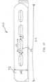
- FIGS. 1B-Dillustrate an embodiment of a triangular implant structure 100 having a central lumen 101 and a series of holes 102 on each face 103 of the implant structure 100 that reach and provide access to the central lumen 101.
- the holes 102can be centered on the face 103 and extend inwardly at an angle that is substantially perpendicular or normal to the face 103 of the implant structure 100.
- each apex 104can be beveled or rounded.
- the distal end 105 of the implant structure 100can be tapered to facilitate implantation into the bone.
- the diameter of the holes 102can be equal to or substantially equal to the diameter of the central lumen 101.
- the diameter of the holes 102can be greater than or less than the diameter of the central lumen 101.
- the implant structure 100 illustrated in FIGS. 1B-Dhas a relative bending strength of about 0.82 and a relative shear strength of about 0.66.
- the distal hole 106 of the central lumen 101can be blocked or sealed so that flow of the bone graft materials fills the central lumen 101 and exits the side holes 102.
- the holes 102can have a diameter (D1) that is about 0.3 of width (W1) of the face 103 of the implant structure 100. In some embodiments, the holes 102 can have a diameter that is greater than about 0.3 of the width of the face 103 of the implant structure 100. In some embodiments, the holes 102 can have a diameter that is less than about 0.3 of the width of the face 103 of the implant structure 100. In some embodiments, the holes 102 can have a diameter that is between about 0.2 to about 0.5 of the width of the face 103 of the implant structure. In some embodiments, the holes 102 can be separated from adjacent holes 102 by about 2/3 of the hole diameter, where separation distance (S1) is measured by the distance between the circumference of the holes 102.
- S1separation distance
- the holes 102can be separated from adjacent holes 102 by less than about 2/3 of the hole diameter. In some embodiments, the holes 102 can be separated from adjacent holes 102 by greater than about 2/3 of the hole diameter. In some embodiments, the holes 102 can be separated from adjacent holes 102 by about 0.5 to about 2 times, or about 0.5 to about 1 times the hole 102 diameter. In some embodiments, the relative bending strength can be at least about 0.5, 0.6, 0.7, 0.8 or 0.9. In some embodiments, the relative bending strength can be between about 0.5 to 0.9. In some embodiments, the relative shear strength can be at least about 0.5, 0.6, 0.7, 0.8 or 0.9. In some embodiments, the relative shear strength can be between about 0.5 to 0.9.
- FIGS. 1E-Gillustrate another embodiment of an implant structure 110 having a central lumen 111 and a series of slots 112 on each face 113 of the implant structure 110 that reach and provide access to the central lumen 111.
- the slots 112can be centered on the face 113 and extend inwardly at an angle that is substantially perpendicular or normal to the face 113 of the implant structure 110.
- each apex 114can be beveled or rounded.
- the distal end 115 of the implant structure 110can be tapered to facilitate implantation into the bone.
- the width of the slotscan be equal to or substantially equal to the diameter of the central lumen 111.
- the width of the slotscan be greater than or less than the diameter of the central lumen 111.
- the implant structure 110 illustrated in FIGS. 1E-Ghas a relative bending strength of about 0.82 and a relative shear strength of about 0.66.
- the distal hole 116 of the central lumen 111can be blocked or sealed so that flow of the bone graft materials fills and exits the slots 112.
- the slots 112can have a width (W3) that is about 0.3 of width (W2) of the face 113 of the implant structure 110. In some embodiments, the slots 112 can have a width that is greater than about 0.3 of the width of the face 113 of the implant structure 110. In some embodiments, the slots 112 can have a width that is less than about 0.3 of the width of the face 113 of the implant structure 110. In some embodiments, the slots 112 can have a width that is between about 0.2 to about 0.6 of the width of the face 113 of the implant structure 110. In some embodiments, the slots 112 can have a length (L3) that is about 0.15 the length (L2) of the face 113.
- the slots 112can have a length that is less than about 0.15 the length of the face 113. In some embodiments, the slots 112 can have a length that is greater than about 0.15 the length of the face 113. In some embodiments, the slots 112 can have a length that is between about 0.1 to 0.4, or about 0.1 to 0.25 the length of the face 113. In some embodiments, the slots 112 are separated (S2) from adjacent slots 112 by about 2/3 the width of the slot 112. In some embodiments, the slots 112 are separated from adjacent slots 112 by greater than about 2/3 the width of the slot 112. In some embodiments, the slots 112 are separated from adjacent slots 112 by less than about 2/3 the width of the slot 112.
- the slots 112can be separated from adjacent slots 112 by about 0.5 to about 2 times, or about 0.5 to about 1 times the slot 112 width.
- the relative bending strengthcan be at least about 0.5, 0.6, 0.7, 0.8 or 0.9. In some embodiments, the relative bending strength can be between about 0.5 to 0.9. In some embodiments, the relative shear strength can be at least about 0.5, 0.6, 0.7, 0.8 or 0.9. In some embodiments, the relative shear strength can be between about 0.5 to 0.9.
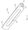
- FIGS. 1H-Jillustrate the only embodiment of an implant structure 120 that falls within the scope of the invention as claimed, said implant structure 120 having a central lumen 121 and a side pocket 122 on each face 123 of the implant structure 120.
- the side pocket 122can be a depression, cavity, groove or slot centered on the face 123 having a width, length and depth.
- the side pocket 122is relatively shallow so that it does not extend to the central lumen 121.
- each apex 124can be beveled or rounded.
- the distal end 125 of the implant structure 120can be tapered to facilitate implantation into the bone.
- 1H-Jhas a relative bending strength of about 0.77 and a relative shear strength of about 0.72.
- the bone graft materialis applied to the side pockets 122 before implantation.
- the bone graft materialis applied during implantation, as further described in U.S. Patent Application 61/609,043 titled Tissue Dilator and Protector, which can be applied to the other implants.
- the side pocket 122can have a width (W4) that is about 0.5 of width (W5) of the face 123 of the implant structure 120. In some embodiments, the side pocket 122 can have a width that is greater than about 0.5 of the width of the face 123 of the implant structure 120. In some embodiments, the side pocket 122 can have a width that is less than about 0.5 of the width of the face 123 of the implant structure 120. In some embodiments, the side pocket 122 can have a width that is between about 0.2 to about 0.8 of the width of the face 123 of the implant structure 120. In some embodiments, the side pocket 122 can have a length (L4) that is about 0.75 the length (L5) of the face 123.
- the side pocket 122can have a length that is less than about 0.75 the length of the face 123. In some embodiments, the side pocket 122 can have a length that is greater than about 0.75 the length of the face 123. In some embodiments, the side pocket 122 can have a length that is between about 0.5 to 0.9 of the length of the face 123. In some embodiments, the side pocket 122 can have a depth between about 0.2 mm and 5 mm, or between about 0.2 mm and 2 mm, or between about 0.2 and 1 mm. In some embodiments, the side pocket 122 can have a depth between about 0.25 mm, 0.5 mm, 0.75 mm, 1 mm or 2 mm. In some embodiments, the relative bending strength can be at least about 0.5, 0.6, 0.7, 0.8 or 0.9. The relative bending strength is between about 0.5 to 0.9 or the relative shear strength is between about 0.5 to 0.9.
- FIGS. 1K-Millustrate another embodiment of an implant structure 130 having a central lumen 131, a side pocket 132 on each face 133 of the implant structure 130, and a plurality of holes 134 located within the side pocket 132.
- the side pocket 132 in the embodiment illustrated in FIGS. 1K-Mcan be the same as or be similar to the side pocket 122 previously described above and illustrated in FIGS. 1H-J .
- the holes 134 illustrated in FIGS. 1K-Mcan be the same as or be similar to the holes 102 previously described above and illustrated in FIGS. 1B-D .
- the holes 134have a diameter that is less than the diameter of the central lumen 131.
- the holes 134have a diameter than is equal to or greater than the diameter of the central lumen 131.
- each apex 135can be beveled or rounded.
- the distal end 136 of the implant structure 130can be tapered to facilitate implantation into the bone.
- the implant structure 130 illustrated in FIGS. 1K-Mhas a relative bending strength of about 0.74 and a relative shear strength of about 0.62.
- the bone graft materialis injected and/or applied to the side pockets 132 and holes 134 before implantation.
- the bone graft materialscan be injected into the central lumen 131, which can have a distal opening 137 that is blocked off or plugged so that the bone graft materials fill the central lumen 131 and exit out the holes 134 which are in fluid communication with the central lumen 131.
- the bone graft materialcan coat and fill both the holes 134 and the side pocket 132. This injection process can be done before implantation, during implantation, or after implantation.
- the side pocket 132 shown in FIGS. 1K-Mhas the same or similar dimensions as the side pocket 122 shown in FIGS. 1H-J and described above.
- the holes 134can have a diameter (D2) that is about 0.4 of the width (W6) of the side pocket 132. In some embodiments, the holes 134 can have a diameter that is greater than or less than about 0.4 times the width of the side pocket 132. In some embodiments, the holes 134 can be separated (S3) by about 1.5 times the diameter of the holes 134. In some embodiments, the holes 134 can be separated by greater than or less than about 1.5 times the diameter of the holes 134.
- the relative bending strengthcan be at least about 0.5, 0.6, 0.7, 0.8 or 0.9. In some embodiments, the relative bending strength can be between about 0.5 to 0.9. In some embodiments, the relative shear strength can be at least about 0.5, 0.6, 0.7, 0.8 or 0.9. In some embodiments, the relative shear strength can be between about 0.5 to 0.9.
- FIGS. 1N-Pillustrate another embodiment of an implant structure 140 having a central lumen 141 and a plurality of peripheral lumens 142 surrounding the central lumen 141.
- the peripheral lumens 142can be oriented longitudinally and can be located between the central lumen 141 and each apex 143.
- the implant structure 140is triangular and has three apexes 143 and three peripheral lumens 142 that surround the central lumen 141.
- both the central lumen 141 and the peripheral lumens 142can extend throughout the longitudinal length of the implant structure 140.
- peripheral lumens 142do not extend throughout the length of the implant structure 140, and instead, the peripheral lumens 142 terminate prior to the distal end 144 of the implant structure 140.
- a plurality of side holes 145can be included in the implant structure 140.
- Each peripheral lumen 142can be intersected by a plurality of side holes 145, where each side hole 145 extends between two faces 146 of the implant structure with a side hole opening 147 on each of the two faces 146.
- the side holes 145can extend transversely through the implant structure 140 at an angle of about 60 degrees from the surfaces of the faces 146.
- each apex 143can be beveled or rounded.
- the distal end 144 of the implant structure 140can be tapered to facilitate implantation into the bone.
- the implant structure 140 illustrated in FIGS. 1N-Phas a relative bending strength of about 0.63 and a relative shear strength of about 0.66.
- the bone graft materialis injected into the peripheral lumens 142, where the bone graft material fills up the peripheral lumens and exits the side holes 145. Injection of the bone graft material can take place before, during, or after implantation. In some embodiments where the peripheral lumens 142 extend completely through the implant structure 140, the distal ends of the peripheral lumens 142 can be blocked or plugged before injection of the bone graft material.
- the peripheral lumens 142have a diameter (D3) of about 0.2 times the width (W7) of the faces 146 of the implant structure. In some embodiments, the peripheral lumens 142 have a diameter greater than or less than about 0.2 times the width of the faces 146 of the implant structure. In some embodiments, the peripheral lumens 142 can have a smaller diameter than the central lumen 141. In other embodiments, the peripheral lumens 142 can have an equal or larger diameter than the central lumen 141. In some embodiments, the side holes 145 have a diameter (D4) equal or substantially equal to the diameter of the peripheral lumens 142.
- the side holes 145have a diameter less than or greater than the diameters of the peripheral lumens 142.
- the relative bending strengthcan be at least about 0.5, 0.6, 0.7, 0.8 or 0.9. In some embodiments, the relative bending strength can be between about 0.5 to 0.9. In some embodiments, the relative shear strength can be at least about 0.5, 0.6, 0.7, 0.8 or 0.9. In some embodiments, the relative shear strength can be between about 0.5 to 0.9.
- FIGS. 1Q-Sillustrate another embodiment of an implant structure 150 having a central lumen 151.
- Each apex 152can be beveled or rounded and can have a plurality of pockets or cavities 153 located at discrete points along the length of the apex 152. These pockets 153 extend from the apex 152 and towards the central lumen 151, but do not reach the central lumen 151.
- the pockets 153have a curved cutout shape, which can correspond in shape to a portion of a cylinder.
- the distal end 154 of the implant structure 140can be tapered to facilitate implantation into the bone.
- 1Q-Shas a relative bending strength of about 0.89 and a relative shear strength of about 0.86.
- the bone graft materialis applied externally to the implant structure 150 either before or during implantation.
- the pockets 153also function to eliminate or reduce a corner haloing effect.
- the pockets 153can have a length (L6) or diameter of about 0.06 of the length (L7) of the apex 152. In some embodiments, the pockets 153 can have a length or diameter greater than or less than about 0.06 of the length of the apex 152. In some embodiments, the pockets 153 can be separated (S4) from adjacent pockets 153 by about 2/3 of the pocket length or diameter. In some embodiments, the pockets 153 can be separated from adjacent pockets 153 by greater than or less than about 2/3 of the hole diameter. In some embodiments, the relative bending strength can be at least about 0.5, 0.6, 0.7, 0.8 or 0.9. In some embodiments, the relative bending strength can be between about 0.5 to 0.95. In some embodiments, the relative shear strength can be at least about 0.5, 0.6, 0.7, 0.8 or 0.9. In some embodiments, the relative shear strength can be between about 0.5 to 0.95.
- FIG. 1T-Villustrate another embodiment of an implant structure 160 having a central lumen 161.
- Each apex 162has a groove 163 that extends along the length of the apex 162.
- the distal end 164 of the implant structure 160can be tapered to facilitate implantation into the bone.
- the implant structure 160 illustrated in FIGS. 1T-Vhas a relative bending strength of about 0.87 and a relative shear strength of about 0.88.
- the bone graft materialis applied externally to the implant structure 160 either before or during implantation.
- the grooves 163also function to eliminate or reduce a corner haloing effect.
- the grooves 163can be circular shaped cutouts running along the apex 162 having a diameter (D5) of about 0.25 of the width of the face 165 and an arc length of about 0.28 of the width of the face 165. In some embodiments, the grooves 163 can have a diameter of greater or less than about 0.25 of the width of the face 165. In some embodiments, the grooves 163 can have an arc length of greater than or less than about 0.25 of the width of the face 165.
- one or more implant structures 20are introduced laterally through the ilium, the SI-Joint, and into the sacrum. This path and resulting placement of the implant structures 20 are best shown in FIGS. 6 and 7A /B. In the illustrated embodiment, three implant structures 20 are placed in this manner. Also in the illustrated embodiment, the implant structures 20 are rectilinear in cross section and triangular in this case, but it should be appreciated that implant structures 20 of other cross sections can be used. In addition, any of the implant structures disclosed above can be used in the implantation procedures herein.
- the physicianBefore undertaking a lateral implantation procedure, the physician identifies the SI-Joint segments that are to be fixated or fused (arthrodesed) using, e.g., the Fortin finger test, thigh thrust, FABER, Gaenslen's, compression, distraction, and diagnostic SI Joint injection.
- the Fortin finger teste.g., the Fortin finger test, thigh thrust, FABER, Gaenslen's, compression, distraction, and diagnostic SI Joint injection.
- the physicianAided by lateral, inlet, and outlet C-arm views, and with the patient lying in a prone position, the physician aligns the greater sciatic notches and then the alae (using lateral visualization) to provide a true lateral position.
- a 3 cm incisionis made starting aligned with the posterior cortex of the sacral canal, followed by blunt tissue separation to the ilium.
- the guide pin 38(with sleeve (not shown)) (e.g., a Steinmann Pin) is started resting on the ilium at a position inferior to the sacrum end plate and just anterior to the sacral canal.
- the guide pin 38In the outlet view, the guide pin 38 should be parallel to the sacrum end plate at a shallow angle anterior (e.g., 15 to 20 degrees off horizontal, as FIG. 7B shows). In a lateral view, the guide pin 38 should be posterior to the sacrum anterior wall. In the inlet view, the guide pin 38 should not violate the sacral foramina. This corresponds generally to the sequence shown diagrammatically in FIGS. 2A and 2B .
- a soft tissue protector(not shown) is desirably slipped over the guide pin 38 and firmly against the ilium before removing the guide pin sleeve (not shown).
- the pilot bore 42is drilled in the manner previously described, as is diagrammatically shown in FIG. 2C .
- the pilot bore 42extends through the ilium, through the SI-Joint, and into the sacrum. The drill bit 40 is then removed.
- the shaped broach 44is tapped into the pilot bore 42 over the guide pin 38 (and through the soft tissue protector) to create a broached bore 48 with the desired profile for the implant structure 20, which, in the illustrated embodiment, is triangular. This generally corresponds to the sequence shown diagrammatically in FIG. 2D .
- the triangular profile of the broached bore 48is also shown in FIG. 5 .
- FIGS. 2E and 2Fillustrate an embodiment of the assembly of a soft tissue protector or dilator or delivery sleeve 200 with a drill sleeve 202, a guide pin sleeve 204 and a handle 206.
- the drill sleeve 202 and guide pin sleeve 204can be inserted within the soft tissue protector 200 to form a soft tissue protector assembly 210 that can slide over the guide pin 208 until bony contact is achieved.
- the soft tissue protector 200can be any one of the soft tissue protectors or dilators or delivery sleeves disclosed herein.
- an expandable dilator or delivery sleeve 200 as disclosed hereincan be used in place of a conventional soft tissue dilator.
- the expandable dilatorcan be slid over the guide pin and then expanded before the drill sleeve 202 and/or guide pin sleeve 204 are inserted within the expandable dilator. In other embodiments, insertion of the drill sleeve 202 and/or guide pin sleeve 204 within the expandable dilator can be used to expand the expandable dilator.
- a dilatorcan be used to open a channel though the tissue prior to sliding the soft tissue protector assembly 210 over the guide pin.
- the dilator(s)can be placed over the guide pin, using for example a plurality of sequentially larger dilators or using an expandable dilator. After the channel has been formed through the tissue, the dilator(s) can be removed and the soft tissue protector assembly can be slid over the guide pin.
- the expandable dilatorcan serve as a soft tissue protector after being expanded. For example, after expansion the drill sleeve and guide pin sleeve can be inserted into the expandable dilator.
- a triangular implant structure 20can be now tapped through the soft tissue protector over the guide pin 38 through the ilium, across the SI-Joint, and into the sacrum, until the proximal end of the implant structure 20 is flush against the lateral wall of the ilium (see also FIGS. 7A and 7B ).
- the guide pin 38 and soft tissue protectorare withdrawn, leaving the implant structure 20 residing in the broached passageway, flush with the lateral wall of the ilium (see FIG. 7A and 7B ).
- two additional implant structures 20are implanted in this manner, as FIG. 6 best shows.
- the proximal ends of the implant structures 20are left proud of the lateral wall of the ilium, such that they extend 1, 2, 3 or 4 mm outside of the ilium. This ensures that the implants 1020 engage the hard cortical portion of the ilium rather than just the softer cancellous portion, through which they might migrate if there was no structural support from hard cortical bone.
- the hard cortical bonecan also bear the loads or forces typically exerted on the bone by the implant 1020.
- the implant structures 20are sized according to the local anatomy.
- representative implant structures 20can range in size, depending upon the local anatomy, from about 35 mm to about 70 mm in length, and about a 7 mm inscribed diameter (i.e. a triangle having a height of about 10.5 mm and a base of about 12 mm).
- the morphology of the local structurescan be generally understood by medical professionals using textbooks of human skeletal anatomy along with their knowledge of the site and its disease or injury. The physician is also able to ascertain the dimensions of the implant structure 20 based upon prior analysis of the morphology of the targeted bone using, for example, plain film x-ray, fluoroscopic x-ray, or MRI or CT scanning.
- one or more implant structures 20can be individually inserted in a minimally invasive fashion across the SI-Joint, as has been described.
- Conventional tissue access tools, obturators, cannulas, and/or drillscan be used for this purpose.
- the novel tissue access tools described above and in co-pending U.S. Application No. 61/609,043, titled "TISSUE DILATOR AND PROTECTER” and filed March 9, 2012can also be used. No joint preparation, removal of cartilage, or scraping are required before formation of the insertion path or insertion of the implant structures 20, so a minimally invasive insertion path sized approximately at or about the maximum outer diameter of the implant structures 20 can be formed.
- the implant structures 20can obviate the need for autologous bone graft material, additional screws and/or rods, hollow modular anchorage screws, cannulated compression screws, threaded cages within the joint, or fracture fixation screws. Still, in the physician's discretion, bone graft material and other fixation instrumentation can be used in combination with the implant structures 20.
- implant structures 20can be used, depending on the size of the patient and the size of the implant structures 20.
- the patientAfter installation, the patient would be advised to prevent or reduce loading of the SI-Joint while fusion occurs. This could be about a six to twelve week period or more, depending on the health of the patient and his or her adherence to post-op protocol.
- the implant structures 20make possible surgical techniques that are less invasive than traditional open surgery with no extensive soft tissue stripping.
- the lateral approach to the SI-Jointprovides a straightforward surgical approach that complements the minimally invasive surgical techniques.
- the profile and design of the implant structures 20minimize or reduce rotation and micromotion.
- Rigid implant structures 20 made from titanium alloyprovide immediate post-op SI Joint stability.
- a bony in-growth region 24comprising a porous plasma spray coating with irregular surfaces, supports stable bone fixation/fusion.
- the implant structures 20 and surgical approachesmake possible the placement of larger fusion surface areas designed to maximize post-surgical weight bearing capacity and provide a biomechanically rigorous implant designed specifically to stabilize the heavily loaded SI-Joint.
- the implant structure 800can have a rectilinear cross-sectional profile formed from a plurality of walls 802 having a thickness of approximately 2 to 3 mm, or 1 to 5 mm, or less than approximately 5, 4, 3, or 2 mm.
- the rectilinear cross-sectional profilecan be triangular, square or rectangular.
- the implant structure 800can have a substantially rectilinear cross-sectional profile formed by a plurality of apices that are joined together by a plurality of walls. The thin walled implant structure 800 can be advanced through the bone with little to no bony preparation.
- the implant structure 800can be driven into the bone without first forming a bore that is shaped like the implant structure 800.
- the distal end 804 of the implant structure 800can be sharpened and/or have cutting edges like a chisel to facilitate the cutting of bone as the implant structure 800 is advanced.
- an osteotomecan be used to cut the bone before the implant structure 800 is inserted into the bone. For example, an osteotome as described in U.S.
- Provisional Application 61/800,966, titled “SYSTEMS AND METHODS FOR REMOVING AN IMPLANT” and filed on March 15, 2013 ,can be adapted to pre-cut the bone to facilitate insertion of the implant structure 800 without forming a complete bore.
- a borecan be formed as described above, and the implant structure 800 can then be inserted into the bore.
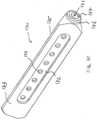
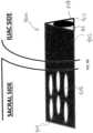
- the distal portion of the plurality of walls 802 forming the implant structure 800can have fenestrations 806.
- the distal portion of the implant structure 800 that is configured to be embedded in the sacrum or second bone segmentcan be fenestrated, while the proximal portion of the implant structure 800 that is configured to be embedded in the illium or first bone segment can be free from fenestrations.
- the proximal portion of the implant structure 800can be fenestrated while the distal portion of the implant structure 800 can be free from fenestration.
- the fenestrationscan be distributed across the entire face of each wall or side of the implant structure. In some embodiments, the concentration or number of fenestrations can be higher in one portion of the implant structure than the other.
- the fenestrations 806can be oval or circular shaped or curvilinear, such that the fenestrations 806 do not have corners.
- the fenestrations 806can be staggered, arranged randomly, or otherwise distributed in a non-aligned pattern across each wall 802.
- each longitudinal row of fenestrationscan be staggered or offset from adjacent longitudinal rows of fenestrations.
- the fenestrationscan alternatively or additionally be staggered along the longitudinal axis of the implant structure 800. This non-aligned arrangement of fenestrations can provide the implant structure with improved structural strength.
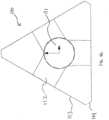
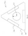
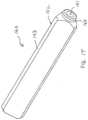
- the implant structure 800can be sized as any other implant structure described herein. In some embodiments, the implant structure 800 can be sized so that the implant structure 800 has walls that inscribe a circle with a diameter of about 8 mm, or between about 4 and 12 mm, as illustrated in FIG. 8B . In some embodiments, the implant structure 800 can be sized so that the wall inscribe a circle with a diameter equal to or about equal to the diameter of a guide pin. In some embodiments, the implant structure 800 can have a proximal end 808 having a cap 810 with a circular opening 812 that allows passage of a guide pin.
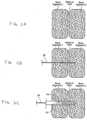
- the implant structure 900can be similar to the embodiment described in FIG. 8A and 8B except that the fenestrations 902 are evenly distributed across the faces of the implant structure.
- FIG. 9Billustrates bone growing within and/or through the fenestrations 902 and lumen of the implant structure 900.
- the bone illustrated within the lumen of the implant structure 900may be native bone that remains after the implant structure 900 is advanced into the bone, i.e. a self-grafting implant.
- implant structure 9A and 9Bcan be filled with bone material and/or a biologic aid such as morselized bone, allograft bone, autograft bone, hydroxyapatite, bone morphogenetic protein and the like to promote bony ingrowth within the implant structure 900.
- a biologic aidsuch as morselized bone, allograft bone, autograft bone, hydroxyapatite, bone morphogenetic protein and the like to promote bony ingrowth within the implant structure 900.
- the interior surface and/or the outer surface of the implant structurecan be roughened and/or coated, using a plasma coating process for example, to provide a porous or roughened surface.
Landscapes
- Health & Medical Sciences (AREA)
- Orthopedic Medicine & Surgery (AREA)
- Life Sciences & Earth Sciences (AREA)
- Surgery (AREA)
- Neurology (AREA)
- Heart & Thoracic Surgery (AREA)
- General Health & Medical Sciences (AREA)
- Biomedical Technology (AREA)
- Nuclear Medicine, Radiotherapy & Molecular Imaging (AREA)
- Medical Informatics (AREA)
- Molecular Biology (AREA)
- Animal Behavior & Ethology (AREA)
- Engineering & Computer Science (AREA)
- Public Health (AREA)
- Veterinary Medicine (AREA)
- Neurosurgery (AREA)
- Prostheses (AREA)
- Surgical Instruments (AREA)
- Materials For Medical Uses (AREA)
Description
- This application relates generally to implants used in medical procedures such as bone fixation or fusion. More specifically, this application relates to fenestrated implants used in bone fixation or fusion.
- Many types of hardware are available both for the fixation of bones that are fractured and for the fixation of bones that are to be fused (arthrodesed).
- For example, the human hip girdle is made up of three large bones joined by three relatively immobile joints. One of the bones is called the sacrum and it lies at the bottom of the lumbar spine, where it connects with the L5 vertebra. The other two bones are commonly called "hip bones" and are technically referred to as the right ilium and-the left ilium. The sacrum connects with both hip bones at the sacroiliac joint (in shorthand, the SI-Joint).
- The SI-Joint functions in the transmission of forces from the spine to the lower extremities, and vice-versa. The SI-Joint has been described as a pain generator for up to 22% of lower back pain.
- To relieve pain generated from the SI Joint, sacroiliac joint fusion is typically indicated as surgical treatment, e.g., for degenerative sacroiliitis, inflammatory sacroiliitis, iatrogenic instability of the sacroiliac joint, osteitis condensans ilii, or traumatic fracture dislocation of the pelvis. Currently, screws and screws with plates are used for sacro-iliac fusion.
- In order to promote bone growth into the implant and enhance fusion of the implant with the bone, pockets or channels can be created in the implant that promote bone growth into the implant. However, these pockets or channels may weaken the structural integrity of the implant, which can also be required to bear large stresses. Therefore, it would be desirable to provide an implant with pockets or channels to promote bone growth while substantially maintaining the structural integrity of the implant.
- Document
US 2011/087296 A1 discloses an implant according to the preamble ofclaim 1. - The present invention relates to an implant according to appended
claims - The novel features of the invention are set forth with particularity in the claims that follow. A better understanding of the features and advantages of the present invention will be obtained by reference to the following detailed description that sets forth illustrative embodiments, of which only the embodiments of
figures 1H-1J fall within the scope of the invention as claimed and in which the principles of the invention are utilized, and the accompanying drawings of which: FIGS. 1A-1V illustrate various embodiments of implant structures with different fenestrations.FIGS. 2A-2D are side section views of the formation of a broached bore in bone according to one example.FIGS. 2E and 2F illustrate the assembly of a soft tissue protector system for placement over a guide wire.FIGS. 3 and 4 are, respectively, anterior and posterior anatomic views of the human hip girdle comprising the sacrum and the hip bones (the right ilium, and the left ilium), the sacrum being connected with both hip bones at the sacroiliac joint (in shorthand, the SI-Joint).FIGS. 5 to 7A and7B are anatomic views showing, respectively, a pre-implanted perspective, implanted perspective, implanted anterior view, and implanted cranio-caudal section view, the implantation of three implant structures for the fixation of the SI-Joint using a lateral approach through the ilium, the Si-Joint, and into the sacrum.FIGS. 8A and8B illustrate another embodiment of an implant structure with fenestrations.FIGS. 9A and9B illustrate yet another embodiment of an implant structure with fenestrations.- Elongated, stem-
like implant structures 20 like that shown inFIG. 1A make possible the fixation of the SI-Joint (shown in anterior and posterior views, respectively, inFIGS. 3 and 4 ) in a minimally invasive manner. Theseimplant structures 20 can be effectively implanted through the use of a lateral surgical approach. The procedure is desirably aided by conventional lateral and/or anterior-posterior (A-P) visualization techniques, e.g., using X-ray image intensifiers such as a C-arms or fluoroscopes to produce a live image feed that is displayed on a TV screen. - In some embodiments, the
implant structures 20 can include pockets, pathways, cavities, openings, fenestrations, channels and/or recesses that allow bone graft materials to be incorporated into the implant structure. These bone graft materials can promote bone growth into and/or around the implant structure, which can reduce the time it takes for the implant structure to be stably integrated with the bone. Bone graft materials can be applied to and/or injected into the implant structure before implantation or applied after implantation by injection of the bone graft material into a proximal cannula or other conduit. In some embodiments, the surfaces of theimplant structure 20 can be roughened or textured to promote bone growth and adherence of the bone graft materials. The internal and/or external surfaces can be roughened or textured by mechanical means or can be spray coated with a roughening material. - The bone graft materials can be a liquid, gel, slurry, paste, powder or other form, and can include a biologic aid that can promote and/or enhance bony ingrowth, tissue repair, and/or reduce inflammation, infection and pain. For example, the biologic aid can include growth factors, such as bone morphogenetic proteins (BMPs), hydroxyapatite in, for example, a liquid or slurry carrier, demineralized bone, morselized autograft or allograft bone, medications to reduce inflammation, infection or pain such as analgesics, antibiotics and steroids. In some embodiments, the growth factors can be human recombinant growth factors, such as hr-BMP-2 and/or hr-BMP-7, or any other human recombinant form ofBMP, for example. The carrier for the biologic aid can be a liquid or gel such as saline or a collagen gel, for example. The biologic aid can also be encapsulated or incorporated in a controlled released formulation so that the biologic aid is released to the patient at the implant site over a longer duration. For example, the controlled release formulation can be configured to release the biologic aid over the course of days or weeks or months, and can be configured to release the biologic aid over the estimated time it would take for the implant site to heal. The amount of biologic aid delivered to the implant structure can be controlled using a variety of techniques, such as controlling or varying the amount of coating material applied to the implant and/or controlling or varying the amount of biologic aid incorporated into the coating material. In some embodiments, in may be important to control the amount of biologic aid delivered because excessive use of certain biologic aids can result in negative effects such as radicular pain, for example.
- In general, any pockets, pathways, cavities, openings, fenestrations, channels and/or recesses in the implant structure may weaken its structural strength, including for example the bending and shear strengths. The following examples of implant structures are variations of the solid
triangular implant structure 20 ofFIG. 1A , which has a single central, longitudinally oriented lumen or cannula for receiving a guide wire or guide pin. The relative bending and shear strengths can be compared to the cannulated but otherwisesolid implant structure 20 ofFIG. 1A , which can be assigned a bending strength of 1.00 and a shear strength of 1.00. The relative bending and shear strengths can be modified or optimized for structural strength and ability to promote bone grafting by varying the size, number, spacing, location, orientation, and shape of the pockets, pathways, cavities, openings, fenestrations, channels and/or recesses. Although the embodiments illustrated herein show triangular implant structures, implant structures with different rectilinear shapes, such as rectangular or square, can be used or substituted for the triangular implant structures. FIGS. 1B-D illustrate an embodiment of atriangular implant structure 100 having acentral lumen 101 and a series ofholes 102 on eachface 103 of theimplant structure 100 that reach and provide access to thecentral lumen 101. Theholes 102 can be centered on theface 103 and extend inwardly at an angle that is substantially perpendicular or normal to theface 103 of theimplant structure 100. In some embodiments, eachapex 104 can be beveled or rounded. In some embodiments, thedistal end 105 of theimplant structure 100 can be tapered to facilitate implantation into the bone. In some embodiments, the diameter of theholes 102 can be equal to or substantially equal to the diameter of thecentral lumen 101. In other embodiments, the diameter of theholes 102 can be greater than or less than the diameter of thecentral lumen 101. In some embodiments, theimplant structure 100 illustrated inFIGS. 1B-D has a relative bending strength of about 0.82 and a relative shear strength of about 0.66. In some embodiments, to inject or load theimplant structure 100 with bone graft materials, thedistal hole 106 of thecentral lumen 101 can be blocked or sealed so that flow of the bone graft materials fills thecentral lumen 101 and exits the side holes 102.- In some embodiments, the
holes 102 can have a diameter (D1) that is about 0.3 of width (W1) of theface 103 of theimplant structure 100. In some embodiments, theholes 102 can have a diameter that is greater than about 0.3 of the width of theface 103 of theimplant structure 100. In some embodiments, theholes 102 can have a diameter that is less than about 0.3 of the width of theface 103 of theimplant structure 100. In some embodiments, theholes 102 can have a diameter that is between about 0.2 to about 0.5 of the width of theface 103 of the implant structure. In some embodiments, theholes 102 can be separated fromadjacent holes 102 by about 2/3 of the hole diameter, where separation distance (S1) is measured by the distance between the circumference of theholes 102. In some embodiments, theholes 102 can be separated fromadjacent holes 102 by less than about 2/3 of the hole diameter. In some embodiments, theholes 102 can be separated fromadjacent holes 102 by greater than about 2/3 of the hole diameter. In some embodiments, theholes 102 can be separated fromadjacent holes 102 by about 0.5 to about 2 times, or about 0.5 to about 1 times thehole 102 diameter. In some embodiments, the relative bending strength can be at least about 0.5, 0.6, 0.7, 0.8 or 0.9. In some embodiments, the relative bending strength can be between about 0.5 to 0.9. In some embodiments, the relative shear strength can be at least about 0.5, 0.6, 0.7, 0.8 or 0.9. In some embodiments, the relative shear strength can be between about 0.5 to 0.9. FIGS. 1E-G illustrate another embodiment of animplant structure 110 having a central lumen 111 and a series ofslots 112 on eachface 113 of theimplant structure 110 that reach and provide access to the central lumen 111. Theslots 112 can be centered on theface 113 and extend inwardly at an angle that is substantially perpendicular or normal to theface 113 of theimplant structure 110. In some embodiments, each apex 114 can be beveled or rounded. In some embodiments, thedistal end 115 of theimplant structure 110 can be tapered to facilitate implantation into the bone. In some embodiments, the width of the slots can be equal to or substantially equal to the diameter of the central lumen 111. In other embodiments, the width of the slots can be greater than or less than the diameter of the central lumen 111. In some embodiments, theimplant structure 110 illustrated inFIGS. 1E-G has a relative bending strength of about 0.82 and a relative shear strength of about 0.66. In some embodiments, to inject or load theimplant structure 110 with bone graft materials, thedistal hole 116 of the central lumen 111 can be blocked or sealed so that flow of the bone graft materials fills and exits theslots 112.- In some embodiments, the
slots 112 can have a width (W3) that is about 0.3 of width (W2) of theface 113 of theimplant structure 110. In some embodiments, theslots 112 can have a width that is greater than about 0.3 of the width of theface 113 of theimplant structure 110. In some embodiments, theslots 112 can have a width that is less than about 0.3 of the width of theface 113 of theimplant structure 110. In some embodiments, theslots 112 can have a width that is between about 0.2 to about 0.6 of the width of theface 113 of theimplant structure 110. In some embodiments, theslots 112 can have a length (L3) that is about 0.15 the length (L2) of theface 113. In some embodiments, theslots 112 can have a length that is less than about 0.15 the length of theface 113. In some embodiments, theslots 112 can have a length that is greater than about 0.15 the length of theface 113. In some embodiments, theslots 112 can have a length that is between about 0.1 to 0.4, or about 0.1 to 0.25 the length of theface 113. In some embodiments, theslots 112 are separated (S2) fromadjacent slots 112 by about 2/3 the width of theslot 112. In some embodiments, theslots 112 are separated fromadjacent slots 112 by greater than about 2/3 the width of theslot 112. In some embodiments, theslots 112 are separated fromadjacent slots 112 by less than about 2/3 the width of theslot 112. In some embodiments, theslots 112 can be separated fromadjacent slots 112 by about 0.5 to about 2 times, or about 0.5 to about 1 times theslot 112 width. In some embodiments, the relative bending strength can be at least about 0.5, 0.6, 0.7, 0.8 or 0.9. In some embodiments, the relative bending strength can be between about 0.5 to 0.9. In some embodiments, the relative shear strength can be at least about 0.5, 0.6, 0.7, 0.8 or 0.9. In some embodiments, the relative shear strength can be between about 0.5 to 0.9. FIGS. 1H-J illustrate the only embodiment of animplant structure 120 that falls within the scope of the invention as claimed, saidimplant structure 120 having acentral lumen 121 and aside pocket 122 on eachface 123 of theimplant structure 120. Theside pocket 122 can be a depression, cavity, groove or slot centered on theface 123 having a width, length and depth. Theside pocket 122 is relatively shallow so that it does not extend to thecentral lumen 121. In some embodiments, each apex 124 can be beveled or rounded. In some embodiments, thedistal end 125 of theimplant structure 120 can be tapered to facilitate implantation into the bone. In some embodiments, theimplant structure 120 illustrated inFIGS. 1H-J has a relative bending strength of about 0.77 and a relative shear strength of about 0.72. In some embodiments, to load theimplant structure 120 with bone graft materials, the bone graft material is applied to the side pockets 122 before implantation. In other embodiments, the bone graft material is applied during implantation, as further described inU.S. Patent Application 61/609,043 - In some embodiments, the
side pocket 122 can have a width (W4) that is about 0.5 of width (W5) of theface 123 of theimplant structure 120. In some embodiments, theside pocket 122 can have a width that is greater than about 0.5 of the width of theface 123 of theimplant structure 120. In some embodiments, theside pocket 122 can have a width that is less than about 0.5 of the width of theface 123 of theimplant structure 120. In some embodiments, theside pocket 122 can have a width that is between about 0.2 to about 0.8 of the width of theface 123 of theimplant structure 120. In some embodiments, theside pocket 122 can have a length (L4) that is about 0.75 the length (L5) of theface 123. In some embodiments, theside pocket 122 can have a length that is less than about 0.75 the length of theface 123. In some embodiments, theside pocket 122 can have a length that is greater than about 0.75 the length of theface 123. In some embodiments, theside pocket 122 can have a length that is between about 0.5 to 0.9 of the length of theface 123. In some embodiments, theside pocket 122 can have a depth between about 0.2 mm and 5 mm, or between about 0.2 mm and 2 mm, or between about 0.2 and 1 mm. In some embodiments, theside pocket 122 can have a depth between about 0.25 mm, 0.5 mm, 0.75 mm, 1 mm or 2 mm. In some embodiments, the relative bending strength can be at least about 0.5, 0.6, 0.7, 0.8 or 0.9. The relative bending strength is between about 0.5 to 0.9 or the relative shear strength is between about 0.5 to 0.9. FIGS. 1K-M illustrate another embodiment of animplant structure 130 having acentral lumen 131, aside pocket 132 on eachface 133 of theimplant structure 130, and a plurality ofholes 134 located within theside pocket 132. Theside pocket 132 in the embodiment illustrated inFIGS. 1K-M can be the same as or be similar to theside pocket 122 previously described above and illustrated inFIGS. 1H-J . Likewise, theholes 134 illustrated inFIGS. 1K-M can be the same as or be similar to theholes 102 previously described above and illustrated inFIGS. 1B-D . In some embodiments, as illustrated inFIGS. 1K-M , theholes 134 have a diameter that is less than the diameter of thecentral lumen 131. In other embodiments, theholes 134 have a diameter than is equal to or greater than the diameter of thecentral lumen 131. In some embodiments, each apex 135 can be beveled or rounded. In some embodiments, thedistal end 136 of theimplant structure 130 can be tapered to facilitate implantation into the bone. In some embodiments, theimplant structure 130 illustrated inFIGS. 1K-M has a relative bending strength of about 0.74 and a relative shear strength of about 0.62. In some embodiments, to load theimplant structure 130 with bone graft materials, the bone graft material is injected and/or applied to the side pockets 132 andholes 134 before implantation. In other embodiments, the bone graft materials can be injected into thecentral lumen 131, which can have adistal opening 137 that is blocked off or plugged so that the bone graft materials fill thecentral lumen 131 and exit out theholes 134 which are in fluid communication with thecentral lumen 131. As the bone graft materials exit theholes 134, the bone graft material can coat and fill both theholes 134 and theside pocket 132. This injection process can be done before implantation, during implantation, or after implantation.- In some embodiments, the
side pocket 132 shown inFIGS. 1K-M has the same or similar dimensions as theside pocket 122 shown inFIGS. 1H-J and described above. In some embodiments, theholes 134 can have a diameter (D2) that is about 0.4 of the width (W6) of theside pocket 132. In some embodiments, theholes 134 can have a diameter that is greater than or less than about 0.4 times the width of theside pocket 132. In some embodiments, theholes 134 can be separated (S3) by about 1.5 times the diameter of theholes 134. In some embodiments, theholes 134 can be separated by greater than or less than about 1.5 times the diameter of theholes 134. In some embodiments, the relative bending strength can be at least about 0.5, 0.6, 0.7, 0.8 or 0.9. In some embodiments, the relative bending strength can be between about 0.5 to 0.9. In some embodiments, the relative shear strength can be at least about 0.5, 0.6, 0.7, 0.8 or 0.9. In some embodiments, the relative shear strength can be between about 0.5 to 0.9. FIGS. 1N-P illustrate another embodiment of animplant structure 140 having acentral lumen 141 and a plurality ofperipheral lumens 142 surrounding thecentral lumen 141. Theperipheral lumens 142 can be oriented longitudinally and can be located between thecentral lumen 141 and each apex 143. As illustrated, theimplant structure 140 is triangular and has threeapexes 143 and threeperipheral lumens 142 that surround thecentral lumen 141. In some embodiments, both thecentral lumen 141 and theperipheral lumens 142 can extend throughout the longitudinal length of theimplant structure 140. In other embodiments, theperipheral lumens 142 do not extend throughout the length of theimplant structure 140, and instead, theperipheral lumens 142 terminate prior to thedistal end 144 of theimplant structure 140. In addition, a plurality of side holes 145 can be included in theimplant structure 140. Eachperipheral lumen 142 can be intersected by a plurality of side holes 145, where eachside hole 145 extends between twofaces 146 of the implant structure with a side hole opening 147 on each of the two faces 146. The side holes 145 can extend transversely through theimplant structure 140 at an angle of about 60 degrees from the surfaces of thefaces 146. In some embodiments, each apex 143 can be beveled or rounded. In some embodiments, thedistal end 144 of theimplant structure 140 can be tapered to facilitate implantation into the bone. In some embodiments, theimplant structure 140 illustrated inFIGS. 1N-P has a relative bending strength of about 0.63 and a relative shear strength of about 0.66. In some embodiments, to load theimplant structure 140 with bone graft materials, the bone graft material is injected into theperipheral lumens 142, where the bone graft material fills up the peripheral lumens and exits the side holes 145. Injection of the bone graft material can take place before, during, or after implantation. In some embodiments where theperipheral lumens 142 extend completely through theimplant structure 140, the distal ends of theperipheral lumens 142 can be blocked or plugged before injection of the bone graft material.- In some embodiments, the
peripheral lumens 142 have a diameter (D3) of about 0.2 times the width (W7) of thefaces 146 of the implant structure. In some embodiments, theperipheral lumens 142 have a diameter greater than or less than about 0.2 times the width of thefaces 146 of the implant structure. In some embodiments, theperipheral lumens 142 can have a smaller diameter than thecentral lumen 141. In other embodiments, theperipheral lumens 142 can have an equal or larger diameter than thecentral lumen 141. In some embodiments, the side holes 145 have a diameter (D4) equal or substantially equal to the diameter of theperipheral lumens 142. In other embodiments, the side holes 145 have a diameter less than or greater than the diameters of theperipheral lumens 142. In some embodiments, the relative bending strength can be at least about 0.5, 0.6, 0.7, 0.8 or 0.9. In some embodiments, the relative bending strength can be between about 0.5 to 0.9. In some embodiments, the relative shear strength can be at least about 0.5, 0.6, 0.7, 0.8 or 0.9. In some embodiments, the relative shear strength can be between about 0.5 to 0.9. FIGS. 1Q-S illustrate another embodiment of animplant structure 150 having acentral lumen 151. Each apex 152 can be beveled or rounded and can have a plurality of pockets orcavities 153 located at discrete points along the length of the apex 152. Thesepockets 153 extend from the apex 152 and towards thecentral lumen 151, but do not reach thecentral lumen 151. In some embodiments, thepockets 153 have a curved cutout shape, which can correspond in shape to a portion of a cylinder. In some embodiments, thedistal end 154 of theimplant structure 140 can be tapered to facilitate implantation into the bone. In some embodiments, theimplant structure 150 illustrated inFIGS. 1Q-S has a relative bending strength of about 0.89 and a relative shear strength of about 0.86. In some embodiments, to load theimplant structure 150 with bone graft materials, the bone graft material is applied externally to theimplant structure 150 either before or during implantation. In addition to receiving the bone graft materials, thepockets 153 also function to eliminate or reduce a corner haloing effect.- In some embodiments, the
pockets 153 can have a length (L6) or diameter of about 0.06 of the length (L7) of the apex 152. In some embodiments, thepockets 153 can have a length or diameter greater than or less than about 0.06 of the length of the apex 152. In some embodiments, thepockets 153 can be separated (S4) fromadjacent pockets 153 by about 2/3 of the pocket length or diameter. In some embodiments, thepockets 153 can be separated fromadjacent pockets 153 by greater than or less than about 2/3 of the hole diameter. In some embodiments, the relative bending strength can be at least about 0.5, 0.6, 0.7, 0.8 or 0.9. In some embodiments, the relative bending strength can be between about 0.5 to 0.95. In some embodiments, the relative shear strength can be at least about 0.5, 0.6, 0.7, 0.8 or 0.9. In some embodiments, the relative shear strength can be between about 0.5 to 0.95. FIG. 1T-V illustrate another embodiment of animplant structure 160 having acentral lumen 161. Each apex 162 has agroove 163 that extends along the length of the apex 162. In some embodiments, thedistal end 164 of theimplant structure 160 can be tapered to facilitate implantation into the bone. In some embodiments, theimplant structure 160 illustrated inFIGS. 1T-V has a relative bending strength of about 0.87 and a relative shear strength of about 0.88. In some embodiments, to load theimplant structure 160 with bone graft materials, the bone graft material is applied externally to theimplant structure 160 either before or during implantation. In addition to receiving the bone graft materials, thegrooves 163 also function to eliminate or reduce a corner haloing effect.- In some embodiments, the
grooves 163 can be circular shaped cutouts running along the apex 162 having a diameter (D5) of about 0.25 of the width of theface 165 and an arc length of about 0.28 of the width of theface 165. In some embodiments, thegrooves 163 can have a diameter of greater or less than about 0.25 of the width of theface 165. In some embodiments, thegrooves 163 can have an arc length of greater than or less than about 0.25 of the width of theface 165. - In one embodiment of a lateral approach (see
FIGS. 5, 6 , and7A/B ), one ormore implant structures 20 are introduced laterally through the ilium, the SI-Joint, and into the sacrum. This path and resulting placement of theimplant structures 20 are best shown inFIGS. 6 and7A /B. In the illustrated embodiment, threeimplant structures 20 are placed in this manner. Also in the illustrated embodiment, theimplant structures 20 are rectilinear in cross section and triangular in this case, but it should be appreciated thatimplant structures 20 of other cross sections can be used. In addition, any of the implant structures disclosed above can be used in the implantation procedures herein. - Before undertaking a lateral implantation procedure, the physician identifies the SI-Joint segments that are to be fixated or fused (arthrodesed) using, e.g., the Fortin finger test, thigh thrust, FABER, Gaenslen's, compression, distraction, and diagnostic SI Joint injection.
- Aided by lateral, inlet, and outlet C-arm views, and with the patient lying in a prone position, the physician aligns the greater sciatic notches and then the alae (using lateral visualization) to provide a true lateral position. A 3 cm incision is made starting aligned with the posterior cortex of the sacral canal, followed by blunt tissue separation to the ilium. From the lateral view, the guide pin 38 (with sleeve (not shown)) (e.g., a Steinmann Pin) is started resting on the ilium at a position inferior to the sacrum end plate and just anterior to the sacral canal. In the outlet view, the
guide pin 38 should be parallel to the sacrum end plate at a shallow angle anterior (e.g., 15 to 20 degrees off horizontal, asFIG. 7B shows). In a lateral view, theguide pin 38 should be posterior to the sacrum anterior wall. In the inlet view, theguide pin 38 should not violate the sacral foramina. This corresponds generally to the sequence shown diagrammatically inFIGS. 2A and 2B . A soft tissue protector (not shown) is desirably slipped over theguide pin 38 and firmly against the ilium before removing the guide pin sleeve (not shown). - Over the guide pin 38 (and through the soft tissue protector), the pilot bore 42 is drilled in the manner previously described, as is diagrammatically shown in
FIG. 2C . The pilot bore 42 extends through the ilium, through the SI-Joint, and into the sacrum. Thedrill bit 40 is then removed. - The shaped
broach 44 is tapped into the pilot bore 42 over the guide pin 38 (and through the soft tissue protector) to create a broached bore 48 with the desired profile for theimplant structure 20, which, in the illustrated embodiment, is triangular. This generally corresponds to the sequence shown diagrammatically inFIG. 2D . The triangular profile of the broached bore 48 is also shown inFIG. 5 . FIGS. 2E and 2F illustrate an embodiment of the assembly of a soft tissue protector or dilator ordelivery sleeve 200 with adrill sleeve 202, aguide pin sleeve 204 and ahandle 206. In some embodiments, thedrill sleeve 202 andguide pin sleeve 204 can be inserted within thesoft tissue protector 200 to form a softtissue protector assembly 210 that can slide over theguide pin 208 until bony contact is achieved. Thesoft tissue protector 200 can be any one of the soft tissue protectors or dilators or delivery sleeves disclosed herein. In some embodiments, an expandable dilator ordelivery sleeve 200 as disclosed herein can be used in place of a conventional soft tissue dilator. In the case of the expandable dilator, in some embodiments, the expandable dilator can be slid over the guide pin and then expanded before thedrill sleeve 202 and/orguide pin sleeve 204 are inserted within the expandable dilator. In other embodiments, insertion of thedrill sleeve 202 and/orguide pin sleeve 204 within the expandable dilator can be used to expand the expandable dilator.- In some embodiments, a dilator can be used to open a channel though the tissue prior to sliding the soft
tissue protector assembly 210 over the guide pin. The dilator(s) can be placed over the guide pin, using for example a plurality of sequentially larger dilators or using an expandable dilator. After the channel has been formed through the tissue, the dilator(s) can be removed and the soft tissue protector assembly can be slid over the guide pin. In some embodiments, the expandable dilator can serve as a soft tissue protector after being expanded. For example, after expansion the drill sleeve and guide pin sleeve can be inserted into the expandable dilator. - As shown in
FIGS. 5 and 6 , atriangular implant structure 20 can be now tapped through the soft tissue protector over theguide pin 38 through the ilium, across the SI-Joint, and into the sacrum, until the proximal end of theimplant structure 20 is flush against the lateral wall of the ilium (see alsoFIGS. 7A and 7B ). Theguide pin 38 and soft tissue protector are withdrawn, leaving theimplant structure 20 residing in the broached passageway, flush with the lateral wall of the ilium (seeFIG. 7A and 7B ). In the illustrated embodiment, twoadditional implant structures 20 are implanted in this manner, asFIG. 6 best shows. In other embodiments, the proximal ends of theimplant structures 20 are left proud of the lateral wall of the ilium, such that they extend 1, 2, 3 or 4 mm outside of the ilium. This ensures that the implants 1020 engage the hard cortical portion of the ilium rather than just the softer cancellous portion, through which they might migrate if there was no structural support from hard cortical bone. The hard cortical bone can also bear the loads or forces typically exerted on the bone by the implant 1020. - The
implant structures 20 are sized according to the local anatomy. For the SI-Joint,representative implant structures 20 can range in size, depending upon the local anatomy, from about 35 mm to about 70 mm in length, and about a 7 mm inscribed diameter (i.e. a triangle having a height of about 10.5 mm and a base of about 12 mm). The morphology of the local structures can be generally understood by medical professionals using textbooks of human skeletal anatomy along with their knowledge of the site and its disease or injury. The physician is also able to ascertain the dimensions of theimplant structure 20 based upon prior analysis of the morphology of the targeted bone using, for example, plain film x-ray, fluoroscopic x-ray, or MRI or CT scanning. - Using a lateral approach, one or
more implant structures 20 can be individually inserted in a minimally invasive fashion across the SI-Joint, as has been described. Conventional tissue access tools, obturators, cannulas, and/or drills can be used for this purpose. Alternatively, the novel tissue access tools described above and in co-pendingU.S. Application No. 61/609,043, titled "TISSUE DILATOR AND PROTECTER" and filed March 9, 2012 implant structures 20, so a minimally invasive insertion path sized approximately at or about the maximum outer diameter of theimplant structures 20 can be formed. - The
implant structures 20 can obviate the need for autologous bone graft material, additional screws and/or rods, hollow modular anchorage screws, cannulated compression screws, threaded cages within the joint, or fracture fixation screws. Still, in the physician's discretion, bone graft material and other fixation instrumentation can be used in combination with theimplant structures 20. - In a representative procedure, one to six, or perhaps up to eight,
implant structures 20 can be used, depending on the size of the patient and the size of theimplant structures 20. After installation, the patient would be advised to prevent or reduce loading of the SI-Joint while fusion occurs. This could be about a six to twelve week period or more, depending on the health of the patient and his or her adherence to post-op protocol. - The
implant structures 20 make possible surgical techniques that are less invasive than traditional open surgery with no extensive soft tissue stripping. The lateral approach to the SI-Joint provides a straightforward surgical approach that complements the minimally invasive surgical techniques. The profile and design of theimplant structures 20 minimize or reduce rotation and micromotion.Rigid implant structures 20 made from titanium alloy provide immediate post-op SI Joint stability. A bony in-growth region 24 comprising a porous plasma spray coating with irregular surfaces, supports stable bone fixation/fusion. Theimplant structures 20 and surgical approaches make possible the placement of larger fusion surface areas designed to maximize post-surgical weight bearing capacity and provide a biomechanically rigorous implant designed specifically to stabilize the heavily loaded SI-Joint. - In some embodiments, as illustrated in
FIGS. 8A and8B , theimplant structure 800 can have a rectilinear cross-sectional profile formed from a plurality ofwalls 802 having a thickness of approximately 2 to 3 mm, or 1 to 5 mm, or less than approximately 5, 4, 3, or 2 mm. In some embodiments, the rectilinear cross-sectional profile can be triangular, square or rectangular. In some embodiments, theimplant structure 800 can have a substantially rectilinear cross-sectional profile formed by a plurality of apices that are joined together by a plurality of walls. The thinwalled implant structure 800 can be advanced through the bone with little to no bony preparation. For example, in some embodiments, theimplant structure 800 can be driven into the bone without first forming a bore that is shaped like theimplant structure 800. In some embodiments, thedistal end 804 of theimplant structure 800 can be sharpened and/or have cutting edges like a chisel to facilitate the cutting of bone as theimplant structure 800 is advanced. In some embodiments, an osteotome can be used to cut the bone before theimplant structure 800 is inserted into the bone. For example, an osteotome as described inU.S. Provisional Application 61/800,966, titled "SYSTEMS AND METHODS FOR REMOVING AN IMPLANT" and filed on March 15, 2013 implant structure 800 without forming a complete bore. In some embodiments, a bore can be formed as described above, and theimplant structure 800 can then be inserted into the bore. - In some embodiments, as illustrated in
FIGS. 8A and8B , the distal portion of the plurality ofwalls 802 forming theimplant structure 800 can have fenestrations 806. For example, the distal portion of theimplant structure 800 that is configured to be embedded in the sacrum or second bone segment can be fenestrated, while the proximal portion of theimplant structure 800 that is configured to be embedded in the illium or first bone segment can be free from fenestrations. In other embodiments, the proximal portion of theimplant structure 800 can be fenestrated while the distal portion of theimplant structure 800 can be free from fenestration. In other embodiments, as illustrated inFIGS. 9A and9B and the other embodiments described herein, the fenestrations can be distributed across the entire face of each wall or side of the implant structure. In some embodiments, the concentration or number of fenestrations can be higher in one portion of the implant structure than the other. - In some embodiments, as illustrated in
FIGS. 8A and8B , thefenestrations 806 can be oval or circular shaped or curvilinear, such that thefenestrations 806 do not have corners. In some embodiments, thefenestrations 806 can be staggered, arranged randomly, or otherwise distributed in a non-aligned pattern across eachwall 802. For example, in some embodiments, each longitudinal row of fenestrations can be staggered or offset from adjacent longitudinal rows of fenestrations. In some embodiments, the fenestrations can alternatively or additionally be staggered along the longitudinal axis of theimplant structure 800. This non-aligned arrangement of fenestrations can provide the implant structure with improved structural strength. - In some embodiments, the
implant structure 800 can be sized as any other implant structure described herein. In some embodiments, theimplant structure 800 can be sized so that theimplant structure 800 has walls that inscribe a circle with a diameter of about 8 mm, or between about 4 and 12 mm, as illustrated inFIG. 8B . In some embodiments, theimplant structure 800 can be sized so that the wall inscribe a circle with a diameter equal to or about equal to the diameter of a guide pin. In some embodiments, theimplant structure 800 can have aproximal end 808 having acap 810 with acircular opening 812 that allows passage of a guide pin. - In some embodiments, as illustrated in
FIGS. 9A and9B , theimplant structure 900 can be similar to the embodiment described inFIG. 8A and8B except that thefenestrations 902 are evenly distributed across the faces of the implant structure.FIG. 9B illustrates bone growing within and/or through thefenestrations 902 and lumen of theimplant structure 900. In some embodiments, the bone illustrated within the lumen of theimplant structure 900 may be native bone that remains after theimplant structure 900 is advanced into the bone, i.e. a self-grafting implant. In some embodiments, the lumen of theimplant structure 900 illustrated inFIGS. 9A and9B , as well as the other implant structures described herein, can be filled with bone material and/or a biologic aid such as morselized bone, allograft bone, autograft bone, hydroxyapatite, bone morphogenetic protein and the like to promote bony ingrowth within theimplant structure 900. This can be appropriate when theimplant structure 900 is inserted into a bore such that after implantation, the lumen of theimplant structure 900 is empty or substantially empty and can be filled with bone growth promoting materials. In addition, as described above, the interior surface and/or the outer surface of the implant structure can be roughened and/or coated, using a plasma coating process for example, to provide a porous or roughened surface. - The terms "about" and "approximately" and the like can mean within 10, 20, or 30 % of the stated value or range.
- Variations and modifications of the devices disclosed herein will be readily apparent to persons skilled in the art. As such, it should be understood that the foregoing detailed description and the accompanying illustrations, are made for purposes of clarity and understanding, and are not intended to limit the scope of the invention, which is defined by the claims appended hereto. Any feature described in any one embodiment described herein can be combined with any other feature of any of the other embodiments whether preferred or not.
- It is understood that the examples and embodiments described herein are for illustrative purposes only and that various modifications or changes in light thereof will be suggested to persons skilled in the art and are to be included within the scope of the appended claims.
Claims (2)
- An implant (110, 900) for bone fixation, comprising:
an elongate body having a longitudinal axis and a triangular cross section transverse to the longitudinal axis, three faces (113), a plurality of apexes (114) joining the three faces, and a plurality of pockets (122, 145) with openings on the three faces, wherein:the elongate body further comprises a central lumen (111) extending along the longitudinal axis of the elongate body,characterised in thatthe plurality of pockets do not extend to the central lumen, andthe implant has a bending strength or a shear strength of 0.5 to 0.9 relative to a reference implant that is cannulated but otherwise solid and which has a bending strength of 1.00 and a shear strength of 1.00. - The implant of claim 1, wherein the plurality of pockets (122, 145) are slots.
Priority Applications (1)
| Application Number | Priority Date | Filing Date | Title |
|---|---|---|---|
| EP23194061.0AEP4275618A3 (en) | 2012-05-04 | 2013-05-06 | Fenestrated implant |
Applications Claiming Priority (4)
| Application Number | Priority Date | Filing Date | Title |
|---|---|---|---|
| US201261642681P | 2012-05-04 | 2012-05-04 | |
| PCT/US2013/039711WO2013166496A1 (en) | 2012-05-04 | 2013-05-06 | Fenestrated implant |
| EP13784137.5AEP2846705B1 (en) | 2012-05-04 | 2013-05-06 | Fenestrated implant |
| EP18213083.1AEP3479778B1 (en) | 2012-05-04 | 2013-05-06 | Fenestrated implant |
Related Parent Applications (2)
| Application Number | Title | Priority Date | Filing Date |
|---|---|---|---|
| EP13784137.5ADivisionEP2846705B1 (en) | 2012-05-04 | 2013-05-06 | Fenestrated implant |
| EP18213083.1ADivisionEP3479778B1 (en) | 2012-05-04 | 2013-05-06 | Fenestrated implant |
Related Child Applications (1)
| Application Number | Title | Priority Date | Filing Date |
|---|---|---|---|
| EP23194061.0ADivisionEP4275618A3 (en) | 2012-05-04 | 2013-05-06 | Fenestrated implant |
Publications (4)
| Publication Number | Publication Date |
|---|---|
| EP3818947A2 EP3818947A2 (en) | 2021-05-12 |
| EP3818947A3 EP3818947A3 (en) | 2021-08-04 |
| EP3818947C0 EP3818947C0 (en) | 2023-08-30 |
| EP3818947B1true EP3818947B1 (en) | 2023-08-30 |
Family
ID=49513152
Family Applications (4)
| Application Number | Title | Priority Date | Filing Date |
|---|---|---|---|
| EP20196052.3AActiveEP3818947B1 (en) | 2012-05-04 | 2013-05-06 | Fenestrated implant |
| EP23194061.0APendingEP4275618A3 (en) | 2012-05-04 | 2013-05-06 | Fenestrated implant |
| EP18213083.1AActiveEP3479778B1 (en) | 2012-05-04 | 2013-05-06 | Fenestrated implant |
| EP13784137.5AActiveEP2846705B1 (en) | 2012-05-04 | 2013-05-06 | Fenestrated implant |
Family Applications After (3)
| Application Number | Title | Priority Date | Filing Date |
|---|---|---|---|
| EP23194061.0APendingEP4275618A3 (en) | 2012-05-04 | 2013-05-06 | Fenestrated implant |
| EP18213083.1AActiveEP3479778B1 (en) | 2012-05-04 | 2013-05-06 | Fenestrated implant |
| EP13784137.5AActiveEP2846705B1 (en) | 2012-05-04 | 2013-05-06 | Fenestrated implant |
Country Status (10)
| Country | Link |
|---|---|
| US (6) | US10426533B2 (en) |
| EP (4) | EP3818947B1 (en) |
| JP (6) | JP6629068B2 (en) |
| KR (1) | KR20150014480A (en) |
| CN (1) | CN104334092A (en) |
| BR (1) | BR112014027319A2 (en) |
| ES (3) | ES2964578T3 (en) |
| HK (1) | HK1206577A1 (en) |
| IN (1) | IN2014DN08676A (en) |
| WO (1) | WO2013166496A1 (en) |
Families Citing this family (52)
| Publication number | Priority date | Publication date | Assignee | Title |
|---|---|---|---|---|
| US20070156241A1 (en) | 2004-08-09 | 2007-07-05 | Reiley Mark A | Systems and methods for the fixation or fusion of bone |
| US20060036251A1 (en) | 2004-08-09 | 2006-02-16 | Reiley Mark A | Systems and methods for the fixation or fusion of bone |
| US8388667B2 (en) | 2004-08-09 | 2013-03-05 | Si-Bone, Inc. | Systems and methods for the fixation or fusion of bone using compressive implants |
| US20180228621A1 (en) | 2004-08-09 | 2018-08-16 | Mark A. Reiley | Apparatus, systems, and methods for the fixation or fusion of bone |
| US9662158B2 (en) | 2004-08-09 | 2017-05-30 | Si-Bone Inc. | Systems and methods for the fixation or fusion of bone at or near a sacroiliac joint |
| US9949843B2 (en) | 2004-08-09 | 2018-04-24 | Si-Bone Inc. | Apparatus, systems, and methods for the fixation or fusion of bone |
| US9333090B2 (en) | 2010-01-13 | 2016-05-10 | Jcbd, Llc | Systems for and methods of fusing a sacroiliac joint |
| US9421109B2 (en) | 2010-01-13 | 2016-08-23 | Jcbd, Llc | Systems and methods of fusing a sacroiliac joint |
| US9381045B2 (en)* | 2010-01-13 | 2016-07-05 | Jcbd, Llc | Sacroiliac joint implant and sacroiliac joint instrument for fusing a sacroiliac joint |
| WO2014015309A1 (en) | 2012-07-20 | 2014-01-23 | Jcbd, Llc | Orthopedic anchoring system and methods |
| CA2806755C (en) | 2010-07-27 | 2018-07-10 | Richard S. Ginn | System for sacro-iliac stabilization |
| US12409039B2 (en)* | 2010-07-27 | 2025-09-09 | Tenon Medical, Inc. | Systems for sacroiliac joint stabilization |
| US10363140B2 (en) | 2012-03-09 | 2019-07-30 | Si-Bone Inc. | Systems, device, and methods for joint fusion |
| US9044321B2 (en) | 2012-03-09 | 2015-06-02 | Si-Bone Inc. | Integrated implant |
| EP3818947B1 (en)* | 2012-05-04 | 2023-08-30 | SI-Bone, Inc. | Fenestrated implant |
| WO2014145902A1 (en) | 2013-03-15 | 2014-09-18 | Si-Bone Inc. | Implants for spinal fixation or fusion |
| US9717539B2 (en) | 2013-07-30 | 2017-08-01 | Jcbd, Llc | Implants, systems, and methods for fusing a sacroiliac joint |
| WO2014146018A1 (en) | 2013-03-15 | 2014-09-18 | Jcbd, Llc | Systems and methods for fusing a sacroiliac joint and anchoring an orthopedic appliance |
| US10245087B2 (en) | 2013-03-15 | 2019-04-02 | Jcbd, Llc | Systems and methods for fusing a sacroiliac joint and anchoring an orthopedic appliance |
| US9826986B2 (en) | 2013-07-30 | 2017-11-28 | Jcbd, Llc | Systems for and methods of preparing a sacroiliac joint for fusion |
| US9700356B2 (en) | 2013-07-30 | 2017-07-11 | Jcbd, Llc | Systems for and methods of fusing a sacroiliac joint |
| US11147688B2 (en) | 2013-10-15 | 2021-10-19 | Si-Bone Inc. | Implant placement |
| US9839448B2 (en)* | 2013-10-15 | 2017-12-12 | Si-Bone Inc. | Implant placement |
| CA2949060A1 (en)* | 2014-05-12 | 2015-11-19 | DePuy Synthes Products, Inc. | Sacral fixation system |
| US10064670B2 (en)* | 2014-05-12 | 2018-09-04 | DePuy Synthes Products, Inc. | Sacral fixation system |
| US9801546B2 (en) | 2014-05-27 | 2017-10-31 | Jcbd, Llc | Systems for and methods of diagnosing and treating a sacroiliac joint disorder |
| US10045803B2 (en) | 2014-07-03 | 2018-08-14 | Mayo Foundation For Medical Education And Research | Sacroiliac joint fusion screw and method |
| US10166033B2 (en) | 2014-09-18 | 2019-01-01 | Si-Bone Inc. | Implants for bone fixation or fusion |
| JP6542362B2 (en)* | 2014-09-18 | 2019-07-10 | エスアイ−ボーン・インコーポレイテッドSi−Bone, Inc. | Matrix implant |
| US10376206B2 (en) | 2015-04-01 | 2019-08-13 | Si-Bone Inc. | Neuromonitoring systems and methods for bone fixation or fusion procedures |
| US10413332B2 (en) | 2016-04-25 | 2019-09-17 | Imds Llc | Joint fusion implant and methods |
| US9833321B2 (en) | 2016-04-25 | 2017-12-05 | Imds Llc | Joint fusion instrumentation and methods |
| EP3500218B1 (en) | 2016-06-23 | 2021-10-13 | Frank H. Boehm | Minimally invasive surgical systems for fusion of the sacroiliac joint |
| US11452548B2 (en) | 2017-04-21 | 2022-09-27 | Stryker Corporation | Stabilization system, implant, and methods for preventing relative motion between sections of tissue |
| US10603055B2 (en) | 2017-09-15 | 2020-03-31 | Jcbd, Llc | Systems for and methods of preparing and fusing a sacroiliac joint |
| US11116519B2 (en) | 2017-09-26 | 2021-09-14 | Si-Bone Inc. | Systems and methods for decorticating the sacroiliac joint |
| ES3011907T3 (en) | 2018-03-28 | 2025-04-08 | Si Bone Inc | Threaded implants for use across bone segments |
| CN109172050A (en)* | 2018-09-21 | 2019-01-11 | 广州市健齿生物科技有限公司 | The titanium plate and preparation method thereof of compound can be filled in a kind of Bioexperiment inside |
| US11166821B2 (en)* | 2018-11-19 | 2021-11-09 | John Anthony Sazy | Implants and implantation techniques for sacroiliac joint fusion |
| EP4613244A2 (en) | 2019-02-14 | 2025-09-10 | SI-Bone Inc. | Implants for spinal fixation and or fusion |
| US11369419B2 (en) | 2019-02-14 | 2022-06-28 | Si-Bone Inc. | Implants for spinal fixation and or fusion |
| JP7646654B2 (en) | 2019-11-21 | 2025-03-17 | エスアイ-ボーン・インコーポレイテッド | Rod coupling assembly for bone stabilization construct - Patent application |
| AU2020392121B2 (en) | 2019-11-27 | 2025-05-22 | Si-Bone, Inc. | Bone stabilizing implants and methods of placement across SI joints |
| EP4072452A4 (en) | 2019-12-09 | 2023-12-20 | SI-Bone, Inc. | Sacro-iliac joint stabilizing implants and methods of implantation |
| US11918257B2 (en) | 2020-03-04 | 2024-03-05 | Orthofix Us Llc | Implant system and method for joint fusion |
| WO2021236646A1 (en)* | 2020-05-19 | 2021-11-25 | Mca Group, Llc | 3d printed osteogenesis scaffold |
| EP4259015A4 (en) | 2020-12-09 | 2024-09-11 | SI-Bone, Inc. | SACROILIAC JOINT STABILIZATION IMPLANTS AND METHODS OF IMPLANTATION |
| WO2022155275A1 (en)* | 2021-01-13 | 2022-07-21 | Bone Solutions, Inc. | Orthopedic implant and methods of use |
| US20240180707A1 (en)* | 2022-12-01 | 2024-06-06 | Globus Medical, Inc. | Sacroiliac joint fixation |
| US11766338B1 (en)* | 2023-02-06 | 2023-09-26 | Robert E. Simonson | Method and apparatus for placement of a reduced vertebral body replacement device during a surgical operation on the cervical portion of the spine including into a transcorporeal void |
| WO2024254613A1 (en)* | 2023-06-08 | 2024-12-12 | VGI Medical, LLC | Apparatus and method for fusing a sacroiliac joint |
| WO2025038769A1 (en) | 2023-08-15 | 2025-02-20 | Si-Bone Inc. | Pelvic stabilization implants, methods of use and manufacture |
Family Cites Families (705)
| Publication number | Priority date | Publication date | Assignee | Title |
|---|---|---|---|---|
| US2675801A (en) | 1954-04-20 | Intramedbllary nail | ||
| US1951278A (en) | 1932-02-13 | 1934-03-13 | Ericsson Ernst Axel Johan | Fracture nail |
| US2136471A (en) | 1937-06-30 | 1938-11-15 | Rudolph H Schneider | Bone pin |
| US2243717A (en) | 1938-09-20 | 1941-05-27 | Moreira Franciseo Elias Godoy | Surgical device |
| US2414882A (en) | 1943-09-24 | 1947-01-28 | Herschel Leiter H | Fracture reduction apparatus |
| US2562419A (en) | 1948-04-05 | 1951-07-31 | George L Ferris | Expansion nut setting tool |
| US2697433A (en) | 1951-12-04 | 1954-12-21 | Max A Zehnder | Device for accurately positioning and guiding guide wires used in the nailing of thefemoral neck |
| US3076453A (en) | 1961-01-16 | 1963-02-05 | Raymond G Tronzo | Hip nail |
| US3506982A (en) | 1965-06-21 | 1970-04-21 | Cleveland Clinic | Endoprosthetic joints |
| US3709218A (en) | 1970-04-24 | 1973-01-09 | W Halloran | Combination intramedullary fixation and external bone compression apparatus |
| US3694821A (en) | 1970-11-02 | 1972-10-03 | Walter D Moritz | Artificial skeletal joint |
| US3744488A (en) | 1971-06-08 | 1973-07-10 | J Cox | Bone splint |
| US4059115A (en) | 1976-06-14 | 1977-11-22 | Georgy Stepanovich Jumashev | Surgical instrument for operation of anterior fenestrated spondylodessis in vertebral osteochondrosis |
| SE7707082L (en)* | 1976-07-06 | 1978-01-07 | Scheicher Hans | DRILLING HEAD AND BONE DRILL, IN PARTICULAR FOR THE PREPARATION OF BENCH CAVITES FOR RECEIVING ENOSSAL PROTETICAL ELEMENTS, AND AN ENOSSAL ODONTOLOGICAL HALF IMPLANT |
| US4156943A (en)* | 1977-08-24 | 1979-06-05 | Collier John P | High-strength porous prosthetic device and process for making the same |
| AT358715B (en) | 1978-09-04 | 1980-09-25 | Plansee Metallwerk | BUTCHING AND REJECTING DEVICE FOR BONE MARKING NAIL |
| US4341206A (en) | 1978-12-19 | 1982-07-27 | Synthes Ag | Device for producing a hole in a bone |
| DE2901962A1 (en) | 1979-01-19 | 1980-07-24 | Max Bernhard Ulrich | DEVICE FOR ILIOSACRAL TRANSFIXATION OF A POOL FRACTURE |
| DE3064260D1 (en) | 1979-07-25 | 1983-08-25 | Univ Exeter | Plugs for the medullary canal of a bone |
| US4399813A (en) | 1981-01-22 | 1983-08-23 | Barber Forest C | Apparatus and method for removing a prosthesis embedded in skeletal bone |
| US4501269A (en) | 1981-12-11 | 1985-02-26 | Washington State University Research Foundation, Inc. | Process for fusing bone joints |
| DE8214493U1 (en) | 1982-05-18 | 1982-09-09 | Howmedica International, Inc. Zweigniederlassung Kiel, 2301 Schönkirchen | Bone nail for the treatment of fractures in the proximal thigh area |
| US4475545A (en) | 1982-12-06 | 1984-10-09 | Ender Hans G | Bone-nail |
| JPS59200642A (en) | 1983-04-28 | 1984-11-14 | 三菱鉱業セメント株式会社 | Bone fixing nail |
| US4569338A (en) | 1984-02-09 | 1986-02-11 | Edwards Charles C | Sacral fixation device |
| US4612918A (en) | 1984-10-16 | 1986-09-23 | Barclay Slocum | Method of eliminating canine cauda equina syndrome |
| FR2575059B1 (en) | 1984-12-21 | 1988-11-10 | Daher Youssef | SHORING DEVICE FOR USE IN A VERTEBRAL PROSTHESIS |
| US4622959A (en) | 1985-03-05 | 1986-11-18 | Marcus Randall E | Multi-use femoral intramedullary nail |
| US4638799A (en) | 1985-06-13 | 1987-01-27 | Moore Robert R | Needle guide apparatus for discolysis procedures |
| US4773402A (en) | 1985-09-13 | 1988-09-27 | Isola Implants, Inc. | Dorsal transacral surgical implant |
| US4743256A (en) | 1985-10-04 | 1988-05-10 | Brantigan John W | Surgical prosthetic implant facilitating vertebral interbody fusion and method |
| US4787378A (en) | 1986-09-08 | 1988-11-29 | Sodhi Jitendra S | Self-retaining nail for fracture of neck of femur |
| JPS6368155A (en) | 1986-09-11 | 1988-03-28 | グンゼ株式会社 | Bone bonding pin |
| IT1214567B (en)* | 1986-12-02 | 1990-01-18 | Cremascoli G S P A | ENDOMIDOLLAR NAIL STRUCTURE, AND EQUIPMENT FOR ITS INSERTION INTO THE BONE. |
| US4834757A (en) | 1987-01-22 | 1989-05-30 | Brantigan John W | Prosthetic implant |
| US4790303A (en) | 1987-03-11 | 1988-12-13 | Acromed Corporation | Apparatus and method for securing bone graft |
| GB8718627D0 (en) | 1987-08-06 | 1987-09-09 | Showell A W Sugicraft Ltd | Spinal implants |
| US4846162A (en) | 1987-09-14 | 1989-07-11 | Moehring H David | Orthopedic nail and method of bone fracture fixation |
| DE3734111A1 (en) | 1987-10-06 | 1989-04-20 | Mecron Med Prod Gmbh | INTERMEDIATE NAIL FOR TREATMENT OF BONE BREAKS ACCORDING TO THE PRINCIPLE OF MARBLE NAILING AND MARNEL TOOL |
| US7431722B1 (en) | 1995-02-27 | 2008-10-07 | Warsaw Orthopedic, Inc. | Apparatus including a guard member having a passage with a non-circular cross section for providing protected access to the spine |
| US7534254B1 (en) | 1988-06-13 | 2009-05-19 | Warsaw Orthopedic, Inc. | Threaded frusto-conical interbody spinal fusion implants |
| US7452359B1 (en) | 1988-06-13 | 2008-11-18 | Warsaw Orthopedic, Inc. | Apparatus for inserting spinal implants |
| EP0703757B1 (en) | 1988-06-13 | 2003-08-27 | Karlin Technology, Inc. | Apparatus for inserting spinal implants |
| US7491205B1 (en) | 1988-06-13 | 2009-02-17 | Warsaw Orthopedic, Inc. | Instrumentation for the surgical correction of human thoracic and lumbar spinal disease from the lateral aspect of the spine |
| US6770074B2 (en) | 1988-06-13 | 2004-08-03 | Gary Karlin Michelson | Apparatus for use in inserting spinal implants |
| US5609635A (en) | 1988-06-28 | 1997-03-11 | Michelson; Gary K. | Lordotic interbody spinal fusion implants |
| US4961740B1 (en) | 1988-10-17 | 1997-01-14 | Surgical Dynamics Inc | V-thread fusion cage and method of fusing a bone joint |
| SE462137B (en) | 1988-10-18 | 1990-05-14 | Freddy Rafael Astudillo Ley | DEVICE FOR CONNECTING AN OPENING IN STERNUM |
| DE3841704A1 (en) | 1988-12-10 | 1990-06-21 | Imz Fertigung Vertrieb | IMPLANTABLE FASTENER FOR EXTRA-ORAL APPLICATIONS |
| US5066296A (en) | 1989-02-02 | 1991-11-19 | Pfizer Hopsital Products Group, Inc. | Apparatus for treating a fracture |
| US4950270A (en) | 1989-02-03 | 1990-08-21 | Boehringer Mannheim Corporation | Cannulated self-tapping bone screw |
| US4969888A (en) | 1989-02-09 | 1990-11-13 | Arie Scholten | Surgical protocol for fixation of osteoporotic bone using inflatable device |
| US5034013A (en) | 1989-04-24 | 1991-07-23 | Zimmer Inc. | Intramedullary nail |
| US5041118A (en) | 1989-04-28 | 1991-08-20 | Implant Technology Inc. | Femoral broach |
| US5139500A (en) | 1989-05-08 | 1992-08-18 | Schwartz Nathan H | Bone attachment system |
| US5458638A (en)* | 1989-07-06 | 1995-10-17 | Spine-Tech, Inc. | Non-threaded spinal implant |
| DE3923995A1 (en) | 1989-07-20 | 1991-01-31 | Lutz Biedermann | BONE STABILIZING ELEMENT |
| US5290558A (en) | 1989-09-21 | 1994-03-01 | Osteotech, Inc. | Flowable demineralized bone powder composition and its use in bone repair |
| US5059193A (en) | 1989-11-20 | 1991-10-22 | Spine-Tech, Inc. | Expandable spinal implant and surgical method |
| CH683065A5 (en) | 1990-03-20 | 1994-01-14 | Synthes Ag | Tibial intramedullary nail with adapted cross-section. |
| US5108397A (en) | 1990-04-19 | 1992-04-28 | Joseph White | Method and apparatus for stabilization of pelvic fractures |
| US5053035A (en) | 1990-05-24 | 1991-10-01 | Mclaren Alexander C | Flexible intramedullary fixation rod |
| US5034011A (en) | 1990-08-09 | 1991-07-23 | Advanced Spine Fixation Systems Incorporated | Segmental instrumentation of the posterior spine |
| US5122141A (en) | 1990-08-30 | 1992-06-16 | Zimmer, Inc. | Modular intramedullary nail |
| US5098434A (en) | 1990-11-28 | 1992-03-24 | Boehringer Mannheim Corporation | Porous coated bone screw |
| US5147402A (en) | 1990-12-05 | 1992-09-15 | Sulzer Brothers Limited | Implant for ingrowth of osseous tissue |
| US5190551A (en) | 1990-12-14 | 1993-03-02 | Zimmer, Inc. | Controlled apparatus and method for extracting cement mantles from bone recesses |
| US5147367A (en) | 1991-02-22 | 1992-09-15 | Ellis Alfred B | Drill pin guide and method for orthopedic surgery |
| US5390683A (en) | 1991-02-22 | 1995-02-21 | Pisharodi; Madhavan | Spinal implantation methods utilizing a middle expandable implant |
| CA2062012C (en) | 1991-03-05 | 2003-04-29 | Randall D. Ross | Bioabsorbable interference bone fixation screw |
| GB9113578D0 (en) | 1991-06-24 | 1991-08-14 | Howmedica | Intramedullary intertrochanteric fracture fixation appliance |
| EP0523926A3 (en) | 1991-07-15 | 1993-12-01 | Smith & Nephew Richards Inc | Prosthetic implants with bioabsorbable coating |
| US5242444A (en) | 1991-11-04 | 1993-09-07 | University Of Florida | Lumbosacral fixation and fusion method and device |
| US5443466A (en) | 1991-12-13 | 1995-08-22 | Shah; Mrugesh K. | Method and apparatus for treating fractures of a bone |
| US5171279A (en) | 1992-03-17 | 1992-12-15 | Danek Medical | Method for subcutaneous suprafascial pedicular internal fixation |
| US5197961A (en) | 1992-05-12 | 1993-03-30 | Castle Tris S | Toenail extender |
| US5433718A (en)* | 1992-08-20 | 1995-07-18 | Brinker; Mark | Antibiotic eluding intramedullary nail apparatus |
| US6989033B1 (en) | 1992-09-17 | 2006-01-24 | Karlheinz Schmidt | Implant for recreating verterbrae and tubular bones |
| SE510158C2 (en) | 1992-10-29 | 1999-04-26 | Medevelop Ab | Anchorage elements for supporting prostheses and the use of such anchorage elements for fixing dentures |
| FR2697742B1 (en) | 1992-11-06 | 1994-12-16 | Biomat | Osteosynthesis device for spinal consolidation. |
| US6984235B2 (en) | 1993-01-21 | 2006-01-10 | Acumed Llc | System for fusing joints |
| US6030162A (en) | 1998-12-18 | 2000-02-29 | Acumed, Inc. | Axial tension screw |
| US6066175A (en) | 1993-02-16 | 2000-05-23 | Henderson; Fraser C. | Fusion stabilization chamber |
| ATE263511T1 (en) | 1993-06-10 | 2004-04-15 | Karlin Technology Inc | PROTECTIVE DEVICE WITH TWO PASSAGES FOR SURGERY OF THE INTERVERBEL SPACE |
| US5334205A (en) | 1993-06-30 | 1994-08-02 | The United States Of America As Represented By The Secretary Of The Air Force | Sacroiliac joint fixation guide |
| US5480402A (en) | 1993-08-05 | 1996-01-02 | Kim; Andrew C. | Shoulder compression interlocking system |
| FI961468A7 (en) | 1993-10-04 | 1996-04-01 | Endocare Ag | Drill bit, as well as Kirschner wires, bone burs or similar equipped with such a drill bit |
| US7722678B2 (en) | 1993-11-01 | 2010-05-25 | Biomet Manufacturing Corp. | Intramedullary compliant fixation |
| JP3509103B2 (en) | 1994-05-23 | 2004-03-22 | スルザー スパイン−テック インコーポレイテッド | Intervertebral fusion implant |
| WO1998008454A1 (en) | 1994-05-25 | 1998-03-05 | Jackson Roger P | Apparatus and method for spinal fixation and correction of spinal deformities |
| US5489284A (en) | 1994-07-15 | 1996-02-06 | Smith & Nephew Richards Inc. | Cannulated modular intramedullary nail |
| FR2722980B1 (en) | 1994-07-26 | 1996-09-27 | Samani Jacques | INTERTEPINOUS VERTEBRAL IMPLANT |
| US5863201A (en)* | 1994-11-30 | 1999-01-26 | Implant Innovations, Inc. | Infection-blocking dental implant |
| US5716358A (en) | 1994-12-02 | 1998-02-10 | Johnson & Johnson Professional, Inc. | Directional bone fixation device |
| US5766252A (en) | 1995-01-24 | 1998-06-16 | Osteonics Corp. | Interbody spinal prosthetic implant and method |
| CN1134810A (en) | 1995-02-17 | 1996-11-06 | 索发默达纳集团股份有限公司 | Improved interbody spinal fusion implants |
| US5591235A (en) | 1995-03-15 | 1997-01-07 | Kuslich; Stephen D. | Spinal fixation device |
| ES2236792T3 (en) | 1995-03-27 | 2005-07-16 | Sdgi Holdings, Inc. | IMPLANTS OF SPINAL FUSION AND INSTRUMENTS FOR INSERTION AND REVIEW. |
| US5782919A (en) | 1995-03-27 | 1998-07-21 | Sdgi Holdings, Inc. | Interbody fusion device and method for restoration of normal spinal anatomy |
| US5607424A (en) | 1995-04-10 | 1997-03-04 | Tropiano; Patrick | Domed cage |
| US5626616A (en) | 1995-05-31 | 1997-05-06 | Speece; Conrad A. | Sacroiliac joint mobilization device |
| US5683391A (en) | 1995-06-07 | 1997-11-04 | Danek Medical, Inc. | Anterior spinal instrumentation and method for implantation and revision |
| US5667510A (en) | 1995-08-03 | 1997-09-16 | Combs; C. Robert | Joint fixation system and method |
| FR2737968B1 (en) | 1995-08-23 | 1997-12-05 | Biomat | IMPLANT FOR OSTEOSYNTHESIS OF SUPERIOR FEMALE EPIPHYSIS |
| US5643264A (en) | 1995-09-13 | 1997-07-01 | Danek Medical, Inc. | Iliac screw |
| US5766174A (en) | 1995-09-26 | 1998-06-16 | Orthologic Corporation | Intramedullary bone fixation device |
| US6423095B1 (en) | 1995-10-16 | 2002-07-23 | Sdgi Holdings, Inc. | Intervertebral spacers |
| US6143031A (en) | 1995-10-20 | 2000-11-07 | Synthes (U.S.A.) | Intervertebral implant with compressible shaped hollow element |
| IT1276590B1 (en) | 1995-11-03 | 1997-11-03 | Fernando Ricci | OSTEO INTEGRATED DENTAL IMPLANT WITH HYBRID ANCHORAGE |
| JPH09149906A (en) | 1995-11-29 | 1997-06-10 | Nagoya Rashi Seisakusho:Kk | Tool for curing bone disease |
| JP3948749B2 (en) | 1995-12-04 | 2007-07-25 | シュトラウマン・ホールディング・アクチェンゲゼルシャフト | Artificial root treatment cap |
| US5709683A (en) | 1995-12-19 | 1998-01-20 | Spine-Tech, Inc. | Interbody bone implant having conjoining stabilization features for bony fusion |
| US5672178A (en) | 1996-01-05 | 1997-09-30 | Petersen; Thomas D. | Fixation pin |
| US5766261A (en) | 1996-02-01 | 1998-06-16 | Osteonics Corp. | Femoral revision broach with modular trial components and method |
| US5868749A (en) | 1996-04-05 | 1999-02-09 | Reed; Thomas M. | Fixation devices |
| DE19628473C1 (en) | 1996-07-15 | 1998-04-23 | Aesculap Ag & Co Kg | Implant to fuse vertebrae |
| US6159214A (en) | 1996-07-31 | 2000-12-12 | Michelson; Gary K. | Milling instrumentation and method for preparing a space between adjacent vertebral bodies |
| JP3263806B2 (en) | 1996-09-18 | 2002-03-11 | タキロン株式会社 | Osteosynthesis pin |
| US5941885A (en) | 1996-10-08 | 1999-08-24 | Jackson; Roger P. | Tools for use in installing osteosynthesis apparatus utilizing set screw with break-off head |
| US6602293B1 (en) | 1996-11-01 | 2003-08-05 | The Johns Hopkins University | Polymeric composite orthopedic implant |
| US6632224B2 (en) | 1996-11-12 | 2003-10-14 | Triage Medical, Inc. | Bone fixation system |
| US5961554A (en) | 1996-12-31 | 1999-10-05 | Janson; Frank S | Intervertebral spacer |
| US7306628B2 (en) | 2002-10-29 | 2007-12-11 | St. Francis Medical Technologies | Interspinous process apparatus and method with a selectably expandable spacer |
| US6068630A (en) | 1997-01-02 | 2000-05-30 | St. Francis Medical Technologies, Inc. | Spine distraction implant |
| US5836948A (en) | 1997-01-02 | 1998-11-17 | Saint Francis Medical Technologies, Llc | Spine distraction implant and method |
| WO1998034552A1 (en) | 1997-02-06 | 1998-08-13 | Surgical Dynamics | Expandable non-threaded spinal fusion device |
| ES2297092T3 (en) | 1997-02-11 | 2008-05-01 | Warsaw Orthopedic, Inc. | PREVIOUS CERVICAL PLATE OF UNIQUE BLOCK. |
| US7066956B2 (en) | 1997-02-12 | 2006-06-27 | Arthrex, Inc. | Transverse fixation technique for ACL reconstruction using bone-tendon-bone graft |
| US5713904A (en) | 1997-02-12 | 1998-02-03 | Third Millennium Engineering, Llc | Selectively expandable sacral fixation screw-sleeve device |
| US20070282443A1 (en) | 1997-03-07 | 2007-12-06 | Disc-O-Tech Medical Technologies Ltd. | Expandable element |
| US5800440A (en) | 1997-03-18 | 1998-09-01 | Johnson & Johnson Professional, Inc. | Device for inserting a surgical pin |
| US5897556A (en) | 1997-06-02 | 1999-04-27 | Sdgi Holdings, Inc. | Device for supporting weak bony structures |
| US7048762B1 (en) | 1997-08-27 | 2006-05-23 | Regeneration Technologies, Inc. | Elongated cortical bone implant |
| US5961522A (en) | 1997-11-10 | 1999-10-05 | Mehdizadeh; Hamid M. | Laminectomy chisel and guide apparatus |
| US6021343A (en) | 1997-11-20 | 2000-02-01 | Surgical Navigation Technologies | Image guided awl/tap/screwdriver |
| US7147666B1 (en) | 1997-11-26 | 2006-12-12 | Bernard Francis Grisoni | Monolithic implants with openings |
| US6214049B1 (en) | 1999-01-14 | 2001-04-10 | Comfort Biomedical, Inc. | Method and apparatus for augmentating osteointegration of prosthetic implant devices |
| US6036696A (en) | 1997-12-19 | 2000-03-14 | Stryker Technologies Corporation | Guide-pin placement device and method of use |
| DE19801219A1 (en) | 1998-01-15 | 1999-07-22 | Holger K Dr Essiger | Bone nail |
| EP1059888B8 (en) | 1998-03-05 | 2004-03-03 | Synthes AG, Chur | Intramedullary nail with locking hole |
| US5928239A (en) | 1998-03-16 | 1999-07-27 | University Of Washington | Percutaneous surgical cavitation device and method |
| WO1999049792A1 (en) | 1998-04-01 | 1999-10-07 | Bionx Implants Oy | Bioabsorbable surgical fastener for tissue treatment |
| US6241729B1 (en) | 1998-04-09 | 2001-06-05 | Sdgi Holdings, Inc. | Method and instrumentation for posterior interbody fusion |
| US6264657B1 (en) | 1998-04-21 | 2001-07-24 | Depuy Acromed, Inc. | Method for removing devices from bone |
| US6241769B1 (en) | 1998-05-06 | 2001-06-05 | Cortek, Inc. | Implant for spinal fusion |
| US6800093B2 (en) | 1998-05-06 | 2004-10-05 | Cortek, Inc. | Device for spinal fusion |
| JPH11318931A (en) | 1998-05-20 | 1999-11-24 | Ikufumi Yamada | Intramedullary nail facilitating distal lateral fixing and nail pulling |
| US6010507A (en) | 1998-07-24 | 2000-01-04 | Rudloff; David A. C. | Repair of bone fracture using flexible fully or partially cannulated compression/decompression fixation element |
| JP4156197B2 (en) | 1998-08-06 | 2008-09-24 | ウォーソー・オーソペディック・インコーポレーテッド | Composite intervertebral spacer |
| US6605294B2 (en) | 1998-08-14 | 2003-08-12 | Incept Llc | Methods of using in situ hydration of hydrogel articles for sealing or augmentation of tissue or vessels |
| US6406498B1 (en)* | 1998-09-04 | 2002-06-18 | Bionx Implants Oy | Bioactive, bioabsorbable surgical composite material |
| EP1131020B1 (en) | 1998-10-30 | 2005-04-20 | Gary Karlin Michelson | Self-broaching, rotatable, push-in interbody fusion implant |
| US6241732B1 (en) | 1998-11-03 | 2001-06-05 | David W. Overaker | Biocompatible absorbable rivets and pins for use in surgical procedures |
| US6120504A (en) | 1998-12-10 | 2000-09-19 | Biomet Inc. | Intramedullary nail having dual distal bore formation |
| JP4167398B2 (en) | 1998-12-23 | 2008-10-15 | ネナド セシック, | Metaphyseal direction intramedullary screw for osteosynthesis of long bones |
| US6197062B1 (en) | 1999-01-11 | 2001-03-06 | Howmedica Osteonics, Corp. | Modular shoulder prosthesis system |
| ATE464847T1 (en) | 1999-01-25 | 2010-05-15 | Warsaw Orthopedic Inc | INSTRUMENT FOR CREATION OF AN INTERVERBEL SPACE FOR ACCOMMODATION OF AN IMPLANT |
| US6086589A (en) | 1999-02-02 | 2000-07-11 | Spineology, Inc. | Method and device for fixing spondylolisthesis posteriorly |
| CA2361068A1 (en) | 1999-02-04 | 2000-08-10 | Sdgi Holdings, Inc. | Improved interbody fusion device with anti-rotation features |
| CA2360904C (en) | 1999-02-04 | 2007-05-22 | Michael Ahrens | Bone screw |
| US6053916A (en) | 1999-02-17 | 2000-04-25 | Moore; Michael R. | Sacroiliac implant |
| US6056749A (en) | 1999-03-15 | 2000-05-02 | Spineology, Inc. | Method and device for fixing and correcting spondylolisthesis anteriorly |
| AU4988700A (en) | 1999-05-05 | 2000-11-17 | Gary K. Michelson | Spinal fusion implants with opposed locking screws |
| US6607530B1 (en) | 1999-05-10 | 2003-08-19 | Highgate Orthopedics, Inc. | Systems and methods for spinal fixation |
| US6221074B1 (en) | 1999-06-10 | 2001-04-24 | Orthodyne, Inc. | Femoral intramedullary rod system |
| US6575991B1 (en) | 1999-06-17 | 2003-06-10 | Inrad, Inc. | Apparatus for the percutaneous marking of a lesion |
| US6497707B1 (en) | 1999-07-23 | 2002-12-24 | Ethicon, Inc. | Graft fixation device combination |
| US6447516B1 (en) | 1999-08-09 | 2002-09-10 | Peter M. Bonutti | Method of securing tissue |
| US8323341B2 (en) | 2007-09-07 | 2012-12-04 | Intrinsic Therapeutics, Inc. | Impaction grafting for vertebral fusion |
| US7972337B2 (en) | 2005-12-28 | 2011-07-05 | Intrinsic Therapeutics, Inc. | Devices and methods for bone anchoring |
| GB9920785D0 (en) | 1999-09-03 | 1999-11-03 | Depuy Int Ltd | Bone splint |
| US6432107B1 (en) | 2000-01-15 | 2002-08-13 | Bret A. Ferree | Enhanced surface area spinal fusion devices |
| US20040260286A1 (en) | 1999-10-08 | 2004-12-23 | Ferree Bret A. | Intradiscal devices with anti-extrusion keels |
| US6494883B1 (en) | 2000-05-26 | 2002-12-17 | Bret A. Ferree | Bone reinforcers |
| US6575899B1 (en) | 1999-10-20 | 2003-06-10 | Sdgi Holdings, Inc. | Methods and instruments for endoscopic interbody surgical techniques |
| CA2387042A1 (en) | 1999-10-20 | 2001-04-26 | Sdgi Holdings, Inc. | Impacted orthopedic bone support implant |
| US6206924B1 (en) | 1999-10-20 | 2001-03-27 | Interpore Cross Internat | Three-dimensional geometric bio-compatible porous engineered structure for use as a bone mass replacement or fusion augmentation device |
| US6764491B2 (en) | 1999-10-21 | 2004-07-20 | Sdgi Holdings, Inc. | Devices and techniques for a posterior lateral disc space approach |
| ATE285207T1 (en) | 1999-10-22 | 2005-01-15 | Archus Orthopedics Inc | FACET ARTHROPLASTY DEVICES |
| US6673116B2 (en) | 1999-10-22 | 2004-01-06 | Mark A. Reiley | Intramedullary guidance systems and methods for installing ankle replacement prostheses |
| US6827740B1 (en) | 1999-12-08 | 2004-12-07 | Gary K. Michelson | Spinal implant surface configuration |
| WO2001041681A1 (en) | 1999-12-10 | 2001-06-14 | Nuvasive, Inc. | Facet screw and bone allograft intervertebral support and fusion system |
| US6558386B1 (en) | 2000-02-16 | 2003-05-06 | Trans1 Inc. | Axial spinal implant and method and apparatus for implanting an axial spinal implant within the vertebrae of the spine |
| US7717958B2 (en) | 2000-02-16 | 2010-05-18 | Trans1, Inc. | Prosthetic nucleus apparatus |
| US6409768B1 (en) | 2000-03-16 | 2002-06-25 | Slobodan Tepic | Screw anchored joint prosthesis |
| US6565566B1 (en) | 2000-03-22 | 2003-05-20 | Spinal Concepts, Inc. | Sacral screw assembly and method |
| KR100810198B1 (en) | 2000-05-25 | 2008-03-06 | 오소플렉스 엘엘씨 | Fixtures for fixing objects to bones |
| FR2809464B1 (en) | 2000-05-26 | 2002-10-11 | Commissariat Energie Atomique | SCREW TRANSMISSION, NUT AND CABLE ATTACHED TO SCREW |
| EP1292239B1 (en) | 2000-06-23 | 2013-02-13 | University Of Southern California | Percutaneous vertebral fusion system |
| KR100364153B1 (en) | 2000-06-29 | 2002-12-12 | 성화플랜트 주식회사 | A method for manufacturing composite storage tank of great guantity |
| US7018416B2 (en) | 2000-07-06 | 2006-03-28 | Zimmer Spine, Inc. | Bone implants and methods |
| US6579293B1 (en) | 2000-08-02 | 2003-06-17 | Rama E. Chandran | Intramedullary rod with interlocking oblique screw for tibio-calcaneal arthrodesis |
| US7833250B2 (en) | 2004-11-10 | 2010-11-16 | Jackson Roger P | Polyaxial bone screw with helically wound capture connection |
| US20060025771A1 (en) | 2000-08-23 | 2006-02-02 | Jackson Roger P | Helical reverse angle guide and advancement structure with break-off extensions |
| US20020038123A1 (en) | 2000-09-20 | 2002-03-28 | Visotsky Jeffrey L. | Osteotomy implant |
| US6527775B1 (en) | 2000-09-22 | 2003-03-04 | Piper Medical, Inc. | Intramedullary interlocking fixation device for the distal radius |
| US20040073216A1 (en) | 2000-10-05 | 2004-04-15 | The Cleveland Clinic Foundation | Apparatus and method for attaching adjacent bones |
| ATE334644T1 (en) | 2000-10-11 | 2006-08-15 | Michael D Mason | INTEGRATED FUSION DEVICE |
| US6556857B1 (en) | 2000-10-24 | 2003-04-29 | Sdgi Holdings, Inc. | Rotation locking driver for image guided instruments |
| US6740088B1 (en) | 2000-10-25 | 2004-05-25 | Sdgi Holdings, Inc. | Anterior lumbar plate and method |
| US6605090B1 (en) | 2000-10-25 | 2003-08-12 | Sdgi Holdings, Inc. | Non-metallic implant devices and intra-operative methods for assembly and fixation |
| US6582467B1 (en) | 2000-10-31 | 2003-06-24 | Vertelink Corporation | Expandable fusion cage |
| DE10055891A1 (en) | 2000-11-10 | 2002-06-06 | Biedermann Motech Gmbh | bone screw |
| FR2817463B1 (en) | 2000-12-05 | 2003-04-04 | Stryker Spine Sa | IN-SITU DISTRACTABLE SPINAL INTERSOMATIC IMPLANT |
| US20020169507A1 (en) | 2000-12-14 | 2002-11-14 | David Malone | Interbody spine fusion cage |
| US6692501B2 (en) | 2000-12-14 | 2004-02-17 | Gary K. Michelson | Spinal interspace shaper |
| US6743257B2 (en) | 2000-12-19 | 2004-06-01 | Cortek, Inc. | Dynamic implanted intervertebral spacer |
| ES2378608T3 (en) | 2000-12-22 | 2012-04-16 | Tyco Healthcare Group Lp | Suture screw |
| FR2818530B1 (en) | 2000-12-22 | 2003-10-31 | Spine Next Sa | INTERVERTEBRAL IMPLANT WITH DEFORMABLE SHIM |
| US6635059B2 (en) | 2001-01-03 | 2003-10-21 | Bernard L. Randall | Cannulated locking screw system especially for transiliac implant |
| US6306140B1 (en) | 2001-01-17 | 2001-10-23 | Synthes (Usa) | Bone screw |
| US6972019B2 (en) | 2001-01-23 | 2005-12-06 | Michelson Gary K | Interbody spinal implant with trailing end adapted to receive bone screws |
| DE60224850T2 (en) | 2001-02-04 | 2009-01-22 | Warsaw Orthopedic, Inc., Warsaw | Instrumentation for introducing and positioning an expandable intervertebral fusion implant |
| WO2002064044A2 (en) | 2001-02-13 | 2002-08-22 | Yeung Jeffrey E | Intervertebral disc repair compression device and trocar |
| US7235081B2 (en) | 2001-07-16 | 2007-06-26 | Spinecore, Inc. | Wedge plate inserter/impactor and related methods for use in implanting an artificial intervertebral disc |
| US20030078660A1 (en)* | 2001-02-15 | 2003-04-24 | Dale Clifford | Orthopedic implant and method for orthopedic treatment |
| US6989032B2 (en) | 2001-07-16 | 2006-01-24 | Spinecore, Inc. | Artificial intervertebral disc |
| US6673075B2 (en) | 2001-02-23 | 2004-01-06 | Albert N. Santilli | Porous intervertebral spacer |
| US6663656B2 (en) | 2001-02-26 | 2003-12-16 | Arthrex, Inc. | Torque driver for interference screw |
| DE60138521D1 (en) | 2001-02-27 | 2009-06-10 | Co Ligne Ag | Medical implant |
| US20020120335A1 (en)* | 2001-02-28 | 2002-08-29 | Angelucci Christopher M. | Laminoplasty implants and methods of use |
| AU2002247230B9 (en) | 2001-03-01 | 2007-05-10 | Warsaw Orthopedic, Inc. | Dynamic lordotic guard with movable extensions for creating an implantation space posteriorly in the lumbar spine and method for use thereof |
| US6896680B2 (en) | 2001-03-01 | 2005-05-24 | Gary K. Michelson | Arcuate dynamic lordotic guard with movable extensions for creating an implantation space posteriorly in the lumbar spine |
| US6666868B2 (en) | 2001-03-02 | 2003-12-23 | Medicinelodge, Inc. | Two-part orthopedic fastener |
| ATE338516T1 (en) | 2001-03-02 | 2006-09-15 | Woodwelding Ag | IMPLANTS AND DEVICE FOR CONNECTING TISSUE PARTS |
| US6595998B2 (en) | 2001-03-08 | 2003-07-22 | Spinewave, Inc. | Tissue distraction device |
| US6511481B2 (en) | 2001-03-30 | 2003-01-28 | Triage Medical, Inc. | Method and apparatus for fixation of proximal femoral fractures |
| US7066943B2 (en) | 2001-03-30 | 2006-06-27 | Zirkle Jr Lewis G | Method and apparatus for locating and stabilizing an orthopedic implant |
| JP4499310B2 (en) | 2001-04-12 | 2010-07-07 | 経憲 武井 | Surgical instruments |
| US7862587B2 (en) | 2004-02-27 | 2011-01-04 | Jackson Roger P | Dynamic stabilization assemblies, tool set and method |
| US6471707B1 (en) | 2001-05-11 | 2002-10-29 | Biomet | Bone screw having bioresorbable proximal shaft portion |
| US20020183858A1 (en) | 2001-06-05 | 2002-12-05 | Contiliano Joseph H. | Attachment of absorbable tissue scaffolds to scaffold fixation devices |
| WO2002100426A1 (en)* | 2001-06-08 | 2002-12-19 | Smith & Nephew Plc | Bmp binding proteins for use in bone or cartilage regeneration |
| DE10129490A1 (en) | 2001-06-21 | 2003-01-02 | Helmut Mueckter | Implantable screw for stabilization of joint or bone fracture, has flexible shaft which interconnects proximal head portion and distal insertion portion of elongated screw body |
| JP4197158B2 (en) | 2001-07-16 | 2008-12-17 | デピュイ・プロダクツ・インコーポレイテッド | Devices with naturally occurring biologically derived materials |
| US6652528B2 (en) | 2001-07-17 | 2003-11-25 | Biomet, Inc. | Intramedullary nail with modular sleeve |
| DE10136129A1 (en) | 2001-07-27 | 2003-02-20 | Biedermann Motech Gmbh | Bone screw and fastening tool for this |
| US6524314B1 (en) | 2001-08-24 | 2003-02-25 | John C. Dean | Interlocking intramedullary nail |
| CA2356535A1 (en) | 2001-09-04 | 2003-03-04 | Sylvio Quesnel | Intervertebral fusion device |
| US6916321B2 (en) | 2001-09-28 | 2005-07-12 | Ethicon, Inc. | Self-tapping resorbable two-piece bone screw |
| US7520898B2 (en) | 2001-10-01 | 2009-04-21 | Scandius Biomedical, Inc. | Apparatus and method for reconstructing a ligament |
| US6835197B2 (en) | 2001-10-17 | 2004-12-28 | Christoph Andreas Roth | Bone fixation system |
| US7008431B2 (en) | 2001-10-30 | 2006-03-07 | Depuy Spine, Inc. | Configured and sized cannula |
| US6709439B2 (en) | 2001-10-30 | 2004-03-23 | Depuy Spine, Inc. | Slaphammer tool |
| US7285121B2 (en)* | 2001-11-05 | 2007-10-23 | Warsaw Orthopedic, Inc. | Devices and methods for the correction and treatment of spinal deformities |
| US6723099B1 (en) | 2001-11-08 | 2004-04-20 | Biomet, Inc. | Three sided tack for bone fixation |
| FR2832054B1 (en) | 2001-11-15 | 2004-09-10 | Rene Louis | POSTERIOR VERTEBRAL JOINT PROSTHESIS |
| US6572620B1 (en) | 2001-11-16 | 2003-06-03 | Lew C. Schon | Modular, blade-rod, intramedullary fixation device |
| US6991461B2 (en) | 2001-12-28 | 2006-01-31 | Gittleman Neal B | Expandable dental implant apparatus |
| US6740118B2 (en) | 2002-01-09 | 2004-05-25 | Sdgi Holdings, Inc. | Intervertebral prosthetic joint |
| US20030181979A1 (en) | 2002-01-23 | 2003-09-25 | Ferree Bret A. | Bone reinforcers |
| US7527649B1 (en) | 2002-02-15 | 2009-05-05 | Nuvasive, Inc. | Intervertebral implant and related methods |
| US20030181982A1 (en) | 2002-03-04 | 2003-09-25 | Spineology, Inc. | No-profile, lumbo-sacral fixation device and method |
| US7819869B2 (en) | 2004-11-15 | 2010-10-26 | Kimberly-Clark Inc. | Methods of treating the sacroilac region of a patient's body |
| EP1482877B1 (en) | 2002-03-11 | 2007-05-30 | Spinal Concepts Inc. | Instrumentation for implanting spinal implant devices |
| US6991653B2 (en) | 2002-03-21 | 2006-01-31 | Sdgi Holdings, Inc. | Vertebral body and disc space replacement devices |
| US20040010315A1 (en) | 2002-03-29 | 2004-01-15 | Song John K. | Self-expanding intervertebral device |
| US8696749B2 (en) | 2002-04-25 | 2014-04-15 | Blackstone Medical, Inc. | Artificial intervertebral disc |
| US6770095B2 (en) | 2002-06-18 | 2004-08-03 | Depuy Acroned, Inc. | Intervertebral disc |
| KR100848950B1 (en) | 2002-06-26 | 2008-07-29 | 신세스 게엠바하 | Bone fixation device |
| US20050143837A1 (en) | 2002-06-27 | 2005-06-30 | Ferree Bret A. | Arthroplasty devices configured to reduce shear stress |
| US7175663B1 (en) | 2003-10-08 | 2007-02-13 | Biomet Manufacturing Corp. | Shoulder implant assembly |
| JP4988203B2 (en) | 2002-07-19 | 2012-08-01 | インターヴェンショナル スパイン、インコーポレイテッド | Spinal fixation method and spinal fixation device |
| WO2004008976A1 (en) | 2002-07-19 | 2004-01-29 | Osteotech, Inc. | Chisels and procedure for insertion of spinal implant in a spinal disc space |
| US7001386B2 (en) | 2002-07-23 | 2006-02-21 | Advanced Orthopaedic Solutions, Inc. | Intramedullary nail for long bone fractures |
| US20040087948A1 (en) | 2002-08-29 | 2004-05-06 | Loubert Suddaby | Spinal facet fixation device |
| ES2343951T3 (en) | 2002-09-24 | 2010-08-13 | Bogomir Gorensek | STABILIZING DEVICE FOR INTERVERTEBRAL DISK AND METHODS FOR IT. |
| US6712852B1 (en) | 2002-09-30 | 2004-03-30 | Depuy Spine, Inc. | Laminoplasty cage |
| DE10246177A1 (en) | 2002-10-02 | 2004-04-22 | Biedermann Motech Gmbh | Anchor element consists of screw with head, bone-thread section on shank and holder joining rod-shaped part to screw. with cavities in wall, and thread-free end of shank |
| DE10246386B4 (en) | 2002-10-04 | 2008-08-07 | Biedermann Motech Gmbh | Bone screw, bone fixation device and retaining element |
| US6966929B2 (en) | 2002-10-29 | 2005-11-22 | St. Francis Medical Technologies, Inc. | Artificial vertebral disk replacement implant with a spacer |
| US20060147332A1 (en) | 2004-12-30 | 2006-07-06 | Howmedica Osteonics Corp. | Laser-produced porous structure |
| AU2003261497B2 (en) | 2002-11-08 | 2009-02-26 | Howmedica Osteonics Corp. | Laser-produced porous surface |
| EP1572017A1 (en) | 2002-11-13 | 2005-09-14 | Orthoplex LLC | Anchoring system for fixing objects to bones |
| US7641677B2 (en) | 2002-11-20 | 2010-01-05 | Orthopediatrics Corp. | Compression bone fragment wire |
| US7175625B2 (en) | 2002-11-25 | 2007-02-13 | Triage Medical | Soft tissue anchor and method of using same |
| US7223269B2 (en) | 2002-12-02 | 2007-05-29 | Chappuis James L | Facet fusion system |
| US20050124993A1 (en) | 2002-12-02 | 2005-06-09 | Chappuis James L. | Facet fusion system |
| US7776042B2 (en) | 2002-12-03 | 2010-08-17 | Trans1 Inc. | Methods and apparatus for provision of therapy to adjacent motion segments |
| US7914545B2 (en) | 2002-12-03 | 2011-03-29 | Arthrosurface, Inc | System and method for retrograde procedure |
| US7204852B2 (en) | 2002-12-13 | 2007-04-17 | Spine Solutions, Inc. | Intervertebral implant, insertion tool and method of inserting same |
| AU2003297195A1 (en) | 2002-12-17 | 2004-07-22 | Amedica Corporation | Total disc implant |
| EP1430858B1 (en) | 2002-12-19 | 2012-11-14 | coLigne AG | A pair of lumbar interbody implants and method of fusing together adjoining vertebrae bodies |
| DE10260222B4 (en) | 2002-12-20 | 2008-01-03 | Biedermann Motech Gmbh | Tubular element for an implant and implant to be used in spine or bone surgery with such an element |
| US7500991B2 (en) | 2002-12-31 | 2009-03-10 | Depuy Acromed, Inc. | Banana cage |
| US7048764B2 (en) | 2003-01-07 | 2006-05-23 | Ferree Bret A | Artificial disc replacements with articulating components |
| USD493533S1 (en) | 2003-02-14 | 2004-07-27 | Nuvasive, Inc. | Intervertebral implant |
| US6669529B1 (en) | 2003-02-25 | 2003-12-30 | Joseph L. Scaries | Turkey call |
| US20040176853A1 (en) | 2003-03-05 | 2004-09-09 | Sennett Andrew R. | Apparatus and method for spinal fusion using posteriorly implanted devices |
| US20050049590A1 (en) | 2003-03-07 | 2005-03-03 | Neville Alleyne | Spinal implant with securement spikes |
| US7648509B2 (en) | 2003-03-10 | 2010-01-19 | Ilion Medical Llc | Sacroiliac joint immobilization |
| EP1617792B1 (en) | 2003-04-10 | 2009-11-18 | Synthes GmbH | Device for the temporary splinting of toes |
| US6993406B1 (en) | 2003-04-24 | 2006-01-31 | Sandia Corporation | Method for making a bio-compatible scaffold |
| US7608097B2 (en) | 2003-04-29 | 2009-10-27 | Millennium Medical Technologies | Bone screw with fluid delivery structure |
| US7025789B2 (en)* | 2003-04-29 | 2006-04-11 | The University Of Hong Kong | Prosthetic device and method for total joint replacement in small joint arthroplasty |
| US7601155B2 (en) | 2003-05-20 | 2009-10-13 | Petersen Thomas D | Instruments and method for minimally invasive surgery for total hips |
| US7377923B2 (en) | 2003-05-22 | 2008-05-27 | Alphatec Spine, Inc. | Variable angle spinal screw assembly |
| US7951176B2 (en) | 2003-05-30 | 2011-05-31 | Synthes Usa, Llc | Bone plate |
| US8398682B2 (en) | 2003-06-18 | 2013-03-19 | Roger P. Jackson | Polyaxial bone screw assembly |
| US8926670B2 (en) | 2003-06-18 | 2015-01-06 | Roger P. Jackson | Polyaxial bone screw assembly |
| US8257398B2 (en) | 2003-06-18 | 2012-09-04 | Jackson Roger P | Polyaxial bone screw with cam capture |
| US7300439B2 (en)* | 2003-06-24 | 2007-11-27 | Depuy Mitek, Inc. | Porous resorbable graft fixation pin |
| WO2005000159A2 (en) | 2003-06-25 | 2005-01-06 | Baylor College Of Medicine | Tissue integration design for seamless implant fixation |
| JP4054291B2 (en) | 2003-07-11 | 2008-02-27 | スミス・アンド・ネフュー株式会社 | Ligament reconstruction tool and ligament reconstruction method |
| US8062270B2 (en) | 2003-07-15 | 2011-11-22 | Spinal Generations, Llc | Method and device for delivering medicine to bone |
| US7575572B2 (en) | 2003-07-15 | 2009-08-18 | Spinal Generations, Llc | Method and device for delivering medicine to bone |
| EP1648348B1 (en) | 2003-07-24 | 2015-06-17 | Tecomet Inc. | Assembled non-random foams |
| US8062365B2 (en) | 2003-08-04 | 2011-11-22 | Warsaw Orthopedic, Inc. | Bone supporting devices with bio-absorbable end members |
| FR2858546B1 (en) | 2003-08-04 | 2006-04-28 | Spine Next Sa | INTERVERTEBRAL DISC PROSTHESIS |
| EP1659973A4 (en) | 2003-08-11 | 2007-10-03 | Imtec Corp | Dental implant system |
| DE20321551U1 (en) | 2003-08-26 | 2007-12-27 | Synthes Gmbh | bone plate |
| US9254137B2 (en) | 2003-08-29 | 2016-02-09 | Lanterna Medical Technologies Ltd | Facet implant |
| GB0320287D0 (en) | 2003-08-29 | 2003-10-01 | Stanmore Implants Worldwide | Shoulder joint prosthetic system |
| US8016865B2 (en) | 2003-09-29 | 2011-09-13 | Depuy Mitek, Inc. | Method of performing anterior cruciate ligament reconstruction using biodegradable interference screw |
| US8388690B2 (en) | 2003-10-03 | 2013-03-05 | Linvatec Corporation | Osteotomy system |
| US20050080415A1 (en) | 2003-10-14 | 2005-04-14 | Keyer Thomas R. | Polyaxial bone anchor and method of spinal fixation |
| US7896917B2 (en) | 2003-10-15 | 2011-03-01 | Biomet Sports Medicine, Llc | Method and apparatus for graft fixation |
| AU2004283727A1 (en) | 2003-10-23 | 2005-05-06 | Trans1 Inc. | Tools and tool kits for performing minimally invasive procedures on the spine |
| US7699852B2 (en) | 2003-11-19 | 2010-04-20 | Zimmer Spine, Inc. | Fenestrated bone tap and method |
| US20050149192A1 (en) | 2003-11-20 | 2005-07-07 | St. Francis Medical Technologies, Inc. | Intervertebral body fusion cage with keels and implantation method |
| US7723395B2 (en) | 2004-04-29 | 2010-05-25 | Kensey Nash Corporation | Compressed porous materials suitable for implant |
| WO2005057165A2 (en) | 2003-12-05 | 2005-06-23 | The Regents Of The University Of Michigan | Biodegradable/bioresorbable tissue augmentation/reconstruction device |
| US7588590B2 (en)* | 2003-12-10 | 2009-09-15 | Facet Solutions, Inc | Spinal facet implant with spherical implant apposition surface and bone bed and methods of use |
| US7785328B2 (en) | 2003-12-30 | 2010-08-31 | Depuy Products, Inc. | Minimally invasive bone miller apparatus |
| AU2005206920B2 (en) | 2004-01-16 | 2011-04-14 | Osteobiologics, Inc. | Bone-tendon-bone implant |
| AU2005206175A1 (en) | 2004-01-16 | 2005-08-04 | Expanding Orthopedics, Inc. | Bone fracture treatment devices |
| US8574268B2 (en) | 2004-01-26 | 2013-11-05 | DePuy Synthes Product, LLC | Highly-versatile variable-angle bone plate system |
| US20050165398A1 (en) | 2004-01-26 | 2005-07-28 | Reiley Mark A. | Percutaneous spine distraction implant systems and methods |
| US20100191292A1 (en) | 2004-02-17 | 2010-07-29 | Demeo Joseph | Oriented polymer implantable device and process for making same |
| US7819902B2 (en) | 2004-02-27 | 2010-10-26 | Custom Spine, Inc. | Medialised rod pedicle screw assembly |
| US20050216082A1 (en) | 2004-03-25 | 2005-09-29 | Zimmer Spine, Inc. | Threaded intervertebral implant |
| US7680594B2 (en) | 2004-04-06 | 2010-03-16 | Honda Motor Co., Ltd. | Display method and system for a vehicle navigation system |
| US20060062825A1 (en)* | 2004-04-19 | 2006-03-23 | Maria Maccecchini | Method of implanting a sterile, active agent-coated material and composition made according to same |
| US7338500B2 (en) | 2004-04-20 | 2008-03-04 | Chappuis James L | Internal pedicle insulator apparatus and method of use |
| US8410146B2 (en) | 2004-04-21 | 2013-04-02 | Sk Chemicals Co., Ltd. | 2-pyridyl substituted imidazoles as ALK5 and/or ALK4 inhibitors |
| DE102004027881B4 (en) | 2004-05-28 | 2006-06-01 | Aesculap Ag & Co. Kg | Bone screw and osteosynthesis device |
| FR2871362B1 (en) | 2004-06-11 | 2007-05-25 | Michel Allard | PIN FOR ATTACHING A SUPPORT ON A BONE |
| EP3087949B1 (en) | 2004-06-14 | 2018-07-25 | Boston Scientific Limited | System relating to implantable supportive slings |
| US7175626B2 (en) | 2004-06-15 | 2007-02-13 | Board Of Regents Of The University Of Nebraska | Dynamic compression device and driving tool |
| WO2006000109A1 (en)* | 2004-06-24 | 2006-01-05 | Synthes Gmbh | Intramedullary nail |
| US7632273B2 (en) | 2004-06-29 | 2009-12-15 | Depuy Products, Inc. | Minimally invasive bone broach |
| MXPA06014714A (en) | 2004-06-30 | 2007-06-22 | Synergy Disc Replacement Inc | Artificial spinal disc. |
| US20100094420A1 (en) | 2004-07-02 | 2010-04-15 | Grohowski Jr Joseph A | Porous Bone Fixation Device |
| US8512340B2 (en) | 2004-07-02 | 2013-08-20 | Stryker Corporation | Torsional pineapple dissection tip |
| US20090324678A1 (en) | 2004-07-16 | 2009-12-31 | Spinal Restoration, Inc. | Methods and kits for treating joints and soft tissues |
| US8444693B2 (en) | 2004-08-09 | 2013-05-21 | Si-Bone Inc. | Apparatus, systems, and methods for achieving lumbar facet fusion |
| US20180228621A1 (en) | 2004-08-09 | 2018-08-16 | Mark A. Reiley | Apparatus, systems, and methods for the fixation or fusion of bone |
| US20070156241A1 (en) | 2004-08-09 | 2007-07-05 | Reiley Mark A | Systems and methods for the fixation or fusion of bone |
| US9949843B2 (en) | 2004-08-09 | 2018-04-24 | Si-Bone Inc. | Apparatus, systems, and methods for the fixation or fusion of bone |
| US8470004B2 (en) | 2004-08-09 | 2013-06-25 | Si-Bone Inc. | Apparatus, systems, and methods for stabilizing a spondylolisthesis |
| US9662158B2 (en) | 2004-08-09 | 2017-05-30 | Si-Bone Inc. | Systems and methods for the fixation or fusion of bone at or near a sacroiliac joint |
| US8414648B2 (en) | 2004-08-09 | 2013-04-09 | Si-Bone Inc. | Apparatus, systems, and methods for achieving trans-iliac lumbar fusion |
| US20060036251A1 (en) | 2004-08-09 | 2006-02-16 | Reiley Mark A | Systems and methods for the fixation or fusion of bone |
| US8425570B2 (en) | 2004-08-09 | 2013-04-23 | Si-Bone Inc. | Apparatus, systems, and methods for achieving anterior lumbar interbody fusion |
| US8388667B2 (en) | 2004-08-09 | 2013-03-05 | Si-Bone, Inc. | Systems and methods for the fixation or fusion of bone using compressive implants |
| US7186255B2 (en) | 2004-08-12 | 2007-03-06 | Atlas Spine, Inc. | Polyaxial screw |
| US20060089647A1 (en) | 2004-08-20 | 2006-04-27 | Culbert Brad S | Method and apparatus for delivering an agent |
| US7799081B2 (en) | 2004-09-14 | 2010-09-21 | Aeolin, Llc | System and method for spinal fusion |
| US20060054171A1 (en) | 2004-09-15 | 2006-03-16 | Bruce Dall | Method and apparatus of approaching a joint |
| WO2006034436A2 (en) | 2004-09-21 | 2006-03-30 | Stout Medical Group, L.P. | Expandable support device and method of use |
| US8298235B2 (en) | 2004-09-30 | 2012-10-30 | Depuy Spine, Inc. | Instrument and method for the insertion and alignment of an intervertebral implant |
| US7452369B2 (en) | 2004-10-18 | 2008-11-18 | Barry Richard J | Spine microsurgery techniques, training aids and implants |
| US20060089656A1 (en) | 2004-10-22 | 2006-04-27 | Sdgi Holdings, Inc. | Revision instruments |
| WO2006047711A2 (en) | 2004-10-25 | 2006-05-04 | Alphaspine, Inc. | Pedicle screw systems and methods |
| US20060089646A1 (en) | 2004-10-26 | 2006-04-27 | Bonutti Peter M | Devices and methods for stabilizing tissue and implants |
| US9463012B2 (en) | 2004-10-26 | 2016-10-11 | P Tech, Llc | Apparatus for guiding and positioning an implant |
| US9271766B2 (en) | 2004-10-26 | 2016-03-01 | P Tech, Llc | Devices and methods for stabilizing tissue and implants |
| US7691129B2 (en) | 2004-10-27 | 2010-04-06 | Felix Brent A | Spinal stabilizing system |
| US7513905B2 (en) | 2004-11-03 | 2009-04-07 | Jackson Roger P | Polyaxial bone screw |
| US7608098B1 (en) | 2004-11-09 | 2009-10-27 | Biomet Sports Medicine, Llc | Bone fixation device |
| US20060111779A1 (en) | 2004-11-22 | 2006-05-25 | Orthopedic Development Corporation, A Florida Corporation | Minimally invasive facet joint fusion |
| US7857832B2 (en) | 2004-12-08 | 2010-12-28 | Interventional Spine, Inc. | Method and apparatus for spinal stabilization |
| SE0403020D0 (en)* | 2004-12-13 | 2004-12-13 | Rickard Braanemark | Implant |
| US20060142772A1 (en) | 2004-12-29 | 2006-06-29 | Ralph James D | Surgical fasteners and related implant devices having bioabsorbable components |
| US20060178673A1 (en) | 2005-02-09 | 2006-08-10 | Arthrocare Corporation | Lockable slide hammer and gripping apparatus |
| US20060195091A1 (en) | 2005-02-15 | 2006-08-31 | Mcgraw J K | Percutaneous spinal stabilization device and method |
| US8740955B2 (en) | 2005-02-15 | 2014-06-03 | Zimmer, Inc. | Bone screw with multiple thread profiles for far cortical locking and flexible engagement to a bone |
| US20060241600A1 (en) | 2005-03-23 | 2006-10-26 | Ensign Michael D | Percutaneous pedicle screw assembly |
| US8986383B2 (en) | 2005-03-24 | 2015-03-24 | Igip, Llc | End cap and connector for a spinal implant |
| US20060217717A1 (en) | 2005-03-24 | 2006-09-28 | Dale Whipple | Methods and devices for stabilizing a bone anchor |
| US7909826B2 (en) | 2005-03-24 | 2011-03-22 | Depuy Spine, Inc. | Low profile spinal tethering methods |
| US7833244B2 (en) | 2005-04-20 | 2010-11-16 | Arthroscopic Innovations Llc | Suture fixation device and method for surgical repair |
| US8292967B2 (en) | 2005-04-21 | 2012-10-23 | Biomet Manufacturing Corp. | Method and apparatus for use of porous implants |
| TWI375545B (en) | 2005-04-25 | 2012-11-01 | Synthes Gmbh | Bone anchor with locking cap and method of spinal fixation |
| WO2006116761A2 (en) | 2005-04-27 | 2006-11-02 | Stout Medical Group, L.P. | Expandable support device and methods of use |
| EP1879527A4 (en) | 2005-05-02 | 2009-08-26 | Kinetic Spine Technologies Inc | Artificial vertebral body |
| US7951198B2 (en) | 2005-05-10 | 2011-05-31 | Acumed Llc | Bone connector with pivotable joint |
| US20060264951A1 (en)* | 2005-05-18 | 2006-11-23 | Nelson Charles L | Minimally Invasive Actuable Bone Fixation Devices Having a Retractable Interdigitation Process |
| US20060293667A1 (en)* | 2005-05-19 | 2006-12-28 | Agnes Vignery | Bone implant device and methods of using same |
| US7837688B2 (en) | 2005-06-13 | 2010-11-23 | Globus Medical | Spinous process spacer |
| US7727235B2 (en) | 2005-06-29 | 2010-06-01 | Ethicon, Inc. | Medical fixation devices with improved torsional drive head |
| KR101145415B1 (en) | 2005-07-08 | 2012-05-15 | 비이더만 모테크 게엠베하 & 코. 카게 | Bone Anchoring Element |
| EP1903949A2 (en) | 2005-07-14 | 2008-04-02 | Stout Medical Group, L.P. | Expandable support device and method of use |
| US20070027544A1 (en) | 2005-07-28 | 2007-02-01 | Altiva Corporation | Spinal cage implant |
| WO2007021772A2 (en) | 2005-08-09 | 2007-02-22 | Trans1, Inc. | Exchange system for axial spinal procedures |
| KR100741293B1 (en) | 2005-08-30 | 2007-07-23 | 주식회사 솔고 바이오메디칼 | Spinal Pedicle Screw |
| US7835784B2 (en) | 2005-09-21 | 2010-11-16 | Medtronic Navigation, Inc. | Method and apparatus for positioning a reference frame |
| GB2430396A (en) | 2005-09-23 | 2007-03-28 | Thomas Hoogland | A surgical drill |
| CA2623448A1 (en) | 2005-09-26 | 2007-03-29 | Frank J. Schwab | Hybrid intervertebral spinal fusion implant |
| CN101272750A (en) | 2005-09-26 | 2008-09-24 | 华沙整形外科股份有限公司 | Transforaminal hybrid implant |
| WO2007041648A2 (en) | 2005-10-03 | 2007-04-12 | Abdou Samy M | Devices and methods for inter-vertebral orthopedic device placement |
| US20070161985A1 (en) | 2005-12-05 | 2007-07-12 | Kentomia, Llc . | Screws configured to engage bones, and methods of attaching implants to skeletal regions |
| US7678114B2 (en) | 2005-12-20 | 2010-03-16 | Warsaw Orthopedic, Inc. | Vertebral implant inserter and method of use |
| CA2572095C (en) | 2005-12-30 | 2009-12-08 | Howmedica Osteonics Corp. | Laser-produced implants |
| US20070173820A1 (en) | 2006-01-13 | 2007-07-26 | Sdgi Holdings, Inc. | Materials, devices, and methods for treating multiple spinal regions including the anterior region |
| EP1983917B1 (en) | 2006-01-27 | 2014-06-25 | Spinal Ventures, LLC | Low pressure delivery system for delivering a solid and liquid mixture into a target site for medical treatment |
| US7967820B2 (en) | 2006-02-07 | 2011-06-28 | P Tech, Llc. | Methods and devices for trauma welding |
| US7780704B2 (en) | 2006-03-10 | 2010-08-24 | Custom Spine, Inc. | Spinal cross-connector |
| US7867257B2 (en) | 2006-03-20 | 2011-01-11 | Synthes Usa, Llc | Poly-axial bone screw mating seat |
| DE602006009069D1 (en) | 2006-04-06 | 2009-10-22 | Biedermann Motech Gmbh | Angled polyaxial bone anchoring device |
| EP2007295A4 (en)* | 2006-04-14 | 2012-05-16 | Blackstone Medical Inc | Percutaneous facet fusion system and method |
| US20070270879A1 (en) | 2006-04-19 | 2007-11-22 | Depuy Spine, Inc. | Sacroiliac joint fusion alignment guide |
| US20070250166A1 (en) | 2006-04-25 | 2007-10-25 | Sdgi Holdings, Inc. | Facet fusion implants and methods of use |
| US20080140082A1 (en) | 2006-07-17 | 2008-06-12 | Eren Erdem | Kit and methods for medical procedures within a sacrum |
| US20080021456A1 (en) | 2006-07-21 | 2008-01-24 | Depuy Spine, Inc. | Sacral or iliac cross connector |
| US8002799B2 (en) | 2006-07-21 | 2011-08-23 | Spinefrontier Lls | System and method for spine fixation |
| US20080021455A1 (en) | 2006-07-21 | 2008-01-24 | Depuy Spine, Inc. | Articulating Sacral or Iliac Connector |
| US20080021454A1 (en) | 2006-07-21 | 2008-01-24 | Depuy Spine, Inc. | Sacral or iliac connector |
| US7967847B2 (en) | 2006-07-24 | 2011-06-28 | Warsaw Orthopedic, Inc. | Spinal stabilization and reconstruction with fusion rods |
| US8894661B2 (en) | 2007-08-16 | 2014-11-25 | Smith & Nephew, Inc. | Helicoil interference fixation system for attaching a graft ligament to a bone |
| EP1897518B1 (en) | 2006-09-05 | 2010-03-03 | CoLigne AG | Spinal implant and instrument |
| US8377133B2 (en) | 2006-09-15 | 2013-02-19 | Pioneer Surgical Technology, Inc. | Systems and methods for sizing, inserting and securing an implant in intervertebral space |
| US20080161927A1 (en) | 2006-10-18 | 2008-07-03 | Warsaw Orthopedic, Inc. | Intervertebral Implant with Porous Portions |
| US20080161810A1 (en) | 2006-10-18 | 2008-07-03 | Warsaw Orthopedic, Inc. | Guide and Cutter for Contouring Facet Joints and Methods of Use |
| US8057481B2 (en) | 2006-11-03 | 2011-11-15 | Innovative Spine, Llc | System and method for providing surgical access to a spine |
| US7850732B2 (en) | 2006-12-11 | 2010-12-14 | Warsaw Orthopedic, Inc. | Sacral prosthesis and surgical method |
| US8734452B2 (en) | 2006-12-15 | 2014-05-27 | Spinefrontier, Inc | Guidance system,tools and devices for spinal fixation |
| US20080154374A1 (en) | 2006-12-20 | 2008-06-26 | Robert David Labrom | Joint implant and a surgical method associated therewith |
| US7892265B2 (en) | 2006-12-28 | 2011-02-22 | Mi4Spine, Llc | Surgical screw including a body that facilitates bone in-growth |
| US8221479B2 (en) | 2007-01-19 | 2012-07-17 | Pbj, Llc | Orthopedic screw insert |
| US10792074B2 (en) | 2007-01-22 | 2020-10-06 | Roger P. Jackson | Pivotal bone anchor assemly with twist-in-place friction fit insert |
| US8425602B2 (en) | 2007-02-09 | 2013-04-23 | Alphatec Spine, Inc. | Curvilinear spinal access method and device |
| EP1961433A1 (en)* | 2007-02-20 | 2008-08-27 | National University of Ireland Galway | Porous substrates for implantation |
| US8133261B2 (en) | 2007-02-26 | 2012-03-13 | Depuy Spine, Inc. | Intra-facet fixation device and method of use |
| US8177786B2 (en) | 2007-03-30 | 2012-05-15 | Depuy Products, Inc. | Orthopaedic trauma hip screw assembly and associated method |
| US20080255664A1 (en) | 2007-04-10 | 2008-10-16 | Mdesign International | Percutaneously deliverable orthopedic joint device |
| WO2008128067A2 (en) | 2007-04-11 | 2008-10-23 | Eduardo Gonzalez-Hernandez | Curved assembly for reattachment of fragmented bone segments |
| US8197513B2 (en) | 2007-04-13 | 2012-06-12 | Depuy Spine, Inc. | Facet fixation and fusion wedge and method of use |
| US7955336B2 (en) | 2007-04-13 | 2011-06-07 | Warsaw Orthopedic, Inc. | Cutting instrument and method of use for preparing an osteochondral plug for implantation |
| US8043334B2 (en) | 2007-04-13 | 2011-10-25 | Depuy Spine, Inc. | Articulating facet fusion screw |
| US7901439B2 (en) | 2007-04-13 | 2011-03-08 | Horton Kenneth L | Allograft spinal facet fusion system |
| US8894685B2 (en) | 2007-04-13 | 2014-11-25 | DePuy Synthes Products, LLC | Facet fixation and fusion screw and washer assembly and method of use |
| US20100286778A1 (en) | 2007-04-18 | 2010-11-11 | Lukas Eisermann | Textile-Based Spinal Implant and Related Methods |
| US8257395B2 (en) | 2007-09-21 | 2012-09-04 | Jmea Corporation | Spinal fixation with selectively applied bone growth promoting agent |
| US20090048675A1 (en) | 2007-04-25 | 2009-02-19 | Bhatnagar Mohit K | Spinal Fusion Implants with Selectively Applied Bone Growth Promoting Agent |
| US20080275454A1 (en) | 2007-05-04 | 2008-11-06 | Geibel Paul T | Lumbar pedicular-facet fixation system and instrumentation |
| WO2008153732A1 (en) | 2007-05-22 | 2008-12-18 | Vg Innovations, Llc | Method and apparatus for spinal facet fusion |
| US9095391B2 (en) | 2007-06-11 | 2015-08-04 | Aeolin Llc | Osseointegration and biointegration coatings for bone screw implants |
| US8500811B2 (en) | 2007-07-02 | 2013-08-06 | Spinal Elements, Inc. | Device and method for delivery of multiple heterogenous orthopedic implants |
| WO2009006622A2 (en) | 2007-07-03 | 2009-01-08 | Innovative Spinal Technologies, Inc. | Facet fusion implant |
| US10758283B2 (en) | 2016-08-11 | 2020-09-01 | Mighty Oak Medical, Inc. | Fixation devices having fenestrations and methods for using the same |
| US7938834B2 (en) | 2007-07-13 | 2011-05-10 | Thomas F Roush | Hybrid fusion/arthroplasty device |
| US20090024174A1 (en)* | 2007-07-17 | 2009-01-22 | Stark John G | Bone screws and particular applications to sacroiliac joint fusion |
| US8052728B2 (en) | 2007-07-31 | 2011-11-08 | Zimmer Spine, Inc. | Method for stabilizing a facet joint |
| EP2117479B1 (en) | 2007-08-31 | 2014-11-12 | Ilion Medical LLC | Sacroiliac joint immobilzation |
| US8894651B2 (en) | 2007-09-11 | 2014-11-25 | Kamran Aflatoon | Method of lateral facet approach, decompression and fusion using screws and staples as well as arthroplasty |
| US20090082869A1 (en) | 2007-09-14 | 2009-03-26 | Slemker Tracy C | Double ended pyramid adapter |
| US8343189B2 (en) | 2007-09-25 | 2013-01-01 | Zyga Technology, Inc. | Method and apparatus for facet joint stabilization |
| US8551171B2 (en) | 2007-10-12 | 2013-10-08 | Globus Medical, Inc. | Methods of stabilizing the sacroiliac joint |
| US8398683B2 (en) | 2007-10-23 | 2013-03-19 | Pioneer Surgical Technology, Inc. | Rod coupling assembly and methods for bone fixation |
| US8109971B2 (en) | 2007-10-29 | 2012-02-07 | Horace Winston Hale | Orthopedic fixation mechanism |
| WO2009067486A2 (en) | 2007-11-19 | 2009-05-28 | David Lee | Method and apparatus for spinal facet joint fusion using irregularly shaped cortical bone implants |
| DE102007056993A1 (en) | 2007-11-27 | 2009-06-04 | Kilian Kraus | Bone-contacting implants |
| US20090171394A1 (en) | 2007-12-18 | 2009-07-02 | Abdou M S | Devices And Methods For The Treatment Of Facet Joint Disease |
| US9668775B2 (en) | 2008-06-03 | 2017-06-06 | Jeffrey Scott Smith | Pedicle screw |
| CA2781407A1 (en) | 2008-01-14 | 2009-07-23 | Michael P. Brenzel | Apparatus and methods for fracture repair |
| EP2237748B1 (en) | 2008-01-17 | 2012-09-05 | Synthes GmbH | An expandable intervertebral implant |
| US20090187247A1 (en) | 2008-01-23 | 2009-07-23 | Metcalf Jr Newton H | Spinal implant having a resorbable anchor device for temporarily securing an interbody device to adjacent upper and lower vertebrae |
| US8092505B2 (en)* | 2008-01-28 | 2012-01-10 | Acumed Llc | Bone nail |
| US8740912B2 (en) | 2008-02-27 | 2014-06-03 | Ilion Medical Llc | Tools for performing less invasive orthopedic joint procedures |
| WO2009131955A1 (en) | 2008-04-21 | 2009-10-29 | Total Connect Spine, Llc | Posterior spinal fastener and method for using same |
| US8080046B2 (en) | 2008-04-24 | 2011-12-20 | Loubert Suddaby | Facet joint fixation device |
| FR2931054A1 (en) | 2008-05-13 | 2009-11-20 | Warsaw Orthopedic Inc | SPINAL CONNECTOR SYSTEM AND SPINAL SURGICAL SYSTEM USING THE SAME |
| US8246654B2 (en) | 2008-06-16 | 2012-08-21 | U.S. Spine, Inc. | Transfacet fixation assembly and related surgical methods |
| US8562348B2 (en) | 2008-07-02 | 2013-10-22 | Zimmer Dental, Inc. | Modular implant with secured porous portion |
| WO2010019514A2 (en) | 2008-08-11 | 2010-02-18 | Arch Day Design, Llc | Collapsible bone screw apparatus |
| JP5774989B2 (en) | 2008-08-13 | 2015-09-09 | スメド−ティーエイ/ティーディー・エルエルシー | Orthopedic screw |
| US8172878B2 (en) | 2008-08-27 | 2012-05-08 | Yue James J | Conical interspinous apparatus and a method of performing interspinous distraction |
| WO2010025386A1 (en) | 2008-08-29 | 2010-03-04 | Smed-Ta/Td, Llc | Orthopaedic implant |
| JP5602739B2 (en) | 2008-09-02 | 2014-10-08 | ジンテス ゲゼルシャフト ミット ベシュレンクテル ハフツング | Intervertebral implant having blades for connection to adjacent vertebral bodies |
| EP2355725B1 (en) | 2008-09-05 | 2017-03-08 | Synthes GmbH | Bone fixation assembly |
| DE102008049012A1 (en) | 2008-09-25 | 2010-04-22 | Bagambisa, Frank, Dr. | Device for explanting a dental implant from a human or animal bone |
| US8398635B2 (en) | 2008-10-09 | 2013-03-19 | Rahul Vaidya | Method and apparatus for minimally invasive treatment of unstable pelvic ring injuries |
| US8177785B2 (en) | 2008-10-09 | 2012-05-15 | Rahul Vaidya | Method for minimally invasive treatment of unstable pelvic ring injuries with an internal anterior fixator and posterior iliosacral screws |
| AU2009222580B2 (en) | 2008-10-10 | 2014-11-27 | Depuy Mitek, Inc. | Method for replacing a ligament in a knee |
| US8506601B2 (en) | 2008-10-14 | 2013-08-13 | Pioneer Surgical Technology, Inc. | Low profile dual locking fixation system and offset anchor member |
| CA2958962C (en) | 2008-10-21 | 2020-03-10 | Ww Technology Ag | Method for fusing a human or animal joint as well as fusion device and tool set for carrying out the method |
| RU2011120290A (en) | 2008-10-29 | 2012-12-10 | Смит Энд Нефью, Инк. | LAYERS OF A POROUS SURFACE WITH AN INCREASED ROUGHNESS AND IMPLANTS CONTAINING SUCH LAYERS |
| EP2745789B1 (en) | 2008-10-30 | 2017-04-19 | Depuy Spine Inc. | Systems for delivering bone cement to a bone anchor |
| JP5291719B2 (en)* | 2008-10-31 | 2013-09-18 | 株式会社ロバート・リード商会 | Bone fixation member and femoral fixation system |
| US20180235643A1 (en) | 2008-12-01 | 2018-08-23 | Dsan Technology, Llc | Bone fusion system and method |
| EP2367484A4 (en)* | 2008-12-04 | 2012-09-12 | Si Bone Inc | Systems and methods for the fixation or fusion of bone at or near a sacroiliac joint |
| JP2010137016A (en) | 2008-12-15 | 2010-06-24 | Kobayashi Pharmaceut Co Ltd | Osteosynthesis implement |
| WO2010080511A1 (en) | 2008-12-18 | 2010-07-15 | 4-Web Spine, Inc. | Truss implant |
| US20100168798A1 (en)* | 2008-12-30 | 2010-07-01 | Clineff Theodore D | Bioactive composites of polymer and glass and method for making same |
| FR2940760B1 (en) | 2009-01-08 | 2010-12-31 | Memometal Technologies | ORTHOPEDIC IMPLANT FOR DIGITAL ARTHROPLASTY |
| US9592131B2 (en) | 2010-01-22 | 2017-03-14 | Frontier Medical Devices, Inc. | Apparatus and method for stabilizing adjacent bone portions |
| US9486324B2 (en) | 2010-01-22 | 2016-11-08 | Frontier Medical Devices, Inc. | Apparatus and method for stabilizing adjacent bone portions |
| WO2010096829A2 (en) | 2009-02-23 | 2010-08-26 | Crocker Spinal, L.L.C. | Press-on link for surgical screws |
| US9482260B1 (en) | 2009-02-24 | 2016-11-01 | William R Krause | Flexible fastening device for industrial use |
| US7935138B1 (en) | 2010-07-28 | 2011-05-03 | Richelsoph Marc E | Active bone screw |
| US8734497B2 (en) | 2009-03-13 | 2014-05-27 | The University Of Toledo | Removable anchoring pedicle screw |
| US9241798B2 (en) | 2009-03-20 | 2016-01-26 | David A. Petersen | Surgical methods and tools |
| EP2416721B1 (en) | 2009-04-09 | 2013-07-10 | Synthes GmbH | Minimally invasive spine augmentation and stabilization system |
| US9408715B2 (en) | 2009-04-15 | 2016-08-09 | DePuy Synthes Products, Inc. | Arcuate fixation member |
| US8641766B2 (en)* | 2009-04-15 | 2014-02-04 | DePuy Synthes Products, LLC | Arcuate fixation member |
| US8529608B2 (en)* | 2009-04-28 | 2013-09-10 | Osteomed Llc | Bone plate with a transfixation screw hole |
| US8439925B2 (en) | 2009-05-11 | 2013-05-14 | Trinity Orthopedics, Llc | Transiliac-transsacral method of performing lumbar spinal interventions |
| US8486084B2 (en) | 2009-06-24 | 2013-07-16 | Donald HUENE | Surgical slap hammer |
| IN2012DN00371A (en) | 2009-06-26 | 2015-08-21 | Safe Wire Holding Llc | |
| US8545531B2 (en) | 2009-06-26 | 2013-10-01 | Safe Wire Holding, Llc | Guidewire and method for surgical procedures |
| US20120123542A1 (en)* | 2009-07-22 | 2012-05-17 | Next21 K.K. | Artificial Bone Constituent Unit And Artificial Bone Constituent System |
| US8394125B2 (en) | 2009-07-24 | 2013-03-12 | Zyga Technology, Inc. | Systems and methods for facet joint treatment |
| EP2467099B1 (en) | 2009-08-19 | 2019-05-15 | Synthes GmbH | Apparatus for augmenting bone |
| US8574273B2 (en)* | 2009-09-09 | 2013-11-05 | Innovision, Inc. | Bone screws and methods of use thereof |
| BR112012002215B1 (en) | 2009-09-14 | 2020-06-02 | Synthes Gmbh | HUMAN HEAD FIXATION DEVICE FOR BONES WITH OSTEOPOROSIS. |
| US8579947B2 (en) | 2009-09-14 | 2013-11-12 | Yangguan Wu | Polyporous hollow bone screw |
| US9814493B2 (en) | 2009-10-12 | 2017-11-14 | Globus Medical, Inc. | Trans-iliac connector |
| WO2011044697A1 (en) | 2009-10-13 | 2011-04-21 | The Royal Institution For The Advancement Of Learning / Mcgill University | Porous bone screw |
| US20110098816A1 (en) | 2009-10-28 | 2011-04-28 | Warsaw Orthopedic, Inc. | Sacro-iliac joint implant system and method |
| US20110098817A1 (en) | 2009-10-28 | 2011-04-28 | Warsaw Orthopedic, Inc. | Sacro-iliac joint implant system and method |
| US8430917B2 (en) | 2009-10-30 | 2013-04-30 | Warsaw Orthopedic, Inc. | Bone engaging implant with adjustment saddle |
| WO2011057079A1 (en) | 2009-11-05 | 2011-05-12 | K2M, Inc. | Semi-constrained bone screw |
| EP2496160B1 (en) | 2009-11-06 | 2017-08-23 | Mark Crawford | Spinal surgery apparatus and method |
| RU2712028C2 (en) | 2009-11-09 | 2020-01-24 | Спайнуэлдинг Аг | Medical device for implantation into human or animal body or for strengthening of human or animal solid tissue for further implantation of separate implant and dental implant |
| WO2011063240A1 (en)* | 2009-11-20 | 2011-05-26 | Knee Creations, Llc | Implantable devices for subchondral treatment of joint pain |
| EP2329780B1 (en) | 2009-12-03 | 2013-02-20 | Biedermann Technologies GmbH & Co. KG | Bone screw |
| US8537464B2 (en) | 2009-12-09 | 2013-09-17 | Advanced Micro Devices, Inc. | Optical isolation module and method for utilizing the same |
| US8348950B2 (en) | 2010-01-04 | 2013-01-08 | Zyga Technology, Inc. | Sacroiliac fusion system |
| US9333090B2 (en) | 2010-01-13 | 2016-05-10 | Jcbd, Llc | Systems for and methods of fusing a sacroiliac joint |
| WO2014015309A1 (en) | 2012-07-20 | 2014-01-23 | Jcbd, Llc | Orthopedic anchoring system and methods |
| US9381045B2 (en) | 2010-01-13 | 2016-07-05 | Jcbd, Llc | Sacroiliac joint implant and sacroiliac joint instrument for fusing a sacroiliac joint |
| US10596004B2 (en) | 2010-01-13 | 2020-03-24 | Jcbd, Llc | Spinopelvic fixation technology |
| CA3002234C (en) | 2010-01-13 | 2020-07-28 | Jcbd, Llc | Sacroiliac joint fixation fusion system |
| US9421109B2 (en) | 2010-01-13 | 2016-08-23 | Jcbd, Llc | Systems and methods of fusing a sacroiliac joint |
| WO2011091052A1 (en) | 2010-01-20 | 2011-07-28 | Kyle Taylor | Apparatus and methods for bone access and cavity preparation |
| US20110184518A1 (en) | 2010-01-22 | 2011-07-28 | Warsaw Orthopedic, Inc. | Sacro-iliac joint implant |
| US8221428B2 (en) | 2010-01-26 | 2012-07-17 | Warsaw Orthopedic, Inc. | Sacro-iliac joint implant system, method and instrument |
| US8556896B2 (en) | 2010-01-27 | 2013-10-15 | Zimmer, Inc. | Distal relief for a surgical device |
| US20110184520A1 (en) | 2010-01-27 | 2011-07-28 | Warsaw Orthopedic, Inc. | Sacro-iliac joint implant, method and apparatus |
| WO2011112615A1 (en) | 2010-03-08 | 2011-09-15 | Krinke Todd A | Apparatus and methods for securing a bone implant |
| US9308080B2 (en) | 2010-03-10 | 2016-04-12 | Smith & Nephew Inc. | Composite interference screws and drivers |
| GB201004068D0 (en) | 2010-03-11 | 2010-04-28 | Goodfellow John | Tibial prosthetic component for a partial or unicondylar meniscal bearing knee replacement,method of selecting such a tibial prosthetic component |
| US8945224B2 (en) | 2010-03-18 | 2015-02-03 | Warsaw, Orthopedic, Inc. | Sacro-iliac implant system, method and apparatus |
| US20110238181A1 (en) | 2010-03-29 | 2011-09-29 | Warsaw Orthopedic, Inc., A Indiana Corporation | Sacro-iliac joint implant system and method |
| WO2011124874A1 (en) | 2010-04-09 | 2011-10-13 | Castrol Limited | Closure and container combination and method |
| EP2384709B1 (en) | 2010-05-05 | 2012-09-05 | Biedermann Technologies GmbH & Co. KG | Receiving part for receiving a rod for coupling the rod to a bone anchoring element, bone anchoring device, method and tool for assembling the same |
| WO2011149557A1 (en) | 2010-05-27 | 2011-12-01 | Stout Medical Group, L.P. | Support device and method for use |
| US20140243912A1 (en) | 2010-05-28 | 2014-08-28 | Jean-Pierre Mobasser | Awl-tipped pedicle screw and method of implanting same |
| US8900251B2 (en) | 2010-05-28 | 2014-12-02 | Zyga Technology, Inc | Radial deployment surgical tool |
| US20110295370A1 (en) | 2010-06-01 | 2011-12-01 | Sean Suh | Spinal Implants and Methods of Use Thereof |
| WO2011153454A2 (en) | 2010-06-03 | 2011-12-08 | The University Of North Carolina At Chapel Hill | Threaded elastic intramedullary nails devices and methods |
| US20110313532A1 (en) | 2010-06-18 | 2011-12-22 | Jessee Hunt | Bone implant interface system and method |
| US8394108B2 (en) | 2010-06-18 | 2013-03-12 | Spine Wave, Inc. | Screw driver for a multiaxial bone screw |
| US8979860B2 (en) | 2010-06-24 | 2015-03-17 | DePuy Synthes Products. LLC | Enhanced cage insertion device |
| US20130338722A1 (en) | 2010-07-07 | 2013-12-19 | Matthew Adam Yalizis | Compression bone screw |
| US8945193B2 (en) | 2010-07-20 | 2015-02-03 | X-Spine Systems, Inc. | Minimally invasive spinal facet compression screw and system for bone joint fusion and fixation |
| US10368919B2 (en) | 2010-07-22 | 2019-08-06 | Globus Medical, Inc. | Sacral-iliac stabilization system |
| US20190298542A1 (en) | 2010-07-23 | 2019-10-03 | Privelop-Spine Ag | Surgical implant |
| AU2011281934B2 (en) | 2010-07-23 | 2016-06-02 | Privelop-Spine Ag | Surgical implant |
| US20220304814A1 (en) | 2010-07-27 | 2022-09-29 | Tenon Medical, Inc. | Prostheses for Stabilizing Bone Structures |
| US20230000631A1 (en) | 2010-07-27 | 2023-01-05 | Tenon Medical, Inc. | Multi-Function Bone Structure Prostheses |
| CA2806755C (en)* | 2010-07-27 | 2018-07-10 | Richard S. Ginn | System for sacro-iliac stabilization |
| US12427027B2 (en) | 2010-07-27 | 2025-09-30 | Tenon Medical, Inc. | Methods for sacroiliac joint stabilization |
| US12409039B2 (en) | 2010-07-27 | 2025-09-09 | Tenon Medical, Inc. | Systems for sacroiliac joint stabilization |
| US20220273447A1 (en) | 2010-07-27 | 2022-09-01 | Tenon Medical, Inc. | Methods for Sacroiliac Joint Stabilization |
| US20220273448A1 (en) | 2010-07-27 | 2022-09-01 | Tenon Medical, Inc. | Methods for Sacroiliac Joint Stabilization |
| US20220296378A1 (en) | 2010-07-27 | 2022-09-22 | Tenon Medical, Inc. | Methods and Prostheses for Stabilizing Bone Structures |
| US9402734B2 (en) | 2010-07-30 | 2016-08-02 | Igip, Llc | Spacer for spinal implant |
| US20120035667A1 (en) | 2010-08-06 | 2012-02-09 | Warsaw Orthopedic, Inc. | Locking mechanisms for pivoting bone anchors |
| EP2420834A1 (en) | 2010-08-16 | 2012-02-22 | Medizinische Hochschule Hannover | Methods and means for diagnosing spondyloarthritis using autoantibody markers |
| EP2608747A4 (en) | 2010-08-24 | 2015-02-11 | Flexmedex Llc | Support device and method for use |
| RU2585694C2 (en) | 2010-09-21 | 2016-06-10 | Спайнуэлдинг Аг | Device for restoration of human or animal joint |
| KR101877806B1 (en) | 2010-10-05 | 2018-07-12 | 모건 피. 로리오 | Minimally invasive intervertebral systems and methods |
| US9220535B2 (en) | 2010-10-26 | 2015-12-29 | Christian Röbling | Process for introducing a stabilizing element into a vertebral column |
| AU2011324058A1 (en) | 2010-11-02 | 2013-06-20 | Roger P. Jackson | Polyaxial bone anchor with pop-on shank and pivotable retainer |
| US9149286B1 (en) | 2010-11-12 | 2015-10-06 | Flexmedex, LLC | Guidance tool and method for use |
| WO2012074991A1 (en) | 2010-11-30 | 2012-06-07 | Amit Sinha | Bone compression and fixation devices |
| US11701238B2 (en) | 2011-01-06 | 2023-07-18 | Darren L. BERGEY | Compressive, orthopedic, anchoring apparatus and method |
| US9039765B2 (en) | 2011-01-21 | 2015-05-26 | Warsaw Orhtopedic, Inc. | Implant system and method for stabilization of a sacro-iliac joint |
| US8394129B2 (en) | 2011-03-10 | 2013-03-12 | Interventional Spine, Inc. | Method and apparatus for minimally invasive insertion of intervertebral implants |
| DE102011001264A1 (en) | 2011-03-14 | 2012-09-20 | Aesculap Ag | Surgical K-wire and surgical screw system |
| US9687278B2 (en) | 2011-03-21 | 2017-06-27 | Ronald Childs | Sleeve for bone fixation device |
| JP5865479B2 (en) | 2011-03-24 | 2016-02-17 | ロジャー・ピー・ジャクソン | Multiaxial bone anchor with compound joint and pop-mounted shank |
| US8562651B2 (en) | 2011-03-30 | 2013-10-22 | Warsaw Orthopedic, Inc. | Sacroiliac terminal anchor device and method |
| WO2012139022A2 (en) | 2011-04-07 | 2012-10-11 | Kube Richard A | Interbody cage for spinal fusion and method of implanting interbody cages into spines |
| US8845693B2 (en) | 2011-04-27 | 2014-09-30 | Jeffrey Scott Smith | Tulip head apparatus |
| US20120277866A1 (en) | 2011-04-28 | 2012-11-01 | Prakasam Kalluri | Angled Bullet-Nose Banana Cage |
| CA2833543A1 (en) | 2011-05-05 | 2012-11-08 | Zyga Technology, Inc. | Sacroiliac fusion system |
| US8900279B2 (en) | 2011-06-09 | 2014-12-02 | Zyga Technology, Inc. | Bone screw |
| EP2720628B1 (en) | 2011-06-17 | 2021-08-11 | Jcbd, Llc | Sacroiliac joint implant system |
| US9861411B2 (en) | 2011-06-28 | 2018-01-09 | Spinologics Inc. | Bone screw, and bone fixation system and method |
| US20190247094A1 (en) | 2011-07-15 | 2019-08-15 | Globus Medical, Inc. | Orthopedic fixation devices and methods of installation thereof |
| US9358047B2 (en) | 2011-07-15 | 2016-06-07 | Globus Medical, Inc. | Orthopedic fixation devices and methods of installation thereof |
| US10335216B2 (en) | 2011-07-15 | 2019-07-02 | Globus Medical, Inc. | Screw implants for bone fusion |
| US9999447B2 (en) | 2011-07-15 | 2018-06-19 | Globus Medical, Inc. | Orthopedic fixation devices and methods of installation thereof |
| US20130018427A1 (en) | 2011-07-15 | 2013-01-17 | Khiem Pham | Screw Implants For Bone Fusion |
| US8888827B2 (en) | 2011-07-15 | 2014-11-18 | Globus Medical, Inc. | Orthopedic fixation devices and methods of installation thereof |
| US9603635B2 (en) | 2011-07-15 | 2017-03-28 | Globus Medical, Inc | Orthopedic fixation devices and methods of installation thereof |
| US10925653B2 (en) | 2011-07-15 | 2021-02-23 | Globus Medical, Inc. | Screw implants for bone fusion |
| US9198676B2 (en) | 2011-07-26 | 2015-12-01 | Howmedica Osteonics Corp. | PCL guides for drilling tibial and femoral tunnels |
| USD951455S1 (en) | 2011-07-27 | 2022-05-10 | Tenon Medical, Inc. | Sacroiliac joint stabilization prosthesis |
| US20130030529A1 (en) | 2011-07-29 | 2013-01-31 | Jessee Hunt | Implant interface system and method |
| US8852241B2 (en) | 2011-08-04 | 2014-10-07 | Devin Datta | Surgical devices and methods providing sacroiliac stabilization |
| US8685096B2 (en) | 2011-08-23 | 2014-04-01 | Amendia, Inc. | Lumbar fusion device |
| EP2747682A4 (en) | 2011-08-23 | 2015-01-21 | Flexmedex Llc | Tissue removal device and method |
| US9113972B2 (en) | 2011-08-24 | 2015-08-25 | Pioneer Surgical Technology, Inc. | Apparatus and methods for immobilization and fusion of a synovial joint |
| US9155580B2 (en) | 2011-08-25 | 2015-10-13 | Medos International Sarl | Multi-threaded cannulated bone anchors |
| US9295497B2 (en) | 2011-08-31 | 2016-03-29 | Biomet Manufacturing, Llc | Patient-specific sacroiliac and pedicle guides |
| US9066734B2 (en) | 2011-08-31 | 2015-06-30 | Biomet Manufacturing, Llc | Patient-specific sacroiliac guides and associated methods |
| US20130085535A1 (en) | 2011-09-21 | 2013-04-04 | Flexmedex, LLC | Support device and method |
| US20130072984A1 (en) | 2011-09-21 | 2013-03-21 | James C. Robinson | Fenestrated bone screws and methods of bone fastening and stabilization |
| US10799367B2 (en) | 2011-10-05 | 2020-10-13 | H. Lee Moffitt Cancer Center And Research Institute, Inc. | Bone fusion system |
| WO2013052807A2 (en) | 2011-10-05 | 2013-04-11 | H. Lee Moffitt Cancer Center And Research Institute, Inc. | Bone fusion system |
| JP5345193B2 (en) | 2011-10-13 | 2013-11-20 | 京セラメディカル株式会社 | Prosthesis for proximal femoral fracture |
| US9615856B2 (en) | 2011-11-01 | 2017-04-11 | Imds Llc | Sacroiliac fusion cage |
| WO2013067528A1 (en) | 2011-11-03 | 2013-05-10 | 4-Web, Inc. | Method of length preservation during bone repair |
| EP3326558B1 (en) | 2011-11-14 | 2025-04-30 | The University of British Columbia | Intramedullary fixation system for management of pelvic and acetabular fractures |
| EP2790599B1 (en) | 2011-12-14 | 2016-08-10 | DePuy Synthes Products, LLC | Device for compression across fractures |
| CN102429716A (en) | 2011-12-19 | 2012-05-02 | 北京爱康宜诚医疗器材股份有限公司 | Integrated-type internal set screw for vertebral column |
| US20130172736A1 (en) | 2012-01-03 | 2013-07-04 | Samy Abdou | Devices and methods for the diagnosis and treatment of sacro-iliac joint disease |
| US9131955B2 (en) | 2012-01-20 | 2015-09-15 | Swofford Ideas, Llc | Anesthesia in bone joints |
| EP2837347B1 (en) | 2012-01-30 | 2018-10-03 | Biedermann Technologies GmbH & Co. KG | Bone anchoring device |
| WO2013116452A2 (en) | 2012-01-31 | 2013-08-08 | The University Of Toledo | Bioactive fusion device |
| EP2814504B1 (en) | 2012-02-01 | 2022-03-16 | Oramed Ltd. | Protease inhibitor-containing compositions, compositions comprising same, and methods for producing and using same |
| JP2015511838A (en) | 2012-02-08 | 2015-04-23 | フォー−ウェブ・インコーポレイテッド | Prosthetic implant for acetabular joint and method of using the same |
| US9907657B2 (en) | 2012-02-09 | 2018-03-06 | Arthrex, Inc. | Porous coating for orthopedic implant utilizing porous, shape memory materials |
| US20130245703A1 (en) | 2012-03-02 | 2013-09-19 | Interventional Spine, Inc. | Method and apparatus for sacroiliac joint fixation |
| US10363140B2 (en) | 2012-03-09 | 2019-07-30 | Si-Bone Inc. | Systems, device, and methods for joint fusion |
| US9044321B2 (en) | 2012-03-09 | 2015-06-02 | Si-Bone Inc. | Integrated implant |
| US20140276851A1 (en) | 2013-03-15 | 2014-09-18 | Bret W. SCHNEIDER | Systems and methods for removing an implant |
| WO2013134692A1 (en) | 2012-03-09 | 2013-09-12 | Si-Bone Inc. | Revision tool and method |
| WO2013134678A1 (en) | 2012-03-09 | 2013-09-12 | Si-Bone Inc. | Threaded implant |
| WO2013134775A1 (en) | 2012-03-09 | 2013-09-12 | Si-Bone Inc. | Guide pin |
| US8778026B2 (en) | 2012-03-09 | 2014-07-15 | Si-Bone Inc. | Artificial SI joint |
| US20140276846A1 (en) | 2013-03-15 | 2014-09-18 | Richard G. Mauldin | Systems and methods for implanting bone graft and implant |
| US20130267989A1 (en) | 2012-03-09 | 2013-10-10 | Richard G. Mauldin | Tissue dilator and protector |
| WO2013134778A1 (en) | 2012-03-09 | 2013-09-12 | Si-Bone Inc. | Impactor |
| US9730801B2 (en) | 2012-04-17 | 2017-08-15 | Warsaw Orthopedic, Inc. | Interbody bone implant device |
| EP3818947B1 (en) | 2012-05-04 | 2023-08-30 | SI-Bone, Inc. | Fenestrated implant |
| US10342897B2 (en) | 2012-05-17 | 2019-07-09 | Cartiheal (2009) Ltd | Biomatrix hydrogels and methods of use thereof |
| CN104349747A (en) | 2012-05-28 | 2015-02-11 | Nlt脊椎有限公司 | Surgical impaling member |
| TW201240653A (en) | 2012-05-30 | 2012-10-16 | Ossaware Biotech Co Ltd | Hollow-grid medical implant |
| US10179014B1 (en)* | 2012-06-01 | 2019-01-15 | Nuvasive, Inc. | Systems and methods for promoting sacroiliac joint fusion |
| US20140012334A1 (en) | 2012-07-03 | 2014-01-09 | Warsaw Orthopedic, Inc. | Mutiple zone bone fastener |
| US20140012340A1 (en) | 2012-07-05 | 2014-01-09 | Warsaw Orthopedic, Inc. | Sacro-iliac joint implant system and method |
| DE102012106336A1 (en) | 2012-07-13 | 2014-01-16 | Aesculap Ag | Bone screw for use in bone fixation system for connecting two bone portions, has distal screw part and proximal screw part, where distal screw part has distal bone thread, and proximal screw part has proximal bone thread |
| EP2877129B1 (en) | 2012-07-25 | 2017-10-11 | Spineology, Inc. | Mesh spacer hybrid |
| EP2877127B1 (en) | 2012-07-26 | 2019-08-21 | Synthes GmbH | Expandable implant |
| US20140031934A1 (en) | 2012-07-26 | 2014-01-30 | Warsaw Orthopedic, Inc. | Sacro-iliac joint implant system and method |
| US9603644B2 (en) | 2012-08-07 | 2017-03-28 | Spinal Generations, Llc | Methods and devices for delivery of medicine to bone |
| US9295488B2 (en) | 2012-08-09 | 2016-03-29 | Wilson T. Asfora | Joint fusion |
| US20140058461A1 (en) | 2012-08-27 | 2014-02-27 | Michael Black | Fenestrated Bone Screw |
| DE202012103384U1 (en) | 2012-09-05 | 2012-09-24 | Signus Medizintechnik Gmbh | Pelvic ring implant |
| US8882818B1 (en) | 2012-09-24 | 2014-11-11 | Vg Innovations, Llc | Method for deploying a fusion device for sacroiliac joint fusion |
| USD697209S1 (en) | 2012-09-24 | 2014-01-07 | NuTech Spine, Inc. | Sacroiliac joint implant |
| JP6310922B2 (en) | 2012-09-25 | 2018-04-11 | フォー−ウェブ・インコーポレイテッド | Programmable graft and method of using a programmable graft to repair bone structure |
| FR2997623B1 (en) | 2012-11-05 | 2015-12-18 | Lavigne Sainte Suzanne Christophe De | INTRAOSSIBLE SCREW FOR ATTACHING TO A BONE A BONE FRAGMENT OR TRANSPLANT AND METHOD OF MAKING SUCH AN INTRAOSSEVER SCREW |
| US10335206B2 (en) | 2012-11-06 | 2019-07-02 | Globus Medical, Inc. | Low profile connectors |
| EP2916777A1 (en) | 2012-11-12 | 2015-09-16 | DePuy Synthes Products, Inc. | Interbody interference implant and instrumentation |
| US9775648B2 (en) | 2012-11-13 | 2017-10-03 | Louis E. Greenberg | Orthopedic implant having non-circular cross section and method of use thereof |
| EP2740427B1 (en) | 2012-12-05 | 2020-03-11 | Biedermann Technologies GmbH & Co. KG | Dynamic bone anchor and method of manufacturing the same |
| US8663332B1 (en) | 2012-12-13 | 2014-03-04 | Ouroboros Medical, Inc. | Bone graft distribution system |
| US20140188179A1 (en) | 2012-12-27 | 2014-07-03 | Wright Medical Technology, Inc. | Percutaneous flaring hammertoe fixation implant and instrument |
| US9451986B2 (en) | 2013-01-24 | 2016-09-27 | Michael R. Stoffman | Percutaneous sacroiliac joint implant and method for surgically inserting and securing the implant into the sacroiliac joint |
| US9486330B2 (en) | 2013-03-01 | 2016-11-08 | Bones And Spine Surgery Inc. | Minimally invasive method and surgical tools for trans-PSOAS approach |
| US9724149B2 (en) | 2013-03-07 | 2017-08-08 | Warsaw Orhtopedic, Inc. | Surgical implant system and method |
| US9795426B2 (en) | 2013-03-07 | 2017-10-24 | DePuy Synthes Products, Inc. | Implants |
| US9883874B1 (en) | 2013-03-08 | 2018-02-06 | Vg Innovations, Llc | Tool and method for implanting fusion device into sacroiliac joint |
| US10610370B2 (en) | 2013-03-14 | 2020-04-07 | Atlas Spine, Inc. | Polyaxial cannulated screw |
| US9433454B2 (en) | 2013-03-14 | 2016-09-06 | Amei Technologies, Inc. | Variable angle screws, plates and systems |
| US9186155B2 (en) | 2013-03-14 | 2015-11-17 | NuTech Spine, Inc. | Sacroiliac joint stabilization method |
| US9763802B2 (en) | 2013-03-14 | 2017-09-19 | Atlas Spine, Inc. | Transpedicular nucleus replacement system |
| US10433880B2 (en) | 2013-03-15 | 2019-10-08 | Jcbd, Llc | Systems and methods for fusing a sacroiliac joint and anchoring an orthopedic appliance |
| WO2014145567A1 (en) | 2013-03-15 | 2014-09-18 | 4-Web, Inc. | Motion preservation implant and methods |
| USD972137S1 (en) | 2013-03-15 | 2022-12-06 | Orthocision Inc. | Surgical rasp |
| WO2014145772A2 (en) | 2013-03-15 | 2014-09-18 | Si-Bone Inc. | Long implant for sacroiliac joint fusion |
| KR20150130528A (en) | 2013-03-15 | 2015-11-23 | 4웹, 인코포레이티드 | Traumatic bone fracture repair systems and methods |
| US9510872B2 (en) | 2013-03-15 | 2016-12-06 | Jcbd, Llc | Spinal stabilization system |
| US9119732B2 (en) | 2013-03-15 | 2015-09-01 | Orthocision, Inc. | Method and implant system for sacroiliac joint fixation and fusion |
| WO2014145725A2 (en) | 2013-03-15 | 2014-09-18 | Si-Bone Inc. | Implants for facet fusion |
| US10245087B2 (en) | 2013-03-15 | 2019-04-02 | Jcbd, Llc | Systems and methods for fusing a sacroiliac joint and anchoring an orthopedic appliance |
| JP6521872B2 (en) | 2013-03-15 | 2019-05-29 | インプランティカ・パテント・リミテッド | Restraint device |
| WO2014146018A1 (en) | 2013-03-15 | 2014-09-18 | Jcbd, Llc | Systems and methods for fusing a sacroiliac joint and anchoring an orthopedic appliance |
| US20230076180A1 (en) | 2013-03-15 | 2023-03-09 | Orthocision, Inc. | Method and implant system for sacroiliac joint fixation and fusion |
| US9993276B2 (en) | 2013-03-15 | 2018-06-12 | Innovision, Inc. | Bone screws and methods of use thereof |
| WO2014145902A1 (en) | 2013-03-15 | 2014-09-18 | Si-Bone Inc. | Implants for spinal fixation or fusion |
| US11172939B2 (en) | 2013-03-15 | 2021-11-16 | Jcbd, Llc | Systems for and methods of preparing a sacroiliac joint for fusion |
| GB2512063B (en) | 2013-03-18 | 2019-05-29 | Fitzbionics Ltd | Spinal implant assembly |
| WO2014169058A1 (en) | 2013-04-09 | 2014-10-16 | Smith & Nephew, Inc | Open-architecture interference screw |
| CN108670349B (en) | 2013-04-24 | 2021-06-04 | Tag医疗器材农业合作有限公司 | Device and method for bone material removal |
| US11147688B2 (en) | 2013-10-15 | 2021-10-19 | Si-Bone Inc. | Implant placement |
| US9839448B2 (en) | 2013-10-15 | 2017-12-12 | Si-Bone Inc. | Implant placement |
| US10166033B2 (en) | 2014-09-18 | 2019-01-01 | Si-Bone Inc. | Implants for bone fixation or fusion |
| JP6542362B2 (en) | 2014-09-18 | 2019-07-10 | エスアイ−ボーン・インコーポレイテッドSi−Bone, Inc. | Matrix implant |
| US10376206B2 (en) | 2015-04-01 | 2019-08-13 | Si-Bone Inc. | Neuromonitoring systems and methods for bone fixation or fusion procedures |
| EP3490474A4 (en) | 2016-07-26 | 2019-08-28 | Band-lok, LLC | ORTHOPEDIC IMPLANTS. |
| US11116519B2 (en) | 2017-09-26 | 2021-09-14 | Si-Bone Inc. | Systems and methods for decorticating the sacroiliac joint |
| ES3011907T3 (en) | 2018-03-28 | 2025-04-08 | Si Bone Inc | Threaded implants for use across bone segments |
| JP6979051B2 (en) | 2018-08-27 | 2021-12-08 | グローバス メディカル インコーポレイティッド | Screw implants for bone fixation |
| US11369419B2 (en) | 2019-02-14 | 2022-06-28 | Si-Bone Inc. | Implants for spinal fixation and or fusion |
| EP4613244A2 (en) | 2019-02-14 | 2025-09-10 | SI-Bone Inc. | Implants for spinal fixation and or fusion |
| AU2020392121B2 (en) | 2019-11-27 | 2025-05-22 | Si-Bone, Inc. | Bone stabilizing implants and methods of placement across SI joints |
| EP4072452A4 (en) | 2019-12-09 | 2023-12-20 | SI-Bone, Inc. | Sacro-iliac joint stabilizing implants and methods of implantation |
| EP4125650A4 (en) | 2020-03-23 | 2024-05-15 | 4-web, Inc. | Sacroiliac joint fusion systems and methods |
- 2013
- 2013-05-06EPEP20196052.3Apatent/EP3818947B1/enactiveActive
- 2013-05-06HKHK15107452.9Apatent/HK1206577A1/enunknown
- 2013-05-06EPEP23194061.0Apatent/EP4275618A3/enactivePending
- 2013-05-06BRBR112014027319Apatent/BR112014027319A2/ennot_activeIP Right Cessation
- 2013-05-06ESES20196052Tpatent/ES2964578T3/enactiveActive
- 2013-05-06ESES13784137Tpatent/ES2714681T3/enactiveActive
- 2013-05-06ININ8676DEN2014patent/IN2014DN08676A/enunknown
- 2013-05-06EPEP18213083.1Apatent/EP3479778B1/enactiveActive
- 2013-05-06ESES18213083Tpatent/ES2828357T3/enactiveActive
- 2013-05-06KRKR1020147034211Apatent/KR20150014480A/ennot_activeWithdrawn
- 2013-05-06CNCN201380023464.8Apatent/CN104334092A/enactivePending
- 2013-05-06JPJP2015510506Apatent/JP6629068B2/enactiveActive
- 2013-05-06EPEP13784137.5Apatent/EP2846705B1/enactiveActive
- 2013-05-06WOPCT/US2013/039711patent/WO2013166496A1/enactiveApplication Filing
- 2013-05-06USUS13/888,249patent/US10426533B2/enactiveActive
- 2018
- 2018-05-28JPJP2018101651Apatent/JP6794400B2/enactiveActive
- 2019
- 2019-08-27USUS16/552,912patent/US11291485B2/enactiveActive
- 2020
- 2020-11-11JPJP2020187677Apatent/JP7065929B2/enactiveActive
- 2022
- 2022-01-31USUS17/649,544patent/US11446069B2/enactiveActive
- 2022-02-09USUS17/650,473patent/US11478287B2/enactiveActive
- 2022-04-26JPJP2022072491Apatent/JP7225455B2/enactiveActive
- 2022-08-25USUS17/822,360patent/US12023079B2/enactiveActive
- 2023
- 2023-02-08JPJP2023017319Apatent/JP7621400B6/enactiveActive
- 2024
- 2024-06-04USUS18/733,547patent/US20240398453A1/enactivePending
- 2024-10-10JPJP2024177702Apatent/JP2025024704A/enactivePending
Also Published As
Similar Documents
| Publication | Publication Date | Title |
|---|---|---|
| US12023079B2 (en) | Fenestrated implant | |
| US20140276846A1 (en) | Systems and methods for implanting bone graft and implant | |
| US11337821B2 (en) | Integrated implant | |
| US20130267961A1 (en) | Impactor | |
| US20130267989A1 (en) | Tissue dilator and protector | |
| EP2827789A1 (en) | Threaded implant |
Legal Events
| Date | Code | Title | Description |
|---|---|---|---|
| PUAI | Public reference made under article 153(3) epc to a published international application that has entered the european phase | Free format text:ORIGINAL CODE: 0009012 | |
| STAA | Information on the status of an ep patent application or granted ep patent | Free format text:STATUS: THE APPLICATION HAS BEEN PUBLISHED | |
| AC | Divisional application: reference to earlier application | Ref document number:3479778 Country of ref document:EP Kind code of ref document:P Ref document number:2846705 Country of ref document:EP Kind code of ref document:P | |
| AK | Designated contracting states | Kind code of ref document:A2 Designated state(s):AL AT BE BG CH CY CZ DE DK EE ES FI FR GB GR HR HU IE IS IT LI LT LU LV MC MK MT NL NO PL PT RO RS SE SI SK SM TR | |
| PUAL | Search report despatched | Free format text:ORIGINAL CODE: 0009013 | |
| AK | Designated contracting states | Kind code of ref document:A3 Designated state(s):AL AT BE BG CH CY CZ DE DK EE ES FI FR GB GR HR HU IE IS IT LI LT LU LV MC MK MT NL NO PL PT RO RS SE SI SK SM TR | |
| RIC1 | Information provided on ipc code assigned before grant | Ipc:A61B 17/04 20060101AFI20210701BHEP | |
| STAA | Information on the status of an ep patent application or granted ep patent | Free format text:STATUS: REQUEST FOR EXAMINATION WAS MADE | |
| 17P | Request for examination filed | Effective date:20220202 | |
| RBV | Designated contracting states (corrected) | Designated state(s):AL AT BE BG CH CY CZ DE DK EE ES FI FR GB GR HR HU IE IS IT LI LT LU LV MC MK MT NL NO PL PT RO RS SE SI SK SM TR | |
| GRAP | Despatch of communication of intention to grant a patent | Free format text:ORIGINAL CODE: EPIDOSNIGR1 | |
| STAA | Information on the status of an ep patent application or granted ep patent | Free format text:STATUS: GRANT OF PATENT IS INTENDED | |
| INTG | Intention to grant announced | Effective date:20230315 | |
| P01 | Opt-out of the competence of the unified patent court (upc) registered | Effective date:20230517 | |
| GRAS | Grant fee paid | Free format text:ORIGINAL CODE: EPIDOSNIGR3 | |
| GRAA | (expected) grant | Free format text:ORIGINAL CODE: 0009210 | |
| STAA | Information on the status of an ep patent application or granted ep patent | Free format text:STATUS: THE PATENT HAS BEEN GRANTED | |
| AC | Divisional application: reference to earlier application | Ref document number:2846705 Country of ref document:EP Kind code of ref document:P Ref document number:3479778 Country of ref document:EP Kind code of ref document:P | |
| AK | Designated contracting states | Kind code of ref document:B1 Designated state(s):AL AT BE BG CH CY CZ DE DK EE ES FI FR GB GR HR HU IE IS IT LI LT LU LV MC MK MT NL NO PL PT RO RS SE SI SK SM TR | |
| REG | Reference to a national code | Ref country code:GB Ref legal event code:FG4D | |
| REG | Reference to a national code | Ref country code:CH Ref legal event code:EP | |
| REG | Reference to a national code | Ref country code:DE Ref legal event code:R096 Ref document number:602013084575 Country of ref document:DE | |
| REG | Reference to a national code | Ref country code:IE Ref legal event code:FG4D | |
| U01 | Request for unitary effect filed | Effective date:20230926 | |
| U07 | Unitary effect registered | Designated state(s):AT BE BG DE DK EE FI FR IT LT LU LV MT NL PT SE SI Effective date:20231005 | |
| P04 | Withdrawal of opt-out of the competence of the unified patent court (upc) registered | Effective date:20230929 | |
| PG25 | Lapsed in a contracting state [announced via postgrant information from national office to epo] | Ref country code:GR Free format text:LAPSE BECAUSE OF FAILURE TO SUBMIT A TRANSLATION OF THE DESCRIPTION OR TO PAY THE FEE WITHIN THE PRESCRIBED TIME-LIMIT Effective date:20231201 | |
| PG25 | Lapsed in a contracting state [announced via postgrant information from national office to epo] | Ref country code:IS Free format text:LAPSE BECAUSE OF FAILURE TO SUBMIT A TRANSLATION OF THE DESCRIPTION OR TO PAY THE FEE WITHIN THE PRESCRIBED TIME-LIMIT Effective date:20231230 | |
| PG25 | Lapsed in a contracting state [announced via postgrant information from national office to epo] | Ref country code:RS Free format text:LAPSE BECAUSE OF FAILURE TO SUBMIT A TRANSLATION OF THE DESCRIPTION OR TO PAY THE FEE WITHIN THE PRESCRIBED TIME-LIMIT Effective date:20230830 Ref country code:NO Free format text:LAPSE BECAUSE OF FAILURE TO SUBMIT A TRANSLATION OF THE DESCRIPTION OR TO PAY THE FEE WITHIN THE PRESCRIBED TIME-LIMIT Effective date:20231130 Ref country code:IS Free format text:LAPSE BECAUSE OF FAILURE TO SUBMIT A TRANSLATION OF THE DESCRIPTION OR TO PAY THE FEE WITHIN THE PRESCRIBED TIME-LIMIT Effective date:20231230 Ref country code:HR Free format text:LAPSE BECAUSE OF FAILURE TO SUBMIT A TRANSLATION OF THE DESCRIPTION OR TO PAY THE FEE WITHIN THE PRESCRIBED TIME-LIMIT Effective date:20230830 Ref country code:GR Free format text:LAPSE BECAUSE OF FAILURE TO SUBMIT A TRANSLATION OF THE DESCRIPTION OR TO PAY THE FEE WITHIN THE PRESCRIBED TIME-LIMIT Effective date:20231201 | |
| PG25 | Lapsed in a contracting state [announced via postgrant information from national office to epo] | Ref country code:PL Free format text:LAPSE BECAUSE OF FAILURE TO SUBMIT A TRANSLATION OF THE DESCRIPTION OR TO PAY THE FEE WITHIN THE PRESCRIBED TIME-LIMIT Effective date:20230830 | |
| REG | Reference to a national code | Ref country code:ES Ref legal event code:FG2A Ref document number:2964578 Country of ref document:ES Kind code of ref document:T3 Effective date:20240408 | |
| PG25 | Lapsed in a contracting state [announced via postgrant information from national office to epo] | Ref country code:SM Free format text:LAPSE BECAUSE OF FAILURE TO SUBMIT A TRANSLATION OF THE DESCRIPTION OR TO PAY THE FEE WITHIN THE PRESCRIBED TIME-LIMIT Effective date:20230830 Ref country code:RO Free format text:LAPSE BECAUSE OF FAILURE TO SUBMIT A TRANSLATION OF THE DESCRIPTION OR TO PAY THE FEE WITHIN THE PRESCRIBED TIME-LIMIT Effective date:20230830 Ref country code:CZ Free format text:LAPSE BECAUSE OF FAILURE TO SUBMIT A TRANSLATION OF THE DESCRIPTION OR TO PAY THE FEE WITHIN THE PRESCRIBED TIME-LIMIT Effective date:20230830 Ref country code:SK Free format text:LAPSE BECAUSE OF FAILURE TO SUBMIT A TRANSLATION OF THE DESCRIPTION OR TO PAY THE FEE WITHIN THE PRESCRIBED TIME-LIMIT Effective date:20230830 | |
| U20 | Renewal fee for the european patent with unitary effect paid | Year of fee payment:12 Effective date:20240408 | |
| REG | Reference to a national code | Ref country code:DE Ref legal event code:R097 Ref document number:602013084575 Country of ref document:DE | |
| PLBE | No opposition filed within time limit | Free format text:ORIGINAL CODE: 0009261 | |
| STAA | Information on the status of an ep patent application or granted ep patent | Free format text:STATUS: NO OPPOSITION FILED WITHIN TIME LIMIT | |
| 26N | No opposition filed | Effective date:20240603 | |
| REG | Reference to a national code | Ref country code:CH Ref legal event code:PL | |
| P05 | Withdrawal of opt-out of the competence of the unified patent court (upc) changed | Free format text:CASE NUMBER: APP_577407/2023 Effective date:20231005 | |
| PG25 | Lapsed in a contracting state [announced via postgrant information from national office to epo] | Ref country code:MC Free format text:LAPSE BECAUSE OF FAILURE TO SUBMIT A TRANSLATION OF THE DESCRIPTION OR TO PAY THE FEE WITHIN THE PRESCRIBED TIME-LIMIT Effective date:20230830 | |
| PG25 | Lapsed in a contracting state [announced via postgrant information from national office to epo] | Ref country code:MC Free format text:LAPSE BECAUSE OF FAILURE TO SUBMIT A TRANSLATION OF THE DESCRIPTION OR TO PAY THE FEE WITHIN THE PRESCRIBED TIME-LIMIT Effective date:20230830 Ref country code:CH Free format text:LAPSE BECAUSE OF NON-PAYMENT OF DUE FEES Effective date:20240531 | |
| PG25 | Lapsed in a contracting state [announced via postgrant information from national office to epo] | Ref country code:IE Free format text:LAPSE BECAUSE OF NON-PAYMENT OF DUE FEES Effective date:20240506 | |
| PGFP | Annual fee paid to national office [announced via postgrant information from national office to epo] | Ref country code:GB Payment date:20250313 Year of fee payment:13 | |
| U20 | Renewal fee for the european patent with unitary effect paid | Year of fee payment:13 Effective date:20250407 | |
| PGFP | Annual fee paid to national office [announced via postgrant information from national office to epo] | Ref country code:ES Payment date:20250606 Year of fee payment:13 | |
| PG25 | Lapsed in a contracting state [announced via postgrant information from national office to epo] | Ref country code:CY Free format text:LAPSE BECAUSE OF FAILURE TO SUBMIT A TRANSLATION OF THE DESCRIPTION OR TO PAY THE FEE WITHIN THE PRESCRIBED TIME-LIMIT; INVALID AB INITIO Effective date:20130506 | |
| PG25 | Lapsed in a contracting state [announced via postgrant information from national office to epo] | Ref country code:HU Free format text:LAPSE BECAUSE OF FAILURE TO SUBMIT A TRANSLATION OF THE DESCRIPTION OR TO PAY THE FEE WITHIN THE PRESCRIBED TIME-LIMIT; INVALID AB INITIO Effective date:20130506 |