EP3814839B1 - Pipeline inspection device - Google Patents
Pipeline inspection deviceDownload PDFInfo
- Publication number
- EP3814839B1 EP3814839B1EP19800876.5AEP19800876AEP3814839B1EP 3814839 B1EP3814839 B1EP 3814839B1EP 19800876 AEP19800876 AEP 19800876AEP 3814839 B1EP3814839 B1EP 3814839B1
- Authority
- EP
- European Patent Office
- Prior art keywords
- hub
- core
- drum
- inspection device
- pipeline inspection
- Prior art date
- Legal status (The legal status is an assumption and is not a legal conclusion. Google has not performed a legal analysis and makes no representation as to the accuracy of the status listed.)
- Active
Links
Images


Classifications
- G—PHYSICS
- G01—MEASURING; TESTING
- G01M—TESTING STATIC OR DYNAMIC BALANCE OF MACHINES OR STRUCTURES; TESTING OF STRUCTURES OR APPARATUS, NOT OTHERWISE PROVIDED FOR
- G01M3/00—Investigating fluid-tightness of structures
- G01M3/005—Investigating fluid-tightness of structures using pigs or moles
- B—PERFORMING OPERATIONS; TRANSPORTING
- B65—CONVEYING; PACKING; STORING; HANDLING THIN OR FILAMENTARY MATERIAL
- B65H—HANDLING THIN OR FILAMENTARY MATERIAL, e.g. SHEETS, WEBS, CABLES
- B65H75/00—Storing webs, tapes, or filamentary material, e.g. on reels
- B65H75/02—Cores, formers, supports, or holders for coiled, wound, or folded material, e.g. reels, spindles, bobbins, cop tubes, cans, mandrels or chucks
- B65H75/34—Cores, formers, supports, or holders for coiled, wound, or folded material, e.g. reels, spindles, bobbins, cop tubes, cans, mandrels or chucks specially adapted or mounted for storing and repeatedly paying-out and re-storing lengths of material provided for particular purposes, e.g. anchored hoses, power cables
- B65H75/36—Cores, formers, supports, or holders for coiled, wound, or folded material, e.g. reels, spindles, bobbins, cop tubes, cans, mandrels or chucks specially adapted or mounted for storing and repeatedly paying-out and re-storing lengths of material provided for particular purposes, e.g. anchored hoses, power cables without essentially involving the use of a core or former internal to a stored package of material, e.g. with stored material housed within casing or container, or intermittently engaging a plurality of supports as in sinuous or serpentine fashion
- B65H75/362—Cores, formers, supports, or holders for coiled, wound, or folded material, e.g. reels, spindles, bobbins, cop tubes, cans, mandrels or chucks specially adapted or mounted for storing and repeatedly paying-out and re-storing lengths of material provided for particular purposes, e.g. anchored hoses, power cables without essentially involving the use of a core or former internal to a stored package of material, e.g. with stored material housed within casing or container, or intermittently engaging a plurality of supports as in sinuous or serpentine fashion with stored material housed within a casing or container
- B65H75/364—Cores, formers, supports, or holders for coiled, wound, or folded material, e.g. reels, spindles, bobbins, cop tubes, cans, mandrels or chucks specially adapted or mounted for storing and repeatedly paying-out and re-storing lengths of material provided for particular purposes, e.g. anchored hoses, power cables without essentially involving the use of a core or former internal to a stored package of material, e.g. with stored material housed within casing or container, or intermittently engaging a plurality of supports as in sinuous or serpentine fashion with stored material housed within a casing or container the stored material being coiled
- B—PERFORMING OPERATIONS; TRANSPORTING
- B65—CONVEYING; PACKING; STORING; HANDLING THIN OR FILAMENTARY MATERIAL
- B65H—HANDLING THIN OR FILAMENTARY MATERIAL, e.g. SHEETS, WEBS, CABLES
- B65H75/00—Storing webs, tapes, or filamentary material, e.g. on reels
- B65H75/02—Cores, formers, supports, or holders for coiled, wound, or folded material, e.g. reels, spindles, bobbins, cop tubes, cans, mandrels or chucks
- B65H75/34—Cores, formers, supports, or holders for coiled, wound, or folded material, e.g. reels, spindles, bobbins, cop tubes, cans, mandrels or chucks specially adapted or mounted for storing and repeatedly paying-out and re-storing lengths of material provided for particular purposes, e.g. anchored hoses, power cables
- B65H75/38—Cores, formers, supports, or holders for coiled, wound, or folded material, e.g. reels, spindles, bobbins, cop tubes, cans, mandrels or chucks specially adapted or mounted for storing and repeatedly paying-out and re-storing lengths of material provided for particular purposes, e.g. anchored hoses, power cables involving the use of a core or former internal to, and supporting, a stored package of material
- B65H75/44—Constructional details
- B65H75/4436—Arrangements for yieldably braking the reel or the material for moderating speed of winding or unwinding
- B65H75/4442—Arrangements for yieldably braking the reel or the material for moderating speed of winding or unwinding acting on the reel
- B65H75/4444—Arrangements for yieldably braking the reel or the material for moderating speed of winding or unwinding acting on the reel with manually adjustable brake pads
- F—MECHANICAL ENGINEERING; LIGHTING; HEATING; WEAPONS; BLASTING
- F16—ENGINEERING ELEMENTS AND UNITS; GENERAL MEASURES FOR PRODUCING AND MAINTAINING EFFECTIVE FUNCTIONING OF MACHINES OR INSTALLATIONS; THERMAL INSULATION IN GENERAL
- F16L—PIPES; JOINTS OR FITTINGS FOR PIPES; SUPPORTS FOR PIPES, CABLES OR PROTECTIVE TUBING; MEANS FOR THERMAL INSULATION IN GENERAL
- F16L55/00—Devices or appurtenances for use in, or in connection with, pipes or pipe systems
- F16L55/26—Pigs or moles, i.e. devices movable in a pipe or conduit with or without self-contained propulsion means
- F16L55/28—Constructional aspects
- F16L55/30—Constructional aspects of the propulsion means, e.g. towed by cables
- G—PHYSICS
- G01—MEASURING; TESTING
- G01N—INVESTIGATING OR ANALYSING MATERIALS BY DETERMINING THEIR CHEMICAL OR PHYSICAL PROPERTIES
- G01N21/00—Investigating or analysing materials by the use of optical means, i.e. using sub-millimetre waves, infrared, visible or ultraviolet light
- G01N21/84—Systems specially adapted for particular applications
- G01N21/88—Investigating the presence of flaws or contamination
- G01N21/95—Investigating the presence of flaws or contamination characterised by the material or shape of the object to be examined
- G01N21/954—Inspecting the inner surface of hollow bodies, e.g. bores
- F—MECHANICAL ENGINEERING; LIGHTING; HEATING; WEAPONS; BLASTING
- F16—ENGINEERING ELEMENTS AND UNITS; GENERAL MEASURES FOR PRODUCING AND MAINTAINING EFFECTIVE FUNCTIONING OF MACHINES OR INSTALLATIONS; THERMAL INSULATION IN GENERAL
- F16L—PIPES; JOINTS OR FITTINGS FOR PIPES; SUPPORTS FOR PIPES, CABLES OR PROTECTIVE TUBING; MEANS FOR THERMAL INSULATION IN GENERAL
- F16L2101/00—Uses or applications of pigs or moles
- F16L2101/30—Inspecting, measuring or testing
Definitions
- the present inventionrelates to pipeline inspection devices for inspecting sewers, drains, pipes, or other conduits.
- WO 2018/112411 A1comprised in the state of the art according to Art. 54(3) EPC, discloses a pipeline inspection device including a cable having a camera disposed on a distal end of the cable, where the camera and the cable are configured to be directed into a conduit.
- a first drumincludes a rear wall, a front wall, and a side wall defining an interior, where the front wall has an opening providing access to the interior, and where the cable is disposed at least partially within the first drum.
- a standsupports the first drum, where the first drum is rotatably coupled to the stand.
- a hubhouses electrical components of the pipeline inspection device. The hub is removably received in the interior of the first drum via the opening, where the hub is selectively removable from the first drum and insertable into an interior of a second drum.
- a pipe inspection systemincluding a (replaceable) cable storage drum and a housing configured to removably receive and rotatably support the cable storage drum.
- a push-cable with a plurality of conductorsis stored in the cable storage drum.
- a camera headis connected to a distal end of the push-cable.
- a slip-ring assemblyhas first and second mating portions that when mated provide conductive paths between the plurality of conductors at a proximal end of the push-capable and a display device. The first portion of the slip-ring assembly is mounted on the housing and the second portion of the slip-ring assembly is mounted on the removable cable storage drum.
- the system connection cable joining the inspection system with a display unitis removable and may be replaced with cables compatible with various alternate image display systems.
- a pipeline inspection devicecomprises a rotatable drum housing a cable, where the cable is extendable into a pipe, a camera positioned on an end of the cable, and a hub housing electrical components of the pipeline inspection device and including a battery housing.
- a standincludes a mounting assembly having a first portion rotatably supporting the drum and a second portion supporting the hub within an interior of the drum, the second portion including a core, where the hub is removably coupled to the mounting assembly via the core.
- the hubis removably coupled to the mounting assembly by a first engagement member on the hub and a second engagement member on the core.
- the second engagement memberis formed by a side wall of the core.
- the first engagement memberincludes a latch having a hook that selectively grips the side wall. The hook is received within a space between two arms extending radially outward from the side wall of the core.
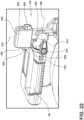
- the invention disclosed hereinprovides a pipeline inspection device 10, as shown in FIG. 1 , which can be used to view the interior of the pipe, conduit, etc., such as a buried sewer pipeline to locate obstructions, blockages, and defects in the pipe.
- a usercan use the pipeline inspection device 10 to observe the interior of a pipe, often from a distance away from the closest access port to the sewer pipeline.
- a cable 14is directed down an access port of the pipe and through the sewer pipeline.
- the cable 14includes an image capturing device (e.g., a camera 18) and/or a locator device 22 (e.g., a sonde) connected at a distal end thereof, for viewing the interior of the pipeline.
- an image capturing devicee.g., a camera 18
- a locator device 22e.g., a sonde
- FIGS. 1-3illustrate one embodiment of the reel 26.
- the reel 26includes a drum 34 for housing the cable 14 and a stand 38 for supporting the drum 34.
- the drum 34includes a closed end defined by a back wall, and an open end defined by a front wall 46.
- a side wall 50extends around the perimeter of the drum 34 between the front wall 46 and the back wall 42. Together, the back wall 42, the side wall 50, and the front wall 46 define an interior 54 of the drum 34 that houses the cable 14.
- the front wall 46includes an opening 58 that provides access to the interior 54 of the drum 34.
- the hub 30can be inserted into the drum 34 via the opening 58. Once inside the drum 34, the hub 30 is positioned so that the cable 14 is wound around the hub 30.
- the drum 34rotates about an axis extending through the back wall 42 and the opening 58 of the front wall 46.
- the cable 14is stored within the interior 54 and is wound about the axis of the drum 34.
- the drum 34can be different sizes in order to accommodate different size or lengths of cables 14. Because the cable 14 is stiff (e.g., a push cable), the cable 14 exerts an outward force towards the walls of the drum 34, and particularly, towards the side wall 50. As the cable 14 is pulled out of the drum 34, the drum 34 can rotate in a first direction about the axis of the drum 34. Conversely, as the cable 14 is pushed back into the drum 34, the drum 34 can rotate in a second direction that is opposite the first direction about the axis of the drum 34.
- the drum 34includes ribs on the inside of the drum 34 to provide for increased frictional engagement with the cable 14.
- FIGS. 2-4Aillustrate a first embodiment of a stand 38
- FIG. 4Billustrates a second embodiment of the stand 38. It should be understood that some of the features of the stand 38 are interchangeable from one embodiment to the other.
- the stand 38includes a base 66 and a center support 70 extending upward from the base 66.
- the base 66includes one or more feet 78 that contact the ground.
- one of more of the feet 78can be replaced with wheels 82, as shown in FIG. 4B .
- the center support 70includes one or more handles to help maneuver and operate the pipeline inspection device 10. In the embodiment illustrated in FIG.
- the center support 70includes a first handle 98 extending in forward direction above the drum 34.
- the handle 98may be oriented in a different direction.
- the handle 98may extend backwards, away from the drum 34 or may extend in a vertical direction.
- the center support 70includes a first handle 98b extending in a forward direction above the drum 34, as shown in FIG. 4A .
- the center support 70 in FIG. 4Balso includes a second handle 102 extending vertically.
- the second handle 102is an extendable handle, such as a telescoping handle, that may be extended to a greater length.
- the fixed portion 94(which may also be referred to as a stationary portion) of the mounting assembly 118 includes the shaft 126 and the core 138.
- the hub 30is attached to the core 138 and, thus, remains rotatably fixed (i.e., stationary) relative to the stand 38.
- the core 138has a generally polygonal front face 162 with a side wall 166 extending around the perimeter of the face 162.
- the core 138also includes a plurality of engagement members 154 that enable the hub 30 to be removably coupled to the reel 26.
- the engagement members 154are sized and shaped to engage with corresponding engagement members 170 on the hub 30.
- the core 138includes a first type of engagement member 154 in the form of a flattened portion 160 formed along the side wall 166 of the core 138.
- the core 138includes a first flattened portion 160a formed along a bottom of the core 138 and a second flattened portion 160b formed along a top of the core 138.
- the flattened portions 160help to create a secure engagement between the core 138 and the hub 30.
- the flattened portions 160help prevent rotation of the hub 30 relative to the core 138.
- the core 138can include fewer or additional flattened portions 160.
- the core 138also includes a second type of engagement member 154 in the form of a pair of arms 168 extending radially outward from the side wall 166.
- a second type of engagement member 154in the form of a pair of arms 168 extending radially outward from the side wall 166.
- one pair of arms 168extends from a left side of the core 138 and another pair of arms 168 extends from a right side of the core 138.
- a space 172is formed between each pair of arms 168. As will be described in greater detail below, the space 172 is sized and shaped to receive one of the engagement members 170 on the hub 30.
- the core 138can include additional or fewer engagement members 154.
- the core 138may include engagement members 154 of different types that are suitable to provide a coupling mechanism for the hub 30 to be secured to the core 138.
- the core 138may include various projections and/or recesses on the core 138 to correspond to engagement members 170 on the hub 30.
- the core 138includes a projection extending radially outwardly from the side wall 166.
- the core 138includes three projections: one projection extending in a downward direction towards the ground when the reel 26 is in an upright position, and two projections extending in an upward direction when the reel 26 is in an upright position.
- the projectionsprevent the hub 30 from rotating relative to the drum 34 and stand 38. Accordingly, in some embodiments, the projections may replace the flattened portions 160. In other embodiments, the projections 164 may be replaced with recesses that receive projections 164 on the hub 30.
- the core 138also includes electrical connections 176 (e.g., terminal blocks) that engage with electrical connections 180 on the hub 30. More specifically, the core 138 includes two electrical connections 176 disposed on the face 162 of the core 138. In other embodiments, different types of electrical connections 176 may be used.
- the core 138includes a housing 184 for receiving and protecting the electrical connections 176.
- the housing 184projects from the face 162 of the core 138 and includes two openings 188 for receiving the two electrical connections 176.
- the openings 188are each formed by two side walls 192 and a back wall 196 forming a U-shape. The openings 188 are oriented in opposed directions and share the back wall 196.
- the housing 184can have different sizes and shapes to accommodate different types of electrical connections 176.
- the core 138supports the hub 30 on the reel 26 such that the electrical connections 176 on the core 138 engage with the electrical connections 180 on the hub 30.
- the electrical components of the hub 30may also include a processor 278 (or controller), a memory source 282, a video processor 286, a wireless communication module 178 (e.g., a Wi-Fi hub, a Bluetooth module), etc.
- the hub 30may include more or fewer of these electrical components.
- the body 182is air and/or water tight in order to protect the electrical components.
- the front end 186 of the hub 30includes a battery housing 202 for receiving the battery 174.
- the battery 174is removable from the battery housing 202 of the hub 30.
- the battery 174may be a rechargeable power tool battery back, such an 18V Li-ion battery pack.
- the battery housing 202includes a cover 206 that can be opened and closed to insert and remove the battery 174, respectively.
- the cover 206is attached to the front end 186 by a hinge (not shown) and a latch 212.
- the hub 30also includes a channel 218 extending through the cylindrical body 182 from the outer wall 194 to the front end 186.
- the rear end 190 of the hub 30has a cavity 198 configured to receive the core 138 of the reel 26 so that the hub 30 can be supported within the interior 54 of the drum 34.
- the cavity 198is formed by a back wall 200 and a peripheral wall 204 extending around the perimeter of the back wall 200.
- the core 138is received within the cavity 198 with the face 162 of the core 138 aligned with the back wall 200 of the hub 30, and the side wall 166 of the core 138 aligned with the peripheral wall 204 of the hub 30.
- the cavity 198includes the electrical connections 180 that engage with the electrical connections 176 on the core 138.
- the electrical connections 180are molded into the back wall 200 of the cavity 198.
- the electrical connectionsare receivers for receiving the terminal blocks 176 on the core 138.
- the electrical connections 180may not be integral with the back wall 200.
- the cavity 198 of the hub 30also includes the engagement members 170 that engage with the engagement members 154 on core 138 of the reel 26. As mentioned, the engagement members 170 secure the hub 30 to the reel 26 and help align the hub 30 and maintain a solid connection between the hub 30 and the reel 26.
- the peripheral wall 204defines a first type of engagement member 170 in the form of a flattened portion 156.
- the flattened portion 156 formed in the peripheral wall 204 of the hub 30is sized and shaped to correspond to the flattened portion 160 formed in the side wall 166 of the core 138.
- the hub 30includes a first flattened portion 156a corresponding to the first flattened portion 160a on the core 138, and a second flattened portion 156b corresponding to the second flattened portion 160b on the core 138.
- the flattened portions 156, 160help prevent rotation of the hub 30 relative to the stand 38.
- the cavity 198also houses a second type of engagement member 170 in the form of one or more latches 214 that engage with the core 138 to secure the hub 30 to the reel 26.
- the hub 30includes two latches 214, however, in other embodiments a greater or fewer number of latches 214 may be used.
- the latches 214are received within the space 172 between the pair of arms 168 on each side of the core 138, and clamp on to the side wall 166.
- the latches 214are movable between a locked position, in which the latches 214 are engaged the core 138, and an unlocked position, in which the latches 214 are disengaged from the core 138.
- the handle 222includes a trigger 226 that activates the latches 214 on the rear end 190 of the cylindrical body 182. Pressing the trigger 226 rotates the latches 214 from the locked position to the unlocked position. In the illustrated embodiment, pressing the trigger 226 rotates the latches 214 outwardly to the unlocked position. The latches 214 are biased inwardly towards the locked position such that releasing the trigger 226 causes the latches 214 to automatically rotate towards the locked position.
- each latch 214includes a plurality of linkages 216 that work together to adjust the latches 214 between the locked and unlocked positions.
- the latches 214each include a first linkage 216a with a hook 232 configured to engage the core 138.
- the hooks 232can grip an engagement member 154 of the core 138 to couple the hub 30 within the interior 54 of the drum 34.
- the first linkage 216ais rotatable about a pivot point 224 between the locked and unlocked positions.
- a second linkage 216bcauses rotation of the first linkage 216a.
- the second linkage 216bis actuated by the trigger 226 to cause rotation of the first linkage 216a to release the hook 232 from the core 138 of the reel 26.
- the hub 30also includes a third type of engagement member 170 in the form of a protrusion 230.
- the cavity 198 of the hub 30includes at least one protrusion 230 that is shaped to align with the recesses 158 ( FIG. 5 ) on the core 138.
- the hub 30includes a square protrusion 230 that is received within the square recess 158 on the face 162 of the core 138.
- the protrusion 230defines a pocket that receives a sensor for monitoring the amount of cable 14 that has been extended from the drum 34.
- the hub 30may also include additional protrusions or recesses corresponding to protrusions and recesses on the core 138.
- the hub 30is inserted into the interior 54 of the drum 34 and the core 138 is received within the cavity 198 of the hub 30.
- the contact between the engagement members 170 on the hub 30 and the engagement members 154 on the core 138help orient the hub 30 and guide the hub 30 onto the core 138.
- the hub 30is removable from the drum 34 and may be attached to two different sized reels 26. Pipes typically come in two different sizes: a 1.5 to 3 inch (3.81 to 7.62 cm) diameter pipe and a 3 to 6 inch (7.62 to 15.24 cm) diameter pipe. Each of the two types of pipes requires a different diameter camera and cable.
- the smaller pipei.e., 1.5 to 3 inch (3.81 to 7.62 cm) pipe
- the larger piperequires a larger diameter camera and cable.
- Each of the smaller diameter camera and cable and the larger diameter camera and cablerequires a corresponding large or small sized reel and cable drum, which are part of correspondingly sized pipeline inspection devices.
- the hub 30may be removably detached and interchangeably attached to each of the drums of the different sized pipeline inspection devices, such that a user only needs a single hub 30 containing the electronics (e.g., the video processor, the battery, the wireless communication module (Wi-Fi hub), etc.) that can be used with either of the reels 26.
- the electronicse.g., the video processor, the battery, the wireless communication module (Wi-Fi hub), etc.
- FIGS. 13-16illustrate a mounting assembly 418 ( FIG. 13 ) and a hub 430 ( FIGS. 14-16 ) according to another embodiment.
- the mounting assembly 418includes a rotatable portion 404 and a fixed portion 406.
- a drumis mounted on the rotatable portion 404 of the mounting assembly 418, while the hub 430 is mounted to the reel 26 via the fixed portion 406 of the mounting assembly 418.
- the mounting assembly 418includes a mounting plate 422, a shaft 426, a slip ring 432, a disk 428, and a core 438.
- the rotatable portion 404 of the mounting assembly 418includes the mounting plate 422, (a portion of) the slip ring 432, and the disk 428.
- mounting plate 422, the slip ring 432, and the disk 428are rotatably fixed relative to one another, and rotate together with the drum 34.
- the fixed portion 406 of the mounting assembly 418includes the shaft 426 and the core 438.
- the shaft 426 and the core 438are rotatably fixed relative to one another and relative to the stand 38.
- the shaft 426is coupled to a center support of a stand.
- the shaft 426provides a cantilevered support for the drum above a platform of the stand.
- the mounting plate 422is fixed to the back wall of the drum. In some embodiments, the mounting plate 422 is integral with the back wall of the drum.
- the slip ring 432is disposed within a space 442 formed by the back wall of the drum. The slip ring 432 allows for transmission of electrical signals, while allowing the drum to rotate relative to the reel.
- the mounting plate 422 and the slip ring 432rotatably support the drum on the shaft 426.
- the disk 428also rotates with the drum.
- the disk 428includes magnets 446 that rotate with the disk 428 and the drum as the cable is unwound from the drum.
- the magnets 446are used in conjunction with a sensor 450 on the hub 430 to measure how much cable has been unwound. Specifically, as the drum rotates, the magnets 446 rotate about the axis of the drum.
- the sensor 450e.g., a Hall sensor
- the sensor 450can monitor 114 the movement of the magnets 446 to determine how much cable has been extended from the drum.
- the core 438is coupled to a distal end of the shaft 426.
- the core 438does not rotate with the drum, but rather, is fixed relative to the shaft 426 and the stand.
- the core 438supports the hub 430 when the hub 430 is inserted into the interior 54 of the drum via an opening on the front wall 46.
- the core 438also includes electrical connections 476 that engage with electrical connections 480 on the hub 430.
- the core 438includes a plurality of engagement members 454 that enables the hub 430 to be removably coupled to the reel.
- the core 438has a generally circular face 462 with a side wall 466 extending around the perimeter of the face 462.
- One of the engagement members 454is formed along the side wall 466 on a top side of the core 438.
- one of the engagement members 454is formed by a flattened portion 464 of the side wall 466.
- the hub 430can grip the core 438 along the flattened portion 464 of the side wall 466.
- the flattened portion 464also prevents the hub 430 from rotating relative to the core 438 and the stand.
- the core 438includes another engagement member 454 in the form of a recess 458 that aligns and engages with a portion of the hub 430.
- the recesses 458help secure the hub 430 to the reel and maintain a slide electrical connection between the two.
- the core 438may include additional engagement members 454 for coupling to the hub 430.
- the hub 430includes a cylindrical body 482 that is received within an interior of the drum.
- the cylindrical body 482is defined by a front end 486, a rear end 490, and an outer wall 494 extending around the perimeter of the hub 430 between the front end 486 and the rear end 490.
- the rear end 490 of the hub 430has a cavity 498 that includes various engagement members 470 that engage with the core 438 of the reel. The engagement members 470 secure the hub 430 to the reel and help align the hub 430 and maintain a solid connection between the hub 430 and the reel.
- the cylindrical body 482defines a housing for maintaining the electrical components of the pipeline inspection device 10.
- the front end 486 of the hub 430includes a battery housing 402 for receiving a battery.
- the batteryis removable from the battery housing 402 of the hub 430.
- the battery housing 402includes a cover 406 that can be opened and closed to insert and remove the battery, respectively.
- the cover 406is attached to the front end 486 by a hinge 410 and a latch 412.
- the hub 430also includes a channel 424 extending through the cylindrical body 482 to receive the cable and helps guide the cable into or out of the drum.
- the core 438 and the hub 430may include more or fewer recesses 458 and protrusions 430, respectively, to help align the hub 430 with the drum.
- the hub 430also includes an engagement member 470 in the form of a rim 434 that extends around the perimeter of the cylindrical body 482 for mating with the opening of the drum. When the hub 430 is received within the drum, the rim 434 engages with the edge of the opening to help align the hub 430 relative to the drum.
- the rim 434further includes a hook 436 to help grip the edge of the opening in the drum.
- the hook 436is arcuate and extends along a bottom edge of the rim 434.
- FIGS. 17-18illustrate a hub 530 according to yet another embodiment.
- the hub 530includes a cylindrical body 582 for maintaining the electrical components of a pipeline inspection device.
- a front end 586 of the hub 530includes a battery housing 502 for receiving a battery.
- the front end 586also includes two handles 522.
- the handles 522are spaced apart such that one handle 522 is on each side of the battery housing 502.
- the handles 522are generally parallel to one another and extend in a vertical direction when the hub 530 is received within the drum.
- a rear end 590 of the hub 530is configured to receive a core of a stand to support the hub 530 on the stand.
- the hub 530includes a plurality of engagement members 570 that engage with the core 18.
- the hub 530includes a cavity 598 configured to receive the core.
- the hooks 566can selectively grip the core to removably couple the hub 530 to the core.
- the hooks 566are moved between a locked and an unlocked position by buttons 564 on the front end 586 of the hub 530.
- the hooks 566are disposed within recesses 568 (another engagement member 570).
- the recesses 568help align the hub 530 with the core to prevent rotation of the hub 530 relative to the core.
- there are two buttons 564each corresponding to one of the hooks 566. When the buttons 564 are squeezed inwardly, the hooks 566 are disengaged from the core. The hooks 566 are biased to a locked position such that releasing the buttons 564 automatically moves the hooks 566 towards the locked position.
- FIGS. 19-21illustrate a brake assembly 302 for selectively limiting the rotational speed of the drum 34 relative to the stand 38.
- the brake assembly 302is disposed on the center support 70 of the stand 38 behind the back wall 42 of the drum 34.
- the brake assembly 302includes a disc 306, a brake pad 310, and an actuator 314.
- the disc 306is rotatably fixed relative to the drum 34 such that the disc 306 rotates with the rotation of the drum 34.
- the disc 306is rotatably fixed relative to the drum 34 by a plurality of interlocking teeth.
- the disc 306includes a first plurality of teeth 318 extending radially inward.
- the drum 34includes a second plurality of teeth 322 extending radially outward from a cap 326 disposed on the back wall 42 of the drum 34.
- the engagement between the first plurality of teeth 318 and the second plurality of teeth 322maintain the rotational orientation of the disc 306 relative to the drum 34.
- the first plurality of teeth 318are evenly spaced around an inner circumference of the disc 306, and the second plurality of teeth 322 are evenly spaced around an outer circumference of the cap 326.
- the teeth 318, 322 on one or both of the cap 326 and the disc 306may be unevenly spaced or may not extend around the entire circumference.
- one or both of the cap 326 and the dismay include a greater or fewer number of teeth.
- the brake pad 310is selectively engagable with the disc 306 to limit rotation of the disc 306, and thereby, restrictiverotation of the drum 34.
- the brake pad 310may selectively exert a frictional force against the disc 306 in order to slow rotation of the drum or bring the drum to a complete stop.
- the amount of frictional force between the brake pad 310 and the disc 306determines the degree to which the rotation of the drum is limited.
- the brake pad 310is movable relative to the disc 306 by an actuator 314.
- the actuator 314is operable to move the brake pad 310 between a first position corresponding to a first frictional force against the disc 306, and a second position corresponding to a second frictional force against the disc 306.
- the second frictional forceis greater than the first frictional force, and therefore, the rotational speed of the drum 34 is slower when the brake pad 310 is in the second position.
- the actuator 314is a rotatable knob with a threaded shaft 330.
- the brake pad 310is coupled to the end of the shaft 330.
- the shaft 330is threadably engaged with a caliper 334.
- the caliper 334includes an annular recess 338 that receives the brake pad 310 and the disc 306.
- the disc 306can rotate within the annular recess 338 of the caliper 334.
- the brake pad 310is movable towards and away from the disc 306 within the space provided by the recess of the caliper 334. Rotation of the actuator 314 threads the shaft 330 into or out of the caliper 334 to adjust the position of the brake pad 310 within the annular recess 338.
- the brake assembly 302can be used to control the speed of the drum 34 (i.e., slow the speed of the drum to various rotational speeds) or to inhibit the drum 34 from rotating all together.
- the pipeline inspection device 10includes a dedicated monitor 114 and a monitor mount 110 for removably coupling the dedicated monitor 114 to the reel 26.
- FIG. 22illustrates the monitor mount 110 extending upwards from the center support 70.
- the monitor mount 110includes an insert member 342 that can be removably received within a receptacle 346 ( FIG. 26 ) of the dedicated monitor 114.
- the dedicated monitor 114can be selectively coupled to the monitor mount 110 by sliding the dedicated monitor 114 onto the insert member 342.
- the insert member 342has a generally rectangular shape with oppositely facing front and rear faces, top and bottom faces, and side faces.
- the insert member 342also includes detent members 350 disposed on the side faces.
- the detent members 350are biased away from one another, for example by springs.
- the detent members 350snap into recesses 348 in the receptacle 346 to hold the dedicated monitor 114 on the monitor mount 110.
- a usercan squeeze buttons 354 disposed on the side faces of the insert member 342 to overcome the spring bias of the detent members 350 and retract the detent members 350 out of the recesses 348.
- FIGS. 23-26illustrate various views of the dedicated monitor 114.
- the dedicated monitor 114is a monitor 114 that is specifically designed for use with the pipeline inspection device.
- the dedicated monitor 114is a monitor 114 that is not capable of being used as an independent computer or with other devices. Rather, the dedicated monitor 114 is specifically designed to be used only with the pipeline inspection device.
- the dedicated monitor 114includes the receptacle 346, which is sized and shaped to receive the insert member 342 of the monitor mount 110.
- the receptacle 346is positioned on the bottom of the dedicated monitor 114, and has a generally rectangular shape that is complimentary to the size and shape of the insert member 342.
- the receptacle 346also includes recesses 348 for engaging with the detent members 350 on the insert member 342.
- the dedicated monitor 114includes a display screen 382 for showing images (both pictures and videos) captured by the camera 18 and a cover 386 to protect the display screen 382.
- the dedicated monitor 114also includes features to help make the dedicated monitor 114 more versatile in how it is being used. For example, in addition to being able to couple the dedicated monitor 114 to the monitor mount 110 on the stand 38, the dedicated monitor 114 can be carried around a worksite by a user or rested on other surfaces.
- the dedicated monitor 114includes a handgrip 390 on the back side of the dedicated monitor 114.
- the dedicated monitor 114includes two handgrips 390, one on each side, so that the dedicated monitor 114 can be held in either hand.
- the handgrips 390are designed to be large enough to be grasped by a user wearing gloves.
- the dedicated monitor 114also includes a stand 394 on the back side of the dedicated monitor 114 to support the dedicated monitor 114 on other surfaces around the worksite.
- the stand 394extends from a rear of the dedicated monitor 114 at a non-perpendicular angle so that the dedicated monitor 114 is supported on a surface at a comfortable viewing angle.
- the dedicated monitor 114includes a wireless communication module 398.
- the dedicated monitor 114can communicate wirelessly with the hub 30 to receive the images captured by the camera 18.
- the wireless communication module 178 of the hub 30can be selectively connected to the wireless communication module 398 of the dedicated monitor 114.
- the dedicated monitor 114can be operated while coupled to the monitor mount 110 or when removed from the monitor mount 110.
- the dedicated monitor 114may include an onboard battery 402 housed within the dedicated monitor 114.
- the dedicated monitor 114may be powered by the hub 30.
- the dedicated monitor 114may be plugged into the hub 30 (directly, or indirectly via the reel 26) to receive power from the battery 174 housed within the hub 30.
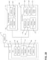
- the hub 30can also wirelessly communicate with a smart device 406, such as a smart phone, laptop computer, or tablet computer to display the images captured by the camera 18.
- the smart device 406is a different computing device from the dedicated monitor 114, and can be used for other purposes apart from the pipeline inspection device.
- the smart device 406includes a display screen 410 configured to display the images and a wireless communication module 414 configured to connect to the wireless communication module 178 of the hub 30.
- the smart device 406may also include a processor 418, a memory source 422, a video processor 426, and a battery 430.
- the smart device 406may include an application with a graphical user interface (GUI) configured to display the images captured by the camera 18.
- GUIgraphical user interface
- the hub 30can process the images prior to transferring the images to the smart device 406.
- the smart device 406may be able to further process the images via the application.
Landscapes
- Engineering & Computer Science (AREA)
- Chemical & Material Sciences (AREA)
- Combustion & Propulsion (AREA)
- General Engineering & Computer Science (AREA)
- General Physics & Mathematics (AREA)
- Physics & Mathematics (AREA)
- Life Sciences & Earth Sciences (AREA)
- Health & Medical Sciences (AREA)
- Mechanical Engineering (AREA)
- Analytical Chemistry (AREA)
- Biochemistry (AREA)
- General Health & Medical Sciences (AREA)
- Immunology (AREA)
- Pathology (AREA)
- Storing, Repeated Paying-Out, And Re-Storing Of Elongated Articles (AREA)
- Investigating Materials By The Use Of Optical Means Adapted For Particular Applications (AREA)
- Storage Of Web-Like Or Filamentary Materials (AREA)
Description
- The present invention relates to pipeline inspection devices for inspecting sewers, drains, pipes, or other conduits.
- Pipeline inspection devices can be used to determine the location of obstructions in underground pipes or find damaged areas that affect the integrity of pipe systems. Generally, a pipeline inspection device includes a cable that can be pushed down a length of the pipe. The end of the cable may include an imaging device, such as a video camera, to help identify an obstruction or damage within the pipe. The end of the cable may also include a location device, such as a sonde, to transmit the location of the end of the cable. The location device allows a user to find the end of the cable and dig down towards the pipe at the proper location where the obstruction might be.
- According to its title and abstract
WO 2018/112411 A1 , comprised in the state of the art according to Art. 54(3) EPC, discloses a pipeline inspection device including a cable having a camera disposed on a distal end of the cable, where the camera and the cable are configured to be directed into a conduit. A first drum includes a rear wall, a front wall, and a side wall defining an interior, where the front wall has an opening providing access to the interior, and where the cable is disposed at least partially within the first drum. A stand supports the first drum, where the first drum is rotatably coupled to the stand. A hub houses electrical components of the pipeline inspection device. The hub is removably received in the interior of the first drum via the opening, where the hub is selectively removable from the first drum and insertable into an interior of a second drum. - According to its title and abstract_
US 2010/208056 A1 discloses a pipe inspection system including a (replaceable) cable storage drum and a housing configured to removably receive and rotatably support the cable storage drum. A push-cable with a plurality of conductors is stored in the cable storage drum. A camera head is connected to a distal end of the push-cable. A slip-ring assembly has first and second mating portions that when mated provide conductive paths between the plurality of conductors at a proximal end of the push-capable and a display device. The first portion of the slip-ring assembly is mounted on the housing and the second portion of the slip-ring assembly is mounted on the removable cable storage drum. The system connection cable joining the inspection system with a display unit is removable and may be replaced with cables compatible with various alternate image display systems. - According to the invention, a pipeline inspection device according to
claim 1 is provided. The pipeline inspection device comprises a rotatable drum housing a cable, where the cable is extendable into a pipe, a camera positioned on an end of the cable, and a hub housing electrical components of the pipeline inspection device and including a battery housing. A stand includes a mounting assembly having a first portion rotatably supporting the drum and a second portion supporting the hub within an interior of the drum, the second portion including a core, where the hub is removably coupled to the mounting assembly via the core. The hub is removably coupled to the mounting assembly by a first engagement member on the hub and a second engagement member on the core. - The second engagement member is formed by a side wall of the core. The first engagement member includes a latch having a hook that selectively grips the side wall. The hook is received within a space between two arms extending radially outward from the side wall of the core.
- Other aspects of the invention will become apparent by consideration of the detailed description and accompanying drawings.
FIG. 1 is a perspective view of a pipeline inspection device according to a first embodiment.FIG. 2 is a perspective view of a stand of the pipeline inspection device illustrated inFIG. 1 .FIG. 3 is a side view of the stand illustrated inFIG. 2 .FIG. 4A is a rear perspective view of the pipeline inspection device ofFIG. 1 .FIG. 4B is a rear perspective view of a pipeline inspection device with another embodiment of a stand.FIG. 5 is a perspective view of a core of a mounting assembly.FIG. 6 is a front perspective view of a hub according to one embodiment.FIG. 7 is a side view of the hub illustrated inFIG. 6 .FIG. 8 is a top view of the hub illustrated inFIG. 6 .FIG. 9 is a first rear perspective view of the hub illustrated inFIG. 6 .FIG. 10 is a second rear perspective view of the hub illustrated inFIG. 6 .FIG. 11 is a detailed view of an engagement member of the hub.FIG. 12 is another detailed view of the engagement member illustrated inFIG. 10 .FIG. 13 illustrates a mounting assembly for use with the pipeline inspection device.FIG. 14 is a front perspective view of the hub according to a second embodiment.FIG. 15 is a rear perspective view of the hub illustrated inFIG. 15 .FIG. 16 is a top view of the hub illustrated inFIG. 15 .FIG. 17 is a front perspective view of a hub according to a third embodiment.FIG. 18 is a rear perspective view of the hub illustrated inFIG. 18 .FIG. 19 is a first perspective view of a brake assembly for use with a pipeline inspection device.FIG. 20 is a second perspective view of the brake assembly ofFIG. 20 .FIG. 21 is a cross-sectional view of the brake assembly ofFIG. 20 .FIG. 22 is a perspective view of a monitor mount.FIG. 23 is a front perspective view of a dedicated monitor for use with a pipeline inspection device.FIG. 24 is a rear perspective view of the dedicated monitor ofFIG. 24 .FIG. 25 is a side view of the dedicated monitor ofFIG. 24 .FIG. 26 is a bottom perspective view of the dedicated monitor ofFIG. 24 .FIG. 27 is a schematic diagram of a hub, a dedicated monitor, and a smart device for use with a pipeline inspection device.FIG. 28 is another schematic diagram of a hub, a dedicated monitor, and a smart device for use with a pipeline inspection device in accordance with another embodiment.- Before any embodiments of the invention are explained in detail, it is to be understood that the invention is not limited in its application to the details of construction and the arrangement of components set forth in the following description or illustrated in the following drawings, but is solely defined by the appended claims.
- The invention disclosed herein provides a
pipeline inspection device 10, as shown inFIG. 1 , which can be used to view the interior of the pipe, conduit, etc., such as a buried sewer pipeline to locate obstructions, blockages, and defects in the pipe. Specifically, a user can use thepipeline inspection device 10 to observe the interior of a pipe, often from a distance away from the closest access port to the sewer pipeline. To view the interior of the pipe, acable 14 is directed down an access port of the pipe and through the sewer pipeline. Thecable 14 includes an image capturing device (e.g., a camera 18) and/or a locator device 22 (e.g., a sonde) connected at a distal end thereof, for viewing the interior of the pipeline. - The
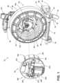
pipeline inspection device 10 includes areel 26 for housing thecable 14 and ahub 30 for housing a power source and other electronic components for operating thepipeline inspection device 10. Thecable 14 is stored on thereel 26 in a wound configuration, but can be unwound and inserted into a length of a pipe under inspection. Thehub 30 provides power to the components of thereel 26 in order to operate thepipeline inspection device 10. As discussed in in greater detail below, thehub 30 is removably coupled to thereel 26. In some embodiments, thehub 30 can be interchangeably used with two or moredifferent reels 26. FIGS. 1-3 illustrate one embodiment of thereel 26. Thereel 26 includes adrum 34 for housing thecable 14 and astand 38 for supporting thedrum 34. Thedrum 34 includes a closed end defined by a back wall, and an open end defined by afront wall 46. Aside wall 50 extends around the perimeter of thedrum 34 between thefront wall 46 and the back wall 42. Together, the back wall 42, theside wall 50, and thefront wall 46 define an interior 54 of thedrum 34 that houses thecable 14. Thefront wall 46 includes anopening 58 that provides access to the interior 54 of thedrum 34. As will be discussed in further detail below, thehub 30 can be inserted into thedrum 34 via theopening 58. Once inside thedrum 34, thehub 30 is positioned so that thecable 14 is wound around thehub 30.- The
drum 34 rotates about an axis extending through the back wall 42 and theopening 58 of thefront wall 46. Thecable 14 is stored within the interior 54 and is wound about the axis of thedrum 34. Thedrum 34 can be different sizes in order to accommodate different size or lengths ofcables 14. Because thecable 14 is stiff (e.g., a push cable), thecable 14 exerts an outward force towards the walls of thedrum 34, and particularly, towards theside wall 50. As thecable 14 is pulled out of thedrum 34, thedrum 34 can rotate in a first direction about the axis of thedrum 34. Conversely, as thecable 14 is pushed back into thedrum 34, thedrum 34 can rotate in a second direction that is opposite the first direction about the axis of thedrum 34. In some embodiments, thedrum 34 includes ribs on the inside of thedrum 34 to provide for increased frictional engagement with thecable 14. - The
drum 34 is supported above the ground by thestand 38.FIGS. 2-4A illustrate a first embodiment of astand 38, andFIG. 4B illustrates a second embodiment of thestand 38. It should be understood that some of the features of thestand 38 are interchangeable from one embodiment to the other. Thestand 38 includes abase 66 and acenter support 70 extending upward from thebase 66. In the illustrated embodiment, thebase 66 includes one ormore feet 78 that contact the ground. In other embodiments, one of more of thefeet 78 can be replaced withwheels 82, as shown inFIG. 4B . Thecenter support 70 includes one or more handles to help maneuver and operate thepipeline inspection device 10. In the embodiment illustrated inFIG. 4A , thecenter support 70 includes afirst handle 98 extending in forward direction above thedrum 34. In other embodiments, thehandle 98 may be oriented in a different direction. For example, in some embodiments, thehandle 98 may extend backwards, away from thedrum 34 or may extend in a vertical direction. In the embodiment illustrated inFIG. 4B , thecenter support 70 includes a first handle 98b extending in a forward direction above thedrum 34, as shown inFIG. 4A . In addition, thecenter support 70 inFIG. 4B also includes asecond handle 102 extending vertically. In the illustrated embodiment, thesecond handle 102 is an extendable handle, such as a telescoping handle, that may be extended to a greater length. - Additionally, the
center support 70 also includes a monitor mount 110 (shown in bothFIGS. 4A and 4B ), which can be used to support a monitor or other components of thepipeline device 10. The monitor and display will be described in greater detail herein. Furthermore, in some embodiments, such asFIG. 4A , the center support may include abackpack plate 242 that enables a user to carry thereel 26 on his/her back. For example, thebackpack plate 242 can be coupled to backpack straps or a full backpack to enable a user to carry thereel 26 as a backpack. In the illustrated embodiment, thebackpack plate 242 is removably attached to thecenter support 70. - Referring back to
FIGS. 2-3 , thedrum 34 and thehub 30 are supported on thestand 38 by a mountingassembly 118. The mountingassembly 118 includes arotatable portion 90 and a fixedportion 94. Thedrum 34 is mounted on therotatable portion 90 of the mountingassembly 118, while thehub 30 is mounted to thereel 26 via the fixedportion 94 of the mountingassembly 118. The mountingassembly 118 includes a mountingplate 122, ashaft 126, aslip ring 130, and acore 138. Therotatable portion 90 of the mountingassembly 118 includes the mountingplate 122 and (a portion of) theslip ring 130, which are rotatably fixed relative to one another. Thus, thedrum 34, the mountingplate 122, and theslip ring 130 rotate together relative to thestand 38. The fixed portion 94 (which may also be referred to as a stationary portion) of the mountingassembly 118 includes theshaft 126 and thecore 138. Thehub 30 is attached to thecore 138 and, thus, remains rotatably fixed (i.e., stationary) relative to thestand 38. - More specifically, the
shaft 126 is coupled to thecenter support 70 of thestand 38. Theshaft 126 provides a cantilevered support for thedrum 34 above thebase 66 of thestand 38. The mountingplate 122 is fixed to the back wall 42 of thedrum 34. In some embodiments, the mountingplate 122 is integral with the back wall 42 of thedrum 34. Theslip ring 130 is supported on theshaft 126 and engages with the back wall 42 of thedrum 34. Theslip ring 130 allows for transmission of electrical signals, while allowing thedrum 34 to rotate relative to thereel 26. The mountingplate 122 and theslip ring 130 rotatably support thedrum 34 on theshaft 126. Thecore 138 is coupled to a distal end of theshaft 126 and extends into the interior 54 of thedrum 34. Thecore 138 supports thehub 30 when thehub 30 is inserted into the interior 54 of thedrum 34 via theopening 58 on thefront wall 46. - With reference to
FIG. 5 , thecore 138 has a generally polygonalfront face 162 with aside wall 166 extending around the perimeter of theface 162. Thecore 138 also includes a plurality of engagement members 154 that enable thehub 30 to be removably coupled to thereel 26. The engagement members 154 are sized and shaped to engage with corresponding engagement members 170 on thehub 30. - Specifically, in the illustrated embodiment, the
core 138 includes a first type of engagement member 154 in the form of a flattened portion 160 formed along theside wall 166 of thecore 138. In the illustrated embodiment, thecore 138 includes a first flattened portion 160a formed along a bottom of thecore 138 and a second flattened portion 160b formed along a top of thecore 138. The flattened portions 160 help to create a secure engagement between the core 138 and thehub 30. In addition, when thehub 30 is coupled to thestand 38, the flattened portions 160 help prevent rotation of thehub 30 relative to thecore 138. In other embodiments, thecore 138 can include fewer or additional flattened portions 160. - The
core 138 also includes a second type of engagement member 154 in the form of a pair of arms 168 extending radially outward from theside wall 166. In the illustrated embodiment, one pair of arms 168 extends from a left side of thecore 138 and another pair of arms 168 extends from a right side of thecore 138. Aspace 172 is formed between each pair of arms 168. As will be described in greater detail below, thespace 172 is sized and shaped to receive one of the engagement members 170 on thehub 30. - In addition, the
core 138 includes a third type of engagement member 154 in the form of a recess 158. Thecore 138 includes at least one recess 158 that aligns and engages with a portion of thehub 30. Specifically, in the illustrated embodiment, thecore 138 includes the recess 158 on theface 162 of thecore 138. The recess 158 is sized and shaped to receive an engagement member 170 on thehub 30. In some embodiments, thecore 138 may include a projection and the hub may include a recess sized and shaped to receive the projection. - In other embodiments, the
core 138 can include additional or fewer engagement members 154. In addition, thecore 138 may include engagement members 154 of different types that are suitable to provide a coupling mechanism for thehub 30 to be secured to thecore 138. For example, thecore 138 may include various projections and/or recesses on thecore 138 to correspond to engagement members 170 on thehub 30. In one embodiment, thecore 138 includes a projection extending radially outwardly from theside wall 166. In another embodiment, thecore 138 includes three projections: one projection extending in a downward direction towards the ground when thereel 26 is in an upright position, and two projections extending in an upward direction when thereel 26 is in an upright position. When thehub 30 is coupled to thecore 138, the projections prevent thehub 30 from rotating relative to thedrum 34 and stand 38. Accordingly, in some embodiments, the projections may replace the flattened portions 160. In other embodiments, the projections 164 may be replaced with recesses that receive projections 164 on thehub 30. - With reference to
FIG. 5 , thecore 138 also includes electrical connections 176 (e.g., terminal blocks) that engage withelectrical connections 180 on thehub 30. More specifically, thecore 138 includes twoelectrical connections 176 disposed on theface 162 of thecore 138. In other embodiments, different types ofelectrical connections 176 may be used. Thecore 138 includes ahousing 184 for receiving and protecting theelectrical connections 176. Thehousing 184 projects from theface 162 of thecore 138 and includes twoopenings 188 for receiving the twoelectrical connections 176. In the illustrated embodiment, theopenings 188 are each formed by twoside walls 192 and aback wall 196 forming a U-shape. Theopenings 188 are oriented in opposed directions and share theback wall 196. In other embodiments, thehousing 184 can have different sizes and shapes to accommodate different types ofelectrical connections 176. Thecore 138 supports thehub 30 on thereel 26 such that theelectrical connections 176 on thecore 138 engage with theelectrical connections 180 on thehub 30. - Referring to
FIGS. 6-10 , thehub 30 includes acylindrical body 182 that is received within theinterior 54 of thedrum 34 and supported on thereel 26. Thecylindrical body 182 is defined by afront end 186, arear end 190, and anouter wall 194 extending around the perimeter of thehub 30 between thefront end 186 and therear end 190. Thecylindrical body 182 defines a housing for maintaining the electrical components of thepipeline inspection device 10. Thehub 30 includes a power source and other electrical components for operating thepipeline inspection device 10. For example, thehub 30 includes a battery 174 (FIG. 7 ) and theelectrical connections 180 that engage with theelectrical connections 176 on thecore 138. The electrical components of thehub 30 may also include a processor 278 (or controller), amemory source 282, avideo processor 286, a wireless communication module 178 (e.g., a Wi-Fi hub, a Bluetooth module), etc. In other embodiments, thehub 30 may include more or fewer of these electrical components. In some embodiments, thebody 182 is air and/or water tight in order to protect the electrical components. - In the illustrated embodiment, the
front end 186 of thehub 30 includes abattery housing 202 for receiving thebattery 174. Thebattery 174 is removable from thebattery housing 202 of thehub 30. In some embodiments, thebattery 174 may be a rechargeable power tool battery back, such an 18V Li-ion battery pack. Thebattery housing 202 includes acover 206 that can be opened and closed to insert and remove thebattery 174, respectively. Thecover 206 is attached to thefront end 186 by a hinge (not shown) and alatch 212. Thehub 30 also includes achannel 218 extending through thecylindrical body 182 from theouter wall 194 to thefront end 186. When thehub 30 is inserted in thedrum 34, thechannel 218 receives thecable 14 and helps guide thecable 14 into or out of thedrum 34. Thehub 30 includes ahandle 222 provided on thefront end 186 of thehub 30. Thehandle 222 extends outwardly from thefront end 186 of thehub 30 and can be used to maneuver thehub 30 into theopening 58 of thedrum 34. In the illustrated embodiment, thehub 30 also includes arim 234 that extends around the perimeter of thecylindrical body 182 for mating with theopening 58 of thedrum 34. When thehub 30 is received within thedrum 34, therim 234 engages with the edge of theopening 58 to help align thehub 30 relative to thedrum 34. - With reference to
FIG. 9-10 , therear end 190 of thehub 30 has acavity 198 configured to receive thecore 138 of thereel 26 so that thehub 30 can be supported within theinterior 54 of thedrum 34. Specifically, thecavity 198 is formed by aback wall 200 and aperipheral wall 204 extending around the perimeter of theback wall 200. Thecore 138 is received within thecavity 198 with theface 162 of the core 138 aligned with theback wall 200 of thehub 30, and theside wall 166 of the core 138 aligned with theperipheral wall 204 of thehub 30. Thecavity 198 includes theelectrical connections 180 that engage with theelectrical connections 176 on thecore 138. Theelectrical connections 180 are molded into theback wall 200 of thecavity 198. In the illustrated embodiment, the electrical connections are receivers for receiving the terminal blocks 176 on thecore 138. In other embodiments, theelectrical connections 180 may not be integral with theback wall 200. - With continued reference to
FIGS. 9-10 , thecavity 198 of thehub 30 also includes the engagement members 170 that engage with the engagement members 154 oncore 138 of thereel 26. As mentioned, the engagement members 170 secure thehub 30 to thereel 26 and help align thehub 30 and maintain a solid connection between thehub 30 and thereel 26. - The
peripheral wall 204 defines a first type of engagement member 170 in the form of a flattened portion 156. The flattened portion 156 formed in theperipheral wall 204 of thehub 30 is sized and shaped to correspond to the flattened portion 160 formed in theside wall 166 of thecore 138. Accordingly, in the illustrated embodiment, thehub 30 includes a first flattened portion 156a corresponding to the first flattened portion 160a on thecore 138, and a second flattened portion 156b corresponding to the second flattened portion 160b on thecore 138. As mentioned, the flattened portions 156, 160 help prevent rotation of thehub 30 relative to thestand 38. - The
cavity 198 also houses a second type of engagement member 170 in the form of one or more latches 214 that engage with the core 138 to secure thehub 30 to thereel 26. In the illustrated embodiment, thehub 30 includes two latches 214, however, in other embodiments a greater or fewer number of latches 214 may be used. The latches 214 are received within thespace 172 between the pair of arms 168 on each side of thecore 138, and clamp on to theside wall 166. As will be described in greater detail below, the latches 214 are movable between a locked position, in which the latches 214 are engaged thecore 138, and an unlocked position, in which the latches 214 are disengaged from thecore 138. - The
handle 222 includes atrigger 226 that activates the latches 214 on therear end 190 of thecylindrical body 182. Pressing thetrigger 226 rotates the latches 214 from the locked position to the unlocked position. In the illustrated embodiment, pressing thetrigger 226 rotates the latches 214 outwardly to the unlocked position. The latches 214 are biased inwardly towards the locked position such that releasing thetrigger 226 causes the latches 214 to automatically rotate towards the locked position. - With reference to
FIGS. 11-12 , each latch 214 includes a plurality of linkages 216 that work together to adjust the latches 214 between the locked and unlocked positions. In the illustrated embodiment, the latches 214 each include afirst linkage 216a with ahook 232 configured to engage thecore 138. Specifically, thehooks 232 can grip an engagement member 154 of the core 138 to couple thehub 30 within theinterior 54 of thedrum 34. Thefirst linkage 216a is rotatable about apivot point 224 between the locked and unlocked positions. Asecond linkage 216b causes rotation of thefirst linkage 216a. Thesecond linkage 216b is actuated by thetrigger 226 to cause rotation of thefirst linkage 216a to release thehook 232 from thecore 138 of thereel 26. - The
hub 30 also includes a third type of engagement member 170 in the form of a protrusion 230. As shown inFIG. 9 , thecavity 198 of thehub 30 includes at least one protrusion 230 that is shaped to align with the recesses 158 (FIG. 5 ) on thecore 138. For example, thehub 30 includes a square protrusion 230 that is received within the square recess 158 on theface 162 of thecore 138. In some embodiments, the protrusion 230 defines a pocket that receives a sensor for monitoring the amount ofcable 14 that has been extended from thedrum 34. Additionally, in some embodiments, thehub 30 may also include additional protrusions or recesses corresponding to protrusions and recesses on thecore 138. - To couple the
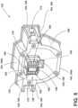
hub 30 to thestand 38, thehub 30 is inserted into the interior 54 of thedrum 34 and thecore 138 is received within thecavity 198 of thehub 30. The contact between the engagement members 170 on thehub 30 and the engagement members 154 on thecore 138 help orient thehub 30 and guide thehub 30 onto thecore 138. As previously mentioned, thehub 30 is removable from thedrum 34 and may be attached to two differentsized reels 26. Pipes typically come in two different sizes: a 1.5 to 3 inch (3.81 to 7.62 cm) diameter pipe and a 3 to 6 inch (7.62 to 15.24 cm) diameter pipe. Each of the two types of pipes requires a different diameter camera and cable. The smaller pipe (i.e., 1.5 to 3 inch (3.81 to 7.62 cm) pipe) requires a smaller diameter camera and cable that is more flexible, while the larger pipe requires a larger diameter camera and cable. Each of the smaller diameter camera and cable and the larger diameter camera and cable requires a corresponding large or small sized reel and cable drum, which are part of correspondingly sized pipeline inspection devices. In the illustrated embodiment, thehub 30 may be removably detached and interchangeably attached to each of the drums of the different sized pipeline inspection devices, such that a user only needs asingle hub 30 containing the electronics (e.g., the video processor, the battery, the wireless communication module (Wi-Fi hub), etc.) that can be used with either of thereels 26. FIGS. 13-16 illustrate a mounting assembly 418 (FIG. 13 ) and a hub 430 (FIGS. 14-16 ) according to another embodiment. With reference toFIG. 13 , the mountingassembly 418 includes arotatable portion 404 and a fixedportion 406. A drum is mounted on therotatable portion 404 of the mountingassembly 418, while thehub 430 is mounted to thereel 26 via the fixedportion 406 of the mountingassembly 418. The mountingassembly 418 includes a mountingplate 422, ashaft 426, aslip ring 432, adisk 428, and acore 438. Therotatable portion 404 of the mountingassembly 418 includes the mountingplate 422, (a portion of) theslip ring 432, and thedisk 428. Thus, mountingplate 422, theslip ring 432, and thedisk 428 are rotatably fixed relative to one another, and rotate together with thedrum 34. The fixedportion 406 of the mountingassembly 418 includes theshaft 426 and thecore 438. Theshaft 426 and thecore 438 are rotatably fixed relative to one another and relative to thestand 38.- The
shaft 426 is coupled to a center support of a stand. Theshaft 426 provides a cantilevered support for the drum above a platform of the stand. The mountingplate 422 is fixed to the back wall of the drum. In some embodiments, the mountingplate 422 is integral with the back wall of the drum. Theslip ring 432 is disposed within a space 442 formed by the back wall of the drum. Theslip ring 432 allows for transmission of electrical signals, while allowing the drum to rotate relative to the reel. The mountingplate 422 and theslip ring 432 rotatably support the drum on theshaft 426. - The
disk 428 also rotates with the drum. Thedisk 428 includesmagnets 446 that rotate with thedisk 428 and the drum as the cable is unwound from the drum. Themagnets 446 are used in conjunction with asensor 450 on thehub 430 to measure how much cable has been unwound. Specifically, as the drum rotates, themagnets 446 rotate about the axis of the drum. The sensor 450 (e.g., a Hall sensor) is located on thestationary hub 430 along the axis. As themagnets 446 rotate, thesensor 450 can monitor 114 the movement of themagnets 446 to determine how much cable has been extended from the drum. - With continued reference to
FIG. 13 , thecore 438 is coupled to a distal end of theshaft 426. Thecore 438 does not rotate with the drum, but rather, is fixed relative to theshaft 426 and the stand. Thecore 438 supports thehub 430 when thehub 430 is inserted into the interior 54 of the drum via an opening on thefront wall 46. Thecore 438 also includeselectrical connections 476 that engage withelectrical connections 480 on thehub 430. Thecore 438 includes a plurality of engagement members 454 that enables thehub 430 to be removably coupled to the reel. - In the illustrated embodiment, the
core 438 has a generallycircular face 462 with aside wall 466 extending around the perimeter of theface 462. One of the engagement members 454 is formed along theside wall 466 on a top side of thecore 438. Specifically, one of the engagement members 454 is formed by a flattened portion 464 of theside wall 466. Thehub 430 can grip thecore 438 along the flattened portion 464 of theside wall 466. The flattened portion 464 also prevents thehub 430 from rotating relative to thecore 438 and the stand. In addition, thecore 438 includes another engagement member 454 in the form of a recess 458 that aligns and engages with a portion of thehub 430. The recesses 458 help secure thehub 430 to the reel and maintain a slide electrical connection between the two. In other embodiments, thecore 438 may include additional engagement members 454 for coupling to thehub 430. - Referring to
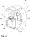
FIGS. 14-16 , thehub 430 includes acylindrical body 482 that is received within an interior of the drum. Thecylindrical body 482 is defined by afront end 486, arear end 490, and anouter wall 494 extending around the perimeter of thehub 430 between thefront end 486 and therear end 490. Therear end 490 of thehub 430 has acavity 498 that includes various engagement members 470 that engage with thecore 438 of the reel. The engagement members 470 secure thehub 430 to the reel and help align thehub 430 and maintain a solid connection between thehub 430 and the reel. - The
cylindrical body 482 defines a housing for maintaining the electrical components of thepipeline inspection device 10. In the illustrated embodiment, thefront end 486 of thehub 430 includes abattery housing 402 for receiving a battery. The battery is removable from thebattery housing 402 of thehub 430. Thebattery housing 402 includes acover 406 that can be opened and closed to insert and remove the battery, respectively. Thecover 406 is attached to thefront end 486 by ahinge 410 and alatch 412. Thehub 430 also includes achannel 424 extending through thecylindrical body 482 to receive the cable and helps guide the cable into or out of the drum. - In addition, the
hub 430 includes ahandle 222 provided on thefront end 486 of thehub 430. Thehandle 222 extends outwardly from thefront end 486 of thehub 430 and can be used to maneuver thehub 430 into the opening of the drum. Thehandle 222 includes a trigger 444 (FIG. 16 ) that activates alatch 414 on therear end 490 of thecylindrical body 482. Thelatch 414 is one of the engagement members 470 disposed within thecavity 498 of thehub 430. Thelatch 414 is configured to engage with the engagement member 454 on thecore 438 of the mountingassembly 418 of the reel. Pressing thetrigger 444 rotates thelatch 414 from a locked position to an unlocked position. In the illustrated embodiment, pressing thetrigger 444 rotates thelatch 414 upward into the unlocked position. Thelatch 414 is biased towards the locked position such that releasing thetrigger 444 causes thelatch 414 to rotate automatically downward and into the locked position. - The
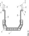
hub 430 also includes various other engagement members 470 that help align and support thehub 430 within the drum. Thecavity 498 of thehub 430 includes at least one protrusion 420 that is shaped to align with the recesses 458 on thecore 438 of the mountingassembly 418. For example, thehub 430 includes a square protrusion 420 that is received within the square recess 458 on theface 462 of thecore 438. The protrusion 420 defines a pocket that receives thesensor 450 for monitoring movement of themagnets 446 to help determine the amount of cable that has been extended from the drum. In some embodiments, thecore 438 and thehub 430 may include more or fewer recesses 458 andprotrusions 430, respectively, to help align thehub 430 with the drum. In the illustrated embodiment, thehub 430 also includes an engagement member 470 in the form of a rim 434 that extends around the perimeter of thecylindrical body 482 for mating with the opening of the drum. When thehub 430 is received within the drum, the rim 434 engages with the edge of the opening to help align thehub 430 relative to the drum. In the illustrated embodiment, the rim 434 further includes a hook 436 to help grip the edge of the opening in the drum. In the illustrated embodiment, the hook 436 is arcuate and extends along a bottom edge of the rim 434. FIGS. 17-18 illustrate ahub 530 according to yet another embodiment. Thehub 530 includes acylindrical body 582 for maintaining the electrical components of a pipeline inspection device. Afront end 586 of thehub 530 includes abattery housing 502 for receiving a battery. Thefront end 586 also includes two handles 522. Thehandles 522 are spaced apart such that onehandle 522 is on each side of thebattery housing 502. Thehandles 522 are generally parallel to one another and extend in a vertical direction when thehub 530 is received within the drum.- A
rear end 590 of thehub 530 is configured to receive a core of a stand to support thehub 530 on the stand. Specifically, thehub 530 includes a plurality of engagement members 570 that engage with thecore 18. As shown inFIG. 18 , thehub 530 includes acavity 598 configured to receive the core. Inside of thecavity 598 are two engagement members 570 in the form of hooks 566. The hooks 566 can selectively grip the core to removably couple thehub 530 to the core. The hooks 566 are moved between a locked and an unlocked position bybuttons 564 on thefront end 586 of thehub 530. The hooks 566 are disposed within recesses 568 (another engagement member 570). The recesses 568 help align thehub 530 with the core to prevent rotation of thehub 530 relative to the core. In the illustrated embodiment, there are twobuttons 564, each corresponding to one of the hooks 566. When thebuttons 564 are squeezed inwardly, the hooks 566 are disengaged from the core. The hooks 566 are biased to a locked position such that releasing thebuttons 564 automatically moves the hooks 566 towards the locked position. FIGS. 19-21 illustrate abrake assembly 302 for selectively limiting the rotational speed of thedrum 34 relative to thestand 38. In the illustrated embodiment, thebrake assembly 302 is disposed on thecenter support 70 of thestand 38 behind the back wall 42 of thedrum 34. Thebrake assembly 302 includes adisc 306, abrake pad 310, and anactuator 314. Thedisc 306 is rotatably fixed relative to thedrum 34 such that thedisc 306 rotates with the rotation of thedrum 34. In the illustrated embodiment, thedisc 306 is rotatably fixed relative to thedrum 34 by a plurality of interlocking teeth. Specifically, thedisc 306 includes a first plurality ofteeth 318 extending radially inward. Thedrum 34 includes a second plurality ofteeth 322 extending radially outward from acap 326 disposed on the back wall 42 of thedrum 34. The engagement between the first plurality ofteeth 318 and the second plurality ofteeth 322 maintain the rotational orientation of thedisc 306 relative to thedrum 34. In the illustrated embodiment, the first plurality ofteeth 318 are evenly spaced around an inner circumference of thedisc 306, and the second plurality ofteeth 322 are evenly spaced around an outer circumference of thecap 326. However, in other embodiments, theteeth cap 326 and thedisc 306 may be unevenly spaced or may not extend around the entire circumference. Likewise, one or both of thecap 326 and the dis may include a greater or fewer number of teeth.- With continued reference to
FIGS. 19-21 , thebrake pad 310 is selectively engagable with thedisc 306 to limit rotation of thedisc 306, and thereby, limiterotation of thedrum 34. Thebrake pad 310 may selectively exert a frictional force against thedisc 306 in order to slow rotation of the drum or bring the drum to a complete stop. The amount of frictional force between thebrake pad 310 and thedisc 306 determines the degree to which the rotation of the drum is limited. Thebrake pad 310 is movable relative to thedisc 306 by anactuator 314. Theactuator 314 is operable to move thebrake pad 310 between a first position corresponding to a first frictional force against thedisc 306, and a second position corresponding to a second frictional force against thedisc 306. The second frictional force is greater than the first frictional force, and therefore, the rotational speed of thedrum 34 is slower when thebrake pad 310 is in the second position. - In the illustrated embodiment, the
actuator 314 is a rotatable knob with a threadedshaft 330. Thebrake pad 310 is coupled to the end of theshaft 330. Theshaft 330 is threadably engaged with acaliper 334. Thecaliper 334 includes anannular recess 338 that receives thebrake pad 310 and thedisc 306. In particular, thedisc 306 can rotate within theannular recess 338 of thecaliper 334. Thebrake pad 310 is movable towards and away from thedisc 306 within the space provided by the recess of thecaliper 334. Rotation of the actuator 314 threads theshaft 330 into or out of thecaliper 334 to adjust the position of thebrake pad 310 within theannular recess 338. Accordingly, rotation of theactuator 314 moves thebrake pad 310 towards or away from thedisc 306 to either increase or decrease the frictional force between thebrake pad 310 and thedisc 306. The greater the frictional force between thebrake pad 310 and thedisc 306, the slower the rotational speed of thedrum 34. Therefore, thebrake assembly 302 can be used to control the speed of the drum 34 (i.e., slow the speed of the drum to various rotational speeds) or to inhibit thedrum 34 from rotating all together. - With reference to
FIGS. 22-26 , thepipeline inspection device 10 includes adedicated monitor 114 and amonitor mount 110 for removably coupling thededicated monitor 114 to thereel 26.FIG. 22 illustrates themonitor mount 110 extending upwards from thecenter support 70. Themonitor mount 110 includes aninsert member 342 that can be removably received within a receptacle 346 (FIG. 26 ) of thededicated monitor 114. Specifically, thededicated monitor 114 can be selectively coupled to themonitor mount 110 by sliding thededicated monitor 114 onto theinsert member 342. Theinsert member 342 has a generally rectangular shape with oppositely facing front and rear faces, top and bottom faces, and side faces. Theinsert member 342 also includesdetent members 350 disposed on the side faces. Thedetent members 350 are biased away from one another, for example by springs. When theinsert member 342 member is received within thereceptacle 346, thedetent members 350 snap intorecesses 348 in thereceptacle 346 to hold thededicated monitor 114 on themonitor mount 110. To release thededicated monitor 114, a user can squeezebuttons 354 disposed on the side faces of theinsert member 342 to overcome the spring bias of thedetent members 350 and retract thedetent members 350 out of therecesses 348. - The
monitor mount 110 rotatably supports thededicated monitor 114 to provide rotation of themonitor 114. In the illustrated embodiment, themonitor mount 110 enables thededicated monitor 114 to be rotated about three axis of rotation. Specifically, themonitor mount 110 includes apivot mount 358 and a ball andsocket mount 362. Thepivot mount 358 provides rotation of themonitor 114 about afirst axis 366. The ball andsocket mount 362 provides rotation of themonitor 114 about asecond axis 370 and athird axis 374. Furthermore, both thepivot mount 358 and the ball andsocket mount 362 include lockingmembers 378 that help maintain themonitor 114 in the desired rotation. FIGS. 23-26 illustrate various views of thededicated monitor 114. Thededicated monitor 114 is amonitor 114 that is specifically designed for use with the pipeline inspection device. In other words, thededicated monitor 114 is amonitor 114 that is not capable of being used as an independent computer or with other devices. Rather, thededicated monitor 114 is specifically designed to be used only with the pipeline inspection device. Thededicated monitor 114 includes thereceptacle 346, which is sized and shaped to receive theinsert member 342 of themonitor mount 110. Specifically, thereceptacle 346 is positioned on the bottom of thededicated monitor 114, and has a generally rectangular shape that is complimentary to the size and shape of theinsert member 342. Thereceptacle 346 also includesrecesses 348 for engaging with thedetent members 350 on theinsert member 342. When thededicated monitor 114 is coupled to themonitor mount 110, thededicated monitor 114 is supported above thestand 38, and can be rotated to a desired orientation.- The
dedicated monitor 114 includes adisplay screen 382 for showing images (both pictures and videos) captured by thecamera 18 and acover 386 to protect thedisplay screen 382. In the illustrated embodiment, thededicated monitor 114 also includes features to help make thededicated monitor 114 more versatile in how it is being used. For example, in addition to being able to couple thededicated monitor 114 to themonitor mount 110 on thestand 38, thededicated monitor 114 can be carried around a worksite by a user or rested on other surfaces. Specifically, thededicated monitor 114 includes ahandgrip 390 on the back side of thededicated monitor 114. In the illustrated embodiment, thededicated monitor 114 includes twohandgrips 390, one on each side, so that thededicated monitor 114 can be held in either hand. Thehandgrips 390 are designed to be large enough to be grasped by a user wearing gloves. Thededicated monitor 114 also includes astand 394 on the back side of thededicated monitor 114 to support thededicated monitor 114 on other surfaces around the worksite. Thestand 394 extends from a rear of thededicated monitor 114 at a non-perpendicular angle so that thededicated monitor 114 is supported on a surface at a comfortable viewing angle. - Referring to
FIGS. 27 and28 , thededicated monitor 114 includes awireless communication module 398. Thededicated monitor 114 can communicate wirelessly with thehub 30 to receive the images captured by thecamera 18. Specifically, thewireless communication module 178 of thehub 30 can be selectively connected to thewireless communication module 398 of thededicated monitor 114. Accordingly, thededicated monitor 114 can be operated while coupled to themonitor mount 110 or when removed from themonitor mount 110. In some embodiments, thededicated monitor 114 may include anonboard battery 402 housed within thededicated monitor 114. In other embodiments, thededicated monitor 114 may be powered by thehub 30. For example, thededicated monitor 114 may be plugged into the hub 30 (directly, or indirectly via the reel 26) to receive power from thebattery 174 housed within thehub 30. - The
hub 30 can receive images captured by the camera and send them to thededicated monitor 114 to show on thedisplay screen 382 for an operator to view. Specifically, thehub 30 can receive the images (pictures and video) captured by thecamera 18 and can process the images prior to transferring the images to thededicated monitor 114. For example, thehub 30 can compress the images, rotate images, enhance the images, or conduct other processing before wirelessly transferring the images to thededicated monitor 114. - The
hub 30 can also wirelessly communicate with asmart device 406, such as a smart phone, laptop computer, or tablet computer to display the images captured by thecamera 18. Thesmart device 406 is a different computing device from thededicated monitor 114, and can be used for other purposes apart from the pipeline inspection device. Specifically, thesmart device 406 includes adisplay screen 410 configured to display the images and awireless communication module 414 configured to connect to thewireless communication module 178 of thehub 30. Thesmart device 406 may also include aprocessor 418, amemory source 422, avideo processor 426, and abattery 430. Additionally, thesmart device 406 may include an application with a graphical user interface (GUI) configured to display the images captured by thecamera 18. Thehub 30 can process the images prior to transferring the images to thesmart device 406. In addition, thesmart device 406 may be able to further process the images via the application. - In some embodiments, the
hub 30 may be in wireless communication with both thededicated monitor 114 and thesmart device 406 simultaneously. For example, the images captured by thecamera 18 may be simultaneously displayed on thededicated monitor 114 and thesmart device 406. In some embodiments, thehub 30 may only be in wireless communication with one of thededicated monitor 114 and thesmart device 406 at the same time. For example, thehub 30 may be configured to automatically decouple from thededicated monitor 114 when a wireless connection is made between thehub 30 and thesmart device 406. Likewise, thehub 30 may be configured to automatically decouple from thesmart device 406 when a wireless connection is made between thehub 30 and thededicated monitor 114. - The embodiments described above and illustrated in the figures are presented by way of example only and are not intended as a limitation of the present invention which is defined by the following claims.
Claims (10)
- A pipeline inspection device (10), comprising:a rotatable drum (34) housing a cable (14), the cable extendable into a pipe;a camera (18) positioned on an end of the cable;a hub (30) housing electrical components of the pipeline inspection device; anda stand (38) including a mounting assembly (118) having a first portion (90) rotatably supporting the drum and a second portion (94) supporting the hub within an interior (54) of the drum, the second portion including a core (138), the hub being removably coupled to the mounting assembly via the core,wherein the hub is removably coupled to the mounting assembly by a first engagement member on the hub and a second engagement member on the core; andwherein the second engagement member is formed by a side wall (166) of the core (138), and wherein the first engagement member includes a latch (214) having a hook (232) that selectively grips the side wall, andwherein the hook is received within a space (172) between two arms (168) extending radially outward from the side wall (166) of the core (138).
- The pipeline inspection device of claim 1, wherein the core (138) is received within a cavity (198) disposed within a rear end (190) of the hub (30) when the hub is coupled to the mounting assembly (118).
- The pipeline inspection device of claim 1, wherein the second portion (94) of the mounting assembly (118) fixedly supports the hub (30) to prevent the hub from rotating relative to the stand (38).
- The pipeline inspection device of claim 1, wherein the core (138) includes a first electrical connection (176) extending from a front face (162) of the core, and wherein the hub (30) includes a second electrical connection (180) that is selectively engagable with the first electrical connection to provide power to the pipeline inspection device.
- The pipeline inspection device of claim 1, wherein the hub (30) includes a trigger (226) actuable to disengage the hook (232) from the core (138) to enable the hub to be removed from the interior (54) of the drum (34).
- The pipeline inspection device of claim 1, wherein one of the core (138) and the hub (30) includes a projection (230) and the other of the core and the hub includes a recess (158) sized and shaped to receive the projection.
- The pipeline inspection device of claim 1, wherein the core (138) includes a front face (162) with a side wall (166) extending around the perimeter of the face, and wherein a flattened portion (160) is formed in the side wall to prevent rotation of the hub (30) relative to the core.
- The pipeline inspection device of claim 1, wherein the first portion of the mounting assembly (118) includes a shaft (126) extending from a center support (70) into the interior (54) of the drum (34), and wherein the core 138 is coupled to a distal end of the shaft.
- The pipeline inspection device of claim 1, wherein the hub (30) includes a battery housing (202) for receiving a battery (174).
- The pipeline inspection device of claim 1, wherein the hub (30) includes a wireless communication module (178) configured to wirelessly output images captured by the camera (18).
Priority Applications (1)
| Application Number | Priority Date | Filing Date | Title |
|---|---|---|---|
| EP25168383.5AEP4592748A2 (en) | 2018-05-09 | 2019-05-09 | Pipeline inspection device |
Applications Claiming Priority (2)
| Application Number | Priority Date | Filing Date | Title |
|---|---|---|---|
| US201862668873P | 2018-05-09 | 2018-05-09 | |
| PCT/US2019/031516WO2019217676A1 (en) | 2018-05-09 | 2019-05-09 | Hub connection for pipeline inspection device |
Related Child Applications (1)
| Application Number | Title | Priority Date | Filing Date |
|---|---|---|---|
| EP25168383.5ADivisionEP4592748A2 (en) | 2018-05-09 | 2019-05-09 | Pipeline inspection device |
Publications (3)
| Publication Number | Publication Date |
|---|---|
| EP3814839A1 EP3814839A1 (en) | 2021-05-05 |
| EP3814839A4 EP3814839A4 (en) | 2022-04-20 |
| EP3814839B1true EP3814839B1 (en) | 2025-04-09 |
Family
ID=68464544
Family Applications (2)
| Application Number | Title | Priority Date | Filing Date |
|---|---|---|---|
| EP19800876.5AActiveEP3814839B1 (en) | 2018-05-09 | 2019-05-09 | Pipeline inspection device |
| EP25168383.5APendingEP4592748A2 (en) | 2018-05-09 | 2019-05-09 | Pipeline inspection device |
Family Applications After (1)
| Application Number | Title | Priority Date | Filing Date |
|---|---|---|---|
| EP25168383.5APendingEP4592748A2 (en) | 2018-05-09 | 2019-05-09 | Pipeline inspection device |
Country Status (4)
| Country | Link |
|---|---|
| US (4) | US11248982B2 (en) |
| EP (2) | EP3814839B1 (en) |
| CN (2) | CN217543532U (en) |
| WO (1) | WO2019217676A1 (en) |
Families Citing this family (13)
| Publication number | Priority date | Publication date | Assignee | Title |
|---|---|---|---|---|
| US10434547B2 (en) | 2016-12-15 | 2019-10-08 | Milwaukee Electric Tool Corporation | Pipeline inspection device |
| EP3814839B1 (en) | 2018-05-09 | 2025-04-09 | Milwaukee Electric Tool Corporation | Pipeline inspection device |
| US11209115B2 (en)* | 2018-11-16 | 2021-12-28 | SeeScan, Inc. | Pipe inspection and/or mapping camera heads, systems, and methods |
| USD988113S1 (en)* | 2019-05-09 | 2023-06-06 | Milwaukee Electric Tool Corporation | Receptacle for pipeline inspection device |
| USD983469S1 (en) | 2019-05-09 | 2023-04-11 | Milwaukee Electric Tool Corporation | Hub for pipeline inspection device |
| WO2021163241A1 (en) | 2020-02-12 | 2021-08-19 | Milwaukee Electric Tool Corporation | Pipeline inspection device with enhanced image control |
| FI129997B (en) | 2021-06-18 | 2022-12-15 | Harmatek Oy | Device for driving replaceable flexible shafts |
| CN217278979U (en)* | 2022-01-26 | 2022-08-23 | 余萍 | Signal receiver and detection system |
| AT18088U1 (en)* | 2022-04-20 | 2024-01-15 | Matthias Manuel Mueller Ing | Mobile supply and operating unit for renovation and inspection devices |
| USD1008048S1 (en)* | 2023-07-25 | 2023-12-19 | Shenzhen Maotewang Electronic Technology Co., Ltd. | Pipe inspection camera |
| US11946600B1 (en)* | 2023-10-11 | 2024-04-02 | Shenzhen Sanyi Technology Co., Ltd. | Pipeline detection device |
| US12352705B1 (en)* | 2025-01-10 | 2025-07-08 | Shenzhen Sanyi Technology Co., Ltd. | Pipeline endoscopic mechanism |
| CN120028438B (en)* | 2025-04-23 | 2025-08-26 | 晋城市鑫环球铸造有限公司 | A flaw detection device and method based on ductile iron pipe production |
Family Cites Families (202)
| Publication number | Priority date | Publication date | Assignee | Title |
|---|---|---|---|---|
| US2301104A (en) | 1941-03-24 | 1942-11-03 | Smith Corp A O | Cable reel |
| US3400230A (en) | 1966-08-25 | 1968-09-03 | Aero Motive Mfg Company | Electric cable reel |
| US3581586A (en)* | 1968-04-19 | 1971-06-01 | Walter L Blackburn | Ratchet winch |
| US3976260A (en) | 1975-02-07 | 1976-08-24 | Grantham & Oleson, Inc. | Transportable cable reel |
| SE439377B (en) | 1978-07-26 | 1985-06-10 | Hitachi Ltd | DEVICE FOR OPTICAL INSPECTION OF PIPE PIPES |
| USD257576S (en) | 1979-03-30 | 1980-12-02 | Noma Lites Canada Limited | Reel for electric cord |
| USD260985S (en) | 1979-04-04 | 1981-09-29 | Fleck Manufacturing Company | Cord reel |
| GB2097537B (en) | 1981-04-27 | 1985-10-02 | British Gas Corp | A pipeline inspectioon vehicle |
| USD286134S (en) | 1983-10-25 | 1986-10-14 | Cable Electric Products, Inc. | Cord reel with integral light |
| USD286503S (en) | 1984-02-21 | 1986-11-04 | Noma Inc. | Cord reel housing |
| US4611360A (en) | 1984-11-15 | 1986-09-16 | Lawrence Irwin F | Pipe cleaning machine |
| SE8406065D0 (en) | 1984-11-30 | 1984-11-30 | Lennart Wettervik | METHOD OF SUGGESTING AND MAPPING OF CLEANING WATER IN WASTE WATER PIPES |
| US4725883A (en) | 1986-07-18 | 1988-02-16 | Westinghouse Electric Corp. | Optical profilometry system for tubular products |
| US4974168A (en) | 1988-04-19 | 1990-11-27 | Cherne Industries, Inc. | Automatic pipeline data collection and display system |
| US5014925A (en) | 1989-02-15 | 1991-05-14 | Charles Cump | Reel assembly and method for loading a reel |
| DE58903297D1 (en) | 1989-04-06 | 1993-02-25 | Heimann Systems Gmbh & Co | MATERIAL TESTING PLANT. |
| US5309595A (en) | 1992-09-24 | 1994-05-10 | Spartan Tool Div. Of Pettibone Corp. | Drain cleaning apparatus |
| DE4413247C2 (en) | 1994-04-16 | 1996-02-15 | Cielker Werner | Device for storing and dispensing a flexible rod |
| US5754220A (en) | 1996-04-26 | 1998-05-19 | Emerson Electric Company | Apparatus for inspecting the interior of pipes |
| US6846285B2 (en) | 1998-09-16 | 2005-01-25 | Olympus Optical Co., Ltd. | Endoscope apparatus with drum part to wind insertion part therearound |
| EP0987541B1 (en) | 1998-09-16 | 2008-07-09 | Mannesmann Präzisrohr GmbH | Apparatus for optical quality control of the inner surface of a tube |
| US6545704B1 (en) | 1999-07-07 | 2003-04-08 | Deep Sea Power & Light | Video pipe inspection distance measuring system |
| DE10035899A1 (en) | 1999-07-23 | 2001-03-29 | Kersten Zaar | Cable drum for video endoscope has ends of conductors in optical cable aligned with daylight lamps connected to drum to couple light into conductor ends |
| US6831679B1 (en) | 2000-02-17 | 2004-12-14 | Deepsea Power & Light Company | Video camera head with thermal feedback lighting control |
| US7104951B2 (en) | 2000-03-15 | 2006-09-12 | Olympus Corporation | Endoscope apparatus with drum part to wind insertion part therearound |
| US7164476B2 (en) | 2000-05-30 | 2007-01-16 | Oyo Corporation U.S.A. | Apparatus and method for detecting pipeline defects |
| US6697102B1 (en) | 2000-10-31 | 2004-02-24 | Deepsea Power & Light Company | Bore hole camera with improved forward and side view illumination |
| US6457669B1 (en) | 2001-01-22 | 2002-10-01 | Chin How Taiwan Inc. | Tube winder structure |
| JP2002236100A (en) | 2001-02-09 | 2002-08-23 | Hitachi Ltd | Nondestructive inspection method and device |
| US20020113870A1 (en) | 2001-02-16 | 2002-08-22 | Mueckl Gareth J. | Pipeline televising apparatus with wireless remote controller |
| GB2380088B (en) | 2001-09-19 | 2003-11-26 | Pearpoint Ltd | Dual reel video inspection apparatus |
| US6958767B2 (en) | 2002-01-31 | 2005-10-25 | Deepsea Power & Light Company | Video pipe inspection system employing non-rotating cable storage drum |
| US6931149B2 (en) | 2002-04-19 | 2005-08-16 | Norsk Elektro Optikk A/S | Pipeline internal inspection device and method |
| USD475277S1 (en) | 2002-07-15 | 2003-06-03 | Sheng Li Wu | Hose reel casing |
| US20040070535A1 (en) | 2002-10-09 | 2004-04-15 | Olsson Mark S. | Single and multi-trace omnidirectional sonde and line locators and transmitter used therewith |
| US7619516B2 (en) | 2002-10-09 | 2009-11-17 | Seektech, Inc. | Single and multi-trace omnidirectional sonde and line locators and transmitter used therewith |
| US7009399B2 (en) | 2002-10-09 | 2006-03-07 | Deepsea Power & Light | Omnidirectional sonde and line locator |
| US7332901B2 (en) | 2005-04-15 | 2008-02-19 | Seektech, Inc. | Locator with apparent depth indication |
| US6862945B2 (en) | 2002-10-22 | 2005-03-08 | Deepsea Power & Light | Camera guide for video pipe inspection system |
| US6889701B2 (en) | 2003-02-24 | 2005-05-10 | Alert Stamping & Mfg Co, Inc | Air hose reel |
| US7676879B1 (en) | 2003-07-22 | 2010-03-16 | Rutenberg Keith H | Battery-powered sewer and drain cleaner |
| US7443154B1 (en) | 2003-10-04 | 2008-10-28 | Seektech, Inc. | Multi-sensor mapping omnidirectional sonde and line locator |
| US8635043B1 (en) | 2003-10-04 | 2014-01-21 | SeeScan, Inc. | Locator and transmitter calibration system |
| US8945746B2 (en) | 2009-08-12 | 2015-02-03 | Samsung Sdi Co., Ltd. | Battery pack with improved heat dissipation efficiency |
| US7336078B1 (en) | 2003-10-04 | 2008-02-26 | Seektech, Inc. | Multi-sensor mapping omnidirectional sonde and line locators |
| US7044623B2 (en) | 2003-11-21 | 2006-05-16 | Deepsea Power & Light | Thru-hull light |
| US7367077B2 (en) | 2004-03-04 | 2008-05-06 | Emerson Electric Co. | Drain cleaning apparatus |
| US6908310B1 (en) | 2004-03-11 | 2005-06-21 | Deepsea Power & Light | Slip ring assembly with integral position encoder |
| US8587648B2 (en) | 2004-06-01 | 2013-11-19 | SeeScan, Inc. | Self-leveling camera head |
| US7221136B2 (en) | 2004-07-08 | 2007-05-22 | Seektech, Inc. | Sondes for locating underground pipes and conduits |
| WO2006078873A2 (en) | 2005-01-18 | 2006-07-27 | Redzone Robotics, Inc. | Autonomous inspector mobile platform |
| US7136765B2 (en) | 2005-02-09 | 2006-11-14 | Deepsea Power & Light, Inc. | Buried object locating and tracing method and system employing principal components analysis for blind signal detection |
| US20060187653A1 (en) | 2005-02-10 | 2006-08-24 | Olsson Mark S | LED illumination devices |
| DE202005002976U1 (en) | 2005-02-24 | 2005-08-04 | Bickel, Günter | Combined transport and storage device for cleaning spiral and accessories used by professional pipe cleaner |
| US7269874B2 (en) | 2005-03-04 | 2007-09-18 | Yoen Hung | Cleaning device for cleaning ducts and pipes |
| US7551197B2 (en) | 2005-09-08 | 2009-06-23 | Ulc Robotics, Inc. | Pipeline inspection system |
| US8203343B1 (en) | 2005-10-12 | 2012-06-19 | Seektech, Inc. | Reconfigurable portable locator employing multiple sensor array having flexible nested orthogonal antennas |
| US7755360B1 (en) | 2005-10-24 | 2010-07-13 | Seektech, Inc. | Portable locator system with jamming reduction |
| USD580857S1 (en) | 2005-10-31 | 2008-11-18 | Custom Accessories, Inc. | Reel assembly |
| US20070132842A1 (en) | 2005-12-09 | 2007-06-14 | Bellsouth Intellectual Property Corporation | Video systems for hazardous material environment |
| US8984698B1 (en) | 2006-03-30 | 2015-03-24 | SeeScan, Inc. | Light weight sewer cable |
| US7557559B1 (en) | 2006-06-19 | 2009-07-07 | Seektech, Inc. | Compact line illuminator for locating buried pipes and cables |
| US7715701B2 (en) | 2006-06-21 | 2010-05-11 | Lange Frederick M | Camera systems, methods and units therefor |
| US8264226B1 (en) | 2006-07-06 | 2012-09-11 | Seektech, Inc. | System and method for locating buried pipes and cables with a man portable locator and a transmitter in a mesh network |
| US10024994B1 (en) | 2006-07-18 | 2018-07-17 | SeeScan, Inc. | Wearable magnetic field utility locator system with sound field generation |
| US20100272885A1 (en) | 2006-08-16 | 2010-10-28 | SeekTech, Inc., a California corporation | Marking Paint Applicator for Portable Locator |
| US7741848B1 (en) | 2006-09-18 | 2010-06-22 | Seektech, Inc. | Adaptive multichannel locator system for multiple proximity detection |
| US20080098544A1 (en) | 2006-10-30 | 2008-05-01 | Emerson Electric Co. | Drain cleaning machine with added stability, portability and maneuverability |
| US8547428B1 (en)* | 2006-11-02 | 2013-10-01 | SeeScan, Inc. | Pipe mapping system |
| US8013610B1 (en) | 2006-12-21 | 2011-09-06 | Seektech, Inc. | High-Q self tuning locating transmitter |
| US8172434B1 (en) | 2007-02-23 | 2012-05-08 | DeepSea Power and Light, Inc. | Submersible multi-color LED illumination system |
| US7359611B1 (en)* | 2007-02-23 | 2008-04-15 | Multilink, Inc. | Slack cable storage box with adjustable height spools |
| US20080229527A1 (en) | 2007-03-20 | 2008-09-25 | Berry Robert B | Rotary chimney brush apparatus |
| US8279278B2 (en) | 2007-07-27 | 2012-10-02 | Water Resources Engineering Corporation | Apparatus for photographing pipe without suspension of water supply and system for controlling the same |
| USD604244S1 (en) | 2007-10-10 | 2009-11-17 | Alert Stamping & Manufacturing Co., Inc. | Cord reel |
| US8289385B2 (en) | 2009-02-13 | 2012-10-16 | Seektech, Inc. | Push-cable for pipe inspection system |
| US8395661B1 (en) | 2009-02-16 | 2013-03-12 | Seektech, Inc. | Pipe inspection system with selective image capture |
| CA2643219C (en) | 2007-12-21 | 2017-08-22 | Knight, Inc. | System, method and program product to screen for longitudinal-seam anomalies |
| US8074916B2 (en) | 2008-02-01 | 2011-12-13 | Applied Optical Systems, Inc. | Fiber optic/electrical cable reel assembly |
| US8400154B1 (en) | 2008-02-08 | 2013-03-19 | Seektech, Inc. | Locator antenna with conductive bobbin |
| CA2722769A1 (en) | 2008-05-22 | 2009-11-26 | Emerson Electric Co. | Drain cleaning apparatus with electronic cable monitoring system |
| US8176593B2 (en) | 2008-05-22 | 2012-05-15 | Emerson Electric Co. | Drain cleaning apparatus with electronic cable monitoring system |
| US8033677B1 (en) | 2008-08-01 | 2011-10-11 | DeepSea Power and Light, Inc. | Deep submersible light with pressure compensation |
| JP2010096718A (en)* | 2008-10-20 | 2010-04-30 | Toshiba Teli Corp | Forcing-type pipe inside inspecting camera device |
| US20100127922A1 (en) | 2008-11-21 | 2010-05-27 | Emerson Electric Co. | System for sharing video captured at jobsite |
| US9316387B1 (en) | 2009-02-05 | 2016-04-19 | Mark S. Olsson | LED lighting devices with enhanced heat dissipation |
| US8167468B1 (en) | 2009-02-05 | 2012-05-01 | DeepSea Power and Light, Inc. | LED lighting fixtures with enhanced heat dissipation |
| US8540429B1 (en) | 2009-02-13 | 2013-09-24 | SeeScan, Inc. | Snap-on pipe guide |
| US10009582B2 (en)* | 2009-02-13 | 2018-06-26 | Seesoon, Inc. | Pipe inspection system with replaceable cable storage drum |
| GB2468301B (en) | 2009-03-03 | 2013-06-12 | Jd7 Ltd | Water mains inspection and servicing |
| US9571326B2 (en) | 2009-03-05 | 2017-02-14 | SeeScan, Inc. | Method and apparatus for high-speed data transfer employing self-synchronizing quadrature amplitude modulation |
| US9465129B1 (en) | 2009-03-06 | 2016-10-11 | See Scan, Inc. | Image-based mapping locating system |
| US8970211B1 (en) | 2009-04-23 | 2015-03-03 | See Scan, Inc. | Pipe inspection cable counter and overlay management system |
| USD636253S1 (en) | 2009-05-22 | 2011-04-19 | Ames True Temper, Inc. | Decorative hose reel |
| US10352550B1 (en) | 2009-07-29 | 2019-07-16 | Deepsea Power & Light Llc | Submersible LED light fixture with multilayer stack for pressure transfer |
| USD815049S1 (en) | 2016-06-23 | 2018-04-10 | Southwire Company, Llc | Flange with vertical slot and jack |
| US9625602B2 (en) | 2009-11-09 | 2017-04-18 | SeeScan, Inc. | Smart personal communication devices as user interfaces |
| US9057754B2 (en) | 2010-03-04 | 2015-06-16 | SeeScan, Inc. | Economical magnetic locator apparatus and method |
| US8478482B2 (en)* | 2010-03-10 | 2013-07-02 | Nissan North America, Inc. | Position detection for activation of device and methods thereof |
| US9791382B2 (en) | 2010-03-26 | 2017-10-17 | SeeScan, Inc. | Pipe inspection system with jetter push-cable |
| US9468954B1 (en) | 2010-03-26 | 2016-10-18 | SeeScan, Inc. | Pipe inspection system with jetter push-cable |
| US8931131B1 (en) | 2010-05-17 | 2015-01-13 | Daniel Feduke | Power snake apparatus |
| US9081109B1 (en) | 2010-06-15 | 2015-07-14 | See Scan, Inc. | Ground-tracking devices for use with a mapping locator |
| US9696448B2 (en) | 2010-06-15 | 2017-07-04 | SeeScan, Inc. | Ground tracking devices and methods for use with a utility locator |
| WO2012024660A2 (en) | 2010-08-20 | 2012-02-23 | Seektech, Inc. | Asymmetric drag force bearings for use with push-cable storage drums |
| US20120069172A1 (en) | 2010-09-16 | 2012-03-22 | CD Lab AG | Camera-based pipeline inspection system |
| WO2012037574A2 (en) | 2010-09-17 | 2012-03-22 | DeepSea Power and Light, Inc. | Led spherical light fixtures with enhanced heat dissipation |
| US9512988B2 (en) | 2010-09-17 | 2016-12-06 | Deepsea Power & Light, Inc. | LED light fixtures with enhanced heat dissipation |
| WO2012053099A1 (en) | 2010-10-22 | 2012-04-26 | Necディスプレイソリューションズ株式会社 | Display device and on-screen display operation method |
| EP2665989B1 (en) | 2010-11-08 | 2019-12-25 | SeeScan, Inc. | Slim profile magnetic user interface devices |
| US8864326B2 (en) | 2010-11-17 | 2014-10-21 | Light & Motion Industries | Adjustable light for underwater photography |
| US9746170B1 (en) | 2010-11-17 | 2017-08-29 | Light & Motion Industries | Adjustable light for underwater photography |
| US9239512B2 (en) | 2010-11-30 | 2016-01-19 | Light & Motion Industries | Underwater camera control |
| US20120147173A1 (en)* | 2010-12-10 | 2012-06-14 | Lynch Christopher J | Hand-carryable pushrod-based camera system |
| US10001425B1 (en) | 2011-01-07 | 2018-06-19 | SeeScan, Inc. | Portable camera controller platform for use with pipe inspection system |
| US9927368B1 (en) | 2011-01-26 | 2018-03-27 | SeeScan, Inc. | Self-leveling inspection systems and methods |
| KR20120092793A (en) | 2011-02-14 | 2012-08-22 | 삼성전자주식회사 | Method of driving light source and display apparatus for performing the same |
| EP2707759B1 (en) | 2011-05-11 | 2023-11-29 | SeeScan, Inc. | Buried object locator apparatus and systems |
| US9506628B1 (en) | 2011-05-28 | 2016-11-29 | Deepsea Power & Lighting, Inc. | Semiconductor lighting devices and methods |
| GB201109583D0 (en) | 2011-06-08 | 2011-07-20 | Ferret Tech Ltd | Leak detection apparatus and plug for use with leak detection apparatus |
| WO2012178205A2 (en) | 2011-06-24 | 2012-12-27 | Mark Olsson | Modular battery pack apparatus, systems, and methods |
| US20130164567A1 (en) | 2011-06-24 | 2013-06-27 | Seektech, Inc. | Modular battery pack apparatus, systems, and methods |
| WO2013023002A2 (en) | 2011-08-08 | 2013-02-14 | Ray Merewether | Phase-synchronized buried object locator apparatus, systems, and methods |
| US9082269B2 (en) | 2011-08-08 | 2015-07-14 | See Scan, Inc. | Haptic directional feedback handles for location devices |
| US9634878B1 (en) | 2011-09-08 | 2017-04-25 | See Scan, Inc. | Systems and methods for data transfer using self-synchronizing quadrature amplitude modulation (QAM) |
| US9574760B1 (en) | 2011-09-19 | 2017-02-21 | Deepsea Power & Light, Inc. | Light fixture with internally-loaded multilayer stack for pressure transfer |
| US9863590B2 (en) | 2011-10-11 | 2018-01-09 | Deepsea Power & Light, Inc. | Pathway lights |
| US9091416B1 (en) | 2011-10-11 | 2015-07-28 | Deepsea Power & Light, Inc. | Pathway illumination devices, methods, and systems |
| US9151484B1 (en) | 2011-10-28 | 2015-10-06 | Deepsea Power & Light, Inc. | LED lighting devices and systems for marine and shoreline environments |
| US9222809B1 (en) | 2011-11-13 | 2015-12-29 | SeeScan, Inc. | Portable pipe inspection systems and apparatus |
| WO2013074705A2 (en) | 2011-11-14 | 2013-05-23 | Mark Olsson | Multi-frequency locating systems and methods |
| US9638824B2 (en) | 2011-11-14 | 2017-05-02 | SeeScan, Inc. | Quad-gradient coils for use in locating systems |
| US9927545B2 (en) | 2011-11-14 | 2018-03-27 | SeeScan, Inc. | Multi-frequency locating system and methods |
| WO2013116394A2 (en) | 2012-01-30 | 2013-08-08 | Mark Olsson | Adjustable variable resolution inspection systems and methods |
| US10175177B2 (en) | 2012-01-30 | 2019-01-08 | SeeScan, Inc. | Adjustable variable resolution inspection systems and methods |
| US9341740B1 (en) | 2012-02-13 | 2016-05-17 | See Scan, Inc. | Optical ground tracking apparatus, systems, and methods |
| EP2748576B1 (en) | 2012-02-16 | 2018-11-21 | Electro Scan, Inc. | System and method for collection, analysis and archiving of pipe defect data |
| US9066446B1 (en) | 2012-02-22 | 2015-06-23 | SeeScan, Inc. | Thermal extraction architecture for camera heads, inspection systems, and other devices and systems |
| US9488747B2 (en) | 2012-03-23 | 2016-11-08 | Seesoon, Inc. | Gradient antenna coils and arrays for use in locating systems |
| WO2013148714A2 (en) | 2012-03-26 | 2013-10-03 | Mark Olsson | Ground tracking systems and apparatus |
| US9411067B2 (en) | 2012-03-26 | 2016-08-09 | SeeScan, Inc. | Ground-tracking systems and apparatus |
| US10608348B2 (en) | 2012-03-31 | 2020-03-31 | SeeScan, Inc. | Dual antenna systems with variable polarization |
| US9448376B2 (en) | 2012-05-01 | 2016-09-20 | SeeScan, Inc. | High bandwidth push cables for video pipe inspection systems |
| WO2013173379A2 (en) | 2012-05-14 | 2013-11-21 | Mark Olsson | Omni-inducer transmitting devices and methods |
| US20140210989A1 (en) | 2012-06-01 | 2014-07-31 | Mark S. Olsson | Systems and methods involving a smart cable storage drum and network node for transmission of data |
| US9143740B2 (en) | 2012-06-01 | 2015-09-22 | Electro Scan, Inc. | Electro-scan integration into video pipe inspection vehicle |
| US9835564B2 (en) | 2012-06-08 | 2017-12-05 | SeeScan, Inc. | Multi-camera pipe inspection apparatus, systems and methods |
| US10090498B2 (en) | 2012-06-24 | 2018-10-02 | SeeScan, Inc. | Modular battery pack apparatus, systems, and methods including viral data and/or code transfer |
| US9769366B2 (en) | 2012-07-13 | 2017-09-19 | SeeScan, Inc. | Self-grounding transmitting portable camera controller for use with pipe inspection system |
| US9019364B2 (en) | 2012-07-17 | 2015-04-28 | Alstom Technology Ltd | Remote visual inspection system |
| US9784837B1 (en) | 2012-08-03 | 2017-10-10 | SeeScan, Inc. | Optical ground tracking apparatus, systems, and methods |
| US9599740B2 (en) | 2012-09-10 | 2017-03-21 | SeeScan, Inc. | User interfaces for utility locators |
| US11187822B2 (en) | 2012-09-14 | 2021-11-30 | SeeScan, Inc. | Sonde devices including a sectional ferrite core structure |
| US10288997B2 (en) | 2012-12-20 | 2019-05-14 | SeeScan, Inc. | Rotating contact assemblies for self-leveling camera heads |
| US9429301B2 (en) | 2012-12-31 | 2016-08-30 | Deepsea Power & Light, Inc. | Semiconductor lighting devices and methods |
| US20140313316A1 (en) | 2013-01-30 | 2014-10-23 | SeeScan, Inc. | Adjustable variable resolution inspection systems and methods using multiple image sensors |
| US20140313321A1 (en) | 2013-02-13 | 2014-10-23 | SeeScan, Inc. | Optical ground tracking apparatus, systems, and methods |
| US20180241166A9 (en) | 2013-03-13 | 2018-08-23 | Mark S. Olsson | Rotating contact assemblies for self-leveling camera heads |
| US20160141766A1 (en) | 2013-03-13 | 2016-05-19 | SeeScan, Inc. | Gradient antenna coils and arrays for use in locating systems |
| US9494706B2 (en) | 2013-03-14 | 2016-11-15 | SeeScan, Inc. | Omni-inducer transmitting devices and methods |
| US9416957B2 (en) | 2013-03-14 | 2016-08-16 | Deepsea Power & Light, Inc. | Semiconductor lighting devices and methods |
| US10490908B2 (en) | 2013-03-15 | 2019-11-26 | SeeScan, Inc. | Dual antenna systems with variable polarization |
| EP2973485B1 (en) | 2013-03-15 | 2024-04-24 | SeeScan, Inc. | Smart cable storage drum and network node systems and methods |
| US9798033B2 (en) | 2013-03-15 | 2017-10-24 | SeeScan, Inc. | Sonde devices including a sectional ferrite core |
| WO2014182737A1 (en) | 2013-05-07 | 2014-11-13 | SeeScan, Inc. | Spring assembly for pipe inspection with push-cable |
| US9891337B2 (en) | 2013-07-15 | 2018-02-13 | SeeScan, Inc. | Utility locator transmitter devices, systems, and methods with dockable apparatus |
| US9521303B2 (en) | 2013-08-26 | 2016-12-13 | SeeScan, Inc. | Cable storage drum with moveable CCU docking apparatus |
| EP3047209B1 (en) | 2013-08-31 | 2018-11-14 | Deepsea Power And Light, Inc. | Led lights with serviceable connector and internal water barrier for deep water use |
| US9746572B2 (en) | 2013-10-17 | 2017-08-29 | SeeScan, Inc. | Electronic marker devices and systems |
| US9684090B1 (en) | 2013-12-23 | 2017-06-20 | SeeScan, Inc. | Nulled-signal utility locating devices, systems, and methods |
| KR102110635B1 (en)* | 2014-01-31 | 2020-05-13 | 히다치 오토모티브 시스템즈 가부시키가이샤 | Brake system |
| US20150262428A1 (en)* | 2014-03-17 | 2015-09-17 | Qualcomm Incorporated | Hierarchical clustering for view management augmented reality |
| US9928613B2 (en) | 2014-07-01 | 2018-03-27 | SeeScan, Inc. | Ground tracking apparatus, systems, and methods |
| EP3164673B1 (en) | 2014-07-01 | 2021-03-10 | SeeScan, Inc. | Ground tracking apparatus, systems, and methods |
| US10571594B2 (en) | 2014-07-15 | 2020-02-25 | SeeScan, Inc. | Utility locator devices, systems, and methods with satellite and magnetic field sonde antenna systems |
| US10440332B2 (en) | 2014-11-07 | 2019-10-08 | SeeScan, Inc. | Inspection camera devices and methods with selectively illuminated multisensor imaging |
| USD755726S1 (en) | 2014-11-12 | 2016-05-10 | Delk Resources, Inc. | Cable reel for retractable booster cables |
| US10764541B2 (en) | 2014-12-15 | 2020-09-01 | SeeScan, Inc. | Coaxial video push-cables for use in inspection systems |
| US9695008B2 (en) | 2015-02-27 | 2017-07-04 | Amphenol Corporation | Cable reel |
| WO2016172509A1 (en) | 2015-04-24 | 2016-10-27 | Conductix, Inc. | Cable reel eddy current brake |
| US11366245B2 (en) | 2015-06-27 | 2022-06-21 | SeeScan, Inc. | Buried utility locator ground tracking apparatus, systems, and methods |
| US10690795B2 (en) | 2015-08-25 | 2020-06-23 | Seescan, Inc | Locating devices, systems, and methods using frequency suites for utility detection |
| EP3380872B1 (en) | 2015-11-25 | 2024-07-10 | SeeScan, Inc. | Utility locating systems, devices, and methods using radio broadcast signals |
| WO2017143090A1 (en) | 2016-02-16 | 2017-08-24 | SeeScan, Inc. | Buried utility marker devices and systems |
| US10162074B2 (en) | 2016-03-11 | 2018-12-25 | SeeScan, Inc. | Utility locators with retractable support structures and applications thereof |
| US11300597B2 (en) | 2016-04-25 | 2022-04-12 | SeeScan, Inc. | Systems and methods for locating and/or mapping buried utilities using vehicle-mounted locating devices |
| EP3472650B1 (en) | 2016-06-21 | 2024-10-09 | SeeScan, Inc. | Systems and methods for uniquely identifying buried utilities in a multi-utility environment |
| US11052809B2 (en) | 2016-07-20 | 2021-07-06 | Dennis Weber | Cable reel trailer |
| US11846095B2 (en) | 2016-08-07 | 2023-12-19 | SeeScan, Inc. | High frequency AC-powered drain cleaning and inspection apparatus and methods |
| US10982495B2 (en)* | 2016-09-08 | 2021-04-20 | Schlumberger Technology Corporation | Drawworks apparatus and method |
| US10617985B2 (en)* | 2016-09-29 | 2020-04-14 | Rosemount Inc. | Gas sensor module with field replaceable, ingress protected, sensor filter |
| US10434547B2 (en) | 2016-12-15 | 2019-10-08 | Milwaukee Electric Tool Corporation | Pipeline inspection device |
| WO2018112476A1 (en) | 2016-12-16 | 2018-06-21 | SeeScan, Inc. | Systems and methods for electronically marking, locating and virtually displaying buried utilities |
| US20190011592A1 (en) | 2017-01-09 | 2019-01-10 | SeeScan, Inc. | Tracked distance measuring devices, systems, and methods |
| EP3568996B1 (en) | 2017-01-12 | 2021-05-12 | SeeScan, Inc. | Magnetic field canceling audio speakers for use with buried utility locators or other devices |
| US10627076B2 (en) | 2017-02-12 | 2020-04-21 | SeeScan, Inc. | Underwater lights with port windows including lens features for providing tailored output beams |
| EP3814839B1 (en) | 2018-05-09 | 2025-04-09 | Milwaukee Electric Tool Corporation | Pipeline inspection device |
| EP3626662B1 (en) | 2018-09-19 | 2021-09-08 | iPEK International GmbH | Cable reel |
| US11859755B2 (en) | 2019-12-03 | 2024-01-02 | SeeScan, Inc. | Integral dual cleaner camera drum systems and methods |
| WO2021163241A1 (en) | 2020-02-12 | 2021-08-19 | Milwaukee Electric Tool Corporation | Pipeline inspection device with enhanced image control |
| US12374875B2 (en) | 2020-08-07 | 2025-07-29 | SeeScan, Inc. | Inspection system push-cable guide apparatus |
| US20220268393A1 (en) | 2021-02-22 | 2022-08-25 | Kakivik Asset Management, LLC | Pipeline Inspection Device |
- 2019
- 2019-05-09EPEP19800876.5Apatent/EP3814839B1/enactiveActive
- 2019-05-09USUS16/407,825patent/US11248982B2/enactiveActive
- 2019-05-09CNCN202121736496.0Upatent/CN217543532U/enactiveActive
- 2019-05-09CNCN201990000702.6Upatent/CN213843665U/enactiveActive
- 2019-05-09WOPCT/US2019/031516patent/WO2019217676A1/ennot_activeCeased
- 2019-05-09EPEP25168383.5Apatent/EP4592748A2/enactivePending
- 2022
- 2022-01-10USUS17/572,251patent/US11892373B2/enactiveActive
- 2024
- 2024-01-02USUS18/402,024patent/US12287258B1/enactiveActive
- 2025
- 2025-03-19USUS19/084,052patent/US20250216284A1/enactivePending
Also Published As
| Publication number | Publication date |
|---|---|
| CN217543532U (en) | 2022-10-04 |
| CN213843665U (en) | 2021-07-30 |
| US12287258B1 (en) | 2025-04-29 |
| US11248982B2 (en) | 2022-02-15 |
| EP3814839A4 (en) | 2022-04-20 |
| EP4592748A2 (en) | 2025-07-30 |
| WO2019217676A1 (en) | 2019-11-14 |
| US20250216284A1 (en) | 2025-07-03 |
| US20190346330A1 (en) | 2019-11-14 |
| US11892373B2 (en) | 2024-02-06 |
| US20220128424A1 (en) | 2022-04-28 |
| EP3814839A1 (en) | 2021-05-05 |
Similar Documents
| Publication | Publication Date | Title |
|---|---|---|
| EP3814839B1 (en) | Pipeline inspection device | |
| US12053807B2 (en) | Pipeline inspection device | |
| US12155973B2 (en) | Pipeline inspection device with enhanced image control | |
| US11859755B2 (en) | Integral dual cleaner camera drum systems and methods | |
| US9924139B2 (en) | Portable pipe inspection systems and apparatus | |
| EP3476498A1 (en) | Cable feed mechanism for a drain cleaner | |
| US20180282991A1 (en) | Drain cleaner with drum exchange mechanism | |
| US20070295874A1 (en) | Controlled rotation mount | |
| US20250256945A1 (en) | Accessible drum-reel frame for pipe inspection camera system | |
| JP2001124670A (en) | Portable gas measuring device | |
| GB2368834A (en) | Cable reel | |
| JPH06253195A (en) | Remote controller built-in monitor television |
Legal Events
| Date | Code | Title | Description |
|---|---|---|---|
| STAA | Information on the status of an ep patent application or granted ep patent | Free format text:STATUS: THE INTERNATIONAL PUBLICATION HAS BEEN MADE | |
| PUAI | Public reference made under article 153(3) epc to a published international application that has entered the european phase | Free format text:ORIGINAL CODE: 0009012 | |
| STAA | Information on the status of an ep patent application or granted ep patent | Free format text:STATUS: REQUEST FOR EXAMINATION WAS MADE | |
| 17P | Request for examination filed | Effective date:20201208 | |
| AK | Designated contracting states | Kind code of ref document:A1 Designated state(s):AL AT BE BG CH CY CZ DE DK EE ES FI FR GB GR HR HU IE IS IT LI LT LU LV MC MK MT NL NO PL PT RO RS SE SI SK SM TR | |
| DAV | Request for validation of the european patent (deleted) | ||
| DAX | Request for extension of the european patent (deleted) | ||
| RIN1 | Information on inventor provided before grant (corrected) | Inventor name:KROHLOW, SAMUEL J. Inventor name:TURNER, CHRISTOPHER J. | |
| A4 | Supplementary search report drawn up and despatched | Effective date:20220322 | |
| RIC1 | Information provided on ipc code assigned before grant | Ipc:G01N 21/954 20060101ALI20220316BHEP Ipc:F16L 101/30 20060101ALI20220316BHEP Ipc:F16L 55/30 20060101ALI20220316BHEP Ipc:B65H 75/36 20060101ALI20220316BHEP Ipc:G03B 37/00 20210101AFI20220316BHEP | |
| STAA | Information on the status of an ep patent application or granted ep patent | Free format text:STATUS: EXAMINATION IS IN PROGRESS | |
| 17Q | First examination report despatched | Effective date:20240410 | |
| GRAP | Despatch of communication of intention to grant a patent | Free format text:ORIGINAL CODE: EPIDOSNIGR1 | |
| STAA | Information on the status of an ep patent application or granted ep patent | Free format text:STATUS: GRANT OF PATENT IS INTENDED | |
| INTG | Intention to grant announced | Effective date:20241104 | |
| GRAS | Grant fee paid | Free format text:ORIGINAL CODE: EPIDOSNIGR3 | |
| GRAA | (expected) grant | Free format text:ORIGINAL CODE: 0009210 | |
| STAA | Information on the status of an ep patent application or granted ep patent | Free format text:STATUS: THE PATENT HAS BEEN GRANTED | |
| AK | Designated contracting states | Kind code of ref document:B1 Designated state(s):AL AT BE BG CH CY CZ DE DK EE ES FI FR GB GR HR HU IE IS IT LI LT LU LV MC MK MT NL NO PL PT RO RS SE SI SK SM TR | |
| REG | Reference to a national code | Ref country code:GB Ref legal event code:FG4D | |
| REG | Reference to a national code | Ref country code:CH Ref legal event code:EP | |
| REG | Reference to a national code | Ref country code:DE Ref legal event code:R096 Ref document number:602019068470 Country of ref document:DE | |
| REG | Reference to a national code | Ref country code:IE Ref legal event code:FG4D | |
| PGFP | Annual fee paid to national office [announced via postgrant information from national office to epo] | Ref country code:DE Payment date:20250529 Year of fee payment:7 | |
| REG | Reference to a national code | Ref country code:NL Ref legal event code:MP Effective date:20250409 | |
| PG25 | Lapsed in a contracting state [announced via postgrant information from national office to epo] | Ref country code:NL Free format text:LAPSE BECAUSE OF FAILURE TO SUBMIT A TRANSLATION OF THE DESCRIPTION OR TO PAY THE FEE WITHIN THE PRESCRIBED TIME-LIMIT Effective date:20250409 | |
| REG | Reference to a national code | Ref country code:AT Ref legal event code:MK05 Ref document number:1784054 Country of ref document:AT Kind code of ref document:T Effective date:20250409 | |
| PG25 | Lapsed in a contracting state [announced via postgrant information from national office to epo] | Ref country code:PT Free format text:LAPSE BECAUSE OF FAILURE TO SUBMIT A TRANSLATION OF THE DESCRIPTION OR TO PAY THE FEE WITHIN THE PRESCRIBED TIME-LIMIT Effective date:20250811 Ref country code:FI Free format text:LAPSE BECAUSE OF FAILURE TO SUBMIT A TRANSLATION OF THE DESCRIPTION OR TO PAY THE FEE WITHIN THE PRESCRIBED TIME-LIMIT Effective date:20250409 Ref country code:ES Free format text:LAPSE BECAUSE OF FAILURE TO SUBMIT A TRANSLATION OF THE DESCRIPTION OR TO PAY THE FEE WITHIN THE PRESCRIBED TIME-LIMIT Effective date:20250409 | |
| REG | Reference to a national code | Ref country code:LT Ref legal event code:MG9D |