EP3814176B1 - Vehicle trim component - Google Patents
Vehicle trim componentDownload PDFInfo
- Publication number
- EP3814176B1 EP3814176B1EP19826875.7AEP19826875AEP3814176B1EP 3814176 B1EP3814176 B1EP 3814176B1EP 19826875 AEP19826875 AEP 19826875AEP 3814176 B1EP3814176 B1EP 3814176B1
- Authority
- EP
- European Patent Office
- Prior art keywords
- structural substrate
- airbag
- airbag chute
- chute
- component
- Prior art date
- Legal status (The legal status is an assumption and is not a legal conclusion. Google has not performed a legal analysis and makes no representation as to the accuracy of the status listed.)
- Active
Links
Images


Classifications
- B—PERFORMING OPERATIONS; TRANSPORTING
- B60—VEHICLES IN GENERAL
- B60R—VEHICLES, VEHICLE FITTINGS, OR VEHICLE PARTS, NOT OTHERWISE PROVIDED FOR
- B60R21/00—Arrangements or fittings on vehicles for protecting or preventing injuries to occupants or pedestrians in case of accidents or other traffic risks
- B60R21/02—Occupant safety arrangements or fittings, e.g. crash pads
- B60R21/16—Inflatable occupant restraints or confinements designed to inflate upon impact or impending impact, e.g. air bags
- B60R21/20—Arrangements for storing inflatable members in their non-use or deflated condition; Arrangement or mounting of air bag modules or components
- B60R21/215—Arrangements for storing inflatable members in their non-use or deflated condition; Arrangement or mounting of air bag modules or components characterised by the covers for the inflatable member
- B—PERFORMING OPERATIONS; TRANSPORTING
- B60—VEHICLES IN GENERAL
- B60R—VEHICLES, VEHICLE FITTINGS, OR VEHICLE PARTS, NOT OTHERWISE PROVIDED FOR
- B60R21/00—Arrangements or fittings on vehicles for protecting or preventing injuries to occupants or pedestrians in case of accidents or other traffic risks
- B60R21/02—Occupant safety arrangements or fittings, e.g. crash pads
- B60R21/16—Inflatable occupant restraints or confinements designed to inflate upon impact or impending impact, e.g. air bags
- B60R21/20—Arrangements for storing inflatable members in their non-use or deflated condition; Arrangement or mounting of air bag modules or components
- B60R21/205—Arrangements for storing inflatable members in their non-use or deflated condition; Arrangement or mounting of air bag modules or components in dashboards
- B—PERFORMING OPERATIONS; TRANSPORTING
- B60—VEHICLES IN GENERAL
- B60K—ARRANGEMENT OR MOUNTING OF PROPULSION UNITS OR OF TRANSMISSIONS IN VEHICLES; ARRANGEMENT OR MOUNTING OF PLURAL DIVERSE PRIME-MOVERS IN VEHICLES; AUXILIARY DRIVES FOR VEHICLES; INSTRUMENTATION OR DASHBOARDS FOR VEHICLES; ARRANGEMENTS IN CONNECTION WITH COOLING, AIR INTAKE, GAS EXHAUST OR FUEL SUPPLY OF PROPULSION UNITS IN VEHICLES
- B60K35/00—Instruments specially adapted for vehicles; Arrangement of instruments in or on vehicles
- B60K35/50—Instruments characterised by their means of attachment to or integration in the vehicle
- B—PERFORMING OPERATIONS; TRANSPORTING
- B29—WORKING OF PLASTICS; WORKING OF SUBSTANCES IN A PLASTIC STATE IN GENERAL
- B29C—SHAPING OR JOINING OF PLASTICS; SHAPING OF MATERIAL IN A PLASTIC STATE, NOT OTHERWISE PROVIDED FOR; AFTER-TREATMENT OF THE SHAPED PRODUCTS, e.g. REPAIRING
- B29C45/00—Injection moulding, i.e. forcing the required volume of moulding material through a nozzle into a closed mould; Apparatus therefor
- B29C45/14—Injection moulding, i.e. forcing the required volume of moulding material through a nozzle into a closed mould; Apparatus therefor incorporating preformed parts or layers, e.g. injection moulding around inserts or for coating articles
- B29C45/14778—Injection moulding, i.e. forcing the required volume of moulding material through a nozzle into a closed mould; Apparatus therefor incorporating preformed parts or layers, e.g. injection moulding around inserts or for coating articles the article consisting of a material with particular properties, e.g. porous, brittle
- B29C45/14786—Fibrous material or fibre containing material, e.g. fibre mats or fibre reinforced material
- B—PERFORMING OPERATIONS; TRANSPORTING
- B29—WORKING OF PLASTICS; WORKING OF SUBSTANCES IN A PLASTIC STATE IN GENERAL
- B29C—SHAPING OR JOINING OF PLASTICS; SHAPING OF MATERIAL IN A PLASTIC STATE, NOT OTHERWISE PROVIDED FOR; AFTER-TREATMENT OF THE SHAPED PRODUCTS, e.g. REPAIRING
- B29C65/00—Joining or sealing of preformed parts, e.g. welding of plastics materials; Apparatus therefor
- B29C65/02—Joining or sealing of preformed parts, e.g. welding of plastics materials; Apparatus therefor by heating, with or without pressure
- B29C65/08—Joining or sealing of preformed parts, e.g. welding of plastics materials; Apparatus therefor by heating, with or without pressure using ultrasonic vibrations
- B—PERFORMING OPERATIONS; TRANSPORTING
- B29—WORKING OF PLASTICS; WORKING OF SUBSTANCES IN A PLASTIC STATE IN GENERAL
- B29C—SHAPING OR JOINING OF PLASTICS; SHAPING OF MATERIAL IN A PLASTIC STATE, NOT OTHERWISE PROVIDED FOR; AFTER-TREATMENT OF THE SHAPED PRODUCTS, e.g. REPAIRING
- B29C66/00—General aspects of processes or apparatus for joining preformed parts
- B29C66/01—General aspects dealing with the joint area or with the area to be joined
- B29C66/05—Particular design of joint configurations
- B29C66/10—Particular design of joint configurations particular design of the joint cross-sections
- B29C66/11—Joint cross-sections comprising a single joint-segment, i.e. one of the parts to be joined comprising a single joint-segment in the joint cross-section
- B29C66/112—Single lapped joints
- B29C66/1122—Single lap to lap joints, i.e. overlap joints
- B—PERFORMING OPERATIONS; TRANSPORTING
- B29—WORKING OF PLASTICS; WORKING OF SUBSTANCES IN A PLASTIC STATE IN GENERAL
- B29C—SHAPING OR JOINING OF PLASTICS; SHAPING OF MATERIAL IN A PLASTIC STATE, NOT OTHERWISE PROVIDED FOR; AFTER-TREATMENT OF THE SHAPED PRODUCTS, e.g. REPAIRING
- B29C66/00—General aspects of processes or apparatus for joining preformed parts
- B29C66/01—General aspects dealing with the joint area or with the area to be joined
- B29C66/05—Particular design of joint configurations
- B29C66/10—Particular design of joint configurations particular design of the joint cross-sections
- B29C66/13—Single flanged joints; Fin-type joints; Single hem joints; Edge joints; Interpenetrating fingered joints; Other specific particular designs of joint cross-sections not provided for in groups B29C66/11 - B29C66/12
- B29C66/131—Single flanged joints, i.e. one of the parts to be joined being rigid and flanged in the joint area
- B—PERFORMING OPERATIONS; TRANSPORTING
- B29—WORKING OF PLASTICS; WORKING OF SUBSTANCES IN A PLASTIC STATE IN GENERAL
- B29C—SHAPING OR JOINING OF PLASTICS; SHAPING OF MATERIAL IN A PLASTIC STATE, NOT OTHERWISE PROVIDED FOR; AFTER-TREATMENT OF THE SHAPED PRODUCTS, e.g. REPAIRING
- B29C66/00—General aspects of processes or apparatus for joining preformed parts
- B29C66/01—General aspects dealing with the joint area or with the area to be joined
- B29C66/05—Particular design of joint configurations
- B29C66/302—Particular design of joint configurations the area to be joined comprising melt initiators
- B29C66/3022—Particular design of joint configurations the area to be joined comprising melt initiators said melt initiators being integral with at least one of the parts to be joined
- B29C66/30223—Particular design of joint configurations the area to be joined comprising melt initiators said melt initiators being integral with at least one of the parts to be joined said melt initiators being rib-like
- B—PERFORMING OPERATIONS; TRANSPORTING
- B29—WORKING OF PLASTICS; WORKING OF SUBSTANCES IN A PLASTIC STATE IN GENERAL
- B29C—SHAPING OR JOINING OF PLASTICS; SHAPING OF MATERIAL IN A PLASTIC STATE, NOT OTHERWISE PROVIDED FOR; AFTER-TREATMENT OF THE SHAPED PRODUCTS, e.g. REPAIRING
- B29C66/00—General aspects of processes or apparatus for joining preformed parts
- B29C66/70—General aspects of processes or apparatus for joining preformed parts characterised by the composition, physical properties or the structure of the material of the parts to be joined; Joining with non-plastics material
- B29C66/71—General aspects of processes or apparatus for joining preformed parts characterised by the composition, physical properties or the structure of the material of the parts to be joined; Joining with non-plastics material characterised by the composition of the plastics material of the parts to be joined
- B—PERFORMING OPERATIONS; TRANSPORTING
- B29—WORKING OF PLASTICS; WORKING OF SUBSTANCES IN A PLASTIC STATE IN GENERAL
- B29C—SHAPING OR JOINING OF PLASTICS; SHAPING OF MATERIAL IN A PLASTIC STATE, NOT OTHERWISE PROVIDED FOR; AFTER-TREATMENT OF THE SHAPED PRODUCTS, e.g. REPAIRING
- B29C66/00—General aspects of processes or apparatus for joining preformed parts
- B29C66/70—General aspects of processes or apparatus for joining preformed parts characterised by the composition, physical properties or the structure of the material of the parts to be joined; Joining with non-plastics material
- B29C66/72—General aspects of processes or apparatus for joining preformed parts characterised by the composition, physical properties or the structure of the material of the parts to be joined; Joining with non-plastics material characterised by the structure of the material of the parts to be joined
- B29C66/721—Fibre-reinforced materials
- B—PERFORMING OPERATIONS; TRANSPORTING
- B29—WORKING OF PLASTICS; WORKING OF SUBSTANCES IN A PLASTIC STATE IN GENERAL
- B29K—INDEXING SCHEME ASSOCIATED WITH SUBCLASSES B29B, B29C OR B29D, RELATING TO MOULDING MATERIALS OR TO MATERIALS FOR MOULDS, REINFORCEMENTS, FILLERS OR PREFORMED PARTS, e.g. INSERTS
- B29K2023/00—Use of polyalkenes or derivatives thereof as moulding material
- B29K2023/10—Polymers of propylene
- B29K2023/12—PP, i.e. polypropylene
- B—PERFORMING OPERATIONS; TRANSPORTING
- B29—WORKING OF PLASTICS; WORKING OF SUBSTANCES IN A PLASTIC STATE IN GENERAL
- B29K—INDEXING SCHEME ASSOCIATED WITH SUBCLASSES B29B, B29C OR B29D, RELATING TO MOULDING MATERIALS OR TO MATERIALS FOR MOULDS, REINFORCEMENTS, FILLERS OR PREFORMED PARTS, e.g. INSERTS
- B29K2713/00—Use of textile products or fabrics for preformed parts, e.g. for inserts
- B—PERFORMING OPERATIONS; TRANSPORTING
- B29—WORKING OF PLASTICS; WORKING OF SUBSTANCES IN A PLASTIC STATE IN GENERAL
- B29L—INDEXING SCHEME ASSOCIATED WITH SUBCLASS B29C, RELATING TO PARTICULAR ARTICLES
- B29L2031/00—Other particular articles
- B29L2031/30—Vehicles, e.g. ships or aircraft, or body parts thereof
- B29L2031/3005—Body finishings
- B29L2031/3008—Instrument panels
- B—PERFORMING OPERATIONS; TRANSPORTING
- B29—WORKING OF PLASTICS; WORKING OF SUBSTANCES IN A PLASTIC STATE IN GENERAL
- B29L—INDEXING SCHEME ASSOCIATED WITH SUBCLASS B29C, RELATING TO PARTICULAR ARTICLES
- B29L2031/00—Other particular articles
- B29L2031/30—Vehicles, e.g. ships or aircraft, or body parts thereof
- B29L2031/3005—Body finishings
- B29L2031/3038—Air bag covers
- B—PERFORMING OPERATIONS; TRANSPORTING
- B60—VEHICLES IN GENERAL
- B60R—VEHICLES, VEHICLE FITTINGS, OR VEHICLE PARTS, NOT OTHERWISE PROVIDED FOR
- B60R21/00—Arrangements or fittings on vehicles for protecting or preventing injuries to occupants or pedestrians in case of accidents or other traffic risks
- B60R21/02—Occupant safety arrangements or fittings, e.g. crash pads
- B60R21/16—Inflatable occupant restraints or confinements designed to inflate upon impact or impending impact, e.g. air bags
- B60R21/23—Inflatable members
- B60R21/235—Inflatable members characterised by their material
- B60R2021/23504—Inflatable members characterised by their material characterised by material
Definitions
- the present inventionrelates to a vehicle trim component.
- trim componentfor a vehicle interior provided as an instrument panel, door panel and various other components. It is known to form the trim component with fibers by a compression forming process.
- PCT/International Patent Application Publication No. WO2018/005197A1for example, relates to a vehicle trim component configured to support an airbag module providing an airbag and comprising a panel comprised of fibers.
- U.S. Patent No. 8,641,084B2provides a mounting intended to bear an inflatable airbag module mounted below the dashboard body of a motor vehicle.
- U.S. Patent Application Publication No. 2006/017268A1relates to an assembly for masking an air-bag for a motor vehicle and a method of making the assembly. It would be advantageous to provide an improved trim component for a vehicle interior.
- the present inventionrelates to a component for a vehicle interior configured to support an airbag module providing an airbag configured to be deployed through an opening into the vehicle interior.
- the componentcomprises a structural substrate and an airbag chute; and a structure between the structural substrate and the airbag chute; the structure may be configured to couple the airbag chute to the structural substrate.
- the structuremay be configured to couple the airbag chute to the structural substrate during deployment of the airbag; the structure comprises a rib injection molded onto the structural substrate; the structure may be bonded to the structural substrate.
- the airbag chutemay be welded to the structure; the airbag chute may be welded to the structure and the structural substrate.
- the structural substratemay comprise a panel comprised at least partially of fibers; the structure may be comprised of resin.
- the structural substratecomprises a first material; the airbag chute comprises a second material; the structure comprises a third material; the third material may be different than the first material and the second material.
- the first materialmay comprise a composite comprising fibers; the second material may comprise thermoplastic polyolefin; the third material may comprise a resin.
- the structural substratemay comprise a fiber panel; the airbag chute may comprise a thermoplastic polyolefin; the structure may comprise polypropylene.
- the structuremay comprise polypropylene filled with structural fibers.
- the airbag chutemay be welded to the structural substrate; the airbag chute is welded to the structure.
- the structuremay comprise a composite comprising fibers; the fibers may be configured to reinforce an interface between the airbag chute and the structural substrate.
- the airbag chutemay comprise at least one flange; the structure may be positioned between the structural substrate and the at least one flange of the airbag chute.
- the airbag chutemay comprise a first flange and a second flange; the first flange may comprise a rib; the second flange may comprise a rib; the structure may comprise the rib of the first flange; the rib of the second flange, a rib injection molded onto the structural substrate adjacent the rib of the first flange; and a rib injection molded onto the structural substrate adjacent the rib of the second flange.
- the rib injection molded onto the structural substrate adjacent the rib of the first flangemay comprise a set of ribs surrounding the rib of the first flange.
- the rib of the first flangemay comprise a height; the rib injection molded onto the structural substrate adjacent the rib of the first flange may comprise a height; the height of the rib of the first flange may be generally the same as the height of the rib injection molded onto the structural substrate adjacent the rib of the first flange.
- the structuremay comprise an interface configured to bond the airbag chute to the structural substrate.
- the componentmay comprise at least one of (a) a trim component; (b) an instrument panel; (c) a trim panel.
- the present inventionrelates to a method of manufacturing a vehicle component configured to support an airbag module providing an airbag for deployment from the airbag module through an opening into the vehicle interior comprising the steps of: (a) providing a fiber panel; (b) compressing the fiber panel in a mold to form a structural substrate; (c) molding a structure on the structural substrate; and (d) joining an airbag chute to the structure.
- the structuremay be configured to couple the airbag chute to the structural substrate.
- the step of molding a structure on the structural substratemay comprise injecting resin into the mold.
- the step of joining an airbag chute to the structurecomprises welding the airbag chute to the structure.
- the step of joining an airbag chute to the structuremay further comprise welding the airbag chute to the structural substrate.
- a vehicle Vincluding an interior I with an instrument panel IP, doors D and a floor console FC.
- interior components of vehicle Vsuch as instrument panel IP and doors D may include trim panels comprised of fiber and plastic.
- instrument panel IP and doors Dmay provide visible surfaces in the vehicle interior of vehicle V.
- instrument panel IP and/or doors Dmay provide at least one airbag behind the visible surfaces; instrument panel IP and/or doors D may provide a weakened area to aid the airbag in breaking through the trim panel during airbag deployment. See FIGURES 1D-1F .
- a component for a vehicle interiormay be configured to provide/support a module with an airbag configured to be deployed through an opening into the vehicle interior. See also FIGURES 3A and 9A-9D .
- instrument panel IPmay provide a weakened shape/zone shown as a recess R to facilitate an airbag AB deployment through an airbag door ABD.
- the weakened shape/zonemay comprise at least one of a recess or a score line behind the visible surface of instrument panel IP.
- the weakened shape/zonemay comprise an "H" shape pattern.
- the weakened shape/zonemay comprise a "U" shape pattern, a "bow tie” shape pattern, or any pattern suitable for airbag deployment.
- the component 1000may comprise a structural substrate 210 and an airbag chute 100 and a structure/interface between the structural substrate and the airbag chute configured to couple the airbag chute to the structural substrate (e.g. features shown as a rib 210r injection molded onto the structural substrate, features 100r on the airbag chute, etc.). See also FIGURES 3A-3C .
- the airbag chute 100may be welded to form a bond/interface at the structure to bond to the structural substrate 210 and/or the airbag chute may be welded to form a bond/interface at the structure and the structural substrate 210. See e.g. FIGURES 6B-6C (showing bond/interface established between airbag chute 100 and structural substrate 210).
- the componente.g. trim/instrument panel IP
- the componentmay comprise a structural substrate and a structure coupled to the structural substrate and configured to facilitate deployment of the airbag (shown as an airbag chute 100); and an interface may be provided to couple the structural substrate and the airbag chute (e.g. structure configured to facilitate deployment of the airbag); the interface may comprise a feature on the structural substrate and/or a feature on the structure configured to facilitate deployment of the airbag. See e.g. FIGURES 5A-5D , 6A-6C , 7A-7B and 8A-8B .
- the interfacemay comprise a bond configured to attach the structure configured to facilitate deployment of the airbag to the structural substrate; the bond of the interface may comprise a weld (e.g. ultrasonic weld, etc.). See e.g. FIGURES 6A-6C , 7A-7B and 8A-8B .
- the interfacemay comprise a bond to a surface of the structural substrate; the interface may comprise a feature on the structural substrate and a feature on the structure configured to facilitate deployment of the airbag; the interface may comprise (a) a bond between the feature the structural substrate and the feature on the structure configured to facilitate deployment of the airbag; and (b) a bond to a surface of the structural substrate.
- the bondmay comprise at least one of a weld and/or an adhesive; the interface may comprise at least one molded feature and/or a mounting area on the structural substrate. See e.g. FIGURES 6C , 7B , 8B and 9B .
- the airbag chute 100xmay comprise members such as a flange and/or set of flanges 100f (e.g. providing a feature such as a rib); the structure/features shown as ribs 210r may be positioned between the structural substrate 210/210x and the members/flange 100f of the airbag chute 210.
- a member/flangemay comprise a rib; a rib injection may be molded onto the structural substrate; the rib arrangement may comprise an interface configured to bond the airbag chute to the structural substrate. See FIGURES 3A-3C , 7A-7B and 8A-8B (bond at interface established between feature shown as flange 100f of airbag chute 100x and features 210r shown as ribs of structural substrate 210/210x).
- the structural substrate 210may comprise a panel comprised at least partially of fibers; the structure for the interface shown as features 210r may be comprised of resin. See also FIGURES 3C and 9A-9D .
- the structural substratemay comprise a fiber panel and/or a material comprising fibers;
- the airbag chutemay comprise a plastic/resin material such as thermoplastic polyolefin;
- the structure/interfacemay comprise a resin material such as polypropylene (which may also comprise fibers such as structural fibers).
- the structural substrate 210may comprise a fiber panel 202t/202u; the structural substrate may comprise a compression formed component formed from the fiber panel 202t.
- the component 1000may comprise a composite structure (e.g. to provide a trim component/panel shown as instrument panel IP with cover/surface) comprising the structural substrate 210 (e.g. with features such as ribs 210r and/or border 210b) and interface/bond to the airbag chute 100 (e.g. the structure configured to facilitate deployment of the airbag).
- structure configured to facilitate deployment of the airbagmay comprise an airbag chute configured to facilitate deployment of the airbag from the airbag module).
- the interfacemay comprise at least one of a bond (e.g. attachment, weld, ultrasonic weld, etc.) of the airbag chute 100/100x to the structural substrate 210/210x.
- the interfacemay comprise a feature 100f on the airbag chute 100; the interface may comprise a feature 210r molded onto the structural substrate.
- the interfacemay comprise a structure; the structure may comprise an interface configured to bond the airbag chute to the structural substrate. See e.g. FIGURES 3A-3C .
- the structure of the interfacemay comprise at least one of (a) a composite material; (b) a resin material; (c) a material comprising fibers; (d) polypropylene with fibers.
- the componentmay comprise a composite structure comprising the structural substrate and the structure configured to facilitate deployment of the airbag; the structure configured to facilitate deployment of the airbag may comprise an airbag chute; the airbag module may be configured to deploy the airbag through an opening in the composite structure; the interface may comprise a feature of the airbag chute; the feature may comprise at least one flange; the interface may be between the structural substrate and the at least one flange of the airbag chute. See e.g. FIGURES 1D-1F .
- the component for a vehicle interiorconfigured to provide a module with an airbag configured to be deployed through an opening into the vehicle interior comprising a structural substrate an airbag chute and an interface configured to couple the structural substrate and the airbag chute;
- the interfacemay comprise a feature on the structural substrate.
- the substratemay comprise a compression-formed component formed from a fiber panel;
- the interfacemay comprise (a) a bond of the feature to the structural substrate and (b) coupling the airbag chute to the feature. See e.g.
- FIGURES 4A-4G , 6C , 7B and 8BThe bond may comprise injection molding of the feature to the structural substrate. See e.g. FIGURES 5A-5D .
- the interfacemay comprise a bond comprising at least one of a weld and/or an adhesive; the interface may comprise a bond configured to attach the feature to the surface of the structural substrate; the interface may comprise (a) a bond between the feature the structural substrate and a feature of the airbag chute; and (b) a bond to a surface of the structural substrate; the interface may comprise at least one molded feature; the interface may comprise a structure; the structure of the interface may comprise at least one of (a) a composite material; (b) a resin material; (c) a material comprising fibers; (d) polypropylene with fibers; (e) a material molded onto the structural substrate.
- the componentmay comprise a composite structure comprising the structural substrate and the airbag chute; the airbag module may be configured to deploy the airbag through an opening in the composite structure.
- the interfacemay comprise the feature and a mounting area on the structural substrate; the interface may comprise the feature on the structural substrate and a feature of the airbag chute; the interface may comprise a bond configured to attach the feature of the airbag chute to the structural substrate; the feature of the airbag chute may comprise at least one flange; the interface may comprise a bond to a surface of the structural substrate. See e.g. FIGURES 4A-4G , 6C , 7B and 8B .
- the interfacemay comprise at least one of (a) a molded feature on the structural substrate; (b) a resin feature on the structural substrate; (c) a mounting area on the structural substrate; (d) a structure injection molded on the structural substrate; (e) a rib; (f) a set of ribs; (g) a rib injection molded onto the structural substrate; (b) a flange on airbag chute; (i) a weld; (j) an ultrasonic weld; (k) a bond; (l) an attachment; (m) a composite material; (n) a resin material; (o) a material comprising fibers; (p) polypropylene with fibers; (q) a material molded onto the structural substrate. See e.g. FIGURES 3A-3C , 5A-5D , 6A-6C , 7A-7B , 8A-8B and 9B .
- the componentmay comprise at least one of (a) a trim component; (b) an instrument panel; (c) a trim panel.
- a component 1000 for a vehicle interiorconfigured to support an airbag module providing an airbag configured to be deployed through an opening into the vehicle interior may comprise a structural substrate 210, an airbag chute 100/100x and a structure 300 between the structural substrate 210 and the airbag chute 100/100x; the structure 300 may be configured to couple the airbag chute 100/100x to the structural substrate 210. The structure 300 may be configured to couple the airbag chute 100/100x to the structural substrate 210 during deployment of the airbag.
- the structure 300may comprise a rib 210r injection molded onto the structural substrate 210.
- the structure 300may be bonded to the structural substrate 210.
- the airbag chute 100/100xmay be welded to the structure 300.
- the airbag chute 100/100xmay be welded to the structure 300 and the structural substrate 210.
- the structural substrate 210may comprise a panel comprised at least partially of fibers; the structure 300 may be comprised of resin.
- the structural substrate 210may comprise a first material; the airbag chute 100/100x may comprise a second material; the structure 300 may comprise a third material; the third material may be different than the first material and the second material.
- the first materialmay comprise a composite comprising fibers; the second material may comprise thermoplastic polyolefin; the third material may comprise a resin.
- the structural substrate 210may comprise a fiber panel; the airbag chute 100/100x may comprise a thermoplastic polyolefin; the structure 300 may comprise polypropylene.
- the structure 300may comprise polypropylene filled with structural fibers.
- the airbag chute 100/100xmay be welded to the structural substrate 210; the airbag chute 100/100x may be welded to the structure 300.
- the structure 300may comprise a composite comprising fibers; the fibers may be configured to reinforce an interface between the airbag chute 100/100x and the structural substrate 210.
- the airbag chute 100/100xmay comprise at least one flange 100f; the structure 300 may be positioned between the structural substrate 210 and the at least one flange 100f of the airbag chute 100/100x.
- the airbag chute 100/100xmay comprise a first flange and a second flange; the first flange may comprise a rib 100r; the second flange may comprise a rib 100r; the structure 300 may comprise the rib 100r of the first flange; the rib 100r of the second flange, a rib 210r injection molded onto the structural substrate 210 adjacent the rib 100r of the first flange; and a rib 210r injection molded onto the structural substrate 210 adjacent the rib 100r of the second flange.
- the rib 210r injection molded onto the structural substrate 210 adjacent the rib 100r of the first flangemay comprise a set of ribs 210r surrounding the rib 100r of the first flange.
- the rib 100r of the first flangemay comprise a height; the rib 210r injection molded onto the structural substrate 210 adjacent the rib 100r of the first flange may comprise a height; the height of the rib 100r of the first flange may be generally the same as the height of the rib 210r injection molded onto the structural substrate 210 adjacent the rib 100r of the first flange.
- the structure 300may comprise an interface configured to bond the airbag chute 100/100x to the structural substrate 210.
- the component 1000may comprise at least one of (a) a trim component; (b) an instrument panel; (c) a trim panel.
- the component for a vehicle interior configured to support an airbag module providing an airbag for deployment through an opening into the vehicle interiormay be manufactured/produced by a process comprising the steps of: (a) providing a fiber panel; (b) compressing the fiber panel in the mold; (c) forming a feature on the structural substrate; and (d) joining an airbag chute to the structural substrate. See also FIGURES 1B-1C , 2A -2 and 9A-9D.
- the featuremay be configured to couple the airbag chute to the structural substrate; the step of forming a feature on the structural substrate may comprise forming a structure for joining the airbag chute to the structural substrate; the feature may comprise an injection-molded structure. See e.g. FIGURES 5A-5D .
- the step of joining an airbag chutemay comprise welding the airbag chute to the structure; the step of joining an airbag chute may comprise welding the airbag chute to the structural substrate. See e.g. FIGURES 6C , 7B and 8B .
- the step of compressing the fiber panel in the moldmay comprise compressing the fiber panel into a structural substrate having a shape. See also FIGURES 10A-10B and 11A-11B .
- the processmay comprise the step of forming a composite structure for the component 1000 comprising a cover C on the structural substrate 210. See e.g. FIGURES 1C and 9A .
- a method of manufacturing a vehicle trim component 1000may comprise the steps of providing a substrate layer (e.g. fiber mat, etc.) as a base for a pre-form substrate, forming the pre-form substrate (e.g. consolidating, compressing, merging/fusing, heating/melting, shaping, cutting/sizing, etc.), pre-treating/heating the pre-form substrate, forming the structural substrate (e.g. compressing/molding the pre-form substrate), joining a rib to the structural substrate, joining an airbag chute to the rib/structural substrate, applying a cover to the structural substrate and finishing/providing a panel assembly (with the cover on the structure/substrate).
- a substrate layere.g. fiber mat, etc.
- the pre-form substratee.g. consolidating, compressing, merging/fusing, heating/melting, shaping, cutting/sizing, etc.
- pre-treating/heating the pre-form substratee.g. compressing/molding the pre
- a method of manufacturing a vehicle trim component 1000may comprise the steps of providing a substrate layer (e.g. fiber mat, etc.) as a base for a pre-form substrate, forming the pre-form substrate (e.g. consolidating, compressing, merging/fusing, heating/melting, shaping, cutting/sizing, etc.), pre-treating/heating the pre-form substrate, forming the structural substrate (e.g.
- a method of manufacturing a vehicle trim component 1000may comprise the steps of provide fiber mat, forming a pre-form substrate, heating the pre-form substrate, forming a structural substrate in a mold, injection molding a rib onto the structural substrate in the mold, removing the structural substrate with the rib from the mold, welding an airbag chute to the rib and the structural substrate, applying a cover to the structural substrate with the chute and finishing/providing a panel assembly (with the cover on the structure/substrate).
- a fiber mat 202umay comprise a combination of fibers (e.g. natural and/or synthetic fibers) and thermoplastic resin (e.g. polypropylene (PP), acrylonitrile butadiene styrene (ABS), polycarbonate (PC), etc.).
- thermoplastic resine.g. polypropylene (PP), acrylonitrile butadiene styrene (ABS), polycarbonate (PC), etc.
- PPpolypropylene
- ABSacrylonitrile butadiene styrene
- PCpolycarbonate
- fiber mat 202umay be trimmed into a fiber mat 202t having a thickness.
- fiber mat 202tmay be heated to induce the thermoplastic resin to liquefy.
- heated fiber mat 202tmay be partially compressed into a fiber panel 202 having a thickness less than the thickness of fiber mat 202t.
- fiber panel 202may be heated in an oven OV.
- heated fiber panel 202may be transferred into a mold having a mold top MT and mold bottom MB.
- a component shown as an instrument panel substrate 200may be produced by a process of compression forming heated fiber panel 202 into a structural substrate 210 and injection molding resin onto compression formed heated fiber panel 202.
- instrument panel substrate 200may provide a plastic rib on a back side of structural substrate 210 to improve structural integrity and rigidity of structural substrate 210.
- Structural substrate 210may be configured to support an airbag chute 100 and an airbag module comprising an airbag.
- structural substrate 210may comprise a border 220b to provide reinforcement and/or dimensional accuracy for structural substrate 210.
- a plastic ribmay be placed at any location on structural substrate 210 (e.g. along an edge of structural substrate 210, in the middle of structural substrate 210, etc.).
- multiple plastic ribsmay be placed at various different locations on structural substrate 210.
- a plastic ribmay improve structural integrity of instrument panel substrate 200.
- instrument panel substrate 200may be able to maintain structural integrity during an airbag deployment; the position/placement of a plastic rib may be intended to create a strength differential between different areas of instrument panel substrate 200; energy needed for an airbag to break through a vehicle interior component 1000 may be directed to a recess 210r of structural substrate 210; a plastic rib may prevent or minimize ripping or tearing of structural substrate 210 at any location other than at recess 210r during an airbag deployment.
- a plastic rib forming a honeycomb shaped patternmay improve structural integrity and rigidity.
- a plastic ribmay be formed in any configuration according to a specific application (e.g. ancillary features for attaching air vents, speakers or infotainment system, etc.).
- a trim component 1000 for a vehicle interiormay comprise airbag chute 100 and instrument panel substrate 200.
- a trim component 1000 for a vehicle interiormay be configured to support an airbag module providing an airbag AB configured to be deployed through an opening into the vehicle interior.
- Trim component 1000may comprise a structural substrate 210 providing a front side, a back side and at least one door established upon deployment of the airbag to facilitate deployment of the airbag from the airbag module through the opening, an airbag chute 100 and a structure 300 positioned between structural substrate 210 and airbag chute 100.
- Structure 300may be configured to secure airbag chute 100 to structural substrate 210.
- Structure 300may be configured to secure airbag chute 100 to structural substrate 210 during deployment of airbag AB.
- Structure 300may comprise a rib injection molded onto the back side of structural substrate 210.
- Structure 300may be bonded to structural substrate 210.
- Structural substrate 210may comprise a panel comprised at least partially of fibers; structure 300 may be comprised of resin.
- Structure 300may comprise polypropylene filled with structural fibers.
- Airbag chute 100may be welded to structure 300.
- Airbag chute 100may be welded to structural substrate 210.
- Structure 300may comprise a composite comprising fibers; the fibers may be configured to reinforce an interface between airbag chute 100 and structural substrate 210.
- Airbag chute 100may comprise at least one flange 100f; structure 300 may be positioned between structural substrate 210 and the at least one flange 100f of airbag chute 100.
- a trim component 1000 for a vehicle interiorconfigured to support an airbag module providing an airbag AB for deployment through an opening into the vehicle interior may be prepared using a mold M by a process comprising the steps of providing a fiber panel 202; disposing fiber panel 202 onto a first surface of mold M; compressing fiber panel 202 between the first surface and a second surface of mold M to form fiber panel 202 into a structural substrate 210 having a shape corresponding to a first contour of the first surface and a second contour of the second surface; molding a structure 300 on a side of structural substrate 210; and joining an airbag chute 100 to structure 300.
- Structure 300may be configured to secure airbag chute 100 to structural substrate 210.
- Structure 300may be configured to secure airbag chute 100 to structural substrate 210 during deployment of airbag AB.
- Molding structure 300 on a side of structural substrate 210may comprise injecting resin into mold M.
- Joining airbag chute 100 to structure 300may comprise welding airbag chute 100 to structure 300.
- Joining airbag chute 100 to structure 300may comprise welding airbag chute 100 to structural substrate 210.
- a method of manufacturing a vehicle trim component 1000 configured to support an airbag module providing an airbag AB for deployment from the airbag module through an opening into the vehicle interiormay comprise the steps of providing a fiber panel 202; disposing fiber panel 202 onto a first surface of a mold M; compressing fiber panel 202 between the first surface and a second surface of mold M to form fiber panel 202 into a structural substrate 210 having a shape corresponding to a first contour of the first surface and a second contour of the second surface; molding a structure 300 on a side of structural substrate 210; and joining an airbag chute 100 to structure 300.
- Structure 300may be configured to secure airbag chute 100 to structural substrate 210. Molding a structure 300 on a side of structural substrate 210 may comprise injecting resin into mold M. Joining airbag chute 100 to structure 300 may comprise welding airbag chute 100 to structure 300. Joining airbag chute 100 to structure 300 may comprise welding airbag chute 100 to structural substrate 210.
- a component for a vehicle interiorconfigured to provide a module with an airbag configured to be deployed through an opening into the vehicle interior
- the interfacemay comprise a feature on the structural substrate.
- the substratemay comprise a compression-formed component formed from a fiber panel.
- the interfacemay comprise (a) a bond of the feature to the structural substrate and (b) coupling the airbag chute to the feature.
- the bondmay comprise injection molding of the feature to the structural substrate.
- the interfacemay comprise a bond comprising at least one of a weld and/or an adhesive.
- the interfacemay comprise a bond configured to attach the feature to the surface of the structural substrate.
- the interfacemay comprise (a) a bond between the feature on the structural substrate and a feature of the airbag chute; and (b) a bond to a surface of the structural substrate.
- the interfacemay comprise at least one molded feature.
- the interfacemay comprise a structure; the structure of the interface may comprise at least one of (a) a composite material; (b) a resin material; (c) a material comprising fibers; (d) polypropylene with fibers; (e) a material molded onto the structural substrate.
- the componentmay comprise a composite structure comprising the structural substrate and the airbag chute; the airbag module may be configured to deploy the airbag through an opening in the composite structure.
- the interfacemay comprise the feature and a mounting area on the structural substrate.
- the interfacemay comprise the feature on the structural substrate and a feature of the airbag chute.
- the interfacemay comprise a bond configured to attach the feature of the airbag chute to the structural substrate; the feature of the airbag chute may comprise at least one flange.
- the interfacemay comprise a bond to a surface of the structural substrate.
- the interfacemay comprise at least one of (a) a molded feature on the structural substrate; (b) a resin feature on the structural substrate; (c) a mounting area on the structural substrate; (d) a structure injection molded on the structural substrate; (e) a rib; (f) a set of ribs; (g) a rib injection molded onto the structural substrate; (h) a flange on airbag chute; (i) a weld; (j) an ultrasonic weld; (k) a bond; (I) an attachment; (m) a composite material; (n) a resin material; (o) a material comprising fibers; (p) polypropylene with fibers; (q) a material molded onto the structural substrate.
- the componentmay comprise at least one of (a) a trim component; (b) an instrument panel; (c) a trim panel.
- a component for a vehicle interiorconfigured to support an airbag module providing an airbag for deployment through an opening into the vehicle interior prepared using a mold by a process comprising the steps of: (a) providing a fiber panel; (b) compressing the fiber panel in the mold; (c) forming a feature on the structural substrate; and (d) joining an airbag chute to the structural substrate.
- the featuremay be configured to couple the airbag chute to the structural substrate.
- the step of forming a feature on the structural substratemay comprise forming a structure for joining the airbag chute to the structural substrate.
- the featuremay comprise an injection-molded structure.
- the step of joining an airbag chute to the structural substratemay comprise welding the airbag chute to the structure.
- the step of joining an airbag chute to the structural substratemay comprise welding the airbag chute to the structural substrate.
- the step of compressing the fiber panel in the moldmay comprise compressing the fiber panel into a structural substrate having a shape.
- the processmay comprise the step of forming a composite structure comprising a cover on the structural substrate.
- a trim component for a vehicle interiorconfigured to support an airbag module providing an airbag configured to be deployed through an opening into the vehicle interior.
- the trim componentmay comprise a structural substrate providing a front side, a back side and at least one door established upon deployment of the airbag to facilitate deployment of the airbag from the airbag module through the opening, an airbag chute and a structure positioned between the structural substrate and the airbag chute.
- the structuremay be configured to secure the airbag chute to the structural substrate.
- the structuremay be configured to secure the airbag chute to the structural substrate during deployment of the airbag.
- the structuremay comprise a rib injection molded onto the back side of the structural substrate.
- the structuremay be bonded to the structural substrate.
- the structural substratemay comprise a panel comprised at least partially of fibers; the reinforcement may be comprised of resin.
- the structural substratemay comprise a fiber panel; the airbag chute may comprise a thermoplastic polyolefin; the structure may comprise polypropylene.
- the structuremay comprise polypropylene filled with structural fibers.
- the airbag chutemay be welded to the structure.
- the airbag chutemay be welded to the structural substrate.
- the structuremay comprise a composite comprising fibers; the fibers may be configured to reinforce an interface between the airbag chute and the structural substrate.
- the airbag chutemay comprise at least one flange; the structure may be positioned between the structural substrate and the at least one flange of the airbag chute.
- a trim component for a vehicle interiorconfigured to support an airbag module providing an airbag for deployment through an opening into the vehicle interior prepared using a mold by a process comprising the steps of providing a fiber panel; disposing the fiber panel onto a first surface of the mold; compressing the fiber panel between the first surface and a second surface of the mold to form the fiber panel into a structural substrate having a shape corresponding to a first contour of the first surface and a second contour of the second surface; molding a structure on a side of the structural substrate; and joining an airbag chute to the structure.
- the structuremay be configured to secure the airbag chute to the structural substrate.
- Joining an airbag chute to the structuremay comprise welding the airbag chute to the structure.
- Joining an airbag chute to the structuremay comprise welding the airbag chute to the structural substrate.
- a method of manufacturing a vehicle trim componentconfigured to support an airbag module providing an airbag for deployment from the airbag module through an opening into the vehicle interior comprising the steps of providing a fiber panel; disposing the fiber panel onto a first surface of a mold; compressing the fiber panel between the first surface and a second surface of the mold to form the fiber panel into a structural substrate having a shape corresponding to a first contour of the first surface and a second contour of the second surface; molding a structure on a side of the structural substrate; and joining an airbag chute to the structure.
- the structuremay be configured to secure the airbag chute to the structural substrate. Molding a structure on a side of the structural substrate may comprise injecting resin into the mold. Joining an airbag chute to the structure may comprise welding the airbag chute to the structure. Joining an airbag chute to the structure may comprise welding the airbag chute to the structural substrate.
- the present applicationrelates to (a) U.S. Patent Application No. 13/595,741 titled “SYSTEM AND METHOD FOR MANUFACTURING A VEHICLE TRIM COMPONENT VIA CONCURRENT COMPRESSION FORMING AND INJECTION MOLDING” filed August 27, 2012 (now U.S. Patent No. 8,939,745 ); (b) U.S. Patent Application No. 13/846,529 titled “SYSTEM AND METHOD FOR MANUFACTURING A VEHICLE TRIM COMPONENT VIA CONCURRENT COMPRESSION FORMING AND INJECTION MOLDING” filed on March 18, 2013 (now U.S. Patent No. 9,149,961 ); (c) U.S. Patent Application No. 14/808,938 titled “VEHICLE TRIM COMPONENT” filed July 24, 2015 (now U.S. Patent No. 10,118,325 ).
Landscapes
- Engineering & Computer Science (AREA)
- Mechanical Engineering (AREA)
- Chemical & Material Sciences (AREA)
- Combustion & Propulsion (AREA)
- Transportation (AREA)
- Air Bags (AREA)
- Injection Moulding Of Plastics Or The Like (AREA)
Description
- The present application claims priority to the following patent application:
U.S. Provisional Patent Application No. 62/691,584 titled "VEHICLE TRIM COMPONENT" filed June 28, 2018 - The present invention relates to a vehicle trim component.
- It is known to provide a trim component for a vehicle interior provided as an instrument panel, door panel and various other components. It is known to form the trim component with fibers by a compression forming process.
PCT/International Patent Application Publication No. WO2018/005197A1 for example, relates to a vehicle trim component configured to support an airbag module providing an airbag and comprising a panel comprised of fibers.U.S. Patent No. 8,641,084B2 provides a mounting intended to bear an inflatable airbag module mounted below the dashboard body of a motor vehicle.U.S. Patent Application Publication No. 2006/017268A1 relates to an assembly for masking an air-bag for a motor vehicle and a method of making the assembly. It would be advantageous to provide an improved trim component for a vehicle interior.- It would also be advantageous to provide an improved trim component formed from a panel with a structure configured to secure an airbag chute to the panel during deployment of an airbag.
- The present invention relates to a component for a vehicle interior configured to support an airbag module providing an airbag configured to be deployed through an opening into the vehicle interior. The component comprises a structural substrate and an airbag chute; and a structure between the structural substrate and the airbag chute; the structure may be configured to couple the airbag chute to the structural substrate. The structure may be configured to couple the airbag chute to the structural substrate during deployment of the airbag; the structure comprises a rib injection molded onto the structural substrate; the structure may be bonded to the structural substrate. The airbag chute may be welded to the structure; the airbag chute may be welded to the structure and the structural substrate. The structural substrate may comprise a panel comprised at least partially of fibers; the structure may be comprised of resin. The structural substrate comprises a first material; the airbag chute comprises a second material; the structure comprises a third material; the third material may be different than the first material and the second material. The first material may comprise a composite comprising fibers; the second material may comprise thermoplastic polyolefin; the third material may comprise a resin. The structural substrate may comprise a fiber panel; the airbag chute may comprise a thermoplastic polyolefin; the structure may comprise polypropylene. The structure may comprise polypropylene filled with structural fibers. The airbag chute may be welded to the structural substrate; the airbag chute is welded to the structure. The structure may comprise a composite comprising fibers; the fibers may be configured to reinforce an interface between the airbag chute and the structural substrate. The airbag chute may comprise at least one flange; the structure may be positioned between the structural substrate and the at least one flange of the airbag chute. The airbag chute may comprise a first flange and a second flange; the first flange may comprise a rib; the second flange may comprise a rib; the structure may comprise the rib of the first flange; the rib of the second flange, a rib injection molded onto the structural substrate adjacent the rib of the first flange; and a rib injection molded onto the structural substrate adjacent the rib of the second flange. The rib injection molded onto the structural substrate adjacent the rib of the first flange may comprise a set of ribs surrounding the rib of the first flange. The rib of the first flange may comprise a height; the rib injection molded onto the structural substrate adjacent the rib of the first flange may comprise a height; the height of the rib of the first flange may be generally the same as the height of the rib injection molded onto the structural substrate adjacent the rib of the first flange. The structure may comprise an interface configured to bond the airbag chute to the structural substrate. The component may comprise at least one of (a) a trim component; (b) an instrument panel; (c) a trim panel.
- The present invention relates to a method of manufacturing a vehicle component configured to support an airbag module providing an airbag for deployment from the airbag module through an opening into the vehicle interior comprising the steps of: (a) providing a fiber panel; (b) compressing the fiber panel in a mold to form a structural substrate; (c) molding a structure on the structural substrate; and (d) joining an airbag chute to the structure. The structure may be configured to couple the airbag chute to the structural substrate. The step of molding a structure on the structural substrate may comprise injecting resin into the mold. The step of joining an airbag chute to the structure comprises welding the airbag chute to the structure. The step of joining an airbag chute to the structure may further comprise welding the airbag chute to the structural substrate.
- The scope of protection of the claims of the present invention is defined by the claims, with acknowledgement that the claims will be interpreted in compliance with the European Patent Convention (including EPC Articles 83 and 84). Embodiments and features that may be provided as optional or alternative to the present invention as claimed are disclosed as exemplary embodiments for illustration purposes as optional/alternative; technical features of the independent claims of the present invention are not presented as optional/alternative.
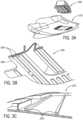
FIGURE 1A is a schematic perspective view of a vehicle according to an exemplary embodiment.FIGURE 1B is a schematic perspective cut-away view of a vehicle showing a vehicle interior according to an exemplary embodiment.FIGURE 1C is a schematic perspective view of a vehicle trim component shown as an instrument panel according to an exemplary embodiment.FIGURES 1D through 1F are schematic perspective detail views of an airbag deployment according to an exemplary embodiment.FIGURE 2A is a schematic perspective view of a vehicle trim component according to an exemplary embodiment.FIGURE 2B is a schematic exploded perspective view of a vehicle trim component according to an exemplary embodiment.FIGURE 2C is a schematic bottom perspective view of a structural substrate of a vehicle trim component according to an exemplary embodimentFIGURE 2D is a schematic bottom perspective cut-away view of a structural substrate of a vehicle trim component according to an exemplary embodiment.FIGURE 3A is a schematic exploded perspective view of a vehicle trim component according to an exemplary embodiment.FIGURE 3B is a schematic partial perspective view of an airbag chute according to an exemplary embodiment.FIGURE 3C is a schematic partial perspective view of a structural substrate of a vehicle interior component according to an exemplary embodiment.FIGURES 4A through 4G are schematic perspective views of a process to form a structural substrate of a vehicle trim component according to an exemplary embodiment.FIGURES 5A through 5D are schematic partial section views of a process to form a vehicle trim component according to an exemplary embodiment.FIGURES 6A through 6C are schematic partial section views of a process to form a vehicle trim component according to an exemplary embodiment.FIGURES 7A through 7B are schematic partial section views of a process to form a vehicle trim component according to an exemplary embodiment.FIGURES 8A through 8B are schematic partial section views of a process to form a vehicle trim component according to an exemplary embodiment.FIGURE 9A is a schematic section view of a vehicle trim component according to an exemplary embodiment.FIGURE 9B is a schematic cut-away section view of a vehicle trim component according to an exemplary embodiment.FIGURES 9C through 9D are schematic cut-away section views of a deployment of an airbag through a vehicle trim component according to an exemplary embodiment.FIGURE 10A is a schematic flow diagram of a method for forming a vehicle interior component according to an exemplary embodiment.FIGURE 10B is a schematic flow diagram of a method for forming a vehicle interior component according to an exemplary embodiment.FIGURES 11A and 11B are schematic flow diagrams of a method for forming a vehicle interior component according to an exemplary embodiment.- Referring to
FIGURES 1A and 1B , a vehicle V is shown including an interior I with an instrument panel IP, doors D and a floor console FC. According to an exemplary embodiment, interior components of vehicle V such as instrument panel IP and doors D may include trim panels comprised of fiber and plastic. According to an exemplary embodiment, instrument panel IP and doors D may provide visible surfaces in the vehicle interior of vehicle V. According to an exemplary embodiment, instrument panel IP and/or doors D may provide at least one airbag behind the visible surfaces; instrument panel IP and/or doors D may provide a weakened area to aid the airbag in breaking through the trim panel during airbag deployment. SeeFIGURES 1D-1F . - According to an exemplary embodiment as shown schematically in
FIGURES 1C-1F , a component for a vehicle interior (such as a trim panel, instrument panel, etc.) may be configured to provide/support a module with an airbag configured to be deployed through an opening into the vehicle interior. See alsoFIGURES 3A and9A-9D . As shown schematically inFIGURES 1C-1F , instrument panel IP may provide a weakened shape/zone shown as a recess R to facilitate an airbag AB deployment through an airbag door ABD. According to an exemplary embodiment, the weakened shape/zone may comprise at least one of a recess or a score line behind the visible surface of instrument panel IP. The weakened shape/zone may comprise an "H" shape pattern. According to an exemplary embodiment, the weakened shape/zone may comprise a "U" shape pattern, a "bow tie" shape pattern, or any pattern suitable for airbag deployment. - As shown schematically according to an exemplary embodiment in
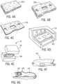
FIGURES 2A-2D , thecomponent 1000 may comprise astructural substrate 210 and anairbag chute 100 and a structure/interface between the structural substrate and the airbag chute configured to couple the airbag chute to the structural substrate (e.g. features shown as arib 210r injection molded onto the structural substrate, features 100r on the airbag chute, etc.). See alsoFIGURES 3A-3C . - As shown schematically according to an exemplary embodiment in
FIGURES 2A-2B ,3A and6A-6C , theairbag chute 100 may be welded to form a bond/interface at the structure to bond to thestructural substrate 210 and/or the airbag chute may be welded to form a bond/interface at the structure and thestructural substrate 210. See e.g.FIGURES 6B-6C (showing bond/interface established betweenairbag chute 100 and structural substrate 210). - As shown schematically according to an exemplary embodiment in
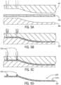
FIGURES 1C-1F ,2A-2D and3A-3C , the component (e.g. trim/instrument panel IP) may comprise a structural substrate and a structure coupled to the structural substrate and configured to facilitate deployment of the airbag (shown as an airbag chute 100); and an interface may be provided to couple the structural substrate and the airbag chute (e.g. structure configured to facilitate deployment of the airbag); the interface may comprise a feature on the structural substrate and/or a feature on the structure configured to facilitate deployment of the airbag. See e.g.FIGURES 5A-5D ,6A-6C ,7A-7B and 8A-8B . As indicated schematically according to an exemplary embodiment, the interface may comprise a bond configured to attach the structure configured to facilitate deployment of the airbag to the structural substrate; the bond of the interface may comprise a weld (e.g. ultrasonic weld, etc.). See e.g.FIGURES 6A-6C ,7A-7B and 8A-8B . As indicated schematically according to an exemplary embodiment, the interface may comprise a bond to a surface of the structural substrate; the interface may comprise a feature on the structural substrate and a feature on the structure configured to facilitate deployment of the airbag; the interface may comprise (a) a bond between the feature the structural substrate and the feature on the structure configured to facilitate deployment of the airbag; and (b) a bond to a surface of the structural substrate. See e.g.FIGURES 6A-6C ,7A-7B ,8A-8B and9A-9D . As indicated schematically according to an exemplary embodiment, the bond may comprise at least one of a weld and/or an adhesive; the interface may comprise at least one molded feature and/or a mounting area on the structural substrate. See e.g.FIGURES 6C ,7B ,8B and9B . - As shown schematically according to an exemplary embodiment in
FIGURES 7A-7B and 8A-8B , theairbag chute 100x may comprise members such as a flange and/or set offlanges 100f (e.g. providing a feature such as a rib); the structure/features shown asribs 210r may be positioned between thestructural substrate 210/210x and the members/flange 100f of theairbag chute 210. As shown schematically according to an exemplary embodiment, a member/flange may comprise a rib; a rib injection may be molded onto the structural substrate; the rib arrangement may comprise an interface configured to bond the airbag chute to the structural substrate. SeeFIGURES 3A-3C ,7A-7B and 8A-8B (bond at interface established between feature shown asflange 100f ofairbag chute 100x and features 210r shown as ribs ofstructural substrate 210/210x). - As shown schematically according to an exemplary embodiment in
FIGURES 4A-4G and5A-5D , thestructural substrate 210 may comprise a panel comprised at least partially of fibers; the structure for the interface shown asfeatures 210r may be comprised of resin. See alsoFIGURES 3C and9A-9D . According to an exemplary embodiment indicated schematically, the structural substrate may comprise a fiber panel and/or a material comprising fibers; the airbag chute may comprise a plastic/resin material such as thermoplastic polyolefin; the structure/interface may comprise a resin material such as polypropylene (which may also comprise fibers such as structural fibers). - As shown schematically according to an exemplary embodiment in
FIGURES 4A-4G and5A-5D , thestructural substrate 210 may comprise afiber panel 202t/202u; the structural substrate may comprise a compression formed component formed from thefiber panel 202t. As shown schematically according to an exemplary embodiment inFIGURES 9A-9D , thecomponent 1000 may comprise a composite structure (e.g. to provide a trim component/panel shown as instrument panel IP with cover/surface) comprising the structural substrate 210 (e.g. with features such asribs 210r and/or border 210b) and interface/bond to the airbag chute 100 (e.g. the structure configured to facilitate deployment of the airbag). See alsoFIGURES 1D-1F and3A (structure configured to facilitate deployment of the airbag may comprise an airbag chute configured to facilitate deployment of the airbag from the airbag module). As shown schematically according to an exemplary embodiment inFIGURES 6C ,7B ,8B and9B , the interface may comprise at least one of a bond (e.g. attachment, weld, ultrasonic weld, etc.) of theairbag chute 100/100x to thestructural substrate 210/210x. As shown schematically according to an exemplary embodiment inFIGURES 7A-7B and 8A-8B , the interface may comprise afeature 100f on theairbag chute 100; the interface may comprise afeature 210r molded onto the structural substrate. As indicated schematically according to an exemplary embodiment, the interface may comprise a structure; the structure may comprise an interface configured to bond the airbag chute to the structural substrate. See e.g.FIGURES 3A-3C . As indicated schematically according to an exemplary embodiment, the structure of the interface may comprise at least one of (a) a composite material; (b) a resin material; (c) a material comprising fibers; (d) polypropylene with fibers. As shown schematically according to an exemplary embodiment inFIGURES 9A-9D , the component may comprise a composite structure comprising the structural substrate and the structure configured to facilitate deployment of the airbag; the structure configured to facilitate deployment of the airbag may comprise an airbag chute; the airbag module may be configured to deploy the airbag through an opening in the composite structure; the interface may comprise a feature of the airbag chute; the feature may comprise at least one flange; the interface may be between the structural substrate and the at least one flange of the airbag chute. See e.g.FIGURES 1D-1F . - According to an exemplary embodiment as indicated schematically in
FIGURES 1D-1F ,2A-2D ,3A-3C ,4A-4G ,5A-5D ,6A-6C ,7A-7B, 8A-8B and9A-9D , the component for a vehicle interior configured to provide a module with an airbag configured to be deployed through an opening into the vehicle interior comprising a structural substrate an airbag chute and an interface configured to couple the structural substrate and the airbag chute; the interface may comprise a feature on the structural substrate. The substrate may comprise a compression-formed component formed from a fiber panel; the interface may comprise (a) a bond of the feature to the structural substrate and (b) coupling the airbag chute to the feature. See e.g.FIGURES 4A-4G ,6C ,7B and 8B . The bond may comprise injection molding of the feature to the structural substrate. See e.g.FIGURES 5A-5D . As indicated schematically inFIGURES 6C ,7B and 8B , the interface may comprise a bond comprising at least one of a weld and/or an adhesive; the interface may comprise a bond configured to attach the feature to the surface of the structural substrate; the interface may comprise (a) a bond between the feature the structural substrate and a feature of the airbag chute; and (b) a bond to a surface of the structural substrate; the interface may comprise at least one molded feature; the interface may comprise a structure; the structure of the interface may comprise at least one of (a) a composite material; (b) a resin material; (c) a material comprising fibers; (d) polypropylene with fibers; (e) a material molded onto the structural substrate. As indicated schematically inFIGURES 9A-9B , the component may comprise a composite structure comprising the structural substrate and the airbag chute; the airbag module may be configured to deploy the airbag through an opening in the composite structure. As indicated schematically according to an exemplary embodiment, the interface may comprise the feature and a mounting area on the structural substrate; the interface may comprise the feature on the structural substrate and a feature of the airbag chute; the interface may comprise a bond configured to attach the feature of the airbag chute to the structural substrate; the feature of the airbag chute may comprise at least one flange; the interface may comprise a bond to a surface of the structural substrate. See e.g.FIGURES 4A-4G ,6C ,7B and 8B . - As shown schematically according to an exemplary embodiment, the interface may comprise at least one of (a) a molded feature on the structural substrate; (b) a resin feature on the structural substrate; (c) a mounting area on the structural substrate; (d) a structure injection molded on the structural substrate; (e) a rib; (f) a set of ribs; (g) a rib injection molded onto the structural substrate; (b) a flange on airbag chute; (i) a weld; (j) an ultrasonic weld; (k) a bond; (l) an attachment; (m) a composite material; (n) a resin material; (o) a material comprising fibers; (p) polypropylene with fibers; (q) a material molded onto the structural substrate. See e.g.
FIGURES 3A-3C ,5A-5D ,6A-6C ,7A-7B ,8A-8B and9B . - As shown schematically according to an exemplary embodiment in
FIGURES 1B and9A , the component may comprise at least one of (a) a trim component; (b) an instrument panel; (c) a trim panel. - According to an exemplary embodiment as indicated schematically in
FIGURES 1D-1F ,2A-2D ,3A-3C ,4A-4G ,5A-5D ,6A-6C ,7A-7B, 8A-8B and9A-9D , acomponent 1000 for a vehicle interior configured to support an airbag module providing an airbag configured to be deployed through an opening into the vehicle interior may comprise astructural substrate 210, anairbag chute 100/100x and astructure 300 between thestructural substrate 210 and theairbag chute 100/100x; thestructure 300 may be configured to couple theairbag chute 100/100x to thestructural substrate 210. Thestructure 300 may be configured to couple theairbag chute 100/100x to thestructural substrate 210 during deployment of the airbag. Thestructure 300 may comprise arib 210r injection molded onto thestructural substrate 210. Thestructure 300 may be bonded to thestructural substrate 210. Theairbag chute 100/100x may be welded to thestructure 300. Theairbag chute 100/100x may be welded to thestructure 300 and thestructural substrate 210. Thestructural substrate 210 may comprise a panel comprised at least partially of fibers; thestructure 300 may be comprised of resin. Thestructural substrate 210 may comprise a first material; theairbag chute 100/100x may comprise a second material; thestructure 300 may comprise a third material; the third material may be different than the first material and the second material. The first material may comprise a composite comprising fibers; the second material may comprise thermoplastic polyolefin; the third material may comprise a resin. Thestructural substrate 210 may comprise a fiber panel; theairbag chute 100/100x may comprise a thermoplastic polyolefin; thestructure 300 may comprise polypropylene. Thestructure 300 may comprise polypropylene filled with structural fibers. Theairbag chute 100/100x may be welded to thestructural substrate 210; theairbag chute 100/100x may be welded to thestructure 300. Thestructure 300 may comprise a composite comprising fibers; the fibers may be configured to reinforce an interface between theairbag chute 100/100x and thestructural substrate 210. Theairbag chute 100/100x may comprise at least oneflange 100f; thestructure 300 may be positioned between thestructural substrate 210 and the at least oneflange 100f of theairbag chute 100/100x. Theairbag chute 100/100x may comprise a first flange and a second flange; the first flange may comprise arib 100r; the second flange may comprise arib 100r; thestructure 300 may comprise therib 100r of the first flange; therib 100r of the second flange, arib 210r injection molded onto thestructural substrate 210 adjacent therib 100r of the first flange; and arib 210r injection molded onto thestructural substrate 210 adjacent therib 100r of the second flange. Therib 210r injection molded onto thestructural substrate 210 adjacent therib 100r of the first flange may comprise a set ofribs 210r surrounding therib 100r of the first flange. Therib 100r of the first flange may comprise a height; therib 210r injection molded onto thestructural substrate 210 adjacent therib 100r of the first flange may comprise a height; the height of therib 100r of the first flange may be generally the same as the height of therib 210r injection molded onto thestructural substrate 210 adjacent therib 100r of the first flange. Thestructure 300 may comprise an interface configured to bond theairbag chute 100/100x to thestructural substrate 210. Thecomponent 1000 may comprise at least one of (a) a trim component; (b) an instrument panel; (c) a trim panel. - According to an exemplary embodiment as shown schematically in
FIGURES 10A-10B and11A-11B , the component for a vehicle interior configured to support an airbag module providing an airbag for deployment through an opening into the vehicle interior may be manufactured/produced by a process comprising the steps of: (a) providing a fiber panel; (b) compressing the fiber panel in the mold; (c) forming a feature on the structural substrate; and (d) joining an airbag chute to the structural substrate. See alsoFIGURES 1B-1C ,2A -2 and 9A-9D. As shown schematically according to an exemplary embodiment inFIGURES 3A-3C ,5A-5D ,6A-6C ,7A-7B ,8A-8B and9A-9B , the feature may be configured to couple the airbag chute to the structural substrate; the step of forming a feature on the structural substrate may comprise forming a structure for joining the airbag chute to the structural substrate; the feature may comprise an injection-molded structure. See e.g.FIGURES 5A-5D . As indicated schematically according to an exemplary embodiment, the step of joining an airbag chute may comprise welding the airbag chute to the structure; the step of joining an airbag chute may comprise welding the airbag chute to the structural substrate. See e.g.FIGURES 6C ,7B and 8B . As shown schematically according to an exemplary embodiment inFIGURES 4A-4E , the step of compressing the fiber panel in the mold may comprise compressing the fiber panel into a structural substrate having a shape. See alsoFIGURES 10A-10B and11A-11B . As shown indicated schematically according to an exemplary embodiment inFIGURES 10A-10B and11A , the process may comprise the step of forming a composite structure for thecomponent 1000 comprising a cover C on thestructural substrate 210. See e.g.FIGURES 1C and9A . - According to an exemplary embodiment as shown schematically in
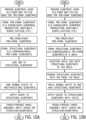
FIGURE 8A , a method of manufacturing avehicle trim component 1000 may comprise the steps of providing a substrate layer (e.g. fiber mat, etc.) as a base for a pre-form substrate, forming the pre-form substrate (e.g. consolidating, compressing, merging/fusing, heating/melting, shaping, cutting/sizing, etc.), pre-treating/heating the pre-form substrate, forming the structural substrate (e.g. compressing/molding the pre-form substrate), joining a rib to the structural substrate, joining an airbag chute to the rib/structural substrate, applying a cover to the structural substrate and finishing/providing a panel assembly (with the cover on the structure/substrate). - According to an exemplary embodiment as shown schematically in
FIGURE 8B , a method of manufacturing avehicle trim component 1000 may comprise the steps of providing a substrate layer (e.g. fiber mat, etc.) as a base for a pre-form substrate, forming the pre-form substrate (e.g. consolidating, compressing, merging/fusing, heating/melting, shaping, cutting/sizing, etc.), pre-treating/heating the pre-form substrate, forming the structural substrate (e.g. compressing/molding the pre-form substrate) in a mold, injection molding a rib onto the structural substrate in the mold, removing the structural substrate with the rib from the mold, applying a cover to the structural substrate with the chute and finishing/providing a panel assembly (with the cover on the structure/substrate). - According to an exemplary embodiment as shown schematically in
FIGURES 9A and 9B , a method of manufacturing avehicle trim component 1000 may comprise the steps of provide fiber mat, forming a pre-form substrate, heating the pre-form substrate, forming a structural substrate in a mold, injection molding a rib onto the structural substrate in the mold, removing the structural substrate with the rib from the mold, welding an airbag chute to the rib and the structural substrate, applying a cover to the structural substrate with the chute and finishing/providing a panel assembly (with the cover on the structure/substrate). - According to an exemplary embodiment as shown schematically in
FIGURE 4A , afiber mat 202u may comprise a combination of fibers (e.g. natural and/or synthetic fibers) and thermoplastic resin (e.g. polypropylene (PP), acrylonitrile butadiene styrene (ABS), polycarbonate (PC), etc.). According to an exemplary embodiment as shown schematically inFIGURE 4B ,fiber mat 202u may be trimmed into afiber mat 202t having a thickness. According to an exemplary embodiment,fiber mat 202t may be heated to induce the thermoplastic resin to liquefy. According to an exemplary embodiment as shown schematically inFIGURE 4C ,heated fiber mat 202t may be partially compressed into afiber panel 202 having a thickness less than the thickness offiber mat 202t. According to an exemplary embodiment as shown schematically inFIGURE 4D ,fiber panel 202 may be heated in an oven OV. As shown schematically inFIGURE 4E ,heated fiber panel 202 may be transferred into a mold having a mold top MT and mold bottom MB. According to an exemplary embodiment as shown schematically inFIGURE 4F , a component shown as aninstrument panel substrate 200 may be produced by a process of compression formingheated fiber panel 202 into astructural substrate 210 and injection molding resin onto compression formedheated fiber panel 202. - According to an exemplary embodiment,
instrument panel substrate 200 may provide a plastic rib on a back side ofstructural substrate 210 to improve structural integrity and rigidity ofstructural substrate 210.Structural substrate 210 may be configured to support anairbag chute 100 and an airbag module comprising an airbag. As shown schematically inFIGURE 7A ,structural substrate 210 may comprise aborder 220b to provide reinforcement and/or dimensional accuracy forstructural substrate 210. According to an exemplary embodiment, a plastic rib may be placed at any location on structural substrate 210 (e.g. along an edge ofstructural substrate 210, in the middle ofstructural substrate 210, etc.). According to an exemplary embodiment, multiple plastic ribs may be placed at various different locations onstructural substrate 210. According to an exemplary embodiment, a plastic rib may improve structural integrity ofinstrument panel substrate 200. According to an exemplary embodiment,instrument panel substrate 200 may be able to maintain structural integrity during an airbag deployment; the position/placement of a plastic rib may be intended to create a strength differential between different areas ofinstrument panel substrate 200; energy needed for an airbag to break through avehicle interior component 1000 may be directed to arecess 210r ofstructural substrate 210; a plastic rib may prevent or minimize ripping or tearing ofstructural substrate 210 at any location other than atrecess 210r during an airbag deployment. A plastic rib forming a honeycomb shaped pattern may improve structural integrity and rigidity. According to an exemplary embodiment, a plastic rib may be formed in any configuration according to a specific application (e.g. ancillary features for attaching air vents, speakers or infotainment system, etc.). According to an exemplary embodiment as shown schematically inFIGURE 2B , atrim component 1000 for a vehicle interior may compriseairbag chute 100 andinstrument panel substrate 200. - According to an exemplary embodiment as shown schematically in
FIGURES 7A -7D, atrim component 1000 for a vehicle interior may be configured to support an airbag module providing an airbag AB configured to be deployed through an opening into the vehicle interior.Trim component 1000 may comprise astructural substrate 210 providing a front side, a back side and at least one door established upon deployment of the airbag to facilitate deployment of the airbag from the airbag module through the opening, anairbag chute 100 and astructure 300 positioned betweenstructural substrate 210 andairbag chute 100.Structure 300 may be configured to secureairbag chute 100 tostructural substrate 210.Structure 300 may be configured to secureairbag chute 100 tostructural substrate 210 during deployment of airbag AB.Structure 300 may comprise a rib injection molded onto the back side ofstructural substrate 210.Structure 300 may be bonded tostructural substrate 210.Structural substrate 210 may comprise a panel comprised at least partially of fibers;structure 300 may be comprised of resin.Structural substrate 210 may comprise a fiber panel;airbag chute 100 may comprise a thermoplastic polyolefin;structure 300 may comprise polypropylene.Structure 300 may comprise polypropylene filled with structural fibers.Airbag chute 100 may be welded tostructure 300.Airbag chute 100 may be welded tostructural substrate 210.Structure 300 may comprise a composite comprising fibers; the fibers may be configured to reinforce an interface betweenairbag chute 100 andstructural substrate 210.Airbag chute 100 may comprise at least oneflange 100f;structure 300 may be positioned betweenstructural substrate 210 and the at least oneflange 100f ofairbag chute 100. - According to an exemplary embodiment as shown schematically in
FIGURES 2A-2D ,4A-4G , and7A -7D, atrim component 1000 for a vehicle interior configured to support an airbag module providing an airbag AB for deployment through an opening into the vehicle interior may be prepared using a mold M by a process comprising the steps of providing afiber panel 202; disposingfiber panel 202 onto a first surface of mold M; compressingfiber panel 202 between the first surface and a second surface of mold M to formfiber panel 202 into astructural substrate 210 having a shape corresponding to a first contour of the first surface and a second contour of the second surface; molding astructure 300 on a side ofstructural substrate 210; and joining anairbag chute 100 to structure 300.Structure 300 may be configured to secureairbag chute 100 tostructural substrate 210.Structure 300 may be configured to secureairbag chute 100 tostructural substrate 210 during deployment of airbag AB.Molding structure 300 on a side ofstructural substrate 210 may comprise injecting resin into mold M. Joiningairbag chute 100 to structure 300 may comprise weldingairbag chute 100 to structure 300. Joiningairbag chute 100 to structure 300 may comprise weldingairbag chute 100 tostructural substrate 210. - According to an exemplary embodiment as shown schematically in
FIGURES 2A-2D ,4A-4G and7A -7D, a method of manufacturing avehicle trim component 1000 configured to support an airbag module providing an airbag AB for deployment from the airbag module through an opening into the vehicle interior may comprise the steps of providing afiber panel 202; disposingfiber panel 202 onto a first surface of a mold M; compressingfiber panel 202 between the first surface and a second surface of mold M to formfiber panel 202 into astructural substrate 210 having a shape corresponding to a first contour of the first surface and a second contour of the second surface; molding astructure 300 on a side ofstructural substrate 210; and joining anairbag chute 100 to structure 300.Structure 300 may be configured to secureairbag chute 100 tostructural substrate 210. Molding astructure 300 on a side ofstructural substrate 210 may comprise injecting resin into mold M. Joiningairbag chute 100 to structure 300 may comprise weldingairbag chute 100 to structure 300. Joiningairbag chute 100 to structure 300 may comprise weldingairbag chute 100 tostructural substrate 210. - According to an exemplary embodiment disclosed is a component for a vehicle interior configured to provide a module with an airbag configured to be deployed through an opening into the vehicle interior comprising a structural substrate, an airbag chute and an interface configured to couple the structural substrate and the airbag chute; the interface may comprise a feature on the structural substrate. The substrate may comprise a compression-formed component formed from a fiber panel. The interface may comprise (a) a bond of the feature to the structural substrate and (b) coupling the airbag chute to the feature. The bond may comprise injection molding of the feature to the structural substrate. The interface may comprise a bond comprising at least one of a weld and/or an adhesive. The interface may comprise a bond configured to attach the feature to the surface of the structural substrate. The interface may comprise (a) a bond between the feature on the structural substrate and a feature of the airbag chute; and (b) a bond to a surface of the structural substrate. The interface may comprise at least one molded feature. The interface may comprise a structure; the structure of the interface may comprise at least one of (a) a composite material; (b) a resin material; (c) a material comprising fibers; (d) polypropylene with fibers; (e) a material molded onto the structural substrate. The component may comprise a composite structure comprising the structural substrate and the airbag chute; the airbag module may be configured to deploy the airbag through an opening in the composite structure. The interface may comprise the feature and a mounting area on the structural substrate. The interface may comprise the feature on the structural substrate and a feature of the airbag chute. The interface may comprise a bond configured to attach the feature of the airbag chute to the structural substrate; the feature of the airbag chute may comprise at least one flange. The interface may comprise a bond to a surface of the structural substrate. The interface may comprise at least one of (a) a molded feature on the structural substrate; (b) a resin feature on the structural substrate; (c) a mounting area on the structural substrate; (d) a structure injection molded on the structural substrate; (e) a rib; (f) a set of ribs; (g) a rib injection molded onto the structural substrate; (h) a flange on airbag chute; (i) a weld; (j) an ultrasonic weld; (k) a bond; (I) an attachment; (m) a composite material; (n) a resin material; (o) a material comprising fibers; (p) polypropylene with fibers; (q) a material molded onto the structural substrate. The component may comprise at least one of (a) a trim component; (b) an instrument panel; (c) a trim panel. According to an exemplary embodiment disclosed is a component for a vehicle interior configured to support an airbag module providing an airbag for deployment through an opening into the vehicle interior prepared using a mold by a process comprising the steps of: (a) providing a fiber panel; (b) compressing the fiber panel in the mold; (c) forming a feature on the structural substrate; and (d) joining an airbag chute to the structural substrate. The feature may be configured to couple the airbag chute to the structural substrate. The step of forming a feature on the structural substrate may comprise forming a structure for joining the airbag chute to the structural substrate. The feature may comprise an injection-molded structure. The step of joining an airbag chute to the structural substrate may comprise welding the airbag chute to the structure. The step of joining an airbag chute to the structural substrate may comprise welding the airbag chute to the structural substrate. The step of compressing the fiber panel in the mold may comprise compressing the fiber panel into a structural substrate having a shape. The process may comprise the step of forming a composite structure comprising a cover on the structural substrate.
- According to an exemplary embodiment disclosed is a trim component for a vehicle interior configured to support an airbag module providing an airbag configured to be deployed through an opening into the vehicle interior. The trim component may comprise a structural substrate providing a front side, a back side and at least one door established upon deployment of the airbag to facilitate deployment of the airbag from the airbag module through the opening, an airbag chute and a structure positioned between the structural substrate and the airbag chute. The structure may be configured to secure the airbag chute to the structural substrate. The structure may be configured to secure the airbag chute to the structural substrate during deployment of the airbag. The structure may comprise a rib injection molded onto the back side of the structural substrate. The structure may be bonded to the structural substrate. The structural substrate may comprise a panel comprised at least partially of fibers; the reinforcement may be comprised of resin. The structural substrate may comprise a fiber panel; the airbag chute may comprise a thermoplastic polyolefin; the structure may comprise polypropylene. The structure may comprise polypropylene filled with structural fibers. The airbag chute may be welded to the structure. The airbag chute may be welded to the structural substrate. The structure may comprise a composite comprising fibers; the fibers may be configured to reinforce an interface between the airbag chute and the structural substrate. The airbag chute may comprise at least one flange; the structure may be positioned between the structural substrate and the at least one flange of the airbag chute.
- According to an exemplary embodiment disclosed is a trim component for a vehicle interior configured to support an airbag module providing an airbag for deployment through an opening into the vehicle interior prepared using a mold by a process comprising the steps of providing a fiber panel; disposing the fiber panel onto a first surface of the mold; compressing the fiber panel between the first surface and a second surface of the mold to form the fiber panel into a structural substrate having a shape corresponding to a first contour of the first surface and a second contour of the second surface; molding a structure on a side of the structural substrate; and joining an airbag chute to the structure. The structure may be configured to secure the airbag chute to the structural substrate. The structure may be configured to secure the airbag chute to the structural substrate during deployment of the airbag. Molding the structure on a side of the structural substrate may comprise injecting resin into the mold. Joining an airbag chute to the structure may comprise welding the airbag chute to the structure. Joining an airbag chute to the structure may comprise welding the airbag chute to the structural substrate.
- According to an exemplary embodiment disclosed is a method of manufacturing a vehicle trim component configured to support an airbag module providing an airbag for deployment from the airbag module through an opening into the vehicle interior comprising the steps of providing a fiber panel; disposing the fiber panel onto a first surface of a mold; compressing the fiber panel between the first surface and a second surface of the mold to form the fiber panel into a structural substrate having a shape corresponding to a first contour of the first surface and a second contour of the second surface; molding a structure on a side of the structural substrate; and joining an airbag chute to the structure. The structure may be configured to secure the airbag chute to the structural substrate. Molding a structure on a side of the structural substrate may comprise injecting resin into the mold. Joining an airbag chute to the structure may comprise welding the airbag chute to the structure. Joining an airbag chute to the structure may comprise welding the airbag chute to the structural substrate.
- The present application relates to (a)
U.S. Patent Application No. 13/595,741 titled "SYSTEM AND METHOD FOR MANUFACTURING A VEHICLE TRIM COMPONENT VIA CONCURRENT COMPRESSION FORMING AND INJECTION MOLDING" filed August 27, 2012 U.S. Patent No. 8,939,745 ); (b)U.S. Patent Application No. 13/846,529 titled "SYSTEM AND METHOD FOR MANUFACTURING A VEHICLE TRIM COMPONENT VIA CONCURRENT COMPRESSION FORMING AND INJECTION MOLDING" filed on March 18, 2013 U.S. Patent No. 9,149,961 U.S. Patent Application No. 14/808,938 titled "VEHICLE TRIM COMPONENT" filed July 24, 2015 U.S. Patent No. 10,118,325 - It
- The extent of the protection conferred by the patent shall be determined by the appended claims. Nevertheless, the description and drawings shall be used to interpret these claims.
Claims (13)
- A component (1000) for a vehicle interior configured to support an airbag module providing an airbag (AB) configured to be deployed into the vehicle interior comprising:- a structural substrate (210);- an airbag chute (100, 100x); and- a structure (300) between the structural substrate (210) and the airbag chute (100, 100x);wherein the structure (300) is configured to couple the airbag chute (100, 100x) to the structural substrate (210);wherein the structural substrate (210) comprises a first material; wherein the airbag chute (100, 100x) comprises a second material; wherein the structure (300) comprises a third material; wherein the third material is different than the first material and the second material;wherein the structure (300) comprises a rib (210r), wherein the rib is injection molded onto the structural substrate (210);wherein the airbag chute (100, 100x) is welded to the structure (300); and wherein the structure is bonded to the structural substrate.
- The component (1000) of Claim 1 wherein the structure (300) is configured to couple the airbag chute (100, 100x) to the structural substrate (210) during deployment of the airbag.
- The component (1000) of one of Claims 1 to 2 wherein the airbag chute (100, 100x) is welded to the structural substrate (210).
- The component (1000) of one of Claims 1 to 3 wherein the structural substrate (210) comprises a panel (202, 202t, 202u) comprised at least partially of fibers; wherein the structure (300) is comprised of resin.
- The component (1000) one of Claims 1 to 4 wherein the first material comprises a composite comprising fibers; wherein the third material comprises a resin.
- The component (1000) of one of Claims 1 to 5 wherein the structural substrate (210) comprises a fiber panel (202, 202t, 202u); wherein the structure (300) comprises polypropylene.
- The component (1000) of one of Claims 1 to 6 wherein the airbag chute (100, 100x) comprises at least one flange (100f); wherein the structure (300) is positioned between the structural substrate (210) and the at least one flange (100f) of the airbag chute (100, 100x).
- The component (1000) of Claim 7 wherein the flange (100f) comprises a rib (100r) comprising a height;wherein the structure (300) comprises a height;wherein the height of the rib (100r) of the flange (100f) and the height of the structure (300) are substantially the same height.
- The component (1000) of one of Claims 1 to 8 wherein the structure (300) comprises an interface configured to bond the airbag chute (100, 100x) to the structural substrate (210).
- The component (1000) of one of Claims 1 to 9 wherein the structural substrate (210) comprises a compression-formed component (1000) formed from a fiber panel (202, 202t, 202u).
- The component (1000) of one of Claims 1 to 10 comprising at least one of (a) a trim component; (b) an instrument panel (IP); (c) a trim panel.
- A method of manufacturing a vehicle component (1000) configured to support an airbag module providing an airbag for deployment from the airbag module through an opening into the vehicle interior comprising the steps of:(a) providing a fiber panel (202, 202t, 202u);(b) compressing the fiber panel (202, 202t, 202u) in a mold to form a structural substrate (210);(c) molding a structure (300) on the structural substrate (210), said structure being made of a material different to a material of the fiber panel; and(d) joining an airbag chute (100, 100x) to the structure (300);wherein the structure (300) is configured to couple the airbag chute (100, 100x) to the structural substrate (210);wherein the structure comprises a rib (210r) that is injection molded onto the structural substrate (210);wherein the step of joining an airbag chute to the structure comprises welding the airbag chute (100, 100x) to the structure (300); andwherein the structure is bonded to the structural substrate.
- The method of Claim 12 further comprising the step of welding the airbag chute (100, 100x) to the structural substrate (210).
Applications Claiming Priority (2)
| Application Number | Priority Date | Filing Date | Title |
|---|---|---|---|
| US201862691584P | 2018-06-28 | 2018-06-28 | |
| PCT/US2019/039590WO2020006290A1 (en) | 2018-06-28 | 2019-06-27 | Vehicle trim component |
Publications (3)
| Publication Number | Publication Date |
|---|---|
| EP3814176A1 EP3814176A1 (en) | 2021-05-05 |
| EP3814176A4 EP3814176A4 (en) | 2021-12-15 |
| EP3814176B1true EP3814176B1 (en) | 2024-02-21 |
Family
ID=68985174
Family Applications (1)
| Application Number | Title | Priority Date | Filing Date |
|---|---|---|---|
| EP19826875.7AActiveEP3814176B1 (en) | 2018-06-28 | 2019-06-27 | Vehicle trim component |
Country Status (4)
| Country | Link |
|---|---|
| US (1) | US10981532B2 (en) |
| EP (1) | EP3814176B1 (en) |
| CN (1) | CN112243416B (en) |
| WO (1) | WO2020006290A1 (en) |
Families Citing this family (11)
| Publication number | Priority date | Publication date | Assignee | Title |
|---|---|---|---|---|
| DE102018006706A1 (en)* | 2018-08-24 | 2020-02-27 | K.L. Kaschier- Und Laminier Gmbh | Airbag cover assembly |
| US11560111B2 (en) | 2019-03-29 | 2023-01-24 | Mcpp Innovation Llc | All TPO airbag assemblies |
| CN115362097A (en) | 2020-04-15 | 2022-11-18 | 上海延锋金桥汽车饰件系统有限公司 | vehicle interior parts |
| EP4301630A4 (en) | 2021-03-01 | 2025-01-01 | Yanfeng Global Automotive Interior Systems Co. Ltd | Component for vehicle interior |
| WO2022265978A1 (en)* | 2021-06-14 | 2022-12-22 | Yanfeng Automotive Safety Systems Co. Ltd | Component for vehicle interior |
| DE102022101281A1 (en)* | 2022-01-20 | 2023-07-20 | Lisa Dräxlmaier GmbH | INTERIOR COMPONENT FOR VEHICLES |
| EP4519125A1 (en)* | 2022-05-06 | 2025-03-12 | Yanfeng International Automotive Technology Co., Ltd | Component for vehicle interior |
| USD1030607S1 (en)* | 2022-06-07 | 2024-06-11 | Taylor Made Group, Llc | Frameless top trim |
| WO2024118844A1 (en) | 2022-11-30 | 2024-06-06 | Yanfeng International Automotive Technology Co., Ltd. | Component for vehicle interior |
| WO2024229450A1 (en)* | 2023-05-04 | 2024-11-07 | Yanfeng International Automotive Technology Co., Ltd. | Component for vehicle interior |
| WO2025090987A1 (en)* | 2023-10-26 | 2025-05-01 | Yanfeng International Automotive Technology Co. Ltd. | Component for vehicle interior |
Family Cites Families (192)
| Publication number | Priority date | Publication date | Assignee | Title |
|---|---|---|---|---|
| DE1107396B (en) | 1954-12-14 | 1961-05-25 | Richard Jonke | Process for the production of reinforced or stiffened plastic molded parts by injection molding |
| GB1352341A (en) | 1970-06-26 | 1974-05-08 | Gkn Sankey Ltd | Manufacture of articles |
| DE2122581A1 (en) | 1971-05-07 | 1972-11-16 | Farbenfabriken Bayer Ag, 5090 Leverkusen | High duty plastic foam - moulded onto reinforced boundary layer previously moulded under vacuum |
| US4015872A (en) | 1975-06-25 | 1977-04-05 | Loznak Edward J | Impaling transfer process and apparatus |
| FR2337030A1 (en) | 1976-01-02 | 1977-07-29 | Michelin & Cie | TIRE MOLDING MEMBRANE AND ITS MANUFACTURING PROCESS |
| US4124242A (en) | 1977-05-09 | 1978-11-07 | Sterling Detroit Company | Method and apparatus for loading presses |
| CA1117266A (en) | 1978-12-29 | 1982-02-02 | Sigurdur I. Arnason | In-the-mold coating method |
| DE3229150C2 (en) | 1982-08-04 | 1986-04-10 | Helmut 6780 Pirmasens Schaefer | Method and device for dressing split leather |
| US4576560A (en) | 1984-11-15 | 1986-03-18 | General Motors Corporation | SMC Loader for compression molding press |
| US5000990A (en) | 1985-08-22 | 1991-03-19 | The Budd Company | One piece molded composite part and method of manufacture |
| CS260213B1 (en) | 1986-03-05 | 1988-12-15 | Jiri Sulc | Method of polymerization casting of articles especially lenses from hydrophilic gels and equipment for realization of this method |
| DE3614533A1 (en) | 1986-04-29 | 1987-11-05 | Walter Isphording | Process for producing compact mouldings from thermoplastic material, containing incorporated reinforcing fibres |
| US4766025A (en) | 1986-09-25 | 1988-08-23 | Sheller Globe Corp. | Composite molded article and method of making same |
| US4836960A (en) | 1987-10-05 | 1989-06-06 | Sola Usa, Inc. | Fabrication of thermoplastic optical components by injection/compression molding |
| US4874561A (en) | 1988-03-03 | 1989-10-17 | Sola Usa, Inc. | Method for designing parametric molding apparatus |
| US4959004A (en) | 1988-11-30 | 1990-09-25 | Sure-Cast Pattern Works, Inc. | Pad-forming device with hold-down knockout pin |
| US4964229A (en) | 1989-02-03 | 1990-10-23 | Sport Maska, Inc. | Method and apparatus for vacuum molding multi-layer footwear |
| DE3913328A1 (en) | 1989-04-22 | 1990-10-25 | Basf Ag | COMPOSITE ELEMENTS WITH IMPROVED RESISTANCE TO TREATMENT Cracking, in particular for KUEHLMOEBELGEHAEUSE |
| EP0403940B1 (en) | 1989-06-14 | 1994-05-11 | Applied Research Of Australia Pty. Ltd. | High strength fibre reinforced polymeric fasteners having threads, for example a nut and bolt |
| JP2767463B2 (en) | 1989-06-30 | 1998-06-18 | 住友化学工業株式会社 | Mold for compression molding of synthetic resin moldings |
| US5108681A (en) | 1989-08-24 | 1992-04-28 | Aeroquip Corporation | Decorative plastic trim strip and method and apparatus for forming |
| DE3933416A1 (en) | 1989-10-06 | 1991-04-18 | Daimler Benz Ag | METHOD FOR LOCALLY DEFINED, FIXING ATTACHMENT OF PLASTIC SMALL PARTS ON NATURAL FIBER OR COMPOSED PRESSURE COMPONENTS THAT ARE BASED ON GLUED OR RESIN-BASED |
| US5082310A (en) | 1989-11-06 | 1992-01-21 | Tip Engineering Group, Inc. | Arrangement for providing an air bag deployment opening |
| JPH03254919A (en) | 1990-03-06 | 1991-11-13 | Takata Kk | Manufacture of module cover of air bag |
| FI903324A7 (en) | 1990-07-02 | 1992-01-03 | Ahlstroem Oy | FOERFARANDE FOER FORMNING AV THERMOPLASTIC AEMNEN. |
| DE4126350C1 (en) | 1991-08-09 | 1993-02-11 | Fa. Andreas Stihl, 7050 Waiblingen, De | Plug section for cable starter in combustion engine - has plug surrounding cable with lateral member passing through it |
| US5580651A (en)* | 1991-08-13 | 1996-12-03 | Woodbridge Foam Corporation | Energy absorbing panel |
| US5968439A (en) | 1991-08-26 | 1999-10-19 | Grove; Dale | Method for simultaneous injection and compression |
| JPH05185466A (en) | 1992-01-14 | 1993-07-27 | Nippon Steel Corp | Composite resin molding method |
| US5370518A (en) | 1992-01-29 | 1994-12-06 | Kabushiki Kaisha Komatsu Seisakusho | Apparatus for injection and compression molding |
| JPH08500075A (en) | 1992-08-11 | 1996-01-09 | イー・カショーギ・インダストリーズ | Hydrating cohesive container |
| US5456490A (en) | 1992-08-13 | 1995-10-10 | Davidson Textron Inc. | Hidden door for an air bag restraint system |
| JPH06143312A (en) | 1992-11-09 | 1994-05-24 | Kotobuki:Kk | Resin molded form and manufacture thereof |
| CA2143004C (en) | 1992-11-25 | 2007-05-01 | Per Just Andersen | Highly inorganically filled compositions |
| ZW2894A1 (en) | 1993-02-17 | 1994-05-04 | Khashoggi E Ind | Methods and systems for manufacturing packaging materials, containers, and other articles of manufacture from hydraulically settable mixtures and highly inorganically filled compositions |
| US5316462A (en) | 1993-02-18 | 1994-05-31 | William Seemann | Unitary vacuum bag for forming fiber reinforced composite articles |
| US5523038A (en) | 1993-03-26 | 1996-06-04 | Ngk Insulators, Ltd. | Process and an apparatus for producing insulators |
| AT399883B (en) | 1993-07-29 | 1995-08-25 | Markus Dipl Ing Rettenbacher | MOLDED BODIES FROM OR WITH AN ENVIRONMENTALLY COMPATIBLE MATERIAL, METHOD FOR THE PRODUCTION AND USE THEREOF |
| JPH07195373A (en) | 1993-12-30 | 1995-08-01 | Star Micronics Co Ltd | Mold and molding method |
| JP3051288B2 (en) | 1993-12-31 | 2000-06-12 | テイ・エス テック株式会社 | Skin integral molding method and apparatus therefor |
| US5804117A (en) | 1994-04-05 | 1998-09-08 | Toyoda Gosei Co., Ltd. | Molding method for resin articles |
| US5658602A (en) | 1994-06-10 | 1997-08-19 | Johnson & Johnson Vision Products, Inc. | Method and apparatus for contact lens mold filling and assembly |
| JP3336325B2 (en) | 1994-11-14 | 2002-10-21 | 豊田合成株式会社 | Resin product having skin layer and method for producing the same |
| US5756406A (en) | 1994-11-30 | 1998-05-26 | Blue Water Plastics, Inc. | Method of making a soft trim composite, and improved soft trim composite |
| US5679301A (en) | 1995-01-06 | 1997-10-21 | Ford Motor Company | Method for molding a multilayered trim component |
| WO1996026060A1 (en) | 1995-02-20 | 1996-08-29 | Miguel Zubigaray Irazabal | Process and machine for the fabrication of decorated vulcanized and polychrome mats, and mats thus obtained |
| AT404690B (en)* | 1995-03-08 | 1999-01-25 | Magna Eybl Gmbh | METHOD FOR PRODUCING CLADDING PARTS FROM FIBER COMPOSITE MATS, AND CLADDING PARTS PRODUCED BY THE METHOD |
| DE19518143C1 (en) | 1995-05-17 | 1996-10-31 | Krauss Maffei Ag | Method and device for producing thin-walled laminated molded parts |
| US5958325A (en) | 1995-06-07 | 1999-09-28 | Tpi Technology, Inc. | Large composite structures and a method for production of large composite structures incorporating a resin distribution network |
| DE69615091T2 (en) | 1995-06-16 | 2002-06-20 | Toyoda Gosei Co., Ltd. | Interior trim part for a motor vehicle with an airbag and manufacturing method therefor |
| US6558608B2 (en) | 1995-06-28 | 2003-05-06 | Tpi Technology, Inc. | Method for molding fiber reinforced composite container |
| US5683796A (en) | 1995-10-05 | 1997-11-04 | Atoma International Inc. | Spray urethane method of making a headliner assembly |
| US5968437A (en) | 1995-11-13 | 1999-10-19 | Kasai Kogyo Co., Ltd. | Method for integrally molding a thermoplastic laminated assembly |
| JP3201243B2 (en) | 1995-12-12 | 2001-08-20 | 豊田合成株式会社 | Automotive interior parts with lid for airbag |
| DE19546585A1 (en) | 1995-12-13 | 1997-06-19 | Trw Repa Gmbh | Laminated vehicle airbag cover, for protecting vehicle occupants during collisions |
| CA2169015A1 (en) | 1996-02-07 | 1997-08-08 | Michael Munger | Compression - injection molding apparatus |
| US6079733A (en) | 1996-08-02 | 2000-06-27 | Tip Engineering Group, Inc. | Trim piece construction for an air bag installation |
| DE19704383A1 (en)* | 1997-02-06 | 1998-08-13 | Moeller Plast Gmbh | Molding and process for its manufacture |
| US5803487A (en)* | 1997-02-19 | 1998-09-08 | Alliedsignal Inc. | Air bag apparatus for vehicle |
| US5807513A (en) | 1997-07-08 | 1998-09-15 | Ut Automotive Dearborn, Inc. | Recycling trim components |
| JP3285141B2 (en) | 1997-11-19 | 2002-05-27 | 河西工業株式会社 | Automotive interior parts and method of manufacturing the same |
| US6051336A (en) | 1998-01-19 | 2000-04-18 | Johnson Controls Technology | Battery case for thin metal film cells |
| JP2002510127A (en) | 1998-01-19 | 2002-04-02 | ジョンソン コントロールズ テクノロジー カンパニー | Vent cover for battery |
| JPH11207768A (en) | 1998-01-29 | 1999-08-03 | Mitsubishi Chemical Corp | Method of manufacturing automotive interior panel with cover for airbag storage |
| JP3943696B2 (en) | 1998-03-11 | 2007-07-11 | 株式会社プライムポリマー | Manufacturing method of laminated molded product |
| WO1999047328A1 (en) | 1998-03-19 | 1999-09-23 | Georg Kaufmann | Device and method for in-mold compression and/or in-mold injection and for edging a decorative material with a supporting material |
| US6291369B1 (en) | 1998-04-08 | 2001-09-18 | Dai Nippon Printing Co., Ltd. | Resin molding |
| DE19817302C1 (en) | 1998-04-18 | 1999-07-08 | Johnson Contr Interiors Gmbh | Mounting device for e.g. mobile phone |
| CH692783A8 (en) | 1998-06-18 | 2003-01-15 | Alcan Tech & Man Ag | Roof group and floor group of a road vehicle. |
| FR2791919B1 (en) | 1999-04-12 | 2001-06-01 | Plastic Omnium Cie | METHOD FOR MAKING A REINFORCED PLASTIC PART BY OVERMOLDING A REINFORCING SHEET, DEVICE FOR IMPLEMENTING THIS PROCESS AND MANUFACTURING LINE COMPRISING THIS DEVICE |
| JP3332081B2 (en) | 1999-09-07 | 2002-10-07 | 日本ピラー工業株式会社 | Mold for manufacturing fuel cell separator and method for manufacturing fuel cell separator |
| CN1301628A (en) | 1999-10-26 | 2001-07-04 | 住友化学工业株式会社 | Laminatod sheet and its material |
| US6471276B1 (en) | 2000-02-04 | 2002-10-29 | Universal Trim, Inc. | Molded insert netted map pocket |
| US6709007B2 (en) | 2000-02-15 | 2004-03-23 | Collins & Aikman Automotive Company Inc. | Airbag door and method for making same |
| GB0004049D0 (en) | 2000-02-21 | 2000-04-12 | Struyk Verwo Group B V | Building products |
| DE10014399A1 (en) | 2000-03-23 | 2001-10-04 | Wacker Polymer Systems Gmbh | Crosslinkable polymer composition useful as a textile binder, comprises a carboxy-functional copolymer and a copolymer having carboxy-reactive groups |
| US20010032377A1 (en)* | 2000-03-27 | 2001-10-25 | Lubera Daniel J. | Resilient clip fastener |
| DE10018893A1 (en) | 2000-04-14 | 2001-10-25 | Acts Gmbh & Co Kg | Instrument panel for a motor vehicle and method for producing a plastic carrier for an instrument panel |
| IT1320350B1 (en) | 2000-05-12 | 2003-11-26 | Crs Srl Ct Ricerche & Sperimen | PROCESS AND EQUIPMENT FOR THERMOCOMPRESSION MOLDING OF ARTICLES OF THERMOPLASTIC MATERIAL. |
| US6457768B1 (en) | 2000-05-18 | 2002-10-01 | Daimlerchrysler Corporation | Two-piece vehicle hardtop having an integral structural headliner |
| JP3807216B2 (en) | 2000-09-29 | 2006-08-09 | 豊田合成株式会社 | Airbag cover |
| CA2322343A1 (en) | 2000-10-02 | 2002-04-02 | Sport Maska Inc. | Method and apparatus for pressure molding multi-layer footwear |
| CA2424081C (en) | 2000-10-02 | 2007-10-23 | Sport Maska Inc. | Method and apparatus for pressure molding multi-layer footwear |
| DE10107269A1 (en) | 2001-02-16 | 2002-08-22 | Volkswagen Ag | Lining e.g. for a vehicle, is produced by placing a mat material in a molding tool, and supplying the mould with liquid plastic, which penetrates the mat and takes on the upper mould inner profile |
| US20020121767A1 (en)* | 2001-03-01 | 2002-09-05 | Preisler Darius J. | Two-component airbag cover having a soft touch feel |
| DE10122312B4 (en) | 2001-05-08 | 2005-04-21 | S+L Werkzeugbau Gmbh & Co. Kg | Contour cutting process |
| JP3893536B2 (en) | 2001-11-19 | 2007-03-14 | 株式会社イノアックコーポレーション | Airbag door |
| EP1453848A4 (en) | 2001-11-21 | 2009-09-09 | Einstein Coll Med | PRODUCTS AND ACTIVITIES OF SIR2 |
| JP3799528B2 (en)* | 2001-12-26 | 2006-07-19 | 株式会社イノアックコーポレーション | Vibration welded material peeling prevention structure |
| US6756003B2 (en) | 2002-03-04 | 2004-06-29 | Visteon Global Technologies, Inc. | Method of attaching thermoplastic attachments to a substrate |
| CA2380114C (en) | 2002-04-04 | 2010-01-19 | Obducat Aktiebolag | Imprint method and device |
| JP4131319B2 (en)* | 2002-06-11 | 2008-08-13 | 株式会社イノアックコーポレーション | Welding structure of instrument panel and insert member |
| FR2842472B1 (en)* | 2002-07-17 | 2005-02-18 | Faurecia Interieur Ind | MASKING ASSEMBLY OF AN INFLATABLE SAFETY CUSHION WITH CORRESPONDING REINFORCING ORGANS AND METHOD OF MAKING SAME |
| EP1391284A1 (en) | 2002-08-23 | 2004-02-25 | Kasai Kogyo Co., Ltd. | Laminated structure and method for manufacturing the same |
| JP4057880B2 (en) | 2002-10-15 | 2008-03-05 | ダイキョーニシカワ株式会社 | Airbag door for vehicle |
| EP1410958B1 (en) | 2002-10-15 | 2006-08-02 | Nishikawa Kasei Co., Ltd. | Vehicle air bag door |
| US8316521B2 (en) | 2002-11-18 | 2012-11-27 | Nakata Coating Co., Ltd. | Device for producing break-scheduled line for vehicle upholstery member |
| MXPA05006205A (en) | 2002-12-10 | 2006-01-27 | Smartslate Inc | Rock laminate. |
| US7014208B2 (en) | 2003-03-21 | 2006-03-21 | Lear Corporation | Interior vehicle trim panel |
| JP4107583B2 (en) | 2003-04-17 | 2008-06-25 | 河西工業株式会社 | Interior parts for automobiles and manufacturing method thereof |
| DE10326181B4 (en) | 2003-06-06 | 2008-04-30 | Cvp Clean Value Plastics Gmbh | Wood-based panel and method for its production |
| US7186105B2 (en) | 2003-07-29 | 2007-03-06 | Crs Srl Centro Ricerche E Sperimentazioni | Apparatus and method for producing an article made of thermoplastic and thermosetting materials |
| US7241412B2 (en) | 2003-07-29 | 2007-07-10 | Crs Srl Centro Richerche E Sperimentazioni | Method for producing a panel of plastics material |
| GB0327065D0 (en) | 2003-11-20 | 2003-12-24 | Intier Automotive Interiors Lt | Apparatus and method for positioning reinforcement material within an interior trim panel |
| US7291301B2 (en)* | 2003-12-09 | 2007-11-06 | International Automotive Components Group North America, Inc. | Method of manufacturing an airbag assembly and vehicle trim component |
| DE102004006487B4 (en) | 2004-02-10 | 2015-03-12 | Lisa Dräxlmaier GmbH | Process for the production of decorative parts and trim |
| RU2359824C2 (en) | 2004-03-01 | 2009-06-27 | Айзапак Холдинг С.А. | Multilayer batch having concave surface |
| JP4443296B2 (en) | 2004-05-07 | 2010-03-31 | カルソニックカンセイ株式会社 | Dissimilar resin molding equipment |
| US20050269804A1 (en) | 2004-05-27 | 2005-12-08 | Satoshi Yamada | Cover of air bag apparatus and manufacturing method thereof |
| WO2006002020A2 (en) | 2004-06-15 | 2006-01-05 | Johnson Controls Technology Company | Vehicle component and method for making a vehicle component |
| US20080237925A1 (en) | 2004-06-15 | 2008-10-02 | Johnson Controls Technology Company | Vehicle Component and Method For Making a Vehicle Component |
| DE102004054228A1 (en) | 2004-11-10 | 2006-06-08 | Volkswagen Ag | Making composite vehicle molding reinforced with natural fibers, presses fibrous preform to shape leaving cavity, then injection-molds functional component into cavity |
| MX2007006436A (en) | 2004-12-03 | 2007-07-20 | Johnson Controls Tech Co | Vehicle trim panel with integrated stitching. |
| US20080073813A1 (en) | 2004-12-17 | 2008-03-27 | Johnson Controls Technology Company | Vehicle Trim Panel with Multiple Decorative Characteristics |
| BRPI0609135A2 (en) | 2005-03-17 | 2010-02-23 | Johnson Controls Tech Co | Vehicle Component and Method for Manufacturing a Vehicle Component |
| JP4666690B2 (en)* | 2005-03-31 | 2011-04-06 | 日本プラスト株式会社 | AIRBAG DEVICE AND INSTRUMENT PANEL STRUCTURE FOR MOUNTING THE SAME |
| EP1897669B1 (en) | 2005-06-29 | 2018-08-15 | Nissha Printing Co., Ltd. | Die for injection compression molding |
| JP4746409B2 (en)* | 2005-11-17 | 2011-08-10 | 三光合成株式会社 | Airbag device for vehicle |
| US20070131841A1 (en) | 2005-12-12 | 2007-06-14 | Gallops Henry M Jr | Archery bow limb compression mold and method for manufacturing archery bow limbs |
| DE102005060147A1 (en) | 2005-12-16 | 2007-06-21 | Bayerische Motoren Werke Ag | Injection molding of fiber-reinforced composites, e.g. for car body components, involves placing an under-sized fiber mat in the mold and enclosing the edges at injection |
| WO2007075462A1 (en) | 2005-12-22 | 2007-07-05 | Johnson Controls Technology Company | Molded article with in-molded decorative element |
| DE102006000657B4 (en) | 2006-01-03 | 2014-09-04 | Volkswagen Ag | Method and device for producing a plastic molding partly laminated with a covering material and the plastic molding itself |
| US20070187930A1 (en)* | 2006-02-16 | 2007-08-16 | Ravi Kiran Chitteti | Automotive structures with hidden airbag door and integrated airbag chute |
| JP5386344B2 (en) | 2006-03-27 | 2014-01-15 | ジョンソン コントロールズ テクノロジー カンパニー | Transmission device for seat adjusters |
| CA2648601A1 (en) | 2006-04-07 | 2007-10-18 | Johnson Controls Technology Company | Vehicle decorative trim |
| JP2007283845A (en) | 2006-04-14 | 2007-11-01 | Kotobukiya Fronte Co Ltd | Manufacturing process of vehicular formed carpet module object and vehicular formed carpet module object |
| PL2010414T3 (en) | 2006-04-20 | 2013-12-31 | Johnson Controls Tech Co | Latch system for sliding panel in vehicle |
| EP1857247A1 (en) | 2006-05-18 | 2007-11-21 | Recticel | Method for producing a multilayered part |
| MX2008014916A (en) | 2006-05-25 | 2009-01-09 | Johnson Controls Tech Co | Molded article including decorative element and method of attaching a decorative element to a vehicle component. |
| JP4836678B2 (en) | 2006-06-16 | 2011-12-14 | 株式会社イノアックコーポレーション | Cushion body manufacturing method |
| EP2029400B1 (en) | 2006-06-16 | 2011-05-18 | Autoliv Development AB | Improvements in or relating to an air-bag housing |
| JP4815285B2 (en) | 2006-07-07 | 2011-11-16 | 河西工業株式会社 | Manufacturing method of interior parts for automobile and molding die |
| KR100767523B1 (en)* | 2006-08-24 | 2007-10-17 | 현대자동차주식회사 | Passenger airbag door structure |
| BRPI0716399A2 (en) | 2006-11-22 | 2013-09-17 | Fukui Prefectural Government | thermoplastic resin-reinforced sheet material, process for its production, and molded thermoplastic resin composite material forming method |
| MX2009007176A (en) | 2007-01-04 | 2009-07-22 | Johnson Controls Tech Co | Integrated soft center floor console. |
| WO2008086081A2 (en) | 2007-01-05 | 2008-07-17 | Johnson Controls Technology Company | Trim panel |
| KR101438246B1 (en) | 2007-01-05 | 2014-09-04 | 존슨 컨트롤스 테크놀러지 컴퍼니 | Method of forming a trim panel with a localized deep soft area and trim panel obtained thereby |
| ATE548223T1 (en) | 2007-01-05 | 2012-03-15 | Johnson Controls Tech Co | OPERATING ARRANGEMENT FOR A SECTION OF A MOTOR VEHICLE INTERIOR, METHOD FOR PRODUCING AN OVERHEAD CONSOLE AND MOTOR VEHICLE INTERIOR |
| CN101646542B (en) | 2007-01-18 | 2014-08-27 | 约翰逊控制技术公司 | Component having a cushioned region and method for making a component having a cushioned region |
| JP5179907B2 (en) | 2007-03-12 | 2013-04-10 | 日産自動車株式会社 | Preliminary body conveying method and manufacturing apparatus |
| DE102007011842A1 (en) | 2007-03-12 | 2008-09-18 | GM Global Technology Operations, Inc., Detroit | Non-visible airbag door, apparatus and method of making the same |
| EP1995034A3 (en)* | 2007-05-24 | 2009-03-11 | Novem Car Interior Design GmbH | Moulded part, in particular decorative part and/or trim for the interior of vehicles and method for manufacturing moulded parts |
| EP2176089B1 (en) | 2007-06-07 | 2015-10-21 | Johnson Controls Technology Company | Illuminated component for a vehicle |
| EP2006166B1 (en) | 2007-06-21 | 2010-07-21 | Peguform Gmbh | Airbag cover |
| EP2006165B1 (en) | 2007-06-21 | 2012-09-05 | SMP Deutschland GmbH | Interior lining with integrated airbag cover for a motor vehicle and method for its manufacture |
| MX2010001398A (en) | 2007-08-07 | 2010-03-01 | Johnson Controls Tech Co | Lighting system. |
| CA2733552C (en) | 2007-08-10 | 2014-09-09 | Certainteed Corporation | Process and apparatus for molding a shingle, for cooling a shingle, for applying a curvature thereto and carrier plate for facilitating the process |
| WO2009045202A1 (en) | 2007-09-28 | 2009-04-09 | Johnson Controls Technology Company | Methods of tensioning coverstock and forming vehicle interior components |
| US20090086068A1 (en) | 2007-09-28 | 2009-04-02 | Tatsuya Hagiwara | Solid-state image pick-up device and image pick-up apparatus |
| CA2707083C (en) | 2007-12-31 | 2012-10-09 | Graphic Packaging International, Inc. | Tool for forming construct |
| JP2009233994A (en) | 2008-03-27 | 2009-10-15 | Daikyonishikawa Corp | Method and apparatus for molding slush molded skin material with tear line |
| ATE501901T1 (en) | 2008-04-30 | 2011-04-15 | Peguform Gmbh | INNER COVER WITH INTEGRATED AIRBAG COVER |
| US20100032080A1 (en) | 2008-08-11 | 2010-02-11 | International Automotive Components Group North America, Inc. | Mold and method for making a trim panel |
| JP5354993B2 (en) | 2008-08-25 | 2013-11-27 | 河西工業株式会社 | Interior parts for automobiles and methods for producing the same |
| JP2010069854A (en) | 2008-09-22 | 2010-04-02 | Inoac Corp | Molded member with foam |
| JP2010168027A (en)* | 2008-09-29 | 2010-08-05 | Toyoda Gosei Co Ltd | Airbag door |
| US7887087B2 (en)* | 2008-11-04 | 2011-02-15 | Automotive Components Holdings, Llc | Energy absorbent hinge for an air bag deployment door |
| US7784820B2 (en)* | 2008-11-04 | 2010-08-31 | Automotive Components Holdings, Llc | Air bag deployment chute |
| CN201304706Y (en) | 2008-11-07 | 2009-09-09 | 郭先煌 | Injection Compression Mold |
| CA2757214C (en) | 2009-03-30 | 2013-08-06 | Showa Denko K.K. | Sheet press molding method and method of producing fuel cell separator |
| JP5548680B2 (en) | 2009-03-30 | 2014-07-16 | 昭和電工株式会社 | Sheet press forming method and fuel cell separator manufacturing method |
| CN102470614B (en) | 2009-08-17 | 2016-04-06 | 奎德兰特塑料合成股份公司 | For the manufacture of the injection moulding process of parts |
| DE102009040901B4 (en) | 2009-09-11 | 2022-02-24 | Brose Fahrzeugteile SE & Co. Kommanditgesellschaft, Coburg | Process for manufacturing supporting structures in motor vehicles |
| US20110089958A1 (en) | 2009-10-19 | 2011-04-21 | Applied Nanostructured Solutions, Llc | Damage-sensing composite structures |
| DE102009055983A1 (en) | 2009-11-23 | 2011-06-09 | Horeth Kunststoffverarbeitung Gmbh | Method and device for producing shaped parts |
| FR2955814B1 (en)* | 2010-01-29 | 2012-03-09 | Faurecia Interieur Ind | INFLATABLE SAFETY CUSHION MODULE HOLDER RESISTANT TO AGING |
| WO2011153645A2 (en) | 2010-06-11 | 2011-12-15 | Sunnybrook Health Sciences Center | Method of forming patient-specific implant |
| US8181987B2 (en)* | 2010-06-27 | 2012-05-22 | Ford Global Technologies, Llc | Air bag deployment door with force transmitting hinge |
| DE102010025941B4 (en) | 2010-07-02 | 2016-11-17 | Johnson Controls Interiors Gmbh & Co. Kg | Vehicle interior trim part in particular door interior trim |
| CN101979263B (en)* | 2010-10-12 | 2012-09-05 | 宁波明飞模具塑料有限公司 | Embedding riveting bracket for connecting automobile interior instrument board with safe air bag cabin |
| DE102010063751A1 (en) | 2010-12-21 | 2012-06-21 | Kraussmaffei Technologies Gmbh | Process for the production of surface-processed lightweight components with high natural fiber content and integrated fasteners |
| DE102011014244A1 (en) | 2011-03-17 | 2012-09-20 | Daimler Ag | Automotive fiber reinforced plastic component used for motor vehicle manufacture, has fiber insert comprising reinforcing and metal fibers, that is selected from group consisting of mat, mesh, fabric, knitted fabric and/or non-woven form |
| US8939745B2 (en) | 2011-08-30 | 2015-01-27 | Johnson Controls Technology Company | System and method for manufacturing a vehicle trim component via concurrent compression forming and injection molding |
| WO2016077773A1 (en) | 2014-11-14 | 2016-05-19 | Yangfeng Us Automotive Interior Systems I Llc | Vehicle trim component having cover and method for such manufacturing vehicle trim component via compression forming and injection molding |
| US8474861B1 (en) | 2012-03-28 | 2013-07-02 | Faurecia Interior Systems, Inc. | Interior panels having integrated airbag deployment doors for motor vehicles and methods for making the same |
| US8764089B2 (en) | 2012-04-23 | 2014-07-01 | Global Ip Holdings, Llc | Compression-molded composite panel including a living hinge having a score line which functions as a style line |
| KR101740884B1 (en) | 2012-08-27 | 2017-06-15 | 존슨 컨트롤스 테크놀러지 컴퍼니 | System and method for mounting an airbag chute assembly within a vehicle trim component |
| WO2015021453A1 (en) | 2013-08-09 | 2015-02-12 | The Regents Of The University Of Michigan | Natural fiber reinforced composite panel and method |
| DE102013224934A1 (en) | 2013-12-04 | 2015-06-11 | Faurecia Innenraum Systeme Gmbh | Method for producing a vehicle interior trim part and vehicle interior trim part |
| CN103640544B (en)* | 2013-12-09 | 2016-04-27 | 重庆长安汽车股份有限公司 | A kind of automobile copilot position air bag mounting bracket |
| US9010800B1 (en)* | 2014-05-28 | 2015-04-21 | Faurecia Interior Systems, Inc. | Interior panels having integrated airbag doors for motor vehicles and methods for making the same |
| JP6482280B2 (en)* | 2015-01-09 | 2019-03-13 | カルソニックカンセイ株式会社 | Airbag mounting structure and airbag mounting method |
| JP6439154B2 (en)* | 2015-03-09 | 2018-12-19 | カルソニックカンセイ株式会社 | Airbag device for vehicle |
| DE102015103585A1 (en) | 2015-03-11 | 2016-09-15 | Trw Automotive Electronics & Components Gmbh | Method for producing a plastic component for the interior of a motor vehicle and plastic component |
| DE102015109597A1 (en) | 2015-06-16 | 2017-01-05 | Bond-Laminates Gmbh | Process for producing a plastic molding, plastic molding and molding tool |
| DE102015110403B3 (en)* | 2015-06-29 | 2016-08-04 | Lisa Dräxlmaier GmbH | Equipment part with glued airbag arrangement |
| DE102015224815A1 (en) | 2015-12-10 | 2017-06-14 | Volkswagen Aktiengesellschaft | Method for producing an instrument panel for a motor vehicle |
| US10710286B2 (en)* | 2016-02-19 | 2020-07-14 | Nyx, Inc. | In-mold carpet lamination |
| EP3478539B1 (en)* | 2016-06-30 | 2021-07-21 | Shanghai Yanfeng Jinqiao Automotive Trim Systems Co. Ltd | Trim component for vehicle interior |
| CN106347289B (en)* | 2016-08-29 | 2018-06-19 | 宁波井上华翔汽车零部件有限公司 | A kind of high security accelerates the safe automobile air bag of pop-up |
| WO2018170084A1 (en) | 2017-03-16 | 2018-09-20 | Guerrilla Industries LLC | Composite structures and methods of forming composite structures |
| US9975514B1 (en)* | 2017-03-31 | 2018-05-22 | Ford Global Technologies, Llc | Automotive air bag chute door hinge with variable extension |
- 2019
- 2019-06-27EPEP19826875.7Apatent/EP3814176B1/enactiveActive
- 2019-06-27CNCN201980038025.1Apatent/CN112243416B/enactiveActive
- 2019-06-27WOPCT/US2019/039590patent/WO2020006290A1/ennot_activeCeased
- 2019-11-15USUS16/685,658patent/US10981532B2/enactiveActive
Also Published As
| Publication number | Publication date |
|---|---|
| CN112243416A (en) | 2021-01-19 |
| WO2020006290A1 (en) | 2020-01-02 |
| EP3814176A4 (en) | 2021-12-15 |
| US10981532B2 (en) | 2021-04-20 |
| US20200079312A1 (en) | 2020-03-12 |
| EP3814176A1 (en) | 2021-05-05 |
| CN112243416B (en) | 2023-06-27 |
Similar Documents
| Publication | Publication Date | Title |
|---|---|---|
| EP3814176B1 (en) | Vehicle trim component | |
| EP3814177B1 (en) | Vehicle trim component | |
| KR101740884B1 (en) | System and method for mounting an airbag chute assembly within a vehicle trim component | |
| EP0749872B1 (en) | Air bag cover and method of manufacturing the same | |
| EP3192636B1 (en) | Manufacturing a vehicle trim component via compression forming and injection molding | |
| KR100735927B1 (en) | Motor vehicle interior components | |
| US10093268B2 (en) | Trim component for vehicle interior | |
| EP2117800B1 (en) | Method of forming a trim panel and trim panel | |
| US7108311B2 (en) | Method of forming a vehicle panel assembly | |
| US20190118756A1 (en) | Vehicle interior component | |
| JP2009526708A (en) | Automotive structure with hidden airbag doors and integral airbag chute | |
| WO2018211866A1 (en) | Vehicle interior material and manufacturing method therefor | |
| WO2005021309A2 (en) | Cloth covered instrument panel | |
| US20080115364A1 (en) | Headliner with Weakened Area and Method of Making Same | |
| JP4263831B2 (en) | Vehicle airbag device | |
| KR100735926B1 (en) | Automotive interior parts and how to form parts |
Legal Events
| Date | Code | Title | Description |
|---|---|---|---|
| STAA | Information on the status of an ep patent application or granted ep patent | Free format text:STATUS: THE INTERNATIONAL PUBLICATION HAS BEEN MADE | |
| PUAI | Public reference made under article 153(3) epc to a published international application that has entered the european phase | Free format text:ORIGINAL CODE: 0009012 | |
| STAA | Information on the status of an ep patent application or granted ep patent | Free format text:STATUS: REQUEST FOR EXAMINATION WAS MADE | |
| 17P | Request for examination filed | Effective date:20201117 | |
| AK | Designated contracting states | Kind code of ref document:A1 Designated state(s):AL AT BE BG CH CY CZ DE DK EE ES FI FR GB GR HR HU IE IS IT LI LT LU LV MC MK MT NL NO PL PT RO RS SE SI SK SM TR | |
| DAV | Request for validation of the european patent (deleted) | ||
| DAX | Request for extension of the european patent (deleted) | ||
| A4 | Supplementary search report drawn up and despatched | Effective date:20211112 | |
| RIC1 | Information provided on ipc code assigned before grant | Ipc:B60R 21/205 20110101ALI20211108BHEP Ipc:B60K 37/00 20060101ALI20211108BHEP Ipc:B29L 31/30 20060101ALI20211108BHEP Ipc:B29C 65/08 20060101ALI20211108BHEP Ipc:B29C 65/06 20060101ALI20211108BHEP Ipc:B60R 21/20 20110101AFI20211108BHEP | |
| STAA | Information on the status of an ep patent application or granted ep patent | Free format text:STATUS: EXAMINATION IS IN PROGRESS | |
| 17Q | First examination report despatched | Effective date:20220628 | |
| P01 | Opt-out of the competence of the unified patent court (upc) registered | Effective date:20230603 | |
| GRAP | Despatch of communication of intention to grant a patent | Free format text:ORIGINAL CODE: EPIDOSNIGR1 | |
| STAA | Information on the status of an ep patent application or granted ep patent | Free format text:STATUS: GRANT OF PATENT IS INTENDED | |
| INTG | Intention to grant announced | Effective date:20231005 | |
| GRAS | Grant fee paid | Free format text:ORIGINAL CODE: EPIDOSNIGR3 | |
| GRAA | (expected) grant | Free format text:ORIGINAL CODE: 0009210 | |
| STAA | Information on the status of an ep patent application or granted ep patent | Free format text:STATUS: THE PATENT HAS BEEN GRANTED | |
| AK | Designated contracting states | Kind code of ref document:B1 Designated state(s):AL AT BE BG CH CY CZ DE DK EE ES FI FR GB GR HR HU IE IS IT LI LT LU LV MC MK MT NL NO PL PT RO RS SE SI SK SM TR | |
| REG | Reference to a national code | Ref country code:GB Ref legal event code:FG4D | |
| REG | Reference to a national code | Ref country code:CH Ref legal event code:EP | |
| REG | Reference to a national code | Ref country code:DE Ref legal event code:R096 Ref document number:602019047017 Country of ref document:DE | |
| REG | Reference to a national code | Ref country code:IE Ref legal event code:FG4D | |
| REG | Reference to a national code | Ref country code:LT Ref legal event code:MG9D | |
| REG | Reference to a national code | Ref country code:NL Ref legal event code:MP Effective date:20240221 | |
| PG25 | Lapsed in a contracting state [announced via postgrant information from national office to epo] | Ref country code:IS Free format text:LAPSE BECAUSE OF FAILURE TO SUBMIT A TRANSLATION OF THE DESCRIPTION OR TO PAY THE FEE WITHIN THE PRESCRIBED TIME-LIMIT Effective date:20240621 | |
| PG25 | Lapsed in a contracting state [announced via postgrant information from national office to epo] | Ref country code:LT Free format text:LAPSE BECAUSE OF FAILURE TO SUBMIT A TRANSLATION OF THE DESCRIPTION OR TO PAY THE FEE WITHIN THE PRESCRIBED TIME-LIMIT Effective date:20240221 | |
| PG25 | Lapsed in a contracting state [announced via postgrant information from national office to epo] | Ref country code:GR Free format text:LAPSE BECAUSE OF FAILURE TO SUBMIT A TRANSLATION OF THE DESCRIPTION OR TO PAY THE FEE WITHIN THE PRESCRIBED TIME-LIMIT Effective date:20240522 | |
| REG | Reference to a national code | Ref country code:AT Ref legal event code:MK05 Ref document number:1658881 Country of ref document:AT Kind code of ref document:T Effective date:20240221 | |
| PG25 | Lapsed in a contracting state [announced via postgrant information from national office to epo] | Ref country code:HR Free format text:LAPSE BECAUSE OF FAILURE TO SUBMIT A TRANSLATION OF THE DESCRIPTION OR TO PAY THE FEE WITHIN THE PRESCRIBED TIME-LIMIT Effective date:20240221 Ref country code:NL Free format text:LAPSE BECAUSE OF FAILURE TO SUBMIT A TRANSLATION OF THE DESCRIPTION OR TO PAY THE FEE WITHIN THE PRESCRIBED TIME-LIMIT Effective date:20240221 Ref country code:RS Free format text:LAPSE BECAUSE OF FAILURE TO SUBMIT A TRANSLATION OF THE DESCRIPTION OR TO PAY THE FEE WITHIN THE PRESCRIBED TIME-LIMIT Effective date:20240521 | |
| PG25 | Lapsed in a contracting state [announced via postgrant information from national office to epo] | Ref country code:ES Free format text:LAPSE BECAUSE OF FAILURE TO SUBMIT A TRANSLATION OF THE DESCRIPTION OR TO PAY THE FEE WITHIN THE PRESCRIBED TIME-LIMIT Effective date:20240221 | |
| PG25 | Lapsed in a contracting state [announced via postgrant information from national office to epo] | Ref country code:AT Free format text:LAPSE BECAUSE OF FAILURE TO SUBMIT A TRANSLATION OF THE DESCRIPTION OR TO PAY THE FEE WITHIN THE PRESCRIBED TIME-LIMIT Effective date:20240221 | |
| PG25 | Lapsed in a contracting state [announced via postgrant information from national office to epo] | Ref country code:RS Free format text:LAPSE BECAUSE OF FAILURE TO SUBMIT A TRANSLATION OF THE DESCRIPTION OR TO PAY THE FEE WITHIN THE PRESCRIBED TIME-LIMIT Effective date:20240521 Ref country code:NO Free format text:LAPSE BECAUSE OF FAILURE TO SUBMIT A TRANSLATION OF THE DESCRIPTION OR TO PAY THE FEE WITHIN THE PRESCRIBED TIME-LIMIT Effective date:20240521 Ref country code:NL Free format text:LAPSE BECAUSE OF FAILURE TO SUBMIT A TRANSLATION OF THE DESCRIPTION OR TO PAY THE FEE WITHIN THE PRESCRIBED TIME-LIMIT Effective date:20240221 Ref country code:LT Free format text:LAPSE BECAUSE OF FAILURE TO SUBMIT A TRANSLATION OF THE DESCRIPTION OR TO PAY THE FEE WITHIN THE PRESCRIBED TIME-LIMIT Effective date:20240221 Ref country code:IS Free format text:LAPSE BECAUSE OF FAILURE TO SUBMIT A TRANSLATION OF THE DESCRIPTION OR TO PAY THE FEE WITHIN THE PRESCRIBED TIME-LIMIT Effective date:20240621 Ref country code:HR Free format text:LAPSE BECAUSE OF FAILURE TO SUBMIT A TRANSLATION OF THE DESCRIPTION OR TO PAY THE FEE WITHIN THE PRESCRIBED TIME-LIMIT Effective date:20240221 Ref country code:GR Free format text:LAPSE BECAUSE OF FAILURE TO SUBMIT A TRANSLATION OF THE DESCRIPTION OR TO PAY THE FEE WITHIN THE PRESCRIBED TIME-LIMIT Effective date:20240522 Ref country code:FI Free format text:LAPSE BECAUSE OF FAILURE TO SUBMIT A TRANSLATION OF THE DESCRIPTION OR TO PAY THE FEE WITHIN THE PRESCRIBED TIME-LIMIT Effective date:20240221 Ref country code:ES Free format text:LAPSE BECAUSE OF FAILURE TO SUBMIT A TRANSLATION OF THE DESCRIPTION OR TO PAY THE FEE WITHIN THE PRESCRIBED TIME-LIMIT Effective date:20240221 Ref country code:BG Free format text:LAPSE BECAUSE OF FAILURE TO SUBMIT A TRANSLATION OF THE DESCRIPTION OR TO PAY THE FEE WITHIN THE PRESCRIBED TIME-LIMIT Effective date:20240221 Ref country code:AT Free format text:LAPSE BECAUSE OF FAILURE TO SUBMIT A TRANSLATION OF THE DESCRIPTION OR TO PAY THE FEE WITHIN THE PRESCRIBED TIME-LIMIT Effective date:20240221 | |
| PG25 | Lapsed in a contracting state [announced via postgrant information from national office to epo] | Ref country code:PL Free format text:LAPSE BECAUSE OF FAILURE TO SUBMIT A TRANSLATION OF THE DESCRIPTION OR TO PAY THE FEE WITHIN THE PRESCRIBED TIME-LIMIT Effective date:20240221 Ref country code:PT Free format text:LAPSE BECAUSE OF FAILURE TO SUBMIT A TRANSLATION OF THE DESCRIPTION OR TO PAY THE FEE WITHIN THE PRESCRIBED TIME-LIMIT Effective date:20240621 | |
| PG25 | Lapsed in a contracting state [announced via postgrant information from national office to epo] | Ref country code:SE Free format text:LAPSE BECAUSE OF FAILURE TO SUBMIT A TRANSLATION OF THE DESCRIPTION OR TO PAY THE FEE WITHIN THE PRESCRIBED TIME-LIMIT Effective date:20240221 Ref country code:PT Free format text:LAPSE BECAUSE OF FAILURE TO SUBMIT A TRANSLATION OF THE DESCRIPTION OR TO PAY THE FEE WITHIN THE PRESCRIBED TIME-LIMIT Effective date:20240621 Ref country code:PL Free format text:LAPSE BECAUSE OF FAILURE TO SUBMIT A TRANSLATION OF THE DESCRIPTION OR TO PAY THE FEE WITHIN THE PRESCRIBED TIME-LIMIT Effective date:20240221 Ref country code:LV Free format text:LAPSE BECAUSE OF FAILURE TO SUBMIT A TRANSLATION OF THE DESCRIPTION OR TO PAY THE FEE WITHIN THE PRESCRIBED TIME-LIMIT Effective date:20240221 | |
| PG25 | Lapsed in a contracting state [announced via postgrant information from national office to epo] | Ref country code:DK Free format text:LAPSE BECAUSE OF FAILURE TO SUBMIT A TRANSLATION OF THE DESCRIPTION OR TO PAY THE FEE WITHIN THE PRESCRIBED TIME-LIMIT Effective date:20240221 | |
| PG25 | Lapsed in a contracting state [announced via postgrant information from national office to epo] | Ref country code:SM Free format text:LAPSE BECAUSE OF FAILURE TO SUBMIT A TRANSLATION OF THE DESCRIPTION OR TO PAY THE FEE WITHIN THE PRESCRIBED TIME-LIMIT Effective date:20240221 | |
| PG25 | Lapsed in a contracting state [announced via postgrant information from national office to epo] | Ref country code:EE Free format text:LAPSE BECAUSE OF FAILURE TO SUBMIT A TRANSLATION OF THE DESCRIPTION OR TO PAY THE FEE WITHIN THE PRESCRIBED TIME-LIMIT Effective date:20240221 Ref country code:CZ Free format text:LAPSE BECAUSE OF FAILURE TO SUBMIT A TRANSLATION OF THE DESCRIPTION OR TO PAY THE FEE WITHIN THE PRESCRIBED TIME-LIMIT Effective date:20240221 | |
| PG25 | Lapsed in a contracting state [announced via postgrant information from national office to epo] | Ref country code:SK Free format text:LAPSE BECAUSE OF FAILURE TO SUBMIT A TRANSLATION OF THE DESCRIPTION OR TO PAY THE FEE WITHIN THE PRESCRIBED TIME-LIMIT Effective date:20240221 | |
| PG25 | Lapsed in a contracting state [announced via postgrant information from national office to epo] | Ref country code:SM Free format text:LAPSE BECAUSE OF FAILURE TO SUBMIT A TRANSLATION OF THE DESCRIPTION OR TO PAY THE FEE WITHIN THE PRESCRIBED TIME-LIMIT Effective date:20240221 Ref country code:SK Free format text:LAPSE BECAUSE OF FAILURE TO SUBMIT A TRANSLATION OF THE DESCRIPTION OR TO PAY THE FEE WITHIN THE PRESCRIBED TIME-LIMIT Effective date:20240221 Ref country code:RO Free format text:LAPSE BECAUSE OF FAILURE TO SUBMIT A TRANSLATION OF THE DESCRIPTION OR TO PAY THE FEE WITHIN THE PRESCRIBED TIME-LIMIT Effective date:20240221 Ref country code:EE Free format text:LAPSE BECAUSE OF FAILURE TO SUBMIT A TRANSLATION OF THE DESCRIPTION OR TO PAY THE FEE WITHIN THE PRESCRIBED TIME-LIMIT Effective date:20240221 Ref country code:DK Free format text:LAPSE BECAUSE OF FAILURE TO SUBMIT A TRANSLATION OF THE DESCRIPTION OR TO PAY THE FEE WITHIN THE PRESCRIBED TIME-LIMIT Effective date:20240221 Ref country code:CZ Free format text:LAPSE BECAUSE OF FAILURE TO SUBMIT A TRANSLATION OF THE DESCRIPTION OR TO PAY THE FEE WITHIN THE PRESCRIBED TIME-LIMIT Effective date:20240221 | |
| REG | Reference to a national code | Ref country code:DE Ref legal event code:R097 Ref document number:602019047017 Country of ref document:DE | |
| PG25 | Lapsed in a contracting state [announced via postgrant information from national office to epo] | Ref country code:IT Free format text:LAPSE BECAUSE OF FAILURE TO SUBMIT A TRANSLATION OF THE DESCRIPTION OR TO PAY THE FEE WITHIN THE PRESCRIBED TIME-LIMIT Effective date:20240221 | |
| PLBE | No opposition filed within time limit | Free format text:ORIGINAL CODE: 0009261 | |
| STAA | Information on the status of an ep patent application or granted ep patent | Free format text:STATUS: NO OPPOSITION FILED WITHIN TIME LIMIT | |
| PG25 | Lapsed in a contracting state [announced via postgrant information from national office to epo] | Ref country code:IT Free format text:LAPSE BECAUSE OF FAILURE TO SUBMIT A TRANSLATION OF THE DESCRIPTION OR TO PAY THE FEE WITHIN THE PRESCRIBED TIME-LIMIT Effective date:20240221 | |
| 26N | No opposition filed | Effective date:20241122 | |
| PG25 | Lapsed in a contracting state [announced via postgrant information from national office to epo] | Ref country code:MC Free format text:LAPSE BECAUSE OF FAILURE TO SUBMIT A TRANSLATION OF THE DESCRIPTION OR TO PAY THE FEE WITHIN THE PRESCRIBED TIME-LIMIT Effective date:20240221 | |
| REG | Reference to a national code | Ref country code:CH Ref legal event code:PL | |
| PG25 | Lapsed in a contracting state [announced via postgrant information from national office to epo] | Ref country code:LU Free format text:LAPSE BECAUSE OF NON-PAYMENT OF DUE FEES Effective date:20240627 | |
| GBPC | Gb: european patent ceased through non-payment of renewal fee | Effective date:20240627 | |
| PG25 | Lapsed in a contracting state [announced via postgrant information from national office to epo] | Ref country code:IE Free format text:LAPSE BECAUSE OF NON-PAYMENT OF DUE FEES Effective date:20240627 | |
| PG25 | Lapsed in a contracting state [announced via postgrant information from national office to epo] | Ref country code:BE Free format text:LAPSE BECAUSE OF NON-PAYMENT OF DUE FEES Effective date:20240630 Ref country code:SI Free format text:LAPSE BECAUSE OF FAILURE TO SUBMIT A TRANSLATION OF THE DESCRIPTION OR TO PAY THE FEE WITHIN THE PRESCRIBED TIME-LIMIT Effective date:20240221 Ref country code:CH Free format text:LAPSE BECAUSE OF NON-PAYMENT OF DUE FEES Effective date:20240630 | |
| PG25 | Lapsed in a contracting state [announced via postgrant information from national office to epo] | Ref country code:FR Free format text:LAPSE BECAUSE OF NON-PAYMENT OF DUE FEES Effective date:20240630 | |
| PG25 | Lapsed in a contracting state [announced via postgrant information from national office to epo] | Ref country code:GB Free format text:LAPSE BECAUSE OF NON-PAYMENT OF DUE FEES Effective date:20240627 | |
| REG | Reference to a national code | Ref country code:BE Ref legal event code:MM Effective date:20240630 | |
| PGFP | Annual fee paid to national office [announced via postgrant information from national office to epo] | Ref country code:DE Payment date:20250402 Year of fee payment:7 |