EP3812547B1 - Gas turbine engine rotor with blades having airfoil plugs for selected mistuning - Google Patents
Gas turbine engine rotor with blades having airfoil plugs for selected mistuningDownload PDFInfo
- Publication number
- EP3812547B1 EP3812547B1EP20201439.5AEP20201439AEP3812547B1EP 3812547 B1EP3812547 B1EP 3812547B1EP 20201439 AEP20201439 AEP 20201439AEP 3812547 B1EP3812547 B1EP 3812547B1
- Authority
- EP
- European Patent Office
- Prior art keywords
- blade
- rotor
- blades
- external surface
- hole
- Prior art date
- Legal status (The legal status is an assumption and is not a legal conclusion. Google has not performed a legal analysis and makes no representation as to the accuracy of the status listed.)
- Active
Links
Images


Classifications
- F—MECHANICAL ENGINEERING; LIGHTING; HEATING; WEAPONS; BLASTING
- F01—MACHINES OR ENGINES IN GENERAL; ENGINE PLANTS IN GENERAL; STEAM ENGINES
- F01D—NON-POSITIVE DISPLACEMENT MACHINES OR ENGINES, e.g. STEAM TURBINES
- F01D5/00—Blades; Blade-carrying members; Heating, heat-insulating, cooling or antivibration means on the blades or the members
- F01D5/12—Blades
- F01D5/14—Form or construction
- F01D5/16—Form or construction for counteracting blade vibration
- F—MECHANICAL ENGINEERING; LIGHTING; HEATING; WEAPONS; BLASTING
- F01—MACHINES OR ENGINES IN GENERAL; ENGINE PLANTS IN GENERAL; STEAM ENGINES
- F01D—NON-POSITIVE DISPLACEMENT MACHINES OR ENGINES, e.g. STEAM TURBINES
- F01D5/00—Blades; Blade-carrying members; Heating, heat-insulating, cooling or antivibration means on the blades or the members
- F01D5/02—Blade-carrying members, e.g. rotors
- F01D5/027—Arrangements for balancing
- F—MECHANICAL ENGINEERING; LIGHTING; HEATING; WEAPONS; BLASTING
- F01—MACHINES OR ENGINES IN GENERAL; ENGINE PLANTS IN GENERAL; STEAM ENGINES
- F01D—NON-POSITIVE DISPLACEMENT MACHINES OR ENGINES, e.g. STEAM TURBINES
- F01D5/00—Blades; Blade-carrying members; Heating, heat-insulating, cooling or antivibration means on the blades or the members
- F01D5/12—Blades
- F01D5/14—Form or construction
- F01D5/147—Construction, i.e. structural features, e.g. of weight-saving hollow blades
- F—MECHANICAL ENGINEERING; LIGHTING; HEATING; WEAPONS; BLASTING
- F04—POSITIVE - DISPLACEMENT MACHINES FOR LIQUIDS; PUMPS FOR LIQUIDS OR ELASTIC FLUIDS
- F04D—NON-POSITIVE-DISPLACEMENT PUMPS
- F04D29/00—Details, component parts, or accessories
- F04D29/02—Selection of particular materials
- F04D29/023—Selection of particular materials especially adapted for elastic fluid pumps
- F—MECHANICAL ENGINEERING; LIGHTING; HEATING; WEAPONS; BLASTING
- F04—POSITIVE - DISPLACEMENT MACHINES FOR LIQUIDS; PUMPS FOR LIQUIDS OR ELASTIC FLUIDS
- F04D—NON-POSITIVE-DISPLACEMENT PUMPS
- F04D29/00—Details, component parts, or accessories
- F04D29/26—Rotors specially for elastic fluids
- F04D29/32—Rotors specially for elastic fluids for axial flow pumps
- F04D29/321—Rotors specially for elastic fluids for axial flow pumps for axial flow compressors
- F04D29/324—Blades
- F—MECHANICAL ENGINEERING; LIGHTING; HEATING; WEAPONS; BLASTING
- F04—POSITIVE - DISPLACEMENT MACHINES FOR LIQUIDS; PUMPS FOR LIQUIDS OR ELASTIC FLUIDS
- F04D—NON-POSITIVE-DISPLACEMENT PUMPS
- F04D29/00—Details, component parts, or accessories
- F04D29/66—Combating cavitation, whirls, noise, vibration or the like; Balancing
- F04D29/661—Combating cavitation, whirls, noise, vibration or the like; Balancing especially adapted for elastic fluid pumps
- F04D29/662—Balancing of rotors
- F—MECHANICAL ENGINEERING; LIGHTING; HEATING; WEAPONS; BLASTING
- F04—POSITIVE - DISPLACEMENT MACHINES FOR LIQUIDS; PUMPS FOR LIQUIDS OR ELASTIC FLUIDS
- F04D—NON-POSITIVE-DISPLACEMENT PUMPS
- F04D29/00—Details, component parts, or accessories
- F04D29/66—Combating cavitation, whirls, noise, vibration or the like; Balancing
- F04D29/661—Combating cavitation, whirls, noise, vibration or the like; Balancing especially adapted for elastic fluid pumps
- F04D29/666—Combating cavitation, whirls, noise, vibration or the like; Balancing especially adapted for elastic fluid pumps by means of rotor construction or layout, e.g. unequal distribution of blades or vanes
- F—MECHANICAL ENGINEERING; LIGHTING; HEATING; WEAPONS; BLASTING
- F04—POSITIVE - DISPLACEMENT MACHINES FOR LIQUIDS; PUMPS FOR LIQUIDS OR ELASTIC FLUIDS
- F04D—NON-POSITIVE-DISPLACEMENT PUMPS
- F04D29/00—Details, component parts, or accessories
- F04D29/66—Combating cavitation, whirls, noise, vibration or the like; Balancing
- F04D29/661—Combating cavitation, whirls, noise, vibration or the like; Balancing especially adapted for elastic fluid pumps
- F04D29/668—Combating cavitation, whirls, noise, vibration or the like; Balancing especially adapted for elastic fluid pumps damping or preventing mechanical vibrations
- F—MECHANICAL ENGINEERING; LIGHTING; HEATING; WEAPONS; BLASTING
- F05—INDEXING SCHEMES RELATING TO ENGINES OR PUMPS IN VARIOUS SUBCLASSES OF CLASSES F01-F04
- F05D—INDEXING SCHEME FOR ASPECTS RELATING TO NON-POSITIVE-DISPLACEMENT MACHINES OR ENGINES, GAS-TURBINES OR JET-PROPULSION PLANTS
- F05D2220/00—Application
- F05D2220/30—Application in turbines
- F05D2220/32—Application in turbines in gas turbines
- F—MECHANICAL ENGINEERING; LIGHTING; HEATING; WEAPONS; BLASTING
- F05—INDEXING SCHEMES RELATING TO ENGINES OR PUMPS IN VARIOUS SUBCLASSES OF CLASSES F01-F04
- F05D—INDEXING SCHEME FOR ASPECTS RELATING TO NON-POSITIVE-DISPLACEMENT MACHINES OR ENGINES, GAS-TURBINES OR JET-PROPULSION PLANTS
- F05D2220/00—Application
- F05D2220/30—Application in turbines
- F05D2220/36—Application in turbines specially adapted for the fan of turbofan engines
- F—MECHANICAL ENGINEERING; LIGHTING; HEATING; WEAPONS; BLASTING
- F05—INDEXING SCHEMES RELATING TO ENGINES OR PUMPS IN VARIOUS SUBCLASSES OF CLASSES F01-F04
- F05D—INDEXING SCHEME FOR ASPECTS RELATING TO NON-POSITIVE-DISPLACEMENT MACHINES OR ENGINES, GAS-TURBINES OR JET-PROPULSION PLANTS
- F05D2230/00—Manufacture
- F05D2230/10—Manufacture by removing material
- F—MECHANICAL ENGINEERING; LIGHTING; HEATING; WEAPONS; BLASTING
- F05—INDEXING SCHEMES RELATING TO ENGINES OR PUMPS IN VARIOUS SUBCLASSES OF CLASSES F01-F04
- F05D—INDEXING SCHEME FOR ASPECTS RELATING TO NON-POSITIVE-DISPLACEMENT MACHINES OR ENGINES, GAS-TURBINES OR JET-PROPULSION PLANTS
- F05D2230/00—Manufacture
- F05D2230/60—Assembly methods
- F—MECHANICAL ENGINEERING; LIGHTING; HEATING; WEAPONS; BLASTING
- F05—INDEXING SCHEMES RELATING TO ENGINES OR PUMPS IN VARIOUS SUBCLASSES OF CLASSES F01-F04
- F05D—INDEXING SCHEME FOR ASPECTS RELATING TO NON-POSITIVE-DISPLACEMENT MACHINES OR ENGINES, GAS-TURBINES OR JET-PROPULSION PLANTS
- F05D2240/00—Components
- F05D2240/20—Rotors
- F05D2240/30—Characteristics of rotor blades, i.e. of any element transforming dynamic fluid energy to or from rotational energy and being attached to a rotor
- F05D2240/307—Characteristics of rotor blades, i.e. of any element transforming dynamic fluid energy to or from rotational energy and being attached to a rotor related to the tip of a rotor blade
- F—MECHANICAL ENGINEERING; LIGHTING; HEATING; WEAPONS; BLASTING
- F05—INDEXING SCHEMES RELATING TO ENGINES OR PUMPS IN VARIOUS SUBCLASSES OF CLASSES F01-F04
- F05D—INDEXING SCHEME FOR ASPECTS RELATING TO NON-POSITIVE-DISPLACEMENT MACHINES OR ENGINES, GAS-TURBINES OR JET-PROPULSION PLANTS
- F05D2250/00—Geometry
- F05D2250/10—Two-dimensional
- F05D2250/19—Two-dimensional machined; miscellaneous
- F05D2250/191—Two-dimensional machined; miscellaneous perforated
- F—MECHANICAL ENGINEERING; LIGHTING; HEATING; WEAPONS; BLASTING
- F05—INDEXING SCHEMES RELATING TO ENGINES OR PUMPS IN VARIOUS SUBCLASSES OF CLASSES F01-F04
- F05D—INDEXING SCHEME FOR ASPECTS RELATING TO NON-POSITIVE-DISPLACEMENT MACHINES OR ENGINES, GAS-TURBINES OR JET-PROPULSION PLANTS
- F05D2260/00—Function
- F05D2260/96—Preventing, counteracting or reducing vibration or noise
- F05D2260/961—Preventing, counteracting or reducing vibration or noise by mistuning rotor blades or stator vanes with irregular interblade spacing, airfoil shape
- Y—GENERAL TAGGING OF NEW TECHNOLOGICAL DEVELOPMENTS; GENERAL TAGGING OF CROSS-SECTIONAL TECHNOLOGIES SPANNING OVER SEVERAL SECTIONS OF THE IPC; TECHNICAL SUBJECTS COVERED BY FORMER USPC CROSS-REFERENCE ART COLLECTIONS [XRACs] AND DIGESTS
- Y02—TECHNOLOGIES OR APPLICATIONS FOR MITIGATION OR ADAPTATION AGAINST CLIMATE CHANGE
- Y02T—CLIMATE CHANGE MITIGATION TECHNOLOGIES RELATED TO TRANSPORTATION
- Y02T50/00—Aeronautics or air transport
- Y02T50/60—Efficient propulsion technologies, e.g. for aircraft
Definitions
- the present inventionrelates generally to gas turbine engines, and more specifically to rotors having airfoils for use in gas turbine engines.
- Gas turbine enginesare used to power aircraft, watercraft, power generators, and the like.
- Gas turbine enginestypically include a compressor, a combustor, and a turbine.
- the compressorcompresses air drawn into the engine and delivers high pressure air to the combustor.
- fuelis mixed with the high pressure air and is ignited.
- Products of the combustion reaction in the combustorare directed into the turbine where work is extracted by rows of rotating blades and nonrotating vanes to drive the compressor and, sometimes, an output shaft.
- Each blade and vanehas an airfoil that interacts with gases as they pass through the engine.
- Airfoilshave natural vibration modes of increasing frequency and complexity of the mode shape.
- the simplest and lowest frequency modesare typically referred to as the first bending mode, the second bending mode, the third bending mode, and the first torsion mode.
- the first bending modeis a motion normal to the working surface of an airfoil in which the entire space of the airfoil moves in the same direction.
- the second bending modeis similar to the first bending mode, but with a change in the sense of the motion somewhere along the span of the airfoil, so that the upper and lower portions of the airfoil move in opposite directions.
- the third bending modeis similar to the second bending mode, but with two changes in the sense of motion somewhere along the span of the airfoil.
- the first torsion modeis a twisting motion around an axis that is parallel to the span of the airfoil, in which the entire space of the airfoil, on either side of the axis moves in the same direction.
- Bladesmay be subject to destructive vibrations induced by unsteady interaction of the airfoils of those blades with gases passing through a gas turbine engine.
- One type of vibrationis flutter, which is an aero-elastic instability resulting from interaction of the flow over the airfoils of the blades and the blades' natural vibration tendencies.
- the lowest frequency vibration modes, the first bending mode and the first torsion modeare often the vibration modes that are susceptible to flutter.
- the unsteady aerodynamic forces on the bladedue to its vibration, add energy to the vibration, causing the vibration amplitude to increase.
- the vibration amplitudecan become large enough to cause damage to a blade.
- forced responseis an aero-elastic response to inlet distortion or wakes from upstream airfoils, struts, or any other flow obstruction.
- the operable range, in terms of pressure rise and flow rate, of turbomachinerycan sometimes be restructured by flutter and forced response phenomena.
- the specific susceptibility of a blade to fluttermay be increased if all the blades on a rotor are identical in terms of their vibration frequencies. Sometimes, intentional variations may be introduced into blades during manufacturing to create structural mistuning of a rotor and provided flutter resistance.
- Document DE 10 2007 014886discloses a rotor for use in a gas turbine engine with the features of the preamble of claim 1.
- United States patent application US 2009/185911 A1discloses a gas turbine engine blade that has a recess located in a surface of the blade and material positioned at least partially within the recess such that the material provides a localized increase in stiffness of the blade.
- United Kingdom patent application GB 2015660 Adiscloses a method for controlling the first torsional node line position in a rotatable blade of a turbomachine to improve its flutter stability.
- the methodinvolves: forming a first monolithic blade having a desired airfoil shape with convex and concave side walls; arranging several of the monolithic blades in a cascade array and subjecting the cascade array to an unsteady, supersonic, transonic and subsonic flow condition thereacross and thereafter determining the unsteady surface pressures acting on the monolithic blades; independently determining the first torsional mode vibration node line of each of the monolithic blades and comparing the resultant unsteady pressure force on the monolithic blades and its relationship to the first torsional mode vibration node line to determine whether or not the monolithic blade is absorbing or adding energy to the air flow thereacross; thereafter forming a plurality of first and thereafter modified composite blades by adding dissimilar material to the blade shape of a monolithic
- a fan bladeincludes a metal airfoil that has first and second opposite sides extending longitudinally between a root and a tip, and laterally between a leading edge and a trailing edge.
- the airfoilfurther includes a plurality of fine striations spaced laterally apart between the leading and trailing edges in the airfoil first side, and extending longitudinally between the root and the tip.
- a viscoelastic filleris bonded in the striations for damping torsional vibrations of the airfoil.
- German patent application DE 1627779 A1discloses a method of manufacturing a hollow aerofoil section blade for a fluid flow machine. The method involves welding a pair of shaped plates together to form a hollow section blade and welding shaped leading and trailing edge sections to the hollow section.
- the two platesare made of titanium and are upset to form a local thickness after which they are shaped by hotpressing and chemical machining.
- the hollow sectionhas ribs and drilled-out portions through which tubular spacers are inserted.
- United States patent US 5314282 Adiscloses a composite fastener member, in one form, having integral head and shank portions is defined by a plurality of superimposed composite fiber reinforced sheets spirally wound about a longitudinal axis.
- the present inventionprovides a rotor for use in a gas turbine engine as set out in the appended claims.
- a bladed rotor 10includes a plurality of blades 14, 16 and plugs 18 that are coupled with the blades 14, 16 to purposefully mistune the bladed rotor 10 to avoid flutter and high vibrations as suggested in Figs. 1 and 2 .
- the plugs 18extend through external surfaces 22, 24 near tips of the blades 14, 16 in illustrative embodiments as shown in Fig. 2 .
- the bladed rotor 10is adapted for use in a gas turbine engine that includes a fan 112, a compressor 114, a combustor 116, and a turbine 118 as shown in Fig. 1 .
- the fan 112is driven by the turbine 118 and provides thrust for propelling an aircraft.
- the compressor 114compresses and delivers air to the combustor 116.
- the combustor 116mixes fuel with the compressed air received from the compressor 114 and ignites the fuel.
- the hot, high pressure products of the combustion reaction in the combustor 116are directed into the turbine 118 to cause the turbine 118 to rotate about an axis 11 of the gas turbine engine 110 and drive the compressor 114 and the fan 112.
- the fan 112includes the rotor 10.
- the rotor 10includes a wheel 12, the plurality of blades 14, 16, and the plurality of plugs 18 as shown in Fig. 2 , which does not fall within the scope of the claims.
- the wheel 12is arranged around the axis 11.
- the blades 14, 16comprise a first material and are arranged around the wheel 12 and each extend radially outwardly away from the wheel 12 relative to the axis 11 to interact with gases surrounding the rotor 10.
- the first materialis a metallic material in the illustrative embodiment.
- the plurality of blades 14, 16are divided into a set of first frequency blades 14 and a set of second frequency blades 16 as shown in Fig. 2 . In other embodiments, additional numbers of frequency blade groups may be used. Each of the first frequency blades 14 and the second frequency blades 16 are similarly sized and shaped. However, the second frequency blades 16 are configured to receive at least one plug 18 comprising a second material different from the first material of the blades 14, 16. The plugs 18 are added to the blades 16 to change the mass of the blades to mistune some of the plurality of blades 16 and reduce flutter effects induced into the rotor 10 during operation of the engine 110.
- the second frequency blades 16are alternated every other blade between the first frequency blades 14 about the wheel 12. In other embodiments, two second frequency blades 16 may be located next to four first frequency blades 14 on each circumferential side of the blades 16. In other embodiments, the other combinations of the first frequency blades 14 and the second frequency blades 16 may be used. In some embodiments, the frequency of the blades 14, 16 may be measured prior to mistuning such that a desired combination of first and second frequency blades 14, 16 may be combined to develop a unique mistuning profile with the plugs 18.
- mistuning bladesmay include changing the existing airfoil shape of some of the blades about the rotor. Yet, such arrangements may cause conflicting issues with the other original blades, such as forced response.
- each of the plugs 18is added to the blade 16 to mistune each blade 16 without affecting the airfoil shape of the blade 16.
- the different second material of the plugs 18alters the frequency of each of the blades 16 by changing the overall mass of the blade 16, but allows the plug 18 to match the contour of external surface 22, 24 of each blade 16. Therefore, the flutter effects may be reduced, while the aerodynamic shape of the blade 16 is maintained.
- Different second materialsmay be used to fine-tune the blade frequencies.
- the first materialcomprises metallic materials
- the second materialcomprises polymeric materials.
- the second materialmay metallic.
- the second materialmay be, for example, one of aluminum, titanium, steel, nickel, and tungsten.
- the second materialis a material that provides a density differential when compared to the first material significant enough to vary the frequency response of the blade. The density differential between the first and second materials adds to the mistuning of the blades.
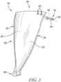
- each blade 14, 16has a base 26 and an airfoil 28 shown in Figs. 3 and 4 .
- the base 26is located adjacent the wheel 12.
- the airfoil 28has an aerodynamic shape for accelerating air through the gas turbine engine 110 and extends radially outward from the base 26.
- the airfoil 28further includes a first external surface 22, a second external surface 24, and a blade tip 30 as shown Figs. 3-4 .
- the second external surface 24is opposite the first external surface 22 to define a leading edge 32, a trailing edge 34, a pressure side 36, and a suction side 38 of the blade 14, 16.
- the blade tip 30is spaced apart radially outward from the base 26.
- the base 26 of each blade 14, 16is a root as shown in Fig. 3 .
- the rootis shaped to be received in a corresponding slot in the wheel 12 to couple the blade 14, 16 to the wheel 12.
- the base 26may be another suitable attachment method.
- the rotor 10is a blade disk or blisk and the blades 14, 16 are integrally formed with the wheel 12.
- Each of the blades 14, 16also has a first torsion node line 40 as shown in Fig. 2 .
- the first torsion node line 40extends radially along the blade 14, 16.
- the first torsion node line 40in addition to first, second, and third bend modes (not shown) make up low order modes that may affect the frequency of each of the blades 14, 16.
- Other modes, i.e. other bend and torsion modesmay be included in the low order modes of other blade embodiments.
- Each of the second frequency blades 16further includes at least one hole 42 as shown in Figs. 3 and 4 .
- the hole 42extends through the first external surface 22, into the blade 16, and out through the second external surface 24 in a direction normal to the first external surface 22 at the blade tip 30.
- the external surface 22 directionis indicated by the line 46, while the direction normal to the external surface 22 is indicated by the line 48 as shown in Fig. 4 .
- the hole 42may extend through the blade 16 at an angle relative to the line 48.
- the second frequency blades 16include at least two holes 42 that extend through the blade 16 in the direction of the line 46 normal to the first external surface 22. In the illustrative embodiment, the two holes 42 together decrease the peak stress in the blade tip 30 as opposed to one hole 42. In other embodiments, the second frequency blades 16 may include more than two holes 42 with a plug 18 located in each hole 42 or a single hole 42.
- the blades 14, 16are solid material including the tip 30 as shown in Fig. 4 . In other embodiments, a portion of the blades 14, 16 may be hollow with the tip 30 being solid material, which may look similar to the radial top view of Fig. 4 . In other embodiments, the blades 14, 16 may be hollow including the tip as shown in Fig. 5 .
- the holes 42are all the same size (i.e. each hole 42 has the same diameter). In other embodiments, some of the holes 42 may be larger in diameter than others. In such embodiments, the plug 18 received in the larger holes 42 may have be larger than the plugs 18 in the smaller holes 42.
- the holes 42are circular in shape as shown in Fig. 3 .
- the holes 42may be another suitable shape with the plug 18 shaped to match the shape of the corresponding holes 42.
- the shape of the holes 42may be selected to concentrate the material density of the plugs 18. In such embodiments, the concentrating the material may be more efficient than drilling multiple holes 42.
- the holes 42may be a rectangular shape extending along the blade tip 30. In other embodiments, the holes 42 may be an ellipse shape.
- the holes 42are located adjacent the trailing edge 34 of the blade 16. In other embodiments, the holes 42 may be located aft of the first torsion node line 40 toward the trailing edge 34, but spaced apart from the trailing edge 34. In other embodiments, the holes 42 may be located adjacent the leading edge 32 of the blade 16. In other embodiments, the holes 42 are located forward of the first torsion line 40 toward the leading edge but spaced apart from the leading edge 32. In other embodiments, the holes 42 may be located anywhere along the blade tip 30 on either side of the first torsion node line 40.
- Each plug 18includes a first outer surface 50, a second outer surface 52, and a side surface 54 as shown in Figs. 3 and 4 .
- the first outer surface 50is flush with the first external surface 22 of the blade 16.
- the second outer surface 52is flush with the second external surface 24 of the blade 16.
- the first and second outer surfaces 50, 52are flush with the corresponding external surfaces 22, 24 such that the outer surfaces 50, 52 are exposed to the gases surrounding the rotor 10.
- the side surface 54extends between and interconnects the first outer surface 50 and the second outer surface 52.
- each plug 18is sized so the first and second outer surfaces 50, 52 are flush with the external surfaces 22, 24 of the blade 16 to maintain the airfoil shape of the blade 16 without effecting the aerodynamics of the blade 16.
- the plugs 18are press fit into the holes 42. As such, the holes 42 have a smaller diameter than the plugs 18. In other embodiments, the plugs 18 may be threaded into place within the holes 42. In other embodiments, the plugs 18 may be adhered to the holes 42. In other embodiments, once the plugs 18 are inserted in the holes 42, excess material not flush with the external surfaces 22, 24 may be machined or polished off to ensure a flush aerodynamic surface 22, 24.
- a method of assembling and using the rotor 10may include several steps. The method includes measuring a frequency response of the rotor 10 to obtain frequency data of the rotor 10, identifying one of the blades 16 included in the plurality of blades 14, 16 to vary a frequency response of the blade 16 based on the frequency data, and forming a first hole 42 that extends through the blade 16 in the direction normal to the external surface 22, 24 at a first location.
- the first locationis based on the frequency data obtained during the measuring step.
- the first locationmay be at the trailing edge 34 of the blade 16 in some embodiments. In other embodiments, the first location may be at the leading edge 32 of the blade 16 in some embodiments. In other embodiments, the first location may be at any other location along the blade tip 30.
- the methodfurther includes forming a plug 18 made of the second material with a first density.
- the first densityis selected based on the frequency data.
- the methodfurther includes inserting the plug 18 into the first hole 42 formed in the first blade to vary the frequency response of the rotor 10.
- the methodmay further include forming a second hole 42 different from the first hole 42 that extends through the blade 16 in the direction normal to the external surface 22, 24 at a second location.
- the second locationis spaced apart from the first location along the blade tip 30.
- the methodfurther includes forming another plug 18 made of the second material with the first density.
- the methodfurther includes inserting the plug 18 into the second hole 42 formed in the first blade to vary the frequency response of the rotor 10.
- the methodfurther includes machining the excess material of the plugs 18 extending past the external surfaces 22, 24 of the blade 16 so that the surfaces 22, 24 are flush.
- the methodmay further include repeating these steps for additional blades 16 included in the rotor 10.
- a methodmay include inserting a plug 18 having a first plug density into the blade 16, operating the gas turbine engine 110 with the rotor 10 and the blade 16, and then removing the plug 18 and inserting a new plug 18 having a second plug density that is different than the first plug density.
- FIG. 5Another embodiment of a rotor 210 not falling within the scope of the claims is shown in Fig. 5 .
- the rotor 10is substantially similar to the rotor 10 shown in Figs. 1-4 and described herein. Accordingly, similar reference numbers in the 200 series indicate features that are common between the rotor 210 and the rotor 10. The description of the rotor 10 is incorporated by reference to apply to the rotor 210, except in instances when it conflicts with the specific description and the drawings of the rotor 210.
- the rotor 210includes the wheel 12, a plurality of blades 216, and a plurality of plugs 218 as shown in Fig. 5 .
- the wheel 12is arranged around the axis 11.
- the plurality of blades 216comprising a first material are arranged around the wheel 12 and extend radially outwardly away from the wheel 12 relative to the axis 11 to interact with gases surrounding the rotor 210.
- the second frequency blades 216are configured to receive at least one plug 218 comprising a second material different from the first material of the blades 216.
- the plugs 218are added to the blades 216 to mistune some of the plurality of blades and reduce flutter effects induced into the rotor 10 during operation of the engine 110.
- Each of the blades 216has an airfoil 228 having a first external surface 222, a second external surface 224, and a blade tip 230 as shown Fig. 5 .
- the second external surface 224is opposite the first external surface 222 to define a leading edge 232, a trailing edge 234, a pressure side 236, and a suction side 238 of the blade 216.
- the airfoil 228has an aerodynamic shape for accelerating air through the gas turbine engine 110.
- Each of the second frequency blades 216further includes holes 242 as shown in Fig. 5 .
- the holes 242extend through the first external surface 222, into the blade 216, and out through the second external surface 224 in a direction 246 normal to the first external surface 222 indicated by line 248 at the blade tip 230.
- Each plug 218includes a first outer surface 250, a second outer surface 252, and a side surface 254 as shown in Fig. 5 .
- the first outer surface 250 and the second outer surface 252are each flush with the corresponding external surface 222, 224 of the blade 216 such that the outer surfaces 250, 252 are exposed to the gases surrounding the rotor 210.
- the side surface 254extends between and interconnects the first outer surface 250 and the second outer surface 250.
- each blade 216is at least partially hollow as shown in Fig. 5 .
- the cavity 256extends through the blade tip 230 such that a portion of the side surface 254 of the each plug 218 is exposed to the cavity 256 formed in the blade tip 230.
- FIG. 6Another embodiment of a rotor 310 not falling within the scope of the claims is shown in Fig. 6 .
- the rotor 10is substantially similar to the rotor 10 shown in Figs. 1-4 and described herein. Accordingly, similar reference numbers in the 300 series indicate features that are common between the rotor 310 and the rotor 10. The description of the rotor 10 is incorporated by reference to apply to the rotor 310, except in instances when it conflicts with the specific description and the drawings of the rotor 310.
- the rotor 310includes the wheel 12, a plurality of blades 316, and a plurality of plugs 318 as shown in Fig. 6 .
- the wheel 12is arranged around the axis 11.
- the plurality of blades 316comprising a first material are arranged around the wheel 12 and each extend radially outwardly away from the wheel 12 relative to the axis 11 to interact with gases surrounding the rotor 310.
- the second frequency blades 316are configured to receive at least one plug 318 comprising a second material different from the first material of the blades 316.
- the plugs 318are added to the blades 316 to mistune some of the plurality of blades 316 and reduce flutter effects induced into the rotor 10 during operation of the engine 110.
- Each of the blades 316has an airfoil 328 having a first external surface 322, a second external surface 324, and a blade tip 330 as shown Fig. 6 .
- the second external surface 324is opposite the first external surface 322 to define a leading edge 332, a trailing edge 334, a pressure side 336, and a suction side 338 of the blade 316.
- the airfoil 328has an aerodynamic shape for accelerating air through the gas turbine engine 110.
- Each of the second frequency blades 316further includes holes 342 as shown in Fig. 6 .
- the holes 342extend through the first external surface 322 and into the blade 316.
- the holes 342are blind holes 342 that extend only partway in to the blade 316.
- Each plug 318includes a first outer surface 350 and a second outer surface as shown in Fig. 6 .
- the first outer surface 350is flush with the first external surface 322 of the blade 316 such that the first outer surface 350 is exposed to the gases surrounding the rotor 310.
- the second outer surfaceengages the hole 342 formed in the blade 316. In some embodiments, the second outer surface may be adhered to the surface forming the blind hole 342.
- FIG. 7An embodiment of a rotor 410 in accordance with the present invention is shown in Fig. 7 .
- the rotor 10is substantially similar to the rotor 10 shown in Figs. 1-4 and described herein. Accordingly, similar reference numbers in the 400 series indicate features that are common between the rotor 410 and the rotor 10.
- the description of the rotor 10is incorporated by reference to apply to the rotor 410, except in instances when it conflicts with the specific description and the drawings of the rotor 410.
- the rotor 410includes the wheel 12, a plurality of blades 414, 416, and a plurality of plugs 418, 420 as shown in Fig. 7 .
- the wheel 12is arranged around the axis 11.
- the plurality of blades 414, 416comprising a first material are arranged around the wheel 12 and extend radially outwardly away from the wheel 12 relative to the axis 11 to interact with gases surrounding the rotor 410.
- the plurality of blades 414, 416are divided into a set of first frequency blades 414 and a set of second frequency blades 416 as shown in Fig. 7 .
- Each of the first frequency blades 414 and the second frequency blades 416are similarly sized.
- the second frequency blades 416are configured to receive at least one first density plug 418 comprising a second material different than the first material of the blades 414, 416
- the first frequency blades 414are configured to receive at least one second density plug 420 comprising a third material different than the first material of the blades 414, 416 and the second material of the plugs 418.
- Each of the blades 416includes an airfoil 428 having a blade tip 430 and a first torsion node line 440 as shown Fig. 7 .
- the airfoil 428has an aerodynamic shape for accelerating air through the gas turbine engine 110.
- the plugs 418, 420are added to the tips 430 of the blades 414, 416 to mistune the plurality of blades 414, 416 and reduce flutter effects induced into the rotor 410 during operation of the engine 110.
- the second frequency blades 416are alternated between the first frequency blades 414 about the wheel 12.
- the second material of the first density plug 418has a density greater than a density of the first material of the blades 414, 416.
- the third material of the second density plug 420has a density that is less than the density of the first material of the blades 414, 416.
- the overall weight of the rotor 410increases since the density of the first density plug 418 is greater than the density of the first frequency blade 416.
- the second density plugs 420are arranged in the blade tip 430 of the second frequency blade 414.
- the lower density material of the second density plugs 420reduces the weight of the second frequency blades 414, evening outer the weight added to the first frequency blades 416, while mistuning each of the blades 414, 416. This results in small density changes in adjacent blades which works to provide an overall difference between the two blades that is significant to adjust the frequency response of the blades.
- a method of assembling and using the rotor 410may include several steps.
- the methodincludes measuring a frequency response of the rotor 410 to obtain frequency data of the rotor 410, identifying one of the first frequency blades 416 included in the plurality of blades 414, 416 to vary a frequency response of the blade 416 based on the frequency data, and forming a first hole 442 that extends through the blade 416 in the direction normal to the external surface 422, 424 at a first location of the first frequency blade 416.
- the first location on the blade 416is based on the frequency data obtained during the measuring step.
- the methodfurther includes forming a first plug 418 made of the second material with a first density.
- the first densityis selected based on the frequency data.
- the methodfurther includes inserting the first plug 418 into the first hole 442 formed in the first blade to vary the frequency response of the rotor 410.
- the methodmay further include forming a second hole 442 different from the first hole 442 that extends through the blade 416 in the direction normal to the external surface 422, 424 at a second location on the first frequency blade 416 based on the frequency data.
- the second locationis spaced apart from the first location along the blade tip 430.
- the methodfurther includes forming a second plug 418 made of the second material with the first density.
- the methodfurther includes inserting the plug 418 into the second hole 442 formed in the first blade to vary the frequency response of the rotor 410.
- the methodfurther includes identifying one of the second frequency blades 414 included in the plurality of blades 414, 416, forming a third hole 442 that extends through the blade 414 in the direction normal to the external surface 422, 424 at a third location on the second frequency blade 414.
- the third locationis based on the frequency data.
- the methodfurther includes forming a third plug 420 made of the third material with a second density.
- the second density materialis selected based on the frequency data, and the second density being different from the first density of the other plugs 418 inserted in the first frequency blade 416.
- the methodfurther includes inserting the third plug 420 into the third hole 442 formed in the second frequency blade 414 to vary the frequency response of the rotor.
- the methodmay further include forming a fourth hole 442 different from the third hole 442 that extends through the second frequency blade 414 in the direction normal to the external surface 422, 424 at a fourth location on the second frequency blade 414 based on the frequency data.
- the second locationis spaced apart from the third location along the blade tip 430.
- the methodfurther includes forming the fourth plug 420 made of the third material with the second density.
- the methodfurther includes inserting the fourth plug 420 into the fourth hole 442 formed in the second frequency blade 414 to vary the frequency response of the rotor 410.
- the methodfurther includes machining the excess material of the plugs 418, 420 extending past the external surfaces 422, 424 of the blades 414, 416 so that the surfaces 422, 424 are flush.
- the methodmay further include repeating these steps for additional blades 414, 416 included in the rotor 410.
- FIG. 8Another embodiment of a rotor 510 not falling within the scope of the claims is shown in Fig. 8 .
- the rotor 10is substantially similar to the rotor 10 shown in Figs. 1-4 and described herein. Accordingly, similar reference numbers in the 500 series indicate features that are common between the rotor 510 and the rotor 10. The description of the rotor 10 is incorporated by reference to apply to the rotor 510, except in instances when it conflicts with the specific description and the drawings of the rotor 510.
- the rotor 510includes the wheel 12, a plurality of blades 514, 516, and a plurality of plugs 518 as shown in Fig. 7 .
- the wheel 12is arranged around the axis 11.
- the plurality of blades 514, 516comprising a first material are arranged around the wheel 12 and extend radially outwardly away from the wheel 12 relative to the axis 11 to interact with gases surrounding the rotor 510.
- the plurality of blades 514, 516are divided into a set of first frequency blades 514 and a set of second frequency blades 516 as shown in Fig. 7 .
- Each of the first frequency blades 514 and the second frequency blades 516are similarly sized.
- the second frequency blades 516are configured to receive a plurality of plugs 518 comprising a second material different from the first material of the blades 514, 516.
- at least three plugs 18are added to each blade 516.
- Each of the blades 516includes an airfoil 528 having a blade tip 530 and a first torsion node line 540 as shown Fig. 8 .
- the airfoil 528has an aerodynamic shape for accelerating air through the gas turbine engine 110.
- the blade tip 530extends from the airfoil 528.
- the first torsion node line 40extends radially along the blade 514, 516.
- the plugs 518are added to the tips 530 of the blades 516 to mistune the plurality of blades 516 and reduce flutter effects induced into the rotor 510 during operation of the engine 110.
- the second frequency blades 516are alternated between the first frequency blades 514 about the wheel 12.
- the three plugs 518extend through the blade tip 530 forward of the first torsion node line 540.
- the plugs 518are spaced apart along the blade tip 530 and also spaced apart radially inward of one another.
- the present disclosurerelates to reducing flutter effects induced into rotors 10, 210, 310, 410, 510 during operation of the gas turbine engine 110.
- Flutteris a common aeromechanic phenomenon that may lead to excessive airfoil vibratory stress and eventual airfoil failure. These flutter affects may be difficult to accommodate when combined with other airfoil requirements, and the frequency of the rotor may also be difficult to assess and verify until the overall designs are complete.
- flutter mitigationsmay use mass mistuning in which the existing airfoil shape is changed and creates one or more geometric standards on the same rotor. This may cause further issues however, since the new airfoil may exhibit adverse qualities, such as efficiency and forcing response.
- the illustrative embodimentsinclude mass mistuning of the blades 16, 216, 316, 414, 416, 516 by adding plugs 18, 218, 318, 418, 420, 518 of differing material to the blade tip 30, 230, 330, 430, 530, through the blade thickness. By selecting the plug material and location, the blades 16, 216, 316, 414, 416, 516 may be mass mistuned.
- the plugs 18, 218, 318, 418, 420, 518are applied through the blade thickness; the airfoil shape of the blade 16, 216, 316, 414, 416, 516 may be maintained without affecting the aerodynamics of the airfoil 28, 228, 328, 428, 528.
- the holes 42, 242, 342are formed by simple drilling and the plugs 18, 218, 318, 418, 420, 518 may be press fit or threaded into place. Additional methods like adhesives or knurling may also be used to retain the plug 18, 218, 318, 418, 420, 518. Different plug materials may be used to finely tune the blade frequencies and may be more or less dense than the first material of the blades 16, 216, 316, 414, 416, 516.
- the plugmay be made from aluminum, titanium, steel, nickel, tungsten, polymer or other materials that provide enough weight density differential to the base material.
- the density differential between the blades 16, 216, 316, 414, 416, 516 and the plugs 18, 218, 318, 418, 420, 518provides the mass mistuning.
- the benefits of the mass mistuning arrangement of the present disclosuremay include modifying an existing blade to achieve the desired frequency without affecting the existing aerodynamic airfoil shape of the blades 16, 216, 316, 414, 416, 516, as the plugs 18, 218, 318, 418, 420, 518 may be flush with the aerodynamic surfaces 22, 24, 222, 224, 322, 324. Further, the present disclosure teaches using a simplified mass mistuning arrangement by using different plug materials and locations to tune the blade 16, 216, 316, 414, 416, 516.
- the present disclosureteaches a rotor 10, 210, 310, 410, 510 that allows the blades 16, 216, 316, 414, 416, 516 that are damaged during use of the gas turbine engine 110 from foreign object damage may be retuned.
- the blades 16, 216, 316, 414, 416, 516may be retuned by adjusting the plugs 18, 218, 318, 418, 420, 518 along with blade frequency data.
- the present disclosurealso teaches a rotor 10, 210, 310, 410, 510 that may allow complex combinations of mass tuning since the blades 16, 216, 316, 414, 416, 516 may be tuned to individual airfoil frequencies.
Landscapes
- Engineering & Computer Science (AREA)
- Mechanical Engineering (AREA)
- General Engineering & Computer Science (AREA)
- Architecture (AREA)
- Turbine Rotor Nozzle Sealing (AREA)
- Structures Of Non-Positive Displacement Pumps (AREA)
Description
- The present invention relates generally to gas turbine engines, and more specifically to rotors having airfoils for use in gas turbine engines.
- Gas turbine engines are used to power aircraft, watercraft, power generators, and the like. Gas turbine engines typically include a compressor, a combustor, and a turbine. The compressor compresses air drawn into the engine and delivers high pressure air to the combustor. In the combustor, fuel is mixed with the high pressure air and is ignited. Products of the combustion reaction in the combustor are directed into the turbine where work is extracted by rows of rotating blades and nonrotating vanes to drive the compressor and, sometimes, an output shaft. Each blade and vane has an airfoil that interacts with gases as they pass through the engine.
- Airfoils have natural vibration modes of increasing frequency and complexity of the mode shape. The simplest and lowest frequency modes are typically referred to as the first bending mode, the second bending mode, the third bending mode, and the first torsion mode. The first bending mode is a motion normal to the working surface of an airfoil in which the entire space of the airfoil moves in the same direction. The second bending mode is similar to the first bending mode, but with a change in the sense of the motion somewhere along the span of the airfoil, so that the upper and lower portions of the airfoil move in opposite directions. The third bending mode is similar to the second bending mode, but with two changes in the sense of motion somewhere along the span of the airfoil. The first torsion mode is a twisting motion around an axis that is parallel to the span of the airfoil, in which the entire space of the airfoil, on either side of the axis moves in the same direction.
- Blades may be subject to destructive vibrations induced by unsteady interaction of the airfoils of those blades with gases passing through a gas turbine engine. One type of vibration is flutter, which is an aero-elastic instability resulting from interaction of the flow over the airfoils of the blades and the blades' natural vibration tendencies. The lowest frequency vibration modes, the first bending mode and the first torsion mode, are often the vibration modes that are susceptible to flutter. When flutter occurs, the unsteady aerodynamic forces on the blade, due to its vibration, add energy to the vibration, causing the vibration amplitude to increase. The vibration amplitude can become large enough to cause damage to a blade. Another type of vibration is known as forced response, which is an aero-elastic response to inlet distortion or wakes from upstream airfoils, struts, or any other flow obstruction. The operable range, in terms of pressure rise and flow rate, of turbomachinery can sometimes be restructured by flutter and forced response phenomena.
- The specific susceptibility of a blade to flutter may be increased if all the blades on a rotor are identical in terms of their vibration frequencies. Sometimes, intentional variations may be introduced into blades during manufacturing to create structural mistuning of a rotor and provided flutter resistance.
Document DE 10 2007 014886 discloses a rotor for use in a gas turbine engine with the features of the preamble ofclaim 1.United States patent application US 2009/185911 A1 discloses a gas turbine engine blade that has a recess located in a surface of the blade and material positioned at least partially within the recess such that the material provides a localized increase in stiffness of the blade.United Kingdom patent application GB 2015660 A - European patent application
EP 924380 A2 German patent application DE 1627779 A1 discloses a method of manufacturing a hollow aerofoil section blade for a fluid flow machine. The method involves welding a pair of shaped plates together to form a hollow section blade and welding shaped leading and trailing edge sections to the hollow section. The two plates are made of titanium and are upset to form a local thickness after which they are shaped by hotpressing and chemical machining. The hollow section has ribs and drilled-out portions through which tubular spacers are inserted.United States patent US 5314282 A discloses a composite fastener member, in one form, having integral head and shank portions is defined by a plurality of superimposed composite fiber reinforced sheets spirally wound about a longitudinal axis. A plurality of fastener members, oppositely disposed within an opening in an article, define a fastener especially useful in joining lightweight composite structures such as aircraft or aircraft engine components.- The present invention provides a rotor for use in a gas turbine engine as set out in the appended claims.
- Embodiments will now be described by way of example only, with reference to the Figures, in which:
Fig. 1 is a cutaway view of a gas turbine engine that includes a fan, a compressor, a combustor, and a turbine, the fan having a rotor including a wheel arranged around an axis of the engine and a plurality of blades arranged around the wheel that each extend radially outward from the wheel to interact with gases flowing through the engine and suggesting that some of the fan blades include mistuning plugs configured to vary a resonance frequencies of the blades;Fig. 2 is a perspective view of a portion of the plurality of blades included in the fan ofFig. 1 showing a rotor not falling within the scope ofclaim 1, which includes plugs comprising a material of a different density than that of the bodies of the blades and suggesting that the plugs extend through a tip of the blade to change the mass of the blade tip to alter the resonance frequencies of the blade;Fig. 3 is an exploded view of one of the blades ofFig. 2 showing the plugs are adapted to fit into through holes formed in the blade tip;Fig. 4 is a top view of the blade ofFig. 3 showing the plugs extend through the blade tip so that outer surfaces of the plugs are flush with external surfaces of the blade;Fig. 5 is another embodiment of a rotor not falling within the scope of claims for use in the gas turbine engine ofFig. 1 showing the rotor includes at least one blade that is hollow with a cavity extending through a tip of the blade and plugs that extend through the blade tip such that a portion of the plug is exposed to the cavity;Fig. 6 is another embodiment of a rotor not falling within the scope of the claims for use in the gas turbine engine ofFig. 1 showing the rotor includes at least one blade and plugs that extend through an external surface of the blade and partway into the blade;Fig. 7 is an embodiment of a rotor according to the invention for use in the gas turbine engine ofFig. 1 showing the rotor includes a plurality of blades and a plurality of plugs, the plurality of plugs including first density plugs having a first density and arranged in first frequency blades and second density plugs having a second density different than the first density and arranged in second frequency blades so that the second frequency blades have a different mass than the first frequency blades; andFig. 8 is another embodiment of a rotor not falling within the scope of the claims for use in the gas turbine engine ofFig. 1 showing the rotor includes a plurality of blades and a plurality of plugs that each extend through a tip of the blade to change the mass at the blade tip to alter the frequency of the blade.- For the purposes of promoting an understanding of the principles of the disclosure, reference will now be made to a number of illustrative embodiments illustrated in the drawings and specific language will be used to describe the same.
- A
bladed rotor 10 includes a plurality ofblades plugs 18 that are coupled with theblades bladed rotor 10 to avoid flutter and high vibrations as suggested inFigs. 1 and 2 . Theplugs 18 extend throughexternal surfaces blades Fig. 2 . - The
bladed rotor 10 is adapted for use in a gas turbine engine that includes afan 112, acompressor 114, acombustor 116, and aturbine 118 as shown inFig. 1 . Thefan 112 is driven by theturbine 118 and provides thrust for propelling an aircraft. Thecompressor 114 compresses and delivers air to thecombustor 116. Thecombustor 116 mixes fuel with the compressed air received from thecompressor 114 and ignites the fuel. The hot, high pressure products of the combustion reaction in thecombustor 116 are directed into theturbine 118 to cause theturbine 118 to rotate about anaxis 11 of thegas turbine engine 110 and drive thecompressor 114 and thefan 112. In the illustrative embodiment, thefan 112 includes therotor 10. - The
rotor 10 includes awheel 12, the plurality ofblades plugs 18 as shown inFig. 2 , which does not fall within the scope of the claims. Thewheel 12 is arranged around theaxis 11. Theblades wheel 12 and each extend radially outwardly away from thewheel 12 relative to theaxis 11 to interact with gases surrounding therotor 10. The first material is a metallic material in the illustrative embodiment. - The plurality of
blades first frequency blades 14 and a set ofsecond frequency blades 16 as shown inFig. 2 . In other embodiments, additional numbers of frequency blade groups may be used. Each of thefirst frequency blades 14 and thesecond frequency blades 16 are similarly sized and shaped. However, thesecond frequency blades 16 are configured to receive at least oneplug 18 comprising a second material different from the first material of theblades plugs 18 are added to theblades 16 to change the mass of the blades to mistune some of the plurality ofblades 16 and reduce flutter effects induced into therotor 10 during operation of theengine 110. - In the illustrative embodiment, the
second frequency blades 16 are alternated every other blade between thefirst frequency blades 14 about thewheel 12. In other embodiments, twosecond frequency blades 16 may be located next to fourfirst frequency blades 14 on each circumferential side of theblades 16. In other embodiments, the other combinations of thefirst frequency blades 14 and thesecond frequency blades 16 may be used. In some embodiments, the frequency of theblades second frequency blades plugs 18. - Flutter may be a common aerodynamic phenomenon that may lead to excessive blade vibratory stress and eventual blade failure. Reducing the phenomenon may be difficult when combined with other requirements of the
blades - As such, each of the
plugs 18 is added to theblade 16 to mistune eachblade 16 without affecting the airfoil shape of theblade 16. The different second material of theplugs 18 alters the frequency of each of theblades 16 by changing the overall mass of theblade 16, but allows theplug 18 to match the contour ofexternal surface blade 16. Therefore, the flutter effects may be reduced, while the aerodynamic shape of theblade 16 is maintained. Different second materials may be used to fine-tune the blade frequencies. - In the illustrative embodiment, the first material comprises metallic materials, while the second material comprises polymeric materials. In other embodiments, the second material may metallic. The second material may be, for example, one of aluminum, titanium, steel, nickel, and tungsten. The second material is a material that provides a density differential when compared to the first material significant enough to vary the frequency response of the blade. The density differential between the first and second materials adds to the mistuning of the blades.
- Turning again to the plurality of
blades blade base 26 and anairfoil 28 shown inFigs. 3 and4 . Thebase 26 is located adjacent thewheel 12. Theairfoil 28 has an aerodynamic shape for accelerating air through thegas turbine engine 110 and extends radially outward from thebase 26. Theairfoil 28 further includes a firstexternal surface 22, a secondexternal surface 24, and ablade tip 30 as shownFigs. 3-4 . The secondexternal surface 24 is opposite the firstexternal surface 22 to define aleading edge 32, a trailingedge 34, apressure side 36, and asuction side 38 of theblade blade tip 30 is spaced apart radially outward from thebase 26. - In the illustrative embodiment, the
base 26 of eachblade Fig. 3 . The root is shaped to be received in a corresponding slot in thewheel 12 to couple theblade wheel 12. In some embodiments, thebase 26 may be another suitable attachment method. In other embodiments, therotor 10 is a blade disk or blisk and theblades wheel 12. - Each of the
blades torsion node line 40 as shown inFig. 2 . The firsttorsion node line 40 extends radially along theblade torsion node line 40, in addition to first, second, and third bend modes (not shown) make up low order modes that may affect the frequency of each of theblades - In the illustrative embodiment, the
torsion node line 40 divides theblade edge 32, while the aft section includes the trailingedge 34. - Each of the
second frequency blades 16 further includes at least onehole 42 as shown inFigs. 3 and4 . Thehole 42 extends through the firstexternal surface 22, into theblade 16, and out through the secondexternal surface 24 in a direction normal to the firstexternal surface 22 at theblade tip 30. - In the illustrative embodiment, the
external surface 22 direction is indicated by theline 46, while the direction normal to theexternal surface 22 is indicated by theline 48 as shown inFig. 4 . In other embodiments, thehole 42 may extend through theblade 16 at an angle relative to theline 48. - In the illustrative embodiment, the
second frequency blades 16 include at least twoholes 42 that extend through theblade 16 in the direction of theline 46 normal to the firstexternal surface 22. In the illustrative embodiment, the twoholes 42 together decrease the peak stress in theblade tip 30 as opposed to onehole 42. In other embodiments, thesecond frequency blades 16 may include more than twoholes 42 with aplug 18 located in eachhole 42 or asingle hole 42. Theblades tip 30 as shown inFig. 4 . In other embodiments, a portion of theblades tip 30 being solid material, which may look similar to the radial top view ofFig. 4 . In other embodiments, theblades Fig. 5 . - In the illustrative embodiment, the
holes 42 are all the same size (i.e. eachhole 42 has the same diameter). In other embodiments, some of theholes 42 may be larger in diameter than others. In such embodiments, theplug 18 received in thelarger holes 42 may have be larger than theplugs 18 in the smaller holes 42. - In the illustrative embodiments, the
holes 42 are circular in shape as shown inFig. 3 . In other embodiments, theholes 42 may be another suitable shape with theplug 18 shaped to match the shape of the corresponding holes 42. - In some embodiments, the shape of the
holes 42 may be selected to concentrate the material density of theplugs 18. In such embodiments, the concentrating the material may be more efficient than drillingmultiple holes 42. In some embodiments, theholes 42 may be a rectangular shape extending along theblade tip 30. In other embodiments, theholes 42 may be an ellipse shape. - In the illustrative embodiment, the
holes 42 are located adjacent the trailingedge 34 of theblade 16. In other embodiments, theholes 42 may be located aft of the firsttorsion node line 40 toward the trailingedge 34, but spaced apart from the trailingedge 34. In other embodiments, theholes 42 may be located adjacent the leadingedge 32 of theblade 16. In other embodiments, theholes 42 are located forward of thefirst torsion line 40 toward the leading edge but spaced apart from the leadingedge 32. In other embodiments, theholes 42 may be located anywhere along theblade tip 30 on either side of the firsttorsion node line 40. Typically, moving theholes 42 and plugs 18 further away from the firsttorsion node line 40 results in a greater change to the frequency response for a given size and density of one of theplugs 18. The location of thehole 42 may be dependent upon the frequency desired for theblade 16. Therefore, the location of thehole 42 may be altered depending on the frequency of theblade 16. - Each
plug 18 includes a firstouter surface 50, a secondouter surface 52, and aside surface 54 as shown inFigs. 3 and4 . The firstouter surface 50 is flush with the firstexternal surface 22 of theblade 16. The secondouter surface 52 is flush with the secondexternal surface 24 of theblade 16. The first and secondouter surfaces external surfaces outer surfaces rotor 10. Theside surface 54 extends between and interconnects the firstouter surface 50 and the secondouter surface 52. In the illustrative embodiment, each plug 18 is sized so the first and secondouter surfaces external surfaces blade 16 to maintain the airfoil shape of theblade 16 without effecting the aerodynamics of theblade 16. - In some embodiments, the
plugs 18 are press fit into theholes 42. As such, theholes 42 have a smaller diameter than theplugs 18. In other embodiments, theplugs 18 may be threaded into place within theholes 42. In other embodiments, theplugs 18 may be adhered to theholes 42. In other embodiments, once theplugs 18 are inserted in theholes 42, excess material not flush with theexternal surfaces aerodynamic surface - A method of assembling and using the
rotor 10 may include several steps. The method includes measuring a frequency response of therotor 10 to obtain frequency data of therotor 10, identifying one of theblades 16 included in the plurality ofblades blade 16 based on the frequency data, and forming afirst hole 42 that extends through theblade 16 in the direction normal to theexternal surface - In the illustrative embodiment, the first location is based on the frequency data obtained during the measuring step. The first location may be at the trailing
edge 34 of theblade 16 in some embodiments. In other embodiments, the first location may be at theleading edge 32 of theblade 16 in some embodiments. In other embodiments, the first location may be at any other location along theblade tip 30. - The method further includes forming a
plug 18 made of the second material with a first density. The first density is selected based on the frequency data. The method further includes inserting theplug 18 into thefirst hole 42 formed in the first blade to vary the frequency response of therotor 10. - In the illustrative embodiment, the method may further include forming a
second hole 42 different from thefirst hole 42 that extends through theblade 16 in the direction normal to theexternal surface blade tip 30. - The method further includes forming another
plug 18 made of the second material with the first density. The method further includes inserting theplug 18 into thesecond hole 42 formed in the first blade to vary the frequency response of therotor 10. - In some embodiments, the method further includes machining the excess material of the
plugs 18 extending past theexternal surfaces blade 16 so that thesurfaces additional blades 16 included in therotor 10. A method may include inserting aplug 18 having a first plug density into theblade 16, operating thegas turbine engine 110 with therotor 10 and theblade 16, and then removing theplug 18 and inserting anew plug 18 having a second plug density that is different than the first plug density. - Another embodiment of a
rotor 210 not falling within the scope of the claims is shown inFig. 5 . Therotor 10 is substantially similar to therotor 10 shown inFigs. 1-4 and described herein. Accordingly, similar reference numbers in the 200 series indicate features that are common between therotor 210 and therotor 10. The description of therotor 10 is incorporated by reference to apply to therotor 210, except in instances when it conflicts with the specific description and the drawings of therotor 210. - The
rotor 210 includes thewheel 12, a plurality ofblades 216, and a plurality ofplugs 218 as shown inFig. 5 . Thewheel 12 is arranged around theaxis 11. The plurality ofblades 216 comprising a first material are arranged around thewheel 12 and extend radially outwardly away from thewheel 12 relative to theaxis 11 to interact with gases surrounding therotor 210. In the illustrative embodiment, thesecond frequency blades 216 are configured to receive at least oneplug 218 comprising a second material different from the first material of theblades 216. Theplugs 218 are added to theblades 216 to mistune some of the plurality of blades and reduce flutter effects induced into therotor 10 during operation of theengine 110. - Each of the
blades 216 has anairfoil 228 having a firstexternal surface 222, a secondexternal surface 224, and ablade tip 230 as shownFig. 5 . The secondexternal surface 224 is opposite the firstexternal surface 222 to define aleading edge 232, a trailingedge 234, apressure side 236, and asuction side 238 of theblade 216. Theairfoil 228 has an aerodynamic shape for accelerating air through thegas turbine engine 110. - Each of the
second frequency blades 216 further includesholes 242 as shown inFig. 5 . Theholes 242 extend through the firstexternal surface 222, into theblade 216, and out through the secondexternal surface 224 in adirection 246 normal to the firstexternal surface 222 indicated byline 248 at theblade tip 230. - Each
plug 218 includes a firstouter surface 250, a secondouter surface 252, and aside surface 254 as shown inFig. 5 . The firstouter surface 250 and the secondouter surface 252 are each flush with the correspondingexternal surface blade 216 such that theouter surfaces rotor 210. Theside surface 254 extends between and interconnects the firstouter surface 250 and the secondouter surface 250. - In the illustrative embodiment, each
blade 216 is at least partially hollow as shown inFig. 5 . Thecavity 256 extends through theblade tip 230 such that a portion of theside surface 254 of the eachplug 218 is exposed to thecavity 256 formed in theblade tip 230. - Another embodiment of a
rotor 310 not falling within the scope of the claims is shown inFig. 6 . Therotor 10 is substantially similar to therotor 10 shown inFigs. 1-4 and described herein. Accordingly, similar reference numbers in the 300 series indicate features that are common between therotor 310 and therotor 10. The description of therotor 10 is incorporated by reference to apply to therotor 310, except in instances when it conflicts with the specific description and the drawings of therotor 310. - The
rotor 310 includes thewheel 12, a plurality ofblades 316, and a plurality ofplugs 318 as shown inFig. 6 . Thewheel 12 is arranged around theaxis 11. The plurality ofblades 316 comprising a first material are arranged around thewheel 12 and each extend radially outwardly away from thewheel 12 relative to theaxis 11 to interact with gases surrounding therotor 310. In the illustrative embodiment, thesecond frequency blades 316 are configured to receive at least oneplug 318 comprising a second material different from the first material of theblades 316. Theplugs 318 are added to theblades 316 to mistune some of the plurality ofblades 316 and reduce flutter effects induced into therotor 10 during operation of theengine 110. - Each of the
blades 316 has anairfoil 328 having a firstexternal surface 322, a secondexternal surface 324, and ablade tip 330 as shownFig. 6 . The secondexternal surface 324 is opposite the firstexternal surface 322 to define aleading edge 332, a trailingedge 334, apressure side 336, and asuction side 338 of theblade 316. Theairfoil 328 has an aerodynamic shape for accelerating air through thegas turbine engine 110. - Each of the
second frequency blades 316 further includesholes 342 as shown inFig. 6 . Theholes 342 extend through the firstexternal surface 322 and into theblade 316. Theholes 342 areblind holes 342 that extend only partway in to theblade 316. - Each
plug 318 includes a firstouter surface 350 and a second outer surface as shown inFig. 6 . The firstouter surface 350 is flush with the firstexternal surface 322 of theblade 316 such that the firstouter surface 350 is exposed to the gases surrounding therotor 310. The second outer surface engages thehole 342 formed in theblade 316. In some embodiments, the second outer surface may be adhered to the surface forming theblind hole 342. - An embodiment of a
rotor 410 in accordance with the present invention is shown inFig. 7 . Therotor 10 is substantially similar to therotor 10 shown inFigs. 1-4 and described herein. Accordingly, similar reference numbers in the 400 series indicate features that are common between therotor 410 and therotor 10. The description of therotor 10 is incorporated by reference to apply to therotor 410, except in instances when it conflicts with the specific description and the drawings of therotor 410. - The
rotor 410 includes thewheel 12, a plurality ofblades plugs Fig. 7 . Thewheel 12 is arranged around theaxis 11. The plurality ofblades wheel 12 and extend radially outwardly away from thewheel 12 relative to theaxis 11 to interact with gases surrounding therotor 410. - In the illustrative embodiment, the plurality of
blades first frequency blades 414 and a set ofsecond frequency blades 416 as shown inFig. 7 . Each of thefirst frequency blades 414 and thesecond frequency blades 416 are similarly sized. However, thesecond frequency blades 416 are configured to receive at least onefirst density plug 418 comprising a second material different than the first material of theblades first frequency blades 414 are configured to receive at least onesecond density plug 420 comprising a third material different than the first material of theblades plugs 418. - Each of the
blades 416 includes anairfoil 428 having ablade tip 430 and a first torsion node line 440 as shownFig. 7 . Theairfoil 428 has an aerodynamic shape for accelerating air through thegas turbine engine 110. - The
plugs tips 430 of theblades blades rotor 410 during operation of theengine 110. In the illustrative embodiment, thesecond frequency blades 416 are alternated between thefirst frequency blades 414 about thewheel 12. - According to the invention, the second material of the
first density plug 418 has a density greater than a density of the first material of theblades second density plug 420 has a density that is less than the density of the first material of theblades - By arranging the first density plugs 418 in the
blade tip 430 of thefirst frequency blades 416, the overall weight of therotor 410 increases since the density of thefirst density plug 418 is greater than the density of thefirst frequency blade 416. To minimize the amount of weight added to therotor 410, the second density plugs 420 are arranged in theblade tip 430 of thesecond frequency blade 414. The lower density material of the second density plugs 420 reduces the weight of thesecond frequency blades 414, evening outer the weight added to thefirst frequency blades 416, while mistuning each of theblades - A method of assembling and using the
rotor 410 may include several steps. The method includes measuring a frequency response of therotor 410 to obtain frequency data of therotor 410, identifying one of thefirst frequency blades 416 included in the plurality ofblades blade 416 based on the frequency data, and forming a first hole 442 that extends through theblade 416 in the direction normal to the external surface 422, 424 at a first location of thefirst frequency blade 416. In the illustrative embodiment, the first location on theblade 416 is based on the frequency data obtained during the measuring step. - The method further includes forming a
first plug 418 made of the second material with a first density. The first density is selected based on the frequency data. The method further includes inserting thefirst plug 418 into the first hole 442 formed in the first blade to vary the frequency response of therotor 410. - In the illustrative embodiment, the method may further include forming a second hole 442 different from the first hole 442 that extends through the
blade 416 in the direction normal to the external surface 422, 424 at a second location on thefirst frequency blade 416 based on the frequency data. The second location is spaced apart from the first location along theblade tip 430. - The method further includes forming a
second plug 418 made of the second material with the first density. The method further includes inserting theplug 418 into the second hole 442 formed in the first blade to vary the frequency response of therotor 410. - In the illustrative embodiment, the method further includes identifying one of the
second frequency blades 414 included in the plurality ofblades blade 414 in the direction normal to the external surface 422, 424 at a third location on thesecond frequency blade 414. In the illustrative embodiment, the third location is based on the frequency data. - The method further includes forming a
third plug 420 made of the third material with a second density. The second density material is selected based on the frequency data, and the second density being different from the first density of theother plugs 418 inserted in thefirst frequency blade 416. - The method further includes inserting the
third plug 420 into the third hole 442 formed in thesecond frequency blade 414 to vary the frequency response of the rotor. In the illustrative embodiment, the method may further include forming a fourth hole 442 different from the third hole 442 that extends through thesecond frequency blade 414 in the direction normal to the external surface 422, 424 at a fourth location on thesecond frequency blade 414 based on the frequency data. The second location is spaced apart from the third location along theblade tip 430. - The method further includes forming the
fourth plug 420 made of the third material with the second density. The method further includes inserting thefourth plug 420 into the fourth hole 442 formed in thesecond frequency blade 414 to vary the frequency response of therotor 410. - In some embodiments, the method further includes machining the excess material of the
plugs blades additional blades rotor 410. - Another embodiment of a
rotor 510 not falling within the scope of the claims is shown inFig. 8 . Therotor 10 is substantially similar to therotor 10 shown inFigs. 1-4 and described herein. Accordingly, similar reference numbers in the 500 series indicate features that are common between therotor 510 and therotor 10. The description of therotor 10 is incorporated by reference to apply to therotor 510, except in instances when it conflicts with the specific description and the drawings of therotor 510. - The
rotor 510 includes thewheel 12, a plurality ofblades plugs 518 as shown inFig. 7 . Thewheel 12 is arranged around theaxis 11. The plurality ofblades wheel 12 and extend radially outwardly away from thewheel 12 relative to theaxis 11 to interact with gases surrounding therotor 510. - In the illustrative embodiment, the plurality of
blades first frequency blades 514 and a set ofsecond frequency blades 516 as shown inFig. 7 . Each of thefirst frequency blades 514 and thesecond frequency blades 516 are similarly sized. However, thesecond frequency blades 516 are configured to receive a plurality ofplugs 518 comprising a second material different from the first material of theblades plugs 18 are added to eachblade 516. - Each of the
blades 516 includes anairfoil 528 having ablade tip 530 and a firsttorsion node line 540 as shownFig. 8 . Theairfoil 528 has an aerodynamic shape for accelerating air through thegas turbine engine 110. Theblade tip 530 extends from theairfoil 528. The firsttorsion node line 40 extends radially along theblade - The
plugs 518 are added to thetips 530 of theblades 516 to mistune the plurality ofblades 516 and reduce flutter effects induced into therotor 510 during operation of theengine 110. In the illustrative embodiment, thesecond frequency blades 516 are alternated between thefirst frequency blades 514 about thewheel 12. - In the illustrative embodiment, the three
plugs 518 extend through theblade tip 530 forward of the firsttorsion node line 540. Theplugs 518 are spaced apart along theblade tip 530 and also spaced apart radially inward of one another. - The present disclosure relates to reducing flutter effects induced into
rotors gas turbine engine 110. Flutter is a common aeromechanic phenomenon that may lead to excessive airfoil vibratory stress and eventual airfoil failure. These flutter affects may be difficult to accommodate when combined with other airfoil requirements, and the frequency of the rotor may also be difficult to assess and verify until the overall designs are complete. - In some embodiments, flutter mitigations may use mass mistuning in which the existing airfoil shape is changed and creates one or more geometric standards on the same rotor. This may cause further issues however, since the new airfoil may exhibit adverse qualities, such as efficiency and forcing response.
- To combat the flutter affects, the illustrative embodiments include mass mistuning of the
blades plugs blade tip blades plugs blade airfoil - In the illustrative embodiment, the
holes plugs plug blades - In some embodiments, the plug may be made from aluminum, titanium, steel, nickel, tungsten, polymer or other materials that provide enough weight density differential to the base material. The density differential between the
blades plugs - The benefits of the mass mistuning arrangement of the present disclosure may include modifying an existing blade to achieve the desired frequency without affecting the existing aerodynamic airfoil shape of the
blades plugs aerodynamic surfaces blade - In some embodiments, the present disclosure teaches a
rotor blades gas turbine engine 110 from foreign object damage may be retuned. Theblades plugs rotor blades
Claims (6)
- A rotor (10, 210, 310, 410, 510) for use in a gas turbine engine (110), the rotor comprising:a wheel (12) arranged around an axis (11);a first blade (16) comprising a first material and extending radially outwardly away from the wheel relative to the axis to allow the first blade to interact with gases surrounding the rotor, the first blade having a first external surface (22, 222, 322) that defines a pressure side (36, 236, 336) of the first blade, and a second external surface (24, 224, 324) opposite the first external surface that defines a suction side (38, 238, 338) of the first blade, the first blade further having a leading edge (32, 232, 332), a trailing edge (34, 234, 334), and a first hole (42, 242, 342), wherein the first hole extends through the first external surface and into the first blade in a direction normal to the first external surface; anda first plug (18, 218, 318, 418, 518) located in the first hole and having a first outer surface (50, 250, 350) flush with the first external surface of the first blade such that the first outer surface is exposed to the gases surrounding the rotor, and the first plug comprises a second material that is different than the first material of the first blade;the rotor further comprising a second blade that extends radially away from the wheel (12) and a second plug (420) coupled with the second blade, the second blade directly neighboring the first blade circumferentially and having a first external surface that defines a pressure side of the second blade, and a second external surface opposite the first external surface of the second blade that defines a suction side of the second blade, the second blade further having a leading edge, a trailing edge, and a second hole, wherein the second hole extends into the second blade in a direction normal to the first external surface of the second blade, the second plug located in the second hole and comprising a third material that is different than the second material,characterized in thatthe second material has a density greater than a density of the first material and the third material has a density that is less than the density of the first material.
- The rotor of claim 1, wherein the first hole (42) is a through hole that extends entirely through the first external surface (22) and the second external surface (24) and wherein the first plug (18) includes a second outer surface (52) that is flush with the second external surface and exposed to the gases surrounding the rotor.
- The rotor of claim 1 or 2, wherein the first blade (16) includes a base (26) located adjacent the wheel (12) and a blade tip (30) spaced apart radially outward from the base and the first hole (42) is located adjacent the blade tip.
- The rotor of any one of claims 1 to 3, wherein the first hole (42) is located adjacent one of the leading edge (32) and the trailing edge (34) of the first blade (16).
- The rotor of claim 2, wherein the first plug (18) includes a side surface (254) that extends between the first outer surface (250) and the second outer surface (252) and the first blade is at least partially hollow in the blade tip (230) such that the side surface of the first plug is exposed to a cavity (256) formed in the blade tip.
- The rotor of any one of claims 1 to 5, wherein the first hole (342) is a blind hole that extends only partway in to the first blade.
Applications Claiming Priority (1)
| Application Number | Priority Date | Filing Date | Title |
|---|---|---|---|
| US16/661,566US11220913B2 (en) | 2019-10-23 | 2019-10-23 | Gas turbine engine blades with airfoil plugs for selected tuning |
Publications (3)
| Publication Number | Publication Date |
|---|---|
| EP3812547A2 EP3812547A2 (en) | 2021-04-28 |
| EP3812547A3 EP3812547A3 (en) | 2021-06-16 |
| EP3812547B1true EP3812547B1 (en) | 2023-06-07 |
Family
ID=72852413
Family Applications (1)
| Application Number | Title | Priority Date | Filing Date |
|---|---|---|---|
| EP20201439.5AActiveEP3812547B1 (en) | 2019-10-23 | 2020-10-13 | Gas turbine engine rotor with blades having airfoil plugs for selected mistuning |
Country Status (2)
| Country | Link |
|---|---|
| US (1) | US11220913B2 (en) |
| EP (1) | EP3812547B1 (en) |
Families Citing this family (9)
| Publication number | Priority date | Publication date | Assignee | Title |
|---|---|---|---|---|
| FR3127017B1 (en)* | 2021-09-10 | 2023-09-08 | Safran Aircraft Engines | PROTECTIVE SHIELD FOR A LEADING EDGE OF A BLADE, ASSOCIATED BLADE AND METHOD FOR MANUFACTURING THE SHIELD |
| FR3127016B1 (en) | 2021-09-10 | 2023-09-08 | Safran Aircraft Engines | METHOD FOR CORRECTING THE RADIAL MOMENT WEIGHT OF A BLADE |
| US11725520B2 (en) | 2021-11-04 | 2023-08-15 | Rolls-Royce Corporation | Fan rotor for airfoil damping |
| FR3130880A1 (en)* | 2021-12-21 | 2023-06-23 | Safran Aircraft Engines | Turbomachine one-piece blisk with improved vibration behavior |
| US11746659B2 (en) | 2021-12-23 | 2023-09-05 | Rolls-Royce North American Technologies Inc. | Fan blade with internal shear-thickening fluid damping |
| US11560801B1 (en) | 2021-12-23 | 2023-01-24 | Rolls-Royce North American Technologies Inc. | Fan blade with internal magnetorheological fluid damping |
| US12410715B2 (en) | 2023-08-10 | 2025-09-09 | General Electric Company | Rotor blade system for turbine engines |
| US20250154869A1 (en)* | 2023-11-09 | 2025-05-15 | Pratt & Whitney Canada Corp. | Tailoring rotor blade sector configurations to tune gas turbine engine bladed rotor |
| US12435634B2 (en) | 2023-11-21 | 2025-10-07 | Rolls-Royce North American Technologies Inc. | Notched turbine airfoils for weight reduction in gas turbine engines |
Citations (2)
| Publication number | Priority date | Publication date | Assignee | Title |
|---|---|---|---|---|
| US20060029501A1 (en)* | 2004-08-09 | 2006-02-09 | General Electric Company | Mixed tuned hybrid blade related method |
| DE102007014886A1 (en)* | 2006-03-31 | 2007-10-04 | General Electric Co. | Load-reduction method for reducing load and adjusting frequency in a turbine rotor blade of base metal material uses a polymer compound material |
Family Cites Families (35)
| Publication number | Priority date | Publication date | Assignee | Title |
|---|---|---|---|---|
| US1603076A (en)* | 1922-11-27 | 1926-10-12 | Motor Player Corp | Means and method for dynamically balancing incased fan blades |
| FR1024218A (en)* | 1950-09-01 | 1953-03-30 | Rateau Soc | Vibration damping device for propeller blades and turbine engine fins |
| GB1089247A (en)* | 1966-06-03 | 1967-11-01 | Rolls Royce | Method of manufacturing a hollow aerofoil section blade for a fluid flow machine |
| DE1947725A1 (en)* | 1969-09-20 | 1971-04-08 | Maschf Augsburg Nuernberg Ag | Device for vibration damping in rods or blades of flow machines, in particular of gas turbines |
| US3754838A (en)* | 1971-11-15 | 1973-08-28 | Ingersoll Rand Co | Vibration suppressed blade |
| US4097192A (en) | 1977-01-06 | 1978-06-27 | Curtiss-Wright Corporation | Turbine rotor and blade configuration |
| US4178667A (en)* | 1978-03-06 | 1979-12-18 | General Motors Corporation | Method of controlling turbomachine blade flutter |
| JPS61181794A (en)* | 1985-02-06 | 1986-08-14 | Nippon Kokan Kk <Nkk> | Propeller for ship |
| GB2284031B (en) | 1987-11-27 | 1995-11-08 | Gen Electric | Composite fastener |
| US4776763A (en)* | 1987-12-02 | 1988-10-11 | Sundstrand Corporation | Mechanical damping of turbine wheel blades |
| US5273398A (en)* | 1992-12-01 | 1993-12-28 | United Technologies Corporation | Rotor blade balance weight assembly |
| US5913661A (en) | 1997-12-22 | 1999-06-22 | General Electric Company | Striated hybrid blade |
| US6428278B1 (en) | 2000-12-04 | 2002-08-06 | United Technologies Corporation | Mistuned rotor blade array for passive flutter control |
| DE10301755A1 (en) | 2003-01-18 | 2004-07-29 | Rolls-Royce Deutschland Ltd & Co Kg | Fan blade for a gas turbine engine |
| FR2869069B1 (en) | 2004-04-20 | 2008-11-21 | Snecma Moteurs Sa | METHOD FOR INTRODUCING A VOLUNTARY CONNECTION TO AN AUBED WHEEL TURBOMACHINE WHEEL WITH VOLUNTARY DISCHARGE |
| EP1640562A1 (en)* | 2004-09-23 | 2006-03-29 | Siemens Aktiengesellschaft | Frequency tuning method of a turbine blade and turbine blade |
| DE102005006414A1 (en) | 2005-02-12 | 2006-08-24 | Mtu Aero Engines Gmbh | A method of machining an integrally bladed rotor |
| GB0601837D0 (en) | 2006-01-31 | 2006-03-08 | Rolls Royce Plc | An aerofoil assembly and a method of manufacturing an aerofoil assembly |
| US7828526B2 (en)* | 2007-04-11 | 2010-11-09 | General Electric Company | Metallic blade having a composite inlay |
| US8241003B2 (en)* | 2008-01-23 | 2012-08-14 | United Technologies Corp. | Systems and methods involving localized stiffening of blades |
| US8167540B2 (en)* | 2008-01-30 | 2012-05-01 | Hamilton Sundstrand Corporation | System for reducing compressor noise |
| US8206110B2 (en)* | 2009-01-23 | 2012-06-26 | Sharolyn Vettese | Horizontal wind turbine blade balancing accessory |
| US9670900B2 (en) | 2013-03-28 | 2017-06-06 | General Electric Company | Rotor blade assembly for wind turbine having load reduction features |
| WO2014197119A2 (en) | 2013-04-16 | 2014-12-11 | United Technologies Corporation | Rotors with modulus mistuned airfoils |
| US11047397B2 (en) | 2014-01-24 | 2021-06-29 | Raytheon Technologies Corporation | Gas turbine engine stator vane mistuning |
| EP2942481B1 (en)* | 2014-05-07 | 2019-03-27 | Rolls-Royce Corporation | Rotor for a gas turbine engine |
| US20150322797A1 (en)* | 2014-05-09 | 2015-11-12 | United Technologies Corporation | Blade element cross-ties |
| FR3025127B1 (en)* | 2014-08-28 | 2017-03-17 | Snecma | REPAIR OF AN ASSEMBLY COMPRISING A MAIN BODY AND A REINFORCEMENT |
| EP3018292B1 (en)* | 2014-11-10 | 2020-08-12 | Ansaldo Energia Switzerland AG | Turbine blade and corresponding gas turbine and manufacturing method |
| US11041388B2 (en)* | 2015-03-30 | 2021-06-22 | Pratt & Whitney Canada Corp. | Blade cutback distribution in rotor for noise reduction |
| US10215194B2 (en) | 2015-12-21 | 2019-02-26 | Pratt & Whitney Canada Corp. | Mistuned fan |
| US10215029B2 (en)* | 2016-01-27 | 2019-02-26 | Hanwha Power Systems Co., Ltd. | Blade assembly |
| GB2551750B (en) | 2016-06-29 | 2020-03-25 | Rolls Royce Plc | Cavity sealing |
| US10577940B2 (en)* | 2017-01-31 | 2020-03-03 | General Electric Company | Turbomachine rotor blade |
| US10830067B2 (en)* | 2018-03-16 | 2020-11-10 | General Electric Company | Mechanical airfoil morphing with internal mechanical structures |
- 2019
- 2019-10-23USUS16/661,566patent/US11220913B2/enactiveActive
- 2020
- 2020-10-13EPEP20201439.5Apatent/EP3812547B1/enactiveActive
Patent Citations (2)
| Publication number | Priority date | Publication date | Assignee | Title |
|---|---|---|---|---|
| US20060029501A1 (en)* | 2004-08-09 | 2006-02-09 | General Electric Company | Mixed tuned hybrid blade related method |
| DE102007014886A1 (en)* | 2006-03-31 | 2007-10-04 | General Electric Co. | Load-reduction method for reducing load and adjusting frequency in a turbine rotor blade of base metal material uses a polymer compound material |
Also Published As
| Publication number | Publication date |
|---|---|
| EP3812547A2 (en) | 2021-04-28 |
| US11220913B2 (en) | 2022-01-11 |
| US20210123347A1 (en) | 2021-04-29 |
| EP3812547A3 (en) | 2021-06-16 |
Similar Documents
| Publication | Publication Date | Title |
|---|---|---|
| EP3812547B1 (en) | Gas turbine engine rotor with blades having airfoil plugs for selected mistuning | |
| US10865807B2 (en) | Mistuned fan | |
| US9932840B2 (en) | Rotor for a gas turbine engine | |
| EP0924381B1 (en) | Frequency tuned turbomachine blade | |
| US6033186A (en) | Frequency tuned hybrid blade | |
| EP1211382B1 (en) | Turbomachine rotor with blades of different frequency | |
| US5725354A (en) | Forward swept fan blade | |
| EP1754857B1 (en) | Hollow fan blade detail half, hollow fan blade for a gas turbine engine, gas turbine engine and corresponding manufacturing method | |
| US6994524B2 (en) | Hollow fan blade for gas turbine engine | |
| US20080304972A1 (en) | Rotary body for turbo machinery with mistuned blades | |
| EP3456920B1 (en) | Mistuned rotor for gas turbine engine | |
| US5913661A (en) | Striated hybrid blade | |
| EP3460186B1 (en) | Compressor rotor, corresponding gas turbine engine and method of reducing flow pattern disparities | |
| EP3765713B1 (en) | Mistuning of turbine blades with one or more internal cavities | |
| US12098655B2 (en) | Stator ring for an aircraft turbine engine and aircraft turbine engine fitted with same | |
| US11725520B2 (en) | Fan rotor for airfoil damping | |
| US11578599B2 (en) | Rotor balance assembly | |
| US11746659B2 (en) | Fan blade with internal shear-thickening fluid damping | |
| US20250283410A1 (en) | Airfoil rotor hub system having intentional frequency mistuning | |
| EP3438634A1 (en) | Method of manufacturing and apparatus | |
| US12385400B2 (en) | Method of manufacturing a mistuned rotor | |
| WO2017157956A1 (en) | Aerofoil for gas turbine incorporating one or more encapsulated void |
Legal Events
| Date | Code | Title | Description |
|---|---|---|---|
| PUAI | Public reference made under article 153(3) epc to a published international application that has entered the european phase | Free format text:ORIGINAL CODE: 0009012 | |
| STAA | Information on the status of an ep patent application or granted ep patent | Free format text:STATUS: THE APPLICATION HAS BEEN PUBLISHED | |
| AK | Designated contracting states | Kind code of ref document:A2 Designated state(s):AL AT BE BG CH CY CZ DE DK EE ES FI FR GB GR HR HU IE IS IT LI LT LU LV MC MK MT NL NO PL PT RO RS SE SI SK SM TR | |
| AX | Request for extension of the european patent | Extension state:BA ME | |
| PUAL | Search report despatched | Free format text:ORIGINAL CODE: 0009013 | |
| AK | Designated contracting states | Kind code of ref document:A3 Designated state(s):AL AT BE BG CH CY CZ DE DK EE ES FI FR GB GR HR HU IE IS IT LI LT LU LV MC MK MT NL NO PL PT RO RS SE SI SK SM TR | |
| RIC1 | Information provided on ipc code assigned before grant | Ipc:F01D 5/02 20060101AFI20210511BHEP Ipc:F01D 5/14 20060101ALI20210511BHEP Ipc:F01D 5/16 20060101ALI20210511BHEP Ipc:F04D 29/66 20060101ALI20210511BHEP | |
| STAA | Information on the status of an ep patent application or granted ep patent | Free format text:STATUS: REQUEST FOR EXAMINATION WAS MADE | |
| 17P | Request for examination filed | Effective date:20211208 | |
| RBV | Designated contracting states (corrected) | Designated state(s):AL AT BE BG CH CY CZ DE DK EE ES FI FR GB GR HR HU IE IS IT LI LT LU LV MC MK MT NL NO PL PT RO RS SE SI SK SM TR | |
| GRAP | Despatch of communication of intention to grant a patent | Free format text:ORIGINAL CODE: EPIDOSNIGR1 | |
| STAA | Information on the status of an ep patent application or granted ep patent | Free format text:STATUS: GRANT OF PATENT IS INTENDED | |
| INTG | Intention to grant announced | Effective date:20230323 | |
| GRAS | Grant fee paid | Free format text:ORIGINAL CODE: EPIDOSNIGR3 | |
| GRAA | (expected) grant | Free format text:ORIGINAL CODE: 0009210 | |
| STAA | Information on the status of an ep patent application or granted ep patent | Free format text:STATUS: THE PATENT HAS BEEN GRANTED | |
| AK | Designated contracting states | Kind code of ref document:B1 Designated state(s):AL AT BE BG CH CY CZ DE DK EE ES FI FR GB GR HR HU IE IS IT LI LT LU LV MC MK MT NL NO PL PT RO RS SE SI SK SM TR | |
| REG | Reference to a national code | Ref country code:GB Ref legal event code:FG4D | |
| REG | Reference to a national code | Ref country code:CH Ref legal event code:EP Ref country code:AT Ref legal event code:REF Ref document number:1575692 Country of ref document:AT Kind code of ref document:T Effective date:20230615 | |
| REG | Reference to a national code | Ref country code:DE Ref legal event code:R096 Ref document number:602020011734 Country of ref document:DE | |
| P01 | Opt-out of the competence of the unified patent court (upc) registered | Effective date:20230528 | |
| REG | Reference to a national code | Ref country code:LT Ref legal event code:MG9D | |
| REG | Reference to a national code | Ref country code:NL Ref legal event code:MP Effective date:20230607 | |
| PG25 | Lapsed in a contracting state [announced via postgrant information from national office to epo] | Ref country code:SE Free format text:LAPSE BECAUSE OF FAILURE TO SUBMIT A TRANSLATION OF THE DESCRIPTION OR TO PAY THE FEE WITHIN THE PRESCRIBED TIME-LIMIT Effective date:20230607 Ref country code:NO Free format text:LAPSE BECAUSE OF FAILURE TO SUBMIT A TRANSLATION OF THE DESCRIPTION OR TO PAY THE FEE WITHIN THE PRESCRIBED TIME-LIMIT Effective date:20230907 Ref country code:ES Free format text:LAPSE BECAUSE OF FAILURE TO SUBMIT A TRANSLATION OF THE DESCRIPTION OR TO PAY THE FEE WITHIN THE PRESCRIBED TIME-LIMIT Effective date:20230607 | |
| REG | Reference to a national code | Ref country code:AT Ref legal event code:MK05 Ref document number:1575692 Country of ref document:AT Kind code of ref document:T Effective date:20230607 | |
| PG25 | Lapsed in a contracting state [announced via postgrant information from national office to epo] | Ref country code:RS Free format text:LAPSE BECAUSE OF FAILURE TO SUBMIT A TRANSLATION OF THE DESCRIPTION OR TO PAY THE FEE WITHIN THE PRESCRIBED TIME-LIMIT Effective date:20230607 Ref country code:NL Free format text:LAPSE BECAUSE OF FAILURE TO SUBMIT A TRANSLATION OF THE DESCRIPTION OR TO PAY THE FEE WITHIN THE PRESCRIBED TIME-LIMIT Effective date:20230607 Ref country code:LV Free format text:LAPSE BECAUSE OF FAILURE TO SUBMIT A TRANSLATION OF THE DESCRIPTION OR TO PAY THE FEE WITHIN THE PRESCRIBED TIME-LIMIT Effective date:20230607 Ref country code:LT Free format text:LAPSE BECAUSE OF FAILURE TO SUBMIT A TRANSLATION OF THE DESCRIPTION OR TO PAY THE FEE WITHIN THE PRESCRIBED TIME-LIMIT Effective date:20230607 Ref country code:HR Free format text:LAPSE BECAUSE OF FAILURE TO SUBMIT A TRANSLATION OF THE DESCRIPTION OR TO PAY THE FEE WITHIN THE PRESCRIBED TIME-LIMIT Effective date:20230607 Ref country code:GR Free format text:LAPSE BECAUSE OF FAILURE TO SUBMIT A TRANSLATION OF THE DESCRIPTION OR TO PAY THE FEE WITHIN THE PRESCRIBED TIME-LIMIT Effective date:20230908 | |
| PG25 | Lapsed in a contracting state [announced via postgrant information from national office to epo] | Ref country code:FI Free format text:LAPSE BECAUSE OF FAILURE TO SUBMIT A TRANSLATION OF THE DESCRIPTION OR TO PAY THE FEE WITHIN THE PRESCRIBED TIME-LIMIT Effective date:20230607 | |
| PG25 | Lapsed in a contracting state [announced via postgrant information from national office to epo] | Ref country code:SK Free format text:LAPSE BECAUSE OF FAILURE TO SUBMIT A TRANSLATION OF THE DESCRIPTION OR TO PAY THE FEE WITHIN THE PRESCRIBED TIME-LIMIT Effective date:20230607 | |
| PG25 | Lapsed in a contracting state [announced via postgrant information from national office to epo] | Ref country code:IS Free format text:LAPSE BECAUSE OF FAILURE TO SUBMIT A TRANSLATION OF THE DESCRIPTION OR TO PAY THE FEE WITHIN THE PRESCRIBED TIME-LIMIT Effective date:20231007 | |
| PG25 | Lapsed in a contracting state [announced via postgrant information from national office to epo] | Ref country code:SM Free format text:LAPSE BECAUSE OF FAILURE TO SUBMIT A TRANSLATION OF THE DESCRIPTION OR TO PAY THE FEE WITHIN THE PRESCRIBED TIME-LIMIT Effective date:20230607 Ref country code:SK Free format text:LAPSE BECAUSE OF FAILURE TO SUBMIT A TRANSLATION OF THE DESCRIPTION OR TO PAY THE FEE WITHIN THE PRESCRIBED TIME-LIMIT Effective date:20230607 Ref country code:RO Free format text:LAPSE BECAUSE OF FAILURE TO SUBMIT A TRANSLATION OF THE DESCRIPTION OR TO PAY THE FEE WITHIN THE PRESCRIBED TIME-LIMIT Effective date:20230607 Ref country code:PT Free format text:LAPSE BECAUSE OF FAILURE TO SUBMIT A TRANSLATION OF THE DESCRIPTION OR TO PAY THE FEE WITHIN THE PRESCRIBED TIME-LIMIT Effective date:20231009 Ref country code:IS Free format text:LAPSE BECAUSE OF FAILURE TO SUBMIT A TRANSLATION OF THE DESCRIPTION OR TO PAY THE FEE WITHIN THE PRESCRIBED TIME-LIMIT Effective date:20231007 Ref country code:EE Free format text:LAPSE BECAUSE OF FAILURE TO SUBMIT A TRANSLATION OF THE DESCRIPTION OR TO PAY THE FEE WITHIN THE PRESCRIBED TIME-LIMIT Effective date:20230607 Ref country code:CZ Free format text:LAPSE BECAUSE OF FAILURE TO SUBMIT A TRANSLATION OF THE DESCRIPTION OR TO PAY THE FEE WITHIN THE PRESCRIBED TIME-LIMIT Effective date:20230607 Ref country code:AT Free format text:LAPSE BECAUSE OF FAILURE TO SUBMIT A TRANSLATION OF THE DESCRIPTION OR TO PAY THE FEE WITHIN THE PRESCRIBED TIME-LIMIT Effective date:20230607 | |
| PG25 | Lapsed in a contracting state [announced via postgrant information from national office to epo] | Ref country code:PL Free format text:LAPSE BECAUSE OF FAILURE TO SUBMIT A TRANSLATION OF THE DESCRIPTION OR TO PAY THE FEE WITHIN THE PRESCRIBED TIME-LIMIT Effective date:20230607 | |
| REG | Reference to a national code | Ref country code:DE Ref legal event code:R097 Ref document number:602020011734 Country of ref document:DE | |
| PLBE | No opposition filed within time limit | Free format text:ORIGINAL CODE: 0009261 | |
| STAA | Information on the status of an ep patent application or granted ep patent | Free format text:STATUS: NO OPPOSITION FILED WITHIN TIME LIMIT | |
| PG25 | Lapsed in a contracting state [announced via postgrant information from national office to epo] | Ref country code:DK Free format text:LAPSE BECAUSE OF FAILURE TO SUBMIT A TRANSLATION OF THE DESCRIPTION OR TO PAY THE FEE WITHIN THE PRESCRIBED TIME-LIMIT Effective date:20230607 | |
| PG25 | Lapsed in a contracting state [announced via postgrant information from national office to epo] | Ref country code:SI Free format text:LAPSE BECAUSE OF FAILURE TO SUBMIT A TRANSLATION OF THE DESCRIPTION OR TO PAY THE FEE WITHIN THE PRESCRIBED TIME-LIMIT Effective date:20230607 | |
| 26N | No opposition filed | Effective date:20240308 | |
| PG25 | Lapsed in a contracting state [announced via postgrant information from national office to epo] | Ref country code:SI Free format text:LAPSE BECAUSE OF FAILURE TO SUBMIT A TRANSLATION OF THE DESCRIPTION OR TO PAY THE FEE WITHIN THE PRESCRIBED TIME-LIMIT Effective date:20230607 Ref country code:IT Free format text:LAPSE BECAUSE OF FAILURE TO SUBMIT A TRANSLATION OF THE DESCRIPTION OR TO PAY THE FEE WITHIN THE PRESCRIBED TIME-LIMIT Effective date:20230607 Ref country code:MC Free format text:LAPSE BECAUSE OF FAILURE TO SUBMIT A TRANSLATION OF THE DESCRIPTION OR TO PAY THE FEE WITHIN THE PRESCRIBED TIME-LIMIT Effective date:20230607 | |
| REG | Reference to a national code | Ref country code:CH Ref legal event code:PL | |
| REG | Reference to a national code | Ref country code:BE Ref legal event code:MM Effective date:20231031 | |
| PG25 | Lapsed in a contracting state [announced via postgrant information from national office to epo] | Ref country code:LU Free format text:LAPSE BECAUSE OF NON-PAYMENT OF DUE FEES Effective date:20231013 | |
| PG25 | Lapsed in a contracting state [announced via postgrant information from national office to epo] | Ref country code:LU Free format text:LAPSE BECAUSE OF NON-PAYMENT OF DUE FEES Effective date:20231013 | |
| PG25 | Lapsed in a contracting state [announced via postgrant information from national office to epo] | Ref country code:CH Free format text:LAPSE BECAUSE OF NON-PAYMENT OF DUE FEES Effective date:20231031 | |
| PG25 | Lapsed in a contracting state [announced via postgrant information from national office to epo] | Ref country code:CH Free format text:LAPSE BECAUSE OF NON-PAYMENT OF DUE FEES Effective date:20231031 | |
| PG25 | Lapsed in a contracting state [announced via postgrant information from national office to epo] | Ref country code:BE Free format text:LAPSE BECAUSE OF NON-PAYMENT OF DUE FEES Effective date:20231031 | |
| PG25 | Lapsed in a contracting state [announced via postgrant information from national office to epo] | Ref country code:IE Free format text:LAPSE BECAUSE OF NON-PAYMENT OF DUE FEES Effective date:20231013 | |
| PG25 | Lapsed in a contracting state [announced via postgrant information from national office to epo] | Ref country code:IE Free format text:LAPSE BECAUSE OF NON-PAYMENT OF DUE FEES Effective date:20231013 | |
| PG25 | Lapsed in a contracting state [announced via postgrant information from national office to epo] | Ref country code:BG Free format text:LAPSE BECAUSE OF FAILURE TO SUBMIT A TRANSLATION OF THE DESCRIPTION OR TO PAY THE FEE WITHIN THE PRESCRIBED TIME-LIMIT Effective date:20230607 | |
| PG25 | Lapsed in a contracting state [announced via postgrant information from national office to epo] | Ref country code:BG Free format text:LAPSE BECAUSE OF FAILURE TO SUBMIT A TRANSLATION OF THE DESCRIPTION OR TO PAY THE FEE WITHIN THE PRESCRIBED TIME-LIMIT Effective date:20230607 | |
| PGFP | Annual fee paid to national office [announced via postgrant information from national office to epo] | Ref country code:DE Payment date:20241029 Year of fee payment:5 | |
| PGFP | Annual fee paid to national office [announced via postgrant information from national office to epo] | Ref country code:FR Payment date:20241025 Year of fee payment:5 | |
| GBPC | Gb: european patent ceased through non-payment of renewal fee | Effective date:20241013 | |
| PG25 | Lapsed in a contracting state [announced via postgrant information from national office to epo] | Ref country code:GB Free format text:LAPSE BECAUSE OF NON-PAYMENT OF DUE FEES Effective date:20241013 | |
| PG25 | Lapsed in a contracting state [announced via postgrant information from national office to epo] | Ref country code:CY Free format text:LAPSE BECAUSE OF FAILURE TO SUBMIT A TRANSLATION OF THE DESCRIPTION OR TO PAY THE FEE WITHIN THE PRESCRIBED TIME-LIMIT; INVALID AB INITIO Effective date:20201013 | |
| PG25 | Lapsed in a contracting state [announced via postgrant information from national office to epo] | Ref country code:HU Free format text:LAPSE BECAUSE OF FAILURE TO SUBMIT A TRANSLATION OF THE DESCRIPTION OR TO PAY THE FEE WITHIN THE PRESCRIBED TIME-LIMIT; INVALID AB INITIO Effective date:20201013 |