EP3811164B1 - Retrofit smart home controller device with power supply module, charger and dock - Google Patents
Retrofit smart home controller device with power supply module, charger and dockDownload PDFInfo
- Publication number
- EP3811164B1 EP3811164B1EP19821493.4AEP19821493AEP3811164B1EP 3811164 B1EP3811164 B1EP 3811164B1EP 19821493 AEP19821493 AEP 19821493AEP 3811164 B1EP3811164 B1EP 3811164B1
- Authority
- EP
- European Patent Office
- Prior art keywords
- smart
- smart home
- wireless
- controller
- home controller
- Prior art date
- Legal status (The legal status is an assumption and is not a legal conclusion. Google has not performed a legal analysis and makes no representation as to the accuracy of the status listed.)
- Active
Links
Images


Classifications
- G—PHYSICS
- G05—CONTROLLING; REGULATING
- G05B—CONTROL OR REGULATING SYSTEMS IN GENERAL; FUNCTIONAL ELEMENTS OF SUCH SYSTEMS; MONITORING OR TESTING ARRANGEMENTS FOR SUCH SYSTEMS OR ELEMENTS
- G05B15/00—Systems controlled by a computer
- G05B15/02—Systems controlled by a computer electric
- G—PHYSICS
- G05—CONTROLLING; REGULATING
- G05B—CONTROL OR REGULATING SYSTEMS IN GENERAL; FUNCTIONAL ELEMENTS OF SUCH SYSTEMS; MONITORING OR TESTING ARRANGEMENTS FOR SUCH SYSTEMS OR ELEMENTS
- G05B15/00—Systems controlled by a computer
- H—ELECTRICITY
- H02—GENERATION; CONVERSION OR DISTRIBUTION OF ELECTRIC POWER
- H02J—CIRCUIT ARRANGEMENTS OR SYSTEMS FOR SUPPLYING OR DISTRIBUTING ELECTRIC POWER; SYSTEMS FOR STORING ELECTRIC ENERGY
- H02J7/00—Circuit arrangements for charging or depolarising batteries or for supplying loads from batteries
- H02J7/02—Circuit arrangements for charging or depolarising batteries or for supplying loads from batteries for charging batteries from AC mains by converters
- H—ELECTRICITY
- H05—ELECTRIC TECHNIQUES NOT OTHERWISE PROVIDED FOR
- H05B—ELECTRIC HEATING; ELECTRIC LIGHT SOURCES NOT OTHERWISE PROVIDED FOR; CIRCUIT ARRANGEMENTS FOR ELECTRIC LIGHT SOURCES, IN GENERAL
- H05B45/00—Circuit arrangements for operating light-emitting diodes [LED]
- H05B45/30—Driver circuits
- H05B45/357—Driver circuits specially adapted for retrofit LED light sources
- H—ELECTRICITY
- H05—ELECTRIC TECHNIQUES NOT OTHERWISE PROVIDED FOR
- H05B—ELECTRIC HEATING; ELECTRIC LIGHT SOURCES NOT OTHERWISE PROVIDED FOR; CIRCUIT ARRANGEMENTS FOR ELECTRIC LIGHT SOURCES, IN GENERAL
- H05B45/00—Circuit arrangements for operating light-emitting diodes [LED]
- H05B45/30—Driver circuits
- H05B45/37—Converter circuits
- H05B45/3725—Switched mode power supply [SMPS]
- H05B45/385—Switched mode power supply [SMPS] using flyback topology
- H—ELECTRICITY
- H05—ELECTRIC TECHNIQUES NOT OTHERWISE PROVIDED FOR
- H05B—ELECTRIC HEATING; ELECTRIC LIGHT SOURCES NOT OTHERWISE PROVIDED FOR; CIRCUIT ARRANGEMENTS FOR ELECTRIC LIGHT SOURCES, IN GENERAL
- H05B47/00—Circuit arrangements for operating light sources in general, i.e. where the type of light source is not relevant
- H05B47/10—Controlling the light source
- H05B47/105—Controlling the light source in response to determined parameters
- H05B47/115—Controlling the light source in response to determined parameters by determining the presence or movement of objects or living beings
- H05B47/12—Controlling the light source in response to determined parameters by determining the presence or movement of objects or living beings by detecting audible sound
- H—ELECTRICITY
- H05—ELECTRIC TECHNIQUES NOT OTHERWISE PROVIDED FOR
- H05B—ELECTRIC HEATING; ELECTRIC LIGHT SOURCES NOT OTHERWISE PROVIDED FOR; CIRCUIT ARRANGEMENTS FOR ELECTRIC LIGHT SOURCES, IN GENERAL
- H05B47/00—Circuit arrangements for operating light sources in general, i.e. where the type of light source is not relevant
- H05B47/10—Controlling the light source
- H05B47/175—Controlling the light source by remote control
- H05B47/19—Controlling the light source by remote control via wireless transmission
- G—PHYSICS
- G05—CONTROLLING; REGULATING
- G05B—CONTROL OR REGULATING SYSTEMS IN GENERAL; FUNCTIONAL ELEMENTS OF SUCH SYSTEMS; MONITORING OR TESTING ARRANGEMENTS FOR SUCH SYSTEMS OR ELEMENTS
- G05B2219/00—Program-control systems
- G05B2219/20—Pc systems
- G05B2219/26—Pc applications
- G05B2219/2642—Domotique, domestic, home control, automation, smart house
- H—ELECTRICITY
- H02—GENERATION; CONVERSION OR DISTRIBUTION OF ELECTRIC POWER
- H02J—CIRCUIT ARRANGEMENTS OR SYSTEMS FOR SUPPLYING OR DISTRIBUTING ELECTRIC POWER; SYSTEMS FOR STORING ELECTRIC ENERGY
- H02J7/00—Circuit arrangements for charging or depolarising batteries or for supplying loads from batteries
- H02J7/0042—Circuit arrangements for charging or depolarising batteries or for supplying loads from batteries characterised by the mechanical construction
- H02J7/0044—Circuit arrangements for charging or depolarising batteries or for supplying loads from batteries characterised by the mechanical construction specially adapted for holding portable devices containing batteries
- H—ELECTRICITY
- H05—ELECTRIC TECHNIQUES NOT OTHERWISE PROVIDED FOR
- H05B—ELECTRIC HEATING; ELECTRIC LIGHT SOURCES NOT OTHERWISE PROVIDED FOR; CIRCUIT ARRANGEMENTS FOR ELECTRIC LIGHT SOURCES, IN GENERAL
- H05B47/00—Circuit arrangements for operating light sources in general, i.e. where the type of light source is not relevant
- H05B47/10—Controlling the light source
- H05B47/175—Controlling the light source by remote control
- H05B47/196—Controlling the light source by remote control characterised by user interface arrangements
- Y—GENERAL TAGGING OF NEW TECHNOLOGICAL DEVELOPMENTS; GENERAL TAGGING OF CROSS-SECTIONAL TECHNOLOGIES SPANNING OVER SEVERAL SECTIONS OF THE IPC; TECHNICAL SUBJECTS COVERED BY FORMER USPC CROSS-REFERENCE ART COLLECTIONS [XRACs] AND DIGESTS
- Y02—TECHNOLOGIES OR APPLICATIONS FOR MITIGATION OR ADAPTATION AGAINST CLIMATE CHANGE
- Y02B—CLIMATE CHANGE MITIGATION TECHNOLOGIES RELATED TO BUILDINGS, e.g. HOUSING, HOUSE APPLIANCES OR RELATED END-USER APPLICATIONS
- Y02B20/00—Energy efficient lighting technologies, e.g. halogen lamps or gas discharge lamps
- Y02B20/30—Semiconductor lamps, e.g. solid state lamps [SSL] light emitting diodes [LED] or organic LED [OLED]
Definitions
- the present applicationis related to the technical field of Retrofitting & wireless technology, more specifically, a retrofit smart home controller device including a power supply, charger and dock.
- the present inventionaims to solve the problem that arises when it is desired to automate the systems of a house such as lighting, HVAC or entertainment, and it is necessary to modify the electrical installation to install a smart home controller device to meet their needs of power. For example, if a user wants to install an LCD-type touch-screen controller to control a smart bulb of his Smart home, rewiring of the entire house would be needed to supply AC or DC power to the screen if there is no power outlet nearby, which represents an economic problem and a time-consuming process.
- the present inventionproposes solution by means of an electronic circuit that may be installed by replacing a common wall switch that only has two wires without the need to have the neutral wire, such as occurs in a conventional light switch.
- the circuitwill have the necessary size to fit in the space occupied by the previous switch inside the electrical box or wall box.
- the circuitcontains a docking station in its front, which can receive and power different types of controllers for smart devices for home automation applications like a smart bulb or a smart security system.
- the electronic circuitis also able to control a conventional light bulb by constantly drawing energy from the electrical installation by letting a small current pass through the conventional light bulb, which should be small enough to not let the light bulb illuminate.
- the wireless controllers of the smart home controller deviceare able to talk to the Smart home via Wi-Fi, Zigbee, Zwave, Nordic, Bluetooth or any other type of communication. Also, these wireless controllers are removable so they can be used anywhere in the house. When the wireless controllers need to recharge their internal battery, they must return to the docking station to recharge.
- the present inventionalso aims to solve a problem presented by all the smart bulbs that contain the control and communication electronics integrated in the same smart bulb. These smart bulbs require energy 24 hours a day to be remotely controlled through wireless communication.
- a smart bulbwith a normal switch, the current flow is completely interrupted when the switch is open, and current flow to the smart bulb is allowed when the switch is closed.
- the problemarises when a user turns off the switch and interrupts the power supply to the smart bulb. When this happens, the smart bulb runs out of power, which prevents it from listening to wireless signals that allow the smart bulb to be activated remotely, for example, through a mobile application. Consequently, smart bulbs can only be controlled remotely, by means of an application, or with the physical switch connected to the electrical installation.
- smart bulbscan not be controlled in both ways at the same time; if the user turns off the wall switch, the smart bulb loses all its automation qualities until the user physically reactivates the switch on the wall. This is a great inconvenience for the user, specifically when he wants to control his smart bulbs remotely, since it is not possible to do it if the switch cuts the current of the smart bulb completely.
- Wi-FiWireless Fidelity
- Zwave/Zigbee radio moduleintegrated in the bulb.
- Wi-FiWireless Fidelity
- Zwave/Zigbee radio moduleintegrated in the bulb.
- a Wi-Fi bulbit communicates directly with the Internet Router and in the case of a Zwave/Zigbee bulb, it communicates with a central control hub that acts as a bridge between the smart bulb and the internet.
- buttons with wireless communicationthat communicate with a central module.
- These button boardscontain a small battery or contain a mechanism that generates electrical energy from the motion when pressing the button. They have limited functionality though, since they are not rechargeable and once the battery runs out, they must be replaced or the button board will stop working and the only way to control the smart bulb would be through the mobile app. It should be mentioned that there are not implementations that control smart bulbs with an improved interface such as a LED screen, since the current consumption in these wireless controllers (button boards with wireless communication) is incredibly limited.
- the technology described in the present applicationcomprises a power supply, which partially exists in the prior art, such as that disclosed in US Patent US 10, 201, 064 B1 belonging to the same Applicant known as KLEVERNESS INCORPORATED, wherein the differences will be described in the detailed description of the invention, that does not require a neutral wire to be able to draw power from an existing electrical grid and generate DC power for an electronic circuit.
- One of the embodiments of the present inventionoccurs when the power supply is connected to an electrical box in series with an incandescent bulb, wherein sufficient energy can be drawn from the line to power the electronic circuit while a relatively small current passes through the bulb. The current passing through the incandescent bulb is not enough to make the bulb light up due to its high impedance.
- the lighting load connected to the smart home controller deviceis a low power bulb.
- the power supplyis connected to a conventional LED or CFL bulb or even some smart bulbs, and it is necessary to use a snubber adapter connected in parallel with the bulb, since due to the low impedance of these bulbs it is possible that the current passing therethrough will make them light up.
- a capacitor, resistance or even a smart snubber circuitwhich already exists in the prior art, such as that disclosed in US Patent US 10, 021, 765 B1 belonging to the same Applicant known as KLEVERNESS INCORPORATED, with electronic components is connected to the bulb to let a small current pass therethrough without the bulb having the blinking problem commonly called flicker, wherein the bulb flickers without control.
- some smart bulbswork as a snubber adapter, since in order to operate, the electronic circuits therein allow the current to flow all the time through the smart light bulb itself, which allows the power supply to be powered in an uninterrupted way and thus eliminating the need for an external snubber adapter.
- the smart home controller deviceis able to work with a three-wire connection, i.e., with the hot, neutral and load wires and thus the need for a snubber adapter is eliminated.
- US 6, 993, 289 B2discloses a system including a wall switch device, a system including a power outlet device. The system includes a wall switch device and a wireless transceiver base to communicate the wall switch device with a network via a wireless data transfer protocol.
- US 2003/083758 A1discloses techniques for remote updating of an intelligent household appliance.
- a user profile in the memory of a serveris remotely configured by use of a graphical interface on a web device and the data contained in the data structure of user profile is sent to the intelligent household appliance to configure and update the recipe program data.
- the present inventionis related to a smart home controller device as defined in claim 1.
- Embodimentsare set out in dependent claims which are used to control different home automation systems and smart devices for automation applications of the smart home such as a smart lighting system, a smart security system, a smart air conditioning system, HVAC, etc.
- the smart home controller devicehas a power supply that does not require a neutral wire to be able to draw power from an existing electrical grid and generate DC power for an electronic circuit. It may be installed by replacing a common wall switch that only has two wires without the need to have the neutral wire, such as occurs in a conventional light switch. Namely, smart home controller device can be installed in a standard electrical box, without the need to modify the electrical installation of the house.
- the smart home controller devicecomprises a dock which includes the aforementioned power supply which, likewise, comprises at least a low power module, a high-power module and a charger module which supplies power to charge a battery of a wireless controller.
- the wireless controller of the smart home controller deviceis via wireless power transmission or by contact, such as with electrical connectors. Such wireless controller, once charged, may be separated from the dock to control, wirelessly, home automation systems and smart devices found within the house.
- the power supply of the smart home controlleris able to draw power from a smart, non-smart, incandescent, FCL or LED type bulb, uninterruptedly, regardless of whether the bulb is ON or OFF.
- the present inventiondescribes a smart home controller device that allows to control a variety of smart appliances and home automation systems of the smart home.
- the smart home controller deviceis able to control either conventional or smart bulbs.
- a preferred embodiment of a smart home controller device for lighting applicationswill be described.
- the smart home controller deviceenergizes a wireless controller of the smart home controller device that can be installed in a standard electrical box by replacing a common wall switch, without the need to modify the electrical installation of the house.
- the smart home controller devicereceives only the phase or neutral wire and the wire from the lighting load or bulb, that is, it only requires two wires to operate and works in an indistinct manner connected to phase or neutral.
- the smart home controller deviceis also able to be installed in an electrical box with three wires (line, phase and load) or with both AC wires (hot and neutral). The fact that it is able to operate with two wires or three wires allows the smart home controller device to be installed in the totality of the existing electrical installations.
- One of the embodiments of the present inventionoccurs when a power supply, included in smart home controller device, is connected to an electrical box in series with an incandescent bulb, wherein sufficient energy can be drawn from the line to power the electronic circuit of the power supply while a relatively small current passes through the incandescent bulb, when it is off.
- the current passing through the incandescent bulbis not enough to make the bulb light up due to its high impedance.
- the lighting load connected to the smart home controller deviceis a low power bulb.
- the power supplyis connected to a conventional LED or CFL bulb or even some smart bulbs, and it is necessary to use a snubber adapter connected in parallel with the bulb, since due to the low impedance of these bulbs it is possible that the current passing therethrough will make them light up. That is, a capacitor, resistance or even a smart snubber circuit with electronic components is connected to the bulb to let a small current pass therethrough without the bulb having the blinking problem commonly called flicker, wherein the bulb flickers without control.
- the power supply of the smart home controller deviceis able to draw power from a smart bulb uninterruptedly, regardless of whether the smart bulb is ON or OFF.
- the smart home controller devicewill never cut off the power supplied to the smart bulb, thus eliminating the aforementioned problem in which the smart bulb loses its supply of power when turned OFF by means of a conventional wall switch.
- the smart home controller deviceallows the smart bulb to listen and receive information wirelessly at all times and can perform the functions of turning ON, OFF, dim and change color when receiving instructions from the central control hub or Wi-Fi router.
- the wireless controller of the smart home controller deviceallows the user to perform a physical action thereon to control the operation and monitor the status of the smart bulb.
- the wireless controllerWhen said physical action is performed, the wireless controller will send a wireless signal to the central control hub or the internet router, in order to control the smart bulb.
- the smart home controller devicenever interrupts the flow of current to the smart bulb, allowing to control the smart bulb through an app, even if the smart home controller device remains in OFF state.
- the smart home controller devicegenerally comprises two main subsystems.
- the first oneis a dock that will be installed on the electrical box by replacing a common wall switch and it contains a circuit that contains the power supply, previously mentioned, that also power a battery contained in the second subsystem.
- the power supplyis able to control up to three independent lighting loads as in a 3 gang switch.
- the second subsystemcomprises the wireless controller compatible with the respective smart bulb and has a rechargeable battery and can be removed to operate remotely as a remote control.
- Fig. 1shows a block diagram of the smart home controller device connected between the electrical installation of the house 103 and a smart bulb 104.
- the dock 101interacts with the wireless controller 102 and consists of at least one low power module 105, which converts the current from AC to DC, and in a preferred embodiment is implemented by means of a Flyback type converter, such as depicted in Fig. 2 .
- the low power module 105energizes a charger module 106, shown in an embodiment in Fig. 3 , which supplies power in a continuous and controlled manner to charge a battery of the wireless controller 102.
- the supply of power to the battery of the wireless controller 102is via wireless power transmission or by contact, such as with electrical connectors.
- the dock 101may also comprise an additional low power module, which in an embodiment shown in Fig. 4 comprises an oscillator that turns ON and OFF an output that allows to obtain energy from the electrical installation 103 when a non-smart bulb, incandescent, FCL or LED type bulb is connected to the smart home controller device.
- the dock 101may comprise in one embodiment a high power module as the one shown in Fig. 5 , which activates or deactivates the current flow through the non-smart bulb to control its turning ON, OFF and dimming.
- the present inventiontakes advantage of the behavior of all smart bulbs, that is, to consume a small current continuously to keep their electronic circuitry functioning, even if the bulb is in its OFF state.
- the embedded power supplyhas a high efficiency so as not to waste energy and thus be able to supply the smart home controller device with the largest possible amount of energy.
- the dock 101is able to support and hold the wireless controller 102 by magnetic means.
- the wireless controller 102is hold to the dock 101 by clips means.
- a DC voltageis supplied to the wireless controller 102, which is used to energize the same and to charge its internal battery.
- the wireless controller 102contains smart electronics therein designed to charge in a stable and controlled way a battery that is of the Ion-Lithium type, which is able to provide the wireless controller 102 with enough charge for a full day.
- the configuration of dock-controllerhas the advantage of allowing the user to remove the wireless controller 102 from the wall so that it can be used anywhere in the house without having to be wired.
- the wireless controller 102can be much more advanced than existing controllers because it contains a battery with much more power than those used in state of the art smart home controllers, and can be recharged by being coupled back to the dock 101.
- Another important advantageis that the wireless controller 102 has different configurations and embodiments, giving the user the flexibility to install different types of wireless controllers in the same dock on the electrical box, such as button panel, LCD touch screen and waterproof outdoor type controllers.
- the wireless controllers 102are able to talk to the smart appliances and home automation systems of the Smart home via Wi-Fi, Zigbee, Zwave, Nordic, Bluetooth, RF or any other type of communication.
- the wireless controllers 102are removable so they can be used anywhere in the house. When the wireless controllers 102 need to recharge their internal battery, they must return to the docking station to recharge.
- wireless controller 102in case wireless controller 102 is not coupled to the dock 101, the latter will be able to control at all times turning On and Off bulbs to which it is connected. That is, the dock 101 controls turning On and Off of bulbs to which it is physically connected, independently of the wireless controller 102. This is very useful, because when the user is not able to find the wireless controller 102 or when it is not at his reach, such user may control turning On and Off the bulbs though the dock 101. This is possible since the dock 101 comprises a capacitive type touch sensor at the front part thereof. In case the wireless controller 102 is coupled to the dock 101, capacitive type touch sensor is covered and invalidated by such wireless controller 102, enabling now the bulb control by the wireless controller 102.
- the wireless controller 102may be a simple button board having buttons of capacitive type or a Tablet type screen (LCD touch screen), as depicted in Fig. 6 .
- the wireless controller 102may even be programmed through a mobile APP to configure a customized action on the capacitive buttons.
- the customized actionmay be turning ON or OFF a smart bulb in the network, control several smart bulbs at the same time or program scenes. It is important to mention that, since the wireless controller 102 will communicate wirelessly with the central control hub or internet router, it can control any smart bulb in the facilities in addition to the smart bulb to which the dock 101 is physically connected.
- the wireless LCD touch screen type controller 102a variety of different scenarios can be programmed through the screen and can even be used to obtain feedback from other bulb-controller systems and display information on the wall of the house.
- the wireless controllers 102are able to communicate with different smart home systems through the internet or locally through well-known communication protocols.
- the wireless controller 102could communicate with the Philips Hue TM central hub to be able to send commands to its system.
- wireless controllers 102 placed on the dockare able to run third party apps such as Apple HomeKit TM or Google Assistant TM and display information in real time from different sources, for example, receive weather information, stock market information and news information which can be displayed on the user's wall, or even play music, without needing to install a Tablet on the wall and have to change the electrical installation of the house.
- third party appssuch as Apple HomeKit TM or Google Assistant TM
- display information in real time from different sourcesfor example, receive weather information, stock market information and news information which can be displayed on the user's wall, or even play music, without needing to install a Tablet on the wall and have to change the electrical installation of the house.
- the screens of the wireless controllers 102can be used as means to perform videocalls through the house or even through the Internet. They can be used as an interphone to manage communication within the house too.
- the wireless controller 102can be used as video intercom, wherein a real-time image is displayed at the entrance of the house from a surveillance camera contained in the wireless controller 102.
- userswill receive a notification, at their mobile handset and/or in other wireless controllers 102 of the house, indicating someone has ring the doorbell in the smart home.
- wireless controllers 102may be used as a closed-circuit television due to its surveillance cameras, as all wireless controllers 102 work as an internal security system. User, through an application, may select and see real-time images from the surveillance cameras contained in each wireless controller 102 within the smart home.
- wireless controllers 102as an internal security system, these can be used to monitor babies and/or underage kids.
- the internal security systemcommunicates wirelessly with communication systems of security guards from residential estates.
- the wireless controllers 102can also be used to increase security with surveillance within a room by using the camera as a security camera, since they can transmit the image in real time to any device connected to the Internet.
- the high-fidelity microphoneis on 24 hours a day to give the user a voice assistance service. That is, the controller has voice systems integrated such as Amazon Alexa TM , Google Home TM or any other voice system that allows to provide such service. It is worth mentioning that wireless controllers 102 also may contain a motion sensor, humidity sensor, temperature sensor, in order to use this information to make the Smart home ecosystem smarter without using a neutral cable, thus enabling the installation of these sensors in a greater number of places.
- the temperature sensordoes not only work for the wireless controllers 102 to indicate the detected temperature, but also for the wireless controllers 102 to work as a smart thermostat. That is, the wireless controllers 102 are able to run third party home automation apps that control air conditioners as well as heating. Said third party home automation apps may be NEST TM , Ecobee TM or any other application dedicated to control air conditioners as well as heating.
- the wireless controllers 102are able to run third party home automation apps such as Apple HomeKit TM or Google Assistant TM , among others.
- the smart home controller deviceis able to modify its user interface through the LCD screen of the wireless controllers 102. That is, the user can choose from an image database one image that matches with the interior design of the house to display it in the LCD screen of the wireless controllers 102 to make the system more aesthetic and interesting.
- a mobile applicationmay be used to take a picture of the wall where the smart home controller device will be installed, and then the LCD screen is able to modify its user interface to display the same color as the wall, to have smart home controllers device with the same finishes and styles as the wall, to provide better aesthetics and integration with the smart home.
Landscapes
- Engineering & Computer Science (AREA)
- General Engineering & Computer Science (AREA)
- Physics & Mathematics (AREA)
- General Physics & Mathematics (AREA)
- Automation & Control Theory (AREA)
- Computer Networks & Wireless Communication (AREA)
- Power Engineering (AREA)
- Selective Calling Equipment (AREA)
- Circuit Arrangement For Electric Light Sources In General (AREA)
- Charge And Discharge Circuits For Batteries Or The Like (AREA)
Description
- The present application is related to the technical field of Retrofitting & wireless technology, more specifically, a retrofit smart home controller device including a power supply, charger and dock.
- The present invention aims to solve the problem that arises when it is desired to automate the systems of a house such as lighting, HVAC or entertainment, and it is necessary to modify the electrical installation to install a smart home controller device to meet their needs of power. For example, if a user wants to install an LCD-type touch-screen controller to control a smart bulb of his Smart home, rewiring of the entire house would be needed to supply AC or DC power to the screen if there is no power outlet nearby, which represents an economic problem and a time-consuming process. The present invention proposes solution by means of an electronic circuit that may be installed by replacing a common wall switch that only has two wires without the need to have the neutral wire, such as occurs in a conventional light switch. This circuit will have the necessary size to fit in the space occupied by the previous switch inside the electrical box or wall box. The circuit contains a docking station in its front, which can receive and power different types of controllers for smart devices for home automation applications like a smart bulb or a smart security system. The electronic circuit is also able to control a conventional light bulb by constantly drawing energy from the electrical installation by letting a small current pass through the conventional light bulb, which should be small enough to not let the light bulb illuminate. The wireless controllers of the smart home controller device are able to talk to the Smart home via Wi-Fi, Zigbee, Zwave, Nordic, Bluetooth or any other type of communication. Also, these wireless controllers are removable so they can be used anywhere in the house. When the wireless controllers need to recharge their internal battery, they must return to the docking station to recharge.
- The present invention also aims to solve a problem presented by all the smart bulbs that contain the control and communication electronics integrated in the same smart bulb. These smart bulbs require energy 24 hours a day to be remotely controlled through wireless communication. By implementing a smart bulb with a normal switch, the current flow is completely interrupted when the switch is open, and current flow to the smart bulb is allowed when the switch is closed. The problem arises when a user turns off the switch and interrupts the power supply to the smart bulb. When this happens, the smart bulb runs out of power, which prevents it from listening to wireless signals that allow the smart bulb to be activated remotely, for example, through a mobile application. Consequently, smart bulbs can only be controlled remotely, by means of an application, or with the physical switch connected to the electrical installation. That is, smart bulbs can not be controlled in both ways at the same time; if the user turns off the wall switch, the smart bulb loses all its automation qualities until the user physically reactivates the switch on the wall. This is a great inconvenience for the user, specifically when he wants to control his smart bulbs remotely, since it is not possible to do it if the switch cuts the current of the smart bulb completely.
- All smart home controller devices in the market implementing an LCD touch screen require a neutral wire in the electrical installation in addition to the hot or live wire to operate. Additionally, some of these smart controller devices require an Ethernet (UTP) wire to operate properly. This generates a serious wiring problem when the house is already built. Consequently, if a user wants to install on the wall some type of smart home controller device that is able to recharge the wireless controller's battery, modifications to the electrical wiring of the house are generally required.
- Most smart bulbs in the market work with a Wi-Fi module or through a Zwave/Zigbee radio module integrated in the bulb. In the case of a Wi-Fi bulb, it communicates directly with the Internet Router and in the case of a Zwave/Zigbee bulb, it communicates with a central control hub that acts as a bridge between the smart bulb and the internet.
- Currently there are several types of wireless controllers for smart bulbs in the prior art which are button boards with wireless communication that communicate with a central module. These button boards contain a small battery or contain a mechanism that generates electrical energy from the motion when pressing the button. They have limited functionality though, since they are not rechargeable and once the battery runs out, they must be replaced or the button board will stop working and the only way to control the smart bulb would be through the mobile app. It should be mentioned that there are not implementations that control smart bulbs with an improved interface such as a LED screen, since the current consumption in these wireless controllers (button boards with wireless communication) is incredibly limited. Therefore, if a person wants to install a wireless controller with an LCD interface or similar in a wall box or electrical box made for a conventional switch, he would have to change the wiring of the house and install a neutral wire to get enough power for the operation of the screen or even to set up a smart tablet in the wall and connect it to an electrical outlet, since the batteries of the current wireless controllers do not provide enough power for the operation of the touch LCD screen.
- The technology described in the present application comprises a power supply, which partially exists in the prior art, such as that disclosed in US Patent
US 10, 201, 064 B1 US 10, 021, 765 B1 - The smart home controller device is able to work with a three-wire connection, i.e., with the hot, neutral and load wires and thus the need for a snubber adapter is eliminated.
US 6, 993, 289 B2 discloses a system including a wall switch device, a system including a power outlet device. The system includes a wall switch device and a wireless transceiver base to communicate the wall switch device with a network via a wireless data transfer protocol. US 2003/083758 A1 discloses techniques for remote updating of an intelligent household appliance. A user profile in the memory of a server is remotely configured by use of a graphical interface on a web device and the data contained in the data structure of user profile is sent to the intelligent household appliance to configure and update the recipe program data.- The present invention is related to a smart home controller device as defined in
claim 1. Embodiments are set out in dependent claims which are used to control different home automation systems and smart devices for automation applications of the smart home such as a smart lighting system, a smart security system, a smart air conditioning system, HVAC, etc. - The smart home controller device has a power supply that does not require a neutral wire to be able to draw power from an existing electrical grid and generate DC power for an electronic circuit. It may be installed by replacing a common wall switch that only has two wires without the need to have the neutral wire, such as occurs in a conventional light switch. Namely, smart home controller device can be installed in a standard electrical box, without the need to modify the electrical installation of the house.
- The smart home controller device comprises a dock which includes the aforementioned power supply which, likewise, comprises at least a low power module, a high-power module and a charger module which supplies power to charge a battery of a wireless controller. The wireless controller of the smart home controller device is via wireless power transmission or by contact, such as with electrical connectors. Such wireless controller, once charged, may be separated from the dock to control, wirelessly, home automation systems and smart devices found within the house.
- Due to the aforementioned components, the power supply of the smart home controller is able to draw power from a smart, non-smart, incandescent, FCL or LED type bulb, uninterruptedly, regardless of whether the bulb is ON or OFF.
- Further innovative objects, advantages and aspects of the invention should be evident throughout the following detailed description together with the accompanying drawings and ends accompanying the present invention.
- The invention may be better understood by referring to the following figures.
Fig. 1 is a block diagram depicting the functioning of a first embodiment of the smart home controller device.Fig. 2 is an electrical diagram of a preferred embodiment of the low power module implemented by means of a Flyback type converter.Fig. 3 is an electrical diagram of a preferred embodiment of the charger module.Fig. 4 is an electrical diagram of a preferred embodiment of the low power module comprising an oscillator.Fig. 5 is an electrical diagram of a preferred embodiment of the high-power module.Fig. 6 shows exploded views of a preferred embodiment of the smart home controller device.Fig. 7 shows isometric and perspective views of a preferred embodiment of the dock.Fig. 8 shows isometric and perspective views of a preferred embodiment of the smart home controller device.Fig. 9 shows frontal views of a preferred embodiment of the wireless controller's user interfaces.- The present invention describes a smart home controller device that allows to control a variety of smart appliances and home automation systems of the smart home. For a smart lighting application, the smart home controller device is able to control either conventional or smart bulbs. A preferred embodiment of a smart home controller device for lighting applications will be described. To control a smart bulb, the smart home controller device energizes a wireless controller of the smart home controller device that can be installed in a standard electrical box by replacing a common wall switch, without the need to modify the electrical installation of the house. The smart home controller device receives only the phase or neutral wire and the wire from the lighting load or bulb, that is, it only requires two wires to operate and works in an indistinct manner connected to phase or neutral. The smart home controller device is also able to be installed in an electrical box with three wires (line, phase and load) or with both AC wires (hot and neutral). The fact that it is able to operate with two wires or three wires allows the smart home controller device to be installed in the totality of the existing electrical installations.
- One of the embodiments of the present invention occurs when a power supply, included in smart home controller device, is connected to an electrical box in series with an incandescent bulb, wherein sufficient energy can be drawn from the line to power the electronic circuit of the power supply while a relatively small current passes through the incandescent bulb, when it is off. The current passing through the incandescent bulb is not enough to make the bulb light up due to its high impedance.
- Another embodiment is implemented when the lighting load connected to the smart home controller device is a low power bulb. In this case, the power supply is connected to a conventional LED or CFL bulb or even some smart bulbs, and it is necessary to use a snubber adapter connected in parallel with the bulb, since due to the low impedance of these bulbs it is possible that the current passing therethrough will make them light up. That is, a capacitor, resistance or even a smart snubber circuit with electronic components is connected to the bulb to let a small current pass therethrough without the bulb having the blinking problem commonly called flicker, wherein the bulb flickers without control. It is worth mentioning that, in the case of smart bulbs, some smart bulbs work as a snubber adapter, since in order to operate, the electronic circuits therein allow the current to flow all the time through the light bulb itself, which allows the power supply to be powered in an uninterrupted way and thus eliminating the need for an external snubber adapter.
- In preferred embodiment, the power supply of the smart home controller device is able to draw power from a smart bulb uninterruptedly, regardless of whether the smart bulb is ON or OFF. The smart home controller device will never cut off the power supplied to the smart bulb, thus eliminating the aforementioned problem in which the smart bulb loses its supply of power when turned OFF by means of a conventional wall switch. The smart home controller device allows the smart bulb to listen and receive information wirelessly at all times and can perform the functions of turning ON, OFF, dim and change color when receiving instructions from the central control hub or Wi-Fi router. The wireless controller of the smart home controller device allows the user to perform a physical action thereon to control the operation and monitor the status of the smart bulb. When said physical action is performed, the wireless controller will send a wireless signal to the central control hub or the internet router, in order to control the smart bulb. With this type of control, the smart home controller device never interrupts the flow of current to the smart bulb, allowing to control the smart bulb through an app, even if the smart home controller device remains in OFF state.
- The smart home controller device generally comprises two main subsystems. The first one is a dock that will be installed on the electrical box by replacing a common wall switch and it contains a circuit that contains the power supply, previously mentioned, that also power a battery contained in the second subsystem. In one embodiment, the power supply is able to control up to three independent lighting loads as in a 3 gang switch. The second subsystem comprises the wireless controller compatible with the respective smart bulb and has a rechargeable battery and can be removed to operate remotely as a remote control.
Fig. 1 shows a block diagram of the smart home controller device connected between the electrical installation of thehouse 103 and asmart bulb 104. Thedock 101 interacts with thewireless controller 102 and consists of at least onelow power module 105, which converts the current from AC to DC, and in a preferred embodiment is implemented by means of a Flyback type converter, such as depicted inFig. 2 . Thelow power module 105 energizes acharger module 106, shown in an embodiment inFig. 3 , which supplies power in a continuous and controlled manner to charge a battery of thewireless controller 102. The supply of power to the battery of thewireless controller 102 is via wireless power transmission or by contact, such as with electrical connectors. Thedock 101 may also comprise an additional low power module, which in an embodiment shown inFig. 4 comprises an oscillator that turns ON and OFF an output that allows to obtain energy from theelectrical installation 103 when a non-smart bulb, incandescent, FCL or LED type bulb is connected to the smart home controller device. Thedock 101 may comprise in one embodiment a high power module as the one shown inFig. 5 , which activates or deactivates the current flow through the non-smart bulb to control its turning ON, OFF and dimming.- The present invention takes advantage of the behavior of all smart bulbs, that is, to consume a small current continuously to keep their electronic circuitry functioning, even if the bulb is in its OFF state. The embedded power supply has a high efficiency so as not to waste energy and thus be able to supply the smart home controller device with the largest possible amount of energy.
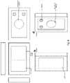
- In a preferred embodiment shown in
Figs. 6 ,7 and8 , thedock 101 is able to support and hold thewireless controller 102 by magnetic means. In a secondary embodiment, thewireless controller 102 is hold to thedock 101 by clips means. When thewireless controller 102 is coupled to thedock 101, a DC voltage is supplied to thewireless controller 102, which is used to energize the same and to charge its internal battery. Thewireless controller 102 contains smart electronics therein designed to charge in a stable and controlled way a battery that is of the Ion-Lithium type, which is able to provide thewireless controller 102 with enough charge for a full day. The configuration of dock-controller has the advantage of allowing the user to remove thewireless controller 102 from the wall so that it can be used anywhere in the house without having to be wired. Thewireless controller 102 can be much more advanced than existing controllers because it contains a battery with much more power than those used in state of the art smart home controllers, and can be recharged by being coupled back to thedock 101. Another important advantage is that thewireless controller 102 has different configurations and embodiments, giving the user the flexibility to install different types of wireless controllers in the same dock on the electrical box, such as button panel, LCD touch screen and waterproof outdoor type controllers. - In a preferred embodiment, the
wireless controllers 102 are able to talk to the smart appliances and home automation systems of the Smart home via Wi-Fi, Zigbee, Zwave, Nordic, Bluetooth, RF or any other type of communication. Thewireless controllers 102 are removable so they can be used anywhere in the house. When thewireless controllers 102 need to recharge their internal battery, they must return to the docking station to recharge. - In a preferred embodiment, in
case wireless controller 102 is not coupled to thedock 101, the latter will be able to control at all times turning On and Off bulbs to which it is connected. That is, thedock 101 controls turning On and Off of bulbs to which it is physically connected, independently of thewireless controller 102. This is very useful, because when the user is not able to find thewireless controller 102 or when it is not at his reach, such user may control turning On and Off the bulbs though thedock 101. This is possible since thedock 101 comprises a capacitive type touch sensor at the front part thereof. In case thewireless controller 102 is coupled to thedock 101, capacitive type touch sensor is covered and invalidated bysuch wireless controller 102, enabling now the bulb control by thewireless controller 102. - The
wireless controller 102 may be a simple button board having buttons of capacitive type or a Tablet type screen (LCD touch screen), as depicted inFig. 6 . Thewireless controller 102 may even be programmed through a mobile APP to configure a customized action on the capacitive buttons. The customized action may be turning ON or OFF a smart bulb in the network, control several smart bulbs at the same time or program scenes. It is important to mention that, since thewireless controller 102 will communicate wirelessly with the central control hub or internet router, it can control any smart bulb in the facilities in addition to the smart bulb to which thedock 101 is physically connected. In the wireless LCD touchscreen type controller 102, a variety of different scenarios can be programmed through the screen and can even be used to obtain feedback from other bulb-controller systems and display information on the wall of the house. - The
wireless controllers 102 are able to communicate with different smart home systems through the internet or locally through well-known communication protocols. For example, thewireless controller 102 could communicate with the Philips Hue™ central hub to be able to send commands to its system. As another example, it is possible to communicate through the internet with smart voice assistants, which control the smart home systems. - As depicted in
Fig. 9 ,wireless controllers 102 placed on the dock are able to run third party apps such as Apple HomeKit™ or Google Assistant™ and display information in real time from different sources, for example, receive weather information, stock market information and news information which can be displayed on the user's wall, or even play music, without needing to install a Tablet on the wall and have to change the electrical installation of the house. - In another embodiment, the screens of the
wireless controllers 102, that include a high-fidelity microphone, can be used as means to perform videocalls through the house or even through the Internet. They can be used as an interphone to manage communication within the house too. - In another embodiment, the
wireless controller 102 can be used as video intercom, wherein a real-time image is displayed at the entrance of the house from a surveillance camera contained in thewireless controller 102. In a preferred embodiment, users will receive a notification, at their mobile handset and/or inother wireless controllers 102 of the house, indicating someone has ring the doorbell in the smart home. Additionally,wireless controllers 102 may be used as a closed-circuit television due to its surveillance cameras, as allwireless controllers 102 work as an internal security system. User, through an application, may select and see real-time images from the surveillance cameras contained in eachwireless controller 102 within the smart home. In a secondary embodiment, by usingwireless controllers 102 as an internal security system, these can be used to monitor babies and/or underage kids. In another secondary embodiment, the internal security system communicates wirelessly with communication systems of security guards from residential estates. - The
wireless controllers 102 can also be used to increase security with surveillance within a room by using the camera as a security camera, since they can transmit the image in real time to any device connected to the Internet. - Additionally, the high-fidelity microphone is on 24 hours a day to give the user a voice assistance service. That is, the controller has voice systems integrated such as Amazon Alexa™, Google Home™ or any other voice system that allows to provide such service. It is worth mentioning that
wireless controllers 102 also may contain a motion sensor, humidity sensor, temperature sensor, in order to use this information to make the Smart home ecosystem smarter without using a neutral cable, thus enabling the installation of these sensors in a greater number of places. - In a secondary embodiment, the temperature sensor does not only work for the
wireless controllers 102 to indicate the detected temperature, but also for thewireless controllers 102 to work as a smart thermostat. That is, thewireless controllers 102 are able to run third party home automation apps that control air conditioners as well as heating. Said third party home automation apps may be NEST™, Ecobee™ or any other application dedicated to control air conditioners as well as heating. - Furthermore, the
wireless controllers 102 are able to run third party home automation apps such as Apple HomeKit™ or Google Assistant™, among others. - The smart home controller device is able to modify its user interface through the LCD screen of the
wireless controllers 102. That is, the user can choose from an image database one image that matches with the interior design of the house to display it in the LCD screen of thewireless controllers 102 to make the system more aesthetic and interesting. A mobile application may be used to take a picture of the wall where the smart home controller device will be installed, and then the LCD screen is able to modify its user interface to display the same color as the wall, to have smart home controllers device with the same finishes and styles as the wall, to provide better aesthetics and integration with the smart home. - It is necessary to bear in mind that within the claim chapter the following terms are used:
- Lighting device refers to a smart, non-smart, incandescent, FCL or LED type bulb;
- Smart lighting device refers to a smart bulb;
- Conventional lighting device refers to a non-smart, incandescent, FCL or LED type bulb.
- It should be understood that the foregoing description is illustrative of the invention and should not be interpreted as limiting the invention. Those skilled in the art may create various modifications and applications without being isolated from the of the invention as defined by the appended claims.
Claims (14)
- A smart home controller device for controlling a lighting device, wherein the smart home controller device is configured to operate with two wires of an electrical installation (103) and to be installed in a standard electrical box, the smart home controller device comprising:a first low power module (105);a charger module (106);a high power module; anda wireless controller (102);wherein the first low power module, when the lighting device is a smart lighting device (104), is configured to energize the charger module (106), which provides power to a battery of the wireless controller (102);wherein the wireless controller (102) is configured to wirelessly send and receive signals from the smart lighting device (104) to control its operation and monitor its status;characterized in that the smart home controller device further comprises:a second low power module, wherein the second low power module is configured to provide power to the wireless controller when the lighting device is ON, when the lighting device is a conventional lighting device;wherein the high power module is configured to control the switching ON, OFF and dimming of the conventional lighting device.
- The smart home controller device of Claim 1, wherein the smart home controller device is configured to draw power from a smart, non-smart, incandescent, FCL or LED type bulb, uninterruptedly, regardless of whether a bulb is ON or OFF.
- The smart home controller device of Claim 1, wherein the wireless controller (102) is configured to wirelessly send and receive signals from the smart lighting device (104) to control its operation and monitor its status independently of whether the smart lighting device (104) is ON or OFF.
- The smart home controller device of Claim 1, wherein the charger module (106) is configured to provide power in a continuous and controlled manner to a battery of the wireless controller (102).
- The smart home controller device of Claim 4, wherein the supply of power to the battery by the wireless controller (102) is via wireless power transmission or by contact via electrical connectors.
- The smart home controller device of Claim 1, wherein the wireless controller (102) is supported and held by magnetic means or by clips means.
- The smart home controller device of Claim 1, wherein the first low power module (105) is implemented by means of a Flyback type converter and wherein the second low power module comprises an oscillator.
- The smart home controller device of Claim 1, wherein the wireless controller (102) has a configuration according to one of the following: a button panel, a LCD touch screen and a waterproof outdoor type controller.
- The smart home controller device of Claim 1, wherein the wireless controller (102) is configured to send a wireless signal to a central control hub or an internet router, in order to control the smart lighting device (104) or to control a second smart lighting device in addition to the smart lighting device (104) to which the smart home controller device is physically connected.
- The smart home controller device of Claim 1, wherein the wireless controller (102) further comprises at least one of the following: a motion sensor, a humidity sensor, a temperature sensor, a surveillance camera and/or a high-fidelity microphone.
- The smart home controller device of Claim 1, wherein the wireless controller (102) is configured to communicate with a plurality of smart home systems through the internet or locally through communication protocols, and wherein the wireless controller (102) is configured to communicate through the internet with a plurality of smart voice assistants adapted to control the smart home systems, or wherein a plurality of wireless controllers (102) are configured to perform videocalls through the smart home or through the Internet or, wherein the plurality of wireless controllers (102) are configured to be an interphone to manage communication within the smart home or, wherein the plurality of wireless controllers (102) are configured to be video intercom, wherein a real-time image is displayed at the entrance of the smart home from a surveillance camera or, wherein the plurality of wireless controllers (102) are configured to be in closed- circuit television systems due to surveillance cameras.
- The smart home controller device of Claim 10, wherein the wireless controller (102) is configured to be a smart thermostat.
- The smart home controller device of Claim 1, wherein the wireless controller (102) is configured to display information in real time and wherein said information comprises weather information, stock market information and news information.
- The smart home controller device of Claim 1, wherein the wireless controller (102) is configured to play music.
Applications Claiming Priority (3)
| Application Number | Priority Date | Filing Date | Title |
|---|---|---|---|
| US201862688865P | 2018-06-22 | 2018-06-22 | |
| US16/448,705US10602592B2 (en) | 2018-06-22 | 2019-06-21 | Retrofit smart home controller device with power supply module, charger and dock |
| PCT/US2019/038643WO2019246607A1 (en) | 2018-06-22 | 2019-06-24 | Retrofit smart home controller device with power supply module, charger and dock |
Publications (3)
| Publication Number | Publication Date |
|---|---|
| EP3811164A1 EP3811164A1 (en) | 2021-04-28 |
| EP3811164A4 EP3811164A4 (en) | 2021-09-01 |
| EP3811164B1true EP3811164B1 (en) | 2022-09-07 |
Family
ID=68980915
Family Applications (1)
| Application Number | Title | Priority Date | Filing Date |
|---|---|---|---|
| EP19821493.4AActiveEP3811164B1 (en) | 2018-06-22 | 2019-06-24 | Retrofit smart home controller device with power supply module, charger and dock |
Country Status (6)
| Country | Link |
|---|---|
| US (1) | US10602592B2 (en) |
| EP (1) | EP3811164B1 (en) |
| CA (1) | CA3104907C (en) |
| ES (1) | ES2932610T3 (en) |
| MX (1) | MX388874B (en) |
| WO (1) | WO2019246607A1 (en) |
Families Citing this family (5)
| Publication number | Priority date | Publication date | Assignee | Title |
|---|---|---|---|---|
| US11476668B2 (en) | 2020-11-19 | 2022-10-18 | Kleverness Incorporated | Electronic commuting device for controlling the energy current flow in a wire bidirectionally within an electrical installation |
| CN114415531B (en)* | 2021-12-31 | 2024-03-15 | 厦门亚锝电子科技有限公司 | Intelligent home control panel and function allocation method thereof |
| US12130604B2 (en) | 2022-02-23 | 2024-10-29 | International Business Machines Corporation | Cognitive retrofit for legacy control devices |
| US12265699B2 (en)* | 2022-06-24 | 2025-04-01 | Red Weather Systems Inc. | Central control hub for entertainment system |
| GB2625081B (en)* | 2022-12-02 | 2025-09-24 | Tewke Ltd | Light switch |
Family Cites Families (18)
| Publication number | Priority date | Publication date | Assignee | Title |
|---|---|---|---|---|
| US4633141A (en) | 1985-02-28 | 1986-12-30 | Motorola, Inc. | Low voltage power source power inverter for an electroluminescent drive |
| US6993289B2 (en) | 2000-08-02 | 2006-01-31 | Simple Devices | System including a wall switch device and a system including a power outlet device and methods for using the same |
| US6751522B2 (en) | 2000-08-30 | 2004-06-15 | Kabushiki Kaisha Topcon | Lens layout setting apparatus for lens grinding process and display apparatus for the same |
| US20030083758A1 (en) | 2001-11-01 | 2003-05-01 | Williamson Charles G. | Remote updating of intelligent household appliances |
| US6751552B1 (en)* | 2002-06-28 | 2004-06-15 | Garmin Ltd. | Rugged, waterproof, navigation device with touch panel |
| US8994276B2 (en) | 2006-03-28 | 2015-03-31 | Wireless Environment, Llc | Grid shifting system for a lighting circuit |
| US20110073743A1 (en) | 2009-05-13 | 2011-03-31 | Steven Shamie | Universal holder and flexible member for mounting, holding and adjustably positioning electronic products and accessories |
| US9078305B2 (en)* | 2009-12-16 | 2015-07-07 | Enlighted, Inc. | Distributed lighting control that includes satellite control units |
| BR112013018148B1 (en) | 2011-01-18 | 2022-05-24 | Savant Systems, Inc | Remote control system and method for electronic devices |
| US10285241B2 (en)* | 2011-10-06 | 2019-05-07 | A9.Com, Inc. | Wireless lighting device with charging port |
| CA2854784C (en)* | 2011-11-03 | 2021-07-20 | Digital Lumens Incorporated | Methods, systems, and apparatus for intelligent lighting |
| US9408268B2 (en)* | 2012-06-19 | 2016-08-02 | Wireless Environment, Llc | Group management of a wireless power outage lighting system |
| US9208676B2 (en) | 2013-03-14 | 2015-12-08 | Google Inc. | Devices, methods, and associated information processing for security in a smart-sensored home |
| US10565835B2 (en) | 2013-01-21 | 2020-02-18 | Rtc Inc. | Control and monitoring of light-emitting-diode (LED) bulbs |
| US9980352B2 (en) | 2013-03-15 | 2018-05-22 | Kortek Industries Pty Ltd | Wireless light pairing, dimming and control |
| BR112016006075B1 (en) | 2013-09-25 | 2020-12-15 | Linde Aktiengesellschaft | COLUMN UNDERSTANDING LIQUID DISTRIBUTORS AND MASS TRANSFER TRAYS CONTAINED BY ANGULAR PROFILES |
| CN104378886A (en) | 2014-11-14 | 2015-02-25 | 生迪光电科技股份有限公司 | Intelligent illumination control system and method |
| US10201064B1 (en) | 2017-08-01 | 2019-02-05 | Kleverness Incorporated | Power supply for a two-wire smart dimmer and lighting loads thereof |
- 2019
- 2019-06-21USUS16/448,705patent/US10602592B2/enactiveActive
- 2019-06-24MXMX2021000065Apatent/MX388874B/enunknown
- 2019-06-24EPEP19821493.4Apatent/EP3811164B1/enactiveActive
- 2019-06-24WOPCT/US2019/038643patent/WO2019246607A1/ennot_activeCeased
- 2019-06-24ESES19821493Tpatent/ES2932610T3/enactiveActive
- 2019-06-24CACA3104907Apatent/CA3104907C/enactiveActive
Also Published As
| Publication number | Publication date |
|---|---|
| MX2021000065A (en) | 2021-12-16 |
| ES2932610T3 (en) | 2023-01-23 |
| EP3811164A1 (en) | 2021-04-28 |
| MX388874B (en) | 2025-03-20 |
| US10602592B2 (en) | 2020-03-24 |
| WO2019246607A1 (en) | 2019-12-26 |
| EP3811164A4 (en) | 2021-09-01 |
| CA3104907A1 (en) | 2019-12-26 |
| US20190394863A1 (en) | 2019-12-26 |
| CA3104907C (en) | 2022-08-23 |
Similar Documents
| Publication | Publication Date | Title |
|---|---|---|
| EP3811164B1 (en) | Retrofit smart home controller device with power supply module, charger and dock | |
| US11658442B2 (en) | Controllable electrical outlet with a controlled wired output | |
| US10070505B2 (en) | Scalable building control system, method, and apparatus | |
| US11460184B2 (en) | Modular smart quick connect device for electrical fixtures | |
| US9920888B1 (en) | Multi-purpose lightbulb having power failure mode | |
| US11209845B2 (en) | Modular wall-mounted electrical control device | |
| US9784417B1 (en) | Multi-purpose lightbulb | |
| EP3047494B1 (en) | Easy-install home automation light switch | |
| US20180109999A1 (en) | Power optimized video for smart home ecosystem | |
| EP2751874B1 (en) | Electric box safety redesign | |
| CN102356448A (en) | Occupancy sensing including device clock | |
| US20230419672A1 (en) | Configurable modular devices and other systems and methods | |
| KR101945238B1 (en) | Remote Controllable Light Switch and Light Switch System | |
| CN105657938A (en) | Lamp control system of smart home | |
| WO2024054582A2 (en) | Configurable devices and other systems and methods | |
| CN212544110U (en) | Composite lamp | |
| CN205265723U (en) | A smart home system | |
| WO2020172847A1 (en) | Smart device, and power taking circuit thereof and method therefor | |
| US11476668B2 (en) | Electronic commuting device for controlling the energy current flow in a wire bidirectionally within an electrical installation | |
| JP2023130911A (en) | Illumination tool and illumination control system |
Legal Events
| Date | Code | Title | Description |
|---|---|---|---|
| STAA | Information on the status of an ep patent application or granted ep patent | Free format text:STATUS: THE INTERNATIONAL PUBLICATION HAS BEEN MADE | |
| PUAI | Public reference made under article 153(3) epc to a published international application that has entered the european phase | Free format text:ORIGINAL CODE: 0009012 | |
| STAA | Information on the status of an ep patent application or granted ep patent | Free format text:STATUS: REQUEST FOR EXAMINATION WAS MADE | |
| 17P | Request for examination filed | Effective date:20210120 | |
| AK | Designated contracting states | Kind code of ref document:A1 Designated state(s):AL AT BE BG CH CY CZ DE DK EE ES FI FR GB GR HR HU IE IS IT LI LT LU LV MC MK MT NL NO PL PT RO RS SE SI SK SM TR | |
| AX | Request for extension of the european patent | Extension state:BA ME | |
| A4 | Supplementary search report drawn up and despatched | Effective date:20210803 | |
| RIC1 | Information provided on ipc code assigned before grant | Ipc:G05B 19/042 20060101AFI20210728BHEP Ipc:G08B 19/00 20060101ALI20210728BHEP Ipc:G08B 23/00 20060101ALI20210728BHEP Ipc:G08B 27/00 20060101ALI20210728BHEP Ipc:H04L 12/28 20060101ALI20210728BHEP | |
| DAV | Request for validation of the european patent (deleted) | ||
| DAX | Request for extension of the european patent (deleted) | ||
| GRAP | Despatch of communication of intention to grant a patent | Free format text:ORIGINAL CODE: EPIDOSNIGR1 | |
| STAA | Information on the status of an ep patent application or granted ep patent | Free format text:STATUS: GRANT OF PATENT IS INTENDED | |
| INTG | Intention to grant announced | Effective date:20220525 | |
| GRAS | Grant fee paid | Free format text:ORIGINAL CODE: EPIDOSNIGR3 | |
| GRAA | (expected) grant | Free format text:ORIGINAL CODE: 0009210 | |
| STAA | Information on the status of an ep patent application or granted ep patent | Free format text:STATUS: THE PATENT HAS BEEN GRANTED | |
| AK | Designated contracting states | Kind code of ref document:B1 Designated state(s):AL AT BE BG CH CY CZ DE DK EE ES FI FR GB GR HR HU IE IS IT LI LT LU LV MC MK MT NL NO PL PT RO RS SE SI SK SM TR | |
| REG | Reference to a national code | Ref country code:GB Ref legal event code:FG4D | |
| REG | Reference to a national code | Ref country code:CH Ref legal event code:EP Ref country code:AT Ref legal event code:REF Ref document number:1517572 Country of ref document:AT Kind code of ref document:T Effective date:20220915 | |
| REG | Reference to a national code | Ref country code:DE Ref legal event code:R096 Ref document number:602019019416 Country of ref document:DE | |
| REG | Reference to a national code | Ref country code:IE Ref legal event code:FG4D | |
| REG | Reference to a national code | Ref country code:LT Ref legal event code:MG9D | |
| REG | Reference to a national code | Ref country code:NL Ref legal event code:MP Effective date:20220907 | |
| REG | Reference to a national code | Ref country code:ES Ref legal event code:FG2A Ref document number:2932610 Country of ref document:ES Kind code of ref document:T3 Effective date:20230123 | |
| PG25 | Lapsed in a contracting state [announced via postgrant information from national office to epo] | Ref country code:SE Free format text:LAPSE BECAUSE OF FAILURE TO SUBMIT A TRANSLATION OF THE DESCRIPTION OR TO PAY THE FEE WITHIN THE PRESCRIBED TIME-LIMIT Effective date:20220907 Ref country code:RS Free format text:LAPSE BECAUSE OF FAILURE TO SUBMIT A TRANSLATION OF THE DESCRIPTION OR TO PAY THE FEE WITHIN THE PRESCRIBED TIME-LIMIT Effective date:20220907 Ref country code:NO Free format text:LAPSE BECAUSE OF FAILURE TO SUBMIT A TRANSLATION OF THE DESCRIPTION OR TO PAY THE FEE WITHIN THE PRESCRIBED TIME-LIMIT Effective date:20221207 Ref country code:LV Free format text:LAPSE BECAUSE OF FAILURE TO SUBMIT A TRANSLATION OF THE DESCRIPTION OR TO PAY THE FEE WITHIN THE PRESCRIBED TIME-LIMIT Effective date:20220907 Ref country code:LT Free format text:LAPSE BECAUSE OF FAILURE TO SUBMIT A TRANSLATION OF THE DESCRIPTION OR TO PAY THE FEE WITHIN THE PRESCRIBED TIME-LIMIT Effective date:20220907 Ref country code:FI Free format text:LAPSE BECAUSE OF FAILURE TO SUBMIT A TRANSLATION OF THE DESCRIPTION OR TO PAY THE FEE WITHIN THE PRESCRIBED TIME-LIMIT Effective date:20220907 | |
| REG | Reference to a national code | Ref country code:AT Ref legal event code:MK05 Ref document number:1517572 Country of ref document:AT Kind code of ref document:T Effective date:20220907 | |
| PG25 | Lapsed in a contracting state [announced via postgrant information from national office to epo] | Ref country code:HR Free format text:LAPSE BECAUSE OF FAILURE TO SUBMIT A TRANSLATION OF THE DESCRIPTION OR TO PAY THE FEE WITHIN THE PRESCRIBED TIME-LIMIT Effective date:20220907 Ref country code:GR Free format text:LAPSE BECAUSE OF FAILURE TO SUBMIT A TRANSLATION OF THE DESCRIPTION OR TO PAY THE FEE WITHIN THE PRESCRIBED TIME-LIMIT Effective date:20221208 | |
| PG25 | Lapsed in a contracting state [announced via postgrant information from national office to epo] | Ref country code:SM Free format text:LAPSE BECAUSE OF FAILURE TO SUBMIT A TRANSLATION OF THE DESCRIPTION OR TO PAY THE FEE WITHIN THE PRESCRIBED TIME-LIMIT Effective date:20220907 Ref country code:RO Free format text:LAPSE BECAUSE OF FAILURE TO SUBMIT A TRANSLATION OF THE DESCRIPTION OR TO PAY THE FEE WITHIN THE PRESCRIBED TIME-LIMIT Effective date:20220907 Ref country code:PT Free format text:LAPSE BECAUSE OF FAILURE TO SUBMIT A TRANSLATION OF THE DESCRIPTION OR TO PAY THE FEE WITHIN THE PRESCRIBED TIME-LIMIT Effective date:20230109 Ref country code:CZ Free format text:LAPSE BECAUSE OF FAILURE TO SUBMIT A TRANSLATION OF THE DESCRIPTION OR TO PAY THE FEE WITHIN THE PRESCRIBED TIME-LIMIT Effective date:20220907 Ref country code:AT Free format text:LAPSE BECAUSE OF FAILURE TO SUBMIT A TRANSLATION OF THE DESCRIPTION OR TO PAY THE FEE WITHIN THE PRESCRIBED TIME-LIMIT Effective date:20220907 | |
| PG25 | Lapsed in a contracting state [announced via postgrant information from national office to epo] | Ref country code:SK Free format text:LAPSE BECAUSE OF FAILURE TO SUBMIT A TRANSLATION OF THE DESCRIPTION OR TO PAY THE FEE WITHIN THE PRESCRIBED TIME-LIMIT Effective date:20220907 Ref country code:PL Free format text:LAPSE BECAUSE OF FAILURE TO SUBMIT A TRANSLATION OF THE DESCRIPTION OR TO PAY THE FEE WITHIN THE PRESCRIBED TIME-LIMIT Effective date:20220907 Ref country code:IS Free format text:LAPSE BECAUSE OF FAILURE TO SUBMIT A TRANSLATION OF THE DESCRIPTION OR TO PAY THE FEE WITHIN THE PRESCRIBED TIME-LIMIT Effective date:20230107 Ref country code:EE Free format text:LAPSE BECAUSE OF FAILURE TO SUBMIT A TRANSLATION OF THE DESCRIPTION OR TO PAY THE FEE WITHIN THE PRESCRIBED TIME-LIMIT Effective date:20220907 | |
| REG | Reference to a national code | Ref country code:DE Ref legal event code:R097 Ref document number:602019019416 Country of ref document:DE | |
| PG25 | Lapsed in a contracting state [announced via postgrant information from national office to epo] | Ref country code:NL Free format text:LAPSE BECAUSE OF FAILURE TO SUBMIT A TRANSLATION OF THE DESCRIPTION OR TO PAY THE FEE WITHIN THE PRESCRIBED TIME-LIMIT Effective date:20220907 Ref country code:AL Free format text:LAPSE BECAUSE OF FAILURE TO SUBMIT A TRANSLATION OF THE DESCRIPTION OR TO PAY THE FEE WITHIN THE PRESCRIBED TIME-LIMIT Effective date:20220907 | |
| PLBE | No opposition filed within time limit | Free format text:ORIGINAL CODE: 0009261 | |
| STAA | Information on the status of an ep patent application or granted ep patent | Free format text:STATUS: NO OPPOSITION FILED WITHIN TIME LIMIT | |
| PG25 | Lapsed in a contracting state [announced via postgrant information from national office to epo] | Ref country code:DK Free format text:LAPSE BECAUSE OF FAILURE TO SUBMIT A TRANSLATION OF THE DESCRIPTION OR TO PAY THE FEE WITHIN THE PRESCRIBED TIME-LIMIT Effective date:20220907 | |
| PGFP | Annual fee paid to national office [announced via postgrant information from national office to epo] | Ref country code:FR Payment date:20230628 Year of fee payment:5 | |
| 26N | No opposition filed | Effective date:20230608 | |
| PG25 | Lapsed in a contracting state [announced via postgrant information from national office to epo] | Ref country code:SI Free format text:LAPSE BECAUSE OF FAILURE TO SUBMIT A TRANSLATION OF THE DESCRIPTION OR TO PAY THE FEE WITHIN THE PRESCRIBED TIME-LIMIT Effective date:20220907 | |
| PGFP | Annual fee paid to national office [announced via postgrant information from national office to epo] | Ref country code:TR Payment date:20230718 Year of fee payment:5 Ref country code:IT Payment date:20230627 Year of fee payment:5 Ref country code:GB Payment date:20230627 Year of fee payment:5 Ref country code:ES Payment date:20230710 Year of fee payment:5 | |
| PGFP | Annual fee paid to national office [announced via postgrant information from national office to epo] | Ref country code:DE Payment date:20230703 Year of fee payment:5 | |
| PG25 | Lapsed in a contracting state [announced via postgrant information from national office to epo] | Ref country code:MC Free format text:LAPSE BECAUSE OF FAILURE TO SUBMIT A TRANSLATION OF THE DESCRIPTION OR TO PAY THE FEE WITHIN THE PRESCRIBED TIME-LIMIT Effective date:20220907 | |
| PG25 | Lapsed in a contracting state [announced via postgrant information from national office to epo] | Ref country code:MC Free format text:LAPSE BECAUSE OF FAILURE TO SUBMIT A TRANSLATION OF THE DESCRIPTION OR TO PAY THE FEE WITHIN THE PRESCRIBED TIME-LIMIT Effective date:20220907 | |
| REG | Reference to a national code | Ref country code:CH Ref legal event code:PL | |
| REG | Reference to a national code | Ref country code:BE Ref legal event code:MM Effective date:20230630 | |
| PG25 | Lapsed in a contracting state [announced via postgrant information from national office to epo] | Ref country code:LU Free format text:LAPSE BECAUSE OF NON-PAYMENT OF DUE FEES Effective date:20230624 | |
| REG | Reference to a national code | Ref country code:IE Ref legal event code:MM4A | |
| PG25 | Lapsed in a contracting state [announced via postgrant information from national office to epo] | Ref country code:LU Free format text:LAPSE BECAUSE OF NON-PAYMENT OF DUE FEES Effective date:20230624 | |
| PG25 | Lapsed in a contracting state [announced via postgrant information from national office to epo] | Ref country code:IE Free format text:LAPSE BECAUSE OF NON-PAYMENT OF DUE FEES Effective date:20230624 | |
| PG25 | Lapsed in a contracting state [announced via postgrant information from national office to epo] | Ref country code:IE Free format text:LAPSE BECAUSE OF NON-PAYMENT OF DUE FEES Effective date:20230624 Ref country code:CH Free format text:LAPSE BECAUSE OF NON-PAYMENT OF DUE FEES Effective date:20230630 | |
| PG25 | Lapsed in a contracting state [announced via postgrant information from national office to epo] | Ref country code:BE Free format text:LAPSE BECAUSE OF NON-PAYMENT OF DUE FEES Effective date:20230630 | |
| PG25 | Lapsed in a contracting state [announced via postgrant information from national office to epo] | Ref country code:BG Free format text:LAPSE BECAUSE OF FAILURE TO SUBMIT A TRANSLATION OF THE DESCRIPTION OR TO PAY THE FEE WITHIN THE PRESCRIBED TIME-LIMIT Effective date:20220907 | |
| PG25 | Lapsed in a contracting state [announced via postgrant information from national office to epo] | Ref country code:BG Free format text:LAPSE BECAUSE OF FAILURE TO SUBMIT A TRANSLATION OF THE DESCRIPTION OR TO PAY THE FEE WITHIN THE PRESCRIBED TIME-LIMIT Effective date:20220907 | |
| REG | Reference to a national code | Ref country code:DE Ref legal event code:R119 Ref document number:602019019416 Country of ref document:DE | |
| GBPC | Gb: european patent ceased through non-payment of renewal fee | Effective date:20240624 | |
| PG25 | Lapsed in a contracting state [announced via postgrant information from national office to epo] | Ref country code:DE Free format text:LAPSE BECAUSE OF NON-PAYMENT OF DUE FEES Effective date:20250101 | |
| PG25 | Lapsed in a contracting state [announced via postgrant information from national office to epo] | Ref country code:FR Free format text:LAPSE BECAUSE OF NON-PAYMENT OF DUE FEES Effective date:20240630 | |
| PG25 | Lapsed in a contracting state [announced via postgrant information from national office to epo] | Ref country code:IT Free format text:LAPSE BECAUSE OF NON-PAYMENT OF DUE FEES Effective date:20240624 Ref country code:GB Free format text:LAPSE BECAUSE OF NON-PAYMENT OF DUE FEES Effective date:20240624 | |
| PG25 | Lapsed in a contracting state [announced via postgrant information from national office to epo] | Ref country code:CY Free format text:LAPSE BECAUSE OF FAILURE TO SUBMIT A TRANSLATION OF THE DESCRIPTION OR TO PAY THE FEE WITHIN THE PRESCRIBED TIME-LIMIT; INVALID AB INITIO Effective date:20190624 | |
| REG | Reference to a national code | Ref country code:ES Ref legal event code:FD2A Effective date:20250730 | |
| PG25 | Lapsed in a contracting state [announced via postgrant information from national office to epo] | Ref country code:HU Free format text:LAPSE BECAUSE OF FAILURE TO SUBMIT A TRANSLATION OF THE DESCRIPTION OR TO PAY THE FEE WITHIN THE PRESCRIBED TIME-LIMIT; INVALID AB INITIO Effective date:20190624 | |
| PG25 | Lapsed in a contracting state [announced via postgrant information from national office to epo] | Ref country code:ES Free format text:LAPSE BECAUSE OF NON-PAYMENT OF DUE FEES Effective date:20240625 |