EP3810231B1 - Enteral syringe with vented collar - Google Patents
Enteral syringe with vented collarDownload PDFInfo
- Publication number
- EP3810231B1 EP3810231B1EP19735208.1AEP19735208AEP3810231B1EP 3810231 B1EP3810231 B1EP 3810231B1EP 19735208 AEP19735208 AEP 19735208AEP 3810231 B1EP3810231 B1EP 3810231B1
- Authority
- EP
- European Patent Office
- Prior art keywords
- syringe
- enteral
- enteral collar
- vent
- collar
- Prior art date
- Legal status (The legal status is an assumption and is not a legal conclusion. Google has not performed a legal analysis and makes no representation as to the accuracy of the status listed.)
- Active
Links
Images


Classifications
- A—HUMAN NECESSITIES
- A61—MEDICAL OR VETERINARY SCIENCE; HYGIENE
- A61M—DEVICES FOR INTRODUCING MEDIA INTO, OR ONTO, THE BODY; DEVICES FOR TRANSDUCING BODY MEDIA OR FOR TAKING MEDIA FROM THE BODY; DEVICES FOR PRODUCING OR ENDING SLEEP OR STUPOR
- A61M39/00—Tubes, tube connectors, tube couplings, valves, access sites or the like, specially adapted for medical use
- A61M39/10—Tube connectors; Tube couplings
- A—HUMAN NECESSITIES
- A61—MEDICAL OR VETERINARY SCIENCE; HYGIENE
- A61M—DEVICES FOR INTRODUCING MEDIA INTO, OR ONTO, THE BODY; DEVICES FOR TRANSDUCING BODY MEDIA OR FOR TAKING MEDIA FROM THE BODY; DEVICES FOR PRODUCING OR ENDING SLEEP OR STUPOR
- A61M5/00—Devices for bringing media into the body in a subcutaneous, intra-vascular or intramuscular way; Accessories therefor, e.g. filling or cleaning devices, arm-rests
- A61M5/178—Syringes
- A61M5/31—Details
- A61M5/3129—Syringe barrels
- A61M5/3134—Syringe barrels characterised by constructional features of the distal end, i.e. end closest to the tip of the needle cannula
- A—HUMAN NECESSITIES
- A61—MEDICAL OR VETERINARY SCIENCE; HYGIENE
- A61J—CONTAINERS SPECIALLY ADAPTED FOR MEDICAL OR PHARMACEUTICAL PURPOSES; DEVICES OR METHODS SPECIALLY ADAPTED FOR BRINGING PHARMACEUTICAL PRODUCTS INTO PARTICULAR PHYSICAL OR ADMINISTERING FORMS; DEVICES FOR ADMINISTERING FOOD OR MEDICINES ORALLY; BABY COMFORTERS; DEVICES FOR RECEIVING SPITTLE
- A61J1/00—Containers specially adapted for medical or pharmaceutical purposes
- A61J1/14—Details; Accessories therefor
- A61J1/20—Arrangements for transferring or mixing fluids, e.g. from vial to syringe
- A61J1/2096—Combination of a vial and a syringe for transferring or mixing their contents
- A—HUMAN NECESSITIES
- A61—MEDICAL OR VETERINARY SCIENCE; HYGIENE
- A61J—CONTAINERS SPECIALLY ADAPTED FOR MEDICAL OR PHARMACEUTICAL PURPOSES; DEVICES OR METHODS SPECIALLY ADAPTED FOR BRINGING PHARMACEUTICAL PRODUCTS INTO PARTICULAR PHYSICAL OR ADMINISTERING FORMS; DEVICES FOR ADMINISTERING FOOD OR MEDICINES ORALLY; BABY COMFORTERS; DEVICES FOR RECEIVING SPITTLE
- A61J15/00—Feeding-tubes for therapeutic purposes
- A61J15/0026—Parts, details or accessories for feeding-tubes
- A61J15/0076—Feeding pumps
- A—HUMAN NECESSITIES
- A61—MEDICAL OR VETERINARY SCIENCE; HYGIENE
- A61J—CONTAINERS SPECIALLY ADAPTED FOR MEDICAL OR PHARMACEUTICAL PURPOSES; DEVICES OR METHODS SPECIALLY ADAPTED FOR BRINGING PHARMACEUTICAL PRODUCTS INTO PARTICULAR PHYSICAL OR ADMINISTERING FORMS; DEVICES FOR ADMINISTERING FOOD OR MEDICINES ORALLY; BABY COMFORTERS; DEVICES FOR RECEIVING SPITTLE
- A61J15/00—Feeding-tubes for therapeutic purposes
- A61J15/0026—Parts, details or accessories for feeding-tubes
- A61J15/0096—Provisions for venting
- A—HUMAN NECESSITIES
- A61—MEDICAL OR VETERINARY SCIENCE; HYGIENE
- A61M—DEVICES FOR INTRODUCING MEDIA INTO, OR ONTO, THE BODY; DEVICES FOR TRANSDUCING BODY MEDIA OR FOR TAKING MEDIA FROM THE BODY; DEVICES FOR PRODUCING OR ENDING SLEEP OR STUPOR
- A61M5/00—Devices for bringing media into the body in a subcutaneous, intra-vascular or intramuscular way; Accessories therefor, e.g. filling or cleaning devices, arm-rests
- A61M5/178—Syringes
- A61M5/31—Details
- A61M2005/3123—Details having air entrapping or venting means, e.g. purging channels in pistons
- A—HUMAN NECESSITIES
- A61—MEDICAL OR VETERINARY SCIENCE; HYGIENE
- A61M—DEVICES FOR INTRODUCING MEDIA INTO, OR ONTO, THE BODY; DEVICES FOR TRANSDUCING BODY MEDIA OR FOR TAKING MEDIA FROM THE BODY; DEVICES FOR PRODUCING OR ENDING SLEEP OR STUPOR
- A61M39/00—Tubes, tube connectors, tube couplings, valves, access sites or the like, specially adapted for medical use
- A61M39/10—Tube connectors; Tube couplings
- A61M2039/1038—Union screw connectors, e.g. hollow screw or sleeve having external threads
- A—HUMAN NECESSITIES
- A61—MEDICAL OR VETERINARY SCIENCE; HYGIENE
- A61M—DEVICES FOR INTRODUCING MEDIA INTO, OR ONTO, THE BODY; DEVICES FOR TRANSDUCING BODY MEDIA OR FOR TAKING MEDIA FROM THE BODY; DEVICES FOR PRODUCING OR ENDING SLEEP OR STUPOR
- A61M39/00—Tubes, tube connectors, tube couplings, valves, access sites or the like, specially adapted for medical use
- A61M39/10—Tube connectors; Tube couplings
- A61M2039/1094—Tube connectors; Tube couplings at least partly incompatible with standard connectors, e.g. to prevent fatal mistakes in connection
- A—HUMAN NECESSITIES
- A61—MEDICAL OR VETERINARY SCIENCE; HYGIENE
- A61M—DEVICES FOR INTRODUCING MEDIA INTO, OR ONTO, THE BODY; DEVICES FOR TRANSDUCING BODY MEDIA OR FOR TAKING MEDIA FROM THE BODY; DEVICES FOR PRODUCING OR ENDING SLEEP OR STUPOR
- A61M39/00—Tubes, tube connectors, tube couplings, valves, access sites or the like, specially adapted for medical use
- A61M39/20—Closure caps or plugs for connectors or open ends of tubes
- A61M2039/205—Closure caps or plugs for connectors or open ends of tubes comprising air venting means
- A—HUMAN NECESSITIES
- A61—MEDICAL OR VETERINARY SCIENCE; HYGIENE
- A61M—DEVICES FOR INTRODUCING MEDIA INTO, OR ONTO, THE BODY; DEVICES FOR TRANSDUCING BODY MEDIA OR FOR TAKING MEDIA FROM THE BODY; DEVICES FOR PRODUCING OR ENDING SLEEP OR STUPOR
- A61M2205/00—General characteristics of the apparatus
- A61M2205/27—General characteristics of the apparatus preventing use
- A61M2205/276—General characteristics of the apparatus preventing use preventing unwanted use
Definitions
- aspects of the present disclosurerelate to a syringe with an enteral connection feature and vents that allow the removal of fluid within the connection feature.
- Enteral nutritioninvolves delivery of nutrient formula or medicine to the gastrointestinal tract.
- Administration of nutrients to a patientcan be accomplished with an enteral feeding system, assembly or device.
- Enteral feeding systemstypically utilize catheters inserted into a patient's nose or mouth, through which nutrients are administered to the gastrointestinal tract.
- a syringe or another devicemay be connected to the catheter to deliver the nutrients through the catheter.
- Nutrients and foodmay also be directly administered to a patient's mouth by a syringe, which may be referred to as an "oral syringe" or "oral delivery" of medication and does not require connection to a catheter or other device.
- Intravenous cathetersare inserted into the vasculature of patients to effect intravascular treatment, which delivers medication through the circulatory or cardiovascular system by accessing any blood vessel.
- cathetersinclude intravenous (IV) catheters, which are inserted into veins, and intraarterial catheters, which are inserted into arteries.
- Syringesare used to deliver fluids for a variety of medical applications, including, for example, oral delivery of nutrients, storage and delivery of fluid to enteral systems by connecting the syringe to an enteral connection, and intravenous delivery of fluids or medication. Delivery of medication through intravenous syringes involves connecting the distal end of a syringe to a catheter by a luer connection.
- a standard luer tip or standard luer connectorhas specifications as provided by the International Organization for Standardization (ISO) defined in ISO 80369-7:2016, including a 6% taper between the distal end and the proximal end.
- ISOInternational Organization for Standardization
- a standard male luer connectorincreases from the open distal end to the proximal end.
- a standard female luer connectordecreases from the open proximal end to the distal end.
- a standard male luer connectorhas an outer cross-sectional diameter measured 0.75 mm from the distal end of the tip of between 3.970 mm and 4.072 mm.
- the length of the standard male luer taperis between 7.500 mm to 10.500 mm.
- the outer cross-sectional diameter measured 7.500 mm from the distal end of the tipis between 4.376 mm and 4.476 mm.
- the phrases "standard male luer connector” and “standard female luer connector”shall refer to connectors having the dimensions described in ISO 80369-7.
- enteral fluidsuch as breast milk or formula from a syringe having a barrel and a plunger in the barrel is achieved by advancing the plunger into the barrel to pressurize the fluid within the barrel and discharge the fluid from the distal tip of the syringe.
- Oral dose syringeshave a barrel with distal tip defining a channel having a diameter substantially larger than the diameter of a needle cannula.
- the distal tipdefines a smooth exterior surface that is insertable into the mouth of a patient to orally introduce medication or other fluids into a patient.
- ENFit connectorLimiting the use of standard luer tips and connectors to use with vascular access systems is one consensus accepted by device manufacturers and regulatory bodies. Recently, the International Standards Organization promulgated ISO 80369-3, to define a safe design for an enteral feeding connector, which is also referred to as ENFit connector.
- the new ENFit connectorhas a unique enteral-specific design that provides a simple way to reduce the risk of enteral tube feeding misconnections and improve patient safety.
- This enteral-specific designhas an enteral collar that surrounds a non-luer tip, the enteral collar including threaded area around the tip of the connector. This area of the collar is sometimes referred to as a moat.
- One method of using an enteral syringeis to fill the syringe with a fluid medication from a cup by inserting the syringe into the cup and drawing up the medication.
- This methodmay be referred to as a "cup fill" operation.
- a medical practitioner performing the cup fill operationmay remove medication from the moat by flicking the syringe barrel with a finger or tapping the syringe barrel, however, it is difficult to ensure that the entire moat has been cleared of medication.
- Residual medication left in the moatis undesirable for several reasons.
- any residual medication in the moatmay interfere when other components (e.g., feeding tubes, extension sets, etc.) are connected to the syringe.
- any residual medicationmay lead to dose accuracy issues (typically overdose), thereby potentially affecting patient safety. Therefore, there is a need for a syringe design which allows for emptying the moat of any medication.
- US 2016/067471 A1discloses a vented connector for medial fluid vessels.
- US 2017/173321 A1discloses enteral connectors having coupling features for providing removable or permanent coupling engagement with a syringe connector.
- US 6 183 421 B1discloses a gas column device with a single use connector.
- EP 2 583 715 A1discloses an infusion tube system and a method for manufacture of infusion tube system.
- US 9 656 022 B1discloses an enteral medication diluting syringe infuser.
- the present disclosurepertains to a syringe comprising a syringe barrel having a distal end, an open proximal end, and a sidewall extending between the distal end to the open proximal end.
- the sidewalldefines a chamber.
- the syringecomprises a non-luer tip at the distal end of the syringe barrel.
- the non-luer tipdimensioned such that the non-luer tip is not connectable to an intravenous device.
- the non-luer tipdefines a fluid pathway in fluid communication with the chamber.
- the syringecomprises an enteral collar having a distal end and a proximal end.
- the proximal endincludes a rim circumferentially abutting the distal end of the syringe barrel.
- the enteral collarsurrounds at least a portion of the non-luer tip and defining a moat region around the non-luer tip.
- the enteral collaris sized to permit connection to an enteral device and prevent connection to a device having a standard luer connector.
- the enteral collarcomprises a vent at the proximal end configured to allow removal of fluid from the moat region and a plug that reversibly seals the vent.
- the enteral collarcomprises four vents at the proximal end.
- the ventsare equally spaced around a circumference of the enteral collar and configured to allow for removal of fluid between the enteral collar and the non-luer tip.
- a further aspect of the present disclosurepertains to a method of adding fluid to a syringe.
- the syringe to which fluid is addedcomprises a syringe barrel having a distal end, an open proximal end and a sidewall extending between the distal end to the open proximal end, the sidewall defining a chamber.
- the syringe used according to the methodfurther comprises a non-luer tip at the distal end of the syringe barrel, the non-luer tip dimensioned such that the non-luer tip is not connectable to an intravenous device, and the non-luer tip defines a fluid pathway in fluid communication with the chamber.
- the syringefurther comprises a plunger within the chamber, an enteral collar having a distal end and a proximal end, the proximal end including a rim circumferentially abutting the distal end of the syringe barrel.
- the enteral collarsurrounds at least a portion of the non-luer tip and defining a moat region around the non-luer tip, the enteral collar sized to permit connection to an enteral device and prevent connection to a device having a standard luer connector and comprising a vent at the proximal end configured to allow removal of fluid from the moat region.
- the non-luer tip of the syringe barrelis placed in a liquid within a liquid reservoir, reversibly sealing the vent with a plug; and the liquid is drawn into the syringe by displacing the plunger within the chamber.
- the distal end of the deviceis the end closest to a patient and away from a practitioner.
- the proximal end of the deviceis the end away from the patient and closest to a practitioner.
- not connectablewith respect to male and female connectors refers to a connector having a shape, size, dimension or structure that prevents connection to another connector.
- a female non-luer connectorhas a shape, size, dimension and/or structure that prevents it from forming a connection with standard a male luer connector and is thus not connectable with respect to the standard male luer connector.
- Such a female non-luer connectorhas a shape, size, dimension and/or structure that permits formation of a connection with a male non-luer connector and is, thus, connectable with respect to the male non-luer connector.
- dimensionshall include the length, diameter or width of a geometric shape or the geometrically shaped components described herein.
- cross-sectional diametershall include the measurement of the longest distance or greatest distance between two points on an edge of a cross-section of an object or component with a circular or non-circular cross-section.
- the two pointsmay be located on the inside surface or outside surface of the edge of the cross-section of the object.
- the cross-sectional diameter of two points located on the inside surface of the edge of the cross-section of the objectshall be referred to as the "inside cross-sectional diameter” and the cross-sectional diameter of two points located on the outside surface of the edge of the cross-section of an object shall be referred to as the "outside cross-sectional diameter.”
- “cross-sectional diameter” of objects having a circular cross-sectionmay be referred to as the "cross-sectional dimension” or “diameter” of the object.
- the terms "cross-sectional dimension,” “cross-sectional diameter” and “diameter”may be used interchangeably for objects having a circular cross-section.
- the enteral collarhas a vent or gap in the enteral collar to allow for removal of fluid between the enteral collar and the syringe tip.
- the enteral collarcomprises more than one vent or gap.
- the ventis placed so as to allow fluid to travel along a threaded region of the enteral collar and out of the collar.
- the syringecomprises a plug that reversibly seals the vent.
- the plugis removable or may be displaced along the longitudinal axis of the syringe barrel to open the vent.
- the plugis rotatable and comprises a gap which can be aligned with the vent to open the vent.
- the syringecan be utilized to draw-up, fill and enterally administer medication or other fluids without fluid in the region between the enteral collar and the syringe tip.
- the syringecan be agitated after drawing-up or filling the syringe to ensure that fluid between the enteral collar and the syringe tip is removed through the vent.
- One or more embodimentsprovide a syringe that can be connected to enteral feeding sets and feeding tubes.
- the connectionis referred to as ENFit and is compliant to ISO 80369-3.
- a syringeis provided that permits the syringe to be connected to enteral tubing and enteral devices such as feeding bags and prevents connection to non-enteral devices, such as intravenous lines, urinary catheters and ventilator tubing.
- One or more embodimentsprovide a syringe that is compliant with ENFit devices and ISO 80369-3 and the syringe is not be compatible with a standard luer connection, thus preventing misadministration of an enteral feeding or medication by the wrong route.
- a syringeis provided with a connector that has a unique enteral-specific design and provides a simple way to reduce the risk of enteral tube feeding misconnections and improve patient safety. Furthermore, the collar does not allow connectivity with any other connector for any other clinical use such as intravenous devices.
- the syringeprovides an enteral-specific syringe that can be used to administer medicine, flush, hydrate, or bolus feed through ENFit feeding tubes and extension sets compliant with ISO 80369-3.
- One or more embodimentprovides a syringe having an enteral collar that does not connect with standard luer connectors that are compliant with ISO Standard 80369-7.
- an embodiment of the disclosureprovides a syringe having a connector with a dimension that is not compatible with standard sized intravenous connectors and ports, thereby keeping the two from being inadvertently mechanically coupled.
- a compatible connectorshall be defined herein as a connector that has a shape, size, dimension or structure to another connector.
- Non-compatible male connectorsmay include standard male luer connectors, which conform to ISO 80369-7:2016.
- the syringe 10includes a syringe barrel 12 having a distal end 14, an open proximal end 16, and a sidewall 18 extending between the distal end 14 to the open proximal end 16, the sidewall 18 defining a chamber 20.
- the axis from the distal end 14 to the open proximal end 16being the longitudinal axis.
- the syringefurther includes a non-luer tip 24 at the distal end 14 of the syringe barrel 12 dimensioned such that the non-luer tip 24 is not connectable to an intravenous device, the non-luer tip 24 defining a fluid pathway 26 in fluid communication with the chamber 20.
- the syringe 10further comprises an enteral collar 30 having a distal end 32 and a proximal end 34.
- the proximal end 34 of the enteral collar 30includes a rim 36 circumferentially abutting the distal end 14 of the syringe barrel 12.
- the enteral collar 30surrounds at least a portion of the non-luer tip 24.
- the enteral collar 30is sized to permit connection to an enteral device and prevent connection to a device having a standard luer connector.
- the enteral collar 30comprises a vent 50 at the proximal end 34 of the enteral collar 30.
- the enteral collar 30is outside the fluid pathway 26 and not in fluid communication with the chamber 20.
- fluid contained in the chamber 20 of the syringe 10flows through non-luer tip 24, and fluid flowing through the non-luer tip 24 is not in contact with the enteral collar 30.
- the vent 50is configured to provide an opportunity or means of escape, passage, or release of fluid between the enteral collar 30 and the non-luer tip 24. As shown in FIG. 6 . the vent 50 may be configured to allow fluid to be removed by traveling according to the arrows 70 through a moat region 38 between the enteral collar 30 and the non-luer tip 24 and through the vent 50. Although not shown in the Figures, in some embodiments, the vent 50 is configured to allow for removal of fluid by air entering the vent 50 to relieve negative pressure and facilitate fluid traveling through the moat region 38 between the enteral collar 30 and the non-luer tip 24 opposite the direction shown in FIG. 6 (i.e. exiting near the distal end 32 of the enteral collar 30).
- the ventmay be any suitable shape through which a fluid may pass.
- the ventis rectangular, square, diamond, oval or circular in shape.
- the enteral collar 30comprises a number of vents 50 in a range of from 1 to 12. In the embodiment shown, the enteral collar 30 comprises four vents 50 (three are visible in FIG. 3 ) at the proximal end 34 of the enteral collar 30.
- the ventshave a rectangular shape, with an aspect ratio of length to width of the rectangle of about 2 to 1.
- the rectangular ventshave a length X width dimensions in a range of from 1-5 mm length and 0.5-5 mm width, with an aspect ratio of length to width of about 2 to 1.
- the length of a rectangular ventis 2 mm and the width is about 1 mm.
- the vent 50may be located in any suitable position on the enteral collar 30.
- the vent 50is located near the proximal end 34 of the enteral collar 30.
- the vent 50is located within the rim 36 of the enteral collar 30 which abuts the distal end 14 of the syringe barrel 12.
- the enteral collar 30comprises a plurality of vents 50 equally spaced around the circumference of the enteral collar 30. For example, four vents 50 may be spaced approximately 90 degrees apart around the circumference of the enteral collar 30.
- the proximal end 34 of the enteral collar 30abuts the distal end 14 of the syringe barrel 12.
- the enteral collar 30is continuous with the sidewall 18.
- continuousmeans that the enteral collar 30 and the sidewall 18 are formed from the same material without an intervening seam or other separation.
- the enteral collar 30is not removable from the syringe or rotatable relative to the syringe barrel 12.
- the enteral collar 30surrounds at least a portion of the non-luer tip 24. In embodiments similar to those pictured, the non-luer tip 24 extends beyond the distal end 32 of the enteral collar 30. In some non-illustrated embodiments, the distal end 32 of the enteral collar 30 extends beyond the end of the non-luer tip 24. In some embodiments, the non-luer tip is sized and dimensioned to provide an ENfit connection that conforms to ISO 80369-3 and is connectable with an opposite ENfit connector that also conforms to ISO 80369-3.
- the enteral collar 30has an inner surface 33 with internal threads 35 or a lug to provide a female non-luer connector, which can engage a male non-luer connector. While not pictured, in other embodiments, the enteral collar 30 has an external surface with external threads or lug to provide a male non-luer connector, which can engage a female non-luer connector. The threads or lug, whether internal or external, are configured to engage a threaded, non-luer connector. In some embodiments, the enteral collar 30 is configured to provide a connector that provides an ENfit connection that conforms to ISO 80369-3 and is connectable with an opposite ENfit connector that also conforms to ISO 80369-3.
- the syringe 10includes a syringe barrel 12. having a distal end 14, an open proximal end 16, a sidewall 18 extending between the distal end 14 to the open proximal end 16, the sidewall 18 defining a chamber 20.
- the axis from the distal end 14 to the open proximal end 16defines a longitudinal axis.
- the syringe 10includes a non-luer tip 24 dimensioned such that the non-luer tip 24 is not connectable to an intravenous device.
- the non-luer tip 24defines a fluid pathway 26 in fluid communication with the chamber 20.
- the syringe 10has an enteral collar 40 having a distal end 42 and a proximal end 44.
- the proximal end 44 of the enteral collar 40includes a rim 46 circumferentially abutting the distal end 14 of the syringe barrel 12.
- the enteral collar 40surrounds at least a portion of the non-luer tip 24.
- the enteral collar 40is sized to permit connection to an enteral device and prevent connection to a device having a standard luer connector.
- the enteral collar 40comprises a vent 50 at the proximal end 44 of the enteral collar 40.
- the enteral collar 40is similar to the enteral collar 30 except that the enteral collar 40 further comprises a plug 60 configured to reversibly seal the vent 50.
- a plug configured to reversibly seal a ventis capable of being positioned so as to seal a vent or leave a vent unaffected and can be transitioned between the two positions.
- the plugwhen the plug does not seal the vent, the position is described as "open". As illustrated in FIG. 11B , when open, fluid within the moat region 48 between the enteral collar 40 and the non-luer tip 24 may travel according to the arrows 90 and will be able to be removed through the vent 50. Similarly, the plug 60 will allow air to enter the vent 50 so as to relieve negative pressure in the moat region 48, thereby allowing the flow of fluid through the moat region 48 in the opposite direction from that shown by the arrows 90 in FIG. 11B .
- the plug 60is removable from the syringe 10. After removal, the syringe 10 may appear as in FIGS. 8 , 10B or 11B .
- the plug 60can be displaced along the longitudinal axis of the syringe barrel 12. The plug 60 may be displaced proximally, towards the practitioner, on the syringe barrel 12 or distally, away from the practitioner, on the enteral collar 40.
- the plug 60is rotatable and comprises a gap which can be aligned with the vent 50.
- the plug 60comprises a number of gaps equal to the number of vents 50 in the enteral collar 40.
- the plug 60comprises more gaps than the number of vents 50 in the enteral collar 40.
- the plug 60comprises fewer gaps than the number of vents 50 in the enteral collar 40.
- the gaphas an area greater than or equal to the area of the vent 50.
- the methodcomprises adding fluid to the syringe.
- the syringecomprises a plunger within the chamber.
- the non-luer tipis placed in fluid communication with a liquid within a liquid reservoir.
- the plungeris displaced within the chamber to draw the liquid into the syringe.
- the syringe providedmay be a syringe comprising an enteral collar 30 or an enteral collar 40. Accordingly, the syringe may comprise a plug 60. If present, the plug 60 may be positioned in an open position or a closed position.
- the tipis placed directly in a liquid within a liquid reservoir.
- the tipmay be connected to the proximal end of a medication straw which has a distal end within the liquid.
- the tipmay be connected to a bottle fill cap and the bottle inverted to place the tip in fluid communication with the liquid inside the bottle. Regardless of the method used, when the plunger is displaced within the chamber, the liquid is drawn into the syringe.
- the liquidmay be any suitable liquid.
- the liquidis a liquid medication.
- the liquidis a nutritional supplement and/or dietary supplement.
- the methodcomprises a "cup-fill" method.
- a cup--fill methodcomprises placing the tip 210 of a syringe 200 in a liquid 250 within a liquid reservoir 260.
- the practitioner 240draws back the plunger 220 of the syringe 200 in order to fill the syringe 200 with the liquid 250.
- a syringe 10 with an enteral collar 30may be placed in a liquid 250 within a liquid reservoir 260. Once placed into the liquid 250, the moat region 38 is filled with liquid 250 to the level of the liquid 250 in the liquid reservoir 260. In some embodiments, the syringe 10 is placed in the liquid 250 such that the vent 50 is above the level of the liquid250 within the liquid reservoir 260. The liquid 250 is drawn into the syringe 10 by displacing the plunger.
- the syringe 10After drawing the liquid 250 into the syringe 10, the syringe 10 is removed from the liquid 250. When removed, the vent 50 allows for the liquid 250 to flow out of the moat region 38. The liquid 250 may flow through the vent 50 or out through the distal end 32 of the enteral collar 30. In some embodiments, the method further comprises agitating the syringe 10 to ensure that liquid 250 in the moat region 38 is removed. Agitating the syringe may include, without limitation, tapping or flicking the syringe 10.
- the syringe 10comprises an enteral collar 40 with a plug 60.
- the vent 50is sealed by the plug 60 (i.e. closed) when the syringe 10 is placed in the liquid 250 and then unsealed (i.e. open) after drawing the liquid into the syringe.
- the plug 60is rotated to unseal the vent 50.
- the plug 60is removed to unseal the vent 50.
- the components of the syringe including the enteral collar, plug and plungermay be fabricated of a variety of materials suitable for medical and health care applications, such as, but not limited to, nylon, polypropylene, polycarbonate, polyvinylidene fluoride, acrylonitrile butadiene styrene, and polyvinyl chloride.
- the plug and the plungerare fabricated from the same material.
Landscapes
- Health & Medical Sciences (AREA)
- Life Sciences & Earth Sciences (AREA)
- Veterinary Medicine (AREA)
- Public Health (AREA)
- General Health & Medical Sciences (AREA)
- Animal Behavior & Ethology (AREA)
- Heart & Thoracic Surgery (AREA)
- Anesthesiology (AREA)
- Hematology (AREA)
- Biomedical Technology (AREA)
- Engineering & Computer Science (AREA)
- Pulmonology (AREA)
- Pharmacology & Pharmacy (AREA)
- Vascular Medicine (AREA)
- Infusion, Injection, And Reservoir Apparatuses (AREA)
Description
- Aspects of the present disclosure relate to a syringe with an enteral connection feature and vents that allow the removal of fluid within the connection feature.
- Enteral nutrition involves delivery of nutrient formula or medicine to the gastrointestinal tract. Administration of nutrients to a patient can be accomplished with an enteral feeding system, assembly or device. Enteral feeding systems typically utilize catheters inserted into a patient's nose or mouth, through which nutrients are administered to the gastrointestinal tract. A syringe or another device may be connected to the catheter to deliver the nutrients through the catheter. Nutrients and food may also be directly administered to a patient's mouth by a syringe, which may be referred to as an "oral syringe" or "oral delivery" of medication and does not require connection to a catheter or other device. Intravenous catheters are inserted into the vasculature of patients to effect intravascular treatment, which delivers medication through the circulatory or cardiovascular system by accessing any blood vessel. Such catheters include intravenous (IV) catheters, which are inserted into veins, and intraarterial catheters, which are inserted into arteries.
- Syringes are used to deliver fluids for a variety of medical applications, including, for example, oral delivery of nutrients, storage and delivery of fluid to enteral systems by connecting the syringe to an enteral connection, and intravenous delivery of fluids or medication. Delivery of medication through intravenous syringes involves connecting the distal end of a syringe to a catheter by a luer connection. A standard luer tip or standard luer connector has specifications as provided by the International Organization for Standardization (ISO) defined in ISO 80369-7:2016, including a 6% taper between the distal end and the proximal end. A standard male luer connector increases from the open distal end to the proximal end. A standard female luer connector decreases from the open proximal end to the distal end. According to ISO 80369-7:2016, a standard male luer connector has an outer cross-sectional diameter measured 0.75 mm from the distal end of the tip of between 3.970 mm and 4.072 mm. The length of the standard male luer taper is between 7.500 mm to 10.500 mm. The outer cross-sectional diameter measured 7.500 mm from the distal end of the tip is between 4.376 mm and 4.476 mm. As used herein, the phrases "standard male luer connector" and "standard female luer connector" shall refer to connectors having the dimensions described in ISO 80369-7.
- Delivery of enteral fluid such as breast milk or formula from a syringe having a barrel and a plunger in the barrel is achieved by advancing the plunger into the barrel to pressurize the fluid within the barrel and discharge the fluid from the distal tip of the syringe. Oral dose syringes have a barrel with distal tip defining a channel having a diameter substantially larger than the diameter of a needle cannula. For a typical oral syringe, the distal tip defines a smooth exterior surface that is insertable into the mouth of a patient to orally introduce medication or other fluids into a patient.
- Limiting the use of standard luer tips and connectors to use with vascular access systems is one consensus accepted by device manufacturers and regulatory bodies. Recently, the International Standards Organization promulgated ISO 80369-3, to define a safe design for an enteral feeding connector, which is also referred to as ENFit connector. The new ENFit connector has a unique enteral-specific design that provides a simple way to reduce the risk of enteral tube feeding misconnections and improve patient safety. This enteral-specific design has an enteral collar that surrounds a non-luer tip, the enteral collar including threaded area around the tip of the connector. This area of the collar is sometimes referred to as a moat.
- One method of using an enteral syringe is to fill the syringe with a fluid medication from a cup by inserting the syringe into the cup and drawing up the medication. This method may be referred to as a "cup fill" operation. During this operation, there is the possibility that the volume of the moat is filled (partially or completely) with the medication. A medical practitioner performing the cup fill operation may remove medication from the moat by flicking the syringe barrel with a finger or tapping the syringe barrel, however, it is difficult to ensure that the entire moat has been cleared of medication.
- Residual medication left in the moat is undesirable for several reasons. First, any residual medication in the moat may interfere when other components (e.g., feeding tubes, extension sets, etc.) are connected to the syringe. Also, any residual medication may lead to dose accuracy issues (typically overdose), thereby potentially affecting patient safety. Therefore, there is a need for a syringe design which allows for emptying the moat of any medication.
US 2016/067471 A1 discloses a vented connector for medial fluid vessels.US 2017/173321 A1 discloses enteral connectors having coupling features for providing removable or permanent coupling engagement with a syringe connector.US 6 183 421 B1 discloses a gas column device with a single use connector.EP 2 583 715 A1 discloses an infusion tube system and a method for manufacture of infusion tube system.US 9 656 022 B1 - The subject matter of the invention is defined by each of
independent claims 1 and 14. - The present disclosure pertains to a syringe comprising a syringe barrel having a distal end, an open proximal end, and a sidewall extending between the distal end to the open proximal end. The sidewall defines a chamber. The syringe comprises a non-luer tip at the distal end of the syringe barrel. The non-luer tip dimensioned such that the non-luer tip is not connectable to an intravenous device. The non-luer tip defines a fluid pathway in fluid communication with the chamber. The syringe comprises an enteral collar having a distal end and a proximal end. The proximal end includes a rim circumferentially abutting the distal end of the syringe barrel. The enteral collar surrounds at least a portion of the non-luer tip and defining a moat region around the non-luer tip.
- The enteral collar is sized to permit connection to an enteral device and prevent connection to a device having a standard luer connector. The enteral collar comprises a vent at the proximal end configured to allow removal of fluid from the moat region and a plug that reversibly seals the vent.
- In another embodiment, the enteral collar comprises four vents at the proximal end. The vents are equally spaced around a circumference of the enteral collar and configured to allow for removal of fluid between the enteral collar and the non-luer tip.
- A further aspect of the present disclosure pertains to a method of adding fluid to a syringe. According to an embodiment of the method, the syringe to which fluid is added comprises a syringe barrel having a distal end, an open proximal end and a sidewall extending between the distal end to the open proximal end, the sidewall defining a chamber. The syringe used according to the method further comprises a non-luer tip at the distal end of the syringe barrel, the non-luer tip dimensioned such that the non-luer tip is not connectable to an intravenous device, and the non-luer tip defines a fluid pathway in fluid communication with the chamber. The syringe further comprises a plunger within the chamber, an enteral collar having a distal end and a proximal end, the proximal end including a rim circumferentially abutting the distal end of the syringe barrel. The enteral collar surrounds at least a portion of the non-luer tip and defining a moat region around the non-luer tip, the enteral collar sized to permit connection to an enteral device and prevent connection to a device having a standard luer connector and comprising a vent at the proximal end configured to allow removal of fluid from the moat region. The non-luer tip of the syringe barrel is placed in a liquid within a liquid reservoir, reversibly sealing the vent with a plug; and the liquid is drawn into the syringe by displacing the plunger within the chamber.
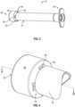
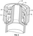
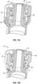
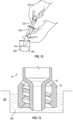
FIG. 1 is a side elevation view of a syringe according to one embodiment;FIG. 2 is a cross-sectional view of the syringe shown inFIG. 1 taken along line A-A';FIG. 3 is a perspective view from the proximal end of the syringe shown inFIG. 1 ;FIG. 4 is an enlarged partial perspective view of the enteral collar of the syringe shown inFIG. 1 ;FIG. 5 is a cross-sectional view of the enteral collar shown inFIG. 4 taken along line B-B';FIG. 6 is cross-sectional view of the enteral collar shown inFIG. 4 depicting the flow of fluid through the moat;FIG. 7 is a side view of a syringe with a plug according to one embodiment;FIG. 8 is a side view of the syringe shown inFIG. 7 with the plug removed from the syringe;FIG. 9 is a cross-sectional view of the syringe shown inFIG. 7 taken along line C-C;FIG. 10A is a cross-sectional perspective view of the enteral collar of the syringe shown inFIG. 7 ;FIG. 10B is a cross-sectional perspective view of the enteral collar of the syringe shown inFIG. 8 ;FIG. 11A is a cross-sectional view of the enteral collar of the syringe shown inFIG. 7 depicting the flow of fluid through the moat;FIG. 11B is a cross-sectional view of the enteral collar of the syringe shown inFIG. 8 depicting the flow of fluid through the moat;FIG. 12 is an illustration of a syringe during a cup fill operation; andFIG. 13 is a cross-sectional view of the enteral collar ofFIG. 4 within a liquid reservoir according to one embodiment.- Before describing several exemplary embodiments of the disclosure, it is to be understood that the disclosure is not limited to the details of construction or process steps set forth in the following description. The disclosure is capable of other embodiments and of being practiced or being carried out in various ways.
- In this disclosure, a convention is followed wherein the distal end of the device is the end closest to a patient and away from a practitioner. Conversely, the proximal end of the device is the end away from the patient and closest to a practitioner.
- The term "not connectable" with respect to male and female connectors refers to a connector having a shape, size, dimension or structure that prevents connection to another connector. For example, a female non-luer connector has a shape, size, dimension and/or structure that prevents it from forming a connection with standard a male luer connector and is thus not connectable with respect to the standard male luer connector. Such a female non-luer connector, however, has a shape, size, dimension and/or structure that permits formation of a connection with a male non-luer connector and is, thus, connectable with respect to the male non-luer connector.
- As used herein, the term "dimension" shall include the length, diameter or width of a geometric shape or the geometrically shaped components described herein. The term "cross-sectional diameter" shall include the measurement of the longest distance or greatest distance between two points on an edge of a cross-section of an object or component with a circular or non-circular cross-section.
- The two points may be located on the inside surface or outside surface of the edge of the cross-section of the object. The cross-sectional diameter of two points located on the inside surface of the edge of the cross-section of the object shall be referred to as the "inside cross-sectional diameter" and the cross-sectional diameter of two points located on the outside surface of the edge of the cross-section of an object shall be referred to as the "outside cross-sectional diameter." It should be recognized that "cross-sectional diameter" of objects having a circular cross-section may be referred to as the "cross-sectional dimension" or "diameter" of the object. The terms "cross-sectional dimension," "cross-sectional diameter" and "diameter" may be used interchangeably for objects having a circular cross-section.
- One or more embodiments provide a syringe with an enteral collar that enables the syringe meet ISO 80369-3 misconnection requirements. In one or more embodiment, the enteral collar has a vent or gap in the enteral collar to allow for removal of fluid between the enteral collar and the syringe tip. In one or more embodiment, the enteral collar comprises more than one vent or gap. In one or more embodiment, the vent is placed so as to allow fluid to travel along a threaded region of the enteral collar and out of the collar. In one or more embodiment, the syringe comprises a plug that reversibly seals the vent. In some embodiments, the plug is removable or may be displaced along the longitudinal axis of the syringe barrel to open the vent. In some embodiments, the plug is rotatable and comprises a gap which can be aligned with the vent to open the vent.
- According to one or more embodiments, the syringe can be utilized to draw-up, fill and enterally administer medication or other fluids without fluid in the region between the enteral collar and the syringe tip. In one or more embodiment, the syringe can be agitated after drawing-up or filling the syringe to ensure that fluid between the enteral collar and the syringe tip is removed through the vent.
- One or more embodiments provide a syringe that can be connected to enteral feeding sets and feeding tubes. In the industry, the connection is referred to as ENFit and is compliant to ISO 80369-3. According to one or more embodiments, a syringe is provided that permits the syringe to be connected to enteral tubing and enteral devices such as feeding bags and prevents connection to non-enteral devices, such as intravenous lines, urinary catheters and ventilator tubing. One or more embodiments provide a syringe that is compliant with ENFit devices and ISO 80369-3 and the syringe is not be compatible with a standard luer connection, thus preventing misadministration of an enteral feeding or medication by the wrong route. Thus, a syringe is provided with a connector that has a unique enteral-specific design and provides a simple way to reduce the risk of enteral tube feeding misconnections and improve patient safety. Furthermore, the collar does not allow connectivity with any other connector for any other clinical use such as intravenous devices. According to one or more embodiments, the syringe provides an enteral-specific syringe that can be used to administer medicine, flush, hydrate, or bolus feed through ENFit feeding tubes and extension sets compliant with ISO 80369-3. One or more embodiment provides a syringe having an enteral collar that does not connect with standard luer connectors that are compliant with ISO Standard 80369-7. Thus, an embodiment of the disclosure provides a syringe having a connector with a dimension that is not compatible with standard sized intravenous connectors and ports, thereby keeping the two from being inadvertently mechanically coupled.
- Aspects of the present disclosure pertain a syringe having an enteral collar with a female connector that prevents misconnection to non-compatible male connectors. A compatible connector shall be defined herein as a connector that has a shape, size, dimension or structure to another connector. Non-compatible male connectors may include standard male luer connectors, which conform to ISO 80369-7:2016.
- Referring now to
FIGS. 1-6 , a first embodiment of asyringe 10 is shown. Thesyringe 10 includes asyringe barrel 12 having adistal end 14, an openproximal end 16, and asidewall 18 extending between thedistal end 14 to the openproximal end 16, thesidewall 18 defining achamber 20. The axis from thedistal end 14 to the openproximal end 16 being the longitudinal axis. The syringe further includes anon-luer tip 24 at thedistal end 14 of thesyringe barrel 12 dimensioned such that thenon-luer tip 24 is not connectable to an intravenous device, thenon-luer tip 24 defining afluid pathway 26 in fluid communication with thechamber 20. Thesyringe 10 further comprises anenteral collar 30 having adistal end 32 and aproximal end 34. Theproximal end 34 of theenteral collar 30 includes arim 36 circumferentially abutting thedistal end 14 of thesyringe barrel 12. Theenteral collar 30 surrounds at least a portion of thenon-luer tip 24. Theenteral collar 30 is sized to permit connection to an enteral device and prevent connection to a device having a standard luer connector. In die embodiment shown, theenteral collar 30 comprises avent 50 at theproximal end 34 of theenteral collar 30. - As best shown in
FIG. 5 , in one or more embodiments, theenteral collar 30 is outside thefluid pathway 26 and not in fluid communication with thechamber 20. In other words, fluid contained in thechamber 20 of thesyringe 10 flows throughnon-luer tip 24, and fluid flowing through thenon-luer tip 24 is not in contact with theenteral collar 30. - In some embodiments, the
vent 50 is configured to provide an opportunity or means of escape, passage, or release of fluid between theenteral collar 30 and thenon-luer tip 24. As shown inFIG. 6 . thevent 50 may be configured to allow fluid to be removed by traveling according to thearrows 70 through amoat region 38 between theenteral collar 30 and thenon-luer tip 24 and through thevent 50. Although not shown in the Figures, in some embodiments, thevent 50 is configured to allow for removal of fluid by air entering thevent 50 to relieve negative pressure and facilitate fluid traveling through themoat region 38 between theenteral collar 30 and thenon-luer tip 24 opposite the direction shown inFIG. 6 (i.e. exiting near thedistal end 32 of the enteral collar 30). - The vent may be any suitable shape through which a fluid may pass. In some embodiments, the vent is rectangular, square, diamond, oval or circular in shape. In some embodiments, the
enteral collar 30 comprises a number ofvents 50 in a range of from 1 to 12. In the embodiment shown, theenteral collar 30 comprises four vents 50 (three are visible inFIG. 3 ) at theproximal end 34 of theenteral collar 30. In some embodiments the vents have a rectangular shape, with an aspect ratio of length to width of the rectangle of about 2 to 1. In specific embodiments, the rectangular vents have a length X width dimensions in a range of from 1-5 mm length and 0.5-5 mm width, with an aspect ratio of length to width of about 2 to 1. In a specific embodiment, the length of a rectangular vent is 2 mm and the width is about 1 mm. - The
vent 50 may be located in any suitable position on theenteral collar 30. In some embodiments, thevent 50 is located near theproximal end 34 of theenteral collar 30. In some embodiments, thevent 50 is located within therim 36 of theenteral collar 30 which abuts thedistal end 14 of thesyringe barrel 12. As shown inFIG. 3 , in some embodiments, theenteral collar 30 comprises a plurality ofvents 50 equally spaced around the circumference of theenteral collar 30. For example, fourvents 50 may be spaced approximately 90 degrees apart around the circumference of theenteral collar 30. - The
proximal end 34 of theenteral collar 30 abuts thedistal end 14 of thesyringe barrel 12. In some embodiments, theenteral collar 30 is continuous with thesidewall 18. As used in this regard, "continuous" means that theenteral collar 30 and thesidewall 18 are formed from the same material without an intervening seam or other separation. In some embodiments, theenteral collar 30 is not removable from the syringe or rotatable relative to thesyringe barrel 12. - The
enteral collar 30 surrounds at least a portion of thenon-luer tip 24. In embodiments similar to those pictured, thenon-luer tip 24 extends beyond thedistal end 32 of theenteral collar 30. In some non-illustrated embodiments, thedistal end 32 of theenteral collar 30 extends beyond the end of thenon-luer tip 24. In some embodiments, the non-luer tip is sized and dimensioned to provide an ENfit connection that conforms to ISO 80369-3 and is connectable with an opposite ENfit connector that also conforms to ISO 80369-3. - As shown in
FIG. 5 , in some embodiments, theenteral collar 30 has aninner surface 33 withinternal threads 35 or a lug to provide a female non-luer connector, which can engage a male non-luer connector. While not pictured, in other embodiments, theenteral collar 30 has an external surface with external threads or lug to provide a male non-luer connector, which can engage a female non-luer connector. The threads or lug, whether internal or external, are configured to engage a threaded, non-luer connector. In some embodiments, theenteral collar 30 is configured to provide a connector that provides an ENfit connection that conforms to ISO 80369-3 and is connectable with an opposite ENfit connector that also conforms to ISO 80369-3. - Referring now to
FIGS. 7-11B , a further embodiment of thesyringe 10 is shown. Similar to the syringe of the first embodiment, thesyringe 10 includes asyringe barrel 12. having adistal end 14, an openproximal end 16, asidewall 18 extending between thedistal end 14 to the openproximal end 16, thesidewall 18 defining achamber 20. The axis from thedistal end 14 to the openproximal end 16 defines a longitudinal axis. Thesyringe 10 includes anon-luer tip 24 dimensioned such that thenon-luer tip 24 is not connectable to an intravenous device. Thenon-luer tip 24 defines afluid pathway 26 in fluid communication with thechamber 20. Thesyringe 10 has anenteral collar 40 having adistal end 42 and aproximal end 44. Theproximal end 44 of theenteral collar 40 includes arim 46 circumferentially abutting thedistal end 14 of thesyringe barrel 12. Theenteral collar 40 surrounds at least a portion of thenon-luer tip 24. Theenteral collar 40 is sized to permit connection to an enteral device and prevent connection to a device having a standard luer connector. Theenteral collar 40 comprises avent 50 at theproximal end 44 of theenteral collar 40. - The
enteral collar 40 is similar to theenteral collar 30 except that theenteral collar 40 further comprises aplug 60 configured to reversibly seal thevent 50. In one or more embodiments, a plug configured to reversibly seal a vent is capable of being positioned so as to seal a vent or leave a vent unaffected and can be transitioned between the two positions. - The position in which the plug seals the vent is described as "closed." As illustrated in
FIG. 11A , when closed, fluid within themoat region 48 between theenteral collar 40 and thenon-luer tip 24 may travel according to thearrows 80 but will not be able to be removed through thevent 50. Similarly, theplug 60 would prevent air from entering thevent 50 to relieve negative pressure, thereby preventing flow of fluid through themoat region 48 in the opposite direction from that shown by thearrows 80 inFIG. 11A . - Conversely, when the plug does not seal the vent, the position is described as "open". As illustrated in
FIG. 11B , when open, fluid within themoat region 48 between theenteral collar 40 and thenon-luer tip 24 may travel according to thearrows 90 and will be able to be removed through thevent 50. Similarly, theplug 60 will allow air to enter thevent 50 so as to relieve negative pressure in themoat region 48, thereby allowing the flow of fluid through themoat region 48 in the opposite direction from that shown by thearrows 90 inFIG. 11B . - Several methods of transitioning the plug from a position where the vent is sealed to a position where the vent is unsealed are envisioned. In some embodiments, the
plug 60 is removable from thesyringe 10. After removal, thesyringe 10 may appear as inFIGS. 8 ,10B or11B . In some embodiments, theplug 60 can be displaced along the longitudinal axis of thesyringe barrel 12. Theplug 60 may be displaced proximally, towards the practitioner, on thesyringe barrel 12 or distally, away from the practitioner, on theenteral collar 40. - In a specific embodiment, the
plug 60 is rotatable and comprises a gap which can be aligned with thevent 50. In some embodiments, theplug 60 comprises a number of gaps equal to the number ofvents 50 in theenteral collar 40. In some embodiments, theplug 60 comprises more gaps than the number ofvents 50 in theenteral collar 40. In some embodiments, theplug 60 comprises fewer gaps than the number ofvents 50 in theenteral collar 40. In some embodiments, the gap has an area greater than or equal to the area of thevent 50. - Another embodiment of the disclosure relates to a method for using a syringe described according to one or more embodiments herein. In particular, the method comprises adding fluid to the syringe. According to some embodiments of the method, the syringe comprises a plunger within the chamber. The non-luer tip is placed in fluid communication with a liquid within a liquid reservoir. The plunger is displaced within the chamber to draw the liquid into the syringe.
- The syringe provided may be a syringe comprising an
enteral collar 30 or anenteral collar 40. Accordingly, the syringe may comprise aplug 60. If present, theplug 60 may be positioned in an open position or a closed position. - Placing the non-luer tip in fluid communication with the liquid may be implemented in a variety of ways. In some embodiments, the tip is placed directly in a liquid within a liquid reservoir. In some embodiments, the tip may be connected to the proximal end of a medication straw which has a distal end within the liquid. In some embodiments, the tip may be connected to a bottle fill cap and the bottle inverted to place the tip in fluid communication with the liquid inside the bottle. Regardless of the method used, when the plunger is displaced within the chamber, the liquid is drawn into the syringe.
- The liquid may be any suitable liquid. In some embodiments, the liquid is a liquid medication. In some embodiments, the liquid is a nutritional supplement and/or dietary supplement.
- In specific embodiments, the method comprises a "cup-fill" method. In general, as illustrated in
FIG. 12 , a cup--fill method comprises placing thetip 210 of asyringe 200 in a liquid 250 within aliquid reservoir 260. Thepractitioner 240 draws back theplunger 220 of thesyringe 200 in order to fill thesyringe 200 with the liquid 250. - As illustrated in
FIG. 13 , asyringe 10 with anenteral collar 30 may be placed in a liquid 250 within aliquid reservoir 260. Once placed into the liquid 250, themoat region 38 is filled withliquid 250 to the level of the liquid 250 in theliquid reservoir 260. In some embodiments, thesyringe 10 is placed in the liquid 250 such that thevent 50 is above the level of the liquid250 within theliquid reservoir 260. The liquid 250 is drawn into thesyringe 10 by displacing the plunger. - After drawing the liquid 250 into the
syringe 10, thesyringe 10 is removed from the liquid 250. When removed, thevent 50 allows for the liquid 250 to flow out of themoat region 38. The liquid 250 may flow through thevent 50 or out through thedistal end 32 of theenteral collar 30. In some embodiments, the method further comprises agitating thesyringe 10 to ensure thatliquid 250 in themoat region 38 is removed. Agitating the syringe may include, without limitation, tapping or flicking thesyringe 10. - In some embodiments, the
syringe 10 comprises anenteral collar 40 with aplug 60. In some embodiments, thevent 50 is sealed by the plug 60 (i.e. closed) when thesyringe 10 is placed in the liquid 250 and then unsealed (i.e. open) after drawing the liquid into the syringe. In some embodiments, theplug 60 is rotated to unseal thevent 50. In some embodiments, theplug 60 is removed to unseal thevent 50. - Without being bound by theory, it is believed that if the vent is closed during a cup-fill method, the positive pressure within the moat region will minimize the amount of liquid therein. Once filled, opening the vent will allow liquid which accumulates in the moat region to be removed.
- The components of the syringe including the enteral collar, plug and plunger may be fabricated of a variety of materials suitable for medical and health care applications, such as, but not limited to, nylon, polypropylene, polycarbonate, polyvinylidene fluoride, acrylonitrile butadiene styrene, and polyvinyl chloride. In some embodiments, the plug and the plunger are fabricated from the same material.
- Reference throughout this specification to "one embodiment," "certain embodiments," "one or more embodiments" or "an embodiment" means that a particular feature, structure, material, or characteristic described in connection with the embodiment is included in at least one embodiment of the disclosure. Thus, the appearances of the phrases such as "in one or more embodiments," "in certain embodiments," "in one embodiment" or "in an embodiment" in various places throughout this specification are not necessarily referring to the same embodiment of the disclosure. Furthermore, the particular features, structures, materials, or characteristics may be combined in any suitable manner in one or more embodiments.
- Although the disclosure herein has been described with reference to particular embodiments, it is to be understood that these embodiments are merely illustrative of the principles and applications of the present disclosure. It will be apparent to those skilled in the art that various modifications and variations can be made to the method and apparatus of the present disclosure without departing from the scope of the disclosure. Thus, it is intended that the present disclosure include modifications and variations that are within the scope of the appended claims.
Claims (17)
- A syringe (10) comprising:a syringe barrel (12) having a distal end, an open proximal end (16), a sidewall (18) extending between the distal end to the open proximal end (16), and the sidewall (18) defining a chamber (20);a non-luer tip (24) at the distal end of the syringe barrel (12) and dimensioned such that the non-luer tip (24) is not connectable to an intravenous device, the non-luer tip (24) defining a fluid pathway (26) in fluid communication with the chamber (20); andan enteral collar (40) having a distal end (42) and a proximal end (44), the proximal end (44) including a rim (46) circumferentially abutting the distal end (14) of the syringe barrel (12), the enteral collar (40) surrounding at least a portion of the non-luer tip (24) and defining a moat region (38) around the non-luer tip (24), the enteral collar (40) sized and configured to permit a threaded connection of the distal end (42) of the enteral collar (40) to an enteral device and prevent connection to a device having a standard luer connector, the proximal end (44) of the enteral collar comprising a vent (50) configured to allow removal of fluid from the moat region (38); anda plug (60) that reversibly seals the vent (50).
- The syringe (10) of claim 1, wherein the vent (50) is configured to allow for removal of fluid between the enteral collar (40) and the non-luer tip (24).
- The syringe (10) of claim 1, wherein the vent (50) is rectangular, square, diamond, oval, or circular.
- The syringe (10) of claim 1, wherein the enteral collar (40)) comprises a number of vents (50) in a range of from 4 to 12.
- The syringe (10) of claim 1, wherein the enteral collar (40) comprises a plurality of vents(50) equally spaced around a circumference of the enteral collar (40).
- The syringe (10) of claim 5, wherein the plug (60) is removable.
- The syringe (10) of claim 5, wherein the plug (60) can be displaced along a longitudinal axis of the syringe barrel (12).
- The syringe (10) of claim 5, wherein the plug (60) is rotatable.
- The syringe (10) of claim 8, wherein rotation of the plug unseals the vent (60).
- The syringe (10) of claim 1, wherein the enteral collar (40) is outside the fluid pathway (26) and not in fluid communication with the chamber (20).
- The syringe (10) of claim 1, wherein the distal end (42) of the enteral collar (40) has an inner surface (33) with threads (35) for engaging a threaded, non-luer connector.
- The syringe (10) of claim 1, wherein the enteral collar (40) is not removable or rotatable relative to the syringe barrel (12).
- The syringe (10) of claim 1, wherein the non-luer tip (24) extends beyond the distal end (42) of the enteral collar (40).
- A method comprising:
adding fluid to a syringe (10) of claim 1, the syringe comprising a chamber (20), a plunger (220), and an enteral collar (40) surrounding a non-luer tip (24) and defining a moat region around the non-luer tip (24), the enteral collar (40) sized and configured to permit a threaded connection of the distal end (42) of the enteral collar (40) to an enteral device and prevent connection to a device having a standard luer connector, a proximal end (44) of the enteral collar (40) comprising a vent (50) configured to allow removal of fluid from the moat region (38);placing the non-luer tip (24) in fluid communication with a liquid within a liquid reservoir;reversibly sealing the vent with a plug (60); anddrawing the liquid into the syringe by displacing the plunger (220) within the chamber (20). - The method of claim 14, further comprising agitating the syringe (10) to ensure that liquid in a region between the enteral collar and the non-luer tip (24) is removed.
- The method of claim 14, wherein the plug (60) is rotated to unseal the vent (50).
- The method of claim 14, wherein the plug (60) is removed to unseal the vent (50).
Applications Claiming Priority (2)
| Application Number | Priority Date | Filing Date | Title |
|---|---|---|---|
| US16/014,621US11147956B2 (en) | 2018-06-21 | 2018-06-21 | Enteral syringe with vented collar |
| PCT/US2019/038404WO2019246485A1 (en) | 2018-06-21 | 2019-06-21 | Enteral syringe with vented collar |
Publications (3)
| Publication Number | Publication Date |
|---|---|
| EP3810231A1 EP3810231A1 (en) | 2021-04-28 |
| EP3810231B1true EP3810231B1 (en) | 2024-01-03 |
| EP3810231C0 EP3810231C0 (en) | 2024-01-03 |
Family
ID=67138267
Family Applications (1)
| Application Number | Title | Priority Date | Filing Date |
|---|---|---|---|
| EP19735208.1AActiveEP3810231B1 (en) | 2018-06-21 | 2019-06-21 | Enteral syringe with vented collar |
Country Status (6)
| Country | Link |
|---|---|
| US (1) | US11147956B2 (en) |
| EP (1) | EP3810231B1 (en) |
| JP (1) | JP7330214B2 (en) |
| CN (1) | CN112351805B (en) |
| ES (1) | ES2968549T3 (en) |
| WO (1) | WO2019246485A1 (en) |
Families Citing this family (1)
| Publication number | Priority date | Publication date | Assignee | Title |
|---|---|---|---|---|
| USD983366S1 (en)* | 2021-07-15 | 2023-04-11 | Kairish Innotech Private Limited | Vial adapter |
Family Cites Families (49)
| Publication number | Priority date | Publication date | Assignee | Title |
|---|---|---|---|---|
| US4390017A (en) | 1981-08-07 | 1983-06-28 | Harrison Eugene O | Enteral feeding system |
| JP2739560B2 (en)* | 1994-04-18 | 1998-04-15 | 三共株式会社 | Vial container |
| US5609584A (en) | 1994-05-18 | 1997-03-11 | Gettig Technologies, Inc. | Adaptor system for use with a syringe |
| US6183421B1 (en) | 1999-08-20 | 2001-02-06 | Donald Eugene Bobo | Gas column device with a single use connector |
| US6599269B1 (en) | 1999-12-03 | 2003-07-29 | Becton Dickinson And Company | Single-use syringe |
| US6511474B1 (en) | 2000-07-12 | 2003-01-28 | Corpak, Inc. | Bolus for non-occluding high flow enteral feeding tube |
| US6500153B1 (en) | 2001-07-13 | 2002-12-31 | Children's And Women's Health Centre Of British Columbia | Syringe and needle for preventing inadvertent drug injection |
| US20060047251A1 (en) | 2002-10-22 | 2006-03-02 | Philip Bickford Smith | Medical small-bore tubing system and kit |
| US20060161115A1 (en) | 2004-11-05 | 2006-07-20 | Fangrow Thomas F | Soft-grip medical connector |
| US8292875B2 (en) | 2006-09-12 | 2012-10-23 | Clay Kennard | Fluid delivery device |
| US8062262B2 (en) | 2006-10-05 | 2011-11-22 | Becton, Dickinson And Company | Extravascular system in-line venting |
| US20080140020A1 (en)* | 2006-12-08 | 2008-06-12 | Utah Medical Products Inc. | Lockable enteral feeding adapter |
| US7842217B2 (en) | 2007-03-28 | 2010-11-30 | Benlan, Inc. | Enteral-only syringe and method of manufacturing same |
| US8888758B2 (en) | 2008-09-05 | 2014-11-18 | Carefusion 303, Inc. | Closed male luer device for minimizing leakage during connection and disconnection |
| US7955317B2 (en) | 2009-06-30 | 2011-06-07 | Tyco Healthcare Group Lp | Female adaptor for feeding line |
| US20120022468A1 (en) | 2010-07-23 | 2012-01-26 | Medela Holding Ag | Enteral Feeding Assembly |
| US8465461B2 (en)* | 2010-07-27 | 2013-06-18 | Becton, Dickinson And Company | Blunt needle safety drug delivery system |
| US9814870B2 (en) | 2010-08-17 | 2017-11-14 | Becton, Dickinson And Company | Non-luer connectors |
| US20120078214A1 (en) | 2010-09-28 | 2012-03-29 | Tyco Healthcare Group Lp | Vial transfer needle assembly |
| IL209102A0 (en) | 2010-11-04 | 2011-01-31 | Medimop Medical Projects Ltd | Inline liquid drug medical device with handle operated flow control member |
| IL209290A0 (en) | 2010-11-14 | 2011-01-31 | Medimop Medical Projects Ltd | Inline liquid drug medical device having rotary flow control member |
| US9433768B2 (en) | 2011-03-25 | 2016-09-06 | Becton, Dickinson And Company | Drug delivery connectors |
| GB2495492A (en) | 2011-10-10 | 2013-04-17 | Iden Shams | Syringe tip with non-luer fitting |
| EP2583715A1 (en) | 2011-10-19 | 2013-04-24 | Unomedical A/S | Infusion tube system and method for manufacture |
| WO2013081699A2 (en) | 2011-11-28 | 2013-06-06 | Neomed, Inc. | Female enteral coupling |
| USD711530S1 (en) | 2012-03-12 | 2014-08-19 | Biomet Sas | Nozzle |
| US9259256B2 (en) | 2011-12-20 | 2016-02-16 | Biomet Sas | Method and apparatus for delivery of bone cement |
| US10737087B2 (en) | 2012-04-17 | 2020-08-11 | Smiths Medical Asd, Inc. | Filling fitting |
| USD710499S1 (en) | 2012-12-19 | 2014-08-05 | Daikyo Seiko, Ltd. | Syringe barrel |
| EP2935034B1 (en)* | 2012-12-19 | 2018-04-11 | Comar, LLC | Upwardly biasing child-resistant closure for liquid medicaments |
| USD714935S1 (en) | 2013-01-10 | 2014-10-07 | Fuso Pharmaeutical Industries, Ltd. | Adapter for connecting a needle to a syringe |
| USD765837S1 (en) | 2013-08-07 | 2016-09-06 | Medimop Medical Projects Ltd. | Liquid transfer device with integral vial adapter |
| USD767124S1 (en) | 2013-08-07 | 2016-09-20 | Medimop Medical Projects Ltd. | Liquid transfer device with integral vial adapter |
| JP6409273B2 (en) | 2013-12-24 | 2018-10-24 | 株式会社ジェイ・エム・エス | Male connector |
| WO2015146831A1 (en) | 2014-03-27 | 2015-10-01 | 株式会社ジェイ・エム・エス | Cleaning adapter |
| EP3191166B1 (en) | 2014-09-08 | 2019-11-20 | Neomed, Inc. | Vented connector for medical fluid vessels |
| US11376409B2 (en)* | 2014-09-08 | 2022-07-05 | Avent, Inc. | Hub component for vented connector |
| US10773067B2 (en) | 2014-09-08 | 2020-09-15 | Neomed, Inc. | Enteral connectors having coupling features |
| US20160106928A1 (en) | 2014-10-16 | 2016-04-21 | Neomed, Inc. | Multi-stage mixing syringe |
| US9199033B1 (en)* | 2014-10-28 | 2015-12-01 | Bayer Healthcare Llc | Self-orienting syringe and syringe interface |
| US9926185B2 (en)* | 2014-12-08 | 2018-03-27 | Neomed, Inc. | Fluid transfer lid |
| WO2016154304A1 (en)* | 2015-03-24 | 2016-09-29 | Neomed, Inc. | Oral administration fluid coupler |
| US9656022B1 (en) | 2015-04-22 | 2017-05-23 | Ronald D. Russo | Enteral medication diluting syringe infuser |
| USD785162S1 (en) | 2015-06-11 | 2017-04-25 | Covidien Lp | Enteral feeding syringe |
| US10682287B2 (en)* | 2015-07-14 | 2020-06-16 | Neomed, Inc. | Dosing control coupling for enteral fluid transfer and enteral couplings and syringes |
| JP6807012B2 (en) | 2016-02-19 | 2021-01-06 | 株式会社ジェイ・エム・エス | adapter |
| US10842983B2 (en) | 2016-10-06 | 2020-11-24 | Becton, Dickinson And Company | Syringe with enteral connection feature |
| US10821053B2 (en) | 2016-10-07 | 2020-11-03 | Becton, Dickinson And Company | Syringe with connector |
| USD861161S1 (en) | 2017-06-22 | 2019-09-24 | Kpr U.S., Llc | Connector |
- 2018
- 2018-06-21USUS16/014,621patent/US11147956B2/enactiveActive
- 2019
- 2019-06-21EPEP19735208.1Apatent/EP3810231B1/enactiveActive
- 2019-06-21JPJP2020567918Apatent/JP7330214B2/enactiveActive
- 2019-06-21ESES19735208Tpatent/ES2968549T3/enactiveActive
- 2019-06-21CNCN201980041285.4Apatent/CN112351805B/enactiveActive
- 2019-06-21WOPCT/US2019/038404patent/WO2019246485A1/ennot_activeCeased
Also Published As
| Publication number | Publication date |
|---|---|
| EP3810231A1 (en) | 2021-04-28 |
| JP2021527467A (en) | 2021-10-14 |
| WO2019246485A1 (en) | 2019-12-26 |
| JP7330214B2 (en) | 2023-08-21 |
| CN112351805B (en) | 2022-10-04 |
| ES2968549T3 (en) | 2024-05-10 |
| EP3810231C0 (en) | 2024-01-03 |
| CN112351805A (en) | 2021-02-09 |
| US11147956B2 (en) | 2021-10-19 |
| US20190388671A1 (en) | 2019-12-26 |
Similar Documents
| Publication | Publication Date | Title |
|---|---|---|
| EP3522953B1 (en) | Syringe with enteral connection feature | |
| JP7118214B2 (en) | non luer connector | |
| US20070060898A1 (en) | Enteral medical treatment assembly having a safeguard against erroneous connection with an intravascular treatment system | |
| AU2021228640B2 (en) | Syringe with snap-in enteral connection feature | |
| AU2011363503A1 (en) | Drug delivery connectors | |
| EP3810231B1 (en) | Enteral syringe with vented collar | |
| JP7630422B2 (en) | Spinal Axial Connector | |
| US12311147B2 (en) | Dual chamber syringe assembly | |
| JP2002078797A (en) | Liquid smapling device for shot injection, and adapter for liquid communication | |
| BR112019006784B1 (en) | SYRINGE WITH ENTERIC CONNECTION FEATURE |
Legal Events
| Date | Code | Title | Description |
|---|---|---|---|
| STAA | Information on the status of an ep patent application or granted ep patent | Free format text:STATUS: UNKNOWN | |
| STAA | Information on the status of an ep patent application or granted ep patent | Free format text:STATUS: THE INTERNATIONAL PUBLICATION HAS BEEN MADE | |
| PUAI | Public reference made under article 153(3) epc to a published international application that has entered the european phase | Free format text:ORIGINAL CODE: 0009012 | |
| STAA | Information on the status of an ep patent application or granted ep patent | Free format text:STATUS: REQUEST FOR EXAMINATION WAS MADE | |
| 17P | Request for examination filed | Effective date:20210114 | |
| AK | Designated contracting states | Kind code of ref document:A1 Designated state(s):AL AT BE BG CH CY CZ DE DK EE ES FI FR GB GR HR HU IE IS IT LI LT LU LV MC MK MT NL NO PL PT RO RS SE SI SK SM TR | |
| AX | Request for extension of the european patent | Extension state:BA ME | |
| DAV | Request for validation of the european patent (deleted) | ||
| DAX | Request for extension of the european patent (deleted) | ||
| GRAP | Despatch of communication of intention to grant a patent | Free format text:ORIGINAL CODE: EPIDOSNIGR1 | |
| STAA | Information on the status of an ep patent application or granted ep patent | Free format text:STATUS: GRANT OF PATENT IS INTENDED | |
| INTG | Intention to grant announced | Effective date:20230831 | |
| RIN1 | Information on inventor provided before grant (corrected) | Inventor name:FRAITES, THOMAS Inventor name:NAGU, THIRUMURUGAN Inventor name:RAMAMURTHY, LOKESH Inventor name:RAO, MILIND | |
| GRAS | Grant fee paid | Free format text:ORIGINAL CODE: EPIDOSNIGR3 | |
| GRAA | (expected) grant | Free format text:ORIGINAL CODE: 0009210 | |
| STAA | Information on the status of an ep patent application or granted ep patent | Free format text:STATUS: THE PATENT HAS BEEN GRANTED | |
| AK | Designated contracting states | Kind code of ref document:B1 Designated state(s):AL AT BE BG CH CY CZ DE DK EE ES FI FR GB GR HR HU IE IS IT LI LT LU LV MC MK MT NL NO PL PT RO RS SE SI SK SM TR | |
| REG | Reference to a national code | Ref country code:GB Ref legal event code:FG4D | |
| REG | Reference to a national code | Ref country code:DE Ref legal event code:R096 Ref document number:602019044441 Country of ref document:DE | |
| REG | Reference to a national code | Ref country code:CH Ref legal event code:EP | |
| REG | Reference to a national code | Ref country code:IE Ref legal event code:FG4D | |
| U01 | Request for unitary effect filed | Effective date:20240111 | |
| U07 | Unitary effect registered | Designated state(s):AT BE BG DE DK EE FI FR IT LT LU LV MT NL PT SE SI Effective date:20240119 | |
| REG | Reference to a national code | Ref country code:ES Ref legal event code:FG2A Ref document number:2968549 Country of ref document:ES Kind code of ref document:T3 Effective date:20240510 | |
| U20 | Renewal fee for the european patent with unitary effect paid | Year of fee payment:6 Effective date:20240521 | |
| PG25 | Lapsed in a contracting state [announced via postgrant information from national office to epo] | Ref country code:IS Free format text:LAPSE BECAUSE OF FAILURE TO SUBMIT A TRANSLATION OF THE DESCRIPTION OR TO PAY THE FEE WITHIN THE PRESCRIBED TIME-LIMIT Effective date:20240503 | |
| PG25 | Lapsed in a contracting state [announced via postgrant information from national office to epo] | Ref country code:GR Free format text:LAPSE BECAUSE OF FAILURE TO SUBMIT A TRANSLATION OF THE DESCRIPTION OR TO PAY THE FEE WITHIN THE PRESCRIBED TIME-LIMIT Effective date:20240404 | |
| PG25 | Lapsed in a contracting state [announced via postgrant information from national office to epo] | Ref country code:HR Free format text:LAPSE BECAUSE OF FAILURE TO SUBMIT A TRANSLATION OF THE DESCRIPTION OR TO PAY THE FEE WITHIN THE PRESCRIBED TIME-LIMIT Effective date:20240103 Ref country code:RS Free format text:LAPSE BECAUSE OF FAILURE TO SUBMIT A TRANSLATION OF THE DESCRIPTION OR TO PAY THE FEE WITHIN THE PRESCRIBED TIME-LIMIT Effective date:20240403 | |
| PG25 | Lapsed in a contracting state [announced via postgrant information from national office to epo] | Ref country code:CZ Free format text:LAPSE BECAUSE OF FAILURE TO SUBMIT A TRANSLATION OF THE DESCRIPTION OR TO PAY THE FEE WITHIN THE PRESCRIBED TIME-LIMIT Effective date:20240103 | |
| PG25 | Lapsed in a contracting state [announced via postgrant information from national office to epo] | Ref country code:RS Free format text:LAPSE BECAUSE OF FAILURE TO SUBMIT A TRANSLATION OF THE DESCRIPTION OR TO PAY THE FEE WITHIN THE PRESCRIBED TIME-LIMIT Effective date:20240403 Ref country code:NO Free format text:LAPSE BECAUSE OF FAILURE TO SUBMIT A TRANSLATION OF THE DESCRIPTION OR TO PAY THE FEE WITHIN THE PRESCRIBED TIME-LIMIT Effective date:20240403 Ref country code:IS Free format text:LAPSE BECAUSE OF FAILURE TO SUBMIT A TRANSLATION OF THE DESCRIPTION OR TO PAY THE FEE WITHIN THE PRESCRIBED TIME-LIMIT Effective date:20240503 Ref country code:HR Free format text:LAPSE BECAUSE OF FAILURE TO SUBMIT A TRANSLATION OF THE DESCRIPTION OR TO PAY THE FEE WITHIN THE PRESCRIBED TIME-LIMIT Effective date:20240103 Ref country code:GR Free format text:LAPSE BECAUSE OF FAILURE TO SUBMIT A TRANSLATION OF THE DESCRIPTION OR TO PAY THE FEE WITHIN THE PRESCRIBED TIME-LIMIT Effective date:20240404 Ref country code:CZ Free format text:LAPSE BECAUSE OF FAILURE TO SUBMIT A TRANSLATION OF THE DESCRIPTION OR TO PAY THE FEE WITHIN THE PRESCRIBED TIME-LIMIT Effective date:20240103 | |
| PG25 | Lapsed in a contracting state [announced via postgrant information from national office to epo] | Ref country code:PL Free format text:LAPSE BECAUSE OF FAILURE TO SUBMIT A TRANSLATION OF THE DESCRIPTION OR TO PAY THE FEE WITHIN THE PRESCRIBED TIME-LIMIT Effective date:20240103 | |
| PG25 | Lapsed in a contracting state [announced via postgrant information from national office to epo] | Ref country code:PL Free format text:LAPSE BECAUSE OF FAILURE TO SUBMIT A TRANSLATION OF THE DESCRIPTION OR TO PAY THE FEE WITHIN THE PRESCRIBED TIME-LIMIT Effective date:20240103 | |
| REG | Reference to a national code | Ref country code:DE Ref legal event code:R097 Ref document number:602019044441 Country of ref document:DE | |
| PG25 | Lapsed in a contracting state [announced via postgrant information from national office to epo] | Ref country code:SM Free format text:LAPSE BECAUSE OF FAILURE TO SUBMIT A TRANSLATION OF THE DESCRIPTION OR TO PAY THE FEE WITHIN THE PRESCRIBED TIME-LIMIT Effective date:20240103 | |
| PG25 | Lapsed in a contracting state [announced via postgrant information from national office to epo] | Ref country code:SK Free format text:LAPSE BECAUSE OF FAILURE TO SUBMIT A TRANSLATION OF THE DESCRIPTION OR TO PAY THE FEE WITHIN THE PRESCRIBED TIME-LIMIT Effective date:20240103 | |
| PG25 | Lapsed in a contracting state [announced via postgrant information from national office to epo] | Ref country code:SM Free format text:LAPSE BECAUSE OF FAILURE TO SUBMIT A TRANSLATION OF THE DESCRIPTION OR TO PAY THE FEE WITHIN THE PRESCRIBED TIME-LIMIT Effective date:20240103 Ref country code:SK Free format text:LAPSE BECAUSE OF FAILURE TO SUBMIT A TRANSLATION OF THE DESCRIPTION OR TO PAY THE FEE WITHIN THE PRESCRIBED TIME-LIMIT Effective date:20240103 Ref country code:RO Free format text:LAPSE BECAUSE OF FAILURE TO SUBMIT A TRANSLATION OF THE DESCRIPTION OR TO PAY THE FEE WITHIN THE PRESCRIBED TIME-LIMIT Effective date:20240103 | |
| PLBE | No opposition filed within time limit | Free format text:ORIGINAL CODE: 0009261 | |
| STAA | Information on the status of an ep patent application or granted ep patent | Free format text:STATUS: NO OPPOSITION FILED WITHIN TIME LIMIT | |
| 26N | No opposition filed | Effective date:20241007 | |
| PG25 | Lapsed in a contracting state [announced via postgrant information from national office to epo] | Ref country code:MC Free format text:LAPSE BECAUSE OF FAILURE TO SUBMIT A TRANSLATION OF THE DESCRIPTION OR TO PAY THE FEE WITHIN THE PRESCRIBED TIME-LIMIT Effective date:20240103 | |
| REG | Reference to a national code | Ref country code:CH Ref legal event code:PL | |
| PG25 | Lapsed in a contracting state [announced via postgrant information from national office to epo] | Ref country code:IE Free format text:LAPSE BECAUSE OF NON-PAYMENT OF DUE FEES Effective date:20240621 | |
| PG25 | Lapsed in a contracting state [announced via postgrant information from national office to epo] | Ref country code:CH Free format text:LAPSE BECAUSE OF NON-PAYMENT OF DUE FEES Effective date:20240630 | |
| U20 | Renewal fee for the european patent with unitary effect paid | Year of fee payment:7 Effective date:20250520 | |
| PGFP | Annual fee paid to national office [announced via postgrant information from national office to epo] | Ref country code:GB Payment date:20250520 Year of fee payment:7 | |
| PGFP | Annual fee paid to national office [announced via postgrant information from national office to epo] | Ref country code:ES Payment date:20250701 Year of fee payment:7 |