EP3808401A1 - Gas-filled chamber for catheter pump motor assembly - Google Patents
Gas-filled chamber for catheter pump motor assemblyDownload PDFInfo
- Publication number
- EP3808401A1 EP3808401A1EP20210759.5AEP20210759AEP3808401A1EP 3808401 A1EP3808401 A1EP 3808401A1EP 20210759 AEP20210759 AEP 20210759AEP 3808401 A1EP3808401 A1EP 3808401A1
- Authority
- EP
- European Patent Office
- Prior art keywords
- assembly
- catheter
- rotor
- fluid
- motor assembly
- Prior art date
- Legal status (The legal status is an assumption and is not a legal conclusion. Google has not performed a legal analysis and makes no representation as to the accuracy of the status listed.)
- Pending
Links
Images


Classifications
- A—HUMAN NECESSITIES
- A61—MEDICAL OR VETERINARY SCIENCE; HYGIENE
- A61M—DEVICES FOR INTRODUCING MEDIA INTO, OR ONTO, THE BODY; DEVICES FOR TRANSDUCING BODY MEDIA OR FOR TAKING MEDIA FROM THE BODY; DEVICES FOR PRODUCING OR ENDING SLEEP OR STUPOR
- A61M60/00—Blood pumps; Devices for mechanical circulatory actuation; Balloon pumps for circulatory assistance
- A61M60/80—Constructional details other than related to driving
- A61M60/855—Constructional details other than related to driving of implantable pumps or pumping devices
- A61M60/869—Compliance chambers containing a gas or liquid other than blood to compensate volume variations of a blood chamber
- A—HUMAN NECESSITIES
- A61—MEDICAL OR VETERINARY SCIENCE; HYGIENE
- A61M—DEVICES FOR INTRODUCING MEDIA INTO, OR ONTO, THE BODY; DEVICES FOR TRANSDUCING BODY MEDIA OR FOR TAKING MEDIA FROM THE BODY; DEVICES FOR PRODUCING OR ENDING SLEEP OR STUPOR
- A61M60/00—Blood pumps; Devices for mechanical circulatory actuation; Balloon pumps for circulatory assistance
- A61M60/80—Constructional details other than related to driving
- A61M60/802—Constructional details other than related to driving of non-positive displacement blood pumps
- A61M60/827—Sealings between moving parts
- A61M60/829—Sealings between moving parts having a purge fluid supply
- A—HUMAN NECESSITIES
- A61—MEDICAL OR VETERINARY SCIENCE; HYGIENE
- A61M—DEVICES FOR INTRODUCING MEDIA INTO, OR ONTO, THE BODY; DEVICES FOR TRANSDUCING BODY MEDIA OR FOR TAKING MEDIA FROM THE BODY; DEVICES FOR PRODUCING OR ENDING SLEEP OR STUPOR
- A61M60/00—Blood pumps; Devices for mechanical circulatory actuation; Balloon pumps for circulatory assistance
- A61M60/10—Location thereof with respect to the patient's body
- A61M60/122—Implantable pumps or pumping devices, i.e. the blood being pumped inside the patient's body
- A61M60/126—Implantable pumps or pumping devices, i.e. the blood being pumped inside the patient's body implantable via, into, inside, in line, branching on, or around a blood vessel
- A61M60/13—Implantable pumps or pumping devices, i.e. the blood being pumped inside the patient's body implantable via, into, inside, in line, branching on, or around a blood vessel by means of a catheter allowing explantation, e.g. catheter pumps temporarily introduced via the vascular system
- A—HUMAN NECESSITIES
- A61—MEDICAL OR VETERINARY SCIENCE; HYGIENE
- A61M—DEVICES FOR INTRODUCING MEDIA INTO, OR ONTO, THE BODY; DEVICES FOR TRANSDUCING BODY MEDIA OR FOR TAKING MEDIA FROM THE BODY; DEVICES FOR PRODUCING OR ENDING SLEEP OR STUPOR
- A61M60/00—Blood pumps; Devices for mechanical circulatory actuation; Balloon pumps for circulatory assistance
- A61M60/10—Location thereof with respect to the patient's body
- A61M60/122—Implantable pumps or pumping devices, i.e. the blood being pumped inside the patient's body
- A61M60/126—Implantable pumps or pumping devices, i.e. the blood being pumped inside the patient's body implantable via, into, inside, in line, branching on, or around a blood vessel
- A61M60/135—Implantable pumps or pumping devices, i.e. the blood being pumped inside the patient's body implantable via, into, inside, in line, branching on, or around a blood vessel inside a blood vessel, e.g. using grafting
- A—HUMAN NECESSITIES
- A61—MEDICAL OR VETERINARY SCIENCE; HYGIENE
- A61M—DEVICES FOR INTRODUCING MEDIA INTO, OR ONTO, THE BODY; DEVICES FOR TRANSDUCING BODY MEDIA OR FOR TAKING MEDIA FROM THE BODY; DEVICES FOR PRODUCING OR ENDING SLEEP OR STUPOR
- A61M60/00—Blood pumps; Devices for mechanical circulatory actuation; Balloon pumps for circulatory assistance
- A61M60/20—Type thereof
- A61M60/205—Non-positive displacement blood pumps
- A61M60/216—Non-positive displacement blood pumps including a rotating member acting on the blood, e.g. impeller
- A—HUMAN NECESSITIES
- A61—MEDICAL OR VETERINARY SCIENCE; HYGIENE
- A61M—DEVICES FOR INTRODUCING MEDIA INTO, OR ONTO, THE BODY; DEVICES FOR TRANSDUCING BODY MEDIA OR FOR TAKING MEDIA FROM THE BODY; DEVICES FOR PRODUCING OR ENDING SLEEP OR STUPOR
- A61M60/00—Blood pumps; Devices for mechanical circulatory actuation; Balloon pumps for circulatory assistance
- A61M60/40—Details relating to driving
- A61M60/403—Details relating to driving for non-positive displacement blood pumps
- A61M60/408—Details relating to driving for non-positive displacement blood pumps the force acting on the blood contacting member being mechanical, e.g. transmitted by a shaft or cable
- A61M60/411—Details relating to driving for non-positive displacement blood pumps the force acting on the blood contacting member being mechanical, e.g. transmitted by a shaft or cable generated by an electromotor
- A61M60/414—Details relating to driving for non-positive displacement blood pumps the force acting on the blood contacting member being mechanical, e.g. transmitted by a shaft or cable generated by an electromotor transmitted by a rotating cable, e.g. for blood pumps mounted on a catheter
- A—HUMAN NECESSITIES
- A61—MEDICAL OR VETERINARY SCIENCE; HYGIENE
- A61M—DEVICES FOR INTRODUCING MEDIA INTO, OR ONTO, THE BODY; DEVICES FOR TRANSDUCING BODY MEDIA OR FOR TAKING MEDIA FROM THE BODY; DEVICES FOR PRODUCING OR ENDING SLEEP OR STUPOR
- A61M60/00—Blood pumps; Devices for mechanical circulatory actuation; Balloon pumps for circulatory assistance
- A61M60/40—Details relating to driving
- A61M60/403—Details relating to driving for non-positive displacement blood pumps
- A61M60/422—Details relating to driving for non-positive displacement blood pumps the force acting on the blood contacting member being electromagnetic, e.g. using canned motor pumps
- A—HUMAN NECESSITIES
- A61—MEDICAL OR VETERINARY SCIENCE; HYGIENE
- A61M—DEVICES FOR INTRODUCING MEDIA INTO, OR ONTO, THE BODY; DEVICES FOR TRANSDUCING BODY MEDIA OR FOR TAKING MEDIA FROM THE BODY; DEVICES FOR PRODUCING OR ENDING SLEEP OR STUPOR
- A61M60/00—Blood pumps; Devices for mechanical circulatory actuation; Balloon pumps for circulatory assistance
- A61M60/80—Constructional details other than related to driving
- A61M60/802—Constructional details other than related to driving of non-positive displacement blood pumps
- A61M60/804—Impellers
- A61M60/806—Vanes or blades
- A61M60/808—Vanes or blades specially adapted for deformable impellers, e.g. expandable impellers
- A—HUMAN NECESSITIES
- A61—MEDICAL OR VETERINARY SCIENCE; HYGIENE
- A61M—DEVICES FOR INTRODUCING MEDIA INTO, OR ONTO, THE BODY; DEVICES FOR TRANSDUCING BODY MEDIA OR FOR TAKING MEDIA FROM THE BODY; DEVICES FOR PRODUCING OR ENDING SLEEP OR STUPOR
- A61M60/00—Blood pumps; Devices for mechanical circulatory actuation; Balloon pumps for circulatory assistance
- A61M60/50—Details relating to control
Definitions
- This applicationis directed to catheter pumps for mechanical circulatory support of a heart.
- Heart diseaseis a major health problem that has high mortality rate. Physicians increasingly use mechanical circulatory support systems for treating heart failure. The treatment of acute heart failure requires a device that can provide support to the patient quickly. Physicians desire treatment options that can be deployed quickly and minimally-invasively.
- MCSMechanical circulatory support
- VADsventricular assist devices
- MIacute myocardial infarction
- PCIpercutaneous coronary intervention
- An example of an MCS systemis a rotary blood pump placed percutaneously, e.g., via a catheter.
- a blood pumpis inserted into the body and connected to the cardiovascular system, for example, to the left ventricle and the ascending aorta to assist the pumping function of the heart.
- Other known applicationsinclude placing the pump in the descending aorta, a peripheral artery, and the like.
- acute circulatory support devicesare used to reduce the afterload on the heart muscle and provide blood flow for a period of time to stabilize the patient prior to heart transplant or for continuing support.
- a blood pumpthat can be placed minimally-invasively, for example, through an 18FR, 14FR, or 8FR incision.
- a heart pumpthat can provide an average flow rate of 4 Lpm or more during operation, for example, at 62 mmHg of aortic pressure.
- VADspercutaneous ventricular assist devices
- Some percutaneous VADsare designed to rotate at speeds of more than 15,000 RPM, and in some cases more than 25,000 RPM in operation.
- the vibration, noise, and heat from the motor and driveshaftcan cause discomfort to the patient, especially when positioned inside the body. Accordingly, there is a need for a device that improves performance and patient comfort with a high speed motor.
- a motorconfigured to drive an operative device, e.g. , an impeller, atherectomy device, or other rotating feature.
- a catheter pump systemcan include a shaft assembly and a working element coupled with a distal portion of the shaft assembly.
- the catheter pump assemblycan include a motor assembly, the motor assembly comprising a chamber and a shaft-driving portion disposed in the chamber, the shaft-driving portion configured to impart rotation to the working element through the shaft assembly, the chamber filled with a gas that at least partially surrounds the shaft-driving portion.
- a fluid pathwaycan convey fluid proximally during operation of the catheter pump system.
- a bypass pathwaycan be in fluid communication with the fluid pathway, the bypass pathway configured to direct at least a portion of the fluid to bypass the chamber.
- the working elementcan comprise an impeller.
- the motor assemblycan further comprise a stator and the shaft-driving portion can comprise a rotor, the stator disposed outside the chamber at least partially about the rotor.
- the bypass pathwaycan direct all or substantially all the fluid to bypass the chamber.
- a gas inletcan supply the gas to the chamber.
- the chamber camcomprise a gas outlet through which the gas can exit the chamber.
- the gascomprises air.
- the fluid pathwaycan comprise a lumen of the shaft assembly, the lumen extending through the chamber such that at least a portion of the fluid passes through the lumen within the chamber.
- a first pressure of the gas in the chamberis greater than a second pressure of the conveyed fluid.
- One or more pumpscan be in fluid communication with the fluid pathway and a controller can control operation of the one or more pumps, the controller configured to apply a suction force to remove the fluid and/or the gas from the catheter pump system.
- the shaft assemblycan comprise an output shaft coupled with the motor assembly and a drive shaft coupled with the impeller, a distal portion of the output shaft coupled with a proximal portion of the drive shaft.
- a catheter assemblycan be disposed between the motor assembly and the impeller, the catheter assembly defining at least a portion of the fluid pathway.
- the catheter pump systemcan include a cannula in which the working element is disposed, the cannula and impeller expandable from a stored configuration to a deployed configuration.
- a method of operating a pumpcomprising an impeller and a motor assembly coupled with the impeller.
- the methodcan include rotating a shaft assembly with a shaft-driving portion of the motor assembly to impart rotation to the impeller, the shaft-driving portion of the motor assembly disposed in a chamber, the chamber filled with a gas that at least partially surrounds the shaft-driving portion.
- the methodcan include directing fluid into the pump, at least a portion of the fluid flowing proximally along a fluid pathway between the impeller and the motor assembly.
- the methodcan include directing at least a portion of the fluid to bypass the chamber.
- the methodcan include directing at least some of the fluid through a lumen extending through an output shaft portion of the shaft assembly, the output shaft portion passing through the chamber.
- the methodcan include inserting a guidewire through the lumen, and advancing the pump over the guidewire to a target site in a patient.
- the methodcan include expanding the impeller from a stored configuration to a deployed configuration.
- a catheter pump systemcan include an impeller and a catheter body having a lumen in which fluid flows proximally therethrough during operation of the catheter pump.
- the catheter pump systemcan include a drive shaft disposed inside the catheter body and coupled with the impeller at a distal portion of the drive shaft, the drive shaft configured such that rotation of the drive shaft causes the impeller to rotate.
- the catheter pump systemcan include a motor assembly.
- the motor assemblycan include a chamber, at least a portion of the chamber in fluid communication with the lumen of the catheter body.
- the motor assemblycan also include a rotor disposed in the at least a portion of the chamber, the rotor mechanically coupled with a proximal portion of the drive shaft such that rotation of the rotor causes the drive shaft to rotate.
- the motor assemblycan include a stator assembly disposed about the rotor and configured to cause the rotor to rotate. No cooling fins extend outside an exterior surface of the motor assembly.
- a catheter pump systemin another embodiment, can include an impeller and a catheter body having a lumen therethrough, the impeller mechanically coupled with a distal portion of the catheter body.
- the catheter pump systemcan include a guidewire guide tube disposed through the lumen from a proximal portion of the catheter pump to a distal portion of the catheter pump, the guidewire guide tube configured to receive a guidewire therein.
- the catheter pump systemcan include an end cap secured to a proximal end portion of the guide tube, the end cap configured such that axial movement of the end cap relative to the catheter body causes the guidewire guide tube to be removed from the catheter pump.
- the catheter pump systemcan include a resealable closure device disposed at a proximal portion of the catheter pump, the closure device configured such that when the guidewire guide tube is removed from the catheter pump, the closure device encloses the proximal portion of the catheter pump system.
- a catheter pump systemin another embodiment, can include a pump including an impeller for pumping blood.
- the catheter pump systemcan include a motor assembly for imparting rotation on the impeller through a drive shaft.
- the motor assemblycan comprise a stator carrying electrical windings and a rotor disposed in at least a portion of the stator, the rotor mechanically coupled with a proximal portion of the drive shaft.
- the catheter pump systemcan include a fluid supply system for delivering fluid to the pump during operation of the pump and returning at least some of the supplied fluid to a waste reservoir.
- the fluid supply systemcan comprise a fluid channel extending within the stator and a fluid pathway which passes outside the stator. During operation of the pump, at least a first portion of the returning fluid can pass through the fluid channel and at least a second portion of the returning fluid can pass through the fluid pathway.
- a method of operating a pumpcan comprise a motor which includes a stator assembly having windings and a rotor positioned within the stator assembly.
- the methodcan include rotating the rotor by selectively energizing the windings.
- the methodcan include cooling the motor by flowing a first fluid portion between the stator assembly and the rotor and by flowing a second fluid portion outside the stator.
- This applicationis generally directed to apparatuses for inducing motion of a fluid relative to the apparatus.
- Exemplars of circulatory support systems for treating heart failure, and in particular emergent and/or acute heart failureare disclosed in U.S. Patent Nos. 4,625,712 ; 4,686,982 ; 4,747,406 ; 4,895,557 ; 4,944,722 ; 6,176,848 ; 6,926,662 ; 7,022,100 ; 7,393,181 ; 7,841,976 ; 8,157,719 ; 8,489,190 ; 8,597,170 ; 8,721,517 and U.S. Pub. Nos.
- a working elemente.g., an impeller
- the motoris a brushless DC (BLDC) motor.
- the motoris a micro BLDC motor.
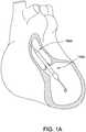
- FIGS 1A-1Bshow aspects of an exemplary catheter pump 100A that can provide relatively high blood flow rates (i.e. full or near full blood flow).
- the pump 100Aincludes a motor assembly 1 driven by a console 122, which can include an electronic controller and various fluid handling systems.
- the console 122directs the operation of the motor 1 and an infusion system that supplies a flow of fluid in the pump 100A. Additional details regarding the exemplary console 122 may be understood from U.S. Patent Publication No. US 2014/0275725 , the contents of which are incorporated by reference herein in their entirety and for all purposes.
- the pump 100Aincludes a catheter assembly 101 that can be coupled with the motor assembly 1 and can house a working element, such as an impeller in an impeller assembly 116A within a distal portion of the catheter assembly 101 of the pump 100A.
- the impelleris rotated remotely by the motor 1 when the pump 100A is operating.
- the motor 1can be disposed outside the patient.
- the motor 1is separate from the console 122, e.g., to be placed closer to the patient.
- the pumpis placed in the patient in a sterile environment and the console is outside the sterile environment.
- the motoris disposed on the sterile side of the system.
- the motor 1is part of the console 122.
- Figure 1Cis a schematic view of another embodiment of a catheter pump system.
- Figure 1Cis similar to Figure IB, except the motor 1 is miniaturized for insertion into the body.
- the motor 1can be disposed proximal the impeller assembly 116A.
- the motor 1can be generally similar to the motor assembly shown in Figure 2 , except the motor 1 is sized and shaped to be inserted into the patient's vasculature.
- One or more electrical linesmay extend from the motor to the console outside the patient. The electrical lines can send signals for controlling the operation of the motor.
- Such embodimentsallow a drive shaft coupled with the impeller and disposed within the catheter assembly 101 to be much shorter, e.g., shorter than the distance from the aortic valve to the aortic arch (about 5 cm or less).
- Various embodiments of the motor assembly 1are disclosed herein, including embodiments having a rotor disposed within a stator assembly.
- waste fluidcan pass through a housing in which the rotor is disposed to help cool the motor assembly 1.
- the housing in which the motor 1 of Figure 1C is disposedcan be sealed from fluids (e.g. , blood and/or saline) so as to isolate the electrical lines from the fluids.
- the housing in which the motor 1 is disposedmay be filled with a gas, which can impede or prevent the flow of liquids into the housing.
- FIG. 1Aillustrates one use of the catheter pump 100A.
- a distal portion of the pump 100A including a catheter assembly including the impeller assembly 116Ais placed in the left ventricle (LV) of the heart to pump blood from the LV into the aorta.
- the pump 100Acan be used in this way to treat a wide range of heart failure patient populations including, but not limited to, cardiogenic shock (such as acute myocardial infarction, acute decompensated heart failure, or postcardiotomy), myocarditis, and others.
- the pumpcan also be used for various other indications including to support a patient during a cardiac invention such as a high-risk percutaneous coronary intervention (PCI) or ablation.
- PCIpercutaneous coronary intervention
- One convenient manner of placement of the distal portion of the pump 100A in the heartis by percutaneous access and delivery using a modified Seldinger technique or other methods familiar to cardiologists. These approaches enable the pump 100A to be used in emergency medicine, a catheter lab and in other medical settings. Modifications can also enable the pump 100A to support the right side of the heart. Example modifications that could be used for right side support include providing delivery features and/or shaping a distal portion that is to be placed through at least one heart valve from the venous side, such as is discussed in US 6,544,216 ; US 7,070,555 ; and US 2012-0203056A1 , all of which are hereby incorporated by reference herein in their entirety for all purposes.
- the impeller assembly 116A(e.g., the impeller and cannula) can be expandable and collapsible. In the collapsed state, the distal end of the catheter pump 100A can be advanced to the heart, for example, through an artery. In the expanded state the impeller assembly 116A is able to pump blood at relatively high flow rates.
- the expandable cannula and impeller configurationallows for decoupling of the insertion size and flow rate, in other words, it allows for higher flow rates than would be possible through a lumen limited to the insertion size with all other things being equal.
- the impeller assembly 116Ais illustrated in the expanded state.
- the collapsed statecan be provided by advancing a distal end 170A of an elongate body 174A distally over the impeller assembly 116A to cause the impeller assembly 116A to collapse.
- Thisprovides an outer profile throughout the catheter assembly and catheter pump 100A that is of small diameter during insertion, for example, to a catheter size of about 12.5 FR in various arrangements.
- the impeller assembly 116Ais not expandable.
- the mechanical components rotatably supporting the impeller within the impeller assembly 116Apermit relatively high rotational speeds while controlling heat and particle generation that can come with high speeds.
- the infusion systemdelivers a cooling and lubricating solution to the distal portion of the catheter pump 100A for these purposes.
- the space for delivery of this fluidis extremely limited. Some of the space is also used for return of the fluid as waste fluid. Providing secure connection and reliable routing of fluid into and out of the catheter pump 100 A is critical and challenging in view of the small profile of the catheter assembly 101.
- the catheter pump 100AWhen activated, the catheter pump 100A can effectively support, restore and/or increase the flow of blood out of the heart and through the patient's vascular system.
- the pump 100Acan be configured to produce a maximum flow rate (e.g. zero mm Hg backpressure) of greater than 4 Lpm, greater than 4.5 Lpm, greater than 5 Lpm, greater than 5.5 Lpm, greater than 6 Lpm, greater than 6.5 Lpm, greater than 7 Lpm, greater than 7.5 Lpm, greater than 8 Lpm, greater than 9 Lpm, or greater than 10 Lpm.
- a maximum flow ratee.g. zero mm Hg backpressure
- the pump 100 Acan be configured to produce an average flow rate at 62 mmHg of greater than 2 Lpm, greater than 2.5 Lpm, greater than 3 Lpm, greater than 3.5 Lpm, greater than 4 Lpm, greater than 4.25 Lpm, greater than 4.5 Lpm, greater than 5 Lpm, greater than 5.5 Lpm, greater than 6 Lpm, greater than 6.5 Lpm, greater than 7 Lpm, greater than 8 Lpm, or greater than 9 Lpm.
- a priming apparatus 1400can be disposed over the impeller assembly 116A.
- the impeller assembly 116Acan include an expandable cannula or housing and an impeller with one or more blades. As the impeller rotates, blood can be pumped proximally (or distally in some implementations) to function as a cardiac assist device.
- the pumpis configured to be primed with fluid.
- a priming apparatus 1400can be disposed over the impeller assembly 116A near the distal end portion 170A of the elongate body 174 A.
- the priming apparatus 1400can be used in connection with a procedure to expel air from the impeller assembly 116A, e.g. , any air that is trapped within the housing or that remains within the elongate body 174A near the distal end 170A.
- the priming proceduremay be performed before the pump is inserted into the patient's vascular system, so that air bubbles are not allowed to enter and/or injure the patient.
- the priming apparatus 1400can include a primer housing 1401 configured to be disposed around both the elongate body 174A and the impeller assembly 116A.
- a sealing cap 1406can be applied to the proximal end 1402 of the primer housing 1401 to substantially seal the priming apparatus 1400 for priming, i.e., so that air does not proximally enter the elongate body 174A and also so that priming fluid does not flow out of the proximal end of the housing 1401.
- the sealing cap 1406can couple to the primer housing 1401 in any way known to a skilled artisan.
- the sealing cap 1406is threaded onto the primer housing by way of a threaded connector 1405 located at the proximal end 1402 of the primer housing 1401.
- the sealing cap 1406can include a sealing recess disposed at the distal end of the sealing cap 1406. The sealing recess can be configured to allow the elongate body 174A to pass through the sealing cap 1406.
- the priming operationcan proceed by introducing fluid into the sealed priming apparatus 1400 to expel air from the impeller assembly 116A and the elongate body 174A.
- Fluidcan be introduced into the priming apparatus 1400 in a variety of ways.
- fluidcan be introduced distally through the elongate body 174A into the priming apparatus 1400.
- an inletsuch as a luer
- a gas permeable membranecan be disposed on a distal end 1404 of the primer housing 1401. The gas permeable membrane can permit air to escape from the primer housing 1401 during priming.
- the priming apparatus 1400also can advantageously be configured to collapse an expandable portion of the catheter pump 100 A.
- the primer housing 1401can include a funnel 1415 where the inner diameter of the housing decreases from distal to proximal.
- the funnelmay be gently curved such that relative proximal movement of the impeller housing causes the impeller housing to be collapsed by the funnel 1415.
- the distal end 170A of the elongate body 174Acan be moved distally relative to the collapsed housing.
- the catheter pump 100Acan be removed from the priming apparatusl400 before a percutaneous heart procedure is performed, e.g. , before the pump 100A is activated to pump blood.
- the embodiments disclosed hereinmay be implemented such that the total time for infusing the system is minimized or reduced.
- the time to fully infuse the systemcan be about six minutes or less.
- the time to infusecan be about three minutes or less.
- the total time to infuse the systemcan be about 45 seconds or less. It should be appreciated that lower times to infuse can be advantageous for use with cardiovascular patients.
- the described pumpis primed with fluid, one will appreciate from the description herein that the priming may be optional.
- the pumpcan be prepared such that all air is removed before it is packaged. In another example, air is removed by placing the pump under vacuum.
- the elongate body 174Aextends from the impeller assembly 116A in a proximal direction to an fluid supply device 195.
- the fluid supply device 195is configured to allow for fluid to enter the catheter assembly 101 of the catheter pump 100A and/or for waste fluid to leave the catheter assembly 101 of the catheter pump 100 A.
- a catheter body 120A(which also passes through the elongate body 174A) can extend proximally and couple to the motor assembly 1.
- the motor assembly 1can provide torque to a drive shaft that extends from the motor assembly 1 through the catheter body 120A to couple to an impeller shaft at or proximal to the impeller assembly 116A.
- the catheter body 120Acan pass within the elongate body 174A such that the external elongate body 174 A can axially translate relative to the internal catheter body 120 A.
- a fluid supply line 6can fluidly couple with the console 122 to supply saline or other fluid to the catheter pump 100A.
- the saline or other fluidcan pass through an internal lumen of the internal catheter body 120A and can provide lubrication to the impeller assembly 116A and/or chemicals to the patient.
- the supplied fluide.g., saline, dextrose, glucose solution, or infusate
- the fluidis supplied to the patient at a flow rate in a range of 15 mL/hr to 50 mL/hr, or more particularly, in a range of 20 mL/hr to 40 mL/hr, or more particularly, in a range of 25 mL/hr to 35 mL/hr.
- One or more electrical conduits 124can provide electrical communication between the console 122 and the motor assembly 1.
- a controller within the console 122can control the operation of the motor assembly 1 during use.
- Fluide.g. , saline
- the fluidcan be provided from outside the patient (e.g. , by way of one or more supply bags) to the pump through a supply lumen in the catheter body.
- the fluidcan return to the motor assembly 1 by way of a lumen (e.g. , a central or interior lumen) of the catheter body.
- a waste line 7can extend from the motor assembly 1 to a waste reservoir 126. Waste fluid from the catheter pump 100A can pass through the motor assembly 1 and out to the reservoir 126 by way of the waste line 7.
- the waste fluidflows to the motor assembly 1 and the reservoir 126 at a flow rate which is lower than that at which the fluid is supplied to the patient.
- some of the supplied fluidmay flow out of the catheter body 120A and into the patient by way of one or more bearings.
- the waste fluid(e.g. , a portion of the fluid which passes proximally back through the motor from the patient) may flow through the motor assembly 1 at any suitable flow rate, e.g., at a flow rate in a range of 5 mL/hr to 20 mL/hr, or more particularly, in a range of 10 mL/hr to 15 mL/hr.
- the pump and motorbe configured to operate without fluid flushing.
- One purpose of the fluid supplyis to cool the motor.
- a micromotordimensioned and configured to be inserted percutaneously, there may not be a need for fluid cooling because the motor heat will be dissipated by the body.
- Accesscan be provided to a proximal end of the catheter assembly 101 of the catheter pump 100A prior to or during use.
- the catheter assembly 101is delivered over a guidewire 235.
- the guidewire 235may be conveniently extended through the entire length of the catheter assembly 101 of the catheter pump 100A and out of a proximal end 1455 of the catheter assembly 101.
- the connection between the motor assembly 1 and the catheter assembly 101is configured to be permanent, such that the catheter pump, the motor housing and the motor are disposable components.
- the coupling between the motor housing and the catheter assembly 101is disengageable, such that the motor and motor housing can be decoupled from the catheter assembly 101 after use.
- the catheter assembly 101 distal of the motorcan be disposable, and the motor and motor housing can be re-usable.
- Figure IBillustrates the guidewire 235 extending from a proximal guidewire opening 237 in the motor assembly 1.
- a clinicianmay insert the guidewire 235 through the patient's vascular system to the heart to prepare a path for the impeller assembly 1 16A to the heart.
- the catheter pump 100Acan include a guidewire guide tube 20 (see Figure 3 ) passing through a central internal lumen of the catheter pump 100A from the proximal guidewire opening 237.
- the guidewire guide tube 20can be pre-installed in the catheter pump 100A to provide the clinician with a preformed pathway along which to insert the guidewire 235.
- the guidewire 235is placed into a peripheral blood vessel, and along the path between that blood vessel and the heart and into a heart chamber, e.g., into the left ventricle. Thereafter, a distal end opening of the catheter pump 100A and guidewire guide tube 20 can be advanced over the proximal end of the guidewire 235 to enable delivery to the catheter pump 100A. After the proximal end of the guidewire 235 is urged proximally within the catheter pump 100A and emerges from the guidewire opening 237 and/or guidewire guide tube 20, the catheter pump 100A can be advanced into the patient. In one method, the guidewire guide tube 20 is withdrawn proximally while holding the catheter pump 100 A.
- the cliniciancan insert the guidewire 235 through the proximal guidewire opening 237 and urge the guidewire 235 along the guidewire guide tube.
- the cliniciancan continue urging the guidewire 235 through the patient's vascular system until the distal end of the guidewire 235 is positioned in the desired position, e.g., in a chamber of the patient's heart, a major blood vessel or other source of blood.
- a proximal end portion of the guidewire 235can extend from the proximal guidewire opening 237.
- the cliniciancan maneuver the impeller assembly 1 16A over the guidewire 235 until the impeller assembly 116A reaches the distal end of the guidewire 235 in the heart, blood vessel or other source of blood.
- the cliniciancan remove the guidewire 235 and the guidewire guide tube.
- the guidewire guide tubecan also be removed before or after the guidewire 235 is removed in some implementations.
- the cliniciancan activate the motor 1 to rotate the impeller and begin operation of the pump 100 A.
- catheter pump 100Ais configured to be inserted using a modified Seldinger technique.
- the pumpmay be configured with a lumen therethrough for receiving a guidewire.
- the guidewireis threaded through the pump without a guidewire guide tube.
- Other configurationsmay be employed for loading the pump onto a guidewire and/or moving the pump to the target location in the body. Examples of similar techniques are described in U. S. Pat. No. 7,022, 100 and U. S. Pub. No. 2005/01 13631 , the entire contents of which patent and publication are incorporated herein for all purposes.
- FIGs 2 and 3further illustrate aspects of embodiments of the motor assembly 1 shown in Figure IB.
- the motor assembly 1can include a stator assembly 2 ( Figs. 2-3 ) and a rotor 15 disposed radially within the stator assembly 2 ( Fig. 3 ).
- the motor assembly 1also includes a flow diverter 3, which can be configured as a manifold for directing fluid through one or more passages in the catheter pump 100 A.
- the flow diverter 3is at least partially disposed radially between the stator assembly 2 and the rotor 15 ( Figs. 2-3 ).
- the flow diverter 3can be fluidly sealed about the rotor 15 and a proximal portion 56 of the catheter body 120 A.
- the sealprevents leakage and also can prevent the fluid from contacting the stator assembly 2.
- the flow diverter 3can include a distal chamber 5 within which the proximal portion 56 of the catheter body 120 A is disposed and a rotor chamber 4 within which the rotor 15 is disposed.
- the distal chamber 5is fluidly connected with the catheter.
- the rotor chamber 4is fluidly connected with the waste line 7.
- the flow diverter 3can also have a proximal chamber 10 in some embodiments. Where provided, the distal chamber 5, rotor chamber 4, and proximal chamber 10 can be in fluid communication within the flow diverter 3.
- One or more flanges 11 A, 1 IBcan mechanically couple the flow diverter 3 to an external housing (not shown).
- the flanges 11 A, 1 IBare examples of mount structures that can be provided, which can include in various embodiments dampers to isolate the motor assembly 1 from external shock or vibration.
- mount structurescan include dampers configured to isolate an outer housing or the environment external to the motor assembly 1 from shock or vibration generated by the motor assembly 1.
- an optional pressure sensor assembly 12is configured to measure the pressure at a distal portion of the catheter pump 100A by, for example, measuring the pressure of a column of fluid that extends distally through a lumen of the catheter body 120A.
- the guidewire guide tube 20can extend proximally through the motor assembly 1 and can terminate at a tube end cap 8. As explained above, the guidewire 235 can be inserted within the guide tube 20 for guiding the catheter pump 100 A to the heart.
- the rotor 15 and stator assembly 2are configured as or are components of a frameless-style motor for driving the impeller assembly 116A at the distal end of the pump 100A.
- the stator assembly 2can comprise a stator and a plurality of conductive windings producing a controlled magnetic field. The windings can be wrapped about or in a stationary portion 65 of the stator assembly 2.
- the rotor 15can comprise a magnetic material, e.g., can include one or more permanent magnets.
- the rotor 15can comprise a multi-pole magnet, e.g. , a four-pole or six-pole magnet.
- the console 122can provide electrical power (e.g. , 24V) to the stator assembly 2 to drive the motor assembly 1.
- One or more leads 9can electrically communicate with the stator assembly 2, e.g. , with one or more Hall sensors used to detect the speed and/or position of the motor. In other embodiments, other sensors (e.g. , optical sensors) can be used to measure motor speed.
- the rotor 15can be secured to an output shaft 13 (which can comprise a hollow shaft with a central lumen) such that rotation of the rotor 15 causes the output shaft 13 to rotate.
- the motor assembly 1can comprise a direct current (DC) brushless motor.
- DCdirect current
- other types of motorscan be used, such as AC motors, gearhead motor, etc.
- first and second journal bearings 18 A, 18Bcan be provided about the output shaft 13 to radially and/or longitudinally center the output shaft 13 and thereby the rotor 15 relative to the stator assembly 2.
- Figure 4Ashows that the output shaft 13 (which is secured to the rotor 15) can be mechanically coupled with the proximal end portion of a drive shaft 16.
- the drive shaft 16extends distally through an internal lumen of the catheter body 120A.
- a distal end portion of the drive shaft 16is mechanically connected with the impeller.
- rotation of the rotor 15causes the output shaft 13 to rotate, which, in turn, causes the drive shaft 16 and the impeller to rotate.
- Figure 4Aalso shows that a lumen 55 can extend through the output shaft 13 and the rotor 15.
- the lumen 55is coupled with a lumen of the catheter body 120A such that the guidewire guide tube 20 can extend through the lumen 55 within the rotor 15 and into the lumen of the catheter body 120A.
- the drive shaft 16comprises a braided shaft having an internal lumen.
- the braided drive shaft 16 or cablecan be permeable to liquid such that supply fluid or waste fluid can flow from outside the drive shaft 16 to within the internal lumen of the drive shaft 16 (and vice versa).
- Figure 4Ashows the tube end cap 8 welded or otherwise secured to a proximal end portion of the guide tube 20.
- the cap 8can be removably engaged (e.g. , screwed or otherwise removably locked) over a female receiver 71 that is secured in a proximal end of the proximal chamber 10.
- the proximal end of the female receiver 71can be disposed in a counterbore of the cap 8, while the guide tube 20 extends through the central opening of the cap 8.
- one or more tabs of the receiver 71can be rotated such that the tab(s) slide under a corresponding tab in the counterbore of the cap 8.
- FIG. 7shows one embodiment of the cap 8 and of the female receiver 71 that can be coupled with the guide tube 20 (not shown).
- the cap 8can be fixed to the guide tube 20; in other embodiments, the receiver 71 can be fixed to the guide tube 20.
- Engaging the cap 8 to the receiver 71can advantageously prevent the guide tube 20 from accidentally being removed from or slid within the catheter pump 100A, e.g. , if the patient or clinician impacts the cap 8.
- the cliniciancan disengage the cap 8 from the receiver 71 and can pull the guide tube 20 from the catheter pump 100 A, for example, by pulling proximally on the end cap 8.
- a resealable septum 72e.g. , a resealable closure member
- the septum 72will naturally reseal the pathway proximally from the motor assembly 1 such that fluid does not exit the assembly 1.
- cap 8is locked and will not be dislodged without rotating and unlocking cap 8 from receiver 71. Otherwise, the cap 8 can slide axially if it is inadvertently bumped by the patient or clinician. This potentially results in the guide tube 20 being pulled out from the distal-most end of the impeller assembly 116A, and because the guide tube cannot be re-inserted, the clinician either has to use the catheter pump 100A without a guide or get a new pump.
- an external surface of an external housing of the motor assembly 1may be kept at or below this temperature.
- regulatory guidelinescan require that no part in contact with skin exceed 40°C.
- various strategies for heat managementare employed by the inventions described herein.
- coolingrefers to transferring away or dissipating heat, and in certain respects, cooling is used interchangeably with removing heat. In some embodiments, however, the fluids passing through or around the motor assembly 1 may not be utilized for cooling purposes.
- Various components of the motor assembly 1generate heat.
- moving parts within the motor assembly 1e.g., the rotating output shaft 13 and/or drive shaft 16
- heatcan be generated by the electrical current flowing through the stator assembly 2 and/or by induction heating caused by conductive components inside a rotating magnetic field.
- friction between the bearings 18 A, 18B and the output shaft 13 and/or friction between the drive shaft 16 and the inner wall of catheter body 120 Amay also generate undesirable heat in the motor assembly. Inadequate cooling can result in temperature increases of the motor assembly 1, which can present patient discomfort, health risks, or performance losses.
- various embodiments disclosed hereincan advantageously transfer away generated heat and cool the motor assembly 1 such that the operating temperature of the assembly 1 is sufficiently low to avoid such complexities of use or operation and/or other components of the system.
- various heat transfer componentscan be used to move heat away from thermal generation sources and away from the patient.
- Various aspects of the illustrated device hereinare designed to reduce the risk of hot spots, reduce the risk of heat spikes, and/or improve heat dissipation to the environment and away from the patient.
- the catheter pumpmakes use of the fluid supply system already embedded in the pump to cool the motor assembly 1 and housing.
- heat absorbing capacity of fluid flowing through the flow diverter 3is used to cool the motor assembly 1.
- the supply line 6can supply fluid 35 from a source (e.g. , a fluid bag) to an outer lumen 57 of the catheter body 120A.
- the supplied fluid 35can travel distally toward the impeller assembly 1 16A to lubricate rotating components in the catheter assembly 101 and/or supply fluid to the patient.
- a seal 19e.g. , an o-ring
- backflowis flow of fluid 35 proximally into the distal chamber 5 rather than distally within the lumen 57. Such flow is to be prevented to ensure that the fluid 35 is initially exposed to moving parts in a distal portion of the catheter assembly 101 to lubricate and cool such distal components.
- Fluid from the catheter pump 100Acan flow proximally through an inner lumen 58 of the catheter body 120A.
- some or all of the supplied fluid 35can flow within the drive shaft 16 and/or around the periphery of the drive shaft 16.
- some or all of the supplied fluid 35can flow in a space disposed radially between the drive shaft 16 and the catheter body 120 A.
- the proximally-fl owing fluidcan flow along a flow pathway which removes heat from the motor assembly 1. As shown in Figure 4A , the proximally-fl owing fluid (or other cooling fluid) can flow into the rotor chamber 4 of the flow diverter 3.
- a first portion 17A of the waste fluidcan pass proximally through the motor assembly 1 about a periphery of the rotor 15, e.g. , in a gap between the rotor 15 and a wall of the flow diverter 3.
- a second portion 17B of the waste fluidcan pass proximally through the motor assembly 1 through the lumen 55 of the output shaft 13.
- the fluid portions 17 A, 17Bcan pass from the rotor chamber 4 into the proximal chamber 10 of the flow diverter 3, where the fluid 17A, 17B can flow out to a reservoir (not shown) by way of line 7.
- the embodiment of Figure 4Acan advantageously convey heat from the heat generating components (e.g. , rotor 15 and stator assembly 2) into the fluid 35 or other cooling fluid and to the reservoir 126 by way of the waste line 7.
- the first portion 17A of the fluid that passes about the periphery of the rotor 15can direct heat radially outward from the rotor 15 and other components of the flow diverter 3.
- the first portion 17A of the fluid that passes about the periphery of the rotor 15can direct heat inward from the stator assembly 2 and other components outside the flow diverter 3.
- the second portion 17B of the waste fluidcan draw heat radially inward, e.g., radially inward from the rotor 15 and other components of the flow diverter 3.
- the temperature of the motor housingcan be reduced or maintained at a suitable operational temperature for the medical staff, the patient and/or for the catheter pump system.
- a gap between the stator assembly and the external motor housinge.g., the outer shell or housing surrounding the motor assembly
- airwhich has the added benefit of being readily available and a good insulator
- inert gaswhich has the added benefit of being readily available and a good insulator
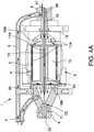
- Figure 4Bis a side cross-sectional view of a motor assembly 1, according to another embodiment.
- components numbered similar to those in Figure 4Arepresent the same or similar components and functionalities.
- a first portion 17A of the fluidcan pass proximally through the motor assembly 1 about a periphery of the rotor 15, e.g. , in a gap between the rotor 15 and a wall of the flow diverter 3.
- a second portion 17B of the fluidcan pass proximally through the motor assembly 1 through the lumen 55 of the output shaft 13.
- the fluid portions 17A, 17Bcan pass from the rotor chamber 4 into the proximal chamber 10 of the flow diverter 3, where the fluid 17A, 17B can flow out to a reservoir (not shown) by way of line 7.
- the fluid portions 17 A, 17Bcan flow along a first fluid pathway or channel within the flow diverter 3 which is disposed inside the stator 2.
- a third portion 17C of the fluidcan be shunted around the rotor 15 and stator assembly 2 along a second fluid pathway or channel.
- the third portion 17C of the proximally-fl owing fluidcan be withdrawn from the inner lumen 58 of the catheter body 120 A by way of a suitable conduit and fluid connector.
- the third fluid portion 17Ccan bypass the motor assembly 1.
- the fluidcan then be conveyed to the waste reservoir by a suitable waste line, which may be the same as or different from the waste line 7.
- the third portion 17C of the proximally-flowing fluidcan be more than, less than, or about the same in volume as the combined volume of the first and second fluid portions 17A, 17B.
- the third portion 17Ccan be transported by a conduit to a heat exchanger to further cool the motor assembly 1.
- the third fluid portion 17Ccan be conveyed to coiled tubing or a tubular sleeve disposed about the stator assembly 2, as shown in various embodiments of the following concurrently filed application: Application No. 15/003,682 , entitled "MOTOR ASSEMBLY WITH HEAT EXCHANGER FOR CATHETER PUMP," and which is expressly incorporated by reference herein in its entirety and for all purposes.
- the embodiment of Figure 4Bmay be desirable in arrangements in which the first and second fluid portions 17A, 17B become too hot and/or otherwise ineffective at cooling the motor assembly 1.
- the motor assembly 1may heat the first and second fluid portions 17A, 17B passing inside the flow diverter 3 to such a degree that the temperatures of the fluid portions 17 A, 17B and/or the motor assembly 1 rise to unacceptable levels.
- itmay be desirable to shunt some, most, or all of the proximally-flowing fluid around the motor assembly 1 along the second fluid pathway.
- the first and second fluid portions 17 A, 17Bmay pass through the flow diverter 3 along the first fluid pathway at a flow rate less than that provided in the embodiment of Figure 4A .
- the fluidmay flow back proximally through the flow diverter at rate such that the combined flow rate of the first and second portions 17 A, 17B is in a range of 5 mL/hr to 20 mL/hr, or more particularly, in a range of 10 mL/hr to 15 mL/hr.
- the proximally-flowing fluidis diverted around the flow diverter 3 and other components of the motor along the second fluid pathway as the third fluid portion 17C.
- the amount of the fluid portion 17C diverted around the motor assembly 1can be any suitable amount so as to maintain an adequate external temperature of the motor assembly 1.
- the third fluid portion 17Crepresents a relatively small volume of fluid diverted from the inner lumen 58.
- the third fluid portion 17Cflows around the motor assembly 1 at a flow rate in a range of 1 mL/hr to 30 mL/hr.
- the third fluid portion 17Cflows around the motor assembly 1 at a flow rate in a range of 1 mL/hr to 5 mL/hr, or in a range of 1 mL/hr to 3 mL/hr. In one embodiment, the third fluid portion 17C flows around the motor assembly 1 at a flow rate in a range of 10 mL/hr to 50 mL/hr. In another embodiment, the third fluid portion 17C represents a majority of the fluid diverted from the inner lumen 58.
- the third fluid portion 17Cmay have a flow rate in a range of 5.5 mL/hr to 12 mL/hr, in a range of 5.5 mL/hr to 10 mL/hr, in a range of 5.5 mL/hr to 8 mL/hr, in a range of 5.5 mL/hr to 7 mL/hr, in a range of 10 mL/hr to 14 mL/hr, or in a range of 8 mL/hr to 12 mL/hr.
- diverting some of the proximally-flowing fluid around the motor assembly 1can improve the transfer of heat away from the motor assembly 1, for example, in situations in which the first and second fluid portions 17 A, 17B become too hot.
- the console 122can be configured to change the amount of the third fluid portion 17C flowing along the second fluid pathway before and/or during a treatment procedure to adjust the volume of fluid that is diverted from the inner lumen 58 around the motor assembly 1.
- the console 122can send instructions to a pump (such as a peristaltic pump) to adjust the flow rate of fluid shunted or bypassed around the motor assembly 1.
- a pumpsuch as a peristaltic pump
- bypassedare used interchangeably herein.
- a majority of the fluidis shunted around the motor assembly, but at least a portion of the fluid passes within the motor assembly for cooling purposes and/or for cleaning the motor.
- the console 122can comprise processing electronics programmed to automatically control the amount of fluid that is shunted around the motor and/or the amount that passes within the motor assembly.
- the cliniciancan engage a valve or other mechanical device to control the relative amount of fluid that bypasses the motor assembly.
- the amount of bypassed fluidcan be controlled in a self-adjusted or balancing manner.
- a common pumpis applied to all three fluid portions 17A-17C. In other embodiments, one pump is applied to draw the first and second fluid portions 17 A, 17B, and a separate pump is applied to draw the third fluid portion 17C.
- all or substantially all the fluid flowing proximally through the inner lumen 58is shunted around the motor assembly 1 along the second fluid pathway.
- the shunted third fluid portion 17Ccan be diverted to a waste reservoir and/or to a heat exchanger disposed about the stator assembly 2, as explained above.
- all (100%) or substantially all (i.e. , between 90% and 100%) of the proximally-flowing fluiddoes not flow within the motor assembly 1 (e.g. , within the flow diverter 3), but is instead diverted around the motor assembly 1.
- the motor assembly 1may be adequately cooled without the fluid portions 17 A, 17B flowing proximally through the flow diverter 3.
- the fluid flowing proximally through the inner lumen 58may also provide sufficient pressure so as to prevent air or other gases from passing distally through the catheter body 120A to the patient.
- the embodiments disclosed in Figures 1A-4Bcan adequately remove heat from the motor assembly 1 without requiring the use of external cooling fins exposed to the outside environs. That is, the thermal performance of the heat removal systems disclosed in Figures 2-4B can adequately reduce the temperature of the outer surface of the motor housing without using cooling fins exposed outside of the motor housing (e.g. , outside of an exterior surface of the motor assembly 1) to the ambient environment. Rather, the heat removal systems may be disposed entirely within the motor housing, e.g. , within the housing which encloses the rotor and stator. For example, in some embodiments, the systems disclosed in Figures 1A-4B can ensure that the temperature of the exterior surface of the motor assembly 1 is not more than about 40 °C.
- the systems disclosed in Figures 1A-4Bcan ensure that the temperature of the exterior surface of the motor assembly 1 is in a range of 15 °C to 42 °C, or more particularly in a range of 20 °C to 42 °C, in a range of 20 °C to 40 °C, in a range of 20 °C to 35 °C, or in a range of 20 °C to 30 °C, without requiring the use of external cooling fins exposed outside the motor housing.
- Figure 5is a schematic perspective view of an interface between the distal chamber 5 and the rotor chamber 4 of the flow diverter 3, with the stator assembly 2 hidden for ease of illustration.
- Figure 5shows the output shaft 13 coupled with a proximal portion of the drive shaft 16 through an aperture in the flange 1 IB.
- the journal bearings 18A ( Figs. 3 and 5 ) and 18B ( Fig. 3 )can be provided on opposite axial sides of the rotor 15 to help maintain the rotor 15 in radial alignment with the rotor chamber 4 and/or in axial alignment with the stator assembly 2. Improving radial alignment of the rotor 15 and output shaft 13 relative to the rotor chamber 4 can reduce or eliminate eccentricity during rotation, which can reduce vibrations.
- journal bearings 18A, 18Bcan be rotationally decoupled with the output shaft 13 such that the output shaft 13 can rotate relative to the bearings 18 A, 18B.
- the journal bearings 18A, 18Bcan be fixed inside the rotor chamber 4.
- one or more passages 59can be provided through or across the bearings 18A, 18B so that cooling fluid can pass axially through the bearings 18A, 18B.
- the passages 59are defined at least in part by a cross-shaped structure of the bearings 18 A, 18B, but other variations for the passages 59 may be suitable.
- the bearings 18A, 18Bcan form radially-extending arms with one or more gaps disposed between the arms. Such gaps can be enclosed peripherally by a housing enclosing the stator assembly 2.
- one or more openingscan be provided through the bearings 18A, 18B to define the passages.
- Figures 6A and 6Bshow one embodiment of an interface 22 between the output shaft 13 and the drive shaft 16.
- the interface 22can comprise a connection between a distal portion of the output shaft 13 and a proximal portion of the drive shaft 16.
- the distal portion of the output shaft 13can comprise a radially-inward taper and one or more holes 61 formed through the output shaft 13.
- the proximal portion of the drive shaft 16can be inserted within the lumen 55 of the output shaft 13 such that the lumen 55 and the inner lumen 58 of the catheter body 120A form a continuous passage. This passage can be used to advance the guidewire guide tube 20, sensors, and other instruments, or to provide fluid communication for cooling fluid or medications.
- Cooling fluidcan flow proximally from the inner lumen 58 of the catheter body 120A and the first portion 17A of the fluid can pass outwardly about the periphery of the rotor 15.
- the second portion 17B of the fluidcan pass through the lumen 55 of the output shaft 13.
- a sleeve 21can be disposed about the proximal portion of the catheter body 120A, and the seal 19 can be provided about the sleeve 21 to seal the distal chamber 5 from the rotor chamber 4.
- the output shaft 13is permanently coupled with, e.g., laser welded to the drive shaft 16.
- a welding machinecan access the interface 22 by way of the holes 61 formed in the output shaft 13 to weld the output shaft 13 to the drive shaft 16.
- the output shaft 13can be secured to the drive shaft 16 in other ways, e.g. , by friction or interference fit, by adhesives, by mechanical fasteners, etc.
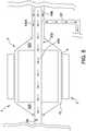
- FIG 8is a schematic side sectional view of a motor assembly 1, according to another embodiment.
- the motor assembly 1can comprise a rotor chamber 4 and a rotor 15 disposed in the rotor chamber 4.
- a stator assembly 2can be disposed outside the rotor chamber 4 and can at least partially surround the rotor chamber 4 and the rotor 15.
- the stator assembly 2can comprise a stator and a plurality of conductive windings producing a controlled magnetic field.
- the windingscan be wrapped about or in a stationary portion of the stator assembly 2.
- the rotor 15can comprise a magnetic material, e.g., can include one or more permanent magnets. In some embodiments, the rotor 15 can comprise a multi-pole magnet, e.g., a four-pole or six-pole magnet. Providing changing electrical currents through the windings of the stator assembly 2 can create magnetic fields that interact with the rotor 15 to cause the rotor 15 to rotate. This is commonly referred to as commutation.
- the console 122(which may include a controller or control system having one or more processors) can provide electrical power (e.g. , 24V) to the stator assembly 2 to drive the motor assembly 1.
- the rotor 15can mechanically connect with (e.g. , be fitted with) a shaft assembly 302 that extends from the motor assembly 1 to the impeller. Rotation of the shaft assembly 302 can cause the impeller to rotate during operation of the catheter pump system.
- the shaft assembly 302can comprise a motor output shaft (such as the output shaft 13 illustrated above) connected with a drive shaft (such as the drive shaft 16 illustrated above). Rotation of the rotor 15 can cause the output shaft and drive shaft to rotate, which in turn imparts rotation to the impeller.
- the rotor 15can define a shaft-driving portion disposed in the rotor chamber 4, and the stator assembly 2 can define an actuation portion disposed about the rotor chamber 4 which causes rotation of the shaft-driving portion.
- the shaft-driving portioncan comprise an electrical, direct current (DC) motor.
- the shaft-driving portioncan comprise a driven magnet in the chamber that is magnetically coupled with a drive magnet disposed about the chamber, which may be similar to the motor assembly described throughout US 2014/0275725 , the contents of which are incorporated herein by reference in their entirety and for all purposes.
- the shaft assembly 302may comprise a continuous shaft extending from the motor to the impeller.
- a lumen 55can be disposed within the shaft assembly 302.
- the portion of the shaft assembly 302 disposed within the motor assembly 1 or chamber 4may be solid without an internal lumen.
- the rotor chamber 4may be filled with a gas 325 that at least partially surrounds the rotor 15 and the portion of the shaft assembly 302 within the chamber 4.
- the gas 325can comprise any suitable gas, such as air, helium, nitrogen, etc.
- the gas 325may advantageously store less thermal energy than a liquid, reducing the overall temperature of the motor assembly 1.
- a fluid pathway within the catheter body 120Amay convey fluids (such as saline) proximally from the patient.
- a first pathway 40 A of proximally-flowing fluidmay pass within the inner lumen 55 of the shaft assembly 302 in some embodiments. In other embodiments, however, no fluid may flow through the lumen 55, or the portion of the shaft assembly 302 within the motor assembly 1 may be solid (i.e., not hollow).
- the fluid in the first pathway 40Amay be confined within the lumen 55. In other embodiments, some fluid in the first pathway 40A may pass through the shaft assembly 302 and enter the chamber 4, for example, if the portion of the shaft assembly 302 within the motor assembly 1 is porous.
- a second bypass pathway 40Bcomprising a conduit 321 can be provided to shunt or bypass at least a second portion of the proximally-flowing around the motor assembly 1.
- the second bypass pathway 40Bcan direct all or substantially all the fluid to bypass the chamber 4.
- the second bypass pathway 40Bcan be in fluid communication with one or more pumps operating under the control of a control system comprising one or more processors.
- the one or more pumps and/or the control systemcan be configured to draw all or substantially all the fluid along the second pathway 40B so as to prevent the fluid from passing proximally into the chamber 4.
- the console 122can comprise processing electronics programmed to automatically control the amount of fluid that is shunted around the motor and/or the amount that passes within the motor assembly.
- the cliniciancan engage a valve or other mechanical device to control the relative amount of fluid that bypasses the motor assembly.
- the amount of bypassed fluidcan be controlled in a self-adjusted or balancing manner.
- the gas 325may help seal the chamber 4, e.g., to impede or prevent proximally-flowing fluid (e.g., liquids such as saline) from entering the rotor chamber 4.
- proximally-flowing fluide.g., liquids such as saline
- the gas 325may be provided within the chamber 4 at a pressure sufficiently high so as to prevent the proximally-flowing fluid from entering the chamber 4.
- the pressure of the gas 325 in the chamber 4may be higher than the pressure of the proximally-flowing fluid so as to assist in sealing the chamber 4 from liquids. It should further be appreciated that it can be important to prevent gases such as air from entering the patient's bloodstream.
- the chamber 4 or the catheter body 120Amay include an outlet port or vent through which the gas 325 can escape the catheter assembly before passing distally to the patient.
- the outlet port or ventcan comprise a bleed valve that can be adjustable to balance the blood pressure of the particular patient.
- the gas 325may be drawn through the conduit 321 shown in Figure 8 , or through another conduit (not illustrated).
- the pressure of the gas 325 within the chamber 4may be less than the blood pressure of the patient.
- the relative pressure differentialcan help to prevent the gas 325 from moving retrograde and entering the patient's bloodstream.
- the relative pressures in the systemcan be advantageously selected to provide a kind of sealing between regions of the pump system.
- the blood pressure of the patientmay be greater than the pressure of the gas 325, which in turn may be greater than the pressure of the proximally-flowing fluid that flows along the pathways 40A and/or 40B.
- the pressure of the gas 325 in the chambermay be 10% more, 20% more, 50% more, or 100% more than the pressure of the proximally-flowing fluid.
- the pressure of the gas 325can be greater than the pressure of the proximally-flowing fluid by an amount in a range of 5% to 100%, in a range of 5% to 50%, in a range of 10% to 50%, in a range of 10% to 40%, or in a range of 20% to 50%.
- the pressure of the gas 325 in the chambercan be substantially greater than the pressure of the proximally-flowing fluid, such that the pressure of the gas 325 is sufficient to impede or limit the flow from entering the chamber.
- the pressure of the gas 325 in the chambercan be in a range of 0.5 psi to 30 psi, for example, in a range of 1 psi to 20 psi, or more particularly, in a range of 1 psi to 10 psi.
- the chamber 4may be pre-filled with the gas 325.
- Figure 9is a schematic side sectional view of a motor assembly 1, according to another embodiment.
- reference numerals in Figure 9represent components that are the same as or similar to like-numbered components in Figure 8 .
- an inlet line 320can supply the gas 325 to the chamber.
- the inlet line 320can be in fluid communication with one or more pumps to controllably and selectively supply the gas 325 to the chamber 4.
- the gas 325can be supplied at the pressures noted above, e.g. , at pressures greater than that of the proximally-flowing fluid.
- an outlet or ventmay also be provided to provide an exit pathway for the gas 325 to leave the catheter system.
Landscapes
- Health & Medical Sciences (AREA)
- Heart & Thoracic Surgery (AREA)
- Engineering & Computer Science (AREA)
- Life Sciences & Earth Sciences (AREA)
- Mechanical Engineering (AREA)
- Anesthesiology (AREA)
- Biomedical Technology (AREA)
- Hematology (AREA)
- Cardiology (AREA)
- Animal Behavior & Ethology (AREA)
- General Health & Medical Sciences (AREA)
- Public Health (AREA)
- Veterinary Medicine (AREA)
- Vascular Medicine (AREA)
- Transplantation (AREA)
- External Artificial Organs (AREA)
Abstract
Description
- This application claims the benefit of
U.S. Provisional Patent Application No. 62/365,258, filed July 21, 2016 - This application is directed to catheter pumps for mechanical circulatory support of a heart.
- Heart disease is a major health problem that has high mortality rate. Physicians increasingly use mechanical circulatory support systems for treating heart failure. The treatment of acute heart failure requires a device that can provide support to the patient quickly. Physicians desire treatment options that can be deployed quickly and minimally-invasively.
- Mechanical circulatory support (MCS) systems and ventricular assist devices (VADs) have gained greater acceptance for the treatment of acute heart failure such as acute myocardial infarction (MI) or to support a patient during high risk percutaneous coronary intervention (PCI). An example of an MCS system is a rotary blood pump placed percutaneously, e.g., via a catheter.
- In a conventional approach, a blood pump is inserted into the body and connected to the cardiovascular system, for example, to the left ventricle and the ascending aorta to assist the pumping function of the heart. Other known applications include placing the pump in the descending aorta, a peripheral artery, and the like. Typically, acute circulatory support devices are used to reduce the afterload on the heart muscle and provide blood flow for a period of time to stabilize the patient prior to heart transplant or for continuing support.
- There is a need for improved mechanical circulatory support devices for treating acute heart failure. There is a need for minimally-invasive devices designed to provide near full heart flow rate .
- There is a need for a blood pump with improved performance and clinical outcomes. There is a need for a pump that can provide elevated flow rates with reduced risk of hemolysis and thrombosis. There is a need for a pump that can be inserted minimally-invasively and provide sufficient flow rates for various indications while reducing the risk of major adverse events.
- In one aspect, there is a need for a blood pump that can be placed minimally-invasively, for example, through an 18FR, 14FR, or 8FR incision. In one aspect, there is a need for a heart pump that can provide an average flow rate of 4 Lpm or more during operation, for example, at 62 mmHg of aortic pressure.
- While the flow rate of a rotary blood pump can be increased by rotating the impeller faster, higher rotational speeds are known to increase the risk of hemolysis, which can lead to adverse outcomes and in some cases death. Higher speeds also lead to performance and patient comfort challenges. Many percutaneous ventricular assist devices (VADs) have driveshafts between the motor and impeller rotating at high speeds. Some percutaneous VADs are designed to rotate at speeds of more than 15,000 RPM, and in some cases more than 25,000 RPM in operation. The vibration, noise, and heat from the motor and driveshaft can cause discomfort to the patient, especially when positioned inside the body. Accordingly, there is a need for a device that improves performance and patient comfort with a high speed motor.
- There is a need for a motor configured to drive an operative device, e.g. , an impeller, atherectomy device, or other rotating feature.
- There is a need for an improved motor with sealing between each end. There is a need for a motor capable of rotating at relatively high speeds and providing sealing between a wet side and an electrical side.
- These and other problems are overcome by the inventions described herein.
- There is a need for a pumping device that can be inserted percutaneously and also provide full cardiac rate flows of the left, right, or both the left and right sides of the heart when called for.
- In one embodiment, a catheter pump system is disclosed. The catheter pump system can include a shaft assembly and a working element coupled with a distal portion of the shaft assembly. The catheter pump assembly can include a motor assembly, the motor assembly comprising a chamber and a shaft-driving portion disposed in the chamber, the shaft-driving portion configured to impart rotation to the working element through the shaft assembly, the chamber filled with a gas that at least partially surrounds the shaft-driving portion. A fluid pathway can convey fluid proximally during operation of the catheter pump system. A bypass pathway can be in fluid communication with the fluid pathway, the bypass pathway configured to direct at least a portion of the fluid to bypass the chamber.
- In some embodiments, the working element can comprise an impeller. The motor assembly can further comprise a stator and the shaft-driving portion can comprise a rotor, the stator disposed outside the chamber at least partially about the rotor. The bypass pathway can direct all or substantially all the fluid to bypass the chamber. A gas inlet can supply the gas to the chamber. The chamber cam comprise a gas outlet through which the gas can exit the chamber. In some embodiments, the gas comprises air. The fluid pathway can comprise a lumen of the shaft assembly, the lumen extending through the chamber such that at least a portion of the fluid passes through the lumen within the chamber. In some embodiments, a first pressure of the gas in the chamber is greater than a second pressure of the conveyed fluid. One or more pumps can be in fluid communication with the fluid pathway and a controller can control operation of the one or more pumps, the controller configured to apply a suction force to remove the fluid and/or the gas from the catheter pump system. The shaft assembly can comprise an output shaft coupled with the motor assembly and a drive shaft coupled with the impeller, a distal portion of the output shaft coupled with a proximal portion of the drive shaft. A catheter assembly can be disposed between the motor assembly and the impeller, the catheter assembly defining at least a portion of the fluid pathway. The catheter pump system can
include a cannula in which the working element is disposed, the cannula and impeller expandable from a stored configuration to a deployed configuration. - In one embodiment, a method of operating a pump is disclosed, the pump comprising an impeller and a motor assembly coupled with the impeller. The method can include rotating a shaft assembly with a shaft-driving portion of the motor assembly to impart rotation to the impeller, the shaft-driving portion of the motor assembly disposed in a chamber, the chamber filled with a gas that at least partially surrounds the shaft-driving portion. The method can include directing fluid into the pump, at least a portion of the fluid flowing proximally along a fluid pathway between the impeller and the motor assembly. The method can include directing at least a portion of the fluid to bypass the chamber.
- In some embodiments, the method can include directing at least some of the fluid through a lumen extending through an output shaft portion of the shaft assembly, the output shaft portion passing through the chamber. The method can include inserting a guidewire through the lumen, and advancing the pump over the guidewire to a target site in a patient. The method can include expanding the impeller from a stored configuration to a deployed configuration.
- In one embodiment, a catheter pump system is disclosed. The catheter pump system can include an impeller and a catheter body having a lumen in which fluid flows proximally therethrough during operation of the catheter pump. The catheter pump system can include a drive shaft disposed inside the catheter body and coupled with the impeller at a distal portion of the drive shaft, the drive shaft configured such that rotation of the drive shaft causes the impeller to rotate. The catheter pump system can include a motor assembly. The motor assembly can include a chamber, at least a portion of the chamber in fluid communication with the lumen of the catheter body. The motor assembly can also include a rotor disposed in the at least a portion of the chamber, the rotor mechanically coupled with a proximal portion of the drive shaft such that rotation of the rotor causes the drive shaft to rotate. The motor assembly can include a stator assembly disposed about the rotor and configured to cause the rotor to rotate. No cooling fins extend outside an exterior surface of the motor assembly.
- In another embodiment, a catheter pump system is disclosed. The catheter pump system can include an impeller and a catheter body having a lumen therethrough, the impeller mechanically coupled with a distal portion of the catheter body. The catheter pump system can include a guidewire guide tube disposed through the lumen from a proximal portion of the catheter pump to a distal portion of the catheter pump, the guidewire guide tube configured to receive a guidewire therein. The catheter pump system can include an end cap secured to a proximal end portion of the guide tube, the end cap configured such that axial movement of the end cap relative to the catheter body causes the guidewire guide tube to be removed from the catheter pump. The catheter pump system can include a resealable closure device disposed at a proximal portion of the catheter pump, the closure device configured such that when the guidewire guide tube is removed from the catheter pump, the closure device encloses the proximal portion of the catheter pump system.
- In another embodiment, a catheter pump system is disclosed. The catheter pump system can include a pump including an impeller for pumping blood. The catheter pump system can include a motor assembly for imparting rotation on the impeller through a drive shaft. The motor assembly can comprise a stator carrying electrical windings and a rotor disposed in at least a portion of the stator, the rotor mechanically coupled with a proximal portion of the drive shaft. The catheter pump system can include a fluid supply system for delivering fluid to the pump during operation of the pump and returning at least some of the supplied fluid to a waste reservoir. The fluid supply system can comprise a fluid channel extending within the stator and a fluid pathway which passes outside the stator. During operation of the pump, at least a first portion of the returning fluid can pass through the fluid channel and at least a second portion of the returning fluid can pass through the fluid pathway.
- In another embodiment, a method of operating a pump is disclosed. The pump can comprise a motor which includes a stator assembly having windings and a rotor positioned within the stator assembly. The method can include rotating the rotor by selectively energizing the windings. The method can include cooling the motor by flowing a first fluid portion between the stator assembly and the rotor and by flowing a second fluid portion outside the stator.
- A more complete appreciation of the subject matter of this application and the various advantages thereof can be realized by reference to the following detailed description, in which reference is made to the accompanying drawings in which:
Figure 1A illustrates one embodiment of a catheter pump system with an impeller assembly configured for percutaneous application and operation.Figure 1B is a schematic view of one embodiment of a catheter pump system adapted to be used in the manner illustrated inFigure 1A .Figure 1C is a schematic view of another embodiment of a catheter pump system.Figure 2 is a side plan view of a motor assembly of the catheter pump system shown in Figure IB, according to various embodiments.Figure 3 is a perspective exploded view of the motor assembly shown inFigure 2 .Figure 4A is a side cross-sectional view of the motor assembly shown inFigures 2-3 .Figure 4B is a side cross-sectional view of a motor assembly, according to another embodiment.Figure 5 is a schematic perspective view of an interface between a distal chamber and a rotor chamber of a flow diverter of the motor assembly, with a stator assembly thereof hidden for ease of illustration.Figure 6A is a schematic perspective view of an interface between an output shaft of the motor assembly and a drive shaft of the catheter pump system.Figure 6B is a cross-sectional perspective view, taken through the longitudinal axis of the catheter, showing the interface shown inFigure 6A .Figure 7 is an image of a cap and a female receiver, with the guide tube not shown.Figure 8 is a schematic side sectional view of a motor assembly, according to another embodiment.Figure 9 is a schematic side sectional view of a motor assembly, according to another embodiment.- More detailed descriptions of various embodiments of components for heart pumps useful to treat patients experiencing cardiac stress, including acute heart failure, are set forth below.
- This application is generally directed to apparatuses for inducing motion of a fluid relative to the apparatus. Exemplars of circulatory support systems for treating heart failure, and in particular emergent and/or acute heart failure, are disclosed in
U.S. Patent Nos. 4,625,712 ;4,686,982 ;4,747,406 ;4,895,557 ;4,944,722 ;6,176,848 ;6,926,662 ;7,022,100 ;7,393,181 ;7,841,976 ;8,157,719 ;8,489,190 ;8,597,170 ;8,721,517 andU.S. Pub. Nos. 2012/0178986 and2014/0010686 , the entire contents of which patents and publications are incorporated by reference for all purposes. In addition, this application incorporates by reference in its entirety and for all purposes the subject matter disclosed in each of the following applications and the provisional applications to which they claim priority: Application No.15/003,576 U.S. Provisional Patent Application No. 62/106,670 15/003,682 U.S. Provisional Patent Application No. 62/106,675 15/003,696 62/1 06,673 - In one example, a working element (e.g., an impeller) can be coupled at a distal portion of the apparatus. In some embodiments, the motor is a brushless DC (BLDC) motor. In some embodiments, the motor is a micro BLDC motor. Some embodiments generally relate to various configurations for a motor assembly adapted to drive an impeller at a distal end of a catheter pump, e.g., a percutaneous heart pump. The motor described herein may be used for other applications including catheter-based devices like an atherectomy device. In such applications, the disclosed motor assembly is disposed outside the patient in some embodiments. In other embodiments, the disclosed motor assembly and/or features of the motor are miniaturized and sized to be inserted within the body, e.g., within the vasculature.
Figures 1A-1B show aspects of anexemplary catheter pump 100A that can provide relatively high blood flow rates (i.e. full or near full blood flow). As shown inFigure 1B , thepump 100A includes a motor assembly 1 driven by aconsole 122, which can include an electronic controller and various fluid handling systems. Theconsole 122 directs the operation of the motor 1 and an infusion system that supplies a flow of fluid in thepump 100A. Additional details regarding theexemplary console 122 may be understood from U.S. Patent Publication No.US 2014/0275725 , the contents of which are incorporated by reference herein in their entirety and for all purposes.- The
pump 100A includes acatheter assembly 101 that can be coupled with the motor assembly 1 and can house a working element, such as an impeller in animpeller assembly 116A within a distal portion of thecatheter assembly 101 of thepump 100A. In various embodiments, the impeller is rotated remotely by the motor 1 when thepump 100A is operating. For example, the motor 1 can be disposed outside the patient. In some embodiments, the motor 1 is separate from theconsole 122, e.g., to be placed closer to the patient. In the exemplary system the pump is placed in the patient in a sterile environment and the console is outside the sterile environment. In one embodiment, the motor is disposed on the sterile side of the system. In other embodiments, the motor 1 is part of theconsole 122. - In still other embodiments, the motor 1 is miniaturized to be insertable into the patient. For example,
Figure 1C is a schematic view of another embodiment of a catheter pump system.Figure 1C is similar to Figure IB, except the motor 1 is miniaturized for insertion into the body. As shown inFigure 1C , for example, the motor 1 can be disposed proximal theimpeller assembly 116A. The motor 1 can be generally similar to the motor assembly shown inFigure 2 , except the motor 1 is sized and shaped to be inserted into the patient's vasculature. One or more electrical lines may extend from the motor to the console outside the patient. The electrical lines can send signals for controlling the operation of the motor. Such embodiments allow a drive shaft coupled with the impeller and disposed within thecatheter assembly 101 to be much shorter, e.g., shorter than the distance from the aortic valve to the aortic arch (about 5 cm or less). Various embodiments of the motor assembly 1 are disclosed herein, including embodiments having a rotor disposed within a stator assembly. In various embodiments, waste fluid can pass through a housing in which the rotor is disposed to help cool the motor assembly 1. In some embodiments, the housing in which the motor 1 ofFigure 1C is disposed can be sealed from fluids (e.g. , blood and/or saline) so as to isolate the electrical lines from the fluids. For example, as disclosed in the embodiments ofFigures 8-9 , the housing in which the motor 1 is disposed may be filled with a gas, which can impede or prevent the flow of liquids into the housing. Figure 1A illustrates one use of thecatheter pump 100A. A distal portion of thepump 100A including a catheter assembly including theimpeller assembly 116A is placed in the left ventricle (LV) of the heart to pump blood from the LV into the aorta. Thepump 100A can be used in this way to treat a wide range of heart failure patient populations including, but not limited to, cardiogenic shock (such as acute myocardial infarction, acute decompensated heart failure, or postcardiotomy), myocarditis, and others. The pump can also be used for various other indications including to support a patient during a cardiac invention such as a high-risk percutaneous coronary intervention (PCI) or ablation. One convenient manner of placement of the distal portion of thepump 100A in the heart is by percutaneous access and delivery using a modified Seldinger technique or other methods familiar to cardiologists. These approaches enable thepump 100A to be used in emergency medicine, a catheter lab and in other medical settings. Modifications can also enable thepump 100A to support the right side of the heart.Example modifications that could be used for right side support include providing delivery features and/or shaping a distal portion that is to be placed through at least one heart valve from the venous side, such as is discussed inUS 6,544,216 ;US 7,070,555 ; andUS 2012-0203056A1 , all of which are hereby incorporated by reference herein in their entirety for all purposes.- The
impeller assembly 116A (e.g., the impeller and cannula) can be expandable and collapsible. In the collapsed state, the distal end of thecatheter pump 100A can be advanced to the heart, for example, through an artery. In the expanded state theimpeller assembly 116A is able to pump blood at relatively high flow rates. In particular, the expandable cannula and impeller configuration allows for decoupling of the insertion size and flow rate, in other words, it allows for higher flow rates than would be possible through a lumen limited to the insertion size with all other things being equal. InFigures 1A and IB, theimpeller assembly 116A is illustrated in the expanded state. The collapsed state can be provided by advancing adistal end 170A of anelongate body 174A distally over theimpeller assembly 116A to cause theimpeller assembly 116A to collapse. This provides an outer profile throughout the catheter assembly andcatheter pump 100A that is of small diameter during insertion, for example, to a catheter size of about 12.5 FR in various arrangements. In other embodiments, theimpeller assembly 116A is not expandable. - The mechanical components rotatably supporting the impeller within the
impeller assembly 116A permit relatively high rotational speeds while controlling heat and particle generation that can come with high speeds. The infusion system delivers a cooling and lubricating solution to the distal portion of thecatheter pump 100A for these purposes. The space for delivery of this fluid is extremely limited. Some of the space is also used for return of the fluid as waste fluid. Providing secure connection and reliable routing of fluid into and out of thecatheter pump 100 A is critical and challenging in view of the small profile of thecatheter assembly 101. - When activated, the catheter pump 100A can effectively support, restore and/or increase the flow of blood out of the heart and through the patient's vascular system. In various embodiments disclosed herein, the
pump 100A can be configured to produce a maximum flow rate (e.g. zero mm Hg backpressure) of greater than 4 Lpm, greater than 4.5 Lpm, greater than 5 Lpm, greater than 5.5 Lpm, greater than 6 Lpm, greater than 6.5 Lpm, greater than 7 Lpm, greater than 7.5 Lpm, greater than 8 Lpm, greater than 9 Lpm, or greater than 10 Lpm. In various embodiments, thepump 100 A can be configured to produce an average flow rate at 62 mmHg of greater than 2 Lpm, greater than 2.5 Lpm, greater than 3 Lpm, greater than 3.5 Lpm, greater than 4 Lpm, greater than 4.25 Lpm, greater than 4.5 Lpm, greater than 5 Lpm, greater than 5.5 Lpm, greater than 6 Lpm, greater than 6.5 Lpm, greater than 7 Lpm, greater than 8 Lpm, or greater than 9 Lpm. - Various aspects of the pump and associated components can be combined with or substituted for those disclosed in
U.S. Patent Nos. 7,393,181 ;8,376,707 ;7,841,976 ;7,022,100 ; and7,998,054 , and inU.S. Pub. Nos. 2011/0004046 ;2012/0178986 ;2012/0172655 ;2012/0178985 ; and2012/0004495 , the entire contents of each of which are incorporated herein for all purposes by reference. In addition, various aspects of the pump and system can be combined with those disclosed in U.S. Patent Publication No.US 2013/0303970 , entitled "DISTAL BEARING SUPPORT," filed on March 13, 2013; U.S. Patent Publication No.US 2014/0275725 , entitled "FLUID HANDLING SYSTEM," filed on March 11, 2014; U.S. Patent Publication No.US 2013/0303969 , entitled "SHEATH SYSTEM FOR CATHETER PUMP," filed on March 13, 2013; U.S. Patent Publication No.US 2013/0303830 , entitled "IMPELLER FOR CATHETER PUMP," filed on March 13, 2013; U.S. Patent Publication No.US 2014/0012065 , entitled "CATHETER PUMP," filed on March 13, 2013; and U.S. Patent Publication No.US 2014/0010686 , entitled "MOTOR ASSEMBLY FOR CATHETER PUMP," filed on March 13, 2013, the entire contents of each of which are incorporated herein for all purposes by reference. - Moving from a
distal end 1450 of thecatheter assembly 101 of thecatheter pump 100A of Figure IB to a proximal end 1455, apriming apparatus 1400 can be disposed over theimpeller assembly 116A. As explained above, theimpeller assembly 116A can include an expandable cannula or housing and an impeller with one or more blades. As the impeller rotates, blood can be pumped proximally (or distally in some implementations) to function as a cardiac assist device. - In various embodiments, the pump is configured to be primed with fluid. Turning to Figure IB, a
priming apparatus 1400 can be disposed over theimpeller assembly 116A near thedistal end portion 170A of theelongate body 174 A. Thepriming apparatus 1400 can be used in connection with a procedure to expel air from theimpeller assembly 116A, e.g. , any air that is trapped within the housing or that remains within theelongate body 174A near thedistal end 170A. For example, the priming procedure may be performed before the pump is inserted into the patient's vascular system, so that air bubbles are not allowed to enter and/or injure the patient. Thepriming apparatus 1400 can include aprimer housing 1401 configured to be disposed around both theelongate body 174A and theimpeller assembly 116A. Asealing cap 1406 can be applied to theproximal end 1402 of theprimer housing 1401 to substantially seal thepriming apparatus 1400 for priming, i.e., so that air does not proximally enter theelongate body 174A and also so that priming fluid does not flow out of the proximal end of thehousing 1401. Thesealing cap 1406 can couple to theprimer housing 1401 in any way known to a skilled artisan. In some embodiments, thesealing cap 1406 is threaded onto the primer housing by way of a threadedconnector 1405 located at theproximal end 1402 of theprimer housing 1401. Thesealing cap 1406 can include a sealing recess disposed at the distal end of thesealing cap 1406. The sealing recess can be configured to allow theelongate body 174A to pass through thesealing cap 1406. - The priming operation can proceed by introducing fluid into the sealed
priming apparatus 1400 to expel air from theimpeller assembly 116A and theelongate body 174A. Fluid can be introduced into thepriming apparatus 1400 in a variety of ways. For example, fluid can be introduced distally through theelongate body 174A into thepriming apparatus 1400. In other embodiments, an inlet, such as a luer, can optionally be formed on a side of theprimer housing 1401 to allow for introduction of fluid into thepriming apparatus 1400. A gas permeable membrane can be disposed on adistal end 1404 of theprimer housing 1401. The gas permeable membrane can permit air to escape from theprimer housing 1401 during priming. - The
priming apparatus 1400 also can advantageously be configured to collapse an expandable portion of thecatheter pump 100 A. Theprimer housing 1401 can include afunnel 1415 where the inner diameter of the housing decreases from distal to proximal. The funnel may be gently curved such that relative proximal movement of the impeller housing causes the impeller housing to be collapsed by thefunnel 1415. During or after the impeller housing has been fully collapsed, thedistal end 170A of theelongate body 174A can be moved distally relative to the collapsed housing. After the impeller housing is fully collapsed and retracted into theelongate body 174A of the sheath assembly, thecatheter pump 100A can be removed from the priming apparatusl400 before a percutaneous heart procedure is performed, e.g. , before thepump 100A is activated to pump blood. The embodiments disclosed herein may be implemented such that the total time for infusing the system is minimized or reduced. For example, in some implementations, the time to fully infuse the system can be about six minutes or less. In other implementations, the time to infuse can be about three minutes or less. In yet other implementations, the total time to infuse the system can be about 45 seconds or less. It should be appreciated that lower times to infuse can be advantageous for use with cardiovascular patients. Although the described pump is primed with fluid, one will appreciate from the description herein that the priming may be optional. For example, the pump can be prepared such that all air is removed before it is packaged. In another example, air is removed by placing the pump under vacuum. - With continued reference to Figure IB, the
elongate body 174A extends from theimpeller assembly 116A in a proximal direction to anfluid supply device 195. Thefluid supply device 195 is configured to allow for fluid to enter thecatheter assembly 101 of the catheter pump 100A and/or for waste fluid to leave thecatheter assembly 101 of thecatheter pump 100 A. Acatheter body 120A (which also passes through theelongate body 174A) can extend proximally and couple to the motor assembly 1. As discussed in more detail herein, the motor assembly 1 can provide torque to a drive shaft that extends from the motor assembly 1 through thecatheter body 120A to couple to an impeller shaft at or proximal to theimpeller assembly 116A. Thecatheter body 120A can pass within theelongate body 174A such that the externalelongate body 174 A can axially translate relative to theinternal catheter body 120 A. - Further, as shown in Figure IB, a
fluid supply line 6 can fluidly couple with theconsole 122 to supply saline or other fluid to thecatheter pump 100A. The saline or other fluid can pass through an internal lumen of theinternal catheter body 120A and can provide lubrication to theimpeller assembly 116A and/or chemicals to the patient. The supplied fluid (e.g., saline, dextrose, glucose solution, or infusate) can be supplied to the patient by way of thecatheter body 120A at any suitable flow rate. For example, in
various embodiments, the fluid is supplied to the patient at a flow rate in a range of 15 mL/hr to 50 mL/hr, or more particularly, in a range of 20 mL/hr to 40 mL/hr, or more particularly, in a range of 25 mL/hr to 35 mL/hr. One or moreelectrical conduits 124 can provide electrical communication between theconsole 122 and the motor assembly 1. A controller within theconsole 122 can control the operation of the motor assembly 1 during use. - Fluid (e.g. , saline) can be provided from outside the patient (e.g. , by way of one or more supply bags) to the pump through a supply lumen in the catheter body. The fluid can return to the motor assembly 1 by way of a lumen (e.g. , a central or interior lumen) of the catheter body. For example, as explained herein, the fluid can return to the motor assembly 1 through the same lumen in which the drive shaft is disposed. In addition, a
waste line 7 can extend from the motor assembly 1 to awaste reservoir 126. Waste fluid from the catheter pump 100A can pass through the motor assembly 1 and out to thereservoir 126 by way of thewaste line 7. In various embodiments, the waste fluid flows to the motor assembly 1 and thereservoir 126 at a flow rate which is lower than that at which the fluid is supplied to the patient. For example, some of the supplied fluid may flow out of thecatheter body 120A and into the patient by way of one or more bearings. The waste fluid (e.g. , a portion of the fluid which passes proximally back through the motor from the patient) may flow through the motor assembly 1 at any suitable flow rate, e.g., at a flow rate in a range of 5 mL/hr to 20 mL/hr, or more particularly, in a range of 10 mL/hr to 15 mL/hr. Although described in terms of fluid and waste lines, one will appreciate that the pump and motor be configured to operate without fluid flushing. One purpose of the fluid supply is to cool the motor. In the case of a micromotor dimensioned and configured to be inserted percutaneously, there may not be a need for fluid cooling because the motor heat will be dissipated by the body. - Access can be provided to a proximal end of the
catheter assembly 101 of thecatheter pump 100A prior to or during use. In one configuration, thecatheter assembly 101 is delivered over aguidewire 235. Theguidewire 235 may be conveniently extended through the entire length of thecatheter assembly 101 of the catheter pump 100A and out of a proximal end 1455 of thecatheter assembly 101. In various embodiments, the connection between the motor assembly 1 and thecatheter assembly 101 is configured to be permanent, such that the catheter pump, the motor housing and the motor are disposable components. However, in other implementations, the coupling between the motor housing and thecatheter assembly 101 is disengageable, such that the motor and motor housing can be decoupled from thecatheter assembly 101 after use. In such embodiments, thecatheter assembly 101 distal of the motor can be disposable, and the motor and motor housing can be re-usable. - In addition, Figure IB illustrates the
guidewire 235 extending from aproximal guidewire opening 237 in the motor assembly 1. Before inserting thecatheter assembly 101 of the catheter pump 100A into a patient, a clinician may insert theguidewire 235 through the patient's vascular system to the heart to prepare a path for the impeller assembly 1 16A to the heart. In some embodiments, thecatheter pump 100A can include a guidewire guide tube 20 (seeFigure 3 ) passing through a central internal lumen of the catheter pump 100A from theproximal guidewire opening 237. Theguidewire guide tube 20 can be pre-installed in the catheter pump 100A to provide the clinician with a preformed pathway along which to insert theguidewire 235. - In one approach, the
guidewire 235 is placed into a peripheral blood vessel, and along the path between that blood vessel and the heart and into a heart chamber, e.g., into the left ventricle. Thereafter, a distal end opening of thecatheter pump 100A and guidewire guidetube 20 can be advanced over the proximal end of theguidewire 235 to enable delivery to thecatheter pump 100A. After the proximal end of theguidewire 235 is urged proximally within thecatheter pump 100A and emerges from theguidewire opening 237 and/orguidewire guide tube 20, thecatheter pump 100A can be advanced into the patient. In one method, theguidewire guide tube 20 is withdrawn proximally while holding thecatheter pump 100 A. - Alternatively, the clinician can insert the
guidewire 235 through theproximal guidewire opening 237 and urge theguidewire 235 along the guidewire guide tube. The clinician can continue urging theguidewire 235 through the patient's vascular system until the distal end of theguidewire 235 is positioned in the desired position, e.g., in a chamber of the patient's heart, a major blood vessel or other source of blood. As shown in Figure IB, a proximal end portion of theguidewire 235 can extend from theproximal guidewire opening 237. Once the distal end of theguidewire 235 is positioned in the heart, the clinician can maneuver the impeller assembly 1 16A over theguidewire 235 until theimpeller assembly 116A reaches the distal end of theguidewire 235 in the heart, blood vessel or other source of blood. The clinician can remove theguidewire 235 and the guidewire guide tube. The guidewire guide tube can also be removed before or after theguidewire 235 is removed in some implementations. After removing at least theguidewire 235, the clinician can activate the motor 1 to rotate the impeller and begin operation of thepump 100 A. - In yet another embodiment, catheter pump 100A is configured to be inserted using a modified Seldinger technique. The pump may be configured with a lumen therethrough for receiving a guidewire. Unlike the embodiment described above, however, the guidewire is threaded through the pump without a guidewire guide tube. One will appreciate from the description herein that other configurations may be employed for loading the pump onto a guidewire and/or moving the pump to the target location in the body. Examples of similar techniques are described in
U. S. Pat. No. 7,022, 100 and U. S. Pub. No.2005/01 13631 , the entire contents of which patent and publication are incorporated herein for all purposes. Figures 2 and3 further illustrate aspects of embodiments of the motor assembly 1 shown in Figure IB. The motor assembly 1 can include a stator assembly 2 (Figs. 2-3 ) and arotor 15 disposed radially within the stator assembly 2 (Fig. 3 ). The motor assembly 1 also includes aflow diverter 3, which can be configured as a manifold for directing fluid through one or more passages in thecatheter pump 100 A. In some cases, theflow diverter 3 is at least partially disposed radially between thestator assembly 2 and the rotor 15 (Figs. 2-3 ). Theflow diverter 3 can be fluidly sealed about therotor 15 and aproximal portion 56 of thecatheter body 120 A. The seal prevents leakage and also can prevent the fluid from contacting thestator assembly 2. Theflow diverter 3 can include adistal chamber 5 within which theproximal portion 56 of thecatheter body 120 A is disposed and arotor chamber 4 within which therotor 15 is disposed. Thedistal chamber 5 is fluidly connected with the catheter. Therotor chamber 4 is fluidly connected with thewaste line 7. Theflow diverter 3 can also have aproximal chamber 10 in some embodiments. Where provided, thedistal chamber 5,rotor chamber 4, andproximal chamber 10 can be in fluid communication within theflow diverter 3. One ormore flanges 11 A, 1 IB can mechanically couple theflow diverter 3 to an external housing (not shown). Theflanges 11 A, 1 IB are examples of mount structures that can be provided, which can include in various embodiments dampers to isolate the motor assembly 1 from external shock or vibration. In some embodiments, mount structures can include dampers configured to isolate an outer housing or the environment external to the motor assembly 1 from shock or vibration generated by the motor assembly 1. Further, an optionalpressure sensor assembly 12 is configured to measure the pressure at a distal portion of the catheter pump 100A by, for example, measuring the pressure of a column of fluid that extends distally through a lumen of thecatheter body 120A. In addition, theguidewire guide tube 20 can extend proximally through the motor assembly 1 and can terminate at atube end cap 8. As explained above, theguidewire 235 can be inserted within theguide tube 20 for guiding thecatheter pump 100 A to the heart.- In various embodiments, the
rotor 15 andstator assembly 2 are configured as or are components of a frameless-style motor for driving theimpeller assembly 116A at the distal end of thepump 100A. For example, thestator assembly 2 can comprise a stator and a plurality of conductive windings producing a controlled magnetic field. The windings can be wrapped about or in astationary portion 65 of thestator assembly 2. Therotor 15 can comprise a magnetic material, e.g., can include one or more permanent magnets. In some embodiments, therotor 15 can comprise a multi-pole magnet, e.g. , a four-pole or six-pole magnet. Providing changing electrical currents through the windings of thestator assembly 2 can create magnetic fields that interact with therotor 15 to cause therotor 15 to rotate. This is commonly referred to as commutation. Theconsole 122 can provide electrical power (e.g. , 24V) to thestator assembly 2 to drive the motor assembly 1. One or more leads 9 can electrically communicate with thestator assembly 2, e.g. , with one or more Hall sensors used to detect the speed and/or position of the motor. In other embodiments, other sensors (e.g. , optical sensors) can be used to measure motor speed. Therotor 15 can be secured to an output shaft 13 (which can comprise a hollow shaft with a central lumen) such that rotation of therotor 15 causes theoutput shaft 13 to rotate. In various embodiments, the motor assembly 1 can comprise a direct current (DC) brushless motor. In other embodiments, other types of motors can be used, such as AC motors, gearhead motor, etc. As shown inFigure 3 , first andsecond journal bearings output shaft 13 to radially and/or longitudinally center theoutput shaft 13 and thereby therotor 15 relative to thestator assembly 2. Figure 4A shows that the output shaft 13 (which is secured to the rotor 15) can be mechanically coupled with the proximal end portion of adrive shaft 16. Thedrive shaft 16 extends distally through an internal lumen of thecatheter body 120A. A distal end portion of thedrive shaft 16 is mechanically connected with the impeller. Thus, rotation of therotor 15 causes theoutput shaft 13 to rotate, which, in turn, causes thedrive shaft 16 and the impeller to rotate.Figure 4A also shows that alumen 55 can extend through theoutput shaft 13 and therotor 15. In certain embodiments, thelumen 55 is coupled with a lumen of thecatheter body 120A such that theguidewire guide tube 20 can extend through thelumen 55 within therotor 15 and into the lumen of thecatheter body 120A. In addition, thedrive shaft 16 comprises a braided shaft having an internal lumen. Thebraided drive shaft 16 or cable can be permeable to liquid such that supply fluid or waste fluid can flow from outside thedrive shaft 16 to within the internal lumen of the drive shaft 16 (and vice versa).Figure 4A shows thetube end cap 8 welded or otherwise secured to a proximal end portion of theguide tube 20. Thecap 8 can be removably engaged (e.g. , screwed or otherwise removably locked) over afemale receiver 71 that is secured in a proximal end of theproximal chamber 10. For example, the proximal end of thefemale receiver 71 can be disposed in a counterbore of thecap 8, while theguide tube 20 extends through the central opening of thecap 8. In a locked configuration, one or more tabs of thereceiver 71 can be rotated such that the tab(s) slide under a corresponding tab in the counterbore of thecap 8. In an unlocked configuration, the tab(s) of thereceiver 71 can be rotated relative to the tabs of thecap 8.Figure 7 shows one embodiment of thecap 8 and of thefemale receiver 71 that can be coupled with the guide tube 20 (not shown). In the illustrated embodiment, thecap 8 can be fixed to theguide tube 20; in other embodiments, thereceiver 71 can be fixed to theguide tube 20. Engaging thecap 8 to thereceiver 71 can advantageously prevent theguide tube 20 from accidentally being removed from or slid within the catheter pump 100A, e.g. , if the patient or clinician impacts thecap 8. To remove the guide tube 20 (e.g., after delivery of theimpeller assembly 116A to the heart), the clinician can disengage thecap 8 from thereceiver 71 and can pull theguide tube 20 from thecatheter pump 100 A, for example, by pulling proximally on theend cap 8. A resealable septum 72 (e.g. , a resealable closure member) can be provided at the proximal end of theflow diverter 3, e.g., near the distal end of thecap 8 when thecap 8 is in place. When theguidewire guide tube 20 is removed from thepump 100 A, theseptum 72 will naturally reseal the pathway proximally from the motor assembly 1 such that fluid does not exit the assembly 1. An advantage of the assembly described herein is that thecap 8 is locked and will not be dislodged without rotating and unlockingcap 8 fromreceiver 71. Otherwise, thecap 8 can slide axially if it is inadvertently bumped by the patient or clinician. This potentially results in theguide tube 20 being pulled out from the distal-most end of theimpeller assembly 116A, and because the guide tube cannot be re-inserted, the clinician either has to use the catheter pump 100A without a guide or get a new pump.- With continued reference to
Figure 4A , it can be important to ensure that the motor assembly 1 is adequately cooled. In various embodiments, it can be important to provide a heat removal system to limit buildup of heat in the motor assembly 1 during operation. For example, it can be important to maintain external surfaces of the motor assembly 1 at a temperature less than about 40°C if the motor assembly 1 is positioned near the patient. For example, an external surface of an external housing of the motor assembly 1 may be kept at or below this temperature. In some respects, regulatory guidelines can require that no part in contact with skin exceed 40°C. To that end, various strategies for heat management are employed by the inventions described herein. It should be appreciated that, as used herein, cooling refers to transferring away or dissipating heat, and in certain respects, cooling is used interchangeably with removing heat. In some embodiments, however, the fluids passing through or around the motor assembly 1 may not be utilized for cooling purposes. - Various components of the motor assembly 1 generate heat. For example, moving parts within the motor assembly 1 (e.g., the
rotating output shaft 13 and/or drive shaft 16) can generate heat by virtue of losses through friction, vibrations, and the like, which may increase the overall temperature of the motor assembly 1. Further, heat can be generated by the electrical current flowing through thestator assembly 2 and/or by induction heating caused by conductive components inside a rotating magnetic field. Furthermore, friction between thebearings output shaft 13 and/or
friction between thedrive shaft 16 and the inner wall ofcatheter body 120 A may also generate undesirable heat in the motor assembly. Inadequate cooling can result in temperature increases of the motor assembly 1, which can present patient discomfort, health risks, or performance losses. This can lead to undesirable usage limitations and engineering complexity, for example, by requiring mitigation for differential heat expansion of adjacent components of different materials. Accordingly, various embodiments disclosed herein can advantageously transfer away generated heat and cool the motor assembly 1 such that the operating temperature of the assembly 1 is sufficiently low to avoid such complexities of use or operation and/or other components of the system. For example, various heat transfer components can be used to move heat away from thermal generation sources and away from the patient. Various aspects of the illustrated device herein are designed to reduce the risk of hot spots, reduce the risk of heat spikes, and/or improve heat dissipation to the environment and away from the patient. - In some embodiments, the catheter pump makes use of the fluid supply system already embedded in the pump to cool the motor assembly 1 and housing. In some embodiments, heat absorbing capacity of fluid flowing through the
flow diverter 3 is used to cool the motor assembly 1. As shown inFigure 4A , thesupply line 6 can supply fluid 35 from a source (e.g. , a fluid bag) to anouter lumen 57 of thecatheter body 120A. The suppliedfluid 35 can travel distally toward the impeller assembly 1 16A to lubricate rotating components in thecatheter assembly 101 and/or supply fluid to the patient. A seal 19 (e.g. , an o-ring) can be provided between therotor chamber 4 and thedistal chamber 5 to prevent backflow of the fluid 35 into therotor chamber 4. In this context, backflow is flow offluid 35 proximally into thedistal chamber 5 rather than distally within thelumen 57. Such flow is to be prevented to ensure that the fluid 35 is initially exposed to moving parts in a distal portion of thecatheter assembly 101 to lubricate and cool such distal components. - Fluid from the catheter pump 100A can flow proximally through an
inner lumen 58 of thecatheter body 120A. For example, after initially cooling distal components some or all of the suppliedfluid 35 can flow within thedrive shaft 16 and/or around the periphery of thedrive shaft 16. After initially cooling distal components some or all of the suppliedfluid 35 can flow in a space disposed radially between thedrive shaft 16 and thecatheter body 120 A. The proximally-fl owing fluid can flow along a flow pathway which removes heat from the motor assembly 1. As shown inFigure 4A , the proximally-fl owing fluid (or other cooling fluid) can flow into therotor chamber 4 of theflow diverter 3. Afirst portion 17A of the waste fluid can pass proximally through the motor assembly 1 about a periphery of therotor 15, e.g. , in a gap between therotor 15 and a wall of theflow diverter 3. In some embodiments, asecond portion 17B of the waste fluid can pass proximally through the motor assembly 1 through thelumen 55 of theoutput shaft 13. Thefluid portions rotor chamber 4 into theproximal chamber 10 of theflow diverter 3, where thefluid line 7. - The embodiment of
Figure 4A can advantageously convey heat from the heat generating components (e.g. ,rotor 15 and stator assembly 2) into the fluid 35 or other cooling fluid and to thereservoir 126 by way of thewaste line 7. For example, thefirst portion 17A of the fluid that passes about the periphery of therotor 15 can direct heat radially outward from therotor 15 and other components of theflow diverter 3. Thefirst portion 17A of the fluid that passes about the periphery of therotor 15 can direct heat inward from thestator assembly 2 and other components outside theflow diverter 3. Thesecond portion 17B of the waste fluid can draw heat radially inward, e.g., radially inward from therotor 15 and other components of theflow diverter 3. As the heat from the motor assembly 1 is conveyed away by way of the fluid to thereservoir 126, the temperature of the motor housing can be reduced or maintained at a suitable operational temperature for the medical staff, the patient and/or for the catheter pump system. A gap between the stator assembly and the external motor housing (e.g., the outer shell or housing surrounding the motor assembly) comprises air (which has the added benefit of being readily available and a good insulator) or inert gas. Thus, the heat from thestator assembly 2 is naturally transferred to the waste line rather than dissipating out the sides of the housing of the motor assembly 1. Figure 4B is a side cross-sectional view of a motor assembly 1, according to another embodiment. Unless otherwise noted, components numbered similar to those inFigure 4A represent the same or similar components and functionalities. For example, as with the embodiment ofFigure 4A , in the embodiment ofFigure 4A , afirst portion 17A of the fluid can pass proximally through the motor assembly 1 about a periphery of therotor 15, e.g. , in a gap between therotor 15 and a wall of theflow diverter 3. In some embodiments, asecond portion 17B of the fluid can pass proximally through the motor assembly 1 through thelumen 55 of theoutput shaft 13. Thefluid portions rotor chamber 4 into theproximal chamber 10 of theflow diverter 3, where thefluid line 7. Thus, thefluid portions flow diverter 3 which is disposed inside thestator 2.- Unlike the embodiment of
Figure 4A , however, in the embodiment ofFigure 4B , athird portion 17C of the fluid can be shunted around therotor 15 andstator assembly 2 along a second fluid pathway or channel. For example, as shown inFigure 4B , thethird portion 17C of the proximally-fl owing fluid can be withdrawn from theinner lumen 58 of thecatheter body 120 A by way of a suitable conduit and fluid connector. Thethird fluid portion 17C can bypass the motor assembly 1. The fluid can then be conveyed to the waste reservoir by a suitable waste line, which may be the same as or different from thewaste line 7. Thethird portion 17C of the proximally-flowing fluid can be more than, less than, or about the same in volume as the combined volume of the first andsecond fluid portions third portion 17C can be transported by a conduit to a heat exchanger to further cool the motor assembly 1. For example, thethird fluid portion 17C can be conveyed to coiled tubing or a tubular sleeve disposed about thestator assembly 2, as shown in various embodiments of the following concurrently filed application: Application No.15/003,682 - The embodiment of
Figure 4B may be desirable in arrangements in which the first andsecond fluid portions
motor assembly 1 may heat the first andsecond fluid portions flow diverter 3 to such a degree that the temperatures of thefluid portions fluid portions flow diverter 3 along the first fluid pathway at a flow rate less than that provided in the embodiment ofFigure 4A . In the embodiment ofFigure 4A , the fluid may flow back proximally through the flow diverter at rate such that the combined flow rate of the first andsecond portions - In the embodiment of
Figure 4B , however, some, most, or all of the proximally-flowing fluid is diverted around theflow diverter 3 and other components of the motor along the second fluid pathway as thethird fluid portion 17C. The amount of thefluid portion 17C diverted around the motor assembly 1 can be any suitable amount so as to maintain an adequate external temperature of the motor assembly 1. For example, in one embodiment, thethird fluid portion 17C represents a relatively small volume of fluid diverted from theinner lumen 58. In one embodiment, thethird fluid portion 17C flows around the motor assembly 1 at a flow rate in a range of 1 mL/hr to 30 mL/hr. In one embodiment, thethird fluid portion 17C flows around the motor assembly 1 at a flow rate in a range of 1 mL/hr to 5 mL/hr, or in a range of 1 mL/hr to 3 mL/hr. In one embodiment, thethird fluid portion 17C flows around the motor assembly 1 at a flow rate in a range of 10 mL/hr to 50 mL/hr. In another embodiment, thethird fluid portion 17C represents a majority of the fluid diverted from theinner lumen 58. For example, in such an embodiment, thethird fluid portion 17C may have a flow rate in a range of 5.5 mL/hr to 12 mL/hr, in a range of 5.5 mL/hr to 10 mL/hr, in a range of 5.5 mL/hr to 8 mL/hr, in a range of 5.5 mL/hr to 7 mL/hr, in a range of 10 mL/hr to 14 mL/hr, or in a range of 8 mL/hr to 12 mL/hr. Advantageously, diverting some of the proximally-flowing fluid around the motor assembly 1 can improve the transfer of heat away from the motor assembly 1, for example, in situations in which the first and secondfluid portions - Moreover, in some embodiments, the
console 122 can be configured to change the amount of thethird fluid portion 17C flowing along the second fluid pathway before and/or during a treatment procedure to adjust the volume of fluid that is diverted from theinner lumen 58 around the motor assembly 1. For example, theconsole 122 can send instructions to a pump (such as a peristaltic pump) to adjust the flow rate of fluid shunted or bypassed around the motor assembly 1. In various respects, the terms "shunted" and "bypassed" are used interchangeably herein. In some embodiments, for example, a majority of the fluid is shunted around the motor assembly, but at least a portion of the fluid passes within the motor assembly for cooling purposes and/or for cleaning the motor. As explained above, in some embodiments, theconsole 122 can comprise processing electronics programmed to automatically control the amount of fluid that is shunted around the motor and/or the amount that passes within the motor assembly. In other embodiments, the clinician can engage a valve or other mechanical device to control the relative amount of fluid that bypasses the motor assembly. In still other embodiments, the amount of bypassed fluid can be controlled in a self-adjusted or balancing manner. In some embodiments, a common pump is applied to all threefluid portions 17A-17C. In other embodiments, one pump is applied to draw the first and secondfluid portions third fluid portion 17C. - In still other embodiments, all or substantially all the fluid flowing proximally through the
inner lumen 58 is shunted around the motor assembly 1 along the second fluid pathway. The shuntedthird fluid portion 17C can be diverted to a waste reservoir and/or to a heat exchanger disposed about thestator assembly 2, as explained above. In such embodiments, all (100%) or substantially all (i.e. , between 90% and 100%) of the proximally-flowing fluid does not flow within the motor assembly 1 (e.g. , within the flow diverter 3), but is instead diverted around the motor assembly 1. Thus, in some embodiments, there may be no proximally-flowingfluid portions flow diverter 3. In such arrangements, the motor assembly 1 may be adequately cooled without thefluid portions flow diverter 3. The fluid flowing proximally through theinner lumen 58 may also provide sufficient pressure so as to prevent air or other gases from passing distally through thecatheter body 120A to the patient. - Advantageously, the embodiments disclosed in
Figures 1A-4B can adequately remove heat from the motor assembly 1 without requiring the use of external cooling fins exposed to the outside environs. That is, the thermal performance of the heat removal systems disclosed inFigures 2-4B can adequately reduce the temperature of the outer surface of the motor housing without using cooling fins exposed outside of the motor housing (e.g. , outside of an exterior surface of the motor assembly 1) to the ambient environment. Rather, the heat removal systems may be disposed entirely within the motor housing, e.g. , within the housing which encloses the rotor and stator. For example, in some embodiments, the systems disclosed inFigures 1A-4B can ensure that the temperature of the exterior surface of the motor assembly 1 is not more than about 40 °C. In some embodiments, the systems disclosed inFigures 1A-4B can ensure that the temperature of the exterior surface of the motor assembly 1 is in a range of 15 °C to 42 °C, or more particularly in a range of 20 °C to 42 °C, in a range of 20 °C to 40 °C, in a range of 20 °C to 35 °C, or in a range of 20 °C to 30 °C, without requiring the use of external cooling fins exposed outside the motor housing. - Still other thermal management techniques may be suitable in combination with the embodiments disclosed herein. For example,
U.S. Patent Publication Nos. 2014/0031606 and2011/0295345 , which are incorporated by reference herein in their entirety and for all purposes, describe structures and materials which may be incorporated in place of or in addition to the devices described above to dissipate heat effectively, as will be understood by one of skill from the description herein. For example, in
embodiments in which the motor is miniaturized so as to be disposed within the patient's body, all or substantially all the fluid may bypass or shunt around the motor. In such embodiments, the miniaturized motor may be sufficiently cooled by the flow of blood passing around the motor and/or motor housing. Figure 5 is a schematic perspective view of an interface between thedistal chamber 5 and therotor chamber 4 of theflow diverter 3, with thestator assembly 2 hidden for ease of illustration.Figure 5 shows theoutput shaft 13 coupled with a proximal portion of thedrive shaft 16 through an aperture in the flange 1 IB. Thejournal bearings 18A (Figs. 3 and5 ) and 18B (Fig. 3 ) can be provided on opposite axial sides of therotor 15 to help maintain therotor 15 in radial alignment with therotor chamber 4 and/or in axial alignment with thestator assembly 2. Improving radial alignment of therotor 15 andoutput shaft 13 relative to therotor chamber 4 can reduce or eliminate eccentricity during rotation, which can reduce vibrations. Improving axial alignment relative to thestator assembly 2 can advantageously improve the efficiency of the motor assembly 1 by ensuring that the windings of thestator assembly 2 are adequately aligned with therotor 15. In various embodiments, thejournal bearings output shaft 13 such that theoutput shaft 13 can rotate relative to thebearings journal bearings rotor chamber 4. Moreover, one ormore passages 59 can be provided through or across thebearings bearings Figure 5 , thepassages 59 are defined at least in part by a cross-shaped structure of thebearings passages 59 may be suitable. For example, thebearings stator assembly 2. In other embodiments, one or more openings can be provided through thebearings Figures 6A and 6B show one embodiment of aninterface 22 between theoutput shaft 13 and thedrive shaft 16. Theinterface 22 can comprise a connection between a distal portion of theoutput shaft 13 and a proximal portion of thedrive shaft 16. The distal portion of theoutput shaft 13 can comprise a radially-inward taper and one ormore holes 61 formed through theoutput shaft 13. The proximal portion of thedrive shaft 16 can be inserted within thelumen 55 of theoutput shaft 13 such that thelumen 55 and theinner lumen 58 of thecatheter body 120A form a continuous passage. This passage can be used to advance theguidewire guide tube 20, sensors, and other instruments, or to provide fluid communication for cooling fluid or medications. Cooling fluid can flow proximally from theinner lumen 58 of thecatheter body 120A and thefirst portion 17A of the fluid can pass outwardly about the periphery of therotor 15. In some embodiments, thesecond portion 17B of the fluid can pass through thelumen 55 of theoutput shaft 13. Asleeve 21 can be disposed about the proximal portion of thecatheter body 120A, and theseal 19 can be provided about thesleeve 21 to seal thedistal chamber 5 from therotor chamber 4.- In the illustrated embodiments, the
output shaft 13 is permanently coupled with, e.g., laser welded to thedrive shaft 16. For example, a welding machine can access theinterface 22 by way of theholes 61 formed in theoutput shaft 13 to weld theoutput shaft 13 to thedrive shaft 16. In other embodiments, theoutput shaft 13 can be secured to thedrive shaft 16 in other ways, e.g. , by friction or interference fit, by adhesives, by mechanical fasteners, etc. - In some embodiments, it can be desirable to provide a gas (such as air, helium, etc.) within the
rotor chamber 4 of the motor assembly.Figure 8 is a schematic side sectional view of a motor assembly 1, according to another embodiment. Unless otherwise noted, reference numerals inFigure 8 represent components that are the same as or similar to like-numbered components inFigures 1A-7 . For example, the motor assembly 1 can comprise arotor chamber 4 and arotor 15 disposed in therotor chamber 4. Astator assembly 2 can be disposed outside therotor chamber 4 and can at least partially surround therotor chamber 4 and therotor 15. As explained above, thestator assembly 2 can comprise a stator and a plurality of conductive windings producing a controlled magnetic field. The windings can be wrapped about or in a stationary portion of thestator assembly 2. Therotor 15 can comprise a magnetic material, e.g., can include one or more permanent magnets. In some embodiments, therotor 15 can comprise a multi-pole magnet, e.g., a four-pole or six-pole magnet. Providing changing electrical currents through the windings of thestator assembly 2 can create magnetic fields that interact with therotor 15 to cause therotor 15 to rotate. This is commonly referred to as commutation. The console 122 (which may include a controller or control system having one or more processors) can provide electrical power (e.g. , 24V) to thestator assembly 2 to drive the motor assembly 1. - The
rotor 15 can mechanically connect with (e.g. , be fitted with) ashaft assembly 302 that extends from the motor assembly 1 to the impeller. Rotation of theshaft assembly 302 can cause the impeller to rotate during operation of the catheter pump system. As explained above, in some embodiments, theshaft assembly 302 can comprise a motor output shaft (such as theoutput shaft 13 illustrated above) connected with a drive shaft (such as thedrive shaft 16 illustrated above). Rotation of therotor 15 can cause the output shaft and drive shaft to rotate, which in turn imparts rotation to the impeller. Thus, in some embodiments, therotor 15 can define a shaft-driving portion disposed in therotor chamber 4, and thestator assembly 2 can define an actuation portion disposed about therotor chamber 4 which causes rotation of the shaft-driving portion. In other embodiments, the shaft-driving portion can comprise an electrical, direct current (DC) motor. In still other embodiments, the shaft-driving portion can comprise a driven magnet in the chamber that is magnetically coupled with a drive magnet disposed about the chamber, which may be similar to the motor assembly described throughoutUS 2014/0275725 , the contents of which are incorporated herein by reference in their entirety and for all purposes. In other embodiments, theshaft assembly 302 may comprise a continuous shaft extending from the motor to the impeller. In various embodiments, as described herein, alumen 55 can be disposed within theshaft assembly 302. In other embodiments, the portion of theshaft assembly 302 disposed within the motor assembly 1 orchamber 4 may be solid without an internal lumen. - In some embodiments, it may be undesirable to provide a liquid (e.g. , saline) within the
rotor chamber 4. For example, in some arrangements, liquid within therotor chamber 4 may become overheated which can in turn cause the motor assembly 1 to reach high temperatures. In the embodiment shown inFigure 8 , therefore, therotor chamber 4 may be filled with agas 325 that at least partially surrounds therotor 15 and the portion of theshaft assembly 302 within thechamber 4. Thegas 325 can comprise any suitable gas, such as air, helium, nitrogen, etc. Thegas 325 may advantageously store less thermal energy than a liquid, reducing the overall temperature of the motor assembly 1. - Moreover, as explained above, a fluid pathway within the
catheter body 120A may convey fluids (such as saline) proximally from the patient. Afirst pathway 40 A of proximally-flowing fluid may pass within theinner lumen 55 of theshaft assembly 302 in some embodiments. In other embodiments, however, no fluid may flow through thelumen 55, or the portion of theshaft assembly 302 within the motor assembly 1 may be solid (i.e., not hollow). In some embodiments, the fluid in thefirst pathway 40A may be confined within thelumen 55. In other embodiments, some fluid in thefirst pathway 40A may pass through theshaft assembly 302 and enter thechamber 4, for example, if the portion of theshaft assembly 302 within the motor assembly 1 is porous. - In addition, as shown in
Figure 8 , asecond bypass pathway 40B comprising aconduit 321 can be provided to shunt or bypass at least a second portion of the proximally-flowing around the motor assembly 1. Thesecond bypass pathway 40B can direct all or substantially all the fluid to bypass thechamber 4. Thesecond bypass pathway 40B can be in fluid communication with one or more pumps operating under the control of a control system comprising one or more processors. In some embodiments, the one or more pumps and/or the control system can be configured to draw all or substantially all the fluid along thesecond pathway 40B so as to prevent the fluid from passing proximally into thechamber 4. In some embodiments, for example, a majority of the fluid is shunted around the motor assembly, but at least a small portion of the fluid passes within the motor assembly for cooling purposes and/or for cleaning the motor. As explained above, in some embodiments, theconsole 122 can comprise processing electronics programmed to automatically control the amount of fluid that is shunted around the motor and/or the amount that passes within the motor assembly. In other embodiments, the clinician can engage a valve or other mechanical device to control the relative amount of fluid that bypasses the motor assembly. In still other embodiments, the amount of bypassed fluid can be controlled in a self-adjusted or balancing manner. - In some embodiments, the
gas 325 may help seal thechamber 4, e.g., to impede or prevent proximally-flowing fluid (e.g., liquids such as saline) from entering therotor chamber 4. For example, in some embodiments, thegas 325 may be provided within thechamber 4 at a pressure sufficiently high so as to prevent the proximally-flowing fluid from entering thechamber 4. Thus, in some embodiments, the pressure of thegas 325 in thechamber 4 may be higher than the pressure of the proximally-flowing fluid so as to assist in sealing thechamber 4 from liquids. It should further be appreciated that it can be important to prevent gases such as air from entering the patient's bloodstream.
Accordingly, in some embodiments, thechamber 4 or thecatheter body 120A may include an outlet port or vent through which thegas 325 can escape the catheter assembly before passing distally to the patient. As an example, the outlet port or vent can comprise a bleed valve that can be adjustable to balance the blood pressure of the particular patient. For example, in some embodiments, thegas 325 may be drawn through theconduit 321 shown inFigure 8 , or through another conduit (not illustrated). - In some arrangements, the pressure of the
gas 325 within thechamber 4 may be less than the blood pressure of the patient. The relative pressure differential can help to prevent thegas 325 from moving retrograde and entering the patient's bloodstream. The relative pressures in the system can be advantageously selected to provide a kind of sealing between regions of the pump system. For example, in some embodiments, the blood pressure of the patient may be greater than the pressure of thegas 325, which in turn may be greater than the pressure of the proximally-flowing fluid that flows along thepathways 40A and/or 40B. In some embodiments, the pressure of thegas 325 in the chamber may be 10% more, 20% more, 50% more, or 100% more than the pressure of the proximally-flowing fluid. For example, in some embodiments, the pressure of thegas 325 can be greater than the pressure of the proximally-flowing fluid by an amount in a range of 5% to 100%, in a range of 5% to 50%, in a range of 10% to 50%, in a range of 10% to 40%, or in a range of 20% to 50%. In some embodiments, the pressure of thegas 325 in the chamber can be substantially greater than the pressure of the proximally-flowing fluid, such that the pressure of thegas 325 is sufficient to impede or limit the flow from entering the chamber. - In some embodiments, the pressure of the
gas 325 in the chamber can be in a range of 0.5 psi to 30 psi, for example, in a range of 1 psi to 20 psi, or more particularly, in a range of 1 psi to 10 psi. In the embodiment ofFigure 8 , thechamber 4 may be pre-filled with thegas 325. Figure 9 is a schematic side sectional view of a motor assembly 1, according to another embodiment. Unless otherwise noted, reference numerals inFigure 9 represent components that are the same as or similar to like-numbered components inFigure 8 . Unlike the embodiment ofFigure 8 , however, aninlet line 320 can supply thegas 325 to the chamber. Theinlet line 320 can be in fluid communication with one or more pumps to controllably and selectively supply thegas 325 to thechamber 4. Thegas 325 can be supplied at the pressures noted above, e.g. , at pressures greater than that of the proximally-flowing fluid. As withFigure 8 , an outlet or vent may also be provided to provide an exit pathway for thegas 325 to leave the catheter system.- Although the embodiments disclosed herein have been described with reference to particular embodiments, it is to be understood that these embodiments are merely illustrative of the principles and applications of the present inventions. It is therefore to be understood that numerous modifications can be made to the illustrative
embodiments and that other arrangements can be devised without departing from the spirit and scope of the present inventions as defined by the appended claims. Thus, it is intended that the present application cover the modifications and variations of these embodiments and their equivalents.
Claims (15)
- A catheter pump system comprising:a catheter assembly; anda motor assembly coupled to the catheter assembly, the motor assembly including:a rotor;a shaft assembly coupled to the rotor and extending distally of the rotor at least partially within the catheter assembly; anda flow diverter disposed about the rotor and spaced apart from the rotor by a gap to define a rotor chamber between the flow diverter and the rotor, wherein the rotor chamber is configured to be filled with a gas pressurized to a gas pressure to facilitate sealing the rotor chamber.
- The catheter pump system of Claim 1, wherein the gas pressure within the rotor chamber is greater than a fluid pressure of a return flow of liquid received from the catheter assembly.
- The catheter pump system of Claim 1, wherein the catheter assembly includes a vent located distally of the flow diverter, wherein the vent is configured to release at least a portion of the gas entrained in an initial flow of the liquid.
- The catheter pump system of Claim 1, wherein the gas pressure within the rotor chamber is configured to be less than a blood pressure of a patient receiving the catheter pump system within a blood flow lumen of the patient.
- The catheter pump system of Claim 1, wherein the gas pressure within the rotor chamber is greater than a fluid pressure of a return flow of liquid received from the catheter assembly and less than a blood pressure of a patient receiving the catheter pump system within a blood flow lumen of the patient.
- The catheter pump system of Claim 1, wherein the shaft assembly comprises an output shaft that defines an output shaft lumen, and wherein the flow diverter is further configured to channel at least a first portion of a return flow of liquid received from the catheter assembly through the output shaft lumen to cool the motor assembly.
- The catheter pump system of Claim 6, wherein at least a portion of the output shaft is fluid permeable, whereby at least some of the first portion of the return flow passing through the output shaft is capable of passing from the output shaft into the rotor chamber.
- The catheter pump system of Claim 6, wherein the motor assembly further comprises a bypass channel coupled to the motor assembly at a position distal of the rotor, wherein the bypass channel is configured to receive and channel at least a second portion of the return flow of the liquid proximally away from the motor assembly.
- The catheter pump system of Claim 8, further comprising a pump configured to control a volume of the first portion of the return flow of liquid through the output shaft lumen and the second portion of the return flow of liquid through the bypass channel.
- The catheter pump system of Claim 1, wherein the shaft assembly comprises a solid output shaft that does not include a flow lumen configured to receive a return flow of liquid from the catheter assembly.
- A motor assembly for use in a catheter pump system, the motor assembly comprising:a rotor;a shaft assembly coupled to the rotor and extending distally of the rotor; anda flow diverter disposed about the rotor and spaced apart from the rotor by a gap to define a rotor chamber between the flow diverter and the rotor, wherein the rotor chamber is configured to be filled with a gas pressurized to a gas pressure to facilitate sealing the rotor chamber.
- The motor assembly of Claim 11, wherein the gas pressure within the rotor chamber is greater than a fluid pressure of a return flow of liquid received from a catheter assembly.
- The motor assembly of Claim 11, wherein the motor assembly includes a bleed valve configured to release at least a portion of the gas entrained in an initial flow of the liquid.
- The motor assembly of Claim 11, wherein the gas pressure within the rotor chamber is configured to be less than a blood pressure of a patient receiving the catheter pump system within a blood flow lumen of the patient.
- The motor assembly of Claim 11, wherein the gas pressure within the rotor chamber is greater than a fluid pressure of a return flow of liquid received from a catheter assembly and less than a blood pressure of a patient receiving the catheter pump system within a blood flow lumen of the patient.
Applications Claiming Priority (3)
| Application Number | Priority Date | Filing Date | Title |
|---|---|---|---|
| US201662365258P | 2016-07-21 | 2016-07-21 | |
| EP17746275.1AEP3487550B1 (en) | 2016-07-21 | 2017-07-19 | Gas-filled chamber for catheter pump motor assembly |
| PCT/US2017/042810WO2018017683A1 (en) | 2016-07-21 | 2017-07-19 | Gas-filled chamber for catheter pump motor assembly |
Related Parent Applications (2)
| Application Number | Title | Priority Date | Filing Date |
|---|---|---|---|
| EP17746275.1ADivision-IntoEP3487550B1 (en) | 2016-07-21 | 2017-07-19 | Gas-filled chamber for catheter pump motor assembly |
| EP17746275.1ADivisionEP3487550B1 (en) | 2016-07-21 | 2017-07-19 | Gas-filled chamber for catheter pump motor assembly |
Publications (1)
| Publication Number | Publication Date |
|---|---|
| EP3808401A1true EP3808401A1 (en) | 2021-04-21 |
Family
ID=59501568
Family Applications (3)
| Application Number | Title | Priority Date | Filing Date |
|---|---|---|---|
| EP20210759.5APendingEP3808401A1 (en) | 2016-07-21 | 2017-07-19 | Gas-filled chamber for catheter pump motor assembly |
| EP20210761.1APendingEP3808402A1 (en) | 2016-07-21 | 2017-07-19 | Gas-filled chamber for catheter pump motor assembly |
| EP17746275.1AActiveEP3487550B1 (en) | 2016-07-21 | 2017-07-19 | Gas-filled chamber for catheter pump motor assembly |
Family Applications After (2)
| Application Number | Title | Priority Date | Filing Date |
|---|---|---|---|
| EP20210761.1APendingEP3808402A1 (en) | 2016-07-21 | 2017-07-19 | Gas-filled chamber for catheter pump motor assembly |
| EP17746275.1AActiveEP3487550B1 (en) | 2016-07-21 | 2017-07-19 | Gas-filled chamber for catheter pump motor assembly |
Country Status (3)
| Country | Link |
|---|---|
| US (4) | US11491322B2 (en) |
| EP (3) | EP3808401A1 (en) |
| WO (1) | WO2018017683A1 (en) |
Families Citing this family (35)
| Publication number | Priority date | Publication date | Assignee | Title |
|---|---|---|---|---|
| CN102380135A (en) | 2006-03-23 | 2012-03-21 | 宾州研究基金会 | Heart assist device with expandable impeller pump |
| US9358329B2 (en) | 2012-07-03 | 2016-06-07 | Thoratec Corporation | Catheter pump |
| WO2014164136A1 (en)* | 2013-03-13 | 2014-10-09 | Thoratec Corporation | Fluid handling system |
| US11160970B2 (en) | 2016-07-21 | 2021-11-02 | Tc1 Llc | Fluid seals for catheter pump motor assembly |
| CA3066361A1 (en) | 2017-06-07 | 2018-12-13 | Shifamed Holdings, Llc | Intravascular fluid movement devices, systems, and methods of use |
| WO2019094963A1 (en) | 2017-11-13 | 2019-05-16 | Shifamed Holdings, Llc | Intravascular fluid movement devices, systems, and methods of use |
| DE102018201030B4 (en) | 2018-01-24 | 2025-10-16 | Kardion Gmbh | Magnetic dome element with magnetic bearing function |
| CN112004563B (en) | 2018-02-01 | 2024-08-06 | 施菲姆德控股有限责任公司 | Intravascular blood pump and methods of use and manufacture |
| DE102018207575A1 (en) | 2018-05-16 | 2019-11-21 | Kardion Gmbh | Magnetic face turning coupling for the transmission of torques |
| DE102018207611A1 (en) | 2018-05-16 | 2019-11-21 | Kardion Gmbh | Rotor bearing system |
| DE102018208541A1 (en) | 2018-05-30 | 2019-12-05 | Kardion Gmbh | Axial pump for a cardiac assist system and method of making an axial pump for a cardiac assist system |
| DE102018208538A1 (en) | 2018-05-30 | 2019-12-05 | Kardion Gmbh | Intravascular blood pump and process for the production of electrical conductors |
| DE102018208539A1 (en) | 2018-05-30 | 2019-12-05 | Kardion Gmbh | A motor housing module for sealing an engine compartment of a motor of a cardiac assist system and cardiac assistance system and method for mounting a cardiac assist system |
| DE102018208555A1 (en) | 2018-05-30 | 2019-12-05 | Kardion Gmbh | Apparatus for anchoring a cardiac assist system in a blood vessel, method of operation, and method of making a device and cardiac assist system |
| DE102018208550A1 (en) | 2018-05-30 | 2019-12-05 | Kardion Gmbh | A lead device for directing blood flow to a cardiac assist system, cardiac assist system, and method of making a lead device |
| DE102018210076A1 (en) | 2018-06-21 | 2019-12-24 | Kardion Gmbh | Method and device for detecting a state of wear of a cardiac support system, method and device for operating a cardiac support system and cardiac support system |
| DE102018210058A1 (en) | 2018-06-21 | 2019-12-24 | Kardion Gmbh | Stator blade device for guiding the flow of a fluid flowing out of an outlet opening of a heart support system, heart support system with stator blade device, method for operating a stator blade device and manufacturing method |
| DE102018211327A1 (en) | 2018-07-10 | 2020-01-16 | Kardion Gmbh | Impeller for an implantable vascular support system |
| DE102018212153A1 (en) | 2018-07-20 | 2020-01-23 | Kardion Gmbh | Inlet line for a pump unit of a cardiac support system, cardiac support system and method for producing an inlet line for a pump unit of a cardiac support system |
| US12161857B2 (en) | 2018-07-31 | 2024-12-10 | Shifamed Holdings, Llc | Intravascular blood pumps and methods of use |
| CN112654389A (en) | 2018-08-07 | 2021-04-13 | 开迪恩有限公司 | Bearing device for a cardiac support system and method for flushing an intermediate space in a bearing device for a cardiac support system |
| WO2020073047A1 (en) | 2018-10-05 | 2020-04-09 | Shifamed Holdings, Llc | Intravascular blood pumps and methods of use |
| WO2021011473A1 (en) | 2019-07-12 | 2021-01-21 | Shifamed Holdings, Llc | Intravascular blood pumps and methods of manufacture and use |
| US11654275B2 (en) | 2019-07-22 | 2023-05-23 | Shifamed Holdings, Llc | Intravascular blood pumps with struts and methods of use and manufacture |
| WO2021062265A1 (en) | 2019-09-25 | 2021-04-01 | Shifamed Holdings, Llc | Intravascular blood pump systems and methods of use and control thereof |
| EP4501393A3 (en) | 2019-09-25 | 2025-04-09 | Shifamed Holdings, LLC | Catheter blood pumps and collapsible pump housings |
| US12121713B2 (en) | 2019-09-25 | 2024-10-22 | Shifamed Holdings, Llc | Catheter blood pumps and collapsible blood conduits |
| EP4072650A4 (en) | 2019-12-11 | 2024-01-10 | Shifamed Holdings, LLC | Descending aorta and vena cava blood pumps |
| DE102020102474A1 (en) | 2020-01-31 | 2021-08-05 | Kardion Gmbh | Pump for conveying a fluid and method for manufacturing a pump |
| CN113244526B (en)* | 2021-07-06 | 2021-11-19 | 丰凯医疗器械(上海)有限公司 | Artificial auxiliary blood pumping device |
| WO2023283751A1 (en)* | 2021-07-12 | 2023-01-19 | 苏州心擎医疗技术有限公司 | Device for assisting heart in event of heart failure |
| WO2024050177A1 (en)* | 2022-08-31 | 2024-03-07 | Cardiovascular Systems, Inc. | Blood pump drive shaft and motor cooling system |
| CN221286570U (en)* | 2023-07-27 | 2024-07-09 | 心擎医疗(苏州)股份有限公司 | Interventional medical instrument |
| US20250099737A1 (en)* | 2023-09-21 | 2025-03-27 | Cardioforma Llc | Electromagnetically-driven heart pump |
| WO2025157875A1 (en)* | 2024-01-26 | 2025-07-31 | Abiomed Europe Gmbh | Blood pump and catheter pump assembly |
Citations (32)
| Publication number | Priority date | Publication date | Assignee | Title |
|---|---|---|---|---|
| US4625712A (en) | 1983-09-28 | 1986-12-02 | Nimbus, Inc. | High-capacity intravascular blood pump utilizing percutaneous access |
| US4686982A (en) | 1985-06-19 | 1987-08-18 | John Nash | Spiral wire bearing for rotating wire drive catheter |
| US4747406A (en) | 1985-02-13 | 1988-05-31 | Intravascular Surgical Instruments, Inc. | Shaft driven, flexible intravascular recanalization catheter |
| US4895557A (en) | 1987-12-07 | 1990-01-23 | Nimbus Medical, Inc. | Drive mechanism for powering intravascular blood pumps |
| US4944722A (en) | 1989-02-23 | 1990-07-31 | Nimbus Medical, Inc. | Percutaneous axial flow blood pump |
| US5964694A (en)* | 1997-04-02 | 1999-10-12 | Guidant Corporation | Method and apparatus for cardiac blood flow assistance |
| US6176848B1 (en) | 1996-04-04 | 2001-01-23 | Impella Cardiotechnik Gmbh | Intravascular blood pump |
| US6544216B1 (en) | 1998-05-13 | 2003-04-08 | Impella Cardiotechnik Aktiengesellschaft | Intracardiac blood pump |
| US20050113631A1 (en) | 2003-11-12 | 2005-05-26 | Bolling Steven F. | Cannulae having a redirecting tip |
| US6926662B1 (en) | 1998-12-23 | 2005-08-09 | A-Med Systems, Inc. | Left and right side heart support |
| US7022100B1 (en) | 1999-09-03 | 2006-04-04 | A-Med Systems, Inc. | Guidable intravascular blood pump and related methods |
| US7070555B2 (en) | 2000-08-18 | 2006-07-04 | Impella Cardiosystems Ag | Intracardiac blood pump |
| US7393181B2 (en) | 2004-09-17 | 2008-07-01 | The Penn State Research Foundation | Expandable impeller pump |
| WO2010042546A1 (en)* | 2008-10-06 | 2010-04-15 | Indiana University Research And Technology Corporation | Methods and apparatus for active or passive assistance in the circulatory system |
| US7841976B2 (en) | 2006-03-23 | 2010-11-30 | Thoratec Corporation | Heart assist device with expandable impeller pump |
| US20110004046A1 (en) | 2009-07-01 | 2011-01-06 | The Penn State Research Foundation | Blood pump with expandable cannula |
| US7998054B2 (en) | 1997-10-09 | 2011-08-16 | Thoratec Corporation | Implantable heart assist system and method of applying same |
| US20110295345A1 (en) | 2010-05-28 | 2011-12-01 | Lockheed Martin Corporation | Implantable infrared nerve stimulation devices for peripheral and cranial nerve interfaces |
| US8157719B1 (en) | 2002-06-28 | 2012-04-17 | Advanced Cardiovascular Systems, Inc. | Devices and methods to perform minimally invasive surgeries |
| US20120172655A1 (en) | 2011-01-05 | 2012-07-05 | Campbell Robert L | Impeller housing for percutaneous heart pump |
| US20120178985A1 (en) | 2011-01-06 | 2012-07-12 | Walters Daniel A | Percutaneous heart pump |
| US20120178986A1 (en) | 2011-01-06 | 2012-07-12 | Campbell Robert L | Percutaneous heart pump |
| US20120203056A1 (en) | 2010-05-26 | 2012-08-09 | Corbett Scott C | Anatomic fit of a percutaneous vad for right heart support |
| US8489190B2 (en) | 2007-10-08 | 2013-07-16 | Ais Gmbh Aachen Innovative Solutions | Catheter device |
| US20130303969A1 (en) | 2012-05-14 | 2013-11-14 | Thoratec Corporation | Sheath system for catheter pump |
| US20130303970A1 (en) | 2012-05-14 | 2013-11-14 | Thoratec Corporation | Distal bearing support |
| US20130303830A1 (en) | 2012-05-14 | 2013-11-14 | Thoratec Corporation | Impeller for catheter pump |
| US8597170B2 (en) | 2011-01-05 | 2013-12-03 | Thoratec Corporation | Catheter pump |
| US20140012065A1 (en) | 2012-07-03 | 2014-01-09 | Thoratec Corporation | Catheter pump |
| US20140010686A1 (en) | 2012-07-03 | 2014-01-09 | Thoratec Corporation | Motor assembly for catheter pump |
| US20140031606A1 (en) | 2012-07-27 | 2014-01-30 | John Freddy Hansen | Thermal Management for Implantable Wireless Power Transfer Systems |
| US20140275725A1 (en) | 2013-03-13 | 2014-09-18 | Thoratec Corporation | Fluid handling system |
Family Cites Families (417)
| Publication number | Priority date | Publication date | Assignee | Title |
|---|---|---|---|---|
| US2789511A (en) | 1953-05-25 | 1957-04-23 | Jabsco Pump Co | Flexible vane pump impeller |
| US3510229A (en) | 1968-07-23 | 1970-05-05 | Maytag Co | One-way pump |
| JPS4823295U (en) | 1971-07-23 | 1973-03-16 | ||
| US3995617A (en) | 1972-05-31 | 1976-12-07 | Watkins David H | Heart assist method and catheter |
| CH591178A5 (en)* | 1972-11-03 | 1977-09-15 | Anvar | |
| FR2267800A1 (en) | 1974-04-17 | 1975-11-14 | Anvar | Catheter insertion system - uses auxiliary fluid injected in catheter and forming propulsion jets |
| US4458366C1 (en) | 1975-05-09 | 2001-02-20 | David C Macgregor | Artificial implantable blood pump |
| DE2624058C2 (en) | 1976-05-28 | 1984-11-15 | Franz Klaus-Union, 4630 Bochum | Permanent magnet pump |
| US4105016A (en)* | 1976-11-18 | 1978-08-08 | Donovan Jr Francis M | Heart pump |
| US4135253A (en) | 1976-11-30 | 1979-01-23 | Medtronic, Inc. | Centrifugal blood pump for cardiac assist |
| US4129129A (en) | 1977-03-18 | 1978-12-12 | Sarns, Inc. | Venous return catheter and a method of using the same |
| US4143425A (en) | 1977-10-27 | 1979-03-13 | Runge Thomas M | Left atrial to descending thoracic aorta left ventricular assist device |
| USD264134S (en) | 1979-05-07 | 1982-04-27 | Stewart-Reiss Laboratories, Inc. | Disposable cassette for use in a peristaltic pump |
| GB2058231B (en) | 1979-09-07 | 1982-01-20 | Woodcoxon Eng International Lt | Variable pitch marine propellers |
| US4382199A (en) | 1980-11-06 | 1983-05-03 | Nu-Tech Industries, Inc. | Hydrodynamic bearing system for a brushless DC motor |
| DE3214397C2 (en) | 1982-04-20 | 1984-07-26 | Karl Dr. 6301 Pohlheim Aigner | Double lumen perfusion catheter |
| US4537561A (en) | 1983-02-24 | 1985-08-27 | Medical Technology, Ltd. | Peristaltic infusion pump and disposable cassette for use therewith |
| US4704121A (en) | 1983-09-28 | 1987-11-03 | Nimbus, Inc. | Anti-thrombogenic blood pump |
| US4673334A (en) | 1984-05-25 | 1987-06-16 | Isco, Inc. | Peristaltic pump |
| US4589822A (en) | 1984-07-09 | 1986-05-20 | Mici Limited Partnership Iv | Centrifugal blood pump with impeller |
| US4696667A (en) | 1986-03-20 | 1987-09-29 | Helmut Masch | Intravascular catheter and method |
| US4753221A (en) | 1986-10-22 | 1988-06-28 | Intravascular Surgical Instruments, Inc. | Blood pumping catheter and method of use |
| US5195960A (en) | 1987-04-27 | 1993-03-23 | Site Microsurgical Systems, Inc. | Disposable vacuum/peristaltic pump cassette system |
| US4902272A (en) | 1987-06-17 | 1990-02-20 | Abiomed Cardiovascular, Inc. | Intra-arterial cardiac support system |
| US4846152A (en) | 1987-11-24 | 1989-07-11 | Nimbus Medical, Inc. | Single-stage axial flow blood pump |
| US4817586A (en) | 1987-11-24 | 1989-04-04 | Nimbus Medical, Inc. | Percutaneous bloom pump with mixed-flow output |
| US5061256A (en) | 1987-12-07 | 1991-10-29 | Johnson & Johnson | Inflow cannula for intravascular blood pumps |
| US4906229A (en) | 1988-05-03 | 1990-03-06 | Nimbus Medical, Inc. | High-frequency transvalvular axisymmetric blood pump |
| US5246347A (en) | 1988-05-17 | 1993-09-21 | Patients Solutions, Inc. | Infusion device with disposable elements |
| FR2632686B1 (en) | 1988-06-14 | 1993-07-16 | Thomson Brandt Armements | |
| US4908012A (en) | 1988-08-08 | 1990-03-13 | Nimbus Medical, Inc. | Chronic ventricular assist system |
| US4964864A (en) | 1988-09-27 | 1990-10-23 | American Biomed, Inc. | Heart assist pump |
| JPH0653161B2 (en) | 1988-09-28 | 1994-07-20 | 東洋紡績株式会社 | Circulator |
| US4919647A (en) | 1988-10-13 | 1990-04-24 | Kensey Nash Corporation | Aortically located blood pumping catheter and method of use |
| US4957504A (en) | 1988-12-02 | 1990-09-18 | Chardack William M | Implantable blood pump |
| US4969865A (en) | 1989-01-09 | 1990-11-13 | American Biomed, Inc. | Helifoil pump |
| FR2644212B1 (en) | 1989-03-13 | 1991-11-15 | Malbec Edouard | CASSETTE FOR PERISTALTIC PUMP WITH DEFORMABLE TUBE, AND PERISTALTIC PUMP EQUIPPED WITH SUCH A CASSETTE |
| US4968293A (en)* | 1989-03-20 | 1990-11-06 | Medtronic, Inc. | Circulatory assist device |
| US5049134A (en) | 1989-05-08 | 1991-09-17 | The Cleveland Clinic Foundation | Sealless heart pump |
| US5324177A (en)* | 1989-05-08 | 1994-06-28 | The Cleveland Clinic Foundation | Sealless rotodynamic pump with radially offset rotor |
| US5045072A (en) | 1989-06-13 | 1991-09-03 | Cordis Corporation | Catheter having highly radiopaque, flexible tip |
| US5089016A (en) | 1989-06-15 | 1992-02-18 | Abiomed Cardiovascular, Inc. | Blood pump |
| US4985014A (en) | 1989-07-11 | 1991-01-15 | Orejola Wilmo C | Ventricular venting loop |
| US5021048A (en) | 1989-08-04 | 1991-06-04 | Medtronic, Inc. | Blood pump drive system |
| US5098256A (en) | 1989-11-21 | 1992-03-24 | The Cleveland Clinic Foundation | Viscous seal blood pump |
| GB2239675A (en) | 1989-12-05 | 1991-07-10 | Man Fai Shiu | Pump for pumping liquid |
| US5163910A (en) | 1990-04-10 | 1992-11-17 | Mayo Foundation For Medical Education And Research | Intracatheter perfusion pump apparatus and method |
| US5106368A (en) | 1990-04-20 | 1992-04-21 | Cook Incorporated | Collapsible lumen catheter for extracorporeal treatment |
| US5211546A (en) | 1990-05-29 | 1993-05-18 | Nu-Tech Industries, Inc. | Axial flow blood pump with hydrodynamically suspended rotor |
| ES2020787A6 (en) | 1990-07-20 | 1991-09-16 | Figuera Aymerich Diego | Intra-ventricular expansible assist pump |
| US5059174A (en) | 1990-08-23 | 1991-10-22 | Vaillancourt Vincent L | Fluid infusion delivery system |
| US5190528A (en) | 1990-10-19 | 1993-03-02 | Boston University | Percutaneous transseptal left atrial cannulation system |
| US5171212A (en) | 1991-02-08 | 1992-12-15 | Minnesota Mining And Manufacturing Company | Blood pumping system with backflow warning |
| US5234407A (en) | 1991-03-06 | 1993-08-10 | Baxter International Inc. | Method and device for exchanging cardiovascular guide catheter while a previously inserted angioplasty guide wire remains in place |
| US5234416A (en) | 1991-06-06 | 1993-08-10 | Advanced Cardiovascular Systems, Inc. | Intravascular catheter with a nontraumatic distal tip |
| US5221270A (en) | 1991-06-28 | 1993-06-22 | Cook Incorporated | Soft tip guiding catheter |
| US5584803A (en) | 1991-07-16 | 1996-12-17 | Heartport, Inc. | System for cardiac procedures |
| JP2713515B2 (en) | 1991-09-17 | 1998-02-16 | 禎祐 山内 | Catheter device |
| DE4222380A1 (en) | 1992-07-08 | 1994-01-13 | Ernst Peter Prof Dr M Strecker | Endoprosthesis implantable percutaneously in a patient's body |
| US5300112A (en) | 1992-07-14 | 1994-04-05 | Aai Corporation | Articulated heart pump |
| US5458459A (en) | 1992-07-30 | 1995-10-17 | Haemonetics Corporation | Centrifugal blood pump with impeller blades forming a spin inducer |
| US5290227A (en) | 1992-08-06 | 1994-03-01 | Pasque Michael K | Method of implanting blood pump in ascending aorta or main pulmonary artery |
| SE501215C2 (en) | 1992-09-02 | 1994-12-12 | Oeyvind Reitan | catheter Pump |
| US5344443A (en) | 1992-09-17 | 1994-09-06 | Rem Technologies, Inc. | Heart pump |
| JP3265650B2 (en) | 1992-09-30 | 2002-03-11 | 日本ゼオン株式会社 | Blood circulation assist device |
| US5376114A (en) | 1992-10-30 | 1994-12-27 | Jarvik; Robert | Cannula pumps for temporary cardiac support and methods of their application and use |
| US5393207A (en) | 1993-01-21 | 1995-02-28 | Nimbus, Inc. | Blood pump with disposable rotor assembly |
| US5643226A (en) | 1993-02-24 | 1997-07-01 | Minnesota Mining And Manufacturing | Low velocity aortic cannula |
| DE69317548T2 (en) | 1993-04-23 | 1998-08-13 | Schneider (Europe) Gmbh, Buelach | Stent with a coating of elastic material and method for applying the coating on the stent |
| US5752932A (en) | 1993-04-29 | 1998-05-19 | Scimed Life Systems, Inc. | Intravascular catheter with a recoverable guide wire lumen and method of use |
| US5405341A (en) | 1993-06-03 | 1995-04-11 | Med-Pro Design, Inc. | Catheter with multiple lumens |
| WO1995010989A1 (en) | 1993-10-19 | 1995-04-27 | Scimed Life Systems, Inc. | Intravascular stent pump |
| US5527159A (en) | 1993-11-10 | 1996-06-18 | The United States Of America As Represented By The Administrator Of The National Aeronautics And Space Administration | Rotary blood pump |
| US5437541A (en) | 1993-12-30 | 1995-08-01 | Vainrub; John | Blade for axial fan |
| CA2157575C (en) | 1994-04-01 | 2000-03-07 | Lilip Lau | Self-expandable stent and stent-graft and method of using them |
| ATE245040T1 (en) | 1994-05-13 | 2003-08-15 | Abbott Lab | DISPOSABLE INFUSION CASSETTE WITH A PUSH-BUTTON OPERATED APSOCKET VALVE |
| US5403292A (en) | 1994-05-18 | 1995-04-04 | Schneider (Usa) Inc. | Thin wall catheter having enhanced torqueability characteristics |
| US5490763A (en) | 1994-09-15 | 1996-02-13 | Abrams; Andrew L. | Pump for shear sensitive fluids |
| US5613935A (en) | 1994-12-16 | 1997-03-25 | Jarvik; Robert | High reliability cardiac assist system |
| US6203528B1 (en) | 1995-03-06 | 2001-03-20 | Baxter International Inc. | Unitary molded elastomer conduit for use with a medical infusion pump |
| US5904668A (en) | 1995-03-06 | 1999-05-18 | Sabratek Corporation | Cassette for an infusion pump |
| US5707218A (en) | 1995-04-19 | 1998-01-13 | Nimbus, Inc. | Implantable electric axial-flow blood pump with blood cooled bearing |
| US5793974A (en) | 1995-06-30 | 1998-08-11 | Sun Microsystems, Inc. | Network navigation and viewing system for network management system |
| US6007479A (en) | 1996-07-08 | 1999-12-28 | H.D.S. Systems Ltd. | Heart assist system and method |
| DE19535781C2 (en) | 1995-09-26 | 1999-11-11 | Fraunhofer Ges Forschung | Device for active flow support of body fluids |
| US6287336B1 (en) | 1995-10-16 | 2001-09-11 | Medtronic, Inc. | Variable flexibility stent |
| US5776161A (en) | 1995-10-16 | 1998-07-07 | Instent, Inc. | Medical stents, apparatus and method for making same |
| AU7431396A (en) | 1995-10-26 | 1997-05-15 | Medisystems Technology Corporation | Pressure measurement in blood treatment |
| US5824070A (en) | 1995-10-30 | 1998-10-20 | Jarvik; Robert | Hybrid flow blood pump |
| US5911685A (en) | 1996-04-03 | 1999-06-15 | Guidant Corporation | Method and apparatus for cardiac blood flow assistance |
| US5746709A (en) | 1996-04-25 | 1998-05-05 | Medtronic, Inc. | Intravascular pump and bypass assembly and method for using the same |
| US6254359B1 (en) | 1996-05-10 | 2001-07-03 | The United States Of America As Represented By The Administrator Of The National Aeronautics And Space Administration | Method for providing a jewel bearing for supporting a pump rotor shaft |
| DE19622335C2 (en) | 1996-06-04 | 1999-03-18 | Voelker Wolfram Priv Doz Dr Me | Balloon catheter |
| CA2206729A1 (en) | 1996-06-13 | 1997-12-13 | Nitinol Devices & Components, Inc. | A stent |
| US6015272A (en) | 1996-06-26 | 2000-01-18 | University Of Pittsburgh | Magnetically suspended miniature fluid pump and method of designing the same |
| US5741234A (en) | 1996-07-16 | 1998-04-21 | Aboul-Hosn; Walid Nagib | Anatomical cavity access sealing condit |
| DE19629614A1 (en) | 1996-07-23 | 1998-01-29 | Cardiotools Herzchirurgietechn | Left-heart assist pump for post-operative period |
| US5779721A (en) | 1996-07-26 | 1998-07-14 | Kensey Nash Corporation | System and method of use for revascularizing stenotic bypass grafts and other blood vessels |
| JP2807786B2 (en) | 1996-07-26 | 1998-10-08 | 工業技術院長 | Artificial heart pump |
| US6245026B1 (en) | 1996-07-29 | 2001-06-12 | Farallon Medsystems, Inc. | Thermography catheter |
| US6053705A (en) | 1996-09-10 | 2000-04-25 | Sulzer Electronics Ag | Rotary pump and process to operate it |
| FR2753235B1 (en) | 1996-09-10 | 1998-12-04 | Conseilray Sa | PORTABLE PERISTALTIC PUMP |
| US5957941A (en) | 1996-09-27 | 1999-09-28 | Boston Scientific Corporation | Catheter system and drive assembly thereof |
| US6783328B2 (en) | 1996-09-30 | 2004-08-31 | Terumo Cardiovascular Systems Corporation | Method and apparatus for controlling fluid pumps |
| ES2227718T3 (en) | 1996-10-04 | 2005-04-01 | United States Surgical Corporation | CIRCULATORY SUPPORT SYSTEM. |
| US6071093A (en) | 1996-10-18 | 2000-06-06 | Abiomed, Inc. | Bearingless blood pump and electronic drive system |
| US5888242A (en) | 1996-11-01 | 1999-03-30 | Nimbus, Inc. | Speed control system for implanted blood pumps |
| DE19703129B4 (en) | 1997-01-29 | 2014-08-21 | Heidelberger Druckmaschinen Ag | Method for evaluating the quality of a printed image produced in multicolor printing on a substrate |
| US5859482A (en) | 1997-02-14 | 1999-01-12 | General Electric Company | Liquid cooled electric motor frame |
| AUPO902797A0 (en) | 1997-09-05 | 1997-10-02 | Cortronix Pty Ltd | A rotary blood pump with hydrodynamically suspended impeller |
| US6129704A (en) | 1997-06-12 | 2000-10-10 | Schneider (Usa) Inc. | Perfusion balloon catheter having a magnetically driven impeller |
| WO1999000368A1 (en) | 1997-06-27 | 1999-01-07 | Merck Sharp & Dohme Limited | Substituted 3-(benzylamino)piperidine derivatives and their use as therapeutic agents |
| WO1999065546A1 (en) | 1998-06-19 | 1999-12-23 | A-Med Systems, Inc. | Apparatus and methods for entering cavities of the body |
| US6395026B1 (en) | 1998-05-15 | 2002-05-28 | A-Med Systems, Inc. | Apparatus and methods for beating heart bypass surgery |
| US6123725A (en) | 1997-07-11 | 2000-09-26 | A-Med Systems, Inc. | Single port cardiac support apparatus |
| US6709418B1 (en) | 1997-07-11 | 2004-03-23 | A-Med Systems, Inc. | Apparatus and methods for entering cavities of the body |
| US6532964B2 (en) | 1997-07-11 | 2003-03-18 | A-Med Systems, Inc. | Pulmonary and circulatory blood flow support devices and methods for heart surgery procedures |
| US6059760A (en) | 1997-08-14 | 2000-05-09 | Medtronic, Inc. | Cannula having reverse flow tip |
| US6250880B1 (en) | 1997-09-05 | 2001-06-26 | Ventrassist Pty. Ltd | Rotary pump with exclusively hydrodynamically suspended impeller |
| US6371935B1 (en) | 1999-01-22 | 2002-04-16 | Cardeon Corporation | Aortic catheter with flow divider and methods for preventing cerebral embolization |
| US6042606A (en) | 1997-09-29 | 2000-03-28 | Cook Incorporated | Radially expandable non-axially contracting surgical stent |
| JP2003521260A (en) | 1997-09-30 | 2003-07-15 | エル.ヴァド テクノロジー,インコーポレイテッド | Cardiovascular support control system |
| US6387037B1 (en) | 1997-10-09 | 2002-05-14 | Orqis Medical Corporation | Implantable heart assist system and method of applying same |
| UA56262C2 (en) | 1997-10-09 | 2003-05-15 | Орквіс Медікел Корпорейшн | Extracardiac pumping system for supplementing blood circulation |
| US6610004B2 (en) | 1997-10-09 | 2003-08-26 | Orqis Medical Corporation | Implantable heart assist system and method of applying same |
| US6007478A (en) | 1997-11-13 | 1999-12-28 | Impella Cardiotechnik Aktiengesellschaft | Cannula having constant wall thickness with increasing distal flexibility and method of making |
| US6234995B1 (en) | 1998-11-12 | 2001-05-22 | Advanced Interventional Technologies, Inc. | Apparatus and method for selectively isolating a proximal anastomosis site from blood in an aorta |
| US6422990B1 (en) | 1997-11-26 | 2002-07-23 | Vascor, Inc. | Blood pump flow rate control method and apparatus utilizing multiple sensors |
| US6056719A (en) | 1998-03-04 | 2000-05-02 | Scimed Life Systems, Inc. | Convertible catheter incorporating a collapsible lumen |
| DE29804046U1 (en) | 1998-03-07 | 1998-04-30 | Günther, Rolf W., Prof. Dr.med., 52074 Aachen | Percutaneously implantable, self-expanding axial pump for temporary heart support |
| US6176822B1 (en) | 1998-03-31 | 2001-01-23 | Impella Cardiotechnik Gmbh | Intracardiac blood pump |
| US6086527A (en) | 1998-04-02 | 2000-07-11 | Scimed Life Systems, Inc. | System for treating congestive heart failure |
| US6190357B1 (en) | 1998-04-21 | 2001-02-20 | Cardiothoracic Systems, Inc. | Expandable cannula for performing cardiopulmonary bypass and method for using same |
| US6511492B1 (en) | 1998-05-01 | 2003-01-28 | Microvention, Inc. | Embolectomy catheters and methods for treating stroke and other small vessel thromboembolic disorders |
| US6508777B1 (en) | 1998-05-08 | 2003-01-21 | Cardeon Corporation | Circulatory support system and method of use for isolated segmental perfusion |
| US6162194A (en) | 1998-05-20 | 2000-12-19 | Apollo Camera, Llc | Surgical irrigation apparatus and methods for use |
| US6135943A (en) | 1998-08-07 | 2000-10-24 | Cardiac Assist Technologies, Inc. | Non-invasive flow indicator for a rotary blood pump |
| US6634364B2 (en) | 2000-12-15 | 2003-10-21 | Cardiac Pacemakers, Inc. | Method of deploying a ventricular lead containing a hemostasis mechanism |
| US6554798B1 (en) | 1998-08-18 | 2003-04-29 | Medtronic Minimed, Inc. | External infusion device with remote programming, bolus estimator and/or vibration alarm capabilities |
| US5927956A (en) | 1998-09-01 | 1999-07-27 | Linvatec Corporation | Peristaltic pump tubing system with latching cassette |
| US6254564B1 (en) | 1998-09-10 | 2001-07-03 | Percardia, Inc. | Left ventricular conduit with blood vessel graft |
| US6086570A (en) | 1998-09-29 | 2000-07-11 | A-Med Systems, Inc. | Hemostasis valve with membranes having offset apertures |
| US6641558B1 (en) | 1998-09-30 | 2003-11-04 | A-Med Systems, Inc. | Method and apparatus for preventing air embolisms |
| US6234960B1 (en) | 1998-09-30 | 2001-05-22 | A-Med Systems, Inc. | Heart stabilizer apparatus |
| US6113536A (en) | 1998-09-30 | 2000-09-05 | A-Med Systems, Inc. | Device and method of attaching a blood pump and tubes to a surgical retractor |
| US6210133B1 (en)* | 1998-09-30 | 2001-04-03 | A-Med Systems, Inc. | Blood pump with sterile motor housing |
| US6152704A (en) | 1998-09-30 | 2000-11-28 | A-Med Systems, Inc. | Blood pump with turbine drive |
| WO2000019097A1 (en) | 1998-09-30 | 2000-04-06 | A-Med Systems, Inc. | Blood pump system with magnetic cable drive |
| DE29821565U1 (en) | 1998-12-02 | 2000-06-15 | Impella Cardiotechnik AG, 52074 Aachen | Bearingless blood pump |
| GB9828696D0 (en) | 1998-12-29 | 1999-02-17 | Houston J G | Blood-flow tubing |
| US6217541B1 (en) | 1999-01-19 | 2001-04-17 | Kriton Medical, Inc. | Blood pump using cross-flow principles |
| US7780628B1 (en) | 1999-01-11 | 2010-08-24 | Angiodynamics, Inc. | Apparatus and methods for treating congestive heart disease |
| US7329236B2 (en) | 1999-01-11 | 2008-02-12 | Flowmedica, Inc. | Intra-aortic renal drug delivery catheter |
| US6749598B1 (en) | 1999-01-11 | 2004-06-15 | Flowmedica, Inc. | Apparatus and methods for treating congestive heart disease |
| US7122019B1 (en) | 2000-11-28 | 2006-10-17 | Flowmedica Inc. | Intra-aortic renal drug delivery catheter |
| US6210397B1 (en) | 1999-01-13 | 2001-04-03 | A-Med Systems, Inc. | Sealing cannula device |
| US6186665B1 (en) | 1999-01-26 | 2001-02-13 | Nimbus, Inc. | Motor rotor bearing assembly for a blood pump |
| US6018208A (en) | 1999-01-26 | 2000-01-25 | Nimbus, Inc. | Articulated motor stator assembly for a pump |
| US6123659A (en) | 1999-01-26 | 2000-09-26 | Nimbus Inc. | Blood pump with profiled outflow region |
| US6245007B1 (en) | 1999-01-28 | 2001-06-12 | Terumo Cardiovascular Systems Corporation | Blood pump |
| DE19904975A1 (en) | 1999-02-06 | 2000-09-14 | Impella Cardiotech Ag | Device for intravascular heart valve surgery |
| US6305962B1 (en) | 1999-02-16 | 2001-10-23 | Nimbus, Incorporated | Inline cable connector |
| EP1034808A1 (en) | 1999-03-09 | 2000-09-13 | Paul Frederik Gründeman | A device for transventricular mechanical circulatory support |
| US6210318B1 (en) | 1999-03-09 | 2001-04-03 | Abiomed, Inc. | Stented balloon pump system and method for using same |
| US6106494A (en) | 1999-03-19 | 2000-08-22 | Stryker Corporation | Self-contained fluid management pump system for surgical procedures |
| US6287319B1 (en) | 1999-03-30 | 2001-09-11 | Amed Systems, Inc. | Cannula with balloon tip |
| US6295877B1 (en) | 1999-03-30 | 2001-10-02 | A-Med Systems, Inc. | Pressure sensing cannula |
| US20010016676A1 (en)* | 1999-04-21 | 2001-08-23 | Jonathan Williams | Intra-aortic balloon pump condensation prevention system |
| AUPP995999A0 (en) | 1999-04-23 | 1999-05-20 | University Of Technology, Sydney | Non-contact estimation and control system |
| AU5151700A (en) | 1999-05-18 | 2000-12-05 | A-Med Systems, Inc. | Supplemental port for catheter perfusion of surgical site |
| US20050165269A9 (en) | 1999-06-18 | 2005-07-28 | Aboul-Hosn Walid N. | Cannulation system and related methods |
| US6190304B1 (en) | 1999-07-13 | 2001-02-20 | University Of North Texas Health Science Center At Fort Worth | Enhanced intra-aortic balloon assist device |
| US6247892B1 (en) | 1999-07-26 | 2001-06-19 | Impsa International Inc. | Continuous flow rotary pump |
| US6136025A (en) | 1999-07-27 | 2000-10-24 | Barbut; Denise R. | Endoscopic arterial pumps for treatment of cardiac insufficiency and venous pumps for right-sided cardiac support |
| US7211919B2 (en)* | 1999-08-16 | 2007-05-01 | American Superconductor Corporation | Thermally-conductive stator support structure |
| US6293926B1 (en) | 1999-11-10 | 2001-09-25 | Alcon Universal Ltd. | Peristaltic pump and cassette |
| US6962488B2 (en) | 1999-11-10 | 2005-11-08 | Alcon, Inc. | Surgical cassette having an aspiration pressure sensor |
| US20040253129A1 (en) | 1999-08-31 | 2004-12-16 | Sorensen Gary P. | Liquid venting surgical cassette |
| AU7354400A (en) | 1999-09-03 | 2001-04-10 | A-Med Systems, Inc. | Guidable intravascular blood pump and related methods |
| US6454775B1 (en) | 1999-12-06 | 2002-09-24 | Bacchus Vascular Inc. | Systems and methods for clot disruption and retrieval |
| US7655016B2 (en) | 1999-09-17 | 2010-02-02 | Covidien | Mechanical pump for removal of fragmented matter and methods of manufacture and use |
| US6596235B2 (en)* | 1999-09-30 | 2003-07-22 | Therox, Inc. | Method for blood oxygenation |
| DE19947907A1 (en) | 1999-10-06 | 2001-04-19 | Thomas Wolffgram | Catheter for the combined examination of the left ventricle and the right and left coronary arteries |
| DE19951607A1 (en) | 1999-10-26 | 2001-05-10 | Biotronik Mess & Therapieg | Stent with a closed structure |
| US7758521B2 (en) | 1999-10-29 | 2010-07-20 | Medtronic, Inc. | Methods and systems for accessing the pericardial space |
| US20030205233A1 (en) | 1999-12-02 | 2003-11-06 | A-Med Systems, Inc. | Surgical drape and panel assembly |
| DE29921352U1 (en) | 1999-12-04 | 2001-04-12 | Impella Cardiotechnik AG, 52074 Aachen | Intravascular blood pump |
| MXPA02009410A (en) | 2000-03-27 | 2004-05-17 | Cleveland Clinic Foundation | Chronic performance control system for rotodynamic blood pumps. |
| US20010031981A1 (en) | 2000-03-31 | 2001-10-18 | Evans Michael A. | Method and device for locating guidewire and treating chronic total occlusions |
| DE10016422B4 (en) | 2000-04-01 | 2013-10-31 | Impella Cardiosystems Ag | Paracardiac blood pump |
| US6413222B1 (en) | 2000-04-13 | 2002-07-02 | Boston Scientific Corporation | Catheter drive shaft clutch |
| US6517528B1 (en) | 2000-04-13 | 2003-02-11 | Scimed Life Systems, Inc. | Magnetic catheter drive shaft clutch |
| JP4363746B2 (en) | 2000-05-25 | 2009-11-11 | 株式会社東芝 | Permanent magnet type reluctance type rotating electrical machine |
| US6527699B1 (en) | 2000-06-02 | 2003-03-04 | Michael P. Goldowsky | Magnetic suspension blood pump |
| US6613008B2 (en) | 2000-06-13 | 2003-09-02 | A-Med Systems, Inc. | Integrated system for cardiopulmonary bypass and related methods |
| US20030018380A1 (en) | 2000-07-07 | 2003-01-23 | Craig Charles H. | Platinum enhanced alloy and intravascular or implantable medical devices manufactured therefrom |
| DE10043151A1 (en) | 2000-08-31 | 2002-03-28 | Peter Steinruecke | Bone cement with antimicrobial effectiveness |
| GB0024304D0 (en) | 2000-10-04 | 2000-11-15 | Mcgill Shane R | Food blending apparatus |
| CN1157545C (en) | 2000-10-25 | 2004-07-14 | 李国坤 | Magnetic suspension bearing |
| DE10058528A1 (en) | 2000-11-24 | 2002-05-29 | Emhart Inc | Clip arrangement for releasably attaching an object to at least one line |
| DE10058669B4 (en) | 2000-11-25 | 2004-05-06 | Impella Cardiotechnik Ag | micromotor |
| DE10059714C1 (en) | 2000-12-01 | 2002-05-08 | Impella Cardiotech Ag | Intravasal pump has pump stage fitted with flexible expandible sleeve contricted during insertion through blood vessel |
| DE10060275A1 (en) | 2000-12-05 | 2002-06-13 | Impella Cardiotech Ag | Method for calibrating a pressure sensor or a flow sensor on a rotary pump |
| US6468298B1 (en) | 2000-12-28 | 2002-10-22 | Advanced Cardiovascular Systems, Inc. | Gripping delivery system for self-expanding stents and method of using the same |
| US6901289B2 (en) | 2000-12-29 | 2005-05-31 | Medtronic, Inc. | System for providing electrical stimulation to a left chamber of a heart |
| US6858019B2 (en) | 2001-01-09 | 2005-02-22 | Rex Medical, L.P. | Dialysis catheter and methods of insertion |
| EP1229244A1 (en) | 2001-01-31 | 2002-08-07 | Precimedix S.A. | Occlusion detector for a peristaltic pump |
| WO2002070039A2 (en) | 2001-03-01 | 2002-09-12 | Three Arch Partners | Intravascular device for treatment of hypertension |
| US6673105B1 (en) | 2001-04-02 | 2004-01-06 | Advanced Cardiovascular Systems, Inc. | Metal prosthesis coated with expandable ePTFE |
| EP1249606A1 (en) | 2001-04-10 | 2002-10-16 | Precimedix S.A. | Medical infusion pump with programmable pump fluid cassette |
| US6547519B2 (en) | 2001-04-13 | 2003-04-15 | Hewlett Packard Development Company, L.P. | Blower impeller apparatus with pivotable blades |
| US6814713B2 (en) | 2001-04-25 | 2004-11-09 | A-Med Systems, Inc. | Systems for performing minimally invasive cardiac medical procedures |
| US6494694B2 (en) | 2001-04-25 | 2002-12-17 | Abbott Laboratories | Disposable infusion cassette with low air bubble retention and improved valves |
| DE10164898B4 (en) | 2001-04-30 | 2010-09-23 | Berlin Heart Gmbh | Method for controlling a support pump for pulsatile pressure fluid delivery systems |
| US6517315B2 (en) | 2001-05-29 | 2003-02-11 | Hewlett-Packard Company | Enhanced performance fan with the use of winglets |
| US6887215B2 (en) | 2001-06-01 | 2005-05-03 | Boston Scientific Scimed, Inc. | Compressible ureteral stent for comfort |
| US20020188167A1 (en) | 2001-06-06 | 2002-12-12 | Anthony Viole | Multilumen catheter for minimizing limb ischemia |
| US6939373B2 (en) | 2003-08-20 | 2005-09-06 | Advanced Cardiovascular Systems, Inc. | Intravascular stent |
| AU2002331563A1 (en) | 2001-08-16 | 2003-03-03 | Apex Medical, Inc. | Physiological heart pump control |
| US6692318B2 (en) | 2001-10-26 | 2004-02-17 | The Penn State Research Foundation | Mixed flow pump |
| TW500877B (en) | 2001-11-09 | 2002-09-01 | Ind Tech Res Inst | Thermolysis reaction actuating pump system |
| US6981942B2 (en) | 2001-11-19 | 2006-01-03 | University Of Medicine And Dentristy Of New Jersey | Temporary blood circulation assist device |
| DE10158146A1 (en) | 2001-11-28 | 2003-06-18 | Horn Gmbh & Co Kg | Self-priming hybrid pump |
| US6776794B1 (en) | 2001-11-28 | 2004-08-17 | Advanced Cardiovascular Systems, Inc. | Stent pattern with mirror image |
| US6866805B2 (en) | 2001-12-27 | 2005-03-15 | Advanced Cardiovascular Systems, Inc. | Hybrid intravascular stent |
| ATE485850T1 (en) | 2002-01-08 | 2010-11-15 | Micromed Technology Inc | SYSTEM FOR DETECTING VENTRICULAR COLLAPSE |
| US8364278B2 (en) | 2002-01-29 | 2013-01-29 | Boston Scientific Neuromodulation Corporation | Lead assembly for implantable microstimulator |
| US7288111B1 (en) | 2002-03-26 | 2007-10-30 | Thoratec Corporation | Flexible stent and method of making the same |
| WO2003103534A2 (en) | 2002-06-01 | 2003-12-18 | Walid Aboul-Hosn | Percutaneously introduced blood pump and related methods |
| AU2003236497A1 (en) | 2002-06-11 | 2003-12-22 | Walid Aboul-Hosn | Expandable blood pump and related methods |
| US20030231959A1 (en) | 2002-06-12 | 2003-12-18 | William Hackett | Impeller assembly for centrifugal pumps |
| US7998190B2 (en) | 2002-06-17 | 2011-08-16 | California Institute Of Technology | Intravascular miniature stent pump |
| US7267667B2 (en) | 2002-07-11 | 2007-09-11 | Boston Scientific Scimed, Inc. | Fluid management system for coronary intervention |
| US6949066B2 (en) | 2002-08-21 | 2005-09-27 | World Heart Corporation | Rotary blood pump diagnostics and cardiac output controller |
| EP1393762A1 (en) | 2002-08-29 | 2004-03-03 | Precimedix S.A. | Peristaltic medical pump |
| ITMI20021895A1 (en) | 2002-09-06 | 2004-03-07 | Gambro Lundia Ab | FLOW INTERCEPTION BODY. |
| US7284956B2 (en) | 2002-09-10 | 2007-10-23 | Miwatec Co., Ltd. | Methods and apparatus for controlling a continuous flow rotary blood pump |
| US6817836B2 (en) | 2002-09-10 | 2004-11-16 | Miwatec Incorporated | Methods and apparatus for controlling a continuous flow rotary blood pump |
| DE10244090A1 (en) | 2002-09-23 | 2004-04-01 | Ismatec S.A. | Hose cassette for a peristaltic pump |
| US6860713B2 (en) | 2002-11-27 | 2005-03-01 | Nidec Corporation | Fan with collapsible blades, redundant fan system, and related method |
| US6972956B2 (en) | 2003-01-16 | 2005-12-06 | Hewlett-Packard Development Company, L.P. | Collapsible fan and system and method incorporating same |
| US20040249442A1 (en) | 2003-02-26 | 2004-12-09 | Fleming James A. | Locking stent having multiple locking points |
| US20070255167A1 (en) | 2004-03-01 | 2007-11-01 | Wolfe Tory Medical, Inc. | Apparatus for monitoring intra-abdominal pressure |
| US7018182B2 (en) | 2003-03-13 | 2006-03-28 | Chf Solutions, Inc. | Self-loading peristaltic pump for extracorporeal blood circuit |
| US20080269846A1 (en) | 2003-03-14 | 2008-10-30 | Light Sciences Oncology, Inc. | Device for treatment of blood vessels using light |
| DE20304533U1 (en) | 2003-03-21 | 2004-08-05 | Impella Cardiosystems Ag | An insertion device for inserting an object into a body vessel |
| US7238010B2 (en) | 2003-04-14 | 2007-07-03 | Stryker Corporation | Surgical irrigation pump and tool system |
| CA2428741A1 (en) | 2003-05-13 | 2004-11-13 | Cardianove Inc. | Dual inlet mixed-flow blood pump |
| ITMO20030201A1 (en) | 2003-07-11 | 2005-01-12 | Hs Hospital Service Spa | SYSTEM OF INFUSION OF PHARMACOLOGICAL SOLUTIONS |
| WO2005007223A2 (en) | 2003-07-16 | 2005-01-27 | Sasha John | Programmable medical drug delivery systems and methods for delivery of multiple fluids and concentrations |
| DE10336902C5 (en) | 2003-08-08 | 2019-04-25 | Abiomed Europe Gmbh | Intracardiac pumping device |
| US7229258B2 (en) | 2003-09-25 | 2007-06-12 | Medforte Research Foundation | Streamlined unobstructed one-pass axial-flow pump |
| US20050085683A1 (en) | 2003-10-15 | 2005-04-21 | Bolling Steven F. | Implantable heart assist system and method of applying same |
| US7037069B2 (en) | 2003-10-31 | 2006-05-02 | The Gorman-Rupp Co. | Impeller and wear plate |
| US7918828B2 (en) | 2003-11-28 | 2011-04-05 | Health Equipment Denmark Aps | Medical securing device |
| US7763011B2 (en) | 2003-12-22 | 2010-07-27 | Boston Scientific Scimed, Inc. | Variable density braid stent |
| DE102004001594B4 (en) | 2004-01-09 | 2006-09-21 | Bio-Gate Ag | Wound dressing and process for its preparation |
| US7290929B2 (en) | 2004-02-09 | 2007-11-06 | Varian Medical Systems Technologies, Inc. | Mounting system for an X-ray tube |
| CA2557915A1 (en) | 2004-03-04 | 2005-03-22 | Cole-Parmer Instrument Company | Peristaltic pump |
| JP2007529273A (en) | 2004-03-15 | 2007-10-25 | メドトロニック ヴァスキュラー インコーポレイテッド | Stent resistant to radial crush |
| US7160243B2 (en) | 2004-03-25 | 2007-01-09 | Terumo Corporation | Method and system for controlling blood pump flow |
| US7172551B2 (en) | 2004-04-12 | 2007-02-06 | Scimed Life Systems, Inc. | Cyclical pressure coronary assist pump |
| US7942804B2 (en) | 2004-05-20 | 2011-05-17 | Cor-Med Vascular, Inc. | Replaceable expandable transmyocardial ventricular assist device |
| WO2005123158A1 (en) | 2004-06-10 | 2005-12-29 | Orqis Medical Corporation | Cannulae and system having reduced flow resistance |
| FR2871858B1 (en) | 2004-06-22 | 2006-10-27 | Gilson Sas Soc Par Actions Sim | PERISTALTIC PUMP COMPRISING A LOCKABLE REMOVABLE CASSETTE |
| FR2871857B1 (en) | 2004-06-22 | 2008-09-12 | Gilson Sas Soc Par Actions Sim | PERISTALTIC PUMP CASSETTE COMPRISING A TUBE PINCH ADJUSTING MEMBER |
| EP2151257B1 (en) | 2004-08-13 | 2013-04-17 | Delgado, Reynolds M., III | Apparatus for long-term assisting a left ventricle to pump blood |
| US20060058869A1 (en) | 2004-09-14 | 2006-03-16 | Vascular Architects, Inc., A Delaware Corporation | Coiled ladder stent |
| US7597662B2 (en) | 2004-09-30 | 2009-10-06 | Boston Scientific Scimed, Inc. | Multi-fluid delivery system |
| KR101327660B1 (en) | 2004-10-05 | 2013-11-12 | 아이노벡스 가부시키가이샤 | Composition and method for therapy or prevention of mental symptom |
| DE102004049986A1 (en) | 2004-10-14 | 2006-04-20 | Impella Cardiosystems Gmbh | Intracardiac blood pump |
| US20060089521A1 (en) | 2004-10-21 | 2006-04-27 | Chang Sheldon S L | Rotor driven linear flow blood pump |
| KR101223820B1 (en) | 2004-10-29 | 2013-01-17 | 제리아 신야쿠 고교 가부시키 가이샤 | Carbazole derivative, solvate thereof, or pharmaceutically acceptable salt thereof |
| DE102004054714A1 (en) | 2004-11-12 | 2006-05-24 | Impella Cardiosystems Gmbh | Foldable intravascular insertable blood pump |
| US8419609B2 (en) | 2005-10-05 | 2013-04-16 | Heartware Inc. | Impeller for a rotary ventricular assist device |
| US20060222533A1 (en)* | 2005-04-01 | 2006-10-05 | The Cleveland Clinic Foundation | Portable blood pumping system |
| DE102005017546A1 (en) | 2005-04-16 | 2006-10-19 | Impella Cardiosystems Gmbh | Method for controlling a blood pump |
| AU2006255059A1 (en)* | 2005-06-06 | 2006-12-14 | Foster-Miller, Inc. | Blood pump |
| WO2006131886A2 (en) | 2005-06-08 | 2006-12-14 | Nxp B.V. | Gps processing arrangement |
| US20130209292A1 (en) | 2005-07-01 | 2013-08-15 | Doan Baykut | Axial flow blood pump with hollow rotor |
| US7878967B1 (en) | 2005-10-06 | 2011-02-01 | Sanjaya Khanal | Heart failure/hemodynamic device |
| DE102006008325B4 (en) | 2006-02-20 | 2013-09-12 | W.O.M. World Of Medicine Ag | Hose cassette for a peristaltic pump |
| US8348991B2 (en) | 2006-03-29 | 2013-01-08 | Boston Scientific Scimed, Inc. | Stent with overlap and high expansion |
| US20070248477A1 (en) | 2006-03-29 | 2007-10-25 | Alcon, Inc. | Cassette having elastomeric clamping ribs |
| US7955365B2 (en) | 2006-04-07 | 2011-06-07 | Medtronic Vascular, Inc. | Closed loop catheter photopolymerization system and method of treating a vascular condition |
| US7942844B2 (en) | 2006-04-28 | 2011-05-17 | Medtronic Minimed, Inc. | Remote monitoring for networked fluid infusion systems |
| US7914436B1 (en) | 2006-06-12 | 2011-03-29 | Abiomed, Inc. | Method and apparatus for pumping blood |
| US9314263B2 (en) | 2006-06-30 | 2016-04-19 | Atheromed, Inc. | Atherectomy devices, systems, and methods |
| US9492192B2 (en) | 2006-06-30 | 2016-11-15 | Atheromed, Inc. | Atherectomy devices, systems, and methods |
| US7981128B2 (en) | 2006-06-30 | 2011-07-19 | Atheromed, Inc. | Atherectomy devices and methods |
| EP2043567B1 (en) | 2006-06-30 | 2011-07-13 | Boston Scientific Limited | Stent design with variable expansion columns along circumference |
| US20090018566A1 (en) | 2006-06-30 | 2009-01-15 | Artheromed, Inc. | Atherectomy devices, systems, and methods |
| DE102006036948A1 (en)* | 2006-08-06 | 2008-02-07 | Akdis, Mustafa, Dipl.-Ing. | blood pump |
| EP2650029B1 (en) | 2006-08-30 | 2015-01-14 | CircuLite, Inc. | Devices and systems for establishing supplemental blood flow in the circulatory system |
| EP2061531B1 (en) | 2006-09-14 | 2016-04-13 | CircuLite, Inc. | Intravascular blood pump and catheter |
| EP2462882B1 (en) | 2006-10-04 | 2016-12-28 | Boston Scientific Limited | Interventional catheters |
| US9622888B2 (en) | 2006-11-16 | 2017-04-18 | W. L. Gore & Associates, Inc. | Stent having flexibly connected adjacent stent elements |
| US20100286791A1 (en) | 2006-11-21 | 2010-11-11 | Goldsmith David S | Integrated system for the ballistic and nonballistic infixion and retrieval of implants |
| US20140163664A1 (en) | 2006-11-21 | 2014-06-12 | David S. Goldsmith | Integrated system for the ballistic and nonballistic infixion and retrieval of implants with or without drug targeting |
| US20080132748A1 (en) | 2006-12-01 | 2008-06-05 | Medical Value Partners, Llc | Method for Deployment of a Medical Device |
| US20080167679A1 (en) | 2007-01-06 | 2008-07-10 | Papp John E | Cage and Sleeve Assembly for a Filtering Device |
| US7633193B2 (en)* | 2007-01-17 | 2009-12-15 | Honeywell International Inc. | Thermal and secondary flow management of electrically driven compressors |
| US7722568B2 (en) | 2007-01-29 | 2010-05-25 | Onset Medical Corporation | Expandable intra-aortic balloon pump sheath |
| AU2008219653B2 (en) | 2007-02-26 | 2014-01-16 | Heartware, Inc. | Intravascular ventricular assist device |
| AT504990B1 (en) | 2007-02-27 | 2008-12-15 | Miracor Medizintechnik Handels | CATHETER FOR SUPPORTING THE PERFORMANCE OF A HEART |
| DE102007012817A1 (en) | 2007-03-16 | 2008-09-18 | Mwf Consult Ltd. | Device for supporting the heart and the circulation |
| DE102007014224A1 (en) | 2007-03-24 | 2008-09-25 | Abiomed Europe Gmbh | Blood pump with micromotor |
| US9138534B2 (en) | 2007-05-11 | 2015-09-22 | Roche Diabetes Care, Inc. | Positive displacement pump |
| US7828710B2 (en) | 2007-06-05 | 2010-11-09 | Medical Value Partners, Llc | Apparatus comprising a drive cable for a medical device |
| EP2173408A1 (en) | 2007-06-27 | 2010-04-14 | Medingo Ltd. | Tubing for fluid delivery device |
| DE602007004842D1 (en) | 2007-07-18 | 2010-04-01 | Surgery In Motion Ltd | Device for assisting in cardiac treatment |
| WO2009011993A1 (en) | 2007-07-19 | 2009-01-22 | Circulite, Inc. | Cannula for heart chamber implantation and related systems and methods |
| US20090053085A1 (en) | 2007-08-24 | 2009-02-26 | Thompson Loren M | Peristalitic pump assembly and method for attaching a cassette thereto |
| US8079948B2 (en) | 2007-08-29 | 2011-12-20 | NuCardia, Inc. | Article comprising an impeller |
| US8062008B2 (en) | 2007-09-27 | 2011-11-22 | Curlin Medical Inc. | Peristaltic pump and removable cassette therefor |
| US7934912B2 (en) | 2007-09-27 | 2011-05-03 | Curlin Medical Inc | Peristaltic pump assembly with cassette and mounting pin arrangement |
| US8083503B2 (en) | 2007-09-27 | 2011-12-27 | Curlin Medical Inc. | Peristaltic pump assembly and regulator therefor |
| EP2047873B1 (en) | 2007-10-08 | 2010-12-15 | Ais Gmbh Aachen Innovative Solutions | Catheter device |
| US8439859B2 (en) | 2007-10-08 | 2013-05-14 | Ais Gmbh Aachen Innovative Solutions | Catheter device |
| ATE480274T1 (en) | 2007-10-08 | 2010-09-15 | Ais Gmbh Aachen Innovative Sol | CATHETER DEVICE |
| WO2009048600A2 (en) | 2007-10-09 | 2009-04-16 | Glenn Bradley J | Enhanced stability implantable medical device |
| US20090099638A1 (en) | 2007-10-11 | 2009-04-16 | Med Institute, Inc. | Motorized deployment system |
| US8052399B2 (en) | 2007-10-18 | 2011-11-08 | Cole-Parmer Instrument Company | Peristaltic pump |
| US8070762B2 (en) | 2007-10-22 | 2011-12-06 | Atheromed Inc. | Atherectomy devices and methods |
| US8343029B2 (en) | 2007-10-24 | 2013-01-01 | Circulite, Inc. | Transseptal cannula, tip, delivery system, and method |
| US9199020B2 (en) | 2007-11-01 | 2015-12-01 | Abiomed, Inc. | Purge-free miniature rotary pump |
| ES2465915T3 (en) | 2007-11-26 | 2014-06-09 | C.R. Bard, Inc. | Integrated system for intravascular catheter placement |
| AU2007362036B2 (en) | 2007-12-07 | 2012-01-19 | NuCardia, Inc. | Medical device |
| US20110054592A1 (en) | 2007-12-12 | 2011-03-03 | Cornova, Inc. | Flexible expandable stent and methods of deployment |
| US7935102B2 (en) | 2007-12-21 | 2011-05-03 | Indian Wells Medical, Inc | Method and apparatus for prevention of catheter air intake |
| US8235943B2 (en) | 2007-12-21 | 2012-08-07 | Indian Wells Medical, Inc. | Method and apparatus for prevention of catheter air intake |
| JP4681625B2 (en) | 2008-02-22 | 2011-05-11 | 三菱重工業株式会社 | Blood pump and pump unit |
| US8236040B2 (en) | 2008-04-11 | 2012-08-07 | Endologix, Inc. | Bifurcated graft deployment systems and methods |
| EP2127864A1 (en) | 2008-05-30 | 2009-12-02 | Jacob Zeilon AB | Multi-layered structure, product comprising said structure and a method for producing said structure |
| JP5473085B2 (en) | 2008-06-23 | 2014-04-16 | カーディオブリッジ ゲーエムベーハー | Catheter pump for circulatory assistance |
| US8257312B2 (en) | 2008-07-30 | 2012-09-04 | Medtronic, Inc. | Integrated slitter for medical instrument inserter |
| US8465456B2 (en) | 2008-07-31 | 2013-06-18 | Boston Scientific Scimed, Inc. | Extendable aspiration catheter |
| JP5298699B2 (en) | 2008-08-20 | 2013-09-25 | セイコーエプソン株式会社 | Control unit, tube unit, micro pump |
| AU2009292201B2 (en) | 2008-09-10 | 2015-04-16 | Heartware, Inc. | TET system for implanted medical device |
| WO2010030390A1 (en) | 2008-09-15 | 2010-03-18 | Leonid Grigorov | Methods and devices having replaceable cartridge for programmable delivery of microdoses of liquid drugs and other fluids |
| CA2738638A1 (en) | 2008-09-26 | 2010-04-01 | Carnegie Mellon University | Magnetically-levitated blood pump with optimization method enabling miniaturization |
| US20100127871A1 (en) | 2008-11-26 | 2010-05-27 | Pontin Srl | System and method for verification of shipped products using rfid tags |
| EP2194278A1 (en) | 2008-12-05 | 2010-06-09 | ECP Entwicklungsgesellschaft mbH | Fluid pump with a rotor |
| US7993259B2 (en) | 2009-01-23 | 2011-08-09 | Wei-Chang Kang | Percutaneous intra-aortic ventricular assist device |
| EP2216059A1 (en) | 2009-02-04 | 2010-08-11 | ECP Entwicklungsgesellschaft mbH | Catheter device with a catheter and an actuation device |
| CA2721282C (en) | 2009-03-17 | 2011-10-11 | Opsens Inc. | Eccentric pressure catheter with guidewire compatibility |
| EP2248544A1 (en) | 2009-05-05 | 2010-11-10 | ECP Entwicklungsgesellschaft mbH | Fluid pump with variable circumference, particularly for medical use |
| US8617239B2 (en) | 2009-05-18 | 2013-12-31 | Cardiobridge Gmbh | Catheter pump |
| EP2266640A1 (en) | 2009-06-25 | 2010-12-29 | ECP Entwicklungsgesellschaft mbH | Compressible and expandable turbine blade for a fluid pump |
| US8382818B2 (en) | 2009-07-02 | 2013-02-26 | Tryton Medical, Inc. | Ostium support for treating vascular bifurcations |
| WO2011008858A1 (en) | 2009-07-15 | 2011-01-20 | Fresenius Medical Care Holdings, Inc. | Medical fluid cassettes and related systems and methods |
| EP2282070B1 (en) | 2009-08-06 | 2012-10-17 | ECP Entwicklungsgesellschaft mbH | Catheter device with a coupling device for a drive device |
| US8388582B2 (en) | 2009-08-12 | 2013-03-05 | Medrad, Inc. | Systems and methods for operating interventional catheters using a common operating console and adaptive interface components |
| US9072540B2 (en) | 2009-08-12 | 2015-07-07 | Boston Scientific Limited | Adaptive tubing cassettes for use in connection with interventional catheter assemblies |
| EP2470119B1 (en) | 2009-08-27 | 2017-05-10 | Medtronic Inc. | Transcatheter valve delivery systems |
| AU2010292247B2 (en) | 2009-09-09 | 2015-05-14 | Abiomed, Inc. | Method for simultaneously delivering fluid to a dual lumen catheter with a single fluid source |
| EP2299119B1 (en) | 2009-09-22 | 2018-11-07 | ECP Entwicklungsgesellschaft mbH | Inflatable rotor for a fluid pump |
| EP2298373A1 (en) | 2009-09-22 | 2011-03-23 | ECP Entwicklungsgesellschaft mbH | Fluid pump with at least one turbine blade and a seating device |
| EP2298371A1 (en) | 2009-09-22 | 2011-03-23 | ECP Entwicklungsgesellschaft mbH | Function element, in particular fluid pump with a housing and a transport element |
| EP2298372A1 (en) | 2009-09-22 | 2011-03-23 | ECP Entwicklungsgesellschaft mbH | Rotor for an axial pump for transporting a fluid |
| DE102009047845A1 (en) | 2009-09-30 | 2011-03-31 | Abiomed Europe Gmbh | Ventricular Assist Device |
| EP2314331B1 (en) | 2009-10-23 | 2013-12-11 | ECP Entwicklungsgesellschaft mbH | Catheter pump arrangement and flexible shaft arrangement with a cable core |
| US8690749B1 (en) | 2009-11-02 | 2014-04-08 | Anthony Nunez | Wireless compressible heart pump |
| US8371832B2 (en) | 2009-12-22 | 2013-02-12 | Q-Core Medical Ltd. | Peristaltic pump with linear flow control |
| US8142400B2 (en) | 2009-12-22 | 2012-03-27 | Q-Core Medical Ltd. | Peristaltic pump with bi-directional pressure sensor |
| EP2338540A1 (en) | 2009-12-23 | 2011-06-29 | ECP Entwicklungsgesellschaft mbH | Delivery blade for a compressible rotor |
| EP2338541A1 (en) | 2009-12-23 | 2011-06-29 | ECP Entwicklungsgesellschaft mbH | Radial compressible and expandable rotor for a fluid pump |
| EP2338539A1 (en) | 2009-12-23 | 2011-06-29 | ECP Entwicklungsgesellschaft mbH | Pump device with a detection device |
| EP2347778A1 (en) | 2010-01-25 | 2011-07-27 | ECP Entwicklungsgesellschaft mbH | Fluid pump with a radially compressible rotor |
| US9662431B2 (en) | 2010-02-17 | 2017-05-30 | Flow Forward Medical, Inc. | Blood pump systems and methods |
| EP2363157A1 (en) | 2010-03-05 | 2011-09-07 | ECP Entwicklungsgesellschaft mbH | Device for exerting mechanical force on a medium, in particular fluid pump |
| EP2388029A1 (en) | 2010-05-17 | 2011-11-23 | ECP Entwicklungsgesellschaft mbH | Pump array |
| EP2399639A1 (en) | 2010-06-25 | 2011-12-28 | ECP Entwicklungsgesellschaft mbH | System for introducing a pump |
| EP2407187A3 (en) | 2010-07-15 | 2012-06-20 | ECP Entwicklungsgesellschaft mbH | Blood pump for invasive application within the body of a patient |
| EP2407185A1 (en) | 2010-07-15 | 2012-01-18 | ECP Entwicklungsgesellschaft mbH | Radial compressible and expandable rotor for a pump with a turbine blade |
| EP2407186A1 (en) | 2010-07-15 | 2012-01-18 | ECP Entwicklungsgesellschaft mbH | Rotor for a pump, produced with an initial elastic material |
| EP2422735A1 (en) | 2010-08-27 | 2012-02-29 | ECP Entwicklungsgesellschaft mbH | Implantable blood transportation device, manipulation device and coupling device |
| WO2012033847A1 (en) | 2010-09-07 | 2012-03-15 | Spence Paul A | Cannula systems and methods |
| US8262619B2 (en) | 2010-09-30 | 2012-09-11 | Tyco Healthcare Group Lp | Introducer sheath for catheters |
| EP2646099B1 (en) | 2010-12-01 | 2015-04-08 | Abiomed, Inc. | Radiopaque cannula marker |
| ES2786754T3 (en) | 2010-12-01 | 2020-10-13 | Abiomed Inc | Loading guide lumen |
| US8562509B2 (en) | 2010-12-30 | 2013-10-22 | Cook Medical Technologies Llc | Ventricular assist device |
| EP2497521A1 (en) | 2011-03-10 | 2012-09-12 | ECP Entwicklungsgesellschaft mbH | Push device for axial insertion of a string-shaped, flexible body |
| US9162017B2 (en) | 2011-08-29 | 2015-10-20 | Minnetronix, Inc. | Expandable vascular pump |
| US8734331B2 (en) | 2011-08-29 | 2014-05-27 | Minnetronix, Inc. | Expandable blood pumps and methods of their deployment and use |
| US8849398B2 (en) | 2011-08-29 | 2014-09-30 | Minnetronix, Inc. | Expandable blood pump for cardiac support |
| US8864643B2 (en) | 2011-10-13 | 2014-10-21 | Thoratec Corporation | Pump and method for mixed flow blood pumping |
| JP5926532B2 (en) | 2011-10-27 | 2016-05-25 | コベルコ建機株式会社 | Electric motor |
| JP6139550B2 (en) | 2011-11-28 | 2017-05-31 | ミ‐ヴァド インコーポレイテッド | Auxiliary circulation apparatus and method |
| EP2606920A1 (en) | 2011-12-22 | 2013-06-26 | ECP Entwicklungsgesellschaft mbH | Sluice device for inserting a catheter |
| EP2606919A1 (en) | 2011-12-22 | 2013-06-26 | ECP Entwicklungsgesellschaft mbH | Sluice device for inserting a catheter |
| EP2607712B1 (en) | 2011-12-22 | 2016-07-13 | ECP Entwicklungsgesellschaft mbH | Pump housing with an interior for holding a pump rotor |
| JP2015505515A (en) | 2012-02-07 | 2015-02-23 | フリダヤ インコーポレーテッドHridaya, Inc. | Blood circulation assist device |
| DE102012202411B4 (en) | 2012-02-16 | 2018-07-05 | Abiomed Europe Gmbh | INTRAVASAL BLOOD PUMP |
| US10520025B1 (en)* | 2012-02-16 | 2019-12-31 | Us Synthetic Corporation | Bearing assembly for use in axial-flow cardiopulmonary bypass blood pumps and related pumps |
| US9199019B2 (en) | 2012-08-31 | 2015-12-01 | Thoratec Corporation | Ventricular cuff |
| EP2830675B1 (en) | 2012-03-26 | 2025-06-25 | Procyrion, Inc. | Systems and methods for fluid flows and/or pressures for circulation and perfusion enhancement |
| DE102012207049A1 (en) | 2012-04-27 | 2015-08-13 | Abiomed Europe Gmbh | INTRAVASAL ROTATION BLOOD PUMP |
| DE102012207056B4 (en) | 2012-04-27 | 2021-11-11 | Abiomed Europe Gmbh | CATHETHER SYSTEM AND INTRAVASAL BLOOD PUMP WITH THIS CATHETER SYSTEM |
| DE102012207053A1 (en) | 2012-04-27 | 2013-10-31 | Abiomed Europe Gmbh | INTRAVASAL ROTATION BLOOD PUMP |
| EP2662099B1 (en) | 2012-05-09 | 2014-09-10 | Abiomed Europe GmbH | Intravascular blood pump |
| WO2013184932A1 (en) | 2012-06-06 | 2013-12-12 | Heartware, Inc. | Speed change algorithm for a continuous flow blood pump |
| EP2692369B1 (en) | 2012-07-31 | 2015-04-15 | Rheinisch-Westfälische Technische Hochschule Aachen | Axial flow blood pump device |
| CN103191476B (en) | 2012-08-03 | 2015-03-11 | 上海交通大学医学院附属上海儿童医学中心 | Single-fulcrum magnetomotive centrifugal blood pump |
| EP2745869A1 (en) | 2012-12-21 | 2014-06-25 | ECP Entwicklungsgesellschaft mbH | Sluice assembly for the introduction of a cord-like body, in particular of a catheter, into a patient |
| US9308302B2 (en) | 2013-03-15 | 2016-04-12 | Thoratec Corporation | Catheter pump assembly including a stator |
| EP2860849B1 (en) | 2013-10-11 | 2016-09-14 | ECP Entwicklungsgesellschaft mbH | Compressible motor, implanting assembly and method for positioning the motor |
| EP2860399A1 (en) | 2013-10-14 | 2015-04-15 | ECP Entwicklungsgesellschaft mbH | Method for operating a supply device that supplies a channel with a liquid, and supply device |
| EP2868289A1 (en) | 2013-11-01 | 2015-05-06 | ECP Entwicklungsgesellschaft mbH | Flexible catheter with a drive shaft |
| EP2868331B1 (en) | 2013-11-01 | 2016-07-13 | ECP Entwicklungsgesellschaft mbH | Pump, in particular blood pump |
| US9616159B2 (en) | 2014-03-05 | 2017-04-11 | Medtronic Vascular Galway | Modular implantable ventricular assist device |
| US10583232B2 (en) | 2014-04-15 | 2020-03-10 | Tc1 Llc | Catheter pump with off-set motor position |
| EP3131599B1 (en)* | 2014-04-15 | 2019-02-20 | Tc1 Llc | Catheter pump with access ports |
| WO2015160943A1 (en) | 2014-04-15 | 2015-10-22 | Thoratec Corporation | Sensors for catheter pumps |
| DK3572120T3 (en) | 2015-01-22 | 2024-07-22 | Ecp Entw Mbh | Catheter device containing a valve for controlling a fluid flow through a catheter |
| WO2016118781A2 (en)* | 2015-01-22 | 2016-07-28 | Thoratec Corporation | Motor assembly with heat exchanger for catheter pump |
| US9770543B2 (en)* | 2015-01-22 | 2017-09-26 | Tc1 Llc | Reduced rotational mass motor assembly for catheter pump |
- 2017
- 2017-07-19EPEP20210759.5Apatent/EP3808401A1/enactivePending
- 2017-07-19EPEP20210761.1Apatent/EP3808402A1/enactivePending
- 2017-07-19EPEP17746275.1Apatent/EP3487550B1/enactiveActive
- 2017-07-19WOPCT/US2017/042810patent/WO2018017683A1/ennot_activeCeased
- 2017-07-19USUS15/654,451patent/US11491322B2/enactiveActive
- 2020
- 2020-11-30USUS17/107,341patent/US11918800B2/enactiveActive
- 2020-11-30USUS17/107,219patent/US12168120B2/enactiveActive
- 2024
- 2024-01-25USUS18/422,174patent/US20240165396A1/enactivePending
Patent Citations (35)
| Publication number | Priority date | Publication date | Assignee | Title |
|---|---|---|---|---|
| US4625712A (en) | 1983-09-28 | 1986-12-02 | Nimbus, Inc. | High-capacity intravascular blood pump utilizing percutaneous access |
| US4747406A (en) | 1985-02-13 | 1988-05-31 | Intravascular Surgical Instruments, Inc. | Shaft driven, flexible intravascular recanalization catheter |
| US4686982A (en) | 1985-06-19 | 1987-08-18 | John Nash | Spiral wire bearing for rotating wire drive catheter |
| US4895557A (en) | 1987-12-07 | 1990-01-23 | Nimbus Medical, Inc. | Drive mechanism for powering intravascular blood pumps |
| US4944722A (en) | 1989-02-23 | 1990-07-31 | Nimbus Medical, Inc. | Percutaneous axial flow blood pump |
| US6176848B1 (en) | 1996-04-04 | 2001-01-23 | Impella Cardiotechnik Gmbh | Intravascular blood pump |
| US5964694A (en)* | 1997-04-02 | 1999-10-12 | Guidant Corporation | Method and apparatus for cardiac blood flow assistance |
| US7998054B2 (en) | 1997-10-09 | 2011-08-16 | Thoratec Corporation | Implantable heart assist system and method of applying same |
| US20120004495A1 (en) | 1997-10-09 | 2012-01-05 | Thoratec Corporation | Implantable heart assist system and method of applying same |
| US6544216B1 (en) | 1998-05-13 | 2003-04-08 | Impella Cardiotechnik Aktiengesellschaft | Intracardiac blood pump |
| US6926662B1 (en) | 1998-12-23 | 2005-08-09 | A-Med Systems, Inc. | Left and right side heart support |
| US7022100B1 (en) | 1999-09-03 | 2006-04-04 | A-Med Systems, Inc. | Guidable intravascular blood pump and related methods |
| US7070555B2 (en) | 2000-08-18 | 2006-07-04 | Impella Cardiosystems Ag | Intracardiac blood pump |
| US8157719B1 (en) | 2002-06-28 | 2012-04-17 | Advanced Cardiovascular Systems, Inc. | Devices and methods to perform minimally invasive surgeries |
| US20050113631A1 (en) | 2003-11-12 | 2005-05-26 | Bolling Steven F. | Cannulae having a redirecting tip |
| US7393181B2 (en) | 2004-09-17 | 2008-07-01 | The Penn State Research Foundation | Expandable impeller pump |
| US8376707B2 (en) | 2004-09-17 | 2013-02-19 | Thoratec Corporation | Expandable impeller pump |
| US7841976B2 (en) | 2006-03-23 | 2010-11-30 | Thoratec Corporation | Heart assist device with expandable impeller pump |
| US8489190B2 (en) | 2007-10-08 | 2013-07-16 | Ais Gmbh Aachen Innovative Solutions | Catheter device |
| WO2010042546A1 (en)* | 2008-10-06 | 2010-04-15 | Indiana University Research And Technology Corporation | Methods and apparatus for active or passive assistance in the circulatory system |
| US20110004046A1 (en) | 2009-07-01 | 2011-01-06 | The Penn State Research Foundation | Blood pump with expandable cannula |
| US20120203056A1 (en) | 2010-05-26 | 2012-08-09 | Corbett Scott C | Anatomic fit of a percutaneous vad for right heart support |
| US20110295345A1 (en) | 2010-05-28 | 2011-12-01 | Lockheed Martin Corporation | Implantable infrared nerve stimulation devices for peripheral and cranial nerve interfaces |
| US20120172655A1 (en) | 2011-01-05 | 2012-07-05 | Campbell Robert L | Impeller housing for percutaneous heart pump |
| US8597170B2 (en) | 2011-01-05 | 2013-12-03 | Thoratec Corporation | Catheter pump |
| US20120178986A1 (en) | 2011-01-06 | 2012-07-12 | Campbell Robert L | Percutaneous heart pump |
| US20120178985A1 (en) | 2011-01-06 | 2012-07-12 | Walters Daniel A | Percutaneous heart pump |
| US20130303969A1 (en) | 2012-05-14 | 2013-11-14 | Thoratec Corporation | Sheath system for catheter pump |
| US20130303970A1 (en) | 2012-05-14 | 2013-11-14 | Thoratec Corporation | Distal bearing support |
| US20130303830A1 (en) | 2012-05-14 | 2013-11-14 | Thoratec Corporation | Impeller for catheter pump |
| US8721517B2 (en) | 2012-05-14 | 2014-05-13 | Thoratec Corporation | Impeller for catheter pump |
| US20140012065A1 (en) | 2012-07-03 | 2014-01-09 | Thoratec Corporation | Catheter pump |
| US20140010686A1 (en) | 2012-07-03 | 2014-01-09 | Thoratec Corporation | Motor assembly for catheter pump |
| US20140031606A1 (en) | 2012-07-27 | 2014-01-30 | John Freddy Hansen | Thermal Management for Implantable Wireless Power Transfer Systems |
| US20140275725A1 (en) | 2013-03-13 | 2014-09-18 | Thoratec Corporation | Fluid handling system |
Also Published As
| Publication number | Publication date |
|---|---|
| US20210077685A1 (en) | 2021-03-18 |
| EP3487550A1 (en) | 2019-05-29 |
| EP3808402A1 (en) | 2021-04-21 |
| US12168120B2 (en) | 2024-12-17 |
| WO2018017683A1 (en) | 2018-01-25 |
| US20240165396A1 (en) | 2024-05-23 |
| US11918800B2 (en) | 2024-03-05 |
| EP3487550B1 (en) | 2022-09-28 |
| US20180021495A1 (en) | 2018-01-25 |
| US20210077686A1 (en) | 2021-03-18 |
| US11491322B2 (en) | 2022-11-08 |
Similar Documents
| Publication | Publication Date | Title |
|---|---|---|
| US11918800B2 (en) | Gas-filled chamber for catheter pump motor assembly | |
| US12350483B2 (en) | Fluid seals for catheter pump motor assembly | |
| US11911579B2 (en) | Reduced rotational mass motor assembly for catheter pump | |
| US9987404B2 (en) | Motor assembly with heat exchanger for catheter pump | |
| US20230181893A1 (en) | Fluid seals for catheter pump motor assembly | |
| US20230132235A1 (en) | Fluid seals for catheter pump motor assembly | |
| US20230211146A1 (en) | Impeller seal assembly for a percutaneous heart pump | |
| US20230191107A1 (en) | Percutaneous heart pump distal seal | |
| US20230201559A1 (en) | Moisture absorbing seal for catheter fluid system | |
| US20230201566A1 (en) | Percutaneous heart pump catheter with pressure sensor | |
| US20230114252A1 (en) | Systems and methods for drive cable covering for a catheter pump motor assembly |
Legal Events
| Date | Code | Title | Description |
|---|---|---|---|
| PUAI | Public reference made under article 153(3) epc to a published international application that has entered the european phase | Free format text:ORIGINAL CODE: 0009012 | |
| STAA | Information on the status of an ep patent application or granted ep patent | Free format text:STATUS: THE APPLICATION HAS BEEN PUBLISHED | |
| AC | Divisional application: reference to earlier application | Ref document number:3487550 Country of ref document:EP Kind code of ref document:P | |
| AK | Designated contracting states | Kind code of ref document:A1 Designated state(s):AL AT BE BG CH CY CZ DE DK EE ES FI FR GB GR HR HU IE IS IT LI LT LU LV MC MK MT NL NO PL PT RO RS SE SI SK SM TR | |
| STAA | Information on the status of an ep patent application or granted ep patent | Free format text:STATUS: REQUEST FOR EXAMINATION WAS MADE | |
| 17P | Request for examination filed | Effective date:20211011 | |
| RBV | Designated contracting states (corrected) | Designated state(s):AL AT BE BG CH CY CZ DE DK EE ES FI FR GB GR HR HU IE IS IT LI LT LU LV MC MK MT NL NO PL PT RO RS SE SI SK SM TR | |
| P01 | Opt-out of the competence of the unified patent court (upc) registered | Effective date:20230616 | |
| STAA | Information on the status of an ep patent application or granted ep patent | Free format text:STATUS: EXAMINATION IS IN PROGRESS | |
| 17Q | First examination report despatched | Effective date:20240527 |