EP3808004B1 - Beamforming-based grant-free non-orthogonal multiple access transmission - Google Patents
Beamforming-based grant-free non-orthogonal multiple access transmissionDownload PDFInfo
- Publication number
- EP3808004B1 EP3808004B1EP19726865.9AEP19726865AEP3808004B1EP 3808004 B1EP3808004 B1EP 3808004B1EP 19726865 AEP19726865 AEP 19726865AEP 3808004 B1EP3808004 B1EP 3808004B1
- Authority
- EP
- European Patent Office
- Prior art keywords
- configuration
- user equipment
- base station
- modulation symbol
- frequency resources
- Prior art date
- Legal status (The legal status is an assumption and is not a legal conclusion. Google has not performed a legal analysis and makes no representation as to the accuracy of the status listed.)
- Active
Links
Images


Classifications
- H—ELECTRICITY
- H04—ELECTRIC COMMUNICATION TECHNIQUE
- H04B—TRANSMISSION
- H04B7/00—Radio transmission systems, i.e. using radiation field
- H04B7/02—Diversity systems; Multi-antenna system, i.e. transmission or reception using multiple antennas
- H04B7/04—Diversity systems; Multi-antenna system, i.e. transmission or reception using multiple antennas using two or more spaced independent antennas
- H04B7/06—Diversity systems; Multi-antenna system, i.e. transmission or reception using multiple antennas using two or more spaced independent antennas at the transmitting station
- H04B7/0613—Diversity systems; Multi-antenna system, i.e. transmission or reception using multiple antennas using two or more spaced independent antennas at the transmitting station using simultaneous transmission
- H04B7/0615—Diversity systems; Multi-antenna system, i.e. transmission or reception using multiple antennas using two or more spaced independent antennas at the transmitting station using simultaneous transmission of weighted versions of same signal
- H04B7/0617—Diversity systems; Multi-antenna system, i.e. transmission or reception using multiple antennas using two or more spaced independent antennas at the transmitting station using simultaneous transmission of weighted versions of same signal for beam forming
- H—ELECTRICITY
- H04—ELECTRIC COMMUNICATION TECHNIQUE
- H04J—MULTIPLEX COMMUNICATION
- H04J99/00—Subject matter not provided for in other groups of this subclass
- H—ELECTRICITY
- H04—ELECTRIC COMMUNICATION TECHNIQUE
- H04L—TRANSMISSION OF DIGITAL INFORMATION, e.g. TELEGRAPHIC COMMUNICATION
- H04L1/00—Arrangements for detecting or preventing errors in the information received
- H04L1/004—Arrangements for detecting or preventing errors in the information received by using forward error control
- H04L1/0056—Systems characterized by the type of code used
- H04L1/0071—Use of interleaving
- H—ELECTRICITY
- H04—ELECTRIC COMMUNICATION TECHNIQUE
- H04L—TRANSMISSION OF DIGITAL INFORMATION, e.g. TELEGRAPHIC COMMUNICATION
- H04L25/00—Baseband systems
- H04L25/02—Details ; arrangements for supplying electrical power along data transmission lines
- H04L25/03—Shaping networks in transmitter or receiver, e.g. adaptive shaping networks
- H04L25/03828—Arrangements for spectral shaping; Arrangements for providing signals with specified spectral properties
- H04L25/03866—Arrangements for spectral shaping; Arrangements for providing signals with specified spectral properties using scrambling
- H—ELECTRICITY
- H04—ELECTRIC COMMUNICATION TECHNIQUE
- H04L—TRANSMISSION OF DIGITAL INFORMATION, e.g. TELEGRAPHIC COMMUNICATION
- H04L5/00—Arrangements affording multiple use of the transmission path
- H04L5/0001—Arrangements for dividing the transmission path
- H04L5/0026—Division using four or more dimensions, e.g. beam steering or quasi-co-location [QCL]
- H—ELECTRICITY
- H04—ELECTRIC COMMUNICATION TECHNIQUE
- H04L—TRANSMISSION OF DIGITAL INFORMATION, e.g. TELEGRAPHIC COMMUNICATION
- H04L5/00—Arrangements affording multiple use of the transmission path
- H04L5/003—Arrangements for allocating sub-channels of the transmission path
- H04L5/0048—Allocation of pilot signals, i.e. of signals known to the receiver
- H04L5/005—Allocation of pilot signals, i.e. of signals known to the receiver of common pilots, i.e. pilots destined for multiple users or terminals
Definitions
- 5Gfifth generation
- 5G technologiesprovide new classes of services for vehicular networking, fixed wireless broadband, and the Internet of Things (IoT).
- IoTInternet of Things
- 5GNRFifth generation new radio
- eMBBenhanced mobile broadband
- URLLCultra-reliable low latency communications
- mMTCmassive machine type communications
- a base stationFor mMTC applications, a base station is expected to accommodate a very large number of low-cost user equipment.
- the data traffic generated by each mMTC user equipment (UE)is expected to be both light and sporadic.
- the signaling overhead and wireless network traffic of the scheduling grants associated with each uplink transmission in conventional wireless communication systemis inefficient for mMTC UEs and applications.
- WO2018062976A1describes method and apparatus for transmitting a control signal associated with uplink data transmission by a terminal when the terminal performs uplink transmission.
- configuring beamformed wireless communication between a base station and a user equipmentin which the base station transmits, using multiple transmit antenna configurations, downlink reference signals to the user equipment, configures time-frequency resources for Non-Orthogonal Multiple Access (NOMA) transmission by the user equipment, and configures an association between the downlink reference signals and the time-frequency resources for the user equipment.
- the base stationtransmits the configuration of the time-frequency resources and the association between the downlink reference signals and the time-frequency resources to the user equipment.
- NOMANon-Orthogonal Multiple Access
- the base stationreceives uplink data from the user equipment on one of the time-frequency resources using a receive antenna configuration, the receive antenna configuration being determined at least in part using one of the multiple transmit antenna configurations used for transmitting one of the downlink reference signals associated with the one of the time-frequency resources as indicated in the association.
- beamformed communication between a base station and a user equipmentin which the user equipment receives, using multiple receive antenna configurations, downlink reference signals from the base station, receives a configuration of time-frequency resources for Non-Orthogonal Multiple Access (NOMA) transmission from the base station, and receives an association between the downlink reference signals and the time-frequency resources from the base station.
- the user equipmenttransmits uplink data to the base station on one of the time-frequency resources using a transmit antenna configuration, the transmit antenna configuration being determined, at least in part, using one of the multiple receive antenna configurations used for receiving one of the downlink reference signals which is associated with the one of the time-frequency resources as indicated in the association.
- NOMANon-Orthogonal Multiple Access
- grant-free uplink (UL) transmissionuser devices perform uplink transmissions autonomously without the transmissions being scheduled by a base station.
- the base stationreceives the uplink transmissions using a predefined detection and/or decoding method.
- the use of grant-free transmissionsis particularly suited to the low-duty cycle and/or sporadic communication needs of massive machine type communications (mMTC) user equipment, systems, and applications.
- mMTCmassive machine type communications
- the benefits of grant-free uplink transmissionsare also applicable to many ultra-reliable low latency communications (URLLC) user equipment, systems, and applications.
- Grant-free uplink transmissionsmay also be applied in a unified framework for all fifth generation new radio (5GNR) user equipment, systems, base stations, and application scenarios.
- 5GNRfifth generation new radio
- non-orthogonal multiple accesscan be utilized as a multiple access scheme.
- NOMAnon-orthogonal multiple access
- the user equipmentperforms grant-free uplink transmissions with resources that are not necessarily orthogonal to each other.
- a resource used by a user equipment for NOMA transmissionis typically described as a multiple access (MA) signature (e.g., orthogonal codes, spreading codes, scrambling codes, mapping patterns, etc. ) .
- MAmultiple access
- a larger number of user equipmentcan be simultaneously supported using NOMA than can be supported using orthogonal resources.
- the base stationblindly decodes all the possible MA signatures since uplink transmissions are not pre-scheduled but are made autonomously by the UEs.
- the MA signaturescan be associated with preambles and/or demodulation reference symbols that are based on a predefined mapping mechanism. For example, if preambles and MA signatures have a one-to-one mapping, the base station can simply detect the presence of a particular preamble to see if the associated user equipment made an uplink transmission instead of decoding an entire uplink transmission of a user equipment to detect the identity of the user equipment.
- a transmit-receive beamrefers to signals generated by applying a specific transmit-receive antenna configuration in a multi-antenna communication device.
- the transmit-receive beamcomprises a specific pattern of spatial filtering that is applied to output signals for transmission.
- the spatial filteringis performed in the radio baseband and can be done by applying weighting coefficients to the complex baseband signal values. With increasing numbers of antenna elements, the cost of performing beamforming in the baseband also increases.
- Analog beamformingperforms spatial filtering on the radio frequency (RF) signals directly, and can be achieved by adjusting the transmission or reception timing of the RF signals on different antenna elements. For example, the timing adjustment is achieved by coupling a phase shifter to each antenna element.
- a transmit-receive beamcan be thought of as applying a specific setting to the array of phase shifters.
- a transmit antenna configurationrefers to a specific transmit beam pattern.
- a receive antenna configurationrefers to a specific receive beam pattern.
- Beam sweepingis an operation where different spatial filtering patterns are applied continuously in the time domain to cover different spatial directions in analog beamforming.
- Transmit beam sweepingis a process where a communication device transmits the same signal in consecutive time slots using different transmit beams.
- receive beam sweepingis the process where a device receives the same signal in consecutive time slots using different receive beams.
- Beam correspondence between transmit beams and receive beams at a base stationcan be achieved if at least one of the following is satisfied:
- beam correspondence between transmit beams and receive beams at a user equipmentcan be achieved if at least one of the following is satisfied:
- signals used for initial access to the wireless network by the user equipmentinclude several synchronization signal blocks (SSBs).
- An SSBincludes a primary synchronization signal, a secondary synchronization signal, and a physical broadcast channel (PBCH).
- PBCHphysical broadcast channel
- a DL reference signal (RS)is a special signal transmitted by the base station on a regular ( e.g ., periodic) basis for measurement and reporting purposes by the UE.
- CSI-RSschannel state information-reference signals
- SSBscan serve as the downlink reference signals (DL RSs).
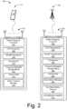
- FIG. 1illustrates an example environment 100 which includes a user equipment 110 (UE 110) that can communicate with base stations 120 (illustrated as base stations 121 and 122) through wireless communication links 130 (wireless link 130), illustrated as wireless links 131 and 132.
- UE 110user equipment 110
- base stations 120illustrated as base stations 121 and 122
- wireless link 130wireless link 130
- the UE 110is implemented as a smartphone but may be implemented as any suitable computing or electronic device, such as a mobile communication device, modem, cellular phone, gaming device, navigation device, media device, laptop computer, desktop computer, tablet computer, smart appliance, vehicle-based communication system, or an Internet-of-Things (IoT) device such as a sensor or an actuator.
- IoTInternet-of-Things
- the base stations 120may be implemented in a macrocell, microcell, small cell, picocell, and the like, or any combination thereof.
- the base stations 120communicate with the user equipment 110 using the wireless links 131 and 132, which may be implemented as any suitable type of wireless link.
- the wireless links 131 and 132include control and data communication, such as downlink of data and control information communicated from the base stations 120 to the user equipment 110, uplink of other data and control information communicated from the user equipment 110 to the base stations 120, or both.
- the wireless links 130may include one or more wireless links (e.g., radio links) or bearers implemented using any suitable communication protocol or standard, or combination of communication protocols or standards, such as 3rd Generation Partnership Project Long-Term Evolution (3GPP LTE), Fifth Generation New Radio (5GNR), and so forth.
- Multiple wireless links 130may be aggregated in a carrier aggregation to provide a higher data rate for the UE 110.
- Multiple wireless links 130 from multiple base stations 120may be configured for Coordinated Multipoint (CoMP) communication with the UE 110.
- CoMPCoordinated Multipoint
- the base stations 120are collectively a Radio Access Network 140 (e.g., RAN, Evolved Universal Terrestrial Radio Access Network, E-UTRAN, 5G NR RAN or NR RAN).
- the base stations 121 and 122 in the RAN 140are connected to a core network 150.
- the base stations 121 and 122connect, at 102 and 104 respectively, to the core network 150 through an NG2 interface for control-plane signaling and using an NG3 interface for user-plane data communications when connecting to a 5G core network, or using an S1 interface for control-plane signaling and user-plane data communications when connecting to an Evolved Packet Core (EPC) network.
- EPCEvolved Packet Core
- the base stations 121 and 122can communicate using an Xn Application Protocol (XnAP) through an Xn interface, or using an X2 Application Protocol (X2AP) through an X2 interface, at 106, to exchange user-plane and control-plane data.
- XnAPXn Application Protocol
- X2APX2 Application Protocol
- the user equipment 110may connect, via the core network 150, to public networks, such as the Internet 160 to interact with a remote service 170.
- FIG. 2illustrates an example device diagram 200 of the user equipment 110 and the base stations 120.
- the user equipment 110 and the base stations 120may include additional functions and interfaces that are omitted from FIG. 2 for the sake of clarity.
- the user equipment 110includes antennas 202, a radio frequency front end 204 (RF front end 204), an LTE transceiver 206, and a 5G NR transceiver 208 for communicating with base stations 120 in the RAN 140.
- the RF front end 204 of the user equipment 110can couple or connect the LTE transceiver 206, and the 5G NR transceiver 208 to the antennas 202 to facilitate various types of wireless communication.
- the antennas 202 of the user equipment 110may include an array of multiple antennas that are configured similar to or differently from each other.
- the antennas 202 and the RF front end 204can be tuned to, and/or be tunable to, one or more frequency bands defined by the 3GPP LTE and 5G NR communication standards and implemented by the LTE transceiver 206, and/or the 5G NR transceiver 208.
- the antennas 202, the RF front end 204, the LTE transceiver 206, and/or the 5G NR transceiver 208may be configured to support beamforming for the transmission and reception of communications with the base stations 120.
- the antennas 202 and the RF front end 204can be implemented for operation in sub-gigahertz bands, sub-6 GHZ bands, and/or above 6 GHz bands that are defined by the 3GPP LTE and 5G NR communication standards.
- the user equipment 110also includes processor(s) 210 and computer-readable storage media 212 (CRM 212).
- the processor 210may be a single core processor or a multiple core processor composed of a variety of materials, such as silicon, polysilicon, high-K dielectric, copper, and so on.
- CRM 212may include any suitable memory or storage device such as random-access memory (RAM), static RAM (SRAM), dynamic RAM (DRAM), non-volatile RAM (NVRAM), read-only memory (ROM), or Flash memory useable to store device data 214 of the user equipment 110.
- the device data 214includes user data, multimedia data, beamforming codebooks, applications, and/or an operating system of the user equipment 110, which are executable by processor(s) 210 to enable user-plane communication, control-plane signaling, and user interaction with the user equipment 110.
- the CRM 212may also include a beam tracking manager 216.
- the beam tracking manager 216may be implemented in whole or part as hardware logic or circuitry integrated with or separate from other components of the user equipment 110.
- the beam tracking manager 216can communicate with the antennas 202, the RF front end 204, the LTE transceiver 206, and/or the 5G NR transceiver 208 to monitor the quality of the wireless communication links 130 and initiate a beam search based on the monitored quality of the wireless communication links 130.
- the device diagram for the base stations 120includes a single network node (e.g., a gNode B).
- the functionality of the base stations 120may be distributed across multiple network nodes or devices and may be distributed in any fashion suitable to perform the functions described herein.
- the base stations 120include antennas 252, a radio frequency front end 254 (RF front end 254), one or more LTE transceivers 256, and/or one or more 5G NR transceivers 258 for communicating with the UE 110.
- the RF front end 254 of the base stations 120can couple or connect the LTE transceivers 256 and the 5GNR transceivers 258 to the antennas 252 to facilitate various types of wireless communication.
- the antennas 252 of the base stations 120may include an array of multiple antennas that are configured similar to or differently from each other.
- the antennas 252 and the RF front end 254can be tuned to, and/or be tunable to, one or more frequency band defined by the 3GPP LTE and 5G NR communication standards, and implemented by the LTE transceivers 256, and/or the 5G NR transceivers 258.
- the antennas 252, the RF front end 254, the LTE transceivers 256, and/or the 5G NR transceivers 258may be configured to support beamforming, such as Massive-MIMO, for the transmission and reception of communications with the UE 110.
- the base stations 120also include processor(s) 260 and computer-readable storage media 262 (CRM 262).
- the processor 260may be a single core processor or a multiple core processor composed of a variety of materials, such as silicon, polysilicon, high-K dielectric, copper, and so on.
- CRM 262may include any suitable memory or storage device such as random-access memory (RAM), static RAM (SRAM), dynamic RAM (DRAM), non-volatile RAM (NVRAM), read-only memory (ROM), or Flash memory useable to store device data 264 of the base stations 120.
- the device data 264includes network scheduling data, radio resource management data, beamforming codebooks, applications, and/or an operating system of the base stations 120, which are executable by processor(s) 260 to enable communication with the user equipment 110.
- CRM 262also includes a resource manager 266.
- the resource manager 266may be implemented in whole or part as hardware logic or circuitry integrated with or separate from other components of the base stations 120.
- the resource manager 266configures the LTE transceivers 256 and the 5G NR transceivers 258 for communication with the user equipment 110, as well as communication with a core network, such as the core network 150.
- the base stations 120include an inter-base station interface 268, such as an Xn and/or X2 interface, which the resource manager 266 configures to exchange user-plane and control-plane data between other base stations 120, to manage the communication of the base stations 120 with the user equipment 110.
- the base stations 120include a core network interface 270 that the resource manager 266 configures to exchange user-plane and control-plane data with core network functions and/or entities.
- beamformingis applied at both the transmitting and the receiving end of a wireless communication link to extend the communication range (distance).
- Appropriate beamforming weightsare established and maintained after a user equipment 110 enters an RRC_CONNECTED state and through a series of related signaling communications.
- a grant-free (GF) NOMA transmissionis made autonomously by a user equipment 110, and the user equipment 110 may be in a state other than the RRC_CONNECTED state, how the user equipment 110 determines the appropriate transmit beam for transmissions to the base station 121 has not been defined. How the base station 121 determines the appropriate receive beam for receiving uplink NOMA transmission from the user equipment 110 is also undefined.
- the base station 121transmits multiple DL RSs, with each DL RS applying spatial filtering patterns to transmit on different transmit beams.
- the base station 121then configures time-frequency resources dedicated to NOMA transmission by the user equipment 110.
- the base station 121further configures an association between the multiple DL RSs and the time-frequency resources, such that each DL RS has an associated time-frequency resource.
- MA signaturescan be associated with preambles and/or demodulation reference symbols that are based on a predefined mapping mechanism, as described above.
- the user equipment 110Before attempting to perform a NOMA transmission, the user equipment 110 receives the DL RSs. By receiving the DL RSs, the user equipment 110 determines which one of the DL RSs yields the best reception quality (e.g ., the highest reference signal received power (RSRP)). Also, the user equipment 110 determines a receive beam for reception of the DL RSs based on measurements of downlink transmissions received by the user equipment 110. Using the association indicated by the base station 121, the user equipment 110 determines one of the time-frequency resources which is associated with the one of the DL RSs. Finally, the user equipment 110 applies the principle of beam correspondence, as described above and performs a NOMA transmission on the one of the time-frequency resources using a transmit beam which is determined based on at least the receive beam used to receive the one of the DL RSs.
- RSRPreference signal received power
- the base station 121attempts to detect uplink NOMA transmissions on each of the time-frequency resources.
- the base station 121first determines a DL RS which is associated with the particular time-frequency resource based on the association relationship. Applying the principle of beam correspondence, the base station 121 then determines a receive beam based on at least the transmit beam which is used for transmitting the DL RS.
- the base station 121can simply detect the presence of a particular preamble to see if the associated user equipment 110 made an uplink transmission instead of decoding an entire uplink transmission of a user equipment 110 to detect the identity of the user equipment.
- the time-frequency resourcescan also be associated with the DL RSs in an indirect fashion.
- the base station 121can configure an association between the DL RSs and multiple Physical Random Access Channel (PRACH) resources and configure another association between the time-frequency resources used for NOMA transmissions with the PRACH resources.
- PRACHPhysical Random Access Channel
- FIG. 3illustrates an air interface resource that extends between a user equipment and a base station and with which various aspects of user equipment-initiated beam search for fifth generation new radio can be implemented.
- the air interface resource 302can be divided into resource units 304, each of which occupies some intersection of frequency spectrum and elapsed time.
- a portion of the air interface resource 302is illustrated graphically in a grid or matrix having multiple resource blocks 310, including example resource blocks 311, 312, 313, 314.
- An example of a resource unit 304therefore includes at least one resource block 310. As shown, time is depicted along the horizontal dimension as the abscissa axis, and frequency is depicted along the vertical dimension as the ordinate axis.
- the air interface resource 302may span any suitable specified frequency range, and/or may be divided into intervals of any specified duration.
- Increments of timecan correspond to, for example, milliseconds (mSec).
- Increments of frequencycan correspond to, for example, megahertz (MHz).
- the base stations 120allocate portions (e.g., resource units 304) of the air interface resource 302 for uplink and downlink communications.
- Each resource block 310 of network access resourcesmay be allocated to support respective wireless communication links 130 of multiple user equipment 110.
- the resource block 311may span, as defined by a given communication protocol, a specified frequency range 306 and comprise multiple subcarriers or frequency sub-bands.
- the resource block 311may include any suitable number of subcarriers ( e.g. , 12) that each correspond to a respective portion ( e.g., 15 kHz) of the specified frequency range 306 ( e.g., 180 kHz).
- the resource block 311may also span, as defined by the given communication protocol, a specified time interval 308 or time slot (e.g., lasting approximately one-half millisecond or 7 orthogonal frequency-division multiplexing (OFDM) symbols).
- the time interval 308includes subintervals that may each correspond to a symbol, such as an OFDM symbol.
- each resource block 310may include multiple resource elements 320 (REs) that correspond to, or are defined by, a subcarrier of the frequency range 306 and a subinterval (or symbol) of the time interval 308.
- a given resource element 320may span more than one frequency subcarrier or symbol.
- a resource unit 304may include at least one resource block 310, at least one resource element 320, and so forth.
- multiple user equipment 110are communicating with the base stations 120 (one of which is shown) through access provided by portions of the air interface resource 302.
- the resource manager 266may determine a respective data-rate, type of information, or amount of information (e.g ., data or control information) to be communicated ( e.g ., transmitted) by the user equipment 110. For example, the resource manager 266 can determine that each user equipment 110 is to transmit at a different respective data rate or transmit a different respective amount of information. The resource manager 266 then allocates one or more resource blocks 310 to each user equipment 110 based on the determined data rate or amount of information.
- the resource manager 266may allocate resource units at an element-level.
- the resource manager 266may allocate one or more resource elements 320 or individual subcarriers to different user equipment 110.
- one resource block 310can be allocated to facilitate network access for multiple user equipment 110.
- the resource manager 266may allocate, at various granularities, one or up to all subcarriers or resource elements 320 of a resource block 310 to one user equipment 110 or divided across multiple user equipment 110, thereby enabling higher network utilization or increased spectrum efficiency.
- the resource manager 266can therefore allocate air interface resource 302 by resource unit 304, resource block 310, frequency carrier, time interval, resource element 320, frequency subcarrier, time subinterval, symbol, spreading code, some combination thereof, and so forth. Based on respective allocations of resource units 304, the resource manager 266 can transmit respective messages to the multiple user equipment 110 indicating the respective allocation of resource units 304 to each user equipment 110. Each message may enable a respective user equipment 110 to queue the information or configure the LTE transceiver 206, the 5G NR transceiver 208, or both to communicate via the allocated resource units 304 of the air interface resource 302.
- Example methods 400 and 500are described with reference to FIGs. 4 and 5 in accordance with one or more aspects of beamforming-based grant-free non-orthogonal multiple access transmission.
- the order in which the method blocks are describedare not intended to be construed as a limitation, and any number of the described method blocks can be skipped or combined in any order to implement a method or an alternate method.
- any of the components, modules, methods, and operations described hereincan be implemented using software, firmware, hardware (e.g ., fixed logic circuitry), manual processing, or any combination thereof.
- any of the functionality described hereincan be performed, at least in part, by one or more hardware logic components, such as, and without limitation, Field-programmable Gate Arrays (FPGAs), Application-specific Integrated Circuits (ASICs), Application-specific Standard Products (ASSPs), System-on-a-chip systems (SoCs), Complex Programmable Logic Devices (CPLDs), and the like.
- FPGAsField-programmable Gate Arrays
- ASICsApplication-specific Integrated Circuits
- ASSPsApplication-specific Standard Products
- SoCsSystem-on-a-chip systems
- CPLDsComplex Programmable Logic Devices
- FIG. 4illustrates example method(s) 400 of beamforming-based grant-free non-orthogonal multiple access transmission as generally related to communications by the base station 121.
- a base stationtransmits, using multiple transmit antenna configurations, multiple downlink reference signals to a user equipment.
- the base station 121transmits multiple downlink signals using multiple transmit antenna configurations of the antennas 252.
- the base stationconfigures time-frequency resources for Non-Orthogonal Multiple Access (NOMA) transmissions by the user equipment.
- NOMANon-Orthogonal Multiple Access
- the base station 121selects a configuration of resource elements 320 in the frequency domain, the time domain, or both, for NOMA transmissions by the user equipment 110.
- the base stationconfigures an association between the downlink reference signals and the time-frequency resources for the user equipment.
- the base station 121configures an association between the downlink reference signals and the time-frequency resources for the user equipment 110.
- the base stationtransmits the configuration of the time-frequency resources and the association between the downlink reference signals and the time-frequency resources to the user equipment.
- the base station 121transmits the configuration of the time-frequency resources and the association between the downlink reference signals and the time-frequency resources to the user equipment 110.
- the base stationreceives uplink data from the user equipment on one of the time-frequency resources using a receive antenna configuration.
- the base station 121receives uplink data from the user equipment 110 on one of the time-frequency resources using a receive antenna configuration for the antennas 252.
- FIG. 5illustrates example method(s) 500 of beamforming-based grant-free non-orthogonal multiple access transmission as generally related to the user equipment 110.
- a user equipmentreceives, using multiple receive antenna configurations, downlink reference signals from a base station.
- the user equipment 110receives downlink reference signals from the base station 121 using multiple receive antenna configurations for the antennas 202.
- the user equipmentreceives a configuration of time-frequency resources for Non-Orthogonal Multiple Access (NOMA) transmissions from the base station.
- NOMANon-Orthogonal Multiple Access
- the user equipment 110receives a configuration of time-frequency resources for Non-Orthogonal Multiple Access (NOMA) transmission from the base station 121.
- the user equipmentreceives an association between the downlink reference signals and the time-frequency resources from the base station.
- the user equipment 110receives an association between the downlink reference signals and the time-frequency resources from the base station 121.
- the user equipmenttransmits uplink data to the base station on one of the time-frequency resources using a transmit antenna configuration.
- the transmit antenna configurationis determined based upon a measurement of one or more receive beams by the user equipment or is determined based on an indication from the base station that is based on an uplink measurement, by the base station, of one or more transmit beams of the user equipment.
- the user equipment 110transmits uplink data to the base station on one of the time-frequency resources using a transmit antenna configuration for the antennas 202.
- Figs. 4 and 5may allow the determination of optimized antenna configurations in a simple manner.
Landscapes
- Engineering & Computer Science (AREA)
- Signal Processing (AREA)
- Computer Networks & Wireless Communication (AREA)
- Physics & Mathematics (AREA)
- Spectroscopy & Molecular Physics (AREA)
- Power Engineering (AREA)
- Mobile Radio Communication Systems (AREA)
Description
- The evolution of wireless communication to fifth generation (5G) standards and technologies provides higher data rates and greater capacity, with improved reliability and lower latency, which enhances mobile broadband services. 5G technologies also provide new classes of services for vehicular networking, fixed wireless broadband, and the Internet of Things (IoT). Fifth generation new radio (5GNR) standards and systems are designed to support three major deployment scenarios: enhanced mobile broadband (eMBB), ultra-reliable low latency communications (URLLC), and massive machine type communications (mMTC).
- For mMTC applications, a base station is expected to accommodate a very large number of low-cost user equipment. The data traffic generated by each mMTC user equipment (UE) is expected to be both light and sporadic. The signaling overhead and wireless network traffic of the scheduling grants associated with each uplink transmission in conventional wireless communication system is inefficient for mMTC UEs and applications.
WO2018062976A1 describes method and apparatus for transmitting a control signal associated with uplink data transmission by a terminal when the terminal performs uplink transmission.- The invention is defined by the features of the appended claims. This summary is provided to introduce simplified concepts of beamforming-based grant-free non-orthogonal multiple access transmission. The simplified concepts are further described below in the Detailed Description. This summary is not intended to identify essential features of the claimed subject matter, nor is it intended for use in determining the scope of the claimed subject matter.
- In some aspects, configuring beamformed wireless communication between a base station and a user equipment is described, in which the base station transmits, using multiple transmit antenna configurations, downlink reference signals to the user equipment, configures time-frequency resources for Non-Orthogonal Multiple Access (NOMA) transmission by the user equipment, and configures an association between the downlink reference signals and the time-frequency resources for the user equipment. The base station transmits the configuration of the time-frequency resources and the association between the downlink reference signals and the time-frequency resources to the user equipment. The base station receives uplink data from the user equipment on one of the time-frequency resources using a receive antenna configuration, the receive antenna configuration being determined at least in part using one of the multiple transmit antenna configurations used for transmitting one of the downlink reference signals associated with the one of the time-frequency resources as indicated in the association.
- In other aspects, beamformed communication between a base station and a user equipment is described, in which the user equipment receives, using multiple receive antenna configurations, downlink reference signals from the base station, receives a configuration of time-frequency resources for Non-Orthogonal Multiple Access (NOMA) transmission from the base station, and receives an association between the downlink reference signals and the time-frequency resources from the base station. The user equipment transmits uplink data to the base station on one of the time-frequency resources using a transmit antenna configuration, the transmit antenna configuration being determined, at least in part, using one of the multiple receive antenna configurations used for receiving one of the downlink reference signals which is associated with the one of the time-frequency resources as indicated in the association.
- Aspects of beamforming-based grant-free non-orthogonal multiple access transmission are described with reference to the following drawings. The same numbers are used throughout the drawings to reference like features and components:
FIG. 1 illustrates an example wireless network environment in which various aspects of beamforming-based grant-free non-orthogonal multiple access transmission can be implemented.FIG. 2 illustrates an example device diagram that can implement various aspects of beamforming-based grant-free non-orthogonal multiple access transmission.FIG. 3 illustrates an air interface resource that extends between a user equipment and a base station and with which various aspects of beamforming-based grant-free non-orthogonal multiple access transmission techniques can be implemented.FIG. 4 illustrates an example method of beamforming-based grant-free non-orthogonal multiple access transmission as generally related to configuring resources for a wireless communication by a base station in accordance with aspects of the techniques described herein.FIG. 5 illustrates an example method of beamforming-based grant-free non-orthogonal multiple access transmission as generally related to communications by a user equipment in accordance with aspects of the techniques described herein.- In aspects of grant-free uplink (UL) transmission, user devices perform uplink transmissions autonomously without the transmissions being scheduled by a base station. The base station receives the uplink transmissions using a predefined detection and/or decoding method. The use of grant-free transmissions is particularly suited to the low-duty cycle and/or sporadic communication needs of massive machine type communications (mMTC) user equipment, systems, and applications. The benefits of grant-free uplink transmissions are also applicable to many ultra-reliable low latency communications (URLLC) user equipment, systems, and applications. Grant-free uplink transmissions may also be applied in a unified framework for all fifth generation new radio (5GNR) user equipment, systems, base stations, and application scenarios.
- Within the context of grant-free uplink transmissions, non-orthogonal multiple access (NOMA) can be utilized as a multiple access scheme. In NOMA, the user equipment performs grant-free uplink transmissions with resources that are not necessarily orthogonal to each other. A resource used by a user equipment for NOMA transmission is typically described as a multiple access (MA) signature (e.g., orthogonal codes, spreading codes, scrambling codes, mapping patterns,etc.). A larger number of user equipment can be simultaneously supported using NOMA than can be supported using orthogonal resources. For uplink detection, the base station blindly decodes all the possible MA signatures since uplink transmissions are not pre-scheduled but are made autonomously by the UEs. To lower decoding complexity, the MA signatures can be associated with preambles and/or demodulation reference symbols that are based on a predefined mapping mechanism. For example, if preambles and MA signatures have a one-to-one mapping, the base station can simply detect the presence of a particular preamble to see if the associated user equipment made an uplink transmission instead of decoding an entire uplink transmission of a user equipment to detect the identity of the user equipment.
- In 5G NR systems, beamforming is expected to be heavily utilized to overcome signal attenuation in higher-frequency radio bands. A transmit-receive beam refers to signals generated by applying a specific transmit-receive antenna configuration in a multi-antenna communication device. The transmit-receive beam comprises a specific pattern of spatial filtering that is applied to output signals for transmission. In the case of digital beamforming, the spatial filtering is performed in the radio baseband and can be done by applying weighting coefficients to the complex baseband signal values. With increasing numbers of antenna elements, the cost of performing beamforming in the baseband also increases. Analog beamforming, on the other hand, performs spatial filtering on the radio frequency (RF) signals directly, and can be achieved by adjusting the transmission or reception timing of the RF signals on different antenna elements. For example, the timing adjustment is achieved by coupling a phase shifter to each antenna element. Conceptually, a transmit-receive beam can be thought of as applying a specific setting to the array of phase shifters.
- In this document, a transmit antenna configuration refers to a specific transmit beam pattern. Similarly, a receive antenna configuration refers to a specific receive beam pattern.
- Beam sweeping is an operation where different spatial filtering patterns are applied continuously in the time domain to cover different spatial directions in analog beamforming. Transmit beam sweeping is a process where a communication device transmits the same signal in consecutive time slots using different transmit beams. Similarly, receive beam sweeping is the process where a device receives the same signal in consecutive time slots using different receive beams.
- Beam correspondence between transmit beams and receive beams at a base station can be achieved if at least one of the following is satisfied:
- a. The base station is able to determine a receive beam for uplink reception based on downlink (DL) measurement of one or more base station transmit beams made by the user equipment, or
- b. The base station is able to determine a transmit beam for the downlink transmission based on the base station's uplink measurement of one or more base station receive beams.
- Similarly, beam correspondence between transmit beams and receive beams at a user equipment can be achieved if at least one of the following is satisfied:
- a. The user equipment is able to determine a user equipment transmit beam for the uplink transmission based on the user equipment's downlink measurement of one or more user equipment receive beams, or
- b. The user equipment is able to determine a user equipment receive beam for downlink reception based on an indication from the base station that is based on uplink measurement of one or more user equipment transmit beams.
- In 5G NR systems, signals used for initial access to the wireless network by the user equipment include several synchronization signal blocks (SSBs). An SSB includes a primary synchronization signal, a secondary synchronization signal, and a physical broadcast channel (PBCH). A DL reference signal (RS) is a special signal transmitted by the base station on a regular (e.g., periodic) basis for measurement and reporting purposes by the UE. In 5G NR systems, channel state information-reference signals (CSI-RSs) and/or SSBs can serve as the downlink reference signals (DL RSs).
FIG. 1 illustrates anexample environment 100 which includes a user equipment 110 (UE 110) that can communicate with base stations 120 (illustrated asbase stations 121 and 122) through wireless communication links 130 (wireless link 130), illustrated aswireless links UE 110 is implemented as a smartphone but may be implemented as any suitable computing or electronic device, such as a mobile communication device, modem, cellular phone, gaming device, navigation device, media device, laptop computer, desktop computer, tablet computer, smart appliance, vehicle-based communication system, or an Internet-of-Things (IoT) device such as a sensor or an actuator. The base stations 120(e.g., an Evolved Universal Terrestrial Radio Access Network Node B, E-UTRAN Node B, evolved Node B, eNodeB, eNB, Next Generation Node B, gNode B, gNB, or the like) may be implemented in a macrocell, microcell, small cell, picocell, and the like, or any combination thereof.- The
base stations 120 communicate with theuser equipment 110 using thewireless links base stations 120 to theuser equipment 110, uplink of other data and control information communicated from theuser equipment 110 to thebase stations 120, or both. The wireless links 130 may include one or more wireless links(e.g., radio links) or bearers implemented using any suitable communication protocol or standard, or combination of communication protocols or standards, such as 3rd Generation Partnership Project Long-Term Evolution (3GPP LTE), Fifth Generation New Radio (5GNR), and so forth.Multiple wireless links 130 may be aggregated in a carrier aggregation to provide a higher data rate for theUE 110.Multiple wireless links 130 frommultiple base stations 120 may be configured for Coordinated Multipoint (CoMP) communication with theUE 110. - The
base stations 120 are collectively a Radio Access Network 140 (e.g., RAN, Evolved Universal Terrestrial Radio Access Network, E-UTRAN, 5G NR RAN or NR RAN). Thebase stations RAN 140 are connected to acore network 150. Thebase stations core network 150 through an NG2 interface for control-plane signaling and using an NG3 interface for user-plane data communications when connecting to a 5G core network, or using an S1 interface for control-plane signaling and user-plane data communications when connecting to an Evolved Packet Core (EPC) network. Thebase stations user equipment 110 may connect, via thecore network 150, to public networks, such as theInternet 160 to interact with aremote service 170. FIG. 2 illustrates an example device diagram 200 of theuser equipment 110 and thebase stations 120. Theuser equipment 110 and thebase stations 120 may include additional functions and interfaces that are omitted fromFIG. 2 for the sake of clarity. Theuser equipment 110 includesantennas 202, a radio frequency front end 204 (RF front end 204), anLTE transceiver 206, and a5G NR transceiver 208 for communicating withbase stations 120 in theRAN 140. The RFfront end 204 of theuser equipment 110 can couple or connect theLTE transceiver 206, and the5G NR transceiver 208 to theantennas 202 to facilitate various types of wireless communication. Theantennas 202 of theuser equipment 110 may include an array of multiple antennas that are configured similar to or differently from each other. Theantennas 202 and the RFfront end 204 can be tuned to, and/or be tunable to, one or more frequency bands defined by the 3GPP LTE and 5G NR communication standards and implemented by theLTE transceiver 206, and/or the5G NR transceiver 208. Additionally, theantennas 202, the RFfront end 204, theLTE transceiver 206, and/or the5G NR transceiver 208 may be configured to support beamforming for the transmission and reception of communications with thebase stations 120. By way of example and not limitation, theantennas 202 and the RFfront end 204 can be implemented for operation in sub-gigahertz bands, sub-6 GHZ bands, and/or above 6 GHz bands that are defined by the 3GPP LTE and 5G NR communication standards.- The
user equipment 110 also includes processor(s) 210 and computer-readable storage media 212 (CRM 212). Theprocessor 210 may be a single core processor or a multiple core processor composed of a variety of materials, such as silicon, polysilicon, high-K dielectric, copper, and so on. The computer-readable storage media described herein excludes propagating signals.CRM 212 may include any suitable memory or storage device such as random-access memory (RAM), static RAM (SRAM), dynamic RAM (DRAM), non-volatile RAM (NVRAM), read-only memory (ROM), or Flash memory useable to store device data 214 of theuser equipment 110. The device data 214 includes user data, multimedia data, beamforming codebooks, applications, and/or an operating system of theuser equipment 110, which are executable by processor(s) 210 to enable user-plane communication, control-plane signaling, and user interaction with theuser equipment 110. - In some implementations, the
CRM 212 may also include abeam tracking manager 216. Alternately or additionally, thebeam tracking manager 216 may be implemented in whole or part as hardware logic or circuitry integrated with or separate from other components of theuser equipment 110. Thebeam tracking manager 216 can communicate with theantennas 202, the RFfront end 204, theLTE transceiver 206, and/or the5G NR transceiver 208 to monitor the quality of thewireless communication links 130 and initiate a beam search based on the monitored quality of the wireless communication links 130. - The device diagram for the
base stations 120, shown inFIG. 2 , includes a single network node (e.g., a gNode B). The functionality of thebase stations 120 may be distributed across multiple network nodes or devices and may be distributed in any fashion suitable to perform the functions described herein. Thebase stations 120 includeantennas 252, a radio frequency front end 254 (RF front end 254), one ormore LTE transceivers 256, and/or one or more5G NR transceivers 258 for communicating with theUE 110. The RFfront end 254 of thebase stations 120 can couple or connect theLTE transceivers 256 and the5GNR transceivers 258 to theantennas 252 to facilitate various types of wireless communication. Theantennas 252 of thebase stations 120 may include an array of multiple antennas that are configured similar to or differently from each other. Theantennas 252 and the RFfront end 254 can be tuned to, and/or be tunable to, one or more frequency band defined by the 3GPP LTE and 5G NR communication standards, and implemented by theLTE transceivers 256, and/or the5G NR transceivers 258. Additionally, theantennas 252, the RFfront end 254, theLTE transceivers 256, and/or the5G NR transceivers 258 may be configured to support beamforming, such as Massive-MIMO, for the transmission and reception of communications with theUE 110. - The
base stations 120 also include processor(s) 260 and computer-readable storage media 262 (CRM 262). Theprocessor 260 may be a single core processor or a multiple core processor composed of a variety of materials, such as silicon, polysilicon, high-K dielectric, copper, and so on.CRM 262 may include any suitable memory or storage device such as random-access memory (RAM), static RAM (SRAM), dynamic RAM (DRAM), non-volatile RAM (NVRAM), read-only memory (ROM), or Flash memory useable to storedevice data 264 of thebase stations 120. Thedevice data 264 includes network scheduling data, radio resource management data, beamforming codebooks, applications, and/or an operating system of thebase stations 120, which are executable by processor(s) 260 to enable communication with theuser equipment 110. CRM 262 also includes aresource manager 266. Alternately or additionally, theresource manager 266 may be implemented in whole or part as hardware logic or circuitry integrated with or separate from other components of thebase stations 120. In at least some aspects, theresource manager 266 configures theLTE transceivers 256 and the5G NR transceivers 258 for communication with theuser equipment 110, as well as communication with a core network, such as thecore network 150.- The
base stations 120 include aninter-base station interface 268, such as an Xn and/or X2 interface, which theresource manager 266 configures to exchange user-plane and control-plane data betweenother base stations 120, to manage the communication of thebase stations 120 with theuser equipment 110. Thebase stations 120 include acore network interface 270 that theresource manager 266 configures to exchange user-plane and control-plane data with core network functions and/or entities. - When operating in higher-frequency radio bands, beamforming is applied at both the transmitting and the receiving end of a wireless communication link to extend the communication range (distance). Appropriate beamforming weights are established and maintained after a
user equipment 110 enters an RRC_CONNECTED state and through a series of related signaling communications. As a grant-free (GF) NOMA transmission is made autonomously by auser equipment 110, and theuser equipment 110 may be in a state other than the RRC_CONNECTED state, how theuser equipment 110 determines the appropriate transmit beam for transmissions to thebase station 121 has not been defined. How thebase station 121 determines the appropriate receive beam for receiving uplink NOMA transmission from theuser equipment 110 is also undefined. - In aspects, to provide transmit beam determination for the
user equipment 110, as well as receive beam determination for thebase station 121, thebase station 121 transmits multiple DL RSs, with each DL RS applying spatial filtering patterns to transmit on different transmit beams. Thebase station 121 then configures time-frequency resources dedicated to NOMA transmission by theuser equipment 110. Thebase station 121 further configures an association between the multiple DL RSs and the time-frequency resources, such that each DL RS has an associated time-frequency resource. Optionally or additionally, MA signatures can be associated with preambles and/or demodulation reference symbols that are based on a predefined mapping mechanism, as described above. - Before attempting to perform a NOMA transmission, the
user equipment 110 receives the DL RSs. By receiving the DL RSs, theuser equipment 110 determines which one of the DL RSs yields the best reception quality (e.g., the highest reference signal received power (RSRP)). Also, theuser equipment 110 determines a receive beam for reception of the DL RSs based on measurements of downlink transmissions received by theuser equipment 110. Using the association indicated by thebase station 121, theuser equipment 110 determines one of the time-frequency resources which is associated with the one of the DL RSs. Finally, theuser equipment 110 applies the principle of beam correspondence, as described above and performs a NOMA transmission on the one of the time-frequency resources using a transmit beam which is determined based on at least the receive beam used to receive the one of the DL RSs. - In another aspect, the
base station 121 attempts to detect uplink NOMA transmissions on each of the time-frequency resources. When detecting a particular time-frequency resource, thebase station 121 first determines a DL RS which is associated with the particular time-frequency resource based on the association relationship. Applying the principle of beam correspondence, thebase station 121 then determines a receive beam based on at least the transmit beam which is used for transmitting the DL RS. Optionally or additionally, if MA signatures are associated with preambles and/or demodulation reference symbols, thebase station 121 can simply detect the presence of a particular preamble to see if the associateduser equipment 110 made an uplink transmission instead of decoding an entire uplink transmission of auser equipment 110 to detect the identity of the user equipment. - In a further aspect, the time-frequency resources can also be associated with the DL RSs in an indirect fashion. For example, the
base station 121 can configure an association between the DL RSs and multiple Physical Random Access Channel (PRACH) resources and configure another association between the time-frequency resources used for NOMA transmissions with the PRACH resources. FIG. 3 illustrates an air interface resource that extends between a user equipment and a base station and with which various aspects of user equipment-initiated beam search for fifth generation new radio can be implemented. Theair interface resource 302 can be divided intoresource units 304, each of which occupies some intersection of frequency spectrum and elapsed time. A portion of theair interface resource 302 is illustrated graphically in a grid or matrix having multiple resource blocks 310, including example resource blocks 311, 312, 313, 314. An example of aresource unit 304 therefore includes at least oneresource block 310. As shown, time is depicted along the horizontal dimension as the abscissa axis, and frequency is depicted along the vertical dimension as the ordinate axis. Theair interface resource 302, as defined by a given communication protocol or standard, may span any suitable specified frequency range, and/or may be divided into intervals of any specified duration. Increments of time can correspond to, for example, milliseconds (mSec). Increments of frequency can correspond to, for example, megahertz (MHz).- In example operations generally, the
base stations 120 allocate portions (e.g., resource units 304) of theair interface resource 302 for uplink and downlink communications. Eachresource block 310 of network access resources may be allocated to support respectivewireless communication links 130 ofmultiple user equipment 110. In the lower left corner of the grid, theresource block 311 may span, as defined by a given communication protocol, a specifiedfrequency range 306 and comprise multiple subcarriers or frequency sub-bands. Theresource block 311 may include any suitable number of subcarriers (e.g., 12) that each correspond to a respective portion (e.g., 15 kHz) of the specified frequency range 306 (e.g., 180 kHz). Theresource block 311 may also span, as defined by the given communication protocol, a specifiedtime interval 308 or time slot (e.g., lasting approximately one-half millisecond or 7 orthogonal frequency-division multiplexing (OFDM) symbols). Thetime interval 308 includes subintervals that may each correspond to a symbol, such as an OFDM symbol. As shown inFIG. 3 , eachresource block 310 may include multiple resource elements 320 (REs) that correspond to, or are defined by, a subcarrier of thefrequency range 306 and a subinterval (or symbol) of thetime interval 308. Alternatively, a givenresource element 320 may span more than one frequency subcarrier or symbol. Thus, aresource unit 304 may include at least oneresource block 310, at least oneresource element 320, and so forth. - In example implementations, multiple user equipment 110 (one of which is shown) are communicating with the base stations 120 (one of which is shown) through access provided by portions of the
air interface resource 302. The resource manager 266 (shown inFIG. 2 ) may determine a respective data-rate, type of information, or amount of information (e.g., data or control information) to be communicated (e.g., transmitted) by theuser equipment 110. For example, theresource manager 266 can determine that eachuser equipment 110 is to transmit at a different respective data rate or transmit a different respective amount of information. Theresource manager 266 then allocates one or more resource blocks 310 to eachuser equipment 110 based on the determined data rate or amount of information. - Additionally or in the alternative to block-level resource grants, the
resource manager 266 may allocate resource units at an element-level. Thus, theresource manager 266 may allocate one ormore resource elements 320 or individual subcarriers todifferent user equipment 110. By so doing, oneresource block 310 can be allocated to facilitate network access formultiple user equipment 110. Accordingly, theresource manager 266 may allocate, at various granularities, one or up to all subcarriers orresource elements 320 of aresource block 310 to oneuser equipment 110 or divided acrossmultiple user equipment 110, thereby enabling higher network utilization or increased spectrum efficiency. - The
resource manager 266 can therefore allocateair interface resource 302 byresource unit 304,resource block 310, frequency carrier, time interval,resource element 320, frequency subcarrier, time subinterval, symbol, spreading code, some combination thereof, and so forth. Based on respective allocations ofresource units 304, theresource manager 266 can transmit respective messages to themultiple user equipment 110 indicating the respective allocation ofresource units 304 to eachuser equipment 110. Each message may enable arespective user equipment 110 to queue the information or configure theLTE transceiver 206, the5G NR transceiver 208, or both to communicate via the allocatedresource units 304 of theair interface resource 302. Example methods FIGs. 4 and5 in accordance with one or more aspects of beamforming-based grant-free non-orthogonal multiple access transmission. The order in which the method blocks are described are not intended to be construed as a limitation, and any number of the described method blocks can be skipped or combined in any order to implement a method or an alternate method. Generally, any of the components, modules, methods, and operations described herein can be implemented using software, firmware, hardware (e.g., fixed logic circuitry), manual processing, or any combination thereof. Some operations of the example methods may be described in the general context of executable instructions stored on computer-readable storage memory that is local and/or remote to a computer processing system, and implementations can include software applications, programs, functions, and the like. Alternatively or in addition, any of the functionality described herein can be performed, at least in part, by one or more hardware logic components, such as, and without limitation, Field-programmable Gate Arrays (FPGAs), Application-specific Integrated Circuits (ASICs), Application-specific Standard Products (ASSPs), System-on-a-chip systems (SoCs), Complex Programmable Logic Devices (CPLDs), and the like.FIG. 4 illustrates example method(s) 400 of beamforming-based grant-free non-orthogonal multiple access transmission as generally related to communications by thebase station 121. Atblock 402, a base station transmits, using multiple transmit antenna configurations, multiple downlink reference signals to a user equipment. For example, thebase station 121 transmits multiple downlink signals using multiple transmit antenna configurations of theantennas 252.- At
block 404, the base station configures time-frequency resources for Non-Orthogonal Multiple Access (NOMA) transmissions by the user equipment. For example, thebase station 121 selects a configuration ofresource elements 320 in the frequency domain, the time domain, or both, for NOMA transmissions by theuser equipment 110. - At
block 406, the base station configures an association between the downlink reference signals and the time-frequency resources for the user equipment. For example, thebase station 121 configures an association between the downlink reference signals and the time-frequency resources for theuser equipment 110. - At
block 408, the base station transmits the configuration of the time-frequency resources and the association between the downlink reference signals and the time-frequency resources to the user equipment. For example, thebase station 121 transmits the configuration of the time-frequency resources and the association between the downlink reference signals and the time-frequency resources to theuser equipment 110. - At
block 410, the base station receives uplink data from the user equipment on one of the time-frequency resources using a receive antenna configuration. For example, thebase station 121 receives uplink data from theuser equipment 110 on one of the time-frequency resources using a receive antenna configuration for theantennas 252. FIG. 5 illustrates example method(s) 500 of beamforming-based grant-free non-orthogonal multiple access transmission as generally related to theuser equipment 110. Atblock 502, a user equipment receives, using multiple receive antenna configurations, downlink reference signals from a base station. For example, theuser equipment 110 receives downlink reference signals from thebase station 121 using multiple receive antenna configurations for theantennas 202.- At
block 504, the user equipment receives a configuration of time-frequency resources for Non-Orthogonal Multiple Access (NOMA) transmissions from the base station. For example, theuser equipment 110 receives a configuration of time-frequency resources for Non-Orthogonal Multiple Access (NOMA) transmission from thebase station 121. - At
block 506, the user equipment receives an association between the downlink reference signals and the time-frequency resources from the base station. For example, theuser equipment 110 receives an association between the downlink reference signals and the time-frequency resources from thebase station 121. - At
block 508, the user equipment transmits uplink data to the base station on one of the time-frequency resources using a transmit antenna configuration. The transmit antenna configuration is determined based upon a measurement of one or more receive beams by the user equipment or is determined based on an indication from the base station that is based on an uplink measurement, by the base station, of one or more transmit beams of the user equipment. For example, theuser equipment 110 transmits uplink data to the base station on one of the time-frequency resources using a transmit antenna configuration for theantennas 202. - The methods of
Figs. 4 and5 may allow the determination of optimized antenna configurations in a simple manner. - Although aspects of beamforming-based grant-free non-orthogonal multiple access transmission have been described in language specific to features and/or methods, the subject of the appended claims is not necessarily limited to the specific features or methods described. Rather, the specific features and methods are disclosed as example implementations of beamforming-based grant-free non-orthogonal multiple access transmission. Further, various different aspects are described, and it is to be appreciated that each described aspect can be implemented independently or in connection with one or more other described aspects.
Claims (15)
- A method for configuring beamformed wireless communication between a base station (120, 121, 122) and a user equipment (110), the method comprising:transmitting (402), by the base station and using multiple transmit antenna configurations, downlink reference signals to the user equipment;configuring (404), by the base station, time-frequency resources for Non-Orthogonal Multiple Access, NOMA, transmissions for the user equipment;configuring (406) an association between the downlink reference signals and the time-frequency resources for the user equipment;transmitting (408), to the user equipment, the configuration of the time-frequency resources for the NOMA transmissions and the association between the downlink reference signals and the time-frequency resources; andreceiving (410) uplink data from the user equipment on one of the time-frequency resources using a receive antenna configuration, the receive antenna configuration being determined at least in part using one of the multiple transmit antenna configurations used for transmitting one of the downlink reference signals associated with one of the time-frequency resources as indicated in the association.
- The method of claim 1 wherein the multiple transmit antenna configurations comprise a setting for beamforming that adjusts transmission timing for a plurality of antennas used by the base station to transmit the downlink reference signals to the user equipment.
- The method of claim 1 or 2, wherein the receive antenna configuration comprises a setting for beamforming that adjusts reception timing for a plurality of antennas used by the base station to receive uplink data from the user equipment.
- The method of any preceding claim, further comprising:
configuring a bit interleaving configuration, a bit scrambling configuration, a modulation symbol spreading configuration, a modulation symbol interleaving configuration, a modulation symbol scrambling configuration, or any combination thereof for a NOMA transmission from the user equipment. - The method of claim 4, wherein receiving the uplink data from the user equipment comprises:
receiving the uplink data by the base station based at least in part on the bit interleaving configuration, the bit scrambling configuration, the modulation symbol spreading configuration, the modulation symbol interleaving configuration, the modulation symbol scrambling configuration, or any combination thereof. - The method of claim 4 or claim 5, wherein the base station transmits the time-frequency resources, the bit interleaving configuration, the bit scrambling configuration, the modulation symbol spreading configuration, the modulation symbol interleaving configuration, the modulation symbol scrambling configuration, or any combination thereof to the user equipment via system information or a dedicated higher-layer message.
- A method for beamformed communication between a base station (120, 121, 122) and a user equipment (110), the method comprising:receiving (502), by the user equipment and using multiple receive antenna configurations, downlink reference signals from the base station;receiving (504, 506), from the base station, a configuration of time-frequency resources for Non-Orthogonal Multiple Access, NOMA, transmissions, and an association between the downlink reference signals and the time-frequency resources for the NOMA transmissions; andtransmitting (508) uplink data to the base station on one of the time-frequency resources using a transmit antenna configuration, the transmit antenna configuration used by the user equipment and being determined, at least in part, using one of the multiple receive antenna configurations used by the user equipment for receiving one of the downlink reference signals that is associated with one of the time-frequency resources as indicated in the association.
- The method of claim 7, wherein the multiple receive antenna configurations, the transmit antenna configuration, or both comprises a setting for beamforming that adjusts reception timing, transmission timing, or both for a plurality of antennas.
- The method of any preceding claim, wherein each downlink reference signal is a synchronization signal block, SSB, or a channel state information-reference signal, CSI-RS.
- The method of any of claims 7 to 9, further comprising:
receiving, from the base station, a bit interleaving configuration, a bit scrambling configuration, a modulation symbol spreading configuration, a modulation symbol interleaving configuration, a modulation symbol scrambling configuration, or any combination thereof for performing a NOMA transmission; and, optionally:wherein the uplink data is transmitted by the user equipment based, at least in part, on the bit interleaving configuration, the bit scrambling configuration, the modulation symbol spreading configuration, the modulation symbol interleaving configuration, the modulation symbol scrambling configuration, or any combination thereof, and/orwherein the time-frequency resources, the bit interleaving configuration, the bit scrambling configuration, the modulation symbol spreading configuration, the modulation symbol interleaving configuration, the modulation symbol scrambling configuration, or any combination thereof are received from the base station via system information or a dedicated higher-layer configuration message. - A base station (120, 121, 122) for configuring beamformed wireless communication with a user equipment, the base station configured to perform the method of any one of claims 1 to 6.
- The base station (120, 121, 122) of claim 11, wherein the multiple transmit configurations, the receive antenna configuration, or both comprises a setting for adjusting transmission timing, reception timing, or both for a plurality of antennas;
the base station comprising:
a plurality of phase shifters for the plurality of antennas, wherein the setting is realized by the plurality of phase shifters for the plurality of antennas. - A user equipment (110) for beamformed communication with a base station, the user equipment configured to perform the method of any one of claims 7 to 12.
- The user equipment (110) of claim 13, further comprising a means (212) for storing one or both of:the multiple receive antenna configurations, the multiple receive antenna configurations including one or more settings for beamforming that adjust reception timing of a plurality of antennas; orthe transmit antenna configuration, the transmit antenna configuration including one or more other settings for beamforming that adjust timing of the plurality of antennas.
- A computer program product comprising instructions which, when the program is executed by a computer, cause the computer to carry out the method of any one of claims 1 to 10.
Applications Claiming Priority (2)
| Application Number | Priority Date | Filing Date | Title |
|---|---|---|---|
| US201862683747P | 2018-06-12 | 2018-06-12 | |
| PCT/US2019/032285WO2019240903A1 (en) | 2018-06-12 | 2019-05-14 | Beamforming-based grant-free non-orthogonal multiple access transmission |
Publications (2)
| Publication Number | Publication Date |
|---|---|
| EP3808004A1 EP3808004A1 (en) | 2021-04-21 |
| EP3808004B1true EP3808004B1 (en) | 2024-11-13 |
Family
ID=66655499
Family Applications (1)
| Application Number | Title | Priority Date | Filing Date |
|---|---|---|---|
| EP19726865.9AActiveEP3808004B1 (en) | 2018-06-12 | 2019-05-14 | Beamforming-based grant-free non-orthogonal multiple access transmission |
Country Status (5)
| Country | Link |
|---|---|
| US (1) | US11424799B2 (en) |
| EP (1) | EP3808004B1 (en) |
| KR (1) | KR102616768B1 (en) |
| CN (1) | CN112219357A (en) |
| WO (1) | WO2019240903A1 (en) |
Families Citing this family (10)
| Publication number | Priority date | Publication date | Assignee | Title |
|---|---|---|---|---|
| EP3808004B1 (en) | 2018-06-12 | 2024-11-13 | Google LLC | Beamforming-based grant-free non-orthogonal multiple access transmission |
| WO2019240887A1 (en) | 2018-06-15 | 2019-12-19 | Google Llc | Cbg-based noma transmission for a wireless network |
| US11063705B2 (en) | 2018-06-18 | 2021-07-13 | Google Llc | Methods and apparatus for HARQ in NOMA transmission for 5G NR |
| US11711194B2 (en) | 2018-06-22 | 2023-07-25 | Google Llc | Multi-branch NOMA wireless communication |
| CN112514517B (en) | 2018-08-10 | 2024-06-04 | 谷歌有限责任公司 | Method and apparatus for uplink control channel in NOMA asynchronous transmission |
| WO2020069090A1 (en) | 2018-09-26 | 2020-04-02 | Google Llc | Non-orthogonal multiple access configuration in split base station architectures |
| US11272482B2 (en)* | 2018-11-01 | 2022-03-08 | Qualcomm Incorporated | Methods for transmission to achieve robust control and feedback performance in a network |
| JP7337101B2 (en)* | 2019-01-10 | 2023-09-01 | パナソニック インテレクチュアル プロパティ コーポレーション オブ アメリカ | Base station, terminal and communication method |
| TR202022629A1 (en)* | 2020-12-31 | 2022-07-21 | Istanbul Medipol Ueniversitesi | A SAFE NOMA METHOD BASED ON PHYSICAL LAYER SECURITY |
| KR20240044966A (en)* | 2022-09-29 | 2024-04-05 | 삼성전자주식회사 | Method and apparatus for antenna mode selection for full duplex in wireless communication systems |
Family Cites Families (81)
| Publication number | Priority date | Publication date | Assignee | Title |
|---|---|---|---|---|
| KR101635883B1 (en) | 2009-02-03 | 2016-07-20 | 엘지전자 주식회사 | Technique for Transmitting and Receiving Downlink Reference Signals |
| US20110158117A1 (en) | 2009-06-29 | 2011-06-30 | Qualcomm Incorporated | Power headroom report for simultaneous transmissions on disparate radio access technologies |
| EP2555459B1 (en) | 2010-03-29 | 2016-02-10 | LG Electronics Inc. | Effective method and device for transmitting control information for supporting uplink multi-antenna transmission |
| US9131457B2 (en) | 2010-08-12 | 2015-09-08 | Samsung Electronics Co., Ltd. | Apparatus and method for transmission of uplink sounding reference signals in a wireless network |
| US9413395B2 (en) | 2011-01-13 | 2016-08-09 | Google Technology Holdings LLC | Inter-modulation distortion reduction in multi-mode wireless communication terminal |
| EP2693815A1 (en) | 2012-08-03 | 2014-02-05 | Panasonic Corporation | Power headroom reporting for in-device coexistence interference avoidance |
| WO2015065156A1 (en) | 2013-11-04 | 2015-05-07 | 엘지전자 주식회사 | Method and apparatus for transmitting signal in wireless communication system |
| US9712272B2 (en) | 2014-06-02 | 2017-07-18 | Intel IP Corporation | User equipment and method for dynamic non-orthogonal multiple access communication |
| US10149318B2 (en) | 2014-09-02 | 2018-12-04 | Qualcomm Incorporated | Techniques for transmitting and receiving downlink control information for a set of NOMA downlink transmissions |
| US10396930B2 (en) | 2014-11-04 | 2019-08-27 | Lg Electronics Inc. | NOMA scheme data receiving method and user equipment |
| EP3249837A4 (en) | 2015-01-30 | 2018-02-21 | Huawei Technologies Co. Ltd. | Transmission method, base station, and user equipment (ue) in non-orthogonal multiple access |
| EP3276902B1 (en) | 2015-03-23 | 2021-11-10 | LG Electronics Inc. | Method and device for transmitting and receiving data using non-orthogonal multiple access in wireless communication system |
| JP6606735B2 (en) | 2015-03-26 | 2019-11-20 | インテル アイピー コーポレーション | Apparatus, program, and non-transitory computer-readable storage medium |
| EP3297306A4 (en) | 2015-05-15 | 2018-04-04 | Fujitsu Limited | Wireless communication system, wireless base station device, terminal device, and wireless communication method |
| US10148332B2 (en) | 2015-05-28 | 2018-12-04 | Futurewei Technologies, Inc. | System and method for multi-level beamformed non-orthogonal multiple access communications |
| WO2017002950A1 (en) | 2015-07-01 | 2017-01-05 | 日本電産コパル株式会社 | Linear vibration motor |
| US10090978B2 (en) | 2015-07-10 | 2018-10-02 | Qualcomm Incorporated | Reference signal and signalling design for non-orthogonal multiple access with legacy user equipment as a base layer |
| ES2869273T3 (en) | 2015-09-21 | 2021-10-25 | Ipcom Gmbh & Co Kg | Non-orthogonal multiple access signaling in LTE |
| WO2017055271A1 (en) | 2015-09-28 | 2017-04-06 | Ipcom Gmbh & Co. Kg | Non-orthogonal multiple access network operation |
| KR20170100188A (en) | 2016-02-25 | 2017-09-04 | 삼성전자주식회사 | Method and Apparatus for supporting Uplink Non-orthogonal Multiple Access and Joint Reception |
| WO2017167198A1 (en) | 2016-04-01 | 2017-10-05 | Huawei Technologies Co., Ltd. | Harq systems and methods for grant-free uplink transmissions |
| KR20170114911A (en)* | 2016-04-04 | 2017-10-16 | 삼성전자주식회사 | Method and apparatus for transmitting and receiving feedback in a wireless communication system |
| CN107370574A (en) | 2016-05-12 | 2017-11-21 | 株式会社Ntt都科摩 | For the feedback method and device of transmitting uplink data |
| CN107466112B (en) | 2016-06-03 | 2022-08-12 | 北京三星通信技术研究有限公司 | Uplink data transmission method, random access method and corresponding terminal and base station |
| WO2017212104A1 (en) | 2016-06-07 | 2017-12-14 | Nokia Technologies Oy | Multi-connectivity of terminal device |
| CN107508661B (en) | 2016-06-14 | 2020-07-21 | 华为技术有限公司 | Data processing method, network equipment and terminal |
| WO2018021819A1 (en) | 2016-07-27 | 2018-02-01 | Samsung Electronics Co., Ltd. | Apparatus and method for retransmission in wireless communication system |
| CN109792739A (en) | 2016-08-10 | 2019-05-21 | Idac控股公司 | Method, apparatus and system for unlicensed uplink multiple access |
| US10645689B2 (en) | 2016-08-11 | 2020-05-05 | Qualcomm Incorporated | Link establishment in a wireless backhaul network using radio access technology |
| US10727897B2 (en) | 2016-08-11 | 2020-07-28 | Mediatek Inc. | Non-orthogonal multiple access wireless communications methods and apparatus thereof |
| WO2018031620A1 (en) | 2016-08-12 | 2018-02-15 | Intel IP Corporation | Uplink grant-free noma (non-orthogonal multiple access) transmissions |
| WO2018032014A1 (en) | 2016-08-12 | 2018-02-15 | Intel Corporation | Uplink grant-less transmission techniques |
| WO2018038410A1 (en) | 2016-08-22 | 2018-03-01 | 엘지전자 주식회사 | Method for transmitting/detecting data on basis of non-orthogonal multiple access method, and device therefor |
| WO2018048237A1 (en) | 2016-09-08 | 2018-03-15 | Samsung Electronics Co., Ltd. | Method and system for implementing multiple-access in wireless communication system |
| US10736081B2 (en) | 2016-09-14 | 2020-08-04 | Huawei Technologies Co., Ltd. | Non-orthogonal multiple access transmission |
| WO2018062842A1 (en) | 2016-09-27 | 2018-04-05 | Samsung Electronics Co., Ltd. | Method and apparatus for receiving downlink reference signal in wireless communication system |
| JP2019208086A (en) | 2016-09-29 | 2019-12-05 | シャープ株式会社 | Base station apparatus, terminal apparatus, and communication method of the same |
| ES2894688T3 (en)* | 2016-09-29 | 2022-02-15 | Samsung Electronics Co Ltd | Method and apparatus for transmitting the uplink control signal in a wireless cellular communication system |
| WO2018064582A1 (en) | 2016-09-30 | 2018-04-05 | Intel IP Corporation | Grant-free uplink non-orthogonal multiple access transmissions |
| US10673593B2 (en) | 2016-11-03 | 2020-06-02 | Huawei Technologies Co., Ltd. | HARQ signaling for grant-free uplink transmissions |
| US11477075B2 (en) | 2016-11-04 | 2022-10-18 | Apple Inc. | Wideband carrier confirguration |
| WO2018084559A1 (en) | 2016-11-04 | 2018-05-11 | Samsung Electronics Co., Ltd. | Method and apparatus for grant-free data transmission in wireless communication system |
| US10595336B2 (en) | 2016-11-15 | 2020-03-17 | Huawei Technologies Co., Ltd. | Systems and methods for grant-free uplink transmissions |
| US10298362B2 (en) | 2016-11-24 | 2019-05-21 | Samsung Electronics Co., Ltd | Method and apparatus for partial retransmission in wireless cellular communication system |
| US10356740B2 (en) | 2016-11-29 | 2019-07-16 | Huawei Technologies Co., Ltd. | System and scheme for uplink synchronization for small data transmissions |
| US10492184B2 (en) | 2016-12-09 | 2019-11-26 | Samsung Electronics Co., Ltd. | Multiplexing control information in a physical uplink data channel |
| JP2020031260A (en) | 2016-12-28 | 2020-02-27 | シャープ株式会社 | Base station device, terminal device, and communication method therefor |
| WO2018128200A1 (en) | 2017-01-04 | 2018-07-12 | 엘지전자 주식회사 | Method for performing harq operation in noma-based system and apparatus therefor |
| US11546929B2 (en) | 2017-01-09 | 2023-01-03 | Huawei Technologies Co., Ltd. | Systems and methods for signaling for semi-static configuration in grant-free uplink transmissions |
| KR102544376B1 (en) | 2017-01-13 | 2023-06-15 | 후아웨이 테크놀러지 컴퍼니 리미티드 | Method, apparatus and system for adjusting radio resource configuration |
| WO2018174649A1 (en) | 2017-03-23 | 2018-09-27 | 엘지전자(주) | Method for transmitting or receiving data in wireless communication system, and device therefor |
| US10218422B2 (en) | 2017-03-24 | 2019-02-26 | Qualcomm Incorporated | Methods for beam switching in millimeter wave systems to manage thermal constraints |
| US11411684B2 (en) | 2017-03-31 | 2022-08-09 | Motorola Mobility Llc | Ceasing transmission repetitions |
| CN108696943B (en) | 2017-04-12 | 2022-11-08 | 株式会社Kt | Method for transmitting and receiving data channel for new radio and apparatus using the same |
| CN110582967B (en) | 2017-05-05 | 2022-05-13 | 摩托罗拉移动有限责任公司 | Scheduling transmission of data |
| US10700912B2 (en) | 2017-05-19 | 2020-06-30 | Huawei Technologies Co., Ltd. | Method and system for non-orthogonal multiple access communication |
| JP2019004320A (en) | 2017-06-15 | 2019-01-10 | シャープ株式会社 | Base station device, terminal device, and communication method thereof |
| EP3651529B1 (en) | 2017-07-07 | 2022-05-11 | Beijing Xiaomi Mobile Software Co., Ltd. | Interference coordination method and apparatus, base station, and user equipment |
| WO2019027289A1 (en)* | 2017-08-03 | 2019-02-07 | 엘지전자 주식회사 | Method and apparatus for transmitting or receiving reference signal in wireless communication system |
| US20190082456A1 (en) | 2017-09-08 | 2019-03-14 | Electronics And Telecommunications Research Institute | Method for transmitting and receiving uplink data channel, and apparatus thereof |
| EP3462622B1 (en) | 2017-09-11 | 2021-11-24 | Apple Inc. | Detection of intermodulation issues and transmission scheme configuration to remedy intermodulation issues |
| US10750488B2 (en) | 2017-09-11 | 2020-08-18 | Apple Inc. | Hybrid automatic repeat request (HARQ) based on codeblock groups in new radio systems |
| US20190053226A1 (en) | 2017-10-23 | 2019-02-14 | Gang Xiong | Uplink control signaling for grant-free uplink transmission |
| US10721114B2 (en) | 2017-11-23 | 2020-07-21 | Huawei Technologies Co., Ltd. | Method and system for symbol sequence generation and transmission for non-orthogonal multiple access transmission |
| US10447518B2 (en) | 2017-12-15 | 2019-10-15 | Huawei Technologies Co., Ltd. | Methods for configurable non-orthogonal multiple access transmission |
| US20210135825A1 (en)* | 2018-01-19 | 2021-05-06 | Idac Holdings, Inc. | Methods and apparatuses for non-orthogonal multiple access |
| EP3776989A1 (en) | 2018-04-05 | 2021-02-17 | Convida Wireless, LLC | Configuration and signaling for ul noma operations |
| US10904868B2 (en) | 2018-04-06 | 2021-01-26 | Qualcomm Incorporated | Multi-layer resource spread multiple access with permuted power scaling and phase rotation |
| US11050532B2 (en) | 2018-04-06 | 2021-06-29 | Huawei Technologies Co., Ltd. | Method and system for non-orthogonal multiple access communication |
| US20190289628A1 (en) | 2018-05-11 | 2019-09-19 | Gang Xiong | Ue using uplink grant-based transmissions and extended power grant-free noma transmissions |
| US10985880B2 (en) | 2018-05-25 | 2021-04-20 | Qualcomm Incorporated | Non-orthogonal multiple access bandwidth part configuration |
| EP3808004B1 (en) | 2018-06-12 | 2024-11-13 | Google LLC | Beamforming-based grant-free non-orthogonal multiple access transmission |
| WO2019240887A1 (en) | 2018-06-15 | 2019-12-19 | Google Llc | Cbg-based noma transmission for a wireless network |
| US11063705B2 (en) | 2018-06-18 | 2021-07-13 | Google Llc | Methods and apparatus for HARQ in NOMA transmission for 5G NR |
| WO2019245662A1 (en) | 2018-06-18 | 2019-12-26 | Google Llc | Methods and apparatus for harq in noma asynchronous transmission |
| US11711194B2 (en) | 2018-06-22 | 2023-07-25 | Google Llc | Multi-branch NOMA wireless communication |
| US20200014457A1 (en) | 2018-07-03 | 2020-01-09 | Google Llc | Multi-Layer NOMA Wireless Communication for Repeating Transmission of a Transport Block |
| CN112514517B (en) | 2018-08-10 | 2024-06-04 | 谷歌有限责任公司 | Method and apparatus for uplink control channel in NOMA asynchronous transmission |
| US11089598B2 (en) | 2018-08-30 | 2021-08-10 | Qualcomm Incorporated | Multiple access signatures for non-orthogonal multiple access (NOMA) wireless communications |
| US11206113B2 (en) | 2018-09-14 | 2021-12-21 | Huawei Technologies Co., Ltd. | Systems and methods for NOMA (non-orthogonal multiple access) transmitter with legacy modulators |
| WO2020069090A1 (en) | 2018-09-26 | 2020-04-02 | Google Llc | Non-orthogonal multiple access configuration in split base station architectures |
- 2019
- 2019-05-14EPEP19726865.9Apatent/EP3808004B1/enactiveActive
- 2019-05-14KRKR1020217000545Apatent/KR102616768B1/enactiveActive
- 2019-05-14USUS17/059,131patent/US11424799B2/enactiveActive
- 2019-05-14WOPCT/US2019/032285patent/WO2019240903A1/ennot_activeCeased
- 2019-05-14CNCN201980037286.1Apatent/CN112219357A/enactivePending
Also Published As
| Publication number | Publication date |
|---|---|
| KR102616768B1 (en) | 2023-12-20 |
| WO2019240903A1 (en) | 2019-12-19 |
| US11424799B2 (en) | 2022-08-23 |
| KR20210019502A (en) | 2021-02-22 |
| US20210211171A1 (en) | 2021-07-08 |
| CN112219357A (en) | 2021-01-12 |
| EP3808004A1 (en) | 2021-04-21 |
Similar Documents
| Publication | Publication Date | Title |
|---|---|---|
| EP3808004B1 (en) | Beamforming-based grant-free non-orthogonal multiple access transmission | |
| EP3616330B1 (en) | Method for Response to Beam Failure Recovery Request | |
| EP4021137B1 (en) | Method by which d2d terminal forms communication link with communication device in wireless communication system, and apparatus for same | |
| CN109845137B (en) | Method and apparatus for beam management reference signal in wireless communication system | |
| EP4005101B1 (en) | Enhanced beam searching for active coordination sets | |
| EP3691168B1 (en) | Method for transmitting and receiving srs and communication device therefor | |
| EP4209065A1 (en) | Timing advance in full-duplex communication | |
| US10476577B1 (en) | User equipment-initiated beam search for fifth generation new radio | |
| KR20190085520A (en) | Method and apparatus for RACH procedure in wireless system | |
| US12341718B2 (en) | Dynamic sounding reference signal (SRS) resource allocation | |
| EP3794760B1 (en) | Cost efficient prach detection | |
| CN115516778B (en) | Efficient PRACH Scheduling | |
| US11711194B2 (en) | Multi-branch NOMA wireless communication | |
| US20190387515A1 (en) | Post-Grant Beam Tracking | |
| CN113348721A (en) | Preamble sequence configuration for Random Access Channel (RACH) | |
| WO2022051940A1 (en) | Multiple component carrier simultaneous transmission control indicator state activation with multiple transmission and reception point transmission | |
| CN116438906A (en) | Method and device for random access in wireless communication system | |
| WO2025010537A1 (en) | Channel state information feedback with time and frequency offset compensation | |
| CN119968909A (en) | Signal transmission/reception method and device for wireless communication | |
| CN120457654A (en) | Method and apparatus for CSI computation and reporting for coherent joint transmission | |
| WO2022010595A1 (en) | Inter-radio access technology channel estimation | |
| US20250080175A1 (en) | Method and device for transmitting and receiving channel state information in wireless communication system | |
| WO2025176637A1 (en) | User equipment participating in a beam management reporting procedure | |
| CN120570055A (en) | Communication method and apparatus for implementing network communication procedures with early channel state information acquisition |
Legal Events
| Date | Code | Title | Description |
|---|---|---|---|
| STAA | Information on the status of an ep patent application or granted ep patent | Free format text:STATUS: THE INTERNATIONAL PUBLICATION HAS BEEN MADE | |
| PUAI | Public reference made under article 153(3) epc to a published international application that has entered the european phase | Free format text:ORIGINAL CODE: 0009012 | |
| STAA | Information on the status of an ep patent application or granted ep patent | Free format text:STATUS: REQUEST FOR EXAMINATION WAS MADE | |
| 17P | Request for examination filed | Effective date:20201215 | |
| AK | Designated contracting states | Kind code of ref document:A1 Designated state(s):AL AT BE BG CH CY CZ DE DK EE ES FI FR GB GR HR HU IE IS IT LI LT LU LV MC MK MT NL NO PL PT RO RS SE SI SK SM TR | |
| AX | Request for extension of the european patent | Extension state:BA ME | |
| DAV | Request for validation of the european patent (deleted) | ||
| DAX | Request for extension of the european patent (deleted) | ||
| STAA | Information on the status of an ep patent application or granted ep patent | Free format text:STATUS: EXAMINATION IS IN PROGRESS | |
| 17Q | First examination report despatched | Effective date:20230622 | |
| GRAP | Despatch of communication of intention to grant a patent | Free format text:ORIGINAL CODE: EPIDOSNIGR1 | |
| STAA | Information on the status of an ep patent application or granted ep patent | Free format text:STATUS: GRANT OF PATENT IS INTENDED | |
| INTG | Intention to grant announced | Effective date:20240826 | |
| GRAS | Grant fee paid | Free format text:ORIGINAL CODE: EPIDOSNIGR3 | |
| GRAA | (expected) grant | Free format text:ORIGINAL CODE: 0009210 | |
| STAA | Information on the status of an ep patent application or granted ep patent | Free format text:STATUS: THE PATENT HAS BEEN GRANTED | |
| P01 | Opt-out of the competence of the unified patent court (upc) registered | Free format text:CASE NUMBER: APP_50604/2024 Effective date:20240906 | |
| AK | Designated contracting states | Kind code of ref document:B1 Designated state(s):AL AT BE BG CH CY CZ DE DK EE ES FI FR GB GR HR HU IE IS IT LI LT LU LV MC MK MT NL NO PL PT RO RS SE SI SK SM TR | |
| REG | Reference to a national code | Ref country code:GB Ref legal event code:FG4D | |
| REG | Reference to a national code | Ref country code:CH Ref legal event code:EP | |
| REG | Reference to a national code | Ref country code:IE Ref legal event code:FG4D | |
| REG | Reference to a national code | Ref country code:DE Ref legal event code:R096 Ref document number:602019061896 Country of ref document:DE | |
| REG | Reference to a national code | Ref country code:LT Ref legal event code:MG9D | |
| REG | Reference to a national code | Ref country code:NL Ref legal event code:MP Effective date:20241113 | |
| PG25 | Lapsed in a contracting state [announced via postgrant information from national office to epo] | Ref country code:IS Free format text:LAPSE BECAUSE OF FAILURE TO SUBMIT A TRANSLATION OF THE DESCRIPTION OR TO PAY THE FEE WITHIN THE PRESCRIBED TIME-LIMIT Effective date:20250313 Ref country code:HR Free format text:LAPSE BECAUSE OF FAILURE TO SUBMIT A TRANSLATION OF THE DESCRIPTION OR TO PAY THE FEE WITHIN THE PRESCRIBED TIME-LIMIT Effective date:20241113 Ref country code:PT Free format text:LAPSE BECAUSE OF FAILURE TO SUBMIT A TRANSLATION OF THE DESCRIPTION OR TO PAY THE FEE WITHIN THE PRESCRIBED TIME-LIMIT Effective date:20250313 | |
| PG25 | Lapsed in a contracting state [announced via postgrant information from national office to epo] | Ref country code:FI Free format text:LAPSE BECAUSE OF FAILURE TO SUBMIT A TRANSLATION OF THE DESCRIPTION OR TO PAY THE FEE WITHIN THE PRESCRIBED TIME-LIMIT Effective date:20241113 Ref country code:NL Free format text:LAPSE BECAUSE OF FAILURE TO SUBMIT A TRANSLATION OF THE DESCRIPTION OR TO PAY THE FEE WITHIN THE PRESCRIBED TIME-LIMIT Effective date:20241113 | |
| REG | Reference to a national code | Ref country code:AT Ref legal event code:MK05 Ref document number:1742446 Country of ref document:AT Kind code of ref document:T Effective date:20241113 | |
| PG25 | Lapsed in a contracting state [announced via postgrant information from national office to epo] | Ref country code:BG Free format text:LAPSE BECAUSE OF FAILURE TO SUBMIT A TRANSLATION OF THE DESCRIPTION OR TO PAY THE FEE WITHIN THE PRESCRIBED TIME-LIMIT Effective date:20241113 | |
| PG25 | Lapsed in a contracting state [announced via postgrant information from national office to epo] | Ref country code:ES Free format text:LAPSE BECAUSE OF FAILURE TO SUBMIT A TRANSLATION OF THE DESCRIPTION OR TO PAY THE FEE WITHIN THE PRESCRIBED TIME-LIMIT Effective date:20241113 | |
| PG25 | Lapsed in a contracting state [announced via postgrant information from national office to epo] | Ref country code:NO Free format text:LAPSE BECAUSE OF FAILURE TO SUBMIT A TRANSLATION OF THE DESCRIPTION OR TO PAY THE FEE WITHIN THE PRESCRIBED TIME-LIMIT Effective date:20250213 | |
| PG25 | Lapsed in a contracting state [announced via postgrant information from national office to epo] | Ref country code:GR Free format text:LAPSE BECAUSE OF FAILURE TO SUBMIT A TRANSLATION OF THE DESCRIPTION OR TO PAY THE FEE WITHIN THE PRESCRIBED TIME-LIMIT Effective date:20250214 Ref country code:LV Free format text:LAPSE BECAUSE OF FAILURE TO SUBMIT A TRANSLATION OF THE DESCRIPTION OR TO PAY THE FEE WITHIN THE PRESCRIBED TIME-LIMIT Effective date:20241113 Ref country code:AT Free format text:LAPSE BECAUSE OF FAILURE TO SUBMIT A TRANSLATION OF THE DESCRIPTION OR TO PAY THE FEE WITHIN THE PRESCRIBED TIME-LIMIT Effective date:20241113 | |
| PG25 | Lapsed in a contracting state [announced via postgrant information from national office to epo] | Ref country code:PL Free format text:LAPSE BECAUSE OF FAILURE TO SUBMIT A TRANSLATION OF THE DESCRIPTION OR TO PAY THE FEE WITHIN THE PRESCRIBED TIME-LIMIT Effective date:20241113 | |
| PG25 | Lapsed in a contracting state [announced via postgrant information from national office to epo] | Ref country code:RS Free format text:LAPSE BECAUSE OF FAILURE TO SUBMIT A TRANSLATION OF THE DESCRIPTION OR TO PAY THE FEE WITHIN THE PRESCRIBED TIME-LIMIT Effective date:20250213 | |
| PG25 | Lapsed in a contracting state [announced via postgrant information from national office to epo] | Ref country code:SM Free format text:LAPSE BECAUSE OF FAILURE TO SUBMIT A TRANSLATION OF THE DESCRIPTION OR TO PAY THE FEE WITHIN THE PRESCRIBED TIME-LIMIT Effective date:20241113 | |
| PGFP | Annual fee paid to national office [announced via postgrant information from national office to epo] | Ref country code:DE Payment date:20250529 Year of fee payment:7 | |
| PG25 | Lapsed in a contracting state [announced via postgrant information from national office to epo] | Ref country code:DK Free format text:LAPSE BECAUSE OF FAILURE TO SUBMIT A TRANSLATION OF THE DESCRIPTION OR TO PAY THE FEE WITHIN THE PRESCRIBED TIME-LIMIT Effective date:20241113 | |
| PG25 | Lapsed in a contracting state [announced via postgrant information from national office to epo] | Ref country code:EE Free format text:LAPSE BECAUSE OF FAILURE TO SUBMIT A TRANSLATION OF THE DESCRIPTION OR TO PAY THE FEE WITHIN THE PRESCRIBED TIME-LIMIT Effective date:20241113 | |
| PG25 | Lapsed in a contracting state [announced via postgrant information from national office to epo] | Ref country code:RO Free format text:LAPSE BECAUSE OF FAILURE TO SUBMIT A TRANSLATION OF THE DESCRIPTION OR TO PAY THE FEE WITHIN THE PRESCRIBED TIME-LIMIT Effective date:20241113 | |
| PG25 | Lapsed in a contracting state [announced via postgrant information from national office to epo] | Ref country code:SK Free format text:LAPSE BECAUSE OF FAILURE TO SUBMIT A TRANSLATION OF THE DESCRIPTION OR TO PAY THE FEE WITHIN THE PRESCRIBED TIME-LIMIT Effective date:20241113 | |
| PG25 | Lapsed in a contracting state [announced via postgrant information from national office to epo] | Ref country code:CZ Free format text:LAPSE BECAUSE OF FAILURE TO SUBMIT A TRANSLATION OF THE DESCRIPTION OR TO PAY THE FEE WITHIN THE PRESCRIBED TIME-LIMIT Effective date:20241113 | |
| PG25 | Lapsed in a contracting state [announced via postgrant information from national office to epo] | Ref country code:IT Free format text:LAPSE BECAUSE OF FAILURE TO SUBMIT A TRANSLATION OF THE DESCRIPTION OR TO PAY THE FEE WITHIN THE PRESCRIBED TIME-LIMIT Effective date:20241113 | |
| REG | Reference to a national code | Ref country code:DE Ref legal event code:R097 Ref document number:602019061896 Country of ref document:DE | |
| PG25 | Lapsed in a contracting state [announced via postgrant information from national office to epo] | Ref country code:SE Free format text:LAPSE BECAUSE OF FAILURE TO SUBMIT A TRANSLATION OF THE DESCRIPTION OR TO PAY THE FEE WITHIN THE PRESCRIBED TIME-LIMIT Effective date:20241113 | |
| PLBE | No opposition filed within time limit | Free format text:ORIGINAL CODE: 0009261 | |
| STAA | Information on the status of an ep patent application or granted ep patent | Free format text:STATUS: NO OPPOSITION FILED WITHIN TIME LIMIT |