EP3807180B1 - Container accessing station with lifting device - Google Patents
Container accessing station with lifting deviceDownload PDFInfo
- Publication number
- EP3807180B1 EP3807180B1EP19730160.9AEP19730160AEP3807180B1EP 3807180 B1EP3807180 B1EP 3807180B1EP 19730160 AEP19730160 AEP 19730160AEP 3807180 B1EP3807180 B1EP 3807180B1
- Authority
- EP
- European Patent Office
- Prior art keywords
- container
- storage
- delivery
- grid
- opening
- Prior art date
- Legal status (The legal status is an assumption and is not a legal conclusion. Google has not performed a legal analysis and makes no representation as to the accuracy of the status listed.)
- Active
Links
Images


Classifications
- B—PERFORMING OPERATIONS; TRANSPORTING
- B65—CONVEYING; PACKING; STORING; HANDLING THIN OR FILAMENTARY MATERIAL
- B65G—TRANSPORT OR STORAGE DEVICES, e.g. CONVEYORS FOR LOADING OR TIPPING, SHOP CONVEYOR SYSTEMS OR PNEUMATIC TUBE CONVEYORS
- B65G1/00—Storing articles, individually or in orderly arrangement, in warehouses or magazines
- B65G1/02—Storage devices
- B65G1/04—Storage devices mechanical
- B65G1/0492—Storage devices mechanical with cars adapted to travel in storage aisles
- B—PERFORMING OPERATIONS; TRANSPORTING
- B65—CONVEYING; PACKING; STORING; HANDLING THIN OR FILAMENTARY MATERIAL
- B65G—TRANSPORT OR STORAGE DEVICES, e.g. CONVEYORS FOR LOADING OR TIPPING, SHOP CONVEYOR SYSTEMS OR PNEUMATIC TUBE CONVEYORS
- B65G1/00—Storing articles, individually or in orderly arrangement, in warehouses or magazines
- B65G1/02—Storage devices
- B65G1/04—Storage devices mechanical
- B65G1/0464—Storage devices mechanical with access from above
- B—PERFORMING OPERATIONS; TRANSPORTING
- B65—CONVEYING; PACKING; STORING; HANDLING THIN OR FILAMENTARY MATERIAL
- B65G—TRANSPORT OR STORAGE DEVICES, e.g. CONVEYORS FOR LOADING OR TIPPING, SHOP CONVEYOR SYSTEMS OR PNEUMATIC TUBE CONVEYORS
- B65G1/00—Storing articles, individually or in orderly arrangement, in warehouses or magazines
- B65G1/02—Storage devices
- B65G1/04—Storage devices mechanical
- B65G1/0471—Storage devices mechanical with access from beneath
- B—PERFORMING OPERATIONS; TRANSPORTING
- B61—RAILWAYS
- B61B—RAILWAY SYSTEMS; EQUIPMENT THEREFOR NOT OTHERWISE PROVIDED FOR
- B61B13/00—Other railway systems
- B—PERFORMING OPERATIONS; TRANSPORTING
- B65—CONVEYING; PACKING; STORING; HANDLING THIN OR FILAMENTARY MATERIAL
- B65G—TRANSPORT OR STORAGE DEVICES, e.g. CONVEYORS FOR LOADING OR TIPPING, SHOP CONVEYOR SYSTEMS OR PNEUMATIC TUBE CONVEYORS
- B65G1/00—Storing articles, individually or in orderly arrangement, in warehouses or magazines
- B65G1/02—Storage devices
- B65G1/04—Storage devices mechanical
- B65G1/0407—Storage devices mechanical using stacker cranes
- B65G1/0414—Storage devices mechanical using stacker cranes provided with satellite cars adapted to travel in storage racks
- B—PERFORMING OPERATIONS; TRANSPORTING
- B65—CONVEYING; PACKING; STORING; HANDLING THIN OR FILAMENTARY MATERIAL
- B65G—TRANSPORT OR STORAGE DEVICES, e.g. CONVEYORS FOR LOADING OR TIPPING, SHOP CONVEYOR SYSTEMS OR PNEUMATIC TUBE CONVEYORS
- B65G1/00—Storing articles, individually or in orderly arrangement, in warehouses or magazines
- B65G1/02—Storage devices
- B65G1/04—Storage devices mechanical
- B65G1/0457—Storage devices mechanical with suspended load carriers
- B—PERFORMING OPERATIONS; TRANSPORTING
- B65—CONVEYING; PACKING; STORING; HANDLING THIN OR FILAMENTARY MATERIAL
- B65G—TRANSPORT OR STORAGE DEVICES, e.g. CONVEYORS FOR LOADING OR TIPPING, SHOP CONVEYOR SYSTEMS OR PNEUMATIC TUBE CONVEYORS
- B65G1/00—Storing articles, individually or in orderly arrangement, in warehouses or magazines
- B65G1/02—Storage devices
- B65G1/04—Storage devices mechanical
- B65G1/0478—Storage devices mechanical for matrix-arrangements
- B—PERFORMING OPERATIONS; TRANSPORTING
- B65—CONVEYING; PACKING; STORING; HANDLING THIN OR FILAMENTARY MATERIAL
- B65G—TRANSPORT OR STORAGE DEVICES, e.g. CONVEYORS FOR LOADING OR TIPPING, SHOP CONVEYOR SYSTEMS OR PNEUMATIC TUBE CONVEYORS
- B65G1/00—Storing articles, individually or in orderly arrangement, in warehouses or magazines
- B65G1/02—Storage devices
- B65G1/04—Storage devices mechanical
- B65G1/0485—Check-in, check-out devices
- B—PERFORMING OPERATIONS; TRANSPORTING
- B65—CONVEYING; PACKING; STORING; HANDLING THIN OR FILAMENTARY MATERIAL
- B65G—TRANSPORT OR STORAGE DEVICES, e.g. CONVEYORS FOR LOADING OR TIPPING, SHOP CONVEYOR SYSTEMS OR PNEUMATIC TUBE CONVEYORS
- B65G1/00—Storing articles, individually or in orderly arrangement, in warehouses or magazines
- B65G1/02—Storage devices
- B65G1/04—Storage devices mechanical
- B65G1/06—Storage devices mechanical with means for presenting articles for removal at predetermined position or level
- B65G1/065—Storage devices mechanical with means for presenting articles for removal at predetermined position or level with self propelled cars
- B—PERFORMING OPERATIONS; TRANSPORTING
- B65—CONVEYING; PACKING; STORING; HANDLING THIN OR FILAMENTARY MATERIAL
- B65G—TRANSPORT OR STORAGE DEVICES, e.g. CONVEYORS FOR LOADING OR TIPPING, SHOP CONVEYOR SYSTEMS OR PNEUMATIC TUBE CONVEYORS
- B65G1/00—Storing articles, individually or in orderly arrangement, in warehouses or magazines
- B65G1/02—Storage devices
- B65G1/04—Storage devices mechanical
- B65G1/137—Storage devices mechanical with arrangements or automatic control means for selecting which articles are to be removed
- B65G1/1373—Storage devices mechanical with arrangements or automatic control means for selecting which articles are to be removed for fulfilling orders in warehouses
- B65G1/1378—Storage devices mechanical with arrangements or automatic control means for selecting which articles are to be removed for fulfilling orders in warehouses the orders being assembled on fixed commissioning areas remote from the storage areas
- B—PERFORMING OPERATIONS; TRANSPORTING
- B65—CONVEYING; PACKING; STORING; HANDLING THIN OR FILAMENTARY MATERIAL
- B65G—TRANSPORT OR STORAGE DEVICES, e.g. CONVEYORS FOR LOADING OR TIPPING, SHOP CONVEYOR SYSTEMS OR PNEUMATIC TUBE CONVEYORS
- B65G47/00—Article or material-handling devices associated with conveyors; Methods employing such devices
- B65G47/02—Devices for feeding articles or materials to conveyors
- B65G47/04—Devices for feeding articles or materials to conveyors for feeding articles
- B65G47/06—Devices for feeding articles or materials to conveyors for feeding articles from a single group of articles arranged in orderly pattern, e.g. workpieces in magazines
- B—PERFORMING OPERATIONS; TRANSPORTING
- B65—CONVEYING; PACKING; STORING; HANDLING THIN OR FILAMENTARY MATERIAL
- B65G—TRANSPORT OR STORAGE DEVICES, e.g. CONVEYORS FOR LOADING OR TIPPING, SHOP CONVEYOR SYSTEMS OR PNEUMATIC TUBE CONVEYORS
- B65G47/00—Article or material-handling devices associated with conveyors; Methods employing such devices
- B65G47/52—Devices for transferring articles or materials between conveyors i.e. discharging or feeding devices
- B—PERFORMING OPERATIONS; TRANSPORTING
- B65—CONVEYING; PACKING; STORING; HANDLING THIN OR FILAMENTARY MATERIAL
- B65G—TRANSPORT OR STORAGE DEVICES, e.g. CONVEYORS FOR LOADING OR TIPPING, SHOP CONVEYOR SYSTEMS OR PNEUMATIC TUBE CONVEYORS
- B65G63/00—Transferring or trans-shipping at storage areas, railway yards or harbours or in opening mining cuts; Marshalling yard installations
- B65G63/002—Transferring or trans-shipping at storage areas, railway yards or harbours or in opening mining cuts; Marshalling yard installations for articles
- B65G63/004—Transferring or trans-shipping at storage areas, railway yards or harbours or in opening mining cuts; Marshalling yard installations for articles for containers
- B—PERFORMING OPERATIONS; TRANSPORTING
- B65—CONVEYING; PACKING; STORING; HANDLING THIN OR FILAMENTARY MATERIAL
- B65G—TRANSPORT OR STORAGE DEVICES, e.g. CONVEYORS FOR LOADING OR TIPPING, SHOP CONVEYOR SYSTEMS OR PNEUMATIC TUBE CONVEYORS
- B65G65/00—Loading or unloading
- B65G65/23—Devices for tilting and emptying of containers
- B—PERFORMING OPERATIONS; TRANSPORTING
- B65—CONVEYING; PACKING; STORING; HANDLING THIN OR FILAMENTARY MATERIAL
- B65G—TRANSPORT OR STORAGE DEVICES, e.g. CONVEYORS FOR LOADING OR TIPPING, SHOP CONVEYOR SYSTEMS OR PNEUMATIC TUBE CONVEYORS
- B65G67/00—Loading or unloading vehicles
- B65G67/02—Loading or unloading land vehicles
- B65G67/24—Unloading land vehicles
- B—PERFORMING OPERATIONS; TRANSPORTING
- B66—HOISTING; LIFTING; HAULING
- B66F—HOISTING, LIFTING, HAULING OR PUSHING, NOT OTHERWISE PROVIDED FOR, e.g. DEVICES WHICH APPLY A LIFTING OR PUSHING FORCE DIRECTLY TO THE SURFACE OF A LOAD
- B66F9/00—Devices for lifting or lowering bulky or heavy goods for loading or unloading purposes
- B66F9/06—Devices for lifting or lowering bulky or heavy goods for loading or unloading purposes movable, with their loads, on wheels or the like, e.g. fork-lift trucks
- B66F9/063—Automatically guided
- B—PERFORMING OPERATIONS; TRANSPORTING
- B66—HOISTING; LIFTING; HAULING
- B66F—HOISTING, LIFTING, HAULING OR PUSHING, NOT OTHERWISE PROVIDED FOR, e.g. DEVICES WHICH APPLY A LIFTING OR PUSHING FORCE DIRECTLY TO THE SURFACE OF A LOAD
- B66F9/00—Devices for lifting or lowering bulky or heavy goods for loading or unloading purposes
- B66F9/06—Devices for lifting or lowering bulky or heavy goods for loading or unloading purposes movable, with their loads, on wheels or the like, e.g. fork-lift trucks
- B66F9/075—Constructional features or details
- B66F9/12—Platforms; Forks; Other load supporting or gripping members
- B66F9/19—Additional means for facilitating unloading
- G—PHYSICS
- G05—CONTROLLING; REGULATING
- G05D—SYSTEMS FOR CONTROLLING OR REGULATING NON-ELECTRIC VARIABLES
- G05D1/00—Control of position, course, altitude or attitude of land, water, air or space vehicles, e.g. using automatic pilots
- G—PHYSICS
- G05—CONTROLLING; REGULATING
- G05D—SYSTEMS FOR CONTROLLING OR REGULATING NON-ELECTRIC VARIABLES
- G05D1/00—Control of position, course, altitude or attitude of land, water, air or space vehicles, e.g. using automatic pilots
- G05D1/0011—Control of position, course, altitude or attitude of land, water, air or space vehicles, e.g. using automatic pilots associated with a remote control arrangement
- G—PHYSICS
- G05—CONTROLLING; REGULATING
- G05D—SYSTEMS FOR CONTROLLING OR REGULATING NON-ELECTRIC VARIABLES
- G05D1/00—Control of position, course, altitude or attitude of land, water, air or space vehicles, e.g. using automatic pilots
- G05D1/02—Control of position or course in two dimensions
- G—PHYSICS
- G05—CONTROLLING; REGULATING
- G05D—SYSTEMS FOR CONTROLLING OR REGULATING NON-ELECTRIC VARIABLES
- G05D1/00—Control of position, course, altitude or attitude of land, water, air or space vehicles, e.g. using automatic pilots
- G05D1/02—Control of position or course in two dimensions
- G05D1/021—Control of position or course in two dimensions specially adapted to land vehicles
- G05D1/0287—Control of position or course in two dimensions specially adapted to land vehicles involving a plurality of land vehicles, e.g. fleet or convoy travelling
- G05D1/0291—Fleet control
- G—PHYSICS
- G05—CONTROLLING; REGULATING
- G05D—SYSTEMS FOR CONTROLLING OR REGULATING NON-ELECTRIC VARIABLES
- G05D1/00—Control of position, course, altitude or attitude of land, water, air or space vehicles, e.g. using automatic pilots
- G05D1/20—Control system inputs
- G05D1/22—Command input arrangements
- G05D1/221—Remote-control arrangements
- G05D1/222—Remote-control arrangements operated by humans
- G—PHYSICS
- G05—CONTROLLING; REGULATING
- G05D—SYSTEMS FOR CONTROLLING OR REGULATING NON-ELECTRIC VARIABLES
- G05D1/00—Control of position, course, altitude or attitude of land, water, air or space vehicles, e.g. using automatic pilots
- G05D1/40—Control within particular dimensions
- G05D1/43—Control of position or course in two dimensions
- G—PHYSICS
- G05—CONTROLLING; REGULATING
- G05D—SYSTEMS FOR CONTROLLING OR REGULATING NON-ELECTRIC VARIABLES
- G05D1/00—Control of position, course, altitude or attitude of land, water, air or space vehicles, e.g. using automatic pilots
- G05D1/60—Intended control result
- G05D1/69—Coordinated control of the position or course of two or more vehicles
- B—PERFORMING OPERATIONS; TRANSPORTING
- B60—VEHICLES IN GENERAL
- B60W—CONJOINT CONTROL OF VEHICLE SUB-UNITS OF DIFFERENT TYPE OR DIFFERENT FUNCTION; CONTROL SYSTEMS SPECIALLY ADAPTED FOR HYBRID VEHICLES; ROAD VEHICLE DRIVE CONTROL SYSTEMS FOR PURPOSES NOT RELATED TO THE CONTROL OF A PARTICULAR SUB-UNIT
- B60W2710/00—Output or target parameters relating to a particular sub-units
- B60W2710/06—Combustion engines, Gas turbines
- B—PERFORMING OPERATIONS; TRANSPORTING
- B60—VEHICLES IN GENERAL
- B60W—CONJOINT CONTROL OF VEHICLE SUB-UNITS OF DIFFERENT TYPE OR DIFFERENT FUNCTION; CONTROL SYSTEMS SPECIALLY ADAPTED FOR HYBRID VEHICLES; ROAD VEHICLE DRIVE CONTROL SYSTEMS FOR PURPOSES NOT RELATED TO THE CONTROL OF A PARTICULAR SUB-UNIT
- B60W2720/00—Output or target parameters relating to overall vehicle dynamics
- B60W2720/10—Longitudinal speed
- B—PERFORMING OPERATIONS; TRANSPORTING
- B60—VEHICLES IN GENERAL
- B60W—CONJOINT CONTROL OF VEHICLE SUB-UNITS OF DIFFERENT TYPE OR DIFFERENT FUNCTION; CONTROL SYSTEMS SPECIALLY ADAPTED FOR HYBRID VEHICLES; ROAD VEHICLE DRIVE CONTROL SYSTEMS FOR PURPOSES NOT RELATED TO THE CONTROL OF A PARTICULAR SUB-UNIT
- B60W2720/00—Output or target parameters relating to overall vehicle dynamics
- B60W2720/24—Direction of travel
- B—PERFORMING OPERATIONS; TRANSPORTING
- B60—VEHICLES IN GENERAL
- B60W—CONJOINT CONTROL OF VEHICLE SUB-UNITS OF DIFFERENT TYPE OR DIFFERENT FUNCTION; CONTROL SYSTEMS SPECIALLY ADAPTED FOR HYBRID VEHICLES; ROAD VEHICLE DRIVE CONTROL SYSTEMS FOR PURPOSES NOT RELATED TO THE CONTROL OF A PARTICULAR SUB-UNIT
- B60W50/00—Details of control systems for road vehicle drive control not related to the control of a particular sub-unit, e.g. process diagnostic or vehicle driver interfaces
- B60W50/0098—Details of control systems ensuring comfort, safety or stability not otherwise provided for
- B—PERFORMING OPERATIONS; TRANSPORTING
- B65—CONVEYING; PACKING; STORING; HANDLING THIN OR FILAMENTARY MATERIAL
- B65G—TRANSPORT OR STORAGE DEVICES, e.g. CONVEYORS FOR LOADING OR TIPPING, SHOP CONVEYOR SYSTEMS OR PNEUMATIC TUBE CONVEYORS
- B65G1/00—Storing articles, individually or in orderly arrangement, in warehouses or magazines
- B65G1/02—Storage devices
- B65G1/04—Storage devices mechanical
- B65G1/0407—Storage devices mechanical using stacker cranes
- B—PERFORMING OPERATIONS; TRANSPORTING
- B65—CONVEYING; PACKING; STORING; HANDLING THIN OR FILAMENTARY MATERIAL
- B65G—TRANSPORT OR STORAGE DEVICES, e.g. CONVEYORS FOR LOADING OR TIPPING, SHOP CONVEYOR SYSTEMS OR PNEUMATIC TUBE CONVEYORS
- B65G1/00—Storing articles, individually or in orderly arrangement, in warehouses or magazines
- B65G1/02—Storage devices
- B65G1/04—Storage devices mechanical
- B65G1/137—Storage devices mechanical with arrangements or automatic control means for selecting which articles are to be removed
- B65G1/1373—Storage devices mechanical with arrangements or automatic control means for selecting which articles are to be removed for fulfilling orders in warehouses
- B65G1/1375—Storage devices mechanical with arrangements or automatic control means for selecting which articles are to be removed for fulfilling orders in warehouses the orders being assembled on a commissioning stacker-crane or truck
- B—PERFORMING OPERATIONS; TRANSPORTING
- B65—CONVEYING; PACKING; STORING; HANDLING THIN OR FILAMENTARY MATERIAL
- B65G—TRANSPORT OR STORAGE DEVICES, e.g. CONVEYORS FOR LOADING OR TIPPING, SHOP CONVEYOR SYSTEMS OR PNEUMATIC TUBE CONVEYORS
- B65G2201/00—Indexing codes relating to handling devices, e.g. conveyors, characterised by the type of product or load being conveyed or handled
- B65G2201/02—Articles
- B65G2201/0235—Containers
- B65G2201/0258—Trays, totes or bins
- B—PERFORMING OPERATIONS; TRANSPORTING
- B65—CONVEYING; PACKING; STORING; HANDLING THIN OR FILAMENTARY MATERIAL
- B65G—TRANSPORT OR STORAGE DEVICES, e.g. CONVEYORS FOR LOADING OR TIPPING, SHOP CONVEYOR SYSTEMS OR PNEUMATIC TUBE CONVEYORS
- B65G2203/00—Indexing code relating to control or detection of the articles or the load carriers during conveying
- B65G2203/02—Control or detection
- B65G2203/0266—Control or detection relating to the load carrier(s)
- B65G2203/0283—Position of the load carrier
- B—PERFORMING OPERATIONS; TRANSPORTING
- B65—CONVEYING; PACKING; STORING; HANDLING THIN OR FILAMENTARY MATERIAL
- B65G—TRANSPORT OR STORAGE DEVICES, e.g. CONVEYORS FOR LOADING OR TIPPING, SHOP CONVEYOR SYSTEMS OR PNEUMATIC TUBE CONVEYORS
- B65G2203/00—Indexing code relating to control or detection of the articles or the load carriers during conveying
- B65G2203/04—Detection means
- B65G2203/042—Sensors
- B—PERFORMING OPERATIONS; TRANSPORTING
- B65—CONVEYING; PACKING; STORING; HANDLING THIN OR FILAMENTARY MATERIAL
- B65G—TRANSPORT OR STORAGE DEVICES, e.g. CONVEYORS FOR LOADING OR TIPPING, SHOP CONVEYOR SYSTEMS OR PNEUMATIC TUBE CONVEYORS
- B65G43/00—Control devices, e.g. for safety, warning or fault-correcting
- B—PERFORMING OPERATIONS; TRANSPORTING
- B65—CONVEYING; PACKING; STORING; HANDLING THIN OR FILAMENTARY MATERIAL
- B65G—TRANSPORT OR STORAGE DEVICES, e.g. CONVEYORS FOR LOADING OR TIPPING, SHOP CONVEYOR SYSTEMS OR PNEUMATIC TUBE CONVEYORS
- B65G57/00—Stacking of articles
- B65G57/02—Stacking of articles by adding to the top of the stack
- B65G57/03—Stacking of articles by adding to the top of the stack from above
- B—PERFORMING OPERATIONS; TRANSPORTING
- B65—CONVEYING; PACKING; STORING; HANDLING THIN OR FILAMENTARY MATERIAL
- B65G—TRANSPORT OR STORAGE DEVICES, e.g. CONVEYORS FOR LOADING OR TIPPING, SHOP CONVEYOR SYSTEMS OR PNEUMATIC TUBE CONVEYORS
- B65G57/00—Stacking of articles
- B65G57/30—Stacking of articles by adding to the bottom of the stack
- B—PERFORMING OPERATIONS; TRANSPORTING
- B65—CONVEYING; PACKING; STORING; HANDLING THIN OR FILAMENTARY MATERIAL
- B65G—TRANSPORT OR STORAGE DEVICES, e.g. CONVEYORS FOR LOADING OR TIPPING, SHOP CONVEYOR SYSTEMS OR PNEUMATIC TUBE CONVEYORS
- B65G63/00—Transferring or trans-shipping at storage areas, railway yards or harbours or in opening mining cuts; Marshalling yard installations
- B65G63/06—Transferring or trans-shipping at storage areas, railway yards or harbours or in opening mining cuts; Marshalling yard installations with essentially-vertical transit
- G—PHYSICS
- G05—CONTROLLING; REGULATING
- G05D—SYSTEMS FOR CONTROLLING OR REGULATING NON-ELECTRIC VARIABLES
- G05D1/00—Control of position, course, altitude or attitude of land, water, air or space vehicles, e.g. using automatic pilots
- G05D1/02—Control of position or course in two dimensions
- G05D1/021—Control of position or course in two dimensions specially adapted to land vehicles
- G05D1/0227—Control of position or course in two dimensions specially adapted to land vehicles using mechanical sensing means, e.g. for sensing treated area
- G05D1/0229—Control of position or course in two dimensions specially adapted to land vehicles using mechanical sensing means, e.g. for sensing treated area in combination with fixed guiding means
- G—PHYSICS
- G05—CONTROLLING; REGULATING
- G05D—SYSTEMS FOR CONTROLLING OR REGULATING NON-ELECTRIC VARIABLES
- G05D1/00—Control of position, course, altitude or attitude of land, water, air or space vehicles, e.g. using automatic pilots
- G05D1/02—Control of position or course in two dimensions
- G05D1/021—Control of position or course in two dimensions specially adapted to land vehicles
- G05D1/0231—Control of position or course in two dimensions specially adapted to land vehicles using optical position detecting means
- G—PHYSICS
- G05—CONTROLLING; REGULATING
- G05D—SYSTEMS FOR CONTROLLING OR REGULATING NON-ELECTRIC VARIABLES
- G05D1/00—Control of position, course, altitude or attitude of land, water, air or space vehicles, e.g. using automatic pilots
- G05D1/02—Control of position or course in two dimensions
- G05D1/021—Control of position or course in two dimensions specially adapted to land vehicles
- G05D1/0259—Control of position or course in two dimensions specially adapted to land vehicles using magnetic or electromagnetic means
- G—PHYSICS
- G05—CONTROLLING; REGULATING
- G05D—SYSTEMS FOR CONTROLLING OR REGULATING NON-ELECTRIC VARIABLES
- G05D1/00—Control of position, course, altitude or attitude of land, water, air or space vehicles, e.g. using automatic pilots
- G05D1/02—Control of position or course in two dimensions
- G05D1/021—Control of position or course in two dimensions specially adapted to land vehicles
- G05D1/0287—Control of position or course in two dimensions specially adapted to land vehicles involving a plurality of land vehicles, e.g. fleet or convoy travelling
- G05D1/0289—Control of position or course in two dimensions specially adapted to land vehicles involving a plurality of land vehicles, e.g. fleet or convoy travelling with means for avoiding collisions between vehicles
- G—PHYSICS
- G05—CONTROLLING; REGULATING
- G05D—SYSTEMS FOR CONTROLLING OR REGULATING NON-ELECTRIC VARIABLES
- G05D1/00—Control of position, course, altitude or attitude of land, water, air or space vehicles, e.g. using automatic pilots
- G05D1/20—Control system inputs
- G05D1/24—Arrangements for determining position or orientation
- G05D1/247—Arrangements for determining position or orientation using signals provided by artificial sources external to the vehicle, e.g. navigation beacons
- G05D1/249—Arrangements for determining position or orientation using signals provided by artificial sources external to the vehicle, e.g. navigation beacons from positioning sensors located off-board the vehicle, e.g. from cameras
- G—PHYSICS
- G05—CONTROLLING; REGULATING
- G05D—SYSTEMS FOR CONTROLLING OR REGULATING NON-ELECTRIC VARIABLES
- G05D1/00—Control of position, course, altitude or attitude of land, water, air or space vehicles, e.g. using automatic pilots
- G05D1/60—Intended control result
- G05D1/69—Coordinated control of the position or course of two or more vehicles
- G05D1/693—Coordinated control of the position or course of two or more vehicles for avoiding collisions between vehicles
Definitions
- the present inventionis related to an automated storage and retrieval system and a method of accessing a storage container.
- Figs. 1A and 1Cdisclose a typical prior art automated storage and retrieval system 1 with a framework structure 100.
- Figs. 1B and 1Ddisclose a prior art container handling vehicle 101 operating the system 1 disclosed in Figs. 1A and 1C , respectively.
- the framework structure 100comprises a plurality of upright members 102 and optionally a plurality of horizontal members 103 supporting the upright members 102.
- the members 102, 103may typically be made of metal, e.g. extruded aluminum profiles.
- the framework structure 100defines a storage grid 104 comprising storage columns 105 arranged in rows, in which storage columns 105 of storage containers 106, also known as bins, are stacked one on top of another to form stacks 107.
- Each storage container 106may typically hold a plurality of product items (not shown), and the product items within a storage container 106 may be identical or may be of different product types depending on the application.
- the storage grid 104guards against horizontal movement of the storage containers 106 in the stacks 107, and guides vertical movement of the storage containers 106, but does normally not otherwise support the storage containers 106 when stacked.
- the automated storage and retrieval system 1comprises a rail system 108 arranged in a grid pattern across the top of the storage 104, on which rail system 108 a plurality of container handling vehicles 200,300 (as exemplified in Figs. 1B and 1D ) are operated to raise storage containers 106 from, and lower storage containers 106 into, the storage columns 105, and also to transport the storage containers 106 above the storage columns 105.
- the horizontal extent of one of the grid cells 122 constituting the grid patternis in Figs. 1A and 1C marked by thick lines.
- Each grid cell 122has a width which is typically within the interval of 30 to 150 cm, and a length which is typically within the interval of 50 to 200 cm.
- Each grid opening 115has a width and a length which is typically 2 to 10 cm less than the width and the length of the grid cell 122 due to the horizontal extent of the rails 110,111.
- the rail system 108comprises a first set of parallel rails 110 arranged to guide movement of the container handling vehicles 200,300 in a first direction X across the top of the frame structure 100, and a second set of parallel rails 111 arranged perpendicular to the first set of rails 110 to guide movement of the container handling vehicles 200,300 in a second direction Y which is perpendicular to the first direction X.
- the rail system 108defines grid columns above which the container handling vehicles 200,300 can move laterally above the storage columns 105, i.e. in a plane which is parallel to the horizontal X-Y plane.
- Each prior art container handling vehicle 200,300comprises a vehicle body and a wheel arrangement of eight wheels 201,301 where a first set of four wheels enable the lateral movement of the container handling vehicles 200,300 in the X direction and a second set of the remaining four wheels enable the lateral movement in the Y direction.
- One or both sets of wheels in the wheel arrangementcan be lifted and lowered, so that the first set of wheels and/or the second set of wheels can be engaged with the respective set of rails 110, 111 at any one time.
- Each prior art container handling vehicle 200,300also comprises a lifting device (not shown) for vertical transportation of storage containers 106, e.g. raising a storage container 106 from, and lowering a storage container 106 into, a storage column 105.
- the lifting devicecomprises one or more gripping / engaging devices (not shown) which are adapted to engage a storage container 106, and which gripping / engaging devices can be lowered from the vehicle 201,301 so that the position of the gripping / engaging devices with respect to the vehicle 201,301 can be adjusted in a third direction Z which is orthogonal the first direction X and the second direction Y.
- Each container handling vehicle 200comprises a storage compartment or space (not shown) for receiving and stowing a storage container 106 when transporting the storage container 106 across the rail system 108
- the storage spacemay comprise a cavity arranged centrally within the vehicle body, e.g. as is described in WO2014/090684A1 .
- the container handling vehicles 300may have a cantilever construction, as is described in NO317366 .
- the container handling vehicles 200may have a footprint, i.e. an extent in the X and Y directions, which is generally equal to the lateral extent of a grid cell 122, i.e. the extent of a grid cell 122 in the X and Y directions, e.g. as is described in WO2015/193278A1 .
- the term "lateral" used hereinmay mean "horizontal".
- the container handling vehicles 200may have a footprint which is larger than the lateral extent of (lateral area defined by) a grid column 105, e.g. as is disclosed in WO2014/090684A1 .
- WO 2016/198467 A1discloses an automated storage and retrieval system comprising:
- the rail system 108may be a single rail system, as is shown in Fig. 2A .
- the rail system 108may be a double rail system, as is shown in Fig. 2B , thus allowing a container handling vehicle 201 having a footprint generally corresponding to the lateral area defined by a grid column 112 to travel along a row of grid columns even if another container handling vehicle 200 is positioned above a grid column neighboring that row.
- Both the single and double rail system, or a combination comprising a single and double rail arrangement in a single rail system 108forms a grid pattern in the horizontal plane P comprising a plurality of rectangular and uniform grid locations or grid cells 122, where each grid cell 122 comprises a grid opening 115 being delimited by a pair of rails 1 10a, 110b of the first rails 110 and a pair of rails 111a, 111b of the second set of rails 111.
- the grid cell 122is indicated by a dashed box.
- rails 110a and 110bform pairs of rails defining parallel rows of grid cells running in the X direction
- rails 111a and 111bform pairs of rails defining parallel rows of grid cells running in the Y direction.
- each grid cell 122has a width W c which is typically within the interval of 30 to 150 cm, and a length L c which is typically within the interval of 50 to 200 cm.
- Each grid opening 115has a width W o and a length L o which is typically 2 to 10 cm less than the width W c and the length L c of the grid cell 122.
- neighboring grid cellsare arranged in contact with each other such that there is no space there-between.
- a majority of the grid columnsare storage columns 105, i.e. grid columns 105 where storage containers 106 are stored in stacks 107.
- a grid 104normally has at least one grid column which is used not for storing storage containers 106, but which comprises a location where the container handling vehicles 200,300 can drop off and/or pick up storage containers 106 so that they can be transported to a second location (not shown) where the storage containers 106 can be accessed from outside of the grid 104 or transferred out of or into the grid 104.
- a locationis normally referred to as a "port” and the grid column in which the port is located may be referred to as a "delivery column" 119,120.
- the drop-off and pick-up ports of the container handling vehiclesare referred to as the "upper ports of a delivery column" 119,120. While the opposite end of the delivery column is referred to as the "lower ports of a delivery column”.
- the storage grids 104 in Figs. 1A and 1Ccomprise two delivery columns 119 and 120.
- the first delivery column 119may for example comprise a dedicated drop-off port where the container handling vehicles 200,300 can drop off storage containers 106 to be transported through the delivery column 119 and further to an access or a transfer station
- the second delivery column 120may comprise a dedicated pick-up port where the container handling vehicles 200,300 can pick up storage containers 106 that have been transported through the delivery column 120 from an access or a transfer station.
- Each of the ports of the first and second delivery columnmay comprise a port suitable for both pick up and drop of storage containers.
- a container accessing stationmay typically be a picking or a stocking station where product items are removed from or positioned into the storage containers 106.
- the storage containers 106are normally never removed from the automated storage and retrieval system 1 but are returned into the storage grid 104 once accessed.
- a storage container 106 stored in the grid 104 disclosed in Fig. 1AWhen a storage container 106 stored in the grid 104 disclosed in Fig. 1A is to be accessed, one of the container handling vehicles 200,300 is instructed to retrieve the target storage container 106 from its position in the grid 104 and to transport it to or through the delivery column 119.
- This operationinvolves moving the container handling vehicle 200,300 to a grid location above the storage column 105 in which the target storage container 106 is positioned, retrieving the storage container 106 from the storage column 105 using the container handling vehicle's lifting device (not shown), and transporting the storage container 106 to the delivery column 119. If the target storage container 106 is located deep within a stack 107, i.e.
- the operationalso involves temporarily moving the above-positioned storage containers prior to lifting the target storage container 106 from the storage column 105.
- This stepwhich is sometimes referred to as "digging" within the art, may be performed with the same container handling vehicle 200,300 that is subsequently used for transporting the target storage container 106 to the delivery column, or with one or a plurality of other cooperating container handling vehicles 200,300.
- the automated storage and retrieval system 1may have container handling vehicles 200,300 specifically dedicated to the task of temporarily removing storage containers 106 from a storage column 105. Once the target storage container 106 has been removed from the storage column 105, the temporarily removed storage containers can be repositioned into the original storage column 105. However, the removed storage containers may alternatively be relocated to other storage columns 105.
- one of the container handling vehicles 200,300is instructed to pick up the storage container 106 from the delivery column 120 and to transport it to a grid location above the storage column 105 where it is to be stored. After any storage containers positioned at or above the target position within the storage column stack 107 have been removed, the container handling vehicle 200,300 positions the storage container 106 at the desired position. The removed storage containers may then be lowered back into the storage column 105 or relocated to other storage columns 105.
- a problem associated with known automated storage and retrieval systems 1is that the area surrounding the pick-up and drop-off ports may become congested with container handling vehicles 200,300 instructed to drop off or pick up storage containers 106. This may seriously impede the operation of the automated storage and retrieval system 1. In small systems this situation may possibly be alleviated by adding delivery columns to the grid, as this will allow the container handling vehicles 200,300 to be distributed among a larger number of ports of delivery columns in order to avoid congestion.
- the conveyor system infrastructuremust normally be increased. This requires space, which may not necessarily be available. Also, adding conveyor system infrastructure is costly.
- Another problem with prior art automated storage and retrieval systems 1is that the separate drop-off ports and pick-up ports of the delivery columns 119,120 require the container handling vehicles 200,300 to move to a storage column 105 after drop-off to retrieve a new storage container 106. Likewise, the container handling vehicles 200,300 have to be empty of a storage container 106 when they are sent to a pick-up port 120 to pick up a storage container. This results in an inefficiency and causes increased congestion around the ports, as container handling vehicles 200,300 are moving around on the grid without a storage container 106 as payload. In addition, the delivery columns 119,120 may take up space on the grid 104 which could be used for other purposes such as the movement of container handling vehicles 200,300.
- An objective of the inventionis to provide an automated storage and retrieval system which is more effective than prior art systems by avoiding or at least reducing congestion of storage containers around the delivery column.
- Another objectiveis to provide a high efficiency automated storage and retrieval system which are easy to install, and which delivery capacity can easily be increased after completed installation.
- Yet another objectiveis to provide a dedicated area where storage containers and items held in the storage containers effectively and easily can be handled at a consumer-accessible level.
- the present inventionis directed to an automated storage and retrieval system according to claim 1. Further embodiments and optional features of the automated storage and retrieval system are defined by the dependent claims.
- the present inventionis directed to a container accessing station for accessing a storage container of an automated storage and retrieval grid.
- the container accessing stationcomprising:
- the lift devicemay be configured to move the storage container in a substantially vertical or purely vertical direction between the first level and the second level.
- the first levelmay be located on a first floor and the second level may be located on a second floor, the first and the second floors being vertically displaced relative to each other, wherein the lifting device is arranged for lifting or lowering a storage container between the first floor and the second floor.
- the first floormay be an area with restricted access for personnel or consumers
- the second floormay be an area where the personnel and/or customers operate, such as in a department store, office, school, etc.
- the automated storage and retrieval systemretrieves a storage container containing the stored items and delivers it to the container accessing station. In this way the entire storage and retrieval system may be hided from the personnel or consumers, thus saving space and increasing safety.
- the lifting devicemay extend beneath the base opening and comprise a lifting frame for releasable connection to the storage container and a lift mechanism arranged to move the lifting frame from the first level to the second level.
- the lift mechanismmay comprise a guide structure extending in a vertical direction at least from the first level to the second level, and the lifting frame may be connected to the guide structure and operable along at least a section of the guide structure.
- the lifting framemay operate along at least a section of the guide structure my means of a motor situated on the lifting frame or on the lift mechanism.
- the motormay be configured to drive the lifting frame along at least a section of the guide structure.
- the lifting framemay be connected to the guide structure such that the lifting frame extends perpendicularly to the guide structure.
- the lifting framemay be in a horizontal or substantial horizontal position and the guide structure in a vertical or substantial vertical position.
- the lifting framemay comprise four corner sections, and gripper elements for releasable connection to the storage container.
- the four corners gripping structuremay maintain the storage container in a motionless or near motionless position on the lifting frame.
- the gripper elementsmay be driven by a gripper motor situated at a periphery of the lifting frame.
- a control modulemay be connected to the gripper motors and controls the gripper motors.
- the storage containermay comprise a plurality of recesses provided at the periphery of the opening of the storage containers, wherein each recess is configured to receive a corresponding gripper element for releasable connection of the storage container to the lifting frame.
- the gripper elementsmay be configured to releasably connect to the storage container using the recesses.
- the lifting framemay provide an opening (OLF) in which an item stored in the storage container can be reached by the human and/or robotic operator at the container accessing station, through the opening (OLF) of the lifting frame.
- the opening (OLF)may align with the access opening when the lifting frame is at the second level so that contents of a container carried by the lifting frame may be accessed via the access opening and opening (OLF).
- the lift mechanismmay comprise a hoist frame with an opening (OHF) provided at the access opening defining an access perimeter and comprises a plurality of lifting bands guided by the hoist frame.
- the lifting framemay be suspended in a horizontal orientation from the hoist frame by the plurality of lifting bands, wherein the access perimeter of the opening in the hoist frame corresponds in shape and alignment to the access perimeter of the opening (OLF) in the lifting frame to allow access to items stored in the storage container through the respective openings (OHF, OLF), when the lifting frame has been lifted up to the hoist frame by the lift mechanism.
- the hoist framemay comprise a pair of arms and a sheave may be connected to a distal end of each arm.
- the lift mechanismmay comprise a lifting shaft for winding/unwinding the lifting bands simultaneously.
- the lifting bandsmay be operated unwound (unwinding) such that they deploy the lifting frame through the base opening where the lifting frame connects to an upper surface of the storage container, and whereupon the lifting bands are operated wound (winding) such that they lift the storage container through the base opening and to the access opening.
- the container accessing stationmay comprise a cabinet body arranged about the access opening and the base opening such that a container lifted into the cabinet body by the lifting device is only accessible through the access opening.
- the access openingmay be in an upper part of the cabinet body, and the base opening may be provided at a lower part of the cabinet body.
- the storage containeris lifted from the first level, beneath the cabinet body, through the base opening and to the second level at the upper part of the cabinet body, so that the storage container may be accessed through the access opening.
- the base openingmay be provided above and adjacent to a floor opening provided between the first level and the second level or the first floor and the second floor of a building.
- the container accessing stationmay comprise a deployable cover for restricting access through the access opening.
- the deployable covermay be a retractable cover.
- the covermay be arranged to open only if predetermined conditions are satisfied (e.g. if access to a container is authorised) and may thereby permit access to a container through the access opening when the container is at the second level.
- the covermay be transparent and may allow the contents of a container to be viewed from outside the container accessing station.
- the present inventionmay also be directed to a container accessing system comprising a container accessing station as described above, and a delivery rail system.
- the delivery rail systemmay comprise at least a first set of parallel rails arranged in a horizontal plane (P1) and extending in a first direction (X), and at least a second set of parallel rails arranged in the horizontal plane (P1) and extending in a second direction (Y) which is orthogonal to the first direction (X), the first and second sets of rails together defining a delivery grid of delivery grid cells, and
- the storage containeris to be efficiently transported between a delivery rail system and a container accessing station that are vertically displaced relative each other, thereby allowing a delivery rail system to be located on a different level than the accessing station, thus allowing efficient utilization of available floor space.
- the present inventionmay also be directed to a container accessing system comprising a container accessing station as described above, and an automated storage and retrieval grid system.
- the automated storage and retrieval gridmay be located on a level below the container accessing station.
- a container handling vehiclemay be adapted to retrieve a storage container from a storage column of the automated storage and retrieval grid and deliver the storage container to the container accessing station.
- the lifting device of the container accessing stationis arranged to retrieve the storage container from the container handling vehicle at the first level and lifts the storage container from the first level to the second level.
- the container accessing stationmay be disposed on a floor above the delivery grid of a delivery system or above a storage and retrieval grid of a container storage and retrieval system.
- the container accessing systemmay comprise a plurality of container accessing stations as described above.
- the present inventionmay also be directed to an automated storage and retrieval system comprising the container accessing station, an automated storage and retrieval grid and a delivery system for transporting the storage container between the automated storage and retrieval grid and the container accessing station.
- the automated storage and retrieval gridcomprises:
- the delivery vehicleis arranged to transport the storage container from the delivery port of the storage grid across the delivery grid to the delivery grid cell situated vertically below the container accessing station and return it to the delivery port for storage within the storage grid.
- the automated storage and retrieval gridcomprises vertical members defining multiple storage columns for storing storage containers on top of each other in vertical stacks.
- the vertical membersare interconnected at their upper ends by a container handling vehicle rail system arranged to guide at least one container handling vehicle.
- the container handling vehicleis configured to raise storage containers from, and lower storage containers into, the storage columns, and to transport the storage containers above the storage columns.
- the container handling vehicle rail systemis arranged in a first horizontal plane and comprises a first set of parallel rails extending in a first direction X, and a second set of parallel rails and extending in a second direction Y which is orthogonal to the first direction X.
- the first and second sets of railsform a grid pattern in the first horizontal plane comprising a plurality of adjacent container handling vehicle grid cells.
- Each container handling vehicle grid cellcomprises a container handling vehicle grid opening defined by a pair of neighboring rails of the first set of rails and a pair of neighboring rails of the second set of rails.
- the automated storage and retrieval gridcomprises a transfer column adapted for transport of a storage container between the container handling vehicle and a delivery space situated at a lower end of the transfer column.
- the delivery systemcomprises a first delivery rail system having at least one set of parallel rails arranged in a second horizontal plane guiding at least one delivery vehicle thereon.
- the delivery vehicleis adapted to receive and/or deliver a storage container at a storage container delivery location arranged below the delivery port of the delivery column and to move between the storage grid and the container accessing station.
- the first delivery rail systemcovers at least an area extending from the delivery port of the storage grid to the container accessing station.
- the present inventionis also directed to a method of accessing a storage container through a container accessing station.
- the container accessing stationcomprises:
- the methodcomprises: retrieving the storage container from a first level using the lifting device and lifting the storage container up through the base opening to a second level; and accessing the storage container at the second level through the access opening.
- each storage structure 1constitutes a framework 100 of in total 143 grid columns 112, where the width and length of the framework corresponds to the width and length of 13 and 11 grid columns 112, respectively.
- the top layer of the framework 100is a rail system 108 onto which a plurality of container handling vehicles 200,300 are operated.
- the framework 100 of the storage system 1is constructed in accordance with the above mentioned prior art framework 100 described above, i.e. a plurality of upright members 102 and a plurality of horizontal members 103 which are supported by the upright members 102, and further that the horizontal members 103 includes the rail system 108 of parallel rails 110,111 in the X direction and the Y direction, respectively, arranged across the top of storage columns 105.
- the horizontal area of a single grid cell 122i.e. along the X and Y directions, may be defined by the distance between adjacent rails 110 and 111, respectively (see also Fig. 3 and 4 ). In Figs. 1A and 1C , such a grid cell 122 is marked on the rail system 108 by thick lines.
- the rail system 108allows the container handling vehicles 200,300 to move horizontally between different grid locations, where each grid location is associated with a grid cell 122.
- the storage grid 104is shown with a height of eight cells. It is understood, however, that the storage grid 104 can in principle be of any size. In particular it is understood that storage grid 104 can be considerably wider and/or longer than disclosed in Figs. 1A and 1C .
- the grid 104may have a horizontal extent of more than 700x700 grid cells 122.
- the grid 104can be considerably deeper than disclosed in Figs. 1A and 1C .
- the storage grid 104may be more than twelve grid cells deep.
- the storage container vehicles 200,300may be of any type known in the art, e.g. any one of the automated container handling vehicles disclosed in WO2014/090684 A1 , in NO317366 or in WO2015/193278A1 .
- the rail system 108may be a single rail system, as is shown in Fig. 2A .
- the rail system 108may be a double rail system, as is shown in Fig. 2B . Details of the single and double rail system are disclosed this specification under the section of background and prior art.
- Fig 3 A-Cshows an embodiment of a remotely operated delivery vehicle 30, hereinafter referred to as a delivery vehicle 30.
- the delivery vehicle 30is configured for transport of a storage container 106 (not shown) between an automated storage and retrieval grid 104 (see fig 4 A and B ) configured to store a plurality of stacks 107 of storage containers 106, hereinafter referred to as a storage grid 104, and a access opening 61 provided in a container accessing station 60 for handling of the storage container 106 by at least one of a robotic operator and human operator.
- Said delivery vehicle 30comprises; a vehicle body 31, a rolling device 32a, 32b connected to the vehicle body 31, a rolling device motor for driving the rolling device 32a, 32b in a horizontal plane (P), and a power source (not shown) connected to the rolling device motor.
- the power sourceshould provide sufficient power to the rolling device motor (not shown) to propel the rolling device 32a, 32b over a set route from the storage grid 104, for example to an access station 60.
- the delivery vehicle 30further comprises a container carrier 35 mounted above the vehicle body 31.
- the container carrier 35should be configured to receive the storage container 106 onto or within the container carrier 35 such that the storage container 106 is prevented to slide along the horizontal plane (P1).
- the container carrier 35may comprise a container supporting device supporting the storage container 106 from below.
- the container carrier 35is disclosed in the form of a storage container receiving compartment having a bottom / base and side walls.
- the volume of the compartmentis in this exemplary configuration such that it may receive and contain the entire horizontal extent of the storage container and at least a part of the vertical extent of the storage container.
- the particular configuration of the container carrier 35 disclosed in 3 A-Ballows the delivery vehicle 30 to transport of a storage container 106 having different heights.
- the size of the compartment within the container carrier 35may easily be adapted for receiving and supporting a multiple number of storage containers 106 in one operation.
- Figure 3 Cshows yet another exemplary configuration of the remotely operated delivery vehicle 30.
- the container carrier 35comprises a base plate, a conveyor arranged on the base plate and two side walls protruding upwards from the base plate.
- the rolling device 32 and the vehicle body 31are equal or similar to the rolling device 32 and the vehicle body 31 described above.
- the conveyormay be set up by inter alia a plurality of parallel oriented rolls 36 having a common longitudinal direction perpendicular to the two side walls. In this way the rolls 36 allow one or more storage containers 106 to be shifted into or off the container carrier 35 while being guided by the side walls.
- the conveyormay be connected to a conveyor motor allowing rotation of one or more of the rolls.
- FIG. 4 A-BPerspective views of an automated storage and retrieval system is shown in Fig. 4 A-B .
- the systemcomprises a storage grid 104 and a delivery system 140 comprising a delivery rail system 50, a plurality of delivery vehicles 30 operating on the delivery rail system 50.
- the storage grid 104is equal or similar to the prior art storage grid 104 as described above, i.e. a storage grid 104 comprising a rail system 108; a plurality of stacks 107 of storage containers 106, a plurality of container handling vehicles 300 for lifting and moving storage containers 106 stacked in the stacks 107 and a delivery column 119,120 configured to receive a storage container 106 from a container handling vehicle 300.
- the delivery system 140comprises one or more of the delivery vehicles 30 as described above, i.e. delivery vehicles 30 configured to receive and support storage container 106 for transport between one or more delivery columns 119,120 and one or more container handling stations 60 located outside the storage grid 104.
- the container handling station 60may be located any predetermined position suitable for handling containers.
- the delivery system 140comprises a delivery rail system 50 situated below a delivery port 150 of the one or more delivery columns 119,120.
- the delivery rail system 50may be constructed in the same way or a similar way as the rail system 108 for the container handling vehicles 200,300.
- the delivery rail 50extends at least from the delivery port 150 of one or more delivery columns 119,120, and to the at least one container accessing station 60, such that each storage container 106 can be lifted into the container accessing station 60 where items held in the storage container 106 may be accessed from a different level than that of the delivery rail (see fig. 6 A-C ).
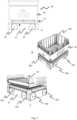
- the container accessing station 60may comprise a cabinet 63 comprising walls and a top cover supported thereon, as shown in figure 5 A-B .
- the items held in the storage containers 106 carried by the delivery vehicle 30 and lifted to the container accessing station 60is reachable trough an access opening 61 in the top cover of the cabinet 63.
- the cabinet 60is arranged adjoining the storage grid 104, where the delivery rail system 50 extends from below the delivery ports 150 and to a position located on a first level below a container accessing station 60.
- the container accessing station 60comprises an access opening 61 through which a human and/or robot may access contents of the container 106.
- the container accessing station 60further comprises a base opening 62 provided at a lower part of the cabinet, and a lifting device 70 arranged to retrieve the container 106 from a first level beneath the base opening 62 and lift it up through the base opening 62 to a second level so that the container 106 may be accessed through the access opening 61.
- the container accessing station 60may comprise a deployable cover 81 for restricting access through the access opening 61.
- the deployable cover 81may be a retractable cover 81.
- the covermay be arranged to open only if predetermined conditions are satisfied (e.g. if access to a container is authorised) and may thereby permit access to a container 106 through the access opening 61 when the container 106 is at the second level.
- the cover 81may be transparent and may allow the contents of a container 106 to be viewed from outside the container accessing station 60.
- Figure 6 A-Cshows a container accessing system comprising a container accessing station 60 and a delivery system 140.
- the delivery system 140in connected to a storage grid (see figure 4 A-B ) such that storage containers 106 may be retrieved form the storage location in the storage grid 104 and transported on delivery vehicles 30 to the delivery grid cell located vertically below a container accessing station 60.
- a lifting device 70 of the container accessing station 60is operated to retrieve the storage container 106 and lifts it up from a first level to a second level where items stored in the storage container 106 may be accessed through the access opening 61 provided in the container accessing station 60.
- the delivery system 140 in figure 6 A-Cmay also be a storage grid (not shown). Such that the vehicle operating on the rails are container handling vehicles 200,300.
- the container handling vehicles 200,300may retrieve a storage container 106 from the grid structure arranged below the rail system in which the container handing vehicles 200,300 operates and deliver it to the lifting device 70 of the container accessing station 60.
- the lifting device 70 of the container accessing station 60may retrieve a storage container 106 from a delivery vehicle 30 or a container handling vehicle 200,300.
- the lifting device 70extends beneath the base opening 62 and comprises a lifting frame 72 for releasable connection to the container 106 and a lift mechanism 71 arranged to move the lifting frame 72 from the first level to the second level.
- the lifting frame 72comprises four corner sections, and gripper elements 78 for releasable connection to the storage container 60.
- the lifting frame 72provides an opening (OLF) in which an item stored in the storage container can be reached by the human and/or robotic operator at the container accessing station 60, through the opening (OLF) of the lifting frame 72 when the container 60 is lifted to the second level at the access opening 61.
- the lift mechanism 71may comprise a guiding structure 73 arranged vertically and at least between the first level and the second level, wherein the horizontal lifting frame 72 is moveable along at least a section of the guiding structure 73.
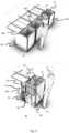
- Figure 7 A-Bshows another embodiment of the lifting device 70 comprising a lifting frame 72 and a lift mechanism 71.
- the lift mechanism 71may comprise a hoist frame 74 with an opening (OHF) provided at the access opening 61 and defining an access perimeter and comprises a plurality of lifting bands guided by the hoist frame 74.
- the lifting frame 72is suspended in a horizontal orientation from the hoist frame 74 by the plurality of lifting bands, wherein the access perimeter of the opening (OHF) in the hoist frame 74 corresponds in shape and alignment to the access perimeter of the opening (OLF) in the lifting frame 74 to allow access to items stored in the storage container through the respective openings (OHF, OLF) when the lifting frame 72 has been lifted up to the hoist frame 74 by the lift mechanism 71.
- the hoist frame 74may comprise a pair of arms 77 and wherein a sheave 79 is connected to a distal end of each arm 77.
- the lift mechanism 71may comprise a lifting shaft 80 for winding/unwinding the lifting bands simultaneously.
- the container accessing station 60may comprise a cabinet body 63 arranged about the access opening 61 and the base opening 62 such that a storage container 106 lifted into the cabinet body 63 by the lifting device 70 is only accessible through the access opening 61.
Landscapes
- Engineering & Computer Science (AREA)
- Mechanical Engineering (AREA)
- Physics & Mathematics (AREA)
- Aviation & Aerospace Engineering (AREA)
- Automation & Control Theory (AREA)
- Radar, Positioning & Navigation (AREA)
- Remote Sensing (AREA)
- General Physics & Mathematics (AREA)
- Transportation (AREA)
- Mathematical Physics (AREA)
- Structural Engineering (AREA)
- Civil Engineering (AREA)
- Life Sciences & Earth Sciences (AREA)
- Geology (AREA)
- Warehouses Or Storage Devices (AREA)
- Human Computer Interaction (AREA)
Description
- The present invention is related to an automated storage and retrieval system and a method of accessing a storage container.
Figs. 1A and1C disclose a typical prior art automated storage andretrieval system 1 with aframework structure 100.Figs. 1B and1D disclose a prior art container handling vehicle 101 operating thesystem 1 disclosed inFigs. 1A and1C , respectively.- The
framework structure 100 comprises a plurality ofupright members 102 and optionally a plurality ofhorizontal members 103 supporting theupright members 102. Themembers - The
framework structure 100 defines astorage grid 104 comprisingstorage columns 105 arranged in rows, in whichstorage columns 105 ofstorage containers 106, also known as bins, are stacked one on top of another to formstacks 107. - Each
storage container 106 may typically hold a plurality of product items (not shown), and the product items within astorage container 106 may be identical or may be of different product types depending on the application. - The
storage grid 104 guards against horizontal movement of thestorage containers 106 in thestacks 107, and guides vertical movement of thestorage containers 106, but does normally not otherwise support thestorage containers 106 when stacked. The automated storage andretrieval system 1 comprises arail system 108 arranged in a grid pattern across the top of thestorage 104, on which rail system 108 a plurality of container handling vehicles 200,300 (as exemplified inFigs. 1B and1D ) are operated to raisestorage containers 106 from, andlower storage containers 106 into, thestorage columns 105, and also to transport thestorage containers 106 above thestorage columns 105. The horizontal extent of one of thegrid cells 122 constituting the grid pattern is inFigs. 1A and1C marked by thick lines. - Each
grid cell 122 has a width which is typically within the interval of 30 to 150 cm, and a length which is typically within the interval of 50 to 200 cm. Eachgrid opening 115 has a width and a length which is typically 2 to 10 cm less than the width and the length of thegrid cell 122 due to the horizontal extent of the rails 110,111. - The
rail system 108 comprises a first set ofparallel rails 110 arranged to guide movement of the container handling vehicles 200,300 in a first direction X across the top of theframe structure 100, and a second set ofparallel rails 111 arranged perpendicular to the first set ofrails 110 to guide movement of the container handling vehicles 200,300 in a second direction Y which is perpendicular to the first direction X. In this way, therail system 108 defines grid columns above which the container handling vehicles 200,300 can move laterally above thestorage columns 105, i.e. in a plane which is parallel to the horizontal X-Y plane. - Each prior art container handling vehicle 200,300 comprises a vehicle body and a wheel arrangement of eight wheels 201,301 where a first set of four wheels enable the lateral movement of the container handling vehicles 200,300 in the X direction and a second set of the remaining four wheels enable the lateral movement in the Y direction. One or both sets of wheels in the wheel arrangement can be lifted and lowered, so that the first set of wheels and/or the second set of wheels can be engaged with the respective set of
rails - Each prior art container handling vehicle 200,300 also comprises a lifting device (not shown) for vertical transportation of
storage containers 106, e.g. raising astorage container 106 from, and lowering astorage container 106 into, astorage column 105. The lifting device comprises one or more gripping / engaging devices (not shown) which are adapted to engage astorage container 106, and which gripping / engaging devices can be lowered from the vehicle 201,301 so that the position of the gripping / engaging devices with respect to the vehicle 201,301 can be adjusted in a third direction Z which is orthogonal the first direction X and the second direction Y. - Conventionally, and also for the purpose of this application, Z=1 identifies the uppermost layer of the
grid 104, i.e. the layer immediately below therail system 108, Z=2 the second layer below therail system 108, Z=3 the third layer etc. In the exemplaryprior art grid 104 disclosed inFigs. 1A and1C , Z=8 identifies the lowermost, bottom layer of thegrid 104. Consequently, as an example, and using the Cartesian coordinate system X, Y, Z indicated inFigs. 1A and1D , the storage container identified as 106' inFig. 1A can be said to occupy grid location or cell X=10, Y=2, Z=3. The container handling vehicles 101 can be said to travel in layer Z=0 and each grid column can be identified by its X and Y coordinates. - Each
container handling vehicle 200 comprises a storage compartment or space (not shown) for receiving and stowing astorage container 106 when transporting thestorage container 106 across therail system 108 The storage space may comprise a cavity arranged centrally within the vehicle body, e.g. as is described inWO2014/090684A1 . - Alternatively, the
container handling vehicles 300 may have a cantilever construction, as is described inNO317366 - The container handling
vehicles 200 may have a footprint, i.e. an extent in the X and Y directions, which is generally equal to the lateral extent of agrid cell 122, i.e. the extent of agrid cell 122 in the X and Y directions, e.g. as is described inWO2015/193278A1 . The term "lateral" used herein may mean "horizontal". - Alternatively, the
container handling vehicles 200 may have a footprint which is larger than the lateral extent of (lateral area defined by) agrid column 105, e.g. as is disclosed inWO2014/090684A1 . WO 2016/198467 A1 discloses an automated storage and retrieval system comprising:- An automated storage and retrieval grid comprising:
- A container handling vehicle rail system for guiding a plurality of container handling vehicles, the container handling vehicle rail system comprising a first set of parallel rails arranged in a horizontal plane and extending in a first direction and a second set of parallel rails arranged in a horizontal plane and extending a second direction which is orthogonal to the first direction, which first and second set of rails form a grid pattern in the horizontal plane comprising a plurality of adjacent container handling vehicle grid opening defined by a pair of neighboring rails of the first set of rails and a pair of neighboring rails of the second set of rails; and..
- A delivery column adapted for transport of a storage container, arranged in a stack of storage containers beneath the container handling vehicle rail system, between a container handling vehicle and a delivery port situated at a lower end of the delivery column,
- A container accessing station.
- The
rail system 108 may be a single rail system, as is shown inFig. 2A . Alternatively, therail system 108 may be a double rail system, as is shown inFig. 2B , thus allowing acontainer handling vehicle 201 having a footprint generally corresponding to the lateral area defined by agrid column 112 to travel along a row of grid columns even if anothercontainer handling vehicle 200 is positioned above a grid column neighboring that row. Both the single and double rail system, or a combination comprising a single and double rail arrangement in asingle rail system 108, forms a grid pattern in the horizontal planeP comprising a plurality of rectangular and uniform grid locations orgrid cells 122, where eachgrid cell 122 comprises agrid opening 115 being delimited by a pair ofrails 1 10a, 110b of thefirst rails 110 and a pair ofrails rails 111. InFig. 2B thegrid cell 122 is indicated by a dashed box. - Consequently,
rails rails - As shown in
Fig. 2C , eachgrid cell 122 has a widthWc which is typically within the interval of 30 to 150 cm, and a lengthLc which is typically within the interval of 50 to 200 cm. Eachgrid opening 115 has a widthWo and a lengthLo which is typically 2 to 10 cm less than the widthWc and the lengthLc of thegrid cell 122. - In theX andY directions, neighboring grid cells are arranged in contact with each other such that there is no space there-between.
- In a
storage grid 104, a majority of the grid columns arestorage columns 105,i.e. grid columns 105 wherestorage containers 106 are stored instacks 107. However, agrid 104 normally has at least one grid column which is used not for storingstorage containers 106, but which comprises a location where the container handling vehicles 200,300 can drop off and/or pick upstorage containers 106 so that they can be transported to a second location (not shown) where thestorage containers 106 can be accessed from outside of thegrid 104 or transferred out of or into thegrid 104. Within the art, such a location is normally referred to as a "port" and the grid column in which the port is located may be referred to as a "delivery column" 119,120. The drop-off and pick-up ports of the container handling vehicles are referred to as the "upper ports of a delivery column" 119,120. While the opposite end of the delivery column is referred to as the "lower ports of a delivery column". - The
storage grids 104 inFigs. 1A and1C comprise twodelivery columns first delivery column 119 may for example comprise a dedicated drop-off port where the container handling vehicles 200,300 can drop offstorage containers 106 to be transported through thedelivery column 119 and further to an access or a transfer station, and thesecond delivery column 120 may comprise a dedicated pick-up port where the container handling vehicles 200,300 can pick upstorage containers 106 that have been transported through thedelivery column 120 from an access or a transfer station. Each of the ports of the first and second delivery column may comprise a port suitable for both pick up and drop of storage containers. - A container accessing station may typically be a picking or a stocking station where product items are removed from or positioned into the
storage containers 106. In a picking or a stocking station, thestorage containers 106 are normally never removed from the automated storage andretrieval system 1 but are returned into thestorage grid 104 once accessed. For transfer of storage containers out or into thestorage grid 104, there are also lower ports provided in a delivery column, such lower ports are e.g. for transferringstorage containers 106 to another storage facility (e.g. to another storage grid), directly to a transport vehicle (e.g. a train or a lorry), or to a production facility. - When a
storage container 106 stored in thegrid 104 disclosed inFig. 1A is to be accessed, one of the container handling vehicles 200,300 is instructed to retrieve thetarget storage container 106 from its position in thegrid 104 and to transport it to or through thedelivery column 119. This operation involves moving the container handling vehicle 200,300 to a grid location above thestorage column 105 in which thetarget storage container 106 is positioned, retrieving thestorage container 106 from thestorage column 105 using the container handling vehicle's lifting device (not shown), and transporting thestorage container 106 to thedelivery column 119. If thetarget storage container 106 is located deep within astack 107, i.e. with one or a plurality of other storage containers positioned above thetarget storage container 106, the operation also involves temporarily moving the above-positioned storage containers prior to lifting thetarget storage container 106 from thestorage column 105. This step, which is sometimes referred to as "digging" within the art, may be performed with the same container handling vehicle 200,300 that is subsequently used for transporting thetarget storage container 106 to the delivery column, or with one or a plurality of other cooperating container handling vehicles 200,300. Alternatively, or in addition, the automated storage andretrieval system 1 may have container handling vehicles 200,300 specifically dedicated to the task of temporarily removingstorage containers 106 from astorage column 105. Once thetarget storage container 106 has been removed from thestorage column 105, the temporarily removed storage containers can be repositioned into theoriginal storage column 105. However, the removed storage containers may alternatively be relocated toother storage columns 105. - When a
storage container 106 is to be stored in thegrid 104, one of the container handling vehicles 200,300 is instructed to pick up thestorage container 106 from thedelivery column 120 and to transport it to a grid location above thestorage column 105 where it is to be stored. After any storage containers positioned at or above the target position within thestorage column stack 107 have been removed, the container handling vehicle 200,300 positions thestorage container 106 at the desired position. The removed storage containers may then be lowered back into thestorage column 105 or relocated toother storage columns 105. - A problem associated with known automated storage and
retrieval systems 1 is that the area surrounding the pick-up and drop-off ports may become congested with container handling vehicles 200,300 instructed to drop off or pick upstorage containers 106. This may seriously impede the operation of the automated storage andretrieval system 1. In small systems this situation may possibly be alleviated by adding delivery columns to the grid, as this will allow the container handling vehicles 200,300 to be distributed among a larger number of ports of delivery columns in order to avoid congestion. However, if ports and columns are added, the conveyor system infrastructure must normally be increased. This requires space, which may not necessarily be available. Also, adding conveyor system infrastructure is costly. - Another problem with prior art automated storage and
retrieval systems 1 is that the separate drop-off ports and pick-up ports of the delivery columns 119,120 require the container handling vehicles 200,300 to move to astorage column 105 after drop-off to retrieve anew storage container 106. Likewise, the container handling vehicles 200,300 have to be empty of astorage container 106 when they are sent to a pick-upport 120 to pick up a storage container. This results in an inefficiency and causes increased congestion around the ports, as container handling vehicles 200,300 are moving around on the grid without astorage container 106 as payload. In addition, the delivery columns 119,120 may take up space on thegrid 104 which could be used for other purposes such as the movement of container handling vehicles 200,300. - In some cases, there might be a desire to separate the storage and retrieval system from public places or consumer-accessible places, due to safety or space considerations, such as in a supermarket or a department store.
- In view of the above, it is desirable to provide an automated storage and retrieval system, and a method for operating such a system, that solve or at least mitigate one or more of the aforementioned problem related to use of prior art storage and retrieval systems.
- An objective of the invention is to provide an automated storage and retrieval system which is more effective than prior art systems by avoiding or at least reducing congestion of storage containers around the delivery column.
- It is an object of the present invention to provide an effective storage and retrieval system that takes up less space on a consumer-accessible level and where elements of the storage and retrieval system may be hidden and secure.
- Another objective is to provide a high efficiency automated storage and retrieval system which are easy to install, and which delivery capacity can easily be increased after completed installation.
- Yet another objective is to provide a dedicated area where storage containers and items held in the storage containers effectively and easily can be handled at a consumer-accessible level.
- The present invention is directed to an automated storage and retrieval system according to
claim 1. Further embodiments and optional features of the automated storage and retrieval system are defined by the dependent claims. - The present invention is directed to a container accessing station for accessing a storage container of an automated storage and retrieval grid.
- The container accessing station comprising:
- an access opening through which a human and/or robot may access contents of the container;
- a base opening; and
- a lifting device arranged to retrieve the container from a first level
- The lift device may be configured to move the storage container in a substantially vertical or purely vertical direction between the first level and the second level.
- The first level may be located on a first floor and the second level may be located on a second floor, the first and the second floors being vertically displaced relative to each other, wherein the lifting device is arranged for lifting or lowering a storage container between the first floor and the second floor.
- The first floor may be an area with restricted access for personnel or consumers, and the second floor may be an area where the personnel and/or customers operate, such as in a department store, office, school, etc. When an item is ordered, the automated storage and retrieval system retrieves a storage container containing the stored items and delivers it to the container accessing station. In this way the entire storage and retrieval system may be hided from the personnel or consumers, thus saving space and increasing safety.
- The lifting device may extend beneath the base opening and comprise a lifting frame for releasable connection to the storage container and a lift mechanism arranged to move the lifting frame from the first level to the second level.
- The lift mechanism may comprise a guide structure extending in a vertical direction at least from the first level to the second level, and the lifting frame may be connected to the guide structure and operable along at least a section of the guide structure.
- The lifting frame may operate along at least a section of the guide structure my means of a motor situated on the lifting frame or on the lift mechanism. Thus, the motor may be configured to drive the lifting frame along at least a section of the guide structure.
- The lifting frame may be connected to the guide structure such that the lifting frame extends perpendicularly to the guide structure. Thus, the lifting frame may be in a horizontal or substantial horizontal position and the guide structure in a vertical or substantial vertical position.
- The lifting frame may comprise four corner sections, and gripper elements for releasable connection to the storage container. The four corners gripping structure may maintain the storage container in a motionless or near motionless position on the lifting frame.
- The gripper elements may be driven by a gripper motor situated at a periphery of the lifting frame. A control module may be connected to the gripper motors and controls the gripper motors.
- The storage container may comprise a plurality of recesses provided at the periphery of the opening of the storage containers, wherein each recess is configured to receive a corresponding gripper element for releasable connection of the storage container to the lifting frame. The gripper elements may be configured to releasably connect to the storage container using the recesses.
- The lifting frame may provide an opening (OLF) in which an item stored in the storage container can be reached by the human and/or robotic operator at the container accessing station, through the opening (OLF) of the lifting frame. The opening (OLF) may align with the access opening when the lifting frame is at the second level so that contents of a container carried by the lifting frame may be accessed via the access opening and opening (OLF).
- The lift mechanism may comprise a hoist frame with an opening (OHF) provided at the access opening defining an access perimeter and comprises a plurality of lifting bands guided by the hoist frame. The lifting frame may be suspended in a horizontal orientation from the hoist frame by the plurality of lifting bands, wherein the access perimeter of the opening in the hoist frame corresponds in shape and alignment to the access perimeter of the opening (OLF) in the lifting frame to allow access to items stored in the storage container through the respective openings (OHF, OLF), when the lifting frame has been lifted up to the hoist frame by the lift mechanism.
- The hoist frame may comprise a pair of arms and a sheave may be connected to a distal end of each arm.
- The lift mechanism may comprise a lifting shaft for winding/unwinding the lifting bands simultaneously.
- The lifting bands may be operated unwound (unwinding) such that they deploy the lifting frame through the base opening where the lifting frame connects to an upper surface of the storage container, and whereupon the lifting bands are operated wound (winding) such that they lift the storage container through the base opening and to the access opening.
- The container accessing station may comprise a cabinet body arranged about the access opening and the base opening such that a container lifted into the cabinet body by the lifting device is only accessible through the access opening.
- The access opening may be in an upper part of the cabinet body, and the base opening may be provided at a lower part of the cabinet body. Thus, the storage container is lifted from the first level, beneath the cabinet body, through the base opening and to the second level at the upper part of the cabinet body, so that the storage container may be accessed through the access opening.
- The base opening may be provided above and adjacent to a floor opening provided between the first level and the second level or the first floor and the second floor of a building.
- The container accessing station may comprise a deployable cover for restricting access through the access opening. The deployable cover may be a retractable cover. The cover may be arranged to open only if predetermined conditions are satisfied (e.g. if access to a container is authorised) and may thereby permit access to a container through the access opening when the container is at the second level. The cover may be transparent and may allow the contents of a container to be viewed from outside the container accessing station.
- The present invention may also be directed to a container accessing system comprising a container accessing station as described above, and a delivery rail system.
- The delivery rail system may comprise at least a first set of parallel rails arranged in a horizontal plane (P1) and extending in a first direction (X), and at least a second set of parallel rails arranged in the horizontal plane (P1) and extending in a second direction (Y) which is orthogonal to the first direction (X), the first and second sets of rails together defining a delivery grid of delivery grid cells, and
- a remotely operated delivery vehicle operating on the delivery rail system and comprising a motorized vehicle body and a container carrier provided above the motorized vehicle body for carrying a storage container,
- By the arrangement of the lift device, the storage container is to be efficiently transported between a delivery rail system and a container accessing station that are vertically displaced relative each other, thereby allowing a delivery rail system to be located on a different level than the accessing station, thus allowing efficient utilization of available floor space.
- The present invention may also be directed to a container accessing system comprising a container accessing station as described above, and an automated storage and retrieval grid system.
- The automated storage and retrieval grid may be located on a level below the container accessing station. A container handling vehicle may be adapted to retrieve a storage container from a storage column of the automated storage and retrieval grid and deliver the storage container to the container accessing station. The lifting device of the container accessing station is arranged to retrieve the storage container from the container handling vehicle at the first level and lifts the storage container from the first level to the second level.
- Thus, the container accessing station may be disposed on a floor above the delivery grid of a delivery system or above a storage and retrieval grid of a container storage and retrieval system.
- The container accessing system may comprise a plurality of container accessing stations as described above.
- The present invention may also be directed to an automated storage and retrieval system comprising the container accessing station, an automated storage and retrieval grid and a delivery system for transporting the storage container between the automated storage and retrieval grid and the container accessing station.
- The automated storage and retrieval grid comprises:
- a container handling vehicle rail system for guiding a plurality of container handling vehicles, the container handling vehicle rail system comprising a first set of parallel rails arranged in a horizontal plane (P) and extending in a first direction (X), and a second set of parallel rails arranged in the horizontal plane (P) and extending in a second direction (Y) which is orthogonal to the first direction (X), which first and second sets of rails form a grid pattern in the horizontal plane (P) comprising a plurality of adjacent container handling vehicle grid cells, each container handling vehicle grid cell comprising a container handling vehicle grid opening defined by a pair of neighboring rails of the first set of rails and a pair of neighboring rails of the second set of rails; and
- a delivery column adapted for transport of a storage container arranged in a stack of storage containers beneath the container handling vehicle rail system between a container handling vehicle and a delivery port situated at a lower end of the delivery column.
- The delivery vehicle is arranged to transport the storage container from the delivery port of the storage grid across the delivery grid to the delivery grid cell situated vertically below the container accessing station and return it to the delivery port for storage within the storage grid.
- The automated storage and retrieval grid comprises vertical members defining multiple storage columns for storing storage containers on top of each other in vertical stacks. The vertical members are interconnected at their upper ends by a container handling vehicle rail system arranged to guide at least one container handling vehicle. The container handling vehicle is configured to raise storage containers from, and lower storage containers into, the storage columns, and to transport the storage containers above the storage columns.
- The container handling vehicle rail system is arranged in a first horizontal plane and comprises a first set of parallel rails extending in a first direction X, and a second set of parallel rails and extending in a second direction Y which is orthogonal to the first direction X. The first and second sets of rails form a grid pattern in the first horizontal plane comprising a plurality of adjacent container handling vehicle grid cells. Each container handling vehicle grid cell comprises a container handling vehicle grid opening defined by a pair of neighboring rails of the first set of rails and a pair of neighboring rails of the second set of rails. Further, the automated storage and retrieval grid comprises a transfer column adapted for transport of a storage container between the container handling vehicle and a delivery space situated at a lower end of the transfer column.
- The delivery system comprises a first delivery rail system having at least one set of parallel rails arranged in a second horizontal plane guiding at least one delivery vehicle thereon.
- The delivery vehicle is adapted to receive and/or deliver a storage container at a storage container delivery location arranged below the delivery port of the delivery column and to move between the storage grid and the container accessing station.
- The first delivery rail system covers at least an area extending from the delivery port of the storage grid to the container accessing station.
- The present invention is also directed to a method of accessing a storage container through a container accessing station. The container accessing station comprises:
- an access opening through which a human and/or robot may access contents of the storage container (106);
- a base opening (62); and
- a lifting device (70).
- The method comprises: retrieving the storage container from a first level using the lifting device and lifting the storage container up through the base opening to a second level; and accessing the storage container at the second level through the access opening.
- Following drawings are appended by way of example only to facilitate the understanding of the invention.
- Fig. 1 A-D
- are perspectives view of a prior art automated storage and retrieval system, where
Fig. 1 A andFig. 1 C shows the complete system andFig. 1 B andFig. 1 D shows examples of system operable prior art container handling vehicles. - Fig. 2 A-C
- Is a view from top of a grid cell comprising a set of parallel rails arranged to guide movement of a remotely operated vehicle.
- Fig. 3 A-C
- shows different versions of a remotely operated delivery vehicle arranged for transporting a storage container between the storage grid and the container accessing station.
- Fig. 4 A-B
- is a perspective view of another automated storage and retrieval grid and a delivery system for transporting storage container between the storage grid and a container accessing station.
- Fig. 5 A-B
- shows a container accessing station according to an embodiment of the present invention where
fig 5 B shows a storage container at the second level. - Fig. 6 A-C
- is a perspective view of a set of the container accessing system comprising a delivery system and a container accessing station with a container lifting device.
- Fig. 7 A-B
- shows a container accessing station according to an embodiment of the present invention comprising a lifting device with lifting bands.
- Fig 8. A-B
- shows a container accessing system according to an embodiment of the present invention.
- In the following, embodiments of the invention will be discussed in more detail with reference to the appended drawings. It should be understood, however, that the drawings are not intended to limit the invention to the subject-matter depicted in the drawings. Furthermore, even if some of the features are described in relation to the system only, it is apparent that they are valid for the delivery vehicles and related methods as well, and vice versa. Hence, any features described in relation to the delivery vehicle only, and/or related methods, are also valid for the system.
- With reference to
Figs. 1A-D thestorage grid 104 of eachstorage structure 1 constitutes aframework 100 of in total 143grid columns 112, where the width and length of the framework corresponds to the width and length of 13 and 11grid columns 112, respectively. The top layer of theframework 100 is arail system 108 onto which a plurality of container handling vehicles 200,300 are operated. - The
framework 100 of thestorage system 1 is constructed in accordance with the above mentionedprior art framework 100 described above, i.e. a plurality ofupright members 102 and a plurality ofhorizontal members 103 which are supported by theupright members 102, and further that thehorizontal members 103 includes therail system 108 of parallel rails 110,111 in the X direction and the Y direction, respectively, arranged across the top ofstorage columns 105. The horizontal area of asingle grid cell 122, i.e. along the X and Y directions, may be defined by the distance betweenadjacent rails Fig. 3 and4 ). InFigs. 1A and1C , such agrid cell 122 is marked on therail system 108 by thick lines. - The
rail system 108 allows the container handling vehicles 200,300 to move horizontally between different grid locations, where each grid location is associated with agrid cell 122. - In
Figs. 1A and1C thestorage grid 104 is shown with a height of eight cells. It is understood, however, that thestorage grid 104 can in principle be of any size. In particular it is understood thatstorage grid 104 can be considerably wider and/or longer than disclosed inFigs. 1A and1C . For example, thegrid 104 may have a horizontal extent of more than700x700 grid cells 122. Also, thegrid 104 can be considerably deeper than disclosed inFigs. 1A and1C . For example, thestorage grid 104 may be more than twelve grid cells deep. - The storage container vehicles 200,300 may be of any type known in the art, e.g. any one of the automated container handling vehicles disclosed in
WO2014/090684 A1 , inNO317366 WO2015/193278A1 . - The
rail system 108 may be a single rail system, as is shown inFig. 2A . Alternatively, therail system 108 may be a double rail system, as is shown inFig. 2B . Details of the single and double rail system are disclosed this specification under the section of background and prior art. Fig 3 A-C shows an embodiment of a remotely operateddelivery vehicle 30, hereinafter referred to as adelivery vehicle 30.- The
delivery vehicle 30 is configured for transport of a storage container 106 (not shown) between an automated storage and retrieval grid 104 (seefig 4 A and B ) configured to store a plurality ofstacks 107 ofstorage containers 106, hereinafter referred to as astorage grid 104, and a access opening 61 provided in acontainer accessing station 60 for handling of thestorage container 106 by at least one of a robotic operator and human operator. - Said
delivery vehicle 30 comprises; avehicle body 31, a rollingdevice vehicle body 31, a rolling device motor for driving the rollingdevice device storage grid 104, for example to anaccess station 60. - The
delivery vehicle 30 further comprises acontainer carrier 35 mounted above thevehicle body 31. Thecontainer carrier 35 should be configured to receive thestorage container 106 onto or within thecontainer carrier 35 such that thestorage container 106 is prevented to slide along the horizontal plane (P1). - The
container carrier 35 may comprise a container supporting device supporting thestorage container 106 from below. - In
Fig. 3 A-B thecontainer carrier 35 is disclosed in the form of a storage container receiving compartment having a bottom / base and side walls. The volume of the compartment is in this exemplary configuration such that it may receive and contain the entire horizontal extent of the storage container and at least a part of the vertical extent of the storage container. - The particular configuration of the
container carrier 35 disclosed in 3 A-B allows thedelivery vehicle 30 to transport of astorage container 106 having different heights. - Note that the size of the compartment within the
container carrier 35 may easily be adapted for receiving and supporting a multiple number ofstorage containers 106 in one operation. Figure 3 C shows yet another exemplary configuration of the remotely operateddelivery vehicle 30. In this configuration thecontainer carrier 35 comprises a base plate, a conveyor arranged on the base plate and two side walls protruding upwards from the base plate. The rollingdevice 32 and thevehicle body 31 are equal or similar to the rollingdevice 32 and thevehicle body 31 described above.- The conveyor may be set up by inter alia a plurality of parallel oriented rolls 36 having a common longitudinal direction perpendicular to the two side walls. In this way the
rolls 36 allow one ormore storage containers 106 to be shifted into or off thecontainer carrier 35 while being guided by the side walls. The conveyor may be connected to a conveyor motor allowing rotation of one or more of the rolls. - Perspective views of an automated storage and retrieval system is shown in
Fig. 4 A-B . The system comprises astorage grid 104 and adelivery system 140 comprising adelivery rail system 50, a plurality ofdelivery vehicles 30 operating on thedelivery rail system 50. - The
storage grid 104 is equal or similar to the priorart storage grid 104 as described above, i.e. astorage grid 104 comprising arail system 108; a plurality ofstacks 107 ofstorage containers 106, a plurality ofcontainer handling vehicles 300 for lifting and movingstorage containers 106 stacked in thestacks 107 and a delivery column 119,120 configured to receive astorage container 106 from acontainer handling vehicle 300. - The
delivery system 140 comprises one or more of thedelivery vehicles 30 as described above, i.e.delivery vehicles 30 configured to receive and supportstorage container 106 for transport between one or more delivery columns 119,120 and one or morecontainer handling stations 60 located outside thestorage grid 104. Thecontainer handling station 60 may be located any predetermined position suitable for handling containers. - The
delivery system 140 comprises adelivery rail system 50 situated below a delivery port 150 of the one or more delivery columns 119,120. - As shown in
Fig. 4 A-B , thedelivery rail system 50 may be constructed in the same way or a similar way as therail system 108 for the container handling vehicles 200,300. Thedelivery rail 50 extends at least from the delivery port 150 of one or more delivery columns 119,120, and to the at least onecontainer accessing station 60, such that eachstorage container 106 can be lifted into thecontainer accessing station 60 where items held in thestorage container 106 may be accessed from a different level than that of the delivery rail (seefig. 6 A-C ). - The
container accessing station 60 may comprise acabinet 63 comprising walls and a top cover supported thereon, as shown infigure 5 A-B . The items held in thestorage containers 106 carried by thedelivery vehicle 30 and lifted to thecontainer accessing station 60 is reachable trough an access opening 61 in the top cover of thecabinet 63. - The
cabinet 60 is arranged adjoining thestorage grid 104, where thedelivery rail system 50 extends from below the delivery ports 150 and to a position located on a first level below acontainer accessing station 60. - The
container accessing station 60 comprises an access opening 61 through which a human and/or robot may access contents of thecontainer 106. Thecontainer accessing station 60 further comprises abase opening 62 provided at a lower part of the cabinet, and alifting device 70 arranged to retrieve thecontainer 106 from a first level beneath thebase opening 62 and lift it up through thebase opening 62 to a second level so that thecontainer 106 may be accessed through theaccess opening 61. - As shown in
figure 5 B , thecontainer accessing station 60 may comprise adeployable cover 81 for restricting access through theaccess opening 61. Thedeployable cover 81 may be aretractable cover 81. The cover may be arranged to open only if predetermined conditions are satisfied (e.g. if access to a container is authorised) and may thereby permit access to acontainer 106 through the access opening 61 when thecontainer 106 is at the second level. Thecover 81 may be transparent and may allow the contents of acontainer 106 to be viewed from outside thecontainer accessing station 60. Figure 6 A-C shows a container accessing system comprising acontainer accessing station 60 and adelivery system 140. Thedelivery system 140 in connected to a storage grid (seefigure 4 A-B ) such thatstorage containers 106 may be retrieved form the storage location in thestorage grid 104 and transported ondelivery vehicles 30 to the delivery grid cell located vertically below acontainer accessing station 60. A liftingdevice 70 of thecontainer accessing station 60 is operated to retrieve thestorage container 106 and lifts it up from a first level to a second level where items stored in thestorage container 106 may be accessed through the access opening 61 provided in thecontainer accessing station 60.- The
delivery system 140 infigure 6 A-C may also be a storage grid (not shown). Such that the vehicle operating on the rails are container handling vehicles 200,300. The container handling vehicles 200,300 may retrieve astorage container 106 from the grid structure arranged below the rail system in which the container handing vehicles 200,300 operates and deliver it to thelifting device 70 of thecontainer accessing station 60. Thus, the liftingdevice 70 of thecontainer accessing station 60 may retrieve astorage container 106 from adelivery vehicle 30 or a container handling vehicle 200,300. - The lifting
device 70 extends beneath thebase opening 62 and comprises a liftingframe 72 for releasable connection to thecontainer 106 and alift mechanism 71 arranged to move the liftingframe 72 from the first level to the second level. - The lifting
frame 72 comprises four corner sections, andgripper elements 78 for releasable connection to thestorage container 60. - The lifting
frame 72 provides an opening (OLF) in which an item stored in the storage container can be reached by the human and/or robotic operator at thecontainer accessing station 60, through the opening (OLF) of the liftingframe 72 when thecontainer 60 is lifted to the second level at theaccess opening 61. - The
lift mechanism 71 may comprise a guidingstructure 73 arranged vertically and at least between the first level and the second level, wherein thehorizontal lifting frame 72 is moveable along at least a section of the guidingstructure 73. Figure 7 A-B shows another embodiment of thelifting device 70 comprising a liftingframe 72 and alift mechanism 71.- The
lift mechanism 71 may comprise a hoistframe 74 with an opening (OHF) provided at the access opening 61 and defining an access perimeter and comprises a plurality of lifting bands guided by the hoistframe 74. The liftingframe 72 is suspended in a horizontal orientation from the hoistframe 74 by the plurality of lifting bands, wherein the access perimeter of the opening (OHF) in the hoistframe 74 corresponds in shape and alignment to the access perimeter of the opening (OLF) in the liftingframe 74 to allow access to items stored in the storage container through the respective openings (OHF, OLF) when the liftingframe 72 has been lifted up to the hoistframe 74 by thelift mechanism 71. - The hoist
frame 74 may comprise a pair ofarms 77 and wherein asheave 79 is connected to a distal end of eacharm 77. - The
lift mechanism 71 may comprise a liftingshaft 80 for winding/unwinding the lifting bands simultaneously. - Accordingly, the container accessing station 60) may comprise a
cabinet body 63 arranged about the access opening 61 and thebase opening 62 such that astorage container 106 lifted into thecabinet body 63 by the liftingdevice 70 is only accessible through theaccess opening 61. - 30
- Delivery vehicle
- 31
- Vehicle body
- 32
- Rolling device
- 32a
- First set of wheels
- 32b
- Second set of wheels
- 35
- Container carrier
- 36
- Rolls of conveyor
- 50
- Delivery rail system
- 51
- Delivery grid
- 52
- Delivery grid cell
- 60
- Container accessing station
- 61
- Access opening
- 62
- Base opening
- 63
- Cabinet
- P1
- Horizontal plane of delivery rail system
- 70
- Lifting device
- 71
- Lift mechanism
- 72
- Lifting frame
- 73
- Guide structure
- 74
- Hoist frame
- 75
- Hoist mechanism
- 76
- Lifting bands
- 77
- Arm
- 78
- Gripper elements
- 79
- Sheave
- 80
- Lifting shaft
- 81
- Deployable cover
- OLF
- Opening lifting frame
- OHF
- Opening hoist frame
- 100
- Framework structure
- 102
- Upright members of framework structure
- 103
- Horizontal members of framework structure
- 104
- Storage grid / three-dimensional grid
- 105
- Storage column
- 106
- Storage container
- 107
- Stack
- 108
- Rail system
- 110
- First set of parallel rails in first direction (X)
- 111
- Second set of parallel rails in second direction (Y)
- 115
- Grid opening
- 119
- Delivery column
- 120
- Delivery column
- 122
- Grid cell
- 140
- Delivery system
- 150
- Delivery port
- 200
- First container handling vehicle
- 201
- Wheel arrangement
- 300
- Second container handling vehicle
- 301
- Wheel arrangement
- X
- First direction
- Y
- Second direction
- P
- Horizontal plane of rail system
Claims (15)
- An automated storage and retrieval system comprising:- an automated storage and retrieval grid (104) comprising:- a container handling vehicle rail system (108) for guiding a plurality of container handling vehicles (200,300), the container handling vehicle rail system (108) comprising a first set of parallel rails (110) arranged in a horizontal plane (P) and extending in a first direction (X), and a second set of parallel rails (111) arranged in the horizontal plane (P) and extending in a second direction (Y) which is orthogonal to the first direction (X), which first and second sets of rails (110, 111) form a grid pattern in the horizontal plane (P) comprising a plurality of adjacent container handling vehicle grid cells (122), each container handling vehicle grid cell (122) comprising a container handling vehicle grid opening (115) defined by a pair of neighboring rails (110a, 110b) of the first set of rails (110) and a pair of neighboring rails (111a, 111b) of the second set of rails (111); and- a delivery column (119,120) adapted for transport of a storage container (106), arranged in a stack (107) of storage containers (106) beneath the container handling vehicle rail system (108), between a container handling vehicle (200,300) and a delivery port (150) situated at a lower end of the delivery column (119,120),- a container accessing station (60),- a delivery rail system comprising at least a first set of parallel rails arranged in a horizontal plane (P1) and extending in a first direction (X), and at least a second set of parallel rails arranged in the horizontal plane (P1) and extending in a second direction (Y) which is orthogonal to the first direction (X), the first and second sets of rails together defining a delivery grid (51) of delivery grid cells (52), and- a delivery vehicle (30) operating on the delivery rail system and comprising a motorized vehicle body and a container carrier provided above the motorized vehicle body for carrying the storage container (106),wherein the delivery vehicle (30) is arranged to transport the storage container (106) from the delivery port (150) of the storage grid (104) across the delivery grid (51) to the delivery grid cell (52) situated vertically below the container accessing station (60),- the container accessing station (60) comprising:- an access opening (61) through which a human and/or robot may access contents of the storage container (106),- a base opening (62), and- a lifting device (70) arranged to retrieve the storage container (106) from a first level beneath the base opening and to lift the storage container (106) up through the base opening (62) to a second level so that the storage container may be accessed through the access opening (61),wherein the delivery vehicle (30) is arranged to deliver the storage container (106) to the lifting device (70) of the container accessing station (60), or receive a storage container (106) from the lifting device (70) and return the storage container to the delivery port (150) for storage within the storage grid (104).
- The system according to claim 1, wherein the delivery vehicle (30) comprises rolling devices (32a, 32b) connected to the vehicle body (31), a rolling device motor for driving the rolling device (32a, 32b) in the horizontal plane (P1), and a power source connected to the rolling device motor.
- The system according to claim 1 or 2, wherein the lifting device (70) extends beneath the base opening (62) and comprises a lifting frame (72) for releasable connection to the storage container (106) and a lifting mechanism (71) arranged to move the lifting frame (72) from the first level to the second level.
- The system according to claim 3, wherein the lifting frame (72) comprises four corner sections, and gripper elements (78) for releasable connection to the storage container (106).
- The system according to claim 3 or 4, wherein the lifting frame (72) provides an opening (OLF) through which an item stored in the storage container (106) can be reached by the human and/or robotic operator at the container accessing station (60), through the access opening (61) and the opening (OLF) of the lifting frame (72).
- The system according to any one of claims 3-5, wherein the lift mechanism (71) comprises a guiding structure (73) arranged vertically and at least between the first level and the second level, wherein the lifting frame (72) is moveable along at least a section of the guiding structure (73).
- The system according to claim 5, wherein the lift mechanism (71) comprises a hoist frame (74) with an opening (OHF) provided at the access opening (61) defining an access perimeter; and comprises a plurality of lifting bands guided by the hoist frame (74), and wherein the lifting frame (72) is suspended in a horizontal orientation from the hoist frame (74) by the plurality of lifting bands, wherein the access perimeter of the opening (OHF) in the hoist frame (74) corresponds in shape and alignment to the access perimeter of the opening (OLF) in the lifting frame (72) to allow access to items stored in the storage container through the respective openings (OHF, OLF) when the lifting frame (72) has been lifted up to the hoist frame (74) by the lift mechanism (71).
- The system according to claim 7, wherein the hoist frame (74) comprises a pair of arms (77) and wherein a sheave (79) is connected to a distal end of each arm (77).
- The system according to claim 8, wherein the lift mechanism (71) comprises a lifting shaft (80) for winding/unwinding the lifting bands simultaneously.
- The system according to any one of the preceding claims, comprising a cabinet body (63) arranged about the access opening (61) and the base opening (62) such that a storage container (106) lifted into the cabinet body (63) by the lifting device (70) is only accessible through the access opening (61).
- The system according to claim 10, wherein container accessing station (60) comprises a deployable cover (81) for restricting access through the access opening (61).
- The system according to claim 11, wherein the deployable cover is a retractable cover (81) arranged to open only if predetermined conditions are satisfied and thereby permit access to the container (106) through the access opening (61) when the container is at the second level.
- The system according to any one of the preceding claims, wherein the container accessing station (60) is disposed on a floor above the delivery grid (51).
- The system according to any one of the preceding claims, comprising a plurality of container accessing stations (60).
- A method of accessing a storage container (106) through a container accessing station (60) within a system according to any one of claims 1-14, wherein the method comprises:retrieving the storage container (106) from a first level using the lifting device (70) and lifting it up through the base opening (62) to a second level; andaccessing the storage container (106) at the second level through the access opening (61).
Priority Applications (1)
| Application Number | Priority Date | Filing Date | Title |
|---|---|---|---|
| EP22199813.1AEP4137423A1 (en) | 2018-06-12 | 2019-06-11 | Container accessing station with lifting device |
Applications Claiming Priority (3)
| Application Number | Priority Date | Filing Date | Title |
|---|---|---|---|
| NO20180813 | 2018-06-12 | ||
| NO20181005ANO344662B1 (en) | 2018-06-12 | 2018-07-19 | An automated storage and retrieval system and a method of transporting storage containers between an automated storage and retrieval grid and a second location |
| PCT/EP2019/065184WO2019238661A1 (en) | 2018-06-12 | 2019-06-11 | Container accessing station with lifting device |
Related Child Applications (2)
| Application Number | Title | Priority Date | Filing Date |
|---|---|---|---|
| EP22199813.1ADivisionEP4137423A1 (en) | 2018-06-12 | 2019-06-11 | Container accessing station with lifting device |
| EP22199813.1ADivision-IntoEP4137423A1 (en) | 2018-06-12 | 2019-06-11 | Container accessing station with lifting device |
Publications (2)
| Publication Number | Publication Date |
|---|---|
| EP3807180A1 EP3807180A1 (en) | 2021-04-21 |
| EP3807180B1true EP3807180B1 (en) | 2023-09-20 |
Family
ID=87554166
Family Applications (2)
| Application Number | Title | Priority Date | Filing Date |
|---|---|---|---|
| EP22199813.1APendingEP4137423A1 (en) | 2018-06-12 | 2019-06-11 | Container accessing station with lifting device |
| EP19730160.9AActiveEP3807180B1 (en) | 2018-06-12 | 2019-06-11 | Container accessing station with lifting device |
Family Applications Before (1)
| Application Number | Title | Priority Date | Filing Date |
|---|---|---|---|
| EP22199813.1APendingEP4137423A1 (en) | 2018-06-12 | 2019-06-11 | Container accessing station with lifting device |
Country Status (9)
| Country | Link |
|---|---|
| US (3) | US11820389B2 (en) |
| EP (2) | EP4137423A1 (en) |
| JP (2) | JP7482791B2 (en) |
| CN (2) | CN112272643B (en) |
| CA (1) | CA3098972A1 (en) |
| DK (1) | DK3807180T3 (en) |
| ES (1) | ES2962115T3 (en) |
| PL (1) | PL3807180T3 (en) |
| WO (1) | WO2019238661A1 (en) |
Families Citing this family (12)
| Publication number | Priority date | Publication date | Assignee | Title |
|---|---|---|---|---|
| GB201805917D0 (en)* | 2018-04-10 | 2018-05-23 | Ocado Innovation Ltd | System and method for picking items |
| WO2019238673A1 (en) | 2018-06-12 | 2019-12-19 | Autostore Technology AS | Storage grid with container accessing station with locking device to lock remotely operated vehicle |
| NO344944B1 (en)* | 2018-10-12 | 2020-07-27 | Autostore Tech As | An access station for picking storage containers |
| NO346056B1 (en) | 2020-06-19 | 2022-01-24 | Autostore Tech As | Container handling vehicle elevator |
| DE102020128511A1 (en) | 2020-10-29 | 2022-05-05 | Dematic Gmbh | Storage system for storing goods in a three-dimensional warehouse |
| CN114455335B (en)* | 2021-08-27 | 2024-06-07 | 西门子工业自动化产品(成都)有限公司 | Separation device and method for stacked boxes |
| CN114368577B (en)* | 2022-01-29 | 2022-11-22 | 上海方仓智能科技有限公司 | Box intelligent warehouse system of stack |
| DE102022129209A1 (en) | 2022-11-04 | 2024-05-08 | Dematic Gmbh | Storage system for compact three-dimensional storage of containers and method for operating such a storage system |
| CN116238407A (en)* | 2023-02-24 | 2023-06-09 | 中铁电气化局集团有限公司 | System for transporting dregs between shield tunneling machine and crane |
| GB2635396A (en)* | 2023-11-10 | 2025-05-14 | Ocado Innovation Ltd | A grid framework structure storage system |
| DE102023136583A1 (en) | 2023-12-22 | 2025-06-26 | Dematic Gmbh | Storage system for compact three-dimensional storage of containers and method for operating such a storage system |
| EP4588824A1 (en)* | 2024-01-19 | 2025-07-23 | Jungheinrich Aktiengesellschaft | Bearing arrangement and method for operating a bearing arrangement |
Family Cites Families (111)
| Publication number | Priority date | Publication date | Assignee | Title |
|---|---|---|---|---|
| US3519150A (en) | 1968-04-05 | 1970-07-07 | Westinghouse Electric Corp | Storage system with means for transferring a vehicle between a plurality of paths that have control means therein |
| US3968888A (en) | 1968-10-21 | 1976-07-13 | The Lummus Company | Warehouse sysem with parallel conductor positional control means for a stacker crane |
| US3608750A (en) | 1969-03-03 | 1971-09-28 | Kaiser Ind Inc | Storage means and load-handling equipment therefor |
| US3800963A (en) | 1972-12-04 | 1974-04-02 | E Holland | Material storage and handling system |
| JPS57194861A (en) | 1981-05-25 | 1982-11-30 | Murata Mach Ltd | Automatic transfer system of workpiece in machine shop |
| NL8104384A (en) | 1981-09-23 | 1983-04-18 | Staalkat Bv | METHOD FOR UNLOADING A STACK FILLED CONTAINER, AND APPARATUS FOR CARRYING OUT THIS METHOD |
| JPS60137703A (en) | 1984-07-31 | 1985-07-22 | Nippon Filing Co Ltd | Secret article keeping equipment |
| US4909697A (en) | 1986-01-02 | 1990-03-20 | Computer Aided Systems, Inc. | Automated work station |
| JPS6417707A (en) | 1987-07-10 | 1989-01-20 | Daifuku Kk | Warehouse facility |
| JPH07110282B2 (en) | 1987-09-29 | 1995-11-29 | テルモ株式会社 | Automatic transfer sterilizer |
| US5078566A (en) | 1988-10-27 | 1992-01-07 | Utdc, Inc. | Freight discharge apparatus |
| GB2233319A (en) | 1989-05-27 | 1991-01-09 | Frederick George Best | Storage system |
| DE4016810C1 (en) | 1990-05-25 | 1991-11-21 | Keuro Maschinenbau Gmbh & Co Kg, 7590 Achern, De | |
| EP0493327A1 (en) | 1990-12-27 | 1992-07-01 | Manitec Consulting AG | Storage rack |
| NL9101633A (en) | 1991-09-26 | 1993-04-16 | Martinus Wilhelmus Johannus Ke | DEVICE FOR LOADING AND DEVICE FOR UNLOADING AN EGG CONTAINER. |
| JP3136782B2 (en) | 1992-07-22 | 2001-02-19 | 株式会社明電舎 | Autonomous guided vehicle intersection control method |
| US5360306A (en) | 1993-07-13 | 1994-11-01 | Kabushiki Kaisha Nakayama Egg | Delivering apparatus using parallel conveyor system and shipping apparatus employed by the delivering apparatus |
| DE9310690U1 (en)* | 1993-07-16 | 1993-09-09 | Siemens AG, 80333 München | Warehouse with integrated sorting area |
| DE9412219U1 (en) | 1994-07-29 | 1995-11-23 | Varta Batterie Ag, 30419 Hannover | Automatic coupling system for vehicle batteries |
| ITPI940032A1 (en)* | 1994-11-03 | 1996-05-03 | Gilberto Rolla | MODULAR AND AUTOMATIC UNDERGROUND STORAGE FOR THE TEMPORARY OR PERMANENT STORAGE OF CONTAINERS AND SIMILAR |
| JPH08217209A (en) | 1995-02-10 | 1996-08-27 | Chiyoda Corp | Picking system |
| JPH09152914A (en) | 1995-11-29 | 1997-06-10 | Oki Electric Ind Co Ltd | Method and system for controlling moving body |
| JPH11143538A (en) | 1997-11-07 | 1999-05-28 | Murata Mach Ltd | Automatic guided vehicle system |
| JP3375061B2 (en) | 1998-12-28 | 2003-02-10 | 村田機械株式会社 | Picking system |
| NO317366B1 (en) | 1999-07-01 | 2004-10-18 | Autostore As | Storage system with remote controlled wagons with two wheelsets and lifting device for operation on rails arranged in cross over columns of storage units separated by vertical profile posts |
| JP2003137406A (en) | 2001-10-30 | 2003-05-14 | Murata Mach Ltd | Parts supply system |
| JP2003146412A (en) | 2001-11-12 | 2003-05-21 | Mitsubishi Electric Corp | Transport system |
| US7101139B1 (en) | 2003-05-06 | 2006-09-05 | Benedict Charles E | Automated material handling system with motorized transfer vehicles |
| US8628289B1 (en) | 2003-05-06 | 2014-01-14 | Charles E. Benedict | Material handling and storage/warehouse system |
| US7591630B2 (en) | 2003-08-29 | 2009-09-22 | Casepick Systems, Llc | Materials-handling system using autonomous transfer and transport vehicles |
| ITBA20040003A1 (en) | 2004-01-16 | 2004-04-16 | Icam S R L | AUTOMATED COMPACT STORAGE WAREHOUSE |
| US7806644B2 (en) | 2004-04-30 | 2010-10-05 | Yuyama Mfg. Co., Ltd. | Tray discharge device |
| US7920962B2 (en) | 2006-06-19 | 2011-04-05 | Kiva Systems, Inc. | System and method for coordinating movement of mobile drive units |
| CN101553416A (en) | 2006-09-25 | 2009-10-07 | 查尔斯·E.·贝内迪克特 | Warehouse storage system |
| US7753637B2 (en) | 2007-03-01 | 2010-07-13 | Benedict Charles E | Port storage and distribution system for international shipping containers |
| GB2457243B (en) | 2008-02-05 | 2010-12-15 | Baa Ltd | Handling |
| JP5142077B2 (en) | 2008-02-05 | 2013-02-13 | 株式会社日立プラントテクノロジー | Transport cart |
| RU2381166C2 (en) | 2008-03-26 | 2010-02-10 | Игорь Вадимович Барсук | System to load breakbulk cargo into container |
| DE102009017241B4 (en) | 2009-04-09 | 2016-12-01 | Fraunhofer-Gesellschaft zur Förderung der angewandten Forschung e.V. | storage system |
| CN102050333A (en) | 2009-11-04 | 2011-05-11 | 中粮集团有限公司 | Method for unloading materials by utilizing unloading device |
| JP2011102166A (en) | 2009-11-10 | 2011-05-26 | Toyota Industries Corp | Conveying route determining method and automatic conveyance system |
| AT509294B1 (en) | 2010-01-14 | 2011-10-15 | Knapp Ag | BAY WAREHOUSE SYSTEM |
| AT511137B1 (en) | 2011-02-08 | 2020-10-15 | Tgw Mechanics Gmbh | SHELF STORAGE SYSTEM AND METHOD OF OPERATING THE SAME |
| CN102992012B (en) | 2011-09-15 | 2015-07-15 | 鸿富锦精密工业(深圳)有限公司 | Positioning mechanism |
| ES2570860T3 (en) | 2011-11-20 | 2016-05-20 | Illinois Tool Works | Storage system and methods |
| EP3192753A1 (en) | 2012-05-11 | 2017-07-19 | Ocado Innovation Limited | Storage systems and methods for retrieving units from a storage system |
| US8721250B2 (en) | 2012-07-11 | 2014-05-13 | Sergey N. Razumov | Robotic device movable in three mutually perpendicular directions |
| US20140086714A1 (en) | 2012-09-27 | 2014-03-27 | Ohad MALIK | Automated warehousing systems and method |
| DE102012022454A1 (en) | 2012-11-09 | 2014-05-15 | SSI Schäfer Noell GmbH Lager- und Systemtechnik | Packing station with stacking funnel and integrated strapping device |
| NO334806B1 (en) | 2012-11-13 | 2014-06-02 | Jakob Hatteland Logistics As | storage System |
| NO335839B1 (en) | 2012-12-10 | 2015-03-02 | Jakob Hatteland Logistics As | Robot for transporting storage containers |
| HK1208749A1 (en) | 2012-12-27 | 2016-03-11 | 以色列宇航工业有限公司 | A method and a system for managing a cargo storage area |
| US9409709B2 (en) | 2013-03-13 | 2016-08-09 | Symbotic, LLC | Automated storage and retrieval system structure |
| US11565598B2 (en) | 2013-03-15 | 2023-01-31 | Symbotic Llc | Rover charging system with one or more charging stations configured to control an output of the charging station independent of a charging station status |
| US9020632B2 (en) | 2013-03-15 | 2015-04-28 | Intelligrated Headquarters, Llc | Storage, retrieval and sortation system |
| US9139363B2 (en) | 2013-03-15 | 2015-09-22 | John Lert | Automated system for transporting payloads |
| GB201310125D0 (en)* | 2013-06-06 | 2013-07-24 | Ocado Ltd | Storage and retrieval system |
| GB201310784D0 (en) | 2013-06-17 | 2013-07-31 | Ocado Ltd | Systems and Methods for Order Processing |
| GB201314313D0 (en) | 2013-08-09 | 2013-09-25 | Ocado Ltd | Apparatus for retrieving units from a storage system |
| SE538974C2 (en) | 2013-12-03 | 2017-03-07 | Texo Application Ab | Emergency stop device for shuttles, and storage system with rails and shuttles |
| EP2881905B1 (en)* | 2013-12-09 | 2018-02-07 | Cleveron AS | Self-service parcel terminal |
| NO340313B1 (en) | 2014-01-08 | 2017-03-27 | Jakob Hatteland Logistics As | Remote controlled vehicle for picking up storage containers from a storage system, storage system for storage of containers and method for replacing a power source |
| JP6647528B2 (en) | 2014-05-07 | 2020-02-14 | 伊東電機株式会社 | lift device |
| GB201409883D0 (en) | 2014-06-03 | 2014-07-16 | Ocado Ltd | Methods, systems, and apparatus for controlling movement of transporting devices |
| NO337544B1 (en) | 2014-06-19 | 2016-05-02 | Jakob Hatteland Logistics As | Remote controlled vehicle assembly to pick up storage containers from a storage system |
| GB2527543A (en) | 2014-06-25 | 2015-12-30 | Ocado Innovation Ltd | System and method for managing shipping containers |
| WO2016006094A1 (en) | 2014-07-11 | 2016-01-14 | 三菱電機株式会社 | Unit storage device and railway vehicle |
| CN104443976A (en) | 2014-07-23 | 2015-03-25 | 贵阳普天物流技术有限公司 | Layer-changing method of dense three-dimensional warehouse shuttle vehicle and single-column lift used |
| WO2016023869A2 (en) | 2014-08-11 | 2016-02-18 | SSI Schäfer Noell GmbH Lager- und Systemtechnik | Storage and order-picking system and method for providing articles in a particular order |
| JP6597061B2 (en) | 2014-09-02 | 2019-10-30 | 株式会社ダイフク | Goods transport equipment |
| US9505556B2 (en) | 2014-09-03 | 2016-11-29 | Ottos Consultants Ltd. | Storage system using lifting mechanism for collecting containers in desired sequence |
| JP6559413B2 (en) | 2014-11-13 | 2019-08-14 | 株式会社東芝 | Transfer device and baggage removal method |
| US10214354B2 (en) | 2014-12-18 | 2019-02-26 | Nextshift Robotics, Inc. | Method and system for automated transport of items |
| CN107428465B (en) | 2015-01-16 | 2021-10-08 | 西姆伯蒂克有限责任公司 | storage and retrieval system |
| KR102502714B1 (en) | 2015-04-15 | 2023-02-21 | 오카도 이노베이션 리미티드 | Object handling system and method |
| GB201509921D0 (en) | 2015-06-08 | 2015-07-22 | Ocado Innovation Ltd | Object storage, handling and retrieving system and method |
| US11053073B2 (en) | 2015-04-15 | 2021-07-06 | Ocado Innovation Limited | Storage system with partition means and methods |
| AU2016253994B2 (en) | 2015-04-27 | 2020-10-15 | Attabotics Inc. | Storage and retrieval system |
| US9409711B1 (en) | 2015-05-27 | 2016-08-09 | Amazon Technologies, Inc. | Semi-automated inventory transfer station output merge logic |
| US10399773B2 (en) | 2015-05-29 | 2019-09-03 | Tgw Mechanics Gmbh | Transport vehicle and method for storing or removing piece goods, and storage system |
| US10435241B2 (en) | 2015-06-02 | 2019-10-08 | Alert Innovation Inc. | Storage and retrieval system |
| NO339783B1 (en) | 2015-06-11 | 2017-01-30 | Jakob Hatteland Logistics As | Storage system |
| IL244096A0 (en) | 2015-08-09 | 2016-07-31 | Israel Aerospace Industries Ltd | Grip for moving an article |
| FI3374291T3 (en)* | 2015-11-11 | 2023-05-08 | Ocado Innovation Ltd | PICKING SYSTEMS AND METHODS |
| JP6995466B2 (en) | 2015-11-11 | 2022-01-14 | トーヨーカネツ株式会社 | Three-dimensional automated warehouse |
| CN105383848A (en) | 2015-12-11 | 2016-03-09 | 吴美俊 | Intelligent storing and fetching system for warehouse logistics |
| NO342458B1 (en) | 2016-01-14 | 2018-05-21 | Autostore Tech As | A storage system and method for storing and transporting bins |
| NO20160075A1 (en) | 2016-01-14 | 2017-04-03 | Autostore Tech As | Method for retrieving items from a storage system and storage system for storing and retrieving bins |
| US20180118078A1 (en) | 2016-01-15 | 2018-05-03 | Abdullah Hassan Alkhaldi | Autonomous mobile automated storage and retrieval system and operating model for on-demand electronic commerce |
| GB201604095D0 (en) | 2016-03-10 | 2016-04-20 | Ocado Innovation Ltd | Storage systems and methods |
| NO344609B1 (en) | 2016-06-06 | 2020-02-10 | Autostore Tech As | Conveyor with tilt function |
| NO344308B1 (en) | 2016-06-21 | 2019-10-28 | Autostore Tech As | Storage system comprising a charging station assembly and method of replacing the power source of a remotely operated vehicle |
| CN106064718A (en) | 2016-08-09 | 2016-11-02 | 无锡德林船舶设备有限公司 | Automatic goods shelf power transmission shaft locking releasing device |
| US11429917B2 (en) | 2016-09-02 | 2022-08-30 | Home Valet, Inc. | System and method for robotic delivery |
| US9637319B1 (en) | 2016-09-02 | 2017-05-02 | Amazon Technologies, Inc. | Tote handling systems and methods |
| GB201615751D0 (en) | 2016-09-15 | 2016-11-02 | Ocado Innovation Ltd | Growing systems and methods |
| US10395152B2 (en) | 2016-09-16 | 2019-08-27 | Amazon Technologies, Inc. | Amassing pick and/or storage task density for inter-floor transfer |
| US10336542B2 (en) | 2016-11-18 | 2019-07-02 | Amazon Technologies, Inc. | Systems and methods for maximizing tote contents |
| WO2018102444A1 (en) | 2016-11-29 | 2018-06-07 | Alert Innovation Inc. | Automated retail supply chain and inventory management system |
| NO343300B1 (en) | 2017-03-10 | 2019-01-21 | Autostore Tech As | Automated storage and retrieval system and method of operating the same |
| JP6968979B2 (en) | 2017-04-18 | 2021-11-24 | アラート イノヴェイション インコーポレイテッド | Machine vision confirmation of each transfer performed by picking workstations with mobile robots and human operators |
| CN106829298B (en) | 2017-04-24 | 2019-10-22 | 深圳市鸿鹭工业设备有限公司 | It is a kind of intelligently to become rail shuttle and Automatic Warehouse |
| NO343848B1 (en) | 2017-06-23 | 2019-06-24 | Autostore Tech As | Automated Storage and Retrieval System Comprising a Container Handling Station |
| NO344236B1 (en) | 2017-06-29 | 2019-10-14 | Autostore Tech As | Automated storage and retrieval system comprising different temperature zones and method for moving a container between temperature zones |
| GB201800961D0 (en) | 2018-01-22 | 2018-03-07 | Ocado Innovation Ltd | System and method for order picking |
| CN112262088B (en)* | 2018-06-12 | 2022-09-20 | 自动存储科技股份有限公司 | Conveyor vehicle, automated storage and retrieval system, and method of transporting storage containers between automated storage and retrieval grids and a second location |
| NO20181563A1 (en)* | 2018-06-12 | 2019-12-13 | Autostore Tech As | Automated storage system and method of retrieving a storage container from storage system |
| NO344742B1 (en)* | 2018-06-12 | 2020-03-30 | Autostore Tech As | A delivery system with an access point and a method of accessing an access point of the delivery system |
| NO20190546A1 (en)* | 2019-04-25 | 2020-10-26 | Autostore Tech As | An automated storage and retrieval system with fire detection device and methods of locating and/or verifying fire or smoke in an automated storage and retrieval system |
| NO346306B1 (en)* | 2019-08-22 | 2022-05-30 | Autostore Tech As | A delivery system, an automated storage and retrieval system and a method of transporting a container |
| NO347754B1 (en)* | 2019-09-02 | 2024-03-18 | Autostore Tech As | Method, and associated system, of providing an operator access to a target storage position in an automated storage and retrieval system |
- 2019
- 2019-06-11CNCN201980039028.7Apatent/CN112272643B/enactiveActive
- 2019-06-11CNCN202210862217.8Apatent/CN115009752B/enactiveActive
- 2019-06-11EPEP22199813.1Apatent/EP4137423A1/enactivePending
- 2019-06-11CACA3098972Apatent/CA3098972A1/enactivePending
- 2019-06-11EPEP19730160.9Apatent/EP3807180B1/enactiveActive
- 2019-06-11ESES19730160Tpatent/ES2962115T3/enactiveActive
- 2019-06-11WOPCT/EP2019/065184patent/WO2019238661A1/ennot_activeCeased
- 2019-06-11JPJP2020569140Apatent/JP7482791B2/enactiveActive
- 2019-06-11PLPL19730160.9Tpatent/PL3807180T3/enunknown
- 2019-06-11USUS15/734,409patent/US11820389B2/enactiveActive
- 2019-06-11DKDK19730160.9Tpatent/DK3807180T3/enactive
- 2023
- 2023-10-17USUS18/488,799patent/US12195053B2/enactiveActive
- 2024
- 2024-04-30JPJP2024073522Apatent/JP7751686B2/enactiveActive
- 2024-12-17USUS18/984,627patent/US20250196897A1/enactivePending
Also Published As
| Publication number | Publication date |
|---|---|
| WO2019238661A1 (en) | 2019-12-19 |
| US20240043045A1 (en) | 2024-02-08 |
| US12195053B2 (en) | 2025-01-14 |
| US20250196897A1 (en) | 2025-06-19 |
| JP2024099779A (en) | 2024-07-25 |
| US20220204261A2 (en) | 2022-06-30 |
| CA3098972A1 (en) | 2019-12-19 |
| DK3807180T3 (en) | 2023-11-06 |
| JP7482791B2 (en) | 2024-05-14 |
| EP4137423A1 (en) | 2023-02-22 |
| US20210163222A1 (en) | 2021-06-03 |
| JP2021527607A (en) | 2021-10-14 |
| CN112272643B (en) | 2022-08-09 |
| CN115009752A (en) | 2022-09-06 |
| CN115009752B (en) | 2025-01-24 |
| CN112272643A (en) | 2021-01-26 |
| PL3807180T3 (en) | 2024-01-03 |
| ES2962115T3 (en) | 2024-03-15 |
| US11820389B2 (en) | 2023-11-21 |
| JP7751686B2 (en) | 2025-10-08 |
| EP3807180A1 (en) | 2021-04-21 |
Similar Documents
| Publication | Publication Date | Title |
|---|---|---|
| EP3807180B1 (en) | Container accessing station with lifting device | |
| US12145801B2 (en) | Automated storage and retrieval system comprising a storage container lift assembly | |
| NO344742B1 (en) | A delivery system with an access point and a method of accessing an access point of the delivery system | |
| US12296864B2 (en) | Delivery system with an access point and a method of accessing an access point of the delivery system | |
| US12312176B2 (en) | Delivery system, an automated storage and retrieval system and a method of transporting a container | |
| WO2019238664A1 (en) | A delivery system with an access point and a method of accessing an access point of the delivery system | |
| HK40078707A (en) | Container accessing station with lifting device | |
| HK40044329B (en) | Container accessing station with lifting device | |
| HK40044329A (en) | Container accessing station with lifting device |
Legal Events
| Date | Code | Title | Description |
|---|---|---|---|
| STAA | Information on the status of an ep patent application or granted ep patent | Free format text:STATUS: UNKNOWN | |
| STAA | Information on the status of an ep patent application or granted ep patent | Free format text:STATUS: THE INTERNATIONAL PUBLICATION HAS BEEN MADE | |
| PUAI | Public reference made under article 153(3) epc to a published international application that has entered the european phase | Free format text:ORIGINAL CODE: 0009012 | |
| STAA | Information on the status of an ep patent application or granted ep patent | Free format text:STATUS: REQUEST FOR EXAMINATION WAS MADE | |
| 17P | Request for examination filed | Effective date:20201209 | |
| AK | Designated contracting states | Kind code of ref document:A1 Designated state(s):AL AT BE BG CH CY CZ DE DK EE ES FI FR GB GR HR HU IE IS IT LI LT LU LV MC MK MT NL NO PL PT RO RS SE SI SK SM TR | |
| AX | Request for extension of the european patent | Extension state:BA ME | |
| DAV | Request for validation of the european patent (deleted) | ||
| DAX | Request for extension of the european patent (deleted) | ||
| GRAP | Despatch of communication of intention to grant a patent | Free format text:ORIGINAL CODE: EPIDOSNIGR1 | |
| STAA | Information on the status of an ep patent application or granted ep patent | Free format text:STATUS: GRANT OF PATENT IS INTENDED | |
| INTG | Intention to grant announced | Effective date:20220608 | |
| GRAS | Grant fee paid | Free format text:ORIGINAL CODE: EPIDOSNIGR3 | |
| GRAJ | Information related to disapproval of communication of intention to grant by the applicant or resumption of examination proceedings by the epo deleted | Free format text:ORIGINAL CODE: EPIDOSDIGR1 | |
| GRAL | Information related to payment of fee for publishing/printing deleted | Free format text:ORIGINAL CODE: EPIDOSDIGR3 | |
| STAA | Information on the status of an ep patent application or granted ep patent | Free format text:STATUS: REQUEST FOR EXAMINATION WAS MADE | |
| GRAP | Despatch of communication of intention to grant a patent | Free format text:ORIGINAL CODE: EPIDOSNIGR1 | |
| STAA | Information on the status of an ep patent application or granted ep patent | Free format text:STATUS: GRANT OF PATENT IS INTENDED | |
| INTC | Intention to grant announced (deleted) | ||
| INTG | Intention to grant announced | Effective date:20221031 | |
| GRAJ | Information related to disapproval of communication of intention to grant by the applicant or resumption of examination proceedings by the epo deleted | Free format text:ORIGINAL CODE: EPIDOSDIGR1 | |
| GRAL | Information related to payment of fee for publishing/printing deleted | Free format text:ORIGINAL CODE: EPIDOSDIGR3 | |
| STAA | Information on the status of an ep patent application or granted ep patent | Free format text:STATUS: REQUEST FOR EXAMINATION WAS MADE | |
| INTC | Intention to grant announced (deleted) | ||
| GRAP | Despatch of communication of intention to grant a patent | Free format text:ORIGINAL CODE: EPIDOSNIGR1 | |
| STAA | Information on the status of an ep patent application or granted ep patent | Free format text:STATUS: GRANT OF PATENT IS INTENDED | |
| INTG | Intention to grant announced | Effective date:20230320 | |
| P01 | Opt-out of the competence of the unified patent court (upc) registered | Effective date:20230524 | |
| GRAA | (expected) grant | Free format text:ORIGINAL CODE: 0009210 | |
| STAA | Information on the status of an ep patent application or granted ep patent | Free format text:STATUS: THE PATENT HAS BEEN GRANTED | |
| AK | Designated contracting states | Kind code of ref document:B1 Designated state(s):AL AT BE BG CH CY CZ DE DK EE ES FI FR GB GR HR HU IE IS IT LI LT LU LV MC MK MT NL NO PL PT RO RS SE SI SK SM TR | |
| REG | Reference to a national code | Ref country code:GB Ref legal event code:FG4D | |
| REG | Reference to a national code | Ref country code:CH Ref legal event code:EP | |
| REG | Reference to a national code | Ref country code:DE Ref legal event code:R096 Ref document number:602019037814 Country of ref document:DE | |
| REG | Reference to a national code | Ref country code:IE Ref legal event code:FG4D | |
| REG | Reference to a national code | Ref country code:DK Ref legal event code:T3 Effective date:20231101 | |
| REG | Reference to a national code | Ref country code:GB Ref legal event code:732E Free format text:REGISTERED BETWEEN 20231019 AND 20231025 | |
| REG | Reference to a national code | Ref country code:SE Ref legal event code:TRGR | |
| REG | Reference to a national code | Ref country code:NL Ref legal event code:FP | |
| REG | Reference to a national code | Ref country code:LT Ref legal event code:MG9D | |
| REG | Reference to a national code | Ref country code:NO Ref legal event code:T2 Effective date:20230920 | |
| PG25 | Lapsed in a contracting state [announced via postgrant information from national office to epo] | Ref country code:GR Free format text:LAPSE BECAUSE OF FAILURE TO SUBMIT A TRANSLATION OF THE DESCRIPTION OR TO PAY THE FEE WITHIN THE PRESCRIBED TIME-LIMIT Effective date:20231221 | |
| PG25 | Lapsed in a contracting state [announced via postgrant information from national office to epo] | Ref country code:RS Free format text:LAPSE BECAUSE OF FAILURE TO SUBMIT A TRANSLATION OF THE DESCRIPTION OR TO PAY THE FEE WITHIN THE PRESCRIBED TIME-LIMIT Effective date:20230920 Ref country code:LV Free format text:LAPSE BECAUSE OF FAILURE TO SUBMIT A TRANSLATION OF THE DESCRIPTION OR TO PAY THE FEE WITHIN THE PRESCRIBED TIME-LIMIT Effective date:20230920 Ref country code:LT Free format text:LAPSE BECAUSE OF FAILURE TO SUBMIT A TRANSLATION OF THE DESCRIPTION OR TO PAY THE FEE WITHIN THE PRESCRIBED TIME-LIMIT Effective date:20230920 Ref country code:HR Free format text:LAPSE BECAUSE OF FAILURE TO SUBMIT A TRANSLATION OF THE DESCRIPTION OR TO PAY THE FEE WITHIN THE PRESCRIBED TIME-LIMIT Effective date:20230920 Ref country code:GR Free format text:LAPSE BECAUSE OF FAILURE TO SUBMIT A TRANSLATION OF THE DESCRIPTION OR TO PAY THE FEE WITHIN THE PRESCRIBED TIME-LIMIT Effective date:20231221 Ref country code:FI Free format text:LAPSE BECAUSE OF FAILURE TO SUBMIT A TRANSLATION OF THE DESCRIPTION OR TO PAY THE FEE WITHIN THE PRESCRIBED TIME-LIMIT Effective date:20230920 | |
| REG | Reference to a national code | Ref country code:AT Ref legal event code:MK05 Ref document number:1613282 Country of ref document:AT Kind code of ref document:T Effective date:20230920 | |
| REG | Reference to a national code | Ref country code:ES Ref legal event code:FG2A Ref document number:2962115 Country of ref document:ES Kind code of ref document:T3 Effective date:20240315 | |
| PG25 | Lapsed in a contracting state [announced via postgrant information from national office to epo] | Ref country code:IS Free format text:LAPSE BECAUSE OF FAILURE TO SUBMIT A TRANSLATION OF THE DESCRIPTION OR TO PAY THE FEE WITHIN THE PRESCRIBED TIME-LIMIT Effective date:20240120 | |
| PG25 | Lapsed in a contracting state [announced via postgrant information from national office to epo] | Ref country code:AT Free format text:LAPSE BECAUSE OF FAILURE TO SUBMIT A TRANSLATION OF THE DESCRIPTION OR TO PAY THE FEE WITHIN THE PRESCRIBED TIME-LIMIT Effective date:20230920 | |
| PG25 | Lapsed in a contracting state [announced via postgrant information from national office to epo] | Ref country code:SM Free format text:LAPSE BECAUSE OF FAILURE TO SUBMIT A TRANSLATION OF THE DESCRIPTION OR TO PAY THE FEE WITHIN THE PRESCRIBED TIME-LIMIT Effective date:20230920 Ref country code:RO Free format text:LAPSE BECAUSE OF FAILURE TO SUBMIT A TRANSLATION OF THE DESCRIPTION OR TO PAY THE FEE WITHIN THE PRESCRIBED TIME-LIMIT Effective date:20230920 Ref country code:IS Free format text:LAPSE BECAUSE OF FAILURE TO SUBMIT A TRANSLATION OF THE DESCRIPTION OR TO PAY THE FEE WITHIN THE PRESCRIBED TIME-LIMIT Effective date:20240120 Ref country code:EE Free format text:LAPSE BECAUSE OF FAILURE TO SUBMIT A TRANSLATION OF THE DESCRIPTION OR TO PAY THE FEE WITHIN THE PRESCRIBED TIME-LIMIT Effective date:20230920 Ref country code:AT Free format text:LAPSE BECAUSE OF FAILURE TO SUBMIT A TRANSLATION OF THE DESCRIPTION OR TO PAY THE FEE WITHIN THE PRESCRIBED TIME-LIMIT Effective date:20230920 Ref country code:PT Free format text:LAPSE BECAUSE OF FAILURE TO SUBMIT A TRANSLATION OF THE DESCRIPTION OR TO PAY THE FEE WITHIN THE PRESCRIBED TIME-LIMIT Effective date:20240122 Ref country code:SK Free format text:LAPSE BECAUSE OF FAILURE TO SUBMIT A TRANSLATION OF THE DESCRIPTION OR TO PAY THE FEE WITHIN THE PRESCRIBED TIME-LIMIT Effective date:20230920 | |
| REG | Reference to a national code | Ref country code:DE Ref legal event code:R097 Ref document number:602019037814 Country of ref document:DE | |
| PLBE | No opposition filed within time limit | Free format text:ORIGINAL CODE: 0009261 | |
| STAA | Information on the status of an ep patent application or granted ep patent | Free format text:STATUS: NO OPPOSITION FILED WITHIN TIME LIMIT | |
| 26N | No opposition filed | Effective date:20240621 | |
| PGFP | Annual fee paid to national office [announced via postgrant information from national office to epo] | Ref country code:IT Payment date:20240624 Year of fee payment:6 | |
| PGFP | Annual fee paid to national office [announced via postgrant information from national office to epo] | Ref country code:CH Payment date:20240701 Year of fee payment:6 | |
| PG25 | Lapsed in a contracting state [announced via postgrant information from national office to epo] | Ref country code:SI Free format text:LAPSE BECAUSE OF FAILURE TO SUBMIT A TRANSLATION OF THE DESCRIPTION OR TO PAY THE FEE WITHIN THE PRESCRIBED TIME-LIMIT Effective date:20230920 | |
| PG25 | Lapsed in a contracting state [announced via postgrant information from national office to epo] | Ref country code:SI Free format text:LAPSE BECAUSE OF FAILURE TO SUBMIT A TRANSLATION OF THE DESCRIPTION OR TO PAY THE FEE WITHIN THE PRESCRIBED TIME-LIMIT Effective date:20230920 | |
| PG25 | Lapsed in a contracting state [announced via postgrant information from national office to epo] | Ref country code:BG Free format text:LAPSE BECAUSE OF FAILURE TO SUBMIT A TRANSLATION OF THE DESCRIPTION OR TO PAY THE FEE WITHIN THE PRESCRIBED TIME-LIMIT Effective date:20230920 | |
| PG25 | Lapsed in a contracting state [announced via postgrant information from national office to epo] | Ref country code:BG Free format text:LAPSE BECAUSE OF FAILURE TO SUBMIT A TRANSLATION OF THE DESCRIPTION OR TO PAY THE FEE WITHIN THE PRESCRIBED TIME-LIMIT Effective date:20230920 | |
| PG25 | Lapsed in a contracting state [announced via postgrant information from national office to epo] | Ref country code:MC Free format text:LAPSE BECAUSE OF FAILURE TO SUBMIT A TRANSLATION OF THE DESCRIPTION OR TO PAY THE FEE WITHIN THE PRESCRIBED TIME-LIMIT Effective date:20230920 | |
| PG25 | Lapsed in a contracting state [announced via postgrant information from national office to epo] | Ref country code:LU Free format text:LAPSE BECAUSE OF NON-PAYMENT OF DUE FEES Effective date:20240611 | |
| PG25 | Lapsed in a contracting state [announced via postgrant information from national office to epo] | Ref country code:IE Free format text:LAPSE BECAUSE OF NON-PAYMENT OF DUE FEES Effective date:20240611 | |
| PGFP | Annual fee paid to national office [announced via postgrant information from national office to epo] | Ref country code:PL Payment date:20250521 Year of fee payment:7 Ref country code:DE Payment date:20250626 Year of fee payment:7 | |
| PGFP | Annual fee paid to national office [announced via postgrant information from national office to epo] | Ref country code:GB Payment date:20250612 Year of fee payment:7 Ref country code:DK Payment date:20250619 Year of fee payment:7 | |
| PGFP | Annual fee paid to national office [announced via postgrant information from national office to epo] | Ref country code:NO Payment date:20250624 Year of fee payment:7 | |
| PGFP | Annual fee paid to national office [announced via postgrant information from national office to epo] | Ref country code:NL Payment date:20250624 Year of fee payment:7 Ref country code:BE Payment date:20250624 Year of fee payment:7 | |
| PGFP | Annual fee paid to national office [announced via postgrant information from national office to epo] | Ref country code:FR Payment date:20250623 Year of fee payment:7 | |
| PGFP | Annual fee paid to national office [announced via postgrant information from national office to epo] | Ref country code:CZ Payment date:20250522 Year of fee payment:7 | |
| PGFP | Annual fee paid to national office [announced via postgrant information from national office to epo] | Ref country code:SE Payment date:20250619 Year of fee payment:7 | |
| PGFP | Annual fee paid to national office [announced via postgrant information from national office to epo] | Ref country code:ES Payment date:20250714 Year of fee payment:7 |