EP3804360B1 - Method of detecting an identifier inside or outside an automotive vehicle - Google Patents
Method of detecting an identifier inside or outside an automotive vehicleDownload PDFInfo
- Publication number
- EP3804360B1 EP3804360B1EP19724217.5AEP19724217AEP3804360B1EP 3804360 B1EP3804360 B1EP 3804360B1EP 19724217 AEP19724217 AEP 19724217AEP 3804360 B1EP3804360 B1EP 3804360B1
- Authority
- EP
- European Patent Office
- Prior art keywords
- motor vehicle
- identifier
- primary
- communication channel
- rssi
- Prior art date
- Legal status (The legal status is an assumption and is not a legal conclusion. Google has not performed a legal analysis and makes no representation as to the accuracy of the status listed.)
- Active
Links
Images


Classifications
- H—ELECTRICITY
- H04—ELECTRIC COMMUNICATION TECHNIQUE
- H04W—WIRELESS COMMUNICATION NETWORKS
- H04W4/00—Services specially adapted for wireless communication networks; Facilities therefor
- H04W4/80—Services using short range communication, e.g. near-field communication [NFC], radio-frequency identification [RFID] or low energy communication
- G—PHYSICS
- G01—MEASURING; TESTING
- G01S—RADIO DIRECTION-FINDING; RADIO NAVIGATION; DETERMINING DISTANCE OR VELOCITY BY USE OF RADIO WAVES; LOCATING OR PRESENCE-DETECTING BY USE OF THE REFLECTION OR RERADIATION OF RADIO WAVES; ANALOGOUS ARRANGEMENTS USING OTHER WAVES
- G01S5/00—Position-fixing by co-ordinating two or more direction or position line determinations; Position-fixing by co-ordinating two or more distance determinations
- G01S5/02—Position-fixing by co-ordinating two or more direction or position line determinations; Position-fixing by co-ordinating two or more distance determinations using radio waves
- G01S5/0269—Inferred or constrained positioning, e.g. employing knowledge of the physical or electromagnetic environment, state of motion or other contextual information to infer or constrain a position
- B—PERFORMING OPERATIONS; TRANSPORTING
- B60—VEHICLES IN GENERAL
- B60R—VEHICLES, VEHICLE FITTINGS, OR VEHICLE PARTS, NOT OTHERWISE PROVIDED FOR
- B60R25/00—Fittings or systems for preventing or indicating unauthorised use or theft of vehicles
- B60R25/20—Means to switch the anti-theft system on or off
- B60R25/24—Means to switch the anti-theft system on or off using electronic identifiers containing a code not memorised by the user
- G—PHYSICS
- G01—MEASURING; TESTING
- G01S—RADIO DIRECTION-FINDING; RADIO NAVIGATION; DETERMINING DISTANCE OR VELOCITY BY USE OF RADIO WAVES; LOCATING OR PRESENCE-DETECTING BY USE OF THE REFLECTION OR RERADIATION OF RADIO WAVES; ANALOGOUS ARRANGEMENTS USING OTHER WAVES
- G01S5/00—Position-fixing by co-ordinating two or more direction or position line determinations; Position-fixing by co-ordinating two or more distance determinations
- G01S5/01—Determining conditions which influence positioning, e.g. radio environment, state of motion or energy consumption
- G01S5/014—Identifying transitions between environments
- G01S5/015—Identifying transitions between environments between indoor and outdoor environments
- G—PHYSICS
- G01—MEASURING; TESTING
- G01S—RADIO DIRECTION-FINDING; RADIO NAVIGATION; DETERMINING DISTANCE OR VELOCITY BY USE OF RADIO WAVES; LOCATING OR PRESENCE-DETECTING BY USE OF THE REFLECTION OR RERADIATION OF RADIO WAVES; ANALOGOUS ARRANGEMENTS USING OTHER WAVES
- G01S5/00—Position-fixing by co-ordinating two or more direction or position line determinations; Position-fixing by co-ordinating two or more distance determinations
- G01S5/02—Position-fixing by co-ordinating two or more direction or position line determinations; Position-fixing by co-ordinating two or more distance determinations using radio waves
- G01S5/0205—Details
- G01S5/0221—Receivers
- G—PHYSICS
- G01—MEASURING; TESTING
- G01S—RADIO DIRECTION-FINDING; RADIO NAVIGATION; DETERMINING DISTANCE OR VELOCITY BY USE OF RADIO WAVES; LOCATING OR PRESENCE-DETECTING BY USE OF THE REFLECTION OR RERADIATION OF RADIO WAVES; ANALOGOUS ARRANGEMENTS USING OTHER WAVES
- G01S5/00—Position-fixing by co-ordinating two or more direction or position line determinations; Position-fixing by co-ordinating two or more distance determinations
- G01S5/02—Position-fixing by co-ordinating two or more direction or position line determinations; Position-fixing by co-ordinating two or more distance determinations using radio waves
- G01S5/0205—Details
- G01S5/0226—Transmitters
- G—PHYSICS
- G07—CHECKING-DEVICES
- G07C—TIME OR ATTENDANCE REGISTERS; REGISTERING OR INDICATING THE WORKING OF MACHINES; GENERATING RANDOM NUMBERS; VOTING OR LOTTERY APPARATUS; ARRANGEMENTS, SYSTEMS OR APPARATUS FOR CHECKING NOT PROVIDED FOR ELSEWHERE
- G07C9/00—Individual registration on entry or exit
- G07C9/00174—Electronically operated locks; Circuits therefor; Nonmechanical keys therefor, e.g. passive or active electrical keys or other data carriers without mechanical keys
- G07C9/00309—Electronically operated locks; Circuits therefor; Nonmechanical keys therefor, e.g. passive or active electrical keys or other data carriers without mechanical keys operated with bidirectional data transmission between data carrier and locks
- H—ELECTRICITY
- H04—ELECTRIC COMMUNICATION TECHNIQUE
- H04W—WIRELESS COMMUNICATION NETWORKS
- H04W4/00—Services specially adapted for wireless communication networks; Facilities therefor
- H04W4/02—Services making use of location information
- H04W4/023—Services making use of location information using mutual or relative location information between multiple location based services [LBS] targets or of distance thresholds
- H—ELECTRICITY
- H04—ELECTRIC COMMUNICATION TECHNIQUE
- H04W—WIRELESS COMMUNICATION NETWORKS
- H04W4/00—Services specially adapted for wireless communication networks; Facilities therefor
- H04W4/30—Services specially adapted for particular environments, situations or purposes
- H04W4/40—Services specially adapted for particular environments, situations or purposes for vehicles, e.g. vehicle-to-pedestrians [V2P]
- B—PERFORMING OPERATIONS; TRANSPORTING
- B60—VEHICLES IN GENERAL
- B60R—VEHICLES, VEHICLE FITTINGS, OR VEHICLE PARTS, NOT OTHERWISE PROVIDED FOR
- B60R2325/00—Indexing scheme relating to vehicle anti-theft devices
- B60R2325/10—Communication protocols, communication systems of vehicle anti-theft devices
- B60R2325/101—Bluetooth
- G—PHYSICS
- G01—MEASURING; TESTING
- G01S—RADIO DIRECTION-FINDING; RADIO NAVIGATION; DETERMINING DISTANCE OR VELOCITY BY USE OF RADIO WAVES; LOCATING OR PRESENCE-DETECTING BY USE OF THE REFLECTION OR RERADIATION OF RADIO WAVES; ANALOGOUS ARRANGEMENTS USING OTHER WAVES
- G01S2205/00—Position-fixing by co-ordinating two or more direction or position line determinations; Position-fixing by co-ordinating two or more distance determinations
- G01S2205/01—Position-fixing by co-ordinating two or more direction or position line determinations; Position-fixing by co-ordinating two or more distance determinations specially adapted for specific applications
- G—PHYSICS
- G07—CHECKING-DEVICES
- G07C—TIME OR ATTENDANCE REGISTERS; REGISTERING OR INDICATING THE WORKING OF MACHINES; GENERATING RANDOM NUMBERS; VOTING OR LOTTERY APPARATUS; ARRANGEMENTS, SYSTEMS OR APPARATUS FOR CHECKING NOT PROVIDED FOR ELSEWHERE
- G07C9/00—Individual registration on entry or exit
- G07C9/00174—Electronically operated locks; Circuits therefor; Nonmechanical keys therefor, e.g. passive or active electrical keys or other data carriers without mechanical keys
- G07C2009/00753—Electronically operated locks; Circuits therefor; Nonmechanical keys therefor, e.g. passive or active electrical keys or other data carriers without mechanical keys operated by active electrical keys
- G07C2009/00769—Electronically operated locks; Circuits therefor; Nonmechanical keys therefor, e.g. passive or active electrical keys or other data carriers without mechanical keys operated by active electrical keys with data transmission performed by wireless means
- G07C2009/00793—Electronically operated locks; Circuits therefor; Nonmechanical keys therefor, e.g. passive or active electrical keys or other data carriers without mechanical keys operated by active electrical keys with data transmission performed by wireless means by Hertzian waves
- G—PHYSICS
- G07—CHECKING-DEVICES
- G07C—TIME OR ATTENDANCE REGISTERS; REGISTERING OR INDICATING THE WORKING OF MACHINES; GENERATING RANDOM NUMBERS; VOTING OR LOTTERY APPARATUS; ARRANGEMENTS, SYSTEMS OR APPARATUS FOR CHECKING NOT PROVIDED FOR ELSEWHERE
- G07C2209/00—Indexing scheme relating to groups G07C9/00 - G07C9/38
- G07C2209/60—Indexing scheme relating to groups G07C9/00174 - G07C9/00944
- G07C2209/63—Comprising locating means for detecting the position of the data carrier, i.e. within the vehicle or within a certain distance from the vehicle
Definitions
- the present inventionrelates to a method for detecting an identifier inside or outside a motor vehicle.
- the present inventionalso relates to a device for detecting an identifier inside or outside an associated motor vehicle. It finds a particular but non-limiting application in the field of motor vehicles.
- the motor vehiclecomprises a primary antenna which transmits a plurality of signals over a plurality of communication channels and the identifier comprises a secondary antenna which receives said plurality of signals over said plurality of communication channels.
- the signalsare Bluetooth Low Energy TM signals which make it possible to determine whether the identifier is indeed located in the passenger compartment of the motor vehicle, thanks to power measurements of the signals received.
- a disadvantage of this state of the artis that there are large dispersions of power measurements of the signals received as a function of the communication channel. Also, if the identifier is located at two different distances in the motor vehicle, a power measurement of the signals received at a first distance on a first channel can be confused with a power measurement of the signals received at a second distance on a second channel different from the first channel. Consequently, we are no longer able to determine precisely where the identifier is located and to determine whether it is inside or outside the motor vehicle.
- the present inventionaims to resolve the previously mentioned drawback.
- the inventionproposes a method for detecting an identifier inside or outside a motor vehicle, according to independent claim 1.
- the detection methodmay also include one or more additional characteristics among the following.
- said combination of said plurality of power measurementsis calculated based on an average of said power measurements.
- said detection methodfurther comprises smoothing said plurality of power measurements for each communication channel.
- said secondary threshold poweris equal to the standard deviation multiplied by a multiplicative factor of the average value of a plurality of power measurements of a plurality of signals received during a phase of calibration.
- said primary threshold poweris equal to the secondary threshold power plus a hysteresis threshold.
- said identifiercommunicates with said motor vehicle according to any scientific and medical industrial frequency band communication protocol.
- the identifieris a mobile telephone.
- the detection devicemay also include one or more additional characteristics among the following.
- one of the two secondary or primary processing unitsis further configured to smooth said plurality of power measurements for each communication channel.
- the inventionrelates to a method for detecting PR of an identifier Id inside or outside a motor vehicle V illustrated on the figures 1 and 2 .
- the motor vehicle V and the identifier Idare illustrated on the Figure 4 .
- the motor vehicle Vincludes a passenger compartment H.
- a processing unit U1, U2comprises one or more processors.
- the identifier Idis an electronic key, a badge, a mobile telephone such as a smartphone called a “smartphone”.
- the identifier Id of the motor vehicleallows access to the motor vehicle and also to start the motor vehicle V.
- the procedures for accessing a motor vehicle and starting a motor vehicle via a identifier Idbeing well known to those skilled in the art, they are not described here.
- the identifier Idis configured to communicate with said motor vehicle V according to a scientific and medical industrial frequency band ISM communication protocol.
- the identifier Idcommunicates with the motor vehicle V according to the Bluetooth TM communication protocol, Bluetooth Low Energy TM referenced BLE, WIFI, etc. whether for access to the vehicle, that is to say to open an opening of the motor vehicle V (door or trunk), or for starting the motor vehicle V.
- the two primary and secondary antennas A1, A2are adapted to communicate according to the Bluetooth TM communication protocol, Bluetooth Low Energy TM referenced BLE, WIFI, etc.
- the detection method PRmakes it possible to determine whether the identifier Id is inside or outside the motor vehicle V, namely inside or outside the passenger compartment H of the motor vehicle V, such as illustrated on the Figure 4 .
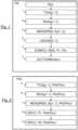
- the PR detection methodis described according to a non-limiting embodiment illustrated in the figure 1 .
- the primary antenna A1emits a plurality of signals Sg1
- the secondary antenna A2emits a plurality of signals Sg1.
- the following stepsare carried out by one or the other of the two primary antennas A1 or secondary A2, or by one or the other of the primary treatment units U1 or secondary U2.
- the non-limiting embodiment described in the figure 1further comprises a non-limiting step of smoothing said plurality of RSSI power measurements for each communication channel C.
- step 1) illustrated TX(Sg1, C)one of the two primary antennas A1 or secondary A2 cyclically emits a plurality of signals Sg1 on a plurality of communication channels C.
- a communication channel Cwill also be called channel C.
- the BLE communication protocolallows bidirectional exchange of data at very short distances and uses radio waves on a frequency band of 2.4 GHz.
- This BLE communication protocolis taken as a non-limiting example in the remainder of the description.
- the transmission of the plurality of signals Sg1is carried out on three channels named C37, C38, C39. These channels are also called broadcast channels under the BLE communications protocol.
- the primary antenna A1 or secondary antenna A2 which transmitsis in an ADV broadcast mode called in English “Advertising”.
- Channel C37uses the frequency 2402MHz, channel C38 the frequency 2426 MHz and channel C39 the frequency 2480 MHz.
- the plurality of transmitted signals Sg1is transmitted every 100ms (milliseconds) on one of the three channels C37, C38 and C39, for example channel C37 and this for a few hundred milliseconds (700ms in an example non-limiting) to a few seconds (between 2 and 5 seconds in a non-limiting example). Then a channel change takes place. The plurality of transmitted signals Sg1 is transmitted every 100 milliseconds on the next channel, C38 for example, for a few hundred milliseconds to a few seconds. Finally, a change of channel is carried out again. The plurality of transmitted signals Sg1 is transmitted every 100 milliseconds on the next channel, C39 for example, for a few hundred milliseconds to a few seconds.
- a step 2) illustrated RX(Sg1', C)the other of the two primary antennas A1 or secondary A2 cyclically receives said plurality of transmitted signals Sg1.
- the received signals corresponding to the transmitted signals Sg1are referenced Sg1' in the figures.
- the identifier Id comprising said antenna secondary A2is arranged at a sufficiently close distance from the first antenna A1, for example below a distance of between 30 and 50 meters.
- the other of the two primary antennas A1 or secondary A2is configured to receive said plurality of signals transmitted Sg1 on three communication channels C37, C38 and C39.
- one of the two secondary processing units U2 or primary U1carries out for each communication channel C a plurality of RSSI power measurements of said plurality of received signals Sg1 ' corresponding to said plurality of transmitted signals Sg1.
- the processing unit which will carry out the RSSI power measurementsis that corresponding to the antenna which receives the plurality of transmitted signals Sg1.
- the primary antenna A1receives the plurality of transmitted signals Sg1, it is the primary processing unit U1 which performs this step, otherwise if it is the secondary antenna A2 which receives the plurality of transmitted signals Sg1, it is the secondary processing unit U2 which carries out this step.
- an RSSI power measurementis also called an RSSI measurement (“Received Signal Strength Indicator”).
- multi-path phenomenondue to the reflection phenomenon, otherwise called multi-path phenomenon (called “multipath” in English) which generates parasitic signals due to reflections of the signal emitted on the metal parts (bodywork, steering wheel, gear lever, floor etc.) of the motor vehicle V, the RSSI power measurement of the received signal Sg1' is interfered with.
- multipathmulti-path phenomenon
- the real curve Cn'is superimposed on the theoretical curve Cn.
- the distance d1is equal to 40cm. In a non-limiting example, the distance d2 is equal to 70cm.
- said plurality of transmitted signals Sg1is transmitted on three communication channels C37, C38 and C39.
- FIG. 6aillustrates an RSSI measurement report of a plurality of signals received Sg1' by the other of the two primary antennas A1 or secondary A2 on the three channels C37, C38 and C39, for two distances d1, d2 between said identifier Id and said primary antenna A1 of said motor vehicle V.
- the distance d1is a distance where the identifier ID is located inside the motor vehicle V
- the distance d2is a distance where the identifier ID is located outside the motor vehicle V.
- the measurementis cyclical on the three channels C37, C38 and C39.
- One of the two secondary processing units U2 or primary U1carries out several RSSI measurements of several received signals Sg1' without changing channels for a time T (corresponding to the duration of the levels on the figure 6a ).
- the time Tis between one and four seconds. In a non-limiting alternative embodiment, the time T is equal to four seconds.
- the other of the two secondary processing units U2 or primary U1will thus distinguish the RSSI measurements on the channels C37, C38, and C39 and carry out processing with the different RSSI measurements, for each channels C37, C38, and C39 so as to be able to precisely detect whether the identifier Id is inside or outside the motor vehicle V.
- the other of the two secondary processing units U2 or primary U1will thus manage the different channels C37, C38, and C39 separately.
- one of the two secondary processing units U2 or primary U1smooths said plurality of RSSI power measurements for each communication channel C.
- the smoothingis carried out by means of a table of size N which produces a sliding average over N samples.
- Nthe oldest value in the table is deleted and the new one is integrated to recalculate the new (sliding) average.
- the valueshave a Gaussian distribution. Thanks to smoothing, we remove divergent RSSI measurements, namely those which go outside the Gaussian. This eliminates the measurement peaks which come from the multi-path phenomenon.
- N10 for the case of transmission every 100ms. We thus obtain a table renewed every one second.
- the rectanglesrepresent the variations of RSSI measurements on the three channels C37, C38 and C39 when the identifier Id is at position #1 and #2 as seen previously.
- the differentiation zones Zare different from one channel C to another.
- said combination Cb of said plurality of RSSI power measurementsis calculated as a function of an average AVG of said RSSI power measurements.
- FIG. 7schematically illustrates all the RSSI measurements of the plurality of signals Sg1' received by the other of the two primary antennas A1 or secondary A2 on a single channel C.
- the set of RSSI measurementsforms a Gaussian G as illustrated in the Figure 7 .
- the combination Cbis the sliding average AVG of said plurality of RSSI power measurements of said plurality of received signals Sg1'.
- said primary threshold power P1is different from one communication channel C to another
- said secondary threshold power P2is different from one communication channel C to another. Note that this corresponds to a majority of Id identifiers such as mobile phones (around 90% of mobile phones). This makes it possible to take into account the RSSI measurement differences between the different C channels.
- channel C37includes an associated primary threshold power P1 37 different from those P1 38 and P1 39 of channels C38 and C39.
- itincludes an associated secondary threshold power P2 37 different from those P2 38 and P2 39 of channels C38 and C39.
- channel C38includes primary threshold powers P1 38 and secondary P2 38 different respectively from the primary threshold powers P1 39 and secondary P2 39 of channel C39.
- the detection method PRalso works even if said primary threshold power P1 is the same from one communication channel C to another, and said secondary threshold power P2 is the same from one communication channel C to 'other. Note that this corresponds to a minority of Id identifiers such as mobile phones (around 10% of mobile phones).
- the activation of a Dem start functionis allowed or prohibited to start the motor vehicle V.
- the second antennas A2 of the identifiers Idin particular when these are mobile telephones, have variable performances depending on the different types of mobile telephones used (namely when they are manufactured by different manufacturers) but also to the interior even from the same range of phones manufactured by the same manufacturer.
- different performanceswe mean that for the same signal Sg1 transmitted by the first antenna A1 (of the same power therefore), the different second antennas A2 will not receive the same signal power, or for the same signal Sg1 transmitted by different second antennas antennas A2 (of the same power therefore), the first antenna A1 will not receive the same signal power.
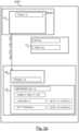
- the PR detection methodfurther comprises a Ph0 calibration phase illustrated on the figure 1 and in detail on the figure 2 .
- the identifier Idis adapted to be positioned at a reference position Por.
- said identifier Idis arranged at a reference position Por in the passenger compartment H of said motor vehicle V as illustrated in the Figure 9 .
- the reference position Porincludes for example a receptacle Re adapted to receive the identifier Id.
- the primary antenna A1is arranged at a predefined distance d3 from the reference position Por of the motor vehicle V.
- the primary antenna A1is arranged at the reference position Por, namely the predefined distance d3 is substantially equal to zero.
- the predefined distance d3is equal to ten centimeters.
- RSSI measurementsare thus reference RSSI measurements determined when the identifier Id is in the reference position Por.
- said secondary threshold power P2is equal to the standard deviation ⁇ multiplied by one multiplicative factor F ⁇ of the average value AVG of said plurality of RSSI power measurements of said plurality of received signals Sg1' during said calibration phase Ph0.
- the multiplicative factor F ⁇makes it possible to cover almost all RSSI measurements.
- the multiplicative factor F ⁇is equal to 2 or 3. This makes it possible to cover more than 95% of the RSSI measurements.
- said primary threshold power P1is equal to the secondary threshold power P2 plus a hysteresis threshold Hy.
- the hysteresis threshold Hymakes it possible to avoid decision instabilities on the identifier Id, namely whether it is inside or outside the motor vehicle V.
- the hysteresis threshold Hyis the same for all channels C37, C38 and C39. In a non-limiting example, it is equal to 3 dB.
- condition a)must is checked on at least one channel C37, C38, C39.
- condition a)is verified but not for the other two channels, then the identifier Id is considered to be inside IN. It is the same if for two channels condition a) is verified, but not for the third.
- condition b)must be verified on at least one channel C37, C38, C39 .
- condition b)is verified but not for the other two channels, then the identifier Id is considered to be outside EX. It is the same if for two channels condition b) is verified, but not for the third.
- FIG. 9illustrates a starting bubble Bu delimited by the secondary power P2.
- the hatched area delimited by the hysteresis Hyis an area in which there is neither authorization nor prohibition of starting. If the identifier Id was considered to be inside the motor vehicle V, then it remains so when it is in the hatched area. If the identifier Id was considered to be outside the motor vehicle V, then it remains so when it is in the hatched area.
- a computer associated with the start buttonwill send to one or the other of the two primary antennas A1 or secondary A2 a command to emit a plurality of signals Sg1.
- the identifier Idis further configured to display on a screen a message (of the “Pop-Up” window type in a non-limiting example) inviting the user of said identifier Id to position it at the reference position Por and to trigger the calibration (by pressing an “Ok” button in a non-limiting example).
- one of the identifier Id or motor vehicle Vis configured to calibrate the other of the identifier Id or motor vehicle V on request, even after the first use of the identifier Id.
- the identifier Idmay include a menu making it possible to launch the calibration function associated with starting the motor vehicle V or vice versa.
- a computer associated with the start buttonwill send to one of the two primary antennas A1 and secondary A2 a command to emit a plurality of signals Sg1, and a message can invite the user of said identifier Id to position said identifier Id at the reference position Por.
- the PR detection methodis implemented by a DISP detection device of an identifier Id inside or outside a motor vehicle V.
- the primary antenna A1is part of a radio frequency module MOD1, otherwise called an RF module. It is the same for the secondary antenna A2 whose RF module is referenced MOD2.
- the different elements of the DISP detection deviceare described in detail below according to a first non-limiting embodiment illustrated in the figure 3a , and according to a second non-limiting embodiment illustrated in the figure 3b .
- said secondary processing unit U2is further configured to carry out the calibration phase Ph0 described previously with the definition of said primary threshold power P1 and said secondary threshold power P2 (functions illustrated on the figure 3a DEF(C, P1, Ph0(Por)) and DEF(C, P2, Ph0(Por))). Note that the functions carried out during the Ph0 calibration phase have not all been illustrated on the figures 3a And 3b .
- the functions performed by the primary antenna A1 in the first non-limiting embodimentare performed by the secondary antenna A2, and vice versa, and the functions carried out by the primary processing unit U1 are carried out by the secondary processing unit U2 and vice and versa.
- the hysteresis threshold Hyis different for each of the channels C37, C38 and C39.
Landscapes
- Engineering & Computer Science (AREA)
- Physics & Mathematics (AREA)
- General Physics & Mathematics (AREA)
- Radar, Positioning & Navigation (AREA)
- Remote Sensing (AREA)
- Computer Networks & Wireless Communication (AREA)
- Signal Processing (AREA)
- Electromagnetism (AREA)
- Toxicology (AREA)
- Health & Medical Sciences (AREA)
- Mechanical Engineering (AREA)
- Lock And Its Accessories (AREA)
- Mobile Radio Communication Systems (AREA)
- Arrangements For Transmission Of Measured Signals (AREA)
Description
Translated fromFrenchLa présente invention concerne un procédé de détection d'un identifiant à l'intérieur ou à l'extérieur d'un véhicule automobile.The present invention relates to a method for detecting an identifier inside or outside a motor vehicle.
La présente invention concerne également un dispositif de détection d'un identifiant à l'intérieur ou à l'extérieur d'un véhicule automobile associé. Elle trouve une application particulière mais non limitative dans le domaine des véhicules automobiles.The present invention also relates to a device for detecting an identifier inside or outside an associated motor vehicle. It finds a particular but non-limiting application in the field of motor vehicles.
Dans le domaine des véhicules automobiles, il existe des procédés de détection d'un identifiant à l'intérieur ou à l'extérieur d'un véhicule automobile, connus de l'homme du métier, qui permettent de déterminer si l'identifiant est à l'intérieur du véhicule automobile et dans l'affirmative d'activer une fonction tel que le démarrage du véhicule automobile. On s'assure ainsi que personne ne pourra démarrer le véhicule automobile alors que l'utilisateur du véhicule et son identifiant se trouve à l'extérieur dudit véhicule. Pour réaliser cette fonction, le véhicule automobile comporte une antenne primaire qui émet une pluralité de signaux sur une pluralité de canaux de communication et l'identifiant comporte une antenne secondaire qui reçoit ladite pluralité de signaux sur ladite pluralité de canaux de communication. Les signaux sont des signaux Bluetooth Low Energy™ qui permettent de déterminer si l'identifiant se situe bien dans l'habitacle du véhicule automobile, ce grâce à des mesures de puissance des signaux reçus.In the field of motor vehicles, there are methods for detecting an identifier inside or outside a motor vehicle, known to those skilled in the art, which make it possible to determine whether the identifier is inside the motor vehicle and if so, activate a function such as starting the motor vehicle. This ensures that no one will be able to start the motor vehicle while the user of the vehicle and his identifier is outside said vehicle. To achieve this function, the motor vehicle comprises a primary antenna which transmits a plurality of signals over a plurality of communication channels and the identifier comprises a secondary antenna which receives said plurality of signals over said plurality of communication channels. The signals are Bluetooth Low Energy™ signals which make it possible to determine whether the identifier is indeed located in the passenger compartment of the motor vehicle, thanks to power measurements of the signals received.
Les documents
Un inconvénient de cet état de la technique est qu'il existe de fortes dispersions de mesures de puissance des signaux reçus en fonction du canal de communication. Aussi, si l'identifiant se trouve à deux distances différentes dans le véhicule automobile, une mesure de puissance des signaux reçus à une première distance sur un premier canal peut être confondue avec une mesure de puissance des signaux reçus à une deuxième distance sur un deuxième canal différent du premier canal. Par conséquent, on n'est plus en mesure de déterminer où se trouve précisément l'identifiant et de déterminer s'il est à l'intérieur ou à l'extérieur du véhicule automobile.A disadvantage of this state of the art is that there are large dispersions of power measurements of the signals received as a function of the communication channel. Also, if the identifier is located at two different distances in the motor vehicle, a power measurement of the signals received at a first distance on a first channel can be confused with a power measurement of the signals received at a second distance on a second channel different from the first channel. Consequently, we are no longer able to determine precisely where the identifier is located and to determine whether it is inside or outside the motor vehicle.
Dans ce contexte, la présente invention vise à résoudre l'inconvénient précédemment mentionné.In this context, the present invention aims to resolve the previously mentioned drawback.
A cette fin l'invention propose un procédé de détection d'un identifiant à l'intérieur ou à l'extérieur d'un véhicule automobile, selon la revendication indépendante 1.To this end, the invention proposes a method for detecting an identifier inside or outside a motor vehicle, according to
Selon des modes de réalisation non limitatifs, le procédé de détection peut comporter en outre une ou plusieurs caractéristiques supplémentaires parmi les suivantes.According to non-limiting embodiments, the detection method may also include one or more additional characteristics among the following.
Selon un mode de réalisation non limitatif, ladite combinaison de ladite pluralité de mesures de puissance est calculée en fonction d'une moyenne desdites mesures de puissance.According to a non-limiting embodiment, said combination of said plurality of power measurements is calculated based on an average of said power measurements.
Selon un mode de réalisation non limitatif, ledit procédé de détection comprend en outre le lissage de ladite pluralité de mesures de puissance pour chaque canal de communication.According to a non-limiting embodiment, said detection method further comprises smoothing said plurality of power measurements for each communication channel.
Selon un mode de réalisation non limitatif, ledit procédé de détection comprend en outre une phase de calibrage comprenant :
- la définition pour chaque canal de communication de ladite puissance seuil primaire lorsque ledit identifiant est disposé à une position de référence dans l'habitacle dudit véhicule automobile ;
- la définition pour chaque canal de communication de ladite puissance seuil secondaire lorsque ledit identifiant est disposé à une position de référence dans l'habitacle dudit véhicule automobile.
- the definition for each communication channel of said primary threshold power when said identifier is placed at a reference position in the passenger compartment of said motor vehicle;
- the definition for each communication channel of said secondary threshold power when said identifier is placed at a reference position in the passenger compartment of said motor vehicle.
Selon un mode de réalisation non limitatif, ladite puissance seuil secondaire est égale à l'écart-type multiplié par un facteur multiplicatif de la valeur moyenne d'une pluralité de mesures de puissances d'une pluralité de signaux reçus lors d'une phase de calibrage.According to a non-limiting embodiment, said secondary threshold power is equal to the standard deviation multiplied by a multiplicative factor of the average value of a plurality of power measurements of a plurality of signals received during a phase of calibration.
Selon un mode de réalisation non limitatif, lequel ladite puissance seuil primaire est égale à la puissance seuil secondaire plus un seuil d'hystérésis.According to a non-limiting embodiment, which said primary threshold power is equal to the secondary threshold power plus a hysteresis threshold.
Selon un mode de réalisation non limitatif, ledit identifiant communique avec ledit véhicule automobile selon tout protocole de communication en bande de fréquence industrielle scientifique et médicale.According to a non-limiting embodiment, said identifier communicates with said motor vehicle according to any scientific and medical industrial frequency band communication protocol.
Selon un mode de réalisation non limitatif, l'identifiant est un téléphone mobile.According to a non-limiting embodiment, the identifier is a mobile telephone.
Selon un mode de réalisation non limitatif, lequel ledit procédé de détection comprend en outre :
- l'autorisation du démarrage dudit véhicule automobile si pour au moins un canal de communication la combinaison de mesures de puissance est supérieure ou égale à ladite puissance seuil secondaire ;
- l'interdiction du démarrage dudit véhicule automobile si pour au moins un canal de communication la combinaison de mesures de puissance est inférieure ou égale à ladite puissance seuil primaire.
- authorizing the starting of said motor vehicle if for at least one communication channel the combination of power measurements is greater than or equal to said secondary threshold power;
- prohibiting the starting of said motor vehicle if for at least one communication channel the combination of power measurements is less than or equal to said primary threshold power.
Il est également proposé un dispositif de détection d'un identifiant à l'intérieur ou à l'extérieur d'un véhicule automobile, selon la revendication indépendante 10.There is also proposed a device for detecting an identifier inside or outside a motor vehicle, according to
Selon des modes de réalisation non limitatifs, le dispositif de détection peut comporter en outre une ou plusieurs caractéristiques supplémentaires parmi les suivantes.According to non-limiting embodiments, the detection device may also include one or more additional characteristics among the following.
Selon un mode de réalisation non limitatif, l'une des deux unités de traitement secondaire ou primaire est en outre configurée pour lisser ladite pluralité de mesures de puissance pour chaque canal de communication.According to a non-limiting embodiment, one of the two secondary or primary processing units is further configured to smooth said plurality of power measurements for each communication channel.
Selon un mode de réalisation non limitatif, l'une des deux unités de traitement secondaire ou primaire est en outre configurée pour, lors de ladite phase de calibrage :
- définir pour chaque canal de communication ladite puissance seuil primaire lorsque ledit identifiant est disposé à une position de référence dans l'habitacle dudit véhicule automobile ;
- définir pour chaque canal de communication ladite puissance seuil secondaire lorsque ledit identifiant est disposé à une position de référence dans l'habitacle dudit véhicule automobile.
- define said primary threshold power for each communication channel when said identifier is placed at a reference position in the passenger compartment of said motor vehicle;
- define said secondary threshold power for each communication channel when said identifier is placed at a reference position in the passenger compartment of said motor vehicle.
Selon un mode de réalisation non limitatif, l'une des deux unités de traitement secondaire ou primaire est en outre configurée pour :
- autoriser le démarrage dudit véhicule automobile si pour au moins un canal de communication la combinaison de mesures de puissance est supérieure ou égale à ladite puissance seuil secondaire ;
- interdire le démarrage dudit véhicule automobile si pour au moins un canal de communication la combinaison de mesure de puissance est inférieure ou égale à ladite puissance seuil primaire.
- authorize the starting of said motor vehicle if for at least one communication channel the combination of power measurements is greater than or equal to said secondary threshold power;
- prohibit the starting of said motor vehicle if for at least one communication channel the power measurement combination is less than or equal to said primary threshold power.
L'invention et ses différentes applications seront mieux comprises à la lecture de la description qui suit et à l'examen des figures qui l'accompagnent.
- la
figure 1 représente un organigramme d'un procédé de détection d'un identifiant à l'intérieur ou à l'extérieur d'un véhicule automobile, selon un mode de réalisation non limitatif de l'invention ; - la
figure 2 illustre un organigramme d'un calibrage d'un canal de communication entre une antenne secondaire de l'identifiant et une antenne primaire du véhicule automobile, ledit calibrage étant effectué par le procédé de détection de lafigure 1 , selon un mode de réalisation non limitatif ; - la
figure 3a représente un schéma d'un dispositif de détection d'un identifiant à l'intérieur ou à l'extérieur d'un véhicule automobile permettant de mettre en oeuvre ledit procédé de détection de lafigure 1 , selon un premier mode de réalisation non limitatif ; - la
figure 3b représente un schéma d'un dispositif de détection d'un identifiant à l'intérieur ou à l'extérieur d'un véhicule automobile permettant de mettre en oeuvre ledit procédé de détection de lafigure 1 , selon un deuxième mode de réalisation non limitatif ; - la
figure 4 représente un véhicule automobile comprenant une antenne primaire et une unité de traitement primaire, et un identifiant comprenant une antenne secondaire et une unité de traitement secondaire, lesdites antennes primaire et secondaire et lesdites unités de traitement primaire et secondaire faisant partie du dispositif de détection desfigures 3a et3b , selon un mode de réalisation non limitatif ; - la
figure 5a représente une courbe théorique de distribution de mesures de puissance d'un signal reçu applicable à l'un ou l'autre des identifiant ou véhicule automobile desfigures 3a et3b , selon un mode de réalisation non limitatif ; - la
figure 5b représente une courbe réelle correspondant à la courbe théorique de lafigure 5a en superposition sur ladite courbe théorique, selon un mode de réalisation non limitatif ; - la
figure 6a représente des mesures de puissance d'une pluralité de signaux reçus sur trois canaux de communication par l'un ou l'autre des identifiant ou véhicule automobile desfigures 3a et3b , selon un mode de réalisation non limitatif ; - la
figure 6b représente lafigure 6a avec des variations de mesures lorsque l'identifiant desfigures 3a et3b se trouve à l'intérieur ou à l'extérieur du véhicule automobile, selon un mode de réalisation non limitatif ; - la
figure 7 représente une gaussienne de mesures de puissance d'une pluralité de signaux reçus cycliquement sur un seul canal de communication par l'un ou l'autre des identifiant ou véhicule automobile desfigures 3a et3b , selon un mode de réalisation non limitatif ; - la
figure 8a illustre un schéma d'un passage de l'identifiant desfigures 3a et3b , de l'intérieur vers l'extérieur du véhicule automobile en fonction d'une courbe de calibration ; - la
figure 8b illustre un schéma d'un passage de l'identifiant desfigures 3a et3b , de l'extérieur vers l'intérieur du véhicule automobile en fonction d'une courbe de calibration ; - la
figure 9 illustre un schéma d'un passage de l'identifiant desfigures 3a et3b de l'intérieur vers l'extérieur du véhicule automobile et de l'extérieur vers l'intérieur du véhicule automobile, basé sur les schémas desfigures 8a et 8b appliqués à une bulle de démarrage.
- there
figure 1 represents a flowchart of a method for detecting an identifier inside or outside a motor vehicle, according to a non-limiting embodiment of the invention; - there
figure 2 illustrates a flowchart of a calibration of a communication channel between a secondary antenna of the identifier and a primary antenna of the motor vehicle, said calibration being carried out by the method of detecting thefigure 1 , according to a non-limiting embodiment; - there
figure 3a represents a diagram of a device for detecting an identifier inside or outside a motor vehicle making it possible to implement said method of detecting thefigure 1 , according to a first non-limiting embodiment; - there
figure 3b represents a diagram of a device for detecting an identifier inside or outside a motor vehicle making it possible to implement said method of detecting thefigure 1 , according to a second non-limiting embodiment; - there
figure 4 represents a motor vehicle comprising a primary antenna and a primary processing unit, and an identifier comprising a secondary antenna and a secondary processing unit, said primary and secondary antennas and said primary and secondary processing units forming part of the device for detectingfigures 3a And3b , according to a non-limiting embodiment; - there
figure 5a represents a theoretical distribution curve of power measurements of a received signal applicable to one or other of the identifiers or motor vehicles of thefigures 3a And3b , according to a mode of non-limiting realization; - there
figure 5b represents a real curve corresponding to the theoretical curve of thefigure 5a superimposed on said theoretical curve, according to a non-limiting embodiment; - there
figure 6a represents power measurements of a plurality of signals received on three communication channels by one or other of the identifiers or motor vehicles of thefigures 3a And3b , according to a non-limiting embodiment; - there
figure 6b represents thefigure 6a with variations in measurements when the identifier of thefigures 3a And3b is located inside or outside the motor vehicle, according to a non-limiting embodiment; - there
Figure 7 represents a Gaussian of power measurements of a plurality of signals received cyclically on a single communication channel by one or other of the identifiers or motor vehicles of thefigures 3a And3b , according to a non-limiting embodiment; - there
figure 8a illustrates a diagram of a passage of the identifier of thefigures 3a And3b , from the inside to the outside of the motor vehicle according to a calibration curve; - there
figure 8b illustrates a diagram of a passage of the identifier of thefigures 3a And3b , from the outside towards the inside of the motor vehicle according to a calibration curve; - there
Figure 9 illustrates a diagram of a passage of the identifier of thefigures 3a And3b from the inside to the outside of the motor vehicle and from the outside to the inside of the motor vehicle, based on the diagrams of thefigures 8a and 8b applied to a startup bubble.
Les éléments identiques, par structure ou par fonction, apparaissant sur différentes figures conservent, sauf précision contraire, les mêmes références.Elements that are identical, by structure or function, appearing in different figures retain, unless otherwise specified, the same references.
L'invention concerne un procédé de détection PR d'un identifiant Id à l'intérieur ou à l'extérieur d'un véhicule automobile V illustré sur les
Le véhicule automobile V et l'identifiant Id sont illustrés sur la
Le véhicule automobile V comprend un habitacle H.The motor vehicle V includes a passenger compartment H.
Le véhicule automobile comprend :
- une antenne primaire A1 intégrée dans l'habitacle H du véhicule automobile V ; et
- une unité de traitement primaire U1 ;
- a primary antenna A1 integrated into the passenger compartment H of the motor vehicle V; And
- a primary processing unit U1;
L'identifiant Id comprend :
- une antenne secondaire A2 ; et
- une unité de traitement secondaire U2.
- a secondary antenna A2; And
- a secondary processing unit U2.
On notera qu'une unité de traitement U1, U2 comprend un ou plusieurs processeurs.Note that a processing unit U1, U2 comprises one or more processors.
Dans des exemples non limitatifs, l'identifiant Id est une clef électronique, un badge, un téléphone mobile tel qu'un téléphone intelligent appelé « smartphone ».In non-limiting examples, the identifier Id is an electronic key, a badge, a mobile telephone such as a smartphone called a “smartphone”.
Dans un mode de réalisation non limitatif, l'identifiant Id du véhicule automobile permet d'accéder au véhicule automobile et également de démarrer le véhicule automobile V. Les procédures d'accès à un véhicule automobile et de démarrage d'un véhicule automobile via un identifiant Id étant bien connue de l'homme du métier, elles ne sont pas décrites ici.In a non-limiting embodiment, the identifier Id of the motor vehicle allows access to the motor vehicle and also to start the motor vehicle V. The procedures for accessing a motor vehicle and starting a motor vehicle via a identifier Id being well known to those skilled in the art, they are not described here.
Dans un mode de réalisation non limitatif, l'identifiant Id est configuré pour communiquer avec ledit véhicule automobile V selon un protocole de communication en bande de fréquence industrielle scientifique et médicale ISM. Dans des variantes de réalisation non limitatives, l'identifiant Id communique avec le véhicule automobile V selon le protocole de communication Bluetooth™, Bluetooth Low Energy™ référencé BLE, WIFI, etc. que ce soit pour l'accès au véhicule, c'est-à-dire pour ouvrir un ouvrant du véhicule automobile V (portière ou coffre), ou pour le démarrage du véhicule automobile V. Ainsi, dans des variantes de réalisation non limitatives, les deux antennes primaire et secondaire A1, A2 sont adaptées pour communiquer selon le protocole de communication Bluetooth™, Bluetooth Low Energy™ référencé BLE, WIFI, etc.In a non-limiting embodiment, the identifier Id is configured to communicate with said motor vehicle V according to a scientific and medical industrial frequency band ISM communication protocol. In non-limiting alternative embodiments, the identifier Id communicates with the motor vehicle V according to the Bluetooth™ communication protocol, Bluetooth Low Energy™ referenced BLE, WIFI, etc. whether for access to the vehicle, that is to say to open an opening of the motor vehicle V (door or trunk), or for starting the motor vehicle V. Thus, in non-limiting alternative embodiments, the two primary and secondary antennas A1, A2 are adapted to communicate according to the Bluetooth™ communication protocol, Bluetooth Low Energy™ referenced BLE, WIFI, etc.
Le procédé de détection PR permet de déterminer si l'identifiant Id est à l'intérieur ou à l'extérieur du véhicule automobile V, à savoir à l'intérieur ou à l'extérieur de l'habitacle H du véhicule automobile V, tel qu'illustré sur la
Le procédé de détection PR est décrit selon un mode de réalisation non limitatif illustré sur la
Selon deux modes de réalisation non limitatifs du procédé de détection PR, soit l'antenne primaire A1 émet une pluralité de signaux Sg1, soit l'antenne secondaire A2 émet une pluralité de signaux Sg1. En fonction de l'émission par l'une ou l'autre des deux antennes primaire A1 ou secondaire A2, les étapes suivantes sont effectuées par l'une ou l'autre des deux antennes primaire A1 ou secondaire A2, ou par l'une ou l'autre des unités de traitement primaire U1 ou secondaire U2.According to two non-limiting embodiments of the detection method PR, either the primary antenna A1 emits a plurality of signals Sg1, or the secondary antenna A2 emits a plurality of signals Sg1. Depending on the emission by one or the other of the two primary antennas A1 or secondary A2, the following steps are carried out by one or the other of the two primary antennas A1 or secondary A2, or by one or the other of the primary treatment units U1 or secondary U2.
Le mode de réalisation non limitatif décrit sur la
Le mode de réalisation non limitatif décrit sur la
- d'autorisation du démarrage dudit véhicule automobile V si pour chaque canal de communication C la combinaison Cb de mesures de puissance RSSI est supérieure ou égale à ladite puissance seuil secondaire P2 ; et
- d'interdiction du démarrage dudit véhicule automobile V si pour chaque canal de communication C la combinaison Cb de mesures de puissance RSSI est inférieure ou égale à ladite puissance seuil primaire P1.
- authorizing the starting of said motor vehicle V if for each communication channel C the combination Cb of RSSI power measurements is greater than or equal to said secondary threshold power P2; And
- prohibiting the starting of said motor vehicle V if for each communication channel C the combination Cb of RSSI power measurements is less than or equal to said primary threshold power P1.
Les étapes du procédé de détection PR sont décrites ci-après.The steps of the PR detection method are described below.
Dans une étape 1) illustrée TX(Sg1, C), l'une des deux antennes primaire A1 ou secondaire A2 émet cycliquement une pluralité de signaux Sg1 sur une pluralité de canaux de communication C.In a step 1) illustrated TX(Sg1, C), one of the two primary antennas A1 or secondary A2 cyclically emits a plurality of signals Sg1 on a plurality of communication channels C.
Dans la suite de la description, un canal de communication C sera également appelé canal C.In the remainder of the description, a communication channel C will also be called channel C.
On notera que le protocole de communication BLE permet l'échange bidirectionnel de données à très courte distance et utilise des ondes radio sur une bande de fréquence de 2,4 GHz. Ce protocole de communication BLE est pris comme exemple non limitatif dans la suite de la description. Dans un mode de réalisation non limitatif, l'émission de la pluralité de signaux Sg1 s'effectue sur trois canaux nommés C37, C38, C39. Ces canaux sont également appelés canaux de diffusion dans le cadre du protocole de communication BLE. On dit dans ce cas que l'antenne primaire A1 ou secondaire A2 qui émet est dans un mode de diffusion ADV appelé en anglais « Advertising ».Note that the BLE communication protocol allows bidirectional exchange of data at very short distances and uses radio waves on a frequency band of 2.4 GHz. This BLE communication protocol is taken as a non-limiting example in the remainder of the description. In a non-limiting embodiment, the transmission of the plurality of signals Sg1 is carried out on three channels named C37, C38, C39. These channels are also called broadcast channels under the BLE communications protocol. In this case we say that the primary antenna A1 or secondary antenna A2 which transmits is in an ADV broadcast mode called in English “Advertising”.
Le canal C37 utilise la fréquence 2402MHz, le canal C38 la fréquence 2426 MHz et le canal C39 la fréquence 2480 MHz.Channel C37 uses the frequency 2402MHz, channel C38 the frequency 2426 MHz and channel C39 the frequency 2480 MHz.
Dans un mode de réalisation non limitatif, la pluralité de signaux émis Sg1 est émise toutes les 100ms (millisecondes) sur un des trois canaux C37, C38 et C39, par exemple le canal C37 et ce durant quelques centaines de millisecondes (700ms dans un exemple non limitatif) à quelques secondes (entre 2 et 5 secondes dans un exemple non limitatif). Puis un changement de canal s'effectue. La pluralité de signaux émis Sg1 est émise toutes les 100 millisecondes sur le canal suivant, C38 par exemple, durant quelques centaines de millisecondes à quelques secondes. Enfin, un changement de canal s'effectue de nouveau, La pluralité de signaux émis Sg1 est émise toutes les 100 millisecondes sur le canal suivant, C39 par exemple, durant quelques centaines de millisecondes à quelques secondes.In a non-limiting embodiment, the plurality of transmitted signals Sg1 is transmitted every 100ms (milliseconds) on one of the three channels C37, C38 and C39, for example channel C37 and this for a few hundred milliseconds (700ms in an example non-limiting) to a few seconds (between 2 and 5 seconds in a non-limiting example). Then a channel change takes place. The plurality of transmitted signals Sg1 is transmitted every 100 milliseconds on the next channel, C38 for example, for a few hundred milliseconds to a few seconds. Finally, a change of channel is carried out again. The plurality of transmitted signals Sg1 is transmitted every 100 milliseconds on the next channel, C39 for example, for a few hundred milliseconds to a few seconds.
Dans une étape 2) illustrée RX(Sg1', C), l'autre des deux antennes primaire A1 ou secondaire A2 reçoit cycliquement ladite pluralité de signaux émis Sg1. Les signaux reçus correspondants aux signaux émis Sg1 sont référencés Sg1' dans les figures.In a step 2) illustrated RX(Sg1', C), the other of the two primary antennas A1 or secondary A2 cyclically receives said plurality of transmitted signals Sg1. The received signals corresponding to the transmitted signals Sg1 are referenced Sg1' in the figures.
Ceci est possible lorsque l'identifiant Id comprenant ladite antenne secondaire A2 est disposé à une distance de la première antenne A1 suffisamment proche, par exemple en deçà d'une distance comprise entre 30 et 50 mètres.This is possible when the identifier Id comprising said antenna secondary A2 is arranged at a sufficiently close distance from the first antenna A1, for example below a distance of between 30 and 50 meters.
Dans un mode de réalisation non limitatif, l'autre des deux antennes primaire A1 ou secondaire A2 est configurée pour recevoir ladite pluralité de signaux émis Sg1 sur trois canaux de communication C37, C38 et C39.In a non-limiting embodiment, the other of the two primary antennas A1 or secondary A2 is configured to receive said plurality of signals transmitted Sg1 on three communication channels C37, C38 and C39.
Ainsi si c'est l'antenne primaire A1 qui est configurée pour émettre, ce sera l'antenne secondaire A2 qui sera configurée pour recevoir, et vice et versa.So if it is the primary antenna A1 which is configured to transmit, it will be the secondary antenna A2 which will be configured to receive, and vice versa.
Dans une étape 3) illustrée MEAS(RSSI, Sg1', C), l'une des deux unités de traitement secondaire U2 ou primaire U1 réalise pour chaque canal de communication C une pluralité de mesures de puissance RSSI de ladite pluralité de signaux reçus Sg1' correspondant à ladite pluralité de signaux émis Sg1.In a step 3) illustrated MEAS (RSSI, Sg1', C), one of the two secondary processing units U2 or primary U1 carries out for each communication channel C a plurality of RSSI power measurements of said plurality of received signals Sg1 ' corresponding to said plurality of transmitted signals Sg1.
Ainsi, l'unité de traitement qui va réaliser les mesures de puissance RSSI est celle correspondante à l'antenne qui reçoit la pluralité de signaux émis Sg1.Thus, the processing unit which will carry out the RSSI power measurements is that corresponding to the antenna which receives the plurality of transmitted signals Sg1.
Ainsi, si l'antenne primaire A1 reçoit la pluralité de signaux émis Sg1, c'est l'unité de traitement primaire U1 qui effectue cette étape, sinon si c'est l'antenne secondaire A2 qui reçoit la pluralité de signaux émis Sg1, c'est l'unité de traitement secondaire U2 qui effectue cette étape.Thus, if the primary antenna A1 receives the plurality of transmitted signals Sg1, it is the primary processing unit U1 which performs this step, otherwise if it is the secondary antenna A2 which receives the plurality of transmitted signals Sg1, it is the secondary processing unit U2 which carries out this step.
Dans la suite de la description, une mesure de puissance RSSI est également appelée mesure RSSI (« Received Signal Strength Indicator » en anglais).In the remainder of the description, an RSSI power measurement is also called an RSSI measurement (“Received Signal Strength Indicator”).
Comme on peut le voir sur la
C'est une courbe logarithmique qui évolue selon la formule 20log(4πd/λ), avec d, la distance et λ une longueur d'onde. En abscisse, on trouve la distance (en mètres), en ordonnée, on trouve la mesure de la puissance RSSI (en décibels dB).It is a logarithmic curve which evolves according to the formula 20log(4πd/λ), with d, the distance and λ a wavelength. On the abscissa, we find the distance (in meters), on the ordinate, we find the RSSI power measurement (in decibels dB).
En raison du phénomène de réflexion, autrement appelé phénomène multi-trajets (appelé « multipath» en anglais) qui engendre des signaux parasites dus à des réflexions du signal émis sur les parties métalliques (carrosserie, volant, levier de vitesse, plancher etc.) du véhicule automobile V, la mesure de puissance RSSI du signal reçu Sg1' est parasité. On obtient ainsi une courbe réelle Cn' de distribution de mesures de puissance RSSI tel qu'illustré sur la
Tel qu'illustré sur la
- en deçà d'une certaine distance d1 correspondant à une puissance seuil secondaire P2, l'identifiant Id se trouve à l'intérieur IN du véhicule automobile V ;
- au delà d'une certaine distance d2 correspondant à une puissance seuil primaire P1, l'identifiant Id se trouve à l'extérieur EX du véhicule automobile V.
- below a certain distance d1 corresponding to a secondary threshold power P2, the identifier Id is located inside IN of the motor vehicle V;
- beyond a certain distance d2 corresponding to a primary threshold power P1, the identifier Id is located outside EX of the motor vehicle V.
Dans un exemple non limitatif, la distance d1 est égale à 40cm. Dans un exemple non limitatif, la distance d2 est égale à 70cm.In a non-limiting example, the distance d1 is equal to 40cm. In a non-limiting example, the distance d2 is equal to 70cm.
Comme décrit précédemment, ladite pluralité de signaux émis Sg1 est émise sur trois canaux de communication C37, C38 et C39.As described previously, said plurality of transmitted signals Sg1 is transmitted on three communication channels C37, C38 and C39.
La
La distance d1 est une distance où l'identifiant ID se trouve à l'intérieur du véhicule automobile V, et la distance d2 est une distance où l'identifiant ID se trouve à l'extérieur du véhicule automobile V.The distance d1 is a distance where the identifier ID is located inside the motor vehicle V, and the distance d2 is a distance where the identifier ID is located outside the motor vehicle V.
On obtient deux relevés de positions #1 et #2 illustrés sur la
Comme on peut le voir, la mesure est cyclique sur les trois canaux C37, C38 et C39.As we can see, the measurement is cyclical on the three channels C37, C38 and C39.
L'une des deux unités de traitement secondaire U2 ou primaire U1 réalise plusieurs mesures RSSI de plusieurs signaux reçus Sg1' sans changer de canal pendant un temps T (correspondant à la durée des paliers sur la
Sur la
- à chaque changement de canal, il y a un palier différent. Ces paliers sont des variations brusques de mesures de puissance RSSI ;
- à chaque retour sur un même canal (par exemple C37a puis C37b), on retrouve le même niveau de palier ;
- la
moyenne AV# 1 des mesures RSSI du canal C39a est du même ordre que la moyenneAV# 2 des mesures RSSI du canal C37b. Dans ce cas, on ne peut distinguer les deux distances d1 ou d2, sur par exemple deux fois T, à savoir environ de deux à huit secondes, si un déplacement très rapide de l'identifiant Id est effectué de #1vers # 2, à savoir de l'intérieur vers l'extérieur du véhicule automobile V. Il y a ainsi un problème de chevauchement entre des mesures RSSI de différents canaux ; - les mesures RSSI sur le canal C37b lorsque l'identifiant Id se trouve à l'extérieur du véhicule automobile V sont équivalentes à celles du canal C39a lorsque l'identifiant Id se trouve à l'intérieur du véhicule automobile V. Il n'est pas possible de savoir si l'identifiant Id se trouve à l'intérieur ou à l'extérieur du véhicule automobile V ;
- Les mesures RSSI sur le canal C38a lorsque l'identifiant Id se trouve à l'extérieur du véhicule automobile V sont plus grandes que celles du canal C39a lorsque l'identifiant Id se trouve à l'intérieur du véhicule automobile V. Il n'est pas possible de savoir si l'identifiant Id se trouve à l'intérieur ou à l'extérieur du véhicule automobile V ;
- Si on observe la différence entre les deux relevés #1
et # 2 à canal fixe, à savoir sur un canal C uniquement, la différence de mesures RSSI est proportionnelle à la différence de distance entre d1 et d2. Si les mesures RSSI sont comparées uniquement à iso canald'une position # 1 dudit identifiant Id à une autreposition # 2, on distingue alors nettement une valeur relative à la différence de distance d1, d2. Ainsi, on distingue nettement la mesure RSSI correspondant à la distance d1 de la mesure RSSI correspondant à la distance d2.
- with each channel change, there is a different level. These levels are sudden variations in RSSI power measurements;
- each time we return to the same channel (for example C37a then C37b), we find the same level;
- the
AV# 1 average of the RSSI measurements of channel C39a is of the same order as theAV# 2 average of the RSSI measurements of channel C37b. In this case, we cannot distinguish the two distances d1 or d2, for example twice T, namely approximately two to eight seconds, if a very rapid movement of the identifier Id is made from #1 to #2, namely from the inside to the outside of the motor vehicle V. There is thus a problem of overlap between RSSI measurements of different channels; - the RSSI measurements on channel C37b when the identifier Id is outside the motor vehicle V are equivalent to those of the channel C39a when the identifier Id is inside the motor vehicle V. It is not possible to know whether the identifier Id is inside or outside the motor vehicle V;
- The RSSI measurements on channel C38a when the identifier Id is outside the motor vehicle V are larger than those of the channel C39a when the identifier Id is inside the motor vehicle V. It is not not possible to know if the identifier Id is located inside or outside the motor vehicle V;
- If we observe the difference between the two fixed
channel readings # 1 and #2, namely on a C channel only, the difference in RSSI measurements is proportional to the difference in distance between d1 and d2. If the RSSI measurements are compared only to iso channel from aposition # 1 of said identifier Id to anotherposition # 2, we then clearly distinguish a value relating to the difference in distance d1, d2. Thus, we clearly distinguish the RSSI measurement corresponding to the distance d1 from the RSSI measurement corresponding to the distance d2.
Comme on va le voir ci-après l'autre des deux unités de traitement secondaire U2 ou primaire U1 va ainsi distinguer les mesures RSSI sur les canaux C37, C38, et C39 et effectuer un traitement avec les différentes mesures RSSI, et ce pour chacun des canaux C37, C38, et C39 de sorte à pouvoir détecter précisément si l'identifiant Id se trouve à l'intérieur ou à l'extérieur du véhicule automobile V. L'autre des deux unités de traitement secondaire U2 ou primaire U1 va ainsi gérer les différents canaux C37, C38, et C39 de manière distincte.As we will see below, the other of the two secondary processing units U2 or primary U1 will thus distinguish the RSSI measurements on the channels C37, C38, and C39 and carry out processing with the different RSSI measurements, for each channels C37, C38, and C39 so as to be able to precisely detect whether the identifier Id is inside or outside the motor vehicle V. The other of the two secondary processing units U2 or primary U1 will thus manage the different channels C37, C38, and C39 separately.
Dans une étape 3') illustrée LISS(RSSI, C), l'une des deux unités de traitement secondaire U2 ou primaire U1 lisse ladite pluralité de mesures de puissance RSSI pour chaque canal de communication C.In a step 3') illustrated LISS(RSSI, C), one of the two secondary processing units U2 or primary U1 smooths said plurality of RSSI power measurements for each communication channel C.
Cela permet d'éviter les variations rapides de mesure.This helps avoid rapid measurement variations.
On notera que c'est la même unité de traitement qui réalise les mesures RSSI à l'étape 3 qui effectue le lissage à l'étape 3'.Note that it is the same processing unit which carries out the RSSI measurements in
Dans un mode de réalisation non limitatif, le lissage est effectué au moyen d'une table de taille N qui réalise une moyenne glissante sur N échantillons. Ainsi pour chaque nouvelle mesure, la valeur la plus ancienne de la table est supprimée et la nouvelle est intégrée pour recalculer la nouvelle moyenne (glissante). Dans la table, les valeurs ont une distribution de type gaussien. Grâce au lissage, on supprime les mesures RSSI divergentes, à savoir celles qui sortent de la gaussienne. On supprime ainsi les pics de mesures qui proviennent du phénomène multi-trajets.In a non-limiting embodiment, the smoothing is carried out by means of a table of size N which produces a sliding average over N samples. Thus for each new measurement, the oldest value in the table is deleted and the new one is integrated to recalculate the new (sliding) average. In the table, the values have a Gaussian distribution. Thanks to smoothing, we remove divergent RSSI measurements, namely those which go outside the Gaussian. This eliminates the measurement peaks which come from the multi-path phenomenon.
Dans un exemple non limitatif, N=10 pour le cas d'émission toutes les 100ms. On obtient ainsi une table renouvelée toute les une seconde.In a non-limiting example, N=10 for the case of transmission every 100ms. We thus obtain a table renewed every one second.
Dans une étape 4) illustrée COMP(C, RSSI, P1, P2), pour chaque canal de communication C, l'une des deux unités de traitement secondaire U2 ou primaire U1 compare une combinaison Cb de ladite pluralité de mesures de puissance RSSI réalisées sur ledit canal de communication C :
- avec une puissance seuil primaire P1 de passage de l'intérieur vers l'extérieur du véhicule automobile V ; et
- avec une puissance seuil secondaire P2 de passage de l'extérieur vers l'intérieur dudit véhicule automobile V.
- with a primary threshold power P1 for passage from the inside to the outside of the motor vehicle V; And
- with a secondary threshold power P2 for passage from the outside to the inside of said motor vehicle V.
On notera que c'est la même unité de traitement qui a réalisé les étapes 3 et 3' qui effectue l'étape 4.Note that it is the same processing unit which carried out
Le fait de faire une comparaison d'une combinaison Cb de mesures RSSI canal C par canal C et non plus sur l'ensemble des canaux C permet de supprimer les problèmes de chevauchement de mesures RSSI entre canaux C vus précédemment sur la
Comme on peut le voir sur la
Ils représentent ainsi une zone de différentiation Z lorsque l'identifiant Id est à la position #1, à savoir à l'intérieur du véhicule automobile V et lorsque l'identifiant Id est à la position #2, à savoir à l'extérieur du véhicule automobile V. Les zones de différentiations Z sont différentes d'un canal C à l'autre. Ainsi, dans l'exemple non limitatif illustré, on a trois zones de différentiations Z37, Z38 et Z39 correspondant aux trois canaux C37, C38 et C39.They thus represent a zone of differentiation Z when the identifier Id is at
En faisant une comparaison différenciée pour chacun des trois canaux C37, C38, C39, on évite qu'une mesure RSSI sur un canal C à une position #1 ou à une position #2 ne chevauche une autre mesure RSSI sur un autre canal C, ce qui est le cas si on ne différencie pas la canal C37 du canal C39 comme vu précédemment.By making a differentiated comparison for each of the three channels C37, C38, C39, we prevent an RSSI measurement on a channel C at a
Cela permet ainsi de savoir si l'identifiant Id se trouve à l'intérieur ou à l'extérieur du véhicule automobile V contrairement à une solution où on effectue une comparaison avec une combinaison de mesures RSSI prises sur l'ensemble des trois canaux C37, C38, C39 sans différenciation des trois canaux C37, C38, C39.This thus makes it possible to know whether the identifier Id is inside or outside the motor vehicle V unlike a solution where a comparison is made with a combination of RSSI measurements taken on all three channels C37, C38, C39 without differentiation of the three channels C37, C38, C39.
Ainsi, en isolant les canaux C37, C38, C39 les uns des autres, on obtient de meilleures performances pour la détection de l'identifiant Id à l'intérieur ou à l'extérieur du véhicule automobile V.Thus, by isolating the channels C37, C38, C39 from each other, better performance is obtained for the detection of the identifier Id inside or outside the motor vehicle V.
Dans un mode de réalisation non limitatif, ladite combinaison Cb de ladite pluralité de mesures de puissance RSSI est calculée en fonction d'une moyenne AVG desdites mesures de puissance RSSI.In a non-limiting embodiment, said combination Cb of said plurality of RSSI power measurements is calculated as a function of an average AVG of said RSSI power measurements.
La
L'ensemble de mesures RSSI forme une gaussienne G tel qu'illustré sur la
Lorsqu'il y a un lissage, la combinaison Cb est la moyenne glissante AVG de ladite pluralité de mesures de puissances RSSI de ladite pluralité de signaux reçus Sg1'.When there is smoothing, the combination Cb is the sliding average AVG of said plurality of RSSI power measurements of said plurality of received signals Sg1'.
Dans un mode de réalisation non limitatif, ladite puissance seuil primaire P1 est différente d'un canal de communication C à l'autre, et ladite puissance seuil secondaire P2 est différente d'un canal de communication C à l'autre. On notera que cela correspond à une majorité des identifiants Id tels que des téléphones mobiles (environ 90% des téléphones mobiles). Cela permet de prendre en compte les écarts de mesure RSSI entre les différents canaux C. Ainsi, tel qu'illustré sur la
Et le canal C38 comprend des puissances seuils primaire P138 et secondaire P238 différentes respectivement des puissances seuils primaire P139 et secondaire P239 du canal C39.And channel C38 includes primary threshold powers P138 and secondary P238 different respectively from the primary threshold powers P139 and secondary P239 of channel C39.
On notera que le procédé de détection PR fonctionne également même si ladite puissance seuil primaire P1 est la même d'un canal de communication C à l'autre, et ladite puissance seuil secondaire P2 est la même d'un canal de communication C à l'autre. On notera que cela correspond à une minorité des identifiants Id tels que des téléphones mobiles (environ 10% des téléphones mobiles).It will be noted that the detection method PR also works even if said primary threshold power P1 is the same from one communication channel C to another, and said secondary threshold power P2 is the same from one communication channel C to 'other. Note that this corresponds to a minority of Id identifiers such as mobile phones (around 10% of mobile phones).
Dans une étape 5) illustrée AUT_FORB(Dem), l'une des deux unités de traitement secondaire U2 ou primaire U1 :
- autorise le démarrage dudit véhicule automobile V si pour chaque canal de communication C la combinaison Cb de mesures de puissance RSSI est supérieure ou égale à ladite puissance seuil secondaire P2 ;
- interdit le démarrage dudit véhicule automobile V si pour chaque canal de communication C la combinaison Cb de mesures de puissance RSSI est inférieure ou égale à ladite puissance seuil primaire P1.
- authorizes the starting of said motor vehicle V if for each communication channel C the combination Cb of RSSI power measurements is greater than or equal to said secondary threshold power P2;
- prohibits the starting of said motor vehicle V if for each communication channel C the combination Cb of RSSI power measurements is less than or equal to said primary threshold power P1.
Autrement dit, on permet ou on interdit l'activation d'une fonction de démarrage Dem pour démarrer le véhicule automobile V.In other words, the activation of a Dem start function is allowed or prohibited to start the motor vehicle V.
On notera que c'est la même unité de traitement qui a réalisé les étapes 3 à 4 qui effectue l'étape 5.Note that it is the same processing unit which carried out
On notera que l'autre des deux unités de traitement secondaire U2 ou primaire U1 est configurée pour :
- changer de canal C ;
- indiquer dans la pluralité de signaux Sg1 le numéro de canal pour permettre le tri entre les canaux.
- Phase de calibrage Ph0
- change channel C;
- indicate in the plurality of signals Sg1 the channel number to allow sorting between the channels.
- Ph0 calibration phase
On notera que les deuxièmes antennes A2 des identifiants Id, notamment lorsque ceux-ci sont des téléphones mobiles, comportent des performances variables selon les différents types de téléphones mobiles utilisés (à savoir lorsqu'ils sont fabriqués par différents fabricants) mais également à l'intérieur même d'une même gamme de téléphones fabriqués par un même fabricant. Par performances différentes, on entend que pour un même signal Sg1 émis par la première antenne A1 (de même puissance donc), les différentes deuxièmes antennes A2 ne vont pas recevoir la même puissance de signal, ou pour un même signal Sg1 émis par différentes deuxièmes antennes A2 (de même puissance donc), la première antenne A1 ne va pas recevoir la même puissance de signal. On aura ainsi une courbe réelle Cn' de distribution de mesures de puissance RSSI différente d'un identifiant Id à l'autre.It will be noted that the second antennas A2 of the identifiers Id, in particular when these are mobile telephones, have variable performances depending on the different types of mobile telephones used (namely when they are manufactured by different manufacturers) but also to the interior even from the same range of phones manufactured by the same manufacturer. By different performances, we mean that for the same signal Sg1 transmitted by the first antenna A1 (of the same power therefore), the different second antennas A2 will not receive the same signal power, or for the same signal Sg1 transmitted by different second antennas antennas A2 (of the same power therefore), the first antenna A1 will not receive the same signal power. We will thus have a real curve Cn' of distribution of RSSI power measurements different from one identifier Id to another.
Il faut donc calibrer la deuxième antenne A2 d'un identifiant Id avec la première antenne A1 ou vice et versa, en particulier lors de la première utilisation de l'identifiant Id avec ledit véhicule automobile V.It is therefore necessary to calibrate the second antenna A2 of an identifier Id with the first antenna A1 or vice versa, in particular during the first use of the identifier Id with said motor vehicle V.
Ainsi, dans un mode de réalisation non limitatif, le procédé de détection PR comprend en outre une phase de calibrage Ph0 illustrée sur la
Pour la phase de calibrage Ph0, l'identifiant Id est adapté pour être positionné à une position de référence Por. Ainsi, pour la phase de calibrage Ph0, ledit identifiant Id est disposé à une position de référence Por dans l'habitacle H dudit véhicule automobile V tel qu'illustré sur la
La position de référence Por comprend par exemple un réceptacle Re adapté pour recevoir l'identifiant Id.The reference position Por includes for example a receptacle Re adapted to receive the identifier Id.
On notera que l'antenne primaire A1 est disposée à une distance prédéfinie d3 de la position de référence Por du véhicule automobile V. Dans un exemple non limitatif illustré sur la
Dans un autre exemple non limitatif, la distance prédéfinie d3 est égale à dix centimètres.In another non-limiting example, the predefined distance d3 is equal to ten centimeters.
Tel qu'illustré sur la
- a) l'émission cyclique par l'une des deux antennes primaire A1 ou secondaire A2 d'une pluralité de signaux Sg1 sur ladite pluralité de canaux de communication C (étape illustrée TX(Sg1, C, PH0(Por))) ;
- b) la réception cyclique par l'autre des deux antennes primaire A1 ou secondaire A2 de ladite pluralité de signaux Sg1 sur ladite pluralité de canaux de communication C (étape illustrée RX(Sg1', C, PH0(Por))). Le calibrage est ainsi symétrique. Soit l'identifiant Id reçoit des signaux émis Sg1 par le véhicule automobile V, soit le véhicule automobile V reçoit des signaux émis Sg1 par l'identifiant Id ;
- c) la réalisation par l'une des deux unités de traitement secondaire U2 ou primaire U1 pour chaque canal de communication C d'une pluralité de mesures de puissance RSSI de ladite pluralité de signaux reçus Sg1' correspondant à ladite pluralité de signaux émis Sg1 (étape illustrée MEAS(RSSI, Sg1', C, PH0(Por))).
- a) the cyclical transmission by one of the two primary antennas A1 or secondary A2 of a plurality of signals Sg1 on said plurality of communication channels C (step illustrated TX(Sg1, C, PH0(Por)));
- b) the cyclic reception by the other of the two primary antennas A1 or secondary A2 of said plurality of signals Sg1 on said plurality of communication channels C (step illustrated RX(Sg1', C, PH0(Por))). The calibration is thus symmetrical. Either the identifier Id receives signals transmitted Sg1 by the motor vehicle V, or the motor vehicle V receives signals transmitted Sg1 by the identifier Id;
- c) the production by one of the two secondary processing units U2 or primary U1 for each communication channel C of a plurality of RSSI power measurements of said plurality of received signals Sg1' corresponding to said plurality of transmitted signals Sg1 ( illustrated step MEAS(RSSI, Sg1', C, PH0(Por))).
Ces mesures RSSI sont ainsi des mesures RSSI de référence déterminées lorsque l'identifiant Id est sur la position de référence Por.These RSSI measurements are thus reference RSSI measurements determined when the identifier Id is in the reference position Por.
On obtient une gaussienne de mesures de puissance Gc de référence, autrement appelée courbe de calibration, telle qu'illustrée sur les
La puissance seuil primaire P1 et la puissance seuil secondaire P2 de chaque canal C est déterminée à partir de ces mesures RSSI de référence. Ainsi, la phase de calibrage Ph0 comprend en outre :
- d) la définition pour chaque canal de communication C d'une puissance seuil primaire P1 lorsque ledit identifiant Id est disposé à une position de référence Por dans l'habitacle H dudit véhicule automobile V (étape illustrée DEF(C, P1, Ph0(Por))) ;
- e) la définition pour chaque canal de communication C d'une puissance seuil secondaire P2 lorsque ledit identifiant Id est disposé à une position de référence Por dans l'habitacle H dudit véhicule automobile V (étape illustrée DEF(C, P2, Ph0(Por))).
- d) the definition for each communication channel C of a primary threshold power P1 when said identifier Id is arranged at a reference position Por in the passenger compartment H of said motor vehicle V (step illustrated DEF(C, P1, Ph0(Por )));
- e) the definition for each communication channel C of a secondary threshold power P2 when said identifier Id is arranged at a reference position Por in the passenger compartment H of said motor vehicle V (step illustrated DEF(C, P2, Ph0(Por ))).
Tel qu'illustré sur la
Le facteur multiplicatif Fσ permet de couvrir presque la totalité des mesures RSSI. Dans un exemple non limitatif, le facteur multiplicatif Fσ est égal à 2 ou 3. Cela permet de couvrir plus de 95% des mesures RSSI.The multiplicative factor Fσ makes it possible to cover almost all RSSI measurements. In a non-limiting example, the multiplicative factor Fσ is equal to 2 or 3. This makes it possible to cover more than 95% of the RSSI measurements.
Tel qu'illustré sur la
Dans un mode de réalisation non limitatif, le seuil d'hystérésis Hy est le même pour tous les canaux C37, C38 et C39. Dans un exemple non limitatif, il est égal à 3 dB.In a non-limiting embodiment, the hysteresis threshold Hy is the same for all channels C37, C38 and C39. In a non-limiting example, it is equal to 3 dB.
Ainsi, en fonctionnement, à savoir lorsque ledit identifiant Id est utilisé pour le démarrage du véhicule automobile V dans l'exemple non limitatif, on peut voir sur les
- a) si pour au moins un canal C, la combinaison Cb de mesures RSSI est supérieure ou égale à la puissance seuil secondaire P2, alors le démarrage est autorisé car cela veut dire que l'identifiant Id est détecté comme étant à l'intérieur du véhicule automobile V, sinon l'identifiant Id est considéré comme se trouvant dans son état antérieur (à l'intérieur IN ou à l'extérieur EX) .
- b) si pour au moins un canal C, la combinaison Cb de mesures RSSI est inférieure ou égale à la puissance seuil primaire P1, alors le démarrage est interdit car cela veut dire que l'identifiant Id est détecté comme étant à l'extérieur du véhicule automobile V, sinon l'identifiant Id est considéré comme restant dans son état antérieur (à l'intérieur IN ou à l'extérieur EX) .
- a) if for at least one channel C, the combination Cb of RSSI measurements is greater than or equal to the secondary threshold power P2, then start-up is authorized because this means that the identifier Id is detected as being inside the motor vehicle V, otherwise the identifier Id is considered to be in its previous state (inside IN or outside EX).
- b) if for at least one channel C, the combination Cb of RSSI measurements is less than or equal to the primary threshold power P1, then starting is prohibited because this means that the identifier Id is detected as being outside the motor vehicle V, otherwise the identifier Id is considered to remain in its previous state (inside IN or outside EX).
Ainsi, pour que l'identifiant Id soit considéré comme étant à l'intérieur IN du véhicule automobile V, à savoir dans l'habitacle H, il faut que la condition a) soit vérifiée sur au moins un canal C37, C38, C39. Ainsi, si pour un seul canal (le canal en cours d'analyse), la condition a) est vérifiée mais pas pour les deux autres canaux, alors l'identifiant Id est considéré comme étant à l'intérieur IN. Il en est de même si pour deux canaux la condition a) est vérifiée, mais pas pour le troisième.Thus, for the identifier Id to be considered to be inside IN of the motor vehicle V, namely in the passenger compartment H, condition a) must is checked on at least one channel C37, C38, C39. Thus, if for a single channel (the channel being analyzed), condition a) is verified but not for the other two channels, then the identifier Id is considered to be inside IN. It is the same if for two channels condition a) is verified, but not for the third.
Par ailleurs, pour que l'identifiant Id soit considéré comme étant à l'extérieur EX du véhicule automobile V, à savoir dans l'habitacle H, il faut que la condition b) soit vérifiée sur au moins un canal C37, C38, C39. Ainsi, si pour un seul canal (le canal en cours d'analyse), la condition b) est vérifiée mais pas pour les deux autres canaux, alors l'identifiant Id est considéré comme étant à l'extérieur EX. Il en est de même si pour deux canaux la condition b) est vérifiée, mais pas pour le troisième.Furthermore, for the identifier Id to be considered to be outside EX of the motor vehicle V, namely in the passenger compartment H, condition b) must be verified on at least one channel C37, C38, C39 . Thus, if for a single channel (the channel being analyzed), condition b) is verified but not for the other two channels, then the identifier Id is considered to be outside EX. It is the same if for two channels condition b) is verified, but not for the third.
On notera que les conditions a) et b) sont vérifiées de façon séquentielle, canal après canal.Note that conditions a) and b) are verified sequentially, channel after channel.
La
Afin de déclencher le calibrage, lorsque l'utilisateur appuie sur le bouton démarrage du véhicule V, lors de la première utilisation de l'identifiant Id avec le véhicule automobile V (dans l'exemple non limitatif pris), un calculateur associé au bouton de démarrage va envoyer à l'une ou l'autre des deux antennes primaire A1 ou secondaire A2 une commande pour émettre une pluralité de signaux Sg1.In order to trigger the calibration, when the user presses the start button of the vehicle V, during the first use of the identifier Id with the motor vehicle V (in the non-limiting example taken), a computer associated with the start button will send to one or the other of the two primary antennas A1 or secondary A2 a command to emit a plurality of signals Sg1.
De plus, dans un mode de réalisation non limitatif, lors de la première utilisation de l'identifiant Id avec le véhicule automobile V (dans l'exemple non limitatif pris), afin que l'identifiant Id soit positionné à la position de référence Por, l'identifiant Id est en outre configuré pour afficher sur un écran un message (de type fenêtre « Pop-Up » dans un exemple non limitatif) invitant l'utilisateur dudit identifiant Id à le positionner au niveau de la position de référence Por et à déclencher le calibrage (en appuyant sur un bouton « Ok » dans un exemple non limitatif).Furthermore, in a non-limiting embodiment, during the first use of the identifier Id with the motor vehicle V (in the non-limiting example taken), so that the identifier Id is positioned at the reference position Por , the identifier Id is further configured to display on a screen a message (of the “Pop-Up” window type in a non-limiting example) inviting the user of said identifier Id to position it at the reference position Por and to trigger the calibration (by pressing an “Ok” button in a non-limiting example).
Dans un autre mode de réalisation non limitatif, l'un des identifiant Id ou véhicule automobile V est configuré pour calibrer l'autre des identifiant Id ou véhicule automobile V sur demande, même après la première utilisation de l'identifiant Id. Par exemple, l'identifiant Id peut comporter un menu permettant de lancer la fonction de calibrage associée au démarrage du véhicule automobile V ou vice et versa. De la même manière que décrit précédemment, un calculateur associé au bouton de démarrage va envoyer à l'une des deux antennes primaire A1 et secondaire A2 une commande pour émettre une pluralité de signaux Sg1, et un message peut inviter l'utilisateur dudit identifiant Id à positionner ledit identifiant Id au niveau de la position de référence Por.In another non-limiting embodiment, one of the identifier Id or motor vehicle V is configured to calibrate the other of the identifier Id or motor vehicle V on request, even after the first use of the identifier Id. For example, the identifier Id may include a menu making it possible to launch the calibration function associated with starting the motor vehicle V or vice versa. In the same way as described previously, a computer associated with the start button will send to one of the two primary antennas A1 and secondary A2 a command to emit a plurality of signals Sg1, and a message can invite the user of said identifier Id to position said identifier Id at the reference position Por.
Le procédé de détection PR est mis en oeuvre par un dispositif de détection DISP d'un identifiant Id à l'intérieur ou à l'extérieur d'un véhicule automobile V.The PR detection method is implemented by a DISP detection device of an identifier Id inside or outside a motor vehicle V.
Le dispositif de détection DISP comprend tel qu'illustré sur les
- ladite antenne primaire A1 ;
- ladite unité de traitement primaire U1 ;
- ladite antenne secondaire A2 ; et
- ladite unité de traitement secondaire U2.
- said primary antenna A1;
- said primary processing unit U1;
- said secondary antenna A2; And
- said secondary processing unit U2.
Dans un mode de réalisation non limitatif, l'antenne primaire A1 fait partie d'un module radiofréquence MOD1, autrement appelé module RF. Il en est de même pour l'antenne secondaire A2 dont le module RF est référencé MOD2.In a non-limiting embodiment, the primary antenna A1 is part of a radio frequency module MOD1, otherwise called an RF module. It is the same for the secondary antenna A2 whose RF module is referenced MOD2.
Les différents éléments du dispositif de détection DISP sont décrits en détail ci-après selon un premier mode de réalisation non limitatif illustré sur la
Selon un premier mode de réalisation non limitatif, l'antenne primaire A1 est configurée pour :
- émettre une pluralité de signaux Sg1 vers l'antenne secondaire A2 sur une pluralité de canaux de communication C (fonction illustrée sur la
figure 3a TX(Sg1, C)).
- transmit a plurality of signals Sg1 towards the secondary antenna A2 on a plurality of communication channels C (function illustrated on the
figure 3a TX(Sg1, C)).
Selon ce premier mode de réalisation non limitatif, l'antenne secondaire A2 est configurée pour :
- recevoir cycliquement la pluralité de signaux Sg1 émis par ladite antenne primaire A1 sur ladite pluralité de canaux de communication C (fonction illustrée sur la
figure 1 RX(Sg1, C).
- cyclically receive the plurality of signals Sg1 transmitted by said primary antenna A1 on said plurality of communication channels C (function illustrated in the
figure 1 RX(Sg1, C).
Selon ce premier mode de réalisation non limitatif, l'unité de traitement primaire U1 est configurée pour :
- changer de canal (fonction illustrée sur la
figure 3a MOV(C)) ; - indiquer dans la pluralité de signaux Sg1 émis un numéro N_ID de canal C pour permettre le tri entre les canaux C (TAG(N_ID)).
- change channels (function shown on the
figure 3a MOV(C)); - indicate in the plurality of signals Sg1 transmitted a channel C number N_ID to allow sorting between the C channels (TAG(N_ID)).
Selon ce premier mode de réalisation non limitatif, l'unité de traitement secondaire U2 est configurée pour :
- réaliser sur chaque canal de communication C une pluralité de mesures de puissance RSSI de ladite pluralité de signaux reçus Sg1' correspondant à ladite pluralité de signaux émis Sg1 (fonction illustrée sur la
figure 3a MEAS(RSSI, Sg1 ', C)).
- carry out on each communication channel C a plurality of RSSI power measurements of said plurality of received signals Sg1' corresponding to said plurality of transmitted signals Sg1 (function illustrated in the
figure 3a MEAS(RSSI, Sg1', C)).
Par ailleurs, l'unité de traitement secondaire U2 est en outre configurée pour, pour chaque canal de communication C, comparer une combinaison Cb de ladite pluralité de mesures de puissance RSSI (fonction illustrée sur la
- avec une puissance seuil primaire P1 de passage de l'intérieur vers l'extérieur du véhicule automobile V ; et
- avec une puissance seuil secondaire P2 de passage de l'extérieur vers l'intérieur dudit véhicule automobile V.
- with a primary threshold power P1 for passage from the inside to the outside of the motor vehicle V; And
- with a secondary threshold power P2 for passage from the outside to the inside of said motor vehicle V.
Dans un mode de réalisation non limitatif, ladite unité de traitement secondaire U2 est en outre configurée pour :
- lisser ladite pluralité de mesures de puissance RSSI pour chaque canal C (fonction illustrée en pointillés sur la
figure 3a LISS(RSSI, C).
- smooth said plurality of RSSI power measurements for each channel C (function illustrated in dotted lines on the
figure 3a LISS(RSSI, C).
Ladite unité de traitement secondaire U2 est en outre configurée pour :
- autoriser le démarrage dudit véhicule automobile V si pour chaque canal la combinaison de mesures de puissance RSSI est supérieure ou égale à ladite puissance seuil secondaire P2 (fonction illustrée sur la
figure 3a AUT-FORB(Dem))) ; - interdire le démarrage dudit véhicule automobile V si pour chaque canal la combinaison de mesures de puissance RSSI est inférieure ou égale à ladite puissance seuil primaire P1 (fonction illustrée sur la
figure 3a AUT-FORB(Dem)).
- authorize the starting of said motor vehicle V if for each channel the combination of RSSI power measurements is greater than or equal to said secondary threshold power P2 (function illustrated on the
figure 3a AUT-FORB(Dem))); - prohibit the starting of said motor vehicle V if for each channel the combination of power measurements RSSI is less than or equal to said primary threshold power P1 (function illustrated on the
figure 3a AUT-FORB(Dem)).
Enfin, dans un mode de réalisation non limitatif, ladite unité de traitement secondaire U2 est en outre configurée pour réaliser la phase de calibrage Ph0 décrite précédemment avec la définition de ladite puissance seuil primaire P1 et de ladite puissance seuil secondaire P2 (fonctions illustrées sur la
Dans ce deuxième mode de réalisation non limitatif, les fonctions réalisées par l'antenne primaire A1 dans le premier mode de réalisation non limitatif, sont réalisées par l'antenne secondaire A2, et vice et versa, et les fonctions réalisées par l'unité de traitement primaire U1 sont réalisées par l'unité de traitement secondaire U2 et vice et versa.In this second non-limiting embodiment, the functions performed by the primary antenna A1 in the first non-limiting embodiment are performed by the secondary antenna A2, and vice versa, and the functions carried out by the primary processing unit U1 are carried out by the secondary processing unit U2 and vice and versa.
On notera que dans d'autres modes de réalisation non limitatifs, on peut avoir toute autre combinaison de réalisation des fonctions citées (mesures RSSI, lissage, comparaison, autorisation/interdiction de démarrage) par l'une ou l'autre des deux unités de traitement secondaire U2 et primaire U1.Note that in other non-limiting embodiments, it is possible to have any other combination of realization of the functions mentioned (RSSI measurements, smoothing, comparison, start authorization/prohibition) by one or the other of the two control units. secondary treatment U2 and primary treatment U1.
Bien entendu la description de l'invention n'est pas limitée à l'application, aux modes de réalisation et aux exemples décrits ci-dessus. Ainsi, dans un autre mode de réalisation non limitatif, la fonction de démarrage Dem peut être remplacée par une autre fonction, et l'autre des deux unités de traitement secondaire U2 ou primaire U1 est configurée pour :
- autoriser ladite fonction dudit véhicule automobile V si pour chaque canal la combinaison de mesures de puissance RSSI est supérieure ou égale à ladite puissance seuil secondaire P2 ;
- interdire ladite fonction dudit véhicule automobile V si pour chaque canal la combinaison de mesures de puissance RSSI est inférieure ou égale à ladite puissance seuil primaire P1.
- authorize said function of said motor vehicle V if for each channel the combination of RSSI power measurements is greater than or equal to said secondary threshold power P2;
- prohibit said function of said motor vehicle V if for each channel the combination of RSSI power measurements is less than or equal to said primary threshold power P1.
Ainsi, dans un autre mode de réalisation non limitatif, le seuil d'hystérésis Hy est différent pour chacun des canaux C37, C38 et C39.Thus, in another non-limiting embodiment, the hysteresis threshold Hy is different for each of the channels C37, C38 and C39.
Ainsi, l'invention décrite présente notamment les avantages suivants :
- elle permet de déterminer un identifiant à l'intérieur ou à l'extérieur de l'habitacle H d'un véhicule automobile V de façon précise ;
- elle évite les fausses détections ;
- elle permet d'utiliser des identifiants Id qui sont des téléphones mobiles ;
- elle permet d'utiliser la technologie Bluetooth Low Energy™. On utilise ainsi la même antenne coté véhicule et côté identifiant. Il n'est pas nécessaire d'utiliser une antenne différente pour l'accès et une antenne supplémentaire pour le démarrage ;
- elle permet un calibrage côté identifiant Id ou côté véhicule automobile.
- it makes it possible to determine an identifier inside or outside the passenger compartment H of a motor vehicle V precisely;
- it avoids false detections;
- it allows the use of Id identifiers which are mobile phones;
- it allows the use of Bluetooth Low Energy™ technology. We thus use the same antenna on the vehicle side and the identifier side. There is no need to use a different antenna for access and an additional antenna for booting;
- it allows calibration on the ID identifier side or on the motor vehicle side.
Claims (13)
- Method (PR) for detecting an identifier (Id) inside or outside a motor vehicle (V), said motor vehicle (V) comprising a primary antenna (A1) and a primary processing unit (U1), said identifier (Id) comprising a secondary antenna (A2) and a secondary processing unit (U2), wherein said detecting method (PR) comprises:- cyclic transmission by one of the two primary or secondary antennas (A1, A2) of a plurality of signals, Sg1, over a plurality of communication channels (C);- cyclic reception by the other of the two primary or secondary antennas (A1, A2) of said plurality of transmitted signals, Sg1;- performance by one of the two secondary or primary processing units (U2, U1), for each communication channel (C), of a plurality of measurements, RSSI, of a power of said plurality of received signals, Sg1', corresponding to said plurality of transmitted signals, Sg1;- for each communication channel (C), comparison by one of the two secondary or primary processing units (U2, U1) of a combination, Cb, of said plurality of power measurements, RSSI, performed on said communication channel (C):- with a primary threshold power (P1) of passage from inside to outside the motor vehicle (V), said primary threshold power (P1) being different from one communication channel (C) to another; and- with a secondary threshold power (P2) of passage from outside to inside said motor vehicle (V), said secondary threshold power (P2) being different from one communication channel (C) to another;- if, for at least one communication channel (C), said combination, Cb, of said plurality of power measurements, RSSI, performed on said communication channel (C) is greater than or equal to said secondary threshold power (P2), said identifier (Id) is detected as being inside said motor vehicle (V), otherwise said identifier (Id) is detected as being in its previous state, inside or outside; and- if, for at least one communication channel (C), said combination, Cb, of said plurality of power measurements, RSSI, performed on said communication channel (C) is less than or equal to said primary threshold power (P1), said identifier (Id) is detected as being outside said motor vehicle (V), otherwise said identifier (Id) is detected as being in its previous state, inside or outside.
- Detecting method (PR) according to Claim 1, wherein said combination (Cb) of said plurality of power measurements (RSSI) is computed based on an average (AVG) of said power measurements (RSSI).
- Detecting method (PR) according to Claim 1 or Claim 2, wherein said detecting method (PR) further comprises smoothing said plurality of power measurements (RSSI) for each communication channel (C).
- Detecting method (PR) according to any one of Claims 1 to 3, wherein said detecting method (PR) further comprises a calibrating phase (Ph0) comprising:- definition for each communication channel (C) of said primary threshold power (P1) when said identifier (Id) is placed in a reference position (Por) in the passenger compartment (H) of said motor vehicle (V);- definition for each communication channel (C) of said secondary threshold power (P2) when said identifier (Id) is placed in a reference position (Por) in the passenger compartment (H) of said motor vehicle (V).
- Detecting method (PR) according to any one of Claims 1 to 4, wherein said secondary threshold power (P2) is equal to the standard deviation (σ) multiplied by a multiplication factor (Fσ) of the average value (AVG) of a plurality of power measurements (RSSI) of a plurality of signals (Sg1') received during a calibrating phase (Ph0).
- Detecting method (PR) according to Claim 5, wherein said primary threshold power (P1) is equal to the secondary threshold power (P2) plus a hysteresis threshold (Hy).
- Detecting method (PR) according to any one of Claims 1 to 6, wherein said identifier (Id) communicates with said motor vehicle (V) using any communication protocol employing the ISM frequency band, ISM being the acronym of Industrial, Scientific and Medical.
- Detecting method (PR) according to any one of Claims 1 to 7, wherein said identifier (Id) is a mobile telephone.
- Detecting method (PR) according to any one of Claims 1 to 8, wherein said detecting method (PR) further comprises:- permitting said motor vehicle (V) to start if, for at least one communication channel (C), the combination (Cb) of power measurements (RSSI) is greater than or equal to said secondary threshold power (P2);- preventing said motor vehicle (V) from starting if, for at least one communication channel (C), the combination (Cb) of power measurements (RSSI) is less than or equal to said primary threshold power (P1).
- Device (DISP) for detecting an identifier (Id) inside or outside a motor vehicle (V), said motor vehicle (V) comprising a primary antenna (A1) and a primary processing unit (U1), said identifier (Id) comprising a secondary antenna (A2) and a secondary processing unit (U2), wherein said detecting device (DISP) comprises said primary and secondary antennas (A1, A2) and said primary and secondary processing units (U1, U2), and wherein:- one of the two primary or secondary antennas (A1, A2) is configured to cyclically transmit a plurality of signals, Sg1, over a plurality of communication channels (C) ;- the other one of the two primary or secondary antennas (A1, A2) is configured to cyclically receive said plurality of signals, Sg1, transmitted by said primary antenna (A1);- one of the two secondary or primary processing units (U2, U1) is configured to:- perform, for each communication channel (C), a plurality of measurements, RSSI, of a power of said plurality of received signals, Sg1', corresponding to said plurality of transmitted signals, Sg1;- compare, for each communication channel (C), a combination, Cb, of said plurality of power measurements, RSSI, performed on said communication channel (C):- with a primary threshold power (P1) of passage from inside to outside the motor vehicle (V), said primary threshold power (P1) being different from one communication channel (C) to another; and- with a secondary threshold power (P2) of passage from outside to inside said motor vehicle (V), said secondary threshold power (P2) being different from one communication channel (C) to another;- if, for at least one communication channel (C), said combination, Cb, of said plurality of power measurements, RSSI, performed on said communication channel (C) is greater than or equal to said secondary threshold power (P2), said detecting device is configured to detect said identifier (Id) as being inside said motor vehicle (V), otherwise said identifier (Id) is detected as being in its previous state, inside or outside; and- if, for at least one communication channel (C), said combination, Cb, of said plurality of power measurements, RSSI, performed on said communication channel (C) is less than or equal to said primary threshold power (P1), said detecting device is configured to detect said identifier (Id) as being outside said motor vehicle (V), otherwise said identifier (Id) is detected as being in its previous state, inside or outside.
- Detecting device (DISP) according to Claim 10, wherein one of the two secondary or primary processing units (U2, U1) is further configured to smooth said plurality of power measurements (RSSI) for each communication channel (C).
- Detecting device (DISP) according to Claim 10 or Claim 11, wherein one of the two secondary or primary processing units (U2, U1) is further configured to, during said calibrating phase (Ph0):- define, for each communication channel (C), said primary threshold power (P1) when said identifier (Id) is placed in a reference position (Por) in the passenger compartment (H) of said motor vehicle (V);- define, for each communication channel (C), said secondary threshold power (P2) when said identifier (Id) is placed in a reference position (Por) in the passenger compartment (H) of said motor vehicle (V).
- Detecting device (DISP) according to any one of Claims 10 to 12, wherein one of the two secondary or primary processing units (U2, U1) is further configured to:- permit said motor vehicle (V) to start if, for at least one communication channel (C), the combination (Cb) of power measurements (RSSI) is greater than or equal to said secondary threshold power (P2);- prevent said motor vehicle (V) from starting if, for at least one communication channel (C), the combination (Cb) of power measurements (RSSI) is less than or equal to said primary threshold power (P1).
Applications Claiming Priority (2)
| Application Number | Priority Date | Filing Date | Title |
|---|---|---|---|
| FR1854887AFR3082088B1 (en) | 2018-06-05 | 2018-06-05 | METHOD FOR DETECTION OF AN IDENTIFIER INSIDE OR OUTSIDE OF A MOTOR VEHICLE |
| PCT/EP2019/062991WO2019233758A1 (en) | 2018-06-05 | 2019-05-20 | Method of detecting an identifier inside or outside an automotive vehicle |
Publications (2)
| Publication Number | Publication Date |
|---|---|
| EP3804360A1 EP3804360A1 (en) | 2021-04-14 |
| EP3804360B1true EP3804360B1 (en) | 2024-03-06 |
Family
ID=65031232
Family Applications (1)
| Application Number | Title | Priority Date | Filing Date |
|---|---|---|---|
| EP19724217.5AActiveEP3804360B1 (en) | 2018-06-05 | 2019-05-20 | Method of detecting an identifier inside or outside an automotive vehicle |
Country Status (4)
| Country | Link |
|---|---|
| EP (1) | EP3804360B1 (en) |
| CN (1) | CN112236339B (en) |
| FR (1) | FR3082088B1 (en) |
| WO (1) | WO2019233758A1 (en) |
Families Citing this family (2)
| Publication number | Priority date | Publication date | Assignee | Title |
|---|---|---|---|---|
| FR3107963B1 (en)* | 2020-03-05 | 2023-06-30 | Continental Automotive | METHOD FOR ULTRA HIGH FREQUENCY CONTINUOUS COMMUNICATION AND LOCATION OF A PORTABLE "HANDS-FREE" ACCESS DEVICE TO A MOTOR VEHICLE |
| CN113049004A (en)* | 2021-02-28 | 2021-06-29 | 哈尔滨工业大学 | Automatic assessment method and device for aeromagnetic compensation calibration quality |
Family Cites Families (8)
| Publication number | Priority date | Publication date | Assignee | Title |
|---|---|---|---|---|
| EP1623893B1 (en)* | 2004-08-05 | 2008-02-27 | Marquardt GmbH | Locking system, in particular for a motor vehicle. |
| FR2971386B1 (en)* | 2011-02-09 | 2013-03-08 | Continental Automotive France | SYSTEM FOR DETERMINING THE PRESENCE OF AN IDENTIFIER WITHIN A HABITACLE |
| ITBO20120712A1 (en)* | 2012-12-28 | 2014-06-29 | Trw Automotive Italia S R L | IMPROVED ACCESS AND START-UP SYSTEM FOR LIABILITIES FOR A MOTOR VEHICLE |
| US10543808B2 (en)* | 2013-07-22 | 2020-01-28 | Trw Automotive U.S. Llc | Passive remote keyless entry system with level-based anti-theft feature |
| FR3040498B1 (en)* | 2015-08-31 | 2018-02-09 | Valeo Comfort And Driving Assistance | METHOD FOR DETERMINING A DISTANCE BETWEEN A VEHICLE AND A VEHICLE ACCESS AND STARTING IDENTIFIER |
| FR3047085B1 (en)* | 2016-01-26 | 2018-04-13 | Continental Automotive France | METHOD FOR ULTRA HIGH FREQUENCY RADIO WAVE LOCATION OF A PORTABLE HANDS-FREE ACCESS AND / OR START DEVICE TO A MOTOR VEHICLE AND ASSOCIATED LOCATION DEVICE |
| US20190130682A1 (en)* | 2016-05-02 | 2019-05-02 | Dura Automotive Systems | Control system and method for a vehicle |
| US10328899B2 (en)* | 2016-10-12 | 2019-06-25 | Denso International America, Inc. | Localization and passive entry / passive start systems and methods for vehicles |
- 2018
- 2018-06-05FRFR1854887Apatent/FR3082088B1/enactiveActive
- 2019
- 2019-05-20WOPCT/EP2019/062991patent/WO2019233758A1/ennot_activeCeased
- 2019-05-20CNCN201980037787.XApatent/CN112236339B/enactiveActive
- 2019-05-20EPEP19724217.5Apatent/EP3804360B1/enactiveActive
Also Published As
| Publication number | Publication date |
|---|---|
| EP3804360A1 (en) | 2021-04-14 |
| CN112236339A (en) | 2021-01-15 |
| WO2019233758A1 (en) | 2019-12-12 |
| CN112236339B (en) | 2023-04-07 |
| FR3082088A1 (en) | 2019-12-06 |
| FR3082088B1 (en) | 2020-05-29 |
Similar Documents
| Publication | Publication Date | Title |
|---|---|---|
| EP3218883B1 (en) | Method for detecting an identifier for starting a motor vehicle | |
| EP3198568B1 (en) | Device for controlling locking/unlocking and/or starting of a vehicle | |
| WO2012107188A1 (en) | System for determining the presence of an identifier inside a passenger compartment | |
| WO2018178533A1 (en) | Method for activating a function of a vehicle | |
| EP2143080B1 (en) | Method for detecting an identification object in a vehicle | |
| EP3804360B1 (en) | Method of detecting an identifier inside or outside an automotive vehicle | |
| WO2019155167A1 (en) | Method for detecting a portable user equipment in a predetermined zone, inside or outside a vehicle, by ultra high frequency, associated detection device and user equipment | |
| EP3339877B1 (en) | Method for locating a user terminal relative to a motor vehicle | |
| WO2023066736A1 (en) | Ultra-wideband-based method for activating a function of a vehicle with a portable user equipment item, associated system and device for activating a function | |
| WO2022214482A1 (en) | Method for activating a vehicle function and associated activation device | |
| WO2022048817A1 (en) | Method for activating a function of a vehicle via an ultrawide band with an item of portable user equipment, associated system and device for activating a function | |
| FR3047085A1 (en) | METHOD FOR ULTRA HIGH FREQUENCY RADIO WAVE LOCATION OF A PORTABLE HANDS-FREE ACCESS AND / OR START DEVICE TO A MOTOR VEHICLE AND ASSOCIATED LOCATION DEVICE | |
| FR3074328B1 (en) | METHOD FOR ACTIVATING AT LEAST ONE FUNCTION OF EQUIPMENT OF A VEHICLE | |
| WO2013087197A1 (en) | Method for characterizing a portable device by way of an antenna on board a motor vehicle | |
| WO2020260033A1 (en) | Method for activating a function of a vehicle by ultra high frequency with an item of portable user equipment and device for activating an associated function | |
| FR3085813A1 (en) | METHOD FOR LOCATING AN IDENTIFIER FOR ACCESS TO A MOTOR VEHICLE | |
| EP4034433A1 (en) | Method for detecting an identifier for passive starting of a vehicle | |
| WO2022269071A1 (en) | Method for detecting the opening of opening elements of a motor vehicle, and associated detection device | |
| FR3155479A1 (en) | METHOD FOR ACTIVATING A VEHICLE FUNCTION AND ASSOCIATED ACTIVATION DEVICE | |
| WO2024165385A1 (en) | Method for activating a vehicle function and associated activation device | |
| FR3152263A1 (en) | Method for activating a vehicle function and associated activation device | |
| FR3154676A1 (en) | METHOD FOR ACTIVATING A VEHICLE FUNCTION AND ASSOCIATED ACTIVATION DEVICE | |
| FR3156725A1 (en) | METHOD FOR ACTIVATING A VEHICLE FUNCTION AND ASSOCIATED ACTIVATION DEVICE | |
| WO2023147929A1 (en) | Method for activating a vehicle function and associated activation device | |
| FR3090260A1 (en) | Transmission / reception device for a motor vehicle |
Legal Events
| Date | Code | Title | Description |
|---|---|---|---|
| STAA | Information on the status of an ep patent application or granted ep patent | Free format text:STATUS: UNKNOWN | |
| STAA | Information on the status of an ep patent application or granted ep patent | Free format text:STATUS: THE INTERNATIONAL PUBLICATION HAS BEEN MADE | |
| PUAI | Public reference made under article 153(3) epc to a published international application that has entered the european phase | Free format text:ORIGINAL CODE: 0009012 | |
| STAA | Information on the status of an ep patent application or granted ep patent | Free format text:STATUS: REQUEST FOR EXAMINATION WAS MADE | |
| 17P | Request for examination filed | Effective date:20201105 | |
| AK | Designated contracting states | Kind code of ref document:A1 Designated state(s):AL AT BE BG CH CY CZ DE DK EE ES FI FR GB GR HR HU IE IS IT LI LT LU LV MC MK MT NL NO PL PT RO RS SE SI SK SM TR | |
| AX | Request for extension of the european patent | Extension state:BA ME | |
| DAV | Request for validation of the european patent (deleted) | ||
| DAX | Request for extension of the european patent (deleted) | ||
| STAA | Information on the status of an ep patent application or granted ep patent | Free format text:STATUS: EXAMINATION IS IN PROGRESS | |
| 17Q | First examination report despatched | Effective date:20220711 | |
| RAP3 | Party data changed (applicant data changed or rights of an application transferred) | Owner name:VALEO COMFORT AND DRIVING ASSISTANCE | |
| P01 | Opt-out of the competence of the unified patent court (upc) registered | Effective date:20230528 | |
| GRAP | Despatch of communication of intention to grant a patent | Free format text:ORIGINAL CODE: EPIDOSNIGR1 | |
| STAA | Information on the status of an ep patent application or granted ep patent | Free format text:STATUS: GRANT OF PATENT IS INTENDED | |
| RIC1 | Information provided on ipc code assigned before grant | Ipc:G01S 5/00 20060101ALI20231005BHEP Ipc:G07C 9/00 20200101ALI20231005BHEP Ipc:G01S 5/02 20100101ALI20231005BHEP Ipc:B60R 25/24 20130101ALI20231005BHEP Ipc:H04W 4/80 20180101ALI20231005BHEP Ipc:H04W 4/40 20180101ALI20231005BHEP Ipc:H04W 4/02 20180101AFI20231005BHEP | |
| INTG | Intention to grant announced | Effective date:20231025 | |
| RAP3 | Party data changed (applicant data changed or rights of an application transferred) | Owner name:VALEO COMFORT AND DRIVING ASSISTANCE | |
| GRAS | Grant fee paid | Free format text:ORIGINAL CODE: EPIDOSNIGR3 | |
| GRAA | (expected) grant | Free format text:ORIGINAL CODE: 0009210 | |
| STAA | Information on the status of an ep patent application or granted ep patent | Free format text:STATUS: THE PATENT HAS BEEN GRANTED | |
| AK | Designated contracting states | Kind code of ref document:B1 Designated state(s):AL AT BE BG CH CY CZ DE DK EE ES FI FR GB GR HR HU IE IS IT LI LT LU LV MC MK MT NL NO PL PT RO RS SE SI SK SM TR | |
| REG | Reference to a national code | Ref country code:CH Ref legal event code:EP | |
| REG | Reference to a national code | Ref country code:IE Ref legal event code:FG4D Free format text:LANGUAGE OF EP DOCUMENT: FRENCH | |
| REG | Reference to a national code | Ref country code:DE Ref legal event code:R096 Ref document number:602019047751 Country of ref document:DE | |
| REG | Reference to a national code | Ref country code:LT Ref legal event code:MG9D | |
| PG25 | Lapsed in a contracting state [announced via postgrant information from national office to epo] | Ref country code:LT Free format text:LAPSE BECAUSE OF FAILURE TO SUBMIT A TRANSLATION OF THE DESCRIPTION OR TO PAY THE FEE WITHIN THE PRESCRIBED TIME-LIMIT Effective date:20240306 | |
| REG | Reference to a national code | Ref country code:NL Ref legal event code:MP Effective date:20240306 | |
| PG25 | Lapsed in a contracting state [announced via postgrant information from national office to epo] | Ref country code:GR Free format text:LAPSE BECAUSE OF FAILURE TO SUBMIT A TRANSLATION OF THE DESCRIPTION OR TO PAY THE FEE WITHIN THE PRESCRIBED TIME-LIMIT Effective date:20240607 | |
| PG25 | Lapsed in a contracting state [announced via postgrant information from national office to epo] | Ref country code:HR Free format text:LAPSE BECAUSE OF FAILURE TO SUBMIT A TRANSLATION OF THE DESCRIPTION OR TO PAY THE FEE WITHIN THE PRESCRIBED TIME-LIMIT Effective date:20240306 Ref country code:RS Free format text:LAPSE BECAUSE OF FAILURE TO SUBMIT A TRANSLATION OF THE DESCRIPTION OR TO PAY THE FEE WITHIN THE PRESCRIBED TIME-LIMIT Effective date:20240606 | |
| PG25 | Lapsed in a contracting state [announced via postgrant information from national office to epo] | Ref country code:ES Free format text:LAPSE BECAUSE OF FAILURE TO SUBMIT A TRANSLATION OF THE DESCRIPTION OR TO PAY THE FEE WITHIN THE PRESCRIBED TIME-LIMIT Effective date:20240306 | |
| PG25 | Lapsed in a contracting state [announced via postgrant information from national office to epo] | Ref country code:RS Free format text:LAPSE BECAUSE OF FAILURE TO SUBMIT A TRANSLATION OF THE DESCRIPTION OR TO PAY THE FEE WITHIN THE PRESCRIBED TIME-LIMIT Effective date:20240606 Ref country code:NO Free format text:LAPSE BECAUSE OF FAILURE TO SUBMIT A TRANSLATION OF THE DESCRIPTION OR TO PAY THE FEE WITHIN THE PRESCRIBED TIME-LIMIT Effective date:20240606 Ref country code:LT Free format text:LAPSE BECAUSE OF FAILURE TO SUBMIT A TRANSLATION OF THE DESCRIPTION OR TO PAY THE FEE WITHIN THE PRESCRIBED TIME-LIMIT Effective date:20240306 Ref country code:HR Free format text:LAPSE BECAUSE OF FAILURE TO SUBMIT A TRANSLATION OF THE DESCRIPTION OR TO PAY THE FEE WITHIN THE PRESCRIBED TIME-LIMIT Effective date:20240306 Ref country code:GR Free format text:LAPSE BECAUSE OF FAILURE TO SUBMIT A TRANSLATION OF THE DESCRIPTION OR TO PAY THE FEE WITHIN THE PRESCRIBED TIME-LIMIT Effective date:20240607 Ref country code:FI Free format text:LAPSE BECAUSE OF FAILURE TO SUBMIT A TRANSLATION OF THE DESCRIPTION OR TO PAY THE FEE WITHIN THE PRESCRIBED TIME-LIMIT Effective date:20240306 Ref country code:ES Free format text:LAPSE BECAUSE OF FAILURE TO SUBMIT A TRANSLATION OF THE DESCRIPTION OR TO PAY THE FEE WITHIN THE PRESCRIBED TIME-LIMIT Effective date:20240306 Ref country code:BG Free format text:LAPSE BECAUSE OF FAILURE TO SUBMIT A TRANSLATION OF THE DESCRIPTION OR TO PAY THE FEE WITHIN THE PRESCRIBED TIME-LIMIT Effective date:20240306 | |
| REG | Reference to a national code | Ref country code:AT Ref legal event code:MK05 Ref document number:1664707 Country of ref document:AT Kind code of ref document:T Effective date:20240306 | |
| PG25 | Lapsed in a contracting state [announced via postgrant information from national office to epo] | Ref country code:SE Free format text:LAPSE BECAUSE OF FAILURE TO SUBMIT A TRANSLATION OF THE DESCRIPTION OR TO PAY THE FEE WITHIN THE PRESCRIBED TIME-LIMIT Effective date:20240306 Ref country code:LV Free format text:LAPSE BECAUSE OF FAILURE TO SUBMIT A TRANSLATION OF THE DESCRIPTION OR TO PAY THE FEE WITHIN THE PRESCRIBED TIME-LIMIT Effective date:20240306 | |
| PG25 | Lapsed in a contracting state [announced via postgrant information from national office to epo] | Ref country code:NL Free format text:LAPSE BECAUSE OF FAILURE TO SUBMIT A TRANSLATION OF THE DESCRIPTION OR TO PAY THE FEE WITHIN THE PRESCRIBED TIME-LIMIT Effective date:20240306 | |
| PG25 | Lapsed in a contracting state [announced via postgrant information from national office to epo] | Ref country code:NL Free format text:LAPSE BECAUSE OF FAILURE TO SUBMIT A TRANSLATION OF THE DESCRIPTION OR TO PAY THE FEE WITHIN THE PRESCRIBED TIME-LIMIT Effective date:20240306 | |
| PG25 | Lapsed in a contracting state [announced via postgrant information from national office to epo] | Ref country code:IS Free format text:LAPSE BECAUSE OF FAILURE TO SUBMIT A TRANSLATION OF THE DESCRIPTION OR TO PAY THE FEE WITHIN THE PRESCRIBED TIME-LIMIT Effective date:20240706 | |
| PG25 | Lapsed in a contracting state [announced via postgrant information from national office to epo] | Ref country code:PT Free format text:LAPSE BECAUSE OF FAILURE TO SUBMIT A TRANSLATION OF THE DESCRIPTION OR TO PAY THE FEE WITHIN THE PRESCRIBED TIME-LIMIT Effective date:20240708 Ref country code:SM Free format text:LAPSE BECAUSE OF FAILURE TO SUBMIT A TRANSLATION OF THE DESCRIPTION OR TO PAY THE FEE WITHIN THE PRESCRIBED TIME-LIMIT Effective date:20240306 | |
| PG25 | Lapsed in a contracting state [announced via postgrant information from national office to epo] | Ref country code:CZ Free format text:LAPSE BECAUSE OF FAILURE TO SUBMIT A TRANSLATION OF THE DESCRIPTION OR TO PAY THE FEE WITHIN THE PRESCRIBED TIME-LIMIT Effective date:20240306 Ref country code:EE Free format text:LAPSE BECAUSE OF FAILURE TO SUBMIT A TRANSLATION OF THE DESCRIPTION OR TO PAY THE FEE WITHIN THE PRESCRIBED TIME-LIMIT Effective date:20240306 | |
| PG25 | Lapsed in a contracting state [announced via postgrant information from national office to epo] | Ref country code:AT Free format text:LAPSE BECAUSE OF FAILURE TO SUBMIT A TRANSLATION OF THE DESCRIPTION OR TO PAY THE FEE WITHIN THE PRESCRIBED TIME-LIMIT Effective date:20240306 | |
| PG25 | Lapsed in a contracting state [announced via postgrant information from national office to epo] | Ref country code:PL Free format text:LAPSE BECAUSE OF FAILURE TO SUBMIT A TRANSLATION OF THE DESCRIPTION OR TO PAY THE FEE WITHIN THE PRESCRIBED TIME-LIMIT Effective date:20240306 | |
| PG25 | Lapsed in a contracting state [announced via postgrant information from national office to epo] | Ref country code:SK Free format text:LAPSE BECAUSE OF FAILURE TO SUBMIT A TRANSLATION OF THE DESCRIPTION OR TO PAY THE FEE WITHIN THE PRESCRIBED TIME-LIMIT Effective date:20240306 | |
| PG25 | Lapsed in a contracting state [announced via postgrant information from national office to epo] | Ref country code:SM Free format text:LAPSE BECAUSE OF FAILURE TO SUBMIT A TRANSLATION OF THE DESCRIPTION OR TO PAY THE FEE WITHIN THE PRESCRIBED TIME-LIMIT Effective date:20240306 Ref country code:SK Free format text:LAPSE BECAUSE OF FAILURE TO SUBMIT A TRANSLATION OF THE DESCRIPTION OR TO PAY THE FEE WITHIN THE PRESCRIBED TIME-LIMIT Effective date:20240306 Ref country code:RO Free format text:LAPSE BECAUSE OF FAILURE TO SUBMIT A TRANSLATION OF THE DESCRIPTION OR TO PAY THE FEE WITHIN THE PRESCRIBED TIME-LIMIT Effective date:20240306 Ref country code:PT Free format text:LAPSE BECAUSE OF FAILURE TO SUBMIT A TRANSLATION OF THE DESCRIPTION OR TO PAY THE FEE WITHIN THE PRESCRIBED TIME-LIMIT Effective date:20240708 Ref country code:PL Free format text:LAPSE BECAUSE OF FAILURE TO SUBMIT A TRANSLATION OF THE DESCRIPTION OR TO PAY THE FEE WITHIN THE PRESCRIBED TIME-LIMIT Effective date:20240306 Ref country code:IS Free format text:LAPSE BECAUSE OF FAILURE TO SUBMIT A TRANSLATION OF THE DESCRIPTION OR TO PAY THE FEE WITHIN THE PRESCRIBED TIME-LIMIT Effective date:20240706 Ref country code:EE Free format text:LAPSE BECAUSE OF FAILURE TO SUBMIT A TRANSLATION OF THE DESCRIPTION OR TO PAY THE FEE WITHIN THE PRESCRIBED TIME-LIMIT Effective date:20240306 Ref country code:CZ Free format text:LAPSE BECAUSE OF FAILURE TO SUBMIT A TRANSLATION OF THE DESCRIPTION OR TO PAY THE FEE WITHIN THE PRESCRIBED TIME-LIMIT Effective date:20240306 Ref country code:AT Free format text:LAPSE BECAUSE OF FAILURE TO SUBMIT A TRANSLATION OF THE DESCRIPTION OR TO PAY THE FEE WITHIN THE PRESCRIBED TIME-LIMIT Effective date:20240306 | |
| PG25 | Lapsed in a contracting state [announced via postgrant information from national office to epo] | Ref country code:IT Free format text:LAPSE BECAUSE OF FAILURE TO SUBMIT A TRANSLATION OF THE DESCRIPTION OR TO PAY THE FEE WITHIN THE PRESCRIBED TIME-LIMIT Effective date:20240306 | |
| REG | Reference to a national code | Ref country code:DE Ref legal event code:R097 Ref document number:602019047751 Country of ref document:DE | |
| REG | Reference to a national code | Ref country code:CH Ref legal event code:PL | |
| PG25 | Lapsed in a contracting state [announced via postgrant information from national office to epo] | Ref country code:IT Free format text:LAPSE BECAUSE OF FAILURE TO SUBMIT A TRANSLATION OF THE DESCRIPTION OR TO PAY THE FEE WITHIN THE PRESCRIBED TIME-LIMIT Effective date:20240306 | |
| PG25 | Lapsed in a contracting state [announced via postgrant information from national office to epo] | Ref country code:MC Free format text:LAPSE BECAUSE OF FAILURE TO SUBMIT A TRANSLATION OF THE DESCRIPTION OR TO PAY THE FEE WITHIN THE PRESCRIBED TIME-LIMIT Effective date:20240306 | |
| PLBE | No opposition filed within time limit | Free format text:ORIGINAL CODE: 0009261 | |
| STAA | Information on the status of an ep patent application or granted ep patent | Free format text:STATUS: NO OPPOSITION FILED WITHIN TIME LIMIT | |
| PG25 | Lapsed in a contracting state [announced via postgrant information from national office to epo] | Ref country code:DK Free format text:LAPSE BECAUSE OF FAILURE TO SUBMIT A TRANSLATION OF THE DESCRIPTION OR TO PAY THE FEE WITHIN THE PRESCRIBED TIME-LIMIT Effective date:20240306 | |
| PG25 | Lapsed in a contracting state [announced via postgrant information from national office to epo] | Ref country code:LU Free format text:LAPSE BECAUSE OF NON-PAYMENT OF DUE FEES Effective date:20240520 | |
| PG25 | Lapsed in a contracting state [announced via postgrant information from national office to epo] | Ref country code:MC Free format text:LAPSE BECAUSE OF FAILURE TO SUBMIT A TRANSLATION OF THE DESCRIPTION OR TO PAY THE FEE WITHIN THE PRESCRIBED TIME-LIMIT Effective date:20240306 Ref country code:LU Free format text:LAPSE BECAUSE OF NON-PAYMENT OF DUE FEES Effective date:20240520 Ref country code:DK Free format text:LAPSE BECAUSE OF FAILURE TO SUBMIT A TRANSLATION OF THE DESCRIPTION OR TO PAY THE FEE WITHIN THE PRESCRIBED TIME-LIMIT Effective date:20240306 Ref country code:CH Free format text:LAPSE BECAUSE OF NON-PAYMENT OF DUE FEES Effective date:20240531 | |
| 26N | No opposition filed | Effective date:20241209 | |
| REG | Reference to a national code | Ref country code:BE Ref legal event code:MM Effective date:20240531 | |
| GBPC | Gb: european patent ceased through non-payment of renewal fee | Effective date:20240606 | |
| PG25 | Lapsed in a contracting state [announced via postgrant information from national office to epo] | Ref country code:IE Free format text:LAPSE BECAUSE OF NON-PAYMENT OF DUE FEES Effective date:20240520 | |
| PG25 | Lapsed in a contracting state [announced via postgrant information from national office to epo] | Ref country code:SI Free format text:LAPSE BECAUSE OF FAILURE TO SUBMIT A TRANSLATION OF THE DESCRIPTION OR TO PAY THE FEE WITHIN THE PRESCRIBED TIME-LIMIT Effective date:20240306 Ref country code:BE Free format text:LAPSE BECAUSE OF NON-PAYMENT OF DUE FEES Effective date:20240531 | |
| PG25 | Lapsed in a contracting state [announced via postgrant information from national office to epo] | Ref country code:GB Free format text:LAPSE BECAUSE OF NON-PAYMENT OF DUE FEES Effective date:20240606 | |
| PGFP | Annual fee paid to national office [announced via postgrant information from national office to epo] | Ref country code:DE Payment date:20250513 Year of fee payment:7 | |
| PGFP | Annual fee paid to national office [announced via postgrant information from national office to epo] | Ref country code:FR Payment date:20250530 Year of fee payment:7 | |
| PG25 | Lapsed in a contracting state [announced via postgrant information from national office to epo] | Ref country code:CY Free format text:LAPSE BECAUSE OF FAILURE TO SUBMIT A TRANSLATION OF THE DESCRIPTION OR TO PAY THE FEE WITHIN THE PRESCRIBED TIME-LIMIT; INVALID AB INITIO Effective date:20190520 | |
| PG25 | Lapsed in a contracting state [announced via postgrant information from national office to epo] | Ref country code:HU Free format text:LAPSE BECAUSE OF FAILURE TO SUBMIT A TRANSLATION OF THE DESCRIPTION OR TO PAY THE FEE WITHIN THE PRESCRIBED TIME-LIMIT; INVALID AB INITIO Effective date:20190520 |