EP3801680B1 - Drug delivery device with needle actuation mechanism - Google Patents
Drug delivery device with needle actuation mechanismDownload PDFInfo
- Publication number
- EP3801680B1 EP3801680B1EP19724875.0AEP19724875AEP3801680B1EP 3801680 B1EP3801680 B1EP 3801680B1EP 19724875 AEP19724875 AEP 19724875AEP 3801680 B1EP3801680 B1EP 3801680B1
- Authority
- EP
- European Patent Office
- Prior art keywords
- needle
- delivery
- guide member
- rotary actuator
- rotation guide
- Prior art date
- Legal status (The legal status is an assumption and is not a legal conclusion. Google has not performed a legal analysis and makes no representation as to the accuracy of the status listed.)
- Active
Links
Images


Classifications
- A—HUMAN NECESSITIES
- A61—MEDICAL OR VETERINARY SCIENCE; HYGIENE
- A61M—DEVICES FOR INTRODUCING MEDIA INTO, OR ONTO, THE BODY; DEVICES FOR TRANSDUCING BODY MEDIA OR FOR TAKING MEDIA FROM THE BODY; DEVICES FOR PRODUCING OR ENDING SLEEP OR STUPOR
- A61M5/00—Devices for bringing media into the body in a subcutaneous, intra-vascular or intramuscular way; Accessories therefor, e.g. filling or cleaning devices, arm-rests
- A61M5/14—Infusion devices, e.g. infusing by gravity; Blood infusion; Accessories therefor
- A61M5/142—Pressure infusion, e.g. using pumps
- A61M5/14244—Pressure infusion, e.g. using pumps adapted to be carried by the patient, e.g. portable on the body
- A61M5/14248—Pressure infusion, e.g. using pumps adapted to be carried by the patient, e.g. portable on the body of the skin patch type
- A—HUMAN NECESSITIES
- A61—MEDICAL OR VETERINARY SCIENCE; HYGIENE
- A61M—DEVICES FOR INTRODUCING MEDIA INTO, OR ONTO, THE BODY; DEVICES FOR TRANSDUCING BODY MEDIA OR FOR TAKING MEDIA FROM THE BODY; DEVICES FOR PRODUCING OR ENDING SLEEP OR STUPOR
- A61M5/00—Devices for bringing media into the body in a subcutaneous, intra-vascular or intramuscular way; Accessories therefor, e.g. filling or cleaning devices, arm-rests
- A61M5/14—Infusion devices, e.g. infusing by gravity; Blood infusion; Accessories therefor
- A61M5/158—Needles for infusions; Accessories therefor, e.g. for inserting infusion needles, or for holding them on the body
- A—HUMAN NECESSITIES
- A61—MEDICAL OR VETERINARY SCIENCE; HYGIENE
- A61M—DEVICES FOR INTRODUCING MEDIA INTO, OR ONTO, THE BODY; DEVICES FOR TRANSDUCING BODY MEDIA OR FOR TAKING MEDIA FROM THE BODY; DEVICES FOR PRODUCING OR ENDING SLEEP OR STUPOR
- A61M5/00—Devices for bringing media into the body in a subcutaneous, intra-vascular or intramuscular way; Accessories therefor, e.g. filling or cleaning devices, arm-rests
- A61M5/14—Infusion devices, e.g. infusing by gravity; Blood infusion; Accessories therefor
- A61M5/142—Pressure infusion, e.g. using pumps
- A61M5/14244—Pressure infusion, e.g. using pumps adapted to be carried by the patient, e.g. portable on the body
- A—HUMAN NECESSITIES
- A61—MEDICAL OR VETERINARY SCIENCE; HYGIENE
- A61M—DEVICES FOR INTRODUCING MEDIA INTO, OR ONTO, THE BODY; DEVICES FOR TRANSDUCING BODY MEDIA OR FOR TAKING MEDIA FROM THE BODY; DEVICES FOR PRODUCING OR ENDING SLEEP OR STUPOR
- A61M5/00—Devices for bringing media into the body in a subcutaneous, intra-vascular or intramuscular way; Accessories therefor, e.g. filling or cleaning devices, arm-rests
- A61M5/14—Infusion devices, e.g. infusing by gravity; Blood infusion; Accessories therefor
- A61M5/142—Pressure infusion, e.g. using pumps
- A61M5/14212—Pumping with an aspiration and an expulsion action
- A—HUMAN NECESSITIES
- A61—MEDICAL OR VETERINARY SCIENCE; HYGIENE
- A61M—DEVICES FOR INTRODUCING MEDIA INTO, OR ONTO, THE BODY; DEVICES FOR TRANSDUCING BODY MEDIA OR FOR TAKING MEDIA FROM THE BODY; DEVICES FOR PRODUCING OR ENDING SLEEP OR STUPOR
- A61M5/00—Devices for bringing media into the body in a subcutaneous, intra-vascular or intramuscular way; Accessories therefor, e.g. filling or cleaning devices, arm-rests
- A61M5/178—Syringes
- A61M5/31—Details
- A61M5/32—Needles; Details of needles pertaining to their connection with syringe or hub; Accessories for bringing the needle into, or holding the needle on, the body; Devices for protection of needles
- A61M5/3205—Apparatus for removing or disposing of used needles or syringes, e.g. containers; Means for protection against accidental injuries from used needles
- A61M5/321—Means for protection against accidental injuries by used needles
- A61M5/322—Retractable needles, i.e. disconnected from and withdrawn into the syringe barrel by the piston
- A61M5/3221—Constructional features thereof, e.g. to improve manipulation or functioning
- A—HUMAN NECESSITIES
- A61—MEDICAL OR VETERINARY SCIENCE; HYGIENE
- A61M—DEVICES FOR INTRODUCING MEDIA INTO, OR ONTO, THE BODY; DEVICES FOR TRANSDUCING BODY MEDIA OR FOR TAKING MEDIA FROM THE BODY; DEVICES FOR PRODUCING OR ENDING SLEEP OR STUPOR
- A61M5/00—Devices for bringing media into the body in a subcutaneous, intra-vascular or intramuscular way; Accessories therefor, e.g. filling or cleaning devices, arm-rests
- A61M5/50—Devices for bringing media into the body in a subcutaneous, intra-vascular or intramuscular way; Accessories therefor, e.g. filling or cleaning devices, arm-rests having means for preventing re-use, or for indicating if defective, used, tampered with or unsterile
- A—HUMAN NECESSITIES
- A61—MEDICAL OR VETERINARY SCIENCE; HYGIENE
- A61M—DEVICES FOR INTRODUCING MEDIA INTO, OR ONTO, THE BODY; DEVICES FOR TRANSDUCING BODY MEDIA OR FOR TAKING MEDIA FROM THE BODY; DEVICES FOR PRODUCING OR ENDING SLEEP OR STUPOR
- A61M5/00—Devices for bringing media into the body in a subcutaneous, intra-vascular or intramuscular way; Accessories therefor, e.g. filling or cleaning devices, arm-rests
- A61M5/14—Infusion devices, e.g. infusing by gravity; Blood infusion; Accessories therefor
- A61M5/142—Pressure infusion, e.g. using pumps
- A61M5/14244—Pressure infusion, e.g. using pumps adapted to be carried by the patient, e.g. portable on the body
- A61M5/14248—Pressure infusion, e.g. using pumps adapted to be carried by the patient, e.g. portable on the body of the skin patch type
- A61M2005/14252—Pressure infusion, e.g. using pumps adapted to be carried by the patient, e.g. portable on the body of the skin patch type with needle insertion means
- A61M2005/14256—Pressure infusion, e.g. using pumps adapted to be carried by the patient, e.g. portable on the body of the skin patch type with needle insertion means with means for preventing access to the needle after use
- A—HUMAN NECESSITIES
- A61—MEDICAL OR VETERINARY SCIENCE; HYGIENE
- A61M—DEVICES FOR INTRODUCING MEDIA INTO, OR ONTO, THE BODY; DEVICES FOR TRANSDUCING BODY MEDIA OR FOR TAKING MEDIA FROM THE BODY; DEVICES FOR PRODUCING OR ENDING SLEEP OR STUPOR
- A61M5/00—Devices for bringing media into the body in a subcutaneous, intra-vascular or intramuscular way; Accessories therefor, e.g. filling or cleaning devices, arm-rests
- A61M5/14—Infusion devices, e.g. infusing by gravity; Blood infusion; Accessories therefor
- A61M5/142—Pressure infusion, e.g. using pumps
- A61M5/14244—Pressure infusion, e.g. using pumps adapted to be carried by the patient, e.g. portable on the body
- A61M2005/14268—Pressure infusion, e.g. using pumps adapted to be carried by the patient, e.g. portable on the body with a reusable and a disposable component
- A—HUMAN NECESSITIES
- A61—MEDICAL OR VETERINARY SCIENCE; HYGIENE
- A61M—DEVICES FOR INTRODUCING MEDIA INTO, OR ONTO, THE BODY; DEVICES FOR TRANSDUCING BODY MEDIA OR FOR TAKING MEDIA FROM THE BODY; DEVICES FOR PRODUCING OR ENDING SLEEP OR STUPOR
- A61M5/00—Devices for bringing media into the body in a subcutaneous, intra-vascular or intramuscular way; Accessories therefor, e.g. filling or cleaning devices, arm-rests
- A61M5/14—Infusion devices, e.g. infusing by gravity; Blood infusion; Accessories therefor
- A61M5/158—Needles for infusions; Accessories therefor, e.g. for inserting infusion needles, or for holding them on the body
- A61M2005/1583—Needle extractors
- A—HUMAN NECESSITIES
- A61—MEDICAL OR VETERINARY SCIENCE; HYGIENE
- A61M—DEVICES FOR INTRODUCING MEDIA INTO, OR ONTO, THE BODY; DEVICES FOR TRANSDUCING BODY MEDIA OR FOR TAKING MEDIA FROM THE BODY; DEVICES FOR PRODUCING OR ENDING SLEEP OR STUPOR
- A61M5/00—Devices for bringing media into the body in a subcutaneous, intra-vascular or intramuscular way; Accessories therefor, e.g. filling or cleaning devices, arm-rests
- A61M5/14—Infusion devices, e.g. infusing by gravity; Blood infusion; Accessories therefor
- A61M5/158—Needles for infusions; Accessories therefor, e.g. for inserting infusion needles, or for holding them on the body
- A61M2005/1585—Needle inserters
- A—HUMAN NECESSITIES
- A61—MEDICAL OR VETERINARY SCIENCE; HYGIENE
- A61M—DEVICES FOR INTRODUCING MEDIA INTO, OR ONTO, THE BODY; DEVICES FOR TRANSDUCING BODY MEDIA OR FOR TAKING MEDIA FROM THE BODY; DEVICES FOR PRODUCING OR ENDING SLEEP OR STUPOR
- A61M5/00—Devices for bringing media into the body in a subcutaneous, intra-vascular or intramuscular way; Accessories therefor, e.g. filling or cleaning devices, arm-rests
- A61M5/14—Infusion devices, e.g. infusing by gravity; Blood infusion; Accessories therefor
- A61M5/158—Needles for infusions; Accessories therefor, e.g. for inserting infusion needles, or for holding them on the body
- A61M2005/1586—Holding accessories for holding infusion needles on the body
- A—HUMAN NECESSITIES
- A61—MEDICAL OR VETERINARY SCIENCE; HYGIENE
- A61M—DEVICES FOR INTRODUCING MEDIA INTO, OR ONTO, THE BODY; DEVICES FOR TRANSDUCING BODY MEDIA OR FOR TAKING MEDIA FROM THE BODY; DEVICES FOR PRODUCING OR ENDING SLEEP OR STUPOR
- A61M5/00—Devices for bringing media into the body in a subcutaneous, intra-vascular or intramuscular way; Accessories therefor, e.g. filling or cleaning devices, arm-rests
- A61M5/178—Syringes
- A61M5/31—Details
- A61M5/32—Needles; Details of needles pertaining to their connection with syringe or hub; Accessories for bringing the needle into, or holding the needle on, the body; Devices for protection of needles
- A61M5/3205—Apparatus for removing or disposing of used needles or syringes, e.g. containers; Means for protection against accidental injuries from used needles
- A61M5/321—Means for protection against accidental injuries by used needles
- A61M5/322—Retractable needles, i.e. disconnected from and withdrawn into the syringe barrel by the piston
- A61M5/3221—Constructional features thereof, e.g. to improve manipulation or functioning
- A61M2005/3223—Means impeding or disabling repositioning of used needles at the syringe nozzle
- A61M2005/3224—Means to disalign the needle tip and syringe nozzle
- A—HUMAN NECESSITIES
- A61—MEDICAL OR VETERINARY SCIENCE; HYGIENE
- A61M—DEVICES FOR INTRODUCING MEDIA INTO, OR ONTO, THE BODY; DEVICES FOR TRANSDUCING BODY MEDIA OR FOR TAKING MEDIA FROM THE BODY; DEVICES FOR PRODUCING OR ENDING SLEEP OR STUPOR
- A61M2205/00—General characteristics of the apparatus
- A61M2205/27—General characteristics of the apparatus preventing use
- A61M2205/273—General characteristics of the apparatus preventing use preventing reuse, e.g. of disposables
Definitions
- This inventionrelates to a drug delivery device for transcutaneous delivery of a liquid drug, with a needle actuation mechanism.
- a drug delivery device with a needle actuation mechanismis described in WO2015015379 .
- the needle actuation mechanism in the drug delivery device described in the aforementioned documentadvantageously provides a reliable and safe needle actuation mechanism that can be actuated by a pump drive and that does not require overcoming high spring forces of a pre-stressed spring, or a complex mechanism for engagement and retraction of the needle.
- US8535269describes a needle actuation system for a drug delivery device having a needle that is mounted on a rotatable support and that is rotated from the protected position to an active position where the needle can then be inserted into a patient's skin. After retraction of the needle after the use of the device, the needle may be pivoted into a protected position.
- This mechanismis however bulky and complicated, which may thus also adversely affect the reliability and safety of the device.
- the provision of the needle in a protected position prior to userequiring rotation of the needle to an active position prior to use, increases the complexity of the actuation of the device, making it not well adapted for automated insertion by motorized actuation means.
- an object of the inventionis to provide a drug delivery device with a needle actuation mechanism that is compact, safe, and reliable.
- Objects of the inventionare achieved by a drug delivery device according to claim 1.
- a drug delivery devicecomprising a delivery unit receiving a drug cartridge containing a drug to be administered to a patient in need thereof, the delivery unit comprising a subcutaneous delivery mechanism including a needle, a needle support to which the needle is mounted, and a needle actuation mechanism configured to move the needle from a retracted position within a housing of the delivery unit, to an extended delivery position where the needle projects through a base wall of the housing, the needle actuation mechanism comprising a rotary actuator configured to engage an engagement lever coupled to the needle support for translating the needle support between retracted and extended delivery positions.
- the needle supportcomprises a translation guide member slidably mounted with respect to the housing, and a rotation guide member rotatably mounted to the translation guide member, the needle being fixed to the rotation guide member configured to tilt the needle in a fully retracted park position after full retraction of the needle.
- the engagement leveris pivotally mounted on the needle support and elastically engages the needle support configured to allow the engagement lever to elastically pivot and bias against the rotary actuator of the needle actuation mechanism in the fully extended delivery position such that the rotary actuator may turn freely in a delivery direction (R+).
- the needle supportcomprises a translation guide member slidably mounted with respect to the housing, and a rotation guide member rotatably mounted to the translation guide member, the needle being fixed to the rotation guide member configured to tilt the needle in a fully retracted park position after full retraction of the needle.
- the rotary actuatoris coupled directly to a rotor of a pump module mounted in the delivery unit.
- the rotary actuatoris integrally formed with the pump module rotor.
- the rotary actuatorcomprises a disc shape with an outer peripheral rim comprising a catch formed by a recess in the rim for engaging an engagement end of the engagement lever.
- the engagement levercomprises a suspension biasing against the needle support for elastic pivoting of the engagement lever relative to the needle support.
- the rotation guide membercomprises a cylindrical body portion rotatably mounted in a rotation member support of the translation guide member.
- the rotation guide member of the needle supportcomprises a liquid channel therein interconnecting a liquid delivery conduit connected to an outlet of the pump module to the hollow needle.
- the engagement levercomprises a protuberance on a lower side of the engagement end configured for catching on a lower catch edge of the rotary actuator when it moves in a reverse direction (R-) for moving the needle from the extended delivery position to the retracted position.
- the engagement levercomprises a pivot portion and an engagement arm extending from the pivot portion to the engagement end, the pivot portion being mounted on a pivot support extending from the rotation guide member of the needle support.
- the rotation guide member of the needle supportcomprises an anti-rotation guide surface slidably engaging a complementary anti-rotation guide surface extending from the housing base wall configured for preventing rotation of the rotation guide member when travelling between the initial retracted position and the extended delivery position, the anti-rotation surfaces arranged to disengage in the fully retracted park position when the rotary actuator is rotated in a reverse direction to allow tilting of the needle into a park position preventing further reuse of the needle.
- the tip of the needle in the park positionengages a locking element that blocks the needle in the park position.
- the locking elementcomprises a locking nest filled with a soft material into which the tip of the needle buries when moving into the park position.
- the soft materialmay advantageously comprise a thermoplastic elastomer.
- the locking elementcomprises a locking protrusion upstanding from the housing base wall, over which the tip of the needle and is blocked thereby in the tilted park position.
- the rotary actuatorcomprises a drive interface configured for coupling to a drive mounted in a base unit comprising an electronic control system, a power source and said pump drive for actuation of the rotary actuator.
- the delivery unitis formed as a disposable part containing said drug cartridge in a housing of the delivery unit, and a base unit formed as a reusable part comprising an electronic control system, a power source, and a pump drive, the base unit being removable mountable to the delivery unit.
- the delivery unitcomprises a mounting surface with an adhesive layer on an underside of the base wall from mounting against a patient's skin, the drug delivery device formed as a patch device.
- a drug delivery device 1comprises a delivery unit 2 and a base unit 4.
- the delivery unit 2is a disposable unit 2 and is removably connected to the base unit 4 which may be re-usable, although it will be appreciated that in other embodiments the base may be formed with the delivery unit as a single disposable unit.
- the delivery unit 2comprises a subcutaneous delivery mechanism 7 to deliver a fluid trans-dermally, a drug cartridge 3 with a reservoir containing the fluid to be administered to a patient, a pump 6 to transfer the fluid from the reservoir to the subcutaneous delivery mechanism 7, and a support member or housing 5 for supporting the aforementioned components.
- a supply conduit 45fluidly connects the outlet of the drug cartridge 3 to the inlet 20 of the pump module 6.
- the base unit 4comprises a pump drive (not shown), a battery (not shown), an electronic control unit (not shown) and a housing.
- the base unit housingmay accommodate a portion of the reservoir when coupled to the delivery unit 2 and optionally comprise one or more sensors for detecting the drug fill level of the reservoir.
- the pump module 6is operable to pump fluid from the drug cartridge to a needle 24 for subcutaneous delivery.
- the pump modulecomprises a drive interface 32 configured to couple rotationally with a pump drive mounted in the base unit 4 such that torque from the pump drive is transferred to the pump module to drive a rotor 20 of the pump in rotation.
- a suitable pump engine and drive unitis provided in WO 2005/039674 , which is incorporated herein by reference.
- the pump enginecould be permanently coupled or attached to a pump drive, and/or the drive could be incorporated in the delivery unit 2 and receive power, for instance via electrical contacts or by induction from a power source (not shown) mounted in the base unit 4.
- An inlet 22 of the pump module 6receives fluid from the supply conduit 45 and an outlet 23 of the pump supplies fluid to the needle 24 via a delivery conduit 46.
- a rotary actuator 10 of a needle actuation mechanism 9is, in an advantageous embodiment, mounted to the pump module 6 such that rotation of the pump rotor by the pump drive causes rotation of the rotary actuator10, as will be discussed in more detail in the following. It will be appreciated that in other embodiments the rotary actuator may not be mounted directly onto the pump module, for example it may be coupled to the pump module via a geared system, or may alternatively be driven separately from the drive coupled to pump module 6, for instance by an independent motor or mechanism.
- the subcutaneous delivery mechanism 7comprises a needle support 8 and a needle 24 mounted to the needle support adapted for trans-dermal delivery of the fluid from the drug cartridge.
- the subcutaneous delivery mechanism 7further comprises a needle actuation mechanism 9.
- the needle support 8comprises a translation guide member 12 that is slidably mounted on a needle support guide 15 fixed to the housing 5, in particular upstanding from the base wall 14 of the housing 5.
- the needle support guide 15comprises translation guide rails 16 that slidably engage with guide rails 43 formed on the translation guide member 12 of the needle support 8.
- the complementary translation guide rail 16 and translation guide rails 43allow slidable movement of the needle support 8 relative to the base wall 14 of the housing 5 such that the needle 24 can be translated from a retracted position within the housing as illustrated in figure 5a and figure 6a , to a delivery position extending through the base wall 14 of the housing as illustrated in figure 5b and figure 6b for a transdermal administration of the liquid drug to a patient.
- the needle support 8further comprises a rotation guide member 13 that is rotatably mounted to the translation guide member 12, the needle 24 being fixed to the rotation guide member 13.
- the rotation guide member 13allows the needle 24 to be rotated from the retracted position illustrated in figures 5a and 6a to a tilted and retracted position as illustrated in figures 5c and 6c that disengages the actuation mechanism 9, thus preventing further use of the drug delivery device.
- the tilted and retracted position illustrated in figures 5c and 6ccorrespond to an end-of-use park position in which the disposable delivery unit may no longer be reused and would need to be replaced by a new delivery unit. In the end-of-use park position illustrated in figures 5c and 6c , the needle 24 can no longer be engaged by the actuation mechanism 9 for return to the extended delivery position, thus ensuring the safety of the drug delivery device after use of the delivery unit.
- the translation guide member 12comprises a rotation member support 44 forming a bearing supporting a body 47, for instance a cylindrically shaped body 47 to allow rotation of the rotation guide member 13 relative to the translation guide member 12 around a rotation axis A1.
- a fluid channelis formed within the rotation body fluidly interconnecting the hollow needle 24 to an inlet on the body 47 connected to a delivery conduit 46 connected via a connector 52 to the pump module outlet 23.
- the conduit 46is supple enough to allow the relative rotation between the rotation guide member 13 and the housing 5.
- the rotation guide member 13is coupled to an engagement lever 11 of the needle actuation mechanism 9.
- the engagement lever 11is in the illustrated embodiment and in a preferred mode of execution, rotatably mounted to the rotation guide member 13.
- the engagement levermay however also be fixedly mounted to the rotation guide member and in a variant integrally formed with the rotation guide member.
- the engagement lever 11comprises a pivot portion 33 rotatably mounted on a pivot support 25 extending from the rotation guide member 13, and an engagement arm 34 extending from the pivot portion 33 to an engagement end 35.
- the engagement end 35is configured to be engaged by a rotary actuator 10 of the needle actuation mechanism 9.
- the rotary actuator 10which in the illustrated embodiment is essentially in the form of a disc or wheel with a circumferential outer rim 28, is provided with a catch 29 that engaged the engagement end 35 when the rotary member is rotated.
- the catch 29is formed by a recess or notch 30 in the rim 28 thus presenting catch edges 31a, 31b which engage respectively an upper surface and lower surface of the engagement end 35.
- the engagement end 35in the retracted and extended positions as shown in figures 5a and 5b and 6a and 6b extends into the notch 30.
- the rotary actuatormay have various other forms and shapes providing an element that pushes down on the engagement lever 11 when moving from the retracted to extended position, respectively having an element that engages the engagement lever to move the lever upwards from the extended to the retracted positions, and the engagement end may also have various shapes and forms complementary to the catch of the rotary actuator for effecting the aforementioned movements.
- the rotary actuator 10is coupled to the rotor 20 of the pump module 6 and may be integrally formed as a single part with the pump module rotor 20. Further, in an advantageous embodiment the rotary actuator 10 may comprise a drive interface 32 for coupling in rotation to a drive (not shown) mounted in the base unit 4. When the disposable unit 2 is coupled to the base unit 4, the drive interface 32 engages a complementary interface of the drive in the base unit. The rotary actuator may thus be driven in rotation by the pump drive, simultaneously with the rotor of the pump module.
- the needle support 8in a retracted position prior to first use of the delivery unit 2, the needle support 8 is in a retracted position with the needle 24 fully positioned within the housing 5 above the base wall 14.
- the engagement end 35is in a position for engagement with the catch 29 of the rotary actuator 10, whereby in the illustrated embodiment the engagement end 35 is positioned within the recess or notch 30.
- the delivery unit 2is coupled and mounted to the base unit 4 such that the pump drive engages the drive interface 32 of the rotary actuator 10.
- the protective film 39is peeled off and the mounting surface 38 of the base will be placed against the patient's skin.
- the base wallmay be provided without an adhesive layer and the device placed against the patient's skin by other means for instance by means of a strap or band encircling the patient's body portion against which the drug delivery device is placed.
- the pump driveis actuated to turn the rotary actuator in a rotation direction that engages the engagement lever 11 and displaces it in translation from the retracted position to an extended delivery position as illustrated in figures 5b and 6b such that the needle 24 pierces through the patient's skin and is in a position ready for delivery of the liquid drug trans-dermally.
- the rotary actuatorin the extended delivery position, may continue rotating in the delivery direction R+.
- the upper engagement edge 31b of the catch 29is configured to be able to move past the engagement end 35 such that the rotary actuator 10 may turn in the delivery direction continuously once the needle is the extended position without being blocked by the engagement lever 11.
- the engagement lever 11may further be provided with a suspension coupling the lever to the rotation guide member 13.
- the suspensioncomprises a lower suspension arm 36 extending from the engagement lever biasing against a lower abutment shoulder 26a extending from the rotation guide member 13 configured to allow limited elastic rotation of the engagement lever relative to the rotation guide member 13 by elastic bending of the suspension arm 36.
- the engagement lever 11may have a certain elasticity to allow flexible bending thereof sufficient to accommodate contact with the rotary actuator during rotation in the delivery direction R+.
- the spring suspension elementmay extend from the rotation guide member 13 and press against a rigid engagement lever 11, or in the further variant elastic members may be provided on both the rotation guide member and the engagement lever that inter-engage.
- the engagement levermay be integrally formed with the rotation guide member 13, for instance as a single injected part, with flexible connecting elements between the engagement lever and other portions of the rotation guide members that enable a certain flexible bending thereof configured to allow contact during rotation in the delivery position yet with sufficient engagement resistance to move the needle actuation mechanism from the retracted to the extended positions.
- the elastic meansmay be connected to an upper portion of the lever or to a lower portion of the lever provided that the function of allowing certain flexibility in the delivery direction is provided as discussed above.
- a command for retraction of the transcutaneous needle from the extended position to the retracted positionis executed.
- the pump driveis controlled to move in a reverse direction R- whereby the rotary actuator 10 moves in the reverse direction R-.
- a lower edge 31a of the catch 29engages the engagement end 35 of the engagement lever 11 thus lifting up the needle support 8 from the extended to the retracted position.
- the engagement endmay be provided with a hook protrusion or other complementary element with the lower catch edge 31a of the rotary actuator such that upon reverse direction the engagement lever is engaged by the catch and lifted upwards away from the base wall 14.
- Rotation of the rotation guide member 13is prevented by an anti-rotation guide surface 27 on the rotation guide member sliding along an anti-rotation guide surface 17 of the needle support guide 15 on the housing 5.
- the anti-rotation guide surface 17may be formed as a surface upstanding from the base wall 14.
- the tip of the needle 24engages a locking element 50, 150 that blocks the needle in the park position.
- the tip of the needle 24slips over a locking protrusion 50, as best seen in Figure 6c , and is then blocked and can no longer return to the unlocked position.
- the locking protrusion 50is provided with a tapered surface on the side facing the orifice 18 to guide the needle tip as it presses elastically against the locking protrusion, and assist it to slip over the locking protrusion 50.
- the needle tipengages in a groove and can no longer slip back to the tapered entry side of the locking protrusion.
- the protuberance 51 on the tip of the engagement lever 35is configured to assist in increasing the torque on the engagement lever 11 to allow the needle tip to slip over the locking protrusion.
- the tip of the needle 24buries into a locking nest 150 filled with a soft material which catches the needle tip, as best seen in Figure 7d , the needle being then blocked from returning to the unlocked position.
- the soft materialmay for instance be a soft polymeric compound, for instance a thermoplastic elastomer, thermoplastic rubber, liquid silicone rubber, or similar material, that may be molded or deposited in a nest wall 151 of the base 14.
- the soft materialmay advantageously be molded in the base of the housing during the base molding process, in a two component molding process as per se known in the art of injection molding.
- an upper suspension arm 37extends from the engagement lever 11 and has a curved flexible end 37a that this configured to biased against an upper surface 48 of the housing 5.
- the upper armdefines the initial position prior to first use as illustrated in figure 5a and prevents upward sliding of the needle support in the initial position.
- the upper armmay optionally also serve to block rotation of the rotation guide member 13 from the retracted tilted position back to a non-tilted position.
- the upper arm 37may also serve to limit the flexible pivoting of the engagement lever during actuation and use by abutting against the abutment 26b on the rotation guide member 13.
- the needle 24is employed for inserting a flexible cannula tube transdermally, the needle being retracted to the fully retracted park position as illustrated in figures 5c and 6c before first administration of a drug.
- the needledoes not need to be hollow and is not connected to the outlet of the pump module.
- the outlet of the pump module in such configurationis connected to via a liquid coupling that closes the orifice through which the needle extends when retracted, for instance in a form of a septum or valve such that after retraction of the needle, liquid pumped by the pump flows through the cannula that extends transdermally through the patient's skin.
- the soft cannulamay increase comfort of wearing the drug delivery device by the patient especially for applications in which the extended use is of a few days or more.
- Cannula insertion configurations using a needleare per se known in the art and do not need to be described further in the present application.
- the pumpIn the fully tilted park position, in the soft cannula variant, the pump may be configured to rotate in either directions R+ or R-, to effect the pumping action, the engagement end of the lever being rotated away from the catch so that it is no long in contact with the rim of the rotary actuator.
- the upper suspension 37may be configured to elastically engage an upper wall portion such that the tilt angle is increased by the elastic force of the suspension in the fully retracted position to completely disengage the engagement end 35 from the catch of the rotary actuator.
- the rotary actuatormay be configured to be rotated in either of the directions for the pumping action depending on the arrangement of the pump inlets and outlets.
Landscapes
- Health & Medical Sciences (AREA)
- Engineering & Computer Science (AREA)
- Hematology (AREA)
- Anesthesiology (AREA)
- Biomedical Technology (AREA)
- Heart & Thoracic Surgery (AREA)
- Vascular Medicine (AREA)
- Life Sciences & Earth Sciences (AREA)
- Animal Behavior & Ethology (AREA)
- General Health & Medical Sciences (AREA)
- Public Health (AREA)
- Veterinary Medicine (AREA)
- Environmental & Geological Engineering (AREA)
- Dermatology (AREA)
- Infusion, Injection, And Reservoir Apparatuses (AREA)
Description
- This invention relates to a drug delivery device for transcutaneous delivery of a liquid drug, with a needle actuation mechanism.
- A drug delivery device with a needle actuation mechanism is described in
WO2015015379 . The needle actuation mechanism in the drug delivery device described in the aforementioned document advantageously provides a reliable and safe needle actuation mechanism that can be actuated by a pump drive and that does not require overcoming high spring forces of a pre-stressed spring, or a complex mechanism for engagement and retraction of the needle. - Nevertheless a drawback of the aforementioned needle actuation mechanism in certain applications is that the lever arm requires a certain size for efficient operation. For very small drug delivery devices such as small patch devices, in particular for drugs that are pumped in very small quantities such as concentrated insulin, the aforementioned mechanism is not sufficiently compact.
US8535269 describes a needle actuation system for a drug delivery device having a needle that is mounted on a rotatable support and that is rotated from the protected position to an active position where the needle can then be inserted into a patient's skin. After retraction of the needle after the use of the device, the needle may be pivoted into a protected position. This mechanism is however bulky and complicated, which may thus also adversely affect the reliability and safety of the device. Moreover, the provision of the needle in a protected position prior to use, requiring rotation of the needle to an active position prior to use, increases the complexity of the actuation of the device, making it not well adapted for automated insertion by motorized actuation means.- It would therefore be advantageous to benefit from the advantages of a simple and reliable needle actuation mechanism yet provide this in a particularly compact configuration.
- It is also desirable to ensure the safety of the device, in particular of the disposable portions of the drug delivery device that should be prevented from be re-used once they have been used.
- In view of the foregoing, an object of the invention is to provide a drug delivery device with a needle actuation mechanism that is compact, safe, and reliable.
- It is advantageous to provide a drug delivery device that is economical to produce.
- It is advantageous to provide a drug delivery device that is comfortable to wear and easy to use.
- Objects of the invention are achieved by a drug delivery device according to
claim 1. - Further aspects are contemplated in the dependent claims.
- Disclosed herein is a drug delivery device comprising a delivery unit receiving a drug cartridge containing a drug to be administered to a patient in need thereof, the delivery unit comprising a subcutaneous delivery mechanism including a needle, a needle support to which the needle is mounted, and a needle actuation mechanism configured to move the needle from a retracted position within a housing of the delivery unit, to an extended delivery position where the needle projects through a base wall of the housing, the needle actuation mechanism comprising a rotary actuator configured to engage an engagement lever coupled to the needle support for translating the needle support between retracted and extended delivery positions.
- According to a first aspect of the invention, the needle support comprises a translation guide member slidably mounted with respect to the housing, and a rotation guide member rotatably mounted to the translation guide member, the needle being fixed to the rotation guide member configured to tilt the needle in a fully retracted park position after full retraction of the needle.
- According to a preferred embodiment, the engagement lever is pivotally mounted on the needle support and elastically engages the needle support configured to allow the engagement lever to elastically pivot and bias against the rotary actuator of the needle actuation mechanism in the fully extended delivery position such that the rotary actuator may turn freely in a delivery direction (R+).
- In an advantageous embodiment, the needle support comprises a translation guide member slidably mounted with respect to the housing, and a rotation guide member rotatably mounted to the translation guide member, the needle being fixed to the rotation guide member configured to tilt the needle in a fully retracted park position after full retraction of the needle.
- In an advantageous embodiment, the rotary actuator is coupled directly to a rotor of a pump module mounted in the delivery unit.
- In an advantageous embodiment, the rotary actuator is integrally formed with the pump module rotor.
- In an advantageous embodiment, the rotary actuator comprises a disc shape with an outer peripheral rim comprising a catch formed by a recess in the rim for engaging an engagement end of the engagement lever.
- In an advantageous embodiment, the engagement lever comprises a suspension biasing against the needle support for elastic pivoting of the engagement lever relative to the needle support.
- In an advantageous embodiment, the rotation guide member comprises a cylindrical body portion rotatably mounted in a rotation member support of the translation guide member.
- In an advantageous embodiment, the rotation guide member of the needle support comprises a liquid channel therein interconnecting a liquid delivery conduit connected to an outlet of the pump module to the hollow needle.
- In an advantageous embodiment, the engagement lever comprises a protuberance on a lower side of the engagement end configured for catching on a lower catch edge of the rotary actuator when it moves in a reverse direction (R-) for moving the needle from the extended delivery position to the retracted position.
- In an advantageous embodiment, the engagement lever comprises a pivot portion and an engagement arm extending from the pivot portion to the engagement end, the pivot portion being mounted on a pivot support extending from the rotation guide member of the needle support.
- In an advantageous embodiment, the rotation guide member of the needle support comprises an anti-rotation guide surface slidably engaging a complementary anti-rotation guide surface extending from the housing base wall configured for preventing rotation of the rotation guide member when travelling between the initial retracted position and the extended delivery position, the anti-rotation surfaces arranged to disengage in the fully retracted park position when the rotary actuator is rotated in a reverse direction to allow tilting of the needle into a park position preventing further reuse of the needle.
- In an advantageous embodiment, the tip of the needle in the park position engages a locking element that blocks the needle in the park position.
- In an advantageous embodiment, the locking element comprises a locking nest filled with a soft material into which the tip of the needle buries when moving into the park position. The soft material may advantageously comprise a thermoplastic elastomer.
- In an advantageous embodiment, the locking element comprises a locking protrusion upstanding from the housing base wall, over which the tip of the needle and is blocked thereby in the tilted park position.
- In an advantageous embodiment, the rotary actuator comprises a drive interface configured for coupling to a drive mounted in a base unit comprising an electronic control system, a power source and said pump drive for actuation of the rotary actuator.
- In an advantageous embodiment, the delivery unit is formed as a disposable part containing said drug cartridge in a housing of the delivery unit, and a base unit formed as a reusable part comprising an electronic control system, a power source, and a pump drive, the base unit being removable mountable to the delivery unit.
- In an advantageous embodiment, the delivery unit comprises a mounting surface with an adhesive layer on an underside of the base wall from mounting against a patient's skin, the drug delivery device formed as a patch device.
- Further objects and advantageous features of the invention will be apparent from the claims, from the detailed description, and annexed drawings, in which:
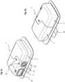
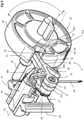
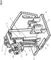
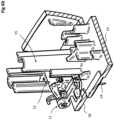
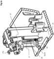
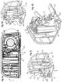
Figure 1a is a perspective view of an embodiment of a drug delivery device according to the invention;Figure 1b is a view similar tofigure 1a from another side of the device;Figure 1c is a perspective view of the device offigures 1a and 1b showing a base unit uncoupled from a delivery unit, a cover portion of the delivery unit being removed to better see the inside of the delivery unit;Figure 2a is a perspective view of the delivery unit of the device offigures 1a to 1c with a cover portion partially removed and without a drug cartridge mounted therein;Figure 2b is a view similar tofigure 2a showing some components of the drug delivery unit in exploded fashion;Figure 3 is an exploded view of components of the delivery unit according to an embodiment of the invention, showinginter alia a pump module and a subcutaneous delivery mechanism of the delivery unit;Figure 4 is a perspective view of a subcutaneous delivery mechanism of a delivery unit according to an embodiment of the invention;Figures 5a to 5c are cross sectional views of the drug delivery device illustrating a sequence of actions of the needle actuation mechanism according to an embodiment to the invention,figure 5a showing the needle actuation mechanism in an initial state prior to first use,figure 5b showing the needle actuation mechanism in an extended delivery position,figure 5c showing the needle actuation system in a retracted and tilted park position;Figure 6a to 6c are perspective views of a needle support of the subcutaneous delivery mechanism in positions corresponding tofigures 5a to 5c respectively;Figures 7a to 7d are views of the drug delivery according to another embodiment of the invention, wherefigure 7a is a cross-sectional view showing the needle actuation system in a retracted and tilted park position, andfigures 7b to 7d are perspective partial views of the needle support and needle actuation mechanism in an initial state prior to first use (figure 7b ), an extended delivery position (figure 7c ) and a retracted and tilted park position (figure 7d ).- Referring to the figures, and in particular to
figures 1-4 , adrug delivery device 1 comprises adelivery unit 2 and abase unit 4. In an embodiment, thedelivery unit 2 is adisposable unit 2 and is removably connected to thebase unit 4 which may be re-usable, although it will be appreciated that in other embodiments the base may be formed with the delivery unit as a single disposable unit. - The
delivery unit 2 comprises a subcutaneous delivery mechanism 7 to deliver a fluid trans-dermally, adrug cartridge 3 with a reservoir containing the fluid to be administered to a patient, apump 6 to transfer the fluid from the reservoir to the subcutaneous delivery mechanism 7, and a support member orhousing 5 for supporting the aforementioned components. Asupply conduit 45 fluidly connects the outlet of thedrug cartridge 3 to theinlet 20 of thepump module 6. - The
base unit 4 comprises a pump drive (not shown), a battery (not shown), an electronic control unit (not shown) and a housing. The base unit housing may accommodate a portion of the reservoir when coupled to thedelivery unit 2 and optionally comprise one or more sensors for detecting the drug fill level of the reservoir. - The
pump module 6 is operable to pump fluid from the drug cartridge to aneedle 24 for subcutaneous delivery. In this example the pump module comprises adrive interface 32 configured to couple rotationally with a pump drive mounted in thebase unit 4 such that torque from the pump drive is transferred to the pump module to drive arotor 20 of the pump in rotation. A suitable pump engine and drive unit is provided inWO 2005/039674 , which is incorporated herein by reference. However, it will be appreciated that other rotary pump engines and pump drives may be used. Moreover, the pump engine could be permanently coupled or attached to a pump drive, and/or the drive could be incorporated in thedelivery unit 2 and receive power, for instance via electrical contacts or by induction from a power source (not shown) mounted in thebase unit 4. - An
inlet 22 of thepump module 6 receives fluid from thesupply conduit 45 and anoutlet 23 of the pump supplies fluid to theneedle 24 via adelivery conduit 46. - A
rotary actuator 10 of aneedle actuation mechanism 9 is, in an advantageous embodiment, mounted to thepump module 6 such that rotation of the pump rotor by the pump drive causes rotation of the rotary actuator10, as will be discussed in more detail in the following. It will be appreciated that in other embodiments the rotary actuator may not be mounted directly onto the pump module, for example it may be coupled to the pump module via a geared system, or may alternatively be driven separately from the drive coupled to pumpmodule 6, for instance by an independent motor or mechanism. - The subcutaneous delivery mechanism 7 comprises a
needle support 8 and aneedle 24 mounted to the needle support adapted for trans-dermal delivery of the fluid from the drug cartridge. The subcutaneous delivery mechanism 7 further comprises aneedle actuation mechanism 9. - The
needle support 8 comprises atranslation guide member 12 that is slidably mounted on aneedle support guide 15 fixed to thehousing 5, in particular upstanding from thebase wall 14 of thehousing 5. Theneedle support guide 15 comprisestranslation guide rails 16 that slidably engage withguide rails 43 formed on thetranslation guide member 12 of theneedle support 8. The complementarytranslation guide rail 16 andtranslation guide rails 43 allow slidable movement of theneedle support 8 relative to thebase wall 14 of thehousing 5 such that theneedle 24 can be translated from a retracted position within the housing as illustrated infigure 5a andfigure 6a , to a delivery position extending through thebase wall 14 of the housing as illustrated infigure 5b andfigure 6b for a transdermal administration of the liquid drug to a patient. - The
needle support 8 further comprises arotation guide member 13 that is rotatably mounted to thetranslation guide member 12, theneedle 24 being fixed to therotation guide member 13. Therotation guide member 13 allows theneedle 24 to be rotated from the retracted position illustrated infigures 5a and6a to a tilted and retracted position as illustrated infigures 5c and6c that disengages theactuation mechanism 9, thus preventing further use of the drug delivery device. The tilted and retracted position illustrated infigures 5c and6c correspond to an end-of-use park position in which the disposable delivery unit may no longer be reused and would need to be replaced by a new delivery unit. In the end-of-use park position illustrated infigures 5c and6c , theneedle 24 can no longer be engaged by theactuation mechanism 9 for return to the extended delivery position, thus ensuring the safety of the drug delivery device after use of the delivery unit. - The
translation guide member 12 comprises arotation member support 44 forming a bearing supporting abody 47, for instance a cylindrically shapedbody 47 to allow rotation of therotation guide member 13 relative to thetranslation guide member 12 around a rotation axisA1. - A fluid channel is formed within the rotation body fluidly interconnecting the
hollow needle 24 to an inlet on thebody 47 connected to adelivery conduit 46 connected via aconnector 52 to thepump module outlet 23. Theconduit 46 is supple enough to allow the relative rotation between therotation guide member 13 and thehousing 5. - The
rotation guide member 13 is coupled to anengagement lever 11 of theneedle actuation mechanism 9. Theengagement lever 11 is in the illustrated embodiment and in a preferred mode of execution, rotatably mounted to therotation guide member 13. Within the scope of the invention, the engagement lever may however also be fixedly mounted to the rotation guide member and in a variant integrally formed with the rotation guide member. - In the illustrated embodiment, the
engagement lever 11 comprises apivot portion 33 rotatably mounted on apivot support 25 extending from therotation guide member 13, and anengagement arm 34 extending from thepivot portion 33 to anengagement end 35. Theengagement end 35 is configured to be engaged by arotary actuator 10 of theneedle actuation mechanism 9. - The
rotary actuator 10, which in the illustrated embodiment is essentially in the form of a disc or wheel with a circumferentialouter rim 28, is provided with acatch 29 that engaged theengagement end 35 when the rotary member is rotated. Thecatch 29 is formed by a recess or notch 30 in therim 28 thus presentingcatch edges engagement end 35. Theengagement end 35 in the retracted and extended positions as shown infigures 5a and 5b and6a and6b extends into the notch 30. - It will be appreciated however that the rotary actuator may have various other forms and shapes providing an element that pushes down on the
engagement lever 11 when moving from the retracted to extended position, respectively having an element that engages the engagement lever to move the lever upwards from the extended to the retracted positions, and the engagement end may also have various shapes and forms complementary to the catch of the rotary actuator for effecting the aforementioned movements. - In an advantageous embodiment, the
rotary actuator 10 is coupled to therotor 20 of thepump module 6 and may be integrally formed as a single part with thepump module rotor 20. Further, in an advantageous embodiment therotary actuator 10 may comprise adrive interface 32 for coupling in rotation to a drive (not shown) mounted in thebase unit 4. When thedisposable unit 2 is coupled to thebase unit 4, thedrive interface 32 engages a complementary interface of the drive in the base unit. The rotary actuator may thus be driven in rotation by the pump drive, simultaneously with the rotor of the pump module. - As best seen in
figure 5a , in a retracted position prior to first use of thedelivery unit 2, theneedle support 8 is in a retracted position with theneedle 24 fully positioned within thehousing 5 above thebase wall 14. Theengagement end 35 is in a position for engagement with thecatch 29 of therotary actuator 10, whereby in the illustrated embodiment theengagement end 35 is positioned within the recess or notch 30. - To use the
drug delivery device 1, thedelivery unit 2 is coupled and mounted to thebase unit 4 such that the pump drive engages thedrive interface 32 of therotary actuator 10. In an embodiment where the delivery unit is provided with an adhesive base theprotective film 39 is peeled off and the mountingsurface 38 of the base will be placed against the patient's skin. It may however be noted that in other embodiments, the base wall may be provided without an adhesive layer and the device placed against the patient's skin by other means for instance by means of a strap or band encircling the patient's body portion against which the drug delivery device is placed. Upon initial use of the drug delivery device, for instance upon a first command to deliver a dose of liquid drug subcutaneously, whereby the initial dose may be setting a basal rate of a drug delivery or a bolus injection, the pump drive is actuated to turn the rotary actuator in a rotation direction that engages theengagement lever 11 and displaces it in translation from the retracted position to an extended delivery position as illustrated infigures 5b and6b such that theneedle 24 pierces through the patient's skin and is in a position ready for delivery of the liquid drug trans-dermally. - In the illustrated embodiment, in the extended delivery position, the rotary actuator may continue rotating in the delivery direction R+. In the delivery direction R+ the
upper engagement edge 31b of thecatch 29 is configured to be able to move past theengagement end 35 such that therotary actuator 10 may turn in the delivery direction continuously once the needle is the extended position without being blocked by theengagement lever 11. - The
engagement lever 11 may further be provided with a suspension coupling the lever to therotation guide member 13. - In the variant illustrated in
figure 4 , the suspension comprises alower suspension arm 36 extending from the engagement lever biasing against alower abutment shoulder 26a extending from therotation guide member 13 configured to allow limited elastic rotation of the engagement lever relative to therotation guide member 13 by elastic bending of thesuspension arm 36. - This allows the
rotary actuator 10 to be in contact with and press slightly against theengagement end 35 of theengagement lever 11 while turning in the delivery direction R+ without affecting the position of the needle during delivery of a drug. - In a variant, instead of a
lower suspension arm 36 extending from theengagement lever 11, other elastic means may be provided, for instance theengagement lever 11 may have a certain elasticity to allow flexible bending thereof sufficient to accommodate contact with the rotary actuator during rotation in the delivery direction R+. - In the variant illustrated in
figures 7a to 7d , there is no lower suspension arm and the elasticity of theengagement lever 11 and of thesuspension arm 37 pressing against theupper abutment shoulder 26b is configured to allow controlled flexible bending of the engagement lever to accommodate contact with the rotary actuator during rotation in the delivery direction R+ without affecting the position of the needle during delivery of a drug. - In a variant, the spring suspension element may extend from the
rotation guide member 13 and press against arigid engagement lever 11, or in the further variant elastic members may be provided on both the rotation guide member and the engagement lever that inter-engage. In further variant, the engagement lever may be integrally formed with therotation guide member 13, for instance as a single injected part, with flexible connecting elements between the engagement lever and other portions of the rotation guide members that enable a certain flexible bending thereof configured to allow contact during rotation in the delivery position yet with sufficient engagement resistance to move the needle actuation mechanism from the retracted to the extended positions. In a variant, the elastic means may be connected to an upper portion of the lever or to a lower portion of the lever provided that the function of allowing certain flexibility in the delivery direction is provided as discussed above. - Once use of the delivery unit is finished, for instance when the drug cartridge is in an empty state, or after a maximum duration of use of the disposable delivery unit is reached, a command for retraction of the transcutaneous needle from the extended position to the retracted position is executed. During this operation, the pump drive is controlled to move in a reverse direction R- whereby the
rotary actuator 10 moves in the reverse direction R-. In the reverse direction, alower edge 31a of thecatch 29 engages theengagement end 35 of theengagement lever 11 thus lifting up theneedle support 8 from the extended to the retracted position. The engagement end may be provided with a hook protrusion or other complementary element with thelower catch edge 31a of the rotary actuator such that upon reverse direction the engagement lever is engaged by the catch and lifted upwards away from thebase wall 14. - Rotation of the
rotation guide member 13 is prevented by ananti-rotation guide surface 27 on the rotation guide member sliding along ananti-rotation guide surface 17 of theneedle support guide 15 on thehousing 5. Theanti-rotation guide surface 17 may be formed as a surface upstanding from thebase wall 14. During rotation in the reverse direction R- of therotary actuator 10 past the initial retracted position prior to the first use illustrated infigure 5a , the needle support is further lifted away from thebase wall 14 until the complementary anti-rotation guide surfaces 27, 17 disengage. At this moment continued rotation in the reverse direction of therotary actuator 10 forces the rotation of therotation guide member 13 into the retracted and tilted park position illustrated infigures 5c and6c in which it can no longer be reengaged thus preventing reuse of thedelivery unit 2. - In the illustrated embodiments, when moving into the park position, the tip of the
needle 24 engages a lockingelement - In the embodiment illustrated in
figures 6a to 6c , when moving into the park position, the tip of theneedle 24 slips over a lockingprotrusion 50, as best seen inFigure 6c , and is then blocked and can no longer return to the unlocked position. The lockingprotrusion 50 is provided with a tapered surface on the side facing theorifice 18 to guide the needle tip as it presses elastically against the locking protrusion, and assist it to slip over the lockingprotrusion 50. Once in the parked and locked position, the needle tip engages in a groove and can no longer slip back to the tapered entry side of the locking protrusion. Theprotuberance 51 on the tip of theengagement lever 35 is configured to assist in increasing the torque on theengagement lever 11 to allow the needle tip to slip over the locking protrusion. - In the embodiment illustrated in
figures 7a to 7d , when moving into the park position, the tip of theneedle 24 buries into a lockingnest 150 filled with a soft material which catches the needle tip, as best seen inFigure 7d , the needle being then blocked from returning to the unlocked position. The soft material may for instance be a soft polymeric compound, for instance a thermoplastic elastomer, thermoplastic rubber, liquid silicone rubber, or similar material, that may be molded or deposited in anest wall 151 of thebase 14. The soft material may advantageously be molded in the base of the housing during the base molding process, in a two component molding process asper se known in the art of injection molding. - In the illustrated embodiments, an
upper suspension arm 37 extends from theengagement lever 11 and has a curvedflexible end 37a that this configured to biased against anupper surface 48 of thehousing 5. The upper arm defines the initial position prior to first use as illustrated infigure 5a and prevents upward sliding of the needle support in the initial position. In the park position, the upper arm may optionally also serve to block rotation of therotation guide member 13 from the retracted tilted position back to a non-tilted position. Theupper arm 37 may also serve to limit the flexible pivoting of the engagement lever during actuation and use by abutting against theabutment 26b on therotation guide member 13. - In an alternative variant, the
needle 24 is employed for inserting a flexible cannula tube transdermally, the needle being retracted to the fully retracted park position as illustrated infigures 5c and6c before first administration of a drug. In this alternative embodiment, the needle does not need to be hollow and is not connected to the outlet of the pump module. The outlet of the pump module in such configuration is connected to via a liquid coupling that closes the orifice through which the needle extends when retracted, for instance in a form of a septum or valve such that after retraction of the needle, liquid pumped by the pump flows through the cannula that extends transdermally through the patient's skin. The soft cannula may increase comfort of wearing the drug delivery device by the patient especially for applications in which the extended use is of a few days or more. Cannula insertion configurations using a needle areper se known in the art and do not need to be described further in the present application. In the fully tilted park position, in the soft cannula variant, the pump may be configured to rotate in either directions R+ or R-, to effect the pumping action, the engagement end of the lever being rotated away from the catch so that it is no long in contact with the rim of the rotary actuator. In this regard, theupper suspension 37 may be configured to elastically engage an upper wall portion such that the tilt angle is increased by the elastic force of the suspension in the fully retracted position to completely disengage theengagement end 35 from the catch of the rotary actuator. In this instance, the rotary actuator may be configured to be rotated in either of the directions for the pumping action depending on the arrangement of the pump inlets and outlets. - Delivery unit 2 (disposable part)
Drug cartridge 3Housing 5Base wall 14Upper surface portion 48- Mounting
surface 38
adhesive layer - Peel off
protective film 39
Needle support guide 15Translation guide rails 16Anti-rotation guide surface 17
Needle outlet 18Septum 19Liquid supply conduit 45Liquid delivery conduit 46Fluidic connector 52- Needle
tip locking element - Locking
protrusion 50 - Locking
nest 150
Lockingnest wall 151
- Locking
Pump module 6Rotor 20Stator 21Inlet 22Outlet 23
- Subcutaneous delivery mechanism 7
Needle 24Needle support 8Translation guide member 12Guide rails 43Rotation body support 44
Rotation guide member 13Body 47Pivot support 25Rotation axis A 1- Abutment shoulders 26
Lower abutment shoulder 26aUpper abutment shoulder 26bUpper stop 49
Anti-rotation guide surface 27
Needle actuation mechanism 9Rotary actuator 10Rim 28Catch 29- Recess /notch 30
- Catch edges 31
Upper catch edge 31bLower catch edge 31a
- Coupling
interface 32
Engagement lever 11Pivot portion 33- Rotation axis A2
Engagement arm 34Engagement end 35Protuberance 51lower suspension arm 36- upper suspension (arm) 37
rounded end 37a
- Base unit 4 (reusable part)
- Electronic control system
- Power source (battery)
- Pump drive
Coupling interface Status indicators 40- User interface (control buttons) 42
Claims (15)
- A drug delivery device (1) comprising a delivery unit (2) receiving a drug cartridge (3) containing a drug to be administered to a patient in need thereof, the delivery unit comprising a subcutaneous delivery mechanism (7) including a needle (24), a needle support (8) to which the needle is mounted, and a needle actuation mechanism (9) configured to move the needle from a retracted position within a housing (5) of the delivery unit (2), to an extended delivery position where the needle projects through a base wall (14) of the housing, the needle actuation mechanism comprising a rotary actuator (10) configured to engage an engagement lever (11) coupled to the needle support (8) for translating the needle support between retracted and extended delivery positions,characterized in that the needle support comprises a translation guide member (12) slidably mounted with respect to the housing (5), and a rotation guide member (13) rotatably mounted to the translation guide member (12), the needle (24) being fixed to the rotation guide member (13) configured to tilt the needle in a fully retracted park position after full retraction of the needle.
- The device according to the preceding claim wherein the engagement lever (11) is pivotally mounted on the needle support (8) and elastically engages the needle support configured to allow the engagement lever (11) to elastically pivot and bias against the rotary actuator (10) of the needle actuation mechanism in the fully extended delivery position such that the rotary actuator may turn freely in a delivery direction (R+).
- The device according to any preceding claim wherein the rotary actuator (10) is coupled directly to a rotor (20) of a pump module (6) mounted in the delivery unit (2).
- The device according to any preceding claim wherein the rotary actuator comprises a disc shape with an outer peripheral rim (28) comprising a catch (29) formed by a recess (30) in the rim (28) for engaging an engagement end (35) of the engagement lever (11).
- The device according to any preceding claim wherein the engagement lever (11) comprises a suspension (36, 37) engaging the needle support (8) allowing elastic pivoting of the engagement lever relative to the needle support.
- The drive according to any preceding claim wherein the rotation guide member comprises a cylindrical body portion (47) rotatably mounted in a rotation member support (44) of the translation guide member (12).
- The device according to any preceding claim wherein the rotation guide member of the needle support comprises a liquid channel therein interconnecting a liquid delivery conduit (46) connected to an outlet (23) of the pump module to the hollow needle (24)
- The device according to any preceding claim wherein the engagement lever comprises a protuberance on a lower side of the engagement end (35) configured for catching on a lower catch edge (31a) of the rotary actuator (10) when it moves in a reverse direction (R-).
- The device according to any preceding claim wherein the engagement lever (11) comprises a pivot portion (33) and an engagement arm (34) extending from the pivot portion to the engagement end (35), the pivot portion being mounted on a pivot support (25) extending from the rotation guide member (13) of the needle support.
- The device according to any preceding claim wherein the rotation guide member (13) of the needle support (8) comprises an anti-rotation guide surface (27) slidably engaging a complementary anti-rotation guide surface (17) extending from the housing base wall (14) configured for preventing rotation of the rotation guide member (13) when travelling between the initial retracted position and the extended delivery position, the anti-rotation surfaces arranged to disengage in the fully retracted park position when the rotary actuator is rotated in a reverse direction to allow tilting of the needle into a park position preventing further reuse of the needle.
- The device according to any preceding claim wherein the rotary actuator (10) comprises a drive interface (32) configured for coupling to a drive mounted in a base unit comprising an electronic control system, a power source and said pump drive for actuation of the rotary actuator (10).
- The device according to any preceding claim wherein the delivery unit is formed as a disposable part containing said drug cartridge (3) in a housing (5) of the delivery unit, and a base unit (4) formed as a reusable part comprising an electronic control system, a power source, and a pump drive, the base unit being removable mountable to the delivery unit.
- The device according to any preceding claim comprising a locking element (50, 150) engaging the tip of the needle in the fully retracted park position to block the needle in the park position.
- The device according to the preceding claim wherein the locking element comprises a locking nest (150) filled with a soft material into which the tip of the needle (24) buries when moving into the park position.
- The device according to claim 13 wherein the locking element comprises a locking protrusion (50) provided with a tapered surface to guide the needle tip over the locking protrusion.
Priority Applications (1)
| Application Number | Priority Date | Filing Date | Title |
|---|---|---|---|
| EP23205208.4AEP4285969A3 (en) | 2018-05-28 | 2019-05-22 | Drug delivery device with needle actuation mechanism |
Applications Claiming Priority (2)
| Application Number | Priority Date | Filing Date | Title |
|---|---|---|---|
| EP18174647.0AEP3574941A1 (en) | 2018-05-28 | 2018-05-28 | Drug delivery device with needle actuation mechanism |
| PCT/EP2019/063269WO2019228895A1 (en) | 2018-05-28 | 2019-05-22 | Drug delivery device with needle actuation mechanism |
Related Child Applications (1)
| Application Number | Title | Priority Date | Filing Date |
|---|---|---|---|
| EP23205208.4ADivisionEP4285969A3 (en) | 2018-05-28 | 2019-05-22 | Drug delivery device with needle actuation mechanism |
Publications (2)
| Publication Number | Publication Date |
|---|---|
| EP3801680A1 EP3801680A1 (en) | 2021-04-14 |
| EP3801680B1true EP3801680B1 (en) | 2023-11-22 |
Family
ID=62455404
Family Applications (3)
| Application Number | Title | Priority Date | Filing Date |
|---|---|---|---|
| EP18174647.0AWithdrawnEP3574941A1 (en) | 2018-05-28 | 2018-05-28 | Drug delivery device with needle actuation mechanism |
| EP19724875.0AActiveEP3801680B1 (en) | 2018-05-28 | 2019-05-22 | Drug delivery device with needle actuation mechanism |
| EP23205208.4APendingEP4285969A3 (en) | 2018-05-28 | 2019-05-22 | Drug delivery device with needle actuation mechanism |
Family Applications Before (1)
| Application Number | Title | Priority Date | Filing Date |
|---|---|---|---|
| EP18174647.0AWithdrawnEP3574941A1 (en) | 2018-05-28 | 2018-05-28 | Drug delivery device with needle actuation mechanism |
Family Applications After (1)
| Application Number | Title | Priority Date | Filing Date |
|---|---|---|---|
| EP23205208.4APendingEP4285969A3 (en) | 2018-05-28 | 2019-05-22 | Drug delivery device with needle actuation mechanism |
Country Status (10)
| Country | Link |
|---|---|
| US (2) | US11744940B2 (en) |
| EP (3) | EP3574941A1 (en) |
| JP (2) | JP7309758B2 (en) |
| KR (1) | KR102523445B1 (en) |
| CN (2) | CN112188904B (en) |
| DK (1) | DK3801680T3 (en) |
| ES (1) | ES2971086T3 (en) |
| FI (1) | FI3801680T3 (en) |
| PT (1) | PT3801680T (en) |
| WO (1) | WO2019228895A1 (en) |
Families Citing this family (23)
| Publication number | Priority date | Publication date | Assignee | Title |
|---|---|---|---|---|
| EP1762259B2 (en) | 2005-09-12 | 2025-01-01 | Unomedical A/S | Inserter for an infusion set with a first and second spring units |
| WO2012123274A1 (en) | 2011-03-14 | 2012-09-20 | Unomedical A/S | Inserter system with transport protection |
| CN119950880A (en) | 2017-05-05 | 2025-05-09 | 里珍纳龙药品有限公司 | Auto-injectors and related methods of use |
| EP3574941A1 (en) | 2018-05-28 | 2019-12-04 | Sensile Medical AG | Drug delivery device with needle actuation mechanism |
| CN112292166B (en)* | 2018-09-22 | 2023-02-21 | 艾斯曲尔医疗公司 | Syringe Needle Insertion and Retraction Assembly |
| EP3632486B1 (en)* | 2018-10-01 | 2021-03-17 | Sensile Medical AG | Subcutaneous delivery mechanism for drug delivery device |
| EP3877018A4 (en) | 2018-11-08 | 2022-08-10 | Capillary Biomedical, Inc. | LINEAR INTRODUCER WITH ROTARY DRIVE |
| EP3659645A1 (en) | 2018-11-30 | 2020-06-03 | Sensile Medical AG | Drug delivery device |
| US11458292B2 (en) | 2019-05-20 | 2022-10-04 | Unomedical A/S | Rotatable infusion device and methods thereof |
| CN114502213B (en) | 2019-10-01 | 2024-09-24 | 优诺医疗有限公司 | Connector with a plurality of connectors |
| EP3928811B1 (en)* | 2020-06-23 | 2025-09-17 | TecMed AG | Wearable drug delivery device |
| EP4204066A4 (en) | 2020-08-28 | 2024-11-13 | Tandem Diabetes Care, Inc. | INSULIN INFUSION SET |
| EP4059540A1 (en) | 2021-03-15 | 2022-09-21 | Sensile Medical AG | Drug delivery device |
| EP4059542A1 (en) | 2021-03-15 | 2022-09-21 | Sensile Medical AG | Drug delivery device |
| USD1007676S1 (en) | 2021-11-16 | 2023-12-12 | Regeneron Pharmaceuticals, Inc. | Wearable autoinjector |
| USD1029241S1 (en)* | 2022-05-06 | 2024-05-28 | Sensile Medical Ag | Medicine injector |
| EP4335470A1 (en) | 2022-09-09 | 2024-03-13 | Sensile Medical AG | Drug delivery device |
| EP4335469A1 (en) | 2022-09-09 | 2024-03-13 | Sensile Medical AG | Drug delivery device |
| EP4356943A1 (en) | 2022-10-21 | 2024-04-24 | Sensile Medical AG | Drug delivery device |
| WO2025045807A1 (en) | 2023-08-31 | 2025-03-06 | Sensile Medical Ag | Drug delivery device |
| WO2025045806A1 (en) | 2023-08-31 | 2025-03-06 | Sensile Medical Ag | Drug delivery device |
| EP4516338B1 (en) | 2023-08-31 | 2025-08-06 | Sensile Medical AG | Drug delivery device |
| WO2025045815A1 (en) | 2023-08-31 | 2025-03-06 | Sensile Medical Ag | Drug delivery device |
Family Cites Families (50)
| Publication number | Priority date | Publication date | Assignee | Title |
|---|---|---|---|---|
| US7530964B2 (en)* | 2000-06-30 | 2009-05-12 | Elan Pharma International Limited | Needle device and method thereof |
| JP2004538103A (en)* | 2001-08-09 | 2004-12-24 | ベクトン・ディキンソン・アンド・カンパニー | Retractable safety needle device |
| EP1527793A1 (en) | 2003-10-27 | 2005-05-04 | Ecole Polytechnique Fédérale de Lausanne (EPFL) | Liquid drug delivery micropump |
| DK1968677T3 (en)* | 2005-09-15 | 2019-07-15 | Hoffmann La Roche | Insertion head with needle guard in the handle |
| EP1764126B1 (en)* | 2005-09-15 | 2010-07-14 | F.Hoffmann-La Roche Ag | Injection head with handle |
| EP1803934B1 (en) | 2005-12-28 | 2008-09-24 | Sensile Pat AG | Micropump |
| JP2008110165A (en)* | 2006-10-31 | 2008-05-15 | Juki Corp | Buttonhole sewing machine |
| CA2677667A1 (en)* | 2007-02-09 | 2008-08-14 | Deka Products Limited Partnership | Automated insertion assembly |
| EP2031527A1 (en) | 2007-07-27 | 2009-03-04 | Sensile Pat AG | Portable medical device |
| EP2052683A1 (en) | 2007-10-23 | 2009-04-29 | Sensile Pat AG | Liquid flow sensing system |
| EP2052677A1 (en) | 2007-10-23 | 2009-04-29 | Sensile Pat AG | Medical device for glucose monitoring or regulation |
| EP2419008A1 (en) | 2009-04-17 | 2012-02-22 | Sensile Pat AG | Medical device for glucose monitoring or regulation |
| EP2275678B1 (en) | 2009-07-13 | 2019-03-06 | Sensile Medical AG | Pump with rotor position measurement system |
| US8449504B2 (en)* | 2009-11-11 | 2013-05-28 | Calibra Medical, Inc. | Wearable infusion device and system |
| EP2512580A4 (en)* | 2009-12-16 | 2013-06-12 | Becton Dickinson Co | Self-injection device |
| CN102803725B (en) | 2010-03-17 | 2016-08-10 | 森西勒Pat股份公司 | micro pump |
| CA3011688C (en)* | 2010-06-09 | 2021-02-23 | Valeritas, Inc. | Fluid delivery device needle retraction mechanisms, cartridges and expandable hydraulic fluid seals |
| EP2495001A1 (en)* | 2011-03-03 | 2012-09-05 | Debiotech S.A. | Cannula inserter |
| US9302285B2 (en) | 2011-07-06 | 2016-04-05 | Sensile Pat Ag | Liquid dispensing system |
| CN103842650B (en) | 2011-09-28 | 2017-06-06 | 森西勒Pat股份公司 | Fuid distribution system |
| EP2628494A1 (en) | 2012-02-17 | 2013-08-21 | Sensile Pat AG | Liquid storage and delivery system |
| US9662621B2 (en) | 2012-03-09 | 2017-05-30 | Sensile Pat Ag | Drug reconstitution system |
| US9072827B2 (en) | 2012-03-26 | 2015-07-07 | Medimop Medical Projects Ltd. | Fail safe point protector for needle safety flap |
| US9463280B2 (en)* | 2012-03-26 | 2016-10-11 | Medimop Medical Projects Ltd. | Motion activated septum puncturing drug delivery device |
| EP2832390A1 (en) | 2013-07-30 | 2015-02-04 | Sensile Pat AG | Drug delivery device with needle actuation mechanism |
| US10046111B2 (en)* | 2013-09-05 | 2018-08-14 | Sanofi-Aventis Deutchland Gmbh | Needle insertion and retraction arrangment with manually triggered, spring-loaded drive mechanism |
| CN105658267B (en)* | 2013-09-05 | 2019-10-25 | 赛诺菲-安万特德国有限公司 | Driving mechanism for needle insertion assembly |
| RU2667305C2 (en)* | 2014-04-30 | 2018-09-18 | Кимберли-Кларк Ворлдвайд, Инк. | Receptacle portion of transdermal drug delivery apparatus and methods |
| EP4140520A1 (en)* | 2015-02-10 | 2023-03-01 | Amgen Inc. | Rotationally biased insertion mechanism for a drug delivery pump |
| JP6522800B2 (en)* | 2015-07-02 | 2019-05-29 | ヴァレリタス・インコーポレーテッド | Fluid delivery device |
| EP3320929A1 (en) | 2016-11-10 | 2018-05-16 | Sensile Pat AG | Drug delivery device |
| EP3495658A1 (en) | 2017-12-06 | 2019-06-12 | Sensile Medical AG | Micropump |
| EP3499034B1 (en) | 2017-12-12 | 2021-06-23 | Sensile Medical AG | Micropump with cam mechanism for axial displacement of rotor |
| EP3502469A1 (en) | 2017-12-20 | 2019-06-26 | Sensile Medical AG | Micropump |
| EP3505757A1 (en) | 2017-12-28 | 2019-07-03 | Sensile Medical AG | Micropump |
| EP3574941A1 (en) | 2018-05-28 | 2019-12-04 | Sensile Medical AG | Drug delivery device with needle actuation mechanism |
| EP3632486B1 (en) | 2018-10-01 | 2021-03-17 | Sensile Medical AG | Subcutaneous delivery mechanism for drug delivery device |
| EP3659645A1 (en) | 2018-11-30 | 2020-06-03 | Sensile Medical AG | Drug delivery device |
| EP4059538A1 (en) | 2021-03-15 | 2022-09-21 | Sensile Medical AG | Drug delivery device |
| EP4059540A1 (en) | 2021-03-15 | 2022-09-21 | Sensile Medical AG | Drug delivery device |
| EP4059539A1 (en) | 2021-03-15 | 2022-09-21 | Sensile Medical AG | Method of producing a drug delivery device |
| EP4059541A1 (en) | 2021-03-15 | 2022-09-21 | Sensile Medical AG | Drug delivery device |
| EP4059542A1 (en) | 2021-03-15 | 2022-09-21 | Sensile Medical AG | Drug delivery device |
| EP4059537A1 (en) | 2021-03-15 | 2022-09-21 | Sensile Medical AG | Drug delivery device |
| EP4331728A1 (en) | 2022-08-29 | 2024-03-06 | Sensile Medical AG | Push actuated double fluid dispenser |
| EP4335469A1 (en) | 2022-09-09 | 2024-03-13 | Sensile Medical AG | Drug delivery device |
| EP4335470A1 (en) | 2022-09-09 | 2024-03-13 | Sensile Medical AG | Drug delivery device |
| EP4338770A1 (en) | 2022-09-14 | 2024-03-20 | Sensile Medical AG | Drug delivery device |
| EP4356943A1 (en) | 2022-10-21 | 2024-04-24 | Sensile Medical AG | Drug delivery device |
| EP4375507A1 (en) | 2022-11-25 | 2024-05-29 | Sensile Medical AG | Micropump |
- 2018
- 2018-05-28EPEP18174647.0Apatent/EP3574941A1/ennot_activeWithdrawn
- 2019
- 2019-05-22ESES19724875Tpatent/ES2971086T3/enactiveActive
- 2019-05-22WOPCT/EP2019/063269patent/WO2019228895A1/ennot_activeCeased
- 2019-05-22DKDK19724875.0Tpatent/DK3801680T3/enactive
- 2019-05-22EPEP19724875.0Apatent/EP3801680B1/enactiveActive
- 2019-05-22CNCN201980034795.9Apatent/CN112188904B/enactiveActive
- 2019-05-22PTPT197248750Tpatent/PT3801680T/enunknown
- 2019-05-22EPEP23205208.4Apatent/EP4285969A3/enactivePending
- 2019-05-22JPJP2020566561Apatent/JP7309758B2/enactiveActive
- 2019-05-22KRKR1020207033987Apatent/KR102523445B1/enactiveActive
- 2019-05-22FIFIEP19724875.0Tpatent/FI3801680T3/enactive
- 2019-05-22CNCN202310934772.1Apatent/CN116983505A/enactivePending
- 2019-05-22USUS17/057,728patent/US11744940B2/enactiveActive
- 2023
- 2023-06-15JPJP2023098379Apatent/JP7413587B2/enactiveActive
- 2023-08-29USUS18/457,394patent/US12364810B2/enactiveActive
Also Published As
| Publication number | Publication date |
|---|---|
| KR20210003226A (en) | 2021-01-11 |
| EP3574941A1 (en) | 2019-12-04 |
| US12364810B2 (en) | 2025-07-22 |
| JP2023116710A (en) | 2023-08-22 |
| US20230398289A1 (en) | 2023-12-14 |
| JP7309758B2 (en) | 2023-07-18 |
| CN112188904B (en) | 2023-10-13 |
| CN112188904A (en) | 2021-01-05 |
| PT3801680T (en) | 2024-01-26 |
| EP4285969A3 (en) | 2024-03-06 |
| US11744940B2 (en) | 2023-09-05 |
| CN116983505A (en) | 2023-11-03 |
| JP7413587B2 (en) | 2024-01-15 |
| FI3801680T3 (en) | 2024-02-08 |
| JP2021525567A (en) | 2021-09-27 |
| EP4285969A2 (en) | 2023-12-06 |
| ES2971086T3 (en) | 2024-06-03 |
| KR102523445B1 (en) | 2023-04-18 |
| EP3801680A1 (en) | 2021-04-14 |
| WO2019228895A1 (en) | 2019-12-05 |
| US20210369957A1 (en) | 2021-12-02 |
| DK3801680T3 (en) | 2024-02-12 |
Similar Documents
| Publication | Publication Date | Title |
|---|---|---|
| EP3801680B1 (en) | Drug delivery device with needle actuation mechanism | |
| EP3886944B1 (en) | Drug delivery device | |
| US10265483B2 (en) | Insulin pump dermal infusion set having partially integrated mechanized cannula insertion with disposable activation portion | |
| EP2473219B1 (en) | Cannula insertion device systems and methods | |
| EP2379134B1 (en) | Needle insertion device |
Legal Events
| Date | Code | Title | Description |
|---|---|---|---|
| STAA | Information on the status of an ep patent application or granted ep patent | Free format text:STATUS: UNKNOWN | |
| STAA | Information on the status of an ep patent application or granted ep patent | Free format text:STATUS: THE INTERNATIONAL PUBLICATION HAS BEEN MADE | |
| PUAI | Public reference made under article 153(3) epc to a published international application that has entered the european phase | Free format text:ORIGINAL CODE: 0009012 | |
| STAA | Information on the status of an ep patent application or granted ep patent | Free format text:STATUS: REQUEST FOR EXAMINATION WAS MADE | |
| 17P | Request for examination filed | Effective date:20201202 | |
| AK | Designated contracting states | Kind code of ref document:A1 Designated state(s):AL AT BE BG CH CY CZ DE DK EE ES FI FR GB GR HR HU IE IS IT LI LT LU LV MC MK MT NL NO PL PT RO RS SE SI SK SM TR | |
| AX | Request for extension of the european patent | Extension state:BA ME | |
| DAV | Request for validation of the european patent (deleted) | ||
| DAX | Request for extension of the european patent (deleted) | ||
| P01 | Opt-out of the competence of the unified patent court (upc) registered | Effective date:20230529 | |
| GRAP | Despatch of communication of intention to grant a patent | Free format text:ORIGINAL CODE: EPIDOSNIGR1 | |
| STAA | Information on the status of an ep patent application or granted ep patent | Free format text:STATUS: GRANT OF PATENT IS INTENDED | |
| INTG | Intention to grant announced | Effective date:20230901 | |
| GRAS | Grant fee paid | Free format text:ORIGINAL CODE: EPIDOSNIGR3 | |
| GRAA | (expected) grant | Free format text:ORIGINAL CODE: 0009210 | |
| STAA | Information on the status of an ep patent application or granted ep patent | Free format text:STATUS: THE PATENT HAS BEEN GRANTED | |
| AK | Designated contracting states | Kind code of ref document:B1 Designated state(s):AL AT BE BG CH CY CZ DE DK EE ES FI FR GB GR HR HU IE IS IT LI LT LU LV MC MK MT NL NO PL PT RO RS SE SI SK SM TR | |
| REG | Reference to a national code | Ref country code:GB Ref legal event code:FG4D | |
| REG | Reference to a national code | Ref country code:CH Ref legal event code:EP | |
| REG | Reference to a national code | Ref country code:DE Ref legal event code:R096 Ref document number:602019041862 Country of ref document:DE | |
| REG | Reference to a national code | Ref country code:IE Ref legal event code:FG4D | |
| REG | Reference to a national code | Ref country code:PT Ref legal event code:SC4A Ref document number:3801680 Country of ref document:PT Date of ref document:20240126 Kind code of ref document:T Free format text:AVAILABILITY OF NATIONAL TRANSLATION Effective date:20240123 | |
| REG | Reference to a national code | Ref country code:FI Ref legal event code:FGE | |
| REG | Reference to a national code | Ref country code:DK Ref legal event code:T3 Effective date:20240207 | |
| REG | Reference to a national code | Ref country code:NL Ref legal event code:FP | |
| REG | Reference to a national code | Ref country code:LT Ref legal event code:MG9D | |
| REG | Reference to a national code | Ref country code:GR Ref legal event code:EP Ref document number:20240400415 Country of ref document:GR Effective date:20240312 | |
| PG25 | Lapsed in a contracting state [announced via postgrant information from national office to epo] | Ref country code:IS Free format text:LAPSE BECAUSE OF FAILURE TO SUBMIT A TRANSLATION OF THE DESCRIPTION OR TO PAY THE FEE WITHIN THE PRESCRIBED TIME-LIMIT Effective date:20240322 | |
| PG25 | Lapsed in a contracting state [announced via postgrant information from national office to epo] | Ref country code:LT Free format text:LAPSE BECAUSE OF FAILURE TO SUBMIT A TRANSLATION OF THE DESCRIPTION OR TO PAY THE FEE WITHIN THE PRESCRIBED TIME-LIMIT Effective date:20231122 | |
| PG25 | Lapsed in a contracting state [announced via postgrant information from national office to epo] | Ref country code:LT Free format text:LAPSE BECAUSE OF FAILURE TO SUBMIT A TRANSLATION OF THE DESCRIPTION OR TO PAY THE FEE WITHIN THE PRESCRIBED TIME-LIMIT Effective date:20231122 Ref country code:IS Free format text:LAPSE BECAUSE OF FAILURE TO SUBMIT A TRANSLATION OF THE DESCRIPTION OR TO PAY THE FEE WITHIN THE PRESCRIBED TIME-LIMIT Effective date:20240322 Ref country code:BG Free format text:LAPSE BECAUSE OF FAILURE TO SUBMIT A TRANSLATION OF THE DESCRIPTION OR TO PAY THE FEE WITHIN THE PRESCRIBED TIME-LIMIT Effective date:20240222 | |
| PG25 | Lapsed in a contracting state [announced via postgrant information from national office to epo] | Ref country code:SE Free format text:LAPSE BECAUSE OF FAILURE TO SUBMIT A TRANSLATION OF THE DESCRIPTION OR TO PAY THE FEE WITHIN THE PRESCRIBED TIME-LIMIT Effective date:20231122 Ref country code:RS Free format text:LAPSE BECAUSE OF FAILURE TO SUBMIT A TRANSLATION OF THE DESCRIPTION OR TO PAY THE FEE WITHIN THE PRESCRIBED TIME-LIMIT Effective date:20231122 Ref country code:PL Free format text:LAPSE BECAUSE OF FAILURE TO SUBMIT A TRANSLATION OF THE DESCRIPTION OR TO PAY THE FEE WITHIN THE PRESCRIBED TIME-LIMIT Effective date:20231122 Ref country code:NO Free format text:LAPSE BECAUSE OF FAILURE TO SUBMIT A TRANSLATION OF THE DESCRIPTION OR TO PAY THE FEE WITHIN THE PRESCRIBED TIME-LIMIT Effective date:20240222 Ref country code:LV Free format text:LAPSE BECAUSE OF FAILURE TO SUBMIT A TRANSLATION OF THE DESCRIPTION OR TO PAY THE FEE WITHIN THE PRESCRIBED TIME-LIMIT Effective date:20231122 Ref country code:HR Free format text:LAPSE BECAUSE OF FAILURE TO SUBMIT A TRANSLATION OF THE DESCRIPTION OR TO PAY THE FEE WITHIN THE PRESCRIBED TIME-LIMIT Effective date:20231122 | |
| REG | Reference to a national code | Ref country code:ES Ref legal event code:FG2A Ref document number:2971086 Country of ref document:ES Kind code of ref document:T3 Effective date:20240603 | |
| PG25 | Lapsed in a contracting state [announced via postgrant information from national office to epo] | Ref country code:SK Free format text:LAPSE BECAUSE OF FAILURE TO SUBMIT A TRANSLATION OF THE DESCRIPTION OR TO PAY THE FEE WITHIN THE PRESCRIBED TIME-LIMIT Effective date:20231122 | |
| PG25 | Lapsed in a contracting state [announced via postgrant information from national office to epo] | Ref country code:SM Free format text:LAPSE BECAUSE OF FAILURE TO SUBMIT A TRANSLATION OF THE DESCRIPTION OR TO PAY THE FEE WITHIN THE PRESCRIBED TIME-LIMIT Effective date:20231122 Ref country code:SK Free format text:LAPSE BECAUSE OF FAILURE TO SUBMIT A TRANSLATION OF THE DESCRIPTION OR TO PAY THE FEE WITHIN THE PRESCRIBED TIME-LIMIT Effective date:20231122 Ref country code:RO Free format text:LAPSE BECAUSE OF FAILURE TO SUBMIT A TRANSLATION OF THE DESCRIPTION OR TO PAY THE FEE WITHIN THE PRESCRIBED TIME-LIMIT Effective date:20231122 Ref country code:EE Free format text:LAPSE BECAUSE OF FAILURE TO SUBMIT A TRANSLATION OF THE DESCRIPTION OR TO PAY THE FEE WITHIN THE PRESCRIBED TIME-LIMIT Effective date:20231122 | |
| REG | Reference to a national code | Ref country code:AT Ref legal event code:UEP Ref document number:1633276 Country of ref document:AT Kind code of ref document:T Effective date:20231122 | |
| REG | Reference to a national code | Ref country code:DE Ref legal event code:R097 Ref document number:602019041862 Country of ref document:DE | |
| PGFP | Annual fee paid to national office [announced via postgrant information from national office to epo] | Ref country code:TR Payment date:20240513 Year of fee payment:6 | |
| PLBE | No opposition filed within time limit | Free format text:ORIGINAL CODE: 0009261 | |
| STAA | Information on the status of an ep patent application or granted ep patent | Free format text:STATUS: NO OPPOSITION FILED WITHIN TIME LIMIT | |
| PG25 | Lapsed in a contracting state [announced via postgrant information from national office to epo] | Ref country code:SI Free format text:LAPSE BECAUSE OF FAILURE TO SUBMIT A TRANSLATION OF THE DESCRIPTION OR TO PAY THE FEE WITHIN THE PRESCRIBED TIME-LIMIT Effective date:20231122 | |
| 26N | No opposition filed | Effective date:20240823 | |
| PG25 | Lapsed in a contracting state [announced via postgrant information from national office to epo] | Ref country code:SI Free format text:LAPSE BECAUSE OF FAILURE TO SUBMIT A TRANSLATION OF THE DESCRIPTION OR TO PAY THE FEE WITHIN THE PRESCRIBED TIME-LIMIT Effective date:20231122 | |
| PG25 | Lapsed in a contracting state [announced via postgrant information from national office to epo] | Ref country code:MC Free format text:LAPSE BECAUSE OF FAILURE TO SUBMIT A TRANSLATION OF THE DESCRIPTION OR TO PAY THE FEE WITHIN THE PRESCRIBED TIME-LIMIT Effective date:20231122 | |
| PG25 | Lapsed in a contracting state [announced via postgrant information from national office to epo] | Ref country code:LU Free format text:LAPSE BECAUSE OF NON-PAYMENT OF DUE FEES Effective date:20240522 | |
| PG25 | Lapsed in a contracting state [announced via postgrant information from national office to epo] | Ref country code:MC Free format text:LAPSE BECAUSE OF FAILURE TO SUBMIT A TRANSLATION OF THE DESCRIPTION OR TO PAY THE FEE WITHIN THE PRESCRIBED TIME-LIMIT Effective date:20231122 Ref country code:LU Free format text:LAPSE BECAUSE OF NON-PAYMENT OF DUE FEES Effective date:20240522 | |
| PG25 | Lapsed in a contracting state [announced via postgrant information from national office to epo] | Ref country code:IE Free format text:LAPSE BECAUSE OF NON-PAYMENT OF DUE FEES Effective date:20240522 | |
| PGFP | Annual fee paid to national office [announced via postgrant information from national office to epo] | Ref country code:NL Payment date:20250522 Year of fee payment:7 | |
| PGFP | Annual fee paid to national office [announced via postgrant information from national office to epo] | Ref country code:FI Payment date:20250520 Year of fee payment:7 | |
| PGFP | Annual fee paid to national office [announced via postgrant information from national office to epo] | Ref country code:DE Payment date:20250519 Year of fee payment:7 | |
| PGFP | Annual fee paid to national office [announced via postgrant information from national office to epo] | Ref country code:GB Payment date:20250522 Year of fee payment:7 Ref country code:ES Payment date:20250616 Year of fee payment:7 Ref country code:DK Payment date:20250521 Year of fee payment:7 | |
| PGFP | Annual fee paid to national office [announced via postgrant information from national office to epo] | Ref country code:BE Payment date:20250520 Year of fee payment:7 Ref country code:IT Payment date:20250530 Year of fee payment:7 | |
| PGFP | Annual fee paid to national office [announced via postgrant information from national office to epo] | Ref country code:PT Payment date:20250513 Year of fee payment:7 | |
| PGFP | Annual fee paid to national office [announced via postgrant information from national office to epo] | Ref country code:FR Payment date:20250521 Year of fee payment:7 | |
| PGFP | Annual fee paid to national office [announced via postgrant information from national office to epo] | Ref country code:GR Payment date:20250519 Year of fee payment:7 | |
| PGFP | Annual fee paid to national office [announced via postgrant information from national office to epo] | Ref country code:CH Payment date:20250601 Year of fee payment:7 | |
| PGFP | Annual fee paid to national office [announced via postgrant information from national office to epo] | Ref country code:AT Payment date:20250519 Year of fee payment:7 | |
| PGFP | Annual fee paid to national office [announced via postgrant information from national office to epo] | Ref country code:CZ Payment date:20250509 Year of fee payment:7 | |
| PG25 | Lapsed in a contracting state [announced via postgrant information from national office to epo] | Ref country code:CY Free format text:LAPSE BECAUSE OF FAILURE TO SUBMIT A TRANSLATION OF THE DESCRIPTION OR TO PAY THE FEE WITHIN THE PRESCRIBED TIME-LIMIT; INVALID AB INITIO Effective date:20190522 | |
| PG25 | Lapsed in a contracting state [announced via postgrant information from national office to epo] | Ref country code:HU Free format text:LAPSE BECAUSE OF FAILURE TO SUBMIT A TRANSLATION OF THE DESCRIPTION OR TO PAY THE FEE WITHIN THE PRESCRIBED TIME-LIMIT; INVALID AB INITIO Effective date:20190522 |