EP3800479B1 - Magnetic resonance tomograph with a line with sensor for detecting line interference - Google Patents
Magnetic resonance tomograph with a line with sensor for detecting line interferenceDownload PDFInfo
- Publication number
- EP3800479B1 EP3800479B1EP19201066.8AEP19201066AEP3800479B1EP 3800479 B1EP3800479 B1EP 3800479B1EP 19201066 AEP19201066 AEP 19201066AEP 3800479 B1EP3800479 B1EP 3800479B1
- Authority
- EP
- European Patent Office
- Prior art keywords
- magnetic resonance
- sensor
- interference
- line
- signal
- Prior art date
- Legal status (The legal status is an assumption and is not a legal conclusion. Google has not performed a legal analysis and makes no representation as to the accuracy of the status listed.)
- Active
Links
Images


Classifications
- G—PHYSICS
- G01—MEASURING; TESTING
- G01R—MEASURING ELECTRIC VARIABLES; MEASURING MAGNETIC VARIABLES
- G01R33/00—Arrangements or instruments for measuring magnetic variables
- G01R33/20—Arrangements or instruments for measuring magnetic variables involving magnetic resonance
- G01R33/28—Details of apparatus provided for in groups G01R33/44 - G01R33/64
- G01R33/42—Screening
- G01R33/422—Screening of the radio frequency field
- G—PHYSICS
- G01—MEASURING; TESTING
- G01R—MEASURING ELECTRIC VARIABLES; MEASURING MAGNETIC VARIABLES
- G01R33/00—Arrangements or instruments for measuring magnetic variables
- G01R33/20—Arrangements or instruments for measuring magnetic variables involving magnetic resonance
- G01R33/28—Details of apparatus provided for in groups G01R33/44 - G01R33/64
- G01R33/32—Excitation or detection systems, e.g. using radio frequency signals
- G01R33/34—Constructional details, e.g. resonators, specially adapted to MR
- G01R33/34046—Volume type coils, e.g. bird-cage coils; Quadrature bird-cage coils; Circularly polarised coils
- G01R33/34053—Solenoid coils; Toroidal coils
- A—HUMAN NECESSITIES
- A61—MEDICAL OR VETERINARY SCIENCE; HYGIENE
- A61B—DIAGNOSIS; SURGERY; IDENTIFICATION
- A61B5/00—Measuring for diagnostic purposes; Identification of persons
- A61B5/05—Detecting, measuring or recording for diagnosis by means of electric currents or magnetic fields; Measuring using microwaves or radio waves
- A61B5/055—Detecting, measuring or recording for diagnosis by means of electric currents or magnetic fields; Measuring using microwaves or radio waves involving electronic [EMR] or nuclear [NMR] magnetic resonance, e.g. magnetic resonance imaging
- G—PHYSICS
- G01—MEASURING; TESTING
- G01R—MEASURING ELECTRIC VARIABLES; MEASURING MAGNETIC VARIABLES
- G01R33/00—Arrangements or instruments for measuring magnetic variables
- G01R33/20—Arrangements or instruments for measuring magnetic variables involving magnetic resonance
- G01R33/28—Details of apparatus provided for in groups G01R33/44 - G01R33/64
- G01R33/32—Excitation or detection systems, e.g. using radio frequency signals
- G01R33/36—Electrical details, e.g. matching or coupling of the coil to the receiver
- G—PHYSICS
- G01—MEASURING; TESTING
- G01R—MEASURING ELECTRIC VARIABLES; MEASURING MAGNETIC VARIABLES
- G01R33/00—Arrangements or instruments for measuring magnetic variables
- G01R33/20—Arrangements or instruments for measuring magnetic variables involving magnetic resonance
- G01R33/44—Arrangements or instruments for measuring magnetic variables involving magnetic resonance using nuclear magnetic resonance [NMR]
- G01R33/48—NMR imaging systems
- G01R33/54—Signal processing systems, e.g. using pulse sequences ; Generation or control of pulse sequences; Operator console
- G01R33/543—Control of the operation of the MR system, e.g. setting of acquisition parameters prior to or during MR data acquisition, dynamic shimming, use of one or more scout images for scan plane prescription
- G—PHYSICS
- G01—MEASURING; TESTING
- G01R—MEASURING ELECTRIC VARIABLES; MEASURING MAGNETIC VARIABLES
- G01R33/00—Arrangements or instruments for measuring magnetic variables
- G01R33/20—Arrangements or instruments for measuring magnetic variables involving magnetic resonance
- G01R33/28—Details of apparatus provided for in groups G01R33/44 - G01R33/64
- G01R33/32—Excitation or detection systems, e.g. using radio frequency signals
- G01R33/36—Electrical details, e.g. matching or coupling of the coil to the receiver
- G01R33/3685—Means for reducing sheath currents, e.g. RF traps, baluns
- G—PHYSICS
- G01—MEASURING; TESTING
- G01R—MEASURING ELECTRIC VARIABLES; MEASURING MAGNETIC VARIABLES
- G01R33/00—Arrangements or instruments for measuring magnetic variables
- G01R33/20—Arrangements or instruments for measuring magnetic variables involving magnetic resonance
- G01R33/44—Arrangements or instruments for measuring magnetic variables involving magnetic resonance using nuclear magnetic resonance [NMR]
- G01R33/48—NMR imaging systems
- G01R33/54—Signal processing systems, e.g. using pulse sequences ; Generation or control of pulse sequences; Operator console
- G01R33/56—Image enhancement or correction, e.g. subtraction or averaging techniques, e.g. improvement of signal-to-noise ratio and resolution
- G01R33/565—Correction of image distortions, e.g. due to magnetic field inhomogeneities
- G01R33/5659—Correction of image distortions, e.g. due to magnetic field inhomogeneities caused by a distortion of the RF magnetic field, e.g. spatial inhomogeneities of the RF magnetic field
Definitions
- the inventionrelates to a magnetic resonance tomograph with a line for an electrical connection in a magnetic resonance tomograph with a connection to the magnetic resonance tomograph.
- Magnetic resonance tomographsare imaging devices which, in order to image an examination object, align nuclear spins of the examination object with a strong external magnetic field and excite them to precess around this alignment by means of an alternating magnetic field. The precession or return of the spins from this excited state to a lower-energy state in turn generates an alternating magnetic field in response, which is received by antennas.
- a spatial codingis impressed on the signals, which subsequently enables the received signal to be assigned to a volume element.
- the signal receivedis then evaluated and a three-dimensional imaging representation of the examination object is provided.
- local receiving antennasso-called local coils, are preferably used, which are arranged directly on the examination object to achieve a better signal-to-noise ratio.
- the receiving antennascan also be installed in a patient bed.
- Magnetic resonance tomographsrequire radiofrequency shielding in two ways.
- high-frequency pulseswith outputs in the kilowatt range are generated, which are only partially absorbed in the patient. Radio waves leaving the patient passageway are radiated into the room and must therefore be shielded to meet emission limits.
- the magnetic resonance signals to be received for imagingare extremely weak.
- SNRsignal-to-noise ratio
- the systemincludes an imaging system with a magnetic field coil and an image acquisition tunnel.
- the imaging systemgenerates an image capture signal in a cable, where the image capture signal can be disturbed by a noise signal.
- a jamming detection sensoris located outside the imaging tunnel close to the signal cable. This noise detection sensor detects the noise event from the signal cable and generates a noise signal therefrom.
- the document U.S. 2019/025389 A1describes a low-field magnetic resonance system that may include an antenna that is capacitively coupled to one of the power supply lines of the system and measurement signals that are detected by the antenna, used for interference suppression in a radio frequency signal of the primary radio frequency receiving antenna.
- Such an antennamay include a thin metal foil wrapped around the power supply line and/or one or more capacitors coupled to the power supply line.
- the magnetic resonance tomographhas a transmitter for generating excitation pulses with a wavelength lambda, an antenna for emitting the excitation pulses, a feed line and a voltage sensor.
- the voltage sensoris arranged on the feed line at an effective distance, which corresponds to a multiple of half the wavelength lambda, from a feed point on the antenna.
- the objectis achieved by a magnetic resonance tomograph according to claim 1 according to the invention.
- the magnetic resonance tomograph according to the inventionhas a line for an electrical connection to the magnetic resonance tomograph.
- the linehas electrical conductors that can carry an electric current. Due to the electrical conductivity, the conductors also act as antennas for electromagnetic waves and can therefore absorb or emit electrical interference capacitively or by induction and also forward it along their extension, for example into a shielded area.
- the line according to the inventionhas a connection, for example a permanent electrical connection or an electrical plug-in connection to the magnetic resonance tomograph.
- the linehas an electrical interference conductor.
- the electrical interference conductorcan also be a conductor of the line that is actually intended to protect the signal lines of the line from interference signals.
- an outer conductor of a coaxial linecan itself introduce interference signals as a conductor into a shielded room.
- Several conductors or wires in a linecan also be interference conductors.
- the interference conductoris designed to pick up an electromagnetic interference signal from the environment and/or emit it into it merely indicates that this is possible due to the electrical properties and the arrangement of the interference conductor and that this therefore represents a potential source of interference .
- the interference conductoris or is acted upon by an additional interference signal.
- the line according to the inventionalso has a sensor which is electrically and/or magnetically coupled to the fault line.
- a sensorwhich is electrically and/or magnetically coupled to the fault line.
- the sensorcan be connected to the magnetic resonance tomograph via a signal connection, via which the recorded interference signal can be forwarded by the interference conductor to a controller of the magnetic resonance tomograph. This enables the controller to recognize and suppress the interference signal, which is known in this way, in the magnetic resonance signals.
- the sensorhas a directional coupler.
- a directional coupleris to be understood as any coupling device which, as a coupling element, supplies a signal which is dependent on the direction of propagation of an interference signal on the interference conductor.
- a directional couplercan be implemented, for example, using striplines parallel to the interfering conductor or transformers.
- the magnetic resonance tomograph according to the invention with a sensoradvantageously enables interference signals on lines to be recognized and/or recorded at the source or at a location where they are well separated from the useful signals, so that they can then be effectively suppressed in the image acquisition .
- a directional couplercan distinguish whether a signal is coming from a local coil or is moving towards the local coil. While interference in image acquisition that runs in the direction of the local coil is problematic, parasitic magnetic resonance signals only lead to artifacts if they are mistaken for interference signals and an attempt is made to compensate for them.
- a directional coupleradvantageously allows the two signals to be separated and only the interference signals to be suppressed.
- the senoris resonant at a Larmor frequency of the magnetic resonance tomograph.
- the Larmor frequencyis the magnetic resonance frequency of the nuclear spins to be detected in the static magnetic field B0 of the magnetic resonance tomograph.
- the resonancecan be achieved by a capacitance connected to the coil.
- Magnetic resonance signals of nuclear spinswhich have the Larmor frequency, are recorded in a magnetic resonance tomograph.
- Image acquisitionis therefore particularly sensitive to interference at this frequency.
- a sensor that resonates at this frequencycan in turn detect the particularly relevant interference signals with a higher amplitude and thus better.
- the sensorhas protection against an excitation pulse of the magnetic resonance tomograph.
- the excitation pulse for the nuclear spins with powers of up to kilowatts at the Larmor frequencycan lead to damage to input elements, particularly in the case of a sensor resonating at this frequency.
- the sensorcan therefore have, for example, passive diodes for short-circuiting the voltages that occur above the blocking voltage. Active circuits that detune the sensor controlled by the controller are also possible.
- the protective elementsadvantageously prevent the sensor from being damaged by the magnetic resonance tomograph.
- the senoris arranged adjacent to a patient tunnel.
- the patient tunnelindicates the location at which magnetic resonance signals for image acquisition are received and which is therefore particularly sensitive to disturbances.
- a distance that is less than 50%, 20% or 10% of the length of the line or a vacuum wavelength of a radio wave at the Larmor frequency of the magnetic resonance tomographis considered to be adjacent.
- the arrangement of the sensor on the line in the vicinity or adjacent to the patient tunneladvantageously ensures that as few disturbances as possible are radiated in between the sensor and patient tunnel but are not detected by the sensor.
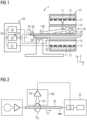
- FIG. 1shows a schematic representation of an embodiment of a magnetic resonance tomograph 1 according to the invention with a 33 with a sensor 60.
- the magnet unit 10has a field magnet 11 that generates a static magnetic field B0 for aligning nuclear spins of samples or of the patient 100 in a recording area.
- the recording areais characterized by an extremely homogeneous static magnetic field B0, with the homogeneity particularly affecting the magnetic field strength or the amount.
- the recording areais almost spherical and is arranged in a patient tunnel 16, which extends in a longitudinal direction 2 extends through the magnet unit 10.
- a patient couch 30can be moved in the patient tunnel 16 by the traversing unit 36 .
- the field magnet 11is usually a superconducting magnet that can provide magnetic fields with a magnetic flux density of up to 3T, and even more in the case of the latest devices. For lesser Field strengths, however, permanent magnets or electromagnets with normally conducting coils can also be used.
- the magnet unit 10has gradient coils 12, which are designed to superimpose variable magnetic fields in three spatial directions on the magnetic field B0 for spatial differentiation of the recorded imaging regions in the examination volume.
- the gradient coils 12are usually coils made from normally conducting wires, which can generate mutually orthogonal fields in the examination volume.
- the magnet unit 10also has a body coil 14 which is designed to emit a high-frequency signal supplied via a signal line into the examination volume and to receive resonance signals emitted by the patient 100 and emit them via a signal line.
- a control unit 20supplies the magnet unit 10 with the various signals for the gradient coils 12 and the body coil 14 and evaluates the received signals.
- control unit 20has a gradient control 21, which is designed to supply the gradient coils 12 with variable currents via supply lines, which provide the desired gradient fields in the examination volume in a time-coordinated manner.
- control unit 20has a high-frequency unit 22 which is designed to generate a high-frequency pulse with a predetermined time profile, amplitude and spectral power distribution for exciting a magnetic resonance of the nuclear spins in the patient 100 .
- Pulse powers in the kilowatt rangecan be achieved.
- the excitation pulsescan be radiated into the patient 100 via the body coil 14 or also via a local transmitting antenna.
- a controller 23communicates with the gradient controller 21 and the radio-frequency unit 22 via a signal bus 25.
- a local coil 50is arranged on the patient 100 and is connected to the high-frequency unit 22 and its receiver 70 via a line 33 .
- the body coil 14it is also conceivable for the body coil 14 to receive magnetic resonance signals and forward them to the receiver 70 .
- the patient tunnelpreferably has a radius R for which: R ⁇ lambda L ⁇ 1 , 841 / 2 * pi
- lambda Lindicates the wavelength of a radio wave in air at the Larmor frequency of the magnetic resonance tomograph 1 . If the radius R is smaller than the right-hand term, the radio wave propagates in the patient tunnel 16 with exponential attenuation and the interference signal is strongly attenuated in the center in the examination area FoV. Lambda L is also referred to as the cut-off wavelength of a circular waveguide, the associated frequency as the cut-off frequency.
- electromagnetic signals which are introduced into the patient tunnel 16 by an electrical conductor such as the line 33are not subject to exponential attenuation, since the line 33 acts like a coaxial conductor together with a conductive wall of the patient tunnel.
- the interferencecan be entered by induction or capacitively outside of the patient tunnel 16, for example on a shielding of the line 33.
- the line 33then acts as an interference conductor within the meaning of the invention.
- the local coil 50consequently receives a mixture of the resonance magnetic signal and interference signals, which are introduced into the patient tunnel 16 via interference conductors, among other things.
- active interference suppressionin which the interference signal is scaled and has the opposite sign to the signal from the local coil 50 is added by the receiver 70, the interference signal in the received signal of the local coil can be reduced or ideally completely suppressed.
- the interference signalitself must be known as precisely as possible. It is then possible, for example by autocorrelation, to determine the proportion of the interference signal in the received signal of the local coil 50 and to significantly reduce or completely eliminate it by a suitable choice of phase shift and amplification or attenuation.
- a sensor 60is therefore provided on the interference line in order to detect the interference signal captured by the interference line and introduced into the patient tunnel 16 with as little distortion as possible.
- Different embodiments of the sensorare presented below.
- an example of a line 33 between local coil 50 and receiver 70is shown as an interference conductor, not according to the invention.
- An alternating current I STinduced by an electromagnetic interference field, flows on the outer conductor of the coaxial line.
- Sourcecan be devices in other rooms or buildings.
- the alternating current I STin turn generates an alternating magnetic field B ST which surrounds the signal line 33 or the interfering conductor.
- the sensor 60uses this by coupling a coil or induction loop 61 to the magnetic interference field B ST .
- the induction loop 61is aligned relative to the interfering conductor such that a normal vector of a surface enclosed by the induction loop 61 is oriented tangentially to the magnetic field lines of the magnetic field B ST running in a circle around the signal line.
- the voltage induced in the induction loop 61is at a maximum and the sensor 60 supplies an interference signal that is as large and low-interference as possible.
- the sensor 60preferably also has a low-noise preamplifier 62 (LNA) which amplifies the induced signal before it is forwarded to the receiver 70 via a sensor line 63 .
- LNAlow-noise preamplifier
- the induction loop 61can also have several turns to the induced to increase tension.
- the induction loop 61is galvanically isolated from the interference conductor.
- sensors 60instead of the coil or induction loop, other sensors 60 are also conceivable, which can detect a high-frequency magnetic alternating field in amplitude and/or phase, such as Hall detectors or Josephson contacts or SQID (superconducting quantum interference device).
- SQIDsuperconducting quantum interference device
- 3 12shows an example of the sensor 60 which is not according to the invention.
- the sensor 60is arranged here on a line 31 for supplying energy to a light, for example for the patient tunnel 16, by way of example.
- the senor 60has an induction loop 61 whose windings are wound around a body which encloses the line 33 or the interfering conductor on the outside. It is also conceivable that the body itself is virtual, i.e. the winding is arranged in this form in a self-supporting manner without a winding body.
- the bodypreferably has the shape of a toroid or cylinder ring, but it is also conceivable that instead of the ring, for example, an ellipse, an ovoid or a polygon encloses the interfering conductor.
- the cross-section of the body and thus the shape of a single winding of the induction loop 61is not only circular, but also, for example, ellipse, polygon or mixed shapes such as D-shaped.
- the individual windingsextend around the body and are in turn lined up circumferentially around the interfering conductor so that two terminals of the induction loop 61 come to lie side by side as shown, so that they are closely spaced and have a small enclosed area back to the low noise Preamplifier 62 can be performed.
- An induction loop 61 shaped in this wayhas, due to the extent along the field lines with a maximum pierced by the field lines B ST , an enclosed area maximum induced voltage.
- the sensoris easy to slide on and is insensitive to changes in position and external interference signals, ie interference signals that are not carried on the interference conductor.
- a gradient connection linewhich connects the controller 20 to the gradient coils 12, is assumed to be an example of the interference line.
- the interference signalis not picked up by induction, but capacitively via the electrical field component of the interference signal.
- the sensor 60can have one or, as shown here, two capacitive coupling elements 64 . These are arranged in the immediate vicinity, preferably on the outside of an insulator of the interfering conductor and are galvanically isolated from it. In these, a voltage difference is caused by the electrical field component of a high-frequency interference propagating along the interference conductor, which is amplified by the low-noise preamplifier 62 and in turn fed to the receiver 70 . It is also conceivable that only one capacitive coupling element 64 is provided and the reference potential is a signal ground.
- the sensorhas a directional coupler.
- a directional coupleris considered to be any form of signal pick-up from the interfering conductor that delivers a signal that is dependent on a propagation direction of the interfering signal on the interfering conductor. This can be a classic directional coupler, but combinations of several inductive or capacitive coupling elements that supply a direction-dependent signal are also conceivable.
- the directional couplermakes it possible to distinguish between signals whose direction of propagation is directed away from the local coil 50 and others that are entered into the local coil.
- a parasitic magnetic resonance signal on an outer conductor of the coaxial cablecan advantageously be distinguished from an interference signal that has entered, so that the magnetic resonance signal is not incorrectly identified as an interference signal and artefacts are not caused by the interference suppression during image analysis.
- the sensor 60 according to the inventionhas a resonance element 66 in order to make the sensor 60 particularly sensitive to a predetermined frequency, preferably to the Larmor frequency of the magnetic resonance tomograph 1 . Since the image is captured by magnetic resonance signals from nuclear spins, whose frequency in the static magnetic field B0 corresponds to the Larmor frequency of the spins in this magnetic field, this reacts particularly sensitively to disturbances in this frequency range. Better interference suppression is therefore particularly effective here and can be achieved by higher output signals from sensor 60 in this frequency range. This can be achieved, for example, by a resonance of the sensor with an amplitude maximum at the Larmor frequency. for the inside 6 In the toroidal coil shown as an example (not according to the invention), this is possible through a capacitance as a resonance element 66 in a parallel resonant circuit.
- An active protective element 67can therefore be provided as protection, here in the form of a pin diode, which, controlled by the controller 20, reduces the input signal of the low-noise amplifier 62.
- Thiscan be as in 6 can be achieved in that the PIN diode, as a variable capacitance, detunes the resonant circuit made up of the induction loop 61 and the resonant element 66 .
- the PIN diodeis operated as a switch that short-circuits the resonant circuit or detunes it by switched-on capacitances or inductances.
- Other mechanical or electronic switchescan also be used for this purpose.
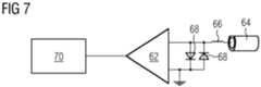
- FIG. 7 12shows an example of the sensor 60 not according to the invention with a capacitive coupling element 64 which is tuned to the Larmor frequency by an inductance as a resonance element 66. Also shown in this figure is an exemplary passive protection element 68 consisting of two anti-parallel diodes which short-circuit and thus limit any signal greater than the threshold voltage.
- inductive pick-up or inductive loop 61 or capacitive coupling element 64each with active protective elements 67 and/or passive protective elements 68, are also conceivable.
Landscapes
- Physics & Mathematics (AREA)
- Health & Medical Sciences (AREA)
- Life Sciences & Earth Sciences (AREA)
- Condensed Matter Physics & Semiconductors (AREA)
- General Physics & Mathematics (AREA)
- High Energy & Nuclear Physics (AREA)
- Nuclear Medicine, Radiotherapy & Molecular Imaging (AREA)
- Engineering & Computer Science (AREA)
- Pathology (AREA)
- Molecular Biology (AREA)
- Radiology & Medical Imaging (AREA)
- Veterinary Medicine (AREA)
- Biomedical Technology (AREA)
- Heart & Thoracic Surgery (AREA)
- Medical Informatics (AREA)
- Biophysics (AREA)
- Surgery (AREA)
- Animal Behavior & Ethology (AREA)
- General Health & Medical Sciences (AREA)
- Public Health (AREA)
- Signal Processing (AREA)
- Epidemiology (AREA)
- Magnetic Resonance Imaging Apparatus (AREA)
Description
Translated fromGermanDie Erfindung betrifft einen Magnetresonanztomographen mit einer Leitung für eine elektrische Verbindung in einem Magnetresonanztomographen mit einem Anschluss an den Magnetresonanztomographen. Magnetresonanztomographen sind bildgebende Vorrichtungen, die zur Abbildung eines Untersuchungsobjektes Kernspins des Untersuchungsobjektes mit einem starken äußeren Magnetfeld ausrichten und durch ein magnetisches Wechselfeld zur Präzession um diese Ausrichtung anregen. Die Präzession bzw. Rückkehr der Spins aus diesem angeregten in einen Zustand mit geringerer Energie wiederum erzeugt als Antwort ein magnetisches Wechselfeld, das über Antennen empfangen wird.The invention relates to a magnetic resonance tomograph with a line for an electrical connection in a magnetic resonance tomograph with a connection to the magnetic resonance tomograph. Magnetic resonance tomographs are imaging devices which, in order to image an examination object, align nuclear spins of the examination object with a strong external magnetic field and excite them to precess around this alignment by means of an alternating magnetic field. The precession or return of the spins from this excited state to a lower-energy state in turn generates an alternating magnetic field in response, which is received by antennas.
Mit Hilfe von magnetischen Gradientenfeldern wird den Signalen eine Ortskodierung aufgeprägt, die nachfolgend eine Zuordnung von dem empfangenen Signal zu einem Volumenelement ermöglicht. Das empfangene Signal wird dann ausgewertet und eine dreidimensionale bildgebende Darstellung des Untersuchungsobjektes bereitgestellt. Zum Empfang des Signals werden vorzugsweise lokale Empfangsantennen, sogenannte Lokalspulen verwendet, die zur Erzielung eines besseren Signal-Rauschabstandes unmittelbar am Untersuchungsobjekt angeordnet werden. Die Empfangsantennen können auch in einer Patientenliege verbaut sein.With the help of magnetic gradient fields, a spatial coding is impressed on the signals, which subsequently enables the received signal to be assigned to a volume element. The signal received is then evaluated and a three-dimensional imaging representation of the examination object is provided. To receive the signal, local receiving antennas, so-called local coils, are preferably used, which are arranged directly on the examination object to achieve a better signal-to-noise ratio. The receiving antennas can also be installed in a patient bed.
Magnetresonanztomographen erfordern in zweierlei Hinsicht eine Hochfrequenzabschirmung. Zum einen werden zur Anregung der Kernspins Hochfrequenzimpulse mit Leistungen im Kilowattbereich erzeugt, die nur teilweise im Patienten absorbiert werden. Radiowellen, die die Patientendurchführung verlassen, werden in den Raum abgestrahlt und müssen daher zur Einhaltung von Emissionsgrenzwerten abgeschirmt werden.Magnetic resonance tomographs require radiofrequency shielding in two ways. On the one hand, to excite the nuclear spins, high-frequency pulses with outputs in the kilowatt range are generated, which are only partially absorbed in the patient. Radio waves leaving the patient passageway are radiated into the room and must therefore be shielded to meet emission limits.
Umgekehrt sind die für die Bildgebung zu empfangenden Magnetresonanzsignale extrem schwach. Um hier ein ausreichendes Signal-zu-Rausch-Verhältnis (SNR) zu erreichen, ist eine Abschirmung externer Störsignal erforderlich.Conversely, the magnetic resonance signals to be received for imaging are extremely weak. In order to achieve a sufficient signal-to-noise ratio (SNR) here, external interference signals must be shielded.
Deshalb werden im Stand der Technik um einen Magnetresonanztomographen aufwändige Schirmkabinen installiert, um sowohl Emissionen als auch Immissionen zu reduzieren.For this reason, in the prior art, complex shielded cabins are installed around a magnetic resonance tomograph in order to reduce both emissions and immissions.
Aus dem Dokument
Das Dokument
Aus dem Dokument von
Aus der nicht vorveröffentlichten Patentanmeldung
Es könnte daher eine Aufgabe der Erfindung sein, den Aufwand für eine Abschirmung zu reduzieren.It could therefore be an object of the invention to reduce the outlay for shielding.
Die Aufgabe wird durch einen erfindungsgemäßen Magnetresonanztomographen nach Anspruch 1 gelöst.The object is achieved by a magnetic resonance tomograph according to claim 1 according to the invention.
Der erfindungsgemäße Magnetresonanztomograph weist eine Leitung für eine elektrische Verbindung mit dem Magnetresonanztomographen auf. Die Leitung weist elektrische Leiter auf, die einen elektrischen Strom führen können. Durch die elektrische Leitfähigkeit wirken die Leiter auch als Antennen für elektromagnetische Wellen und können deshalb elektrische Störungen kapazitiv oder durch Induktion aufnehmen bzw. aussenden und auch entlang ihrer Erstreckung weiterleiten, beispielsweise in einen abgeschirmten Bereich. Die erfindungsgemäße Leitung weist einen Anschluss, beispielsweise eine feste elektrische Verbindung oder elektrische Steckverbindung zu dem Magnetresonanztomographen auf.The magnetic resonance tomograph according to the invention has a line for an electrical connection to the magnetic resonance tomograph. The line has electrical conductors that can carry an electric current. Due to the electrical conductivity, the conductors also act as antennas for electromagnetic waves and can therefore absorb or emit electrical interference capacitively or by induction and also forward it along their extension, for example into a shielded area. The line according to the invention has a connection, for example a permanent electrical connection or an electrical plug-in connection to the magnetic resonance tomograph.
Die Leitung weist einen elektrischen Störleiter auf. Darunter ist ein Leiter zu verstehen, der durch seine Anordnung oder Verschaltung in der Lage ist, ein Störsignal zu übertragen. Als Störsignal im Sinne dieser Erfindung wird dabei jedes Signal betrachtet, dass nicht zur Bildererfassung beiträgt und die Qualität der bereitgestellten Bilder beeinträchtigen kann. Es kann sich dabei also auch um Signale handeln, die zwar zur Bilderfassung notwendig sind, aber nicht unmittelbar Bildinformation tragen. Beispiele sind Störungen auf Stromversorgungsleitungen, Steuerleitungen, Kommunikationsleitungen, wie zum Beispiel die Verständigungseinrichtungen mit dem Patienten, oder eine Beleuchtung im Patiententunnel. Aber auch unmittelbar für die Bilderzeugung relevante Leitungen wie Gradientenspulenanschlussleitungen, Shim-Stromleitungen, und deren Signale können bei der Bilderfassung zu Artefakten führen und werden in diesem Sinne als Störleiter betrachtet.The line has an electrical interference conductor. This means a conductor that is able to transmit an interference signal due to its arrangement or wiring. Any signal that does not contribute to image acquisition is considered to be an interference signal within the meaning of this invention and may affect the quality of the images provided. It can also involve signals that are necessary for image acquisition but do not directly carry image information. Examples are disturbances on power supply lines, control lines, communication lines, such as the communication devices with the patient, or lighting in the patient tunnel. However, lines that are directly relevant to image generation, such as gradient coil connection lines, shim power lines, and their signals can lead to artefacts during image acquisition and are considered interference conductors in this sense.
Der elektrische Störleiter kann dabei auch ein Leiter der Leitung sein, der eigentlich dafür vorgesehen ist, die Signalleitungen der Leitung vor Störsignalen zu schützen. Beispielsweise kann ein Außenleiter einer Koaxialleitung auch selbst Störsignale als Leiter in einen geschirmten Raum eintragen. Auch können mehrere Leiter bzw. Adern einer Leitung Störleiter sein.The electrical interference conductor can also be a conductor of the line that is actually intended to protect the signal lines of the line from interference signals. For example, an outer conductor of a coaxial line can itself introduce interference signals as a conductor into a shielded room. Several conductors or wires in a line can also be interference conductors.
Das Merkmal, dass der Störleiter ausgelegt ist, ein elektromagnetisches Störsignal aus der Umgebung aufzunehmen und/oder in diese abzustrahlen gibt dabei lediglich an, dass diese durch die elektrischen Eigenschaften und die Anordnung des Störleiters möglich ist und dieser dadurch eine potentielle Quelle für einen Störeintrag darstellt. Es soll jedoch in keiner Weise im Sinne des Patentanspruchs erforderlich sein, dass der Störleiter mit einem zusätzlichen Störsignal beaufschlagt ist bzw. wird.The feature that the interference conductor is designed to pick up an electromagnetic interference signal from the environment and/or emit it into it merely indicates that this is possible due to the electrical properties and the arrangement of the interference conductor and that this therefore represents a potential source of interference . However, it should in no way be necessary in the sense of the patent claim that the interference conductor is or is acted upon by an additional interference signal.
Die erfindungsgemäße Leitung weist weiterhin einen Sensor auf, der in elektrischer und/oder magnetischer Kopplung mit der Störleitung ist. Unterschiedliche denkbare Ausführungsformen der Kopplung sind im Einzelnen in den Unteransprüchen angegeben.The line according to the invention also has a sensor which is electrically and/or magnetically coupled to the fault line. Different conceivable embodiments of the coupling are specified in detail in the dependent claims.
Der Sensor ist über eine Signalverbindung mit dem Magnetresonanztomographen verbindbar, über die das aufgenommene Störsignal von dem Störleiter an eine Steuerung des Magnetresonanztomographen weitergeleitet werden kann. Dies ermöglicht der Steuerung, das so bekannte Störsignal in den Magnetresonanzsignalen zu erkennen und zu unterdrücken.The sensor can be connected to the magnetic resonance tomograph via a signal connection, via which the recorded interference signal can be forwarded by the interference conductor to a controller of the magnetic resonance tomograph. This enables the controller to recognize and suppress the interference signal, which is known in this way, in the magnetic resonance signals.
Der Sensor weist einen Richtkoppler auf. Als Richtkoppler ist hierbei jede Kopplungseinrichtung zu verstehen, die als Koppelelement ein Signal liefert, das abhängig von der Ausbreitungsrichtung eines Störsignals auf dem Störleiter ist. Ein Richtkoppler lässt sich beispielsweise durch Streifenleitungen parallel zum Störleiter oder Transformatoren realisieren.The sensor has a directional coupler. In this context, a directional coupler is to be understood as any coupling device which, as a coupling element, supplies a signal which is dependent on the direction of propagation of an interference signal on the interference conductor. A directional coupler can be implemented, for example, using striplines parallel to the interfering conductor or transformers.
Auf vorteilhafte Weise ermöglicht der erfindungsgemäße Magnetresonanztomograph mit einem Sensor, Störsignale auf Leitungen möglichst an der Quelle bzw. an einem Ort zu erkennen und/oder zu erfassen, wo sie von den Nutzsignalen gut getrennt vorliegen, sodass sie anschließend in der Bilderfassung effektiv unterdrückt werden können.The magnetic resonance tomograph according to the invention with a sensor advantageously enables interference signals on lines to be recognized and/or recorded at the source or at a location where they are well separated from the useful signals, so that they can then be effectively suppressed in the image acquisition .
Ein Richtkoppler kann unterscheiden, ob ein Signal von einer Lokalspule kommt oder sich in Richtung zu der Lokalspule bewegt. Während Störungen bei der Bilderfassung problematisch sind, die in Richtung der Lokalspule laufen, führen parasitäre Magnetresonanzsignale erst zu Artefakten, wenn diese irrtümlich für Störsignale gehalten werden und versucht wird, diese zu kompensieren. Ein Richtkoppler erlaubt es dabei auf Vorteilhafte Weise, beide Signale zu trennen und lediglich die Störsignale zu unterdrücken.A directional coupler can distinguish whether a signal is coming from a local coil or is moving towards the local coil. While interference in image acquisition that runs in the direction of the local coil is problematic, parasitic magnetic resonance signals only lead to artifacts if they are mistaken for interference signals and an attempt is made to compensate for them. A directional coupler advantageously allows the two signals to be separated and only the interference signals to be suppressed.
Weitere vorteilhafte Ausführungsformen sind in den Unteransprüchen angegeben.Further advantageous embodiments are specified in the subclaims.
In einer möglichen Ausführungsform des erfindungsgemäßen Magnetresonanztomographen ist der Sensor auf einer Larmorfrequenz des Magnetresonanztomographen resonant. Als Larmorfrequenz wird dabei die Magnetresonanzfrequenz der zu erfassenden Kernspins im statischen magnetischen Feld B0 des Magnetresonanztomographen bezeichnet. Die Resonanz kann beispielsweise bei einer induktiven Ankopplung mittels Spule durch eine mit der Spule verbundenen Kapazität erreicht werden.In a possible embodiment of the magnetic resonance tomograph according to the invention, the sensor is resonant at a Larmor frequency of the magnetic resonance tomograph. The Larmor frequency is the magnetic resonance frequency of the nuclear spins to be detected in the static magnetic field B0 of the magnetic resonance tomograph. In the case of an inductive coupling by means of a coil, for example, the resonance can be achieved by a capacitance connected to the coil.
Zur Bildgebung werden bei einem Magnetresonanztomographen Magnetresonanzsignale von Kernspins erfasst, die die Larmorfrequenz aufweisen. Die Bilderfassung ist daher besonders sensibel für Störungen mit dieser Frequenz. Durch einen auf dieser Frequenz resonanten Sensor können wiederum die besonders relevanten Störsignale mit höherer Amplitude und somit besser erfasst werden.For imaging, magnetic resonance signals of nuclear spins, which have the Larmor frequency, are recorded in a magnetic resonance tomograph. Image acquisition is therefore particularly sensitive to interference at this frequency. A sensor that resonates at this frequency can in turn detect the particularly relevant interference signals with a higher amplitude and thus better.
In einer denkbaren Ausführungsform des erfindungsgemäßen Magnetresonanztomographen weist der Sensor einen Schutz gegen einen Anregungspuls des Magnetresonanztomographen auf. Der Anregungspuls für die Kernspins mit Leistungen bis zu Kilowatt auf der Larmorfrequenz kann insbesondere bei einem auf dieser Frequenz resonanten Sensor zur Beschädigung von Eingangselementen führen. Der Sensor kann deshalb beispielsweise passive Dioden zum Kurzschluss der auftretenden Spannungen oberhalb der Sperrspannung aufweisen. Auch aktive Schaltungen, die den Sensor gesteuert von der Steuerung verstimmen, sind möglich.In a conceivable embodiment of the magnetic resonance tomograph according to the invention, the sensor has protection against an excitation pulse of the magnetic resonance tomograph. The excitation pulse for the nuclear spins with powers of up to kilowatts at the Larmor frequency can lead to damage to input elements, particularly in the case of a sensor resonating at this frequency. The sensor can therefore have, for example, passive diodes for short-circuiting the voltages that occur above the blocking voltage. Active circuits that detune the sensor controlled by the controller are also possible.
Auf vorteilhafte Weise verhindern die Schutzelemente eine Beschädigung des Sensors durch den Magnetresonanztomographen.The protective elements advantageously prevent the sensor from being damaged by the magnetic resonance tomograph.
In einer möglichen Ausführungsform des erfindungsgemäßen Magnetresonanztomographen ist der Sensor benachbart zu einem Patiententunnel angeordnet. Der Patiententunnel gibt hierbei den Ort an, an dem Magnetresonanzsignale zur Bilderfassung empfangen werden und der deshalb besonders sensitiv für Störungen ist. Als benachbart wird dabei ein Abstand angesehen, der kleiner als 50%, 20% oder 10% der Länge der Leitung oder einer Vakuumwellenlänge einer Radiowelle bei der Larmorfrequenz des Magnetresonanztomographen ist.In a possible embodiment of the magnetic resonance tomograph according to the invention, the sensor is arranged adjacent to a patient tunnel. In this case, the patient tunnel indicates the location at which magnetic resonance signals for image acquisition are received and which is therefore particularly sensitive to disturbances. A distance that is less than 50%, 20% or 10% of the length of the line or a vacuum wavelength of a radio wave at the Larmor frequency of the magnetic resonance tomograph is considered to be adjacent.
Die Anordnung des Sensors an der Leitung in der Nähe bzw. benachbart zu dem Patiententunnel stellt auf vorteilhafte Weise sicher, dass möglichst wenige Störungen zwischen Sensor und Patiententunnel eingestrahlt, aber nicht durch den Sensor erfasst werden.The arrangement of the sensor on the line in the vicinity or adjacent to the patient tunnel advantageously ensures that as few disturbances as possible are radiated in between the sensor and patient tunnel but are not detected by the sensor.
Die oben beschriebenen Eigenschaften, Merkmale und Vorteile dieser Erfindung sowie die Art und Weise, wie diese erreicht werden, werden klarer und deutlicher verständlich im Zusammenhang mit der folgenden Beschreibung der Ausführungsbeispiele, die im Zusammenhang mit den Zeichnungen näher erläutert werden.The properties, features and advantages of this invention described above, and the manner in which they are achieved, will become clearer and more clearly understood in connection with the following description of the exemplary embodiments, which are explained in more detail in connection with the drawings.
Es zeigen:
- Fig. 1
- eine schematische Darstellung eines erfindungsgemäßen Magnetresonanztomographen;
- Fig. 2
- eine schematische Darstellung einer nicht-erfindungsgemässen Leitung eines Magnetreso- nanztomographen mit einem Sensor;
- Fig. 3
- eine schematische Darstellung einer nichterfindungsgemässenLeitung eines Magnetresonanztomographen mit einem Sensor;
- Fig. 4
- eine schematische Darstellung einer nicht-erfindungsgemässen Leitung eines Magnetreso- nanztomographen mit einem Sensor;
- Fig. 5
- eine schematische Darstellung einer Ausführungsform einer Leitung des erfindungsgemäßen Magnetresonanztomographen mit einem Sensor;
- Fig. 6
- eine schematische Darstellung eines nichterfindungsgemässen Sensors eines Magnetresonanztomographen;
- Fig. 7
- eine schematische Darstellung eines nichterfindungsgemässen Sensors eines Magnetresonanztomographen.
- 1
- a schematic representation of a magnetic resonance tomograph according to the invention;
- 2
- a schematic representation of a non-inventive line of a magnetic resonance tomograph with a sensor;
- 3
- a schematic representation of a line, not according to the invention, of a magnetic resonance tomograph with a sensor;
- 4
- a schematic representation of a non-inventive line of a magnetic resonance tomograph with a sensor;
- figure 5
- a schematic representation of an embodiment of a line of the magnetic resonance tomograph according to the invention with a sensor;
- 6
- a schematic representation of a non-inventive sensor of a magnetic resonance tomograph;
- 7
- a schematic representation of a non-inventive sensor of a magnetic resonance tomograph.
Die Magneteinheit 10 weist einen Feldmagneten 11 auf, der ein statisches Magnetfeld B0 zur Ausrichtung von Kernspins von Proben bzw. des Patienten 100 in einem Aufnahmebereich erzeugt. Der Aufnahmebereich zeichnet sich durch ein äußerst homogenes statisches Magnetfeld B0 aus, wobei die Homogenität insbesondere die Magnetfeldstärke bzw. den Betrag betrifft. Der Aufnahmebereich ist nahezu kugelförmig und in einem Patiententunnel 16 angeordnet, der sich in einer Längsrichtung 2 durch die Magneteinheit 10 erstreckt. Eine Patientenliege 30 ist in dem Patiententunnel 16 von der Verfahreinheit 36 bewegbar. Üblicherweise handelt es sich bei dem Feldmagneten 11 um einen supraleitenden Magneten, der magnetische Felder mit einer magnetischen Flussdichte von bis zu 3T, bei neuesten Geräten sogar darüber, bereitstellen kann. Für geringere Feldstärken können jedoch auch Permanentmagnete oder Elektromagnete mit normalleitenden Spulen Verwendung finden.The
Weiterhin weist die Magneteinheit 10 Gradientenspulen 12 auf, die dazu ausgelegt sind, zur räumlichen Differenzierung der erfassten Abbildungsbereiche in dem Untersuchungsvolumen dem Magnetfeld B0 variable Magnetfelder in drei Raumrichtungen zu überlagern. Die Gradientenspulen 12 sind üblicherweise Spulen aus normalleitenden Drähten, die zueinander orthogonale Felder in dem Untersuchungsvolumen erzeugen können.Furthermore, the
Die Magneteinheit 10 weist ebenfalls eine Körperspule 14 auf, die dazu ausgelegt ist, ein über eine Signalleitung zugeführtes Hochfrequenzsignal in das Untersuchungsvolumen abzustrahlen und von dem Patient 100 emittierte Resonanzsignale zu empfangen und über eine Signalleitung abzugeben.The
Eine Steuereinheit 20 versorgt die Magneteinheit 10 mit den verschiedenen Signalen für die Gradientenspulen 12 und die Körperspule 14 und wertet die empfangenen Signale aus.A
So weist die Steuereinheit 20 eine Gradientenansteuerung 21 auf, die dazu ausgelegt ist, die Gradientenspulen 12 über Zuleitungen mit variablen Strömen zu versorgen, welche zeitlich koordiniert die erwünschten Gradientenfelder in dem Untersuchungsvolumen bereitstellen.Thus, the
Weiterhin weist die Steuereinheit 20 eine Hochfrequenzeinheit 22 auf, die ausgelegt ist, einen Hochfrequenz-Puls mit einem vorgegebenen zeitlichen Verlauf, Amplitude und spektraler Leistungsverteilung zur Anregung einer Magnetresonanz der Kernspins in dem Patienten 100 zu erzeugen. Dabei können Pulsleistungen im Bereich von Kilowatt erreicht werden. Die Anregungspulse können über die Körperspule 14 oder auch über eine lokale Sendeantenne in den Patienten 100 abgestrahlt werden.Furthermore, the
Eine Steuerung 23 kommuniziert über einen Signalbus 25 mit der Gradientensteuerung 21 und der Hochfrequenzeinheit 22.A
Auf dem Patienten 100 ist eine Lokalspule 50 angeordnet, die über eine Leitung 33 mit der Hochfrequenzeinheit 22 und deren Empfänger 70 verbunden ist. Denkbar ist es aber auch, dass die Körperspule 14 Magnetresonanzsignale empfängt und an den Empfänger 70 weiterleitet.A
Der Patiententunnel hat vorzugsweise einen Radius R für den gilt:
LambdaL gibt dabei die Wellenlänge einer Radiowelle in Luft bei der Larmorfrequenz des Magnetresonanztomographen 1 an. Ist der Radius R kleiner als der rechte Term, so breitet sich die Radiowelle in dem Patiententunnel 16 exponentiell gedämpft aus und das Störsignal ist in der Mitte im Untersuchungsbereich FoV stark gedämpft. LambdaL wird auch als Grenzwellenlänge eines Rundhohlleiters bezeichnet, die dazugehörige Frequenz als Grenzfrequenz.In this case, lambdaL indicates the wavelength of a radio wave in air at the Larmor frequency of the magnetic resonance tomograph 1 . If the radius R is smaller than the right-hand term, the radio wave propagates in the
Der exponentiellen Dämpfung unterliegen jedoch nicht elektromagnetische Signale, die durch einen elektrischen Leiter wie die Leitung 33 in den Patiententunnel 16 eingetragen werden, denn die Leitung 33 wirkt zusammen mit einer leitenden Wandung des Patiententunnels wie ein Koaxialleiter. Die Störung kann durch Induktion oder kapazitiv außerhalb des Patiententunnels 16 beispielsweise auf eine Abschirmung der Leitung 33 eingetragen werden. Die Leitung 33 wirkt dann als Störleiter im Sinne der Erfindung.However, electromagnetic signals which are introduced into the
Die Lokalspule 50 empfängt folglich ein Gemisch aus Resonanzmagnetsignal und Störsignalen, die unter anderem über Störleiter in den Patiententunnel 16 eingetragen werden. Mittels aktiver Störunterdrückung, bei der das Störsignal skaliert und mit umgekehrtem Vorzeichen zu dem Signal der Lokalspule 50 von dem Empfänger 70 addiert wird, kann das Störsignal in dem Empfangssignal der Lokalspule reduziert oder im Idealfall ganz unterdrückt werden. Dazu muss jedoch das Störsignal selbst möglichst genau bekannt sein. Dann ist es beispielsweise durch Autokorrelation möglich, den Anteil des Störsignals in dem Empfangssignal der Lokalspule 50 zu bestimmen und durch geeignete Wahl von Phasenverschiebung und Verstärkung bzw. Abschwächung diesen wesentlich zu verringern oder ganz zu eliminieren.The
Gemäß der Erfindung ist deshalb ein Sensor 60 an der Störleitung vorgesehen, um das von der Störleitung eingefangene und in den Patiententunnel 16 eingetragene Störsignal möglichst unverfälscht zu erfassen. Unterschiedliche Ausführungsformen des Sensors sind nachfolgend dargestellt.According to the invention, a
In
Grundsätzlich sind anstelle der Spule bzw. Induktionsschleife auch andere Sensoren 60 denkbar, die ein hochfrequentes magnetisches Wechselfeld in Amplitude und/oder Phase erfassen können, wie beispielsweise Hall-Detektoren oder Josephson-Kontakte bzw. SQID (superconducting quantum interference device) .Basically, instead of the coil or induction loop,
Der Sensor 60 weist hier eine Induktionsschleife 61 auf, deren Windungen um einen Körper gewickelt sind, der die Leitung 33 bzw. den Störleiter außenumfänglich umschließt. Denkbar ist auch, dass der Körper selbst virtuell ist, d.h. die Wicklung freitragend ohne Wickelkörper in dieser Form angeordnet ist. Vorzugsweise hat der Körper dabei die Form eines Toroid bzw. Zylinderrings, es ist aber auch denkbar, dass anstelle des Rings beispielsweise eine Ellipse, ein Ovoid oder auch ein Polygon den Störleiter umschließt. Ebenfalls ist es denkbar, dass der Querschnitt des Köpers und damit die Form einer einzelnen Windung der Induktionsschleife 61 nicht nur die Kreisform, sondern beispielsweise ebenfalls Ellipse, Polygon oder auch Mischformen wie D-förmig. Mit anderen Worten, die einzelnen Windungen erstrecken sich um den Körper und sind wiederum entlang des Umfangs um den Störleiter aneinandergereiht, sodass zwei Anschlüsse der Induktionsschleife 61, wie dargestellt nebeneinander zu liegen kommen, sodass diese mit geringem Abstand und kleiner umschlossener Fläche zurück zu dem rauscharmen Vorverstärker 62 geführt werden können.Here, the
Eine derart geformte Induktionsschleife 61 weist durch die Erstreckung entlang der Feldlinien mit einer maximalen von den Feldlinien BST durchstoßenen umschlossenen Fläche eine maximale induzierte Spannung auf. Gleichzeitig ist der Sensor einfach aufzuschieben und ist unempfindlich gegen Positionsänderungen und externe, d.h. nicht auf dem Störleiter geführte Störsignale.An
Hier erfolgt die Aufnahme des Störsignals nicht durch Induktion, sondern kapazitiv über die elektrische Feldkomponente des Störsignals. Der Sensor 60 kann einen, oder wie hier dargestellt, zwei kapazitive Koppelelemente 64 aufweisen. Diese sind in unmittelbarer Nähe, vorzugsweise außen an einem Isolator des Störleiters angeordnet und von diesem galvanisch getrennt. In diesen wird durch die elektrische Feldkomponente einer sich entlang des Störleiters ausbreitenden Hochfrequenzstörung eine Spannungsdifferenz verursacht, die von dem rauscharmen Vorverstärker 62 verstärkt und wiederum dem Empfänger 70 zugeführt wird. Denkbar ist es auch, dass lediglich ein kapazitives Koppelelement 64 vorgesehen ist und das Bezugspotential eine Signalmasse ist.Here, the interference signal is not picked up by induction, but capacitively via the electrical field component of the interference signal. The
Die in
Der Richtkoppler ermöglicht, zwischen Signalen zu unterscheiden, deren Ausbreitungsrichtung von der Lokalspule 50 weg gerichtet und and solchen, die in die Lokalspule eingetragen werden. So kann auf vorteilhafte Weise ein parasitäres Magnetresonanzsignal auf einem Außenleiter des Koaxialkabels von einem eingetragenen Störsignal unterschieden werden, sodass nicht das Magnetresonanzsignal fehlerhaft als Störsignal identifiziert wird und dadurch Artefakte durch die Störunterdrückung bei der Bildauswertung verursacht werden.The directional coupler makes it possible to distinguish between signals whose direction of propagation is directed away from the
In der Ausführungsform der
Durch einen großen Dynamikumfang zwischen Störsignal und Magnetresonanzsignal auf der einen Seite und dem Hochfrequenz-puls zur Anregung der Kernspins auf der anderen Seite ist es insbesondere bei einem resonanten Sensor möglich, dass beispielsweise durch hohe Eingangsamplituden während des Anregungspulses der Sensor, insbesondere der rauscharme Verstärker 62 beschädigt wird. Als Schutz kann deshalb ein aktives Schutzelement 67 vorgesehen sein, hier in Form einer Pin-Diode, das gesteuert von der Steuerung 20 das Eingangssignal des rauscharmen Verstärkers 62 reduziert. Dies kann wie in
Denkbar sind auch andere Kombinationen von induktivem Aufnehmer bzw. Induktionsschleite 61 oder kapazitivem Koppelement 64 jeweils mit aktiven Schutzelementen 67 und/oder passiven Schutzelementen 68.Other combinations of inductive pick-up or
Obwohl die Erfindung im Detail durch das bevorzugte Ausführungsbeispiel näher illustriert und beschrieben wurde, so ist die Erfindung nicht durch die offenbarten Beispiele eingeschränkt und andere Variationen können vom Fachmann hieraus abgeleitet werden, ohne den Schutzumfang der Erfindung zu verlassen.Although the invention has been illustrated and described in detail by the preferred embodiment, the invention is not limited by the disclosed examples and other variations can be derived therefrom by those skilled in the art without departing from the scope of the invention.
Claims (4)
- Magnetic resonance tomography apparatus with a line (33) for an electrical connection in a magnetic resonance tomography apparatus (1) with a connector to the magnetic resonance tomography apparatus (1), wherein the line (33) comprises an electrical interference conductor, which is configured to pick up an electromagnetic interference signal from the environment and/or irradiate said signal into the environment, wherein the line (33) comprises a sensor (60), which is electrically and/or magnetically coupled to the interference line, wherein the line (33) comprises a signal connection, which is configured to provide the interference signal picked up by the sensor at the connector to the magnetic resonance tomography apparatus (1) for processing, wherein the sensor can be connected to the magnetic resonance tomography apparatus via a signal connection via which the interference signal picked up by the interference conductor can be relayed to a control system of the magnetic resonance tomography apparatus,
characterised in that
the sensor (60) comprises a directional coupler (65), wherein the magnetic resonance tomography apparatus (1) comprises a control system (23), which is configured to generate magnetic resonance imaging from received magnetic resonance signals in dependence on the interference signals picked up by the sensor (60). - Magnetic resonance tomography apparatus according to one of the preceding claims, wherein the sensor (60) is protected against an excitation pulse of the magnetic resonance tomography apparatus (1).
- Magnetic resonance tomography apparatus according to claim 1, wherein the sensor (60) is arranged adjacent to a patient tunnel (16).
- Magnetic resonance tomography apparatus according to claim 3, wherein the sensor (60) resonates at a Larmor frequency of the magnetic resonance tomography apparatus (1) .
Priority Applications (3)
| Application Number | Priority Date | Filing Date | Title |
|---|---|---|---|
| EP19201066.8AEP3800479B1 (en) | 2019-10-02 | 2019-10-02 | Magnetic resonance tomograph with a line with sensor for detecting line interference |
| CN202011048715.6ACN112596012B (en) | 2019-10-02 | 2020-09-29 | Circuit with a sensor for detecting a disturbance associated with the circuit |
| US17/039,278US11307273B2 (en) | 2019-10-02 | 2020-09-30 | Line with sensor for detecting line-conducted interference in a magnetic resonance tomography apparatus |
Applications Claiming Priority (1)
| Application Number | Priority Date | Filing Date | Title |
|---|---|---|---|
| EP19201066.8AEP3800479B1 (en) | 2019-10-02 | 2019-10-02 | Magnetic resonance tomograph with a line with sensor for detecting line interference |
Publications (2)
| Publication Number | Publication Date |
|---|---|
| EP3800479A1 EP3800479A1 (en) | 2021-04-07 |
| EP3800479B1true EP3800479B1 (en) | 2023-03-22 |
Family
ID=68137858
Family Applications (1)
| Application Number | Title | Priority Date | Filing Date |
|---|---|---|---|
| EP19201066.8AActiveEP3800479B1 (en) | 2019-10-02 | 2019-10-02 | Magnetic resonance tomograph with a line with sensor for detecting line interference |
Country Status (3)
| Country | Link |
|---|---|
| US (1) | US11307273B2 (en) |
| EP (1) | EP3800479B1 (en) |
| CN (1) | CN112596012B (en) |
Families Citing this family (7)
| Publication number | Priority date | Publication date | Assignee | Title |
|---|---|---|---|---|
| US11460525B2 (en)* | 2020-02-12 | 2022-10-04 | GE Precision Healthcare LLC | Systems and methods for toroidal twinax cable trap |
| EP4012437A1 (en) | 2020-12-11 | 2022-06-15 | Siemens Healthcare GmbH | Magnetic resonance tomography with dual acquisition for interference reduction |
| DE102020215738B4 (en) | 2020-12-11 | 2024-08-22 | Siemens Healthineers Ag | Method for operating a magnetic resonance imaging system with iterative interference reduction by means of at least one auxiliary receiving antenna and one main receiving antenna |
| DE102021205090A1 (en) | 2021-05-19 | 2022-11-24 | Siemens Healthcare Gmbh | Magnetic resonance imaging with signal suppression |
| CN118339566A (en) | 2021-06-11 | 2024-07-12 | 西克公司 | System and method for flux biasing of superconducting quantum circuits |
| EP4328611A1 (en)* | 2022-08-25 | 2024-02-28 | Siemens Healthineers AG | Device and method for suppressing interference in a magnetic resonance tomograph |
| CN119535078B (en)* | 2025-01-22 | 2025-06-10 | 中汽研新能源汽车检验中心(天津)有限公司 | Autonomous driving electromagnetic interference test device, vehicle, method, system and medium |
Citations (1)
| Publication number | Priority date | Publication date | Assignee | Title |
|---|---|---|---|---|
| EP3667348A1 (en)* | 2018-12-13 | 2020-06-17 | Siemens Healthcare GmbH | Device and method for b1 limitation |
Family Cites Families (22)
| Publication number | Priority date | Publication date | Assignee | Title |
|---|---|---|---|---|
| JPH04109933A (en)* | 1990-08-31 | 1992-04-10 | Shimadzu Corp | Electrocardiogram synchronizing device for nuclear magnetic resonance diagnosing unit |
| US6396268B1 (en)* | 2000-10-02 | 2002-05-28 | Ge Medical Systems Global Technology Company, Llc | Magnetic resonance imaging device having magnetic field disturbance compensation |
| AU2003224375A1 (en)* | 2002-05-13 | 2003-11-11 | Koninklijke Philips Electronics N.V. | Magnetic resonance imaging |
| US6788063B1 (en)* | 2003-02-26 | 2004-09-07 | Ge Medical Systems Technology Company, Llc | Method and system for improving transient noise detection |
| US7403011B2 (en)* | 2006-02-13 | 2008-07-22 | General Electric Company | Self-shielded packaging for circuitry integrated with receiver coils in a imaging system |
| WO2008022441A1 (en) | 2006-08-24 | 2008-02-28 | Imris Inc | Automatic noise cancellation for unshielded mr systems |
| US20080315879A1 (en) | 2007-06-19 | 2008-12-25 | General Electric Company | System and apparatus for electromagnetic noise detection in an mr imaging scanner environment |
| US10162026B2 (en)* | 2009-11-09 | 2018-12-25 | Vista Clara Inc. | Noise canceling in-situ NMR detection |
| US8816684B2 (en) | 2009-11-09 | 2014-08-26 | Vista Clara Inc. | Noise canceling in-situ NMR detection |
| CN103026252B (en)* | 2010-07-23 | 2016-01-06 | 皇家飞利浦电子股份有限公司 | Dual Pressure Sensor Signal Chain for Removing Mutually Coupled MRI Interference |
| CN102445675B (en)* | 2010-10-12 | 2016-04-27 | 深圳迈瑞生物医疗电子股份有限公司 | Device for restraining electromagnetic interference and adopt the MR imaging apparatus of this device |
| DE102011006509B4 (en)* | 2011-03-31 | 2016-05-12 | Siemens Aktiengesellschaft | Local coil system, magnetic resonance system and method for transmitting signals from a local coil |
| US20140155732A1 (en) | 2011-07-28 | 2014-06-05 | The Brigham And Women's Hospital, Inc | Systems and methods for portable magnetic resonance measurements of lung properties |
| DE102011086288B4 (en)* | 2011-11-14 | 2014-10-09 | Siemens Aktiengesellschaft | Magnetic resonance imaging system, receiving device for such a system and method for obtaining an image signal in the system |
| US9620283B2 (en)* | 2014-02-27 | 2017-04-11 | GM Global Technology Operations LLC | Low cost wireless (resistive) sensor based on impedance coupling/modulation using MRC |
| RU2685057C2 (en)* | 2014-03-31 | 2019-04-16 | Конинклейке Филипс Н.В. | Magnetic resonance imaging with rf noise detection coils |
| CN105137374B (en)* | 2014-06-03 | 2018-09-25 | 中国科学院上海微系统与信息技术研究所 | A kind of MR imaging method and device of ultrahigh resolution |
| BR112017004353A2 (en)* | 2014-09-05 | 2017-12-05 | Hyperfine Res Inc | ferromagnetic magnification for magnetic resonance imaging |
| US10901055B2 (en)* | 2015-05-15 | 2021-01-26 | Eidgenossische Technische Hochschule (Eth) | Active noise suppression for magnetic resonance based magnetic field probes |
| US10585153B2 (en)* | 2016-11-22 | 2020-03-10 | Hyperfine Research, Inc. | Rotatable magnet methods and apparatus for a magnetic resonance imaging system |
| EP3535594B1 (en)* | 2017-01-13 | 2023-03-29 | Siemens Healthcare GmbH | Magnetic resonance scanner and local coil matrix for operation at low magnetic field strengths |
| EP3467531A1 (en) | 2017-10-05 | 2019-04-10 | Siemens Healthcare GmbH | Magnetic resonance tomograph with active interference suppression and method for suppressing interference in a magnetic resonance tomograph |
- 2019
- 2019-10-02EPEP19201066.8Apatent/EP3800479B1/enactiveActive
- 2020
- 2020-09-29CNCN202011048715.6Apatent/CN112596012B/enactiveActive
- 2020-09-30USUS17/039,278patent/US11307273B2/enactiveActive
Patent Citations (1)
| Publication number | Priority date | Publication date | Assignee | Title |
|---|---|---|---|---|
| EP3667348A1 (en)* | 2018-12-13 | 2020-06-17 | Siemens Healthcare GmbH | Device and method for b1 limitation |
Also Published As
| Publication number | Publication date |
|---|---|
| US11307273B2 (en) | 2022-04-19 |
| EP3800479A1 (en) | 2021-04-07 |
| CN112596012A (en) | 2021-04-02 |
| US20210103018A1 (en) | 2021-04-08 |
| CN112596012B (en) | 2025-02-18 |
Similar Documents
| Publication | Publication Date | Title |
|---|---|---|
| EP3800479B1 (en) | Magnetic resonance tomograph with a line with sensor for detecting line interference | |
| DE4113120C2 (en) | ||
| DE4322352C2 (en) | High-frequency system of a magnetic resonance imaging system with a galvanically decoupled local coil device | |
| EP0222982B1 (en) | Surface coil for nuclear magnetic resonance analysis | |
| EP1279968A2 (en) | Transceiver coil for MR apparatus | |
| DE102013213377B3 (en) | Local coil for MRI system, has diode that is connected to antenna between two connection points in the space formed between two portions of antenna | |
| DE102016212043B4 (en) | Patient couch with flexible RF transmission power distribution for a magnetic resonance tomograph | |
| EP2414859B1 (en) | Devices and cabling for use in a multi-resonant magnetic resonance system | |
| US10809327B2 (en) | Sheath wave barrier-free connecting lead and magnetic resonance tomograph with connecting lead | |
| DE3427666A1 (en) | CIRCUIT ARRANGEMENT FOR A MEASURING HEAD OF A NUCLEAR SPIN RESON | |
| EP3535594A1 (en) | Magnetic resonance scanner and local coil matrix for operation at low magnetic field strengths | |
| DE102014222938A1 (en) | MR local coil system, MR system and method of operating the same | |
| US8179137B2 (en) | Magnetic resonance compatible multichannel stripline balun | |
| DE102020208816A1 (en) | Device and method for active local reception suppression in magnetic resonance recordings | |
| DE102010043134A1 (en) | Magnetic resonance apparatus has antenna elements in measuring space of chamber such that effective component of antenna elements are extended radially or diagonally in measuring space as viewed from high-frequency shield | |
| DE4138690A1 (en) | CIRCULAR POLARIZING LOCAL ANTENNA FOR A NUCLEAR SPIN RESONANCE DEVICE | |
| DE102020213938A1 (en) | Method and device for interference suppression for MR whole-body antennas | |
| DE102020211606A1 (en) | Method and device for suppressing spurious emissions in magnetic resonance systems | |
| US11280861B2 (en) | Sheath wave barrier for magnetic resonance (MR) applications | |
| EP3134745B1 (en) | Device and method for electrically linking electronic assemblies by means of screened balanced line | |
| DE4238831A1 (en) | HF arrangement for NMR tomography appts - includes surface coil inductively coupled to HF transmission antenna, and electronic switch for damping | |
| DE102021214562B3 (en) | Magnetic resonance local coil for percutaneous MRI-guided needle intervention | |
| DE102020211602A1 (en) | Device and methods for frequency-compensated interference suppression in magnetic resonance systems | |
| DE102020211608A1 (en) | Apparatus and method for far-field interference suppression for a magnetic resonance system | |
| EP3667348B1 (en) | Device and method for b1 limitation |
Legal Events
| Date | Code | Title | Description |
|---|---|---|---|
| PUAI | Public reference made under article 153(3) epc to a published international application that has entered the european phase | Free format text:ORIGINAL CODE: 0009012 | |
| STAA | Information on the status of an ep patent application or granted ep patent | Free format text:STATUS: THE APPLICATION HAS BEEN PUBLISHED | |
| AK | Designated contracting states | Kind code of ref document:A1 Designated state(s):AL AT BE BG CH CY CZ DE DK EE ES FI FR GB GR HR HU IE IS IT LI LT LU LV MC MK MT NL NO PL PT RO RS SE SI SK SM TR | |
| AX | Request for extension of the european patent | Extension state:BA ME | |
| STAA | Information on the status of an ep patent application or granted ep patent | Free format text:STATUS: REQUEST FOR EXAMINATION WAS MADE | |
| 17P | Request for examination filed | Effective date:20211004 | |
| RBV | Designated contracting states (corrected) | Designated state(s):AL AT BE BG CH CY CZ DE DK EE ES FI FR GB GR HR HU IE IS IT LI LT LU LV MC MK MT NL NO PL PT RO RS SE SI SK SM TR | |
| STAA | Information on the status of an ep patent application or granted ep patent | Free format text:STATUS: EXAMINATION IS IN PROGRESS | |
| 17Q | First examination report despatched | Effective date:20220316 | |
| RIC1 | Information provided on ipc code assigned before grant | Ipc:G01R 33/565 20060101ALN20221013BHEP Ipc:G01R 33/36 20060101AFI20221013BHEP | |
| GRAP | Despatch of communication of intention to grant a patent | Free format text:ORIGINAL CODE: EPIDOSNIGR1 | |
| STAA | Information on the status of an ep patent application or granted ep patent | Free format text:STATUS: GRANT OF PATENT IS INTENDED | |
| RIC1 | Information provided on ipc code assigned before grant | Ipc:G01R 33/565 20060101ALN20221025BHEP Ipc:G01R 33/36 20060101AFI20221025BHEP | |
| INTG | Intention to grant announced | Effective date:20221123 | |
| GRAS | Grant fee paid | Free format text:ORIGINAL CODE: EPIDOSNIGR3 | |
| GRAA | (expected) grant | Free format text:ORIGINAL CODE: 0009210 | |
| STAA | Information on the status of an ep patent application or granted ep patent | Free format text:STATUS: THE PATENT HAS BEEN GRANTED | |
| AK | Designated contracting states | Kind code of ref document:B1 Designated state(s):AL AT BE BG CH CY CZ DE DK EE ES FI FR GB GR HR HU IE IS IT LI LT LU LV MC MK MT NL NO PL PT RO RS SE SI SK SM TR | |
| REG | Reference to a national code | Ref country code:GB Ref legal event code:FG4D Free format text:NOT ENGLISH | |
| REG | Reference to a national code | Ref country code:CH Ref legal event code:EP | |
| REG | Reference to a national code | Ref country code:DE Ref legal event code:R096 Ref document number:502019007265 Country of ref document:DE | |
| REG | Reference to a national code | Ref country code:IE Ref legal event code:FG4D Free format text:LANGUAGE OF EP DOCUMENT: GERMAN | |
| REG | Reference to a national code | Ref country code:AT Ref legal event code:REF Ref document number:1555634 Country of ref document:AT Kind code of ref document:T Effective date:20230415 | |
| REG | Reference to a national code | Ref country code:LT Ref legal event code:MG9D | |
| REG | Reference to a national code | Ref country code:NL Ref legal event code:MP Effective date:20230322 | |
| PG25 | Lapsed in a contracting state [announced via postgrant information from national office to epo] | Ref country code:RS Free format text:LAPSE BECAUSE OF FAILURE TO SUBMIT A TRANSLATION OF THE DESCRIPTION OR TO PAY THE FEE WITHIN THE PRESCRIBED TIME-LIMIT Effective date:20230322 Ref country code:NO Free format text:LAPSE BECAUSE OF FAILURE TO SUBMIT A TRANSLATION OF THE DESCRIPTION OR TO PAY THE FEE WITHIN THE PRESCRIBED TIME-LIMIT Effective date:20230622 Ref country code:LV Free format text:LAPSE BECAUSE OF FAILURE TO SUBMIT A TRANSLATION OF THE DESCRIPTION OR TO PAY THE FEE WITHIN THE PRESCRIBED TIME-LIMIT Effective date:20230322 Ref country code:LT Free format text:LAPSE BECAUSE OF FAILURE TO SUBMIT A TRANSLATION OF THE DESCRIPTION OR TO PAY THE FEE WITHIN THE PRESCRIBED TIME-LIMIT Effective date:20230322 Ref country code:HR Free format text:LAPSE BECAUSE OF FAILURE TO SUBMIT A TRANSLATION OF THE DESCRIPTION OR TO PAY THE FEE WITHIN THE PRESCRIBED TIME-LIMIT Effective date:20230322 | |
| PG25 | Lapsed in a contracting state [announced via postgrant information from national office to epo] | Ref country code:SE Free format text:LAPSE BECAUSE OF FAILURE TO SUBMIT A TRANSLATION OF THE DESCRIPTION OR TO PAY THE FEE WITHIN THE PRESCRIBED TIME-LIMIT Effective date:20230322 Ref country code:NL Free format text:LAPSE BECAUSE OF FAILURE TO SUBMIT A TRANSLATION OF THE DESCRIPTION OR TO PAY THE FEE WITHIN THE PRESCRIBED TIME-LIMIT Effective date:20230322 Ref country code:GR Free format text:LAPSE BECAUSE OF FAILURE TO SUBMIT A TRANSLATION OF THE DESCRIPTION OR TO PAY THE FEE WITHIN THE PRESCRIBED TIME-LIMIT Effective date:20230623 Ref country code:FI Free format text:LAPSE BECAUSE OF FAILURE TO SUBMIT A TRANSLATION OF THE DESCRIPTION OR TO PAY THE FEE WITHIN THE PRESCRIBED TIME-LIMIT Effective date:20230322 | |
| PG25 | Lapsed in a contracting state [announced via postgrant information from national office to epo] | Ref country code:SM Free format text:LAPSE BECAUSE OF FAILURE TO SUBMIT A TRANSLATION OF THE DESCRIPTION OR TO PAY THE FEE WITHIN THE PRESCRIBED TIME-LIMIT Effective date:20230322 Ref country code:RO Free format text:LAPSE BECAUSE OF FAILURE TO SUBMIT A TRANSLATION OF THE DESCRIPTION OR TO PAY THE FEE WITHIN THE PRESCRIBED TIME-LIMIT Effective date:20230322 Ref country code:PT Free format text:LAPSE BECAUSE OF FAILURE TO SUBMIT A TRANSLATION OF THE DESCRIPTION OR TO PAY THE FEE WITHIN THE PRESCRIBED TIME-LIMIT Effective date:20230724 Ref country code:ES Free format text:LAPSE BECAUSE OF FAILURE TO SUBMIT A TRANSLATION OF THE DESCRIPTION OR TO PAY THE FEE WITHIN THE PRESCRIBED TIME-LIMIT Effective date:20230322 Ref country code:EE Free format text:LAPSE BECAUSE OF FAILURE TO SUBMIT A TRANSLATION OF THE DESCRIPTION OR TO PAY THE FEE WITHIN THE PRESCRIBED TIME-LIMIT Effective date:20230322 | |
| PG25 | Lapsed in a contracting state [announced via postgrant information from national office to epo] | Ref country code:SK Free format text:LAPSE BECAUSE OF FAILURE TO SUBMIT A TRANSLATION OF THE DESCRIPTION OR TO PAY THE FEE WITHIN THE PRESCRIBED TIME-LIMIT Effective date:20230322 Ref country code:PL Free format text:LAPSE BECAUSE OF FAILURE TO SUBMIT A TRANSLATION OF THE DESCRIPTION OR TO PAY THE FEE WITHIN THE PRESCRIBED TIME-LIMIT Effective date:20230322 Ref country code:IS Free format text:LAPSE BECAUSE OF FAILURE TO SUBMIT A TRANSLATION OF THE DESCRIPTION OR TO PAY THE FEE WITHIN THE PRESCRIBED TIME-LIMIT Effective date:20230722 | |
| REG | Reference to a national code | Ref country code:DE Ref legal event code:R097 Ref document number:502019007265 Country of ref document:DE | |
| PLBE | No opposition filed within time limit | Free format text:ORIGINAL CODE: 0009261 | |
| STAA | Information on the status of an ep patent application or granted ep patent | Free format text:STATUS: NO OPPOSITION FILED WITHIN TIME LIMIT | |
| PG25 | Lapsed in a contracting state [announced via postgrant information from national office to epo] | Ref country code:SI Free format text:LAPSE BECAUSE OF FAILURE TO SUBMIT A TRANSLATION OF THE DESCRIPTION OR TO PAY THE FEE WITHIN THE PRESCRIBED TIME-LIMIT Effective date:20230322 Ref country code:DK Free format text:LAPSE BECAUSE OF FAILURE TO SUBMIT A TRANSLATION OF THE DESCRIPTION OR TO PAY THE FEE WITHIN THE PRESCRIBED TIME-LIMIT Effective date:20230322 Ref country code:CZ Free format text:LAPSE BECAUSE OF FAILURE TO SUBMIT A TRANSLATION OF THE DESCRIPTION OR TO PAY THE FEE WITHIN THE PRESCRIBED TIME-LIMIT Effective date:20230322 | |
| 26N | No opposition filed | Effective date:20240102 | |
| REG | Reference to a national code | Ref country code:DE Ref legal event code:R081 Ref document number:502019007265 Country of ref document:DE Owner name:SIEMENS HEALTHINEERS AG, DE Free format text:FORMER OWNER: SIEMENS HEALTHCARE GMBH, MUENCHEN, DE | |
| PG25 | Lapsed in a contracting state [announced via postgrant information from national office to epo] | Ref country code:IT Free format text:LAPSE BECAUSE OF FAILURE TO SUBMIT A TRANSLATION OF THE DESCRIPTION OR TO PAY THE FEE WITHIN THE PRESCRIBED TIME-LIMIT Effective date:20230322 Ref country code:MC Free format text:LAPSE BECAUSE OF FAILURE TO SUBMIT A TRANSLATION OF THE DESCRIPTION OR TO PAY THE FEE WITHIN THE PRESCRIBED TIME-LIMIT Effective date:20230322 | |
| REG | Reference to a national code | Ref country code:CH Ref legal event code:PL | |
| REG | Reference to a national code | Ref country code:BE Ref legal event code:MM Effective date:20231031 | |
| PG25 | Lapsed in a contracting state [announced via postgrant information from national office to epo] | Ref country code:LU Free format text:LAPSE BECAUSE OF NON-PAYMENT OF DUE FEES Effective date:20231002 | |
| PG25 | Lapsed in a contracting state [announced via postgrant information from national office to epo] | Ref country code:LU Free format text:LAPSE BECAUSE OF NON-PAYMENT OF DUE FEES Effective date:20231002 | |
| PG25 | Lapsed in a contracting state [announced via postgrant information from national office to epo] | Ref country code:CH Free format text:LAPSE BECAUSE OF NON-PAYMENT OF DUE FEES Effective date:20231031 | |
| PG25 | Lapsed in a contracting state [announced via postgrant information from national office to epo] | Ref country code:CH Free format text:LAPSE BECAUSE OF NON-PAYMENT OF DUE FEES Effective date:20231031 | |
| PG25 | Lapsed in a contracting state [announced via postgrant information from national office to epo] | Ref country code:BE Free format text:LAPSE BECAUSE OF NON-PAYMENT OF DUE FEES Effective date:20231031 | |
| PG25 | Lapsed in a contracting state [announced via postgrant information from national office to epo] | Ref country code:IE Free format text:LAPSE BECAUSE OF NON-PAYMENT OF DUE FEES Effective date:20231002 | |
| PG25 | Lapsed in a contracting state [announced via postgrant information from national office to epo] | Ref country code:IE Free format text:LAPSE BECAUSE OF NON-PAYMENT OF DUE FEES Effective date:20231002 | |
| PG25 | Lapsed in a contracting state [announced via postgrant information from national office to epo] | Ref country code:BG Free format text:LAPSE BECAUSE OF FAILURE TO SUBMIT A TRANSLATION OF THE DESCRIPTION OR TO PAY THE FEE WITHIN THE PRESCRIBED TIME-LIMIT Effective date:20230322 | |
| PG25 | Lapsed in a contracting state [announced via postgrant information from national office to epo] | Ref country code:BG Free format text:LAPSE BECAUSE OF FAILURE TO SUBMIT A TRANSLATION OF THE DESCRIPTION OR TO PAY THE FEE WITHIN THE PRESCRIBED TIME-LIMIT Effective date:20230322 | |
| PGFP | Annual fee paid to national office [announced via postgrant information from national office to epo] | Ref country code:GB Payment date:20241104 Year of fee payment:6 | |
| PGFP | Annual fee paid to national office [announced via postgrant information from national office to epo] | Ref country code:FR Payment date:20241016 Year of fee payment:6 | |
| PGFP | Annual fee paid to national office [announced via postgrant information from national office to epo] | Ref country code:DE Payment date:20241219 Year of fee payment:6 | |
| PG25 | Lapsed in a contracting state [announced via postgrant information from national office to epo] | Ref country code:CY Free format text:LAPSE BECAUSE OF FAILURE TO SUBMIT A TRANSLATION OF THE DESCRIPTION OR TO PAY THE FEE WITHIN THE PRESCRIBED TIME-LIMIT; INVALID AB INITIO Effective date:20191002 | |
| PG25 | Lapsed in a contracting state [announced via postgrant information from national office to epo] | Ref country code:HU Free format text:LAPSE BECAUSE OF FAILURE TO SUBMIT A TRANSLATION OF THE DESCRIPTION OR TO PAY THE FEE WITHIN THE PRESCRIBED TIME-LIMIT; INVALID AB INITIO Effective date:20191002 |