EP3799963B1 - Spray gun system with fluid flow control - Google Patents
Spray gun system with fluid flow controlDownload PDFInfo
- Publication number
- EP3799963B1 EP3799963B1EP20199426.6AEP20199426AEP3799963B1EP 3799963 B1EP3799963 B1EP 3799963B1EP 20199426 AEP20199426 AEP 20199426AEP 3799963 B1EP3799963 B1EP 3799963B1
- Authority
- EP
- European Patent Office
- Prior art keywords
- spray gun
- pressure
- controller
- fluid
- flow rate
- Prior art date
- Legal status (The legal status is an assumption and is not a legal conclusion. Google has not performed a legal analysis and makes no representation as to the accuracy of the status listed.)
- Active
Links
Images


Classifications
- B—PERFORMING OPERATIONS; TRANSPORTING
- B05—SPRAYING OR ATOMISING IN GENERAL; APPLYING FLUENT MATERIALS TO SURFACES, IN GENERAL
- B05B—SPRAYING APPARATUS; ATOMISING APPARATUS; NOZZLES
- B05B7/00—Spraying apparatus for discharge of liquids or other fluent materials from two or more sources, e.g. of liquid and air, of powder and gas
- B05B7/02—Spray pistols; Apparatus for discharge
- B05B7/04—Spray pistols; Apparatus for discharge with arrangements for mixing liquids or other fluent materials before discharge
- B05B7/0416—Spray pistols; Apparatus for discharge with arrangements for mixing liquids or other fluent materials before discharge with arrangements for mixing one gas and one liquid
- B—PERFORMING OPERATIONS; TRANSPORTING
- B05—SPRAYING OR ATOMISING IN GENERAL; APPLYING FLUENT MATERIALS TO SURFACES, IN GENERAL
- B05B—SPRAYING APPARATUS; ATOMISING APPARATUS; NOZZLES
- B05B12/00—Arrangements for controlling delivery; Arrangements for controlling the spray area
- B05B12/08—Arrangements for controlling delivery; Arrangements for controlling the spray area responsive to condition of liquid or other fluent material to be discharged, of ambient medium or of target ; responsive to condition of spray devices or of supply means, e.g. pipes, pumps or their drive means
- B05B12/085—Arrangements for controlling delivery; Arrangements for controlling the spray area responsive to condition of liquid or other fluent material to be discharged, of ambient medium or of target ; responsive to condition of spray devices or of supply means, e.g. pipes, pumps or their drive means responsive to flow or pressure of liquid or other fluent material to be discharged
- B—PERFORMING OPERATIONS; TRANSPORTING
- B05—SPRAYING OR ATOMISING IN GENERAL; APPLYING FLUENT MATERIALS TO SURFACES, IN GENERAL
- B05B—SPRAYING APPARATUS; ATOMISING APPARATUS; NOZZLES
- B05B12/00—Arrangements for controlling delivery; Arrangements for controlling the spray area
- B05B12/004—Arrangements for controlling delivery; Arrangements for controlling the spray area comprising sensors for monitoring the delivery, e.g. by displaying the sensed value or generating an alarm
- B05B12/006—Pressure or flow rate sensors
- B—PERFORMING OPERATIONS; TRANSPORTING
- B05—SPRAYING OR ATOMISING IN GENERAL; APPLYING FLUENT MATERIALS TO SURFACES, IN GENERAL
- B05B—SPRAYING APPARATUS; ATOMISING APPARATUS; NOZZLES
- B05B12/00—Arrangements for controlling delivery; Arrangements for controlling the spray area
- B05B12/08—Arrangements for controlling delivery; Arrangements for controlling the spray area responsive to condition of liquid or other fluent material to be discharged, of ambient medium or of target ; responsive to condition of spray devices or of supply means, e.g. pipes, pumps or their drive means
- B05B12/085—Arrangements for controlling delivery; Arrangements for controlling the spray area responsive to condition of liquid or other fluent material to be discharged, of ambient medium or of target ; responsive to condition of spray devices or of supply means, e.g. pipes, pumps or their drive means responsive to flow or pressure of liquid or other fluent material to be discharged
- B05B12/087—Flow or presssure regulators, i.e. non-electric unitary devices comprising a sensing element, e.g. a piston or a membrane, and a controlling element, e.g. a valve
Definitions
- the present disclosurerelates to a spray gun system, and more particularly, to a method for detecting fluid flow in a spray gun system.
- Spray gunsare used to spray liquids, such as paint, under pressure onto a working surface. Spray guns can be used for many different applications but in many applications the spray gun is either pressure controlled or flow controlled to achieve the desired flow rate output.
- the usercontrols the dispensing flow rate by adjusting the pressure of the pump system, nozzle size, and the gun trigger opening position.
- a controllerconnected to both an electronically-controlled proportional valve and an electronic fluid pressure sensor attempts to drive the system pressure to the target pressure using closed-loop feedback control.
- the usercontrols the dispensing flow rate by setting the target flow rate in the controller.
- the controlleris connected to and receives data from an electronically-controlled proportional valve, an electronic fluid pressure sensor, and an electronic flow meter.
- the controlleruses feedback control techniques to adjust parameters of the spray gun system in an attempt to achieve the user-defined target fluid flow rate.
- the systemcan become over-pressured if only air and no fluid is dispensing from the spray gun. If only air is flowing from the spray gun, the controller may attempt to increase pressure rapidly because the flow meter is not returning a measurement equal to the target flow rate. If this occurs, the system may quickly become over-pressured, resulting in too much flow rapidly exiting the spray gun and an unsatisfactory finish on the working surface.
- US 2017/043359discloses a method for controlling a system pressure within a closed system, which includes sending a signal to a pressure control valve corresponding to a pressure set point and actuating the pressure control valve to vary a pilot pressure of a control fluid contained within a pressure control line that is fluidly connected to a pressure regulator.
- a diaphragm of the pressure regulatoris disposed between the pressure control line and a system line and acts on a fluid with the system line to modify the system pressure.
- a spray gun system as defined in claim 1is provided.
- a method for detecting fluid flow as defined in claim 10is provided.
- FIG. 1is a schematic block diagram of spray gun system 10 which includes spray gun 12, controller 14, pressure sensor 16, flow meter 18, airflow switch 20, fluid flow control regulator 22, air pilot output 24, and pump 26.
- Spray gun 12can be a manual, hand-held spray gun in which a user operates a trigger to discharge a liquid (e.g. paint) from a nozzle onto a working surface.
- Controller 14can be a controller device configured to be communicatively coupled with components of spray gun system 10 for monitoring and control of the components during operation of the spray gun system 10, as is discussed further below.
- Pressure sensor 16can be a device, such as a pressure transducer or other device, for measuring the pressure of gases or liquids that generates and sends a signal as a function of the pressure imposed on the device.
- Flow meter 18can be a device capable of calculating the flow of a fluid by determining the forces produced by the flowing fluid as it overcomes a known constriction.
- Airflow switch 20can be a device that detects gas flow in a system and sends a signal indicating detection of the gas flow.
- Fluid flow control regulator 22can be a device that regulates the flow or pressure (e.g. by adjusting the size of an orifice) of a fluid flowing through spray gun system 10.
- Air pilot output 24can be a device that increases and/or decreases air pressure within spray gun system 10 to increase and/or decrease fluid pressure within fluid flow control regulator 22.
- Pump 26can be a device that moves fluids using mechanical action.
- pump 26can be an electrically powered pump, a pneumatically powered pump, an engine powered pump, or any other type of pump capable of moving a fluid in spray gun system 10.
- controller 14includes one or more processors and computer-readable memory.
- the one or more processorscan include any one or more of a microprocessor, a digital signal processor (DSP), an application specific integrated circuit (ASIC), a field-programmable gate array (FPGA), or other equivalent discrete or integrated logic circuitry.
- DSPdigital signal processor
- ASICapplication specific integrated circuit
- FPGAfield-programmable gate array
- Computer-readable memory of controller 14can be configured to store information within controller 14 during operation.
- the computer-readable memorycan be described, in some examples, as computer-readable storage media.
- a computer-readable storage mediumcan include a non-transitory medium.
- the term "non-transitory"can indicate that the storage medium is not embodied in a carrier wave or a propagated signal.
- a non-transitory storage mediumcan store data that can, over time, change (e.g., in RAM or cache).
- Computer-readable memory of controller 14can include volatile and non-volatile memories. Examples of volatile memories can include random access memories (RAM), dynamic random access memories (DRAM), static random access memories (SRAM), and other forms of volatile memories. Examples of non-volatile memories can include magnetic hard discs, optical discs, flash memories, or forms of electrically programmable memories (EPROM) or electrically erasable and programmable (EEPROM) memories.
- RAMrandom access memories
- DRAMdynamic random access memories
- SRAMstatic
- Controller 14can be a controller device configured to be communicatively coupled with components of spray gun system 10, such as pressure sensor 16, flow meter 18, airflow switch 20, and air pilot output 24, for monitoring and control of the components during operation of the spray gun system 10.
- controller 14includes and/or is operatively coupled to a display device and/or user interface elements (e.g., buttons, dials, graphical control elements presented at a touch-sensitive display, or other user interface elements) to enable user interaction with controller 14, such as for initialization, monitoring, and/or control of the system.
- controller 14can be communicatively coupled to one or more remote computing devices, such as via a wired or wireless communications network, or both.
- Spray gun 12is pneumatically connected to and receives a gas flow, such as air, through airflow switch 20.
- Airflow switch 20receives system air 28 through a hose or tube connected to airflow switch 20.
- Airflow switch 20is also electrically connected to controller 14.
- Airflow switch 20is configured to send airflow data to controller 14, indicating when air has begun to flow within spray gun system 10.
- Spray gun 12is also fluidly connected to and receives fluid flow through flow meter 18.
- Flow meter 18is fluidly connected to both spray gun 12 and pressure sensor 16 and receives fluid flow through pressure sensor 16.
- Flow meter 18is also electrically connected to controller 14 and flow meter 18 is configured to send fluid flow rate measurements to controller 14.
- flow meter 18is positioned between spray gun 12 and pressure sensor 16.
- flow meter 18can be positioned upstream of pressure sensor 16 or fluid flow control regulator 22.
- flow meter 18could be positioned between pressure sensor 16 and fluid flow control regulator 22.
- flow meter 18could be positioned between fluid flow control regulator 22 and pump 26.
- Pressure sensor 16is fluidly connected to both flow meter 18 and fluid flow control regulator 22. Pressure sensor 16 receives fluid flow through fluid flow control regulator 22. Pressure sensor 16 is also electrically connected to controller 14 and pressure sensor 16 is configured to send fluid pressure measurements to controller 14.
- Fluid flow control regulator 22is fluidly connected to both pressure sensor 16 and pump 26. Fluid flow control regulator 22 receives fluid flow through pump 26. Fluid flow control regulator 22 is also pneumatically connected to air pilot output 24 and fluid flow control regulator 22 receives pressurized input air from air pilot output 24. Air pilot output 24 is pneumatically connected to both fluid flow control regulator 22 and air input 30. Air pilot output 24 receives pressurized air from air input 30 and supplies the pressurized air to fluid flow control regulator 22.
- Air pilot output 24is also electrically connected to controller 14 and controlled by signals received from controller 14, such as a current, voltage, or other control signal configured to cause air pilot output 24 to increase and/or decrease air pressure provided to fluid flow control regulator 22 via air pilot output 24.
- Pump 26is fluidly connected to fluid flow control regulator 22. Pump 26 receives working fluid (e.g., paint) from fluid input 32. Pump 26 is also pneumatically connected to air input 30 which supplies a gas, such as air, to power pump 26.
- working fluidenters pump 26 through fluid input 32 and air enters pump 26 through air input 30.
- the air entering pump 26is used to power pump 26 and allows pump 26 to drive fluid through spray gun system 10 under pressure.
- Pressurized air from air input 30is also directed to air pilot output 24.
- Air pilot output 24uses the pressurized air to control the fluid pressure within fluid flow control regulator 22 based on a command received from controller 14 to adjust pressure within spray gun system 10, such as a current, a voltage, or other control signal.
- Fluid flow control regulator 22receives fluid from pump 26 and is configured to control the fluid pressure within spray gun system 10 by, e.g., adjusting the size of an orifice within fluid flow control regulator 22 or otherwise increasing and/or decreasing pressure of the fluid according to the control signal received from air pilot output 24.
- the pressurized fluid exiting fluid flow control regulator 22is driven through spray gun system 10.
- Pressurized fluid driven through fluid flow control regulator 22is received by pressure sensor 16, which is configured to measure the fluid pressure within spray gun system 10 and transmit the fluid pressure measurement to controller 14 for further processing, as is discussed further below.
- flow meter 18receives fluid from pressure sensor 16 and is configured to measure the fluid flow rate of spray gun system 10 and transmit the flow rate measurement to controller 14 for further processing, as is discussed further below.
- the pressurized fluidreaches spray gun 12 where it is mixed with a flow of air in response to operator action to activate spray gun 12, such as via a trigger or other actuation mechanism of spray gun 12.
- the flow of airpasses airflow switch 20, causing airflow switch 20 to send a signal to controller 14 indicating that air is flowing within spray gun system 10.
- the mixture of pressurized fluid and pressurized airatomizes the fluid mixture, resulting in a satisfactory finish on the working product.
- controller 14implements closed-loop control operations to control fluid pressure within spray gun system 10 to achieve a target flow rate of fluid distributed from spray gun 12, such as a user-defined target flow rate (e.g., entered via a user interface of controller 14), a system-defined target flow rate, a predefined target flow rate, or other target flow rate.
- controller 14can implement a flow control loop that adjusts a pressure set-point to achieve the target flow rate.
- the flow control loopcan be implemented as a proportional-integral-derivative (PID) control loop or other closed-loop control algorithm.
- PIDproportional-integral-derivative
- controller 14can receive, as feedback, a measured flow rate of fluid within spray gun system 10 from flow meter 18, the measured flow rate indicating a rate of fluid flowing through spray gun system 10 from pump 26 to spray gun 12. Controller 14 can increase and/or decrease the pressure set-point in a controlled manner (i.e., via the flow control feedback loop) to achieve the target flow rate.
- Controller 14can further implement a pressure control loop (e.g., a PID control loop or other closed-loop control algorithm) to adjust fluid pressure within spray gun system 10 to achieve the pressure set-point defined by the flow control loop.
- controller 14can receive, as feedback, a measured pressure of fluid within spray gun system 10 via pressure sensor 16.
- Controller 14can output, via the pressure control loop, a control command (e.g., a voltage, a current, or other control command) to air pilot output 24 to cause air pilot output 24 to increase and/or decrease the fluid pressure via fluid flow control regulator 22.
- a control commande.g., a voltage, a current, or other control command
- controller 14can control a pressure set-point via a flow control loop (e.g., an outer loop) to achieve a target flow rate, such as a user-defined target flow rate configured to produce a satisfactory finish of the fluid (e.g., paint) on a working product. Controller 14 can further control fluid pressure within spray gun system 10 via a pressure control loop (e.g., an inner loop) to achieve the pressure set-point determined via the flow control loop.
- a flow control loope.g., an outer loop
- a target flow ratesuch as a user-defined target flow rate configured to produce a satisfactory finish of the fluid (e.g., paint) on a working product.
- Controller 14can further control fluid pressure within spray gun system 10 via a pressure control loop (e.g., an inner loop) to achieve the pressure set-point determined via the flow control loop.
- spray gun 12can be manually actuated (e.g., via a trigger or other actuation mechanism) such that only pressurized air flows through spray gun 12. That is, in certain examples, spray gun 12 can be manually actuated via user input to a trigger or other mechanism so that pressurized air is distributed from spray gun 12 and fluid (e.g., paint) is not distributed from spray gun 12, such as for the often-termed "dusting" of the surface of the working product. In such examples, air flowing through spray gun 12 is sensed by airflow switch 20, which transmits a signal (e.g., an electrical signal) to controller 14 indicating that air is being distributed by spray gun 12.
- a signale.g., an electrical signal
- fluid pressure within spray gun system 10is maintained at the pressure set-point via the pressure control loop implemented by controller 14.
- the error term in the flow control looprepresenting a difference between the target flow rate and the measured flow rate can be large, thereby resulting in an increased pressure set-point and a buildup of fluid pressure within spray gun system 10 via operation of the pressure control loop to achieve the increased pressure set-point.
- controller 14executes the flow control loop to achieve the target flow rate in response to determining that fluid is being distributed from spray gun 12. Controller 14 refrains from executing the flow control loop to achieve the target flow rate in response to determining that fluid is not being distributed from spray gun 12, but rather executes only the pressure control loop to maintain the pressure set-point. As such, controller 14 can maintain the pressure set-point when fluid is not being distributed without resulting in a buildup of system pressure and the undesirable spraying effects resulting therefrom.
- controller 14can determine whether fluid is being distributed from spray gun 12 based on an error term within the pressure control loop representing a difference between the pressure set-point and the measured pressure received from pressure sensor 16. That is, rather than utilize the flow rate measurement from flow meter 18, which can introduce latency into the flow detection operations, controller 14 can determine whether fluid is flowing within spray gun system 10 using the pressure error term within the pressure control loop. Such flow detection operations can identify, based on the tendency of pressure to decrease within moving fluid, the movement of fluid within spray gun system 10 prior to detection by flow meter 18. As such, controller 14, monitoring the pressure error term within the pressure control loop, can quickly and reliably identify the movement of fluid within spray gun system 10, thereby enabling controller 14 to quickly and efficiently respond to moving fluid to execute the flow control loop and provide satisfactory finish to the working product.
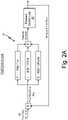
- FIG. 2Ais a schematic block diagram of fluid control loop 34, which is executed by controller 14 of spray gun system 10.
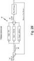
- FIG. 2Bis a schematic block diagram of pressure control loop 36, which is executed by controller 14 of spray gun system 10.
- FIGS. 2A and 2Bwill be discussed together.
- FIGS. 2A and 2Bboth include a proportional-integral-derivative (PID) control loop, with FIG. 2A showing a fluid flow PID control loop and FIG. 2B showing a pressure PID control loop.
- PID control loopscontinuously calculate an error value, which is the difference between a desired set-point and a measured process variable, and then apply a correction based on proportional, integral, and derivative terms of the error.
- PID control loopscan be used to automatically apply accurate and responsive correction to a control function with minimal delay and overshoot, resulting in convergence on the desired set-point quickly and efficiently.
- controller 14can identify a fluid flow set-point (i.e., a target flow rate) received via user input or defined by controller 14 (e.g., predefined and stored in computer-readable memory of controller 14).
- a fluid flow set-pointi.e., a target flow rate
- controller 14e.g., predefined and stored in computer-readable memory of controller 14.
- fluid flow set-point 38is provided as input to fluid control loop 34 and is processed by the PID function within fluid control loop 34.
- fluid control loop 34can subtract the measured flow rate received from flow meter 18 from fluid flow set-point 38 to identify a flow rate error (Fe).
- Fluid control loop 34further identifies a mathematical integral of the flow rate error with respect to time (e.g., via numerical integration techniques) and a mathematical derivative of the flow rate error with respect to time (e.g., via numerical differentiation techniques). Fluid control loop 34 multiplies the flow rate error by a proportional gain to produce a scaled proportional error term. Fluid control loop 34 multiplies the integral of the flow rate error by an integral gain to produce a scaled integrated error term. Fluid control loop 34 multiplies the derivative of the flow rate error by a derivative gain to produce a scaled differentiated error term. Fluid control loop 34 determines pressure set-point 40 as the sum of the scaled proportional error term, the scaled integrated error term, and the scaled differentiated error term. Values of the proportional gain, the integral gain, and the derivative gain can be determined experimentally and/or mathematically to achieve target response time and accuracy thresholds.
- Fluid control loop 34outputs pressure set-point 40 for processing by the pressure control loop, as is further described below. Accordingly, fluid control loop 34 identifies a pressure set-point that can be utilized for achieving a fluid flow set-point that is determined and/or received via user input to produce a satisfactory finish on a working surface.
- pressure set-point 40is provided as input to pressure control loop 36 and is processed by the PID function in pressure control loop 36.
- pressure control loop 36can implement a PID feedback control loop based on a pressure error representing a difference between pressure set-point 40 and a measured fluid pressure received from pressure sensor 16.
- Pressure control loop 36can determine the pressure error (Pe) by subtracting the measured pressure received from pressure sensor 16 from pressure set-point 40.
- Pressure control loop 36can multiply the pressure error by a proportional gain to produce a scaled proportional error term.
- Pressure control loop 36further multiplies the integral of the pressure error by an integral gain to produce a scaled integrated error term, and multiplies the derivative of the pressure error by a derivative gain to produce a scaled differentiated error term.
- Pressure control loop 36determines current control value 42 as the sum of the scaled proportional error term, the scaled integrated error term, and the scaled differentiated error term. Values of the proportional gain, the integral gain, and the derivative gain can be determined experimentally and/or mathematically to achieve target response time and accuracy thresholds.
- pressure control loop 36outputs current control value 42 that is utilized for transmitting a control command (e.g., a current control command) to air pilot output 24.
- current control value 42can represent a current value, such as current value between four and twenty milliamps (or other ranges), which is configured to represent a scale of pressure ranges output by air pilot output 24.
- FIG. 2Billustrates and describes current control value 42 as representing an electrical current, it should be understood that other control values can be utilized, such as a voltage control, a digital output, or other control values configured to control operation of air pilot output 24 to supply pressure air.
- Air pilot output 24supplies pressurized air to fluid flow control regulator 22 to increase or decrease fluid pressure within spray gun system 10 based on current control value 42 provided by controller 14. Increasing or decreasing the fluid pressure within spray gun system 10 results in an increase or decrease in the fluid flow rate exiting spray gun 12.
- Pressure sensor 16, flow meter 18, and controller 14(with fluid control loop 34 and pressure control loop 36) work in conjunction to continuously monitor the pressure and fluid flow rate within spray gun system 10 and also to adjust the fluid pressure within spray gun system 10 to achieve fluid flow set-point 38 (e.g., input by the user into controller 14). Further, data within pressure control loop 36 can be utilized to indicate precisely when fluid begins to flow within spray gun system 10, as is discussed further below.
- FIG. 3is a flowchart illustrating example operations of fluid flow detection process 44 within spray gun system 10.
- Fluid flow detection process 44includes steps 100-112.
- Step 100includes receiving pressure set-point 40 from fluid control loop 34.
- Step 102includes receiving the measured fluid pressure within spray gun system 10 from pressure sensor 16.
- Step 104includes calculating pressure error 46 within spray gun system 10. For instance, controller 14 can subtract the measured pressure received by pressure sensor 16 from pressure set-point 40 to determine pressure error 46.
- Step 105includes performing pressure control loop 36, as discussed above in FIG. 2B .
- controller 14can execute pressure control loop 36 to adjust current control value 42 to achieve pressure set-point 40.
- Step 106includes comparing the calculated pressure error 46 to an error threshold.
- the error thresholdcan be a user defined value, an experimental based value, or a mathematically derived value. If pressure error 46 is greater than the error threshold ("YES" branch of Step 106), a counter is incremented. For instance, controller 14 can increment the counter by an increment value, such as an integer value of two, or other integer or non-integer values. In other examples, controller 14 can increment the counter by an increment value, such as an integer value of five. If pressure error 46 is not greater than the error threshold ("NO" branch of Step 106), the counter is not incremented.
- Step 108includes comparing the counter to a count threshold.
- the count thresholdcan be a user defined value, an experimental based value, or a mathematically derived value. If the counter is greater than the count threshold ("YES" branch of Step 108), this indicates that fluid is flowing within spray gun system 10.
- Step 110includes controller 14 executing fluid control loop 34 to adjust pressure set-point 40 to achieve fluid flow set-point 38. If the counter is not greater than the count threshold ("NO" branch of Step 108), this indicates that fluid is not flowing within spray gun system 10. In response to determining that the counter is not greater than the count threshold, controller 14 refrains from executing fluid control loop 34 and continues to execute pressure control loop 36 to achieve a predefined pressure set-point.
- Step 112includes decrementing the counter each time pressure error 46 is compared to the error threshold.
- controller 14can decrement the counter by a decrement value, such as an integer value of one, or other integer or non-integer value.
- the increment valuei.e., applied in Step 106
- controller 14 of spray gun system 10is configured to set the counter to an initialization value in response to receiving a signal from airflow switch 20 indicating that spray gun 12 is not triggered and airflow is not being distributed from spray gun system 10.
- controller 14can receive an indication that air is not flowing from airflow switch 20 and in response reset the counter to an initialization value, such as a value or 1.
- Fluid flow detection process 44prevents over-pressurization of spray gun system 10 when the system is in a flow control operation. Fluid flow detection process 44 responds very quickly and directly to fluid flow within spray gun system 10, even for very low fluid flow rates. Further, fluid flow detection process 44 can replace or eliminate the need for airflow switch 20 because fluid flow detection process 44 indicates precisely when fluid is flowing through spray gun system 10. Knowing when fluid is flowing helps prevent over-pressurization of spray gun system 10 which results in a stable and even flow exiting spray gun 12, leading to satisfactory finishes on working surfaces when in flow control operation.
Landscapes
- Chemical & Material Sciences (AREA)
- Analytical Chemistry (AREA)
- Physics & Mathematics (AREA)
- Fluid Mechanics (AREA)
- Nozzles (AREA)
- General Physics & Mathematics (AREA)
Description
- The present disclosure relates to a spray gun system, and more particularly, to a method for detecting fluid flow in a spray gun system.
- Spray guns are used to spray liquids, such as paint, under pressure onto a working surface. Spray guns can be used for many different applications but in many applications the spray gun is either pressure controlled or flow controlled to achieve the desired flow rate output. In a pressure controlled system, the user controls the dispensing flow rate by adjusting the pressure of the pump system, nozzle size, and the gun trigger opening position. In addition, a controller connected to both an electronically-controlled proportional valve and an electronic fluid pressure sensor attempts to drive the system pressure to the target pressure using closed-loop feedback control.
- In a flow controlled system, the user controls the dispensing flow rate by setting the target flow rate in the controller. The controller is connected to and receives data from an electronically-controlled proportional valve, an electronic fluid pressure sensor, and an electronic flow meter. The controller uses feedback control techniques to adjust parameters of the spray gun system in an attempt to achieve the user-defined target fluid flow rate. In some flow controlled applications, the system can become over-pressured if only air and no fluid is dispensing from the spray gun. If only air is flowing from the spray gun, the controller may attempt to increase pressure rapidly because the flow meter is not returning a measurement equal to the target flow rate. If this occurs, the system may quickly become over-pressured, resulting in too much flow rapidly exiting the spray gun and an unsatisfactory finish on the working surface.
US 2017/043359 discloses a method for controlling a system pressure within a closed system, which includes sending a signal to a pressure control valve corresponding to a pressure set point and actuating the pressure control valve to vary a pilot pressure of a control fluid contained within a pressure control line that is fluidly connected to a pressure regulator. A diaphragm of the pressure regulator is disposed between the pressure control line and a system line and acts on a fluid with the system line to modify the system pressure.- According to one aspect of the invention, a spray gun system as defined in claim 1 is provided.
- According to another aspect of the invention, a method for detecting fluid flow as defined in
claim 10 is provided. FIG. 1 is a schematic block diagram of a spray gun system.FIG. 2A is a schematic block diagram of an example fluid control loop within the spray gun system.FIG. 2B is a schematic block diagram of an example pressure control loop within the spray gun system.FIG. 3 is a flowchart illustrating example operations of the fluid flow detection process within the spray gun system.FIG. 1 is a schematic block diagram ofspray gun system 10 which includesspray gun 12,controller 14,pressure sensor 16,flow meter 18,airflow switch 20, fluidflow control regulator 22,air pilot output 24, andpump 26.Spray gun 12 can be a manual, hand-held spray gun in which a user operates a trigger to discharge a liquid (e.g. paint) from a nozzle onto a working surface.Controller 14 can be a controller device configured to be communicatively coupled with components ofspray gun system 10 for monitoring and control of the components during operation of thespray gun system 10, as is discussed further below.Pressure sensor 16 can be a device, such as a pressure transducer or other device, for measuring the pressure of gases or liquids that generates and sends a signal as a function of the pressure imposed on the device.Flow meter 18 can be a device capable of calculating the flow of a fluid by determining the forces produced by the flowing fluid as it overcomes a known constriction.Airflow switch 20 can be a device that detects gas flow in a system and sends a signal indicating detection of the gas flow. Fluidflow control regulator 22 can be a device that regulates the flow or pressure (e.g. by adjusting the size of an orifice) of a fluid flowing throughspray gun system 10.Air pilot output 24 can be a device that increases and/or decreases air pressure withinspray gun system 10 to increase and/or decrease fluid pressure within fluidflow control regulator 22.Pump 26 can be a device that moves fluids using mechanical action. For example,pump 26 can be an electrically powered pump, a pneumatically powered pump, an engine powered pump, or any other type of pump capable of moving a fluid inspray gun system 10.- Though not shown in
FIG. 1 for purposes of clarity and ease of illustration,controller 14 includes one or more processors and computer-readable memory. Examples of the one or more processors can include any one or more of a microprocessor, a digital signal processor (DSP), an application specific integrated circuit (ASIC), a field-programmable gate array (FPGA), or other equivalent discrete or integrated logic circuitry. - Computer-readable memory of
controller 14 can be configured to store information withincontroller 14 during operation. The computer-readable memory can be described, in some examples, as computer-readable storage media. In some examples, a computer-readable storage medium can include a non-transitory medium. The term "non-transitory" can indicate that the storage medium is not embodied in a carrier wave or a propagated signal. In certain examples, a non-transitory storage medium can store data that can, over time, change (e.g., in RAM or cache). Computer-readable memory ofcontroller 14 can include volatile and non-volatile memories. Examples of volatile memories can include random access memories (RAM), dynamic random access memories (DRAM), static random access memories (SRAM), and other forms of volatile memories. Examples of non-volatile memories can include magnetic hard discs, optical discs, flash memories, or forms of electrically programmable memories (EPROM) or electrically erasable and programmable (EEPROM) memories. Controller 14 can be a controller device configured to be communicatively coupled with components ofspray gun system 10, such aspressure sensor 16,flow meter 18,airflow switch 20, andair pilot output 24, for monitoring and control of the components during operation of thespray gun system 10. In some examples,controller 14 includes and/or is operatively coupled to a display device and/or user interface elements (e.g., buttons, dials, graphical control elements presented at a touch-sensitive display, or other user interface elements) to enable user interaction withcontroller 14, such as for initialization, monitoring, and/or control of the system. Though not illustrated in the example ofFIG. 1 , in certain examples,controller 14 can be communicatively coupled to one or more remote computing devices, such as via a wired or wireless communications network, or both.Spray gun 12 is pneumatically connected to and receives a gas flow, such as air, throughairflow switch 20.Airflow switch 20 receivessystem air 28 through a hose or tube connected toairflow switch 20.Airflow switch 20 is also electrically connected tocontroller 14.Airflow switch 20 is configured to send airflow data to controller 14, indicating when air has begun to flow withinspray gun system 10.Spray gun 12 is also fluidly connected to and receives fluid flow throughflow meter 18.Flow meter 18 is fluidly connected to bothspray gun 12 andpressure sensor 16 and receives fluid flow throughpressure sensor 16.Flow meter 18 is also electrically connected tocontroller 14 andflow meter 18 is configured to send fluid flow rate measurements to controller 14. In the embodiment shown,flow meter 18 is positioned betweenspray gun 12 andpressure sensor 16. In another embodiment,flow meter 18 can be positioned upstream ofpressure sensor 16 or fluidflow control regulator 22. For example,flow meter 18 could be positioned betweenpressure sensor 16 and fluidflow control regulator 22. In another example,flow meter 18 could be positioned between fluidflow control regulator 22 andpump 26.Pressure sensor 16 is fluidly connected to bothflow meter 18 and fluidflow control regulator 22.Pressure sensor 16 receives fluid flow through fluidflow control regulator 22.Pressure sensor 16 is also electrically connected tocontroller 14 andpressure sensor 16 is configured to send fluid pressure measurements to controller 14. Fluidflow control regulator 22 is fluidly connected to bothpressure sensor 16 andpump 26. Fluidflow control regulator 22 receives fluid flow throughpump 26. Fluidflow control regulator 22 is also pneumatically connected toair pilot output 24 and fluidflow control regulator 22 receives pressurized input air fromair pilot output 24.Air pilot output 24 is pneumatically connected to both fluidflow control regulator 22 andair input 30.Air pilot output 24 receives pressurized air fromair input 30 and supplies the pressurized air to fluidflow control regulator 22.Air pilot output 24 is also electrically connected tocontroller 14 and controlled by signals received fromcontroller 14, such as a current, voltage, or other control signal configured to causeair pilot output 24 to increase and/or decrease air pressure provided to fluidflow control regulator 22 viaair pilot output 24.Pump 26 is fluidly connected to fluidflow control regulator 22.Pump 26 receives working fluid (e.g., paint) fromfluid input 32.Pump 26 is also pneumatically connected to airinput 30 which supplies a gas, such as air, topower pump 26.- In operation, working fluid enters
pump 26 throughfluid input 32 and air enterspump 26 throughair input 30. Theair entering pump 26 is used topower pump 26 and allows pump 26 to drive fluid throughspray gun system 10 under pressure. Pressurized air fromair input 30 is also directed toair pilot output 24.Air pilot output 24 uses the pressurized air to control the fluid pressure within fluidflow control regulator 22 based on a command received fromcontroller 14 to adjust pressure withinspray gun system 10, such as a current, a voltage, or other control signal. - Fluid
flow control regulator 22 receives fluid frompump 26 and is configured to control the fluid pressure withinspray gun system 10 by, e.g., adjusting the size of an orifice within fluidflow control regulator 22 or otherwise increasing and/or decreasing pressure of the fluid according to the control signal received fromair pilot output 24. The pressurized fluid exiting fluidflow control regulator 22 is driven throughspray gun system 10. Pressurized fluid driven through fluidflow control regulator 22 is received bypressure sensor 16, which is configured to measure the fluid pressure withinspray gun system 10 and transmit the fluid pressure measurement tocontroller 14 for further processing, as is discussed further below. - In the embodiment shown, flow
meter 18 receives fluid frompressure sensor 16 and is configured to measure the fluid flow rate ofspray gun system 10 and transmit the flow rate measurement tocontroller 14 for further processing, as is discussed further below. The pressurized fluid reachesspray gun 12 where it is mixed with a flow of air in response to operator action to activatespray gun 12, such as via a trigger or other actuation mechanism ofspray gun 12. The flow of air passesairflow switch 20, causing airflow switch 20 to send a signal tocontroller 14 indicating that air is flowing withinspray gun system 10. The mixture of pressurized fluid and pressurized air atomizes the fluid mixture, resulting in a satisfactory finish on the working product. - According to techniques of this disclosure,
controller 14 implements closed-loop control operations to control fluid pressure withinspray gun system 10 to achieve a target flow rate of fluid distributed fromspray gun 12, such as a user-defined target flow rate (e.g., entered via a user interface of controller 14), a system-defined target flow rate, a predefined target flow rate, or other target flow rate. For instance, as is further described below,controller 14 can implement a flow control loop that adjusts a pressure set-point to achieve the target flow rate. The flow control loop can be implemented as a proportional-integral-derivative (PID) control loop or other closed-loop control algorithm. For example,controller 14 can receive, as feedback, a measured flow rate of fluid withinspray gun system 10 fromflow meter 18, the measured flow rate indicating a rate of fluid flowing throughspray gun system 10 frompump 26 tospray gun 12.Controller 14 can increase and/or decrease the pressure set-point in a controlled manner (i.e., via the flow control feedback loop) to achieve the target flow rate. Controller 14 can further implement a pressure control loop (e.g., a PID control loop or other closed-loop control algorithm) to adjust fluid pressure withinspray gun system 10 to achieve the pressure set-point defined by the flow control loop. For instance,controller 14 can receive, as feedback, a measured pressure of fluid withinspray gun system 10 viapressure sensor 16.Controller 14 can output, via the pressure control loop, a control command (e.g., a voltage, a current, or other control command) toair pilot output 24 to causeair pilot output 24 to increase and/or decrease the fluid pressure via fluidflow control regulator 22.- As such,
controller 14 can control a pressure set-point via a flow control loop (e.g., an outer loop) to achieve a target flow rate, such as a user-defined target flow rate configured to produce a satisfactory finish of the fluid (e.g., paint) on a working product.Controller 14 can further control fluid pressure withinspray gun system 10 via a pressure control loop (e.g., an inner loop) to achieve the pressure set-point determined via the flow control loop. - In some examples,
spray gun 12 can be manually actuated (e.g., via a trigger or other actuation mechanism) such that only pressurized air flows throughspray gun 12. That is, in certain examples,spray gun 12 can be manually actuated via user input to a trigger or other mechanism so that pressurized air is distributed fromspray gun 12 and fluid (e.g., paint) is not distributed fromspray gun 12, such as for the often-termed "dusting" of the surface of the working product. In such examples, air flowing throughspray gun 12 is sensed byairflow switch 20, which transmits a signal (e.g., an electrical signal) tocontroller 14 indicating that air is being distributed byspray gun 12. Since fluid is not being distributed byspray gun 12 in such examples, fluid pressure withinspray gun system 10 is maintained at the pressure set-point via the pressure control loop implemented bycontroller 14. However, in examples where fluid is not being distributed, the error term in the flow control loop representing a difference between the target flow rate and the measured flow rate can be large, thereby resulting in an increased pressure set-point and a buildup of fluid pressure withinspray gun system 10 via operation of the pressure control loop to achieve the increased pressure set-point. - As such, according to techniques described herein,
controller 14 executes the flow control loop to achieve the target flow rate in response to determining that fluid is being distributed fromspray gun 12.Controller 14 refrains from executing the flow control loop to achieve the target flow rate in response to determining that fluid is not being distributed fromspray gun 12, but rather executes only the pressure control loop to maintain the pressure set-point. As such,controller 14 can maintain the pressure set-point when fluid is not being distributed without resulting in a buildup of system pressure and the undesirable spraying effects resulting therefrom. - Moreover,
controller 14 can determine whether fluid is being distributed fromspray gun 12 based on an error term within the pressure control loop representing a difference between the pressure set-point and the measured pressure received frompressure sensor 16. That is, rather than utilize the flow rate measurement fromflow meter 18, which can introduce latency into the flow detection operations,controller 14 can determine whether fluid is flowing withinspray gun system 10 using the pressure error term within the pressure control loop. Such flow detection operations can identify, based on the tendency of pressure to decrease within moving fluid, the movement of fluid withinspray gun system 10 prior to detection byflow meter 18. As such,controller 14, monitoring the pressure error term within the pressure control loop, can quickly and reliably identify the movement of fluid withinspray gun system 10, thereby enablingcontroller 14 to quickly and efficiently respond to moving fluid to execute the flow control loop and provide satisfactory finish to the working product. FIG. 2A is a schematic block diagram offluid control loop 34, which is executed bycontroller 14 ofspray gun system 10.FIG. 2B is a schematic block diagram ofpressure control loop 36, which is executed bycontroller 14 ofspray gun system 10.FIGS. 2A and2B will be discussed together.FIGS. 2A and2B both include a proportional-integral-derivative (PID) control loop, withFIG. 2A showing a fluid flow PID control loop andFIG. 2B showing a pressure PID control loop. PID control loops continuously calculate an error value, which is the difference between a desired set-point and a measured process variable, and then apply a correction based on proportional, integral, and derivative terms of the error. PID control loops can be used to automatically apply accurate and responsive correction to a control function with minimal delay and overshoot, resulting in convergence on the desired set-point quickly and efficiently.- When operating
spray gun system 10 in a flow control operation,controller 14 can identify a fluid flow set-point (i.e., a target flow rate) received via user input or defined by controller 14 (e.g., predefined and stored in computer-readable memory of controller 14). As shown inFIG. 2A , fluid flow set-point 38 is provided as input tofluid control loop 34 and is processed by the PID function withinfluid control loop 34. For example, as illustrated inFIG. 2A ,fluid control loop 34 can subtract the measured flow rate received fromflow meter 18 from fluid flow set-point 38 to identify a flow rate error (Fe). Fluid control loop 34 further identifies a mathematical integral of the flow rate error with respect to time (e.g., via numerical integration techniques) and a mathematical derivative of the flow rate error with respect to time (e.g., via numerical differentiation techniques).Fluid control loop 34 multiplies the flow rate error by a proportional gain to produce a scaled proportional error term.Fluid control loop 34 multiplies the integral of the flow rate error by an integral gain to produce a scaled integrated error term.Fluid control loop 34 multiplies the derivative of the flow rate error by a derivative gain to produce a scaled differentiated error term.Fluid control loop 34 determines pressure set-point 40 as the sum of the scaled proportional error term, the scaled integrated error term, and the scaled differentiated error term. Values of the proportional gain, the integral gain, and the derivative gain can be determined experimentally and/or mathematically to achieve target response time and accuracy thresholds.Fluid control loop 34 outputs pressure set-point 40 for processing by the pressure control loop, as is further described below. Accordingly,fluid control loop 34 identifies a pressure set-point that can be utilized for achieving a fluid flow set-point that is determined and/or received via user input to produce a satisfactory finish on a working surface.- As shown in
FIG. 2B , pressure set-point 40 is provided as input topressure control loop 36 and is processed by the PID function inpressure control loop 36. For instance, as was similarly described above with respect tofluid control loop 34 ofFIG. 2A ,pressure control loop 36 can implement a PID feedback control loop based on a pressure error representing a difference between pressure set-point 40 and a measured fluid pressure received frompressure sensor 16.Pressure control loop 36 can determine the pressure error (Pe) by subtracting the measured pressure received frompressure sensor 16 from pressure set-point 40.Pressure control loop 36 can multiply the pressure error by a proportional gain to produce a scaled proportional error term.Pressure control loop 36 further multiplies the integral of the pressure error by an integral gain to produce a scaled integrated error term, and multiplies the derivative of the pressure error by a derivative gain to produce a scaled differentiated error term.Pressure control loop 36 determinescurrent control value 42 as the sum of the scaled proportional error term, the scaled integrated error term, and the scaled differentiated error term. Values of the proportional gain, the integral gain, and the derivative gain can be determined experimentally and/or mathematically to achieve target response time and accuracy thresholds. - As illustrated in
FIG. 2B ,pressure control loop 36 outputscurrent control value 42 that is utilized for transmitting a control command (e.g., a current control command) toair pilot output 24. For instance,current control value 42 can represent a current value, such as current value between four and twenty milliamps (or other ranges), which is configured to represent a scale of pressure ranges output byair pilot output 24. Though the example ofFIG. 2B illustrates and describescurrent control value 42 as representing an electrical current, it should be understood that other control values can be utilized, such as a voltage control, a digital output, or other control values configured to control operation ofair pilot output 24 to supply pressure air. Air pilot output 24 supplies pressurized air to fluidflow control regulator 22 to increase or decrease fluid pressure withinspray gun system 10 based oncurrent control value 42 provided bycontroller 14. Increasing or decreasing the fluid pressure withinspray gun system 10 results in an increase or decrease in the fluid flow rate exitingspray gun 12.Pressure sensor 16,flow meter 18, and controller 14 (withfluid control loop 34 and pressure control loop 36) work in conjunction to continuously monitor the pressure and fluid flow rate withinspray gun system 10 and also to adjust the fluid pressure withinspray gun system 10 to achieve fluid flow set-point 38 (e.g., input by the user into controller 14). Further, data withinpressure control loop 36 can be utilized to indicate precisely when fluid begins to flow withinspray gun system 10, as is discussed further below.FIG. 3 is a flowchart illustrating example operations of fluidflow detection process 44 withinspray gun system 10. Fluidflow detection process 44 includes steps 100-112. Step 100 includes receiving pressure set-point 40 fromfluid control loop 34. Step 102 includes receiving the measured fluid pressure withinspray gun system 10 frompressure sensor 16. Step 104 includes calculating pressure error 46 withinspray gun system 10. For instance,controller 14 can subtract the measured pressure received bypressure sensor 16 from pressure set-point 40 to determine pressure error 46. Step 105 includes performingpressure control loop 36, as discussed above inFIG. 2B . For instance,controller 14 can executepressure control loop 36 to adjustcurrent control value 42 to achieve pressure set-point 40.- Step 106 includes comparing the calculated pressure error 46 to an error threshold. The error threshold can be a user defined value, an experimental based value, or a mathematically derived value. If pressure error 46 is greater than the error threshold ("YES" branch of Step 106), a counter is incremented. For instance,
controller 14 can increment the counter by an increment value, such as an integer value of two, or other integer or non-integer values. In other examples,controller 14 can increment the counter by an increment value, such as an integer value of five. If pressure error 46 is not greater than the error threshold ("NO" branch of Step 106), the counter is not incremented. - Step 108 includes comparing the counter to a count threshold. The count threshold can be a user defined value, an experimental based value, or a mathematically derived value. If the counter is greater than the count threshold ("YES" branch of Step 108), this indicates that fluid is flowing within
spray gun system 10. In response to determining that the counter is greater than the count threshold,Step 110 includescontroller 14 executingfluid control loop 34 to adjust pressure set-point 40 to achieve fluid flow set-point 38. If the counter is not greater than the count threshold ("NO" branch of Step 108), this indicates that fluid is not flowing withinspray gun system 10. In response to determining that the counter is not greater than the count threshold,controller 14 refrains from executingfluid control loop 34 and continues to executepressure control loop 36 to achieve a predefined pressure set-point. - Step 112 includes decrementing the counter each time pressure error 46 is compared to the error threshold. For example,
controller 14 can decrement the counter by a decrement value, such as an integer value of one, or other integer or non-integer value. In some examples, the increment value (i.e., applied in Step 106) can be greater than the decrement value, such that the counter is incremented at a greater rate than it is decremented, but is incremented only in response to determining that pressure error 46 is greater than the error threshold. Further,controller 14 ofspray gun system 10 is configured to set the counter to an initialization value in response to receiving a signal fromairflow switch 20 indicating thatspray gun 12 is not triggered and airflow is not being distributed fromspray gun system 10. In other words,controller 14 can receive an indication that air is not flowing fromairflow switch 20 and in response reset the counter to an initialization value, such as a value or 1. - Fluid
flow detection process 44 prevents over-pressurization ofspray gun system 10 when the system is in a flow control operation. Fluidflow detection process 44 responds very quickly and directly to fluid flow withinspray gun system 10, even for very low fluid flow rates. Further, fluidflow detection process 44 can replace or eliminate the need forairflow switch 20 because fluidflow detection process 44 indicates precisely when fluid is flowing throughspray gun system 10. Knowing when fluid is flowing helps prevent over-pressurization ofspray gun system 10 which results in a stable and even flow exitingspray gun 12, leading to satisfactory finishes on working surfaces when in flow control operation.
Claims (15)
- A spray gun system (10) comprising:a spray gun (12) configured to distribute a mixture of air and fluid onto a working surface;a pressure sensor (16) fluidly connected to the spray gun, wherein the pressure sensor is configured to measure fluid pressure within the spray gun system; anda controller (14) electrically connected to the pressure sensor, wherein the controller is configured to:receive a measured pressure from the pressure sensor;calculate pressure error based on the measured pressure and a pressure set-point;compare the pressure error to an error threshold;increment an increment counter if the pressure error exceeds the error threshold;perform, in response to determining that the increment counter exceeds a count threshold, a flow control loop that:receives a target flow rate as input;receives a measured flow rate as feedback;determines a flow rate error as a difference between the target flow rate and the measured flow rate; andadjusts the pressure set-point using the flow rate error to achieve the target flow rate; andperform a pressure control loop that adjusts the fluid pressure within the spray gun system using the pressure error to achieve the pressure set-point.
- The spray gun system (10) of claim 1, wherein the controller (14) is further configured to refrain from performing the flow control loop in response to determining that the increment counter does not exceed the count threshold.
- The spray gun system (10) of claim 1, wherein:the controller (14) calculates the pressure error by subtracting the measured pressure from the pressure set-point;the pressure set-point is one of a user defined value, an experimentally-defined value, or a mathematically-derived value based on the target flow rate determined during operation of the flow control loop; andthe error threshold is one of a user defined value, an experimentally-defined value, or a mathematically-derived value.
- The spray gun system (10) of claim 1 and further comprising an airflow switch (20) pneumatically connected to the spray gun (12) and electrically connected to the controller (14), wherein the airflow switch is configured to send a signal to the controller indicating whether the spray gun is triggered and airflow is being distributed from the spray gun or whether the spray gun is not triggered and airflow is not being distributed from the spray gun.
- The spray gun system (10) of claim 4, wherein the controller (14) is further configured to set the counter to an initialization value in response to receiving a signal from the airflow switch (20) indicating that the spray gun (12) is not triggered and airflow is not being distributed from the spray gun system.
- The spray gun system (10) of claim 1 and further comprising a flow meter (18) fluidly connected to the spray gun (12) and electrically connected to the controller (14), wherein the flow meter is configured to measure fluid flow rate of the spray gun system, and wherein the flow meter is configured to send the fluid flow rate measurement to the controller.
- The spray gun system (10) of claim 1, wherein:the controller (14) is further configured to decrement the counter after each comparison of the pressure error to the error threshold; andthe increment counter exceeding the count threshold indicates that fluid has begun flowing within the spray gun system.
- The spray gun system (10) of claim 1 and further comprising a fluid flow control regulator (22) fluidly connected to the pressure sensor (16), wherein the fluid flow control regulator is configured to control the fluid pressure within the spray gun system.
- The spray gun system (10) of claim 8 and further comprising an air pilot output (24) pneumatically connected to the fluid flow control regulator (22) and electrically connected to the controller (14), wherein the controller is configured to send a signal to the air pilot output to adjust the fluid pressure within the fluid flow control regulator to achieve the pressure set-point.
- A method for detecting fluid flow in a spray gun system (10) including a spray gun (12), a pressure sensor (16), and a controller (14), the method comprising:receiving, by the controller, a pressure measurement from the pressure sensor that is fluidly connected to the spray gun and electrically connected to the controller;calculating, by the controller, the pressure error based on the measured pressure and a pressure set-point;comparing, by the controller, the pressure error to an error threshold;incrementing, by the controller, a counter if the pressure error exceeds the error threshold;performing, by the controller, in response to determining that the increment counter exceeds a count threshold, a flow control loop that:receives a target flow rate as input;receives a measured flow rate as feedback;determines a flow rate error as a difference between the target flow rate and the measured flow rate; andadjusts the pressure set-point using the flow rate error to achieve the target flow rate; andperforming, by the controller, a pressure control loop that adjusts the fluid pressure within the spray gun system using the pressure error to achieve the pressure set-point.
- The method of claim 10, wherein the method further comprises refraining, by the controller (14), from performing the flow control loop in response to determining that the increment counter does not exceed the count threshold, wherein the increment counter exceeding the count threshold indicates that fluid has begun flowing within the spray gun system (10).
- The method of claim 10, wherein:the controller (14) calculates the pressure error by subtracting a measured pressure from a pressure set-point;the controller is further configured to decrement the counter after each comparison of the pressure error to the error threshold.the pressure set-point is one of a user defined value, an experimentally-defined value, or a mathematically-derived value based on the target flow rate determined during operation of the flow control loop; andthe error threshold is one of a user defined value, an experimentally-defined value, or a mathematically-derived value.
- The method of claim 10 and further comprising an airflow switch (20) pneumatically connected to the spray gun (12) and electrically connected to the controller (14), wherein the airflow switch is configured to send a signal to the controller indicating whether the spray gun is triggered and airflow is being distributed from the spray gun or whether the spray gun is not triggered and airflow is not being distributed from the spray gun.
- The method of claim 10 and further comprising:a flow meter (18) fluidly connected to the spray gun (12) and electrically connected to the controller (14), wherein the flow meter is configured to measure the fluid flow rate of the spray gun system (10); and wherein the flow meter is configured to send the fluid flow rate measurement to the controller;a fluid flow control regulator (22) fluidly connected to the pressure sensor, wherein the fluid flow control regulator is configured to control the fluid pressure within the spray gun system;an air pilot output (24) pneumatically connected to the fluid flow control regulator and electrically connected to the controller, wherein the controller is configured to send a signal to the air pilot output to adjust the fluid pressure within the fluid flow control regulator to achieve the pressure set-point.; anda pump (26) fluidly connected to the fluid flow control regulator, wherein the pump is configured to supply fluid to the spray gun system.
- The method of claim 10, wherein the controller (14) is further configured to:set the counter to an initialization value in response to receiving a signal from the airflow switch (20) indicating that the spray gun (12) is not triggered and airflow is not being distributed from the spray gun system (10); andperform the flow control loop to achieve the target flow rate based on a difference between the target flow rate and the fluid flow rate measurement.
Applications Claiming Priority (1)
| Application Number | Priority Date | Filing Date | Title |
|---|---|---|---|
| US201962910917P | 2019-10-04 | 2019-10-04 |
Publications (2)
| Publication Number | Publication Date |
|---|---|
| EP3799963A1 EP3799963A1 (en) | 2021-04-07 |
| EP3799963B1true EP3799963B1 (en) | 2023-01-18 |
Family
ID=72709201
Family Applications (1)
| Application Number | Title | Priority Date | Filing Date |
|---|---|---|---|
| EP20199426.6AActiveEP3799963B1 (en) | 2019-10-04 | 2020-09-30 | Spray gun system with fluid flow control |
Country Status (3)
| Country | Link |
|---|---|
| US (1) | US11951498B2 (en) |
| EP (1) | EP3799963B1 (en) |
| CN (1) | CN112604835B (en) |
Families Citing this family (3)
| Publication number | Priority date | Publication date | Assignee | Title |
|---|---|---|---|---|
| CN114146840A (en)* | 2021-12-06 | 2022-03-08 | 广东亨通光电科技有限公司 | Resin coating device and control method thereof |
| US20230347362A1 (en)* | 2022-04-29 | 2023-11-02 | Canadian Tire Corporation Limited | Foam sprayer |
| CN116991098A (en)* | 2023-07-05 | 2023-11-03 | 浙江中控研究院有限公司 | A multifunctional human-machine interactive valve control operation method and device |
Citations (1)
| Publication number | Priority date | Publication date | Assignee | Title |
|---|---|---|---|---|
| EP3137229B1 (en)* | 2014-05-01 | 2019-03-27 | Graco Minnesota Inc. | Method for flow control calibration of high-transient systems |
Family Cites Families (13)
| Publication number | Priority date | Publication date | Assignee | Title |
|---|---|---|---|---|
| US4988015A (en)* | 1986-10-30 | 1991-01-29 | Nordson Corporation | Method for dispensing fluid materials |
| US5320280A (en) | 1992-06-19 | 1994-06-14 | Graco Inc. | Pneumatically controlled spraying system having a diaphragm-operated switch |
| US6053147A (en)* | 1998-03-02 | 2000-04-25 | Cummins Engine Company, Inc. | Apparatus and method for diagnosing erratic pressure sensor operation in a fuel system of an internal combustion engine |
| US6149071A (en)* | 1998-06-10 | 2000-11-21 | Global Metering Solutions, Llc | Flow control system for spray applications |
| CA2671500C (en) | 2009-07-10 | 2011-05-24 | Thomas Lemmer | Pressure differential motor control system and method |
| US9132442B2 (en)* | 2012-11-10 | 2015-09-15 | Mi Yan | Diagnosis and controls of a fluid delivery apparatus with hydraulic buffer |
| TW201600735A (en)* | 2014-05-01 | 2016-01-01 | 葛萊兒明尼蘇達股份有限公司 | Method for fluid pressure control in a closed system |
| US10814340B2 (en)* | 2016-01-22 | 2020-10-27 | Graco Minnesota Inc. | Flow-based control for texture sprayer |
| US20190388923A1 (en)* | 2017-01-27 | 2019-12-26 | Briggs & Stratton Corporation | Battery powered pressure washer |
| JP6277303B1 (en) | 2017-05-09 | 2018-02-07 | 長瀬産業株式会社 | Painting equipment |
| US11022987B2 (en) | 2017-07-21 | 2021-06-01 | Carlisle Fluid Technologies, Inc. | Systems and methods for improved control of impingement mixing |
| CN109990946B (en) | 2017-12-29 | 2021-08-20 | 上海威派格智慧水务股份有限公司 | Pressure transmitter with fault self-checking function and fault self-checking method thereof |
| CN108721741A (en) | 2018-06-08 | 2018-11-02 | 天卓睿丰医疗器械(北京)有限公司 | A kind of atomizing control system |
- 2020
- 2020-09-23USUS17/029,837patent/US11951498B2/enactiveActive
- 2020-09-28CNCN202011042316.9Apatent/CN112604835B/enactiveActive
- 2020-09-30EPEP20199426.6Apatent/EP3799963B1/enactiveActive
Patent Citations (1)
| Publication number | Priority date | Publication date | Assignee | Title |
|---|---|---|---|---|
| EP3137229B1 (en)* | 2014-05-01 | 2019-03-27 | Graco Minnesota Inc. | Method for flow control calibration of high-transient systems |
Also Published As
| Publication number | Publication date |
|---|---|
| CN112604835A (en) | 2021-04-06 |
| EP3799963A1 (en) | 2021-04-07 |
| US20210101165A1 (en) | 2021-04-08 |
| US11951498B2 (en) | 2024-04-09 |
| CN112604835B (en) | 2023-06-23 |
Similar Documents
| Publication | Publication Date | Title |
|---|---|---|
| EP3799963B1 (en) | Spray gun system with fluid flow control | |
| KR101360871B1 (en) | Flow controller delivery of specified quantity of a fluid | |
| CN106170346B (en) | Fluid pressure control method in closed system | |
| JP6636945B2 (en) | Correction method for flow control in transient system. | |
| EP3471895B1 (en) | Methods for applying a liquid coating to a substrate | |
| US7026569B2 (en) | Welding machine | |
| CN109542130B (en) | Ion shower nozzle flow control system and equipment | |
| AU2016226582B2 (en) | Liquid dispensing system with improved pressure control | |
| US6874404B1 (en) | Compressed air flow rate controller | |
| KR102570643B1 (en) | Injection flow rate controlled coating device | |
| US11573583B2 (en) | Pressure control using an external trigger | |
| JP2006272211A (en) | Paint flow rate feedback controlling system in painting | |
| CN112763178B (en) | Hypersonic wind tunnel regulating valve opening degree presetting method capable of automatically stopping in advance | |
| US12098940B2 (en) | Pressure control system, pressure control method, and pressure control program | |
| JP3330180B2 (en) | Diagnostic device for paint quantitative supply system | |
| JP2023550129A (en) | Method and apparatus for pulsed gas supply with pressure control |
Legal Events
| Date | Code | Title | Description |
|---|---|---|---|
| PUAI | Public reference made under article 153(3) epc to a published international application that has entered the european phase | Free format text:ORIGINAL CODE: 0009012 | |
| STAA | Information on the status of an ep patent application or granted ep patent | Free format text:STATUS: THE APPLICATION HAS BEEN PUBLISHED | |
| AK | Designated contracting states | Kind code of ref document:A1 Designated state(s):AL AT BE BG CH CY CZ DE DK EE ES FI FR GB GR HR HU IE IS IT LI LT LU LV MC MK MT NL NO PL PT RO RS SE SI SK SM TR | |
| AX | Request for extension of the european patent | Extension state:BA ME | |
| STAA | Information on the status of an ep patent application or granted ep patent | Free format text:STATUS: REQUEST FOR EXAMINATION WAS MADE | |
| 17P | Request for examination filed | Effective date:20211007 | |
| RBV | Designated contracting states (corrected) | Designated state(s):AL AT BE BG CH CY CZ DE DK EE ES FI FR GB GR HR HU IE IS IT LI LT LU LV MC MK MT NL NO PL PT RO RS SE SI SK SM TR | |
| GRAP | Despatch of communication of intention to grant a patent | Free format text:ORIGINAL CODE: EPIDOSNIGR1 | |
| STAA | Information on the status of an ep patent application or granted ep patent | Free format text:STATUS: GRANT OF PATENT IS INTENDED | |
| INTG | Intention to grant announced | Effective date:20220805 | |
| GRAS | Grant fee paid | Free format text:ORIGINAL CODE: EPIDOSNIGR3 | |
| GRAA | (expected) grant | Free format text:ORIGINAL CODE: 0009210 | |
| STAA | Information on the status of an ep patent application or granted ep patent | Free format text:STATUS: THE PATENT HAS BEEN GRANTED | |
| AK | Designated contracting states | Kind code of ref document:B1 Designated state(s):AL AT BE BG CH CY CZ DE DK EE ES FI FR GB GR HR HU IE IS IT LI LT LU LV MC MK MT NL NO PL PT RO RS SE SI SK SM TR | |
| REG | Reference to a national code | Ref country code:GB Ref legal event code:FG4D | |
| REG | Reference to a national code | Ref country code:DE Ref legal event code:R096 Ref document number:602020007654 Country of ref document:DE | |
| REG | Reference to a national code | Ref country code:CH Ref legal event code:EP | |
| REG | Reference to a national code | Ref country code:AT Ref legal event code:REF Ref document number:1544379 Country of ref document:AT Kind code of ref document:T Effective date:20230215 Ref country code:IE Ref legal event code:FG4D | |
| REG | Reference to a national code | Ref country code:LT Ref legal event code:MG9D | |
| REG | Reference to a national code | Ref country code:NL Ref legal event code:MP Effective date:20230118 | |
| REG | Reference to a national code | Ref country code:AT Ref legal event code:MK05 Ref document number:1544379 Country of ref document:AT Kind code of ref document:T Effective date:20230118 | |
| PG25 | Lapsed in a contracting state [announced via postgrant information from national office to epo] | Ref country code:NL Free format text:LAPSE BECAUSE OF FAILURE TO SUBMIT A TRANSLATION OF THE DESCRIPTION OR TO PAY THE FEE WITHIN THE PRESCRIBED TIME-LIMIT Effective date:20230118 | |
| P01 | Opt-out of the competence of the unified patent court (upc) registered | Effective date:20230531 | |
| PG25 | Lapsed in a contracting state [announced via postgrant information from national office to epo] | Ref country code:RS Free format text:LAPSE BECAUSE OF FAILURE TO SUBMIT A TRANSLATION OF THE DESCRIPTION OR TO PAY THE FEE WITHIN THE PRESCRIBED TIME-LIMIT Effective date:20230118 Ref country code:PT Free format text:LAPSE BECAUSE OF FAILURE TO SUBMIT A TRANSLATION OF THE DESCRIPTION OR TO PAY THE FEE WITHIN THE PRESCRIBED TIME-LIMIT Effective date:20230518 Ref country code:NO Free format text:LAPSE BECAUSE OF FAILURE TO SUBMIT A TRANSLATION OF THE DESCRIPTION OR TO PAY THE FEE WITHIN THE PRESCRIBED TIME-LIMIT Effective date:20230418 Ref country code:LV Free format text:LAPSE BECAUSE OF FAILURE TO SUBMIT A TRANSLATION OF THE DESCRIPTION OR TO PAY THE FEE WITHIN THE PRESCRIBED TIME-LIMIT Effective date:20230118 Ref country code:LT Free format text:LAPSE BECAUSE OF FAILURE TO SUBMIT A TRANSLATION OF THE DESCRIPTION OR TO PAY THE FEE WITHIN THE PRESCRIBED TIME-LIMIT Effective date:20230118 Ref country code:HR Free format text:LAPSE BECAUSE OF FAILURE TO SUBMIT A TRANSLATION OF THE DESCRIPTION OR TO PAY THE FEE WITHIN THE PRESCRIBED TIME-LIMIT Effective date:20230118 Ref country code:ES Free format text:LAPSE BECAUSE OF FAILURE TO SUBMIT A TRANSLATION OF THE DESCRIPTION OR TO PAY THE FEE WITHIN THE PRESCRIBED TIME-LIMIT Effective date:20230118 Ref country code:AT Free format text:LAPSE BECAUSE OF FAILURE TO SUBMIT A TRANSLATION OF THE DESCRIPTION OR TO PAY THE FEE WITHIN THE PRESCRIBED TIME-LIMIT Effective date:20230118 | |
| PG25 | Lapsed in a contracting state [announced via postgrant information from national office to epo] | Ref country code:SE Free format text:LAPSE BECAUSE OF FAILURE TO SUBMIT A TRANSLATION OF THE DESCRIPTION OR TO PAY THE FEE WITHIN THE PRESCRIBED TIME-LIMIT Effective date:20230118 Ref country code:PL Free format text:LAPSE BECAUSE OF FAILURE TO SUBMIT A TRANSLATION OF THE DESCRIPTION OR TO PAY THE FEE WITHIN THE PRESCRIBED TIME-LIMIT Effective date:20230118 Ref country code:IS Free format text:LAPSE BECAUSE OF FAILURE TO SUBMIT A TRANSLATION OF THE DESCRIPTION OR TO PAY THE FEE WITHIN THE PRESCRIBED TIME-LIMIT Effective date:20230518 Ref country code:GR Free format text:LAPSE BECAUSE OF FAILURE TO SUBMIT A TRANSLATION OF THE DESCRIPTION OR TO PAY THE FEE WITHIN THE PRESCRIBED TIME-LIMIT Effective date:20230419 Ref country code:FI Free format text:LAPSE BECAUSE OF FAILURE TO SUBMIT A TRANSLATION OF THE DESCRIPTION OR TO PAY THE FEE WITHIN THE PRESCRIBED TIME-LIMIT Effective date:20230118 | |
| REG | Reference to a national code | Ref country code:DE Ref legal event code:R097 Ref document number:602020007654 Country of ref document:DE | |
| PG25 | Lapsed in a contracting state [announced via postgrant information from national office to epo] | Ref country code:SM Free format text:LAPSE BECAUSE OF FAILURE TO SUBMIT A TRANSLATION OF THE DESCRIPTION OR TO PAY THE FEE WITHIN THE PRESCRIBED TIME-LIMIT Effective date:20230118 Ref country code:RO Free format text:LAPSE BECAUSE OF FAILURE TO SUBMIT A TRANSLATION OF THE DESCRIPTION OR TO PAY THE FEE WITHIN THE PRESCRIBED TIME-LIMIT Effective date:20230118 Ref country code:EE Free format text:LAPSE BECAUSE OF FAILURE TO SUBMIT A TRANSLATION OF THE DESCRIPTION OR TO PAY THE FEE WITHIN THE PRESCRIBED TIME-LIMIT Effective date:20230118 Ref country code:DK Free format text:LAPSE BECAUSE OF FAILURE TO SUBMIT A TRANSLATION OF THE DESCRIPTION OR TO PAY THE FEE WITHIN THE PRESCRIBED TIME-LIMIT Effective date:20230118 Ref country code:CZ Free format text:LAPSE BECAUSE OF FAILURE TO SUBMIT A TRANSLATION OF THE DESCRIPTION OR TO PAY THE FEE WITHIN THE PRESCRIBED TIME-LIMIT Effective date:20230118 | |
| PLBE | No opposition filed within time limit | Free format text:ORIGINAL CODE: 0009261 | |
| STAA | Information on the status of an ep patent application or granted ep patent | Free format text:STATUS: NO OPPOSITION FILED WITHIN TIME LIMIT | |
| PG25 | Lapsed in a contracting state [announced via postgrant information from national office to epo] | Ref country code:SK Free format text:LAPSE BECAUSE OF FAILURE TO SUBMIT A TRANSLATION OF THE DESCRIPTION OR TO PAY THE FEE WITHIN THE PRESCRIBED TIME-LIMIT Effective date:20230118 | |
| 26N | No opposition filed | Effective date:20231019 | |
| PG25 | Lapsed in a contracting state [announced via postgrant information from national office to epo] | Ref country code:SI Free format text:LAPSE BECAUSE OF FAILURE TO SUBMIT A TRANSLATION OF THE DESCRIPTION OR TO PAY THE FEE WITHIN THE PRESCRIBED TIME-LIMIT Effective date:20230118 | |
| REG | Reference to a national code | Ref country code:CH Ref legal event code:PL | |
| PG25 | Lapsed in a contracting state [announced via postgrant information from national office to epo] | Ref country code:LU Free format text:LAPSE BECAUSE OF NON-PAYMENT OF DUE FEES Effective date:20230930 | |
| REG | Reference to a national code | Ref country code:BE Ref legal event code:MM Effective date:20230930 | |
| PG25 | Lapsed in a contracting state [announced via postgrant information from national office to epo] | Ref country code:LU Free format text:LAPSE BECAUSE OF NON-PAYMENT OF DUE FEES Effective date:20230930 Ref country code:IT Free format text:LAPSE BECAUSE OF FAILURE TO SUBMIT A TRANSLATION OF THE DESCRIPTION OR TO PAY THE FEE WITHIN THE PRESCRIBED TIME-LIMIT Effective date:20230118 Ref country code:MC Free format text:LAPSE BECAUSE OF FAILURE TO SUBMIT A TRANSLATION OF THE DESCRIPTION OR TO PAY THE FEE WITHIN THE PRESCRIBED TIME-LIMIT Effective date:20230118 | |
| REG | Reference to a national code | Ref country code:IE Ref legal event code:MM4A | |
| PG25 | Lapsed in a contracting state [announced via postgrant information from national office to epo] | Ref country code:IE Free format text:LAPSE BECAUSE OF NON-PAYMENT OF DUE FEES Effective date:20230930 | |
| PG25 | Lapsed in a contracting state [announced via postgrant information from national office to epo] | Ref country code:CH Free format text:LAPSE BECAUSE OF NON-PAYMENT OF DUE FEES Effective date:20230930 | |
| PG25 | Lapsed in a contracting state [announced via postgrant information from national office to epo] | Ref country code:IE Free format text:LAPSE BECAUSE OF NON-PAYMENT OF DUE FEES Effective date:20230930 Ref country code:CH Free format text:LAPSE BECAUSE OF NON-PAYMENT OF DUE FEES Effective date:20230930 | |
| PG25 | Lapsed in a contracting state [announced via postgrant information from national office to epo] | Ref country code:BE Free format text:LAPSE BECAUSE OF NON-PAYMENT OF DUE FEES Effective date:20230930 | |
| PGFP | Annual fee paid to national office [announced via postgrant information from national office to epo] | Ref country code:DE Payment date:20240927 Year of fee payment:5 | |
| PGFP | Annual fee paid to national office [announced via postgrant information from national office to epo] | Ref country code:GB Payment date:20240927 Year of fee payment:5 | |
| PGFP | Annual fee paid to national office [announced via postgrant information from national office to epo] | Ref country code:FR Payment date:20240925 Year of fee payment:5 | |
| PG25 | Lapsed in a contracting state [announced via postgrant information from national office to epo] | Ref country code:BG Free format text:LAPSE BECAUSE OF FAILURE TO SUBMIT A TRANSLATION OF THE DESCRIPTION OR TO PAY THE FEE WITHIN THE PRESCRIBED TIME-LIMIT Effective date:20230118 | |
| PG25 | Lapsed in a contracting state [announced via postgrant information from national office to epo] | Ref country code:BG Free format text:LAPSE BECAUSE OF FAILURE TO SUBMIT A TRANSLATION OF THE DESCRIPTION OR TO PAY THE FEE WITHIN THE PRESCRIBED TIME-LIMIT Effective date:20230118 | |
| PG25 | Lapsed in a contracting state [announced via postgrant information from national office to epo] | Ref country code:CY Free format text:LAPSE BECAUSE OF FAILURE TO SUBMIT A TRANSLATION OF THE DESCRIPTION OR TO PAY THE FEE WITHIN THE PRESCRIBED TIME-LIMIT; INVALID AB INITIO Effective date:20200930 | |
| PG25 | Lapsed in a contracting state [announced via postgrant information from national office to epo] | Ref country code:HU Free format text:LAPSE BECAUSE OF FAILURE TO SUBMIT A TRANSLATION OF THE DESCRIPTION OR TO PAY THE FEE WITHIN THE PRESCRIBED TIME-LIMIT; INVALID AB INITIO Effective date:20200930 |