EP3798679B1 - Laser safety verification - Google Patents
Laser safety verificationDownload PDFInfo
- Publication number
- EP3798679B1 EP3798679B1EP19306238.7AEP19306238AEP3798679B1EP 3798679 B1EP3798679 B1EP 3798679B1EP 19306238 AEP19306238 AEP 19306238AEP 3798679 B1EP3798679 B1EP 3798679B1
- Authority
- EP
- European Patent Office
- Prior art keywords
- illumination
- cluster
- laser
- level
- during
- Prior art date
- Legal status (The legal status is an assumption and is not a legal conclusion. Google has not performed a legal analysis and makes no representation as to the accuracy of the status listed.)
- Active
Links
Images


Classifications
- G—PHYSICS
- G01—MEASURING; TESTING
- G01S—RADIO DIRECTION-FINDING; RADIO NAVIGATION; DETERMINING DISTANCE OR VELOCITY BY USE OF RADIO WAVES; LOCATING OR PRESENCE-DETECTING BY USE OF THE REFLECTION OR RERADIATION OF RADIO WAVES; ANALOGOUS ARRANGEMENTS USING OTHER WAVES
- G01S17/00—Systems using the reflection or reradiation of electromagnetic waves other than radio waves, e.g. lidar systems
- G01S17/88—Lidar systems specially adapted for specific applications
- G01S17/89—Lidar systems specially adapted for specific applications for mapping or imaging
- G01S17/894—3D imaging with simultaneous measurement of time-of-flight at a 2D array of receiver pixels, e.g. time-of-flight cameras or flash lidar
- G—PHYSICS
- G01—MEASURING; TESTING
- G01S—RADIO DIRECTION-FINDING; RADIO NAVIGATION; DETERMINING DISTANCE OR VELOCITY BY USE OF RADIO WAVES; LOCATING OR PRESENCE-DETECTING BY USE OF THE REFLECTION OR RERADIATION OF RADIO WAVES; ANALOGOUS ARRANGEMENTS USING OTHER WAVES
- G01S17/00—Systems using the reflection or reradiation of electromagnetic waves other than radio waves, e.g. lidar systems
- G01S17/88—Lidar systems specially adapted for specific applications
- G01S17/89—Lidar systems specially adapted for specific applications for mapping or imaging
- G—PHYSICS
- G01—MEASURING; TESTING
- G01S—RADIO DIRECTION-FINDING; RADIO NAVIGATION; DETERMINING DISTANCE OR VELOCITY BY USE OF RADIO WAVES; LOCATING OR PRESENCE-DETECTING BY USE OF THE REFLECTION OR RERADIATION OF RADIO WAVES; ANALOGOUS ARRANGEMENTS USING OTHER WAVES
- G01S17/00—Systems using the reflection or reradiation of electromagnetic waves other than radio waves, e.g. lidar systems
- G01S17/02—Systems using the reflection of electromagnetic waves other than radio waves
- G01S17/06—Systems determining position data of a target
- G01S17/08—Systems determining position data of a target for measuring distance only
- G01S17/10—Systems determining position data of a target for measuring distance only using transmission of interrupted, pulse-modulated waves
- G—PHYSICS
- G01—MEASURING; TESTING
- G01S—RADIO DIRECTION-FINDING; RADIO NAVIGATION; DETERMINING DISTANCE OR VELOCITY BY USE OF RADIO WAVES; LOCATING OR PRESENCE-DETECTING BY USE OF THE REFLECTION OR RERADIATION OF RADIO WAVES; ANALOGOUS ARRANGEMENTS USING OTHER WAVES
- G01S7/00—Details of systems according to groups G01S13/00, G01S15/00, G01S17/00
- G01S7/48—Details of systems according to groups G01S13/00, G01S15/00, G01S17/00 of systems according to group G01S17/00
- G01S7/481—Constructional features, e.g. arrangements of optical elements
- G01S7/4814—Constructional features, e.g. arrangements of optical elements of transmitters alone
- G01S7/4815—Constructional features, e.g. arrangements of optical elements of transmitters alone using multiple transmitters
- G—PHYSICS
- G01—MEASURING; TESTING
- G01S—RADIO DIRECTION-FINDING; RADIO NAVIGATION; DETERMINING DISTANCE OR VELOCITY BY USE OF RADIO WAVES; LOCATING OR PRESENCE-DETECTING BY USE OF THE REFLECTION OR RERADIATION OF RADIO WAVES; ANALOGOUS ARRANGEMENTS USING OTHER WAVES
- G01S7/00—Details of systems according to groups G01S13/00, G01S15/00, G01S17/00
- G01S7/48—Details of systems according to groups G01S13/00, G01S15/00, G01S17/00 of systems according to group G01S17/00
- G01S7/481—Constructional features, e.g. arrangements of optical elements
- G01S7/4816—Constructional features, e.g. arrangements of optical elements of receivers alone
- G—PHYSICS
- G01—MEASURING; TESTING
- G01S—RADIO DIRECTION-FINDING; RADIO NAVIGATION; DETERMINING DISTANCE OR VELOCITY BY USE OF RADIO WAVES; LOCATING OR PRESENCE-DETECTING BY USE OF THE REFLECTION OR RERADIATION OF RADIO WAVES; ANALOGOUS ARRANGEMENTS USING OTHER WAVES
- G01S7/00—Details of systems according to groups G01S13/00, G01S15/00, G01S17/00
- G01S7/48—Details of systems according to groups G01S13/00, G01S15/00, G01S17/00 of systems according to group G01S17/00
- G01S7/497—Means for monitoring or calibrating
- G—PHYSICS
- G01—MEASURING; TESTING
- G01S—RADIO DIRECTION-FINDING; RADIO NAVIGATION; DETERMINING DISTANCE OR VELOCITY BY USE OF RADIO WAVES; LOCATING OR PRESENCE-DETECTING BY USE OF THE REFLECTION OR RERADIATION OF RADIO WAVES; ANALOGOUS ARRANGEMENTS USING OTHER WAVES
- G01S17/00—Systems using the reflection or reradiation of electromagnetic waves other than radio waves, e.g. lidar systems
- G01S17/02—Systems using the reflection of electromagnetic waves other than radio waves
- G01S17/06—Systems determining position data of a target
- G01S17/42—Simultaneous measurement of distance and other co-ordinates
Definitions
- the present disclosurerelates generally to the field of time of flight (ToF) depth map sensors, and in particular to a method and device for laser safety verification for such sensors.
- ToFtime of flight
- ToF camerastime-of-flight (ToF) cameras based on single-photon avalanche diodes (SPADs) to provide precise photon arrival times makes them popular candidates for depth map sensors.
- ToF camerasgenerally comprise a laser source such as a vertical-cavity surface-emitting laser (VCSEL) that emits, into an image scene, optical pulses or an optical waveform, and an array of SPADs for detecting the return signal.
- VCSELvertical-cavity surface-emitting laser
- the laser sourceIn a typical ToF camera, the laser source is usually able to reach output power levels which are sufficiently high to damage the eye. Laser safety of such ToF cameras is thus of critical importance. While current technology allows laser safety in ToF cameras to be achieved under many operating conditions, there is a need for a system and method providing further improved safety verification.
- US 2018/095168describes an optoelectronic sensor and a method for optical monitoring.
- WO 2018/156412describes an eye safe VCSEL illuminator package.
- One embodimentaddresses all or some of the drawbacks of known laser safety verification methods and devices for depth map sensors.
- One embodimentprovides a method of laser safety verification for a depth map sensor, comprising:
- the methodcomprises detecting, during the first illumination phase, a level of illumination of the first cluster, the first threshold value being a variable threshold, the level of which is generated based on said level of illumination of the first cluster.
- the methodcomprises:
- the methodcomprises comparing the level of illumination of the first cluster, during the second illumination phase, with a second threshold value to verify the safety of the laser illumination system.
- said first and second threshold valuesare the same.
- the depth map sensorcomprises N clusters, including said first and second clusters, where N is equal to two or more, the method further comprising detecting, during the first illumination phase, a level of illumination of all N clusters except the first cluster.
- the laser illumination systemcomprises N laser light sources.
- the methodcomprises N illumination phases, including said first and second illumination phases, each illumination phase using one of said N laser light sources.
- the illumination level of the second clusteris obtained by reading the second pixels.
- the illumination level of the second clusteris obtained by averaging outputs of the second pixels.
- the laser illumination systemcomprises a least one vertical-cavity surface-emitting laser.
- each pixelcomprises at least one single-photon avalanche diode.
- One embodimentprovides a non-transitory storage medium, storing computer instructions that cause a processing device of the control circuit of the device to execute the steps performed by the control circuit.
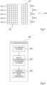
- Figure 1schematically illustrates, in the form of blocks, a depth map sensor 100 according to an example embodiment of the present disclosure.
- the depth map sensor 100comprises a pixel array (PIXEL ARRAY) 102.
- the pixel array 102is for example a scanned return array that is adapted to be scanned in synchronization with an illumination of an image scene.
- the pixel array 102is a single-photon avalanche diode (SPAD) array, that is an array 102 whose pixels each comprise at least one SPAD.
- SPADsingle-photon avalanche diode
- the image sceneis illuminated by a laser illumination system (ILLUMINATION SYSTEM) 104.
- the laser illumination system 104comprises a plurality of laser light sources 106.
- the laser illumination system 104is for example a scanned array of vertical-cavity surface-emitting lasers (VCSELs), where each light source 106 corresponds to at least one VCSEL.
- the depth map sensor 100may include at least one lens and/or diffuser (not shown in Figure 1 ), which partially or entirely covers the laser illumination system 104.
- the letter "N”denotes the total number of laser light sources 106 belonging to the laser illumination system 104 of the depth map sensor 100.
- five laser light sources 106(106-1, 106-2, 106-3, 106-4 and 106-5) arranged in a one by five array are represented, although no limitation is implied as to the number and the arrangement of laser light sources 106 in the laser illumination system 104.
- the arraycould be an i by j array of light sources 106, where i and j are each integers equal to 1 or more and i times j equals N.
- the laser illumination system 104successively illuminates various regions of the image scene, the regions potentially being partially overlapping.
- the laser illumination system 104comprises only one laser light source, e.g. a single VCSEL, and an optical system adapted to scan the image scene.
- Such an optical systemmay comprise at least one mirror which is tilted at discrete angles with respect to the laser light source, thus deflecting the emitted laser light towards a plurality of N regions within the image scene, which again may be partially overlapping.
- the light sources 106 of the laser illumination system 104are driven by a control circuit (CTRL) 108.
- CTRLcontrol circuit
- the pixel array 102may also be driven by the control circuit 108, as represented in Figure 1 .
- the pixel array 102is alternatively driven by another element or circuit (not shown in Figure 1 ) of the depth map sensor 100.
- the control circuit 108is a microcontroller, an application-specific integrated circuit (ASIC) or a field-programmable gate array (FPGA) .
- the depth map sensor 100can further comprise several other elements or circuits which are symbolized, in Figure 1 , by a single functional block (FCT) 110.
- FCTsingle functional block
- Each laser source 106 of the laser illumination system 104emits or transmits, into the image scene, optical pulses or an optical waveform.
- a return signal, caused by the reflection of these optical pulses or this optical waveform in the image scene,is detected by the pixel array 102.
- the depth map sensor 100can be configured to perform either direct ToF (dToF) or indirect ToF (iToF).
- the time delay of each return pulse with respect to the corresponding transmitted pulseis estimated in order to determine the time-of-flight, which can be converted into a distance measurement.
- the phase of the returned waveformis compared with that of the emitted waveform in order to estimate the time-of-flight, which is then converted into a distance measurement.
- FIG 2schematically illustrates, in the form of blocks, the control circuit 108 of the depth map sensor 100 of Figure 1 according to an example embodiment in a case in which the functions of this control circuit 108 are implemented in software.
- control circuit 108comprises a processing device (P) 202, an instruction memory (INSTR MEM) 204 and an image memory (IMAGE MEM) 206.
- the instruction memory 204is for example a non-transitory storage medium adapted to store computer instructions, which may be executed by the processing device 202.
- the image memory 206is also for example a non-transitory storage medium.
- the image memory 206is adapted to store information provided by the pixel array 102 of Figure 1 . More specifically, the image memory 206 may store data related to a three-dimensional (3D) view of the image scene, also termed "depth map", as captured by the depth map sensor 100.
- 3Dthree-dimensional
- Figure 3schematically illustrates the pixel array 102 of the depth map sensor 100 of Figure 1 according to an example embodiment.
- the pixel array 102is formed of an array of pixels 302. According to this embodiment, the pixel array 102 is divided into several clusters 304 of pixels 302. Clusters 304 are defined here as regions of the pixel array 102, each comprising at least one pixel 302 and preferably a plurality of adjacent pixels 302.
- the pixel array 102is divided into five clusters 304, each cluster 304 comprising two adjacent rows of pixels 302. More specifically:
- the clusters 304are shown in Figure 3 as rectangular-shaped regions of the pixel array 102, each cluster 304 comprising a same number of pixels 302, though no limitation is implied as to the shapes of the clusters 304 and number of pixels 302 in each cluster 304. In particular, each of the clusters 304 may have any shape and may comprise any number of pixels 302, which may or may not be adjacent. Although five clusters 304 (304-1, 304-2, 304-3, 304-4 and 304-5) are represented in Figure 3 , the pixel array 102 may comprise any number of clusters 304.
- the pixels 302 of one of the clusters 304are for example illuminated at once during an illumination phase.
- Each of the clusters 304is for example illuminated sequentially in a corresponding illumination phase.
- the clusters 304 of the pixel array 102are for example activated to detect illumination from the image scene in sequence from top to bottom as they are illuminated during the scanning operation.
- the sequential activation of the clusters 304is performed in synchronization with the illumination of corresponding or associated laser light sources 106 (106-1, 106-2, 106-3, 106-4 and 106-5) of the laser illumination system 104 of Figure 1 .
- the number of clusters 304is equal to the number N of laser light sources 106, where N is equal to two or more.
- each laser light source 106 of the laser illumination system 104is configured to illuminate a corresponding cluster 304 of the pixel array 102.
- the time period during which a given laser source 106 illuminates a cluster 304is termed "illumination phase".
- illumination phasethe time period during which a given laser source 106 illuminates a cluster 304.
- the depth map sensor 100 of Figure 1is already adapted to reach a high degree of operation safety, e.g. by limiting the light output energy and/or power of its laser illumination system 104.
- a high degree of operation safetye.g. by limiting the light output energy and/or power of its laser illumination system 104.
- laser safetymay not be fully guaranteed despite all current precautions.
- Such failure scenarioscould possibly occur, for example, if a water droplet were to accidentally form in a transmission path of the laser light emitted by the illumination system 104 of Figure 1 .
- a raindropcould for example happen to fall just above the depth map sensor 100 on a cover glass of the phone.
- Delivered power and/or energymay then be concentrated on a smaller spot than without any water droplet being located on top of the illumination system 104, thus increasing local light intensity in an area of the image scene. This could be hazardous for a user of the mobile phone comprising the depth map sensor 100, for example if, at the same time, the laser light output happens to be orientated towards the user's eyes.
- a reference detectoradapted to capture a portion of the emitted light that is reflected by an output lens, typically located above the laser source.
- Such a reference detectorwhich is generally optically isolated from the pixel array, may be used to infer the output power and/or energy that is emitted through the lens.
- Such an indirect techniqueis very challenging to calibrate, as it is difficult to set a threshold that reliably separates unsafe laser operation from corner cases during normal use.
- the reference detectormay be unable to detect it.
- Figure 4is a simplified flow diagram of an embodiment of operations associated with the laser safety verification of the depth map sensor 100 of Figure 1 during a single illumination phase 400.
- the illumination phase 400corresponds to the illumination phase during which the laser light source 106-1 of the depth map sensor 100 illuminates the cluster 304-1, as described in relation with Figure 3 .
- the illumination phase 400begins with illuminating a cluster (block 402), i.e. the cluster 304-1 of the pixel array 102.
- the cluster 304-1is associated with the laser light source 106-1, an illumination is expected to be detected only by the cluster 304-1, whereas almost no illumination should be captured by other clusters 304.
- the inventorshave found that a significant amount of light hits at least some of the other clusters, such as for example the cluster 304-2.
- the level of illuminationis hence detected in at least one other cluster (block 404), different from the cluster 304-1.
- the level of illuminationis detected in the cluster 304-2 while illuminating the cluster 304-1 with the laser light source 106-1.
- the light that reaches the cluster 304-2that is the illumination of the cluster 304-2, is captured and detected or measured by the cluster 304-2 during the illumination phase of the cluster 304-1.
- the level of illumination captured by the cluster 304-2is afterwards compared with a threshold value (block 406).
- the threshold valuemay be set during a calibration phase, for example a calibration phase performed in factory, using a reference/standard environment, after production of the depth map sensor 100.
- a threshold valuemay include a margin whose value is for example defined with respect to a noise level such as ambient light taking into account a future implementation of the depth map sensor 100 in a product.
- the threshold valueis set using a highly reflective surface, so as to calibrate the depth map sensor 100 by exposing it to the highest illumination level that may be reached during its future operation.
- Figure 5is a flow diagram illustrating operations in a method of laser safety verification of the depth map sensor 100 of Figure 1 according to another example embodiment.
- the flow diagram of Figure 5more specifically depicts a method of laser safety verification comprising N illumination phases, each using one of the N laser light sources 106 of the illumination system 104.
- N illumination phaseseach using one of the N laser light sources 106 of the illumination system 104.
- all N clusters 304 of the pixel array 102, except the cluster 304 that is illuminated by the considered laser light source 106,are successively swept through so as to detect their level of illumination and to compare it with a threshold value.
- the threshold valueis assumed to be the same for all N clusters 304 in the example embodiment of Figure 5 .
- at least one different threshold valuemay alternatively be set for at least one of the N clusters 304, for example to take into account process variations between the pixels of different clusters 304.
- the level of illumination of each cluster 304may be obtained by averaging the output of each of its pixels 302.
- the level of illumination of each cluster 304may alternatively be defined as the peak value, that is the highest illumination level reached among all pixels 302 of the cluster 304.
- a SPAD array of a depth map sensorgenerally operates by generating, at each pixel, events in response to photons hitting the pixel.
- a counter within each pixel, or outside the pixel array,is used to count the events occurring at each pixel.
- the output of a pixelfor example corresponds to the sum of one or more count values generated by the events detected at the considered pixel.
- the thresholdmay be a relative threshold.
- the thresholdmay correspond, for a cluster 304 that is not illuminated, to a detected level of illumination equal to a percentage, e.g. 10 %, of the level of illumination of the cluster 304 that is illuminated.
- the laser safety verification methodmay thus comprise detecting the illumination of the cluster 304 that is illuminated.
- the thresholdmay alternatively be an absolute threshold, i.e. a threshold value that is set regardless of the illumination of the cluster 304 that is illuminated.
- control circuit 108 of Figure 1may be executed by the control circuit 108 of Figure 1 .
- the instruction memory 204may store computer instructions that cause the method described below to be implemented when executed by the processing device 202.
- the beginning of the laser safety verification method(block 500) is followed by the setting of a counter k to the value 1 (block 502).
- a k-th illumination phase(dashed block 504) then starts, comprising blocks 506 to 520, and a k-th laser light source is activated (block 506). This causes a k-th cluster to be illuminated (block 508).
- each value of kcorresponds to one of the N illumination phases, using one of the N laser light sources, k being thus an integer ranging from 1 to N. If applied to the depth map sensor 100 as described in relation with Figure 1 , each value of k represents one of the five possible illumination phases using one of the five laser light sources 106 of the laser illumination system 104. In this case, k is ranging from 1 to 5.
- the illumination phase of the cluster 304-1starts by activating the laser light source 106-1, which in turn causes the cluster 304-1 to be illuminated.
- a counter pis then set to the value 1 (block 510) .
- the counter pis used for sweeping through the N clusters 304. If applied to the pixel array 102 as described in relation with Figure 3 , each value of p represents one of the five clusters 304 of pixels 302. In this case, p is an integer ranging from 1 to 5.
- the value of the counter pis then compared with the value N (block 514). This allows for all the N clusters, except the cluster associated with the activated laser light source, to be swept through during each illumination phase. At this stage, the value of the counter p is equal to 1, which is not equal to N (output NO of block 514), as N is assumed to be equal to 5.
- the counter pis incremented (block 516) and the comparison 512 between p and k happens again. At this point, the value of the counter p is equal to 2 while the value of the counter k is still equal to 1. Counters p and k hence have different values (output YES of block 512).
- a level of illuminationis then detected by a p-th cluster (block 518), that is the cluster 304-2, at this stage.
- the illumination of the cluster 304-2is then compared to the threshold value (block 520).
- an average level or a peak levelbased on the outputs of the pixels 302-2 belonging to the cluster 304-2, may for example be compared to the threshold value by the control circuit 108 of Figure 1 .
- the depth map sensor 100is considered to be laser unsafe (block 522) and the laser safety verification method ends (block 524). This may for example occur during one of the failure scenarios that have been previously described.
- the depth map sensor 100is temporarily considered to be laser safe.
- the laser safety verification methodtherefore carries on by comparing the illumination of the other clusters, namely the clusters 304-3, 304-4 and 304-5, with the threshold value. This is achieved by incrementing the value of p and therefore repeating the operations described above in relation with blocks 512, 518, 520, 514 and 516.
- the depth map sensor 100is so far still considered to be laser safe.
- the value of the counter pis equal to 5, that is to say equal to N (output YES of block 514).
- the illumination phase of the cluster 304-1is therefore completed.
- the value of the counter kis then compared with the value N (block 528). This allows for all the N illumination phases, that is to say all the N laser light sources 106, to be swept through during the laser safety verification method. At this stage, the value of the counter k is equal to 1, which is not equal to N (output NO of block 528).
- the counter kis incremented (block 530).
- the value of the counter kbeing, at this stage, equal to 2, the illumination phase of the cluster 304-2 begins and the laser light source 106-2 is activated.
- the illumination phase of the cluster 304-2is performed in a similar way to what has been previously described in relation with the illumination phase of the cluster 304-1.
- the illumination detected by all clusters 304, except the cluster 304-2is smaller than the threshold value, the illumination phase of the cluster 304-2 ends and the depth map sensor 100 is still considered to be laser safe at that point. In this case, the laser safety verification method continues and the illumination phases follow one another until the end of the illumination phase of the cluster 304-5.
- the value of the counter kis equal to 5, that is to say equal to N (output YES of block 528).
- the depth map sensor 100is considered to be laser safe (block 526).
- the depth map sensor 100is otherwise considered to be laser unsafe. In both cases, the laser safety verification method then reaches its end 524.
- the laser safety verification method described above in relation with Figure 5may be executed by the control circuit 108 before any ranging operation performed by the depth map sensor 100. According to an embodiment, the laser safety detection method is executed around every 30 ms.
- the clusters 304 of the pixel array 102may be scanned from top to bottom during operation, one cluster being read while the next cluster is detecting a level of illumination.
- the laser safety verification method described aboveis advantageously compatible with performing such parallel reading and detection operations.
- the detection of the illumination of several other clustersmay be performed in parallel. In other words, detection of the illumination may occur, at once, in a plurality of clusters. This would advantageously enable to perform the laser safety verification in a shorter time.
- the laser safety verification methodmay be adapted to any number of light sources 106 and any number of clusters 304.
- the methodmay further be adapted to cases where only some of the light sources 106 are activated and/or only some of the clusters 304 detect an illumination.
- one or more clusters of interest (CoI)that is one or more clusters whose illumination is considered to be particularly relevant to laser safety verification, may be defined.
- the order in which an illumination is detected by clusters 304 during illumination phasesmay vary from one illumination phase to another.
- the order in which laser light sources 106 are activatedmay also vary from one laser safety verification to another. All such variations are within the capabilities of those skilled in the art based on the functional description provided hereinabove.
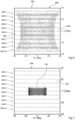
- Figures 6 and 7show two examples of the illumination captured by the pixel array 102 of Figure 3 . More specifically, Figures 6 and 7 each are plots of the angular distribution of the illumination level or intensity detected by the pixel array 102.
- an angular range of 80°, from -40° to +40°is both horizontally (H, deg) and vertically (V, deg) covered by the depth map sensor 100 of Figure 1 .
- these angular rangesare covered by the sequence of illumination phases of the depth map sensor 100.
- the illumination levelsare shown in grayscale.
- White or light gray areascorrespond, in this example, to low illumination levels while dark gray or black areas correspond to high illumination levels.
- the plot of the illumination captured by the pixel array 102mainly features a first large area 600 and two smaller second areas 602.
- the first area 600 and the second areas 602being respectively colored in light gray and in white, it may be inferred that the illumination power is widely spread in the image scene.
- the plot of Figure 6corresponds, for example, to a laser safe operation where the power of the laser illumination system 104 is almost evenly distributed among various regions in the image scene.
- the plot of the illumination captured by the pixel array 102mainly features a rectangular spot 700 surrounded by a large white third area 702.
- the spot 700is both smaller and darker than the first area 600 of Figure 6
- the white third area 702is wider than the second areas 602 of Figure 6 .
- the illumination poweris concentrated in the image scene.
- the power distributionis said to have "collapsed".
- the plot of Figure 7corresponds, for example, to a laser unsafe operation where the power of the laser illumination system 104 is focused on only one or some of the regions of the image scene.
- the pixels 302 of the pixel array 102may not comprise SPADs.
- the pixel array 102may instead comprise other types of pixels, such as for example CMOS pixels.
- the number, shape and area of the clusters 304 of pixels 302may furthermore be adapted to the application.
Landscapes
- Engineering & Computer Science (AREA)
- Physics & Mathematics (AREA)
- General Physics & Mathematics (AREA)
- Computer Networks & Wireless Communication (AREA)
- Radar, Positioning & Navigation (AREA)
- Remote Sensing (AREA)
- Electromagnetism (AREA)
- Optical Radar Systems And Details Thereof (AREA)
Description
- The present disclosure relates generally to the field of time of flight (ToF) depth map sensors, and in particular to a method and device for laser safety verification for such sensors.
- The ability of time-of-flight (ToF) cameras based on single-photon avalanche diodes (SPADs) to provide precise photon arrival times makes them popular candidates for depth map sensors. Such ToF cameras generally comprise a laser source such as a vertical-cavity surface-emitting laser (VCSEL) that emits, into an image scene, optical pulses or an optical waveform, and an array of SPADs for detecting the return signal.
- In a typical ToF camera, the laser source is usually able to reach output power levels which are sufficiently high to damage the eye. Laser safety of such ToF cameras is thus of critical importance. While current technology allows laser safety in ToF cameras to be achieved under many operating conditions, there is a need for a system and method providing further improved safety verification.
US 2018/095168 describes an optoelectronic sensor and a method for optical monitoring.WO 2018/156412 describes an eye safe VCSEL illuminator package.US 2015/285625 describes a high resolution, high frame rate, low power image sensor.- There is a need to improve laser safety verification methods and devices for depth map sensors.
- One embodiment addresses all or some of the drawbacks of known laser safety verification methods and devices for depth map sensors.
- One embodiment provides a method of laser safety verification for a depth map sensor, comprising:
- illuminating via an image scene, during a first illumination phase, using a laser illumination system, a first cluster of one or more first pixels of a pixel array of the depth map sensor, while not illuminating a second cluster, different from the first cluster, of one or more second pixels of the pixel array of the depth map sensor;
- detecting, during the first illumination phase, a level of illumination of the second cluster; and
- comparing the detected level of illumination of the second cluster, during the first illumination phase, with a first threshold value to verify the safety of the laser illumination system.
- According to one embodiment, the method comprises detecting, during the first illumination phase, a level of illumination of the first cluster, the first threshold value being a variable threshold, the level of which is generated based on said level of illumination of the first cluster.
- According to one embodiment, the method comprises:
- illuminating, during a second illumination phase, using the laser illumination system, the second cluster, while not illuminating the first cluster; and
- detecting, during the second illumination phase, a level of illumination of the first cluster.
- According to one embodiment, the method comprises comparing the level of illumination of the first cluster, during the second illumination phase, with a second threshold value to verify the safety of the laser illumination system.
- According to one embodiment, said first and second threshold values are the same.
- According to one embodiment, the depth map sensor comprises N clusters, including said first and second clusters, where N is equal to two or more, the method further comprising detecting, during the first illumination phase, a level of illumination of all N clusters except the first cluster.
- According to one embodiment, the laser illumination system comprises N laser light sources.
- According to one embodiment, the method comprises N illumination phases, including said first and second illumination phases, each illumination phase using one of said N laser light sources.
- According to one embodiment, the illumination level of the second cluster is obtained by reading the second pixels.
- According to one embodiment, the illumination level of the second cluster is obtained by averaging outputs of the second pixels.
- One embodiment provides a device comprising:
- a laser illumination system;
- a first cluster of one or more first pixels of a pixel array of a depth map sensor;
- a second cluster, different from the first cluster, of one or more second pixels of the pixel array of the depth map sensor; and
- a control circuit configured:
- to illuminate via an image scene, during a first illumination phase, using the laser illumination system, the first cluster while not illuminating the second cluster;
- to detect, during the first illumination phase, a level of illumination of the second cluster; and
- to compare the detected level of illumination of the second cluster, during the first illumination phase, with a first threshold value to verify the safety of the laser illumination system.
- According to one embodiment, the laser illumination system comprises a least one vertical-cavity surface-emitting laser.
- According to one embodiment, each pixel comprises at least one single-photon avalanche diode.
- One embodiment provides a non-transitory storage medium, storing computer instructions that cause a processing device of the control circuit of the device to execute the steps performed by the control circuit.
- The foregoing features and advantages, as well as others, will be described in detail in the following description of specific embodiments given by way of illustration and not limitation with reference to the accompanying drawings, in which:
Figure 1 schematically illustrates, in the form of blocks, a depth map sensor according to an example embodiment of the present disclosure;Figure 2 schematically illustrates, in the form of blocks, a control circuit of the depth map sensor ofFigure 1 according to an example embodiment;Figure 3 schematically illustrates a pixel array of the depth map sensor ofFigure 1 according to an example embodiment;Figure 4 is a flow diagram illustrating operations in a method of laser safety verification of the depth map sensor ofFigure 1 according to an example embodiment;Figure 5 is a flow diagram illustrating operations in a method of laser safety verification of the depth map sensor ofFigure 1 according to another example embodiment;Figure 6 shows an example of the illumination captured by the pixel array ofFigure 3 ; andFigure 7 shows another example of the illumination captured by the pixel array ofFigure 3 .- Like features have been designated by like references in the various figures. In particular, the structural and/or functional features that are common among the various embodiments may have the same references and may dispose identical structural, dimensional and material properties.
- For the sake of clarity, only the operations and elements that are useful for an understanding of the embodiments described herein have been illustrated and described in detail.
- Unless indicated otherwise, when reference is made to two elements connected together, this signifies a direct connection without any intermediate elements other than conductors, and when reference is made to two elements linked or coupled together, this signifies that these two elements can be connected or they can be linked or coupled via one or more other elements.
- In the following disclosure, unless indicated otherwise, when reference is made to absolute positional qualifiers, such as the terms "front", "back", "top", "bottom", "left", "right", etc., or to relative positional qualifiers, such as the terms "above", "below", "higher", "lower", etc., or to qualifiers of orientation, such as "horizontal", "vertical", etc., reference is made to the orientation shown in the figures, or to a depth map sensor as orientated during normal use.
- Unless specified otherwise, the expressions "around", "approximately", "substantially" and "in the order of" signify within 10%, and preferably within 5%.
Figure 1 schematically illustrates, in the form of blocks, adepth map sensor 100 according to an example embodiment of the present disclosure.- According to this embodiment, the
depth map sensor 100 comprises a pixel array (PIXEL ARRAY) 102. Thepixel array 102 is for example a scanned return array that is adapted to be scanned in synchronization with an illumination of an image scene. In some embodiments, thepixel array 102 is a single-photon avalanche diode (SPAD) array, that is anarray 102 whose pixels each comprise at least one SPAD. - The image scene is illuminated by a laser illumination system (ILLUMINATION SYSTEM) 104. According to this embodiment, the
laser illumination system 104 comprises a plurality oflaser light sources 106. Thelaser illumination system 104 is for example a scanned array of vertical-cavity surface-emitting lasers (VCSELs), where eachlight source 106 corresponds to at least one VCSEL. Thedepth map sensor 100 may include at least one lens and/or diffuser (not shown inFigure 1 ), which partially or entirely covers thelaser illumination system 104. - In the following disclosure, the letter "N" denotes the total number of
laser light sources 106 belonging to thelaser illumination system 104 of thedepth map sensor 100. InFigure 1 , five laser light sources 106 (106-1, 106-2, 106-3, 106-4 and 106-5) arranged in a one by five array are represented, although no limitation is implied as to the number and the arrangement of laserlight sources 106 in thelaser illumination system 104. For example, more generally, the array could be an i by j array oflight sources 106, where i and j are each integers equal to 1 or more and i times j equals N. - More generally, the
laser illumination system 104 successively illuminates various regions of the image scene, the regions potentially being partially overlapping. In some alternative embodiments (not shown inFigure 1 ), thelaser illumination system 104 comprises only one laser light source, e.g. a single VCSEL, and an optical system adapted to scan the image scene. Such an optical system may comprise at least one mirror which is tilted at discrete angles with respect to the laser light source, thus deflecting the emitted laser light towards a plurality of N regions within the image scene, which again may be partially overlapping. - The
light sources 106 of thelaser illumination system 104 are driven by a control circuit (CTRL) 108. Thepixel array 102 may also be driven by thecontrol circuit 108, as represented inFigure 1 . Thepixel array 102 is alternatively driven by another element or circuit (not shown inFigure 1 ) of thedepth map sensor 100. In some embodiments, thecontrol circuit 108 is a microcontroller, an application-specific integrated circuit (ASIC) or a field-programmable gate array (FPGA) . - The
depth map sensor 100 can further comprise several other elements or circuits which are symbolized, inFigure 1 , by a single functional block (FCT) 110. - Each
laser source 106 of thelaser illumination system 104 emits or transmits, into the image scene, optical pulses or an optical waveform. A return signal, caused by the reflection of these optical pulses or this optical waveform in the image scene, is detected by thepixel array 102. According to one embodiment, thedepth map sensor 100 can be configured to perform either direct ToF (dToF) or indirect ToF (iToF). - In the case of dToF, the time delay of each return pulse with respect to the corresponding transmitted pulse is estimated in order to determine the time-of-flight, which can be converted into a distance measurement.
- In the case of iToF, the phase of the returned waveform is compared with that of the emitted waveform in order to estimate the time-of-flight, which is then converted into a distance measurement.
Figure 2 schematically illustrates, in the form of blocks, thecontrol circuit 108 of thedepth map sensor 100 ofFigure 1 according to an example embodiment in a case in which the functions of thiscontrol circuit 108 are implemented in software.- According to this embodiment, the
control circuit 108 comprises a processing device (P) 202, an instruction memory (INSTR MEM) 204 and an image memory (IMAGE MEM) 206. Theinstruction memory 204 is for example a non-transitory storage medium adapted to store computer instructions, which may be executed by theprocessing device 202. - The
image memory 206 is also for example a non-transitory storage medium. In some embodiments, theimage memory 206 is adapted to store information provided by thepixel array 102 ofFigure 1 . More specifically, theimage memory 206 may store data related to a three-dimensional (3D) view of the image scene, also termed "depth map", as captured by thedepth map sensor 100. Figure 3 schematically illustrates thepixel array 102 of thedepth map sensor 100 ofFigure 1 according to an example embodiment.- The
pixel array 102 is formed of an array ofpixels 302. According to this embodiment, thepixel array 102 is divided intoseveral clusters 304 ofpixels 302.Clusters 304 are defined here as regions of thepixel array 102, each comprising at least onepixel 302 and preferably a plurality ofadjacent pixels 302. - In the example depicted in
Figure 3 , thepixel array 102 is divided into fiveclusters 304, eachcluster 304 comprising two adjacent rows ofpixels 302. More specifically: - a cluster 304-1 comprises two rows of pixels 302-1;
- a cluster 304-2 comprises two rows of pixels 302-2;
- a cluster 304-3 comprises two rows of pixels 302-3;
- a cluster 304-4 comprises two rows of pixels 302-4; and
- a cluster 304-5 comprises two rows of pixels 302-5.
- The
clusters 304 are shown inFigure 3 as rectangular-shaped regions of thepixel array 102, eachcluster 304 comprising a same number ofpixels 302, though no limitation is implied as to the shapes of theclusters 304 and number ofpixels 302 in eachcluster 304. In particular, each of theclusters 304 may have any shape and may comprise any number ofpixels 302, which may or may not be adjacent. Although five clusters 304 (304-1, 304-2, 304-3, 304-4 and 304-5) are represented inFigure 3 , thepixel array 102 may comprise any number ofclusters 304. - During operation of the
depth map sensor 100 ofFigure 1 , thepixels 302 of one of theclusters 304 are for example illuminated at once during an illumination phase. Each of theclusters 304 is for example illuminated sequentially in a corresponding illumination phase. Theclusters 304 of thepixel array 102 are for example activated to detect illumination from the image scene in sequence from top to bottom as they are illuminated during the scanning operation. - According to one embodiment, the sequential activation of the clusters 304 (304-1, 304-2, 304-3, 304-4 and 304-5) is performed in synchronization with the illumination of corresponding or associated laser light sources 106 (106-1, 106-2, 106-3, 106-4 and 106-5) of the
laser illumination system 104 ofFigure 1 . According to this embodiment, the number ofclusters 304 is equal to the number N of laserlight sources 106, where N is equal to two or more. In other words, eachlaser light source 106 of thelaser illumination system 104 is configured to illuminate acorresponding cluster 304 of thepixel array 102. - In the following disclosure, the time period during which a given
laser source 106 illuminates acluster 304 is termed "illumination phase". Given that thelaser illumination system 104 is assumed to comprise N laserlight sources 106, there are also N illumination phases. In particular: - one illumination phase is defined by the cluster 304-1 being illuminated using the laser light source 106-1; and
- another illumination phase is defined by the cluster 304-2 being illuminated using the laser light source 106-2.
- The
depth map sensor 100 ofFigure 1 is already adapted to reach a high degree of operation safety, e.g. by limiting the light output energy and/or power of itslaser illumination system 104. However, in some very rare failure scenarios, corresponding to marginal or corner cases, laser safety may not be fully guaranteed despite all current precautions. - Such failure scenarios could possibly occur, for example, if a water droplet were to accidentally form in a transmission path of the laser light emitted by the
illumination system 104 ofFigure 1 . Supposing that thedepth map sensor 100 is embedded in a mobile phone, a raindrop could for example happen to fall just above thedepth map sensor 100 on a cover glass of the phone. By acting as a convergent optical lens, such a raindrop could tend to focus the emitted laser light. Delivered power and/or energy may then be concentrated on a smaller spot than without any water droplet being located on top of theillumination system 104, thus increasing local light intensity in an area of the image scene. This could be hazardous for a user of the mobile phone comprising thedepth map sensor 100, for example if, at the same time, the laser light output happens to be orientated towards the user's eyes. - Other failure scenarios include external optics being added to a device featuring the
depth map sensor 100, lens drop or damage, water ingress inside thesensor 100, etc. Laser safety issues may also arise in a rare case where the scanning of thelaser light sources 106 gets stuck, the laser light being then continuously emitted towards a same region of the image scene. This may result in a high concentration of power in this region, potentially exceeding a power allowance, instead of the power being spread between several regions of the image scene when it is scanned normally. - While laser safety in most frequent cases is generally fully ensured by known methods, failure scenarios such as those described above can be difficult to detect with a satisfactory level of certainty. In fact, existing methods of laser safety verification infer potentially unsafe states by an indirect detection of specific failure modes. Unfortunately, the existing methods are often limited to these specific failure modes. Laser safety detection in several other use cases may therefore either lead to false positive, that is cases where laser safety issues are wrongly detected, or to safety detection fails, that is cases where true laser safety issues remain undetected.
- It is known to use a reference detector adapted to capture a portion of the emitted light that is reflected by an output lens, typically located above the laser source. Such a reference detector, which is generally optically isolated from the pixel array, may be used to infer the output power and/or energy that is emitted through the lens. However, such an indirect technique is very challenging to calibrate, as it is difficult to set a threshold that reliably separates unsafe laser operation from corner cases during normal use. Furthermore, should the optical characteristics of the laser light be changed by an optically-active element located beyond the lens, the reference detector may be unable to detect it.
Figure 4 is a simplified flow diagram of an embodiment of operations associated with the laser safety verification of thedepth map sensor 100 ofFigure 1 during asingle illumination phase 400.- The operations described below in relation with
Figure 4 may for example be executed by thecontrol circuit 108 ofFigures 1 and 2 . During these operations, it is presumed that thedepth map sensor 100 is pointed at an image scene reflecting, at least partially, the laser light emitted by thedepth map sensor 100, and that thedepth map sensor 100 is not, for example, oriented towards the sky. - For the sake of clarity, it is assumed here that the
illumination phase 400 corresponds to the illumination phase during which the laser light source 106-1 of thedepth map sensor 100 illuminates the cluster 304-1, as described in relation withFigure 3 . According to this embodiment, theillumination phase 400 begins with illuminating a cluster (block 402), i.e. the cluster 304-1 of thepixel array 102. - Because the cluster 304-1 is associated with the laser light source 106-1, an illumination is expected to be detected only by the cluster 304-1, whereas almost no illumination should be captured by
other clusters 304. However, in at least some of the above-described failure scenarios, the inventors have found that a significant amount of light hits at least some of the other clusters, such as for example the cluster 304-2. - The level of illumination is hence detected in at least one other cluster (block 404), different from the cluster 304-1. For example, the level of illumination is detected in the cluster 304-2 while illuminating the cluster 304-1 with the laser light source 106-1.
- According to an embodiment, the light that reaches the cluster 304-2, that is the illumination of the cluster 304-2, is captured and detected or measured by the cluster 304-2 during the illumination phase of the cluster 304-1. The level of illumination captured by the cluster 304-2 is afterwards compared with a threshold value (block 406).
- The threshold value may be set during a calibration phase, for example a calibration phase performed in factory, using a reference/standard environment, after production of the
depth map sensor 100. Such a threshold value may include a margin whose value is for example defined with respect to a noise level such as ambient light taking into account a future implementation of thedepth map sensor 100 in a product. For example, the threshold value is set using a highly reflective surface, so as to calibrate thedepth map sensor 100 by exposing it to the highest illumination level that may be reached during its future operation. Figure 5 is a flow diagram illustrating operations in a method of laser safety verification of thedepth map sensor 100 ofFigure 1 according to another example embodiment.- The flow diagram of
Figure 5 more specifically depicts a method of laser safety verification comprising N illumination phases, each using one of the N laserlight sources 106 of theillumination system 104. During each of the N illumination phases, allN clusters 304 of thepixel array 102, except thecluster 304 that is illuminated by the consideredlaser light source 106, are successively swept through so as to detect their level of illumination and to compare it with a threshold value. - For the sake of clarity, the threshold value is assumed to be the same for all
N clusters 304 in the example embodiment ofFigure 5 . However, at least one different threshold value may alternatively be set for at least one of theN clusters 304, for example to take into account process variations between the pixels ofdifferent clusters 304. - The level of illumination of each
cluster 304 may be obtained by averaging the output of each of itspixels 302. The level of illumination of eachcluster 304 may alternatively be defined as the peak value, that is the highest illumination level reached among allpixels 302 of thecluster 304. For example, as known by those skilled in the art, a SPAD array of a depth map sensor generally operates by generating, at each pixel, events in response to photons hitting the pixel. A counter within each pixel, or outside the pixel array, is used to count the events occurring at each pixel. The output of a pixel for example corresponds to the sum of one or more count values generated by the events detected at the considered pixel. - The threshold may be a relative threshold. In such a case, the threshold may correspond, for a
cluster 304 that is not illuminated, to a detected level of illumination equal to a percentage, e.g. 10 %, of the level of illumination of thecluster 304 that is illuminated. The laser safety verification method may thus comprise detecting the illumination of thecluster 304 that is illuminated. - The threshold may alternatively be an absolute threshold, i.e. a threshold value that is set regardless of the illumination of the
cluster 304 that is illuminated. - The method described hereafter may be executed by the
control circuit 108 ofFigure 1 . For example, when thecontrol circuit 108 comprises theprocessing device 202 and theinstruction memory 204 ofFigure 2 , theinstruction memory 204 may store computer instructions that cause the method described below to be implemented when executed by theprocessing device 202. - According to an embodiment, the beginning of the laser safety verification method (block 500) is followed by the setting of a counter k to the value 1 (block 502). A k-th illumination phase (dashed block 504) then starts, comprising
blocks 506 to 520, and a k-th laser light source is activated (block 506). This causes a k-th cluster to be illuminated (block 508). - In the flow diagram represented in
Figure 5 , each value of k corresponds to one of the N illumination phases, using one of the N laser light sources, k being thus an integer ranging from 1 to N. If applied to thedepth map sensor 100 as described in relation withFigure 1 , each value of k represents one of the five possible illumination phases using one of the fivelaser light sources 106 of thelaser illumination system 104. In this case, k is ranging from 1 to 5. - With k being equal to 1 at this stage of the flow diagram, the illumination phase of the cluster 304-1 starts by activating the laser light source 106-1, which in turn causes the cluster 304-1 to be illuminated.
- A counter p is then set to the value 1 (block 510) . According to this embodiment, the counter p is used for sweeping through the
N clusters 304. If applied to thepixel array 102 as described in relation withFigure 3 , each value of p represents one of the fiveclusters 304 ofpixels 302. In this case, p is an integer ranging from 1 to 5. - The value of the counter p is then compared with the value of the counter k (block 512), in order to exclude an illumination detection by the
cluster 304 associated with the activatedlaser light source 106, i.e. the case in which p = k. In the case that p = k (output NO of block 512), the cluster 304-1 is not activated to detect an illumination, and the method goes straight to block 514. - The value of the counter p is then compared with the value N (block 514). This allows for all the N clusters, except the cluster associated with the activated laser light source, to be swept through during each illumination phase. At this stage, the value of the counter p is equal to 1, which is not equal to N (output NO of block 514), as N is assumed to be equal to 5.
- The counter p is incremented (block 516) and the
comparison 512 between p and k happens again. At this point, the value of the counter p is equal to 2 while the value of the counter k is still equal to 1. Counters p and k hence have different values (output YES of block 512). - A level of illumination is then detected by a p-th cluster (block 518), that is the cluster 304-2, at this stage.
- The illumination of the cluster 304-2 is then compared to the threshold value (block 520). To this end, an average level or a peak level, based on the outputs of the pixels 302-2 belonging to the cluster 304-2, may for example be compared to the threshold value by the
control circuit 108 ofFigure 1 . - According to one embodiment, if the illumination of the cluster 304-2 is found to be greater than or equal to the threshold value (output YES of block 520), the
depth map sensor 100 is considered to be laser unsafe (block 522) and the laser safety verification method ends (block 524). This may for example occur during one of the failure scenarios that have been previously described. - According to this embodiment, if the illumination of the cluster 304-2 is found to be lower than the threshold value (output NO of block 520), the
depth map sensor 100 is temporarily considered to be laser safe. The laser safety verification method therefore carries on by comparing the illumination of the other clusters, namely the clusters 304-3, 304-4 and 304-5, with the threshold value. This is achieved by incrementing the value of p and therefore repeating the operations described above in relation withblocks - Supposing that the illumination detected by the clusters 304-3, 304-4 and 304-5 is lower than the threshold value, the
depth map sensor 100 is so far still considered to be laser safe. At this point, the value of the counter p is equal to 5, that is to say equal to N (output YES of block 514). The illumination phase of the cluster 304-1 is therefore completed. - The value of the counter k is then compared with the value N (block 528). This allows for all the N illumination phases, that is to say all the N laser
light sources 106, to be swept through during the laser safety verification method. At this stage, the value of the counter k is equal to 1, which is not equal to N (output NO of block 528). - The counter k is incremented (block 530). The value of the counter k being, at this stage, equal to 2, the illumination phase of the cluster 304-2 begins and the laser light source 106-2 is activated. The illumination phase of the cluster 304-2 is performed in a similar way to what has been previously described in relation with the illumination phase of the cluster 304-1.
- If the illumination detected by all
clusters 304, except the cluster 304-2, is smaller than the threshold value, the illumination phase of the cluster 304-2 ends and thedepth map sensor 100 is still considered to be laser safe at that point. In this case, the laser safety verification method continues and the illumination phases follow one another until the end of the illumination phase of the cluster 304-5. - At this step, the value of the counter k is equal to 5, that is to say equal to N (output YES of block 528). Assuming that no illumination reaching or exceeding the threshold value has been detected while sweeping through the
laser light sources 106 and theclusters 304, thedepth map sensor 100 is considered to be laser safe (block 526). Thedepth map sensor 100 is otherwise considered to be laser unsafe. In both cases, the laser safety verification method then reaches itsend 524. - The laser safety verification method described above in relation with
Figure 5 may be executed by thecontrol circuit 108 before any ranging operation performed by thedepth map sensor 100. According to an embodiment, the laser safety detection method is executed around every 30 ms. - In the
depth map sensor 100, theclusters 304 of thepixel array 102 may be scanned from top to bottom during operation, one cluster being read while the next cluster is detecting a level of illumination. In this case, the laser safety verification method described above is advantageously compatible with performing such parallel reading and detection operations. However, in alternative embodiments, it would be possible to scan theclusters 304 of thepixel array 102 in other directions, e.g. from bottom to top, from right to left or from left to right. It would furthermore be possible to have illumination phases in which acluster 304 is activated in order to detect a level of illumination while some or all of the other clusters are successively illuminated. - In alternative embodiments, during the illumination of one cluster, the detection of the illumination of several other clusters may be performed in parallel. In other words, detection of the illumination may occur, at once, in a plurality of clusters. This would advantageously enable to perform the laser safety verification in a shorter time.
- More generally, the laser safety verification method that has been previously described in relation with
Figure 5 may be adapted to any number oflight sources 106 and any number ofclusters 304. The method may further be adapted to cases where only some of thelight sources 106 are activated and/or only some of theclusters 304 detect an illumination. For example, one or more clusters of interest (CoI), that is one or more clusters whose illumination is considered to be particularly relevant to laser safety verification, may be defined. The order in which an illumination is detected byclusters 304 during illumination phases may vary from one illumination phase to another. The order in whichlaser light sources 106 are activated may also vary from one laser safety verification to another. All such variations are within the capabilities of those skilled in the art based on the functional description provided hereinabove. Figures 6 and 7 show two examples of the illumination captured by thepixel array 102 ofFigure 3 . More specifically,Figures 6 and 7 each are plots of the angular distribution of the illumination level or intensity detected by thepixel array 102. In the examples ofFigures 6 and 7 , it is assumed that, in the image scene, an angular range of 80°, from -40° to +40°, is both horizontally (H, deg) and vertically (V, deg) covered by thedepth map sensor 100 ofFigure 1 . In other words, these angular ranges are covered by the sequence of illumination phases of thedepth map sensor 100.- In the example of
Figures 6 and 7 , it is assumed that ten clusters 604 (604-1, 604-2, 604-3, 604-4, 604-5, 604-6, 604-7, 604-8, 604-9 and 604-10) of thepixel array 102 are scanned vertically, from top to bottom. - In the plots of
Figures 6 and 7 , the illumination levels are shown in grayscale. White or light gray areas correspond, in this example, to low illumination levels while dark gray or black areas correspond to high illumination levels. - In
Figure 6 , the plot of the illumination captured by thepixel array 102 mainly features a firstlarge area 600 and two smallersecond areas 602. Thefirst area 600 and thesecond areas 602 being respectively colored in light gray and in white, it may be inferred that the illumination power is widely spread in the image scene. The plot ofFigure 6 corresponds, for example, to a laser safe operation where the power of thelaser illumination system 104 is almost evenly distributed among various regions in the image scene. - In
Figure 7 , the plot of the illumination captured by thepixel array 102 mainly features arectangular spot 700 surrounded by a large whitethird area 702. Thespot 700 is both smaller and darker than thefirst area 600 ofFigure 6 , whereas the whitethird area 702 is wider than thesecond areas 602 ofFigure 6 . It may hence be inferred that the illumination power is concentrated in the image scene. In this case, the power distribution is said to have "collapsed". The plot ofFigure 7 corresponds, for example, to a laser unsafe operation where the power of thelaser illumination system 104 is focused on only one or some of the regions of the image scene. - An execution of the method that have previously been described in relation with
Figure 5 may lead to the detection of a laser safe situation in the case ofFigure 6 and of a laser unsafe situation in the case ofFigure 7 . The image scene could also have been scanned horizontally, e.g. from left to right. This would also have led to similar detections. - Various embodiments and variants have been described. Those skilled in the art will understand that certain features of these embodiments can be combined and other variants will readily occur to those skilled in the art. In particular, the
pixels 302 of thepixel array 102 may not comprise SPADs. Thepixel array 102 may instead comprise other types of pixels, such as for example CMOS pixels. The number, shape and area of theclusters 304 ofpixels 302 may furthermore be adapted to the application. - Finally, the practical implementation of the embodiments and variants described herein is within the capabilities of those skilled in the art based on the functional description provided hereinabove. In particular, the practical method used for reading the pixels and storing the corresponding information is within the capabilities of those skilled in the art.
Claims (14)
- A method of laser safety verification for a depth map sensor (100), comprising:illuminating via an image scene, during a first illumination phase (400), using a laser illumination system (104), a first cluster (304-1) of one or more first pixels (302-1) of a pixel array (102) of the depth map sensor, while not illuminating a second cluster (304-2), different from the first cluster, of one or more second pixels (302-2) of the pixel array of the depth map sensor;detecting, during the first illumination phase, a level of illumination of the second cluster; andcomparing the detected level of illumination of the second cluster (304-2), during the first illumination phase (400), with a first threshold value to verify the safety of the laser illumination system (104).
- The method of claim 1, further comprising detecting, during the first illumination phase (400), a level of illumination of the first cluster (304-1), the first threshold value being a variable threshold, the level of which is generated based on said level of illumination of the first cluster.
- The method of claims 1 or 2, further comprising:illuminating, during a second illumination phase, using the laser illumination system (104), the second cluster (304-2), while not illuminating the first cluster (304-1); anddetecting, during the second illumination phase, a level of illumination of the first cluster.
- The method of claim 3, further comprising comparing the level of illumination of the first cluster (304-1), during the second illumination phase, with a second threshold value to verify the safety of the laser illumination system (104) .
- The method of claims 1 and 4, wherein said first and second threshold values are the same.
- The method of any of claims 1 to 5, wherein the depth map sensor (102) comprises N clusters (304-1, 304-2, 304-3, 304-4, 304-5), including said first and second clusters (304-1, 304-2), where N is equal to two or more, the method further comprising detecting, during the first illumination phase (400), a level of illumination of all N clusters except the first cluster (304-1).
- The method of claim 6, wherein the laser illumination system (104) comprises N laser light sources (106-1, 106-2, 106-3, 106-4, 106-5).
- The method of claims 3 and 7, further comprising N illumination phases, including said first and second illumination phases, each illumination phase using one of said N laser light sources (106-1, 106-2, 106-3, 106-4, 106-5).
- The method of any of claims 1 to 8, wherein the illumination level of the second cluster (304-2) is obtained by reading the second pixels (302-2).
- The method of any of claims 1 to 9, wherein the illumination level of the second cluster (304-2) is obtained by averaging outputs of the second pixels (302-2) .
- A device comprising:a laser illumination system (104);a first cluster (304-1) of one or more first pixels (302-1) of a pixel array (102) of a depth map sensor (100);a second cluster (304-2), different from the first cluster, of one or more second pixels (302-2) of the pixel array of the depth map sensor; anda control circuit (108), configured:to illuminate via an image scene, during a first illumination phase (400), using the laser illumination system, the first cluster while not illuminating the second cluster;to detect, during the first illumination phase, a level of illumination of the second cluster; andto compare the detected level of illumination of the second cluster (304-2), during the first illumination phase (400), with a first threshold value to verify the safety of the laser illumination system (104).
- The device of claim 11, wherein the laser illumination system (104) comprises a least one vertical-cavity surface-emitting laser.
- The device of claim 11 or 12, wherein each pixel (302) comprises at least one single-photon avalanche diode.
- A non-transitory storage medium (204), storing computer instructions that cause a processing device (202) of the control circuit (108) of the device of any of claims 11 to 13 to execute the steps performed by the control circuit (108) according to claim 11.
Priority Applications (2)
| Application Number | Priority Date | Filing Date | Title |
|---|---|---|---|
| EP19306238.7AEP3798679B1 (en) | 2019-09-30 | 2019-09-30 | Laser safety verification |
| US17/024,418US11353591B2 (en) | 2019-09-30 | 2020-09-17 | Method and device for laser safety verification |
Applications Claiming Priority (1)
| Application Number | Priority Date | Filing Date | Title |
|---|---|---|---|
| EP19306238.7AEP3798679B1 (en) | 2019-09-30 | 2019-09-30 | Laser safety verification |
Publications (2)
| Publication Number | Publication Date |
|---|---|
| EP3798679A1 EP3798679A1 (en) | 2021-03-31 |
| EP3798679B1true EP3798679B1 (en) | 2023-06-21 |
Family
ID=68281372
Family Applications (1)
| Application Number | Title | Priority Date | Filing Date |
|---|---|---|---|
| EP19306238.7AActiveEP3798679B1 (en) | 2019-09-30 | 2019-09-30 | Laser safety verification |
Country Status (2)
| Country | Link |
|---|---|
| US (1) | US11353591B2 (en) |
| EP (1) | EP3798679B1 (en) |
Families Citing this family (1)
| Publication number | Priority date | Publication date | Assignee | Title |
|---|---|---|---|---|
| EP3798679B1 (en)* | 2019-09-30 | 2023-06-21 | STMicroelectronics (Research & Development) Limited | Laser safety verification |
Family Cites Families (18)
| Publication number | Priority date | Publication date | Assignee | Title |
|---|---|---|---|---|
| DK3876510T3 (en)* | 2008-05-20 | 2024-11-11 | Adeia Imaging Llc | CAPTURE AND PROCESSING OF IMAGES USING MONOLITHIC CAMERA ARRAY WITH HETEROGENEOUS IMAGES |
| DE102008060141B4 (en)* | 2008-12-03 | 2017-12-21 | Forschungszentrum Jülich GmbH | Method for measuring the growth of leaf discs and a device suitable for this purpose |
| DE102009012441B4 (en)* | 2009-03-12 | 2010-12-09 | Deutsches Zentrum für Luft- und Raumfahrt e.V. | Method for reducing the memory requirement when determining disparity values for at least two stereoscopically recorded images |
| US9058661B2 (en)* | 2009-05-11 | 2015-06-16 | Universitat Zu Lubeck | Method for the real-time-capable, computer-assisted analysis of an image sequence containing a variable pose |
| US9536345B2 (en)* | 2012-12-26 | 2017-01-03 | Intel Corporation | Apparatus for enhancement of 3-D images using depth mapping and light source synthesis |
| US9952323B2 (en)* | 2014-04-07 | 2018-04-24 | Samsung Electronics Co., Ltd. | High resolution, high frame rate, low power image sensor |
| US20170142393A1 (en)* | 2014-06-27 | 2017-05-18 | Heptagon Micro Optics Pte. Ltd. | Structured Light Imaging System and Method |
| GB2562924B (en)* | 2015-12-14 | 2021-05-19 | Motion Metrics Int Corp | Method and apparatus for identifying fragmented material portions within an image |
| US10839573B2 (en)* | 2016-03-22 | 2020-11-17 | Adobe Inc. | Apparatus, systems, and methods for integrating digital media content into other digital media content |
| CN109642787B (en)* | 2016-07-20 | 2021-10-29 | 穆拉有限公司 | System and method for 3D surface measurement |
| US9990521B2 (en)* | 2016-09-06 | 2018-06-05 | Amazon Technologies, Inc. | Bundled unit identification and tracking |
| US11303859B2 (en)* | 2016-09-29 | 2022-04-12 | Stmicroelectronics (Research & Development) Limited | Time of flight sensing for brightness and autofocus control in image projection devices |
| EP3519850B1 (en)* | 2016-09-30 | 2024-10-30 | Magic Leap, Inc. | Projector with spatial light modulation |
| DE102016118758B4 (en)* | 2016-10-04 | 2025-10-09 | Sick Ag | Optoelectronic sensor and method for optically detecting a surveillance area |
| WO2018156412A1 (en)* | 2017-02-24 | 2018-08-30 | Princeton Optronics, Inc. | Eye safe vcsel illuminator package |
| US10755426B2 (en)* | 2018-05-23 | 2020-08-25 | Apple Inc. | Efficient scene depth map enhancement for low power devices |
| US11209310B2 (en)* | 2019-08-30 | 2021-12-28 | Stmicroelectronics (Grenoble 2) Sas | Depth map sensor based on dToF and iToF |
| EP3798679B1 (en)* | 2019-09-30 | 2023-06-21 | STMicroelectronics (Research & Development) Limited | Laser safety verification |
- 2019
- 2019-09-30EPEP19306238.7Apatent/EP3798679B1/enactiveActive
- 2020
- 2020-09-17USUS17/024,418patent/US11353591B2/enactiveActive
Also Published As
| Publication number | Publication date |
|---|---|
| US20210096258A1 (en) | 2021-04-01 |
| EP3798679A1 (en) | 2021-03-31 |
| US11353591B2 (en) | 2022-06-07 |
Similar Documents
| Publication | Publication Date | Title |
|---|---|---|
| KR102454144B1 (en) | Synchronized spinning lidar and rolling shutter camera system | |
| US11977156B2 (en) | Optical distance measuring device | |
| KR20190106765A (en) | Camera and method of detecting image data | |
| JP7541030B2 (en) | Temporal Jitter in LIDAR Systems | |
| US11914078B2 (en) | Calibration of a depth sensing array using color image data | |
| US9525863B2 (en) | Time-of-flight depth mapping with flexible scan pattern | |
| EP2451150A2 (en) | Color sensor insensitive to distance variations | |
| US12140706B2 (en) | Systems and methods for modifying LIDAR field of view | |
| US12019188B2 (en) | Eye-safe scanning lidar with virtual protective housing | |
| US20220268896A1 (en) | Optical distance measurement apparatus | |
| US20240053448A1 (en) | Laser Detection Apparatus and Control Method Thereof, Control Apparatus, and Terminal | |
| US12174298B2 (en) | Lidar sensor for optically detecting a field of vision, working device or vehicle including a lidar sensor, and method for optically detecting a field of vision | |
| EP3798679B1 (en) | Laser safety verification | |
| WO2022035573A1 (en) | Techniques for detecting and mitigating interference among multiple lidar sensors | |
| US20220291502A1 (en) | Optical scanning system | |
| JP2017215642A (en) | Monitoring system | |
| CN112887628B (en) | Optical detection and ranging apparatus and method of increasing dynamic range thereof | |
| CN112904313A (en) | Method, system, and electronic circuit for suppressing ambient light of LiDAR equipment | |
| US20200026070A1 (en) | Irradiation apparatus | |
| US20240175988A1 (en) | Sensor device, control device, control method, program, and storage medium | |
| CN112887627B (en) | Method for increasing dynamic range of LiDAR device, light detection and ranging LiDAR device, and machine-readable medium | |
| CN109146942A (en) | Picture depth measuring device and method | |
| US20240168135A1 (en) | Sensor device, control device, control method, program, and storage medium | |
| WO2025190919A1 (en) | Dtof lidar device with reduced optical crosstalk, and control method thereof | |
| CN119064898A (en) | Light detection and ranging device and event detection method thereof |
Legal Events
| Date | Code | Title | Description |
|---|---|---|---|
| PUAI | Public reference made under article 153(3) epc to a published international application that has entered the european phase | Free format text:ORIGINAL CODE: 0009012 | |
| STAA | Information on the status of an ep patent application or granted ep patent | Free format text:STATUS: THE APPLICATION HAS BEEN PUBLISHED | |
| AK | Designated contracting states | Kind code of ref document:A1 Designated state(s):AL AT BE BG CH CY CZ DE DK EE ES FI FR GB GR HR HU IE IS IT LI LT LU LV MC MK MT NL NO PL PT RO RS SE SI SK SM TR | |
| AX | Request for extension of the european patent | Extension state:BA ME | |
| STAA | Information on the status of an ep patent application or granted ep patent | Free format text:STATUS: REQUEST FOR EXAMINATION WAS MADE | |
| 17P | Request for examination filed | Effective date:20210409 | |
| RBV | Designated contracting states (corrected) | Designated state(s):AL AT BE BG CH CY CZ DE DK EE ES FI FR GB GR HR HU IE IS IT LI LT LU LV MC MK MT NL NO PL PT RO RS SE SI SK SM TR | |
| RIC1 | Information provided on ipc code assigned before grant | Ipc:G01S 17/42 19800101ALI20230111BHEP Ipc:G01S 17/10 19800101ALI20230111BHEP Ipc:G01S 7/497 19950101ALI20230111BHEP Ipc:G01S 7/481 19950101ALI20230111BHEP Ipc:G01S 17/894 20200101AFI20230111BHEP | |
| GRAP | Despatch of communication of intention to grant a patent | Free format text:ORIGINAL CODE: EPIDOSNIGR1 | |
| STAA | Information on the status of an ep patent application or granted ep patent | Free format text:STATUS: GRANT OF PATENT IS INTENDED | |
| INTG | Intention to grant announced | Effective date:20230222 | |
| GRAS | Grant fee paid | Free format text:ORIGINAL CODE: EPIDOSNIGR3 | |
| GRAA | (expected) grant | Free format text:ORIGINAL CODE: 0009210 | |
| STAA | Information on the status of an ep patent application or granted ep patent | Free format text:STATUS: THE PATENT HAS BEEN GRANTED | |
| AK | Designated contracting states | Kind code of ref document:B1 Designated state(s):AL AT BE BG CH CY CZ DE DK EE ES FI FR GB GR HR HU IE IS IT LI LT LU LV MC MK MT NL NO PL PT RO RS SE SI SK SM TR | |
| REG | Reference to a national code | Ref country code:CH Ref legal event code:EP | |
| REG | Reference to a national code | Ref country code:DE Ref legal event code:R096 Ref document number:602019031301 Country of ref document:DE | |
| REG | Reference to a national code | Ref country code:AT Ref legal event code:REF Ref document number:1581282 Country of ref document:AT Kind code of ref document:T Effective date:20230715 | |
| REG | Reference to a national code | Ref country code:IE Ref legal event code:FG4D | |
| REG | Reference to a national code | Ref country code:LT Ref legal event code:MG9D | |
| REG | Reference to a national code | Ref country code:NL Ref legal event code:MP Effective date:20230621 | |
| PG25 | Lapsed in a contracting state [announced via postgrant information from national office to epo] | Ref country code:SE Free format text:LAPSE BECAUSE OF FAILURE TO SUBMIT A TRANSLATION OF THE DESCRIPTION OR TO PAY THE FEE WITHIN THE PRESCRIBED TIME-LIMIT Effective date:20230621 Ref country code:NO Free format text:LAPSE BECAUSE OF FAILURE TO SUBMIT A TRANSLATION OF THE DESCRIPTION OR TO PAY THE FEE WITHIN THE PRESCRIBED TIME-LIMIT Effective date:20230921 | |
| REG | Reference to a national code | Ref country code:AT Ref legal event code:MK05 Ref document number:1581282 Country of ref document:AT Kind code of ref document:T Effective date:20230621 | |
| PG25 | Lapsed in a contracting state [announced via postgrant information from national office to epo] | Ref country code:RS Free format text:LAPSE BECAUSE OF FAILURE TO SUBMIT A TRANSLATION OF THE DESCRIPTION OR TO PAY THE FEE WITHIN THE PRESCRIBED TIME-LIMIT Effective date:20230621 Ref country code:NL Free format text:LAPSE BECAUSE OF FAILURE TO SUBMIT A TRANSLATION OF THE DESCRIPTION OR TO PAY THE FEE WITHIN THE PRESCRIBED TIME-LIMIT Effective date:20230621 Ref country code:LV Free format text:LAPSE BECAUSE OF FAILURE TO SUBMIT A TRANSLATION OF THE DESCRIPTION OR TO PAY THE FEE WITHIN THE PRESCRIBED TIME-LIMIT Effective date:20230621 Ref country code:LT Free format text:LAPSE BECAUSE OF FAILURE TO SUBMIT A TRANSLATION OF THE DESCRIPTION OR TO PAY THE FEE WITHIN THE PRESCRIBED TIME-LIMIT Effective date:20230621 Ref country code:HR Free format text:LAPSE BECAUSE OF FAILURE TO SUBMIT A TRANSLATION OF THE DESCRIPTION OR TO PAY THE FEE WITHIN THE PRESCRIBED TIME-LIMIT Effective date:20230621 Ref country code:GR Free format text:LAPSE BECAUSE OF FAILURE TO SUBMIT A TRANSLATION OF THE DESCRIPTION OR TO PAY THE FEE WITHIN THE PRESCRIBED TIME-LIMIT Effective date:20230922 | |
| PG25 | Lapsed in a contracting state [announced via postgrant information from national office to epo] | Ref country code:FI Free format text:LAPSE BECAUSE OF FAILURE TO SUBMIT A TRANSLATION OF THE DESCRIPTION OR TO PAY THE FEE WITHIN THE PRESCRIBED TIME-LIMIT Effective date:20230621 | |
| PG25 | Lapsed in a contracting state [announced via postgrant information from national office to epo] | Ref country code:SK Free format text:LAPSE BECAUSE OF FAILURE TO SUBMIT A TRANSLATION OF THE DESCRIPTION OR TO PAY THE FEE WITHIN THE PRESCRIBED TIME-LIMIT Effective date:20230621 | |
| PG25 | Lapsed in a contracting state [announced via postgrant information from national office to epo] | Ref country code:ES Free format text:LAPSE BECAUSE OF FAILURE TO SUBMIT A TRANSLATION OF THE DESCRIPTION OR TO PAY THE FEE WITHIN THE PRESCRIBED TIME-LIMIT Effective date:20230621 | |
| PG25 | Lapsed in a contracting state [announced via postgrant information from national office to epo] | Ref country code:IS Free format text:LAPSE BECAUSE OF FAILURE TO SUBMIT A TRANSLATION OF THE DESCRIPTION OR TO PAY THE FEE WITHIN THE PRESCRIBED TIME-LIMIT Effective date:20231021 | |
| PG25 | Lapsed in a contracting state [announced via postgrant information from national office to epo] | Ref country code:SM Free format text:LAPSE BECAUSE OF FAILURE TO SUBMIT A TRANSLATION OF THE DESCRIPTION OR TO PAY THE FEE WITHIN THE PRESCRIBED TIME-LIMIT Effective date:20230621 Ref country code:SK Free format text:LAPSE BECAUSE OF FAILURE TO SUBMIT A TRANSLATION OF THE DESCRIPTION OR TO PAY THE FEE WITHIN THE PRESCRIBED TIME-LIMIT Effective date:20230621 Ref country code:RO Free format text:LAPSE BECAUSE OF FAILURE TO SUBMIT A TRANSLATION OF THE DESCRIPTION OR TO PAY THE FEE WITHIN THE PRESCRIBED TIME-LIMIT Effective date:20230621 Ref country code:PT Free format text:LAPSE BECAUSE OF FAILURE TO SUBMIT A TRANSLATION OF THE DESCRIPTION OR TO PAY THE FEE WITHIN THE PRESCRIBED TIME-LIMIT Effective date:20231023 Ref country code:IS Free format text:LAPSE BECAUSE OF FAILURE TO SUBMIT A TRANSLATION OF THE DESCRIPTION OR TO PAY THE FEE WITHIN THE PRESCRIBED TIME-LIMIT Effective date:20231021 Ref country code:ES Free format text:LAPSE BECAUSE OF FAILURE TO SUBMIT A TRANSLATION OF THE DESCRIPTION OR TO PAY THE FEE WITHIN THE PRESCRIBED TIME-LIMIT Effective date:20230621 Ref country code:EE Free format text:LAPSE BECAUSE OF FAILURE TO SUBMIT A TRANSLATION OF THE DESCRIPTION OR TO PAY THE FEE WITHIN THE PRESCRIBED TIME-LIMIT Effective date:20230621 Ref country code:CZ Free format text:LAPSE BECAUSE OF FAILURE TO SUBMIT A TRANSLATION OF THE DESCRIPTION OR TO PAY THE FEE WITHIN THE PRESCRIBED TIME-LIMIT Effective date:20230621 Ref country code:AT Free format text:LAPSE BECAUSE OF FAILURE TO SUBMIT A TRANSLATION OF THE DESCRIPTION OR TO PAY THE FEE WITHIN THE PRESCRIBED TIME-LIMIT Effective date:20230621 | |
| PG25 | Lapsed in a contracting state [announced via postgrant information from national office to epo] | Ref country code:PL Free format text:LAPSE BECAUSE OF FAILURE TO SUBMIT A TRANSLATION OF THE DESCRIPTION OR TO PAY THE FEE WITHIN THE PRESCRIBED TIME-LIMIT Effective date:20230621 | |
| REG | Reference to a national code | Ref country code:DE Ref legal event code:R097 Ref document number:602019031301 Country of ref document:DE | |
| PLBE | No opposition filed within time limit | Free format text:ORIGINAL CODE: 0009261 | |
| STAA | Information on the status of an ep patent application or granted ep patent | Free format text:STATUS: NO OPPOSITION FILED WITHIN TIME LIMIT | |
| PG25 | Lapsed in a contracting state [announced via postgrant information from national office to epo] | Ref country code:DK Free format text:LAPSE BECAUSE OF FAILURE TO SUBMIT A TRANSLATION OF THE DESCRIPTION OR TO PAY THE FEE WITHIN THE PRESCRIBED TIME-LIMIT Effective date:20230621 | |
| REG | Reference to a national code | Ref country code:CH Ref legal event code:PL | |
| PG25 | Lapsed in a contracting state [announced via postgrant information from national office to epo] | Ref country code:SI Free format text:LAPSE BECAUSE OF FAILURE TO SUBMIT A TRANSLATION OF THE DESCRIPTION OR TO PAY THE FEE WITHIN THE PRESCRIBED TIME-LIMIT Effective date:20230621 | |
| PG25 | Lapsed in a contracting state [announced via postgrant information from national office to epo] | Ref country code:LU Free format text:LAPSE BECAUSE OF NON-PAYMENT OF DUE FEES Effective date:20230930 | |
| REG | Reference to a national code | Ref country code:BE Ref legal event code:MM Effective date:20230930 | |
| 26N | No opposition filed | Effective date:20240322 | |
| GBPC | Gb: european patent ceased through non-payment of renewal fee | Effective date:20230930 | |
| PG25 | Lapsed in a contracting state [announced via postgrant information from national office to epo] | Ref country code:SI Free format text:LAPSE BECAUSE OF FAILURE TO SUBMIT A TRANSLATION OF THE DESCRIPTION OR TO PAY THE FEE WITHIN THE PRESCRIBED TIME-LIMIT Effective date:20230621 Ref country code:LU Free format text:LAPSE BECAUSE OF NON-PAYMENT OF DUE FEES Effective date:20230930 Ref country code:IT Free format text:LAPSE BECAUSE OF FAILURE TO SUBMIT A TRANSLATION OF THE DESCRIPTION OR TO PAY THE FEE WITHIN THE PRESCRIBED TIME-LIMIT Effective date:20230621 Ref country code:MC Free format text:LAPSE BECAUSE OF FAILURE TO SUBMIT A TRANSLATION OF THE DESCRIPTION OR TO PAY THE FEE WITHIN THE PRESCRIBED TIME-LIMIT Effective date:20230621 | |
| REG | Reference to a national code | Ref country code:IE Ref legal event code:MM4A | |
| PG25 | Lapsed in a contracting state [announced via postgrant information from national office to epo] | Ref country code:IE Free format text:LAPSE BECAUSE OF NON-PAYMENT OF DUE FEES Effective date:20230930 | |
| PG25 | Lapsed in a contracting state [announced via postgrant information from national office to epo] | Ref country code:GB Free format text:LAPSE BECAUSE OF NON-PAYMENT OF DUE FEES Effective date:20230930 | |
| PG25 | Lapsed in a contracting state [announced via postgrant information from national office to epo] | Ref country code:CH Free format text:LAPSE BECAUSE OF NON-PAYMENT OF DUE FEES Effective date:20230930 | |
| PG25 | Lapsed in a contracting state [announced via postgrant information from national office to epo] | Ref country code:IE Free format text:LAPSE BECAUSE OF NON-PAYMENT OF DUE FEES Effective date:20230930 Ref country code:GB Free format text:LAPSE BECAUSE OF NON-PAYMENT OF DUE FEES Effective date:20230930 Ref country code:FR Free format text:LAPSE BECAUSE OF NON-PAYMENT OF DUE FEES Effective date:20230930 Ref country code:CH Free format text:LAPSE BECAUSE OF NON-PAYMENT OF DUE FEES Effective date:20230930 | |
| PG25 | Lapsed in a contracting state [announced via postgrant information from national office to epo] | Ref country code:BE Free format text:LAPSE BECAUSE OF NON-PAYMENT OF DUE FEES Effective date:20230930 | |
| PGFP | Annual fee paid to national office [announced via postgrant information from national office to epo] | Ref country code:DE Payment date:20240820 Year of fee payment:6 | |
| PG25 | Lapsed in a contracting state [announced via postgrant information from national office to epo] | Ref country code:BG Free format text:LAPSE BECAUSE OF FAILURE TO SUBMIT A TRANSLATION OF THE DESCRIPTION OR TO PAY THE FEE WITHIN THE PRESCRIBED TIME-LIMIT Effective date:20230621 | |
| PG25 | Lapsed in a contracting state [announced via postgrant information from national office to epo] | Ref country code:BG Free format text:LAPSE BECAUSE OF FAILURE TO SUBMIT A TRANSLATION OF THE DESCRIPTION OR TO PAY THE FEE WITHIN THE PRESCRIBED TIME-LIMIT Effective date:20230621 | |
| PG25 | Lapsed in a contracting state [announced via postgrant information from national office to epo] | Ref country code:CY Free format text:LAPSE BECAUSE OF FAILURE TO SUBMIT A TRANSLATION OF THE DESCRIPTION OR TO PAY THE FEE WITHIN THE PRESCRIBED TIME-LIMIT; INVALID AB INITIO Effective date:20190930 | |
| PG25 | Lapsed in a contracting state [announced via postgrant information from national office to epo] | Ref country code:HU Free format text:LAPSE BECAUSE OF FAILURE TO SUBMIT A TRANSLATION OF THE DESCRIPTION OR TO PAY THE FEE WITHIN THE PRESCRIBED TIME-LIMIT; INVALID AB INITIO Effective date:20190930 |