EP3794497B1 - Collaborative rfid reader using code divisional multiple access (cdma) and methods for same - Google Patents
Collaborative rfid reader using code divisional multiple access (cdma) and methods for sameDownload PDFInfo
- Publication number
- EP3794497B1 EP3794497B1EP19804527.0AEP19804527AEP3794497B1EP 3794497 B1EP3794497 B1EP 3794497B1EP 19804527 AEP19804527 AEP 19804527AEP 3794497 B1EP3794497 B1EP 3794497B1
- Authority
- EP
- European Patent Office
- Prior art keywords
- reader
- rfid
- signal
- cdma
- readers
- Prior art date
- Legal status (The legal status is an assumption and is not a legal conclusion. Google has not performed a legal analysis and makes no representation as to the accuracy of the status listed.)
- Active
Links
Images


Classifications
- G—PHYSICS
- G06—COMPUTING OR CALCULATING; COUNTING
- G06K—GRAPHICAL DATA READING; PRESENTATION OF DATA; RECORD CARRIERS; HANDLING RECORD CARRIERS
- G06K7/00—Methods or arrangements for sensing record carriers, e.g. for reading patterns
- G06K7/10—Methods or arrangements for sensing record carriers, e.g. for reading patterns by electromagnetic radiation, e.g. optical sensing; by corpuscular radiation
- G06K7/10009—Methods or arrangements for sensing record carriers, e.g. for reading patterns by electromagnetic radiation, e.g. optical sensing; by corpuscular radiation sensing by radiation using wavelengths larger than 0.1 mm, e.g. radio-waves or microwaves
- G06K7/10019—Methods or arrangements for sensing record carriers, e.g. for reading patterns by electromagnetic radiation, e.g. optical sensing; by corpuscular radiation sensing by radiation using wavelengths larger than 0.1 mm, e.g. radio-waves or microwaves resolving collision on the communication channels between simultaneously or concurrently interrogated record carriers.
- H—ELECTRICITY
- H04—ELECTRIC COMMUNICATION TECHNIQUE
- H04B—TRANSMISSION
- H04B7/00—Radio transmission systems, i.e. using radiation field
- H04B7/14—Relay systems
- H04B7/15—Active relay systems
- H04B7/204—Multiple access
- H04B7/216—Code division or spread-spectrum multiple access [CDMA, SSMA]
- G—PHYSICS
- G06—COMPUTING OR CALCULATING; COUNTING
- G06K—GRAPHICAL DATA READING; PRESENTATION OF DATA; RECORD CARRIERS; HANDLING RECORD CARRIERS
- G06K19/00—Record carriers for use with machines and with at least a part designed to carry digital markings
- G06K19/06—Record carriers for use with machines and with at least a part designed to carry digital markings characterised by the kind of the digital marking, e.g. shape, nature, code
- G06K19/067—Record carriers with conductive marks, printed circuits or semiconductor circuit elements, e.g. credit or identity cards also with resonating or responding marks without active components
- G06K19/07—Record carriers with conductive marks, printed circuits or semiconductor circuit elements, e.g. credit or identity cards also with resonating or responding marks without active components with integrated circuit chips
- G06K19/0723—Record carriers with conductive marks, printed circuits or semiconductor circuit elements, e.g. credit or identity cards also with resonating or responding marks without active components with integrated circuit chips the record carrier comprising an arrangement for non-contact communication, e.g. wireless communication circuits on transponder cards, non-contact smart cards or RFIDs
- G06K19/0724—Record carriers with conductive marks, printed circuits or semiconductor circuit elements, e.g. credit or identity cards also with resonating or responding marks without active components with integrated circuit chips the record carrier comprising an arrangement for non-contact communication, e.g. wireless communication circuits on transponder cards, non-contact smart cards or RFIDs the arrangement being a circuit for communicating at a plurality of frequencies, e.g. for managing time multiplexed communication over at least two antennas of different types
- H—ELECTRICITY
- H04—ELECTRIC COMMUNICATION TECHNIQUE
- H04B—TRANSMISSION
- H04B5/00—Near-field transmission systems, e.g. inductive or capacitive transmission systems
- H04B5/70—Near-field transmission systems, e.g. inductive or capacitive transmission systems specially adapted for specific purposes
- H04B5/79—Near-field transmission systems, e.g. inductive or capacitive transmission systems specially adapted for specific purposes for data transfer in combination with power transfer
- H—ELECTRICITY
- H04—ELECTRIC COMMUNICATION TECHNIQUE
- H04B—TRANSMISSION
- H04B5/00—Near-field transmission systems, e.g. inductive or capacitive transmission systems
- H04B5/20—Near-field transmission systems, e.g. inductive or capacitive transmission systems characterised by the transmission technique; characterised by the transmission medium
- H—ELECTRICITY
- H04—ELECTRIC COMMUNICATION TECHNIQUE
- H04B—TRANSMISSION
- H04B5/00—Near-field transmission systems, e.g. inductive or capacitive transmission systems
- H04B5/40—Near-field transmission systems, e.g. inductive or capacitive transmission systems characterised by components specially adapted for near-field transmission
- H04B5/45—Transponders
Definitions
- the present disclosurerelates to RFID systems, and in particular, simultaneous RFID signaling by multiple collaborative readers using CDMA reader encoding.
- Read reliabilityis one of the critical limits of ultra-high-frequency (“UHF”) radio frequency identification (“RFID”) systems when a large number of passive tags are present in a complex multi-path environment.
- UHFultra-high-frequency
- RFIDradio frequency identification
- read failure ratesoften should be lower than 10 -5 , or equivalently, read yields should be above 99.999%, to achieve manageable logistic purposes in Internet of Things (“IoT”).
- IoTInternet of Things
- a tag at a certain position and/or orientationmay not be able to harvest sufficient RF energy from a reader to power up, or the tag may not effectively backscatter to the reader even if it is within the nominal reading range.
- the reading zone of a first readermay only cover Tag Group 1, missing Tag Group 2. Adding Reader 2 to cover Tag Group 2 may cause interference (e.g., Reader 1 Rx can be interfered by Reader 2 Tx), and tags in both reading zones cannot properly decode the reader commands.
- TTFtag-talk-first
- TTOtag-talk-only
- R2RCremains a serious concern to the system operation. Additional delay caused by tag TDMA embedded inside reader TDMA will also limit the tag sampling rate for tracking moving tags in real time.
- US2010201492 A1relates to orthogonal codes corresponding to RFID tag, and is reflected in the preamble of claims 4 and 8.
- the present disclosureprovides an RFID system using a collaborative reader code division multiple access (“CDMA") protocol.
- CDMAcollaborative reader code division multiple access
- the RFID systemprovides synchronous tag access for all readers within range.
- the tagcan distinguish the downlink commands from multiple readers simultaneously and then formulate a response accordingly.
- the present disclosureprovides a collaborative reader CDMA scheme in a harmonic RFID system, which can solve the reader-to-reader collision ("R2RC") problem and significantly enhance the read yield rate for tags in the overlapped reading zone.
- R2RCreader-to-reader collision
- the reduction in the read failure rate in the collaborative reader CDMA schemeis much more than the failure rate product of the individual readers in the complex multi-path scenarios by exploiting the channel characteristics and the failure correlation. This improvement can fundamentally benefit the reliability in the logistic RFID applications.
- the presented reader CDMAis demonstrated in a simple experimental prototype to verify R2RC resolution and read yield improvement.
- the two-reader collaborative CDMA schemeachieved below 10 -5 in the read failure rate when individual readers had 0.05 - 0.2 failure rates in the complex multi-path scenarios due to rich channel exploitation and anticorrelation in the failure incidences.
- the present disclosureprovides collaborative radiofrequency identification (RFID) readers that employ code division multiple access (CDMA) encoding to simultaneously broadcast to and read responses from tags in an overlapping reading zone with improved data synchronization and read yield rates.
- RFIDradiofrequency identification
- CDMAcode division multiple access
- a harmonic backscattering schemeis used to enable the system to have a much higher signal-to-noise ratio (SNR) and sensitivity, while the reader CDMA protocol can be integrated with an initial TDMA polling process or alternative tag CDMA scheme.
- a method 100 for collaborative RFIDis provided ( see, e.g., Figure 7 ).
- An RFID readeris provided 103.
- the provided 103 readerhas a baseband frequency and is a member of a group of participating RFID readers. Each participating RFID reader is synchronized to the baseband frequency. For example, each participating RFID reader may have a common baseband clock, CLK bb .
- the provided 103 readeris assigned an orthogonal code with which it can produce a CDMA-encoded signal.
- Each participating RFID readeris assigned a code, and each of the codes are orthogonal to the other codes (mutually orthogonal).
- the set of all mutually-orthogonal codes for the participating RFID readersis known to each of the participating RFID readers, including the provided 103 RFID reader.
- the provided 103 RFID readeris used to transmit 106 a CDMA-encoded signal to all RFID tags within a reading range of the RFID reader ( i.e. , broadcasting the CDMA-encoded signal).
- a tag within range of the broadcast signalwill decode the signal and may send a response.
- the method 100includes receiving 109 a response signal from an RFID tag.
- the received 109 response signalwill include data encoded with a code of a participating RFID reader.
- the RFID readerwill decode 112 the data of the received 109 response using the appropriate code of the known set of mutually-orthogonal code.
- the received 109 response signalwill include data encoded with the code of the provided 103 RFID reader, which in other cases the received 109 response signal will include data encoded with the code of another participating RFID reader.
- any RFID reader of the participating systemwill be able to read signals generated by tags in response to the broadcast of any RFID reader of the participating system.
- the method 100include transmitting 115 a polling signal to RFID tags within the reading range, the polling signal comprising the set of the orthogonal codes of all participating RFID readers.
- At least two RFID readersare provided.
- Each of the at least two RFID readershave a synchronized baseband frequency.
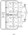
- the diagram of Figure 4depicts a common baseband clock, CLK bb , received by a first RFID reader (Reader 1) and a second RFID reader (Reader 2).
- Each RFID readeris assigned a unique code which is orthogonal to the codes assigned to the other RFID readers.
- the set of mutually-orthogonal codes for all of the RFID readers (of the at least two RFID readers)is known to each RFID reader.
- Datais encoded using the orthogonal code assigned to the first RFID reader.
- a first CDMA-encoded signalis can be produced using the orthogonal code of a first RFID reader of the at least two RFID readers.
- the first CDMA-encoded signalis transmitted using the first RFID reader.
- the signalmay be transmitted to an RFID tag.
- the same or different datamay also be encoded using the orthogonal code assigned to a second RFID reader to produce a second CDMA-encoded signal.
- the second CDMA-encoded signalmay be transmitted by the second RFID reader.
- the second CDMA-encoded signalmay be transmitted by the second RFID reader at the same time or a different time as the first CDMA-encoded signal is transmitted by the first RFID reader.
- Additional CDMA-encoded signalsmay be produced and transmitted using additional RFID readers and the corresponding orthogonal codes.
- a response signalmay be received from the RFID tag.
- the RFID tagmay, upon receiving the signal transmitted from the first RFID receiver, transmit a response signal (for example, the tag may backscatter a signal).
- a response signalmay be received at an RFID reader, such as, for example, the second RFID reader.
- the response signalincludes data encoded with the orthogonal code of one or more RFID readers, such as, for example, the orthogonal code of the first RFID reader. Because each RFID reader has available the set of mutually-orthogonal codes, the receiving RFID reader is able to decode the data of the response signal regardless of which orthogonal code the data was encoded with.
- the second RFID readermay decode the data of the response signal.
- the response signalmay include data encoded by, for example, the orthogonal codes of the first and second RFID reader and decode data using both codes. In this way, regardless of which reader receives a response signal from an RFID tag, the data relevant to each reader may be decoded and processed accordingly.
- a collaborative RFID reader 10is provided (see, e.g., Figure 5 ).
- the RFID reader 10includes a transmitter (Tx) 20 having a Tx baseband frequency modulated on a Tx carrier frequency.
- the Tx baseband frequencyis configured to be synchronized to a Tx baseband frequency (i.e., Tx baseband frequencies, as the case may be) of one or more additional RFID readers 90.
- the Tx baseband frequenciesmay be synchronized by, for example, provision of a common baseband clock signal or a baseband clock retrieval module.
- the RFID reader 10further includes a non-transient memory 42.
- the non-transient memory 42may be any type suitable for electronic storage of data.
- non-transient memory 42examples include dynamic or static random access memories, flash memories, electronically-erasable programmable memories, or the like.
- the non-transient memory 42is configured to store a unique orthogonal code assigned to each RFID reader 10,90 within the collaborative reader CDMA scheme.
- the RFID reader 10includes a processor 40 that is in electronic communication with the transmitter 20 and the non-transient memory 42.
- the processor 40may be, for example, a field-programmable gate array (FPGA), a microprocessor, an application-specific integrated circuit (ASIC), or the like, or combinations of these and/or other components.
- the processor 40is programmed to encode data according to the assigned orthogonal code. In this way, a first CDMA-encoded signal is produced.
- the processor 40transmits the first CDMA-encoded signal using the transmitter 20. For example the first CDMA-encoded signal may be transmitted to an RFID tag 95 within range (the "reading range") of the RFID reader 10.
- the RFID 10 readermay also include a receiver (Rx) 30 in electronic communication with the processor 40.
- the receiver 30has an Rx baseband frequency, which is synchronized to the Tx baseband frequency.
- the Rx carrier frequencymay be different than the Tx carrier frequency.
- the processor 40may be further programmed to receive a response signal from an RFID tag 95.
- the response signalincludes encoded data, which may be encoded using the orthogonal code of the RFID reader 10 or orthogonal codes of the one or more additional participating RFID readers 90.
- the RFID reader 10can decode the encoded data of the response signal using the assigned orthogonal code of the RFID reader 10 and/or one or more codes of the set of mutually orthogonal codes.
- a method for collaborative RFID readingis provided. At least two RFID readers are provided. For example, multiple RFID readers may be provided. The multiple RFID readers have a synchronized baseband frequency.
- the diagram of Figure 4depicts a common baseband clock, CLK bb , received by a first RFID reader (Reader 1) and a second RFID reader (Reader 2).
- Each RFID readeris assigned a unique code which is orthogonal to the codes assigned to the other RFID readers.
- the set of mutually-orthogonal codes for all of the RFID readers (of the participating RFID readers)is known to all participating RFID readers. In this way, CDMA-encoded signals are produced.
- the CDMA-encoded signalsare transmitted to all RFID tags within reading range of the RFID readers.
- Response signalsare received from the RFID tags.
- the RFID tagsmay, upon receiving the transmitted CDMA-encoded signals, transmit response signals (for example, the tags may backscatter signals).
- response signalsmay be received at one or more of the participating RFID readers. Because each RFID reader has available the set of mutually-orthogonal codes, the receiving RFID readers are able to decode the data of the response signals regardless of which orthogonal code the data was encoded with.
- Embodiments of the present disclosuremay thus use a harmonic RFID system, for example, as shown in Figure 2 , which utilizes the second harmonic to isolate the downlink (reader-to-tag) and uplink (tag-to-reader) signals and has been demonstrated for indoor localization, tag CDMA for simultaneous access, and vital-sign monitoring.
- the downlink signal from the reader Tx at fgoes through a low-pass filter (LPF) to broadcast to the harmonic tag which harvests the RF energy, powers up, converts part of the RF signal at f to the 2 nd harmonic at 2f, and finally backscatters to the reader Rx at 2 f in the uplink signal.
- LPFlow-pass filter
- a high-pass filter (HPF) at the reader Rxprovides high isolation (sufficient separation) between the downlink self-interference at f and the received harmonic signal at 2 f .
- the reader Rx SNRis hence not limited by the high phase noise skirt of its own Tx. SNR and sensitivity of the reader Rx can thus be greatly improved.
- An exemplary harmonic tag prototypeis shown in Figure 3(a) .
- the tagharvests the downlink RF energy through antenna A (Ant A).
- the tag Rxdemodulates the reader command from the downlink and the logic unit responds according to the air protocol.
- Antenna Bconverts part of the downlink signal to 2 f by the reflective nonlinear transmission line (NLTL).
- the harmonic signalis then backscattered from Ant B to the reader Rx.
- An RF switch in front of the NLTLmay be provided for the uplink on-off keying (OOK) modulation.
- the PCB prototype of an exemplary harmonic tagis shown in Figure 3(b) , which is based on the WISP platform. Because the tag is passive, its size and packaging are not limited by the battery or the recharging circuits. Thus, the PCB prototype can be readily adapted to integrated circuits (IC) and printed antennas to reduce the overall size.
- ICintegrated circuits
- two harmonic readersare configured by a software defined radio (SDR, Ettus X310, UBX 160) to demonstrate how collaborative reader CDMA can resolve R2RC and improve read yield rates.
- SDRsoftware defined radio
- the given SDR platformprovides two pairs of Tx/Rx, which are designed as two coherent but independent harmonic readers with synchronized basebands.
- the FPGA in Reader 1generates the baseband signal transformed by the digital-to-analog converter 1 (DAC1) to the intermediate frequency (IF), which is further upconverted by the mixer to the fundamental RF band at f .
- the signalis then amplified by the power amplifier (PA1) as the Tx1 signal.
- PA1power amplifier
- the low-pass filter 1 (LPF1), splitter1, and high-pass filter 1 (HPF1)forms the broadband duplexer for Antenna 1 (Ant1) with reasonable insertion loss compromise.
- the signal flow of the duplexeris shown as the solid black arrows for the fundamental frequency signal ( f ) and the dotted-line arrows for the 2 nd harmonic signal (2 f ).
- the harmonic tagresponds to Reader 1 by Ant1, going through splitter1 and HPF1 to Rx1.
- the signalis amplified and down-converted by the local oscillator (LO) to the IF band, and then sampled by the analog-to-digital converter 1 (ADC1), which is then demodulated by the FPGA to retrieve the tag OOK information.
- Another channel of the SDRis configured as Reader 2, which operates similarly but independently to Reader 1.
- the LO synthesizers for f and 2 fare driven by the same clock source as CLK1 for Reader 1 and CLK2 for Reader 2. This clock distribution makes the harmonic reader coherent, and accurate phase of the backscattered signal can be retrieved for estimation of time of flight (ToF).
- CLK1 and CLK2are not required to be synchronized if the related carrier phase information between Reader 1 and Reader 2 is not essential.
- the baseband signals of each readershould be synchronized ( CLK bb ) with precise bit alignment to maximize the orthogonality among chip codes.
- each readerwill be assigned a unique chip code, and all readers within the collaborative CDMA scheme will have the full chip code table. Then each reader will poll as well as register its chip code to all tags within the reading range. For each reader polling procedure, the tags can respond to the reader by an EPC TDMA protocol or the alternative tag CDMA protocol. After all readers finish the polling process, the readers send the CDMA coded commands simultaneously to access all the tags. Each tag receives and demodulates the CDMA coded frame, retrieving the information from each reader within the feasible range and responding to the readers accordingly.
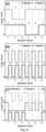
- the reader CDMA modulation and demodulation schemeis illustrated in Figure 8(a) , where Reader 1 prepares to send (111001) 2 represented by the solid line, and Reader 2 to send (100111) 2 represented by the dashed line.
- 1 bit per symbolis considered here.
- Reader 1has the CDMA chip code (01) 2 and Reader 2 the code (10) 2 .
- the solid lineis the baseband signal for Reader 1, and the dashed line is for Reader 2.
- the basebandAfter CDMA chip code injection, the baseband has 2 bits per symbol. The baseband signals of these two readers are synchronized and fed to their own DACs simultaneously.
- the RF signals of the two readersmay be transmitted to the tags at the same time, and added together in the communication channel to reach the tag Rx in their respective reading zones.
- the dotted line in Figure 8(c)represents a simulated baseband signal received by a tag that is in an overlapped reading zone where the received signal strength (RSS) from both readers is assumed to be similar for illustrative convenience.
- the tagaccesses the chip code table established during the polling stage, multiplies the selected code with the received baseband, and then operates all the bits (2 bits here) within the same symbol with logical OR.
- the information corresponding to the selected chip codemay then be demodulated.
- the baseband signal received by the tagmay be multiplied with the orthogonal code (10) 2 of Reader 2 to obtain (100000101010) 2 .
- the original information of (100111) 2may be retrieved from Reader 2.
- FIG 9shows the experimental setup for an exemplary collaborative reader CDMA for verification.
- an SDR moduleis configured as two independent harmonic readers connected to Ant1 and Ant2, respectively.
- a harmonic tagstands on a foam and moves within the reading zones of both readers.
- the reader antennasare on average at about 2 meters away from the tag.
- the distances of Ant1 and Ant2 in Figure 9are non-limiting and provided for clear picture presentation.
- Reader 1 and Reader 2utilize an embodiment of the present collaborative CDMA protocol to access the tag simultaneously.
- the experimental setupused a bit rate of 400 kbps (kilobits per second), although other baseband bandwidth will not change our observation significantly.
- the IF frequencywas set at 1 MHz, so each bit spanned 2.5 periods of the IF cycle.
- the sampling rates of the reader Rx ADC and Tx DACwere both at 20 MSps (mega-symbols per second), where the waveform of each bit was represented by 50 points to provide sufficient equalization and timing accuracy.
- the lower solid curve and the lower dashed curveare the in-phase and quadrature (I/Q) signals of Reader 1 denoted by R1I and R1Q, while the upper solid curve and the upper dashed curve are I/Q signals of Reader 2 denoted by R2I and R2Q, respectively.
- the basebands of the two readerswere synchronized with the SDR, and the bits were aligned and converted by their own DACs to the IF band, which were further up-converted to the downlink RF signal at 950 MHz to be transmitted to the tag simultaneously.
- the tag Rxwas designed as the low-pass filter to detect the envelope of the downlink signal.
- the tagdemodulated the information from Reader 1 as (111001) 2 and from Reader 2 as (100111) 2 correctly.
- the tagthen backscattered the 2 nd harmonic as the uplink signal to the readers.
- the tagreplayed what was received from all readers in range, but the uplink can be alternatively operated with tag CDMA protocol and tag-specific ID information for multi-tag access as well.
- the demodulated baseband signals from the tag to the two readers received by Ant1 (lower) and Ant2 (upper)are shown in Figure 10(c) . Because the distance from the tag to Ant1 and Ant2 was about the same here, the amplitude envelopes were similar, and the waveform amplitudes were normalized to the full scale of the ADC.
- the logic valuesare denoted as the digits in Figure 10(c) , which are (110101101011) 2 .
- each readercould receive the original information from both readers.
- the baseband (upper) received by Ant2can be decoded with the chip code of either reader, where the logic 1's by the black color are attributed to Reader 2, and the gray 1's are to Reader 1.
- the baseband signal received by Ant1 from the tagAs the reader information can be processed by the tag and relayed to other readers, the multiple readers can be viewed as a high channel-efficiency multi-static reader system.
- the system read yield A(C)is just the incidence of a 11 under various channel conditions C , which highly depends on the relative range, antenna orientation alignment, multi-path, and RF scattering object placement.
- the read yieldcan be calculated as the OR operation of the diagonal elements of A ( C ), which means at least one reader should successfully read the tag.
- the static read yield in this conditionis also equivalent to one reader with multiple TDMA antennas in the current EPC operations.
- A(C)is not fully utilized, and the proposed CDMA protocol can further improve the system yield by exploiting the OR operation of all elements in A(C).
- FIGs 11(a)-11(d)An experimental illustration is shown in Figures 11(a)-11(d) with two readers in a multi-static Tx/Rx indoor setup.
- the four multi-path scenariosare created with different scatterers (black rectangles) placed in the overlapped reading zone (gray oval).
- both readersmaintain direct line-of-sight (LoS) to the tag when it moves and rotates randomly within the reading zone.
- Large scatterersare successively inserted into the reading zone to increase the multi-path complexity.
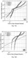
- Figure 12shows the ample read yield improvement of the collaborative reader CDMA scheme over that of the individual readers operating simultaneously, especially in the complex multi-path scenarios. Notice that Rx jamming between the two readers is removed in all cases due to the use of harmonic backscattering and reader CDMA.
- the reader Tx poweris continuously adjusted to collect changing failure rates in various tag positions and orientations. More than 300,000 reading incidences are collected in each set of experiment data.
- the curves delineated with ⁇ markers and ⁇ markersare the failure rates of Reader 1 and Reader 2, respectively, vs. that of the collaborative read in the corresponding channel condition in Figures 11(a)-11(d) .
- the dashed line in each figurehas a slope of 2 denoting the condition of uncorrelated read failure incidences of individual readers.
- the failure rate of the collaborative reader CDMA schemeis close to the product of the failure rates of the two readers, and the slope in the log-log plot is around 2, indicating the expected condition of uncorrelated read failures of the two readers.
- the yield of the individual readerstarts to degrade much faster than that of the collaborative reader CDMA scheme.
Landscapes
- Engineering & Computer Science (AREA)
- Computer Networks & Wireless Communication (AREA)
- Physics & Mathematics (AREA)
- Health & Medical Sciences (AREA)
- Toxicology (AREA)
- Theoretical Computer Science (AREA)
- General Physics & Mathematics (AREA)
- Signal Processing (AREA)
- Artificial Intelligence (AREA)
- Computer Vision & Pattern Recognition (AREA)
- General Health & Medical Sciences (AREA)
- Electromagnetism (AREA)
- Computer Hardware Design (AREA)
- Microelectronics & Electronic Packaging (AREA)
- Near-Field Transmission Systems (AREA)
- Mobile Radio Communication Systems (AREA)
Description
- The present disclosure relates to RFID systems, and in particular, simultaneous RFID signaling by multiple collaborative readers using CDMA reader encoding.
- Read reliability is one of the critical limits of ultra-high-frequency ("UHF") radio frequency identification ("RFID") systems when a large number of passive tags are present in a complex multi-path environment. In many practical applications, read failure rates often should be lower than 10-5, or equivalently, read yields should be above 99.999%, to achieve manageable logistic purposes in Internet of Things ("IoT"). Because of the directivities of reader and tag antennas and RF shadowing from objects and other tags, a tag at a certain position and/or orientation may not be able to harvest sufficient RF energy from a reader to power up, or the tag may not effectively backscatter to the reader even if it is within the nominal reading range.
- Previous RFID systems with the electronic production code ("EPC") generation 2 (Gen 2) protocol perform a detailed tag singulation process in time division multiple access ("TDMA"), explore multiple reader antenna placement, and introduce relative movement between the reader and tags to minimize the read failure probability, but with only limited success. Alternatively, to improve the read yield or to enlarge the total coverage area, one can disperse more readers with significantly overlapped reading zones. However, this has the potential for severe reader-to-reader collision ("R2RC") that is difficult to resolve within the current EPC tag TDMA scheme. This is because when multiple readers are employed, further collaborative reader TDMA schemes need to be adopted by all readers to resolve R2RC, as not only the receiver (Rx) of one reader can be interfered by the other reader transmitters (Tx), but also the tags within the reading zones of more than one readers cannot decode the reader commands correctly when they broadcast at the same time.
- As shown in
Figure 1 , the reading zone of a first reader (Reader 1) may only coverTag Group 1, missingTag Group 2. AddingReader 2 to coverTag Group 2 may cause interference (e.g.,Reader 1 Rx can be interfered byReader 2 Tx), and tags in both reading zones cannot properly decode the reader commands. Even in tag-talk-first ("TTF") and tag-talk-only ("TTO") schemes, with the reader playing a smaller role in streamlining the tag response sequence, R2RC remains a serious concern to the system operation. Additional delay caused by tag TDMA embedded inside reader TDMA will also limit the tag sampling rate for tracking moving tags in real time.US2010201492 A1 relates to orthogonal codes corresponding to RFID tag, and is reflected in the preamble ofclaims - The invention is set out in the independent claims.
- In a first aspect, the present disclosure provides an RFID system using a collaborative reader code division multiple access ("CDMA") protocol. In this way, the RFID system provides synchronous tag access for all readers within range. The tag can distinguish the downlink commands from multiple readers simultaneously and then formulate a response accordingly.
- The present disclosure provides a collaborative reader CDMA scheme in a harmonic RFID system, which can solve the reader-to-reader collision ("R2RC") problem and significantly enhance the read yield rate for tags in the overlapped reading zone. The reduction in the read failure rate in the collaborative reader CDMA scheme is much more than the failure rate product of the individual readers in the complex multi-path scenarios by exploiting the channel characteristics and the failure correlation. This improvement can fundamentally benefit the reliability in the logistic RFID applications.
- The presented reader CDMA is demonstrated in a simple experimental prototype to verify R2RC resolution and read yield improvement. The two-reader collaborative CDMA scheme achieved below 10-5 in the read failure rate when individual readers had 0.05 - 0.2 failure rates in the complex multi-path scenarios due to rich channel exploitation and anticorrelation in the failure incidences.
- For a fuller understanding of the nature and objects of the disclosure, reference should be made to the following detailed description taken in conjunction with the accompanying drawings, in which:
Figure 1 is a diagram depicting how two nearby RFID readers can suffer from reader-to-reader collision ("R2RC") for tags within the overlapped reading zone as well as possible reader receiver jamming.Figure 2 is a schematic of a harmonic RFID system. LPF: low-pass filter; HPF: high-pass filter.Figure 3(a) is a schematic of a harmonic RFID tag with harmonic generation by a reflective nonlinear transmission line ("NLTL") and having an RF switch for uplink modulation.Figure 3(b) is a PCB prototype of the harmonic tag ofFigure 3(a) .Figure 4 is a diagram of an exemplary harmonic RFID system according to an embodiment of the present disclosure and having two CDMA readers configured by a software-defined radio (SDR) platform (showing where Reader 1 and Reader 2 can simultaneously access a harmonic tag within an overlapped reading zone).Figure 5 is a diagram of an exemplary RFID reader according to another embodiment of the present disclosure and shown with additional readers and a harmonic tag.Figure 6 is a flow chart showing an exemplary collaborative reader CDMA protocol.Figure 7 is a chart showing a method according to another embodiment of the present disclosure.Figures 8(a)-8(b) are illustrations of an exemplary reader CDMA protocol. (a) The information for the readers to be sent to the tag. (b) The orthogonal CDMA codes of each reader. (c) The baseband waveform of each reader and a possible baseband waveform received by a tag when the received signal strength (RSS) from the two readers is similar.Figure 9 shows an exemplary experimental setup where an SDR module is configured as two harmonic readers operating the collaborative CDMA protocol implemented by Lab VIEW. A harmonic tag stands on a movable foam substrate for convenience. The ranges of the Ant1 and Ant2 are just for convenient picture illustration. Experiments were conducted with both readers at about 2 meters away from the tag.Figures 10(a)-10(c) show details of the experimental prototype for reader CDMA: (a) The modulated digital IF signals of the two readers. The curves are R1I (lower solid line): the in-phase signal ofReader 1, R1Q (lower dashed line): the quadrature signal ofReader 1, R2I (upper solid line): the in-phase signal ofReader 2, and R2Q (upper dashed line): the quadrature signal ofReader 2. (b) The baseband received at the tag. (c) The baseband received from Ant1 ofReader 1 and Ant2 ofReader 2.Figures 1 1(a)-1 1(d) . Experimental scenarios with various scatterers in the reading zone. (a) Both readers maintain direct line-of-sight to a tag when it moves and rotates randomly within the overlapped reading zone. (b-d) Large scatterers are successively added to the reading zone to create complex multi-path scenarios.Figures 12(a)-12(d) . Experimental benchmarks of the failure rates in the single reader scheme and the collaborative CDMA reader scheme for the channel conditions inFigures 1 1(a)-1 1(d). The dotted line shows the slope of 2 in the log-log plot, which corresponds to the case of uncorrelated individual reader failures and little reader collaboration, which is mostly valid for both curves in (a). Slopes higher than 2 in (b)-(d) suggest anticorrelation in individual reader failures and rich reader collaboration. Failure rates of below 10-5 were achieved using collaborative reader CDMA even though individual readers have failure rates between 0.05 and 0.2.- In a first aspect, the present disclosure provides collaborative radiofrequency identification (RFID) readers that employ code division multiple access (CDMA) encoding to simultaneously broadcast to and read responses from tags in an overlapping reading zone with improved data synchronization and read yield rates. In some embodiments, a harmonic backscattering scheme is used to enable the system to have a much higher signal-to-noise ratio (SNR) and sensitivity, while the reader CDMA protocol can be integrated with an initial TDMA polling process or alternative tag CDMA scheme.
- In an embodiment, a
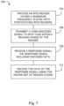
method 100 for collaborative RFID is provided (see, e.g.,Figure 7 ). An RFID reader is provided103. The provided103 reader has a baseband frequency and is a member of a group of participating RFID readers. Each participating RFID reader is synchronized to the baseband frequency. For example, each participating RFID reader may have a common baseband clock,CLKbb. The provided103 reader is assigned an orthogonal code with which it can produce a CDMA-encoded signal. Each participating RFID reader is assigned a code, and each of the codes are orthogonal to the other codes (mutually orthogonal). The set of all mutually-orthogonal codes for the participating RFID readers is known to each of the participating RFID readers, including the provided103 RFID reader. - The provided103 RFID reader is used to transmit106 a CDMA-encoded signal to all RFID tags within a reading range of the RFID reader (i.e., broadcasting the CDMA-encoded signal). As will be further described below, a tag within range of the broadcast signal will decode the signal and may send a response. The
method 100 includes receiving109 a response signal from an RFID tag. The received109 response signal will include data encoded with a code of a participating RFID reader. The RFID reader will decode112 the data of the received109 response using the appropriate code of the known set of mutually-orthogonal code. For example, in some cases, the received109 response signal will include data encoded with the code of the provided103 RFID reader, which in other cases the received109 response signal will include data encoded with the code of another participating RFID reader. In this way, any RFID reader of the participating system will be able to read signals generated by tags in response to the broadcast of any RFID reader of the participating system. - In some embodiments, the
method 100 include transmitting115 a polling signal to RFID tags within the reading range, the polling signal comprising the set of the orthogonal codes of all participating RFID readers. - In a more particular non-limiting example used to illustrate an embodiment, at least two RFID readers are provided. Each of the at least two RFID readers have a synchronized baseband frequency. For example, the diagram of
Figure 4 depicts a common baseband clock,CLKbb, received by a first RFID reader (Reader 1) and a second RFID reader (Reader 2). Each RFID reader is assigned a unique code which is orthogonal to the codes assigned to the other RFID readers. The set of mutually-orthogonal codes for all of the RFID readers (of the at least two RFID readers) is known to each RFID reader. - Data is encoded using the orthogonal code assigned to the first RFID reader. In this way a first CDMA-encoded signal is can be produced using the orthogonal code of a first RFID reader of the at least two RFID readers. The first CDMA-encoded signal is transmitted using the first RFID reader. The signal may be transmitted to an RFID tag. The same or different data may also be encoded using the orthogonal code assigned to a second RFID reader to produce a second CDMA-encoded signal. The second CDMA-encoded signal may be transmitted by the second RFID reader. The second CDMA-encoded signal may be transmitted by the second RFID reader at the same time or a different time as the first CDMA-encoded signal is transmitted by the first RFID reader. Additional CDMA-encoded signals may be produced and transmitted using additional RFID readers and the corresponding orthogonal codes.
- A response signal may be received from the RFID tag. For example, the RFID tag may, upon receiving the signal transmitted from the first RFID receiver, transmit a response signal (for example, the tag may backscatter a signal). Such a response signal may be received at an RFID reader, such as, for example, the second RFID reader. The response signal includes data encoded with the orthogonal code of one or more RFID readers, such as, for example, the orthogonal code of the first RFID reader. Because each RFID reader has available the set of mutually-orthogonal codes, the receiving RFID reader is able to decode the data of the response signal regardless of which orthogonal code the data was encoded with. In the example where the response signal is received by the second RFID reader and encoded with the orthogonal code of the first RFID reader, the second RFID reader may decode the data of the response signal. Furthermore, the response signal may include data encoded by, for example, the orthogonal codes of the first and second RFID reader and decode data using both codes. In this way, regardless of which reader receives a response signal from an RFID tag, the data relevant to each reader may be decoded and processed accordingly.
- In another aspect, a
collaborative RFID reader 10 is provided (see, e.g.,Figure 5 ). TheRFID reader 10 includes a transmitter (Tx)20 having a Tx baseband frequency modulated on a Tx carrier frequency. The Tx baseband frequency is configured to be synchronized to a Tx baseband frequency (i.e., Tx baseband frequencies, as the case may be) of one or moreadditional RFID readers 90. The Tx baseband frequencies may be synchronized by, for example, provision of a common baseband clock signal or a baseband clock retrieval module. TheRFID reader 10 further includes anon-transient memory 42. Thenon-transient memory 42 may be any type suitable for electronic storage of data. Some examples ofnon-transient memory 42 include dynamic or static random access memories, flash memories, electronically-erasable programmable memories, or the like. Thenon-transient memory 42 is configured to store a unique orthogonal code assigned to eachRFID reader - The
RFID reader 10 includes aprocessor 40 that is in electronic communication with thetransmitter 20 and thenon-transient memory 42. Theprocessor 40 may be, for example, a field-programmable gate array (FPGA), a microprocessor, an application-specific integrated circuit (ASIC), or the like, or combinations of these and/or other components. Theprocessor 40 is programmed to encode data according to the assigned orthogonal code. In this way, a first CDMA-encoded signal is produced. Theprocessor 40 transmits the first CDMA-encoded signal using thetransmitter 20. For example the first CDMA-encoded signal may be transmitted to anRFID tag 95 within range (the "reading range") of theRFID reader 10. - The
RFID 10 reader may also include a receiver (Rx)30 in electronic communication with theprocessor 40. Thereceiver 30 has an Rx baseband frequency, which is synchronized to the Tx baseband frequency. The Rx carrier frequency may be different than the Tx carrier frequency. For example, the Rx carrier frequency may be twice the Tx carrier frequency (second harmonic). In such embodiments, theprocessor 40 may be further programmed to receive a response signal from anRFID tag 95. The response signal includes encoded data, which may be encoded using the orthogonal code of theRFID reader 10 or orthogonal codes of the one or more additional participatingRFID readers 90. Because thenon-transient memory 42 has stored the set of mutually-orthogonal codes for eachreader RFID reader 10 can decode the encoded data of the response signal using the assigned orthogonal code of theRFID reader 10 and/or one or more codes of the set of mutually orthogonal codes. - In another aspect, a method for collaborative RFID reading is provided. At least two RFID readers are provided. For example, multiple RFID readers may be provided. The multiple RFID readers have a synchronized baseband frequency. For example, the diagram of
Figure 4 depicts a common baseband clock,CLKbb, received by a first RFID reader (Reader 1) and a second RFID reader (Reader 2). Each RFID reader is assigned a unique code which is orthogonal to the codes assigned to the other RFID readers. The set of mutually-orthogonal codes for all of the RFID readers (of the participating RFID readers) is known to all participating RFID readers. In this way, CDMA-encoded signals are produced. The CDMA-encoded signals are transmitted to all RFID tags within reading range of the RFID readers. - Response signals are received from the RFID tags. For example, the RFID tags may, upon receiving the transmitted CDMA-encoded signals, transmit response signals (for example, the tags may backscatter signals). Such response signals may be received at one or more of the participating RFID readers. Because each RFID reader has available the set of mutually-orthogonal codes, the receiving RFID readers are able to decode the data of the response signals regardless of which orthogonal code the data was encoded with.
- The following discussion provides additional embodiments, including prototypes, and discussion of the theory of operation, all of which are intended to be non-limiting and provided for the purpose of further illustrating the disclosure.
- In a conventional RFID system employing the EPC protocol, where the downlink and uplink signals share the same frequency band, poor isolation by the duplex circulator with direct leakage from reader Tx to Rx as well as by the antenna reflection from imperfect impedance match and nearby large objects renders low SNR at the reader Rx. For applications that rely on accurate amplitude and phase demodulation of the backscattered signal to retrieve, for example, location and vital signs in addition to the digital tag identification (ID), the conventional EPC scheme cannot provide feasible performance. Embodiments of the present disclosure may thus use a harmonic RFID system, for example, as shown in
Figure 2 , which utilizes the second harmonic to isolate the downlink (reader-to-tag) and uplink (tag-to-reader) signals and has been demonstrated for indoor localization, tag CDMA for simultaneous access, and vital-sign monitoring. The downlink signal from the reader Tx atf goes through a low-pass filter (LPF) to broadcast to the harmonic tag which harvests the RF energy, powers up, converts part of the RF signal atf to the 2nd harmonic at2f, and finally backscatters to the reader Rx at 2f in the uplink signal. A high-pass filter (HPF) at the reader Rx provides high isolation (sufficient separation) between the downlink self-interference atf and the received harmonic signal at 2f. The reader Rx SNR is hence not limited by the high phase noise skirt of its own Tx. SNR and sensitivity of the reader Rx can thus be greatly improved. - An exemplary harmonic tag prototype is shown in
Figure 3(a) . The tag harvests the downlink RF energy through antenna A (Ant A). After the tag powers up, the tag Rx demodulates the reader command from the downlink and the logic unit responds according to the air protocol. Antenna B (Ant B) converts part of the downlink signal to 2f by the reflective nonlinear transmission line (NLTL). The harmonic signal is then backscattered from Ant B to the reader Rx. An RF switch in front of the NLTL may be provided for the uplink on-off keying (OOK) modulation. The PCB prototype of an exemplary harmonic tag is shown inFigure 3(b) , which is based on the WISP platform. Because the tag is passive, its size and packaging are not limited by the battery or the recharging circuits. Thus, the PCB prototype can be readily adapted to integrated circuits (IC) and printed antennas to reduce the overall size. - As shown in the exemplary embodiment of
Figure 4 , two harmonic readers are configured by a software defined radio (SDR, Ettus X310, UBX 160) to demonstrate how collaborative reader CDMA can resolve R2RC and improve read yield rates. The given SDR platform provides two pairs of Tx/Rx, which are designed as two coherent but independent harmonic readers with synchronized basebands. The FPGA inReader 1 generates the baseband signal transformed by the digital-to-analog converter 1 (DAC1) to the intermediate frequency (IF), which is further upconverted by the mixer to the fundamental RF band atf. The signal is then amplified by the power amplifier (PA1) as the Tx1 signal. The low-pass filter 1 (LPF1), splitter1, and high-pass filter 1 (HPF1) forms the broadband duplexer for Antenna 1 (Ant1) with reasonable insertion loss compromise. The signal flow of the duplexer is shown as the solid black arrows for the fundamental frequency signal (f) and the dotted-line arrows for the 2nd harmonic signal (2f). The harmonic tag responds toReader 1 by Ant1, going through splitter1 and HPF1 to Rx1. The signal is amplified and down-converted by the local oscillator (LO) to the IF band, and then sampled by the analog-to-digital converter 1 (ADC1), which is then demodulated by the FPGA to retrieve the tag OOK information. Another channel of the SDR is configured asReader 2, which operates similarly but independently toReader 1. - The LO synthesizers forf and 2f are driven by the same clock source as CLK1 for
Reader 1 and CLK2 forReader 2. This clock distribution makes the harmonic reader coherent, and accurate phase of the backscattered signal can be retrieved for estimation of time of flight (ToF). However, for protocols such as the pulse interval encoding (PIE) used in the EPC downlink, CLK1 and CLK2 are not required to be synchronized if the related carrier phase information betweenReader 1 andReader 2 is not essential. However, to realize CDMA on the multiple readers, the baseband signals of each reader should be synchronized (CLKbb) with precise bit alignment to maximize the orthogonality among chip codes. - An exemplary protocol conducted on the CDMA readers is described in
Figure 6 . First, through initial reader coordination, each reader will be assigned a unique chip code, and all readers within the collaborative CDMA scheme will have the full chip code table. Then each reader will poll as well as register its chip code to all tags within the reading range. For each reader polling procedure, the tags can respond to the reader by an EPC TDMA protocol or the alternative tag CDMA protocol. After all readers finish the polling process, the readers send the CDMA coded commands simultaneously to access all the tags. Each tag receives and demodulates the CDMA coded frame, retrieving the information from each reader within the feasible range and responding to the readers accordingly. - The reader CDMA modulation and demodulation scheme is illustrated in
Figure 8(a) , whereReader 1 prepares to send (111001)2 represented by the solid line, andReader 2 to send (100111)2 represented by the dashed line. In this illustrative and non-limiting example, 1 bit per symbol is considered here. As shown inFigure 8(b) ,Reader 1 has the CDMA chip code (01)2 andReader 2 the code (10)2. InFigure 8(c) , the solid line is the baseband signal forReader 1, and the dashed line is forReader 2. After CDMA chip code injection, the baseband has 2 bits per symbol. The baseband signals of these two readers are synchronized and fed to their own DACs simultaneously. After the up-conversion of the mixers, the RF signals of the two readers may be transmitted to the tags at the same time, and added together in the communication channel to reach the tag Rx in their respective reading zones. The dotted line inFigure 8(c) represents a simulated baseband signal received by a tag that is in an overlapped reading zone where the received signal strength (RSS) from both readers is assumed to be similar for illustrative convenience. To demodulate the information from each reader, the tag accesses the chip code table established during the polling stage, multiplies the selected code with the received baseband, and then operates all the bits (2 bits here) within the same symbol with logical OR. The information corresponding to the selected chip code may then be demodulated. For example, the baseband signal received by the tag may be multiplied with the orthogonal code (10)2 ofReader 2 to obtain (100000101010)2. After the OR operation in each symbol, the original information of (100111)2 may be retrieved fromReader 2. Figure 9 shows the experimental setup for an exemplary collaborative reader CDMA for verification. In this non-limiting example, an SDR module is configured as two independent harmonic readers connected to Ant1 and Ant2, respectively. A harmonic tag stands on a foam and moves within the reading zones of both readers. The reader antennas are on average at about 2 meters away from the tag. The distances of Ant1 and Ant2 inFigure 9 are non-limiting and provided for clear picture presentation.Reader 1 andReader 2 utilize an embodiment of the present collaborative CDMA protocol to access the tag simultaneously. In this experiment, the same reader information and chip code assignment shown inFigure 8 were used. The experimental setup used a bit rate of 400 kbps (kilobits per second), although other baseband bandwidth will not change our observation significantly. The IF frequency was set at 1 MHz, so each bit spanned 2.5 periods of the IF cycle. The sampling rates of the reader Rx ADC and Tx DAC were both at 20 MSps (mega-symbols per second), where the waveform of each bit was represented by 50 points to provide sufficient equalization and timing accuracy. As shown inFigure 10(a) , the lower solid curve and the lower dashed curve are the in-phase and quadrature (I/Q) signals ofReader 1 denoted by R1I and R1Q, while the upper solid curve and the upper dashed curve are I/Q signals ofReader 2 denoted by R2I and R2Q, respectively. The basebands of the two readers were synchronized with the SDR, and the bits were aligned and converted by their own DACs to the IF band, which were further up-converted to the downlink RF signal at 950 MHz to be transmitted to the tag simultaneously. The tag Rx was designed as the low-pass filter to detect the envelope of the downlink signal. After the comparator, the logic level was equalized, as shown inFigure 10(b) . Based on the orthogonal code table and the CDMA decoding method described above, the tag demodulated the information fromReader 1 as (111001)2 and fromReader 2 as (100111)2 correctly.- The tag then backscattered the 2nd harmonic as the uplink signal to the readers. In this experiment to demonstrate the collaborative reading properties, the tag replayed what was received from all readers in range, but the uplink can be alternatively operated with tag CDMA protocol and tag-specific ID information for multi-tag access as well. The demodulated baseband signals from the tag to the two readers received by Ant1 (lower) and Ant2 (upper) are shown in
Figure 10(c) . Because the distance from the tag to Ant1 and Ant2 was about the same here, the amplitude envelopes were similar, and the waveform amplitudes were normalized to the full scale of the ADC. The logic values are denoted as the digits inFigure 10(c) , which are (110101101011)2. Because the tag just replayed the signals from both readers on the 2nd harmonic, each reader could receive the original information from both readers. For example, inFigure 10(c) , the baseband (upper) received by Ant2 can be decoded with the chip code of either reader, where thelogic 1's by the black color are attributed toReader 2, and the gray 1's are toReader 1. The same case applies to the baseband signal received by Ant1 from the tag. As the reader information can be processed by the tag and relayed to other readers, the multiple readers can be viewed as a high channel-efficiency multi-static reader system. - One of the most important applications in the multi-static reader system is the collaborative reading under complex multi-path scenarios, because the channels are now not limited to the individual reader-tag-reader path. The multi-static n-reader system yield in the channel conditionC can be described as the matrixA(C):

- For example, four readers will have four Tx/Rx pairs. With the collaborative reader CDMA protocol, all four reader Tx can poll the tag simultaneously. The tag can then formulate the response accordingly with the knowledge of all reader information, which can be received by all four reader Rx. Hence, the channel information can be fully utilized to serve the various purposes in specific applications. An experimental illustration is shown in
Figures 11(a)-11(d) with two readers in a multi-static Tx/Rx indoor setup. The four multi-path scenarios are created with different scatterers (black rectangles) placed in the overlapped reading zone (gray oval). InFigure 11(a) , both readers maintain direct line-of-sight (LoS) to the tag when it moves and rotates randomly within the reading zone. InFigs. 11 (b-d), large scatterers are successively inserted into the reading zone to increase the multi-path complexity. Figure 12 shows the ample read yield improvement of the collaborative reader CDMA scheme over that of the individual readers operating simultaneously, especially in the complex multi-path scenarios. Notice that Rx jamming between the two readers is removed in all cases due to the use of harmonic backscattering and reader CDMA. The reader Tx power is continuously adjusted to collect changing failure rates in various tag positions and orientations. More than 300,000 reading incidences are collected in each set of experiment data. InFigures 12(a)-12(d) , the curves delineated with ∘ markers and × markers are the failure rates ofReader 1 andReader 2, respectively, vs. that of the collaborative read in the corresponding channel condition inFigures 11(a)-11(d) . The dashed line in each figure has a slope of 2 denoting the condition of uncorrelated read failure incidences of individual readers. InFigure 12(a) , the failure rate of the collaborative reader CDMA scheme is close to the product of the failure rates of the two readers, and the slope in the log-log plot is around 2, indicating the expected condition of uncorrelated read failures of the two readers. InFigs. 12(b)-12(d) , when large scatterers were successively added to the reading zone, the yield of the individual reader starts to degrade much faster than that of the collaborative reader CDMA scheme. InFigure 12(d) , LoS of both readers are mostly blocked that the individual readers can only achieve failure rates of 0.2 (read yield of 80%) and 0.13 (read yield of 87%) under the largest Tx power,i.e., the diagonal terms ofA(C) have relatively low probability to be 1. In comparison, the collaborative reader CDMA scheme can still reach below 10-5 failure rate (read yield > 99.999%), which implies the off-diagonal terms ofA(C) contribute significantly and their incidences of 0 are anti-correlated to those of the diagonal terms. Although the degree of improvement in read yields depends on the actual channel condition, the slopes in the collaborative CDMA scheme are in general much higher than 2, similar to the cases inFigures 12(b)-12(d) , due to the rich channel availability and the anti-correlations of the read failure in each channel- Although the present disclosure has been described with respect to one or more particular embodiments, it will be understood that other embodiments of the present disclosure may be made without departing from and scope of the present disclosure.

Claims (10)
- A method for collaborative RFID readers, comprising:providing an RFID reader, the RFID reader having a baseband frequency and being a member of a group of participating RFID readers each being synchronized to the baseband frequency, and wherein the RFID reader is assigned an orthogonal code to produce a code division multiple access (CDMA)-encoded signal, and a set of mutually-orthogonal codes for all participating RFID readers is known to the RFID reader;transmitting, using the RFID reader, a CDMA-encoded signal to RFID tags within a reading range of the RFID reader;receiving a response signal from an RFID tag within the reading range, wherein the response signal comprises data encoded with an orthogonal code of an RFID reader of the group of participating RFID readers; anddecoding the data of the response signal using the known set of mutually-orthogonal codes.
- The method of claim 1, wherein the response signal is decoded using the assigned code of the RFID reader or using the assigned code of another participating reader.
- The method of claim 1, further comprising transmitting a polling signal to RFID tags within the reading range, the polling signal comprising the set of the orthogonal codes for all participating RFID readers.
- A collaborative RFID reader, comprising:a transmitter (20) having a Tx baseband frequency, wherein the Tx baseband frequency is configured to be synchronized to a Tx baseband frequency of participating RFID readers;a non-transient memory (42) configured to store an assigned orthogonal code;a processor (40) in electronic communication with the transmitter and the non-transient memory,wherein the processor is programmed to:encode data according to the assigned orthogonal code to produce a code division multiple access (CDMA)-encoded signal; andtransmit the CDMA-encoded signal using the transmitter;characterized in that the non-transient memory is further configured to store a set of mutually-orthogonal codes assigned to all participating RFID readers; wherein the processor is further programmed to process one or more codes of the set of mutually orthogonal codes.
- The collaborative RFID reader of claim 4, further comprising:a receiver having an Rx baseband frequency, wherein the Rx baseband frequency is synchronized to the Tx baseband frequency;wherein the processor is further programmed to:receive a response signal from an RFID tag, wherein the response signal comprises encoded data; anddecode the encoded data using the assigned orthogonal code and/or one or more codes of the set of mutually orthogonal codes.
- The collaborative RFID reader of claim 5, wherein an Rx carrier frequency is separated from a Tx carrier frequency to reduce receiver interference.
- The collaborative RFID reader of claim 6, wherein the Rx carrier frequency is twice the Tx carrier frequency.
- An RFID tag (95), comprising:a non-transient memory configured to store a unique identification code; anda first antenna configured for a signal at a first frequency;a receiver in electronic communication with the non-transient memory and the first antenna,characterized in that the receiver is configured to receive and decode a reader code division multiple access (CDMA)-encoded signal from the first antenna using a code of memutually-orthogonal RFID reader codes which are stored in the non-transient memory.
- The RFID tag of claim 8, further comprising an energy-harvesting circuit configured to harvest RF energy from a signal received from the first antenna.
- The RFID tag of claim 8, further comprising:a second antenna configured for a signal at a second frequency, wherein the second frequency is separated from the first frequency to reduce receiver interference at a reader; anda frequency conversion unit configured to convert a portion of a received signal to a signal at a second frequency to backscatter the signal using the second antenna.
Applications Claiming Priority (2)
| Application Number | Priority Date | Filing Date | Title |
|---|---|---|---|
| US201862671405P | 2018-05-14 | 2018-05-14 | |
| PCT/US2019/032255WO2019222242A1 (en) | 2018-05-14 | 2019-05-14 | Collaborative rfid reader using code divisional multiple access (cdma) and methods for same |
Publications (3)
| Publication Number | Publication Date |
|---|---|
| EP3794497A1 EP3794497A1 (en) | 2021-03-24 |
| EP3794497A4 EP3794497A4 (en) | 2022-02-09 |
| EP3794497B1true EP3794497B1 (en) | 2023-07-05 |
Family
ID=68541067
Family Applications (1)
| Application Number | Title | Priority Date | Filing Date |
|---|---|---|---|
| EP19804527.0AActiveEP3794497B1 (en) | 2018-05-14 | 2019-05-14 | Collaborative rfid reader using code divisional multiple access (cdma) and methods for same |
Country Status (5)
| Country | Link |
|---|---|
| US (2) | US11392782B2 (en) |
| EP (1) | EP3794497B1 (en) |
| CN (1) | CN112714912B (en) |
| CA (1) | CA3100324A1 (en) |
| WO (1) | WO2019222242A1 (en) |
Families Citing this family (10)
| Publication number | Priority date | Publication date | Assignee | Title |
|---|---|---|---|---|
| CN112532342B (en)* | 2019-09-17 | 2023-05-16 | 华为技术有限公司 | Data transmission method and device in back reflection communication |
| CN114154597B (en)* | 2020-09-07 | 2024-02-13 | 英业达科技有限公司 | Spare part management method and system based on wireless radio frequency identification |
| US12265944B2 (en) | 2021-02-12 | 2025-04-01 | VenaResourses, Inc. | Adaptive RFID inventory system |
| US11282031B1 (en) | 2021-02-12 | 2022-03-22 | VenaResources, Inc. | Adaptive RFID inventory system |
| WO2023010341A1 (en)* | 2021-08-04 | 2023-02-09 | Oppo广东移动通信有限公司 | Wireless communication method, terminal device and network device |
| CN113676263B (en)* | 2021-08-10 | 2022-12-16 | 华南理工大学 | Human body internal communication device and method based on ultrasonic backscattering |
| US20230093484A1 (en)* | 2021-09-23 | 2023-03-23 | Apple Inc. | Systems and methods for de-correlating coded signals in dual port transmissions |
| CN115296703A (en)* | 2022-07-08 | 2022-11-04 | 无锡大华锐频科技有限公司 | Radio frequency identification method, system and device |
| GB2622088B (en)* | 2022-09-02 | 2024-12-25 | Nokia Technologies Oy | Adaptive configuration of multistatic tag backscatter |
| CN118199790A (en)* | 2022-12-12 | 2024-06-14 | 维沃移动通信有限公司 | Transmission method, device, terminal and network equipment |
Family Cites Families (74)
| Publication number | Priority date | Publication date | Assignee | Title |
|---|---|---|---|---|
| DE69516568T2 (en) | 1994-03-04 | 2001-01-04 | Ncr International, Inc. | Extended wireless transmission system with modulated reflection |
| US7603894B2 (en) | 2000-09-08 | 2009-10-20 | Automotive Technologies International, Inc. | Self-powered tire monitoring system |
| US7693626B2 (en) | 2000-09-08 | 2010-04-06 | Automotive Technologies International, Inc. | Vehicular tire monitoring based on sensed acceleration |
| US8024084B2 (en) | 1995-06-07 | 2011-09-20 | Automotive Technologies International, Inc. | Vehicle diagnostic techniques |
| US9443358B2 (en) | 1995-06-07 | 2016-09-13 | Automotive Vehicular Sciences LLC | Vehicle software upgrade techniques |
| US5777561A (en) | 1996-09-30 | 1998-07-07 | International Business Machines Corporation | Method of grouping RF transponders |
| CA2219268A1 (en) | 1996-12-31 | 1998-06-30 | Lucent Technologies, Inc. | Subcarrier frequency division multiplexing of modulated backscatter signals |
| US5952922A (en) | 1996-12-31 | 1999-09-14 | Lucent Technologies Inc. | In-building modulated backscatter system |
| US5935077A (en) | 1997-08-14 | 1999-08-10 | Ogle; John Seldon | Noninvasive blood flow sensor using magnetic field parallel to skin |
| US6650230B1 (en) | 1998-11-19 | 2003-11-18 | Ncr Corporation | Modulated backscatter wireless communication system having an extended range |
| US7193504B2 (en) | 2001-10-09 | 2007-03-20 | Alien Technology Corporation | Methods and apparatuses for identification |
| US6936011B2 (en) | 2002-01-22 | 2005-08-30 | Medcare Flags Hf | Analysis of sleep apnea |
| US6963301B2 (en) | 2002-08-19 | 2005-11-08 | G-Track Corporation | System and method for near-field electromagnetic ranging |
| US7822424B2 (en) | 2003-02-24 | 2010-10-26 | Invisitrack, Inc. | Method and system for rangefinding using RFID and virtual triangulation |
| US7119738B2 (en) | 2004-03-01 | 2006-10-10 | Symbol Technologies, Inc. | Object location system and method using RFID |
| US7030761B2 (en) | 2004-03-16 | 2006-04-18 | Symbol Technologies | Multi-resolution object location system and method |
| US7667572B2 (en)* | 2004-07-30 | 2010-02-23 | Reva Systems Corporation | RFID tag data acquisition system |
| US20060224048A1 (en) | 2005-03-22 | 2006-10-05 | Aware Technologies, Inc. | Wearable personal area data network |
| US7096133B1 (en) | 2005-05-17 | 2006-08-22 | National Semiconductor Corporation | Method of establishing benchmark for figure of merit indicative of amplifier flicker noise |
| US20060284727A1 (en) | 2005-06-16 | 2006-12-21 | Psc Scanning, Inc. | Method and system with functionality for finding range between an electronic tag reader and tag |
| KR100682062B1 (en)* | 2005-06-23 | 2007-02-15 | 삼성전자주식회사 | Reader, Tag, Radio Identification System and Radio Identification Method |
| KR100690296B1 (en)* | 2005-11-03 | 2007-03-09 | 삼성전자주식회사 | Apparatus and method for changing information of RFID tag in portable terminal |
| US8044773B2 (en) | 2006-03-23 | 2011-10-25 | Intel Corporation | Parallel RFID system using CDMA |
| US7978785B2 (en) | 2006-08-02 | 2011-07-12 | Edgewater Computer Systems, Inc. | Quadrature frequency doubler with adjustable phase offset |
| US8754749B2 (en)* | 2006-09-01 | 2014-06-17 | Intermec Ip Corp. | RFID tags with CDMA communication capabilities |
| US9489813B1 (en) | 2006-09-22 | 2016-11-08 | Michael L. Beigel | System for location in environment and identification tag |
| US7610813B2 (en) | 2006-09-29 | 2009-11-03 | Intel Corporation | Method and apparatus for a self-powered RFID-readable pedometer |
| US8360315B2 (en) | 2007-03-02 | 2013-01-29 | Harold Szu | Smart hybrid card system providing authenticity, privacy, and security (APS) |
| US8463361B2 (en) | 2007-05-24 | 2013-06-11 | Lifewave, Inc. | System and method for non-invasive instantaneous and continuous measurement of cardiac chamber volume |
| US20080299933A1 (en) | 2007-06-04 | 2008-12-04 | Mediaphy Corporation | Flicker noise reduction |
| WO2009009722A2 (en) | 2007-07-12 | 2009-01-15 | University Of Florida Research Foundation, Inc. | Random body movement cancellation for non-contact vital sign detection |
| US7928965B2 (en) | 2007-12-27 | 2011-04-19 | Apple Inc. | Touch screen RFID tag reader |
| MX2010007414A (en) | 2008-01-04 | 2011-02-23 | Raytheon Sarcos Llc | Non-invasive method and device for measuring cardiac output. |
| US20100060424A1 (en) | 2008-03-19 | 2010-03-11 | Checkpoint Systems, Inc. | Range Extension and Multiple Access in Modulated Backscatter Systems |
| US20100152600A1 (en) | 2008-04-03 | 2010-06-17 | Kai Sensors, Inc. | Non-contact physiologic motion sensors and methods for use |
| EP3232414A1 (en) | 2008-04-14 | 2017-10-18 | Mojix, Inc. | Radio frequency identification tag location estimation and tracking system |
| US9402544B2 (en) | 2009-02-03 | 2016-08-02 | Abbott Diabetes Care Inc. | Analyte sensor and apparatus for insertion of the sensor |
| KR20100092323A (en) | 2009-02-12 | 2010-08-20 | 삼성전자주식회사 | Rfid communication method |
| US8628477B2 (en) | 2009-07-31 | 2014-01-14 | Nellcor Puritan Bennett Ireland | Systems and methods for non-invasive determination of blood pressure |
| US8267325B2 (en) | 2009-08-05 | 2012-09-18 | Avery Dennison Corporation | Wristband with elastic portion and inelastic portion containing a RFID inlay |
| US8823577B2 (en) | 2009-12-23 | 2014-09-02 | Itrack, Llc | Distance separation tracking system |
| EP2515747A2 (en) | 2009-12-23 | 2012-10-31 | DELTA, Dansk Elektronik, Lys & Akustik | A monitoring system |
| US8188908B2 (en) | 2010-01-29 | 2012-05-29 | Amtech Systems, LLC | System and method for measurement of distance to a tag by a modulated backscatter RFID reader |
| US20130030257A1 (en) | 2010-05-14 | 2013-01-31 | Kai Medical, Inc. | Systems and methods for non-contact multiparameter vital signs monitoring, apnea therapy, apnea diagnosis, and snore therapy |
| US8665098B2 (en) | 2010-09-20 | 2014-03-04 | Industrial Technology Research Institute | Non-contact motion detection apparatus |
| US9215023B2 (en)* | 2010-09-30 | 2015-12-15 | Broadcom Corporation | Portable computing device having an RF based architecture |
| US8436765B2 (en) | 2011-03-14 | 2013-05-07 | Omron Corporation | Communication processing device and distance measurement method in communication processing device |
| US9035774B2 (en) | 2011-04-11 | 2015-05-19 | Lone Star Ip Holdings, Lp | Interrogator and system employing the same |
| US8989867B2 (en) | 2011-07-14 | 2015-03-24 | Cyberonics, Inc. | Implantable nerve wrap for nerve stimulation configured for far field radiative powering |
| US10013588B2 (en)* | 2011-08-17 | 2018-07-03 | Hand Held Products, Inc. | Encoded information reading terminal with multi-directional antenna |
| DE102011088827B3 (en)* | 2011-12-16 | 2013-03-07 | Christoph RULAND | Roulette table for board game, particularly scrabble, chess and nine men morris, has electronic system with electronic circuit, multiple antennas and code division multiple access-transmitter for sending code sequences through antennas |
| US9314648B2 (en) | 2011-12-23 | 2016-04-19 | Texas Tech University System | System, method and apparatus for tracking targets during treatment using a radar motion sensor |
| US9675315B2 (en) | 2012-04-27 | 2017-06-13 | Medtronic, Inc. | Method and apparatus for cardiac function monitoring |
| WO2014012012A1 (en) | 2012-07-12 | 2014-01-16 | Cornell University | Rfid device, methods and applications |
| US10863313B2 (en) | 2014-08-01 | 2020-12-08 | Polte Corporation | Network architecture and methods for location services |
| US9330561B2 (en) | 2013-03-04 | 2016-05-03 | Hello Inc. | Remote communication systems and methods for communicating with a building gateway control to control building systems and elements |
| EP3903876B1 (en) | 2013-09-16 | 2024-10-23 | The Board of Trustees of the Leland Stanford Junior University | Multi-element coupler for generation of electromagnetic energy |
| CN103514464B (en)* | 2013-09-27 | 2017-01-11 | 中国电子科技集团公司第七研究所 | RFID multi-label read-write identification method and device based on multiple channels |
| US9753131B2 (en) | 2013-10-09 | 2017-09-05 | Massachusetts Institute Of Technology | Motion tracking via body radio reflections |
| US9467118B2 (en) | 2013-10-19 | 2016-10-11 | Liming Zhou | RFID positioning and tracking apparatus and methods |
| EP3071096A4 (en) | 2013-11-22 | 2017-08-09 | Mc10, Inc. | Conformal sensor systems for sensing and analysis of cardiac activity |
| CN103605949B (en)* | 2013-12-09 | 2017-01-18 | 武汉大学 | Large-scale RFID (radio frequency identification) anti-collision method based on CDMA (code division multiple access) |
| WO2016009315A1 (en) | 2014-07-14 | 2016-01-21 | Sensifree Ltd. | Systems and methods for contactless arterial pressure estimator |
| TW201612845A (en) | 2014-08-28 | 2016-04-01 | Resmed Ltd | Method, system and apparatus for diagnosis, monitoring and treatment of respiratory disorders |
| CN104244405B (en)* | 2014-09-18 | 2018-04-24 | 电子科技大学 | Indoor positioning device and method based on CDMA |
| KR102145095B1 (en) | 2014-10-24 | 2020-08-18 | 폴테 코포레이션 | Partially synchronized multilateration or trilateration method and system for positional finding using rf |
| US10687729B2 (en) | 2014-11-24 | 2020-06-23 | Koninklijke Philips N.V. | Apparatus and method for estimating a value of a physiological characteristic |
| EP3033991B1 (en) | 2014-12-15 | 2018-02-28 | Stichting IMEC Nederland | System and method for blood pressure estimation |
| US10537403B2 (en) | 2015-05-21 | 2020-01-21 | Drexel University | Passive RFID based health data monitor |
| US20170108452A1 (en) | 2015-10-19 | 2017-04-20 | Solvz Inc. | Time of Flight Sensor Device Configured to Measure a Characteristic of a Selected Medium |
| US20180338709A1 (en) | 2015-12-01 | 2018-11-29 | Koninklijke Philips N.V. | Activity identification and tracking |
| DK3426133T3 (en) | 2016-03-10 | 2020-08-10 | Epitronic Holdings Pte Ltd | MICROELECTRONIC SENSORS FOR NON-INVASIVE MONITORING OF PHYSIOLOGICAL PARAMETERS |
| ES2806975T3 (en) | 2016-07-11 | 2021-02-19 | Epitronic Holdings Pte Ltd | Surface Acoustic Wave RFID Sensor for Hemodynamic Wearable Accessories |
| US10452876B2 (en) | 2016-07-29 | 2019-10-22 | University Of Massachusetts | Systems and methods for asymmetric backscatter communications |
- 2019
- 2019-05-14EPEP19804527.0Apatent/EP3794497B1/enactiveActive
- 2019-05-14CACA3100324Apatent/CA3100324A1/enactivePending
- 2019-05-14USUS17/055,974patent/US11392782B2/enactiveActive
- 2019-05-14CNCN201980045054.0Apatent/CN112714912B/enactiveActive
- 2019-05-14WOPCT/US2019/032255patent/WO2019222242A1/ennot_activeCeased
- 2022
- 2022-06-13USUS17/839,325patent/US11922250B2/enactiveActive
Also Published As
| Publication number | Publication date |
|---|---|
| US20220318525A1 (en) | 2022-10-06 |
| CN112714912B (en) | 2024-07-09 |
| US11392782B2 (en) | 2022-07-19 |
| EP3794497A1 (en) | 2021-03-24 |
| US20210279433A1 (en) | 2021-09-09 |
| WO2019222242A1 (en) | 2019-11-21 |
| CA3100324A1 (en) | 2019-11-21 |
| US11922250B2 (en) | 2024-03-05 |
| EP3794497A4 (en) | 2022-02-09 |
| CN112714912A (en) | 2021-04-27 |
Similar Documents
| Publication | Publication Date | Title |
|---|---|---|
| EP3794497B1 (en) | Collaborative rfid reader using code divisional multiple access (cdma) and methods for same | |
| Hui et al. | Collaborative reader code division multiple access in the harmonic RFID system | |
| US8044773B2 (en) | Parallel RFID system using CDMA | |
| US6466771B2 (en) | Wireless communication system, radio frequency communications system, wireless communications method, radio frequency communications method, and backscatter radio frequency communications system | |
| US20240224180A1 (en) | Network device and zero-power-consumption terminal | |
| US8451097B2 (en) | RFID interrogator with improved symbol decoding and methods based thereon | |
| US7385511B2 (en) | Carrierless RFID system | |
| US8451093B2 (en) | RFID tag, interrogator and system with improved symbol encoding and decoding | |
| EP2248066B1 (en) | Interrogation of rfid communication units | |
| US12349068B2 (en) | Low power Wi-Fi backscatter communication | |
| US7697946B2 (en) | Reflective communication using radio-frequency devices | |
| US20240405863A1 (en) | Method and device of back scattering communication | |
| De Donno et al. | Challenge: Towards distributed RFID sensing with software-defined radio | |
| WO2009117604A1 (en) | Range extension and multiple access in modulated backscatter systems | |
| CN102129580B (en) | Data communication method from label to reader-writer based on Miller codes | |
| US20240333575A1 (en) | Modulation scheme conversion device and gateway | |
| CN1677973A (en) | Data transmission method and apparatus in RFID and remote sensor systems | |
| CN115208728A (en) | Signal synchronization method and related equipment | |
| CN101159024A (en) | Semiconductor integrated circuit device and receiving device | |
| CN101346734B (en) | RFID system | |
| Ying et al. | A system design for UHF RFID reader | |
| Galler et al. | SDR based EPC UHF RFID reader DS-SS localization testbed | |
| PT1719067E (en) | Method for the operation of rfid read/write devices | |
| EP1964029B1 (en) | Rfid system | |
| US12313766B2 (en) | Radar system, a radar arrangement, and a radar method for concurrent radar operations |
Legal Events
| Date | Code | Title | Description |
|---|---|---|---|
| STAA | Information on the status of an ep patent application or granted ep patent | Free format text:STATUS: THE INTERNATIONAL PUBLICATION HAS BEEN MADE | |
| PUAI | Public reference made under article 153(3) epc to a published international application that has entered the european phase | Free format text:ORIGINAL CODE: 0009012 | |
| STAA | Information on the status of an ep patent application or granted ep patent | Free format text:STATUS: REQUEST FOR EXAMINATION WAS MADE | |
| 17P | Request for examination filed | Effective date:20201130 | |
| AK | Designated contracting states | Kind code of ref document:A1 Designated state(s):AL AT BE BG CH CY CZ DE DK EE ES FI FR GB GR HR HU IE IS IT LI LT LU LV MC MK MT NL NO PL PT RO RS SE SI SK SM TR | |
| AX | Request for extension of the european patent | Extension state:BA ME | |
| DAV | Request for validation of the european patent (deleted) | ||
| DAX | Request for extension of the european patent (deleted) | ||
| A4 | Supplementary search report drawn up and despatched | Effective date:20220112 | |
| RIC1 | Information provided on ipc code assigned before grant | Ipc:H04B 7/00 20060101ALI20220105BHEP Ipc:G06K 19/07 20060101ALI20220105BHEP Ipc:H04B 7/216 20060101ALI20220105BHEP Ipc:G06K 7/10 20060101AFI20220105BHEP | |
| GRAP | Despatch of communication of intention to grant a patent | Free format text:ORIGINAL CODE: EPIDOSNIGR1 | |
| STAA | Information on the status of an ep patent application or granted ep patent | Free format text:STATUS: GRANT OF PATENT IS INTENDED | |
| INTG | Intention to grant announced | Effective date:20221206 | |
| GRAS | Grant fee paid | Free format text:ORIGINAL CODE: EPIDOSNIGR3 | |
| GRAA | (expected) grant | Free format text:ORIGINAL CODE: 0009210 | |
| STAA | Information on the status of an ep patent application or granted ep patent | Free format text:STATUS: THE PATENT HAS BEEN GRANTED | |
| P01 | Opt-out of the competence of the unified patent court (upc) registered | Effective date:20230524 | |
| AK | Designated contracting states | Kind code of ref document:B1 Designated state(s):AL AT BE BG CH CY CZ DE DK EE ES FI FR GB GR HR HU IE IS IT LI LT LU LV MC MK MT NL NO PL PT RO RS SE SI SK SM TR | |
| REG | Reference to a national code | Ref country code:CH Ref legal event code:EP | |
| REG | Reference to a national code | Ref country code:AT Ref legal event code:REF Ref document number:1585502 Country of ref document:AT Kind code of ref document:T Effective date:20230715 | |
| REG | Reference to a national code | Ref country code:DE Ref legal event code:R096 Ref document number:602019032254 Country of ref document:DE | |
| REG | Reference to a national code | Ref country code:IE Ref legal event code:FG4D | |
| REG | Reference to a national code | Ref country code:LT Ref legal event code:MG9D | |
| REG | Reference to a national code | Ref country code:NL Ref legal event code:MP Effective date:20230705 | |
| REG | Reference to a national code | Ref country code:AT Ref legal event code:MK05 Ref document number:1585502 Country of ref document:AT Kind code of ref document:T Effective date:20230705 | |
| PG25 | Lapsed in a contracting state [announced via postgrant information from national office to epo] | Ref country code:NL Free format text:LAPSE BECAUSE OF FAILURE TO SUBMIT A TRANSLATION OF THE DESCRIPTION OR TO PAY THE FEE WITHIN THE PRESCRIBED TIME-LIMIT Effective date:20230705 | |
| PG25 | Lapsed in a contracting state [announced via postgrant information from national office to epo] | Ref country code:GR Free format text:LAPSE BECAUSE OF FAILURE TO SUBMIT A TRANSLATION OF THE DESCRIPTION OR TO PAY THE FEE WITHIN THE PRESCRIBED TIME-LIMIT Effective date:20231006 | |
| PG25 | Lapsed in a contracting state [announced via postgrant information from national office to epo] | Ref country code:ES Free format text:LAPSE BECAUSE OF FAILURE TO SUBMIT A TRANSLATION OF THE DESCRIPTION OR TO PAY THE FEE WITHIN THE PRESCRIBED TIME-LIMIT Effective date:20230705 | |
| PG25 | Lapsed in a contracting state [announced via postgrant information from national office to epo] | Ref country code:IS Free format text:LAPSE BECAUSE OF FAILURE TO SUBMIT A TRANSLATION OF THE DESCRIPTION OR TO PAY THE FEE WITHIN THE PRESCRIBED TIME-LIMIT Effective date:20231105 | |
| PG25 | Lapsed in a contracting state [announced via postgrant information from national office to epo] | Ref country code:SE Free format text:LAPSE BECAUSE OF FAILURE TO SUBMIT A TRANSLATION OF THE DESCRIPTION OR TO PAY THE FEE WITHIN THE PRESCRIBED TIME-LIMIT Effective date:20230705 Ref country code:RS Free format text:LAPSE BECAUSE OF FAILURE TO SUBMIT A TRANSLATION OF THE DESCRIPTION OR TO PAY THE FEE WITHIN THE PRESCRIBED TIME-LIMIT Effective date:20230705 Ref country code:PT Free format text:LAPSE BECAUSE OF FAILURE TO SUBMIT A TRANSLATION OF THE DESCRIPTION OR TO PAY THE FEE WITHIN THE PRESCRIBED TIME-LIMIT Effective date:20231106 Ref country code:NO Free format text:LAPSE BECAUSE OF FAILURE TO SUBMIT A TRANSLATION OF THE DESCRIPTION OR TO PAY THE FEE WITHIN THE PRESCRIBED TIME-LIMIT Effective date:20231005 Ref country code:LV Free format text:LAPSE BECAUSE OF FAILURE TO SUBMIT A TRANSLATION OF THE DESCRIPTION OR TO PAY THE FEE WITHIN THE PRESCRIBED TIME-LIMIT Effective date:20230705 Ref country code:LT Free format text:LAPSE BECAUSE OF FAILURE TO SUBMIT A TRANSLATION OF THE DESCRIPTION OR TO PAY THE FEE WITHIN THE PRESCRIBED TIME-LIMIT Effective date:20230705 Ref country code:IS Free format text:LAPSE BECAUSE OF FAILURE TO SUBMIT A TRANSLATION OF THE DESCRIPTION OR TO PAY THE FEE WITHIN THE PRESCRIBED TIME-LIMIT Effective date:20231105 Ref country code:HR Free format text:LAPSE BECAUSE OF FAILURE TO SUBMIT A TRANSLATION OF THE DESCRIPTION OR TO PAY THE FEE WITHIN THE PRESCRIBED TIME-LIMIT Effective date:20230705 Ref country code:GR Free format text:LAPSE BECAUSE OF FAILURE TO SUBMIT A TRANSLATION OF THE DESCRIPTION OR TO PAY THE FEE WITHIN THE PRESCRIBED TIME-LIMIT Effective date:20231006 Ref country code:FI Free format text:LAPSE BECAUSE OF FAILURE TO SUBMIT A TRANSLATION OF THE DESCRIPTION OR TO PAY THE FEE WITHIN THE PRESCRIBED TIME-LIMIT Effective date:20230705 Ref country code:ES Free format text:LAPSE BECAUSE OF FAILURE TO SUBMIT A TRANSLATION OF THE DESCRIPTION OR TO PAY THE FEE WITHIN THE PRESCRIBED TIME-LIMIT Effective date:20230705 Ref country code:AT Free format text:LAPSE BECAUSE OF FAILURE TO SUBMIT A TRANSLATION OF THE DESCRIPTION OR TO PAY THE FEE WITHIN THE PRESCRIBED TIME-LIMIT Effective date:20230705 | |
| PG25 | Lapsed in a contracting state [announced via postgrant information from national office to epo] | Ref country code:PL Free format text:LAPSE BECAUSE OF FAILURE TO SUBMIT A TRANSLATION OF THE DESCRIPTION OR TO PAY THE FEE WITHIN THE PRESCRIBED TIME-LIMIT Effective date:20230705 | |
| REG | Reference to a national code | Ref country code:DE Ref legal event code:R097 Ref document number:602019032254 Country of ref document:DE | |
| PG25 | Lapsed in a contracting state [announced via postgrant information from national office to epo] | Ref country code:SM Free format text:LAPSE BECAUSE OF FAILURE TO SUBMIT A TRANSLATION OF THE DESCRIPTION OR TO PAY THE FEE WITHIN THE PRESCRIBED TIME-LIMIT Effective date:20230705 Ref country code:RO Free format text:LAPSE BECAUSE OF FAILURE TO SUBMIT A TRANSLATION OF THE DESCRIPTION OR TO PAY THE FEE WITHIN THE PRESCRIBED TIME-LIMIT Effective date:20230705 Ref country code:EE Free format text:LAPSE BECAUSE OF FAILURE TO SUBMIT A TRANSLATION OF THE DESCRIPTION OR TO PAY THE FEE WITHIN THE PRESCRIBED TIME-LIMIT Effective date:20230705 Ref country code:DK Free format text:LAPSE BECAUSE OF FAILURE TO SUBMIT A TRANSLATION OF THE DESCRIPTION OR TO PAY THE FEE WITHIN THE PRESCRIBED TIME-LIMIT Effective date:20230705 Ref country code:CZ Free format text:LAPSE BECAUSE OF FAILURE TO SUBMIT A TRANSLATION OF THE DESCRIPTION OR TO PAY THE FEE WITHIN THE PRESCRIBED TIME-LIMIT Effective date:20230705 Ref country code:SK Free format text:LAPSE BECAUSE OF FAILURE TO SUBMIT A TRANSLATION OF THE DESCRIPTION OR TO PAY THE FEE WITHIN THE PRESCRIBED TIME-LIMIT Effective date:20230705 | |
| PLBE | No opposition filed within time limit | Free format text:ORIGINAL CODE: 0009261 | |
| STAA | Information on the status of an ep patent application or granted ep patent | Free format text:STATUS: NO OPPOSITION FILED WITHIN TIME LIMIT | |
| PG25 | Lapsed in a contracting state [announced via postgrant information from national office to epo] | Ref country code:IT Free format text:LAPSE BECAUSE OF FAILURE TO SUBMIT A TRANSLATION OF THE DESCRIPTION OR TO PAY THE FEE WITHIN THE PRESCRIBED TIME-LIMIT Effective date:20230705 | |
| 26N | No opposition filed | Effective date:20240408 | |
| PGFP | Annual fee paid to national office [announced via postgrant information from national office to epo] | Ref country code:GB Payment date:20240524 Year of fee payment:6 | |
| PGFP | Annual fee paid to national office [announced via postgrant information from national office to epo] | Ref country code:DE Payment date:20240524 Year of fee payment:6 | |
| PG25 | Lapsed in a contracting state [announced via postgrant information from national office to epo] | Ref country code:SI Free format text:LAPSE BECAUSE OF FAILURE TO SUBMIT A TRANSLATION OF THE DESCRIPTION OR TO PAY THE FEE WITHIN THE PRESCRIBED TIME-LIMIT Effective date:20230705 | |
| PGFP | Annual fee paid to national office [announced via postgrant information from national office to epo] | Ref country code:FR Payment date:20240524 Year of fee payment:6 | |
| PG25 | Lapsed in a contracting state [announced via postgrant information from national office to epo] | Ref country code:BG Free format text:LAPSE BECAUSE OF FAILURE TO SUBMIT A TRANSLATION OF THE DESCRIPTION OR TO PAY THE FEE WITHIN THE PRESCRIBED TIME-LIMIT Effective date:20230705 | |
| PG25 | Lapsed in a contracting state [announced via postgrant information from national office to epo] | Ref country code:BG Free format text:LAPSE BECAUSE OF FAILURE TO SUBMIT A TRANSLATION OF THE DESCRIPTION OR TO PAY THE FEE WITHIN THE PRESCRIBED TIME-LIMIT Effective date:20230705 | |
| REG | Reference to a national code | Ref country code:CH Ref legal event code:PL | |
| PG25 | Lapsed in a contracting state [announced via postgrant information from national office to epo] | Ref country code:MC Free format text:LAPSE BECAUSE OF FAILURE TO SUBMIT A TRANSLATION OF THE DESCRIPTION OR TO PAY THE FEE WITHIN THE PRESCRIBED TIME-LIMIT Effective date:20230705 | |
| PG25 | Lapsed in a contracting state [announced via postgrant information from national office to epo] | Ref country code:LU Free format text:LAPSE BECAUSE OF NON-PAYMENT OF DUE FEES Effective date:20240514 | |
| PG25 | Lapsed in a contracting state [announced via postgrant information from national office to epo] | Ref country code:MC Free format text:LAPSE BECAUSE OF FAILURE TO SUBMIT A TRANSLATION OF THE DESCRIPTION OR TO PAY THE FEE WITHIN THE PRESCRIBED TIME-LIMIT Effective date:20230705 Ref country code:LU Free format text:LAPSE BECAUSE OF NON-PAYMENT OF DUE FEES Effective date:20240514 Ref country code:CH Free format text:LAPSE BECAUSE OF NON-PAYMENT OF DUE FEES Effective date:20240531 | |
| REG | Reference to a national code | Ref country code:BE Ref legal event code:MM Effective date:20240531 | |
| PG25 | Lapsed in a contracting state [announced via postgrant information from national office to epo] | Ref country code:IE Free format text:LAPSE BECAUSE OF NON-PAYMENT OF DUE FEES Effective date:20240514 | |
| PG25 | Lapsed in a contracting state [announced via postgrant information from national office to epo] | Ref country code:BE Free format text:LAPSE BECAUSE OF NON-PAYMENT OF DUE FEES Effective date:20240531 | |
| PG25 | Lapsed in a contracting state [announced via postgrant information from national office to epo] | Ref country code:CY Free format text:LAPSE BECAUSE OF FAILURE TO SUBMIT A TRANSLATION OF THE DESCRIPTION OR TO PAY THE FEE WITHIN THE PRESCRIBED TIME-LIMIT; INVALID AB INITIO Effective date:20190514 | |
| PG25 | Lapsed in a contracting state [announced via postgrant information from national office to epo] | Ref country code:HU Free format text:LAPSE BECAUSE OF FAILURE TO SUBMIT A TRANSLATION OF THE DESCRIPTION OR TO PAY THE FEE WITHIN THE PRESCRIBED TIME-LIMIT; INVALID AB INITIO Effective date:20190514 |