EP3794302B1 - Bipod with sling stud mount - Google Patents
Bipod with sling stud mountDownload PDFInfo
- Publication number
- EP3794302B1 EP3794302B1EP20791288.2AEP20791288AEP3794302B1EP 3794302 B1EP3794302 B1EP 3794302B1EP 20791288 AEP20791288 AEP 20791288AEP 3794302 B1EP3794302 B1EP 3794302B1
- Authority
- EP
- European Patent Office
- Prior art keywords
- detent
- pawls
- pivot
- firearm
- pivot holder
- Prior art date
- Legal status (The legal status is an assumption and is not a legal conclusion. Google has not performed a legal analysis and makes no representation as to the accuracy of the status listed.)
- Active
Links
Images


Classifications
- F—MECHANICAL ENGINEERING; LIGHTING; HEATING; WEAPONS; BLASTING
- F41—WEAPONS
- F41C—SMALLARMS, e.g. PISTOLS, RIFLES; ACCESSORIES THEREFOR
- F41C23/00—Butts; Butt plates; Stocks
- F41C23/02—Attachment of slings
- F—MECHANICAL ENGINEERING; LIGHTING; HEATING; WEAPONS; BLASTING
- F41—WEAPONS
- F41A—FUNCTIONAL FEATURES OR DETAILS COMMON TO BOTH SMALLARMS AND ORDNANCE, e.g. CANNONS; MOUNTINGS FOR SMALLARMS OR ORDNANCE
- F41A23/00—Gun mountings, e.g. on vehicles; Disposition of guns on vehicles
- F41A23/02—Mountings without wheels
- F41A23/04—Unipods
- F—MECHANICAL ENGINEERING; LIGHTING; HEATING; WEAPONS; BLASTING
- F41—WEAPONS
- F41A—FUNCTIONAL FEATURES OR DETAILS COMMON TO BOTH SMALLARMS AND ORDNANCE, e.g. CANNONS; MOUNTINGS FOR SMALLARMS OR ORDNANCE
- F41A23/00—Gun mountings, e.g. on vehicles; Disposition of guns on vehicles
- F41A23/02—Mountings without wheels
- F41A23/08—Bipods
- F41A23/10—Bipods adjustable
- F—MECHANICAL ENGINEERING; LIGHTING; HEATING; WEAPONS; BLASTING
- F41—WEAPONS
- F41C—SMALLARMS, e.g. PISTOLS, RIFLES; ACCESSORIES THEREFOR
- F41C23/00—Butts; Butt plates; Stocks
- F41C23/16—Forestocks; Handgrips; Hand guards
Definitions
- the present disclosurerelates generally to bipods.
- the present disclosurerelates to systems, methods and apparatuses for a bipod configured for coupling to a sling stud mount of a firearm.
- Modern firearmssuch as rifles in particular, may be more accurately and conveniently fired by the shooter if the firearm is equipped with a bipod device for supporting and steadying the barrel.
- Bipodsmay be fixedly or removably mounted onto firearms, and have been found to be most convenient if they can further be retracted in a storage position when not in use.
- Exemplary bipods and mounting devicesare taught in prior U.S. Pat. No. 3,327,422 issued Jun. 27, 1967 ; U.S. Pat. No. 4,470,216 issued Sep. 11, 1984 ; U.S. Pat. No. 4,625,620 issued Dec. 2, 1986 ; and U.S. Pat. No. 4,641,451 issued Feb. 10, 1987 ; U.S. Pat. No. 4,903,425 issued Feb. 27, 1990 ; and U.S. Pat. No. 5,711,103 issued Jan. 27, 1998 , and U.S. Pat. No. 7,779,572 issued Aug. 24, 2010 and US 7 954 272 B2 .
- the present disclosurerelates generally to a bipod-to-firearm interface for a sling stud (or sling swivel stud). More specifically, but without limitation, the present disclosure relates to a bipod having a firearm forend interface, a sling stud clasp assembly optionally including spring-loaded pawls that open and close to grasp a firearm's sling stud, and these pawls being biased toward an open position, and opening and closing of the sling stud clasp assembly being effected by rotation of a sling stud locking mechanism coupled to the sling stud clasp assembly.
- the sling stud clasp assemblycan be arranged below and partially passing up and through an aperture in a mounting plate.
- the sling stud locking mechanismcan be positioned below the firearm forend interface, and in some instances can include a rotating knob having a threading relationship to the sling stud clasp assembly. More specifically, the sling stud clasp assembly can include spring-loaded pawls that pivot on a pivot axis.
- the pivot axiscan be held within a pivot holder having outer threads on a lower portion thereof that can threadingly couple to inner threads of the rotating knob. Accordingly, when the knob is rotated in a first direction, the pivot holder is pulled downward relative to the knob and mounting plate and consequently, the pivot axis and the spring-loaded pawls are also pulled downward relative to the knob and mounting plate.
- the spring-loaded pawlsare pulled downward through the aperture in the mounting plate they are pressed inward and can pivot or close on a sling stud thereby grasping and locking the sling stud to the bipod-to-firearm interface (e.g., see FIGs. 10-11 ).
- Rotating the rotating knob in a second directionforces the sling stud clasp assembly upward allowing the spring-loaded pawls to pivot outward as they clear a top of the aperture in the mounting plate.
- the pivot holder and the knobcan be concentrically arranged around a vertical axis that also passes through a center of the sling stud (in other words, the knob and pivot holder are aligned along a common axis with the sling stud).
- the firearm forend interfacecan include its own sling stud, for instance, extending rearward from a back of the firearm forend interface.
- This sling stud of the bipodcan enable sling stud access for the user since the firearm's forend sling stud is used to mount the bipod and thus isn't available for a sling or other accessory attachment.
- the bipodcan include a housing with two leg assemblies attached thereto.
- the housingcan include an aperture through which passes a pivot rod, the pivot rod having a threaded coupling to a locking knob arranged below the housing, wherein turning of the locking knob results in the pivot rod moving up or down along a vertical axis passing through the pivot rod and the housing.
- a top of the pivot rodcan be coupled to a cant nut having a tubular shape and a longitudinal axis perpendicular to the vertical axis.
- a firearm forend interfacecan include an aperture having a similar shape to the cant nut, and the cant nut arranged within this aperture in the firearm forend interface.
- the firearm forend interfacecan rotate or cant around the cant nut to provide canting to a firearm mounted to the firearm forend interface.
- a pivot blockcan be arranged between the housing and the firearm forend interface and can pivot atop the housing.
- the pivot blockcan include a concave hollow into which a portion of a bottom of the firearm forend interface is shaped to rest in such that when the locking knob is tightened, the pivot block and firearm forend interface pivot in unison. Rotation of the locking knob pushes the cant nut and thereby the firearm forend interface up or down to lock or unlock the firearm forend interface into the concave hollow in the pivot block.
- the firearm forend interfacecan be shaped to fit a variety of known and yet-to-be-known accessory interfaces, such as, but not limited, to M-LOK, Picatinny rail, and NATO rail.
- Some embodiments of the disclosuremay be characterized as a bipod assembly comprising a firearm forend interface, a pivot holder, two pawls, and a sling stud locking mechanism.
- the firearm forend interfacecan have a vertical aperture shaped to receive the pivot holder.
- the pivot holdercan be shaped to slidingly move vertically with the vertical aperture in the firearm forend interface.
- the two pawlscan be pivotally coupled to each other and pivotally coupled to the pivot holder via a pivot pin.
- the sling stud locking mechanismcan be threadingly coupled to the pivot holder and can be configured to cause the vertical movement of the pivot holder via rotation of the sling stud locking mechanism. Upward vertical movement of the pivot holder can cause opening of the two pawls, whereas downward vertical movement of the pivot holder can cause closing of the two pawls.
- the assemblymay comprise a firearm having a forend, a firearm forend interface, a pivot holder, two pawls, and a sling stud locking mechanism.
- the firearm forend interfacecan be configured for coupling to a bottom of the forend and may have a vertical aperture shaped to receive a pivot holder.
- the pivot holdermay be shaped to slidingly move vertically within the vertical aperture in the firearm forend interface.
- the two pawlsmay be pivotally coupled to each other and to the pivot holder via a pivot pin.
- the sling stud locking mechanismmay be threadingly coupled to the pivot holder and configured to, via rotation of the sling stud locking mechanism, cause the vertical movement of the pivot holder.
- the movement of the pivot holder within the vertical aperture in a first directionmay cause opening of the two pawls, and movement of the pivot holder within the vertical aperture in a second direction may cause closing of the two pawls
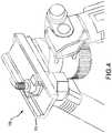
- FIGs. 1 and 2show perspective views of an embodiment of the herein disclosed bipod coupled to a generic firearm forend 101.
- the bipodenables selective and lockable cant and pivoting and interfacing with a firearm, such as a rifle, via one of various known interfacing platforms (e.g., M-LOK, NATO Rail, Picatinny).
- the legscan also telescope and be stored in a position folded up and back to a position near the forend 101 of the firearm and parallel to the barrel (e.g., rotated roughly 90° from a deployed position).
- the bipodcan further include legs 102 rotationally coupled to a housing 104.
- the housing 104can include a pivot block 107 that couples to the firearm forend interface 106.
- the firearm forend interface 106is configured for interfacing with a firearm, handguard of a firearm, etc. via the sling stud platform.
- a sling stud locking mechanism 110arranged below the firearm forend interface 106, can rotate in a first direction to loosen the bipod from the sling stud and allow the bipod to be removed from the firearm. Rotating the sling stud locking mechanism 110 in a second direction can tighten a coupling between the bipod and the sling stud of the firearm to secure the bipod to the firearm.
- the firearm forend interface 106can couple to the housing 104 via the pivot block 107. In other embodiments this coupling can include different degrees of rotational freedom (e.g., cant and pivot to name two).
- structures to allow cant and pivot between the housing 104 and the firearm forend interface 106are shown, but these are not intended to limit the scope of the disclosure.
- the legs 102, housing 104, locking knob 108, and pivot block 107are substantially the same as described in U.S. Patent Nos. 10,161,706 and 10,168,119 .
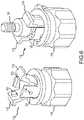
- FIGs. 3-5show a sling stud clasp assembly 112 coupled to a sling stud, such as a sling stud that was used to couple the forend 101 to the bipod in FIG. 1 .
- the sling stud clasp assembly 112is arranged within an aperture 114 in the firearm forend interface 106 and is rotatably coupled to and controlled by a sling stud locking mechanism 110 (e.g., a rotating knob) below a front overhanging portion of the firearm forend interface 106.
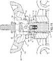
- FIGs. 10 and 11show a cross section of the same.
- FIGs. 3-5exclude the firearm to make it easier to view portions of the bipod that are otherwise obscured from view.
- a sling stud 120 of the firearmis still visible to illustrate interaction with the sling stud clasp assembly 112 (shown in a "closed” or “locked” position or state).
- the sling stud clasp assembly 112is arranged through an aperture 114 in the firearm forend interface 106 (this aperture is more easily seen in FIGs. 10 and 11 ).
- the aperture 114can extend through the firearm forend interface 106, from a top to a bottom of the firearm forend interface 106, and the sling stud clasp assembly 112 can pass through this aperture 114 to couple to the sling stud locking mechanism 110 (e.g., via a threaded engagement).
- the sling stud locking mechanism 110can form a rotational coupling to the sling stud clasp assembly 112 (the sling stud locking mechanism 110 can rotate, which in turn causes the sling stud clasp assembly 112 to move up and down).
- the sling stud locking mechanism 110can be moved toward a locked position (e.g., via rotation in a first direction) to move the sling stud clasp assembly 112 from an open to a closed position and thereby lock it onto the firearm sling stud 120.
- This motioncan overcome a bias on the sling stud clasp assembly 112, caused by a biasing component 142 and detent 144, and force the sling stud clasp assembly 112 toward the closed position.
- rotation of the sling stud locking mechanism 110 in a first directioncan cause a pair of spring-loaded pawls 132, 134 of the sling stud clasp assembly 112 (see FIGs. 6-12 ) to close or rotate inward around a pivot axis 136 (see FIG. 7 ).
- Rotationespecially via a threaded engagement, can effect a large torque able to overcome the bias from the biasing component 142 that otherwise forces the pawls 132, 134 toward an open position in which they are not in contact with the firearm sling stud 120. Further details describing opening and closing of the pawls 132, 134 can be seen in FIGs. 10-12 .
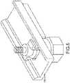
- the firearm forend interface 106can comprise two components: a soft flange (not shown in FIG. 4 , but visible as 115 in FIGs. 3 and 10-11 ) and a mounting plate 116 (shown in FIGs. 4 and 10-11 ).
- the mounting plate 116can couple to a bottom of the soft flange 115 and can interface the firearm forend interface 106 to the rest of the bipod (e.g., to the pivot block 107).
- the mounting plate 116can include structure for cant movement relative to the bipod housing (i.e., rotation around an axis parallel with the longitudinal axis of the firearm barrel).
- FIG. 5illustrates another view of the mounting plate 116, but with the soft flange 115 removed.
- FIG. 3also shows two variations of the firearm forend interface 106: a version having a wider soft flange 115a (left) and a version having a narrower soft flange 115b (right).
- firearm forend interfaces 106can be adapted to different sizes and shapes of firearm forends, and are non-limiting.
- the soft flange 115can be formed from rubber, cloth, polymer, or any other material unlikely to scratch the forend of the rifle that the bipod is being attached to (e.g., wooden forends).
- FIG. 6illustrates details of the sling stud clasp assembly 112 and the sling stud locking mechanism 110.
- the left figureshows the sling stud clasp assembly 112 in the open position
- the right figureshows the sling stud clasp assembly 112 in the closed position and clamped to a firearm sling stud 120.
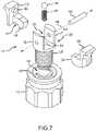
- the sling stud locking mechanism 110can also include a first spring-loaded pawl 132 and a second spring-loaded pawl 134 both rotatably coupled to a pivot holder 124 via a pivot pin 138 passing along a pivot axis 136 parallel to a longitudinal axis of the firearm barrel.
- the spring-loaded pawls 132, 134can each include protrusions 122, 123 shaped to enter an opposing side of an aperture in the firearm sling stud 120 when the pawls 132, 134 close upon the firearm sling stud 120.
- the pivot holder 124can also include a threaded lower portion 126, the cylindrical upper portion 128, and a pawl-holding recess 130 within the cylindrical section 128 (see FIG. 7 ).
- the pawl-holding recess 130can be shaped and sized to receive at least a portion of both of the pawls 132, 134.
- An outer diameter of the cylindrical section 128can have a similar (or just smaller) diameter than an inner diameter of a lock aperture 148 through the sling stud locking mechanism 110. This enables the cylindrical section 128 to slide vertically within the lock aperture 148.
- the pivot axis 136 and pivot pin 138can pass through the pawls 132, 134, the cylindrical section 128 of the pivot holder 124, and the pawl-holding recess 130. Accordingly, when the sling stud locking mechanism 110 is rotated, inner threads thereof interface with outer threads of the threaded lower portion 126 causing the pivot holder 124 to move upward or downward within the lock aperture 148. This movement pulls the pivot pin 138 with the pivot holder 124 which in turn pulls the pawls 132, 134 up and down, which causes opening and closing of the pawls 132, 134.
- FIGs. 10-12The loosening and tightening of the sling stud clasp assembly 112 is best seen in FIGs. 10-12 .
- the cross section in FIG. 10shows the sling stud clasp assembly 112 in the open position, without a sling stud shown
- FIG. 11shows the sling stud clasp assembly 112 in the closed position and grasping the firearm sling stud 120.
- One or both of the spring-loaded pawls 132, 134can include an irregular bottom surface, and different portions of this irregular bottom surface are presented to and contact the detent 144 as the pivot holder 124 moves within the aperture 114. In turn, this contact leads to different torques applied to the pawls 132, 134.
- the irregular surfacecan include one or both of a pawl detent 146 and a pawl groove 147.
- Both the pawl detent 146 and the pawl groove 147can include curved surfaces and the pawl groove 147 can be closer to the pivot axis 136 than the pawl detent 146.
- a first radius from the pawl detent 146 to the pivot axis 136can be greater than a second radius from the pawl groove 147 to the pivot axis 136.
- the pawl detent 146 and/or pawl groove 147can include one or more straight surfaces as well, or one or more straight surfaces joined by beveled edges, corners, or jogs.
- the pawl detent 146can be arranged toward an outside of each pawl 132, 134.
- the detent 144can interact with the pawl groove 147 when the spring-loaded pawls 132, 134 are in the open position as well as with an inside side of the detent 146 (see FIG. 12A ), and can interact solely with the pawl detent 146 when the pawls 132, 134 are in the closed position (see FIG. 12C ).
- FIG. 12shows opening and closing of the pawls in three stages from open ( FIG. 12A ) to closed ( FIG. 12C ).
- the pawl groove 147is in contact with a top of the detent 144 and the detent 144 is in a topmost position of the three stages shown in FIG. 12 .
- the pawls 132, 134via the pawl groove 147, apply little if any pressure downward on the top of the detent 144.
- the detent 144can be arranged partially in the vertical aperture 140 and partly in the pawl-holding recess 130.
- a biasing component 142(e.g., a spring) can also be arranged in the vertical aperture between a bottom of the detent 144 and a bottom of the vertical aperture 140. However, this position of the biasing component is not limiting. This biasing component 142 can apply a bias on the detent 144 tending to push it upward toward the pawls 132, 134.
- the knob 110, the pivot holder 124, and the vertical aperture 140can all be aligned along a common axis that passes through a center of the sling stud (as best seen in FIG. 8 ). This axis may also pass through the detent 144, and the detent 144 may move up and down along this axis.
- the threaded portion 126 of the pivot holder 124threadingly engages inner threads of the sling stud locking mechanism 110 and this interaction pulls the pivot holder 124 downward.
- Downward movement of the pivot holder 124brings the pivot pin 138 with it, and with this comes the spring-loaded pawls 132, 134 (see FIG. 12B ).
- the spring-loaded pawls 132, 134are pulled downward with the pivot holder 124, the sides of the pawls 132, 134 contact edges of the aperture 114 in the mounting plate 116 and this gradually forces the pawls 132, 134 inward.
- the pawl detent 146pivots downward relative to the pivot axis 136 and begins to interface with and press down on a top of the detent 144.
- the bias on them to openincreases.
- the pivot holder 124continues to descend further pulling the pawls 132, 134 inward and clamping them into a horizontal aperture in the sling stud (not shown) until a fully closed position is reached at FIG. 12C and the bipod is secured to the sling stud and hence the firearm.
- the sling stud locking mechanism 110can be rotated in a second direction to cause the pivot holder 124 to move upward.
- the detent 144can interact with an angled side of the pawl detent 146 and cause the pawls 132, 134 to pivot outward (or begin to open) as they move upward and clear a top of the aperture 114.
- This outward pivotingcan be caused by upward pressure from the detent 144 on the pawl detent 146 (clockwise in FIG. 11 for pawl 134).
- the detent 144continues to force the spring-loaded pawls 132, 134 toward the open position until they reach the position shown in FIG. 12A .
- the biasing component 142is at a maximum extension for the three figures in FIG. 12 , though it still may remain under some compression such that an upward bias remains on the detent 144.
- a bottom outer edge of each pawl 132, 134may include an angled surface that aligns with a top of the pivot holder 124 when the pawls 132, 134 are fully-opened, as best seen in FIGs. 10 and 12A .
- These angled surfacescan prevent overextension of the pawls 132, 134 (i.e., prevent excessive outward pivoting). For instance, in FIG. 12A , the pawls 132, 134 are not able to pivot any further outward. In some embodiments, only one of the pawls 132, 134 may include this angled surface at the bottom outer edge.
- FIGs. 10-12show a specific irregular bottom surface to the detent 144 that may include a pawl detent 146 and a groove detent 147, other irregular surfaces can also be implemented as long as a rotational bias (or torque) is maintained on the pawls 132, 134 throughout a range of vertical motion of the pivot holder 124.
- FIGs. 7-12only a single pawl detent 146 and pawl groove 147 are visible, however the other pawl may or may not also include its own pawl detent 146 and pawl groove 147.
- a bottom surface of either or both of the pawls 132, 134can be described as irregular as shown throughout the figures.
- a clevis 125can prevent the sling stud clasp assembly 112 and the sling stud locking mechanism 110 from pulling apart and decoupling when the sling stud locking mechanism 110 is rotated in a second direction (e.g., a loosening direction).
- FIGs. 10 and 11show the wider soft flange 115a shown in the left of FIG. 3 , though other sizes and shapes of soft flanges can be implemented without departing from the scope of this disclosure (e.g., the narrower soft flange 115b).
- FIG. 8illustrates the pivot holder 124, pivot pin 138, and pawls 132, 134 in isolation with a sling stud 120.
- the pawls 132, 134are in an open position, but one can see how the protrusions 122, 123 are aligned to enter a horizontal aperture through the sling stud 120.
- FIG. 9illustrates another view of the pawls 132, 134, pivot pin 138, and sling stud 120 shown in FIG. 8 .
- the detent 146 and groove 147are just one example of an interface structure between the spring-loaded pawls 132, 134 and the detent 144, and other interfaces are also contemplated without departing from the scope of this disclosure.
- the detent 144is shown as a sphere, in other embodiments, a cylindrical plunger or curved component could also be implemented. In another embodiment, part of the detent 144 could be curved or even spherical, while another portion could be cylindrical (e.g., a lower portion could be cylindrical and an upper portion could be curved). For instance, the detent 144 could have a "bullet" shape.
- Non-limiting examples of the biasing componentinclude, a compression spring, a conical spring, a coil spring, leaf spring, disc or Bellevile spring, barrel spring, elliptical helical spring, volute spring, and a pneumatic plunger.
- Non-limiting examples of the detent 144include a curved or spherical detent, a cylindrical detent, and a pointed detent.
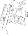
- FIG. 13shows a profile view of the firearm forend interface 106 and a sling stud 1302 extending rearward from a rear of the firearm forend interface 106.
- FIG. 14shows an isometric view of a left, top, rear of the firearm forend interface 106.
- the sling stud 1302is shown extending rearward parallel to a longitudinal axis of the firearm barrel, in other embodiments, any angle oblique to the firearm sling stud 120 can be used, and the sling stud 1302 can be arranged on other portions of the firearm forend interface 106.
- a rearward position for the sling stud 1302may be optimal for user access as well as optimal alignment with tension forces from a sling.
Landscapes
- Engineering & Computer Science (AREA)
- General Engineering & Computer Science (AREA)
- Hooks, Suction Cups, And Attachment By Adhesive Means (AREA)
- Pivots And Pivotal Connections (AREA)
- Hinges (AREA)
- Snaps, Bayonet Connections, Set Pins, And Snap Rings (AREA)
- Load-Engaging Elements For Cranes (AREA)
- Clamps And Clips (AREA)
- Vibration Prevention Devices (AREA)
Description
- The present disclosure relates generally to bipods. In particular, but not by way of limitation, the present disclosure relates to systems, methods and apparatuses for a bipod configured for coupling to a sling stud mount of a firearm.
- Modern firearms, such as rifles in particular, may be more accurately and conveniently fired by the shooter if the firearm is equipped with a bipod device for supporting and steadying the barrel. Bipods may be fixedly or removably mounted onto firearms, and have been found to be most convenient if they can further be retracted in a storage position when not in use. Exemplary bipods and mounting devices are taught in prior
U.S. Pat. No. 3,327,422 issued Jun. 27, 1967 ;U.S. Pat. No. 4,470,216 issued Sep. 11, 1984 ;U.S. Pat. No. 4,625,620 issued Dec. 2, 1986 ; andU.S. Pat. No. 4,641,451 issued Feb. 10, 1987 ;U.S. Pat. No. 4,903,425 issued Feb. 27, 1990 ; andU.S. Pat. No. 5,711,103 issued Jan. 27, 1998 , andU.S. Pat. No. 7,779,572 issued Aug. 24, 2010 andUS 7 954 272 B2 . - Existing bipods attach to firearms via a number of interfaces including M-LOK, NATO Rail, Picatinny Rail, and the sling stud. The Harris Bipod is one very common bipod that attaches to the sling stud, but tends to be finicky and difficult to install. Thus, there is a need for a simpler and more secure method of attaching a bipod to a sling stud, and one that is quicker and less prone to mounting errors.
- The following presents a simplified summary relating to one or more aspects and/or embodiments disclosed herein. As such, the following summary should not be considered an extensive overview relating to all contemplated aspects and/or embodiments, nor should the following summary be regarded to identify key or critical elements relating to all contemplated aspects and/or embodiments or to delineate the scope associated with any particular aspect and/or embodiment. Accordingly, the following summary has the sole purpose to present certain concepts relating to one or more aspects and/or embodiments relating to the mechanisms disclosed herein in a simplified form to precede the detailed description presented below.
- The present disclosure relates generally to a bipod-to-firearm interface for a sling stud (or sling swivel stud). More specifically, but without limitation, the present disclosure relates to a bipod having a firearm forend interface, a sling stud clasp assembly optionally including spring-loaded pawls that open and close to grasp a firearm's sling stud, and these pawls being biased toward an open position, and opening and closing of the sling stud clasp assembly being effected by rotation of a sling stud locking mechanism coupled to the sling stud clasp assembly. The sling stud clasp assembly can be arranged below and partially passing up and through an aperture in a mounting plate. The sling stud locking mechanism can be positioned below the firearm forend interface, and in some instances can include a rotating knob having a threading relationship to the sling stud clasp assembly. More specifically, the sling stud clasp assembly can include spring-loaded pawls that pivot on a pivot axis. The pivot axis can be held within a pivot holder having outer threads on a lower portion thereof that can threadingly couple to inner threads of the rotating knob. Accordingly, when the knob is rotated in a first direction, the pivot holder is pulled downward relative to the knob and mounting plate and consequently, the pivot axis and the spring-loaded pawls are also pulled downward relative to the knob and mounting plate. As the spring-loaded pawls are pulled downward through the aperture in the mounting plate they are pressed inward and can pivot or close on a sling stud thereby grasping and locking the sling stud to the bipod-to-firearm interface (e.g., see
FIGs. 10-11 ). Rotating the rotating knob in a second direction forces the sling stud clasp assembly upward allowing the spring-loaded pawls to pivot outward as they clear a top of the aperture in the mounting plate. The pivot holder and the knob can be concentrically arranged around a vertical axis that also passes through a center of the sling stud (in other words, the knob and pivot holder are aligned along a common axis with the sling stud). - The firearm forend interface can include its own sling stud, for instance, extending rearward from a back of the firearm forend interface. This sling stud of the bipod can enable sling stud access for the user since the firearm's forend sling stud is used to mount the bipod and thus isn't available for a sling or other accessory attachment.
- Generally, the bipod can include a housing with two leg assemblies attached thereto. The housing can include an aperture through which passes a pivot rod, the pivot rod having a threaded coupling to a locking knob arranged below the housing, wherein turning of the locking knob results in the pivot rod moving up or down along a vertical axis passing through the pivot rod and the housing. A top of the pivot rod can be coupled to a cant nut having a tubular shape and a longitudinal axis perpendicular to the vertical axis. A firearm forend interface can include an aperture having a similar shape to the cant nut, and the cant nut arranged within this aperture in the firearm forend interface. The firearm forend interface can rotate or cant around the cant nut to provide canting to a firearm mounted to the firearm forend interface. A pivot block can be arranged between the housing and the firearm forend interface and can pivot atop the housing. The pivot block can include a concave hollow into which a portion of a bottom of the firearm forend interface is shaped to rest in such that when the locking knob is tightened, the pivot block and firearm forend interface pivot in unison. Rotation of the locking knob pushes the cant nut and thereby the firearm forend interface up or down to lock or unlock the firearm forend interface into the concave hollow in the pivot block. The firearm forend interface can be shaped to fit a variety of known and yet-to-be-known accessory interfaces, such as, but not limited, to M-LOK, Picatinny rail, and NATO rail.
- Some embodiments of the disclosure may be characterized as a bipod assembly comprising a firearm forend interface, a pivot holder, two pawls, and a sling stud locking mechanism. The firearm forend interface can have a vertical aperture shaped to receive the pivot holder. The pivot holder can be shaped to slidingly move vertically with the vertical aperture in the firearm forend interface. The two pawls can be pivotally coupled to each other and pivotally coupled to the pivot holder via a pivot pin. The sling stud locking mechanism can be threadingly coupled to the pivot holder and can be configured to cause the vertical movement of the pivot holder via rotation of the sling stud locking mechanism. Upward vertical movement of the pivot holder can cause opening of the two pawls, whereas downward vertical movement of the pivot holder can cause closing of the two pawls.
- Other embodiments of the disclosure can be characterized as a firearm assembly. The assembly may comprise a firearm having a forend, a firearm forend interface, a pivot holder, two pawls, and a sling stud locking mechanism. The firearm forend interface can be configured for coupling to a bottom of the forend and may have a vertical aperture shaped to receive a pivot holder. The pivot holder may be shaped to slidingly move vertically within the vertical aperture in the firearm forend interface. The two pawls may be pivotally coupled to each other and to the pivot holder via a pivot pin. The sling stud locking mechanism may be threadingly coupled to the pivot holder and configured to, via rotation of the sling stud locking mechanism, cause the vertical movement of the pivot holder. The movement of the pivot holder within the vertical aperture in a first direction may cause opening of the two pawls, and movement of the pivot holder within the vertical aperture in a second direction may cause closing of the two pawls
- Various objects and advantages and a more complete understanding of the present disclosure are apparent and more readily appreciated by referring to the following detailed description and to the appended claims when taken in conjunction with the accompanying drawings:
FIG. 1 shows a perspective view of an embodiment of the herein disclosed bipod coupled to a generic firearm forend;FIG. 2 shows another perspective view of an embodiment of the herein disclosed bipod coupled to a generic firearm forend;FIG. 3 shows two flanges that can be used on the bipod shown inFIGs. 1 and2 ;FIG. 4 shows a view of the bipod without a flange;FIG. 5 shows a detailed view of the bipod interfacing with a sling stud of a firearm;FIG. 6 illustrates details of the sling stud clasp assembly and the sling stud locking mechanism;FIG. 7 illustrates a detailed and exploded view of the sling stud clasp assembly and the sling stud locking mechanism;FIG. 8 illustrates the pivot holder, pivot pin, and pawls in isolation with a sling stud;FIG. 9 illustrates another view of the pawls, pivot pin, and sling stud shown inFIG. 8 ;FIG. 10 shows the sling stud clasp assembly in the open position, without a sling stud shown;FIG. 11 shows the sling stud clasp assembly in the closed position and grasping the firearm sling stud;FIG. 12A shows a first position of the pawls in the sling stud clasp assembly;FIG. 12B shows a second position of the pawls in the sling stud clasp assembly;FIG. 12C shows a third position of the pawls in the sling stud clasp assembly;FIG. 13 shows a profile view of the firearm forend interface and a sling stud extending rearward from a rear of the firearm forend interface; andFIG. 14 shows an isometric view of a left, top, rear of the firearm forend interface inFIG. 13 .- The word "exemplary" is used herein to mean "serving as an example, instance, or illustration." Any embodiment described herein as "exemplary" is not necessarily to be construed as preferred or advantageous over other embodiments.
FIGs. 1 and2 show perspective views of an embodiment of the herein disclosed bipod coupled to ageneric firearm forend 101. The bipod enables selective and lockable cant and pivoting and interfacing with a firearm, such as a rifle, via one of various known interfacing platforms (e.g., M-LOK, NATO Rail, Picatinny). The legs can also telescope and be stored in a position folded up and back to a position near theforend 101 of the firearm and parallel to the barrel (e.g., rotated roughly 90° from a deployed position). The bipod can further includelegs 102 rotationally coupled to ahousing 104. Thehousing 104 can include apivot block 107 that couples to thefirearm forend interface 106. In this embodiment, thefirearm forend interface 106 is configured for interfacing with a firearm, handguard of a firearm, etc. via the sling stud platform. A slingstud locking mechanism 110, arranged below thefirearm forend interface 106, can rotate in a first direction to loosen the bipod from the sling stud and allow the bipod to be removed from the firearm. Rotating the slingstud locking mechanism 110 in a second direction can tighten a coupling between the bipod and the sling stud of the firearm to secure the bipod to the firearm. Thefirearm forend interface 106 can couple to thehousing 104 via thepivot block 107. In other embodiments this coupling can include different degrees of rotational freedom (e.g., cant and pivot to name two). In the illustrated embodiments, structures to allow cant and pivot between thehousing 104 and thefirearm forend interface 106 are shown, but these are not intended to limit the scope of the disclosure.- The
legs 102,housing 104, lockingknob 108, and pivot block 107 are substantially the same as described inU.S. Patent Nos. 10,161,706 10,168,119 FIGs. 3-5 show a slingstud clasp assembly 112 coupled to a sling stud, such as a sling stud that was used to couple theforend 101 to the bipod inFIG. 1 . The slingstud clasp assembly 112 is arranged within anaperture 114 in thefirearm forend interface 106 and is rotatably coupled to and controlled by a sling stud locking mechanism 110 (e.g., a rotating knob) below a front overhanging portion of thefirearm forend interface 106.FIGs. 10 and11 show a cross section of the same.FIGs. 3-5 exclude the firearm to make it easier to view portions of the bipod that are otherwise obscured from view. However, asling stud 120 of the firearm is still visible to illustrate interaction with the sling stud clasp assembly 112 (shown in a "closed" or "locked" position or state). The slingstud clasp assembly 112 is arranged through anaperture 114 in the firearm forend interface 106 (this aperture is more easily seen inFIGs. 10 and11 ). Theaperture 114 can extend through thefirearm forend interface 106, from a top to a bottom of thefirearm forend interface 106, and the slingstud clasp assembly 112 can pass through thisaperture 114 to couple to the sling stud locking mechanism 110 (e.g., via a threaded engagement). For instance, the slingstud locking mechanism 110 can form a rotational coupling to the sling stud clasp assembly 112 (the slingstud locking mechanism 110 can rotate, which in turn causes the slingstud clasp assembly 112 to move up and down). The slingstud locking mechanism 110 can be moved toward a locked position (e.g., via rotation in a first direction) to move the slingstud clasp assembly 112 from an open to a closed position and thereby lock it onto thefirearm sling stud 120. This motion can overcome a bias on the slingstud clasp assembly 112, caused by abiasing component 142 anddetent 144, and force the slingstud clasp assembly 112 toward the closed position. For instance, rotation of the slingstud locking mechanism 110 in a first direction can cause a pair of spring-loadedpawls FIGs. 6-12 ) to close or rotate inward around a pivot axis 136 (seeFIG. 7 ). Rotation, especially via a threaded engagement, can effect a large torque able to overcome the bias from thebiasing component 142 that otherwise forces thepawls firearm sling stud 120. Further details describing opening and closing of thepawls FIGs. 10-12 .- In some embodiments, the
firearm forend interface 106 can comprise two components: a soft flange (not shown inFIG. 4 , but visible as 115 inFIGs. 3 and10-11 ) and a mounting plate 116 (shown inFIGs. 4 and10-11 ). The mountingplate 116 can couple to a bottom of the soft flange 115 and can interface thefirearm forend interface 106 to the rest of the bipod (e.g., to the pivot block 107). In some cases, the mountingplate 116 can include structure for cant movement relative to the bipod housing (i.e., rotation around an axis parallel with the longitudinal axis of the firearm barrel). FIG. 5 illustrates another view of the mountingplate 116, but with the soft flange 115 removed.FIG. 3 also shows two variations of the firearm forend interface 106: a version having a widersoft flange 115a (left) and a version having a narrowersoft flange 115b (right). These and other firearm forend interfaces 106 can be adapted to different sizes and shapes of firearm forends, and are non-limiting. The soft flange 115 can be formed from rubber, cloth, polymer, or any other material unlikely to scratch the forend of the rifle that the bipod is being attached to (e.g., wooden forends).FIG. 6 illustrates details of the slingstud clasp assembly 112 and the slingstud locking mechanism 110. The left figure shows the slingstud clasp assembly 112 in the open position, and the right figure shows the slingstud clasp assembly 112 in the closed position and clamped to afirearm sling stud 120. The slingstud locking mechanism 110 can also include a first spring-loadedpawl 132 and a second spring-loadedpawl 134 both rotatably coupled to apivot holder 124 via apivot pin 138 passing along apivot axis 136 parallel to a longitudinal axis of the firearm barrel. The spring-loadedpawls protrusions firearm sling stud 120 when thepawls firearm sling stud 120. Thepivot holder 124 can also include a threadedlower portion 126, the cylindricalupper portion 128, and a pawl-holdingrecess 130 within the cylindrical section 128 (seeFIG. 7 ). The pawl-holdingrecess 130 can be shaped and sized to receive at least a portion of both of thepawls cylindrical section 128 can have a similar (or just smaller) diameter than an inner diameter of alock aperture 148 through the slingstud locking mechanism 110. This enables thecylindrical section 128 to slide vertically within thelock aperture 148. Thepivot axis 136 andpivot pin 138 can pass through thepawls cylindrical section 128 of thepivot holder 124, and the pawl-holdingrecess 130. Accordingly, when the slingstud locking mechanism 110 is rotated, inner threads thereof interface with outer threads of the threadedlower portion 126 causing thepivot holder 124 to move upward or downward within thelock aperture 148. This movement pulls thepivot pin 138 with thepivot holder 124 which in turn pulls thepawls pawls - The loosening and tightening of the sling
stud clasp assembly 112 is best seen inFIGs. 10-12 . Notably, the cross section inFIG. 10 shows the slingstud clasp assembly 112 in the open position, without a sling stud shown, andFIG. 11 shows the slingstud clasp assembly 112 in the closed position and grasping thefirearm sling stud 120. One or both of the spring-loadedpawls detent 144 as thepivot holder 124 moves within theaperture 114. In turn, this contact leads to different torques applied to thepawls pawl detent 146 and apawl groove 147. Both thepawl detent 146 and thepawl groove 147 can include curved surfaces and thepawl groove 147 can be closer to thepivot axis 136 than thepawl detent 146. In other words, a first radius from thepawl detent 146 to thepivot axis 136 can be greater than a second radius from thepawl groove 147 to thepivot axis 136. However, thepawl detent 146 and/orpawl groove 147 can include one or more straight surfaces as well, or one or more straight surfaces joined by beveled edges, corners, or jogs. Thepawl detent 146 can be arranged toward an outside of eachpawl detent 144 can interact with thepawl groove 147 when the spring-loadedpawls FIG. 12A ), and can interact solely with thepawl detent 146 when thepawls FIG. 12C ). FIG. 12 shows opening and closing of the pawls in three stages from open (FIG. 12A ) to closed (FIG. 12C ). In the open position thepawl groove 147 is in contact with a top of thedetent 144 and thedetent 144 is in a topmost position of the three stages shown inFIG. 12 . Here thepawls pawl groove 147, apply little if any pressure downward on the top of thedetent 144. Thedetent 144 can be arranged partially in thevertical aperture 140 and partly in the pawl-holdingrecess 130. A biasing component 142 (e.g., a spring) can also be arranged in the vertical aperture between a bottom of thedetent 144 and a bottom of thevertical aperture 140. However, this position of the biasing component is not limiting. Thisbiasing component 142 can apply a bias on thedetent 144 tending to push it upward toward thepawls knob 110, thepivot holder 124, and thevertical aperture 140 can all be aligned along a common axis that passes through a center of the sling stud (as best seen inFIG. 8 ). This axis may also pass through thedetent 144, and thedetent 144 may move up and down along this axis.- Specifically, as the sling
stud locking mechanism 110 is rotated in a first direction, the threadedportion 126 of thepivot holder 124 threadingly engages inner threads of the slingstud locking mechanism 110 and this interaction pulls thepivot holder 124 downward. Downward movement of thepivot holder 124 brings thepivot pin 138 with it, and with this comes the spring-loadedpawls 132, 134 (seeFIG. 12B ). As the spring-loadedpawls pivot holder 124, the sides of thepawls aperture 114 in the mountingplate 116 and this gradually forces thepawls pawls pawl detent 146 pivots downward relative to thepivot axis 136 and begins to interface with and press down on a top of thedetent 144. This causes thebiasing component 142 to become compressed and increase an upward bias on thedetent 144, which in turn increases its bias on the pawl detent 146 (even as thepawls pawls - As the sling
stud locking mechanism 110 continues to rotate in the first direction, thepivot holder 124 continues to descend further pulling thepawls FIG. 12C and the bipod is secured to the sling stud and hence the firearm. - From the closed position in
FIG. 12C , the slingstud locking mechanism 110 can be rotated in a second direction to cause thepivot holder 124 to move upward. One can see how upward movement of thepivot holder 124 causes thedetent 144 to first contact thepawl detent 146 since at this angle, thepawl detent 146 sits lower in the system than thepawl groove 147. As this upward movement continues, thedetent 144 can interact with an angled side of thepawl detent 146 and cause thepawls aperture 114. This outward pivoting can be caused by upward pressure from thedetent 144 on the pawl detent 146 (clockwise inFIG. 11 for pawl 134). As thepivot holder 124 rises further and thepawls aperture 114, thedetent 144 continues to force the spring-loadedpawls FIG. 12A . Here, thebiasing component 142 is at a maximum extension for the three figures inFIG. 12 , though it still may remain under some compression such that an upward bias remains on thedetent 144. - A bottom outer edge of each
pawl pivot holder 124 when thepawls FIGs. 10 and12A . These angled surfaces can prevent overextension of thepawls 132, 134 (i.e., prevent excessive outward pivoting). For instance, inFIG. 12A , thepawls pawls - While
FIGs. 10-12 show a specific irregular bottom surface to thedetent 144 that may include apawl detent 146 and agroove detent 147, other irregular surfaces can also be implemented as long as a rotational bias (or torque) is maintained on thepawls pivot holder 124. - In
FIGs. 7-12 only asingle pawl detent 146 andpawl groove 147 are visible, however the other pawl may or may not also include itsown pawl detent 146 andpawl groove 147. A bottom surface of either or both of thepawls - A clevis 125 (see
FIG. 7 ) can prevent the slingstud clasp assembly 112 and the slingstud locking mechanism 110 from pulling apart and decoupling when the slingstud locking mechanism 110 is rotated in a second direction (e.g., a loosening direction).FIGs. 10 and11 show the widersoft flange 115a shown in the left ofFIG. 3 , though other sizes and shapes of soft flanges can be implemented without departing from the scope of this disclosure (e.g., the narrowersoft flange 115b). FIG. 8 illustrates thepivot holder 124,pivot pin 138, andpawls sling stud 120. Thepawls protrusions sling stud 120.FIG. 9 illustrates another view of thepawls pivot pin 138, andsling stud 120 shown inFIG. 8 .- It should be understood that the
detent 146 and groove 147 are just one example of an interface structure between the spring-loadedpawls detent 144, and other interfaces are also contemplated without departing from the scope of this disclosure. Further, although thedetent 144 is shown as a sphere, in other embodiments, a cylindrical plunger or curved component could also be implemented. In another embodiment, part of thedetent 144 could be curved or even spherical, while another portion could be cylindrical (e.g., a lower portion could be cylindrical and an upper portion could be curved). For instance, thedetent 144 could have a "bullet" shape. - Non-limiting examples of the biasing component include, a compression spring, a conical spring, a coil spring, leaf spring, disc or Bellevile spring, barrel spring, elliptical helical spring, volute spring, and a pneumatic plunger. Non-limiting examples of the
detent 144 include a curved or spherical detent, a cylindrical detent, and a pointed detent. FIG. 13 shows a profile view of thefirearm forend interface 106 and asling stud 1302 extending rearward from a rear of thefirearm forend interface 106.FIG. 14 shows an isometric view of a left, top, rear of thefirearm forend interface 106. Although thesling stud 1302 is shown extending rearward parallel to a longitudinal axis of the firearm barrel, in other embodiments, any angle oblique to thefirearm sling stud 120 can be used, and thesling stud 1302 can be arranged on other portions of thefirearm forend interface 106. However, given the location of the firearm forend, thebipod legs 102, and the slingstud locking mechanism 110, as well as the fact that slings tend to also be coupled to a fixture toward the rear of the firearm, a rearward position for thesling stud 1302 may be optimal for user access as well as optimal alignment with tension forces from a sling.- As used herein, the recitation of "at least one of A, B and C" is intended to mean "either A, B, C or any combination of A, B and C." The previous description of the disclosed embodiments is provided to enable any person skilled in the art to make or use the present disclosure. Various modifications to these embodiments will be readily apparent to those skilled in the art, and the generic principles defined herein may be applied to other embodiments without departing from the scope of the disclosure as in the appended claims.
Claims (12)
- A bipod assembly comprising:a firearm forend interface (106) having a vertical aperture (114) shaped to receive a pivot holder (124),the pivot holder shaped to slidingly move vertically with the vertical aperture in the firearm forend interface;two pawls (132, 134) pivotally coupled to each other and to the pivot holder via a pivot pin (138);a sling stud locking mechanism (110) threadingly coupled to the pivot holder (124) and configured to cause the vertical movement of the pivot holder via rotation,wherein upward vertical movement of the pivot holder causes opening of the two pawls and downward vertical movement of the pivot holder causes closing of the two pawls.
- The bipod assembly of Claim 1, wherein:at least one of the two pawls includes a pawl detent (146) at a first radius from the pivot pin;a detent is arranged at least partially within a vertical aperture in the pivot holder;a biasing component (142) is arranged within the vertical aperture and below the detent, the biasing component configured to apply a bias to a bottom of the detent.
- The bipod assembly of Claim 1 or Claim 2, wherein when the locking mechanism is rotated in a first direction, the pivot holder, detent, and pivot pin move upward, and via interaction of a top of the detent and an irregular bottom surface of at least one of the pawls, both pawls are forced upward and tend to pivot outward toward an open position.
- The bipod assembly of Claim 1, wherein one or both of the pawls includes an irregular bottom surface.
- The bipod assembly of Claim 4, wherein the irregular bottom surface includes a pawl detent (146) and a pawl groove (147).
- The bipod assembly of Claim 5, wherein the pawl detent is at a first radius from the pivot pin and the pawl groove is at a second radius from the pivot pin, wherein the first radius is greater than the second radius.
- A firearm assembly comprising:a firearm having a forend;a firearm forend interface (106) configured for coupling to a bottom of the forend and having a vertical aperture (114) shaped to receive a pivot holder (124);the pivot holder shaped to slidingly move vertically within the vertical aperture in the firearm forend interface;two pawls (132, 134) pivotally coupled to each other and to the pivot holder via a pivot pin (138);a sling stud locking mechanism (110) threadingly coupled to the pivot holder and configured to, via rotation of the sling stud locking mechanism, cause the vertical movement of the pivot holder,wherein movement of the pivot holder within the vertical aperture in a first direction causes opening of the two pawls and movement of the pivot holder within the vertical aperture in a second direction causes closing of the two pawls.
- The firearm assembly of Claim 7, wherein:at least one of the two pawls includes a pawl detent at a first radius from the pivot pin;a detent is arranged at least partially within a vertical aperture in the pivot holder;a biasing component is arranged within the vertical aperture and below the detent, the biasing component configured to apply a bias to a bottom of the detent.
- The firearm assembly of Claim 7 or Claim 8, wherein when the locking mechanism is rotated in a first direction, the pivot holder, detent, and pivot pin move upward, and via interaction of a top of the detent and an irregular bottom surface of at least one of the pawls, both pawls are forced upward and tend to pivot outward toward an open position.
- The firearm assembly of Claim 7, wherein one or both of the pawls includes an irregular bottom surface.
- The firearm assembly of Claim 10, wherein the irregular bottom surface includes a pawl detent (146) and a pawl groove (147)
- The firearm assembly of Claim 11, wherein the pawl detent is at a first radius from the pivot pin and the pawl groove is at a second radius from the pivot pin, wherein the first radius is greater than the second radius.
Priority Applications (1)
| Application Number | Priority Date | Filing Date | Title |
|---|---|---|---|
| EP22169610.7AEP4060279A1 (en) | 2019-04-17 | 2020-04-16 | Bipod with sling stud mount |
Applications Claiming Priority (2)
| Application Number | Priority Date | Filing Date | Title |
|---|---|---|---|
| US201962835333P | 2019-04-17 | 2019-04-17 | |
| PCT/US2020/028498WO2020214803A2 (en) | 2019-04-17 | 2020-04-16 | Bipod with sling stud mount |
Related Child Applications (1)
| Application Number | Title | Priority Date | Filing Date |
|---|---|---|---|
| EP22169610.7ADivisionEP4060279A1 (en) | 2019-04-17 | 2020-04-16 | Bipod with sling stud mount |
Publications (3)
| Publication Number | Publication Date |
|---|---|
| EP3794302A2 EP3794302A2 (en) | 2021-03-24 |
| EP3794302A4 EP3794302A4 (en) | 2021-07-14 |
| EP3794302B1true EP3794302B1 (en) | 2022-04-27 |
Family
ID=72838363
Family Applications (2)
| Application Number | Title | Priority Date | Filing Date |
|---|---|---|---|
| EP22169610.7APendingEP4060279A1 (en) | 2019-04-17 | 2020-04-16 | Bipod with sling stud mount |
| EP20791288.2AActiveEP3794302B1 (en) | 2019-04-17 | 2020-04-16 | Bipod with sling stud mount |
Family Applications Before (1)
| Application Number | Title | Priority Date | Filing Date |
|---|---|---|---|
| EP22169610.7APendingEP4060279A1 (en) | 2019-04-17 | 2020-04-16 | Bipod with sling stud mount |
Country Status (10)
| Country | Link |
|---|---|
| US (4) | US11320226B2 (en) |
| EP (2) | EP4060279A1 (en) |
| JP (1) | JP6944086B2 (en) |
| CN (1) | CN112534203B (en) |
| AU (1) | AU2020260120B2 (en) |
| CA (1) | CA3132383C (en) |
| IL (1) | IL285266B2 (en) |
| PL (1) | PL3794302T3 (en) |
| TW (1) | TWI807279B (en) |
| WO (1) | WO2020214803A2 (en) |
Cited By (1)
| Publication number | Priority date | Publication date | Assignee | Title |
|---|---|---|---|---|
| US12013201B2 (en) | 2019-04-17 | 2024-06-18 | Magpul Industries Corp. | Bipod with sling stud mount |
Families Citing this family (7)
| Publication number | Priority date | Publication date | Assignee | Title |
|---|---|---|---|---|
| US10168119B2 (en)* | 2016-12-23 | 2019-01-01 | Magpul Industries Corp. | Firearm bipod |
| USD875871S1 (en)* | 2017-12-22 | 2020-02-18 | Magpul Industries Corp. | Bipod |
| USD898156S1 (en)* | 2019-04-17 | 2020-10-06 | Magpul Industries Corp. | Bipod with sling stud mount |
| WO2021257013A1 (en)* | 2020-06-17 | 2021-12-23 | Bahtiyar Tasyagan | Adjustable forend mechanism in rifles |
| DE102020132603B4 (en)* | 2020-12-08 | 2024-08-22 | Sorin Pavel | Portable firearm |
| SE546060C2 (en) | 2021-05-03 | 2024-04-30 | Scandinavian Arms AB | Bipod |
| SE546059C2 (en)* | 2021-05-03 | 2024-04-30 | Scandinavian Arms AB | Bipod |
Family Cites Families (39)
| Publication number | Priority date | Publication date | Assignee | Title |
|---|---|---|---|---|
| US2771699A (en) | 1953-08-24 | 1956-11-27 | George L Herter | Quick detachable gun sling swivel |
| US3327422A (en) | 1965-10-23 | 1967-06-27 | Harris Gerald | Bipod for attachment to a firearm |
| US3999461A (en)* | 1975-09-03 | 1976-12-28 | The United States Of America As Represented By The Secretary Of The Army | Modular lightweight squad automatic weapon system |
| US4641451A (en) | 1982-04-12 | 1987-02-10 | Gerald Harris | Bipod mounting device and muzzle brake |
| US4470216A (en) | 1982-04-12 | 1984-09-11 | Gerald Harris | Bipod mounting device and muzzle brake |
| US4625620A (en) | 1985-05-07 | 1986-12-02 | Gerald Harris | Bipod for a firearm |
| US4903425A (en) | 1989-02-03 | 1990-02-27 | Gerald Harris | Pivotal adapter for bipods and attachment therefor |
| US5194678A (en)* | 1992-01-27 | 1993-03-16 | Terry Kramer | Firearm rest |
| US5402595A (en)* | 1993-12-13 | 1995-04-04 | Tamllos; George M. | Shooting device |
| US5711103A (en) | 1995-10-13 | 1998-01-27 | Keng; Da | Bipod mounting device |
| US6843015B2 (en)* | 1999-10-06 | 2005-01-18 | Ronnie L. Sharp | Bipod for firearms |
| TW488615U (en) | 2000-12-21 | 2002-05-21 | Hung-Ping Chen | Improvement for connector structure configuration of interface card |
| US7454858B2 (en)* | 2003-08-05 | 2008-11-25 | R/M Equipment, Inc. | Weapon grip assembly |
| US7431247B2 (en)* | 2003-10-27 | 2008-10-07 | Andrew Bobro | Bipod for a rifle of optical instrument |
| US8402684B1 (en) | 2005-05-31 | 2013-03-26 | Kasey Dallas Beltz | Bipod firearm support |
| US7571563B2 (en)* | 2005-10-06 | 2009-08-11 | Bushnell Inc. | Flexible supports for rifles, spotting scopes, and the like |
| US7779572B2 (en) | 2006-05-08 | 2010-08-24 | Battenfeld Technologies, Inc. | Bipod device for use with a firearm |
| US7954272B2 (en) | 2007-05-08 | 2011-06-07 | Battenfeld Technologies, Inc. | Adjustable firearm supports and associated methods of use and manufacture |
| US20090126250A1 (en)* | 2007-06-29 | 2009-05-21 | Da Keng | Bipod assembly & kit with interchangeable bipod legs providing a selection of bipod leg end effecters |
| US8656622B2 (en)* | 2007-10-11 | 2014-02-25 | Ashbury International Group, Inc. | Tactical firearm systems and methods of manufacturing same |
| US8104213B2 (en) | 2009-11-30 | 2012-01-31 | Keng's Firearms Specialty, Inc. | Method for quick disconnect bipod mount assembly with adjustable and lockable tilt, pan and cant controls |
| US8468733B2 (en) | 2011-08-02 | 2013-06-25 | Mark A. Deros | Accessory rails with slot adapters and mechanisms of use |
| US9239210B2 (en)* | 2014-04-03 | 2016-01-19 | Magpul Industries Corp. | Firearm accessory mounting interface |
| US9239209B2 (en)* | 2014-04-03 | 2016-01-19 | Magpul Industries, Corp. | Firearm accessory mounting interface |
| TWM488615U (en)* | 2014-03-07 | 2014-10-21 | Wingun Technology Co Ltd | Bipod |
| US9335113B1 (en)* | 2014-03-17 | 2016-05-10 | Peleton Technology Llc | Quick and stable claw attachment assembly systems for firearm and firearm stands |
| CN204373500U (en)* | 2014-12-10 | 2015-06-03 | 四川华庆机械有限责任公司 | A kind of foot rest locking and detent mechanism |
| CN106440931A (en)* | 2016-04-15 | 2017-02-22 | 陈小鸣 | Bipod capable of achieving tube back end compression ejection |
| US10168119B2 (en) | 2016-12-23 | 2019-01-01 | Magpul Industries Corp. | Firearm bipod |
| US10161706B2 (en)* | 2016-12-23 | 2018-12-25 | Magpul Industries Corp. | Firearm bipod |
| CN206709686U (en)* | 2017-05-17 | 2017-12-05 | 重庆建设工业(集团)有限责任公司 | A kind of supporting construction of sniper rifle bipod |
| CN206832121U (en)* | 2017-06-23 | 2018-01-02 | 朱坤振 | A kind of automatic firearm bomb-release point is away from controller |
| US10782084B2 (en)* | 2017-09-05 | 2020-09-22 | 4xA Technologies Inc. | Bipod for projectile weapons |
| AU2019205833A1 (en)* | 2018-01-08 | 2020-07-23 | McEwin Design Pty Ltd | Rifle bipod |
| US10139183B1 (en)* | 2018-01-26 | 2018-11-27 | Cheh-Kang Liu | Bipod |
| CN108478268B (en)* | 2018-05-29 | 2023-09-12 | 迪恩医疗科技有限公司 | Orthopedic screw with hook |
| US10184746B1 (en)* | 2018-07-19 | 2019-01-22 | Cheh-Kang Liu | Bipod dual-mount attachment structure |
| EP4060279A1 (en) | 2019-04-17 | 2022-09-21 | Magpul Industries Corp. | Bipod with sling stud mount |
| US11226170B2 (en)* | 2019-11-12 | 2022-01-18 | Magpul Industries Corp. | Takedown stock for a pistol-caliber carbine |
- 2020
- 2020-04-16EPEP22169610.7Apatent/EP4060279A1/enactivePending
- 2020-04-16USUS17/256,250patent/US11320226B2/enactiveActive
- 2020-04-16ILIL285266Apatent/IL285266B2/enunknown
- 2020-04-16CNCN202080004017.8Apatent/CN112534203B/enactiveActive
- 2020-04-16EPEP20791288.2Apatent/EP3794302B1/enactiveActive
- 2020-04-16PLPL20791288.2Tpatent/PL3794302T3/enunknown
- 2020-04-16AUAU2020260120Apatent/AU2020260120B2/enactiveActive
- 2020-04-16JPJP2021503164Apatent/JP6944086B2/enactiveActive
- 2020-04-16CACA3132383Apatent/CA3132383C/enactiveActive
- 2020-04-16WOPCT/US2020/028498patent/WO2020214803A2/ennot_activeCeased
- 2021
- 2021-03-17TWTW110109581Apatent/TWI807279B/enactive
- 2022
- 2022-03-24USUS17/702,981patent/US11624577B2/enactiveActive
- 2023
- 2023-02-28USUS18/115,033patent/US12013201B2/enactiveActive
- 2024
- 2024-05-10USUS18/660,624patent/US20240302123A1/enactivePending
Cited By (1)
| Publication number | Priority date | Publication date | Assignee | Title |
|---|---|---|---|---|
| US12013201B2 (en) | 2019-04-17 | 2024-06-18 | Magpul Industries Corp. | Bipod with sling stud mount |
Also Published As
| Publication number | Publication date |
|---|---|
| EP3794302A4 (en) | 2021-07-14 |
| JP2021524573A (en) | 2021-09-13 |
| US20220214130A1 (en) | 2022-07-07 |
| AU2020260120A1 (en) | 2021-10-07 |
| TWI807279B (en) | 2023-07-01 |
| US11320226B2 (en) | 2022-05-03 |
| IL285266B1 (en) | 2024-10-01 |
| JP6944086B2 (en) | 2021-10-06 |
| PL3794302T3 (en) | 2022-10-10 |
| CN112534203B (en) | 2022-11-18 |
| US20230204316A1 (en) | 2023-06-29 |
| IL285266A (en) | 2021-09-30 |
| EP3794302A2 (en) | 2021-03-24 |
| US11624577B2 (en) | 2023-04-11 |
| WO2020214803A3 (en) | 2020-12-10 |
| IL285266B2 (en) | 2025-02-01 |
| US20220042760A1 (en) | 2022-02-10 |
| EP4060279A1 (en) | 2022-09-21 |
| AU2020260120B2 (en) | 2024-12-05 |
| US20240302123A1 (en) | 2024-09-12 |
| TW202140988A (en) | 2021-11-01 |
| US12013201B2 (en) | 2024-06-18 |
| CN112534203A (en) | 2021-03-19 |
| WO2020214803A2 (en) | 2020-10-22 |
| CA3132383C (en) | 2022-05-31 |
| CA3132383A1 (en) | 2020-10-22 |
Similar Documents
| Publication | Publication Date | Title |
|---|---|---|
| EP3794302B1 (en) | Bipod with sling stud mount | |
| US8464628B2 (en) | Attachment mechanisms for coupling firearms to supporting structures | |
| CA2005046C (en) | Pivotal adapter for bipods and attachment therefor | |
| US9328998B2 (en) | Quick-detach accessory base mount for an accessory rail | |
| US7891126B2 (en) | Canting vertical fore grip with bipod | |
| US8225543B2 (en) | Canting vertical fore grip with bipod | |
| US7631455B2 (en) | Quick disconnect bipod mount assembly with adjustable and lockable tilt, pan and cant controls | |
| US8104213B2 (en) | Method for quick disconnect bipod mount assembly with adjustable and lockable tilt, pan and cant controls | |
| US11585624B2 (en) | Shooting rest and support system | |
| US6629380B2 (en) | Handgun rest for field and hunting use | |
| US12332017B2 (en) | Handgun brace | |
| HK40048491B (en) | Bipod with sling stud mount | |
| HK40048491A (en) | Bipod with sling stud mount | |
| US20240151492A1 (en) | Quick disconnect sling mount for a firearm |
Legal Events
| Date | Code | Title | Description |
|---|---|---|---|
| STAA | Information on the status of an ep patent application or granted ep patent | Free format text:STATUS: THE INTERNATIONAL PUBLICATION HAS BEEN MADE | |
| PUAI | Public reference made under article 153(3) epc to a published international application that has entered the european phase | Free format text:ORIGINAL CODE: 0009012 | |
| STAA | Information on the status of an ep patent application or granted ep patent | Free format text:STATUS: REQUEST FOR EXAMINATION WAS MADE | |
| 17P | Request for examination filed | Effective date:20201218 | |
| AK | Designated contracting states | Kind code of ref document:A2 Designated state(s):AL AT BE BG CH CY CZ DE DK EE ES FI FR GB GR HR HU IE IS IT LI LT LU LV MC MK MT NL NO PL PT RO RS SE SI SK SM TR | |
| AX | Request for extension of the european patent | Extension state:BA ME | |
| A4 | Supplementary search report drawn up and despatched | Effective date:20210616 | |
| RIC1 | Information provided on ipc code assigned before grant | Ipc:F41A 23/08 20060101AFI20210610BHEP Ipc:F41A 23/10 20060101ALI20210610BHEP Ipc:F16M 11/04 20060101ALI20210610BHEP Ipc:F16M 11/20 20060101ALI20210610BHEP Ipc:F16M 11/24 20060101ALI20210610BHEP Ipc:F41A 23/00 20060101ALI20210610BHEP Ipc:F41A 23/04 20060101ALI20210610BHEP Ipc:F41C 23/16 20060101ALI20210610BHEP Ipc:F41C 23/02 20060101ALI20210610BHEP | |
| RIC1 | Information provided on ipc code assigned before grant | Ipc:F41C 23/02 20060101ALI20210930BHEP Ipc:F41C 23/16 20060101ALI20210930BHEP Ipc:F41A 23/04 20060101ALI20210930BHEP Ipc:F41A 23/00 20060101ALI20210930BHEP Ipc:F16M 11/24 20060101ALI20210930BHEP Ipc:F16M 11/20 20060101ALI20210930BHEP Ipc:F16M 11/04 20060101ALI20210930BHEP Ipc:F41A 23/10 20060101ALI20210930BHEP Ipc:F41A 23/08 20060101AFI20210930BHEP | |
| GRAP | Despatch of communication of intention to grant a patent | Free format text:ORIGINAL CODE: EPIDOSNIGR1 | |
| STAA | Information on the status of an ep patent application or granted ep patent | Free format text:STATUS: GRANT OF PATENT IS INTENDED | |
| DAV | Request for validation of the european patent (deleted) | ||
| DAX | Request for extension of the european patent (deleted) | ||
| INTG | Intention to grant announced | Effective date:20211108 | |
| REG | Reference to a national code | Ref country code:HK Ref legal event code:DE Ref document number:40048491 Country of ref document:HK | |
| GRAS | Grant fee paid | Free format text:ORIGINAL CODE: EPIDOSNIGR3 | |
| GRAA | (expected) grant | Free format text:ORIGINAL CODE: 0009210 | |
| STAA | Information on the status of an ep patent application or granted ep patent | Free format text:STATUS: THE PATENT HAS BEEN GRANTED | |
| RIN1 | Information on inventor provided before grant (corrected) | Inventor name:ROBERTS, TIMOTHY ERIC | |
| AK | Designated contracting states | Kind code of ref document:B1 Designated state(s):AL AT BE BG CH CY CZ DE DK EE ES FI FR GB GR HR HU IE IS IT LI LT LU LV MC MK MT NL NO PL PT RO RS SE SI SK SM TR | |
| REG | Reference to a national code | Ref country code:GB Ref legal event code:FG4D | |
| REG | Reference to a national code | Ref country code:CH Ref legal event code:EP | |
| REG | Reference to a national code | Ref country code:AT Ref legal event code:REF Ref document number:1487234 Country of ref document:AT Kind code of ref document:T Effective date:20220515 | |
| REG | Reference to a national code | Ref country code:DE Ref legal event code:R096 Ref document number:602020002870 Country of ref document:DE | |
| REG | Reference to a national code | Ref country code:IE Ref legal event code:FG4D | |
| REG | Reference to a national code | Ref country code:SE Ref legal event code:TRGR | |
| REG | Reference to a national code | Ref country code:LT Ref legal event code:MG9D | |
| REG | Reference to a national code | Ref country code:NL Ref legal event code:MP Effective date:20220427 | |
| REG | Reference to a national code | Ref country code:AT Ref legal event code:MK05 Ref document number:1487234 Country of ref document:AT Kind code of ref document:T Effective date:20220427 | |
| PG25 | Lapsed in a contracting state [announced via postgrant information from national office to epo] | Ref country code:NL Free format text:LAPSE BECAUSE OF FAILURE TO SUBMIT A TRANSLATION OF THE DESCRIPTION OR TO PAY THE FEE WITHIN THE PRESCRIBED TIME-LIMIT Effective date:20220427 | |
| PG25 | Lapsed in a contracting state [announced via postgrant information from national office to epo] | Ref country code:PT Free format text:LAPSE BECAUSE OF FAILURE TO SUBMIT A TRANSLATION OF THE DESCRIPTION OR TO PAY THE FEE WITHIN THE PRESCRIBED TIME-LIMIT Effective date:20220829 Ref country code:NO Free format text:LAPSE BECAUSE OF FAILURE TO SUBMIT A TRANSLATION OF THE DESCRIPTION OR TO PAY THE FEE WITHIN THE PRESCRIBED TIME-LIMIT Effective date:20220727 Ref country code:LT Free format text:LAPSE BECAUSE OF FAILURE TO SUBMIT A TRANSLATION OF THE DESCRIPTION OR TO PAY THE FEE WITHIN THE PRESCRIBED TIME-LIMIT Effective date:20220427 Ref country code:HR Free format text:LAPSE BECAUSE OF FAILURE TO SUBMIT A TRANSLATION OF THE DESCRIPTION OR TO PAY THE FEE WITHIN THE PRESCRIBED TIME-LIMIT Effective date:20220427 Ref country code:GR Free format text:LAPSE BECAUSE OF FAILURE TO SUBMIT A TRANSLATION OF THE DESCRIPTION OR TO PAY THE FEE WITHIN THE PRESCRIBED TIME-LIMIT Effective date:20220728 Ref country code:FI Free format text:LAPSE BECAUSE OF FAILURE TO SUBMIT A TRANSLATION OF THE DESCRIPTION OR TO PAY THE FEE WITHIN THE PRESCRIBED TIME-LIMIT Effective date:20220427 Ref country code:BG Free format text:LAPSE BECAUSE OF FAILURE TO SUBMIT A TRANSLATION OF THE DESCRIPTION OR TO PAY THE FEE WITHIN THE PRESCRIBED TIME-LIMIT Effective date:20220727 Ref country code:AT Free format text:LAPSE BECAUSE OF FAILURE TO SUBMIT A TRANSLATION OF THE DESCRIPTION OR TO PAY THE FEE WITHIN THE PRESCRIBED TIME-LIMIT Effective date:20220427 | |
| PG25 | Lapsed in a contracting state [announced via postgrant information from national office to epo] | Ref country code:RS Free format text:LAPSE BECAUSE OF FAILURE TO SUBMIT A TRANSLATION OF THE DESCRIPTION OR TO PAY THE FEE WITHIN THE PRESCRIBED TIME-LIMIT Effective date:20220427 Ref country code:LV Free format text:LAPSE BECAUSE OF FAILURE TO SUBMIT A TRANSLATION OF THE DESCRIPTION OR TO PAY THE FEE WITHIN THE PRESCRIBED TIME-LIMIT Effective date:20220427 Ref country code:IS Free format text:LAPSE BECAUSE OF FAILURE TO SUBMIT A TRANSLATION OF THE DESCRIPTION OR TO PAY THE FEE WITHIN THE PRESCRIBED TIME-LIMIT Effective date:20220827 | |
| REG | Reference to a national code | Ref country code:DE Ref legal event code:R097 Ref document number:602020002870 Country of ref document:DE | |
| PG25 | Lapsed in a contracting state [announced via postgrant information from national office to epo] | Ref country code:SM Free format text:LAPSE BECAUSE OF FAILURE TO SUBMIT A TRANSLATION OF THE DESCRIPTION OR TO PAY THE FEE WITHIN THE PRESCRIBED TIME-LIMIT Effective date:20220427 Ref country code:SK Free format text:LAPSE BECAUSE OF FAILURE TO SUBMIT A TRANSLATION OF THE DESCRIPTION OR TO PAY THE FEE WITHIN THE PRESCRIBED TIME-LIMIT Effective date:20220427 Ref country code:RO Free format text:LAPSE BECAUSE OF FAILURE TO SUBMIT A TRANSLATION OF THE DESCRIPTION OR TO PAY THE FEE WITHIN THE PRESCRIBED TIME-LIMIT Effective date:20220427 Ref country code:ES Free format text:LAPSE BECAUSE OF FAILURE TO SUBMIT A TRANSLATION OF THE DESCRIPTION OR TO PAY THE FEE WITHIN THE PRESCRIBED TIME-LIMIT Effective date:20220427 Ref country code:EE Free format text:LAPSE BECAUSE OF FAILURE TO SUBMIT A TRANSLATION OF THE DESCRIPTION OR TO PAY THE FEE WITHIN THE PRESCRIBED TIME-LIMIT Effective date:20220427 Ref country code:DK Free format text:LAPSE BECAUSE OF FAILURE TO SUBMIT A TRANSLATION OF THE DESCRIPTION OR TO PAY THE FEE WITHIN THE PRESCRIBED TIME-LIMIT Effective date:20220427 | |
| PLBE | No opposition filed within time limit | Free format text:ORIGINAL CODE: 0009261 | |
| STAA | Information on the status of an ep patent application or granted ep patent | Free format text:STATUS: NO OPPOSITION FILED WITHIN TIME LIMIT | |
| PG25 | Lapsed in a contracting state [announced via postgrant information from national office to epo] | Ref country code:AL Free format text:LAPSE BECAUSE OF FAILURE TO SUBMIT A TRANSLATION OF THE DESCRIPTION OR TO PAY THE FEE WITHIN THE PRESCRIBED TIME-LIMIT Effective date:20220427 | |
| 26N | No opposition filed | Effective date:20230130 | |
| PG25 | Lapsed in a contracting state [announced via postgrant information from national office to epo] | Ref country code:SI Free format text:LAPSE BECAUSE OF FAILURE TO SUBMIT A TRANSLATION OF THE DESCRIPTION OR TO PAY THE FEE WITHIN THE PRESCRIBED TIME-LIMIT Effective date:20220427 | |
| REG | Reference to a national code | Ref country code:CH Ref legal event code:PL | |
| PG25 | Lapsed in a contracting state [announced via postgrant information from national office to epo] | Ref country code:LU Free format text:LAPSE BECAUSE OF NON-PAYMENT OF DUE FEES Effective date:20230416 | |
| PG25 | Lapsed in a contracting state [announced via postgrant information from national office to epo] | Ref country code:MC Free format text:LAPSE BECAUSE OF FAILURE TO SUBMIT A TRANSLATION OF THE DESCRIPTION OR TO PAY THE FEE WITHIN THE PRESCRIBED TIME-LIMIT Effective date:20220427 | |
| PG25 | Lapsed in a contracting state [announced via postgrant information from national office to epo] | Ref country code:MC Free format text:LAPSE BECAUSE OF FAILURE TO SUBMIT A TRANSLATION OF THE DESCRIPTION OR TO PAY THE FEE WITHIN THE PRESCRIBED TIME-LIMIT Effective date:20220427 Ref country code:LI Free format text:LAPSE BECAUSE OF NON-PAYMENT OF DUE FEES Effective date:20230430 Ref country code:IT Free format text:LAPSE BECAUSE OF FAILURE TO SUBMIT A TRANSLATION OF THE DESCRIPTION OR TO PAY THE FEE WITHIN THE PRESCRIBED TIME-LIMIT Effective date:20220427 Ref country code:CH Free format text:LAPSE BECAUSE OF NON-PAYMENT OF DUE FEES Effective date:20230430 | |
| REG | Reference to a national code | Ref country code:IE Ref legal event code:MM4A | |
| PG25 | Lapsed in a contracting state [announced via postgrant information from national office to epo] | Ref country code:IE Free format text:LAPSE BECAUSE OF NON-PAYMENT OF DUE FEES Effective date:20230416 | |
| PG25 | Lapsed in a contracting state [announced via postgrant information from national office to epo] | Ref country code:IE Free format text:LAPSE BECAUSE OF NON-PAYMENT OF DUE FEES Effective date:20230416 | |
| PG25 | Lapsed in a contracting state [announced via postgrant information from national office to epo] | Ref country code:BG Free format text:LAPSE BECAUSE OF FAILURE TO SUBMIT A TRANSLATION OF THE DESCRIPTION OR TO PAY THE FEE WITHIN THE PRESCRIBED TIME-LIMIT Effective date:20220427 | |
| PG25 | Lapsed in a contracting state [announced via postgrant information from national office to epo] | Ref country code:BG Free format text:LAPSE BECAUSE OF FAILURE TO SUBMIT A TRANSLATION OF THE DESCRIPTION OR TO PAY THE FEE WITHIN THE PRESCRIBED TIME-LIMIT Effective date:20220427 | |
| PGFP | Annual fee paid to national office [announced via postgrant information from national office to epo] | Ref country code:SE Payment date:20250306 Year of fee payment:6 | |
| PGFP | Annual fee paid to national office [announced via postgrant information from national office to epo] | Ref country code:BE Payment date:20250305 Year of fee payment:6 | |
| PGFP | Annual fee paid to national office [announced via postgrant information from national office to epo] | Ref country code:FR Payment date:20250314 Year of fee payment:6 Ref country code:CZ Payment date:20250311 Year of fee payment:6 | |
| PGFP | Annual fee paid to national office [announced via postgrant information from national office to epo] | Ref country code:GB Payment date:20250312 Year of fee payment:6 | |
| PGFP | Annual fee paid to national office [announced via postgrant information from national office to epo] | Ref country code:PL Payment date:20250311 Year of fee payment:6 Ref country code:DE Payment date:20250313 Year of fee payment:6 | |
| PG25 | Lapsed in a contracting state [announced via postgrant information from national office to epo] | Ref country code:CY Free format text:LAPSE BECAUSE OF FAILURE TO SUBMIT A TRANSLATION OF THE DESCRIPTION OR TO PAY THE FEE WITHIN THE PRESCRIBED TIME-LIMIT; INVALID AB INITIO Effective date:20200416 | |
| PG25 | Lapsed in a contracting state [announced via postgrant information from national office to epo] | Ref country code:HU Free format text:LAPSE BECAUSE OF FAILURE TO SUBMIT A TRANSLATION OF THE DESCRIPTION OR TO PAY THE FEE WITHIN THE PRESCRIBED TIME-LIMIT; INVALID AB INITIO Effective date:20200416 |