EP3791815B1 - Expandable mouth catheter - Google Patents
Expandable mouth catheterDownload PDFInfo
- Publication number
- EP3791815B1 EP3791815B1EP20195533.3AEP20195533AEP3791815B1EP 3791815 B1EP3791815 B1EP 3791815B1EP 20195533 AEP20195533 AEP 20195533AEP 3791815 B1EP3791815 B1EP 3791815B1
- Authority
- EP
- European Patent Office
- Prior art keywords
- distal
- segment
- proximal
- tip
- dilator
- Prior art date
- Legal status (The legal status is an assumption and is not a legal conclusion. Google has not performed a legal analysis and makes no representation as to the accuracy of the status listed.)
- Active
Links
Images


Classifications
- A—HUMAN NECESSITIES
- A61—MEDICAL OR VETERINARY SCIENCE; HYGIENE
- A61B—DIAGNOSIS; SURGERY; IDENTIFICATION
- A61B17/00—Surgical instruments, devices or methods
- A61B17/22—Implements for squeezing-off ulcers or the like on inner organs of the body; Implements for scraping-out cavities of body organs, e.g. bones; for invasive removal or destruction of calculus using mechanical vibrations; for removing obstructions in blood vessels, not otherwise provided for
- A61B17/221—Gripping devices in the form of loops or baskets for gripping calculi or similar types of obstructions
- A—HUMAN NECESSITIES
- A61—MEDICAL OR VETERINARY SCIENCE; HYGIENE
- A61B—DIAGNOSIS; SURGERY; IDENTIFICATION
- A61B17/00—Surgical instruments, devices or methods
- A61B17/22—Implements for squeezing-off ulcers or the like on inner organs of the body; Implements for scraping-out cavities of body organs, e.g. bones; for invasive removal or destruction of calculus using mechanical vibrations; for removing obstructions in blood vessels, not otherwise provided for
- A61B17/22031—Gripping instruments, e.g. forceps, for removing or smashing calculi
- A—HUMAN NECESSITIES
- A61—MEDICAL OR VETERINARY SCIENCE; HYGIENE
- A61B—DIAGNOSIS; SURGERY; IDENTIFICATION
- A61B17/00—Surgical instruments, devices or methods
- A61B17/22—Implements for squeezing-off ulcers or the like on inner organs of the body; Implements for scraping-out cavities of body organs, e.g. bones; for invasive removal or destruction of calculus using mechanical vibrations; for removing obstructions in blood vessels, not otherwise provided for
- A—HUMAN NECESSITIES
- A61—MEDICAL OR VETERINARY SCIENCE; HYGIENE
- A61M—DEVICES FOR INTRODUCING MEDIA INTO, OR ONTO, THE BODY; DEVICES FOR TRANSDUCING BODY MEDIA OR FOR TAKING MEDIA FROM THE BODY; DEVICES FOR PRODUCING OR ENDING SLEEP OR STUPOR
- A61M25/00—Catheters; Hollow probes
- A61M25/0043—Catheters; Hollow probes characterised by structural features
- A61M25/005—Catheters; Hollow probes characterised by structural features with embedded materials for reinforcement, e.g. wires, coils, braids
- A61M25/0052—Localized reinforcement, e.g. where only a specific part of the catheter is reinforced, for rapid exchange guidewire port
- A—HUMAN NECESSITIES
- A61—MEDICAL OR VETERINARY SCIENCE; HYGIENE
- A61M—DEVICES FOR INTRODUCING MEDIA INTO, OR ONTO, THE BODY; DEVICES FOR TRANSDUCING BODY MEDIA OR FOR TAKING MEDIA FROM THE BODY; DEVICES FOR PRODUCING OR ENDING SLEEP OR STUPOR
- A61M25/00—Catheters; Hollow probes
- A61M25/0067—Catheters; Hollow probes characterised by the distal end, e.g. tips
- A61M25/0074—Dynamic characteristics of the catheter tip, e.g. openable, closable, expandable or deformable
- A—HUMAN NECESSITIES
- A61—MEDICAL OR VETERINARY SCIENCE; HYGIENE
- A61M—DEVICES FOR INTRODUCING MEDIA INTO, OR ONTO, THE BODY; DEVICES FOR TRANSDUCING BODY MEDIA OR FOR TAKING MEDIA FROM THE BODY; DEVICES FOR PRODUCING OR ENDING SLEEP OR STUPOR
- A61M25/00—Catheters; Hollow probes
- A61M25/0067—Catheters; Hollow probes characterised by the distal end, e.g. tips
- A61M25/0082—Catheter tip comprising a tool
- A—HUMAN NECESSITIES
- A61—MEDICAL OR VETERINARY SCIENCE; HYGIENE
- A61M—DEVICES FOR INTRODUCING MEDIA INTO, OR ONTO, THE BODY; DEVICES FOR TRANSDUCING BODY MEDIA OR FOR TAKING MEDIA FROM THE BODY; DEVICES FOR PRODUCING OR ENDING SLEEP OR STUPOR
- A61M25/00—Catheters; Hollow probes
- A61M25/01—Introducing, guiding, advancing, emplacing or holding catheters
- A61M25/0105—Steering means as part of the catheter or advancing means; Markers for positioning
- A61M25/0133—Tip steering devices
- A61M25/0147—Tip steering devices with movable mechanical means, e.g. pull wires
- A—HUMAN NECESSITIES
- A61—MEDICAL OR VETERINARY SCIENCE; HYGIENE
- A61B—DIAGNOSIS; SURGERY; IDENTIFICATION
- A61B17/00—Surgical instruments, devices or methods
- A61B17/22—Implements for squeezing-off ulcers or the like on inner organs of the body; Implements for scraping-out cavities of body organs, e.g. bones; for invasive removal or destruction of calculus using mechanical vibrations; for removing obstructions in blood vessels, not otherwise provided for
- A61B2017/22001—Angioplasty, e.g. PCTA
- A—HUMAN NECESSITIES
- A61—MEDICAL OR VETERINARY SCIENCE; HYGIENE
- A61B—DIAGNOSIS; SURGERY; IDENTIFICATION
- A61B17/00—Surgical instruments, devices or methods
- A61B17/22—Implements for squeezing-off ulcers or the like on inner organs of the body; Implements for scraping-out cavities of body organs, e.g. bones; for invasive removal or destruction of calculus using mechanical vibrations; for removing obstructions in blood vessels, not otherwise provided for
- A61B17/22031—Gripping instruments, e.g. forceps, for removing or smashing calculi
- A61B2017/22034—Gripping instruments, e.g. forceps, for removing or smashing calculi for gripping the obstruction or the tissue part from inside
- A—HUMAN NECESSITIES
- A61—MEDICAL OR VETERINARY SCIENCE; HYGIENE
- A61B—DIAGNOSIS; SURGERY; IDENTIFICATION
- A61B17/00—Surgical instruments, devices or methods
- A61B17/22—Implements for squeezing-off ulcers or the like on inner organs of the body; Implements for scraping-out cavities of body organs, e.g. bones; for invasive removal or destruction of calculus using mechanical vibrations; for removing obstructions in blood vessels, not otherwise provided for
- A61B17/22031—Gripping instruments, e.g. forceps, for removing or smashing calculi
- A61B2017/22035—Gripping instruments, e.g. forceps, for removing or smashing calculi for retrieving or repositioning foreign objects
- A—HUMAN NECESSITIES
- A61—MEDICAL OR VETERINARY SCIENCE; HYGIENE
- A61B—DIAGNOSIS; SURGERY; IDENTIFICATION
- A61B17/00—Surgical instruments, devices or methods
- A61B17/22—Implements for squeezing-off ulcers or the like on inner organs of the body; Implements for scraping-out cavities of body organs, e.g. bones; for invasive removal or destruction of calculus using mechanical vibrations; for removing obstructions in blood vessels, not otherwise provided for
- A61B2017/22051—Implements for squeezing-off ulcers or the like on inner organs of the body; Implements for scraping-out cavities of body organs, e.g. bones; for invasive removal or destruction of calculus using mechanical vibrations; for removing obstructions in blood vessels, not otherwise provided for with an inflatable part, e.g. balloon, for positioning, blocking, or immobilisation
- A61B2017/22065—Functions of balloons
- A61B2017/22069—Immobilising; Stabilising
- A—HUMAN NECESSITIES
- A61—MEDICAL OR VETERINARY SCIENCE; HYGIENE
- A61B—DIAGNOSIS; SURGERY; IDENTIFICATION
- A61B17/00—Surgical instruments, devices or methods
- A61B17/22—Implements for squeezing-off ulcers or the like on inner organs of the body; Implements for scraping-out cavities of body organs, e.g. bones; for invasive removal or destruction of calculus using mechanical vibrations; for removing obstructions in blood vessels, not otherwise provided for
- A61B2017/22072—Implements for squeezing-off ulcers or the like on inner organs of the body; Implements for scraping-out cavities of body organs, e.g. bones; for invasive removal or destruction of calculus using mechanical vibrations; for removing obstructions in blood vessels, not otherwise provided for with an instrument channel, e.g. for replacing one instrument by the other
- A—HUMAN NECESSITIES
- A61—MEDICAL OR VETERINARY SCIENCE; HYGIENE
- A61B—DIAGNOSIS; SURGERY; IDENTIFICATION
- A61B17/00—Surgical instruments, devices or methods
- A61B17/22—Implements for squeezing-off ulcers or the like on inner organs of the body; Implements for scraping-out cavities of body organs, e.g. bones; for invasive removal or destruction of calculus using mechanical vibrations; for removing obstructions in blood vessels, not otherwise provided for
- A61B2017/22079—Implements for squeezing-off ulcers or the like on inner organs of the body; Implements for scraping-out cavities of body organs, e.g. bones; for invasive removal or destruction of calculus using mechanical vibrations; for removing obstructions in blood vessels, not otherwise provided for with suction of debris
- A—HUMAN NECESSITIES
- A61—MEDICAL OR VETERINARY SCIENCE; HYGIENE
- A61B—DIAGNOSIS; SURGERY; IDENTIFICATION
- A61B17/00—Surgical instruments, devices or methods
- A61B17/22—Implements for squeezing-off ulcers or the like on inner organs of the body; Implements for scraping-out cavities of body organs, e.g. bones; for invasive removal or destruction of calculus using mechanical vibrations; for removing obstructions in blood vessels, not otherwise provided for
- A61B17/221—Gripping devices in the form of loops or baskets for gripping calculi or similar types of obstructions
- A61B2017/2215—Gripping devices in the form of loops or baskets for gripping calculi or similar types of obstructions having an open distal end
- A—HUMAN NECESSITIES
- A61—MEDICAL OR VETERINARY SCIENCE; HYGIENE
- A61B—DIAGNOSIS; SURGERY; IDENTIFICATION
- A61B2217/00—General characteristics of surgical instruments
- A61B2217/002—Auxiliary appliance
- A61B2217/005—Auxiliary appliance with suction drainage system
- A—HUMAN NECESSITIES
- A61—MEDICAL OR VETERINARY SCIENCE; HYGIENE
- A61M—DEVICES FOR INTRODUCING MEDIA INTO, OR ONTO, THE BODY; DEVICES FOR TRANSDUCING BODY MEDIA OR FOR TAKING MEDIA FROM THE BODY; DEVICES FOR PRODUCING OR ENDING SLEEP OR STUPOR
- A61M25/00—Catheters; Hollow probes
- A61M25/0067—Catheters; Hollow probes characterised by the distal end, e.g. tips
- A61M25/0074—Dynamic characteristics of the catheter tip, e.g. openable, closable, expandable or deformable
- A61M2025/0079—Separate user-activated means, e.g. guidewires, guide tubes, balloon catheters or sheaths, for sealing off an orifice, e.g. a lumen or side holes, of a catheter
- A—HUMAN NECESSITIES
- A61—MEDICAL OR VETERINARY SCIENCE; HYGIENE
- A61M—DEVICES FOR INTRODUCING MEDIA INTO, OR ONTO, THE BODY; DEVICES FOR TRANSDUCING BODY MEDIA OR FOR TAKING MEDIA FROM THE BODY; DEVICES FOR PRODUCING OR ENDING SLEEP OR STUPOR
- A61M25/00—Catheters; Hollow probes
- A61M25/0067—Catheters; Hollow probes characterised by the distal end, e.g. tips
- A61M25/0082—Catheter tip comprising a tool
- A61M2025/0096—Catheter tip comprising a tool being laterally outward extensions or tools, e.g. hooks or fibres
- A—HUMAN NECESSITIES
- A61—MEDICAL OR VETERINARY SCIENCE; HYGIENE
- A61M—DEVICES FOR INTRODUCING MEDIA INTO, OR ONTO, THE BODY; DEVICES FOR TRANSDUCING BODY MEDIA OR FOR TAKING MEDIA FROM THE BODY; DEVICES FOR PRODUCING OR ENDING SLEEP OR STUPOR
- A61M25/00—Catheters; Hollow probes
- A61M25/01—Introducing, guiding, advancing, emplacing or holding catheters
- A61M25/06—Body-piercing guide needles or the like
- A61M25/0662—Guide tubes
- A61M2025/0687—Guide tubes having means for atraumatic insertion in the body or protection of the tip of the sheath during insertion, e.g. special designs of dilators, needles or sheaths
- A—HUMAN NECESSITIES
- A61—MEDICAL OR VETERINARY SCIENCE; HYGIENE
- A61M—DEVICES FOR INTRODUCING MEDIA INTO, OR ONTO, THE BODY; DEVICES FOR TRANSDUCING BODY MEDIA OR FOR TAKING MEDIA FROM THE BODY; DEVICES FOR PRODUCING OR ENDING SLEEP OR STUPOR
- A61M2210/00—Anatomical parts of the body
- A61M2210/06—Head
- A61M2210/0625—Mouth
Definitions
- the present disclosuregenerally relates to devices and methods for removing acute blockages from blood vessels during intravascular medical treatments. More specifically, the present disclosure relates to an expandable catheter used in aspiration of clots.
- Clot retrieval catheters and devicesare used in mechanical thrombectomy for endovascular intervention, often in cases where patients are suffering from conditions such as acute ischemic stroke (AIS), myocardial infarction (MI), and pulmonary embolism (PE). Accessing remote areas such as the neurovascular bed is challenging with conventional technology, as the target vessels are small in diameter, distant relative to the site of insertion, and are highly tortuous.
- AISacute ischemic stroke
- MImyocardial infarction
- PEpulmonary embolism
- the clot itselfcan complicate procedures by taking on a number of complex morphologies and consistencies, ranging from simple tube-shaped structures which assume the shape of the vessel to long, strand-like arrangements that can span multiple vessels at one time.
- the age of a clotcan also affect its compliance, with older clots tending to be less compressible than fresh clots.
- Fibrin rich clotsalso present a challenge in having a sticky nature that can cause a clot to roll along the outer surface of a mechanical thrombectomy device rather than being gripped effectively.
- Combinations of soft and firm clot regionscan also separate during aspiration, with fragmentation leading to distal embolization which can occur in vessels that cannot be reached with currently available devices. Additionally, breaking the bonds adhering the clot to the vessel wall without damaging fragile vessels is a significant challenge.
- Small diameters and fixed tip sizescan also be less efficient at directing the aspiration necessary to remove blood and thrombus material during the procedure.
- the aspiration suctionmust be strong enough such that any fragmentation occurring through the use of a mechanical thrombectomy device or other methods can, at the very least, be held stationary so that fragments cannot migrate and occlude distal vessels.
- a significant portion of the aspiration flowends up coming from vessel fluid proximal to the tip of the catheter where there is no clot. This significantly reduces aspiration efficiency, lowering the success rate of clot removal.
- US 5971938 Adescribes an access device having a distal, expandable member with a low-profile state facilitating insertion and a high-profile state facilitating operation of the device.
- An obturatorcan be used to move the expandable member between its two states.
- the devicecan have an outer tube and an inner tube connected to respective ends of a cylindrical expansion member, so that co-axial movement of the tubes changes the state of the member.
- An actuator slideable on a handlefacilitates the co-axial movement of the tubes, and a resulting formation of the expandable member in a funnel configuration.
- US 4324262 Adescribes a catheter adapted to be introduced into a body cavity, such as a bronchial tube or lung, and a method of using the catheter.
- the catheterconsists of inner and outer concentric tubes having a reflected cylindrical membrane attached adjacent their distal ends. Pressurized fluid may be introduced through the perfusate passage running between the tubes and thus between the walls of the reflected membrane in order to provide relative rigidity for the membrane and to seal the reflected end of the membrane, thereby creating a closed pristine chamber, defined by the walls of the reflected membrane about the end of the inner tube.
- a cagecomposed of balls mounted on resilient pins may be disposed within the reflected membrane to aid the reflection of the membrane.
- a portion of the reflected membranemay be perforate.
- the inner tubeis extended to open and pass through the reflection, thereby rolling the inner wall about the reflected portion and reversing the inner walls of the pristine chamber.
- a topical antibiotic or local anestheticmay be introduced into the membrane and extruded through the perforations during the introduction or exit, or a lung brush or other sampling means may be inserted through the lumen of the inner tube during use.
- the cathetermay also be used for endotracheal intubation.
- US 2005/187570 A1describes an access device adapted for use in a body conduit comprising an outer tube having a proximal end and a distal end, an inner tube disposed coaxially with the outer tube having a proximal end and a distal end, and an expandable portion having a first end coupled to the distal end of the outer tube and a second end coupled to the distal end of the inner tube.
- the outer tube and the inner tubeare movable relative to each other to transform the expandable portion between a low-profile state and a high-profile state
- at least one of the outer and inner tubescomprises a wire-reinforced tube or is formed from a plurality of individual, discrete, generally ring-shaped elements arranged in series and fused or bonded together to form a continuous tubular structure.
- the access devicemay further comprise an actuator coupled to one of the outer and inner tubes and being movable relative to the other of the outer and inner tubes to transform the expandable portion between the low- and high-profile states.
- the expandable portionmay be formed with a braid material and has the shape of a cone.
- the ring-shaped elementsmay be formed of a thermoplastic or a thermoset material, and they may include at least one of plastic rings, metallic rings, un-reinforced plastic rings and metal reinforced plastic rings assembled along the length of at least one of the tubes to provide variable flexibility and kink-resistance.
- the wire-reinforced tubeis formed by coating a wire with a plastic material, wrapping the coated wire around a mandrel forming a plurality of windings, and heating the wound coated wire until the plastic material melts and bonds the windings forming the wire-reinforced tube.
- US 2001/011182 A1describes a device for the removal of a blockage in a passageway such as a dialysis graft or in a body passageway includes a catheter for reception and aspiration of the blockage and an occlusion engaging element distal of the distal end of the catheter which occlusion engaging element is supported on a wire that extends through the catheter.
- a devicesuch as a multi-wing malecot expansion device that is expanded after the catheter is placed in position so as to block the occlusion from passing around the outside of the catheter.
- the support wirecan be a movable core guide wire which has a braided device on its distal end.
- the braidWhen the core is as distal as possible of the distal end of the shell, the braid is in a collapsed minimum diameter state for insertion through the catheter and through the occlusion. Proximal movement of the core causes the braid to expand to the wall of the graft. Subsequent proximal movement of the entire support wire causes the braid to contact the occlusion forcing the occlusion into the catheter for aspiration and removal.
- the designfeatures an expandable catheter with an expandable clot-facing mouth for flow restriction, aspiration efficiency, and easy retrieval of the clot while also having a collapsed state that is low-profile and sufficiently flexible for delivery in a standard sheath or outer catheter.
- the cathetercan also have a tailored, variable-stiffness body section incorporating deliverability enhancements over existing designs and capable of navigating tortuous areas of the vasculature to reach an occlusive clot.
- a catheter systemis disclosed that is actuatable to a deployed state.
- the systemincludes a catheter body with a lumen.
- a dilatoris positioned at least partially within the lumen, a distal end of the dilator being connected to a distal tip of the catheter body.
- the dilatoris retractable to expand and invert the distal tip to form a funnel shape in the deployed state.
- the distal tipincludes a proximal segment and a distal segment extended from the proximal segment and being substantially flexible.
- a proximal end of the distal segmentis extended from the proximal segment and includes a pull ring adjacent and/or connected to a distal end of the distal segment.
- a midpoint of the distal segment in a collapsed statetransitions to being a distalmost atraumatic end of the funnel shape in the deployed state distal of the catheter body.
- the distal segment in a collapsed statecan be substantially tubular and in the deployed state can include the funnel shape.
- An air cushioncan be formed by the funnel shape between the distal end and the pull ring.
- the distal segmentcan be divided into a proximal braid portion and a distal spiral portion.
- the dilatorcan include a proximal segment and a distal segment distal of the proximal segment can include a diameter greater than the proximal segment, the distal segment can include a contact element extended radially outward from the distal segment of the dilator and configured to contact and translate proximally the pull ring until being aligned at or adjacent the proximal end of the distal segment of the dilator.
- the contact elementcan include an interference fit with the distal end of the distal tip of the catheter body.
- the distal segment of the dilatorcan include a greatest diameter at the contact element and decreases from the contact element to the distal end of the distal segment.
- the distal segment of the dilatorcan include a greatest diameter at the contact element and tapers from the contact element to a junction between the proximal and distal segments of the dilator.
- the proximal segment of the dilatorbeing highly flexible or substantially more flexible than the distal segment of the dilator.
- the dilatorcan include a substantially flexible segment extending distally of the stiffer distal segment, the substantially flexible segment being a short nose.
- the proximal segment of the dilatorcan include a fiber reinforcement system to negate elongation.
- the dilatorcan include a proximal segment and a distal segment distal of the proximal segment.
- the distal segment of the dilatorcan include a greatest diameter greater than the proximal segment.
- the distal segment of the dilatorcan include a distal contact element extended radially outward from the distal segment and configured to contact and translate proximally the pull ring until being aligned at or adjacent the proximal end of the distal segment.
- a proximal contact element of the dilatorcan be proximally spaced from the distal contact element and extended radially outward from the distal segment and configured to contact and translate proximally the pull ring, the proximal contact element can include a diameter less than the distal contact element.
- the pull ringcan be connected between the contact elements.
- the pull ringcan be positioned in a gap positioned between the contact elements.
- the contact elementcan include an interference fit with the distal end of the distal tip when in the funnel shape of the deployed state.
- At least one of the contact elementsincludes a magnetic connector operable to magnetically retract the distal tip to the funnel shape of the deployed state.
- the proximal segment and/or the distal segment of the dilatorcan include a substantially thinned wall.
- the proximal segmentcan include string-like filaments configured to prevent elongation under tension.
- the proximal segment of the distal tipcan be stiffer than the distal segment.
- the distal segmentcan be stiffer than the proximal segment.
- the distal segmentcan include a resistance to remain in a substantially tubular shape prior to deployment.
- proximal segment and/or the distal segment of the distal tipcan include a braided structure.
- the proximal segment and/or the distal segment of the distal tipcan include a memory alloy.
- the distal segment of the distal tip in a collapsed statecan be substantially tubular and in the deployed state can include the funnel shape, an air cushion formed by the funnel shape between the distal end and the pull ring.
- the dilatorcan include a proximal segment and a distal segment distal of the proximal segment.
- the distal segmentcan include a distal contact element extended radially outward from the distal segment and configured to contact and translate proximally the pull ring until being aligned at or adjacent the proximal end of the distal segment of the distal tip.
- the pull ringcan include a magnetic connector. The proximal end of the distal tip is magnetized configured to attract the pull ring thereby causing the distal tip to retract to the funnel shape.
- the proximal end of the distal tip and the pull ringare locked together in the deployed state, including, but not limited to, corresponding magnets locked together.
- the proximal end of the distal tip and the pull ringeach include planar mating surfaces.
- the proximal end of the distal tip and the pull ringeach include mating surfaces profiled with ridges and/or interlocking recesses.
- the proximal end of the distal tip and the pull ringeach include mating surfaces tapered for a taper lock interaction.
- the proximal end of the distal tip and the pull ringeach include mating surfaces configured to snap lock together.
- the pull ringincludes a similar diameter to the catheter body such that an abutment is formed between the pull ring and catheter body in the deployed state.
- the distal tipcan extend distally from an inner diameter of the pull ring and around an outer diameter of the pull ring to extend proximally over the catheter body.
- the distal tipcan include a proximal segment and a distal segment extended from the proximal segment.
- the distal segment of the distal tipcan be substantially flexible and include a proximal end positioned on an outer surface of the distal tip.
- the distal segment of the distal tipcan include a pull ring adjacent or immediately distal thereof.
- the distal tipcan be configured for interacting between the pull ring and a distal face of catheter body.
- the proximal end of the distal segment of the distal tipcan be external to the pull ring.
- the distal tipcan be integral with the catheter body.
- the distal tipcan include a proximal segment and a distal segment extended from the proximal segment.
- the distal segmentcan be substantially flexible and include a proximal end substantially aligned with a pull ring internal thereto when configured in the funnel shape.
- the dilatorcan include a substantially tubular proximal segment and a distal segment distal of the proximal segment.
- the distal segment of the dilatorcan include a diameter greater than the proximal segment.
- the distal segment of the dilatorcan include a contact element extended radially outward from the distal segment and configured to contact and translate proximally the pull ring until being aligned at or adjacent a distal end of the proximal segment of the distal tip.
- the contact elementcan be an outward angled latch.
- the contact elementcan be an orthogonally outward latch.
- the contact elementcan be distal of the proximal end of the distal segment.
- a midpoint of the distal segment of the distal tip in a collapsed statetransitions to being a distalmost petal tip of the funnel shape in the deployed state distal of the catheter.
- a midpoint of the distal segment of the distal tip in a collapsed statetransitions to being a distalmost flower-like petal tip of the funnel shape in the deployed state distal of the catheter.
- the dilatorcan include a proximal segment and a distal segment distal of the proximal segment.
- the distal segmentcan include a distal contact element extended radially outward from the distal segment and configured to contact and translate proximally the pull ring until being aligned at or adjacent the proximal end of the distal tip.
- the dilatorcan include a proximal contact element tapering proximally from the distal contact element.
- the proximal contact elementcan include a diameter less than the distal contact element.
- the distal contact elementcan be an outwardly extend ring-like member.
- the distal contact elementcan include a semi-circle shape.
- the distal contact elementcan be connected to the pull ring.
- a midpoint of the distal segment in a collapsed statetransitions to being a distalmost petal tip of the funnel shape in the deployed state distal of the catheter.
- a midpoint of the distal segment in a collapsed statetransitions to being a distalmost flower-like petal tip of the funnel shape in the deployed state distal of the catheter.
- the dilatorcan include a proximal segment and a distal segment distal of the proximal segment.
- the distal segmentcan include a greatest diameter greater than the proximal segment and can include a diameter larger than the proximal segment.
- a distal contact elementcan include a transition from the distal segment to the proximal segment and configured to contact and translate proximally the pull ring to cause an interference fit with the pull ring to transmit a force to expand the distal tip to the funnel shape.
- the distal tipis configured to first expand to a substantially conical shape before inverting to form the funnel shape.
- the proximal segment of the dilatoris highly flexible and includes a thin wall.
- the proximal segment of the dilatoris highly flexible and includes longitudinal string-like fibres to prevent it from stretching under tension.
- an interference force between the dilator and the pull ringis incapable of moving the pull ring proximally.
- the dilator tipcan squeeze through the pull ring.
- the dilator tipis easily retracted through the catheter.
- the dilator tipcan include a proximal segment and a distal segment extended from the proximal segment.
- the distal segmentcan be substantially flexible and be at least partially positioned around the proximal segment at least at a proximal end of the distal segment.
- the distal tipcan include a pull ring, which can include an external taper matching an internal taper of the proximal segment such that tapers lock together when forming the funnel shape.
- the braidextends circumferentially at a mid point of the distal tip to aid in defining a rounded inversion seam.
- the braidextends from proximal to distal end of the distal tip thereby providing a rounded inversion seam.
- the braidincludes a subset of filaments extended from proximal to middle portions so that the filaments revert to extend back to the proximal portion forming a looped braid pattern, and the remaining filaments extend from a proximal end to a distal end such that a spiral portion is formed distal of the looped subset of filaments.
- the braidincludes filaments extended from proximal to distal portions in a helical configuration.
- the braidincludes an inversion hinge in or around the middle portion.
- the proximal portioncan be relatively stiff.
- the middle portioncan be relatively flexible, and the distal portion can include a flexible helix.
- the distal tipcan include a braid with proximal, middle and distal portions, wherein the distal portion includes sufficient radial force to push the proximal portion radially outwardly while being configured to accommodate various vessel sizes in an atraumatic manner.
- a method of inverting an expansile catheter in a blood vesselcan include advancing the catheter to a target site; and retracting, by a dilator at least partially within a lumen of the catheter, a distal tip of the catheter, causing the distal tip to expand and invert to a funnel shape.
- the methodcan include restricting, by the funnel shape, flow in the blood vessel.
- the methodcan include withdrawing the dilator from the catheter; aspirating through the catheter to stimulate a thrombus into a mouth of the funnel shape; and withdrawing the catheter with the captured thrombus from the patient.
- the methodcan include capturing the occlusive thrombus with a mechanical thrombectomy device; and withdrawing the thrombectomy device into the funnel shape of the catheter.
- the dilatormay not be required.
- the collapsed tipcan be corked onto the clot and aspiration suction force can pull the distal end proximally to invert the tip and create the inverted funnel shape during aspiration.
- the objective of the solution of this disclosureis an invertible, expansile catheter capable of providing both local flow restriction/arrest with a large distal facing mouth and a tailored, highly flexible body section capable of navigating tortuous areas of the vasculature to reach an occlusive clot.
- Flow restriction and large tipped designsoffer substantially greater aspiration efficiency.
- Such advantagescan also be especially beneficial in the case of stroke intervention procedures, where vessels in the neurovascular bed are particularly small and circuitous, and as a result a tailored axial and bending stiffness profile can inhibit kinking and binding.
- the cathetercan also be compatible with relatively low-profile access sheaths and outer catheters, so that a puncture wound in the patient's groin (in the case of femoral access) can be easily and reliably closed.
- the cathetercan also feature internal and/or external low-friction liners, and an outer polymer jacket or membrane disposed around the support structure.
- Accessing the various vessels within the vascular systeminvolves well-known procedural steps and the use of a number of conventional, commercially-available accessory products. These products, such as angiographic materials, rotating hemostasis valves, and guidewires are widely used in laboratory and medical procedures. When these products are employed in conjunction with the system and methods of this disclosure in the description below, their function and exact constitution are not described in detail.
- a catheter system 100 for removing an occlusive clot C(shown in Figs. 2A-2D ) from a vessel BV of a patient.
- System 100can be an aspiration catheter of traditional construction or can have rapid-exchange (RX) type features, many of which can greatly increase the speed and efficiency of the clot retrieval procedure.
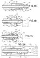
- Figs. 2A-2Dillustrate catheter body 50 of catheter 100 deployed to a target blood vessel BV, according to aspects of the present disclosure.
- System 100can be actuatable to a deployed state, which is shown in Fig. 1C .
- a dilator 70can be positioned at least partially within the lumen 47 of the catheter body 50.
- a distal end 78 of the dilator 70can be connected to a distal tip 51 of the catheter body 50.
- the dilator 70can be retractable to invert the distal tip 51 and form a funnel shape in the deployed state, as shown with system moving proximally one or more distances D from an initial elongate state of Fig. 1A to deployed in Fig. 1C . While Fig. 1C does show the deployed state, dilator 70 would be fully removed prior to aspiration in order to maximize the flowrate possible through the catheter body of tip 51 and also to allow passage of a microcatheter and stentriever. Dilator 70 may also include a distally protruding microcatheter portion such that a stentriever could be uncovered across the clot during activation of the funnel and removal of the dilator 70.
- the ratio of collapsed OD to deployed funnel ODis contemplated to range between approximately 2.5 mm to 4.0 mm.
- the ratiois contemplated to range 4.0mm to 6.0mm.
- the ratiois feasible for ICA vessel placement.
- the ratiois envisaged to target M1 and Carotid T locations.
- a ratio between the collapsed OD to funnel ODis dependent on the length of the corresponding catheter tip when collapsed.
- the tip collapsed lengthcan be range between 3mm and 8mm (e.g., the distances D in the figures) for expanded ODs of approximately 2.5mm to 5.0mm.
- the ratiocan be a function of the diameter the braid is set at and the braid angle.
- System 100can be configured to expand to a wide range of target vessel diameters, such as a carotid terminus (3.2-5.2 mm), a horizontal M1 segment of the Middle Cerebral Arteries (1.6-3.5 mm), and/or the Internal Carotid Artery (ICA, 2.7-7.5 mm). If the catheter system 100 is then retracted from an M1 segment to the ICA (or another route with a proximally increasing vessel inner diameter), the radial force of the tip 50 once in the funnel shape can continue to seal with the vessel across a range of vessel sizes.
- target vessel diameterssuch as a carotid terminus (3.2-5.2 mm), a horizontal M1 segment of the Middle Cerebral Arteries (1.6-3.5 mm), and/or the Internal Carotid Artery (ICA, 2.7-7.5 mm). If the catheter system 100 is then retracted from an M1 segment to the ICA (or another route with a proximally increasing vessel inner diameter), the radial force of the tip 50
- a tip 50 capable of a range of target vessel diameterscan also seal at vessel bifurcations which can have a wider cross-sectional area than the vessel proximal and vessels distal to the bifurcation.
- the tip 51is inverted to the deployed funnel shape at the treatment location to avoid having to advance a funnel-shaped catheter tip through the vasculature.
- the ideal nominal diameter of the catheter system 100depends on the location of the target clot and/or a diameter of any other catheter through which catheter system 100 is to be delivered.
- the maximum diameter of the tip 50can be a minimum of 2.5 mm (but in some instances up to 8 mm), allowing it to seal against the walls of the vessel and providing a funnel-shape distal mouth as large as the vessel itself.
- the tip 51can also provide an opening large enough to oppose bifurcations and/or proximal vessel locations. This seal, in combination with a maximized proximal lumen of the disclosed RX system over a conventional catheter, offers benefits in terms of aspiration force at the face of the clot and increased flowrates with a design that utilizes the larger inner diameter of the outer catheter.
- distal tip 51can include a proximal segment 55 and a distal segment 52 extended from the proximal segment 55.
- Segment 52can be substantially flexible and a proximal end 53 of the distal segment 52 can be extended from the proximal segment 55 and include a pull ring 54 adjacent and/or connected to a distal end 58 of the distal segment 52.
- Pull ring 54 in this examplecan be positioned on a proximal face 54 of the distal end inside the distal segment 52.
- segment 52can be an expandable sheath attached under pull ring 54.
- Distal segment 52 in a collapsed statecan be substantially tubular ( Fig. 1A ) whereas in in the deployed state after proximally moving distances D ( Fig. 1B, Fig. 1C ) segment 52 can include the funnel shape.
- the funnel shape formed by the inverted distal segment 52can include an air cushion 60 formed between the distal end 58 and the pull ring 54.
- ring 54can be positioned inside the lumen 47 to form a compression lock therewith thereby securing segment 52 in its expanded, funnel shape.
- the compression lockcan be defined as the interference fit by fitting the ring 54 within lumen 47 whose inner diameter may be slightly less than the outer diameter of ring 54.
- the distal segment 52can be divided into a proximal braid portion and a distal spiral braid portion.
- An elastomeric membranecan be interlaced, coated thereon, or extend over the braid or inverting frame structure.
- an elastic membranecan follow the contours of the underlying braided strut framework of tip 51.
- the elastic membranecan at least partially run the length of tip 51.
- tip 51can be further coated with a lubricious material such as commercially available hydrophilic coatings (e.g., Surmodics, Harland, Biocoat, Covalon) or may include low friction materials or fillers.
- the membranecan also float over the inverting support structure such that the inverting structure struts can move freely under the membrane.
- the membraneincapsulates the inverting support structure.
- dilator 70can include a proximal segment 76 and a distal segment 77 distally extended thereof.
- Segment 77can include a diameter greater than the proximal segment 76 and include a contact element 71 extended radially outward to contact and translate proximally the pull ring 54 one or more distances D until being aligned at or adj acent the proximal end 53 of the distal segment 52.
- contact element 71can be a sudden, angled outward transition that creates a contact surface that forms an interference fit with distal end 58 of segment 52.
- dilator 70can be solid and/or hollow with a lumen therein.
- Dilator 70can include an inner lumen 75 be substantially elongate (e.g. tubular) at its proximal segment 76 and taper radially, outwardly to distal segment 77 with distal end 78 having a larger diameter than the proximal segment 76. This taper can commence at a transition or junction 73 between segments 76, 77.
- Dilator 70can be highly flexible proximal to tip 51.
- Dilator 70can include one or more fibers as part of its structure that are configured for reinforcement to negate elongation thereof.
- segment 76can be highly flexible or substantially more flexible than the distal segment 77.
- the distal segment 77in some examples can still have adequate flexibility to contort around tortuous vasculature. Any stiff portions required to transmit force to ring 54 can be kept as short as possible to maintain lateral flexibility of the tip 51.
- system 100can use an aspiration source to capture a clot, as shown in Figs. 2A-2D .
- Figs. 2A-2Dshow system 100 being deployed and then aspirating clot C, preferably with dilator 70 fully removed as in Fig. 2D .
- the main advantage of using dilator 70 as shown and describedis that it can be removed after inversion of the tip such that the full cross-sectional area of catheter 50 can be used to maximize flow rate and force on the clot C through catheter body 50 when in the funnel shape, as shown.
- the funnel shape formed by tip 51 being expandedcan seal with the walls of the blood vessel BV or the seal or seals can be selectively activated (e.g., by moving dilator 70 proximally or distally).
- Tip 51 once expandedcan include a large, atraumatic mouth for efficient aspiration.
- Tip 51can include kink-resistant characteristics to aid in advancing it to the target location. It can therefore have multiple configurations, or be fabricated from multiple materials, as discussed herein, so as to maintain lateral flexibility but avoid expanding or kinking in compression.
- the large distal mouth of tip 51 shown in Figs. 2A-2Dcan offer improved performance over conventional fixed-mouth designs, which can be hindered by having firm, fibrin-rich clots lodge in the tip and/or by having softer portions of the clot shear away. It is less likely for clots to become lodged in the tubular section of the disclosed invertible, expansile tip 51 due to the progressive compression of the clot upon entry to the reducing funnel shape.
- Struts of the tip 51can be formed from Nitinol or another shape-memory material with sufficient elastic strain capacity such that the elastic limit would not be exceeded when the tip is constrained and delivered in the collapsed configuration within an outer catheter or during expansion to invert to a funnel shape.
- the strutscan be heat set expanded only to promote inversion at a predetermined location, said expanded area being restrained by an outer membrane covering. Actively inverting in this respect the frame then pushes the membrane outwardly by increasing the radial force of the frame.
- the frameworkcan be constructed from wire, allowing a non-superelastic material like a stainless-steel alloy to be employed, since the wires would be free to move independent of one another.
- a framework of tip 51 constructed of wire using superelastic or shape memory materialscan also be envisaged, such a device offering improved torque and durability characteristics.
- a framework of tip 51can be laser cut or formed with wire from a non-superelastic or shape memory material that accommodates strain by including cells or bends, with a lower degree of strain required to move from a collapsed state for delivery to an expanded state for clot retrieval.
- the frameworkcan include additional cells, longer cell struts, and/or lower cell angles to reduce strain requirements.
- Figs. 3A - 3Bdepicts another invertible, expansile tip 251 going from a first configuration, shown in Fig. 3A , with dilator 270 and then a close-up of the funnel-shape, deployed configuration of tip 251 in Fig. 3B without dilator 270. While not shown, dilator 270 could be included in Fig. 3B as needed or required. It is understood that similar reference numbers examples discussed throughout this disclosure indicate identical or functionality similar elements. With that, dilator 270 can include inner lumen 275 with proximal segment 276 and distal segment 277 terminating in distal end 278 distal of the proximal segment 276.
- Dilator 270can include distal contact element 271 extended radially outward from the distal segment 277. Element 271 can be configured to contact and translate the pull ring 254 until being aligned at or adjacent the proximal end 258 of the distal segment 252. Dilator 270 may also include a sudden, angled outward transition (e.g., element 271 here being substantially orthogonal to the outer surface of dilator 270) to form a contact surface that forms an interference fit with distal end 258 of segment 252. Dilator 270 can also have a proximal contact element 273 proximally spaced from the distal contact element 271 and similarly extended radially outward from the distal segment 277.
- a sudden, angled outward transitione.g., element 271 here being substantially orthogonal to the outer surface of dilator 270
- Dilator 270can also have a proximal contact element 273 proximally spaced from the distal contact element 271 and similarly extended
- a groovecan be defined between elements 271, 273 in which the pull ring 254 can be positioned or otherwise connected.
- opposed faces of the space or groove between elements 271, 213can be planar or otherwise conform to the shape of ring 254.
- element 271can urge or otherwise couple to end 258 while element 273 can urge or otherwise couple to ring 254.
- element 273can include a diameter less than element 271, or vice versa. From element 271 to distal end 278, dilator 270 can taper to a smaller diameter.
- an interference fitcan be provided in catheter body 250 between distal end 258 of the distal tip 251 when in the funnel shape of the deployed state.
- at least one of the contact elements 271, 273can include a magnetic connector operable to magnetically retract the distal tip 251 to the funnel shape of the deployed state.
- the magnetic coupling thereincan facilitate the actuation of tip 271 into the inverted, funnel-shape of the deployed state.
- Segment 276 and/or the segment 277can include a substantially thinned wall.
- dilatorcan include a relatively thin wall proximal to tip for optimum flexibility.
- Segment 276 in some examplescan include string-like filaments configured to prevent elongation under tension.
- its proximal segment 255can be stiffer than the distal segment 252.
- segment 252can include a resistance or bias to remain in its substantially tubular shape prior to deployment, as in Fig. 3A .
- Proximal segment 255 and/or distal segment 252can also include a braided structure, similar to segments 152, 155.
- segments 252, 255can be constructed from a framework of struts that include a memory alloy.
- segment 252can be divided into a proximal braid portion and a distal spiral braid portion as well include one or more elastomeric coating(s) or membrane(s).
- the braid and spiral portions of this examplecan be created, for example, by finishing the ends of the clockwise braid wires at a midpoint between the ends of the counterclockwise braid wires such that the counterclockwise braid wires form a spiral past this point. In some examples, this can be achieved by cutting the clockwise wires of a standard braid on a circumferential plane at a location between the ends of the braid. In another example, clockwise braids can be looped to extend proximally such that a denser proximal braid is paired with a distal spiral portion.
- Figs. 4A - 4Bdepicts another invertible, expansile tip 351 of catheter 350 going from a first configuration, shown in Fig. 4A , with dilator 370 and then a close-up of the funnel-shape, deployed configuration in Fig. 4B , after dilator 370 has been retracted to invert tip 351 to the funnel-shape.
- proximal segment 355 of tip 351can include a distal end 353 that can include a magnetic element capable of coupling with corresponding ring 354, which in turn can be magnetized.
- Ring 354 as showncan be configured to magnetically couple with end 353 so tip 351 can maintain the inverted, funnel shape shown in Fig. 4B .
- ring 354 and/or end 353can be made from a ferrous metal such that one is attracted to the other.
- both featuresare magnetic such that the south pole of one engages with the north pole of the other to form a stronger engagement than if a ferrous metal was used.
- dilator 370can include magnetic features to engage with the pull ring 354 to provide sufficient force to invert tip 351 to its inverted, funnel-shape.
- dilator 370can include inner lumen 575, distal segment 377 terminating in distal end 278 distal of the proximal segment 376, with each including similar diameters.
- Contact element 371 of dilator 370can be a distal end of a notch or gutter or groove or recess of dilator whereas contact element 372 can be the proximal end of the same notch or gutter or groove or recess.
- element 371can be magnetic so as to grip ring 354 (e.g., by constructing ring 354 out of one or more ferrous materials), and pull ring 354 proximally during retraction of the dilator 370.
- Ring 354which can be coupled to end 358, can be positioned therebetween respective to said notch or gutter or groove or recess and/or therearound.
- distal segment 377translate pull ring 354 until being aligned at or adjacent the proximal end 358 of the distal segment 352 thereby inverting segment 352 to form the atraumatic funnel-shape of Fig. 4B .
- the proximal end 353 of the distal tip 351 and the pull ring 354can be locked together in the deployed state by the corresponding magnetic coupling therebetween.
- the proximal end 353 of the distal tip 351 and the pull ring 354can each include planar mating surfaces or mating surfaces profiled with ridges and/or interlocking recesses.
- mating surfacescan be tapered for an interlocking taper lock interaction.
- mating surfacescan be configured to snap lock together.
- Fig. 5Adepicts another invertible, expansile tip 451 of catheter 450 with dilator 470.
- Tip 451can include proximal segment 455 and distal segment 452 extended from the proximal segment 455 and being substantially flexible.
- a proximal end 453 of the distal segment 452can be positioned on an outer surface of the distal tip 451.
- a pull ring 454can be adjacent or immediately distal of segment 455 so ring 454 can be used to pull and cause segment 452 to invert to the funnel-shape of Fig. 5A .
- proximal end 453 of the distal segment 452can be external to the pull ring 454. Aligning ring 454 in this respect and attaching proximal end 453 as shown to the OD of catheter 450 and position membrane structure attached to distal face of pull ring. In turn, this attachment allows membrane to smoothly taper distally when inverted.
- Fig. 5Bdepicts another invertible, expansile tip 551 of catheter 550 with dilator 570 of this disclosure.
- Distal tip 551 as showncan be integral with the catheter body 550, including segment 555 being integral with segment 552.
- Dilator 570 of this examplecan also include a greatest diameter at or around contact element 573, which here can be an outward bulge or ring-like extrusion configured to be arranged internal to ring 554 and form an interference fit with element that distally tapers from element 573.
- ring 554fits under catheter body 550, the proximal face of membrane structure is in line with or integral with distal face of catheter body 550, and the membrane structure is attached under pull ring 554. In turn, this attachment allows membrane to smoothly taper distally when inverted.
- Fig. 5Cdepicts another invertible, expansile tip 651 of catheter 650 in the deployed configuration with dilator 670.
- dilator 670can include a distal segment 677 distal of the proximal segment 676 with a diameter greater than the proximal segment 676. The change in diameter can be gradual to form an elliptical or otherwise curved shape.
- Distal segment 677can include a contact element 671 extended radially outward from the distal segment 677 and configured to contact and translate proximally the pull ring 654 until being aligned at or adjacent a distal end of the proximal segment 655.
- Element 671 as can be seencan be an outward angled latch.
- element 671 as showncan include be angled distally so as to form an acute angle between it and the outer surface of dilator 670. This latch in turn can prevent the distal end of segment 652 from disengaging therefrom in the funnel-shape, as shown.
- Fig. 5Cdepicts another invertible, expansile tip 651 of catheter 650 in the deployed configuration with dilator 670.
- dilator 670can include inner lumen 675, a distal segment 677 with distal end 678 distal of the proximal segment 676 with a diameter greater than the proximal segment 676. The change in diameter can be gradual to form an elliptical or otherwise curved shape.
- Distal segment 677can include a contact element 671 extended radially outward from the distal segment 677 and configured to contact and translate proximally the pull ring 654 until being aligned at or adjacent a distal end of the proximal segment 655.
- Element 671 as can be seencan be an outward angled latch.
- element 671 as showncan include be angled distally so as to form an acute angle between it and the outer surface of dilator 670. This latch in turn can prevent the distal end of segment 652 from disengaging therefrom in the funnel-shape, as shown.
- Element 671is not so limited, however, and can instead by substantially orthogonal with respect to the outer surface of dilator 670. Element 671 may also be distal of the proximal end 653 of segment 652, whereby end 653 can be positioned on an outer surface of segment 655. In some examples, a midpoint of the distal segment 652 in a collapsed state transitions to being a distalmost petal tip of the funnel shape in the deployed state distal of the catheter 650. System 600 in this respect can include one continuous petal or a plurality of radially separated distalmost flower-like petal tips that form the funnel shape. In other examples, the funnel-shape of system 600 can be more pointed, or less atraumatic than the rounded funnel-shapes of Figs. 5A-5B .
- Fig. 6Adepicts another invertible, expansile tip 751 of catheter 750 in the deployed configuration with a dilator 770 of this disclosure.
- contact element 771 of dilator 770is distal of and attached to tip 751 and provides a relatively smooth transition for clot capture and/or use of a stentriever therein.
- the inner diameter of system 700being reduced on account of distal end 758 of segment 752 being positioned at least partially inside the inner diameter of system 700.
- the proximal face of pull ring 754abuts the distal face of the catheter body 750 and the membrane/framework can be attached under the pull ring 754.
- the proximal membrane structureis attached to the OD of catheter 750 which allows the membrane to smoothly taper distally when inverted.
- Fig. 6Bdepicts another invertible, expansile tip 851 of catheter 850 in the deployed configuration with a dilator 870 of this disclosure.
- contact element 871 of dilator 870is distal of and attached to tip 851.
- tip 851can also include a relatively sharper edge in the funnel-shape, as compared to tip 751.
- the proximal face of ring 854abuts the distal face of the catheter body 850 and the membrane/framework is attached to the distal face of ring 854.
- thiscauses a sharper inversion of funnel and the proximal membrane structure attached to an OD of catheter 750.
- Fig. 6Cdepicts another invertible, expansile tip 951 of catheter 950 in the deployed configuration with a dilator 970 of this disclosure.
- contact element 971 of dilator 970is distal of and attached to tip 951.
- distal contact element 971extended radially outward from the distal segment 977 and configured to contact and translate proximally the pull ring 954 until being aligned at or adjacent the proximal end 953 of the distal tip 951.
- a proximal end face of element 971can be arranged to contact ring 954, which can be on a distal face of distal end 958 of segment 952.
- the proximal face of ring 954abuts the distal face of the catheter body 950 and the membrane/framework is attached to the distal face of ring 954 and a relatively sharper inversion of funnel results.
- end 958can have a biased curve that facilitates contact between ring 954 and end 958.
- the curvecan extend proximally before returning distally to urge ring 954 to couple with the proximal face of element 971.
- element 971can include or be an outwardly extend ring-like member.
- Element 971can also include a semi-circle shape.
- Figs. 7A-7Cillustrates tip 851 but with a modified, sharper funnel-shape, previously described in Fig. 6B , transitioning from the collapsed, tubular state of Fig. 7A to the deployed, funnel-shape of Fig. 7C .
- dilator 870is seen coupled to ring 854 at its respective contact element.
- Fig. 7Bshows dilator 870 having been retracted a first distance causing segment 852 to initiate its expansion as its midsection begins inverting.
- Fig. 7Cshows ring 854 having been proximally translated by dilator 870 until contacting the distal face of segment 855.
- segment 852is completely inverted to the funnel-shape.
- ring 854has a similar diameter to segment 855 such that an abutment is formed between the ring 854 and segment 855 in the expanded state.
- this minimal difference in inner and outer diameters between the proximal and distal ends of catheter 850optimizes its relatively low outer profile and large inner diameter.
- Figs. 8A-8Cillustrates another expansile, invertible tip 1051 of catheter 1050 of this disclosure being deployed by being inverted in connection with dilator 1070, according to aspects of the present disclosure.
- tip 1051is shown transitioning from the collapsed, tubular state of Fig. 8A to the deployed, funnel-shape of Fig. 8C .
- a proximal face of element 1071is coupled to ring 1054.
- Fig. 8Bshows dilator 1070 having been retracted a first distance causing segment 1052 to initiate its expansion as its midsection begins inverting.
- segment 1052can include a generally conical shape before inverting.
- Ring 1054has been proximally translated by dilator 1070 until be arranged proximate the distal face of segment 1055 (e.g., here, internal to segment 1055). In turn, segment 1052 is completely inverted to the funnel-shape shown in Fig. 8C .
- Ring 1054can have a diameter to less than an inner diameter of segment 1055 such that an abutment is formed between the ring 1054 and the inner surface of segment 1055 in the expanded state.
- segment 1077 of dilator 1070can be ultra soft to provide sufficient interference with pull ring 1054 to transmit a radial force sufficient to cause segment 1052 to expand and invert, as shown between Figs. 8A-8C .
- segment 1076can be highly flexible so that it does not contribute significantly to stiffness of system. To achieve this, segment 1076 can include a relatively thin wall and may include longitudinal string-like fibers to prevent it from stretching under tension.
- the interference force between the dilator 1070 and ring 1054can be insufficient to move ring 1054 more proximally and the tip of dilator 1070 (e.g., segment 1077) squeezes through ring 1054.
- segment 1077is sized to have a small clearance with the lumen of segment 1055, segment 1077 can be easily retracted through the catheter system 1000.
- dilator 1070can be re-advanced to push ring 1054 distally and un-invert the funnel-shape to a collapsed, tubular sheath of Fig. 8A .
- a second stiffer dilatormay be supplied for the purpose of collapsing tip 1051, once inverted and expanded within a blood vessel, where the first dilator 1070 may be present.
- Figs. 9A-9Billustrate another expansile, invertible tip 1151 of catheter 1150.
- Fig. 9Ashows tip 1151 with dilator 1170 in the expanded, funnel-shape configuration.
- Fig. 9Bshows tip 1151 in the same configuration but with dilator 1170 having been retracted and removed from tip 1151.
- the distal face of element 1171is coupled to the proximal face of end 1158 so that tip 1151 is compressed through ring 1154.
- an inner diameter of end 1158is coupled to ring 1154.
- coupling end 1158 to ring 1154 as described and shownallows tip 1151 to form a gradual smooth curve for entry of aspirated clot and or stent retriever devices.
- ring 1154being sized smaller than main catheter body inner diameter of segment 1155 allows for the pull ring 1054 to wedge or lock in position as segment 1177 of dilator 1170 compresses through it.
- Figs. 10A-10Billustrates tip 1251, according to aspects of the present disclosure, whereby Fig. 10A shows the tip 1251 when extended in the tubular configuration and Fig. 10B is a close-up of tip 1251 ring 1254 has been retracted to cause segment 1252 to expand and invert to the funnel shape.
- Ring 1254can include an external taper that matches an internal taper 1259 positioned at a distal end of segment 1255.
- the corresponding taperscan couple and/or lock together. While only tapered surfaces are shown in Figs. 10A - 10B , it is contemplated that other interlocking surfaces can be used as needed or required.
- Figs. 11A - 11Bdepicts another expansile tip 1351 of catheter 1350 going from a first, tubular configuration in Fig. 11A with dilator 1370 and then to the expanded, inverted funnel-shape, deployed configuration of Fig. 11B .
- Dilator 1370can include a contact element 1371 that includes the greatest diameter of dilator 1370 and then progressively, distally tapers therefrom for gradual radial compression of clot.
- ring 1354can include a similar diameter to the diameter of segment 1355 such that an abutment therebetween can prevent ring 1354 from moving proximally into the lumen of segment 1355, as shown in Fig. 11B .
- Distal end 1358 of segment 1352is attached within an inner diameter of ring 1354, which provides the interference fit between end 1358 and/or ring 1354 with element 1371 of dilator 1370.
- segment 1352can expand and invert to form a rounded feature for atraumatic funnel configured to interact and seal with a vessel wall.
- tip 1351were manufactured to be stiff, it would form too large a round profile and have the potential of kinking when collapsed for delivery through an outer balloon guide or long guide sheath. Kinking can also prevent tip 1351 from forming a gradual taper in the deployed, funnel-shape configuration and may form a snag point for stentrievers during retraction in the catheter lumen.
- configuring tip 1351 with a flexible portioncan allow it to first form a soft compressible rounded feature in the collapsed configuration that will recover to form a progressive taper extending distally form the inner diameter of ring 1354 to aid in compression of clot during aspiration and to provide an unhindered path for collapsing a stentriever during retraction into the catheter lumen.
- Fig. 12Adepicts an example construction of one expansile, invertible tip 1451, which can include a braid with proximal 1447, middle 1445, and distal 1443 segments.
- Middle segment 1445can include filaments that extend from proximal to a transition point with distal segment 1443, then they revert to extend back proximally forming a braid pattern.
- Distal segment 1443can include filaments that extend from proximal to distal in a helical configuration and/or can include sufficient radial force to push proximal segment 1447 radially outwardly while being conformable to accommodate various vessel sizes in an atraumatic manner.
- a helical patterncan allow for a wider range of vessel size range than a braid as the helical wires will create a spiral pattern that can adjust more easily than a braid pattern.
- Distal segment 1443can extend circumferentially at or around the transition between segments 1445, 1443 to aid in defining a less rounded inversion seam at the vessel wall.
- Figs. 12B - 12Ddepicts views of tip 1451 once expanded and inverted to the funnel shape, according to this disclosure.
- Fig. 12Cis a side plane view of tip 1451 with an example coating (though a coating is not necessarily required) whereas Fig. 12D is a front plan view of segment 1451 and Fig. 12B is a rear plan view of segment 1451.
- segment 1443 and its helical configurationcan convert segment 1443 to spiral during inversion.
- along the lower dashed linesdepicts the inversion seam of a sharper inversion seam design in comparison to a rounded inversion seam that can interact with the vessel wall during use.
- Fig. 12Calong the lower dashed lines depicts the inversion seam of a sharper inversion seam design in comparison to a rounded inversion seam that can interact with the vessel wall during use.
- segments 1447 and 1445which form the braid's integrity and provide an inversion hinge at the transition point between segments 1445, 1443.
- a coating or membrane as described in this disclosurecould be used with tip 1451 as needed or required.
- Fig. 13depicts an example construction of one expansile, invertible tip 1551, which can include a braid with proximal 1547, middle 1545, and distal 1543 segments, whereby the braid of tip 1551 may extend from proximal to distal end.
- Tip 1551can provide a more rounded inversion seam that can interact with the vessel wall during use.
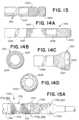
- Fig. 14Adepicts an example construction of one expansile, invertible tip 1651, which can include a braid with proximal 1647, middle 1645, and distal 1643 segments. Segment 1639 is proximal of segment 1647 and portion 1641 represents a transition between each segment. Segment 1647 can be relatively stiff, segment 1645 can be relatively flexible, and segment 1643 can include a helical configuration with respect to its filaments. Middle segment 1645 can in turn be configured to distribute the radial force over a larger region during the inversion step of tip 1651. Middle segment 1645 being relatively flexible at the mid-section can also lower structure inflection forces during inversion especially with the added constraints of a low profile vessel, thus reducing radial force exerted by the structure and potential vessel trauma.
- Figs. 14B - 14Ddepicts views of tip 1651 once expanded and inverted to the funnel shape, according to this disclosure.
- Fig. 14Cis a side plane view of tip 1651
- Fig. 14Dis a front plan view of segment 1651
- Fig. 14Bis a rear plan view of segment 1651.
- segment 1543 and its helical configurationcan convert segment 1543 to spiral during inversion.
- the inversion seam of the rounded lower corners segment 1645can interact with the vessel wall during use.
- Fig. 14Bshows segments 1647 and 1645 which form the braid's integrity and provide an inversion hinge at the transition point between segments 1645, 1643.
- An inversion hingecan be applied by heat setting the filaments to have a larger diameter at the center than the proximal and distal ends to promote inflection, the membrane having sufficient resistance to expansion to hold the enlarged diameter in a substantially tubular shape in line with proximal and distal segments in the collapsed configuration.
- Thiscan be done with a non-shape memory material by using an oversized braid and reducing the distal and proximal diameters through attachment means to the distal pull ring and proximal catheter body respectively (e.g., reflowing jacket material, adhesive or by a restraining ring).
- a coating or membrane as described in this disclosurecould be used with tip 1651 as needed or required.
- Figs. 15A - 16Fdepicts views of an expansile, invertible tip 1751 according to this disclosure.
- tip 1751can include a braided construction with segments 1755 and 1752.
- Segment 1752can include a proximal portion 1751 and a distal portion 1759, each with a braid pattern (e.g., the same pattern or a different pattern).
- a transition portion 1753can be positioned between segments 1755 and 1752.
- braid wirescan loop around ring 1754 to allow rotation of the braid about ring 1754 during inversion, which can facilitate complete inversion of the distal segment 1752.
- Fig. 15Ais denoted strictly for illustrative purposes sections A, B, C.
- braided wirescan loop from A to C to A.
- segment 1751is not so limited and braided wires can also loop from A to B to A.
- braided wirescan loop from A to B to A to C to A.
- braided wirescan loop from A to C, as well as any combination of these various braided wire loop configurations.
- at least one braid wire of tip 1751can be twisted just proximal of ring 1754 to hold ring 1754 in place.
- Fig. 15Ba close-up of tip 1751 is shown in the expanded, inverted funnel-shape configuration.
- segment 1752has been inverted and expanded as ring 1754 has been translated proximally, as in previous example distal tips of this disclosure.
- Fig. 15Cis a similar view of Fig. 15B , but with the mandrel and/or dilator removed and leaving tip 1751 alone in the expanded, inverted funnel-shape configuration.
- Fig. 16Ais a close-up view of section A of Fig. 15A showing braided wires as previously described.
- Fig. 16Bis a close-up view of section B of Fig. 15A showing braided density or PPI change as previously described.
- Fig. 16Cis a close-up view of section C of Fig. 15A showing braided wires looped around pull ring as previously described.
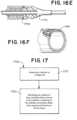
- Fig. 16Dis a close-up cross-section view of section C of Fig. 15A along center line with an example dilator 1770 coupled with ring 1754. As shown, dilator 1770 has circumferential ribs to grip pull ring 1754.
- Fig. 16Eis a close-up cross-section view of section C of Fig.
- Fig. 16Fis a close-up perspective view of section C of Fig. 15A showing braided wires looped and coupled with ring 1754, as previously described.
- the filaments in the present examplecan extend proximal to distal and can be looped back at the distal end.
- Ring 1754can be threaded through the looped ends such that when inverted the looped filaments rotate about ring 1754 to invert the outward face to face radially inwardly and thereby form a distal facing funnel, as shown.
- Visibility during deployment of any of the herein disclosed catheter systemscan be aided by adding alloying elements (such as palladium, platinum, gold, etc.), by the application of a radiopaque compound, or through the placement of radiopaque markers on one or more of the catheters and devices. Suitable practices are frequently used in connection with other devices and implants and are well known in the art.
- a radiopaque compoundcan be incorporated on a cover can be incorporated in the distal tip, or one or more radiopaque markers can be added at, on, and/or adjacent the distal end of the tip.
- one or more of the braid wiresmay include DFT wire comprising a platinum core (for radiopacity) with NiTi outer layer. With such markers, the physician will be able to visually confirm that the mouth has fully inverted and expanded to the vessel wall.
- the aspiration source used in the catheter systems of this disclosurecan be a manual syringe or a small-displacement vacuum pump and aspiration directed to the distal tip of any of the herein disclosed catheter systems. Effective aspiration can be accomplished by the sealing action of the inverted, funnel shape of the distal tip with the vessel walls, the interior walls of an outer catheter, and/or through the use of a flow restrictor/seal. In some instances, however, dislodging or fully retrieving a clot with any of the heretofore catheter systems using aspiration alone is not possible.
- a thrombectomy devicecan be used with the catheter systems of this disclosure and can be any of a number of commercially available products which can be supplied with or separate from the aspirating clot retrieval catheter.
- Using a thrombectomy device in conjunction with an expanding mouth catheter system of this disclosurehas several benefits to increase the likelihood of first-pass success.
- the thrombectomy devicecan support the lumen of the vessel during aspiration such that it will be less likely to collapse under negative pressure, and the thrombectomy device will hold the clot together should the clot comprise an array of stiff and soft portions that may otherwise fragment.
- the thrombectomy devicecan also allow the user to pinch a clot that otherwise would not fully enter the lumen of the clot retrieval catheter between the catheter tip and thrombectomy device.
- a pinched clotwill be less likely to dislodge from the clot retrieval catheter as the clot retrieval catheter, clot, and thrombectomy device are retracted as one through the vasculature and outer catheter.
- Fig. 17is a flow diagram each comprising method steps for performing a procedure with one system of this disclosure.
- the method stepscan be implemented by any of the example systems, devices, and/or apparatus described herein or by a means that would be known to one of ordinary skill in the art.
- step 1710includes advancing any catheter of this disclosure to a target site.
- Step 1720includes retracting, by a dilator at least partially within a lumen of the catheter and preferably removing the dilator to maximize aspiration flow rate and force on a clot that is retracted into the catheter, a distal tip of the catheter, causing the distal tip to expand and invert to a funnel shape.
- the dilatorcan be withdrawn and aspiration can then be applied through the catheter, depending on how the user has deployed the flow restrictions and/or seals, to stimulate the clot into the mouth of the catheter. If aspiration alone is insufficient to dislodge and capture the thrombus or if additional grip on the clot is desired during initial aspiration and dislodgement, a microcatheter with a mechanical thrombectomy clot retrieval device can be advanced to the target. The mechanical thrombectomy device can then be deployed to capture the clot using any method commonly known in the art.
- Aspirationcan continue during the entirety of this step to prevent blood reflux and maintain a tight grip on the clot, or at intervals chosen by the user.
- aspiration and pulling of the clot with a stent retrievermay be optimal to increase the chances of first pass success.
- the captured clot and clot retrieval cathetercan be withdrawn from the patient or the clot retrieval catheter can be left in place to maintain access as the mechanical thrombectomy clot retrieval device is withdrawn with the clot from the patient. If the clot is observed in the aspiration source and/or thrombectomy device and flow is not blocked in the clot retrieval catheter, this step can also involve carefully injecting contrast under low pressure through the system using known techniques to determine if the vessel is patent. If the vessel is patent, the clot retrieval catheter can be removed. If a blockage remains, additional passes of aspiration, thrombectomy or a combination of these may be repeated until the vessel is patent.
- distal and proximalare used throughout the preceding description and are meant to refer to a positions and directions relative to a treating physician or user. As such, “distal” or “distally” refer to a position distant to or a direction away from the physician. Similarly, “proximal” or “proximally” refer to a position near to or a direction towards the physician. Furthermore, the singular forms “a”, “an”, and “the” include plural referents unless the context clearly dictates otherwise.
- the terms “about” or “approximately” referring to any numerical values or rangesindicate a suitable dimensional tolerance that allows the part or collection of components to function for its intended purpose as described herein. More specifically, “about” or “approximately” may refer to the range of values ⁇ 20% of the recited value, e.g. "about 90%” may refer to the range of values from 71% to 99%.
Landscapes
- Health & Medical Sciences (AREA)
- Life Sciences & Earth Sciences (AREA)
- Engineering & Computer Science (AREA)
- Animal Behavior & Ethology (AREA)
- Veterinary Medicine (AREA)
- Public Health (AREA)
- Biomedical Technology (AREA)
- Heart & Thoracic Surgery (AREA)
- General Health & Medical Sciences (AREA)
- Surgery (AREA)
- Biophysics (AREA)
- Pulmonology (AREA)
- Anesthesiology (AREA)
- Hematology (AREA)
- Molecular Biology (AREA)
- Medical Informatics (AREA)
- Nuclear Medicine, Radiotherapy & Molecular Imaging (AREA)
- Vascular Medicine (AREA)
- Orthopedic Medicine & Surgery (AREA)
- Mechanical Engineering (AREA)
- Media Introduction/Drainage Providing Device (AREA)
- Surgical Instruments (AREA)
Description
- This application claims the benefit of
U.S. Provisional 62/898,864, filed September 11, 2019 - The present disclosure generally relates to devices and methods for removing acute blockages from blood vessels during intravascular medical treatments. More specifically, the present disclosure relates to an expandable catheter used in aspiration of clots.
- Clot retrieval catheters and devices are used in mechanical thrombectomy for endovascular intervention, often in cases where patients are suffering from conditions such as acute ischemic stroke (AIS), myocardial infarction (MI), and pulmonary embolism (PE). Accessing remote areas such as the neurovascular bed is challenging with conventional technology, as the target vessels are small in diameter, distant relative to the site of insertion, and are highly tortuous.
- The clot itself can complicate procedures by taking on a number of complex morphologies and consistencies, ranging from simple tube-shaped structures which assume the shape of the vessel to long, strand-like arrangements that can span multiple vessels at one time. The age of a clot can also affect its compliance, with older clots tending to be less compressible than fresh clots. Fibrin rich clots also present a challenge in having a sticky nature that can cause a clot to roll along the outer surface of a mechanical thrombectomy device rather than being gripped effectively. Combinations of soft and firm clot regions can also separate during aspiration, with fragmentation leading to distal embolization which can occur in vessels that cannot be reached with currently available devices. Additionally, breaking the bonds adhering the clot to the vessel wall without damaging fragile vessels is a significant challenge.
- Conventional clot retrieval catheters, especially those for operating in the neurovascular, can suffer from a number of drawbacks. First, the diameters of the catheters themselves must be small enough to avoid causing significant discomfort to the patient. The catheter must also be sufficiently flexible to navigate the vasculature and endure high strains, while also having the axial stiffness to offer smooth advancement along the route. Once at the target site, typical objects to be retrieved from the body can be substantially larger in size than the catheter tip, making it more difficult to retrieve objects into the tip. For example, fibrin-rich clots can often be difficult to extract as they can become lodged in the tip of traditional fixed-mouth catheters. This lodging can cause softer portions of the clot to shear away from the firmer regions, leading to distal embolization.
- Small diameters and fixed tip sizes can also be less efficient at directing the aspiration necessary to remove blood and thrombus material during the procedure. The aspiration suction must be strong enough such that any fragmentation occurring through the use of a mechanical thrombectomy device or other methods can, at the very least, be held stationary so that fragments cannot migrate and occlude distal vessels. When aspirating with a traditional fixed-mouth catheter, however, a significant portion of the aspiration flow ends up coming from vessel fluid proximal to the tip of the catheter where there is no clot. This significantly reduces aspiration efficiency, lowering the success rate of clot removal.
- The disclosed design is aimed at providing an improved aspirating retrieval catheter which addresses the above-stated deficiencies.
US 5971938 A describes an access device having a distal, expandable member with a low-profile state facilitating insertion and a high-profile state facilitating operation of the device. An obturator can be used to move the expandable member between its two states. Alternatively, the device can have an outer tube and an inner tube connected to respective ends of a cylindrical expansion member, so that co-axial movement of the tubes changes the state of the member. An actuator slideable on a handle facilitates the co-axial movement of the tubes, and a resulting formation of the expandable member in a funnel configuration.US 4324262 A describes a catheter adapted to be introduced into a body cavity, such as a bronchial tube or lung, and a method of using the catheter. The catheter consists of inner and outer concentric tubes having a reflected cylindrical membrane attached adjacent their distal ends. Pressurized fluid may be introduced through the perfusate passage running between the tubes and thus between the walls of the reflected membrane in order to provide relative rigidity for the membrane and to seal the reflected end of the membrane, thereby creating a closed pristine chamber, defined by the walls of the reflected membrane about the end of the inner tube. A cage composed of balls mounted on resilient pins may be disposed within the reflected membrane to aid the reflection of the membrane. A portion of the reflected membrane may be perforate. Following introduction of the catheter into a bronchial tube in the disclosed method, the inner tube is extended to open and pass through the reflection, thereby rolling the inner wall about the reflected portion and reversing the inner walls of the pristine chamber. Optionally, a topical antibiotic or local anesthetic may be introduced into the membrane and extruded through the perforations during the introduction or exit, or a lung brush or other sampling means may be inserted through the lumen of the inner tube during use. The catheter may also be used for endotracheal intubation.US 2005/187570 A1 describes an access device adapted for use in a body conduit comprising an outer tube having a proximal end and a distal end, an inner tube disposed coaxially with the outer tube having a proximal end and a distal end, and an expandable portion having a first end coupled to the distal end of the outer tube and a second end coupled to the distal end of the inner tube. The outer tube and the inner tube are movable relative to each other to transform the expandable portion between a low-profile state and a high-profile state, and at least one of the outer and inner tubes comprises a wire-reinforced tube or is formed from a plurality of individual, discrete, generally ring-shaped elements arranged in series and fused or bonded together to form a continuous tubular structure. The access device may further comprise an actuator coupled to one of the outer and inner tubes and being movable relative to the other of the outer and inner tubes to transform the expandable portion between the low- and high-profile states. The expandable portion may be formed with a braid material and has the shape of a cone. The ring-shaped elements may be formed of a thermoplastic or a thermoset material, and they may include at least one of plastic rings, metallic rings, un-reinforced plastic rings and metal reinforced plastic rings assembled along the length of at least one of the tubes to provide variable flexibility and kink-resistance. The wire-reinforced tube is formed by coating a wire with a plastic material, wrapping the coated wire around a mandrel forming a plurality of windings, and heating the wound coated wire until the plastic material melts and bonds the windings forming the wire-reinforced tube.US 2001/011182 A1 describes a device for the removal of a blockage in a passageway such as a dialysis graft or in a body passageway includes a catheter for reception and aspiration of the blockage and an occlusion engaging element distal of the distal end of the catheter which occlusion engaging element is supported on a wire that extends through the catheter. At the distal end of the catheter, there is a device such as a multi-wing malecot expansion device that is expanded after the catheter is placed in position so as to block the occlusion from passing around the outside of the catheter. The support wire can be a movable core guide wire which has a braided device on its distal end. When the core is as distal as possible of the distal end of the shell, the braid is in a collapsed minimum diameter state for insertion through the catheter and through the occlusion. Proximal movement of the core causes the braid to expand to the wall of the graft. Subsequent proximal movement of the entire support wire causes the braid to contact the occlusion forcing the occlusion into the catheter for aspiration and removal. - The invention is defined by the claims.
- It is an object of the present disclosure to provide systems, devices, and methods to meet the above-stated needs. The design features an expandable catheter with an expandable clot-facing mouth for flow restriction, aspiration efficiency, and easy retrieval of the clot while also having a collapsed state that is low-profile and sufficiently flexible for delivery in a standard sheath or outer catheter. The catheter can also have a tailored, variable-stiffness body section incorporating deliverability enhancements over existing designs and capable of navigating tortuous areas of the vasculature to reach an occlusive clot.
- A catheter system is disclosed that is actuatable to a deployed state. The system includes a catheter body with a lumen. A dilator is positioned at least partially within the lumen, a distal end of the dilator being connected to a distal tip of the catheter body. The dilator is retractable to expand and invert the distal tip to form a funnel shape in the deployed state.
- The distal tip includes a proximal segment and a distal segment extended from the proximal segment and being substantially flexible. A proximal end of the distal segment is extended from the proximal segment and includes a pull ring adjacent and/or connected to a distal end of the distal segment.
- In some examples, a midpoint of the distal segment in a collapsed state transitions to being a distalmost atraumatic end of the funnel shape in the deployed state distal of the catheter body.
- In some examples, the distal segment in a collapsed state can be substantially tubular and in the deployed state can include the funnel shape. An air cushion can be formed by the funnel shape between the distal end and the pull ring.
- In some examples, the distal segment can be divided into a proximal braid portion and a distal spiral portion.
- In some examples, the dilator can include a proximal segment and a distal segment distal of the proximal segment can include a diameter greater than the proximal segment, the distal segment can include a contact element extended radially outward from the distal segment of the dilator and configured to contact and translate proximally the pull ring until being aligned at or adjacent the proximal end of the distal segment of the dilator.
- In some examples, the contact element can include an interference fit with the distal end of the distal tip of the catheter body.
- In some examples, the distal segment of the dilator can include a greatest diameter at the contact element and decreases from the contact element to the distal end of the distal segment.
- In some examples, the distal segment of the dilator can include a greatest diameter at the contact element and tapers from the contact element to a junction between the proximal and distal segments of the dilator.
- In some examples, the proximal segment of the dilator being highly flexible or substantially more flexible than the distal segment of the dilator..
- In some examples, the dilator can include a substantially flexible segment extending distally of the stiffer distal segment, the substantially flexible segment being a short nose.
- In some examples, the proximal segment of the dilator can include a fiber reinforcement system to negate elongation.
- In some examples, the dilator can include a proximal segment and a distal segment distal of the proximal segment. The distal segment of the dilator can include a greatest diameter greater than the proximal segment. The distal segment of the dilator can include a distal contact element extended radially outward from the distal segment and configured to contact and translate proximally the pull ring until being aligned at or adjacent the proximal end of the distal segment. A proximal contact element of the dilator can be proximally spaced from the distal contact element and extended radially outward from the distal segment and configured to contact and translate proximally the pull ring, the proximal contact element can include a diameter less than the distal contact element. The pull ring can be connected between the contact elements.
- In some examples, the pull ring can be positioned in a gap positioned between the contact elements.
- In some examples, the contact element can include an interference fit with the distal end of the distal tip when in the funnel shape of the deployed state.
- In some examples, at least one of the contact elements includes a magnetic connector operable to magnetically retract the distal tip to the funnel shape of the deployed state.
- In some examples, the proximal segment and/or the distal segment of the dilator can include a substantially thinned wall.
- In some examples, the proximal segment can include string-like filaments configured to prevent elongation under tension.
- In some examples, the proximal segment of the distal tip can be stiffer than the distal segment.
- In some examples, the distal segment can be stiffer than the proximal segment.
- In some examples, the distal segment can include a resistance to remain in a substantially tubular shape prior to deployment.
- In some examples, the proximal segment and/or the distal segment of the distal tip can include a braided structure.
- In some examples, the proximal segment and/or the distal segment of the distal tip can include a memory alloy.
- In some examples, the distal segment of the distal tip in a collapsed state can be substantially tubular and in the deployed state can include the funnel shape, an air cushion formed by the funnel shape between the distal end and the pull ring.
- In some examples, the dilator can include a proximal segment and a distal segment distal of the proximal segment. The distal segment can include a distal contact element extended radially outward from the distal segment and configured to contact and translate proximally the pull ring until being aligned at or adjacent the proximal end of the distal segment of the distal tip. The pull ring can include a magnetic connector. The proximal end of the distal tip is magnetized configured to attract the pull ring thereby causing the distal tip to retract to the funnel shape.
- In some examples, the proximal end of the distal tip and the pull ring are locked together in the deployed state, including, but not limited to, corresponding magnets locked together.
- In some examples, the proximal end of the distal tip and the pull ring each include planar mating surfaces.
- In some examples, the proximal end of the distal tip and the pull ring each include mating surfaces profiled with ridges and/or interlocking recesses.
- In some examples, the proximal end of the distal tip and the pull ring each include mating surfaces tapered for a taper lock interaction.
- The proximal end of the distal tip and the pull ring each include mating surfaces configured to snap lock together.
- In some examples, the pull ring includes a similar diameter to the catheter body such that an abutment is formed between the pull ring and catheter body in the deployed state. The distal tip can extend distally from an inner diameter of the pull ring and around an outer diameter of the pull ring to extend proximally over the catheter body.
- In some examples, the distal tip can include a proximal segment and a distal segment extended from the proximal segment. The distal segment of the distal tip can be substantially flexible and include a proximal end positioned on an outer surface of the distal tip. The distal segment of the distal tip can include a pull ring adjacent or immediately distal thereof. The distal tip can be configured for interacting between the pull ring and a distal face of catheter body.
- In some examples, the proximal end of the distal segment of the distal tip can be external to the pull ring.
- In some examples, the distal tip can be integral with the catheter body. The distal tip can include a proximal segment and a distal segment extended from the proximal segment. The distal segment can be substantially flexible and include a proximal end substantially aligned with a pull ring internal thereto when configured in the funnel shape.
- In some examples, the dilator can include a substantially tubular proximal segment and a distal segment distal of the proximal segment. The distal segment of the dilator can include a diameter greater than the proximal segment. The distal segment of the dilator can include a contact element extended radially outward from the distal segment and configured to contact and translate proximally the pull ring until being aligned at or adjacent a distal end of the proximal segment of the distal tip.
- In some examples, the contact element can be an outward angled latch.
- In some examples, the contact element can be an orthogonally outward latch.
- In some examples, the contact element can be distal of the proximal end of the distal segment.
- In some examples, a midpoint of the distal segment of the distal tip in a collapsed state transitions to being a distalmost petal tip of the funnel shape in the deployed state distal of the catheter.
- In some examples, a midpoint of the distal segment of the distal tip in a collapsed state transitions to being a distalmost flower-like petal tip of the funnel shape in the deployed state distal of the catheter.
- In some examples, the dilator can include a proximal segment and a distal segment distal of the proximal segment. The distal segment can include a distal contact element extended radially outward from the distal segment and configured to contact and translate proximally the pull ring until being aligned at or adjacent the proximal end of the distal tip.
- In some examples, the dilator can include a proximal contact element tapering proximally from the distal contact element. The proximal contact element can include a diameter less than the distal contact element. In some examples, the distal contact element can be an outwardly extend ring-like member. In some examples, the distal contact element can include a semi-circle shape. In some examples, the distal contact element can be connected to the pull ring.
- In some examples, a midpoint of the distal segment in a collapsed state transitions to being a distalmost petal tip of the funnel shape in the deployed state distal of the catheter.
- In some examples, a midpoint of the distal segment in a collapsed state transitions to being a distalmost flower-like petal tip of the funnel shape in the deployed state distal of the catheter.
- In some examples, the dilator can include a proximal segment and a distal segment distal of the proximal segment. The distal segment can include a greatest diameter greater than the proximal segment and can include a diameter larger than the proximal segment. A distal contact element can include a transition from the distal segment to the proximal segment and configured to contact and translate proximally the pull ring to cause an interference fit with the pull ring to transmit a force to expand the distal tip to the funnel shape.
- In some examples, the distal tip is configured to first expand to a substantially conical shape before inverting to form the funnel shape.
- In some examples, the proximal segment of the dilator is highly flexible and includes a thin wall.
- In some examples, the proximal segment of the dilator is highly flexible and includes longitudinal string-like fibres to prevent it from stretching under tension.
- In some examples, upon forming the inverted funnel shape, an interference force between the dilator and the pull ring is incapable of moving the pull ring proximally.
- In some examples, the dilator tip can squeeze through the pull ring.
- In some examples, the dilator tip is easily retracted through the catheter.
- In some examples, the dilator tip can include a proximal segment and a distal segment extended from the proximal segment. The distal segment can be substantially flexible and be at least partially positioned around the proximal segment at least at a proximal end of the distal segment. The distal tip can include a pull ring, which can include an external taper matching an internal taper of the proximal segment such that tapers lock together when forming the funnel shape.
- In some examples, the braid extends circumferentially at a mid point of the distal tip to aid in defining a rounded inversion seam.
- In some examples, the braid extends from proximal to distal end of the distal tip thereby providing a rounded inversion seam.
- In some examples, the braid includes a subset of filaments extended from proximal to middle portions so that the filaments revert to extend back to the proximal portion forming a looped braid pattern, and the remaining filaments extend from a proximal end to a distal end such that a spiral portion is formed distal of the looped subset of filaments.
- In some examples, the braid includes filaments extended from proximal to distal portions in a helical configuration.
- In some examples, the braid includes an inversion hinge in or around the middle portion.
- In some examples, the proximal portion can be relatively stiff. The middle portion can be relatively flexible, and the distal portion can include a flexible helix.
- In some examples, the distal tip can include a braid with proximal, middle and distal portions, wherein the distal portion includes sufficient radial force to push the proximal portion radially outwardly while being configured to accommodate various vessel sizes in an atraumatic manner.
- In some examples, a method of inverting an expansile catheter in a blood vessel is disclosed. The method can include advancing the catheter to a target site; and retracting, by a dilator at least partially within a lumen of the catheter, a distal tip of the catheter, causing the distal tip to expand and invert to a funnel shape.
- In some examples, the method can include restricting, by the funnel shape, flow in the blood vessel.
- In some examples, the method can include withdrawing the dilator from the catheter; aspirating through the catheter to stimulate a thrombus into a mouth of the funnel shape; and withdrawing the catheter with the captured thrombus from the patient.
- In some examples, the method can include capturing the occlusive thrombus with a mechanical thrombectomy device; and withdrawing the thrombectomy device into the funnel shape of the catheter.
- In some examples, the dilator may not be required. In such approaches, the collapsed tip can be corked onto the clot and aspiration suction force can pull the distal end proximally to invert the tip and create the inverted funnel shape during aspiration.
- Other aspects and features of the present disclosure will become apparent to those of ordinary skill in the art, upon reviewing the following detailed description in conjunction with the accompanying figures.
- The above and further aspects of this disclosure are further discussed with the following description of the accompanying drawings, in which like numerals indicate like structural elements and features in various figures. The drawings are not necessarily to scale, emphasis instead being placed upon illustrating principles of the disclosure. The figures depict one or more implementations of the inventive devices, by way of example only, not by way of limitation. It is expected that those of skill in the art can conceive of and combining elements from multiple figures to better suit the needs of the user.
Fig. 1A depicts an expansile tip of an expansile catheter in a first configuration with a dilator of this disclosure.Fig. 1B depicts the expansile tip of the expansile catheter in another configuration with the dilator ofFig. 1A .Fig. 1C depicts the expansile tip of the expansile catheter in another configuration with the dilator ofFig. 1A .Fig. 2A depicts the expansile tip of an expansile catheter ofFigs. 1A-1C , deployed to a target location, according to aspects of the present disclosure.Fig. 2B depicts the expansile tip of an expansile catheter ofFigs. 1A-1C , deployed to a target location, according to aspects of the present disclosure.Fig. 2C depicts the expansile tip of an expansile catheter ofFigs. 1A-1C , deployed to a target location, according to aspects of the present disclosure.Fig. 2D depicts the expansile tip of an expansile catheter ofFigs. 1A-1C , deployed to a target location, according to aspects of the present disclosure.Fig. 3A depicts an expansile tip of an expansile catheter in a first configuration with a dilator of this disclosure.Fig. 3B depicts the expansile tip of the expansile catheter in another configuration with the dilator ofFig. 3A .Fig. 4A depicts an expansile tip of an expansile catheter in a first configuration with a dilator of this disclosure.Fig. 4B depicts the expansile tip of the expansile catheter in another configuration with the dilator ofFig. 4A .Fig. 5A depicts an expansile tip of an expansile catheter in the deployed configuration with a dilator of this disclosure.Fig. 5B depicts an expansile tip of an expansile catheter in the deployed configuration with a dilator of this disclosure.Fig. 5C depicts an expansile tip of an expansile catheter in the deployed configuration with a dilator of this disclosure.Fig. 6A depicts an expansile tip of an expansile catheter in the deployed configuration with a dilator of this disclosure.Fig. 6B depicts an expansile tip of an expansile catheter in the deployed configuration with a dilator of this disclosure.Fig. 6C depicts an expansile tip of an expansile catheter in the deployed configuration with a dilator of this disclosure.Fig. 7A depicts the expansile tip of an expansile catheter ofFig. 6B , being deployed according to aspects of the present disclosure.Fig. 7B depicts the expansile tip of an expansile catheter ofFig. 6B , being deployed according to aspects of the present disclosure.Fig. 7C depicts the expansile tip of an expansile catheter ofFig. 6B , being deployed according to aspects of the present disclosure.Fig. 8A depicts the expansile tip of an expansile catheter being deployed according to aspects of the present disclosure.Fig. 8B depicts the expansile tip of an expansile catheter ofFig. 8A , being deployed according to aspects of the present disclosure.Fig. 8C depicts the expansile tip of an expansile catheter ofFigs. 8A - 8B , being deployed according to aspects of the present disclosure.Fig. 9A depicts an expansile tip of an expansile catheter in the deployed configuration with a dilator of this disclosure.Fig. 9B depicts the expansile tip in the deployed configuration ofFig. 9A with the dilator removed.Fig. 10A depicts an expansile tip of an expansile catheter in a first configuration, according to aspects of the present disclosure.Fig. 10B is a close-up of the expansile tip ofFig. 10A in the deployed configuration, according to aspects of the present disclosure.Fig. 11A depicts an expansile tip of an expansile catheter in a first configuration with a dilator of this disclosure.Fig. 11B depicts the expansile tip of the expansile catheter in another configuration with the dilator ofFig. 11A .Fig. 12A depicts a side view of an expansile tip of an expansile catheter in one configuration according to this disclosure.Fig. 12B depicts a rear view of the expansile tip ofFig. 12A in another configuration according to this disclosure.Fig. 12C depicts a side view of the expansile tip ofFig. 12B according to this disclosure.Fig. 12D depicts a front view of the expansile tip ofFig. 12B according to this disclosure.Fig. 13 depicts a side view of an expansile tip of an expansile catheter in one configuration according to this disclosure.Fig. 14A depicts a side view of an expansile tip of an expansile catheter in one configuration according to this disclosure.Fig. 14B depicts a rear view of the expansile tip ofFig. 14A in another configuration according to this disclosure.Fig. 14C depicts a side view of the expansile tip ofFig. 14B according to this disclosure.Fig. 14D depicts a front view of the expansile tip ofFig. 14B according to this disclosure.Fig. 15A depicts a side view of an expansile tip of an expansile catheter in one configuration according to this disclosure.Fig. 15B depicts a close-up view of the expansile tip ofFig. 15A according to this disclosure.Fig. 15C depicts a close-up view of the expansile tip ofFig. 15A according to this disclosure.Fig. 16A depicts a close-up view of the expansile tip ofFig. 15A according to this disclosure.Fig. 16B depicts a close-up view of the expansile tip ofFig. 15A according to this disclosure.Fig. 16C depicts a close-up view of the expansile tip ofFig. 15A according to this disclosure.Fig. 16D depicts a close-up view of the expansile tip ofFig. 15A according to this disclosure.Fig. 16E depicts a close-up view of the expansile tip ofFig. 15A according to this disclosure.Fig. 16F depicts a close-up view of the expansile tip ofFig. 15A according to this disclosure.Fig. 17 is a flow diagram outlining a method of use for the system according to aspects of the present disclosure.- The objective of the solution of this disclosure is an invertible, expansile catheter capable of providing both local flow restriction/arrest with a large distal facing mouth and a tailored, highly flexible body section capable of navigating tortuous areas of the vasculature to reach an occlusive clot. Flow restriction and large tipped designs offer substantially greater aspiration efficiency. Such advantages can also be especially beneficial in the case of stroke intervention procedures, where vessels in the neurovascular bed are particularly small and circuitous, and as a result a tailored axial and bending stiffness profile can inhibit kinking and binding. The catheter can also be compatible with relatively low-profile access sheaths and outer catheters, so that a puncture wound in the patient's groin (in the case of femoral access) can be easily and reliably closed. The catheter can also feature internal and/or external low-friction liners, and an outer polymer jacket or membrane disposed around the support structure.
- These improvements can lead to safe and more rapid access of a catheter and other devices to complex areas in order to remove occlusions and shorten procedure times. While the description is in many cases in the context of mechanical thrombectomy treatments, the systems and methods may be adapted for other procedures and in other body passageways as well.
- Accessing the various vessels within the vascular system, whether they are coronary, pulmonary, or cerebral, involves well-known procedural steps and the use of a number of conventional, commercially-available accessory products. These products, such as angiographic materials, rotating hemostasis valves, and guidewires are widely used in laboratory and medical procedures. When these products are employed in conjunction with the system and methods of this disclosure in the description below, their function and exact constitution are not described in detail.
- Referring to the figures, in
Figs. 1A-1C there is illustrated acatheter system 100 for removing an occlusive clot C (shown inFigs. 2A-2D ) from a vessel BV of a patient.System 100 can be an aspiration catheter of traditional construction or can have rapid-exchange (RX) type features, many of which can greatly increase the speed and efficiency of the clot retrieval procedure. In particular,Figs. 2A-2D illustratecatheter body 50 ofcatheter 100 deployed to a target blood vessel BV, according to aspects of the present disclosure.System 100 can be actuatable to a deployed state, which is shown inFig. 1C . Adilator 70 can be positioned at least partially within thelumen 47 of thecatheter body 50. Adistal end 78 of thedilator 70 can be connected to adistal tip 51 of thecatheter body 50. Thedilator 70 can be retractable to invert thedistal tip 51 and form a funnel shape in the deployed state, as shown with system moving proximally one or more distances D from an initial elongate state ofFig. 1A to deployed inFig. 1C . WhileFig. 1C does show the deployed state,dilator 70 would be fully removed prior to aspiration in order to maximize the flowrate possible through the catheter body oftip 51 and also to allow passage of a microcatheter and stentriever.Dilator 70 may also include a distally protruding microcatheter portion such that a stentriever could be uncovered across the clot during activation of the funnel and removal of thedilator 70. - For an OD of approximately 2mm catheter body in an M1, the ratio of collapsed OD to deployed funnel OD is contemplated to range between approximately 2.5 mm to 4.0 mm. At the carotid T, the ratio is contemplated to range 4.0mm to 6.0mm. Where the ratio is contemplated to range 5.0 to 8.0mm, the ratio is feasible for ICA vessel placement. Where the ratio is contemplated to range 2.5 to 5.0mm, the ratio is envisaged to target M1 and Carotid T locations.
- In some examples, a ratio between the collapsed OD to funnel OD is dependent on the length of the corresponding catheter tip when collapsed. Preferably, the tip collapsed length can be range between 3mm and 8mm (e.g., the distances D in the figures) for expanded ODs of approximately 2.5mm to 5.0mm. Yet, in some examples, the ratio can be a function of the diameter the braid is set at and the braid angle.
System 100 can be configured to expand to a wide range of target vessel diameters, such as a carotid terminus (3.2-5.2 mm), a horizontal M1 segment of the Middle Cerebral Arteries (1.6-3.5 mm), and/or the Internal Carotid Artery (ICA, 2.7-7.5 mm). If thecatheter system 100 is then retracted from an M1 segment to the ICA (or another route with a proximally increasing vessel inner diameter), the radial force of thetip 50 once in the funnel shape can continue to seal with the vessel across a range of vessel sizes. Further, atip 50 capable of a range of target vessel diameters can also seal at vessel bifurcations which can have a wider cross-sectional area than the vessel proximal and vessels distal to the bifurcation. Preferably, thetip 51 is inverted to the deployed funnel shape at the treatment location to avoid having to advance a funnel-shaped catheter tip through the vasculature.- The ideal nominal diameter of the
cathetersystem 100 depends on the location of the target clot and/or a diameter of any other catheter through whichcatheter system 100 is to be delivered. For retrieval of clots in the intracranial vessels of the cerebral vascular bed, where vessel diameters at the M1 locations are commonly around 3 mm, an applicable system can have an outer catheter with an inner diameter of 0.165 mm to 2.03 mm (0.0065" to 0.080 ") (as further values are mentioned in inches in the rest of the disclosure, the correspondence between millimetres and inches is as follows: 1 inch = 25.4 mm) and an RX clot retrieval catheter with an inner diameter of 0.055"-0.070". Upon deployment, the maximum diameter of thetip 50 can be a minimum of 2.5 mm (but in some instances up to 8 mm), allowing it to seal against the walls of the vessel and providing a funnel-shape distal mouth as large as the vessel itself. In some instances, thetip 51 can also provide an opening large enough to oppose bifurcations and/or proximal vessel locations. This seal, in combination with a maximized proximal lumen of the disclosed RX system over a conventional catheter, offers benefits in terms of aspiration force at the face of the clot and increased flowrates with a design that utilizes the larger inner diameter of the outer catheter. - In some examples,
distal tip 51 can include aproximal segment 55 and adistal segment 52 extended from theproximal segment 55.Segment 52 can be substantially flexible and aproximal end 53 of thedistal segment 52 can be extended from theproximal segment 55 and include apull ring 54 adjacent and/or connected to adistal end 58 of thedistal segment 52. Pullring 54 in this example can be positioned on aproximal face 54 of the distal end inside thedistal segment 52. In this respect,segment 52 can be an expandable sheath attached underpull ring 54. - A midpoint of the
distal segment 52 in the collapsed state, as inFig. 1A , can transition to being a distalmost atraumatic end of the funnel shape in the deployed state, as inFig. 1C , distal of thecatheter body 50, asdilator 70 moves proximally a distance D while connected todistal end 58.Distal segment 52 in a collapsed state can be substantially tubular (Fig. 1A ) whereas in in the deployed state after proximally moving distances D (Fig. 1B, Fig. 1C )segment 52 can include the funnel shape. - In some examples, the funnel shape formed by the inverted
distal segment 52 can include anair cushion 60 formed between thedistal end 58 and thepull ring 54. In some examples of the funnel shape,ring 54 can be positioned inside thelumen 47 to form a compression lock therewith thereby securingsegment 52 in its expanded, funnel shape. The compression lock can be defined as the interference fit by fitting thering 54 withinlumen 47 whose inner diameter may be slightly less than the outer diameter ofring 54. - In some examples, the
distal segment 52 can be divided into a proximal braid portion and a distal spiral braid portion. An elastomeric membrane can be interlaced, coated thereon, or extend over the braid or inverting frame structure. For example, an elastic membrane can follow the contours of the underlying braided strut framework oftip 51. The elastic membrane can at least partially run the length oftip 51. In other examples,tip 51 can be further coated with a lubricious material such as commercially available hydrophilic coatings (e.g., Surmodics, Harland, Biocoat, Covalon) or may include low friction materials or fillers. The membrane can also float over the inverting support structure such that the inverting structure struts can move freely under the membrane. In some examples, the membrane incapsulates the inverting support structure. - In some examples,
dilator 70 can include aproximal segment 76 and adistal segment 77 distally extended thereof.Segment 77 can include a diameter greater than theproximal segment 76 and include acontact element 71 extended radially outward to contact and translate proximally thepull ring 54 one or more distances D until being aligned at or adj acent theproximal end 53 of thedistal segment 52. In this example,contact element 71 can be a sudden, angled outward transition that creates a contact surface that forms an interference fit withdistal end 58 ofsegment 52. - In some examples,
dilator 70 can be solid and/or hollow with a lumen therein.Dilator 70 can include aninner lumen 75 be substantially elongate (e.g. tubular) at itsproximal segment 76 and taper radially, outwardly todistal segment 77 withdistal end 78 having a larger diameter than theproximal segment 76. This taper can commence at a transition orjunction 73 betweensegments Dilator 70 can be highly flexible proximal to tip 51.Dilator 70 can include one or more fibers as part of its structure that are configured for reinforcement to negate elongation thereof. In some examples,segment 76 can be highly flexible or substantially more flexible than thedistal segment 77. Thedistal segment 77 in some examples can still have adequate flexibility to contort around tortuous vasculature. Any stiff portions required to transmit force to ring 54 can be kept as short as possible to maintain lateral flexibility of thetip 51. - In one example,
system 100 can use an aspiration source to capture a clot, as shown inFigs. 2A-2D . In particular,Figs. 2A- 2D show system 100 being deployed and then aspirating clot C, preferably withdilator 70 fully removed as inFig. 2D . The main advantage of usingdilator 70 as shown and described is that it can be removed after inversion of the tip such that the full cross-sectional area ofcatheter 50 can be used to maximize flow rate and force on the clot C throughcatheter body 50 when in the funnel shape, as shown. As also shown inFigs. 2A-2D , the funnel shape formed bytip 51 being expanded can seal with the walls of the blood vessel BV or the seal or seals can be selectively activated (e.g., by movingdilator 70 proximally or distally). Tip 51 once expanded can include a large, atraumatic mouth for efficient aspiration.Tip 51 can include kink-resistant characteristics to aid in advancing it to the target location. It can therefore have multiple configurations, or be fabricated from multiple materials, as discussed herein, so as to maintain lateral flexibility but avoid expanding or kinking in compression. The large distal mouth oftip 51 shown inFigs. 2A-2D can offer improved performance over conventional fixed-mouth designs, which can be hindered by having firm, fibrin-rich clots lodge in the tip and/or by having softer portions of the clot shear away. It is less likely for clots to become lodged in the tubular section of the disclosed invertible,expansile tip 51 due to the progressive compression of the clot upon entry to the reducing funnel shape.- Struts of the
tip 51 can be formed from Nitinol or another shape-memory material with sufficient elastic strain capacity such that the elastic limit would not be exceeded when the tip is constrained and delivered in the collapsed configuration within an outer catheter or during expansion to invert to a funnel shape. The struts can be heat set expanded only to promote inversion at a predetermined location, said expanded area being restrained by an outer membrane covering. Actively inverting in this respect the frame then pushes the membrane outwardly by increasing the radial force of the frame. In another case, the framework can be constructed from wire, allowing a non-superelastic material like a stainless-steel alloy to be employed, since the wires would be free to move independent of one another. It is appreciated that a framework oftip 51 constructed of wire using superelastic or shape memory materials can also be envisaged, such a device offering improved torque and durability characteristics. In another case, a framework oftip 51 can be laser cut or formed with wire from a non-superelastic or shape memory material that accommodates strain by including cells or bends, with a lower degree of strain required to move from a collapsed state for delivery to an expanded state for clot retrieval. For example, the framework can include additional cells, longer cell struts, and/or lower cell angles to reduce strain requirements. Figs. 3A - 3B depicts another invertible,expansile tip 251 going from a first configuration, shown inFig. 3A , withdilator 270 and then a close-up of the funnel-shape, deployed configuration oftip 251 inFig. 3B withoutdilator 270. While not shown,dilator 270 could be included inFig. 3B as needed or required. It is understood that similar reference numbers examples discussed throughout this disclosure indicate identical or functionality similar elements. With that,dilator 270 can includeinner lumen 275 withproximal segment 276 anddistal segment 277 terminating indistal end 278 distal of theproximal segment 276.Dilator 270 can includedistal contact element 271 extended radially outward from thedistal segment 277.Element 271 can be configured to contact and translate thepull ring 254 until being aligned at or adjacent theproximal end 258 of thedistal segment 252.Dilator 270 may also include a sudden, angled outward transition (e.g.,element 271 here being substantially orthogonal to the outer surface of dilator 270) to form a contact surface that forms an interference fit withdistal end 258 ofsegment 252.Dilator 270 can also have a proximal contact element 273 proximally spaced from thedistal contact element 271 and similarly extended radially outward from thedistal segment 277. In some examples, a groove can be defined betweenelements 271, 273 in which thepull ring 254 can be positioned or otherwise connected. In this respect, opposed faces of the space or groove betweenelements 271, 213 can be planar or otherwise conform to the shape ofring 254. In some examples,element 271 can urge or otherwise couple to end 258 while element 273 can urge or otherwise couple to ring 254. In some examples, element 273 can include a diameter less thanelement 271, or vice versa. Fromelement 271 todistal end 278,dilator 270 can taper to a smaller diameter.- As in
system 100, an interference fit can be provided in catheter body 250 betweendistal end 258 of thedistal tip 251 when in the funnel shape of the deployed state. In some examples, at least one of thecontact elements 271, 273 can include a magnetic connector operable to magnetically retract thedistal tip 251 to the funnel shape of the deployed state. In so doing, the magnetic coupling therein can facilitate the actuation oftip 271 into the inverted, funnel-shape of the deployed state.Segment 276 and/or thesegment 277 can include a substantially thinned wall. Preferably, going fromsegment 276 tosegment 277, dilator can include a relatively thin wall proximal to tip for optimum flexibility. Segment 276 in some examples can include string-like filaments configured to prevent elongation under tension. With respect to tip 251, itsproximal segment 255 can be stiffer than thedistal segment 252. However, this example is not so limited and insteadsegment 252 can be stiffer than theproximal segment 255. In some examples,segment 252 can include a resistance or bias to remain in its substantially tubular shape prior to deployment, as inFig. 3A .Proximal segment 255 and/ordistal segment 252 can also include a braided structure, similar to segments 152, 155. For examples,segments segment 52,segment 252 can be divided into a proximal braid portion and a distal spiral braid portion as well include one or more elastomeric coating(s) or membrane(s). The braid and spiral portions of this example can be created, for example, by finishing the ends of the clockwise braid wires at a midpoint between the ends of the counterclockwise braid wires such that the counterclockwise braid wires form a spiral past this point. In some examples, this can be achieved by cutting the clockwise wires of a standard braid on a circumferential plane at a location between the ends of the braid. In another example, clockwise braids can be looped to extend proximally such that a denser proximal braid is paired with a distal spiral portion.Figs. 4A - 4B depicts another invertible,expansile tip 351 ofcatheter 350 going from a first configuration, shown inFig. 4A , with dilator 370 and then a close-up of the funnel-shape, deployed configuration inFig. 4B , after dilator 370 has been retracted to inverttip 351 to the funnel-shape. In this instance,proximal segment 355 oftip 351 can include adistal end 353 that can include a magnetic element capable of coupling withcorresponding ring 354, which in turn can be magnetized.Ring 354 as shown can be configured to magnetically couple withend 353 sotip 351 can maintain the inverted, funnel shape shown inFig. 4B . In some examples,ring 354 and/or end 353 can be made from a ferrous metal such that one is attracted to the other. Alternatively, both features are magnetic such that the south pole of one engages with the north pole of the other to form a stronger engagement than if a ferrous metal was used. In yet another embodiment, dilator 370 can include magnetic features to engage with thepull ring 354 to provide sufficient force to inverttip 351 to its inverted, funnel-shape.- In some examples, dilator 370 can include
inner lumen 575,distal segment 377 terminating indistal end 278 distal of theproximal segment 376, with each including similar diameters.Contact element 371 of dilator 370 can be a distal end of a notch or gutter or groove or recess of dilator whereas contact element 372 can be the proximal end of the same notch or gutter or groove or recess. In some examples,element 371 can be magnetic so as to grip ring 354 (e.g., by constructingring 354 out of one or more ferrous materials), and pullring 354 proximally during retraction of the dilator 370.Ring 354, which can be coupled to end 358, can be positioned therebetween respective to said notch or gutter or groove or recess and/or therearound. As arranged,distal segment 377 translatepull ring 354 until being aligned at or adjacent theproximal end 358 of thedistal segment 352 thereby invertingsegment 352 to form the atraumatic funnel-shape ofFig. 4B . In some examples, theproximal end 353 of thedistal tip 351 and thepull ring 354 can be locked together in the deployed state by the corresponding magnetic coupling therebetween. Theproximal end 353 of thedistal tip 351 and thepull ring 354 can each include planar mating surfaces or mating surfaces profiled with ridges and/or interlocking recesses. For example, mating surfaces can be tapered for an interlocking taper lock interaction. In other examples, mating surfaces can be configured to snap lock together. Fig. 5A depicts another invertible,expansile tip 451 ofcatheter 450 withdilator 470.Tip 451 can includeproximal segment 455 anddistal segment 452 extended from theproximal segment 455 and being substantially flexible. Aproximal end 453 of thedistal segment 452 can be positioned on an outer surface of thedistal tip 451. Similar to previously described tips, apull ring 454 can be adjacent or immediately distal ofsegment 455 soring 454 can be used to pull andcause segment 452 to invert to the funnel-shape ofFig. 5A . In some example,proximal end 453 of thedistal segment 452 can be external to thepull ring 454. Aligningring 454 in this respect and attachingproximal end 453 as shown to the OD ofcatheter 450 and position membrane structure attached to distal face of pull ring. In turn, this attachment allows membrane to smoothly taper distally when inverted.Fig. 5B depicts another invertible,expansile tip 551 ofcatheter 550 withdilator 570 of this disclosure.Distal tip 551 as shown can be integral with thecatheter body 550, includingsegment 555 being integral with segment 552.Dilator 570 of this example can also include a greatest diameter at or aroundcontact element 573, which here can be an outward bulge or ring-like extrusion configured to be arranged internal to ring 554 and form an interference fit with element that distally tapers fromelement 573. As shown,ring 554 fits undercatheter body 550, the proximal face of membrane structure is in line with or integral with distal face ofcatheter body 550, and the membrane structure is attached underpull ring 554. In turn, this attachment allows membrane to smoothly taper distally when inverted.Fig. 5C depicts another invertible,expansile tip 651 of catheter 650 in the deployed configuration withdilator 670. As shown,dilator 670 can include a distal segment 677 distal of theproximal segment 676 with a diameter greater than theproximal segment 676. The change in diameter can be gradual to form an elliptical or otherwise curved shape. Distal segment 677 can include acontact element 671 extended radially outward from the distal segment 677 and configured to contact and translate proximally thepull ring 654 until being aligned at or adjacent a distal end of theproximal segment 655.Element 671 as can be seen can be an outward angled latch. For example,element 671 as shown can include be angled distally so as to form an acute angle between it and the outer surface ofdilator 670. This latch in turn can prevent the distal end of segment 652 from disengaging therefrom in the funnel-shape, as shown.Fig. 5C depicts another invertible,expansile tip 651 of catheter 650 in the deployed configuration withdilator 670. As shown,dilator 670 can includeinner lumen 675, a distal segment 677 withdistal end 678 distal of theproximal segment 676 with a diameter greater than theproximal segment 676. The change in diameter can be gradual to form an elliptical or otherwise curved shape. Distal segment 677 can include acontact element 671 extended radially outward from the distal segment 677 and configured to contact and translate proximally thepull ring 654 until being aligned at or adjacent a distal end of theproximal segment 655.Element 671 as can be seen can be an outward angled latch. For example,element 671 as shown can include be angled distally so as to form an acute angle between it and the outer surface ofdilator 670. This latch in turn can prevent the distal end of segment 652 from disengaging therefrom in the funnel-shape, as shown.Fig. 5C depicts another invertible,expansile tip 651 of catheter 650 in the deployed configuration withdilator 670. As shown,dilator 670 can includeinner lumen 675, a distal segment 677 withdistal end 678 distal of theproximal segment 676 with a diameter greater than theproximal segment 676. The change in diameter can be gradual to form an elliptical or otherwise curved shape. Distal segment 677 can include acontact element 671 extended radially outward from the distal segment 677 and configured to contact and translate proximally thepull ring 654 until being aligned at or adjacent a distal end of theproximal segment 655.Element 671 as can be seen can be an outward angled latch. For example,element 671 as shown can include be angled distally so as to form an acute angle between it and the outer surface ofdilator 670. This latch in turn can prevent the distal end of segment 652 from disengaging therefrom in the funnel-shape, as shown.Element 671 is not so limited, however, and can instead by substantially orthogonal with respect to the outer surface ofdilator 670.Element 671 may also be distal of theproximal end 653 of segment 652, wherebyend 653 can be positioned on an outer surface ofsegment 655. In some examples, a midpoint of the distal segment 652 in a collapsed state transitions to being a distalmost petal tip of the funnel shape in the deployed state distal of the catheter 650.System 600 in this respect can include one continuous petal or a plurality of radially separated distalmost flower-like petal tips that form the funnel shape. In other examples, the funnel-shape ofsystem 600 can be more pointed, or less atraumatic than the rounded funnel-shapes ofFigs. 5A-5B .Fig. 6A depicts another invertible,expansile tip 751 ofcatheter 750 in the deployed configuration with a dilator 770 of this disclosure. As shown,contact element 771 of dilator 770 is distal of and attached to tip 751 and provides a relatively smooth transition for clot capture and/or use of a stentriever therein. By arranging dilator 770 as shown with respect to tip 751, the inner diameter of system 700 being reduced on account ofdistal end 758 of segment 752 being positioned at least partially inside the inner diameter of system 700. Advantageously, the proximal face of pull ring 754 abuts the distal face of thecatheter body 750 and the membrane/framework can be attached under the pull ring 754. In this example, the proximal membrane structure is attached to the OD ofcatheter 750 which allows the membrane to smoothly taper distally when inverted.Fig. 6B depicts another invertible,expansile tip 851 ofcatheter 850 in the deployed configuration with adilator 870 of this disclosure. As shown,contact element 871 ofdilator 870 is distal of and attached to tip 851. Here, sinceend 858 ofsegment 852 is coaxial withsegment 855 in the deployed, funnel-shape, the inner diameter betweensegments tip 851 can also include a relatively sharper edge in the funnel-shape, as compared totip 751. Here, advantageously the proximal face ofring 854 abuts the distal face of thecatheter body 850 and the membrane/framework is attached to the distal face ofring 854. Moreover, this causes a sharper inversion of funnel and the proximal membrane structure attached to an OD ofcatheter 750.Fig. 6C depicts another invertible, expansile tip 951 of catheter 950 in the deployed configuration with adilator 970 of this disclosure. As shown,contact element 971 ofdilator 970 is distal of and attached to tip 951. In particular,distal contact element 971 extended radially outward from the distal segment 977 and configured to contact and translate proximally thepull ring 954 until being aligned at or adjacent the proximal end 953 of the distal tip 951. A proximal end face ofelement 971 can be arranged to contactring 954, which can be on a distal face ofdistal end 958 ofsegment 952. Here the proximal face ofring 954 abuts the distal face of the catheter body 950 and the membrane/framework is attached to the distal face ofring 954 and a relatively sharper inversion of funnel results.- As shown, end 958 can have a biased curve that facilitates contact between
ring 954 and end 958. In the funnel-shape configuration shown, the curve can extend proximally before returning distally to urgering 954 to couple with the proximal face ofelement 971. In some examples,element 971 can include or be an outwardly extend ring-like member.Element 971 can also include a semi-circle shape. Figs. 7A-7C illustratestip 851 but with a modified, sharper funnel-shape, previously described inFig. 6B , transitioning from the collapsed, tubular state ofFig. 7A to the deployed, funnel-shape ofFig. 7C . In particular,dilator 870 is seen coupled to ring 854 at its respective contact element.Fig. 7B showsdilator 870 having been retracted a firstdistance causing segment 852 to initiate its expansion as its midsection begins inverting.Fig. 7C showsring 854 having been proximally translated bydilator 870 until contacting the distal face ofsegment 855. In turn,segment 852 is completely inverted to the funnel-shape. Here,ring 854 has a similar diameter tosegment 855 such that an abutment is formed between thering 854 andsegment 855 in the expanded state. Advantageously, this minimal difference in inner and outer diameters between the proximal and distal ends ofcatheter 850 optimizes its relatively low outer profile and large inner diameter.Figs. 8A-8C illustrates another expansile, invertible tip 1051 ofcatheter 1050 of this disclosure being deployed by being inverted in connection withdilator 1070, according to aspects of the present disclosure. In particular, tip 1051 is shown transitioning from the collapsed, tubular state ofFig. 8A to the deployed, funnel-shape ofFig. 8C . A proximal face ofelement 1071 is coupled toring 1054.Fig. 8B showsdilator 1070 having been retracted a firstdistance causing segment 1052 to initiate its expansion as its midsection begins inverting. In the state ofFig. 8B ,segment 1052 can include a generally conical shape before inverting.Fig. 8C showsring 1054 having been proximally translated bydilator 1070 until be arranged proximate the distal face of segment 1055 (e.g., here, internal to segment 1055). In turn,segment 1052 is completely inverted to the funnel-shape shown inFig. 8C .Ring 1054 can have a diameter to less than an inner diameter ofsegment 1055 such that an abutment is formed between thering 1054 and the inner surface ofsegment 1055 in the expanded state.- In some examples,
segment 1077 ofdilator 1070 can be ultra soft to provide sufficient interference withpull ring 1054 to transmit a radial force sufficient to causesegment 1052 to expand and invert, as shown betweenFigs. 8A-8C . In some examples,segment 1076 can be highly flexible so that it does not contribute significantly to stiffness of system. To achieve this,segment 1076 can include a relatively thin wall and may include longitudinal string-like fibers to prevent it from stretching under tension. - In some examples, once the inverted funnel shape shown in
Fig. 8C has been formed, the interference force between thedilator 1070 andring 1054 can be insufficient to movering 1054 more proximally and the tip of dilator 1070 (e.g., segment 1077) squeezes throughring 1054. Assegment 1077 is sized to have a small clearance with the lumen ofsegment 1055,segment 1077 can be easily retracted through the catheter system 1000. In some examples,dilator 1070 can be re-advanced to pushring 1054 distally and un-invert the funnel-shape to a collapsed, tubular sheath ofFig. 8A . In some examples, though not shown, a second stiffer dilator may be supplied for the purpose of collapsing tip 1051, once inverted and expanded within a blood vessel, where thefirst dilator 1070 may be present. Figs. 9A-9B illustrate another expansile,invertible tip 1151 ofcatheter 1150. In particular,Fig. 9A showstip 1151 withdilator 1170 in the expanded, funnel-shape configuration.Fig. 9B showstip 1151 in the same configuration but withdilator 1170 having been retracted and removed fromtip 1151. Here, the distal face ofelement 1171 is coupled to the proximal face of end 1158 so thattip 1151 is compressed throughring 1154. In turn, an inner diameter of end 1158 is coupled toring 1154. In this example, coupling end 1158 to ring 1154 as described and shown allowstip 1151 to form a gradual smooth curve for entry of aspirated clot and or stent retriever devices. Moreover,ring 1154 being sized smaller than main catheter body inner diameter ofsegment 1155 allows for thepull ring 1054 to wedge or lock in position as segment 1177 ofdilator 1170 compresses through it.Figs. 10A-10B illustratestip 1251, according to aspects of the present disclosure, wherebyFig. 10A shows thetip 1251 when extended in the tubular configuration andFig. 10B is a close-up oftip 1251ring 1254 has been retracted to cause segment 1252 to expand and invert to the funnel shape.Ring 1254 can include an external taper that matches aninternal taper 1259 positioned at a distal end ofsegment 1255. As shown more clearly in inFig. 10B which shows the closed up of the coupled tapers, the corresponding tapers can couple and/or lock together. While only tapered surfaces are shown inFigs. 10A - 10B , it is contemplated that other interlocking surfaces can be used as needed or required.Figs. 11A - 11B depicts anotherexpansile tip 1351 ofcatheter 1350 going from a first, tubular configuration inFig. 11A withdilator 1370 and then to the expanded, inverted funnel-shape, deployed configuration ofFig. 11B .Dilator 1370 can include acontact element 1371 that includes the greatest diameter ofdilator 1370 and then progressively, distally tapers therefrom for gradual radial compression of clot. Here,ring 1354 can include a similar diameter to the diameter ofsegment 1355 such that an abutment therebetween can preventring 1354 from moving proximally into the lumen ofsegment 1355, as shown inFig. 11B .Distal end 1358 ofsegment 1352 is attached within an inner diameter ofring 1354, which provides the interference fit betweenend 1358 and/orring 1354 withelement 1371 ofdilator 1370. Advantageously, in this example there is less of a difference in inner diameter betweensegment 1355 and ring1354 such that clots can be less restricted from entering the lumen ofsegment 1355.- Further, by folding
segment 1352, as shown, to extend distally from the inner diameter ofring 1354 and reverting to extend proximally over the outer diameter ofring 1354,segment 1353 can expand and invert to form a rounded feature for atraumatic funnel configured to interact and seal with a vessel wall. - If
tip 1351 were manufactured to be stiff, it would form too large a round profile and have the potential of kinking when collapsed for delivery through an outer balloon guide or long guide sheath. Kinking can also preventtip 1351 from forming a gradual taper in the deployed, funnel-shape configuration and may form a snag point for stentrievers during retraction in the catheter lumen. Therefore, configuringtip 1351 with a flexible portion can allow it to first form a soft compressible rounded feature in the collapsed configuration that will recover to form a progressive taper extending distally form the inner diameter ofring 1354 to aid in compression of clot during aspiration and to provide an unhindered path for collapsing a stentriever during retraction into the catheter lumen. Fig. 12A depicts an example construction of one expansile,invertible tip 1451, which can include a braid with proximal 1447, middle 1445, and distal 1443 segments.Middle segment 1445 can include filaments that extend from proximal to a transition point withdistal segment 1443, then they revert to extend back proximally forming a braid pattern.Distal segment 1443 can include filaments that extend from proximal to distal in a helical configuration and/or can include sufficient radial force to pushproximal segment 1447 radially outwardly while being conformable to accommodate various vessel sizes in an atraumatic manner. A helical pattern can allow for a wider range of vessel size range than a braid as the helical wires will create a spiral pattern that can adjust more easily than a braid pattern.Distal segment 1443 can extend circumferentially at or around the transition betweensegments Figs. 12B - 12D depicts views oftip 1451 once expanded and inverted to the funnel shape, according to this disclosure. In particular,Fig. 12C is a side plane view oftip 1451 with an example coating (though a coating is not necessarily required) whereasFig. 12D is a front plan view ofsegment 1451 andFig. 12B is a rear plan view ofsegment 1451. As shown inFig. 12D ,segment 1443 and its helical configuration can convertsegment 1443 to spiral during inversion. As is also evident inFig. 12C , along the lower dashed lines depicts the inversion seam of a sharper inversion seam design in comparison to a rounded inversion seam that can interact with the vessel wall during use.Fig. 12B showssegments segments tip 1451 as needed or required.Fig. 13 depicts an example construction of one expansile,invertible tip 1551, which can include a braid with proximal 1547, middle 1545, and distal 1543 segments, whereby the braid oftip 1551 may extend from proximal to distal end.Tip 1551 can provide a more rounded inversion seam that can interact with the vessel wall during use.Fig. 14A depicts an example construction of one expansile,invertible tip 1651, which can include a braid with proximal 1647, middle 1645, and distal 1643 segments.Segment 1639 is proximal ofsegment 1647 andportion 1641 represents a transition between each segment.Segment 1647 can be relatively stiff,segment 1645 can be relatively flexible, andsegment 1643 can include a helical configuration with respect to its filaments.Middle segment 1645 can in turn be configured to distribute the radial force over a larger region during the inversion step oftip 1651.Middle segment 1645 being relatively flexible at the mid-section can also lower structure inflection forces during inversion especially with the added constraints of a low profile vessel, thus reducing radial force exerted by the structure and potential vessel trauma.Figs. 14B - 14D depicts views oftip 1651 once expanded and inverted to the funnel shape, according to this disclosure. In particular,Fig. 14C is a side plane view oftip 1651 whereasFig. 14D is a front plan view ofsegment 1651 andFig. 14B is a rear plan view ofsegment 1651. As shown inFig. 14D ,segment 1543 and its helical configuration can convertsegment 1543 to spiral during inversion. As is also evident inFig. 14C , the inversion seam of the roundedlower corners segment 1645 can interact with the vessel wall during use.Fig. 14B showssegments segments tip 1651 as needed or required.Figs. 15A - 16F depicts views of an expansile,invertible tip 1751 according to this disclosure. InFig. 15A ,tip 1751 can include a braided construction withsegments Segment 1752 can include aproximal portion 1751 and adistal portion 1759, each with a braid pattern (e.g., the same pattern or a different pattern). Atransition portion 1753 can be positioned betweensegments tip 1751, braid wires can loop aroundring 1754 to allow rotation of the braid aboutring 1754 during inversion, which can facilitate complete inversion of thedistal segment 1752.Fig. 15A is denoted strictly for illustrative purposes sections A, B, C. It is understood that braided wires can loop from A to C to A. However,segment 1751 is not so limited and braided wires can also loop from A to B to A. In other examples, braided wires can loop from A to B to A to C to A. In other examples, braided wires can loop from A to C, as well as any combination of these various braided wire loop configurations. In some examples, at least one braid wire oftip 1751 can be twisted just proximal ofring 1754 to holdring 1754 in place.- Turning to
Fig. 15B , a close-up oftip 1751 is shown in the expanded, inverted funnel-shape configuration. Here, it can be seen thatsegment 1752 has been inverted and expanded asring 1754 has been translated proximally, as in previous example distal tips of this disclosure.Fig. 15C is a similar view ofFig. 15B , but with the mandrel and/or dilator removed and leavingtip 1751 alone in the expanded, inverted funnel-shape configuration. Fig. 16A is a close-up view of section A ofFig. 15A showing braided wires as previously described.Fig. 16B is a close-up view of section B ofFig. 15A showing braided density or PPI change as previously described.Fig. 16C is a close-up view of section C ofFig. 15A showing braided wires looped around pull ring as previously described.Fig. 16D is a close-up cross-section view of section C ofFig. 15A along center line with anexample dilator 1770 coupled withring 1754. As shown,dilator 1770 has circumferential ribs to grippull ring 1754.Fig. 16E is a close-up cross-section view of section C ofFig. 15A along center line with anotherexample dilator 1770 coupled withring 1754, wherebydilator 1770 includes abutment features that fold distally to aid radial compression to squeeze throughring 1754 after reaching a predetermined force.Fig. 16F is a close-up perspective view of section C ofFig. 15A showing braided wires looped and coupled withring 1754, as previously described. The filaments in the present example can extend proximal to distal and can be looped back at the distal end.Ring 1754 can be threaded through the looped ends such that when inverted the looped filaments rotate aboutring 1754 to invert the outward face to face radially inwardly and thereby form a distal facing funnel, as shown.- Visibility during deployment of any of the herein disclosed catheter systems can be aided by adding alloying elements (such as palladium, platinum, gold, etc.), by the application of a radiopaque compound, or through the placement of radiopaque markers on one or more of the catheters and devices. Suitable practices are frequently used in connection with other devices and implants and are well known in the art. For example, a radiopaque compound can be incorporated on a cover can be incorporated in the distal tip, or one or more radiopaque markers can be added at, on, and/or adjacent the distal end of the tip. Additionally, one or more of the braid wires may include DFT wire comprising a platinum core (for radiopacity) with NiTi outer layer. With such markers, the physician will be able to visually confirm that the mouth has fully inverted and expanded to the vessel wall.
- The aspiration source used in the catheter systems of this disclosure can be a manual syringe or a small-displacement vacuum pump and aspiration directed to the distal tip of any of the herein disclosed catheter systems. Effective aspiration can be accomplished by the sealing action of the inverted, funnel shape of the distal tip with the vessel walls, the interior walls of an outer catheter, and/or through the use of a flow restrictor/seal. In some instances, however, dislodging or fully retrieving a clot with any of the heretofore catheter systems using aspiration alone is not possible. In this respect, it is contemplated that a thrombectomy device can be used with the catheter systems of this disclosure and can be any of a number of commercially available products which can be supplied with or separate from the aspirating clot retrieval catheter. Using a thrombectomy device in conjunction with an expanding mouth catheter system of this disclosure has several benefits to increase the likelihood of first-pass success. The thrombectomy device can support the lumen of the vessel during aspiration such that it will be less likely to collapse under negative pressure, and the thrombectomy device will hold the clot together should the clot comprise an array of stiff and soft portions that may otherwise fragment. The thrombectomy device can also allow the user to pinch a clot that otherwise would not fully enter the lumen of the clot retrieval catheter between the catheter tip and thrombectomy device. A pinched clot will be less likely to dislodge from the clot retrieval catheter as the clot retrieval catheter, clot, and thrombectomy device are retracted as one through the vasculature and outer catheter.
Fig. 17 is a flow diagram each comprising method steps for performing a procedure with one system of this disclosure. The method steps can be implemented by any of the example systems, devices, and/or apparatus described herein or by a means that would be known to one of ordinary skill in the art.- Referring the
method 1700 outlined inFig. 17 ,step 1710 includes advancing any catheter of this disclosure to a target site.Step 1720 includes retracting, by a dilator at least partially within a lumen of the catheter and preferably removing the dilator to maximize aspiration flow rate and force on a clot that is retracted into the catheter, a distal tip of the catheter, causing the distal tip to expand and invert to a funnel shape. - In some examples of
method 1700, the dilator can be withdrawn and aspiration can then be applied through the catheter, depending on how the user has deployed the flow restrictions and/or seals, to stimulate the clot into the mouth of the catheter. If aspiration alone is insufficient to dislodge and capture the thrombus or if additional grip on the clot is desired during initial aspiration and dislodgement, a microcatheter with a mechanical thrombectomy clot retrieval device can be advanced to the target. The mechanical thrombectomy device can then be deployed to capture the clot using any method commonly known in the art. Aspiration can continue during the entirety of this step to prevent blood reflux and maintain a tight grip on the clot, or at intervals chosen by the user. In some examples, aspiration and pulling of the clot with a stent retriever may be optimal to increase the chances of first pass success. - In some examples of
method 1700, the captured clot and clot retrieval catheter can be withdrawn from the patient or the clot retrieval catheter can be left in place to maintain access as the mechanical thrombectomy clot retrieval device is withdrawn with the clot from the patient. If the clot is observed in the aspiration source and/or thrombectomy device and flow is not blocked in the clot retrieval catheter, this step can also involve carefully injecting contrast under low pressure through the system using known techniques to determine if the vessel is patent. If the vessel is patent, the clot retrieval catheter can be removed. If a blockage remains, additional passes of aspiration, thrombectomy or a combination of these may be repeated until the vessel is patent. - The disclosure is not necessarily limited to the examples described, which can be varied in construction and detail. The terms "distal" and "proximal" are used throughout the preceding description and are meant to refer to a positions and directions relative to a treating physician or user. As such, "distal" or "distally" refer to a position distant to or a direction away from the physician. Similarly, "proximal" or "proximally" refer to a position near to or a direction towards the physician. Furthermore, the singular forms "a", "an", and "the" include plural referents unless the context clearly dictates otherwise.
- As used herein, the terms "about" or "approximately" referring to any numerical values or ranges indicate a suitable dimensional tolerance that allows the part or collection of components to function for its intended purpose as described herein. More specifically, "about" or "approximately" may refer to the range of values ±20% of the recited value, e.g. "about 90%" may refer to the range of values from 71% to 99%.
- In describing example embodiments, terminology has been resorted to for the sake of clarity. It is intended that each term contemplates its broadest meaning as understood by those skilled in the art and includes all technical equivalents that operate in a similar manner to accomplish a similar purpose without departing from the scope of the appended claims. It is also to be understood that the mention of one or more steps of a method does not preclude the presence of additional method steps or intervening method steps between those steps expressly identified. Some steps of a method can be performed in a different order than those described herein without departing from the scope of the disclosed technology. Similarly, it is also to be understood that some of the method steps may be omitted.
- The mention of one or more components in a device or system does not preclude the presence of additional components or intervening components between those components expressly identified. For clarity and conciseness, not all possible combinations have been listed, and such modifications are often apparent to those of skill in the art and are intended to be within the scope of the claims which follow.
Claims (14)
- A catheter system (100) actuatable to a deployed state, comprising:a catheter body (50) comprising a lumen (47);a dilator (70) positioned at least partially within the lumen (47), a distal end (78) of the dilator (70) releasably connected to a distal tip (51) of the catheter body (50),the dilator (70) being retractable to expand and invert the distal tip (51) and form a funnel shape in the deployed state,
the distal tip (51) comprises:a proximal segment (55); anda distal segment (52) extended from the proximal segment (55) and being substantially flexible, a proximal end (53) of the distal segment (52) extended from the proximal segment (55), the system further comprising:a pull ring (54) adjacent and/or connected to a distal end (58) of the distal segment (52),characterised in that the proximal end (53) of the distal tip (51) and the pull ring (54) each comprise mating surfaces configured to snap lock together. - The system of claim 1, a midpoint of the distal segment (52) in a collapsed state transitions to being a distalmost atraumatic end of the funnel shape in the deployed state distal of the catheter body (50).
- The system of any preceding claim, the distal segment (52) in a collapsed state being substantially tubular and in the deployed state comprising the funnel shape, an air cushion (60) formed by the funnel shape between the distal end (58) and the pull ring (54).
- The system of any preceding claim, the distal segment (52) divided into a proximal braid portion and a distal spiral portion.
- The system of any preceding claim, the dilator (70) comprisinga proximal segment (76);a distal segment (77) distal of the proximal segment (76) comprising a diameter greater than the proximal segment (76), the distal segment (77) comprising a contact element (71) extended radially outward from the distal segment (77) and configured to contact and translate proximally the pull ring (54) until being aligned at or adjacent the proximal end (53) of the distal segment (52).
- The system of claim 5, the contact element (71) comprising an interference fit with the distal end (58) of the distal tip (51) of the catheter body (50).
- The system of claim 5, the distal segment (77) of the dilator (70) comprising a greatest diameter at the contact element (71) and decreases from the contact element (71) to the distal end (78) of the distal segment (77).
- The system of claim 5, the distal segment (77) of the dilator (70) comprising a greatest diameter at the contact element (71) and tapers from the contact element (71) to a junction (73) between the proximal (76) and distal (77) segments.
- The system of claim 5, the proximal segment (76) of the dilator (70) being highly flexible or substantially more flexible than the distal segment (77) of the dilator (70).
- The system of claim 9, further comprising:
a substantially flexible segment extending distally of the stiffer distal segment (77), the substantially flexible segment being a short nose. - The system of claim 5, the proximal segment (76) of the dilator (70) comprising a fiber reinforcement system to negate elongation.
- The system of any preceding claim, wherein the proximal end (353) of the distal tip (351) and the pull ring (354) are locked together in the deployed state.
- The system of any preceding claim, the distal tip (51) being configured to first expand to a substantially conical shape before inverting to form the funnel shape.
- The system of claim 1, the distal tip (1451) comprising a braid comprising proximal (1447), middle (1445) and distal (1443) portions, wherein the braid comprises filaments extended from proximal (1447) to distal portions (1443) in a helical configuration, wherein the distal portion (1443) comprises sufficient radial force to push the proximal portion (1447) radially outwardly while being configured to accommodate various vessel sizes in an atraumatic manner.
Priority Applications (1)
| Application Number | Priority Date | Filing Date | Title |
|---|---|---|---|
| EP24184346.5AEP4427686A3 (en) | 2019-09-11 | 2020-09-10 | Expandable mouth catheter |
Applications Claiming Priority (1)
| Application Number | Priority Date | Filing Date | Title |
|---|---|---|---|
| US201962898864P | 2019-09-11 | 2019-09-11 |
Related Child Applications (1)
| Application Number | Title | Priority Date | Filing Date |
|---|---|---|---|
| EP24184346.5ADivisionEP4427686A3 (en) | 2019-09-11 | 2020-09-10 | Expandable mouth catheter |
Publications (3)
| Publication Number | Publication Date |
|---|---|
| EP3791815A1 EP3791815A1 (en) | 2021-03-17 |
| EP3791815B1true EP3791815B1 (en) | 2024-06-26 |
| EP3791815C0 EP3791815C0 (en) | 2024-06-26 |
Family
ID=72473359
Family Applications (2)
| Application Number | Title | Priority Date | Filing Date |
|---|---|---|---|
| EP20195533.3AActiveEP3791815B1 (en) | 2019-09-11 | 2020-09-10 | Expandable mouth catheter |
| EP24184346.5APendingEP4427686A3 (en) | 2019-09-11 | 2020-09-10 | Expandable mouth catheter |
Family Applications After (1)
| Application Number | Title | Priority Date | Filing Date |
|---|---|---|---|
| EP24184346.5APendingEP4427686A3 (en) | 2019-09-11 | 2020-09-10 | Expandable mouth catheter |
Country Status (6)
| Country | Link |
|---|---|
| US (2) | US11529495B2 (en) |
| EP (2) | EP3791815B1 (en) |
| JP (2) | JP7666814B2 (en) |
| KR (2) | KR20210031630A (en) |
| CN (2) | CN112472208B (en) |
| ES (1) | ES2987037T3 (en) |
Families Citing this family (24)
| Publication number | Priority date | Publication date | Assignee | Title |
|---|---|---|---|---|
| US20170136158A1 (en)* | 2015-10-16 | 2017-05-18 | Angiodynamics, Inc. | Systems and Methods for Removing Undesirable Material Within a Circulatory System |
| US10517617B2 (en) | 2007-12-20 | 2019-12-31 | Angiodynamics, Inc. | Systems and methods for removing undesirable material within a circulatory system utilizing a balloon catheter |
| US9055964B2 (en) | 2011-03-15 | 2015-06-16 | Angio Dynamics, Inc. | Device and method for removing material from a hollow anatomical structure |
| US12245788B2 (en) | 2011-03-15 | 2025-03-11 | Angiodynamics, Inc. | Device and method for removing material from a hollow anatomical structure |
| US10471183B2 (en) | 2015-12-22 | 2019-11-12 | Access Vascular, Inc. | High strength biomedical materials |
| CA3067850A1 (en) | 2017-06-21 | 2018-12-27 | Access Vascular, Inc | High strength porous materials incorporating water soluble polymers |
| US12285182B2 (en) | 2018-10-10 | 2025-04-29 | Innova Vascular, Inc. | Devices and methods for removing an embolus |
| JP2022514368A (en) | 2018-12-19 | 2022-02-10 | アクセス・バスキュラー・インコーポレイテッド | High-strength porous material for emission control |
| CA3169505A1 (en)* | 2020-02-25 | 2021-09-02 | Bioflow Inc | Isolating drainage catheter |
| US20210338393A1 (en)* | 2020-05-04 | 2021-11-04 | Stoma Ventures, LLC | Disposable dental aerosol device |
| US20210402147A1 (en)* | 2020-06-25 | 2021-12-30 | Oscor Inc. | Braid and pull wire containment ring for deflectable guiding catheter |
| US11992627B2 (en)* | 2020-06-30 | 2024-05-28 | Access Vascular, Inc. | Articles comprising markings and related methods |
| AU2022231082A1 (en) | 2021-03-01 | 2023-09-21 | Endovascular Engineering, Inc. | Aspiration devices for treatment of thrombosis including expandable distal ends and systems and methods thereof |
| US11786388B2 (en)* | 2021-03-12 | 2023-10-17 | Cook Medical Technologies Llc | Endovascular delivery systems with radial orientation mechanisms |
| US12239341B2 (en) | 2021-03-30 | 2025-03-04 | Medtronic Vascular, Inc. | Tissue-removing catheter with a coupled inner liner |
| CN119606491A (en)* | 2021-03-30 | 2025-03-14 | 美敦力瓦斯科尔勒公司 | Tissue removal catheter with coupled liner |
| US11679195B2 (en) | 2021-04-27 | 2023-06-20 | Contego Medical, Inc. | Thrombus aspiration system and methods for controlling blood loss |
| US20250235219A1 (en)* | 2022-03-15 | 2025-07-24 | Shifamed Holdings, Llc | Thrombus removal systems and associated methods |
| CN114903557A (en)* | 2022-05-11 | 2022-08-16 | 苏州铨通医疗科技有限公司 | A suction device and method for making and using the same |
| US12053192B2 (en) | 2022-09-01 | 2024-08-06 | Endovascular Engineering, Inc. | Systems, devices, and methods for aspiration, including expandable structures and rotatable shafts |
| CN117814871A (en)* | 2023-02-23 | 2024-04-05 | 萃杰医疗科技(南京)有限公司 | Directional thrombolysis catheter device |
| US20250090182A1 (en)* | 2023-09-14 | 2025-03-20 | Inari Medical, Inc. | Multi-lumen aspiration catheters, and associated systems and methods |
| KR102716303B1 (en)* | 2024-01-26 | 2024-10-15 | 주식회사 엔벤트릭 | Mechanical thrombectomy device |
| WO2025174892A1 (en)* | 2024-02-13 | 2025-08-21 | Breathewave Technologies Inc. | Personalized-fit nasal dilator |
Citations (1)
| Publication number | Priority date | Publication date | Assignee | Title |
|---|---|---|---|---|
| US20010011182A1 (en)* | 1997-11-12 | 2001-08-02 | William Dubrul | Biological passageway occlusion removal |
Family Cites Families (741)
| Publication number | Priority date | Publication date | Assignee | Title |
|---|---|---|---|---|
| US3021380A (en) | 1955-11-30 | 1962-02-13 | Fmc Corp | Liquid-cooled cable for electric furnaces and connectors therefor |
| US3002822A (en) | 1956-08-09 | 1961-10-03 | Blaw Knox Co | Direct-fired heat kettle |
| US3021379A (en) | 1960-04-21 | 1962-02-13 | Roland D Jackel | Ceramic separators for primary batteries |
| US4324262A (en) | 1979-01-02 | 1982-04-13 | University Of Virginia Alumni Patents Foundation | Aspirating culture catheter and method of use |
| US4243040A (en) | 1979-09-17 | 1981-01-06 | Beecher William H | Extracting device for removing objects from human body passages |
| SE433445B (en) | 1981-04-16 | 1984-05-28 | Erik Gustav Percy Nordqvist | urinary catheter |
| US4351342A (en) | 1981-06-10 | 1982-09-28 | Wiita Bruce E | Balloon catheter |
| US4592356A (en) | 1984-09-28 | 1986-06-03 | Pedro Gutierrez | Localizing device |
| US4738666A (en) | 1985-06-11 | 1988-04-19 | Genus Catheter Technologies, Inc. | Variable diameter catheter |
| US4767404A (en) | 1986-07-14 | 1988-08-30 | R & S Associates Co. | Surgical suction device having a perforated sleeve |
| US4719924A (en) | 1986-09-09 | 1988-01-19 | C. R. Bard, Inc. | Small diameter steerable guidewire with adjustable tip |
| US4793348A (en) | 1986-11-15 | 1988-12-27 | Palmaz Julio C | Balloon expandable vena cava filter to prevent migration of lower extremity venous clots into the pulmonary circulation |
| US4873978A (en) | 1987-12-04 | 1989-10-17 | Robert Ginsburg | Device and method for emboli retrieval |
| US5011488A (en) | 1988-12-07 | 1991-04-30 | Robert Ginsburg | Thrombus extraction system |
| US5106364A (en) | 1989-07-07 | 1992-04-21 | Kabushiki Kaisha Topcon | Surgical cutter |
| DE8910603U1 (en) | 1989-09-06 | 1989-12-07 | Günther, Rolf W., Prof. Dr. | Device for removing blood clots from arteries and veins |
| US5092839A (en) | 1989-09-29 | 1992-03-03 | Kipperman Robert M | Coronary thrombectomy |
| US5256144A (en) | 1989-11-02 | 1993-10-26 | Danforth Biomedical, Inc. | Low profile, high performance interventional catheters |
| US5122136A (en) | 1990-03-13 | 1992-06-16 | The Regents Of The University Of California | Endovascular electrolytically detachable guidewire tip for the electroformation of thrombus in arteries, veins, aneurysms, vascular malformations and arteriovenous fistulas |
| US5171233A (en) | 1990-04-25 | 1992-12-15 | Microvena Corporation | Snare-type probe |
| AU646666B2 (en) | 1990-05-14 | 1994-03-03 | Colin Nates | Surgical apparatus |
| US5449372A (en) | 1990-10-09 | 1995-09-12 | Scimed Lifesystems, Inc. | Temporary stent and methods for use and manufacture |
| WO1992007606A1 (en) | 1990-10-29 | 1992-05-14 | Scimed Life Systems, Inc. | Guide catheter system for angioplasty balloon catheter |
| JPH05208014A (en) | 1991-04-10 | 1993-08-20 | Olympus Optical Co Ltd | Treating tool |
| US6309379B1 (en) | 1991-05-23 | 2001-10-30 | Lloyd K. Willard | Sheath for selective delivery of multiple intravascular devices and methods of use thereof |
| DE69226539T2 (en) | 1991-09-05 | 1999-04-29 | Mayo Foundation For Medical Education And Research, Rochester, Minn. | BENDING TUBULAR DEVICE FOR MEDICAL APPLICATIONS |
| US5261916A (en) | 1991-12-12 | 1993-11-16 | Target Therapeutics | Detachable pusher-vasoocclusive coil assembly with interlocking ball and keyway coupling |
| US5234437A (en) | 1991-12-12 | 1993-08-10 | Target Therapeutics, Inc. | Detachable pusher-vasoocclusion coil assembly with threaded coupling |
| EP0661949A4 (en) | 1992-09-23 | 1995-09-20 | Target Therapeutics Inc | Medical retrieval device. |
| AU5822094A (en) | 1993-01-18 | 1994-08-15 | John Crowe | Endoscope forceps |
| US5396902A (en) | 1993-02-03 | 1995-03-14 | Medtronic, Inc. | Steerable stylet and manipulative handle assembly |
| US5538512A (en) | 1993-02-25 | 1996-07-23 | Zenzon; Wendy J. | Lubricious flow directed catheter |
| US5897567A (en) | 1993-04-29 | 1999-04-27 | Scimed Life Systems, Inc. | Expandable intravascular occlusion material removal devices and methods of use |
| GB9308893D0 (en) | 1993-04-29 | 1993-06-16 | Special Trustees For The Unite | Apparatus for collecting data |
| US5531715A (en)* | 1993-05-12 | 1996-07-02 | Target Therapeutics, Inc. | Lubricious catheters |
| CA2172129A1 (en) | 1993-09-20 | 1995-04-06 | Bruce H. Diamond | Multiple biopsy sampling device |
| US5855598A (en) | 1993-10-21 | 1999-01-05 | Corvita Corporation | Expandable supportive branched endoluminal grafts |
| US5387226A (en) | 1994-01-14 | 1995-02-07 | Baxter International Inc. | Rapid exchange catheter |
| US5609627A (en) | 1994-02-09 | 1997-03-11 | Boston Scientific Technology, Inc. | Method for delivering a bifurcated endoluminal prosthesis |
| ES2340142T3 (en) | 1994-07-08 | 2010-05-31 | Ev3 Inc. | SYSTEM TO CARRY OUT AN INTRAVASCULAR PROCEDURE. |
| US5520651A (en) | 1994-10-03 | 1996-05-28 | Conmed Corporation | Self releasing suction and irrigation apparatus and method of attachment |
| US5558652A (en) | 1994-10-06 | 1996-09-24 | B. Braun Medical, Inc. | Introducer with radiopaque marked tip and method of manufacture therefor |
| US5658296A (en) | 1994-11-21 | 1997-08-19 | Boston Scientific Corporation | Method for making surgical retrieval baskets |
| US5709704A (en) | 1994-11-30 | 1998-01-20 | Boston Scientific Corporation | Blood clot filtering |
| US5549626A (en) | 1994-12-23 | 1996-08-27 | New York Society For The Ruptured And Crippled Maintaining The Hospital For Special Surgery | Vena caval filter |
| US6348056B1 (en) | 1999-08-06 | 2002-02-19 | Scimed Life Systems, Inc. | Medical retrieval device with releasable retrieval basket |
| CA2212084C (en) | 1995-02-02 | 2008-11-18 | Boston Scientific Corporation | Surgical wire basket extractor |
| US5846248A (en) | 1995-04-13 | 1998-12-08 | Boston Scientific Corporation | Method and apparatus for severing and capturing polyps |
| US5645558A (en) | 1995-04-20 | 1997-07-08 | Medical University Of South Carolina | Anatomically shaped vasoocclusive device and method of making the same |
| US5639277A (en) | 1995-04-28 | 1997-06-17 | Target Therapeutics, Inc. | Embolic coils with offset helical and twisted helical shapes |
| US5938645A (en) | 1995-05-24 | 1999-08-17 | Boston Scientific Corporation Northwest Technology Center Inc. | Percutaneous aspiration catheter system |
| US6312407B1 (en) | 1995-06-05 | 2001-11-06 | Medtronic Percusurge, Inc. | Occlusion of a vessel |
| US5624461A (en) | 1995-06-06 | 1997-04-29 | Target Therapeutics, Inc. | Three dimensional in-filling vaso-occlusive coils |
| US5713853A (en) | 1995-06-07 | 1998-02-03 | Interventional Innovations Corporation | Methods for treating thrombosis |
| RU2157146C2 (en) | 1995-06-13 | 2000-10-10 | ВИЛЬЯМ КУК Европа, A/S | Device for performing implantation in blood vessels and hollow organs |
| JPH0919438A (en) | 1995-07-04 | 1997-01-21 | Asahi Optical Co Ltd | Basket-type grasping tool for endoscope |
| US5601600A (en) | 1995-09-08 | 1997-02-11 | Conceptus, Inc. | Endoluminal coil delivery system having a mechanical release mechanism |
| US5779716A (en) | 1995-10-06 | 1998-07-14 | Metamorphic Surgical Devices, Inc. | Device for removing solid objects from body canals, cavities and organs |
| US6168604B1 (en) | 1995-10-06 | 2001-01-02 | Metamorphic Surgical Devices, Llc | Guide wire device for removing solid objects from body canals |
| US6264663B1 (en) | 1995-10-06 | 2001-07-24 | Metamorphic Surgical Devices, Llc | Device for removing solid objects from body canals, cavities and organs including an invertable basket |
| US5827304A (en) | 1995-11-16 | 1998-10-27 | Applied Medical Resources Corporation | Intraluminal extraction catheter |
| US5769871A (en) | 1995-11-17 | 1998-06-23 | Louisville Laboratories, Inc. | Embolectomy catheter |
| US5695519A (en) | 1995-11-30 | 1997-12-09 | American Biomed, Inc. | Percutaneous filter for carotid angioplasty |
| US6168622B1 (en) | 1996-01-24 | 2001-01-02 | Microvena Corporation | Method and apparatus for occluding aneurysms |
| US5895398A (en) | 1996-02-02 | 1999-04-20 | The Regents Of The University Of California | Method of using a clot capture coil |
| CN1216929A (en) | 1996-02-02 | 1999-05-19 | 血管转换公司 | Method and apparatus for blocking flow through blood vessels |
| NL1002423C2 (en) | 1996-02-22 | 1997-08-25 | Cordis Europ | Temporary filter catheter. |
| US5728078A (en) | 1996-03-19 | 1998-03-17 | Powers Dental & Medical Technologies Inc. | Medical suctioning bacteria valve and related method |
| US5846251A (en)* | 1996-07-22 | 1998-12-08 | Hart; Charles C. | Access device with expandable containment member |
| US5971938A (en)* | 1996-04-02 | 1999-10-26 | Hart; Charles C. | Access device with expandable containment member |
| US6254571B1 (en) | 1996-04-18 | 2001-07-03 | Applied Medical Resources Corporation | Remote clot management |
| US5935139A (en) | 1996-05-03 | 1999-08-10 | Boston Scientific Corporation | System for immobilizing or manipulating an object in a tract |
| US6096053A (en) | 1996-05-03 | 2000-08-01 | Scimed Life Systems, Inc. | Medical retrieval basket |
| US6022336A (en) | 1996-05-20 | 2000-02-08 | Percusurge, Inc. | Catheter system for emboli containment |
| US5662671A (en) | 1996-07-17 | 1997-09-02 | Embol-X, Inc. | Atherectomy device having trapping and excising means for removal of plaque from the aorta and other arteries |
| US6066158A (en) | 1996-07-25 | 2000-05-23 | Target Therapeutics, Inc. | Mechanical clot encasing and removal wire |
| US6325819B1 (en) | 1996-08-19 | 2001-12-04 | Cook Incorporated | Endovascular prosthetic device, an endovascular graft prothesis with such a device, and a method for repairing an abdominal aortic aneurysm |
| US6520951B1 (en) | 1996-09-13 | 2003-02-18 | Scimed Life Systems, Inc. | Rapid exchange catheter with detachable hood |
| US5827321A (en) | 1997-02-07 | 1998-10-27 | Cornerstone Devices, Inc. | Non-Foreshortening intraluminal prosthesis |
| US5893869A (en) | 1997-02-19 | 1999-04-13 | University Of Iowa Research Foundation | Retrievable inferior vena cava filter system and method for use thereof |
| WO1998038929A1 (en) | 1997-03-06 | 1998-09-11 | Percusurge, Inc. | Intravascular aspiration system |
| EP0934092A4 (en) | 1997-03-06 | 2008-03-26 | Boston Scient Scimed Inc | DEVICE AND METHOD FOR DISTAL PROTECTION |
| US5814064A (en) | 1997-03-06 | 1998-09-29 | Scimed Life Systems, Inc. | Distal protection device |
| US5947995A (en) | 1997-06-06 | 1999-09-07 | Samuels; Shaun Lawrence Wilkie | Method and apparatus for removing blood clots and other objects |
| US5904698A (en) | 1997-06-10 | 1999-05-18 | Applied Medical Resources Corporation | Surgical shaving device for use within body conduits |
| US5968057A (en) | 1997-06-18 | 1999-10-19 | Taheri; Syde A. | Apparatus for removing a blood clot from a vessel |
| US5911725A (en) | 1997-08-22 | 1999-06-15 | Boury; Harb N. | Intraluminal retrieval catheter |
| US6361545B1 (en) | 1997-09-26 | 2002-03-26 | Cardeon Corporation | Perfusion filter catheter |
| US6395014B1 (en) | 1997-09-26 | 2002-05-28 | John A. Macoviak | Cerebral embolic protection assembly and associated methods |
| US6066149A (en) | 1997-09-30 | 2000-05-23 | Target Therapeutics, Inc. | Mechanical clot treatment device with distal filter |
| US6099534A (en) | 1997-10-01 | 2000-08-08 | Scimed Life Systems, Inc. | Releasable basket |
| US6174318B1 (en) | 1998-04-23 | 2001-01-16 | Scimed Life Systems, Inc. | Basket with one or more moveable legs |
| US5908435A (en) | 1997-10-23 | 1999-06-01 | Samuels; Shaun L. W. | Expandable lumen device and method of use |
| US7491216B2 (en) | 1997-11-07 | 2009-02-17 | Salviac Limited | Filter element with retractable guidewire tip |
| EP1028670B1 (en) | 1997-11-07 | 2008-01-02 | Salviac Limited | An embolic protection device |
| US9498604B2 (en) | 1997-11-12 | 2016-11-22 | Genesis Technologies Llc | Medical device and method |
| US20040199202A1 (en) | 1997-11-12 | 2004-10-07 | Genesis Technologies Llc | Biological passageway occlusion removal |
| US20100030256A1 (en) | 1997-11-12 | 2010-02-04 | Genesis Technologies Llc | Medical Devices and Methods |
| US20040260333A1 (en) | 1997-11-12 | 2004-12-23 | Dubrul William R. | Medical device and method |
| JP3075355B2 (en) | 1998-02-05 | 2000-08-14 | オリンパス光学工業株式会社 | Basket type grasping forceps |
| WO1999039648A1 (en) | 1998-02-10 | 1999-08-12 | Dubrul William R | Entrapping apparatus and method for use |
| US6602265B2 (en) | 1998-02-10 | 2003-08-05 | Artemis Medical, Inc. | Tissue separation medical device and method |
| US6960222B2 (en) | 1998-03-13 | 2005-11-01 | Gore Enterprise Holdins, Inc. | Catheter having a funnel-shaped occlusion balloon of uniform thickness and methods of manufacture |
| US6540712B1 (en)* | 1998-03-13 | 2003-04-01 | Arteria Medical Science, Inc. | Methods and low profile apparatus for reducing embolization during treatment of carotid artery disease |
| US6423032B2 (en) | 1998-03-13 | 2002-07-23 | Arteria Medical Science, Inc. | Apparatus and methods for reducing embolization during treatment of carotid artery disease |
| AU746955B2 (en) | 1998-03-27 | 2002-05-09 | Cook Urological Inc. | Minimally-invasive medical retrieval device |
| JP2002503140A (en) | 1998-04-23 | 2002-01-29 | サイムド ライフ システムズ,インコーポレイテッド | Non-traumatic medical recovery device |
| US6511492B1 (en) | 1998-05-01 | 2003-01-28 | Microvention, Inc. | Embolectomy catheters and methods for treating stroke and other small vessel thromboembolic disorders |
| IL124958A0 (en) | 1998-06-16 | 1999-01-26 | Yodfat Ofer | Implantable blood filtering device |
| US6165194A (en) | 1998-07-24 | 2000-12-26 | Micrus Corporation | Intravascular flow modifier and reinforcement device |
| US6656218B1 (en) | 1998-07-24 | 2003-12-02 | Micrus Corporation | Intravascular flow modifier and reinforcement device |
| US6306163B1 (en) | 1998-08-04 | 2001-10-23 | Advanced Cardiovascular Systems, Inc. | Assembly for collecting emboli and method of use |
| US6093199A (en) | 1998-08-05 | 2000-07-25 | Endovascular Technologies, Inc. | Intra-luminal device for treatment of body cavities and lumens and method of use |
| US6022343A (en) | 1998-09-03 | 2000-02-08 | Intratherapeutics, Inc. | Bridged coil catheter support structure |
| US6409683B1 (en) | 1998-09-30 | 2002-06-25 | Cordis Corporation | Medical guidewire with improved coil attachment |
| US6371963B1 (en) | 1998-11-17 | 2002-04-16 | Scimed Life Systems, Inc. | Device for controlled endoscopic penetration of injection needle |
| US5997939A (en) | 1998-11-24 | 1999-12-07 | Archer-Daniels-Midland Company | Weather-resistant protein supplement feeds, and methods of making same |
| US6102932A (en) | 1998-12-15 | 2000-08-15 | Micrus Corporation | Intravascular device push wire delivery system |
| US6165199A (en) | 1999-01-12 | 2000-12-26 | Coaxia, Inc. | Medical device for removing thromboembolic material from cerebral arteries and methods of use |
| US6161547A (en) | 1999-01-15 | 2000-12-19 | Coaxia, Inc. | Medical device for flow augmentation in patients with occlusive cerebrovascular disease and methods of use |
| US7018401B1 (en) | 1999-02-01 | 2006-03-28 | Board Of Regents, The University Of Texas System | Woven intravascular devices and methods for making the same and apparatus for delivery of the same |
| US20020138094A1 (en) | 1999-02-12 | 2002-09-26 | Thomas Borillo | Vascular filter system |
| US6146396A (en) | 1999-03-05 | 2000-11-14 | Board Of Regents, The University Of Texas System | Declotting method and apparatus |
| US20020169474A1 (en) | 1999-03-08 | 2002-11-14 | Microvena Corporation | Minimally invasive medical device deployment and retrieval system |
| US6673089B1 (en) | 1999-03-11 | 2004-01-06 | Mindguard Ltd. | Implantable stroke treating device |
| US6632236B2 (en) | 1999-03-12 | 2003-10-14 | Arteria Medical Science, Inc. | Catheter having radially expandable main body |
| US6893450B2 (en) | 1999-03-26 | 2005-05-17 | Cook Urological Incorporated | Minimally-invasive medical retrieval device |
| US8428747B2 (en) | 1999-04-05 | 2013-04-23 | The Spectranetics Corp. | Lead locking device and method |
| US7014647B2 (en) | 1999-05-07 | 2006-03-21 | Salviac Limited | Support frame for an embolic protection device |
| GB2365356A (en) | 1999-05-07 | 2002-02-20 | Salviac Ltd | An embolic protection device |
| US6964672B2 (en) | 1999-05-07 | 2005-11-15 | Salviac Limited | Support frame for an embolic protection device |
| WO2000067666A1 (en) | 1999-05-07 | 2000-11-16 | Salviac Limited | Improved filter element for embolic protection device |
| US6585756B1 (en) | 1999-05-14 | 2003-07-01 | Ernst P. Strecker | Implantable lumen prosthesis |
| US6350271B1 (en) | 1999-05-17 | 2002-02-26 | Micrus Corporation | Clot retrieval device |
| US6375668B1 (en) | 1999-06-02 | 2002-04-23 | Hanson S. Gifford | Devices and methods for treating vascular malformations |
| US6458139B1 (en) | 1999-06-21 | 2002-10-01 | Endovascular Technologies, Inc. | Filter/emboli extractor for use in variable sized blood vessels |
| US6544279B1 (en) | 2000-08-09 | 2003-04-08 | Incept, Llc | Vascular device for emboli, thrombus and foreign body removal and methods of use |
| US6616679B1 (en) | 1999-07-30 | 2003-09-09 | Incept, Llc | Rapid exchange vascular device for emboli and thrombus removal and methods of use |
| US6214026B1 (en) | 1999-07-30 | 2001-04-10 | Incept Llc | Delivery system for a vascular device with articulation region |
| US7306618B2 (en) | 1999-07-30 | 2007-12-11 | Incept Llc | Vascular device for emboli and thrombi removal and methods of use |
| US20020026211A1 (en) | 1999-12-23 | 2002-02-28 | Farhad Khosravi | Vascular device having emboli and thrombus removal element and methods of use |
| US6530939B1 (en) | 1999-07-30 | 2003-03-11 | Incept, Llc | Vascular device having articulation region and methods of use |
| US6179861B1 (en) | 1999-07-30 | 2001-01-30 | Incept Llc | Vascular device having one or more articulation regions and methods of use |
| US6203561B1 (en) | 1999-07-30 | 2001-03-20 | Incept Llc | Integrated vascular device having thrombectomy element and vascular filter and methods of use |
| US6346116B1 (en) | 1999-08-03 | 2002-02-12 | Medtronic Ave, Inc. | Distal protection device |
| US6245087B1 (en) | 1999-08-03 | 2001-06-12 | Embol-X, Inc. | Variable expansion frame system for deploying medical devices and methods of use |
| US6251122B1 (en) | 1999-09-02 | 2001-06-26 | Scimed Life Systems, Inc. | Intravascular filter retrieval device and method |
| US6146404A (en) | 1999-09-03 | 2000-11-14 | Scimed Life Systems, Inc. | Removable thrombus filter |
| US6315778B1 (en) | 1999-09-10 | 2001-11-13 | C. R. Bard, Inc. | Apparatus for creating a continuous annular lesion |
| US6454775B1 (en) | 1999-12-06 | 2002-09-24 | Bacchus Vascular Inc. | Systems and methods for clot disruption and retrieval |
| US6660013B2 (en) | 1999-10-05 | 2003-12-09 | Omnisonics Medical Technologies, Inc. | Apparatus for removing plaque from blood vessels using ultrasonic energy |
| US6652555B1 (en) | 1999-10-27 | 2003-11-25 | Atritech, Inc. | Barrier device for covering the ostium of left atrial appendage |
| US6425909B1 (en) | 1999-11-04 | 2002-07-30 | Concentric Medical, Inc. | Methods and devices for filtering fluid flow through a body structure |
| US9113936B2 (en) | 1999-12-23 | 2015-08-25 | Abbott Laboratories | Snare |
| US6575997B1 (en) | 1999-12-23 | 2003-06-10 | Endovascular Technologies, Inc. | Embolic basket |
| US6660021B1 (en) | 1999-12-23 | 2003-12-09 | Advanced Cardiovascular Systems, Inc. | Intravascular device and system |
| US6402771B1 (en) | 1999-12-23 | 2002-06-11 | Guidant Endovascular Solutions | Snare |
| US6520934B1 (en) | 1999-12-29 | 2003-02-18 | Advanced Cardiovascular Systems, Inc. | Catheter assemblies with flexible radiopaque marker |
| US6383206B1 (en) | 1999-12-30 | 2002-05-07 | Advanced Cardiovascular Systems, Inc. | Embolic protection system and method including filtering elements |
| US6663613B1 (en) | 2000-01-25 | 2003-12-16 | Bacchus Vascular, Inc. | System and methods for clot dissolution |
| US6540768B1 (en) | 2000-02-09 | 2003-04-01 | Cordis Corporation | Vascular filter system |
| US6391037B1 (en) | 2000-03-02 | 2002-05-21 | Prodesco, Inc. | Bag for use in the intravascular treatment of saccular aneurysms |
| US6485502B2 (en) | 2000-03-10 | 2002-11-26 | T. Anthony Don Michael | Vascular embolism prevention device employing filters |
| US6695865B2 (en) | 2000-03-20 | 2004-02-24 | Advanced Bio Prosthetic Surfaces, Ltd. | Embolic protection device |
| US6632241B1 (en) | 2000-03-22 | 2003-10-14 | Endovascular Technologies, Inc. | Self-expanding, pseudo-braided intravascular device |
| US6514273B1 (en) | 2000-03-22 | 2003-02-04 | Endovascular Technologies, Inc. | Device for removal of thrombus through physiological adhesion |
| GB2369575A (en) | 2000-04-20 | 2002-06-05 | Salviac Ltd | An embolic protection system |
| US6592616B1 (en) | 2000-04-28 | 2003-07-15 | Advanced Cardiovascular Systems, Inc. | System and device for minimizing embolic risk during an interventional procedure |
| US6334864B1 (en) | 2000-05-17 | 2002-01-01 | Aga Medical Corp. | Alignment member for delivering a non-symmetric device with a predefined orientation |
| US6602271B2 (en) | 2000-05-24 | 2003-08-05 | Medtronic Ave, Inc. | Collapsible blood filter with optimal braid geometry |
| AUPQ831500A0 (en) | 2000-06-22 | 2000-07-13 | White, Geoffrey H. | Method and apparatus for performing percutaneous thromboembolectomies |
| US6565591B2 (en) | 2000-06-23 | 2003-05-20 | Salviac Limited | Medical device |
| DE10191982T1 (en) | 2000-06-23 | 2003-11-06 | Salviac Ltd | Filter element for embolic protection device |
| US20070208371A1 (en) | 2000-06-29 | 2007-09-06 | Concentric Medical, Inc. | Devices and methods for removing obstructions from a patient and methods for making obstruction removing devices |
| US7285126B2 (en) | 2000-06-29 | 2007-10-23 | Concentric Medical, Inc. | Systems, methods and devices for removing obstructions from a blood vessel |
| US6730104B1 (en) | 2000-06-29 | 2004-05-04 | Concentric Medical, Inc. | Methods and devices for removing an obstruction from a blood vessel |
| US20050288686A1 (en) | 2000-06-29 | 2005-12-29 | Concentric Medical, Inc., A Delaware Corporation | Systems, methods and devices for removing obstructions from a blood vessel |
| US6824545B2 (en) | 2000-06-29 | 2004-11-30 | Concentric Medical, Inc. | Systems, methods and devices for removing obstructions from a blood vessel |
| US7727243B2 (en) | 2000-06-29 | 2010-06-01 | Concentric Medical., Inc. | Systems, methods and devices for removing obstructions from a blood vessel |
| US8298257B2 (en) | 2000-06-29 | 2012-10-30 | Concentric Medical, Inc. | Systems, methods and devices for removing obstructions from a blood vessel |
| US6663650B2 (en) | 2000-06-29 | 2003-12-16 | Concentric Medical, Inc. | Systems, methods and devices for removing obstructions from a blood vessel |
| CA2411699A1 (en) | 2000-06-29 | 2002-01-10 | Ivan Sepetka | Systems, methods and devices for removing obstructions from a blood vessel |
| US7766921B2 (en) | 2000-06-29 | 2010-08-03 | Concentric Medical, Inc. | Systems, methods and devices for removing obstructions from a blood vessel |
| US7727242B2 (en) | 2000-06-29 | 2010-06-01 | Concentric Medical, Inc. | Systems, methods and devices for removing obstructions from a blood vessel |
| US20040073243A1 (en) | 2000-06-29 | 2004-04-15 | Concentric Medical, Inc., A Delaware Corporation | Systems, methods and devices for removing obstructions from a blood vessel |
| AU2001273088A1 (en) | 2000-06-30 | 2002-01-30 | Viacor Incorporated | Intravascular filter with debris entrapment mechanism |
| US6485501B1 (en) | 2000-08-11 | 2002-11-26 | Cordis Corporation | Vascular filter system with guidewire and capture mechanism |
| US7381198B2 (en) | 2000-08-23 | 2008-06-03 | Revascular Therapeutics, Inc. | Steerable distal support system |
| SE517247C2 (en) | 2000-09-13 | 2002-05-14 | Dan Lundgren | Strainer for suction tubes for surgical or dental use |
| US6500181B1 (en)* | 2000-10-17 | 2002-12-31 | Valdemar Portney | Instrument for folding and inserting anterior chamber intraocular lenses |
| US6589265B1 (en) | 2000-10-31 | 2003-07-08 | Endovascular Technologies, Inc. | Intrasaccular embolic device |
| US6602272B2 (en) | 2000-11-02 | 2003-08-05 | Advanced Cardiovascular Systems, Inc. | Devices configured from heat shaped, strain hardened nickel-titanium |
| US6740094B2 (en) | 2000-11-06 | 2004-05-25 | The Regents Of The University Of California | Shape memory polymer actuator and catheter |
| US7229472B2 (en) | 2000-11-16 | 2007-06-12 | Cordis Corporation | Thoracic aneurysm repair prosthesis and system |
| US6517551B1 (en) | 2000-11-22 | 2003-02-11 | George Mark Driskill | Intravascular foreign object retrieval catheter |
| US6726703B2 (en) | 2000-11-27 | 2004-04-27 | Scimed Life Systems, Inc. | Distal protection device and method |
| US6579308B1 (en) | 2000-11-28 | 2003-06-17 | Scimed Life Systems, Inc. | Stent devices with detachable distal or proximal wires |
| US7927784B2 (en) | 2000-12-20 | 2011-04-19 | Ev3 | Vascular lumen debulking catheters and methods |
| US6582448B1 (en) | 2000-12-21 | 2003-06-24 | Advanced Cardiovascular Systems, Inc. | Vessel occlusion device for embolic protection system |
| US6951569B2 (en) | 2000-12-27 | 2005-10-04 | Ethicon, Inc. | Surgical balloon having varying wall thickness |
| WO2002094111A2 (en) | 2001-01-16 | 2002-11-28 | Incept Llc | Vascular device for emboli and thrombi removal |
| US6936059B2 (en) | 2001-01-16 | 2005-08-30 | Scimed Life Systems, Inc. | Endovascular guidewire filter and methods of use |
| US6610077B1 (en) | 2001-01-23 | 2003-08-26 | Endovascular Technologies, Inc. | Expandable emboli filter and thrombectomy device |
| US7226464B2 (en) | 2001-03-01 | 2007-06-05 | Scimed Life Systems, Inc. | Intravascular filter retrieval device having an actuatable dilator tip |
| US6562066B1 (en) | 2001-03-02 | 2003-05-13 | Eric C. Martin | Stent for arterialization of the coronary sinus and retrograde perfusion of the myocardium |
| US6579302B2 (en) | 2001-03-06 | 2003-06-17 | Cordis Corporation | Total occlusion guidewire device |
| US7214237B2 (en) | 2001-03-12 | 2007-05-08 | Don Michael T Anthony | Vascular filter with improved strength and flexibility |
| US20020177800A1 (en) | 2001-04-16 | 2002-11-28 | Bagaoisan Celso J. | Aspiration catheters and method of use |
| US6814739B2 (en) | 2001-05-18 | 2004-11-09 | U.S. Endoscopy Group, Inc. | Retrieval device |
| US6635070B2 (en) | 2001-05-21 | 2003-10-21 | Bacchus Vascular, Inc. | Apparatus and methods for capturing particulate material within blood vessels |
| US6551341B2 (en) | 2001-06-14 | 2003-04-22 | Advanced Cardiovascular Systems, Inc. | Devices configured from strain hardened Ni Ti tubing |
| US6702782B2 (en) | 2001-06-26 | 2004-03-09 | Concentric Medical, Inc. | Large lumen balloon catheter |
| US6638245B2 (en) | 2001-06-26 | 2003-10-28 | Concentric Medical, Inc. | Balloon catheter |
| ATE372729T1 (en) | 2001-06-28 | 2007-09-15 | Lithotech Medical Ltd | DEVICE FOR CATCHING FOREIGN BODY |
| US7338510B2 (en) | 2001-06-29 | 2008-03-04 | Advanced Cardiovascular Systems, Inc. | Variable thickness embolic filtering devices and method of manufacturing the same |
| US6997939B2 (en) | 2001-07-02 | 2006-02-14 | Rubicon Medical, Inc. | Methods, systems, and devices for deploying an embolic protection filter |
| JP4567918B2 (en) | 2001-07-02 | 2010-10-27 | テルモ株式会社 | Intravascular foreign matter removal wire and medical device |
| US8252040B2 (en) | 2001-07-20 | 2012-08-28 | Microvention, Inc. | Aneurysm treatment device and method of use |
| US8715312B2 (en) | 2001-07-20 | 2014-05-06 | Microvention, Inc. | Aneurysm treatment device and method of use |
| US6533800B1 (en) | 2001-07-25 | 2003-03-18 | Coaxia, Inc. | Devices and methods for preventing distal embolization using flow reversal in arteries having collateral blood flow |
| JP4313197B2 (en) | 2001-08-22 | 2009-08-12 | ゴア エンタープライズ ホールディングス,インコーポレイティド | Apparatus and method for treating a stroke and controlling blood flow characteristics of the brain |
| US6730107B2 (en) | 2001-08-23 | 2004-05-04 | Scimed Life Systems, Inc. | Single lumen rapid-exchange catheter |
| US6551342B1 (en) | 2001-08-24 | 2003-04-22 | Endovascular Technologies, Inc. | Embolic filter |
| US7175655B1 (en) | 2001-09-17 | 2007-02-13 | Endovascular Technologies, Inc. | Avoiding stress-induced martensitic transformation in nickel titanium alloys used in medical devices |
| US20040138692A1 (en) | 2003-01-13 | 2004-07-15 | Scimed Life Systems, Inc. | Embolus extractor |
| US7749243B2 (en) | 2001-10-19 | 2010-07-06 | Boston Scientific Scimed, Inc. | Embolus extractor |
| EP1441666B1 (en) | 2001-11-09 | 2008-01-23 | Rubicon Medical, Inc. | Stent delivery device with embolic protection |
| US7594926B2 (en) | 2001-11-09 | 2009-09-29 | Boston Scientific Scimed, Inc. | Methods, systems and devices for delivering stents |
| US6740050B2 (en)* | 2001-11-27 | 2004-05-25 | Advanced Cardiovascular Systems, Inc. | Intracorporeal member with improved transition section |
| US6890340B2 (en) | 2001-11-29 | 2005-05-10 | Medtronic Vascular, Inc. | Apparatus for temporary intraluminal protection |
| US6837898B2 (en) | 2001-11-30 | 2005-01-04 | Advanced Cardiovascular Systems, Inc. | Intraluminal delivery system for an attachable treatment device |
| US7153320B2 (en) | 2001-12-13 | 2006-12-26 | Scimed Life Systems, Inc. | Hydraulic controlled retractable tip filter retrieval catheter |
| US6790196B2 (en) | 2001-12-18 | 2004-09-14 | Scimed Life Systems, Inc. | Aspirating devices for removal of thrombus/lipid from a body lumen |
| EP1455686A2 (en) | 2001-12-21 | 2004-09-15 | Salviac Limited | A support frame for an embolic protection device |
| US8647359B2 (en) | 2002-01-10 | 2014-02-11 | Boston Scientific Scimed, Inc. | Distal protection filter |
| US7118539B2 (en) | 2002-02-26 | 2006-10-10 | Scimed Life Systems, Inc. | Articulating guide wire for embolic protection and methods of use |
| US7063707B2 (en) | 2002-03-06 | 2006-06-20 | Scimed Life Systems, Inc. | Medical retrieval device |
| US20030176884A1 (en) | 2002-03-12 | 2003-09-18 | Marwane Berrada | Everted filter device |
| US20030187495A1 (en) | 2002-04-01 | 2003-10-02 | Cully Edward H. | Endoluminal devices, embolic filters, methods of manufacture and use |
| US20030191493A1 (en) | 2002-04-05 | 2003-10-09 | Epstein Gordon H. | Device for clot retrieval and distal protection |
| US20030199917A1 (en) | 2002-04-22 | 2003-10-23 | Knudson Mark B. | Thrombus treatment with emboli management |
| US6685628B2 (en) | 2002-05-15 | 2004-02-03 | Dinh Q. Vu | Endoscopic balloon for spill-proof laparoscopic ovarian cystectomy |
| US20030236533A1 (en) | 2002-06-20 | 2003-12-25 | The Regents Of The University Of California | Shape memory polymer actuator and catheter |
| US20040006305A1 (en)* | 2002-07-03 | 2004-01-08 | Stephen Hebert | Balloon catheter having an expandable distal end |
| US7166120B2 (en) | 2002-07-12 | 2007-01-23 | Ev3 Inc. | Catheter with occluding cuff |
| US7232452B2 (en) | 2002-07-12 | 2007-06-19 | Ev3 Inc. | Device to create proximal stasis |
| US8425549B2 (en) | 2002-07-23 | 2013-04-23 | Reverse Medical Corporation | Systems and methods for removing obstructive matter from body lumens and treating vascular defects |
| JP4142369B2 (en) | 2002-08-07 | 2008-09-03 | オリンパス株式会社 | Endoscopic treatment system |
| US7058456B2 (en) | 2002-08-09 | 2006-06-06 | Concentric Medical, Inc. | Methods and devices for changing the shape of a medical device |
| DE10242444A1 (en) | 2002-09-11 | 2004-04-01 | pfm Produkte für die Medizin AG | extractor |
| FR2844492B1 (en) | 2002-09-12 | 2005-06-10 | Valeo Systemes Dessuyage | ARRANGEMENT FOR FASTENING A WIPER BLADE ON AN ARM |
| US20060100695A1 (en) | 2002-09-27 | 2006-05-11 | Peacock James C Iii | Implantable stent with modified ends |
| CA2501147A1 (en) | 2002-10-10 | 2004-04-22 | Micro Therapeutics, Inc. | Wire braid-reinforced microcatheter |
| US6989021B2 (en) | 2002-10-31 | 2006-01-24 | Cordis Corporation | Retrievable medical filter |
| US8282678B2 (en) | 2002-11-13 | 2012-10-09 | Allium Medical Solutions Ltd. | Endoluminal lining |
| US7766973B2 (en) | 2005-01-19 | 2010-08-03 | Gi Dynamics, Inc. | Eversion resistant sleeves |
| WO2004056275A1 (en) | 2002-12-23 | 2004-07-08 | Lithotech Medical Ltd. | Surgical device for extracting a foreign object and method for manufacturing thereof |
| US7323001B2 (en) | 2003-01-30 | 2008-01-29 | Ev3 Inc. | Embolic filters with controlled pore size |
| US7220271B2 (en) | 2003-01-30 | 2007-05-22 | Ev3 Inc. | Embolic filters having multiple layers and controlled pore size |
| DE602004003266D1 (en) | 2003-02-07 | 2007-01-04 | Pierpont Family Ltd Partnershi | Catheter system for angioplasty |
| US20040199201A1 (en) | 2003-04-02 | 2004-10-07 | Scimed Life Systems, Inc. | Embolectomy devices |
| JP4731471B2 (en)* | 2003-04-16 | 2011-07-27 | ジェネシス・テクノロジーズ・エルエルシー | Medical devices and methods |
| US7604649B2 (en) | 2003-04-29 | 2009-10-20 | Rex Medical, L.P. | Distal protection device |
| US7331976B2 (en) | 2003-04-29 | 2008-02-19 | Rex Medical, L.P. | Distal protection device |
| WO2004100772A2 (en) | 2003-05-12 | 2004-11-25 | University Of Florida | Devices and methods for disruption and removal of luninal occlusions |
| US7122043B2 (en) | 2003-05-19 | 2006-10-17 | Stout Medical Group, L.P. | Tissue distention device and related methods for therapeutic intervention |
| WO2005000130A1 (en) | 2003-06-11 | 2005-01-06 | Concentric Medical, Inc. | Systems, methods and devices for removing obstructions from a blood vessel |
| US7722634B2 (en) | 2003-07-03 | 2010-05-25 | Regents Of The University Of Minnesota | Medical device and method of intravenous filtration |
| US7220252B2 (en) | 2003-07-18 | 2007-05-22 | Polyzen, Inc. | Inflatable dual balloon catheter |
| US7316692B2 (en) | 2003-08-12 | 2008-01-08 | Boston Scientific Scimed, Inc. | Laser-cut clot puller |
| US20050049669A1 (en) | 2003-08-29 | 2005-03-03 | Jones Donald K. | Self-expanding stent and stent delivery system with distal protection |
| US20050049670A1 (en) | 2003-08-29 | 2005-03-03 | Jones Donald K. | Self-expanding stent and stent delivery system for treatment of vascular disease |
| JP2007503918A (en) | 2003-09-04 | 2007-03-01 | セカント メディカル エルエルシー | Intravascular snare for capturing and removing arterial emboli |
| US8535344B2 (en) | 2003-09-12 | 2013-09-17 | Rubicon Medical, Inc. | Methods, systems, and devices for providing embolic protection and removing embolic material |
| US20050059993A1 (en) | 2003-09-17 | 2005-03-17 | Kamal Ramzipoor | Embolectomy device |
| US8388630B2 (en) | 2003-09-18 | 2013-03-05 | Boston Scientific Scimed, Inc. | Medical retrieval devices and methods |
| US7371228B2 (en) | 2003-09-19 | 2008-05-13 | Medtronic Vascular, Inc. | Delivery of therapeutics to treat aneurysms |
| JP3660931B2 (en) | 2003-09-22 | 2005-06-15 | 新 石丸 | Thrombus embolus capture device |
| US7344550B2 (en) | 2003-10-21 | 2008-03-18 | Boston Scientific Scimed, Inc. | Clot removal device |
| US6994718B2 (en) | 2003-10-29 | 2006-02-07 | Medtronic Vascular, Inc. | Distal protection device for filtering and occlusion |
| US7220269B1 (en) | 2003-11-06 | 2007-05-22 | Possis Medical, Inc. | Thrombectomy catheter system with occluder and method of using same |
| US7744604B2 (en) | 2003-11-13 | 2010-06-29 | Lawrence Livermore National Security, Llc | Shape memory polymer medical device |
| JP2005160648A (en) | 2003-12-01 | 2005-06-23 | Terumo Corp | Wire and medical instrument for removing foreign body in blood vessel |
| US7651514B2 (en) | 2003-12-11 | 2010-01-26 | Boston Scientific Scimed, Inc. | Nose rider improvement for filter exchange and methods of use |
| JP4301935B2 (en) | 2003-12-26 | 2009-07-22 | テルモ株式会社 | Device for retaining embolus member |
| US20070179513A1 (en) | 2004-01-09 | 2007-08-02 | Deutsch Harvey L | Method and device for removing an occlusion |
| US8002822B2 (en) | 2004-01-22 | 2011-08-23 | Isoflux, Inc. | Radiopaque coating for biomedical devices |
| CA2556935A1 (en)* | 2004-02-19 | 2005-09-01 | Applied Medical Resources Corporation | Embolectomy capture sheath |
| US20050209673A1 (en) | 2004-03-04 | 2005-09-22 | Y Med Inc. | Bifurcation stent delivery devices |
| US20070118165A1 (en) | 2004-03-08 | 2007-05-24 | Demello Jonathan R | System and method for removal of material from a blood vessel using a small diameter catheter |
| US20080228209A1 (en) | 2004-03-08 | 2008-09-18 | Demello Richard M | System and method for removal of material from a blood vessel using a small diameter catheter |
| US20080045881A1 (en) | 2004-03-26 | 2008-02-21 | University Of Southern California | Devices and methods for removing a matter from a body cavity of a patient |
| US20050228417A1 (en) | 2004-03-26 | 2005-10-13 | Teitelbaum George P | Devices and methods for removing a matter from a body cavity of a patient |
| US7232462B2 (en) | 2004-03-31 | 2007-06-19 | Cook Incorporated | Self centering delivery catheter |
| US7654997B2 (en) | 2004-04-21 | 2010-02-02 | Acclarent, Inc. | Devices, systems and methods for diagnosing and treating sinusitus and other disorders of the ears, nose and/or throat |
| US9308382B2 (en) | 2004-06-10 | 2016-04-12 | Medtronic Urinary Solutions, Inc. | Implantable pulse generator systems and methods for providing functional and/or therapeutic stimulation of muscles and/or nerves and/or central nervous system tissue |
| US20060184175A1 (en) | 2004-07-29 | 2006-08-17 | X-Sten, Inc. | Spinal ligament modification devices |
| US7582109B2 (en) | 2004-08-04 | 2009-09-01 | Delegge Rebecca | Thermal transition methods and devices |
| DE102004040868A1 (en) | 2004-08-23 | 2006-03-09 | Miloslavski, Elina | Device for removing thrombi |
| US9655633B2 (en) | 2004-09-10 | 2017-05-23 | Penumbra, Inc. | System and method for treating ischemic stroke |
| US20060058837A1 (en) | 2004-09-10 | 2006-03-16 | Arani Bose | System and method for treating ischemic stroke |
| US7931659B2 (en) | 2004-09-10 | 2011-04-26 | Penumbra, Inc. | System and method for treating ischemic stroke |
| EP2468348B1 (en) | 2004-09-17 | 2016-10-26 | Codman & Shurtleff, Inc. | Thin film metallic devices for plugging aneurysms or vessels |
| WO2006052322A2 (en) | 2004-09-22 | 2006-05-18 | Guterman Lee R | Cranial aneurysm treatment arrangement |
| US20060089637A1 (en) | 2004-10-14 | 2006-04-27 | Werneth Randell L | Ablation catheter |
| US8562672B2 (en) | 2004-11-19 | 2013-10-22 | Medtronic, Inc. | Apparatus for treatment of cardiac valves and method of its manufacture |
| US20060149313A1 (en) | 2004-12-30 | 2006-07-06 | Edward Arguello | Distal protection apparatus with improved wall apposition |
| US7527637B2 (en) | 2005-01-07 | 2009-05-05 | Medtronic Vascular Inc. | Distal protection device for filtering and occlusion |
| US8057543B2 (en) | 2005-01-28 | 2011-11-15 | Greatbatch Ltd. | Stent coating for eluting medication |
| US8109941B2 (en) | 2005-02-28 | 2012-02-07 | Boston Scientific Scimed, Inc. | Distal release retrieval assembly and related methods of use |
| EP1863402B1 (en) | 2005-03-24 | 2010-01-13 | Cook Incorporated | Exchangeable delivery system with distal protection |
| US20060229638A1 (en) | 2005-03-29 | 2006-10-12 | Abrams Robert M | Articulating retrieval device |
| US7955344B2 (en) | 2005-04-01 | 2011-06-07 | Nexgen Medical Systems, Inc. | Thrombus removal system and process |
| US8603122B2 (en) | 2005-04-01 | 2013-12-10 | Nexgen Medical Systems, Incorporated | Thrombus removal system and process |
| US7955345B2 (en) | 2005-04-01 | 2011-06-07 | Nexgen Medical Systems, Inc. | Thrombus removal system and process |
| US20060282111A1 (en) | 2005-06-09 | 2006-12-14 | Baylor College Of Medicine | Segmented Embolectomy Catheter |
| US9636115B2 (en) | 2005-06-14 | 2017-05-02 | Stryker Corporation | Vaso-occlusive delivery device with kink resistant, flexible distal end |
| EP2759276A1 (en) | 2005-06-20 | 2014-07-30 | Medtronic Ablation Frontiers LLC | Ablation catheter |
| US8109962B2 (en) | 2005-06-20 | 2012-02-07 | Cook Medical Technologies Llc | Retrievable device having a reticulation portion with staggered struts |
| US7850708B2 (en) | 2005-06-20 | 2010-12-14 | Cook Incorporated | Embolic protection device having a reticulated body with staggered struts |
| US7766934B2 (en) | 2005-07-12 | 2010-08-03 | Cook Incorporated | Embolic protection device with an integral basket and bag |
| US7771452B2 (en) | 2005-07-12 | 2010-08-10 | Cook Incorporated | Embolic protection device with a filter bag that disengages from a basket |
| US8187298B2 (en) | 2005-08-04 | 2012-05-29 | Cook Medical Technologies Llc | Embolic protection device having inflatable frame |
| US8123769B2 (en) | 2005-08-12 | 2012-02-28 | Cook Medical Technologies Llc | Thrombus removal device |
| US8702777B2 (en) | 2005-08-22 | 2014-04-22 | Incept, Llc | Steep-taper flared stents and apparatus and methods for delivering them |
| US20080188928A1 (en) | 2005-09-16 | 2008-08-07 | Amr Salahieh | Medical device delivery sheath |
| US8632562B2 (en) | 2005-10-03 | 2014-01-21 | Cook Medical Technologies Llc | Embolic protection device |
| US8182508B2 (en) | 2005-10-04 | 2012-05-22 | Cook Medical Technologies Llc | Embolic protection device |
| US8252017B2 (en) | 2005-10-18 | 2012-08-28 | Cook Medical Technologies Llc | Invertible filter for embolic protection |
| US20090221967A1 (en) | 2005-10-28 | 2009-09-03 | Carag Ag | Intravascular Device |
| JP2009514630A (en) | 2005-11-09 | 2009-04-09 | フェノックス ゲーエムベーハー | Thrombus removal device |
| US8066036B2 (en) | 2005-11-17 | 2011-11-29 | Microvention, Inc. | Three-dimensional complex coil |
| DE102005059670A1 (en) | 2005-12-12 | 2007-06-14 | Phenox Gmbh | Device for removing thrombi from blood vessels |
| US7837702B2 (en) | 2005-12-21 | 2010-11-23 | Nexeon Medsystems, Inc. | Interventional catheter for retrograde use having embolic protection capability and methods of use |
| WO2007076480A2 (en) | 2005-12-23 | 2007-07-05 | Levy Elad I | Bifurcated aneurysm treatment arrangement |
| JP5301080B2 (en) | 2005-12-26 | 2013-09-25 | 株式会社ジャパンディスプレイ | Liquid crystal display |
| US20070149996A1 (en) | 2005-12-28 | 2007-06-28 | Medtronic Vascular, Inc. | Low profile filter |
| US7691124B2 (en) | 2006-01-31 | 2010-04-06 | Codman & Shurtleff, Inc. | Delivery of therapeutic devices |
| BRPI0707681A2 (en) | 2006-02-01 | 2011-05-10 | Cleveland Clinic Foudation | Method and apparatus for increasing blood flow through a blocked artery |
| EP1986568B1 (en) | 2006-02-03 | 2017-04-05 | Covidien LP | Methods and devices for restoring blood flow within blocked vasculature |
| US9757260B2 (en) | 2006-03-30 | 2017-09-12 | Medtronic Vascular, Inc. | Prosthesis with guide lumen |
| US7846175B2 (en) | 2006-04-03 | 2010-12-07 | Medrad, Inc. | Guidewire and collapsable filter system |
| US20070239182A1 (en) | 2006-04-03 | 2007-10-11 | Boston Scientific Scimed, Inc. | Thrombus removal device |
| US9615832B2 (en) | 2006-04-07 | 2017-04-11 | Penumbra, Inc. | Aneurysm occlusion system and method |
| US20070239254A1 (en) | 2006-04-07 | 2007-10-11 | Chris Chia | System for percutaneous delivery and removal of a prosthetic valve |
| US20120150147A1 (en) | 2010-12-08 | 2012-06-14 | Penumbra, Inc. | System and method for treating ischemic stroke |
| GB0700560D0 (en) | 2007-01-11 | 2007-02-21 | Emcision Ltd | Device and method for the treatment of diseased tissue such as tumours |
| US20100016957A1 (en) | 2006-05-26 | 2010-01-21 | Edwin Jager | Device and method for controlled delivery of chemical substances |
| US20070288038A1 (en) | 2006-06-13 | 2007-12-13 | Frank Bimbo | Medical Retrieval Devices and Methods |
| CA2655026C (en) | 2006-06-15 | 2016-08-02 | Microvention, Inc. | Embolization device constructed from expansible polymer |
| JP5065710B2 (en)* | 2006-06-20 | 2012-11-07 | テルモ株式会社 | Catheter assembly |
| US20100004607A1 (en) | 2006-07-21 | 2010-01-07 | Scott Wilson | Devices and methods for accessing a cerebral vessel |
| US20080082107A1 (en) | 2006-07-21 | 2008-04-03 | John Miller | Devices and methods for removing obstructions from a cerebral vessel |
| US7708704B2 (en) | 2006-07-31 | 2010-05-04 | Codman & Shurtleff, Pc | Interventional medical device component having an interrupted spiral section and method of making the same |
| CA2660851A1 (en) | 2006-08-17 | 2008-02-21 | Nfocus Neuromedical, Inc. | Isolation devices for the treatment of aneurysms |
| US8834554B2 (en) | 2006-08-22 | 2014-09-16 | Abbott Cardiovascular Systems Inc. | Intravascular stent |
| DE102006044831A1 (en) | 2006-09-20 | 2008-04-03 | Phenox Gmbh | Device for removing thrombi from blood vessels |
| US9149609B2 (en) | 2006-10-16 | 2015-10-06 | Embolitech, Llc | Catheter for removal of an organized embolic thrombus |
| US20080269774A1 (en) | 2006-10-26 | 2008-10-30 | Chestnut Medical Technologies, Inc. | Intracorporeal Grasping Device |
| WO2008057554A1 (en) | 2006-11-08 | 2008-05-15 | Cook Incorporated | Thrombus removal device |
| EP2263605A1 (en) | 2006-11-20 | 2010-12-22 | SeptRx, Inc. | Device and method for preventing the undesired passage of emboli from a venous blood pool to an arterial blood pool |
| US20080281350A1 (en) | 2006-12-13 | 2008-11-13 | Biomerix Corporation | Aneurysm Occlusion Devices |
| US7914549B2 (en) | 2007-01-05 | 2011-03-29 | Hesham Morsi | Mechanical embolectomy and suction catheter |
| EP3689274A1 (en) | 2007-02-05 | 2020-08-05 | Boston Scientific Limited | Thrombectomy system |
| US8333783B2 (en) | 2007-02-16 | 2012-12-18 | Reverse Medical Corporation | Occlusion device and method of use |
| CA2673213A1 (en) | 2007-03-20 | 2008-09-25 | Minvasys | Apparatus and methods for stent delivery with embolic protection |
| US20080243170A1 (en) | 2007-03-30 | 2008-10-02 | Boston Scientific Scimed, Inc. | Embolic capturing devices and methods |
| US10064635B2 (en) | 2007-04-17 | 2018-09-04 | Covidien Lp | Articulating retrieval devices |
| US8535334B2 (en) | 2007-04-17 | 2013-09-17 | Lazarus Effect, Inc. | Complex wire formed devices |
| US20080275488A1 (en) | 2007-05-01 | 2008-11-06 | Fleming James A | Extended duration removable medical filter |
| US20080275493A1 (en) | 2007-05-01 | 2008-11-06 | Victor Farmiga | Extended duration medical filter system with caged filter |
| US20110022149A1 (en) | 2007-06-04 | 2011-01-27 | Cox Brian J | Methods and devices for treatment of vascular defects |
| WO2008157256A1 (en) | 2007-06-13 | 2008-12-24 | Catharos Medical Systems, Inc. | Methods and devices for removal of a medical agent from a physiological efferent fluid collection site |
| US20090024157A1 (en) | 2007-07-18 | 2009-01-22 | Abbott Laboratories | Embolic protection device with open cell design |
| EP2180839A4 (en) | 2007-08-06 | 2013-08-28 | Michael R Henson | Thrombectomy system and method |
| WO2009019664A2 (en) | 2007-08-07 | 2009-02-12 | Itgi Medical Ltd. | Method and devices useful for the treatment of aneurysms |
| JP2010268818A (en) | 2007-09-06 | 2010-12-02 | Will Fine:Kk | Intravascular clot recovering device |
| JP2009066178A (en)* | 2007-09-13 | 2009-04-02 | Goodman Co Ltd | Suction catheter |
| US8252018B2 (en) | 2007-09-14 | 2012-08-28 | Cook Medical Technologies Llc | Helical embolic protection device |
| US8419748B2 (en) | 2007-09-14 | 2013-04-16 | Cook Medical Technologies Llc | Helical thrombus removal device |
| US9138307B2 (en) | 2007-09-14 | 2015-09-22 | Cook Medical Technologies Llc | Expandable device for treatment of a stricture in a body vessel |
| US8585713B2 (en) | 2007-10-17 | 2013-11-19 | Covidien Lp | Expandable tip assembly for thrombus management |
| US10123803B2 (en) | 2007-10-17 | 2018-11-13 | Covidien Lp | Methods of managing neurovascular obstructions |
| US8088140B2 (en) | 2008-05-19 | 2012-01-03 | Mindframe, Inc. | Blood flow restorative and embolus removal methods |
| US9220522B2 (en) | 2007-10-17 | 2015-12-29 | Covidien Lp | Embolus removal systems with baskets |
| US9198687B2 (en) | 2007-10-17 | 2015-12-01 | Covidien Lp | Acute stroke revascularization/recanalization systems processes and products thereby |
| US8066757B2 (en) | 2007-10-17 | 2011-11-29 | Mindframe, Inc. | Blood flow restoration and thrombus management methods |
| US9827084B2 (en) | 2007-10-26 | 2017-11-28 | Embolitech, Llc | Intravascular guidewire filter system for pulmonary embolism protection and embolism removal or maceration |
| US8221358B2 (en) | 2007-11-20 | 2012-07-17 | Warsaw Orthopedic, Inc. | Devices and methods for delivering drug depots to a site beneath the skin |
| DE102007056946A1 (en) | 2007-11-27 | 2009-05-28 | Gunnar Pah | Device for filtering blood |
| WO2009073619A2 (en) | 2007-11-30 | 2009-06-11 | New England Association Of Gynecologic Laparoscopists, Llp | Transcervical excision and removal of tissue |
| WO2009076482A1 (en) | 2007-12-10 | 2009-06-18 | Incept, Llc | Retrieval apparatus and methods for use |
| US8734374B2 (en) | 2007-12-20 | 2014-05-27 | Angiodynamics, Inc. | Systems and methods for removing undesirable material within a circulatory system during a surgical procedure |
| US8506512B2 (en) | 2007-12-20 | 2013-08-13 | Angio Dynamics | Systems and methods for removing undesirable material within a circulatory system utilizing a balloon catheter |
| US8075510B2 (en) | 2007-12-20 | 2011-12-13 | Vortex Medical, Inc. | Systems and methods for removing undesirable material within a circulatory system |
| US20110213290A1 (en) | 2007-12-20 | 2011-09-01 | Vortex Medical | Systems and Methods for Removing Undesirable Material Within a Circulatory System |
| US10517617B2 (en) | 2007-12-20 | 2019-12-31 | Angiodynamics, Inc. | Systems and methods for removing undesirable material within a circulatory system utilizing a balloon catheter |
| WO2009086208A2 (en) | 2007-12-21 | 2009-07-09 | Microvention, Inc. | Hydrogel filaments for biomedical uses |
| US8545526B2 (en) | 2007-12-26 | 2013-10-01 | Lazarus Effect, Inc. | Retrieval systems and methods for use thereof |
| US8246672B2 (en) | 2007-12-27 | 2012-08-21 | Cook Medical Technologies Llc | Endovascular graft with separately positionable and removable frame units |
| US20090177206A1 (en) | 2008-01-08 | 2009-07-09 | Zimmer Spine, Inc. | Instruments, implants, and methods for fixation of vertebral compression fractures |
| US8021379B2 (en) | 2008-01-11 | 2011-09-20 | Medtronic Vascular, Inc. | Obstruction removal system |
| US8021380B2 (en) | 2008-01-11 | 2011-09-20 | Dustin Thompson | Obstruction removal system |
| CA2781407A1 (en) | 2008-01-14 | 2009-07-23 | Michael P. Brenzel | Apparatus and methods for fracture repair |
| US20110046716A1 (en) | 2008-02-20 | 2011-02-24 | Murray Vascular Pty Limited | Stent |
| JP5457373B2 (en) | 2008-02-22 | 2014-04-02 | コヴィディエン リミテッド パートナーシップ | Device for blood flow recovery |
| US8974518B2 (en) | 2008-03-25 | 2015-03-10 | Medtronic Vascular, Inc. | Eversible branch stent-graft and deployment method |
| WO2009124288A1 (en) | 2008-04-04 | 2009-10-08 | Reverse Medical Corporation | Multi-utilitarian microcatheter system and method of use |
| US20090270815A1 (en) | 2008-04-29 | 2009-10-29 | Infraredx, Inc. | Catheter Priming System |
| EP2192947A1 (en) | 2008-04-30 | 2010-06-09 | Medtronic, Inc. | Techniques for placing medical leads for electrical stimulation of nerve tissue |
| US8992591B2 (en) | 2008-05-07 | 2015-03-31 | Cook Medical Technologies Llc | Delivery system with low longitudinal compressibility |
| US20090292307A1 (en) | 2008-05-22 | 2009-11-26 | Nasser Razack | Mechanical embolectomy device and method |
| US20090299374A1 (en) | 2008-06-02 | 2009-12-03 | Loma Vista Medical, Inc. | Inflatable medical devices |
| US8939991B2 (en) | 2008-06-08 | 2015-01-27 | Hotspur Technologies, Inc. | Apparatus and methods for removing obstructive material from body lumens |
| EP2309934B1 (en)* | 2008-06-19 | 2018-11-07 | AngioDynamics, Inc. | A thrombectomy catheter and a device comprising the same |
| US8070694B2 (en) | 2008-07-14 | 2011-12-06 | Medtronic Vascular, Inc. | Fiber based medical devices and aspiration catheters |
| US8333796B2 (en) | 2008-07-15 | 2012-12-18 | Penumbra, Inc. | Embolic coil implant system and implantation method |
| EP2341845B1 (en) | 2008-07-22 | 2016-01-06 | Neuravi Limited | Clot capture systems |
| US9402707B2 (en) | 2008-07-22 | 2016-08-02 | Neuravi Limited | Clot capture systems and associated methods |
| US9232992B2 (en) | 2008-07-24 | 2016-01-12 | Aga Medical Corporation | Multi-layered medical device for treating a target site and associated method |
| US8465456B2 (en) | 2008-07-31 | 2013-06-18 | Boston Scientific Scimed, Inc. | Extendable aspiration catheter |
| WO2010017537A2 (en)* | 2008-08-08 | 2010-02-11 | Incept, Llc | Apparatus and methods for accessing and removing material from body lumens |
| DE102008038195A1 (en) | 2008-08-19 | 2010-02-25 | Phenox Gmbh | Device for opening occluded blood vessels |
| US9005237B2 (en) | 2008-08-29 | 2015-04-14 | Rapid Medical Ltd. | Device and method for clot capture |
| US9034008B2 (en) | 2008-08-29 | 2015-05-19 | Rapid Medical Ltd. | Device and method involving stabilization during clot removal |
| US8864792B2 (en) | 2008-08-29 | 2014-10-21 | Rapid Medical, Ltd. | Device and method for clot engagement |
| US8758364B2 (en) | 2008-08-29 | 2014-06-24 | Rapid Medical Ltd. | Device and method for clot engagement and capture |
| ATE534336T1 (en) | 2008-08-29 | 2011-12-15 | Rapid Medical Ltd | EMBOLECTOMY DEVICE |
| US8721714B2 (en) | 2008-09-17 | 2014-05-13 | Medtronic Corevalve Llc | Delivery system for deployment of medical devices |
| DE202009001951U1 (en) | 2008-10-02 | 2010-03-04 | M T W - Endoskopie Inhaber Wolfgang Haag E.K. | Medical instrument |
| US7951111B2 (en) | 2008-10-10 | 2011-05-31 | Intervalve, Inc. | Valvuloplasty catheter and methods |
| WO2010046897A1 (en) | 2008-10-24 | 2010-04-29 | Rapid Medical Ltd. | Embolectomy device containing a distal and proximal effecter |
| US20100125326A1 (en) | 2008-11-20 | 2010-05-20 | Medtronic Vascular, Inc. | Braided Stent With a Shortenable Tether |
| WO2010065556A1 (en) | 2008-12-01 | 2010-06-10 | Percutaneous Systems, Inc. | Methods and systems for capturing and removing urinary stones from body cavities |
| US20110152920A1 (en) | 2008-12-02 | 2011-06-23 | Rapid Medical Ltd. | Embolectomy device |
| US20100191272A1 (en) | 2009-01-23 | 2010-07-29 | Salviac Limited | Distal access embolic protection system and methods of using the same |
| US8361095B2 (en) | 2009-02-17 | 2013-01-29 | Cook Medical Technologies Llc | Loop thrombectomy device |
| US20100211094A1 (en) | 2009-02-18 | 2010-08-19 | Cook Incorporated | Umbrella distal embolic protection device |
| US9011511B2 (en) | 2009-02-20 | 2015-04-21 | Boston Scientific Scimed, Inc. | Balloon catheter |
| EP2403583B1 (en) | 2009-03-06 | 2016-10-19 | Lazarus Effect, Inc. | Retrieval systems |
| US20100249815A1 (en) | 2009-03-25 | 2010-09-30 | Cook Incorporated | Everted sheath thrombectomy device |
| US9717500B2 (en) | 2009-04-15 | 2017-08-01 | Microvention, Inc. | Implant delivery system |
| GB2470716B (en) | 2009-05-18 | 2013-10-23 | Cook Medical Technologies Llc | Thrombus retrieval device |
| DE202009012796U1 (en) | 2009-05-29 | 2009-11-26 | Aesculap Ag | Surgical instrument |
| TR201907891T4 (en) | 2009-06-15 | 2019-06-21 | Perflow Medical Ltd | Apparatus for maintaining blood flow through a blocked vein. |
| US8758423B2 (en) | 2009-06-18 | 2014-06-24 | Graftcraft I Goteborg Ab | Device and method for treating ruptured aneurysms |
| US8795317B2 (en) | 2009-07-08 | 2014-08-05 | Concentric Medical, Inc. | Embolic obstruction retrieval devices and methods |
| US8529596B2 (en) | 2009-07-08 | 2013-09-10 | Concentric Medical, Inc. | Vascular and bodily duct treatment devices and methods |
| US8795345B2 (en) | 2009-07-08 | 2014-08-05 | Concentric Medical, Inc. | Vascular and bodily duct treatment devices and methods |
| US8357179B2 (en) | 2009-07-08 | 2013-01-22 | Concentric Medical, Inc. | Vascular and bodily duct treatment devices and methods |
| US8357178B2 (en) | 2009-07-08 | 2013-01-22 | Concentric Medical, Inc. | Vascular and bodily duct treatment devices and methods |
| JP5537081B2 (en) | 2009-07-28 | 2014-07-02 | 浜松ホトニクス株式会社 | Processing object cutting method |
| US8057497B1 (en) | 2009-07-28 | 2011-11-15 | Seshadri Raju | Thrombectomy removal device kit |
| US9452040B2 (en) | 2009-08-27 | 2016-09-27 | Boston Scientific Scimed Inc. | Embolic protection devices with an improved filter membrane |
| US20110054504A1 (en) | 2009-08-31 | 2011-03-03 | Boston Scientific Scimed, Inc. | Recanalization device with expandable cage |
| US8911487B2 (en) | 2009-09-22 | 2014-12-16 | Penumbra, Inc. | Manual actuation system for deployment of implant |
| US8357893B2 (en) | 2009-09-23 | 2013-01-22 | Ut-Battelle, Llc | Ion mobility sensor system |
| US20110071432A1 (en) | 2009-09-24 | 2011-03-24 | Carrillo Jr Oscar R | Fine Needle Aspiration Device with Distal Anchor |
| US20110077620A1 (en) | 2009-09-30 | 2011-03-31 | Debeer Nicholas C | Guide Catheters |
| US8372133B2 (en) | 2009-10-05 | 2013-02-12 | 480 Biomedical, Inc. | Polymeric implant delivery system |
| US8636724B2 (en) | 2009-10-26 | 2014-01-28 | Poiesis Medical, Llc | Balloon encapsulated catheter tip |
| US20110130756A1 (en) | 2009-12-01 | 2011-06-02 | Everson Jr David C | Vasculature device |
| DE102009056450A1 (en) | 2009-12-01 | 2011-06-09 | Acandis Gmbh & Co. Kg | Medical device for introduction into a hollow organ and method for producing such a device |
| DE102009056448B4 (en) | 2009-12-01 | 2011-11-10 | Acandis Gmbh & Co. Kg | Delivery system for a medical functional element |
| US9539081B2 (en) | 2009-12-02 | 2017-01-10 | Surefire Medical, Inc. | Method of operating a microvalve protection device |
| CN102821704A (en) | 2010-02-05 | 2012-12-12 | 斯瑞克运营有限公司 | Multimode occlusion and stenosis treatment apparatus and method of use |
| DE102010025661A1 (en) | 2010-02-05 | 2011-08-11 | Acandis GmbH & Co. KG, 76327 | Medical device for the release of concrements, method for producing such a device, treatment system with such a device and method for producing a treatment system |
| CA2804254C (en) | 2010-02-23 | 2016-11-01 | Medina Medical, Inc. | Devices and methods for vascular recanalization |
| DE102010010848A1 (en) | 2010-03-10 | 2011-09-15 | Acandis Gmbh & Co. Kg | Medical device for removing concretions from hollow organs of the body |
| DE102010010849B4 (en) | 2010-03-10 | 2024-10-02 | Acandis Gmbh | Medical device for removing concretions from hollow body organs and method for producing such a device |
| GB2478592B (en) | 2010-03-12 | 2012-02-29 | Cook Medical Technologies Llc | Obstruction removal assembly and method |
| DE102010014778A1 (en) | 2010-04-13 | 2011-10-13 | Acandis Gmbh & Co. Kg | Medical device for e.g. removing thrombus from curved blood vessel, has suction opening turnable towards calculus such that calculus is connected with suction element over low pressure laterally transferable from line and suction element |
| EP2558005B1 (en) | 2010-04-13 | 2022-03-30 | MIVI Neuroscience, Inc | Embolectomy devices for treatment of acute ischemic stroke condition |
| AU2011240927B2 (en) | 2010-04-14 | 2015-07-16 | Microvention, Inc. | Implant delivery device |
| US8764811B2 (en) | 2010-04-20 | 2014-07-01 | Medtronic Vascular, Inc. | Controlled tip release stent graft delivery system and method |
| US10220134B2 (en) | 2010-04-23 | 2019-03-05 | Mark D. Wieczorek | Transseptal access device and method of use |
| US20130184739A1 (en) | 2010-04-28 | 2013-07-18 | Eamon Brady | Clot engagement and removal systems |
| US10335577B2 (en) | 2010-05-19 | 2019-07-02 | Nfinium Vascular Technologies, Llc | Augmented delivery catheter and method |
| US9126016B2 (en) | 2010-05-19 | 2015-09-08 | Nfusion Vascular Systems Llc | Augmented delivery catheter and method |
| DE102010024085B4 (en) | 2010-06-17 | 2012-10-18 | Acandis Gmbh & Co. Kg | Delivery system for a medical functional element |
| US8876878B2 (en) | 2010-07-23 | 2014-11-04 | Medtronic, Inc. | Attachment mechanism for stent release |
| US8858497B2 (en) | 2010-09-07 | 2014-10-14 | Angio Dynamics, Inc. | Device and method for removing material from a hollow anatomical structure |
| US8616040B2 (en) | 2010-09-17 | 2013-12-31 | Medtronic Vascular, Inc. | Method of forming a drug-eluting medical device |
| US9039749B2 (en) | 2010-10-01 | 2015-05-26 | Covidien Lp | Methods and apparatuses for flow restoration and implanting members in the human body |
| ES2683943T3 (en) | 2010-10-22 | 2018-09-28 | Neuravi Limited | Clot capture and removal system |
| WO2012064726A1 (en) | 2010-11-12 | 2012-05-18 | Stryker Corporation | Axially variable radial pressure cages for clot capture |
| EP2646102A4 (en) | 2010-12-03 | 2017-12-06 | AngioDynamics, Inc. | Devices and methods for removing clots |
| US8915950B2 (en) | 2010-12-06 | 2014-12-23 | Covidien Lp | Vascular remodeling device |
| WO2012081020A1 (en) | 2010-12-12 | 2012-06-21 | Perflow Medical Ltd. | Method and apparatus for occlusion retrieval |
| WO2012088162A1 (en) | 2010-12-20 | 2012-06-28 | Microvention, Inc. | Polymer stents and methods of manufacture |
| WO2012106657A2 (en) | 2011-02-04 | 2012-08-09 | Concentric Medical, Inc. | Vascular and bodily duct treatment devices and methods |
| DE102011011510B4 (en) | 2011-02-17 | 2022-12-29 | Acandis Gmbh | Medical device for removing calculus and system with such a medical device |
| ES2807348T3 (en) | 2011-03-07 | 2021-02-22 | Stryker Corp | Balloon catheter and support shaft for it |
| EP4566553A3 (en) | 2011-03-09 | 2025-08-06 | Neuravi Limited | A clot retrieval device for removing occlusive clot from a blood vessel |
| US11259824B2 (en) | 2011-03-09 | 2022-03-01 | Neuravi Limited | Clot retrieval device for removing occlusive clot from a blood vessel |
| DE102011014586B3 (en) | 2011-03-21 | 2012-09-13 | Acandis Gmbh & Co. Kg | Medical device for treatment of hollow organs of the body, system with such a device and method for producing such a device |
| US20120283768A1 (en) | 2011-05-05 | 2012-11-08 | Sequent Medical Inc. | Method and apparatus for the treatment of large and giant vascular defects |
| US9486604B2 (en) | 2011-05-12 | 2016-11-08 | Medtronic, Inc. | Packaging and preparation tray for a delivery system |
| WO2012156924A1 (en) | 2011-05-17 | 2012-11-22 | Cardioflow Ltd. | Vascular occlusion and aspiration device |
| WO2012158668A1 (en) | 2011-05-17 | 2012-11-22 | Stryker Corporation | Method of fabricating an implantable medical device that includes one or more thin film polymer support layers |
| US20120296362A1 (en) | 2011-05-19 | 2012-11-22 | Tyco Healthcare Group Lp | Vascular remodeling device |
| ES2683178T3 (en) | 2011-05-23 | 2018-09-25 | Covidien Lp | Extraction systems |
| WO2012166467A1 (en) | 2011-05-27 | 2012-12-06 | Stryker Corporation | Assembly for percutaneously inserting an implantable medical device, steering the device to a target location and deploying the device |
| US11026708B2 (en) | 2011-07-26 | 2021-06-08 | Thrombx Medical, Inc. | Intravascular thromboembolectomy device and method using the same |
| US8916996B2 (en) | 2011-07-29 | 2014-12-23 | General Electric Company | Electrical distribution system |
| US10779855B2 (en) | 2011-08-05 | 2020-09-22 | Route 92 Medical, Inc. | Methods and systems for treatment of acute ischemic stroke |
| US8617200B2 (en) | 2011-08-17 | 2013-12-31 | Cook Medical Technologies Llc | Multi-layer filtration device |
| US20130046333A1 (en) | 2011-08-19 | 2013-02-21 | Donald K. Jones | Intralumenal retrieval system |
| US20130046334A1 (en) | 2011-08-19 | 2013-02-21 | Donald K. Jones | Intralumenal retrieval system |
| WO2013037805A1 (en) | 2011-09-12 | 2013-03-21 | Highlife Sas | Treatment catheter system |
| JP5998147B2 (en) | 2011-09-27 | 2016-09-28 | 寛治 井上 | Vascular free substance capture device |
| US20130085439A1 (en) | 2011-09-30 | 2013-04-04 | Tyco Healthcare Group Lp | Device to encourage blood circulation between dialysis |
| US9750565B2 (en) | 2011-09-30 | 2017-09-05 | Medtronic Advanced Energy Llc | Electrosurgical balloons |
| US12096951B2 (en) | 2011-10-05 | 2024-09-24 | Penumbra, Inc. | System and method for treating ischemic stroke |
| AU2015271876B2 (en) | 2011-10-17 | 2017-03-09 | W. L. Gore & Associates, Inc. | Endoluminal device retrieval devices and related systems and methods |
| CN104159525A (en) | 2011-10-24 | 2014-11-19 | 急速医疗有限公司 | Clot removal devices and methods |
| US8771341B2 (en) | 2011-11-04 | 2014-07-08 | Reverse Medical Corporation | Protuberant aneurysm bridging device and method of use |
| US20140309673A1 (en) | 2011-11-11 | 2014-10-16 | Nathan John Dacuycuy | Devices for removing vessel occlusions |
| US20130144328A1 (en) | 2011-12-06 | 2013-06-06 | Boston Scientific Scimed, Inc. | Expanding distal sheath with combined embolic protection |
| US9439750B2 (en) | 2011-12-16 | 2016-09-13 | Stryker Corporation | Embolectomy cage |
| GB2498349B (en) | 2012-01-10 | 2013-12-11 | Cook Medical Technologies Llc | Object capture device |
| ES2671045T3 (en) | 2012-01-15 | 2018-06-04 | Triticum Ltd. | Device to remove occlusions of a biological vessel |
| CN104159535A (en) | 2012-01-17 | 2014-11-19 | 波士顿科学西美德公司 | Renal nerve modulation devices and methods for making and using the same |
| CN104168845B (en) | 2012-01-17 | 2017-10-20 | 珀弗娄医疗有限公司 | Method and apparatus for removing blockages |
| DE102012101284A1 (en) | 2012-02-17 | 2013-09-05 | Acandis Gmbh & Co. Kg | Medical device with a grid structure and treatment system with such a medical device |
| US9522258B2 (en) | 2012-02-24 | 2016-12-20 | Cook Medical Technologies Llc | Clot removal system and method |
| CA2863672C (en) | 2012-03-06 | 2017-02-14 | Georg Bortlein | Treatment catheter member with encircling function |
| CA2867181C (en) | 2012-03-16 | 2020-08-11 | Microvention, Inc. | Stent and stent delivery device |
| US9717421B2 (en) | 2012-03-26 | 2017-08-01 | Medtronic, Inc. | Implantable medical device delivery catheter with tether |
| US9833625B2 (en) | 2012-03-26 | 2017-12-05 | Medtronic, Inc. | Implantable medical device delivery with inner and outer sheaths |
| US9242290B2 (en) | 2012-04-03 | 2016-01-26 | Medtronic Vascular, Inc. | Method and apparatus for creating formed elements used to make wound stents |
| US9700399B2 (en) | 2012-04-26 | 2017-07-11 | Medtronic Vascular, Inc. | Stopper to prevent graft material slippage in a closed web stent-graft |
| US9549832B2 (en) | 2012-04-26 | 2017-01-24 | Medtronic Vascular, Inc. | Apparatus and methods for filling a drug eluting medical device via capillary action |
| US9622892B2 (en)* | 2012-04-26 | 2017-04-18 | Cook Medical Technologies Llc | Longitudinally reinforced sheath |
| WO2013179217A1 (en) | 2012-05-29 | 2013-12-05 | Alvimedica Tibbi̇ Ürünler San. Ve Diş Ti̇c. A.Ş. | A balloon dilatation catheter for treatment of paranasal sinus diseases |
| JP5238088B1 (en) | 2012-06-29 | 2013-07-17 | ハリマ化成株式会社 | Solder alloy, solder paste and electronic circuit board |
| US9445828B2 (en) | 2012-07-05 | 2016-09-20 | Cognition Medical Corp. | Methods, devices, and systems for postconditioning with clot removal |
| US20140012281A1 (en) | 2012-07-09 | 2014-01-09 | Boston Scientific Scimed, Inc. | Expandable guide extension catheter |
| US9149190B2 (en) | 2012-07-17 | 2015-10-06 | Stryker Corporation | Notification system of deviation from predefined conditions |
| EP2882350B1 (en) | 2012-08-13 | 2019-09-25 | MicroVention, Inc. | Shaped removal device |
| US9204887B2 (en) | 2012-08-14 | 2015-12-08 | W. L. Gore & Associates, Inc. | Devices and systems for thrombus treatment |
| CN104812420B (en) | 2012-08-17 | 2017-09-22 | 波士顿科学西美德公司 | Guiding extension conduit |
| EP2895227B1 (en) | 2012-09-17 | 2018-06-20 | Boston Scientific Scimed, Inc. | Collarless guide extension catheter |
| US9504476B2 (en) | 2012-10-01 | 2016-11-29 | Microvention, Inc. | Catheter markers |
| US11419620B2 (en) | 2012-10-03 | 2022-08-23 | The University Of Toledo | Minimally invasive thrombectomy |
| EP2906254B1 (en) | 2012-10-15 | 2020-01-08 | Microvention, Inc. | Polymeric treatment compositions |
| US9456834B2 (en) | 2012-10-31 | 2016-10-04 | Covidien Lp | Thrombectomy device with distal protection |
| US9314248B2 (en) | 2012-11-06 | 2016-04-19 | Covidien Lp | Multi-pivot thrombectomy device |
| US10327781B2 (en) | 2012-11-13 | 2019-06-25 | Covidien Lp | Occlusive devices |
| US8784434B2 (en) | 2012-11-20 | 2014-07-22 | Inceptus Medical, Inc. | Methods and apparatus for treating embolism |
| US9539022B2 (en) | 2012-11-28 | 2017-01-10 | Microvention, Inc. | Matter conveyance system |
| WO2014089392A1 (en) | 2012-12-07 | 2014-06-12 | Medtronic, Inc. | Minimally invasive implantable neurostimulation system |
| US20140180377A1 (en) | 2012-12-20 | 2014-06-26 | Penumbra, Inc. | Aneurysm occlusion system and method |
| US9358021B2 (en) | 2013-01-09 | 2016-06-07 | Covidien Lp | Connection of an endovascular intervention device to a manipulation member |
| US10342546B2 (en) | 2013-01-14 | 2019-07-09 | Microvention, Inc. | Occlusive device |
| WO2014113257A2 (en) | 2013-01-15 | 2014-07-24 | A.V. Medical Technologies, Ltd. | Infusion catheter with guidewire valving |
| US10688230B2 (en) | 2013-03-07 | 2020-06-23 | Circulite, Inc. | Malleable cannula |
| US20140257362A1 (en) | 2013-03-07 | 2014-09-11 | St. Jude Medical, Cardiology Division, Inc. | Filtering and removing particulates from bloodstream |
| US9539382B2 (en) | 2013-03-12 | 2017-01-10 | Medtronic, Inc. | Stepped catheters with flow restrictors and infusion systems using the same |
| US9642635B2 (en) | 2013-03-13 | 2017-05-09 | Neuravi Limited | Clot removal device |
| US20140277003A1 (en) | 2013-03-13 | 2014-09-18 | The Spectranetics Corporation | Material Capturing Guidewire |
| US9433429B2 (en) | 2013-03-14 | 2016-09-06 | Neuravi Limited | Clot retrieval devices |
| WO2014150824A1 (en) | 2013-03-14 | 2014-09-25 | Stryker Corporation | Vaso-occlusive device delivery system |
| CN105228534B (en) | 2013-03-14 | 2018-03-30 | 斯瑞克公司 | Vaso-Occlusive Device Delivery System |
| WO2014140092A2 (en) | 2013-03-14 | 2014-09-18 | Neuravi Limited | Devices and methods for removal of acute blockages from blood vessels |
| EP2967573B1 (en) | 2013-03-14 | 2021-04-21 | Stryker Corporation | Vaso-occlusive device delivery system |
| JP6182660B2 (en) | 2013-03-14 | 2017-08-16 | ボストン サイエンティフィック サイムド,インコーポレイテッドBoston Scientific Scimed,Inc. | Subintimal reentry catheter with shape-controlled balloon |
| ES2708786T3 (en) | 2013-03-14 | 2019-04-11 | Neuravi Ltd | Clot recovery device to remove occlusive clots from a blood vessel |
| US9545301B2 (en) | 2013-03-15 | 2017-01-17 | Covidien Lp | Coated medical devices and methods of making and using same |
| US9398966B2 (en) | 2013-03-15 | 2016-07-26 | Medtronic Vascular, Inc. | Welded stent and stent delivery system |
| US9724112B2 (en) | 2013-03-15 | 2017-08-08 | Cook Medical Technologies Llc | Shape memory metal emboli trap |
| US9603610B2 (en) | 2013-03-15 | 2017-03-28 | DePuy Synthes Products, Inc. | Tools and methods for tissue removal |
| BR112015023602A2 (en) | 2013-03-15 | 2017-07-18 | Microvention Inc | embolic protection device |
| WO2014151123A1 (en) | 2013-03-15 | 2014-09-25 | Microvention, Inc. | Multi-component obstruction removal system and method |
| US9393035B2 (en) | 2013-04-12 | 2016-07-19 | Yongyi Alan Yu | Systems and methods for restoring blood flow to a vessel |
| US8974472B2 (en) | 2013-04-16 | 2015-03-10 | Calcula Technologies, Inc. | Method for removing kidney stones |
| US9662425B2 (en) | 2013-04-22 | 2017-05-30 | Stryker European Holdings I, Llc | Method for drug loading hydroxyapatite coated implant surfaces |
| US10111676B2 (en) | 2013-05-01 | 2018-10-30 | Cook Medical Technologies Llc | Looped clot retriever wire |
| WO2014178198A1 (en) | 2013-05-02 | 2014-11-06 | テルモ株式会社 | Blood clot removal device |
| ITMI20130816A1 (en) | 2013-05-20 | 2014-11-21 | Fabio Melchiorre | DEVICE TO INTRODUCE WITH EXPANDABLE ENDS |
| US9445928B2 (en) | 2013-05-30 | 2016-09-20 | Medtronic Vascular, Inc. | Delivery system having a single handed deployment handle for a retractable outer sheath |
| US20140364896A1 (en) | 2013-06-07 | 2014-12-11 | Abott Cardiovascular Systems, Inc. | Device, system, and method for thrombus retrieval |
| US9737306B2 (en) | 2013-06-14 | 2017-08-22 | Artventive Medical Group, Inc. | Implantable luminal devices |
| US9259237B2 (en) | 2013-07-12 | 2016-02-16 | Inceptus Medical, Llc | Methods and apparatus for treating pulmonary embolism |
| US10076399B2 (en) | 2013-09-13 | 2018-09-18 | Covidien Lp | Endovascular device engagement |
| US9675782B2 (en) | 2013-10-10 | 2017-06-13 | Medtronic Vascular, Inc. | Catheter pull wire actuation mechanism |
| US10383644B2 (en) | 2013-10-17 | 2019-08-20 | Covidien Lp | Mechanical thrombectomy with proximal occlusion |
| US10238406B2 (en) | 2013-10-21 | 2019-03-26 | Inari Medical, Inc. | Methods and apparatus for treating embolism |
| US9955978B2 (en) | 2013-10-25 | 2018-05-01 | Medtronic Vascular, Inc. | Tissue compression device with multi-chamber bladder |
| WO2015073704A1 (en) | 2013-11-13 | 2015-05-21 | Covidien Lp | Galvanically assisted attachment of medical devices to thrombus |
| GB2520482B (en) | 2013-11-15 | 2015-12-23 | Cook Medical Technologies Llc | Aneurysm closure device |
| KR102211335B1 (en) | 2013-12-20 | 2021-02-03 | 마이크로벤션, 인코포레이티드 | Device delivery system |
| EP3082939B1 (en) | 2013-12-20 | 2020-12-02 | MicroVention, Inc. | Delivery adapter |
| US9265512B2 (en) | 2013-12-23 | 2016-02-23 | Silk Road Medical, Inc. | Transcarotid neurovascular catheter |
| EP3086721B1 (en) | 2013-12-24 | 2020-09-16 | Boston Scientific Scimed, Inc. | Medical retrieval devices |
| US8900265B1 (en) | 2014-01-03 | 2014-12-02 | Legacy Ventures LLC | Clot retrieval system |
| WO2015179324A2 (en) | 2014-05-18 | 2015-11-26 | Legacy Ventures LLC | Clot retrieval system |
| US9962177B2 (en) | 2014-01-03 | 2018-05-08 | Legacy Ventures LLC | Clot retrieval system |
| US9155552B2 (en) | 2014-01-03 | 2015-10-13 | Legacy Ventures LLC | Clot retrieval system |
| US20150290437A1 (en) | 2014-02-13 | 2015-10-15 | Artventive Medical Group, Inc. | Luminal device delivery system |
| US20160066921A1 (en) | 2014-02-21 | 2016-03-10 | Neuravi Limited | DEVICE AND METHOD FOR ENDOVASCULAR TREATMENT OF ANEURYSMS USING EMBOLIC ePTFE |
| US10271863B2 (en) | 2014-03-04 | 2019-04-30 | Thrombx Medical, Inc. | Intravascular thromboembolectomy device comprising a plurality of clot engaging elements and method using the same |
| US20150374391A1 (en) | 2014-03-07 | 2015-12-31 | Inceptus Medical, Llc | Methods and apparatus for treating small vessel thromboembolisms |
| JP6959003B2 (en) | 2014-03-10 | 2021-11-02 | トリバスキュラー インコーポレイテッド | Inflatable occlusion wire balloon for aortic applications |
| US10285720B2 (en) | 2014-03-11 | 2019-05-14 | Neuravi Limited | Clot retrieval system for removing occlusive clot from a blood vessel |
| US9968740B2 (en)* | 2014-03-25 | 2018-05-15 | Surefire Medical, Inc. | Closed tip dynamic microvalve protection device |
| WO2015157181A1 (en) | 2014-04-08 | 2015-10-15 | Stryker Corporation | Implant delivery system |
| WO2015167997A1 (en) | 2014-04-30 | 2015-11-05 | Stryker Corporation | Implant delivery system and method of use |
| WO2015179377A1 (en) | 2014-05-20 | 2015-11-26 | Muffin Incorporated | Aneurysm stop pressure system |
| US9060777B1 (en) | 2014-05-28 | 2015-06-23 | Tw Medical Technologies, Llc | Vaso-occlusive devices and methods of use |
| EP3151904A4 (en) | 2014-06-04 | 2018-02-14 | Nfinium Vascular Technologies, LLC | Low radial force vascular device and method of occlusion |
| CN106470728A (en) | 2014-06-09 | 2017-03-01 | 因赛普特斯医学有限责任公司 | Retraction and suction device and related systems and methods for treating embolism |
| JP6595513B2 (en) | 2014-06-13 | 2019-10-23 | ニューラヴィ・リミテッド | Device for removal of acute occlusions from blood vessels |
| US10792056B2 (en) | 2014-06-13 | 2020-10-06 | Neuravi Limited | Devices and methods for removal of acute blockages from blood vessels |
| US10265086B2 (en) | 2014-06-30 | 2019-04-23 | Neuravi Limited | System for removing a clot from a blood vessel |
| WO2016010995A1 (en) | 2014-07-15 | 2016-01-21 | Boston Scientific Scimed, Inc. | Medical retrieval devices |
| US9668898B2 (en) | 2014-07-24 | 2017-06-06 | Medtronic Vascular, Inc. | Stent delivery system having dynamic deployment and methods of manufacturing same |
| US9801657B2 (en) | 2014-09-12 | 2017-10-31 | Freudenberg Medical, Llc | Expandable introducer sheath |
| US9770577B2 (en) | 2014-09-15 | 2017-09-26 | Medtronic Xomed, Inc. | Pressure relief for a catheter balloon device |
| US9579484B2 (en) | 2014-09-19 | 2017-02-28 | Medtronic Vascular, Inc. | Sterile molded dispenser |
| CN106455910B (en) | 2014-10-01 | 2018-07-24 | 奥林巴斯株式会社 | Endoscope-use swan-neck and endoscope with the endoscope-use swan-neck |
| EP4008389B1 (en) | 2014-11-04 | 2025-07-02 | OrbusNeich Medical Pte. Ltd. | Progressive flexibility catheter support frame |
| US20160135829A1 (en) | 2014-11-13 | 2016-05-19 | Angiodynamics, Inc. | Systems and methods for en bloc removal of undesirable material from passageways |
| EP3682821B1 (en) | 2014-11-26 | 2022-05-11 | Neuravi Limited | A clot retrieval device for removing an occlusive clot from a blood vessel |
| US10617435B2 (en) | 2014-11-26 | 2020-04-14 | Neuravi Limited | Clot retrieval device for removing clot from a blood vessel |
| CN205729569U (en) | 2014-12-31 | 2016-11-30 | 科迪斯公司 | Ink vessel transfusing implant |
| US11771446B2 (en) | 2020-10-19 | 2023-10-03 | Anaconda Biomed, S.L. | Thrombectomy system and method of use |
| ES2577288B8 (en) | 2015-01-13 | 2019-01-10 | Anaconda Biomed S L | Device for thrombectomy |
| CN119949953A (en)* | 2015-02-04 | 2025-05-09 | 92号医疗公司 | Intravascular access system, dilator and system including dilator |
| US9692557B2 (en) | 2015-02-04 | 2017-06-27 | Stryker European Holdings I, Llc | Apparatus and methods for administering treatment within a bodily duct of a patient |
| US10314699B2 (en) | 2015-03-13 | 2019-06-11 | St. Jude Medical, Cardiology Division, Inc. | Recapturable valve-graft combination and related methods |
| US10327896B2 (en) | 2015-04-10 | 2019-06-25 | Edwards Lifesciences Corporation | Expandable sheath with elastomeric cross sectional portions |
| US10603195B1 (en) | 2015-05-20 | 2020-03-31 | Paul Sherburne | Radial expansion and contraction features of medical devices |
| WO2016189394A1 (en) | 2015-05-27 | 2016-12-01 | Angioworks Medical, B.V. | Devices and methods for minimally invasive tissue removal |
| CA2988595A1 (en) | 2015-06-30 | 2017-01-05 | Boston Scientific Scimed, Inc. | Retrieval devices and related methods of use |
| CN104905873B (en) | 2015-07-09 | 2018-05-04 | 宁波胜杰康生物科技有限公司 | A kind of new intracavitary neoplasm cryoablation conduit and its operating method |
| US9999493B2 (en) | 2015-08-06 | 2018-06-19 | Kp Medcure, Inc. | Axial lengthening thrombus capture system |
| US10307168B2 (en) | 2015-08-07 | 2019-06-04 | Terumo Corporation | Complex coil and manufacturing techniques |
| US10154905B2 (en) | 2015-08-07 | 2018-12-18 | Medtronic Vascular, Inc. | System and method for deflecting a delivery catheter |
| US10492938B2 (en) | 2015-08-11 | 2019-12-03 | Terumo Corporation | System and method for implant delivery |
| JP6816126B2 (en) | 2015-09-18 | 2021-01-20 | マイクロベンション インコーポレイテッドMicrovention, Inc. | Releasable delivery system |
| JP6854282B2 (en) | 2015-09-18 | 2021-04-07 | テルモ株式会社 | Pressable implant delivery system |
| CN113952095B (en) | 2015-09-18 | 2025-06-06 | 微仙美国有限公司 | Implant retention, detachment and delivery systems |
| EP3349669B1 (en) | 2015-09-18 | 2020-10-21 | Terumo Corporation | Vessel prosthesis |
| JP6591664B2 (en) | 2015-09-21 | 2019-10-16 | ストライカー コーポレイションStryker Corporation | Embolization removal device |
| CN108024821B (en) | 2015-09-21 | 2020-10-30 | 斯瑞克公司 | Embolectomy device |
| US10172632B2 (en) | 2015-09-22 | 2019-01-08 | Medtronic Vascular, Inc. | Occlusion bypassing apparatus with a re-entry needle and a stabilization tube |
| CN108348319B (en) | 2015-09-28 | 2020-03-10 | 斯瑞克公司 | Mechanical embolectomy device and method |
| WO2017062383A1 (en) | 2015-10-07 | 2017-04-13 | Stryker Corporation | Multiple barrel clot removal devices |
| US10327791B2 (en) | 2015-10-07 | 2019-06-25 | Medtronic Vascular, Inc. | Occlusion bypassing apparatus with a re-entry needle and a distal stabilization balloon |
| US10786302B2 (en) | 2015-10-09 | 2020-09-29 | Medtronic, Inc. | Method for closure and ablation of atrial appendage |
| US20170100142A1 (en) | 2015-10-09 | 2017-04-13 | Incuvate, Llc | Systems and methods for management of thrombosis |
| US10271873B2 (en) | 2015-10-26 | 2019-04-30 | Medtronic Vascular, Inc. | Sheathless guide catheter assembly |
| WO2017072663A1 (en) | 2015-10-26 | 2017-05-04 | Ronen Jaffe | A catheter and a retrieval system using the catheter |
| JP6878422B2 (en) | 2015-10-31 | 2021-05-26 | ニューロヴァスク・テクノロジーズ・インコーポレイテッド | Embolectomy devices and methods with blood flow restriction |
| WO2017087816A1 (en) | 2015-11-19 | 2017-05-26 | Penumbra, Inc. | Systems and methods for treatment of stroke |
| US10716915B2 (en) | 2015-11-23 | 2020-07-21 | Mivi Neuroscience, Inc. | Catheter systems for applying effective suction in remote vessels and thrombectomy procedures facilitated by catheter systems |
| US10631946B2 (en) | 2015-11-30 | 2020-04-28 | Penumbra, Inc. | System for endoscopic intracranial procedures |
| EP3386580B1 (en) | 2015-12-09 | 2023-11-01 | Medtronic Vascular Inc. | Catheter with a lumen shaped as an identification symbol |
| WO2017097616A1 (en) | 2015-12-11 | 2017-06-15 | Neuravi Limited | Devices and methods for removal of acute blockages from blood vessels |
| US10500046B2 (en) | 2015-12-14 | 2019-12-10 | Medtronic, Inc. | Delivery system having retractable wires as a coupling mechanism and a deployment mechanism for a self-expanding prosthesis |
| US10159568B2 (en) | 2015-12-14 | 2018-12-25 | Medtronic, Inc. | Delivery system having retractable wires as a coupling mechanism and a deployment mechanism for a self-expanding prosthesis |
| WO2017117284A1 (en) | 2015-12-30 | 2017-07-06 | Stryker Corporation | Embolic devices and methods of manufacturing same |
| US20170189033A1 (en) | 2016-01-06 | 2017-07-06 | Microvention, Inc. | Occlusive Embolic Coil |
| US10070950B2 (en) | 2016-02-09 | 2018-09-11 | Medtronic Vascular, Inc. | Endoluminal prosthetic assemblies, and associated systems and methods for percutaneous repair of a vascular tissue defect |
| AU2017218115B2 (en) | 2016-02-10 | 2020-03-05 | Microvention, Inc. | Devices for vascular occlusion |
| KR102837372B1 (en) | 2016-02-10 | 2025-07-24 | 마이크로벤션, 인코포레이티드 | Intravascular treatment site access |
| US10188500B2 (en) | 2016-02-12 | 2019-01-29 | Medtronic Vascular, Inc. | Stent graft with external scaffolding and method |
| CN108697423A (en) | 2016-02-16 | 2018-10-23 | 伊瑟拉医疗公司 | The part flow arrangement of suction unit and anchoring |
| WO2017147493A1 (en) | 2016-02-24 | 2017-08-31 | Incept, Llc | Enhanced flexibility neurovascular catheter |
| WO2017151988A1 (en) | 2016-03-03 | 2017-09-08 | Boston Scientific Scimed, Inc. | Guide extension catheter with expandable balloon |
| CN114432008A (en) | 2016-03-31 | 2022-05-06 | 美敦力瓦斯科尔勒公司 | Expandable introducer sheath with steering mechanism |
| US20170281331A1 (en) | 2016-03-31 | 2017-10-05 | Medtronic Vascular, Inc. | Endoluminal prosthetic devices having fluid-absorbable compositions for repair of a vascular tissue defect |
| US10695542B2 (en) | 2016-04-04 | 2020-06-30 | Medtronic Vascular, Inc. | Drug coated balloon |
| US10252024B2 (en) | 2016-04-05 | 2019-04-09 | Stryker Corporation | Medical devices and methods of manufacturing same |
| US10441407B2 (en) | 2016-04-12 | 2019-10-15 | Medtronic Vascular, Inc. | Gutter filling stent-graft and method |
| US9987122B2 (en) | 2016-04-13 | 2018-06-05 | Medtronic Vascular, Inc. | Iliac branch device and method |
| US10010403B2 (en) | 2016-04-18 | 2018-07-03 | Medtronic Vascular, Inc. | Stent-graft prosthesis and method of manufacture |
| US20170304097A1 (en) | 2016-04-21 | 2017-10-26 | Medtronic Vascular, Inc. | Stent-graft delivery system having an inner shaft component with a loading pad or covering on a distal segment thereof for stent retention |
| EP3448276B1 (en) | 2016-04-25 | 2020-03-04 | Stryker Corporation | Clot-engulfing mechanical thrombectomy apparatuses |
| WO2017189591A1 (en) | 2016-04-25 | 2017-11-02 | Stryker Corporation | Inverting mechanical thrombectomy apparatuses and methods of use in the vasculature |
| US10940294B2 (en) | 2016-04-25 | 2021-03-09 | Medtronic Vascular, Inc. | Balloon catheter including a drug delivery sheath |
| EP3590446B1 (en) | 2016-04-25 | 2021-01-06 | Stryker Corporation | Anti-jamming and macerating thrombectomy apparatuses |
| US10517711B2 (en) | 2016-04-25 | 2019-12-31 | Medtronic Vascular, Inc. | Dissection prosthesis system and method |
| US11147952B2 (en) | 2016-04-28 | 2021-10-19 | Medtronic Vascular, Inc. | Drug coated inflatable balloon having a thermal dependent release layer |
| US10406011B2 (en) | 2016-04-28 | 2019-09-10 | Medtronic Vascular, Inc. | Implantable medical device delivery system |
| US10191615B2 (en) | 2016-04-28 | 2019-01-29 | Medtronic Navigation, Inc. | Method and apparatus for image-based navigation |
| US10292844B2 (en) | 2016-05-17 | 2019-05-21 | Medtronic Vascular, Inc. | Method for compressing a stented prosthesis |
| US10786659B2 (en) | 2016-06-01 | 2020-09-29 | Microvention, Inc. | Reinforced balloon catheter |
| CN109561903B (en) | 2016-06-03 | 2021-07-27 | 斯瑞克公司 | Flip thrombectomy device |
| WO2018006041A1 (en) | 2016-06-30 | 2018-01-04 | Avinger, Inc. | Atherectomy catheter with shapeable distal tip |
| US10856981B2 (en) | 2016-07-08 | 2020-12-08 | Edwards Lifesciences Corporation | Expandable sheath and methods of using the same |
| US20180042623A1 (en) | 2016-08-11 | 2018-02-15 | Stanley Batiste | Blood Clot Aspiration Catheter |
| EP3500191B1 (en)* | 2016-08-17 | 2020-09-23 | Neuravi Limited | A clot retrieval system for removing occlusive clot from a blood vessel |
| JP2019187458A (en) | 2016-08-29 | 2019-10-31 | テルモ株式会社 | Suction catheter, suction system, and treatment method |
| US10314684B2 (en) | 2016-09-07 | 2019-06-11 | Daniel Ezra Walzman | Simultaneous rotating separator, irrigator microcatheter for thrombectomy |
| US10610668B2 (en) | 2016-10-05 | 2020-04-07 | Becton, Dickinson And Company | Catheter with an asymmetric tip |
| FI3528717T3 (en) | 2016-10-24 | 2024-08-09 | Inari Medical Inc | Devices for treating vascular occlusion |
| AU2017254847A1 (en) | 2016-11-28 | 2018-06-14 | Neuravi Limited | Devices and methods for removal of acute blockages from blood vessels |
| US10806893B2 (en) | 2017-01-10 | 2020-10-20 | Surefire Medical, Inc. | Guiding catheter having shape-retentive distal end |
| US20180193050A1 (en) | 2017-01-10 | 2018-07-12 | Empire Technology Development Llc | Diverticulum inverting device |
| US10864350B2 (en) | 2017-01-20 | 2020-12-15 | Route 92 Medical, Inc. | Single operator intracranial medical device delivery systems and methods of use |
| EP3585305B1 (en) | 2017-02-23 | 2025-07-30 | Boston Scientific Scimed, Inc. | Medical drain device |
| WO2018169959A1 (en) | 2017-03-13 | 2018-09-20 | The Regents Of The University Of California | Adjustable caliber catheter system |
| EP3600079A1 (en) | 2017-03-27 | 2020-02-05 | Append Medical Ltd. | Left atrial appendage closure |
| CN110520187B (en) | 2017-04-20 | 2021-11-02 | 朝日英达科株式会社 | catheter |
| US10499895B2 (en) | 2017-04-24 | 2019-12-10 | Medtronic Vascular, Inc. | Elastic introducer sheath |
| AU2018204059A1 (en) | 2017-06-28 | 2019-01-17 | Neuravi Limited | Clot retrieval system for removing occlusive clot from a blood vessel |
| EP4085853B1 (en) | 2017-07-31 | 2024-07-24 | Boston Scientific Scimed, Inc. | Introducer system with expandable capabilities |
| CN111511296A (en) | 2017-09-30 | 2020-08-07 | 赛瑞特锐弗有限公司 | Extraction system |
| US20200297364A1 (en) | 2017-10-16 | 2020-09-24 | Shanghai Wallaby Medical Technologies Co., Inc. | Devices and methods for treating blocked blood vessels |
| US10258357B1 (en) | 2017-10-16 | 2019-04-16 | Michael Bruce Horowitz | Catheter based retrieval device with proximal body having axial freedom of movement |
| CN117599322A (en) | 2018-02-15 | 2024-02-27 | 阿比奥梅德公司 | Expandable introducer sheath for medical devices |
| US11305095B2 (en) | 2018-02-22 | 2022-04-19 | Scientia Vascular, Llc | Microfabricated catheter having an intermediate preferred bending section |
| US11191556B2 (en) | 2018-03-01 | 2021-12-07 | Covidien Lp | Catheter including an expandable member |
| SG11202008410YA (en) | 2018-03-07 | 2020-09-29 | Innovative Cardiovascular Solutions Llc | Embolic protection device |
| EP3764922A4 (en) | 2018-03-12 | 2022-01-12 | Xtract Medical, Inc. | Devices and methods for removing material from a patient |
| CN111867495A (en) | 2018-03-12 | 2020-10-30 | 纽瓦斯克医疗科技有限公司 | Blood flow protection device for ischemic stroke treatment |
| CN112105318B (en) | 2018-04-09 | 2024-04-16 | 爱德华兹生命科学公司 | Expandable sheath |
| WO2019236737A1 (en) | 2018-06-05 | 2019-12-12 | Medtronic Vascular, Inc. | Catheter including slidable push grip |
| US11272945B2 (en) | 2018-10-10 | 2022-03-15 | Innova Vascular, Inc. | Device for removing an embolus |
| US11253279B2 (en) | 2018-11-15 | 2022-02-22 | Progressive NEURO, Inc. | Apparatus, system, and method for vasculature obstruction removal |
| WO2020139979A1 (en) | 2018-12-27 | 2020-07-02 | C. R. Bard, Inc. | Extraction basket |
| ES2910600T3 (en) | 2019-03-04 | 2022-05-12 | Neuravi Ltd | Powered Clot Recovery Catheter |
| ES2964532T3 (en) | 2019-03-04 | 2024-04-08 | Neuravi Ltd | Funnel actuation systems |
| CN110141303B (en) | 2019-06-06 | 2022-09-02 | 赛诺神畅医疗科技有限公司 | Apparatus for breaking thrombus and sucking thrombus |
| EP3982882A4 (en) | 2019-06-17 | 2023-07-05 | The Foundry, LLC | Hybrid expandable device |
| JP2022540692A (en) | 2019-07-19 | 2022-09-16 | エリクシアー メディカル コーポレイション | Devices and methods for thrombus aspiration |
| JP7648607B2 (en) | 2019-09-09 | 2025-03-18 | シファメド・ホールディングス・エルエルシー | ADJUSTABLE SHUNTS AND ASSOCIATED SYSTEMS AND METHODS - Patent application |
| CN115175638B (en) | 2019-11-05 | 2025-09-26 | 瓦斯科尔勒治疗股份有限公司 | Axially extended thrombus capture system, tensioning system, and expandable funnel catheter |
| US11779364B2 (en) | 2019-11-27 | 2023-10-10 | Neuravi Limited | Actuated expandable mouth thrombectomy catheter |
| US11839725B2 (en) | 2019-11-27 | 2023-12-12 | Neuravi Limited | Clot retrieval device with outer sheath and inner catheter |
| US20210153883A1 (en) | 2019-11-27 | 2021-05-27 | Neuravi Limited | Aspiration catheter, systems, and methods thereof |
| US20210196292A1 (en) | 2019-12-26 | 2021-07-01 | Neuravi Limited | Intravascular Catheter |
| EP4090222A1 (en) | 2020-01-16 | 2022-11-23 | Entellect Medical Holdings | A steerable shaft for interventional devices |
| CN115697220A (en) | 2020-02-11 | 2023-02-03 | 史赛克公司 | Anti-locking thrombectomy device and method |
| AU2020429461A1 (en) | 2020-02-18 | 2022-09-22 | Vantis Vascular, Inc. | Intravascular delivery system and method for percutaneous coronary intervention |
| KR20230009271A (en) | 2020-05-13 | 2023-01-17 | 에드워즈 라이프사이언시스 코포레이션 | Kink-resistant inflatable sheath |
| CN116348047A (en) | 2020-07-20 | 2023-06-27 | 万能医药公司 | Device and method for aspiration of thrombus |
| DE202020107013U1 (en) | 2020-12-04 | 2021-01-07 | Biotronik Ag | Expandable insertion element, especially for catheter-supported aortic valve implantation |
| US11872354B2 (en) | 2021-02-24 | 2024-01-16 | Neuravi Limited | Flexible catheter shaft frame with seam |
- 2020
- 2020-09-10EPEP20195533.3Apatent/EP3791815B1/enactiveActive
- 2020-09-10USUS17/017,276patent/US11529495B2/enactiveActive
- 2020-09-10EPEP24184346.5Apatent/EP4427686A3/enactivePending
- 2020-09-10ESES20195533Tpatent/ES2987037T3/enactiveActive
- 2020-09-10JPJP2020151892Apatent/JP7666814B2/enactiveActive
- 2020-09-11CNCN202010954005.3Apatent/CN112472208B/enactiveActive
- 2020-09-11KRKR1020200117165Apatent/KR20210031630A/enactivePending
- 2021
- 2021-09-08KRKR1020210119740Apatent/KR20220034005A/enactivePending
- 2021-09-09JPJP2021146725Apatent/JP2022046451A/enactivePending
- 2021-09-10CNCN202111062868.0Apatent/CN114159120A/enactivePending
- 2022
- 2022-10-21USUS17/971,266patent/US12029864B2/enactiveActive
Patent Citations (1)
| Publication number | Priority date | Publication date | Assignee | Title |
|---|---|---|---|---|
| US20010011182A1 (en)* | 1997-11-12 | 2001-08-02 | William Dubrul | Biological passageway occlusion removal |
Also Published As
| Publication number | Publication date |
|---|---|
| CN112472208B (en) | 2025-09-26 |
| ES2987037T3 (en) | 2024-11-13 |
| US20230041285A1 (en) | 2023-02-09 |
| US12029864B2 (en) | 2024-07-09 |
| EP3791815C0 (en) | 2024-06-26 |
| KR20220034005A (en) | 2022-03-17 |
| KR20210031630A (en) | 2021-03-22 |
| EP4427686A2 (en) | 2024-09-11 |
| CN114159120A (en) | 2022-03-11 |
| JP2021041169A (en) | 2021-03-18 |
| JP7666814B2 (en) | 2025-04-22 |
| US11529495B2 (en) | 2022-12-20 |
| EP4427686A3 (en) | 2024-11-06 |
| CN112472208A (en) | 2021-03-12 |
| EP3791815A1 (en) | 2021-03-17 |
| US20210069468A1 (en) | 2021-03-11 |
| JP2022046451A (en) | 2022-03-23 |
Similar Documents
| Publication | Publication Date | Title |
|---|---|---|
| EP3791815B1 (en) | Expandable mouth catheter | |
| US20230200830A1 (en) | Devices and methods for removal of acute blockages from blood vessels | |
| EP3827763B1 (en) | Clot retrieval device with outer sheath and inner catheter | |
| US20240188972A1 (en) | Expandable mouth aspirating clot retrieval catheter | |
| US20210077134A1 (en) | Devices and methods for removal of acute blockages from blood vessels | |
| EP3335647A2 (en) | Devices for removal of acute blockages from blood vessels | |
| EP3888570B1 (en) | Catheter funnel extension | |
| WO2017097616A1 (en) | Devices and methods for removal of acute blockages from blood vessels | |
| US20230414232A1 (en) | Catheter tip expandable in compression | |
| US20240066264A1 (en) | Collapsible and expandable support frames for catheter tips | |
| JP2025515801A (en) | Funnel-shaped catheter tip with angled folded hoop | |
| JP2025516868A (en) | Wire-supported expandable catheter tip |
Legal Events
| Date | Code | Title | Description |
|---|---|---|---|
| PUAI | Public reference made under article 153(3) epc to a published international application that has entered the european phase | Free format text:ORIGINAL CODE: 0009012 | |
| STAA | Information on the status of an ep patent application or granted ep patent | Free format text:STATUS: THE APPLICATION HAS BEEN PUBLISHED | |
| AK | Designated contracting states | Kind code of ref document:A1 Designated state(s):AL AT BE BG CH CY CZ DE DK EE ES FI FR GB GR HR HU IE IS IT LI LT LU LV MC MK MT NL NO PL PT RO RS SE SI SK SM TR | |
| AX | Request for extension of the european patent | Extension state:BA ME | |
| STAA | Information on the status of an ep patent application or granted ep patent | Free format text:STATUS: REQUEST FOR EXAMINATION WAS MADE | |
| 17P | Request for examination filed | Effective date:20210907 | |
| RBV | Designated contracting states (corrected) | Designated state(s):AL AT BE BG CH CY CZ DE DK EE ES FI FR GB GR HR HU IE IS IT LI LT LU LV MC MK MT NL NO PL PT RO RS SE SI SK SM TR | |
| STAA | Information on the status of an ep patent application or granted ep patent | Free format text:STATUS: EXAMINATION IS IN PROGRESS | |
| 17Q | First examination report despatched | Effective date:20230524 | |
| GRAP | Despatch of communication of intention to grant a patent | Free format text:ORIGINAL CODE: EPIDOSNIGR1 | |
| STAA | Information on the status of an ep patent application or granted ep patent | Free format text:STATUS: GRANT OF PATENT IS INTENDED | |
| INTG | Intention to grant announced | Effective date:20240126 | |
| RIN1 | Information on inventor provided before grant (corrected) | Inventor name:KELLY, RONALD J. Inventor name:KEATING, KARL | |
| GRAS | Grant fee paid | Free format text:ORIGINAL CODE: EPIDOSNIGR3 | |
| GRAA | (expected) grant | Free format text:ORIGINAL CODE: 0009210 | |
| STAA | Information on the status of an ep patent application or granted ep patent | Free format text:STATUS: THE PATENT HAS BEEN GRANTED | |
| AK | Designated contracting states | Kind code of ref document:B1 Designated state(s):AL AT BE BG CH CY CZ DE DK EE ES FI FR GB GR HR HU IE IS IT LI LT LU LV MC MK MT NL NO PL PT RO RS SE SI SK SM TR | |
| REG | Reference to a national code | Ref country code:GB Ref legal event code:FG4D | |
| REG | Reference to a national code | Ref country code:CH Ref legal event code:EP | |
| REG | Reference to a national code | Ref country code:DE Ref legal event code:R096 Ref document number:602020032883 Country of ref document:DE | |
| U01 | Request for unitary effect filed | Effective date:20240722 | |
| U07 | Unitary effect registered | Designated state(s):AT BE BG DE DK EE FI FR IT LT LU LV MT NL PT RO SE SI Effective date:20240902 | |
| U20 | Renewal fee for the european patent with unitary effect paid | Year of fee payment:5 Effective date:20240902 | |
| PG25 | Lapsed in a contracting state [announced via postgrant information from national office to epo] | Ref country code:HR Free format text:LAPSE BECAUSE OF FAILURE TO SUBMIT A TRANSLATION OF THE DESCRIPTION OR TO PAY THE FEE WITHIN THE PRESCRIBED TIME-LIMIT Effective date:20240626 | |
| PGFP | Annual fee paid to national office [announced via postgrant information from national office to epo] | Ref country code:IE Payment date:20240812 Year of fee payment:5 | |
| PG25 | Lapsed in a contracting state [announced via postgrant information from national office to epo] | Ref country code:GR Free format text:LAPSE BECAUSE OF FAILURE TO SUBMIT A TRANSLATION OF THE DESCRIPTION OR TO PAY THE FEE WITHIN THE PRESCRIBED TIME-LIMIT Effective date:20240927 | |
| PG25 | Lapsed in a contracting state [announced via postgrant information from national office to epo] | Ref country code:NO Free format text:LAPSE BECAUSE OF FAILURE TO SUBMIT A TRANSLATION OF THE DESCRIPTION OR TO PAY THE FEE WITHIN THE PRESCRIBED TIME-LIMIT Effective date:20240926 Ref country code:HR Free format text:LAPSE BECAUSE OF FAILURE TO SUBMIT A TRANSLATION OF THE DESCRIPTION OR TO PAY THE FEE WITHIN THE PRESCRIBED TIME-LIMIT Effective date:20240626 Ref country code:GR Free format text:LAPSE BECAUSE OF FAILURE TO SUBMIT A TRANSLATION OF THE DESCRIPTION OR TO PAY THE FEE WITHIN THE PRESCRIBED TIME-LIMIT Effective date:20240927 Ref country code:RS Free format text:LAPSE BECAUSE OF FAILURE TO SUBMIT A TRANSLATION OF THE DESCRIPTION OR TO PAY THE FEE WITHIN THE PRESCRIBED TIME-LIMIT Effective date:20240926 | |
| REG | Reference to a national code | Ref country code:ES Ref legal event code:FG2A Ref document number:2987037 Country of ref document:ES Kind code of ref document:T3 Effective date:20241113 | |
| PG25 | Lapsed in a contracting state [announced via postgrant information from national office to epo] | Ref country code:PL Free format text:LAPSE BECAUSE OF FAILURE TO SUBMIT A TRANSLATION OF THE DESCRIPTION OR TO PAY THE FEE WITHIN THE PRESCRIBED TIME-LIMIT Effective date:20240626 | |
| PG25 | Lapsed in a contracting state [announced via postgrant information from national office to epo] | Ref country code:IS Free format text:LAPSE BECAUSE OF FAILURE TO SUBMIT A TRANSLATION OF THE DESCRIPTION OR TO PAY THE FEE WITHIN THE PRESCRIBED TIME-LIMIT Effective date:20241026 | |
| PG25 | Lapsed in a contracting state [announced via postgrant information from national office to epo] | Ref country code:CZ Free format text:LAPSE BECAUSE OF FAILURE TO SUBMIT A TRANSLATION OF THE DESCRIPTION OR TO PAY THE FEE WITHIN THE PRESCRIBED TIME-LIMIT Effective date:20240626 | |
| PG25 | Lapsed in a contracting state [announced via postgrant information from national office to epo] | Ref country code:SK Free format text:LAPSE BECAUSE OF FAILURE TO SUBMIT A TRANSLATION OF THE DESCRIPTION OR TO PAY THE FEE WITHIN THE PRESCRIBED TIME-LIMIT Effective date:20240626 | |
| PG25 | Lapsed in a contracting state [announced via postgrant information from national office to epo] | Ref country code:SM Free format text:LAPSE BECAUSE OF FAILURE TO SUBMIT A TRANSLATION OF THE DESCRIPTION OR TO PAY THE FEE WITHIN THE PRESCRIBED TIME-LIMIT Effective date:20240626 | |
| PGFP | Annual fee paid to national office [announced via postgrant information from national office to epo] | Ref country code:ES Payment date:20241007 Year of fee payment:5 | |
| PG25 | Lapsed in a contracting state [announced via postgrant information from national office to epo] | Ref country code:SM Free format text:LAPSE BECAUSE OF FAILURE TO SUBMIT A TRANSLATION OF THE DESCRIPTION OR TO PAY THE FEE WITHIN THE PRESCRIBED TIME-LIMIT Effective date:20240626 Ref country code:SK Free format text:LAPSE BECAUSE OF FAILURE TO SUBMIT A TRANSLATION OF THE DESCRIPTION OR TO PAY THE FEE WITHIN THE PRESCRIBED TIME-LIMIT Effective date:20240626 Ref country code:PL Free format text:LAPSE BECAUSE OF FAILURE TO SUBMIT A TRANSLATION OF THE DESCRIPTION OR TO PAY THE FEE WITHIN THE PRESCRIBED TIME-LIMIT Effective date:20240626 Ref country code:IS Free format text:LAPSE BECAUSE OF FAILURE TO SUBMIT A TRANSLATION OF THE DESCRIPTION OR TO PAY THE FEE WITHIN THE PRESCRIBED TIME-LIMIT Effective date:20241026 Ref country code:CZ Free format text:LAPSE BECAUSE OF FAILURE TO SUBMIT A TRANSLATION OF THE DESCRIPTION OR TO PAY THE FEE WITHIN THE PRESCRIBED TIME-LIMIT Effective date:20240626 | |
| PG25 | Lapsed in a contracting state [announced via postgrant information from national office to epo] | Ref country code:MC Free format text:LAPSE BECAUSE OF FAILURE TO SUBMIT A TRANSLATION OF THE DESCRIPTION OR TO PAY THE FEE WITHIN THE PRESCRIBED TIME-LIMIT Effective date:20240626 | |
| REG | Reference to a national code | Ref country code:CH Ref legal event code:PL | |
| PLBE | No opposition filed within time limit | Free format text:ORIGINAL CODE: 0009261 | |
| STAA | Information on the status of an ep patent application or granted ep patent | Free format text:STATUS: NO OPPOSITION FILED WITHIN TIME LIMIT | |
| GBPC | Gb: european patent ceased through non-payment of renewal fee | Effective date:20240926 | |
| 26N | No opposition filed | Effective date:20250327 | |
| PG25 | Lapsed in a contracting state [announced via postgrant information from national office to epo] | Ref country code:GB Free format text:LAPSE BECAUSE OF NON-PAYMENT OF DUE FEES Effective date:20240926 | |
| PG25 | Lapsed in a contracting state [announced via postgrant information from national office to epo] | Ref country code:CH Free format text:LAPSE BECAUSE OF NON-PAYMENT OF DUE FEES Effective date:20240930 | |
| U20 | Renewal fee for the european patent with unitary effect paid | Year of fee payment:6 Effective date:20250807 |