EP3791115B1 - Hvac system and control method thereof - Google Patents
Hvac system and control method thereofDownload PDFInfo
- Publication number
- EP3791115B1 EP3791115B1EP19759727.1AEP19759727AEP3791115B1EP 3791115 B1EP3791115 B1EP 3791115B1EP 19759727 AEP19759727 AEP 19759727AEP 3791115 B1EP3791115 B1EP 3791115B1
- Authority
- EP
- European Patent Office
- Prior art keywords
- fan
- valve
- air
- air temperature
- hvac system
- Prior art date
- Legal status (The legal status is an assumption and is not a legal conclusion. Google has not performed a legal analysis and makes no representation as to the accuracy of the status listed.)
- Active
Links
Images
Classifications
- F—MECHANICAL ENGINEERING; LIGHTING; HEATING; WEAPONS; BLASTING
- F24—HEATING; RANGES; VENTILATING
- F24F—AIR-CONDITIONING; AIR-HUMIDIFICATION; VENTILATION; USE OF AIR CURRENTS FOR SCREENING
- F24F11/00—Control or safety arrangements
- F24F11/62—Control or safety arrangements characterised by the type of control or by internal processing, e.g. using fuzzy logic, adaptive control or estimation of values
- F24F11/63—Electronic processing
- F—MECHANICAL ENGINEERING; LIGHTING; HEATING; WEAPONS; BLASTING
- F24—HEATING; RANGES; VENTILATING
- F24F—AIR-CONDITIONING; AIR-HUMIDIFICATION; VENTILATION; USE OF AIR CURRENTS FOR SCREENING
- F24F11/00—Control or safety arrangements
- F24F11/30—Control or safety arrangements for purposes related to the operation of the system, e.g. for safety or monitoring
- F24F11/46—Improving electric energy efficiency or saving
- F—MECHANICAL ENGINEERING; LIGHTING; HEATING; WEAPONS; BLASTING
- F24—HEATING; RANGES; VENTILATING
- F24F—AIR-CONDITIONING; AIR-HUMIDIFICATION; VENTILATION; USE OF AIR CURRENTS FOR SCREENING
- F24F11/00—Control or safety arrangements
- F24F11/70—Control systems characterised by their outputs; Constructional details thereof
- F24F11/72—Control systems characterised by their outputs; Constructional details thereof for controlling the supply of treated air, e.g. its pressure
- F24F11/74—Control systems characterised by their outputs; Constructional details thereof for controlling the supply of treated air, e.g. its pressure for controlling air flow rate or air velocity
- F24F11/77—Control systems characterised by their outputs; Constructional details thereof for controlling the supply of treated air, e.g. its pressure for controlling air flow rate or air velocity by controlling the speed of ventilators
- F—MECHANICAL ENGINEERING; LIGHTING; HEATING; WEAPONS; BLASTING
- F24—HEATING; RANGES; VENTILATING
- F24F—AIR-CONDITIONING; AIR-HUMIDIFICATION; VENTILATION; USE OF AIR CURRENTS FOR SCREENING
- F24F11/00—Control or safety arrangements
- F24F11/70—Control systems characterised by their outputs; Constructional details thereof
- F24F11/80—Control systems characterised by their outputs; Constructional details thereof for controlling the temperature of the supplied air
- F24F11/83—Control systems characterised by their outputs; Constructional details thereof for controlling the temperature of the supplied air by controlling the supply of heat-exchange fluids to heat-exchangers
- F24F11/84—Control systems characterised by their outputs; Constructional details thereof for controlling the temperature of the supplied air by controlling the supply of heat-exchange fluids to heat-exchangers using valves
- F—MECHANICAL ENGINEERING; LIGHTING; HEATING; WEAPONS; BLASTING
- F24—HEATING; RANGES; VENTILATING
- F24F—AIR-CONDITIONING; AIR-HUMIDIFICATION; VENTILATION; USE OF AIR CURRENTS FOR SCREENING
- F24F5/00—Air-conditioning systems or apparatus not covered by F24F1/00 or F24F3/00, e.g. using solar heat or combined with household units such as an oven or water heater
- F24F5/0003—Exclusively-fluid systems
- G—PHYSICS
- G05—CONTROLLING; REGULATING
- G05B—CONTROL OR REGULATING SYSTEMS IN GENERAL; FUNCTIONAL ELEMENTS OF SUCH SYSTEMS; MONITORING OR TESTING ARRANGEMENTS FOR SUCH SYSTEMS OR ELEMENTS
- G05B19/00—Programme-control systems
- G05B19/02—Programme-control systems electric
- G05B19/18—Numerical control [NC], i.e. automatically operating machines, in particular machine tools, e.g. in a manufacturing environment, so as to execute positioning, movement or co-ordinated operations by means of programme data in numerical form
- G05B19/4155—Numerical control [NC], i.e. automatically operating machines, in particular machine tools, e.g. in a manufacturing environment, so as to execute positioning, movement or co-ordinated operations by means of programme data in numerical form characterised by programme execution, i.e. part programme or machine function execution, e.g. selection of a programme
- G—PHYSICS
- G05—CONTROLLING; REGULATING
- G05D—SYSTEMS FOR CONTROLLING OR REGULATING NON-ELECTRIC VARIABLES
- G05D7/00—Control of flow
- G05D7/06—Control of flow characterised by the use of electric means
- G05D7/0617—Control of flow characterised by the use of electric means specially adapted for fluid materials
- G05D7/0629—Control of flow characterised by the use of electric means specially adapted for fluid materials characterised by the type of regulator means
- G05D7/0635—Control of flow characterised by the use of electric means specially adapted for fluid materials characterised by the type of regulator means by action on throttling means
- F—MECHANICAL ENGINEERING; LIGHTING; HEATING; WEAPONS; BLASTING
- F24—HEATING; RANGES; VENTILATING
- F24F—AIR-CONDITIONING; AIR-HUMIDIFICATION; VENTILATION; USE OF AIR CURRENTS FOR SCREENING
- F24F2110/00—Control inputs relating to air properties
- F24F2110/10—Temperature
- F—MECHANICAL ENGINEERING; LIGHTING; HEATING; WEAPONS; BLASTING
- F24—HEATING; RANGES; VENTILATING
- F24F—AIR-CONDITIONING; AIR-HUMIDIFICATION; VENTILATION; USE OF AIR CURRENTS FOR SCREENING
- F24F2140/00—Control inputs relating to system states
- F24F2140/20—Heat-exchange fluid temperature
- G—PHYSICS
- G05—CONTROLLING; REGULATING
- G05B—CONTROL OR REGULATING SYSTEMS IN GENERAL; FUNCTIONAL ELEMENTS OF SUCH SYSTEMS; MONITORING OR TESTING ARRANGEMENTS FOR SUCH SYSTEMS OR ELEMENTS
- G05B2219/00—Program-control systems
- G05B2219/20—Pc systems
- G05B2219/26—Pc applications
- G05B2219/2614—HVAC, heating, ventillation, climate control
- Y—GENERAL TAGGING OF NEW TECHNOLOGICAL DEVELOPMENTS; GENERAL TAGGING OF CROSS-SECTIONAL TECHNOLOGIES SPANNING OVER SEVERAL SECTIONS OF THE IPC; TECHNICAL SUBJECTS COVERED BY FORMER USPC CROSS-REFERENCE ART COLLECTIONS [XRACs] AND DIGESTS
- Y02—TECHNOLOGIES OR APPLICATIONS FOR MITIGATION OR ADAPTATION AGAINST CLIMATE CHANGE
- Y02B—CLIMATE CHANGE MITIGATION TECHNOLOGIES RELATED TO BUILDINGS, e.g. HOUSING, HOUSE APPLIANCES OR RELATED END-USER APPLICATIONS
- Y02B10/00—Integration of renewable energy sources in buildings
- Y02B10/40—Geothermal heat-pumps
- Y—GENERAL TAGGING OF NEW TECHNOLOGICAL DEVELOPMENTS; GENERAL TAGGING OF CROSS-SECTIONAL TECHNOLOGIES SPANNING OVER SEVERAL SECTIONS OF THE IPC; TECHNICAL SUBJECTS COVERED BY FORMER USPC CROSS-REFERENCE ART COLLECTIONS [XRACs] AND DIGESTS
- Y02—TECHNOLOGIES OR APPLICATIONS FOR MITIGATION OR ADAPTATION AGAINST CLIMATE CHANGE
- Y02B—CLIMATE CHANGE MITIGATION TECHNOLOGIES RELATED TO BUILDINGS, e.g. HOUSING, HOUSE APPLIANCES OR RELATED END-USER APPLICATIONS
- Y02B30/00—Energy efficient heating, ventilation or air conditioning [HVAC]
- Y02B30/70—Efficient control or regulation technologies, e.g. for control of refrigerant flow, motor or heating
Definitions
- the present inventionrelates to a heating, ventilation, and air conditioning system, and to a control method for the system.
- a heating, ventilation, and air conditioning (HVAC) systemincludes an air handling unit (or referred to as an air handling set), and the air handling unit is generally provided with an air supply fan located at an air outlet.
- the fansupplies cold or warm air.
- How to control an HVAC system in a large place to provide a comfortable environment temperatureis a complex subject.
- a fandirectly supplies handled air to a station platform and a station hall.
- the fanis provided with a frequency converter, the fan has to operate at a fixed speed because there is no suitable control method.
- the fan and a valve through which cold water flows in a water system of the HVAC systemare controlled in a coupled manner, and once the HVAC system is not under a good control, coupling between the fan and the valve will lead to system oscillation. Moreover, this causes the actual environment temperature to excessively deviate from a comfortable temperature value, and consequently the system continuously operates at a high energy consumption.
- US 2012/0016526 A1discloses systems and methods of controlling a heating, ventilating, and air conditioning system are provided that operate according to signals returned from return air temperature sensors as well as the supply air temperature sensors. Using predetermined temperature setpoints, return temperature information, and supply temperature information, the HVAC system is configured to maintain the temperature of a room first, by the use of its cooling valve, and second and only when the capacity of the cooling valve has peaked, by use of the fan.
- CN 207 268 524 Udiscloses adjustment controlling means for subway station air conditioning system, aimed at energy saving in the central air conditioning system.
- the modelmakes use of temperature and humidity sensor, air supply temperature and humidity sensor, return air temperature and humidity sensor, fresh air valve, return air valve, exhaust valve and water valve.
- the HVAC systemcomprises an air handling unit, and the air handling unit is provided with a valve through which a fluid medium passes and a fan; and the method comprises:
- Another aspect of the present inventionprovides an HVAC system using the foregoing control method according to claim 8.
- the HVAC systemcan operate in a steady and energy-saving way. This is very favorable for a large-space air-conditioning system to adapt to a variety of load conditions, so that the system obtains best conditions.
- the present applicationcan provide a rapid response to a cooling load change of the system, so as to meet people's comfort requirements.
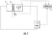
- FIG. 1is a schematic diagram of an embodiment of an HVAC system according to the present invention, where a solid line refers to an air line, a dashed line refers to a signal transmission line, and a double dot dash line is a water system line.
- decoupling controlis performed on the fan 2 and the valve 3, that is, the fan 2 and the valve 3 are independently controlled as defined in claim 1.
- the to-be-controlled valve 3is disposed at an air outlet of the air handling unit 1, and a flow rate of cold water entering the cold water coil pipe may be changed by changing a position of the valve 3, thereby changing a temperature of air passing through the cold water coil pipe.
- an operating speed of the fan 2 and an opening degree of the valve 3are controlled respectively, and control on one of the fan 2 and the valve 3 is independent of control on the other.
- control on the fan 2includes operating speed adjustment of the fan 2
- control on the valve 3includes opening degree adjustment of the valve 3.
- the HVAC systemmay be provided with a controller 5, and the controller 5 is connected to the fan 2 and the valve 3 in a communication way, receives signals from the fan 2 and the valve 3, and sends instructions to the fan 2 and the valve 3, as shown in FIG. 1 .
- the controller 5may be disposed as an independent component as shown in the figure, or may be integrated into a control unit of the entire HVAC system.
- the fan 2 and the valve 3need to be adjusted, the fan 2 is first adjusted to a minimum value, and the valve 3 is then adjusted as defined in claim 1. In this way, working statuses of the fan 2 and the valve 3 can satisfy an actual demand and energy consumption is reduced. Moreover, both the fan 2 and the valve 3 may work within reasonable parameter ranges respectively, so as to avoid system oscillation caused by coupling between the fan 2 and the valve 3.
- the flow rate and the flow velocity of airare increased to improve cold air supply.
- the opening degree of the valve 3is first increased to a maximum value, and the speed of the fan 2 is then adjusted.
- the speed of the fan 2is decreased first to a minimum value, and the opening degree of the valve 3 is then adjusted.
- the minimum value of the speed of the fan 2may be preset or may be a threshold set based on a working condition of the fan 2.
- the speed of the fan 2may be increased or decreased step by step, for example, adjusted step by step by setting a step time.
- the controller 5adjusts the fan 2 and the valve 3 based on the return air temperature.
- the return air temperaturemay be the temperature of return air monitored at an air return port of the air handling unit, or monitored indoor temperature. If the monitored return air temperature is the monitored indoor temperature, the monitored return air temperature may be collected by arranging a plurality of monitoring points. For example, in subway, temperatures at a plurality of positions in a station platform and a station hall are monitored, and an average value of data of these monitoring points or most unfavorable data is selected as the return air temperature.
- An ideal return air temperature valuemay be set in the system, and the temperature value represents a temperature at which a human body feels comfortable.
- the fan 2 and the valve 3are adjusted, so that an actual return air temperature is close to the set value of the ideal return air temperature.
- control method in the present inventionis also applicable to an HVAC system in other large places, including a shopping mall, an airport, a supermarket, and etc.
- the present inventionmay also be applied to a case where an HVAC system provides warm air.
- a fluid medium passing through the valve 3is a hot medium, such as hot water supplied by a boiler, and decoupling control is also performed on the fan 2 and the valve 3 by using the foregoing method.
- adjustment on the fan and the valvecomprises decreasing the opening degree of the valve after decreasing a speed of the fan to a minimum value.
- the actual return air temperaturewhen the actual return air temperature is increased, it indicates that the temperature of the environment is excessively high, and it is necessary to reduce a flow velocity and a flow rate of warm air, and in this case, the speed of the fan 2 is first decreased to the minimum value step by step, and then the opening degree of the valve 3 is decreased.
- the actual return air temperaturewhen the actual return air temperature is decreased, it indicates that the temperature of the environment is not high enough, and it is necessary to increase the flow rate and the flow volume of the warm air, and therefore the opening degree of the valve 3 is first increased to the maximum value, and then the speed of the fan 2 is increased step by step. It should be understood that in this example, orders of adjusting the fan 2 and the valve 3 may be interchanged.
- Opening degree adjustment of the valve 3is determined based on a supply air temperature and a specified value of the supply air temperature.
- the specified value of the supply air temperatureis determined based on a return air temperature and a specified value of the return air temperature.
- the foregoing controlmay be implemented through dual PID (proportional-integral-differential (controller)) closed-loop control. For a first PID control loop, a monitored return air temperature and a preset return air temperature value preset in the system are input, and after the monitored return air temperature and the preset return air temperature value are compared, a calculated preset supply temperature value is output.
- a monitored actual supply temperature and the output of the last PIDare input, and after the monitored actual supply temperature and the preset supply temperature value are compared, a calculated opening degree of the valve is output.
- a plurality of air handling unitsmay be arranged in an HVAC system in a large place.
- a fan and a valve of each air handling unitmay be adjusted.
Landscapes
- Engineering & Computer Science (AREA)
- Combustion & Propulsion (AREA)
- Mechanical Engineering (AREA)
- General Engineering & Computer Science (AREA)
- Chemical & Material Sciences (AREA)
- Physics & Mathematics (AREA)
- Fluid Mechanics (AREA)
- General Physics & Mathematics (AREA)
- Automation & Control Theory (AREA)
- Signal Processing (AREA)
- Sustainable Development (AREA)
- Life Sciences & Earth Sciences (AREA)
- Fuzzy Systems (AREA)
- Mathematical Physics (AREA)
- Human Computer Interaction (AREA)
- Manufacturing & Machinery (AREA)
- Air Conditioning Control Device (AREA)
Description
- The present invention relates to a heating, ventilation, and air conditioning system, and to a control method for the system.
- A heating, ventilation, and air conditioning (HVAC) system includes an air handling unit (or referred to as an air handling set), and the air handling unit is generally provided with an air supply fan located at an air outlet. The fan supplies cold or warm air. How to control an HVAC system in a large place to provide a comfortable environment temperature is a complex subject. Especially in a large-scale underground project such as a subway station, due to lack of a heat exchange device at a tail end, a fan directly supplies handled air to a station platform and a station hall. Although the fan is provided with a frequency converter, the fan has to operate at a fixed speed because there is no suitable control method. In addition, the fan and a valve through which cold water flows in a water system of the HVAC system are controlled in a coupled manner, and once the HVAC system is not under a good control, coupling between the fan and the valve will lead to system oscillation. Moreover, this causes the actual environment temperature to excessively deviate from a comfortable temperature value, and consequently the system continuously operates at a high energy consumption.
US 2012/0016526 A1 discloses systems and methods of controlling a heating, ventilating, and air conditioning system are provided that operate according to signals returned from return air temperature sensors as well as the supply air temperature sensors. Using predetermined temperature setpoints, return temperature information, and supply temperature information, the HVAC system is configured to maintain the temperature of a room first, by the use of its cooling valve, and second and only when the capacity of the cooling valve has peaked, by use of the fan.CN 207 268 524 U discloses adjustment controlling means for subway station air conditioning system, aimed at energy saving in the central air conditioning system. The model makes use of temperature and humidity sensor, air supply temperature and humidity sensor, return air temperature and humidity sensor, fresh air valve, return air valve, exhaust valve and water valve.- One aspect of the present invention provides a control method for an HVAC system in a relatively large spatial place according to claim 1. In particular, the HVAC system comprises an air handling unit, and the air handling unit is provided with a valve through which a fluid medium passes and a fan; and the method comprises:
- monitoring a return air temperature of air circulated back to the air handling unit;
- providing a return air temperature setpoint of the HVAC system;
- performing decoupling adjustment on one of the fan and the valve, and then adjusting the other of the fan and the valve so that the return air temperature is close to the return air temperature setpoint;
- wherein an opening degree adjustment of the valve is determined based on a supply air temperature of air leaving the air handling unit and a supply air temperature setpoint;
- characterized in that: adjustment on the fan and the valve comprises decreasing the opening degree of the valve after decreasing a speed of the fan to a minimum value.
- Another aspect of the present invention provides an HVAC system using the foregoing control method according to claim 8.
- Through optimized decoupling control of a fan and a valve, the HVAC system can operate in a steady and energy-saving way. This is very favorable for a large-space air-conditioning system to adapt to a variety of load conditions, so that the system obtains best conditions. In a subway station space, the present application can provide a rapid response to a cooling load change of the system, so as to meet people's comfort requirements.
- Through the following detailed descriptions with reference to the accompanying drawing, other aspects and features of the present invention will become apparent. However, it should be noted that the accompanying drawing is designed only for explanation and is not intended to limit the scope of the present invention which is defined in the appended claims. It should further be noted that the accompanying drawing is only intended to conceptually illustrate a structure and a process described herein, and unless noted otherwise, it is not necessary to draft the accompanying drawing according to the scale.
- With reference to the following detailed description of specific embodiments in conjunction with the accompanying drawing, the present invention is more fully understood. The same reference numeral in the accompanying drawing always represents the same element in the figure.
FIG. 1 is a schematic diagram of an embodiment of an HVAC system according to the present invention, where a solid line refers to an air line, a dashed line refers to a signal transmission line, and a double dot dash line is a water system line. - To help a person skilled in the art to understand a subject matter claimed by the present application, the specific embodiments of the present invention are described in detail below with reference to the accompanying drawing.
- An HVAC system in the present invention is used in an air conditioning system in a relatively large spatial place, especially in a subway station. Referring to
FIG. 1 , a tail end device of an HVAC system in the present invention is an air handling unit 1, wherein the air handling unit 1 is provided with afan 2 and a valve 3, and handled air passes through thefan 2 and then leaves the air handling unit 1 as supplied air. After being circulated, air returns to the air handling unit 1 as return air and is handled again in the unit. The fan is provided with a frequency conversion driver, thefan 2 is controlled by the frequency conversion driver to operate at a variable speed, thereby changing a flow rate of air passing through thefan 2. The valve 3 controls a fluid medium, that is, cold water, flowing through a cold water coil pipe 4 in the air handling unit 1. When the water system operates, air is cooled after flowing through the cold water coil pipe, then enters thefan 2, and is sent out of the air handling unit 1 by thefan 2. - In the present invention, decoupling control is performed on the
fan 2 and the valve 3, that is, thefan 2 and the valve 3 are independently controlled as defined in claim 1. The to-be-controlled valve 3 is disposed at an air outlet of the air handling unit 1, and a flow rate of cold water entering the cold water coil pipe may be changed by changing a position of the valve 3, thereby changing a temperature of air passing through the cold water coil pipe. In the present invention, an operating speed of thefan 2 and an opening degree of the valve 3 are controlled respectively, and control on one of thefan 2 and the valve 3 is independent of control on the other. In the present invention, control on thefan 2 includes operating speed adjustment of thefan 2, and control on the valve 3 includes opening degree adjustment of the valve 3. No matter which one of thefan 2 and the valve 3 changes in parameter, air temperature at the air outlet is affected. The present invention provides a set of optimized control strategy to adjust the parameters of thefan 2 and the valve 3 separately, so that the temperature in an environment is close to an ideal value. The HVAC system may be provided with a controller 5, and the controller 5 is connected to thefan 2 and the valve 3 in a communication way, receives signals from thefan 2 and the valve 3, and sends instructions to thefan 2 and the valve 3, as shown inFIG. 1 . The controller 5 may be disposed as an independent component as shown in the figure, or may be integrated into a control unit of the entire HVAC system. - When the
fan 2 and the valve 3 need to be adjusted, thefan 2 is first adjusted to a minimum value, and the valve 3 is then adjusted as defined in claim 1. In this way, working statuses of thefan 2 and the valve 3 can satisfy an actual demand and energy consumption is reduced. Moreover, both thefan 2 and the valve 3 may work within reasonable parameter ranges respectively, so as to avoid system oscillation caused by coupling between thefan 2 and the valve 3. - In an example comprising at least the features of claim 1 or 8, when the air temperature at the air outlet needs to be decreased, the flow rate and the flow velocity of air are increased to improve cold air supply. Specifically, the opening degree of the valve 3 is first increased to a maximum value, and the speed of the
fan 2 is then adjusted. According to the invention, when the air temperature at the air outlet needs to be increased, the flow rate and the flow velocity of air are decreased to reduce cold air supply. Specifically, the speed of thefan 2 is decreased first to a minimum value, and the opening degree of the valve 3 is then adjusted. The minimum value of the speed of thefan 2 may be preset or may be a threshold set based on a working condition of thefan 2. During adjustment of thefan 2, the speed of thefan 2 may be increased or decreased step by step, for example, adjusted step by step by setting a step time. - The controller 5 adjusts the
fan 2 and the valve 3 based on the return air temperature. The return air temperature may be the temperature of return air monitored at an air return port of the air handling unit, or monitored indoor temperature. If the monitored return air temperature is the monitored indoor temperature, the monitored return air temperature may be collected by arranging a plurality of monitoring points. For example, in subway, temperatures at a plurality of positions in a station platform and a station hall are monitored, and an average value of data of these monitoring points or most unfavorable data is selected as the return air temperature. In an example comprising at least the features of claim 1 or 8, when the detected return air temperature is increased, it indicates that temperatures in the station platform and the station hall are not low enough, and it is necessary to increase cold air supply, and therefore the opening degree of the valve 3 and the speed of thefan 2 are sequentially increased. In an example comprising at least the features of claim 1 or 8, when the detected return air temperature is in a downtrend, it indicates that temperatures in the station platform and the station hall are excessively low, and it is necessary to reduce cold air supply, and therefore the opening degree of the valve 3 and the speed of thefan 2 are sequentially decreased. It should be understood that in this example, orders of adjusting thefan 2 and the valve 3 may be interchanged. - An ideal return air temperature value may be set in the system, and the temperature value represents a temperature at which a human body feels comfortable. The
fan 2 and the valve 3 are adjusted, so that an actual return air temperature is close to the set value of the ideal return air temperature. - A person skilled in the art may conclude that the control method in the present invention is also applicable to an HVAC system in other large places, including a shopping mall, an airport, a supermarket, and etc. In addition, based on the foregoing concept and as long as in the scope of the claims, the present invention may also be applied to a case where an HVAC system provides warm air. In this case, a fluid medium passing through the valve 3 is a hot medium, such as hot water supplied by a boiler, and decoupling control is also performed on the
fan 2 and the valve 3 by using the foregoing method. To be specific, adjustment on the fan and the valve comprises decreasing the opening degree of the valve after decreasing a speed of the fan to a minimum value. For example, when the actual return air temperature is increased, it indicates that the temperature of the environment is excessively high, and it is necessary to reduce a flow velocity and a flow rate of warm air, and in this case, the speed of thefan 2 is first decreased to the minimum value step by step, and then the opening degree of the valve 3 is decreased. In an example comprising at least the features of claim 1 or 8, when the actual return air temperature is decreased, it indicates that the temperature of the environment is not high enough, and it is necessary to increase the flow rate and the flow volume of the warm air, and therefore the opening degree of the valve 3 is first increased to the maximum value, and then the speed of thefan 2 is increased step by step. It should be understood that in this example, orders of adjusting thefan 2 and the valve 3 may be interchanged. - Opening degree adjustment of the valve 3 is determined based on a supply air temperature and a specified value of the supply air temperature. The specified value of the supply air temperature is determined based on a return air temperature and a specified value of the return air temperature. The foregoing control may be implemented through dual PID (proportional-integral-differential (controller)) closed-loop control. For a first PID control loop, a monitored return air temperature and a preset return air temperature value preset in the system are input, and after the monitored return air temperature and the preset return air temperature value are compared, a calculated preset supply temperature value is output. In a second PID control loop, a monitored actual supply temperature and the output of the last PID (i.e., the preset supply temperature value) are input, and after the monitored actual supply temperature and the preset supply temperature value are compared, a calculated opening degree of the valve is output.
- A plurality of air handling units may be arranged in an HVAC system in a large place. In the present invention, a fan and a valve of each air handling unit may be adjusted.
- Although the specific embodiments of the present invention have been shown and described in detail to illustrate a principle of the present invention, it should be understood that the present invention may be implemented in another way without departing from the scope of the invention as defined in the appended claims.
Claims (8)
- A control method for an HVAC system in a relatively large spatial place, wherein the HVAC system comprises an air handling unit (1), and the air handling unit is provided with a valve (3) through which a fluid medium passes and a fan (2); and the method comprises:monitoring a return air temperature of air circulated back to the air handling unit;providing a return air temperature setpoint of the HVAC system;performing decoupling adjustment on one of the fan and the valve, and then adjusting the other of the fan and the valve so that the return air temperature is close to the return air temperature setpoint;wherein an opening degree adjustment of the valve (3) is determined based on a supply air temperature of air leaving the air handling unit (1) and a supply air temperature setpoint of the HVAC system;characterized in that:
adjustment on the fan and the valve comprises decreasing the opening degree of the valve after decreasing a speed of the fan to a minimum value. - The control method according to claim 1, wherein the opening degree adjustment of the valve (3) further comprises determining the supply air temperature setpoint based on the return air temperature and the return air temperature setpoint.
- The control method according to claim 2, wherein the opening degree adjustment of the valve (3) is implemented via a PID control method.
- The control method according to claim 1, wherein adjustment on a speed of the fan (2) comprises increasing the speed of the fan step by step or decreasing the speed of the fan step by step.
- The control method according to claim 1, wherein the fan (2) is configured to be a frequency conversion fan.
- The control method according to claim 1, wherein the fan (2) is configured to cause air passing through the fan to leave the air handling unit (1); and the valve (3) is configured to be adjacent to an air outlet of the air handling unit and to adjust a flow volume of the fluid medium that exchanges heat with air that is about to enter the fan.
- The control method according to claim 1, wherein monitoring of the return air temperature comprises monitoring an air temperature at a return air port of the air handling unit or monitoring a plurality of environment temperatures in the relatively large spatial place.
- An HVAC system, wherein:the HVAC system comprises an air handling unit (1), and the air handling unit is provided with a valve (3) through which a fluid medium passes and a fan (2);the HVAC system comprises means for: monitoring a return air temperature of the air circulated back to the air handling unit, providing a return air temperature setpoint of the HVAC system, and adjusting an opening degree of a valve and speed of a fan; andthe HVAC system is suitable for being disposed inside a subway station and is configured to use the control method according to any of claims 1 to 7.
Applications Claiming Priority (2)
| Application Number | Priority Date | Filing Date | Title |
|---|---|---|---|
| CN201810442329.1ACN110469925B (en) | 2018-05-10 | 2018-05-10 | HVAC system and control method thereof |
| PCT/IB2019/000596WO2019215513A1 (en) | 2018-05-10 | 2019-04-23 | Hvac system and control method thereof |
Publications (2)
| Publication Number | Publication Date |
|---|---|
| EP3791115A1 EP3791115A1 (en) | 2021-03-17 |
| EP3791115B1true EP3791115B1 (en) | 2025-03-12 |
Family
ID=66669030
Family Applications (1)
| Application Number | Title | Priority Date | Filing Date |
|---|---|---|---|
| EP19759727.1AActiveEP3791115B1 (en) | 2018-05-10 | 2019-04-23 | Hvac system and control method thereof |
Country Status (4)
| Country | Link |
|---|---|
| US (1) | US11454412B2 (en) |
| EP (1) | EP3791115B1 (en) |
| CN (1) | CN110469925B (en) |
| WO (1) | WO2019215513A1 (en) |
Families Citing this family (1)
| Publication number | Priority date | Publication date | Assignee | Title |
|---|---|---|---|---|
| EP3957927B1 (en)* | 2019-07-01 | 2023-08-02 | Shanghai Meicon Intelligent Construction Co., Ltd. | Control system of air conditioner and air-conditioning device |
Family Cites Families (27)
| Publication number | Priority date | Publication date | Assignee | Title |
|---|---|---|---|---|
| JP2633415B2 (en) | 1991-07-03 | 1997-07-23 | 松下精工株式会社 | Control device for air conditioner |
| JP3365544B2 (en)* | 1997-12-15 | 2003-01-14 | 新晃工業株式会社 | Air conditioner controller |
| US6792766B2 (en) | 2002-10-04 | 2004-09-21 | Cascade Manufacturing, L.P. | Zone demand controlled dual air conditioning system and controller therefor |
| US8147301B2 (en) | 2006-01-19 | 2012-04-03 | Ray Ghattas | Air handling system for clean room |
| US20070289322A1 (en) | 2006-04-28 | 2007-12-20 | Mathews Thomas J | Air handler unit fan installation and control method |
| US9028308B2 (en)* | 2006-12-15 | 2015-05-12 | Philip A. J. Bastow | Integrated structural slab and access floor HVAC system for buildings |
| WO2008079829A2 (en) | 2006-12-22 | 2008-07-03 | Duncan Scot M | Optimized control system for cooling systems |
| US8872379B2 (en) | 2007-11-30 | 2014-10-28 | Johnson Controls Technology Company | Efficient usage, storage, and sharing of energy in buildings, vehicles, and equipment |
| JP5524090B2 (en) | 2008-03-03 | 2014-06-18 | ヴィジレント コーポレイション | Method and system for coordinating control of an HVAC unit |
| US8955761B2 (en) | 2008-03-19 | 2015-02-17 | Rockwell Automation Technologies, Inc. | Retrofitting a constant volume air handling unit with a variable frequency drive |
| US20090243535A1 (en) | 2008-03-31 | 2009-10-01 | Johnson Controls Technology Company | Multi-Input Relay Board |
| US9709965B2 (en) | 2008-12-04 | 2017-07-18 | Baselayer Technology, Llc | Data center intelligent control and optimization |
| WO2011049905A1 (en) | 2009-10-20 | 2011-04-28 | Transkinetic Energy Corporation | Methods and system for reduction of utility usage and measurement thereof |
| CA2808503A1 (en) | 2010-08-20 | 2012-02-23 | Vigilent Corporation | Energy-optimal control decisions for hvac systems |
| US8229597B2 (en)* | 2011-09-27 | 2012-07-24 | Jpmorgan Chase Bank, N.A. | Heating, ventilation, and air conditioning management system and method |
| US9822989B2 (en) | 2011-12-12 | 2017-11-21 | Vigilent Corporation | Controlling air temperatures of HVAC units |
| CN104204684B (en)* | 2012-03-21 | 2017-08-11 | 开利公司 | The coordination air side control of HVAC system |
| CN103574829B (en)* | 2012-07-18 | 2016-04-13 | 同方泰德国际科技(北京)有限公司 | A kind of energy-saving control method of air-conditioner set |
| CN104713205A (en)* | 2013-12-12 | 2015-06-17 | 广州市地下铁道总公司 | Ventilation air conditioning energy saving system for subway |
| US9581985B2 (en) | 2014-02-21 | 2017-02-28 | Johnson Controls Technology Company | Systems and methods for auto-commissioning and self-diagnostics |
| CN103968481A (en) | 2014-05-05 | 2014-08-06 | 华中科技大学 | Independent temperature controlling and energy saving device for subway station office platform |
| WO2016025739A1 (en) | 2014-08-14 | 2016-02-18 | Vigilent Corporation | Method and apparatus for optimizing control variables to minimize power consumption of cooling systems |
| CN104748326A (en)* | 2015-03-17 | 2015-07-01 | 广东申菱空调设备有限公司 | Chilled water precision air conditioner and energy-conservation control method thereof |
| CN105222284B (en)* | 2015-10-30 | 2018-01-16 | 珠海格力电器股份有限公司 | Air conditioner control method and device and air conditioner system |
| US10365001B2 (en) | 2016-02-18 | 2019-07-30 | Johnson Controls Technology Company | HVAC system with multivariable optimization using a plurality of single-variable extremum-seeking controllers |
| SG10201605828UA (en) | 2016-07-15 | 2018-02-27 | Barghest Building Performance Pte Ltd | Method for improving operational efficiency of a cooling system through retrofitting a building with a master controller |
| CN207268524U (en)* | 2017-09-08 | 2018-04-24 | 浙江大冲能源科技有限公司 | A kind of geomantic omen joint debugging control device for subway station air-conditioning system |
- 2018
- 2018-05-10CNCN201810442329.1Apatent/CN110469925B/enactiveActive
- 2019
- 2019-04-23USUS17/053,926patent/US11454412B2/enactiveActive
- 2019-04-23EPEP19759727.1Apatent/EP3791115B1/enactiveActive
- 2019-04-23WOPCT/IB2019/000596patent/WO2019215513A1/ennot_activeCeased
Also Published As
| Publication number | Publication date |
|---|---|
| CN110469925B (en) | 2022-11-29 |
| US11454412B2 (en) | 2022-09-27 |
| US20210262686A1 (en) | 2021-08-26 |
| CN110469925A (en) | 2019-11-19 |
| EP3791115A1 (en) | 2021-03-17 |
| WO2019215513A1 (en) | 2019-11-14 |
Similar Documents
| Publication | Publication Date | Title |
|---|---|---|
| EP2102568B1 (en) | Air-conditioning algorithm for water terminal free cooling | |
| US11384951B2 (en) | Zoning system for air conditioning (HVAC) equipment | |
| US20180363933A1 (en) | Zoning System for Air Conditioning (HVAC) Equipment | |
| JP2022137259A (en) | Method for improving work efficiency of cooling system by remodeling building by main control device | |
| US20150204551A1 (en) | Energy saving method for room level heating and cooling system | |
| CN107514743A (en) | Air conditioner control method, control device and air conditioner | |
| EP2737263B1 (en) | Hvac systems | |
| US5261481A (en) | Method of determining setback for HVAC system | |
| KR20160051596A (en) | Air-conditioning system | |
| US20170129311A1 (en) | Air conditioning system and method of controlling the same | |
| US20070084939A1 (en) | Systems and methods of controlling a fan coil unit | |
| EP3791115B1 (en) | Hvac system and control method thereof | |
| JP2003139372A (en) | Optimal restraint control system for air-conditioning/ heat source equipment | |
| CN113525025A (en) | Thermal management system and control method thereof | |
| JP4477914B2 (en) | Air conditioning system | |
| JP2020143853A (en) | Air conditioning system and method of controlling the same | |
| JPH0131877Y2 (en) | ||
| CN110567102A (en) | Fan coil control method and system based on constant temperature difference adjustment | |
| CN105737339A (en) | Fan coil temperature control device capable of controlling opening limit range of water valve according to return air temperature | |
| EP3495912B1 (en) | Parallel valve control | |
| JP6951259B2 (en) | Air conditioning system | |
| CN217715142U (en) | City wisdom heating system | |
| CN115214734B (en) | Battery power locomotive thermal management device and control method thereof | |
| JP3522556B2 (en) | Control mode switching device and temperature control system | |
| EP4513098A1 (en) | Methods and systems for controlling an hvac system to identify energy usage under different control strategies |
Legal Events
| Date | Code | Title | Description |
|---|---|---|---|
| STAA | Information on the status of an ep patent application or granted ep patent | Free format text:STATUS: UNKNOWN | |
| STAA | Information on the status of an ep patent application or granted ep patent | Free format text:STATUS: THE INTERNATIONAL PUBLICATION HAS BEEN MADE | |
| PUAI | Public reference made under article 153(3) epc to a published international application that has entered the european phase | Free format text:ORIGINAL CODE: 0009012 | |
| STAA | Information on the status of an ep patent application or granted ep patent | Free format text:STATUS: REQUEST FOR EXAMINATION WAS MADE | |
| 17P | Request for examination filed | Effective date:20201103 | |
| AK | Designated contracting states | Kind code of ref document:A1 Designated state(s):AL AT BE BG CH CY CZ DE DK EE ES FI FR GB GR HR HU IE IS IT LI LT LU LV MC MK MT NL NO PL PT RO RS SE SI SK SM TR | |
| AX | Request for extension of the european patent | Extension state:BA ME | |
| DAV | Request for validation of the european patent (deleted) | ||
| DAX | Request for extension of the european patent (deleted) | ||
| STAA | Information on the status of an ep patent application or granted ep patent | Free format text:STATUS: EXAMINATION IS IN PROGRESS | |
| 17Q | First examination report despatched | Effective date:20230309 | |
| GRAP | Despatch of communication of intention to grant a patent | Free format text:ORIGINAL CODE: EPIDOSNIGR1 | |
| STAA | Information on the status of an ep patent application or granted ep patent | Free format text:STATUS: GRANT OF PATENT IS INTENDED | |
| INTG | Intention to grant announced | Effective date:20240424 | |
| GRAJ | Information related to disapproval of communication of intention to grant by the applicant or resumption of examination proceedings by the epo deleted | Free format text:ORIGINAL CODE: EPIDOSDIGR1 | |
| STAA | Information on the status of an ep patent application or granted ep patent | Free format text:STATUS: EXAMINATION IS IN PROGRESS | |
| INTC | Intention to grant announced (deleted) | ||
| GRAP | Despatch of communication of intention to grant a patent | Free format text:ORIGINAL CODE: EPIDOSNIGR1 | |
| STAA | Information on the status of an ep patent application or granted ep patent | Free format text:STATUS: GRANT OF PATENT IS INTENDED | |
| INTG | Intention to grant announced | Effective date:20241004 | |
| GRAS | Grant fee paid | Free format text:ORIGINAL CODE: EPIDOSNIGR3 | |
| GRAA | (expected) grant | Free format text:ORIGINAL CODE: 0009210 | |
| STAA | Information on the status of an ep patent application or granted ep patent | Free format text:STATUS: THE PATENT HAS BEEN GRANTED | |
| AK | Designated contracting states | Kind code of ref document:B1 Designated state(s):AL AT BE BG CH CY CZ DE DK EE ES FI FR GB GR HR HU IE IS IT LI LT LU LV MC MK MT NL NO PL PT RO RS SE SI SK SM TR | |
| REG | Reference to a national code | Ref country code:GB Ref legal event code:FG4D | |
| REG | Reference to a national code | Ref country code:CH Ref legal event code:EP | |
| REG | Reference to a national code | Ref country code:DE Ref legal event code:R096 Ref document number:602019067187 Country of ref document:DE | |
| REG | Reference to a national code | Ref country code:IE Ref legal event code:FG4D | |
| PG25 | Lapsed in a contracting state [announced via postgrant information from national office to epo] | Ref country code:RS Free format text:LAPSE BECAUSE OF FAILURE TO SUBMIT A TRANSLATION OF THE DESCRIPTION OR TO PAY THE FEE WITHIN THE PRESCRIBED TIME-LIMIT Effective date:20250612 | |
| PG25 | Lapsed in a contracting state [announced via postgrant information from national office to epo] | Ref country code:FI Free format text:LAPSE BECAUSE OF FAILURE TO SUBMIT A TRANSLATION OF THE DESCRIPTION OR TO PAY THE FEE WITHIN THE PRESCRIBED TIME-LIMIT Effective date:20250312 | |
| PGFP | Annual fee paid to national office [announced via postgrant information from national office to epo] | Ref country code:DE Payment date:20250319 Year of fee payment:7 | |
| PG25 | Lapsed in a contracting state [announced via postgrant information from national office to epo] | Ref country code:ES Free format text:LAPSE BECAUSE OF FAILURE TO SUBMIT A TRANSLATION OF THE DESCRIPTION OR TO PAY THE FEE WITHIN THE PRESCRIBED TIME-LIMIT Effective date:20250312 | |
| PGFP | Annual fee paid to national office [announced via postgrant information from national office to epo] | Ref country code:GB Payment date:20250423 Year of fee payment:7 | |
| REG | Reference to a national code | Ref country code:LT Ref legal event code:MG9D | |
| PG25 | Lapsed in a contracting state [announced via postgrant information from national office to epo] | Ref country code:NO Free format text:LAPSE BECAUSE OF FAILURE TO SUBMIT A TRANSLATION OF THE DESCRIPTION OR TO PAY THE FEE WITHIN THE PRESCRIBED TIME-LIMIT Effective date:20250612 | |
| PG25 | Lapsed in a contracting state [announced via postgrant information from national office to epo] | Ref country code:HR Free format text:LAPSE BECAUSE OF FAILURE TO SUBMIT A TRANSLATION OF THE DESCRIPTION OR TO PAY THE FEE WITHIN THE PRESCRIBED TIME-LIMIT Effective date:20250312 | |
| REG | Reference to a national code | Ref country code:NL Ref legal event code:MP Effective date:20250312 | |
| PG25 | Lapsed in a contracting state [announced via postgrant information from national office to epo] | Ref country code:LV Free format text:LAPSE BECAUSE OF FAILURE TO SUBMIT A TRANSLATION OF THE DESCRIPTION OR TO PAY THE FEE WITHIN THE PRESCRIBED TIME-LIMIT Effective date:20250312 | |
| PGFP | Annual fee paid to national office [announced via postgrant information from national office to epo] | Ref country code:FR Payment date:20250423 Year of fee payment:7 | |
| PG25 | Lapsed in a contracting state [announced via postgrant information from national office to epo] | Ref country code:GR Free format text:LAPSE BECAUSE OF FAILURE TO SUBMIT A TRANSLATION OF THE DESCRIPTION OR TO PAY THE FEE WITHIN THE PRESCRIBED TIME-LIMIT Effective date:20250613 Ref country code:BG Free format text:LAPSE BECAUSE OF FAILURE TO SUBMIT A TRANSLATION OF THE DESCRIPTION OR TO PAY THE FEE WITHIN THE PRESCRIBED TIME-LIMIT Effective date:20250312 | |
| REG | Reference to a national code | Ref country code:AT Ref legal event code:MK05 Ref document number:1775281 Country of ref document:AT Kind code of ref document:T Effective date:20250312 | |
| PG25 | Lapsed in a contracting state [announced via postgrant information from national office to epo] | Ref country code:NL Free format text:LAPSE BECAUSE OF FAILURE TO SUBMIT A TRANSLATION OF THE DESCRIPTION OR TO PAY THE FEE WITHIN THE PRESCRIBED TIME-LIMIT Effective date:20250312 | |
| PG25 | Lapsed in a contracting state [announced via postgrant information from national office to epo] | Ref country code:SE Free format text:LAPSE BECAUSE OF FAILURE TO SUBMIT A TRANSLATION OF THE DESCRIPTION OR TO PAY THE FEE WITHIN THE PRESCRIBED TIME-LIMIT Effective date:20250312 | |
| PG25 | Lapsed in a contracting state [announced via postgrant information from national office to epo] | Ref country code:SM Free format text:LAPSE BECAUSE OF FAILURE TO SUBMIT A TRANSLATION OF THE DESCRIPTION OR TO PAY THE FEE WITHIN THE PRESCRIBED TIME-LIMIT Effective date:20250312 | |
| PG25 | Lapsed in a contracting state [announced via postgrant information from national office to epo] | Ref country code:PT Free format text:LAPSE BECAUSE OF FAILURE TO SUBMIT A TRANSLATION OF THE DESCRIPTION OR TO PAY THE FEE WITHIN THE PRESCRIBED TIME-LIMIT Effective date:20250714 |