EP3789648A1 - Ball-lock connector - Google Patents
Ball-lock connectorDownload PDFInfo
- Publication number
- EP3789648A1 EP3789648A1EP19196036.8AEP19196036AEP3789648A1EP 3789648 A1EP3789648 A1EP 3789648A1EP 19196036 AEP19196036 AEP 19196036AEP 3789648 A1EP3789648 A1EP 3789648A1
- Authority
- EP
- European Patent Office
- Prior art keywords
- connector
- engagement
- ball
- engagement ball
- counter
- Prior art date
- Legal status (The legal status is an assumption and is not a legal conclusion. Google has not performed a legal analysis and makes no representation as to the accuracy of the status listed.)
- Granted
Links
Images


Classifications
- F—MECHANICAL ENGINEERING; LIGHTING; HEATING; WEAPONS; BLASTING
- F16—ENGINEERING ELEMENTS AND UNITS; GENERAL MEASURES FOR PRODUCING AND MAINTAINING EFFECTIVE FUNCTIONING OF MACHINES OR INSTALLATIONS; THERMAL INSULATION IN GENERAL
- F16B—DEVICES FOR FASTENING OR SECURING CONSTRUCTIONAL ELEMENTS OR MACHINE PARTS TOGETHER, e.g. NAILS, BOLTS, CIRCLIPS, CLAMPS, CLIPS OR WEDGES; JOINTS OR JOINTING
- F16B7/00—Connections of rods or tubes, e.g. of non-circular section, mutually, including resilient connections
- F16B7/04—Clamping or clipping connections
- F16B7/0406—Clamping or clipping connections for rods or tubes being coaxial
- F16B7/0413—Clamping or clipping connections for rods or tubes being coaxial for tubes using the innerside thereof
- F16B7/042—Clamping or clipping connections for rods or tubes being coaxial for tubes using the innerside thereof with a locking element, e.g. pin, ball or pushbutton, engaging in a hole in the wall of at least one tube
- H—ELECTRICITY
- H01—ELECTRIC ELEMENTS
- H01R—ELECTRICALLY-CONDUCTIVE CONNECTIONS; STRUCTURAL ASSOCIATIONS OF A PLURALITY OF MUTUALLY-INSULATED ELECTRICAL CONNECTING ELEMENTS; COUPLING DEVICES; CURRENT COLLECTORS
- H01R13/00—Details of coupling devices of the kinds covered by groups H01R12/70 or H01R24/00 - H01R33/00
- H01R13/62—Means for facilitating engagement or disengagement of coupling parts or for holding them in engagement
- H01R13/639—Additional means for holding or locking coupling parts together, after engagement, e.g. separate keylock, retainer strap
- H—ELECTRICITY
- H01—ELECTRIC ELEMENTS
- H01R—ELECTRICALLY-CONDUCTIVE CONNECTIONS; STRUCTURAL ASSOCIATIONS OF A PLURALITY OF MUTUALLY-INSULATED ELECTRICAL CONNECTING ELEMENTS; COUPLING DEVICES; CURRENT COLLECTORS
- H01R4/00—Electrically-conductive connections between two or more conductive members in direct contact, i.e. touching one another; Means for effecting or maintaining such contact; Electrically-conductive connections having two or more spaced connecting locations for conductors and using contact members penetrating insulation
- H01R4/28—Clamped connections, spring connections
- H01R4/50—Clamped connections, spring connections utilising a cam, wedge, cone or ball also combined with a screw
- G—PHYSICS
- G02—OPTICS
- G02B—OPTICAL ELEMENTS, SYSTEMS OR APPARATUS
- G02B6/00—Light guides; Structural details of arrangements comprising light guides and other optical elements, e.g. couplings
- G02B6/24—Coupling light guides
- G02B6/36—Mechanical coupling means
- G02B6/38—Mechanical coupling means having fibre to fibre mating means
- G02B6/3807—Dismountable connectors, i.e. comprising plugs
- G02B6/3873—Connectors using guide surfaces for aligning ferrule ends, e.g. tubes, sleeves, V-grooves, rods, pins, balls
- G02B6/3882—Connectors using guide surfaces for aligning ferrule ends, e.g. tubes, sleeves, V-grooves, rods, pins, balls using rods, pins or balls to align a pair of ferrule ends
- G—PHYSICS
- G02—OPTICS
- G02B—OPTICAL ELEMENTS, SYSTEMS OR APPARATUS
- G02B6/00—Light guides; Structural details of arrangements comprising light guides and other optical elements, e.g. couplings
- G02B6/24—Coupling light guides
- G02B6/36—Mechanical coupling means
- G02B6/38—Mechanical coupling means having fibre to fibre mating means
- G02B6/3807—Dismountable connectors, i.e. comprising plugs
- G02B6/389—Dismountable connectors, i.e. comprising plugs characterised by the method of fastening connecting plugs and sockets, e.g. screw- or nut-lock, snap-in, bayonet type
- G02B6/3893—Push-pull type, e.g. snap-in, push-on
- H—ELECTRICITY
- H01—ELECTRIC ELEMENTS
- H01R—ELECTRICALLY-CONDUCTIVE CONNECTIONS; STRUCTURAL ASSOCIATIONS OF A PLURALITY OF MUTUALLY-INSULATED ELECTRICAL CONNECTING ELEMENTS; COUPLING DEVICES; CURRENT COLLECTORS
- H01R13/00—Details of coupling devices of the kinds covered by groups H01R12/70 or H01R24/00 - H01R33/00
- H01R13/46—Bases; Cases
- H01R13/533—Bases, cases made for use in extreme conditions, e.g. high temperature, radiation, vibration, corrosive environment, pressure
- H—ELECTRICITY
- H01—ELECTRIC ELEMENTS
- H01R—ELECTRICALLY-CONDUCTIVE CONNECTIONS; STRUCTURAL ASSOCIATIONS OF A PLURALITY OF MUTUALLY-INSULATED ELECTRICAL CONNECTING ELEMENTS; COUPLING DEVICES; CURRENT COLLECTORS
- H01R13/00—Details of coupling devices of the kinds covered by groups H01R12/70 or H01R24/00 - H01R33/00
- H01R13/62—Means for facilitating engagement or disengagement of coupling parts or for holding them in engagement
- H01R13/627—Snap or like fastening
- H01R13/6276—Snap or like fastening comprising one or more balls engaging in a hole or a groove
- H—ELECTRICITY
- H01—ELECTRIC ELEMENTS
- H01R—ELECTRICALLY-CONDUCTIVE CONNECTIONS; STRUCTURAL ASSOCIATIONS OF A PLURALITY OF MUTUALLY-INSULATED ELECTRICAL CONNECTING ELEMENTS; COUPLING DEVICES; CURRENT COLLECTORS
- H01R13/00—Details of coupling devices of the kinds covered by groups H01R12/70 or H01R24/00 - H01R33/00
- H01R13/62—Means for facilitating engagement or disengagement of coupling parts or for holding them in engagement
- H01R13/629—Additional means for facilitating engagement or disengagement of coupling parts, e.g. aligning or guiding means, levers, gas pressure electrical locking indicators, manufacturing tolerances
- H—ELECTRICITY
- H01—ELECTRIC ELEMENTS
- H01R—ELECTRICALLY-CONDUCTIVE CONNECTIONS; STRUCTURAL ASSOCIATIONS OF A PLURALITY OF MUTUALLY-INSULATED ELECTRICAL CONNECTING ELEMENTS; COUPLING DEVICES; CURRENT COLLECTORS
- H01R24/00—Two-part coupling devices, or either of their cooperating parts, characterised by their overall structure
- H—ELECTRICITY
- H01—ELECTRIC ELEMENTS
- H01R—ELECTRICALLY-CONDUCTIVE CONNECTIONS; STRUCTURAL ASSOCIATIONS OF A PLURALITY OF MUTUALLY-INSULATED ELECTRICAL CONNECTING ELEMENTS; COUPLING DEVICES; CURRENT COLLECTORS
- H01R3/00—Electrically-conductive connections not otherwise provided for
- H01R3/08—Electrically-conductive connections not otherwise provided for for making connection to a liquid
- H—ELECTRICITY
- H01—ELECTRIC ELEMENTS
- H01R—ELECTRICALLY-CONDUCTIVE CONNECTIONS; STRUCTURAL ASSOCIATIONS OF A PLURALITY OF MUTUALLY-INSULATED ELECTRICAL CONNECTING ELEMENTS; COUPLING DEVICES; CURRENT COLLECTORS
- H01R43/00—Apparatus or processes specially adapted for manufacturing, assembling, maintaining, or repairing of line connectors or current collectors or for joining electric conductors
- H01R43/26—Apparatus or processes specially adapted for manufacturing, assembling, maintaining, or repairing of line connectors or current collectors or for joining electric conductors for engaging or disengaging the two parts of a coupling device
- F—MECHANICAL ENGINEERING; LIGHTING; HEATING; WEAPONS; BLASTING
- F16—ENGINEERING ELEMENTS AND UNITS; GENERAL MEASURES FOR PRODUCING AND MAINTAINING EFFECTIVE FUNCTIONING OF MACHINES OR INSTALLATIONS; THERMAL INSULATION IN GENERAL
- F16L—PIPES; JOINTS OR FITTINGS FOR PIPES; SUPPORTS FOR PIPES, CABLES OR PROTECTIVE TUBING; MEANS FOR THERMAL INSULATION IN GENERAL
- F16L37/00—Couplings of the quick-acting type
- F16L37/22—Couplings of the quick-acting type in which the connection is maintained by means of balls, rollers or helical springs under radial pressure between the parts
- F16L37/23—Couplings of the quick-acting type in which the connection is maintained by means of balls, rollers or helical springs under radial pressure between the parts by means of balls
Definitions
- the inventionrelates to a connector comprising at least one engagement ball that is movable between an engagement position and a disengagement position.
- the inventionmoreover relates to a system comprising the connector and a counter connector. Further, the invention relates to a method of unlocking a connector from a counter connector.
- the inventiongenerally concerns the art of ball-lock connectors.
- a connector of this typecan be locked to a counter connector by means of a ball-lock.
- a group of ballsis positioned in holes located around the inner diameter of the connector.
- a springloaded sleeve around the connector's outer diameterforces the balls toward the connector's inner diameter.
- the sleeveis pushed back, which opens a clearance so the balls are free to move outward.
- the releasing the sleeveforces the balls inward against a locking groove on the outer diameter of the counter connector.
- pushing the sleeve backprovides the balls with clearance to move outward and allow the connector to be removed from the counter connector.
- US 8764473 B2discloses a connector comprising a tubular member with ball storage holes therein, and engagement balls contained in the ball storage holes.
- An inner sleeve and an outer sleeveare disposed on the outside of the tubular member so as to move in the axial direction.
- each engagement ballmoves from a first position wherein a part of the engagement ball is projected from the inner peripheral surface of the tubular member to a second position which is close to a first inner peripheral surface of an outer sleeve, wherein a part of the engagement ball is not projected from the inner peripheral surface. Thereafter, the engagement balls return to the first position.
- each engagement ballmoves from the first position to a third position which is close to a second inner peripheral surface of the outer sleeve, wherein a part of the engagement ball is not projected from the inner peripheral surface, and thereafter, returns to the first position.
- a radio frequency connectorthat comprises a retaining ring holding locking steel balls.
- An outer side of the ballscontacts a sheath tensioned by a small spring, and an inner side contacts a tapered ring tensioned by a large spring.
- a front end of the socketmoves the sheath against the force of a small spring and the steel balls are moved by the force of the large spring through the tapered ring into a position in which they engage with a corresponding part of the socket.
- a nut of the connectorcan be operated to return the tapered ring in the original position against the force of the large spring.
- the locking steel ballscan return into their previous position.
- a pipe coupling with a similar mode of operationis known from FR 248 4053 A2 .
- DE 10 2016 105 975 A1describes a locking device which comprises a first locking means and a second locking means which can be joined with one another.
- Blocking ballsare provided for engaging the first locking means with the second locking means. They can be moved by means of an actuator.
- Another actuatoris arranged in the first locking means or in the second locking means to protect against failure of the locking device.
- the first locking means and the second locking meansare provided for use in a plug and a corresponding counter plug.
- the inventionmoreover aims at providing an improved system that comprises the connector and a counter connector. Further, the invention seeks to provide an improved method of unlocking a connector from a counter connector.
- the problemis solved by a connector with the features of claim 1.
- the connectorcomprising at least one engagement ball that is movable between an engagement position and a disengagement position. A motion of an engagement ball operating part of the connector relatively to an inner housing of the connector can force the at least one engagement ball from the engagement position into the disengagement position.
- the lockis particularly reliable even if the connector and a counter connector, to which the connector is locked, are pulled apart from each other with great force or the connector and the counter connector are exposed to strong vibrations.
- an “engagement position”is a position in which the at least one locking ball extends into an engagement space in which it is accessible for an engagement part of a counter connector so that the engagement ball of the connector and the engagement part of the counter connector can engage with each other to effect locking of the connector to the counter connector.
- the “disengagement position”is a position in which the at least one locking ball is withdrawn from the engagement space so that the engagement ball of the connector and the engagement part of the counter connector do no longer engage with each other, thus effecting the connector to be released from the counter connector.
- a preferred connector according to the inventioncomprises both an inner housing and an outer housing, and, preferably, the outer housing is outside the inner housing in the sense that it at least partially encloses the inner housing.
- the motion of the engagement ball operating part "forces" the engagement ball from the engagement position into the disengagement positionmeans that it applies a force directly to the engagement ball, which force moves the engagement ball from the engagement position to the disengagement position.
- the force applied by the engagement ball operating part to the engagement ballhas at least one component - in the sense of a parallelogram of forces - that extends in the direction from the engagement position to the disengagement position of the engagement ball. This is in contrast to the situation for example in US 8764473 B2 and DE 102016105975 A1 , where it is a part of the counter-connector that forces the engagement ball from the engagement position into the disengagement position.
- the engagement ball operating partforces the engagement ball from the engagement position into the disengagement position by means of moving from a locking position into the unlocking position.
- the present inventionencompasses embodiments in which the outer housing and the engagement ball operating part are separate parts, and embodiments, in which they are a single part that servers both as the outer housing and the engagement ball operating part.
- the engagement ball within the meaning of the present inventionmust not necessarily be spherical or essentially spherical but can also deviate from a spherical shape toward an ellipsoidal, cylindrical, ovoid, cuboid or pill shape. Yet, the preferred engagement ball is essentially spherical.
- the connectorcomprises an inner housing, at least one engagement ball, an engagement ball operating part that can move the at least one engagement ball between an engagement position and a disengagement position, and a supporting part which is rigidly connected with an inner housing and on which the at least one engagement ball at least partially rests in the engagement position.
- the engagement ball operating partcomprises claws that extend through at least one window in the supporting part or the inner housing or between the supporting part and the inner housing.
- This aspect of the inventionallows the connector to be advantageously compact.
- the diameter of the connectorcan be reduced. It is also achievable that the length of the connector is reduced.
- the problemis solved by a system according to claim 13.
- the systemcomprises the connector as described above and a counter connector that can be locked to the connector by means of the at least one engagement ball of the connector that engages with an engagement part of the counter connect.
- the problemis solved by means of a system comprising a connector and a counter connector that can be locked to the connector by means of a locking mechanism with at least one engagement ball of the connector that can be moved relatively to an inner housing of the connector from a disengagement position into an engagement position.
- the at least one engagement ballengages with an engagement part of the counter connector in order to lock the connector to the counter connector. If the at least one engagement ball is in the engagement position and the locking mechanism is loaded, the at least one engagement ball does not, as a result of the force exerted on the engagement ball by the engagement part, exert a force on a part of the connector that is movable relatively to the inner housing and retains the engagement ball in the engagement position.
- the locking mechanismis loaded means that in a situation where the connector is locked to the counter connector my means of the engagement of the at least one engagement ball of the connector with the engagement part of the counter connector, the connector and the counter connector are pulled apart from each other in a direction opposite to the mating direction.
- the problemis solved by the method of unlocking a connector from a counter connector according to claim 16.
- An engagement ball of the connectormoves from a locking position, in which the engagement ball is engaged with an engagement part of the counter connector to lock the connector to the counter connector, to an unlocking position, in which the engagement ball is no longer engaged with the engagement part of the counter connector.
- a connector according to the inventioncan serve to attach a cable to an apparatus.
- the connectorcan be attached to the cable; counter connector can be arranged on the apparatus, for example on a front panel of the apparatus.
- the inventionalso includes embodiments in which the connector is arranged on the apparatus; in such embodiments, the counter connector can be attached to the cable.
- both , the connector and the counter connectorare attached to cables, or both are arranged on apparatus.
- the connector, the system and the method according to the inventionis particularly resistant to vibration and shock. It can also be achieved that it is particularly suitable for be pre-stressed connectors, ie for connectors in which when the connector is locked to the counter connector, an force, typically provided by an elastic pre-stressing element, is present that biases the connector and the counter connector apart from each, thus keeping the locking mechanism under the tension of this force.
- pre-stressed connectorsare for example used to establish a reliable contact between optical fibres.
- the preferred connectorcomprising at least one engagement ball that is movable between an engagement position and a disengagement position, wherein a motion of an engagement ball operating part of the connector can force the at least one engagement ball from the engagement position into the disengagement position.
- a preferred connectorcomprises an inner housing and outer housing which is movable relatively to the inner housing in a longitudinal direction of the connector.
- the outer housingis operatively connected with the engagement ball operating part such that when the outer housing is moved relatively to the inner housing, it moves the engagement ball operating part to force the at least one engagement ball from the engagement position into the disengagement position.
- the outer housingis moved, typically by an operator, relatively to the inner housing
- the outer housingmoves an engagement ball operating part
- the engagement ball operating partforces the engagement ball from the locking position into the unlocking position.
- the outer housingcan move between a distal position and a proximal position.
- the outer housingmoves the engagement ball operating part with it to force the at least one engagement ball from the engagement position into the disengagement position. It is an achievable advantage of this embodiment of the invention that a pulling of the outer housing in the proximal direction can effect a disengagement of the engagement ball and thus an unlocking of the connector from the counter connector. This can allow for a simple and intuitive operation of the connector.
- the distal position of the outer housingis the position closest to the distal end of the connector.
- the connector's distal endis the end that is intended to face the counter connector for mating the connector with the counter connector.
- the proximal position of the outer housingis the position closest to the proximal end of the connector.
- the connector's proximal endis the end that is opposite of its distal end.
- the distal directionis the direction that extends along the longitudinal axis of the connector and points towards the distal end of the connector.
- the proximal directionis the direction towards the proximal end of the connector.
- the motion of the engagement ball operating partis in the longitudinal direction of the connector.
- the engagement ball operating partcan move between a distal position and a proximal position.
- the distal position of the engagement ball operating partis the locking position while the proximal position is the unlocking position.
- the distal position of the engagement ball operating partis the position closest to the distal end of the connector
- the proximal position of the engagement ball operating partis the position closest to the proximal end of the connector.
- the engagement ball in the engagement positionwhen it in the engagement position, it extends into a space which is suitable for an engagement part of a counter connector to be located to engage with the engagement ball in order to secure the connector to the counter connector.
- thisis a cylindrical space that extends from the distal end of the connector some distance into the connector.
- a cylindrical part of the counter connector that comprises the engagement partcan enter.
- the engagement partmay for example be part of a ring shaped groove or one or more recesses in the cylindrical part.
- the motion of the at least one engagement ball between the engagement position and the disengagement positionpreferably has a component in a radial direction of the connector. More preferably, the engagement position of the at least one engagement ball is closer to the longitudinal axis of the connector than the disengagement position. This way, for engagement with a counter connector, it can engage with an engagement part of the counter connector that faces the outside of the counter connector.
- the at least one engagement ballis biased, directly or indirectly, in the engagement position by means of an elastic element.
- the elastic elementpreferably is a spring such as a helical spring or a leaf spring, or a body of an elastic material, for example a synthetic or natural rubber material.
- a particularly preferred springis a wave spring, for example a Crest-to-Crest (R) wave spring as available from Smalley Steel Ring Co, 555 Oakwood Rd, Lake Zurich, IL 60047, USA.
- RCrest-to-Crest
- the at least one engagement ballcan be forced against the biasing force of the elastic element from the engagement position into the disengagement position.
- the at least one engagement ballis biased in the engagement position by means of the elastic element via the engagement ball operating part.
- the elastic elementexerts a force on the engagement ball operating part, at least a component of this force being directed in the distal direction of the connector.
- the elastic elementcan bias the engagement ball operating part in its distal position.
- the preferred engagement ball operating partis a ball cage.
- the preferred ball cagecomprises apertures in which the ball(s) is/are held.
- the preferred engagement ball operating partis essentially ring shaped.
- the aperturespreferably are tapered or stepped to reduce their diameter towards one side of the engagement ball operating part, in order to prevent the engagement balls from falling into the space vacated by the counter connector when the connector is separated from the counter connector.
- the preferred engagement ball operating partis provided with at least one claw that preferably extends from the ring shaped ball cage towards the elastic element to contact the elastic element.
- the engagement ball operating parthas more than one, for example 2, 3, 4, 5 or more claws. Each claw may hold 1 or more than one ball, for example 2 or 3 balls.
- the at least one engagement ball at least in the engagement positionrests on the surface of a supporting part, which surface is tapered along its extension in the longitudinal direction of the connector.
- the at least one engagement ballcan roll or slide along the tapered surface of the supporting part.
- the preferred supporting partis rigidly with the inner housing so that it cannot move in the longitudinal direction, particular preferably it is rigidly connected with the inner housing.
- At least one windowis provided in the supporting part or the inner housing or between the supporting part and the inner housing.
- the engagement ball operating partcomprises claws that extend through at least one window.
- the preferred supporting partcomprises at least one claw.
- the at least oneextends from a ring that comprises the surface on which the at least one engagement ball rests.
- the supporting partis attached to the inner housing.
- the inner housing and the supporting part with the at least one clawcan be formed in one piece.
- the supporting parthas more than one, for example 2, 3, 4, 5 or more claws.
- the preferred clawsmesh with the claws of the engagement ball supporting part. This can provide for a particularly slim design of the connector.
- the outer housingpreferably comprises a catch that when the outer housing is operated can engage with a counter catch of the engagement ball operating part to move the engagement ball operating part, preferably against the force of the elastic element, so that engagement ball operating part force the at least one engagement ball from the engagement position into the disengagement position.
- the outer housingmoves the engagement ball operating part from its locking position into the unlocking position.
- the catch of the outer housing and the counter catch of the engagement ball operating partpreferably are shaped and arranged in a way that when the engagement ball operating part is moved from its position in which the engagement ball is in its engagement position to its position in which the engagement ball is in its disengagement position, this motion of the engagement ball operating part is not translated into motion of the outer housing.
- the preferred connectorcomprises at least two engagement balls, for example 2, 3, 4, 5, 6, 8, 9 or 10 engagement balls. It may also comprise more than 10 engagement balls.
- the preferred connectorcan be locked to a counter connector by means of a locking mechanism with at least one engagement ball of the connector that can be moved relatively to an inner housing of the connector from a disengagement position into an engagement position.
- the at least one engagement ballengages with an engagement part of the counter connector.
- the at least one engagement ballpreferably does not exert a force on a part of the connector that is movable relatively to the inner housing and retains the engagement ball in the engagement position. More preferably, if does not exert a force on any part of the connector that is movable relatively to the inner housing. Particularly preferably, it does not exert a force on the engagement ball operating part. More preferably, it exerts a force only on the surface of the supporting part.
- the at least one supporting part of the connectorholds the engagement ball in a locking position against forces applied to the at least one engagement ball by the counter connector.
- a channelis provide between the at least one supporting part of the connector and the engagement part of the counter connector, and an engagement ball operating part can force the at least one engagement ball along the channel from the engagement position into the disengagement position.
- the engagement ballcan be moved from the engagement position to the disengagement position without any contribution from the counter connector, in particular its engagement part.
- the connector, the system and the method according to the inventionis particularly resistant to vibration and shock and is particularly suitable for be pre-stressed connectors.
- the preferred connectoris an electrical connector with a contact face that has one or more electrical contact elements, for example one or more contact pins or sockets.
- the connectoris an optical and/or fluid connector with a contact face that has one or more optical and/or fluid contact elements.
- the preferred connectoris formed such that it can be attached to a cable that leads into to connector and comprises electrical, optical and/or fluid conduits that are connected to the electrical, optical and/or fluid contact elements.
- the preferred inner housingis rigidly attached to the contact elements and/or the conduits.
- the connector 1 shown in Figures 1 to 5comprises an inner housing 2 that extends from the proximal end 3 to the distal end 4 of the connector 1.
- a cable(not shown) is introduced into the inner housing 2, and at the distal end 3, a connector face (not shown) is provided to mate with a corresponding connector face of the counter connector 5.
- a claw ring 6is rigidly mounted onto the inner housing 2.
- the claw ring 6comprises three claws 7 that extend towards the distal end 3 of the connector 1, are equally spaced at angles of 120° relatively to each other and each span approximately 60°.
- each claw 7At the distal ends of each claw 7, its inside is tapered towards the longitudinal axis of the connector 1, thereby forming a supporting part 8 for two engagement balls 9.
- each claw 7there are provided two apertures 10, through which the engagements balls 9 can be introduced from the outside to the inner side of the claw 7 during the assembly of the connector 1.
- the engagement balls 9are held in an engagement ball operating part 11 in the form of a ring shaped ball cage.
- the ball cagecomprises six apertures to hold the six balls 9. Through the apertures, the balls 9 can extend a certain distance into the space between the ball cage and the inner housing 2.
- the aperturesare inwardly tapered towards the inside of the ball cage, in order to prevent the engagement balls 9 from falling into the space between the ball cage and the inner housing.
- the engagement ball operating part 11moreover comprises claws 12 that extend towards the proximal end 3 of the connector 1 between the claws 7 of the claw ring as shown in Figure 4 .
- a stop 13is provided that is pressed against in the distal direction by a pre-tensioned wave spring 14.
- the wave spring 14sits on a ring-shaped protrusion 15 of the inner housing 2 of the connector 1.
- the engagement ball operating part 11can be slid along the longitudinal axis of the connector 1 against the force of the wave spring 14 from a distal position, which is the engagement ball operating part's 11 resting position and is also referred to as the locking position, towards a proximal position, also referred to as the unlocking position.
- a distal positionwhich is the engagement ball operating part's 11 resting position and is also referred to as the locking position
- proximal positionalso referred to as the unlocking position.
- the distal positionthe tapered surfaces of the supporting parts 8 of the claws 7 of the claw ring 6 press the engagement balls 9 inwardly into apertures of the engagement ball operating part 11 so that they maximally extend into the space between the ball cage and the inner housing 2. This is also referred to as the engagement position of the engagement balls.
- An outer housing 16 of the connector 1is slidably mounted, via a press ring 17 of the outer housing 16, on the inner housing 2 of the connector 1.
- a first seal ring 18seals the outer housing 16 against the inner housing 2.
- Figures 1 and 2show the connector 1 in its resting configuration, disconnected from the counter connector 5.
- the inner housing 2 of the connector 1is slid into the housing 20 of the counter connector 5 past a second rubber seal ring 21.
- the operatorcan grip the connector 1 at its outer housing 16 or, if preferred, at any other part such as the exposed part of the inner housing 2 or the cable.
- the inner housing 2 of the connector 1is slid into the housing 20 of the counter connector 5, the latter enters into the space between the ball cage and the inner housing 2.
- the engagement of the engagement balls 9 with the proximal side of the annular groove 23locks the connector 1 to the counter connector 5.
- the engagement balls 9are clamped between the proximal side of the annular groove 23, which acts as an engagement part 24 of the counter connector 5, and the surface of the supporting part 8 of the connector 1.
- the engagement part 24 of the counter connector 5, and the surface of the supporting part 8 of the connectorare formed and arranged in such a way that the force applied to the engagement balls 9 by the engagement part 24 of the counter connector is the opposite of the force applied to the engagement balls 9 by the surface of the supporting part 8.
- the connectoris particularly resistant to vibration and shock and suitable for be pre-stressed connectors.
- the operatorpulls the outer housing 16 of the connector 1 in the proximal direction.
- the outer housing 16is slid from its distal position into its proximal position.
- the engagement ball operating part 11moves the engagement ball operating part 11 with it.
- the engagement balls 9become increasingly free to move radially in the outside direction away from the apertures.
- theydisengage from the engagement part 24 of the counter connector 5, thereby unlocking the connector 1 from the counter connector 5.
- the force of the wave spring 14returns the engagement ball operating means 11 into its distal position and with it the entire connector 1 in its resting configuration.
Landscapes
- Engineering & Computer Science (AREA)
- Physics & Mathematics (AREA)
- General Engineering & Computer Science (AREA)
- General Physics & Mathematics (AREA)
- Optics & Photonics (AREA)
- Mechanical Engineering (AREA)
- Manufacturing & Machinery (AREA)
- Details Of Connecting Devices For Male And Female Coupling (AREA)
- Snaps, Bayonet Connections, Set Pins, And Snap Rings (AREA)
- Quick-Acting Or Multi-Walled Pipe Joints (AREA)
Abstract
Description
- The invention relates to a connector comprising at least one engagement ball that is movable between an engagement position and a disengagement position. The invention moreover relates to a system comprising the connector and a counter connector. Further, the invention relates to a method of unlocking a connector from a counter connector.
- The invention generally concerns the art of ball-lock connectors. A connector of this type can be locked to a counter connector by means of a ball-lock. In a typical ball-lock, a group of balls is positioned in holes located around the inner diameter of the connector. A springloaded sleeve around the connector's outer diameter forces the balls toward the connector's inner diameter. To connect the connector, the sleeve is pushed back, which opens a clearance so the balls are free to move outward. Once the connector is in place, releasing the sleeve forces the balls inward against a locking groove on the outer diameter of the counter connector. To disconnect, pushing the sleeve back provides the balls with clearance to move outward and allow the connector to be removed from the counter connector.
US 8764473 B2 discloses a connector comprising a tubular member with ball storage holes therein, and engagement balls contained in the ball storage holes. An inner sleeve and an outer sleeve are disposed on the outside of the tubular member so as to move in the axial direction. When a counterpart connector is attached to the connector, each engagement ball moves from a first position wherein a part of the engagement ball is projected from the inner peripheral surface of the tubular member to a second position which is close to a first inner peripheral surface of an outer sleeve, wherein a part of the engagement ball is not projected from the inner peripheral surface. Thereafter, the engagement balls return to the first position. When the counterpart connector is detached, each engagement ball moves from the first position to a third position which is close to a second inner peripheral surface of the outer sleeve, wherein a part of the engagement ball is not projected from the inner peripheral surface, and thereafter, returns to the first position.- From CN 101656381 A a radio frequency connector is known that comprises a retaining ring holding locking steel balls. An outer side of the balls contacts a sheath tensioned by a small spring, and an inner side contacts a tapered ring tensioned by a large spring. When the connector is introduced into a matching socket, a front end of the socket moves the sheath against the force of a small spring and the steel balls are moved by the force of the large spring through the tapered ring into a position in which they engage with a corresponding part of the socket. To release the connector from the socket, a nut of the connector can be operated to return the tapered ring in the original position against the force of the large spring. As a result, the locking steel balls can return into their previous position. A pipe coupling with a similar mode of operation is known from
FR 248 4053 A2 DE 10 2016 105 975 A1 describes a locking device which comprises a first locking means and a second locking means which can be joined with one another. Blocking balls are provided for engaging the first locking means with the second locking means. They can be moved by means of an actuator. Another actuator is arranged in the first locking means or in the second locking means to protect against failure of the locking device. The first locking means and the second locking means are provided for use in a plug and a corresponding counter plug.- Other ball-lock connectors, ball-lock pipe couplings and other ball-lock couplings are known from
CN 2729951 Y ,CN 102856723 A anCN 108254835 A ,FR 1384065 A FR 2527741 B1 EP 0184799 A2 ,US 20120243932 A1 andUS 9242422 B2 - It is an object of the present invention to provide an improved connector that comprises at least one engagement ball that is movable between an engagement position and a disengagement position. The invention moreover aims at providing an improved system that comprises the connector and a counter connector. Further, the invention seeks to provide an improved method of unlocking a connector from a counter connector.
- The reference numerals in the patent claims are not meant to be limiting but merely serve to improve readability of the claims.
- In one aspect of the invention, the problem is solved by a connector with the features of claim 1. The connector comprising at least one engagement ball that is movable between an engagement position and a disengagement position. A motion of an engagement ball operating part of the connector relatively to an inner housing of the connector can force the at least one engagement ball from the engagement position into the disengagement position.
- It is an achievable advantage of this embodiment of the invention that the lock is particularly reliable even if the connector and a counter connector, to which the connector is locked, are pulled apart from each other with great force or the connector and the counter connector are exposed to strong vibrations.
- In the context of the present invention, an "engagement position" is a position in which the at least one locking ball extends into an engagement space in which it is accessible for an engagement part of a counter connector so that the engagement ball of the connector and the engagement part of the counter connector can engage with each other to effect locking of the connector to the counter connector. Accordingly, the "disengagement position" is a position in which the at least one locking ball is withdrawn from the engagement space so that the engagement ball of the connector and the engagement part of the counter connector do no longer engage with each other, thus effecting the connector to be released from the counter connector.
- In the context of the present invention, the adjective "inner" in "inner housing" merely serves to distinguish this housing from another, optional "outer" housing. Yet, the presence of the inner housing does not necessarily require the existence of the outer housing or any other further housing. Also, the adjective "inner" in "inner housing" does not necessarily require that there exist parts of the connector that are in any way outside the inner housing. However, a preferred connector according to the invention comprises both an inner housing and an outer housing, and, preferably, the outer housing is outside the inner housing in the sense that it at least partially encloses the inner housing.
- In the context of the present invention, that the motion of the engagement ball operating part "forces" the engagement ball from the engagement position into the disengagement position means that it applies a force directly to the engagement ball, which force moves the engagement ball from the engagement position to the disengagement position. Accordingly, the force applied by the engagement ball operating part to the engagement ball has at least one component - in the sense of a parallelogram of forces - that extends in the direction from the engagement position to the disengagement position of the engagement ball. This is in contrast to the situation for example in
US 8764473 B2 andDE 102016105975 A1 , where it is a part of the counter-connector that forces the engagement ball from the engagement position into the disengagement position. - Preferably, the engagement ball operating part forces the engagement ball from the engagement position into the disengagement position by means of moving from a locking position into the unlocking position.
- The present invention encompasses embodiments in which the outer housing and the engagement ball operating part are separate parts, and embodiments, in which they are a single part that servers both as the outer housing and the engagement ball operating part.
- The engagement ball within the meaning of the present invention must not necessarily be spherical or essentially spherical but can also deviate from a spherical shape toward an ellipsoidal, cylindrical, ovoid, cuboid or pill shape. Yet, the preferred engagement ball is essentially spherical.
- In a further aspect of the invention, the problem is solved by a connector with the features of
claim 12. The connector comprises an inner housing, at least one engagement ball, an engagement ball operating part that can move the at least one engagement ball between an engagement position and a disengagement position, and a supporting part which is rigidly connected with an inner housing and on which the at least one engagement ball at least partially rests in the engagement position. The engagement ball operating part comprises claws that extend through at least one window in the supporting part or the inner housing or between the supporting part and the inner housing. - This aspect of the invention allows the connector to be advantageously compact. In particular, the diameter of the connector can be reduced. It is also achievable that the length of the connector is reduced.
- In another aspect of the invention, the problem is solved by a system according to
claim 13. The system comprises the connector as described above and a counter connector that can be locked to the connector by means of the at least one engagement ball of the connector that engages with an engagement part of the counter connect. - When the connector is locked to the counter connector this means that it is prevented by the engagement of the engagement ball with the engagement part from being removed from the counter connector. Conversely, when the engagement ball does not engage with the engagement part, removal of the connector from the counter connector is no longer hindered by any cooperation of the engagement ball with the engagement part.
- In yet another aspect of the invention, the problem is solved by means of a system comprising a connector and a counter connector that can be locked to the connector by means of a locking mechanism with at least one engagement ball of the connector that can be moved relatively to an inner housing of the connector from a disengagement position into an engagement position. In the engagement position, the at least one engagement ball engages with an engagement part of the counter connector in order to lock the connector to the counter connector. If the at least one engagement ball is in the engagement position and the locking mechanism is loaded, the at least one engagement ball does not, as a result of the force exerted on the engagement ball by the engagement part, exert a force on a part of the connector that is movable relatively to the inner housing and retains the engagement ball in the engagement position.
- It is an achievable advantage of this aspect of the invention that the lock is particularly reliable even if the locking mechanism is loaded with large forces or the system is exposed to strong vibrations.
- In the context of the present invention, the locking mechanism is loaded means that in a situation where the connector is locked to the counter connector my means of the engagement of the at least one engagement ball of the connector with the engagement part of the counter connector, the connector and the counter connector are pulled apart from each other in a direction opposite to the mating direction.
- In yet another aspect of the invention, the problem is solved by the method of unlocking a connector from a counter connector according to
claim 16. An engagement ball of the connector moves from a locking position, in which the engagement ball is engaged with an engagement part of the counter connector to lock the connector to the counter connector, to an unlocking position, in which the engagement ball is no longer engaged with the engagement part of the counter connector. - A connector according to the invention can serve to attach a cable to an apparatus. For this purpose, the connector can be attached to the cable; counter connector can be arranged on the apparatus, for example on a front panel of the apparatus. Yet, the invention also includes embodiments in which the connector is arranged on the apparatus; in such embodiments, the counter connector can be attached to the cable. In other embodiments, both , the connector and the counter connector are attached to cables, or both are arranged on apparatus.
- With the invention it can advantageously be avoided that a part of the counter connector, in particular the engagement part, plays a role in moving the engagement ball from the engagement position to the disengagement position. As a result, it is achievable that the connector, the system and the method according to the invention is particularly resistant to vibration and shock. It can also be achieved that it is particularly suitable for be pre-stressed connectors, ie for connectors in which when the connector is locked to the counter connector, an force, typically provided by an elastic pre-stressing element, is present that biases the connector and the counter connector apart from each, thus keeping the locking mechanism under the tension of this force. Such pre-stressed connectors are for example used to establish a reliable contact between optical fibres.
- Preferred features of the invention which may be applied alone or in combination are discussed in the following and in the dependent claims.
- The preferred connector comprising at least one engagement ball that is movable between an engagement position and a disengagement position, wherein a motion of an engagement ball operating part of the connector can force the at least one engagement ball from the engagement position into the disengagement position.
- A preferred connector comprises an inner housing and outer housing which is movable relatively to the inner housing in a longitudinal direction of the connector. Preferably, the outer housing is operatively connected with the engagement ball operating part such that when the outer housing is moved relatively to the inner housing, it moves the engagement ball operating part to force the at least one engagement ball from the engagement position into the disengagement position. In other words (a) the outer housing is moved, typically by an operator, relatively to the inner housing (b) the outer housing moves an engagement ball operating part, and (c) the engagement ball operating part forces the engagement ball from the locking position into the unlocking position. It is an achievable advantage of this embodiment of the invention that the disengaging of the engagement ball can be effected from an easily accessible part of the connector, namely the outer housing; this can allow for a simple and intuitive operation of the connector.
- Preferably, the outer housing can move between a distal position and a proximal position. Preferably, when the outer housing is moved into the proximal position, it moves the engagement ball operating part with it to force the at least one engagement ball from the engagement position into the disengagement position. It is an achievable advantage of this embodiment of the invention that a pulling of the outer housing in the proximal direction can effect a disengagement of the engagement ball and thus an unlocking of the connector from the counter connector. This can allow for a simple and intuitive operation of the connector.
- In the context of the present invention, the distal position of the outer housing is the position closest to the distal end of the connector. The connector's distal end is the end that is intended to face the counter connector for mating the connector with the counter connector. Accordingly, the proximal position of the outer housing is the position closest to the proximal end of the connector. The connector's proximal end is the end that is opposite of its distal end. The distal direction is the direction that extends along the longitudinal axis of the connector and points towards the distal end of the connector. Conversely, the proximal direction is the direction towards the proximal end of the connector.
- In a preferred connector, the motion of the engagement ball operating part is in the longitudinal direction of the connector. Preferably, the engagement ball operating part can move between a distal position and a proximal position. Preferably, the distal position of the engagement ball operating part is the locking position while the proximal position is the unlocking position. This embodiment of the invention allows for a particularly simple construction of the operational connection between the outer housing and the engagement ball operating part, for example by means of a catch and a counter catch as is explained further below in more detail.
- As in the case of the outer housing, the distal position of the engagement ball operating part is the position closest to the distal end of the connector, and the proximal position of the engagement ball operating part is the position closest to the proximal end of the connector.
- Preferably, when the engagement ball in the engagement position, it extends into a space which is suitable for an engagement part of a counter connector to be located to engage with the engagement ball in order to secure the connector to the counter connector. Typically, this is a cylindrical space that extends from the distal end of the connector some distance into the connector. Preferably, in this space a cylindrical part of the counter connector that comprises the engagement part can enter. The engagement part may for example be part of a ring shaped groove or one or more recesses in the cylindrical part.
- The motion of the at least one engagement ball between the engagement position and the disengagement position preferably has a component in a radial direction of the connector. More preferably, the engagement position of the at least one engagement ball is closer to the longitudinal axis of the connector than the disengagement position. This way, for engagement with a counter connector, it can engage with an engagement part of the counter connector that faces the outside of the counter connector.
- In a preferred connector, the at least one engagement ball is biased, directly or indirectly, in the engagement position by means of an elastic element. The elastic element preferably is a spring such as a helical spring or a leaf spring, or a body of an elastic material, for example a synthetic or natural rubber material. A particularly preferred spring is a wave spring, for example a Crest-to-Crest (R) wave spring as available from Smalley Steel Ring Co, 555 Oakwood Rd, Lake Zurich, IL 60047, USA. Advantageously, with the elastic element the at least one engagement ball can be forced against the biasing force of the elastic element from the engagement position into the disengagement position.
- In a preferred embodiment of the invention, the at least one engagement ball is biased in the engagement position by means of the elastic element via the engagement ball operating part. Preferably, the elastic element exerts a force on the engagement ball operating part, at least a component of this force being directed in the distal direction of the connector. As a result, the elastic element can bias the engagement ball operating part in its distal position.
- The preferred engagement ball operating part is a ball cage. The preferred ball cage comprises apertures in which the ball(s) is/are held. As a result, the engagement ball operating part cannot only - preferably by virtue of the elastic element that act on the engagement ball operating part - bias the at least one engagement ball in the engagement position, but can also, when operated, move the at least one engagement ball from the engagement position into the disengagement position.
- The preferred engagement ball operating part is essentially ring shaped. The apertures preferably are tapered or stepped to reduce their diameter towards one side of the engagement ball operating part, in order to prevent the engagement balls from falling into the space vacated by the counter connector when the connector is separated from the counter connector. The preferred engagement ball operating part is provided with at least one claw that preferably extends from the ring shaped ball cage towards the elastic element to contact the elastic element. Preferably, the engagement ball operating part has more than one, for example 2, 3, 4, 5 or more claws. Each claw may hold 1 or more than one ball, for example 2 or 3 balls.
- In a preferred connector the at least one engagement ball at least in the engagement position, preferably also in the disengagement position, rests on the surface of a supporting part, which surface is tapered along its extension in the longitudinal direction of the connector. Preferably, when moving back and forth between the engagement position and the disengagement position, the at least one engagement ball can roll or slide along the tapered surface of the supporting part. As a result, advantageously, the longitudinal motion of the at least one engagement ball operating part can be translated into a partially radial motion of the at least one engagement ball. The preferred supporting part is rigidly with the inner housing so that it cannot move in the longitudinal direction, particular preferably it is rigidly connected with the inner housing.
- In a preferred embodiment of the invention, at least one window is provided in the supporting part or the inner housing or between the supporting part and the inner housing. Preferably, the engagement ball operating part comprises claws that extend through at least one window. As a result, it is achievable that the ball cage of the engagement ball operating part is located between the inner housing and the supporting part, and that the elastic element that biases the at least one engagement ball, directly or indirectly, in the engagement position is located on the same side, preferably outside, with regard to the radial direction of both the inner housing and the supporting part. This embodiment of the invention allows the connector to be advantageously compact. In particular, the diameter of the connector can be reduced. It is also achievable that the length of the connector is reduced.
- The preferred supporting part comprises at least one claw. The at least one extends from a ring that comprises the surface on which the at least one engagement ball rests. At the at least one claw, the supporting part is attached to the inner housing. Alternatively, the inner housing and the supporting part with the at least one claw can be formed in one piece. Preferably, the supporting part has more than one, for example 2, 3, 4, 5 or more claws. The preferred claws mesh with the claws of the engagement ball supporting part. This can provide for a particularly slim design of the connector.
- The outer housing preferably comprises a catch that when the outer housing is operated can engage with a counter catch of the engagement ball operating part to move the engagement ball operating part, preferably against the force of the elastic element, so that engagement ball operating part force the at least one engagement ball from the engagement position into the disengagement position. For this, preferably, the outer housing moves the engagement ball operating part from its locking position into the unlocking position.
- The catch of the outer housing and the counter catch of the engagement ball operating part preferably are shaped and arranged in a way that when the engagement ball operating part is moved from its position in which the engagement ball is in its engagement position to its position in which the engagement ball is in its disengagement position, this motion of the engagement ball operating part is not translated into motion of the outer housing. As a result, advantageously, when joining the connector with the counter connector, the connector can be gripped at the outer housing of the connector without impeding the engagement and locking mechanism.
- The preferred connector comprises at least two engagement balls, for example 2, 3, 4, 5, 6, 8, 9 or 10 engagement balls. It may also comprise more than 10 engagement balls.
- The preferred connector can be locked to a counter connector by means of a locking mechanism with at least one engagement ball of the connector that can be moved relatively to an inner housing of the connector from a disengagement position into an engagement position. Preferably, in the engagement position the at least one engagement ball engages with an engagement part of the counter connector. If the at least one engagement ball is in the engagement position and the locking mechanism is loaded, the at least one engagement ball preferably does not exert a force on a part of the connector that is movable relatively to the inner housing and retains the engagement ball in the engagement position. More preferably, if does not exert a force on any part of the connector that is movable relatively to the inner housing. Particularly preferably, it does not exert a force on the engagement ball operating part. More preferably, it exerts a force only on the surface of the supporting part.
- Preferably, when the connector is locked to the counter connector, the at least one supporting part of the connector holds the engagement ball in a locking position against forces applied to the at least one engagement ball by the counter connector. Preferably, when the connector is locked to the counter connector, a channel is provide between the at least one supporting part of the connector and the engagement part of the counter connector, and an engagement ball operating part can force the at least one engagement ball along the channel from the engagement position into the disengagement position. Thereby, advantageously, the engagement ball can be moved from the engagement position to the disengagement position without any contribution from the counter connector, in particular its engagement part. As a result, it is achievable that the connector, the system and the method according to the invention is particularly resistant to vibration and shock and is particularly suitable for be pre-stressed connectors.
- The preferred connector is an electrical connector with a contact face that has one or more electrical contact elements, for example one or more contact pins or sockets. In addition or alternatively, the connector is an optical and/or fluid connector with a contact face that has one or more optical and/or fluid contact elements. The preferred connector is formed such that it can be attached to a cable that leads into to connector and comprises electrical, optical and/or fluid conduits that are connected to the electrical, optical and/or fluid contact elements. The preferred inner housing is rigidly attached to the contact elements and/or the conduits.
- In the following, further preferred embodiments of invention are illustrated by means of examples. The invention is not limited to these examples, however.
- The drawings schematically show:
- Figure 1
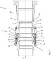
- A perspective cutaway drawing of a connector and a counter connector according to the invention;
- Figure 2
- A cross-sectional cutaway drawing of the connector and the counter connector of
Figure 1 with the engagement balls in the engagement position; - Figure 3
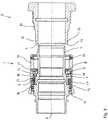
- A cross-sectional cutaway drawing of the connector and the counter connector of
Figure 1 with the engagement balls in the disengagement position; - Figure 4
- A perspective cutaway drawing of the claw ring and the engagement ball operating part; and
- Figure 5
- A perspective cutaway explosion drawing of the claw ring and the engagement ball operating part.
- In the following description of preferred embodiments of the invention, identical reference numerals refer to identical or similar components.
- The connector 1 shown in
Figures 1 to 5 comprises aninner housing 2 that extends from theproximal end 3 to thedistal end 4 of the connector 1. Typically, at theproximal end 3, a cable (not shown) is introduced into theinner housing 2, and at thedistal end 3, a connector face (not shown) is provided to mate with a corresponding connector face of thecounter connector 5. Onto theinner housing 2, aclaw ring 6 is rigidly mounted. As can be seen best inFigures 4 and5 , theclaw ring 6 comprises threeclaws 7 that extend towards thedistal end 3 of the connector 1, are equally spaced at angles of 120° relatively to each other and each span approximately 60°. At the distal ends of eachclaw 7, its inside is tapered towards the longitudinal axis of the connector 1, thereby forming a supportingpart 8 for twoengagement balls 9. In eachclaw 7 there are provided twoapertures 10, through which theengagements balls 9 can be introduced from the outside to the inner side of theclaw 7 during the assembly of the connector 1. - The
engagement balls 9 are held in an engagementball operating part 11 in the form of a ring shaped ball cage. The ball cage comprises six apertures to hold the sixballs 9. Through the apertures, theballs 9 can extend a certain distance into the space between the ball cage and theinner housing 2. The apertures are inwardly tapered towards the inside of the ball cage, in order to prevent theengagement balls 9 from falling into the space between the ball cage and the inner housing. The engagementball operating part 11 moreover comprisesclaws 12 that extend towards theproximal end 3 of the connector 1 between theclaws 7 of the claw ring as shown inFigure 4 . At the proximal end of eachclaw 12, astop 13 is provided that is pressed against in the distal direction by apre-tensioned wave spring 14. Thewave spring 14 sits on a ring-shapedprotrusion 15 of theinner housing 2 of the connector 1. - The engagement
ball operating part 11 can be slid along the longitudinal axis of the connector 1 against the force of thewave spring 14 from a distal position, which is the engagement ball operating part's 11 resting position and is also referred to as the locking position, towards a proximal position, also referred to as the unlocking position. In the distal position, the tapered surfaces of the supportingparts 8 of theclaws 7 of theclaw ring 6 press theengagement balls 9 inwardly into apertures of the engagementball operating part 11 so that they maximally extend into the space between the ball cage and theinner housing 2. This is also referred to as the engagement position of the engagement balls. When the engagementball operating part 11 slides towards its proximal position, thewave spring 14 gives way and theclaws 12 of the engagementball operating part 11 pass over the ring part of theclaw ring 6. At the same time, as theengagement balls 9 move in proximal direction relatively to theclaws 7 of theclaw ring 6, they become free to also move radially in the outside direction away from the apertures. - An
outer housing 16 of the connector 1 is slidably mounted, via apress ring 17 of theouter housing 16, on theinner housing 2 of the connector 1. Afirst seal ring 18 seals theouter housing 16 against theinner housing 2. On the inside of theouter housing 16, acatch 19 is provided that can engage with a counter catch of the engagementball operating part 11. As a result, when theouter housing 16 is slid from it distal position to its proximal position, the engagementball operating part 11 likewise is slid from its distal position to its proximal position. Conversely, when the engagementball operating part 11 is slid, by the force of the wave spring, from its proximal position to its distal position, theouter housing 16 likewise is slid from its proximal position to its distal position. Figures 1 and2 show the connector 1 in its resting configuration, disconnected from thecounter connector 5. In order to attach and lock the connector 1 to thecounter connector 5, theinner housing 2 of the connector 1 is slid into thehousing 20 of thecounter connector 5 past a secondrubber seal ring 21. For this, the operator can grip the connector 1 at itsouter housing 16 or, if preferred, at any other part such as the exposed part of theinner housing 2 or the cable. As theinner housing 2 of the connector 1 is slid into thehousing 20 of thecounter connector 5, the latter enters into the space between the ball cage and theinner housing 2. The leadingedge 22 of thehousing 20 of thecounter connector 5 presses on the parts of theengagement balls 9 that extend into the space between the ball cage and theinner housing 2, and theengagement balls 9 yield by sliding or rolling outwardly along the tapered surface of the supportingpart 8, at the same time moving the engagementball operating part 11 in the proximal direction against the force of thewave spring 14.Figure 3 shows the engagement balls (9) and the engagement ball operating part (11) in this position. This does not affect theouter housing 16 of theconnector 2, which can remain in its distal position. Subsequently, the leadingedge 22 of thehousing 20 of thecounter connector 5 passes theengagement balls 9, and as anannular groove 23 on the outside of thehousing 20 of thecounter connector 5 reaches theengagement balls 9, they are forced into theannular groove 23 by thewave spring 14 via the engagementball operating part 11.- The engagement of the
engagement balls 9 with the proximal side of theannular groove 23 locks the connector 1 to thecounter connector 5. In particular, when the connector 1 and thecounter connector 5 are pulled away from each other (for example by an external force or by pre-stressing element inside the connector 1 and/or the counter connector 5), theengagement balls 9 are clamped between the proximal side of theannular groove 23, which acts as anengagement part 24 of thecounter connector 5, and the surface of the supportingpart 8 of the connector 1. Theengagement part 24 of thecounter connector 5, and the surface of the supportingpart 8 of the connector are formed and arranged in such a way that the force applied to theengagement balls 9 by theengagement part 24 of the counter connector is the opposite of the force applied to theengagement balls 9 by the surface of the supportingpart 8. Accordingly, there is no resulting force acting on theengagement balls 9 that could move theengagement balls 9 out of their engagement positions. This can only be achieved by the engagementball operating part 11. Consequently, the connector is particularly resistant to vibration and shock and suitable for be pre-stressed connectors. - In order to unlock and detach the connector 1 from the
counter connector 5, the operator pulls theouter housing 16 of the connector 1 in the proximal direction. As a result, theouter housing 16 is slid from its distal position into its proximal position. By means of thecatch 19 and the engagement ball operating part's 11 counter catch, it moves the engagementball operating part 11 with it. As the engagementballs operating part 11 is moved from its distal position towards its proximal position, theengagement balls 9 become increasingly free to move radially in the outside direction away from the apertures. Eventually, they disengage from theengagement part 24 of thecounter connector 5, thereby unlocking the connector 1 from thecounter connector 5. As the connector 1 detaches from thecounter connector 5, the force of thewave spring 14 returns the engagement ball operating means 11 into its distal position and with it the entire connector 1 in its resting configuration. - The features as described in the above description, claims and figures can be relevant individually or in any combination to realise the various embodiments of the invention.
Claims (17)
- A connector (1) comprising at least one engagement ball (9) that is movable between an engagement position and a disengagement position,characterised in that a motion of an engagement ball operating part (11) of the connector (1) relatively to an inner housing (2) of the connector (1) can force the at least one engagement ball (9) from the engagement position into the disengagement position.
- The connector (1) of claim 1,characterised in that it comprises an inner housing (2) and an outer housing (16) which is movable relatively to the inner housing (2) in a longitudinal direction of the connector (1), wherein the outer housing (16) is operatively connected with the engagement ball operating part (11) such that when the outer housing (16) is moved relatively to the inner housing (2), the engagement ball operating part (11) is moved to force the at least one engagement ball (9) from the engagement position into the disengagement position.
- The connector (1) of any one of the previous claims,characterised in that the motion of the engagement ball operating part (11) is in the longitudinal direction of the connector (1).
- The connector (1) of any one of the previous claims,characterised in that when the engagement ball (9) is in the engagement position, it extends into a space which is suitable for an engagement part (24) of a counter connector (5) to be located to engage with the engagement ball (9) in order to secure the connector (1) to the counter connector (5).
- The connector (1) of any one of the previous claims,characterised in that the motion of the at least one engagement ball (9) between the engagement position and the disengagement position has a component in a radial direction of the connector (1).
- The connector (1) of any one of the previous claims,characterised in that the at least one engagement ball (9) is biased in the engagement position by means of an elastic element (14).
- The connector (1) of claim 6,characterised in that the at least one engagement ball (9) is biased in the engagement position by means of the elastic element via the engagement ball operating part (11).
- The connector (1) of any one of the previous claims,characterised in that at least in the engagement position the at least one engagement ball (9) rests on the surface of a at least one supporting part (8), which surface is tapered along its extension in the longitudinal direction of the connector (1).
- The connector (1) of any one of the previous claims,characterised in that the outer housing comprises a catch that when the outer housing is operated can engage with a counter catch of the engagement ball operating part (11) to move the engagement ball operating part (11), so that engagement ball operating part (11) force the at least one engagement ball (9) from the engagement position into the disengagement position.
- The connector (1) of claim 9,characterised in that the catch of the outer housing and the counter catch of the engagement ball operating part (11) are shaped and arranged in a way that when the engagement ball operating part (11) is moved from its position in which the at least one engagement ball (9) is in its engagement position to its position in which the at least one engagement ball (9) is in its disengagement position, this motion of the engagement ball operating part (11) is not translated into motion of the outer housing.
- The connector (1) of any one of the previous claims,characterised in that it comprises at least two engagement balls (9).
- A connector (1) comprising an inner housing (2), at least one engagement ball (9), an engagement ball operating part (11) that can move the at least one engagement ball (9) between an engagement position and a disengagement position, and a supporting part (8) which is rigidly connected with an inner housing (2) and on which the at least one engagement ball (9) at least partially rests in the engagement positioncharacterised in that the engagement ball operating part (11) comprises claws that extend through at least one window in the supporting part (8) or the inner housing (2) or between the supporting part (8) and the inner housing (2).
- A system comprising a connector (1) according to any one of the previous claims and a counter connector (5) that can be locked to the connector (1) by means of the at least one engagement ball (9) of the connector (1) that engages with an engagement part (24) of the counter connect.
- The system according to claim 13,characterised in that when the connector (1) is locked to the counter connector (5), at least one supporting part (8) of the connector (1) holds the at least one engagement ball (9) in a locking position against forces applied to the engagement ball (9) by the counter connector (5), a channel is provide between the at least one supporting part (8) of the connector (1) and the engagement part (24) of the counter connector (5), and an engagement ball operating part (11) can force the at least one engagement ball (9) along the channel from the engagement position into the disengagement position.
- A system comprising a connector (1) and a counter connector (5) that can be locked to the connector (1) by means of a locking mechanism with at least one engagement ball (9) of the connector (1) that can be moved relatively to an inner housing of the connector (1) from a disengagement position into an engagement position in which it engages with an engagement part (24) of the counter connector,characterised in that if the at least one engagement ball (8) is in the engagement position and the locking mechanism is loaded, the at least one engagement ball (8) does not exert a force on a part of the connector that is movable relatively to the inner housing and retains the engagement ball (8) in the engagement position.
- A method of unlocking a connector (1) from a counter connector (5) by moving an engagement ball (9) of the connector (1) from an locking position, in which the engagement ball (9) is engaged with an engagement part (24) of the counter connector (5) to lock the connector (1) to the counter connector (5), to an unlocking position, in which the engagement ball (9) is no longer engaged with the engagement part (24) of the counter connector (5).
- The method of claim 16,characterised in that an outer housing of the connector (1) moves relatively to the inner housing, the outer housing moves an engagement ball operating part (11), and the engagement ball operating part (11) forces the engagement ball (9) from the locking position into the unlocking position.
Priority Applications (6)
| Application Number | Priority Date | Filing Date | Title |
|---|---|---|---|
| EP19196036.8AEP3789648B1 (en) | 2019-09-06 | 2019-09-06 | Ball-lock connector |
| RU2020124225ARU2748941C1 (en) | 2019-09-06 | 2020-07-21 | Ball valve connection |
| JP2020127748AJP7228546B2 (en) | 2019-09-06 | 2020-07-28 | ball-lock connector |
| CN202010909479.6ACN112467473B (en) | 2019-09-06 | 2020-09-02 | Ball lock connector |
| KR1020200112220AKR102536620B1 (en) | 2019-09-06 | 2020-09-03 | Ball-lock connector |
| US17/012,249US11668334B2 (en) | 2019-09-06 | 2020-09-04 | Ball-lock connector |
Applications Claiming Priority (1)
| Application Number | Priority Date | Filing Date | Title |
|---|---|---|---|
| EP19196036.8AEP3789648B1 (en) | 2019-09-06 | 2019-09-06 | Ball-lock connector |
Publications (3)
| Publication Number | Publication Date |
|---|---|
| EP3789648A1true EP3789648A1 (en) | 2021-03-10 |
| EP3789648C0 EP3789648C0 (en) | 2024-01-03 |
| EP3789648B1 EP3789648B1 (en) | 2024-01-03 |
Family
ID=67875410
Family Applications (1)
| Application Number | Title | Priority Date | Filing Date |
|---|---|---|---|
| EP19196036.8AActiveEP3789648B1 (en) | 2019-09-06 | 2019-09-06 | Ball-lock connector |
Country Status (6)
| Country | Link |
|---|---|
| US (1) | US11668334B2 (en) |
| EP (1) | EP3789648B1 (en) |
| JP (1) | JP7228546B2 (en) |
| KR (1) | KR102536620B1 (en) |
| CN (1) | CN112467473B (en) |
| RU (1) | RU2748941C1 (en) |
Cited By (1)
| Publication number | Priority date | Publication date | Assignee | Title |
|---|---|---|---|---|
| WO2025132386A1 (en)* | 2023-12-20 | 2025-06-26 | Smw Autoblok | Mandrel assembly system |
Families Citing this family (5)
| Publication number | Priority date | Publication date | Assignee | Title |
|---|---|---|---|---|
| CN115117669B (en)* | 2021-03-19 | 2025-07-04 | 泰科电子(上海)有限公司 | Connectors and Connector Assemblies |
| CN113062454B (en)* | 2021-03-30 | 2022-12-06 | 山西宏厚装配式建筑科技发展有限公司 | Steel structure beam column frame assembling type process |
| TWI820765B (en)* | 2021-08-16 | 2023-11-01 | 顏玉惠 | Connector shroud |
| USD1006595S1 (en)* | 2021-10-26 | 2023-12-05 | Gem Products, Llc | Latch backing plate |
| CN115978375A (en)* | 2022-10-21 | 2023-04-18 | 广东安达智能装备股份有限公司 | A quick connection structure and intelligent platform system |
Citations (15)
| Publication number | Priority date | Publication date | Assignee | Title |
|---|---|---|---|---|
| FR1384065A (en) | 1963-11-12 | 1965-01-04 | Staubli Freres & Cie | Quick coupling device for pipes and the like |
| FR2484053A2 (en) | 1980-06-06 | 1981-12-11 | Fremy Raoul | Quick disconnect pipe coupling - can be separated by axial movement of spring loaded sliding locking sleeve which has locking rollers seated in groove |
| FR2527741B1 (en) | 1982-06-01 | 1986-02-21 | Staubli Sa Ets | IMPROVEMENTS ON QUICK CONNECTIONS FOR REMOVABLE JOINING OF PIPES |
| EP0184799A2 (en) | 1984-12-11 | 1986-06-18 | RECTUS-APPARATEBAU Walter Klein GmbH | Vent coupling |
| US4932431A (en)* | 1989-08-07 | 1990-06-12 | Tuthill Corporation | Coupling with heat fusible actuator member |
| CN2729951Y (en) | 2004-09-08 | 2005-09-28 | 贵州航天电器股份有限公司 | Ball type quick push-pull locking and unlocking electric connector |
| CN101656381A (en)* | 2008-08-22 | 2010-02-24 | 贵州航天电器股份有限公司 | High-power radio frequency connector capable of being locked and separated quickly |
| US20120243932A1 (en) | 2011-03-23 | 2012-09-27 | GM Global Technology Operations LLC | Quick release vehicle accessory connection system |
| CN102856723A (en) | 2012-03-29 | 2013-01-02 | 中航光电科技股份有限公司 | Plug with looseness-prevention connecting nut and connector assembly |
| US8764473B2 (en) | 2010-04-22 | 2014-07-01 | Canare Electric Co., Ltd. | Ball-lock connector |
| US8844942B1 (en)* | 2010-06-25 | 2014-09-30 | Greatbatch Ltd. | Quick-load connector for a surgical tool |
| US9242422B2 (en) | 2011-06-16 | 2016-01-26 | Von Arx Ag | Quick-connect coupling |
| US9502822B1 (en)* | 2015-12-01 | 2016-11-22 | Chung-Chuan Huang | Ball-lock axial connector assembly |
| DE102016105975A1 (en) | 2016-04-01 | 2017-10-05 | Harting Ag & Co. Kg | Locking device for connectors |
| CN108254835A (en) | 2017-11-14 | 2018-07-06 | 烽火通信科技股份有限公司 | A connector, an adapter and a quick-plug optical fiber connection assembly |
Family Cites Families (34)
| Publication number | Priority date | Publication date | Assignee | Title |
|---|---|---|---|---|
| US2665928A (en)* | 1948-10-27 | 1954-01-12 | Case Co J I | Coupling |
| US3567175A (en)* | 1968-10-08 | 1971-03-02 | Stile Craft Mfg Inc | Quick release coupling |
| US3715099A (en)* | 1971-06-02 | 1973-02-06 | Crawford Fitting Co | Valved quick-disconnect coupling |
| US4014467A (en)* | 1975-11-03 | 1977-03-29 | Duff-Norton Company, Inc. | Dishwasher and coupling |
| FR2366475A1 (en)* | 1976-10-04 | 1978-04-28 | Salanon Sa | AUTOMATIC SWITCHING QUICK CONNECTOR |
| US4198080A (en)* | 1978-05-19 | 1980-04-15 | Baxter Travenol Laboratories, Inc. | Telescoping-type connector |
| US4213482A (en)* | 1978-10-25 | 1980-07-22 | Gondek John T | Hydraulic coupler |
| WO1980001311A1 (en)* | 1978-12-20 | 1980-06-26 | Abnox Ag | Pipe coupling |
| US4645372A (en)* | 1984-10-01 | 1987-02-24 | Matsui-Walterschield Ltd. | Power transmitting coupling |
| JPH0755855Y2 (en)* | 1988-02-04 | 1995-12-25 | ケーエス・サノヤス株式会社 | Rotating joint connection structure |
| US4859110A (en)* | 1988-09-21 | 1989-08-22 | Neapco, Inc. | Automatic coupling device |
| JPH0753032Y2 (en)* | 1991-06-11 | 1995-12-06 | 日東工器株式会社 | Pipe fitting |
| EP0536434B1 (en)* | 1991-10-08 | 1994-09-28 | RECTUS-APPARATEBAU Walter Klein GmbH | Self-vented quick coupling for pressurized gas pipes, especially for compressed air pipes |
| US5366313A (en)* | 1992-11-02 | 1994-11-22 | Norco, Inc. | Strut construction |
| US5540250A (en)* | 1994-03-22 | 1996-07-30 | Perfecting Coupling Company | Quick-disconnect fluid coupling |
| US5445358A (en)* | 1994-12-16 | 1995-08-29 | Parker-Hannifin Corporation | Exhaust type quick action coupler |
| JPH0992395A (en)* | 1995-09-20 | 1997-04-04 | Sumitomo Wiring Syst Ltd | Locking mechanism for connector |
| JPH0992295A (en) | 1995-09-21 | 1997-04-04 | Matsushita Electric Ind Co Ltd | Manufacturing method of air electrode for button type zinc-air battery |
| SE506405C2 (en)* | 1996-03-22 | 1997-12-15 | Nyberg Bo Erik | Quick release with pressure relief for safe release |
| JP2909020B2 (en)* | 1996-06-11 | 1999-06-23 | ナスコフィッティング株式会社 | Pipe fittings |
| FR2786848B1 (en)* | 1998-12-02 | 2001-02-09 | Legris Sa | BALL COUPLER |
| US6655991B2 (en)* | 2002-01-09 | 2003-12-02 | Clark Heebe | Coaxial cable quick connect/disconnect connector |
| JP3983728B2 (en)* | 2003-09-18 | 2007-09-26 | 日東工器株式会社 | Pipe fittings and sockets for pipe fittings |
| JP4484143B2 (en)* | 2004-06-09 | 2010-06-16 | 日東工器株式会社 | Plug / socket assembly |
| US7841580B2 (en)* | 2005-04-18 | 2010-11-30 | Macro Technologies, Inc. | Pressurized fluid coupler with anti-recoil feature and methods |
| FR2890719B1 (en)* | 2005-09-14 | 2007-10-12 | Staubli Faverges Sca | QUICK CONNECTION OF SECURITY FOR THE JOINING OF TWO PIPES |
| US8056581B2 (en)* | 2006-04-06 | 2011-11-15 | Fastest, Inc. | Latching connectors |
| JP4831619B2 (en)* | 2006-11-24 | 2011-12-07 | 日東工器株式会社 | Joint, socket and plug used for this joint |
| US20080315581A1 (en)* | 2007-01-29 | 2008-12-25 | White Davis A | Non-Rotating Coupling Device |
| KR101260115B1 (en)* | 2008-02-28 | 2013-05-02 | 니토 코키 가부시키가이샤 | Socket for pipe coupling and pipe coupling |
| RU2487782C2 (en)* | 2011-02-10 | 2013-07-20 | Геннадий Михайлович Целковнев | Connector of modules |
| FR2998637B1 (en)* | 2012-11-23 | 2015-06-26 | Staubli Sa Ets | RAPID COUPLING FEMALE ELEMENT AND RAPID CONNECTION INCORPORATING SUCH A MEMBER |
| JP2018515731A (en)* | 2015-04-24 | 2018-06-14 | ジェネラル・プラズマ・インコーポレーテッド | Push-type connection and pull-type separated quick fitting |
| CN106848740A (en)* | 2017-01-23 | 2017-06-13 | 中航光电科技股份有限公司 | A kind of connector and its lock sleeve |
- 2019
- 2019-09-06EPEP19196036.8Apatent/EP3789648B1/enactiveActive
- 2020
- 2020-07-21RURU2020124225Apatent/RU2748941C1/enactive
- 2020-07-28JPJP2020127748Apatent/JP7228546B2/enactiveActive
- 2020-09-02CNCN202010909479.6Apatent/CN112467473B/enactiveActive
- 2020-09-03KRKR1020200112220Apatent/KR102536620B1/enactiveActive
- 2020-09-04USUS17/012,249patent/US11668334B2/enactiveActive
Patent Citations (15)
| Publication number | Priority date | Publication date | Assignee | Title |
|---|---|---|---|---|
| FR1384065A (en) | 1963-11-12 | 1965-01-04 | Staubli Freres & Cie | Quick coupling device for pipes and the like |
| FR2484053A2 (en) | 1980-06-06 | 1981-12-11 | Fremy Raoul | Quick disconnect pipe coupling - can be separated by axial movement of spring loaded sliding locking sleeve which has locking rollers seated in groove |
| FR2527741B1 (en) | 1982-06-01 | 1986-02-21 | Staubli Sa Ets | IMPROVEMENTS ON QUICK CONNECTIONS FOR REMOVABLE JOINING OF PIPES |
| EP0184799A2 (en) | 1984-12-11 | 1986-06-18 | RECTUS-APPARATEBAU Walter Klein GmbH | Vent coupling |
| US4932431A (en)* | 1989-08-07 | 1990-06-12 | Tuthill Corporation | Coupling with heat fusible actuator member |
| CN2729951Y (en) | 2004-09-08 | 2005-09-28 | 贵州航天电器股份有限公司 | Ball type quick push-pull locking and unlocking electric connector |
| CN101656381A (en)* | 2008-08-22 | 2010-02-24 | 贵州航天电器股份有限公司 | High-power radio frequency connector capable of being locked and separated quickly |
| US8764473B2 (en) | 2010-04-22 | 2014-07-01 | Canare Electric Co., Ltd. | Ball-lock connector |
| US8844942B1 (en)* | 2010-06-25 | 2014-09-30 | Greatbatch Ltd. | Quick-load connector for a surgical tool |
| US20120243932A1 (en) | 2011-03-23 | 2012-09-27 | GM Global Technology Operations LLC | Quick release vehicle accessory connection system |
| US9242422B2 (en) | 2011-06-16 | 2016-01-26 | Von Arx Ag | Quick-connect coupling |
| CN102856723A (en) | 2012-03-29 | 2013-01-02 | 中航光电科技股份有限公司 | Plug with looseness-prevention connecting nut and connector assembly |
| US9502822B1 (en)* | 2015-12-01 | 2016-11-22 | Chung-Chuan Huang | Ball-lock axial connector assembly |
| DE102016105975A1 (en) | 2016-04-01 | 2017-10-05 | Harting Ag & Co. Kg | Locking device for connectors |
| CN108254835A (en) | 2017-11-14 | 2018-07-06 | 烽火通信科技股份有限公司 | A connector, an adapter and a quick-plug optical fiber connection assembly |
Cited By (2)
| Publication number | Priority date | Publication date | Assignee | Title |
|---|---|---|---|---|
| WO2025132386A1 (en)* | 2023-12-20 | 2025-06-26 | Smw Autoblok | Mandrel assembly system |
| FR3157241A1 (en)* | 2023-12-20 | 2025-06-27 | Smw Autoblok | Mandrel assembly system |
Also Published As
| Publication number | Publication date |
|---|---|
| EP3789648C0 (en) | 2024-01-03 |
| US11668334B2 (en) | 2023-06-06 |
| JP7228546B2 (en) | 2023-02-24 |
| KR102536620B1 (en) | 2023-05-25 |
| JP2021044232A (en) | 2021-03-18 |
| CN112467473A (en) | 2021-03-09 |
| US20210071698A1 (en) | 2021-03-11 |
| KR20210030208A (en) | 2021-03-17 |
| RU2748941C1 (en) | 2021-06-02 |
| EP3789648B1 (en) | 2024-01-03 |
| CN112467473B (en) | 2023-03-24 |
Similar Documents
| Publication | Publication Date | Title |
|---|---|---|
| US11668334B2 (en) | Ball-lock connector | |
| US11637387B2 (en) | Coaxial and cluster connector assemblies | |
| JP5391137B2 (en) | Ball lock connector | |
| EP1666783B1 (en) | Pipe joint and socket for pipe joint | |
| US5984709A (en) | Electric connector | |
| KR102419081B1 (en) | Connector for a cable and connector assembly | |
| EP2037543A1 (en) | Electrical connector and connector assembly | |
| US10355406B2 (en) | Electrical connector | |
| EP2395609B1 (en) | Anti-vibration connector coupling | |
| US4907981A (en) | Quick-release electrical connector coupling device | |
| US20030155766A1 (en) | Coupling for connecting hydraulic ducts | |
| US20130099482A1 (en) | Coupling device and connector including such a device | |
| EP3580817B1 (en) | Electrical connector assembly with unlocking device for the unlocking process | |
| US9595788B1 (en) | Electrical connector having a flexible latch actuated by a ramp on a release collar | |
| KR102573088B1 (en) | Connector assembly that can be mated in a single operation | |
| US9197008B1 (en) | Electrical assembly having a threaded coupling nut and retaining ring | |
| KR102665452B1 (en) | Connector assembly couplable with single action | |
| KR102782576B1 (en) | Connector assembly for electric cable | |
| KR20230014100A (en) | Connector assembly couplable with single action | |
| HK1108767A1 (en) | Conductor connecting structure of power cable | |
| HK1108767B (en) | Conductor connecting structure of power cable | |
| HK1001826B (en) | Connecting device |
Legal Events
| Date | Code | Title | Description |
|---|---|---|---|
| PUAI | Public reference made under article 153(3) epc to a published international application that has entered the european phase | Free format text:ORIGINAL CODE: 0009012 | |
| STAA | Information on the status of an ep patent application or granted ep patent | Free format text:STATUS: THE APPLICATION HAS BEEN PUBLISHED | |
| AK | Designated contracting states | Kind code of ref document:A1 Designated state(s):AL AT BE BG CH CY CZ DE DK EE ES FI FR GB GR HR HU IE IS IT LI LT LU LV MC MK MT NL NO PL PT RO RS SE SI SK SM TR | |
| AX | Request for extension of the european patent | Extension state:BA ME | |
| STAA | Information on the status of an ep patent application or granted ep patent | Free format text:STATUS: REQUEST FOR EXAMINATION WAS MADE | |
| 17P | Request for examination filed | Effective date:20210412 | |
| RBV | Designated contracting states (corrected) | Designated state(s):AL AT BE BG CH CY CZ DE DK EE ES FI FR GB GR HR HU IE IS IT LI LT LU LV MC MK MT NL NO PL PT RO RS SE SI SK SM TR | |
| RAP3 | Party data changed (applicant data changed or rights of an application transferred) | Owner name:ODU GMBH & CO. KG | |
| STAA | Information on the status of an ep patent application or granted ep patent | Free format text:STATUS: EXAMINATION IS IN PROGRESS | |
| 17Q | First examination report despatched | Effective date:20220705 | |
| GRAP | Despatch of communication of intention to grant a patent | Free format text:ORIGINAL CODE: EPIDOSNIGR1 | |
| STAA | Information on the status of an ep patent application or granted ep patent | Free format text:STATUS: GRANT OF PATENT IS INTENDED | |
| INTG | Intention to grant announced | Effective date:20230714 | |
| GRAS | Grant fee paid | Free format text:ORIGINAL CODE: EPIDOSNIGR3 | |
| GRAA | (expected) grant | Free format text:ORIGINAL CODE: 0009210 | |
| STAA | Information on the status of an ep patent application or granted ep patent | Free format text:STATUS: THE PATENT HAS BEEN GRANTED | |
| AK | Designated contracting states | Kind code of ref document:B1 Designated state(s):AL AT BE BG CH CY CZ DE DK EE ES FI FR GB GR HR HU IE IS IT LI LT LU LV MC MK MT NL NO PL PT RO RS SE SI SK SM TR | |
| REG | Reference to a national code | Ref country code:GB Ref legal event code:FG4D | |
| REG | Reference to a national code | Ref country code:CH Ref legal event code:EP | |
| REG | Reference to a national code | Ref country code:DE Ref legal event code:R096 Ref document number:602019044341 Country of ref document:DE | |
| REG | Reference to a national code | Ref country code:IE Ref legal event code:FG4D | |
| U01 | Request for unitary effect filed | Effective date:20240103 | |
| U07 | Unitary effect registered | Designated state(s):AT BE BG DE DK EE FI FR IT LT LU LV MT NL PT SE SI Effective date:20240126 | |
| PG25 | Lapsed in a contracting state [announced via postgrant information from national office to epo] | Ref country code:ES Free format text:LAPSE BECAUSE OF FAILURE TO SUBMIT A TRANSLATION OF THE DESCRIPTION OR TO PAY THE FEE WITHIN THE PRESCRIBED TIME-LIMIT Effective date:20240103 | |
| PG25 | Lapsed in a contracting state [announced via postgrant information from national office to epo] | Ref country code:ES Free format text:LAPSE BECAUSE OF FAILURE TO SUBMIT A TRANSLATION OF THE DESCRIPTION OR TO PAY THE FEE WITHIN THE PRESCRIBED TIME-LIMIT Effective date:20240103 | |
| PG25 | Lapsed in a contracting state [announced via postgrant information from national office to epo] | Ref country code:IS Free format text:LAPSE BECAUSE OF FAILURE TO SUBMIT A TRANSLATION OF THE DESCRIPTION OR TO PAY THE FEE WITHIN THE PRESCRIBED TIME-LIMIT Effective date:20240503 | |
| PG25 | Lapsed in a contracting state [announced via postgrant information from national office to epo] | Ref country code:GR Free format text:LAPSE BECAUSE OF FAILURE TO SUBMIT A TRANSLATION OF THE DESCRIPTION OR TO PAY THE FEE WITHIN THE PRESCRIBED TIME-LIMIT Effective date:20240404 | |
| PG25 | Lapsed in a contracting state [announced via postgrant information from national office to epo] | Ref country code:HR Free format text:LAPSE BECAUSE OF FAILURE TO SUBMIT A TRANSLATION OF THE DESCRIPTION OR TO PAY THE FEE WITHIN THE PRESCRIBED TIME-LIMIT Effective date:20240103 Ref country code:RS Free format text:LAPSE BECAUSE OF FAILURE TO SUBMIT A TRANSLATION OF THE DESCRIPTION OR TO PAY THE FEE WITHIN THE PRESCRIBED TIME-LIMIT Effective date:20240403 | |
| PG25 | Lapsed in a contracting state [announced via postgrant information from national office to epo] | Ref country code:CZ Free format text:LAPSE BECAUSE OF FAILURE TO SUBMIT A TRANSLATION OF THE DESCRIPTION OR TO PAY THE FEE WITHIN THE PRESCRIBED TIME-LIMIT Effective date:20240103 | |
| PG25 | Lapsed in a contracting state [announced via postgrant information from national office to epo] | Ref country code:RS Free format text:LAPSE BECAUSE OF FAILURE TO SUBMIT A TRANSLATION OF THE DESCRIPTION OR TO PAY THE FEE WITHIN THE PRESCRIBED TIME-LIMIT Effective date:20240403 Ref country code:NO Free format text:LAPSE BECAUSE OF FAILURE TO SUBMIT A TRANSLATION OF THE DESCRIPTION OR TO PAY THE FEE WITHIN THE PRESCRIBED TIME-LIMIT Effective date:20240403 Ref country code:IS Free format text:LAPSE BECAUSE OF FAILURE TO SUBMIT A TRANSLATION OF THE DESCRIPTION OR TO PAY THE FEE WITHIN THE PRESCRIBED TIME-LIMIT Effective date:20240503 Ref country code:HR Free format text:LAPSE BECAUSE OF FAILURE TO SUBMIT A TRANSLATION OF THE DESCRIPTION OR TO PAY THE FEE WITHIN THE PRESCRIBED TIME-LIMIT Effective date:20240103 Ref country code:GR Free format text:LAPSE BECAUSE OF FAILURE TO SUBMIT A TRANSLATION OF THE DESCRIPTION OR TO PAY THE FEE WITHIN THE PRESCRIBED TIME-LIMIT Effective date:20240404 Ref country code:CZ Free format text:LAPSE BECAUSE OF FAILURE TO SUBMIT A TRANSLATION OF THE DESCRIPTION OR TO PAY THE FEE WITHIN THE PRESCRIBED TIME-LIMIT Effective date:20240103 | |
| PG25 | Lapsed in a contracting state [announced via postgrant information from national office to epo] | Ref country code:PL Free format text:LAPSE BECAUSE OF FAILURE TO SUBMIT A TRANSLATION OF THE DESCRIPTION OR TO PAY THE FEE WITHIN THE PRESCRIBED TIME-LIMIT Effective date:20240103 | |
| PG25 | Lapsed in a contracting state [announced via postgrant information from national office to epo] | Ref country code:PL Free format text:LAPSE BECAUSE OF FAILURE TO SUBMIT A TRANSLATION OF THE DESCRIPTION OR TO PAY THE FEE WITHIN THE PRESCRIBED TIME-LIMIT Effective date:20240103 | |
| REG | Reference to a national code | Ref country code:DE Ref legal event code:R097 Ref document number:602019044341 Country of ref document:DE | |
| PG25 | Lapsed in a contracting state [announced via postgrant information from national office to epo] | Ref country code:SM Free format text:LAPSE BECAUSE OF FAILURE TO SUBMIT A TRANSLATION OF THE DESCRIPTION OR TO PAY THE FEE WITHIN THE PRESCRIBED TIME-LIMIT Effective date:20240103 | |
| PGFP | Annual fee paid to national office [announced via postgrant information from national office to epo] | Ref country code:GB Payment date:20240923 Year of fee payment:6 | |
| PG25 | Lapsed in a contracting state [announced via postgrant information from national office to epo] | Ref country code:SK Free format text:LAPSE BECAUSE OF FAILURE TO SUBMIT A TRANSLATION OF THE DESCRIPTION OR TO PAY THE FEE WITHIN THE PRESCRIBED TIME-LIMIT Effective date:20240103 | |
| U20 | Renewal fee for the european patent with unitary effect paid | Year of fee payment:6 Effective date:20240925 | |
| PG25 | Lapsed in a contracting state [announced via postgrant information from national office to epo] | Ref country code:SM Free format text:LAPSE BECAUSE OF FAILURE TO SUBMIT A TRANSLATION OF THE DESCRIPTION OR TO PAY THE FEE WITHIN THE PRESCRIBED TIME-LIMIT Effective date:20240103 Ref country code:SK Free format text:LAPSE BECAUSE OF FAILURE TO SUBMIT A TRANSLATION OF THE DESCRIPTION OR TO PAY THE FEE WITHIN THE PRESCRIBED TIME-LIMIT Effective date:20240103 Ref country code:RO Free format text:LAPSE BECAUSE OF FAILURE TO SUBMIT A TRANSLATION OF THE DESCRIPTION OR TO PAY THE FEE WITHIN THE PRESCRIBED TIME-LIMIT Effective date:20240103 | |
| PLBE | No opposition filed within time limit | Free format text:ORIGINAL CODE: 0009261 | |
| STAA | Information on the status of an ep patent application or granted ep patent | Free format text:STATUS: NO OPPOSITION FILED WITHIN TIME LIMIT | |
| 26N | No opposition filed | Effective date:20241007 | |
| PG25 | Lapsed in a contracting state [announced via postgrant information from national office to epo] | Ref country code:MC Free format text:LAPSE BECAUSE OF FAILURE TO SUBMIT A TRANSLATION OF THE DESCRIPTION OR TO PAY THE FEE WITHIN THE PRESCRIBED TIME-LIMIT Effective date:20240103 | |
| REG | Reference to a national code | Ref country code:CH Ref legal event code:PL | |
| PG25 | Lapsed in a contracting state [announced via postgrant information from national office to epo] | Ref country code:CH Free format text:LAPSE BECAUSE OF NON-PAYMENT OF DUE FEES Effective date:20240930 | |
| PG25 | Lapsed in a contracting state [announced via postgrant information from national office to epo] | Ref country code:IE Free format text:LAPSE BECAUSE OF NON-PAYMENT OF DUE FEES Effective date:20240906 |