EP3788944A1 - System for determining the shape of a bendable instrument - Google Patents
System for determining the shape of a bendable instrumentDownload PDFInfo
- Publication number
- EP3788944A1 EP3788944A1EP20189123.1AEP20189123AEP3788944A1EP 3788944 A1EP3788944 A1EP 3788944A1EP 20189123 AEP20189123 AEP 20189123AEP 3788944 A1EP3788944 A1EP 3788944A1
- Authority
- EP
- European Patent Office
- Prior art keywords
- control element
- instrument
- segment
- control
- actuator
- Prior art date
- Legal status (The legal status is an assumption and is not a legal conclusion. Google has not performed a legal analysis and makes no representation as to the accuracy of the status listed.)
- Granted
Links
Images


Classifications
- A—HUMAN NECESSITIES
- A61—MEDICAL OR VETERINARY SCIENCE; HYGIENE
- A61B—DIAGNOSIS; SURGERY; IDENTIFICATION
- A61B1/00—Instruments for performing medical examinations of the interior of cavities or tubes of the body by visual or photographical inspection, e.g. endoscopes; Illuminating arrangements therefor
- A61B1/005—Flexible endoscopes
- A61B1/0051—Flexible endoscopes with controlled bending of insertion part
- A61B1/0052—Constructional details of control elements, e.g. handles
- A—HUMAN NECESSITIES
- A61—MEDICAL OR VETERINARY SCIENCE; HYGIENE
- A61B—DIAGNOSIS; SURGERY; IDENTIFICATION
- A61B1/00—Instruments for performing medical examinations of the interior of cavities or tubes of the body by visual or photographical inspection, e.g. endoscopes; Illuminating arrangements therefor
- A61B1/00112—Connection or coupling means
- A61B1/00121—Connectors, fasteners and adapters, e.g. on the endoscope handle
- A61B1/00128—Connectors, fasteners and adapters, e.g. on the endoscope handle mechanical, e.g. for tubes or pipes
- A—HUMAN NECESSITIES
- A61—MEDICAL OR VETERINARY SCIENCE; HYGIENE
- A61B—DIAGNOSIS; SURGERY; IDENTIFICATION
- A61B1/00—Instruments for performing medical examinations of the interior of cavities or tubes of the body by visual or photographical inspection, e.g. endoscopes; Illuminating arrangements therefor
- A61B1/005—Flexible endoscopes
- A61B1/009—Flexible endoscopes with bending or curvature detection of the insertion part
- A—HUMAN NECESSITIES
- A61—MEDICAL OR VETERINARY SCIENCE; HYGIENE
- A61B—DIAGNOSIS; SURGERY; IDENTIFICATION
- A61B34/00—Computer-aided surgery; Manipulators or robots specially adapted for use in surgery
- A61B34/20—Surgical navigation systems; Devices for tracking or guiding surgical instruments, e.g. for frameless stereotaxis
- A—HUMAN NECESSITIES
- A61—MEDICAL OR VETERINARY SCIENCE; HYGIENE
- A61B—DIAGNOSIS; SURGERY; IDENTIFICATION
- A61B5/00—Measuring for diagnostic purposes; Identification of persons
- A61B5/06—Devices, other than using radiation, for detecting or locating foreign bodies ; Determining position of diagnostic devices within or on the body of the patient
- A61B5/065—Determining position of the probe employing exclusively positioning means located on or in the probe, e.g. using position sensors arranged on the probe
- A—HUMAN NECESSITIES
- A61—MEDICAL OR VETERINARY SCIENCE; HYGIENE
- A61M—DEVICES FOR INTRODUCING MEDIA INTO, OR ONTO, THE BODY; DEVICES FOR TRANSDUCING BODY MEDIA OR FOR TAKING MEDIA FROM THE BODY; DEVICES FOR PRODUCING OR ENDING SLEEP OR STUPOR
- A61M25/00—Catheters; Hollow probes
- A61M25/01—Introducing, guiding, advancing, emplacing or holding catheters
- A61M25/0105—Steering means as part of the catheter or advancing means; Markers for positioning
- A61M25/0133—Tip steering devices
- A61M25/0147—Tip steering devices with movable mechanical means, e.g. pull wires
- A—HUMAN NECESSITIES
- A61—MEDICAL OR VETERINARY SCIENCE; HYGIENE
- A61M—DEVICES FOR INTRODUCING MEDIA INTO, OR ONTO, THE BODY; DEVICES FOR TRANSDUCING BODY MEDIA OR FOR TAKING MEDIA FROM THE BODY; DEVICES FOR PRODUCING OR ENDING SLEEP OR STUPOR
- A61M25/00—Catheters; Hollow probes
- A61M25/01—Introducing, guiding, advancing, emplacing or holding catheters
- A61M25/0105—Steering means as part of the catheter or advancing means; Markers for positioning
- A61M25/0133—Tip steering devices
- A61M25/0155—Tip steering devices with hydraulic or pneumatic means, e.g. balloons or inflatable compartments
- A—HUMAN NECESSITIES
- A61—MEDICAL OR VETERINARY SCIENCE; HYGIENE
- A61M—DEVICES FOR INTRODUCING MEDIA INTO, OR ONTO, THE BODY; DEVICES FOR TRANSDUCING BODY MEDIA OR FOR TAKING MEDIA FROM THE BODY; DEVICES FOR PRODUCING OR ENDING SLEEP OR STUPOR
- A61M25/00—Catheters; Hollow probes
- A61M25/01—Introducing, guiding, advancing, emplacing or holding catheters
- A61M25/0105—Steering means as part of the catheter or advancing means; Markers for positioning
- A61M25/0133—Tip steering devices
- A61M25/0158—Tip steering devices with magnetic or electrical means, e.g. by using piezo materials, electroactive polymers, magnetic materials or by heating of shape memory materials
- A—HUMAN NECESSITIES
- A61—MEDICAL OR VETERINARY SCIENCE; HYGIENE
- A61B—DIAGNOSIS; SURGERY; IDENTIFICATION
- A61B90/00—Instruments, implements or accessories specially adapted for surgery or diagnosis and not covered by any of the groups A61B1/00 - A61B50/00, e.g. for luxation treatment or for protecting wound edges
- A61B90/06—Measuring instruments not otherwise provided for
- A61B2090/064—Measuring instruments not otherwise provided for for measuring force, pressure or mechanical tension
- A—HUMAN NECESSITIES
- A61—MEDICAL OR VETERINARY SCIENCE; HYGIENE
- A61B—DIAGNOSIS; SURGERY; IDENTIFICATION
- A61B90/00—Instruments, implements or accessories specially adapted for surgery or diagnosis and not covered by any of the groups A61B1/00 - A61B50/00, e.g. for luxation treatment or for protecting wound edges
- A61B90/36—Image-producing devices or illumination devices not otherwise provided for
- A61B90/361—Image-producing devices, e.g. surgical cameras
Definitions
- Bendable instrumentscome in many forms such as catheters, colonoscopes, endoscopes and the like. Control elements are used to bend the instruments into a desired shape or as part of steering or maneuvering the instrument as needed for a surgical or exploratory procedure for example. While the instrument may be controlled to ultimately reach a desired position, knowing the shape of the instrument may provide useful information for maneuvering the instrument or to aid in the procedure.
- One embodiment of the inventionprovides method of determining the shape of a bendable instrument by moving at least two control elements first and second amounts without bending the instrument; measuring the first and second amounts; and determining the shape of the instrument from the first and second amounts.
- the moving stepis accomplished without using an actuator connected to a control element.
- the moving stepremoves slack from the at least two control elements before the measuring step.
- the removing stepis performed by applying a known drive command to an actuator.
- the drive commandis insufficient to change the position of the instrument.
- the drive commandis the current applied to an actuator.
- the removing stepis performed using a tension measurement taken in a connector that couples an actuator to one of the at least two control elements.
- the removing stepis performed using a feedback loop that receives input from a sensor.
- the input from a sensoris related to a tension measurement of a control element.
- the sensoris located on or in the bendable instrument.
- the sensoris located on or in a connector that joins the bendable instrument to an actuator.
- the sensoris located on or in an actuator connected to a control element.
- a stepis performed by removing the slack from the at least two control elements during a first time period at a first force limit before removing the slack from the at least two control elements during a second time period at a second different force limit.
- the first force limitis less than the second force limit.
- the determining stepuses a look up table that correlates the first and second amounts to the instrument shape, position or configuration. In another aspect, the determining step uses a modeled kinematic relationship between first and second amounts and the instrument shape, position or configuration. In another aspect, the determining step uses a calculated position delta of the at least two control elements. In another aspect, the determining step uses a calculated position delta of complementary control elements within the at least two control elements. In another aspect, the determining step uses a calculated position delta of a pair of opposing control elements within the at least two control elements.
- the measuring stepincludes the steps of (a) moving a control element not being used to bend the instrument; and (b) determining a calculated position delta for the control element not being used to bend the instrument. In one aspect, the determining step uses the calculated position delta for a control element not being used to bend the instrument.
- the step of positioning the bendable instrument within a lumenis performed before the moving step.
- the moving stepis performed by the lumen acting on the instrument.
- the determining stepis used to determine the shape of the lumen.
- the techniques described hereinmay be used to determine the shape of a bendable instrument by measuring or manipulating information related to the position of the control implements used to change the shape of or maneuver the instrument.
- the techniques described hereinhave several advantages.
- the techniquesare independent of the force used for measurement as well as the tortuosity of the control wires used to maneuver the steerable instrument.
- the techniquesrepeatably and reliably reproduce the shape of the instrument.
- the techniques described hereinenable the measurement and/or determination of steerable instrument shape using measurements of the control wires or cables used to control the instrument. Details of the various alternative embodiments for performing the methods of the invention will be appreciated after discussion of an exemplary bendable instrument and instrument control system.
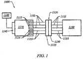
- FIG. 1illustrates a schematic view of a system 1000 for moving a controllable article 1100
- a force generator under control of one or both of a user input device 1140 and a system controller 1145generates forces that are used to move the controllable article 1100.
- the forces generated by the force generatorare transmitted to the controllable article using force connecting elements 1135 and a connector assembly 1120.
- the controllable articlemay also be an articulating instrument or a bendable instrument.
- a connector assembly 1120completes the transmission of power generated by the force generator 1110 and applied to the controllable article 1100.
- the two portions 1125, 1130 of the connector assembly 1120are disengagably coupled.
- the connector portion 1125is the first connector portion or the force generation side connector.
- the connector 1130is the second connector portion or the controllable article side connector portion.
- the connector portions 1125, 1130are in a coupled condition, the force transmission elements 1135 are joined and force generated by the' force generator 1110 is applied to the controllable article 1100.
- the connector portion 1130, force transmission elements. 1135 and the controllable article 1100may be removed, in some embodiments as a single integrated unit, from the connector portion 1125, force transmission elements 1135 and the force generator 1110 or actuators 1115.
- the connector assembly 1120provides the ability to quickly connect and disconnect the two portions 1125, 1130 allows a single force transmission portion to be used with multiple controllable articles.
- articulating instrumentssuch as, for example, endoscopes typically have only 4 cables to provide limited control at the tip of the endoscope.
- the connectorprovides compact organization and efficient coupling of numerous force transmission elements used by highly maneuverable controllable articles. As described below, the connector may also house sensors.
- the connectorscould also provide other advantages to determining the bend of an instrument such as allowing efficient removal of cable slack or measurement of cable movement.
- the connectorcan be modified to allow attachment, placement, manipulation and/or operation of sensors used to measure the cables.
- the connector 1120may include sensors and/or safety features to help ensure proper operation and articulation of the controllable article.
- the connectorrefers to embodiments of the connector 1120 as well as embodiments of the first and second connector portions 1125, 1130.
- One sensor or featuremay indicate or detect translation or movement of the engaging elements (i.e., carriage assemblies 120 described below) or the force transmission elements 1135 themselves.
- Another sensor or featuremay also detect and measure or otherwise quantify the amount of translation or movement of the engaging elements (i.e., carriage assemblies 120 described below), the force transmission elements 1135 themselves or other indicia of the amount of control cable movement.
- Another sensor or indicatormay be used to generate a signal based on contacting a known position used to correlate to the bend or position of the instrument.
- FIG. 2illustrates a perspective view of a connector assembly 110 according to one embodiment of the present invention.
- the connector assembly 110includes a first connector portion 112 (not shown but within housing 109) and a second connector portion 114.
- the first connector portion 112is within the housing 109.
- the second connector assembly 114includes a plurality of guide ways 118 each containing a carriage assembly 120.
- Each carriage assemblycontains one or more than one engaging feature 122.
- Engaging features 122 on carriage assemblies 120, in the second connector portion 114are adapted to engage with the engaging features 122 on carriage assemblies 120 of the first connector portion 112.
- One end of the carriage assembliesis connected to force transmission elements or cables 130.
- the cablesare Bowden cables.
- the cablesrun through a slack area 116.
- the slack area 116allows added space for cable slack that may build up during controllable article movement. Thereafter, the cables are connected as desired to the controllable article.
- the housing 109provides a structural base for supporting the connector assembly 110.
- the first connector portion 112(not shown) is secured within the housing 109.
- the first connector portion and its carriage assembliesare connected via force transmission elements 130 to actuators 105. While four actuators 105 are illustrated, it is to be appreciated that more actuators may be used to drive a corresponding number of carriage assemblies.
- the housing 109also provides an opening 107 configured to receive the second connector portion 114.
- either one or both of the opening 107 or a portion of the second connector portion 114may be keyed to ensure correct orientation prior to connection.
- first and second connector portions 112, 114are brought into engagement using an appropriate quick release mechanism, such as for example a cam actuated lever or other engagement device as known to those of ordinary skill in the art.
- an appropriate quick release mechanismsuch as for example a cam actuated lever or other engagement device as known to those of ordinary skill in the art.
- FIG. 3shows an embodiment where the bendable instrument is a tendon driven endoscope 2510.
- the endoscope 2510has an elongate body 2512 with a manually or selectively steerable distal portion 2516, an automatically controlled portion 2520, and a flexible and passively manipulated proximal portion 2514, which may be optionally omitted from the device.
- the steerable distal portion 2516can be articulated by hand (i.e., using mechanical force of a conventional endoscope manual controls adapted to articulate segments) or with mechanical assistance from actuators.
- some embodimentsallow a user to input steering commands (i.e., via a joystick 2544 or other input device) into a controller that translates the steering commands into endoscope segment movement.
- the automatically controlled portion 2520is segmented, and each segment is capable of bending through a full range of steerable motion.
- the distal portion 2516is also a controllable segment.
- the selectively steerable distal portion 2516can be selectively steered or bent up to, e.g., a full 180 degree bend in any direction 2518, as shown.
- a fiber optic imaging bundle 2534 and one or more illumination fibers 2532may extend through the body 2512 from the proximal portion 2514 to the distal portion 2516.
- the endoscope 2510may be configured as a video endoscope with a miniaturized video camera, such as a CCD or CMOS camera, positioned at the distal portion 2516 of the endoscope body 2512.
- the images from the video cameracan be transmitted to a video monitor by a transmission cable or by wireless transmission where images may be viewed in realtime and/or recorded by a recording device onto analog recording medium, e.g., magnetic tape, or digital recording medium, e.g., compact disc, digital tape, etc. LEDs or other light sources could also be used for illumination at the distal tip of the endoscope.
- analog recording mediume.g., magnetic tape, or digital recording medium, e.g., compact disc, digital tape, etc.
- LEDs or other light sourcescould also be used for illumination at the distal tip of the endoscope.
- the body 2512 of the endoscope 2510may also include one or more access lumens 2528 that may optionally be used for illumination, fibers for providing a light source, insufflation or irrigation, air and water channels, and vacuum channels.
- the body 2512 of the endoscope 2510is highly flexible so that it is able to bend around small diameter curves without buckling or kinking while maintaining the various channels intact.
- the body 2512 of the endoscope 2510may range typically from 135 to 185 cm in length and about 13-19 mm in diameter.
- the endoscope 2510can be made in a variety of other sizes and configurations for other medical and industrial applications.
- the controllable portion 2520is composed of at least one segment 2522, and preferably several segments 2522, which are, controllable via a computer and/ore electronic controller 2540 located at a distance from the endoscope 2510.
- the segments 2522may have forces transmission elements or tendons mechanically connected to force generators or actuators to allow for the controlled motion of the segments 2522 in space.
- the actuators driving the tendonsmay include a variety of different types of mechanisms capable of applying a force to a tendon, e.g., electromechanical motors, pneumatic and hydraulic cylinders, pneumatic and hydraulic motors, solenoids, shape' memory alloy wires, electronic rotary actuators or other devices or methods as known in the art.
- the linear translation of the actuators within the controllermay be configured to move over a relatively short distance to accomplish effective articulation depending upon the desired degree of segment movement and articulation.
- the movement of the actuatorsmay be measured using sensors to provide input to the methods described below ( FIG. 9 ).
- Each segment 2522preferably defines at least one lumen running throughout to provide an access channel through which wires, optical fibers, air and/or water channels, various endoscopic tools, or any variety of devices and wires may be routed.
- a polymeric covering, or sheath, 2530may also extend over the body of the endoscope 2512 including the controllable portion 2520 and steerable distal portion 2516. This sheath 2530 can preferably provide a smooth transition between the controllable segments 2522, the steerable distal portion 2516, and the flexible tubing of proximal portion 2514
- a handle 2524may be attached to the proximal end of the endoscope.
- the handle 2524may include an ocular connected to the fiber optic imaging bundle 2534 for direct viewing.
- a cable 2552provides a connection to a video monitor, camera, e.g., a CCD or CMOS camera, or a recording device 2550.
- An illumination source 2536 and an illumination cable 2538is connected to or continuous with the illumination fibers 2534. Alternatively, some or all of these connections could be made at the controller 2540.
- luer lock fittings 2526may be located on the handle 2524 and connected to the various instrument channels.
- the handle 2524may be connected to a motion controller 2540 by way of a controller cable 2542.
- a steering controller 2544may be connected to the motion controller 2540 by way of a second cable 2546 or it may optionally be connected directly to the handle 2524.
- the handlemay have the steering control mechanism integrated directly into the handle, e.g., in the form of a joystick, conventional disk controllers such as dials, pulleys or wheels, etc.
- the steering controller 2544allows the user to selectively steer or bend the selectively steerable distal portion 2516 of the body 2512 in the desired direction 2518.
- the steering controller 2544may be a joystick controller as shown, or other steering control mechanism, e.g., dual dials or rotary knobs as in conventional endoscopes, track balls, touch pads, mouse, or sensory gloves.
- the motion controller 2540controls the movement of the segmented automatically controlled proximal portion 2520 of the body 2512. This controller 2540 may be implemented using a motion control program running on a microcomputer or using an application specific motion controller.
- the actuators applying force to the tendonsmay be included in the motion controller unit 2540, as shown, or may be located separately and connected by a control cable.
- the tendons controlling the steerable distal portion 2516 and the controllable segments 2522extend down the length of the endoscope body 2512 and connect to the actuators.
- FIG. 3shows a variation in which the tendons may pass through the handle 2524 and connect directly to the motion controller 2540 via a quick-release connector 2554.
- quick release connector 2254could be any of the above described connector or engagement assemblies.
- the tendonsmay be part of the control cable 2542, although they could independently connect to the actuators, so long as the actuators are in communication with the controller 2540.
- An axial motion transducer (also called a depth referencing device or datum) 2548may be provided for measuring the axial motion, i.e., the depth change, of the endoscope body 2512 as it is advanced and withdrawn.
- the depth referencing device 2548can be made in many possible configurations.
- the axial motion-transducer 2548 in FIG. 3is configured as a ring 2548 that may surround the body 2512 of the endoscope 2510.
- the axial motion transducer 2548is preferably attached to a fixed point of reference, such as the surgical table or the insertion point for the endoscope 2510 on the patient's body.
- Depth referencing device 2548, and different examples thereof; as well as segment articulation and cable operationare described in further detail in U.S. patent application Ser. No. 10/229,577 filed Aug. 27, 2002 .
- FIG. 4shows a partial schematic representation of a single tendon bending a segment.
- the Bowden cable 2610has a sleeve 2614 attached to the base 2622 of the segment 2601 and also fixed at the proximal actuator end 2603.
- the tendon cable 2612is connected to the actuator 2605 and the distal segment end 2630. By applying tension to the tendon 2612, only the intended segment 2601 is bent, and more proximal segments are unaffected.
- the tendon 2612is placed in tension by the actuator 2605, which is show in this variation, as a motor pulling on the tendon cable 2612.
- Sensorsmay be provided on any of the components in FIG. 4 to provide information for the methods described below in FIG. 9 .
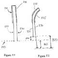
- FIGS. 5A to 5Cillustrate a variation of the tendon driven endoscope navigating a tortuous path.
- the path 701is shown in FIG. 5A .
- This pathwaymay represent a portion of colon, for example.
- the distal tip of the device 704approaches the designated bend.
- FIG. 5Bshows the distal tip being steered 705 (i.e., from the phantom position to the solid position) to assume the appropriate curve or bend 706.
- This steeringcould be performed manually by the user, e.g. a doctor, or automatically using an automatic detection method that could determine the proximity of the walls of the pathway or using images of the pathway generated by the instrument alone or in combination with images generated by an imaging modality outside of the instrument.
- the bending of the steerable tipis performed by placing tension on the tendon, or combination of tendons that result in the appropriate bending.
- the deviceis then advanced again in FIG. 5C .
- the selected curveis propagated do wn the proximal length of the endoscope, so that the bend 706 of the endoscope remains in relatively the same position with respect to the pathway 701. This prevents excessive contact with the walls, and allows the endoscope to move more easily along the tortuous pathway 701.
- the endoscopeis in continuous communication with the motion controller, and the motion controller can monitor the location of the endoscope within the pathway, e.g., depth of insertion, as well as the selected bends or curves that define the pathway of the endoscope. Depth can be determined by, e.g., the axial motion transducer 2548 previously described, or by more direct measurement techniques.
- each segmentcould be determined by the tension applied to the tendons, or by direct measurement, such as direct measurement of displacement of the tendon cables.
- the motion controllercan propagate the selected shape of a segment at a specified location, or depth, within the body, e.g., by setting the lengths of the sides of more proximal segments equal to the corresponding lengths of the sides of more distal segments as the device is moved distally.
- the controllercan also use this information to automatically steer the body of the endoscope, or for other purposes, e.g. creating a virtual map of the endoscope pathway for analytic use.
- the motion controllercan also adjust for tendon stretch or compression.
- the motion controllercan control the "slack" in the tendons, particularly in tendons that are not actively under tension or compression. This action by the motion controller may be used in the methods of the invention as described below. Allowing slack in inactive tendons reduces the amount of force that is required to articulate more proximal segments.
- the umbilicus at the distal end of the endoscopemay contain space to allow slack in individual tendons.
- the bending and advancing processcan be done in a stepwise or continuous manner. If stepwise e.g., as the tendon is advanced by a segment length, the next proximal segment 706 is bent to the same shape as the previous segment or distal steerable portion. A more continuous process could also result by bending the segment incrementally as the tendon is advanced. This could be accomplished by the computer control; for example when the segments are smaller than the navigated curve.
- FIG. 6shows an example of the resulting segment articulation which may be possible through the use of two or three tendons to articulate the controllable segments, including the steerable distal section.
- FIG. 6shows one example of a possible range of motion of a controllable segment of the present invention actuated, in this example, by three tendons.
- a segment in the relaxed, upright position 3001can be bent in virtually any direction relative to the x-y plane.
- the figureshows a segment 3002 that has been bent down and at an angle relative to its original position 3001.
- the angles alpha ( ⁇ ) and beta ( ⁇ )describe the bend assumed by the segment.
- Angle betadescribes the angle in the x-y plane and angle alpha describes the angle in the x-z plane.
- controllable segments of the endoscopecan bend through all 360 degrees in the ⁇ angle and up to 90 degrees in the ⁇ angle.
- An angle ⁇ greater than 90 degreeswould result in looping of the endoscope.
- the segmentis shown bent approximately 45 degrees along angle ⁇ .
- the freedom of movement of a segmentis, in part determined by the articulation method, the size of the segment, the materials from which it is constructed, and the manner in which it is constructed, among others. Some of these factors are discussed herein.
- the steerable distal portion, as well as the endoscope and the controllable segmentsare bendable but preferably not compressible or expansible.
- the centerline 3004 of the relaxed segment 3001is approximately the same length as the centerline 3006 of the segment after bending 3002.
- FIGS. 7A to 7Eshow the use of three tendons to actuate a segment in a bendable instrument.
- the control elements shown in this exampleare all Bowden type cables 3010 that have an internal cable 3012 coaxially surrounded by a housing or sleeve 3014 in which the cable is free to move.
- Bowden cablescan be used to apply either tensile or compressive forces, i.e., they may be pushed or pulled, to articulate the endoscope and can be actuated remotely to deliver forces as desired at locations along the endoscope. Force from a tendon is exerted across or through the segment by attaching the tendon cable at the distal end of the segment 3020 and the tendon housing 3014 at the proximal end of the segment 3022.
- FIG. 7Ashows a view of the top of the segment with three attachment sites for the tendon cables indicated 3020.
- three tendonsare used to actuate each segment, including the steerable distal portion, although four or more tendons could be used.
- Three tendonscan reliably articulate a segment in any direction without having to rotate the segment or endoscope about its longitudinal axis.
- the three cable tendons 3012are preferably attached at the distal end of the segment 3020 close to the segment's edge, spaced equally apart.
- tendonsare attached at the two o'clock, six o'clock and 10 o'clock positions. It is desirable to use fewer tendons, because of space concerns, since the tendons controlling each segment project proximally to the actuators.
- two tendonscould be used to control a segment it may also be desirable to include one or more biasing element, e.g., a spring, to assist in articulating a segment in three dimensions.
- two tendonsmay be used to bend a segment in three dimensional space by controlling motion in two directions while rotating the segment about its longitudinal axis.
- FIG. 7Bshows a relaxed segment with three tendons attached.
- the tendon sleeves 3014are shown attached to the proximal end of the segment 3022 directly below the corresponding cable attachment sites.
- FIGS. 7C, 7D and 7Eshow this segment bent by each of the controlling tendons 3010 separately.
- first tendon 3030 in the six o'clock positionmay be pushed either alone or in combination with second 3032 and third tendons 3034 being pulled to result in the same configuration.
- circumferential locations of the tendons and/or biasing elementsare illustrative and are hot intended to be limited to the examples described herein. Rather, they may be varied according to the desired effects as understood by one of skill in the art.
- FIGs. 8A and 8Billustrate a simplified segment 810 of a bendable instrument 800.
- Segment 810is one segment within the bendable instrument that may be configured as described above in FIGs. 1 and 3 , for example.
- Control elements 820, 830are similar to those described above and are actuated to bend" the segment 810.
- Two control elementsare illustrated for simplicity of explaining the methods of the invention. The invention is not however limited only to bending segments using only two control elements or to segments having only two control elements. Three control elements (i.e., FIGs. 6 and 7 ) or more control elements could be used to provide the desired degree of control.
- inventions of embodiments of the inventionmay also be applied, for example, to a steerable instrument and control system that utilizes articulating segments with two opposing control wires for each axis of articulation.
- a steerable instrument and control systemthat utilizes articulating segments with two opposing control wires for each axis of articulation.
- an articulating segment with three control elements acting in concert to control both axes of articulationmay also be applied, for example, to a steerable instrument and control system that utilizes articulating segments with two opposing control wires for each axis of articulation.
- Complementary control wiresoperate cooperatively to control the bend of a segment. Two or a pair of complementary control wires may be used to control the bend of an instrument within a plane, for example.
- control wires 820, 830are a complementary pair of control wires for the segment 810. The plane of articulation is within the page.
- the control elements 820, 830are shown in the neutral position 840 where the segment 810 is straight or non-bent.
- articulation of the exemplary segment 810is achieved by pulling one control element while leaving the opposing control element slack.
- FIG.8Bshows the segment 810 bending to the right into position 835.
- the position 835is achieved when the segment 810 bends by pulling on control element 830 while control element 820 is slack. As a result, pulling control element 830 moves the control element 830 to a position 860 from the neutral position 840. The movement of the segment 810 into position 835 moves control element 820 to a position 850 from the neutral position 840.
- the flow chart 900 in FIG. 9illustrates an embodiment of a method of determining the shape a bendable instrument according to the invention.
- the first step, step 910includes moving at least two control elements first and second amounts without bending the instrument.
- the step of positioning the bendable instrument within a lumenis performed before the moving step.
- the second step, step 920,includes measuring the first and second amounts.
- the position or amount of movement of the control elementscan be measured using any suitable indication or device in any suitable position.
- the amount of control element movementmay be obtained through measurement or indication taken on the control side such as system controller 1145, an actuator connected to a control element, or the force generator 1110 via encoder or other suitable measurement device.
- the amount of control wire movementmay be obtained through measurement or indication taken on any of the components illustrated in FIG. 4 .
- the amount of control element movementmay be obtained through measurement or indication taken from a sensor on or in a connector that joins the bendable instrument to an actuator.
- Exemplary connectorsinclude embodiments of the articulatable connector 110 illustrated in FIG. 2 and further described in US Patent Application Serial No. 10/988,212 now U.S.
- the amount of control element movementmay be obtained through measurement or indication taken on a bendable instrument, the controllable article 1100 illustrated in FIG. 1 , the segmented instrument 2510 in FIG. 25, the segment 2601 or the cable 2612 in FIG. 4 .
- any of the components of the controllable instrument, the connector (if present) or the control or actuation systemmay be modified to include sensors. These sensors are adapted based on their position in "the system and relationship the control cables to provide measurement of the amount of control cable movement or other information useful for embodiments of the invention. Sensors may be located in either or both of the connector portions 112, 114 or in any of the connection and release mechanisms described herein. Any of a wide variety of commonly available sensors may be used to accomplish the functionalities described herein such as, for example, reed switches, electro-optical switches, resistive switches, contact switches, optical indicators, strain gauges, stress gauges, measurement indicators and the like.
- Sensorsmay be used to provide a tension measurement taken in a connector that couples an actuator to one of the at least two control elements.
- the measurement instrumentis an optical encoder.
- the tensioning element or actuatoris a permanent magnet brushed DC motor. Movement of the DC motor may be measured, controlled and monitored using an optical encoder.
- a sensor or sensorsmay provide input to a feedback loop used to monitor performance of the steps in method 900.
- a sensormay be used to monitor slack removal from control wires.
- the input from the sensoris related to a tension measurement of a control element.
- the output or signal from a sensormay be integrated into the control system.
- sensors within the connectorcould be used to measure carriage assembly movement inside of a connector as the indication for measuring amounts of control cable movement.
- a sensormay be coupled to or in communication with a portion of the connector assembly and have an output that indicates the control cable position.
- the control systemcould be adapted to use the output of the sensor, in place of or in addition to encoders on the instrument to control and/or monitor the position, shape, and movement of the instrument. It is to be appreciated that sensors used herein may be adapted to provide information used during the moving step 910, the measuring step 920 and/or the determining step 930.
- the tip of the endoscope and different segments or positions of the endoscopecould be determined using the position of the carriage assembly/assemblies and cables used to control those segments.
- a sensormay be used to determine the length of travel of a carriage assembly.
- the length of travel of a carriage assemblymay be used to correspond to or be part of the measuring or determining step of the present invention.
- predetermined relationships between the carriage assembly position and the segment anglei.e., using look up tables or kinematics relationships
- predetermined relationships between the carriage assembly position and the segment anglei.e., using look up tables or kinematics relationships
- Embodiments of the connector described in FIG. 1may be particularly well suited for determination of position of the control cables using the position and/or movement of the cables or carriage assemblies or other components within the connector 1120.
- the position, shape, and/or movement of the tip of a steerable endoscope or portion thereofcould be measured and/or determined using the position of the cables, carriage assemblies or other components within the connector 1120.
- the amount of within connector movement of the cables, carriage assemblies or componentsmay be correlated to an amount, degree or type of bending or instrument position.
- the position of the tip, sections, segments or modules of a controllable articlemay be determined using the methods of the invention.
- measurement of linear motion of a control cable within the connectormay be used to determine segment position including the position and movement of the instrument tip.
- Sensors to detect movementmay be placed in one or both connector portions 112, 114 or elsewhere on the instrument, an actuator using to articulate the instrument or in the control system.
- the slackmay be removed from the control elements before the moving, measuring or determining steps.
- the step of removing slack from the control elementsis performed before the measuring step.
- accuracy of control element measurementis achieved by simultaneously pulling all control wires with a constant force to remove the slack from the control wires. Simultaneously pulling all of the control wires reduces the likelihood that the removal of the slack would change the position of the instrument and adversely impact the measurement technique.
- One embodiment of the methodincludes the step of removing slack from the at least two control elements of the set of control wires before the measuring step. While the removal of slack can lead to increased accuracy, inadvertent instrument segment movement during slack removal will diminish accuracy. As such, the removing step is completed without changing the position of the instrument.
- One way to ensure that the position of the instrument is not changedis to power an actuator with a known drive command.
- a drive commandis selected that is insufficient to change the position of the instrument.
- One type of drive commandis the drive current used to operate an actuator. A low drive current may be selected and used to remove slack but not result in articulation.
- the low drive currentensures that segment movement does not occur, it may remove slack at a slow rate.
- the first force limitis less than the second force limit.
- the force limits selectedare insufficient to result in segment articulation.
- This methodcould be used on the non-controlling wire of a wire set. For example, pull the slack out of the wire not currently being used for control to gain a measurement of the angle or position actually achieved. It is to be appreciated that the concept of removing slack, generally understood in the context of flexible control elements, may also be applied to control rods, semi-rigid control elements or rigid control elements by placing the control element under tension to improve the reliability and repeatability of the steps of the inventive method.
- the first stepis a high speed removal at a low force.
- the speed of removalis reduced and the force of removal increased.
- the first stepquickly removes the gross slack and the second step confirms the removal of slack and holds the wires in tension for increased accuracy during the measuring step.
- the counter balancing action of the wiresmitigates any tendency of the applied slack removal forces to result in segment articulation.
- the third step, step 930includes determining the position of the instrument from the first and second amounts.
- the next stepis to determine the position of the instrument from the measured amounts.
- One technique to aid in the removal of common mode factorsinvolves the use of a position delta.
- the techniqueis independent of the force used for measurement as well as the tortuosity of the control wires used to maneuver the steerable instrument.
- the position deltais used to normalize the obtained measurement information for a control cable.
- the position deltamay be explained through reference to FIGs. 8 A and 8B.
- the position deltacan be calculated by subtracting a neutral or calibrated position from a measured position.
- the position delta for controllable element 820is obtained by subtracting the neutral position 840 from the measured position 850.
- the position delta for controllable element 830is obtained by subtracting the neutral position 840 from the measured position 860.
- the determining stepuses a calculated position delta of the at least two control elements.
- summing the position deltas 870 from opposing control wires such as control wires 820, 830yields a result which has a relationship with the bend, angle or shape of the segment.
- the determining stepuses a calculated position delta of complementary control elements within the at least two control elements. In an alternative embodiment, the determining step uses a calculated position delta of a pair of opposing control elements within the at least two control elements.
- the relationship between the opposing control wires position delta or sum of the position deltas and the shape or angle of the segmentis essentially independent of the tortuosity/friction in the cables and of the force used in the measurement.
- summing the position deltas from opposing control wiresyields a result which has a linear relationship with the angle of the segment.
- Numerous techniquesmay be used to perform the determining step. In one technique, the determining step comprises using a look up table that correlates the first and second amounts to the instrument position. In yet another technique, the determining step comprises using a modeled kinematic relationship between first and second amounts and the instrument positions.
- complimentary control wiresare used to measure the angle a segment has taken after the control wires have been relaxed.
- the instrumentWhen the control wires are relaxed, the instrument is allowed to assume the shape of its surroundings. The surroundings act as an external force to move the instrument.
- Information determined using the methods of the inventionsuch as the bend, position, shape, or angle of the instrument at this time may be used as an indication of the shape of the surroundings influencing the position, shape or angle of the instrument.
- the moving stepis accomplished without using an actuator connected to a control element.
- the moving stepis performed by the lumen acting on the instrument.
- the position of the instrumentis determined using a control element not being used to control a segment (i.e., a slack cable).
- the measuring stepincludes moving a control element not being used to bend the instrument. Thereafter, perform the step of determining a calculated position delta for the control element not being used to bend the instrument. The position delta can then be used as described above.
- the determining stepuses the calculated position delta for a control element not being used to bend the instrument. As such, moving may be accomplished by forces external to the instrument.
- the moving, measuring and determining techniques described hereinmay also be used to determine the neutral position 840.
- the ability to accurately control an instrument.is based in part on the ability to repeatably and reliably determine a neutral or calibration position.
- One exemplary positionis the straight or unarticulated position illustrated in FIG. 8A .
- the instrumentmay be held manually or secured to a calibration fixture that holds the instrument in the desired calibration position. Once in the desired position, the slack is removed from all of the control wires to measure and determine the neutral or calibration position 840 for each control wire.
- the techniques described hereinmay be used periodically to determine and/or confirm the characteristics of the control cables relative to the neutral or calibration condition. In this way, changes in control wire performance due, for example, to temporary elongation (i.e., stretch) or permanent elongation (i.e., cable construction or creep) may be monitored and used to compensate for control wire changes.
- the connector and engagement assemblies of the present inventionmay be configured for the efficient control of a wide variety of controllable articles in a number of other medical and industrial applications.
- theycan also be configured for use with catheters, cannulas, surgical instruments, interluminal instruments, and/or introducer sheaths that use the principles described above for navigating through body channels or within the body. They may also be used for industrial applications such as inspection and exploratory applications within tortuous regions, e.g., machinery, pipes, difficult to access enclosures and the like.
- the motion controller assembliescan be used to control the automatically controlled proximal portion to follow the selected path and, if necessary, to return to a desired location using the three-dimensional model in the electronic memory of the controller. While the above illustrative embodiments have described mechanical connections and force transmissions of the first and second connector portions, it is to be appreciated that alternative embodiments of the connector of the present invention may be modified and adapted to accommodate other forms of energy, position, or force transfer including but not limited to, electrical, pneumatic, hydraulic and the like. Modification of the above described assemblies and methods for carrying out the invention, and variations of aspects of the invention that are obvious to those of skill in the art are intended to be within the scope of the claims.
- the disclosurefurther encompasses a method of determining the shape a bendable instrument, comprising moving at least two control elements first and second amounts without bending the instrument; measuring the first and second amounts; and determining the shape of the instrument from the first and second amounts.
- the moving stepmay be accomplished without using an actuator connected to a control element.
- the moving stepmay remove slack from the at least two control elements before the measuring step.
- the removing stepmay be performed by applying a known drive command to an actuator.
- the drive commandmay be insufficient to change the position of the instrument.
- the removing stepmay be performed using a tension measurement taken in a connector that couples an actuator to one of the at least two control elements or may be performed using a feedback loop that receives input from a sensor.
- the input from a sensormay be related to a tension measurement of a control element.
- the sensormay be located on or in the bendable instrument or may be located on or in a connector that joins the bendable instrument to an actuator.
- the sensormay be located on or in an actuator connected to a control element.
- the methodmay further comprise removing the slack from the at least two control elements during a first time period at a first force limit before removing the slack from the at least two control elements during a second time period at a second different force limit.
- the first force limitmay be less than the second force limit.
- the velocity of slack removal during the first time periodmay be greater than the velocity of slack removal during the second time period.
- the disclosurefurther encompasses a method of determining the shape a bendable instrument, comprising moving at least two control elements first and second amounts without bending the instrument; measuring the first and second amounts; and determining the shape of the instrument from the first and second amounts wherein the determining step may comprise using a look up table that correlates the first and second amounts to the instrument shape.
- the determining stepmay comprise using a modeled kinematic relationship between first and second amounts and the instrument shape or may use a calculated position delta of the at least two control elements.
- the determining stepmay use a calculated position delta of complementary control elements within the at least two control elements.
- the determining stepmay use a calculated position delta of a pair of opposing control elements within the at least two control elements.
- the disclosurefurther encompasses a method of determining the shape a bendable instrument, comprising moving at least two control elements first and second amounts without bending the instrument; measuring the first and second amounts; and determining the shape of the instrument from the first and second amounts wherein the measuring step further comprises moving a control element not being used to bend the instrument; and determining a calculated position delta for the control element not being used to bend the instrument.
- the determining stepmay use the calculated position delta for a control element not being used to bend the instrument.
- the disclosurefurther encompasses a method of determining the shape a bendable instrument, comprising moving at least two control elements first and second amounts without bending the instrument; measuring the first and second amounts; and determining the shape of the instrument from the first and second amounts further comprising positioning the bendable instrument within a lumen before the moving step.
- the moving stepmay be performed by a lumen acting on the instrument.
- the methodmay further comprise using the determining step to determine the shape of the lumen.
Landscapes
- Health & Medical Sciences (AREA)
- Life Sciences & Earth Sciences (AREA)
- Engineering & Computer Science (AREA)
- Surgery (AREA)
- Heart & Thoracic Surgery (AREA)
- Veterinary Medicine (AREA)
- Public Health (AREA)
- General Health & Medical Sciences (AREA)
- Animal Behavior & Ethology (AREA)
- Biomedical Technology (AREA)
- Biophysics (AREA)
- Medical Informatics (AREA)
- Molecular Biology (AREA)
- Physics & Mathematics (AREA)
- Pathology (AREA)
- Nuclear Medicine, Radiotherapy & Molecular Imaging (AREA)
- Anesthesiology (AREA)
- Hematology (AREA)
- Pulmonology (AREA)
- Radiology & Medical Imaging (AREA)
- Optics & Photonics (AREA)
- Mechanical Engineering (AREA)
- Human Computer Interaction (AREA)
- Robotics (AREA)
- Endoscopes (AREA)
- Instruments For Viewing The Inside Of Hollow Bodies (AREA)
- Bending Of Plates, Rods, And Pipes (AREA)
- Length Measuring Devices By Optical Means (AREA)
Abstract
Description
- This patent application is a divisional application of European Patent Application number
06838329.8 - Bendable instruments come in many forms such as catheters, colonoscopes, endoscopes and the like. Control elements are used to bend the instruments into a desired shape or as part of steering or maneuvering the instrument as needed for a surgical or exploratory procedure for example. While the instrument may be controlled to ultimately reach a desired position, knowing the shape of the instrument may provide useful information for maneuvering the instrument or to aid in the procedure.
- What are needed are improved techniques for identifying the shape of a bendable instrument.
- One embodiment of the invention provides method of determining the shape of a bendable instrument by moving at least two control elements first and second amounts without bending the instrument; measuring the first and second amounts; and determining the shape of the instrument from the first and second amounts. In one alternative, the moving step is accomplished without using an actuator connected to a control element. In another alternative, the moving step removes slack from the at least two control elements before the measuring step. In one aspect, the removing step is performed by applying a known drive command to an actuator. In one embodiment, the drive command is insufficient to change the position of the instrument. In one embodiment, the drive command is the current applied to an actuator. In another embodiment, the removing step is performed using a tension measurement taken in a connector that couples an actuator to one of the at least two control elements. In another embodiment, the removing step is performed using a feedback loop that receives input from a sensor. In one aspect, the input from a sensor is related to a tension measurement of a control element. In one embodiment, the sensor is located on or in the bendable instrument. In another embodiment, the sensor is located on or in a connector that joins the bendable instrument to an actuator. In yet another aspect, the sensor is located on or in an actuator connected to a control element.
- In another alternative, a step is performed by removing the slack from the at least two control elements during a first time period at a first force limit before removing the slack from the at least two control elements during a second time period at a second different force limit. In one aspect, the first force limit is less than the second force limit.
- In another embodiment, the determining step uses a look up table that correlates the first and second amounts to the instrument shape, position or configuration. In another aspect, the determining step uses a modeled kinematic relationship between first and second amounts and the instrument shape, position or configuration. In another aspect, the determining step uses a calculated position delta of the at least two control elements. In another aspect, the determining step uses a calculated position delta of complementary control elements within the at least two control elements. In another aspect, the determining step uses a calculated position delta of a pair of opposing control elements within the at least two control elements. In yet another alternative embodiment, the measuring step includes the steps of (a) moving a control element not being used to bend the instrument; and (b) determining a calculated position delta for the control element not being used to bend the instrument. In one aspect, the determining step uses the calculated position delta for a control element not being used to bend the instrument.
- In one alternative, the step of positioning the bendable instrument within a lumen is performed before the moving step. In another aspect, the moving step is performed by the lumen acting on the instrument. In another aspect, the determining step is used to determine the shape of the lumen.
- The novel features of the invention are set forth with particularity in the claims that follow. A better understanding of the features and advantages of the present invention will be obtained by reference to the following detailed description that sets forth illustrative embodiments, in which the principles of the invention are utilized, and the accompanying drawings of which:
FIG. 1 shows a schematic view of a system for articulating a controllable article or bendable instrument.FIG. 2 is a perspective view of a connector assembly.FIG. 3 illustrates an embodiment where the bendable instrument or controllable article is a segmented endoscope.FIG. 4 shows a partial schematic representation of a single tendon bending a segment.FIGs. 5A-5C illustrate an endoscope traversing a pathway.FIG. 6 describes the range of motion of bending through the use of three control cables.FIGs. 7A-7E show the use of three control elements to bend a segment.FIGS. 8A and 8B illustrate the use of two control wires to bend a segment.FIG. 9 is a flow chart illustrating a method of determining the position of an instrument.- There are a number of articulating instruments, bendable instruments and steerable instruments available. Examples of such instruments and various control systems are described in, for example,
U.S. Patent 6,468,203 ;U.S. Patent 6,858,005 andU.S. Patent Application Serial No. 10/988,212 US 2006/0052664 , titled "Articulatable Connector Device for Endoscopes ". The application and patents listed above are commonly assigned with this application. - The techniques described herein may be used to determine the shape of a bendable instrument by measuring or manipulating information related to the position of the control implements used to change the shape of or maneuver the instrument. The techniques described herein have several advantages. The techniques are independent of the force used for measurement as well as the tortuosity of the control wires used to maneuver the steerable instrument. The techniques repeatably and reliably reproduce the shape of the instrument. In addition, the techniques described herein enable the measurement and/or determination of steerable instrument shape using measurements of the control wires or cables used to control the instrument. Details of the various alternative embodiments for performing the methods of the invention will be appreciated after discussion of an exemplary bendable instrument and instrument control system.
FIG. 1 illustrates a schematic view of asystem 1000 for moving acontrollable article 1100, A force generator under control of one or both of auser input device 1140 and asystem controller 1145 generates forces that are used to move thecontrollable article 1100. The forces generated by the force generator are transmitted to the controllable article usingforce connecting elements 1135 and aconnector assembly 1120. The controllable article may also be an articulating instrument or a bendable instrument.- A
connector assembly 1120 completes the transmission of power generated by theforce generator 1110 and applied to thecontrollable article 1100. The twoportions connector assembly 1120 are disengagably coupled. Theconnector portion 1125 is the first connector portion or the force generation side connector. Theconnector 1130 is the second connector portion or the controllable article side connector portion. When theconnector portions force transmission elements 1135 are joined and force generated by the'force generator 1110 is applied to thecontrollable article 1100. When theconnector portions connector portion 1130, force transmission elements. 1135 and thecontrollable article 1100 may be removed, in some embodiments as a single integrated unit, from theconnector portion 1125, forcetransmission elements 1135 and theforce generator 1110 oractuators 1115. - The
connector assembly 1120 provides the ability to quickly connect and disconnect the twoportions - As will be detailed below, the organization provided by the connectors could also provide other advantages to determining the bend of an instrument such as allowing efficient removal of cable slack or measurement of cable movement. Furthermore, the connector can be modified to allow attachment, placement, manipulation and/or operation of sensors used to measure the cables. The
connector 1120 may include sensors and/or safety features to help ensure proper operation and articulation of the controllable article. In the discussion that follows, the connector refers to embodiments of theconnector 1120 as well as embodiments of the first andsecond connector portions carriage assemblies 120 described below) or theforce transmission elements 1135 themselves. Another sensor or feature may also detect and measure or otherwise quantify the amount of translation or movement of the engaging elements (i.e.,carriage assemblies 120 described below), theforce transmission elements 1135 themselves or other indicia of the amount of control cable movement. Another sensor or indicator may be used to generate a signal based on contacting a known position used to correlate to the bend or position of the instrument. FIG. 2 illustrates a perspective view of a connector assembly 110 according to one embodiment of the present invention. The connector assembly 110 includes a first connector portion 112 (not shown but within housing 109) and asecond connector portion 114. The first connector portion 112 is within thehousing 109. Thesecond connector assembly 114 includes a plurality ofguide ways 118 each containing acarriage assembly 120. Each carriage assembly contains one or more than oneengaging feature 122. Engagingfeatures 122 oncarriage assemblies 120, in thesecond connector portion 114 are adapted to engage with the engagingfeatures 122 oncarriage assemblies 120 of the first connector portion 112. One end of the carriage assemblies is connected to force transmission elements orcables 130. In the illustrated embodiment, the cables are Bowden cables. The cables run through aslack area 116. Theslack area 116 allows added space for cable slack that may build up during controllable article movement. Thereafter, the cables are connected as desired to the controllable article.- The
housing 109 provides a structural base for supporting the connector assembly 110. In this embodiment, the first connector portion 112 (not shown) is secured within thehousing 109. The first connector portion and its carriage assemblies are connected viaforce transmission elements 130 toactuators 105. While fouractuators 105 are illustrated, it is to be appreciated that more actuators may be used to drive a corresponding number of carriage assemblies. Thehousing 109 also provides anopening 107 configured to receive thesecond connector portion 114. Optionally, either one or both of theopening 107 or a portion of thesecond connector portion 114 may be keyed to ensure correct orientation prior to connection. When thesecond connector portion 114 is placed within theopening 107, the first andsecond connector portions 112, 114 are brought into engagement using an appropriate quick release mechanism, such as for example a cam actuated lever or other engagement device as known to those of ordinary skill in the art. When the first andsecond connector portion 112, 114 are engaged, forces generated byactuators 105 are transmitted to the controllable article. FIG. 3 shows an embodiment where the bendable instrument is a tendon drivenendoscope 2510. Theendoscope 2510 has anelongate body 2512 with a manually or selectively steerabledistal portion 2516, an automatically controlledportion 2520, and a flexible and passively manipulatedproximal portion 2514, which may be optionally omitted from the device. The steerabledistal portion 2516 can be articulated by hand (i.e., using mechanical force of a conventional endoscope manual controls adapted to articulate segments) or with mechanical assistance from actuators. In addition, some embodiments allow a user to input steering commands (i.e., via a joystick 2544 or other input device) into a controller that translates the steering commands into endoscope segment movement.- The automatically controlled
portion 2520 is segmented, and each segment is capable of bending through a full range of steerable motion. Thedistal portion 2516 is also a controllable segment. A more detailed description on the construction and operation of the segmented endoscope may be found inU.S. patent application Ser. No. 10/229,577 filed Aug. 27, 2002 - The selectively steerable
distal portion 2516 can be selectively steered or bent up to, e.g., a full 180 degree bend in anydirection 2518, as shown. A fiberoptic imaging bundle 2534 and one ormore illumination fibers 2532 may extend through thebody 2512 from theproximal portion 2514 to thedistal portion 2516. Alternatively, theendoscope 2510 may be configured as a video endoscope with a miniaturized video camera, such as a CCD or CMOS camera, positioned at thedistal portion 2516 of theendoscope body 2512. The images from the video camera can be transmitted to a video monitor by a transmission cable or by wireless transmission where images may be viewed in realtime and/or recorded by a recording device onto analog recording medium, e.g., magnetic tape, or digital recording medium, e.g., compact disc, digital tape, etc. LEDs or other light sources could also be used for illumination at the distal tip of the endoscope. - The
body 2512 of theendoscope 2510 may also include one ormore access lumens 2528 that may optionally be used for illumination, fibers for providing a light source, insufflation or irrigation, air and water channels, and vacuum channels. Generally, thebody 2512 of theendoscope 2510 is highly flexible so that it is able to bend around small diameter curves without buckling or kinking while maintaining the various channels intact. When configured for use as a colonoscope, thebody 2512 of theendoscope 2510 may range typically from 135 to 185 cm in length and about 13-19 mm in diameter. Theendoscope 2510 can be made in a variety of other sizes and configurations for other medical and industrial applications. - The
controllable portion 2520 is composed of at least onesegment 2522, and preferablyseveral segments 2522, which are, controllable via a computer and/oreelectronic controller 2540 located at a distance from theendoscope 2510. Thesegments 2522 may have forces transmission elements or tendons mechanically connected to force generators or actuators to allow for the controlled motion of thesegments 2522 in space. The actuators driving the tendons may include a variety of different types of mechanisms capable of applying a force to a tendon, e.g., electromechanical motors, pneumatic and hydraulic cylinders, pneumatic and hydraulic motors, solenoids, shape' memory alloy wires, electronic rotary actuators or other devices or methods as known in the art. The linear translation of the actuators within the controller may be configured to move over a relatively short distance to accomplish effective articulation depending upon the desired degree of segment movement and articulation. The movement of the actuators may be measured using sensors to provide input to the methods described below (FIG. 9 ). - Each
segment 2522 preferably defines at least one lumen running throughout to provide an access channel through which wires, optical fibers, air and/or water channels, various endoscopic tools, or any variety of devices and wires may be routed. A polymeric covering, or sheath, 2530 may also extend over the body of theendoscope 2512 including thecontrollable portion 2520 and steerabledistal portion 2516. Thissheath 2530 can preferably provide a smooth transition between thecontrollable segments 2522, the steerabledistal portion 2516, and the flexible tubing ofproximal portion 2514 - A
handle 2524 may be attached to the proximal end of the endoscope. Thehandle 2524 may include an ocular connected to the fiberoptic imaging bundle 2534 for direct viewing. Acable 2552 provides a connection to a video monitor, camera, e.g., a CCD or CMOS camera, or arecording device 2550. Anillumination source 2536 and anillumination cable 2538 is connected to or continuous with theillumination fibers 2534. Alternatively, some or all of these connections could be made at thecontroller 2540.luer lock fittings 2526 may be located on thehandle 2524 and connected to the various instrument channels. - The
handle 2524 may be connected to amotion controller 2540 by way of acontroller cable 2542. A steering controller 2544 may be connected to themotion controller 2540 by way of asecond cable 2546 or it may optionally be connected directly to thehandle 2524. Alternatively, the handle may have the steering control mechanism integrated directly into the handle, e.g., in the form of a joystick, conventional disk controllers such as dials, pulleys or wheels, etc. The steering controller 2544 allows the user to selectively steer or bend the selectively steerabledistal portion 2516 of thebody 2512 in the desireddirection 2518. The steering controller 2544 may be a joystick controller as shown, or other steering control mechanism, e.g., dual dials or rotary knobs as in conventional endoscopes, track balls, touch pads, mouse, or sensory gloves. Themotion controller 2540 controls the movement of the segmented automatically controlledproximal portion 2520 of thebody 2512. Thiscontroller 2540 may be implemented using a motion control program running on a microcomputer or using an application specific motion controller. - The actuators applying force to the tendons may be included in the
motion controller unit 2540, as shown, or may be located separately and connected by a control cable. The tendons controlling the steerabledistal portion 2516 and thecontrollable segments 2522 extend down the length of theendoscope body 2512 and connect to the actuators.FIG. 3 shows a variation in which the tendons may pass through thehandle 2524 and connect directly to themotion controller 2540 via a quick-release connector 2554. In this embodiment, quick release connector 2254 could be any of the above described connector or engagement assemblies. In this variation, the tendons may be part of thecontrol cable 2542, although they could independently connect to the actuators, so long as the actuators are in communication with thecontroller 2540. - An axial motion transducer (also called a depth referencing device or datum) 2548 may be provided for measuring the axial motion, i.e., the depth change, of the
endoscope body 2512 as it is advanced and withdrawn. Thedepth referencing device 2548 can be made in many possible configurations. For example, the axial motion-transducer 2548 inFIG. 3 is configured as aring 2548 that may surround thebody 2512 of theendoscope 2510. Theaxial motion transducer 2548 is preferably attached to a fixed point of reference, such as the surgical table or the insertion point for theendoscope 2510 on the patient's body.Depth referencing device 2548, and different examples thereof; as well as segment articulation and cable operation are described in further detail inU.S. patent application Ser. No. 10/229,577 filed Aug. 27, 2002 FIG. 4 shows a partial schematic representation of a single tendon bending a segment. For clarity, the other parts of a complete endoscope, including other tendons and segments, have been omitted fromFIG. 4 . Tension applied to a tendon cable is transferred across the entire segment, resulting in bending. TheBowden cable 2610 has asleeve 2614 attached to thebase 2622 of thesegment 2601 and also fixed at theproximal actuator end 2603. Thetendon cable 2612 is connected to theactuator 2605 and the distal segment end 2630. By applying tension to thetendon 2612, only the intendedsegment 2601 is bent, and more proximal segments are unaffected. Thetendon 2612 is placed in tension by theactuator 2605, which is show in this variation, as a motor pulling on thetendon cable 2612. Sensors may be provided on any of the components inFIG. 4 to provide information for the methods described below inFIG. 9 .FIGS. 5A to 5C illustrate a variation of the tendon driven endoscope navigating a tortuous path. Thepath 701 is shown inFIG. 5A . This pathway may represent a portion of colon, for example. InFIG. 5A , the distal tip of thedevice 704 approaches the designated bend.FIG. 5B shows the distal tip being steered 705 (i.e., from the phantom position to the solid position) to assume the appropriate curve or bend 706. This steering could be performed manually by the user, e.g. a doctor, or automatically using an automatic detection method that could determine the proximity of the walls of the pathway or using images of the pathway generated by the instrument alone or in combination with images generated by an imaging modality outside of the instrument. As described, the bending of the steerable tip is performed by placing tension on the tendon, or combination of tendons that result in the appropriate bending.- The device is then advanced again in
FIG. 5C . As it is advanced, the selected curve is propagated do wn the proximal length of the endoscope, so that thebend 706 of the endoscope remains in relatively the same position with respect to thepathway 701. This prevents excessive contact with the walls, and allows the endoscope to move more easily along thetortuous pathway 701. The endoscope is in continuous communication with the motion controller, and the motion controller can monitor the location of the endoscope within the pathway, e.g., depth of insertion, as well as the selected bends or curves that define the pathway of the endoscope. Depth can be determined by, e.g., theaxial motion transducer 2548 previously described, or by more direct measurement techniques. Likewise, the shape of each segment could be determined by the tension applied to the tendons, or by direct measurement, such as direct measurement of displacement of the tendon cables. The motion controller can propagate the selected shape of a segment at a specified location, or depth, within the body, e.g., by setting the lengths of the sides of more proximal segments equal to the corresponding lengths of the sides of more distal segments as the device is moved distally. The controller can also use this information to automatically steer the body of the endoscope, or for other purposes, e.g. creating a virtual map of the endoscope pathway for analytic use. - In addition to measuring tendon displacement, the motion controller alone, a connector of the present invention alone or the controller and the connector operating together can also adjust for tendon stretch or compression. For example, the motion controller can control the "slack" in the tendons, particularly in tendons that are not actively under tension or compression. This action by the motion controller may be used in the methods of the invention as described below. Allowing slack in inactive tendons reduces the amount of force that is required to articulate more proximal segments. In variations described above the umbilicus at the distal end of the endoscope may contain space to allow slack in individual tendons.
- The bending and advancing process can be done in a stepwise or continuous manner. If stepwise e.g., as the tendon is advanced by a segment length, the next
proximal segment 706 is bent to the same shape as the previous segment or distal steerable portion. A more continuous process could also result by bending the segment incrementally as the tendon is advanced. This could be accomplished by the computer control; for example when the segments are smaller than the navigated curve. FIG. 6 shows an example of the resulting segment articulation which may be possible through the use of two or three tendons to articulate the controllable segments, including the steerable distal section.FIG. 6 shows one example of a possible range of motion of a controllable segment of the present invention actuated, in this example, by three tendons. A segment in the relaxed,upright position 3001 can be bent in virtually any direction relative to the x-y plane. The figure, as an illustrative example, shows asegment 3002 that has been bent down and at an angle relative to itsoriginal position 3001. The angles alpha (α) and beta (β) describe the bend assumed by the segment. Angle beta describes the angle in the x-y plane and angle alpha describes the angle in the x-z plane. In one variation, the controllable segments of the endoscope can bend through all 360 degrees in the β angle and up to 90 degrees in the α angle. An angle α greater than 90 degrees would result in looping of the endoscope. InFIG. 6 , the segment is shown bent approximately 45 degrees along angle α. The freedom of movement of a segment is, in part determined by the articulation method, the size of the segment, the materials from which it is constructed, and the manner in which it is constructed, among others. Some of these factors are discussed herein.- The steerable distal portion, as well as the endoscope and the controllable segments are bendable but preferably not compressible or expansible. Thus, in
FIG. 6 , thecenterline 3004 of therelaxed segment 3001 is approximately the same length as thecenterline 3006 of the segment after bending 3002. FIGS. 7A to 7E show the use of three tendons to actuate a segment in a bendable instrument. The control elements shown in this example are all Bowden type cables 3010 that have aninternal cable 3012 coaxially surrounded by a housing orsleeve 3014 in which the cable is free to move. Bowden cables can be used to apply either tensile or compressive forces, i.e., they may be pushed or pulled, to articulate the endoscope and can be actuated remotely to deliver forces as desired at locations along the endoscope. Force from a tendon is exerted across or through the segment by attaching the tendon cable at the distal end of thesegment 3020 and thetendon housing 3014 at the proximal end of thesegment 3022.FIG. 7A shows a view of the top of the segment with three attachment sites for the tendon cables indicated 3020.- In one variation, three tendons are used to actuate each segment, including the steerable distal portion, although four or more tendons could be used. Three tendons can reliably articulate a segment in any direction without having to rotate the segment or endoscope about its longitudinal axis. The three
cable tendons 3012 are preferably attached at the distal end of thesegment 3020 close to the segment's edge, spaced equally apart. InFIG. 7A , tendons are attached at the two o'clock, six o'clock and 10 o'clock positions. It is desirable to use fewer tendons, because of space concerns, since the tendons controlling each segment project proximally to the actuators. Thus, two tendons could be used to control a segment it may also be desirable to include one or more biasing element, e.g., a spring, to assist in articulating a segment in three dimensions. In another variation, two tendons may be used to bend a segment in three dimensional space by controlling motion in two directions while rotating the segment about its longitudinal axis. FIG. 7B shows a relaxed segment with three tendons attached. Thetendon sleeves 3014 are shown attached to the proximal end of thesegment 3022 directly below the corresponding cable attachment sites.FIGS. 7C, 7D and 7E show this segment bent by each of the controlling tendons 3010 separately.- As shown in
FIG. 7C , applying tension by pulling on thefirst tendon 3030 results in a bending in the direction of thefirst tendon 3030. That is, looking down on the top of the unbent segment (as inFIG. 7B ), if the first tendon is attached at the six o'clock position, then pulling on just this tendon results in bending the segment towards the six o'clock position. Likewise, inFIG. 7D , putting tension only on asecond tendon 3032 attached at the two o'clock position results in bending the segment towards the two o'clock direction. Finally, pulling on the tendon in the teno'clock position 3034 bends the segment towards the ten o'clock direction. In all cases, the bending is continuous; the greater the tension applied, the further the bending (the α angle, in the x-z plane ofFIG. 6 ). A segment can be bent in any direction by pulling on individual tendons or a combination of two tendons. Thus, to bend the segment in the twelve o'clock direction, both the second 3032 and the third 3034 tendon could be pulled with equal force. Alternatively,first tendon 3030 in the six o'clock position may be pushed either alone or in combination with second 3032 andthird tendons 3034 being pulled to result in the same configuration. - In all these variations, the circumferential locations of the tendons and/or biasing elements are illustrative and are hot intended to be limited to the examples described herein. Rather, they may be varied according to the desired effects as understood by one of skill in the art.
FIGs. 8A and 8B illustrate asimplified segment 810 of abendable instrument 800.Segment 810 is one segment within the bendable instrument that may be configured as described above inFIGs. 1 and3 , for example.Control elements segment 810. Two control elements are illustrated for simplicity of explaining the methods of the invention. The invention is not however limited only to bending segments using only two control elements or to segments having only two control elements. Three control elements (i.e.,FIGs. 6 and 7 ) or more control elements could be used to provide the desired degree of control. The techniques of embodiments of the invention may also be applied, for example, to a steerable instrument and control system that utilizes articulating segments with two opposing control wires for each axis of articulation. Alternatively, in a three element system, an articulating segment with three control elements acting in concert to control both axes of articulation.- Complementary control wires operate cooperatively to control the bend of a segment. Two or a pair of complementary control wires may be used to control the bend of an instrument within a plane, for example. As illustrated in
FIG. 8A, 8B ,control wires segment 810. The plane of articulation is within the page. InFIG. 8A thecontrol elements neutral position 840 where thesegment 810 is straight or non-bent. In normal use, articulation of theexemplary segment 810 is achieved by pulling one control element while leaving the opposing control element slack.FIG.8B shows thesegment 810 bending to the right intoposition 835. Theposition 835 is achieved when thesegment 810 bends by pulling oncontrol element 830 whilecontrol element 820 is slack. As a result, pullingcontrol element 830 moves thecontrol element 830 to aposition 860 from theneutral position 840. The movement of thesegment 810 intoposition 835 movescontrol element 820 to a position 850 from theneutral position 840. - The
flow chart 900 inFIG. 9 illustrates an embodiment of a method of determining the shape a bendable instrument according to the invention. The first step, step 910, includes moving at least two control elements first and second amounts without bending the instrument. In one embodiment, the step of positioning the bendable instrument within a lumen is performed before the moving step. - The second step, step 920, includes measuring the first and second amounts.
- The position or amount of movement of the control elements can be measured using any suitable indication or device in any suitable position. The amount of control element movement may be obtained through measurement or indication taken on the control side such as
system controller 1145, an actuator connected to a control element, or theforce generator 1110 via encoder or other suitable measurement device. The amount of control wire movement may be obtained through measurement or indication taken on any of the components illustrated inFIG. 4 . The amount of control element movement may be obtained through measurement or indication taken from a sensor on or in a connector that joins the bendable instrument to an actuator. Exemplary connectors include embodiments of the articulatable connector 110 illustrated inFIG. 2 and further described inUS Patent Application Serial No. 10/988,212 now U.S. Patent Application PublicationUS 2006/0052664 titled "Connector Device For A Controllable Instrument." The amount of control element movement may be obtained through measurement or indication taken on a bendable instrument, thecontrollable article 1100 illustrated inFIG. 1 , thesegmented instrument 2510 in FIG. 25, thesegment 2601 or thecable 2612 inFIG. 4 . - Any of the components of the controllable instrument, the connector (if present) or the control or actuation system may be modified to include sensors. These sensors are adapted based on their position in "the system and relationship the control cables to provide measurement of the amount of control cable movement or other information useful for embodiments of the invention. Sensors may be located in either or both of the
connector portions 112, 114 or in any of the connection and release mechanisms described herein. Any of a wide variety of commonly available sensors may be used to accomplish the functionalities described herein such as, for example, reed switches, electro-optical switches, resistive switches, contact switches, optical indicators, strain gauges, stress gauges, measurement indicators and the like. Sensors may be used to provide a tension measurement taken in a connector that couples an actuator to one of the at least two control elements. In one embodiment, the measurement instrument is an optical encoder. In one embodiment, the tensioning element or actuator is a permanent magnet brushed DC motor. Movement of the DC motor may be measured, controlled and monitored using an optical encoder. - A sensor or sensors may provide input to a feedback loop used to monitor performance of the steps in
method 900. A sensor may be used to monitor slack removal from control wires. In one aspect, the input from the sensor is related to a tension measurement of a control element. - Additionally, the output or signal from a sensor may be integrated into the control system. For example, sensors within the connector could be used to measure carriage assembly movement inside of a connector as the indication for measuring amounts of control cable movement. Such a sensor may be coupled to or in communication with a portion of the connector assembly and have an output that indicates the control cable position. Furthermore, the control system could be adapted to use the output of the sensor, in place of or in addition to encoders on the instrument to control and/or monitor the position, shape, and movement of the instrument. It is to be appreciated that sensors used herein may be adapted to provide information used during the moving step 910, the measuring step 920 and/or the determining
step 930. - In a specific example where the controllable article is a steerable endoscope, the tip of the endoscope and different segments or positions of the endoscope could be determined using the position of the carriage assembly/assemblies and cables used to control those segments. In another example, a sensor may be used to determine the length of travel of a carriage assembly. The length of travel of a carriage assembly may be used to correspond to or be part of the measuring or determining step of the present invention. For example, predetermined relationships between the carriage assembly position and the segment angle (i.e., using look up tables or kinematics relationships) could be used as part of the determining step.
- Embodiments of the connector described in
FIG. 1 may be particularly well suited for determination of position of the control cables using the position and/or movement of the cables or carriage assemblies or other components within theconnector 1120. For example, the position, shape, and/or movement of the tip of a steerable endoscope or portion thereof could be measured and/or determined using the position of the cables, carriage assemblies or other components within theconnector 1120. The amount of within connector movement of the cables, carriage assemblies or components may be correlated to an amount, degree or type of bending or instrument position. As such, by monitoring, measuring and/or determining within connector movements, the position of the tip, sections, segments or modules of a controllable article may be determined using the methods of the invention. In some embodiments, measurement of linear motion of a control cable within the connector may be used to determine segment position including the position and movement of the instrument tip. Sensors to detect movement may be placed in one or bothconnector portions 112, 114 or elsewhere on the instrument, an actuator using to articulate the instrument or in the control system. - Optionally, the slack may be removed from the control elements before the moving, measuring or determining steps. In one embodiment, the step of removing slack from the control elements is performed before the measuring step. In one example, accuracy of control element measurement is achieved by simultaneously pulling all control wires with a constant force to remove the slack from the control wires. Simultaneously pulling all of the control wires reduces the likelihood that the removal of the slack would change the position of the instrument and adversely impact the measurement technique.
- One embodiment of the method includes the step of removing slack from the at least two control elements of the set of control wires before the measuring step. While the removal of slack can lead to increased accuracy, inadvertent instrument segment movement during slack removal will diminish accuracy. As such, the removing step is completed without changing the position of the instrument. One way to ensure that the position of the instrument is not changed is to power an actuator with a known drive command. In one alternative, a drive command is selected that is insufficient to change the position of the instrument. One type of drive command is the drive current used to operate an actuator. A low drive current may be selected and used to remove slack but not result in articulation. While the low drive current ensures that segment movement does not occur, it may remove slack at a slow rate. In an alternative slack removal technique, there is provided the step of removing the slack from the at least two control elements during a first time period at a first force limit before removing the slack from the at least two control elements during a second time period at a second different force limit. In one alternative, the first force limit is less than the second force limit. The use of a two step slack removal process allows a lower force to be applied first for a short period of time for gross slack removal. Then, after the first time period has elapsed and when it is likely that the gross slack is removed, the force limit for slack removal is increased. In any event, the force limits selected are insufficient to result in segment articulation. This method could be used on the non-controlling wire of a wire set. For example, pull the slack out of the wire not currently being used for control to gain a measurement of the angle or position actually achieved. It is to be appreciated that the concept of removing slack, generally understood in the context of flexible control elements, may also be applied to control rods, semi-rigid control elements or rigid control elements by placing the control element under tension to improve the reliability and repeatability of the steps of the inventive method.
- In one alternative of the two step force removal technique, the first step is a high speed removal at a low force. Next, the speed of removal is reduced and the force of removal increased. In this way the first step quickly removes the gross slack and the second step confirms the removal of slack and holds the wires in tension for increased accuracy during the measuring step. In the case where complementary control cables are used, the counter balancing action of the wires mitigates any tendency of the applied slack removal forces to result in segment articulation.
- The third step,
step 930, includes determining the position of the instrument from the first and second amounts. - After moving the control elements to bend a segment and then measure the amount of movements, the next step is to determine the position of the instrument from the measured amounts. One technique to aid in the removal of common mode factors involves the use of a position delta. The technique is independent of the force used for measurement as well as the tortuosity of the control wires used to maneuver the steerable instrument. The position delta is used to normalize the obtained measurement information for a control cable. The position delta may be explained through reference to
FIGs. 8 A and 8B. The position delta can be calculated by subtracting a neutral or calibrated position from a measured position. The position delta forcontrollable element 820 is obtained by subtracting theneutral position 840 from the measured position 850. Similarly, the position delta forcontrollable element 830 is obtained by subtracting theneutral position 840 from the measuredposition 860. In one aspect, the determining step uses a calculated position delta of the at least two control elements. In one embodiment, summing the position deltas 870 from opposing control wires such ascontrol wires - In one embodiment, the determining step uses a calculated position delta of complementary control elements within the at least two control elements. In an alternative embodiment, the determining step uses a calculated position delta of a pair of opposing control elements within the at least two control elements. The relationship between the opposing control wires position delta or sum of the position deltas and the shape or angle of the segment is essentially independent of the tortuosity/friction in the cables and of the force used in the measurement. In one embodiment, summing the position deltas from opposing control wires yields a result which has a linear relationship with the angle of the segment. Numerous techniques may be used to perform the determining step. In one technique, the determining step comprises using a look up table that correlates the first and second amounts to the instrument position. In yet another technique, the determining step comprises using a modeled kinematic relationship between first and second amounts and the instrument positions.
- In one embodiment of the method of the invention, complimentary control wires are used to measure the angle a segment has taken after the control wires have been relaxed. When the control wires are relaxed, the instrument is allowed to assume the shape of its surroundings. The surroundings act as an external force to move the instrument. Information determined using the methods of the invention such as the bend, position, shape, or angle of the instrument at this time may be used as an indication of the shape of the surroundings influencing the position, shape or angle of the instrument. This is one way of using the determining step to determine the shape of the lumen. As a result, the moving step is accomplished without using an actuator connected to a control element. In another embodiment, the moving step is performed by the lumen acting on the instrument.
- In an alternative embodiment of the measuring step, the position of the instrument is determined using a control element not being used to control a segment (i.e., a slack cable). In this alternative, the measuring step includes moving a control element not being used to bend the instrument. Thereafter, perform the step of determining a calculated position delta for the control element not being used to bend the instrument. The position delta can then be used as described above. In another aspect of this alternative, the determining step uses the calculated position delta for a control element not being used to bend the instrument. As such, moving may be accomplished by forces external to the instrument.
- It is to be appreciated that the moving, measuring and determining techniques described herein may also be used to determine the
neutral position 840. The ability to accurately control an instrument. is based in part on the ability to repeatably and reliably determine a neutral or calibration position. One exemplary position is the straight or unarticulated position illustrated inFIG. 8A . The instrument may be held manually or secured to a calibration fixture that holds the instrument in the desired calibration position. Once in the desired position, the slack is removed from all of the control wires to measure and determine the neutral orcalibration position 840 for each control wire. The techniques described herein may be used periodically to determine and/or confirm the characteristics of the control cables relative to the neutral or calibration condition. In this way, changes in control wire performance due, for example, to temporary elongation (i.e., stretch) or permanent elongation (i.e., cable construction or creep) may be monitored and used to compensate for control wire changes. - Although the endoscope connectors and assemblies have been described for use with colonoscopes, the connector and engagement assemblies of the present invention may be configured for the efficient control of a wide variety of controllable articles in a number of other medical and industrial applications. In addition, they can also be configured for use with catheters, cannulas, surgical instruments, interluminal instruments, and/or introducer sheaths that use the principles described above for navigating through body channels or within the body. They may also be used for industrial applications such as inspection and exploratory applications within tortuous regions, e.g., machinery, pipes, difficult to access enclosures and the like.
- In yet another variation, the motion controller assemblies can be used to control the automatically controlled proximal portion to follow the selected path and, if necessary, to return to a desired location using the three-dimensional model in the electronic memory of the controller. While the above illustrative embodiments have described mechanical connections and force transmissions of the first and second connector portions, it is to be appreciated that alternative embodiments of the connector of the present invention may be modified and adapted to accommodate other forms of energy, position, or force transfer including but not limited to, electrical, pneumatic, hydraulic and the like. Modification of the above described assemblies and methods for carrying out the invention, and variations of aspects of the invention that are obvious to those of skill in the art are intended to be within the scope of the claims.
- The disclosure further encompasses a method of determining the shape a bendable instrument, comprising moving at least two control elements first and second amounts without bending the instrument; measuring the first and second amounts; and determining the shape of the instrument from the first and second amounts. The moving step may be accomplished without using an actuator connected to a control element. The moving step may remove slack from the at least two control elements before the measuring step. The removing step may be performed by applying a known drive command to an actuator. The drive command may be insufficient to change the position of the instrument. The removing step may be performed using a tension measurement taken in a connector that couples an actuator to one of the at least two control elements or may be performed using a feedback loop that receives input from a sensor. The input from a sensor may be related to a tension measurement of a control element. The sensor may be located on or in the bendable instrument or may be located on or in a connector that joins the bendable instrument to an actuator. The sensor may be located on or in an actuator connected to a control element.
- The method may further comprise removing the slack from the at least two control elements during a first time period at a first force limit before removing the slack from the at least two control elements during a second time period at a second different force limit. The first force limit may be less than the second force limit. The velocity of slack removal during the first time period may be greater than the velocity of slack removal during the second time period.
- The disclosure further encompasses a method of determining the shape a bendable instrument, comprising moving at least two control elements first and second amounts without bending the instrument; measuring the first and second amounts; and determining the shape of the instrument from the first and second amounts wherein the determining step may comprise using a look up table that correlates the first and second amounts to the instrument shape. Alternatively, the determining step may comprise using a modeled kinematic relationship between first and second amounts and the instrument shape or may use a calculated position delta of the at least two control elements. The determining step may use a calculated position delta of complementary control elements within the at least two control elements. The determining step may use a calculated position delta of a pair of opposing control elements within the at least two control elements.
- The disclosure further encompasses a method of determining the shape a bendable instrument, comprising moving at least two control elements first and second amounts without bending the instrument; measuring the first and second amounts; and determining the shape of the instrument from the first and second amounts wherein the measuring step further comprises moving a control element not being used to bend the instrument; and determining a calculated position delta for the control element not being used to bend the instrument. The determining step may use the calculated position delta for a control element not being used to bend the instrument.
- The disclosure further encompasses a method of determining the shape a bendable instrument, comprising moving at least two control elements first and second amounts without bending the instrument; measuring the first and second amounts; and determining the shape of the instrument from the first and second amounts further comprising positioning the bendable instrument within a lumen before the moving step. The moving step may be performed by a lumen acting on the instrument. The method may further comprise using the determining step to determine the shape of the lumen.
- While particular non-limiting embodiments of the present invention have been illustrated and described, it would be obvious to those skilled in the art that various other changes and modifications can be made without departing from the scope of the invention as described. It is therefore intended to cover in the appended claims all such changes and modifications that are within the scope of this invention.
Claims (13)
- A system, comprising:an instrument (800) having a bendable segment (810);a first control element (820) operably coupled to the segment (810);a second control element (830) operably coupled to the segment (810);a first actuator operatively coupled to the first control element (820);a second actuator operatively coupled to the second control element (830);one or more sensors configured to detect a position of the first control element (820) and the second control element (830);a control system configured to:send a first command, when the instrument (800) is in a neutral shape, to operate the first actuator to move the first control element (820) a first amount and operate the second actuator to move the second control element (830) a second amount without bending the instrument (800) from the neutral shape;receive, from the one or more sensors, a signal corresponding to a first calibration position (840) of the first control element and a signal corresponding to a second calibration position (840) of the second control element;send a second command to bend the segment (810) of the instrument (800) from a non-bent position by operating the first actuator to move the first control element (820) a first movement amount from the first calibration position and by operating the second actuator to move the second control element (830) a second movement amount from the second calibration position;receive, from the one or more sensors, a signal corresponding to the first movement amount of the first control element and a signal corresponding to the second movement amount of the second control element;determine a first measured position (850) from the first movement amount and a second measured position (860) from the second movement amount;calculate a first position delta by calculating a difference between the first calibration position from the first measured position;calculate a second position delta by calculating a difference between the second calibration position from the second measured position; anddetermine a resulting shape of the bendable segment based on a sum of the first position delta and the second position delta.
- The system of claim 1, wherein the first amount removes slack from the first control element (820) and the second amount removes slack from the second control element (830).
- The system of claim 2, wherein at least one of the removing of slack from the first control element (820) and the removal of slack from the second control element (830) includes a first step and a second step.
- The system of claim 3, wherein the first step includes removing slack from the first control element (820) and the second control element (830) at a first force over a first period of time and the second step includes removing slack from the first control element (820) and the second control element (830) at a second force over a second period of time.
- The system of claim 4, wherein the first force is less than the second force.
- The system of claim 4, wherein the first force is applied at a first speed and the second force is applied at a second speed.
- The system of claim 6, wherein the first speed is higher than the second speed.
- The system of claim 4, wherein the first force is sufficient to remove gross slack and the second force is sufficient to maintain tension on the first and second control elements (820,830).
- The system of claim 1, wherein the first control element (820) is complementary to the second control element (830).
- The system of claim 1, wherein the first control element (820) is opposed to the second control element (830).
- The system of claim 1, wherein the one or more sensors comprise one or more optical sensors.
- The system of claim 1, wherein the first actuator or the second actuator comprises an electric motor.
- The system of claim 1, wherein the one or more sensors are operably coupled to the first actuator and the second actuator and configured to sense movement of the first actuator and the second actuator.
Applications Claiming Priority (3)
| Application Number | Priority Date | Filing Date | Title |
|---|---|---|---|
| US73935305P | 2005-11-22 | 2005-11-22 | |
| PCT/US2006/045304WO2007062179A2 (en) | 2005-11-22 | 2006-11-21 | Method of determining the shape of a bendable instrument |
| EP06838329.8AEP1956962B1 (en) | 2005-11-22 | 2006-11-21 | System for determining the shape of a bendable instrument |
Related Parent Applications (2)
| Application Number | Title | Priority Date | Filing Date |
|---|---|---|---|
| EP06838329.8ADivisionEP1956962B1 (en) | 2005-11-22 | 2006-11-21 | System for determining the shape of a bendable instrument |
| EP06838329.8ADivision-IntoEP1956962B1 (en) | 2005-11-22 | 2006-11-21 | System for determining the shape of a bendable instrument |
Publications (2)
| Publication Number | Publication Date |
|---|---|
| EP3788944A1true EP3788944A1 (en) | 2021-03-10 |
| EP3788944B1 EP3788944B1 (en) | 2024-02-28 |
Family
ID=38067935
Family Applications (2)
| Application Number | Title | Priority Date | Filing Date |
|---|---|---|---|
| EP06838329.8AActiveEP1956962B1 (en) | 2005-11-22 | 2006-11-21 | System for determining the shape of a bendable instrument |
| EP20189123.1AActiveEP3788944B1 (en) | 2005-11-22 | 2006-11-21 | System for determining the shape of a bendable instrument |
Family Applications Before (1)
| Application Number | Title | Priority Date | Filing Date |
|---|---|---|---|
| EP06838329.8AActiveEP1956962B1 (en) | 2005-11-22 | 2006-11-21 | System for determining the shape of a bendable instrument |
Country Status (4)
| Country | Link |
|---|---|
| US (3) | US20070161857A1 (en) |
| EP (2) | EP1956962B1 (en) |
| JP (1) | JP2009516574A (en) |
| WO (1) | WO2007062179A2 (en) |
Families Citing this family (54)
| Publication number | Priority date | Publication date | Assignee | Title |
|---|---|---|---|---|
| US8517923B2 (en) | 2000-04-03 | 2013-08-27 | Intuitive Surgical Operations, Inc. | Apparatus and methods for facilitating treatment of tissue via improved delivery of energy based and non-energy based modalities |
| US6858005B2 (en) | 2000-04-03 | 2005-02-22 | Neo Guide Systems, Inc. | Tendon-driven endoscope and methods of insertion |
| US8888688B2 (en) | 2000-04-03 | 2014-11-18 | Intuitive Surgical Operations, Inc. | Connector device for a controllable instrument |
| US6610007B2 (en) | 2000-04-03 | 2003-08-26 | Neoguide Systems, Inc. | Steerable segmented endoscope and method of insertion |
| US6468203B2 (en) | 2000-04-03 | 2002-10-22 | Neoguide Systems, Inc. | Steerable endoscope and improved method of insertion |
| CA2472207A1 (en) | 2002-01-09 | 2003-07-24 | Neoguide Systems, Inc. | Apparatus and method for endoscopic colectomy |
| US8882657B2 (en) | 2003-03-07 | 2014-11-11 | Intuitive Surgical Operations, Inc. | Instrument having radio frequency identification systems and methods for use |
| US20070161857A1 (en)* | 2005-11-22 | 2007-07-12 | Neoguide Systems, Inc. | Method of determining the shape of a bendable instrument |
| US8083879B2 (en) | 2005-11-23 | 2011-12-27 | Intuitive Surgical Operations, Inc. | Non-metallic, multi-strand control cable for steerable instruments |
| US8568299B2 (en) | 2006-05-19 | 2013-10-29 | Intuitive Surgical Operations, Inc. | Methods and apparatus for displaying three-dimensional orientation of a steerable distal tip of an endoscope |
| US20080009712A1 (en)* | 2006-06-16 | 2008-01-10 | Adams Mark L | Apparatus and Methods for Maneuvering a Therapeutic Tool Within a Body Lumen |
| KR100883337B1 (en)* | 2007-03-19 | 2009-02-11 | 한양대학교 산학협력단 | Endoscope and its motion control system |
| EP2626030A3 (en) | 2007-08-14 | 2017-03-08 | Koninklijke Philips N.V. | Robotic instrument systems and methods utilizing optical fiber sensors |
| US9220398B2 (en) | 2007-10-11 | 2015-12-29 | Intuitive Surgical Operations, Inc. | System for managing Bowden cables in articulating instruments |
| EP2215960B1 (en)* | 2007-11-29 | 2017-12-27 | Olympus Corporation | Endoscope curve control apparatus |
| WO2009097461A1 (en)* | 2008-01-29 | 2009-08-06 | Neoguide Systems Inc. | Apparatus and methods for automatically controlling an endoscope |
| US8182418B2 (en) | 2008-02-25 | 2012-05-22 | Intuitive Surgical Operations, Inc. | Systems and methods for articulating an elongate body |
| US9161817B2 (en) | 2008-03-27 | 2015-10-20 | St. Jude Medical, Atrial Fibrillation Division, Inc. | Robotic catheter system |
| US20090248042A1 (en)* | 2008-03-27 | 2009-10-01 | Kirschenman Mark B | Model catheter input device |
| US8780339B2 (en) | 2009-07-15 | 2014-07-15 | Koninklijke Philips N.V. | Fiber shape sensing systems and methods |
| US8672837B2 (en) | 2010-06-24 | 2014-03-18 | Hansen Medical, Inc. | Methods and devices for controlling a shapeable medical device |
| US20130030363A1 (en) | 2011-07-29 | 2013-01-31 | Hansen Medical, Inc. | Systems and methods utilizing shape sensing fibers |
| JP6290099B2 (en) | 2012-02-03 | 2018-03-07 | インテュイティブ サージカル オペレーションズ, インコーポレイテッド | Steerable flexible needle with implantable shape sensing function |
| US9211134B2 (en) | 2012-04-09 | 2015-12-15 | Carefusion 2200, Inc. | Wrist assembly for articulating laparoscopic surgical instruments |
| US9057600B2 (en) | 2013-03-13 | 2015-06-16 | Hansen Medical, Inc. | Reducing incremental measurement sensor error |
| US9014851B2 (en) | 2013-03-15 | 2015-04-21 | Hansen Medical, Inc. | Systems and methods for tracking robotically controlled medical instruments |
| US11020016B2 (en) | 2013-05-30 | 2021-06-01 | Auris Health, Inc. | System and method for displaying anatomy and devices on a movable display |
| JP6153414B2 (en)* | 2013-08-06 | 2017-06-28 | オリンパス株式会社 | Insertion system and method for adjusting shape detection characteristics of shape sensor |
| US11007026B2 (en) | 2013-10-25 | 2021-05-18 | Intuitive Surgical Operations, Inc. | Flexible instrument with embedded actuation conduits |
| EP3653156B1 (en) | 2013-10-25 | 2023-08-02 | Intuitive Surgical Operations, Inc. | Flexible instrument with grooved steerable tube |
| EP3096817B8 (en)* | 2014-01-22 | 2018-12-26 | Regenexx, LLC | Percutaneous delivery device for tendon-ligament-muscle repair |
| JP6667510B2 (en)* | 2014-09-09 | 2020-03-18 | インテュイティブ サージカル オペレーションズ, インコーポレイテッド | Flexible medical instruments |
| US10143526B2 (en) | 2015-11-30 | 2018-12-04 | Auris Health, Inc. | Robot-assisted driving systems and methods |
| US10729886B2 (en) | 2016-08-24 | 2020-08-04 | Intuitive Surgical Operations, Inc. | Axial support structure for a flexible elongate device |
| DE102017103819A1 (en)* | 2017-02-24 | 2018-08-30 | Hoya Corporation | Endoscope with several bending sections |
| WO2018183727A1 (en) | 2017-03-31 | 2018-10-04 | Auris Health, Inc. | Robotic systems for navigation of luminal networks that compensate for physiological noise |
| US10022192B1 (en) | 2017-06-23 | 2018-07-17 | Auris Health, Inc. | Automatically-initialized robotic systems for navigation of luminal networks |
| WO2019016327A1 (en)* | 2017-07-21 | 2019-01-24 | Mourik International B.V. | Removing particulate material from vessels |
| NL2019952B1 (en)* | 2017-07-21 | 2019-02-06 | Mourik Int B V | Removing particulate material from vessels |
| WO2019125964A1 (en) | 2017-12-18 | 2019-06-27 | Auris Health, Inc. | Methods and systems for instrument tracking and navigation within luminal networks |
| JP7225259B2 (en) | 2018-03-28 | 2023-02-20 | オーリス ヘルス インコーポレイテッド | Systems and methods for indicating probable location of instruments |
| MX2020012904A (en) | 2018-05-31 | 2021-02-26 | Auris Health Inc | Image-based airway analysis and mapping. |
| KR102567087B1 (en) | 2018-05-31 | 2023-08-17 | 아우리스 헬스, 인코포레이티드 | Robotic systems and methods for navigation of luminal networks detecting physiological noise |
| CN112804959B (en) | 2018-09-28 | 2025-01-28 | 奥瑞斯健康公司 | Robotic systems and methods for accompanying endoscopic and percutaneous medical procedures |
| GB201901147D0 (en)* | 2019-01-28 | 2019-03-20 | Imperial Innovations Ltd | Trans-oral surgery device |
| CN114025699B (en)* | 2019-05-31 | 2025-04-04 | 佳能美国公司 | Actively controlled steerable medical devices with passive bending modes |
| JP7150997B2 (en)* | 2019-08-30 | 2022-10-11 | オリンパス株式会社 | Information processing device, endoscope control device, method of operating information processing device, method of operating endoscope control device, and program |
| US11147633B2 (en) | 2019-08-30 | 2021-10-19 | Auris Health, Inc. | Instrument image reliability systems and methods |
| US11207141B2 (en) | 2019-08-30 | 2021-12-28 | Auris Health, Inc. | Systems and methods for weight-based registration of location sensors |
| WO2021137108A1 (en) | 2019-12-31 | 2021-07-08 | Auris Health, Inc. | Alignment interfaces for percutaneous access |
| EP4084721B1 (en) | 2019-12-31 | 2025-10-01 | Auris Health, Inc. | Anatomical feature identification and targeting |
| WO2021137109A1 (en) | 2019-12-31 | 2021-07-08 | Auris Health, Inc. | Alignment techniques for percutaneous access |
| US11737663B2 (en) | 2020-03-30 | 2023-08-29 | Auris Health, Inc. | Target anatomical feature localization |
| WO2021225535A1 (en)* | 2020-05-07 | 2021-11-11 | Ozyegin Universitesi | A guiding assembly for catheters. |
Citations (5)
| Publication number | Priority date | Publication date | Assignee | Title |
|---|---|---|---|---|
| US6468203B2 (en) | 2000-04-03 | 2002-10-22 | Neoguide Systems, Inc. | Steerable endoscope and improved method of insertion |
| US20040034279A1 (en)* | 2002-03-22 | 2004-02-19 | Olympus Optical Co., Ltd. | Endoscope apparatus having electric bending endoscope |
| US20040138530A1 (en)* | 2002-07-15 | 2004-07-15 | Olympus Optical Co., Ltd. | Apparatus for traction positional control |
| US6858005B2 (en) | 2000-04-03 | 2005-02-22 | Neo Guide Systems, Inc. | Tendon-driven endoscope and methods of insertion |
| US20060052664A1 (en) | 2000-04-03 | 2006-03-09 | Julian Christopher A | Connector device for a controllable instrument |
Family Cites Families (418)
| Publication number | Priority date | Publication date | Assignee | Title |
|---|---|---|---|---|
| US616672A (en) | 1898-12-27 | kelling | ||
| US2510198A (en) | 1947-10-17 | 1950-06-06 | Earl B Tesmer | Flexible positioner |
| US2533494A (en) | 1949-02-18 | 1950-12-12 | Jr Iverson O Mitchell | Adjustable article support |
| US2767705A (en) | 1954-10-08 | 1956-10-23 | Technical Oil Tool Corp | Sigmoidoscope with suction attachment for immobilizing adjacent tissue |
| US3060972A (en) | 1957-08-22 | 1962-10-30 | Bausch & Lomb | Flexible tube structures |
| NL106631C (en) | 1960-02-04 | 1963-11-15 | Pieter Johannes Meijs | SUPPORT AND LOCKING DEVICE, IN PARTICULAR FOR A TIMER |
| US3071161A (en) | 1960-05-16 | 1963-01-01 | Bausch & Lomb | Bidirectionally flexible segmented tube |
| US3190286A (en) | 1961-10-31 | 1965-06-22 | Bausch & Lomb | Flexible viewing probe for endoscopic use |
| GB983560A (en) | 1962-09-18 | 1965-02-17 | Polymathic Engineering Company | Supporting stand for instruments, tools and the like |
| US3162214A (en) | 1963-01-16 | 1964-12-22 | American Optical Corp | Flexible tubular structures |
| US3266059A (en) | 1963-06-19 | 1966-08-16 | North American Aviation Inc | Prestressed flexible joint for mechanical arms and the like |
| US3430662A (en) | 1964-09-21 | 1969-03-04 | Stephen Guarnaschelli | Flexible segmented tube |
| US3610231A (en) | 1967-07-21 | 1971-10-05 | Olympus Optical Co | Endoscope |
| US3546961A (en) | 1967-12-22 | 1970-12-15 | Gen Electric | Variable flexibility tether |
| US3497083A (en) | 1968-05-10 | 1970-02-24 | Us Navy | Tensor arm manipulator |
| JPS4831554B1 (en) | 1968-12-24 | 1973-09-29 | ||
| US3625084A (en) | 1970-09-21 | 1971-12-07 | Nasa | Flexible/rigidifiable cable assembly |
| US3739770A (en) | 1970-10-09 | 1973-06-19 | Olympus Optical Co | Bendable tube of an endoscope |
| US3946727A (en) | 1971-06-15 | 1976-03-30 | Olympus Optical Co., Ltd. | Flexible tube assembly for an endoscope |
| US3773034A (en) | 1971-11-24 | 1973-11-20 | Itt Research Institute | Steerable catheter |
| US3871358A (en) | 1972-08-04 | 1975-03-18 | Olympus Optical Co | Guiding tube for the insertion of an admissible medical implement into a human body |
| US3780740A (en) | 1972-11-01 | 1973-12-25 | J Rhea | Intubation device and method of advancing a tube past the pylorus |
| JPS506192A (en) | 1973-05-18 | 1975-01-22 | ||
| US3897775A (en) | 1973-09-07 | 1975-08-05 | Olympus Optical Co | Endoscope with facile bending operation |
| US3858578A (en) | 1974-01-21 | 1975-01-07 | Pravel Wilson & Matthews | Surgical retaining device |
| US3990434A (en) | 1975-02-18 | 1976-11-09 | The United States Of America As Represented By The Department Of Health, Education And Welfare | Reversible intravasal occlusive device |
| JPS535073A (en) | 1976-07-06 | 1978-01-18 | Mitsubishi Heavy Ind Ltd | Solid-gas contact reaction apparatus |
| US4054128A (en) | 1976-09-28 | 1977-10-18 | Universite De Sherbrooke | Device for carrying observation and/or manipulation instruments |
| DE2657255A1 (en) | 1976-12-17 | 1978-06-29 | P H Dr Schomacher | DEVICE FOR CLOSING SEPARATED BODY BARRELS |
| JPS5940002Y2 (en) | 1976-12-28 | 1984-11-12 | 株式会社メドス研究所 | Bending device in endoscope |
| US4176662A (en) | 1977-06-17 | 1979-12-04 | The United States Of America As Represented By The Administrator Of The National Aeronautics And Space Administration | Apparatus for endoscopic examination |
| JPS6112961Y2 (en)* | 1978-04-12 | 1986-04-22 | ||
| DE2823025C2 (en) | 1978-05-26 | 1986-02-06 | Rolf 2300 Quarnbek Emeis | Device for transporting an instrument (colonoscope) for colon diagnostics and / or therapy |
| JPS5754724Y2 (en) | 1978-10-03 | 1982-11-26 | ||
| SU871786A1 (en) | 1978-12-04 | 1981-10-15 | Сктб Средств Неразрушающего Контроля | Pipe for endoscopy |
| JPS5586435A (en) | 1978-12-22 | 1980-06-30 | Olympus Optical Co | Endoscope |
| US4494417A (en) | 1979-03-16 | 1985-01-22 | Robotgruppen Hb | Flexible arm, particularly a robot arm |
| SE419421B (en) | 1979-03-16 | 1981-08-03 | Ove Larson | RESIDENTIAL ARM IN SPECIAL ROBOT ARM |
| JPS6041203Y2 (en) | 1979-04-03 | 1985-12-14 | 富士写真光機株式会社 | Curved tube part of endoscope |
| JPS606652B2 (en) | 1979-11-16 | 1985-02-19 | オリンパス光学工業株式会社 | Flexible tube for endoscope |
| US4366810A (en) | 1980-08-28 | 1983-01-04 | Slanetz Jr Charles A | Tactile control device for a remote sensing device |
| DE3214615C2 (en)* | 1981-04-21 | 1985-04-25 | Kabushiki Kaisha Medos Kenkyusho, Tokio/Tokyo | Curvature control arrangement for an endoscope |
| EP0077526B1 (en) | 1981-10-15 | 1987-09-16 | Olympus Optical Co., Ltd. | Endoscope system with an electric bending mechanism |
| EP0078017B1 (en)* | 1981-10-22 | 1988-03-30 | Olympus Optical Co., Ltd. | Endoscope apparatus with motor-driven bending mechanism |
| JPS5878639A (en) | 1981-11-04 | 1983-05-12 | オリンパス光学工業株式会社 | Endoscope |
| US4601283A (en) | 1981-12-07 | 1986-07-22 | Machida Endoscope Co., Ltd. | Endoscope with a memory shape alloy to control tube bending |
| US4489826A (en) | 1982-02-05 | 1984-12-25 | Philip Dubson | Adjustable apparatus |
| JPS5953188A (en) | 1982-09-22 | 1984-03-27 | 株式会社日立製作所 | Articulated manipulator |
| US4643184A (en) | 1982-09-29 | 1987-02-17 | Mobin Uddin Kazi | Embolus trap |
| US4551061A (en) | 1983-04-18 | 1985-11-05 | Olenick Ralph W | Flexible, extensible robot arm |
| GB2145691B (en) | 1983-08-29 | 1987-06-03 | Toshiba Kk | Extendible and contractable arms |
| US4543090A (en) | 1983-10-31 | 1985-09-24 | Mccoy William C | Steerable and aimable catheter |
| JPS60179713A (en) | 1984-02-28 | 1985-09-13 | Olympus Optical Co Ltd | Endoscope device |
| JPS60176417U (en) | 1984-05-02 | 1985-11-22 | 株式会社 町田製作所 | Guide tube for endoscope insertion |
| GB8413058D0 (en) | 1984-05-22 | 1984-06-27 | Minvade Ltd | Endoscopes |
| JPS60187737U (en) | 1984-05-23 | 1985-12-12 | オリンパス光学工業株式会社 | Indwelling tube guide device |
| US4651718A (en) | 1984-06-29 | 1987-03-24 | Warner-Lambert Technologies Inc. | Vertebra for articulatable shaft |
| DE3426024C2 (en) | 1984-07-14 | 1987-01-02 | Robert 5441 Bell Merkt | Kit for producing an assembly jig for pipelines, in particular pipelines for hydraulic or pneumatic circuits or working circuits |
| US4754909A (en) | 1984-08-09 | 1988-07-05 | Barker John M | Flexible stapler |
| US4577621A (en) | 1984-12-03 | 1986-03-25 | Patel Jayendrakumar I | Endoscope having novel proximate and distal portions |
| US4646722A (en) | 1984-12-10 | 1987-03-03 | Opielab, Inc. | Protective endoscope sheath and method of installing same |
| DE3447642C1 (en) | 1984-12-28 | 1986-09-18 | Bernhard M. Dr. 5600 Wuppertal Cramer | Steerable guidewire for catheters |
| SU1256955A1 (en) | 1985-01-17 | 1986-09-15 | Всесоюзный Проектно-Технологический Институт Тяжелого Машиностроения | Manipulator |
| JPH055529Y2 (en) | 1985-03-25 | 1993-02-15 | ||
| US4624243A (en) | 1985-04-08 | 1986-11-25 | American Hospital Supply Corp. | Endoscope having a reusable eyepiece and a disposable distal section |
| US4601713A (en)* | 1985-06-11 | 1986-07-22 | Genus Catheter Technologies, Inc. | Variable diameter catheter |
| US4683773A (en) | 1985-06-27 | 1987-08-04 | Gary Diamond | Robotic device |
| SU1301701A1 (en) | 1985-11-04 | 1987-04-07 | Государственный Научно-Исследовательский Институт Машиноведения Им.А.А.Благонравова | Industrial robot actuating device |
| JPS62113125A (en) | 1985-11-13 | 1987-05-25 | Olympus Optical Co Ltd | Endoscope |
| JPS62139626A (en) | 1985-12-13 | 1987-06-23 | オリンパス光学工業株式会社 | Flexible tube for endoscope |
| DE3704247A1 (en) | 1986-02-14 | 1987-08-20 | Olympus Optical Co | ENDOSCOPE INSERTION DEVICE |
| JPS62192134A (en) | 1986-02-17 | 1987-08-22 | オリンパス光学工業株式会社 | Curved part device for endoscope |
| US4686963A (en) | 1986-03-05 | 1987-08-18 | Circon Corporation | Torsion resistant vertebrated probe of simple construction |
| US4799474A (en) | 1986-03-13 | 1989-01-24 | Olympus Optical Co., Ltd. | Medical tube to be inserted in body cavity |
| US4688555A (en)* | 1986-04-25 | 1987-08-25 | Circon Corporation | Endoscope with cable compensating mechanism |
| DE3734979A1 (en) | 1986-10-16 | 1988-04-28 | Olympus Optical Co | ENDOSCOPE |
| US4917114A (en) | 1986-10-17 | 1990-04-17 | United States Surgical Corporation | Surgical fastener and surgical stapling apparatus |
| US4753223A (en) | 1986-11-07 | 1988-06-28 | Bremer Paul W | System for controlling shape and direction of a catheter, cannula, electrode, endoscope or similar article |
| JPS63123011A (en) | 1986-11-12 | 1988-05-26 | Olympus Optical Co Ltd | Endoscope |
| US4895431A (en)* | 1986-11-13 | 1990-01-23 | Olympus Optical Co., Ltd. | Method of processing endoscopic images |
| JPS63136014A (en) | 1986-11-28 | 1988-06-08 | Res Dev Corp Of Japan | Active bending device for flexible tube |
| US4793326A (en) | 1986-12-08 | 1988-12-27 | Olympus Optical Co., Ltd. | Endoscope having insertion end guide means |
| US4832473A (en) | 1987-02-06 | 1989-05-23 | Olympus Optical Co., Ltd. | Endoscope with elastic actuator comprising a synthetic rubber tube with only radial expansion controlled by a mesh-like tube |
| EP0549569B1 (en) | 1987-02-09 | 1995-01-25 | Sumitomo Electric Industries Limited | Mechanism for bending elongated body |
| DE3707787A1 (en) | 1987-03-11 | 1988-09-22 | Patrik Dr Med Gruendler | Endoscope |
| JPS63272322A (en) | 1987-05-01 | 1988-11-09 | Olympus Optical Co Ltd | Apparatus for detecting curvature of leading end part of endoscope |
| US4807593A (en) | 1987-05-08 | 1989-02-28 | Olympus Optical Co. Ltd. | Endoscope guide tube |
| US4884557A (en) | 1987-05-15 | 1989-12-05 | Olympus Optical Co., Ltd. | Endoscope for automatically adjusting an angle with a shape memory alloy |
| US4796607A (en) | 1987-07-28 | 1989-01-10 | Welch Allyn, Inc. | Endoscope steering section |
| IT1235460B (en) | 1987-07-31 | 1992-07-30 | Confida Spa | FLEXIBLE ENDOSCOPE. |
| US4787369A (en) | 1987-08-14 | 1988-11-29 | Welch Allyn, Inc. | Force relieving, force limiting self-adjusting steering for borescope or endoscope |
| US4890602A (en) | 1987-11-25 | 1990-01-02 | Hake Lawrence W | Endoscope construction with means for controlling rigidity and curvature of flexible endoscope tube |
| US4815450A (en) | 1988-02-01 | 1989-03-28 | Patel Jayendra I | Endoscope having variable flexibility |
| JP2619912B2 (en) | 1988-04-13 | 1997-06-11 | オリンパス光学工業株式会社 | Shape memory actuator |
| JPH01229220A (en) | 1988-03-09 | 1989-09-12 | Olympus Optical Co Ltd | Guide tube for endoscope |
| US4930494A (en) | 1988-03-09 | 1990-06-05 | Olympus Optical Co., Ltd. | Apparatus for bending an insertion section of an endoscope using a shape memory alloy |
| US4834068A (en) | 1988-03-18 | 1989-05-30 | Gottesman James E | Barrier shield method and apparatus for optical-medical devices |
| US4987314A (en) | 1988-04-21 | 1991-01-22 | Olympus Optical Co., Ltd. | Actuator apparatus utilizing a shape-memory alloy |
| US4903806A (en) | 1988-05-06 | 1990-02-27 | Dana Corporation | Hydraulically actuated release mechanism for a clutch |
| US5005558A (en) | 1988-05-16 | 1991-04-09 | Kabushiki Kaisha Toshiba | Endoscope |
| US4873990A (en) | 1988-09-23 | 1989-10-17 | The United States Of America As Represented By The Administrator Of The National Aeronautics And Space Administration | Circumferential pressure probe |
| GB2226245A (en) | 1988-11-18 | 1990-06-27 | Alan Crockard | Endoscope, remote actuator and aneurysm clip applicator. |
| EP0382974A1 (en) | 1989-01-23 | 1990-08-22 | C.R. Bard, Inc. | Braided guide wire and method for the use thereof |
| US4977886A (en) | 1989-02-08 | 1990-12-18 | Olympus Optical Co., Ltd. | Position controlling apparatus |
| US5018509A (en) | 1989-02-21 | 1991-05-28 | Olympus Optical Co., Ltd. | Endoscope insertion controlling apparatus |
| JP2981556B2 (en) | 1989-02-28 | 1999-11-22 | 旭光学工業株式会社 | Endoscope tip |
| JPH02246986A (en) | 1989-03-20 | 1990-10-02 | Olympus Optical Co Ltd | In-vivo guiding tool |
| US4919112B1 (en)* | 1989-04-07 | 1993-12-28 | Low-cost semi-disposable endoscope | |
| US5421337A (en) | 1989-04-14 | 1995-06-06 | Massachusetts Institute Of Technology | Spectral diagnosis of diseased tissue |
| JPH0651018B2 (en) | 1989-05-02 | 1994-07-06 | 株式会社東芝 | Endoscope |
| JP2778739B2 (en) | 1989-05-10 | 1998-07-23 | オリンパス光学工業株式会社 | Measurement endoscope device |
| US5014709A (en) | 1989-06-13 | 1991-05-14 | Biologic Systems Corp. | Method and apparatus for high resolution holographic imaging of biological tissue |
| US5207695A (en) | 1989-06-19 | 1993-05-04 | Trout Iii Hugh H | Aortic graft, implantation device, and method for repairing aortic aneurysm |
| DE3921233A1 (en)* | 1989-06-28 | 1991-02-14 | Storz Karl Gmbh & Co | ENDOSCOPE WITH A VIDEO DEVICE AT THE DISTAL END |
| US4982725A (en)* | 1989-07-04 | 1991-01-08 | Olympus Optical Co., Ltd. | Endoscope apparatus |
| US5005559A (en) | 1989-07-27 | 1991-04-09 | Massachusetts Institute Of Technology | Video-graphic arthroscopy system |
| DE3943872B4 (en) | 1989-08-01 | 2005-08-25 | Stm Medizintechnik Starnberg Gmbh | Device for introducing a medical endoscope into a body canal |
| US5060632A (en)* | 1989-09-05 | 1991-10-29 | Olympus Optical Co., Ltd. | Endoscope apparatus |
| US4957486A (en) | 1989-10-02 | 1990-09-18 | Davis Emsley A | Rectal-stomal insert apparatus and method |
| US4941454A (en)* | 1989-10-05 | 1990-07-17 | Welch Allyn, Inc. | Servo actuated steering mechanism for borescope or endoscope |
| US4949927A (en) | 1989-10-17 | 1990-08-21 | John Madocks | Articulable column |
| DE3935256C1 (en) | 1989-10-23 | 1991-01-03 | Bauerfeind, Peter, Dr., 8264 Waldkraiburg, De | |
| JPH03136630A (en) | 1989-10-24 | 1991-06-11 | Olympus Optical Co Ltd | Endoscope guide tube |
| US5257617A (en) | 1989-12-25 | 1993-11-02 | Asahi Kogaku Kogyo Kabushiki Kaisha | Sheathed endoscope and sheath therefor |
| JPH03218723A (en)* | 1990-01-24 | 1991-09-26 | Toshiba Corp | Endoscope |
| DE4102211A1 (en) | 1990-01-26 | 1991-08-01 | Asahi Optical Co Ltd | BENDING DEVICE FOR AN ENDOSCOPE |
| US5025778A (en) | 1990-03-26 | 1991-06-25 | Opielab, Inc. | Endoscope with potential channels and method of using the same |
| US5253647A (en) | 1990-04-13 | 1993-10-19 | Olympus Optical Co., Ltd. | Insertion position and orientation state pickup for endoscope |
| US4989581A (en)* | 1990-06-01 | 1991-02-05 | Welch Allyn, Inc. | Torsional strain relief for borescope |
| US5092901A (en) | 1990-06-06 | 1992-03-03 | The Royal Institution For The Advancement Of Learning (Mcgill University) | Shape memory alloy fibers having rapid twitch response |
| JPH0454970A (en) | 1990-06-25 | 1992-02-21 | Olympus Optical Co Ltd | Medical treatment device |
| JPH04122233A (en) | 1990-09-11 | 1992-04-22 | Toshiba Corp | Endoscope |
| US5125395A (en) | 1990-09-12 | 1992-06-30 | Adair Edwin Lloyd | Deflectable sheath for optical catheter |
| GB9023394D0 (en) | 1990-10-26 | 1990-12-05 | Gore W L & Ass Uk | Segmented flexible housing |
| JP2598568B2 (en)* | 1990-11-20 | 1997-04-09 | オリンパス光学工業株式会社 | Electronic endoscope device |
| US5531664A (en) | 1990-12-26 | 1996-07-02 | Olympus Optical Co., Ltd. | Bending actuator having a coil sheath with a fixed distal end and a free proximal end |
| US5228429A (en) | 1991-01-14 | 1993-07-20 | Tadashi Hatano | Position measuring device for endoscope |
| US5250058A (en) | 1991-01-17 | 1993-10-05 | Ethicon, Inc. | Absorbable anastomosic fastener means |
| US5188111A (en) | 1991-01-18 | 1993-02-23 | Catheter Research, Inc. | Device for seeking an area of interest within a body |
| US5400769A (en) | 1991-02-18 | 1995-03-28 | Olympus Optical Co., Ltd. | Electrically bendable endoscope apparatus having controlled fixed bending speed |
| JP3063784B2 (en) | 1991-03-26 | 2000-07-12 | オリンパス光学工業株式会社 | Endoscope device |
| US5347987A (en) | 1991-04-08 | 1994-09-20 | Feldstein David A | Self-centering endoscope system |
| JP3065702B2 (en) | 1991-04-23 | 2000-07-17 | オリンパス光学工業株式会社 | Endoscope system |
| US6485413B1 (en) | 1991-04-29 | 2002-11-26 | The General Hospital Corporation | Methods and apparatus for forward-directed optical scanning instruments |
| US5251611A (en) | 1991-05-07 | 1993-10-12 | Zehel Wendell E | Method and apparatus for conducting exploratory procedures |
| CA2042075C (en) | 1991-05-08 | 2001-01-23 | Branko Palcic | Endoscopic imaging system |
| US5127393A (en) | 1991-05-28 | 1992-07-07 | Medilase, Inc. | Flexible endoscope with rigid introducer |
| US5159446A (en)* | 1991-06-21 | 1992-10-27 | Olympus Optical Co., Ltd. | Electronic endoscope system provided with a separate camera controlling unit and motor controlling unit |
| US5769792A (en) | 1991-07-03 | 1998-06-23 | Xillix Technologies Corp. | Endoscopic imaging system for diseased tissue |
| DE69228184T2 (en) | 1991-07-04 | 1999-09-16 | Earl Owen | TUBULAR, SURGICAL IMPLANT |
| JPH0511196A (en) | 1991-07-08 | 1993-01-19 | Olympus Optical Co Ltd | Visual field direction conversion optical system for endoscope |
| JPH0523291A (en) | 1991-07-24 | 1993-02-02 | Machida Endscope Co Ltd | Curved tube of endoscope |
| JPH05184526A (en) | 1991-09-17 | 1993-07-27 | Olympus Optical Co Ltd | Bending mechanism for flexible tube |
| US5343874A (en) | 1991-09-27 | 1994-09-06 | Applied Medical Technology, Inc. | Tract measuring device |
| US5370108A (en) | 1991-10-02 | 1994-12-06 | Asahi Kogaku Kogyo Kabushiki Kaisha | Endoscope |
| JPH05111458A (en) | 1991-10-21 | 1993-05-07 | Asahi Optical Co Ltd | End signal signal cable coating structure |
| JP3149219B2 (en) | 1991-10-15 | 2001-03-26 | 旭光学工業株式会社 | Covering structure of curved part of endoscope |
| US5197649A (en) | 1991-10-29 | 1993-03-30 | The Trustees Of Columbia University In The City Of New York | Gastrointestinal endoscoptic stapler |
| US5271381A (en) | 1991-11-18 | 1993-12-21 | Vision Sciences, Inc. | Vertebrae for a bending section of an endoscope |
| US5217001A (en) | 1991-12-09 | 1993-06-08 | Nakao Naomi L | Endoscope sheath and related method |
| US5469840A (en)* | 1991-12-10 | 1995-11-28 | Olympus Optical, Ltd. | Electromotive warping type endoscope with velocity control |
| US6808520B1 (en)* | 1991-12-13 | 2004-10-26 | Endovascular Technologies, Inc. | Dual valve, flexible expandable sheath and method |
| US5348259A (en) | 1992-02-10 | 1994-09-20 | Massachusetts Institute Of Technology | Flexible, articulable column |
| US5658238A (en) | 1992-02-25 | 1997-08-19 | Olympus Optical Co., Ltd. | Endoscope apparatus capable of being switched to a mode in which a curvature operating lever is returned and to a mode in which the curvature operating lever is not returned |
| US5234448A (en) | 1992-02-28 | 1993-08-10 | Shadyside Hospital | Method and apparatus for connecting and closing severed blood vessels |
| US5279559A (en) | 1992-03-06 | 1994-01-18 | Aai Corporation | Remote steering system for medical catheter |
| US5624380A (en) | 1992-03-12 | 1997-04-29 | Olympus Optical Co., Ltd. | Multi-degree of freedom manipulator |
| US5299559A (en)* | 1992-03-13 | 1994-04-05 | Acuson Corporation | Endoscope with overload protective device |
| US5425738A (en) | 1992-04-08 | 1995-06-20 | American Cyanamid Company | Endoscopic anastomosis ring insertion device and method of use thereof |
| US5602449A (en) | 1992-04-13 | 1997-02-11 | Smith & Nephew Endoscopy, Inc. | Motor controlled surgical system and method having positional control |
| JPH05305073A (en) | 1992-05-01 | 1993-11-19 | Olympus Optical Co Ltd | Position detection display device for insertion tool |
| US6096289A (en) | 1992-05-06 | 2000-08-01 | Immunomedics, Inc. | Intraoperative, intravascular, and endoscopic tumor and lesion detection, biopsy and therapy |
| US5325845A (en) | 1992-06-08 | 1994-07-05 | Adair Edwin Lloyd | Steerable sheath for use with selected removable optical catheter |
| JPH067287A (en) | 1992-06-25 | 1994-01-18 | Toshiba Corp | Endoscope device |
| US5482029A (en) | 1992-06-26 | 1996-01-09 | Kabushiki Kaisha Toshiba | Variable flexibility endoscope system |
| US5297443A (en) | 1992-07-07 | 1994-03-29 | Wentz John D | Flexible positioning appendage |
| JP3421038B2 (en)* | 1992-09-01 | 2003-06-30 | エドウィン エル アデアー, | Sterilizable endoscope having a detachable disposable tube assembly |
| US5402768A (en) | 1992-09-01 | 1995-04-04 | Adair; Edwin L. | Endoscope with reusable core and disposable sheath with passageways |
| US5772597A (en) | 1992-09-14 | 1998-06-30 | Sextant Medical Corporation | Surgical tool end effector |
| US5337732A (en) | 1992-09-16 | 1994-08-16 | Cedars-Sinai Medical Center | Robotic endoscopy |
| US5662587A (en) | 1992-09-16 | 1997-09-02 | Cedars Sinai Medical Center | Robotic endoscopy |
| US5279610A (en) | 1992-11-06 | 1994-01-18 | Cook Incorporated | Oroesophageal, instrument introducer assembly and method of use |
| US5383467A (en) | 1992-11-18 | 1995-01-24 | Spectrascience, Inc. | Guidewire catheter and apparatus for diagnostic imaging |
| ATE151615T1 (en) | 1992-11-18 | 1997-05-15 | Spectrascience Inc | DIAGNOSTIC IMAGE DEVICE |
| US5383852A (en) | 1992-12-04 | 1995-01-24 | C. R. Bard, Inc. | Catheter with independent proximal and distal control |
| DE4244990C2 (en) | 1992-12-15 | 2002-03-14 | Stm Medtech Starnberg | Device for moving an endoscope shaft along a channel-like cavity |
| US5460168A (en) | 1992-12-25 | 1995-10-24 | Olympus Optical Co., Ltd. | Endoscope cover assembly and cover-system endoscope |
| US5653690A (en)* | 1992-12-30 | 1997-08-05 | Medtronic, Inc. | Catheter having a balloon with retention enhancement |
| US5405337A (en) | 1993-02-24 | 1995-04-11 | The Board Of Trustees Of The Leland Stanford Junior University | Spatially distributed SMA actuator film providing unrestricted movement in three dimensional space |
| US5460166A (en) | 1993-03-11 | 1995-10-24 | Olympus Optical, Ltd. | Endoscope of an endoscope cover system wherein, at the time of the maximum curvature, a fluid tube path will be curved as twisted so as to move to the side on which the radius of curvature will become larger |
| US5551945A (en)* | 1993-03-16 | 1996-09-03 | Olympus Optical Co., Ltd. | Endoscope system including endoscope and protection cover |
| US5413108A (en) | 1993-04-21 | 1995-05-09 | The Research Foundation Of City College Of New York | Method and apparatus for mapping a tissue sample for and distinguishing different regions thereof based on luminescence measurements of cancer-indicative native fluorophor |
| US5507717A (en) | 1993-05-24 | 1996-04-16 | Olympus Optical Co., Ltd. | Device for bending the insertion section of an endoscope |
| US5487757A (en) | 1993-07-20 | 1996-01-30 | Medtronic Cardiorhythm | Multicurve deflectable catheter |
| US5415633A (en) | 1993-07-28 | 1995-05-16 | Active Control Experts, Inc. | Remotely steered catheterization device |
| US5556370A (en) | 1993-07-28 | 1996-09-17 | The Board Of Trustees Of The Leland Stanford Junior University | Electrically activated multi-jointed manipulator |
| DE4496456D2 (en) | 1993-08-30 | 1997-07-31 | Stm Medtech Starnberg | Endoscope with a movable front end area |
| US5389222A (en) | 1993-09-21 | 1995-02-14 | The United States Of America As Represented By The United States Department Of Energy | Spring-loaded polymeric gel actuators |
| US5577992A (en) | 1993-10-05 | 1996-11-26 | Asahi Kogaku Kogyo Kabushiki Kaisha | Bendable portion of endoscope |
| US5558091A (en) | 1993-10-06 | 1996-09-24 | Biosense, Inc. | Magnetic determination of position and orientation |
| US5451221A (en)* | 1993-12-27 | 1995-09-19 | Cynosure, Inc. | Endoscopic light delivery system |
| US5449206A (en) | 1994-01-04 | 1995-09-12 | Lockwood Products, Inc. | Ball and socket joint with internal stop |
| US5860581A (en) | 1994-03-24 | 1999-01-19 | United States Surgical Corporation | Anvil for circular stapler |
| US5590660A (en) | 1994-03-28 | 1997-01-07 | Xillix Technologies Corp. | Apparatus and method for imaging diseased tissue using integrated autofluorescence |
| US5429118A (en) | 1994-04-07 | 1995-07-04 | Cook (Canada) Incorporated | Disposable medical scope sheath |
| US5662585A (en)* | 1994-05-05 | 1997-09-02 | Imagyn Medical, Inc. | Endoscope with protruding member and method of utilizing the same |
| US5842973A (en) | 1994-05-17 | 1998-12-01 | Bullard; James Roger | Nasal intubation apparatus |
| US5558665A (en) | 1994-06-24 | 1996-09-24 | Archimedes Surgical, Inc. | Surgical instrument and method for intraluminal retraction of an anatomic structure |
| US5624381A (en) | 1994-08-09 | 1997-04-29 | Kieturakis; Maciej J. | Surgical instrument and method for retraction of an anatomic structure defining an interior lumen |
| AU1693095A (en) | 1994-08-19 | 1996-03-14 | Biosense, Inc. | Medical diagnosis, treatment and imaging systems |
| US5765561A (en)* | 1994-10-07 | 1998-06-16 | Medical Media Systems | Video-based surgical targeting system |
| ATE228338T1 (en) | 1994-10-07 | 2002-12-15 | Univ St Louis | SURGICAL NAVIGATION ARRANGEMENT INCLUDING REFERENCE AND LOCATION SYSTEMS |
| US5645520A (en) | 1994-10-12 | 1997-07-08 | Computer Motion, Inc. | Shape memory alloy actuated rod for endoscopic instruments |
| US5728044A (en) | 1995-03-10 | 1998-03-17 | Shan; Yansong | Sensor device for spacial imaging of endoscopes |
| DE19510962C2 (en) | 1995-03-25 | 1998-02-05 | Winter & Ibe Olympus | Medical endoscopic device with super elastic element |
| FR2732225A1 (en) | 1995-03-27 | 1996-10-04 | Mazars Paul | Catheter with externally controlled deformation |
| JP3543027B2 (en) | 1995-04-10 | 2004-07-14 | オリンパス株式会社 | Curved sheath for probe |
| US5620408A (en) | 1995-04-14 | 1997-04-15 | Vennes; Jack A. | Endoscopic over-tube |
| JPH08322786A (en) | 1995-05-30 | 1996-12-10 | Toshiba Medical Eng Co Ltd | In-vivo diagnostic treatment device |
| US5667476A (en) | 1995-06-05 | 1997-09-16 | Vision-Sciences, Inc. | Endoscope articulation system to reduce effort during articulation of an endoscope |
| US5759151A (en) | 1995-06-07 | 1998-06-02 | Carnegie Mellon University | Flexible steerable device for conducting exploratory procedures |
| US6210337B1 (en) | 1995-06-07 | 2001-04-03 | Atl Ultrasound Inc. | Ultrasonic endoscopic probe |
| US5752912A (en) | 1995-06-26 | 1998-05-19 | Asahi Kogaku Kogyo Kabushiki Kaisha | Manipulator for flexible portion of an endoscope |
| JPH0928662A (en) | 1995-07-17 | 1997-02-04 | Olympus Optical Co Ltd | Endscope shape sensing system |
| US5776050A (en) | 1995-07-24 | 1998-07-07 | Medical Media Systems | Anatomical visualization system |
| GB9519194D0 (en) | 1995-09-20 | 1995-11-22 | Univ Wales Medicine | Anorectal angle measurement |
| US5810717A (en) | 1995-09-22 | 1998-09-22 | Mitsubishi Cable Industries, Ltd. | Bending mechanism and stereoscope using same |
| DE19535179A1 (en) | 1995-09-22 | 1997-03-27 | Wolf Gmbh Richard | Angled pipe and process for its manufacture |
| US5810715A (en) | 1995-09-29 | 1998-09-22 | Olympus Optical Co., Ltd. | Endoscope provided with function of being locked to flexibility of insertion part which is set by flexibility modifying operation member |
| ATE440559T1 (en)* | 1995-10-13 | 2009-09-15 | Medtronic Vascular Inc | DEVICE FOR INTERSTITIAL TRANSVASCULAR PROCEDURES |
| US5651769A (en) | 1995-10-16 | 1997-07-29 | The Beth Israel Hospital Association | Method for retrieving pancreatic juice utilizing and endoscopically wire-guided catheter |
| ES2221941T3 (en) | 1995-12-11 | 2005-01-16 | Zco, Llc | CONSTRUCTION SYSTEM |
| JP3221824B2 (en) | 1995-12-19 | 2001-10-22 | 富士写真光機株式会社 | Endoscope with bending section protection mechanism |
| US5749828A (en) | 1995-12-22 | 1998-05-12 | Hewlett-Packard Company | Bending neck for use with invasive medical devices |
| CA2242356C (en) | 1996-01-08 | 2005-08-23 | Biosense, Inc. | Methods and apparatus for myocardial revascularization |
| US5989230A (en) | 1996-01-11 | 1999-11-23 | Essex Technology, Inc. | Rotate to advance catheterization system |
| US5810776A (en)* | 1996-02-13 | 1998-09-22 | Imagyn Medical, Inc. | Method and apparatus for performing laparoscopy |
| CA2246332C (en) | 1996-02-15 | 2009-04-14 | Biosense, Inc. | Catheter based surgery |
| AU709081B2 (en) | 1996-02-15 | 1999-08-19 | Biosense, Inc. | Medical procedures and apparatus using intrabody probes |
| WO1997029710A1 (en) | 1996-02-15 | 1997-08-21 | Biosense, Inc. | Medical probes with field transducers |
| ES2241037T3 (en) | 1996-02-15 | 2005-10-16 | Biosense Webster, Inc. | PRECISE DETERMINATION OF THE POSITION OF ENDOSCOPES. |
| AU706052B2 (en) | 1996-02-15 | 1999-06-10 | Biosense, Inc. | Movable transmit or receive coils for location system |
| US5647368A (en) | 1996-02-28 | 1997-07-15 | Xillix Technologies Corp. | Imaging system for detecting diseased tissue using native fluorsecence in the gastrointestinal and respiratory tract |
| US5813976A (en) | 1996-04-02 | 1998-09-29 | Filipi; Charles J. | Stabilizing instrumentation for the performing of endoscopic surgical procedures |
| US6015710A (en) | 1996-04-09 | 2000-01-18 | The University Of Texas System | Modulation of mammalian telomerase by peptide nucleic acids |
| US5762613A (en) | 1996-05-07 | 1998-06-09 | Spectrascience, Inc. | Optical biopsy forceps |
| US5773835A (en) | 1996-06-07 | 1998-06-30 | Rare Earth Medical, Inc. | Fiber optic spectroscopy |
| US6119913A (en) | 1996-06-14 | 2000-09-19 | Boston Scientific Corporation | Endoscopic stapler |
| DE19626433A1 (en) | 1996-06-19 | 1998-01-15 | Jan Henrik Dr Wilkens | Endoscope head arrangement with integrated image production arrangement |
| US5902254A (en) | 1996-07-29 | 1999-05-11 | The Nemours Foundation | Cathether guidewire |
| US6016440A (en) | 1996-07-29 | 2000-01-18 | Bruker Analytik Gmbh | Device for infrared (IR) spectroscopic investigations of internal surfaces of a body |
| US5685822A (en) | 1996-08-08 | 1997-11-11 | Vision-Sciences, Inc. | Endoscope with sheath retaining device |
| US5993447A (en)* | 1996-08-16 | 1999-11-30 | United States Surgical | Apparatus for thermal treatment of tissue |
| US7018331B2 (en)* | 1996-08-26 | 2006-03-28 | Stryker Corporation | Endoscope assembly useful with a scope-sensing light cable |
| CA2264026C (en) | 1996-08-27 | 2004-03-02 | C.R. Bard, Inc. | Torquable, low mass medical guidewire |
| US6096009A (en) | 1996-09-13 | 2000-08-01 | Boston Scientific Corporation | Guidewire and catheter locking device and method |
| US5971767A (en) | 1996-09-16 | 1999-10-26 | The Research Foundation Of State University Of New York | System and method for performing a three-dimensional virtual examination |
| IT1285533B1 (en) | 1996-10-22 | 1998-06-08 | Scuola Superiore Di Studi Universitari E Di Perfezionamento Sant Anna | ENDOSCOPIC ROBOT |
| US5912147A (en) | 1996-10-22 | 1999-06-15 | Health Research, Inc. | Rapid means of quantitating genomic instability |
| US6058323A (en) | 1996-11-05 | 2000-05-02 | Lemelson; Jerome | System and method for treating select tissue in a living being |
| US5941908A (en) | 1997-04-23 | 1999-08-24 | Vascular Science, Inc. | Artificial medical graft with a releasable retainer |
| US5810716A (en) | 1996-11-15 | 1998-09-22 | The United States Of America As Represented By The Secretary Of The Navy | Articulated manipulator for minimally invasive surgery (AMMIS) |
| DE19748795B4 (en) | 1996-11-18 | 2006-08-17 | Olympus Corporation | endoscope |
| GB9624486D0 (en) | 1996-11-26 | 1997-01-15 | Univ Bristol | Control means |
| US5968052A (en)* | 1996-11-27 | 1999-10-19 | Scimed Life Systems Inc. | Pull back stent delivery system with pistol grip retraction handle |
| JP3615890B2 (en)* | 1996-12-04 | 2005-02-02 | フジノン株式会社 | Electronic endoscope device |
| US5779624A (en) | 1996-12-05 | 1998-07-14 | Boston Scientific Corporation | Sigmoid splint device for endoscopy |
| US5885208A (en) | 1996-12-24 | 1999-03-23 | Olympus Optical Co., Ltd. | Endoscope system |
| SI0901341T1 (en)* | 1997-01-03 | 2005-04-30 | Biosense Webster, Inc. | Bend-responsive catheter |
| IL126016A (en)* | 1997-01-03 | 2003-06-24 | Biosense Inc | Conformal catheter |
| US5928136A (en) | 1997-02-13 | 1999-07-27 | Karl Storz Gmbh & Co. | Articulated vertebra for endoscopes and method to make it |
| US5893369A (en)* | 1997-02-24 | 1999-04-13 | Lemole; Gerald M. | Procedure for bypassing an occlusion in a blood vessel |
| US6201989B1 (en) | 1997-03-13 | 2001-03-13 | Biomax Technologies Inc. | Methods and apparatus for detecting the rejection of transplanted tissue |
| US5944690A (en)* | 1997-03-17 | 1999-08-31 | C.R. Bard, Inc. | Slidable control mechanism for steerable catheter |
| US5876373A (en) | 1997-04-04 | 1999-03-02 | Eclipse Surgical Technologies, Inc. | Steerable catheter |
| JPH10337274A (en) | 1997-04-09 | 1998-12-22 | Olympus Optical Co Ltd | Endoscopic spectrometry device |
| DE19880445D2 (en) | 1997-04-16 | 2002-08-14 | Storz Karl Gmbh & Co Kg | Endoscopic system |
| US5908381A (en) | 1997-04-30 | 1999-06-01 | C. R. Bard Inc. | Directional surgical device for use with endoscope, gastroscope, colonoscope or the like |
| US5921915A (en) | 1997-04-30 | 1999-07-13 | C.R. Bard, Inc. | Directional surgical device for use with endoscope, gastroscope, colonoscope or the like |
| US5879297A (en) | 1997-05-08 | 1999-03-09 | Lucent Medical Systems, Inc. | System and method to determine the location and orientation of an indwelling medical device |
| US6149581A (en) | 1997-06-12 | 2000-11-21 | Klingenstein; Ralph James | Device and method for access to the colon and small bowel of a patient |
| DE19729499A1 (en) | 1997-07-10 | 1999-01-14 | Friedrich Schiller Uni Jena Bu | Guide for flexible endoscope, with reinforcements |
| JP3723327B2 (en) | 1997-07-25 | 2005-12-07 | 田淵 和久 | Internal / external medical examination table |
| US5921926A (en) | 1997-07-28 | 1999-07-13 | University Of Central Florida | Three dimensional optical imaging colposcopy |
| JPH1152413A (en) | 1997-07-30 | 1999-02-26 | Matsushita Electric Ind Co Ltd | Liquid crystal display device and method of manufacturing the same |
| JPH1156754A (en) | 1997-08-18 | 1999-03-02 | Asahi Optical Co Ltd | Operation unit of endoscope |
| US5916147A (en) | 1997-09-22 | 1999-06-29 | Boury; Harb N. | Selectively manipulable catheter |
| ES2368847T3 (en) | 1997-09-26 | 2011-11-22 | Cryolife, Inc. | SUTURE ANASTOMOSIS DEVICE. |
| US6147480A (en) | 1997-10-23 | 2000-11-14 | Biosense, Inc. | Detection of metal disturbance |
| JP3231707B2 (en) | 1997-10-28 | 2001-11-26 | 譲 土井 | Endoscope measuring tool |
| US6348058B1 (en) | 1997-12-12 | 2002-02-19 | Surgical Navigation Technologies, Inc. | Image guided spinal surgery guide, system, and method for use thereof |
| US5989182A (en) | 1997-12-19 | 1999-11-23 | Vista Medical Technologies, Inc. | Device-steering shaft assembly and endoscope |
| WO1999033392A1 (en) | 1997-12-29 | 1999-07-08 | Falko Skrabal | Deformable probe with automatic detection of the position of the probe |
| EP1051104B1 (en) | 1998-01-26 | 2008-04-09 | Massachusetts Institute Of Technology | Fluorescence imaging endoscope |
| US6129667A (en) | 1998-02-02 | 2000-10-10 | General Electric Company | Luminal diagnostics employing spectral analysis |
| WO1999039648A1 (en) | 1998-02-10 | 1999-08-12 | Dubrul William R | Entrapping apparatus and method for use |
| US20020128661A1 (en) | 1998-02-24 | 2002-09-12 | Brock David L. | Surgical instrument |
| US6066102A (en) | 1998-03-09 | 2000-05-23 | Spectrascience, Inc. | Optical biopsy forceps system and method of diagnosing tissue |
| US6174291B1 (en) | 1998-03-09 | 2001-01-16 | Spectrascience, Inc. | Optical biopsy system and methods for tissue diagnosis |
| DE19815598B4 (en) | 1998-04-07 | 2007-01-18 | Stm Medizintechnik Starnberg Gmbh | Flexible access tube with everting tube system |
| US6249076B1 (en) | 1998-04-14 | 2001-06-19 | Massachusetts Institute Of Technology | Conducting polymer actuator |
| JPH11299725A (en) | 1998-04-21 | 1999-11-02 | Olympus Optical Co Ltd | Hood for endoscope |
| US6106510A (en) | 1998-05-28 | 2000-08-22 | Medtronic, Inc. | Extruded guide catheter shaft with bump extrusion soft distal segment |
| US6616600B2 (en) | 1998-06-11 | 2003-09-09 | Fritz Pauker | Endoscope shaft |
| US6066132A (en) | 1998-06-30 | 2000-05-23 | Ethicon, Inc. | Articulating endometrial ablation device |
| WO2000010456A1 (en) | 1998-08-02 | 2000-03-02 | Super Dimension Ltd. | Intrabody navigation system for medical applications |
| JP3514979B2 (en)* | 1998-08-06 | 2004-04-05 | オリンパス株式会社 | Endoscope device |
| AU5275099A (en) | 1998-08-17 | 2000-03-14 | Coroneo Inc. | Pericardium retraction device for positioning a beating heart |
| US6511417B1 (en) | 1998-09-03 | 2003-01-28 | Olympus Optical Co., Ltd. | System for detecting the shape of an endoscope using source coils and sense coils |
| DE19840986A1 (en) | 1998-09-08 | 2000-03-09 | Etm Endoskopische Technik Gmbh | Quick release for an endoscope |
| US6185448B1 (en)* | 1998-09-29 | 2001-02-06 | Simcha Borovsky | Apparatus and method for locating and mapping a catheter in intracardiac operations |
| US6544215B1 (en) | 1998-10-02 | 2003-04-08 | Scimed Life Systems, Inc. | Steerable device for introducing diagnostic and therapeutic apparatus into the body |
| WO2000027462A1 (en) | 1998-11-06 | 2000-05-18 | The Furukawa Electric Co., Ltd. | NiTi-TYPE MEDICAL GUIDE WIRE AND METHOD OF PRODUCING THE SAME |
| US6174280B1 (en) | 1998-11-19 | 2001-01-16 | Vision Sciences, Inc. | Sheath for protecting and altering the bending characteristics of a flexible endoscope |
| JP3448228B2 (en) | 1998-11-30 | 2003-09-22 | 富士写真光機株式会社 | Endoscope insertion guide tube |
| AU1405400A (en)* | 1998-12-01 | 2000-06-19 | Atropos Limited | A medical device comprising an evertable sleeve |
| US6162171A (en) | 1998-12-07 | 2000-12-19 | Wan Sing Ng | Robotic endoscope and an autonomous pipe robot for performing endoscopic procedures |
| US7125403B2 (en) | 1998-12-08 | 2006-10-24 | Intuitive Surgical | In vivo accessories for minimally invasive robotic surgery |
| JP2000193893A (en) | 1998-12-28 | 2000-07-14 | Suzuki Motor Corp | Bending device of insertion tube for inspection |
| US6203494B1 (en) | 1999-03-02 | 2001-03-20 | Olympus Optical Co., Ltd. | Endoscope capable of varying hardness of flexible part of insertion unit thereof |
| US6179776B1 (en) | 1999-03-12 | 2001-01-30 | Scimed Life Systems, Inc. | Controllable endoscopic sheath apparatus and related method of use |
| US6902528B1 (en) | 1999-04-14 | 2005-06-07 | Stereotaxis, Inc. | Method and apparatus for magnetically controlling endoscopes in body lumens and cavities |
| US6569173B1 (en) | 1999-12-14 | 2003-05-27 | Integrated Vascular Interventional Technologies, L.C. | Compression plate anastomosis apparatus |
| JP4436479B2 (en) | 1999-04-23 | 2010-03-24 | オリンパス株式会社 | Endoscope and angle wire driving method |
| US6459481B1 (en) | 1999-05-06 | 2002-10-01 | David F. Schaack | Simple system for endoscopic non-contact three-dimentional measurement |
| US6482149B1 (en) | 1999-05-12 | 2002-11-19 | Fuji Photo Optical Co., Ltd. | Curved part of endoscope |
| EP1185200B1 (en) | 1999-06-05 | 2008-01-09 | Wilson-Cook Medical Inc. | Indicia for an endoscopic medical device |
| JP3490932B2 (en) | 1999-06-07 | 2004-01-26 | ペンタックス株式会社 | Swallowable endoscope device |
| JP3365981B2 (en) | 1999-08-05 | 2003-01-14 | オリンパス光学工業株式会社 | Endoscope shape detector |
| US7713279B2 (en)* | 2000-12-20 | 2010-05-11 | Fox Hollow Technologies, Inc. | Method and devices for cutting tissue |
| JP4454078B2 (en) | 1999-10-08 | 2010-04-21 | 株式会社町田製作所 | Endoscope bending tube and method of manufacturing the same |
| GB9927358D0 (en) | 1999-11-19 | 2000-01-19 | Marconi Electronic Syst Ltd | Endoscope suitable for magnetic resonance imaging |
| US6533752B1 (en) | 2000-01-05 | 2003-03-18 | Thomas C Waram | Variable shape guide apparatus |
| US6517477B1 (en) | 2000-01-27 | 2003-02-11 | Scimed Life Systems, Inc. | Catheter introducer system for exploration of body cavities |
| JP3765218B2 (en) | 2000-02-03 | 2006-04-12 | フジノン株式会社 | Endoscope operation wire guide device |
| US7993368B2 (en) | 2003-03-13 | 2011-08-09 | C.R. Bard, Inc. | Suture clips, delivery devices and methods |
| US6817973B2 (en) | 2000-03-16 | 2004-11-16 | Immersion Medical, Inc. | Apparatus for controlling force for manipulation of medical instruments |
| JP4477280B2 (en) | 2000-03-16 | 2010-06-09 | メディガス リミテッド | Gastric fistula wall forming device |
| IL139788A (en) | 2000-11-20 | 2006-10-05 | Minelu Zonnenschein | Stapler for endoscopes |
| IL141665A (en) | 2001-02-26 | 2007-02-11 | Minelu Zonnenschein | Ultrasonic positioning |
| IL138632A (en) | 2000-09-21 | 2008-06-05 | Minelu Zonnenschein | Multiple view endoscopes |
| US6428203B1 (en) | 2000-03-23 | 2002-08-06 | Ta Instruments, Inc. | Power compensation differential scanning calorimeter |
| EP1265522A1 (en) | 2000-03-23 | 2002-12-18 | Atropos Limited | An insertion device for an endoscope |
| WO2001074266A1 (en) | 2000-03-30 | 2001-10-11 | The Board Of Trustees Of The Leland Stanford Junior University | Apparatus and method for calibrating an endoscope |
| WO2005018428A2 (en) | 2000-04-03 | 2005-03-03 | Neoguide Systems, Inc. | Activated polymer articulated instruments and methods of insertion |
| US6837846B2 (en) | 2000-04-03 | 2005-01-04 | Neo Guide Systems, Inc. | Endoscope having a guide tube |
| US6800056B2 (en) | 2000-04-03 | 2004-10-05 | Neoguide Systems, Inc. | Endoscope with guiding apparatus |
| US8517923B2 (en) | 2000-04-03 | 2013-08-27 | Intuitive Surgical Operations, Inc. | Apparatus and methods for facilitating treatment of tissue via improved delivery of energy based and non-energy based modalities |
| US20050165276A1 (en) | 2004-01-28 | 2005-07-28 | Amir Belson | Methods and apparatus for accessing and treating regions of the body |
| US6974411B2 (en) | 2000-04-03 | 2005-12-13 | Neoguide Systems, Inc. | Endoscope with single step guiding apparatus |
| US6984203B2 (en) | 2000-04-03 | 2006-01-10 | Neoguide Systems, Inc. | Endoscope with adjacently positioned guiding apparatus |
| US6610007B2 (en)* | 2000-04-03 | 2003-08-26 | Neoguide Systems, Inc. | Steerable segmented endoscope and method of insertion |
| AU2001248487A1 (en) | 2000-04-21 | 2001-11-07 | Universite Pierre Et Marie Curie (Paris Vi) | Device for positioning, exploring and/or operating in particular in the field ofendoscopy and/or minimally invasive surgery |
| US6309346B1 (en) | 2000-06-29 | 2001-10-30 | Ashkan Farhadi | Creeping colonoscope |
| CA2414258C (en) | 2000-07-13 | 2006-10-17 | Wilson Cook Medical, Inc. | System of indicia for a medical device |
| EP1303222A1 (en) | 2000-07-21 | 2003-04-23 | Atropos Limited | A cannula |
| AU2002224519A1 (en) | 2000-07-21 | 2002-02-05 | Atropos Limited | A surgical instrument |
| JP2002078674A (en) | 2000-09-08 | 2002-03-19 | Fuji Photo Optical Co Ltd | Curved surface structure of endoscope |
| EP1365686A4 (en) | 2000-09-23 | 2009-12-02 | Ramin Shahidi | Endoscopic targeting method and system |
| US6423014B1 (en)* | 2000-09-29 | 2002-07-23 | University Of Vermont | Therapeutic and diagnostic needling device and method |
| JP2002177198A (en) | 2000-10-02 | 2002-06-25 | Olympus Optical Co Ltd | Endoscope |
| JP2002177201A (en) | 2000-10-02 | 2002-06-25 | Olympus Optical Co Ltd | Endoscope |
| US6461294B1 (en) | 2000-10-30 | 2002-10-08 | Vision Sciences, Inc. | Inflatable member for an endoscope sheath |
| US6569085B2 (en) | 2001-08-16 | 2003-05-27 | Syntheon, Llc | Methods and apparatus for delivering a medical instrument over an endoscope while the endoscope is in a body lumen |
| DE20101993U1 (en) | 2001-02-06 | 2001-06-07 | Dr.Ing.H.C. F. Porsche Ag, 70435 Stuttgart | Exhaust system |
| US6793621B2 (en) | 2001-03-08 | 2004-09-21 | Atropos Limited | Colonic overtube |
| US20050203339A1 (en) | 2001-03-08 | 2005-09-15 | Atropos Limited | Colonic overtube |
| EP1385415A2 (en) | 2001-03-08 | 2004-02-04 | Atropos Limited | Inserting device for colonoscopes |
| WO2002089692A1 (en) | 2001-05-04 | 2002-11-14 | Areall | Method and device for guiding the movement of at least one reference point in relation to a body |
| JP3720727B2 (en) | 2001-05-07 | 2005-11-30 | オリンパス株式会社 | Endoscope shape detection device |
| FR2825013B1 (en) | 2001-05-28 | 2004-01-09 | Univ Paris Curie | ORIENTABLE ACTIVE TUBULAR STRUCTURE AND ENDOSCOPE FORMED FROM SUCH A STRUCTURE |
| JP3907968B2 (en) | 2001-06-01 | 2007-04-18 | 日産自動車株式会社 | Vehicle roof molding mounting structure |
| US20030083546A1 (en) | 2001-10-18 | 2003-05-01 | John Butler | Device |
| JP2003135381A (en) | 2001-10-31 | 2003-05-13 | Machida Endscope Co Ltd | Curved tube and its manufacturing method |
| US6960161B2 (en)* | 2001-12-28 | 2005-11-01 | Karl Storz Imaging Inc. | Unified electrical and illumination cable for endoscopic video imaging system |
| US7493156B2 (en) | 2002-01-07 | 2009-02-17 | Cardiac Pacemakers, Inc. | Steerable guide catheter with pre-shaped rotatable shaft |
| CA2472207A1 (en)* | 2002-01-09 | 2003-07-24 | Neoguide Systems, Inc. | Apparatus and method for endoscopic colectomy |
| US20030167007A1 (en) | 2002-01-09 | 2003-09-04 | Amir Belson | Apparatus and method for spectroscopic examination of the colon |
| US7277833B2 (en)* | 2002-02-06 | 2007-10-02 | Siemens Corporate Research, Inc. | Modeling of the workspace and active pending behavior of an endscope using filter functions |
| JP2003230536A (en)* | 2002-02-07 | 2003-08-19 | Olympus Optical Co Ltd | Electric curving endoscope |
| JP4197877B2 (en)* | 2002-02-25 | 2008-12-17 | オリンパス株式会社 | Electric bending endoscope apparatus and calibration method |
| WO2003073921A1 (en) | 2002-03-06 | 2003-09-12 | Atropos Limited | A steerable colonoscope probe with variable stiffness |
| US7250027B2 (en) | 2002-05-30 | 2007-07-31 | Karl Storz Endovision, Inc. | Articulating vertebrae with asymmetrical and variable radius of curvature |
| EP1513440A2 (en) | 2002-05-30 | 2005-03-16 | The Board of Trustees of The Leland Stanford Junior University | Apparatus and method for coronary sinus access |
| US6790173B2 (en) | 2002-06-13 | 2004-09-14 | Usgi Medical, Inc. | Shape lockable apparatus and method for advancing an instrument through unsupported anatomy |
| US20050137454A1 (en) | 2002-06-13 | 2005-06-23 | Usgi Medical Corp. | Shape lockable apparatus and method for advancing an instrument through unsupported anatomy |
| US7041052B2 (en) | 2002-06-13 | 2006-05-09 | Usgi Medical Inc. | Shape lockable apparatus and method for advancing an instrument through unsupported anatomy |
| US20060089535A1 (en) | 2002-07-11 | 2006-04-27 | Dan Raz | Piston-actuated endoscopic steering system |
| US7442192B2 (en) | 2002-07-14 | 2008-10-28 | Knowlton Edward W | Method and apparatus for surgical dissection |
| US20040186350A1 (en) | 2003-01-13 | 2004-09-23 | Usgi Medical Corp. | Apparatus and methods for guiding an endoscope via a rigidizable wire guide |
| DE602004015729D1 (en) | 2003-02-11 | 2008-09-25 | Olympus Corp | ABOUT TUBE |
| US20040176683A1 (en) | 2003-03-07 | 2004-09-09 | Katherine Whitin | Method and apparatus for tracking insertion depth |
| US8882657B2 (en) | 2003-03-07 | 2014-11-11 | Intuitive Surgical Operations, Inc. | Instrument having radio frequency identification systems and methods for use |
| US8187288B2 (en) | 2003-03-10 | 2012-05-29 | Boston Scientific Scimed, Inc. | Re-shapeable medical device |
| US8118732B2 (en)* | 2003-04-01 | 2012-02-21 | Boston Scientific Scimed, Inc. | Force feedback control system for video endoscope |
| US7431694B2 (en)* | 2003-05-16 | 2008-10-07 | Ethicon Endo-Surgery, Inc. | Method of guiding medical devices |
| JP3854946B2 (en)* | 2003-05-30 | 2006-12-06 | オリンパス株式会社 | Endoscope |
| US7134993B2 (en)* | 2004-01-29 | 2006-11-14 | Ge Inspection Technologies, Lp | Method and apparatus for improving the operation of a remote viewing device by changing the calibration settings of its articulation servos |
| WO2005084542A1 (en) | 2004-03-04 | 2005-09-15 | Agency For Science, Technology And Research | Apparatus for medical and/or simulation procedures |
| US7837615B2 (en) | 2004-05-10 | 2010-11-23 | Usgi Medical, Inc. | Shape lockable apparatus and method for advancing an instrument through unsupported anatomy |
| US7520854B2 (en)* | 2004-07-14 | 2009-04-21 | Olympus Corporation | Endoscope system allowing movement of a display image |
| JP2006068393A (en) | 2004-09-03 | 2006-03-16 | Olympus Corp | Endoscope |
| JP4695420B2 (en)* | 2004-09-27 | 2011-06-08 | オリンパス株式会社 | Bending control device |
| US20060235457A1 (en) | 2005-04-15 | 2006-10-19 | Amir Belson | Instruments having a rigidizable external working channel |
| JP5000503B2 (en) | 2005-06-14 | 2012-08-15 | オリンパスメディカルシステムズ株式会社 | Endoscopic treatment tool |
| JP2009507617A (en) | 2005-09-14 | 2009-02-26 | ネオガイド システムズ, インコーポレイテッド | Method and apparatus for performing transluminal and other operations |
| US20070161857A1 (en)* | 2005-11-22 | 2007-07-12 | Neoguide Systems, Inc. | Method of determining the shape of a bendable instrument |
| US8083879B2 (en) | 2005-11-23 | 2011-12-27 | Intuitive Surgical Operations, Inc. | Non-metallic, multi-strand control cable for steerable instruments |
| US8568299B2 (en) | 2006-05-19 | 2013-10-29 | Intuitive Surgical Operations, Inc. | Methods and apparatus for displaying three-dimensional orientation of a steerable distal tip of an endoscope |
| US8494608B2 (en)* | 2008-04-18 | 2013-07-23 | Medtronic, Inc. | Method and apparatus for mapping a structure |
| JP5331507B2 (en)* | 2009-02-18 | 2013-10-30 | 富士フイルム株式会社 | Endoscope |
| US20100261435A1 (en) | 2009-04-09 | 2010-10-14 | Broadcom Corporation | Multiple frequency band information signal frequency band compression |
| KR20110017761A (en) | 2009-08-14 | 2011-02-22 | 에스비리모티브 주식회사 | Electrode plate for secondary battery and secondary battery comprising same |
| CN102770060B (en)* | 2010-03-17 | 2015-03-25 | 奥林巴斯医疗株式会社 | Endoscope system |
| US8672837B2 (en)* | 2010-06-24 | 2014-03-18 | Hansen Medical, Inc. | Methods and devices for controlling a shapeable medical device |
| JP6012950B2 (en)* | 2011-10-14 | 2016-10-25 | オリンパス株式会社 | Bending motion system |
| CN110034794B (en) | 2014-04-24 | 2021-08-31 | 松下电器(美国)知识产权公司 | Transmission method, transmission device, reception method, and reception device |
| IT201700042116A1 (en)* | 2017-04-14 | 2018-10-14 | Medical Microinstruments Spa | ROBOTIC ASSEMBLY FOR SURGERY |
- 2006
- 2006-11-21USUS11/603,943patent/US20070161857A1/ennot_activeAbandoned
- 2006-11-21WOPCT/US2006/045304patent/WO2007062179A2/enactiveApplication Filing
- 2006-11-21JPJP2008542456Apatent/JP2009516574A/enactivePending
- 2006-11-21EPEP06838329.8Apatent/EP1956962B1/enactiveActive
- 2006-11-21EPEP20189123.1Apatent/EP3788944B1/enactiveActive
- 2017
- 2017-03-20USUS15/463,745patent/US11096563B2/enactiveActive
- 2021
- 2021-07-30USUS17/389,942patent/US11617499B2/enactiveActive
Patent Citations (5)
| Publication number | Priority date | Publication date | Assignee | Title |
|---|---|---|---|---|
| US6468203B2 (en) | 2000-04-03 | 2002-10-22 | Neoguide Systems, Inc. | Steerable endoscope and improved method of insertion |
| US6858005B2 (en) | 2000-04-03 | 2005-02-22 | Neo Guide Systems, Inc. | Tendon-driven endoscope and methods of insertion |
| US20060052664A1 (en) | 2000-04-03 | 2006-03-09 | Julian Christopher A | Connector device for a controllable instrument |
| US20040034279A1 (en)* | 2002-03-22 | 2004-02-19 | Olympus Optical Co., Ltd. | Endoscope apparatus having electric bending endoscope |
| US20040138530A1 (en)* | 2002-07-15 | 2004-07-15 | Olympus Optical Co., Ltd. | Apparatus for traction positional control |
Also Published As
| Publication number | Publication date |
|---|---|
| WO2007062179A3 (en) | 2009-04-30 |
| WO2007062179A2 (en) | 2007-05-31 |
| EP1956962A4 (en) | 2010-01-20 |
| US11617499B2 (en) | 2023-04-04 |
| US20210369082A1 (en) | 2021-12-02 |
| EP3788944B1 (en) | 2024-02-28 |
| JP2009516574A (en) | 2009-04-23 |
| US11096563B2 (en) | 2021-08-24 |
| EP1956962B1 (en) | 2020-09-16 |
| EP1956962A2 (en) | 2008-08-20 |
| US20170251905A1 (en) | 2017-09-07 |
| US20070161857A1 (en) | 2007-07-12 |
Similar Documents
| Publication | Publication Date | Title |
|---|---|---|
| US11617499B2 (en) | System for determining the shape of a bendable instrument | |
| US12076102B2 (en) | Connector device for a controllable instrument | |
| EP1534118B1 (en) | Tendon-driven endoscope | |
| US11039736B2 (en) | System for controlling an instrument using shape sensors | |
| JP2021151468A (en) | Steerable medical device with strain relief element | |
| US9808140B2 (en) | Steerable segmented endoscope and method of insertion | |
| US20130096385A1 (en) | Vision probe and catheter systems |
Legal Events
| Date | Code | Title | Description |
|---|---|---|---|
| PUAI | Public reference made under article 153(3) epc to a published international application that has entered the european phase | Free format text:ORIGINAL CODE: 0009012 | |
| STAA | Information on the status of an ep patent application or granted ep patent | Free format text:STATUS: THE APPLICATION HAS BEEN PUBLISHED | |
| AC | Divisional application: reference to earlier application | Ref document number:1956962 Country of ref document:EP Kind code of ref document:P | |
| AK | Designated contracting states | Kind code of ref document:A1 Designated state(s):AT BE BG CH CY CZ DE DK EE ES FI FR GB GR HU IE IS IT LI LT LU LV MC NL PL PT RO SE SI SK TR | |
| AX | Request for extension of the european patent | Extension state:AL BA HR MK RS | |
| STAA | Information on the status of an ep patent application or granted ep patent | Free format text:STATUS: REQUEST FOR EXAMINATION WAS MADE | |
| 17P | Request for examination filed | Effective date:20210823 | |
| RBV | Designated contracting states (corrected) | Designated state(s):AT BE BG CH CY CZ DE DK EE ES FI FR GB GR HU IE IS IT LI LT LU LV MC NL PL PT RO SE SI SK TR | |
| P01 | Opt-out of the competence of the unified patent court (upc) registered | Effective date:20230526 | |
| GRAP | Despatch of communication of intention to grant a patent | Free format text:ORIGINAL CODE: EPIDOSNIGR1 | |
| STAA | Information on the status of an ep patent application or granted ep patent | Free format text:STATUS: GRANT OF PATENT IS INTENDED | |
| GRAS | Grant fee paid | Free format text:ORIGINAL CODE: EPIDOSNIGR3 | |
| INTG | Intention to grant announced | Effective date:20231218 | |
| RIN1 | Information on inventor provided before grant (corrected) | Inventor name:OHLINE, ROBERT Inventor name:DURANT, KEVIN Inventor name:MINTZ, DAVID | |
| GRAA | (expected) grant | Free format text:ORIGINAL CODE: 0009210 | |
| STAA | Information on the status of an ep patent application or granted ep patent | Free format text:STATUS: THE PATENT HAS BEEN GRANTED | |
| AC | Divisional application: reference to earlier application | Ref document number:1956962 Country of ref document:EP Kind code of ref document:P | |
| AK | Designated contracting states | Kind code of ref document:B1 Designated state(s):AT BE BG CH CY CZ DE DK EE ES FI FR GB GR HU IE IS IT LI LT LU LV MC NL PL PT RO SE SI SK TR | |
| REG | Reference to a national code | Ref country code:GB Ref legal event code:FG4D | |
| REG | Reference to a national code | Ref country code:CH Ref legal event code:EP | |
| REG | Reference to a national code | Ref country code:DE Ref legal event code:R096 Ref document number:602006060553 Country of ref document:DE | |
| REG | Reference to a national code | Ref country code:IE Ref legal event code:FG4D | |
| REG | Reference to a national code | Ref country code:LT Ref legal event code:MG9D | |
| PG25 | Lapsed in a contracting state [announced via postgrant information from national office to epo] | Ref country code:IS Free format text:LAPSE BECAUSE OF FAILURE TO SUBMIT A TRANSLATION OF THE DESCRIPTION OR TO PAY THE FEE WITHIN THE PRESCRIBED TIME-LIMIT Effective date:20240628 | |
| REG | Reference to a national code | Ref country code:NL Ref legal event code:MP Effective date:20240228 | |
| PG25 | Lapsed in a contracting state [announced via postgrant information from national office to epo] | Ref country code:LT Free format text:LAPSE BECAUSE OF FAILURE TO SUBMIT A TRANSLATION OF THE DESCRIPTION OR TO PAY THE FEE WITHIN THE PRESCRIBED TIME-LIMIT Effective date:20240228 | |
| PG25 | Lapsed in a contracting state [announced via postgrant information from national office to epo] | Ref country code:GR Free format text:LAPSE BECAUSE OF FAILURE TO SUBMIT A TRANSLATION OF THE DESCRIPTION OR TO PAY THE FEE WITHIN THE PRESCRIBED TIME-LIMIT Effective date:20240529 | |
| PG25 | Lapsed in a contracting state [announced via postgrant information from national office to epo] | Ref country code:NL Free format text:LAPSE BECAUSE OF FAILURE TO SUBMIT A TRANSLATION OF THE DESCRIPTION OR TO PAY THE FEE WITHIN THE PRESCRIBED TIME-LIMIT Effective date:20240228 | |
| PG25 | Lapsed in a contracting state [announced via postgrant information from national office to epo] | Ref country code:ES Free format text:LAPSE BECAUSE OF FAILURE TO SUBMIT A TRANSLATION OF THE DESCRIPTION OR TO PAY THE FEE WITHIN THE PRESCRIBED TIME-LIMIT Effective date:20240228 | |
| PG25 | Lapsed in a contracting state [announced via postgrant information from national office to epo] | Ref country code:NL Free format text:LAPSE BECAUSE OF FAILURE TO SUBMIT A TRANSLATION OF THE DESCRIPTION OR TO PAY THE FEE WITHIN THE PRESCRIBED TIME-LIMIT Effective date:20240228 Ref country code:LT Free format text:LAPSE BECAUSE OF FAILURE TO SUBMIT A TRANSLATION OF THE DESCRIPTION OR TO PAY THE FEE WITHIN THE PRESCRIBED TIME-LIMIT Effective date:20240228 Ref country code:IS Free format text:LAPSE BECAUSE OF FAILURE TO SUBMIT A TRANSLATION OF THE DESCRIPTION OR TO PAY THE FEE WITHIN THE PRESCRIBED TIME-LIMIT Effective date:20240628 Ref country code:GR Free format text:LAPSE BECAUSE OF FAILURE TO SUBMIT A TRANSLATION OF THE DESCRIPTION OR TO PAY THE FEE WITHIN THE PRESCRIBED TIME-LIMIT Effective date:20240529 Ref country code:FI Free format text:LAPSE BECAUSE OF FAILURE TO SUBMIT A TRANSLATION OF THE DESCRIPTION OR TO PAY THE FEE WITHIN THE PRESCRIBED TIME-LIMIT Effective date:20240228 Ref country code:ES Free format text:LAPSE BECAUSE OF FAILURE TO SUBMIT A TRANSLATION OF THE DESCRIPTION OR TO PAY THE FEE WITHIN THE PRESCRIBED TIME-LIMIT Effective date:20240228 Ref country code:BG Free format text:LAPSE BECAUSE OF FAILURE TO SUBMIT A TRANSLATION OF THE DESCRIPTION OR TO PAY THE FEE WITHIN THE PRESCRIBED TIME-LIMIT Effective date:20240228 | |
| PG25 | Lapsed in a contracting state [announced via postgrant information from national office to epo] | Ref country code:PT Free format text:LAPSE BECAUSE OF FAILURE TO SUBMIT A TRANSLATION OF THE DESCRIPTION OR TO PAY THE FEE WITHIN THE PRESCRIBED TIME-LIMIT Effective date:20240628 Ref country code:PL Free format text:LAPSE BECAUSE OF FAILURE TO SUBMIT A TRANSLATION OF THE DESCRIPTION OR TO PAY THE FEE WITHIN THE PRESCRIBED TIME-LIMIT Effective date:20240228 | |
| REG | Reference to a national code | Ref country code:AT Ref legal event code:MK05 Ref document number:1660395 Country of ref document:AT Kind code of ref document:T Effective date:20240228 | |
| PG25 | Lapsed in a contracting state [announced via postgrant information from national office to epo] | Ref country code:SE Free format text:LAPSE BECAUSE OF FAILURE TO SUBMIT A TRANSLATION OF THE DESCRIPTION OR TO PAY THE FEE WITHIN THE PRESCRIBED TIME-LIMIT Effective date:20240228 Ref country code:PT Free format text:LAPSE BECAUSE OF FAILURE TO SUBMIT A TRANSLATION OF THE DESCRIPTION OR TO PAY THE FEE WITHIN THE PRESCRIBED TIME-LIMIT Effective date:20240628 Ref country code:PL Free format text:LAPSE BECAUSE OF FAILURE TO SUBMIT A TRANSLATION OF THE DESCRIPTION OR TO PAY THE FEE WITHIN THE PRESCRIBED TIME-LIMIT Effective date:20240228 Ref country code:LV Free format text:LAPSE BECAUSE OF FAILURE TO SUBMIT A TRANSLATION OF THE DESCRIPTION OR TO PAY THE FEE WITHIN THE PRESCRIBED TIME-LIMIT Effective date:20240228 | |
| PG25 | Lapsed in a contracting state [announced via postgrant information from national office to epo] | Ref country code:DK Free format text:LAPSE BECAUSE OF FAILURE TO SUBMIT A TRANSLATION OF THE DESCRIPTION OR TO PAY THE FEE WITHIN THE PRESCRIBED TIME-LIMIT Effective date:20240228 | |
| PG25 | Lapsed in a contracting state [announced via postgrant information from national office to epo] | Ref country code:CZ Free format text:LAPSE BECAUSE OF FAILURE TO SUBMIT A TRANSLATION OF THE DESCRIPTION OR TO PAY THE FEE WITHIN THE PRESCRIBED TIME-LIMIT Effective date:20240228 Ref country code:EE Free format text:LAPSE BECAUSE OF FAILURE TO SUBMIT A TRANSLATION OF THE DESCRIPTION OR TO PAY THE FEE WITHIN THE PRESCRIBED TIME-LIMIT Effective date:20240228 | |
| PG25 | Lapsed in a contracting state [announced via postgrant information from national office to epo] | Ref country code:AT Free format text:LAPSE BECAUSE OF FAILURE TO SUBMIT A TRANSLATION OF THE DESCRIPTION OR TO PAY THE FEE WITHIN THE PRESCRIBED TIME-LIMIT Effective date:20240228 | |
| PG25 | Lapsed in a contracting state [announced via postgrant information from national office to epo] | Ref country code:SK Free format text:LAPSE BECAUSE OF FAILURE TO SUBMIT A TRANSLATION OF THE DESCRIPTION OR TO PAY THE FEE WITHIN THE PRESCRIBED TIME-LIMIT Effective date:20240228 | |
| PG25 | Lapsed in a contracting state [announced via postgrant information from national office to epo] | Ref country code:SK Free format text:LAPSE BECAUSE OF FAILURE TO SUBMIT A TRANSLATION OF THE DESCRIPTION OR TO PAY THE FEE WITHIN THE PRESCRIBED TIME-LIMIT Effective date:20240228 Ref country code:RO Free format text:LAPSE BECAUSE OF FAILURE TO SUBMIT A TRANSLATION OF THE DESCRIPTION OR TO PAY THE FEE WITHIN THE PRESCRIBED TIME-LIMIT Effective date:20240228 Ref country code:EE Free format text:LAPSE BECAUSE OF FAILURE TO SUBMIT A TRANSLATION OF THE DESCRIPTION OR TO PAY THE FEE WITHIN THE PRESCRIBED TIME-LIMIT Effective date:20240228 Ref country code:DK Free format text:LAPSE BECAUSE OF FAILURE TO SUBMIT A TRANSLATION OF THE DESCRIPTION OR TO PAY THE FEE WITHIN THE PRESCRIBED TIME-LIMIT Effective date:20240228 Ref country code:CZ Free format text:LAPSE BECAUSE OF FAILURE TO SUBMIT A TRANSLATION OF THE DESCRIPTION OR TO PAY THE FEE WITHIN THE PRESCRIBED TIME-LIMIT Effective date:20240228 Ref country code:AT Free format text:LAPSE BECAUSE OF FAILURE TO SUBMIT A TRANSLATION OF THE DESCRIPTION OR TO PAY THE FEE WITHIN THE PRESCRIBED TIME-LIMIT Effective date:20240228 | |
| REG | Reference to a national code | Ref country code:DE Ref legal event code:R097 Ref document number:602006060553 Country of ref document:DE | |
| PG25 | Lapsed in a contracting state [announced via postgrant information from national office to epo] | Ref country code:IT Free format text:LAPSE BECAUSE OF FAILURE TO SUBMIT A TRANSLATION OF THE DESCRIPTION OR TO PAY THE FEE WITHIN THE PRESCRIBED TIME-LIMIT Effective date:20240228 | |
| PG25 | Lapsed in a contracting state [announced via postgrant information from national office to epo] | Ref country code:IT Free format text:LAPSE BECAUSE OF FAILURE TO SUBMIT A TRANSLATION OF THE DESCRIPTION OR TO PAY THE FEE WITHIN THE PRESCRIBED TIME-LIMIT Effective date:20240228 | |
| PLBE | No opposition filed within time limit | Free format text:ORIGINAL CODE: 0009261 | |
| STAA | Information on the status of an ep patent application or granted ep patent | Free format text:STATUS: NO OPPOSITION FILED WITHIN TIME LIMIT | |
| PGFP | Annual fee paid to national office [announced via postgrant information from national office to epo] | Ref country code:DE Payment date:20241128 Year of fee payment:19 | |
| 26N | No opposition filed | Effective date:20241129 | |
| PG25 | Lapsed in a contracting state [announced via postgrant information from national office to epo] | Ref country code:SI Free format text:LAPSE BECAUSE OF FAILURE TO SUBMIT A TRANSLATION OF THE DESCRIPTION OR TO PAY THE FEE WITHIN THE PRESCRIBED TIME-LIMIT Effective date:20240228 | |
| REG | Reference to a national code | Ref country code:CH Ref legal event code:PL | |
| PG25 | Lapsed in a contracting state [announced via postgrant information from national office to epo] | Ref country code:MC Free format text:LAPSE BECAUSE OF FAILURE TO SUBMIT A TRANSLATION OF THE DESCRIPTION OR TO PAY THE FEE WITHIN THE PRESCRIBED TIME-LIMIT Effective date:20240228 | |
| PG25 | Lapsed in a contracting state [announced via postgrant information from national office to epo] | Ref country code:LU Free format text:LAPSE BECAUSE OF NON-PAYMENT OF DUE FEES Effective date:20241121 | |
| REG | Reference to a national code | Ref country code:CH Ref legal event code:PL | |
| GBPC | Gb: european patent ceased through non-payment of renewal fee | Effective date:20241121 | |
| PG25 | Lapsed in a contracting state [announced via postgrant information from national office to epo] | Ref country code:CH Free format text:LAPSE BECAUSE OF NON-PAYMENT OF DUE FEES Effective date:20241130 | |
| REG | Reference to a national code | Ref country code:BE Ref legal event code:MM Effective date:20241130 |