EP3785654B1 - Multifunctional high-frequency electric knife - Google Patents
Multifunctional high-frequency electric knifeDownload PDFInfo
- Publication number
- EP3785654B1 EP3785654B1EP19791969.9AEP19791969AEP3785654B1EP 3785654 B1EP3785654 B1EP 3785654B1EP 19791969 AEP19791969 AEP 19791969AEP 3785654 B1EP3785654 B1EP 3785654B1
- Authority
- EP
- European Patent Office
- Prior art keywords
- electrode
- clamping element
- jaw arm
- electrosurgical knife
- pin shaft
- Prior art date
- Legal status (The legal status is an assumption and is not a legal conclusion. Google has not performed a legal analysis and makes no representation as to the accuracy of the status listed.)
- Active
Links
Images


Classifications
- A—HUMAN NECESSITIES
- A61—MEDICAL OR VETERINARY SCIENCE; HYGIENE
- A61B—DIAGNOSIS; SURGERY; IDENTIFICATION
- A61B18/00—Surgical instruments, devices or methods for transferring non-mechanical forms of energy to or from the body
- A61B18/04—Surgical instruments, devices or methods for transferring non-mechanical forms of energy to or from the body by heating
- A61B18/12—Surgical instruments, devices or methods for transferring non-mechanical forms of energy to or from the body by heating by passing a current through the tissue to be heated, e.g. high-frequency current
- A61B18/14—Probes or electrodes therefor
- A61B18/1442—Probes having pivoting end effectors, e.g. forceps
- A61B18/1445—Probes having pivoting end effectors, e.g. forceps at the distal end of a shaft, e.g. forceps or scissors at the end of a rigid rod
- A—HUMAN NECESSITIES
- A61—MEDICAL OR VETERINARY SCIENCE; HYGIENE
- A61B—DIAGNOSIS; SURGERY; IDENTIFICATION
- A61B18/00—Surgical instruments, devices or methods for transferring non-mechanical forms of energy to or from the body
- A61B18/04—Surgical instruments, devices or methods for transferring non-mechanical forms of energy to or from the body by heating
- A61B18/12—Surgical instruments, devices or methods for transferring non-mechanical forms of energy to or from the body by heating by passing a current through the tissue to be heated, e.g. high-frequency current
- A61B18/14—Probes or electrodes therefor
- A61B18/1482—Probes or electrodes therefor having a long rigid shaft for accessing the inner body transcutaneously in minimal invasive surgery, e.g. laparoscopy
- A—HUMAN NECESSITIES
- A61—MEDICAL OR VETERINARY SCIENCE; HYGIENE
- A61B—DIAGNOSIS; SURGERY; IDENTIFICATION
- A61B18/00—Surgical instruments, devices or methods for transferring non-mechanical forms of energy to or from the body
- A61B18/04—Surgical instruments, devices or methods for transferring non-mechanical forms of energy to or from the body by heating
- A61B18/12—Surgical instruments, devices or methods for transferring non-mechanical forms of energy to or from the body by heating by passing a current through the tissue to be heated, e.g. high-frequency current
- A61B18/14—Probes or electrodes therefor
- A61B18/1492—Probes or electrodes therefor having a flexible, catheter-like structure, e.g. for heart ablation
- A—HUMAN NECESSITIES
- A61—MEDICAL OR VETERINARY SCIENCE; HYGIENE
- A61B—DIAGNOSIS; SURGERY; IDENTIFICATION
- A61B17/00—Surgical instruments, devices or methods
- A61B17/28—Surgical forceps
- A61B17/29—Forceps for use in minimally invasive surgery
- A—HUMAN NECESSITIES
- A61—MEDICAL OR VETERINARY SCIENCE; HYGIENE
- A61B—DIAGNOSIS; SURGERY; IDENTIFICATION
- A61B17/00—Surgical instruments, devices or methods
- A61B17/00234—Surgical instruments, devices or methods for minimally invasive surgery
- A61B2017/00238—Type of minimally invasive operation
- A61B2017/00269—Type of minimally invasive operation endoscopic mucosal resection EMR
- A—HUMAN NECESSITIES
- A61—MEDICAL OR VETERINARY SCIENCE; HYGIENE
- A61B—DIAGNOSIS; SURGERY; IDENTIFICATION
- A61B18/00—Surgical instruments, devices or methods for transferring non-mechanical forms of energy to or from the body
- A61B2018/00053—Mechanical features of the instrument of device
- A61B2018/00059—Material properties
- A61B2018/00071—Electrical conductivity
- A61B2018/00083—Electrical conductivity low, i.e. electrically insulating
- A—HUMAN NECESSITIES
- A61—MEDICAL OR VETERINARY SCIENCE; HYGIENE
- A61B—DIAGNOSIS; SURGERY; IDENTIFICATION
- A61B18/00—Surgical instruments, devices or methods for transferring non-mechanical forms of energy to or from the body
- A61B2018/00053—Mechanical features of the instrument of device
- A61B2018/00107—Coatings on the energy applicator
- A—HUMAN NECESSITIES
- A61—MEDICAL OR VETERINARY SCIENCE; HYGIENE
- A61B—DIAGNOSIS; SURGERY; IDENTIFICATION
- A61B18/00—Surgical instruments, devices or methods for transferring non-mechanical forms of energy to or from the body
- A61B2018/00315—Surgical instruments, devices or methods for transferring non-mechanical forms of energy to or from the body for treatment of particular body parts
- A61B2018/00482—Digestive system
- A61B2018/00494—Stomach, intestines or bowel
- A—HUMAN NECESSITIES
- A61—MEDICAL OR VETERINARY SCIENCE; HYGIENE
- A61B—DIAGNOSIS; SURGERY; IDENTIFICATION
- A61B18/00—Surgical instruments, devices or methods for transferring non-mechanical forms of energy to or from the body
- A61B2018/00571—Surgical instruments, devices or methods for transferring non-mechanical forms of energy to or from the body for achieving a particular surgical effect
- A61B2018/00601—Cutting
- A—HUMAN NECESSITIES
- A61—MEDICAL OR VETERINARY SCIENCE; HYGIENE
- A61B—DIAGNOSIS; SURGERY; IDENTIFICATION
- A61B18/00—Surgical instruments, devices or methods for transferring non-mechanical forms of energy to or from the body
- A61B2018/00571—Surgical instruments, devices or methods for transferring non-mechanical forms of energy to or from the body for achieving a particular surgical effect
- A61B2018/00607—Coagulation and cutting with the same instrument
- A—HUMAN NECESSITIES
- A61—MEDICAL OR VETERINARY SCIENCE; HYGIENE
- A61B—DIAGNOSIS; SURGERY; IDENTIFICATION
- A61B18/00—Surgical instruments, devices or methods for transferring non-mechanical forms of energy to or from the body
- A61B2018/0091—Handpieces of the surgical instrument or device
- A—HUMAN NECESSITIES
- A61—MEDICAL OR VETERINARY SCIENCE; HYGIENE
- A61B—DIAGNOSIS; SURGERY; IDENTIFICATION
- A61B18/00—Surgical instruments, devices or methods for transferring non-mechanical forms of energy to or from the body
- A61B18/04—Surgical instruments, devices or methods for transferring non-mechanical forms of energy to or from the body by heating
- A61B18/12—Surgical instruments, devices or methods for transferring non-mechanical forms of energy to or from the body by heating by passing a current through the tissue to be heated, e.g. high-frequency current
- A61B18/14—Probes or electrodes therefor
- A61B2018/1405—Electrodes having a specific shape
- A61B2018/1412—Blade
- A—HUMAN NECESSITIES
- A61—MEDICAL OR VETERINARY SCIENCE; HYGIENE
- A61B—DIAGNOSIS; SURGERY; IDENTIFICATION
- A61B18/00—Surgical instruments, devices or methods for transferring non-mechanical forms of energy to or from the body
- A61B18/04—Surgical instruments, devices or methods for transferring non-mechanical forms of energy to or from the body by heating
- A61B18/12—Surgical instruments, devices or methods for transferring non-mechanical forms of energy to or from the body by heating by passing a current through the tissue to be heated, e.g. high-frequency current
- A61B18/14—Probes or electrodes therefor
- A61B2018/1405—Electrodes having a specific shape
- A61B2018/1417—Ball
- A—HUMAN NECESSITIES
- A61—MEDICAL OR VETERINARY SCIENCE; HYGIENE
- A61B—DIAGNOSIS; SURGERY; IDENTIFICATION
- A61B18/00—Surgical instruments, devices or methods for transferring non-mechanical forms of energy to or from the body
- A61B18/04—Surgical instruments, devices or methods for transferring non-mechanical forms of energy to or from the body by heating
- A61B18/12—Surgical instruments, devices or methods for transferring non-mechanical forms of energy to or from the body by heating by passing a current through the tissue to be heated, e.g. high-frequency current
- A61B18/14—Probes or electrodes therefor
- A61B2018/1405—Electrodes having a specific shape
- A61B2018/1422—Hook
- A—HUMAN NECESSITIES
- A61—MEDICAL OR VETERINARY SCIENCE; HYGIENE
- A61B—DIAGNOSIS; SURGERY; IDENTIFICATION
- A61B18/00—Surgical instruments, devices or methods for transferring non-mechanical forms of energy to or from the body
- A61B18/04—Surgical instruments, devices or methods for transferring non-mechanical forms of energy to or from the body by heating
- A61B18/12—Surgical instruments, devices or methods for transferring non-mechanical forms of energy to or from the body by heating by passing a current through the tissue to be heated, e.g. high-frequency current
- A61B18/14—Probes or electrodes therefor
- A61B2018/1405—Electrodes having a specific shape
- A61B2018/1425—Needle
- A—HUMAN NECESSITIES
- A61—MEDICAL OR VETERINARY SCIENCE; HYGIENE
- A61B—DIAGNOSIS; SURGERY; IDENTIFICATION
- A61B18/00—Surgical instruments, devices or methods for transferring non-mechanical forms of energy to or from the body
- A61B18/04—Surgical instruments, devices or methods for transferring non-mechanical forms of energy to or from the body by heating
- A61B18/12—Surgical instruments, devices or methods for transferring non-mechanical forms of energy to or from the body by heating by passing a current through the tissue to be heated, e.g. high-frequency current
- A61B18/14—Probes or electrodes therefor
- A61B18/1442—Probes having pivoting end effectors, e.g. forceps
- A61B2018/1452—Probes having pivoting end effectors, e.g. forceps including means for cutting
- A—HUMAN NECESSITIES
- A61—MEDICAL OR VETERINARY SCIENCE; HYGIENE
- A61B—DIAGNOSIS; SURGERY; IDENTIFICATION
- A61B18/00—Surgical instruments, devices or methods for transferring non-mechanical forms of energy to or from the body
- A61B18/04—Surgical instruments, devices or methods for transferring non-mechanical forms of energy to or from the body by heating
- A61B18/12—Surgical instruments, devices or methods for transferring non-mechanical forms of energy to or from the body by heating by passing a current through the tissue to be heated, e.g. high-frequency current
- A61B18/14—Probes or electrodes therefor
- A61B2018/1475—Electrodes retractable in or deployable from a housing
- A—HUMAN NECESSITIES
- A61—MEDICAL OR VETERINARY SCIENCE; HYGIENE
- A61B—DIAGNOSIS; SURGERY; IDENTIFICATION
- A61B2218/00—Details of surgical instruments, devices or methods for transferring non-mechanical forms of energy to or from the body
- A61B2218/001—Details of surgical instruments, devices or methods for transferring non-mechanical forms of energy to or from the body having means for irrigation and/or aspiration of substances to and/or from the surgical site
- A61B2218/002—Irrigation
Definitions
- the present disclosurerelates to an electrosurgical knife (electric knife) for cutting lesioned tissue at high frequency under the guidance of an endoscope in the field of medical instruments, and in particular to a high-frequency electrosurgical knife into which cutting, injection, and hemostasis functions are integrated.
- electrosurgical knifeelectric knife
- EMRendoscopic mucosal resection
- ESDendoscopic submucosal dissection
- the endoscopic submucosal dissectionrefers to an endoscopic minimally invasive technique for submucosal dissection of a lesion larger than 2 cm using a high-frequency instrument. This technique enables the complete resection of a larger lesion and provides accurate pathological diagnosis and staging for the lesion. Compared with traditional surgical procedures, ESD can effect a radical cure of tumors and furthermore maintain a better physiological function in the digestive tract and significantly improve the quality of life of the patient after surgery, which, at present, has become the preferred therapeutic method for early cancers and precancerous lesions of the digestive tract including esophagus.
- ESDrequires a long time and has a high risk of complications such as bleeding and perforation, because a large area of mucosa will be excised.
- the current various incision knives for use in endoscopic submucosal dissectiongenerally only have the function of cutting tissue, and rarely have the function of electrocoagulation and hemostasis. Once bleeding occurs, the incision knife must be removed from the channel of the endoscope and replaced with an electrocoagulation forceps for electrocoagulation and hemostasis.
- it is necessary to change instruments repeatedlywhich greatly increases the surgery operation time, and sometimes may also miss the best time point to perform hemostasis, leading to excessive blood loss and some unnecessary damage to surrounding tissue in the patient.
- the ESD procedureis complicated, generally requires a long time, and should be performed under the guidance of an endoscope.
- the endoscopeis first introduced into the human body to find the lesioned tissue.
- An instrumentis introduced into the human body through the channel of the endoscope for marking the lesion.
- the instrumentis withdrawn and replaced with an injection needle for submucosal injection.
- surgeryis performed using a suitable electrosurgical knife. It takes about 1 to 2 hours to successfully excise an early cancerous lesion of about 3 cm and extract a specimen for pathological analysis. It is necessary to change instruments in the surgery, which results in more complicated surgery and prolonged surgery time, thereby causing pain to the patient. Therefore, there is a need to develop a high-frequency electrosurgical knife into which cutting, injection, and coagulation functions are integrated.
- US2010217151relates to systems performing submucosal medical procedures in a desired area of the digestive tract using endoscopy.
- WO2017122607relates to a high-frequency treatment device for an endoscope.
- An object of the present disclosureis to provide a multifunctional high-frequency electrosurgical knife device, which is capable of cutting lesioned tissue in a human body, coagulating the lesioned tissue at high frequency, cauterizing the lesioned tissue at high temperature, and injecting a liquid into the lesioned tissue, so as to achieve a positionable multifunctional high-frequency electrosurgical knife into which cutting, liquid injection, and coagulation functions are integrated.
- the inventionis defined by independent claim 1.
- one end of a treatment partis defined as a distal end
- one end of an operating partis defined as a proximal end.
- a multifunctional high-frequency electrosurgical knifecomprises: a treatment part, a sheath part, and an operating part.
- the treatment partis located at a distal end of the multifunctional high-frequency electrosurgical knife and comprises: an electrode for cutting tissue and injecting a liquid, which can be pushed out or retracted relative to the distal end of the sheath part and which has a hollow tubular portion extending in an axial direction; and a clip component for performing hemostasis of tissue, which can be pushed out or retracted relative to the distal end of the sheath part and which comprises a first clamping element, a second clamping element, and a first pin shaft by which the first clamping element and the second clamping element are connected, wherein the clip component can be opened and closed by driving the first pin shaft.
- the sheath partis located at a proximal end of the treatment part and comprises: a hollow pull rod, wherein the electrode may extend distally from its proximal end through the interior of the proximal end of the hollow pull rod, the hollow pull rod is connected to the first clamping element and the second clamping element by means of the first pin shaft, and the hollow pull rod is operable to drive the clip component to be pushed out or retracted relative to the distal end of the sheath part; and an insulating outer tube having a lumen extending along an axis of the sheath part, in which the hollow pull rod and the clip component can be accommodated.
- the first clamping element and the second clamping elementintersect in a cross shape, and the first clamping element and the second clamping element are symmetrically shaped, so as to form a clip portion of the clip component.
- a locking memberis provided on an outer surface of the hollow tubular portion of the electrode, a limit block is provided on an outer wall of the hollow tubular portion of the electrode, and a maximum distance by which the electrode is protruded distally can be controlled by cooperation of the limit block with the first pin shaft.
- the operating partis located at the proximal end of the sheath part and comprises: a high-frequency connector connected to the electrode via a wire; a component that drives the electrode to move by means of an operating wire; a member that drives the hollow pull rod to move; and a liquid inlet that allows a liquid to flow to the hollow tubular portion of the electrode.
- the memberis a slider, which is slidable back and forth along the core rod, to protrude or retract the clip component.
- the component that drives the electrode to moveis a thumb ring, which is provided at the proximal end of the operating part, and the thumb ring is slidable back and forth along the core rod, to protrude or retract the electrode.
- the sheath partfurther comprises a spring tube, covering an outer layer of the hollow pull rod. An outer surface of the distal end of the hollow pull rod is covered with a fixed base, which is connected to the distal end of the spring tube.
- the operating partfurther comprises a core rod, extending along the axial direction of the high-frequency electrosurgical knife, and a distal end of the core rod is connected to the insulating outer tube.
- the sheath partis flexible and comprises a fixed base, a hollow pull rod, a spring tube, and an insulating outer tube.
- the treatment partwhich is provided at a position closer to the distal side than the sheath part, comprises: a clip component and an electrode.
- the operating partwhich is provided at the proximal end of the sheath part, is used for operating the treatment part and comprises a high-frequency connector, a slider, a liquid inlet, a thumb ring, and a core rod.
- the treatment parthas a clip component and an electrode, wherein the clip component comprises: a first clamping element, a second clamping element, a first pin shaft, a second pin shaft, a third pin shaft, a fourth pin shaft, a first jaw arm, a second jaw arm, a third jaw arm, and a fourth jaw arm.
- the clip componentis used for performing hemostasis of tissue.
- the clip componentcan be pushed out or retracted relative to the distal end of the sheath part.
- the clip componentcomprises a first clamping element and a second clamping element, the first clamping element and the second clamping element are connected by the first pin shaft, and the clip component can be opened and closed by driving the first pin shaft.
- the hollow pull rodis also movably connected to the third jaw arm and the fourth jaw arm by means of the first pin shaft, the third jaw arm and the first jaw arm are movably connected by the third pin shaft, the fourth jaw arm and the second jaw arm are movably connected by the fourth pin shaft, and the first jaw arm and the second jaw arm are movably connected to the hollow pull rod by means of the second pin shaft.
- the first clamping element and the second clamping elementintersect in a cross shape, the intersecting positions are movably connected by the first pin shaft to form a clip portion of the clip component.
- the first clamping element and the second clamping elementare symmetrically shaped, and the first clamping element and the second clamping element are combined such that any one of a T shape, an L shape, a cylindrical shape, or a spherical shape is formed by their end portions.
- the first clamping element and the second clamping elementare in the closed state.
- the first clamping element and the second clamping elementare coated with a coating film or ceramic material, which can serve as an insulator.
- the first jaw arm and the second jaw armmay also be in a hook structure at their ends, and are movably connected to the first clamping element and the second clamping element by means of the third pin shaft and the fourth pin shaft, respectively.
- the electrodecomprises: a hollow tubular portion extending in an axial direction and a protrusion at the distal end.
- the distal end of the electrodeextends outwardly in a direction perpendicular to an axis of the hollow tubular portion by a length greater than the radius of the cross section of the hollow tubular portion of the electrode, and the outwardly extending portion forms a protrusion at the distal end of the electrode.
- the protrusionhas a cross section distributed (arranged) radially, for example, distributed circumferentially, distributed in a triangular shape, or distributed in a Y shape.
- the protrusionmay be in the form of a three-dimensional shape such as a hemisphere, a sphere, a cylinder, a triangular prism, a Y shape, or the like.
- the protruding portioncan cut the target lesioned tissue, which serves as the head portion of the entire high-frequency electrosurgical knife.
- the electrodemay have only the hollow tubular portion extending in the axial direction, and in this case, the hollow tubular portion serves as the head portion of the entire high-frequency electrosurgical knife.
- a locking memberis provided on the outer wall of the hollow tubular portion of the electrode.
- the locking memberis block-shaped, ring-shaped, or tubular, wherein the block-shaped locking member may consist of a set of locking blocks spaced apart from each other.
- the electrodeis made of a metal material, which is not limited to conductive materials such as stainless steel, titanium, and tungsten. The electrode can be pushed out or retracted and cut the target lesioned tissue when it is pushed out.
- the hollow tubular portion of the electrodeis partially located in the core rod and partially extends from the core rod.
- the part of the hollow tubular portion of the electrode that extends from the core rodis provided with an insulating outer tube, which is positionally fixed.
- the hollow tubular portion of the electrodeextends from the distal side of the sheath part to the operating part in the axial direction of the sheath part and is connected to the thumb ring of the operating part via an operating wire.
- the sheath partis provided at the proximal end of the treatment part and comprises: a fixed base, a hollow pull rod, a spring tube, an insulating outer tube, and a locking member.
- the insulating outer tubeis coated with an insulating coating to serve as an insulator.
- the insulating outer tubehas a lumen extending along the axis of the sheath part, and the locking member is provided on the outer wall of the hollow tubular portion of the electrode in the insulating outer tube.
- a limit blockmay also be provided on the outer wall of the hollow tubular portion of the electrode as required.
- the limit blockwill be locked by the first pin shaft when it is moved toward the distal end of the electrosurgical knife.
- the maximum distance by which the head of the knife is protrudedis controlled by the cooperation of the limit block with the first pin shaft.
- the limit blockis block-shaped or ring-shaped.
- the locking member and the limit blockmay be provided with an insulating coating or insulated by themselves.
- the limit blockmay be disposed at a certain distance on the outer wall of the hollow tubular portion of the electrode, so as to reserve a length for the head of the knife, so that the hollow tubular portion and the protrusion of the electrode can be completely received into the insulating outer tube.
- a spiral member coated with an insulating coating or a hollow hose with a conductive layeris used as the spring tube, so that the sheath part is freely bendable in an endoscope and thus can pass through a curve of the endoscope in a better way.
- the proximal outer layer of the hollow tubular portion of the electrodeis covered with a hollow pull rod.
- the outer layer of the hollow pull rodis covered with a spring tube.
- the spring tube and the hollow tubular portion of the electrode, serving as a driving part,are components for torque transmission, such that double drive is formed inside the sheath part.
- the proximal end of the spring tubecommunicates with the hollow tubular portion of the electrode, to achieve a conducting circuit.
- the distal end of the spring tubeis provided with a fixed base, which can connect the pull rod and the distal end of the spring tube.
- the operating parthas a high-frequency connector, a slider, a liquid inlet, a core rod, and a thumb ring.
- the core rodextends in the axial direction of the high-frequency electrosurgical knife.
- the distal end of the core rodis connected to the insulating outer tube.
- a thumb ring for controlling the movement of the hollow tubular portion of the electrodeis provided at the end of the core rod.
- the thumb ringmay be in the shape of a circle, a square, an oval, or the like.
- the thumb ringis connected to the proximal end of the hollow tubular portion of the electrode.
- the hollow tubular structure of the electrodehas an inner diameter smaller than that of the core rod, so that when the thumb ring is pulled, the hollow tubular portion of the electrode can be pulled back and forth along the interior of the core rod, to pushed out or retract the electrode.
- the protruded amount of the head of the knifeis accurately restricted by abutment of the limit block on the outer wall of the hollow tubular portion against the first pin shaft. In specific operations, in the event of a bend or curve or the like, there is a sufficient length between the electrode and the core rod, to ensure an allowance for the protruded amount of the head of the knife.
- a slideris provided at the middle of the core rod. When the slider is pushed, the hollow pull rod can reciprocate in the cavity along the core rod to push out or retract the clip component.
- the diameter dimension of the inner cavity of the core rodis larger than the diameter dimension of the inner cavity of the spring tube, the diameter dimension of the inner cavity of the spring tube is larger than the diameter dimension of the inner cavity of the hollow pull rod, and the diameter dimension of the inner cavity of the hollow pull rod is larger than the diameter dimension of the hollow tubular portion of the electrode, so that it is ensured that the hollow tubular portion of the electrode is coaxially inserted into the interior of the spring tube.
- a liquid inletsuch as a 6% Luer connector, is also provided at the end of the core rod.
- a syringe or an infusion pumpmay be connected to the 6% Luer connector to inject a liquid, such as normal saline or the like.
- the high-frequency connectoris located at the distal end of the operating part.
- the high-frequency connectoris connected to the spring tube inside the electrosurgical knife.
- the high-frequency connectoris connected to an external high-frequency power generator, wherein the high-frequency generator includes, but is not limited to, CONMED 60-8200-230, ERBE VIO300S, 300D, among others.
- the insulating outer tubemay be first moved proximally, and the slider is pushed to move toward the distal end of the high-frequency electrosurgical knife so that the hollow pull rod drives the first clamping element and the second clamping element to move.
- the spring tube and the hollow tubular portion of the electrodecan drive the first clamping element and the second clamping element to be opened, closed, and rotated, so that the first clamping element and the second clamping element are opened and can be used as a hemostatic forceps for electrocoagulation and hemostasis, and the clip component is freely rotatable to conveniently and accurately grasp a bleeding site.
- the sliderWhen the hemostasis is completed, the slider is pushed to move toward the proximal end of the high-frequency electrosurgical knife, so that the first clamping element and the second clamping element are closed.
- the thumb ringis pushed to move toward the distal end of the high-frequency electrosurgical knife, so that the electrode is protruded, and the protrusion of the electrode is used as an incision knife to cut the lesioned tissue.
- the electrodemay only have a hollow tubular portion extending in the axial direction, and the hollow tubular portion is used for cutting the lesioned tissue.
- the distal end of the electrodeWhen it is necessary to inject a liquid into tissue, the distal end of the electrode may be placed inside the target mucosal tissue, and an infusion pump or an external syringe is connected to the 6% Luer connector to inject normal saline or indigo carmine, so that the mucosal tissue is elevated, and a liquid buffer layer, i.e., a "water cushion", is formed under the mucosa.
- the "water cushion”allows an effective separation between the muscular layer and the lesioned tissue, and also effectively prevents heat conduction, so that a clearer field of view is provided in surgery, and the risk of bleeding is significantly reduced because blood vessels are squeezed and closed by the water cushion.
- This liquid channelmay also be used for cleaning the bleeding site. There is no need to change parts frequently during the surgical operation, which greatly reduces the surgery time and improves the safety of the surgery.
- the multifunctional high-frequency electrosurgical knife according to the present disclosurehas an electrode made of a metal material with a hollow tubular portion, so as to form a liquid channel, so that a liquid can pass through the hollow tubular portion of the electrode and can be submucosally injected for elevating mucosal tissue, or can also be used for cleaning a bleeding site.
- the multifunctional high-frequency electrosurgical knife according to the present disclosurehas a spiral member coated with an insulating coating or a hollow hose with a conductive layer used as the spring tube of the sheath part, so that the electrosurgical knife is freely bendable in an endoscope.
- the multifunctional high-frequency electrosurgical knife according to the present disclosurehas a first clamping element and a second clamping element that can be freely closed and opened, and the clip component when closed is freely rotatable to conveniently and accurately grasp a bleeding point.
- the multifunctional high-frequency electrosurgical knife according to the present disclosurehas a locking member and a limit block on the outer surface of the hollow tubular portion of the electrode, so that free positioning can be achieved, and the knife can be selectively protruded at different lengths according to actual conditions.
- a multifunctional high-frequency electrosurgical knife in this embodimentcomprises a treatment part 10, a sheath part 20, and an operating part 30.
- the treatment part 10comprises an electrode 11, a clip having a first clamping element 12a and a second clamping element 12b, a first pin shaft 13a, a second pin shaft 13b, a third pin shaft 13c, a fourth pin shaft 13d, a first jaw arm 14a, a second jaw arm 14b, a third jaw arm 14c, and a fourth jaw arm 14d.
- the first jaw arm 14a and the third jaw arm 14care movably connected by the third pin shaft 13c
- the second jaw arm 14b and the fourth jaw arm 14dare movably connected by the fourth pin shaft 13d
- the first jaw arm 14a and the third jaw arm 14cmay also be movably connected in the form of a hook structure 16a
- the second jaw arm 14b and the fourth jaw arm 14dmay also be movably connected in the form of a hook structure 16b.
- the first jaw arm 14a and the second jaw arm 14bare movably connected by the second pin shaft 13b.
- the third jaw arm 14c and the fourth jaw arm 14dare movably connected to the tails of the first clamping element 12a and the second clamping element 12b by means of the first pin shaft 13a.
- the first pin shaft 13ais fixedly connected to the distal end of the hollow pull rod 22, and the second pin shaft 13b is movably connected to the distal end of the hollow pull rod 22, so that the hollow pull rod 22 can be pulled to protrude or withdraw the clip component.
- the first clamping element 12a and the second clamping element 12bintersect in a cross shape.
- the clip movably connected by the first pin shaft 13acan be opened or closed.
- the first clamping element 12a and the second clamping element 12bintersect in a cross shape, in the opened state.
- the first clamping element 12a and the second clamping element 12bare symmetrically shaped, so as to form a clip portion of the clip component for performing hemostasis of tissue.
- the first clamping element 12a and the second clamping element 12bmay be covered with a coating film or ceramic material serving as an insulator.
- the electrode 11is passed from the distal end through the hollow pull rod 22 and connected to an operating wire at the proximal end.
- the electrode 11may comprise a hollow tubular portion 111 extending in an axial direction and a protrusion 112 at the distal end, or the electrode 11 may have only the hollow tubular portion 111 extending in the axial direction without the protrusion 112.
- the distal end of the electrode 11extends outwardly in a direction perpendicular to the axis of the hollow tubular portion 111 by a length greater than the radius of the cross section of the hollow tubular portion 111 of the electrode, and the outwardly extending portion forms a protrusion 112 at the distal end of the electrode 11.
- the protrusion 112has a cross section distributed (arranged) circumferentially, and the protrusion 112 is in the shape of a hemisphere.
- the protrusion 112has a cross section distributed (arranged) circumferentially, and the protrusion 112 is in the shape of a sphere.
- the protrusion 112has a cross section distributed (arranged) circumferentially, and the protrusion 112 is in a cylindrical shape.
- the protrusion 112has a cross section distributed (arranged) in a triangular shape, and the protrusion 112 is in the shape of a triangular prism.
- the protrusion 112has a cross section distributed (arranged) in a Y shape, and the protrusion 112 is Y-shaped.
- the electrode 11may have only the hollow tubular portion 111 extending in the axial direction.
- the sheath part 20comprises a fixed base 21, a hollow pull rod 22, a spring tube 23, an insulating outer tube 24, a locking member 15, and a limit block 17.
- the hollow pull rod 22may be a hollow pull rod allowing the electrode 11 to pass through.
- the first pin shaft 13ais fixedly connected to the distal end of the hollow pull rod 22.
- the third jaw arm 14c and the fourth jaw arm 14dare movably connected to the tails of the first clamping element 12a and the second clamping element 12b by means of the first pin shaft 13a, and fixed to the hollow pull rod 22.
- the second pin shaft 13bis movably connected to the distal end of the hollow pull rod 22.
- the first jaw arm 14a and the second jaw arm 14bare movably connected to each other by means of the second pin shaft 13b, and movably fixed to the hollow pull rod 22.
- the hollow pull rod 22can be pulled to enable the clip component to be protruded or withdrawn.
- the outer surface of the distal end of the hollow pull rod 22is covered with the fixed base 21.
- the fixed base 21may be connected to the distal end of the spring tube 23.
- the spring tube 23can increase the flexibility and bendability of the multifunctional high-frequency electrosurgical knife.
- the insulating outer tube 24has a lumen extending along the axis of the sheath part 20, in which the hollow pull rod 22 is movable freely.
- the locking member 15is provided on the outer surface of the hollow tubular portion 111.
- the locking member 15is block-shaped, ring-shaped, or tubular, wherein the block-shaped locking member may consist of a set of locking blocks spaced apart from each other.
- the limit block 17is provided on the outer wall of the hollow tubular portion 111 of the electrode. The limit block 17 will be locked by the first pin shaft 13a to control the maximum distance by which the electrode 11 is protruded toward the front end, thereby controlling the protruded length of the electrode 11.
- the limit block 17is block-shaped or ring-shaped.
- the operating part 30is provided at the proximal end of the sheath part 20, which can push out or retract the electrode 11 and the clip component relative to the front end of the sheath part 20, and can provide a lumen through which a liquid is injected.
- the operating part 30comprises a high-frequency connector 31, a slider 32, a core rod 33, a thumb ring 34, and a liquid inlet 35.
- the thumb ring 34 at the proximal endis connected to the electrode 11 via an operating wire, so as to control the protruding and withdrawal of the electrode 11.
- the high-frequency connector 31may be connected to the electrode 11 via a wire, to supply the electrode 11 with a high-frequency current.
- the electrode 11extends distally from its proximal end through the interior of the proximal end of the hollow pull rod 22.
- the slider 32is connected to the proximal end of the hollow pull rod 22, and the slider 32 is movable back and forth along the core rod 33, so as to drive the hollow pull rod 22 to move, for protruding or retracting the clip component.
- the hollow pull rod 22drives the first clamping element 12a and the second clamping element 12b to be moved distally and gradually opened to intersect in a cross shape.
- the hollow pull rod 22drives the first clamping element 12a and the second clamping element 12b to be contracted into the insulating outer tube 24.
- the spring tube 23 and the electrode 11, serving as a driving partare components for torque transmission, so that double drive is formed inside the sheath part 20.
- the spring tube 23increases the twisting force for the driving part.
- FIGS. 6A-6Dillustrate an operation procedure of the multifunctional high-frequency electrosurgical knife in the present disclosure.
- the multifunctional high-frequency electrosurgical knife of the present disclosureis inserted to the vicinity of the lesioned tissue 40 through a channel of an endoscope.
- the electrode 11is kept in the retracted state, the protrusion 112 of the electrode is closely attached to the first clamping element 12a and the second clamping element 12b, and the first clamping element 12a and the second clamping element 12b are contracted in the insulating outer tube 24.
- the electrode 11After the multifunctional high-frequency electrosurgical knife reaches the lesioned tissue 40, the electrode 11 is still kept in the retracted state, and the high-frequency connector 31 of the multifunctional high-frequency electrosurgical knife of the present disclosure is connected to an external high-frequency generator, wherein the high-frequency generator includes, but is not limited to, CONMED 60-8200-230, ERBE VIO300S, 300D, etc.
- the high-frequency generatorincludes, but is not limited to, CONMED 60-8200-230, ERBE VIO300S, 300D, etc.
- the thumb ring 34 of the multifunctional high-frequency electrosurgical knife of the present disclosureis pushed to move forward, so that the electrode 11 is protruded.
- the electrode 11is placed at a marked point and inserted into the submucosa of the lesioned tissue 40, and normal saline or indigo carmine is injected into the lesioned tissue 40 through the liquid inlet 35 so that the tissue is elevated.
- FIGS. 6C-6Dafter the lesioned tissue is elevated, a high-frequency current is applied again to the electrode, while the tissue is cut by the electrode 11 in a direction shown in FIG. 6C .
- the application of the high-frequency currentis stopped, and the slider 32 is pushed forward to drive the hollow pull rod 22 to move forward, so that the clip component is opened, and the first clamping element 12a and the second clamping element 12b are opened to intersect in a cross shape.
- the thumb ring 34is retracted backward to withdraw the electrode 11, so that the opened first clamping element 12a and second clamping element 12b can be used as a hemostatic forceps for electrocoagulation and hemostasis.
- the clip componentis rotatable freely to conveniently and accurately grasp a bleeding point.
- the thumb ringmay be in a shape of circle, square, oval, or the like.
- the multifunctional high-frequency electrosurgical knife according to the present disclosurehas both an electrode and a clip component and thus can achieve the integrated functions of liquid injection, cutting, and hemostasis, so that there is no need to frequently change instruments during a surgical procedure, thereby greatly shortening the surgery time and improving the safety of surgery.
- the multifunctional high-frequency electrosurgical knife according to the present disclosurehas an electrode made of a metal material with a hollow tubular portion, and the hollow portion forms a liquid channel, so that a liquid can pass through the hollow tubular portion of the electrode and can be submucosally injected for elevating mucosal tissue, or can also be used for cleaning a bleeding site.
- the multifunctional high-frequency electrosurgical knife according to the present disclosurehas a first clamping element and a second clamping element that can be freely closed and opened, and a torsional force from the spring tube is transmitted to the clip component so that the clip component is freely rotatable to conveniently and accurately grasp a bleeding point.
- the multifunctional high-frequency electrosurgical knife according to the present disclosurehas a locking member and a limit block on the hollow tubular portion of the electrode, so that free positioning can be achieved, and the electrode can be selectively protruded at different lengths according to actual conditions.
Landscapes
- Health & Medical Sciences (AREA)
- Surgery (AREA)
- Engineering & Computer Science (AREA)
- Life Sciences & Earth Sciences (AREA)
- Biomedical Technology (AREA)
- Molecular Biology (AREA)
- Nuclear Medicine, Radiotherapy & Molecular Imaging (AREA)
- Plasma & Fusion (AREA)
- Physics & Mathematics (AREA)
- Heart & Thoracic Surgery (AREA)
- Medical Informatics (AREA)
- Otolaryngology (AREA)
- Animal Behavior & Ethology (AREA)
- General Health & Medical Sciences (AREA)
- Public Health (AREA)
- Veterinary Medicine (AREA)
- Cardiology (AREA)
- Surgical Instruments (AREA)
Description
- The present disclosure relates to an electrosurgical knife (electric knife) for cutting lesioned tissue at high frequency under the guidance of an endoscope in the field of medical instruments, and in particular to a high-frequency electrosurgical knife into which cutting, injection, and hemostasis functions are integrated.
- For over 50 years since the advent of endoscopic technology, the endoscopic technology has gone through the stage from use in disease diagnosis to use in disease therapy, and it has been very effective and reliable for therapy of some digestive diseases and has even become the first therapeutic choice. In recent years, with the development of the endoscopic technology, endoscopic tissue biopsy, endoscopic mucosal resection (EMR), and endoscopic submucosal dissection (ESD) have been widely used and are gradually becoming the preferred therapeutic means for the therapy of gastrointestinal bleeding, polypectomy, and early cancer. Among them, especially ESD has played a key role in the detection, diagnosis, and resection of early cancers.
- The endoscopic submucosal dissection refers to an endoscopic minimally invasive technique for submucosal dissection of a lesion larger than 2 cm using a high-frequency instrument. This technique enables the complete resection of a larger lesion and provides accurate pathological diagnosis and staging for the lesion. Compared with traditional surgical procedures, ESD can effect a radical cure of tumors and furthermore maintain a better physiological function in the digestive tract and significantly improve the quality of life of the patient after surgery, which, at present, has become the preferred therapeutic method for early cancers and precancerous lesions of the digestive tract including esophagus.
- ESD requires a long time and has a high risk of complications such as bleeding and perforation, because a large area of mucosa will be excised. The current various incision knives for use in endoscopic submucosal dissection generally only have the function of cutting tissue, and rarely have the function of electrocoagulation and hemostasis. Once bleeding occurs, the incision knife must be removed from the channel of the endoscope and replaced with an electrocoagulation forceps for electrocoagulation and hemostasis. Especially for a patient in which abundant blood is supplied to the submucosa, it is necessary to change instruments repeatedly, which greatly increases the surgery operation time, and sometimes may also miss the best time point to perform hemostasis, leading to excessive blood loss and some unnecessary damage to surrounding tissue in the patient. In addition, the ESD procedure is complicated, generally requires a long time, and should be performed under the guidance of an endoscope. The endoscope is first introduced into the human body to find the lesioned tissue. An instrument is introduced into the human body through the channel of the endoscope for marking the lesion. After the lesion is marked, the instrument is withdrawn and replaced with an injection needle for submucosal injection. After the injection, surgery is performed using a suitable electrosurgical knife. It takes about 1 to 2 hours to successfully excise an early cancerous lesion of about 3 cm and extract a specimen for pathological analysis. It is necessary to change instruments in the surgery, which results in more complicated surgery and prolonged surgery time, thereby causing pain to the patient. Therefore, there is a need to develop a high-frequency electrosurgical knife into which cutting, injection, and coagulation functions are integrated.
US2010217151 relates to systems performing submucosal medical procedures in a desired area of the digestive tract using endoscopy.WO2017122607 relates to a high-frequency treatment device for an endoscope.- An object of the present disclosure is to provide a multifunctional high-frequency electrosurgical knife device, which is capable of cutting lesioned tissue in a human body, coagulating the lesioned tissue at high frequency, cauterizing the lesioned tissue at high temperature, and injecting a liquid into the lesioned tissue, so as to achieve a positionable multifunctional high-frequency electrosurgical knife into which cutting, liquid injection, and coagulation functions are integrated. The invention is defined by independent claim 1.
- Hereinafter, one end of a treatment part is defined as a distal end, and one end of an operating part is defined as a proximal end.
- A multifunctional high-frequency electrosurgical knife comprises: a treatment part, a sheath part, and an operating part. The treatment part is located at a distal end of the multifunctional high-frequency electrosurgical knife and comprises: an electrode for cutting tissue and injecting a liquid, which can be pushed out or retracted relative to the distal end of the sheath part and which has a hollow tubular portion extending in an axial direction; and a clip component for performing hemostasis of tissue, which can be pushed out or retracted relative to the distal end of the sheath part and which comprises a first clamping element, a second clamping element, and a first pin shaft by which the first clamping element and the second clamping element are connected, wherein the clip component can be opened and closed by driving the first pin shaft. The sheath part is located at a proximal end of the treatment part and comprises: a hollow pull rod, wherein the electrode may extend distally from its proximal end through the interior of the proximal end of the hollow pull rod, the hollow pull rod is connected to the first clamping element and the second clamping element by means of the first pin shaft, and the hollow pull rod is operable to drive the clip component to be pushed out or retracted relative to the distal end of the sheath part; and an insulating outer tube having a lumen extending along an axis of the sheath part, in which the hollow pull rod and the clip component can be accommodated. When the clip component is in an opened state, the first clamping element and the second clamping element intersect in a cross shape, and the first clamping element and the second clamping element are symmetrically shaped, so as to form a clip portion of the clip component. A locking member is provided on an outer surface of the hollow tubular portion of the electrode, a limit block is provided on an outer wall of the hollow tubular portion of the electrode, and a maximum distance by which the electrode is protruded distally can be controlled by cooperation of the limit block with the first pin shaft. When the first clamping element and the second clamping element are closed, the locking member is locked by the first clamping element and the second clamping element to control a minimum distance by which the electrode is protruded distally. The operating part is located at the proximal end of the sheath part and comprises: a high-frequency connector connected to the electrode via a wire; a component that drives the electrode to move by means of an operating wire; a member that drives the hollow pull rod to move; and a liquid inlet that allows a liquid to flow to the hollow tubular portion of the electrode.
- Preferably, the member is a slider, which is slidable back and forth along the core rod, to protrude or retract the clip component.
- Preferably, the component that drives the electrode to move is a thumb ring, which is provided at the proximal end of the operating part, and the thumb ring is slidable back and forth along the core rod, to protrude or retract the electrode.
- The sheath part further comprises a spring tube, covering an outer layer of the hollow pull rod. An outer surface of the distal end of the hollow pull rod is covered with a fixed base, which is connected to the distal end of the spring tube. The operating part further comprises a core rod, extending along the axial direction of the high-frequency electrosurgical knife, and a distal end of the core rod is connected to the insulating outer tube.
- The sheath part is flexible and comprises a fixed base, a hollow pull rod, a spring tube, and an insulating outer tube. The treatment part, which is provided at a position closer to the distal side than the sheath part, comprises: a clip component and an electrode. The operating part, which is provided at the proximal end of the sheath part, is used for operating the treatment part and comprises a high-frequency connector, a slider, a liquid inlet, a thumb ring, and a core rod.
- The treatment part has a clip component and an electrode, wherein the clip component comprises: a first clamping element, a second clamping element, a first pin shaft, a second pin shaft, a third pin shaft, a fourth pin shaft, a first jaw arm, a second jaw arm, a third jaw arm, and a fourth jaw arm. The clip component is used for performing hemostasis of tissue. The clip component can be pushed out or retracted relative to the distal end of the sheath part. The clip component comprises a first clamping element and a second clamping element, the first clamping element and the second clamping element are connected by the first pin shaft, and the clip component can be opened and closed by driving the first pin shaft. The hollow pull rod is also movably connected to the third jaw arm and the fourth jaw arm by means of the first pin shaft, the third jaw arm and the first jaw arm are movably connected by the third pin shaft, the fourth jaw arm and the second jaw arm are movably connected by the fourth pin shaft, and the first jaw arm and the second jaw arm are movably connected to the hollow pull rod by means of the second pin shaft. The first clamping element and the second clamping element intersect in a cross shape, the intersecting positions are movably connected by the first pin shaft to form a clip portion of the clip component. The first clamping element and the second clamping element are symmetrically shaped, and the first clamping element and the second clamping element are combined such that any one of a T shape, an L shape, a cylindrical shape, or a spherical shape is formed by their end portions. When the protruding portion of the electrode is in contact with the lesioned tissue, the first clamping element and the second clamping element are in the closed state. The first clamping element and the second clamping element are coated with a coating film or ceramic material, which can serve as an insulator. The first jaw arm and the second jaw arm may also be in a hook structure at their ends, and are movably connected to the first clamping element and the second clamping element by means of the third pin shaft and the fourth pin shaft, respectively. The electrode comprises: a hollow tubular portion extending in an axial direction and a protrusion at the distal end. The distal end of the electrode extends outwardly in a direction perpendicular to an axis of the hollow tubular portion by a length greater than the radius of the cross section of the hollow tubular portion of the electrode, and the outwardly extending portion forms a protrusion at the distal end of the electrode. Preferably, the protrusion has a cross section distributed (arranged) radially, for example, distributed circumferentially, distributed in a triangular shape, or distributed in a Y shape. The protrusion may be in the form of a three-dimensional shape such as a hemisphere, a sphere, a cylinder, a triangular prism, a Y shape, or the like. When the electrode is powered on, the protruding portion can cut the target lesioned tissue, which serves as the head portion of the entire high-frequency electrosurgical knife. Alternatively, the electrode may have only the hollow tubular portion extending in the axial direction, and in this case, the hollow tubular portion serves as the head portion of the entire high-frequency electrosurgical knife. A locking member is provided on the outer wall of the hollow tubular portion of the electrode. The locking member is block-shaped, ring-shaped, or tubular, wherein the block-shaped locking member may consist of a set of locking blocks spaced apart from each other. The electrode is made of a metal material, which is not limited to conductive materials such as stainless steel, titanium, and tungsten. The electrode can be pushed out or retracted and cut the target lesioned tissue when it is pushed out. The hollow tubular portion of the electrode is partially located in the core rod and partially extends from the core rod. The part of the hollow tubular portion of the electrode that extends from the core rod is provided with an insulating outer tube, which is positionally fixed. Here, the hollow tubular portion of the electrode extends from the distal side of the sheath part to the operating part in the axial direction of the sheath part and is connected to the thumb ring of the operating part via an operating wire.
- The sheath part is provided at the proximal end of the treatment part and comprises: a fixed base, a hollow pull rod, a spring tube, an insulating outer tube, and a locking member. The insulating outer tube is coated with an insulating coating to serve as an insulator. The insulating outer tube has a lumen extending along the axis of the sheath part, and the locking member is provided on the outer wall of the hollow tubular portion of the electrode in the insulating outer tube. When the locking member is moved to the distal ends of the first clamping element and the second clamping element, which are in the closed state, the locking member is locked by the clamping elements to achieve positioning. At this time, the electrode has a minimum protruded length. A limit block may also be provided on the outer wall of the hollow tubular portion of the electrode as required. The limit block will be locked by the first pin shaft when it is moved toward the distal end of the electrosurgical knife. The maximum distance by which the head of the knife is protruded is controlled by the cooperation of the limit block with the first pin shaft.
- The limit block is block-shaped or ring-shaped. The locking member and the limit block may be provided with an insulating coating or insulated by themselves. The limit block may be disposed at a certain distance on the outer wall of the hollow tubular portion of the electrode, so as to reserve a length for the head of the knife, so that the hollow tubular portion and the protrusion of the electrode can be completely received into the insulating outer tube. When the position of the locking member is flush with the distal end of the insulating outer tube, the head of the knife is only partially received in the insulating outer tube. A spiral member coated with an insulating coating or a hollow hose with a conductive layer is used as the spring tube, so that the sheath part is freely bendable in an endoscope and thus can pass through a curve of the endoscope in a better way. The proximal outer layer of the hollow tubular portion of the electrode is covered with a hollow pull rod. The outer layer of the hollow pull rod is covered with a spring tube. The spring tube and the hollow tubular portion of the electrode, serving as a driving part, are components for torque transmission, such that double drive is formed inside the sheath part. Moreover, the proximal end of the spring tube communicates with the hollow tubular portion of the electrode, to achieve a conducting circuit. The distal end of the spring tube is provided with a fixed base, which can connect the pull rod and the distal end of the spring tube.
- The operating part has a high-frequency connector, a slider, a liquid inlet, a core rod, and a thumb ring. The core rod extends in the axial direction of the high-frequency electrosurgical knife. The distal end of the core rod is connected to the insulating outer tube. A thumb ring for controlling the movement of the hollow tubular portion of the electrode is provided at the end of the core rod. The thumb ring may be in the shape of a circle, a square, an oval, or the like. The thumb ring is connected to the proximal end of the hollow tubular portion of the electrode. The hollow tubular structure of the electrode has an inner diameter smaller than that of the core rod, so that when the thumb ring is pulled, the hollow tubular portion of the electrode can be pulled back and forth along the interior of the core rod, to pushed out or retract the electrode. The protruded amount of the head of the knife is accurately restricted by abutment of the limit block on the outer wall of the hollow tubular portion against the first pin shaft. In specific operations, in the event of a bend or curve or the like, there is a sufficient length between the electrode and the core rod, to ensure an allowance for the protruded amount of the head of the knife. A slider is provided at the middle of the core rod. When the slider is pushed, the hollow pull rod can reciprocate in the cavity along the core rod to push out or retract the clip component. The diameter dimension of the inner cavity of the core rod is larger than the diameter dimension of the inner cavity of the spring tube, the diameter dimension of the inner cavity of the spring tube is larger than the diameter dimension of the inner cavity of the hollow pull rod, and the diameter dimension of the inner cavity of the hollow pull rod is larger than the diameter dimension of the hollow tubular portion of the electrode, so that it is ensured that the hollow tubular portion of the electrode is coaxially inserted into the interior of the spring tube. A liquid inlet, such as a 6% Luer connector, is also provided at the end of the core rod. A syringe or an infusion pump may be connected to the 6% Luer connector to inject a liquid, such as normal saline or the like. The high-frequency connector is located at the distal end of the operating part. The high-frequency connector is connected to the spring tube inside the electrosurgical knife. The high-frequency connector is connected to an external high-frequency power generator, wherein the high-frequency generator includes, but is not limited to, CONMED 60-8200-230, ERBE VIO300S, 300D, among others.
- In an actual operation process, the insulating outer tube may be first moved proximally, and the slider is pushed to move toward the distal end of the high-frequency electrosurgical knife so that the hollow pull rod drives the first clamping element and the second clamping element to move. Thus, the spring tube and the hollow tubular portion of the electrode can drive the first clamping element and the second clamping element to be opened, closed, and rotated, so that the first clamping element and the second clamping element are opened and can be used as a hemostatic forceps for electrocoagulation and hemostasis, and the clip component is freely rotatable to conveniently and accurately grasp a bleeding site. When the hemostasis is completed, the slider is pushed to move toward the proximal end of the high-frequency electrosurgical knife, so that the first clamping element and the second clamping element are closed. The thumb ring is pushed to move toward the distal end of the high-frequency electrosurgical knife, so that the electrode is protruded, and the protrusion of the electrode is used as an incision knife to cut the lesioned tissue. The electrode may only have a hollow tubular portion extending in the axial direction, and the hollow tubular portion is used for cutting the lesioned tissue. When it is necessary to inject a liquid into tissue, the distal end of the electrode may be placed inside the target mucosal tissue, and an infusion pump or an external syringe is connected to the 6% Luer connector to inject normal saline or indigo carmine, so that the mucosal tissue is elevated, and a liquid buffer layer, i.e., a "water cushion", is formed under the mucosa. The "water cushion" allows an effective separation between the muscular layer and the lesioned tissue, and also effectively prevents heat conduction, so that a clearer field of view is provided in surgery, and the risk of bleeding is significantly reduced because blood vessels are squeezed and closed by the water cushion. This liquid channel may also be used for cleaning the bleeding site. There is no need to change parts frequently during the surgical operation, which greatly reduces the surgery time and improves the safety of the surgery.
- The multifunctional high-frequency electrosurgical knife according to the present disclosure has an electrode made of a metal material with a hollow tubular portion, so as to form a liquid channel, so that a liquid can pass through the hollow tubular portion of the electrode and can be submucosally injected for elevating mucosal tissue, or can also be used for cleaning a bleeding site.
- The multifunctional high-frequency electrosurgical knife according to the present disclosure has a spiral member coated with an insulating coating or a hollow hose with a conductive layer used as the spring tube of the sheath part, so that the electrosurgical knife is freely bendable in an endoscope.
- The multifunctional high-frequency electrosurgical knife according to the present disclosure has a first clamping element and a second clamping element that can be freely closed and opened, and the clip component when closed is freely rotatable to conveniently and accurately grasp a bleeding point.
- The multifunctional high-frequency electrosurgical knife according to the present disclosure has a locking member and a limit block on the outer surface of the hollow tubular portion of the electrode, so that free positioning can be achieved, and the knife can be selectively protruded at different lengths according to actual conditions.
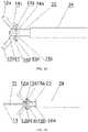
FIG. 1 is a schematic diagram of a multifunctional high-frequency electrosurgical knife.FIG. 2 is a partially enlarged schematic diagram of the multifunctional high-frequency electrosurgical knife in a state where clamping elements are closed.FIGS. 3A-3B are partially enlarged schematic diagrams of the multifunctional high-frequency electrosurgical knife in a state where the clamping elements are opened.FIGS. 4A-4B are schematic diagrams of the multifunctional high-frequency electrosurgical knife with different protruded lengths of the knife.FIGS. 5A-5F are schematic diagrams of a distal end of an electrode.FIGS. 6A-6D are schematic diagrams illustrating a process of using the multifunctional high-frequency electrosurgical knife.FIG. 7 is a schematic diagram of a thumb ring.- 10, treatment part; 11, electrode; 111, hollow tubular portion; 112, protrusion; 12a, first clamping element; 12b, second clamping element; 13a, first pin shaft; 13b, second pin shaft; 13c, third pin shaft; 13d, fourth pin shaft; 14a, first jaw arm; 14b, second jaw arm; 14c, third jaw arm; 14d, fourth jaw arm; 15, locking member; 16a, hook structure; 16b, hook structure; 17, limit block; 20, sheath part; 21, fixed base; 22, hollow pull rod; 23, spring tube; 24, insulating outer tube; 30, operating part; 31, high-frequency connector; 32, slider; 33, core rod; 34, thumb ring; 35, liquid inlet; 40, lesioned tissue
- In order to further clarify the objects, technical solutions, and advantages of the present disclosure, the present disclosure will be described in further detail with reference to the drawings and embodiments below. It should be understood that the specific embodiments described herein are intended only to explain the present disclosure and are not intended to limit the present disclosure.
- Hereinafter, one end of the treatment part is defined as a distal end, and one end of the operating part is defined as a proximal end. As shown in
FIGS. 1-3 , a multifunctional high-frequency electrosurgical knife in this embodiment comprises a treatment part 10, a sheath part 20, and an operating part 30. The treatment part 10 comprises anelectrode 11, a clip having afirst clamping element 12a and asecond clamping element 12b, afirst pin shaft 13a, asecond pin shaft 13b, athird pin shaft 13c, afourth pin shaft 13d, afirst jaw arm 14a, asecond jaw arm 14b, athird jaw arm 14c, and afourth jaw arm 14d. Thefirst jaw arm 14a and thethird jaw arm 14c are movably connected by thethird pin shaft 13c, and thesecond jaw arm 14b and thefourth jaw arm 14d are movably connected by thefourth pin shaft 13d. Thefirst jaw arm 14a and thethird jaw arm 14c may also be movably connected in the form of ahook structure 16a, and thesecond jaw arm 14b and thefourth jaw arm 14d may also be movably connected in the form of a hook structure 16b. Thefirst jaw arm 14a and thesecond jaw arm 14b are movably connected by thesecond pin shaft 13b. Thethird jaw arm 14c and thefourth jaw arm 14d are movably connected to the tails of thefirst clamping element 12a and thesecond clamping element 12b by means of thefirst pin shaft 13a. Thefirst pin shaft 13a is fixedly connected to the distal end of thehollow pull rod 22, and thesecond pin shaft 13b is movably connected to the distal end of thehollow pull rod 22, so that thehollow pull rod 22 can be pulled to protrude or withdraw the clip component. - As shown in
FIGS. 3A and 3B , thefirst clamping element 12a and thesecond clamping element 12b intersect in a cross shape. The clip movably connected by thefirst pin shaft 13a can be opened or closed. Thefirst clamping element 12a and thesecond clamping element 12b intersect in a cross shape, in the opened state. Thefirst clamping element 12a and thesecond clamping element 12b are symmetrically shaped, so as to form a clip portion of the clip component for performing hemostasis of tissue. Thefirst clamping element 12a and thesecond clamping element 12b may be covered with a coating film or ceramic material serving as an insulator. - As shown in
FIGS. 5A-5F , theelectrode 11 is passed from the distal end through thehollow pull rod 22 and connected to an operating wire at the proximal end. Theelectrode 11 may comprise a hollowtubular portion 111 extending in an axial direction and aprotrusion 112 at the distal end, or theelectrode 11 may have only the hollowtubular portion 111 extending in the axial direction without theprotrusion 112. The distal end of theelectrode 11 extends outwardly in a direction perpendicular to the axis of the hollowtubular portion 111 by a length greater than the radius of the cross section of the hollowtubular portion 111 of the electrode, and the outwardly extending portion forms aprotrusion 112 at the distal end of theelectrode 11. - As shown in
FIG. 5A , theprotrusion 112 has a cross section distributed (arranged) circumferentially, and theprotrusion 112 is in the shape of a hemisphere. As shown inFIG. 5B , theprotrusion 112 has a cross section distributed (arranged) circumferentially, and theprotrusion 112 is in the shape of a sphere. As shown inFIG. 5C , theprotrusion 112 has a cross section distributed (arranged) circumferentially, and theprotrusion 112 is in a cylindrical shape. As shown inFIG. 5D , theprotrusion 112 has a cross section distributed (arranged) in a triangular shape, and theprotrusion 112 is in the shape of a triangular prism. As shown inFIG. 5E , theprotrusion 112 has a cross section distributed (arranged) in a Y shape, and theprotrusion 112 is Y-shaped. As shown inFIG. 5F , theelectrode 11 may have only the hollowtubular portion 111 extending in the axial direction. - As shown in
FIG. 2 , the sheath part 20 comprises a fixedbase 21, ahollow pull rod 22, aspring tube 23, an insulatingouter tube 24, a lockingmember 15, and alimit block 17. Thehollow pull rod 22 may be a hollow pull rod allowing theelectrode 11 to pass through. Thefirst pin shaft 13a is fixedly connected to the distal end of thehollow pull rod 22. Thethird jaw arm 14c and thefourth jaw arm 14d are movably connected to the tails of thefirst clamping element 12a and thesecond clamping element 12b by means of thefirst pin shaft 13a, and fixed to thehollow pull rod 22. Thesecond pin shaft 13b is movably connected to the distal end of thehollow pull rod 22. Thefirst jaw arm 14a and thesecond jaw arm 14b are movably connected to each other by means of thesecond pin shaft 13b, and movably fixed to thehollow pull rod 22. Thus, thehollow pull rod 22 can be pulled to enable the clip component to be protruded or withdrawn. The outer surface of the distal end of thehollow pull rod 22 is covered with the fixedbase 21. The fixedbase 21 may be connected to the distal end of thespring tube 23. Thespring tube 23 can increase the flexibility and bendability of the multifunctional high-frequency electrosurgical knife. The insulatingouter tube 24 has a lumen extending along the axis of the sheath part 20, in which thehollow pull rod 22 is movable freely. - As shown in
FIG. 2 andFIGS. 4A-4B , the lockingmember 15 is provided on the outer surface of the hollowtubular portion 111. The lockingmember 15 is block-shaped, ring-shaped, or tubular, wherein the block-shaped locking member may consist of a set of locking blocks spaced apart from each other. Thelimit block 17 is provided on the outer wall of the hollowtubular portion 111 of the electrode. Thelimit block 17 will be locked by thefirst pin shaft 13a to control the maximum distance by which theelectrode 11 is protruded toward the front end, thereby controlling the protruded length of theelectrode 11. When the lockingmember 15 is moved to the distal ends of thefirst clamping element 12a and thesecond clamping element 12b, which are in the closed state, the lockingmember 15 is locked by the two clamping elements to achieve positioning. At this time, theelectrode 11 has a minimum protruded length. Thelimit block 17 is block-shaped or ring-shaped. - As shown in
FIGS. 1 and 2 , the operating part 30 is provided at the proximal end of the sheath part 20, which can push out or retract theelectrode 11 and the clip component relative to the front end of the sheath part 20, and can provide a lumen through which a liquid is injected. The operating part 30 comprises a high-frequency connector 31, aslider 32, acore rod 33, athumb ring 34, and aliquid inlet 35. Thethumb ring 34 at the proximal end is connected to theelectrode 11 via an operating wire, so as to control the protruding and withdrawal of theelectrode 11. The high-frequency connector 31 may be connected to theelectrode 11 via a wire, to supply theelectrode 11 with a high-frequency current. Theelectrode 11 extends distally from its proximal end through the interior of the proximal end of thehollow pull rod 22. Theslider 32 is connected to the proximal end of thehollow pull rod 22, and theslider 32 is movable back and forth along thecore rod 33, so as to drive thehollow pull rod 22 to move, for protruding or retracting the clip component. When theslider 32 is pushed forward, thehollow pull rod 22 drives thefirst clamping element 12a and thesecond clamping element 12b to be moved distally and gradually opened to intersect in a cross shape. When theslider 32 is retracted backward, thehollow pull rod 22 drives thefirst clamping element 12a and thesecond clamping element 12b to be contracted into the insulatingouter tube 24. In this way, the opening and closing of thefirst clamping element 12a and thesecond clamping element 12b are achieved. Thespring tube 23 and theelectrode 11, serving as a driving part, are components for torque transmission, so that double drive is formed inside the sheath part 20. Thespring tube 23 increases the twisting force for the driving part. FIGS. 6A-6D illustrate an operation procedure of the multifunctional high-frequency electrosurgical knife in the present disclosure. During an actual operation, as shown inFIG. 6A , the multifunctional high-frequency electrosurgical knife of the present disclosure is inserted to the vicinity of thelesioned tissue 40 through a channel of an endoscope. In this process, theelectrode 11 is kept in the retracted state, theprotrusion 112 of the electrode is closely attached to thefirst clamping element 12a and thesecond clamping element 12b, and thefirst clamping element 12a and thesecond clamping element 12b are contracted in the insulatingouter tube 24. After the multifunctional high-frequency electrosurgical knife reaches thelesioned tissue 40, theelectrode 11 is still kept in the retracted state, and the high-frequency connector 31 of the multifunctional high-frequency electrosurgical knife of the present disclosure is connected to an external high-frequency generator, wherein the high-frequency generator includes, but is not limited to, CONMED 60-8200-230, ERBE VIO300S, 300D, etc. Thus, a high-frequency current is applied to theelectrode 11, and the periphery of thelesioned tissue 40 is marked. After the marking is completed, the application of the high-frequency current is stopped.- As shown in
FIG. 6B , thethumb ring 34 of the multifunctional high-frequency electrosurgical knife of the present disclosure is pushed to move forward, so that theelectrode 11 is protruded. Theelectrode 11 is placed at a marked point and inserted into the submucosa of thelesioned tissue 40, and normal saline or indigo carmine is injected into thelesioned tissue 40 through theliquid inlet 35 so that the tissue is elevated. - As shown in
FIGS. 6C-6D , after the lesioned tissue is elevated, a high-frequency current is applied again to the electrode, while the tissue is cut by theelectrode 11 in a direction shown inFIG. 6C . As shown inFIG. 6D , after the cutting is finished, the application of the high-frequency current is stopped, and theslider 32 is pushed forward to drive thehollow pull rod 22 to move forward, so that the clip component is opened, and thefirst clamping element 12a and thesecond clamping element 12b are opened to intersect in a cross shape. Then, thethumb ring 34 is retracted backward to withdraw theelectrode 11, so that the opened first clampingelement 12a andsecond clamping element 12b can be used as a hemostatic forceps for electrocoagulation and hemostasis. The clip component is rotatable freely to conveniently and accurately grasp a bleeding point. - As shown in
FIG. 7 , the thumb ring may be in a shape of circle, square, oval, or the like. - Four functions can be achieved by using the instrument constructed as described above. Firstly, the multifunctional high-frequency electrosurgical knife according to the present disclosure has both an electrode and a clip component and thus can achieve the integrated functions of liquid injection, cutting, and hemostasis, so that there is no need to frequently change instruments during a surgical procedure, thereby greatly shortening the surgery time and improving the safety of surgery. Secondly, the multifunctional high-frequency electrosurgical knife according to the present disclosure has an electrode made of a metal material with a hollow tubular portion, and the hollow portion forms a liquid channel, so that a liquid can pass through the hollow tubular portion of the electrode and can be submucosally injected for elevating mucosal tissue, or can also be used for cleaning a bleeding site. Thirdly, a spiral member coated with an insulating coating or a hollow hose with a conductive layer is used as the spring tube of the sheath part, so that the electrosurgical knife is freely bendable in an endoscope. Fourthly, the multifunctional high-frequency electrosurgical knife according to the present disclosure has a first clamping element and a second clamping element that can be freely closed and opened, and a torsional force from the spring tube is transmitted to the clip component so that the clip component is freely rotatable to conveniently and accurately grasp a bleeding point. Fifthly, the multifunctional high-frequency electrosurgical knife according to the present disclosure has a locking member and a limit block on the hollow tubular portion of the electrode, so that free positioning can be achieved, and the electrode can be selectively protruded at different lengths according to actual conditions.
- The above description is only illustrative of preferable embodiments of the present disclosure to enable those skilled in the art to understand or implement the invention of the present disclosure. Various modifications and combinations of these embodiments will be apparent to those skilled in the art.
Claims (15)
- A multifunctional high-frequency electrosurgical knife, comprising:a treatment part (10), a sheath part (20), and an operating part (30),wherein the treatment part (10) is located at a distal end of the multifunctional high-frequency electrosurgical knife and comprises: an electrode (11), configured to cut a tissue and inject a liquid, wherein the electrode (11) is able to be pushed out or retracted relative to a distal end of the sheath part (20) and the electrode (11) has a hollow tubular portion (111) extending in an axial direction; and a clip component, configured to perform hemostasis of a tissue, wherein the clip component is able to be pushed out or retracted relative to the distal end of the sheath part (20) and the clip component comprises a first clamping element (12a), a second clamping element (12b), and a first pin shaft (13a) by which the first clamping element (12a) and the second clamping element (12b) are connected, wherein the clip component is able to be opened and closed by the first pin shaft (13a) being driven;the sheath part (20) is located at a proximal end of the treatment part (10) and comprises: a hollow pull rod (22), wherein the electrode (11) is able to extend distally from its proximal end through an interior of a proximal end of the hollow pull rod (22), the hollow pull rod (22) is connected to the first clamping element (12a) and the second clamping element (12b) by means of the first pin shaft (13a), and the hollow pull rod (22) is operable to drive the clip component to be pushed out or retracted relative to the distal end of the sheath part (20); and an insulating outer tube (24), having a lumen extending along an axis of the sheath part (20), in which the hollow pull rod (22) and the clip component are accommodated; andthe operating part (30) is located at a proximal end of the sheath part (20) and comprises: a high-frequency connector (31), connected to the electrode (11) via a wire; a component, driving the electrode (11) to move by means of an operating wire; a member, driving the hollow pull rod (22) to move; and a liquid inlet (35), allowing a liquid to flow to the hollow tubular portion (111) of the electrode (11).
- The multifunctional high-frequency electrosurgical knife according to claim 1, wherein a distal end of the electrode (11) extends outwardly in a direction perpendicular to an axis of the hollow tubular portion (111) by a length greater than a radius of a cross section of the hollow tubular portion (111) of the electrode (11), and an outwardly extending portion forms a protrusion (112) at the distal end of the electrode (11).
- The multifunctional high-frequency electrosurgical knife according to claim 2, wherein the protrusion (112) is in the shape of a hemisphere, of a sphere or of a triangular prism, or has a cylindrical shape or Y-shape.
- The multifunctional high-frequency electrosurgical knife according to any one of claims 1-3, wherein the treatment part (10) further comprises a second pin shaft (13b), a third pin shaft (13c), a fourth pin shaft (13d), a first jaw arm (14a), a second jaw arm (14b), a third jaw arm (14c), and a fourth jaw arm (14d), wherein the hollow pull rod (22) is movably connected to the third jaw arm (14c) and the fourth jaw arm (14d) by means of the first pin shaft (13a), the third jaw arm (14c) and the first jaw arm (14a) are movably connected by the third pin shaft (13c), the fourth jaw arm (14d) and the second jaw arm (14b) are movably connected by the fourth pin shaft (13d), and the first jaw arm (14a) and the second jaw arm (14b) are movably connected to the hollow pull rod (22) by means of the second pin shaft (13b).
- The multifunctional high-frequency electrosurgical knife according to claim 4, wherein the first jaw arm (14a) and the third jaw arm (14c), in a form of a hook structure (16a), are movably connected, and the second jaw arm (14b) and the fourth jaw arm (14d), in a form of a hook structure (16b), are movably connected.
- The multifunctional high-frequency electrosurgical knife according to any one of claims 1-5, wherein the sheath part (20) further comprises a spring tube (23), which covers an outer layer of the hollow pull rod (22).
- The multifunctional high-frequency electrosurgical knife according to claim 6, wherein an outer surface of a distal end of the hollow pull rod (22) is covered with a fixed base (21), wherein the fixed base (21) is connected to a distal end of the spring tube (23).
- The multifunctional high-frequency electrosurgical knife according to claim 1 or 4, wherein when the clip component is in an opened state, the first clamping element (12a) and the second clamping element (12b) intersect in a cross shape, and the first clamping element (12a) and the second clamping element (12b) are symmetrically shaped, so as to form a clip portion of the clip component.
- The multifunctional high-frequency electrosurgical knife according to any one of claims 1-8, wherein the first clamping element (12a) and the second clamping element (12b) are coated with a coating film or ceramic material.
- The multifunctional high-frequency electrosurgical knife according to any one of claims 1-9, wherein a locking member (15) is provided on an outer surface of the hollow tubular portion (111) of the electrode (11), and a limit block (17) is provided on an outer wall of the hollow tubular portion (111), wherein a maximum distance by which the electrode (11) is protruded distally is controlled by cooperation of the limit block (17) with the first pin shaft (13a), and a minimum distance by which the electrode (11) is protruded distally is controlled by cooperation of the locking member (15), the first clamping element (12a), and the second clamping element (12b).
- The multifunctional high-frequency electrosurgical knife according to claim 10, wherein the locking member (15) is block-shaped, ring-shaped, or tubular.
- The multifunctional high-frequency electrosurgical knife according to claim 10 or 11, wherein the limit block (17) is block-shaped or ring-shaped.
- The multifunctional high-frequency electrosurgical knife according to any one of claims 1-12, wherein the operating part (30) further comprises a core rod (33), which extends along an axial direction of the high-frequency electrosurgical knife, and a distal end of the core rod (33) is connected to the insulating outer tube (24).
- The multifunctional high-frequency electrosurgical knife according to claim 13, further comprising a slider (32), wherein the slider (32) is slidable back and forth along the core rod (33), so as to protrude or retract the clip component.
- The multifunctional high-frequency electrosurgical knife according to any one of claims 1-14, wherein the component, driving the electrode (11) to move, is a thumb ring (34) provided at a proximal end of the operating part (30), wherein the thumb ring (34) is slidable back and forth along the core rod (33), so as to protrude or retract the electrode (11).
Applications Claiming Priority (2)
| Application Number | Priority Date | Filing Date | Title |
|---|---|---|---|
| CN201810366219.1ACN108523985B (en) | 2018-04-23 | 2018-04-23 | Multifunctional high-frequency electric incision knife |
| PCT/CN2019/083463WO2019206042A1 (en) | 2018-04-23 | 2019-04-19 | Multifunctional high-frequency electric knife |
Publications (3)
| Publication Number | Publication Date |
|---|---|
| EP3785654A1 EP3785654A1 (en) | 2021-03-03 |
| EP3785654A4 EP3785654A4 (en) | 2021-06-30 |
| EP3785654B1true EP3785654B1 (en) | 2022-05-11 |
Family
ID=63479279
Family Applications (1)
| Application Number | Title | Priority Date | Filing Date |
|---|---|---|---|
| EP19791969.9AActiveEP3785654B1 (en) | 2018-04-23 | 2019-04-19 | Multifunctional high-frequency electric knife |
Country Status (9)
| Country | Link |
|---|---|
| US (1) | US12108975B2 (en) |
| EP (1) | EP3785654B1 (en) |
| JP (1) | JP7064024B2 (en) |
| KR (1) | KR20210011910A (en) |
| CN (1) | CN108523985B (en) |
| AU (1) | AU2019260152B2 (en) |
| BR (1) | BR112020021605A2 (en) |
| CA (1) | CA3097932C (en) |
| WO (1) | WO2019206042A1 (en) |
Families Citing this family (11)
| Publication number | Priority date | Publication date | Assignee | Title |
|---|---|---|---|---|
| CN108523985B (en)* | 2018-04-23 | 2024-05-07 | 南微医学科技股份有限公司 | Multifunctional high-frequency electric incision knife |
| CN112312853B (en)* | 2019-03-04 | 2024-07-19 | 丰光产业株式会社 | Medical treatment device |
| US20220240962A1 (en)* | 2019-05-20 | 2022-08-04 | Kaneka Corporation | Endoscope forceps |
| CN111166464A (en)* | 2019-12-27 | 2020-05-19 | 范东香 | An endoscopic tissue cutter |
| WO2022157974A1 (en)* | 2021-01-25 | 2022-07-28 | オリンパスメディカルシステムズ株式会社 | Treatment instrument |
| CN113712662B (en)* | 2021-09-07 | 2022-04-08 | 南昌华安众辉健康科技有限公司 | Fast-assembling electric coagulation hook and assembling method thereof |
| CN113813042B (en)* | 2021-10-22 | 2023-12-05 | 杭州维纳安可医疗科技有限责任公司 | Electrode needle and electrode device |
| CN114569234B (en)* | 2021-11-19 | 2024-09-06 | 青岛市城阳区人民医院 | Multifunctional snare for endoscopic surgery |
| CN114191069B (en)* | 2021-12-06 | 2024-01-12 | 安瑞医疗器械(杭州)有限公司 | Hemostatic forceps and clamp parts thereof |
| CN114376717A (en)* | 2022-01-12 | 2022-04-22 | 扬州发特利医疗器械科技有限公司 | Cutting knife for bipolar double-injection |
| CN115944376A (en)* | 2023-01-29 | 2023-04-11 | 杭州罗伯医疗科技有限公司 | Electrosurgical Instruments |
Family Cites Families (39)
| Publication number | Priority date | Publication date | Assignee | Title |
|---|---|---|---|---|
| US5820630A (en)* | 1996-10-22 | 1998-10-13 | Annex Medical, Inc. | Medical forceps jaw assembly |
| US5931810A (en)* | 1996-12-05 | 1999-08-03 | Comedicus Incorporated | Method for accessing the pericardial space |
| JPH1119085A (en)* | 1997-07-03 | 1999-01-26 | Nippon Zeon Co Ltd | Forceps type electric treatment instrument |
| JP2000245740A (en) | 1999-03-03 | 2000-09-12 | Fuji Photo Optical Co Ltd | Treating tool for enoscope |
| US6190386B1 (en)* | 1999-03-09 | 2001-02-20 | Everest Medical Corporation | Electrosurgical forceps with needle electrodes |
| JP2001095812A (en) | 1999-09-29 | 2001-04-10 | Olympus Optical Co Ltd | High frequency treatment appliance for excision |
| AU2003279854B2 (en)* | 2002-10-04 | 2008-12-18 | Covidien Lp | Tool assembly for a surgical stapling device |
| JP4436698B2 (en) | 2004-02-25 | 2010-03-24 | オリンパス株式会社 | High frequency treatment tool |
| US20080021274A1 (en)* | 2005-01-05 | 2008-01-24 | Avantis Medical Systems, Inc. | Endoscopic medical device with locking mechanism and method |
| DE102006023696B4 (en)* | 2005-05-20 | 2019-10-17 | Kaneka Corporation | High-frequency incision instrument for an endoscope |
| US20060271042A1 (en)* | 2005-05-26 | 2006-11-30 | Gyrus Medical, Inc. | Cutting and coagulating electrosurgical forceps having cam controlled jaw closure |
| CN101420914B (en) | 2006-04-11 | 2011-06-29 | 爱尔伯电子医疗设备公司 | Multi-function device for endoscopic surgery |
| US20100217151A1 (en) | 2007-07-11 | 2010-08-26 | Zach Gostout | Methods and Systems for Performing Submucosal Medical Procedures |
| US20100185196A1 (en) | 2009-01-21 | 2010-07-22 | Satomi Sakao | Medical treatment apparatus, treatment instrument and treatment method for living tissue using energy |
| EP2526884B1 (en)* | 2010-01-22 | 2018-07-11 | Olympus Corporation | Treatment device |
| DE102011000964B4 (en)* | 2010-12-13 | 2014-10-23 | Erbe Elektromedizin Gmbh | surgical device |
| CN102379739B (en)* | 2011-08-31 | 2013-07-24 | 南京微创医学科技有限公司 | Winding prevention type multifunctional high-frequency scalpel of endoscope |
| US8926609B2 (en) | 2011-11-08 | 2015-01-06 | Olympus Medical Systems Corp. | Treatment device and treatment method |
| US8968309B2 (en)* | 2011-11-10 | 2015-03-03 | Covidien Lp | Surgical forceps |
| JP5755121B2 (en)* | 2011-11-30 | 2015-07-29 | Hoya株式会社 | Endoscopic high-frequency treatment instrument |
| CN102579129A (en)* | 2012-03-28 | 2012-07-18 | 刘枫 | High-frequency incision knife with accurate fixed-length knife bit for endoscope |
| CN104411265B (en) | 2012-09-12 | 2016-11-16 | 奥林巴斯株式会社 | High frequency electric knife |
| CN103110457B (en)* | 2013-01-16 | 2015-04-01 | 王实 | Mucous membrane separating scalpel |
| CN203059895U (en)* | 2013-01-29 | 2013-07-17 | 上海威尔逊光电仪器有限公司 | Rotation handle applied to endoscope appliance |
| EP3056158B1 (en) | 2013-10-09 | 2019-04-24 | Olympus Corporation | High-frequency treatment tool for endoscope |
| KR101656944B1 (en)* | 2013-10-16 | 2016-09-19 | 국립암센터 | Endoscopic Injection Apparatus |
| CN103750901B (en)* | 2014-02-14 | 2016-01-20 | 徐美东 | A kind of Multifunctional high-frequency incision knife |
| CN104248461B (en)* | 2014-09-25 | 2016-06-22 | 安瑞医疗器械(杭州)有限公司 | Clamp, clamp pusher and hemostatic clamp |
| CN205054424U (en)* | 2015-06-30 | 2016-03-02 | 复旦大学附属中山医院 | But injection peels off incision sword under scope mucosa |
| US20190374242A1 (en) | 2015-09-11 | 2019-12-12 | Katya Surgical Ltd | Multi-functional laparoscopic surgical apparatuses and applications thereof |
| CN105434038B (en)* | 2015-12-15 | 2018-07-06 | 安瑞医疗器械(杭州)有限公司 | A kind of endoscope-use multifunctional high frequency cutter |
| JP6655398B2 (en) | 2016-01-13 | 2020-02-26 | Hoya株式会社 | High frequency treatment tool for endoscope |
| CN107343815A (en)* | 2016-05-06 | 2017-11-14 | 徐�明 | A kind of multifunctional composite electric knife |
| CN106214247B (en)* | 2016-07-04 | 2018-08-14 | 南京微创医学科技股份有限公司 | A kind of bipolar high frequency electric knife |
| CN206044658U (en)* | 2016-07-16 | 2017-03-29 | 杨奕夫 | Laparoscopic surgery coagulation formula biopsy extraction is clamped |
| CN106491176A (en)* | 2016-11-15 | 2017-03-15 | 浙江创想医学科技有限公司 | One kind is rotatable to be repeated to be opened and closed hemostatic clamp |
| JP6326609B2 (en)* | 2016-12-01 | 2018-05-23 | コヴィディエン リミテッド パートナーシップ | Bipolar surgical instrument |
| CN107693110B (en)* | 2017-09-30 | 2020-09-04 | 四川大学华西医院 | Mucous membrane stripper under endoscope |
| CN108523985B (en)* | 2018-04-23 | 2024-05-07 | 南微医学科技股份有限公司 | Multifunctional high-frequency electric incision knife |
- 2018
- 2018-04-23CNCN201810366219.1Apatent/CN108523985B/enactiveActive
- 2019
- 2019-04-19CACA3097932Apatent/CA3097932C/enactiveActive
- 2019-04-19BRBR112020021605-4Apatent/BR112020021605A2/enactiveIP Right Grant
- 2019-04-19EPEP19791969.9Apatent/EP3785654B1/enactiveActive
- 2019-04-19KRKR1020207029757Apatent/KR20210011910A/ennot_activeCeased
- 2019-04-19WOPCT/CN2019/083463patent/WO2019206042A1/ennot_activeCeased
- 2019-04-19AUAU2019260152Apatent/AU2019260152B2/enactiveActive
- 2019-04-19JPJP2020570623Apatent/JP7064024B2/enactiveActive
- 2019-04-19USUS17/048,240patent/US12108975B2/enactiveActive
Also Published As
| Publication number | Publication date |
|---|---|
| WO2019206042A1 (en) | 2019-10-31 |
| AU2019260152A1 (en) | 2020-11-12 |
| KR20210011910A (en) | 2021-02-02 |
| CN108523985A (en) | 2018-09-14 |
| EP3785654A4 (en) | 2021-06-30 |
| CN108523985B (en) | 2024-05-07 |
| EP3785654A1 (en) | 2021-03-03 |
| CA3097932C (en) | 2023-06-20 |
| JP7064024B2 (en) | 2022-05-09 |
| JP2021516597A (en) | 2021-07-08 |
| BR112020021605A2 (en) | 2021-01-26 |
| US12108975B2 (en) | 2024-10-08 |
| AU2019260152B2 (en) | 2021-12-16 |
| US20210077179A1 (en) | 2021-03-18 |
| CA3097932A1 (en) | 2019-10-31 |
Similar Documents
| Publication | Publication Date | Title |
|---|---|---|
| EP3785654B1 (en) | Multifunctional high-frequency electric knife | |
| CA3090198C (en) | Dual-channel injection bipolar high frequency electrosurgical knife | |
| US9421063B2 (en) | Endoscopic devices and related methods of use | |
| JP4366077B2 (en) | Steerable sphincter instrument and method for cannulation, nipple incision and sphincter incision | |
| US6296639B1 (en) | Apparatuses and methods for interstitial tissue removal | |
| JP2002511302A (en) | Electrocautery catheter | |
| JP3235996U (en) | Medical connection device | |
| KR102234752B1 (en) | Four blades - scissors knife for Endosurgical procedure | |
| HK40037515A (en) | Multifunctional high-frequency electric knife | |
| HK40037515B (en) | Multifunctional high-frequency electric knife | |
| US20170164971A1 (en) | Endoscopic tissue manipulation tool | |
| CN209107567U (en) | A kind of multifunctional high frequency cutting is operated on | |
| EP3808316B1 (en) | Hot-puncture stent implantation device | |
| HK1261009A1 (en) | A multifunctional high-frequency electrosurgical cutting knife | |
| US12023278B1 (en) | Devices for performing intraocular surgery and methods for using them | |
| CN119791791A (en) | Flexible puncture structure and steam ablation system | |
| HK40034362B (en) | Dual-channel injection bipolar high frequency electrosurgical knife | |
| HK40034362A (en) | Dual-channel injection bipolar high frequency electrosurgical knife |
Legal Events
| Date | Code | Title | Description |
|---|---|---|---|
| STAA | Information on the status of an ep patent application or granted ep patent | Free format text:STATUS: THE INTERNATIONAL PUBLICATION HAS BEEN MADE | |
| PUAI | Public reference made under article 153(3) epc to a published international application that has entered the european phase | Free format text:ORIGINAL CODE: 0009012 | |
| STAA | Information on the status of an ep patent application or granted ep patent | Free format text:STATUS: REQUEST FOR EXAMINATION WAS MADE | |
| 17P | Request for examination filed | Effective date:20201029 | |
| AK | Designated contracting states | Kind code of ref document:A1 Designated state(s):AL AT BE BG CH CY CZ DE DK EE ES FI FR GB GR HR HU IE IS IT LI LT LU LV MC MK MT NL NO PL PT RO RS SE SI SK SM TR | |
| AX | Request for extension of the european patent | Extension state:BA ME | |
| REG | Reference to a national code | Ref country code:HK Ref legal event code:DE Ref document number:40037515 Country of ref document:HK | |
| A4 | Supplementary search report drawn up and despatched | Effective date:20210528 | |
| RIC1 | Information provided on ipc code assigned before grant | Ipc:A61B 18/12 20060101AFI20210521BHEP Ipc:A61B 18/14 20060101ALI20210521BHEP Ipc:A61B 18/00 20060101ALN20210521BHEP Ipc:A61B 17/29 20060101ALN20210521BHEP Ipc:A61B 18/08 20060101ALN20210521BHEP Ipc:A61B 17/00 20060101ALN20210521BHEP | |
| DAV | Request for validation of the european patent (deleted) | ||
| DAX | Request for extension of the european patent (deleted) | ||
| GRAP | Despatch of communication of intention to grant a patent | Free format text:ORIGINAL CODE: EPIDOSNIGR1 | |
| STAA | Information on the status of an ep patent application or granted ep patent | Free format text:STATUS: GRANT OF PATENT IS INTENDED | |
| RIC1 | Information provided on ipc code assigned before grant | Ipc:A61B 17/00 20060101ALN20211108BHEP Ipc:A61B 18/08 20060101ALN20211108BHEP Ipc:A61B 17/29 20060101ALN20211108BHEP Ipc:A61B 18/00 20060101ALN20211108BHEP Ipc:A61B 18/14 20060101ALI20211108BHEP Ipc:A61B 18/12 20060101AFI20211108BHEP | |
| RIC1 | Information provided on ipc code assigned before grant | Ipc:A61B 17/00 20060101ALN20211117BHEP Ipc:A61B 18/08 20060101ALN20211117BHEP Ipc:A61B 17/29 20060101ALN20211117BHEP Ipc:A61B 18/00 20060101ALN20211117BHEP Ipc:A61B 18/14 20060101ALI20211117BHEP Ipc:A61B 18/12 20060101AFI20211117BHEP | |
| INTG | Intention to grant announced | Effective date:20211202 | |
| GRAS | Grant fee paid | Free format text:ORIGINAL CODE: EPIDOSNIGR3 | |
| GRAA | (expected) grant | Free format text:ORIGINAL CODE: 0009210 | |
| STAA | Information on the status of an ep patent application or granted ep patent | Free format text:STATUS: THE PATENT HAS BEEN GRANTED | |
| AK | Designated contracting states | Kind code of ref document:B1 Designated state(s):AL AT BE BG CH CY CZ DE DK EE ES FI FR GB GR HR HU IE IS IT LI LT LU LV MC MK MT NL NO PL PT RO RS SE SI SK SM TR | |
| REG | Reference to a national code | Ref country code:GB Ref legal event code:FG4D | |
| REG | Reference to a national code | Ref country code:CH Ref legal event code:EP | |
| REG | Reference to a national code | Ref country code:AT Ref legal event code:REF Ref document number:1490746 Country of ref document:AT Kind code of ref document:T Effective date:20220515 | |
| REG | Reference to a national code | Ref country code:DE Ref legal event code:R096 Ref document number:602019014965 Country of ref document:DE | |
| REG | Reference to a national code | Ref country code:IE Ref legal event code:FG4D | |
| REG | Reference to a national code | Ref country code:LT Ref legal event code:MG9D | |
| REG | Reference to a national code | Ref country code:NL Ref legal event code:MP Effective date:20220511 | |
| REG | Reference to a national code | Ref country code:AT Ref legal event code:MK05 Ref document number:1490746 Country of ref document:AT Kind code of ref document:T Effective date:20220511 | |
| PG25 | Lapsed in a contracting state [announced via postgrant information from national office to epo] | Ref country code:SE Free format text:LAPSE BECAUSE OF FAILURE TO SUBMIT A TRANSLATION OF THE DESCRIPTION OR TO PAY THE FEE WITHIN THE PRESCRIBED TIME-LIMIT Effective date:20220511 Ref country code:PT Free format text:LAPSE BECAUSE OF FAILURE TO SUBMIT A TRANSLATION OF THE DESCRIPTION OR TO PAY THE FEE WITHIN THE PRESCRIBED TIME-LIMIT Effective date:20220912 Ref country code:NO Free format text:LAPSE BECAUSE OF FAILURE TO SUBMIT A TRANSLATION OF THE DESCRIPTION OR TO PAY THE FEE WITHIN THE PRESCRIBED TIME-LIMIT Effective date:20220811 Ref country code:NL Free format text:LAPSE BECAUSE OF FAILURE TO SUBMIT A TRANSLATION OF THE DESCRIPTION OR TO PAY THE FEE WITHIN THE PRESCRIBED TIME-LIMIT Effective date:20220511 Ref country code:LT Free format text:LAPSE BECAUSE OF FAILURE TO SUBMIT A TRANSLATION OF THE DESCRIPTION OR TO PAY THE FEE WITHIN THE PRESCRIBED TIME-LIMIT Effective date:20220511 Ref country code:HR Free format text:LAPSE BECAUSE OF FAILURE TO SUBMIT A TRANSLATION OF THE DESCRIPTION OR TO PAY THE FEE WITHIN THE PRESCRIBED TIME-LIMIT Effective date:20220511 Ref country code:GR Free format text:LAPSE BECAUSE OF FAILURE TO SUBMIT A TRANSLATION OF THE DESCRIPTION OR TO PAY THE FEE WITHIN THE PRESCRIBED TIME-LIMIT Effective date:20220812 Ref country code:FI Free format text:LAPSE BECAUSE OF FAILURE TO SUBMIT A TRANSLATION OF THE DESCRIPTION OR TO PAY THE FEE WITHIN THE PRESCRIBED TIME-LIMIT Effective date:20220511 Ref country code:BG Free format text:LAPSE BECAUSE OF FAILURE TO SUBMIT A TRANSLATION OF THE DESCRIPTION OR TO PAY THE FEE WITHIN THE PRESCRIBED TIME-LIMIT Effective date:20220811 Ref country code:AT Free format text:LAPSE BECAUSE OF FAILURE TO SUBMIT A TRANSLATION OF THE DESCRIPTION OR TO PAY THE FEE WITHIN THE PRESCRIBED TIME-LIMIT Effective date:20220511 | |
| PG25 | Lapsed in a contracting state [announced via postgrant information from national office to epo] | Ref country code:RS Free format text:LAPSE BECAUSE OF FAILURE TO SUBMIT A TRANSLATION OF THE DESCRIPTION OR TO PAY THE FEE WITHIN THE PRESCRIBED TIME-LIMIT Effective date:20220511 Ref country code:PL Free format text:LAPSE BECAUSE OF FAILURE TO SUBMIT A TRANSLATION OF THE DESCRIPTION OR TO PAY THE FEE WITHIN THE PRESCRIBED TIME-LIMIT Effective date:20220511 Ref country code:LV Free format text:LAPSE BECAUSE OF FAILURE TO SUBMIT A TRANSLATION OF THE DESCRIPTION OR TO PAY THE FEE WITHIN THE PRESCRIBED TIME-LIMIT Effective date:20220511 Ref country code:IS Free format text:LAPSE BECAUSE OF FAILURE TO SUBMIT A TRANSLATION OF THE DESCRIPTION OR TO PAY THE FEE WITHIN THE PRESCRIBED TIME-LIMIT Effective date:20220911 | |
| PG25 | Lapsed in a contracting state [announced via postgrant information from national office to epo] | Ref country code:SM Free format text:LAPSE BECAUSE OF FAILURE TO SUBMIT A TRANSLATION OF THE DESCRIPTION OR TO PAY THE FEE WITHIN THE PRESCRIBED TIME-LIMIT Effective date:20220511 Ref country code:SK Free format text:LAPSE BECAUSE OF FAILURE TO SUBMIT A TRANSLATION OF THE DESCRIPTION OR TO PAY THE FEE WITHIN THE PRESCRIBED TIME-LIMIT Effective date:20220511 Ref country code:RO Free format text:LAPSE BECAUSE OF FAILURE TO SUBMIT A TRANSLATION OF THE DESCRIPTION OR TO PAY THE FEE WITHIN THE PRESCRIBED TIME-LIMIT Effective date:20220511 Ref country code:ES Free format text:LAPSE BECAUSE OF FAILURE TO SUBMIT A TRANSLATION OF THE DESCRIPTION OR TO PAY THE FEE WITHIN THE PRESCRIBED TIME-LIMIT Effective date:20220511 Ref country code:EE Free format text:LAPSE BECAUSE OF FAILURE TO SUBMIT A TRANSLATION OF THE DESCRIPTION OR TO PAY THE FEE WITHIN THE PRESCRIBED TIME-LIMIT Effective date:20220511 Ref country code:DK Free format text:LAPSE BECAUSE OF FAILURE TO SUBMIT A TRANSLATION OF THE DESCRIPTION OR TO PAY THE FEE WITHIN THE PRESCRIBED TIME-LIMIT Effective date:20220511 Ref country code:CZ Free format text:LAPSE BECAUSE OF FAILURE TO SUBMIT A TRANSLATION OF THE DESCRIPTION OR TO PAY THE FEE WITHIN THE PRESCRIBED TIME-LIMIT Effective date:20220511 | |
| REG | Reference to a national code | Ref country code:DE Ref legal event code:R097 Ref document number:602019014965 Country of ref document:DE | |
| PLBE | No opposition filed within time limit | Free format text:ORIGINAL CODE: 0009261 | |
| STAA | Information on the status of an ep patent application or granted ep patent | Free format text:STATUS: NO OPPOSITION FILED WITHIN TIME LIMIT | |
| PG25 | Lapsed in a contracting state [announced via postgrant information from national office to epo] | Ref country code:AL Free format text:LAPSE BECAUSE OF FAILURE TO SUBMIT A TRANSLATION OF THE DESCRIPTION OR TO PAY THE FEE WITHIN THE PRESCRIBED TIME-LIMIT Effective date:20220511 | |
| 26N | No opposition filed | Effective date:20230214 | |
| PG25 | Lapsed in a contracting state [announced via postgrant information from national office to epo] | Ref country code:SI Free format text:LAPSE BECAUSE OF FAILURE TO SUBMIT A TRANSLATION OF THE DESCRIPTION OR TO PAY THE FEE WITHIN THE PRESCRIBED TIME-LIMIT Effective date:20220511 | |
| REG | Reference to a national code | Ref country code:CH Ref legal event code:PL | |
| PG25 | Lapsed in a contracting state [announced via postgrant information from national office to epo] | Ref country code:LU Free format text:LAPSE BECAUSE OF NON-PAYMENT OF DUE FEES Effective date:20230419 | |
| REG | Reference to a national code | Ref country code:BE Ref legal event code:MM Effective date:20230430 | |
| PG25 | Lapsed in a contracting state [announced via postgrant information from national office to epo] | Ref country code:MC Free format text:LAPSE BECAUSE OF FAILURE TO SUBMIT A TRANSLATION OF THE DESCRIPTION OR TO PAY THE FEE WITHIN THE PRESCRIBED TIME-LIMIT Effective date:20220511 | |
| PG25 | Lapsed in a contracting state [announced via postgrant information from national office to epo] | Ref country code:MC Free format text:LAPSE BECAUSE OF FAILURE TO SUBMIT A TRANSLATION OF THE DESCRIPTION OR TO PAY THE FEE WITHIN THE PRESCRIBED TIME-LIMIT Effective date:20220511 Ref country code:LI Free format text:LAPSE BECAUSE OF NON-PAYMENT OF DUE FEES Effective date:20230430 Ref country code:IT Free format text:LAPSE BECAUSE OF FAILURE TO SUBMIT A TRANSLATION OF THE DESCRIPTION OR TO PAY THE FEE WITHIN THE PRESCRIBED TIME-LIMIT Effective date:20220511 Ref country code:CH Free format text:LAPSE BECAUSE OF NON-PAYMENT OF DUE FEES Effective date:20230430 | |
| REG | Reference to a national code | Ref country code:IE Ref legal event code:MM4A | |
| PG25 | Lapsed in a contracting state [announced via postgrant information from national office to epo] | Ref country code:BE Free format text:LAPSE BECAUSE OF NON-PAYMENT OF DUE FEES Effective date:20230430 | |
| PG25 | Lapsed in a contracting state [announced via postgrant information from national office to epo] | Ref country code:IE Free format text:LAPSE BECAUSE OF NON-PAYMENT OF DUE FEES Effective date:20230419 | |
| PG25 | Lapsed in a contracting state [announced via postgrant information from national office to epo] | Ref country code:IE Free format text:LAPSE BECAUSE OF NON-PAYMENT OF DUE FEES Effective date:20230419 | |
| PG25 | Lapsed in a contracting state [announced via postgrant information from national office to epo] | Ref country code:BG Free format text:LAPSE BECAUSE OF FAILURE TO SUBMIT A TRANSLATION OF THE DESCRIPTION OR TO PAY THE FEE WITHIN THE PRESCRIBED TIME-LIMIT Effective date:20220511 | |
| PG25 | Lapsed in a contracting state [announced via postgrant information from national office to epo] | Ref country code:BG Free format text:LAPSE BECAUSE OF FAILURE TO SUBMIT A TRANSLATION OF THE DESCRIPTION OR TO PAY THE FEE WITHIN THE PRESCRIBED TIME-LIMIT Effective date:20220511 | |
| PGFP | Annual fee paid to national office [announced via postgrant information from national office to epo] | Ref country code:FR Payment date:20250314 Year of fee payment:7 | |
| PGFP | Annual fee paid to national office [announced via postgrant information from national office to epo] | Ref country code:GB Payment date:20250314 Year of fee payment:7 | |
| PGFP | Annual fee paid to national office [announced via postgrant information from national office to epo] | Ref country code:DE Payment date:20250417 Year of fee payment:7 | |
| PG25 | Lapsed in a contracting state [announced via postgrant information from national office to epo] | Ref country code:CY Free format text:LAPSE BECAUSE OF FAILURE TO SUBMIT A TRANSLATION OF THE DESCRIPTION OR TO PAY THE FEE WITHIN THE PRESCRIBED TIME-LIMIT; INVALID AB INITIO Effective date:20190419 | |
| PG25 | Lapsed in a contracting state [announced via postgrant information from national office to epo] | Ref country code:HU Free format text:LAPSE BECAUSE OF FAILURE TO SUBMIT A TRANSLATION OF THE DESCRIPTION OR TO PAY THE FEE WITHIN THE PRESCRIBED TIME-LIMIT; INVALID AB INITIO Effective date:20190419 |