EP3783303B1 - Method and device for measuring an optical lens for individual wear situations of a user - Google Patents
Method and device for measuring an optical lens for individual wear situations of a userDownload PDFInfo
- Publication number
- EP3783303B1 EP3783303B1EP20194216.6AEP20194216AEP3783303B1EP 3783303 B1EP3783303 B1EP 3783303B1EP 20194216 AEP20194216 AEP 20194216AEP 3783303 B1EP3783303 B1EP 3783303B1
- Authority
- EP
- European Patent Office
- Prior art keywords
- lens
- dimensional shape
- image data
- computing unit
- test structure
- Prior art date
- Legal status (The legal status is an assumption and is not a legal conclusion. Google has not performed a legal analysis and makes no representation as to the accuracy of the status listed.)
- Active
Links
Images


Classifications
- G—PHYSICS
- G01—MEASURING; TESTING
- G01M—TESTING STATIC OR DYNAMIC BALANCE OF MACHINES OR STRUCTURES; TESTING OF STRUCTURES OR APPARATUS, NOT OTHERWISE PROVIDED FOR
- G01M11/00—Testing of optical apparatus; Testing structures by optical methods not otherwise provided for
- G01M11/02—Testing optical properties
- G01M11/0242—Testing optical properties by measuring geometrical properties or aberrations
- G01M11/0257—Testing optical properties by measuring geometrical properties or aberrations by analyzing the image formed by the object to be tested
- G01M11/0264—Testing optical properties by measuring geometrical properties or aberrations by analyzing the image formed by the object to be tested by using targets or reference patterns
- G—PHYSICS
- G01—MEASURING; TESTING
- G01B—MEASURING LENGTH, THICKNESS OR SIMILAR LINEAR DIMENSIONS; MEASURING ANGLES; MEASURING AREAS; MEASURING IRREGULARITIES OF SURFACES OR CONTOURS
- G01B11/00—Measuring arrangements characterised by the use of optical techniques
- G01B11/24—Measuring arrangements characterised by the use of optical techniques for measuring contours or curvatures
- G01B11/245—Measuring arrangements characterised by the use of optical techniques for measuring contours or curvatures using a plurality of fixed, simultaneously operating transducers
- A—HUMAN NECESSITIES
- A61—MEDICAL OR VETERINARY SCIENCE; HYGIENE
- A61B—DIAGNOSIS; SURGERY; IDENTIFICATION
- A61B3/00—Apparatus for testing the eyes; Instruments for examining the eyes
- A61B3/0016—Operational features thereof
- A61B3/0025—Operational features thereof characterised by electronic signal processing, e.g. eye models
- A—HUMAN NECESSITIES
- A61—MEDICAL OR VETERINARY SCIENCE; HYGIENE
- A61B—DIAGNOSIS; SURGERY; IDENTIFICATION
- A61B3/00—Apparatus for testing the eyes; Instruments for examining the eyes
- A61B3/02—Subjective types, i.e. testing apparatus requiring the active assistance of the patient
- A61B3/028—Subjective types, i.e. testing apparatus requiring the active assistance of the patient for testing visual acuity; for determination of refraction, e.g. phoropters
- A61B3/04—Trial frames; Sets of lenses for use therewith
- A—HUMAN NECESSITIES
- A61—MEDICAL OR VETERINARY SCIENCE; HYGIENE
- A61B—DIAGNOSIS; SURGERY; IDENTIFICATION
- A61B3/00—Apparatus for testing the eyes; Instruments for examining the eyes
- A61B3/10—Objective types, i.e. instruments for examining the eyes independent of the patients' perceptions or reactions
- A61B3/1005—Objective types, i.e. instruments for examining the eyes independent of the patients' perceptions or reactions for measuring distances inside the eye, e.g. thickness of the cornea
- A—HUMAN NECESSITIES
- A61—MEDICAL OR VETERINARY SCIENCE; HYGIENE
- A61B—DIAGNOSIS; SURGERY; IDENTIFICATION
- A61B3/00—Apparatus for testing the eyes; Instruments for examining the eyes
- A61B3/10—Objective types, i.e. instruments for examining the eyes independent of the patients' perceptions or reactions
- A61B3/103—Objective types, i.e. instruments for examining the eyes independent of the patients' perceptions or reactions for determining refraction, e.g. refractometers, skiascopes
- A61B3/1035—Objective types, i.e. instruments for examining the eyes independent of the patients' perceptions or reactions for determining refraction, e.g. refractometers, skiascopes for measuring astigmatism
- A—HUMAN NECESSITIES
- A61—MEDICAL OR VETERINARY SCIENCE; HYGIENE
- A61B—DIAGNOSIS; SURGERY; IDENTIFICATION
- A61B3/00—Apparatus for testing the eyes; Instruments for examining the eyes
- A61B3/10—Objective types, i.e. instruments for examining the eyes independent of the patients' perceptions or reactions
- A61B3/107—Objective types, i.e. instruments for examining the eyes independent of the patients' perceptions or reactions for determining the shape or measuring the curvature of the cornea
- G—PHYSICS
- G01—MEASURING; TESTING
- G01M—TESTING STATIC OR DYNAMIC BALANCE OF MACHINES OR STRUCTURES; TESTING OF STRUCTURES OR APPARATUS, NOT OTHERWISE PROVIDED FOR
- G01M11/00—Testing of optical apparatus; Testing structures by optical methods not otherwise provided for
- G01M11/02—Testing optical properties
- G—PHYSICS
- G02—OPTICS
- G02C—SPECTACLES; SUNGLASSES OR GOGGLES INSOFAR AS THEY HAVE THE SAME FEATURES AS SPECTACLES; CONTACT LENSES
- G02C7/00—Optical parts
- G02C7/02—Lenses; Lens systems ; Methods of designing lenses
- G02C7/024—Methods of designing ophthalmic lenses
- G—PHYSICS
- G01—MEASURING; TESTING
- G01M—TESTING STATIC OR DYNAMIC BALANCE OF MACHINES OR STRUCTURES; TESTING OF STRUCTURES OR APPARATUS, NOT OTHERWISE PROVIDED FOR
- G01M11/00—Testing of optical apparatus; Testing structures by optical methods not otherwise provided for
- G01M11/02—Testing optical properties
- G01M11/0207—Details of measuring devices
- G01M11/0214—Details of devices holding the object to be tested
Definitions
- the present disclosurerelates to the field of ophthalmic optics and in particular to a device for measuring the optical effect of an optical lens arranged in a measurement volume, in particular a spectacle lens.
- the present disclosurealso relates to a device for measuring a spatial refractive index distribution of an optical lens, in particular a spectacle lens, arranged in a measuring volume.
- the present disclosurealso relates to a method for calibrating a corresponding device, a computer-implemented method for measuring the optical effect of an optical lens arranged in a measurement volume.
- the usually interesting measured value for spectacle lensesis the vertex power (SBW).
- the vertex poweris an effective variable of the lens under a certain observation situation. As a result, the SBW is different depending on how great the distance to the viewer is or how the lens is tilted.
- a measuring device which determines an SBW by direct interpretation of the light rays penetrating through a lenswill always determine an SBW of this measuring device configuration. For a clear qualification of a component, such effective variables are only useful to a limited extent.
- the ISO SBWwas therefore defined as a remedy.
- the ISO SBWis the SBW, which is measured perpendicular to the surface normal with parallel incidence of light. For this purpose, special measuring devices were developed in the past, which determine the ISO SBW at individual positions of a lens.
- the advantage of the ISO SBWis that it is a clear component size and not an effective variable like the SBW.
- the disadvantageis that the ISO SBW can deviate from the effect of glasses in the wearer situation (also referred to as the practical vertex power or practical value).
- a lensmeter with a lens system for checking ready-glazed glassesis out of the DE 1 238 690 B1 known. This allows the vertex power of a spectacle lens which is already set in a frame can be determined.
- a method and a device for detecting the shape of transparent refractive objectsare known.
- the object to be measuredis inserted into an imaging system in transmission.
- an imaging systemBy means of the modified imaging system created in this way, a grid with a known structure is imaged on a receiving device and the resulting image is evaluated.
- Two-dimensional grids with known structuresare used, the grid points of which are assigned to evaluable spatial coordinates in grid coordinate systems.
- One or more of these two-dimensional gridsare used in at least two different positions with respect to the object to be measured.
- US 2016/0109362 A1discloses a method and apparatus for determining a local refractive index.
- WO 2017/134275 A1describes methods and systems for determining an optical axis and / or physical properties of a lens and the use of the same in virtual imaging and in head-mounted display devices.
- the devicehas a display for displaying a test structure.
- the devicehas an image acquisition device for acquiring the test structure with an imaging beam path which penetrates the left spectacle lens and / or the right spectacle lens of the spectacles.
- the The devicehas a computer unit with a computer program that generates a refractive power distribution for at least a section of the left spectacle lens and from the image of the test structure captured with the image capture device and a known spatial position of the display relative to the image capture device and a known spatial position of the glasses relative to the image capture device / or the right lens.
- DE 10 2013 219 838 A1discloses a method and system for determining the spatial structure of an object.
- DE 10 2014 005 281 A1discloses a method and a device for determining the position of at least one spectacle lens in space.
- DE 10 2011 089 704 A1discloses the storage of information on a spectacle lens, a spectacle lens blank or a semifinished spectacle lens.
- Devices known from the prior artare effect measuring devices in which the effect of an optical element is first determined in a measuring position.
- a device for measuring the optical effect of an optical lens arranged in a measurement volumewith a display device set up to display a test structure; one Image acquisition device, set up to acquire image data of the test structure from several points of view through imaging beam paths which penetrate the lens; and a computing unit, wherein the computing unit is set up to determine a three-dimensional shape of the lens based on the image data; and calculating an optical power of the lens based on its three-dimensional shape.
- the lensis a spectacle lens.
- the computing unitcan be set up to calculate the optical effect of the spectacle lens for a predefined wearing position of a user, which can differ from a measuring position in which the image data are recorded.
- a measurement situation and an actual wearing situation or wearing position of a spectacle lenscan diverge or differ from one another to such an extent that a reliable statement is no longer possible.
- a further effect measurementwould be necessary under wearing conditions.
- the solution according to the inventionpursues a different approach: A two-stage procedure is proposed in which the three-dimensional shape of the lens is first determined and only then is the optical effect of the lens calculated. A known three-dimensional shape or topography of the lens makes it possible that the optical effect can subsequently be calculated for any viewing or carrying situation. Advantages can in particular include more precise results and better individualized statements for a wide range of user-specific requests.
- the display unitshows a test structure.
- the test structureis captured by the image capture device from several points of view. Since the test structure is known, an association can be made between image data of the test structure recorded by the image acquisition device for each of the plurality of viewpoints. If an optical lens is now placed in a measurement volume between the display device and the image acquisition device, the beam paths between the respective pixels of the image data and the corresponding image elements of the test structure are influenced.
- the calculation of the optical effect based on the three-dimensional shapecan subsequently be carried out using known methods.
- the three-dimensional shape of the entire lensdoes not necessarily have to be determined.
- the calculationcan only take place for a partial area, for example only the front and rear surfaces, without side surfaces or only a partial area in the user's field of vision.
- a device for measuring a spatial refractive index distribution of an optical lens arranged in a measurement volumeis proposed with a display device set up to display a test structure; an image acquisition device set up to acquire image data of the test structure from a plurality of viewpoints through imaging beam paths which penetrate the lens; an interface set up for receiving lens geometry data which describe a three-dimensional shape of the lens; and a computing unit, wherein the computing unit is set up to compute a spatial refractive index distribution of the lens based on the image data and the lens geometry data.
- One advantage of this solutionis that a three-dimensional refractive power distribution can be determined within the lens. For example, to describe a progressive lens in which the optical effect for the distance and near range is provided by a three-dimensional variation of the refractive index.
- a device for measuring the optical effect of an optical lens arranged in a measurement volumeis proposed, the optical lens being a spectacle lens, with a display device set up to display a test structure; an image acquisition device set up to acquire image data of the test structure from a plurality of viewpoints through imaging beam paths which penetrate the lens; and a computing unit, the computing unit being set up to: determine a three-dimensional shape of the lens based on the image data; and calculating an optical power of the lens based on its three-dimensional shape.
- the computing unitis set up to further determine the three-dimensional shape of the lens taking into account one or more known contact points of the lens.
- a position of the support pointsis used to assign an expected value for its position in the measurement volume to an algorithm which determines the shape of the spectacle lens.
- a device for measuring the optical effect of an optical lens arranged in a measuring volumewith a display device set up to display a test structure; an image capture device, set up to acquire image data of the test structure from several points of view through imaging beam paths which penetrate the lens; and a computing unit, the computing unit being set up to: determine a three-dimensional shape of the lens based on the image data; and calculating an optical power of the lens based on its three-dimensional shape.
- the computing unitis set up to determine the three-dimensional shape of the lens taking into account a boundary condition, the boundary condition being determined by reading out information about the lens to be measured.
- the boundary conditionis determined by reading a code on the lens.
- a methodfor measuring the optical effect of an optical lens arranged in a measurement volume, the optical lens being a spectacle lens, is disclosed with the following steps: providing a test structure for display on a display device; Acquisition of image data of the test structure from several points of view through imaging beam paths which penetrate the lens; Determining a three-dimensional shape of the lens based on image data; and calculating an optical power of the lens based on its three-dimensional shape.
- a computer program productcomprising instructions which, when the program is executed by a computer, cause the computer to carry out the aforementioned method.
- capturing image datacan be understood to mean receiving image data.
- the termcan therefore be understood as a transmission of measurement data generated by a physical image sensor.
- the test structurecan be provided accordingly by providing test structure data.
- the datacan in turn be displayed by a display device.
- test structurecan also be a preceding step which is not carried out by the computer program product.
- the term front surface or surface on the object siderefers to the surface of a spectacle lens that is intended to be facing away from the eye in the spectacles.
- the term rear surface or surface on the eye siderefers to the surface of a spectacle lens that is intended to be facing the eye in the spectacles.
- the term front surface in the context of the present disclosurecan denote that surface of the lens which faces the display device.
- a rear surfacecan denote that surface which faces away from the display device.
- the image capture devicehas a first camera and a second camera, the first camera being set up to capture first image data from a first point of view and the second camera being set up to capture second image data from a second point of view; and wherein the computing unit is set up to determine the three-dimensional shape of the lens based on the first and second image data.
- the first and second image datacan also be recorded from different positions by means of a camera. In order to move the camera between the first and the second position, a moving device or a positioning device can be provided.
- the first camera and the second cameracan be arranged at an angle to one another, so that the test structure can be captured by the first camera from a first angle and by the second camera from a second angle.
- the lensis a spectacle lens and the calculation of the optical effect of the spectacle lens is carried out for a specified wearing position of a user.
- a The particular advantagecan be that the optical effect can also be calculated retrospectively for any given or desired wearing position of the user.
- the wearing positioncan also differ significantly from a measuring position in which the image data are recorded.
- the computing unitcannot be set up to calculate the optical power of the spectacle lens for a predetermined wearing position of a user, which differs from a measurement position in which the image data are recorded.
- a user-specific adaptation and a flexible; Calculation of utility valuestake place.
- conventional lens measuring devicesdo not make any individualized statements for the user.
- the computing unitis set up to iteratively determine the three-dimensional shape of the lens by means of an integration method.
- the computing unitis set up to determine the three-dimensional shape of the lens based on tracing back the light rays entering the image acquisition device.
- light beams entering the image acquisition devicecan be traced back to known original locations of the test structure displayed on the display device.
- the relative position of the display device and the positions or viewpoints from which the image data are recordedare known.
- the relative positionscan optionally be determined on the basis of the camera calibration described above by means of a change in distance or height.
- Methodssuch as back propagation or inverse ray tracing can be used to determine the three-dimensional shape of the lens.
- the surface of the lens to be measuredcan be reconstructed based on a comparison of a target position and an actual position of one or more elements of the test structure in the captured image.
- the three-dimensional shape of the lenscan be determined by dividing a front and / or rear surface of the lens into surface elements and determining an alignment of the surface elements, in particular a determination of surface normals of the surface elements. This determination can in particular be carried out based on a backtracking of the light beams entering the image acquisition device.
- an alignment of the surfacecan be determined for (each) individual surface element (s). For example, surface normals can be calculated for individual sections or surface elements.
- the computing unitcan be designed to determine a three-dimensional shape of a front surface and / or a rear surface of the lens based on the alignment of the surface elements.
- a surface of the lense.g. the front or back surface, can be composed of individual surface elements.
- the surfaceis preferably composed in such a way that no (significant) cracks occur between adjacent elements.
- the computing unitcan be set up to determine the three-dimensional shape of the lens, taking into account the boundary condition that a front surface or rear surface of the lens is a parameterizable surface, in particular a plane, sphere, torus or a section thereof.
- a front surface or rear surface of the lensis a parameterizable surface, in particular a plane, sphere, torus or a section thereof.
- the computing unitis set up to determine the three-dimensional shape of the lens, also taking into account one or more known support points of the lens.
- the computing unitis set up to determine the three-dimensional shape of the lens taking into account a boundary condition, the boundary condition being determined by reading out information about the lens to be measured, in particular by reading out a marking or a code the lens.
- Advantagescan again consist in a faster and / or more precise calculation, since the degrees of freedom are further reduced.
- several known support points or a lens lens or spectacle holdercan also be taken into account.
- Can be used as a code on a lensFor example, an engraving, a marker with regard to a curvature, a material or a refractive index can be read out and taken into account in the calculation.
- the computing unitis also set up to determine a refractive index, in particular to determine a spatial distribution of the refractive index, of the lens to be measured.
- a lens or a spectacle lens with a refractive indexcan be viewed as a special case.
- the refractive indexis preferably constant at least in a partial section.
- a spatial distribution of the refractive index of a so-called GRIN lens (GRaded-INdex)can be determined.
- the inventorshave recognized that the proposed solution can be used not only to determine the shape, but also to determine the refractive index, i.e. the internal measurement of a transparent body. For example, an inner interface between regions with different refractive indices can be determined. Possible applications are, for example, multi-part lenses, lenses with materials with different refractive indices, achromatic lenses, optical systems or objectives.
- the devicecan also have a height adjustment device which is set up to vary a distance between the image acquisition device and the display device.
- the computing unitcan be set up to determine a beam direction of the light beams captured by the image capture device based on image data captured from different distances between the image capture device and the display device. An association between pixels and beam direction can thus be made in a simple manner.
- the device 10 shownserves to determine the optical effect of an optical lens 100, in particular a spectacle lens.
- the device 10has a display device 20 which is set up to display a test structure 21.
- a test structure 21For example, it can be a screen or a display and can display various test structures.
- the device 10also has an image acquisition device 30 which is set up to acquire image data of the test structure 21 from a plurality of viewpoints 31, 31 ', 31 ′′ through imaging beam paths 32 which penetrate the lens 100 Camera are recorded one after the other, which are arranged one after the other at the different positions.
- a plurality of camerasare preferably provided in order to record the image data in parallel.
- mixed formscan also be provided second camera 34, wherein the first camera 33 is set up to capture first image data from a first point of view 33 and the second camera 34 is set up to capture second image data from a second point of view 33 ′′.
- the measurement volume 200lies between the test structure 21 that can be displayed on the display device 20 and the image acquisition device 30.
- the device 10also has a computing unit 40.
- the computing unit 40can be, for example, a computer, microcontroller, FPGA or the like.
- the computing unit 40is set up to determine a three-dimensional shape of the lens 100 based on the image data and to calculate an optical effect of the lens 100 based on the three-dimensional shape.
- a two-stage procedureis proposed in which the three-dimensional shape of the lens is first determined and only subsequently is the optical effect of the lens calculated from its three-dimensional shape.
- FIG. 10shows a top view of a test structure 21 of a display device 20 recorded by a lens 100.
- Thiscan be, for example, the test structure 21 recorded by the camera 33 through the lens 100 according to FIG Fig. 1 Act.
- the test structure 21is reproduced in a distorted manner by the lens 100.
- Conclusions about the optical effect of the lens 100can already be drawn from such a deflection of the beams. However, only one statement can be made about the effect of the lens 100 in its entirety.
- Fig. 3shows a further exemplary image which is recorded with a camera.
- the glasses 101 with the optical lens 100are arranged in a strongly tilted manner in the measurement area, so that the beam deflection caused by the optical lens 100 reproduces the actual optical effect in a wearing position only to a limited extent.
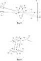
- Fig. 4shows an exemplary representation of beam paths through a transparent object, such as a lens 100.
- the origin of the beam pathsis a defined point 22 on the display device 21.
- the beam paths emanating from the defined point 22enter the lens 101 on the surface 102 and at the surface 103 from the lens. They thus penetrate the lens 100.
- the light raysare refracted both on the entry surface 102 and on the exit surface 103.
- a different optical effectcan result.
- the inventorshave recognized that such an ambiguity or ambiguity of the optical effect can be resolved by recording the test structure from several points of view and thus recording a large number of imaging beam paths (see also Fig. 1 ), from which the optical properties of an intermediate lens can be determined.
- an equation system with a large number of equationscan be set up for the imaging beam paths, each of which establishes an association between imaging beams entering the image capturing device from several points of view, which penetrate the lens 100, and their known origins on the display device 20. From this, the three-dimensional shape of the lens 100 and also optionally its refractive index or a braking force distribution within the lens can be determined.
- FIG Fig. 5A simplified example of beam paths through a lens 100 is shown in FIG Fig. 5 reproduce.
- the image point 22 on the display device 20is captured by the camera 34.
- the beam path 110enters the lens at point 104 on the front surface 102 of lens 100 and exits the lens at point 106 on the rear surface 103.
- the entry point 104 and the exit point 105including the spatial orientation of the surface at these points.
- the image acquisition device 30records the test structure from further points of view, as indicated by the further camera 33, further beam paths 111 and 112 can be recorded.
- an exit point 104coincides with the beam path 110 of the camera 34.
- an entry point 105coincides with the beam path 110 of the camera 34.
- a plurality of equationscan be set up, from which the properties of the lens 100 arranged between the display device 20 and the image acquisition device 30 can be determined.
- the computing unitcan be set up to model the lens 100, preferably as a composite surface from parameterizable surface elements, as in FIG Fig. 6 shown as an example.
- An orientation of the surface elements 106, 107 of the front and rear surfaces 102, 103can be determined from the deflection of the rays at points 104 and 105.
- a more extensive division within the lens 100can optionally also be carried out.
- further interfacescan be determined within the lens 100.
- the computing unitcan also be designed to determine a refractive index of the lens 100 or also a spatial distribution of the refractive index of the lens.
- the devicecan be designed as a device for measuring a spatial refractive index distribution of an optical lens arranged in a measuring volume.
- an interface set up for receiving lens geometry data which describes a three-dimensional shape of the lenscan preferably be provided.
- the shape of the lensdoes not have to be calculated and can serve as input parameters for calculating the spatial refractive index distribution of the lens based on the image data and the lens geometry data.
- the computing unitcan be set up to determine the three-dimensional shape of the lens based on a tracing of the light beams entering the image capturing device.
- the directions, under which the light beams 110, 111, 112 enter the cameras 33, 34 of the image capturing deviceare known.
- the image acquisition devicecan be calibrated as described below. Starting from the respective camera 33, 34, the incoming rays can thus be traced back.
- the lens 100is located in the beam path between the image acquisition device or the respective cameras (with a known position) and the test structure (with a known position).
- this modelcan be successively parameterized by the computing unit in such a way that the (known) test structure is mapped by the model of lens 100 in such a way that the image data acquired by the image acquisition device result.
- the orientations of the surface elements forming the lens surfacerepresented here by the surface normals 129, 130, can be adapted and a distance 131 between the surface elements can be varied, and optionally a refractive index n or a refractive index distribution within the lens can be varied.
- Fig. 7 and Fig. 8show further embodiments of a device 10 for measuring the optical effect of an optical lens 100 arranged in a measuring volume.
- Corresponding assembliesare denoted by the same reference symbols and are not explained again in detail to avoid repetition.
- Fig. 8shows an embodiment in which the image capture device 30 has two cameras 30, 31 '.
- the camerassee a pattern or a test structure 21 from different angles.
- the computing unitis designed to reconstruct the measurement object 4 from the corresponding image data.
- a gradient fieldcan be determined from the surface elements or from the normals 129, 129 ', as in FIG Figs. 5 and 6 explained.
- the principleworks with one, two or more cameras.
- two camerasare used, since a good cost / benefit ratio can be achieved here. Additional cameras can be used to further increase the accuracy.
- the image acquisition device 30 or the cameras 31, 31 'is calibrated in such a way that a function is known with which a clear main light beam (camera beam) can be derived from the origin and direction in 3D for each sensor coordinate.
- This calibrationcan be carried out according to the state of the art.
- a known optical design of the camera and / or a lens usedcan be included in the model of the camera.
- the display device 20can, for example, have self-illuminating sources such as light-emitting diodes arranged in an array, a TFT or LED display, a 3D display, laser sources, a polarization display, or also a collimated, optionally structured lighting unit.
- the display devicecan also be illuminated.
- an illuminated display devicecan display test charts (e.g. dot patterns or checked patterns), a particularly regular 3D pattern, an unknown, feature-rich flat image (where positions can be estimated during the optimization) or an unknown feature-rich 3D scene (positions are estimated during optimization).
- the computing unit 40can use further information to determine the three-dimensional shape.
- the known points of view or positions of the cameras from which the image data are recorded and a known position of the test structurecan be based in particular.
- the image datacan be locations of the images of light beams entering the cameras on the camera detectors.
- the light rays entering the image acquisition devicecan be calculated from the image data and the known viewpoints.
- a calibration of the image acquisition devicecan serve as a basis.
- the computing unit 40is set up to determine the three-dimensional shape of the lens taking into account one or more boundary conditions. For example, a contact point or stop 51 can be specified. At this point, the location of the lens 100 is known and can be taken into account in determining the three-dimensional shape of the lens. Furthermore, information such as a shape of a front and / or rear surface of the lens, a refractive index or material, etc. can be specified. Alternatively or additionally, the device can be designed to read out information present on the lens, for example in the form of an engraving or a marker 140, and take it into account when determining the three-dimensional shape and / or when calculating the optical effect.
- a particularly advantageous application of the present inventionis spectacle lens measurement, in particular the measurement of progressive spectacle lenses - also known as varifocals.
- simpler spectacle lensessuch as spherical, aspherical, toric or prismatic lenses can also be measured with the proposed device.
- the computing unitcan be set up to calculate an ISO vertex power or a vertex power in a predetermined measuring device configuration in order to provide comparable data.
- wearer-specific datasuch as the distance between a pupil and the spectacle lens (cornea-vertex distance HSA) and its position (e.g. frame lens angle or forward inclination), it is possible to calculate usage vertex power.
- the computing unitcan also be designed to determine a position and location of the spectacle lenses relative to one another. Further information such as the distance between the viewing channels can be calculated from this.
- a transparent body with zones of different effectscan also be provided as several measurement objects. This can be, for example, a pair of glasses with two lenses or a lens with several zones - bi, tri, or multifocal lens.
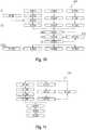
- FIG. 9shows a flowchart of a method 900 for measuring the optical effect of an optical lens, in particular a spectacle lens, arranged in a measuring volume, with the steps.
- a test structure for display on a display deviceis provided.
- image data of the test structureare acquired from several points of view through imaging beam paths which penetrate the lens.
- a three-dimensional shape of the lensis determined based on image data (and the known positions of the viewpoints and the display device relative to one another).
- an optical effect of the lensis calculated based on its three-dimensional shape. The calculation can be made for any usage situation.
- the computing unitcan therefore be set up to calculate a first optical effect in accordance with an ISO vertex power and to calculate a second optical effect in accordance with a usage situation of a user.
- the measuring methodcan be preceded by a step 905 for calibrating the device.
- a corresponding method for calibrating the devicecan in turn have the following steps: In a first calibration step, a test structure is provided on the display device. In a second calibration step, a first distance between the image acquisition device and the display device is set and image data of the test structure are acquired with the image acquisition device from the first distance.
- a height adjustment device 150can be provided which is set up to vary a distance between the image acquisition device and the display device.
- the computing unitcan furthermore be set up to determine a beam direction of the light beams detected by the image detection device based on image data acquired from different distances between the image acquisition device and the display device.
- a second distancecan be set between the image acquisition device and the display device and image data of the test structure can be acquired with the image acquisition device from the second distance. From this, in a further step, a direction of incident light rays, which are captured by the image capturing device, and corresponding image points in the image data can be determined.
- FIG. 10shows a detailed flow diagram of an embodiment of a method 1000 for measuring the optical effect of a lens arranged in a measuring volume.
- a test structureis displayed on the display device. For example, this can be an entire pattern of dots or stripes.
- image data of the test structureare acquired by the image acquisition device.
- positions of features of the test structurefor example the positions of pattern points in the image data (corresponding to positions on a detector surface of the image acquisition device) can be determined.
- a camera calibrationcan take place in step S1001, for example as explained above or in FIG Fig. 11 described in detail.
- step S1014light rays incident into the image acquisition device or their directions can then be determined. From the camera images of the displayed pattern, viewed through the lens to be measured, the light rays that enter the camera can be determined as a 3D vector.
- a full or partial pattern of a test structurecan be displayed on the display device.
- image data of the test structureare acquired by the image acquisition device.
- pattern pointscan be assigned to image points in the image data.
- a sequence of different test patternscan be provided in order to resolve any ambiguity in the assignment of pattern points to image points in the image data.
- an assignment of light spots in the image data captured with the image capture device to a position of the light points on the display device and thus also to the calculated position Light rays that have entered the image capture devicetake place.
- the computing unitcan be set up to determine neighborhood relationships from an overall pattern of a test structure.
- a step S1031areal illumination can be provided on the display device. For example, all pixels of the display device can display "white". As a result, a contour of the lens can emerge and a contour of the lens can be determined in step S1032. In a step S1033, a position and dimensions of the lens can be determined based on the recorded contour. In other words, a position of the lens in the measurement volume can be determined in a simple manner.
- a "best-fitting" parameterizable lenscan be calculated.
- a “best-fitting” parametrizable lenscan preferably be determined by backward propagation of the camera light rays, which lens could be located in the measuring volume of the device.
- a lens that can be parameterizedis understood to be a lens that can be described with a few parameters such as radius, thickness, and refractive index. These include, for example, spherical and toric lenses. Toric lenses are a general compromise that can be used here. In a more specific embodiment, it can be sufficient to define individual "toric zones" on the lens and only to describe the spectacle lens here. A first of these zones can be, for example, a "far range" of a progressive lens. A second of these zones can be, for example, a "near area" of a progressive lens. In addition to the location of the lens or the individual surfaces, other parameters can be the radii, the thickness and the refractive index.
- a “best-fitting” gradient surface of the front and / or rear surface of the lenscan be determined by inverse ray tracing of the camera rays.
- An area of the "best-fitting" parameterizable lens determined in step S1041can thus be described as a gradient area and the gradients at the locations of the beam passages can be varied so that the positions of the luminous points on the display device are perfectly met by backward propagation of the camera beams.
- the three-dimensional shape of the lensis adapted in such a way that the received from the image capture device Light beams and the associated beam sources match on the display device.
- a front and or back surface of the lenscan be obtained by integration from the gradient surface.
- a (continuous) new surfaceis determined from a gradient surface determined in sections or for surface elements. This can be the front surface or the rear surface of the lens.
- steps S1042 and S1043can be repeated iteratively. For example, the steps can be repeated until a quality criterion is met.
- step S1041can also be included in the iteration loop in order to take alternative lens geometries into account. As a result of the iteration, there may be a three-dimensional shape of the lens.
- a shape of the lenscan be specified and instead a spatial refractive index distribution within the lens can be determined iteratively in an analogous manner.
- One or more variablescan subsequently be determined from the specific three-dimensional shape (possibly including the refractive index).
- a use valuein particular a user-specific use value, can be calculated.
- wearer-specific datacan be provided in step S1051, such as a distance from the cornea to the vertex.
- an ISO vertex powercan be determined.
- a vertex powercan be determined in a device configuration.
- FIG. 11shows a flowchart of an exemplary embodiment of a method 1100 for calibrating a device for measuring individual data of an optical lens arranged in a measuring volume.
- the calibrationcan in particular serve to provide a set of functions which assigns a beam direction such as a 3D vector to one - preferably each - image point of the image data recorded by the image recording device, which describes a beam direction or a light beam that penetrates the image recording device.
- (x 0 , y 0 , 0)describes a point of the light beam of a reference plane of the image capturing device, preferably a point of the light beam of a reference plane in the lens system of a camera of the image capturing device, and (dx, dy, 1) the direction vector of the incident beam.
- the set of functionsconsists of the four functions x 0 (x, y), y 0 (x, y), dx (x, y) and dy (x, y) where x and y are the pixel coordinates in the image data of the image acquisition device, here one Camera, describe.
- Such a set of functionscan be determined in that a test structure, for example a point pattern, is displayed on the display device and this is viewed with the cameras of the image acquisition device at different distances.
- the deviceas in Fig. 8 Shown by way of example, have a height adjustment device 150 which is set up to vary a distance between the image acquisition device and the display device.
- steps S1101 to S1104can each correspond to steps S1011 to S1014 described above in FIG Fig. 10 correspond.
- Steps S1111 to S1113 shownmay each be as described above Correspond to steps S1021 to S1023.
- a loopis provided, with a distance between the image capturing device and the display device being varied in step S1121.
- the computing unitcan be set up to determine a direction of the incident light beams based on the image data acquired at the first distance and the image data acquired at the second distance. It goes without saying that the determination can also be based on a relative position between the display device and the image capture device and on the variation in the distance.
- a step S1131an interpolation of 3D light rays from a plurality of, preferably for each image point or pixel of the image capturing device can be carried out.
- the variables x 0 , y 0 , dx and dycan be determined for the image points.
- a polynomial fitcan be carried out on the quantities x 0 , y 0 , dx and dy.
- a set of functionscan thus be determined which assigns a direction of an incident light beam to each image point of the image data acquired by the image acquisition device.
- a spatial position of a support point 51can be determined.
- the display device 20can be set up to display a monochrome or background with constant brightness as a test structure.
- the image capture devicecaptures the display without the lens inserted.
- the support pointslead to a shadow being cast (for example a circle in the case of support balls), which is captured by the image capture device and contained in the image data.
- the computing unitcan be designed to determine a position of the support points 51 based on this image data. These can in turn be taken into account as boundary conditions when determining a three-dimensional shape of a lens.
- its central point(the position) can be determined by intersecting the camera beams.
- the position of the support pointscan be used to create an algorithm that determines the shape of the spectacle lens Assign the expected value for its position in the measurement volume.
- FIG. 11shows a schematic sectional illustration of an eye 1200.
- the eyehas a cornea or cornea 1201, an iris 1202, a pupil 1203 and the lens 1204.
- Fig. 13shows a top view of the eye with an image of the iris 1202 and the pupil 1203.
- a major contribution to the ametropiadoes not come from the lens 1204 but from the cornea 1201.
- a major contribution to the ametropia of a test personcan be due to an astigmatism. It is therefore desirable to be able to objectively determine a shape of the cornea.
- Fig. 14shows a schematic representation of a device for measuring the cornea of a test subject according to a further aspect of the present disclosure.
- the devicecan have the following: an image acquisition device (30) set up to acquire image data of an iris (1202) of the test subject from several (known) points of view through imaging beam paths (32) which penetrate the cornea (1201); and a computer unit (40).
- the computing unitis set up to: provide a mathematical model of an anterior segment of the eye of the test person with a mathematical model of the cornea and the iris; Identifying and registering image features of the iris which are present in a plurality of images of the image data; Determining deviations between actual positions of the image features of the iris in the images captured from multiple viewpoints and expected positions of the image features of the iris in the images captured from multiple viewpoints, taking into account the mathematical model of the cornea and the position of the iris; Adapting parameters of the mathematical model of the cornea in such a way that the Deviations are minimized; and determining a measured variable of the cornea from the adapted mathematical model of the cornea.
- the image capturing device 30can again be configured identically or similarly as for Fig. 1 describe.
- the image acquisition deviceacquires image data of the iris 1202, the beam paths passing through the cornea 1201.
- a camera 33can be positioned one after the other at different known positions.
- a positioning device(not shown) can be used for this purpose.
- several cameras 33, 34can be provided which capture the image data in parallel.
- One advantage of the parallel acquisitionis that the user's eye does not move between the different measurements.
- the inventorshave recognized that the cornea 1201 lying between the iris 1202 and the image acquisition device 30 can also be calculated without knowledge of the appearance of the iris 1202. It is true that the iris 1202 has an unknown structure or an unknown pattern. However, the Iris 1202 is usually heavily structured. The inventors have recognized that a large number of image features of the iris can be identified and subsequently evaluated with regard to their position in several images of the image data recorded from different positions. For this purpose, a system of equations can be set up from the imaging beam paths 32, which are recorded at the respective known positions, from which the shape of the cornea 1201 can be calculated.
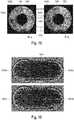
- Figures 15 and 16show the assignment or correlation of unknown image features in images of the iris recorded from different points of view.
- the left picture in Fig. 15 FIG. 15shows a first image 1500a of the iris 1202 - through the cornea - from a first position, for example recorded with the camera 33 in FIG Fig. 14 .
- the right picture in Fig. 16 FIG. 14shows a second image 1500b of the iris 1202 - through the cornea - from a second position, for example recorded with the camera 34 in FIG Fig. 14 .
- a correlation 1502 between the same starting points 1501a and 1501b of the iris 1201can be determined.
- Corresponding pointsare indicated by reference numerals 1503a and 1503b connected by 1502 '.
- Such an assignment 1500can be carried out for a large number of images 1500a to 1500d and image points, as in FIG Fig. 16 shown.
- a large number of beam pathscan be reconstructed, as in Fig. 14 shown.
- the light raysstarting from the same image point on the iris 1202, pass through the cornea 1201 at different points and are captured by the image capturing device 30 at different locations. If an identical starting point is now identified in the images, statements can be made about the cornea 1201 lying between the starting point on the iris 1202 and the entry into the cameras 33, 34, as above with reference to FIG Fig. 14 described.
- Fig. 17shows a flow diagram of an embodiment of a method for measuring the cornea of a test subject.
- the camera systemcan be calibrated in an optional upstream step. However, the calibration can already be carried out by the manufacturer.
- image data of an iris of the test personcan be acquired from several points of view through imaging beam paths which penetrate the cornea.
- a mathematical model of an anterior segment of the eye of the test subject with a mathematical model of the cornea (and the position of the iris relative to the cornea)can be provided.
- image features of the iriswhich are present in several (preferably all) images of the image data can be identified and registered (or assigned in the images).
- a fourth step 1704deviations between actual positions of the image features of the iris in the images captured from multiple viewpoints and expected positions of the image features of the iris in the images captured from multiple viewpoints can be determined, taking into account the mathematical model of the cornea and the position of the iris.
- parameters of the mathematical model of the corneacan be adapted in such a way that the deviations are minimized.
- Steps 1703 and 1704can preferably be repeated iteratively.
- a measured variable of the Corneacan be determined from the adapted mathematical model of the cornea. For example, a refractive power or an astigmatism can be evaluated.
- the solutions disclosed herein in the field of ophthalmic opticscan in particular enable a simplified contactless measurement of lens elements arranged in a measurement volume or also a contactless measurement of the cornea, in particular with reduced impairment of a light-sensitive user.
Landscapes
- Health & Medical Sciences (AREA)
- Life Sciences & Earth Sciences (AREA)
- Physics & Mathematics (AREA)
- Ophthalmology & Optometry (AREA)
- Engineering & Computer Science (AREA)
- General Health & Medical Sciences (AREA)
- Molecular Biology (AREA)
- Public Health (AREA)
- Biomedical Technology (AREA)
- Heart & Thoracic Surgery (AREA)
- Medical Informatics (AREA)
- Veterinary Medicine (AREA)
- Surgery (AREA)
- Animal Behavior & Ethology (AREA)
- Biophysics (AREA)
- General Physics & Mathematics (AREA)
- Analytical Chemistry (AREA)
- Chemical & Material Sciences (AREA)
- Geometry (AREA)
- Signal Processing (AREA)
- Optics & Photonics (AREA)
- Eyeglasses (AREA)
- Length Measuring Devices By Optical Means (AREA)
- Testing Of Optical Devices Or Fibers (AREA)
Description
Translated fromGermanDie vorliegende Offenbarung betrifft das Gebiet der Augenoptik und insbesondere eine Vorrichtung zum Vermessen der optischen Wirkung einer in einem Messvolumen angeordneten optischen Linse, insbesondere eines Brillenglases. Die vorliegende Offenbarung betrifft ferner eine Vorrichtung zum Vermessen einer räumlichen Brechzahlverteilung einer in einem Messvolumen angeordneten optischen Linse, insbesondere eines Brillenglases. Die vorliegende Offenbarung betrifft ferner ein Verfahren zum Kalibrieren einer entsprechenden Vorrichtung, ein computerimplementiertes Verfahren zum Vermessen der optischen Wirkung einer in einem Messvolumen angeordneten optischen Linse.The present disclosure relates to the field of ophthalmic optics and in particular to a device for measuring the optical effect of an optical lens arranged in a measurement volume, in particular a spectacle lens. The present disclosure also relates to a device for measuring a spatial refractive index distribution of an optical lens, in particular a spectacle lens, arranged in a measuring volume. The present disclosure also relates to a method for calibrating a corresponding device, a computer-implemented method for measuring the optical effect of an optical lens arranged in a measurement volume.
Der üblicherweise interessante Messwert bei Brillengläsern ist der Scheitelbrechwert (SBW). Der Scheitelbrechwert ist eine Wirkgröße der Linse unter einer bestimmten Beobachtungssituation. Folglich ist der SBW unterschiedlich je nachdem wie groß der Abstand zum Betrachter ist oder wie die Linse geneigt ist. Ein Messgerät, welches einen SBW durch direkte Interpretation der durch eine Linse durchdringenden Lichtstrahlen ermittelt, wird immer einen SBW dieser Messgerätekonfiguration bestimmen. Für eine eindeutige Qualifizierung eines Bauteiles sind solche Wirkgrößen nur bedingt nützlich. Als Abhilfe wurde deshalb der ISO SBW definiert. Der ISO SBW ist der SBW, welcher senkrecht zu der Flächennormale bei parallelem Lichteinfall gemessen wird. Hierzu wurden in der Vergangenheit spezielle Messgeräte entwickelt, welche an einzelnen Positionen einer Linse den ISO SBW bestimmen.The usually interesting measured value for spectacle lenses is the vertex power (SBW). The vertex power is an effective variable of the lens under a certain observation situation. As a result, the SBW is different depending on how great the distance to the viewer is or how the lens is tilted. A measuring device which determines an SBW by direct interpretation of the light rays penetrating through a lens will always determine an SBW of this measuring device configuration. For a clear qualification of a component, such effective variables are only useful to a limited extent. The ISO SBW was therefore defined as a remedy. The ISO SBW is the SBW, which is measured perpendicular to the surface normal with parallel incidence of light. For this purpose, special measuring devices were developed in the past, which determine the ISO SBW at individual positions of a lens.
Der Vorteil des ISO SBW ist, dass dieser eine eindeutige Bauteilgröße ist und nicht wie der SBW eine Wirkgröße. Nachteilig ist, dass der ISO SBW abweichen kann von der Wirkung einer Brille in der Trägersituation (auch als Gebrauchs-Scheitelbrechwert oder Gebrauchswert bezeichnet).The advantage of the ISO SBW is that it is a clear component size and not an effective variable like the SBW. The disadvantage is that the ISO SBW can deviate from the effect of glasses in the wearer situation (also referred to as the practical vertex power or practical value).
Ein Scheitelbrechwertmesser mit einer Brillenanlage für die Nachprüfung fertig verglaster Brillen ist aus der
Aus der
Aus der
Bei aus dem Stand der Technik bekannten Geräten handelt es sich um Wirkungsmessgeräte, bei welchen zunächst die Wirkung eines optischen Elements in einer Messposition bestimmt wird.Devices known from the prior art are effect measuring devices in which the effect of an optical element is first determined in a measuring position.
Vor diesem Hintergrund ist es eine Aufgabe der vorliegenden Erfindung, eine Messvorrichtung bereitzustellen, welche eine flexiblere Bestimmung der optischen Wirkung einer optischen Linse ermöglicht.Against this background, it is an object of the present invention to provide a measuring device which enables a more flexible determination of the optical effect of an optical lens.
Die beanspruchten Gegenstände sind in den unabhängigen Ansprüchen definiert. Vorteilhafte Ausführungsformen sind in den abhängigen Ansprüchen beschrieben. In der Beschreibung angegebene weitere Beispiele und Aspekte dienen lediglich dem Verständnis beanspruchten Erfindung, welche in den unabhängigen Patentansprüchen definiert ist. Die Aspekte, die das Verfahren zum Kalibrieren betreffen, sind nicht Teil der Erfindung.The claimed subjects are defined in the independent claims. Advantageous embodiments are described in the dependent claims. Further examples and aspects given in the description serve only for the understanding of the claimed invention, which is defined in the independent patent claims. The aspects relating to the method of calibration are not part of the invention.
Gemäß einem ersten Aspekt der vorliegenden Offenbarung wird daher vorgeschlagen, eine Vorrichtung zum Vermessen der optischen Wirkung einer in einem Messvolumen angeordneten optischen Linse, insbesondere eines Brillenglases, bereitzustellen mit einer Anzeigeeinrichtung eingerichtet zum Anzeigen einer Teststruktur; einer Bilderfassungseinrichtung, eingerichtet zum Erfassen von Bilddaten der Teststruktur aus mehreren Blickpunkten durch Abbildungsstrahlengänge, welche die Linse durchsetzen; und einer Recheneinheit, wobei die Recheneinheit eingerichtet ist zum Bestimmen einer dreidimensionalen Form der Linse basierend auf den Bilddaten; und Berechnen einer optischen Wirkung der Linse basierend auf deren dreidimensionaler Form. Die Linse ist ein Brillenglas. Die Recheneinheit kann eingerichtet sein zum Berechnen der optischen Wirkung des Brillenglases für eine vorgegebene Trageposition eines Nutzers, welche sich von einer Messposition, in welcher die Bilddaten erfasst werden, unterscheiden kann.According to a first aspect of the present disclosure, it is therefore proposed to provide a device for measuring the optical effect of an optical lens arranged in a measurement volume, in particular a spectacle lens, with a display device set up to display a test structure; one Image acquisition device, set up to acquire image data of the test structure from several points of view through imaging beam paths which penetrate the lens; and a computing unit, wherein the computing unit is set up to determine a three-dimensional shape of the lens based on the image data; and calculating an optical power of the lens based on its three-dimensional shape. The lens is a spectacle lens. The computing unit can be set up to calculate the optical effect of the spectacle lens for a predefined wearing position of a user, which can differ from a measuring position in which the image data are recorded.
Gegenüber konventionellen Scheitelbrechwertmessgeräten können wesentliche Vorteile der Erfindung insbesondere in einer verbesserten Eindeutigkeit und/oder Einsatzbreite bestehen. Ein Grund hierfür ist, dass die optische Wirkung einer Linse immer abhängig von der Durchstrahlrichtung ist. Ein Messgerät, welches ausschließlich die optische Wirkung misst, kann diese nur sicher für den Fall der Messanordnung bestimmen. Für eine Vielzahl an Anwendungsfällen können hiermit bereits sehr genaue Aussagen getroffen werden.Compared to conventional lens measuring devices, there can be significant advantages of the invention in particular in improved clarity and / or range of use. One reason for this is that the optical effect of a lens always depends on the direction of the radiation. A measuring device that only measures the optical effect can only reliably determine this for the case of the measuring arrangement. This means that very precise statements can be made for a large number of applications.
Allerdings können eine Messsituation und eine tatsächliche Tragesituation oder Trageposition eines Brillenglases auseinanderfallen bzw. in einem Maß voneinander abweichen, dass eine verlässliche Aussage nicht mehr möglich ist. Um die optische Wirkung in der Trageposition zu bestimmen, wäre also eine weitere Wirkungsmessung unter Tragebedingungen erforderlich.However, a measurement situation and an actual wearing situation or wearing position of a spectacle lens can diverge or differ from one another to such an extent that a reliable statement is no longer possible. In order to determine the optical effect in the wearing position, a further effect measurement would be necessary under wearing conditions.
Die erfindungsgemäße Lösung verfolgt einen anderen Ansatz: Es wird ein zweistufiges Vorgehen vorgeschlagen, bei welchen zunächst die dreidimensionale Form der Linse bestimmt wird und erst nachfolgend die optische Wirkung der Linse berechnet wird. Eine bekannte dreidimensionale Form bzw. Topographie der Linse ermöglicht es, dass die optische Wirkung nachfolgend für beliebige Durchblicks- oder Tragesituation berechnet werden kann. Vorteile können insbesondere genauere Ergebnisse und besser individualisierte Aussagen für eine große Bandbreite an nutzerspezifischen Wünschen umfassen.The solution according to the invention pursues a different approach: A two-stage procedure is proposed in which the three-dimensional shape of the lens is first determined and only then is the optical effect of the lens calculated. A known three-dimensional shape or topography of the lens makes it possible that the optical effect can subsequently be calculated for any viewing or carrying situation. Advantages can in particular include more precise results and better individualized statements for a wide range of user-specific requests.
Die Anzeigeeinheit zeigt eine Teststruktur an. Die Teststruktur wird von der Bilderfassungseinrichtung aus mehreren Blickpunkten erfasst. Da die Teststruktur bekannt ist, kann eine Zuordnung zwischen von der Bilderfassungseinrichtung erfassten Bilddaten der Teststruktur für jeden der mehreren Blickpunkte erfolgen. Wird nun eine optische Linse in einem Messvolumen zwischen der Anzeigeeinrichtung und der Bilderfassungseinrichtung platziert, so werden die Strahlengänge zwischen jeweiligen Pixeln der Bilddaten und den korrespondieren Bildelementen der Teststruktur beeinflusst.The display unit shows a test structure. The test structure is captured by the image capture device from several points of view. Since the test structure is known, an association can be made between image data of the test structure recorded by the image acquisition device for each of the plurality of viewpoints. If an optical lens is now placed in a measurement volume between the display device and the image acquisition device, the beam paths between the respective pixels of the image data and the corresponding image elements of the test structure are influenced.
Hierbei lässt sich jedoch nicht nur eine einzelne virtuelle Brechebene, wie in der
Die Berechnung der optischen Wirkung basierend auf der dreidimensionalen Form kann nachfolgend mit bekannten Verfahren erfolgen.The calculation of the optical effect based on the three-dimensional shape can subsequently be carried out using known methods.
Es versteht sich, dass nicht notwendigerweise die dreidimensionale Form der gesamten Linse bestimmt werden muss. Beispielsweise kann die Berechnung nur für einen Teilbereich erfolgen, beispielsweise nur die Vorder- und Rückfläche, ohne Seitenflächen oder nur einen Teilbereich im Sichtfeld eines Nutzers.It goes without saying that the three-dimensional shape of the entire lens does not necessarily have to be determined. For example, the calculation can only take place for a partial area, for example only the front and rear surfaces, without side surfaces or only a partial area in the user's field of vision.
Bei der Bestimmung der dreidimensionalen Form der Linse durch die Recheneinheit können weitergehenden Informationen, wie beispielsweise eine bekannte räumliche Lage der Anzeigeeinrichtung relativ zu jeweiligen den Blickpunkten, aus welchen die Erfassung erfolgt, vorteilhaft berücksichtigt werden.When the three-dimensional shape of the lens is determined by the computing unit, further information, such as a known spatial position of the display device relative to the respective viewpoints from which the detection takes place, can advantageously be taken into account.
Gemäß einem zweiten Aspekt der vorliegenden Offenbarung wird eine Vorrichtung zum Vermessen einer räumlichen Brechzahlverteilung einer in einem Messvolumen angeordneten optischen Linse, insbesondere eines Brillenglases, vorgeschlagen mit einer Anzeigeeinrichtung eingerichtet zum Anzeigen einer Teststruktur; einer Bilderfassungseinrichtung eingerichtet zum Erfassen von Bilddaten der Teststruktur aus mehreren Blickpunkten durch Abbildungsstrahlengänge, welche die Linse durchsetzen; einer Schnittstelle eingerichtet zum Empfangen von Linsengeometriedaten, welche eine dreidimensionale Form der Linse beschreiben; und einer Recheneinheit, wobei die Recheneinheit eingerichtet ist zum Berechnen einer räumlichen Brechzahlverteilung der Linse basierend auf den Bilddaten und den Linsengeometriedaten.According to a second aspect of the present disclosure, a device for measuring a spatial refractive index distribution of an optical lens arranged in a measurement volume, in particular a spectacle lens, is proposed with a display device set up to display a test structure; an image acquisition device set up to acquire image data of the test structure from a plurality of viewpoints through imaging beam paths which penetrate the lens; an interface set up for receiving lens geometry data which describe a three-dimensional shape of the lens; and a computing unit, wherein the computing unit is set up to compute a spatial refractive index distribution of the lens based on the image data and the lens geometry data.
Ein Vorteil dieser Lösung besteht darin, dass eine dreidimensionale Brechkraftverteilung innerhalb der Linse bestimmt werden kann. Beispielsweise zur Beschreibung eines Gleitsichtglases, bei welchem die optische Wirkung für Fern- und Nahbereich durch eine dreidimensionale Variation des Brechungsindices bereitgestellt wird.One advantage of this solution is that a three-dimensional refractive power distribution can be determined within the lens. For example, to describe a progressive lens in which the optical effect for the distance and near range is provided by a three-dimensional variation of the refractive index.
Gemäß Anspruch 1 wird eine Vorrichtung zum Vermessen der optischen Wirkung einer in einem Messvolumen angeordneten optischen Linse vorgeschlagen, wobei die optische Linse ein Brillenglas ist, mit einer Anzeigeeinrichtung eingerichtet zum Anzeigen einer Teststruktur; einer Bilderfassungseinrichtung, eingerichtet zum Erfassen von Bilddaten der Teststruktur aus mehreren Blickpunkten durch Abbildungsstrahlengänge, welche die Linse durchsetzen; und einer Recheneinheit, wobei die Recheneinheit eingerichtet ist zum: Bestimmen einer dreidimensionalen Form der Linse basierend auf den Bilddaten; und Berechnen einer optischen Wirkung der Linse basierend auf deren dreidimensionaler Form. Die Recheneinheit ist dazu eingerichtet, die dreidimensionale Form der Linse ferner unter Berücksichtigung eines oder mehrerer bekannten Auflagepunktes der Linse zu bestimmen. Eine Position der Auflagepunkte wird dazu verwendet, um einem Algorithmus, welcher die Form des Brillenglases bestimmt, einen Erwartungswert für deren Position im Messvolumen zuzuordnen.According to claim 1, a device for measuring the optical effect of an optical lens arranged in a measurement volume is proposed, the optical lens being a spectacle lens, with a display device set up to display a test structure; an image acquisition device set up to acquire image data of the test structure from a plurality of viewpoints through imaging beam paths which penetrate the lens; and a computing unit, the computing unit being set up to: determine a three-dimensional shape of the lens based on the image data; and calculating an optical power of the lens based on its three-dimensional shape. The computing unit is set up to further determine the three-dimensional shape of the lens taking into account one or more known contact points of the lens. A position of the support points is used to assign an expected value for its position in the measurement volume to an algorithm which determines the shape of the spectacle lens.
Gemäß Anspruch 2 wird eine Vorrichtung zum Vermessen der optischen Wirkung einer in einem Messvolumen angeordneten optischen Linse vorgeschlagen, mit einer Anzeigeeinrichtung eingerichtet zum Anzeigen einer Teststruktur; einer Bilderfassungseinrichtung, eingerichtet zum Erfassen von Bilddaten der Teststruktur aus mehreren Blickpunkten durch Abbildungsstrahlengänge, welche die Linse durchsetzen; und einer Recheneinheit, wobei die Recheneinheit eingerichtet ist zum: Bestimmen einer dreidimensionalen Form der Linse basierend auf den Bilddaten; und Berechnen einer optischen Wirkung der Linse basierend auf deren dreidimensionaler Form. Die Recheneinheit ist dazu eingerichtet, die dreidimensionale Form der Linse unter Berücksichtigung einer Randbedingung zu bestimmen, wobei die Randbedingung bestimmt wird durch Auslesen von Information über die zu vermessende Linse. Die Randbedingung wird bestimmt durch Auslesen eines Codes auf der Linse.According to claim 2, a device for measuring the optical effect of an optical lens arranged in a measuring volume is proposed, with a display device set up to display a test structure; an image capture device, set up to acquire image data of the test structure from several points of view through imaging beam paths which penetrate the lens; and a computing unit, the computing unit being set up to: determine a three-dimensional shape of the lens based on the image data; and calculating an optical power of the lens based on its three-dimensional shape. The computing unit is set up to determine the three-dimensional shape of the lens taking into account a boundary condition, the boundary condition being determined by reading out information about the lens to be measured. The boundary condition is determined by reading a code on the lens.
Gemäß einem weiteren Aspekt der vorliegenden Offenbarung wird ein Verfahren, insbesondere computerimplementiertes Verfahren, zum Vermessen der optischen Wirkung einer in einem Messvolumen angeordneten optischen Linse, wobei die optische Linse ein Brillenglas ist, offenbart mit den Schritten: Bereitstellen einer Teststruktur zur Anzeige auf einer Anzeigeeinrichtung; Erfassen von Bilddaten der Teststruktur aus mehreren Blickpunkten durch Abbildungsstrahlengänge, welche die Linse durchsetzen; Bestimmen einer dreidimensionalen Form der Linse basierend auf Bilddaten; und Berechnen einer optischen Wirkung der Linse basierend auf deren dreidimensionaler Form.According to a further aspect of the present disclosure, a method, in particular a computer-implemented method, for measuring the optical effect of an optical lens arranged in a measurement volume, the optical lens being a spectacle lens, is disclosed with the following steps: providing a test structure for display on a display device; Acquisition of image data of the test structure from several points of view through imaging beam paths which penetrate the lens; Determining a three-dimensional shape of the lens based on image data; and calculating an optical power of the lens based on its three-dimensional shape.
Gemäß einem weiteren Aspekt der vorliegenden Offenbarung wird ein Computerprogrammprodukt vorgeschlagen, umfassend Befehle, die bei der Ausführung des Programms durch einen Computer diesen veranlassen, das vorstehend genannte Verfahren auszuführen. Es versteht sich, dass die Verfahrensschritte hierbei zur Ausführung durch einen Computer ausgebildet sind. Beispielsweise kann unter Erfassen von Bilddaten das Empfangen von Bilddaten verstanden werden. Der Begriff kann also als eine Übermittlung von, von einem physikalischen Bildsensor erzeugten, Messdaten verstanden werden. Die Bereitstellung der Teststruktur kann entsprechend durch Bereitstellen von Teststrukturdaten erfolgen. Die Daten können wiederum von einer Anzeigeeinrichtung angezeigt werden.According to a further aspect of the present disclosure, a computer program product is proposed, comprising instructions which, when the program is executed by a computer, cause the computer to carry out the aforementioned method. It goes without saying that the method steps here are designed to be carried out by a computer. For example, capturing image data can be understood to mean receiving image data. The term can therefore be understood as a transmission of measurement data generated by a physical image sensor. The test structure can be provided accordingly by providing test structure data. The data can in turn be displayed by a display device.
Das Bereitstellen der Teststruktur kann auch ein vorgelagerter Schritt sein, welcher nicht von dem Computerprogrammprodukt ausgeführt wird.The provision of the test structure can also be a preceding step which is not carried out by the computer program product.
Falls nicht anderweitig spezifiziert, sollen die hierin verwendeten Begriffe im Sinne der Norm DIN EN ISO 13666:2012 des Deutschen Instituts für Normung e.V. verstanden werden.Unless otherwise specified, the terms used here should be understood in the sense of the DIN EN ISO 13666: 2012 standard of the German Institute for Standardization.
Der Begriff Vorderfläche oder objektseitige Fläche bezeichnet gemäß Abschnitt 5.8 der Norm DIN EN ISO 13666:2012 die Fläche eines Brillenglases, die bestimmungsgemäß in der Brille vom Auge abgewandt liegt. Der Begriff Rückfläche oder augenseitige Fläche bezeichnet gemäß Abschnitt 5.19 der Norm DIN EN ISO 13666:2012 die Fläche eines Brillenglases, die bestimmungsgemäß in der Brille dem Auge zugewandt liegt. Alternativ hierzu kann der Begriff Vorderfläche im Rahmen der vorliegenden Offenbarung diejenige Fläche der Linse bezeichnen, welche der Anzeigeeinrichtung zugewandt ist. Entsprechend kann eine Rückfläche im Rahmend der vorliegenden Offenbarung diejenige Fläche bezeichnen, welche der Anzeigeeinrichtung abgewandt ist.According to Section 5.8 of the DIN EN ISO 13666: 2012 standard, the term front surface or surface on the object side refers to the surface of a spectacle lens that is intended to be facing away from the eye in the spectacles. According to Section 5.19 of the DIN EN ISO 13666: 2012 standard, the term rear surface or surface on the eye side refers to the surface of a spectacle lens that is intended to be facing the eye in the spectacles. As an alternative to this, the term front surface in the context of the present disclosure can denote that surface of the lens which faces the display device. Correspondingly, within the scope of the present disclosure, a rear surface can denote that surface which faces away from the display device.
In einer Ausgestaltung kann vorgesehen sein, dass die Bilderfassungseinrichtung eine erste Kamera und eine zweite Kamera aufweist, wobei die erste Kamera zum Erfassen von ersten Bilddaten aus einem ersten Blickpunkt eingerichtet ist und die zweite Kamera zum Erfassen von zweiten Bilddaten aus einem zweiten Blickpunkt eingerichtet ist; und wobei die Recheneinheit eingerichtet ist zum Bestimmen der dreidimensionalen Form der Linse basierend auf den ersten und zweiten Bilddaten. Alternativ zur Verwendung von zwei Kameras kann die Erfassung der ersten und zweiten Bilddaten auch mittels einer Kamera aus verschiedenen Positionen erfolgen. Um die Kamera zwischen der ersten und der zweiten Position zu bewegen, kann eine Verfahreinrichtung bzw. eine Positioniereinrichtung vorgesehen sein.In one embodiment, it can be provided that the image capture device has a first camera and a second camera, the first camera being set up to capture first image data from a first point of view and the second camera being set up to capture second image data from a second point of view; and wherein the computing unit is set up to determine the three-dimensional shape of the lens based on the first and second image data. As an alternative to using two cameras, the first and second image data can also be recorded from different positions by means of a camera. In order to move the camera between the first and the second position, a moving device or a positioning device can be provided.
In einer optionalen Weiterbildung können die erste Kamera und die zweite Kamera in einem Winkel zueinander angeordnet sein, so dass die Teststruktur von der ersten Kamera aus einem ersten Winkel und von der zweiten Kamera aus einem zweiten Winkel erfasst werden kann.In an optional development, the first camera and the second camera can be arranged at an angle to one another, so that the test structure can be captured by the first camera from a first angle and by the second camera from a second angle.
Die Linse ist ein Brillenglas und die Berechnung der optischen Wirkung des Brillenglases erfolgt für eine vorgegebene Trageposition eines Nutzers. Ein Vorteil kann insbesondere darin bestehen, dass eine Berechnung der optischen Wirkung auch im Nachhinein für jede beliebige vorgegebene bzw. gewünschte Trageposition des Nutzers erfolgen kann. Hierbei kann sich die Trageposition auch deutlich von einer Messposition, in welcher die Bilddaten erfasst werden unterscheiden. Die Recheneinheit kein eingerichtet sein zum Berechnung der optischen Wirkung des Brillenglases für eine vorgegebene Trageposition eines Nutzers, welche sich von einer Messposition, in welcher die Bilddaten erfasst werden, unterscheidet. Insbesondere kann eine nutzerspezifische Anpassung und eine flexible; Berechnung von Gebrauchswerten erfolgen. Demgegenüber treffen konventionelle Scheitelbrechwertmessgeräte keine individualisierte Aussage für den Nutzer.The lens is a spectacle lens and the calculation of the optical effect of the spectacle lens is carried out for a specified wearing position of a user. A The particular advantage can be that the optical effect can also be calculated retrospectively for any given or desired wearing position of the user. Here, the wearing position can also differ significantly from a measuring position in which the image data are recorded. The computing unit cannot be set up to calculate the optical power of the spectacle lens for a predetermined wearing position of a user, which differs from a measurement position in which the image data are recorded. In particular, a user-specific adaptation and a flexible; Calculation of utility values take place. In contrast, conventional lens measuring devices do not make any individualized statements for the user.
In einer Ausgestaltung kann vorgesehen sein, dass die Recheneinheit dazu eingerichtet ist, die dreidimensionale Form der Linse iterativ mittels eines Integrationsverfahrens zu bestimmen.In one embodiment, it can be provided that the computing unit is set up to iteratively determine the three-dimensional shape of the lens by means of an integration method.
In einer weiteren Ausgestaltung kann vorgesehen sein, dass die Recheneinheit eingerichtet ist zum Bestimmen der dreidimensionalen Form der Linse basierend auf einer Rückverfolgung der in die Bilderfassungseinrichtung eintretenden Lichtstrahlen. Insbesondere können in die Bilderfassungseinrichtung eintretende Lichtstrahlen zu bekannten Ursprungsorten der auf der Anzeigeeinrichtung angezeigten Teststruktur zurückverfolgt werden. Insbesondere sind die Relativposition der Anzeigeeinrichtung und die Positionen bzw. Blickpunkten, aus welchen die Bilddaten erfasst werden, bekannt. Die Relativpositionen können optional auf Basis der vorstehend beschriebenen Kamerakalibrierung mittels Abstands- bzw. Höhenänderung ermittelt werden. Zur Bestimmung der dreidimensionalen Form der Linse können Verfahren wie beispielsweise Backpropagation oder inversen Raytracing zum Einsatz kommen. Vereinfacht gesprochen kann eine Flächenrekonstruktion der zu messenden Linse basierend auf einem Vergleich einer Soll-Position und einer Ist-Position eines oder mehrerer Elemente der Teststruktur im erfassten Bild erfolgen.In a further embodiment, it can be provided that the computing unit is set up to determine the three-dimensional shape of the lens based on tracing back the light rays entering the image acquisition device. In particular, light beams entering the image acquisition device can be traced back to known original locations of the test structure displayed on the display device. In particular, the relative position of the display device and the positions or viewpoints from which the image data are recorded are known. The relative positions can optionally be determined on the basis of the camera calibration described above by means of a change in distance or height. Methods such as back propagation or inverse ray tracing can be used to determine the three-dimensional shape of the lens. In simple terms, the surface of the lens to be measured can be reconstructed based on a comparison of a target position and an actual position of one or more elements of the test structure in the captured image.
In einer Ausgestaltung kann das Bestimmen der dreidimensionalen Form der Linse eine Aufteilung einer Vorder- und/oder Rückfläche der Linse in Flächenelemente und eine Bestimmung einer Ausrichtung der Flächenelemente, insbesondere eine Bestimmung von Oberflächennormalen der Flächenelemente, umfassen. Diese Bestimmung kann insbesondere basierend auf einer Rückverfolgung der in die Bilderfassungseinrichtung eintretenden Lichtstrahlen vorgenommen werden. Mit anderen Worten kann für (jedes) einzelne Flächenelement(e) eine Ausrichtung der Oberfläche bestimmt werden. Beispielsweise kann eine Berechnung von Oberflächennormalen für einzelne Abschnitte bzw. Flächenelemente erfolgen.In one embodiment, the three-dimensional shape of the lens can be determined by dividing a front and / or rear surface of the lens into surface elements and determining an alignment of the surface elements, in particular a determination of surface normals of the surface elements. This determination can in particular be carried out based on a backtracking of the light beams entering the image acquisition device. In other words, an alignment of the surface can be determined for (each) individual surface element (s). For example, surface normals can be calculated for individual sections or surface elements.
In einer Weiterbildung kann die Recheneinheit dazu ausgebildet sein, basierend auf der Ausrichtung der Flächenelemente, eine dreidimensionale Form einer Vorderfläche und/oder einer Rückfläche der Linse zu bestimmen. Eine Oberfläche der Linse, z.B. die Vorder- oder Rückfläche kann aus einzelnen Flächenelementen zusammengesetzt werden. Vorzugsweise wird die Oberfläche derart zusammengesetzt, dass keine (signifikanten) Sprünge zwischen benachbarten Elementen entstehen.In one development, the computing unit can be designed to determine a three-dimensional shape of a front surface and / or a rear surface of the lens based on the alignment of the surface elements. A surface of the lens, e.g. the front or back surface, can be composed of individual surface elements. The surface is preferably composed in such a way that no (significant) cracks occur between adjacent elements.
In einer Ausgestaltung kann die Recheneinheit dazu eingerichtet sein, die dreidimensionale Form der Linse zu bestimmen unter Berücksichtigung der Randbedingung, dass eine Vorderfläche oder Rückfläche der Linse eine parametrisierbare Fläche, insbesondere eine Ebene, Sphäre, Torus oder ein Abschnitt davon ist. Ein Vorteil besteht in einer schnelleren Berechnung und/oder höherer Genauigkeit, da der Parameterraum durch Vorgabe von Randbedingungen reduziert wirdIn one embodiment, the computing unit can be set up to determine the three-dimensional shape of the lens, taking into account the boundary condition that a front surface or rear surface of the lens is a parameterizable surface, in particular a plane, sphere, torus or a section thereof. One advantage is a faster calculation and / or higher accuracy, since the parameter space is reduced by specifying boundary conditions
In einer Ausgestaltung kann vorgesehen sein, dass die Recheneinheit dazu eingerichtet ist, die dreidimensionale Form der Linse ferner unter Berücksichtigung eines bekannten oder mehrerer bekannten Auflagepunkte(s) der Linse zu bestimmen. Alternativ oder zusätzlich kann vorgesehen sein, dass die Recheneinheit dazu eingerichtet sein, die dreidimensionale Form der Linse unter Berücksichtigung einer Randbedingung zu bestimmen, wobei die Randbedingung bestimmt wird durch Auslesen von Information über die zu vermessende Linse, insbesondere durch Auslesen einer Markierung oder eines Codes auf der Linse. Vorteile können erneut in einer schnelleren und/oder genaueren Berechnung bestehen, da die Freiheitsgrade weiter reduziert werden. Es versteht sich, dass auch mehrere bekannten Auflagepunkte oder eine Linsenglas- oder Brillenhalterung berücksichtigt werden können. Als Code auf einer Linse kann beispielsweise eine Gravur, ein Marker bzgl. einer Krümmung, eines Materials, oder eines Brechungsindices ausgelesen und in der Berechnung berücksichtigt werden.In one embodiment, it can be provided that the computing unit is set up to determine the three-dimensional shape of the lens, also taking into account one or more known support points of the lens. Alternatively or additionally, it can be provided that the computing unit is set up to determine the three-dimensional shape of the lens taking into account a boundary condition, the boundary condition being determined by reading out information about the lens to be measured, in particular by reading out a marking or a code the lens. Advantages can again consist in a faster and / or more precise calculation, since the degrees of freedom are further reduced. It goes without saying that several known support points or a lens lens or spectacle holder can also be taken into account. Can be used as a code on a lens For example, an engraving, a marker with regard to a curvature, a material or a refractive index can be read out and taken into account in the calculation.
In einer Ausgestaltung kann vorgesehen sein, dass die Recheneinheit ferner eingerichtet ist zur Bestimmung eines Brechungsindex, insbesondere zur Bestimmung einer räumlichen Brechzahlverteilung, der zu vermessenden Linse. Eine Linse bzw. ein Brillenglas mit einem Brechungsindex kann als Spezialfall angesehen werden. Vorzugsweise ist der Brechungsindex zumindest in einem Teilabschnitt konstant. Ferner kann eine räumliche Brechzahlverteilung einer sogenannten GRIN-Linse (GRaded-INdex) bestimmt werden. Die Erfinder haben erkannt, dass die vorgeschlagene Lösung nicht nur zur Formerfassung, sondern auch zur Bestimmung des Brechungsindex, d.h. der innere Vermessung eines transparenten Körpers dienen kann. Beispielsweise kann eine innere Grenzfläche zwischen Bereichen mit unterschiedlichem Brechungsindex bestimmt werden. Mögliche Anwendungsfälle sind beispielsweise mehrteilige Linsen, Linsen mit Materialien mit unterschiedlichem Brechungsindex, Achromaten, optische Systeme oder Objektive.In one embodiment, it can be provided that the computing unit is also set up to determine a refractive index, in particular to determine a spatial distribution of the refractive index, of the lens to be measured. A lens or a spectacle lens with a refractive index can be viewed as a special case. The refractive index is preferably constant at least in a partial section. Furthermore, a spatial distribution of the refractive index of a so-called GRIN lens (GRaded-INdex) can be determined. The inventors have recognized that the proposed solution can be used not only to determine the shape, but also to determine the refractive index, i.e. the internal measurement of a transparent body. For example, an inner interface between regions with different refractive indices can be determined. Possible applications are, for example, multi-part lenses, lenses with materials with different refractive indices, achromatic lenses, optical systems or objectives.
In einer Ausgestaltung kann die Vorrichtung ferner eine Höhenverstelleinrichtung aufweisen, die dazu eingerichtet ist, einem Abstand zwischen der Bilderfassungseinrichtung und der Anzeigeeinrichtung zu variieren. Ferner kann die Recheneinheit dazu eingerichtet sein, basierend auf aus unterschiedlichen Abständen zwischen der Bilderfassungseinrichtung und der Anzeigeeinrichtung erfassten Bilddaten, eine Strahlrichtung der von der Bilderfassungseinrichtung erfassten Lichtstrahlen zu bestimmen. Somit kann auf einfache Art und Weise eine Zuordnung zwischen Pixel und Strahlrichtung erfolgen.In one embodiment, the device can also have a height adjustment device which is set up to vary a distance between the image acquisition device and the display device. Furthermore, the computing unit can be set up to determine a beam direction of the light beams captured by the image capture device based on image data captured from different distances between the image capture device and the display device. An association between pixels and beam direction can thus be made in a simple manner.
Die vorstehend für den ersten Aspekt der Erfindung ausführlich beschriebenen Vorteile gelten für die weiteren Aspekte der Erfindung entsprechend.The advantages described in detail above for the first aspect of the invention apply correspondingly to the other aspects of the invention.
Es versteht sich, dass die vorstehend genannten und die nachstehend noch zu erläuternden Merkmale nicht nur in der jeweils angegebenen Kombination, sondern auch in anderen Kombinationen oder in Alleinstellung verwendbar sind, ohne den Rahmen der vorliegenden Erfindung zu verlassen.It goes without saying that the features mentioned above and those yet to be explained below are not only used in the respectively specified combination, but can also be used in other combinations or on their own without departing from the scope of the present invention.
Ausführungsformen der Erfindung sind in der Zeichnung dargestellt und werden in der nachfolgenden Beschreibung näher erläutert.
- Fig. 1
- zeigt eine schematische Darstellung einer Vorrichtung zum Vermessen der optischen Wirkung einer in einem Messvolumen angeordneten optischen Linse;
- Fig. 2
- zeigt eine beispielhafte Darstellung einer durch eine Linse aufgenommenen Teststruktur;
- Fig. 3
- zeigt eine beispielhafte Darstellung einer durch ein verkipptes Brillenglas aufgenommenen Teststruktur;
- Fig. 4
- zeigt eine Darstellung von Strahlengängen durch ein transparentes Objekt;
- Fig. 5
- zeigt eine Darstellung von Strahlengängen durch eine Linse;
- Fig. 6
- zeigt eine aus parametrierbaren Flächenelementen zusammengesetzte Linse;
- Fig. 7
- zeigt eine schematische Darstellung einer Vorrichtung zum Vermessen der optischen Wirkung einer in einem Messvolumen angeordneten optischen Linse;
- Fig. 8
- zeigt eine weitere Ausführungsform einer Vorrichtung zum Vermessen der optischen Wirkung einer in einem Messvolumen angeordneten optischen Linse;
- Fig. 9
- zeigt ein Flussdiagramm einer Ausgestaltung eines Verfahrens zum Vermessen der optischen Wirkung einer in einem Messvolumen angeordneten optischen Linse;
- Fig. 10
- zeigt ein detailliertes Flussdiagram einer Ausgestaltung solchen Verfahrens;
- Fig. 11
- zeigt ein Flussdiagram einer Ausführungsform eines Verfahrens zum Kalibrieren;
- Fig. 12
- zeigt eine schematische Darstellung eines Auges;
- Fig. 13
- zeigt eine Abbildung einer Draufsicht auf das Auge mit einer Abbildung der Iris;
- Fig. 14
- zeigt eine schematische Darstellung einer Vorrichtung zur Cornea-Vermessung;
- Fig. 15
- zeigt die Zuordnung bzw. Korrelation von Bildmerkmalen in aus unterschiedlichen Blickpunkten aufgenommenen Bildern der Iris;
- Fig. 16
- zeigt weitere Korrelationen von Bildmerkmalen; und
- Fig. 17
- zeigt ein Flussdiagram einer Ausführungsform eines Verfahrens zur Cornea-Vermessung.
- Fig. 1
- shows a schematic representation of a device for measuring the optical effect of an optical lens arranged in a measuring volume;
- Fig. 2
- shows an exemplary representation of a test structure picked up by a lens;
- Fig. 3
- shows an exemplary representation of a test structure recorded through a tilted spectacle lens;
- Fig. 4
- shows a representation of beam paths through a transparent object;
- Fig. 5
- shows a representation of beam paths through a lens;
- Fig. 6
- shows a lens composed of parameterizable surface elements;
- Fig. 7
- shows a schematic representation of a device for measuring the optical effect of an optical lens arranged in a measuring volume;
- Fig. 8
- shows a further embodiment of a device for measuring the optical effect of an optical lens arranged in a measuring volume;
- Fig. 9
- shows a flowchart of an embodiment of a method for measuring the optical effect of an optical lens arranged in a measuring volume;
- Fig. 10
- shows a detailed flow diagram of an embodiment of such a method;
- Fig. 11
- shows a flow diagram of an embodiment of a method for calibration;
- Fig. 12
- shows a schematic representation of an eye;
- Fig. 13
- shows an image of a top view of the eye with an image of the iris;
- Fig. 14
- shows a schematic representation of a device for measuring the cornea;
- Fig. 15
- shows the assignment or correlation of image features in images of the iris recorded from different points of view;
- Fig. 16
- shows further correlations of image features; and
- Fig. 17
- shows a flow diagram of an embodiment of a method for measuring the cornea.
Die in
Die Vorrichtung 10 weist ferner eine Bilderfassungseinrichtung 30 auf, die eingerichtet ist zum Erfassen von Bilddaten der Teststruktur 21 aus mehreren Blickpunkten 31, 31', 31" durch Abbildungsstrahlengänge 32, welche die Linse 100 durchsetzen. Die Abbildungsstrahlengänge aus den verschiedenen Blickpunkten können einerseits mit einer Kamera nacheinander aufgenommen werden, welche nacheinander an den verschiedenen Positionen angeordnet wird. Vorzugsweise sind jedoch mehrere Kameras vorgesehen, um die Bilddaten parallel zu erfassen. Es versteht sich, dass auch Mischformen vorgesehen sein können. Beispielsweise kann eine Bilderfassungseinrichtung 30 eine erste Kamera 33 und eine zweite Kamera 34 aufweisen, wobei die erste Kamera 33 zum Erfassen von ersten Bilddaten aus einem ersten Blickpunkt 33 eingerichtet ist und die zweite Kamera 34 zum Erfassen von zweiten Bilddaten aus einem zweiten Blickpunkt 33" eingerichtet ist. Das Messvolumen 200 liegt zwischen der auf der Anzeigeeinrichtung 20 anzeigebaren Teststruktur 21 und der Bilderfassungseinrichtung 30.The
Die Vorrichtung 10 weist ferner eine Recheneinheit 40 auf. Bei der Recheneinheit 40 kann es sich beispielsweise um einen Computer, Mikrokontroller, FPGA oder dergleichen handeln. Die Recheneinheit 40 ist eingerichtet zum Bestimmen einer dreidimensionalen Form der Linse 100 basierend auf den Bilddaten und zum Berechnen einer optischen Wirkung der Linse 100 basierend auf der dreidimensionalen Form. Mit anderen Worten wird also ein zweistufiges Vorgehen vorgeschlagen, bei welchen zunächst die dreidimensionale Form der Linse bestimmt wird und erst nachfolgend die optische Wirkung der Linse aus deren dreidimensionaler Form berechnet wird.The
Dieser Ansatz gemäß der vorliegenden Offenbarung soll nachfolgend bezugnehmend auf die
Die Erfinder haben erkannt, dass eine solche Unbestimmtheit bzw. Mehrdeutigkeit der optischen Wirkung aufgelöst werden kann, indem die Teststruktur aus mehreren Blickpunkten aufgenommen wird und somit eine Vielzahl an Abbildungsstrahlengängen erfasst wird (siehe auch
Ein vereinfachtes Beispiel von Strahlengängen durch eine Linse 100 ist in
Hierfür kann die Recheneinheit dazu eingerichtet sein, die Linse 100 vorzugsweise als zusammengesetzte Fläche aus parametrierbaren Flächenelementen zu modellieren, wie in
Optional kann die Vorrichtung als Vorrichtung zum Vermessen einer räumlichen Brechzahlverteilung einer in einem Messvolumen angeordneten optischen Linse ausgebildet sein. Hierfür kann vorzugsweise eine Schnittstelle eingerichtet zum Empfangen von Linsengeometriedaten, welche eine dreidimensionale Form der Linse beschreiben, vorgesehen sein. In diesem Fall muss die Form der Linse nicht berechnet werden und kann als Eingabeparameter für die Berechnung der räumlichen Brechzahlverteilung der Linse basierend auf den Bilddaten und den Linsengeometriedaten dienen.Optionally, the device can be designed as a device for measuring a spatial refractive index distribution of an optical lens arranged in a measuring volume. For this purpose, an interface set up for receiving lens geometry data which describes a three-dimensional shape of the lens can preferably be provided. In this case, the shape of the lens does not have to be calculated and can serve as input parameters for calculating the spatial refractive index distribution of the lens based on the image data and the lens geometry data.
Bezugnehmend auf
Licht aus definierten Quellen an definierten Ursprungspunkten der Teststruktur 21 durchdringt die Linse 100 und wird von der Bilderfassungseinrichtung 30 mit einem kalibrierten Kamerasystem aus verschiedenen Blickwinkeln aufgenommen. Aus den entstandenen Bildern werden die brechenden Flächen des Körpers rekonstruiert.Light from defined sources at defined points of origin of the
Das Prinzip funktioniert sowohl mit einer, zwei oder mehreren Kameras. In einer vorteilhaften Ausführungsform kommen zwei Kameras zum Einsatz, da hierbei ein gutes Kosten- / Nutzenverhältnis erzielt werden kann. Um die Genauigkeit weiter zu steigern, können noch weitere Kameras zum Einsatz kommen.The principle works with one, two or more cameras. In an advantageous embodiment, two cameras are used, since a good cost / benefit ratio can be achieved here. Additional cameras can be used to further increase the accuracy.
Die Bilderfassungseinrichtung 30 bzw. die Kameras 31, 31' ist derart kalibriert, dass eine Funktion bekannt ist, mit der für jede Sensorkoordinate ein eindeutiger Hauptlichtstrahl (Kamerastrahl) aus Ursprung und Richtung in 3D abgeleitet werden kann. Diese Kalibrierung kann nach dem Stand der Technik erfolgen. Alternativ kann anstatt der oben beschriebenen Kamerakalibrierung ein bekanntes Optikdesign der Kamera und/oder eines verwendeten Objektivs in das Model der Kamera mit einbezogen werden.The
Die Anzeigeeinrichtung 20 kann beispielsweise selbstleuchtende Quellen, wie in einem Array angeordnete Leuchtdioden, ein TFT oder LED Display, ein 3D Display, Laser-Quellen, ein Polarisations-Display, oder auch eine kollimierte, wahlweise strukturierte Beleuchtungseinheit aufweisen. Die Anzeigevorrichtung kann auch angeleuchtet sein. Beispielsweise kann eine angeleuchtete Anzeigevorrichtung Test-Charts (z.B. Punktmuster oder Karomuster), ein insbesondere regelmäßiges 3D Pattern, ein unbekanntes Feature-reiches flaches Bild (wobei Positionen während der Optimierung geschätzt werden können) oder auch eine unbekannte Feature-reiche 3D-Szene (Positionen werden während der Optimierung geschätzt) aufweisen.The
Die Recheneinheit 40 kann für die Bestimmung der dreidimensionalen Form weitergehende Informationen nutzen. Zur Rekonstruktion der dreidimensionalen Form können insbesondere auch auf den bekannten Blickpunkten bzw. Positionen der Kameras, aus welchen die Bilddaten erfasst werden, und auf einer bekannten Position der Teststruktur basieren. Bei den Bilddaten kann es sich im vorliegenden Beispiel um Orte der Abbildungen von in die Kameras eintretenden Lichtstrahlen auf den Kameradetektoren handeln. Aus den Bilddaten und den bekannten Blickpunkten können die in die Bilderfassungseinrichtung eintretenden Lichtstrahlen berechnet werden. Als Grundlage kann eine Kalibrierung der Bilderfassungseinrichtung dienen.The
Die Recheneinheit 40 ist eingerichtet sein, die dreidimensionale Form der Linse unter Berücksichtigung einer oder mehrerer Randbedingungen zu bestimmen. Beispielsweise kann ein Anlagepunkt oder Anschlag 51 vorgegeben sein. An diesem Punkt ist die Lage der Linse 100 bekannt und kann bei der Bestimmung der dreidimensionalen Form der Linse berücksichtigt werden. Ferner können Informationen wie eine Form einer Vorder- und/oder Rückfläche der Linse, ein Brechungsindex oder Material, etc. vorgegeben sein. Alternativ oder zusätzlich kann die Vorrichtung dazu ausgebildet sein, auf der Linse vorhandene Informationen, beispielsweise in Form einer Gravur oder eines Markers 140, auszulesen und bei der Bestimmung der dreidimensionalen Form und/oder bei der Berechnung der optischen Wirkung berücksichtigen.The
Ein besonders vorteilhafter Anwendungsfall der vorliegenden Erfindung ist die Brillenglas-Vermessung, insbesondere die Vermessung von progressiven Brillengläsern - auch bekannt als Gleitsichtbrillengläser. Einfachere Brillengläser wie sphärische, asphärische, torische oder prismatische Gläser können jedoch ebenfalls mit der vorgeschlagenen Vorrichtung vermessen werden.A particularly advantageous application of the present invention is spectacle lens measurement, in particular the measurement of progressive spectacle lenses - also known as varifocals. However, simpler spectacle lenses such as spherical, aspherical, toric or prismatic lenses can also be measured with the proposed device.
Optional kann die Recheneinheit eingerichtet sein zum Berechnen eines ISO Scheitelbrechwerts oder eines Scheitelbrechwerts in einer vorgegebenen Messgerätekonfiguration, um vergleichbare Daten bereitzustellen. Durch Bereitstellen trägerspezifischer Daten wie z.B. Abstand einer Pupille zum Brillenglas (Hornhaut-Scheitel-Abstand HSA) und dessen Lage (z.B. Fassungsscheibenwinkel oder Vorneigung) können Gebrauchs-Scheitelbrechwerte berechnet werden.Optionally, the computing unit can be set up to calculate an ISO vertex power or a vertex power in a predetermined measuring device configuration in order to provide comparable data. By providing wearer-specific data such as the distance between a pupil and the spectacle lens (cornea-vertex distance HSA) and its position (e.g. frame lens angle or forward inclination), it is possible to calculate usage vertex power.
Optional können mehrere Messobjekte gleichzeitig im Messraum vermessen werden. Für den Fall, dass eine Brille mit einem linken und einem rechten Brillenglas vermessen werden, kann die Recheneinheit ferner dazu ausgebildet sein, eine Position und Lage der Brillengläser relativ zueinander zu bestimmen. Hieraus können weitere Informationen wie z.B. der Abstand der Sehkanäle berechnet werden. Als mehrere Messobjekte kann auch ein transparenter Körper mit Zonen verschiedener Wirkungen vorgesehen werden. Dies kann z.B. eine Brille mit zwei Linsen sein oder eine Linse mit mehreren Zonen sein - Bi-, Tri, oder Multifokallinse.Optionally, several measuring objects can be measured at the same time in the measuring room. In the event that spectacles with a left and a right spectacle lens are measured, the computing unit can also be designed to determine a position and location of the spectacle lenses relative to one another. Further information such as the distance between the viewing channels can be calculated from this. A transparent body with zones of different effects can also be provided as several measurement objects. This can be, for example, a pair of glasses with two lenses or a lens with several zones - bi, tri, or multifocal lens.
Optional kann dem Messverfahren ein Schritt 905 zum Kalibrieren der Vorrichtung vorgelagert sein.Optionally, the measuring method can be preceded by a
Ein entsprechendes Verfahren zum Kalibrieren der Vorrichtung kann seinerseits wiederum folgende Schritte aufweisen: In einem ersten Kalibierschritt wird eine Teststruktur auf der Anzeigeeinrichtung bereitgestellt. In einem zweiten Kalibrierschritt wird ein erster Abstand zwischen der Bilderfassungseinrichtung und der Anzeigeeinrichtung eingestellt und werden aus dem ersten Abstand Bilddaten der Teststruktur mit der Bilderfassungseinrichtung erfasst.A corresponding method for calibrating the device can in turn have the following steps: In a first calibration step, a test structure is provided on the display device. In a second calibration step, a first distance between the image acquisition device and the display device is set and image data of the test structure are acquired with the image acquisition device from the first distance.
Wie in
In einem weiteren Schritt des Verfahrens zum Kalibrieren der Vorrichtung kann ein zweiter Abstand zwischen der Bilderfassungseinrichtung und der Anzeigeeinrichtung eingestellt werden und Bilddaten der Teststruktur mit der Bilderfassungseinrichtung aus dem zweiten Abstand erfasst. Hieraus kann in einem weiteren Schritt eine Richtung von einfallenden Lichtstrahlen, welche von der Bilderfassungseinrichtung erfasst werden, und korrespondierenden Bildpunkten in den Bilddaten bestimmt werden.In a further step of the method for calibrating the device, a second distance can be set between the image acquisition device and the display device and image data of the test structure can be acquired with the image acquisition device from the second distance. From this, in a further step, a direction of incident light rays, which are captured by the image capturing device, and corresponding image points in the image data can be determined.
In einem ersten Schritt S1011 wird eine Teststruktur auf der Anzeigeeinrichtung angezeigt. Beispielsweise kann es sich hierbei um ein gesamtes Punkte- oder Streifenmuster handeln. In einem weiteren Schritt S1012 werden Bilddaten der Teststruktur von der Bilderfassungseinrichtung erfasst. In Schritt S1013 können Positionen von Merkmalen der Teststruktur, beispielsweise die Positionen von Musterpunkten in den Bilddaten (entsprechend Positionen auf einer Detektorfläche der Bilderfassungseinrichtung), bestimmt werden. Hierbei kann in Schritt S1001 eine Kamerakalibrierung erfolgen, wie beispielsweise vorstehend erläutert oder in
In einem Schritt S1021 kann ein Voll- oder Teilmuster einer Teststruktur auf der Anzeigeeinrichtung angezeigt werden. In einem weiten Schritt S1022 werden Bilddaten der Teststruktur von der Bilderfassungseinrichtung erfasst. In Schritt S1023 kann eine Zuordnung von Musterpunkten zu Bildpunkten in den Bilddaten vorgenommen werden. Insbesondere kann eine Sequenz von unterschiedlichen Testmustern bereitgestellt werden, um eine etwaige Mehrdeutigkeit bei der Zuordnung von Musterpunkten zu Bildpunkten in den Bilddaten aufzulösen. Mit anderen Worten kann eine Zuordnung von Leuchtflecken in den mit der Bilderfassungseinrichtung erfassten Bilddaten zu einer Position der Leuchtpunkte auf Anzeigeeinrichtung und damit auch zu den berechneten Lichtstrahlen, welche in die Bilderfassungseinrichtung eingefallen sind erfolgen. Die Recheneinheit kann alternativ oder zusätzlich dazu eingerichtet sein, Nachbarschaftsbeziehungen aus einem Gesamtmuster einer Teststruktur zu bestimmen.In a step S1021, a full or partial pattern of a test structure can be displayed on the display device. In a further step S1022, image data of the test structure are acquired by the image acquisition device. In step S1023, pattern points can be assigned to image points in the image data. In particular, a sequence of different test patterns can be provided in order to resolve any ambiguity in the assignment of pattern points to image points in the image data. In other words, an assignment of light spots in the image data captured with the image capture device to a position of the light points on the display device and thus also to the calculated position Light rays that have entered the image capture device take place. As an alternative or in addition to this, the computing unit can be set up to determine neighborhood relationships from an overall pattern of a test structure.
In einem Schritt S1031 kann auf der Anzeigeeinrichtung eine flächige Ausleuchtung bereitgestellt werden. Beispielsweise können alle Pixel der Anzeigeeinrichtung "weiß" anzeigen. Infolgedessen kann sich eine Kontur der Linse abzeichnen und in Schritt S1032 eine Kontur der Linse bestimmt werden. In einem Schritt S1033 können eine Lage und Abmaße der Linse basierend auf der erfassten Kontur bestimmt werden. Mit anderen Worten kann auf einfache Art und Weise eine Lage der Linse im Messvolumen bestimmt werden.In a step S1031, areal illumination can be provided on the display device. For example, all pixels of the display device can display "white". As a result, a contour of the lens can emerge and a contour of the lens can be determined in step S1032. In a step S1033, a position and dimensions of the lens can be determined based on the recorded contour. In other words, a position of the lens in the measurement volume can be determined in a simple manner.
In Schritt S1041 kann eine Berechnung einer "bestpassenden" parametrisierbaren Linse erfolgen. Vorzugsweise kann durch Rückwärtspropagation der Kameralichtstrahlen eine "bestpassende" parametrisierbare Linse ermittelt werden, welche im Messvolumen des Geräts liegen könnte. Als parametrisierbare Linse wird eine Linse verstanden, welche sich mit wenigen Parametern wie Radius, Dicke, Brechungsindex beschreiben lässt. Hierzu gehören z.B. sphärische und torische Linsen. Torische Linsen sind ein allgemeiner Kompromiss, welcher hier angewendet werden kann. In einer spezielleren Ausführung kann es ausreichend sein, einzelne "torische Zonen" auf der Linse zu definieren und nur hier das Brillenglas zu beschreiben. Eine erste dieser Zonen kann z.B. ein "Fernbereich" eines Gleitsichtglases sein. Eine zweite dieser Zonen kann z.B. ein "Nahbereich" eines Gleitsichtglases sein. Weitere Parameter können neben dem Ort der Linse bzw. den einzelnen Flächen, die Radien, die Dicke und der Brechungsindex sein.In step S1041, a "best-fitting" parameterizable lens can be calculated. A “best-fitting” parametrizable lens can preferably be determined by backward propagation of the camera light rays, which lens could be located in the measuring volume of the device. A lens that can be parameterized is understood to be a lens that can be described with a few parameters such as radius, thickness, and refractive index. These include, for example, spherical and toric lenses. Toric lenses are a general compromise that can be used here. In a more specific embodiment, it can be sufficient to define individual "toric zones" on the lens and only to describe the spectacle lens here. A first of these zones can be, for example, a "far range" of a progressive lens. A second of these zones can be, for example, a "near area" of a progressive lens. In addition to the location of the lens or the individual surfaces, other parameters can be the radii, the thickness and the refractive index.
In Schritt S1042 kann eine Bestimmung einer "bestpassenden" Gradientenfläche der Vorder- und oder Rückfläche der Linse erfolgen durch inverses Raytracing der Kamerastrahlen. Eine Fläche der in Schritt S1041 bestimmten "bestpassenden" parametrisierbaren Linse kann somit als Gradientenfläche beschrieben werden und die Gradienten an den Orten der Strahldurchtritte so variiert werden, dass durch Rückwärtspropagation der Kamerastrahlen die Positionen der Leuchtpunkte auf dem Anzeigeeinrichtung perfekt getroffen werden. Vereinfacht gesprochen wird die dreidimensionale Form der Linse also derart angepasst, dass die von der Bilderfassungseinrichtung empfangenen Lichtstrahlen und die zugehörigen Strahlquellen auf der Anzeigeeinrichtung zusammenpassen.In step S1042, a “best-fitting” gradient surface of the front and / or rear surface of the lens can be determined by inverse ray tracing of the camera rays. An area of the "best-fitting" parameterizable lens determined in step S1041 can thus be described as a gradient area and the gradients at the locations of the beam passages can be varied so that the positions of the luminous points on the display device are perfectly met by backward propagation of the camera beams. Put simply, the three-dimensional shape of the lens is adapted in such a way that the received from the image capture device Light beams and the associated beam sources match on the display device.
In Schritt S1043 kann eine Vorder- und oder Rückfläche der Linse durch Integration aus der Gradientenfläche erhalten werden. Mit anderen Worten wird aus einer abschnittsweise bzw. für Flächenelemente bestimmten Gradientenfläche eine (durchgängige) neue Oberfläche bestimmt. Hierbei kann es sich um die Vorderfläche oder die Rückfläche der Linse handeln.In step S1043, a front and or back surface of the lens can be obtained by integration from the gradient surface. In other words, a (continuous) new surface is determined from a gradient surface determined in sections or for surface elements. This can be the front surface or the rear surface of the lens.
Gemäß Schritt S1044 können die Schritte S1042 und S1043 iterativ wiederholt werden. Beispielsweise können die Schritte so lange wiederholt werden, bis ein Gütekriterium erfüllt ist. Optional kann, wenn keine hinreichende Güte erreicht wird, auch der Schritt S1041 in die Iterationsschleife mit einbezogen werden, um alternative Linsengeometrien zu berücksichtigen. Als Ergebnis der Iteration kann eine dreidimensionale Form der Linse vorliegen.According to step S1044, steps S1042 and S1043 can be repeated iteratively. For example, the steps can be repeated until a quality criterion is met. Optionally, if a sufficient quality is not achieved, step S1041 can also be included in the iteration loop in order to take alternative lens geometries into account. As a result of the iteration, there may be a three-dimensional shape of the lens.
In einer weiteren Ausführungsform kann eine Form der Linse vorgegeben sein und stattdessen eine räumliche Brechzahlverteilung innerhalb der Linse analog iterativ bestimmt werden.In a further embodiment, a shape of the lens can be specified and instead a spatial refractive index distribution within the lens can be determined iteratively in an analogous manner.
Aus der bestimmten dreidimensionalen Form (ggf. inkl. des Brechungsindices) können nachfolgend eine oder mehrere Größen bestimmt werden. In Schritt S1052 kann ein Gebrauchswert, insbesondere ein nutzerspezifischer Gebrauchswert, berechnet werden. Hierfür können in Schritt S1051 trägerspezifische Daten bereitgestellt werden, wie z.B. ein Abstand Hornhaut zu Scheitel. In Schritt S1053 kann ein ISO Scheitelbrechwert bestimmt werden. In Schritt S1054 kann ein Scheitelbrechwert in einer Gerätekonfiguration bestimmt werden.One or more variables can subsequently be determined from the specific three-dimensional shape (possibly including the refractive index). In step S1052, a use value, in particular a user-specific use value, can be calculated. For this purpose, wearer-specific data can be provided in step S1051, such as a distance from the cornea to the vertex. In step S1053, an ISO vertex power can be determined. In step S1054, a vertex power can be determined in a device configuration.
Wurden mehrere Linsen oder Brillengläser gleichzeitig im Messvolumen angeordnet, so können optional zusätzliche Parameter wie z.B. der Abstand der Progressionskanäle bestimmt werden.If several lenses or spectacle glasses were arranged in the measurement volume at the same time, additional parameters such as the distance between the progression channels can optionally be determined.
Es versteht sich, dass die vorstehend genannten Schritte durch die Recheneinheit durchgeführt werden können und diese entsprechend zur Durchführung der Schritte eingerichtet sein kann.It goes without saying that the above-mentioned steps can be carried out by the arithmetic unit and this can be set up accordingly to carry out the steps.

Ein derartiger Funktionensatz kann bestimmt werden, indem eine Teststruktur, beispielsweise ein Punktemuster, auf der Anzeigeeinrichtung angezeigt wird und dieses mit den Kameras der Bilderfassungseinrichtung unter verschiedenen Abständen betrachtet wird. Zu diesem Zweck kann die Vorrichtung, wie in
Bei dem in
Wie in
Optional kann analog zur Kamerakalibrierung eine räumliche Lage eines Auflagepunktes 51, wie beispielhaft in
Es versteht sich, dass die obigen Erläuterungen für die nachfolgenden Ausführungsbeispiele entsprechend gelten können und umgekehrt. Um Wiederholungen zu vermeiden soll im Folgenden soll insbesondere auf weitergehende Aspekte eingegangen werden. Merkmale der obigen und nachfolgenden Ausführungsbeispiele können vorteilhaft miteinander kombiniert werden.It goes without saying that the above explanations can apply accordingly to the following exemplary embodiments and vice versa. In order to avoid repetition, further aspects are to be dealt with in the following in particular. Features of the above and the following exemplary embodiments can advantageously be combined with one another.
Die Erfinder haben erkannt, dass die hierin beschriebenen Konzepte auch vorteilhaft zur Cornea-Vermessung eingesetzt werden können.
Die Bilderfassungseinrichtung 30 kann erneut gleich oder ähnlich ausgestaltet sein, wie für
Die Erfinder haben erkannt, dass die zwischen der Iris 1202 und der Bilderfassungseinrichtung 30 liegende Cornea 1201 auch ohne Kenntnis des Aussehens der Iris 1202 berechnen lassen kann. Zwar weist die Iris 1202 eine unbekannte Struktur bzw. ein unbekanntes Muster auf. Allerdings ist die Iris 1202 üblicherweise stark strukturiert. Die Erfinder haben erkannt, dass eine Vielzahl von Bildmerkmalen der Iris identifiziert und nachfolgend hinsichtlich ihrer Position in mehreren aus unterschiedlichen Positionen aufgenommenen Bildern der Bilddaten ausgewertet werden können. Hierfür können aus den Abbildungsstrahlengängen 32, welche an den jeweiligen bekannten Positionen erfasst werden, ein Gleichungssystem aufgestellt werden, aus welche sich die Form der Cornea 1201 berechnen lässt.The inventors have recognized that the
Basierend auf dieser Korrelations- bzw. Zuordnungsanalyse können eine Vielzahl an Strahlengängen rekonstruiert werden, wie in
Zusammenfassend können die hierin offenbarten Lösungen auf dem Gebiet der Augenoptik insbesondere eine vereinfachte berührungslose Vermessung von in einem Messvolumen angeordneten Linsenelementen oder auch eine berührungslose Vermessung der Cornea ermöglichen, insbesondere bei verminderter Beeinträchtigung eines lichtempfindlichen Nutzers.In summary, the solutions disclosed herein in the field of ophthalmic optics can in particular enable a simplified contactless measurement of lens elements arranged in a measurement volume or also a contactless measurement of the cornea, in particular with reduced impairment of a light-sensitive user.
Claims (14)
- Apparatus (10) for measuring the optical power of an optical lens (100) arranged in a measurement volume (200), the optical lens being a spectacle lens, comprising:- a display device (20) which is configured to display a test structure (21);- an image capturing device (30) which is configured to capture image data of the test structure from a plurality of viewpoints (31, 31', 31") by way of imaging beam paths (32) which pass through the lens (100); and- a computing unit (40), wherein the computing unit is configured to:- determine a three-dimensional shape of the lens (100) on the basis of the image data; and- calculate an optical power of the lens (100) on the basis of the three-dimensional form thereof;wherein the computing unit (40) is configured to determine the three-dimensional shape of the lens (100) further taking account of one or more known contact points (51) of the lens; wherein a position of the contact points is used to assign an expected value for the position thereof in the measurement volume to an algorithm which determines the shape of the spectacle lens.
- Apparatus (10) for measuring the optical power of an optical lens (100) arranged in a measurement volume (200), the optical lens being a spectacle lens, comprising:- a display device (20) which is configured to display a test structure (21);- an image capturing device (30) which is configured to capture image data of the test structure from a plurality of viewpoints (31, 31', 31") by way of imaging beam paths (32) which pass through the lens (100); and- a computing unit (40), wherein the computing unit is configured to:- determine a three-dimensional shape of the lens (100) on the basis of the image data; and- calculate an optical power of the lens (100) on the basis of the three-dimensional form thereof;wherein the computing unit (40) is configured to determine the three-dimensional shape of the lens taking account of a boundary condition, wherein the boundary condition is determined by reading information about the lens (100) to be measured, wherein the boundary condition is determined by reading a code (140) on the lens.
- Apparatus according to Claim 1 or 2,characterized in that the image capturing device (30) comprises a first camera (33) and a second camera (34), wherein the first camera (33) is configured to capture first image data from a first viewpoint and the second camera (34) is configured to capture second image data from a second viewpoint; and wherein the computing unit (40) is configured to determine the three-dimensional shape of the lens (100) on the basis of the first and second image data.
- Apparatus according to any one of the preceding claims,characterized in that the computing unit (40) is configured to calculate the optical power of the spectacle lens for a specified wearing position of a user, which differs from a measurement position in which the image data are captured.
- Apparatus according to any one of the preceding claims,characterized in that the computing unit (40) is configured to iteratively determine the three-dimensional shape of the lens (100) by means of an integration method.
- Apparatus according to any one of the preceding claims,characterized in that the computing unit (40) is configured to determine the three-dimensional shape of the lens (100) on the basis of tracing back the light beams entering the image capturing device (30).
- Apparatus according to any one of the preceding claims,characterized in that determining the three-dimensional shape of the lens (100) comprises a division of a front and/or back surface (102, 103) of the lens into surface elements (106, 108) and a determination of an alignment of the surface elements.
- Apparatus according to Claim 6,characterized in that the computing unit (40) is embodied to determine a three-dimensional shape of a front surface (102) and a back surface (103) of the lens (100) on the basis of the alignment of the surface elements.
- Apparatus according to any one of the preceding claims,characterized in that the computing unit (40) is configured to determine the three-dimensional shape of the lens (100) taking into account the boundary condition that a front surface (102) or a back surface (103) of the lens has a parameterizable area.
- Apparatus according to Claim 9,characterized in that the parameterizable area includes a sphere, a torus or a section thereof.
- Apparatus according to any one of the preceding claims,characterized in that the computing unit (40) is further configured to determine a spatial refractive index distribution of the lens (100) to be measured.
- Apparatus according to any one of the preceding claims,characterized by:- a height adjustment device (150) which is configured to vary a distance between the image capturing device (30) and the display device (20); and- wherein the computing unit (40) is further configured to determine, on the basis of image data captured from different distances between the image capturing device and the display device, a beam direction of the light beams captured by the image capturing device.
- Method (900) for measuring the optical power of an optical lens (100) arranged in a measurement volume (200), the optical lens being a spectacle lens, including the steps of:- providing a test structure (21) for display on a display device (20);- capturing image data of the test structure from a plurality of viewpoints (31, 31', 31") by way of imaging beam paths (32) which pass through the lens (100) ;- determining a three-dimensional shape of the lens (100) on the basis of image data; and- calculating an optical power of the lens (100) on the basis of the three-dimensional shape thereof;wherein the three-dimensional shape of the lens (100) is determined taking account of one or more known contact points (51) of the lens; wherein a position of the contact points is used to assign an expected value for the position thereof in the measurement volume to an algorithm which determines the shape of the spectacle lens.
- Method (900) for measuring the optical power of an optical lens (100) arranged in a measurement volume (200), the optical lens being a spectacle lens, including the steps of:- providing a test structure (21) for display on a display device (20);- capturing image data of the test structure from a plurality of viewpoints (31, 31', 31") by way of imaging beam paths (32) which pass through the lens (100) ;- determining a three-dimensional shape of the lens (100) on the basis of image data; and- calculating an optical power of the lens (100) on the basis of the three-dimensional shape thereof;wherein the three-dimensional shape of the lens is determined taking account of a boundary condition, wherein the boundary condition is determined by reading information about the lens (100) to be measured, wherein the boundary condition is determined by reading a code (140) on the lens.
Applications Claiming Priority (3)
| Application Number | Priority Date | Filing Date | Title |
|---|---|---|---|
| EP18168823.5AEP3561446A1 (en) | 2018-04-23 | 2018-04-23 | Method and device for measuring an optical lens for individual wear situations of a user |
| PCT/EP2019/060346WO2019206893A2 (en) | 2018-04-23 | 2019-04-23 | Method and device for measuring an optical lens for individual wearing situations by an user |
| EP19718408.8AEP3746740B1 (en) | 2018-04-23 | 2019-04-23 | Method and device for measuring an optical lens for individual wear situations of a user |
Related Parent Applications (2)
| Application Number | Title | Priority Date | Filing Date |
|---|---|---|---|
| EP19718408.8ADivisionEP3746740B1 (en) | 2018-04-23 | 2019-04-23 | Method and device for measuring an optical lens for individual wear situations of a user |
| EP19718408.8ADivision-IntoEP3746740B1 (en) | 2018-04-23 | 2019-04-23 | Method and device for measuring an optical lens for individual wear situations of a user |
Publications (2)
| Publication Number | Publication Date |
|---|---|
| EP3783303A1 EP3783303A1 (en) | 2021-02-24 |
| EP3783303B1true EP3783303B1 (en) | 2021-11-03 |
Family
ID=62046784
Family Applications (4)
| Application Number | Title | Priority Date | Filing Date |
|---|---|---|---|
| EP18168823.5AWithdrawnEP3561446A1 (en) | 2018-04-23 | 2018-04-23 | Method and device for measuring an optical lens for individual wear situations of a user |
| EP20194216.6AActiveEP3783303B1 (en) | 2018-04-23 | 2019-04-23 | Method and device for measuring an optical lens for individual wear situations of a user |
| EP21168318.0AActiveEP3869150B1 (en) | 2018-04-23 | 2019-04-23 | Method and apparatus for corneal measurement of a subject |
| EP19718408.8AActiveEP3746740B1 (en) | 2018-04-23 | 2019-04-23 | Method and device for measuring an optical lens for individual wear situations of a user |
Family Applications Before (1)
| Application Number | Title | Priority Date | Filing Date |
|---|---|---|---|
| EP18168823.5AWithdrawnEP3561446A1 (en) | 2018-04-23 | 2018-04-23 | Method and device for measuring an optical lens for individual wear situations of a user |
Family Applications After (2)
| Application Number | Title | Priority Date | Filing Date |
|---|---|---|---|
| EP21168318.0AActiveEP3869150B1 (en) | 2018-04-23 | 2019-04-23 | Method and apparatus for corneal measurement of a subject |
| EP19718408.8AActiveEP3746740B1 (en) | 2018-04-23 | 2019-04-23 | Method and device for measuring an optical lens for individual wear situations of a user |
Country Status (6)
| Country | Link |
|---|---|
| US (2) | US11099100B2 (en) |
| EP (4) | EP3561446A1 (en) |
| KR (2) | KR102306581B1 (en) |
| CN (2) | CN111971524B (en) |
| ES (3) | ES2878192T3 (en) |
| WO (1) | WO2019206893A2 (en) |
Families Citing this family (7)
| Publication number | Priority date | Publication date | Assignee | Title |
|---|---|---|---|---|
| EP3796829A1 (en)* | 2018-05-23 | 2021-03-31 | Alcon Inc. | Measuring a posterior corneal surface of an eye |
| CN114902030B (en)* | 2019-12-26 | 2025-08-19 | 尼德克株式会社 | Spectacle lens measuring device and storage medium |
| EP4321923A4 (en) | 2021-08-05 | 2024-10-30 | Samsung Electronics Co., Ltd. | AUGMENTED REALITY DEVICE AND METHOD FOR DETECTING A USER'S GAZE |
| WO2023014185A1 (en)* | 2021-08-05 | 2023-02-09 | 삼성전자 주식회사 | Augmented reality device and method for detecting gaze of user |
| WO2024128004A1 (en)* | 2022-12-14 | 2024-06-20 | コニカミノルタ株式会社 | Measurement system and measurement method for optical properties of transparent object, and program |
| CN117029704A (en)* | 2023-09-27 | 2023-11-10 | 成都曙创大能科技有限公司 | Multi-lens wire drawing die aperture measurement system |
| EP4555272A1 (en)* | 2023-10-02 | 2025-05-21 | Foundation for Research and Technology - Hellas (Forth) | Method and apparatus for creating a three-dimensional representation of an object, and uses of the apparatus |
Family Cites Families (32)
| Publication number | Priority date | Publication date | Assignee | Title |
|---|---|---|---|---|
| DE1238690B (en) | 1964-12-11 | 1967-04-13 | Zeiss Carl Fa | Glasses system for lensmeter for checking ready-made glasses |
| US4420228A (en)* | 1980-06-12 | 1983-12-13 | Humphrey Instruments, Inc. | Method and apparatus for analysis of corneal shape |
| CN1069873A (en)* | 1991-08-31 | 1993-03-17 | 凤凰激光系统有限公司 | Ophthalmic diagnostic apparatus and method |
| DE19950790A1 (en)* | 1999-10-21 | 2001-06-21 | Technolas Gmbh | Eye refractive profile developing method for ophthalmic refractive surgery, involves developing refractive course of treatment of eye from determined corneal topography and wavefront aberration |
| ES2214164T3 (en)* | 2001-04-27 | 2009-03-01 | BAUSCH & LOMB INCORPORATED | RECOGNITION AND ALIGNMENT OF IRIS PATTERN. |
| JP2005211631A (en)* | 2004-01-29 | 2005-08-11 | Tomey Corporation | Timing to start measurement in ophthalmologic apparatus |
| US8919958B2 (en)* | 2006-01-20 | 2014-12-30 | Clarity Medical Systems, Inc. | Apparatus and method for operating a real time large diopter range sequential wavefront sensor |
| JP5139792B2 (en) | 2007-12-19 | 2013-02-06 | 株式会社トプコン | Ball shape measuring device |
| EP2101143A1 (en)* | 2008-03-10 | 2009-09-16 | Technische Universität Carolo-Wilhelmina zu Braunschweig | Method and device for recording the shape of transparent refractive objects |
| PT2583618T (en)* | 2011-10-22 | 2018-01-24 | Alcon Pharmaceuticals Ltd | Apparatus for monitoring one or more parameters of the eye |
| DE102011089704B4 (en) | 2011-12-22 | 2020-06-18 | Carl Zeiss Vision International Gmbh | Method for storing information on a spectacle lens, glass or plastic body designed as a spectacle lens blank or semi-finished spectacle lens, device for storing information, method for reading out and reading device |
| US20140039510A1 (en)* | 2012-07-31 | 2014-02-06 | Paul Van Saarloos | Tps tools and methods for the surgical placement of intraocular implants |
| US9332899B2 (en)* | 2012-11-06 | 2016-05-10 | Clarity Medical Systems, Inc. | Electronic eye marking/registration |
| WO2014149625A1 (en)* | 2013-03-15 | 2014-09-25 | Amo Development Llc | Systems and methods for providing anatomical flap centration for an ophthalmic laser treatment system |
| US10369053B2 (en)* | 2013-04-17 | 2019-08-06 | Optimedica Corporation | Corneal topography measurements and fiducial mark incisions in laser surgical procedures |
| AU2014261378B2 (en) | 2013-05-02 | 2017-02-16 | Carl Zeiss Ag | Method and system for determining the spatial structure of an object |
| DE102013219838B4 (en)* | 2013-09-30 | 2015-11-26 | Carl Zeiss Ag | Method and system for determining the spatial structure of an object |
| JP6349701B2 (en)* | 2013-11-29 | 2018-07-04 | 株式会社ニデック | Ophthalmic measuring device |
| EP3079913A4 (en)* | 2013-12-13 | 2017-02-15 | Hewlett-Packard Development Company, L.P. | Printable recording media |
| DE102014005281B4 (en) | 2014-04-09 | 2016-07-14 | Rodenstock Gmbh | Determining the position of at least one spectacle lens in space |
| WO2015177651A1 (en)* | 2014-04-21 | 2015-11-26 | Amo Groningen B.V. | Ophthalmic devices, system and methods that improve peripheral vision |
| US9818021B2 (en)* | 2014-10-21 | 2017-11-14 | Isra Surface Vision Gmbh | Method for determining a local refractive power and device therefor |
| DE102014115331A1 (en)* | 2014-10-21 | 2016-04-21 | Isra Surface Vision Gmbh | Method and device for determining a three-dimensional distortion |
| US9649026B2 (en)* | 2014-11-21 | 2017-05-16 | Disney Enterprises, Inc. | Coupled reconstruction of refractive and opaque surfaces |
| NZ773836A (en)* | 2015-03-16 | 2022-07-01 | Magic Leap Inc | Methods and systems for diagnosing and treating health ailments |
| DE102015211879B4 (en)* | 2015-06-25 | 2018-10-18 | Carl Zeiss Ag | Measuring individual data of glasses |
| WO2017134275A1 (en)* | 2016-02-05 | 2017-08-10 | Eidgenossische Technische Hochschule Zurich | Methods and systems for determining an optical axis and/or physical properties of a lens and use of the same in virtual imaging and head-mounted displays |
| JP6800597B2 (en)* | 2016-03-30 | 2020-12-16 | キヤノン株式会社 | Controls, control methods and programs |
| CN109690553A (en)* | 2016-06-29 | 2019-04-26 | 醒眸行有限公司 | The system and method for executing eye gaze tracking |
| WO2018052455A1 (en)* | 2016-09-19 | 2018-03-22 | Optimedica Corporation | Systems for opthalmic measurements and laser surgery and systems for surgical planning based thereon |
| JP6823985B2 (en)* | 2016-09-28 | 2021-02-03 | Juki株式会社 | 3D shape measurement method and 3D shape measurement device |
| EP3305176A1 (en)* | 2016-10-04 | 2018-04-11 | Essilor International | Method for determining a geometrical parameter of an eye of a subject |
- 2018
- 2018-04-23EPEP18168823.5Apatent/EP3561446A1/ennot_activeWithdrawn
- 2019
- 2019-04-23CNCN201980027633.2Apatent/CN111971524B/enactiveActive
- 2019-04-23EPEP20194216.6Apatent/EP3783303B1/enactiveActive
- 2019-04-23WOPCT/EP2019/060346patent/WO2019206893A2/ennot_activeCeased
- 2019-04-23ESES19718408Tpatent/ES2878192T3/enactiveActive
- 2019-04-23ESES20194216Tpatent/ES2904779T3/enactiveActive
- 2019-04-23CNCN202210915517.8Apatent/CN115248012B/enactiveActive
- 2019-04-23EPEP21168318.0Apatent/EP3869150B1/enactiveActive
- 2019-04-23KRKR1020207030591Apatent/KR102306581B1/enactiveActive
- 2019-04-23EPEP19718408.8Apatent/EP3746740B1/enactiveActive
- 2019-04-23ESES21168318Tpatent/ES2964477T3/enactiveActive
- 2019-04-23KRKR1020217030412Apatent/KR102443550B1/enactiveActive
- 2020
- 2020-10-20USUS17/074,710patent/US11099100B2/enactiveActive
- 2021
- 2021-05-21USUS17/327,344patent/US20210325276A1/ennot_activeAbandoned
Also Published As
| Publication number | Publication date |
|---|---|
| CN111971524A (en) | 2020-11-20 |
| ES2878192T3 (en) | 2021-11-18 |
| US20210325276A1 (en) | 2021-10-21 |
| EP3746740A2 (en) | 2020-12-09 |
| ES2904779T3 (en) | 2022-04-06 |
| EP3746740B1 (en) | 2021-06-09 |
| KR102443550B1 (en) | 2022-09-16 |
| CN115248012B (en) | 2025-09-12 |
| EP3869150B1 (en) | 2023-10-11 |
| CN111971524B (en) | 2022-07-08 |
| KR102306581B1 (en) | 2021-09-30 |
| EP3783303A1 (en) | 2021-02-24 |
| EP3869150C0 (en) | 2023-10-11 |
| EP3561446A1 (en) | 2019-10-30 |
| EP3869150A1 (en) | 2021-08-25 |
| WO2019206893A2 (en) | 2019-10-31 |
| WO2019206893A3 (en) | 2019-12-19 |
| ES2964477T3 (en) | 2024-04-08 |
| KR20200136449A (en) | 2020-12-07 |
| US20210033489A1 (en) | 2021-02-04 |
| CN115248012A (en) | 2022-10-28 |
| KR20210119571A (en) | 2021-10-05 |
| US11099100B2 (en) | 2021-08-24 |
Similar Documents
| Publication | Publication Date | Title |
|---|---|---|
| EP3783303B1 (en) | Method and device for measuring an optical lens for individual wear situations of a user | |
| DE102015211879B4 (en) | Measuring individual data of glasses | |
| EP1567827B1 (en) | Method and device for optical form measurement and/or estimation | |
| EP3959497B1 (en) | Method and device for measuring the local refractive power or refractive power distribution of a spectacle lens | |
| EP3574371B1 (en) | Computer-implemented method for determining centring parameters | |
| DE102015001874A1 (en) | Device and method for distance determination and / or centering using corneal reflections | |
| EP3210071B1 (en) | Apparatus and method for determining optical parameters | |
| EP3735891A2 (en) | Computer-implemented method for detecting corneal time | |
| DE102011115239A1 (en) | Method for determining user data to manufacture e.g. drilling spectacle lens, to nylor frame for spectacle wearer, involves determining contour dots of edge of spectacle lens in user image data based on tracer data record | |
| DE60132551T2 (en) | METHOD AND APPARATUS FOR MEASURING THE GEOMETRIC STRUCTURE OF AN OPTICAL COMPONENT BY LIGHT TRANSMISSION | |
| DE102015011427B4 (en) | Image acquisition system and image evaluation system | |
| DE102014013447A1 (en) | Method for the accurate determination of optical parameters of a subject for the adaptation of glasses to the subject and immobiles Videozentriersystem | |
| DE102018109726B4 (en) | Method and device for measuring the cornea | |
| DE102010007922B4 (en) | Device and method for determining a pupil distance | |
| DE102022202208A1 (en) | Method for pupil detection and/or pupil tracking, optical system and data glasses | |
| EP3433669B1 (en) | Method and device for the determination of 3d-coordinates of at least one predetermined point of an object | |
| EP4256307A1 (en) | Computer-implemented method, computer program, data processing system, and device for determining the reflectance behavior of a surface of an object, and storage medium with instructions stored thereon for determining the reflectance behavior of a surface of an object | |
| DE102022107686A1 (en) | Method and device for determining an imaging quality of an optical system to be tested | |
| DE19624135A1 (en) | Eye movement control method for viewing three=dimensional image | |
| EP3602098A1 (en) | Sound source visualisation system | |
| DE10328145A1 (en) | Imaging characteristics measuring method for transparent object e.g. optical component, using light transmitted through object for providing images of spaced raster structures at receiver | |
| DE102016205219A1 (en) | Multi-directional triangulation measuring system with procedures | |
| DE102018100661A1 (en) | Apparatus and method for determining an ophthalmic optical parameter set for a pair of spectacles |
Legal Events
| Date | Code | Title | Description |
|---|---|---|---|
| PUAI | Public reference made under article 153(3) epc to a published international application that has entered the european phase | Free format text:ORIGINAL CODE: 0009012 | |
| STAA | Information on the status of an ep patent application or granted ep patent | Free format text:STATUS: EXAMINATION IS IN PROGRESS | |
| 17P | Request for examination filed | Effective date:20200903 | |
| AC | Divisional application: reference to earlier application | Ref document number:3746740 Country of ref document:EP Kind code of ref document:P | |
| AK | Designated contracting states | Kind code of ref document:A1 Designated state(s):AL AT BE BG CH CY CZ DE DK EE ES FI FR GB GR HR HU IE IS IT LI LT LU LV MC MK MT NL NO PL PT RO RS SE SI SK SM TR | |
| AX | Request for extension of the european patent | Extension state:BA ME | |
| 17Q | First examination report despatched | Effective date:20210201 | |
| GRAP | Despatch of communication of intention to grant a patent | Free format text:ORIGINAL CODE: EPIDOSNIGR1 | |
| STAA | Information on the status of an ep patent application or granted ep patent | Free format text:STATUS: GRANT OF PATENT IS INTENDED | |
| INTG | Intention to grant announced | Effective date:20210526 | |
| GRAS | Grant fee paid | Free format text:ORIGINAL CODE: EPIDOSNIGR3 | |
| GRAA | (expected) grant | Free format text:ORIGINAL CODE: 0009210 | |
| STAA | Information on the status of an ep patent application or granted ep patent | Free format text:STATUS: THE PATENT HAS BEEN GRANTED | |
| AC | Divisional application: reference to earlier application | Ref document number:3746740 Country of ref document:EP Kind code of ref document:P | |
| AK | Designated contracting states | Kind code of ref document:B1 Designated state(s):AL AT BE BG CH CY CZ DE DK EE ES FI FR GB GR HR HU IE IS IT LI LT LU LV MC MK MT NL NO PL PT RO RS SE SI SK SM TR | |
| REG | Reference to a national code | Ref country code:GB Ref legal event code:FG4D Free format text:NOT ENGLISH | |
| REG | Reference to a national code | Ref country code:AT Ref legal event code:REF Ref document number:1444333 Country of ref document:AT Kind code of ref document:T Effective date:20211115 Ref country code:CH Ref legal event code:EP | |
| REG | Reference to a national code | Ref country code:DE Ref legal event code:R096 Ref document number:502019002661 Country of ref document:DE | |
| REG | Reference to a national code | Ref country code:IE Ref legal event code:FG4D Free format text:LANGUAGE OF EP DOCUMENT: GERMAN | |
| REG | Reference to a national code | Ref country code:NL Ref legal event code:FP | |
| REG | Reference to a national code | Ref country code:LT Ref legal event code:MG9D | |
| REG | Reference to a national code | Ref country code:ES Ref legal event code:FG2A Ref document number:2904779 Country of ref document:ES Kind code of ref document:T3 Effective date:20220406 | |
| PG25 | Lapsed in a contracting state [announced via postgrant information from national office to epo] | Ref country code:RS Free format text:LAPSE BECAUSE OF FAILURE TO SUBMIT A TRANSLATION OF THE DESCRIPTION OR TO PAY THE FEE WITHIN THE PRESCRIBED TIME-LIMIT Effective date:20211103 Ref country code:LT Free format text:LAPSE BECAUSE OF FAILURE TO SUBMIT A TRANSLATION OF THE DESCRIPTION OR TO PAY THE FEE WITHIN THE PRESCRIBED TIME-LIMIT Effective date:20211103 Ref country code:FI Free format text:LAPSE BECAUSE OF FAILURE TO SUBMIT A TRANSLATION OF THE DESCRIPTION OR TO PAY THE FEE WITHIN THE PRESCRIBED TIME-LIMIT Effective date:20211103 Ref country code:BG Free format text:LAPSE BECAUSE OF FAILURE TO SUBMIT A TRANSLATION OF THE DESCRIPTION OR TO PAY THE FEE WITHIN THE PRESCRIBED TIME-LIMIT Effective date:20220203 | |
| PG25 | Lapsed in a contracting state [announced via postgrant information from national office to epo] | Ref country code:IS Free format text:LAPSE BECAUSE OF FAILURE TO SUBMIT A TRANSLATION OF THE DESCRIPTION OR TO PAY THE FEE WITHIN THE PRESCRIBED TIME-LIMIT Effective date:20220303 Ref country code:SE Free format text:LAPSE BECAUSE OF FAILURE TO SUBMIT A TRANSLATION OF THE DESCRIPTION OR TO PAY THE FEE WITHIN THE PRESCRIBED TIME-LIMIT Effective date:20211103 Ref country code:PT Free format text:LAPSE BECAUSE OF FAILURE TO SUBMIT A TRANSLATION OF THE DESCRIPTION OR TO PAY THE FEE WITHIN THE PRESCRIBED TIME-LIMIT Effective date:20220303 Ref country code:PL Free format text:LAPSE BECAUSE OF FAILURE TO SUBMIT A TRANSLATION OF THE DESCRIPTION OR TO PAY THE FEE WITHIN THE PRESCRIBED TIME-LIMIT Effective date:20211103 Ref country code:NO Free format text:LAPSE BECAUSE OF FAILURE TO SUBMIT A TRANSLATION OF THE DESCRIPTION OR TO PAY THE FEE WITHIN THE PRESCRIBED TIME-LIMIT Effective date:20220203 Ref country code:LV Free format text:LAPSE BECAUSE OF FAILURE TO SUBMIT A TRANSLATION OF THE DESCRIPTION OR TO PAY THE FEE WITHIN THE PRESCRIBED TIME-LIMIT Effective date:20211103 Ref country code:HR Free format text:LAPSE BECAUSE OF FAILURE TO SUBMIT A TRANSLATION OF THE DESCRIPTION OR TO PAY THE FEE WITHIN THE PRESCRIBED TIME-LIMIT Effective date:20211103 Ref country code:GR Free format text:LAPSE BECAUSE OF FAILURE TO SUBMIT A TRANSLATION OF THE DESCRIPTION OR TO PAY THE FEE WITHIN THE PRESCRIBED TIME-LIMIT Effective date:20220204 | |
| PG25 | Lapsed in a contracting state [announced via postgrant information from national office to epo] | Ref country code:SM Free format text:LAPSE BECAUSE OF FAILURE TO SUBMIT A TRANSLATION OF THE DESCRIPTION OR TO PAY THE FEE WITHIN THE PRESCRIBED TIME-LIMIT Effective date:20211103 Ref country code:SK Free format text:LAPSE BECAUSE OF FAILURE TO SUBMIT A TRANSLATION OF THE DESCRIPTION OR TO PAY THE FEE WITHIN THE PRESCRIBED TIME-LIMIT Effective date:20211103 Ref country code:RO Free format text:LAPSE BECAUSE OF FAILURE TO SUBMIT A TRANSLATION OF THE DESCRIPTION OR TO PAY THE FEE WITHIN THE PRESCRIBED TIME-LIMIT Effective date:20211103 Ref country code:EE Free format text:LAPSE BECAUSE OF FAILURE TO SUBMIT A TRANSLATION OF THE DESCRIPTION OR TO PAY THE FEE WITHIN THE PRESCRIBED TIME-LIMIT Effective date:20211103 Ref country code:DK Free format text:LAPSE BECAUSE OF FAILURE TO SUBMIT A TRANSLATION OF THE DESCRIPTION OR TO PAY THE FEE WITHIN THE PRESCRIBED TIME-LIMIT Effective date:20211103 Ref country code:CZ Free format text:LAPSE BECAUSE OF FAILURE TO SUBMIT A TRANSLATION OF THE DESCRIPTION OR TO PAY THE FEE WITHIN THE PRESCRIBED TIME-LIMIT Effective date:20211103 | |
| REG | Reference to a national code | Ref country code:DE Ref legal event code:R097 Ref document number:502019002661 Country of ref document:DE | |
| PLBE | No opposition filed within time limit | Free format text:ORIGINAL CODE: 0009261 | |
| STAA | Information on the status of an ep patent application or granted ep patent | Free format text:STATUS: NO OPPOSITION FILED WITHIN TIME LIMIT | |
| 26N | No opposition filed | Effective date:20220804 | |
| PG25 | Lapsed in a contracting state [announced via postgrant information from national office to epo] | Ref country code:AL Free format text:LAPSE BECAUSE OF FAILURE TO SUBMIT A TRANSLATION OF THE DESCRIPTION OR TO PAY THE FEE WITHIN THE PRESCRIBED TIME-LIMIT Effective date:20211103 | |
| REG | Reference to a national code | Ref country code:CH Ref legal event code:PL | |
| PG25 | Lapsed in a contracting state [announced via postgrant information from national office to epo] | Ref country code:MC Free format text:LAPSE BECAUSE OF FAILURE TO SUBMIT A TRANSLATION OF THE DESCRIPTION OR TO PAY THE FEE WITHIN THE PRESCRIBED TIME-LIMIT Effective date:20211103 Ref country code:LU Free format text:LAPSE BECAUSE OF NON-PAYMENT OF DUE FEES Effective date:20220423 Ref country code:LI Free format text:LAPSE BECAUSE OF NON-PAYMENT OF DUE FEES Effective date:20220430 Ref country code:CH Free format text:LAPSE BECAUSE OF NON-PAYMENT OF DUE FEES Effective date:20220430 | |
| PG25 | Lapsed in a contracting state [announced via postgrant information from national office to epo] | Ref country code:IE Free format text:LAPSE BECAUSE OF NON-PAYMENT OF DUE FEES Effective date:20220423 | |
| PG25 | Lapsed in a contracting state [announced via postgrant information from national office to epo] | Ref country code:MK Free format text:LAPSE BECAUSE OF FAILURE TO SUBMIT A TRANSLATION OF THE DESCRIPTION OR TO PAY THE FEE WITHIN THE PRESCRIBED TIME-LIMIT Effective date:20211103 Ref country code:CY Free format text:LAPSE BECAUSE OF FAILURE TO SUBMIT A TRANSLATION OF THE DESCRIPTION OR TO PAY THE FEE WITHIN THE PRESCRIBED TIME-LIMIT Effective date:20211103 | |
| PG25 | Lapsed in a contracting state [announced via postgrant information from national office to epo] | Ref country code:HU Free format text:LAPSE BECAUSE OF FAILURE TO SUBMIT A TRANSLATION OF THE DESCRIPTION OR TO PAY THE FEE WITHIN THE PRESCRIBED TIME-LIMIT; INVALID AB INITIO Effective date:20190423 | |
| PG25 | Lapsed in a contracting state [announced via postgrant information from national office to epo] | Ref country code:TR Free format text:LAPSE BECAUSE OF FAILURE TO SUBMIT A TRANSLATION OF THE DESCRIPTION OR TO PAY THE FEE WITHIN THE PRESCRIBED TIME-LIMIT Effective date:20211103 | |
| PG25 | Lapsed in a contracting state [announced via postgrant information from national office to epo] | Ref country code:MT Free format text:LAPSE BECAUSE OF FAILURE TO SUBMIT A TRANSLATION OF THE DESCRIPTION OR TO PAY THE FEE WITHIN THE PRESCRIBED TIME-LIMIT Effective date:20211103 | |
| PGFP | Annual fee paid to national office [announced via postgrant information from national office to epo] | Ref country code:NL Payment date:20250418 Year of fee payment:7 | |
| REG | Reference to a national code | Ref country code:AT Ref legal event code:MM01 Ref document number:1444333 Country of ref document:AT Kind code of ref document:T Effective date:20240423 | |
| PGFP | Annual fee paid to national office [announced via postgrant information from national office to epo] | Ref country code:DE Payment date:20250422 Year of fee payment:7 | |
| PGFP | Annual fee paid to national office [announced via postgrant information from national office to epo] | Ref country code:GB Payment date:20250423 Year of fee payment:7 Ref country code:ES Payment date:20250530 Year of fee payment:7 | |
| PGFP | Annual fee paid to national office [announced via postgrant information from national office to epo] | Ref country code:IT Payment date:20250424 Year of fee payment:7 Ref country code:BE Payment date:20250418 Year of fee payment:7 | |
| PGFP | Annual fee paid to national office [announced via postgrant information from national office to epo] | Ref country code:FR Payment date:20250425 Year of fee payment:7 | |
| PG25 | Lapsed in a contracting state [announced via postgrant information from national office to epo] | Ref country code:AT Free format text:LAPSE BECAUSE OF NON-PAYMENT OF DUE FEES Effective date:20240423 |