EP3777964A1 - Apparatus for treating neurological disorders - Google Patents
Apparatus for treating neurological disordersDownload PDFInfo
- Publication number
- EP3777964A1 EP3777964A1EP20196584.5AEP20196584AEP3777964A1EP 3777964 A1EP3777964 A1EP 3777964A1EP 20196584 AEP20196584 AEP 20196584AEP 3777964 A1EP3777964 A1EP 3777964A1
- Authority
- EP
- European Patent Office
- Prior art keywords
- stimulation
- sub
- power
- parameter
- signal
- Prior art date
- Legal status (The legal status is an assumption and is not a legal conclusion. Google has not performed a legal analysis and makes no representation as to the accuracy of the status listed.)
- Granted
Links
Images


Classifications
- A—HUMAN NECESSITIES
- A61—MEDICAL OR VETERINARY SCIENCE; HYGIENE
- A61B—DIAGNOSIS; SURGERY; IDENTIFICATION
- A61B5/00—Measuring for diagnostic purposes; Identification of persons
- A61B5/24—Detecting, measuring or recording bioelectric or biomagnetic signals of the body or parts thereof
- A61B5/316—Modalities, i.e. specific diagnostic methods
- A61B5/369—Electroencephalography [EEG]
- A61B5/372—Analysis of electroencephalograms
- A61B5/374—Detecting the frequency distribution of signals, e.g. detecting delta, theta, alpha, beta or gamma waves
- A—HUMAN NECESSITIES
- A61—MEDICAL OR VETERINARY SCIENCE; HYGIENE
- A61B—DIAGNOSIS; SURGERY; IDENTIFICATION
- A61B5/00—Measuring for diagnostic purposes; Identification of persons
- A61B5/40—Detecting, measuring or recording for evaluating the nervous system
- A61B5/4076—Diagnosing or monitoring particular conditions of the nervous system
- A—HUMAN NECESSITIES
- A61—MEDICAL OR VETERINARY SCIENCE; HYGIENE
- A61B—DIAGNOSIS; SURGERY; IDENTIFICATION
- A61B5/00—Measuring for diagnostic purposes; Identification of persons
- A61B5/48—Other medical applications
- A61B5/4836—Diagnosis combined with treatment in closed-loop systems or methods
- A—HUMAN NECESSITIES
- A61—MEDICAL OR VETERINARY SCIENCE; HYGIENE
- A61N—ELECTROTHERAPY; MAGNETOTHERAPY; RADIATION THERAPY; ULTRASOUND THERAPY
- A61N1/00—Electrotherapy; Circuits therefor
- A61N1/02—Details
- A61N1/04—Electrodes
- A61N1/05—Electrodes for implantation or insertion into the body, e.g. heart electrode
- A61N1/0526—Head electrodes
- A61N1/0529—Electrodes for brain stimulation
- A61N1/0534—Electrodes for deep brain stimulation
- A—HUMAN NECESSITIES
- A61—MEDICAL OR VETERINARY SCIENCE; HYGIENE
- A61N—ELECTROTHERAPY; MAGNETOTHERAPY; RADIATION THERAPY; ULTRASOUND THERAPY
- A61N1/00—Electrotherapy; Circuits therefor
- A61N1/18—Applying electric currents by contact electrodes
- A61N1/32—Applying electric currents by contact electrodes alternating or intermittent currents
- A61N1/36—Applying electric currents by contact electrodes alternating or intermittent currents for stimulation
- A61N1/3605—Implantable neurostimulators for stimulating central or peripheral nerve system
- A61N1/3606—Implantable neurostimulators for stimulating central or peripheral nerve system adapted for a particular treatment
- A61N1/36067—Movement disorders, e.g. tremor or Parkinson disease
- A—HUMAN NECESSITIES
- A61—MEDICAL OR VETERINARY SCIENCE; HYGIENE
- A61N—ELECTROTHERAPY; MAGNETOTHERAPY; RADIATION THERAPY; ULTRASOUND THERAPY
- A61N1/00—Electrotherapy; Circuits therefor
- A61N1/18—Applying electric currents by contact electrodes
- A61N1/32—Applying electric currents by contact electrodes alternating or intermittent currents
- A61N1/36—Applying electric currents by contact electrodes alternating or intermittent currents for stimulation
- A61N1/3605—Implantable neurostimulators for stimulating central or peripheral nerve system
- A61N1/36128—Control systems
- A61N1/36135—Control systems using physiological parameters
- A61N1/36139—Control systems using physiological parameters with automatic adjustment
- A—HUMAN NECESSITIES
- A61—MEDICAL OR VETERINARY SCIENCE; HYGIENE
- A61N—ELECTROTHERAPY; MAGNETOTHERAPY; RADIATION THERAPY; ULTRASOUND THERAPY
- A61N1/00—Electrotherapy; Circuits therefor
- A61N1/18—Applying electric currents by contact electrodes
- A61N1/32—Applying electric currents by contact electrodes alternating or intermittent currents
- A61N1/36—Applying electric currents by contact electrodes alternating or intermittent currents for stimulation
- A61N1/3605—Implantable neurostimulators for stimulating central or peripheral nerve system
- A61N1/36128—Control systems
- A61N1/36146—Control systems specified by the stimulation parameters
- A61N1/36167—Timing, e.g. stimulation onset
- A61N1/36178—Burst or pulse train parameters
- G—PHYSICS
- G16—INFORMATION AND COMMUNICATION TECHNOLOGY [ICT] SPECIALLY ADAPTED FOR SPECIFIC APPLICATION FIELDS
- G16H—HEALTHCARE INFORMATICS, i.e. INFORMATION AND COMMUNICATION TECHNOLOGY [ICT] SPECIALLY ADAPTED FOR THE HANDLING OR PROCESSING OF MEDICAL OR HEALTHCARE DATA
- G16H20/00—ICT specially adapted for therapies or health-improving plans, e.g. for handling prescriptions, for steering therapy or for monitoring patient compliance
- G16H20/30—ICT specially adapted for therapies or health-improving plans, e.g. for handling prescriptions, for steering therapy or for monitoring patient compliance relating to physical therapies or activities, e.g. physiotherapy, acupressure or exercising
- A—HUMAN NECESSITIES
- A61—MEDICAL OR VETERINARY SCIENCE; HYGIENE
- A61B—DIAGNOSIS; SURGERY; IDENTIFICATION
- A61B5/00—Measuring for diagnostic purposes; Identification of persons
- A61B5/40—Detecting, measuring or recording for evaluating the nervous system
- A61B5/4076—Diagnosing or monitoring particular conditions of the nervous system
- A61B5/4082—Diagnosing or monitoring movement diseases, e.g. Parkinson, Huntington or Tourette
- A—HUMAN NECESSITIES
- A61—MEDICAL OR VETERINARY SCIENCE; HYGIENE
- A61B—DIAGNOSIS; SURGERY; IDENTIFICATION
- A61B5/00—Measuring for diagnostic purposes; Identification of persons
- A61B5/72—Signal processing specially adapted for physiological signals or for diagnostic purposes
- A61B5/7235—Details of waveform analysis
- A61B5/7253—Details of waveform analysis characterised by using transforms
- A61B5/7257—Details of waveform analysis characterised by using transforms using Fourier transforms
- A—HUMAN NECESSITIES
- A61—MEDICAL OR VETERINARY SCIENCE; HYGIENE
- A61N—ELECTROTHERAPY; MAGNETOTHERAPY; RADIATION THERAPY; ULTRASOUND THERAPY
- A61N1/00—Electrotherapy; Circuits therefor
- A61N1/18—Applying electric currents by contact electrodes
- A61N1/32—Applying electric currents by contact electrodes alternating or intermittent currents
- A61N1/36—Applying electric currents by contact electrodes alternating or intermittent currents for stimulation
- A61N1/3605—Implantable neurostimulators for stimulating central or peripheral nerve system
- A61N1/3606—Implantable neurostimulators for stimulating central or peripheral nerve system adapted for a particular treatment
- A61N1/36064—Epilepsy
- A—HUMAN NECESSITIES
- A61—MEDICAL OR VETERINARY SCIENCE; HYGIENE
- A61N—ELECTROTHERAPY; MAGNETOTHERAPY; RADIATION THERAPY; ULTRASOUND THERAPY
- A61N1/00—Electrotherapy; Circuits therefor
- A61N1/18—Applying electric currents by contact electrodes
- A61N1/32—Applying electric currents by contact electrodes alternating or intermittent currents
- A61N1/36—Applying electric currents by contact electrodes alternating or intermittent currents for stimulation
- A61N1/3605—Implantable neurostimulators for stimulating central or peripheral nerve system
- A61N1/3606—Implantable neurostimulators for stimulating central or peripheral nerve system adapted for a particular treatment
- A61N1/36071—Pain
- A—HUMAN NECESSITIES
- A61—MEDICAL OR VETERINARY SCIENCE; HYGIENE
- A61N—ELECTROTHERAPY; MAGNETOTHERAPY; RADIATION THERAPY; ULTRASOUND THERAPY
- A61N1/00—Electrotherapy; Circuits therefor
- A61N1/18—Applying electric currents by contact electrodes
- A61N1/32—Applying electric currents by contact electrodes alternating or intermittent currents
- A61N1/36—Applying electric currents by contact electrodes alternating or intermittent currents for stimulation
- A61N1/3605—Implantable neurostimulators for stimulating central or peripheral nerve system
- A61N1/3606—Implantable neurostimulators for stimulating central or peripheral nerve system adapted for a particular treatment
- A61N1/36082—Cognitive or psychiatric applications, e.g. dementia or Alzheimer's disease
Definitions
- the present inventionconcerns an apparatus and a method for treating neurological disorders.
- the present inventionconcerns an apparatus and a method for treating neurological disorders based on the feedback of deep brain stimulation, therefore capable of detecting biopotentials from a stimulation electrode or from neighbouring electrodes, correlating such signals with the clinical state of the patient and feeding the stimulation parameters back in order to optimise the therapy.
- local biopotentialsmeans the electric potentials produced by groups of neurones close to the recording and stimulation electrodes.
- local field potentialsmeans the sum of the pre and post synaptic activity around a stimulation electrode implanted in the brain.
- base clinical state of a patientmeans the state of the patient in the absence of therapies, both pharmacological and by stimulation, for a sufficiently long time period, so that the effects of the therapies have totally worn off, in general equal to at least 12 hours.
- DBSdeep brain stimulation
- DBSdeep brain stimulation
- electrodesare implanted by neurosurgery.
- Electric stimulationconsists of delivering a train of electric pulses in the brain area of interest through the implanted electrode, which for this purpose is connected to a pulse generator.
- Deep brain stimulationis currently used in clinical trials or for the treatment of epilepsy, migraines, some psychiatric disturbances, pain and movement disorders, such as dystonia, tremor and Parkinson's disease.
- Such a methodallows the functional autonomy of patients to be improved, thus offering an improved quality of life. Since the use of deep brain stimulation is particularly consolidated in the treatment of Parkinson's disease, in the present description reference will mainly be made, although only as an example and not for limiting purposes, to such a disease.
- Parkinson's diseasethe implantation areas of the electrode most used in clinical practice are some structures of the grey nucleus, including in particular the internal globus pallidus and the subthalamic nucleus, as well as the inner peduncle pontine nucleus.
- the choice of the implantation areais at the discretion of the neurologist based on the symptoms to be tackled.
- Parkinson's diseaseis characterised by a wide spectrum of motor and non-motor symptoms, where the motor symptoms comprise, amongst other things, rigidity, bradykinesia, rest tremor, akinesia, postural instability, inability to walk and so on.
- the parameter setting processis carried out empirically, requiring time, clinical experience and numerous visits to adjust to the optimal values. Moreover, such adjustment leads to setting that, even if initially optimal, is unable to adapt to variations that came afterwards. Indeed, once the parameters have been set, the stimulation is delivered independently from the clinical state of the patient, not being able to adapt to possible variations of such a clinical state. Therefore, clinical fluctuations characterising an advanced stage of Parkinson's disease remain uncontrolled.
- an apparatus for treating neurological disordershas been made that is capable of monitoring the clinical state of the patient by recording a physiological marker, also known as biomarker, as control variable, and of adapting the stimulation parameters to the clinical state detected.
- a physiological markeralso known as biomarker
- Such a systemis known as adaptive brain stimulation.
- An example of such an apparatusis described in European patent EP 1 940 508 . Through such an apparatus it is possible to decrease the time necessary to set the optimal parameters and decrease the occurrence of side effects.
- the local field potentialsAs a marker based on which to adapt the stimulation parameters.
- the local field potentialsprove particularly suitable for the purpose, since they correlate with both motor and non-motor symptoms, they can be recorded by the stimulation electrode even during the stimulation itself, they can be influenced through stimulation and maintain such properties for a long time after the electrode has been implanted.
- Neurophysiological recordings carried out through an electrode for deep brain stimulationhave, indeed, shown that the local field potentials are correlated to the clinical state of the patient, for example to the performance of movements, as well as to cognitive and behavioural stimuli.
- the ApplicantIn relation to the correlation between the local field potentials and the symptoms of the disorders to be treated, the Applicant has observed that a lot of the information content of the local field potentials relative to the disorders to be treated can be extrapolated through frequency analysis. In other words, the Applicant has found that there is a link between the power of the local field potentials in certain frequency bands and specific symptoms of the disturbance to be treated. Specifically, the Applicant has identified a relationship between sets of power values of the local field potentials and the variations in the clinical state in terms of symptoms to be treated.
- the significant oscillatory rhythms in terms of their correlation with the symptomatic state of the patientare: low frequencies (4-10 Hz), the beta band (alpha/low beta: 11-20 Hz, high beta: 20-35 Hz), the gamma band (60-80 Hz) and high frequencies (250-350 Hz).
- patent EP 2 004 036also describes a medical device that, for the treatment of a motor disorder, uses a physiological marker of the clinical state of a patient.
- the physiological markeris calculated based on two values representative of the amount of oscillatory activity of the physiological signal detected, each relative to a different range of frequencies.
- Patent EP 2 004 036also refers to the possibility of adjusting the therapy in feedback based on the two values representative of the amount of oscillatory activity, in particular by adjusting the stimulation parameters so as to keep the biomarker calculated based on such two values, in a predetermined range.
- EP 2 004 036does not, however, provide any indication concerning the adjustment logic for an optimal adaptation of the stimulation parameters.
- the Applicanthas found the need to devise an apparatus and a method capable of administering a deep brain stimulation therapy in an optimised manner as a function of the instantaneous clinical state of the patient, expressed through a physiological marker calculated from the local field potentials measured on the patient.
- the problem forming the basis of the present inventionis therefore that of making an apparatus and a method for treating neurological disorders that is able to adapt the stimulation administered in an optimal manner as a function of the instantaneous clinical state of the patient, operating automatically and continuously.
- the Applicanthas perceived the need to identify a law of variability that correlates the stimulation parameters with the local field potentials, based on which it is possible to construct an automatic control of the therapy that adapts in an optimised and quick manner to possible changes in the clinical state of the patient.
- the inventionconcerns an apparatus for treating neurological disorders comprising
- the Applicanthas observed that, for example, the oscillations in the beta band are suppressed following administration of a suitable drug (for example dopamine) and correlate with the preparation and performance of the movement. Such oscillations reflect the response of the grey nucleus to the drug and correlate with the motor state. In the same way, it has been demonstrated that a deep brain stimulation treatment induces a power reduction in the beta band.
- a suitable drugfor example dopamine
- the Applicanthas observed that the oscillations in the band of low frequencies (4- 10Hz) increases with a deep brain stimulation and/or pharmacological treatment.
- a percentage decrease in the UPDRS scaleis observed, i.e. an improvement in the clinical state of the patient after administration of the drug or the deep stimulation therapy, a corresponding increase in the power of the local field potentials calculated in the band of low frequencies with respect to the base clinical state is observed.
- the Applicanttherefore started from the assumption that an improvement in the clinical state of the patient is correlated to a percentage variation of the power of the local field potentials, and hypothesised a proportional relationship between such a power calculated in a certain frequency band, whether it is calculated in the frequency domain, or in the time domain, and the clinical state, for example expressed in UPDRS scale.
- the Applicanthas also hypothesised that the relationship between stimulation and local field potentials can be expressed through a proportional relationship between the stimulation signal and the power of the local field potentials. From such an assumption, it follows that the clinical state can be expressed as a function of the stimulation signal.
- Such a functiondetermines that, for certain ranges of input power values, the stimulation parameters can vary as a function of the input power, adapting to the instantaneous clinical state of the patient and for other ranges of input power values the stimulation parameters are set equal to respective saturation values at which the stimulation was still actually effective. In this way, the occurrence of side effects due to stimulation therapy is avoided, at the same time ensuring a definite benefit induced by the stimulation.
- the inventionconcerns a method for treating neurological disorders comprising the steps consisting of:
- the method for treating neurological disorders according to the inventionachieves the technical effects described above in relation to the apparatus.
- the present inventionin at least one of the aforementioned aspects, can have at least one of the following preferred characteristics, which are in particular able to be combined with each other as desired in order to satisfy specific application requirements.
- the law of variability U i (P BF ) of the stimulation parameter V i outside of the saturation rangescomprises a further additional term (K 2i ), thereby resulting in:
- U i P BFK 1 i V i 2 ⁇ V i 1 P BF 2 ⁇ P BF 1 P BF ⁇ P BF 1 + V i 1 + K 2 i .
- the law of variability U i (P BF ) of the stimulation parameter V i outside of the saturation rangescomprises a further additional term (K 2i ), thereby resulting in:
- U i P BFK 1 i ⁇ 1 1 + e ⁇ p P BF ⁇ P BF 2 ⁇ P BF 1 2 + V i 1 + K 2 i .
- the selected laws of variability in feedbackallow a vast range of adjustment strategies to be carried out through a suitable calibration of the parameters thereof.
- This flexibilityis an essential requirement that allows the use of the apparatus according to the present invention in association with multiple different neurological disorders, each characterised by mutually heterogeneous symptoms that in turn correlate with the local field potentials in different frequency bands and with different time dynamics.
- the at least one acquisition modulecomprises processing means for transforming the acquired signal characteristic of cerebral activity in the frequency domain.
- the processing means for transforming the acquired signal characteristic of cerebral activity in the frequency domainimplement a Fourier transform, preferably of the FFT (Fast Fourier Transform) type. More preferably, the processing means for transforming the acquired signal characteristic of cerebral activity in the frequency domain are of the hardware or software type.
- the at least one acquisition modulecomprises an integral block for conditioning the acquired signal characteristic of cerebral activity.
- the at least one acquisition modulecomprises a derivative block for conditioning the acquired signal characteristic of cerebral activity.
- the at least one stimulation moduleis a pulse generator.
- the at least one control moduleis suitable for implementing the above law of variability U i (P BF ).
- the frequency band BF and the parameters of the law of variabilityare obtained according to the following steps:
- the stimulation signalcomprises a train of pulses and the stimulation parameter V i is chosen from the group consisting of:
- the maximum power value P BF2 of the signal characteristic of cerebral activity calculated in the frequency band BFcorresponds to the power value P OFFOFF that can be determined when the patient is in the base state and the minimum power value P BF1 corresponds to the power value P ONON that can be determined when the patient is subjected both to pharmacological therapy and to stimulation therapy active at the maximum threshold value V i_HighThreshold of the stimulation parameter.
- the frequency band BFis a sub-band of the beta band (10 - 35 Hz).
- the minimum power value P BF1 of the signal characteristic of cerebral activity calculated in the frequency band BFcorresponds to the power value P OFFOFF that can be determined when the patient is in the base state and the maximum power value P BF2 corresponds to the power value P ONON that can be determined when the patient is subjected both to pharmacological therapy and to stimulation therapy active at the maximum threshold stimulation parameter V i_HighThreshold .
- the frequency band BFis a sub-band of the low frequencies (4- 10 Hz).
- the signal characteristic of cerebral activityis a signal coming from the grey nucleus.
- the power calculated in at least one frequency band of the acquired signal characteristic of cerebral activityis compared with a reference value and, based on the difference between the calculated power and the reference value, a control signal for a stimulation module is generated that sets the stimulation parameters.
- the power P BF of the acquired signal characteristic of cerebral activityis integrated with a time constant ⁇ .
- the time constant ⁇is selected as a function of the adjustment that is wished to be obtained: the greater the time constant ⁇ , the greater the accuracy of the adjustment but also the delay in response of the system. Therefore, the time constant ⁇ with which the power of band P BF is integrated is chosen seeking the ideal compromise between accuracy and speed of response of the adjustment.
- the power P of the acquired signal characteristic of cerebral activityis a derivative.
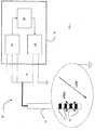
- FIG 1an apparatus for treating neurological disorders is shown, wholly indicated with 10.
- the apparatus for treating neurological disorders 10comprises at least one electro-catheter 11 suitable for being implanted in the brain of a patient to administer an electric stimulation.
- the electro-catheter 11preferably comprises at least three metallic contacts accessible through external connections also called electrodes 12.
- electrodes 12are metallic contacts accessible through external connections also called electrodes 12.
- the electrodes 12are connected to a processing and stimulation device 14 that, in the embodiment illustrated in figure 1 , comprises three functional modules connected together in feedback and interoperating: a stimulation module 16, an acquisition module 18 and a control module 20.
- the stimulation module 16is adapted to generate a stimulation signal V stim characterised by a set of parameters V a ,V d ,V f , and to send to the electrodes 12 the stimulation signal generated.
- the stimulation module 16is a generator of pulses defined by the amplitude, frequency and duration of the pulses.
- the acquisition module 18is assigned to the acquisition of a signal characteristic of cerebral activity coming from the brain of the patient.
- the acquisition module 18comprises processing means for transforming the acquired signal characteristic of cerebral activity in the frequency domain.
- the processing meanscarry out an FFT (Fast Fourier Transform) and can be made through hardware means and/or software means.
- the acquisition module 18also preferably comprises an integral block and a derivative block (not illustrated) of the signal characteristic of cerebral activity transformed in the frequency domain.
- the control module 20implements an adjuster, preferably a feedback controller. As illustrated more clearly in figure 3 , the control module 20 is functionally connected, upstream, to the acquisition module 18 and, downstream, to the stimulation module 16 that determines the stimulation signal V stim . As a function of the spectral power of the signal characteristic of cerebral activity acquired by the acquisition module 18, the control module 20 determines at least one signal based on which at least one parameter V a ,V d ,V f of the stimulation signal V stim set by the stimulation module 16 is defined.
- control module 20receives in input the signal acquired in the time domain or transformed in the frequency domain by the acquisition module 18 to determine its power. Based on such a power, preferably integrated based on a time constant ⁇ and/or derived according to specificities of the stimulation parameter to be adjusted, the stimulation parameters are calculated based on a transfer function having a saturating trend such as to also determine that the stimulation parameters are variable between two saturation values (V i_HighThreshold ; V i_LowThreshold ) between which the stimulation is actually effective.
- V i_HighThresholdV i_LowThreshold
- the transfer function having a saturating trendis implemented as a piecewise function based on ranges of values of the input power, i.e. such as to place the stimulation parameter V i equal to a maximum value V i_HighThreshold or to a minimum value V i_LowThreshold in the saturation ranges, allowing the stimulation parameter V i to vary, outside the saturation ranges, as a function of the power P BF of the signal acquired according to a law of variability U i (P BF ).
- the parameter K 1irepresents a proportional adjustment factor preferably having unitary value so that the maximum excursion of P BF corresponds to the maximum excursion of the output V i (P BF ).
- the parameter K 1itakes on values greater than 1, an additional saturation block is foreseen in order to ensure that the stimulation parameter V i is kept within the predetermined stimulation range.
- the parameter pis adjusted based on the desired value of the function U i (P BF ) around the point P BF2 and P BF1 .
- the control module 20foresees to implement a respective law of variability V a (P BF ),V d (P BF ),V f (P BF ) for each stimulation parameter V a ,V d ,V f .
- the stimulation signal V stim in output from the stimulation module 16is characterised by the parameters V a ,V d ,V f , calculated based on the respective output of the control module 20.
- the time constant ⁇ based on which the integration of the spectral power P BF takes placeis selected as a function of the control requirements: the greater the time constant ⁇ the smaller the variance on the evaluation of the spectral power P BF of the acquired signal and therefore on the instantaneous clinical state of the patient.
- increasing the time constant ⁇increases the delay in identifying the clinical state of the patient.
- controlallows variable setting of the time constant ⁇ , so that the most suitable time constant can be set each time based on the specific application, taking into account the compromise between speed and accuracy of detection of the power.
- the adjuster implemented by the control module 20is characterised by a wide degree of flexibility thanks to the possibility of calibrating the adjustment parameters K 1i , K 2i P BF2 , P BF1 , ⁇ , V i1 , V i2 . It is thus possible to carry out a vast range of adjustment strategies.
- the operating method 100 of the apparatus for treating neurological disorders 10is schematically illustrated in figure 2 .
- an initialisation sessionPrior to the stimulation treatment there is an initialisation session (step 110).
- the initialisation sessionis carried out after the patient has spent a sufficient time (generally 12 hours) without pharmacological medication. After such a time period without pharmacological therapy, the patient is considered to be in the so-called "OFF-OFF" or base clinical condition, i.e. in the absence of stimulation and with effect of pharmacological therapy having worn off.
- step 111there is the identification (step 111) of at least one of the threshold values of the specific stimulation parameters of the patient based on which to set the treatment.
- the amplitude of the stimulation voltageis identified.
- step 111Such identification takes place through an expert, like for example a neurologist specialised in the treatment of neurological disorders through deep brain stimulation.
- the step of identifying the parameters(step 111) therefore takes place through a series of stimulation tests with different parameter values, based on which the expert decides the maximum threshold value V i_HighThreshold , to obtain the maximum clinical effect before the appearance of side effects, and minimum threshold value V i_LowThreshold , to obtain the minimum or zero clinical effect.
- the saturation values of the stimulation parameters V i2 and V i1can be placed equal, respectively, to the maximum threshold value V i_HighThreshold and minimum threshold value V i_LowThreshold or alternatively, respectively equal to the minimum threshold value V i_LowThreshold and maximum threshold value V i_HighThreshold .
- the step of identifying the stimulation parametersleads to determining the maximum and minimum amplitude of the voltage that can be set V a_HighThreshold and V a_LowThreshold .
- the maximum/minimum frequency and/or the maximum/minimum duration of the stimulation signal V stimcan be identified.
- step 112there is a recording (step 112) of the neurophysiological signal: the harmonic content of the neurophysiological signal of the specific patient in the absence of stimulation is detected and analysed to identify the characteristics of the specific frequency spectrum of the patient.
- at least one frequency peakis identified, with respect to which the at least one frequency band BF is centred based on which to calculate the spectral power of the signal.
- the frequency bandsare defined through a minimum frequency and a maximum frequency: fw_min ⁇ BF ⁇ fw_max and correspond to the frequency bands with which the symptoms of the neurological disorders that it is wished to counteract most probably correlate.
- the frequencies fw_min and fw_maxcan be selected arbitrarily.
- a calibration stepin which the signal characteristic of cerebral activity is recorded in a plurality of different conditions to extract the values of the power in the frequency band defined previously.
- the neurophysiological signal of the patient at the base stateis detected, i.e. in the absence of therapies of any kind (pharmacological or stimulation) also called OFF-OFF state, and the power in the band of interest is stored.
- the recording of the neurophysiological signal at the OFF-OFF statetakes place for an initial period, in general equal to 20 minutes. Once the initial period has ended, the stimulation is brought to the maximum threshold stimulation values V i_HighThreshold determined previously.
- the processing and stimulation deviceproceeds to store the power of the signal characteristic of cerebral activity of the patient in the clinical OFF-ON state, i.e. in the absence of pharmacological therapy (LEVOdopamine), but in the presence of stimulation. After a further time period, in general equal to another 20 minutes, the pharmacological therapy is started again proceeding to store the power. After a third time period, the drug taken is considered to be completely assimilated and the patient is in the clinical ON-ON state, i.e. in the presence of pharmacological therapy and of stimulation. The storage of the power of the signal characteristic of cerebral activity of the patient is therefore ended.
- pharmacological therapyLEVOdopamine
- the maximum power value P BF2 and minimum power value P BF1are extrapolated.
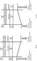
- the caseis also shown in which the frequency band of interest coincides with the low frequencies (4-10 Hz).
- the minimum power value P BF1coincides with the power value in the OFF-OFF state (P lowOFFOFF ) whereas the maximum power value P BF2 coincides with the power value at the ON-ON state (P lowONON ).
- the method 100 for treating neurological disorderscomprises the repetition of the following steps.
- the delivery of the deep brain stimulationis started (step 120).
- the acquisition module 18records a signal characteristic of cerebral activity of the patient (sub-step 131), preferably the local field potentials LFP recorded at the grey nucleus, and thereafter transforms it (sub-step 132) preferably in the frequency domain, for example through FFT (Fast Fourier Transform), determining its spectral power P BF (sub-step 133).
- the poweris also integrated based on the time constant ⁇ (sub-step 134).
- step 140based on the spectral power P BF recorded, there is a step of updating the stimulation parameters (step 140).
- control module 20preferably compares the power P BF with a range of reference values [P BF2 ; P BL1 ] that correlate more with the frequency band of interest. Based on the difference between the power P BF calculated and the lower limit P BF1 of such a reference range [P BF2 ; P BF1 ] a control signal for a stimulation module (16) is generated which sets the stimulation parameters (V a ,V d ,V f ) according to the law of variability V i (P BF ) given above.
- the upper extreme P BF2 of the range of valuesis equal to the power P ⁇ OFFOFF at the OFF-OFF state and the lower extreme P BF1 of the range of values is equal to the power P ⁇ ONON at the ON-ON state determined in the initialisation step, with P BF2 >P BF1 .
- the treatment method according to the inventionis specifically used for treating clinical-motor functions of Parkinson's disease that most correlate with the beta band ⁇ , which has therefore been identified as the reference frequency band BF based on which to calculate the spectral power of the acquired local field potentials.
- the reference frequency band BFbased on which to calculate the spectral power of the acquired local field potentials.
- the treatment method according to the inventionis specifically used for the treatment of the clinical-motor fluctuations of Parkinson's disease that most correlate with the band of low frequencies (4-10 Hz), which has therefore been identified as reference frequency band BF based on which to calculate the spectral power of the acquired local field potentials.
- the treatment method according to the inventionit also proved sufficient to carry out an adaptation of just the stimulation amplitude V a .
Landscapes
- Health & Medical Sciences (AREA)
- Life Sciences & Earth Sciences (AREA)
- Neurology (AREA)
- General Health & Medical Sciences (AREA)
- Public Health (AREA)
- Engineering & Computer Science (AREA)
- Neurosurgery (AREA)
- Biomedical Technology (AREA)
- Veterinary Medicine (AREA)
- Animal Behavior & Ethology (AREA)
- Biophysics (AREA)
- Heart & Thoracic Surgery (AREA)
- Radiology & Medical Imaging (AREA)
- Nuclear Medicine, Radiotherapy & Molecular Imaging (AREA)
- Medical Informatics (AREA)
- Psychology (AREA)
- Pathology (AREA)
- Molecular Biology (AREA)
- Physics & Mathematics (AREA)
- Surgery (AREA)
- Physiology (AREA)
- Cardiology (AREA)
- Hospice & Palliative Care (AREA)
- Psychiatry (AREA)
- Physical Education & Sports Medicine (AREA)
- Epidemiology (AREA)
- Primary Health Care (AREA)
- Electrotherapy Devices (AREA)
Abstract
Description
- The present invention concerns an apparatus and a method for treating neurological disorders. In greater detail, the present invention concerns an apparatus and a method for treating neurological disorders based on the feedback of deep brain stimulation, therefore capable of detecting biopotentials from a stimulation electrode or from neighbouring electrodes, correlating such signals with the clinical state of the patient and feeding the stimulation parameters back in order to optimise the therapy.
- In the present description and in the subsequent claims, the expression "local biopotentials" means the electric potentials produced by groups of neurones close to the recording and stimulation electrodes.
- In the present description and in the subsequent claims, the expression "local field potentials" means the sum of the pre and post synaptic activity around a stimulation electrode implanted in the brain.
- In the present description and in the subsequent claims, the expression "base clinical state" of a patient means the state of the patient in the absence of therapies, both pharmacological and by stimulation, for a sufficiently long time period, so that the effects of the therapies have totally worn off, in general equal to at least 12 hours.
- As known, deep brain stimulation, also known by the acronym DBS, is a therapeutic method based on the modulation of the activities of structures of the central nervous system through an electric stimulation delivered locally. For this purpose, electrodes are implanted by neurosurgery. Electric stimulation consists of delivering a train of electric pulses in the brain area of interest through the implanted electrode, which for this purpose is connected to a pulse generator.
- Deep brain stimulation is currently used in clinical trials or for the treatment of epilepsy, migraines, some psychiatric disturbances, pain and movement disorders, such as dystonia, tremor and Parkinson's disease. Such a method allows the functional autonomy of patients to be improved, thus offering an improved quality of life. Since the use of deep brain stimulation is particularly consolidated in the treatment of Parkinson's disease, in the present description reference will mainly be made, although only as an example and not for limiting purposes, to such a disease.
- In the case of Parkinson's disease, the implantation areas of the electrode most used in clinical practice are some structures of the grey nucleus, including in particular the internal globus pallidus and the subthalamic nucleus, as well as the inner peduncle pontine nucleus. The choice of the implantation area is at the discretion of the neurologist based on the symptoms to be tackled. As an example, it should be considered, indeed, that Parkinson's disease is characterised by a wide spectrum of motor and non-motor symptoms, where the motor symptoms comprise, amongst other things, rigidity, bradykinesia, rest tremor, akinesia, postural instability, inability to walk and so on. Clinical studies widely support the benefits brought by deep brain stimulation at the subthalamic nucleus, which is therefore the preferred implantation area in most treatments. Such a treatment method can cause various side effects including dyskinesia, language and psychiatric difficulties that can, nevertheless, be mitigated through a reprogramming of the stimulation parameters.
- In the case of conventional brain stimulation, the parameter setting process is carried out empirically, requiring time, clinical experience and numerous visits to adjust to the optimal values. Moreover, such adjustment leads to setting that, even if initially optimal, is unable to adapt to variations that came afterwards. Indeed, once the parameters have been set, the stimulation is delivered independently from the clinical state of the patient, not being able to adapt to possible variations of such a clinical state. Therefore, clinical fluctuations characterising an advanced stage of Parkinson's disease remain uncontrolled.
- In order to overcome the limitations described above, an apparatus for treating neurological disorders has been made that is capable of monitoring the clinical state of the patient by recording a physiological marker, also known as biomarker, as control variable, and of adapting the stimulation parameters to the clinical state detected. Such a system is known as adaptive brain stimulation. An example of such an apparatus is described in
European patent EP 1 940 508 . Through such an apparatus it is possible to decrease the time necessary to set the optimal parameters and decrease the occurrence of side effects. - From
EP 1 940 508 - In line with such an observation,
patent EP 2 004 036 also describes a medical device that, for the treatment of a motor disorder, uses a physiological marker of the clinical state of a patient. In particular, the physiological marker is calculated based on two values representative of the amount of oscillatory activity of the physiological signal detected, each relative to a different range of frequencies.Patent EP 2 004 036 also refers to the possibility of adjusting the therapy in feedback based on the two values representative of the amount of oscillatory activity, in particular by adjusting the stimulation parameters so as to keep the biomarker calculated based on such two values, in a predetermined range.EP 2 004 036 does not, however, provide any indication concerning the adjustment logic for an optimal adaptation of the stimulation parameters. - Also known is the study ofSantaniello et al. Described in the article titled "Closed-Loop Control of Deep Brain Stimulation: A Simulation Study" published in IEEE Transactions on neural systems and rehabilitation engineering, Vol. 19, No. 1, February 2011, pages 15-24, which has the purpose of developing a closed-loop control system for automatically adjusting the stimulation parameters based on the neuronal signals recorded through the same stimulation electrode, in particular based on the local field potentials. Such a control system comprises, downstream of the transfer function, a saturating trend function that limits the amplitude of the stimulation parameters if the transfer function determines an output value outside a predetermined range. Such a limitation is therefore carried out as a function of the output of the transfer function.
- However, such a system is unable to correlate the power of the local field potentials calculated in specific frequency bands with the stimulation parameters, so as to take into account the link observed by the Applicant between the particular sets of band power values and the specific symptoms of the disturbance to be treated. In other words, the transfer function of the control system described in Santaniello applies the same law of variability independently from the set to which the power value that it receives in input belongs.
- In light of the above, the Applicant has found the need to devise an apparatus and a method capable of administering a deep brain stimulation therapy in an optimised manner as a function of the instantaneous clinical state of the patient, expressed through a physiological marker calculated from the local field potentials measured on the patient.
- The problem forming the basis of the present invention is therefore that of making an apparatus and a method for treating neurological disorders that is able to adapt the stimulation administered in an optimal manner as a function of the instantaneous clinical state of the patient, operating automatically and continuously.
- For this purpose, the Applicant has perceived the need to identify a law of variability that correlates the stimulation parameters with the local field potentials, based on which it is possible to construct an automatic control of the therapy that adapts in an optimised and quick manner to possible changes in the clinical state of the patient.
- In accordance with a first aspect thereof, the invention concerns an apparatus for treating neurological disorders comprising
- at least one electrode implantable in the brain of a patient and
- a processing and stimulation device connected to the at least one electrode, wherein the processing and stimulation device comprises
- at least one stimulation module adapted to generate a stimulation signal to be sent to the at least one electrode, the stimulation signal being characterised by a plurality of parameters,
- at least one acquisition module of a signal characteristic of cerebral activity coming from the brain of the patient, adapted to determine its power in at least one frequency band, and
- at least one control module of at least one parameter of the stimulation signal as a function of the power of the acquired signal characteristic of cerebral activity based on a transfer function having a saturating trend, wherein the transfer function is such as to set said at least one parameter (Va,Vd,Vf) of the stimulation signal (Vstim) differently dependent on a plurality of power ranges, keeping it within a predetermined stimulation range ([Vi_HighThreshold; Vi_LowThreshold]) with i = a,d,f. In the present description and in the subsequent claims, the expression "transfer function having a saturating trend" means a function that for input values greater than or less than respective first and second predetermined input values respectively places the output variable (different from the input variable) equal to a first and a second predetermined output value and for input values comprised between the first and the second predetermined input values, the output can take values based on a predetermined law of variability. Therefore, in the present description and in the subsequent claims, the definition of "saturating trend function" should not be taken in the narrow sense as a function that forces the input variable to not take values in output greater or less than predetermined thresholds.
- The Applicant has observed that, for example, the oscillations in the beta band are suppressed following administration of a suitable drug (for example dopamine) and correlate with the preparation and performance of the movement. Such oscillations reflect the response of the grey nucleus to the drug and correlate with the motor state. In the same way, it has been demonstrated that a deep brain stimulation treatment induces a power reduction in the beta band.
- In other words, when an improvement of the motor state of the patient is observed after the administration of the drug or after a deep brain stimulation therapy, a corresponding percentage reduction of the power of the local field potentials calculated in the beta band with respect to the base clinical state, i.e. the clinical state prior to the administration of therapies, is observed. The variation of the motor state of the patient is expressed in UPDRS (Unified Parkinson's Disease rating scale) as percentage values with respect to the base state.
- Similarly, the Applicant has observed that the oscillations in the band of low frequencies (4- 10Hz) increases with a deep brain stimulation and/or pharmacological treatment. In other words, when a percentage decrease in the UPDRS scale is observed, i.e. an improvement in the clinical state of the patient after administration of the drug or the deep stimulation therapy, a corresponding increase in the power of the local field potentials calculated in the band of low frequencies with respect to the base clinical state is observed.
- The Applicant therefore started from the assumption that an improvement in the clinical state of the patient is correlated to a percentage variation of the power of the local field potentials, and hypothesised a proportional relationship between such a power calculated in a certain frequency band, whether it is calculated in the frequency domain, or in the time domain, and the clinical state, for example expressed in UPDRS scale.
- The Applicant has also hypothesised that the relationship between stimulation and local field potentials can be expressed through a proportional relationship between the stimulation signal and the power of the local field potentials. From such an assumption, it follows that the clinical state can be expressed as a function of the stimulation signal.
- In accordance with the assumptions outlined above it is possible to control the clinical state of the patient by modifying the stimulation parameters as a function of the power in a certain frequency band according to the mathematical function indicated above.
- Such a function determines that, for certain ranges of input power values, the stimulation parameters can vary as a function of the input power, adapting to the instantaneous clinical state of the patient and for other ranges of input power values the stimulation parameters are set equal to respective saturation values at which the stimulation was still actually effective. In this way, the occurrence of side effects due to stimulation therapy is avoided, at the same time ensuring a definite benefit induced by the stimulation.
- Similarly, in accordance with a second aspect thereof, the invention concerns a method for treating neurological disorders comprising the steps consisting of:
- sending at least one stimulation signal characterised by a plurality of parameters to at least one electrode implantable in the brain of a patient;
- acquiring at least one signal characteristic of cerebral activity coming from the brain of the patient and determining its power in at least one frequency band; and
- adjusting at least one parameter of the stimulation signal as a function of the power of the acquired signal characteristic of cerebral activity based on a transfer function having a saturating trend, wherein the transfer function is such as to set said at least one parameter (Va,Vd,Vf) of the stimulation signal (Vstim) differently dependent on a plurality of power ranges, keeping it within a predetermined stimulation range ([Vi_HighThreshold;Vi_LowThreshold]) with i = a,d,f.
- Advantageously, the method for treating neurological disorders according to the invention achieves the technical effects described above in relation to the apparatus.
- The present invention, in at least one of the aforementioned aspects, can have at least one of the following preferred characteristics, which are in particular able to be combined with each other as desired in order to satisfy specific application requirements.
- Preferably, the transfer function having a saturating trend as a function of a plurality of power ranges is a piecewise function, placing the stimulation parameter equal to a first value of the stimulation parameter for powers of the acquired signal greater than a first power limit value and placing the stimulation parameter equal to a second value of the stimulation parameter for powers of the acquired signal below a second power limit value according to the following law of variability:


- Even more preferably, the law of variability Ui(PBF) of the stimulation parameter Vi outside of the saturation ranges comprises a further additional term (K2i), thereby resulting in:

- Alternatively, the law of variability Ui(PBF) of the stimulation parameter outside of the saturation ranges is of the following type:

- More preferably, the law of variability Ui(PBF) of the stimulation parameter Vi outside of the saturation ranges comprises a further additional term (K2i), thereby resulting in:

- Advantageously, the selected laws of variability in feedback allow a vast range of adjustment strategies to be carried out through a suitable calibration of the parameters thereof. This flexibility is an essential requirement that allows the use of the apparatus according to the present invention in association with multiple different neurological disorders, each characterised by mutually heterogeneous symptoms that in turn correlate with the local field potentials in different frequency bands and with different time dynamics.
- Preferably, the at least one acquisition module comprises processing means for transforming the acquired signal characteristic of cerebral activity in the frequency domain.
- In an even more preferred manner, the processing means for transforming the acquired signal characteristic of cerebral activity in the frequency domain implement a Fourier transform, preferably of the FFT (Fast Fourier Transform) type. More preferably, the processing means for transforming the acquired signal characteristic of cerebral activity in the frequency domain are of the hardware or software type.
- Preferably, the at least one acquisition module comprises an integral block for conditioning the acquired signal characteristic of cerebral activity.
- Alternatively or in combination, the at least one acquisition module comprises a derivative block for conditioning the acquired signal characteristic of cerebral activity.
- In this way, advantageously, it is possible to carry out prior conditioning of the signal fed to the control module that is independent and specific for each stimulation parameter.
- Preferably, the at least one stimulation module is a pulse generator.
- Preferably, the at least one control module is suitable for implementing the above law of variability Ui(PBF).
- Preferably, the frequency band BF and the parameters of the law of variability, such as a first Vi1 and a second Vi2 threshold value of a stimulation parameter Vi, a maximum power value PBF2 and a minimum power value PBF1 are obtained according to the following steps:
- a) Identifying at least one maximum threshold value Vi_HighThreshold of a stimulation parameter Vi above which the patient shows signs of side effects caused by the stimulation and a minimum threshold value Vi_LowThreshold for which the patient shows the minimum or zero benefit induced by stimulation, and placing the extremes of the predetermined stimulation range ([Vi2;Vi1]) alternatively respectively equal to the maximum threshold value Vi_HighThreshold and minimum threshold value Vi_LowThreshold of the stimulation parameter or to a percentage thereof;
- b) Determining the frequency band BF, detecting a frequency peak of the power spectrum of a signal characteristic of cerebral activity of the patient recorded in the absence of stimulation, the frequency band BF being centred on such a frequency peak and having a bandwidth selected arbitrarily;
- c) Recording the trend over time of the power PBF of a signal characteristic of cerebral activity calculated in the frequency band BF in the three conditions:
- base state;
- active stimulation at the maximum threshold value Vi_HighThreshold of the stimulation parameter Vi and pharmacological therapy absent; and
- active stimulation at the maximum threshold value Vi_HighThreshold of the stimulation parameter Vi and pharmacological therapy administered and active;
- d) Identifying a maximum power value PBF2 and a minimum power value PBF1 of the trend recorded at step c).
- Preferably, the stimulation signal comprises a train of pulses and the stimulation parameter Vi is chosen from the group consisting of:
- The amplitude of the stimulation pulses;
- The stimulation pulse repetition frequency;
- The stimulation pulse duration.
- Preferably, the maximum power value PBF2 of the signal characteristic of cerebral activity calculated in the frequency band BF corresponds to the power value POFFOFF that can be determined when the patient is in the base state and the minimum power value PBF1 corresponds to the power value PONON that can be determined when the patient is subjected both to pharmacological therapy and to stimulation therapy active at the maximum threshold value Vi_HighThreshold of the stimulation parameter.
- More preferably, the frequency band BF is a sub-band of the beta band (10 - 35 Hz).
- Alternatively, the minimum power value PBF1 of the signal characteristic of cerebral activity calculated in the frequency band BF corresponds to the power value POFFOFF that can be determined when the patient is in the base state and the maximum power value PBF2 corresponds to the power value PONON that can be determined when the patient is subjected both to pharmacological therapy and to stimulation therapy active at the maximum threshold stimulation parameter Vi_HighThreshold. Preferably, in this case, the frequency band BF is a sub-band of the low frequencies (4- 10 Hz). Preferably, the signal characteristic of cerebral activity is a signal coming from the grey nucleus. Preferably, the power calculated in at least one frequency band of the acquired signal characteristic of cerebral activity is compared with a reference value and, based on the difference between the calculated power and the reference value, a control signal for a stimulation module is generated that sets the stimulation parameters.
- Preferably, the power PBF of the acquired signal characteristic of cerebral activity is integrated with a time constant τ.
- Advantageously, the time constant τ is selected as a function of the adjustment that is wished to be obtained: the greater the time constant τ, the greater the accuracy of the adjustment but also the delay in response of the system. Therefore, the time constant τ with which the power of band PBF is integrated is chosen seeking the ideal compromise between accuracy and speed of response of the adjustment.
- Alternatively or in addition, the power P of the acquired signal characteristic of cerebral activity is a derivative.
- Further characteristics and advantages of the present invention will become clearer from the following detailed description of some preferred embodiments thereof, made with reference to the attached drawings.
- The different characteristics in the single configurations can be combined with each other as desired according to the previous description, if it were necessary to have advantages resulting specifically from a particular combination.
- In such drawings,
figure 1 is a schematic representation of an apparatus for treating neurological disorders according to a preferred embodiment of the present invention;figure 2 is a block diagram of the main steps of the method for treating neurological disorders in accordance with the present invention;figure 3 is a detailed block diagram of a step of the method for treating neurological disorders according to the present invention;figure 4a is a diagram of the variation in power in beta band during the calibration step of the maximum and minimum spectral power thresholds in the case of Parkinson's disease;figure 4b is a diagram of the variation in spectral power at the low frequencies during the calibration step of the maximum and minimum spectral power thresholds in the case of Parkinson's disease.- In the following description, to illustrate the figures identical reference numerals or symbols are used to indicate constructive elements with the same function. Moreover, for the sake of clarity of illustration, some references are not repeated in all of the figures.
- With reference to
figure 1 , an apparatus for treating neurological disorders is shown, wholly indicated with 10. - The apparatus for treating
neurological disorders 10 comprises at least one electro-catheter 11 suitable for being implanted in the brain of a patient to administer an electric stimulation. The electro-catheter 11 preferably comprises at least three metallic contacts accessible through external connections also calledelectrodes 12. However, it is obviously possible to hypothesise alternative solutions in which the electrodes are not necessarily carried by one same electro- catheter. - The
electrodes 12 are connected to a processing andstimulation device 14 that, in the embodiment illustrated infigure 1 , comprises three functional modules connected together in feedback and interoperating: astimulation module 16, anacquisition module 18 and acontrol module 20. - The
stimulation module 16 is adapted to generate a stimulation signal Vstim characterised by a set of parameters Va,Vd,Vf, and to send to theelectrodes 12 the stimulation signal generated. In particular, thestimulation module 16 is a generator of pulses defined by the amplitude, frequency and duration of the pulses. - The
acquisition module 18 is assigned to the acquisition of a signal characteristic of cerebral activity coming from the brain of the patient. In detail, theacquisition module 18 comprises processing means for transforming the acquired signal characteristic of cerebral activity in the frequency domain. Specifically, the processing means carry out an FFT (Fast Fourier Transform) and can be made through hardware means and/or software means. Theacquisition module 18 also preferably comprises an integral block and a derivative block (not illustrated) of the signal characteristic of cerebral activity transformed in the frequency domain. - The
control module 20 implements an adjuster, preferably a feedback controller. As illustrated more clearly infigure 3 , thecontrol module 20 is functionally connected, upstream, to theacquisition module 18 and, downstream, to thestimulation module 16 that determines the stimulation signal Vstim. As a function of the spectral power of the signal characteristic of cerebral activity acquired by theacquisition module 18, thecontrol module 20 determines at least one signal based on which at least one parameter Va,Vd,Vf of the stimulation signal Vstim set by thestimulation module 16 is defined. - Advantageously, the
control module 20 receives in input the signal acquired in the time domain or transformed in the frequency domain by theacquisition module 18 to determine its power. Based on such a power, preferably integrated based on a time constant τ and/or derived according to specificities of the stimulation parameter to be adjusted, the stimulation parameters are calculated based on a transfer function having a saturating trend such as to also determine that the stimulation parameters are variable between two saturation values (Vi_HighThreshold; Vi_LowThreshold) between which the stimulation is actually effective. - In particular, the transfer function having a saturating trend is implemented as a piecewise function based on ranges of values of the input power, i.e. such as to place the stimulation parameter Vi equal to a maximum value Vi_HighThreshold or to a minimum value Vi_LowThreshold in the saturation ranges, allowing the stimulation parameter Vi to vary, outside the saturation ranges, as a function of the power PBF of the signal acquired according to a law of variability Ui(PBF).
- This translates into the following transfer function, where the saturation ranges correspond to powers PBF of the acquired signal greater than a first power limit value PBF2 or powers PBF of the acquired signal below a second power limit value PBF1:

- In particular, the law of variability Ui(PBF) of the stimulation parameter outside the saturation ranges is of the following type:

- Alternatively, the law of variability Ui(PBF) of the stimulation parameter outside of the saturation ranges is of the sigmoid type:

- In both cases, the parameter K1i represents a proportional adjustment factor preferably having unitary value so that the maximum excursion of PBF corresponds to the maximum excursion of the output Vi(PBF). In the case in which the parameter K1i takes on values greater than 1, an additional saturation block is foreseen in order to ensure that the stimulation parameter Vi is kept within the predetermined stimulation range. In the sole case of sigmoid function, the parameter p is adjusted based on the desired value of the function Ui(PBF) around the point PBF2 and PBF1.
- Specifically, since deep brain stimulation uses a stimulus defined by three stimulation parameters Va,Vd,Vf relative, respectively, to amplitude, duration and frequency of the stimulation signal Vstim, the
control module 20 foresees to implement a respective law of variability Va(PBF),Vd(PBF),Vf(PBF) for each stimulation parameter Va,Vd,Vf. The stimulation signal Vstim in output from thestimulation module 16 is characterised by the parameters Va,Vd,Vf, calculated based on the respective output of thecontrol module 20. - Advantageously, the time constant τ based on which the integration of the spectral power PBF takes place, is selected as a function of the control requirements: the greater the time constant τ the smaller the variance on the evaluation of the spectral power PBF of the acquired signal and therefore on the instantaneous clinical state of the patient. However, increasing the time constant τ increases the delay in identifying the clinical state of the patient.
- Preferably, the control allows variable setting of the time constant τ, so that the most suitable time constant can be set each time based on the specific application, taking into account the compromise between speed and accuracy of detection of the power.
- The adjuster implemented by the
control module 20 is characterised by a wide degree of flexibility thanks to the possibility of calibrating the adjustment parameters K1i, K2i PBF2, PBF1, τ, Vi1, Vi2. It is thus possible to carry out a vast range of adjustment strategies. - The
operating method 100 of the apparatus for treatingneurological disorders 10 is schematically illustrated infigure 2 . - Prior to the stimulation treatment there is an initialisation session (step 110). The initialisation session is carried out after the patient has spent a sufficient time (generally 12 hours) without pharmacological medication. After such a time period without pharmacological therapy, the patient is considered to be in the so-called "OFF-OFF" or base clinical condition, i.e. in the absence of stimulation and with effect of pharmacological therapy having worn off.
- Then there is the identification (step 111) of at least one of the threshold values of the specific stimulation parameters of the patient based on which to set the treatment. In particular, in simplifying terms, the amplitude of the stimulation voltage is identified.
- Such identification takes place through an expert, like for example a neurologist specialised in the treatment of neurological disorders through deep brain stimulation. The step of identifying the parameters (step 111) therefore takes place through a series of stimulation tests with different parameter values, based on which the expert decides the maximum threshold value Vi_HighThreshold, to obtain the maximum clinical effect before the appearance of side effects, and minimum threshold value Vi_LowThreshold, to obtain the minimum or zero clinical effect. The saturation values of the stimulation parameters Vi2 and Vi1 can be placed equal, respectively, to the maximum threshold value Vi_HighThreshold and minimum threshold value Vi_LowThreshold or alternatively, respectively equal to the minimum threshold value Vi_LowThreshold and maximum threshold value Vi_HighThreshold.
- In the case in which the parameter analysed is the amplitude Va of the stimulation signal Vstim, the step of identifying the stimulation parameters leads to determining the maximum and minimum amplitude of the voltage that can be set Va_HighThreshold and Va_LowThreshold. Similarly, the maximum/minimum frequency and/or the maximum/minimum duration of the stimulation signal Vstim can be identified.
- Then there is a recording (step 112) of the neurophysiological signal: the harmonic content of the neurophysiological signal of the specific patient in the absence of stimulation is detected and analysed to identify the characteristics of the specific frequency spectrum of the patient. In particular, at least one frequency peak is identified, with respect to which the at least one frequency band BF is centred based on which to calculate the spectral power of the signal. The frequency bands are defined through a minimum frequency and a maximum frequency: fw_min<BF<fw_max and correspond to the frequency bands with which the symptoms of the neurological disorders that it is wished to counteract most probably correlate. The frequencies fw_min and fw_max can be selected arbitrarily.
- Once the stimulation parameters and the frequency band have been defined, there is a calibration step (step 113) in which the signal characteristic of cerebral activity is recorded in a plurality of different conditions to extract the values of the power in the frequency band defined previously. Specifically, for the calibration step (step 113), the neurophysiological signal of the patient at the base state is detected, i.e. in the absence of therapies of any kind (pharmacological or stimulation) also called OFF-OFF state, and the power in the band of interest is stored. The recording of the neurophysiological signal at the OFF-OFF state takes place for an initial period, in general equal to 20 minutes. Once the initial period has ended, the stimulation is brought to the maximum threshold stimulation values Vi_HighThreshold determined previously. The processing and stimulation device proceeds to store the power of the signal characteristic of cerebral activity of the patient in the clinical OFF-ON state, i.e. in the absence of pharmacological therapy (LEVOdopamine), but in the presence of stimulation. After a further time period, in general equal to another 20 minutes, the pharmacological therapy is started again proceeding to store the power. After a third time period, the drug taken is considered to be completely assimilated and the patient is in the clinical ON-ON state, i.e. in the presence of pharmacological therapy and of stimulation. The storage of the power of the signal characteristic of cerebral activity of the patient is therefore ended.
- Once the storage has ended, in the three
initialisation steps 110, of the power calculated in the frequency band identified initially, the maximum power value PBF2 and minimum power value PBF1 are extrapolated. - In the specific case illustrated in
figure 4a , relative to a frequency band of interest coinciding with a sub-band of the beta band (10-35 Hz), the maximum power value PBF2 coincides with the power value in the OFF-OFF state (PβOFFOFF), whereas the minimum power value PBF1 coincides with the power value in the ON-ON state (PβONON). - In example terms, the case is also shown in which the frequency band of interest coincides with the low frequencies (4-10 Hz). In this case, as shown in
figure 4b , the minimum power value PBF1 coincides with the power value in the OFF-OFF state (PlowOFFOFF) whereas the maximum power value PBF2 coincides with the power value at the ON-ON state (PlowONON). - Once the
initialisation step 110 of the therapy has ended, themethod 100 for treating neurological disorders comprises the repetition of the following steps. - The delivery of the deep brain stimulation is started (step 120).
- Thereafter (step 130), the
acquisition module 18 records a signal characteristic of cerebral activity of the patient (sub-step 131), preferably the local field potentials LFP recorded at the grey nucleus, and thereafter transforms it (sub-step 132) preferably in the frequency domain, for example through FFT (Fast Fourier Transform), determining its spectral power PBF (sub-step 133). Preferably, the power is also integrated based on the time constant τ (sub-step 134). - Finally, based on the spectral power PBF recorded, there is a step of updating the stimulation parameters (step 140).
- For this purpose, the
control module 20 preferably compares the power PBF with a range of reference values [PBF2; PBL1] that correlate more with the frequency band of interest. Based on the difference between the power PBF calculated and the lower limit PBF1 of such a reference range [PBF2; PBF1] a control signal for a stimulation module (16) is generated which sets the stimulation parameters (Va,Vd,Vf) according to the law of variability Vi(PBF) given above. - In the case in which the frequency band of interest coincides with a sub-band of the beta band (10-35 Hz) that, as will be seen hereinafter, proves particularly suitable for the treatment of some symptoms of Parkinson's disease, the upper extreme PBF2 of the range of values is equal to the power PβOFFOFF at the OFF-OFF state and the lower extreme PBF1 of the range of values is equal to the power PβONON at the ON-ON state determined in the initialisation step, with PBF2>PBF1.
- In example terms, the case is now discussed in which the treatment method according to the invention is specifically used for treating clinical-motor functions of Parkinson's disease that most correlate with the beta band β, which has therefore been identified as the reference frequency band BF based on which to calculate the spectral power of the acquired local field potentials. For this treatment it has also proven sufficient to carry out an adaptation of just the stimulation amplitude Va.
- In this case, the law of variability takes the form:

- With the adjustment parameters K1i, PBF2, PBF1, Vi1, Vi2, K2i equal to:
- PBF=Pβ;
- PBF2 = PβOFFOFF
- PBF1 = PβONON
- Vi2 = Va_HighThreshold
- Vi1 = Va_LowThreshold
- K1i = Ka = 1
- K2i = 0
- In the case of the treatment of the symptoms of Parkinson's disease that correlate with the beta band, there is therefore a simplified adjustment model based on the following law of variability:

- Alternatively, the case is now discussed in which the treatment method according to the invention is specifically used for the treatment of the clinical-motor fluctuations of Parkinson's disease that most correlate with the band of low frequencies (4-10 Hz), which has therefore been identified as reference frequency band BF based on which to calculate the spectral power of the acquired local field potentials. For this treatment, it also proved sufficient to carry out an adaptation of just the stimulation amplitude Va.
- In this case, the law of variability takes the form

- With the adjustment parameters K1i, PBF2, PBF1, Vi1, Vi2, K2i equal to:
- PBF=Plow
- PBF2 = PlowONON
- PBF1 = PlowOFFOFF
- Vi2 = Va_LowThreshold
- Vi1 = Va_HighThreshold
- K1i = Ka = 1
- K2i = 0
- In the case of treatment of the symptoms of Parkinson's disease that correlate most with the low frequencies, there is therefore a simplified adjustment model defined by the following law of variability:

- From the description that has been made the characteristics of the apparatus and of the method for treating neurological disorders object of the present invention are clear, just as the relative advantages are also clear.
- From the embodiments described above further variants are possible, without departing from the teaching of the invention.
- Finally, it is clear that an apparatus and a method for treating neurological disorders thus conceived can undergo numerous modifications and variants, all of which are covered by the invention; moreover, all of the details can be replaced by technically equivalent elements. In practice, the materials used, as well as the sizes, can be whatever according to the technical requirements.


Claims (12)
- Apparatus (10) for treating neurological disorders comprising- at least one electrode (12) implantable in the brain of a patient and- a processing and stimulation device (14) connected to the at least one electrode (12), wherein the processing and stimulation device (14) comprises- at least one stimulation module (16) adapted to generate a stimulation signal (Vstim) to be sent to the at least one electrode (12), the stimulation signal (Vstim) beingcharacterised by a plurality of parameters (Va,Vd,Vf),- at least one acquisition module (18) of a signal characteristic of cerebral activity coming from the brain of the patient adapted to determine its power (PBF) in at least one frequency band (BF), and- at least one control module (20) of at least one parameter (Va,Vd,Vf) of the stimulation signal (Vstim) as a function of the power (PBF) of the signal characteristic of cerebral activity acquired, based on a transfer function having a saturating trend, wherein the transfer function is such as to set said at least one parameter (Va,Vd,Vf) of the stimulation signal (Vstim) differently dependent on a plurality of power ranges, by keeping the at least one parameter (Va,Vd,Vf) within a predetermined stimulation range ([Vi_HighThreshold;Vi_LowThreshold]) with i = a,d,f, wherein a maximum power limit value (PBF2) of a power range of the plurality of power ranges is a power of a sub-band of the beta band measured in the absence of pharmacological therapy and in the absence of electrical stimulation (PβOFFOFF); or
wherein a maximum power limit value (PBF2) of a power range of the plurality of power ranges is a power of a low frequency band measured in the presence of pharmacological therapy and in the presence of electrical stimulation (PlowONON). - Apparatus (10) according to claim 1, wherein the control module (20) is configured such that when the power (PBF) of the signal characteristic of cerebral activity acquired in the beta frequency band meets or exceeds the maximum power limit value (PBF2), at least one parameter (Va,Vd,Vf) of the stimulation signal (Vstim) is set to a maximum value (Vi_HighThreshold) of the stimulation parameter that provides a maximum clinical effect before side effects appear;
and/or
wherein the control module (20) is configured such that when the power (PBF) of the signal characteristic of cerebral activity acquired in the low frequency band meets or exceeds the maximum power limit value (PBF2), at least one parameter (Va,Vd,Vf) of the stimulation signal (Vstim) is set to a minimum value (Vi_LowThreshold) of the stimulation parameter that provides a minimum clinical effect. - Apparatus (10) according to claim 1 or 2, wherein the control module is further configured to adjust at least one parameter (Va,Vd,Vf) of the stimulation signal (Vstim) when the power (PBF) of the signal characteristic of cerebral activity acquired in the beta frequency band is at or below a minimum power limit value (PBF1) of a power range of the plurality of power ranges, wherein the minimum power limit value (PBF1) is a power of a sub-band of the beta band measured in the presence of pharmacological therapy and in the presence of electrical stimulation (PβONON); and/or
wherein the control module is further configured to adjust at least one parameter (Va,Vd,Vf) of the stimulation signal (Vstim) when the power (PBF) of the signal characteristic of cerebral activity acquired in the low frequency band is at or below a minimum power limit value (PBF1) of a power range of the plurality of power ranges, wherein the minimum power limit value (PBF1) is a power of the low frequency band measured in the absence of pharmacological therapy and in the absence of electrical stimulation (PlowOFFOFF). - Apparatus (10) according to claim 3, wherein the control module (20) is configured such that when the power (PBF) of the signal characteristic of cerebral activity acquired in the beta frequency band is at or below the minimum power limit value (PBF1), at least one parameter (Va,Vd,Vf) of the stimulation signal (Vstim) is set to a minimum value (Vi_LowThreshold) of the stimulation parameter that provides a minimum clinical effect; and/or
wherein the control module (20) is configured such that when the power (PBF) of the signal characteristic of cerebral activity acquired in the low frequency band is at or below the minimum power limit value (PBF1), at least one parameter (Va,Vd,Vf) of the stimulation signal (Vstim) is set to a maximum value (Vi_HighThreshold) of the stimulation parameter that provides a maximum clinical effect before side effects appear. - Apparatus according to any one of the preceding claims, wherein the at least one control module (20) is configured to adjust at least one stimulation parameter (Va,Vd,Vf) of the stimulation signal (Vstim) according to a piecewise transfer function based on the power (PBF) of the beta frequency band, wherein the piecewise transfer function is:

- Apparatus (10) according to claim 5, wherein the law of variability (Ui(PBF)) of the stimulation parameter (Vi) outside the saturation ranges is of the following type:

- Apparatus according to any one of claims 1 to 4, wherein the at least one control module (20) is configured to adjust at least one stimulation parameter (Va,Vd,Vf) of the stimulation signal (Vstim) according to a piecewise transfer function based on the power (PBF) of the low frequency band, wherein the piecewise transfer function is:

- Apparatus (10) according to claim 7, wherein the law of variability (Ui(PBF)) of the stimulation parameter (Vi) outside the saturation ranges is of the following type:

- Apparatus (10) according to any one of the previous claims, wherein the at least one acquisition module (18) comprises processing means for transforming the acquired signal characteristic of cerebral activity in the frequency domain, preferably of the type implementing a Fast Fourier Transform.
- Apparatus (10) according to any one of the previous claims, wherein the at least one acquisition module (18) comprises an integral block and/or a derivative block for signal conditioning of the recorded signal characteristic of cerebral activity.
- Apparatus (10) according to any one of the previous claims, wherein the at least one stimulation module (16) is a pulse generator.
- Apparatus (10) according to claim 11, wherein the pulse generator generates a stimulation signal (Vstim) comprising a pulse train, wherein at least one stimulating parameter (Va,Vd,Vf) of the plurality of stimulating parameters (Va,Vd,Vf) characterising the stimulation signal (Vstim) is chosen from the group consisting of:- The amplitude of the stimulation pulses;- The stimulation pulse repetition frequency;- The stimulation pulse duration.


Applications Claiming Priority (3)
| Application Number | Priority Date | Filing Date | Title |
|---|---|---|---|
| ITMI20150219 | 2015-02-16 | ||
| PCT/IB2016/050735WO2016132258A1 (en) | 2015-02-16 | 2016-02-11 | Apparatus and method for treating neurological disorders |
| EP16713069.9AEP3259020B1 (en) | 2015-02-16 | 2016-02-11 | Apparatus for treating neurological disorders |
Related Parent Applications (2)
| Application Number | Title | Priority Date | Filing Date |
|---|---|---|---|
| EP16713069.9ADivisionEP3259020B1 (en) | 2015-02-16 | 2016-02-11 | Apparatus for treating neurological disorders |
| EP16713069.9ADivision-IntoEP3259020B1 (en) | 2015-02-16 | 2016-02-11 | Apparatus for treating neurological disorders |
Publications (2)
| Publication Number | Publication Date |
|---|---|
| EP3777964A1true EP3777964A1 (en) | 2021-02-17 |
| EP3777964B1 EP3777964B1 (en) | 2025-08-27 |
Family
ID=52633441
Family Applications (2)
| Application Number | Title | Priority Date | Filing Date |
|---|---|---|---|
| EP16713069.9AActiveEP3259020B1 (en) | 2015-02-16 | 2016-02-11 | Apparatus for treating neurological disorders |
| EP20196584.5AActiveEP3777964B1 (en) | 2015-02-16 | 2016-02-11 | Method for initializing an apparatus for treating neurological disorders |
Family Applications Before (1)
| Application Number | Title | Priority Date | Filing Date |
|---|---|---|---|
| EP16713069.9AActiveEP3259020B1 (en) | 2015-02-16 | 2016-02-11 | Apparatus for treating neurological disorders |
Country Status (3)
| Country | Link |
|---|---|
| US (3) | US10596379B2 (en) |
| EP (2) | EP3259020B1 (en) |
| WO (1) | WO2016132258A1 (en) |
Families Citing this family (9)
| Publication number | Priority date | Publication date | Assignee | Title |
|---|---|---|---|---|
| EP3259020B1 (en) | 2015-02-16 | 2020-11-11 | Newronika S.p.A. | Apparatus for treating neurological disorders |
| IT201800002962A1 (en) | 2018-02-22 | 2019-08-22 | Newronika Srl | APPARATUS FOR THE TREATMENT OF NEUROLOGICAL DISORDERS USING ELECTROSTIMULATION AND METHOD OF PROCESSING THE NEUROLOGICAL SIGNAL COLLECTED BY THIS APP |
| US11318296B2 (en)* | 2018-10-26 | 2022-05-03 | Medtronic, Inc. | Signal-based automated deep brain stimulation programming |
| US11318309B2 (en) | 2018-12-13 | 2022-05-03 | Newronika S.P.A. | Method and apparatus for treating Tourette Syndrome by brain stimulation |
| JP2023509633A (en) | 2019-12-31 | 2023-03-09 | メドトロニック,インコーポレイテッド | brain stimulation and sensing |
| AU2021310547A1 (en) | 2020-07-17 | 2023-02-09 | Newronika S.P.A. | Systems and methods for adaptive deep brain stimulation |
| WO2022047382A1 (en) | 2020-08-31 | 2022-03-03 | Medtronic, Inc. | Directional sensing for programming guidance |
| IT202200000965A1 (en)* | 2022-01-20 | 2023-07-20 | Newronika S P A | Device for adaptive treatment of neurological diseases and method of control of a device for adaptive treatment of neurological diseases |
| CN120053882B (en)* | 2025-04-30 | 2025-08-22 | 浙江大学 | Closed-loop neural regulation system based on drug and movement status of Parkinson's disease patients |
Citations (5)
| Publication number | Priority date | Publication date | Assignee | Title |
|---|---|---|---|---|
| US20070162086A1 (en)* | 1998-08-05 | 2007-07-12 | Bioneuronics Corporation | Monitoring efficacy of neural modulation therapy |
| US20070225674A1 (en)* | 2006-03-24 | 2007-09-27 | Medtronic, Inc. | Method and Apparatus for the Treatment of Movement Disorders |
| EP1940508A1 (en) | 2005-10-28 | 2008-07-09 | Universita'degli Studi Di Milano | Apparatus for treating neurological disorders by means of chronic adaptive brain stimulation as a function of local biopotentials |
| US20090099627A1 (en)* | 2007-10-16 | 2009-04-16 | Medtronic, Inc. | Therapy control based on a patient movement state |
| US20100114237A1 (en)* | 2008-10-31 | 2010-05-06 | Medtronic, Inc. | Mood circuit monitoring to control therapy delivery |
Family Cites Families (94)
| Publication number | Priority date | Publication date | Assignee | Title |
|---|---|---|---|---|
| US20020169485A1 (en) | 1995-10-16 | 2002-11-14 | Neuropace, Inc. | Differential neurostimulation therapy driven by physiological context |
| US6480743B1 (en) | 2000-04-05 | 2002-11-12 | Neuropace, Inc. | System and method for adaptive brain stimulation |
| US5683422A (en) | 1996-04-25 | 1997-11-04 | Medtronic, Inc. | Method and apparatus for treating neurodegenerative disorders by electrical brain stimulation |
| US6016449A (en) | 1997-10-27 | 2000-01-18 | Neuropace, Inc. | System for treatment of neurological disorders |
| US7277758B2 (en) | 1998-08-05 | 2007-10-02 | Neurovista Corporation | Methods and systems for predicting future symptomatology in a patient suffering from a neurological or psychiatric disorder |
| US6366813B1 (en) | 1998-08-05 | 2002-04-02 | Dilorenzo Daniel J. | Apparatus and method for closed-loop intracranical stimulation for optimal control of neurological disease |
| US7231254B2 (en) | 1998-08-05 | 2007-06-12 | Bioneuronics Corporation | Closed-loop feedback-driven neuromodulation |
| US6820019B1 (en) | 1999-07-31 | 2004-11-16 | Medtronic, Inc. | Device and method for determining and communicating the remaining life of a battery in an implantable neurological tissue stimulating device |
| US6560486B1 (en) | 1999-10-12 | 2003-05-06 | Ivan Osorio | Bi-directional cerebral interface system |
| ATE323528T1 (en) | 1999-12-07 | 2006-05-15 | Univ George Mason | ADAPTIVE MODULATION OF AN ELECTRICAL FIELD FOR NEURAL SYSTEMS |
| US6873872B2 (en) | 1999-12-07 | 2005-03-29 | George Mason University | Adaptive electric field modulation of neural systems |
| US6473639B1 (en) | 2000-03-02 | 2002-10-29 | Neuropace, Inc. | Neurological event detection procedure using processed display channel based algorithms and devices incorporating these procedures |
| US7024247B2 (en) | 2001-10-15 | 2006-04-04 | Northstar Neuroscience, Inc. | Systems and methods for reducing the likelihood of inducing collateral neural activity during neural stimulation threshold test procedures |
| US7089059B1 (en) | 2000-11-03 | 2006-08-08 | Pless Benjamin D | Predicting susceptibility to neurological dysfunction based on measured neural electrophysiology |
| US7787958B2 (en) | 2001-04-13 | 2010-08-31 | Greatbatch Ltd. | RFID detection and identification system for implantable medical lead systems |
| US7127296B2 (en) | 2001-11-02 | 2006-10-24 | Advanced Bionics Corporation | Method for increasing the therapeutic ratio/usage range in a neurostimulator |
| US6993384B2 (en) | 2001-12-04 | 2006-01-31 | Advanced Bionics Corporation | Apparatus and method for determining the relative position and orientation of neurostimulation leads |
| US7853330B2 (en) | 2001-12-04 | 2010-12-14 | Boston Scientific Neuromodulation Corporation | Apparatus and method for determining the relative position and orientation of neurostimulation leads |
| US7110820B2 (en) | 2002-02-05 | 2006-09-19 | Tcheng Thomas K | Responsive electrical stimulation for movement disorders |
| US7236830B2 (en) | 2002-12-10 | 2007-06-26 | Northstar Neuroscience, Inc. | Systems and methods for enhancing or optimizing neural stimulation therapy for treating symptoms of Parkinson's disease and/or other movement disorders |
| US7582062B2 (en) | 2003-09-12 | 2009-09-01 | Medical Research Council | Methods of neural centre location and electrode placement in the central nervous system |
| US8396565B2 (en) | 2003-09-15 | 2013-03-12 | Medtronic, Inc. | Automatic therapy adjustments |
| JP2005252497A (en) | 2004-03-02 | 2005-09-15 | Sanyo Electric Co Ltd | Analog/digital converter |
| US8135473B2 (en) | 2004-04-14 | 2012-03-13 | Medtronic, Inc. | Collecting posture and activity information to evaluate therapy |
| US8187209B1 (en) | 2005-03-17 | 2012-05-29 | Great Lakes Neurotechnologies Inc | Movement disorder monitoring system and method |
| US8401665B2 (en) | 2005-04-01 | 2013-03-19 | Boston Scientific Neuromodulation Corporation | Apparatus and methods for detecting position and migration of neurostimulation leads |
| WO2006119015A1 (en) | 2005-04-30 | 2006-11-09 | Medtronic, Inc. | Impedance-based stimulation adjustment |
| WO2007112092A2 (en) | 2006-03-24 | 2007-10-04 | Medtronic, Inc. | Collecting gait information for evaluation and control of therapy |
| WO2008041129A2 (en) | 2006-06-28 | 2008-04-10 | Medtrode Inc. | Systems and mthods for improving a cognitive function |
| US8644930B2 (en) | 2006-08-28 | 2014-02-04 | Medtronic, Inc. | Operational electrode impedance measurement for an implantable medical stimulator |
| US8280514B2 (en) | 2006-10-31 | 2012-10-02 | Advanced Neuromodulation Systems, Inc. | Identifying areas of the brain by examining the neuronal signals |
| US9615744B2 (en) | 2007-01-31 | 2017-04-11 | Medtronic, Inc. | Chopper-stabilized instrumentation amplifier for impedance measurement |
| US7385443B1 (en) | 2007-01-31 | 2008-06-10 | Medtronic, Inc. | Chopper-stabilized instrumentation amplifier |
| US20080183245A1 (en) | 2007-01-31 | 2008-07-31 | Van Oort Geeske | Telemetry of external physiological sensor data and implantable medical device data to a central processing system |
| US7391257B1 (en) | 2007-01-31 | 2008-06-24 | Medtronic, Inc. | Chopper-stabilized instrumentation amplifier for impedance measurement |
| US8036736B2 (en) | 2007-03-21 | 2011-10-11 | Neuro Vista Corporation | Implantable systems and methods for identifying a contra-ictal condition in a subject |
| CA2694498C (en) | 2007-07-20 | 2014-12-02 | Boston Scientific Neuromodulation Corporation | Use of stimulation pulse shape to control neural recruitment order and clinical effect |
| JP4966777B2 (en) | 2007-07-25 | 2012-07-04 | ルネサスエレクトロニクス株式会社 | A / D converter |
| US8019419B1 (en) | 2007-09-25 | 2011-09-13 | Dorin Panescu | Methods and apparatus for leadless, battery-less, wireless stimulation of tissue |
| US8380314B2 (en) | 2007-09-26 | 2013-02-19 | Medtronic, Inc. | Patient directed therapy control |
| US9248280B2 (en) | 2007-11-02 | 2016-02-02 | Boston Scientific Neuromodulation Corporation | Closed-loop feedback for steering stimulation energy within tissue |
| US9662502B2 (en) | 2008-10-14 | 2017-05-30 | Great Lakes Neurotechnologies Inc. | Method and system for tuning of movement disorder therapy devices |
| US8521294B2 (en) | 2008-10-24 | 2013-08-27 | The General Hospital Corporation | System and method for dynamically configurable deep brain stimulation |
| US8774923B2 (en) | 2009-03-22 | 2014-07-08 | Sorin Crm Sas | Optimal deep brain stimulation therapy with Q learning |
| US8504154B2 (en) | 2009-03-30 | 2013-08-06 | Medtronic, Inc. | Physiological signal amplifier with voltage protection and fast signal recovery |
| US9399132B2 (en) | 2009-06-30 | 2016-07-26 | Boston Scientific Neuromodulation Corporation | Method and device for acquiring physiological data during tissue stimulation procedure |
| WO2011008747A2 (en) | 2009-07-15 | 2011-01-20 | Cardiac Pacemakers, Inc. | Remote sensing in an implantable medical device |
| US9399144B2 (en) | 2009-09-10 | 2016-07-26 | Newton Howard | System, method, and applications of using the fundamental code unit and brain language |
| US9814885B2 (en) | 2010-04-27 | 2017-11-14 | Medtronic, Inc. | Stimulation electrode selection |
| US8473063B2 (en) | 2010-09-22 | 2013-06-25 | Medtronic, Inc. | Method and apparatus for event-triggered reinforcement of a favorable brain state |
| US8433419B2 (en) | 2010-10-13 | 2013-04-30 | Cardiac Pacemakers, Inc. | Method and apparatus for controlling neurostimulation according to physical state |
| US9061140B2 (en) | 2010-10-13 | 2015-06-23 | Boston Scientific Neuromodulation Corporation | Sample and hold circuitry for monitoring voltages in an implantable neurostimulator |
| US9144686B2 (en) | 2011-01-21 | 2015-09-29 | Neurocardiac Innovations, Llc | Implantable medical device with external access for recharging and data communication |
| US9381356B2 (en) | 2011-05-13 | 2016-07-05 | Saluda Medical Pty Ltd. | Method and apparatus for controlling a neural stimulus |
| US9888861B2 (en) | 2011-08-25 | 2018-02-13 | Medtronic, Inc. | Method and apparatus for detecting a biomarker in the presence of electrical stimulation |
| US8543221B2 (en) | 2011-09-22 | 2013-09-24 | Advanced Neuromodulation Systems, Inc. | External systems for detecting implantable neurostimulation leads and devices, and methods of using same |
| EP2814565B1 (en) | 2012-02-19 | 2019-04-03 | Medtronic Inc. | Brain stimulation response profiling |
| US8892208B2 (en) | 2012-06-13 | 2014-11-18 | The Regents Of The University Of Michigan | Closed-loop neural stimulation |
| US9375582B2 (en) | 2012-08-31 | 2016-06-28 | Nuvectra Corporation | Touch screen safety controls for clinician programmer |
| US9211417B2 (en) | 2012-09-10 | 2015-12-15 | Great Lakes Neurotechnologies Inc | Movement disorder therapy system, devices and methods, and intelligent methods of tuning |
| US9238142B2 (en) | 2012-09-10 | 2016-01-19 | Great Lakes Neurotechnologies Inc. | Movement disorder therapy system and methods of tuning remotely, intelligently and/or automatically |
| WO2014093178A2 (en) | 2012-12-14 | 2014-06-19 | Boston Scientific Neuromodulation Corporation | Method for automation of therapy-based programming in a tissue stimulator user interface |
| EP2948213B1 (en)* | 2013-01-23 | 2018-03-07 | Cornell University | System and methods for multi-site activation of the thalamus |
| US9119964B2 (en) | 2013-03-06 | 2015-09-01 | Boston Scientific Neuromodulation Corporation | System for deep brain stimulation employing a sensor for monitoring patient movement and providing closed loop control |
| US9521979B2 (en) | 2013-03-15 | 2016-12-20 | Medtronic, Inc. | Control of spectral agressors in a physiological signal monitoring device |
| US11083402B2 (en) | 2013-06-04 | 2021-08-10 | Medtronic, Inc. | Patient state determination based on one or more spectral characteristics of a bioelectrical brain signal |
| EP3035844B1 (en) | 2013-08-20 | 2020-07-15 | The Regents of The University of California | Circuit for electrocorticography signal acquisition |
| CA3205443A1 (en) | 2013-11-07 | 2015-05-14 | Dexcom, Inc. | Systems and methods for transmitting and continuous monitoring of analyte values |
| US9421379B2 (en) | 2014-02-25 | 2016-08-23 | Boston Scientific Neuromodulation Corporation | Neuromodulation system incorporating multivariate sensing, multivariable pattern recognition, and patient specific adaptation |
| US9750938B2 (en) | 2014-03-11 | 2017-09-05 | Cardiac Pacemakers, Inc. | Visualization of biological environment impact on implanted therapy |
| US9504832B2 (en) | 2014-11-12 | 2016-11-29 | Cyberonics, Inc. | Neurostimulation titration process via adaptive parametric modification |
| EP3259020B1 (en) | 2015-02-16 | 2020-11-11 | Newronika S.p.A. | Apparatus for treating neurological disorders |
| WO2016196790A1 (en) | 2015-06-02 | 2016-12-08 | Battelle Memorial Institute | Closed loop deep brain stimulation systems and methods |
| US9844676B2 (en) | 2015-08-27 | 2017-12-19 | Medtronic, Inc. | Systems, apparatus and methods facilitating communication between an implantable device and an external device |
| EP3484577B1 (en) | 2016-07-18 | 2025-06-18 | Nalu Medical, Inc. | Systems for treating pelvic disorders and pain conditions |
| WO2018064225A1 (en) | 2016-09-27 | 2018-04-05 | The Board Of Trustees Of The Leland Stanford Junior University | Treatment for loss of control disorders |
| US10953222B2 (en) | 2016-09-27 | 2021-03-23 | Medtronic, Inc. | Adaptive deep brain stimulation using frequency sub-bands |
| WO2018112164A1 (en) | 2016-12-14 | 2018-06-21 | Functional Neurosciences Inc. | Patient stimulation system |
| WO2018119327A1 (en) | 2016-12-22 | 2018-06-28 | The Alfred E. Mann Foundation For Scientific Research | Neurostimulators and stimulation systems |
| US10471259B2 (en) | 2017-02-28 | 2019-11-12 | Medtronic, Inc. | Devices and methods for sensing physiological signals during stimulation therapy |
| WO2018187080A1 (en) | 2017-04-07 | 2018-10-11 | Vanderbilt University | Deep brain stimulation in early stage parkinson's |
| US20200324108A1 (en) | 2017-10-10 | 2020-10-15 | Cochlear Limited | Neural stimulator with flying lead electrode |
| US11154251B2 (en) | 2018-02-10 | 2021-10-26 | The Governing Council Of The University Of Toronto | System and method for classifying time series data for state identification |
| IT201800002962A1 (en) | 2018-02-22 | 2019-08-22 | Newronika Srl | APPARATUS FOR THE TREATMENT OF NEUROLOGICAL DISORDERS USING ELECTROSTIMULATION AND METHOD OF PROCESSING THE NEUROLOGICAL SIGNAL COLLECTED BY THIS APP |
| US11318296B2 (en) | 2018-10-26 | 2022-05-03 | Medtronic, Inc. | Signal-based automated deep brain stimulation programming |
| AU2019373097B2 (en) | 2018-11-02 | 2025-06-12 | Saluda Medical Pty Ltd | Characterisation of neurostimulation therapeutic efficacy |
| WO2020097618A1 (en) | 2018-11-09 | 2020-05-14 | The Regents Of The University Of Colorado, A Body Corporate | Deep brain stimulation using artificial neural networks |
| US11318309B2 (en) | 2018-12-13 | 2022-05-03 | Newronika S.P.A. | Method and apparatus for treating Tourette Syndrome by brain stimulation |
| US11888325B2 (en) | 2019-12-18 | 2024-01-30 | Medtronic, Inc. | Implantable medical system with external power charger |
| JP2023509633A (en) | 2019-12-31 | 2023-03-09 | メドトロニック,インコーポレイテッド | brain stimulation and sensing |
| US11633603B2 (en) | 2020-01-07 | 2023-04-25 | Medtronic, Inc. | Burr cap-mounted electrodes |
| CA3172072A1 (en) | 2020-02-19 | 2021-08-26 | Boston Scientific Neuromodulation Corporation | Methods and systems for treatment of insomnia using deep brain stimulation |
| AU2021310547A1 (en) | 2020-07-17 | 2023-02-09 | Newronika S.P.A. | Systems and methods for adaptive deep brain stimulation |
| GB202012308D0 (en) | 2020-08-07 | 2020-09-23 | Univ Oxford Innovation Ltd | Deep brain stimulation |
- 2016
- 2016-02-11EPEP16713069.9Apatent/EP3259020B1/enactiveActive
- 2016-02-11WOPCT/IB2016/050735patent/WO2016132258A1/ennot_activeCeased
- 2016-02-11USUS15/550,284patent/US10596379B2/enactiveActive
- 2016-02-11EPEP20196584.5Apatent/EP3777964B1/enactiveActive
- 2020
- 2020-02-14USUS16/792,098patent/US12268510B2/enactiveActive
- 2025
- 2025-03-03USUS19/069,118patent/US20250194986A1/enactivePending
Patent Citations (7)
| Publication number | Priority date | Publication date | Assignee | Title |
|---|---|---|---|---|
| US20070162086A1 (en)* | 1998-08-05 | 2007-07-12 | Bioneuronics Corporation | Monitoring efficacy of neural modulation therapy |
| EP1940508A1 (en) | 2005-10-28 | 2008-07-09 | Universita'degli Studi Di Milano | Apparatus for treating neurological disorders by means of chronic adaptive brain stimulation as a function of local biopotentials |
| US20080269836A1 (en)* | 2005-10-28 | 2008-10-30 | Universita' Degli Studi Di Milano | Apparatus for Treating Neurological Disorders by Means of Chronic Adaptive Brain Stimulation as a Function of Local Biopotentials |
| US20070225674A1 (en)* | 2006-03-24 | 2007-09-27 | Medtronic, Inc. | Method and Apparatus for the Treatment of Movement Disorders |
| EP2004036A1 (en) | 2006-03-24 | 2008-12-24 | Medtronic, Inc. | Method and apparatus for the treatment of movement disorders |
| US20090099627A1 (en)* | 2007-10-16 | 2009-04-16 | Medtronic, Inc. | Therapy control based on a patient movement state |
| US20100114237A1 (en)* | 2008-10-31 | 2010-05-06 | Medtronic, Inc. | Mood circuit monitoring to control therapy delivery |
Non-Patent Citations (5)
| Title |
|---|
| J. MODOLO ET AL: "Model-driven therapeutic treatment of neurological disorders: reshaping brain rhythms with neuromodulation", JOURNAL OF NEUROSCIENCE, vol. 30, no. 1, 17 November 2010 (2010-11-17), US, pages 11 476 - 74, XP055218693, ISSN: 0270-6474, DOI: 10.1016/j.expneurol.2009.04.020* |
| J. MODOLO ET AL: "Past, Present and Future of Brain Stimulation", MATHEMATICAL MODELLING OF NATURAL PHENOMENA, vol. 5, no. 2, 1 January 2010 (2010-01-01), pages 185 - 207, XP055199670, ISSN: 0973-5348, DOI: 10.1051/mmnp/20105207* |
| PEDRAM AFSHAR ET AL: "A translational platform for prototyping closed-loop neuromodulation systems", FRONTIERS IN NEURAL CIRCUITS, vol. 6, 1 January 2013 (2013-01-01), XP055218692, DOI: 10.3389/fncir.2012.00117* |
| SANTANIELLO ET AL.: "Closed-Loop Control of Deep Brain Stimulation: A Simulation Study", IEEE TRANSACTIONS ON NEURAL SYSTEMS AND REHABILITATION ENGINEERING, vol. 19, no. 1, February 2011 (2011-02-01), pages 15 - 24, XP011373991, DOI: 10.1109/TNSRE.2010.2081377 |
| SANTANIELLO S ET AL: "Closed-Loop Control of Deep Brain Stimulation: A Simulation Study", IEEE TRANSACTIONS ON NEURAL SYSTEMS AND REHABILITATIONENGINEERING, IEEE SERVICE CENTER, NEW YORK, NY, US, vol. 19, no. 1, 1 February 2011 (2011-02-01), pages 15 - 24, XP011373991, ISSN: 1534-4320, DOI: 10.1109/TNSRE.2010.2081377* |
Also Published As
| Publication number | Publication date |
|---|---|
| WO2016132258A1 (en) | 2016-08-25 |
| EP3259020B1 (en) | 2020-11-11 |
| EP3259020A1 (en) | 2017-12-27 |
| US10596379B2 (en) | 2020-03-24 |
| US20200254261A1 (en) | 2020-08-13 |
| US12268510B2 (en) | 2025-04-08 |
| US20250194986A1 (en) | 2025-06-19 |
| EP3777964B1 (en) | 2025-08-27 |
| US20180280699A1 (en) | 2018-10-04 |
Similar Documents
| Publication | Publication Date | Title |
|---|---|---|
| US12268510B2 (en) | Apparatus and method for treating neurological disorders | |
| Priori et al. | Adaptive deep brain stimulation (aDBS) controlled by local field potential oscillations | |
| US10016606B2 (en) | Movement disorder symptom control | |
| US10350410B2 (en) | Device and method for effective non-invasive neurostimulation by means of varying stimulus sequences | |
| US9592384B2 (en) | Method for the desynchronization of neural brain activity | |
| EP2797666B1 (en) | Apparatus for calibrating invasive electric desynchronizing neurostimulation | |
| EP1691887B1 (en) | Device for desynchronising neuronal cerebral activity | |
| EP3188794B1 (en) | Device for non-invasive neurostimulation by means of multichannel bursts | |
| US20190070415A1 (en) | Cranial nerve stimulation to treat seizure disorders | |
| US20060224191A1 (en) | Systems and methods for monitoring a patient's neurological disease state | |
| US20070142862A1 (en) | Systems and methods for monitoring a patient's neurological disease state | |
| CA2524617A1 (en) | System and method of assessment of the efficacy of treatment of neurological disorders using the electroencephalogram | |
| EP3183031B1 (en) | Device for effective non-invasive desynchronizing neurostimulation | |
| EP3429682A1 (en) | Device for effective, invasive and amplitude-modulated neurostimulation | |
| CN109846478A (en) | A method to assess cortical excitability after transcranial direct current stimulation | |
| US20160082263A1 (en) | System and method for determining optimal deep brain stimulation parameters for treating intractable epilepsy | |
| Gunduz | Defining Targets for Tic Detection and Suppression in Tourette Syndrome Deep Brain Stimulation | |
| EP3750592B1 (en) | System for treating movement disorders | |
| Shirvalkar et al. | Personalized brain network dynamics of spontaneous and evoked pain-influence of responsive brain stimulation | |
| Bari et al. | Deep brain stimulation of the subgenual cingulate cortex for the treatment of chronic low back pain: a first in human clinical trial | |
| Tramonti Fantozzi et al. | Possible Effect of the Trigeminal Nerve Stimulation on Auditory Event-Related Potentials |
Legal Events
| Date | Code | Title | Description |
|---|---|---|---|
| PUAI | Public reference made under article 153(3) epc to a published international application that has entered the european phase | Free format text:ORIGINAL CODE: 0009012 | |
| STAA | Information on the status of an ep patent application or granted ep patent | Free format text:STATUS: THE APPLICATION HAS BEEN PUBLISHED | |
| AC | Divisional application: reference to earlier application | Ref document number:3259020 Country of ref document:EP Kind code of ref document:P | |
| AK | Designated contracting states | Kind code of ref document:A1 Designated state(s):AL AT BE BG CH CY CZ DE DK EE ES FI FR GB GR HR HU IE IS IT LI LT LU LV MC MK MT NL NO PL PT RO RS SE SI SK SM TR | |
| STAA | Information on the status of an ep patent application or granted ep patent | Free format text:STATUS: REQUEST FOR EXAMINATION WAS MADE | |
| 17P | Request for examination filed | Effective date:20210802 | |
| RBV | Designated contracting states (corrected) | Designated state(s):AL AT BE BG CH CY CZ DE DK EE ES FI FR GB GR HR HU IE IS IT LI LT LU LV MC MK MT NL NO PL PT RO RS SE SI SK SM TR | |
| P01 | Opt-out of the competence of the unified patent court (upc) registered | Effective date:20230526 | |
| STAA | Information on the status of an ep patent application or granted ep patent | Free format text:STATUS: EXAMINATION IS IN PROGRESS | |
| 17Q | First examination report despatched | Effective date:20240305 | |
| GRAP | Despatch of communication of intention to grant a patent | Free format text:ORIGINAL CODE: EPIDOSNIGR1 | |
| STAA | Information on the status of an ep patent application or granted ep patent | Free format text:STATUS: GRANT OF PATENT IS INTENDED | |
| RIC1 | Information provided on ipc code assigned before grant | Ipc:A61N 1/05 20060101ALI20250313BHEP Ipc:A61B 5/374 20210101ALI20250313BHEP Ipc:A61B 5/00 20060101ALI20250313BHEP Ipc:A61N 1/36 20060101AFI20250313BHEP | |
| RIN1 | Information on inventor provided before grant (corrected) | Inventor name:ROSSI, LORENZO Inventor name:PRIORI, ALBERTO Inventor name:ARLOTTI, MATTIA | |
| INTG | Intention to grant announced | Effective date:20250402 | |
| GRAS | Grant fee paid | Free format text:ORIGINAL CODE: EPIDOSNIGR3 | |
| GRAA | (expected) grant | Free format text:ORIGINAL CODE: 0009210 | |
| STAA | Information on the status of an ep patent application or granted ep patent | Free format text:STATUS: THE PATENT HAS BEEN GRANTED | |
| AC | Divisional application: reference to earlier application | Ref document number:3259020 Country of ref document:EP Kind code of ref document:P | |
| AK | Designated contracting states | Kind code of ref document:B1 Designated state(s):AL AT BE BG CH CY CZ DE DK EE ES FI FR GB GR HR HU IE IS IT LI LT LU LV MC MK MT NL NO PL PT RO RS SE SI SK SM TR | |
| REG | Reference to a national code | Ref country code:GB Ref legal event code:FG4D | |
| REG | Reference to a national code | Ref country code:CH Ref legal event code:EP | |
| REG | Reference to a national code | Ref country code:DE Ref legal event code:R096 Ref document number:602016093411 Country of ref document:DE | |
| REG | Reference to a national code | Ref country code:IE Ref legal event code:FG4D |