EP3777777B1 - Glenoid implant for a shoulder prosthesis - Google Patents
Glenoid implant for a shoulder prosthesisDownload PDFInfo
- Publication number
- EP3777777B1 EP3777777B1EP20194804.9AEP20194804AEP3777777B1EP 3777777 B1EP3777777 B1EP 3777777B1EP 20194804 AEP20194804 AEP 20194804AEP 3777777 B1EP3777777 B1EP 3777777B1
- Authority
- EP
- European Patent Office
- Prior art keywords
- baseplate
- anchor member
- glenoid implant
- locking screw
- glenosphere
- Prior art date
- Legal status (The legal status is an assumption and is not a legal conclusion. Google has not performed a legal analysis and makes no representation as to the accuracy of the status listed.)
- Active
Links
Images


Classifications
- A—HUMAN NECESSITIES
- A61—MEDICAL OR VETERINARY SCIENCE; HYGIENE
- A61F—FILTERS IMPLANTABLE INTO BLOOD VESSELS; PROSTHESES; DEVICES PROVIDING PATENCY TO, OR PREVENTING COLLAPSING OF, TUBULAR STRUCTURES OF THE BODY, e.g. STENTS; ORTHOPAEDIC, NURSING OR CONTRACEPTIVE DEVICES; FOMENTATION; TREATMENT OR PROTECTION OF EYES OR EARS; BANDAGES, DRESSINGS OR ABSORBENT PADS; FIRST-AID KITS
- A61F2/00—Filters implantable into blood vessels; Prostheses, i.e. artificial substitutes or replacements for parts of the body; Appliances for connecting them with the body; Devices providing patency to, or preventing collapsing of, tubular structures of the body, e.g. stents
- A61F2/02—Prostheses implantable into the body
- A61F2/30—Joints
- A61F2/40—Joints for shoulders
- A61F2/4081—Glenoid components, e.g. cups
- A—HUMAN NECESSITIES
- A61—MEDICAL OR VETERINARY SCIENCE; HYGIENE
- A61B—DIAGNOSIS; SURGERY; IDENTIFICATION
- A61B17/00—Surgical instruments, devices or methods
- A61B17/56—Surgical instruments or methods for treatment of bones or joints; Devices specially adapted therefor
- A61B17/58—Surgical instruments or methods for treatment of bones or joints; Devices specially adapted therefor for osteosynthesis, e.g. bone plates, screws or setting implements
- A61B17/68—Internal fixation devices, including fasteners and spinal fixators, even if a part thereof projects from the skin
- A61B17/80—Cortical plates, i.e. bone plates; Instruments for holding or positioning cortical plates, or for compressing bones attached to cortical plates
- A61B17/8033—Cortical plates, i.e. bone plates; Instruments for holding or positioning cortical plates, or for compressing bones attached to cortical plates having indirect contact with screw heads, or having contact with screw heads maintained with the aid of additional components, e.g. nuts, wedges or head covers
- A—HUMAN NECESSITIES
- A61—MEDICAL OR VETERINARY SCIENCE; HYGIENE
- A61B—DIAGNOSIS; SURGERY; IDENTIFICATION
- A61B17/00—Surgical instruments, devices or methods
- A61B17/56—Surgical instruments or methods for treatment of bones or joints; Devices specially adapted therefor
- A61B17/58—Surgical instruments or methods for treatment of bones or joints; Devices specially adapted therefor for osteosynthesis, e.g. bone plates, screws or setting implements
- A61B17/68—Internal fixation devices, including fasteners and spinal fixators, even if a part thereof projects from the skin
- A61B17/80—Cortical plates, i.e. bone plates; Instruments for holding or positioning cortical plates, or for compressing bones attached to cortical plates
- A61B17/8052—Cortical plates, i.e. bone plates; Instruments for holding or positioning cortical plates, or for compressing bones attached to cortical plates immobilised relative to screws by interlocking form of the heads and plate holes, e.g. conical or threaded
- A—HUMAN NECESSITIES
- A61—MEDICAL OR VETERINARY SCIENCE; HYGIENE
- A61B—DIAGNOSIS; SURGERY; IDENTIFICATION
- A61B17/00—Surgical instruments, devices or methods
- A61B17/56—Surgical instruments or methods for treatment of bones or joints; Devices specially adapted therefor
- A61B17/58—Surgical instruments or methods for treatment of bones or joints; Devices specially adapted therefor for osteosynthesis, e.g. bone plates, screws or setting implements
- A61B17/68—Internal fixation devices, including fasteners and spinal fixators, even if a part thereof projects from the skin
- A61B17/84—Fasteners therefor or fasteners being internal fixation devices
- A61B17/86—Pins or screws or threaded wires; nuts therefor
- A—HUMAN NECESSITIES
- A61—MEDICAL OR VETERINARY SCIENCE; HYGIENE
- A61F—FILTERS IMPLANTABLE INTO BLOOD VESSELS; PROSTHESES; DEVICES PROVIDING PATENCY TO, OR PREVENTING COLLAPSING OF, TUBULAR STRUCTURES OF THE BODY, e.g. STENTS; ORTHOPAEDIC, NURSING OR CONTRACEPTIVE DEVICES; FOMENTATION; TREATMENT OR PROTECTION OF EYES OR EARS; BANDAGES, DRESSINGS OR ABSORBENT PADS; FIRST-AID KITS
- A61F2/00—Filters implantable into blood vessels; Prostheses, i.e. artificial substitutes or replacements for parts of the body; Appliances for connecting them with the body; Devices providing patency to, or preventing collapsing of, tubular structures of the body, e.g. stents
- A61F2/02—Prostheses implantable into the body
- A61F2/30—Joints
- A61F2/30721—Accessories
- A61F2/30749—Fixation appliances for connecting prostheses to the body
- A—HUMAN NECESSITIES
- A61—MEDICAL OR VETERINARY SCIENCE; HYGIENE
- A61F—FILTERS IMPLANTABLE INTO BLOOD VESSELS; PROSTHESES; DEVICES PROVIDING PATENCY TO, OR PREVENTING COLLAPSING OF, TUBULAR STRUCTURES OF THE BODY, e.g. STENTS; ORTHOPAEDIC, NURSING OR CONTRACEPTIVE DEVICES; FOMENTATION; TREATMENT OR PROTECTION OF EYES OR EARS; BANDAGES, DRESSINGS OR ABSORBENT PADS; FIRST-AID KITS
- A61F2/00—Filters implantable into blood vessels; Prostheses, i.e. artificial substitutes or replacements for parts of the body; Appliances for connecting them with the body; Devices providing patency to, or preventing collapsing of, tubular structures of the body, e.g. stents
- A61F2/02—Prostheses implantable into the body
- A61F2/30—Joints
- A61F2002/30001—Additional features of subject-matter classified in A61F2/28, A61F2/30 and subgroups thereof
- A61F2002/30003—Material related properties of the prosthesis or of a coating on the prosthesis
- A61F2002/30004—Material related properties of the prosthesis or of a coating on the prosthesis the prosthesis being made from materials having different values of a given property at different locations within the same prosthesis
- A61F2002/30011—Material related properties of the prosthesis or of a coating on the prosthesis the prosthesis being made from materials having different values of a given property at different locations within the same prosthesis differing in porosity
- A—HUMAN NECESSITIES
- A61—MEDICAL OR VETERINARY SCIENCE; HYGIENE
- A61F—FILTERS IMPLANTABLE INTO BLOOD VESSELS; PROSTHESES; DEVICES PROVIDING PATENCY TO, OR PREVENTING COLLAPSING OF, TUBULAR STRUCTURES OF THE BODY, e.g. STENTS; ORTHOPAEDIC, NURSING OR CONTRACEPTIVE DEVICES; FOMENTATION; TREATMENT OR PROTECTION OF EYES OR EARS; BANDAGES, DRESSINGS OR ABSORBENT PADS; FIRST-AID KITS
- A61F2/00—Filters implantable into blood vessels; Prostheses, i.e. artificial substitutes or replacements for parts of the body; Appliances for connecting them with the body; Devices providing patency to, or preventing collapsing of, tubular structures of the body, e.g. stents
- A61F2/02—Prostheses implantable into the body
- A61F2/30—Joints
- A61F2002/30001—Additional features of subject-matter classified in A61F2/28, A61F2/30 and subgroups thereof
- A61F2002/30316—The prosthesis having different structural features at different locations within the same prosthesis; Connections between prosthetic parts; Special structural features of bone or joint prostheses not otherwise provided for
- A61F2002/30329—Connections or couplings between prosthetic parts, e.g. between modular parts; Connecting elements
- A61F2002/30331—Connections or couplings between prosthetic parts, e.g. between modular parts; Connecting elements made by longitudinally pushing a protrusion into a complementarily-shaped recess, e.g. held by friction fit
- A61F2002/30332—Conically- or frustoconically-shaped protrusion and recess
- A—HUMAN NECESSITIES
- A61—MEDICAL OR VETERINARY SCIENCE; HYGIENE
- A61F—FILTERS IMPLANTABLE INTO BLOOD VESSELS; PROSTHESES; DEVICES PROVIDING PATENCY TO, OR PREVENTING COLLAPSING OF, TUBULAR STRUCTURES OF THE BODY, e.g. STENTS; ORTHOPAEDIC, NURSING OR CONTRACEPTIVE DEVICES; FOMENTATION; TREATMENT OR PROTECTION OF EYES OR EARS; BANDAGES, DRESSINGS OR ABSORBENT PADS; FIRST-AID KITS
- A61F2/00—Filters implantable into blood vessels; Prostheses, i.e. artificial substitutes or replacements for parts of the body; Appliances for connecting them with the body; Devices providing patency to, or preventing collapsing of, tubular structures of the body, e.g. stents
- A61F2/02—Prostheses implantable into the body
- A61F2/30—Joints
- A61F2002/30001—Additional features of subject-matter classified in A61F2/28, A61F2/30 and subgroups thereof
- A61F2002/30316—The prosthesis having different structural features at different locations within the same prosthesis; Connections between prosthetic parts; Special structural features of bone or joint prostheses not otherwise provided for
- A61F2002/30329—Connections or couplings between prosthetic parts, e.g. between modular parts; Connecting elements
- A61F2002/30331—Connections or couplings between prosthetic parts, e.g. between modular parts; Connecting elements made by longitudinally pushing a protrusion into a complementarily-shaped recess, e.g. held by friction fit
- A61F2002/30362—Connections or couplings between prosthetic parts, e.g. between modular parts; Connecting elements made by longitudinally pushing a protrusion into a complementarily-shaped recess, e.g. held by friction fit with possibility of relative movement between the protrusion and the recess
- A61F2002/30364—Rotation about the common longitudinal axis
- A61F2002/30367—Rotation about the common longitudinal axis with additional means for preventing said rotation
- A—HUMAN NECESSITIES
- A61—MEDICAL OR VETERINARY SCIENCE; HYGIENE
- A61F—FILTERS IMPLANTABLE INTO BLOOD VESSELS; PROSTHESES; DEVICES PROVIDING PATENCY TO, OR PREVENTING COLLAPSING OF, TUBULAR STRUCTURES OF THE BODY, e.g. STENTS; ORTHOPAEDIC, NURSING OR CONTRACEPTIVE DEVICES; FOMENTATION; TREATMENT OR PROTECTION OF EYES OR EARS; BANDAGES, DRESSINGS OR ABSORBENT PADS; FIRST-AID KITS
- A61F2/00—Filters implantable into blood vessels; Prostheses, i.e. artificial substitutes or replacements for parts of the body; Appliances for connecting them with the body; Devices providing patency to, or preventing collapsing of, tubular structures of the body, e.g. stents
- A61F2/02—Prostheses implantable into the body
- A61F2/30—Joints
- A61F2002/30001—Additional features of subject-matter classified in A61F2/28, A61F2/30 and subgroups thereof
- A61F2002/30316—The prosthesis having different structural features at different locations within the same prosthesis; Connections between prosthetic parts; Special structural features of bone or joint prostheses not otherwise provided for
- A61F2002/30329—Connections or couplings between prosthetic parts, e.g. between modular parts; Connecting elements
- A61F2002/30405—Connections or couplings between prosthetic parts, e.g. between modular parts; Connecting elements made by screwing complementary threads machined on the parts themselves
- A—HUMAN NECESSITIES
- A61—MEDICAL OR VETERINARY SCIENCE; HYGIENE
- A61F—FILTERS IMPLANTABLE INTO BLOOD VESSELS; PROSTHESES; DEVICES PROVIDING PATENCY TO, OR PREVENTING COLLAPSING OF, TUBULAR STRUCTURES OF THE BODY, e.g. STENTS; ORTHOPAEDIC, NURSING OR CONTRACEPTIVE DEVICES; FOMENTATION; TREATMENT OR PROTECTION OF EYES OR EARS; BANDAGES, DRESSINGS OR ABSORBENT PADS; FIRST-AID KITS
- A61F2/00—Filters implantable into blood vessels; Prostheses, i.e. artificial substitutes or replacements for parts of the body; Appliances for connecting them with the body; Devices providing patency to, or preventing collapsing of, tubular structures of the body, e.g. stents
- A61F2/02—Prostheses implantable into the body
- A61F2/30—Joints
- A61F2002/30001—Additional features of subject-matter classified in A61F2/28, A61F2/30 and subgroups thereof
- A61F2002/30316—The prosthesis having different structural features at different locations within the same prosthesis; Connections between prosthetic parts; Special structural features of bone or joint prostheses not otherwise provided for
- A61F2002/30329—Connections or couplings between prosthetic parts, e.g. between modular parts; Connecting elements
- A61F2002/30476—Connections or couplings between prosthetic parts, e.g. between modular parts; Connecting elements locked by an additional locking mechanism
- A61F2002/30495—Connections or couplings between prosthetic parts, e.g. between modular parts; Connecting elements locked by an additional locking mechanism using a locking ring
- A—HUMAN NECESSITIES
- A61—MEDICAL OR VETERINARY SCIENCE; HYGIENE
- A61F—FILTERS IMPLANTABLE INTO BLOOD VESSELS; PROSTHESES; DEVICES PROVIDING PATENCY TO, OR PREVENTING COLLAPSING OF, TUBULAR STRUCTURES OF THE BODY, e.g. STENTS; ORTHOPAEDIC, NURSING OR CONTRACEPTIVE DEVICES; FOMENTATION; TREATMENT OR PROTECTION OF EYES OR EARS; BANDAGES, DRESSINGS OR ABSORBENT PADS; FIRST-AID KITS
- A61F2/00—Filters implantable into blood vessels; Prostheses, i.e. artificial substitutes or replacements for parts of the body; Appliances for connecting them with the body; Devices providing patency to, or preventing collapsing of, tubular structures of the body, e.g. stents
- A61F2/02—Prostheses implantable into the body
- A61F2/30—Joints
- A61F2002/30001—Additional features of subject-matter classified in A61F2/28, A61F2/30 and subgroups thereof
- A61F2002/30316—The prosthesis having different structural features at different locations within the same prosthesis; Connections between prosthetic parts; Special structural features of bone or joint prostheses not otherwise provided for
- A61F2002/30329—Connections or couplings between prosthetic parts, e.g. between modular parts; Connecting elements
- A61F2002/30476—Connections or couplings between prosthetic parts, e.g. between modular parts; Connecting elements locked by an additional locking mechanism
- A61F2002/305—Snap connection
- A—HUMAN NECESSITIES
- A61—MEDICAL OR VETERINARY SCIENCE; HYGIENE
- A61F—FILTERS IMPLANTABLE INTO BLOOD VESSELS; PROSTHESES; DEVICES PROVIDING PATENCY TO, OR PREVENTING COLLAPSING OF, TUBULAR STRUCTURES OF THE BODY, e.g. STENTS; ORTHOPAEDIC, NURSING OR CONTRACEPTIVE DEVICES; FOMENTATION; TREATMENT OR PROTECTION OF EYES OR EARS; BANDAGES, DRESSINGS OR ABSORBENT PADS; FIRST-AID KITS
- A61F2/00—Filters implantable into blood vessels; Prostheses, i.e. artificial substitutes or replacements for parts of the body; Appliances for connecting them with the body; Devices providing patency to, or preventing collapsing of, tubular structures of the body, e.g. stents
- A61F2/02—Prostheses implantable into the body
- A61F2/30—Joints
- A61F2002/30001—Additional features of subject-matter classified in A61F2/28, A61F2/30 and subgroups thereof
- A61F2002/30316—The prosthesis having different structural features at different locations within the same prosthesis; Connections between prosthetic parts; Special structural features of bone or joint prostheses not otherwise provided for
- A61F2002/30329—Connections or couplings between prosthetic parts, e.g. between modular parts; Connecting elements
- A61F2002/30476—Connections or couplings between prosthetic parts, e.g. between modular parts; Connecting elements locked by an additional locking mechanism
- A61F2002/30507—Connections or couplings between prosthetic parts, e.g. between modular parts; Connecting elements locked by an additional locking mechanism using a threaded locking member, e.g. a locking screw or a set screw
- A—HUMAN NECESSITIES
- A61—MEDICAL OR VETERINARY SCIENCE; HYGIENE
- A61F—FILTERS IMPLANTABLE INTO BLOOD VESSELS; PROSTHESES; DEVICES PROVIDING PATENCY TO, OR PREVENTING COLLAPSING OF, TUBULAR STRUCTURES OF THE BODY, e.g. STENTS; ORTHOPAEDIC, NURSING OR CONTRACEPTIVE DEVICES; FOMENTATION; TREATMENT OR PROTECTION OF EYES OR EARS; BANDAGES, DRESSINGS OR ABSORBENT PADS; FIRST-AID KITS
- A61F2/00—Filters implantable into blood vessels; Prostheses, i.e. artificial substitutes or replacements for parts of the body; Appliances for connecting them with the body; Devices providing patency to, or preventing collapsing of, tubular structures of the body, e.g. stents
- A61F2/02—Prostheses implantable into the body
- A61F2/30—Joints
- A61F2002/30001—Additional features of subject-matter classified in A61F2/28, A61F2/30 and subgroups thereof
- A61F2002/30316—The prosthesis having different structural features at different locations within the same prosthesis; Connections between prosthetic parts; Special structural features of bone or joint prostheses not otherwise provided for
- A61F2002/30535—Special structural features of bone or joint prostheses not otherwise provided for
- A61F2002/30537—Special structural features of bone or joint prostheses not otherwise provided for adjustable
- A61F2002/30538—Special structural features of bone or joint prostheses not otherwise provided for adjustable for adjusting angular orientation
- A—HUMAN NECESSITIES
- A61—MEDICAL OR VETERINARY SCIENCE; HYGIENE
- A61F—FILTERS IMPLANTABLE INTO BLOOD VESSELS; PROSTHESES; DEVICES PROVIDING PATENCY TO, OR PREVENTING COLLAPSING OF, TUBULAR STRUCTURES OF THE BODY, e.g. STENTS; ORTHOPAEDIC, NURSING OR CONTRACEPTIVE DEVICES; FOMENTATION; TREATMENT OR PROTECTION OF EYES OR EARS; BANDAGES, DRESSINGS OR ABSORBENT PADS; FIRST-AID KITS
- A61F2/00—Filters implantable into blood vessels; Prostheses, i.e. artificial substitutes or replacements for parts of the body; Appliances for connecting them with the body; Devices providing patency to, or preventing collapsing of, tubular structures of the body, e.g. stents
- A61F2/02—Prostheses implantable into the body
- A61F2/30—Joints
- A61F2002/30001—Additional features of subject-matter classified in A61F2/28, A61F2/30 and subgroups thereof
- A61F2002/30316—The prosthesis having different structural features at different locations within the same prosthesis; Connections between prosthetic parts; Special structural features of bone or joint prostheses not otherwise provided for
- A61F2002/30535—Special structural features of bone or joint prostheses not otherwise provided for
- A61F2002/30565—Special structural features of bone or joint prostheses not otherwise provided for having spring elements
- A61F2002/30571—Leaf springs
- A—HUMAN NECESSITIES
- A61—MEDICAL OR VETERINARY SCIENCE; HYGIENE
- A61F—FILTERS IMPLANTABLE INTO BLOOD VESSELS; PROSTHESES; DEVICES PROVIDING PATENCY TO, OR PREVENTING COLLAPSING OF, TUBULAR STRUCTURES OF THE BODY, e.g. STENTS; ORTHOPAEDIC, NURSING OR CONTRACEPTIVE DEVICES; FOMENTATION; TREATMENT OR PROTECTION OF EYES OR EARS; BANDAGES, DRESSINGS OR ABSORBENT PADS; FIRST-AID KITS
- A61F2/00—Filters implantable into blood vessels; Prostheses, i.e. artificial substitutes or replacements for parts of the body; Appliances for connecting them with the body; Devices providing patency to, or preventing collapsing of, tubular structures of the body, e.g. stents
- A61F2/02—Prostheses implantable into the body
- A61F2/30—Joints
- A61F2002/30001—Additional features of subject-matter classified in A61F2/28, A61F2/30 and subgroups thereof
- A61F2002/30316—The prosthesis having different structural features at different locations within the same prosthesis; Connections between prosthetic parts; Special structural features of bone or joint prostheses not otherwise provided for
- A61F2002/30535—Special structural features of bone or joint prostheses not otherwise provided for
- A61F2002/30604—Special structural features of bone or joint prostheses not otherwise provided for modular
- A61F2002/30607—Kits of prosthetic parts to be assembled in various combinations for forming different prostheses
- A—HUMAN NECESSITIES
- A61—MEDICAL OR VETERINARY SCIENCE; HYGIENE
- A61F—FILTERS IMPLANTABLE INTO BLOOD VESSELS; PROSTHESES; DEVICES PROVIDING PATENCY TO, OR PREVENTING COLLAPSING OF, TUBULAR STRUCTURES OF THE BODY, e.g. STENTS; ORTHOPAEDIC, NURSING OR CONTRACEPTIVE DEVICES; FOMENTATION; TREATMENT OR PROTECTION OF EYES OR EARS; BANDAGES, DRESSINGS OR ABSORBENT PADS; FIRST-AID KITS
- A61F2/00—Filters implantable into blood vessels; Prostheses, i.e. artificial substitutes or replacements for parts of the body; Appliances for connecting them with the body; Devices providing patency to, or preventing collapsing of, tubular structures of the body, e.g. stents
- A61F2/02—Prostheses implantable into the body
- A61F2/30—Joints
- A61F2/30767—Special external or bone-contacting surface, e.g. coating for improving bone ingrowth
- A61F2/30771—Special external or bone-contacting surface, e.g. coating for improving bone ingrowth applied in original prostheses, e.g. holes or grooves
- A61F2002/30772—Apertures or holes, e.g. of circular cross section
- A61F2002/30774—Apertures or holes, e.g. of circular cross section internally-threaded
- A—HUMAN NECESSITIES
- A61—MEDICAL OR VETERINARY SCIENCE; HYGIENE
- A61F—FILTERS IMPLANTABLE INTO BLOOD VESSELS; PROSTHESES; DEVICES PROVIDING PATENCY TO, OR PREVENTING COLLAPSING OF, TUBULAR STRUCTURES OF THE BODY, e.g. STENTS; ORTHOPAEDIC, NURSING OR CONTRACEPTIVE DEVICES; FOMENTATION; TREATMENT OR PROTECTION OF EYES OR EARS; BANDAGES, DRESSINGS OR ABSORBENT PADS; FIRST-AID KITS
- A61F2/00—Filters implantable into blood vessels; Prostheses, i.e. artificial substitutes or replacements for parts of the body; Appliances for connecting them with the body; Devices providing patency to, or preventing collapsing of, tubular structures of the body, e.g. stents
- A61F2/02—Prostheses implantable into the body
- A61F2/30—Joints
- A61F2/30767—Special external or bone-contacting surface, e.g. coating for improving bone ingrowth
- A61F2/30771—Special external or bone-contacting surface, e.g. coating for improving bone ingrowth applied in original prostheses, e.g. holes or grooves
- A61F2002/30772—Apertures or holes, e.g. of circular cross section
- A61F2002/30784—Plurality of holes
- A61F2002/30787—Plurality of holes inclined obliquely with respect to each other
- A—HUMAN NECESSITIES
- A61—MEDICAL OR VETERINARY SCIENCE; HYGIENE
- A61F—FILTERS IMPLANTABLE INTO BLOOD VESSELS; PROSTHESES; DEVICES PROVIDING PATENCY TO, OR PREVENTING COLLAPSING OF, TUBULAR STRUCTURES OF THE BODY, e.g. STENTS; ORTHOPAEDIC, NURSING OR CONTRACEPTIVE DEVICES; FOMENTATION; TREATMENT OR PROTECTION OF EYES OR EARS; BANDAGES, DRESSINGS OR ABSORBENT PADS; FIRST-AID KITS
- A61F2/00—Filters implantable into blood vessels; Prostheses, i.e. artificial substitutes or replacements for parts of the body; Appliances for connecting them with the body; Devices providing patency to, or preventing collapsing of, tubular structures of the body, e.g. stents
- A61F2/02—Prostheses implantable into the body
- A61F2/30—Joints
- A61F2/30767—Special external or bone-contacting surface, e.g. coating for improving bone ingrowth
- A61F2/30771—Special external or bone-contacting surface, e.g. coating for improving bone ingrowth applied in original prostheses, e.g. holes or grooves
- A61F2002/3085—Special external or bone-contacting surface, e.g. coating for improving bone ingrowth applied in original prostheses, e.g. holes or grooves with a threaded, e.g. self-tapping, bone-engaging surface, e.g. external surface
- A—HUMAN NECESSITIES
- A61—MEDICAL OR VETERINARY SCIENCE; HYGIENE
- A61F—FILTERS IMPLANTABLE INTO BLOOD VESSELS; PROSTHESES; DEVICES PROVIDING PATENCY TO, OR PREVENTING COLLAPSING OF, TUBULAR STRUCTURES OF THE BODY, e.g. STENTS; ORTHOPAEDIC, NURSING OR CONTRACEPTIVE DEVICES; FOMENTATION; TREATMENT OR PROTECTION OF EYES OR EARS; BANDAGES, DRESSINGS OR ABSORBENT PADS; FIRST-AID KITS
- A61F2/00—Filters implantable into blood vessels; Prostheses, i.e. artificial substitutes or replacements for parts of the body; Appliances for connecting them with the body; Devices providing patency to, or preventing collapsing of, tubular structures of the body, e.g. stents
- A61F2/02—Prostheses implantable into the body
- A61F2/30—Joints
- A61F2/40—Joints for shoulders
- A61F2/4081—Glenoid components, e.g. cups
- A61F2002/4085—Glenoid components, e.g. cups having a convex shape, e.g. hemispherical heads
Definitions
- the present inventionrelates to a glenoid implant for a shoulder prosthesis.
- the systems and methods described hereinare directed to orthopedic implants, for example to reverse shoulder replacement systems and methods for implantation.
- Shoulder replacement surgeryinvolves placing a motion providing device at the glenohumeral joint, i.e., the joint interface between the scapula and the proximal humerus of the arm. See Figure 1 .
- Reverse shoulder replacementreverses the curvature of the natural glenoid cavity and the proximal head of the humerus. That is, a convex surface of a glenoid component is positioned on the scapula and a concave surface of a humeral component is positioned on the proximal humerus.
- glenoid component designsa one-piece construct is provided in which a central threaded post projects from a baseplate.
- the threaded postprovides fixation to the bone of the scapula, but provides little to no flexibility of the final positioning of peripheral features of the baseplate, such as screw or mount holes thereon.
- the unitary nature of this approachrequires more inventory to provide a proper mix of baseplate configurations and threaded post sizes. US 2012/253467 discloses such glenoid implants.
- An object of the inventionis a glenoid implant as defined in claim 1.
- a glenoid implantincludes an anchor member and a baseplate.
- the anchor memberhas a longitudinal portion configured to be secured to a bone and a proximal head.
- the proximal headhas a first engaging surface.
- the baseplatehas a proximal end and a distal end.
- the distal end of the baseplatecomprises a first aperture sized to accept the proximal head of the anchor member and a second engaging surface.
- the first engaging surfacecouples with the second engaging surface.
- the anchor memberis restrained against axial translation by this engagement with respect to the baseplate but is permitted to rotate with respect to the baseplate.
- a glenoid implantmay further comprise a locking structure configured to apply a force to the anchor member.
- a glenoid implantmay further comprise a glenosphere configured to be attached to the baseplate.
- a glenoid implantmay also include one or more perimeter anchors for securing the baseplate to bone.
- a method for implanting a glenoid implantwhich is disclosed herein but which is not part of the invention, includes providing an anchor member and a baseplate.
- the anchor memberhas a longitudinal portion configured to be secured to a bone and a proximal head.
- the proximal headhas a first engaging surface.
- the baseplatehas a proximal end and a distal end.
- the distal end of the baseplatecomprises a first aperture sized to accept the proximal head of the anchor member and a second engaging surface.
- the methodincludes securing the anchor member at least partially to bone.
- the methodfurther includes, with the proximal head of the anchor member inserted into the first aperture such that the first engaging surface is coupled to the second engaging surface, rotating the baseplate relative to the anchor member to adjust the position of the baseplate without adjusting the rotational position of the anchor member.
- the methodmay further include securing the baseplate to the bone.
- the methodfurther comprises, prior to securing the anchor member at least partially to bone, inserting the proximal head into the first aperture to cause the first engaging surface to couple with the second engaging surface.
- the methodmay also comprise applying a force to the anchor member with a locking member to prevent rotation between the anchor member and the baseplate.
- the methodmay also comprise engaging a glenosphere to the baseplate.
- securing the baseplate to bonecomprises inserting one or more perimeter anchors through one or more openings in the baseplate.
- system or kitmay also be provided according to some embodiments, wherein the system or kit comprises a plurality of anchor members engageable with one or more baseplates and/or a plurality of baseplates engageable with one or more anchor members, examples of which are described further herein.
- Figure 1depicts the human shoulder.
- the glenoid cavityis a portion of the shoulder that is located on the scapula.
- the glenoid cavityarticulates with the head of the humerus to permit motion of the glenohumeral joint.
- Total shoulder arthroplastyreplaces the glenohumeral joint with prosthetic articular surfaces that replicate the naturally occurring concave and convex surfaces of the body.
- an articular surfacereplaces the humeral head and an articular surface replaces cartilage in the glenoid cavity.
- a glenoid implant with a convex spherical headis inserted into the glenoid cavity and a complimentary socket is placed on the humerus.
- Reverse total shoulder arthroplastyreverses the naturally occurring ball and socket orientation related to the glenohumeral joint.
- FIGS 2-4depict a glenoid implant 100, more preferably a reverse glenoid implant, configured to be implanted in the glenoid cavity of a patient in the patient's scapula.
- the glenoid implant 100includes an anchor member 104 for anchoring the implant 100 in the scapular glenoid, a baseplate 108, a locking structure 112 configured to deter rotation of the anchor member relative to the baseplate, and a glenosphere 116 having an articular surface (e.g., a convex, spherical surface).
- the glenosphere 116is configured to couple to a complimentary prosthetic device anchored to the humerus (not shown, but sometimes referred to herein as the humeral component) in order for the joint replacement implants to replicate the motion of the human shoulder.
- the humeral componentcan take any suitable form such as those disclosed in connection with Figures 18-21 and elsewhere in US provisional application number 61/719835, filed October 29, 2012 .
- Suitable humeral componentscan be configured to couple with reverse shoulder joint components, including those described in connection with Figures 1-9 , 27-38, and 39-41 of the '835 application.
- Suitable humeral componentscan be configured to adapt to anatomical and reverse shoulder configurations.
- the glenoid implant 100 and the humeral componentprovide a replacement for the natural glenohumeral joint.
- distal and proximalare used to refer to the orientation of the glenoid implant as shown in Figures 2-4 .
- a longitudinal axis 120 of the glenoid implant 100extends through a central longitudinal axis 124 of anchor member 104 (shown in Figures 4 and 6 ).
- the glenosphere 116is towards the proximal end along the longitudinal axis 120 and the anchor member 104 is towards the distal end along the longitudinal axis 120.
- an elementis proximal to another element if it is closer to a central aperture 128 (shown in Figure 4 ) of the glenosphere 116 than the other element, and an element is distal to another element if it closer to a distal tip 132 (shown in Figure 4 ) of the anchor member 104 than the other element.
- a distal tip 132shown in Figure 4
- the distal tip 132 of the anchor member 104is more medial on the patient, whereas the articular surface of the glenosphere 116 is more lateral on the patient.
- Figures 3 and 4show that the baseplate 108 is oriented substantially perpendicular to the longitudinal axis 120 of the glenoid implant 100.
- the baseplate 108is shown coupled to the anchor member 104 in Figures 4 and 5 and apart from the anchor member 104 in Figure 6 .
- the baseplate 108has a proximal end 136 and a distal end 140.
- the proximal end 136comprises a proximal surface 144 and the distal end 140 comprises a distal surface 148.
- the proximal surface 144can be substantially parallel to the distal surface 148.
- the baseplate 108can also include a bone engaging surface 152.
- a thickness of the baseplate 108 defined between the proximal surface 144 and the bone engaging surface 152may correspond to the amount that the baseplate 108 extends above a surface of the bone when implanted.
- the thicknesscan be in a range between about 2mm and about 12mm, e.g., between about 4mm and about 9mm, e.g., about 6mm. Thicknesses of about 3mm, 5mm, 7mm, 8mm, 10mm and 11mm are also contemplated.
- the bone engaging surface 152can be substantially parallel to the proximal surface 144 and/or the distal surface 148.
- the baseplate 108also has a lateral surface 156 that spans between the proximal surface 144 of the baseplate 108 and the bone engaging surface 152 of the baseplate 108.
- the lateral surface 156can have a circular profile when viewed in a cross-section plane extending parallel to the proximal surface 144.
- the diameter of the circular profilecan be between about 20 mm and about 40 mm, e.g., between about 25mm and about 35 mm, e.g. about 30 mm.
- the lateral surface 156 of the baseplate 108is configured to form a portion of a friction lock engagement, such as a Morse taper.
- the lateral surface 156 of the baseplate 108is tronconical.
- tronconicalrefers to a shape or surface that is or is similar to a truncated cone.
- the lateral surface 156is configured with a gradually increasing perimeter in a direction from proximal surface 144 toward the bone engaging surface 152.
- the baseplate 108can include a central protrusion 160 that projects distally from the bone engaging surface 152 to the distal end 140.
- the central protrusion 160has an outer surface 164 that extends from the bone engaging surface 152 to the distal surface 148.
- the central protrusion 160can include a first aperture 168 which may be cylindrical.
- the first aperture 168may include a groove 172 along an inner wall of the first aperture.
- the baseplate 108can have a second aperture 176 that in some embodiments, extends from the first aperture 168 to the proximal end 136 of the baseplate 108, such that a lumen 180 is formed through the baseplate 108.
- the second aperture 176can include an internally threaded surface 184 as shown. In some embodiments, the second aperture 176 is smaller in diameter than the first aperture 168.
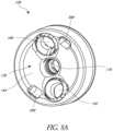
- Figure 6shows that the baseplate 108 includes a plurality of holes, e.g., two holes 188, 192 positioned laterally outward of the lumen 180, that are configured to accept perimeter anchor members 196.
- the holes 188, 192extend from the proximal end 136 of the baseplate 108 to the bone engaging surface 152 of the baseplate 108.
- These holes 188, 192are also illustrated in Figure 8A , which illustrates a perspective view of the proximal end 136 of the baseplate 108 of Figures 2-6 .
- the baseplate 108may have a circular shape, with a thickness between the proximal surface 144 and the bone engaging surface 152 that is less than a diameter of the proximal surface 136. It will be appreciated that the baseplate 108 need not be circular, and may have other shapes as well.
- the holes 188, 192can be defined in part by internal members 200 that are disposed within recesses 204 in baseplate 108.
- the internal member 200is semi-spherical and the recess 204 is semi-spherical, in order to permit the rotation and tilting of the internal member 200 with respect to the baseplate 108.
- the internal member 200allows a longitudinal axis extending centrally through the holes 188, 192 (for example longitudinal axis 208 extending through hole 188 as shown in Figure 6 ) to be aimed to some extent toward a desired anatomical feature.
- the movement of the internal member 200allows the positioning and/or aiming of perimeter anchor members 196 toward a desired location.
- the longitudinal axis 208 extending through the hole 188can be substantially parallel to a longitudinal axis 212 extending through the second aperture 176 and/or lumen 180, as shown by the orientation of the internal member 200 in part defining the hole 188 or angled with respect to the longitudinal axis 212 of the second aperture 176 and/or lumen 180, not shown.
- perimeter anchor members 196are inserted through the baseplate 108 from the proximal end 136 thereof. As shown in Figure 6 , the perimeter anchor member 196 can be inserted in the general direction of Arrow A.
- FIG. 6shows that the anchor member 104 is configured to be attached to the bone of a patient.
- the anchor member 104is generally formed of a cylindrical longitudinal portion 216 and a proximal head 220, both of which extend along a longitudinal axis 124 of the anchor member 104.
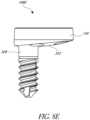
- the anchor member 104has an external lateral surface 224 which may include a self-tapping threaded surface. Other lateral surfaces of anchor members are discussed below in connection with Figures 7A-7E , 8E , and 9A .
- a threaded surfaceis right-handed when the driving action is performed with clockwise rotation and left-handed when the driving action is performed with counterclockwise rotation.
- the threading of the external lateral surface 224 of the anchor member 104may be right-handed or left-handed.
- the longitudinal portion 216 of the anchor member 104comprises a distally tapered distal tip 132.
- the proximal head 220can have a cavity 228 disposed about the longitudinal axis 124.
- the cavity 228extends distally from the proximal end of the proximal head 220.
- the cavity 228comprises one or more flat surfaces that are capable of mating with a driver configured to apply rotational force to drive the anchor member 104 into the bone.
- the cavity 228can have a hexagonal cross-section, centered on the longitudinal axis 124, configured to mate with a hexagonal cross-section driver.
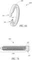
- the proximal head 220can comprise a groove 232.
- the groove 232is a circumferential groove around an external surface of the proximal head 220.
- the proximal head 220may include an inclined surface 236, the function of which is discussed in greater detail below.
- the anchor member 104 and the baseplate 108are coupled in the first aperture 168, which is sized to accept the proximal head 220 of the anchor member 104.
- the glenoid implant 100comprises a member 240, as shown in Figure 3 , 4 and 6 , that is sized to fit partly within the groove 232 in the proximal head 220 and partly within the groove 172 in the baseplate 108.
- the member 240can comprise a c-clip, o-ring or similar protruding device that can span at least a portion of the groove 232 in the proximal head 220 and at least a portion of the groove 172 in the baseplate 108.
- member 240may be comprised of elastically deformable barbs, fingers, or other projections having one end attached to and angled away from either head 220 or baseplate 108 such that the projections are deformed between head and baseplate when head is inserted into baseplate and such that the unattached end of the projections elastically expands into groove in head or baseplate.
- the anchor member 104is held at a fixed position along the longitudinal axis 120 of the glenoid implant 100, shown in Figure 4 , relative to the baseplate 108.
- the coupling provided by the member 240does not prevent the relative rotation of the anchor member 104 and the baseplate 108.
- the member 240is retained within the groove 172 of the baseplate 108 before the proximal head 220 of the anchor member 104 is inserted into the first aperture 168.
- Figure 6depicts the anchor member 104 separate from the baseplate 108, e.g., before being coupled to the baseplate.
- the anchor member 104can be inserted from the distal end 140 of the baseplate 108 into the first aperture 168.
- the inclined surface 236 of the proximal head 220initially contacts the member 240.
- Further insertion of the anchor member 104displaces the member 240 away from the axis 124, farther into the groove 172.
- Such displacementallows the anchor member 104 to be inserted farther into the first aperture 168.
- the anchor member 104is inserted into the first aperture 168 until the member 240 engages the groove 232 in the proximal head 220.
- the anchor member 104is retained in the baseplate 108 by the spanning of the member 240 across the gap between the longitudinally adjacent grooves 232, 172, as shown in Figure 4 .
- the member 240is deformed by the proximal head 220 when the proximal head 220 is inserted into the first aperture 168.
- the inclined surface 236can provide a progressively larger force on the member 240 as the proximal head 220 is urged from the distal end 140 of the baseplate 108 proximally into the first aperture 168 of the central protrusion 160.
- the inclined surface 236can have an angle of about 45 degrees or greater. In this context, the angle is measured relative to the flattened proximal end of the proximal head 220.
- the member 240has a corresponding inclined surface 368 (see Figure 6 ) that faces distally.
- the member 240When the groove 232 in the proximal head 220 aligns with the groove 172 in the baseplate 108, the member 240 returns to a relaxed state, e.g., is no longer deformed and the member 240 functions to couple the anchor member 104 to the baseplate 108. More specifically, the member 240 couples the proximal head 220 to the first aperture 168.
- Figure 6Aillustrates a member 240A having mating ends.
- the clip member 240Ahas a first end 241, a second end 242, and an arcuate segment 243 therebetween.
- the inclined surface 368is provided along a distal-facing side of the arcuate segment 243.
- the first and second ends 241, 242are configured to mate or nest together when urged toward each other.
- the first end 241can have a reduced thickness on the distal facing side thereof and the second end 242 can have a reduced thickness on a proximal facing side thereof.
- the reductions in thickness of the first and second ends 241, 242can sum to the total thickness of the arcuate segment 243 or more in various embodiment.
- the ends 241, 242can move from a spaced apart configuration to an overlapping configuration with minimal to no deflection of the ends 241, 242 in a proximal-distal direction being required.
- the reductions in thickness of the first and second ends 241, 242can sum to less than total thickness of the arcuate segment 243.
- deflection of the ends along the proximal-distal directionwill occur causing a widening of the clip 240A in the region of the ends 241, 242 compared to in the arcuate segment 243.
- Figure 6Aillustrates an enlarged configuration of the member 240A, e.g., a configuration in which an anchor member is being inserted and the clip member 240A is enlarged to permit advancement of a head of the anchor member through the clip member 240A and a corresponding baseplate.
- These structuresare examples of various means for preventing axial translation of the baseplate 108 relative to the anchor member 104 while permitting rotation therebetween.
- Figure 4shows that the glenosphere 116 defines a convex, articular surface 244.
- the glenosphere 116defines an interior surface 248 configured to receive the baseplate 108.
- the interior surface 248 of the glenosphere 116is configured to couple with the lateral surface 156 of the baseplate 108.
- the interior surface 248 of the glenosphere 116is configured to frictionally engage the surface 156, e.g., in a Morse taper.
- the interior surface 248 of the glenosphere 116is tronconical.
- the glenosphere 116can include an internal threaded surface 252.
- the glenosphere 116comprises a creep-resistant material, such as a suitable metal including any of stainless steel, cobalt-chrome alloy, or titanium which permits the interior surface 248 to deflect slightly in connection with forming a secure connection such as a Morse taper.
- a creep-resistant materialsuch as a suitable metal including any of stainless steel, cobalt-chrome alloy, or titanium which permits the interior surface 248 to deflect slightly in connection with forming a secure connection such as a Morse taper.
- the locking structure 112can include a locking screw 256, a compression washer 260, and a threaded member 264, which may be a bushing.
- the locking screw 256has a body that extends along the longitudinal axis 120 when the assembly 100 is assembled.
- the locking screw 256can have an external threaded surface 272 and a proximal head 276, as shown in Figure 4 .
- a lateral surface 280 of the locking screw 256 located between the external threaded surface 272 and the proximal head 276has a smooth surface, e.g., one that is not threaded.
- a drivercan be introduced into the proximal head 276 of the locking screw 256 in order to rotate the locking screw 256.
- the compression washer 260is generally annular in shape in one embodiment.
- the threaded member 264includes one or more internal threads 284 configured to mate with the external threaded surface 272 of the locking screw 256.
- the threaded member 264can include a sidewall 288 that forms an internal cavity 292 configured to house the compression washer 260.
- the sidewall 288can have an external threaded surface 296 that is configured to mate with an internal threaded surface 252 of the glenosphere 116.
- the glenoid implant 100is configured to be assembled as shown in Figures 2 and 4 .
- Figure 4shows that during assembly of the locking structure 112, the compression washer 260 can be inserted into the internal cavity 292 of the threaded member 264 and housed within the sidewall 288.
- the locking screw 256can be inserted through the compression washer 260 from the proximal end to the distal end thereof. A portion of the external threaded surface 272 of the locking screw 256 passes through the central aperture of the compression washer 260.
- the locking screw 256can be inserted into the threaded member 264 such that the external threaded surface 272 of the locking screw 256 mates with the internal thread(s) 284 of the threaded member 264.
- the locking screw 256can be further rotated until the compression washer 260 is loosely retained between the threaded member 264 and the proximal head 276 of the locking screw 256.
- the smooth lateral surface 280can be disposed within the internal threads 284 of the threaded member 264, when the compression washer 260 is loosely retained.
- the locking structure 112which can include the locking screw 256, the compression washer 260, and the threaded member 264, can be coupled to the glenosphere 116, as shown in Figure 4 .
- the locking structure 112is coupled to the glenosphere 116 after the locking structure 112 has been assembled, as described above.
- the threads on external surface 296 of the sidewall 288 of the threaded member 264can be rotated to engage the internal threaded surface 252 of the glenosphere 116. This may involve rotation of the locking screw 256 toward the threaded member 264, so that the proximal head 276 of the locking screw 256 fits within the glenosphere 116.
- the glenosphere 116can have a central aperture 128 that allows access to the proximal head 276 of the locking screw 256.
- the central aperture 128permits a driver or other tool to engage the locking screw 256.
- the proximal head 276 of the locking screw 256can have a cavity with one or more flats, e.g., a hexagonal cavity, configured to mate with the driver.
- the locking structure 112can be coupled to the baseplate 108, as shown in Figure 4 . In some embodiments, the locking structure 112 is coupled to the baseplate 108 after the locking structure 112 has been assembled, as described above. In some embodiments, the locking structure 112 is coupled to the baseplate 108 after the locking structure 112 is coupled to the glenosphere 116, as described above.
- the locking screw 256can be rotated until the external threaded surface 272 of the locking screw 256 engages the second aperture 176 in baseplate 108, in particular the threaded surface 184 (See Figure 6 ). When the locking screw 256 is rotated, the locking screw 256 traverses the second aperture 176 distally toward the anchor member 104.
- the locking screw 256is capable of applying a force to the proximal head 220 of the anchor member 104. In some embodiments, this downward (e.g., distally directed) force applies a compression force to the member 240 such that the member 240 applies a frictional force to the groove 232 on the proximal head 220. A friction force will also be applied by the distal tip 300 to the wall at the distal end of the cavity 228.
- the distally directed forces created by the locking screw 256 on the anchor member 104 and/or the member 240are sufficient to reduce or prohibit the rotation of the anchor member 104 with respect to the baseplate 108.
- high frictioncan arise due to the high normal force generated by action of the locking screw 256.
- the locking screw 256when the locking screw 256 is rotated and advanced towards the anchor member 104, the locking screw 256 can cause a force to be applied to the glenosphere 116. Rotation of the locking screw 256 can move the proximal head 276 toward the distal end of the threaded member 264. Rotation of the locking screw 256 can bring the proximal head 276 of the locking screw 256 into contact with the compression washer 260. In some embodiments, the proximal head 276 of the locking screw 256 can apply a downward force on the compression washer 260. The compression washer 260 can thereby apply a downward force on the threaded member 264.
- the threaded member 264 including the sidewall 288can be coupled with the internal threaded surface 252 of the glenosphere 116.
- the threaded member 264can provide a downward force on the glenosphere 116, as the locking screw 256 is advanced distally toward the anchor member 104. This causes the glenosphere 116 to move distally and engage the lateral surface 156 of the baseplate 108.
- Figure 4shows that the lateral surface 156 of the baseplate 108 is tapered, e.g., tronconical, in some embodiments.
- the glenosphere 116defines an interior surface 248 that is tapered or tronconical or otherwise configured to create high friction with the baseplate 108.
- the surfaces 156, 248can be initially engaged in any suitable manner, e.g., using an impactor to create an initial frictional engagement therebetween.
- the lateral surface 156 of the baseplate 108 and the interior surface 248 of the glenosphere 116form a Morse taper.
- the distally directed force of the locking screw 256enhances, e.g., makes more rigid, the connection between the anchor 104 and baseplate 108, reducing or eliminating play between these components.
- the distally directed force of the locking screw 256can also increase the friction at the surfaces 156, 248.
- the frictional force created by the coupling of the glenosphere 116 and the baseplate 108add to the rigidity of the glenoid implant 100.
- the compression washer 260 shown in Figure 4can have multiple functions.
- the compression washer 260is configured to fill the space between the proximal head 276 of the locking screw 256 and the threaded member 264 to add to the rigidity of the implant 100.
- rotation of the locking screw 256applies a force on the compression washer 260 which can compress or otherwise deform the compression washer 260.
- the compression washer 260applies a force to maintain the position of the locking screw 256.
- the placement and use of the compression washer 260facilitates the rigidity of the glenoid implant 100 by filling the space between the proximal head 276 of the locking screw 256 and the threaded member 264.
- the locking screw 256applies a force to the anchor member 104.
- the compression washer 260enhances the connection of the anchor member 104 to the baseplate 104 which reduces or eliminate play between these components to minimize or reduce loosening of these components over time.
- the compression washer 260further minimizes or prevents rotation, translation, or micromotion of the anchor member 104 with respect to the baseplate 108.
- the compression washer 260tends to distribute the force of the proximal head 276 of the locking screw 256.
- the compression washer 260causes the proximal head 276 of the locking screw 256 to be in contact with a larger surface area of the threaded member 264.
- the distribution of forcefacilitates the downward movement of the glenosphere 116 with respect to the baseplate 108 and/or enhances friction between the surfaces 156, 248 as discussed above.
- the compression washer 260further minimizes or prevents rotation, translation, or micromotion of the glenosphere 116 with respect to the baseplate 108.
- the glenoid implant 100can have a modular design, meaning that the anchor member 104 and the baseplate 108 can be interchangeable with another anchor member and/or another baseplate.
- a single baseplatecan couple with any one of a plurality of anchor members in a kit including a plurality of anchor members, such as shown in Figure 7A-7E .
- a single anchor membercan couple with any one of a plurality of baseplates in some or in another kit, including for example the baseplates shown in Figures 8A-8G .
- the proximal heads of the anchor memberscan have a consistent diameter among a plurality of anchor members in some kits.
- the grooves and the cavities of the anchor memberscan be consistent in size and location among a plurality of anchor members in some kits.
- the grooves and first apertures of the baseplatesis a consistent diameter among a plurality of baseplates in the kit.
- the second apertures and the lumens of the baseplatescan be consistent in size and location among a plurality of baseplates. This allows for the interchangeability of the plurality of anchor members with any one of a plurality of baseplates or the plurality of baseplates with any one of a plurality of anchor members.
- Figures 7A-7Eshow that the modular design allows the use of a plurality of anchor members with a given baseplate.
- the anchor members 104A-104Einclude a longitudinal portion 216A, 216B, 216C, 216D or 216E, a distal end, a proximal head 220, and a groove 232.
- the anchor members 104A-104E shown in Figures 7A-7Eare compatible with the baseplates 108, described herein.
- the anchor members 104A-104Emay include additional features of anchor members described herein.
- Figures 7A-7Cdiffer with respect to the external lateral surface and the longitudinal portion of the anchor member.
- the anchor members 104A, 104B, 104Cmay have a longitudinal portion 216A, 216B, 216C having different configurations, e.g., diameters and/or lengths.
- the longitudinal portion 216A of anchor member 104Ahas a constant diameter and thread pitch, but different lengths in different embodiments.
- the anchor member 104Bhas a different diameter and/or thread pitch from the anchor member 104A.
- the anchor member 104Chas a different diameter and/or thread pitch from the anchor members 104A and 104B.
- the anchor members 104A-104Ccan have a different diameter in the longitudinal portions 216A-216C.
- the diametersare in the range of 6.5 mm to 9.5 mm. Larger diameter anchor members can be useful for revision of total shoulder arthroplasty or failed reverse shoulder arthroplasty.
- the anchor members of the plurality of anchor memberscan have different lengths, and in some embodiments the lengths of the anchor member can be in the range of 15 mm to 40 mm.
- the external lateral surfaceis configured to engage a bony surface.
- the configurations shown in Figures 7A-7Cdemonstrate the ability to provide, e.g., in a kit, a plurality of anchor members from which a particular anchor member can be selected based on the anatomy of a patient.
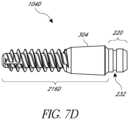
- Figure 7Ddepicts another embodiment of an anchor member 104D.
- the anchor member 104Dhas a cylindrical section of material along the longitudinal portion 216D of the anchor member 104D.
- the cylindrical sectionincludes porous material 304 to promote bony ingrowth. That is, bone material can grow into the pores of the cylindrical section of porous material 304.
- the longitudinal portion 216Dmay include an external threaded surface to engage bone.
- Figures 7A-7Dshow the proximal head 220 of the anchor members 104A-104D may have a consistent configuration.
- the proximal headcan have a unitary diameter among a plurality of anchor members.
- the anchor membermay include a groove that engages member 240 as described above.
- Figure 7Eshows an anchor member 104E.
- the longitudinal portion 216Ecan include an external lateral surface that is generally without threads to be tapped or otherwise pressed into the bone.
- the external lateral surfacemay be comprised of ridges, circumferential ridges, rough coatings, knurling, plasma sprayed metal, or other rough surfaces that will increase the friction of the longitudinal portion 216E relative to the bone thereby helping to prevent longitudinal portion 216E from pulling out of the bone.
- the anchor member 104Ecomprises a proximal head 220 that is the same as the proximal heads in the anchor members of Figures 7A-7D .
- the longitudinal portion 216Ecan be tapered, e.g., having a narrower transverse profile adjacent to its distal end and a wider transverse profile adjacent to the head 220.
- the proximal head 220has a groove 232 that couples with the baseplate 108 in the same manner as the other anchor members discussed herein.
- the anchor member 104Eprovides additional options for the interchangeable anchor member.
- the anchor members 104, 104A-104E (described above) and 312can be made from a biocompatible material such as a metal alloy, polymer, or ceramic.
- anchor memberscan be made from stainless steel, titanium, titanium alloy, cobalt-chrome alloy, and/or PEEK.
- the anchor member 104, 104A-104E, 312is more rigid than the baseplate 108. The rigidity of the anchor member 104, 104A-104E, 312 prevents deformation of the anchor member during insertion into the bone and during use as a glenoid implant.
- Figures 8A-8Hillustrate embodiments of baseplates having features similar to those described above and/or additional features. One or more of these features may be interchanged or incorporated into any of the baseplates described herein.
- the baseplate 108, 108G, 108Hmay include tool engaging grooves or openings 398.
- the tool engaging grooves 398are configured to engage two radially extending legs of a tool described below with reference to Figure 10 .
- the central protrusion 160is centrally disposed relative to the lateral surface 156 of the baseplate 108.
- a central longitudinal axis of the central protrusion 160can be disposed equidistant from points along the lateral surface 156, as shown in Figure 5 .
- Figures 8B-8Hillustrate more features of baseplates that can be combined with and/or substituted for features illustrated in the embodiment of Figures 5 and 8A .
- Figures 8B-8Eillustrate baseplates 108B-108D with configurations that can augment or compensate for scapula bone loss.
- Figure 8Bshows that the bone engaging surface 320 has a curved surface (e.g., a convex surface).
- the bone engaging surface 320is symmetrical with respect to the central protrusion.
- Figure 8Cshows that the bone engaging surface 324 of the baseplate 108C has an anatomically curved surface.
- the curved surfacecan be nonsymmetrical with respect to the central protrusion.
- the curved surfacecan be selected by the surgeon to match an anatomic feature of the patient's bone.
- the bone engaging surfaces 152, 320, 324can match the curvature of the glenoid cavity of the patient.
- Figures 8D-8Eillustrate that the protrusion 328 can be eccentric with respect to the baseplate 108D.
- the protrusion 328is not centrally disposed relative to the lateral surface 156 of the baseplate 108D.
- An anchor membersuch as anchor member 104 can be inserted into the protrusion 328, as discussed above with reference to central protrusion 160.
- the anchor memberis eccentric with respect to the baseplate 108D.
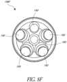
- Figures 8F-8Heach illustrate embodiments of a baseplate 108F, 108G, 108H with a plurality of holes, e.g., five, holes 190 or four holes 194.
- the holesare located around the periphery of the lumen 180.
- the holesare equidistant with respect to each other, in other words, the holes are equally spaced around the lumen 180.
- Figure 8Gfurther illustrates that tool engaging grooves 398 may also be provided between holes 194.
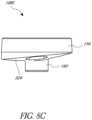
- Figure 8Hillustrates a baseplate 108H that has further features that can be combined with any of the other baseplates herein.
- the baseplate 108Hhas a radial protrusion 330 disposed between the proximal surface 144 and the bone engaging surface (not shown but opposite the surface 144).
- the radial protrusion 330has a proximally oriented face 334.
- the face 334can include an annular surface extending outward from a distal portion of the peripheral surface 156. In one embodiment, the face 334 abuts the glenosphere 116 when the glenoid implant 100 is fully assembled.
- the radial protrusion 330can also define a positive stop for the distal advancement of the glenosphere 116 during assembly of the glenoid implant 100 such that the glenosphere is not overstressed by being advanced too far over the surface 156.
- Figures 9A and 9Billustrate an alternative embodiment of an anchor member 312 and a baseplate 336.
- the proximal head 340 of the anchor member 312can include a threaded surface 344, as shown in Figure 9A .
- the threads disposed on the surface 344 of the proximal head 340 of the anchor member 312may be left-handed.
- the first aperture 348 in the baseplate 336can include a threaded surface 352 configured to mate with the threads on the surface 344 of the proximal head 340.
- the threaded surface 352 of the first aperture 348can be left-handed.
- the baseplate 336can comprise a central portion 356 that is not threaded.
- the central portion 356can be surrounded by a smooth surface.
- the threaded surface in the aperture 348is disposed between the smooth surface and a distal surface 358 of the baseplate 336.
- the smooth surface of the first aperture 348has a length (e.g., along the longitudinal axis of the aperture, left to right on Figure 9B ) and a width (e.g., a diameter or dimension transverse to the longitudinal axis of the aperture, up and down on Figure 9B ).
- the threaded surface 344has a length less than or equal to the length of the smooth surface disposed around the central portion 356 of the first aperture.
- the threaded surface 344When the threaded surface 344 is housed in the central portion 356, rotation in one direction does not cause the threaded surface 344 and the threads in the aperture 348 to engage each other in a manner permitting advancement along the longitudinal axis of the anchor member 312 or the baseplate 336.
- the baseplate 336can be rotated clockwise without the threads engaging and without the baseplate advancing axially along the longitudinal axis of the anchor member 312.
- the anchor member 312 and the baseplate 336are restrained in axial translation but are permitted to rotate relative to each other.
- the threaded surface 344 and the threads in the aperture 348could be right-handed and in such arrangement the baseplate could be rotated counterclockwise without the threads engaging.
- the anchor member 312can be advanced from the distal end 360 of the baseplate 336, through the first aperture 348.
- the threaded surface 344 of the anchor member 312can engage the threaded surface 352 of the baseplate 336.
- the anchor member 312can be advanced until the threaded surface 344 on the proximal head 340 is proximal of the threaded surface 352 such that the threads of the surface 344 disengage from the threads of the threaded surface 352 of the first aperture 348.
- the threaded surface 344 of the proximal head 340disengages from the threaded surface 352 of the first aperture 348, the threaded surface 344 of the proximal head 340 is disposed within the central portion 356.
- Figures 9A and 9Bshow that in this configuration, the anchor member 312 is prevented from axial translation with respect to the baseplate 336 but is freely rotatable with respect to the baseplate 336.
- the proximal head 340 of the anchor member 312is advanced into the central portion 356 of the baseplate 336 before the anchor member 312 is driven into the bone.
- the manufacturercan provide the anchor member 312 coupled to the baseplate 336, as shown in Figure 9A , or this assembly can be provided by the surgeon after selecting the baseplate 336 and/or the anchor member 312 from a plurality of baseplates and/or anchor members as discussed elsewhere herein.
- the baseplate 336can be held in a desired orientation when the anchor member 312 is driven into the bone.
- the baseplate 336is maintained in a desired orientation by one or more tools, such as the cannulated tools as described in connection with Figure 10 below while the anchor member 312 is advanced by rotation into the bone.
- the anchor member 312is partially or fully seated within the bone before the proximal head 340 of the anchor member 312 is advanced into the central portion 356 of the baseplate 336.
- the first aperture 348 and the threaded surface 344 of the proximal head 340can have left-handed threads.
- the external lateral surface 364 of the anchor member 100can have right-handed threads.
- the baseplate 336can be rotated with respect to the proximal head 340 such that the proximal head 340 advances through the first aperture 348 and is disposed within the central aperture 356 without disengaging the external lateral surface 364 of the anchor member 312 from the bone.
- the surgeoncan then rotate the baseplate 336 to align the baseplate 336 with anatomical features of the patient.
- the surgeoncan fully seat anchor member 312 into the bone.
- the locking structure 112described in greater detail above, can be utilized with anchor member 312 and baseplate 336.
- the locking structure 112applies a force to the anchor member 312, which prevents subsequent rotation of the anchor member 312 with respect to the baseplate 336.
- the locking structure 112may also apply a force to glenosphere 116, which creates a frictional lock with the baseplate 336. Further details regarding the use of the locking structure and methods of using the anchor member 312 and baseplate 336 are described below.
- Figure 9Ashows that the anchor member 312 can be cannulated.
- the cannulationallows the anchor member 312 to slide over a guide wire during insertion.
- the use of a guide wirehelps to ensure the proper placement of the anchor member 312 within the bone.
- the anchor members 104, 104A-104Ecan also be cannulated to facilitate placement.
- a method of using the glenoid implant 100can include a plurality of steps, in addition to the method of assembling the glenoid implant 100 described above. The surgeon may select one or more of the plurality of steps. Further, a manufacturer providing a glenoid implant can provide instructions for one or more of the plurality of steps.
- a method of using a glenoid implantcomprises selecting a preferred baseplate and/or preferred anchor member from a plurality of anchor members such as anchor members 104, 104A-104E, 312 and/or a plurality of baseplates such as baseplates 108, 108B-108G, 336 described above, to best suit the patient.
- any of the baseplates 108, 108B-108G, 336 and/or the anchors 104, 104A-104E, 312can be selected based upon the shape of the prepared bone.
- the baseplates and/or anchorscan also be selected based on patient anatomy. For example, a baseplate could be selected that has holes arranged to be positioned above underlying scapular bone.
- a baseplatecould be selected that has holes arranged to be positioned above underlying high quality, e.g., high density, bone.
- the baseplatecan have a variety of different bone engaging surfaces 152, 316, 320, 324 332, and configurations in order to best suit the patient.
- the surgeonmay select from a variety of bone anchors, such as those shown in Figures 6 , 7A-7E , and 9A-9B .
- the plurality of anchor memberscan include different diameters of the longitudinal portion, wherein the bone anchor is selected based on the best fit with the anatomic structure of the patient, specifically the best fit in accordance with the glenoid that was removed.
- the bottom loaded design(e.g., where the anchor member is inserted in the distal end 140 of the baseplate) permits the longitudinal portion and the external lateral surface of the anchor member to have a larger diameter than the diameter of one or more of the following: the second aperture, the first aperture, the lumen, and the central protrusion, which is an advantage for revision cases where much glenoid bone is typically removed. Further, the surgeon can make this selection after exposing the shoulder joint and inspecting the patient's anatomy.
- the bone anchors in the kitcan have different thread pitch, lengths and diameters of the longitudinal portion, and integral components such as those to promote bony ingrowth, as shown in Figure 7D .
- the surgeon or other practitionermay attach the anchor member to the baseplate.
- a surgeonmay insert the proximal head 220 of any of the anchor members 104, 104A-104E into the first aperture 168 of any of the baseplates 108, 108B-108G. This insertion can result in coupling the anchor member 104, 104A-104E to the baseplate 108, 108B-108G.
- the proximal head 220is inserted from the distal end 140 of the baseplate 108, 108B-108G into the first aperture 168.
- the proximal head 220does not traverse the second aperture 176.
- the longitudinal portion 216, 216A-216E of the anchor member 104, 104A-104Eremains distal to the baseplate 108, 108B-108G when the proximal head 220 of the anchor member 104, 104A-104E is inserted into the first aperture 168 of the baseplate 108, 108B-108G.
- the longitudinal portion 216, 216A-216E of the anchor member 104, 104A-104Eis not inserted into the first aperture 168.
- the longitudinal portion 216, 216A-216E of the anchor member 104, 104A-104Eis not inserted into the second aperture 176.
- the longitudinal portion 216, 216A-216E of the anchor member 104, 104A-104Eremains outside the confines of the baseplate 108, 108B-108G during coupling of the anchor member 104, 104A-104E to the baseplate 108, 108B-108G. During coupling, the longitudinal portion 216, 216A-216E extends distally.
- an anchor member(such as anchor member 104) with a baseplate pre-attached (such as baseplate 108) can be inserted into a bone such as the scapular glenoid.
- the anchor membermay be inserted separately from the baseplate.
- an anchor member 104may be at least partially seated or fully seated within the bone before the proximal head 220 of the anchor member 104 is inserted into the first aperture 168 of the baseplate 108.
- an anchor member and a baseplatemay come pre-attached by the man ufactu rer.
- the surgeonfirst pierces a hole in the glenoid, typically the hole being slightly smaller than the diameter of the anchor member 104.
- the surgeonrotates the anchor member 104 into the glenoid using a tool designed to mate with the cavity 228 of the anchor member, e.g., with a hexagonal tip. This tool may be inserted through the lumen 180 in the baseplate when the baseplate is pre-attached to the anchor member.
- the self-tapping threads of the external lateral surface 224 of the anchor member 104if provided, permit the anchor member to be driven into the bone, optionally into the pre-formed hole.
- the surgeoncan insert a guide wire into the bone in combination with a cannulated anchor member. The guide wire can facilitate placement of the anchor member with respect to the bone.
- a holeis made in the glenoid of a diameter of the central protrusion 160 of the baseplate 108 in order to accommodate the central protrusion 160 when the anchor member is fully seated in the bone.
- One method stepincludes shaping the bone to match the distal surface 148 of the baseplate 108.
- the hole in the glenoid and the shaping of the bonemay be done to accommodate the shapes of any of the other baseplates (e.g., baseplates 108B-108G and 336) described herein.
- the anchor memberis pre-attached to the baseplate or can be attached by the surgeon during implantation.
- the anchor membercan be rotated (e.g. driven into the bone) without corresponding rotation of the baseplate.
- the baseplate 108is held in a desired orientation when the anchor member 104 is driven into the bone. In some embodiments, the baseplate 108 is maintained in a desired orientation by tools, as described below.
- a cannula 372is configured to interact with the baseplate 108.
- the cannula 372has two radially extending legs 376, 380.
- the radially extending legs 376, 380permit the cannula 372 to be a smaller diameter than the diameter of the baseplate 108.
- the radially extending legs 376, 380include a distal feature that mates with a feature on the proximal end 136 of the baseplate 108, for instance with tool engaging grooves 398 shown in Figure 8A .
- the radially extending legs 376, 380may extend, and partially cover the holes 188, 192.
- the cannula 372is sized to accept an inner cannula 384.
- the inner cannula 384can have multiple functions in some embodiments.
- the inner cannula 384can be configured to assist in docking and un-docking the legs 376, 380 with the baseplate 108.
- the outer profile of the inner cannula 384can be larger than the inner profile of the outer cannula 372 near the distal end of the legs 376, 380.
- the outer surface of the inner cannula 384spreads the legs 376, 380.
- Another function for the inner cannula 384 in some embodimentsis to provide access for a driver therethrough to mate with the cavity 228 in the proximal head 220 of the anchor member 104
- the inner cannula 284can have an inner lumen to provide such access.
- the drivercan be used to insert the anchor member 104 into the bone while the cannula 372 maintains the rotational orientation of the baseplate 108.
- the cannula 372may further be used to rotate baseplate 108 to a desired orientation with respect to the bone.
- the baseplate 108is rotated to align the holes 188, 192 (shown in Figure 6 ) with anatomic features of the patient. In some embodiments, the baseplate 108 is rotated to align the bone engaging surface 152 with anatomic features of the patient.
- the baseplate 108is freely rotatable with respect to the anchor member 104.
- the baseplate 108can be rotated and orientated without adjusting the rotational position of the anchor member 104.
- the anchor member 104can be rotated and orientated without adjusting the rotational position of the baseplate 108.
- the baseplate 108is rotated after the anchor member 104 is partially or fully driven into the bone. In some embodiments, the baseplate 108 is rotated before the anchor member 104 is driven into the bone.
- perimeter anchors 196such as shown in Figure 6 may be inserted into holes 188 and 192 provided in the baseplate 108.
- perimeter anchors 196are inserted from the proximal end 136 of the baseplate 108 to the bone engaging surface 152 of the baseplate 108, or through the baseplate 108. This is the opposite direction the anchor member 104 is inserted into the baseplate 108.
- the locking structure 112may be used to further secure the anchor member relative to the baseplate and to attach the glenosphere to the baseplate.
- the baseplate 108is in the desired orientation with respect to the patient, and the perimeter anchors 196 have been inserted, the rotation of the anchor member 104 with respect to the baseplate 108 can be restricted via the locking structure 112.
- the locking screw 256is inserted into the second aperture 176 of the baseplate which has the threaded surface 184.
- the locking screw 256is rotated until the locking screw 256 applies a force on the proximal head 220 of the anchor member 104.
- the locking screw 256enters a cavity 228 in the proximal head 220 of the anchor member 104.
- the forceinteracts with the member 240 to prevent rotation of the anchor member 104 with respect to the baseplate 108. After application of force by the locking screw 256, the anchor member 104 is prohibited from axial translation and rotation with respect to the baseplate 108.
- a glenosphere 116such as shown in Figures 3 and 4 may be attached to the baseplate 108.
- the glenosphere 116may have already been attached to the threaded member 264 when the locking screw 256 is inserted into the cavity 228 in the proximal head 220 of the anchor member 104.
- the glenosphere 116may be attached to threaded member 264 after the locking screw 256 is inserted into the cavity 228.
- the lateral surface 156 of the baseplate 108is tapered and the interior surface 248 of the glenosphere 116 is tapered. When the glenosphere 116 moves distally, the interior surface 248 engages with the lateral surface 156 of the baseplate 108.
- the interior surface 248 and the lateral surface 156form a Morse taper.
- the locking screw 256simultaneously applies a force to the anchor member 104 and the glenosphere 116 when the locking screw 256 is advanced through the second aperture 176.
- the glenoid implant 100is dimensioned so that the locking screw 256 applies a force to the proximal head 220 of the anchor member 104 simultaneously with the glenosphere 116 interior surface 248 mating with the lateral surface of the baseplate 108. In this way, the locking screw 256 creates a downward force on the anchor member 104 and creates a downward force on the threaded member 264 which is coupled to the glenosphere 116. The downward force causes the interior surface 248 and the lateral surface 156 to engage. In some embodiments, the locking screw 256 creates a push force on the glenosphere 116 and/or a pull force on the baseplate 108.
- the compression washer 260 provided between the proximal head 276 of the locking screw 256 and the baseplate 108may be utilized to prevent micromotion.
- the compression washer 260provides resistance against backout when the locking screw 256 creates a push force on the anchor member 104.
- the compression washer 260is designed to fill the space between the proximal head 276 of the locking screw 256 and the threaded member 264 as the locking screw 256 creates a push force on the glenosphere 116 and/or pull force on the baseplate 108.
- the placement and use of the compression washer 260facilitates the rigidity of the glenoid implant 100, and further prevents rotation, translation and/or micromotion of the anchor member 104 with respect to the baseplate 108. Further, preventing micromotion involves no additional step from the current procedure of securing a locking member.
- a bone graftmay be placed into the bone.
- the bone graftcan be attached to or disposed about any of the surfaces or portions of the baseplates described herein including the distal surface 148, distal end 140, the bone engaging surface 152, 316, 320, 324, 332, the central protrusion 160, 328, or the longitudinal portion 216, 216A-216E of the anchor member 104, 104A-104E or any other feature that would benefit from bony ingrowth. Allowing the anchor member 104, 104A-104E to be driven into the bone independently of rotation of the baseplate 108, 108B-108G causes less wear and stress on the bone graft during insertion.
- the anchor member 104, 104A-104Eis freely rotatable with respect to the bone graft.
- the bone graftis coupled to the baseplate 108, 108B-108G and rotates when the baseplate 108, 108B-108G rotates but not when the anchor member 104, 104A-104E rotates.
- the bone graftis inserted after the anchor member 104, 104A-104E is fully or partially seated within the bone.
Landscapes
- Health & Medical Sciences (AREA)
- Orthopedic Medicine & Surgery (AREA)
- Cardiology (AREA)
- Oral & Maxillofacial Surgery (AREA)
- Transplantation (AREA)
- Engineering & Computer Science (AREA)
- Biomedical Technology (AREA)
- Heart & Thoracic Surgery (AREA)
- Vascular Medicine (AREA)
- Life Sciences & Earth Sciences (AREA)
- Animal Behavior & Ethology (AREA)
- General Health & Medical Sciences (AREA)
- Public Health (AREA)
- Veterinary Medicine (AREA)
- Prostheses (AREA)
Description
- The present invention relates to a glenoid implant for a shoulder prosthesis.
- The systems and methods described herein are directed to orthopedic implants, for example to reverse shoulder replacement systems and methods for implantation.
- Shoulder replacement surgery involves placing a motion providing device at the glenohumeral joint, i.e., the joint interface between the scapula and the proximal humerus of the arm. See
Figure 1 . Reverse shoulder replacement reverses the curvature of the natural glenoid cavity and the proximal head of the humerus. That is, a convex surface of a glenoid component is positioned on the scapula and a concave surface of a humeral component is positioned on the proximal humerus. - Some reverse shoulder systems have limitations in connection with the fixation of the glenoid component. In some glenoid component designs, a one-piece construct is provided in which a central threaded post projects from a baseplate. The threaded post provides fixation to the bone of the scapula, but provides little to no flexibility of the final positioning of peripheral features of the baseplate, such as screw or mount holes thereon. Also, the unitary nature of this approach requires more inventory to provide a proper mix of baseplate configurations and threaded post sizes.
US 2012/253467 discloses such glenoid implants. - Other reverse shoulder systems provide a plate having an integral fixed central post and a plurality of screws that are placed through either the post or the plate. These systems are limited in that the length, inner diameter, and configuration of the central post are fixed. As such, the size of a screw placed through the central post is predefined which limits the ability to perform revisions (subsequent surgeries on the patient to replace the system). In a revision surgery the old implant must be removed and replaced with a new implant. Commonly a lot of bone is removed with the old implant and in this case larger screws are required to securely fix the new glenoid implant to the scapula.
- In currently available systems, specifically unitary systems having an integral fixed central threaded post, independent rotation is not provided between the post and the baseplate. For these unitary systems the post and the baseplate rotate together when the post is driven into the bone. With other glenoid implants wherein an anchor member is driven through the baseplate and extends from a distal end of the baseplate, axial translation of the baseplate relative to the anchor member is not prevented. For these systems, the baseplate is not secured against axial translation until the anchor member is fully engaged in the scapula and pulls the baseplate against the surface of the bone thereby preventing rotation of the baseplate.
- There is a need for new shoulder prosthesis systems that can provide more flexibility and better adaptability to patient anatomies while maximizing revision options. When implanting reverse shoulder systems it is desirable to independently attach a baseplate to the scapula and thereafter to independently rotate the baseplate with respect to the scapula such that fixation means in the periphery of the baseplate can be driven into bone thereunder.
- An object of the invention is a glenoid implant as defined in claim 1.
- A glenoid implant, according to some embodiments disclosed herein, includes an anchor member and a baseplate. The anchor member has a longitudinal portion configured to be secured to a bone and a proximal head. The proximal head has a first engaging surface. The baseplate has a proximal end and a distal end. The distal end of the baseplate comprises a first aperture sized to accept the proximal head of the anchor member and a second engaging surface. When the proximal head is inserted from the distal end of the baseplate into the first aperture, the first engaging surface couples with the second engaging surface. In some embodiments, the anchor member is restrained against axial translation by this engagement with respect to the baseplate but is permitted to rotate with respect to the baseplate.
- Other embodiments of a glenoid implant may further comprise a locking structure configured to apply a force to the anchor member. A glenoid implant may further comprise a glenosphere configured to be attached to the baseplate. A glenoid implant may also include one or more perimeter anchors for securing the baseplate to bone.
- A method for implanting a glenoid implant, which is disclosed herein but which is not part of the invention, includes providing an anchor member and a baseplate. The anchor member has a longitudinal portion configured to be secured to a bone and a proximal head. The proximal head has a first engaging surface. The baseplate has a proximal end and a distal end. The distal end of the baseplate comprises a first aperture sized to accept the proximal head of the anchor member and a second engaging surface. The method includes securing the anchor member at least partially to bone. The method further includes, with the proximal head of the anchor member inserted into the first aperture such that the first engaging surface is coupled to the second engaging surface, rotating the baseplate relative to the anchor member to adjust the position of the baseplate without adjusting the rotational position of the anchor member. The method may further include securing the baseplate to the bone.
- In some cases, the method further comprises, prior to securing the anchor member at least partially to bone, inserting the proximal head into the first aperture to cause the first engaging surface to couple with the second engaging surface. The method may also comprise applying a force to the anchor member with a locking member to prevent rotation between the anchor member and the baseplate. The method may also comprise engaging a glenosphere to the baseplate. In some cases, securing the baseplate to bone comprises inserting one or more perimeter anchors through one or more openings in the baseplate.
- Other embodiments of the invention include additional implants or components of implants described herein. A system or kit may also be provided according to some embodiments, wherein the system or kit comprises a plurality of anchor members engageable with one or more baseplates and/or a plurality of baseplates engageable with one or more anchor members, examples of which are described further herein.
- These and other features, aspects and advantages are described below with reference to the drawings, which are intended to illustrate but not to limit the inventions. In the drawings, like reference characters denote corresponding features consistently throughout similar embodiments. The following is a brief description of each of the drawings.
Figure 1 is a schematic view of the human shoulder.Figure 2 is a perspective view of a glenoid implant in an assembled configuration.Figure 3 is an exploded view of the glenoid implant shown inFigure 2 .Figure 4 is a cross-sectional side view of the glenoid implant shown inFigure 2 .Figure 5 is a side view of a baseplate and an anchor member of a glenoid implant.Figure 6 is a cross-sectional, exploded side view of a baseplate, an anchor member and perimeter anchor members.Figure 6A illustrates an embodiment of an anchor retention member.Figures 7A-7E are side views of different embodiments of anchor members, which may be assembled into a kit.Figure 8A is a top perspective view of a baseplate.Figures 8B-8E are side views of different embodiments of baseplates.Figures 8F-G are top views of different embodiments of baseplates.Figure 8H is a top perspective view of another embodiment of a baseplate.Figure 9A is a cross-sectional side view of a baseplate with a dual threaded lumen and an anchor member.Figure 9B is a cross-sectional side view of the baseplate ofFigure 9A .Figure 10 illustrates an implantation tool and a method of using such a tool to implant a portion of a glenoid implant.- While the present description sets forth specific details of various embodiments, it will be appreciated that the description is illustrative only and should not be construed in any way as limiting. Furthermore, various applications of such embodiments and modifications thereto, which may occur to those who are skilled in the art, are also encompassed by the general concepts described herein. Each and every feature described herein, and each and every combination of two or more of such features, is included within the scope of the present invention provided that the features included in such a combination are not mutually inconsistent.
Figure 1 depicts the human shoulder. The glenoid cavity is a portion of the shoulder that is located on the scapula. The glenoid cavity articulates with the head of the humerus to permit motion of the glenohumeral joint. Total shoulder arthroplasty replaces the glenohumeral joint with prosthetic articular surfaces that replicate the naturally occurring concave and convex surfaces of the body. Typically, in total shoulder arthroplasty, an articular surface replaces the humeral head and an articular surface replaces cartilage in the glenoid cavity. In a typical reverse total shoulder arthroplasty, a glenoid implant with a convex spherical head is inserted into the glenoid cavity and a complimentary socket is placed on the humerus. Reverse total shoulder arthroplasty reverses the naturally occurring ball and socket orientation related to the glenohumeral joint.Figures 2-4 depict aglenoid implant 100, more preferably a reverse glenoid implant, configured to be implanted in the glenoid cavity of a patient in the patient's scapula. Theglenoid implant 100 includes ananchor member 104 for anchoring theimplant 100 in the scapular glenoid, abaseplate 108, a lockingstructure 112 configured to deter rotation of the anchor member relative to the baseplate, and aglenosphere 116 having an articular surface (e.g., a convex, spherical surface). Theglenosphere 116 is configured to couple to a complimentary prosthetic device anchored to the humerus (not shown, but sometimes referred to herein as the humeral component) in order for the joint replacement implants to replicate the motion of the human shoulder. The humeral component can take any suitable form such as those disclosed in connection with Figures 18-21 and elsewhere inUS provisional application number 61/719835, filed October 29, 2012 Figures 1-9 , 27-38, and 39-41 of the '835 application. Suitable humeral components can be configured to adapt to anatomical and reverse shoulder configurations. Theglenoid implant 100 and the humeral component provide a replacement for the natural glenohumeral joint.- As used herein, the terms "distal" and "proximal" are used to refer to the orientation of the glenoid implant as shown in
Figures 2-4 . As shown inFigure 3 , alongitudinal axis 120 of theglenoid implant 100 extends through a centrallongitudinal axis 124 of anchor member 104 (shown inFigures 4 and6 ). Theglenosphere 116 is towards the proximal end along thelongitudinal axis 120 and theanchor member 104 is towards the distal end along thelongitudinal axis 120. In other words, an element is proximal to another element if it is closer to a central aperture 128 (shown inFigure 4 ) of theglenosphere 116 than the other element, and an element is distal to another element if it closer to a distal tip 132 (shown inFigure 4 ) of theanchor member 104 than the other element. At some points below, reference may be made to the anatomical location. In use when the implant is delivered into a patient's scapula, thedistal tip 132 of theanchor member 104 is more medial on the patient, whereas the articular surface of theglenosphere 116 is more lateral on the patient. Figures 3 and4 show that thebaseplate 108 is oriented substantially perpendicular to thelongitudinal axis 120 of theglenoid implant 100. Thebaseplate 108 is shown coupled to theanchor member 104 inFigures 4 and5 and apart from theanchor member 104 inFigure 6 . Referring now toFigure 5 , thebaseplate 108 has aproximal end 136 and adistal end 140. Theproximal end 136 comprises aproximal surface 144 and thedistal end 140 comprises adistal surface 148. Theproximal surface 144 can be substantially parallel to thedistal surface 148. Thebaseplate 108 can also include abone engaging surface 152. A thickness of thebaseplate 108 defined between theproximal surface 144 and thebone engaging surface 152 may correspond to the amount that thebaseplate 108 extends above a surface of the bone when implanted. The thickness can be in a range between about 2mm and about 12mm, e.g., between about 4mm and about 9mm, e.g., about 6mm. Thicknesses of about 3mm, 5mm, 7mm, 8mm, 10mm and 11mm are also contemplated. Thebone engaging surface 152 can be substantially parallel to theproximal surface 144 and/or thedistal surface 148. Thebaseplate 108 also has alateral surface 156 that spans between theproximal surface 144 of thebaseplate 108 and thebone engaging surface 152 of thebaseplate 108. Thelateral surface 156 can have a circular profile when viewed in a cross-section plane extending parallel to theproximal surface 144. The diameter of the circular profile can be between about 20 mm and about 40 mm, e.g., between about 25mm and about 35 mm, e.g. about 30 mm. In some embodiments, thelateral surface 156 of thebaseplate 108 is configured to form a portion of a friction lock engagement, such as a Morse taper. In one embodiment, thelateral surface 156 of thebaseplate 108 is tronconical. The term tronconical, as used herein, refers to a shape or surface that is or is similar to a truncated cone. In some embodiments, thelateral surface 156 is configured with a gradually increasing perimeter in a direction fromproximal surface 144 toward thebone engaging surface 152.- As illustrated in
Figure 5 , in some embodiments, thebaseplate 108 can include acentral protrusion 160 that projects distally from thebone engaging surface 152 to thedistal end 140. Thecentral protrusion 160 has anouter surface 164 that extends from thebone engaging surface 152 to thedistal surface 148. Referring now toFigure 6 , thecentral protrusion 160 can include afirst aperture 168 which may be cylindrical. In some embodiments, thefirst aperture 168 may include agroove 172 along an inner wall of the first aperture. Thebaseplate 108 can have asecond aperture 176 that in some embodiments, extends from thefirst aperture 168 to theproximal end 136 of thebaseplate 108, such that alumen 180 is formed through thebaseplate 108. Thesecond aperture 176 can include an internally threadedsurface 184 as shown. In some embodiments, thesecond aperture 176 is smaller in diameter than thefirst aperture 168. Figure 6 shows that thebaseplate 108 includes a plurality of holes, e.g., twoholes lumen 180, that are configured to acceptperimeter anchor members 196. Theholes proximal end 136 of thebaseplate 108 to thebone engaging surface 152 of thebaseplate 108. Theseholes Figure 8A , which illustrates a perspective view of theproximal end 136 of thebaseplate 108 ofFigures 2-6 . As illustrated, thebaseplate 108 may have a circular shape, with a thickness between theproximal surface 144 and thebone engaging surface 152 that is less than a diameter of theproximal surface 136. It will be appreciated that thebaseplate 108 need not be circular, and may have other shapes as well.- Referring to
Figures 3 and6 , theholes internal members 200 that are disposed withinrecesses 204 inbaseplate 108. In some embodiments, theinternal member 200 is semi-spherical and therecess 204 is semi-spherical, in order to permit the rotation and tilting of theinternal member 200 with respect to thebaseplate 108. Theinternal member 200 allows a longitudinal axis extending centrally through theholes 188, 192 (for examplelongitudinal axis 208 extending throughhole 188 as shown inFigure 6 ) to be aimed to some extent toward a desired anatomical feature. The movement of theinternal member 200 allows the positioning and/or aiming ofperimeter anchor members 196 toward a desired location. Thelongitudinal axis 208 extending through thehole 188 can be substantially parallel to alongitudinal axis 212 extending through thesecond aperture 176 and/orlumen 180, as shown by the orientation of theinternal member 200 in part defining thehole 188 or angled with respect to thelongitudinal axis 212 of thesecond aperture 176 and/orlumen 180, not shown. - The number and position of the
holes perimeter anchor members 196, and size constraints dictated by dimensions of thebaseplate 108. Thus, there may be fewer or greater holes and perimeter anchors members than illustrated. In some embodiments,perimeter anchor members 196 are inserted through thebaseplate 108 from theproximal end 136 thereof. As shown inFigure 6 , theperimeter anchor member 196 can be inserted in the general direction of Arrow A. Figure 6 shows that theanchor member 104 is configured to be attached to the bone of a patient. Theanchor member 104 is generally formed of a cylindricallongitudinal portion 216 and aproximal head 220, both of which extend along alongitudinal axis 124 of theanchor member 104. Theanchor member 104 has an externallateral surface 224 which may include a self-tapping threaded surface. Other lateral surfaces of anchor members are discussed below in connection withFigures 7A-7E ,8E , and9A . As used herein, a threaded surface is right-handed when the driving action is performed with clockwise rotation and left-handed when the driving action is performed with counterclockwise rotation. The threading of the externallateral surface 224 of theanchor member 104 may be right-handed or left-handed. In some embodiments, thelongitudinal portion 216 of theanchor member 104 comprises a distally tapereddistal tip 132.Figure 6 shows that theproximal head 220 can have acavity 228 disposed about thelongitudinal axis 124. Thecavity 228 extends distally from the proximal end of theproximal head 220. In some embodiments, thecavity 228 comprises one or more flat surfaces that are capable of mating with a driver configured to apply rotational force to drive theanchor member 104 into the bone. For example, thecavity 228 can have a hexagonal cross-section, centered on thelongitudinal axis 124, configured to mate with a hexagonal cross-section driver. Theproximal head 220 can comprise agroove 232. In some embodiments, thegroove 232 is a circumferential groove around an external surface of theproximal head 220. Theproximal head 220 may include aninclined surface 236, the function of which is discussed in greater detail below.- Referring to
Figures 5 and6 , theanchor member 104 and thebaseplate 108 are coupled in thefirst aperture 168, which is sized to accept theproximal head 220 of theanchor member 104. In some embodiments, theglenoid implant 100 comprises amember 240, as shown inFigure 3 ,4 and6 , that is sized to fit partly within thegroove 232 in theproximal head 220 and partly within thegroove 172 in thebaseplate 108. Themember 240 can comprise a c-clip, o-ring or similar protruding device that can span at least a portion of thegroove 232 in theproximal head 220 and at least a portion of thegroove 172 in thebaseplate 108. Alternativelymember 240 may be comprised of elastically deformable barbs, fingers, or other projections having one end attached to and angled away from eitherhead 220 orbaseplate 108 such that the projections are deformed between head and baseplate when head is inserted into baseplate and such that the unattached end of the projections elastically expands into groove in head or baseplate. In this way, theanchor member 104 is held at a fixed position along thelongitudinal axis 120 of theglenoid implant 100, shown inFigure 4 , relative to thebaseplate 108. Preferably the coupling provided by themember 240 does not prevent the relative rotation of theanchor member 104 and thebaseplate 108. In some embodiments, as shown inFigures 4 and6 , themember 240 is retained within thegroove 172 of thebaseplate 108 before theproximal head 220 of theanchor member 104 is inserted into thefirst aperture 168. Figure 6 depicts theanchor member 104 separate from thebaseplate 108, e.g., before being coupled to the baseplate. Theanchor member 104 can be inserted from thedistal end 140 of thebaseplate 108 into thefirst aperture 168. During insertion, theinclined surface 236 of theproximal head 220 initially contacts themember 240. Further insertion of theanchor member 104 displaces themember 240 away from theaxis 124, farther into thegroove 172. Such displacement allows theanchor member 104 to be inserted farther into thefirst aperture 168. Theanchor member 104 is inserted into thefirst aperture 168 until themember 240 engages thegroove 232 in theproximal head 220. Theanchor member 104 is retained in thebaseplate 108 by the spanning of themember 240 across the gap between the longitudinallyadjacent grooves Figure 4 .- In some embodiments, the
member 240 is deformed by theproximal head 220 when theproximal head 220 is inserted into thefirst aperture 168. For example, theinclined surface 236 can provide a progressively larger force on themember 240 as theproximal head 220 is urged from thedistal end 140 of thebaseplate 108 proximally into thefirst aperture 168 of thecentral protrusion 160. Theinclined surface 236 can have an angle of about 45 degrees or greater. In this context, the angle is measured relative to the flattened proximal end of theproximal head 220. In one embodiment, themember 240 has a corresponding inclined surface 368 (seeFigure 6 ) that faces distally. When thegroove 232 in theproximal head 220 aligns with thegroove 172 in thebaseplate 108, themember 240 returns to a relaxed state, e.g., is no longer deformed and themember 240 functions to couple theanchor member 104 to thebaseplate 108. More specifically, themember 240 couples theproximal head 220 to thefirst aperture 168. Figure 6A illustrates amember 240A having mating ends. In particular, theclip member 240A has afirst end 241, asecond end 242, and anarcuate segment 243 therebetween. Theinclined surface 368 is provided along a distal-facing side of thearcuate segment 243. The first and second ends 241, 242 are configured to mate or nest together when urged toward each other. For example, thefirst end 241 can have a reduced thickness on the distal facing side thereof and thesecond end 242 can have a reduced thickness on a proximal facing side thereof. The reductions in thickness of the first and second ends 241, 242 can sum to the total thickness of thearcuate segment 243 or more in various embodiment. As a result, theends ends arcuate segment 243. In such embodiments, upon causing theends clip 240A in the region of theends arcuate segment 243.Figure 6A illustrates an enlarged configuration of themember 240A, e.g., a configuration in which an anchor member is being inserted and theclip member 240A is enlarged to permit advancement of a head of the anchor member through theclip member 240A and a corresponding baseplate. These structures are examples of various means for preventing axial translation of thebaseplate 108 relative to theanchor member 104 while permitting rotation therebetween.Figure 4 shows that theglenosphere 116 defines a convex,articular surface 244. Theglenosphere 116 defines aninterior surface 248 configured to receive thebaseplate 108. In particular, theinterior surface 248 of theglenosphere 116 is configured to couple with thelateral surface 156 of thebaseplate 108. In some embodiments, theinterior surface 248 of theglenosphere 116 is configured to frictionally engage thesurface 156, e.g., in a Morse taper. In some embodiments, theinterior surface 248 of theglenosphere 116 is tronconical. Theglenosphere 116 can include an internal threadedsurface 252. In some embodiments, theglenosphere 116 comprises a creep-resistant material, such as a suitable metal including any of stainless steel, cobalt-chrome alloy, or titanium which permits theinterior surface 248 to deflect slightly in connection with forming a secure connection such as a Morse taper.- Referring to
Figures 3 and4 , the lockingstructure 112 can include a lockingscrew 256, acompression washer 260, and a threadedmember 264, which may be a bushing. The lockingscrew 256 has a body that extends along thelongitudinal axis 120 when theassembly 100 is assembled. The lockingscrew 256 can have an external threadedsurface 272 and aproximal head 276, as shown inFigure 4 . Alateral surface 280 of the lockingscrew 256 located between the external threadedsurface 272 and theproximal head 276 has a smooth surface, e.g., one that is not threaded. In some embodiments, a driver can be introduced into theproximal head 276 of the lockingscrew 256 in order to rotate the lockingscrew 256. Thecompression washer 260 is generally annular in shape in one embodiment. The threadedmember 264 includes one or moreinternal threads 284 configured to mate with the external threadedsurface 272 of the lockingscrew 256. The threadedmember 264 can include asidewall 288 that forms aninternal cavity 292 configured to house thecompression washer 260. Thesidewall 288 can have an external threadedsurface 296 that is configured to mate with an internal threadedsurface 252 of theglenosphere 116. Theglenoid implant 100 is configured to be assembled as shown inFigures 2 and4 . Figure 4 shows that during assembly of the lockingstructure 112, thecompression washer 260 can be inserted into theinternal cavity 292 of the threadedmember 264 and housed within thesidewall 288. The lockingscrew 256 can be inserted through thecompression washer 260 from the proximal end to the distal end thereof. A portion of the external threadedsurface 272 of the lockingscrew 256 passes through the central aperture of thecompression washer 260. The lockingscrew 256 can be inserted into the threadedmember 264 such that the external threadedsurface 272 of the lockingscrew 256 mates with the internal thread(s) 284 of the threadedmember 264. The lockingscrew 256 can be further rotated until thecompression washer 260 is loosely retained between the threadedmember 264 and theproximal head 276 of the lockingscrew 256. The smoothlateral surface 280 can be disposed within theinternal threads 284 of the threadedmember 264, when thecompression washer 260 is loosely retained.- The locking
structure 112, which can include the lockingscrew 256, thecompression washer 260, and the threadedmember 264, can be coupled to theglenosphere 116, as shown inFigure 4 . In some embodiments, the lockingstructure 112 is coupled to theglenosphere 116 after the lockingstructure 112 has been assembled, as described above. The threads onexternal surface 296 of thesidewall 288 of the threadedmember 264 can be rotated to engage the internal threadedsurface 252 of theglenosphere 116. This may involve rotation of the lockingscrew 256 toward the threadedmember 264, so that theproximal head 276 of the lockingscrew 256 fits within theglenosphere 116. Theglenosphere 116 can have acentral aperture 128 that allows access to theproximal head 276 of the lockingscrew 256. Thecentral aperture 128 permits a driver or other tool to engage the lockingscrew 256. As shown inFigure 4 , theproximal head 276 of the lockingscrew 256 can have a cavity with one or more flats, e.g., a hexagonal cavity, configured to mate with the driver. - The locking
structure 112 can be coupled to thebaseplate 108, as shown inFigure 4 . In some embodiments, the lockingstructure 112 is coupled to thebaseplate 108 after the lockingstructure 112 has been assembled, as described above. In some embodiments, the lockingstructure 112 is coupled to thebaseplate 108 after the lockingstructure 112 is coupled to theglenosphere 116, as described above. The lockingscrew 256 can be rotated until the external threadedsurface 272 of the lockingscrew 256 engages thesecond aperture 176 inbaseplate 108, in particular the threaded surface 184 (SeeFigure 6 ). When the lockingscrew 256 is rotated, the lockingscrew 256 traverses thesecond aperture 176 distally toward theanchor member 104. Further rotation of the lockingscrew 256 brings thedistal tip 300 of the lockingscrew 256 into contact with theproximal head 220 of theanchor member 104. In some embodiments, thedistal tip 300 of the lockingscrew 256 enters thecavity 228. The lockingscrew 256 is capable of applying a force to theproximal head 220 of theanchor member 104. In some embodiments, this downward (e.g., distally directed) force applies a compression force to themember 240 such that themember 240 applies a frictional force to thegroove 232 on theproximal head 220. A friction force will also be applied by thedistal tip 300 to the wall at the distal end of thecavity 228. The distally directed forces created by the lockingscrew 256 on theanchor member 104 and/or themember 240 are sufficient to reduce or prohibit the rotation of theanchor member 104 with respect to thebaseplate 108. For example, high friction can arise due to the high normal force generated by action of the lockingscrew 256. - Referring to
Figure 4 , when the lockingscrew 256 is rotated and advanced towards theanchor member 104, the lockingscrew 256 can cause a force to be applied to theglenosphere 116. Rotation of the lockingscrew 256 can move theproximal head 276 toward the distal end of the threadedmember 264. Rotation of the lockingscrew 256 can bring theproximal head 276 of the lockingscrew 256 into contact with thecompression washer 260. In some embodiments, theproximal head 276 of the lockingscrew 256 can apply a downward force on thecompression washer 260. Thecompression washer 260 can thereby apply a downward force on the threadedmember 264. The threadedmember 264 including thesidewall 288 can be coupled with the internal threadedsurface 252 of theglenosphere 116. The threadedmember 264 can provide a downward force on theglenosphere 116, as the lockingscrew 256 is advanced distally toward theanchor member 104. This causes theglenosphere 116 to move distally and engage thelateral surface 156 of thebaseplate 108. Figure 4 shows that thelateral surface 156 of thebaseplate 108 is tapered, e.g., tronconical, in some embodiments. Theglenosphere 116 defines aninterior surface 248 that is tapered or tronconical or otherwise configured to create high friction with thebaseplate 108. Thesurfaces lateral surface 156 of thebaseplate 108 and theinterior surface 248 of theglenosphere 116 form a Morse taper. The distally directed force of the lockingscrew 256 enhances, e.g., makes more rigid, the connection between theanchor 104 andbaseplate 108, reducing or eliminating play between these components. As a secondary advantageous effect, the distally directed force of the lockingscrew 256 can also increase the friction at thesurfaces glenosphere 116 and thebaseplate 108 add to the rigidity of theglenoid implant 100.- The
compression washer 260 shown inFigure 4 can have multiple functions. Thecompression washer 260 is configured to fill the space between theproximal head 276 of the lockingscrew 256 and the threadedmember 264 to add to the rigidity of theimplant 100. In particular, rotation of the lockingscrew 256 applies a force on thecompression washer 260 which can compress or otherwise deform thecompression washer 260. In the compressed state, thecompression washer 260 applies a force to maintain the position of the lockingscrew 256. The placement and use of thecompression washer 260 facilitates the rigidity of theglenoid implant 100 by filling the space between theproximal head 276 of the lockingscrew 256 and the threadedmember 264. Additionally, the lockingscrew 256 applies a force to theanchor member 104. This force enhances the connection of theanchor member 104 to thebaseplate 104 which reduces or eliminate play between these components to minimize or reduce loosening of these components over time. For example, maintaining the position of the lockingscrew 256, thecompression washer 260 further minimizes or prevents rotation, translation, or micromotion of theanchor member 104 with respect to thebaseplate 108. In some embodiments, thecompression washer 260 tends to distribute the force of theproximal head 276 of the lockingscrew 256. Thecompression washer 260 causes theproximal head 276 of the lockingscrew 256 to be in contact with a larger surface area of the threadedmember 264. The distribution of force facilitates the downward movement of theglenosphere 116 with respect to thebaseplate 108 and/or enhances friction between thesurfaces compression washer 260 further minimizes or prevents rotation, translation, or micromotion of theglenosphere 116 with respect to thebaseplate 108. - The
glenoid implant 100 can have a modular design, meaning that theanchor member 104 and thebaseplate 108 can be interchangeable with another anchor member and/or another baseplate. In some embodiments a single baseplate can couple with any one of a plurality of anchor members in a kit including a plurality of anchor members, such as shown inFigure 7A-7E . In some embodiments, a single anchor member can couple with any one of a plurality of baseplates in some or in another kit, including for example the baseplates shown inFigures 8A-8G . The proximal heads of the anchor members can have a consistent diameter among a plurality of anchor members in some kits. Further, the grooves and the cavities of the anchor members can be consistent in size and location among a plurality of anchor members in some kits. In some embodiments, the grooves and first apertures of the baseplates is a consistent diameter among a plurality of baseplates in the kit. Further, the second apertures and the lumens of the baseplates can be consistent in size and location among a plurality of baseplates. This allows for the interchangeability of the plurality of anchor members with any one of a plurality of baseplates or the plurality of baseplates with any one of a plurality of anchor members. Figures 7A-7E show that the modular design allows the use of a plurality of anchor members with a given baseplate. InFigures 7A-7E , theanchor members 104A-104E include alongitudinal portion proximal head 220, and agroove 232. Theanchor members 104A-104E shown inFigures 7A-7E are compatible with thebaseplates 108, described herein. Theanchor members 104A-104E may include additional features of anchor members described herein.Figures 7A-7C differ with respect to the external lateral surface and the longitudinal portion of the anchor member. Theanchor members longitudinal portion longitudinal portion 216A ofanchor member 104A has a constant diameter and thread pitch, but different lengths in different embodiments. Theanchor member 104B has a different diameter and/or thread pitch from theanchor member 104A. Theanchor member 104C has a different diameter and/or thread pitch from theanchor members - As shown in
Figures 7A-7C , theanchor members 104A-104C can have a different diameter in thelongitudinal portions 216A-216C. In some embodiments, the diameters are in the range of 6.5 mm to 9.5 mm. Larger diameter anchor members can be useful for revision of total shoulder arthroplasty or failed reverse shoulder arthroplasty. The anchor members of the plurality of anchor members can have different lengths, and in some embodiments the lengths of the anchor member can be in the range of 15 mm to 40 mm. The external lateral surface is configured to engage a bony surface. The configurations shown inFigures 7A-7C demonstrate the ability to provide, e.g., in a kit, a plurality of anchor members from which a particular anchor member can be selected based on the anatomy of a patient. Figure 7D depicts another embodiment of ananchor member 104D. Theanchor member 104D has a cylindrical section of material along thelongitudinal portion 216D of theanchor member 104D. The cylindrical section includesporous material 304 to promote bony ingrowth. That is, bone material can grow into the pores of the cylindrical section ofporous material 304. Thelongitudinal portion 216D may include an external threaded surface to engage bone.Figures 7A-7D show theproximal head 220 of theanchor members 104A-104D may have a consistent configuration. For example, the proximal head can have a unitary diameter among a plurality of anchor members. The anchor member may include a groove that engagesmember 240 as described above.Figure 7E shows ananchor member 104E. Thelongitudinal portion 216E can include an external lateral surface that is generally without threads to be tapped or otherwise pressed into the bone. The external lateral surface may be comprised of ridges, circumferential ridges, rough coatings, knurling, plasma sprayed metal, or other rough surfaces that will increase the friction of thelongitudinal portion 216E relative to the bone thereby helping to preventlongitudinal portion 216E from pulling out of the bone. Theanchor member 104E comprises aproximal head 220 that is the same as the proximal heads in the anchor members ofFigures 7A-7D . Thelongitudinal portion 216E can be tapered, e.g., having a narrower transverse profile adjacent to its distal end and a wider transverse profile adjacent to thehead 220. Theproximal head 220 has agroove 232 that couples with thebaseplate 108 in the same manner as the other anchor members discussed herein. Theanchor member 104E provides additional options for the interchangeable anchor member.- The
anchor members Figure 9A ) can be made from a biocompatible material such as a metal alloy, polymer, or ceramic. For example, anchor members can be made from stainless steel, titanium, titanium alloy, cobalt-chrome alloy, and/or PEEK. In some embodiments, theanchor member baseplate 108. The rigidity of theanchor member Figures 8A-8H illustrate embodiments of baseplates having features similar to those described above and/or additional features. One or more of these features may be interchanged or incorporated into any of the baseplates described herein. In the embodiment ofFigures 8A , G and H, on theproximal surface 144, thebaseplate openings 398. Thetool engaging grooves 398 are configured to engage two radially extending legs of a tool described below with reference toFigure 10 .- As shown in the embodiments of
Figures 5 ,8AC and8F-8H , thecentral protrusion 160 is centrally disposed relative to thelateral surface 156 of thebaseplate 108. For example, a central longitudinal axis of thecentral protrusion 160 can be disposed equidistant from points along thelateral surface 156, as shown inFigure 5 .Figures 8B-8H illustrate more features of baseplates that can be combined with and/or substituted for features illustrated in the embodiment ofFigures 5 and8A . For example,Figures 8B-8E illustratebaseplates 108B-108D with configurations that can augment or compensate for scapula bone loss.Figure 8B shows that thebone engaging surface 320 has a curved surface (e.g., a convex surface). Thebone engaging surface 320 is symmetrical with respect to the central protrusion.Figure 8C shows that thebone engaging surface 324 of thebaseplate 108C has an anatomically curved surface. The curved surface can be nonsymmetrical with respect to the central protrusion. The curved surface can be selected by the surgeon to match an anatomic feature of the patient's bone. Thebone engaging surfaces Figures 8D-8E illustrate that theprotrusion 328 can be eccentric with respect to thebaseplate 108D. In each of these embodiments, theprotrusion 328 is not centrally disposed relative to thelateral surface 156 of thebaseplate 108D. An anchor member such asanchor member 104 can be inserted into theprotrusion 328, as discussed above with reference tocentral protrusion 160. When an anchor member is coupled to thebaseplate 108D, the anchor member is eccentric with respect to thebaseplate 108D.Figures 8F-8H each illustrate embodiments of abaseplate holes 190 or fourholes 194. The holes are located around the periphery of thelumen 180. In some embodiments, the holes are equidistant with respect to each other, in other words, the holes are equally spaced around thelumen 180.Figure 8G further illustrates thattool engaging grooves 398 may also be provided betweenholes 194.Figure 8H illustrates abaseplate 108H that has further features that can be combined with any of the other baseplates herein. Thebaseplate 108H has aradial protrusion 330 disposed between theproximal surface 144 and the bone engaging surface (not shown but opposite the surface 144). Theradial protrusion 330 has a proximally orientedface 334. Theface 334 can include an annular surface extending outward from a distal portion of theperipheral surface 156. In one embodiment, theface 334 abuts theglenosphere 116 when theglenoid implant 100 is fully assembled. Theradial protrusion 330 can also define a positive stop for the distal advancement of theglenosphere 116 during assembly of theglenoid implant 100 such that the glenosphere is not overstressed by being advanced too far over thesurface 156.Figures 9A and 9B illustrate an alternative embodiment of ananchor member 312 and abaseplate 336. Theproximal head 340 of theanchor member 312 can include a threadedsurface 344, as shown inFigure 9A . The threads disposed on thesurface 344 of theproximal head 340 of theanchor member 312 may be left-handed. Thefirst aperture 348 in thebaseplate 336 can include a threadedsurface 352 configured to mate with the threads on thesurface 344 of theproximal head 340. The threadedsurface 352 of thefirst aperture 348 can be left-handed. Further, thebaseplate 336 can comprise acentral portion 356 that is not threaded. Thecentral portion 356 can be surrounded by a smooth surface. The threaded surface in theaperture 348 is disposed between the smooth surface and adistal surface 358 of thebaseplate 336. The smooth surface of thefirst aperture 348 has a length (e.g., along the longitudinal axis of the aperture, left to right onFigure 9B ) and a width (e.g., a diameter or dimension transverse to the longitudinal axis of the aperture, up and down onFigure 9B ). The threadedsurface 344 has a length less than or equal to the length of the smooth surface disposed around thecentral portion 356 of the first aperture. When the threadedsurface 344 is housed in thecentral portion 356, rotation in one direction does not cause the threadedsurface 344 and the threads in theaperture 348 to engage each other in a manner permitting advancement along the longitudinal axis of theanchor member 312 or thebaseplate 336. For example, if the threadedsurface 344 and the threads in theaperture 348 are left-handed, thebaseplate 336 can be rotated clockwise without the threads engaging and without the baseplate advancing axially along the longitudinal axis of theanchor member 312. Thus, theanchor member 312 and thebaseplate 336 are restrained in axial translation but are permitted to rotate relative to each other. Of course, the threadedsurface 344 and the threads in theaperture 348 could be right-handed and in such arrangement the baseplate could be rotated counterclockwise without the threads engaging.- In some embodiments, the
anchor member 312 can be advanced from thedistal end 360 of thebaseplate 336, through thefirst aperture 348. The threadedsurface 344 of theanchor member 312 can engage the threadedsurface 352 of thebaseplate 336. Theanchor member 312 can be advanced until the threadedsurface 344 on theproximal head 340 is proximal of the threadedsurface 352 such that the threads of thesurface 344 disengage from the threads of the threadedsurface 352 of thefirst aperture 348. When the threadedsurface 344 of theproximal head 340 disengages from the threadedsurface 352 of thefirst aperture 348, the threadedsurface 344 of theproximal head 340 is disposed within thecentral portion 356.Figures 9A and 9B show that in this configuration, theanchor member 312 is prevented from axial translation with respect to thebaseplate 336 but is freely rotatable with respect to thebaseplate 336. - In some embodiments, the
proximal head 340 of theanchor member 312 is advanced into thecentral portion 356 of thebaseplate 336 before theanchor member 312 is driven into the bone. For instance, the manufacturer can provide theanchor member 312 coupled to thebaseplate 336, as shown inFigure 9A , or this assembly can be provided by the surgeon after selecting thebaseplate 336 and/or theanchor member 312 from a plurality of baseplates and/or anchor members as discussed elsewhere herein. Thebaseplate 336 can be held in a desired orientation when theanchor member 312 is driven into the bone. In some embodiments, thebaseplate 336 is maintained in a desired orientation by one or more tools, such as the cannulated tools as described in connection withFigure 10 below while theanchor member 312 is advanced by rotation into the bone. - According to some methods, the
anchor member 312 is partially or fully seated within the bone before theproximal head 340 of theanchor member 312 is advanced into thecentral portion 356 of thebaseplate 336. As noted above, thefirst aperture 348 and the threadedsurface 344 of theproximal head 340 can have left-handed threads. The externallateral surface 364 of theanchor member 100 can have right-handed threads. Thebaseplate 336 can be rotated with respect to theproximal head 340 such that theproximal head 340 advances through thefirst aperture 348 and is disposed within thecentral aperture 356 without disengaging the externallateral surface 364 of theanchor member 312 from the bone. Once the threadedsurface 344 on theproximal head 340 is contained within thecentral portion 356, the surgeon can then rotate thebaseplate 336 to align thebaseplate 336 with anatomical features of the patient. In some embodiments, following proper orientation of thebaseplate 336 relative to the patient, the surgeon can fully seatanchor member 312 into the bone. In some embodiments, the lockingstructure 112, described in greater detail above, can be utilized withanchor member 312 andbaseplate 336. The lockingstructure 112 applies a force to theanchor member 312, which prevents subsequent rotation of theanchor member 312 with respect to thebaseplate 336. The lockingstructure 112 may also apply a force toglenosphere 116, which creates a frictional lock with thebaseplate 336. Further details regarding the use of the locking structure and methods of using theanchor member 312 andbaseplate 336 are described below. Figure 9A shows that theanchor member 312 can be cannulated. The cannulation allows theanchor member 312 to slide over a guide wire during insertion. The use of a guide wire helps to ensure the proper placement of theanchor member 312 within the bone. Theanchor members - A method of using the
glenoid implant 100 can include a plurality of steps, in addition to the method of assembling theglenoid implant 100 described above. The surgeon may select one or more of the plurality of steps. Further, a manufacturer providing a glenoid implant can provide instructions for one or more of the plurality of steps. - In accordance with one possibility, a method of using a glenoid implant comprises selecting a preferred baseplate and/or preferred anchor member from a plurality of anchor members such as
anchor members baseplates baseplates anchors Figures 5 and8A-8G , the baseplate can have a variety of differentbone engaging surfaces Figures 6 ,7A-7E , and9A-9B . The plurality of anchor members can include different diameters of the longitudinal portion, wherein the bone anchor is selected based on the best fit with the anatomic structure of the patient, specifically the best fit in accordance with the glenoid that was removed. As noted above, the bottom loaded design (e.g., where the anchor member is inserted in thedistal end 140 of the baseplate) permits the longitudinal portion and the external lateral surface of the anchor member to have a larger diameter than the diameter of one or more of the following: the second aperture, the first aperture, the lumen, and the central protrusion, which is an advantage for revision cases where much glenoid bone is typically removed. Further, the surgeon can make this selection after exposing the shoulder joint and inspecting the patient's anatomy. The bone anchors in the kit can have different thread pitch, lengths and diameters of the longitudinal portion, and integral components such as those to promote bony ingrowth, as shown inFigure 7D . - After selecting a preferred anchor member and a preferred baseplate, the surgeon or other practitioner may attach the anchor member to the baseplate. For example, a surgeon may insert the
proximal head 220 of any of theanchor members first aperture 168 of any of thebaseplates anchor member baseplate proximal head 220 is inserted from thedistal end 140 of thebaseplate first aperture 168. Theproximal head 220 does not traverse thesecond aperture 176. Thelongitudinal portion anchor member baseplate proximal head 220 of theanchor member first aperture 168 of thebaseplate longitudinal portion anchor member first aperture 168. Thelongitudinal portion anchor member second aperture 176. Thelongitudinal portion anchor member baseplate anchor member baseplate longitudinal portion - As shown in
Figure 10 , an anchor member (such as anchor member 104) with a baseplate pre-attached (such as baseplate 108) can be inserted into a bone such as the scapular glenoid. It will be appreciated that although certain embodiments described herein involve the surgeon or practitioner pre-attaching the anchor member and baseplate before inserting the anchor member into bone, in other embodiments, the anchor member may be inserted separately from the baseplate. For example, ananchor member 104 may be at least partially seated or fully seated within the bone before theproximal head 220 of theanchor member 104 is inserted into thefirst aperture 168 of thebaseplate 108. In yet other embodiments, an anchor member and a baseplate may come pre-attached by the man ufactu rer. - With reference to
Figure 10 , as the surgeon prepares the patient for the implantation of theglenoid implant 100, the surgeon first pierces a hole in the glenoid, typically the hole being slightly smaller than the diameter of theanchor member 104. In one embodiment, the surgeon rotates theanchor member 104 into the glenoid using a tool designed to mate with thecavity 228 of the anchor member, e.g., with a hexagonal tip. This tool may be inserted through thelumen 180 in the baseplate when the baseplate is pre-attached to the anchor member. The self-tapping threads of the externallateral surface 224 of theanchor member 104, if provided, permit the anchor member to be driven into the bone, optionally into the pre-formed hole. The surgeon can insert a guide wire into the bone in combination with a cannulated anchor member. The guide wire can facilitate placement of the anchor member with respect to the bone. - In some methods, a hole is made in the glenoid of a diameter of the
central protrusion 160 of thebaseplate 108 in order to accommodate thecentral protrusion 160 when the anchor member is fully seated in the bone. One method step includes shaping the bone to match thedistal surface 148 of thebaseplate 108. The hole in the glenoid and the shaping of the bone may be done to accommodate the shapes of any of the other baseplates (e.g.,baseplates 108B-108G and 336) described herein. - In embodiments where the anchor member is pre-attached to the baseplate or can be attached by the surgeon during implantation..
- After advancing the anchor into the bone such that the baseplate is adjacent to the glenoid the anchor member can be rotated (e.g. driven into the bone) without corresponding rotation of the baseplate. These arrangements allow the surgeon to position the baseplate relative to bone, specifically anatomical features of the bone, and maintain that position as the bone anchor member is rotated further into the bone to frictionally secure the baseplate to the bone). In some embodiments, the
baseplate 108 is held in a desired orientation when theanchor member 104 is driven into the bone. In some embodiments, thebaseplate 108 is maintained in a desired orientation by tools, as described below. - Referring now to
Figure 10 , in some methods tools are used to maintain the orientation of thebaseplate 108 relative to the bone. In one embodiment, acannula 372 is configured to interact with thebaseplate 108. In some embodiments, thecannula 372 has two radially extendinglegs radially extending legs cannula 372 to be a smaller diameter than the diameter of thebaseplate 108. In some embodiments, theradially extending legs proximal end 136 of thebaseplate 108, for instance withtool engaging grooves 398 shown inFigure 8A . In some embodiments, theradially extending legs holes cannula 372 is sized to accept aninner cannula 384. Theinner cannula 384 can have multiple functions in some embodiments. Theinner cannula 384 can be configured to assist in docking and un-docking thelegs baseplate 108. For example, the outer profile of theinner cannula 384 can be larger than the inner profile of theouter cannula 372 near the distal end of thelegs inner cannula 384 is advanced distally in theouter cannula 372 the outer surface of theinner cannula 384 spreads thelegs inner cannula 384 in some embodiments is to provide access for a driver therethrough to mate with thecavity 228 in theproximal head 220 of theanchor member 104 Theinner cannula 284 can have an inner lumen to provide such access. Thus, the driver can be used to insert theanchor member 104 into the bone while thecannula 372 maintains the rotational orientation of thebaseplate 108. Thecannula 372 may further be used to rotatebaseplate 108 to a desired orientation with respect to the bone. - In some embodiments, the
baseplate 108 is rotated to align theholes 188, 192 (shown inFigure 6 ) with anatomic features of the patient. In some embodiments, thebaseplate 108 is rotated to align thebone engaging surface 152 with anatomic features of the patient. When thebaseplate 108 is coupled to theanchor member 104, thebaseplate 108 is freely rotatable with respect to theanchor member 104. Thebaseplate 108 can be rotated and orientated without adjusting the rotational position of theanchor member 104. Theanchor member 104 can be rotated and orientated without adjusting the rotational position of thebaseplate 108. In some embodiments, thebaseplate 108 is rotated after theanchor member 104 is partially or fully driven into the bone. In some embodiments, thebaseplate 108 is rotated before theanchor member 104 is driven into the bone. - Following proper orientation of the
baseplate 108 relative to the bone, the surgeon can fully seatanchor member 104 into the bone using the driver. After theanchor member 104 is fully seated in the bone and thebaseplate 108 is properly oriented relative to the bone, perimeter anchors 196 such as shown inFigure 6 may be inserted intoholes baseplate 108. In some embodiments, perimeter anchors 196 are inserted from theproximal end 136 of thebaseplate 108 to thebone engaging surface 152 of thebaseplate 108, or through thebaseplate 108. This is the opposite direction theanchor member 104 is inserted into thebaseplate 108. - In some embodiments, after the anchor member and baseplate are attached to the bone, the locking
structure 112 may be used to further secure the anchor member relative to the baseplate and to attach the glenosphere to the baseplate. For example, after theanchor member 104 shown inFigure 10 has been inserted into the bone, thebaseplate 108 is in the desired orientation with respect to the patient, and the perimeter anchors 196 have been inserted, the rotation of theanchor member 104 with respect to thebaseplate 108 can be restricted via the lockingstructure 112. With the lockingstructure 112 already assembled as described with respect toFigure 3 above, and either with or without theglenosphere 116 attached to the threadedmember 264, the lockingscrew 256 is inserted into thesecond aperture 176 of the baseplate which has the threadedsurface 184. The lockingscrew 256 is rotated until the lockingscrew 256 applies a force on theproximal head 220 of theanchor member 104. In some embodiments, the lockingscrew 256 enters acavity 228 in theproximal head 220 of theanchor member 104. In some embodiments, the force interacts with themember 240 to prevent rotation of theanchor member 104 with respect to thebaseplate 108. After application of force by the lockingscrew 256, theanchor member 104 is prohibited from axial translation and rotation with respect to thebaseplate 108. - With the locking
structure 112 in place, aglenosphere 116 such as shown inFigures 3 and4 may be attached to thebaseplate 108. In one embodiment, theglenosphere 116 may have already been attached to the threadedmember 264 when the lockingscrew 256 is inserted into thecavity 228 in theproximal head 220 of theanchor member 104. In another embodiment, theglenosphere 116 may be attached to threadedmember 264 after the lockingscrew 256 is inserted into thecavity 228. In some embodiments, thelateral surface 156 of thebaseplate 108 is tapered and theinterior surface 248 of theglenosphere 116 is tapered. When theglenosphere 116 moves distally, theinterior surface 248 engages with thelateral surface 156 of thebaseplate 108. In some embodiments, theinterior surface 248 and thelateral surface 156 form a Morse taper. - In some embodiments, the locking
screw 256 simultaneously applies a force to theanchor member 104 and theglenosphere 116 when the lockingscrew 256 is advanced through thesecond aperture 176. In some embodiments, theglenoid implant 100 is dimensioned so that the lockingscrew 256 applies a force to theproximal head 220 of theanchor member 104 simultaneously with the glenosphere 116interior surface 248 mating with the lateral surface of thebaseplate 108. In this way, the lockingscrew 256 creates a downward force on theanchor member 104 and creates a downward force on the threadedmember 264 which is coupled to theglenosphere 116. The downward force causes theinterior surface 248 and thelateral surface 156 to engage. In some embodiments, the lockingscrew 256 creates a push force on theglenosphere 116 and/or a pull force on thebaseplate 108. - As illustrated in
Figure 4 , thecompression washer 260 provided between theproximal head 276 of the lockingscrew 256 and thebaseplate 108 may be utilized to prevent micromotion. Thecompression washer 260 provides resistance against backout when the lockingscrew 256 creates a push force on theanchor member 104. Thecompression washer 260 is designed to fill the space between theproximal head 276 of the lockingscrew 256 and the threadedmember 264 as the lockingscrew 256 creates a push force on theglenosphere 116 and/or pull force on thebaseplate 108. The placement and use of thecompression washer 260 facilitates the rigidity of theglenoid implant 100, and further prevents rotation, translation and/or micromotion of theanchor member 104 with respect to thebaseplate 108. Further, preventing micromotion involves no additional step from the current procedure of securing a locking member. - In some embodiments, a bone graft (not shown) may be placed into the bone. The bone graft can be attached to or disposed about any of the surfaces or portions of the baseplates described herein including the
distal surface 148,distal end 140, thebone engaging surface central protrusion longitudinal portion anchor member anchor member baseplate anchor member baseplate baseplate anchor member anchor member - Although these inventions have been disclosed in the context of certain preferred embodiments and examples, it will be understood by those skilled in the art that the present inventions extend beyond the specifically disclosed embodiments to other alternative embodiments and/or uses of the inventions and obvious modifications and equivalents thereof. In addition, while several variations of the inventions have been shown and described in detail, other modifications, which are within the scope of these inventions, will be readily apparent to those of skill in the art based upon this disclosure. It is also contemplated that various combination or sub-combinations of the specific features and aspects of the embodiments may be made and still fall within the scope of the inventions. It should be understood that various features and aspects of the disclosed embodiments can be combined with or substituted for one another in order to form varying modes of the disclosed inventions. Thus, it is intended that the scope of at least some of the present inventions herein disclosed should not be limited by the particular disclosed embodiments described above.
Claims (15)
- A glenoid implant of a shoulder prosthesis, comprising:an anchor member (104; 104A; 104B; 104C; 104D; 104E; 312) including a longitudinal portion (216; 216A; 216B; 216C; 216D; 216E) configured to be secured to a bone;a baseplate (108; 108B; 108C; 108D; 108E; 108F; 108G; 108H; 336) including a proximal end (136) and a distal end (140);a glenosphere (116) including an articular surface (244); anda locking structure (112) configured to couple the baseplate (108; 108B; 108C; 108D; 108E; 108F; 108G; 108H; 336) to the glenosphere (116),characterized in that the baseplate (108; 108B; 108C; 108D; 108E; 108F; 108G; 108H; 336) is configured to receive a proximal head (220; 340) of the anchor member (104; 104A; 104B; 104C; 104D; 104E; 312) from the distal end (140) of the baseplate,andin that the locking structure (112) is configured to contact the proximal head (220; 340) of the anchor member (104; 104A; 104B; 104C; 104D; 104E; 312) to apply a distally directed force to the anchor member to reduce rotation of the anchor member with respect to the baseplate (108; 108B; 108C; 108D; 108E; 108F; 108G; 108H; 336).
- The glenoid implant of Claim 1, wherein the glenosphere (116) defines an interior surface (248) configured to receive the baseplate (108; 108B; 108C; 108D; 108E; 108F; 108G; 108H; 336).
- The glenoid implant of Claim 2, wherein the interior surface (248) of the glenosphere (116) is configured to frictionally engage a surface (156) of the baseplate (108; 108B; 108C; 108D; 108E; 108F; 108G; 108H; 336) in a Morse taper.
- The glenoid implant of any one of the preceding claims, wherein the locking structure (112) comprises a threaded member (264) configured to mate with an internal threaded surface (252) of the glenosphere (116).
- The glenoid implant of any one of the preceding claims, wherein the locking structure (112) comprises a locking screw (256) configured to engage an aperture (176) in the baseplate (108; 108B; 108C; 108D; 108E; 108F; 108G; 108H; 336).
- The glenoid implant of any one of the preceding claims, wherein the locking structure (112) comprises a compression washer (260) configured to minimize micromotion of the glenosphere (116) with respect to the baseplate (108; 108B; 108C; 108D; 108E; 108F; 108G; 108H; 336).
- The glenoid implant claim 1, wherein the locking structure (112) comprises a locking screw (256) configured to contact the proximal head (220; 340) of the anchor member (104; 104A; 104B; 104C; 104D; 104E; 312) to apply said distally directed force to the anchor member.
- The glenoid implant of claim 7, wherein the locking screw (256) includes a distal tip (300) configured to be received into a cavity (228) of the proximal head (220; 340), which extends distally from the proximal end of the proximal head, and to apply a friction force to the wall at the distal end of the cavity.
- The glenoid implant of any one of the preceding claims, wherein the distal end (140) of the baseplate (108; 108B; 108C; 108D; 108E; 108F; 108G; 108H; 336) comprises an aperture (168; 348) sized to accept the proximal head (220; 340) of the anchor member (104; 104A; 104B; 104C; 104D; 104E; 312).
- The glenoid implant of claim 1, wherein the locking structure (112) comprises:a locking screw (256);a threaded member (264);and a compression washer (260) configured to fill a space between the locking screw (256) and the threaded member (264).
- The glenoid implant of claim 10, wherein when the locking screw (256) is inserted into the threaded member (264), an external threaded surface (272) of the locking screw (256) mates with internal threads (284) of the threaded member (264).
- The glenoid implant of claim 11, wherein upon further rotation of the locking screw (256), a smooth lateral surface (280) of the locking screw (256) is disposed within one or more internal threads (284) of the threaded member (264).
- The glenoid implant of any one of claims 10 to 12, wherein rotation of the locking screw (256) causes the threaded member (264) to apply a force to the glenosphere (116).
- The glenoid implant of any one of claims 10 to 13, wherein when assembled, the locking screw (256) is configured to apply a force to the compression washer (260) and to apply said distally directed force to the anchor member (104; 104A; 104B; 104C; 104D; 104E; 312).
- The glenoid implant of any one of the preceding claims, wherein the glenosphere (116) comprises a central aperture (128) that allows access to the locking structure (112).
Applications Claiming Priority (3)
| Application Number | Priority Date | Filing Date | Title |
|---|---|---|---|
| US201461923382P | 2014-01-03 | 2014-01-03 | |
| PCT/US2014/072442WO2015103090A1 (en) | 2014-01-03 | 2014-12-26 | Reverse shoulder systems |
| EP14827689.2AEP3089709B1 (en) | 2014-01-03 | 2014-12-26 | Reverse shoulder systems |
Related Parent Applications (1)
| Application Number | Title | Priority Date | Filing Date |
|---|---|---|---|
| EP14827689.2ADivisionEP3089709B1 (en) | 2014-01-03 | 2014-12-26 | Reverse shoulder systems |
Publications (3)
| Publication Number | Publication Date |
|---|---|
| EP3777777A2 EP3777777A2 (en) | 2021-02-17 |
| EP3777777A3 EP3777777A3 (en) | 2021-03-31 |
| EP3777777B1true EP3777777B1 (en) | 2023-04-05 |
Family
ID=52350384
Family Applications (2)
| Application Number | Title | Priority Date | Filing Date |
|---|---|---|---|
| EP20194804.9AActiveEP3777777B1 (en) | 2014-01-03 | 2014-12-26 | Glenoid implant for a shoulder prosthesis |
| EP14827689.2AActiveEP3089709B1 (en) | 2014-01-03 | 2014-12-26 | Reverse shoulder systems |
Family Applications After (1)
| Application Number | Title | Priority Date | Filing Date |
|---|---|---|---|
| EP14827689.2AActiveEP3089709B1 (en) | 2014-01-03 | 2014-12-26 | Reverse shoulder systems |
Country Status (3)
| Country | Link |
|---|---|
| US (4) | US9629725B2 (en) |
| EP (2) | EP3777777B1 (en) |
| WO (1) | WO2015103090A1 (en) |
Families Citing this family (60)
| Publication number | Priority date | Publication date | Assignee | Title |
|---|---|---|---|---|
| US8778028B2 (en) | 2005-02-25 | 2014-07-15 | Shoulder Innovations, Inc. | Methods and devices for less invasive glenoid replacement |
| US20230080207A1 (en) | 2005-02-25 | 2023-03-16 | Shoulder Innovations, Inc. | Methods and devices for less invasive glenoid replacement |
| US10945743B2 (en) | 2009-04-17 | 2021-03-16 | Arthrosurface Incorporated | Glenoid repair system and methods of use thereof |
| WO2010121250A1 (en) | 2009-04-17 | 2010-10-21 | Arthrosurface Incorporated | Glenoid resurfacing system and method |
| FR2955247B1 (en) | 2010-01-21 | 2013-04-26 | Tornier Sa | GLENOIDAL COMPONENT OF SHOULDER PROSTHESIS |
| FR2971144A1 (en) | 2011-02-08 | 2012-08-10 | Tornier Sa | GLENOIDAL IMPLANT FOR SHOULDER PROSTHESIS AND SURGICAL KIT |
| US9498334B2 (en)* | 2012-03-27 | 2016-11-22 | DePuy Synthes Products, Inc. | Glenoid defect-filling component |
| US20150223941A1 (en)* | 2012-08-27 | 2015-08-13 | Conformis, Inc. | Methods, Devices and Techniques for Improved Placement and Fixation of Shoulder Implant Components |
| US20140343616A1 (en)* | 2013-04-22 | 2014-11-20 | Daniel Sellers | Arthrodesis compression device |
| WO2015103090A1 (en) | 2014-01-03 | 2015-07-09 | Tornier, Inc. | Reverse shoulder systems |
| US9681960B2 (en) | 2014-05-16 | 2017-06-20 | Howmedica Osteonics Corp. | Guides for fracture system |
| US10575968B2 (en) | 2014-05-16 | 2020-03-03 | Howmedica Osteonics Corp. | Guides for fracture system |
| US10492926B1 (en) | 2014-09-04 | 2019-12-03 | Shoulder Innovations, Inc. | Alignment guide for humeral or femoral stem replacement prostheses |
| US10213237B2 (en) | 2014-10-03 | 2019-02-26 | Stryker European Holdings I, Llc | Periprosthetic extension plate |
| WO2016164385A1 (en)* | 2015-04-07 | 2016-10-13 | Zimmer, Inc. | Convertible glenoid |
| CA2983650C (en) | 2015-04-24 | 2021-03-16 | Biomet Manufacturing, Llc | Patient-specific augmented glenoid systems and methods |
| US10722374B2 (en) | 2015-05-05 | 2020-07-28 | Tornier, Inc. | Convertible glenoid implant |
| US10251685B2 (en) | 2016-03-17 | 2019-04-09 | Stryker European Holdings I, Llc | Floating locking insert |
| US10463499B2 (en) | 2016-03-25 | 2019-11-05 | Tornier, Inc. | Stemless shoulder implant with fixation components |
| US11129724B2 (en)* | 2016-07-28 | 2021-09-28 | Howmedica Osteonics Corp. | Stemless prosthesis anchor component |
| CA3032645A1 (en) | 2016-08-01 | 2018-02-08 | Exactech, Inc. | Platform rtsa glenoid prosthesis with modular attachments capable of improving initial fixation, fracture reconstructions, and joint biomechanics |
| US11039930B2 (en) | 2017-02-23 | 2021-06-22 | Encore Medical, L.P. | Hip implant system |
| EP4520302A3 (en) | 2017-04-14 | 2025-04-16 | Shoulder Innovations, Inc. | Total shoulder prosthesis having inset glenoid implant convertible from anatomic to reverse |
| EP3651664A1 (en) | 2017-07-11 | 2020-05-20 | Tornier, Inc. | Guides and instruments for improving accuracy of glenoid implant placement |
| CA3072342A1 (en) | 2017-08-10 | 2019-02-14 | Tornier, Inc. | Patient specific glenoid bone augment components and methods of making and using the same |
| WO2019079104A2 (en)* | 2017-10-16 | 2019-04-25 | Imascap Sas | Shoulder implants and methods of use and assembly |
| FR3074035B1 (en)* | 2017-11-28 | 2022-06-17 | Shoulder Friends Inst | GLENOID IMPLANT FOR REVERSED SHOULDER PROSTHESIS |
| US11399948B2 (en) | 2017-12-11 | 2022-08-02 | Howmedica Osteonics Corp. | Stemless prosthesis anchor components and kits |
| EP4108194A1 (en) | 2018-03-02 | 2022-12-28 | Stryker European Holdings I, LLC | Bone plates and associated screws |
| US12138172B2 (en) | 2018-04-30 | 2024-11-12 | Shoulder Innovations, Inc. | Inset/onlay glenoid, porous coated convertible glenoid, and humeral heads with textured undersides |
| US10813769B2 (en) | 2018-07-24 | 2020-10-27 | DePuy Synthes Products, Inc. | Baseplate of a modular shoulder joint prosthesis and related methods for implanting the same |
| EP3829494B1 (en)* | 2018-07-27 | 2024-08-07 | DePuy Ireland Unlimited Company | Implants |
| AU2020237088B2 (en)* | 2019-03-11 | 2025-09-04 | Shoulder Innovations, Inc. | Total reverse shoulder systems and methods |
| WO2020186099A1 (en) | 2019-03-12 | 2020-09-17 | Arthrosurface Incorporated | Humeral and glenoid articular surface implant systems and methods |
| EP3958796B1 (en) | 2019-04-25 | 2024-02-14 | Encore Medical, L.P. (D/B/A DJO Surgical) | Glenoid implant |
| JP7257546B2 (en)* | 2019-05-13 | 2023-04-13 | ハウメディカ オステオニクス コーポレイション | Glenoid baseplate and implant assembly |
| AU2020204539B2 (en)* | 2019-07-12 | 2024-10-31 | Howmedica Osteonics Corp. | Augmented glenoid design |
| EP3771509A1 (en) | 2019-08-01 | 2021-02-03 | Howmedica Osteonics Corp. | Multi-stage additive manufacturing process with inserts |
| EP3982848A1 (en) | 2019-08-09 | 2022-04-20 | Howmedica Osteonics Corp. | Apparatuses and methods for implanting glenoid prostheses |
| EP4527357A3 (en) | 2019-10-01 | 2025-06-04 | Howmedica Osteonics Corporation | Shoulder prosthesis components and assemblies |
| CN114630625A (en)* | 2019-10-24 | 2022-06-14 | Ignite骨科有限责任公司 | Orthopedic implant system with reinforcement device and method of use |
| USD955581S1 (en)* | 2019-11-18 | 2022-06-21 | Limacorporate S.P.A. | Prosthesis element |
| USD955580S1 (en)* | 2019-11-18 | 2022-06-21 | Limacorporate S.P.A. | Prosthesis element |
| IT201900021432A1 (en)* | 2019-11-18 | 2021-05-18 | Limacorporate Spa | Glenoid component for shoulder prosthesis and relative shoulder prosthesis |
| USD954952S1 (en)* | 2019-11-18 | 2022-06-14 | Limacorporate S.P.A. | Prosthesis element |
| AU2021200854A1 (en) | 2020-03-03 | 2021-09-16 | Howmedica Osteonics Corp. | Glenoid implant with additively manufactured fixation posts |
| US11432935B2 (en)* | 2020-04-01 | 2022-09-06 | Arthrex, Inc. | Orthopaedic implants including peripheral aperture arrangements |
| WO2021202101A1 (en)* | 2020-04-01 | 2021-10-07 | Arthrex, Inc. | Systems and methods of forming orthopaedic implants including printed augments |
| EP4262631A4 (en)* | 2020-12-16 | 2024-11-06 | Formae Inc. | FIXATION ASSEMBLY FOR FIXING A MEDICAL IMPLANT IN A PATIENT |
| US20220249131A1 (en)* | 2021-02-09 | 2022-08-11 | Rtg Scientific, Llc | Fastening devices, systems, and methods |
| US11737883B2 (en) | 2021-03-02 | 2023-08-29 | Arthrex, Inc. | Orthopaedic implants including breakaway fastener |
| IT202100005870A1 (en)* | 2021-03-12 | 2022-09-12 | Limacorporate Spa | SHOULDER PROSTHESIS |
| US11819415B2 (en) | 2021-04-02 | 2023-11-21 | Arthrex, Inc. | Orthopaedic implant systems including internal networks and methods of repair |
| EP4595929A3 (en) | 2021-04-27 | 2025-09-17 | Arthrex, Inc. | Orthopaedic implant systems including transfer features for plan transfer |
| EP4166114B1 (en) | 2021-10-15 | 2024-04-17 | FX Shoulder Solutions | Implant with ceramic articular surface |
| KR20250069522A (en)* | 2022-06-29 | 2025-05-19 | 앙코르 메디컬, 엘.피.(디/비/에이 디제이오 서지컬) | Transitional Shoulder Arthroplasty System |
| IT202200020094A1 (en)* | 2022-09-30 | 2024-03-30 | Medacta Int Sa | ANCHORING DEVICE FOR A SHOULDER PROSTHESIS IN REVERSE CONFIGURATION, BONE FIXATION SCREW AND ANCHORING SYSTEM |
| IT202300001239A1 (en) | 2023-01-27 | 2024-07-27 | Limacorporate Spa | POLYAXIAL SCREW AND ORTHOPAEDIC COMPONENT ASSEMBLY |
| WO2025090285A1 (en)* | 2023-10-24 | 2025-05-01 | Howmedica Osteonics Corp. | Improved glenoid implants |
| WO2025189029A1 (en)* | 2024-03-06 | 2025-09-12 | Catalyst Orthoscience Inc. | Arthroplasty devices, systems, instruments, and methods |
Family Cites Families (262)
| Publication number | Priority date | Publication date | Assignee | Title |
|---|---|---|---|---|
| FR2567019A1 (en) | 1984-07-06 | 1986-01-10 | Fournier Gilles | Method for retaining the parts of an articular internal prosthesis. |
| US4725280A (en) | 1986-03-28 | 1988-02-16 | Laure Prosthetics, Inc. | Finger implant |
| US5080673A (en) | 1988-02-03 | 1992-01-14 | Intermedics Orthopedics, Inc. | Glenoid prosthesis and method of use |
| JP3017744B2 (en) | 1989-03-09 | 2000-03-13 | パイオニア株式会社 | Voice change circuit |
| US4986833A (en) | 1989-05-05 | 1991-01-22 | Worland Richard L | Glenoid component for an artificial shoulder joint |
| US5032132A (en) | 1990-01-22 | 1991-07-16 | Boehringer Mannheim Corporation | Glenoid component |
| US5108446A (en) | 1990-11-26 | 1992-04-28 | Sulzer Brothers Limited | Hip joint prosthesis |
| US6102954A (en) | 1992-05-18 | 2000-08-15 | Astra Aktiebolag | Joint prosthesis and apparatus for preparing the bone prior to fitting of the prosthesis |
| FR2694186B1 (en) | 1992-07-29 | 1994-09-16 | Science Medecine | Screwed glenoid prosthesis and placement method. |
| US5489309A (en) | 1993-01-06 | 1996-02-06 | Smith & Nephew Richards Inc. | Modular humeral component system |
| US6197065B1 (en) | 1993-11-01 | 2001-03-06 | Biomet, Inc. | Method and apparatus for segmental bone replacement |
| US5489311A (en) | 1994-01-21 | 1996-02-06 | Joint Medical Products Corporation | Prosthesis with orientable bearing surface |
| JPH08957A (en) | 1994-02-18 | 1996-01-09 | Babcock & Wilcox Co:The | Production of nox reductive precursor for generating plasma from mixture of molecule nitrogen and hydrocarbon |
| US5458637A (en) | 1994-11-21 | 1995-10-17 | Zimmer, Inc. | Orthopaedic base component with modular augmentation block |
| GB2297257A (en) | 1995-01-24 | 1996-07-31 | Corin Medical Ltd | Shoulder prosthesis with meniscal component |
| FR2739151B1 (en) | 1995-09-22 | 1997-11-28 | Numedic | DEVICE FOR SOLIDARIZING A PART ON A SUPPORT |
| FR2741796B1 (en) | 1995-11-30 | 1998-03-27 | Tornier Sa | DEVICE FOR FIXING A PROSTHESIS AND PARTICULARLY A GLENOIDAL PROSTHESIS OF OMOPLATE |
| US5662657A (en) | 1996-01-17 | 1997-09-02 | Sunmed, Inc. | Intramedullary bone plug |
| US6171342B1 (en) | 1996-07-23 | 2001-01-09 | Depuy Orthopaedics, Inc. | Medical fastening system |
| US8480754B2 (en) | 2001-05-25 | 2013-07-09 | Conformis, Inc. | Patient-adapted and improved articular implants, designs and related guide tools |
| US6139550A (en) | 1997-02-11 | 2000-10-31 | Michelson; Gary K. | Skeletal plating system |
| US5800551A (en) | 1997-03-10 | 1998-09-01 | Biomet, Inc. | Apparatus and method for shoulder arthroplasty |
| DE59708326D1 (en) | 1997-06-12 | 2002-10-31 | Sulzer Orthopaedie Ag Baar | Fastening system for metallic support shells |
| US5954722A (en) | 1997-07-29 | 1999-09-21 | Depuy Acromed, Inc. | Polyaxial locking plate |
| US6454769B2 (en) | 1997-08-04 | 2002-09-24 | Spinal Concepts, Inc. | System and method for stabilizing the human spine with a bone plate |
| US6379386B1 (en) | 1997-09-09 | 2002-04-30 | Stryker Technologies Corporation | Anatomic glenoid shoulder prosthesis together with methods and tools for implanting same |
| FR2773469B1 (en) | 1998-01-09 | 2000-03-03 | Alain Leonard | SURGICAL EQUIPMENT FOR THE IMPLANTATION OF A TOTAL SHOULDER PROSTHESIS, AND TOTAL SHOULDER PROSTHESIS |
| FR2776506B1 (en) | 1998-03-25 | 2000-08-18 | Depuy France | GLENOIDIAN SHOULDER PROSTHESIS AND ITS POSITION ANCILLARY |
| US6228119B1 (en) | 1998-06-09 | 2001-05-08 | Depuy Orthopaedics, Inc. | Modular glenoid assembly |
| ATE250905T1 (en) | 1998-12-22 | 2003-10-15 | Ct Pulse Orthopedics Ltd | GLENOID PROSTHESIS AND CONSTRUCTION KIT WITH GLENOID PROSTHESIS |
| FR2795304B1 (en) | 1999-06-28 | 2001-08-03 | Aston Medical Ltd | SHOULDER JOINT PROSTHETIC ASSEMBLY |
| FR2802799B1 (en) | 1999-12-23 | 2002-08-16 | Depuy France | SHOULDER PROSTHESIS KIT |
| AU2001236569A1 (en) | 2000-01-30 | 2001-08-07 | Diamicron, Inc. | Spine prosthesis having at least one diamond articulation surface |
| US6911047B2 (en) | 2000-03-17 | 2005-06-28 | Depuy Orthopaedics, Inc. | Apparatus and method for securing a cementless glenoid component to a glenoid surface of a scapula |
| US6676706B1 (en) | 2000-04-26 | 2004-01-13 | Zimmer Technology, Inc. | Method and apparatus for performing a minimally invasive total hip arthroplasty |
| US7163541B2 (en) | 2002-12-03 | 2007-01-16 | Arthrosurface Incorporated | Tibial resurfacing system |
| US20020016634A1 (en) | 2000-07-28 | 2002-02-07 | Brian Maroney | Device and method for positioning an eccentric humeral head of a humerus prothesis for a shoulder arthroplasty |
| JP2004512923A (en) | 2000-11-16 | 2004-04-30 | ホーバー,ウィリー | Artificial joint |
| US6589281B2 (en) | 2001-01-16 | 2003-07-08 | Edward R. Hyde, Jr. | Transosseous core approach and instrumentation for joint replacement and repair |
| FR2821545B1 (en) | 2001-03-02 | 2003-08-29 | Aston Medical Ltd | PROSTHETIC ASSEMBLY FOR THE ARTICULATION OF THE SHOULDER |
| DE10123517C1 (en) | 2001-05-15 | 2002-11-28 | Keramed Medizintechnik Gmbh | Shoulder endoprosthesis has a joint connection formed by a protrusion on a middle part clamped by a clamping element from the proximal end of the middle part in a recess in the proximal end of a shaft |
| FR2825263A1 (en) | 2001-05-30 | 2002-12-06 | Tecknimed | Shoulder joint prosthesis has cap on humerus to engage socket with movement limiting stop surfaces |
| US6942699B2 (en) | 2001-07-11 | 2005-09-13 | Biomet, Inc. | Shoulder prosthesis |
| US6783549B1 (en) | 2001-07-27 | 2004-08-31 | Biomet, Inc. | Modular humeral head resurfacing system |
| US8753402B2 (en) | 2001-07-27 | 2014-06-17 | Biomet Manufacturing, Llc | Modular humeral head resurfacing system |
| US20030055507A1 (en) | 2001-09-11 | 2003-03-20 | Incumed, Incorporated | Modular prosthesis and insertion tool for bone structures |
| US7572295B2 (en) | 2001-12-04 | 2009-08-11 | Active Implants Corporation | Cushion bearing implants for load bearing applications |
| US6699289B2 (en) | 2001-12-31 | 2004-03-02 | Depuy Orthopaedics, Inc. | Augmented glenoid component having an interrupted surface and associated method for securing the augmented glenoid component to a glenoid surface of a scapula |
| US6790234B1 (en) | 2002-01-04 | 2004-09-14 | Frankle Mark A | Reverse shoulder prosthesis system |
| FR2835425B1 (en) | 2002-02-04 | 2004-04-09 | Tornier Sa | PROSTHETIC ELEMENT COMPRISING TWO COMPONENTS AND METHOD FOR ASSEMBLING SUCH A PROSTHETIC ELEMENT |
| FR2836039B1 (en) | 2002-02-15 | 2004-10-01 | Tornier Sa | GLENOIDAL COMPONENT OF SHOULDER PROSTHESIS AND TOTAL SHOULDER PROSTHESIS INCORPORATING SUCH COMPONENT |
| EP2359775B1 (en) | 2002-02-20 | 2012-12-26 | Zimmer, Inc. | Knee arthroplasty prosthesis |
| US6679916B1 (en) | 2002-04-29 | 2004-01-20 | Mark A. Frankle | Shoulder prosthesis system |
| US7771483B2 (en) | 2003-12-30 | 2010-08-10 | Zimmer, Inc. | Tibial condylar hemiplasty implants, anchor assemblies, and related methods |
| US20060100716A1 (en) | 2002-06-27 | 2006-05-11 | Reto Lerf | Open-pored metal coating for joint replacement implants and method for production thereof |
| US7175663B1 (en) | 2003-10-08 | 2007-02-13 | Biomet Manufacturing Corp. | Shoulder implant assembly |
| US8062376B2 (en) | 2002-07-10 | 2011-11-22 | Biomet Manufacturing Corp. | Shoulder implant assembly |
| US7204854B2 (en) | 2002-08-15 | 2007-04-17 | Arthrex, Inc. | Metal back prosthetic glenoid component with cemented pegs and hollow metal cage screw |
| US7179260B2 (en) | 2003-09-29 | 2007-02-20 | Smith & Nephew, Inc. | Bone plates and bone plate assemblies |
| US7175665B2 (en) | 2002-09-09 | 2007-02-13 | Depuy Products, Inc. | Universal tibial augment |
| US7329284B2 (en) | 2002-09-27 | 2008-02-12 | Depuy Products, Inc. | Concave resurfacing prosthesis |
| US7901408B2 (en) | 2002-12-03 | 2011-03-08 | Arthrosurface, Inc. | System and method for retrograde procedure |
| FR2850010B1 (en) | 2003-01-17 | 2005-12-02 | Tornier Sa | ANCILLARY FOR THE INSTALLATION OF A PROTHETIC COTYL FOR A HIP PROSTHESIS |
| US7527631B2 (en) | 2003-03-31 | 2009-05-05 | Depuy Products, Inc. | Arthroplasty sizing gauge |
| WO2004093747A1 (en) | 2003-04-02 | 2004-11-04 | Ortho Development Corporation | Tibial augment connector |
| ITUD20030094A1 (en) | 2003-04-30 | 2004-11-01 | Lima Lto Spa | REVERSE PROSTHESIS FOR THE JOINT OF THE SHOULDER. |
| ITUD20030092A1 (en) | 2003-04-30 | 2004-11-01 | Lima Lto Spa | PROSTHESIS FOR THE JOINT OF THE SHOULDER. |
| US20050043805A1 (en) | 2003-08-11 | 2005-02-24 | Chudik Steven C. | Devices and methods used for shoulder replacement |
| FR2859099B1 (en) | 2003-08-25 | 2006-01-06 | Tornier Sa | GLENOIDAL COMPONENT OF SHOULDER PROSTHESIS AND TOTAL SHOULDER PROSTHESIS INCORPORATING SUCH COMPONENT |
| GB0320287D0 (en) | 2003-08-29 | 2003-10-01 | Stanmore Implants Worldwide | Shoulder joint prosthetic system |
| US20050060039A1 (en) | 2003-09-11 | 2005-03-17 | Jean-Maxwell Cyprien | Shoulder glenoid prosthesis with method and tools for implanting it |
| US8070820B2 (en) | 2003-10-08 | 2011-12-06 | Biomet Manufacturing Corp. | Shoulder implant assembly |
| WO2005037135A2 (en) | 2003-10-14 | 2005-04-28 | The University Of Iowa Research Foundation | Ankle prosthesis and method for implanting ankle prosthesis |
| US7666522B2 (en) | 2003-12-03 | 2010-02-23 | IMDS, Inc. | Laser based metal deposition (LBMD) of implant structures |
| US7578824B2 (en) | 2003-12-30 | 2009-08-25 | Zimmer, Inc. | Methods and apparatus for forming a tunnel through a proximal end of a tibia |
| AU2005205856B2 (en) | 2004-01-22 | 2011-03-31 | Sq Products Ag | Humeral head prosthesis |
| US8574268B2 (en) | 2004-01-26 | 2013-11-05 | DePuy Synthes Product, LLC | Highly-versatile variable-angle bone plate system |
| US7637928B2 (en) | 2004-01-26 | 2009-12-29 | Synthes Usa, Llc | Variable angle locked bone fixation system |
| ATE503442T1 (en) | 2004-05-19 | 2011-04-15 | Zimmer Gmbh | GLENOID ANCHORAGE |
| US8303665B2 (en) | 2004-06-15 | 2012-11-06 | Tornier Sas | Glenoidal component, set of such components and shoulder prosthesis incorporating such a glenoidal component |
| FR2871371B1 (en) | 2004-06-15 | 2007-04-06 | Tornier Sas | GLENOIDAL COMPONENT OF SHOULDER PROSTHESIS, SET OF COMPONENT ELEMENTS OF SUCH COMPONENT AND TOTAL SHOULDER PROSTHESIS INCORPORATING SUCH COMPONENT |
| US7927335B2 (en) | 2004-09-27 | 2011-04-19 | Depuy Products, Inc. | Instrument for preparing an implant support surface and associated method |
| US20060074353A1 (en) | 2004-09-27 | 2006-04-06 | Deffenbaugh Daren L | Glenoid instrumentation and associated method |
| US7922769B2 (en) | 2004-09-27 | 2011-04-12 | Depuy Products, Inc. | Modular glenoid prosthesis and associated method |
| US7892287B2 (en) | 2004-09-27 | 2011-02-22 | Depuy Products, Inc. | Glenoid augment and associated method |
| DE102004053606A1 (en) | 2004-11-05 | 2006-05-11 | Plus Orthopedics Ag | glenoid prosthesis |
| US7160331B2 (en) | 2004-12-01 | 2007-01-09 | Mayo Foundation For Medical Research And Education | Sigmoid notch implant |
| US20060122705A1 (en) | 2004-12-06 | 2006-06-08 | Morgan Jeffrey D | Hydroxyapatite backed glenoid prosthesis |
| US7883653B2 (en) | 2004-12-30 | 2011-02-08 | Depuy Products, Inc. | Method of making an implantable orthopaedic bearing |
| US7316715B2 (en) | 2005-02-18 | 2008-01-08 | Howmedica Osteonics Corp. | Polyaxial screw for acetabular cup |
| AU2012204090A1 (en) | 2005-02-25 | 2012-08-02 | Shoulder Innovations, Llc | Shoulder implant for glenoid replacement and methods of use thereof |
| US8778028B2 (en) | 2005-02-25 | 2014-07-15 | Shoulder Innovations, Inc. | Methods and devices for less invasive glenoid replacement |
| US20060200248A1 (en)* | 2005-03-03 | 2006-09-07 | Laurent Beguin | Prosthesis for the glenoid cavity of the scapula |
| US7445638B2 (en) | 2005-03-03 | 2008-11-04 | Biomet France | Humeral implant for shoulder prosthesis |
| US20070055380A1 (en) | 2005-09-08 | 2007-03-08 | Biomet Manufacturing Corp | Method and apparatus for a glenoid prosthesis |
| GB2431354A (en) | 2005-10-24 | 2007-04-25 | Benoist Girard Sas | A prosthetic glenoid component with soft bearing surface |
| ITUD20050185A1 (en) | 2005-11-03 | 2007-05-04 | Lima Lto Spa | ADDITIONAL FIXING ELEMENT FOR A PROSTHESIS FOR THE ARTICULATION OF THE SHOULDER |
| CN103239304B (en) | 2005-11-07 | 2015-09-30 | 精密技术公司 | For installing prosthese on the bone of a patient |
| EP1973498B1 (en) | 2005-11-09 | 2014-04-23 | Zimmer GmbH | Implant |
| EP1787603A1 (en) | 2005-11-18 | 2007-05-23 | Zimmer GmbH | Basis-platform for an artificial joint |
| US7766969B2 (en) | 2005-12-05 | 2010-08-03 | Zimmer, Inc. | Modular progressive implant for a joint articulation surface |
| US8728387B2 (en) | 2005-12-06 | 2014-05-20 | Howmedica Osteonics Corp. | Laser-produced porous surface |
| US20070162147A1 (en)* | 2005-12-21 | 2007-07-12 | Lewis Paul P P | Orthopaedic joint assembly with rigidly locked fastener, kit and associated method |
| US7854768B2 (en) | 2006-01-20 | 2010-12-21 | Zimmer Technology, Inc. | Shoulder arthroplasty system |
| US7959680B2 (en) | 2006-02-02 | 2011-06-14 | Biomet Manufacturing Corp. | Method and apparatus for performing a shoulder implant procedure |
| US20110190899A1 (en) | 2006-02-27 | 2011-08-04 | Biomet Manufacturing Corp. | Patient-specific augments |
| US8425614B2 (en)* | 2006-03-20 | 2013-04-23 | Biomet Manufacturing Corp. | Modular center pegged glenoid |
| US7753959B2 (en) | 2006-03-20 | 2010-07-13 | Biomet Manufacturing Corp. | Modular center pegged glenoid |
| WO2007109319A2 (en) | 2006-03-21 | 2007-09-27 | Axiom Orthopaedics, Inc. | Glenoid component with improved fixation stability |
| JP5180953B2 (en) | 2006-03-23 | 2013-04-10 | イグザクテック・インコーポレイテッド | Reverse shoulder glenoid plate and prosthesis |
| FR2899790B1 (en) | 2006-04-13 | 2008-06-13 | Tornier Sas | GLENOIDAL COMPONENT FOR TOTAL SHOULDER PROSTHESIS, SET OF SUCH COMPONENTS, AND TOTAL SHOULDER PROSTHESIS COMPRISING SUCH A COMPONENT |
| US20070260321A1 (en) | 2006-05-02 | 2007-11-08 | Stchur Robert P | Conically-shaped glenoid implant with a prosthetic glenoid insert used in total shoulder arthroplasty and method |
| DE102006041550B4 (en) | 2006-05-22 | 2018-07-19 | Mathys Ag Bettlach | Shoulder prosthesis with projection on the base plate |
| DE102006041551B4 (en) | 2006-05-22 | 2018-07-19 | Mathys Ag Bettlach | shoulder prosthesis |
| FR2902993B1 (en) | 2006-06-28 | 2008-09-05 | Trois S Ortho Sa | SHOULDER PROSTHESIS AND INSTRUMENT SET FOR THE IMPLANTATION OF THIS PROSTHESIS |
| US7604665B2 (en) | 2006-09-20 | 2009-10-20 | Depuy Products, Inc. | Glenoid component for shoulder arthroplasty |
| US7896923B2 (en)* | 2006-11-30 | 2011-03-01 | Biomet Manufacturing Corp. | Arthroscopic unicompartmental knee implantation system and related method |
| FR2911773B1 (en) | 2007-01-30 | 2009-03-27 | Tornier Sas | METHOD AND ASSEMBLY OF SURGICAL INSTRUMENTATION FOR POSITIONING A TOTAL REVERSE SHOULDER PROSTHESIS, AND CORRESPONDING PROSTHESIS |
| WO2008109751A1 (en) | 2007-03-06 | 2008-09-12 | The Cleveland Clinic Foundation | Method and apparatus for preparing for a surgical procedure |
| US7572294B2 (en) | 2007-03-07 | 2009-08-11 | Biomet Manufacturing Corp. | Method and apparatus for removing an acetabular bearing |
| ES2397225T3 (en) | 2007-04-20 | 2013-03-05 | Woodwelding Ag | Implant system to attach an implant to bone tissue |
| US8591592B2 (en) | 2007-05-01 | 2013-11-26 | Arthrex, Inc. | Method of implanting partial humeral head prosthesis |
| ITUD20070092A1 (en) | 2007-05-29 | 2008-11-30 | Lima Lto S P A | PROSTHETIC ELEMENT AND RELATIVE PROCEDURE FOR IMPLEMENTATION |
| US8257363B2 (en) | 2007-10-12 | 2012-09-04 | Howmedica Osteonics Corp. | Expandable reverse shoulder trial |
| EP2057970B1 (en) | 2007-11-07 | 2016-01-06 | Arthrex, Inc. | Hybrid glenoid for shoulder arthroplasty |
| US7993408B2 (en) | 2008-02-12 | 2011-08-09 | Biomet Manufacturing Corp. | Acetabular cup having an adjustable modular augment |
| EP2262448A4 (en) | 2008-03-03 | 2014-03-26 | Arthrosurface Inc | Bone resurfacing system and method |
| DE102008021110A1 (en) | 2008-04-28 | 2009-10-29 | Smith & Nephew Orthopaedics Ag | Scapular component of a shoulder joint prosthesis |
| US8454703B2 (en) | 2008-05-21 | 2013-06-04 | Linares Medical Devices, Llc | Shoulder implant with first and second composite sub-assemblies and improved mounting anchors for establishing a secure joint |
| US8597334B2 (en) | 2008-10-17 | 2013-12-03 | Osteomed Llc | Angulated locking plate/screw interface |
| US8241365B2 (en) | 2008-12-23 | 2012-08-14 | Depuy Products, Inc. | Shoulder prosthesis with vault-filling structure having bone-sparing configuration |
| US8632597B2 (en) | 2008-12-23 | 2014-01-21 | DePuy Synthes Products, LLC | Rotatable reverse metaglene |
| US20100161066A1 (en) | 2008-12-23 | 2010-06-24 | Depuy Products, Inc. | Shoulder Prosthesis having Augmented Metaglene Component for Use in Rotator Cuff Deficient Shoulder |
| US20100217399A1 (en)* | 2009-02-22 | 2010-08-26 | Groh Gordon I | Base plate system for shoulder arthroplasty and method of using the same |
| US9545311B2 (en) | 2009-03-05 | 2017-01-17 | Tornier, Inc. | Glenoid implant anchor post |
| CA2754581C (en) | 2009-03-11 | 2016-06-07 | Exactech, Inc. | Motion inducing reverse shoulder assembly |
| US10945743B2 (en) | 2009-04-17 | 2021-03-16 | Arthrosurface Incorporated | Glenoid repair system and methods of use thereof |
| FR2944694B1 (en) | 2009-04-22 | 2012-05-18 | Tornier Sa | DEVICE FOR FIXING THE GLENE OF A GLENOIDAL ARTICULAR COMPONENT FOR A SHOULDER PROSTHESIS AND CORRESPONDING SHOULDER PROSTHESIS |
| WO2010129880A2 (en) | 2009-05-07 | 2010-11-11 | Smith & Nephew, Inc. | Modular trial heads for a prosthetic |
| US8828311B2 (en) | 2009-05-15 | 2014-09-09 | Board Of Regents, The University Of Texas System | Reticulated mesh arrays and dissimilar array monoliths by additive layered manufacturing using electron and laser beam melting |
| US9549820B2 (en) | 2009-06-25 | 2017-01-24 | Zimmer, Inc. | Glenoid implant with synthetic labrum |
| WO2011010189A1 (en) | 2009-07-23 | 2011-01-27 | Didier Nimal | Biomedical device, method for manufacturing the same and use thereof |
| US9512445B2 (en) | 2009-08-31 | 2016-12-06 | The Cleveland Clinic Foundation | Humeral joint replacement component |
| US8444680B2 (en) | 2009-11-09 | 2013-05-21 | Arthrex, Inc. | Polyaxial bushing for locking plate |
| US8246687B2 (en) | 2009-11-18 | 2012-08-21 | Biomet Manufacturing Corp. | Shoulder prosthetic |
| US8231683B2 (en) | 2009-12-08 | 2012-07-31 | Depuy Products, Inc. | Shoulder prosthesis assembly having glenoid rim replacement structure |
| CA2782137A1 (en) | 2009-12-11 | 2011-06-16 | Conformis, Inc. | Patient-specific and patient-engineered orthopedic implants |
| FR2955247B1 (en) | 2010-01-21 | 2013-04-26 | Tornier Sa | GLENOIDAL COMPONENT OF SHOULDER PROSTHESIS |
| US8556901B2 (en) | 2009-12-31 | 2013-10-15 | DePuy Synthes Products, LLC | Reciprocating rasps for use in an orthopaedic surgical procedure |
| FR2955248B1 (en) | 2010-01-21 | 2012-03-30 | Tornier Sa | GLENOIDAL COMPONENT OF SHOULDER PROSTHESIS |
| IT1398004B1 (en) | 2010-02-10 | 2013-02-04 | Lima Lto S P A Ora Limacorporate Spa | GLENOID SUPPORT FOR SHOULDER PROSTHESIS |
| EP2544629A4 (en) | 2010-03-11 | 2013-09-18 | Univ Missouri | JOINT IMPLANT AND PROSTHESIS AND METHOD |
| EP2575689A2 (en) | 2010-05-26 | 2013-04-10 | Topsfield Medical GmbH | Implantable prostheses |
| US8532806B1 (en) | 2010-06-07 | 2013-09-10 | Marcos V. Masson | Process for manufacture of joint implants |
| US20120004733A1 (en) | 2010-06-30 | 2012-01-05 | Hodorek Brian C | Modular articulating prostheses and associated methods |
| WO2012021857A2 (en) | 2010-08-13 | 2012-02-16 | Mason James Bettenga | Surgical guides |
| US20120059383A1 (en) | 2010-09-03 | 2012-03-08 | Zimmer, Inc. | Instrument for placement and implantation of a prosthetic component |
| FR2966343B1 (en) | 2010-10-22 | 2012-12-07 | Tornier Sa | SET OF GLENOIDIAN COMPONENTS OF SHOULDER PROSTHESIS |
| FR2967046A1 (en) | 2010-11-10 | 2012-05-11 | Tornier Sa | ORTHOPEDIC BONE PREPARATION MACHINE, ESPECIALLY GLENOIDIAN PREPARATION |
| JP5720189B2 (en) | 2010-11-10 | 2015-05-20 | 三菱マテリアル株式会社 | Porous implant material |
| JP5613902B2 (en) | 2010-11-10 | 2014-10-29 | 三菱マテリアル株式会社 | Porous implant material |
| US8480750B2 (en) | 2010-11-24 | 2013-07-09 | DePuy Synthes Products, LLC | Modular glenoid prosthesis |
| US8465548B2 (en) | 2010-11-24 | 2013-06-18 | DePuy Synthes Products, LLC | Modular glenoid prosthesis |
| KR101109086B1 (en) | 2011-01-04 | 2012-01-31 | 주식회사 코렌텍 | Implants for Bioinsertion with Porous Coating Layers |
| US8454702B2 (en) | 2011-01-20 | 2013-06-04 | Biomet Manufacturing Corp. | Reverse shoulder prosthetic |
| FR2971144A1 (en) | 2011-02-08 | 2012-08-10 | Tornier Sa | GLENOIDAL IMPLANT FOR SHOULDER PROSTHESIS AND SURGICAL KIT |
| AU2012214581A1 (en) | 2011-02-07 | 2013-08-15 | Exactech, Inc. | Adjustable reverse shoulder prostheses |
| US20120253467A1 (en)* | 2011-02-13 | 2012-10-04 | Mark Frankle | Shoulder Arthroplasty Systems and Configurations for Components Thereof |
| US8551177B2 (en) | 2011-03-18 | 2013-10-08 | DePuy Synthes Products, LLC | Revision glenoid kit |
| US9226830B2 (en) | 2011-03-18 | 2016-01-05 | DePuy Synthes Products, Inc. | Device and method for retroversion correction for shoulder arthroplasty |
| WO2012141790A1 (en) | 2011-04-13 | 2012-10-18 | Synthes Usa, Llc | Patient specific joint prosthesis |
| US8721728B2 (en) | 2011-04-27 | 2014-05-13 | Biomet Manufacturing, Llc | Modular glenoid prosthesis |
| US8591591B2 (en) | 2011-05-25 | 2013-11-26 | Biomet Manufacturing, Llc | Spring base glenosphere |
| FR2977791B1 (en) | 2011-07-11 | 2014-07-04 | Cie Financiere Et Medicale | IMPLANT FORMING PART OF A PROSTHESIS OF ARTICULATION, PARTICULARLY IMPLANT OF OMOPLATE FORMING PART OF A PROSTHESIS OF ARTICULATION OF THE SHOULDER |
| EP2731638B1 (en) | 2011-07-13 | 2020-04-08 | Zimmer, Inc. | Rapid manufacturing of porous metal prostheses |
| EP2561835B1 (en) | 2011-08-26 | 2016-03-16 | Greatbatch Medical SA | Straight cup impactor |
| GB2494388A (en) | 2011-08-31 | 2013-03-13 | Rangan Implants & Procedures Ltd | Stemless shoulder implant assembly |
| WO2013059090A1 (en) | 2011-10-17 | 2013-04-25 | Biomet Trauma, LLC | Variable locking bone plating system |
| KR20130046337A (en) | 2011-10-27 | 2013-05-07 | 삼성전자주식회사 | Multi-view device and contol method thereof, display apparatus and contol method thereof, and display system |
| US9554910B2 (en) | 2011-10-27 | 2017-01-31 | Biomet Manufacturing, Llc | Patient-specific glenoid guide and implants |
| US8449617B1 (en) | 2011-11-16 | 2013-05-28 | Biomet Manufacturing Corp. | Convertible glenoid implant |
| US9421106B2 (en) | 2011-12-07 | 2016-08-23 | Howmedica Osteonics Corp. | Reverse shoulder baseplate with alignment guide for glenosphere |
| US9414927B2 (en) | 2011-12-08 | 2016-08-16 | Imds Llc | Shoulder arthroplasty |
| US9439768B2 (en) | 2011-12-08 | 2016-09-13 | Imds Llc | Glenoid vault fixation |
| US8790402B2 (en) | 2012-01-09 | 2014-07-29 | Zimmer, Inc. | Composite device that combines porous metal and bone stimuli |
| US9498334B2 (en) | 2012-03-27 | 2016-11-22 | DePuy Synthes Products, Inc. | Glenoid defect-filling component |
| US20130261751A1 (en) | 2012-03-27 | 2013-10-03 | Kyle E. Lappin | Reverse shoulder orthopaedic implant having an elliptical glenosphere component |
| JP6166775B2 (en) | 2012-03-28 | 2017-07-19 | オーソソフト インコーポレイティド | Glenoid implants using patient-specific instruments |
| US9135374B2 (en) | 2012-04-06 | 2015-09-15 | Howmedica Osteonics Corp. | Surface modified unit cell lattice structures for optimized secure freeform fabrication |
| US20140005789A1 (en) | 2012-06-28 | 2014-01-02 | Depuy Products, Inc. | Modified Glenoid Components and Methods of Installing Same |
| US8843229B2 (en) | 2012-07-20 | 2014-09-23 | Biomet Manufacturing, Llc | Metallic structures having porous regions from imaged bone at pre-defined anatomic locations |
| EP2689750B1 (en) | 2012-07-23 | 2016-08-24 | Tornier Orthopedics Ireland Ltd. | Glenoidal implant for shoulder prosthesis and surgical kit |
| US9788957B2 (en) | 2012-12-07 | 2017-10-17 | Cleveland Clinic Foundation | Glenoid vault fixation |
| US9668873B2 (en) | 2013-03-08 | 2017-06-06 | Biomet Manufacturing, Llc | Modular glenoid base plate with augments |
| US9044330B2 (en) | 2013-03-12 | 2015-06-02 | DePuy Synthes Products, Inc. | System and method for implanting a secondary glenoid prosthesis |
| US9480570B2 (en) | 2013-03-13 | 2016-11-01 | Biomet Manufacturing, Llc | Porous metal glenoid and associated method for molding the same |
| US9433454B2 (en) | 2013-03-14 | 2016-09-06 | Amei Technologies, Inc. | Variable angle screws, plates and systems |
| US9289306B2 (en) | 2013-03-15 | 2016-03-22 | Catalyst Orthopaedics Llc | Humeral arthroplasty |
| EP2967893B1 (en) | 2013-03-15 | 2017-03-01 | The Cleveland Clinic Foundation | Prosthetic articulation surface mounting |
| GB201317285D0 (en) | 2013-09-30 | 2013-11-13 | Depuy Ireland | An instrument for positioning a cup component of an orthopaedic joint prosthesis |
| PL3054896T3 (en) | 2013-10-13 | 2018-02-28 | 41Hemiverse Ag | Joint implant |
| CA2927811C (en) | 2013-10-17 | 2022-07-05 | Imascap Sas | Methods, systems and devices for pre-operatively planned glenoid placement guides and uses thereof |
| WO2015066608A1 (en) | 2013-11-04 | 2015-05-07 | Boulris Craig | Shoulder replacement with enhanced glenoid fixation |
| EP3925574A1 (en) | 2013-11-08 | 2021-12-22 | Imascap | Pre-operatively planned adaptive glenoid implants and method for planning its design |
| US9345582B2 (en) | 2013-11-19 | 2016-05-24 | VXP Solutions LLC | Method and apparatus for restoring a shoulder joint and/or another joint |
| US20150150688A1 (en) | 2013-12-03 | 2015-06-04 | Biomet Manufacturing, Llc | Patient-Specific Glenoid Implant |
| WO2015103090A1 (en) | 2014-01-03 | 2015-07-09 | Tornier, Inc. | Reverse shoulder systems |
| US9615839B2 (en) | 2014-03-18 | 2017-04-11 | Howmedica Osteonics Corp. | Shape-fit glenoid reaming systems and methods |
| US20150272741A1 (en) | 2014-03-26 | 2015-10-01 | Biomet Manufacturing, Llc | Press-fit glenoid with peripheral compression pegs |
| EP2939638B1 (en) | 2014-04-30 | 2018-04-11 | Zimmer GmbH | A set for connecting a prosthetic assembly of an artificial joint to a bone |
| US9839436B2 (en) | 2014-06-03 | 2017-12-12 | Biomet Manufacturing, Llc | Patient-specific glenoid depth control |
| US9844440B2 (en)* | 2014-08-14 | 2017-12-19 | Biomet Manufacturing, Llc | Glenoid implant |
| US9713533B2 (en) | 2014-12-02 | 2017-07-25 | Biomet Manufacturing, Llc | In-line pegged hybrid glenoid |
| US9955984B2 (en) | 2015-01-12 | 2018-05-01 | Biomet Manufacturing, Llc | Augmented glenoid and method for preparation |
| EP3270828B1 (en)* | 2015-03-19 | 2019-12-25 | Limacorporate SPA | Improved glenoid anchor for a shoulder joint prosthesis |
| US20160270922A1 (en) | 2015-03-19 | 2016-09-22 | Limacorporate S.P.A. | Glenoid Anchor for a Shoulder Joint Prosthesis |
| US9510952B2 (en) | 2015-04-03 | 2016-12-06 | Biomet Maufacturing, LLC | Glenoid trial and implant assembly for reverse total shoulder arthroplasty and method of use |
| WO2016164385A1 (en)* | 2015-04-07 | 2016-10-13 | Zimmer, Inc. | Convertible glenoid |
| CA2983650C (en) | 2015-04-24 | 2021-03-16 | Biomet Manufacturing, Llc | Patient-specific augmented glenoid systems and methods |
| US10722374B2 (en) | 2015-05-05 | 2020-07-28 | Tornier, Inc. | Convertible glenoid implant |
| EP4431035A3 (en) | 2015-07-08 | 2025-03-26 | Howmedica Osteonics Corp. | Reverse shoulder systems |
| GB2547907A (en) | 2016-03-02 | 2017-09-06 | Invibio Knees Ltd | Prosthesis |
| US11013619B2 (en) | 2016-03-22 | 2021-05-25 | Tornier | Instrumentation and method for implanting a glenoidal prosthetic component on a glenoid |
| US11090161B2 (en) | 2016-03-25 | 2021-08-17 | Howmedica Osteonics Corp. | Surgical instrumentation assembly, set and surgical shoulder repair method |
| EP3685804A1 (en) | 2016-03-25 | 2020-07-29 | Tornier | Joint prosthesis spacer |
| US10463499B2 (en) | 2016-03-25 | 2019-11-05 | Tornier, Inc. | Stemless shoulder implant with fixation components |
| EP3260087B1 (en) | 2016-06-24 | 2019-08-07 | Tornier | Set for a glenoid implant |
| US10226350B2 (en) | 2016-07-15 | 2019-03-12 | Encore Medical L.P. | Glenosphere with hood for augmented fixation and related methods |
| US20180085226A1 (en) | 2016-09-26 | 2018-03-29 | Keith Baumgarten | Convertible anatomic to reverse total shoulder arthroplasty device |
| EP3332750B1 (en)* | 2016-12-09 | 2021-06-30 | Tornier | Glenoid implant for a shoulder prosthesis, and set for assembling such a glenoid implant |
| CA3051099C (en) | 2017-01-20 | 2022-07-12 | Biomet Manufacturing, Llc | Modular augment component |
| EP4520302A3 (en) | 2017-04-14 | 2025-04-16 | Shoulder Innovations, Inc. | Total shoulder prosthesis having inset glenoid implant convertible from anatomic to reverse |
| EP3624707B1 (en) | 2017-05-19 | 2023-07-12 | Biomet Manufacturing, LLC | Joint reaming devices |
| EP3412252B1 (en) | 2017-06-09 | 2020-02-12 | Howmedica Osteonics Corp. | Polymer interlock support structure |
| EP3651664A1 (en) | 2017-07-11 | 2020-05-20 | Tornier, Inc. | Guides and instruments for improving accuracy of glenoid implant placement |
| CA3072342A1 (en) | 2017-08-10 | 2019-02-14 | Tornier, Inc. | Patient specific glenoid bone augment components and methods of making and using the same |
| WO2019079104A2 (en) | 2017-10-16 | 2019-04-25 | Imascap Sas | Shoulder implants and methods of use and assembly |
| FR3074035B1 (en) | 2017-11-28 | 2022-06-17 | Shoulder Friends Inst | GLENOID IMPLANT FOR REVERSED SHOULDER PROSTHESIS |
| US10813769B2 (en)* | 2018-07-24 | 2020-10-27 | DePuy Synthes Products, Inc. | Baseplate of a modular shoulder joint prosthesis and related methods for implanting the same |
| EP3829494B1 (en) | 2018-07-27 | 2024-08-07 | DePuy Ireland Unlimited Company | Implants |
| US10583012B1 (en) | 2018-09-07 | 2020-03-10 | Raphael S. F. Longobardi | Universal shoulder prosthesis system |
| WO2020072466A1 (en) | 2018-10-02 | 2020-04-09 | Tornier, Inc. | Metaphyseal referencing technique and instrument |
| EP4257090A3 (en)* | 2018-10-02 | 2023-12-13 | Howmedica Osteonics Corp. | Shoulder prosthesis components and assemblies |
| US20220096241A1 (en) | 2019-01-24 | 2022-03-31 | Arthrosurface Incorporated | Hybrid inlay/onlay articular surface implants and methods |
| FR3093637B3 (en) | 2019-03-12 | 2021-04-02 | Fx Solutions | ASSEMBLY FORMED BY A BONE ANCHORING BASE FORMING PART OF A JOINT PROSTHESIS AND BY AT LEAST ONE SCREW FOR FIXING THIS BASE TO A BONE |
| KR102650843B1 (en) | 2019-04-25 | 2024-03-22 | 앙코르 메디컬, 엘.피.(디/비/에이 디제이오 서지컬) | glenoid implant system |
| JP7257546B2 (en) | 2019-05-13 | 2023-04-13 | ハウメディカ オステオニクス コーポレイション | Glenoid baseplate and implant assembly |
| IT201900009015A1 (en) | 2019-06-14 | 2020-12-14 | Limacorporate Spa | Improved glenoidal adapter for shoulder joint prosthesis |
| US12433755B2 (en) | 2019-06-14 | 2025-10-07 | Arthrosurface Incorporated | Articular surface implant systems and methods including glenoid reverse shoulder |
| US11458019B2 (en) | 2019-06-25 | 2022-10-04 | Depuy Ireland Unlimited Company | Prosthetic implants including a frame for fixation to bone and related methods |
| US11666449B2 (en) | 2019-07-30 | 2023-06-06 | Howmedica Osteonics Corp. | Keeled glenoid implant |
| AU2020207869A1 (en) | 2019-08-01 | 2021-02-18 | Howmedica Osteonics Corp. | Hybrid metal-backed glenoid component |
| CN114630625A (en) | 2019-10-24 | 2022-06-14 | Ignite骨科有限责任公司 | Orthopedic implant system with reinforcement device and method of use |
| IT201900021432A1 (en) | 2019-11-18 | 2021-05-18 | Limacorporate Spa | Glenoid component for shoulder prosthesis and relative shoulder prosthesis |
| EP3838231A1 (en) | 2019-12-16 | 2021-06-23 | Waldemar Link GmbH & Co. KG | Component for a joint replacement |
| IT202000000925U1 (en) | 2020-02-27 | 2021-08-27 | Permedica S P A | COUPLING SYSTEM BETWEEN THE PARTS IN A PROSTHESIS FOR THE SHOULDER JOINT |
| US20230096120A1 (en) | 2020-03-02 | 2023-03-30 | Raphael S.F. Longobardi, Llc | Universal shoulder prosthesis system and tools |
| WO2021202101A1 (en) | 2020-04-01 | 2021-10-07 | Arthrex, Inc. | Systems and methods of forming orthopaedic implants including printed augments |
| US11850158B2 (en) | 2020-05-26 | 2023-12-26 | Howmedica Osteonics Corp. | Orthopedic surgical implant device with porous material and fluid channels for cleaning the porous material |
| AU2021277758A1 (en) | 2020-12-30 | 2022-07-14 | Howmedica Osteonics Corp. | Cementless screw-in-peg fixation |
| US11737883B2 (en) | 2021-03-02 | 2023-08-29 | Arthrex, Inc. | Orthopaedic implants including breakaway fastener |
| US11819415B2 (en) | 2021-04-02 | 2023-11-21 | Arthrex, Inc. | Orthopaedic implant systems including internal networks and methods of repair |
- 2014
- 2014-12-26WOPCT/US2014/072442patent/WO2015103090A1/enactiveApplication Filing
- 2014-12-26EPEP20194804.9Apatent/EP3777777B1/enactiveActive
- 2014-12-26EPEP14827689.2Apatent/EP3089709B1/enactiveActive
- 2015
- 2015-07-08USUS14/794,544patent/US9629725B2/enactiveActive
- 2017
- 2017-03-30USUS15/474,864patent/US10357373B2/enactiveActive
- 2019
- 2019-06-03USUS16/430,256patent/US11103357B2/enactiveActive
- 2021
- 2021-06-11USUS17/345,348patent/US12144739B2/enactiveActive
Also Published As
| Publication number | Publication date |
|---|---|
| EP3777777A3 (en) | 2021-03-31 |
| US20210298910A1 (en) | 2021-09-30 |
| US12144739B2 (en) | 2024-11-19 |
| US20180078377A1 (en) | 2018-03-22 |
| WO2015103090A1 (en) | 2015-07-09 |
| US11103357B2 (en) | 2021-08-31 |
| EP3089709B1 (en) | 2020-09-09 |
| US10357373B2 (en) | 2019-07-23 |
| US20190298537A1 (en) | 2019-10-03 |
| US20150305877A1 (en) | 2015-10-29 |
| EP3777777A2 (en) | 2021-02-17 |
| US9629725B2 (en) | 2017-04-25 |
| EP3089709A1 (en) | 2016-11-09 |
Similar Documents
| Publication | Publication Date | Title |
|---|---|---|
| EP3777777B1 (en) | Glenoid implant for a shoulder prosthesis | |
| EP3319559B1 (en) | Reverse shoulder systems | |
| CN110772360B (en) | Base plate for a modular shoulder prosthesis and associated method for implanting same | |
| US9295556B2 (en) | Minimally invasive total hip replacement | |
| US9452055B2 (en) | Method of using rotatable reverse metaglene kit | |
| AU2015205931B2 (en) | Shoulder arthroplasty | |
| US7604667B2 (en) | Unitary acetabular cup prosthesis with extension for deficient acetabulum | |
| EP2762107A2 (en) | Shoulder arthroplasty system | |
| KR20110096127A (en) | Iliac tube prosthesis | |
| AU2012321093B2 (en) | Shoulder arthroplasty | |
| US20240350275A1 (en) | Augmented glenoid implant and method of installing the same during an orthopaedic shoulder procedure | |
| US20250032267A1 (en) | Reverse shoulder systems and methods | |
| EP2662056B1 (en) | Rotatable reverse metaglene assembly | |
| US20250009521A1 (en) | Stemless implant assemblies with screw fixation |
Legal Events
| Date | Code | Title | Description |
|---|---|---|---|
| PUAI | Public reference made under article 153(3) epc to a published international application that has entered the european phase | Free format text:ORIGINAL CODE: 0009012 | |
| STAA | Information on the status of an ep patent application or granted ep patent | Free format text:STATUS: THE APPLICATION HAS BEEN PUBLISHED | |
| AC | Divisional application: reference to earlier application | Ref document number:3089709 Country of ref document:EP Kind code of ref document:P | |
| AK | Designated contracting states | Kind code of ref document:A2 Designated state(s):AL AT BE BG CH CY CZ DE DK EE ES FI FR GB GR HR HU IE IS IT LI LT LU LV MC MK MT NL NO PL PT RO RS SE SI SK SM TR | |
| PUAL | Search report despatched | Free format text:ORIGINAL CODE: 0009013 | |
| AK | Designated contracting states | Kind code of ref document:A3 Designated state(s):AL AT BE BG CH CY CZ DE DK EE ES FI FR GB GR HR HU IE IS IT LI LT LU LV MC MK MT NL NO PL PT RO RS SE SI SK SM TR | |
| RIC1 | Information provided on ipc code assigned before grant | Ipc:A61B 17/86 20060101ALN20210223BHEP Ipc:A61F 2/30 20060101ALN20210223BHEP Ipc:A61B 17/80 20060101ALN20210223BHEP Ipc:A61F 2/40 20060101AFI20210223BHEP | |
| STAA | Information on the status of an ep patent application or granted ep patent | Free format text:STATUS: REQUEST FOR EXAMINATION WAS MADE | |
| 17P | Request for examination filed | Effective date:20210907 | |
| RBV | Designated contracting states (corrected) | Designated state(s):AL AT BE BG CH CY CZ DE DK EE ES FI FR GB GR HR HU IE IS IT LI LT LU LV MC MK MT NL NO PL PT RO RS SE SI SK SM TR | |
| RAP1 | Party data changed (applicant data changed or rights of an application transferred) | Owner name:HOWMEDICA OSTEONICS CORP. | |
| RIC1 | Information provided on ipc code assigned before grant | Ipc:A61B 17/86 20060101ALN20220826BHEP Ipc:A61B 17/80 20060101ALN20220826BHEP Ipc:A61F 2/30 20060101ALN20220826BHEP Ipc:A61F 2/40 20060101AFI20220826BHEP | |
| GRAP | Despatch of communication of intention to grant a patent | Free format text:ORIGINAL CODE: EPIDOSNIGR1 | |
| STAA | Information on the status of an ep patent application or granted ep patent | Free format text:STATUS: GRANT OF PATENT IS INTENDED | |
| RIN1 | Information on inventor provided before grant (corrected) | Inventor name:MUTCHLER, AUSTIN, WYATT Inventor name:HODOREK, BRIAN, C. Inventor name:KUESTER, WILLIAM, MATTHEW Inventor name:GARGAC, SHAWN, MARTIN | |
| RIC1 | Information provided on ipc code assigned before grant | Ipc:A61B 17/86 20060101ALN20221004BHEP Ipc:A61B 17/80 20060101ALN20221004BHEP Ipc:A61F 2/30 20060101ALN20221004BHEP Ipc:A61F 2/40 20060101AFI20221004BHEP | |
| INTG | Intention to grant announced | Effective date:20221024 | |
| GRAS | Grant fee paid | Free format text:ORIGINAL CODE: EPIDOSNIGR3 | |
| GRAA | (expected) grant | Free format text:ORIGINAL CODE: 0009210 | |
| STAA | Information on the status of an ep patent application or granted ep patent | Free format text:STATUS: THE PATENT HAS BEEN GRANTED | |
| AC | Divisional application: reference to earlier application | Ref document number:3089709 Country of ref document:EP Kind code of ref document:P | |
| AK | Designated contracting states | Kind code of ref document:B1 Designated state(s):AL AT BE BG CH CY CZ DE DK EE ES FI FR GB GR HR HU IE IS IT LI LT LU LV MC MK MT NL NO PL PT RO RS SE SI SK SM TR | |
| REG | Reference to a national code | Ref country code:GB Ref legal event code:FG4D | |
| REG | Reference to a national code | Ref country code:CH Ref legal event code:EP | |
| REG | Reference to a national code | Ref country code:AT Ref legal event code:REF Ref document number:1557703 Country of ref document:AT Kind code of ref document:T Effective date:20230415 | |
| REG | Reference to a national code | Ref country code:DE Ref legal event code:R096 Ref document number:602014086658 Country of ref document:DE | |
| REG | Reference to a national code | Ref country code:IE Ref legal event code:FG4D | |
| REG | Reference to a national code | Ref country code:NL Ref legal event code:FP | |
| P01 | Opt-out of the competence of the unified patent court (upc) registered | Effective date:20230515 | |
| REG | Reference to a national code | Ref country code:LT Ref legal event code:MG9D | |
| REG | Reference to a national code | Ref country code:AT Ref legal event code:MK05 Ref document number:1557703 Country of ref document:AT Kind code of ref document:T Effective date:20230405 | |
| PG25 | Lapsed in a contracting state [announced via postgrant information from national office to epo] | Ref country code:SE Free format text:LAPSE BECAUSE OF FAILURE TO SUBMIT A TRANSLATION OF THE DESCRIPTION OR TO PAY THE FEE WITHIN THE PRESCRIBED TIME-LIMIT Effective date:20230405 Ref country code:PT Free format text:LAPSE BECAUSE OF FAILURE TO SUBMIT A TRANSLATION OF THE DESCRIPTION OR TO PAY THE FEE WITHIN THE PRESCRIBED TIME-LIMIT Effective date:20230807 Ref country code:NO Free format text:LAPSE BECAUSE OF FAILURE TO SUBMIT A TRANSLATION OF THE DESCRIPTION OR TO PAY THE FEE WITHIN THE PRESCRIBED TIME-LIMIT Effective date:20230705 Ref country code:ES Free format text:LAPSE BECAUSE OF FAILURE TO SUBMIT A TRANSLATION OF THE DESCRIPTION OR TO PAY THE FEE WITHIN THE PRESCRIBED TIME-LIMIT Effective date:20230405 Ref country code:AT Free format text:LAPSE BECAUSE OF FAILURE TO SUBMIT A TRANSLATION OF THE DESCRIPTION OR TO PAY THE FEE WITHIN THE PRESCRIBED TIME-LIMIT Effective date:20230405 | |
| PG25 | Lapsed in a contracting state [announced via postgrant information from national office to epo] | Ref country code:RS Free format text:LAPSE BECAUSE OF FAILURE TO SUBMIT A TRANSLATION OF THE DESCRIPTION OR TO PAY THE FEE WITHIN THE PRESCRIBED TIME-LIMIT Effective date:20230405 Ref country code:PL Free format text:LAPSE BECAUSE OF FAILURE TO SUBMIT A TRANSLATION OF THE DESCRIPTION OR TO PAY THE FEE WITHIN THE PRESCRIBED TIME-LIMIT Effective date:20230405 Ref country code:LV Free format text:LAPSE BECAUSE OF FAILURE TO SUBMIT A TRANSLATION OF THE DESCRIPTION OR TO PAY THE FEE WITHIN THE PRESCRIBED TIME-LIMIT Effective date:20230405 Ref country code:LT Free format text:LAPSE BECAUSE OF FAILURE TO SUBMIT A TRANSLATION OF THE DESCRIPTION OR TO PAY THE FEE WITHIN THE PRESCRIBED TIME-LIMIT Effective date:20230405 Ref country code:IS Free format text:LAPSE BECAUSE OF FAILURE TO SUBMIT A TRANSLATION OF THE DESCRIPTION OR TO PAY THE FEE WITHIN THE PRESCRIBED TIME-LIMIT Effective date:20230805 Ref country code:HR Free format text:LAPSE BECAUSE OF FAILURE TO SUBMIT A TRANSLATION OF THE DESCRIPTION OR TO PAY THE FEE WITHIN THE PRESCRIBED TIME-LIMIT Effective date:20230405 Ref country code:GR Free format text:LAPSE BECAUSE OF FAILURE TO SUBMIT A TRANSLATION OF THE DESCRIPTION OR TO PAY THE FEE WITHIN THE PRESCRIBED TIME-LIMIT Effective date:20230706 | |
| PG25 | Lapsed in a contracting state [announced via postgrant information from national office to epo] | Ref country code:FI Free format text:LAPSE BECAUSE OF FAILURE TO SUBMIT A TRANSLATION OF THE DESCRIPTION OR TO PAY THE FEE WITHIN THE PRESCRIBED TIME-LIMIT Effective date:20230405 | |
| REG | Reference to a national code | Ref country code:DE Ref legal event code:R097 Ref document number:602014086658 Country of ref document:DE | |
| PG25 | Lapsed in a contracting state [announced via postgrant information from national office to epo] | Ref country code:SK Free format text:LAPSE BECAUSE OF FAILURE TO SUBMIT A TRANSLATION OF THE DESCRIPTION OR TO PAY THE FEE WITHIN THE PRESCRIBED TIME-LIMIT Effective date:20230405 | |
| PG25 | Lapsed in a contracting state [announced via postgrant information from national office to epo] | Ref country code:SM Free format text:LAPSE BECAUSE OF FAILURE TO SUBMIT A TRANSLATION OF THE DESCRIPTION OR TO PAY THE FEE WITHIN THE PRESCRIBED TIME-LIMIT Effective date:20230405 Ref country code:SK Free format text:LAPSE BECAUSE OF FAILURE TO SUBMIT A TRANSLATION OF THE DESCRIPTION OR TO PAY THE FEE WITHIN THE PRESCRIBED TIME-LIMIT Effective date:20230405 Ref country code:RO Free format text:LAPSE BECAUSE OF FAILURE TO SUBMIT A TRANSLATION OF THE DESCRIPTION OR TO PAY THE FEE WITHIN THE PRESCRIBED TIME-LIMIT Effective date:20230405 Ref country code:EE Free format text:LAPSE BECAUSE OF FAILURE TO SUBMIT A TRANSLATION OF THE DESCRIPTION OR TO PAY THE FEE WITHIN THE PRESCRIBED TIME-LIMIT Effective date:20230405 Ref country code:DK Free format text:LAPSE BECAUSE OF FAILURE TO SUBMIT A TRANSLATION OF THE DESCRIPTION OR TO PAY THE FEE WITHIN THE PRESCRIBED TIME-LIMIT Effective date:20230405 Ref country code:CZ Free format text:LAPSE BECAUSE OF FAILURE TO SUBMIT A TRANSLATION OF THE DESCRIPTION OR TO PAY THE FEE WITHIN THE PRESCRIBED TIME-LIMIT Effective date:20230405 | |
| PLBE | No opposition filed within time limit | Free format text:ORIGINAL CODE: 0009261 | |
| STAA | Information on the status of an ep patent application or granted ep patent | Free format text:STATUS: NO OPPOSITION FILED WITHIN TIME LIMIT | |
| 26N | No opposition filed | Effective date:20240108 | |
| PG25 | Lapsed in a contracting state [announced via postgrant information from national office to epo] | Ref country code:SI Free format text:LAPSE BECAUSE OF FAILURE TO SUBMIT A TRANSLATION OF THE DESCRIPTION OR TO PAY THE FEE WITHIN THE PRESCRIBED TIME-LIMIT Effective date:20230405 | |
| PG25 | Lapsed in a contracting state [announced via postgrant information from national office to epo] | Ref country code:SI Free format text:LAPSE BECAUSE OF FAILURE TO SUBMIT A TRANSLATION OF THE DESCRIPTION OR TO PAY THE FEE WITHIN THE PRESCRIBED TIME-LIMIT Effective date:20230405 | |
| REG | Reference to a national code | Ref country code:CH Ref legal event code:PL | |
| PG25 | Lapsed in a contracting state [announced via postgrant information from national office to epo] | Ref country code:LU Free format text:LAPSE BECAUSE OF NON-PAYMENT OF DUE FEES Effective date:20231226 | |
| PG25 | Lapsed in a contracting state [announced via postgrant information from national office to epo] | Ref country code:MC Free format text:LAPSE BECAUSE OF FAILURE TO SUBMIT A TRANSLATION OF THE DESCRIPTION OR TO PAY THE FEE WITHIN THE PRESCRIBED TIME-LIMIT Effective date:20230405 | |
| REG | Reference to a national code | Ref country code:BE Ref legal event code:MM Effective date:20231231 | |
| PG25 | Lapsed in a contracting state [announced via postgrant information from national office to epo] | Ref country code:MC Free format text:LAPSE BECAUSE OF FAILURE TO SUBMIT A TRANSLATION OF THE DESCRIPTION OR TO PAY THE FEE WITHIN THE PRESCRIBED TIME-LIMIT Effective date:20230405 Ref country code:LU Free format text:LAPSE BECAUSE OF NON-PAYMENT OF DUE FEES Effective date:20231226 | |
| PG25 | Lapsed in a contracting state [announced via postgrant information from national office to epo] | Ref country code:BE Free format text:LAPSE BECAUSE OF NON-PAYMENT OF DUE FEES Effective date:20231231 | |
| PG25 | Lapsed in a contracting state [announced via postgrant information from national office to epo] | Ref country code:CH Free format text:LAPSE BECAUSE OF NON-PAYMENT OF DUE FEES Effective date:20231231 | |
| PG25 | Lapsed in a contracting state [announced via postgrant information from national office to epo] | Ref country code:CH Free format text:LAPSE BECAUSE OF NON-PAYMENT OF DUE FEES Effective date:20231231 Ref country code:BE Free format text:LAPSE BECAUSE OF NON-PAYMENT OF DUE FEES Effective date:20231231 | |
| PG25 | Lapsed in a contracting state [announced via postgrant information from national office to epo] | Ref country code:BG Free format text:LAPSE BECAUSE OF FAILURE TO SUBMIT A TRANSLATION OF THE DESCRIPTION OR TO PAY THE FEE WITHIN THE PRESCRIBED TIME-LIMIT Effective date:20230405 | |
| PGFP | Annual fee paid to national office [announced via postgrant information from national office to epo] | Ref country code:NL Payment date:20241004 Year of fee payment:11 | |
| PG25 | Lapsed in a contracting state [announced via postgrant information from national office to epo] | Ref country code:BG Free format text:LAPSE BECAUSE OF FAILURE TO SUBMIT A TRANSLATION OF THE DESCRIPTION OR TO PAY THE FEE WITHIN THE PRESCRIBED TIME-LIMIT Effective date:20230405 | |
| PGFP | Annual fee paid to national office [announced via postgrant information from national office to epo] | Ref country code:DE Payment date:20241029 Year of fee payment:11 | |
| PGFP | Annual fee paid to national office [announced via postgrant information from national office to epo] | Ref country code:GB Payment date:20241001 Year of fee payment:11 | |
| PGFP | Annual fee paid to national office [announced via postgrant information from national office to epo] | Ref country code:FR Payment date:20241111 Year of fee payment:11 | |
| PGFP | Annual fee paid to national office [announced via postgrant information from national office to epo] | Ref country code:IE Payment date:20241001 Year of fee payment:11 | |
| PGFP | Annual fee paid to national office [announced via postgrant information from national office to epo] | Ref country code:IT Payment date:20241112 Year of fee payment:11 | |
| PG25 | Lapsed in a contracting state [announced via postgrant information from national office to epo] | Ref country code:CY Free format text:LAPSE BECAUSE OF FAILURE TO SUBMIT A TRANSLATION OF THE DESCRIPTION OR TO PAY THE FEE WITHIN THE PRESCRIBED TIME-LIMIT; INVALID AB INITIO Effective date:20141226 | |
| PG25 | Lapsed in a contracting state [announced via postgrant information from national office to epo] | Ref country code:HU Free format text:LAPSE BECAUSE OF FAILURE TO SUBMIT A TRANSLATION OF THE DESCRIPTION OR TO PAY THE FEE WITHIN THE PRESCRIBED TIME-LIMIT; INVALID AB INITIO Effective date:20141226 |