EP3777743B1 - Dynamic ablation and sensing according to contact of segmented electrodes - Google Patents
Dynamic ablation and sensing according to contact of segmented electrodesDownload PDFInfo
- Publication number
- EP3777743B1 EP3777743B1EP20191096.5AEP20191096AEP3777743B1EP 3777743 B1EP3777743 B1EP 3777743B1EP 20191096 AEP20191096 AEP 20191096AEP 3777743 B1EP3777743 B1EP 3777743B1
- Authority
- EP
- European Patent Office
- Prior art keywords
- electrode
- processor
- tissue
- electrodes
- sensing
- Prior art date
- Legal status (The legal status is an assumption and is not a legal conclusion. Google has not performed a legal analysis and makes no representation as to the accuracy of the status listed.)
- Active
Links
Images


Classifications
- A—HUMAN NECESSITIES
- A61—MEDICAL OR VETERINARY SCIENCE; HYGIENE
- A61B—DIAGNOSIS; SURGERY; IDENTIFICATION
- A61B5/00—Measuring for diagnostic purposes; Identification of persons
- A61B5/05—Detecting, measuring or recording for diagnosis by means of electric currents or magnetic fields; Measuring using microwaves or radio waves
- A61B5/053—Measuring electrical impedance or conductance of a portion of the body
- A61B5/0536—Impedance imaging, e.g. by tomography
- A—HUMAN NECESSITIES
- A61—MEDICAL OR VETERINARY SCIENCE; HYGIENE
- A61B—DIAGNOSIS; SURGERY; IDENTIFICATION
- A61B18/00—Surgical instruments, devices or methods for transferring non-mechanical forms of energy to or from the body
- A61B18/04—Surgical instruments, devices or methods for transferring non-mechanical forms of energy to or from the body by heating
- A61B18/12—Surgical instruments, devices or methods for transferring non-mechanical forms of energy to or from the body by heating by passing a current through the tissue to be heated, e.g. high-frequency current
- A61B18/14—Probes or electrodes therefor
- A61B18/1492—Probes or electrodes therefor having a flexible, catheter-like structure, e.g. for heart ablation
- A—HUMAN NECESSITIES
- A61—MEDICAL OR VETERINARY SCIENCE; HYGIENE
- A61B—DIAGNOSIS; SURGERY; IDENTIFICATION
- A61B18/00—Surgical instruments, devices or methods for transferring non-mechanical forms of energy to or from the body
- A—HUMAN NECESSITIES
- A61—MEDICAL OR VETERINARY SCIENCE; HYGIENE
- A61B—DIAGNOSIS; SURGERY; IDENTIFICATION
- A61B18/00—Surgical instruments, devices or methods for transferring non-mechanical forms of energy to or from the body
- A61B18/04—Surgical instruments, devices or methods for transferring non-mechanical forms of energy to or from the body by heating
- A61B18/12—Surgical instruments, devices or methods for transferring non-mechanical forms of energy to or from the body by heating by passing a current through the tissue to be heated, e.g. high-frequency current
- A61B18/1206—Generators therefor
- A61B18/1233—Generators therefor with circuits for assuring patient safety
- A—HUMAN NECESSITIES
- A61—MEDICAL OR VETERINARY SCIENCE; HYGIENE
- A61B—DIAGNOSIS; SURGERY; IDENTIFICATION
- A61B18/00—Surgical instruments, devices or methods for transferring non-mechanical forms of energy to or from the body
- A61B18/04—Surgical instruments, devices or methods for transferring non-mechanical forms of energy to or from the body by heating
- A61B18/12—Surgical instruments, devices or methods for transferring non-mechanical forms of energy to or from the body by heating by passing a current through the tissue to be heated, e.g. high-frequency current
- A61B18/14—Probes or electrodes therefor
- A—HUMAN NECESSITIES
- A61—MEDICAL OR VETERINARY SCIENCE; HYGIENE
- A61B—DIAGNOSIS; SURGERY; IDENTIFICATION
- A61B5/00—Measuring for diagnostic purposes; Identification of persons
- A61B5/24—Detecting, measuring or recording bioelectric or biomagnetic signals of the body or parts thereof
- A61B5/25—Bioelectric electrodes therefor
- A61B5/279—Bioelectric electrodes therefor specially adapted for particular uses
- A61B5/28—Bioelectric electrodes therefor specially adapted for particular uses for electrocardiography [ECG]
- A61B5/283—Invasive
- A61B5/287—Holders for multiple electrodes, e.g. electrode catheters for electrophysiological study [EPS]
- A—HUMAN NECESSITIES
- A61—MEDICAL OR VETERINARY SCIENCE; HYGIENE
- A61B—DIAGNOSIS; SURGERY; IDENTIFICATION
- A61B5/00—Measuring for diagnostic purposes; Identification of persons
- A61B5/68—Arrangements of detecting, measuring or recording means, e.g. sensors, in relation to patient
- A61B5/6846—Arrangements of detecting, measuring or recording means, e.g. sensors, in relation to patient specially adapted to be brought in contact with an internal body part, i.e. invasive
- A61B5/6847—Arrangements of detecting, measuring or recording means, e.g. sensors, in relation to patient specially adapted to be brought in contact with an internal body part, i.e. invasive mounted on an invasive device
- A61B5/6852—Catheters
- A61B5/6853—Catheters with a balloon
- A—HUMAN NECESSITIES
- A61—MEDICAL OR VETERINARY SCIENCE; HYGIENE
- A61B—DIAGNOSIS; SURGERY; IDENTIFICATION
- A61B5/00—Measuring for diagnostic purposes; Identification of persons
- A61B5/68—Arrangements of detecting, measuring or recording means, e.g. sensors, in relation to patient
- A61B5/6846—Arrangements of detecting, measuring or recording means, e.g. sensors, in relation to patient specially adapted to be brought in contact with an internal body part, i.e. invasive
- A61B5/6847—Arrangements of detecting, measuring or recording means, e.g. sensors, in relation to patient specially adapted to be brought in contact with an internal body part, i.e. invasive mounted on an invasive device
- A61B5/6852—Catheters
- A61B5/6858—Catheters with a distal basket, e.g. expandable basket
- A—HUMAN NECESSITIES
- A61—MEDICAL OR VETERINARY SCIENCE; HYGIENE
- A61B—DIAGNOSIS; SURGERY; IDENTIFICATION
- A61B5/00—Measuring for diagnostic purposes; Identification of persons
- A61B5/68—Arrangements of detecting, measuring or recording means, e.g. sensors, in relation to patient
- A61B5/6846—Arrangements of detecting, measuring or recording means, e.g. sensors, in relation to patient specially adapted to be brought in contact with an internal body part, i.e. invasive
- A61B5/6885—Monitoring or controlling sensor contact pressure
- A—HUMAN NECESSITIES
- A61—MEDICAL OR VETERINARY SCIENCE; HYGIENE
- A61M—DEVICES FOR INTRODUCING MEDIA INTO, OR ONTO, THE BODY; DEVICES FOR TRANSDUCING BODY MEDIA OR FOR TAKING MEDIA FROM THE BODY; DEVICES FOR PRODUCING OR ENDING SLEEP OR STUPOR
- A61M25/00—Catheters; Hollow probes
- A61M25/10—Balloon catheters
- A—HUMAN NECESSITIES
- A61—MEDICAL OR VETERINARY SCIENCE; HYGIENE
- A61B—DIAGNOSIS; SURGERY; IDENTIFICATION
- A61B18/00—Surgical instruments, devices or methods for transferring non-mechanical forms of energy to or from the body
- A61B2018/00005—Cooling or heating of the probe or tissue immediately surrounding the probe
- A61B2018/00011—Cooling or heating of the probe or tissue immediately surrounding the probe with fluids
- A61B2018/00029—Cooling or heating of the probe or tissue immediately surrounding the probe with fluids open
- A—HUMAN NECESSITIES
- A61—MEDICAL OR VETERINARY SCIENCE; HYGIENE
- A61B—DIAGNOSIS; SURGERY; IDENTIFICATION
- A61B18/00—Surgical instruments, devices or methods for transferring non-mechanical forms of energy to or from the body
- A61B2018/00053—Mechanical features of the instrument of device
- A61B2018/0016—Energy applicators arranged in a two- or three dimensional array
- A—HUMAN NECESSITIES
- A61—MEDICAL OR VETERINARY SCIENCE; HYGIENE
- A61B—DIAGNOSIS; SURGERY; IDENTIFICATION
- A61B18/00—Surgical instruments, devices or methods for transferring non-mechanical forms of energy to or from the body
- A61B2018/00053—Mechanical features of the instrument of device
- A61B2018/00214—Expandable means emitting energy, e.g. by elements carried thereon
- A61B2018/0022—Balloons
- A—HUMAN NECESSITIES
- A61—MEDICAL OR VETERINARY SCIENCE; HYGIENE
- A61B—DIAGNOSIS; SURGERY; IDENTIFICATION
- A61B18/00—Surgical instruments, devices or methods for transferring non-mechanical forms of energy to or from the body
- A61B2018/00053—Mechanical features of the instrument of device
- A61B2018/00214—Expandable means emitting energy, e.g. by elements carried thereon
- A61B2018/00267—Expandable means emitting energy, e.g. by elements carried thereon having a basket shaped structure
- A—HUMAN NECESSITIES
- A61—MEDICAL OR VETERINARY SCIENCE; HYGIENE
- A61B—DIAGNOSIS; SURGERY; IDENTIFICATION
- A61B18/00—Surgical instruments, devices or methods for transferring non-mechanical forms of energy to or from the body
- A61B2018/00315—Surgical instruments, devices or methods for transferring non-mechanical forms of energy to or from the body for treatment of particular body parts
- A61B2018/00345—Vascular system
- A61B2018/00351—Heart
- A61B2018/00375—Ostium, e.g. ostium of pulmonary vein or artery
- A—HUMAN NECESSITIES
- A61—MEDICAL OR VETERINARY SCIENCE; HYGIENE
- A61B—DIAGNOSIS; SURGERY; IDENTIFICATION
- A61B18/00—Surgical instruments, devices or methods for transferring non-mechanical forms of energy to or from the body
- A61B2018/00315—Surgical instruments, devices or methods for transferring non-mechanical forms of energy to or from the body for treatment of particular body parts
- A61B2018/00345—Vascular system
- A61B2018/00351—Heart
- A61B2018/00386—Coronary vessels
- A—HUMAN NECESSITIES
- A61—MEDICAL OR VETERINARY SCIENCE; HYGIENE
- A61B—DIAGNOSIS; SURGERY; IDENTIFICATION
- A61B18/00—Surgical instruments, devices or methods for transferring non-mechanical forms of energy to or from the body
- A61B2018/00315—Surgical instruments, devices or methods for transferring non-mechanical forms of energy to or from the body for treatment of particular body parts
- A61B2018/00541—Lung or bronchi
- A—HUMAN NECESSITIES
- A61—MEDICAL OR VETERINARY SCIENCE; HYGIENE
- A61B—DIAGNOSIS; SURGERY; IDENTIFICATION
- A61B18/00—Surgical instruments, devices or methods for transferring non-mechanical forms of energy to or from the body
- A61B2018/00571—Surgical instruments, devices or methods for transferring non-mechanical forms of energy to or from the body for achieving a particular surgical effect
- A61B2018/00577—Ablation
- A—HUMAN NECESSITIES
- A61—MEDICAL OR VETERINARY SCIENCE; HYGIENE
- A61B—DIAGNOSIS; SURGERY; IDENTIFICATION
- A61B18/00—Surgical instruments, devices or methods for transferring non-mechanical forms of energy to or from the body
- A61B2018/00571—Surgical instruments, devices or methods for transferring non-mechanical forms of energy to or from the body for achieving a particular surgical effect
- A61B2018/00613—Irreversible electroporation
- A—HUMAN NECESSITIES
- A61—MEDICAL OR VETERINARY SCIENCE; HYGIENE
- A61B—DIAGNOSIS; SURGERY; IDENTIFICATION
- A61B18/00—Surgical instruments, devices or methods for transferring non-mechanical forms of energy to or from the body
- A61B2018/00636—Sensing and controlling the application of energy
- A61B2018/00642—Sensing and controlling the application of energy with feedback, i.e. closed loop control
- A61B2018/00654—Sensing and controlling the application of energy with feedback, i.e. closed loop control with individual control of each of a plurality of energy emitting elements
- A—HUMAN NECESSITIES
- A61—MEDICAL OR VETERINARY SCIENCE; HYGIENE
- A61B—DIAGNOSIS; SURGERY; IDENTIFICATION
- A61B18/00—Surgical instruments, devices or methods for transferring non-mechanical forms of energy to or from the body
- A61B2018/00636—Sensing and controlling the application of energy
- A61B2018/00666—Sensing and controlling the application of energy using a threshold value
- A61B2018/00678—Sensing and controlling the application of energy using a threshold value upper
- A—HUMAN NECESSITIES
- A61—MEDICAL OR VETERINARY SCIENCE; HYGIENE
- A61B—DIAGNOSIS; SURGERY; IDENTIFICATION
- A61B18/00—Surgical instruments, devices or methods for transferring non-mechanical forms of energy to or from the body
- A61B2018/00636—Sensing and controlling the application of energy
- A61B2018/00696—Controlled or regulated parameters
- A61B2018/00702—Power or energy
- A—HUMAN NECESSITIES
- A61—MEDICAL OR VETERINARY SCIENCE; HYGIENE
- A61B—DIAGNOSIS; SURGERY; IDENTIFICATION
- A61B18/00—Surgical instruments, devices or methods for transferring non-mechanical forms of energy to or from the body
- A61B2018/00636—Sensing and controlling the application of energy
- A61B2018/00773—Sensed parameters
- A61B2018/00791—Temperature
- A61B2018/00797—Temperature measured by multiple temperature sensors
- A—HUMAN NECESSITIES
- A61—MEDICAL OR VETERINARY SCIENCE; HYGIENE
- A61B—DIAGNOSIS; SURGERY; IDENTIFICATION
- A61B18/00—Surgical instruments, devices or methods for transferring non-mechanical forms of energy to or from the body
- A61B2018/00636—Sensing and controlling the application of energy
- A61B2018/00773—Sensed parameters
- A61B2018/00791—Temperature
- A61B2018/00821—Temperature measured by a thermocouple
- A—HUMAN NECESSITIES
- A61—MEDICAL OR VETERINARY SCIENCE; HYGIENE
- A61B—DIAGNOSIS; SURGERY; IDENTIFICATION
- A61B18/00—Surgical instruments, devices or methods for transferring non-mechanical forms of energy to or from the body
- A61B2018/00636—Sensing and controlling the application of energy
- A61B2018/00773—Sensed parameters
- A61B2018/00839—Bioelectrical parameters, e.g. ECG, EEG
- A—HUMAN NECESSITIES
- A61—MEDICAL OR VETERINARY SCIENCE; HYGIENE
- A61B—DIAGNOSIS; SURGERY; IDENTIFICATION
- A61B18/00—Surgical instruments, devices or methods for transferring non-mechanical forms of energy to or from the body
- A61B2018/00636—Sensing and controlling the application of energy
- A61B2018/00773—Sensed parameters
- A61B2018/00845—Frequency
- A—HUMAN NECESSITIES
- A61—MEDICAL OR VETERINARY SCIENCE; HYGIENE
- A61B—DIAGNOSIS; SURGERY; IDENTIFICATION
- A61B18/00—Surgical instruments, devices or methods for transferring non-mechanical forms of energy to or from the body
- A61B2018/00636—Sensing and controlling the application of energy
- A61B2018/00773—Sensed parameters
- A61B2018/00875—Resistance or impedance
- A—HUMAN NECESSITIES
- A61—MEDICAL OR VETERINARY SCIENCE; HYGIENE
- A61B—DIAGNOSIS; SURGERY; IDENTIFICATION
- A61B18/00—Surgical instruments, devices or methods for transferring non-mechanical forms of energy to or from the body
- A61B2018/0091—Handpieces of the surgical instrument or device
- A61B2018/00916—Handpieces of the surgical instrument or device with means for switching or controlling the main function of the instrument or device
- A61B2018/00958—Handpieces of the surgical instrument or device with means for switching or controlling the main function of the instrument or device for switching between different working modes of the main function
- A—HUMAN NECESSITIES
- A61—MEDICAL OR VETERINARY SCIENCE; HYGIENE
- A61B—DIAGNOSIS; SURGERY; IDENTIFICATION
- A61B18/00—Surgical instruments, devices or methods for transferring non-mechanical forms of energy to or from the body
- A61B18/04—Surgical instruments, devices or methods for transferring non-mechanical forms of energy to or from the body by heating
- A61B18/12—Surgical instruments, devices or methods for transferring non-mechanical forms of energy to or from the body by heating by passing a current through the tissue to be heated, e.g. high-frequency current
- A61B18/1206—Generators therefor
- A61B2018/124—Generators therefor switching the output to different electrodes, e.g. sequentially
- A—HUMAN NECESSITIES
- A61—MEDICAL OR VETERINARY SCIENCE; HYGIENE
- A61B—DIAGNOSIS; SURGERY; IDENTIFICATION
- A61B18/00—Surgical instruments, devices or methods for transferring non-mechanical forms of energy to or from the body
- A61B18/04—Surgical instruments, devices or methods for transferring non-mechanical forms of energy to or from the body by heating
- A61B18/12—Surgical instruments, devices or methods for transferring non-mechanical forms of energy to or from the body by heating by passing a current through the tissue to be heated, e.g. high-frequency current
- A61B18/14—Probes or electrodes therefor
- A61B2018/1405—Electrodes having a specific shape
- A61B2018/142—Electrodes having a specific shape at least partly surrounding the target, e.g. concave, curved or in the form of a cave
- A—HUMAN NECESSITIES
- A61—MEDICAL OR VETERINARY SCIENCE; HYGIENE
- A61B—DIAGNOSIS; SURGERY; IDENTIFICATION
- A61B18/00—Surgical instruments, devices or methods for transferring non-mechanical forms of energy to or from the body
- A61B18/04—Surgical instruments, devices or methods for transferring non-mechanical forms of energy to or from the body by heating
- A61B18/12—Surgical instruments, devices or methods for transferring non-mechanical forms of energy to or from the body by heating by passing a current through the tissue to be heated, e.g. high-frequency current
- A61B18/14—Probes or electrodes therefor
- A61B2018/1467—Probes or electrodes therefor using more than two electrodes on a single probe
- A—HUMAN NECESSITIES
- A61—MEDICAL OR VETERINARY SCIENCE; HYGIENE
- A61B—DIAGNOSIS; SURGERY; IDENTIFICATION
- A61B34/00—Computer-aided surgery; Manipulators or robots specially adapted for use in surgery
- A61B34/20—Surgical navigation systems; Devices for tracking or guiding surgical instruments, e.g. for frameless stereotaxis
- A61B2034/2046—Tracking techniques
Definitions
- the present inventionrelates generally to medical probes, and particularly to cardiac radiofrequency (RF) ablation and electrophysiological (EP) sensing multi-electrode catheters.
- RFradiofrequency
- EPelectrophysiological
- U.S. Patent 6,053,912describes systems and associated methods for ablating body tissue that employ an electrode for contacting tissue to form a tissue-electrode interface.
- the electrodeis adapted to be connected to a source of ablation energy to conduct ablation energy for transmission by the electrode into tissue at the tissue-electrode interface.
- the systems and methodsalso include an element to cool the electrode.
- the systems and methodshold a tissue temperature sensing element in a carrier in thermal conductive contact with tissue beneath the tissue-electrode interface.
- the systems and methodsinclude a controller that is coupled to the tissue temperature sensing element to control either the supply of ablation energy, or the rate at which the electrode is cooled, or both, based at least in part, upon temperature sensed by the temperature sensing element.
- U.S. Patent 5,496,312describes a control that responds to impedance and temperature between active and return electrodes of the electrosurgical generator during tissue desiccation. Tissue contacts separately and independently provide high frequency power to effect tissue electrosurgically.
- a method of controlresponds to tissue impedance by supplying high frequency power separately and independently to contacts, monitoring, regulating and controlling impedance between the contacts and the return electrode. The method sets the generator power applied by each contact, and transmits temperature values for each contact with sensors, to regulate contact power.
- US2012136346 A1discloses an ablation device wherein a control unit determines the state of contact between the ablation electrode and biological tissue based on a temperature signal. The output of a feedback controller coupled to a temperature sensor and a source of RF energy modifies the power output of the source of RF energy.
- a medical probesuch as an intra-cardiac radiofrequency (RF) multi-electrode catheter and/or an irreversible electroporation (IRE) multi-electrode catheter
- RFradiofrequency
- IREirreversible electroporation
- the ablating electrodes disposed over the catheterare in good physical contact with the tissue being ablated.
- RFradiofrequency
- IREirreversible electroporation
- the ablating electrodes disposed over the catheterare in good physical contact with the tissue being ablated.
- RFradiofrequency
- IREirreversible electroporation
- multi-electrode catheterssuch as the Lasso catheter (made by Biosense Webster, Irvine, California) or a basket catheter, they may also have only part of their electrodes in sufficient contact with tissue for ablation.
- an applied RF powermay cause unwanted effects such as clot formation.
- an incomplete PV isolationmay occur, but without known unwanted effects.
- the term "applying ablative power”covers both applying RF power and applying IRE pulses.
- the ablative powercomprises either a radiofrequency (RF) power output by an RF generator or irreversible electroporation (IRE) pulses output by an IRE pulse generator.
- RFradiofrequency
- IREirreversible electroporation
- a single generatormay be configured to interchangeably output RF power and IRE pulses.
- an expandable multi-electrode cathetere.g., inflatable balloon catheter
- comprises electrodes divided into segmentsi.e., into electrode segments.
- a processor-controlled switching boxalso referred to as switching assembly.
- the processorcan, by controlling the switching box, switch to re-use the electrode segment as a sensor.
- the processor controlling the switching boxcan switch the electrode segment between operating as an ablation electrode and operating as a sensing electrode applied to, for example, acquiring intracardiac electrogram signals (i.e., for electrophysiological (EP) sensing).
- a balloon catheteris provided with ten electrodes disposed on a membrane of the balloon.
- Each of the ten electrodesis divided into four segments with one or more temperature sensors, such as thermocouples, located on each electrode segment.
- the switching boxconnects all the segments of each electrode as ablation electrodes as the catheter is positioned in contact with an ostium, and RF ablative power is supplied to the electrodes.
- the one or more temperature sensorssense the rising temperature of the electrode segment in real-time.
- the temperature of each electrode segmentis monitored by a processor receiving temperature readings sensed by the one or more temperature sensors.
- the processoruses a preset temperature criterion, such as a relation of the temperature readings with respect to a preset threshold temperature, to determine sufficiency of contact (i.e., to determine whether a physical contact between any of the electrodes and tissue meets a predefined contact quality with tissue). For example, if a temperature reading from of an electrode segment is above the preset threshold temperature (e.g., a threshold determined by previous experimentation), the processor determines that the contact of the electrode segment with the tissue is good, i.e., meeting a predefined contact quality criterion, and that tissue is being ablated. In this case the switching box continues to connect the electrode segment to the ablative power source.
- a preset temperature criterionsuch as a relation of the temperature readings with respect to a preset threshold temperature
- the processordetermines that the level of contact of the electrode segment with tissue is insufficient (meaning that the ablative energy mainly heats blood). In this case the processor controls the switching box to switch the electrode segment from receiving ablation power to acting as a sensing electrode.
- one of the one or more temperature sensorsmeasures a temperature below or equal to the threshold temperature to switch the electrode segment into a sensing electrode.
- the processorcompares an average temperature sensed by the one or more temperature sensors to the threshold temperature, and controls the switching box according to the average electrode segment temperature.
- the switching assemblyis configured to initially have each of the electrode segments connected in parallel to a generator of the ablative power and to an EP sensing system. Upon deciding that the level of contact of a given electrode segment with tissue is insufficient, the processor is configured to control the switching assembly to disconnect the electrode segment from the generator.
- the ablation systemis additionally, or alternatively, configured to measure an impedance between each electrode segment and tissue.
- a processor of the systemanalyzes a characteristic of the measured impedance, for example, different frequency-dependence of the impedance of blood and tissue, and, using the outcome of the analysis, provides an independent assessment for each electrode segment as to whether the electrode segment is in direct electrical contact with (i.e., touches) cardiac tissue or is not in contact (e.g., the electrode segment is mostly immersed in blood).
- the switching boxWhen using impedance measurements alone, initially the switching box has all of the electrode segments of all of the electrodes connected as sensing electrodes.
- the catheteris positioned in contact with tissue, such as of an ostium of a PV, and impedances are measured.
- tissuesuch as of an ostium of a PV
- impedancesare measured.
- An electrode segment with a frequency-dependent impedance indicative of bloodis kept by the processor switched as a sensing electrode.
- the aforementioned impedance-measurement-based touch indication with tissuemay be utilized, for example, to reposition the multi-electrode catheter inside the lumen to improve contact of an electrode segment determined to be mostly in contact with blood.
- electrode segment temperature and impedanceare both measured and analyzed in real-time, i.e., during the application of ablative power. Using two indications to determine whether an electrode segment can be used for ablation, or used only for sensing, can enhance the clinical selectivity of the disclosed technique.
- the processoris programmed in software containing a particular algorithm that enables the processor to conduct each of the processor related steps and functions outlined above.
- the disclosed segmented balloon ablation techniquecan provide safer and more effective balloon ablation treatments. This, in turn, may improve the clinical outcome of cardiac balloon ablation treatments, such as of pulmonary vein (PV) isolation for treatment of arrhythmia.
- PVpulmonary vein
- Fig. 1is a schematic, pictorial illustration of a catheter-based position-tracking and balloon-ablation system 20, in accordance with an exemplary embodiment of the present invention.
- System 20comprises a catheter 21 that is fit at a distal end 22a of a shaft 22 of the catheter with an RF ablation expandable balloon 40 comprising segmented electrodes 50 (seen in inset 25).
- segmented electrodes 50are used for ablating tissue of an ostium 51 of a PV in a heart 26.
- Console 24includes a switching box 46 (also referred to as a switching assembly) that can switch any segment of a segmented electrodes 50 between acting as an ablation electrode and acting as a sensing electrode.
- An ablation protocolcomprising ablation parameters including preset temperature and/or impedance criterions is stored in a memory 48 of console 24.
- Physician 30inserts distal end 22a of shaft 22 through a sheath 23 into heart 26 of a patient 28 lying on a table 29. Physician 30 navigates the distal end of shaft 22 to a target location in the heart 26 by manipulating shaft 22 using a manipulator 32 near the proximal end of the catheter and/or deflection from the sheath 23. During the insertion of distal end 22a, balloon 40 is maintained in a collapsed configuration by sheath 23. By containing balloon 40 in a collapsed configuration, sheath 23 also serves to minimize vascular trauma along the way to target location.
- physician 30retracts sheath 23 and inflates balloon 40, and further manipulates shaft 22 to place segmented electrodes 50 disposed over a perimeter of balloon 40 in contact with ostium 51 the pulmonary vein.
- Electrodes 50are connected by wires running through shaft 22 to processor 41 controlling switching box 46 of interface circuits 44 in a console 24.
- processor 41includes an ablation-electrode impedance sensing module 47 and a temperature sensing module 49.
- Impedance sensing module 47receives electrical impedance signals, measured between segmented electrodes 50 and surface electrodes 38, which are seen in the exemplified system as attached by wires running through a cable 37 to the chest of patient 28.
- a method for tracking the positions of electrodes 50 using the measured impedancesis implemented in various medical applications, for example in the CARTO TM system, produced by Biosense-Webster (Irvine, California) and is described in detail in U.S. Patents 7,756,576 , 7,869,865 , 7,848,787 , and 8, 456, 182 . This method is sometimes called Advanced Catheter Location (ACL).
- Console 24drives a display 27, which shows the tracked position of balloon 40 inside heart 26.
- distal end 22acomprises a magnetic position sensor 39 contained within distal end 22a just proximally to expandable balloon 40.
- console 24receives signals from magnetic sensor 39 in response to magnetic fields from external field generators 36, for example, for the purpose of measuring the position of ablation balloon 40 in the heart and, optionally, presenting the tracked position on a display 27.
- Magnetic field generators 36are placed at known positions external to patient 28, e.g., below patient table 29.
- Console 24also comprises a driver circuit 34, configured to drive magnetic field generators 36.
- the method of position sensing using external magnetic fieldsis implemented in various medical applications, for example, in the CARTO TM system, produced by Biosense-Webster and is described in detail in U.S. Patents 5,391,199 , 6, 690, 963 , 6,484,118 , 6, 239, 724 , 6, 618, 612 and 6, 332, 089 , in PCT Patent Publication WO 96/05768 , and in U.S. Patent Application Publications 2002/0065455 A1 , 2003/0120150 A1 and 2004/0068178 A1 .
- control console 24comprises a processor 41, typically a general-purpose computer, with suitable front end and interface circuits 44 for receiving signals from catheter 21, as well as for applying RF energy treatment via catheter 21 in a left atrium of heart 26 and for controlling the other components of system 20.
- processor 41typically comprises software in a memory 48 of system 20, that is programmed to carry out the functions described herein.
- the softwaremay be downloaded to the computer in electronic form, over a network, for example, or it may, alternatively or additionally, be provided and/or stored on non-transitory tangible media, such as magnetic, optical, or electronic memory.
- processor 41runs a dedicated algorithm as disclosed herein, included in Fig. 4 , that enables processor 41 to perform the disclosed steps, as further described below.
- Fig. 2is a schematic, pictorial side view of the balloon catheter of Fig. 1 deployed in a region of a pulmonary vein (PV) and its ostium 51, in accordance with an exemplary embodiment of the invention.
- the balloon catheteris used to ablate ostium 51 tissue to isolate a source of arrhythmia.
- Balloon 40has ten segmented electrodes 50 disposed over a membrane 71 of the balloon. RF power can be delivered from ablative power source 45 independently to each of the four electrode segments 55 of each of the ten electrodes 50, depending on the level of physical contact of each segment 55 with tissue during ablation.
- Each of electrode segments 55is fitted with a temperature sensor 57 in order to monitor electrode segment 55 temperature during ablation. While Fig. 2 shows a single temperature sensor 57 per electrode segment 55, in general, several temperature sensors 57 are disposed over each electrode segment 55. The lowest temperature reading, or the average temperature reading, may be used per electrode segment to determine quality of physical contact of segment 55 with tissue.
- an electrode segment 55ais not in good contact with tissue. Based on temperature readings from sensor 57a as below or equal to the preset threshold temperature during ablation, processor 41 determines the insufficient physical contact of electrode segment 55a. Responsively, processor 41 controls switching box 46 to switch electrode segment 55a into a sensing electrode.
- switching box 46initially connects all electrode segments 55 of all electrodes 50, in parallel, to ablative power source 45 and to the EP sensing system. Upon deciding that the level of contact of a given electrode segment 55 with tissue is insufficient, processor 41 controls switching box 46 to disconnect the electrode segment from the generator, and in this manner facilitate the re-use of this electrode segment for EP sensing.
- Fig. 2The pictorial side view shown in Fig. 2 is chosen by way of example, where other embodiments are possible.
- cooling fluidsprays via irrigation holes (not shown) in electrodes 50 to cool ablated tissue.
- Fig. 2describes a multi-electrode balloon catheter, the principles of the disclosed techniques apply to any catheter having a distal end fitted with multiple electrodes, such as the aforementioned Lasso and basket catheters.
- Fig. 3is a block diagram that schematically describes the functionality of processor-controlled switching box 46 of Fig. 1 , in accordance with an exemplary embodiment of the invention.
- switching box 46in response to a command by processor 41, connects an electrode segment to ablation power, or connects the electrode segment as a sensing electrode.
- switching box 46connects an electrode segment to a position sensing subsystem of system 20 to provide signal positions to be used with the aforementioned ACL position tracking method.
- FIG. 3The block diagram of Fig. 3 is highly simplified to maintain clarity of presentation. System elements that do not contribute directly to the clarity presentation are thus omitted.
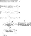
- Fig. 4is a flow chart that schematically illustrates a method for interchangeably using segmented electrodes of the balloon catheter of Fig. 2 for sensing and ablation. This method is useful for better understanding the invention, but any methods for treatment of the human or animal body by surgery or therapy and diagnostic methods practised on the human or animal body are not claimed.
- the device of the inventionmay be used to perform these methods.
- the algorithmcarries out a process that begins when physician 30 positions the balloon catheter at a target location within a lumen of a patient, such as at ostium 51, at a balloon catheter positioning step 80. Next, physician 30 inflates balloon 40 to contact the lumen wall with electrode segments 55 over an entire circumference of the lumen, at a balloon inflation step 82.
- physician 30connects all segments 55 of an electrode 50 and provides RF ablation power to each electrode 50, at an ablation step 84.
- processor 41uses measurements from one or more temperature sensors 57 to monitor a resulting temperature of each electrode segment 55.
- Processor 41compares temperature readings from sensor 57 on each segment with a preset threshold temperature, at a segment temperature checking step 88.
- the processorcontrols switching box 46 to maintain the segment operation as an ablation electrode, at an ablation continuation step 90. If, on the other hand, segment temperature is below or equals the preset temperature threshold, processor 41 controls switching box 46 to stop supplying RF power to the segment and to switch the segment to operate as a sensing electrode, at a switching step 92.
- Fig. 4The exemplary flow chart shown in Fig. 4 is chosen purely for the sake of conceptual clarity. In alternative embodiments, additional steps may be performed, such as processor 41 monitoring measured impedances of segments, and acting according to measured impedances, as described above. While Fig. 4 describes the method using multi-electrode balloon catheter, the principles of the present disclosure apply to any catheter having a distal end fitted with multiple electrodes, such as the aforementioned Lasso and basket catheters.
- the methods and systems described hereincan also be used in other applications that require a determination of occlusion, such as, for example, in renal denervation, and generally, in ablating other organs.
Landscapes
- Health & Medical Sciences (AREA)
- Life Sciences & Earth Sciences (AREA)
- Surgery (AREA)
- Engineering & Computer Science (AREA)
- Heart & Thoracic Surgery (AREA)
- Public Health (AREA)
- Biomedical Technology (AREA)
- General Health & Medical Sciences (AREA)
- Veterinary Medicine (AREA)
- Animal Behavior & Ethology (AREA)
- Medical Informatics (AREA)
- Molecular Biology (AREA)
- Physics & Mathematics (AREA)
- Biophysics (AREA)
- Pathology (AREA)
- Nuclear Medicine, Radiotherapy & Molecular Imaging (AREA)
- Otolaryngology (AREA)
- Cardiology (AREA)
- Plasma & Fusion (AREA)
- Physiology (AREA)
- Radiology & Medical Imaging (AREA)
- Child & Adolescent Psychology (AREA)
- Pulmonology (AREA)
- Anesthesiology (AREA)
- Hematology (AREA)
- Surgical Instruments (AREA)
Description
- The present invention relates generally to medical probes, and particularly to cardiac radiofrequency (RF) ablation and electrophysiological (EP) sensing multi-electrode catheters.
- Techniques that use a medical probe to perform temperature-monitored ablation of intra body tissue were previously proposed in the patent literature. For example,
U.S. Patent 6,053,912 describes systems and associated methods for ablating body tissue that employ an electrode for contacting tissue to form a tissue-electrode interface. The electrode is adapted to be connected to a source of ablation energy to conduct ablation energy for transmission by the electrode into tissue at the tissue-electrode interface. The systems and methods also include an element to cool the electrode. The systems and methods hold a tissue temperature sensing element in a carrier in thermal conductive contact with tissue beneath the tissue-electrode interface. The systems and methods include a controller that is coupled to the tissue temperature sensing element to control either the supply of ablation energy, or the rate at which the electrode is cooled, or both, based at least in part, upon temperature sensed by the temperature sensing element. - As another example,
U.S. Patent 5,496,312 describes a control that responds to impedance and temperature between active and return electrodes of the electrosurgical generator during tissue desiccation. Tissue contacts separately and independently provide high frequency power to effect tissue electrosurgically. A method of control responds to tissue impedance by supplying high frequency power separately and independently to contacts, monitoring, regulating and controlling impedance between the contacts and the return electrode. The method sets the generator power applied by each contact, and transmits temperature values for each contact with sensors, to regulate contact power.US2012136346 A1 discloses an ablation device wherein a control unit determines the state of contact between the ablation electrode and biological tissue based on a temperature signal. The output of a feedback controller coupled to a temperature sensor and a source of RF energy modifies the power output of the source of RF energy. - The present invention is defined by independent claim 1. Optional features are set out in the dependent claims.
- The present invention will be more fully understood from the following detailed description of the embodiments thereof, taken together with the drawings in which:
Fig. 1 is a schematic, pictorial illustration of a catheter-based, position-tracking and balloon-ablation system, in accordance with an exemplary embodiment of the present invention;Fig. 2 is a schematic, pictorial side view of a distal end of the balloon catheter ofFig. 1 deployed in a region of a pulmonary vein (PV) and its ostium, in accordance with an exemplary embodiment of the invention;Fig. 3 is a block diagram that schematically describes the functionality of the processor-controlled switching box ofFig. 1 , in accordance with an exemplary embodiment of the invention; andFig. 4 is a flow chart that schematically illustrates a method for interchangeably using segmented electrodes of the balloon catheter ofFig. 2 for sensing and ablation. This method is useful for better understanding the invention, but any methods for treatment of the human or animal body by surgery or therapy and diagnostic methods practised on the human or animal body are not claimed. The device of the invention may be used to perform these methods.- For efficient ablation with a medical probe, such as an intra-cardiac radiofrequency (RF) multi-electrode catheter and/or an irreversible electroporation (IRE) multi-electrode catheter, it is important that the ablating electrodes disposed over the catheter are in good physical contact with the tissue being ablated. For example, when a balloon catheter with multiple ablation electrodes is used to ablate tissue in an organ, such as an ostium of a pulmonary vein (PV), typically all of the catheter electrodes are positioned to contact the PV. However, the contact of some of the electrodes may not be sufficient for effective and safe ablation.
- Similarly, with other multi-electrode catheters, such as the Lasso catheter (made by Biosense Webster, Irvine, California) or a basket catheter, they may also have only part of their electrodes in sufficient contact with tissue for ablation.
- For these electrodes, rather than ablating tissue, an applied RF power may cause unwanted effects such as clot formation. In case of IRE, an incomplete PV isolation may occur, but without known unwanted effects.
- In the context of the present patent application, the term "applying ablative power" covers both applying RF power and applying IRE pulses. Typically, the ablative power comprises either a radiofrequency (RF) power output by an RF generator or irreversible electroporation (IRE) pulses output by an IRE pulse generator. However, a single generator may be configured to interchangeably output RF power and IRE pulses.
- Exemplary embodiments of the present invention that are described hereinafter provide techniques to apply ablation and electrophysiological (EP) sensing in a spatially selectable manner. In some exemplary embodiments, an expandable multi-electrode catheter (e.g., inflatable balloon catheter) is provided that comprises electrodes divided into segments (i.e., into electrode segments). Further provided is a processor-controlled switching box (also referred to as switching assembly). During application of ablative power by the electrode segments, depending on whether, and how well, an electrode segment among the electrode segments of the multi-electrode catheter contacts tissue, the processor can, by controlling the switching box, switch to re-use the electrode segment as a sensor. In another exemplary embodiment, the processor controlling the switching box can switch the electrode segment between operating as an ablation electrode and operating as a sensing electrode applied to, for example, acquiring intracardiac electrogram signals (i.e., for electrophysiological (EP) sensing).
- In some exemplary embodiments, by way of example of a multi-electrode catheter, a balloon catheter is provided with ten electrodes disposed on a membrane of the balloon. Each of the ten electrodes is divided into four segments with one or more temperature sensors, such as thermocouples, located on each electrode segment. Initially the switching box connects all the segments of each electrode as ablation electrodes as the catheter is positioned in contact with an ostium, and RF ablative power is supplied to the electrodes. During application of ablative power to an electrode segment, the one or more temperature sensors sense the rising temperature of the electrode segment in real-time.
- The temperature of each electrode segment is monitored by a processor receiving temperature readings sensed by the one or more temperature sensors. The processor uses a preset temperature criterion, such as a relation of the temperature readings with respect to a preset threshold temperature, to determine sufficiency of contact (i.e., to determine whether a physical contact between any of the electrodes and tissue meets a predefined contact quality with tissue). For example, if a temperature reading from of an electrode segment is above the preset threshold temperature (e.g., a threshold determined by previous experimentation), the processor determines that the contact of the electrode segment with the tissue is good, i.e., meeting a predefined contact quality criterion, and that tissue is being ablated. In this case the switching box continues to connect the electrode segment to the ablative power source.
- If, on the other hand, the temperature of an electrode segment does not rise above the threshold temperature, the processor determines that the level of contact of the electrode segment with tissue is insufficient (meaning that the ablative energy mainly heats blood). In this case the processor controls the switching box to switch the electrode segment from receiving ablation power to acting as a sensing electrode.
- In an exemplary embodiment, it is sufficient that one of the one or more temperature sensors measures a temperature below or equal to the threshold temperature to switch the electrode segment into a sensing electrode. In another exemplary embodiment, the processor compares an average temperature sensed by the one or more temperature sensors to the threshold temperature, and controls the switching box according to the average electrode segment temperature.
- In an alternative exemplary embodiment, the switching assembly is configured to initially have each of the electrode segments connected in parallel to a generator of the ablative power and to an EP sensing system. Upon deciding that the level of contact of a given electrode segment with tissue is insufficient, the processor is configured to control the switching assembly to disconnect the electrode segment from the generator.
- In some exemplary embodiments, the ablation system is additionally, or alternatively, configured to measure an impedance between each electrode segment and tissue. A processor of the system analyzes a characteristic of the measured impedance, for example, different frequency-dependence of the impedance of blood and tissue, and, using the outcome of the analysis, provides an independent assessment for each electrode segment as to whether the electrode segment is in direct electrical contact with (i.e., touches) cardiac tissue or is not in contact (e.g., the electrode segment is mostly immersed in blood).
- When using impedance measurements alone, initially the switching box has all of the electrode segments of all of the electrodes connected as sensing electrodes. The catheter is positioned in contact with tissue, such as of an ostium of a PV, and impedances are measured. Each electrode having a frequency-dependent impedance indicative of tissue connected to the ablative power source by the processor, using the switching box. An electrode segment with a frequency-dependent impedance indicative of blood is kept by the processor switched as a sensing electrode.
- In some exemplary embodiments, just prior to applying RF power, the aforementioned impedance-measurement-based touch indication with tissue may be utilized, for example, to reposition the multi-electrode catheter inside the lumen to improve contact of an electrode segment determined to be mostly in contact with blood.
- A technique for sensing of electrode-tissue physical contact using analysis of frequency response of tissue is described in
U.S. Patent Application 15/991,291, filed May 29, 2018 - In some exemplary embodiments, electrode segment temperature and impedance are both measured and analyzed in real-time, i.e., during the application of ablative power. Using two indications to determine whether an electrode segment can be used for ablation, or used only for sensing, can enhance the clinical selectivity of the disclosed technique.
- Typically, the processor is programmed in software containing a particular algorithm that enables the processor to conduct each of the processor related steps and functions outlined above.
- By providing electrode segments that are switchable according to quality of contact with tissue, the disclosed segmented balloon ablation technique can provide safer and more effective balloon ablation treatments. This, in turn, may improve the clinical outcome of cardiac balloon ablation treatments, such as of pulmonary vein (PV) isolation for treatment of arrhythmia.
Fig. 1 is a schematic, pictorial illustration of a catheter-based position-tracking and balloon-ablation system 20, in accordance with an exemplary embodiment of the present invention.System 20 comprises acatheter 21 that is fit at adistal end 22a of ashaft 22 of the catheter with an RF ablationexpandable balloon 40 comprising segmented electrodes 50 (seen in inset 25). In the exemplary embodiment described herein,segmented electrodes 50 are used for ablating tissue of anostium 51 of a PV in aheart 26.- The proximal end of
catheter 21 is connected to acontrol console 24 comprising anablative power source 45.Console 24 includes a switching box 46 (also referred to as a switching assembly) that can switch any segment of asegmented electrodes 50 between acting as an ablation electrode and acting as a sensing electrode. An ablation protocol comprising ablation parameters including preset temperature and/or impedance criterions is stored in amemory 48 ofconsole 24. Physician 30 insertsdistal end 22a ofshaft 22 through asheath 23 intoheart 26 of a patient 28 lying on a table 29.Physician 30 navigates the distal end ofshaft 22 to a target location in theheart 26 by manipulatingshaft 22 using amanipulator 32 near the proximal end of the catheter and/or deflection from thesheath 23. During the insertion ofdistal end 22a,balloon 40 is maintained in a collapsed configuration bysheath 23. By containingballoon 40 in a collapsed configuration,sheath 23 also serves to minimize vascular trauma along the way to target location.- Once
distal end 22a ofshaft 22 has reached the target location,physician 30 retractssheath 23 and inflatesballoon 40, and further manipulatesshaft 22 to place segmentedelectrodes 50 disposed over a perimeter ofballoon 40 in contact withostium 51 the pulmonary vein. Electrodes 50 are connected by wires running throughshaft 22 toprocessor 41controlling switching box 46 ofinterface circuits 44 in aconsole 24. To perform its functions,processor 41 includes an ablation-electrodeimpedance sensing module 47 and atemperature sensing module 49.Impedance sensing module 47 receives electrical impedance signals, measured betweensegmented electrodes 50 andsurface electrodes 38, which are seen in the exemplified system as attached by wires running through acable 37 to the chest ofpatient 28. A method for tracking the positions ofelectrodes 50 using the measured impedances is implemented in various medical applications, for example in the CARTO™ system, produced by Biosense-Webster (Irvine, California) and is described in detail inU.S. Patents 7,756,576 ,7,869,865 ,7,848,787 , and8, 456, 182 . This method is sometimes called Advanced Catheter Location (ACL).Console 24 drives adisplay 27, which shows the tracked position ofballoon 40 insideheart 26.- As further shown in
inset 25,distal end 22a comprises amagnetic position sensor 39 contained withindistal end 22a just proximally toexpandable balloon 40. During navigation ofdistal end 22a inheart 26,console 24 receives signals frommagnetic sensor 39 in response to magnetic fields fromexternal field generators 36, for example, for the purpose of measuring the position ofablation balloon 40 in the heart and, optionally, presenting the tracked position on adisplay 27.Magnetic field generators 36 are placed at known positions external topatient 28, e.g., below patient table 29.Console 24 also comprises adriver circuit 34, configured to drivemagnetic field generators 36. - The method of position sensing using external magnetic fields is implemented in various medical applications, for example, in the CARTO™ system, produced by Biosense-Webster and is described in detail in
U.S. Patents 5,391,199 ,6, 690, 963 ,6,484,118 ,6, 239, 724 ,6, 618, 612 and6, 332, 089 , inPCT Patent Publication WO 96/05768 U.S. Patent Application Publications 2002/0065455 A1 ,2003/0120150 A1 2004/0068178 A1 - As noted above,
control console 24 comprises aprocessor 41, typically a general-purpose computer, with suitable front end andinterface circuits 44 for receiving signals fromcatheter 21, as well as for applying RF energy treatment viacatheter 21 in a left atrium ofheart 26 and for controlling the other components ofsystem 20.Processor 41 typically comprises software in amemory 48 ofsystem 20, that is programmed to carry out the functions described herein. The software may be downloaded to the computer in electronic form, over a network, for example, or it may, alternatively or additionally, be provided and/or stored on non-transitory tangible media, such as magnetic, optical, or electronic memory. In particular,processor 41 runs a dedicated algorithm as disclosed herein, included inFig. 4 , that enablesprocessor 41 to perform the disclosed steps, as further described below. Fig. 2 is a schematic, pictorial side view of the balloon catheter ofFig. 1 deployed in a region of a pulmonary vein (PV) and itsostium 51, in accordance with an exemplary embodiment of the invention. The balloon catheter is used to ablateostium 51 tissue to isolate a source of arrhythmia.Balloon 40 has ten segmentedelectrodes 50 disposed over amembrane 71 of the balloon. RF power can be delivered fromablative power source 45 independently to each of the fourelectrode segments 55 of each of the tenelectrodes 50, depending on the level of physical contact of eachsegment 55 with tissue during ablation.- Each of
electrode segments 55 is fitted with atemperature sensor 57 in order to monitorelectrode segment 55 temperature during ablation. WhileFig. 2 shows asingle temperature sensor 57 perelectrode segment 55, in general,several temperature sensors 57 are disposed over eachelectrode segment 55. The lowest temperature reading, or the average temperature reading, may be used per electrode segment to determine quality of physical contact ofsegment 55 with tissue. - As seen in
Fig. 2 , anelectrode segment 55a is not in good contact with tissue. Based on temperature readings fromsensor 57a as below or equal to the preset threshold temperature during ablation,processor 41 determines the insufficient physical contact ofelectrode segment 55a. Responsively,processor 41controls switching box 46 to switchelectrode segment 55a into a sensing electrode. - In an alternative exemplary embodiment, switching
box 46 initially connects allelectrode segments 55 of allelectrodes 50, in parallel, toablative power source 45 and to the EP sensing system. Upon deciding that the level of contact of a givenelectrode segment 55 with tissue is insufficient,processor 41controls switching box 46 to disconnect the electrode segment from the generator, and in this manner facilitate the re-use of this electrode segment for EP sensing. - The pictorial side view shown in
Fig. 2 is chosen by way of example, where other embodiments are possible. For example, in another exemplary embodiment, cooling fluid sprays via irrigation holes (not shown) inelectrodes 50 to cool ablated tissue. WhileFig. 2 describes a multi-electrode balloon catheter, the principles of the disclosed techniques apply to any catheter having a distal end fitted with multiple electrodes, such as the aforementioned Lasso and basket catheters. Fig. 3 is a block diagram that schematically describes the functionality of processor-controlledswitching box 46 ofFig. 1 , in accordance with an exemplary embodiment of the invention. As seen, in response to a command byprocessor 41, switchingbox 46 either connects an electrode segment to ablation power, or connects the electrode segment as a sensing electrode. For example, switchingbox 46 connects an electrode segment to a position sensing subsystem ofsystem 20 to provide signal positions to be used with the aforementioned ACL position tracking method.- The block diagram of
Fig. 3 is highly simplified to maintain clarity of presentation. System elements that do not contribute directly to the clarity presentation are thus omitted. Fig. 4 is a flow chart that schematically illustrates a method for interchangeably using segmented electrodes of the balloon catheter ofFig. 2 for sensing and ablation. This method is useful for better understanding the invention, but any methods for treatment of the human or animal body by surgery or therapy and diagnostic methods practised on the human or animal body are not claimed. The device of the invention may be used to perform these methods. The algorithm, according to the presented exemplary embodiment, carries out a process that begins whenphysician 30 positions the balloon catheter at a target location within a lumen of a patient, such as atostium 51, at a ballooncatheter positioning step 80. Next,physician 30 inflatesballoon 40 to contact the lumen wall withelectrode segments 55 over an entire circumference of the lumen, at aballoon inflation step 82.- Next,
physician 30 connects allsegments 55 of anelectrode 50 and provides RF ablation power to eachelectrode 50, at an ablation step 84. At a subsequenttemperature monitoring step 86,processor 41 uses measurements from one ormore temperature sensors 57 to monitor a resulting temperature of eachelectrode segment 55.Processor 41 compares temperature readings fromsensor 57 on each segment with a preset threshold temperature, at a segmenttemperature checking step 88. - If the segment temperature is above the preset threshold, meaning that the electrode segment is in good contact with ablated tissue, the processor
controls switching box 46 to maintain the segment operation as an ablation electrode, at anablation continuation step 90. If, on the other hand, segment temperature is below or equals the preset temperature threshold,processor 41controls switching box 46 to stop supplying RF power to the segment and to switch the segment to operate as a sensing electrode, at a switchingstep 92. - The exemplary flow chart shown in
Fig. 4 is chosen purely for the sake of conceptual clarity. In alternative embodiments, additional steps may be performed, such asprocessor 41 monitoring measured impedances of segments, and acting according to measured impedances, as described above. WhileFig. 4 describes the method using multi-electrode balloon catheter, the principles of the present disclosure apply to any catheter having a distal end fitted with multiple electrodes, such as the aforementioned Lasso and basket catheters. - Although the embodiments described herein mainly address pulmonary vein isolation, the methods and systems described herein can also be used in other applications that require a determination of occlusion, such as, for example, in renal denervation, and generally, in ablating other organs.
- It will thus be appreciated that the embodiments described above are cited by way of example, and that the present invention is not limited to what has been particularly shown and described hereinabove. Rather, the scope of the present invention includes both combinations and sub-combinations of the various features described hereinabove, as well as variations and modifications thereof, provided that they fall under the scope of the appended claims.
Claims (10)
- A system (20), comprising:a catheter comprising an expandable distal end (40) having multiple electrodes (50) that are configured to be placed in contact with tissue (51) in an organ and to apply ablative power to tissue; anda processor (41), which is configured to:during application of the ablative power, determine whether a physical contact between the electrodes (50) and tissue meets a predefined contact quality; andif the physical contact of an electrode (50) among the electrodes (50) with the tissue does not meet the predefined contact quality, re-use the electrode (50) for electrophysiological, EP, sensing.
- The system (20) according to claim 1, wherein the ablative power comprises at least one of a radiofrequency (RF) power outputted by an RF generator and irreversible electroporation, IRE, pulses outputted by an IRE pulse generator.
- The system (20) according to claim 1, and comprising a switching assembly configured to switch the electrode (50) between a generator of the ablative power and an EP sensing system, wherein the processor (41) is configured to control the switching assembly to (i) initially connect the electrode (50) to the generator and (ii) subsequently connect the electrode (50) to the EP sensing system for re-using the electrode (50) for EP sensing.
- The system (20) according to claim 3, wherein each of the electrodes (50) comprises a plurality of electrode segments (55), and wherein the switching assembly (46) and the processor (41) are configured to individually switch any of the electrode segments (55) between the generator and the EP sensing system.
- The system (20) according to claim 1, and comprising a switching assembly (46) configured to initially have each of the electrodes (50) connected in parallel to a generator of the ablative power and to an EP sensing system, wherein the processor (41) is configured to control the switching assembly (46) to subsequently disconnect the electrode (50) from the generator for re-using the electrode (50) for EP sensing.
- The system (20) according to claim 5, wherein each of the electrodes (50) comprises a plurality of electrode segments (55), and wherein the switching assembly (46) and the processor (41) are configured to individually disconnect any of the electrode segments (55) from the generator.
- The system (20) according to claim 1, wherein the processor (41) is configured to determine whether the physical contact of the electrode (50) meets the predefined contact quality, by evaluating a preset temperature criterion.
- The system (20) according to claim 7, wherein the processor (41) is configured to evaluate the preset temperature criterion by evaluating a relation of a measured temperature of the electrode to a preset threshold temperature.
- The system (20) according to claim 1, wherein the processor (41) is configured to determine whether the physical contact of the electrode meets the predefined contact quality, by evaluating a preset impedance criterion.
- The system (20) according to claim 9, wherein the processor (41) is configured to evaluate the impedance criterion by assessing whether a frequency-dependence of the impedance indicates that the electrode contacts blood or indicates that the electrode contacts tissue.
Applications Claiming Priority (1)
| Application Number | Priority Date | Filing Date | Title |
|---|---|---|---|
| US16/541,374US12114918B2 (en) | 2019-08-15 | 2019-08-15 | Dynamic ablation and sensing according to contact of segmented electrodes |
Publications (3)
| Publication Number | Publication Date |
|---|---|
| EP3777743A1 EP3777743A1 (en) | 2021-02-17 |
| EP3777743C0 EP3777743C0 (en) | 2023-10-11 |
| EP3777743B1true EP3777743B1 (en) | 2023-10-11 |
Family
ID=72087943
Family Applications (1)
| Application Number | Title | Priority Date | Filing Date |
|---|---|---|---|
| EP20191096.5AActiveEP3777743B1 (en) | 2019-08-15 | 2020-08-14 | Dynamic ablation and sensing according to contact of segmented electrodes |
Country Status (7)
| Country | Link |
|---|---|
| US (1) | US12114918B2 (en) |
| EP (1) | EP3777743B1 (en) |
| JP (1) | JP7547115B2 (en) |
| KR (1) | KR20210021438A (en) |
| CN (1) | CN112451081B (en) |
| IL (1) | IL276304B2 (en) |
| RU (1) | RU2761291C1 (en) |
Families Citing this family (45)
| Publication number | Priority date | Publication date | Assignee | Title |
|---|---|---|---|---|
| US10905329B2 (en) | 2016-06-09 | 2021-02-02 | Biosense Webster (Israel) Ltd. | Multi-function conducting elements for a catheter |
| US12029545B2 (en) | 2017-05-30 | 2024-07-09 | Biosense Webster (Israel) Ltd. | Catheter splines as location sensors |
| US20190314083A1 (en) | 2018-04-11 | 2019-10-17 | Biosense Webster (Israel) Ltd. | Flexible Multi-Arm Catheter with Diametrically Opposed Sensing Electrodes |
| CN112639990B (en) | 2018-04-30 | 2025-04-15 | 小利兰·斯坦福大学托管委员会 | Systems and methods for maintaining health using a personal digital phenotype |
| US11045628B2 (en) | 2018-12-11 | 2021-06-29 | Biosense Webster (Israel) Ltd. | Balloon catheter with high articulation |
| US11207016B2 (en) | 2018-12-28 | 2021-12-28 | Biosense Webster (Israel) Ltd. | Mapping ECG signals using a multipole electrode assembly |
| US11850051B2 (en) | 2019-04-30 | 2023-12-26 | Biosense Webster (Israel) Ltd. | Mapping grid with high density electrode array |
| US11712172B2 (en) | 2019-07-18 | 2023-08-01 | Biosense Webster (Israel) Ltd. | Visual guidance for positioning a distal end of a medical probe |
| US11950930B2 (en) | 2019-12-12 | 2024-04-09 | Biosense Webster (Israel) Ltd. | Multi-dimensional acquisition of bipolar signals from a catheter |
| US11517218B2 (en) | 2019-12-20 | 2022-12-06 | Biosense Webster (Israel) Ltd. | Selective graphical presentation of electrophysiological parameters |
| IL295739A (en) | 2020-02-20 | 2022-10-01 | Univ Leland Stanford Junior | A system and method for targeting and treating abnormal biological rhythms |
| US12232874B2 (en) | 2020-05-29 | 2025-02-25 | Biosense Webster (Israel) Ltd. | Electrode apparatus for diagnosis of arrhythmias |
| US11987017B2 (en) | 2020-06-08 | 2024-05-21 | Biosense Webster (Israel) Ltd. | Features to assist in assembly and testing of devices |
| US12076071B2 (en) | 2020-08-14 | 2024-09-03 | Kardium Inc. | Systems and methods for treating tissue with pulsed field ablation |
| US12048479B2 (en) | 2020-09-10 | 2024-07-30 | Biosense Webster (Israel) Ltd. | Surface mounted electrode catheter |
| US11950841B2 (en) | 2020-09-22 | 2024-04-09 | Biosense Webster (Israel) Ltd. | Basket catheter having insulated ablation electrodes and diagnostic electrodes |
| US11950840B2 (en) | 2020-09-22 | 2024-04-09 | Biosense Webster (Israel) Ltd. | Basket catheter having insulated ablation electrodes |
| US12082875B2 (en) | 2020-09-24 | 2024-09-10 | Biosense Webster (Israel) Ltd | Balloon catheter having a coil for sensing tissue temperature and position of the balloon |
| US11974803B2 (en) | 2020-10-12 | 2024-05-07 | Biosense Webster (Israel) Ltd. | Basket catheter with balloon |
| US12201786B2 (en) | 2020-12-17 | 2025-01-21 | Biosense Webster (Israel) Ltd. | Measurement of distal end dimension of catheters using magnetic fields |
| US11918383B2 (en) | 2020-12-21 | 2024-03-05 | Biosense Webster (Israel) Ltd. | Visualizing performance of catheter electrodes |
| CN112618010B (en)* | 2021-03-10 | 2021-05-28 | 上海安钛克医疗科技有限公司 | Ablation system |
| CR20230475A (en) | 2021-04-07 | 2024-01-19 | Btl Medical Dev A S | Pulsed field ablation device and method |
| US12064170B2 (en) | 2021-05-13 | 2024-08-20 | Biosense Webster (Israel) Ltd. | Distal assembly for catheter with lumens running along spines |
| EP4366637B1 (en) | 2021-07-06 | 2025-06-25 | BTL Medical Development A.S. | Pulsed field ablation device |
| CN117835929A (en) | 2021-08-10 | 2024-04-05 | 菲斯卡德公司 | Treatment system with sensing and ablation catheter for treatment of heart rhythm disorders |
| US12364426B2 (en) | 2021-08-12 | 2025-07-22 | Biosense Webster (Israel) Ltd. | Electro-anatomical mapping and annotation presented in electrophysiological procedures |
| US12004804B2 (en) | 2021-09-09 | 2024-06-11 | Biosense Webster (Israel) Ltd. | Basket catheter with mushroom shape distal tip |
| US12011280B2 (en) | 2021-10-04 | 2024-06-18 | Biosense Webster (Israel) Ltd. | Electrophysiological mapping in the presence of injury current |
| US11564591B1 (en) | 2021-11-29 | 2023-01-31 | Physcade, Inc. | System and method for diagnosing and treating biological rhythm disorders |
| US12419683B2 (en) | 2021-12-22 | 2025-09-23 | Biosense Webster (Israel) Ltd. | Irreversible electroporation with shorted electrodes |
| CN114271931B (en)* | 2021-12-23 | 2023-09-12 | 心航路医学科技(广州)有限公司 | Pulse ablation system |
| US20230210589A1 (en)* | 2021-12-30 | 2023-07-06 | Biosense Webster (Israel) Ltd. | Basket Catheter Having Ablation Electrodes and Temperature Sensors |
| CN119365143A (en)* | 2022-06-23 | 2025-01-24 | 美敦力公司 | Application of non-therapeutic waveforms with gradient sensing to predict pulsed field ablation (PFA) fields |
| US20230414273A1 (en)* | 2022-06-23 | 2023-12-28 | Biosense Webster (Israel) Ltd. | Graphical Contact Quality Indicator for Balloon Catheter Navigation |
| IL319700A (en) | 2022-10-05 | 2025-05-01 | Btl Medical Dev A S | Pulsed field ablation device and method |
| CN115721409A (en)* | 2022-11-15 | 2023-03-03 | 上海玄宇医疗器械有限公司 | Ablation catheter and control device and control method thereof |
| US12376879B2 (en) | 2023-03-03 | 2025-08-05 | Theraheart Inc. | Expandable elements for shunting catheters |
| CN116035693A (en)* | 2023-03-14 | 2023-05-02 | 上海圣达济医疗科技有限公司 | A device for releasing radio frequency energy |
| US12290310B2 (en) | 2023-04-06 | 2025-05-06 | Theraheart Inc. | Slicing elements for shunting catheters |
| US12262943B2 (en) | 2023-06-15 | 2025-04-01 | Theraheart Inc. | Expandable ablation mechanisms for shunting catheters |
| US20250213295A1 (en)* | 2023-12-29 | 2025-07-03 | Boston Scientific Scimed, Inc. | Electroporation ablation from tissue-contacting electrodes |
| US12290370B1 (en) | 2024-01-19 | 2025-05-06 | Physcade, Inc. | System and method for mapping activation waves to guide treatment of biological rhythm disorders |
| WO2025193514A1 (en)* | 2024-03-15 | 2025-09-18 | CRC EP, Inc. | Contact uniformity assessment based on impedance values |
| US12201354B1 (en) | 2024-04-01 | 2025-01-21 | Theraheart Inc. | Expandable ablation mechanisms for shunting catheters |
Citations (1)
| Publication number | Priority date | Publication date | Assignee | Title |
|---|---|---|---|---|
| US20120136346A1 (en)* | 2010-11-29 | 2012-05-31 | Medtronic Ablation Frontiers Llc | System and Method for Adaptive RF Ablation |
Family Cites Families (51)
| Publication number | Priority date | Publication date | Assignee | Title |
|---|---|---|---|---|
| US5391199A (en) | 1993-07-20 | 1995-02-21 | Biosense, Inc. | Apparatus and method for treating cardiac arrhythmias |
| US5496312A (en) | 1993-10-07 | 1996-03-05 | Valleylab Inc. | Impedance and temperature generator control |
| WO1995010978A1 (en)* | 1993-10-19 | 1995-04-27 | Ep Technologies, Inc. | Segmented electrode assemblies for ablation of tissue |
| JP3564141B2 (en)* | 1994-06-27 | 2004-09-08 | ボストン サイエンティフィック リミテッド | System for controlling tissue ablation using multiple temperature sensing elements |
| AU1693095A (en) | 1994-08-19 | 1996-03-14 | Biosense, Inc. | Medical diagnosis, treatment and imaging systems |
| US6690963B2 (en) | 1995-01-24 | 2004-02-10 | Biosense, Inc. | System for determining the location and orientation of an invasive medical instrument |
| US6053912A (en) | 1995-05-01 | 2000-04-25 | Ep Techonologies, Inc. | Systems and methods for sensing sub-surface temperatures in body tissue during ablation with actively cooled electrodes |
| US6113592A (en) | 1995-06-09 | 2000-09-05 | Engineering & Research Associates, Inc. | Apparatus and method for controlling ablation depth |
| US5836874A (en)* | 1996-04-08 | 1998-11-17 | Ep Technologies, Inc. | Multi-function electrode structures for electrically analyzing and heating body tissue |
| AU709081B2 (en) | 1996-02-15 | 1999-08-19 | Biosense, Inc. | Medical procedures and apparatus using intrabody probes |
| US6618612B1 (en) | 1996-02-15 | 2003-09-09 | Biosense, Inc. | Independently positionable transducers for location system |
| US5836990A (en)* | 1997-09-19 | 1998-11-17 | Medtronic, Inc. | Method and apparatus for determining electrode/tissue contact |
| US6239724B1 (en) | 1997-12-30 | 2001-05-29 | Remon Medical Technologies, Ltd. | System and method for telemetrically providing intrabody spatial position |
| US6183468B1 (en) | 1998-09-10 | 2001-02-06 | Scimed Life Systems, Inc. | Systems and methods for controlling power in an electrosurgical probe |
| US6391024B1 (en) | 1999-06-17 | 2002-05-21 | Cardiac Pacemakers, Inc. | RF ablation apparatus and method having electrode/tissue contact assessment scheme and electrocardiogram filtering |
| US6484118B1 (en) | 2000-07-20 | 2002-11-19 | Biosense, Inc. | Electromagnetic position single axis system |
| US7729742B2 (en) | 2001-12-21 | 2010-06-01 | Biosense, Inc. | Wireless position sensor |
| US20040068178A1 (en) | 2002-09-17 | 2004-04-08 | Assaf Govari | High-gradient recursive locating system |
| US8068906B2 (en) | 2004-06-21 | 2011-11-29 | Aorora Technologies Pty Ltd | Cardiac monitoring system |
| US7869865B2 (en) | 2005-01-07 | 2011-01-11 | Biosense Webster, Inc. | Current-based position sensing |
| EP2759276A1 (en)* | 2005-06-20 | 2014-07-30 | Medtronic Ablation Frontiers LLC | Ablation catheter |
| US7848787B2 (en) | 2005-07-08 | 2010-12-07 | Biosense Webster, Inc. | Relative impedance measurement |
| US7756576B2 (en) | 2005-08-26 | 2010-07-13 | Biosense Webster, Inc. | Position sensing and detection of skin impedance |
| BRPI0621017A2 (en) | 2005-12-06 | 2011-11-29 | St Jude Medical Atrial Fibrill Div | tissue ablation electrode junction evaluation |
| US20080312521A1 (en) | 2007-06-14 | 2008-12-18 | Solomon Edward G | System and method for determining electrode-tissue contact using phase difference |
| US8456182B2 (en) | 2008-09-30 | 2013-06-04 | Biosense Webster, Inc. | Current localization tracker |
| US9445742B2 (en) | 2009-09-01 | 2016-09-20 | Roman A. Slizynski | Electrical impedance techniques in tissue-mass detection and characterization |
| US8668686B2 (en) | 2009-12-23 | 2014-03-11 | Biosense Webster (Israel) Ltd. | Sensing contact of ablation catheter using differential temperature measurements |
| US9539046B2 (en)* | 2010-08-03 | 2017-01-10 | Medtronic Cryocath Lp | Cryogenic medical mapping and treatment device |
| US10016233B2 (en) | 2010-12-06 | 2018-07-10 | Biosense Webster (Israel) Ltd. | Treatment of atrial fibrillation using high-frequency pacing and ablation of renal nerves |
| US8644917B2 (en) | 2011-09-20 | 2014-02-04 | Albert Einstein Healthcare Network | Cardio mapping system and method for cardio mapping |
| WO2013074813A1 (en)* | 2011-11-15 | 2013-05-23 | Boston Scientific Scimed, Inc. | Device and methods for renal nerve modulation monitoring |
| CN104755010A (en) | 2012-07-04 | 2015-07-01 | 西比姆公司 | Devices and systems for carotid body ablation |
| US9204841B2 (en) | 2012-12-31 | 2015-12-08 | Biosense Webster (Israel) Ltd. | Catheter with serially connected sensing structures and methods of calibration and detection |
| US20140243809A1 (en)* | 2013-02-22 | 2014-08-28 | Mark Gelfand | Endovascular catheters for trans-superficial temporal artery transmural carotid body modulation |
| US10201383B2 (en)* | 2013-03-15 | 2019-02-12 | Retrovascular, Inc. | Methods for tissue ablation measurement and control and devices thereof |
| EP3071137A1 (en) | 2013-11-20 | 2016-09-28 | Boston Scientific Scimed, Inc. | Ablation medical devices and methods for making and using ablation medical devices |
| US9788893B2 (en)* | 2014-11-20 | 2017-10-17 | Biosense Webster (Israel) Ltd. | Catheter with soft distal tip for mapping and ablating tubular region |
| CA2969129A1 (en) | 2014-12-03 | 2016-06-09 | Metavention, Inc. | Systems and methods for modulating nerves or other tissue |
| US20160242667A1 (en) | 2015-02-20 | 2016-08-25 | Boston Scientific Scimed Inc. | Tissue contact sensing using a medical device |
| US9636164B2 (en) | 2015-03-25 | 2017-05-02 | Advanced Cardiac Therapeutics, Inc. | Contact sensing systems and methods |
| US10143399B2 (en) | 2015-04-02 | 2018-12-04 | Medtronic Ablation Frontiers Llc | Tissue contact sensing with a multi electrode ablation catheter |
| US10182742B2 (en) | 2015-04-02 | 2019-01-22 | Medtronic Ablation Frontiers Llc | Tissue contact sensing with a multi electrode ablation catheter |
| CN107405099B (en)* | 2015-05-11 | 2021-02-09 | 圣犹达医疗用品心脏病学部门有限公司 | High density mapping and ablation catheter |
| CN107635503B (en) | 2015-05-12 | 2021-09-07 | 纳维斯国际有限公司 | Damage estimation by dielectric property analysis |
| US20170156791A1 (en)* | 2015-12-08 | 2017-06-08 | Biosense Webster (Israel) Ltd. | Ablating and sensing electrodes |
| US20170202614A1 (en) | 2016-01-20 | 2017-07-20 | Rainbow Medical Ltd. | Catheter guidance and procedure planning |
| WO2017160808A1 (en) | 2016-03-15 | 2017-09-21 | Advanced Cardiac Therapeutics, Inc. | Improved devices, systems and methods for irrigated ablation |
| CN109561929A (en)* | 2016-06-06 | 2019-04-02 | 纽乌罗有限公司 | Device for far field bipolar ablation |
| EP3525665A4 (en) | 2016-10-11 | 2020-05-13 | Acutus Medical, Inc. | ABLATION SYSTEM WITH POWER CONTROL |
| US20180325585A1 (en) | 2017-05-15 | 2018-11-15 | Biosense Webster (Israel) Ltd. | Networked thermistors |
- 2019
- 2019-08-15USUS16/541,374patent/US12114918B2/enactiveActive
- 2020
- 2020-07-10KRKR1020200085206Apatent/KR20210021438A/enactivePending
- 2020-07-26ILIL276304Apatent/IL276304B2/enunknown
- 2020-08-10RURU2020126582Apatent/RU2761291C1/enactive
- 2020-08-14JPJP2020136928Apatent/JP7547115B2/enactiveActive
- 2020-08-14EPEP20191096.5Apatent/EP3777743B1/enactiveActive
- 2020-08-14CNCN202010817311.2Apatent/CN112451081B/enactiveActive
Patent Citations (1)
| Publication number | Priority date | Publication date | Assignee | Title |
|---|---|---|---|---|
| US20120136346A1 (en)* | 2010-11-29 | 2012-05-31 | Medtronic Ablation Frontiers Llc | System and Method for Adaptive RF Ablation |
Also Published As
| Publication number | Publication date |
|---|---|
| RU2761291C1 (en) | 2021-12-06 |
| IL276304A (en) | 2021-03-01 |
| EP3777743A1 (en) | 2021-02-17 |
| JP2021030077A (en) | 2021-03-01 |
| CN112451081A (en) | 2021-03-09 |
| CN112451081B (en) | 2025-09-02 |
| KR20210021438A (en) | 2021-02-26 |
| EP3777743C0 (en) | 2023-10-11 |
| US20210045805A1 (en) | 2021-02-18 |
| US12114918B2 (en) | 2024-10-15 |
| JP7547115B2 (en) | 2024-09-09 |
| IL276304B2 (en) | 2024-08-01 |
| IL276304B1 (en) | 2024-04-01 |
Similar Documents
| Publication | Publication Date | Title |
|---|---|---|
| EP3777743B1 (en) | Dynamic ablation and sensing according to contact of segmented electrodes | |
| US12336845B2 (en) | Catheter with plurality of sensing electrodes used as ablation electrode | |
| JP7395663B2 (en) | Temperature-controlled short-term ablation using multiple electrodes | |
| US20230414279A1 (en) | Ablation catheters and related systems and methods | |
| EP2197377B1 (en) | Device for real-time lesion estimation during ablation | |
| EP3184066B1 (en) | Estimating a temperature during ablation | |
| EP3202357A1 (en) | Temperature controlled short duration ablation | |
| EP3202355A1 (en) | Temperature controlled short duration ablation | |
| JP2015089521A (en) | Using catheter position and temperature measurements to detect movement from the ablation site | |
| EP3216412A1 (en) | Temperature controlled short duration ablation | |
| EP3202356A1 (en) | Temperature controlled short duration ablation | |
| CN115886980A (en) | Phrenic Nerve Warning | |
| EP3434214B1 (en) | Tissue thickness using pulsed power | |
| KR20220014274A (en) | Cautious irreversible-electroporation (ire) protocol for avoiding bubble generation | |
| CN117084775A (en) | Impedance-based ablation index for IRE |
Legal Events
| Date | Code | Title | Description |
|---|---|---|---|
| PUAI | Public reference made under article 153(3) epc to a published international application that has entered the european phase | Free format text:ORIGINAL CODE: 0009012 | |
| STAA | Information on the status of an ep patent application or granted ep patent | Free format text:STATUS: THE APPLICATION HAS BEEN PUBLISHED | |
| AK | Designated contracting states | Kind code of ref document:A1 Designated state(s):AL AT BE BG CH CY CZ DE DK EE ES FI FR GB GR HR HU IE IS IT LI LT LU LV MC MK MT NL NO PL PT RO RS SE SI SK SM TR | |
| AX | Request for extension of the european patent | Extension state:BA ME | |
| STAA | Information on the status of an ep patent application or granted ep patent | Free format text:STATUS: REQUEST FOR EXAMINATION WAS MADE | |
| 17P | Request for examination filed | Effective date:20210804 | |
| RBV | Designated contracting states (corrected) | Designated state(s):AL AT BE BG CH CY CZ DE DK EE ES FI FR GB GR HR HU IE IS IT LI LT LU LV MC MK MT NL NO PL PT RO RS SE SI SK SM TR | |
| RAP3 | Party data changed (applicant data changed or rights of an application transferred) | Owner name:BIOSENSE WEBSTER (ISRAEL) LTD. | |
| GRAP | Despatch of communication of intention to grant a patent | Free format text:ORIGINAL CODE: EPIDOSNIGR1 | |
| STAA | Information on the status of an ep patent application or granted ep patent | Free format text:STATUS: GRANT OF PATENT IS INTENDED | |
| RIC1 | Information provided on ipc code assigned before grant | Ipc:A61B 34/20 20160101ALN20230123BHEP Ipc:A61B 18/12 20060101ALN20230123BHEP Ipc:A61B 18/00 20060101ALN20230123BHEP Ipc:A61B 18/14 20060101AFI20230123BHEP | |
| RIC1 | Information provided on ipc code assigned before grant | Ipc:A61B 34/20 20160101ALN20230202BHEP Ipc:A61B 18/12 20060101ALN20230202BHEP Ipc:A61B 18/00 20060101ALN20230202BHEP Ipc:A61B 18/14 20060101AFI20230202BHEP | |
| RIC1 | Information provided on ipc code assigned before grant | Ipc:A61B 34/20 20160101ALN20230206BHEP Ipc:A61B 18/12 20060101ALN20230206BHEP Ipc:A61B 18/00 20060101ALN20230206BHEP Ipc:A61B 18/14 20060101AFI20230206BHEP | |
| INTG | Intention to grant announced | Effective date:20230223 | |
| GRAJ | Information related to disapproval of communication of intention to grant by the applicant or resumption of examination proceedings by the epo deleted | Free format text:ORIGINAL CODE: EPIDOSDIGR1 | |
| STAA | Information on the status of an ep patent application or granted ep patent | Free format text:STATUS: REQUEST FOR EXAMINATION WAS MADE | |
| GRAP | Despatch of communication of intention to grant a patent | Free format text:ORIGINAL CODE: EPIDOSNIGR1 | |
| STAA | Information on the status of an ep patent application or granted ep patent | Free format text:STATUS: GRANT OF PATENT IS INTENDED | |
| INTC | Intention to grant announced (deleted) | ||
| RIC1 | Information provided on ipc code assigned before grant | Ipc:A61B 34/20 20160101ALN20230522BHEP Ipc:A61B 18/12 20060101ALN20230522BHEP Ipc:A61B 18/00 20060101ALN20230522BHEP Ipc:A61B 18/14 20060101AFI20230522BHEP | |
| INTG | Intention to grant announced | Effective date:20230606 | |
| GRAS | Grant fee paid | Free format text:ORIGINAL CODE: EPIDOSNIGR3 | |
| GRAA | (expected) grant | Free format text:ORIGINAL CODE: 0009210 | |
| STAA | Information on the status of an ep patent application or granted ep patent | Free format text:STATUS: THE PATENT HAS BEEN GRANTED | |
| AK | Designated contracting states | Kind code of ref document:B1 Designated state(s):AL AT BE BG CH CY CZ DE DK EE ES FI FR GB GR HR HU IE IS IT LI LT LU LV MC MK MT NL NO PL PT RO RS SE SI SK SM TR | |
| REG | Reference to a national code | Ref country code:GB Ref legal event code:FG4D | |
| REG | Reference to a national code | Ref country code:CH Ref legal event code:EP | |
| REG | Reference to a national code | Ref country code:DE Ref legal event code:R096 Ref document number:602020018940 Country of ref document:DE | |
| REG | Reference to a national code | Ref country code:IE Ref legal event code:FG4D | |
| U01 | Request for unitary effect filed | Effective date:20231108 | |
| U07 | Unitary effect registered | Designated state(s):AT BE BG DE DK EE FI FR IT LT LU LV MT NL PT SE SI Effective date:20231117 | |
| PG25 | Lapsed in a contracting state [announced via postgrant information from national office to epo] | Ref country code:GR Free format text:LAPSE BECAUSE OF FAILURE TO SUBMIT A TRANSLATION OF THE DESCRIPTION OR TO PAY THE FEE WITHIN THE PRESCRIBED TIME-LIMIT Effective date:20240112 | |
| PG25 | Lapsed in a contracting state [announced via postgrant information from national office to epo] | Ref country code:IS Free format text:LAPSE BECAUSE OF FAILURE TO SUBMIT A TRANSLATION OF THE DESCRIPTION OR TO PAY THE FEE WITHIN THE PRESCRIBED TIME-LIMIT Effective date:20240211 | |
| PG25 | Lapsed in a contracting state [announced via postgrant information from national office to epo] | Ref country code:ES Free format text:LAPSE BECAUSE OF FAILURE TO SUBMIT A TRANSLATION OF THE DESCRIPTION OR TO PAY THE FEE WITHIN THE PRESCRIBED TIME-LIMIT Effective date:20231011 | |
| PG25 | Lapsed in a contracting state [announced via postgrant information from national office to epo] | Ref country code:IS Free format text:LAPSE BECAUSE OF FAILURE TO SUBMIT A TRANSLATION OF THE DESCRIPTION OR TO PAY THE FEE WITHIN THE PRESCRIBED TIME-LIMIT Effective date:20240211 Ref country code:GR Free format text:LAPSE BECAUSE OF FAILURE TO SUBMIT A TRANSLATION OF THE DESCRIPTION OR TO PAY THE FEE WITHIN THE PRESCRIBED TIME-LIMIT Effective date:20240112 Ref country code:ES Free format text:LAPSE BECAUSE OF FAILURE TO SUBMIT A TRANSLATION OF THE DESCRIPTION OR TO PAY THE FEE WITHIN THE PRESCRIBED TIME-LIMIT Effective date:20231011 | |
| PG25 | Lapsed in a contracting state [announced via postgrant information from national office to epo] | Ref country code:RS Free format text:LAPSE BECAUSE OF FAILURE TO SUBMIT A TRANSLATION OF THE DESCRIPTION OR TO PAY THE FEE WITHIN THE PRESCRIBED TIME-LIMIT Effective date:20231011 Ref country code:PL Free format text:LAPSE BECAUSE OF FAILURE TO SUBMIT A TRANSLATION OF THE DESCRIPTION OR TO PAY THE FEE WITHIN THE PRESCRIBED TIME-LIMIT Effective date:20231011 Ref country code:NO Free format text:LAPSE BECAUSE OF FAILURE TO SUBMIT A TRANSLATION OF THE DESCRIPTION OR TO PAY THE FEE WITHIN THE PRESCRIBED TIME-LIMIT Effective date:20240111 Ref country code:HR Free format text:LAPSE BECAUSE OF FAILURE TO SUBMIT A TRANSLATION OF THE DESCRIPTION OR TO PAY THE FEE WITHIN THE PRESCRIBED TIME-LIMIT Effective date:20231011 | |
| REG | Reference to a national code | Ref country code:DE Ref legal event code:R097 Ref document number:602020018940 Country of ref document:DE | |
| PG25 | Lapsed in a contracting state [announced via postgrant information from national office to epo] | Ref country code:CZ Free format text:LAPSE BECAUSE OF FAILURE TO SUBMIT A TRANSLATION OF THE DESCRIPTION OR TO PAY THE FEE WITHIN THE PRESCRIBED TIME-LIMIT Effective date:20231011 | |
| PG25 | Lapsed in a contracting state [announced via postgrant information from national office to epo] | Ref country code:SK Free format text:LAPSE BECAUSE OF FAILURE TO SUBMIT A TRANSLATION OF THE DESCRIPTION OR TO PAY THE FEE WITHIN THE PRESCRIBED TIME-LIMIT Effective date:20231011 | |
| PG25 | Lapsed in a contracting state [announced via postgrant information from national office to epo] | Ref country code:SM Free format text:LAPSE BECAUSE OF FAILURE TO SUBMIT A TRANSLATION OF THE DESCRIPTION OR TO PAY THE FEE WITHIN THE PRESCRIBED TIME-LIMIT Effective date:20231011 Ref country code:SK Free format text:LAPSE BECAUSE OF FAILURE TO SUBMIT A TRANSLATION OF THE DESCRIPTION OR TO PAY THE FEE WITHIN THE PRESCRIBED TIME-LIMIT Effective date:20231011 Ref country code:RO Free format text:LAPSE BECAUSE OF FAILURE TO SUBMIT A TRANSLATION OF THE DESCRIPTION OR TO PAY THE FEE WITHIN THE PRESCRIBED TIME-LIMIT Effective date:20231011 Ref country code:CZ Free format text:LAPSE BECAUSE OF FAILURE TO SUBMIT A TRANSLATION OF THE DESCRIPTION OR TO PAY THE FEE WITHIN THE PRESCRIBED TIME-LIMIT Effective date:20231011 | |
| U20 | Renewal fee for the european patent with unitary effect paid | Year of fee payment:5 Effective date:20240705 | |
| PLBE | No opposition filed within time limit | Free format text:ORIGINAL CODE: 0009261 | |
| STAA | Information on the status of an ep patent application or granted ep patent | Free format text:STATUS: NO OPPOSITION FILED WITHIN TIME LIMIT | |
| 26N | No opposition filed | Effective date:20240712 | |
| PGFP | Annual fee paid to national office [announced via postgrant information from national office to epo] | Ref country code:GB Payment date:20240701 Year of fee payment:5 | |
| REG | Reference to a national code | Ref country code:CH Ref legal event code:PL | |
| PG25 | Lapsed in a contracting state [announced via postgrant information from national office to epo] | Ref country code:MC Free format text:LAPSE BECAUSE OF FAILURE TO SUBMIT A TRANSLATION OF THE DESCRIPTION OR TO PAY THE FEE WITHIN THE PRESCRIBED TIME-LIMIT Effective date:20231011 Ref country code:CH Free format text:LAPSE BECAUSE OF NON-PAYMENT OF DUE FEES Effective date:20240831 | |
| PG25 | Lapsed in a contracting state [announced via postgrant information from national office to epo] | Ref country code:IE Free format text:LAPSE BECAUSE OF NON-PAYMENT OF DUE FEES Effective date:20240814 | |
| U20 | Renewal fee for the european patent with unitary effect paid | Year of fee payment:6 Effective date:20250709 |