EP3777713A1 - Staple forming pocket arrangements comprising primary sidewalls and pocket sidewalls - Google Patents
Staple forming pocket arrangements comprising primary sidewalls and pocket sidewallsDownload PDFInfo
- Publication number
- EP3777713A1 EP3777713A1EP20198128.9AEP20198128AEP3777713A1EP 3777713 A1EP3777713 A1EP 3777713A1EP 20198128 AEP20198128 AEP 20198128AEP 3777713 A1EP3777713 A1EP 3777713A1
- Authority
- EP
- European Patent Office
- Prior art keywords
- forming
- anvil
- patent application
- staple
- Prior art date
- Legal status (The legal status is an assumption and is not a legal conclusion. Google has not performed a legal analysis and makes no representation as to the accuracy of the status listed.)
- Withdrawn
Links
Images


Classifications
- A—HUMAN NECESSITIES
- A61—MEDICAL OR VETERINARY SCIENCE; HYGIENE
- A61B—DIAGNOSIS; SURGERY; IDENTIFICATION
- A61B17/00—Surgical instruments, devices or methods
- A61B17/068—Surgical staplers, e.g. containing multiple staples or clamps
- A61B17/072—Surgical staplers, e.g. containing multiple staples or clamps for applying a row of staples in a single action, e.g. the staples being applied simultaneously
- A—HUMAN NECESSITIES
- A61—MEDICAL OR VETERINARY SCIENCE; HYGIENE
- A61B—DIAGNOSIS; SURGERY; IDENTIFICATION
- A61B17/00—Surgical instruments, devices or methods
- A61B17/064—Surgical staples, i.e. penetrating the tissue
- A61B17/0644—Surgical staples, i.e. penetrating the tissue penetrating the tissue, deformable to closed position
- A—HUMAN NECESSITIES
- A61—MEDICAL OR VETERINARY SCIENCE; HYGIENE
- A61B—DIAGNOSIS; SURGERY; IDENTIFICATION
- A61B17/00—Surgical instruments, devices or methods
- A61B17/068—Surgical staplers, e.g. containing multiple staples or clamps
- A61B17/072—Surgical staplers, e.g. containing multiple staples or clamps for applying a row of staples in a single action, e.g. the staples being applied simultaneously
- A61B17/07207—Surgical staplers, e.g. containing multiple staples or clamps for applying a row of staples in a single action, e.g. the staples being applied simultaneously the staples being applied sequentially
- A—HUMAN NECESSITIES
- A61—MEDICAL OR VETERINARY SCIENCE; HYGIENE
- A61B—DIAGNOSIS; SURGERY; IDENTIFICATION
- A61B34/00—Computer-aided surgery; Manipulators or robots specially adapted for use in surgery
- A61B34/30—Surgical robots
- A—HUMAN NECESSITIES
- A61—MEDICAL OR VETERINARY SCIENCE; HYGIENE
- A61B—DIAGNOSIS; SURGERY; IDENTIFICATION
- A61B17/00—Surgical instruments, devices or methods
- A61B17/068—Surgical staplers, e.g. containing multiple staples or clamps
- A—HUMAN NECESSITIES
- A61—MEDICAL OR VETERINARY SCIENCE; HYGIENE
- A61B—DIAGNOSIS; SURGERY; IDENTIFICATION
- A61B17/00—Surgical instruments, devices or methods
- A61B17/11—Surgical instruments, devices or methods for performing anastomosis; Buttons for anastomosis
- A61B17/115—Staplers for performing anastomosis, e.g. in a single operation
- A—HUMAN NECESSITIES
- A61—MEDICAL OR VETERINARY SCIENCE; HYGIENE
- A61B—DIAGNOSIS; SURGERY; IDENTIFICATION
- A61B17/00—Surgical instruments, devices or methods
- A61B2017/00367—Details of actuation of instruments, e.g. relations between pushing buttons, or the like, and activation of the tool, working tip, or the like
- A61B2017/00398—Details of actuation of instruments, e.g. relations between pushing buttons, or the like, and activation of the tool, working tip, or the like using powered actuators, e.g. stepper motors, solenoids
- A—HUMAN NECESSITIES
- A61—MEDICAL OR VETERINARY SCIENCE; HYGIENE
- A61B—DIAGNOSIS; SURGERY; IDENTIFICATION
- A61B17/00—Surgical instruments, devices or methods
- A61B2017/0046—Surgical instruments, devices or methods with a releasable handle; with handle and operating part separable
- A—HUMAN NECESSITIES
- A61—MEDICAL OR VETERINARY SCIENCE; HYGIENE
- A61B—DIAGNOSIS; SURGERY; IDENTIFICATION
- A61B17/00—Surgical instruments, devices or methods
- A61B2017/0046—Surgical instruments, devices or methods with a releasable handle; with handle and operating part separable
- A61B2017/00464—Surgical instruments, devices or methods with a releasable handle; with handle and operating part separable for use with different instruments
- A—HUMAN NECESSITIES
- A61—MEDICAL OR VETERINARY SCIENCE; HYGIENE
- A61B—DIAGNOSIS; SURGERY; IDENTIFICATION
- A61B17/00—Surgical instruments, devices or methods
- A61B2017/00526—Methods of manufacturing
- A—HUMAN NECESSITIES
- A61—MEDICAL OR VETERINARY SCIENCE; HYGIENE
- A61B—DIAGNOSIS; SURGERY; IDENTIFICATION
- A61B17/00—Surgical instruments, devices or methods
- A61B17/068—Surgical staplers, e.g. containing multiple staples or clamps
- A61B17/072—Surgical staplers, e.g. containing multiple staples or clamps for applying a row of staples in a single action, e.g. the staples being applied simultaneously
- A61B2017/07214—Stapler heads
- A61B2017/07228—Arrangement of the staples
- A—HUMAN NECESSITIES
- A61—MEDICAL OR VETERINARY SCIENCE; HYGIENE
- A61B—DIAGNOSIS; SURGERY; IDENTIFICATION
- A61B17/00—Surgical instruments, devices or methods
- A61B17/068—Surgical staplers, e.g. containing multiple staples or clamps
- A61B17/072—Surgical staplers, e.g. containing multiple staples or clamps for applying a row of staples in a single action, e.g. the staples being applied simultaneously
- A61B2017/07214—Stapler heads
- A61B2017/07235—Stapler heads containing different staples, e.g. staples of different shapes, sizes or materials
- A—HUMAN NECESSITIES
- A61—MEDICAL OR VETERINARY SCIENCE; HYGIENE
- A61B—DIAGNOSIS; SURGERY; IDENTIFICATION
- A61B17/00—Surgical instruments, devices or methods
- A61B17/068—Surgical staplers, e.g. containing multiple staples or clamps
- A61B17/072—Surgical staplers, e.g. containing multiple staples or clamps for applying a row of staples in a single action, e.g. the staples being applied simultaneously
- A61B2017/07214—Stapler heads
- A61B2017/07242—Stapler heads achieving different staple heights during the same shot, e.g. using an anvil anvil having different heights or staples of different sizes
- A—HUMAN NECESSITIES
- A61—MEDICAL OR VETERINARY SCIENCE; HYGIENE
- A61B—DIAGNOSIS; SURGERY; IDENTIFICATION
- A61B17/00—Surgical instruments, devices or methods
- A61B17/068—Surgical staplers, e.g. containing multiple staples or clamps
- A61B17/072—Surgical staplers, e.g. containing multiple staples or clamps for applying a row of staples in a single action, e.g. the staples being applied simultaneously
- A61B2017/07214—Stapler heads
- A61B2017/07257—Stapler heads characterised by its anvil
- A61B2017/07264—Stapler heads characterised by its anvil characterised by its staple forming cavities, e.g. geometry or material
- A—HUMAN NECESSITIES
- A61—MEDICAL OR VETERINARY SCIENCE; HYGIENE
- A61B—DIAGNOSIS; SURGERY; IDENTIFICATION
- A61B17/00—Surgical instruments, devices or methods
- A61B17/068—Surgical staplers, e.g. containing multiple staples or clamps
- A61B17/072—Surgical staplers, e.g. containing multiple staples or clamps for applying a row of staples in a single action, e.g. the staples being applied simultaneously
- A61B2017/07214—Stapler heads
- A61B2017/07278—Stapler heads characterised by its sled or its staple holder
- A—HUMAN NECESSITIES
- A61—MEDICAL OR VETERINARY SCIENCE; HYGIENE
- A61B—DIAGNOSIS; SURGERY; IDENTIFICATION
- A61B17/00—Surgical instruments, devices or methods
- A61B17/068—Surgical staplers, e.g. containing multiple staples or clamps
- A61B17/072—Surgical staplers, e.g. containing multiple staples or clamps for applying a row of staples in a single action, e.g. the staples being applied simultaneously
- A61B2017/07214—Stapler heads
- A61B2017/07285—Stapler heads characterised by its cutter
- A—HUMAN NECESSITIES
- A61—MEDICAL OR VETERINARY SCIENCE; HYGIENE
- A61B—DIAGNOSIS; SURGERY; IDENTIFICATION
- A61B17/00—Surgical instruments, devices or methods
- A61B17/28—Surgical forceps
- A61B17/29—Forceps for use in minimally invasive surgery
- A61B2017/2901—Details of shaft
- A61B2017/2902—Details of shaft characterized by features of the actuating rod
- A—HUMAN NECESSITIES
- A61—MEDICAL OR VETERINARY SCIENCE; HYGIENE
- A61B—DIAGNOSIS; SURGERY; IDENTIFICATION
- A61B17/00—Surgical instruments, devices or methods
- A61B17/28—Surgical forceps
- A61B17/29—Forceps for use in minimally invasive surgery
- A61B2017/2926—Details of heads or jaws
- A61B2017/2927—Details of heads or jaws the angular position of the head being adjustable with respect to the shaft
- A—HUMAN NECESSITIES
- A61—MEDICAL OR VETERINARY SCIENCE; HYGIENE
- A61B—DIAGNOSIS; SURGERY; IDENTIFICATION
- A61B17/00—Surgical instruments, devices or methods
- A61B17/28—Surgical forceps
- A61B17/29—Forceps for use in minimally invasive surgery
- A61B2017/2926—Details of heads or jaws
- A61B2017/2932—Transmission of forces to jaw members
- A61B2017/2933—Transmission of forces to jaw members camming or guiding means
- A61B2017/2936—Pins in guiding slots
Definitions
- the present inventionrelates to surgical instruments and, in various arrangements, to surgical stapling and cutting instruments and staple cartridges for use therewith that are designed to staple and cut tissue.
- a stapling assemblycomprising:
- a stapling assemblycomprising:
- a stapling assemblycomprising:
- One aim of the present inventionis to achieve optimal staple forming even in instances where the staple is misaligned with the staple forming pocket axis during forming. This will be explained in further detail below.
- proximal and distalare used herein with reference to a clinician manipulating the handle portion of the surgical instrument.
- proximalrefers to the portion closest to the clinician and the term “distal” refers to the portion located away from the clinician.
- distalrefers to the portion located away from the clinician.
- spatial termssuch as “vertical”, “horizontal”, “up”, and “down” may be used herein with respect to the drawings.
- surgical instrumentsare used in many orientations and positions, and these terms are not intended to be limiting and/or absolute.
- Various exemplary devices and methodsare provided for performing laparoscopic and minimally invasive surgical procedures.
- the various methods and devices disclosed hereincan be used in numerous surgical procedures and applications including, for example, in connection with open surgical procedures.
- the various instruments disclosed hereincan be inserted into a body in any way, such as through a natural orifice, through an incision or puncture hole formed in tissue, etc.
- the working portions or end effector portions of the instrumentscan be inserted directly into a patient's body or can be inserted through an access device that has a working channel through which the end effector and elongate shaft of a surgical instrument can be advanced.
- a surgical stapling systemcan comprise a shaft and an end effector extending from the shaft.
- the end effectorcomprises a first jaw and a second jaw.
- the first jawcomprises a staple cartridge.
- the staple cartridgeis insertable into and removable from the first jaw; however, other embodiments are envisioned in which a staple cartridge is not removable from, or at least readily replaceable from, the first jaw.
- the second jawcomprises an anvil configured to deform staples ejected from the staple cartridge.
- the second jawis pivotable relative to the first jaw about a closure axis; however, other embodiments are envisioned in which the first jaw is pivotable relative to the second jaw.
- the surgical stapling systemfurther comprises an articulation joint configured to permit the end effector to be rotated, or articulated, relative to the shaft.
- the end effectoris rotatable about an articulation axis extending through the articulation joint. Other embodiments are envisioned which do not include an articulation joint.
- the staple cartridgecomprises a cartridge body.
- the cartridge bodyincludes a proximal end, a distal end, and a deck extending between the proximal end and the distal end.
- the staple cartridgeis positioned on a first side of the tissue to be stapled and the anvil is positioned on a second side of the tissue.
- the anvilis moved toward the staple cartridge to compress and clamp the tissue against the deck.
- staples removably stored in the cartridge bodycan be deployed into the tissue.
- the cartridge bodyincludes staple cavities defined therein wherein staples are removably stored in the staple cavities.
- the staple cavitiesare arranged in six longitudinal rows. Three rows of staple cavities are positioned on a first side of a longitudinal slot and three rows of staple cavities are positioned on a second side of the longitudinal slot. Other arrangements of staple cavities and staples may be possible.
- the staplesare supported by staple drivers in the cartridge body.
- the driversare movable between a first, or unfired position, and a second, or fired, position to eject the staples from the staple cavities.
- the driversare retained in the cartridge body by a retainer which extends around the bottom of the cartridge body and includes resilient members configured to grip the cartridge body and hold the retainer to the cartridge body.
- the driversare movable between their unfired positions and their fired positions by a sled.
- the sledis movable between a proximal position adjacent the proximal end and a distal position adjacent the distal end.
- the sledcomprises a plurality of ramped surfaces configured to slide under the drivers and lift the drivers, and the staples supported thereon, toward the anvil.
- the sledis moved distally by a firing member.
- the firing memberis configured to contact the sled and push the sled toward the distal end.
- the longitudinal slot defined in the cartridge bodyis configured to receive the firing member.
- the anvilalso includes a slot configured to receive the firing member.
- the firing memberfurther comprises a first cam which engages the first jaw and a second cam which engages the second jaw. As the firing member is advanced distally, the first cam and the second cam can control the distance, or tissue gap, between the deck of the staple cartridge and the anvil.
- the firing memberalso comprises a knife configured to incise the tissue captured intermediate the staple cartridge and the anvil. It is desirable for the knife to be positioned at least partially proximal to the ramped surfaces such that the staples are ejected ahead of the knife.
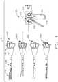
- FIG. 1depicts a motor-driven surgical system 10 that may be used to perform a variety of different surgical procedures.
- the surgical system 10includes four interchangeable surgical tool assemblies 100, 200, 300 and 1000 that are each adapted for interchangeable use with a handle assembly 500.
- Each interchangeable surgical tool assembly 100, 200, 300 and 1000may be designed for use in connection with the performance of one or more specific surgical procedures.
- the interchangeable surgical tool assembliesmay be effectively employed with a tool drive assembly of a robotically controlled or automated surgical system.
- the surgical tool assemblies disclosed hereinmay be employed with various robotic systems, instruments, components and methods such as, but not limited to, those disclosed in U.S. Patent No. 9,072,535 , entitled SURGICAL STAPLING INSTRUMENTS WITH ROTATABLE STAPLE DEPLOYMENT ARRANGEMENTS, which is hereby incorporated by reference herein in its entirety.
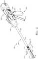
- FIG. 2illustrates one form of an interchangeable surgical tool assembly 100 that is operably coupled to the handle assembly 500.
- FIG. 3illustrates attachment of the interchangeable surgical tool assembly 100 to the handle assembly 500. The attachment arrangement and process depicted in FIG. 3 may also be employed in connection with attachment of any of the interchangeable surgical tool assemblies 100, 200, 300 and 1000 to a tool drive portion or tool drive housing of a robotic system.
- the handle assembly 500may comprise a handle housing 502 that includes a pistol grip portion 504 that can be gripped and manipulated by the clinician.
- the handle assembly 500operably supports a plurality of drive systems that are configured to generate and apply various control motions to corresponding portions of the interchangeable surgical tool assembly 100, 200, 300 and/or 1000 that is operably attached thereto.
- the handle assembly 500may further include a frame 506 that operably supports the plurality of drive systems.
- the frame 506can operably support a "first" or closure drive system, generally designated as 510, which may be employed to apply closing and opening motions to the interchangeable surgical tool assembly 100, 200, 300 and 1000 that is operably attached or coupled to the handle assembly 500.
- the closure drive system 510may include an actuator in the form of a closure trigger 512 that is pivotally supported by the frame 506.
- the closure drive system 510further includes a closure linkage assembly 514 that is pivotally coupled to the closure trigger 512 or otherwise operably interfaces therewith.
- the closure linkage assembly 514includes a transverse attachment pin 516 that facilitates attachment to a corresponding drive system on the surgical tool assembly.
- the cliniciandepresses the closure trigger 512 towards the pistol grip portion 504.
- the closure drive systemis configured to lock the closure trigger 512 into the fully depressed or fully actuated position.
- closure release button assembly 518When the clinician desires to unlock the closure trigger 512 to permit it to be biased to the unactuated position, the clinician simply activates a closure release button assembly 518 which enables the closure trigger to return to unactuated position.
- the closure release button 518may also be configured to interact with various sensors that communicate with a microcontroller 520 in the handle assembly 500 for tracking the position of the closure trigger 512. Further details concerning the configuration and operation of the closure release button assembly 518 may be found in U.S. Patent Application Publication No. 2015/0272575 .
- the handle assembly 500 and the frame 506may operably support another drive system referred to herein as a firing drive system 530 that is configured to apply firing motions to corresponding portions of the interchangeable surgical tool assembly that is attached thereto.
- a firing drive system 530may employ an electric motor (not shown in FIGS. 1-3 ) that is located in the pistol grip portion 504 of the handle assembly 500.
- the motormay be a DC brushed driving motor having a maximum rotation of, approximately, 25,000 RPM, for example.
- the motormay include a brushless motor, a cordless motor, a synchronous motor, a stepper motor, or any other suitable electric motor.
- the motormay be powered by a power source 522 that in one form may comprise a removable power pack.
- the power packmay support a plurality of Lithium Ion ("LI") or other suitable batteries therein. A number of batteries may be connected in series may be used as the power source 522 for the surgical system 10.
- the power source 522may be replaceable and/or rechargeable.
- the electric motoris configured to axially drive a longitudinally movable drive member 540 in a distal and proximal directions depending upon the polarity of the motor. For example, when the motor is driven in one rotary direction, the longitudinally movable drive member 540 the will be axially driven in the distal direction "DD". When the motor is driven in the opposite rotary direction, the longitudinally movable drive member 540 will be axially driven in a proximal direction "PD”.
- the handle assembly 500can include a switch 513 which can be configured to reverse the polarity applied to the electric motor by the power source 522 or otherwise control the motor.
- the handle assembly 500can also include a sensor or sensors (not shown) that is configured to detect the position of the drive member 540 and/or the direction in which the drive member 540 is being moved. Actuation of the motor can be controlled by a firing trigger 532 ( FIG. 1 ) that is pivotally supported on the handle assembly 500.
- the firing trigger 532may be pivoted between an unactuated position and an actuated position.
- the firing trigger 532may be biased into the unactuated position by a spring or other biasing arrangement such that when the clinician releases the firing trigger 532, it may be pivoted or otherwise returned to the unactuated position by the spring or biasing arrangement.
- the firing trigger 532can be positioned "outboard" of the closure trigger 512 as was discussed above.
- the handle assembly 500may be equipped with a firing trigger safety button (not shown) to prevent inadvertent actuation of the firing trigger 532.
- a firing trigger safety button(not shown) to prevent inadvertent actuation of the firing trigger 532.
- the safety buttonis contained in the handle assembly 500 where the clinician cannot readily access it and move it between a safety position preventing actuation of the firing trigger 532 and a firing position wherein the firing trigger 532 may be fired.
- the safety button and the firing trigger 532pivot down wherein they can then be manipulated by the clinician.
- the longitudinally movable drive member 540may have a rack of teeth (not shown) formed thereon for meshing engagement with a corresponding drive gear arrangement (not shown) that interfaces with the motor. Further details regarding those features may be found in U.S. Patent Application Publication No. 2015/0272575 .
- At least one formalso includes a manually-actuatable "bailout" assembly that is configured to enable the clinician to manually retract the longitudinally movable drive member 540 should the motor become disabled.
- the bailout assemblymay include a lever or bailout handle assembly that is stored within the handle assembly 500 under a releasable door 550. The lever is configured to be manually pivoted into ratcheting engagement with the teeth in the drive member 540.
- the interchangeable surgical tool assembly 100includes a surgical end effector 110 that comprises a first jaw and a second jaw.
- the first jawcomprises an elongate channel 112 that is configured to operably support a surgical staple cartridge 116 therein.
- the second jawcomprises an anvil 114 that is pivotally supported relative to the elongate channel 112.
- the interchangeable surgical tool assembly 100also includes a lockable articulation joint 120 which can be configured to releasably hold the end effector 110 in a desired position relative to a shaft axis SA. Details regarding various constructions and operation of the end effector 110, the articulation joint 120 and the articulation lock are set forth in U.S. Patent Application Serial No.
- the interchangeable surgical tool assembly 100can include a proximal housing or nozzle 130 and a closure tube assembly 140 which can be utilized to close and/or open the anvil 114 of the end effector 110.
- the closure tube assembly 140is movably supported on a spine 145 which supports articulation driver arrangement 147 for applying articulation motions to the surgical end effector 110.
- the spine 145is configured to, one, slidably support a firing bar 170 therein and, two, slidably support the closure tube assembly 140 which extends around the spine 145.
- the spine 145includes a proximal end that is rotatably supported in a chassis 150. See FIG. 3 .
- the proximal end of the spine 145is attached to a spine bearing (not shown) that is configured to be supported within the chassis 150.
- a spine bearing(not shown) that is configured to be supported within the chassis 150.
- Such an arrangementfacilitates rotatable attachment of the spine 145 to the chassis 150 such that the spine 145 may be selectively rotated about a shaft axis SA relative to the chassis 150.
- the interchangeable surgical tool assembly 100includes a closure shuttle 160 that is slidably supported within the chassis 150 such that it may be axially moved relative thereto.
- the closure shuttle 160includes a pair of proximally-protruding hooks 162 that are configured for attachment to the attachment pin 516 that is attached to the closure linkage assembly 514 in the handle assembly 500.
- a proximal closure tube segment 146 of the closure tube assembly 140is coupled to the closure shuttle 160 for relative rotation thereto.
- a closure spring(not shown) may also be journaled on the closure tube assembly 140 and serves to bias the closure tube assembly 140 in the proximal direction "PD" which can serve to pivot the closure trigger 512 into the unactuated position when the shaft assembly 100 is operably coupled to the handle assembly 500.
- the closure tube assembly 140is translated distally (direction DD) to close the anvil 114, for example, in response to the actuation of the closure trigger 512.
- the closure tube assembly 140includes a distal closure tube segment 142 that is pivotally pinned to a distal end of a proximal closure tube segment 146.
- the distal closure tube segment 142is configured to axially move with the proximal closure tube segment 146 relative to the surgical end effector 110.
- the distal closure tube segment 142has a horseshoe aperture 143 therein that defines a downwardly extending return tab (not shown) that cooperates with an anvil tab 117 formed on the proximal end of the anvil 114 to pivot the anvil 114 back to an open position.
- the closure tube assembly 140In the fully open position, the closure tube assembly 140 is in its proximal-most or unactuated position.
- the interchangeable surgical tool assembly 100further includes a firing bar 170 that is supported for axial travel within the shaft spine 145.
- the firing bar 170includes an intermediate firing shaft portion that is configured for attachment to a distal cutting portion or knife bar that is configured for axial travel through the surgical end effector 110.
- the interchangeable surgical tool assembly 100includes a clutch assembly (not shown) which can be configured to selectively and releasably couple the articulation driver to the firing bar 170. Further details regarding the clutch assembly features and operation may be found in U.S. Patent Application Publication No. 2014/0263541 . As discussed in U.S. Patent Application Publication No.
- the interchangeable surgical tool assembly 100may also include a slip ring assembly (not shown) which can be configured to conduct electrical power to and/or from the end effector 110 and/or communicate signals to and/or from the end effector 110.
- the chassis 150has at least one, and preferably two, tapered attachment portions 152 formed thereon that are adapted to be received within corresponding dovetail slots 507 formed within a distal end of the frame 506.
- Each dovetail slot 507may be tapered or, stated another way, be somewhat V-shaped to seatingly receive the tapered attachment portions 152 therein.
- a shaft attachment lug 172is formed on the proximal end of the firing shaft 170. When the interchangeable surgical tool assembly 100 is coupled to the handle assembly 500, the shaft attachment lug 172 is received in a firing shaft attachment cradle 542 formed in the distal end of the longitudinally movable drive member 540.
- the interchangeable surgical tool assembly 100also employs a latch system 180 for releasably latching the shaft assembly 100 to the frame 506 of the handle assembly 500.
- the latch system 180includes a lock member or lock yoke 182 that is movably coupled to the chassis 150.
- the lock yoke 182includes two proximally protruding lock lugs 184 that are configured for releasable engagement with corresponding lock detents or grooves 509 in the distal attachment flange of the frame 506.
- the lock yoke 182is biased in the proximal direction by spring or biasing member.
- Actuation of the lock yoke 182may be accomplished by a latch button 186 that is slidably mounted on a latch actuator assembly that is mounted to the chassis 150.
- the latch button 186may be biased in a proximal direction relative to the lock yoke 182.
- the lock yoke 182may be moved to an unlocked position by biasing the latch button 186 the in distal direction DD which also causes the lock yoke 182 to pivot out of retaining engagement with the distal attachment flange of the frame 506.
- the clinicianmay position the chassis 150 of the interchangeable surgical tool assembly 100 above or adjacent to the distal end of the frame 506 such that the tapered attachment portions 152 formed on the chassis 150 are aligned with the dovetail slots 507 in the frame 506.
- the clinicianmay then move the surgical tool assembly 100 along an installation axis IA that is perpendicular to the shaft axis SA to seat the tapered attachment portions 152 in "operable engagement" with the corresponding dovetail receiving slots 507 in the distal end of the frame 506.
- the shaft attachment lug 172 on the firing shaft 170will also be seated in the cradle 542 in the longitudinally movable drive member 540 and the portions of pin 516 on the closure link 514 will be seated in the corresponding hooks 162 in the closure shuttle 160.
- operble engagementin the context of two components means that the two components are sufficiently engaged with each other so that upon application of an actuation motion thereto, the components may carry out their intended action, function and/or procedure.
- the surgical system 10 illustrated in that Figureincludes four interchangeable surgical tool assemblies 100, 200, 300 and 1000 that may each be effectively employed with the same handle assembly 500 to perform different surgical procedures.
- the construction of an exemplary form of interchangeable surgical tool assembly 100was briefly discussed above and is discussed in further detail in U.S. Patent Application Publication No. 2014/0263541 .
- Various details regarding interchangeable surgical tool assemblies 200 and 300may be found in the various U.S. Patent Applications that were filed on even date herewith and which have been incorporated by reference herein.
- Various details regarding interchangeable surgical tool assembly 1000will be discussed in further detail below.
- each of the surgical tool assemblies 100, 200, 300 and 1000includes a pair of jaws wherein at least one of the jaws is movable between open positions wherein tissue may be captured or manipulated between the two jaws and closed positions wherein the tissue is firmly retained therebetween.
- the movable jaw or jawsare moved between open and closed positions upon application of closure and opening motions applied thereto from the handle assembly or the robotic or automated surgical system to which the surgical tool assembly is operably coupled.
- each of the illustrated interchangeable surgical tool assembliesincludes a firing member that is configured to cut tissue and fire staples from a staple cartridge that is supported in one of the jaws in response to firing motions applied thereto by the handle assembly or robotic system.
- Each surgical tool assemblymay be uniquely designed to perform a specific procedure, for example, to cut and fasten a particular type of and thickness of tissue within a certain area in the body.
- the closing, firing and articulation control systems in the handle assembly 500 or robotic systemmay be configured to generate axial control motions and/or rotary control motions depending upon the type of closing, firing and articulation system configurations that are employed in the surgical tool assembly.
- one of the closure system control componentswhich may, for example, comprise a closure tube assembly as described above, moves axially from an unactuated position to its fully actuated position.
- the axial distance that the closure tube assembly moves between its unactuated position to its fully actuated positionmay be referred to herein as its "closure stroke length”.
- one of the firing system control componentswhich may, for example, comprise the longitudinally movable drive member as described above moves axially from its unactuated position to its fully actuated or fired position.
- the axial distance that the longitudinally movable drive member moves between its unactuated position and its fully fired positionmay be referred to herein as its "firing stroke length”.
- the handle assembly or robotic systemmay employ articulation control components that move axially through an "articulation drive stroke length".
- each of the surgical tool assembliesmust be able to accommodate control movements of the closure, firing and/or articulation components through each of their entire stroke lengths without placing undue stress on the surgical tool components which might lead to damage or catastrophic failure of surgical tool assembly.
- the interchangeable surgical tool assembly 1000includes a surgical end effector 1100 that comprises an elongate channel 1102 that is configured to operably support a staple cartridge 1110 therein.
- the end effector 1100may further include an anvil 1130 that is pivotally supported relative to the elongate channel 1102.
- the interchangeable surgical tool assembly 1000may further include an articulation joint 1200 and an articulation lock 1210 ( FIGS. 5 and 8-10 ) which can be configured to releasably hold the end effector 1100 in a desired articulated position relative to a shaft axis SA. Details regarding the construction and operation of the articulation lock 1210 may be found in in U.S. Patent Application Serial No.
- the interchangeable surgical tool assembly 1000can further include a proximal housing or nozzle 1300 comprised of nozzle portions 1302, 1304 as well as an actuator wheel portion 1306 that is configured to be coupled to the assembled nozzle portions 1302, 1304 by snaps, lugs, screws etc.
- the interchangeable surgical tool assembly 1000can further include a closure tube assembly 1400 which can be utilized to close and/or open the anvil 1130 of the end effector 1100 as will be discussed in further detail below.
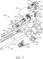
- the interchangeable surgical tool assembly 1000can include a spine assembly 1500 which can be configured to support the articulation lock 1210.
- the spine assembly 1500comprises an "elastic" spine or frame member 1510 which will be described in further detail below.
- a distal end portion 1522 of the elastic spine member 1510is attached to a distal frame segment 1560 that operably supports the articulation lock 1210 therein.
- the spine assembly 1500is configured to, one, slidably support a firing member assembly 1600 therein and, two, slidably support the closure tube assembly 1400 which extends around the spine assembly 1500.
- the spine assembly 1500can also be configured to slidably support a proximal articulation driver 1700.
- the distal frame segment 1560is pivotally coupled to the elongate channel 1102 by an end effector mounting assembly 1230.
- the distal end 1562 of the distal frame segment 1560has a pivot pin 1564 formed thereon.
- the pivot pin 1564is adapted to be pivotally received within a pivot hole 1234 formed in pivot base portion 1232 of the end effector mounting assembly 1230.
- the end effector mounting assembly 1230is attached to the proximal end 1103 of the elongate channel 1102 by a spring pin 1105 or other suitable member.
- the pivot pin 1564defines an articulation axis B-B that is transverse to the shaft axis SA. See FIG. 4 .
- Such arrangementfacilitates pivotal travel (i.e., articulation) of the end effector 1100 about the articulation axis B-B relative to the spine assembly 1500.
- the articulation driver 1700has a distal end 1702 that is configured to operably engage the articulation lock 1210.
- the articulation lock 1210includes an articulation frame 1212 that is adapted to operably engage a drive pin 1238 on the pivot base portion 1232 of the end effector mounting assembly 1230.
- a cross-link 1237may be linked to the drive pin 1238 and articulation frame 1212 to assist articulation of the end effector 1100.
- further details regarding the operation of the articulation lock 1210 and the articulation frame 1212may be found in U.S. Patent Application Serial No. 13/803,086 , now U.S. Patent Application Publication No.
- the elastic spine member 1510includes a proximal end 1514 which is rotatably supported in a chassis 1800.
- the proximal end 1514 of the elastic spine member 1510has a thread 1516 formed thereon for threaded attachment to a spine bearing (not shown) that is configured to be supported within the chassis 1800.
- a spine bearingnot shown
- Such an arrangementfacilitates rotatable attachment of the elastic spine member 1510 to the chassis 1800 such that the spine assembly 1500 may be selectively rotated about a shaft axis SA relative to the chassis 1800.
- the interchangeable surgical tool assembly 1000includes a closure shuttle 1420 that is slidably supported within the chassis 1800 such that it may be axially moved relative thereto.
- the closure shuttle 1420includes a pair of proximally-protruding hooks 1421 that are configured for attachment to the attachment pin 516 that is attached to the closure linkage assembly 514 of the handle assembly 500 as was discussed above.
- a proximal end 1412 of a proximal closure tube segment 1410is coupled to the closure shuttle 1420 for relative rotation thereto.
- a U-shaped connector 1424is inserted into an annular slot 1414 in the proximal end 1412 of the proximal closure tube segment 1410 and is retained within vertical slots 1422 in the closure shuttle 1420. See FIG. 7 .
- Such arrangementserves to attach the proximal closure tube segment 1410 to the closure shuttle 1420 for axial travel therewith while enabling the closure tube assembly 1400 to rotate relative to the closure shuttle 1420 about the shaft axis SA.
- a closure spring(not shown) is journaled on the proximal end 1412 of the proximal closure tube segment 1410 and serves to bias the closure tube assembly 1400 in the proximal direction PD which can serve to pivot the closure trigger 512 on the handle assembly 500 ( FIG. 3 ) into the unactuated position when the interchangeable surgical tool assembly 1000 is operably coupled to the handle assembly 500.
- the illustrated interchangeable surgical tool assembly 1000includes an articulation joint 1200.
- Other interchangeable surgical tool assembliesmay not be capable of articulation.
- upper and lower tangs 1415, 1416protrude distally from a distal end of the proximal closure tube segment 1410 to be movably coupled to an end effector closure sleeve or distal closure tube segment 1430 of the closure tube assembly 1400.
- the distal closure tube segment 1430includes upper and lower tangs 1434, 1436 that protrude proximally from a proximal end thereof.
- An upper double pivot link 1220includes proximal and distal pins that engage corresponding holes in the upper tangs 1415, 1434 of the proximal closure tube segment 1410 and distal closure tube segment 1430, respectively.
- a lower double pivot link 1222includes proximal and distal pins that engage corresponding holes in the lower tangs 1416 and 1436 of the proximal closure tube segment 1410 and distal closure tube segment 1430, respectively.
- the interchangeable surgical tool assembly 1000further includes a firing member assembly 1600 that is supported for axial travel within the spine assembly 1500.
- the firing member assembly 1600includes an intermediate firing shaft portion 1602 that is configured for attachment to a distal cutting portion or knife bar 1610.
- the firing member assembly 1600may also be referred to herein as a "second shaft” and/or a "second shaft assembly”.
- the intermediate firing shaft portion 1602may include a longitudinal slot 1604 in the distal end thereof which can be configured to receive a tab (not shown) on the proximal end of the knife bar 1610.
- the longitudinal slot 1604 and the proximal end of the knife bar 1610can be sized and configured to permit relative movement therebetween and can comprise a slip joint 1612.
- the slip joint 1612can permit the intermediate firing shaft portion 1602 of the firing member assembly 1600 to be moved to articulate the end effector 1100 without moving, or at least substantially moving, the knife bar 1610.
- the intermediate firing shaft portion 1602can be advanced distally until a proximal sidewall of the longitudinal slot 1604 comes into contact with the tab on the knife bar 1610 to advance the knife bar 1610 and fire the staple cartridge 1110 positioned within the elongate channel 1102.
- the elastic spine member 1520has an elongate opening or window 1525 therein to facilitate assembly and insertion of the intermediate firing shaft portion 1602 into the elastic spine member 1520.
- a top frame segment 1527may be engaged with the elastic spine member 1520 to enclose the intermediate firing shaft portion 1602 and knife bar 1610 therein. Further description of the operation of the firing member assembly 1600 may be found in U.S. Patent Application Serial No. 13/803,086 , now U.S. Patent Application Publication No. 2014/0263541 .
- the interchangeable tool assembly 1000can include a clutch assembly 1620 which can be configured to selectively and releasably couple the articulation driver 1800 to the firing member assembly 1600.
- the clutch assembly 1620includes a lock collar, or sleeve 1622, positioned around the firing member assembly 1600 wherein the lock sleeve 1622 can be rotated between an engaged position in which the lock sleeve 1622 couples the articulation driver 1700 to the firing member assembly 1600 and a disengaged position in which the articulation driver 1700 is not operably coupled to the firing member assembly 1600.
- lock sleeve 1622When lock sleeve 1622 is in its engaged position, distal movement of the firing member assembly 1600 can move the articulation driver 1700 distally and, correspondingly, proximal movement of the firing member assembly 1600 can move the articulation driver 1700 proximally.
- lock sleeve 1622When lock sleeve 1622 is in its disengaged position, movement of the firing member assembly 1600 is not transmitted to the articulation driver 1700 and, as a result, the firing member assembly 1600 can move independently of the articulation driver 1700.
- the articulation driver 1700can be held in position by the articulation lock 1210 when the articulation driver 1700 is not being moved in the proximal or distal directions by the firing member assembly 1600.
- the lock sleeve 1622can comprise a cylindrical, or an at least substantially cylindrical, body including a longitudinal aperture 1624 defined therein configured to receive the firing member assembly 1600.
- the lock sleeve 1622can comprise diametrically-opposed, inwardly-facing lock protrusions 1626, 1628 and an outwardly-facing lock member 1629.
- the lock protrusions 1626, 1628can be configured to be selectively engaged with the intermediate firing shaft portion 1602 of the firing member assembly 1600.
- the lock protrusions 1626, 1628are positioned within a drive notch 1605 defined in the intermediate firing shaft portion 1602 such that a distal pushing force and/or a proximal pulling force can be transmitted from the firing member assembly 1600 to the lock sleeve 1622.
- the second lock member 1629is received within a drive notch 1704 defined in the articulation driver 1700 such that the distal pushing force and/or the proximal pulling force applied to the lock sleeve 1622 can be transmitted to the articulation driver 1700.
- the firing member assembly 1600, the lock sleeve 1622, and the articulation driver 1700will move together when the lock sleeve 1622 is in its engaged position.
- the lock protrusions 1626, 1628may not be positioned within the drive notch 1605 of the intermediate firing shaft portion 1602 of the firing member assembly 1600 and, as a result, a distal pushing force and/or a proximal pulling force may not be transmitted from the firing member assembly 1600 to the lock sleeve 1622.
- the distal pushing force and/or the proximal pulling forcemay not be transmitted to the articulation driver 1700.
- the firing member assembly 1600can be slid proximally and/or distally relative to the lock sleeve 1622 and the proximal articulation driver 1700.
- the clutching assembly 1620further includes a switch drum 1630 that interfaces with the lock sleeve 1622. Further details concerning the operation of the switch drum and lock sleeve 1622 may be found in U.S. Patent Application Serial No. 13/803,086 , now U.S. Patent Application Publication No. 2014/0263541 , and Serial No. 15/019,196 .
- the switch drum 1630can further comprise at least partially circumferential openings 1632, 1634 defined therein which can receive circumferential mounts 1305 that extend from the nozzle halves 1302, 1304 and permit relative rotation, but not translation, between the switch drum 1630 and the proximal nozzle 1300. See FIG. 6 . Rotation of the nozzle 1300 to a point where the mounts reach the end of their respective slots 1632, 1634 in the switch drum 1630 will result in rotation of the switch drum 1630 about the shaft axis SA. Rotation of the switch drum 1630 will ultimately result in the movement of the lock sleeve 1622 between its engaged and disengaged positions.
- the nozzle 1300may be employed to operably engage and disengage the articulation drive system with the firing drive system in the various manners described in further detail in U.S. Patent Application Serial No. 13/803,086 , now U.S. Patent Application Publication No. 2014/0263541 , and U.S. Patent Application Serial No. 15/019,196 , which have each been herein incorporated by reference in their respective entirety.
- the switch drum 1630includes a an L-shaped slot 1636 that extends into a distal opening 1637 in the switch drum 1630.
- the distal opening 1637receives a transverse pin 1639 of a shifter plate 1638.
- the shifter plate 1638is received within a longitudinal slot (not shown) that is provided in the lock sleeve 1622 to facilitate axial movement of the lock sleeve 1622 when engaged with the articulation driver 1700.
- Further details regarding the operation of the shifter plate and shift drum arrangementsmay be found in U.S. Patent Application Serial No. 14/868,718, filed September 28, 2015 , entitled SURGICAL STAPLING INSTRUMENT WITH SHAFT RELEASE, POWERED FIRING AND POWERED ARTICULATION, the entire disclosure of which is hereby incorporated by reference herein.
- the interchangeable tool assembly 1000can comprise a slip ring assembly 1640 which can be configured to conduct electrical power to and/or from the end effector 1100 and/or communicate signals to and/or from the end effector 1100, back to a microprocessor in the handle assembly or robotic system controller, for example.
- a slip ring assembly 1640which can be configured to conduct electrical power to and/or from the end effector 1100 and/or communicate signals to and/or from the end effector 1100, back to a microprocessor in the handle assembly or robotic system controller, for example.
- Further details concerning the slip ring assembly 1640 and associated connectorsmay be found in U.S. Patent Application Serial No. 13/803,086 , now U.S. Patent Application Publication No. 2014/0263541 , and U.S. Patent Application Serial No. 15/019,196 which have each been herein incorporated by reference in their respective entirety as well as in U.S. Patent Application Serial No.
- the interchangeable surgical tool assembly 1000can also comprise at least one sensor that is configured to detect the position of the switch drum 1630.
- the chassis 1800includes at least one, and preferably two, tapered attachment portions 1802 formed thereon that are adapted to be received within corresponding dovetail slots 507 formed within the distal end portion of the frame 506 of the handle assembly 500 as was discussed above.
- a shaft attachment lug 1605is formed on the proximal end of the intermediate firing shaft 1602.
- the shaft attachment lug 1605is received in a firing shaft attachment cradle 542 that is formed in the distal end of the longitudinal drive member 540. See FIG. 3 .
- the latch system 1810includes a lock member or lock yoke 1812 that is movably coupled to the chassis 1800.
- the lock yoke 1812has a U-shape with two spaced downwardly extending legs 1814.
- the legs 1814each have a pivot lug (not shown) formed thereon that are adapted to be received in corresponding holes 1816 formed in the chassis 1800.
- Such arrangementfacilitates pivotal attachment of the lock yoke 1812 to the chassis 1800.
- the lock yoke 1812may include two proximally protruding lock lugs 1818 that are configured for releasable engagement with corresponding lock detents or grooves 509 in the distal end of the frame 506 of the handle assembly 500. See FIG. 3 .
- the lock yoke 1812is biased in the proximal direction by a spring or biasing member 1819. Actuation of the lock yoke 1812 may be accomplished by a latch button 1820 that is slidably mounted on a latch actuator assembly 1822 that is mounted to the chassis 1800.
- the latch button 1820may be biased in a proximal direction relative to the lock yoke 1812.
- the lock yoke 1812may be moved to an unlocked position by biasing the latch button 1820 the in distal direction which also causes the lock yoke 1812 to pivot out of retaining engagement with the distal end of the frame 506.
- the lock lugs 1818are retainingly seated within the corresponding lock detents or grooves 509 in the distal end of the frame 506.
- the lock yoke 1812includes at least one and preferably two lock hooks 1824 that are adapted to contact corresponding lock lug portions 1426 that are formed on the closure shuttle 1420.
- the lock yoke 1812may be pivoted in a distal direction to unlock the interchangeable surgical tool assembly 1000 from the handle assembly 500.
- the lock hooks 1824do not contact the lock lug portions 1426 on the closure shuttle 1420.
- the lock yoke 1812is prevented from being pivoted to an unlocked position.
- the knife bar 1610may comprise a laminated beam structure that includes at least two beam layers.
- Such beam layersmay comprise, for example, stainless steel bands that are interconnected by, for example, welding or pinning together at their proximal ends and/or at other locations along their length.
- the distal ends of the bandsare not connected together to allow the laminates or bands to splay relative to each other when the end effector is articulated.
- Such arrangementpermits the knife bar 1610 to be sufficiently flexible to accommodate articulation of the end effector.
- Various laminated knife bar arrangementsare disclosed in U.S. Patent Application Serial No. 15/019,245 . As can also be seen in FIG.
- a middle support member 1614is employed to provide lateral support to the knife bar 1610 as it flexes to accommodate articulation of the surgical end effector 1100. Further details concerning the middle support member and alternative knife bar support arrangements are disclosed in U.S. Patent Application Serial No. 15/019,245 . As can also be seen in FIG. 10 , a firing member or knife member 1620 is attached to the distal end of the knife bar 1610.
- FIG. 11illustrates one form of a firing member 1660 that may be employed with the interchangeable tool assembly 1000.
- the firing member 1660comprises a body portion 1662 that includes a proximally extending connector member 1663 that is configured to be received in a correspondingly shaped connector opening 1614 in the distal end of the knife bar 1610. See FIG. 10 .
- the connector 1663may be retained within the connector opening 1614 by friction and/or welding or suitable adhesive, etc.
- the body portion 1662protrudes through an elongate slot 1104 in the elongate channel 1102 and terminates in a foot member 1664 that extends laterally on each side of the body portion 1662.
- the foot member 1664rides within a passage 1105 in the elongate channel 1102 that is located under the surgical staple cartridge 1110.
- one form of the firing member 1660may further include laterally protruding central tabs, pins or retainer features 1680.
- the central retainer features 1680ride on the inner surface 1106 of the elongate channel 1102.
- the body portion 1662 of the firing member 1660further includes a tissue cutting edge or feature 1666 that is disposed between a distally protruding hook feature 1665 and a distally protruding top nose portion 1670.
- the firing member 1660may further include two laterally extending top tabs, pins or anvil engagement features 1665. As the firing member 1660 is driven distally, a top portion of the body 1662 extends through a centrally disposed anvil slot 1138 and the top anvil engagement features 1672 ride on corresponding ledges 1136 formed on each side of the anvil slot 1134. See FIGS. 13 and 14 .
- the firing member 1660is configured to operably interface with a sled assembly 1120 that is operably supported within the body 1111 of the surgical staple cartridge 1110.
- the sled assembly 1120is slidably displaceable within the surgical staple cartridge body 1111 from a proximal starting position adjacent the proximal end 1112 of the cartridge body 1111 to an ending position adjacent a distal end 1113 of the cartridge body 1111.
- the cartridge body 1111operably supports therein a plurality of staple drivers (not shown) that are aligned in rows on each side of a centrally disposed slot 1114.
- the centrally disposed slot 1114enables the firing member 1660 to pass therethrough and cut the tissue that is clamped between the anvil 1130 and the staple cartridge 1110.
- the driversare associated with corresponding pockets 1116 that open through the upper deck surface 1115 of the cartridge body.
- Each of the staple driverssupports one or more surgical staple or fastener (not shown) thereon.
- the sled assembly 1120includes a plurality of sloped or wedge-shaped cams 1122 wherein each cam 1122 corresponds to a particular line of fasteners or drivers located on a side of the slot 1114.
- one cam 1122is aligned with one line of "double” drivers that each support two staples or fasteners thereon and another cam 1122 is aligned with another line of "single” drivers on the same side of the slot 1114 that each operably support a single surgical staple or fastener thereon.
- the sled assembly 1120has a central body portion 1124 that is configured to be engaged by the hook portion 1665 of the firing member 1660.
- the firing member 1660drives the sled assembly 1120 distally as well.
- the tissue cutting feature 1666cuts the tissue that is clamped between the anvil assembly 1130 and the cartridge 1110 and the sled assembly 1120 drives the drivers upwardly in the cartridge which drive the corresponding staples or fasteners into forming contact with the anvil assembly 1130.
- the elongate shaft assemblymay be configured in such a way so as to prevent the inadvertent advancement of the firing member unless an unspent staple cartridge is properly supported in the elongate channel 1102 of the surgical end effector 1100. If, for example, no staple cartridge is present at all and the firing member is distally advanced through the end effector, the tissue would be severed, but not stapled. Similarly, if a spent staple cartridge (i.e., a staple cartridge wherein at least some of the staples have already been fired therefrom) is present in the end effector and the firing member is advanced, the tissue would be severed, but may not be completely stapled, if at all.
- a spent staple cartridgei.e., a staple cartridge wherein at least some of the staples have already been fired therefrom
- An "unfired”, “unspent”, “fresh” or “new” cartridge 1110means herein that the cartridge 1110 has all of its fasteners in their "ready-to-be-fired positions".
- the sled assembly 1120When in that position, the sled assembly 1120 is located in its starting position.
- the new cartridge 1110is seated within the elongate channel 1102 and may be retained therein by snap features on the cartridge body that are configured to retainingly engage corresponding portions of the elongate channel 1102.
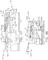
- FIGS. 15 and 18illustrate a portion of the surgical end effector 1100 with a new or unfired surgical staple cartridge 1110 seated therein. As can be seen in those Figures, the sled assembly 1120 is in the starting position.
- the illustrated interchangeable surgical tool assembly 1000employs a firing member lockout system generally designated as 1650.
- the firing member lockout system 1650includes movable lock member 1652 that is configured to retainingly engage the firing member 1660 when a surgical staple cartridge 1110 is not properly seated within the elongate channel 1102.
- the lock member 1652comprises at least one laterally moving locking portion 1654 that is configured to retainingly engage a corresponding portion of the firing member when the sled assembly 1120 is not present within the cartridge 1110 in its starting position.
- the lock member 1652employs two laterally moving locking portions 1654 wherein each locking portion 1654 engages a laterally extending portion of the firing member 1660.
- the lock member 1652comprises a generally U-shaped spring member wherein each laterally movable leg or locking portion 1654 extends from a central spring portion 1653 and is configured to move in lateral directions represented by "L" in FIGS. 18 and 19 .
- the spring or lock member 1652may be fabricated from high strength spring steel or similar material.
- the central spring portion 1653may be seated within a slot 1236 in the end effector mounting assembly 1230. See FIG. 10 .
- each of the laterally movable legs or locking portions 1654has a distal end 1656 with a locking window 1658 therein.
- FIGS. 15 and 18illustrate a portion of the surgical end effector 1100 with a new unfired cartridge 1110 properly installed therein.
- the sled assembly 1120includes an unlocking feature 1126 that corresponds to each of the laterally movable locking portion 1654.
- an unlocking feature 1126is provided on or extends proximally from each of the central wedge-shaped cams 1122.
- the unlocking feature 1126may comprise a proximally protruding portion of the corresponding wedge-shaped cam 1122.
- FIG. 15 and 18illustrate a portion of the surgical end effector 1100 with a new unfired cartridge 1110 properly installed therein.
- the sled assembly 1120includes an unlocking feature 1126 that corresponds to each of the laterally movable locking portion 1654.
- an unlocking feature 1126is provided on or extends proximally from each of the central wedge-shaped cams 1122.
- the unlocking feature 1126may comprise a proximally protruding portion of the corresponding wedge-
- the unlocking features 1124engage and bias the corresponding locking portions 1654 laterally in a direction that is transverse to the shaft axis SA.
- the central retainer features 1680are not in retaining engagement with their corresponding locking window 1658.
- the firing member 1660may be distally axially advanced (fired).
- the locking portions 1654spring laterally into retaining engagement with the firing member 1660.
- the firing member 1660cannot be moved distally.
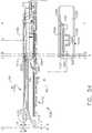
- FIGS. 16 and 17illustrate the retraction of the firing member 1660 back to the starting position after firing the cartridge 1110 and driving the sled assembly 1120 distally.
- FIG. 16depicts the initial reengagement of the retaining feature 1680 into its corresponding locking window 1658.
- FIG. 17illustrates the retaining feature in its locked position when the firing member 1660 has been fully retracted back to its starting position.
- each of the retaining features 1680may be provided with a proximally facing, laterally tapered end portion.
- Such lockout systemprevents actuation of the firing member 1660 when a new unfired cartridge is not present or when a new unfired cartridge is present, but has not been properly seated in the elongate channel 1102.
- the lockout systemmay prevent the clinician from distally advancing the firing member in the case where a spent or partially fired cartridge has been inadvertently properly seated within the elongate channel.
- Another advantage that may be provided by the lockout system 1650is that, unlike other firing member lock out arrangements that require movement of the firing member into and out of alignment with the corresponding slots/passages in the staple cartridge, the firing member 1660 remains in alignment with the cartridge passages while in the locked and unlocked position.
- the locking portions 1654are designed to move laterally into and out of engagement with corresponding sides of the firing member. Such lateral movement of the locking portions or portion is distinguishable from other locking arrangements that move in vertical directions to engage and disengage portions of the firing member.
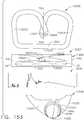
- the anvil 1130includes an elongated anvil body portion 1132 and a proximal anvil mounting portion 1150.
- the elongated anvil body portion 1132includes an outer surface 1134 that defines two downwardly extending tissue stop members 1136 that are adjacent to the proximal anvil mounting portion 1150.
- the elongated anvil body portion 1132also includes an underside 1135 that defines an elongate anvil slot 1138. In the illustrated arrangement shown in FIG.14 , the anvil slot 1138 is centrally disposed in the underside 1135.
- the underside 1135includes three rows 1140, 1141, 1142 of staple forming pockets 1143, 1144 and 1145 located on each side of the anvil slot 1138.
- the anvil slot 1138as well as the proximal ramp portion 1148, extend into the anvil mounting portion 1150.
- the anvil slot 1138divides or bifurcates the anvil mounting portion 1150 into two anvil attachment flanges 1151.
- the anvil attachments flanges 1151are coupled together at their proximal ends by a connection bridge 1153.
- the connection bridge 1153serves to provide support to the anvil attachment flanges 1151 and can serve to make the anvil mounting portion 1150 more rigid than the mounting portions of other anvil arrangements wherein the anvil attachment flanges are not connected at their proximal ends.
- the anvil slot 1138has a wide portion 1139 to accommodate the top portion and top anvil engagement features 1632 of the firing member 1660.
- each of the anvil attachment flanges 1151includes a transverse mounting hole 1156 that is configured to receive a pivot pin 1158 ( FIGS. 10 and 20 ) therethrough.
- the anvil mounting portion 1150is pivotally pinned to the proximal end 1103 of the elongate channel 1102 by the pivot pin 1158 which extends through mounting holes 1107 in the proximal end 1103 of the elongate channel 1102 and the mounting hole 1156 in anvil mounting portion 1150.
- Such arrangementserves to pivotally affix the anvil 1130 to the elongate channel 1102 for selective pivotal travel about a fixed anvil axis A-A which is transverse to the shaft axis SA. See FIG. 5 .
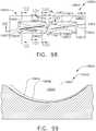
- the anvil mounting portion 1150also includes a cam surface 1152 that extends from a centralized firing member parking area 1154 to the outer surface 1134 of the anvil body portion 1132.
- the anvil 1130is moved between an open position and closed positions by axially advancing and retracting the distal closure tube segment 1430.
- a distal end portion of the distal closure tube segment 1430has an internal cam surface formed thereon that is configured to cammingly engage the cam surface 1552 or cam surfaces formed on the anvil mounting portion 1150.
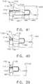
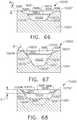
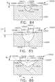
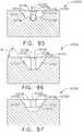
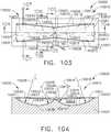
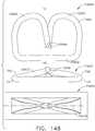
- FIG. 22illustrates a cam surface 1152a formed on the anvil mounting portion 1150 so as to establish a single contact path 1155a with the internal cam surface 1444, for example, on the distal closure tube segment 1430.
- FIG. 23illustrates a cam surface 1152b that is configured relative to the internal cam surface 1444 on the distal closure tube segment to establish two separate and distinct arcuate contact paths 1155b between the cam surface 1152 on the anvil mounting portion 1150 and internal cam surface 1444 on the distal closure tube segment 1430. In addition to other potential advantages discussed herein, such arrangement may serve to better distribute the closure forces from the distal closure tube segment 1430 to the anvil 1130.
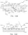
- FIG. 24illustrates a cam surface 1152c that is configured relative to the internal cam surface 1444 of the distal closure tube segment 1430 to establish three distinct zones of contact 1155c and 1155d between the cam surfaces on the anvil mounting portion 1150 and the distal closure tube segment 1430. The zones 1155c, 1155d establish larger areas of camming contact between the cam surface or cam surfaces on the distal closure tube segment 1430 and the anvil mounting portion 1150 and may serve to better distribute the closure forces to the anvil 1130.
- the anvil 1130is pivoted about the anvil axis AA which results in the pivotal movement of the distal end of the end 1133 of elongate anvil body portion 1132 toward the surgical staple cartridge 1110 and distal end 1105 of the elongate channel 1102.
- the anvil body portion 1132begins to pivot, it contacts the tissue that is to be cut and stapled which is now positioned between the underside 1135 of the elongate anvil body portion 1132 and the deck 1116 of the surgical staple cartridge 1110.
- the anvil 1130may experience considerable amounts of resistive forces.
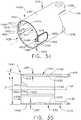
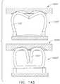
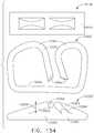
- FIGS. 25-27illustrate an alternative anvil embodiment that includes features that may improve the stiffness of the anvil body and its resistance to flexure forces that may be generated during the closing and/or firing processes.
- the anvil 1130'may otherwise be identical in construction to the anvil 1130 described above except for the differences discussed herein. As can be seen in those Figures, the anvil 1130' has an elongate anvil body 1132' that has an upper body portion 1165 that has an anvil cap1170 attached thereto. In the embodiment depicted in FIGS. 25-27 , the anvil cap 1170 is roughly rectangular in shape and has an outer cap perimeter 1172.
- the perimeter 1172 of the anvil cap 1170is configured to be inserted through the correspondingly-shaped opening 1137 formed in the upper body portion 1165 and received on axially extending internal ledge portions 1139 formed therein. See FIG. 27 .
- the internal ledge portions 1139are configured to support the corresponding long sides 1177 of the anvil cap 1170.
- the anvil cap 1170may be slide onto the internal ledges 1139 through an opening (not shown) in the distal end 1133 of the anvil body 1132'.
- no internal ledge portionsare provided.
- the anvil body 1132' and the anvil cap 1170may be fabricated from suitable metal that is conducive to welding.
- a first weld 1178may extend around the entire cap perimeter 1172 of the anvil cap 1170 or it may only be located along the long sides 1177 of the anvil cap 1170 and not the distal end 1173 and/or proximal end 1175 thereof.
- the first weld 1178may be continuous or it may be discontinuous or intermittent.
- the weld segmentsmay be equally distributed along the long sides 1177 of the anvil cap 1170 or the weld segments may be more densely spaced closer to the distal ends of the long sides 1177 or more densely spaced closer to the proximal ends of the long sides 1177. In still other arrangements, the weld segments may be more densely spaced in the center areas of the long sides 1177 of the anvil cap 1170.
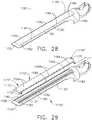
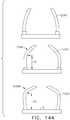
- FIGS. 28-30illustrate an anvil cap 1170' that is configured to be "mechanically interlocked” to the anvil body 1132' as well as welded to the upper body portion 1165.
- a plurality of retention formations 1182are formed into the wall 1180 of the upper body portion 1165 that defines opening 1137.
- the term "mechanically interlocked”means that the anvil cap will remain affixed to the elongate anvil body regardless of the orientation of the elongate anvil body and without any additional retaining or fastening such as welding and/or adhesive, for example.
- the retention formations 1182may protrude inwardly into the opening 1137 from the opening wall 1180.
- the retention formations 1182may be integrally formed into the wall 1180 or otherwise be attached thereto.
- the retention formations 1182are designed to frictionally engage a corresponding portion of the anvil cap 1170' when it is installed in the opening 1137 to frictionally retain the anvil cap 1170' therein.
- the retention formations 1182protrude inwardly into the opening 1137 and are configured to be frictionally received within a correspondingly shaped engagement area 1184 formed in the outer perimeter 1172' of the anvil cap 1170'.
- the retention formations 1182only correspond to the long sides 1177' of the anvil cap 1170' and are not provided in the portions of the wall 1180 that correspond to the distal end 1173 or proximal end 1175 of the anvil cap 1170'.
- the retention formations 1182may also be provided in the portions of the wall 1180 that correspond to the distal end 1173 and proximal end 1175 of the anvil cap 1170' as wall as the long sides 1177' thereof.
- the retention formations 1182may only be provided in the portions of the wall 1180 that correspond to one or both of the distal and proximal ends 1173, 1175 of the anvil cap 1170'.
- the retention formations 1182may be provided in the portions of the wall 1180 corresponding to the long sides 1177' and only one of the proximal and distal ends 1173, 1175 of the anvil cap 1170'. It will be further understood that the retention protrusions in all of the foregoing embodiments may be alternatively formed on the anvil cap with the engagement areas being formed in the elongate anvil body.
- the retention formations 1182are equally spaced or equally distributed along the wall portions 1180 that correspond to the long sides 1177' of the anvil cap 1170'.
- the retention formations 1182may be more densely spaced closer to the distal ends of the long sides 1177' or more densely spaced closer to the proximal ends of the long sides 1177'.
- the spacing between those retention formations adjacent the distal end, the proximal end or both the distal and proximal endsmay be less than the spacing of the formations located in the central portion of the anvil cap 1170'.
- the retention formations 1182may be more densely spaced in the center areas of the long sides 1177' of the anvil cap 1170'.
- the correspondingly shaped engagement areas 1184may not be provided in the outer perimeter 1172' or in portions of the outer perimeter 1172' of the anvil cap 1170'.
- the retention formations and correspondingly shaped engagement areasmay be provided with different shapes and sizes.
- the retention formationsmay be sized relative to the engagement areas so that there is no interference fit therebetween. In such arrangements, the anvil cap may be retained in position by welding, adhesive, etc.
- a weld 1178'may extend around the entire perimeter 1172' of the anvil cap 1170' or the weld 1178' may only be located along the long sides 1177' of the anvil cap 1170' and not the distal end 1173 and/or proximal end 1175 thereof.
- the weld 1178'may be continuous or it may be discontinuous or intermittent.
- the weld segmentsmay be equally distributed along the long sides 1177' of the anvil cap 1170' or the weld segments may be more densely spaced closer to the distal ends of the long sides 1177' or more densely spaced closer to the proximal ends of the long sides 1177'.
- the weld segmentsmay be more densely spaced in the center areas of the long sides 1177' of the anvil cap 1170'.
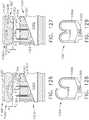
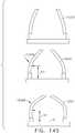
- FIGS. 31 and 32illustrate another anvil arrangement 1130" that is has an anvil cap 1170" attached thereto.
- the anvil cap 1170"is roughly rectangular in shape and has an outer cap perimeter 1172".
- the outer cap perimeter 1172"is configured to be inserted through the correspondingly-shaped opening 1137" in upper body portion 1165 of the anvil body 1132" and received on axially extending internal ledge portions 1139" and 1190" formed therein. See FIG. 32 .
- the ledge portions 1139" and 1190"are configured to support the corresponding long sides 1177" of the anvil cap 1170".
- the anvil cap 1170"may be slid onto the internal ledges 1139" and 1190" through an opening (not shown) in the distal end 1133" of the anvil body 1132'.
- the anvil body 1132" and the anvil cap 1170"may be fabricated from metal material that is conducive to welding.
- a first weld 1178"may extend around the entire perimeter 1172" of the anvil cap 1170” or it may only be located along the long sides 1177" of the anvil cap 1170" and not the distal end 1173" and/or proximal end (not shown) thereof.
- the weld 1178"may be continuous or it may be discontinuous or intermittent.
- the continuous weld embodimenthas more weld surface area due to the irregularly shape perimeter of the anvil cap 1170" as compared to the embodiments with a straight perimeter sides such as the anvil caps shown in FIG. 26 , for example.
- the weld segmentsmay be equally distributed along the long sides 1177" of the anvil cap 1170" or the weld segments may be more densely spaced closer to the distal ends of the long sides 1177" or more densely spaced closer to the proximal ends of the long sides 1177".
- the weld segmentsmay be more densely spaced in the center areas of the long sides 1177" of the anvil cap 1170".
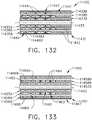
- the anvil cap 1170"may be additionally welded to the anvil body 1132" by a plurality of second discrete "deep” welds 1192".
- each weld 1192"may be placed at the bottom of a corresponding hole or opening 1194" provided through the anvil cap 1170" so that a discrete weld 1192" may be formed along the portion of the anvil body 1132" between the ledges 1190" and 1139". See FIG. 32 .
- the welds 1192"may be equally distributed along the long sides 1177" of the anvil cap 1170" or the welds 1192" may be more densely spaced closer to the distal ends of the long sides 1177" or more densely spaced closer to the proximal ends of the long sides 1177". In still other arrangements, the welds 1192" may be more densely spaced in the center areas of the long sides 1177" of the anvil cap 1170".
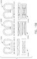
- FIG. 33illustrates another anvil cap 1170"' that is configured to be mechanically interlocked to the anvil body 1132"' as well as welded to the upper body portion 1165.
- a "tongue-in-groove” arrangementis employed along each long side 1177'" of the anvil cap 1170'".
- a laterally extending continuous or intermittent tab 1195'"protrudes from each of the long sides 1177'" of the anvil cap 1170'".
- Each tab 1195"corresponds to an axial slot 1197'" formed in the anvil body 1132'".
- the anvil cap 1170'"is slid in from an opening (not shown) in the distal end of the anvil body 1132'" to "mechanically” affix the anvil cap to the anvil body 1132'".
- the tabs 1195'" and slots 1197'"may be sized relative to each other to establish a sliding frictional fit therebetween.
- the anvil cap 1170'"may be welded to the anvil body 1132'".
- the anvil body 1132'" and the anvil cap 1170'”may be fabricated from metal that is conducive to welding.
- the weld 1178'"may extend around the entire perimeter 1172'" of the anvil cap 1170'" or it may only be located along the long sides 1177'" of the anvil cap 1170'".
- the weld 1178'"may be continuous or it may be discontinuous or intermittent.
- the weld segmentsmay be equally distributed along the long sides 1177'" of the anvil cap 1170'" or the weld segments may be more densely spaced closer to the distal ends of the long sides 1177'" or more densely spaced closer to the proximal ends of the long sides 1177'".
- the weld segmentsmay be more densely spaced in the center areas of the long sides 1177'" of the anvil cap 1170'".
- the anvil embodiments described herein with anvil capsmay provide several advantages.
- One advantage for example,may make the anvil and firing member assembly process easier. That is, the firing member may be installed through the opening in the anvil body while the anvil is attached to the elongate channel.
- Another advantageis that the upper cap may improve the anvil's stiffness and resistance to the above-mentioned flexure forces that may be experienced when clamping tissue. By resisting such flexure, the frictional forces normally encountered by the firing member 1660 may be reduced. Thus, the amount of firing force required to drive the firing member from its starting to ending position in the surgical staple cartridge may also be reduced.
- the anvil 1130begins to pivot, the anvil body 1132 contacts the tissue that is to be cut and stapled which is positioned between the undersurface of the elongate anvil body 1132 and the deck of the surgical staple cartridge 1110. As the anvil body 1132 is compressed onto the tissue, the anvil 1130 may experience considerable amounts of resistive forces. To continue the closure process, these resistive forces must be overcome by the distal closure tube segment 1430 as it cammingly contacts the anvil mounting portion 1150. These resistive forces may be generally applied to the distal closure tube segment 1430 in the vertical directions V which, if excessive, could conceivably cause the distal closure tube segment 1430 to expand or elongate in the vertical direction (distance ID in FIG. 31 may increase).
- the distal closure tube 1430elongates in the vertical directions, the distal closure tube segment 1430 may not be able to effectively close the anvil 1130 and retain the anvil 1130 in the fully closed position. If that condition occurs, the firing member 1660 may encounter dramatically higher resistance which will then require higher firing forces to distally advance the firing member.
- FIGS. 34 and 35illustrate one form of a closure member for applying a closure motion to a movable jaw of a surgical instrument.
- the closure membercomprises, for example, a distal closure tube segment 1430 that has a closure body portion 1470.
- the interchangeable surgical tool assembly 1000is configured so as to facilitate selective articulation of the surgical end effector 1100.
- the distal closure tube segment 1430is movably coupled to the proximal closure tube segment 1410 by means of an upper tang 1434 and a lower tang 1436 and upper and lower double pivot links 1220 and 1222. See FIG. 10 .
- the distal closure tube segment 1430may be machined or otherwise formed from round bar stock manufactured from, for example, suitable metal material.
- the closure body 1470has an outer surface 1431 and an inner surface 1433 that defines an upper wall portion 1440 that has an upper wall cross-sectional thickness UWT and a lower wall portion 1442 that has a lower wall thickness LWT.
- the upper wall portion 1440is located above the shaft axis SA and the lower wall portion 1442 is located below the shaft axis SA.
- the distal end 1441 of the upper wall portion 1440has an internal cam surface 1444 formed thereon at a cam angle ⁇ .
- UWT > LWTwhich serves to provide a longer internal cam surface 1444 than might other wise be attainable if the distal closure tube segment has a uniform wall thickness.
- a long internal cam surfacemay be advantageous for transferring the closure forces to the cam surface(s) on the anvil mounting portion 1150.
- the transitional sidewalls 1446, 1448 that are located on each side of the shaft axis SA between the upper wall portion 1440 and the lower wall portion 1442comprise generally flat, vertically extending internal sidewall surfaces 1451, 1453 that may be generally parallel to each other.
- the transitional sidewalls 1446, 1448each have a wall thickness that transitions from the upper wall thickness to the lower wall thickness.
- the distal closure tube segment 1430also includes positive jaw or anvil opening features 1462 that correspond to each of the sidewalls 1446 and 1448 and protrude inwardly therefrom.
- the anvil opening features 1462are formed on a lateral mounting body 1460 that sized to be received within a correspondingly-shaped cavity 1447, 1449 machined or otherwise formed in the transitional sidewalls 1446, 1448 adjacent the distal end 1438 of the distal closure tube segment 1430.
- the positive anvil opening features 1462extend inwardly through corresponding openings 1450, 1452 in the transitional sidewalls 1446, 1448.
- the lateral mounting bodies 1460are welded to the distal closure tube segment 1430 with welds 1454.
- the lateral mounting bodies 1460may be retained in place with a mechanical/frictional fit, tongue-in-groove arrangements, adhesive, etc.
- FIGS. 36-41illustrate one example of the use of the distal closure tube segment 1430 to move the anvil 1130 from a fully closed position to a fully open position.
- FIGS. 36 and 39illustrate the position of the distal closure tube segment 1430 and, more particularly the position of one of the positive anvil opening features 1462 when the distal closure tube segment 1430 is in the fully closed position.
- an anvil opening ramp 1162is formed on the underside of each of the anvil attachment flanges 1151.
- each of the positive anvil opening features 1462is located in a cavity 1164 that is established between the anvil opening ramps 1162 and the bottom portion of the elongate channel 1102. When in that position, the positive anvil opening features 1462 do not contact the anvil mounting portion 1150 or at least do not apply any significant opening motions or forces thereto.
- FIGS. 37 and 40illustrate the positions of the anvil 1130 and the distal closure tube segment 1430 upon the initial application of an opening motion in the proximal direction PD to the distal closure tube segment 1430. As can be seen in FIG. 37 , the positive jaw opening features 1462 have initially contacted the anvil opening ramps 1164 to cause the anvil 1130 to start pivoting to an open position.
- each of the positive anvil opening features 1462has a ramped or rounded distal end 1463 to facilitate better camming contact with the corresponding anvil opening ramp 1162.
- the distal closure tube segment 1430has been retracted back to its fully retracted position which has caused the positive anvil opening features 1462 to be driven to the distal ends of the anvil opening ramps 1162 which causes the anvil 1130 to be pivoted to its fully open position as shown therein.
- Other embodimentsmay not employ the positive jaw opening features, but may rely on springs or other biasing arrangements to bias the anvil to the open position when the distal closure tube segment has been retracted to its proximal-most starting position.
- FIGS. 42 and 43illustrate another closure member for applying closure motions to a movable jaw of a surgical instrument.
- the closure membercomprises a distal closure tube segment 1430' that may be similar to the distal closure tube segment 1430 without the positive anvil opening features.
- the distal closure tube segment 1430'has a closure body 1470' that has an outer surface 1440' and an inner surface 1433' that define an upper wall portion 1440' and a lower wall portion 1442'.
- the upper wall portion 1440' of the distal closure tube segment 1430'may be provided with the thickest wall thickness UWT and the lower portion of the distal closure tube segment 1430' may have the thinnest wall thickness LWT.
- the UWT and LWTare measured along a common reference line that extends through a center axis or point C of the distal closure tube segment 1430'.
- UWTis diametrically opposite from LWT
- UWT> LWT.
- Such wall thickness arrangementsfacilitate formation of a longer internal camming surface 1444'.
- the distal closure tube segment 1430'has an outer surface 1431' that has circular cross-sectional shape.
- the distal closure tube segment 1430'may be machined from solid bar stock.
- internal radius Ri from a first center axis A innerextends to the inner surface 1433' and the outer radius R 2 from a second center axis A outer extends to the outer surface 1431'.
- axis A inneris offset by distance OR from axis A outer and R 2 > R 1 .
- FIG. 44illustrates another closure member for applying closure motions to a movable jaw of a surgical instrument.
- the closure membercomprises a distal closure tube segment 1430" that has a closure body 1470".
- the closure body 1470"has an outer surface 1431' and an inner surface 1433" that define an upper wall portion 1440" that has an upper wall thickness UWT and a lower wall portion 1442" that has a lower wall thickness LWT and two sidewall portions 1435' that each has a sidewall thickness SWT.
- UWT> LWT.
- SWT>UWT.
- sidewall portions 1435'have the same sidewall thickness SWT.
- each sidewall portion 1435'may have different thicknesses. As can be seen in FIG. 44 , each sidewall portion 1435' defines an internal, vertically extending internal surface portion 1437'. In the illustrated embodiment, the vertically extending internal surface portions are approximately parallel to each other. Such thicker vertical sidewall portions 1435' may help to prevent or at least minimize the vertical elongation of the distal closure tube segment 1430" when in use.
- R 1 and R 2are measured from a common center point or center axis C and R 1 > R 2 .
- Each of the sidewall portions 1435" of the closure body portion 1470'" of the distal closure tube segment 1430'" that extend between the upper portion 1431" and 1433"have a sidewall thickness SWT that is approximately equal to the UWT at points along a horizontal reference line HR.
- the horizontal reference line HRis perpendicular to a vertical reference line VR that extends through the center axis C and along which the UWT and LWT may be measured and compared.
- SWTUWT.
- SWTwhen measured along the horizontal reference line HR may be slightly less than the UWT.
- the SWTmay continue to decrease until the side wall portions 1435' transition into the lower portion 1433' that has a constant lower wall thickness LWT.
- the inner sidewalls 1437"extend at an angle A 2 when measured from a corresponding vertical reference axis VR' that is perpendicular to the horizontal reference axis HR and parallel to vertical reference axis VR
- FIG. 46illustrates another closure member for applying closure motions to a movable jaw of a surgical instrument.
- the closure membercomprises a distal closure tube segment 1430" that has a closure body 1470" that has a round outer surface 1431" and a rectangular shaped internal passage 1439 extending therethrough.
- the outer surface 1431"is located a distance R from the geometric center point or center axis C.
- the upper wall thickness UWTis equal to the lower wall thickness LWT.
- the thicknesses SWT of the sidewall portions 1437"are greater than the upper wall and lower wall thicknesses UWT and LWT.
- SWTis greater than UWT and LWT.
- the portion of the distal closure tube segment 1430" located above the horizontal reference line HRis a mirror image of the portion of the distal closure tube segment 1430" located below the horizontal reference line HR.
- the side portions 1437"are thicker than the upper and lower wall portions and may tend to prevent or minimize the tendency of the distal closure tube segment to elongate in the vertical directions.
- the internal camming surfacemay be formed on the distal end of the upper wall portion 1440".
- the anvil 1130is moved between open and closed positions by distally advancing the distal closure tube segment 1430.
- the distal ends 1163 of the anvil attachment flanges 1151may extend above the deck surface 1116 of the staple cartridge 1110.
- the distal ends 1163 of the anvil attachment flanges 1151extend past the deck surface 1116 of the staple cartridge 1110 to thereby prevent infiltration of tissue therebetween which might hamper the closure process. See FIG. 40 .
- the distal ends 1461 of the lateral mounting bodies on the distal closure tube segment 1430further act as tissue stops to prevent tissue from infiltrating therebetween. See FIG. 41 .
- FIG. 47depicts portion of a surgical end effector 110' that may be similar to the surgical end effector 110 of the interchangeable surgical tool assembly 100 of FIGS. 1 and 2 .
- the anvil 114includes an elongate body portion 190 and an anvil mounting portion 192.
- the anvil mounting portion 192comprises two spaced anvil mounting flanges 194 that protrude proximally from the elongate body portion 190.
- Each anvil mounting flange 194has an outwardly extending trunnion 196 thereon.
- the trunnions 196are each movably received within a corresponding kidney slot or elongated arcuate trunnion slot 197 that is provided in the elongate channel 112.
- the trunnions 196are generally located in the bottom portions 198 of the elongated arcuate trunnion slots 197.
- the anvil 114can be moved to a closed position by distally advancing the distal closure tube segment 142 in the distal direction DD so that the end 148 of the distal closure tube segment 142 rides up a cam surface 193 that is formed on the anvil mounting portion 192 of the anvil 114.
- the distal closure tube segment 142causes the body portion 190 of the anvil 114 to pivot and move axially relative to the surgical staple cartridge 116.
- the distal end 148 of the distal closure tube segment 142abuts/contacts an abrupt anvil ledge 191 and serves to position the anvil 114 so that the forming pockets (not shown) in the underside of the body portion 190 are properly aligned with the staples in the cartridge.
- the anvil ledge 191is defined between the cam surface 193 on the anvil mounting portion 192 and the elongate anvil body portion 190. Stated another way, in this arrangement, the cam surface 193 does not extend to the outermost surface 195 of the anvil body 190. After the distal closure tube 142 has reached this fully extended position, any further application of closure motions/ forces to the anvil 114, may cause damage to the anvil and/or the closure system components. As can be seen in FIG. 47 , in this arrangement, the closure force F H is parallel to the shaft axis SA. The distance between an axis or plane T A passing through the centers of the trunnions 196 to the closure force vector F H is represented as distance X R . This distance X R times the closure force F H represents a closure moment C M that is applied to the anvil 114.
- FIGS. 48 and 49illustrate the closure force configurations for an anvil 1130 of a surgical end effector 1100 of the interchangeable tool assembly 1000.
- the anvil trunnions 1158are pivotally mounted within holes 1154 in the elongate channel 1102.
- the anvil 1130does not move axially. Instead, the anvil 1130 is constrained to only pivot about the anvil axis AA.
- the interaction between the internal cam surface 1444 on the distal closure tube segment 1430 and the cam surface 1152 on the anvil mounting portion 1150results in the distal closure tube segment 1430 experiencing a vertical closure force component V F .
- the resultant force vector F N experienced by the cam surface 1152 on the anvil mounting portion 1150is "normal to" or perpendicular to the internal cam surface 1444.
- Angle ⁇ in FIGS. 48 and 49represents the angle of the camming surface 1152 as a well as the internal camming surface 1440 to the horizontal.
- the distance between this resultant force vector F N and an axis or plane T A that extends through the centers of the anvil trunnions 1158is represented as moment arm M A .
- This moment arm distance M A times the resultant force vector F Nrepresents a closure moment C M1 that is applied to the anvil 1130.
- FIG. 49also illustrates the resistive forces established by the tissue during the closure process.
- F Trepresents the force generated by the tissue when the tissue is clamped between the anvil and the staple cartridge.
- This "counter" moment M T that is applied to the anvil 1130equals the distance X T between the tissue force T F and the axis or plane T A that extends through the centers of the anvil trunnions 1158 times the tissue force T F .
- C M1must be greater than M T .
- the firing bar 170is attached to a firing member 174 that, when in a starting or unfired position, is located within the elongate channel 112 and, more particularly, is located completely distal to the distal closure tube segment 142 in a position wherein a top portion 175 of the firing member 174 is in contact with a portion of the anvil 114. Because the firing member 174 is located in a position wherein the top portion 175 thereof can contact the anvil as the anvil 114 is moved to the closed position, such arrangement may result in the need for higher closure forces to move the anvil 114 to a completely or fully closed position.
- the firing member 1660is "parked" in the firing member parking area 1154 that is within the distal closure tube segment 1430.
- the firing member 1660is located within the firing member parking area 1154 within the distal closure tube segment 1430, it is unable to generate significant frictional forces with the anvil.
- one of the advantages that may be achieved by parking the firing member 1660 completely within the distal closure tube segment 1430may be the reduction of the amount of closure force necessary to close the anvil to a fully closed position and/or a reduction in the amount of firing force needed to advance the firing member from the starting to ending position within the end effector.
- parking the firing member 1660 so that the firing member 1660 is completely proximal to the distal end of the distal closure tube segment 1430 and the internal cam surface 1444 thereon and in a starting position wherein any frictional contact between the firing member and the anvil is eliminated or reducedmay ultimately require lower closure and firing forces to be generated for operation of the end effector.
- FIGS. 20 and 21another advantage that may be provided by the anvil 1130 and elongate channel 1102 depicted therein is that the anvil mounting portion 1150 of the anvil 1130 is generally more robust and therefor stiffer than other anvil and elongate channel arrangements.
- FIG. 50illustrates use of stiffener gussets 199 between the anvil mounting flanges 194 and the elongate anvil body portion 190. Similar gusset arrangements may also be employed between the anvil attachment flanges 1151 and anvil body 1132 of anvil 1130 to further enhance anvil stiffness.
- the interchangeable surgical tool 1000includes an elastic spine member 1520.
- the distal end portion 1522 of the elastic spine member 1520is separated from the proximal end portion 1524 of the elastic spine member 15 by a stretch feature 1530 formed in the elastic spine member 1520.
- a stretch limiting insert 1540is retainingly supported between the distal end portion 1522 and the proximal end portion 1524.
- the elastic spine member 1520may be fabricated from, for example, suitable polymeric material, rubber, etc. which has a modulus of elasticity designated as ME 1 for reference purposes.
- the stretch feature 1530may include a plurality of stretch cavities 1532.
- the illustrated stretch feature 1530includes four triangular-shaped stretch cavities 1532 that are arranged to define some what flexible wall segments 1534 therebetween. Other shapes and numbers of stretch cavities 1532 may be employed.
- the stretch cavities 1532may be molded or machined into the elastic spine member 1520, for example.
- the stretch limiting insert 1540comprises a body portion 1541 which has a modulus of elasticity designated as ME 2 for reference purposes.
- the body portion 1541includes two downwardly extending mounting lugs 1542 that are each configured to be seated into mounting cavities 1535 formed in the elastic spine member 1520. See also FIG. 7A .
- the body portion 1541 in the illustrated arrangementis provided with a plurality of upper cavities 1543.
- the illustrated exampleincludes four upper cavities 1543 that are relatively square or rectangular in shape and which are spaced to define flexible walls 1544 therebetween. Other embodiments may include other numbers and shapes of upper cavities.
- the body portion 1541 of the illustrated stretch limiting insert 1540also includes a centrally disposed, downwardly protruding central lug portion 1545 that is configured to be seated in a central cavity 1536 above the stretch feature 1530. See FIG. 7A .
- the central lug portion 1545includes a pair of central passages 1546 that extend laterally therethrough to define a flexible wall 1547 therebetween.
- the stretch limiting insert 1540includes an elongated lateral cavity 1548 that is positioned on each lateral side of the body portion 1541. Only one lateral cavity 1548 may be seen in FIGS. 6 and 51-54 . Each elongated lateral cavity 1548 is configured to support a corresponding stretch limiter 1550 therein.
- the stretch limiter 1550includes an elongate body portion 1552 that terminates on each end with a downwardly extending mounting lug 1554. Each mounting lug 1554 is received in a corresponding lug cavity 1549 formed in the body portion 1541.
- the stretch limitermay have a modulus of elasticity for reference purposes of ME 3 . In at least one arrangement, ME 3 ⁇ ME 2 ⁇ ME 1 .
- FIG. 51illustrates the anvil 1130 in an open position.
- the distal closure tube segment 1430is in its starting or unactuated position and the positive anvil opening features 1462 have pivoted the anvil 1130 to the open position.
- the firing member 1660is in the unactuated or starting position wherein the upper portion, including the top nose portion 1630, is parked in the firing member parking area 1154 of the anvil mounting portion 1150.
- the stretch limiting insert 1540is in an unstretched state.
- the axial length of the stretch limiting insert 1540 when in the unstretched stateis represented by L us in FIG. 51 .
- L usrepresents the distance between a reference axis A that corresponds to the proximal end of the body portion 1541 of the stretch limiting insert 1540 and a reference axis B that corresponds to the distal end of the body portion 1541 as shown in FIG. 51 .
- the axis labeled Fcorresponds to the location of the distal end of the staple cartridge 1110 that has been properly seated within the elongate channel 1102. It will be understood that when the tool assembly 1000 is in this unactuated state, the elastic spine member 1520 is in a relaxed unstretched state.
- FIG. 52illustrates the interchangeable surgical tool assembly 1000 after the closure drive system 510 has been activated as described above to drive the distal closure tube segment 1430 distally in the distal direction DD.
- the cam surface 1444 on the distal end 1441 of the upper wall portion 1440 of the distal closure tube segment 1430cammingly contacts the cam surface 1152 on the anvil mounting portion 1150 and pivots the anvil 1130 to the closed position as shown.
- the closure drive system 510moves the distal closure tube segment 1430 through its entire closure stroke distance and then is deactivated and the distal closure tube segment is axially locked or otherwise retained in that position by the closure drive system 510.
- Axis B as shown in FIG. 52is a reference axis for the stretch limiting insert 1540 when in a relaxed or unstretched state.
- Axis Ccorresponds to the end of the stretch limiting insert 1540 after the stretch limiting insert has been stretched into its maximum elongated stated.
- the distance L srepresents the maximum amount or length that the stretch limiting insert 1540 may elongate.
- Axis Gcorresponds to the location of the distal end of the surgical staple cartridge 1110 after the anvil 1130 has been moved to that "first" closed position.
- the distance L T between reference axes F and Grepresents the axial distance that the elongate channel 1102 and the anvil 1130 have traveled during actuation of the closure drive system 510. This distance L T may be equal to the distance Ls that the stretch limiting insert 1540 was stretched during the closure process as limited by the stretch limiter 1550.
- each mounting lug 1554 of the stretch limiter 1550serves to limit the amount of elongation experienced by the stretch limiting insert 1540 which in turn limits the amount of distal travel of the elongate channel 1102 and anvil 1130 relative to the proximal end portion 1524 of the elastic spine 1520.
- the distal closure tube 1430is axially locked in position by the closure drive system 510.
- the anvil 1130is retained in a 'first" closed position relative to the surgical staple cartridge 1110.
- the firing drive system 530has yet to be actuated, the firing member 1660 has not moved and remains parked in the firing member parking area 1154.
- the position of the underside of the anvil 1130 when in the "first" closed positionis represented by axis K in FIGS. 52 and 53 .
- FIG. 53illustrates the position of the firing member 1660 after the firing drive system 530 has been initially actuated.
- the firing member 1660has been distally advanced out of the firing member parking area 1154.
- the top portion of the firing member 1660 and, more specifically, each of the top anvil engagement features 1672has entered the proximal ramp portion 1138 of the corresponding axial passage 1146 in the anvil 1130.
- the anvil 1130may be under considerable bending stress caused by the tissue that is clamped between the underside of the anvil 1130 and the deck of the staple cartridge 1110.
- the amount of force required to fire the firing member 1660 or, stated another way, the amount of force required to distally push the firing member 1660 through the tissue that is clamped between the anvil 1130 and the cartridge 1110is increasing. See line 1480 in FIG. 55 .
- the stretch limiting insertis trying to retract the elongate channel 1102 and anvil 1130 in the proximal direction PD into the distal closure tube segment 1430.
- the stretch limiting insert 1540will cause the elongate channel 1102 and anvil 1130 to be drawn proximally further into the distal closure tube segment 1430.
- the position of the distal end 1113 of the staple cartridge 1110 after the elongate channel 1102 and anvil 1130 have traveled in the proximal direction PDis represented as position H in FIG. 54 .
- the axial distance that the elongate channel 1102 and the anvil 1130 traveled in the proximal direction PDis represented as distance I in FIG. 54 .
- Line M in FIG. 54represents the "second" closed position of the anvil 1130.
- the distance between position K and position M which is represented as distance Ncomprises the vertical distance that the distal end 1133 of the anvil body 1132 traveled between the first closed position and the second closed position.
- Line 1480represents the amount of firing force required to move the firing member 1660 from its starting to ending position when the end effector 1100 is clamping tissue therein.
- Line 1482represents the amount of firing force required to move the firing member the interchangeable surgical tool assembly 1000 described above.
- Line 1482represents the firing force required to move the firing member 174 from its starting to ending position through tissue that is clamped in the end effector 110 or 110'.
- the firing forces required by both of the surgical tool assemblies 100, 1000are substantially the same or very similar until the point in time 1484 wherein the elastic spine assembly 1510 of the interchangeable tool assembly 1000 results in an application of a second amount of closure force to the anvil.
- the second amount of closure forceis experienced by the anvil 1130 (point 1484)
- the amount of closure force required to complete the firing processis less than the amount of closure force required to complete the closing process in tool assembly 100.
- FIG. 56compares the amount of firing load required to move a firing member of various surgical end effectors from a starting position (0.0) to an ending position (1.0).
- the vertical axisrepresents the amount of firing load and the horizontal axis represents the percentage distance that the firing member traveled between the starting position (0.0) and the ending position (1.0).
- Line 1490depicts the firing force required to fire, for example, the firing member of a surgical tool assembly 100 or similar tool assembly.
- Line 1492depicts the firing force required to fire the firing member of a surgical tool assembly that employs the various firing member improvements and configurations that may be disclosed in, for example, U.S. Patent Application Serial No.
- Line 1494depicts the firing force required to fire the firing member from its starting to ending position of surgical tool assemblies that employ at least some of the features and arrangements disclosed herein for stiffening the anvil.
- Line 1496depicts the firing force required to fire, for example, surgical tool assemblies that employ the elastic spine arrangement and at least some of the features and arrangements disclosed herein for stiffening the anvil. As can be seen in that Figure, the surgical tool assembly that employs the elastic spine arrangement and at least some of the anvil stiffening arrangements disclosed herein have a much lower force-to-fire requirement.
- FIGS. 57-62depict a forming pocket arrangement 10100 that is configured to deform a staple during a surgical stapling procedure.
- the forming pocket arrangement 10100comprises a proximal forming pocket 10110 and a distal forming pocket 10130 defined in a planar, or tissue-engaging, surface 10107 of an anvil 10101.
- the pockets 10110, 10130are aligned along a longitudinal pocket axis 10103 of the forming pocket arrangement 10100.
- a stapleis intended to be formed along the pocket axis 10103 by the forming pocket arrangement 10100 when deployed from a staple cartridge.
- the forming pocket arrangement 10100further comprises a bridge, or ridge, portion 10105 defined between the forming pockets 10110, 10130.
- the bridge portion 10105is part of the planar surface 10107 of the anvil 10101.
- the bridge portion 10105comprises a bridge width "W”.
- the forming pocket arrangement 10100comprises a center "C" defined within the bridge portion 10105.
- the forming pocket arrangement 10100is bilaterally symmetric with respect to the bridge portion 10105, bilaterally symmetric with respect to the pocket axis 10103, and rotationally symmetric with respect to the center "C”.
- the forming pocket 10110comprises a pair of pocket sidewalls 10113 and the forming pocket 10130 comprises a pair of pocket sidewalls 10133.
- the pocket sidewalls 10113, 10133are configured to direct the tips and the legs of the staples toward the forming surfaces of the pockets 10110, 10130 in the event that the staple tips and/or the legs of the staples initially strike the sidewalls 10113, 10133 of the pockets 10110, 10130. Referring to FIGS. 60-62 , the sidewalls 10113, 10133 extend from the planar surface 10107 of the anvil 10101 toward the forming surfaces of each pocket 10110, 10130.
- the sidewalls 10113, 10133 of the forming pockets 10110, 10130are angled with respect to the planar surface 10107 of the anvil 10101 at angle ⁇ in order to direct, or channel, the staple legs and/or the tips of the staples toward the forming surfaces.
- the sidewalls 10113, 10133are configured to encourage the staple tips and/or the legs of the staples to form along the pocket axis 10103 as the staples are formed against the forming surfaces of the pockets 10110, 10130.
- the forming surfaces of the pockets 10110, 10130comprise an entry zone forming surface 10111, 10131 and an exit zone forming surface 10112, 10132, respectively.
- the amount of surface area of the forming surfaces that the entry zone forming surfaces 10111, 10131 coveris equal to the amount of surface area of the forming surfaces that the exit zone forming surfaces 10112, 10132 cover.
- the entry zone forming surfaces 10111, 10131transition to the exit zone forming surfaces 10112, 10132 in the center of each pocket 10110, 10130.
- the transitions between the entry zone forming surfaces 10111, 10131 and the exit zone forming surfaces 10112, 10132define a valley, or trough of each pocket 10110, 10130.
- the valleys of the forming pockets 10110, 10130define a portion, or segment, of the forming surfaces having the greatest vertical distance from the planar surface 10107.
- each pocket 10110, 10130comprise a longitudinal radius of curvature 10117, 10137, respectively.
- the longitudinal radius of curvature 10117is equal to the radius of curvature 10137.
- the longitudinal radius of curvature 10117 and the longitudinal radius of curvature 10137can form a symmetric staple.
- the longitudinal radius of curvature 10117 and the longitudinal radius of curvature 10137are different and can form an asymmetric staple.
- FIG. 61is a cross-sectional view of the distal forming pocket 10130 taken along line 61-61 in FIG. 58 . This view illustrates the valley, or trough, of the distal forming pocket 10130.
- the outer edges of each pocket 10110, 10130define the widest portion of the forming surfaces of each pocket 10110, 10130.
- FIG. 60illustrates a cross-sectional view of the distal forming pocket 10130 taken along line 60-60 in FIG. 58 which is within the exit zone forming surface 10132 of the distal forming pocket 10130.
- 62is a cross-sectional view of the distal forming pocket 10130 taken along line 62-62 in FIG. 58 which is within the entry zone forming surface 10132 of the distal forming pocket 10130.
- a proximal staple legis configured to land in the entry zone forming surface 10111 of the proximal forming pocket 10110 and exit in the exit zone forming surface 10112 of the proximal forming pocket 10110.
- a distal staple legis configured to land in the entry zone forming surface 10131 of the distal forming pocket 10130 and exit in the exit zone forming surface 10132 of the distal forming pocket 10130.
- FIGS. 63-68depict a forming pocket arrangement 10200 that is configured to deform a staple during a surgical stapling procedure.
- the forming pocket arrangement 10200comprises a proximal forming pocket 10210 and a distal forming pocket 10230 defined in a planar, or tissue-engaging, surface 10207 of an anvil 10201.
- the pockets 10210, 10230are aligned along a longitudinal pocket axis 10203 of the forming pocket arrangement 10200.
- a stapleis intended to be formed along the pocket axis 10203 by the forming pocket arrangement 10200 when deployed from a staple cartridge.
- the forming pocket arrangement 10200further comprises a bridge portion 10205 defined between the forming pockets 10210, 10230.
- the bridge portion 10205is recessed with respect to the planar surface 10207 of the anvil 10201.
- the bridge portion 10205comprises a bridge width "W” and a bridge depth “D".
- the bridge depth "D”is the distance that the bridge portion 10205 is recessed with respect to the planar surface 10207.
- the forming pocket arrangement 10200comprises a center "C" defined within the bridge portion 10205.
- the forming pocket arrangement 10200is bilaterally symmetric with respect to the bridge portion 10205, bilaterally symmetric with respect to pocket axis 10203, and rotationally symmetric with respect to the center "C".
- the forming pocket arrangement 10200further comprises a pair of primary sidewalls 10208 extending from the planar surface 10207 of the anvil 10201 toward the pockets 10210, 10230 and the bridge portion 10205.
- the primary sidewalls 10208are angled at angle ⁇ 2 with respect to the planar surface 10207 of the anvil 10201.
- the forming pocket arrangement 10200further comprises edge features 10215, 10235 which provide a transition feature between the outer edges of the pockets 10210, 10230 and the planar surface 10207, between the longitudinal edges of the pockets 10210, 10230 and the primary sidewalls 10208, and between the inner edges of pockets 10210, 10230 and the bridge portion 10205.
- These edges 10215, 10235can be rounded, and/or chamfered, for example.
- the edge features 10215, 10235may help prevent staple tips from sticking, as discussed in greater detail below.
- the forming pocket 10210comprises a pair of pocket sidewalls 10213 and the forming pocket 10230 comprises a pair of pocket sidewalls 10233.
- the pocket sidewalls 10213, 10233are configured to direct the staple tips and the legs of the staples toward the forming surfaces of the pockets 10210, 10230 in the event that the staple tips and/or the legs of the staples initially strike the sidewalls 10213, 10233 of the pockets 10210, 10230.
- the sidewalls 10213, 10233extend from the transition edges 10215, 10235 toward the forming surfaces of each pocket 10210, 10230.
- the sidewalls 10213, 10233 of the forming pockets 10210, 10230are angled with respect to the planar surface 10207 of the anvil 10201 at angle ⁇ 1 in order to direct, or channel, the legs and/or the staple tips of the staples toward the forming surfaces of the pockets 10210, 10230.
- the sidewalls 10213, 10233are configured to encourage the staple tips and/or the legs of the staples to form along the pocket axis 10203 as the staples are formed against the forming surfaces of the pockets 10210, 10230.
- the primary sidewalls 10208 and the pocket sidewalls 10213, 10233can provide a funnel-like configuration for directing staple tips. Referring to FIGS. 66 and 67 , the angle ⁇ 1 is greater than the angle ⁇ 2 .
- the pockets 10210, 10230further comprise transition edges 10214, 10234 which provide a transition feature between the pocket sidewalls 10213, 10233 and the forming surfaces, as discussed in greater detail below.
- the transition edges 10214, 10234can comprise a similar profile as the transition edges 10215, 10235.
- the transition edges 10214, 10234can comprise a different profile than the transition edges 10215, 10235. That said, the edges 10214, 10234 can be rounded, or chamfered, for example.
- edges 10214, 10234comprise a first end where the edges 10214, 10234 meet the outer ends of the pockets 10210, 10230 and a second end where the edges 10214, 10234 approach the bridge portion 10205, or the inner ends of the pockets 10210, 10230.
- the edges 10214, 10234may transition into the transition edges 10215, 10235 near the bridge portion 10205.
- the edge features 10214, 10234may also help prevent staple tips from sticking in the pockets 10210, 10230 when forming, as discussed in greater detail below.
- the forming surfaces of the pockets 10210, 10230comprise an entry zone forming surface 10211, 10231 and an exit zone forming surface 10212, 10232, respectively.
- the amount of surface area of the forming surfaces that the entry zone forming surfaces 10211, 10231 coveris greater than the amount of surface area of the forming surfaces that the exit zone forming surfaces 10212, 10232 cover.
- the entry zone forming surfaces 10211, 10231do not transition to the exit zone forming surfaces 10212, 10232 in the center of each pocket 10210, 10230. Rather, the transition points where the entry zones 10211, 10231 transition to the exit zones 10212, 10232 are closer to the bridge portion 10205.
- the transitions between the entry zone forming surfaces 10211, 10231 and the exit zone forming surfaces 10212, 10232define a valley, or trough of each pocket 10210, 10230.
- the valleys of the forming pockets 10210, 10230define a portion, or segment, of the forming surfaces having the greatest vertical distance from the planar surface 10207.
- each pocket 10210, 10230comprise more than one radius of curvature.
- the pocket 10210comprises an entry radius of curvature 10217 corresponding to the entry zone forming surface 10211 and an exit radius of curvature 10218 corresponding to the exit zone forming surface 10212.
- the pocket 10230comprises an entry radius of curvature 10237 corresponding to the entry zone forming surface 10231 and an exit radius of curvature 10238 corresponding to the exit zone forming surface 10232.
- the entry radii of curvature 10217, 10237are larger than the exit radii of curvature 10218, 10238, respectively.
- the valleys of the forming pockets 10210, 10230also define the narrowest portion of the forming surfaces of each pocket 10210, 10230.
- the outer edges of each pocket 10210, 10230also referred to as entry edges because they define the beginning of the entry zone forming surfaces 10211, 10231, comprise an entry width.
- the inner edges of each pocket 10210, 10230also referred to as exit edges because they define the end of the exit zone forming surfaces 10212, 10232, comprise an exit width. In this instance, the entry width is greater than the exit width. Also, the exit width is greater than the valley width, or the narrowest portion of the forming surfaces.
- FIG. 67is a cross-sectional view of the distal forming pocket 10230 taken along line 67-67 in FIG. 64 .
- This viewillustrates the valley, or trough, of the distal forming pocket 10230.
- This valley, or troughis also the transition between the entry zone forming surface 10231 and the exit zone forming surface 10232.
- FIG. 66illustrates a cross-sectional view of the distal forming pocket 10230 taken along line 66-66 in FIG. 64 which is located within the exit zone forming surface 10232 of the forming pocket 10230.
- FIG. 68is a cross-sectional view of the distal forming pocket 10230 taken along line 68-68 in FIG. 64 which is within the entry zone forming surface 10232 of the distal forming pocket 10230.
- the forming pocket arrangement 10200and various other forming pocket arrangements disclosed herein, are configured to be used with staples with various diameters.
- the diameters of staples to be used with the forming pocket arrangement 10200can vary between about 0.0079 inches and about 0.0094 inches, for example.
- the entry radius of curvature and the exit radius of curvature of each forming surfacecomprise a ratio of about 1.5:1 to about 3:1 when the entry radius is between about 8x the staple diameter and 10x the staple diameter, for example. In at least one instance, the entry radius of curvature and the exit radius of curvature of each forming surface comprise a ratio of about 2:1 when the entry radius is 9x the staple diameter, for example.
- the entry radius of curvature and the exit radius of curvature of each forming surfacecomprise a ratio of about 1.5:1 to about 3:1 when the entry radius is above about 0.6x the staple crown length and the ridge, or bridge, width is less than 1x the staple diameter, for example.
- the entry radius of curvature and the exit radius of curvature of each forming surfacecomprise a ratio of about 2:1 when the entry radius is above about 0.6x the staple crown length and the ridge, or bridge, width is less than 1x the staple diameter.
- the exit radius of curvatureis between about 4x the staple diameter and about 6x diameter, for example. In at least one instance, the exit radius of curvature is about 4.5x the staple diameter.
- FIGS. 69-74depict a forming pocket arrangement 10300 that is configured to deform a staple during a surgical stapling procedure.
- the forming pocket arrangement 10300comprises a proximal forming pocket 10310 and a distal forming pocket 10330 defined in a planar, or tissue-contacting, surface 10307 of an anvil 10301.
- the pockets 10310, 10330are aligned along a longitudinal pocket axis 10303 of the forming pocket arrangement 10300.
- a stapleis intended to be formed along the pocket axis 10303 by the forming pocket arrangement 10300 when deployed from a staple cartridge.
- the forming pocket arrangement 10300further comprises a bridge portion 10305 defined between the forming pockets 10310, 10330.
- the bridge portion 10305is recessed with respect to the planar surface 10307 of the anvil 10301.
- the bridge portion 10305comprises a bridge width "W” and a bridge depth “D".
- the bridge depth "D”is the distance that the bridge portion 10305 is recessed with respect to the planar surface 10307.
- the forming pocket arrangement 10300comprises a center "C" defined within the bridge portion 10305.
- the forming pocket arrangement 10300is bilaterally symmetric with respect to the bridge portion 10305, bilaterally symmetric with respect to pocket axis 10303, and rotationally symmetric with respect to the center "C".
- the forming pocket arrangement 10300further comprises a pair of primary sidewalls 10308 extending from the planar surface 10307 of the anvil 10301 toward the pockets 10310, 10330 and the bridge portion 10305.
- the primary sidewalls 10308are angled at angle ⁇ 2 with respect to the planar surface 10307 of the anvil 10301.
- the forming pocket arrangement 10300further comprises a pair of edge features 10309 which provide a transition feature between the lateral edges of the pockets 10310, 10330 and the primary sidewalls 10308.
- the edges 10309also provide a transition feature between central portions of the primary sidewalls 10308 and the bridge portion 10305. These edges 10309 can be rounded, and/or chamfered, for example.
- the edge features 10309may help prevent staple tips from sticking, as discussed in greater detail below.
- the forming pocket 10310comprises a pair of pocket sidewalls 10313 and the forming pocket 10330 comprises a pair of pocket sidewalls 10333.
- the pocket sidewalls 10313, 10333are configured to direct the staple tips and the legs of the staples toward the forming surfaces of the pockets 10310, 10330 in the event that the staple tips and/or the legs of the staples initially strike the sidewalls 10313, 10333 of the pockets 10310, 10330.
- the sidewalls 10313, 10333extend from the transition edges 10309 toward the forming surfaces of each pocket 10310, 10330.
- the sidewalls 10313, 10333 of the forming pockets 10310, 10330are angled with respect to the planar surface 10307 of the anvil 10301 at angle ⁇ 1 in order to direct, or channel, the legs and/or staple tips of the staples toward the forming surfaces of the pockets 10310, 10330.
- the sidewalls 10313, 10333are configured to encourage the staple tips and/or the legs of the staples to form along the pocket axis 10303 as the staples are formed against the forming surfaces of the pockets 10310, 10330.
- the primary sidewalls 10308 and the pocket sidewalls 10313, 10333can provide a funnel-like configuration for corresponding staple tips. Referring to FIGS.
- the angle ⁇ 1is greater than the angle ⁇ 2 .
- the pocket sidewalls 10313, 10333can be considered aggressive.
- the angle ⁇ 1is 80 degrees.
- the angle ⁇ 2is significantly less aggressive than the angle ⁇ 1 .
- the angle ⁇ 2is 4 degrees.
- Angle ⁇ 3( FIG. 73 ) is defined as the angle between the sidewalls 10333 is between about 0 degrees and about 10 degrees. In various instances, the angle ⁇ 3 is 0 degrees and the walls 10333 are at least substantially parallel to each other.
- the pockets 10310, 10330further comprise transition edges 10306 which provide a transition feature between the pocket sidewalls 10313, 10333 and the forming surfaces, as discussed in greater detail below.
- the transition edges 10306can comprise a similar profile as the transition edges 10309.
- the transition edges 10306can comprise a different profile than the transition edges 10309. That said, the edges 10307 can be rounded, or chamfered, for example.
- the edges 10306, 10309comprise a first end where the edges 10306, 10309 meet the outer ends of the pockets 10310, 10330 and a second end where the edges 10306, 10309 approach the bridge portion 10305, or the inner ends of the pockets 10310, 10330.
- the edges 10306may transition into the transition edges 10309 near the bridge portion 10305.
- the edge features 10306may also help prevent staple tips from sticking in the pockets 10310, 10330 when forming, as discussed in greater detail below.
- the forming surfaces of the pockets 10310, 10330comprise an entry zone forming surface 10311, 10331 and an exit zone forming surface 10312, 10332, respectively.
- the amount of surface area of the forming surfaces that the entry zone forming surfaces 10311, 10331 coveris greater than the amount of surface area of the forming surfaces that the exit zone forming surfaces 10312, 10332 cover.
- the entry zone forming surfaces 10311, 10331do not transition to the exit zone forming surfaces 10312, 10332 in the center of each pocket 10310, 10330.
- transition points where the entry zones 10311, 10331 transition to the exit zones 10312, 10332are closer to the bridge portion 10305.
- the transitions between the entry zone forming surfaces 10311, 10331 and the exit zone forming surfaces 10312, 10332define a valley, or trough of each pocket 10310, 10330.
- the valleys of the forming pockets 10310, 10330define a portion, or segment, of the forming surfaces having the greatest vertical distance from the planar surface 10307.
- each pocket 10310, 10330comprise more than one radius of curvature.
- the pocket 10310comprises an entry radius of curvature 10317 corresponding to the entry zone forming surface 10311 and an exit radius of curvature 10318 corresponding to the exit zone forming surface 10312.
- the pocket 10330comprises an entry radius of curvature 10337 corresponding to the entry zone forming surface 10331 and an exit radius of curvature 10338 corresponding to the exit zone forming surface 10332.
- the entry radii of curvature 10317, 10337are larger than the exit radii of curvature 10318, 10338.
- each pocket 10310, 10330also referred to as entry edges because they define the beginning of the entry zone forming surfaces 10311, 10331, comprise an entry width which is the largest width of the forming surfaces of each pocket 10310, 10330.
- the transitions between entry and exit zonescomprise a transition width which is less than the entry width but greater than the exit width.
- FIG. 73is a cross-sectional view of the distal forming pocket 10330 taken along line 73-73 in FIG. 70 .
- This viewillustrates the valley, or trough, of the distal forming pocket 10330.
- This valley, or troughis also the transition between the entry zone forming surface 10331 and the exit zone forming surface 10332.
- FIG. 72illustrates a cross-sectional view of the distal forming pocket 10330 taken along line 72-72 in FIG. 70 which is located within the exit zone forming surface 10332 of the forming pocket 10330.
- FIG. 74is a cross-sectional view of the distal forming pocket 10330 taken along line 74-74 in FIG. 70 which is within the entry zone forming surface 10332 of the distal forming pocket 10330.
- FIGS. 75-80depict a forming pocket arrangement 10400 that is configured to deform a staple during a surgical stapling procedure.
- the forming pocket arrangement 10400comprises a proximal forming pocket 10410 and a distal forming pocket 10430 defined in a planar, or tissue-contacting, surface 10407 of an anvil 10401.
- the pockets 10410, 10430are aligned along a longitudinal pocket axis 10403 of the forming pocket arrangement 10400.
- a stapleis intended to be formed along the pocket axis 10403 by the forming pocket arrangement 10400 when deployed from a staple cartridge.
- the forming pocket arrangement 10400further comprises a bridge portion 10405 defined between the forming pockets 10410, 10430.
- the bridge portion 10405is recessed with respect to the planar surface 10407 of the anvil 10401.
- the bridge portion 10405comprises a bridge width "W” and a bridge depth “D".
- the bridge depth "D”is the distance that the bridge portion 10405 is recessed with respect to the planar surface 10407.
- the forming pocket arrangement 10400comprises a center "C" defined within the bridge portion 10405.
- the forming pocket arrangement 10400is bilaterally symmetric with respect to the bridge portion 10405, bilaterally symmetric with respect to pocket axis 10403, and rotationally symmetric with respect to the center "C".
- the forming pocket arrangement 10400further comprises a pair of primary sidewalls 10408 extending from the planar surface 10407 of the anvil 10401 toward the pockets 10410, 10430 and the bridge portion 10405. Specifically, each sidewall 10408 shares an edge with only a portion of each pocket, as discussed in greater detail below.
- the primary sidewalls 10408are angled at angle ⁇ 4 with respect to the planar surface 10407 of the anvil 10401.
- Each forming pocket 10410, 10430comprises a pair of pocket sidewalls, wherein each pocket sidewall of each pair comprises discrete, sidewall portions.
- the proximal forming pocket 10410comprises a pair of pocket sidewalls, each comprising discrete sidewall portions 10413 and 10416.
- the sidewall portions 10413may be referred to as entry sidewalls portions and the sidewalls portions 10416 may be referred to as exit sidewalls portions.
- the distal forming pocket 10430comprises a pair of pocket sidewalls, each comprising discrete sidewall portions 10433 and 10436 respectively.
- the sidewall portions 10433may be referred to as entry sidewalls portions and the sidewalls portions 10436 may be referred to as exit sidewalls portions.
- the pocket sidewalls 10413, 10416, 10433, 10436are configured to direct the staple tips and the legs of the staples toward the forming surfaces of the pockets 10410, 10430 in the event that the staple tips and/or the legs of the staples initially strike the sidewalls 10413, 10416, 10433, 10436 of the pockets 10410, 10430.
- the sidewall portions 10413extend from the planar surface 10407 toward the forming surface of the proximal forming pocket 10410.
- the sidewall portions 10413transition into the forming surface via transition feature 10414.
- Another transition feature 10417is provided between the discrete sidewall portions 10413 and 10416 to provide the discrete, sidewall features.
- the transition features 10414, 10417may comprise rounded and/or chamfered surfaces, for example.
- the transition features 10414, 10417may, instead, comprise a discrete edge.
- the sidewall portions 10416share an edge with the primary sidewalls 10408 and extend from the primary sidewalls 10408 toward the forming surface of the proximal forming pocket 10410.
- the sidewalls 10413 and 10416are orientated at different angles with respect to the pocket axis 10403.
- the sidewall portion 10413is at least substantially parallel with respect to the pocket axis 10403 and the sidewall portion 10416 is angled at angle ⁇ 3 with respect to the pocket axis 10403.
- substantially parallelrefers to an orientation that is nearly parallel to, or parallel to, the pocket axis 10403.
- the sidewall portions 10433extend from the planar surface 10407 toward the forming surface of the distal forming pocket 10430.
- the sidewall portions 10433transition into the forming surface via transition feature 10434.
- Another transition feature 10437is provided between the discrete sidewall portions 10433 and 10436 to provide the discrete, sidewall features.
- the transition features 10434, 10437may comprise rounded and/or chamfered surfaces, for example.
- the transition features 10434, 10437may, instead, comprise a discrete edge.
- the sidewall portions 10436share an edge with the primary sidewalls 10408 and extend from the primary sidewalls 10408 toward the forming surface of the distal forming pocket 10430.
- the sidewalls 10433 and 10436are orientated at different angles with respect to the pocket axis 10403.
- the sidewall portion 10433is at least substantially parallel with respect to the pocket axis 10403 and the sidewall portion 10436 is angled at angle ⁇ 3 with respect to the pocket axis 10403.
- substantially parallelrefers to an orientation that is nearly parallel to, or parallel to, the pocket axis 10403.
- the sidewall portions 10413, 10433are angled with respect to the planar surface 10407 of the anvil 10401 at a different angle than the sidewall portions 10416, 10436.
- the proximal forming pocket 10410comprises a configuration symmetric of the distal forming pocket 10430.
- the entry sidewall portions 10433are angled with respect to the planar surface 10407 at angle ⁇ 1 .
- the exit sidewall portions 10436are angled with respect to the planar surface 10407 at angle ⁇ 2 .
- Angle ⁇ 2is greater than angle ⁇ 1 .
- Angle ⁇ 2is between about 60 degrees and about 90 degrees, for example. In various instances, angle ⁇ 2 is about 80 degrees. In other instances, angle ⁇ 2 is about 90 degrees.
- the exit sidewall portions 10436are more aggressively angled, or more vertical, than the entry sidewall portions 10433.
- the sidewall portions 10433, 10436are angled with respect to the planar surface 10407 of the anvil 10401 in order to direct, or channel, the legs and/or staple tips of the staples toward the forming surface of the distal pocket 10430 and, additionally, control the forming of the legs, as discussed in greater detail below.
- the primary sidewalls 10408 and the pocket sidewalls 10413, 10416, 10433, 10436can provide a funnel-like configuration for corresponding staple tips.
- the transition edges 10414, 10434provide a transition feature between the pocket sidewall portions 10413, 10416, 10433, 10436 and the forming surfaces.
- the edges 10414, 10434comprise a first end where the edges 10414, 10434 meet the outer ends of the pockets 10410, 10430 and a second end where the edges 10414, 10434 meet the bridge portion 10405, or the inner ends of the pockets 10410, 10430.
- the edge features 10414, 10434may help prevent staple tips from sticking in the pockets 10410, 10430 when forming, as discussed in greater detail below.
- the forming surfaces of the pockets 10410, 10430comprise an entry zone forming surface 10411, 10431 and an exit zone forming surface 10412, 10432, respectively.
- the amount of surface area of the forming surfaces that the entry zone forming surfaces 10411, 10431 coveris greater than the amount of surface area of the forming surfaces that the exit zone forming surfaces 10412, 10432 cover.
- the entry zone forming surfaces 10411, 10431do not transition to the exit zone forming surfaces 10412, 10432 in the center of each pocket 10410, 10430.
- transition points where the entry zones 10411, 10431 transition to the exit zones 10412, 10432are closer to the bridge portion 10405.
- the transitions between the entry zone forming surfaces 10411, 10431 and the exit zone forming surfaces 10412, 10432define a valley, or trough of each pocket 10410, 10430.
- the valleys of the forming pockets 10410, 10430define a portion, or segment, of the forming surfaces having the greatest vertical distance from the planar surface 10407.
- the transition between the entry zone forming surfaces 10411, 10431 and the exit zone forming surfaces 10412, 10432occurs at the transition features 10417, 10437.
- each pocket 10410, 10430comprise more than one radius of curvature.
- the pocket 10410comprises an entry radius of curvature 10418 corresponding to the entry zone forming surface 10411 and an exit radius of curvature 10419 corresponding to the exit zone forming surface 10412.
- the pocket 10430comprises an entry radius of curvature 10438 corresponding to the entry zone forming surface 10431 and an exit radius of curvature 10439 corresponding to the exit zone forming surface 10432.
- the entry radii of curvature 10418, 10438are larger than the exit radii of curvature 10419, 10439.
- each pocket 10410, 10430also referred to as entry edges because they define the beginning of the entry zone forming surfaces 10411, 10431, comprise an entry width which is the largest width of the forming surfaces of each pocket 10410, 10430.
- the transitions between entry and exit zonescomprise a transition width which is less than the entry width. In various instances, the transition width is similar to the exit width ( FIG. 76 ).
- the exit zone forming surfaces 10412, 10413comprise the narrowest sections of the forming surfaces of each pocket 10410, 10430.
- the narrowest sectionis the valley, or trough, of each pocket 10410, 10430.
- the valleycomprises a width greater than the largest diameter staple configured for use with the forming pocket arrangement 10400.
- FIG. 79is a cross-sectional view of the distal forming pocket 10430 taken along line 79-79 in FIG. 76 . This view is taken along a section of the entry zone forming surface 10431 and illustrates the transition of each discrete, sidewall portions 10433, 10436.
- FIG. 78illustrates a cross-sectional view of the distal forming pocket 10430 taken along line 78-78 in FIG.
- FIG. 80is a cross-sectional view of the distal forming pocket 10430 taken along line 80-80 in FIG. 76 which is within the entry zone forming surface 10432 of the distal forming pocket 10430.
- FIGS. 81-86depict a forming pocket arrangement 10500 that is configured to deform a staple during a surgical stapling procedure.
- the forming pocket arrangement 10500comprises a proximal forming pocket 10510 and a distal forming pocket 10530 defined in a planar, or tissue-contacting, surface 10507 of an anvil 10501.
- the pockets 10510, 10530are aligned along a longitudinal pocket axis 10503 of the forming pocket arrangement 10500.
- a stapleis intended to be formed along the pocket axis 10503 by the forming pocket arrangement 10500 when deployed from a staple cartridge.
- the forming pocket arrangement 10500further comprises a bridge portion 10505 defined between the forming pockets 10510, 10530.
- the bridge portion 10505is recessed with respect to the planar surface 10507 of the anvil 10501.
- the bridge portion 10505comprises a bridge width "W” and a bridge depth "D".
- the bridge portion 10505is substantially V-shaped with a rounded bottom portion.
- the bridge depth "D”is the distance that the bottom portion of the bridge portion 10505 is recessed with respect to the planar surface 10507.
- the forming pocket arrangement 10500comprises a center "C" defined within the bridge portion 10505.
- the forming pocket arrangement 10500is bilaterally symmetric with respect to the bridge portion 10505, bilaterally symmetric with respect to pocket axis 10503, and rotationally symmetric with respect to the center "C”.
- the forming pocket arrangement 10500further comprises a pair of primary sidewalls 10508 extending from the planar surface 10507 of the anvil 10501 toward the pockets 10510, 10530 and the bridge portion 10505.
- the primary sidewalls 10508are angled at angle ⁇ 1 with respect to the planar surface 10507 of the anvil 10501.
- the primary sidewalls 10508comprise inner edges that are curved, or contoured, with respect to the pockets 10510, 10530.
- the forming pocket 10510comprises a pair of pocket sidewalls 10513 and the forming pocket 10530 comprises a pair of pocket sidewalls 10533.
- the pocket sidewalls 10513, 10533comprise curved, or contoured, profiles and are configured to direct the staple tips and the legs of the staples toward the forming surfaces of the pockets 10510, 10530 as well as help control the forming process of the staples.
- the sidewalls 10513, 10533extend from the primary sidewalls 10508 and the planar surface 10507 toward the forming surfaces of each pocket 10510, 10530.
- the sidewalls 10513, 10533are configured to encourage the staple tips and/or the legs of the staples to form along the pocket axis 10503 as the staples are formed against the forming surfaces of the pockets 10510, 10530. Collectively, the primary sidewalls 10508 and the pocket sidewalls 10513, 10533 cooperate to funnel corresponding staple tips toward the lateral center of each pocket 10510, 10530. Discussed in greater detail below, the sidewalls 10513, 10533 comprise entry portions and exit portions where the entry portions comprise a less aggressive channeling configuration than the exit portions.
- the forming surfaces of the pockets 10510, 10530comprise an entry zone forming surface 10511, 10531 and an exit zone forming surface 10512, 10532, respectively.
- the entry zone forming surfaces 10511, 10531can coincide with the less aggressive channeling portions of the sidewalls 10513, 10533.
- the exit zone forming surfaces 10512, 10532can coincide with the more aggressive channeling portions of the sidewalls 10513, 10533.
- the pockets 10510, 10530further comprise a forming, or guiding, groove 10515, 10535, also referred to as a tip control channel, extending the entire longitudinal length of each pocket 10510, 10530 and positioned centrally with respect to the outer lateral edges of the pockets 10510, 10530.
- the grooves 10515, 10535are narrower at the outer longitudinal edges of the pockets 10510, 10530 than the inner longitudinal edges of the pockets 10510, 10530.
- the grooves 10515, 10535meet at the bridge portion 10505 to encourage the staple tips, and staple legs, to contact each other during the forming process, as discussed in greater detail below.
- grooves defined in the forming surfaces of forming pocketscan have a similar effect in staple forming as more aggressively-angled exit walls and/or narrowly-configured exit walls.
- each pocket 10510, 10530comprise more than one radius of curvature.
- the pocket 10510comprises an entry radius of curvature 10517 corresponding to the entry zone forming surface 10511 and an exit radius of curvature 10518 corresponding to the exit zone forming surface 10512.
- the pocket 10530comprises an entry radius of curvature 10537 corresponding to the entry zone forming surface 10531 and an exit radius of curvature 10538 corresponding to the exit zone forming surface 10532.
- the entry radii of curvature 10517, 10537are larger than the exit radii of curvature 10518, 10538.
- each pocket 10510, 10530are referred to as entry edges because they define the beginning of the entry zone forming surfaces 10511, 10531.
- the entry edgescomprise an entry width which is the largest width of the forming surfaces of each pocket 10510, 10530.
- the inner edges of each pocket 10510, 10530are referred to as exit edges because they define the end of the exit zone forming surfaces 10512, 10532.
- the exit edgescomprise an exit width, also referred to as the bridge width "W" which is the narrowest section of the forming surfaces of each pocket 10510, 10530.
- the transitions between entry and exit zonescomprise a transition width which is less than the entry width but greater than the exit width.
- FIG. 85is a cross-sectional view of the distal forming pocket 10530 taken along line 85-85 in FIG. 82 .
- This viewis taken near the valley, or trough, of the distal forming pocket 10530.
- This valley, or troughis also the transition between the entry zone forming surface 10531 and the exit zone forming surface 10532. In various instances, the transition between entry and exit zones does not occur at the valley, or trough, of the pocket.
- FIG. 84illustrates a cross-sectional view of the distal forming pocket 10530 taken along line 84-84 in FIG. 82 which is located within the exit zone forming surface 10532 of the forming pocket 10530.
- 86is a cross-sectional view of the distal forming pocket 10530 taken along line 86-86 in FIG. 82 which is within the entry zone forming surface 10532 of the distal forming pocket 10530.
- the sidewalls 10533are illustrated in this figure as linear, or at least substantially linear, and are angled at angle ⁇ 2 with respect to the planar surface 10507. Angle ⁇ 2 is greater than angle ⁇ 1 .
- Groove widthsmay be narrower than the largest-diameter staple that is configured for use with the forming pocket arrangement and larger than the smallest-diameter staple that is configured for use with the forming pocket arrangement. In other instances, the groove width may be narrower than the smallest-diameter staple configured for use with the forming pocket arrangement. Yet, in other instances, the groove width may be wider than the largest-diameter staple configured for use with the forming pocket arrangement. Additionally, grooves defined in the forming pockets may comprise multiple widths corresponding to the entry zone and the exit zone, accordingly. For example, a portion of the groove residing in the entry zone can comprise a width which is less than the width of a portion of the groove residing in the exit zone. In another example, a portion of the groove residing in the entry zone can comprise a width which is greater than the width of a portion of the groove residing in the exit zone. In other instances, a groove only residing in one of the zones can comprise multiple widths.
- FIGS. 87-92depict a forming pocket arrangement 10600 that is configured to deform a staple during a surgical stapling procedure.
- the forming pocket arrangement 10600is similar in many respects to the forming pocket arrangement 10100.
- the forming pocket arrangement 10600comprises a proximal forming pocket 10610 and a distal forming pocket 10630 defined in a planar, or tissue-contacting, surface 10607 of an anvil 10601.
- the pockets 10610, 10630are aligned along a longitudinal pocket axis 10603 of the forming pocket arrangement 10600.
- a stapleis intended to be formed along the pocket axis 10603 by the forming pocket arrangement 10600 when deployed from a staple cartridge. Referring to FIG.
- the forming pocket arrangement 10600further comprises a bridge portion 10605 defined between the forming pockets 10610, 10630.
- the bridge portion 10605is part of the planar surface 10607 of the anvil 10601.
- the bridge portion 10605comprises an inner bridge width "Wi” and an outer bridge width "W 2 ".
- the inner bridge width "Wi”is less than the outer bridge width "W 2 ".
- the forming pocket arrangement 10600comprises a center "C" defined within the bridge portion 10605.
- the forming pocket arrangement 10600is bilaterally symmetric with respect to the bridge portion 10605, bilaterally symmetric with respect to the pocket axis 10603, and rotationally symmetric with respect to the center "C".
- the forming pocket 10610comprises a pair of pocket sidewalls 10613 and the forming pocket 10630 comprises a pair of pocket sidewalls 10633.
- the pocket sidewalls 10613, 10633are configured to direct the tips and legs of a staple toward the forming surfaces of the pockets 10610, 10630 in the event that the staple tips and/or the legs of the staples initially strike the sidewalls 10613, 10633 of the pockets 10610, 10630. Referring to FIGS. 90-92 , the sidewalls 10613, 10633 extend from the planar surface 10607 of the anvil 10601 toward the forming surfaces of each pocket 10610, 10630.
- the sidewalls 10613, 10633 of the forming pockets 10610, 10630are angled with respect to the planar surface 10607 of the anvil 10601 at angle ⁇ in order to direct, or channel, the legs and/or tips of a staple toward the forming surfaces.
- the sidewalls 10613, 10633are configured to encourage the staple tips and/or the legs of the staples to form along the pocket axis 10603 as the staples are formed against the forming surfaces of the pockets 10610, 10630.
- the forming surfaces of the pockets 10610, 10630comprise an entry zone forming surface 10611, 10631, an exit zone forming surface 10612, 10632, and a groove, or channel, 10615, 10635 defined in the forming surfaces, respectively.
- the amount of surface area of the forming surfaces that the entry zone forming surfaces 10611, 10631 coveris equal to the amount of surface area of the forming surfaces that the exit zone forming surfaces 10612, 10632 cover.
- the entry zone forming surfaces 10611, 10631transition to the exit zone forming surfaces 10612, 10632 in the center of each pocket 10610, 10630.
- the transitions between the entry zone forming surfaces 10611, 10631 and the exit zone forming surfaces 10612, 10632define a valley, or trough of each pocket 10610, 10630.
- the valleys of the forming pockets 10610, 10630define a portion, or segment, of the forming surfaces having the greatest vertical distance from the planar surface 10607.
- the forming surfacesalso comprise transition features 10616, 10636 surrounding the grooves 10615, 10635, respectively, as well as transition features 10617, 10637 at the inner and outer longitudinal edges of the pockets 10610, 10630, respectively.
- the transition features 10616, 10617, 10636, 10637are rounded, however, the transition features 10616, 10617, 10636, 10637 can comprise any suitable profile in addition to, or in lieu of, a rounded edge.
- the transition features 10616, 10636provide a transition between the grooves 10615, 10635 and the forming surfaces of each pocket 10610, 10630.
- the transition features 10616, 10636may provide a transition between the grooves 10615, 10635 and the sidewalls 10613, 10633.
- the transition features 10617, 10637provide a transition between the forming surfaces and the planar surface 10607.
- the transition features 10617, 10637comprise extension portions 10618, 10638 positioned at the proximal and distal ends of each groove 10615, 10635.
- FIG. 91is a cross-sectional view of the distal forming pocket 10630 taken along line 91-91 in FIG. 87 . This view illustrates the valley, or trough, of the distal forming pocket 10630.
- the outer longitudinal edges of each pocket 10610, 10630define the widest portion of the forming surfaces of each pocket 10610, 10630.
- FIG. 90illustrates a cross-sectional view of the distal forming pocket 10630 taken along line 90-90 in FIG. 87 which is within the exit zone forming surface 10632 of the distal forming pocket 10630.
- FIG. 92is a cross-sectional view of the distal forming pocket 10630 taken along line 92-92 in FIG. 87 which is within the entry zone forming surface 10632 of the distal forming pocket 10630.
- FIGS. 93-97depict a forming pocket arrangement 10700 that is configured to deform a staple during a surgical stapling procedure.
- the forming pocket arrangement 10700is similar in many respects to the forming pocket arrangement 10600.
- the forming pocket arrangement 10700comprises a proximal forming pocket 10710 and a distal forming pocket 10730 defined in a planar, or tissue-contacting, surface 10707 of an anvil 10701.
- the pockets 10710, 10730are aligned along a longitudinal pocket axis 10703 of the forming pocket arrangement 10700.
- a stapleis intended to be formed along the pocket axis 10703 by the forming pocket arrangement 10700 when deployed from a staple cartridge. Referring to FIG.
- the forming pocket arrangement 10700further comprises a bridge portion 10705 defined between the forming pockets 10710, 10730.
- the bridge portion 10705is part of the planar surface 10707 of the anvil 10701.
- the bridge portion 10705comprises an inner bridge width "W 1 " and an outer bridge width "W 2 ".
- the inner bridge width "W 1 "is less than the outer bridge width "W 2 ".
- the forming pocket arrangement 10700comprises a center "C" defined within the bridge portion 10705.
- the forming pocket arrangement 10700is bilaterally symmetric with respect to the bridge portion 10705, bilaterally symmetric with respect to the pocket axis 10703, and rotationally symmetric with respect to the center "C".
- the forming pocket 10710comprises a pair of pocket sidewalls 10713 and the forming pocket 10730 comprises a pair of pocket sidewalls 10733.
- the pocket sidewalls 10713, 10733are configured to direct the staple tips and the legs of staples toward the forming surfaces of the pockets 10710, 10730 in the event that the staple tips and/or the legs of the staples initially strike the sidewalls 10713, 10733 of the pockets 10710, 10730.
- the sidewalls 10713, 10733extend from the planar surface 10707 of the anvil 10701 toward the forming surfaces of each pocket 10710, 10730.
- the sidewalls 10713, 10733 of the forming pockets 10710, 10730are angled with respect to the planar surface 10707 of the anvil 10701 at angle ⁇ in order to direct, or channel, the legs and/or staple tips of the staples toward the forming surfaces.
- the sidewalls 10713, 10733are configured to encourage the staple tips and/or the legs of the staples to form along the pocket axis 10703 as the staples are formed against the forming surfaces of the pockets 10710, 10730.
- the forming surfaces of the pockets 10710, 10730comprise an entry zone forming surface 10711, 10731, an exit zone forming surface 10712, 10732, and a groove, or channel, 10715, 10735 defined in the forming surfaces, respectively.
- the amount of surface area of the forming surfaces that the entry zone forming surfaces 10711, 10731 coveris equal to the amount of surface area of the forming surfaces that the exit zone forming surfaces 10712, 10732 cover.
- the entry zone forming surfaces 10711, 10731transition to the exit zone forming surfaces 10712, 10732 in the center of each pocket 10710, 10730.
- the transitions between the entry zone forming surfaces 10711, 10731 and the exit zone forming surfaces 10712, 10732define a valley, or trough of each pocket 10710, 10730.
- the valleys of the forming pockets 10710, 10730define a portion, or segment, of the forming surfaces having the greatest vertical distance from the planar surface 10707.
- the grooves 10715, 10735which are aligned with the pocket axis 10703, are defined only within a portion of each pocket 10710, 10730. In this instance, the grooves 10715, 10735 are positioned entirely within the exit zone forming surfaces 10712, 10732. In other instances, the grooves can be positioned entirely within the entry zones.
- the grooves 10715, 10735comprise edges 10716, 10736 which provide a transition between the grooves 10715, 10735 and their respective forming surfaces.
- the edges 10716, 10736comprise a rounded profile, however, flat, curved, and/or irregular profiles are contemplated, for example. The rounded profile may help prevent staple tip sticking, as discussed in greater detail below.
- the grooves 10715, 10735extend from a central portion of their forming surface toward the bridge portion 10705 of the pocket arrangement 10700.
- the grooves 10715, 10735extend into the bridge portion 10705 of the pocket arrangement 10700. In other words, the grooves 10715, 10735 extend beyond the inner longitudinal edges 10717, 10737 of each pocket 10710, 10730.
- FIG. 95is a cross-sectional view of the distal forming pocket 10730 taken along line 95-95 in FIG. 93 . This cross-sectional view is taken within the exit zone forming surface 10732.
- the diameter of the staple "S”is larger than the width, or diameter, of the groove 10735. However, the diameter of the staple “S” is smaller than the width of the groove 10735 plus the transition edges 10736. This prevents the body of the staple "S" from contacting the bottom of the groove 10735.
- This configurationmay help maintain minimal, dual-tangent contact between the staple "S” as it forms within the exit zone forming surface 10732 and exits the distal pocket 10730.
- Minimal contact between the staple and the pocketmay help prevent staple tip sticking and provide a more continuously formed staple, as discussed in greater detail below.
- Staples used with this forming pocket arrangementmay comprise a diameter larger than the width of the groove 10735 plus the width of the edges 10736. In this instance, among others, a similar dual-tangent contact would occur.
- FIG. 96is a cross-sectional view of the distal forming pocket 10730 taken along line 96-96 in FIG. 93 . This view illustrates the valley, or trough, of the distal forming pocket 10730.
- the outer longitudinal edges of each pocket 10710, 10730define the widest portion of the forming surfaces of each pocket 10710, 10730.
- FIG. 97is a cross-sectional view of the distal forming pocket 10730 taken along line 97-97 in FIG. 93 which is within the entry zone forming surface 10732 of the distal forming pocket 10730.
- FIGS. 98-102depict a forming pocket arrangement 10800 that is configured to deform a staple during a surgical stapling procedure.
- the forming pocket arrangement 10800is similar in many respects to the forming pocket arrangement 10600.
- the forming pocket arrangement 10800comprises a proximal forming pocket 10810 and a distal forming pocket 10830 defined in a planar, or tissue-contacting, surface 10807 of an anvil 10801.
- the pockets 10810, 10830are aligned along a longitudinal pocket axis 10803 of the forming pocket arrangement 10800.
- a stapleis not intended to be formed along the pocket axis 10803 when deployed from a staple cartridge.
- the forming pocket arrangement 10800further comprises a bridge portion 10805 defined between the forming pockets 10810, 10830.
- the bridge portion 10805is part of the planar surface 10807 of the anvil 10801.
- the bridge portion 10805comprises an inner bridge width "Wi” and an outer bridge width "W 2 ".
- the inner bridge width "Wi”is less than the outer bridge width "W 2 ".
- the forming pocket arrangement 10800comprises a center "C" defined within the bridge portion 10805.
- the forming pocket arrangement 10800is bilaterally asymmetric with respect to the bridge portion 10805, bilaterally asymmetric with respect to the pocket axis 10803, and rotationally symmetric with respect to the center "C".
- the forming pocket 10810comprises a pair of pocket sidewalls 10813 and the forming pocket 10830 comprises a pair of pocket sidewalls 10833.
- the pocket sidewalls 10813, 10833are configured to direct the staple tips and the legs of the staples toward the forming surfaces of the pockets 10810, 10830 in the event that the staple tips and/or the legs of the staples initially strike the sidewalls 10813, 10833 of the pockets 10810, 10830.
- the sidewalls 10813, 10833extend from the planar surface 10807 of the anvil 10801 toward the forming surfaces of each pocket 10810, 10830.
- the sidewalls 10813, 10833 of the forming pockets 10810, 10830are angled with respect to the planar surface 10807 of the anvil 10801 at angle ⁇ in order to direct, or channel, the legs and/or staple tips of the staples toward the forming surfaces.
- the sidewalls 10813, 10833are configured to push, or guide, the staple tips and/or the legs of staples toward the forming surfaces of the pockets 10810, 10830.
- the forming surfaces of the pockets 10810, 10830comprise an entry zone forming surface 10811, 10831, an exit zone forming surface 10812, 10832, and a groove, or channel, 10815, 10835 defined in the forming surfaces, respectively.
- the amount of surface area of the forming surfaces that the entry zone forming surfaces 10811, 10831 coveris equal to the amount of surface area of the forming surfaces that the exit zone forming surfaces 10812, 10832 cover.
- the entry zone forming surfaces 10811, 10831transition to the exit zone forming surfaces 10812, 10832 in the center of each pocket 10810, 10830.
- the transitions between the entry zone forming surfaces 10811, 10831 and the exit zone forming surfaces 10812, 10832define a valley, or trough of each pocket 10810, 10830.
- the valleys of the forming pockets 10810, 10830define a portion, or segment, of the forming surfaces having the greatest vertical distance from the planar surface 10807.
- the forming surfacesalso comprise transition features 10816, 10836 surrounding the grooves 10815, 10835 as well as transition features 10817, 10837 at the inner and outer longitudinal edges of each pocket 10810, 10830.
- the transition features 10816, 10817, 10836, 10837are rounded, however, the transition features 10816, 10817, 10836, 10837 can comprise any suitable profile in addition to, or in lieu of, a rounded edge, for example.
- the transition features 10816, 10836provide a transition between the grooves 10815, 10835 and the forming surfaces of the pockets 10810, 10830, respectively.
- the transition features 10816, 10836may provide a transition between the grooves 10815, 10835 and the sidewalls 10813, 10833.
- the transition features 10817, 10837provide a transition between the forming surfaces and the planar surface 10807.
- the transition features 10817, 10837comprise extension portions positioned at the proximal and distal ends of the grooves 10815, 10835.
- the grooves 10815, 10835are angled with respect to the pocket axis 10803.
- the grooves 10815, 10835each comprise an entry portion and an exit portion where the entry portion of the groove 10815 and the entry portion of the groove 10835 are on opposite sides of the pocket axis 10803 and the exit portion of the groove 10815 and the exit portion of the groove 10835 are on opposite sides of the pocket axis 10803.
- This configurationencourages legs to form away from each other. For example, instead of head to head contact between a pair of corresponding legs, the legs are configured to form offset with respect to and on opposite sides of the pocket axis 10803.
- FIG. 101is a cross-sectional view of the distal forming pocket 10830 taken along line 101-101 in FIG. 98 . This view illustrates the valley, or trough, of the distal forming pocket 10830. The outer longitudinal edges of each pocket 10810, 10830 define the widest portion of the forming surfaces of each pocket 10810, 10830.
- FIG. 100illustrates a cross-sectional view of the distal forming pocket 10830 taken along line 100-100 in FIG. 98 which is within the exit zone forming surface 10832 of the distal forming pocket 10830.
- FIG. 102is a cross-sectional view of the distal forming pocket 10830 taken along line 102-102 in FIG. 98 which is within the entry zone forming surface 10832 of the distal forming pocket 10830.
- FIGS. 103-107depict a forming pocket arrangement 10900 that is configured to deform a staple during a surgical stapling procedure.
- the forming pocket arrangement 10900may be similar to the forming pocket arrangement 10200 in many respects.
- the forming pocket arrangement 10900comprises a proximal forming pocket 10910 and a distal forming pocket 10930 defined in a planar, or tissue-contacting, surface 10907 of an anvil 10901.
- the pockets 10910, 10930are aligned along a longitudinal pocket axis 10903 of the forming pocket arrangement 10900.
- a stapleis intended to be formed along the pocket axis 10903 by the forming pocket arrangement 10900 when deployed from a staple cartridge. Referring to FIGS.
- the forming pocket arrangement 10900further comprises a bridge portion 10905 defined between the forming pockets 10910, 10930.
- the bridge portion 10905is recessed with respect to the planar surface 10907 of the anvil 10901.
- the bridge portion 10905comprises a first bridge width "W 1 " and a second bridge width "W 2 ".
- the first width "W 1 "is greater than the second width "W 2 ".
- the bridge portionalso comprises a bridge depth "D”.
- the bridge depth "D”is the distance that the bridge portion 10905 is recessed with respect to the planar surface 10907.
- the forming pocket arrangement 10900comprises a center "C" defined within the bridge portion 10905.
- the forming pocket arrangement 10900is bilaterally symmetric with respect to the bridge portion 10905, bilaterally symmetric with respect to pocket axis 10903, and rotationally symmetric with respect to the center "C”.
- the forming pocket arrangement 10900further comprises a pair of primary sidewalls 10908 extending from the planar surface 10907 of the anvil 10901 toward the pockets 10910, 10930 and the bridge portion 10905.
- the primary sidewalls 10908are angled at angle ⁇ 2 with respect to the planar surface 10907 of the anvil 10901.
- the forming pocket arrangement 10900further comprises edge features 10915, 10935 which provide a transition feature between the outer edges of the pockets 10910, 10930 and the planar surface 10907 and between the longitudinal edges of the pockets 10910, 10930 and the primary sidewalls 10908.
- These edges 10915, 10935can be rounded, and/or chamfered, for example.
- the edge features 10915, 10935may help prevent staple tips from sticking, as discussed in greater detail below.
- the forming pocket 10910comprises a pair of pocket sidewalls 10913 and the forming pocket 10930 comprises a pair of pocket sidewalls 10933.
- the pocket sidewalls 10913, 10933are configured to direct the staple tips and the legs of the staples toward the forming surfaces of the pockets 10910, 10930 in the event that the staple tips and/or the legs of the staples initially strike the sidewalls 10913, 10933 of the pockets 10910, 10930.
- the sidewalls 10913, 10933extend from the transition edges 10915, 10935 toward the forming surfaces of each pocket 10910, 10930.
- the sidewalls 10913, 10933 of the forming pockets 10910, 10930are angled with respect to the planar surface 10907 of the anvil 10901 at angle ⁇ 1 in order to direct, or channel, the legs and/or staple tips of the staples toward the forming surfaces of the pockets 10910, 10930.
- the sidewalls 10913, 10933are configured to encourage the staple tips and/or the legs of the staples to form along the pocket axis 10903 as the staples are formed against the forming surfaces of the pockets 10910, 10930.
- the primary sidewalls 10908 and the pocket sidewalls 10913, 10933can provide a funnel-like configuration for receiving two staple tips. Referring to FIGS. 105 and 106 , the angle ⁇ 1 is greater than the angle ⁇ 2 .
- the pockets 10910, 10930further comprise transition edges 10914, 10934 which provide a transition feature between the pocket sidewalls 10913, 10933 and the forming surfaces, as discussed in greater detail below.
- the transition edges 10914, 10934can comprise a similar profile as the transition edges 10915, 10935.
- the transition edges 10914, 10934can comprise a different profile than the transition edges 10915, 10935.
- the edges 10914, 10934can be rounded, or chamfered, for example.
- the edges 10914, 10934comprise a first end where the edges 10914, 10934 meet the outer corners of the pockets 10910, 10930 and a second end where the edges 10914, 10934 approach the bridge portion 10905, or the inner ends of the pockets 10910, 10930.
- the edges 10914, 10934may transition into the transition edges 10915, 10935 near the bridge portion 10905.
- the edge features 10914, 10934may also help prevent staple tips from sticking in the pockets 10910, 10930 when forming, as discussed in greater detail below.
- the forming surfaces of the pockets 10910, 10930comprise an entry zone forming surface 10911, 10931 and an exit zone forming surface 10912, 10932, respectively.
- the amount of surface area of the forming surfaces that the entry zone forming surfaces 10911, 10931 coveris greater than the amount of surface area of the forming surfaces that the exit zone forming surfaces 10912, 10932 cover.
- the entry zone forming surfaces 10911, 10931do not transition to the exit zone forming surfaces 10912, 10932 in the center of each pocket 10910, 10930.
- transition points where the entry zones 10911, 10931 transition to the exit zones 10912, 10932are closer to the bridge portion 10905.
- the transitions between the entry zone forming surfaces 10911, 10931 and the exit zone forming surfaces 10912, 10932define a valley, or trough of each pocket 10910, 10930.
- the valleys of the forming pockets 10910, 10930define a portion, or segment, of the forming surfaces having the greatest vertical distance from the planar surface 10907.
- each pocket 10910, 10930comprise more than one radius of curvature.
- the pocket 10910comprises an entry radius of curvature 10918 corresponding to the entry zone forming surface 10911 and an exit radius of curvature 10919 corresponding to the exit zone forming surface 10912.
- the pocket 10930comprises an entry radius of curvature 10938 corresponding to the entry zone forming surface 10931 and an exit radius of curvature 10939 corresponding to the exit zone forming surface 10932.
- the entry radii of curvature 10918, 10938are larger than the exit radii of curvature 10919, 10939.
- each pocket 10910, 10930also comprise grooves, or channels, 10916, 10936 defined in the entire longitudinal length of each form pocket 10910, 10930, respectively.
- the forming surfacesmay comprise a main forming surface length and the grooves may comprise a groove length which is greater than the main forming surface length.
- the grooves 10916, 10936are configured to guide staple tips and/or legs during the forming process.
- the groovesalso comprise transition edges 10917, 10937 providing a transition between the forming surfaces and the grooves 10916, 10936 and between the grooves 10916, 10936 and the sidewalls 10913, 10933.
- the transition edges 10917, 10937may comprise a rounded profile and/or a chamfered profile, for example.
- a staple "S"is shown.
- FIG. 105is a cross-sectional view of the distal forming pocket 10930 taken along line 105-105 in FIG. 103 . This cross-sectional view is taken within the exit zone forming surface 10932.
- the diameter of the staple "S”is larger than the width of the groove 10936. However, the diameter of the staple "S” is smaller than the width of the groove 10936 plus the transition edges 10937. This prevents the body of the staple "S” from contacting the deepest portion of the groove 10936.
- the forming pocket arrangement 10900is configured to be employed with staples of varying diameter.
- the diameter of the staplemay be less than that of the width of the grooves 10916, 10936 such that the staple can enter and contact the deepest portion of the grooves 10916, 10936.
- the valleys of the forming pockets 10910, 10930also define the narrowest portion of the forming surfaces of each pocket 10910, 10930.
- the outer longitudinal edges of each pocket 10910, 10930also referred to as entry edges because they define the beginning of the entry zone forming surfaces 10911, 10931, comprise an entry width.
- the inner longitudinal edges of each pocket 10910, 10930also referred to as exit edges because they define the end of the exit zone forming surfaces 10912, 10932, comprise an exit width. In this instance, the entry width is greater than the exit width. Also, the exit width is greater than the valley width, or the narrowest portion of the forming surfaces.
- FIG. 106is a cross-sectional view of the distal forming pocket 10930 taken along line 106-106 in FIG. 103 .
- This viewillustrates the valley, or trough, of the distal forming pocket 10930.
- This valley, or troughis also the transition between the entry zone forming surface 10931 and the exit zone forming surface 10932.
- FIG. 107is a cross-sectional view of the distal forming pocket 10930 taken along line 107-107 in FIG. 103 which is within the entry zone forming surface 10932 of the distal forming pocket 10930.
- FIGS. 108-112depict a forming pocket arrangement 11000 that is configured to deform a staple during a surgical stapling procedure.
- the forming pocket arrangement 11000comprises a proximal forming pocket 11010 and a distal forming pocket 11030 defined in a planar, or tissue-contacting, surface 11007 of an anvil 11001.
- the pockets 11010, 11030are aligned along a longitudinal pocket axis 11003 of the forming pocket arrangement 11000.
- a stapleis intended to be formed away from the pocket axis 11003 by the forming pocket arrangement 11000 when deployed from a staple cartridge.
- the forming pocket arrangement 11000further comprises a bridge portion 11005 defined between the forming pockets 11010, 11030.
- the bridge portion 11005is recessed with respect to the planar surface 11007 of the anvil 11001 and angled with respect to the pocket axis 11003.
- the bridge portion 11005comprises a bridge width "W” and a bridge depth "D".
- the bridge portion 11005is substantially U-shaped with a substantial planar bottom portion.
- the bridge depth "D”is the distance that the planar portion of the bridge portion 11005 is recessed with respect to the planar surface 11007.
- the forming pocket arrangement 11000comprises a center "C" defined within the bridge portion 11005.
- the forming pocket arrangement 11000is bilaterally asymmetric with respect to the bridge portion 11005, bilaterally asymmetric with respect to pocket axis 11003, and rotationally symmetric with respect to the center "C”.
- the forming pocket arrangement 11000further comprises a pair of primary sidewalls 11008 extending from the planar surface 11007 of the anvil 11001 toward the pockets 11010, 11030 and the bridge portion 11005.
- the primary sidewalls 11008are angled at angle ⁇ 2 with respect to the planar surface 11007 of the anvil 11001.
- the primary sidewalls 11008comprise inner edges that are curved, or contoured, with respect to the pockets 11010, 11030.
- the forming pocket 11010comprises a pair of pocket sidewalls 11013 and the forming pocket 11030 comprises a pair of pocket sidewalls 11033.
- the pocket sidewalls 11013, 11033comprise a substantially V-shaped profile near the entry portion and a curved, or contoured, profile.
- the sidewalls 11013, 11033are configured to direct the staple tips and the legs of the staples toward the forming surfaces of the pockets 11010, 11030 as well as help control the forming process of the staples.
- the sidewalls 11013, 11033extend from the primary sidewalls 11008 and the planar surface 11007 toward the forming surfaces of each pocket 11010, 11030.
- the primary sidewalls 11008 and the pocket sidewalls 11013, 11033cooperate to funnel corresponding staple tips toward the forming surfaces each pocket 11010, 11030.
- the sidewalls 11013, 11033comprise entry portions and exit portions where the entry portions comprise a less aggressive channeling configuration than the exit portions.
- the forming surfaces of the pockets 11010, 11030comprise an entry zone forming surface 11011, 11031 and an exit zone forming surface 11012, 11032, respectively.
- the entry zone forming surfaces 11011, 11031can coincide with the less aggressive channeling portions of the sidewalls 11013, 11033.
- the entry zone forming surfaces 11011, 11031can also coincide with the substantially V-shaped profile of each pocket 11010, 11030.
- the exit zone forming surfaces 11012, 11032can coincide with the more aggressive channeling portions of the sidewalls 11013, 11033.
- the exit zone forming surfaces 11012, 11032can also coincide with the curved, or contoured, profile of each pocket 11010, 11030.
- the pockets 11010, 11030further comprise a forming, or guiding, groove 11015, 11035, respectively, which extend the entire longitudinal length of the pockets 11010, 11030 and are positioned on only one side of the pocket axis 11003.
- the grooves 11015, 11035are angled with respect to the pocket axis 11003.
- the grooves 11015, 11035are narrower at the outer longitudinal edges of the pockets 11010, 11030 than the inner longitudinal edges of the pockets 11010, 11030.
- the grooves 11015, 11035are also parallel, or at least substantially parallel, to each other.
- each pocket 11010, 11030comprise more than one radius of curvature.
- the pocket 11010comprises an entry radius of curvature 11017 corresponding to the entry zone forming surface 11011 and an exit radius of curvature 11018 corresponding to the exit zone forming surface 11012.
- the pocket 11030comprises an entry radius of curvature 11037 corresponding to the entry zone forming surface 11031 and an exit radius of curvature 11038 corresponding to the exit zone forming surface 11032.
- the entry radii of curvature 11017, 11037are larger than the exit radii of curvature 11018, 11038.
- each pocket 11010, 11030are referred to as entry edges because they define the beginning of the entry zone forming surfaces 11011, 11031.
- the entry edgescomprise an entry width which is the largest width of the forming surfaces of each pocket 11010, 11030.
- the inner longitudinal edges of each pocket 11010, 11030are referred to as exit edges because they define the end of the exit zone forming surfaces 11012, 11032.
- the exit edgescomprise an exit width which is the narrowest section of the forming surfaces of each pocket 11010, 11030.
- the transitions between entry and exit zonescomprise a transition width which is less than the entry width but greater than the exit width.
- FIG. 110is a cross-sectional view of the distal forming pocket 11030 taken along line 110-110 in FIG. 108 . This view is taken within the exit zone forming surface 11032 of the forming pocket 11030. The sidewall 11033 which the groove 11035 is angled toward is curved more and more aggressively sloped than the other sidewall 11033 which the groove 11035 is angled away from.
- FIG. 111is a cross-sectional view of the distal forming pocket 11030 taken along line 111-111 in FIG. 108 . This view is taken near the valley, or trough, of the forming pocket 11030.
- each sidewall 11033is substantially similar near this section of the pocket 11030 though, the sidewall 11033 which the groove 11035 is angled toward is, still, curved more and more aggressively sloped than the other sidewall 11033 which the groove 11035 is angled away from.
- FIG. 112is cross-sectional view of the distal forming pocket 11030 taken along line 112-112 in FIG. 108 . This view is taken within the entry zone forming surface 11031 of the forming pocket 11030. In this section of the pocket, the sidewalls 11033 are substantially flat. However, it can be seen that the sidewall 11033 which the groove 11035 is angled toward is still curved slightly.
- the sidewall 11033 which the groove 11035 is angled away fromis planar in this section and is angled at angle ⁇ 1 with respect to the planar surface 11007. Angle ⁇ 1 is greater than angle ⁇ 2 .
- FIGS. 113-117depict a forming pocket arrangement 11100 that is configured to deform a staple during a surgical stapling procedure.
- the forming pocket arrangement 11100comprises a proximal forming pocket 11110 and a distal forming pocket 11130 defined in a planar, or tissue-contacting, surface 11107 of an anvil 11101.
- the pockets 11110, 11130are aligned along a longitudinal pocket axis 11103 of the forming pocket arrangement 11100.
- the forming pocket arrangement 11100further comprises a bridge portion 11105 defined between the forming pockets 11110, 11130. In this instance, the bridge portion 11105 is part of the planar surface 11107 of the anvil 11101.
- the bridge portion 11105comprises a bridge width "W".
- the forming pocket arrangement 11100comprises a center "C" defined within the bridge portion 11105.
- the forming pocket arrangement 11100is bilaterally symmetric with respect to the bridge portion 11105, bilaterally asymmetric with respect to pocket axis 11103, and rotationally asymmetric with respect to the center "C”.
- Each forming pocket 11110, 11130comprises a filleted edge 11114, 11134, respectively, extending around the perimeter of each pocket 11110, 11130.
- the edges 11114, 11134provide a curved transition between the planar surface 11107 and the pockets 11110, 11130. Specifically, the edges 11114, 11134 transition the planar surface 11107 into pocket sidewalls 11113A, 11113B of the pocket 11110 and pocket sidewalls 11133A, 11133B of the pocket 11130.
- the edges 11114, 11134also transition the planar surface 11107 into the entry and exit portions of the forming surfaces of each pocket 11110, 11130.
- the sidewalls 11113A, 11133Aare angled with respect to the pocket axis 11103 at angle ⁇ .
- the sidewalls 11113B, 11133Bcomprise distinct sidewall portions 11121, 11122, 11123 and 11141, 11142, 11143, respectively.
- the sidewall portions 11121, 11141are angled with respect to the pocket axis 11103 at a different angle than the angle at which the sidewall portions 11113A, 11133A are angled with respect to the pocket axis 11103.
- the sidewall portions 11122, 11142are parallel, or at least substantially parallel, to the pocket axis 11103.
- the sidewall portions 11123, 11143are parallel, or at least substantially parallel, to the sidewalls 11113A, 11133A.
- the sidewalls 11113A, 11113B, 11133A, 11133Bare configured to direct the staple tips and the legs of the staples toward the forming surfaces of the pockets 11110, 11130 as well as help control the forming process of the staples.
- the sidewalls 11113A, 11113B, 11133A, 11133Bextend from the transition edges 11114, 11134 to transition edges 11116, 11136. These edges 11116, 11136 provide a rounded, or smoothed, transition feature between the sidewalls 11113A, 11113B, 11133A, 11133B and the forming surfaces of each pocket 11110, 11130.
- the edges 11116, 11136may comprise rounded and/or flat profiles.
- the forming surfaces of the pockets 11110, 11130comprise an entry zone forming surface 11111, 11131 and an exit zone forming surface 11112, 11132, respectively.
- the pockets 11110, 11130further comprise a forming, or guiding, groove 11115, 11135 defined in the forming pockets 11110, 11130, respectively.
- the grooves 11115, 11135extend parallel, or at least substantially parallel, to the pocket axis 11103 and reside only in the entry zone forming surface 11111, 11131.
- the pockets 11110, 11130also comprise filleted transition edges extending around the perimeter of the grooves 11115, 11135, respectively, to provide a smooth a transition between the forming surfaces and the grooves 11115, 11135. The filleted transition edges may aid in ensuring two-point forming contact, as discussed in greater detail below.
- the grooves 11115, 11135also reside entirely on one side of the pocket axis 11103.
- each pocket 11110, 11130comprise more than one radius of curvature.
- the proximal pocket 11110comprises an entry radius of curvature 11127 corresponding to the entry zone forming surface 11111 and an exit radius of curvature 11128 corresponding to the exit zone forming surface 11112.
- the distal pocket 11130comprises an entry radius of curvature 11147 corresponding to the entry zone forming surface 11131 and an exit radius of curvature 11148 corresponding to the exit zone forming surface 11132.
- the entry radii of curvature 11117, 11137are larger than the exit radii of curvature 11118, 11138.
- the forming surfacescomprise a transition point where the radii of curvature switch from entry radii of curvature 11127, 11147 to exit radii of curvature 11128, 11148. In this instance, this transition point occurs at the ends of the grooves 11115, 11135 which are closer to the bridge portion 11105.
- each pocket 11110, 11130are referred to as entry edges because they define the beginning of the entry zone forming surfaces 11111, 11131.
- the entry edgescomprise an entry width which is the largest width of the forming surfaces of each pocket 11110, 11130.
- the inner longitudinal edges of each pocket 11110, 11130are referred to as exit edges because they define the end of the exit zone forming surfaces 11112, 11132.
- the exit edgescomprise an exit width which is the narrowest section of the forming surfaces of each pocket 11110, 11130.
- the transition point where the entry zone transitions to the exit zonecomprises a transition width which is less than the entry width but greater than the exit width.
- FIG. 115is a cross-sectional view of the distal forming pocket 11130 taken along line 115-115 in FIG. 113 . This view is taken within the exit zone forming surface 11132 of the forming pocket 11130.
- FIG. 116is a cross-sectional view of the distal forming pocket 11130 taken along line 116-116 in FIG. 113 . This view is taken near the valley, or trough, of the forming pocket 11130. In this view, it can be seen that the groove 11135 may be considered an extension of the sidewall portion 11142.
- FIG. 117is cross-sectional view of the distal forming pocket 11130 taken along line 117-117 in FIG. 113 .
- FIGS. 118-125depict a forming pocket arrangement 11200 that is configured to deform a staple during a surgical stapling procedure.
- the forming pocket arrangement 11200comprises a proximal forming pocket 11210 and a distal forming pocket 11230 defined in a planar, or tissue-contacting, surface 11207 of an anvil 11201.
- the pockets 11210, 11230are aligned along a longitudinal pocket axis 11203 of the forming pocket arrangement 11200.
- the forming pocket arrangement 11200further comprises a bridge portion 11205 defined between the forming pockets 11210, 11230. In this instance, the bridge portion 11205 is recessed with respect to the planar surface 11207 of the anvil 11201.
- the bridge portion 11205comprises a bridge width "W” and a bridge depth "D".
- the bridge depth “D”is the distance that the bridge portion 11205 is recessed with respect to the planar surface 11207.
- the forming pocket arrangement 11200comprises a center "C” defined within the bridge portion 11205. In this instance, the center “C” is not the geometrical center of the pocket arrangement 11200, rather, the center “C” is identified as being near the central portion of the bridge portion 11205 to define an intermediate reference point between the pockets to describe, in this case, the lack of symmetry of the pocket arrangement 11200.
- the forming pocket arrangement 11200is bilaterally asymmetric with respect to the bridge portion 11205, bilaterally symmetric with respect to pocket axis 11203, and rotationally asymmetric with respect to the center "C".
- the pockets 11210, 11230are different in many respects, as discussed in greater detail below.
- the forming pocket arrangement 11200further comprises a pair of primary sidewalls 11208 extending from the planar surface 11207 of the anvil 11201 toward the pockets 11210, 11230 and the bridge portion 11205.
- the primary sidewalls 11208are angled at angle ⁇ with respect to the planar surface 11207 of the anvil 11201.
- the proximal forming pocket 11210comprises a pair of pocket sidewalls 11213 configured to direct staple tips and/or legs toward a forming surface of the pocket as well as control the forming of the staples.
- the pocket sidewalls 11213are substantially vertical. In other words, the sidewalls 11213 are oriented 90 degrees, or approximately 90 degrees, with respect to the planar surface 11207 of the anvil 11201.
- the pocket sidewalls 11213extend from the primary sidewalls 11208 toward the forming surface of the proximal pocket 11210. Collectively, the primary sidewalls 11208 and the pocket sidewalls 11213 cooperate to funnel corresponding staple tips toward the forming surface of the proximal pocket 11210.
- transition features 11214Extending from the sidewalls 11213 to the forming surface of the proximal forming pocket 11210 are transition features 11214.
- the features 11214are curved, however, the features 11214 may be flat in addition to, or in lieu of, being curved. These features 11214 may help prevent staple tip sticking, as discussed in greater detail below.
- the forming surface of the proximal forming pocket 11210comprises an entry zone forming surface 11211 and an exit zone forming surface 11212.
- the entry zone forming surface 11211corresponds with a proximal portion of the proximal pocket 11210.
- the exit zone forming 11212corresponds with a distal portion of the proximal pocket 11210.
- the entry zone forming surface 11211corresponds to a portion of the pocket 11210 of which the corresponding staple tip is intended to enter, or strike, the pocket 11210 and begin forming.
- the exit zone forming surface 11212corresponds to a portion of the pocket 11210 where the corresponding staple tip is intended to exit the pocket 11210.
- the forming surface of the proximal forming pocket 11210also comprises a forming surface length Li and a forming surface depth V 1 .
- the length Liis identified as the distance between the entry edge of the pocket 11210 and the exit edge of the pocket 11210.
- the forming surface depth V 1is identified as the deepest portion of the pocket 11210, or the trough of the pocket 11210, also referred to as the valley of the pocket 11210.
- the distal forming pocket 11230is different than the proximal forming pocket 11210.
- the distal forming pocket 11230comprises a pair of pocket sidewalls 11233 configured to direct staple tips and/or legs toward a forming surface of the pocket as well as control the forming of the staples.
- the sidewalls 11233comprise discrete sidewall portions angled at different angles with respect to the pocket axis 11203.
- the pocket sidewalls 11233are substantially vertical. In other words, the sidewalls 11233 are oriented 90 degrees, or at least substantially 90 degrees, with respect to the planar surface 11207 of the anvil 11201.
- the pocket sidewalls 11233extend from the primary sidewalls 11208 toward the forming surface of the distal pocket 11230.
- the primary sidewalls 11208 and the pocket sidewalls 11233cooperate to funnel corresponding staple tips toward the forming surface of the distal pocket 11230.
- Extending from the sidewalls 11233 to the forming surface of the proximal forming pocket 11230are transition features 11234.
- the features 11234are curved, however, the features 11234 may be flat in addition to, or in lieu of, being curved. These features 11234 may help prevent staple tip sticking, as discussed in greater detail below.
- the features 11234 of the distal forming pocket 11230comprise a smaller radius of curvature than the features 11213 of the proximal forming pocket 11210.
- the forming surface of the distal forming pocket 11230comprises an entry zone forming surface 11231 and an exit zone forming surface 11232.
- the entry zone forming surface 11231corresponds with a distal portion of the distal pocket 11230.
- the exit zone forming 11232corresponds with a proximal portion of the distal pocket 11230.
- the entry zone forming surface 11231corresponds to a portion of the pocket 11230 of which the corresponding staple tip is intended to enter, or strike, the pocket 11230 and begin forming.
- the exit zone forming surface 11232corresponds to a portion of the pocket 11230 where the corresponding staple tip is intended to exit the pocket 11230.
- the forming surface of the distal forming pocket 11210also comprises a forming surface length L 2 and a forming surface depth V 2 .
- the length L 2is identified as the distance between the entry edge of the pocket 11230 and the exit edge of the pocket 11230.
- the forming surface depth V 2is identified as the deepest portion of the pocket 11230, or the trough of the pocket 11230, also referred to as the valley of the pocket 11230.
- the forming surface length L 2 of the distal pocket 11230is greater than the forming surface length Li of the proximal pocket 11210.
- the forming surface depth V 1 of the proximal pocket 11210is greater than the forming surface depth V 2 of the distal pocket 11230. In other instances, the forming surface depth V 1 of the proximal pocket 11210 may be less than the forming surface depth V 2 of the distal pocket 11230.
- tissuecan be pushed forward during a firing stroke owing to the advancement of the tissue-cutting knife, for example, and, consequently, tissue may be urged forward during firing of the staples. If the staples are being ejected from the cartridge and into the tissue as the tissue is moving longitudinally relative to the deck, this may cause the staple legs and/or staple tips to bend distally with respect to their bases owing to the tissue flow. In this instance, a distal forming pocket having a greater forming surface length than the proximal forming pocket may be able to account for this longitudinal deflection of the staple legs.
- each pocket 11210, 11230comprise more than one radius of curvature.
- the proximal pocket 11210comprises an entry radius of curvature 11216 corresponding to the entry zone forming surface 11211 and an exit radius of curvature 11217 corresponding to the exit zone forming surface 11212.
- the distal pocket 11230comprises an entry radius of curvature 11236 corresponding to the entry zone forming surface 11231 and an exit radius of curvature 11237 corresponding to the exit zone forming surface 11232.
- the entry radii of curvature 11216, 11236are larger than the exit radii of curvature 11217, 11237.
- the entry radii of curvature 11216, 11236are different and the exit radii of curvature 11217, 11237 are different. Specific relationships between the radii of curvature and various pocket features will be discussed in greater detail below along with some potential advantages and patterns of the specific relationships.
- the outer longitudinal edge of the proximal pocket 11210is referred to as an entry edge because its defines the beginning of the entry zone forming surface 11211.
- the entry edgecomprises an entry width which is the largest width of the forming surface of the proximal pocket 11210.
- the entry width of the forming surface of the proximal pocket 11210is also greater than the bridge width "W".
- the inner longitudinal edge of the proximal pocket 11210is referred to as an exit edge because it defines the end of the exit zone forming surface 11212.
- the exit edgecomprises an exit width which is the narrowest section of the forming surface of the proximal pocket 11210.
- the transition between the entry zone forming surface 11211 and the exit zone forming surface 11212comprise a transition width which is less than the entry width but greater than the exit width.
- the exit width and the transition width of the forming surface of the proximal pocket 11210are both less than the bridge width "W".
- FIG. 123is a cross-sectional view of the proximal forming pocket 11210 taken along line 123-123 in FIG. 118 . This view is taken within the exit zone forming surface 11212 of the forming pocket 11210.
- FIG. 124is a cross-sectional view of the proximal forming pocket 11210 taken along line 124-124 in FIG. 118 . This view is taken at, or near, the valley, or trough, of the forming pocket 11210.
- FIG. 125is cross-sectional view of the proximal forming pocket 11210 taken along line 125-125 in FIG. 118 . This view is taken within the entry zone forming surface 11211 of the forming pocket 11210.
- the outer longitudinal edge of the distal pocket 11230is referred to as an entry edge because it defines the beginning of the entry zone forming surface 11231.
- the entry edgecomprises an entry width which is the largest width of the forming surface of the distal pocket 11230.
- the entry width of the forming surface of the distal pocket 11230is greater than the bridge width "W".
- the inner longitudinal edge of the distal pocket 11230is referred to as an exit edge because it defines the end of the exit zone forming surface 11232.
- the exit edgecomprises an exit width which is the narrowest section of the forming surface of the distal pocket 11230.
- the transition between the entry zone forming surface 11231 and the exit zone forming surface 11232comprise a transition width which is less than the entry width but greater than the exit width.
- the exit width and the transition width of the forming surface of the distal pocket 11230are both less than the bridge width "W". Though, with respect to pocket width (distance between outer lateral edges) at these locations, the pocket 11230 is wider than the bridge portion 11205.
- FIG. 120is a cross-sectional view of the distal forming pocket 11230 taken along line 120-120 in FIG. 118 . This view is taken within the exit zone forming surface 11232 of the forming pocket 11230.
- FIG. 121is a cross-sectional view of the distal forming pocket 11230 taken along line 121-121 in FIG. 118 . This view is taken at, or near, the valley, or trough, of the forming pocket 11230.
- FIG. 122is cross-sectional view of the distal forming pocket 11230 taken along line 122-122 in FIG. 118 . This view is taken within the entry zone forming surface 11231 of the forming pocket 11230.
- Another asymmetric property of the forming pocket arrangement 11200involves the size of the landing zones of each pocket and the exit zones of each pocket.
- the proximal pocketcomprises a smaller landing zone and exit zone than the landing zone and exit zone of the distal pocket.
- the center "C" of the arrangementdoes not correspond to the geometric center of the staple crown. Tuning certain features of forming pocket arrangements to better accommodate for expected tissue flow which ultimately can effect the proximal and distal staple legs differently, for example, can lead to asymmetric, but potentially optimal, forming pocket arrangements.
- FIGS. 126-129two different stapling assembly arrangements 11300 and 11300' are illustrated.
- One of the arrangements 11300( FIG. 126 ) comprises forming pockets with identical forming surface, or valley, depths.
- the other arrangement 11300'( FIG. 128 ) comprises forming pockets with different forming surface depths. Both arrangements 11300, 11300' are depicted in a scenario where the anvil has not been clamped to be substantially parallel to the top surface, or deck, of the staple cartridge.
- the stapling assembly 11300 depicted in FIG. 126comprises a first jaw 11310 comprising a staple cartridge 11311, a second jaw 11320 comprising an anvil 11321, and staples 11301 removably stored within the cartridge 11311 configured to be ejected from the cartridge 11311 by a sled 11312.
- the sled 11312comprises a cam, or pusher surface, 11313 configured to contact a driving surface 11303 of the staple 11301 and push the staples 11301 toward forming pockets 11323 of the anvil 11321 to form the staple legs 11304 (proximal leg) and 11305 (distal leg) which extend from a staple base portion 11302 of each staple 11301.
- the forming pockets 11323 of this arrangement 11300comprise identical forming surface depths. This depth is the distance between a planar anvil surface 11322 and the valley, or trough, of the pocket 11323.
- the distal leg 11305will form with a larger forming height than the proximal leg 11304 ( FIG. 127 ). This may also be described as the distal leg 11305 not being completely formed due to the fact that the anvil 11321 was not clamped into a position such that the planar anvil surface 11322 was parallel to the cartridge deck 11314.
- the stapling assembly 11300' depicted in FIG. 128comprises all of the same elements as the stapling assembly 11300 with the exception of the second jaw 11320.
- the stapling assembly 11300'comprises a second jaw 11320' comprising an anvil 11321' including a planar anvil surface 11322' and a plurality of forming pockets 11323A, 11323B defined in the anvil 11321'.
- the forming pockets 11323A, 11323B of this arrangement 11300'comprise different forming surface depths.
- the proximal pockets 11323A, configured to form proximal staple legs such as the proximal staple leg 11304,comprise a deeper forming surface depth than the distal pockets 11323B.
- the distal pockets 11323Bconfigured to form distal staple legs such as the distal staple leg 11305, comprise a forming surface depth shallower than that of the proximal pockets 11323A in order to account for a potentially-angled jaw 11320'.
- the proximal leg 11304 and the distal leg 11305may form with identical, or substantially the same, forming heights ( FIG. 130 ).
- the anvilis intended to be clamped into a position placing the anvil surface substantially parallel to the deck of the cartridge, this is does not always happen.
- thicker tissue sectionsmay end up in the distal portion of the end effector (this can occur with already stapled tissue that ends up re-clamped in a proximal section of the end effector for a subsequent firing that is thinner and more compact than the tissue at the distal end of the next section of tissue to be stapled). Consequently, the anvil may not be able to be clamped into a substantially parallel configuration with respect to the cartridge.
- staplesmay form like staple 11301 in FIG.
- one solutionmay be to embrace the likelihood of non-parallel alignment and design the forming pocket arrangement, or forming pocket pairs, as described above.
- the distal leg of the staplemay over form. Over-forming a staple may, in some circumstances, be more advantageous than under, or partially, forming ( FIG. 127 ) a staple. Providing a valley depth difference between pocket pairs can prevent modifications between proximal and distal legs of staples.
- FIGS. 130-133depict various anvils to be employed with a surgical instrument for forming surgical staples.
- FIG. 130depicts an anvil 11400 comprising a cartridge-facing portion 11401.
- the anvil 11400comprises a pair of longitudinal, inner rows 11407A, 11407B of forming pockets 11405, a pair of longitudinal, intermediate rows 11408A, 11408B of forming pockets 11405, and a pair of longitudinal, outer rows 11409A, 11409B of forming pockets 11405.
- the rows 11407A, 11407B, 11408A, 11408B, 11409A, 11409Bare aligned with, or substantially parallel to, a longitudinal anvil axis 11403.
- the forming pockets 11405are defined in the cartridge-facing portion 11401.
- the cartridge-facing portion 11401may be planar or may comprise multiple stepped surfaces, for instance.
- the cartridge-facing portion 11401may comprise two different stepped surfaces where the inner rows 11407A, 11407B and intermediate rows 11408A, 11408B of forming pockets 11405 are defined in one of the steps and the outer rows 11409A, 11409B of forming pockets 11405 are defined in the other step.
- Another examplemay include three different stepped surfaces: the inner rows 11407A, 11407B of forming pockets 11405 defined in a first step, the intermediate rows 11408A, 11408B of forming pockets 11405 defined in a second step, and the outer rows 11409A, 11409B of forming pockets 11405 defined in a third step.
- FIG. 131depicts an anvil 11410 comprising a cartridge-facing portion 11411 and laterally changing pairs of forming pockets defined therein.
- the anvil 11410comprises a pair of longitudinal, inner rows 11417A, 11417B of forming pocket pairs 11421, a pair of longitudinal, intermediate rows 11418A, 11418B of forming pocket pairs 11423, and a pair of longitudinal, outer rows 11419A, 11419B of forming pocket pairs 11425.
- the rows 11417A, 11417B, 11418A, 11418B, 11419A, 11419Bare aligned with, or substantially parallel to, a longitudinal anvil axis 11413.
- the forming pocket pairs 11421, 11423, 11425are defined in the cartridge-facing portion 11401.
- the pocket pairs 11421are comprised of a first type of forming pockets 11422. These forming pockets 11422 may be similar in many respects to the forming pockets 10210, 10230, for example.
- the pocket pairs 11423are comprised of a second type of forming pockets 11424A (proximal), 11424B (distal) which are asymmetric.
- the forming pockets 11424A, 11424Bmay be similar in many respects to the forming pockets 11210, 11230, respectively, for example.
- the pocket pairs 11425are comprised of a third type of forming pockets 11426. These forming pockets 11422 may be similar in many respects to the forming pockets 10110, 10130, for example.
- the anvil 11410may also comprise various stepped configurations as discussed in connection with the anvil 11400, among others.
- FIG. 132depicts an anvil 11430 comprising a cartridge-facing portion 11431 and longitudinally changing pairs of forming pockets defined therein.
- the anvil 11430comprises a pair of longitudinal, inner rows 11437A, 11437B which include forming pocket pairs 11441, 11443, 11445, a pair of longitudinal, intermediate rows 11438A, 11438B which include forming pocket pairs 11441, 11443, 11445, and a pair of longitudinal, outer rows 11439A, 11439B which include forming pocket pairs 11441, 11443, 11445.
- the rows 11437A, 11437B, 11438A, 11438B, 11439A, 11439Bare aligned with, or substantially parallel to, a longitudinal anvil axis 11433.
- the forming pocket pairs 11441, 11443, 11445are defined in the cartridge-facing portion 11431.
- the pocket pairs 11441are comprised of a first type of forming pockets 11442. These forming pockets 11442 may be similar in many respects to the forming pockets 10210, 10230, for example.
- the pocket pairs 11443are comprised of a second type of forming pockets 11444. These forming pockets 11444 may be similar in many respects to the forming pockets 10110, 10130, for example.
- the pocket pairs 11445are comprised of a third type of forming pockets 11446A (proximal), 11446B (distal) which are asymmetric.
- the forming pockets 11446A, 11446Bmay be similar in many respects to the forming pockets 11210, 11230, respectively, for example.
- the anvil 11430may also comprise various stepped configurations as discussed in connection with the anvil 11400, among others.
- FIG. 133depicts an anvil 11450 comprising a cartridge-facing portion 11451 and forming pocket pairs that vary longitudinally and laterally on the anvil 11450.
- the anvil 11450comprises a pair of longitudinal, inner rows 11457A, 11457B of forming pocket pairs 11461, a pair of longitudinal, intermediate rows 11458A, 11458B of forming pocket pairs 11463, 11465, and a pair of longitudinal, outer rows 11459A, 11459B of forming pocket pairs 11467.
- the rows 11457A, 11457B, 11458A, 11458B, 11459A, 11459Bare aligned with, or substantially parallel to, a longitudinal anvil axis 11453.
- the forming pocket pairs 11461, 11463, 11465, 11467are defined in the cartridge-facing portion 11451.
- the pocket pairs 11461are comprised of a first type of forming pockets 11462. These forming pockets 11462 may be similar in many respects to the forming pockets 10510, 10530, for example.
- the pocket pairs 11463are comprised of a second type of forming pockets 11464. These forming pockets 11464 may be similar in many respects to the forming pockets 10210, 10230, for example.
- the pocket pairs 11465are comprised of a third type of forming pockets 11466A (proximal), 11466B (distal) which are asymmetric.
- the forming pockets 11466A, 11466Bmay be similar in many respects to the forming pockets 11210, 11230, respectively, for example.
- the pocket pairs 11467are comprised of a fourth type of forming pockets 11468. These forming pockets 11468 may be similar in many respects to the forming pockets 10110, 10130, for example.
- the anvil 11450may also comprise various stepped configurations as discussed in connection with the anvil 11400, among others.
- an anvilmay comprise one type of forming pockets on one side of the anvil axis and another type of forming pockets on the other side of the anvil axis.
- one type of forming pocketsmay be associated with a proximal portion of the anvil corresponding to an initial stage of firing of the surgical instrument
- a second type of forming pocketsmay be associated with an intermediate portion of the anvil corresponding to a stage of firing that is subsequent the initial stage of firing
- a third type of forming pocketsmay be associated with a third and final stage of firing that is subsequent the intermediate stage of firing and the initial stage of firing.
- the pocketsmay be strategically positioned on the anvil to increase the overall performance of the pockets.
- one type of forming pocketsmay form taller staples more consistently and overall better than it forms shorter staples, or vice versa.
- a cartridge having multiple staples with different diametersit may be advantageous to have the forming pockets that form staples with smaller diameters form the smaller staples in the cartridge and, similarly, have the forming pockets that form staples with larger diameters form the larger staples in the cartridge.
- a table 12000is shown identifying features of various forming pocket arrangements.
- the tableidentifies features for forming pocket arrangement 10100 and forming pocket arrangement 10200.
- the tablealso identifies features for other forming pocket arrangements tested in a finite element analysis environment that may be similar to the forming pocket arrangements 10100, 10200 in many respects.
- Forming pocket arrangements A1, A2are similar to forming pocket arrangement 10100 and forming pocket arrangements B1, B2 are similar to forming pocket arrangement 10200.
- the table 12000also identifies features of the forming pocket arrangements 12100.
- features 12001, 12003, 12005, 12007, and 12009are referenced with respect to some of the forming pocket arrangements identified in the table 12000 as well as another forming pocket arrangement in accordance with at least one embodiment.
- FIG. 135From top to bottom in FIG. 135 , cross-sectional views of the forming pocket arrangement 10100, the forming pocket arrangement 12100, the forming pocket arrangement 10200, and the forming pocket arrangement 10400 are illustrated.
- the feature 12001represents the longitudinal enter radius of each forming pocket.
- the feature 12003represents the longitudinal exit radius of each forming pocket.
- the feature 12005represents the distance between the valleys of the forming pocket pairs. In other words, the feature 12005 represents the distance between the deepest point of the pockets in each forming pocket arrangement.
- the feature 12007represents the width of the ridge, or bridge, of each forming pocket arrangement.
- the feature 12009represents the depth of the ridge, or bridge, of each forming pocket arrangement.
- FIG. 136depicts three forming pocket arrangements 10100, 10200, 10400 and corresponding staples 10100', 10200', 10400' formed with the forming pocket arrangements 10100, 10200, 10400, respectively.
- the pocket arrangement 10200requires the least amount of force to fully form the staple 10200'. In other words, the maximum force required to form the staple 10200' with the forming pocket arrangement 10200 is less than the maximum force required to form the other staples 10100', 10400' with the forming pocket arrangements 10100, 10400. This can be advantageous in that minimizing overall staple firing force can minimize stress and strain on other components within the surgical stapling assembly. Minimizing mechanical stress and strain can reduce the likelihood of elements failing prematurely.
- FIG. 137is a table 12200 identifying additional features of various forming pocket arrangements discussed above.
- Column 12201identifies various maximum forces to fire to fully form a staple with different forming pocket arrangements.
- Column 12203identifies various maximum forces to fire to overdrive a staple with different forming pocket arrangements.
- FIG. 138depicts a staple 12301 in a B-formed configuration 12300 and in a overdrive configuration 12300' formed with the forming pocket arrangement 10100.
- the staple 12301comprises a staple base 12302 and a pair of staple legs 12303 extending from the staple base 12302.
- Each staple leg 12303comprises a staple tip 12304 configured to contact a forming pocket when the staple 12301 is driven toward the anvil of a surgical instrument.
- the staple 12301comprises various bend regions, or zones, 12305, 12306, which, when formed by certain forming pocket arrangements, can bend into predictable bend profiles.
- the forming pocket arrangement 10100causes the bend regions 12305, 12306, to bend into a discrete profile.
- the staple 12301 in the fully-formed configurationfor instance, comprises a boxy structure rather than a continuously formed structure.
- the bend regions 12305, 12306comprise sharp bend portions.
- the gap distance 12308 between the tips 12304 of the legs 12303is significant. In various tissue-fastening scenarios, these gaps 12307, 12308 between the bend portions 12606 and the staple tips 12304 can less effectively seal tissue.
- the force F required to form the staple 12301 with the forming pocket arrangement 10100is illustrated in the graph 12310 of FIG. 138 .
- the force profilecomprises specific zones and peaks 12302, 12303, 12304, 12305, 12306.
- the initial peak 12302represents tip strike, or tip contact, with its corresponding forming pocket.
- the legs 12303will then buckle and begin bending at the bend regions 12306.
- the bending of these bend regions 12306corresponds to the portion 12313 of the graph 12310.
- the legs 12303will then progress to a second buckling stage once the bend regions 12306 are fully, or mostly, formed and the bend regions 12306 contact the entry zone forming surfaces of the pockets. Once the bend regions 12306 contact the forming pockets, the legs 12303 will buckle into a B-shape forming the bend regions 12305. This second buckling stage produces a second force peak 12314.
- the staple 12301When the staple 12301 is formed beyond its B-formed configuration 12300, the staple is in an overdrive configuration 12300'. This can happen for various reasons. One reason may be that, the staple 12301 is lifted above the deck of the staple cartridge to fully eject the staple 12301 from the staple cartridge. With respect to the overdrive configuration 12300' of the staple 12301, the gap 12308 has significantly increased in distance between the staple tips 12304. Additionally, the legs 12303 of the staple 12301 have began to form additional overdrive bend regions between the staple base 12302 and the bend regions 12305. When this region bends, the formed staple height can decrease which can also contribute to less effectively sealed tissue. Moreover, when this region bends, bowing "B" of the staple legs 12303 can occur.
- This bowing "B”comprises a width that, when increased, can cause the staple 12301 to less effectively seal tissue.
- a second force peak 12316represents the force required to overdrive the staple 12301. This force is significantly more than the force required to B-form the staple 12301 at peak 12314.
- FIG. 139depicts a staple 12321 in a B-formed configuration 12320 and in a overdrive configuration 12320' formed with the forming pocket arrangement 10200.
- the staple 12321comprises a staple base 12322 and a pair of staple legs 12323 extending from the staple base 12322.
- Each staple leg 12323comprises a staple tip 12324 configured to contact corresponding forming pockets when the staple 12321 is driven toward the anvil of a surgical instrument.
- the staple 12321comprises various bend regions, or zones, 12325, 12326, which, when formed by certain forming pocket arrangements, can bend into predictable bend profiles.
- the forming pocket arrangement 10200causes the bend regions 12325, 12326 to bend into a more continuous profile than the bend regions 12305, 12306 of the staple 12301 formed with the forming pocket arrangement 10100.
- the staple 12321 in the B-formed configurationcomprises a profile closer to an actual "B" staple configuration than the fully-formed, discrete bend configuration of the staple 12301.
- the bend regions 12325, 12326comprise larger bend radii of curvature than the bend regions 12305, 12306.
- the gap distance 12327 between the bend portions 12326 of the legs 12323is less than the gap distance 12307.
- the gap distance 12328 between the tips 12324 of the legs 12323is less than the gap distance 12308.
- the smaller gaps 12327, 12328 between the bend portions 12626 and the staple tips 12324can aid in sealing tissue more effectively than the staple 12301. Minimizing these gap distances may increase the tissue capturing ability of the staple 12321.
- the force F required to form the staple 12321 with the forming pocket arrangement 10200is illustrated in the graph 12330 of FIG. 139 .
- the force profilecomprises specific zones 12333, 12335 and peaks 12332, 12334, 12336.
- the initial peak 12332represents tip strike, or tip contact, with its corresponding forming pocket. Once the staple tips strike the pockets and stick in the exit zones of the pockets, the legs 12323 will then buckle and begin bending at the bend regions 12326. The bending of these bend regions 12326 corresponds to the portion 12333 of the graph 12330.
- the legs 12323will then progress to a second buckling stage once the bend regions 12326 are fully, or mostly, formed and the bend regions 12326 contact and glide within the entry zone forming surfaces of the pockets. Once the bend regions 12326 contact the forming pockets, the legs 12323 will buckle into a B-shape forming the bend regions 12325. This second buckling stage produces a second force peak 12334. Compared to the staple 12301, the staple 12321 formed with the forming pocket arrangement 10200 requires less force to fully form.
- an overdrive configuration 12320'In a situation where the staple 12321 is formed beyond its B-formed configuration 12320 can be referred to as an overdrive configuration 12320'.
- the gap distance 12328has increased in distance between the staple tips 12304, however, the gap is not as significant as the gap distance between the tips 12304 of the staple 12301 in its overdrive configuration 12300'.
- the gap distance 12327 between the bend regions 12326has decreased.
- the legs 12323 of the staple 12321have began to form additional overdrive bend regions between the staple base 12322 and the bend regions 12325.
- the bowing "B" of the staple legs 12323is less than the bowing "B” of the staple legs 12303 in its overdrive configuration 12300'.
- another force peak 12336represents the force required to overdrive the staple 12321.
- the force 12336is similar to the force 12334 required to B-form the staple 12301.
- the forming pocket arrangement 10100 and staple 12301are illustrated in FIGS. 140 and 141 in a tip strike stage 12400, a first bend stage 12400', a second bend stage 12400", and a B, or fully, formed stage 12400"'.
- the legs of the staple 12301are configured to buckle into the first bend stage 12400'. After buckling, the legs bend creating first bend regions.
- the legsare configured to buckle a second time when the first bend regions contact the forming pockets into the second bend stage 12400". After buckling a second time, the legs bend again creating second bend regions.
- the staple 12301then finishes forming and, desirably, attains a fully formed stage 12400"'.
- the fully formed stage 12400'"illustrates the staple 12301 with discretely bent legs.
- the forming pocket arrangement 10200 and staple 12321are illustrated in FIGS. 142 and 143 in a tip strike stage 12500, a first bend stage 12500', a second bend stage 12500", and a fully formed stage 12500'".
- the legs of the staple 12501are configured to buckle into the first bend stage 12500'. After buckling, the legs bend creating first bend regions.
- the first bend regions of the staple 12321comprise greater radii of curvature than the first bend regions of the staple 12301.
- the legsare configured to buckle a second time when the first bend regions contact the forming pockets into the second bend stage 12500". After buckling a second time, the legs bend again creating second bend regions.
- the second bend regions of the staple 12321comprise a greater radius of curvature than the second bend regions of the staple 12301. Because the bend regions of the staple 12321 comprise a greater radius of curvature than the bend regions of the staple 12301, the legs of the staple 12321 comprise more continuously formed staple legs.
- the staple 12321then finishes forming and, desirably, attains a fully formed stage 12500"'. As can be seen in FIG. 143 , the fully-formed stage 12500'" illustrates the staple 12321 with more continuously-formed staple legs than the staple 12301. As a result, the staple 12321 more closely resembles a true "B" formation than the staple 12301.
- the staple 12321forms with less of a tissue path, or footprint, than the staple 12301.
- a large tissue path footprintcan cause excessive tissue stretching and/or ripping during the forming of the staple.
- the legs 12323form and follow closer to the path of the tips 12324 than the legs 12303 and the tips 12304.
- FIGS. 144 and 145depict the staples 12301, 12321 forming from their tip strike stage to a partially-formed stage. This partially-formed stage may also be referred to as a tip sticking stage.
- the legs 12303are configured to buckle creating the bend regions 12306.
- the loads experienced by the legs 12303 when formed with the forming pocket arrangement 10100comprise a first eccentricity.
- the legs 12323are configured to buckle creating the bend regions 12326.
- the loads experienced by the legs 12323 when formed with the forming pocket arrangement 10200comprise a second eccentricity. Due to the differences in pocket shape of the forming pocket arrangements 10100, 10200, the second eccentricity is greater than the first eccentricity.
- the legs 12303deflect at the bend regions 12306 a distance D1 from a datum D.
- the legs 12323deflect at the bend regions 12326 a distance D2 from a datum D.
- the distance D2is less than the distance D1.
- Lowering the deflection, or the bend regions 12326causes the legs 12323 to buckle and form with greater radii of curvature thus creating more continuously formed staple legs.
- FIGS. 146-153forming of staples formed with various forming pocket arrangements discussed above will now be described. Staples do not always contact their respective forming pockets in an aligned state. Providing forming pocket arrangements which can counter poor formation of a staple in the event that the staple is not aligned with its corresponding forming pockets during forming can be advantageous.
- FIG. 146depicts a side view 12700 and a bottom view 12700' of a staple 12701 in a fully-formed configuration formed with the forming pocket arrangement 10200.
- this staple 12701was not aligned with the pocket axis 10203 of the forming pocket arrangement 10200 during the forming process.
- the staple 12701was driven off plane with respect to the pocket axis 10203.
- the tips 12704did not strike the forming pocket arrangement 10200 along the pocket axis 10203 nor was the crown, or base, 12702 of the staple 12701 aligned with the pocket axis 10203 during forming.
- the staple 12701comprises a first tip alignment axis TA1, a second tip alignment axis TA2, and a crown alignment axis CA.
- the tips 12704are configured to cross the first tip alignment axis TA1 and, as a result, overlap, or cross each other.
- the fully formed location of the tips 12704defines the second tip alignment axis TA2.
- This axiscan be defined as an axis parallel to the crown alignment axis CA defined by the crown 12702 and aligned with an average point between the tips 12704. Minimizing the distance between the crown alignment axis CA and the second tip alignment axis TA2 can be advantageous in that the closer that these axes are to each other, the more effective the tissue capturing and/or sealing ability of the staple 12701.
- FIG. 147is a comparison of the staple 12701 and forming pocket arrangement 10200 of FIG. 146 and a staple 12801 formed with forming pocket arrangement 10100.
- the distance between the second tip alignment axis TA2 and the crown alignment axis CA of the staple 12801is greater than the distance between the second tip alignment axis TA2 and the crown alignment axis CA of the staple 12701.
- the tips 12804 of the staple 12801do not overlap in this misalignment forming scenario of the staple 12801.
- FIG. 148depicts a side view 12900 and a bottom view 12900' of a staple 12901 in a fully-formed configuration formed with the forming pocket arrangement 10400.
- this staple 12901was not aligned with the pocket axis 10403 of the forming pocket arrangement 10400 during the forming process.
- the staple 12901was driven off plane with respect to the pocket axis 10403.
- the tips 12904did not strike the forming pocket arrangement 10400 along the pocket axis 10403 nor was the crown, or base, 12902 of the staple 12901 aligned with the pocket axis 10403 during forming.
- the staple 12901comprises a first tip alignment axis TA1, a second tip alignment axis TA2, and a crown alignment axis CA.
- the tips 12904are configured to partially, and/or fully, cross the first tip alignment axis TA1 and, as a result, partially cross each other.
- the fully formed location of the tips 12904defines the second tip alignment axis TA2.
- This axiscan be defined as an axis parallel to the crown alignment axis CA defined by the crown 12902 and aligned with an average point between the tips 12904.
- Minimizing the distance between the crown alignment axis CA and the second tip alignment axis TA2can be advantageous in that the closer that these axes are to each other, the more effective the tissue capturing and/or sealing ability of the staple 12901.
- the narrowly-spaced exit walls and/or the aggressively-angled exit walls of the forming pocket arrangement 10400can encourage legs of staples to form closer to their crowns.
- the forming pocket arrangement 10400can encourage planar forming in at least the event of misalignment.
- FIG. 149depicts a side view 13000 and a bottom view 13000' of a staple 13001 in a fully-formed configuration formed with the forming pocket arrangement 10300.
- this staple 13001was not aligned with the pocket axis 10303 of the forming pocket arrangement 10300 during the forming process.
- the staple 13001was driven off plane with respect to the pocket axis 10303.
- the tips 13004did not strike the forming pocket arrangement 10300 along the pocket axis 10303 nor was the crown, or base, 13002 of the staple 13001 aligned with the pocket axis 10303 during forming.
- the staple 13001comprises a first tip alignment axis TA1, a second tip alignment axis TA2, and a crown alignment axis CA.
- the legs 13003are configured to be formed into a position in which they the legs are at least substantially aligned with the first tip alignment axis TA1.
- the tips 13004 and/or legsmay contact each other during forming which may prevent the legs 13003 from crossing the first tip alignment axis TA1.
- the fully-formed location of the tips 13004defines the second tip alignment axis TA2.
- This axiscan be defined as an axis parallel to the crown alignment axis CA defined by the crown 13002 and aligned with an average point between the tips 13004.
- Minimizing the distance between the crown alignment axis CA and the second tip alignment axis TA2can be advantageous in that the closer that these axes are to each other, the more effective the tissue capturing and/or sealing ability of the staple 13001.
- the narrowly-spaced exit walls and/or the aggressively-angled exit walls of the forming pocket arrangement 10300can encourage legs of staples to form closer to their crowns.
- the forming pocket arrangement 10300can encourage planar forming in the event of misalignment.
- FIGS. 150 and 151depict staples formed with the forming pocket arrangement 10500 where one staple was aligned with the pocket axis 10503 of the forming pocket arrangement 10500 and the other staple was misaligned with the pocket axis 10503 of the forming pocket arrangement 10500.
- FIG. 150depicts a side view 13100 and a bottom view 13100' of a staple 13101 in a fully-formed configuration formed with the forming pocket arrangement 10500. This staple 13101 was aligned with the pocket axis 10503 of the forming pocket arrangement 10500 during the forming process. The tips 13104 struck the forming pocket arrangement 10500 along the pocket axis 10503.
- the staple 13101comprises a first tip alignment axis TA1, a second tip alignment axis TA2, and a crown alignment axis CA.
- the staple 13101forms such that the second tip alignment axis TA2 and the crown alignment axis CA are substantially aligned or, in other words, the staple 13101 assumes a substantially planar configuration.
- the force to fire the staple 13101is illustrated in the graph 13110.
- FIG. 151depicts a side view 13120 and a bottom view 13120' of a staple 13121 in a fully formed configuration formed with the forming pocket arrangement 10500.
- This staple 13121was misaligned with the pocket axis 10503 of the forming pocket arrangement 10500 during the forming process.
- the staple 13121was driven off plane with respect to the pocket axis 10503.
- the tips 13124did not strike the forming pocket arrangement 10500 along the pocket axis 10503 nor was the crown, or base, 13122 of the staple 13121 aligned with the pocket axis 10503 during forming.
- the staple 13121comprises a first tip alignment axis TA1, a second tip alignment axis TA2, and a crown alignment axis CA.
- the staple 13121forms such that the second tip alignment axis TA2 and the crown alignment axis CA are substantially aligned with each other or, in other words, the staple 13121 assumes a substantially planar configuration.
- the staple 13121forms into a fully-formed configuration that may be more acceptable to a surgeon to more adequately seal tissue than staples formed with other forming pocket arrangements which form in a misaligned state.
- FIGS. 152 and 153depict staples formed with the forming pocket arrangement 11000 where one staple was aligned with the pocket axis 11003 of the forming pocket arrangement 11000 and the other staple was misaligned with the pocket axis 11003 of the forming pocket arrangement 11000.
- FIG. 152depicts a side view 13200 and a bottom view 13200' of a staple 13201 in a fully-formed configuration formed with the forming pocket arrangement 11000. This staple 13201 was aligned with the pocket axis 11003 of the forming pocket arrangement 11000 during the forming process. The tips 13204 struck the forming pocket arrangement 11000 along the pocket axis 11003.
- the staple 13201comprises a first tip alignment axis TA1, a second tip alignment axis TA2, and a crown alignment axis CA.
- the staple 13101forms such that the second tip alignment axis TA2 and the crown alignment axis CA are substantially aligned, however, the axes TA2, CA are also non-parallel.
- the force to fire the staple 13201is illustrated in the graph 13210. It can be seen in the graph 13210 that the force to fire the staple 13201 does not comprise two distinct, substantial force peaks as graphs related to other forming pocket arrangements discussed above.
- the staple 13201is configured to contact multiple points of the pockets of the forming pocket arrangement 11000 simultaneously during forming. This dual-tangent contact with the forming pockets can help reduce staple tip and/or leg sticking as well as the force to fire the staple 13201.
- FIG. 153depicts a side view 13220 and a bottom view 13220' of a staple 13221 in a fully-formed configuration formed with the forming pocket arrangement 11000.
- This staple 13221was misaligned with the pocket axis 11003 of the forming pocket arrangement 11000 during the forming process.
- the staple 13221was driven off plane with respect to the pocket axis 11003.
- the tips 13224did not strike the forming pocket arrangement 11000 along the pocket axis 11003 nor was the crown, or base, 13222 of the staple 13221 aligned with the pocket axis 11003 during forming.
- the staple 13221comprises a first tip alignment axis TA1, a second tip alignment axis TA2, and a crown alignment axis CA.
- the staple 13221forms such that the second tip alignment axis TA2 and the crown alignment axis CA are substantially aligned with each other or, in other words, the staple 13221 assumes a substantially planar configuration.
- the axes TA2, CAare parallel.
- the staple 13221forms into a fully-formed configuration that may be more acceptable to a surgeon to more adequately seal tissue than staples formed with other forming pocket arrangements which form in a misaligned state.
- the force to fire the staple 13221is illustrated in the graph 13230. Similar to the staple 13201, the force to fire the staple 13201 does not comprise two distinct, substantial force peaks as graphs related to other forming pocket arrangements discussed above.
- a cross section of a forming pocket 11030 of the forming pocket arrangement 11000is illustrated with various diameter staple profiles 11041, 11042, 11043.
- Various sizes of staplesare configured to be formed with the forming pocket arrangement 11000. Larger staple diameters may provide the dual-tangent contact with the forming pocket sidewalls as discussed above. Smaller diameter staples may provide full contact with the bottom 11035 of the forming pocket 11030 during forming.
- Having grooves formed in forming surfaces of forming pocketscan encourage staples to form more planar than staples formed with forming pockets without grooves formed in their forming surfaces especially when the staples are misaligned with the forming pocket axis during forming.
- a staple 13301is illustrated in a fully-formed configuration formed with the forming pocket arrangement 10100 ( FIG. 154 ) and a staple 13401 is illustrated in a fully-formed configuration formed with the forming pocket arrangement 10600 ( FIG. 155 ).
- the staples 13301, 13401were misaligned with their respective pocket axes 10103, 10603 during forming.
- the staple 13401comprises a more planar fully formed configuration than the staple 13301.
- the tips 13304 of the staple 13301may exit the forming pocket arrangement 10100 in a direction pointed away from the pocket axis 10103.
- the legs 13303 of the staple 13301may form away from the crown 13302 defining a tip-forming offset distance 13305.
- the tips 13404 of the staple 13401are encouraged to exit the forming pocket arrangement 10600 along the pocket axis 10603.
- the legs 13403 of the staple 13401may form away from the crown 13402 less than those of the staple 13301 defining a tip-forming offset distance 13405 which, in this instance, is less than the tip-forming offset distance 13305.
- an end effector in accordance with various embodimentscan comprise electrodes configured to heat and seal the tissue.
- an end effector in accordance with certain embodimentscan apply vibrational energy to seal the tissue.
- the devices disclosed hereincan be designed to be disposed of after a single use, or they can be designed to be used multiple times. In either case, however, a device can be reconditioned for reuse after at least one use. Reconditioning can include any combination of the steps including, but not limited to, the disassembly of the device, followed by cleaning or replacement of particular pieces of the device, and subsequent reassembly of the device. In particular, a reconditioning facility and/or surgical team can disassemble a device and, after cleaning and/or replacing particular parts of the device, the device can be reassembled for subsequent use.
- reconditioning of a devicecan utilize a variety of techniques for disassembly, cleaning/replacement, and reassembly. Use of such techniques, and the resulting reconditioned device, are all within the scope of the present application.
- the devices disclosed hereinmay be processed before surgery.
- a new or used instrumentmay be obtained and, when necessary, cleaned.
- the instrumentmay then be sterilized.
- the instrumentis placed in a closed and sealed container, such as a plastic or TYVEK bag.
- the container and instrumentmay then be placed in a field of radiation that can penetrate the container, such as gamma radiation, x-rays, and/or high-energy electrons.
- the radiationmay kill bacteria on the instrument and in the container.
- the sterilized instrumentmay then be stored in the sterile container.
- the sealed containermay keep the instrument sterile until it is opened in a medical facility.
- a devicemay also be sterilized using any other technique known in the art, including but not limited to beta radiation, gamma radiation, ethylene oxide, plasma peroxide, and/or steam.
Landscapes
- Health & Medical Sciences (AREA)
- Surgery (AREA)
- Life Sciences & Earth Sciences (AREA)
- Engineering & Computer Science (AREA)
- Heart & Thoracic Surgery (AREA)
- Biomedical Technology (AREA)
- Nuclear Medicine, Radiotherapy & Molecular Imaging (AREA)
- Medical Informatics (AREA)
- Molecular Biology (AREA)
- Animal Behavior & Ethology (AREA)
- General Health & Medical Sciences (AREA)
- Public Health (AREA)
- Veterinary Medicine (AREA)
- Robotics (AREA)
- Surgical Instruments (AREA)
Abstract
Description
- The present invention relates to surgical instruments and, in various arrangements, to surgical stapling and cutting instruments and staple cartridges for use therewith that are designed to staple and cut tissue.
- In accordance with the present invention, there is provided a stapling assembly, comprising:
- a first jaw;
- a second jaw movable relative to said first jaw;
- a staple cartridge comprising a plurality of staples; and
- an anvil configured to deform said staples, said anvil comprising:
- a tissue-engaging surface; and
- a pair of forming pockets defined in said tissue-engaging surface and aligned along a longitudinal pocket axis, wherein said pair of forming pockets is configured to deform corresponding legs of a said staple, and wherein said pair of forming pockets comprises:
- a proximal forming pocket, comprising:
- a forming surface, wherein said forming surface comprises an entry zone comprising a first radius of curvature and an exit zone comprising a second radius of curvature, and wherein said first radius of curvature and said second radius of curvature are different;
- a pair of sidewalls extending between said forming surface and said tissue-engaging surface, wherein each said sidewall comprises:
- a first discrete sidewall portion defining a first plane oriented at a first angle with respect to said tissue-engaging surface; and
- a second discrete sidewall portion defining a second plane oriented at a second angle with respect to said tissue-engaging surface, wherein said first angle and said second angle are different; and
- a distal forming pocket.
- a proximal forming pocket, comprising:
- There is also provided a stapling assembly, comprising:
- a first jaw;
- a second jaw movable relative to said first jaw;
- a staple cartridge comprising a plurality of staples; and
- an anvil configured to deform said staples, said anvil comprising:
- a tissue-engaging surface; and
- a pair of forming pockets defined in said tissue-engaging surface and aligned along a longitudinal pocket axis, wherein said pair of forming pockets is configured to deform corresponding legs of a said staple, and wherein said pair of forming pockets comprises:
- a proximal forming pocket, comprising:
- a proximal end;
- a distal end;
- a forming zone, wherein said forming zone comprises:
- an entry zone comprising a first radius of curvature;
- an exit zone comprising a second radius of curvature, wherein said first radius of curvature and said second radius of curvature comprise a ratio of between 1.5:1 and 3:1; and
- a groove extending between said proximal end and said distal end; and
- a pair of concave sidewalls extending between said forming zone and said tissue-engaging surface, wherein the distance between said concave sidewalls at said proximal end is greater than the distance between said concave sidewalls at said distal end; and
- a distal forming pocket.
- a proximal forming pocket, comprising:
- There is also provided a stapling assembly, comprising:
- a first jaw;
- a second jaw movable relative to said first jaw;
- a staple cartridge comprising a plurality of staples; and
- an anvil configured to deform said staples, said anvil comprising:
- a tissue-engaging surface; and
- a pair of forming pockets defined in said tissue-engaging surface and aligned along a longitudinal pocket axis, wherein said pair of forming pockets is configured to deform corresponding legs of a said staple, and wherein said pair of forming pockets comprises:
- a proximal forming pocket, comprising:
- a forming surface, wherein said forming surface comprises an entry zone comprising a first radius of curvature and an exit zone comprising a second radius of curvature, and wherein said first radius of curvature and said second radius of curvature are different;
- a pair of entry zone sidewalls oriented at a first angle with respect to said tissue-engaging surface; and
- a pair of exit zone sidewalls oriented at a second angle with respect to said tissue-engaging surface, wherein said first angle is less than said second angle; and
- a distal forming pocket.
- a proximal forming pocket, comprising:
- One aim of the present invention is to achieve optimal staple forming even in instances where the staple is misaligned with the staple forming pocket axis during forming. This will be explained in further detail below.
- Various features of the embodiments described herein, together with advantages thereof, may be understood in accordance with the following description taken in conjunction with the accompanying drawings as follows:
FIG. 1 is a side elevational view of a surgical system comprising a handle assembly and multiple interchangeable surgical tool assemblies that may be used therewith;FIG. 2 is a perspective view of one of the interchangeable surgical tool assemblies ofFIG. 1 operably coupled to the handle assembly ofFIG. 1 ;FIG. 3 is an exploded assembly view of portions of the handle assembly and interchangeable surgical tool assembly ofFIGS. 1 and2 ;FIG. 4 is a perspective view of another one of the interchangeable surgical tool assemblies depicted inFIG. 1 ;FIG. 5 is a partial cross-sectional perspective view of the interchangeable surgical tool assembly ofFIG. 4 ;FIG. 6 is another partial cross-sectional view of a portion of the interchangeable surgical tool assembly ofFIGS. 4 and5 ;FIG. 7 is an exploded assembly view of a portion of the interchangeable surgical tool assembly ofFIGS. 4-6 ;FIG. 7A is an enlarged top view of a portion of an elastic spine assembly of the interchangeable surgical tool assembly ofFIG. 7 ;FIG. 8 is another exploded assembly view of a portion of the interchangeable surgical tool assembly ofFIGS. 4-7 ;FIG. 9 is another cross-sectional perspective view of a surgical end effector portion of the interchangeable surgical tool assembly ofFIGS. 4-8 ;FIG. 10 is an exploded assembly view of the surgical end effector portion of the interchangeable surgical tool assembly depicted inFIG. 9 ;FIG. 11 is a perspective view, a side elevational view and a front elevational view of a firing member embodiment that may be employed in the interchangeable surgical tool assembly ofFIG. 10 ;FIG. 12 is a perspective view of an anvil that may be employed in the interchangeable surgical tool assembly ofFIG. 4 ;FIG. 13 is a cross-sectional side elevational view of the anvil ofFIG. 12 ;FIG. 14 is a bottom view of the anvil ofFIGS. 12 and13 ;FIG. 15 is a cross-sectional side elevational view of a portion of a surgical end effector and shaft portion of the interchangeable surgical tool assembly ofFIG. 4 with an unspent or unfired surgical staple cartridge properly seated with an elongate channel of the surgical end effector;FIG. 16 is another cross-sectional side elevational view of the surgical end effector and shaft portion ofFIG. 15 after the surgical staple cartridge has been at least partially fired and a firing member thereof is being retracted to a starting position;FIG. 17 is another cross-sectional side elevational view of the surgical end effector and shaft portion ofFIG. 16 after the firing member has been fully retracted back to the starting position;FIG. 18 is a top cross-sectional view of the surgical end effector and shaft portion depicted inFIG. 15 with the unspent or unfired surgical staple cartridge properly seated with the elongate channel of the surgical end effector;FIG. 19 is another top cross-sectional view of the surgical end effector ofFIG. 18 with a surgical staple cartridge mounted therein that has been at least partially fired and illustrates the firing member retained in a locked position;FIG. 20 is a partial cross-sectional view of portions of the anvil and elongate channel of the interchangeable tool assembly ofFIG. 4 ;FIG. 21 is an exploded side elevational view of portions of the anvil and elongate channel ofFIG. 20 ;FIG. 22 is a rear perspective view of an anvil mounting portion of an anvil embodiment;FIG. 23 is a rear perspective view of an anvil mounting portion of another anvil embodiment;FIG. 24 is a rear perspective view of an anvil mounting portion of another anvil embodiment;FIG. 25 is a perspective view of an anvil embodiment;FIG. 26 is an exploded perspective view of the anvil ofFIG. 25 ;FIG. 27 is a cross-sectional end view of the anvil ofFIG. 25 ;FIG. 28 is a perspective view of another anvil embodiment;FIG. 29 is an exploded perspective view of the anvil embodiment ofFIG. 28 ;FIG. 30 is a top view of a distal end portion of an anvil body portion of the anvil ofFIG. 28 ;FIG. 31 is a top view of a distal end portion of an anvil body portion of another anvil embodiment;FIG. 32 is a cross-sectional end perspective view of the anvil ofFIG. 31 ;FIG. 33 is a cross-sectional end perspective view of another anvil embodiment;FIG. 34 is a perspective view of a closure member embodiment comprising a distal closure tube segment;FIG. 35 is a cross-sectional side elevational view of the closure member embodiment ofFIG. 34 ;FIG. 36 is a partial cross-sectional view of an interchangeable surgical tool assembly embodiment showing a position of an anvil mounting portion of an anvil in a fully closed position and a firing member thereof in a starting position;FIG. 37 is another partial cross-sectional view of the interchangeable surgical tool assembly ofFIG. 36 at the commencement of an opening process;FIG. 38 is another partial cross-sectional view of the interchangeable surgical tool assembly ofFIG. 37 with the anvil in the fully opened position;FIG. 39 is a side elevational view of a portion of the interchangeable surgical tool assembly ofFIG. 36 ;FIG. 40 is a side elevational view of a portion of the interchangeable surgical tool assembly ofFIG. 37 ;FIG. 41 is a side elevational view of a portion of the interchangeable surgical tool assembly ofFIG. 38 ;FIG. 42 is a cross-sectional side elevational view of another closure member embodiment;FIG. 43 is a cross-sectional end view of the closure member ofFIG. 42 ;FIG. 44 is a cross-sectional end view of another closure member embodiment;FIG. 45 is a cross-sectional end view of another closure member embodiment;FIG. 46 is a cross-sectional end view of another closure member embodiment;FIG. 47 is a partial cross-sectional view of portions of a surgical end effector of an interchangeable tool assembly illustrated inFIG. 1 ;FIG. 48 is a partial cross-sectional view of portions of a surgical end effector of the interchangeable surgical tool assembly ofFIG. 5 ;FIG. 49 is another cross-sectional view of the surgical end effector ofFIG. 48 ;FIG. 50 is a partial perspective view of a portion of an underside of an anvil embodiment;FIG. 51 is a partial cross-sectional view of a portion of the interchangeable surgical tool assembly ofFIG. 5 with an anvil of a surgical end effector thereof in a fully opened position;FIG. 52 is another partial cross-sectional view of a portion of the interchangeable surgical tool assembly ofFIG. 51 with the anvil of the surgical end effector thereof in a first closed position;FIG. 53 is another partial cross-sectional view of a portion of the interchangeable surgical tool assembly ofFIG. 51 at the commencement of the firing process wherein the anvil is in the first closed position and a firing member of the surgical end effector thereof has moved distally out of a starting position;FIG. 54 is another partial cross-sectional view of a portion of the interchangeable surgical tool assembly ofFIG. 51 wherein the anvil is in a second closed position and the firing member has been distally advanced into a surgical staple cartridge of the surgical end effector thereof;FIG. 55 is a graphical comparison of firing energy versus time for different interchangeable surgical tool assemblies;FIG. 56 is a graphical depiction of force to fire improvements and comparisons of firing loads verses the percentage of firing distance that the firing member thereof has traveled for four different interchangeable surgical tool assemblies;FIG. 57 is a cross-sectional perspective view of a staple forming pocket arrangement comprising a proximal forming pocket and a distal forming pocket, wherein each pocket comprises a pair of angled sidewalls and a forming surface;FIG. 58 is a plan view of the staple forming pocket arrangement ofFIG. 57 ;FIG. 59 is a cross-sectional view of the staple forming pocket arrangement ofFIG. 57 taken along line 59-59 inFIG. 58 ;FIG. 60 is a cross-sectional view of the staple forming pocket arrangement ofFIG. 57 taken along line 60-60 inFIG. 58 ;FIG. 61 is a cross-sectional view of the staple forming pocket arrangement ofFIG. 57 taken along line 61-61 inFIG. 58 ;FIG. 62 is a cross-sectional view of the staple forming pocket arrangement ofFIG. 57 taken along line 62-62 inFIG. 58 ;FIG. 63 is a cross-sectional perspective view of a staple forming pocket arrangement comprising a proximal forming pocket and a distal forming pocket, wherein each pocket comprises a forming surface having an entry zone and an exit zone comprising different radii of curvature;FIG. 64 is a plan view of the staple forming pocket arrangement ofFIG. 63 ;FIG. 65 is a cross-sectional view of the staple forming pocket arrangement ofFIG. 63 taken along line 65-65 inFIG. 64 ;FIG. 66 is a cross-sectional view of the staple forming pocket arrangement ofFIG. 63 taken along line 66-66 inFIG. 64 ;FIG. 67 is a cross-sectional view of the staple forming pocket arrangement ofFIG. 63 taken along line 67-67 inFIG. 64 ;FIG. 68 is a cross-sectional view of the staple forming pocket arrangement ofFIG. 63 taken along line 68-68 inFIG. 64 ;FIG. 69 is a cross-sectional perspective view of a staple forming pocket arrangement comprising a proximal forming pocket, a distal forming pocket, and a pair of primary sidewalls extending from a planar anvil surface to the pockets at a first angle, wherein each pocket comprises a pair of pocket sidewalls extending from the primary sidewalls to forming surfaces of the pockets at a second angle different than the first angle;FIG. 70 is a plan view of the staple forming pocket arrangement ofFIG. 69 ;FIG. 71 is a cross-sectional view of the staple forming pocket arrangement ofFIG. 69 taken along line 71-71 inFIG. 70 ;FIG. 72 is a cross-sectional view of the staple forming pocket arrangement ofFIG. 69 taken along line 72-72 inFIG. 70 ;FIG. 73 is a cross-sectional view of the staple forming pocket arrangement ofFIG. 69 taken along line 73-73 inFIG. 70 ;FIG. 74 is a cross-sectional view of the staple forming pocket arrangement ofFIG. 69 taken along line 74-74 inFIG. 70 ;FIG. 75 is a cross-sectional perspective view of a staple forming pocket arrangement comprising a proximal forming pocket, a distal forming pocket, and primary sidewalls, wherein each pocket comprises a pair of pocket sidewalls, and wherein each pocket sidewall comprises discrete sidewall portions;FIG. 76 is a plan view of the staple forming pocket arrangement ofFIG. 75 ;FIG. 77 is a cross-sectional view of the staple forming pocket arrangement ofFIG. 75 taken along line 77-77 inFIG. 76 ;FIG. 78 is a cross-sectional view of the staple forming pocket arrangement ofFIG. 75 taken along line 78-78 inFIG. 76 ;FIG. 79 is a cross-sectional view of the staple forming pocket arrangement ofFIG. 75 taken along line 79-79 inFIG. 76 ;FIG. 80 is a cross-sectional view of the staple forming pocket arrangement ofFIG. 75 taken along line 80-80 inFIG. 76 ;FIG. 81 is a cross-sectional perspective view of a staple forming pocket arrangement comprising a proximal forming pocket, a distal forming pocket, and primary sidewalls, wherein each pocket comprises a pair of contoured sidewalls;FIG. 82 is a plan view of the staple forming pocket arrangement ofFIG. 81 ;FIG. 83 is a cross-sectional view of the staple forming pocket arrangement ofFIG. 81 taken along line 83-83 inFIG. 82 ;FIG. 84 is a cross-sectional view of the staple forming pocket arrangement ofFIG. 81 taken along line 84-84 inFIG. 82 ;FIG. 85 is a cross-sectional view of the staple forming pocket arrangement ofFIG. 81 taken along line 85-85 inFIG. 82 ;FIG. 86 is a cross-sectional view of the staple forming pocket arrangement ofFIG. 81 taken along line 86-86 inFIG. 82 ;FIG. 87 is a plan view of a staple forming pocket arrangement comprising a proximal forming pocket and a distal forming pocket, wherein each pocket comprises a forming surface having a groove defined therein;FIG. 88 is a cross-sectional view of the staple forming pocket arrangement ofFIG. 87 taken along line 88-88 inFIG. 87 ;FIG. 89 is an enlarged view of the proximal forming pocket of the staple forming pocket arrangement shown inFIG. 88 ;FIG. 90 is a cross-sectional view of the staple forming pocket arrangement ofFIG. 87 taken along line 90-90 inFIG. 87 ;FIG. 91 is a cross-sectional view of the staple forming pocket arrangement ofFIG. 87 taken along line 91-91 inFIG. 87 ;FIG. 92 is a cross-sectional view of the staple forming pocket arrangement ofFIG. 87 taken along line 92-92 inFIG. 87 ;FIG. 93 is a plan view of a staple forming pocket arrangement comprising a proximal forming pocket and a distal forming pocket, wherein each pocket comprises a forming surface having a zoned groove defined therein;FIG. 94 is a cross-sectional view of the staple forming pocket arrangement ofFIG. 93 taken along line 94-94 inFIG. 93 ;FIG. 95 is a cross-sectional view of the staple forming pocket arrangement ofFIG. 93 taken along line 95-95 inFIG. 93 ;FIG. 96 is a cross-sectional view of the staple forming pocket arrangement ofFIG. 93 taken along line 96-96 inFIG. 93 ;FIG. 97 is a cross-sectional view of the staple forming pocket arrangement ofFIG. 93 taken along line 97-97 inFIG. 93 ;FIG. 98 is a plan view of a staple forming pocket arrangement comprising a proximal forming pocket and a distal forming pocket, wherein each pocket comprises a forming surface having a groove defined therein, and wherein the pockets are bilaterally asymmetric with respect to a bridge of the pocket pair;FIG. 99 is a cross-sectional view of the staple forming pocket arrangement ofFIG. 98 taken along line 99-99 inFIG. 98 ;FIG. 100 is a cross-sectional view of the staple forming pocket arrangement ofFIG. 98 taken along line 100-100 inFIG. 98 ;FIG. 101 is a cross-sectional view of the staple forming pocket arrangement ofFIG. 98 taken along line 101-101 inFIG. 98 ;FIG. 102 is a cross-sectional view of the staple forming pocket arrangement ofFIG. 98 taken along line 102-102 inFIG. 98 ;FIG. 103 is a plan view of a staple forming pocket arrangement comprising a proximal forming pocket and a distal forming pocket, wherein each pocket comprises a forming surface having an entry zone and an exit zone comprising different radii of curvature, and wherein each forming surface comprises a groove defined therein;FIG. 104 is a cross-sectional view of the staple forming pocket arrangement ofFIG. 103 taken along line 104-104 inFIG. 103 ;FIG. 105 is a cross-sectional view of the staple forming pocket arrangement ofFIG. 103 taken along line 105-105 inFIG. 103 ;FIG. 106 is a cross-sectional view of the staple forming pocket arrangement ofFIG. 103 taken along line 106-106 inFIG. 103 ;FIG. 107 is a cross-sectional view of the staple forming pocket arrangement ofFIG. 103 taken along line 107-107 inFIG. 103 ;FIG. 108 is a plan view of a staple forming pocket arrangement comprising a proximal forming pocket and a distal forming pocket, wherein each pocket comprises a pair of contoured sidewalls and a forming surface groove defined therein, and wherein the pockets are bilaterally asymmetric with respect to a bridge of the pocket pair;FIG. 109 is a cross-sectional view of the staple forming pocket arrangement ofFIG. 108 taken along line 109-109 inFIG. 108 ;FIG. 110 is a cross-sectional view of the staple forming pocket arrangement ofFIG. 108 taken along line 110-110 inFIG. 108 ;FIG. 111 is a cross-sectional view of the staple forming pocket arrangement ofFIG. 108 taken along line 111-111 inFIG. 108 ;FIG. 112 is a cross-sectional view of the staple forming pocket arrangement ofFIG. 108 taken along line 112-112 inFIG. 108 ;FIG. 113 is a plan view of a staple forming pocket arrangement comprising a proximal forming pocket and a distal forming pocket each comprising a forming surface groove defined therein, wherein the pockets are bilaterally symmetric with respect to a bridge of the pocket pair and rotationally asymmetric with respect to a center portion of the bridge;FIG. 114 is a cross-sectional view of the staple forming pocket arrangement ofFIG. 113 taken along line 114-114 inFIG. 113 ;FIG. 115 is a cross-sectional view of the staple forming pocket arrangement ofFIG. 113 taken along line 115-115 inFIG. 113 ;FIG. 116 is a cross-sectional view of the staple forming pocket arrangement ofFIG. 113 taken along line 116-116 inFIG. 113 ;FIG. 117 is a cross-sectional view of the staple forming pocket arrangement ofFIG. 113 taken along line 117-117 inFIG. 113 ;FIG. 118 is a plan view of a staple forming pocket arrangement comprising a proximal forming pocket and a distal forming pocket which is different than the proximal forming pocket, wherein the pockets are bilaterally asymmetric with respect to a bridge of the pocket pair, bilaterally symmetric with respect to a pocket axis of the pocket pair, and rotationally asymmetric with respect to a center portion of the bridge;FIG. 119 is a cross-sectional view of the staple forming pocket arrangement ofFIG. 118 taken along line 119-119 inFIG. 118 ;FIG. 120 is a cross-sectional view of the staple forming pocket arrangement ofFIG. 118 taken along line 120-120 inFIG. 118 ;FIG. 121 is a cross-sectional view of the staple forming pocket arrangement ofFIG. 118 taken along line 121-121 inFIG. 118 ;FIG. 122 is a cross-sectional view of the staple forming pocket arrangement ofFIG. 118 taken along line 122-122 inFIG. 118 ;FIG. 123 is a cross-sectional view of the staple forming pocket arrangement ofFIG. 118 taken along line 123-123 inFIG. 118 ;FIG. 124 is a cross-sectional view of the staple forming pocket arrangement ofFIG. 118 taken along line 124-124 inFIG. 118 ;FIG. 125 is a cross-sectional view of the staple forming pocket arrangement ofFIG. 118 taken along line 125-125 inFIG. 118 ;FIG. 126 is partial cross-sectional view of a stapling assembly in a fully clamped but nonparallel configuration;FIG. 127 is an elevational view of a staple formed with the stapling assembly ofFIG. 126 ;FIG. 128 is partial cross-sectional view of another stapling assembly in a fully clamped but nonparallel configuration;FIG. 129 is an elevational view of a staple formed with the stapling assembly ofFIG. 128 ;FIG. 130 is a bottom view of an anvil comprising a plurality of forming pockets that are identical;FIG. 131 is a bottom view of an anvil comprising laterally changing forming pocket pairs;FIG. 132 is a bottom view of an anvil comprising longitudinally changing forming pocket pairs;FIG. 133 is a bottom view of an anvil comprising laterally and longitudinally changing forming pocket pairs;FIG. 134 is a table identifying specific features of various forming pocket arrangements;FIG. 135 contains cross-sectional views of different forming pocket arrangements corresponding to various features listed in the table ofFIG. 134 ;FIG. 136 is a comparison of forming pocket arrangements, staples formed with those forming pocket arrangements, and the maximum forces required to fire those staples against those forming pocket arrangements;FIG. 137 is a table identifying additional features of the forming pocket arrangements shown in the table ofFIG. 134 ;FIG. 138 depicts a staple in a fully formed configuration and in an overdriven configuration formed with a forming pocket arrangement in accordance with at least one embodiment;FIG. 139 depicts a staple in a fully formed configuration and in an overdriven configuration formed with a forming pocket arrangement in accordance with at least one embodiment;FIG. 140 depicts a staple in a first and second stage of a forming process formed with a forming pocket arrangement in accordance with at least one embodiment;FIG. 141 depicts the staple ofFIG. 140 in a third and fourth stage of the forming process formed with the forming pocket arrangement ofFIG. 140 ;FIG. 142 depicts a staple in a first and second stage of a forming process formed with a forming pocket arrangement in accordance with at least one embodiment;FIG. 143 depicts the staple ofFIG. 142 in a third and fourth stage of the forming process formed with the forming pocket arrangement ofFIG. 142 ;FIG. 144 depicts a staple in various stages of forming formed with a forming pocket arrangement in accordance with at least one embodiment;FIG. 145 depicts a staple in various stages of forming formed with a forming pocket arrangement in accordance with at least one embodiment;FIG. 146 depicts a staple formed with the forming pocket arrangement ofFIG. 63 in a fully formed configuration, wherein the staple contacted the forming pockets in a misaligned state;FIG. 147 is a comparison of forming pocket arrangements and staples formed with the forming pocket arrangements;FIG. 148 depicts a staple formed with the forming pocket arrangement ofFIG. 75 in a fully formed configuration, wherein the staple contacted the forming pockets in a misaligned state;FIG. 149 depicts a staple formed with the forming pocket arrangement ofFIG. 69 in a fully formed configuration, wherein the staple contacted the forming pockets in a misaligned state;FIG. 150 depicts a staple formed with the forming pocket arrangement ofFIG. 81 in a fully formed configuration, wherein the staple contacted the forming pockets in an aligned state;FIG. 151 depicts a staple formed with the forming pocket arrangement ofFIG. 81 in a fully formed configuration, wherein the staple contacted the forming pockets in an misaligned state;FIG. 152 depicts a staple formed with the forming pocket arrangement ofFIG. 108 in a fully formed configuration, wherein the staple contacted the forming pockets in an aligned state;FIG. 153 depicts a staple formed with the forming pocket arrangement ofFIG. 108 in a fully formed configuration, wherein the staple contacted the forming pockets in an misaligned state;FIG. 154 depicts a staple formed with the forming pocket arrangement ofFIG. 57 in a fully formed configuration, wherein the staple contacted the forming pockets in an misaligned state; andFIG. 155 depicts a staple formed with the forming pocket arrangement ofFIG. 87 in a fully formed configuration, wherein the staple contacted the forming pockets in an misaligned state.- Corresponding reference characters indicate corresponding parts throughout the several views. The exemplifications set out herein illustrate various embodiments of the invention, in one form, and such exemplifications are not to be construed as limiting the scope of the invention in any manner.
- Applicant of the present application owns the following U.S. Patent Applications that were filed on even date herewith and which are each herein incorporated by reference in their respective entireties:
- U.S. Patent Application Serial No. , entitled SURGICAL STAPLING INSTRUMENTS AND REPLACEABLE TOOL ASSEMBLIES THEREOF; Attorney Docket No. END7980USNP/160155;
- U.S. Patent Application Serial No.__________, entitled ARTICULATABLE SURGICAL STAPLING INSTRUMENTS; Attorney Docket No. END7981USNP/160156;
- U.S. Patent Application Serial No.__________, entitled LOCKOUT ARRANGEMENTS FOR SURGICAL END EFFECTORS; Attorney Docket No. END7982USNP/160157;
- U.S. Patent Application Serial No.__________, entitled SURGICAL END EFFECTORS AND FIRING MEMBERS THEREOF; Attorney Docket No. END7983USNP/160158;
- U.S. Patent Application Serial No.__________, entitled LOCKOUT ARRANGEMENTS FOR SURGICAL END EFFECTORS AND REPLACEABLE TOOL ASSEMBLIES; Attorney Docket No. END7984USNP/160159; and
- U.S. Patent Application Serial No.__________, entitled SURGICAL END EFFECTORS AND ADAPTABLE FIRING MEMBERS THEREFOR; Attorney Docket No. END7985USNP/160160.
- Applicant of the present application owns the following U.S. Patent Applications that were filed on even date herewith and which are each herein incorporated by reference in their respective entireties:
- U.S. Patent Application Serial No.__________, entitled STAPLE CARTRIDGES AND ARRANGEMENTS OF STAPLES AND STAPLE CAVITIES THEREIN; Attorney Docket No. END7986USNP/160161;
- U.S. Patent Application Serial No.__________, entitled SURGICAL TOOL ASSEMBLIES WITH CLUTCHING ARRANGEMENTS FOR SHIFTING BETWEEN CLOSURE SYSTEMS WITH CLOSURE STROKE REDUCTION FEATURES AND ARTICULATION AND FIRING SYSTEMS; Attorney Docket No. END7987USNP/160162;
- U.S. Patent Application Serial No.__________, entitled SURGICAL STAPLING INSTRUMENTS AND STAPLE-FORMING ANVILS; Attorney Docket No. END7988USNP/160163;
- U.S. Patent Application Serial No.__________, entitled SURGICAL TOOL ASSEMBLIES WITH CLOSURE STROKE REDUCTION FEATURES; Attorney Docket No. END7989USNP/160164;
- U.S. Patent Application Serial No.__________, entitled STAPLE CARTRIDGES AND ARRANGEMENTS OF STAPLES AND STAPLE CAVITIES THEREIN; Attorney Docket No. END7990USNP/160165;
- U.S. Patent Application Serial No.__________, entitled SURGICAL STAPLING INSTRUMENTS AND STAPLE-FORMING ANVILS; Attorney Docket No. END7991USNP/160166;
- U.S. Patent Application Serial No.__________, entitled SURGICAL INSTRUMENTS WITH JAW OPENING FEATURES FOR INCREASING A JAW OPENING DISTANCE; Attorney Docket No. END7992USNP/160167;
- U.S. Patent Application Serial No.__________, entitled METHODS OF STAPLING TISSUE; Attorney Docket No. END7993USNP/160168;
- U.S. Patent Application Serial No.__________, entitled FIRING MEMBERS WITH NON-PARALLEL JAW ENGAGEMENT FEATURES FOR SURGICAL END EFFECTORS; Attorney Docket No. END7994USNP/160169;
- U.S. Patent Application Serial No.__________, entitled SURGICAL END EFFECTORS WITH EXPANDABLE TISSUE STOP ARRANGEMENTS; Attorney Docket No. END7995USNP/160170;
- U.S. Patent Application Serial No.__________, entitled SURGICAL STAPLING INSTRUMENTS AND STAPLE-FORMING ANVILS; Attorney Docket No. END7996USNP/160171;
- U.S. Patent Application Serial No.__________, entitled SURGICAL INSTRUMENTS WITH POSITIVE JAW OPENING FEATURES; Attorney Docket No. END7997USNP/160172;
- U.S. Patent Application Serial No.__________, entitled SURGICAL INSTRUMENTS WITH LOCKOUT ARRANGEMENTS FOR PREVENTING FIRING SYSTEM ACTUATION UNLESS AN UNSPENT STAPLE CARTRIDGE IS PRESENT; Attorney Docket No. END7998USNP/160173; and
- U.S. Patent Application Serial No.__________, entitled STAPLE CARTRIDGES AND ARRANGEMENTS OF STAPLES AND STAPLE CAVITIES THEREIN; Attorney Docket No. END7999USNP/160174.
- Applicant of the present application owns the following U.S. Patent Applications that were filed on even date herewith and which are each herein incorporated by reference in their respective entireties:
- U.S. Patent Application Serial No.__________, entitled METHOD FOR RESETTING A FUSE OF A SURGICAL INSTRUMENT SHAFT; Attorney Docket No. END8013USNP/160175;
- U.S. Patent Application Serial No.__________, entitled STAPLE FORMING POCKET ARRANGEMENT TO ACCOMMODATE DIFFERENT TYPES OF STAPLES; Attorney Docket No. END8014USNP/160176;
- U.S. Patent Application Serial No.__________, entitled SURGICAL INSTRUMENT COMPRISING IMPROVED JAW CONTROL; Attorney Docket No. END8016USNP/160178;
- U.S. Patent Application Serial No.__________, entitled STAPLE CARTRIDGE AND STAPLE CARTRIDGE CHANNEL COMPRISING WINDOWS DEFINED THEREIN; Attorney Docket No. END8017USNP/160179;
- U.S. Patent Application Serial No.__________, entitled SURGICAL INSTRUMENT COMPRISING A CUTTING MEMBER; Attorney Docket No. END8018USNP/160180;
- U.S. Patent Application Serial No.__________, entitled STAPLE FIRING MEMBER COMPRISING A MISSING CARTRIDGE AND/OR SPENT CARTRIDGE LOCKOUT; Attorney Docket No. END8019USNP/160181;
- U.S. Patent Application Serial No.__________, entitled FIRING ASSEMBLY COMPRISING A LOCKOUT; Attorney Docket No. END8020USNP/160182;
- U.S. Patent Application Serial No.__________, entitled SURGICAL INSTRUMENT SYSTEM COMPRISING AN END EFFECTOR LOCKOUT AND A FIRING ASSEMBLY LOCKOUT; Attorney Docket No. END8021USNP/160183;
- U.S. Patent Application Serial No.__________, entitled FIRING ASSEMBLY COMPRISING A FUSE; Attorney Docket No. END8022USNP/160184; and
- U.S. Patent Application Serial No.__________, entitled FIRING ASSEMBLY COMPRISING A MULTIPLE FAILED-STATE FUSE; Attorney Docket No. END8023USNP/160185.
- Applicant of the present application owns the following U.S. Patent Applications that were filed on even date herewith and which are each herein incorporated by reference in their respective entireties:
- U.S. Patent Application Serial No.__________, entitled STAPLE FORMING POCKET ARRANGEMENTS; Attorney Docket No. END8038USNP/160186;
- U.S. Patent Application Serial No.__________, entitled ANVIL ARRANGEMENTS FOR SURGICAL STAPLERS; Attorney Docket No. END8039USNP/160187;
- U.S. Patent Application Serial No.__________, entitled METHOD OF DEFORMING STAPLES FROM TWO DIFFERENT TYPES OF STAPLE CARTRIDGES WITH THE SAME SURGICAL STAPLING INSTRUMENT; Attorney Docket No. END8041USNP/160189;
- U.S. Patent Application Serial No.__________, entitled BILATERALLY ASYMMETRIC STAPLE FORMING POCKET PAIRS; Attorney Docket No. END8042USNP/160190;
- U.S. Patent Application Serial No.__________, entitled CLOSURE MEMBERS WITH CAM SURFACE ARRANGEMENTS FOR SURGICAL INSTRUMENTS WITH SEPARATE AND DISTINCT CLOSURE AND FIRING SYSTEMS; Attorney Docket No. END8043USNP/160191;
- U.S. Patent Application Serial No.__________, entitled SURGICAL STAPLERS WITH INDEPENDENTLY ACTUATABLE CLOSING AND FIRING SYSTEMS; Attorney Docket No. END8044USNP/160192;
- U.S. Patent Application Serial No.__________, entitled SURGICAL STAPLING INSTRUMENTS WITH SMART STAPLE CARTRIDGES; Attorney Docket No. END8045USNP/160193;
- U.S. Patent Application Serial No.__________, entitled STAPLE CARTRIDGE COMPRISING STAPLES WITH DIFFERENT CLAMPING BREADTHS; Attorney Docket No. END8047USNP/160195;
- U.S. Patent Application Serial No.__________, entitled NO-CARTRIDGE AND SPENT CARTRIDGE LOCKOUT ARRANGEMENTS FOR SURGICAL STAPLERS; Attorney Docket No. END8050USNP/160198;
- U.S. Patent Application Serial No.__________, entitled FIRING MEMBER PIN ANGLE; Attorney Docket No. END8051USNP/160199;
- U.S. Patent Application Serial No.__________, entitled STAPLE FORMING POCKET ARRANGEMENTS COMPRISING ZONED FORMING SURFACE GROOVES; Attorney Docket No. END8052USNP/160200;
- U.S. Patent Application Serial No.__________, entitled SURGICAL INSTRUMENT WITH MULTIPLE FAILURE RESPONSE MODES; Attorney Docket No. END8053USNP/160201;
- U.S. Patent Application Serial No.__________, entitled SURGICAL INSTRUMENT WITH PRIMARY AND SAFETY PROCESSORS; Attorney Docket No. END8054USNP/160202;
- U.S. Patent Application Serial No.__________, entitled SURGICAL INSTRUMENTS WITH JAWS THAT ARE PIVOTABLE ABOUT A FIXED AXIS AND INCLUDE SEPARATE AND DISTINCT CLOSURE AND FIRING SYSTEMS; Attorney Docket No. END8056USNP/160204;
- U.S. Patent Application Serial No.__________, entitled ANVIL HAVING A KNIFE SLOT WIDTH; Attorney Docket No. END8057USNP/160205;
- U.S. Patent Application Serial No.__________, entitled CLOSURE MEMBER ARRANGEMENTS FOR SURGICAL INSTRUMENTS; Attorney Docket No. END8058USNP/160206; and
- U.S. Patent Application Serial No.__________, entitled FIRING MEMBER PIN CONFIGURATIONS; Attorney Docket No. END8059USNP/160207.
- Applicant of the present application owns the following U.S. Patent Applications that were filed on even date herewith and which are each herein incorporated by reference in their respective entireties:
- U.S. Patent Application Serial No. , entitled STEPPED STAPLE CARTRIDGE WITH ASYMMETRICAL STAPLES; Attorney Docket No. END8000USNP/160208;
- U.S. Patent Application Serial No.__________, entitled STEPPED STAPLE CARTRIDGE WITH TISSUE RETENTION AND GAP SETTING FEATURES; Attorney Docket No. END8001USNP/160209;
- U.S. Patent Application Serial No.__________, entitled STAPLE CARTRIDGE WITH DEFORMABLE DRIVER RETENTION FEATURES; Attorney Docket No. END8002USNP/160210;
- U.S. Patent Application Serial No.__________, entitled DURABILITY FEATURES FOR END EFFECTORS AND FIRING ASSEMBLIES OF SURGICAL STAPLING INSTRUMENTS; Attorney Docket No. END8003USNP/160211;
- U.S. Patent Application Serial No.__________, entitled SURGICAL STAPLING INSTRUMENTS HAVING END EFFECTORS WITH POSITIVE OPENING FEATURES; Attorney Docket No. END8004USNP/160212; and
- U.S. Patent Application Serial No.__________, entitled CONNECTION PORTIONS FOR DEPOSABLE LOADING UNITS FOR SURGICAL STAPLING INSTRUMENTS; Attorney Docket No. END8005USNP/160213.
- Applicant of the present application owns the following U.S. Patent Applications that were filed on even date herewith and which are each herein incorporated by reference in their respective entireties:
- U.S. Patent Application Serial No.__________, entitled METHOD FOR ATTACHING A SHAFT ASSEMBLY TO A SURGICAL INSTRUMENT AND, ALTERNATIVELY, TO A SURGICAL ROBOT; Attorney Docket No. END8006USNP/160214;
- U.S. Patent Application Serial No.__________, entitled SHAFT ASSEMBLY COMPRISING A MANUALLY-OPERABLE RETRACTION SYSTEM FOR USE WITH A MOTORIZED SURGICAL INSTRUMENT SYSTEM; Attorney Docket No. END8007USNP/160215;
- U.S. Patent Application Serial No.__________, entitled SHAFT ASSEMBLY COMPRISING SEPARATELY ACTUATABLE AND RETRACTABLE SYSTEMS; Attorney Docket No. END8008USNP/160216;
- U.S. Patent Application Serial No.__________, entitled SHAFT ASSEMBLY COMPRISING A CLUTCH CONFIGURED TO ADAPT THE OUTPUT OF A ROTARY FIRING MEMBER TO TWO DIFFERENT SYSTEMS; Attorney Docket No. END8009USNP/160217;
- U.S. Patent Application Serial No.__________, entitled SURGICAL SYSTEM COMPRISING A FIRING MEMBER ROTATABLE INTO AN ARTICULATION STATE TO ARTICULATE AN END EFFECTOR OF THE SURGICAL SYSTEM; Attorney Docket No. END8010USNP/160218;
- U.S. Patent Application Serial No.__________, entitled SHAFT ASSEMBLY COMPRISING A LOCKOUT; Attorney Docket No. END8011USNP/160219; and
- U.S. Patent Application Serial No.__________, entitled SHAFT ASSEMBLY COMPRISING FIRST AND SECOND ARTICULATION LOCKOUTS; Attorney Docket No. END8012USNP/160220.
- Applicant of the present application owns the following U.S. Patent Applications that were filed on even date herewith and which are each herein incorporated by reference in their respective entireties:
- U.S. Patent Application Serial No.__________, entitled SURGICAL STAPLING SYSTEMS; Attorney Docket No. END8024USNP/160221;
- U.S. Patent Application Serial No.__________, entitled SURGICAL STAPLING SYSTEMS; Attorney Docket No. END8025USNP/160222;
- U.S. Patent Application Serial No.__________, entitled SURGICAL STAPLING SYSTEMS; Attorney Docket No. END8026USNP/160223;
- U.S. Patent Application Serial No.__________, entitled SURGICAL STAPLE CARTRIDGE WITH MOVABLE CAMMING MEMBER CONFIGURED TO DISENGAGE FIRING MEMBER LOCKOUT FEATURES; Attorney Docket No. END8027USNP/160224;
- U.S. Patent Application Serial No.__________, entitled SURGICAL STAPLING SYSTEMS; Attorney Docket No. END8028USNP/160225;
- U.S. Patent Application Serial No.__________, entitled JAW ACTUATED LOCK ARRANGEMENTS FOR PREVENTING ADVANCEMENT OF A FIRING MEMBER IN A SURGICAL END EFFECTOR UNLESS AN UNFIRED CARTRIDGE IS INSTALLED IN THE END EFFECTOR; Attorney Docket No. END8029USNP/160226;
- U.S. Patent Application Serial No.__________, entitled AXIALLY MOVABLE CLOSURE SYSTEM ARRANGEMENTS FOR APPLYING CLOSURE MOTIONS TO JAWS OF SURGICAL INSTRUMENTS; Attorney Docket No. END8030USNP/160227;
- U.S. Patent Application Serial No.__________, entitled PROTECTIVE COVER ARRANGEMENTS FOR A JOINT INTERFACE BETWEEN A MOVABLE JAW AND ACTUATOR SHAFT OF A SURGICAL INSTRUMENT; Attorney Docket No. END8031 USNP/160228;
- U.S. Patent Application Serial No. , entitled SURGICAL END EFFECTOR WITH TWO SEPARATE COOPERATING OPENING FEATURES FOR OPENING AND CLOSING END EFFECTOR JAWS; Attorney Docket No. END8032USNP/160229;
- U.S. Patent Application Serial No. , entitled ARTICULATABLE SURGICAL END EFFECTOR WITH ASYMMETRIC SHAFT ARRANGEMENT; Attorney Docket No. END8033USNP/160230;
- U.S. Patent Application Serial No. , entitled ARTICULATABLE SURGICAL INSTRUMENT WITH INDEPENDENT PIVOTABLE LINKAGE DISTAL OF AN ARTICULATION LOCK; Attorney Docket No. END8034USNP/160231;
- U.S. Patent Application Serial No.__________, entitled ARTICULATION LOCK ARRANGEMENTS FOR LOCKING AN END EFFECTOR IN AN ARTICULATED POSITION IN RESPONSE TO ACTUATION OF A JAW CLOSURE SYSTEM; Attorney Docket No. END8035USNP/160232;
- U.S. Patent Application Serial No.__________, entitled LATERALLY ACTUATABLE ARTICULATION LOCK ARRANGEMENTS FOR LOCKING AN END EFFECTOR OF A SURGICAL INSTRUMENT IN AN ARTICULATED CONFIGURATION; Attorney Docket No. END8036USNP/160233; and
- U.S. Patent Application Serial No. , entitled ARTICULATABLE SURGICAL INSTRUMENTS WITH ARTICULATION STROKE AMPLIFICATION FEATURES; Attorney Docket No. END8037USNP/160234.
- Applicant of the present application owns the following U.S. Patent Applications that were filed on June 24, 2016 and which are each herein incorporated by reference in their respective entireties:
U.S. Patent Application Serial No. 15/191,775 U.S. Patent Application Serial No. 15/191,807 U.S. Patent Application Serial No. 15/191,834 U.S. Patent Application Serial No. 15/191,788 U.S. Patent Application Serial No. 15/191,818 - Applicant of the present application owns the following U.S. Patent Applications that were filed on June 24, 2016 and which are each herein incorporated by reference in their respective entireties:
U.S. Design Patent Application Serial No. 29/569,218 , entitled SURGICAL FASTENER;U.S. Design Patent Application Serial No. 29/569,227 , entitled SURGICAL FASTENER;U.S. Design Patent Application Serial No. 29/569,259 , entitled SURGICAL FASTENER CARTRIDGE; andU.S. Design Patent Application Serial No. 29/569,264 , entitled SURGICAL FASTENER CARTRIDGE.- Applicant of the present application owns the following patent applications that were filed on April 1, 2016 and which are each herein incorporated by reference in their respective entirety:
U.S. Patent Application Serial No. 15/089,325 , entitled METHOD FOR OPERATING A SURGICAL STAPLING SYSTEM;U.S. Patent Application Serial No. 15/089,321 , entitled MODULAR SURGICAL STAPLING SYSTEM COMPRISING A DISPLAY;U.S. Patent Application Serial No. 15/089,326 , entitled SURGICAL STAPLING SYSTEM COMPRISING A DISPLAY INCLUDING A RE-ORIENTABLE DISPLAY FIELD;U.S. Patent Application Serial No. 15/089,263 , entitled SURGICAL INSTRUMENT HANDLE ASSEMBLY WITH RECONFIGURABLE GRIP PORTION;U.S. Patent Application Serial No. 15/089,262 , entitled ROTARY POWERED SURGICAL INSTRUMENT WITH MANUALLY ACTUATABLE BAILOUT SYSTEM;U.S. Patent Application Serial No. 15/089,277 , entitled SURGICAL CUTTING AND STAPLING END EFFECTOR WITH ANVIL CONCENTRIC DRIVE MEMBER;U.S. Patent Application Serial No. 15/089,296 , entitled INTERCHANGEABLE SURGICAL TOOL ASSEMBLY WITH A SURGICAL END EFFECTOR THAT IS SELECTIVELY ROTATABLE ABOUT A SHAFT AXIS;U.S. Patent Application Serial No. 15/089,258 , entitled SURGICAL STAPLING SYSTEM COMPRISING A SHIFTABLE TRANSMISSION;U.S. Patent Application Serial No. 15/089,278 , entitled SURGICAL STAPLING SYSTEM CONFIGURED TO PROVIDE SELECTIVE CUTTING OF TISSUE;U.S. Patent Application Serial No. 15/089,284 , entitled SURGICAL STAPLING SYSTEM COMPRISING A CONTOURABLE SHAFT;U.S. Patent Application Serial No. 15/089,295 , entitled SURGICAL STAPLING SYSTEM COMPRISING A TISSUE COMPRESSION LOCKOUT;U.S. Patent Application Serial No. 15/089,300 , entitled SURGICAL STAPLING SYSTEM COMPRISING AN UNCLAMPING LOCKOUT;U.S. Patent Application Serial No. 15/089,196 , entitled SURGICAL STAPLING SYSTEM COMPRISING A JAW CLOSURE LOCKOUT;U.S. Patent Application Serial No. 15/089,203 , entitled SURGICAL STAPLING SYSTEM COMPRISING A JAW ATTACHMENT LOCKOUT;U.S. Patent Application Serial No. 15/089,210 , entitled SURGICAL STAPLING SYSTEM COMPRISING A SPENT CARTRIDGE LOCKOUT;U.S. Patent Application Serial No. 15/089,324 , entitled SURGICAL INSTRUMENT COMPRISING A SHIFTING MECHANISM;U.S. Patent Application Serial No. 15/089,335 , entitled SURGICAL STAPLING INSTRUMENT COMPRISING MULTIPLE LOCKOUTS;U.S. Patent Application Serial No. 15/089,339 , entitled SURGICAL STAPLING INSTRUMENT;U.S. Patent Application Serial No. 15/089,253 , entitled SURGICAL STAPLING SYSTEM CONFIGURED TO APPLY ANNULAR ROWS OF STAPLES HAVING DIFFERENT HEIGHTS;U.S. Patent Application Serial No. 15/089,304 , entitled SURGICAL STAPLING SYSTEM COMPRISING A GROOVED FORMING POCKET;U.S. Patent Application Serial No. 15/089,331 , entitled ANVIL MODIFICATION MEMBERS FOR SURGICAL STAPLERS;U.S. Patent Application Serial No. 15/089,336 , entitled STAPLE CARTRIDGES WITH ATRAUMATIC FEATURES;U.S. Patent Application Serial No. 15/089,312 , entitled CIRCULAR STAPLING SYSTEM COMPRISING AN INCISABLE TISSUE SUPPORT;U.S. Patent Application Serial No. 15/089,309 , entitled CIRCULAR STAPLING SYSTEM COMPRISING ROTARY FIRING SYSTEM; andU.S. Patent Application Serial No. 15/089,349 , entitled CIRCULAR STAPLING SYSTEM COMPRISING LOAD CONTROL.- Applicant of the present application also owns the U.S. Patent Applications identified below which were filed on December 31, 2015 which are each herein incorporated by reference in their respective entirety:
U.S. Patent Application Serial No. 14/984,488 U.S. Patent Application Serial No. 14/984,525 U.S. Patent Application Serial No. 14/984,552 - Applicant of the present application also owns the U.S. Patent Applications identified below which were filed on February 9, 2016 which are each herein incorporated by reference in their respective entirety:
U.S. Patent Application Serial No. 15/019,220 , entitled SURGICAL INSTRUMENT WITH ARTICULATING AND AXIALLY TRANSLATABLE END EFFECTOR;U.S. Patent Application Serial No. 15/019,228 , entitled SURGICAL INSTRUMENTS WITH MULTIPLE LINK ARTICULATION ARRANGEMENTS;U.S. Patent Application Serial No. 15/019,196 , entitled SURGICAL INSTRUMENT ARTICULATION MECHANISM WITH SLOTTED SECONDARY CONSTRAINT;U.S. Patent Application Serial No. 15/019,206 , entitled SURGICAL INSTRUMENTS WITH AN END EFFECTOR THAT IS HIGHLY ARTICULATABLE RELATIVE TO AN ELONGATE SHAFT ASSEMBLY;U.S. Patent Application Serial No. 15/019,215 , entitled SURGICAL INSTRUMENTS WITH NON-SYMMETRICAL ARTICULATION ARRANGEMENTS;U.S. Patent Application Serial No. 15/019,227 , entitled ARTICULATABLE SURGICAL INSTRUMENTS WITH SINGLE ARTICULATION LINK ARRANGEMENTS;U.S. Patent Application Serial No. 15/019,235 , entitled SURGICAL INSTRUMENTS WITH TENSIONING ARRANGEMENTS FOR CABLE DRIVEN ARTICULATION SYSTEMS;U.S. Patent Application Serial No. 15/019,230 , entitled ARTICULATABLE SURGICAL INSTRUMENTS WITH OFF-AXIS FIRING BEAM ARRANGEMENTS; andU.S. Patent Application Serial No. 15/019,245 , entitled SURGICAL INSTRUMENTS WITH CLOSURE STROKE REDUCTION ARRANGEMENTS.- Applicant of the present application also owns the U.S. Patent Applications identified below which were filed on February 12, 2016 which are each herein incorporated by reference in their respective entirety:
U.S. Patent Application Serial No. 15/043,254 , entitled MECHANISMS FOR COMPENSATING FOR DRIVETRAIN FAILURE IN POWERED SURGICAL INSTRUMENTS;U.S. Patent Application Serial No. 15/043,259 , entitled MECHANISMS FOR COMPENSATING FOR DRIVETRAIN FAILURE IN POWERED SURGICAL INSTRUMENTS;U.S. Patent Application Serial No. 15/043,275 , entitled MECHANISMS FOR COMPENSATING FOR DRIVETRAIN FAILURE IN POWERED SURGICAL INSTRUMENTS; andU.S. Patent Application Serial No. 15/043,289 , entitled MECHANISMS FOR COMPENSATING FOR DRIVETRAIN FAILURE IN POWERED SURGICAL INSTRUMENTS.- Applicant of the present application owns the following patent applications that were filed on June 18, 2015 and which are each herein incorporated by reference in their respective entirety:
U.S. Patent Application Serial No. 14/742,925 U.S. Patent Application Serial No. 14/742,941 , entitled SURGICAL END EFFECTORS WITH DUAL CAM ACTUATED JAW CLOSING FEATURES;U.S. Patent Application Serial No. 14/742,914 U.S. Patent Application Serial No. 14/742,900 U.S. Patent Application Serial No. 14/742,885 U.S. Patent Application Serial No. 14/742,876 - Applicant of the present application owns the following patent applications that were filed on March 6, 2015 and which are each herein incorporated by reference in their respective entirety:
U.S. Patent Application Serial No. 14/640,746 U.S. Patent Application Publication No. 2016/0256184 ;U.S. Patent Application Serial No. 14/640,795 U.S. Patent Application Publication No. 2016/02561185 U.S. Patent Application Serial No. 14/640,832 U.S. Patent Application Publication No. 2016/0256154 ;U.S. Patent Application Serial No. 14/640,935 U.S. Patent Application Publication No. 2016/0256071 ;U.S. Patent Application Serial No. 14/640,831 U.S. Patent Application Publication No. 2016/0256153 ;U.S. Patent Application Serial No. 14/640,859 U.S. Patent Application Publication No. 2016/0256187 ;U.S. Patent Application Serial No. 14/640,817 U.S. Patent Application Publication No. 2016/0256186 ;U.S. Patent Application Serial No. 14/640,844 U.S. Patent Application Publication No. 2016/0256155 ;U.S. Patent Application Serial No. 14/640,837 U.S. Patent Application Publication No. 2016/0256163 ;U.S. Patent Application Serial No. 14/640,765 U.S. Patent Application Publication No. 2016/0256160 ;U.S. Patent Application Serial No. 14/640,799 U.S. Patent Application Publication No. 2016/0256162 ; andU.S. Patent Application Serial No. 14/640,780 U.S. Patent Application Publication No. 2016/0256161 .- Applicant of the present application owns the following patent applications that were filed on February 27, 2015, and which are each herein incorporated by reference in their respective entirety:
U.S. Patent Application Serial No. 14/633,576 U.S. Patent Application Publication No. 2016/0249919 ;U.S. Patent Application Serial No. 14/633,546 U.S. Patent Application Publication No. 2016/0249915 ;U.S. Patent Application Serial No. 14/633,560 U.S. Patent Application Publication No. 2016/0249910 ;U.S. Patent Application Serial No. 14/633,566 U.S. Patent Application Publication No. 2016/0249918 ;U.S. Patent Application Serial No. 14/633,555 U.S. Patent Application Publication No. 2016/0249916 ;U.S. Patent Application Serial No. 14/633,542 U.S. Patent Application Publication No. 2016/0249908 ;U.S. Patent Application Serial No. 14/633,548 U.S. Patent Application Publication No. 2016/0249909 ;U.S. Patent Application Serial No. 14/633,526 U.S. Patent Application Publication No. 2016/0249945 ;U.S. Patent Application Serial No. 14/633,541 U.S. Patent Application Publication No. 2016/0249927 ; andU.S. Patent Application Serial No. 14/633,562 U.S. Patent Application Publication No. 2016/0249917 .- Applicant of the present application owns the following patent applications that were filed on December 18, 2014 and which are each herein incorporated by reference in their respective entirety:
U.S. Patent Application Serial No. 14/574,478 U.S. Patent Application Publication No. 2016/0174977 ;U.S. Patent Application Serial No. 14/574,483 U.S. Patent Application Publication No. 2016/0174969 ;U.S. Patent Application Serial No. 14/575,139 U.S. Patent Application Publication No. 2016/0174978 ;U.S. Patent Application Serial No. 14/575,148 U.S. Patent Application Publication No. 2016/0174976 ;U.S. Patent Application Serial No. 14/575,130 U.S. Patent Application Publication No. 2016/0174972 ;U.S. Patent Application Serial No. 14/575,143 U.S. Patent Application Publication No. 2016/0174983 ;U.S. Patent Application Serial No. 14/575,117 U.S. Patent Application Publication No. 2016/0174975 ;U.S. Patent Application Serial No. 14/575,154 U.S. Patent Application Publication No. 2016/0174973 ;U.S. Patent Application Serial No. 14/574,493 U.S. Patent Application Publication No. 2016/0174970 ; andU.S. Patent Application Serial No. 14/574,500 U.S. Patent Application Publication No. 2016/0174971 .- Applicant of the present application owns the following patent applications that were filed on March 1, 2013 and which are each herein incorporated by reference in their respective entirety:
U.S. Patent Application Serial No. 13/782,295 U.S. Patent Application Publication No. 2014/0246471 ;U.S. Patent Application Serial No. 13/782,323 U.S. Patent Application Publication No. 2014/0246472 ;U.S. Patent Application Serial No. 13/782,338 U.S. Patent Application Publication No. 2014/0249557 ;U.S. Patent Application Serial No. 13/782,499 U.S. Patent No. 9,358,003 U.S. Patent Application Serial No. 13/782,460 U.S. Patent Application Publication No. 2014/0246478 ;U.S. Patent Application Serial No. 13/782,358 U.S. Patent No. 9,326,767 U.S. Patent Application Serial No. 13/782,481 U.S. Patent No. 9,468,438 U.S. Patent Application Serial No. 13/782,518 U.S. Patent Application Publication No. 2014/0246475 ;U.S. Patent Application Serial No. 13/782,375 U.S. Patent No. 9,398,911 U.S. Patent Application Serial No. 13/782,536 U.S. Patent No. 9,307,986 - Applicant of the present application also owns the following patent applications that were filed on March 14, 2013 and which are each herein incorporated by reference in their respective entirety:
U.S. Patent Application Serial No. 13/803,097 U.S. Patent Application Publication No. 2014/0263542 ;U.S. Patent Application Serial No. 13/803,193 U.S. Patent No. 9,332,987 U.S. Patent Application Serial No. 13/803,053 U.S. Patent Application Publication No. 2014/0263564 ;U.S. Patent Application Serial No. 13/803,086 U.S. Patent Application Publication No. 2014/0263541 ;U.S. Patent Application Serial No. 13/803,210 U.S. Patent Application Publication No. 2014/0263538 ;U.S. Patent Application Serial No. 13/803,148 U.S. Patent Application Publication No. 2014/0263554 ;U.S. Patent Application Serial No. 13/803,066 U.S. Patent Application Publication No. 2014/0263565 ;U.S. Patent Application Serial No. 13/803,117 U.S. Patent No. 9,351,726 U.S. Patent Application Serial No. 13/803,130 U.S. Patent No. 9,351,727 U.S. Patent Application Serial No. 13/803,159 U.S. Patent Application Publication No. 2014/0277017 .- Applicant of the present application also owns the following patent application that was filed on March 7, 2014 and is herein incorporated by reference in its entirety:
U.S. Patent Application Serial No. 14/200,111 U.S. Patent Application Publication No. 2014/0263539 .- Applicant of the present application also owns the following patent applications that were filed on March 26, 2014 and are each herein incorporated by reference in their respective entirety:
U.S. Patent Application Serial No. 14/226,106 U.S. Patent Application Publication No. 2015/0272582 ;U.S. Patent Application Serial No. 14/226,099 U.S. Patent Application Publication No. 2015/0272581 ;U.S. Patent Application Serial No. 14/226,094 U.S. Patent Application Publication No. 2015/0272580 ;U.S. Patent Application Serial No. 14/226,117 U.S. Patent Application Publication No. 2015/0272574 ;U.S. Patent Application Serial No. 14/226,075 U.S. Patent Application Publication No. 2015/0272579 ;U.S. Patent Application Serial No. 14/226,093 U.S. Patent Application Publication No. 2015/0272569 ;U.S. Patent Application Serial No. 14/226,116 U.S. Patent Application Publication No. 2015/0272571 ;U.S. Patent Application Serial No. 14/226,071 U.S. Patent Application Publication No. 2015/0272578 ;U.S. Patent Application Serial No. 14/226,097 U.S. Patent Application Publication No. 2015/0272570 ;U.S. Patent Application Serial No. 14/226,126 U.S. Patent Application Publication No. 2015/0272572 ;U.S. Patent Application Serial No. 14/226,133 U.S. Patent Application Publication No. 2015/0272557 ;U.S. Patent Application Serial No. 14/226,081 U.S. Patent Application Publication No. 2015/0277471 ;U.S. Patent Application Serial No. 14/226,076 U.S. Patent Application Publication No. 2015/0280424 ;U.S. Patent Application Serial No. 14/226,111 U.S. Patent Application Publication No. 2015/0272583 ; andU.S. Patent Application Serial No. 14/226,125 U.S. Patent Application Publication No. 2015/0280384 .- Applicant of the present application also owns the following patent applications that were filed on September 5, 2014 and which are each herein incorporated by reference in their respective entirety:
U.S. Patent Application Serial No. 14/479,103 U.S. Patent Application Publication No. 2016/0066912 ;U.S. Patent Application Serial No. 14/479,119 U.S. Patent Application Publication No. 2016/0066914 ;U.S. Patent Application Serial No. 14/478,908 U.S. Patent Application Publication No. 2016/0066910 ;U.S. Patent Application Serial No. 14/478,895 U.S. Patent Application Publication No. 2016/0066909 ;U.S. Patent Application Serial No. 14/479,110 U.S. Patent Application Publication No. 2016/0066915 ;U.S. Patent Application Serial No. 14/479,098 U.S. Patent Application Publication No. 2016/0066911 ;U.S. Patent Application Serial No. 14/479,115 U.S. Patent Application Publication No. 2016/0066916 ; andU.S. Patent Application Serial No. 14/479,108 U.S. Patent Application Publication No. 2016/0066913 .- Applicant of the present application also owns the following patent applications that were filed on April 9, 2014 and which are each herein incorporated by reference in their respective entirety:
U.S. Patent Application Serial No. 14/248,590 U.S. Patent Application Publication No. 2014/0305987 ;U.S. Patent Application Serial No. 14/248,581 U.S. Patent Application Publication No. 2014/0305989 ;U.S. Patent Application Serial No. 14/248,595 U.S. Patent Application Publication No. 2014/0305988 ;U.S. Patent Application Serial No. 14/248,588 U.S. Patent Application Publication No. 2014/0309666 ;U.S. Patent Application Serial No. 14/248,591 U.S. Patent Application Publication No. 2014/0305991 ;U.S. Patent Application Serial No. 14/248,584 U.S. Patent Application Publication No. 2014/0305994 ;U.S. Patent Application Serial No. 14/248,587 U.S. Patent Application Publication No. 2014/0309665 ;U.S. Patent Application Serial No. 14/248,586 U.S. Patent Application Publication No. 2014/0305990 ; andU.S. Patent Application Serial No. 14/248,607 U.S. Patent Application Publication No. 2014/0305992 .- Applicant of the present application also owns the following patent applications that were filed on April 16, 2013 and which are each herein incorporated by reference in their respective entirety:
U.S. Provisional Patent Application Serial No. 61/812,365 U.S. Provisional Patent Application Serial No. 61/812,376 U.S. Provisional Patent Application Serial No. 61/812,382 U.S. Provisional Patent Application Serial No. 61/812,385 U.S. Provisional Patent Application Serial No. 61/812,372 - Numerous specific details are set forth to provide a thorough understanding of the overall structure, function, manufacture, and use of the embodiments as described in the specification and illustrated in the accompanying drawings. Well-known operations, components, and elements have not been described in detail so as not to obscure the embodiments described in the specification. The reader will understand that the embodiments described and illustrated herein are non-limiting examples, and thus it can be appreciated that the specific structural and functional details disclosed herein may be representative and illustrative. Variations and changes thereto may be made without departing from the scope of the claims.
- The terms "comprise" (and any form of comprise, such as "comprises" and "comprising"), "have" (and any form of have, such as "has" and "having"), "include" (and any form of include, such as "includes" and "including") and "contain" (and any form of contain, such as "contains" and "containing") are open-ended linking verbs. As a result, a surgical system, device, or apparatus that "comprises," "has," "includes" or "contains" one or more elements possesses those one or more elements, but is not limited to possessing only those one or more elements. Likewise, an element of a system, device, or apparatus that "comprises," "has," "includes" or "contains" one or more features possesses those one or more features, but is not limited to possessing only those one or more features.
- The terms "proximal" and "distal" are used herein with reference to a clinician manipulating the handle portion of the surgical instrument. The term "proximal" refers to the portion closest to the clinician and the term "distal" refers to the portion located away from the clinician. It will be further appreciated that, for convenience and clarity, spatial terms such as "vertical", "horizontal", "up", and "down" may be used herein with respect to the drawings. However, surgical instruments are used in many orientations and positions, and these terms are not intended to be limiting and/or absolute.
- Various exemplary devices and methods are provided for performing laparoscopic and minimally invasive surgical procedures. However, the reader will readily appreciate that the various methods and devices disclosed herein can be used in numerous surgical procedures and applications including, for example, in connection with open surgical procedures. As the present Detailed Description proceeds, the reader will further appreciate that the various instruments disclosed herein can be inserted into a body in any way, such as through a natural orifice, through an incision or puncture hole formed in tissue, etc. The working portions or end effector portions of the instruments can be inserted directly into a patient's body or can be inserted through an access device that has a working channel through which the end effector and elongate shaft of a surgical instrument can be advanced.
- A surgical stapling system can comprise a shaft and an end effector extending from the shaft. The end effector comprises a first jaw and a second jaw. The first jaw comprises a staple cartridge. The staple cartridge is insertable into and removable from the first jaw; however, other embodiments are envisioned in which a staple cartridge is not removable from, or at least readily replaceable from, the first jaw. The second jaw comprises an anvil configured to deform staples ejected from the staple cartridge. The second jaw is pivotable relative to the first jaw about a closure axis; however, other embodiments are envisioned in which the first jaw is pivotable relative to the second jaw. The surgical stapling system further comprises an articulation joint configured to permit the end effector to be rotated, or articulated, relative to the shaft. The end effector is rotatable about an articulation axis extending through the articulation joint. Other embodiments are envisioned which do not include an articulation joint.
- The staple cartridge comprises a cartridge body. The cartridge body includes a proximal end, a distal end, and a deck extending between the proximal end and the distal end. In use, the staple cartridge is positioned on a first side of the tissue to be stapled and the anvil is positioned on a second side of the tissue. The anvil is moved toward the staple cartridge to compress and clamp the tissue against the deck. Thereafter, staples removably stored in the cartridge body can be deployed into the tissue. The cartridge body includes staple cavities defined therein wherein staples are removably stored in the staple cavities. The staple cavities are arranged in six longitudinal rows. Three rows of staple cavities are positioned on a first side of a longitudinal slot and three rows of staple cavities are positioned on a second side of the longitudinal slot. Other arrangements of staple cavities and staples may be possible.
- The staples are supported by staple drivers in the cartridge body. The drivers are movable between a first, or unfired position, and a second, or fired, position to eject the staples from the staple cavities. The drivers are retained in the cartridge body by a retainer which extends around the bottom of the cartridge body and includes resilient members configured to grip the cartridge body and hold the retainer to the cartridge body. The drivers are movable between their unfired positions and their fired positions by a sled. The sled is movable between a proximal position adjacent the proximal end and a distal position adjacent the distal end. The sled comprises a plurality of ramped surfaces configured to slide under the drivers and lift the drivers, and the staples supported thereon, toward the anvil.
- Further to the above, the sled is moved distally by a firing member. The firing member is configured to contact the sled and push the sled toward the distal end. The longitudinal slot defined in the cartridge body is configured to receive the firing member. The anvil also includes a slot configured to receive the firing member. The firing member further comprises a first cam which engages the first jaw and a second cam which engages the second jaw. As the firing member is advanced distally, the first cam and the second cam can control the distance, or tissue gap, between the deck of the staple cartridge and the anvil. The firing member also comprises a knife configured to incise the tissue captured intermediate the staple cartridge and the anvil. It is desirable for the knife to be positioned at least partially proximal to the ramped surfaces such that the staples are ejected ahead of the knife.
FIG. 1 depicts a motor-drivensurgical system 10 that may be used to perform a variety of different surgical procedures. As can be seen in that Figure, one example of thesurgical system 10 includes four interchangeablesurgical tool assemblies handle assembly 500. Each interchangeablesurgical tool assembly U.S. Patent No. 9,072,535 FIG. 2 illustrates one form of an interchangeablesurgical tool assembly 100 that is operably coupled to thehandle assembly 500.FIG. 3 illustrates attachment of the interchangeablesurgical tool assembly 100 to thehandle assembly 500. The attachment arrangement and process depicted inFIG. 3 may also be employed in connection with attachment of any of the interchangeablesurgical tool assemblies handle assembly 500 may comprise ahandle housing 502 that includes apistol grip portion 504 that can be gripped and manipulated by the clinician. As will be briefly discussed below, thehandle assembly 500 operably supports a plurality of drive systems that are configured to generate and apply various control motions to corresponding portions of the interchangeablesurgical tool assembly - Referring now to
FIG. 3 , thehandle assembly 500 may further include aframe 506 that operably supports the plurality of drive systems. For example, theframe 506 can operably support a "first" or closure drive system, generally designated as 510, which may be employed to apply closing and opening motions to the interchangeablesurgical tool assembly handle assembly 500. In at least one form, theclosure drive system 510 may include an actuator in the form of aclosure trigger 512 that is pivotally supported by theframe 506. Such arrangement enables theclosure trigger 512 to be manipulated by a clinician such that when the clinician grips thepistol grip portion 504 of thehandle assembly 500, theclosure trigger 512 may be easily pivoted from a starting or "unactuated" position to an "actuated" position and more particularly to a fully compressed or fully actuated position. In various forms, theclosure drive system 510 further includes aclosure linkage assembly 514 that is pivotally coupled to theclosure trigger 512 or otherwise operably interfaces therewith. As will be discussed in further detail below, in the illustrated example, theclosure linkage assembly 514 includes atransverse attachment pin 516 that facilitates attachment to a corresponding drive system on the surgical tool assembly. In use, to actuate the closure drive system, the clinician depresses theclosure trigger 512 towards thepistol grip portion 504. As described in further detail inU.S. Patent Application Serial No. 14/226,142 , entitled SURGICAL INSTRUMENT COMPRISING A SENSOR SYSTEM, nowU.S. Patent Application Publication No. 2015/0272575 , which is hereby incorporated by reference in its entirety herein, when the clinician fully depresses theclosure trigger 512 to attain the full closure stroke, the closure drive system is configured to lock theclosure trigger 512 into the fully depressed or fully actuated position. When the clinician desires to unlock theclosure trigger 512 to permit it to be biased to the unactuated position, the clinician simply activates a closurerelease button assembly 518 which enables the closure trigger to return to unactuated position. Theclosure release button 518 may also be configured to interact with various sensors that communicate with amicrocontroller 520 in thehandle assembly 500 for tracking the position of theclosure trigger 512. Further details concerning the configuration and operation of the closurerelease button assembly 518 may be found inU.S. Patent Application Publication No. 2015/0272575 . - In at least one form, the
handle assembly 500 and theframe 506 may operably support another drive system referred to herein as afiring drive system 530 that is configured to apply firing motions to corresponding portions of the interchangeable surgical tool assembly that is attached thereto. As was described in detail inU.S. Patent Application Publication No. 2015/0272575 , the firingdrive system 530 may employ an electric motor (not shown inFIGS. 1-3 ) that is located in thepistol grip portion 504 of thehandle assembly 500. In various forms, the motor may be a DC brushed driving motor having a maximum rotation of, approximately, 25,000 RPM, for example. In other arrangements, the motor may include a brushless motor, a cordless motor, a synchronous motor, a stepper motor, or any other suitable electric motor. The motor may be powered by apower source 522 that in one form may comprise a removable power pack. The power pack may support a plurality of Lithium Ion ("LI") or other suitable batteries therein. A number of batteries may be connected in series may be used as thepower source 522 for thesurgical system 10. In addition, thepower source 522 may be replaceable and/or rechargeable. - The electric motor is configured to axially drive a longitudinally
movable drive member 540 in a distal and proximal directions depending upon the polarity of the motor. For example, when the motor is driven in one rotary direction, the longitudinallymovable drive member 540 the will be axially driven in the distal direction "DD". When the motor is driven in the opposite rotary direction, the longitudinallymovable drive member 540 will be axially driven in a proximal direction "PD". Thehandle assembly 500 can include aswitch 513 which can be configured to reverse the polarity applied to the electric motor by thepower source 522 or otherwise control the motor. Thehandle assembly 500 can also include a sensor or sensors (not shown) that is configured to detect the position of thedrive member 540 and/or the direction in which thedrive member 540 is being moved. Actuation of the motor can be controlled by a firing trigger 532 (FIG. 1 ) that is pivotally supported on thehandle assembly 500. The firingtrigger 532 may be pivoted between an unactuated position and an actuated position. The firingtrigger 532 may be biased into the unactuated position by a spring or other biasing arrangement such that when the clinician releases the firingtrigger 532, it may be pivoted or otherwise returned to the unactuated position by the spring or biasing arrangement. In at least one form, the firingtrigger 532 can be positioned "outboard" of theclosure trigger 512 as was discussed above. As discussed inU.S. Patent Application Publication No. 2015/0272575 , thehandle assembly 500 may be equipped with a firing trigger safety button (not shown) to prevent inadvertent actuation of the firingtrigger 532. When theclosure trigger 512 is in the unactuated position, the safety button is contained in thehandle assembly 500 where the clinician cannot readily access it and move it between a safety position preventing actuation of the firingtrigger 532 and a firing position wherein the firingtrigger 532 may be fired. As the clinician depresses theclosure trigger 512, the safety button and the firingtrigger 532 pivot down wherein they can then be manipulated by the clinician. - In at least one form, the longitudinally
movable drive member 540 may have a rack of teeth (not shown) formed thereon for meshing engagement with a corresponding drive gear arrangement (not shown) that interfaces with the motor. Further details regarding those features may be found inU.S. Patent Application Publication No. 2015/0272575 . At least one form also includes a manually-actuatable "bailout" assembly that is configured to enable the clinician to manually retract the longitudinallymovable drive member 540 should the motor become disabled. The bailout assembly may include a lever or bailout handle assembly that is stored within thehandle assembly 500 under areleasable door 550. The lever is configured to be manually pivoted into ratcheting engagement with the teeth in thedrive member 540. Thus, the clinician can manually retract thedrive member 540 by using the bailout handle assembly to ratchet the drive member 5400 in the proximal direction "PD".U.S. Patent Application Serial No. 12/249,117 , entitled POWERED SURGICAL CUTTING AND STAPLING APPARATUS WITH MANUALLY RETRACTABLE FIRING SYSTEM, nowU.S. Patent No. 8,608,045 , the entire disclosure of which is hereby incorporated by reference herein discloses bailout arrangements and other components, arrangements and systems that may also be employed with the various surgical tool assemblies disclosed herein. - Turning now to
FIG. 2 , the interchangeablesurgical tool assembly 100 includes asurgical end effector 110 that comprises a first jaw and a second jaw. In one arrangement, the first jaw comprises anelongate channel 112 that is configured to operably support a surgicalstaple cartridge 116 therein. The second jaw comprises ananvil 114 that is pivotally supported relative to theelongate channel 112. The interchangeablesurgical tool assembly 100 also includes a lockable articulation joint 120 which can be configured to releasably hold theend effector 110 in a desired position relative to a shaft axis SA. Details regarding various constructions and operation of theend effector 110, the articulation joint 120 and the articulation lock are set forth inU.S. Patent Application Serial No. 13/803,086 , entitled ARTICULATABLE SURGICAL INSTRUMENT COMPRISING AN ARTICULATION LOCK, nowU.S. Patent Application Publication No. 2014/0263541 , which is hereby incorporated by reference herein in its entirety. As can be further seen inFIGS. 2 and3 , the interchangeablesurgical tool assembly 100 can include a proximal housing ornozzle 130 and aclosure tube assembly 140 which can be utilized to close and/or open theanvil 114 of theend effector 110. As discussed inU.S. Patent Application Publication No. 2015/0272575 , theclosure tube assembly 140 is movably supported on aspine 145 which supportsarticulation driver arrangement 147 for applying articulation motions to thesurgical end effector 110. Thespine 145 is configured to, one, slidably support a firingbar 170 therein and, two, slidably support theclosure tube assembly 140 which extends around thespine 145. In various circumstances, thespine 145 includes a proximal end that is rotatably supported in achassis 150. SeeFIG. 3 . In one arrangement, for example, the proximal end of thespine 145 is attached to a spine bearing (not shown) that is configured to be supported within thechassis 150. Such an arrangement facilitates rotatable attachment of thespine 145 to thechassis 150 such that thespine 145 may be selectively rotated about a shaft axis SA relative to thechassis 150. - Still referring to
FIG. 3 , the interchangeablesurgical tool assembly 100 includes aclosure shuttle 160 that is slidably supported within thechassis 150 such that it may be axially moved relative thereto. As can be seen inFIG. 3 , theclosure shuttle 160 includes a pair of proximally-protrudinghooks 162 that are configured for attachment to theattachment pin 516 that is attached to theclosure linkage assembly 514 in thehandle assembly 500. A proximalclosure tube segment 146 of theclosure tube assembly 140 is coupled to theclosure shuttle 160 for relative rotation thereto. Thus, when thehooks 162 are hooked over thepin 516, actuation of theclosure trigger 512 will result in the axial movement of theclosure shuttle 160 and ultimately, theclosure tube assembly 140 on thespine 145. A closure spring (not shown) may also be journaled on theclosure tube assembly 140 and serves to bias theclosure tube assembly 140 in the proximal direction "PD" which can serve to pivot theclosure trigger 512 into the unactuated position when theshaft assembly 100 is operably coupled to thehandle assembly 500. In use, theclosure tube assembly 140 is translated distally (direction DD) to close theanvil 114, for example, in response to the actuation of theclosure trigger 512. Theclosure tube assembly 140 includes a distalclosure tube segment 142 that is pivotally pinned to a distal end of a proximalclosure tube segment 146. The distalclosure tube segment 142 is configured to axially move with the proximalclosure tube segment 146 relative to thesurgical end effector 110. When the distal end of the distalclosure tube segment 142 strikes a proximal surface orledge 115 on theanvil 114, theanvil 114 is pivoted closed. Further details concerning the closure ofanvil 114 may be found in the aforementionedU.S. Patent Application Publication No. 2014/0263541 and will be discussed in further detail below. As was also described in detail inU.S. Patent Application Publication No. 2014/0263541 , theanvil 114 is opened by proximally translating the distalclosure tube segment 142. The distalclosure tube segment 142 has ahorseshoe aperture 143 therein that defines a downwardly extending return tab (not shown) that cooperates with ananvil tab 117 formed on the proximal end of theanvil 114 to pivot theanvil 114 back to an open position. In the fully open position, theclosure tube assembly 140 is in its proximal-most or unactuated position. - As was also indicated above, the interchangeable
surgical tool assembly 100 further includes a firingbar 170 that is supported for axial travel within theshaft spine 145. The firingbar 170 includes an intermediate firing shaft portion that is configured for attachment to a distal cutting portion or knife bar that is configured for axial travel through thesurgical end effector 110. In at least one arrangement, the interchangeablesurgical tool assembly 100 includes a clutch assembly (not shown) which can be configured to selectively and releasably couple the articulation driver to the firingbar 170. Further details regarding the clutch assembly features and operation may be found inU.S. Patent Application Publication No. 2014/0263541 . As discussed inU.S. Patent Application Publication No. 2014/0263541 , when the clutch assembly is in its engaged position, distal movement of the firingbar 170 can move thearticulation driver arrangement 147 distally and, correspondingly, proximal movement of the firingbar 170 can move thearticulation driver arrangement 147 proximally. When the clutch assembly is in its disengaged position, movement of the firingbar 170 is not transmitted to thearticulation driver arrangement 147 and, as a result, the firingbar 170 can move independently of thearticulation driver arrangement 147. The interchangeablesurgical tool assembly 100 may also include a slip ring assembly (not shown) which can be configured to conduct electrical power to and/or from theend effector 110 and/or communicate signals to and/or from theend effector 110. Further details regarding the slip ring assembly may be found inU.S. Patent Application Publication No. 2014/0263541 .U.S. Patent Application Serial No. 13/800,067 , entitled STAPLE CARTRIDGE TISSUE THICKNESS SENSOR SYSTEM, nowU.S. Patent Application Publication No. 2014/0263552 is incorporated by reference in its entirety.U.S. Patent No. 9,345,481 - Still referring to
FIG. 3 , thechassis 150 has at least one, and preferably two, taperedattachment portions 152 formed thereon that are adapted to be received within correspondingdovetail slots 507 formed within a distal end of theframe 506. Eachdovetail slot 507 may be tapered or, stated another way, be somewhat V-shaped to seatingly receive the taperedattachment portions 152 therein. As can be further seen inFIG. 3 , ashaft attachment lug 172 is formed on the proximal end of the firingshaft 170. When the interchangeablesurgical tool assembly 100 is coupled to thehandle assembly 500, theshaft attachment lug 172 is received in a firingshaft attachment cradle 542 formed in the distal end of the longitudinallymovable drive member 540. The interchangeablesurgical tool assembly 100 also employs alatch system 180 for releasably latching theshaft assembly 100 to theframe 506 of thehandle assembly 500. In at least one form, for example, thelatch system 180 includes a lock member orlock yoke 182 that is movably coupled to thechassis 150. Thelock yoke 182 includes two proximally protruding lock lugs 184 that are configured for releasable engagement with corresponding lock detents orgrooves 509 in the distal attachment flange of theframe 506. In various forms, thelock yoke 182 is biased in the proximal direction by spring or biasing member. Actuation of thelock yoke 182 may be accomplished by alatch button 186 that is slidably mounted on a latch actuator assembly that is mounted to thechassis 150. Thelatch button 186 may be biased in a proximal direction relative to thelock yoke 182. As will be discussed in further detail below, thelock yoke 182 may be moved to an unlocked position by biasing thelatch button 186 the in distal direction DD which also causes thelock yoke 182 to pivot out of retaining engagement with the distal attachment flange of theframe 506. When thelock yoke 182 is in "retaining engagement" with the distal attachment flange of theframe 506, the lock lugs 184 are retainingly seated within the corresponding lock detents orgrooves 509 in the distal end of theframe 506. Further details concerning the latching system may be found inU.S. Patent Application Publication No. 2014/0263541 . - Attachment of the interchangeable
surgical tool assembly 100 to thehandle assembly 500 will now be described with reference toFIG. 3 . To commence the coupling process, the clinician may position thechassis 150 of the interchangeablesurgical tool assembly 100 above or adjacent to the distal end of theframe 506 such that the taperedattachment portions 152 formed on thechassis 150 are aligned with thedovetail slots 507 in theframe 506. The clinician may then move thesurgical tool assembly 100 along an installation axis IA that is perpendicular to the shaft axis SA to seat the taperedattachment portions 152 in "operable engagement" with the correspondingdovetail receiving slots 507 in the distal end of theframe 506. In doing so, theshaft attachment lug 172 on the firingshaft 170 will also be seated in thecradle 542 in the longitudinallymovable drive member 540 and the portions ofpin 516 on theclosure link 514 will be seated in the correspondinghooks 162 in theclosure shuttle 160. As used herein, the term "operable engagement" in the context of two components means that the two components are sufficiently engaged with each other so that upon application of an actuation motion thereto, the components may carry out their intended action, function and/or procedure. - Returning now to
FIG. 1 , thesurgical system 10 illustrated in that Figure includes four interchangeablesurgical tool assemblies same handle assembly 500 to perform different surgical procedures. The construction of an exemplary form of interchangeablesurgical tool assembly 100 was briefly discussed above and is discussed in further detail inU.S. Patent Application Publication No. 2014/0263541 . Various details regarding interchangeablesurgical tool assemblies surgical tool assembly 1000 will be discussed in further detail below. - As illustrated in
FIG. 1 , each of thesurgical tool assemblies handle assembly 500 or robotic system may be configured to generate axial control motions and/or rotary control motions depending upon the type of closing, firing and articulation system configurations that are employed in the surgical tool assembly. In one arrangement, when a closure control system in the handle assembly or robotic system is fully actuated, one of the closure system control components which may, for example, comprise a closure tube assembly as described above, moves axially from an unactuated position to its fully actuated position. The axial distance that the closure tube assembly moves between its unactuated position to its fully actuated position may be referred to herein as its "closure stroke length". Similarly, when a firing system in the handle assembly or robotic system is fully actuated, one of the firing system control components which may, for example, comprise the longitudinally movable drive member as described above moves axially from its unactuated position to its fully actuated or fired position. The axial distance that the longitudinally movable drive member moves between its unactuated position and its fully fired position may be referred to herein as its "firing stroke length". For those surgical tool assemblies that employ articulatable end effector arrangements, the handle assembly or robotic system may employ articulation control components that move axially through an "articulation drive stroke length". In many circumstances, the closure stroke length, the firing stroke length and the articulation drive stroke length are fixed for a particular handle assembly or robotic system. Thus, each of the surgical tool assemblies must be able to accommodate control movements of the closure, firing and/or articulation components through each of their entire stroke lengths without placing undue stress on the surgical tool components which might lead to damage or catastrophic failure of surgical tool assembly. - Turning now to
FIGS. 4-10 , the interchangeablesurgical tool assembly 1000 includes asurgical end effector 1100 that comprises anelongate channel 1102 that is configured to operably support astaple cartridge 1110 therein. Theend effector 1100 may further include ananvil 1130 that is pivotally supported relative to theelongate channel 1102. The interchangeablesurgical tool assembly 1000 may further include an articulation joint 1200 and an articulation lock 1210 (FIGS. 5 and8-10 ) which can be configured to releasably hold theend effector 1100 in a desired articulated position relative to a shaft axis SA. Details regarding the construction and operation of thearticulation lock 1210 may be found in inU.S. Patent Application Serial No. 13/803,086 , entitled ARTICULATABLE SURGICAL INSTRUMENT COMPRISING AN ARTICULATION LOCK, nowU.S. Patent Application Publication No. 2014/0263541 , the entire disclosure of which is hereby incorporated by reference herein. Additional details concerning the articulation lock may also be found inU.S. Patent Application Serial No. 15/019,196, filed February 9, 2016 , entitled SURGICAL INSTRUMENT ARTICULATION MECHANISM WITH SLOTTED SECONDARY CONSTRAINT, the entire disclosure of which is hereby incorporated by reference herein. As can be seen inFIG. 7 , the interchangeablesurgical tool assembly 1000 can further include a proximal housing ornozzle 1300 comprised ofnozzle portions actuator wheel portion 1306 that is configured to be coupled to the assemblednozzle portions surgical tool assembly 1000 can further include aclosure tube assembly 1400 which can be utilized to close and/or open theanvil 1130 of theend effector 1100 as will be discussed in further detail below. Primarily referring now toFIGS. 8 and9 , the interchangeablesurgical tool assembly 1000 can include aspine assembly 1500 which can be configured to support thearticulation lock 1210. In the illustrated arrangement, thespine assembly 1500 comprises an "elastic" spine orframe member 1510 which will be described in further detail below. Adistal end portion 1522 of theelastic spine member 1510 is attached to adistal frame segment 1560 that operably supports thearticulation lock 1210 therein. As can be seen inFIGS. 7 and8 , thespine assembly 1500 is configured to, one, slidably support a firingmember assembly 1600 therein and, two, slidably support theclosure tube assembly 1400 which extends around thespine assembly 1500. Thespine assembly 1500 can also be configured to slidably support aproximal articulation driver 1700. - As can be seen in
FIG. 10 , thedistal frame segment 1560 is pivotally coupled to theelongate channel 1102 by an endeffector mounting assembly 1230. In one arrangement, for example, thedistal end 1562 of thedistal frame segment 1560 has apivot pin 1564 formed thereon. Thepivot pin 1564 is adapted to be pivotally received within apivot hole 1234 formed inpivot base portion 1232 of the endeffector mounting assembly 1230. The endeffector mounting assembly 1230 is attached to theproximal end 1103 of theelongate channel 1102 by aspring pin 1105 or other suitable member. Thepivot pin 1564 defines an articulation axis B-B that is transverse to the shaft axis SA. SeeFIG. 4 . Such arrangement facilitates pivotal travel (i.e., articulation) of theend effector 1100 about the articulation axis B-B relative to thespine assembly 1500. - Still referring to
FIG. 10 , in the illustrated embodiment, thearticulation driver 1700 has adistal end 1702 that is configured to operably engage thearticulation lock 1210. Thearticulation lock 1210 includes anarticulation frame 1212 that is adapted to operably engage adrive pin 1238 on thepivot base portion 1232 of the endeffector mounting assembly 1230. In addition, across-link 1237 may be linked to thedrive pin 1238 andarticulation frame 1212 to assist articulation of theend effector 1100. As indicated above, further details regarding the operation of thearticulation lock 1210 and thearticulation frame 1212 may be found inU.S. Patent Application Serial No. 13/803,086 , nowU.S. Patent Application Publication No. 2014/0263541 . Further details regarding the end effector mounting assembly and crosslink may be found inU.S. Patent Application Serial No. 15/019,245, filed February 9, 2016 , entitled SURGICAL INSTRUMENTS WITH CLOSURE STROKE REDUCTION ARRANGEMENTS, the entire disclosure of which is hereby incorporated by reference herein. In various circumstances, theelastic spine member 1510 includes a proximal end 1514 which is rotatably supported in achassis 1800. In one arrangement, for example, the proximal end 1514 of theelastic spine member 1510 has athread 1516 formed thereon for threaded attachment to a spine bearing (not shown) that is configured to be supported within thechassis 1800. Such an arrangement facilitates rotatable attachment of theelastic spine member 1510 to thechassis 1800 such that thespine assembly 1500 may be selectively rotated about a shaft axis SA relative to thechassis 1800. - Referring primarily to
FIG. 7 , the interchangeablesurgical tool assembly 1000 includes aclosure shuttle 1420 that is slidably supported within thechassis 1800 such that it may be axially moved relative thereto. In one form, theclosure shuttle 1420 includes a pair of proximally-protrudinghooks 1421 that are configured for attachment to theattachment pin 516 that is attached to theclosure linkage assembly 514 of thehandle assembly 500 as was discussed above. Aproximal end 1412 of a proximalclosure tube segment 1410 is coupled to theclosure shuttle 1420 for relative rotation thereto. For example, aU-shaped connector 1424 is inserted into anannular slot 1414 in theproximal end 1412 of the proximalclosure tube segment 1410 and is retained withinvertical slots 1422 in theclosure shuttle 1420. SeeFIG. 7 . Such arrangement serves to attach the proximalclosure tube segment 1410 to theclosure shuttle 1420 for axial travel therewith while enabling theclosure tube assembly 1400 to rotate relative to theclosure shuttle 1420 about the shaft axis SA. A closure spring (not shown) is journaled on theproximal end 1412 of the proximalclosure tube segment 1410 and serves to bias theclosure tube assembly 1400 in the proximal direction PD which can serve to pivot theclosure trigger 512 on the handle assembly 500 (FIG. 3 ) into the unactuated position when the interchangeablesurgical tool assembly 1000 is operably coupled to thehandle assembly 500. - As indicated above, the illustrated interchangeable
surgical tool assembly 1000 includes an articulation joint 1200. Other interchangeable surgical tool assemblies, however, may not be capable of articulation. As can be seen inFIG. 10 , upper andlower tangs closure tube segment 1410 to be movably coupled to an end effector closure sleeve or distalclosure tube segment 1430 of theclosure tube assembly 1400. As can be seen inFIG. 10 , the distalclosure tube segment 1430 includes upper andlower tangs double pivot link 1220 includes proximal and distal pins that engage corresponding holes in theupper tangs closure tube segment 1410 and distalclosure tube segment 1430, respectively. Similarly, a lowerdouble pivot link 1222 includes proximal and distal pins that engage corresponding holes in thelower tangs closure tube segment 1410 and distalclosure tube segment 1430, respectively. As will be discussed in further detail below, distal and proximal axial translation of theclosure tube assembly 1400 will result in the closing and opening of theanvil 1130 relative to theelongate channel 1102. - As mentioned above, the interchangeable
surgical tool assembly 1000 further includes a firingmember assembly 1600 that is supported for axial travel within thespine assembly 1500. In the illustrated embodiment, the firingmember assembly 1600 includes an intermediatefiring shaft portion 1602 that is configured for attachment to a distal cutting portion orknife bar 1610. The firingmember assembly 1600 may also be referred to herein as a "second shaft" and/or a "second shaft assembly". As can be seen inFIGS. 7-10 , the intermediatefiring shaft portion 1602 may include alongitudinal slot 1604 in the distal end thereof which can be configured to receive a tab (not shown) on the proximal end of theknife bar 1610. Thelongitudinal slot 1604 and the proximal end of theknife bar 1610 can be sized and configured to permit relative movement therebetween and can comprise a slip joint 1612. The slip joint 1612 can permit the intermediatefiring shaft portion 1602 of the firingmember assembly 1600 to be moved to articulate theend effector 1100 without moving, or at least substantially moving, theknife bar 1610. Once theend effector 1100 has been suitably oriented, the intermediatefiring shaft portion 1602 can be advanced distally until a proximal sidewall of thelongitudinal slot 1604 comes into contact with the tab on theknife bar 1610 to advance theknife bar 1610 and fire thestaple cartridge 1110 positioned within theelongate channel 1102. As can be further seen inFIGS. 8 and9 , theelastic spine member 1520 has an elongate opening orwindow 1525 therein to facilitate assembly and insertion of the intermediatefiring shaft portion 1602 into theelastic spine member 1520. Once the intermediatefiring shaft portion 1602 has been inserted therein, atop frame segment 1527 may be engaged with theelastic spine member 1520 to enclose the intermediatefiring shaft portion 1602 andknife bar 1610 therein. Further description of the operation of the firingmember assembly 1600 may be found inU.S. Patent Application Serial No. 13/803,086 , nowU.S. Patent Application Publication No. 2014/0263541 . - Further to the above, the
interchangeable tool assembly 1000 can include aclutch assembly 1620 which can be configured to selectively and releasably couple thearticulation driver 1800 to the firingmember assembly 1600. In one form, theclutch assembly 1620 includes a lock collar, orsleeve 1622, positioned around the firingmember assembly 1600 wherein thelock sleeve 1622 can be rotated between an engaged position in which thelock sleeve 1622 couples thearticulation driver 1700 to the firingmember assembly 1600 and a disengaged position in which thearticulation driver 1700 is not operably coupled to the firingmember assembly 1600. Whenlock sleeve 1622 is in its engaged position, distal movement of the firingmember assembly 1600 can move thearticulation driver 1700 distally and, correspondingly, proximal movement of the firingmember assembly 1600 can move thearticulation driver 1700 proximally. Whenlock sleeve 1622 is in its disengaged position, movement of the firingmember assembly 1600 is not transmitted to thearticulation driver 1700 and, as a result, the firingmember assembly 1600 can move independently of thearticulation driver 1700. In various circumstances, thearticulation driver 1700 can be held in position by thearticulation lock 1210 when thearticulation driver 1700 is not being moved in the proximal or distal directions by the firingmember assembly 1600. - Referring primarily to
FIG. 7 , thelock sleeve 1622 can comprise a cylindrical, or an at least substantially cylindrical, body including alongitudinal aperture 1624 defined therein configured to receive the firingmember assembly 1600. Thelock sleeve 1622 can comprise diametrically-opposed, inwardly-facinglock protrusions lock member 1629. Thelock protrusions firing shaft portion 1602 of the firingmember assembly 1600. More particularly, when thelock sleeve 1622 is in its engaged position, thelock protrusions drive notch 1605 defined in the intermediatefiring shaft portion 1602 such that a distal pushing force and/or a proximal pulling force can be transmitted from the firingmember assembly 1600 to thelock sleeve 1622. When thelock sleeve 1622 is in its engaged position, thesecond lock member 1629 is received within adrive notch 1704 defined in thearticulation driver 1700 such that the distal pushing force and/or the proximal pulling force applied to thelock sleeve 1622 can be transmitted to thearticulation driver 1700. In effect, the firingmember assembly 1600, thelock sleeve 1622, and thearticulation driver 1700 will move together when thelock sleeve 1622 is in its engaged position. On the other hand, when thelock sleeve 1622 is in its disengaged position, thelock protrusions drive notch 1605 of the intermediatefiring shaft portion 1602 of the firingmember assembly 1600 and, as a result, a distal pushing force and/or a proximal pulling force may not be transmitted from the firingmember assembly 1600 to thelock sleeve 1622. Correspondingly, the distal pushing force and/or the proximal pulling force may not be transmitted to thearticulation driver 1700. In such circumstances, the firingmember assembly 1600 can be slid proximally and/or distally relative to thelock sleeve 1622 and theproximal articulation driver 1700. The clutchingassembly 1620 further includes aswitch drum 1630 that interfaces with thelock sleeve 1622. Further details concerning the operation of the switch drum andlock sleeve 1622 may be found inU.S. Patent Application Serial No. 13/803,086 , nowU.S. Patent Application Publication No. 2014/0263541 , and Serial No.15/019,196 switch drum 1630 can further comprise at least partiallycircumferential openings circumferential mounts 1305 that extend from thenozzle halves switch drum 1630 and theproximal nozzle 1300. SeeFIG. 6 . Rotation of thenozzle 1300 to a point where the mounts reach the end of theirrespective slots switch drum 1630 will result in rotation of theswitch drum 1630 about the shaft axis SA. Rotation of theswitch drum 1630 will ultimately result in the movement of thelock sleeve 1622 between its engaged and disengaged positions. Thus, in essence, thenozzle 1300 may be employed to operably engage and disengage the articulation drive system with the firing drive system in the various manners described in further detail inU.S. Patent Application Serial No. 13/803,086 , nowU.S. Patent Application Publication No. 2014/0263541 , andU.S. Patent Application Serial No. 15/019,196 , which have each been herein incorporated by reference in their respective entirety. - In the illustrated arrangement, the
switch drum 1630 includes a an L-shaped slot 1636 that extends into a distal opening 1637 in theswitch drum 1630. The distal opening 1637 receives a transverse pin 1639 of a shifter plate 1638. In one example, the shifter plate 1638 is received within a longitudinal slot (not shown) that is provided in thelock sleeve 1622 to facilitate axial movement of thelock sleeve 1622 when engaged with thearticulation driver 1700. Further details regarding the operation of the shifter plate and shift drum arrangements may be found inU.S. Patent Application Serial No. 14/868,718, filed September 28, 2015 - As also illustrated in
FIGS. 7 and8 , theinterchangeable tool assembly 1000 can comprise aslip ring assembly 1640 which can be configured to conduct electrical power to and/or from theend effector 1100 and/or communicate signals to and/or from theend effector 1100, back to a microprocessor in the handle assembly or robotic system controller, for example. Further details concerning theslip ring assembly 1640 and associated connectors may be found inU.S. Patent Application Serial No. 13/803,086 , nowU.S. Patent Application Publication No. 2014/0263541 , andU.S. Patent Application Serial No. 15/019,196 which have each been herein incorporated by reference in their respective entirety as well as inU.S. Patent Application Serial No. 13/800,067 , entitled STAPLE CARTRIDGE TISSUE THICKNESS SENSOR SYSTEM, nowU.S. Patent Application Publication No. 2014/0263552 , which is hereby incorporated by reference herein in its entirety. As also described in further detail in the aforementioned patent applications that have been incorporated by reference herein, the interchangeablesurgical tool assembly 1000 can also comprise at least one sensor that is configured to detect the position of theswitch drum 1630. - Referring again to
FIG. 7 , thechassis 1800 includes at least one, and preferably two, taperedattachment portions 1802 formed thereon that are adapted to be received within correspondingdovetail slots 507 formed within the distal end portion of theframe 506 of thehandle assembly 500 as was discussed above. As can be further seen inFIG. 7 , ashaft attachment lug 1605 is formed on the proximal end of theintermediate firing shaft 1602. As will be discussed in further detail below, when the interchangeablesurgical tool assembly 1000 is coupled to thehandle assembly 500, theshaft attachment lug 1605 is received in a firingshaft attachment cradle 542 that is formed in the distal end of thelongitudinal drive member 540. SeeFIG. 3 . - Various interchangeable surgical tool assemblies employ a
latch system 1810 for removably coupling the interchangeablesurgical tool assembly 1000 to theframe 506 of thehandle assembly 500. As can be seen inFIG. 7 , for example, in at least one form, thelatch system 1810 includes a lock member orlock yoke 1812 that is movably coupled to thechassis 1800. In the illustrated embodiment, for example, thelock yoke 1812 has a U-shape with two spaced downwardly extendinglegs 1814. Thelegs 1814 each have a pivot lug (not shown) formed thereon that are adapted to be received in correspondingholes 1816 formed in thechassis 1800. Such arrangement facilitates pivotal attachment of thelock yoke 1812 to thechassis 1800. Thelock yoke 1812 may include two proximally protruding lock lugs 1818 that are configured for releasable engagement with corresponding lock detents orgrooves 509 in the distal end of theframe 506 of thehandle assembly 500. SeeFIG. 3 . In various forms, thelock yoke 1812 is biased in the proximal direction by a spring or biasingmember 1819. Actuation of thelock yoke 1812 may be accomplished by alatch button 1820 that is slidably mounted on a latch actuator assembly 1822 that is mounted to thechassis 1800. Thelatch button 1820 may be biased in a proximal direction relative to thelock yoke 1812. Thelock yoke 1812 may be moved to an unlocked position by biasing thelatch button 1820 the in distal direction which also causes thelock yoke 1812 to pivot out of retaining engagement with the distal end of theframe 506. When thelock yoke 1812 is in "retaining engagement" with the distal end of theframe 506, the lock lugs 1818 are retainingly seated within the corresponding lock detents orgrooves 509 in the distal end of theframe 506. - In the illustrated arrangement, the
lock yoke 1812 includes at least one and preferably twolock hooks 1824 that are adapted to contact correspondinglock lug portions 1426 that are formed on theclosure shuttle 1420. When theclosure shuttle 1420 is in an unactuated position, thelock yoke 1812 may be pivoted in a distal direction to unlock the interchangeablesurgical tool assembly 1000 from thehandle assembly 500. When in that position, the lock hooks 1824 do not contact thelock lug portions 1426 on theclosure shuttle 1420. However, when theclosure shuttle 1420 is moved to an actuated position, thelock yoke 1812 is prevented from being pivoted to an unlocked position. Stated another way, if the clinician were to attempt to pivot thelock yoke 1812 to an unlocked position or, for example, thelock yoke 1812 was in advertently bumped or contacted in a manner that might otherwise cause it to pivot distally, the lock hooks 1824 on thelock yoke 1812 will contact the lock lugs 1426 on theclosure shuttle 1420 and prevent movement of thelock yoke 1812 to an unlocked position. - Still referring to
FIG. 10 , theknife bar 1610 may comprise a laminated beam structure that includes at least two beam layers. Such beam layers may comprise, for example, stainless steel bands that are interconnected by, for example, welding or pinning together at their proximal ends and/or at other locations along their length. In alternative embodiments, the distal ends of the bands are not connected together to allow the laminates or bands to splay relative to each other when the end effector is articulated. Such arrangement permits theknife bar 1610 to be sufficiently flexible to accommodate articulation of the end effector. Various laminated knife bar arrangements are disclosed inU.S. Patent Application Serial No. 15/019,245 . As can also be seen inFIG. 10 , amiddle support member 1614 is employed to provide lateral support to theknife bar 1610 as it flexes to accommodate articulation of thesurgical end effector 1100. Further details concerning the middle support member and alternative knife bar support arrangements are disclosed inU.S. Patent Application Serial No. 15/019,245 . As can also be seen inFIG. 10 , a firing member orknife member 1620 is attached to the distal end of theknife bar 1610. FIG. 11 illustrates one form of a firingmember 1660 that may be employed with theinterchangeable tool assembly 1000. In one exemplary form, the firingmember 1660 comprises abody portion 1662 that includes a proximally extendingconnector member 1663 that is configured to be received in a correspondingly shapedconnector opening 1614 in the distal end of theknife bar 1610. SeeFIG. 10 . Theconnector 1663 may be retained within theconnector opening 1614 by friction and/or welding or suitable adhesive, etc. Thebody portion 1662 protrudes through anelongate slot 1104 in theelongate channel 1102 and terminates in afoot member 1664 that extends laterally on each side of thebody portion 1662. As the firingmember 1660 is driven distally through thesurgical staple cartridge 1110, thefoot member 1664 rides within apassage 1105 in theelongate channel 1102 that is located under thesurgical staple cartridge 1110. As can be seen inFIG. 11 , one form of the firingmember 1660 may further include laterally protruding central tabs, pins or retainer features 1680. As the firingmember 1660 is driven distally through thesurgical staple cartridge 1110, the central retainer features 1680 ride on theinner surface 1106 of theelongate channel 1102. Thebody portion 1662 of the firingmember 1660 further includes a tissue cutting edge or feature 1666 that is disposed between a distally protrudinghook feature 1665 and a distally protrudingtop nose portion 1670. As can be further seen inFIG. 11 , the firingmember 1660 may further include two laterally extending top tabs, pins or anvil engagement features 1665. As the firingmember 1660 is driven distally, a top portion of thebody 1662 extends through a centrallydisposed anvil slot 1138 and the top anvil engagement features 1672 ride on correspondingledges 1136 formed on each side of theanvil slot 1134. SeeFIGS. 13 and 14 .- Returning to
FIG. 10 , the firingmember 1660 is configured to operably interface with asled assembly 1120 that is operably supported within thebody 1111 of thesurgical staple cartridge 1110. Thesled assembly 1120 is slidably displaceable within the surgicalstaple cartridge body 1111 from a proximal starting position adjacent theproximal end 1112 of thecartridge body 1111 to an ending position adjacent adistal end 1113 of thecartridge body 1111. Thecartridge body 1111 operably supports therein a plurality of staple drivers (not shown) that are aligned in rows on each side of a centrally disposedslot 1114. The centrally disposedslot 1114 enables the firingmember 1660 to pass therethrough and cut the tissue that is clamped between theanvil 1130 and thestaple cartridge 1110. The drivers are associated with correspondingpockets 1116 that open through theupper deck surface 1115 of the cartridge body. Each of the staple drivers supports one or more surgical staple or fastener (not shown) thereon. Thesled assembly 1120 includes a plurality of sloped or wedge-shapedcams 1122 wherein eachcam 1122 corresponds to a particular line of fasteners or drivers located on a side of theslot 1114. In the illustrated example, onecam 1122 is aligned with one line of "double" drivers that each support two staples or fasteners thereon and anothercam 1122 is aligned with another line of "single" drivers on the same side of theslot 1114 that each operably support a single surgical staple or fastener thereon. Thus, in the illustrated example, when thesurgical staple cartridge 1110 is "fired", there will be three lines of staples on each lateral side of the tissue cut line. However, other cartridge and driver configurations could also be employed to fire other staple/fastener arrangements. Thesled assembly 1120 has acentral body portion 1124 that is configured to be engaged by thehook portion 1665 of the firingmember 1660. Thus, when the firingmember 1660 is fired or driven distally, the firingmember 1660 drives thesled assembly 1120 distally as well. As the firingmember 1660 moves distally through thecartridge 1110, thetissue cutting feature 1666 cuts the tissue that is clamped between theanvil assembly 1130 and thecartridge 1110 and thesled assembly 1120 drives the drivers upwardly in the cartridge which drive the corresponding staples or fasteners into forming contact with theanvil assembly 1130. - In those embodiments wherein the firing member includes a tissue cutting surface, it may be desirable for the elongate shaft assembly to be configured in such a way so as to prevent the inadvertent advancement of the firing member unless an unspent staple cartridge is properly supported in the
elongate channel 1102 of thesurgical end effector 1100. If, for example, no staple cartridge is present at all and the firing member is distally advanced through the end effector, the tissue would be severed, but not stapled. Similarly, if a spent staple cartridge (i.e., a staple cartridge wherein at least some of the staples have already been fired therefrom) is present in the end effector and the firing member is advanced, the tissue would be severed, but may not be completely stapled, if at all. It will be appreciated that such occurrences could lead to undesirable catastrophic results during the surgical procedure.U.S. Patent No. 6,988,649 entitled SURGICAL STAPLING INSTRUMENT HAVING A SPENT CARTRIDGE LOCKOUT,U.S. Patent No. 7,044,352 entitled SURGICAL STAPLING INSTRUMENT HAVING A SINGLE LOCKOUT MECHANISM FOR PREVENTION OF FIRING, andU.S. Patent No. 7,380,695 entitled SURGICAL STAPLING INSTRUMENT HAVING A SINGLE LOCKOUT MECHANISM FOR PREVENTION OF FIRING, andU.S. Patent Application Serial No. 14/742,933 , entitled SURGICAL STAPLING INSTRUMENTS WITH LOCKOUT ARRANGEMENTS FOR PREVENTING FIRING SYSTEM ACTUATION WHEN A CARTRIDGE IS SPENT OR MISSING each disclose various firing member lockout arrangements. Each of those references is hereby incorporated by reference in its entirety herein. - An "unfired", "unspent", "fresh" or "new"
cartridge 1110 means herein that thecartridge 1110 has all of its fasteners in their "ready-to-be-fired positions". When in that position, thesled assembly 1120 is located in its starting position. Thenew cartridge 1110 is seated within theelongate channel 1102 and may be retained therein by snap features on the cartridge body that are configured to retainingly engage corresponding portions of theelongate channel 1102.FIGS. 15 and18 illustrate a portion of thesurgical end effector 1100 with a new or unfiredsurgical staple cartridge 1110 seated therein. As can be seen in those Figures, thesled assembly 1120 is in the starting position. To prevent the firing system from being activated and, more precisely, to prevent thefiring member 1660 from being distally driven through theend effector 1110 unless an unfired or new surgical staple cartridge has been properly seated within theelongate channel 1102, the illustrated interchangeablesurgical tool assembly 1000 employs a firing member lockout system generally designated as 1650. - Referring now to
FIGS. 10 and15-19 , in one form, the firingmember lockout system 1650 includesmovable lock member 1652 that is configured to retainingly engage the firingmember 1660 when asurgical staple cartridge 1110 is not properly seated within theelongate channel 1102. Thelock member 1652 comprises at least one laterally movinglocking portion 1654 that is configured to retainingly engage a corresponding portion of the firing member when thesled assembly 1120 is not present within thecartridge 1110 in its starting position. In the illustrated arrangement, thelock member 1652 employs two laterally movinglocking portions 1654 wherein each lockingportion 1654 engages a laterally extending portion of the firingmember 1660. - In the illustrated embodiment, the
lock member 1652 comprises a generally U-shaped spring member wherein each laterally movable leg or lockingportion 1654 extends from acentral spring portion 1653 and is configured to move in lateral directions represented by "L" inFIGS. 18 and 19 . It will be appreciated that the term "lateral directions" refers to directions that are transverse to the shaft axis SA. The spring orlock member 1652 may be fabricated from high strength spring steel or similar material. Thecentral spring portion 1653 may be seated within aslot 1236 in the endeffector mounting assembly 1230. SeeFIG. 10 . As can be seen inFIGS. 15-17 , each of the laterally movable legs or lockingportions 1654 has adistal end 1656 with alocking window 1658 therein. When the lockingmember 1652 is in a locked position, thecentral retainer feature 1680 on each lateral side extends into thecorresponding locking window 1658 to retainingly prevent the firing member from being distally axially advanced. - Operation of the firing member lock out system will be explained with reference to
FIGS. 15-19 .FIGS. 15 and18 illustrate a portion of thesurgical end effector 1100 with a newunfired cartridge 1110 properly installed therein. As can be seen in those Figures, thesled assembly 1120 includes an unlockingfeature 1126 that corresponds to each of the laterallymovable locking portion 1654. In the illustrated arrangement, an unlockingfeature 1126 is provided on or extends proximally from each of the central wedge-shapedcams 1122. In alternative arrangements, the unlockingfeature 1126 may comprise a proximally protruding portion of the corresponding wedge-shapedcam 1122. As can be seen inFIG. 18 , when thesled assembly 1120 is in its starting position, the unlockingfeatures 1124 engage and bias thecorresponding locking portions 1654 laterally in a direction that is transverse to the shaft axis SA. When the lockingportions 1654 are in those unlocked orientations, the central retainer features 1680 are not in retaining engagement with theircorresponding locking window 1658. When in those orientations, the firingmember 1660 may be distally axially advanced (fired). However, when a cartridge is not present in theelongate channel 1102 or the sled assembly has been moved out of its starting position (meaning the cartridge is partially or completely fired), the lockingportions 1654 spring laterally into retaining engagement with the firingmember 1660. When in that position as illustrated inFIG. 19 , the firingmember 1660 cannot be moved distally. FIGS. 16 and 17 illustrate the retraction of the firingmember 1660 back to the starting position after firing thecartridge 1110 and driving thesled assembly 1120 distally.FIG. 16 depicts the initial reengagement of theretaining feature 1680 into itscorresponding locking window 1658.FIG. 17 illustrates the retaining feature in its locked position when the firingmember 1660 has been fully retracted back to its starting position. To assist in the lateral displacement of the lockingportions 1654 when they are each initially contacted by the proximally moving retainingfeatures 1680, each of the retaining features 1680 may be provided with a proximally facing, laterally tapered end portion. Such lockout system prevents actuation of the firingmember 1660 when a new unfired cartridge is not present or when a new unfired cartridge is present, but has not been properly seated in theelongate channel 1102. In addition, the lockout system may prevent the clinician from distally advancing the firing member in the case where a spent or partially fired cartridge has been inadvertently properly seated within the elongate channel. Another advantage that may be provided by thelockout system 1650 is that, unlike other firing member lock out arrangements that require movement of the firing member into and out of alignment with the corresponding slots/passages in the staple cartridge, the firingmember 1660 remains in alignment with the cartridge passages while in the locked and unlocked position. The lockingportions 1654 are designed to move laterally into and out of engagement with corresponding sides of the firing member. Such lateral movement of the locking portions or portion is distinguishable from other locking arrangements that move in vertical directions to engage and disengage portions of the firing member.- Returning to
FIGS. 13 and 14 , in one form, theanvil 1130 includes an elongatedanvil body portion 1132 and a proximalanvil mounting portion 1150. The elongatedanvil body portion 1132 includes anouter surface 1134 that defines two downwardly extendingtissue stop members 1136 that are adjacent to the proximalanvil mounting portion 1150. The elongatedanvil body portion 1132 also includes anunderside 1135 that defines anelongate anvil slot 1138. In the illustrated arrangement shown inFIG.14 , theanvil slot 1138 is centrally disposed in theunderside 1135. Theunderside 1135 includes threerows staple forming pockets anvil slot 1138. Adjacent each side of theanvil slot 1138 are twoelongate anvil passages 1146. Eachpassage 1146 has aproximal ramp portion 1148. SeeFIG. 13 . As the firingmember 1660 is advanced distally, the top anvil engagement features 1632 initially enter the correspondingproximal ramp portions 1148 and into the correspondingelongate anvil passages 1146. - Turning to
FIGS. 12 and13 , theanvil slot 1138, as well as theproximal ramp portion 1148, extend into theanvil mounting portion 1150. Stated another way, theanvil slot 1138 divides or bifurcates theanvil mounting portion 1150 into twoanvil attachment flanges 1151. Theanvil attachments flanges 1151 are coupled together at their proximal ends by aconnection bridge 1153. Theconnection bridge 1153 serves to provide support to theanvil attachment flanges 1151 and can serve to make theanvil mounting portion 1150 more rigid than the mounting portions of other anvil arrangements wherein the anvil attachment flanges are not connected at their proximal ends. As can also be seen inFIGS. 12 and14 , theanvil slot 1138 has awide portion 1139 to accommodate the top portion and top anvil engagement features 1632 of the firingmember 1660. - As can be seen in
FIGS. 13 and20-24 , each of theanvil attachment flanges 1151 includes atransverse mounting hole 1156 that is configured to receive a pivot pin 1158 (FIGS. 10 and20 ) therethrough. Theanvil mounting portion 1150 is pivotally pinned to theproximal end 1103 of theelongate channel 1102 by thepivot pin 1158 which extends through mountingholes 1107 in theproximal end 1103 of theelongate channel 1102 and the mountinghole 1156 inanvil mounting portion 1150. Such arrangement serves to pivotally affix theanvil 1130 to theelongate channel 1102 for selective pivotal travel about a fixed anvil axis A-A which is transverse to the shaft axis SA. SeeFIG. 5 . Theanvil mounting portion 1150 also includes acam surface 1152 that extends from a centralized firingmember parking area 1154 to theouter surface 1134 of theanvil body portion 1132. - In the illustrated arrangement, the
anvil 1130 is moved between an open position and closed positions by axially advancing and retracting the distalclosure tube segment 1430. As will be discussed in further detail below, a distal end portion of the distalclosure tube segment 1430 has an internal cam surface formed thereon that is configured to cammingly engage thecam surface 1552 or cam surfaces formed on theanvil mounting portion 1150.FIG. 22 illustrates acam surface 1152a formed on theanvil mounting portion 1150 so as to establish asingle contact path 1155a with theinternal cam surface 1444, for example, on the distalclosure tube segment 1430.FIG. 23 illustrates acam surface 1152b that is configured relative to theinternal cam surface 1444 on the distal closure tube segment to establish two separate and distinctarcuate contact paths 1155b between thecam surface 1152 on theanvil mounting portion 1150 andinternal cam surface 1444 on the distalclosure tube segment 1430. In addition to other potential advantages discussed herein, such arrangement may serve to better distribute the closure forces from the distalclosure tube segment 1430 to theanvil 1130.FIG. 24 illustrates acam surface 1152c that is configured relative to theinternal cam surface 1444 of the distalclosure tube segment 1430 to establish three distinct zones ofcontact anvil mounting portion 1150 and the distalclosure tube segment 1430. Thezones closure tube segment 1430 and theanvil mounting portion 1150 and may serve to better distribute the closure forces to theanvil 1130. - As the distal
closure tube segment 1430 cammingly engages theanvil mounting portion 1150 of theanvil 1130, theanvil 1130 is pivoted about the anvil axis AA which results in the pivotal movement of the distal end of theend 1133 of elongateanvil body portion 1132 toward thesurgical staple cartridge 1110 anddistal end 1105 of theelongate channel 1102. As theanvil body portion 1132 begins to pivot, it contacts the tissue that is to be cut and stapled which is now positioned between theunderside 1135 of the elongateanvil body portion 1132 and thedeck 1116 of thesurgical staple cartridge 1110. As theanvil body portion 1132 is compressed onto the tissue, theanvil 1130 may experience considerable amounts of resistive forces. These resistive forces are overcome as thedistal closure tube 1430 continues its distal advancement. However, depending upon their magnitudes and points of application to theanvil body portion 1132, these resistive forces could tend to cause portions of theanvil 1130 to flex which may generally be undesirable. For example, such flexure may cause misalignment between the firingmember 1660 and thepassages anvil 1130. In instances wherein the flexure is excessive, such flexure could significantly increase the amount of firing force required to fire the instrument (i.e., drive the firingmember 1660 through the tissue from its starting to ending position). Such excessive firing force may result in damage to the end effector, and/or the firing member, and/or the knife bar, and/or the firing drive system components, etc. Thus, it may be advantageous for the anvil to be constructed so as to resist such flexure. FIGS. 25-27 illustrate an alternative anvil embodiment that includes features that may improve the stiffness of the anvil body and its resistance to flexure forces that may be generated during the closing and/or firing processes. The anvil 1130' may otherwise be identical in construction to theanvil 1130 described above except for the differences discussed herein. As can be seen in those Figures, the anvil 1130' has an elongate anvil body 1132' that has anupper body portion 1165 that has an anvil cap1170 attached thereto. In the embodiment depicted inFIGS. 25-27 , theanvil cap 1170 is roughly rectangular in shape and has anouter cap perimeter 1172. Theperimeter 1172 of theanvil cap 1170 is configured to be inserted through the correspondingly-shapedopening 1137 formed in theupper body portion 1165 and received on axially extendinginternal ledge portions 1139 formed therein. SeeFIG. 27 . Theinternal ledge portions 1139 are configured to support the correspondinglong sides 1177 of theanvil cap 1170. In an alternative embodiment, theanvil cap 1170 may be slide onto theinternal ledges 1139 through an opening (not shown) in thedistal end 1133 of the anvil body 1132'. In yet another embodiment, no internal ledge portions are provided. The anvil body 1132' and theanvil cap 1170 may be fabricated from suitable metal that is conducive to welding. Afirst weld 1178 may extend around theentire cap perimeter 1172 of theanvil cap 1170 or it may only be located along thelong sides 1177 of theanvil cap 1170 and not thedistal end 1173 and/orproximal end 1175 thereof. Thefirst weld 1178 may be continuous or it may be discontinuous or intermittent. In those embodiments where thefirst weld 1178 is discontinuous or intermittent, the weld segments may be equally distributed along thelong sides 1177 of theanvil cap 1170 or the weld segments may be more densely spaced closer to the distal ends of thelong sides 1177 or more densely spaced closer to the proximal ends of thelong sides 1177. In still other arrangements, the weld segments may be more densely spaced in the center areas of thelong sides 1177 of theanvil cap 1170.FIGS. 28-30 illustrate ananvil cap 1170' that is configured to be "mechanically interlocked" to the anvil body 1132' as well as welded to theupper body portion 1165. In this embodiment, a plurality ofretention formations 1182 are formed into thewall 1180 of theupper body portion 1165 that definesopening 1137. As used in this context, the term "mechanically interlocked" means that the anvil cap will remain affixed to the elongate anvil body regardless of the orientation of the elongate anvil body and without any additional retaining or fastening such as welding and/or adhesive, for example. Theretention formations 1182 may protrude inwardly into theopening 1137 from theopening wall 1180. Theretention formations 1182 may be integrally formed into thewall 1180 or otherwise be attached thereto. Theretention formations 1182 are designed to frictionally engage a corresponding portion of theanvil cap 1170' when it is installed in theopening 1137 to frictionally retain theanvil cap 1170' therein. In the illustrated embodiment, theretention formations 1182 protrude inwardly into theopening 1137 and are configured to be frictionally received within a correspondingly shapedengagement area 1184 formed in the outer perimeter 1172' of theanvil cap 1170'. In the illustrated arrangement, theretention formations 1182 only correspond to the long sides 1177' of theanvil cap 1170' and are not provided in the portions of thewall 1180 that correspond to thedistal end 1173 orproximal end 1175 of theanvil cap 1170'. In alternative arrangements, theretention formations 1182 may also be provided in the portions of thewall 1180 that correspond to thedistal end 1173 andproximal end 1175 of theanvil cap 1170' as wall as the long sides 1177' thereof. In still other arrangements, theretention formations 1182 may only be provided in the portions of thewall 1180 that correspond to one or both of the distal andproximal ends anvil cap 1170'. In still other arrangements, theretention formations 1182 may be provided in the portions of thewall 1180 corresponding to the long sides 1177' and only one of the proximal anddistal ends anvil cap 1170'. It will be further understood that the retention protrusions in all of the foregoing embodiments may be alternatively formed on the anvil cap with the engagement areas being formed in the elongate anvil body.- In the embodiment illustrated in
FIGS. 28-30 , theretention formations 1182 are equally spaced or equally distributed along thewall portions 1180 that correspond to the long sides 1177' of theanvil cap 1170'. In alternative embodiments, theretention formations 1182 may be more densely spaced closer to the distal ends of the long sides 1177' or more densely spaced closer to the proximal ends of the long sides 1177'. Stated another way, the spacing between those retention formations adjacent the distal end, the proximal end or both the distal and proximal ends may be less than the spacing of the formations located in the central portion of theanvil cap 1170'. In still other arrangements, theretention formations 1182 may be more densely spaced in the center areas of the long sides 1177' of theanvil cap 1170'. Also in alternative embodiments, the correspondingly shapedengagement areas 1184 may not be provided in the outer perimeter 1172' or in portions of the outer perimeter 1172' of theanvil cap 1170'. In other embodiments, the retention formations and correspondingly shaped engagement areas may be provided with different shapes and sizes. In alternative arrangements, the retention formations may be sized relative to the engagement areas so that there is no interference fit therebetween. In such arrangements, the anvil cap may be retained in position by welding, adhesive, etc. - In the illustrated example, a weld 1178' may extend around the entire perimeter 1172' of the
anvil cap 1170' or the weld 1178' may only be located along the long sides 1177' of theanvil cap 1170' and not thedistal end 1173 and/orproximal end 1175 thereof. The weld 1178' may be continuous or it may be discontinuous or intermittent. In those embodiments where the weld 1178' is discontinuous or intermittent, the weld segments may be equally distributed along the long sides 1177' of theanvil cap 1170' or the weld segments may be more densely spaced closer to the distal ends of the long sides 1177' or more densely spaced closer to the proximal ends of the long sides 1177'. In still other arrangements, the weld segments may be more densely spaced in the center areas of the long sides 1177' of theanvil cap 1170'. FIGS. 31 and32 illustrate anotheranvil arrangement 1130" that is has ananvil cap 1170" attached thereto. In the depicted example, theanvil cap 1170" is roughly rectangular in shape and has anouter cap perimeter 1172". Theouter cap perimeter 1172" is configured to be inserted through the correspondingly-shapedopening 1137" inupper body portion 1165 of theanvil body 1132" and received on axially extendinginternal ledge portions 1139" and 1190" formed therein. SeeFIG. 32 . Theledge portions 1139" and 1190" are configured to support the correspondinglong sides 1177" of theanvil cap 1170". In an alternative embodiment, theanvil cap 1170" may be slid onto theinternal ledges 1139" and 1190" through an opening (not shown) in thedistal end 1133" of the anvil body 1132'. Theanvil body 1132" and theanvil cap 1170" may be fabricated from metal material that is conducive to welding. Afirst weld 1178" may extend around theentire perimeter 1172" of theanvil cap 1170" or it may only be located along thelong sides 1177" of theanvil cap 1170" and not thedistal end 1173" and/or proximal end (not shown) thereof. Theweld 1178" may be continuous or it may be discontinuous or intermittent. It will be appreciated that the continuous weld embodiment has more weld surface area due to the irregularly shape perimeter of theanvil cap 1170" as compared to the embodiments with a straight perimeter sides such as the anvil caps shown inFIG. 26 , for example. In those embodiments where theweld 1178" is discontinuous or intermittent, the weld segments may be equally distributed along thelong sides 1177" of theanvil cap 1170" or the weld segments may be more densely spaced closer to the distal ends of thelong sides 1177" or more densely spaced closer to the proximal ends of thelong sides 1177". In still other arrangements, the weld segments may be more densely spaced in the center areas of thelong sides 1177" of theanvil cap 1170".- Still referring to
FIGS. 31 and32 , theanvil cap 1170" may be additionally welded to theanvil body 1132" by a plurality of second discrete "deep"welds 1192". For example, eachweld 1192" may be placed at the bottom of a corresponding hole oropening 1194" provided through theanvil cap 1170" so that adiscrete weld 1192" may be formed along the portion of theanvil body 1132" between theledges 1190" and 1139". SeeFIG. 32 . Thewelds 1192" may be equally distributed along thelong sides 1177" of theanvil cap 1170" or thewelds 1192" may be more densely spaced closer to the distal ends of thelong sides 1177" or more densely spaced closer to the proximal ends of thelong sides 1177". In still other arrangements, thewelds 1192" may be more densely spaced in the center areas of thelong sides 1177" of theanvil cap 1170". FIG. 33 illustrates anotheranvil cap 1170"' that is configured to be mechanically interlocked to theanvil body 1132"' as well as welded to theupper body portion 1165. In this embodiment, a "tongue-in-groove" arrangement is employed along each long side 1177'" of theanvil cap 1170'". In particular, a laterally extending continuous or intermittent tab 1195'" protrudes from each of the long sides 1177'" of theanvil cap 1170'". Eachtab 1195" corresponds to an axial slot 1197'" formed in the anvil body 1132'". Theanvil cap 1170'" is slid in from an opening (not shown) in the distal end of the anvil body 1132'" to "mechanically" affix the anvil cap to the anvil body 1132'". The tabs 1195'" and slots 1197'" may be sized relative to each other to establish a sliding frictional fit therebetween. In addition, theanvil cap 1170'" may be welded to the anvil body 1132'". The anvil body 1132'" and theanvil cap 1170'" may be fabricated from metal that is conducive to welding. The weld 1178'" may extend around the entire perimeter 1172'" of theanvil cap 1170'" or it may only be located along the long sides 1177'" of theanvil cap 1170'". The weld 1178'" may be continuous or it may be discontinuous or intermittent. In those embodiments where the weld 1178'" is discontinuous or intermittent, the weld segments may be equally distributed along the long sides 1177'" of theanvil cap 1170'" or the weld segments may be more densely spaced closer to the distal ends of the long sides 1177'" or more densely spaced closer to the proximal ends of the long sides 1177'". In still other arrangements, the weld segments may be more densely spaced in the center areas of the long sides 1177'" of theanvil cap 1170'".- The anvil embodiments described herein with anvil caps may provide several advantages. One advantage for example, may make the anvil and firing member assembly process easier. That is, the firing member may be installed through the opening in the anvil body while the anvil is attached to the elongate channel. Another advantage is that the upper cap may improve the anvil's stiffness and resistance to the above-mentioned flexure forces that may be experienced when clamping tissue. By resisting such flexure, the frictional forces normally encountered by the firing
member 1660 may be reduced. Thus, the amount of firing force required to drive the firing member from its starting to ending position in the surgical staple cartridge may also be reduced. - As indicated above, as the
anvil 1130 begins to pivot, theanvil body 1132 contacts the tissue that is to be cut and stapled which is positioned between the undersurface of theelongate anvil body 1132 and the deck of thesurgical staple cartridge 1110. As theanvil body 1132 is compressed onto the tissue, theanvil 1130 may experience considerable amounts of resistive forces. To continue the closure process, these resistive forces must be overcome by the distalclosure tube segment 1430 as it cammingly contacts theanvil mounting portion 1150. These resistive forces may be generally applied to the distalclosure tube segment 1430 in the vertical directions V which, if excessive, could conceivably cause the distalclosure tube segment 1430 to expand or elongate in the vertical direction (distance ID inFIG. 31 may increase). If thedistal closure tube 1430 elongates in the vertical directions, the distalclosure tube segment 1430 may not be able to effectively close theanvil 1130 and retain theanvil 1130 in the fully closed position. If that condition occurs, the firingmember 1660 may encounter dramatically higher resistance which will then require higher firing forces to distally advance the firing member. FIGS. 34 and 35 illustrate one form of a closure member for applying a closure motion to a movable jaw of a surgical instrument. In the illustrated arrangement, the closure member comprises, for example, a distalclosure tube segment 1430 that has aclosure body portion 1470. As discussed above, one form of the interchangeablesurgical tool assembly 1000 is configured so as to facilitate selective articulation of thesurgical end effector 1100. To facilitate such articulation, the distalclosure tube segment 1430 is movably coupled to the proximalclosure tube segment 1410 by means of anupper tang 1434 and alower tang 1436 and upper and lowerdouble pivot links FIG. 10 . In one arrangement, the distalclosure tube segment 1430 may be machined or otherwise formed from round bar stock manufactured from, for example, suitable metal material. In the illustrated arrangement, theclosure body 1470 has anouter surface 1431 and aninner surface 1433 that defines anupper wall portion 1440 that has an upper wall cross-sectional thickness UWT and alower wall portion 1442 that has a lower wall thickness LWT. Theupper wall portion 1440 is located above the shaft axis SA and thelower wall portion 1442 is located below the shaft axis SA. Thedistal end 1441 of theupper wall portion 1440 has aninternal cam surface 1444 formed thereon at a cam angle Θ. Also in the illustrated embodiment, UWT > LWT which serves to provide a longerinternal cam surface 1444 than might other wise be attainable if the distal closure tube segment has a uniform wall thickness. A long internal cam surface may be advantageous for transferring the closure forces to the cam surface(s) on theanvil mounting portion 1150. As can also be seen inFIGS. 34 and 35 , thetransitional sidewalls upper wall portion 1440 and thelower wall portion 1442 comprise generally flat, vertically extendinginternal sidewall surfaces transitional sidewalls - In the illustrated arrangement, the distal
closure tube segment 1430 also includes positive jaw or anvil opening features 1462 that correspond to each of thesidewalls FIGS. 34 and 35 , the anvil opening features 1462 are formed on alateral mounting body 1460 that sized to be received within a correspondingly-shapedcavity transitional sidewalls distal end 1438 of the distalclosure tube segment 1430. The positive anvil opening features 1462 extend inwardly throughcorresponding openings transitional sidewalls lateral mounting bodies 1460 are welded to the distalclosure tube segment 1430 withwelds 1454. In addition to the welds or in alternative to the welds, thelateral mounting bodies 1460 may be retained in place with a mechanical/frictional fit, tongue-in-groove arrangements, adhesive, etc. FIGS. 36-41 illustrate one example of the use of the distalclosure tube segment 1430 to move theanvil 1130 from a fully closed position to a fully open position.FIGS. 36 and39 illustrate the position of the distalclosure tube segment 1430 and, more particularly the position of one of the positive anvil opening features 1462 when the distalclosure tube segment 1430 is in the fully closed position. In the illustrated example, ananvil opening ramp 1162 is formed on the underside of each of theanvil attachment flanges 1151. When theanvil 1130 and the distalclosure tube segment 1430 are in their fully closed positions shown inFIG. 36 , each of the positive anvil opening features 1462 is located in acavity 1164 that is established between theanvil opening ramps 1162 and the bottom portion of theelongate channel 1102. When in that position, the positive anvil opening features 1462 do not contact theanvil mounting portion 1150 or at least do not apply any significant opening motions or forces thereto.FIGS. 37 and40 illustrate the positions of theanvil 1130 and the distalclosure tube segment 1430 upon the initial application of an opening motion in the proximal direction PD to the distalclosure tube segment 1430. As can be seen inFIG. 37 , the positive jaw opening features 1462 have initially contacted theanvil opening ramps 1164 to cause theanvil 1130 to start pivoting to an open position. In the illustrated arrangement, each of the positive anvil opening features 1462 has a ramped or roundeddistal end 1463 to facilitate better camming contact with the correspondinganvil opening ramp 1162. InFIGS. 38 and41 , the distalclosure tube segment 1430 has been retracted back to its fully retracted position which has caused the positive anvil opening features 1462 to be driven to the distal ends of theanvil opening ramps 1162 which causes theanvil 1130 to be pivoted to its fully open position as shown therein. Other embodiments may not employ the positive jaw opening features, but may rely on springs or other biasing arrangements to bias the anvil to the open position when the distal closure tube segment has been retracted to its proximal-most starting position.FIGS. 42 and 43 illustrate another closure member for applying closure motions to a movable jaw of a surgical instrument. In this example, the closure member comprises a distal closure tube segment 1430' that may be similar to the distalclosure tube segment 1430 without the positive anvil opening features. The distal closure tube segment 1430' has a closure body 1470' that has an outer surface 1440' and an inner surface 1433' that define an upper wall portion 1440' and a lower wall portion 1442'. As indicated above, it may be desirable to employ as large of internal camming surface 1444' as possible in order to maximize the camming contact with the camming surface on theanvil mounting portion 1150 to thereby effectively transfer the closure forces thereto. Thus, the upper wall portion 1440' of the distal closure tube segment 1430' may be provided with the thickest wall thickness UWT and the lower portion of the distal closure tube segment 1430' may have the thinnest wall thickness LWT. For reference purposes, the UWT and LWT are measured along a common reference line that extends through a center axis or point C of the distal closure tube segment 1430'. Thus, where UWT is diametrically opposite from LWT, UWT > LWT. Such wall thickness arrangements facilitate formation of a longer internal camming surface 1444'.- As can be seen in
FIG. 43 , the distal closure tube segment 1430' has an outer surface 1431' that has circular cross-sectional shape. The distal closure tube segment 1430' may be machined from solid bar stock. In the illustrated example, internal radius Ri from a first center axis Ainner extends to the inner surface 1433' and the outer radius R2 from a second center axis Aouter extends to the outer surface 1431'. In the illustrated example, axis Ainner is offset by distance OR from axis Aouter and R2 > R1. FIG. 44 illustrates another closure member for applying closure motions to a movable jaw of a surgical instrument. In this example, the closure member comprises a distalclosure tube segment 1430" that has aclosure body 1470". Theclosure body 1470" has an outer surface 1431' and aninner surface 1433" that define anupper wall portion 1440" that has an upper wall thickness UWT and alower wall portion 1442" that has a lower wall thickness LWT and two sidewall portions 1435' that each has a sidewall thickness SWT. In the illustrated example, UWT > LWT. In addition, SWT>UWT. Thus, SWT > UWT> LWT. In the illustrated arrangement, sidewall portions 1435' have the same sidewall thickness SWT. In other arrangements, the sidewall portions 1435' may have different thicknesses. As can be seen inFIG. 44 , each sidewall portion 1435' defines an internal, vertically extending internal surface portion 1437'. In the illustrated embodiment, the vertically extending internal surface portions are approximately parallel to each other. Such thicker vertical sidewall portions 1435' may help to prevent or at least minimize the vertical elongation of the distalclosure tube segment 1430" when in use.- In the example depicted in
FIG. 45 , R1 and R2 are measured from a common center point or center axis C and R1 > R2. Each of thesidewall portions 1435" of the closure body portion 1470'" of the distal closure tube segment 1430'" that extend between theupper portion 1431" and 1433" have a sidewall thickness SWT that is approximately equal to the UWT at points along a horizontal reference line HR. The horizontal reference line HR is perpendicular to a vertical reference line VR that extends through the center axis C and along which the UWT and LWT may be measured and compared. Thus, SWT = UWT. In other examples, SWT, when measured along the horizontal reference line HR may be slightly less than the UWT. The SWT may continue to decrease until the side wall portions 1435' transition into the lower portion 1433' that has a constant lower wall thickness LWT. Thus, theinner sidewalls 1437" extend at an angle A2 when measured from a corresponding vertical reference axis VR' that is perpendicular to the horizontal reference axis HR and parallel to vertical reference axis VR FIG. 46 illustrates another closure member for applying closure motions to a movable jaw of a surgical instrument. In this example, the closure member comprises a distalclosure tube segment 1430" that has aclosure body 1470" that has a roundouter surface 1431" and a rectangular shapedinternal passage 1439 extending therethrough. Theouter surface 1431" is located a distance R from the geometric center point or center axis C. When measured along a vertical reference axis VR that extends through the center point or center axis C as shown, the upper wall thickness UWT is equal to the lower wall thickness LWT. When measure along a horizontal reference axis HR that extends through the center point or center axis C and which is perpendicular to the vertical reference axis VR, the thicknesses SWT of thesidewall portions 1437" are greater than the upper wall and lower wall thicknesses UWT and LWT. Thus, SWT is greater than UWT and LWT. Stated another way, the portion of the distalclosure tube segment 1430" located above the horizontal reference line HR is a mirror image of the portion of the distalclosure tube segment 1430" located below the horizontal reference line HR. In this example, theside portions 1437" are thicker than the upper and lower wall portions and may tend to prevent or minimize the tendency of the distal closure tube segment to elongate in the vertical directions. The internal camming surface may be formed on the distal end of theupper wall portion 1440".- In the illustrated arrangement, the
anvil 1130 is moved between open and closed positions by distally advancing the distalclosure tube segment 1430. As can be seen inFIG. 41 , when theanvil 1130 is in the fully open position, the distal ends 1163 of theanvil attachment flanges 1151 may extend above thedeck surface 1116 of thestaple cartridge 1110. When the closure process is commenced by distally advancing the distal closure tube segment in the distal direction DD, the distal ends 1163 of theanvil attachment flanges 1151 extend past thedeck surface 1116 of thestaple cartridge 1110 to thereby prevent infiltration of tissue therebetween which might hamper the closure process. SeeFIG. 40 . Once theanvil 1130 has been moved to the fully closed position by the distalclosure tube segment 1430, the distal ends 1461 of the lateral mounting bodies on the distalclosure tube segment 1430 further act as tissue stops to prevent tissue from infiltrating therebetween. SeeFIG. 41 . FIG. 47 depicts portion of asurgical end effector 110' that may be similar to thesurgical end effector 110 of the interchangeablesurgical tool assembly 100 ofFIGS. 1 and2 . In the example illustrated inFIG. 47 , theanvil 114 includes anelongate body portion 190 and ananvil mounting portion 192. Theanvil mounting portion 192 comprises two spacedanvil mounting flanges 194 that protrude proximally from theelongate body portion 190. Eachanvil mounting flange 194 has an outwardly extendingtrunnion 196 thereon. Thetrunnions 196 are each movably received within a corresponding kidney slot or elongatedarcuate trunnion slot 197 that is provided in theelongate channel 112. When theanvil 114 is in a "fully opened" position, thetrunnions 196 are generally located in thebottom portions 198 of the elongatedarcuate trunnion slots 197. Theanvil 114 can be moved to a closed position by distally advancing the distalclosure tube segment 142 in the distal direction DD so that the end 148 of the distalclosure tube segment 142 rides up a cam surface 193 that is formed on theanvil mounting portion 192 of theanvil 114. As the distal end 148 of the distalclosure tube segment 142 is distally advanced along a cam surface 193 on theanvil mounting portion 192, the distalclosure tube segment 142 causes thebody portion 190 of theanvil 114 to pivot and move axially relative to the surgicalstaple cartridge 116. When the distalclosure tube segment 142 reaches the end of its closure stroke, the distal end 148 of the distalclosure tube segment 142 abuts/contacts anabrupt anvil ledge 191 and serves to position theanvil 114 so that the forming pockets (not shown) in the underside of thebody portion 190 are properly aligned with the staples in the cartridge. Theanvil ledge 191 is defined between the cam surface 193 on theanvil mounting portion 192 and the elongateanvil body portion 190. Stated another way, in this arrangement, the cam surface 193 does not extend to theoutermost surface 195 of theanvil body 190. After thedistal closure tube 142 has reached this fully extended position, any further application of closure motions/ forces to theanvil 114, may cause damage to the anvil and/or the closure system components. As can be seen inFIG. 47 , in this arrangement, the closure force FH is parallel to the shaft axis SA. The distance between an axis or plane TA passing through the centers of thetrunnions 196 to the closure force vector FH is represented as distance XR. This distance XR times the closure force FH represents a closure moment CM that is applied to theanvil 114.FIGS. 48 and49 illustrate the closure force configurations for ananvil 1130 of asurgical end effector 1100 of theinterchangeable tool assembly 1000. As indicated above, theanvil trunnions 1158 are pivotally mounted withinholes 1154 in theelongate channel 1102. Unlike theanvil 114 described above, theanvil 1130 does not move axially. Instead, theanvil 1130 is constrained to only pivot about the anvil axis AA. As the distalclosure tube segment 1430 is advanced in the distal direction DD under the horizontal closure force FH1, the interaction between theinternal cam surface 1444 on the distalclosure tube segment 1430 and thecam surface 1152 on theanvil mounting portion 1150 results in the distalclosure tube segment 1430 experiencing a vertical closure force component VF. The resultant force vector FN experienced by thecam surface 1152 on theanvil mounting portion 1150 is "normal to" or perpendicular to theinternal cam surface 1444. Angle Θ inFIGS. 48 and49 represents the angle of thecamming surface 1152 as a well as theinternal camming surface 1440 to the horizontal. The distance between this resultant force vector FN and an axis or plane TA that extends through the centers of theanvil trunnions 1158 is represented as moment arm MA. This moment arm distance MA times the resultant force vector FN represents a closure moment CM1 that is applied to theanvil 1130. Thus, in applications wherein the horizontal closure forces FH = FH1, the actual amount of closure torque applied toanvil 1130 will be greater than the amount of closure torque applied to theanvil 114 because MA > XR and therefor the closure moment applied to theanvil 1130 will be greater than the closure moment applied to theanvil 114.FIG. 49 also illustrates the resistive forces established by the tissue during the closure process. FT represents the force generated by the tissue when the tissue is clamped between the anvil and the staple cartridge. This "counter" moment MT that is applied to theanvil 1130 equals the distance XT between the tissue force TF and the axis or plane TA that extends through the centers of theanvil trunnions 1158 times the tissue force TF. Thus, in order to achieve a desired amount of anvil closure, CM1 must be greater than MT.- Returning to the example depicted in
FIG. 47 , it can be seen that the firingbar 170 is attached to a firingmember 174 that, when in a starting or unfired position, is located within theelongate channel 112 and, more particularly, is located completely distal to the distalclosure tube segment 142 in a position wherein atop portion 175 of the firingmember 174 is in contact with a portion of theanvil 114. Because the firingmember 174 is located in a position wherein thetop portion 175 thereof can contact the anvil as theanvil 114 is moved to the closed position, such arrangement may result in the need for higher closure forces to move theanvil 114 to a completely or fully closed position. In addition, when the firing system is activated, higher firing forces may be required to overcome the frictional interference between thetop portion 175 of the firingmember 174 and theanvil 114. Conversely as can be seen inFIG. 48 , in theend effector 1100, the firingmember 1660 is "parked" in the firingmember parking area 1154 that is within the distalclosure tube segment 1430. When the firingmember 1660 is located within the firingmember parking area 1154 within the distalclosure tube segment 1430, it is unable to generate significant frictional forces with the anvil. Thus, one of the advantages that may be achieved by parking the firingmember 1660 completely within the distalclosure tube segment 1430 may be the reduction of the amount of closure force necessary to close the anvil to a fully closed position and/or a reduction in the amount of firing force needed to advance the firing member from the starting to ending position within the end effector. Stated another way, parking the firingmember 1660 so that the firingmember 1660 is completely proximal to the distal end of the distalclosure tube segment 1430 and theinternal cam surface 1444 thereon and in a starting position wherein any frictional contact between the firing member and the anvil is eliminated or reduced, may ultimately require lower closure and firing forces to be generated for operation of the end effector. - As discussed above, excessive flexure of the anvil during the closure and firing processes can lead to the need for undesirably higher firing forces. Thus, stiffer anvil arrangements are generally desirable. Returning to
FIGS. 20 and 21 , another advantage that may be provided by theanvil 1130 andelongate channel 1102 depicted therein is that theanvil mounting portion 1150 of theanvil 1130 is generally more robust and therefor stiffer than other anvil and elongate channel arrangements.FIG. 50 illustrates use ofstiffener gussets 199 between theanvil mounting flanges 194 and the elongateanvil body portion 190. Similar gusset arrangements may also be employed between theanvil attachment flanges 1151 andanvil body 1132 ofanvil 1130 to further enhance anvil stiffness. - As indicated above, the interchangeable
surgical tool 1000 includes anelastic spine member 1520. As can be seen inFIGS. 6 ,7 ,7A ,8 and51-54 , thedistal end portion 1522 of theelastic spine member 1520 is separated from theproximal end portion 1524 of the elastic spine member 15 by astretch feature 1530 formed in theelastic spine member 1520. In addition, astretch limiting insert 1540 is retainingly supported between thedistal end portion 1522 and theproximal end portion 1524. In various arrangements, theelastic spine member 1520 may be fabricated from, for example, suitable polymeric material, rubber, etc. which has a modulus of elasticity designated as ME1 for reference purposes. Thestretch feature 1530 may include a plurality ofstretch cavities 1532. As can be seen inFIG. 7A , the illustratedstretch feature 1530 includes four triangular-shapedstretch cavities 1532 that are arranged to define some whatflexible wall segments 1534 therebetween. Other shapes and numbers ofstretch cavities 1532 may be employed. Thestretch cavities 1532 may be molded or machined into theelastic spine member 1520, for example. - Still referring to
FIGS. 6 ,7 and51-54 , thestretch limiting insert 1540 comprises abody portion 1541 which has a modulus of elasticity designated as ME2 for reference purposes. As can be seen inFIG. 6 , thebody portion 1541 includes two downwardly extending mountinglugs 1542 that are each configured to be seated into mountingcavities 1535 formed in theelastic spine member 1520. See alsoFIG. 7A . To provide thestretch limiting insert 1540 with a desired amount of stretch capacity and elasticity, thebody portion 1541 in the illustrated arrangement is provided with a plurality ofupper cavities 1543. The illustrated example includes fourupper cavities 1543 that are relatively square or rectangular in shape and which are spaced to defineflexible walls 1544 therebetween. Other embodiments may include other numbers and shapes of upper cavities. Thebody portion 1541 of the illustratedstretch limiting insert 1540 also includes a centrally disposed, downwardly protrudingcentral lug portion 1545 that is configured to be seated in acentral cavity 1536 above thestretch feature 1530. SeeFIG. 7A . In the illustrated example, thecentral lug portion 1545 includes a pair ofcentral passages 1546 that extend laterally therethrough to define aflexible wall 1547 therebetween. - Also in the illustrated example, the
stretch limiting insert 1540 includes anelongated lateral cavity 1548 that is positioned on each lateral side of thebody portion 1541. Only onelateral cavity 1548 may be seen inFIGS. 6 and51-54 . Eachelongated lateral cavity 1548 is configured to support acorresponding stretch limiter 1550 therein. Thus, in the described example, twostretch limiters 1550 are employed in thestretch limiting insert 1540. In at least one arrangement, thestretch limiter 1550 includes anelongate body portion 1552 that terminates on each end with a downwardly extending mountinglug 1554. Each mountinglug 1554 is received in acorresponding lug cavity 1549 formed in thebody portion 1541. The stretch limiter may have a modulus of elasticity for reference purposes of ME3. In at least one arrangement, ME3 < ME2 < ME1. - Actuation of the interchangeable
surgical tool assembly 1000 when operably attached to thehandle assembly 500 will now be described in further detail with reference toFIGS. 51-54 .FIG. 51 illustrates theanvil 1130 in an open position. As can be seen in that Figure, the distalclosure tube segment 1430 is in its starting or unactuated position and the positive anvil opening features 1462 have pivoted theanvil 1130 to the open position. In addition, the firingmember 1660 is in the unactuated or starting position wherein the upper portion, including thetop nose portion 1630, is parked in the firingmember parking area 1154 of theanvil mounting portion 1150. When theinterchangeable tool assembly 1000 is in this unactuated state, thestretch limiting insert 1540 is in an unstretched state. The axial length of thestretch limiting insert 1540 when in the unstretched state is represented by Lus inFIG. 51 . Lus represents the distance between a reference axis A that corresponds to the proximal end of thebody portion 1541 of thestretch limiting insert 1540 and a reference axis B that corresponds to the distal end of thebody portion 1541 as shown inFIG. 51 . The axis labeled F corresponds to the location of the distal end of thestaple cartridge 1110 that has been properly seated within theelongate channel 1102. It will be understood that when thetool assembly 1000 is in this unactuated state, theelastic spine member 1520 is in a relaxed unstretched state. FIG. 52 illustrates the interchangeablesurgical tool assembly 1000 after theclosure drive system 510 has been activated as described above to drive the distalclosure tube segment 1430 distally in the distal direction DD. As the distalclosure tube segment 1430 moves distally, thecam surface 1444 on thedistal end 1441 of theupper wall portion 1440 of the distalclosure tube segment 1430 cammingly contacts thecam surface 1152 on theanvil mounting portion 1150 and pivots theanvil 1130 to the closed position as shown. Theclosure drive system 510 moves the distalclosure tube segment 1430 through its entire closure stroke distance and then is deactivated and the distal closure tube segment is axially locked or otherwise retained in that position by theclosure drive system 510. As the distalclosure tube segment 1430 contacts theanvil mounting portion 1150, the closure forces generated by the distal advancement of the distalclosure tube segment 1430 on theanvil 1130 will also axially advance theanvil 1130 and theelongate channel 1102 in the distal direction DD. Thestretch feature 1530 in theelastic spine 1520 will begin to stretch to accommodate this distal advancement of theelongate channel 1102 andanvil 1130. Axis B as shown inFIG. 52 is a reference axis for thestretch limiting insert 1540 when in a relaxed or unstretched state. Axis C corresponds to the end of thestretch limiting insert 1540 after the stretch limiting insert has been stretched into its maximum elongated stated. The distance Ls represents the maximum amount or length that thestretch limiting insert 1540 may elongate. Axis G corresponds to the location of the distal end of thesurgical staple cartridge 1110 after theanvil 1130 has been moved to that "first" closed position. The distance LT between reference axes F and G represents the axial distance that theelongate channel 1102 and theanvil 1130 have traveled during actuation of theclosure drive system 510. This distance LT may be equal to the distance Ls that thestretch limiting insert 1540 was stretched during the closure process as limited by thestretch limiter 1550.- Returning to
FIG. 51 , it can be noted that there is a space S between each mountinglug 1554 of thestretch limiter 1550 and theinner walls 1551 of each of thelug cavities 1549 prior to commencement of the closure process. As can be seen inFIG. 52 the spaces S are gone. That is, each of the mountinglugs 1554 abuts itscorresponding cavity wall 1549 in thestretch limiting insert 1540. Thus thestretch limiter 1550 serves to limit the amount of elongation experienced by thestretch limiting insert 1540 which in turn limits the amount of distal travel of theelongate channel 1102 andanvil 1130 relative to theproximal end portion 1524 of theelastic spine 1520. Thedistal closure tube 1430 is axially locked in position by theclosure drive system 510. When in that position, theanvil 1130 is retained in a 'first" closed position relative to thesurgical staple cartridge 1110. Because thefiring drive system 530 has yet to be actuated, the firingmember 1660 has not moved and remains parked in the firingmember parking area 1154. The position of the underside of theanvil 1130 when in the "first" closed position is represented by axis K inFIGS. 52 and53 . FIG. 53 illustrates the position of the firingmember 1660 after thefiring drive system 530 has been initially actuated. As can be seen in that Figure, the firingmember 1660 has been distally advanced out of the firingmember parking area 1154. The top portion of the firingmember 1660 and, more specifically, each of the top anvil engagement features 1672 has entered theproximal ramp portion 1138 of the correspondingaxial passage 1146 in theanvil 1130. At this point in the process, theanvil 1130 may be under considerable bending stress caused by the tissue that is clamped between the underside of theanvil 1130 and the deck of thestaple cartridge 1110. This bending stress, as well as the frictional resistance between the various portions of the firing member and theanvil 1130 andelongate channel 1102, serve to essentially retain theelongate channel 1102 and the distal closure tube segment in a static condition while the firingmember 1660 is initially distally advanced. During this time period, the amount of force required to fire the firingmember 1660 or, stated another way, the amount of force required to distally push thefiring member 1660 through the tissue that is clamped between theanvil 1130 and thecartridge 1110 is increasing. Seeline 1480 inFIG. 55 . Also during this time period, the stretch limiting insert is trying to retract theelongate channel 1102 andanvil 1130 in the proximal direction PD into the distalclosure tube segment 1430. Once the amount of friction between the firingmember 1660 and theanvil 1130 andelongate channel 1102 is less than the retraction force generated by thestretch limiting insert 1540, thestretch limiting insert 1540 will cause theelongate channel 1102 andanvil 1130 to be drawn proximally further into the distalclosure tube segment 1430. The position of thedistal end 1113 of thestaple cartridge 1110 after theelongate channel 1102 andanvil 1130 have traveled in the proximal direction PD is represented as position H inFIG. 54 . The axial distance that theelongate channel 1102 and theanvil 1130 traveled in the proximal direction PD is represented as distance I inFIG. 54 . This proximal movement of theanvil 1130 and theelongate channel 1102 into the distalclosure tube segment 1430 will result in the application of additional closure forces to theanvil 1130 by the distalclosure tube segment 1430. Line M inFIG. 54 represents the "second" closed position of theanvil 1130. The distance between position K and position M which is represented as distance N comprises the vertical distance that thedistal end 1133 of theanvil body 1132 traveled between the first closed position and the second closed position.- The application of additional closure forces to the
anvil 1130 by the distalclosure tube segment 1430 when theanvil 1130 is in the second closed position, resists the amount of flexure forces applied to theanvil 1130 by the tissue that is clamped between theanvil 1130 and thecartridge 1110. Such condition may lead to better alignment between the passages in theanvil body 1130 and the firingmember 1660 which may ultimately reduce the amount of frictional resistance that the firingmember 1660 experiences as it continues to advance distally through theend effector 1100. Thus, the amount of firing force required to advance the firing member through the balance of its firing stroke to the ending position may be reduced. This reduction of the firing force can be seen in the chart inFIG. 55 . The chart depicted inFIG. 55 compares the firing force (Energy) required to fire the firing member from the beginning to the end of the firing process.Line 1480 represents the amount of firing force required to move the firingmember 1660 from its starting to ending position when theend effector 1100 is clamping tissue therein.Line 1482, for example, represents the amount of firing force required to move the firing member the interchangeablesurgical tool assembly 1000 described above.Line 1482 represents the firing force required to move the firingmember 174 from its starting to ending position through tissue that is clamped in theend effector surgical tool assemblies time 1484 wherein theelastic spine assembly 1510 of theinterchangeable tool assembly 1000 results in an application of a second amount of closure force to the anvil. As can be seen in the chart ofFIG. 55 , when the second amount of closure force is experienced by the anvil 1130 (point 1484), the amount of closure force required to complete the firing process is less than the amount of closure force required to complete the closing process intool assembly 100. FIG. 56 compares the amount of firing load required to move a firing member of various surgical end effectors from a starting position (0.0) to an ending position (1.0). The vertical axis represents the amount of firing load and the horizontal axis represents the percentage distance that the firing member traveled between the starting position (0.0) and the ending position (1.0).Line 1490 depicts the firing force required to fire, for example, the firing member of asurgical tool assembly 100 or similar tool assembly.Line 1492 depicts the firing force required to fire the firing member of a surgical tool assembly that employs the various firing member improvements and configurations that may be disclosed in, for example, U.S. Patent Application Serial No. , entitled STAPLE CARTRIDGE COMPRISING STAPLES WITH DIFFERENT CLAMPING BREADTHS; Attorney Docket No. END8047USNP/160195, and the other above-mentioned U.S. Patent Applications that were filed on even date herewith and which have been incorporated by reference herein in their respective entirety.Line 1494 depicts the firing force required to fire the firing member from its starting to ending position of surgical tool assemblies that employ at least some of the features and arrangements disclosed herein for stiffening the anvil.Line 1496 depicts the firing force required to fire, for example, surgical tool assemblies that employ the elastic spine arrangement and at least some of the features and arrangements disclosed herein for stiffening the anvil. As can be seen in that Figure, the surgical tool assembly that employs the elastic spine arrangement and at least some of the anvil stiffening arrangements disclosed herein have a much lower force-to-fire requirement.FIGS. 57-62 depict a formingpocket arrangement 10100 that is configured to deform a staple during a surgical stapling procedure. The formingpocket arrangement 10100 comprises a proximal formingpocket 10110 and a distal formingpocket 10130 defined in a planar, or tissue-engaging,surface 10107 of ananvil 10101. Thepockets longitudinal pocket axis 10103 of the formingpocket arrangement 10100. A staple is intended to be formed along thepocket axis 10103 by the formingpocket arrangement 10100 when deployed from a staple cartridge. Referring toFIGS. 58 and 59 , the formingpocket arrangement 10100 further comprises a bridge, or ridge,portion 10105 defined between the formingpockets bridge portion 10105 is part of theplanar surface 10107 of theanvil 10101. Thebridge portion 10105 comprises a bridge width "W". The formingpocket arrangement 10100 comprises a center "C" defined within thebridge portion 10105. The formingpocket arrangement 10100 is bilaterally symmetric with respect to thebridge portion 10105, bilaterally symmetric with respect to thepocket axis 10103, and rotationally symmetric with respect to the center "C".- The forming
pocket 10110 comprises a pair ofpocket sidewalls 10113 and the formingpocket 10130 comprises a pair ofpocket sidewalls 10133. Thepocket sidewalls pockets sidewalls pockets FIGS. 60-62 , thesidewalls planar surface 10107 of theanvil 10101 toward the forming surfaces of eachpocket sidewalls pockets planar surface 10107 of theanvil 10101 at angle θ in order to direct, or channel, the staple legs and/or the tips of the staples toward the forming surfaces. Thesidewalls pocket axis 10103 as the staples are formed against the forming surfaces of thepockets - Referring again to
FIG. 58 , the forming surfaces of thepockets zone forming surface zone forming surface 10112, 10132, respectively. In this instance, the amount of surface area of the forming surfaces that the entryzone forming surfaces zone forming surfaces 10112, 10132 cover. As a result, the entryzone forming surfaces zone forming surfaces 10112, 10132 in the center of eachpocket zone forming surfaces zone forming surfaces 10112, 10132 define a valley, or trough of eachpocket pockets planar surface 10107. - Referring to
FIG. 59 , the forming surfaces of eachpocket curvature curvature 10117 is equal to the radius ofcurvature 10137. Also, in this instance, the longitudinal radius ofcurvature 10117 and the longitudinal radius ofcurvature 10137 can form a symmetric staple. In other embodiments, the longitudinal radius ofcurvature 10117 and the longitudinal radius ofcurvature 10137 are different and can form an asymmetric staple. - The valleys of the forming
pockets pocket FIG. 61 is a cross-sectional view of the distal formingpocket 10130 taken along line 61-61 inFIG. 58 . This view illustrates the valley, or trough, of the distal formingpocket 10130. The outer edges of eachpocket pocket FIG. 60 illustrates a cross-sectional view of the distal formingpocket 10130 taken along line 60-60 inFIG. 58 which is within the exitzone forming surface 10132 of the distal formingpocket 10130.FIG. 62 is a cross-sectional view of the distal formingpocket 10130 taken along line 62-62 inFIG. 58 which is within the entryzone forming surface 10132 of the distal formingpocket 10130. A proximal staple leg is configured to land in the entryzone forming surface 10111 of the proximal formingpocket 10110 and exit in the exit zone forming surface 10112 of the proximal formingpocket 10110. Similarly, a distal staple leg is configured to land in the entryzone forming surface 10131 of the distal formingpocket 10130 and exit in the exitzone forming surface 10132 of the distal formingpocket 10130. FIGS. 63-68 depict a formingpocket arrangement 10200 that is configured to deform a staple during a surgical stapling procedure. The formingpocket arrangement 10200 comprises a proximal formingpocket 10210 and a distal formingpocket 10230 defined in a planar, or tissue-engaging,surface 10207 of ananvil 10201. Thepockets longitudinal pocket axis 10203 of the formingpocket arrangement 10200. A staple is intended to be formed along thepocket axis 10203 by the formingpocket arrangement 10200 when deployed from a staple cartridge. Referring toFIGS. 64 and 65 , the formingpocket arrangement 10200 further comprises abridge portion 10205 defined between the formingpockets bridge portion 10205 is recessed with respect to theplanar surface 10207 of theanvil 10201. Thebridge portion 10205 comprises a bridge width "W" and a bridge depth "D". The bridge depth "D" is the distance that thebridge portion 10205 is recessed with respect to theplanar surface 10207. The formingpocket arrangement 10200 comprises a center "C" defined within thebridge portion 10205. The formingpocket arrangement 10200 is bilaterally symmetric with respect to thebridge portion 10205, bilaterally symmetric with respect topocket axis 10203, and rotationally symmetric with respect to the center "C".- The forming
pocket arrangement 10200 further comprises a pair ofprimary sidewalls 10208 extending from theplanar surface 10207 of theanvil 10201 toward thepockets bridge portion 10205. Theprimary sidewalls 10208 are angled at angle θ2 with respect to theplanar surface 10207 of theanvil 10201. The formingpocket arrangement 10200 further comprises edge features 10215, 10235 which provide a transition feature between the outer edges of thepockets planar surface 10207, between the longitudinal edges of thepockets primary sidewalls 10208, and between the inner edges ofpockets bridge portion 10205. Theseedges - The forming
pocket 10210 comprises a pair ofpocket sidewalls 10213 and the formingpocket 10230 comprises a pair ofpocket sidewalls 10233. Thepocket sidewalls pockets sidewalls pockets sidewalls pocket sidewalls pockets planar surface 10207 of theanvil 10201 at angle θ1 in order to direct, or channel, the legs and/or the staple tips of the staples toward the forming surfaces of thepockets sidewalls pocket axis 10203 as the staples are formed against the forming surfaces of thepockets primary sidewalls 10208 and thepocket sidewalls FIGS. 66 and 67 , the angle θ1 is greater than the angle θ2. - The
pockets pocket sidewalls edges edges edges pockets edges bridge portion 10205, or the inner ends of thepockets edges bridge portion 10205. The edge features 10214, 10234 may also help prevent staple tips from sticking in thepockets - Referring again to
FIG. 64 , the forming surfaces of thepockets zone forming surface zone forming surface zone forming surfaces zone forming surfaces zone forming surfaces zone forming surfaces pocket entry zones exit zones bridge portion 10205. The transitions between the entryzone forming surfaces zone forming surfaces pocket pockets planar surface 10207. - Referring to
FIG. 65 , the forming surfaces of eachpocket pocket 10210 comprises an entry radius ofcurvature 10217 corresponding to the entryzone forming surface 10211 and an exit radius ofcurvature 10218 corresponding to the exitzone forming surface 10212. Similarly, thepocket 10230 comprises an entry radius ofcurvature 10237 corresponding to the entryzone forming surface 10231 and an exit radius ofcurvature 10238 corresponding to the exitzone forming surface 10232. In this instance, the entry radii ofcurvature curvature - In addition to defining the transition points where the entry zones transition to the exit zones, the valleys of the forming
pockets pocket pocket zone forming surfaces pocket zone forming surfaces FIG. 67 is a cross-sectional view of the distal formingpocket 10230 taken along line 67-67 inFIG. 64 . This view illustrates the valley, or trough, of the distal formingpocket 10230. This valley, or trough, is also the transition between the entryzone forming surface 10231 and the exitzone forming surface 10232.FIG. 66 illustrates a cross-sectional view of the distal formingpocket 10230 taken along line 66-66 inFIG. 64 which is located within the exitzone forming surface 10232 of the formingpocket 10230.FIG. 68 is a cross-sectional view of the distal formingpocket 10230 taken along line 68-68 inFIG. 64 which is within the entryzone forming surface 10232 of the distal formingpocket 10230. - The forming
pocket arrangement 10200, and various other forming pocket arrangements disclosed herein, are configured to be used with staples with various diameters. The diameters of staples to be used with the formingpocket arrangement 10200 can vary between about 0.0079 inches and about 0.0094 inches, for example. Additionally, the entry radius of curvature and the exit radius of curvature of each forming surface comprise a ratio of about 1.5:1 to about 3:1 when the entry radius is between about 8x the staple diameter and 10x the staple diameter, for example. In at least one instance, the entry radius of curvature and the exit radius of curvature of each forming surface comprise a ratio of about 2:1 when the entry radius is 9x the staple diameter, for example. In other instances, the entry radius of curvature and the exit radius of curvature of each forming surface comprise a ratio of about 1.5:1 to about 3:1 when the entry radius is above about 0.6x the staple crown length and the ridge, or bridge, width is less than 1x the staple diameter, for example. In at least one instance, the entry radius of curvature and the exit radius of curvature of each forming surface comprise a ratio of about 2:1 when the entry radius is above about 0.6x the staple crown length and the ridge, or bridge, width is less than 1x the staple diameter. The exit radius of curvature is between about 4x the staple diameter and about 6x diameter, for example. In at least one instance, the exit radius of curvature is about 4.5x the staple diameter. FIGS. 69-74 depict a formingpocket arrangement 10300 that is configured to deform a staple during a surgical stapling procedure. The formingpocket arrangement 10300 comprises a proximal formingpocket 10310 and a distal formingpocket 10330 defined in a planar, or tissue-contacting,surface 10307 of ananvil 10301. Thepockets longitudinal pocket axis 10303 of the formingpocket arrangement 10300. A staple is intended to be formed along thepocket axis 10303 by the formingpocket arrangement 10300 when deployed from a staple cartridge. Referring toFIGS. 70 and 71 , the formingpocket arrangement 10300 further comprises abridge portion 10305 defined between the formingpockets bridge portion 10305 is recessed with respect to theplanar surface 10307 of theanvil 10301. Thebridge portion 10305 comprises a bridge width "W" and a bridge depth "D". The bridge depth "D" is the distance that thebridge portion 10305 is recessed with respect to theplanar surface 10307. The formingpocket arrangement 10300 comprises a center "C" defined within thebridge portion 10305. The formingpocket arrangement 10300 is bilaterally symmetric with respect to thebridge portion 10305, bilaterally symmetric with respect topocket axis 10303, and rotationally symmetric with respect to the center "C".- The forming
pocket arrangement 10300 further comprises a pair ofprimary sidewalls 10308 extending from theplanar surface 10307 of theanvil 10301 toward thepockets bridge portion 10305. Theprimary sidewalls 10308 are angled at angle θ2 with respect to theplanar surface 10307 of theanvil 10301. The formingpocket arrangement 10300 further comprises a pair of edge features 10309 which provide a transition feature between the lateral edges of thepockets primary sidewalls 10308. Theedges 10309 also provide a transition feature between central portions of theprimary sidewalls 10308 and thebridge portion 10305. Theseedges 10309 can be rounded, and/or chamfered, for example. The edge features 10309 may help prevent staple tips from sticking, as discussed in greater detail below. - The forming
pocket 10310 comprises a pair ofpocket sidewalls 10313 and the formingpocket 10330 comprises a pair ofpocket sidewalls 10333. Thepocket sidewalls pockets sidewalls pockets sidewalls pocket sidewalls pockets planar surface 10307 of theanvil 10301 at angle θ1 in order to direct, or channel, the legs and/or staple tips of the staples toward the forming surfaces of thepockets sidewalls pocket axis 10303 as the staples are formed against the forming surfaces of thepockets primary sidewalls 10308 and thepocket sidewalls FIGS. 72 and 73 , the angle θ1 is greater than the angle θ2. In this instance, thepocket sidewalls FIG. 73 ) is defined as the angle between thesidewalls 10333 is between about 0 degrees and about 10 degrees. In various instances, the angle θ3 is 0 degrees and thewalls 10333 are at least substantially parallel to each other. - The
pockets pocket sidewalls edges 10307 can be rounded, or chamfered, for example. Theedges edges pockets edges bridge portion 10305, or the inner ends of thepockets edges 10306 may transition into the transition edges 10309 near thebridge portion 10305. The edge features 10306 may also help prevent staple tips from sticking in thepockets - Referring again to
FIG. 70 , the forming surfaces of thepockets zone forming surface zone forming surface zone forming surfaces zone forming surfaces zone forming surfaces zone forming surfaces pocket entry zones exit zones bridge portion 10305. The transitions between the entryzone forming surfaces zone forming surfaces pocket pockets planar surface 10307. Note, when using the term "entry", "entry" corresponds to the intended "entry" feature where a staple tip is intended to enter a staple pocket during the staple firing process. Similarly, when using the term "exit", "exit" corresponds to the intended "exit" feature where a staple tip is intended to exit a staple pocket during the staple firing process. - Referring to
FIG. 71 , the forming surfaces of eachpocket pocket 10310 comprises an entry radius ofcurvature 10317 corresponding to the entryzone forming surface 10311 and an exit radius ofcurvature 10318 corresponding to the exitzone forming surface 10312. Similarly, thepocket 10330 comprises an entry radius ofcurvature 10337 corresponding to the entryzone forming surface 10331 and an exit radius ofcurvature 10338 corresponding to the exitzone forming surface 10332. In this instance, the entry radii ofcurvature curvature - The outer edges of each
pocket zone forming surfaces pocket pocket zone forming surfaces pocket pocket arrangement 10300. The transitions between entry and exit zones comprise a transition width which is less than the entry width but greater than the exit width.FIG. 73 is a cross-sectional view of the distal formingpocket 10330 taken along line 73-73 inFIG. 70 . This view illustrates the valley, or trough, of the distal formingpocket 10330. This valley, or trough, is also the transition between the entryzone forming surface 10331 and the exitzone forming surface 10332.FIG. 72 illustrates a cross-sectional view of the distal formingpocket 10330 taken along line 72-72 inFIG. 70 which is located within the exitzone forming surface 10332 of the formingpocket 10330.FIG. 74 is a cross-sectional view of the distal formingpocket 10330 taken along line 74-74 inFIG. 70 which is within the entryzone forming surface 10332 of the distal formingpocket 10330. FIGS. 75-80 depict a formingpocket arrangement 10400 that is configured to deform a staple during a surgical stapling procedure. The formingpocket arrangement 10400 comprises a proximal formingpocket 10410 and a distal formingpocket 10430 defined in a planar, or tissue-contacting,surface 10407 of ananvil 10401. Thepockets longitudinal pocket axis 10403 of the formingpocket arrangement 10400. A staple is intended to be formed along thepocket axis 10403 by the formingpocket arrangement 10400 when deployed from a staple cartridge. Referring toFIGS. 76 and 77 , the formingpocket arrangement 10400 further comprises abridge portion 10405 defined between the formingpockets bridge portion 10405 is recessed with respect to theplanar surface 10407 of theanvil 10401. Thebridge portion 10405 comprises a bridge width "W" and a bridge depth "D". The bridge depth "D" is the distance that thebridge portion 10405 is recessed with respect to theplanar surface 10407. The formingpocket arrangement 10400 comprises a center "C" defined within thebridge portion 10405. The formingpocket arrangement 10400 is bilaterally symmetric with respect to thebridge portion 10405, bilaterally symmetric with respect topocket axis 10403, and rotationally symmetric with respect to the center "C".- The forming
pocket arrangement 10400 further comprises a pair ofprimary sidewalls 10408 extending from theplanar surface 10407 of theanvil 10401 toward thepockets bridge portion 10405. Specifically, eachsidewall 10408 shares an edge with only a portion of each pocket, as discussed in greater detail below. Theprimary sidewalls 10408 are angled at angle θ4 with respect to theplanar surface 10407 of theanvil 10401. - Each forming
pocket pocket 10410 comprises a pair of pocket sidewalls, each comprisingdiscrete sidewall portions sidewall portions 10413 may be referred to as entry sidewalls portions and thesidewalls portions 10416 may be referred to as exit sidewalls portions. Similarly, the distal formingpocket 10430 comprises a pair of pocket sidewalls, each comprisingdiscrete sidewall portions sidewall portions 10433 may be referred to as entry sidewalls portions and thesidewalls portions 10436 may be referred to as exit sidewalls portions. Thepocket sidewalls pockets sidewalls pockets - The
sidewall portions 10413 extend from theplanar surface 10407 toward the forming surface of the proximal formingpocket 10410. Thesidewall portions 10413 transition into the forming surface viatransition feature 10414. Anothertransition feature 10417 is provided between thediscrete sidewall portions sidewall portions 10416 share an edge with theprimary sidewalls 10408 and extend from theprimary sidewalls 10408 toward the forming surface of the proximal formingpocket 10410. Thesidewalls pocket axis 10403. In this instance, thesidewall portion 10413 is at least substantially parallel with respect to thepocket axis 10403 and thesidewall portion 10416 is angled at angle θ3 with respect to thepocket axis 10403. The phrase "substantially parallel" refers to an orientation that is nearly parallel to, or parallel to, thepocket axis 10403. - The
sidewall portions 10433 extend from theplanar surface 10407 toward the forming surface of the distal formingpocket 10430. Thesidewall portions 10433 transition into the forming surface viatransition feature 10434. Anothertransition feature 10437 is provided between thediscrete sidewall portions sidewall portions 10436 share an edge with theprimary sidewalls 10408 and extend from theprimary sidewalls 10408 toward the forming surface of the distal formingpocket 10430. Thesidewalls pocket axis 10403. In this instance, thesidewall portion 10433 is at least substantially parallel with respect to thepocket axis 10403 and thesidewall portion 10436 is angled at angle θ3 with respect to thepocket axis 10403. The phrase "substantially parallel" refers to an orientation that is nearly parallel to, or parallel to, thepocket axis 10403. - Referring now to
FIGS. 78-80 , thesidewall portions planar surface 10407 of theanvil 10401 at a different angle than thesidewall portions pocket 10430 will be discussed; however, it should be noted that due to the symmetry of thepockets pocket 10410 comprises a configuration symmetric of the distal formingpocket 10430. Beginning withFIG. 80 , theentry sidewall portions 10433 are angled with respect to theplanar surface 10407 at angle θ1. Referring now toFIG. 79 , theexit sidewall portions 10436 are angled with respect to theplanar surface 10407 at angle θ2. Angle θ2 is greater than angle θ1. Angle θ2 is between about 60 degrees and about 90 degrees, for example. In various instances, angle θ2 is about 80 degrees. In other instances, angle θ2 is about 90 degrees. As can be seen in the figures, theexit sidewall portions 10436 are more aggressively angled, or more vertical, than theentry sidewall portions 10433. Collectively, thesidewall portions planar surface 10407 of theanvil 10401 in order to direct, or channel, the legs and/or staple tips of the staples toward the forming surface of thedistal pocket 10430 and, additionally, control the forming of the legs, as discussed in greater detail below. Also, collectively, theprimary sidewalls 10408 and thepocket sidewalls - Further to the above, the transition edges 10414, 10434 provide a transition feature between the
pocket sidewall portions edges edges pockets edges bridge portion 10405, or the inner ends of thepockets pockets - Referring again to
FIG. 76 , the forming surfaces of thepockets zone forming surface zone forming surface zone forming surfaces zone forming surfaces zone forming surfaces zone forming surfaces pocket entry zones exit zones bridge portion 10405. The transitions between the entryzone forming surfaces zone forming surfaces pocket pockets planar surface 10407. In this instance, the transition between the entryzone forming surfaces zone forming surfaces - Referring to
FIG. 77 , the forming surfaces of eachpocket pocket 10410 comprises an entry radius ofcurvature 10418 corresponding to the entryzone forming surface 10411 and an exit radius of curvature 10419 corresponding to the exitzone forming surface 10412. Similarly, thepocket 10430 comprises an entry radius ofcurvature 10438 corresponding to the entryzone forming surface 10431 and an exit radius ofcurvature 10439 corresponding to the exitzone forming surface 10432. In this instance, the entry radii ofcurvature curvature 10419, 10439. Specific relationships between the radii of curvature and various pocket features will be discussed in greater detail below along with some potential advantages and patterns of the specific relationships. - The outer edges of each
pocket zone forming surfaces pocket pocket zone forming surfaces pocket FIG. 76 ). The exitzone forming surfaces pocket pocket pocket arrangement 10400.FIG. 79 is a cross-sectional view of the distal formingpocket 10430 taken along line 79-79 inFIG. 76 . This view is taken along a section of the entryzone forming surface 10431 and illustrates the transition of each discrete,sidewall portions FIG. 78 illustrates a cross-sectional view of the distal formingpocket 10430 taken along line 78-78 inFIG. 76 which is located within the exitzone forming surface 10432 of the formingpocket 10430.FIG. 80 is a cross-sectional view of the distal formingpocket 10430 taken along line 80-80 inFIG. 76 which is within the entryzone forming surface 10432 of the distal formingpocket 10430. FIGS. 81-86 depict a formingpocket arrangement 10500 that is configured to deform a staple during a surgical stapling procedure. The formingpocket arrangement 10500 comprises a proximal formingpocket 10510 and a distal formingpocket 10530 defined in a planar, or tissue-contacting,surface 10507 of ananvil 10501. Thepockets longitudinal pocket axis 10503 of the formingpocket arrangement 10500. A staple is intended to be formed along thepocket axis 10503 by the formingpocket arrangement 10500 when deployed from a staple cartridge. Referring toFIGS. 82 and 83 , the formingpocket arrangement 10500 further comprises abridge portion 10505 defined between the formingpockets bridge portion 10505 is recessed with respect to theplanar surface 10507 of theanvil 10501. Thebridge portion 10505 comprises a bridge width "W" and a bridge depth "D". Thebridge portion 10505 is substantially V-shaped with a rounded bottom portion. The bridge depth "D" is the distance that the bottom portion of thebridge portion 10505 is recessed with respect to theplanar surface 10507. The formingpocket arrangement 10500 comprises a center "C" defined within thebridge portion 10505. The formingpocket arrangement 10500 is bilaterally symmetric with respect to thebridge portion 10505, bilaterally symmetric with respect topocket axis 10503, and rotationally symmetric with respect to the center "C".- The forming
pocket arrangement 10500 further comprises a pair ofprimary sidewalls 10508 extending from theplanar surface 10507 of theanvil 10501 toward thepockets bridge portion 10505. Theprimary sidewalls 10508 are angled at angle θ1 with respect to theplanar surface 10507 of theanvil 10501. Theprimary sidewalls 10508 comprise inner edges that are curved, or contoured, with respect to thepockets - The forming
pocket 10510 comprises a pair ofpocket sidewalls 10513 and the formingpocket 10530 comprises a pair ofpocket sidewalls 10533. Thepocket sidewalls pockets sidewalls primary sidewalls 10508 and theplanar surface 10507 toward the forming surfaces of eachpocket sidewalls pocket axis 10503 as the staples are formed against the forming surfaces of thepockets primary sidewalls 10508 and thepocket sidewalls pocket sidewalls - Referring again to
FIG. 82 , the forming surfaces of thepockets zone forming surface zone forming surface zone forming surfaces sidewalls zone forming surfaces sidewalls pockets groove pocket pockets grooves pockets pockets grooves bridge portion 10505 to encourage the staple tips, and staple legs, to contact each other during the forming process, as discussed in greater detail below. In some instances, grooves defined in the forming surfaces of forming pockets can have a similar effect in staple forming as more aggressively-angled exit walls and/or narrowly-configured exit walls. - Referring to
FIG. 83 , the forming surfaces of eachpocket pocket 10510 comprises an entry radius ofcurvature 10517 corresponding to the entryzone forming surface 10511 and an exit radius ofcurvature 10518 corresponding to the exitzone forming surface 10512. Similarly, thepocket 10530 comprises an entry radius ofcurvature 10537 corresponding to the entryzone forming surface 10531 and an exit radius ofcurvature 10538 corresponding to the exitzone forming surface 10532. In this instance, the entry radii ofcurvature curvature - Referring now to
FIGS. 84-86 , the outer longitudinal edges of eachpocket zone forming surfaces pocket pocket zone forming surfaces pocket FIG. 85 is a cross-sectional view of the distal formingpocket 10530 taken along line 85-85 inFIG. 82 . This view is taken near the valley, or trough, of the distal formingpocket 10530. This valley, or trough, is also the transition between the entryzone forming surface 10531 and the exitzone forming surface 10532. In various instances, the transition between entry and exit zones does not occur at the valley, or trough, of the pocket.FIG. 84 illustrates a cross-sectional view of the distal formingpocket 10530 taken along line 84-84 inFIG. 82 which is located within the exitzone forming surface 10532 of the formingpocket 10530.FIG. 86 is a cross-sectional view of the distal formingpocket 10530 taken along line 86-86 inFIG. 82 which is within the entryzone forming surface 10532 of the distal formingpocket 10530. Thesidewalls 10533 are illustrated in this figure as linear, or at least substantially linear, and are angled at angle θ2 with respect to theplanar surface 10507. Angle θ2 is greater than angle θ1. - Groove widths may be narrower than the largest-diameter staple that is configured for use with the forming pocket arrangement and larger than the smallest-diameter staple that is configured for use with the forming pocket arrangement. In other instances, the groove width may be narrower than the smallest-diameter staple configured for use with the forming pocket arrangement. Yet, in other instances, the groove width may be wider than the largest-diameter staple configured for use with the forming pocket arrangement. Additionally, grooves defined in the forming pockets may comprise multiple widths corresponding to the entry zone and the exit zone, accordingly. For example, a portion of the groove residing in the entry zone can comprise a width which is less than the width of a portion of the groove residing in the exit zone. In another example, a portion of the groove residing in the entry zone can comprise a width which is greater than the width of a portion of the groove residing in the exit zone. In other instances, a groove only residing in one of the zones can comprise multiple widths.
FIGS. 87-92 depict a formingpocket arrangement 10600 that is configured to deform a staple during a surgical stapling procedure. The formingpocket arrangement 10600 is similar in many respects to the formingpocket arrangement 10100. The formingpocket arrangement 10600 comprises a proximal formingpocket 10610 and a distal formingpocket 10630 defined in a planar, or tissue-contacting,surface 10607 of ananvil 10601. Thepockets longitudinal pocket axis 10603 of the formingpocket arrangement 10600. A staple is intended to be formed along thepocket axis 10603 by the formingpocket arrangement 10600 when deployed from a staple cartridge. Referring toFIG. 88 , the formingpocket arrangement 10600 further comprises abridge portion 10605 defined between the formingpockets bridge portion 10605 is part of theplanar surface 10607 of theanvil 10601. Thebridge portion 10605 comprises an inner bridge width "Wi" and an outer bridge width "W2". The inner bridge width "Wi" is less than the outer bridge width "W2". The formingpocket arrangement 10600 comprises a center "C" defined within thebridge portion 10605. The formingpocket arrangement 10600 is bilaterally symmetric with respect to thebridge portion 10605, bilaterally symmetric with respect to thepocket axis 10603, and rotationally symmetric with respect to the center "C".- The forming
pocket 10610 comprises a pair ofpocket sidewalls 10613 and the formingpocket 10630 comprises a pair ofpocket sidewalls 10633. Thepocket sidewalls pockets sidewalls pockets FIGS. 90-92 , thesidewalls planar surface 10607 of theanvil 10601 toward the forming surfaces of eachpocket sidewalls pockets planar surface 10607 of theanvil 10601 at angle θ in order to direct, or channel, the legs and/or tips of a staple toward the forming surfaces. Thesidewalls pocket axis 10603 as the staples are formed against the forming surfaces of thepockets - Referring again to
FIG. 87 , the forming surfaces of thepockets zone forming surface 10611, 10631, an exitzone forming surface zone forming surfaces 10611, 10631 cover is equal to the amount of surface area of the forming surfaces that the exitzone forming surfaces zone forming surfaces 10611, 10631 transition to the exitzone forming surfaces pocket zone forming surfaces 10611, 10631 and the exitzone forming surfaces pocket pockets planar surface 10607. - The forming surfaces also comprise transition features 10616, 10636 surrounding the
grooves pockets grooves pocket pocket grooves sidewalls planar surface 10607. The transition features 10617, 10637 compriseextension portions groove - The valleys of the forming
pockets pocket FIG. 91 is a cross-sectional view of the distal formingpocket 10630 taken along line 91-91 inFIG. 87 . This view illustrates the valley, or trough, of the distal formingpocket 10630. The outer longitudinal edges of eachpocket pocket FIG. 90 illustrates a cross-sectional view of the distal formingpocket 10630 taken along line 90-90 inFIG. 87 which is within the exitzone forming surface 10632 of the distal formingpocket 10630.FIG. 92 is a cross-sectional view of the distal formingpocket 10630 taken along line 92-92 inFIG. 87 which is within the entryzone forming surface 10632 of the distal formingpocket 10630. FIGS. 93-97 depict a formingpocket arrangement 10700 that is configured to deform a staple during a surgical stapling procedure. The formingpocket arrangement 10700 is similar in many respects to the formingpocket arrangement 10600. The formingpocket arrangement 10700 comprises a proximal formingpocket 10710 and a distal formingpocket 10730 defined in a planar, or tissue-contacting,surface 10707 of ananvil 10701. Thepockets longitudinal pocket axis 10703 of the formingpocket arrangement 10700. A staple is intended to be formed along thepocket axis 10703 by the formingpocket arrangement 10700 when deployed from a staple cartridge. Referring toFIG. 94 , the formingpocket arrangement 10700 further comprises abridge portion 10705 defined between the formingpockets bridge portion 10705 is part of theplanar surface 10707 of theanvil 10701. Thebridge portion 10705 comprises an inner bridge width "W1" and an outer bridge width "W2". The inner bridge width "W1" is less than the outer bridge width "W2". The formingpocket arrangement 10700 comprises a center "C" defined within thebridge portion 10705. The formingpocket arrangement 10700 is bilaterally symmetric with respect to thebridge portion 10705, bilaterally symmetric with respect to thepocket axis 10703, and rotationally symmetric with respect to the center "C".- The forming
pocket 10710 comprises a pair ofpocket sidewalls 10713 and the formingpocket 10730 comprises a pair ofpocket sidewalls 10733. Thepocket sidewalls pockets sidewalls pockets FIGS. 95-97 , thesidewalls planar surface 10707 of theanvil 10701 toward the forming surfaces of eachpocket sidewalls pockets planar surface 10707 of theanvil 10701 at angle θ in order to direct, or channel, the legs and/or staple tips of the staples toward the forming surfaces. Thesidewalls pocket axis 10703 as the staples are formed against the forming surfaces of thepockets - Referring again to
FIG. 93 , the forming surfaces of thepockets zone forming surface zone forming surface zone forming surfaces zone forming surfaces zone forming surfaces zone forming surfaces pocket zone forming surfaces zone forming surfaces pocket pockets planar surface 10707. - The
grooves pocket axis 10703, are defined only within a portion of eachpocket grooves zone forming surfaces grooves edges grooves edges grooves bridge portion 10705 of thepocket arrangement 10700. Thegrooves bridge portion 10705 of thepocket arrangement 10700. In other words, thegrooves longitudinal edges pocket - Referring to
FIG. 95 , thegroove 10735 and a staple "S" are illustrated.FIG. 95 is a cross-sectional view of the distal formingpocket 10730 taken along line 95-95 inFIG. 93 . This cross-sectional view is taken within the exitzone forming surface 10732. The diameter of the staple "S" is larger than the width, or diameter, of thegroove 10735. However, the diameter of the staple "S" is smaller than the width of thegroove 10735 plus the transition edges 10736. This prevents the body of the staple "S" from contacting the bottom of thegroove 10735. This configuration may help maintain minimal, dual-tangent contact between the staple "S" as it forms within the exitzone forming surface 10732 and exits thedistal pocket 10730. Minimal contact between the staple and the pocket may help prevent staple tip sticking and provide a more continuously formed staple, as discussed in greater detail below. Staples used with this forming pocket arrangement may comprise a diameter larger than the width of thegroove 10735 plus the width of theedges 10736. In this instance, among others, a similar dual-tangent contact would occur. - The valleys of the forming
pockets pocket FIG. 96 is a cross-sectional view of the distal formingpocket 10730 taken along line 96-96 inFIG. 93 . This view illustrates the valley, or trough, of the distal formingpocket 10730. The outer longitudinal edges of eachpocket pocket FIG. 97 is a cross-sectional view of the distal formingpocket 10730 taken along line 97-97 inFIG. 93 which is within the entryzone forming surface 10732 of the distal formingpocket 10730. FIGS. 98-102 depict a formingpocket arrangement 10800 that is configured to deform a staple during a surgical stapling procedure. The formingpocket arrangement 10800 is similar in many respects to the formingpocket arrangement 10600. The formingpocket arrangement 10800 comprises a proximal formingpocket 10810 and a distal formingpocket 10830 defined in a planar, or tissue-contacting,surface 10807 of ananvil 10801. Thepockets longitudinal pocket axis 10803 of the formingpocket arrangement 10800. However, a staple is not intended to be formed along thepocket axis 10803 when deployed from a staple cartridge. Rather, a staple is intended to be formed away from thepocket axis 10803. Referring toFIG. 98 , the formingpocket arrangement 10800 further comprises a bridge portion 10805 defined between the formingpockets planar surface 10807 of theanvil 10801. The bridge portion 10805 comprises an inner bridge width "Wi" and an outer bridge width "W2". The inner bridge width "Wi" is less than the outer bridge width "W2". The formingpocket arrangement 10800 comprises a center "C" defined within the bridge portion 10805. The formingpocket arrangement 10800 is bilaterally asymmetric with respect to the bridge portion 10805, bilaterally asymmetric with respect to thepocket axis 10803, and rotationally symmetric with respect to the center "C".- The forming
pocket 10810 comprises a pair ofpocket sidewalls 10813 and the formingpocket 10830 comprises a pair ofpocket sidewalls 10833. Thepocket sidewalls pockets sidewalls pockets FIGS. 100-102 , thesidewalls planar surface 10807 of theanvil 10801 toward the forming surfaces of eachpocket sidewalls pockets planar surface 10807 of theanvil 10801 at angle θ in order to direct, or channel, the legs and/or staple tips of the staples toward the forming surfaces. Thesidewalls pockets - Referring again to
FIG. 98 , the forming surfaces of thepockets zone forming surface zone forming surface 10812, 10832, and a groove, or channel, 10815, 10835 defined in the forming surfaces, respectively. In this instance, the amount of surface area of the forming surfaces that the entryzone forming surfaces zone forming surfaces 10812, 10832 cover. As a result, the entryzone forming surfaces zone forming surfaces 10812, 10832 in the center of eachpocket zone forming surfaces zone forming surfaces 10812, 10832 define a valley, or trough of eachpocket pockets planar surface 10807. - The forming surfaces also comprise transition features 10816, 10836 surrounding the
grooves 10815, 10835 as well as transition features 10817, 10837 at the inner and outer longitudinal edges of eachpocket grooves 10815, 10835 and the forming surfaces of thepockets pockets grooves 10815, 10835 and thesidewalls planar surface 10807. The transition features 10817, 10837 comprise extension portions positioned at the proximal and distal ends of thegrooves 10815, 10835. - The
grooves 10815, 10835 are angled with respect to thepocket axis 10803. Thegrooves 10815, 10835 each comprise an entry portion and an exit portion where the entry portion of the groove 10815 and the entry portion of thegroove 10835 are on opposite sides of thepocket axis 10803 and the exit portion of the groove 10815 and the exit portion of thegroove 10835 are on opposite sides of thepocket axis 10803. This configuration encourages legs to form away from each other. For example, instead of head to head contact between a pair of corresponding legs, the legs are configured to form offset with respect to and on opposite sides of thepocket axis 10803. - The valleys of the forming
pockets pocket FIG. 101 is a cross-sectional view of the distal formingpocket 10830 taken along line 101-101 inFIG. 98 . This view illustrates the valley, or trough, of the distal formingpocket 10830. The outer longitudinal edges of eachpocket pocket FIG. 100 illustrates a cross-sectional view of the distal formingpocket 10830 taken along line 100-100 inFIG. 98 which is within the exitzone forming surface 10832 of the distal formingpocket 10830.FIG. 102 is a cross-sectional view of the distal formingpocket 10830 taken along line 102-102 inFIG. 98 which is within the entryzone forming surface 10832 of the distal formingpocket 10830. FIGS. 103-107 depict a formingpocket arrangement 10900 that is configured to deform a staple during a surgical stapling procedure. The formingpocket arrangement 10900 may be similar to the formingpocket arrangement 10200 in many respects. The formingpocket arrangement 10900 comprises a proximal formingpocket 10910 and a distal formingpocket 10930 defined in a planar, or tissue-contacting,surface 10907 of ananvil 10901. Thepockets longitudinal pocket axis 10903 of the formingpocket arrangement 10900. A staple is intended to be formed along thepocket axis 10903 by the formingpocket arrangement 10900 when deployed from a staple cartridge. Referring toFIGS. 103 and 104 , the formingpocket arrangement 10900 further comprises abridge portion 10905 defined between the formingpockets bridge portion 10905 is recessed with respect to theplanar surface 10907 of theanvil 10901. Thebridge portion 10905 comprises a first bridge width "W1" and a second bridge width "W2". The first width "W1" is greater than the second width "W2". The bridge portion also comprises a bridge depth "D". The bridge depth "D" is the distance that thebridge portion 10905 is recessed with respect to theplanar surface 10907. The formingpocket arrangement 10900 comprises a center "C" defined within thebridge portion 10905. The formingpocket arrangement 10900 is bilaterally symmetric with respect to thebridge portion 10905, bilaterally symmetric with respect topocket axis 10903, and rotationally symmetric with respect to the center "C".- The forming
pocket arrangement 10900 further comprises a pair ofprimary sidewalls 10908 extending from theplanar surface 10907 of theanvil 10901 toward thepockets bridge portion 10905. Theprimary sidewalls 10908 are angled at angle θ2 with respect to theplanar surface 10907 of theanvil 10901. The formingpocket arrangement 10900 further comprises edge features 10915, 10935 which provide a transition feature between the outer edges of thepockets planar surface 10907 and between the longitudinal edges of thepockets primary sidewalls 10908. Theseedges - The forming
pocket 10910 comprises a pair ofpocket sidewalls 10913 and the formingpocket 10930 comprises a pair ofpocket sidewalls 10933. Thepocket sidewalls pockets sidewalls pockets sidewalls pocket sidewalls pockets planar surface 10907 of theanvil 10901 at angle θ1 in order to direct, or channel, the legs and/or staple tips of the staples toward the forming surfaces of thepockets sidewalls pocket axis 10903 as the staples are formed against the forming surfaces of thepockets primary sidewalls 10908 and thepocket sidewalls FIGS. 105 and 106 , the angle θ1 is greater than the angle θ2. - The
pockets pocket sidewalls edges edges edges pockets edges bridge portion 10905, or the inner ends of thepockets edges bridge portion 10905. The edge features 10914, 10934 may also help prevent staple tips from sticking in thepockets - Referring again to
FIGS. 103 and 104 , the forming surfaces of thepockets zone forming surface zone forming surface zone forming surfaces zone forming surfaces zone forming surfaces zone forming surfaces pocket entry zones exit zones bridge portion 10905. The transitions between the entryzone forming surfaces zone forming surfaces pocket pockets planar surface 10907. - Referring to
FIG. 104 , the forming surfaces of eachpocket pocket 10910 comprises an entry radius ofcurvature 10918 corresponding to the entryzone forming surface 10911 and an exit radius ofcurvature 10919 corresponding to the exitzone forming surface 10912. Similarly, thepocket 10930 comprises an entry radius ofcurvature 10938 corresponding to the entryzone forming surface 10931 and an exit radius ofcurvature 10939 corresponding to the exitzone forming surface 10932. In this instance, the entry radii ofcurvature curvature - The forming surfaces of each
pocket form pocket grooves grooves grooves sidewalls FIG. 105 , a staple "S" is shown.FIG. 105 is a cross-sectional view of the distal formingpocket 10930 taken along line 105-105 inFIG. 103 . This cross-sectional view is taken within the exitzone forming surface 10932. The diameter of the staple "S" is larger than the width of thegroove 10936. However, the diameter of the staple "S" is smaller than the width of thegroove 10936 plus the transition edges 10937. This prevents the body of the staple "S" from contacting the deepest portion of thegroove 10936. This configuration may help maintain minimal contact between the staple "S" as it forms against the forming surface. Minimal contact between the staple and the pocket may help prevent staple tip sticking and provide a more continuously formed staple, as discussed in greater detail below. The formingpocket arrangement 10900 is configured to be employed with staples of varying diameter. In one instance, the diameter of the staple may be less than that of the width of thegrooves grooves - In addition to defining the transition points where the entry zones transition to the exit zones, the valleys of the forming
pockets pocket pocket zone forming surfaces pocket zone forming surfaces FIG. 106 is a cross-sectional view of the distal formingpocket 10930 taken along line 106-106 inFIG. 103 . This view illustrates the valley, or trough, of the distal formingpocket 10930. This valley, or trough, is also the transition between the entryzone forming surface 10931 and the exitzone forming surface 10932.FIG. 107 is a cross-sectional view of the distal formingpocket 10930 taken along line 107-107 inFIG. 103 which is within the entryzone forming surface 10932 of the distal formingpocket 10930. FIGS. 108-112 depict a formingpocket arrangement 11000 that is configured to deform a staple during a surgical stapling procedure. The formingpocket arrangement 11000 comprises a proximal formingpocket 11010 and a distal formingpocket 11030 defined in a planar, or tissue-contacting,surface 11007 of ananvil 11001. Thepockets longitudinal pocket axis 11003 of the formingpocket arrangement 11000. A staple is intended to be formed away from thepocket axis 11003 by the formingpocket arrangement 11000 when deployed from a staple cartridge. Referring toFIGS. 108 and 109 , the formingpocket arrangement 11000 further comprises abridge portion 11005 defined between the formingpockets bridge portion 11005 is recessed with respect to theplanar surface 11007 of theanvil 11001 and angled with respect to thepocket axis 11003. Thebridge portion 11005 comprises a bridge width "W" and a bridge depth "D". Thebridge portion 11005 is substantially U-shaped with a substantial planar bottom portion. The bridge depth "D" is the distance that the planar portion of thebridge portion 11005 is recessed with respect to theplanar surface 11007. The formingpocket arrangement 11000 comprises a center "C" defined within thebridge portion 11005. The formingpocket arrangement 11000 is bilaterally asymmetric with respect to thebridge portion 11005, bilaterally asymmetric with respect topocket axis 11003, and rotationally symmetric with respect to the center "C".- The forming
pocket arrangement 11000 further comprises a pair ofprimary sidewalls 11008 extending from theplanar surface 11007 of theanvil 11001 toward thepockets bridge portion 11005. Theprimary sidewalls 11008 are angled at angle θ2 with respect to theplanar surface 11007 of theanvil 11001. Theprimary sidewalls 11008 comprise inner edges that are curved, or contoured, with respect to thepockets - The forming
pocket 11010 comprises a pair ofpocket sidewalls 11013 and the formingpocket 11030 comprises a pair ofpocket sidewalls 11033. Thepocket sidewalls sidewalls pockets sidewalls primary sidewalls 11008 and theplanar surface 11007 toward the forming surfaces of eachpocket primary sidewalls 11008 and thepocket sidewalls pocket sidewalls - Referring again to
FIG. 108 , the forming surfaces of thepockets zone forming surface zone forming surface zone forming surfaces sidewalls zone forming surfaces pocket zone forming surfaces sidewalls zone forming surfaces pocket pockets groove pockets pocket axis 11003. Thegrooves pocket axis 11003. Thegrooves pockets pockets grooves - Referring to
FIG. 109 , the forming surfaces of eachpocket pocket 11010 comprises an entry radius ofcurvature 11017 corresponding to the entryzone forming surface 11011 and an exit radius ofcurvature 11018 corresponding to the exitzone forming surface 11012. Similarly, thepocket 11030 comprises an entry radius ofcurvature 11037 corresponding to the entryzone forming surface 11031 and an exit radius ofcurvature 11038 corresponding to the exitzone forming surface 11032. In this instance, the entry radii ofcurvature curvature - Referring now to
FIGS. 110-112 , the outer longitudinal edges of eachpocket zone forming surfaces pocket pocket zone forming surfaces pocket FIG. 110 is a cross-sectional view of the distal formingpocket 11030 taken along line 110-110 inFIG. 108 . This view is taken within the exitzone forming surface 11032 of the formingpocket 11030. Thesidewall 11033 which thegroove 11035 is angled toward is curved more and more aggressively sloped than theother sidewall 11033 which thegroove 11035 is angled away from.FIG. 111 is a cross-sectional view of the distal formingpocket 11030 taken along line 111-111 inFIG. 108 . This view is taken near the valley, or trough, of the formingpocket 11030. The curvature, or contoured, profile of eachsidewall 11033 is substantially similar near this section of thepocket 11030 though, thesidewall 11033 which thegroove 11035 is angled toward is, still, curved more and more aggressively sloped than theother sidewall 11033 which thegroove 11035 is angled away from.FIG. 112 is cross-sectional view of the distal formingpocket 11030 taken along line 112-112 inFIG. 108 . This view is taken within the entryzone forming surface 11031 of the formingpocket 11030. In this section of the pocket, thesidewalls 11033 are substantially flat. However, it can be seen that thesidewall 11033 which thegroove 11035 is angled toward is still curved slightly. Thesidewall 11033 which thegroove 11035 is angled away from is planar in this section and is angled at angle θ1 with respect to theplanar surface 11007. Angle θ1 is greater than angle θ2.FIGS. 113-117 depict a formingpocket arrangement 11100 that is configured to deform a staple during a surgical stapling procedure. The formingpocket arrangement 11100 comprises a proximal formingpocket 11110 and a distal formingpocket 11130 defined in a planar, or tissue-contacting,surface 11107 of ananvil 11101. Thepockets longitudinal pocket axis 11103 of the formingpocket arrangement 11100. Referring toFIGS. 113 and 114 , the formingpocket arrangement 11100 further comprises abridge portion 11105 defined between the formingpockets bridge portion 11105 is part of theplanar surface 11107 of theanvil 11101. Thebridge portion 11105 comprises a bridge width "W". The formingpocket arrangement 11100 comprises a center "C" defined within thebridge portion 11105. The formingpocket arrangement 11100 is bilaterally symmetric with respect to thebridge portion 11105, bilaterally asymmetric with respect topocket axis 11103, and rotationally asymmetric with respect to the center "C".- Each forming
pocket edge pocket edges planar surface 11107 and thepockets edges planar surface 11107 into pocket sidewalls 11113A, 11113B of thepocket 11110 and pocket sidewalls 11133A, 11133B of thepocket 11130. Theedges planar surface 11107 into the entry and exit portions of the forming surfaces of eachpocket - The
sidewalls pocket axis 11103 at angle θ. The sidewalls 11113B, 11133B comprisedistinct sidewall portions sidewall portions pocket axis 11103 at a different angle than the angle at which thesidewall portions pocket axis 11103. Thesidewall portions 11122, 11142 are parallel, or at least substantially parallel, to thepocket axis 11103. Thesidewall portions sidewalls sidewalls pockets - The
sidewalls edges edges sidewalls pocket edges - Referring again to
FIG. 113 , the forming surfaces of thepockets zone forming surface zone forming surface pockets groove pockets grooves pocket axis 11103 and reside only in the entryzone forming surface pockets grooves grooves grooves pocket axis 11103. - Referring to
FIG. 114 , the forming surfaces of eachpocket proximal pocket 11110 comprises an entry radius ofcurvature 11127 corresponding to the entryzone forming surface 11111 and an exit radius ofcurvature 11128 corresponding to the exitzone forming surface 11112. Similarly, thedistal pocket 11130 comprises an entry radius ofcurvature 11147 corresponding to the entryzone forming surface 11131 and an exit radius ofcurvature 11148 corresponding to the exitzone forming surface 11132. In this instance, the entry radii of curvature 11117, 11137 are larger than the exit radii of curvature 11118, 11138. Additionally, the forming surfaces comprise a transition point where the radii of curvature switch from entry radii ofcurvature curvature grooves bridge portion 11105. Specific relationships between the radii of curvature and various pocket features will be discussed in greater detail below along with some potential advantages and patterns of the specific relationships. - The outer longitudinal edges of each
pocket zone forming surfaces pocket pocket zone forming surfaces pocket FIG. 115 is a cross-sectional view of the distal formingpocket 11130 taken along line 115-115 inFIG. 113 . This view is taken within the exitzone forming surface 11132 of the formingpocket 11130.FIG. 116 is a cross-sectional view of the distal formingpocket 11130 taken along line 116-116 inFIG. 113 . This view is taken near the valley, or trough, of the formingpocket 11130. In this view, it can be seen that thegroove 11135 may be considered an extension of thesidewall portion 11142.FIG. 117 is cross-sectional view of the distal formingpocket 11130 taken along line 117-117 inFIG. 113 .FIGS. 118-125 depict a formingpocket arrangement 11200 that is configured to deform a staple during a surgical stapling procedure. The formingpocket arrangement 11200 comprises a proximal formingpocket 11210 and a distal formingpocket 11230 defined in a planar, or tissue-contacting,surface 11207 of ananvil 11201. Thepockets longitudinal pocket axis 11203 of the formingpocket arrangement 11200. Referring toFIGS. 118 and 119 , the formingpocket arrangement 11200 further comprises abridge portion 11205 defined between the formingpockets bridge portion 11205 is recessed with respect to theplanar surface 11207 of theanvil 11201. Thebridge portion 11205 comprises a bridge width "W" and a bridge depth "D". The bridge depth "D" is the distance that thebridge portion 11205 is recessed with respect to theplanar surface 11207. The formingpocket arrangement 11200 comprises a center "C" defined within thebridge portion 11205. In this instance, the center "C" is not the geometrical center of thepocket arrangement 11200, rather, the center "C" is identified as being near the central portion of thebridge portion 11205 to define an intermediate reference point between the pockets to describe, in this case, the lack of symmetry of thepocket arrangement 11200. Specifically, the formingpocket arrangement 11200 is bilaterally asymmetric with respect to thebridge portion 11205, bilaterally symmetric with respect topocket axis 11203, and rotationally asymmetric with respect to the center "C". Thepockets - The forming
pocket arrangement 11200 further comprises a pair ofprimary sidewalls 11208 extending from theplanar surface 11207 of theanvil 11201 toward thepockets bridge portion 11205. Theprimary sidewalls 11208 are angled at angle θ with respect to theplanar surface 11207 of theanvil 11201. - The proximal forming
pocket 11210 comprises a pair ofpocket sidewalls 11213 configured to direct staple tips and/or legs toward a forming surface of the pocket as well as control the forming of the staples. Thepocket sidewalls 11213 are substantially vertical. In other words, thesidewalls 11213 are oriented 90 degrees, or approximately 90 degrees, with respect to theplanar surface 11207 of theanvil 11201. The pocket sidewalls 11213 extend from theprimary sidewalls 11208 toward the forming surface of theproximal pocket 11210. Collectively, theprimary sidewalls 11208 and thepocket sidewalls 11213 cooperate to funnel corresponding staple tips toward the forming surface of theproximal pocket 11210. Extending from thesidewalls 11213 to the forming surface of the proximal formingpocket 11210 are transition features 11214. In this instance, thefeatures 11214 are curved, however, thefeatures 11214 may be flat in addition to, or in lieu of, being curved. Thesefeatures 11214 may help prevent staple tip sticking, as discussed in greater detail below. - The forming surface of the proximal forming
pocket 11210 comprises an entryzone forming surface 11211 and an exitzone forming surface 11212. The entryzone forming surface 11211 corresponds with a proximal portion of theproximal pocket 11210. The exit zone forming 11212 corresponds with a distal portion of theproximal pocket 11210. Similarly, the entryzone forming surface 11211 corresponds to a portion of thepocket 11210 of which the corresponding staple tip is intended to enter, or strike, thepocket 11210 and begin forming. The exitzone forming surface 11212 corresponds to a portion of thepocket 11210 where the corresponding staple tip is intended to exit thepocket 11210. - The forming surface of the proximal forming
pocket 11210 also comprises a forming surface length Li and a forming surface depth V1. The length Li is identified as the distance between the entry edge of thepocket 11210 and the exit edge of thepocket 11210. The forming surface depth V1 is identified as the deepest portion of thepocket 11210, or the trough of thepocket 11210, also referred to as the valley of thepocket 11210. - In many respects, the distal forming
pocket 11230 is different than the proximal formingpocket 11210. The distal formingpocket 11230 comprises a pair ofpocket sidewalls 11233 configured to direct staple tips and/or legs toward a forming surface of the pocket as well as control the forming of the staples. Thesidewalls 11233 comprise discrete sidewall portions angled at different angles with respect to thepocket axis 11203. Thepocket sidewalls 11233 are substantially vertical. In other words, thesidewalls 11233 are oriented 90 degrees, or at least substantially 90 degrees, with respect to theplanar surface 11207 of theanvil 11201. The pocket sidewalls 11233 extend from theprimary sidewalls 11208 toward the forming surface of thedistal pocket 11230. Collectively, theprimary sidewalls 11208 and thepocket sidewalls 11233 cooperate to funnel corresponding staple tips toward the forming surface of thedistal pocket 11230. Extending from thesidewalls 11233 to the forming surface of the proximal formingpocket 11230 are transition features 11234. In this instance thefeatures 11234 are curved, however, thefeatures 11234 may be flat in addition to, or in lieu of, being curved. Thesefeatures 11234 may help prevent staple tip sticking, as discussed in greater detail below. Thefeatures 11234 of the distal formingpocket 11230 comprise a smaller radius of curvature than thefeatures 11213 of the proximal formingpocket 11210. - The forming surface of the distal forming
pocket 11230 comprises an entryzone forming surface 11231 and an exitzone forming surface 11232. The entryzone forming surface 11231 corresponds with a distal portion of thedistal pocket 11230. The exit zone forming 11232 corresponds with a proximal portion of thedistal pocket 11230. Similarly, the entryzone forming surface 11231 corresponds to a portion of thepocket 11230 of which the corresponding staple tip is intended to enter, or strike, thepocket 11230 and begin forming. The exitzone forming surface 11232 corresponds to a portion of thepocket 11230 where the corresponding staple tip is intended to exit thepocket 11230. - The forming surface of the distal forming
pocket 11210 also comprises a forming surface length L2 and a forming surface depth V2. The length L2 is identified as the distance between the entry edge of thepocket 11230 and the exit edge of thepocket 11230. The forming surface depth V2 is identified as the deepest portion of thepocket 11230, or the trough of thepocket 11230, also referred to as the valley of thepocket 11230. The forming surface length L2 of thedistal pocket 11230 is greater than the forming surface length Li of theproximal pocket 11210. Additionally, the forming surface depth V1 of theproximal pocket 11210 is greater than the forming surface depth V2 of thedistal pocket 11230. In other instances, the forming surface depth V1 of theproximal pocket 11210 may be less than the forming surface depth V2 of thedistal pocket 11230. - The difference in forming surface lengths between two pockets in a pocket arrangement intended to form one staple can be advantageous. In certain instances, tissue can be pushed forward during a firing stroke owing to the advancement of the tissue-cutting knife, for example, and, consequently, tissue may be urged forward during firing of the staples. If the staples are being ejected from the cartridge and into the tissue as the tissue is moving longitudinally relative to the deck, this may cause the staple legs and/or staple tips to bend distally with respect to their bases owing to the tissue flow. In this instance, a distal forming pocket having a greater forming surface length than the proximal forming pocket may be able to account for this longitudinal deflection of the staple legs.
- Referring to
FIG. 119 , the forming surfaces of eachpocket proximal pocket 11210 comprises an entry radius ofcurvature 11216 corresponding to the entryzone forming surface 11211 and an exit radius ofcurvature 11217 corresponding to the exitzone forming surface 11212. Similarly, thedistal pocket 11230 comprises an entry radius ofcurvature 11236 corresponding to the entryzone forming surface 11231 and an exit radius of curvature 11237 corresponding to the exitzone forming surface 11232. In this instance, the entry radii ofcurvature curvature 11217, 11237. Additionally, the entry radii ofcurvature curvature 11217, 11237 are different. Specific relationships between the radii of curvature and various pocket features will be discussed in greater detail below along with some potential advantages and patterns of the specific relationships. - Turning to
FIGS. 123-125 , the outer longitudinal edge of theproximal pocket 11210 is referred to as an entry edge because its defines the beginning of the entryzone forming surface 11211. The entry edge comprises an entry width which is the largest width of the forming surface of theproximal pocket 11210. The entry width of the forming surface of theproximal pocket 11210 is also greater than the bridge width "W". The inner longitudinal edge of theproximal pocket 11210 is referred to as an exit edge because it defines the end of the exitzone forming surface 11212. The exit edge comprises an exit width which is the narrowest section of the forming surface of theproximal pocket 11210. The transition between the entryzone forming surface 11211 and the exitzone forming surface 11212 comprise a transition width which is less than the entry width but greater than the exit width. The exit width and the transition width of the forming surface of theproximal pocket 11210 are both less than the bridge width "W". FIG. 123 is a cross-sectional view of the proximal formingpocket 11210 taken along line 123-123 inFIG. 118 . This view is taken within the exitzone forming surface 11212 of the formingpocket 11210.FIG. 124 is a cross-sectional view of the proximal formingpocket 11210 taken along line 124-124 inFIG. 118 . This view is taken at, or near, the valley, or trough, of the formingpocket 11210.FIG. 125 is cross-sectional view of the proximal formingpocket 11210 taken along line 125-125 inFIG. 118 . This view is taken within the entryzone forming surface 11211 of the formingpocket 11210.- Turning to
FIGS. 120-122 , the outer longitudinal edge of thedistal pocket 11230 is referred to as an entry edge because it defines the beginning of the entryzone forming surface 11231. The entry edge comprises an entry width which is the largest width of the forming surface of thedistal pocket 11230. The entry width of the forming surface of thedistal pocket 11230 is greater than the bridge width "W". The inner longitudinal edge of thedistal pocket 11230 is referred to as an exit edge because it defines the end of the exitzone forming surface 11232. The exit edge comprises an exit width which is the narrowest section of the forming surface of thedistal pocket 11230. The transition between the entryzone forming surface 11231 and the exitzone forming surface 11232 comprise a transition width which is less than the entry width but greater than the exit width. The exit width and the transition width of the forming surface of thedistal pocket 11230 are both less than the bridge width "W". Though, with respect to pocket width (distance between outer lateral edges) at these locations, thepocket 11230 is wider than thebridge portion 11205. FIG. 120 is a cross-sectional view of the distal formingpocket 11230 taken along line 120-120 inFIG. 118 . This view is taken within the exitzone forming surface 11232 of the formingpocket 11230.FIG. 121 is a cross-sectional view of the distal formingpocket 11230 taken along line 121-121 inFIG. 118 . This view is taken at, or near, the valley, or trough, of the formingpocket 11230.FIG. 122 is cross-sectional view of the distal formingpocket 11230 taken along line 122-122 inFIG. 118 . This view is taken within the entryzone forming surface 11231 of the formingpocket 11230.- Another asymmetric property of the forming
pocket arrangement 11200 involves the size of the landing zones of each pocket and the exit zones of each pocket. For example, the proximal pocket comprises a smaller landing zone and exit zone than the landing zone and exit zone of the distal pocket. Additionally, the center "C" of the arrangement does not correspond to the geometric center of the staple crown. Tuning certain features of forming pocket arrangements to better accommodate for expected tissue flow which ultimately can effect the proximal and distal staple legs differently, for example, can lead to asymmetric, but potentially optimal, forming pocket arrangements. - The difference in forming surface depths between two pockets in a pocket arrangement intended to form a single staple can be advantageous. Turning now to
FIGS. 126-129 , two differentstapling assembly arrangements 11300 and 11300' are illustrated. One of the arrangements 11300 (FIG. 126 ) comprises forming pockets with identical forming surface, or valley, depths. The other arrangement 11300' (FIG. 128 ) comprises forming pockets with different forming surface depths. Botharrangements 11300, 11300' are depicted in a scenario where the anvil has not been clamped to be substantially parallel to the top surface, or deck, of the staple cartridge. - The stapling
assembly 11300 depicted inFIG. 126 comprises afirst jaw 11310 comprising astaple cartridge 11311, asecond jaw 11320 comprising ananvil 11321, andstaples 11301 removably stored within thecartridge 11311 configured to be ejected from thecartridge 11311 by asled 11312. Thesled 11312 comprises a cam, or pusher surface, 11313 configured to contact a drivingsurface 11303 of thestaple 11301 and push thestaples 11301 toward formingpockets 11323 of theanvil 11321 to form the staple legs 11304 (proximal leg) and 11305 (distal leg) which extend from astaple base portion 11302 of each staple 11301. As discussed above, the formingpockets 11323 of thisarrangement 11300 comprise identical forming surface depths. This depth is the distance between aplanar anvil surface 11322 and the valley, or trough, of thepocket 11323. When forming the staple 11301 with theanvil 11321 of thearrangement 11300 when the anvil is angled at angle θ with respect to thecartridge deck 11314, thedistal leg 11305 will form with a larger forming height than the proximal leg 11304 (FIG. 127 ). This may also be described as thedistal leg 11305 not being completely formed due to the fact that theanvil 11321 was not clamped into a position such that theplanar anvil surface 11322 was parallel to thecartridge deck 11314. - The stapling assembly 11300' depicted in
FIG. 128 comprises all of the same elements as the staplingassembly 11300 with the exception of thesecond jaw 11320. The stapling assembly 11300' comprises a second jaw 11320' comprising an anvil 11321' including a planar anvil surface 11322' and a plurality of formingpockets pockets proximal pockets 11323A, configured to form proximal staple legs such as the proximalstaple leg 11304, comprise a deeper forming surface depth than thedistal pockets 11323B. Thedistal pockets 11323B, configured to form distal staple legs such as the distalstaple leg 11305, comprise a forming surface depth shallower than that of theproximal pockets 11323A in order to account for a potentially-angled jaw 11320'. When forming thestaples 11301 with the anvil 11321' of the arrangement 11300' when the anvil is angled at angle θ with respect to thecartridge deck 11314, theproximal leg 11304 and thedistal leg 11305 may form with identical, or substantially the same, forming heights (FIG. 130 ). - Although the anvil is intended to be clamped into a position placing the anvil surface substantially parallel to the deck of the cartridge, this is does not always happen. For example, due to unexpected tissue behavior and/or the nature of a surgical stapling procedure, thicker tissue sections may end up in the distal portion of the end effector (this can occur with already stapled tissue that ends up re-clamped in a proximal section of the end effector for a subsequent firing that is thinner and more compact than the tissue at the distal end of the next section of tissue to be stapled). Consequently, the anvil may not be able to be clamped into a substantially parallel configuration with respect to the cartridge. As a result, staples may form like
staple 11301 inFIG. 127 having one partially-formedleg 11305 and one fully-formedleg 11304. Instead of designing the anvil to ensure parallel alignment with the cartridge when clamped, one solution may be to embrace the likelihood of non-parallel alignment and design the forming pocket arrangement, or forming pocket pairs, as described above. Moreover, in the event that the anvil shown in the arrangement 11300' depicted inFIG. 128 is clamped at least substantially parallel to thedeck 11314, the distal leg of the staple may over form. Over-forming a staple may, in some circumstances, be more advantageous than under, or partially, forming (FIG. 127 ) a staple. Providing a valley depth difference between pocket pairs can prevent modifications between proximal and distal legs of staples. FIGS. 130-133 depict various anvils to be employed with a surgical instrument for forming surgical staples.FIG. 130 depicts ananvil 11400 comprising a cartridge-facingportion 11401. Theanvil 11400 comprises a pair of longitudinal,inner rows pockets 11405, a pair of longitudinal,intermediate rows pockets 11405, and a pair of longitudinal,outer rows pockets 11405. Therows longitudinal anvil axis 11403. The formingpockets 11405 are defined in the cartridge-facingportion 11401. The cartridge-facingportion 11401 may be planar or may comprise multiple stepped surfaces, for instance. For example, the cartridge-facingportion 11401 may comprise two different stepped surfaces where theinner rows intermediate rows pockets 11405 are defined in one of the steps and theouter rows pockets 11405 are defined in the other step. Another example may include three different stepped surfaces: theinner rows pockets 11405 defined in a first step, theintermediate rows pockets 11405 defined in a second step, and theouter rows pockets 11405 defined in a third step.FIG. 131 depicts ananvil 11410 comprising a cartridge-facingportion 11411 and laterally changing pairs of forming pockets defined therein. Theanvil 11410 comprises a pair of longitudinal,inner rows 11417A, 11417B of formingpocket pairs 11421, a pair of longitudinal,intermediate rows pocket pairs 11423, and a pair of longitudinal,outer rows rows longitudinal anvil axis 11413. The formingpocket pairs portion 11401. The pocket pairs 11421 are comprised of a first type of formingpockets 11422. These formingpockets 11422 may be similar in many respects to the formingpockets pockets 11424A (proximal), 11424B (distal) which are asymmetric. The forming pockets 11424A, 11424B may be similar in many respects to the formingpockets pockets 11426. These formingpockets 11422 may be similar in many respects to the formingpockets anvil 11410 may also comprise various stepped configurations as discussed in connection with theanvil 11400, among others.FIG. 132 depicts ananvil 11430 comprising a cartridge-facingportion 11431 and longitudinally changing pairs of forming pockets defined therein. Theanvil 11430 comprises a pair of longitudinal,inner rows pocket pairs intermediate rows pocket pairs outer rows pocket pairs rows longitudinal anvil axis 11433. The formingpocket pairs portion 11431. The pocket pairs 11441 are comprised of a first type of formingpockets 11442. These formingpockets 11442 may be similar in many respects to the formingpockets pockets 11444. These formingpockets 11444 may be similar in many respects to the formingpockets pockets 11446A (proximal), 11446B (distal) which are asymmetric. The forming pockets 11446A, 11446B may be similar in many respects to the formingpockets anvil 11430 may also comprise various stepped configurations as discussed in connection with theanvil 11400, among others.FIG. 133 depicts ananvil 11450 comprising a cartridge-facingportion 11451 and forming pocket pairs that vary longitudinally and laterally on theanvil 11450. Theanvil 11450 comprises a pair of longitudinal,inner rows pocket pairs 11461, a pair of longitudinal,intermediate rows pocket pairs outer rows rows longitudinal anvil axis 11453. The formingpocket pairs portion 11451. The pocket pairs 11461 are comprised of a first type of formingpockets 11462. These formingpockets 11462 may be similar in many respects to the formingpockets pockets 11464. These formingpockets 11464 may be similar in many respects to the formingpockets pockets 11466A (proximal), 11466B (distal) which are asymmetric. The forming pockets 11466A, 11466B may be similar in many respects to the formingpockets pockets 11468. These formingpockets 11468 may be similar in many respects to the formingpockets anvil 11450 may also comprise various stepped configurations as discussed in connection with theanvil 11400, among others.- In addition to, or in lieu of, laterally and/or longitudinally changing pocket pairs, an anvil may comprise one type of forming pockets on one side of the anvil axis and another type of forming pockets on the other side of the anvil axis. Also, one type of forming pockets may be associated with a proximal portion of the anvil corresponding to an initial stage of firing of the surgical instrument, a second type of forming pockets may be associated with an intermediate portion of the anvil corresponding to a stage of firing that is subsequent the initial stage of firing, and a third type of forming pockets may be associated with a third and final stage of firing that is subsequent the intermediate stage of firing and the initial stage of firing. The pockets may be strategically positioned on the anvil to increase the overall performance of the pockets. For example, one type of forming pockets may form taller staples more consistently and overall better than it forms shorter staples, orvice versa. In another example, with a cartridge having multiple staples with different diameters it may be advantageous to have the forming pockets that form staples with smaller diameters form the smaller staples in the cartridge and, similarly, have the forming pockets that form staples with larger diameters form the larger staples in the cartridge.
- Turning now to
FIG. 134 , a table 12000 is shown identifying features of various forming pocket arrangements. The table identifies features for formingpocket arrangement 10100 and formingpocket arrangement 10200. The table also identifies features for other forming pocket arrangements tested in a finite element analysis environment that may be similar to the formingpocket arrangements pocket arrangement 10100 and forming pocket arrangements B1, B2 are similar to formingpocket arrangement 10200. The table 12000 also identifies features of the formingpocket arrangements 12100. - Referring also to
FIG. 135 , features 12001, 12003, 12005, 12007, and 12009 are referenced with respect to some of the forming pocket arrangements identified in the table 12000 as well as another forming pocket arrangement in accordance with at least one embodiment. From top to bottom inFIG. 135 , cross-sectional views of the formingpocket arrangement 10100, the formingpocket arrangement 12100, the formingpocket arrangement 10200, and the formingpocket arrangement 10400 are illustrated. Thefeature 12001 represents the longitudinal enter radius of each forming pocket. Thefeature 12003 represents the longitudinal exit radius of each forming pocket. Thefeature 12005 represents the distance between the valleys of the forming pocket pairs. In other words, thefeature 12005 represents the distance between the deepest point of the pockets in each forming pocket arrangement. Thefeature 12007 represents the width of the ridge, or bridge, of each forming pocket arrangement. Thefeature 12009 represents the depth of the ridge, or bridge, of each forming pocket arrangement. FIG. 136 depicts three formingpocket arrangements pocket arrangements pocket arrangement 10200 requires the least amount of force to fully form the staple 10200'. In other words, the maximum force required to form the staple 10200' with the formingpocket arrangement 10200 is less than the maximum force required to form the other staples 10100', 10400' with the formingpocket arrangements FIG. 137 is a table 12200 identifying additional features of various forming pocket arrangements discussed above. Column 12201 identifies various maximum forces to fire to fully form a staple with different forming pocket arrangements. Column 12203 identifies various maximum forces to fire to overdrive a staple with different forming pocket arrangements.FIG. 138 depicts a staple 12301 in a B-formedconfiguration 12300 and in a overdrive configuration 12300' formed with the formingpocket arrangement 10100. Thestaple 12301 comprises astaple base 12302 and a pair ofstaple legs 12303 extending from thestaple base 12302. Eachstaple leg 12303 comprises astaple tip 12304 configured to contact a forming pocket when thestaple 12301 is driven toward the anvil of a surgical instrument. Thestaple 12301 comprises various bend regions, or zones, 12305, 12306, which, when formed by certain forming pocket arrangements, can bend into predictable bend profiles. The formingpocket arrangement 10100 causes thebend regions staple 12301 in the fully-formed configuration, for instance, comprises a boxy structure rather than a continuously formed structure. Thebend regions significant gap distance 12307 between thebend portions 12306 of thelegs 12303. Additionally, thegap distance 12308 between thetips 12304 of thelegs 12303 is significant. In various tissue-fastening scenarios, thesegaps staple tips 12304 can less effectively seal tissue.- The force F required to form the
staple 12301 with the formingpocket arrangement 10100 is illustrated in thegraph 12310 ofFIG. 138 . The force profile comprises specific zones and peaks 12302, 12303, 12304, 12305, 12306. Theinitial peak 12302 represents tip strike, or tip contact, with its corresponding forming pocket. Once the staple tips strike the pockets and stick in the exit zones of the pockets, thelegs 12303 will then buckle and begin bending at thebend regions 12306. The bending of thesebend regions 12306 corresponds to theportion 12313 of thegraph 12310. Thelegs 12303 will then progress to a second buckling stage once thebend regions 12306 are fully, or mostly, formed and thebend regions 12306 contact the entry zone forming surfaces of the pockets. Once thebend regions 12306 contact the forming pockets, thelegs 12303 will buckle into a B-shape forming thebend regions 12305. This second buckling stage produces asecond force peak 12314. - When the
staple 12301 is formed beyond its B-formedconfiguration 12300, the staple is in an overdrive configuration 12300'. This can happen for various reasons. One reason may be that, thestaple 12301 is lifted above the deck of the staple cartridge to fully eject the staple 12301 from the staple cartridge. With respect to the overdrive configuration 12300' of thestaple 12301, thegap 12308 has significantly increased in distance between thestaple tips 12304. Additionally, thelegs 12303 of thestaple 12301 have began to form additional overdrive bend regions between thestaple base 12302 and thebend regions 12305. When this region bends, the formed staple height can decrease which can also contribute to less effectively sealed tissue. Moreover, when this region bends, bowing "B" of thestaple legs 12303 can occur. This bowing "B" comprises a width that, when increased, can cause thestaple 12301 to less effectively seal tissue. Referring to thegraph 12310, asecond force peak 12316 represents the force required to overdrive thestaple 12301. This force is significantly more than the force required to B-form thestaple 12301 atpeak 12314. FIG. 139 depicts a staple 12321 in a B-formedconfiguration 12320 and in a overdrive configuration 12320' formed with the formingpocket arrangement 10200. Thestaple 12321 comprises astaple base 12322 and a pair ofstaple legs 12323 extending from thestaple base 12322. Eachstaple leg 12323 comprises astaple tip 12324 configured to contact corresponding forming pockets when thestaple 12321 is driven toward the anvil of a surgical instrument. Thestaple 12321 comprises various bend regions, or zones, 12325, 12326, which, when formed by certain forming pocket arrangements, can bend into predictable bend profiles. The formingpocket arrangement 10200 causes thebend regions bend regions staple 12301 formed with the formingpocket arrangement 10100. In other words, thestaple 12321 in the B-formed configuration comprises a profile closer to an actual "B" staple configuration than the fully-formed, discrete bend configuration of thestaple 12301. Thebend regions bend regions gap distance 12327 between thebend portions 12326 of thelegs 12323 is less than thegap distance 12307. Moreover, thegap distance 12328 between thetips 12324 of thelegs 12323 is less than thegap distance 12308. In various tissue-fastening scenarios, thesmaller gaps staple tips 12324 can aid in sealing tissue more effectively than thestaple 12301. Minimizing these gap distances may increase the tissue capturing ability of thestaple 12321.- The force F required to form the
staple 12321 with the formingpocket arrangement 10200 is illustrated in thegraph 12330 ofFIG. 139 . The force profile comprisesspecific zones peaks initial peak 12332 represents tip strike, or tip contact, with its corresponding forming pocket. Once the staple tips strike the pockets and stick in the exit zones of the pockets, thelegs 12323 will then buckle and begin bending at thebend regions 12326. The bending of thesebend regions 12326 corresponds to theportion 12333 of thegraph 12330. Thelegs 12323 will then progress to a second buckling stage once thebend regions 12326 are fully, or mostly, formed and thebend regions 12326 contact and glide within the entry zone forming surfaces of the pockets. Once thebend regions 12326 contact the forming pockets, thelegs 12323 will buckle into a B-shape forming thebend regions 12325. This second buckling stage produces asecond force peak 12334. Compared to thestaple 12301, thestaple 12321 formed with the formingpocket arrangement 10200 requires less force to fully form. - In a situation where the
staple 12321 is formed beyond its B-formedconfiguration 12320 can be referred to as an overdrive configuration 12320'. With respect to the overdrive configuration 12320' of thestaple 12321, thegap distance 12328 has increased in distance between thestaple tips 12304, however, the gap is not as significant as the gap distance between thetips 12304 of thestaple 12301 in its overdrive configuration 12300'. Thegap distance 12327 between thebend regions 12326 has decreased. Additionally, thelegs 12323 of thestaple 12321 have began to form additional overdrive bend regions between thestaple base 12322 and thebend regions 12325. However, compared to thestaple 12301, the bowing "B" of thestaple legs 12323 is less than the bowing "B" of thestaple legs 12303 in its overdrive configuration 12300'. Referring to thegraph 12330 inFIG. 139 , anotherforce peak 12336 represents the force required to overdrive thestaple 12321. Theforce 12336 is similar to theforce 12334 required to B-form thestaple 12301. As a result, the force to fire thestaple 12321 in an overdrive situation is not as critical to the rest of the instrument as the force to fire thestaple 12301 in an overdrive situation. - The forming
pocket arrangement 10100 andstaple 12301 are illustrated inFIGS. 140 and141 in atip strike stage 12400, a first bend stage 12400', asecond bend stage 12400", and a B, or fully, formedstage 12400"'. During thetip strike stage 12400, the legs of thestaple 12301 are configured to buckle into the first bend stage 12400'. After buckling, the legs bend creating first bend regions. The legs are configured to buckle a second time when the first bend regions contact the forming pockets into thesecond bend stage 12400". After buckling a second time, the legs bend again creating second bend regions. Thestaple 12301 then finishes forming and, desirably, attains a fully formedstage 12400"'. As can be seen inFIG. 141 , the fully formed stage 12400'" illustrates the staple 12301 with discretely bent legs. - The forming
pocket arrangement 10200 andstaple 12321 are illustrated inFIGS. 142 and143 in atip strike stage 12500, a first bend stage 12500', asecond bend stage 12500", and a fully formed stage 12500'". During thetip strike stage 12500, the legs of the staple 12501 are configured to buckle into the first bend stage 12500'. After buckling, the legs bend creating first bend regions. The first bend regions of thestaple 12321 comprise greater radii of curvature than the first bend regions of thestaple 12301. The legs are configured to buckle a second time when the first bend regions contact the forming pockets into thesecond bend stage 12500". After buckling a second time, the legs bend again creating second bend regions. The second bend regions of thestaple 12321 comprise a greater radius of curvature than the second bend regions of thestaple 12301. Because the bend regions of thestaple 12321 comprise a greater radius of curvature than the bend regions of thestaple 12301, the legs of thestaple 12321 comprise more continuously formed staple legs. Thestaple 12321 then finishes forming and, desirably, attains a fully formedstage 12500"'. As can be seen inFIG. 143 , the fully-formed stage 12500'" illustrates the staple 12321 with more continuously-formed staple legs than thestaple 12301. As a result, thestaple 12321 more closely resembles a true "B" formation than thestaple 12301. - Compared to the
staple 12301 and its respective formingpocket arrangement 10100, the staple 12321 forms with less of a tissue path, or footprint, than thestaple 12301. A large tissue path footprint can cause excessive tissue stretching and/or ripping during the forming of the staple. Because of the more continuous curvature of the profile of the formedstaple 12321, thelegs 12323 form and follow closer to the path of thetips 12324 than thelegs 12303 and thetips 12304. FIGS. 144 and145 depict thestaples FIG. 144 , thelegs 12303 are configured to buckle creating thebend regions 12306. The loads experienced by thelegs 12303 when formed with the formingpocket arrangement 10100 comprise a first eccentricity. As can be seen inFIG. 145 , thelegs 12323 are configured to buckle creating thebend regions 12326. The loads experienced by thelegs 12323 when formed with the formingpocket arrangement 10200 comprise a second eccentricity. Due to the differences in pocket shape of the formingpocket arrangements legs 12303 deflect at the bend regions 12306 a distance D1 from a datum D. Thelegs 12323 deflect at the bend regions 12326 a distance D2 from a datum D. The distance D2 is less than the distance D1. Lowering the deflection, or thebend regions 12326 causes thelegs 12323 to buckle and form with greater radii of curvature thus creating more continuously formed staple legs.- Referring now to
FIGS. 146-153 , forming of staples formed with various forming pocket arrangements discussed above will now be described. Staples do not always contact their respective forming pockets in an aligned state. Providing forming pocket arrangements which can counter poor formation of a staple in the event that the staple is not aligned with its corresponding forming pockets during forming can be advantageous. FIG. 146 depicts aside view 12700 and a bottom view 12700' of a staple 12701 in a fully-formed configuration formed with the formingpocket arrangement 10200. However, thisstaple 12701 was not aligned with thepocket axis 10203 of the formingpocket arrangement 10200 during the forming process. Thestaple 12701 was driven off plane with respect to thepocket axis 10203. Thetips 12704 did not strike the formingpocket arrangement 10200 along thepocket axis 10203 nor was the crown, or base, 12702 of the staple 12701 aligned with thepocket axis 10203 during forming.- The
staple 12701 comprises a first tip alignment axis TA1, a second tip alignment axis TA2, and a crown alignment axis CA. Thetips 12704 are configured to cross the first tip alignment axis TA1 and, as a result, overlap, or cross each other. The fully formed location of thetips 12704 defines the second tip alignment axis TA2. This axis can be defined as an axis parallel to the crown alignment axis CA defined by thecrown 12702 and aligned with an average point between thetips 12704. Minimizing the distance between the crown alignment axis CA and the second tip alignment axis TA2 can be advantageous in that the closer that these axes are to each other, the more effective the tissue capturing and/or sealing ability of thestaple 12701. FIG. 147 is a comparison of thestaple 12701 and formingpocket arrangement 10200 ofFIG. 146 and astaple 12801 formed with formingpocket arrangement 10100. As can be seen fromFIG. 146 , the distance between the second tip alignment axis TA2 and the crown alignment axis CA of thestaple 12801 is greater than the distance between the second tip alignment axis TA2 and the crown alignment axis CA of thestaple 12701. Moreover, the tips 12804 of thestaple 12801 do not overlap in this misalignment forming scenario of thestaple 12801. Thestaple 12801 formed on apath 12805 directed away from the crown alignment axis CA whereas thestaple 12701 formed on apath 12705 more aligned with the crown alignment axis CA.FIG. 148 depicts aside view 12900 and a bottom view 12900' of a staple 12901 in a fully-formed configuration formed with the formingpocket arrangement 10400. However, thisstaple 12901 was not aligned with thepocket axis 10403 of the formingpocket arrangement 10400 during the forming process. Thestaple 12901 was driven off plane with respect to thepocket axis 10403. Thetips 12904 did not strike the formingpocket arrangement 10400 along thepocket axis 10403 nor was the crown, or base, 12902 of the staple 12901 aligned with thepocket axis 10403 during forming.- The
staple 12901 comprises a first tip alignment axis TA1, a second tip alignment axis TA2, and a crown alignment axis CA. Thetips 12904 are configured to partially, and/or fully, cross the first tip alignment axis TA1 and, as a result, partially cross each other. The fully formed location of thetips 12904 defines the second tip alignment axis TA2. This axis can be defined as an axis parallel to the crown alignment axis CA defined by thecrown 12902 and aligned with an average point between thetips 12904. Minimizing the distance between the crown alignment axis CA and the second tip alignment axis TA2 can be advantageous in that the closer that these axes are to each other, the more effective the tissue capturing and/or sealing ability of thestaple 12901. Compared to the formingpocket arrangement 10200 ofFIG. 146 , for example, the narrowly-spaced exit walls and/or the aggressively-angled exit walls of the formingpocket arrangement 10400 can encourage legs of staples to form closer to their crowns. In other words, the formingpocket arrangement 10400 can encourage planar forming in at least the event of misalignment. FIG. 149 depicts aside view 13000 and a bottom view 13000' of a staple 13001 in a fully-formed configuration formed with the formingpocket arrangement 10300. However, thisstaple 13001 was not aligned with thepocket axis 10303 of the formingpocket arrangement 10300 during the forming process. Thestaple 13001 was driven off plane with respect to thepocket axis 10303. Thetips 13004 did not strike the formingpocket arrangement 10300 along thepocket axis 10303 nor was the crown, or base, 13002 of the staple 13001 aligned with thepocket axis 10303 during forming.- The
staple 13001 comprises a first tip alignment axis TA1, a second tip alignment axis TA2, and a crown alignment axis CA. Thelegs 13003 are configured to be formed into a position in which they the legs are at least substantially aligned with the first tip alignment axis TA1. In some instances, thetips 13004 and/or legs may contact each other during forming which may prevent thelegs 13003 from crossing the first tip alignment axis TA1. The fully-formed location of thetips 13004 defines the second tip alignment axis TA2. This axis can be defined as an axis parallel to the crown alignment axis CA defined by thecrown 13002 and aligned with an average point between thetips 13004. Minimizing the distance between the crown alignment axis CA and the second tip alignment axis TA2 can be advantageous in that the closer that these axes are to each other, the more effective the tissue capturing and/or sealing ability of thestaple 13001. Compared to the formingpocket arrangement 10200 ofFIG. 146 , for example, the narrowly-spaced exit walls and/or the aggressively-angled exit walls of the formingpocket arrangement 10300 can encourage legs of staples to form closer to their crowns. In other words, the formingpocket arrangement 10300 can encourage planar forming in the event of misalignment. FIGS. 150 and151 depict staples formed with the formingpocket arrangement 10500 where one staple was aligned with thepocket axis 10503 of the formingpocket arrangement 10500 and the other staple was misaligned with thepocket axis 10503 of the formingpocket arrangement 10500.FIG. 150 depicts aside view 13100 and a bottom view 13100' of a staple 13101 in a fully-formed configuration formed with the formingpocket arrangement 10500. Thisstaple 13101 was aligned with thepocket axis 10503 of the formingpocket arrangement 10500 during the forming process. Thetips 13104 struck the formingpocket arrangement 10500 along thepocket axis 10503.- The
staple 13101 comprises a first tip alignment axis TA1, a second tip alignment axis TA2, and a crown alignment axis CA. When aligned with thepocket axis 10503, the staple 13101 forms such that the second tip alignment axis TA2 and the crown alignment axis CA are substantially aligned or, in other words, thestaple 13101 assumes a substantially planar configuration. The force to fire thestaple 13101 is illustrated in thegraph 13110. FIG. 151 depicts aside view 13120 and a bottom view 13120' of a staple 13121 in a fully formed configuration formed with the formingpocket arrangement 10500. Thisstaple 13121 was misaligned with thepocket axis 10503 of the formingpocket arrangement 10500 during the forming process. Thestaple 13121 was driven off plane with respect to thepocket axis 10503. Thetips 13124 did not strike the formingpocket arrangement 10500 along thepocket axis 10503 nor was the crown, or base, 13122 of the staple 13121 aligned with thepocket axis 10503 during forming.- The
staple 13121 comprises a first tip alignment axis TA1, a second tip alignment axis TA2, and a crown alignment axis CA. When misaligned with thepocket axis 10503, the staple 13121 forms such that the second tip alignment axis TA2 and the crown alignment axis CA are substantially aligned with each other or, in other words, thestaple 13121 assumes a substantially planar configuration. Compared toFIG. 150 where thestaple 13101 was aligned with thepocket axis 10503, the staple 13121 forms into a fully-formed configuration that may be more acceptable to a surgeon to more adequately seal tissue than staples formed with other forming pocket arrangements which form in a misaligned state. FIGS. 152 and153 depict staples formed with the formingpocket arrangement 11000 where one staple was aligned with thepocket axis 11003 of the formingpocket arrangement 11000 and the other staple was misaligned with thepocket axis 11003 of the formingpocket arrangement 11000.FIG. 152 depicts aside view 13200 and a bottom view 13200' of a staple 13201 in a fully-formed configuration formed with the formingpocket arrangement 11000. Thisstaple 13201 was aligned with thepocket axis 11003 of the formingpocket arrangement 11000 during the forming process. Thetips 13204 struck the formingpocket arrangement 11000 along thepocket axis 11003.- The
staple 13201 comprises a first tip alignment axis TA1, a second tip alignment axis TA2, and a crown alignment axis CA. When aligned with thepocket axis 11003, the staple 13101 forms such that the second tip alignment axis TA2 and the crown alignment axis CA are substantially aligned, however, the axes TA2, CA are also non-parallel. Oneleg 13204 formed on one side of thecrown 13203 and theother leg 13204 formed on the other side of thecrown 13203. The force to fire thestaple 13201 is illustrated in thegraph 13210. It can be seen in thegraph 13210 that the force to fire thestaple 13201 does not comprise two distinct, substantial force peaks as graphs related to other forming pocket arrangements discussed above. Thestaple 13201 is configured to contact multiple points of the pockets of the formingpocket arrangement 11000 simultaneously during forming. This dual-tangent contact with the forming pockets can help reduce staple tip and/or leg sticking as well as the force to fire thestaple 13201. FIG. 153 depicts aside view 13220 and a bottom view 13220' of a staple 13221 in a fully-formed configuration formed with the formingpocket arrangement 11000. Thisstaple 13221 was misaligned with thepocket axis 11003 of the formingpocket arrangement 11000 during the forming process. Thestaple 13221 was driven off plane with respect to thepocket axis 11003. Thetips 13224 did not strike the formingpocket arrangement 11000 along thepocket axis 11003 nor was the crown, or base, 13222 of the staple 13221 aligned with thepocket axis 11003 during forming.- The
staple 13221 comprises a first tip alignment axis TA1, a second tip alignment axis TA2, and a crown alignment axis CA. When misaligned with thepocket axis 11003, the staple 13221 forms such that the second tip alignment axis TA2 and the crown alignment axis CA are substantially aligned with each other or, in other words, thestaple 13221 assumes a substantially planar configuration. The axes TA2, CA are parallel. Compared toFIG. 152 where thestaple 13201 was aligned with thepocket axis 11003, the staple 13221 forms into a fully-formed configuration that may be more acceptable to a surgeon to more adequately seal tissue than staples formed with other forming pocket arrangements which form in a misaligned state. The force to fire thestaple 13221 is illustrated in thegraph 13230. Similar to thestaple 13201, the force to fire thestaple 13201 does not comprise two distinct, substantial force peaks as graphs related to other forming pocket arrangements discussed above. - Still referring to
FIG. 153 , a cross section of a formingpocket 11030 of the formingpocket arrangement 11000 is illustrated with various diameter staple profiles 11041, 11042, 11043. Various sizes of staples are configured to be formed with the formingpocket arrangement 11000. Larger staple diameters may provide the dual-tangent contact with the forming pocket sidewalls as discussed above. Smaller diameter staples may provide full contact with thebottom 11035 of the formingpocket 11030 during forming. - Having grooves formed in forming surfaces of forming pockets can encourage staples to form more planar than staples formed with forming pockets without grooves formed in their forming surfaces especially when the staples are misaligned with the forming pocket axis during forming. Turning now to
FIGS. 154 and155 , astaple 13301 is illustrated in a fully-formed configuration formed with the forming pocket arrangement 10100 (FIG. 154 ) and astaple 13401 is illustrated in a fully-formed configuration formed with the forming pocket arrangement 10600 (FIG. 155 ). Thestaples staples staples staple 13401 comprises a more planar fully formed configuration than thestaple 13301. Thetips 13304 of thestaple 13301 may exit the formingpocket arrangement 10100 in a direction pointed away from thepocket axis 10103. Thelegs 13303 of thestaple 13301 may form away from thecrown 13302 defining a tip-forming offsetdistance 13305. Thetips 13404 of thestaple 13401 are encouraged to exit the formingpocket arrangement 10600 along thepocket axis 10603. Thelegs 13403 of thestaple 13401 may form away from thecrown 13402 less than those of thestaple 13301 defining a tip-forming offsetdistance 13405 which, in this instance, is less than the tip-forming offsetdistance 13305. - Example 1 - A stapling assembly comprising a first jaw, a second jaw movable relative to the first jaw, and a staple cartridge comprising a plurality of staples, wherein each staple is comprised of a wire defined by a staple diameter, and wherein each staple comprises staple legs. The stapling assembly further comprises an anvil configured to deform the staples, wherein the anvil comprises a tissue-engaging surface and a pair of forming pockets defined in the planar surface, wherein the pair of forming pockets is configured to deform the staple legs of a staple. The pair of forming pockets comprises a proximal forming pocket comprising a forming surface, wherein the forming surface comprises an entry zone comprising a first radius of curvature and an exit zone comprising a second radius of curvature, wherein the first radius of curvature and the second radius of curvature comprise a ratio of 1.5:1 to 3:1, and wherein the first radius of curvature is between 8 times and 10 times larger than the staple diameter, and a distal forming pocket.
- Example 2 - The stapling assembly of Example 1, wherein the ratio is about 2:1.
- Example 3 - The stapling assembly of Examples 1 or 2, wherein the first radius of curvature is about 9 times larger than the staple diameter.
- Example 4 - The stapling assembly of Examples 1, 2, or 3, wherein the second radius of curvature is between 4 times and 6 times larger than the staple diameter.
- Example 5 - The stapling assembly of Examples 1, 2, 3, or 4, wherein the second radius of curvature is about 4.5 times larger than the staple diameter.
- Example 6 - The stapling assembly of Examples 1, 2, 3, 4, or 5, wherein the pair of forming pockets define a ridge therebetween, wherein the ridge comprises a ridge width, and wherein the ridge width is less than the staple diameter.
- Example 7 - The stapling assembly of Examples 1, 2, 3, 4, 5, or 6, wherein the staple diameter is between .0079 inches and .0094 inches.
- Example 8 - A stapling assembly comprising a first jaw, a second jaw movable relative to the first jaw, and a staple cartridge comprising a plurality of staples, wherein each staple comprises a pair of staple legs extending from a staple base, and wherein the staple base comprises a staple base length. The stapling assembly further comprises an anvil configured to deform the staples. The anvil comprises a tissue-engaging surface and a pair of forming pockets defined in the tissue-engaging surface, wherein the pair of forming pockets is configured to deform the legs of a staple. The pair of forming pockets comprises a proximal forming pocket comprising a forming surface, wherein the forming surface comprises an entry zone comprising a first radius of curvature and an exit zone comprising a second radius of curvature, wherein the first radius of curvature and the second radius of curvature comprise a ratio of 1.5:1 to 3:1, and wherein the first radius of curvature is greater than about 0.6 times the staple base length, and a distal forming pocket.
- Example 9 - The stapling assembly of Example 8, wherein the ratio is about 2:1.
- Example 10 - The stapling assembly of Examples 8 or 9, wherein each staple comprises a staple diameter, and wherein the first radius of curvature is between 8 times and 10 times larger than the staple diameter.
- Example 11 - The stapling assembly of Examples 8, 9, or 10, wherein each staple comprises a staple diameter, and wherein the first radius of curvature is about 9 times larger than the staple diameter.
- Example 12 - The stapling assembly of Examples 8, 9, 10, or 11, wherein each staple comprises a staple diameter, and wherein the second radius of curvature is between 4 times and 6 times larger than the staple diameter.
- Example 13 - The stapling assembly of Examples 8, 9, 10, 11, or 12, wherein each staple comprises a staple diameter, and wherein the second radius of curvature is about 4.5 times larger than the staple diameter.
- Example 14 - The stapling assembly of Examples 8, 9, 10, 11, 12, or 13, wherein each staple comprises a staple diameter, wherein the pair of forming pockets define a ridge there between, wherein the ridge comprises a ridge width, and wherein the ridge width is less than 1 times the staple diameter.
- Example 15 - The stapling assembly of Examples 8, 9, 10, 11, 12, 13, or 14, wherein the staple diameter is between .0079 inches and .0094 inches.
- Example 16 - A stapling assembly comprising a first jaw, a second jaw movable relative to the first jaw, and a fastener cartridge comprising a plurality of fasteners, wherein each fastener is comprised of a wire having a wire diameter, and wherein each fastener comprises fastener legs. The stapling assembly further comprises an anvil configured to deform the fasteners. The anvil comprises a tissue-engaging surface and first and second fastener forming features defined in the tissue-engaging surface, wherein the first and second fastener forming features are configured to deform the legs of a fastener. The first and second fastener forming features comprise a first forming feature comprising a forming surface, wherein the forming surface comprises an entry region comprising a first radius of curvature and an exit region comprising a second radius of curvature, wherein the first radius of curvature and the second radius of curvature comprise a ratio of 1.2:1 to 3.3:1, and wherein the first radius of curvature is between about 7 times and about 11 times larger than the wire diameter, and a second forming feature.
- Example 17 - The stapling assembly of Example 16, wherein the ratio is about 2:1.
- Example 18 - The stapling assembly of Examples 16 or 17, wherein the first radius of curvature is about 9 times larger than the wire diameter.
- Example 19 - The stapling assembly of Examples 16, 17, or 18, wherein the second radius of curvature is between about 4 times and about 6 times larger than the wire diameter.
- Example 20 - The stapling assembly of Examples 16, 17, 18, or 19, wherein the second radius of curvature is 4.5 times larger than the wire diameter.
- Example 21 - The stapling assembly of Examples 16, 17, 18, 19, or 20, wherein the first and second fastener forming features define a central portion therebetween, wherein the central portion comprises a width, and wherein the width is less than the wire diameter.
- Example 22 - The stapling assembly of Examples 16, 17, 18, 19, 20, or 21, wherein the wire diameter is between .0075 inches and .0098 inches.
- Example 23 - A stapling assembly comprising a first jaw, a second jaw movable relative to the first jaw, and a staple cartridge comprising a plurality of staples. The stapling assembly further comprises an anvil configured to deform the staples. The anvil comprises a tissue-engaging surface and a pair of forming pockets defined in the tissue-engaging surface and aligned along a longitudinal pocket axis, wherein the pair of forming pockets is configured to deform corresponding legs of a staple. The pair of forming pockets comprises a proximal forming pocket comprising a forming surface, wherein the forming surface comprises an entry zone comprising a first radius of curvature and an exit zone comprising a second radius of curvature, and wherein the first radius of curvature and the second radius of curvature are different and a pair of sidewalls extending between the forming surface and the tissue-engaging surface. Each sidewall comprises a first discrete sidewall portion defining a first plane oriented at a first angle with respect to the tissue-engaging surface and a second discrete sidewall portion defining a second plane oriented at a second angle with respect to the tissue-engaging surface, wherein the first angle and the second angle are different. The pair of forming pockets further comprises a distal forming pocket.
- Example 24 - The stapling assembly of Example 23, wherein the second plane is angled with respect to the longitudinal pocket axis.
- Example 25 - The stapling assembly of Examples 23 or 24, wherein the second angle is greater than the first angle.
- Example 26 - The stapling assembly of Examples 23, 24, or 25, wherein the second angle is between 80 degrees and 90 degrees.
- Example 27 - The stapling assembly of Examples 23, 24, 25, or 26, wherein each sidewall of the pair of sidewalls further comprises a central sidewall portion extending between the tissue-engaging surface and the second discrete sidewall portion.
- Example 28 - The stapling assembly of Examples 23, 24, 25, 26, or 27, wherein a transition between the forming surface and each sidewall of the pair of sidewalls comprises a fillet edge.
- Example 29 - The stapling assembly of Examples 23, 24, 25, 26, 27, or 28, wherein a transition between the discrete sidewall portions comprises a fillet edge.
- Example 30 - The stapling assembly of Examples 23, 24, 25, 26, 27, 28, or 29, wherein a transition between the discrete sidewall portions intersects the forming surface at a transition between the entry zone and the exit zone.
- Example 31 - The stapling assembly of Examples 23, 24, 25, 26, 27, 28, 29, or 30, wherein the pair of forming pockets define a ridge there between, and wherein the forming surface comprises a first end comprising a first width, a second end comprising a second width, wherein the second width is less than the first width, and wherein the second end defines an edge of the ridge, and a valley positioned between the first end and the second end, wherein the valley comprises a third width that is less than the second width.
- Example 32 - The stapling assembly of Example 32, wherein the valley is closer to the second end than the first end.
- Example 33 - The stapling assembly of Examples 31 or 32, wherein each staple comprises a staple diameter, wherein the staple diameter is between .0079 inches and .0094 inches, and wherein the third width is greater than .0094 inches.
- Example 34 - The stapling assembly of Examples 23, 24, 25, 26, 27, 28, 29, 30, 31, 32, or 33, wherein the first radius of curvature and the second radius of curvature comprise a ratio of 1.5:1 to 3:1.
- Example 35 - The stapling assembly of Examples 23, 24, 25, 26, 27, 28, 29, 30, 31, 32, 33, or 34, wherein the ratio is 2:1.
- Example 36 - A stapling assembly comprising a first jaw, a second jaw movable relative to the first jaw, and a staple cartridge comprising a plurality of staples. The stapling assembly further comprises an anvil configured to deform the staples. The anvil comprises a tissue-engaging surface and a pair of forming pockets defined in the tissue-engaging surface and aligned along a longitudinal pocket axis, wherein the pair of forming pockets is configured to deform corresponding legs of a staple. The pair of forming pockets comprises a proximal forming pocket comprising a proximal end, a distal end, and a forming zone. The forming zone comprises an entry zone comprising a first radius of curvature, an exit zone comprising a second radius of curvature, wherein the first radius of curvature and the second radius of curvature comprise a ratio of between 1.5:1 and 3:1, and a groove extending between the proximal end and the distal end. The proximal forming pocket further comprises a pair of concave sidewalls extending between the forming zone and the tissue-engaging surface, wherein the distance between the concave sidewalls at the proximal end is greater than the distance between the concave sidewalls at the distal end. The pair of forming pockets further comprises a distal forming pocket.
- Example 37 - The stapling assembly of Example 36, wherein each staple comprises staple legs, and wherein the forming pockets are configured to encourage the legs of a staple to contact each other as the staple is deformed.
- Example 38 - The stapling assembly of Examples 36 or 37, wherein the pair of forming pockets defines a ridge therebetween, and wherein the ridge comprises a surface that is at least substantially parallel to the tissue-engaging surface.
- Example 39 - The stapling assembly of Examples 36, 37, or 38, wherein the distal forming pocket comprises a proximal end, a distal end, and a forming zone. The forming zone comprises an entry zone comprising a first radius of curvature, an exit zone comprising a second radius of curvature, wherein the first radius of curvature and the second radius of curvature comprise a ratio of between 1.5:1 and 3:1, and a groove extending between the proximal end and the distal end. The distal forming pocket further comprises a pair of concave sidewalls extending between the forming zone and the tissue-engaging surface, wherein the distance between the concave sidewalls at the proximal end is greater than the distance between the concave sidewalls at the distal end, wherein the groove of the distal pocket and the groove of the proximal pocket are not parallel to the longitudinal pocket axis, and wherein the groove of the distal pocket and the groove of the proximal pocket are parallel to each other.
- Example 40 - A stapling assembly comprising a first jaw, a second jaw movable relative to the first jaw, and a staple cartridge comprising a plurality of staples. The stapling assembly further comprises an anvil configured to deform the staples. The anvil comprises a tissue-engaging surface and a pair of forming pockets defined in the tissue-engaging surface and aligned along a longitudinal pocket axis, wherein the pair of forming pockets is configured to deform corresponding legs of a staple. The pair of forming pockets comprises a proximal forming pocket comprising a forming surface, wherein the forming surface comprises an entry zone comprising a first radius of curvature and an exit zone comprising a second radius of curvature, and wherein the first radius of curvature and the second radius of curvature are different, a pair of entry zone sidewalls oriented at a first angle with respect to the tissue-engaging surface, and a pair of exit zone sidewalls oriented at a second angle with respect to the tissue-engaging surface, wherein the first angle is less than the second angle. The pair of forming pockets further comprises a distal forming pocket.
- Example 41 - The stapling assembly of Example 40, wherein the first radius of curvature and the second radius of curvature comprise a ratio of between 1.5:1 and 3:1.
- Example 42 - The stapling assembly of Examples 40 or 41, wherein the second angle is 90 degrees.
- Example 43 - A stapling assembly comprising a first jaw, a second jaw movable relative to the first jaw, and a staple cartridge comprising a plurality of staples, wherein each staple comprises a staple diameter. The stapling assembly further comprises an anvil configured to deform the staples. The anvil comprises a tissue-engaging surface and a pair of forming pockets defined in the tissue-engaging surface, wherein the pair of forming pockets is configured to deform corresponding legs of a staple. The pair of forming pockets comprises a proximal forming pocket comprising a forming surface, wherein the forming surface comprises an entry zone comprising a first radius of curvature and an exit zone comprising a second radius of curvature, a pair of sidewalls extending at an angle from the forming surface toward the tissue-engaging surface, and a groove defined in the forming surface, wherein the groove comprises a diameter less than the staple diameter. The pair of forming pockets further comprises a distal forming pocket.
- Example 44 - The stapling assembly of Example 43, wherein the groove is positioned only in the exit zone.
- Example 45 - The stapling assembly of Examples 43 or 44, wherein the groove comprises two longitudinal edges configured to provide dual-tangent contact between each longitudinal edge and a staple.
- Example 46 - The stapling assembly of Examples 43, 44, or 45, wherein the groove and the forming surface comprise a fillet transition between the groove and the forming surface.
- Example 47 - The stapling assembly of Examples 43, 44, 45, or 46, wherein the pair of forming pockets define a longitudinal pocket axis, and wherein the pair of forming pockets are bilaterally symmetric with respect to the longitudinal pocket axis.
- Example 48 - The stapling assembly of Examples 43, 44, 45, or 46, wherein the pair of forming pockets define a longitudinal pocket axis, and wherein the pair of forming pockets are bilaterally asymmetric with respect to the longitudinal pocket axis.
- Example 49 - The stapling assembly of Examples 43, 44, 45, 46, 47, or 48, wherein the groove does not intersect the longitudinal pocket axis.
- Example 50 - The stapling assembly of Examples 43, 44, 45, 46, 47, or 48, wherein the groove comprises a first portion positioned on a first side of the longitudinal pocket axis and a second portion positioned on a second side of the longitudinal pocket axis, wherein the groove intersects the longitudinal pocket axis.
- Example 51 - The stapling assembly of Examples 43, 44, 45, 46, 47, 48, 49, or 50, wherein the first radius of curvature and the second radius of curvature are different.
- Example 52 - The stapling assembly of Examples 43, 44, 45, 46, 47, 48, 49, 50, or 51, wherein each staple comprises a staple diameter, and wherein the staple diameter is between .0079 inches and .0094 inches.
- Example 53 - The stapling assembly of Examples 43, 44, 45, 46, 47, 48, 49, 50, 51, or 52, wherein the groove comprises a diameter less than .0094 inches but greater than .0079 inches.
- Example 54 - The stapling assembly of Examples 43, 44, 45, 46, 47, 48, 49, 50, 51, or 52, wherein the groove comprises a diameter less than .0079 inches.
- Example 55 - The stapling assembly of Examples 43, 44, 45, 46, 47, 48, 49, 50, 51, 52, 53, or 54, wherein the groove extends from a portion of the entry zone through a portion of the exit zone.
- Example 56 - The stapling assembly of Examples 43, 44, 45, 46, 47, 48, 49, 50, 51, 52, 53, 54, or 55, wherein the groove extends from a portion of the entry zone through the entirety of the exit zone.
- Example 57 - The stapling assembly of Examples 43, 44, 45, 46, 47, 48, 49, 50, 51, 52, 53, 54, 55, or 56, wherein the forming surface comprises a proximal end and a distal end, wherein the groove comprises a first diameter at the proximal end and a second diameter at the distal end, and wherein the second width is greater than the first width.
- Example 58 - A stapling assembly comprising a first jaw, a second jaw movable relative to the first jaw, a staple cartridge comprising a plurality of staples, wherein each staple is comprised of a wire having a wire diameter, and wherein each staple comprises staple legs, and an anvil configured to deform the staples. The anvil comprises a tissue-engaging surface and a pair of forming pockets defined in the tissue-engaging surface, wherein the pair of forming pockets is configured to deform the legs of a staple. The pair of forming pockets comprises a proximal forming pocket comprising a forming surface, wherein the forming surface comprises an entry zone comprising a first radius of curvature and an exit zone comprising a second radius of curvature, a pair of sidewalls extending between the forming surface and the tissue-engaging surface, and a tip control channel defined in the forming surface, wherein the tip control channel defines a tip control axis, and wherein the tip control channel comprises a diameter less than the wire diameter. The pair of forming pockets further comprises a distal forming pocket.
- Example 59 - A stapling assembly comprising a first jaw, a second jaw movable relative to the first jaw, a staple cartridge comprising a plurality of staples, and an anvil configured to deform the staples. The anvil comprises a tissue-engaging surface and a pair of forming pockets defined in the tissue-engaging surface, wherein the pair of forming pockets is configured to deform corresponding legs of a staple. The pair of forming pockets comprises a longitudinal pocket axis, a proximal forming pocket, and a distal forming pocket. The proximal forming pocket comprises a forming surface comprising an entry zone comprising a first radius of curvature and an exit zone comprising a second radius of curvature, and a tip control channel defined in the forming surface, wherein the tip control channel defines a tip control axis, and wherein the tip control axis and the longitudinal pocket axis are not parallel.
- Example 60 - The stapling assembly of Example 59, wherein the distal forming pocket comprises a forming surface comprising an entry zone comprising a first radius of curvature and an exit zone comprising a second radius of curvature. The distal forming pocket further comprises a tip control channel defined in the forming surface, wherein the tip control channel defines a tip control axis, and wherein the tip control axes are parallel.
- Example 61 - The stapling assembly of Example 60, wherein the tip control axis of the tip control channel of the proximal forming pocket is positioned on a first side of the longitudinal pocket axis, and wherein the tip control axis of the tip control channel of the distal forming pocket is positioned on a second side of the longitudinal pocket axis.
- Example 62 - The stapling assembly of Examples 59, 60, or 61, wherein the proximal forming pocket and the distal forming pocket define a bridge portion therebetween, and wherein the bridge portion is angled with respect to the longitudinal pocket axis.
- Example 63 - A stapling assembly comprising a first jaw, a second jaw movable relative to the first jaw, a staple cartridge comprising a plurality of staples, and an anvil configured to deform the staples. The anvil comprises a tissue-engaging surface and a pair of forming pockets defined in the tissue-engaging surface, wherein the pair of forming pockets is configured to deform corresponding legs of a staple. The pair of forming pockets comprises a longitudinal pocket axis, an intermediate axis comprising a center point, a proximal forming pocket, and a distal forming pocket, wherein the pair of forming pockets are bilaterally symmetric with respect to the longitudinal pocket axis, wherein the pair of forming pockets are bilaterally asymmetric with respect to the intermediate axis, and wherein the pair of forming pockets are rotationally asymmetric with respect to the center point.
- Example 64 - The stapling assembly of Example 63, wherein the proximal forming pocket comprises a proximal pocket forming surface comprising a proximal pocket entry zone and a proximal pocket exit zone, wherein the proximal pocket entry zone comprises a first radius of curvature and the proximal pocket exit zone comprises a second radius of curvature, wherein the first radius of curvature and the second radius of curvature are different, wherein the first radius of curvature and the second radius of curvature define a first curvature ratio, and wherein the distal forming pocket comprises a distal pocket forming surface comprising a distal pocket entry zone and a distal pocket exit zone, wherein the distal pocket entry zone comprises a third radius of curvature and the distal pocket exit zone comprises a fourth radius of curvature, wherein the third radius of curvature and the fourth radius of curvature are different, wherein the third radius of curvature and the fourth radius of curvature define a second curvature ratio, and wherein the first curvature ratio and the second curvature ratio are different.
- Example 65 - The stapling assembly of Example 63, wherein the proximal forming pocket comprises a proximal pocket forming surface comprising a proximal pocket entry zone and a proximal pocket exit zone, wherein the proximal pocket entry zone comprises a first radius of curvature and the proximal pocket exit zone comprises a second radius of curvature, wherein the first radius of curvature and the second radius of curvature are different, wherein the first radius of curvature and the second radius of curvature define a first curvature ratio, and wherein the distal forming pocket comprises a distal pocket forming surface comprising a distal pocket entry zone and a distal pocket exit zone, wherein the distal pocket entry zone comprises a third radius of curvature and the distal pocket exit zone comprises a fourth radius of curvature, wherein the third radius of curvature and the fourth radius of curvature are different, wherein the third radius of curvature and the fourth radius of curvature define a second curvature ratio, wherein the first radius of curvature and the third radius of curvature are different, wherein the second radius of curvature and the fourth radius of curvature are different, and wherein the first curvature ratio and the second curvature ratio are the same.
- Example 66 - The stapling assembly of Examples 63, 64, or 65, wherein the proximal forming pocket comprises a proximal pocket forming surface, wherein the proximal pocket forming surface comprises a proximal pocket valley depth, wherein the distal forming pocket comprises a distal pocket forming surface, wherein the distal pocket forming surface comprises a distal pocket valley depth, and wherein the proximal pocket valley depth and the distal pocket valley depth are different.
- Example 67 - The stapling assembly of Example 66, wherein the proximal pocket valley depth is greater than the distal pocket valley depth.
- Example 68 - The stapling assembly of Examples 63, 64, 65, 66, or 67, wherein the pair of forming pockets define a intermediate datum between the proximal forming pocket and the distal forming pocket, and wherein the intermediate datum is positioned at the central point defined between a proximal end of the proximal forming pocket and a distal end of the distal forming pocket.
- Example 69 - The stapling assembly of Examples 63, 64, 65, 66, or 67, wherein the pair of forming pockets define a intermediate datum between the proximal forming pocket and the distal forming pocket, and wherein the intermediate datum is positioned at a point other than the central point defined between a proximal end of the proximal forming pocket and a distal end of the distal forming pocket.
- Example 70 - The stapling assembly of Examples 63, 64, 65, 66, 67, 68, or 69, wherein each forming pocket comprises an entry zone configured to receive corresponding tips of the staples, and wherein the entry zone of the distal forming pocket is larger than the entry zone of the proximal forming pocket.
- Example 71 - The stapling assembly of Examples 63, 64, 65, 66, 67, 68, 69, or 70, wherein the corresponding legs of a staple comprise an equal leg height.
- Example 72 - The stapling assembly of Examples 63, 64, 65, 66, 67, 68, 69, 70, or 71, wherein the proximal forming pocket comprises a proximal pocket forming surface and a pair of sidewalls extending between the proximal pocket forming surface and the tissue-engaging surface at a first angle with respect to the tissue-engaging surface, wherein the distal forming pocket comprises a distal pocket forming surface and a pair of sidewalls extending between the distal pocket forming surface and the tissue-engaging surface at a second angle with respect to the tissue-engaging surface, wherein the first angle is different than the second angle.
- Example 73 - The stapling assembly of Example 72, wherein the first angle is less than the second angle.
- Example 74 - The stapling assembly of Examples 63, 64, 65, 66, 67, 68, 69, 70, 71, 72, or 73, wherein the proximal forming pocket comprises a proximal pocket forming surface comprising a proximal entry width and a proximal exit width, wherein the distal forming pocket comprises a distal pocket forming surface comprising a distal entry width and a distal exit width, wherein the proximal entry width is different than the distal entry width, and wherein the proximal exit width is different than the distal exit width.
- Example 75 - The stapling assembly of Examples 63, 64, 65, 66, 67, 68, 69, 70, 71, 72, 73, or 74, wherein the proximal forming pocket comprises a proximal pocket forming surface and a pair of discrete sidewalls extending between the proximal pocket forming surface and the tissue-engaging surface, wherein the distal forming pocket comprises a distal pocket forming surface and a pair of discrete sidewalls extending between the distal pocket forming surface and the tissue-engaging surface.
- Example 76 - A stapling assembly comprising a first jaw, a second jaw movable relative to the first jaw, a staple cartridge comprising a plurality of staples, and an anvil configured to deform the staples. The anvil comprises a tissue-engaging surface and a row of forming pockets defined in the tissue-engaging surface, wherein the forming pockets are configured to deform corresponding legs of the staples. The row of forming pockets comprises a staple row axis, a first zone of forming pocket pairs positioned along a first portion of the staple row axis, wherein the forming pocket pairs of the first zone comprise a first geometry, and a second zone of forming pocket pairs positioned along a second portion of the staple row axis, wherein the forming pocket pairs of the second zone comprise a second geometry, and wherein the first geometry is different than the first geometry. Each forming pocket pair of the second zone comprises a longitudinal pocket axis, an intermediate axis comprising a center point, a proximal forming pocket and a distal forming pocket, wherein the forming pocket pairs of the second zone are bilaterally symmetric with respect to the longitudinal pocket axis, wherein the forming pocket pairs of the second zone are bilaterally asymmetric with respect to the intermediate axis, and wherein the pair of forming pockets are rotationally asymmetric with respect to the center point.
- Example 77 - A stapling assembly comprising a first jaw, a second jaw movable relative to the first jaw, a staple cartridge comprising a plurality of staples, and an anvil configured to deform the staples. The anvil comprises a tissue-engaging surface and a pair of forming pockets defined in the tissue-engaging surface, wherein the pair of forming pockets is configured to deform corresponding legs of a staple. The pair of forming pockets comprises a longitudinal pocket axis, an intermediate axis comprising a center point, a proximal forming pocket, and a distal forming pocket, wherein the pair of forming pockets are bilaterally asymmetric with respect to the longitudinal pocket axis and the intermediate axis, and wherein the pair of forming pockets are rotationally asymmetric with respect to the center point.
- Example 78 - The stapling assembly of Example 77, wherein the geometry of the proximal forming pocket and the geometry of the distal forming pocket are the same.
- Example 79 - The stapling assembly of Examples 77 or 78, wherein the proximal forming pocket and the distal forming pocket each comprise a forming surface and a groove defined in the forming surface extending between a first side of the longitudinal pocket axis and a second side of the longitudinal pocket axis.
- Example 80 - The stapling assembly of Example 79, wherein the proximal forming pocket and the distal forming pocket each comprise a fillet transition between the groove and the forming surface.
- Example 81 - The stapling assembly of Examples 79 or 80, wherein each staple comprises a staple diameter, and wherein the groove comprises a diameter less than the staple diameter. Example 82 - The stapling assembly of Examples 79 or 80, wherein each staple comprises a staple diameter, and wherein the groove comprises a diameter greater than the staple diameter.
- Many of the surgical instrument systems described herein are motivated by an electric motor; however, the surgical instrument systems described herein can be motivated in any suitable manner. In various instances, the surgical instrument systems described herein can be motivated by a manually-operated trigger, for example. In certain instances, the motors disclosed herein may comprise a portion or portions of a robotically controlled system. Moreover, any of the end effectors and/or tool assemblies disclosed herein can be utilized with a robotic surgical instrument system.
U.S. Patent Application Serial No. 13/118,241 , entitled SURGICAL STAPLING INSTRUMENTS WITH ROTATABLE STAPLE DEPLOYMENT ARRANGEMENTS, nowU.S. Patent No. 9,072,535 - The surgical instrument systems described herein have been described in connection with the deployment and deformation of staples; however, the embodiments described herein are not so limited. Various embodiments are envisioned which deploy fasteners other than staples, such as clamps or tacks, for example. Moreover, various embodiments are envisioned which utilize any suitable means for sealing tissue. For instance, an end effector in accordance with various embodiments can comprise electrodes configured to heat and seal the tissue. Also, for instance, an end effector in accordance with certain embodiments can apply vibrational energy to seal the tissue.
- The entire disclosures of:
U.S. Patent No. 5,403,312 , entitled ELECTROSURGICAL HEMOSTATIC DEVICE, which issued on April 4, 1995;U.S. Patent No. 7,000,818 , entitled SURGICAL STAPLING INSTRUMENT HAVING SEPARATE DISTINCT CLOSING AND FIRING SYSTEMS, which issued on February 21, 2006;U.S. Patent No. 7,422,139 , entitled MOTOR-DRIVEN SURGICAL CUTTING AND FASTENING INSTRUMENT WITH TACTILE POSITION FEEDBACK, which issued on September 9, 2008;U.S. Patent No. 7,464,849 , entitled ELECTRO-MECHANICAL SURGICAL INSTRUMENT WITH CLOSURE SYSTEM AND ANVIL ALIGNMENT COMPONENTS, which issued on December 16, 2008;U.S. Patent No. 7,670,334 , entitled SURGICAL INSTRUMENT HAVING AN ARTICULATING END EFFECTOR, which issued on March 2, 2010;U.S. Patent No. 7,753,245 , entitled SURGICAL STAPLING INSTRUMENTS, which issued on July 13, 2010;U.S. Patent No. 8,393,514 , entitled SELECTIVELY ORIENTABLE IMPLANTABLE FASTENER CARTRIDGE, which issued on March 12, 2013;U.S. Patent Application Serial No. 11/343,803 , entitled SURGICAL INSTRUMENT HAVING RECORDING CAPABILITIES; nowU.S. Patent No. 7,845,537 ;U.S. Patent Application Serial No. 12/031,573 , entitled SURGICAL CUTTING AND FASTENING INSTRUMENT HAVING RF ELECTRODES, filed February 14, 2008;U.S. Patent Application Serial No. 12/031,873 , entitled END EFFECTORS FOR A SURGICAL CUTTING AND STAPLING INSTRUMENT, filed February 15, 2008, nowU.S. Patent No. 7,980,443 ;U.S. Patent Application Serial No. 12/235,782 , entitled MOTOR-DRIVEN SURGICAL CUTTING INSTRUMENT, nowU.S. Patent No. 8,210,411 ;U.S. Patent Application Serial No. 12/249,117 , entitled POWERED SURGICAL CUTTING AND STAPLING APPARATUS WITH MANUALLY RETRACTABLE FIRING SYSTEM, nowU.S. Patent No. 8,608,045 ;U.S. Patent Application Serial No. 12/647,100 U.S. Patent No. 8,220,688 ;U.S. Patent Application Serial No. 12/893,461 U.S. Patent No. 8,733,613 ;U.S. Patent Application Serial No. 13/036,647 , entitled SURGICAL STAPLING INSTRUMENT, filed February 28, 2011, nowU.S. Patent No. 8,561,870 ;U.S. Patent Application Serial No. 13/118,241 , entitled SURGICAL STAPLING INSTRUMENTS WITH ROTATABLE STAPLE DEPLOYMENT ARRANGEMENTS, nowU.S. Patent No. 9,072,535 U.S. Patent Application Serial No. 13/524,049 U.S. Patent No. 9,101,358 U.S. Patent Application Serial No. 13/800,025 U.S. Patent No. 9,345,481 U.S. Patent Application Serial No. 13/800,067 U.S. Patent Application Publication No. 2014/0263552 ;U.S. Patent Application Publication No. 2007/0175955 , entitled SURGICAL CUTTING AND FASTENING INSTRUMENT WITH CLOSURE TRIGGER LOCKING MECHANISM, filed January 31, 2006; andU.S. Patent Application Publication No. 2010/0264194 , entitled SURGICAL STAPLING INSTRUMENT WITH AN ARTICULATABLE END EFFECTOR, filed April 22, 2010, nowU.S. Patent No. 8,308,040 , are hereby incorporated by reference herein.- Although various devices have been described herein in connection with certain embodiments, modifications and variations to those embodiments may be implemented. Particular features, structures, or characteristics may be combined in any suitable manner in one or more embodiments. Thus, the particular features, structures, or characteristics illustrated or described in connection with one embodiment may be combined in whole or in part, with the features, structures or characteristics of one ore more other embodiments without limitation. Also, where materials are disclosed for certain components, other materials may be used. Furthermore, according to various embodiments, a single component may be replaced by multiple components, and multiple components may be replaced by a single component, to perform a given function or functions. The foregoing description and following claims are intended to cover all such modification and variations.
- The devices disclosed herein can be designed to be disposed of after a single use, or they can be designed to be used multiple times. In either case, however, a device can be reconditioned for reuse after at least one use. Reconditioning can include any combination of the steps including, but not limited to, the disassembly of the device, followed by cleaning or replacement of particular pieces of the device, and subsequent reassembly of the device. In particular, a reconditioning facility and/or surgical team can disassemble a device and, after cleaning and/or replacing particular parts of the device, the device can be reassembled for subsequent use. Those skilled in the art will appreciate that reconditioning of a device can utilize a variety of techniques for disassembly, cleaning/replacement, and reassembly. Use of such techniques, and the resulting reconditioned device, are all within the scope of the present application.
- The devices disclosed herein may be processed before surgery. First, a new or used instrument may be obtained and, when necessary, cleaned. The instrument may then be sterilized. In one sterilization technique, the instrument is placed in a closed and sealed container, such as a plastic or TYVEK bag. The container and instrument may then be placed in a field of radiation that can penetrate the container, such as gamma radiation, x-rays, and/or high-energy electrons. The radiation may kill bacteria on the instrument and in the container. The sterilized instrument may then be stored in the sterile container. The sealed container may keep the instrument sterile until it is opened in a medical facility. A device may also be sterilized using any other technique known in the art, including but not limited to beta radiation, gamma radiation, ethylene oxide, plasma peroxide, and/or steam.
- While this invention has been described as having exemplary designs, the present invention may be further modified within the spirit and scope of the disclosure. This application is therefore intended to cover any variations, uses, or adaptations of the invention using its general principles.
- Any patent, publication, or other disclosure material, in whole or in part, that is said to be incorporated by reference herein is incorporated herein only to the extent that the incorporated materials do not conflict with existing definitions, statements, or other disclosure material set forth in this disclosure. As such, and to the extent necessary, the disclosure as explicitly set forth herein supersedes any conflicting material incorporated herein by reference. Any material, or portion thereof, that is said to be incorporated by reference herein, but which conflicts with existing definitions, statements, or other disclosure material set forth herein will only be incorporated to the extent that no conflict arises between that incorporated material and the existing disclosure material.
- Embodiments of the invention:
- 1. A stapling assembly, comprising:
- a first jaw;
- a second jaw movable relative to said first jaw;
- a staple cartridge comprising a plurality of staples; and
- an anvil configured to deform said staples, said anvil comprising:
- a tissue-engaging surface; and
- a pair of forming pockets defined in said tissue-engaging surface and aligned along a longitudinal pocket axis, wherein said pair of forming pockets is configured to deform corresponding legs of a said staple, and wherein said pair of forming pockets comprises:
- a proximal forming pocket, comprising:
- a forming surface, wherein said forming surface comprises an entry zone comprising a first radius of curvature and an exit zone comprising a second radius of curvature, and wherein said first radius of curvature and said second radius of curvature are different;
- a pair of sidewalls extending between said forming surface and said tissue-engaging surface, wherein each said sidewall comprises:
- a first discrete sidewall portion defining a first plane oriented at a first angle with respect to said tissue-engaging surface; and
- a second discrete sidewall portion defining a second plane oriented at a second angle with respect to said tissue-engaging surface, wherein said first angle and said second angle are different; and
- a distal forming pocket.
- a proximal forming pocket, comprising:
- 2. The stapling assembly of
Embodiment 1, wherein said second plane is angled with respect to said longitudinal pocket axis. - 3. The stapling assembly of
Embodiment 1 orEmbodiment 2, wherein said second angle is greater than said first angle. - 4. The stapling assembly of
Embodiment 3, wherein said second angle is between 80 degrees and 90 degrees. - 5. The stapling assembly of any one of the preceding Embodiments, wherein each said sidewall of said pair of sidewalls further comprises a central sidewall portion extending between said tissue-engaging surface and said second discrete sidewall portion.
- 6. The stapling assembly of any one of the preceding Embodiments, wherein a transition between said forming surface and each said sidewall of said pair of sidewalls comprises a fillet edge.
- 7. The stapling assembly of any one of the preceding Embodiments, wherein a transition between said discrete sidewall portions comprises a fillet edge.
- 8. The stapling assembly of Embodiment 7, wherein a transition between said discrete sidewall portions intersects said forming surface at a transition between said entry zone and said exit zone.
- 9. The stapling assembly of any one of the preceding Embodiments, wherein said pair of forming pockets define a ridge there between, and wherein said forming surface comprises:
- a first end comprising a first width;
- a second end comprising a second width, wherein said second width is less than said first width, and wherein said second end defines an edge of said ridge; and
- a valley positioned between said first end and said second end, wherein said valley comprises a third width that is less than said second width.
- 10. The stapling assembly of Embodiment 9, wherein said valley is closer to said second end than said first end.
- 11. The stapling assembly of Embodiment 9 or
Embodiment 10, wherein each said staple comprises a staple diameter, wherein said staple diameter is between .0079 inches and .0094 inches, and wherein said third width is greater than .0094 inches. - 12. The stapling assembly of any one of the preceding Embodiment, wherein said first radius of curvature and said second radius of curvature comprise a ratio of 1.5:1 to 3:1, for example wherein said ratio is 2:1.
- 13. A stapling assembly, comprising:
- a first jaw;
- a second jaw movable relative to said first jaw;
- a staple cartridge comprising a plurality of staples; and
- an anvil configured to deform said staples, said anvil comprising:
- a tissue-engaging surface; and
- a pair of forming pockets defined in said tissue-engaging surface and aligned along a longitudinal pocket axis, wherein said pair of forming pockets is configured to deform corresponding legs of a said staple, and wherein said pair of forming pockets comprises:
- a proximal forming pocket, comprising:
- a proximal end;
- a distal end;
- a forming zone, wherein said forming zone comprises:
- an entry zone comprising a first radius of curvature;
- an exit zone comprising a second radius of curvature, wherein said first radius of curvature and said second radius of curvature comprise a ratio of between 1.5:1 and 3:1; and
- a groove extending between said proximal end and said distal end; and
- a pair of concave sidewalls extending between said forming zone and said tissue-engaging surface, wherein the distance between said concave sidewalls at said proximal end is greater than the distance between said concave sidewalls at said distal end; and
- a distal forming pocket.
- a proximal forming pocket, comprising:
- 14. The stapling assembly of Embodiment 13, wherein each said staple comprises staple legs, and wherein said forming pockets are configured to encourage the legs of a said staple to contact each other as said staple is deformed, and/or
wherein said pair of forming pockets defines a ridge therebetween, and wherein said ridge comprises a surface that is at least substantially parallel to said tissue-engaging surface. - 15. The stapling assembly of Embodiment 13 or Embodiment 14, wherein said distal forming pocket comprises:
- a proximal end;
- a distal end;
- a forming zone, wherein said forming zone comprises:
- an entry zone comprising a first radius of curvature;
- an exit zone comprising a second radius of curvature, wherein said first radius of curvature and said second radius of curvature comprise a ratio of between 1.5:1 and 3:1; and
- a groove extending between said proximal end and said distal end; and
- a pair of concave sidewalls extending between said forming zone and said tissue-engaging surface, wherein the distance between said concave sidewalls at said proximal end is greater than the distance between said concave sidewalls at said distal end; and
- wherein said groove of said distal pocket and said groove of said proximal pocket are not parallel to said longitudinal pocket axis, and wherein said groove of said distal pocket and said groove of said proximal pocket are parallel to each other.
- 16. A stapling assembly, comprising:
- a first jaw;
- a second jaw movable relative to said first jaw;
- a staple cartridge comprising a plurality of staples; and
- an anvil configured to deform said staples, said anvil comprising:
- a tissue-engaging surface; and
- a pair of forming pockets defined in said tissue-engaging surface and aligned along a longitudinal pocket axis, wherein said pair of forming pockets is configured to deform corresponding legs of a said staple, and wherein said pair of forming pockets comprises:
- a proximal forming pocket, comprising:
- a forming surface, wherein said forming surface comprises an entry zone comprising a first radius of curvature and an exit zone comprising a second radius of curvature, and wherein said first radius of curvature and said second radius of curvature are different;
- a pair of entry zone sidewalls oriented at a first angle with respect to said tissue-engaging surface; and
- a pair of exit zone sidewalls oriented at a second angle with respect to said tissue-engaging surface, wherein said first angle is less than said second angle; and
- a distal forming pocket.
- a proximal forming pocket, comprising:
- 17. The stapling assembly of
Embodiment 16, wherein said first radius of curvature and said second radius of curvature comprise a ratio of between 1.5:1 and 3:1, and/or
wherein said second angle is 90 degrees.
Claims (8)
- A stapling assembly, comprising:a first jaw;a second jaw movable relative to said first jaw;a staple cartridge comprising a plurality of staples; andan anvil configured to deform said staples, said anvil comprising:a tissue-engaging surface; anda pair of forming pockets defined in said tissue-engaging surface and aligned along a longitudinal pocket axis, wherein said pair of forming pockets is configured to deform corresponding legs of a said staple, and wherein said pair of forming pockets comprises:a proximal forming pocket, comprising:a proximal end;a distal end;a forming zone, wherein said forming zone comprises:an entry zone comprising a first radius of curvature;an exit zone comprising a second radius of curvature, wherein said first radius of curvature and said second radius of curvature comprise a ratio of between 1.5:1 and 3:1; anda groove extending between said proximal end and said distal end; anda pair of concave sidewalls extending between said forming zone and said tissue-engaging surface, wherein the distance between said concave sidewalls at said proximal end is greater than the distance between said concave sidewalls at said distal end; anda distal forming pocket.
- The stapling assembly of Claim 1, wherein each said staple comprises staple legs, and wherein said forming pockets are configured to encourage the legs of a said staple to contact each other as said staple is deformed, and/or
wherein said pair of forming pockets defines a ridge therebetween, and wherein said ridge comprises a surface that is at least substantially parallel to said tissue-engaging surface. - The stapling assembly of claim 1 or claim 2, wherein a diameter of at least one of the plurality of staples is larger than the width of said groove of said proximal pocket.
- The stapling assembly of claim 3, wherein said groove of the proximal pocket comprises an edge (10736) which provides a transition between said groove of the proximal pocket and the forming zone of the proximal pocket.
- The stapling assembly of claim 4, wherein the diameter of the at least one of the plurality of staples is smaller than the width of the groove plus the edge.
- The stapling assembly of Claim 1, wherein said distal forming pocket comprises:a proximal end;a distal end;a forming zone, wherein said forming zone comprises:an entry zone comprising a first radius of curvature;an exit zone comprising a second radius of curvature, wherein said first radius of curvature and said second radius of curvature comprise a ratio of between 1.5:1 and 3:1; anda groove extending between said proximal end and said distal end; anda pair of concave sidewalls extending between said forming zone and said tissue-engaging surface, wherein the distance between said concave sidewalls at said proximal end is greater than the distance between said concave sidewalls at said distal end; andwherein said groove of said distal pocket and said groove of said proximal pocket are not parallel to said longitudinal pocket axis, and wherein said groove of said distal pocket and said groove of said proximal pocket are parallel to each other.
- The stapling assembly of claim 6, wherein the groove of the proximal pocket comprises an entry portion and an exit portion, and wherein the groove of the distal pocket comprises an entry portion and an exit portion, and wherein the entry portion of the groove of the proximal pocket and the entry portion of the groove of the distal pocket are on opposite sides of the longitudinal pocket axis, and wherein the exit portion of the groove of the proximal pocket and the exit portion of the groove of the distal pocket are on opposite sides of the longitudinal pocket axis.
- The stapling assembly of claim 6, wherein said groove of said proximal pocket extends the entire longitudinal length of the forming pocket and is positioned on only one side of the longitudinal pocket axis, and wherein said groove of said distal pocket extends the entire longitudinal length of the distal pocket and is positioned on only one side of the longitudinal pocket axis.
Applications Claiming Priority (5)
| Application Number | Priority Date | Filing Date | Title |
|---|---|---|---|
| US15/385,900US10898186B2 (en) | 2016-12-21 | 2016-12-21 | Staple forming pocket arrangements comprising primary sidewalls and pocket sidewalls |
| US15/385,893US10682138B2 (en) | 2016-12-21 | 2016-12-21 | Bilaterally asymmetric staple forming pocket pairs |
| US15/385,920US10499914B2 (en) | 2016-12-21 | 2016-12-21 | Staple forming pocket arrangements |
| US15/385,897US20180168598A1 (en) | 2016-12-21 | 2016-12-21 | Staple forming pocket arrangements comprising zoned forming surface grooves |
| EP17209322.1AEP3338656B1 (en) | 2016-12-21 | 2017-12-21 | Staple forming pocket arrangements comprising primary sidewalls and pocket sidewalls |
Related Parent Applications (1)
| Application Number | Title | Priority Date | Filing Date |
|---|---|---|---|
| EP17209322.1ADivisionEP3338656B1 (en) | 2016-12-21 | 2017-12-21 | Staple forming pocket arrangements comprising primary sidewalls and pocket sidewalls |
Publications (1)
| Publication Number | Publication Date |
|---|---|
| EP3777713A1true EP3777713A1 (en) | 2021-02-17 |
Family
ID=63914663
Family Applications (6)
| Application Number | Title | Priority Date | Filing Date |
|---|---|---|---|
| EP17209358.5AActiveEP3338661B1 (en) | 2016-12-21 | 2017-12-21 | Staple forming pocket arrangements |
| EP20163739.4AWithdrawnEP3685764A3 (en) | 2016-12-21 | 2017-12-21 | Staple forming pocket arrangements comprising zoned forming surface grooves |
| EP17209312.2AActiveEP3338655B1 (en) | 2016-12-21 | 2017-12-21 | Staple forming pocket arrangements comprising zoned forming surface grooves |
| EP20198128.9AWithdrawnEP3777713A1 (en) | 2016-12-21 | 2017-12-21 | Staple forming pocket arrangements comprising primary sidewalls and pocket sidewalls |
| EP17209322.1AActiveEP3338656B1 (en) | 2016-12-21 | 2017-12-21 | Staple forming pocket arrangements comprising primary sidewalls and pocket sidewalls |
| EP17209410.4APendingEP3338671A3 (en) | 2016-12-21 | 2017-12-21 | Bilaterally asymmetric staple forming pocket pairs |
Family Applications Before (3)
| Application Number | Title | Priority Date | Filing Date |
|---|---|---|---|
| EP17209358.5AActiveEP3338661B1 (en) | 2016-12-21 | 2017-12-21 | Staple forming pocket arrangements |
| EP20163739.4AWithdrawnEP3685764A3 (en) | 2016-12-21 | 2017-12-21 | Staple forming pocket arrangements comprising zoned forming surface grooves |
| EP17209312.2AActiveEP3338655B1 (en) | 2016-12-21 | 2017-12-21 | Staple forming pocket arrangements comprising zoned forming surface grooves |
Family Applications After (2)
| Application Number | Title | Priority Date | Filing Date |
|---|---|---|---|
| EP17209322.1AActiveEP3338656B1 (en) | 2016-12-21 | 2017-12-21 | Staple forming pocket arrangements comprising primary sidewalls and pocket sidewalls |
| EP17209410.4APendingEP3338671A3 (en) | 2016-12-21 | 2017-12-21 | Bilaterally asymmetric staple forming pocket pairs |
Country Status (3)
| Country | Link |
|---|---|
| US (4) | US10898186B2 (en) |
| EP (6) | EP3338661B1 (en) |
| WO (4) | WO2018116005A2 (en) |
Families Citing this family (672)
| Publication number | Priority date | Publication date | Assignee | Title |
|---|---|---|---|---|
| US9060770B2 (en) | 2003-05-20 | 2015-06-23 | Ethicon Endo-Surgery, Inc. | Robotically-driven surgical instrument with E-beam driver |
| US20070084897A1 (en) | 2003-05-20 | 2007-04-19 | Shelton Frederick E Iv | Articulating surgical stapling instrument incorporating a two-piece e-beam firing mechanism |
| US9072535B2 (en) | 2011-05-27 | 2015-07-07 | Ethicon Endo-Surgery, Inc. | Surgical stapling instruments with rotatable staple deployment arrangements |
| US11998198B2 (en) | 2004-07-28 | 2024-06-04 | Cilag Gmbh International | Surgical stapling instrument incorporating a two-piece E-beam firing mechanism |
| US11890012B2 (en) | 2004-07-28 | 2024-02-06 | Cilag Gmbh International | Staple cartridge comprising cartridge body and attached support |
| US8215531B2 (en) | 2004-07-28 | 2012-07-10 | Ethicon Endo-Surgery, Inc. | Surgical stapling instrument having a medical substance dispenser |
| US7934630B2 (en) | 2005-08-31 | 2011-05-03 | Ethicon Endo-Surgery, Inc. | Staple cartridges for forming staples having differing formed staple heights |
| US7669746B2 (en) | 2005-08-31 | 2010-03-02 | Ethicon Endo-Surgery, Inc. | Staple cartridges for forming staples having differing formed staple heights |
| US11484312B2 (en) | 2005-08-31 | 2022-11-01 | Cilag Gmbh International | Staple cartridge comprising a staple driver arrangement |
| US11246590B2 (en) | 2005-08-31 | 2022-02-15 | Cilag Gmbh International | Staple cartridge including staple drivers having different unfired heights |
| US9237891B2 (en) | 2005-08-31 | 2016-01-19 | Ethicon Endo-Surgery, Inc. | Robotically-controlled surgical stapling devices that produce formed staples having different lengths |
| US10159482B2 (en) | 2005-08-31 | 2018-12-25 | Ethicon Llc | Fastener cartridge assembly comprising a fixed anvil and different staple heights |
| US20070106317A1 (en) | 2005-11-09 | 2007-05-10 | Shelton Frederick E Iv | Hydraulically and electrically actuated articulation joints for surgical instruments |
| US11278279B2 (en) | 2006-01-31 | 2022-03-22 | Cilag Gmbh International | Surgical instrument assembly |
| US8820603B2 (en) | 2006-01-31 | 2014-09-02 | Ethicon Endo-Surgery, Inc. | Accessing data stored in a memory of a surgical instrument |
| US20120292367A1 (en) | 2006-01-31 | 2012-11-22 | Ethicon Endo-Surgery, Inc. | Robotically-controlled end effector |
| US7753904B2 (en) | 2006-01-31 | 2010-07-13 | Ethicon Endo-Surgery, Inc. | Endoscopic surgical instrument with a handle that can articulate with respect to the shaft |
| US11224427B2 (en) | 2006-01-31 | 2022-01-18 | Cilag Gmbh International | Surgical stapling system including a console and retraction assembly |
| US8708213B2 (en) | 2006-01-31 | 2014-04-29 | Ethicon Endo-Surgery, Inc. | Surgical instrument having a feedback system |
| US11793518B2 (en) | 2006-01-31 | 2023-10-24 | Cilag Gmbh International | Powered surgical instruments with firing system lockout arrangements |
| US8186555B2 (en) | 2006-01-31 | 2012-05-29 | Ethicon Endo-Surgery, Inc. | Motor-driven surgical cutting and fastening instrument with mechanical closure system |
| US20110295295A1 (en) | 2006-01-31 | 2011-12-01 | Ethicon Endo-Surgery, Inc. | Robotically-controlled surgical instrument having recording capabilities |
| US7845537B2 (en) | 2006-01-31 | 2010-12-07 | Ethicon Endo-Surgery, Inc. | Surgical instrument having recording capabilities |
| US20110024477A1 (en) | 2009-02-06 | 2011-02-03 | Hall Steven G | Driven Surgical Stapler Improvements |
| US8992422B2 (en) | 2006-03-23 | 2015-03-31 | Ethicon Endo-Surgery, Inc. | Robotically-controlled endoscopic accessory channel |
| US8322455B2 (en) | 2006-06-27 | 2012-12-04 | Ethicon Endo-Surgery, Inc. | Manually driven surgical cutting and fastening instrument |
| US7506791B2 (en) | 2006-09-29 | 2009-03-24 | Ethicon Endo-Surgery, Inc. | Surgical stapling instrument with mechanical mechanism for limiting maximum tissue compression |
| US10568652B2 (en) | 2006-09-29 | 2020-02-25 | Ethicon Llc | Surgical staples having attached drivers of different heights and stapling instruments for deploying the same |
| US11980366B2 (en) | 2006-10-03 | 2024-05-14 | Cilag Gmbh International | Surgical instrument |
| US8652120B2 (en) | 2007-01-10 | 2014-02-18 | Ethicon Endo-Surgery, Inc. | Surgical instrument with wireless communication between control unit and sensor transponders |
| US11291441B2 (en) | 2007-01-10 | 2022-04-05 | Cilag Gmbh International | Surgical instrument with wireless communication between control unit and remote sensor |
| US8632535B2 (en) | 2007-01-10 | 2014-01-21 | Ethicon Endo-Surgery, Inc. | Interlock and surgical instrument including same |
| US8684253B2 (en) | 2007-01-10 | 2014-04-01 | Ethicon Endo-Surgery, Inc. | Surgical instrument with wireless communication between a control unit of a robotic system and remote sensor |
| US11039836B2 (en) | 2007-01-11 | 2021-06-22 | Cilag Gmbh International | Staple cartridge for use with a surgical stapling instrument |
| US20080169333A1 (en) | 2007-01-11 | 2008-07-17 | Shelton Frederick E | Surgical stapler end effector with tapered distal end |
| US7673782B2 (en) | 2007-03-15 | 2010-03-09 | Ethicon Endo-Surgery, Inc. | Surgical stapling instrument having a releasable buttress material |
| US8893946B2 (en) | 2007-03-28 | 2014-11-25 | Ethicon Endo-Surgery, Inc. | Laparoscopic tissue thickness and clamp load measuring devices |
| US8931682B2 (en) | 2007-06-04 | 2015-01-13 | Ethicon Endo-Surgery, Inc. | Robotically-controlled shaft based rotary drive systems for surgical instruments |
| US11564682B2 (en) | 2007-06-04 | 2023-01-31 | Cilag Gmbh International | Surgical stapler device |
| US7753245B2 (en) | 2007-06-22 | 2010-07-13 | Ethicon Endo-Surgery, Inc. | Surgical stapling instruments |
| US11849941B2 (en) | 2007-06-29 | 2023-12-26 | Cilag Gmbh International | Staple cartridge having staple cavities extending at a transverse angle relative to a longitudinal cartridge axis |
| US8636736B2 (en) | 2008-02-14 | 2014-01-28 | Ethicon Endo-Surgery, Inc. | Motorized surgical cutting and fastening instrument |
| US9179912B2 (en) | 2008-02-14 | 2015-11-10 | Ethicon Endo-Surgery, Inc. | Robotically-controlled motorized surgical cutting and fastening instrument |
| US7866527B2 (en) | 2008-02-14 | 2011-01-11 | Ethicon Endo-Surgery, Inc. | Surgical stapling apparatus with interlockable firing system |
| JP5410110B2 (en) | 2008-02-14 | 2014-02-05 | エシコン・エンド−サージェリィ・インコーポレイテッド | Surgical cutting / fixing instrument with RF electrode |
| US8758391B2 (en) | 2008-02-14 | 2014-06-24 | Ethicon Endo-Surgery, Inc. | Interchangeable tools for surgical instruments |
| US7819298B2 (en) | 2008-02-14 | 2010-10-26 | Ethicon Endo-Surgery, Inc. | Surgical stapling apparatus with control features operable with one hand |
| US11986183B2 (en) | 2008-02-14 | 2024-05-21 | Cilag Gmbh International | Surgical cutting and fastening instrument comprising a plurality of sensors to measure an electrical parameter |
| US8573465B2 (en) | 2008-02-14 | 2013-11-05 | Ethicon Endo-Surgery, Inc. | Robotically-controlled surgical end effector system with rotary actuated closure systems |
| US9585657B2 (en) | 2008-02-15 | 2017-03-07 | Ethicon Endo-Surgery, Llc | Actuator for releasing a layer of material from a surgical end effector |
| US11272927B2 (en) | 2008-02-15 | 2022-03-15 | Cilag Gmbh International | Layer arrangements for surgical staple cartridges |
| US11648005B2 (en) | 2008-09-23 | 2023-05-16 | Cilag Gmbh International | Robotically-controlled motorized surgical instrument with an end effector |
| US9386983B2 (en) | 2008-09-23 | 2016-07-12 | Ethicon Endo-Surgery, Llc | Robotically-controlled motorized surgical instrument |
| US9005230B2 (en) | 2008-09-23 | 2015-04-14 | Ethicon Endo-Surgery, Inc. | Motorized surgical instrument |
| US8210411B2 (en) | 2008-09-23 | 2012-07-03 | Ethicon Endo-Surgery, Inc. | Motor-driven surgical cutting instrument |
| US8608045B2 (en) | 2008-10-10 | 2013-12-17 | Ethicon Endo-Sugery, Inc. | Powered surgical cutting and stapling apparatus with manually retractable firing system |
| US8517239B2 (en) | 2009-02-05 | 2013-08-27 | Ethicon Endo-Surgery, Inc. | Surgical stapling instrument comprising a magnetic element driver |
| US8444036B2 (en) | 2009-02-06 | 2013-05-21 | Ethicon Endo-Surgery, Inc. | Motor driven surgical fastener device with mechanisms for adjusting a tissue gap within the end effector |
| RU2525225C2 (en) | 2009-02-06 | 2014-08-10 | Этикон Эндо-Серджери, Инк. | Improvement of drive surgical suturing instrument |
| US8663220B2 (en) | 2009-07-15 | 2014-03-04 | Ethicon Endo-Surgery, Inc. | Ultrasonic surgical instruments |
| US11090104B2 (en) | 2009-10-09 | 2021-08-17 | Cilag Gmbh International | Surgical generator for ultrasonic and electrosurgical devices |
| US8220688B2 (en) | 2009-12-24 | 2012-07-17 | Ethicon Endo-Surgery, Inc. | Motor-driven surgical cutting instrument with electric actuator directional control assembly |
| US8851354B2 (en) | 2009-12-24 | 2014-10-07 | Ethicon Endo-Surgery, Inc. | Surgical cutting instrument that analyzes tissue thickness |
| US8783543B2 (en) | 2010-07-30 | 2014-07-22 | Ethicon Endo-Surgery, Inc. | Tissue acquisition arrangements and methods for surgical stapling devices |
| US11812965B2 (en) | 2010-09-30 | 2023-11-14 | Cilag Gmbh International | Layer of material for a surgical end effector |
| US9788834B2 (en) | 2010-09-30 | 2017-10-17 | Ethicon Llc | Layer comprising deployable attachment members |
| US12213666B2 (en) | 2010-09-30 | 2025-02-04 | Cilag Gmbh International | Tissue thickness compensator comprising layers |
| US11925354B2 (en) | 2010-09-30 | 2024-03-12 | Cilag Gmbh International | Staple cartridge comprising staples positioned within a compressible portion thereof |
| US10945731B2 (en) | 2010-09-30 | 2021-03-16 | Ethicon Llc | Tissue thickness compensator comprising controlled release and expansion |
| US9364233B2 (en) | 2010-09-30 | 2016-06-14 | Ethicon Endo-Surgery, Llc | Tissue thickness compensators for circular surgical staplers |
| US9629814B2 (en) | 2010-09-30 | 2017-04-25 | Ethicon Endo-Surgery, Llc | Tissue thickness compensator configured to redistribute compressive forces |
| US9386988B2 (en) | 2010-09-30 | 2016-07-12 | Ethicon End-Surgery, LLC | Retainer assembly including a tissue thickness compensator |
| US9232941B2 (en) | 2010-09-30 | 2016-01-12 | Ethicon Endo-Surgery, Inc. | Tissue thickness compensator comprising a reservoir |
| US9016542B2 (en) | 2010-09-30 | 2015-04-28 | Ethicon Endo-Surgery, Inc. | Staple cartridge comprising compressible distortion resistant components |
| US11298125B2 (en) | 2010-09-30 | 2022-04-12 | Cilag Gmbh International | Tissue stapler having a thickness compensator |
| US20220175370A1 (en)* | 2010-09-30 | 2022-06-09 | Cilag Gmbh International | Tissue thickness compensator comprising at least one medicament |
| US9351730B2 (en) | 2011-04-29 | 2016-05-31 | Ethicon Endo-Surgery, Llc | Tissue thickness compensator comprising channels |
| US8695866B2 (en) | 2010-10-01 | 2014-04-15 | Ethicon Endo-Surgery, Inc. | Surgical instrument having a power control circuit |
| AU2012250197B2 (en) | 2011-04-29 | 2017-08-10 | Ethicon Endo-Surgery, Inc. | Staple cartridge comprising staples positioned within a compressible portion thereof |
| US11207064B2 (en) | 2011-05-27 | 2021-12-28 | Cilag Gmbh International | Automated end effector component reloading system for use with a robotic system |
| US9044230B2 (en) | 2012-02-13 | 2015-06-02 | Ethicon Endo-Surgery, Inc. | Surgical cutting and fastening instrument with apparatus for determining cartridge and firing motion status |
| JP6224070B2 (en) | 2012-03-28 | 2017-11-01 | エシコン・エンド−サージェリィ・インコーポレイテッドEthicon Endo−Surgery,Inc. | Retainer assembly including tissue thickness compensator |
| BR112014024098B1 (en) | 2012-03-28 | 2021-05-25 | Ethicon Endo-Surgery, Inc. | staple cartridge |
| MX358135B (en) | 2012-03-28 | 2018-08-06 | Ethicon Endo Surgery Inc | Tissue thickness compensator comprising a plurality of layers. |
| US9439668B2 (en) | 2012-04-09 | 2016-09-13 | Ethicon Endo-Surgery, Llc | Switch arrangements for ultrasonic surgical instruments |
| US11871901B2 (en) | 2012-05-20 | 2024-01-16 | Cilag Gmbh International | Method for situational awareness for surgical network or surgical network connected device capable of adjusting function based on a sensed situation or usage |
| US9101358B2 (en) | 2012-06-15 | 2015-08-11 | Ethicon Endo-Surgery, Inc. | Articulatable surgical instrument comprising a firing drive |
| US20140005718A1 (en) | 2012-06-28 | 2014-01-02 | Ethicon Endo-Surgery, Inc. | Multi-functional powered surgical device with external dissection features |
| US9289256B2 (en) | 2012-06-28 | 2016-03-22 | Ethicon Endo-Surgery, Llc | Surgical end effectors having angled tissue-contacting surfaces |
| US11278284B2 (en) | 2012-06-28 | 2022-03-22 | Cilag Gmbh International | Rotary drive arrangements for surgical instruments |
| US12383267B2 (en) | 2012-06-28 | 2025-08-12 | Cilag Gmbh International | Robotically powered surgical device with manually-actuatable reversing system |
| JP6290201B2 (en) | 2012-06-28 | 2018-03-07 | エシコン・エンド−サージェリィ・インコーポレイテッドEthicon Endo−Surgery,Inc. | Lockout for empty clip cartridge |
| US9282974B2 (en) | 2012-06-28 | 2016-03-15 | Ethicon Endo-Surgery, Llc | Empty clip cartridge lockout |
| US20140001231A1 (en) | 2012-06-28 | 2014-01-02 | Ethicon Endo-Surgery, Inc. | Firing system lockout arrangements for surgical instruments |
| US9408606B2 (en) | 2012-06-28 | 2016-08-09 | Ethicon Endo-Surgery, Llc | Robotically powered surgical device with manually-actuatable reversing system |
| US20140005705A1 (en) | 2012-06-29 | 2014-01-02 | Ethicon Endo-Surgery, Inc. | Surgical instruments with articulating shafts |
| BR112014032776B1 (en) | 2012-06-28 | 2021-09-08 | Ethicon Endo-Surgery, Inc | SURGICAL INSTRUMENT SYSTEM AND SURGICAL KIT FOR USE WITH A SURGICAL INSTRUMENT SYSTEM |
| US9408622B2 (en) | 2012-06-29 | 2016-08-09 | Ethicon Endo-Surgery, Llc | Surgical instruments with articulating shafts |
| US9393037B2 (en) | 2012-06-29 | 2016-07-19 | Ethicon Endo-Surgery, Llc | Surgical instruments with articulating shafts |
| RU2672520C2 (en) | 2013-03-01 | 2018-11-15 | Этикон Эндо-Серджери, Инк. | Hingedly turnable surgical instruments with conducting ways for signal transfer |
| BR112015021082B1 (en) | 2013-03-01 | 2022-05-10 | Ethicon Endo-Surgery, Inc | surgical instrument |
| US9808244B2 (en) | 2013-03-14 | 2017-11-07 | Ethicon Llc | Sensor arrangements for absolute positioning system for surgical instruments |
| US9629629B2 (en) | 2013-03-14 | 2017-04-25 | Ethicon Endo-Surgey, LLC | Control systems for surgical instruments |
| US9826976B2 (en) | 2013-04-16 | 2017-11-28 | Ethicon Llc | Motor driven surgical instruments with lockable dual drive shafts |
| BR112015026109B1 (en) | 2013-04-16 | 2022-02-22 | Ethicon Endo-Surgery, Inc | surgical instrument |
| MX369362B (en) | 2013-08-23 | 2019-11-06 | Ethicon Endo Surgery Llc | Firing member retraction devices for powered surgical instruments. |
| US9775609B2 (en) | 2013-08-23 | 2017-10-03 | Ethicon Llc | Tamper proof circuit for surgical instrument battery pack |
| MX369672B (en) | 2013-12-17 | 2019-11-15 | Standard Bariatrics Inc | Resection line guide for a medical procedure and method of using same. |
| US9724092B2 (en) | 2013-12-23 | 2017-08-08 | Ethicon Llc | Modular surgical instruments |
| US20150173749A1 (en) | 2013-12-23 | 2015-06-25 | Ethicon Endo-Surgery, Inc. | Surgical staples and staple cartridges |
| US9839428B2 (en) | 2013-12-23 | 2017-12-12 | Ethicon Llc | Surgical cutting and stapling instruments with independent jaw control features |
| US20150173756A1 (en) | 2013-12-23 | 2015-06-25 | Ethicon Endo-Surgery, Inc. | Surgical cutting and stapling methods |
| US9962161B2 (en) | 2014-02-12 | 2018-05-08 | Ethicon Llc | Deliverable surgical instrument |
| JP6462004B2 (en) | 2014-02-24 | 2019-01-30 | エシコン エルエルシー | Fastening system with launcher lockout |
| US12232723B2 (en) | 2014-03-26 | 2025-02-25 | Cilag Gmbh International | Systems and methods for controlling a segmented circuit |
| BR112016021943B1 (en) | 2014-03-26 | 2022-06-14 | Ethicon Endo-Surgery, Llc | SURGICAL INSTRUMENT FOR USE BY AN OPERATOR IN A SURGICAL PROCEDURE |
| US20150272580A1 (en) | 2014-03-26 | 2015-10-01 | Ethicon Endo-Surgery, Inc. | Verification of number of battery exchanges/procedure count |
| US10004497B2 (en) | 2014-03-26 | 2018-06-26 | Ethicon Llc | Interface systems for use with surgical instruments |
| US10013049B2 (en) | 2014-03-26 | 2018-07-03 | Ethicon Llc | Power management through sleep options of segmented circuit and wake up control |
| WO2015153324A1 (en) | 2014-03-29 | 2015-10-08 | Standard Bariatrics, Inc. | End effectors, surgical stapling devices, and methods of using same |
| AU2015241193B2 (en) | 2014-03-29 | 2020-01-02 | Standard Bariatrics, Inc. | End effectors surgical stapling devices, and methods of using same |
| US9737355B2 (en) | 2014-03-31 | 2017-08-22 | Ethicon Llc | Controlling impedance rise in electrosurgical medical devices |
| US20150297225A1 (en) | 2014-04-16 | 2015-10-22 | Ethicon Endo-Surgery, Inc. | Fastener cartridges including extensions having different configurations |
| BR112016023825B1 (en) | 2014-04-16 | 2022-08-02 | Ethicon Endo-Surgery, Llc | STAPLE CARTRIDGE FOR USE WITH A SURGICAL STAPLER AND STAPLE CARTRIDGE FOR USE WITH A SURGICAL INSTRUMENT |
| US10327764B2 (en) | 2014-09-26 | 2019-06-25 | Ethicon Llc | Method for creating a flexible staple line |
| US10470768B2 (en) | 2014-04-16 | 2019-11-12 | Ethicon Llc | Fastener cartridge including a layer attached thereto |
| CN106456159B (en) | 2014-04-16 | 2019-03-08 | 伊西康内外科有限责任公司 | Fastener Cartridge Assembly and Nail Retainer Cover Arrangement |
| CN106456176B (en) | 2014-04-16 | 2019-06-28 | 伊西康内外科有限责任公司 | Fastener Cartridge Including Extensions With Different Configurations |
| BR112017004361B1 (en) | 2014-09-05 | 2023-04-11 | Ethicon Llc | ELECTRONIC SYSTEM FOR A SURGICAL INSTRUMENT |
| US11311294B2 (en) | 2014-09-05 | 2022-04-26 | Cilag Gmbh International | Powered medical device including measurement of closure state of jaws |
| US10135242B2 (en) | 2014-09-05 | 2018-11-20 | Ethicon Llc | Smart cartridge wake up operation and data retention |
| US10105142B2 (en) | 2014-09-18 | 2018-10-23 | Ethicon Llc | Surgical stapler with plurality of cutting elements |
| US11523821B2 (en) | 2014-09-26 | 2022-12-13 | Cilag Gmbh International | Method for creating a flexible staple line |
| CN107427300B (en) | 2014-09-26 | 2020-12-04 | 伊西康有限责任公司 | Surgical suture buttresses and auxiliary materials |
| US10076325B2 (en) | 2014-10-13 | 2018-09-18 | Ethicon Llc | Surgical stapling apparatus comprising a tissue stop |
| US9924944B2 (en) | 2014-10-16 | 2018-03-27 | Ethicon Llc | Staple cartridge comprising an adjunct material |
| US11141153B2 (en) | 2014-10-29 | 2021-10-12 | Cilag Gmbh International | Staple cartridges comprising driver arrangements |
| US10517594B2 (en) | 2014-10-29 | 2019-12-31 | Ethicon Llc | Cartridge assemblies for surgical staplers |
| US11504192B2 (en) | 2014-10-30 | 2022-11-22 | Cilag Gmbh International | Method of hub communication with surgical instrument systems |
| US9844376B2 (en) | 2014-11-06 | 2017-12-19 | Ethicon Llc | Staple cartridge comprising a releasable adjunct material |
| US10736636B2 (en) | 2014-12-10 | 2020-08-11 | Ethicon Llc | Articulatable surgical instrument system |
| MX389118B (en) | 2014-12-18 | 2025-03-20 | Ethicon Llc | SURGICAL INSTRUMENT WITH AN ANVIL THAT CAN BE SELECTIVELY MOVED ON A DISCRETE, NON-MOBILE AXIS RELATIVE TO A STAPLE CARTRIDGE. |
| US9987000B2 (en) | 2014-12-18 | 2018-06-05 | Ethicon Llc | Surgical instrument assembly comprising a flexible articulation system |
| US9943309B2 (en) | 2014-12-18 | 2018-04-17 | Ethicon Llc | Surgical instruments with articulatable end effectors and movable firing beam support arrangements |
| US10188385B2 (en) | 2014-12-18 | 2019-01-29 | Ethicon Llc | Surgical instrument system comprising lockable systems |
| US9844374B2 (en) | 2014-12-18 | 2017-12-19 | Ethicon Llc | Surgical instrument systems comprising an articulatable end effector and means for adjusting the firing stroke of a firing member |
| US10085748B2 (en) | 2014-12-18 | 2018-10-02 | Ethicon Llc | Locking arrangements for detachable shaft assemblies with articulatable surgical end effectors |
| US9844375B2 (en) | 2014-12-18 | 2017-12-19 | Ethicon Llc | Drive arrangements for articulatable surgical instruments |
| US10159483B2 (en) | 2015-02-27 | 2018-12-25 | Ethicon Llc | Surgical apparatus configured to track an end-of-life parameter |
| US11154301B2 (en) | 2015-02-27 | 2021-10-26 | Cilag Gmbh International | Modular stapling assembly |
| US10180463B2 (en) | 2015-02-27 | 2019-01-15 | Ethicon Llc | Surgical apparatus configured to assess whether a performance parameter of the surgical apparatus is within an acceptable performance band |
| JP2020121162A (en) | 2015-03-06 | 2020-08-13 | エシコン エルエルシーEthicon LLC | Time dependent evaluation of sensor data to determine stability element, creep element and viscoelastic element of measurement |
| US9993248B2 (en) | 2015-03-06 | 2018-06-12 | Ethicon Endo-Surgery, Llc | Smart sensors with local signal processing |
| US9901342B2 (en) | 2015-03-06 | 2018-02-27 | Ethicon Endo-Surgery, Llc | Signal and power communication system positioned on a rotatable shaft |
| US10548504B2 (en) | 2015-03-06 | 2020-02-04 | Ethicon Llc | Overlaid multi sensor radio frequency (RF) electrode system to measure tissue compression |
| US10245033B2 (en) | 2015-03-06 | 2019-04-02 | Ethicon Llc | Surgical instrument comprising a lockable battery housing |
| US10687806B2 (en) | 2015-03-06 | 2020-06-23 | Ethicon Llc | Adaptive tissue compression techniques to adjust closure rates for multiple tissue types |
| US9924961B2 (en) | 2015-03-06 | 2018-03-27 | Ethicon Endo-Surgery, Llc | Interactive feedback system for powered surgical instruments |
| US9808246B2 (en) | 2015-03-06 | 2017-11-07 | Ethicon Endo-Surgery, Llc | Method of operating a powered surgical instrument |
| US10617412B2 (en) | 2015-03-06 | 2020-04-14 | Ethicon Llc | System for detecting the mis-insertion of a staple cartridge into a surgical stapler |
| US10441279B2 (en) | 2015-03-06 | 2019-10-15 | Ethicon Llc | Multiple level thresholds to modify operation of powered surgical instruments |
| US10433844B2 (en) | 2015-03-31 | 2019-10-08 | Ethicon Llc | Surgical instrument with selectively disengageable threaded drive systems |
| US10835249B2 (en) | 2015-08-17 | 2020-11-17 | Ethicon Llc | Implantable layers for a surgical instrument |
| MX2022009705A (en) | 2015-08-26 | 2022-11-07 | Ethicon Llc | Surgical staples comprising hardness variations for improved fastening of tissue. |
| US10980538B2 (en) | 2015-08-26 | 2021-04-20 | Ethicon Llc | Surgical stapling configurations for curved and circular stapling instruments |
| RU2725081C2 (en) | 2015-08-26 | 2020-06-29 | ЭТИКОН ЭлЭлСи | Strips with surgical staples allowing the presence of staples with variable properties and providing simple loading of the cartridge |
| MX2018002392A (en) | 2015-08-26 | 2018-08-01 | Ethicon Llc | Staple cartridge assembly comprising various tissue compression gaps and staple forming gaps. |
| US10238390B2 (en) | 2015-09-02 | 2019-03-26 | Ethicon Llc | Surgical staple cartridges with driver arrangements for establishing herringbone staple patterns |
| MX2022006189A (en) | 2015-09-02 | 2022-06-16 | Ethicon Llc | Surgical staple configurations with camming surfaces located between portions supporting surgical staples. |
| US10285837B1 (en) | 2015-09-16 | 2019-05-14 | Standard Bariatrics, Inc. | Systems and methods for measuring volume of potential sleeve in a sleeve gastrectomy |
| US10363036B2 (en) | 2015-09-23 | 2019-07-30 | Ethicon Llc | Surgical stapler having force-based motor control |
| US10327769B2 (en) | 2015-09-23 | 2019-06-25 | Ethicon Llc | Surgical stapler having motor control based on a drive system component |
| US10238386B2 (en) | 2015-09-23 | 2019-03-26 | Ethicon Llc | Surgical stapler having motor control based on an electrical parameter related to a motor current |
| US10105139B2 (en) | 2015-09-23 | 2018-10-23 | Ethicon Llc | Surgical stapler having downstream current-based motor control |
| US10299878B2 (en) | 2015-09-25 | 2019-05-28 | Ethicon Llc | Implantable adjunct systems for determining adjunct skew |
| US10478188B2 (en) | 2015-09-30 | 2019-11-19 | Ethicon Llc | Implantable layer comprising a constricted configuration |
| US10194973B2 (en) | 2015-09-30 | 2019-02-05 | Ethicon Llc | Generator for digitally generating electrical signal waveforms for electrosurgical and ultrasonic surgical instruments |
| US11890015B2 (en) | 2015-09-30 | 2024-02-06 | Cilag Gmbh International | Compressible adjunct with crossing spacer fibers |
| US10433846B2 (en) | 2015-09-30 | 2019-10-08 | Ethicon Llc | Compressible adjunct with crossing spacer fibers |
| US10980539B2 (en) | 2015-09-30 | 2021-04-20 | Ethicon Llc | Implantable adjunct comprising bonded layers |
| US10595930B2 (en) | 2015-10-16 | 2020-03-24 | Ethicon Llc | Electrode wiping surgical device |
| US10973517B2 (en) | 2015-11-13 | 2021-04-13 | Intuitive Surgical Operations, Inc. | Stapler with composite cardan and screw drive |
| US10265068B2 (en) | 2015-12-30 | 2019-04-23 | Ethicon Llc | Surgical instruments with separable motors and motor control circuits |
| US10368865B2 (en) | 2015-12-30 | 2019-08-06 | Ethicon Llc | Mechanisms for compensating for drivetrain failure in powered surgical instruments |
| US10292704B2 (en) | 2015-12-30 | 2019-05-21 | Ethicon Llc | Mechanisms for compensating for battery pack failure in powered surgical instruments |
| US12193698B2 (en) | 2016-01-15 | 2025-01-14 | Cilag Gmbh International | Method for self-diagnosing operation of a control switch in a surgical instrument system |
| US11129670B2 (en) | 2016-01-15 | 2021-09-28 | Cilag Gmbh International | Modular battery powered handheld surgical instrument with selective application of energy based on button displacement, intensity, or local tissue characterization |
| US11051840B2 (en) | 2016-01-15 | 2021-07-06 | Ethicon Llc | Modular battery powered handheld surgical instrument with reusable asymmetric handle housing |
| US11229471B2 (en) | 2016-01-15 | 2022-01-25 | Cilag Gmbh International | Modular battery powered handheld surgical instrument with selective application of energy based on tissue characterization |
| US10413291B2 (en) | 2016-02-09 | 2019-09-17 | Ethicon Llc | Surgical instrument articulation mechanism with slotted secondary constraint |
| BR112018016098B1 (en) | 2016-02-09 | 2023-02-23 | Ethicon Llc | SURGICAL INSTRUMENT |
| US11213293B2 (en) | 2016-02-09 | 2022-01-04 | Cilag Gmbh International | Articulatable surgical instruments with single articulation link arrangements |
| US10448948B2 (en) | 2016-02-12 | 2019-10-22 | Ethicon Llc | Mechanisms for compensating for drivetrain failure in powered surgical instruments |
| US10258331B2 (en) | 2016-02-12 | 2019-04-16 | Ethicon Llc | Mechanisms for compensating for drivetrain failure in powered surgical instruments |
| US11224426B2 (en) | 2016-02-12 | 2022-01-18 | Cilag Gmbh International | Mechanisms for compensating for drivetrain failure in powered surgical instruments |
| JP2017170586A (en)* | 2016-03-25 | 2017-09-28 | セイコーエプソン株式会社 | End effector, robot and robot control device |
| US10413297B2 (en) | 2016-04-01 | 2019-09-17 | Ethicon Llc | Surgical stapling system configured to apply annular rows of staples having different heights |
| US10617413B2 (en) | 2016-04-01 | 2020-04-14 | Ethicon Llc | Closure system arrangements for surgical cutting and stapling devices with separate and distinct firing shafts |
| US10492783B2 (en) | 2016-04-15 | 2019-12-03 | Ethicon, Llc | Surgical instrument with improved stop/start control during a firing motion |
| US10335145B2 (en) | 2016-04-15 | 2019-07-02 | Ethicon Llc | Modular surgical instrument with configurable operating mode |
| US11607239B2 (en) | 2016-04-15 | 2023-03-21 | Cilag Gmbh International | Systems and methods for controlling a surgical stapling and cutting instrument |
| US11179150B2 (en) | 2016-04-15 | 2021-11-23 | Cilag Gmbh International | Systems and methods for controlling a surgical stapling and cutting instrument |
| US10456137B2 (en) | 2016-04-15 | 2019-10-29 | Ethicon Llc | Staple formation detection mechanisms |
| US10405859B2 (en) | 2016-04-15 | 2019-09-10 | Ethicon Llc | Surgical instrument with adjustable stop/start control during a firing motion |
| US10426467B2 (en) | 2016-04-15 | 2019-10-01 | Ethicon Llc | Surgical instrument with detection sensors |
| US10828028B2 (en) | 2016-04-15 | 2020-11-10 | Ethicon Llc | Surgical instrument with multiple program responses during a firing motion |
| US10357247B2 (en) | 2016-04-15 | 2019-07-23 | Ethicon Llc | Surgical instrument with multiple program responses during a firing motion |
| US10363037B2 (en) | 2016-04-18 | 2019-07-30 | Ethicon Llc | Surgical instrument system comprising a magnetic lockout |
| US11317917B2 (en) | 2016-04-18 | 2022-05-03 | Cilag Gmbh International | Surgical stapling system comprising a lockable firing assembly |
| US20170296173A1 (en) | 2016-04-18 | 2017-10-19 | Ethicon Endo-Surgery, Llc | Method for operating a surgical instrument |
| US10456193B2 (en) | 2016-05-03 | 2019-10-29 | Ethicon Llc | Medical device with a bilateral jaw configuration for nerve stimulation |
| JP6957532B2 (en) | 2016-06-24 | 2021-11-02 | エシコン エルエルシーEthicon LLC | Staple cartridges including wire staples and punched staples |
| US10893863B2 (en) | 2016-06-24 | 2021-01-19 | Ethicon Llc | Staple cartridge comprising offset longitudinal staple rows |
| USD847989S1 (en) | 2016-06-24 | 2019-05-07 | Ethicon Llc | Surgical fastener cartridge |
| JP6980705B2 (en) | 2016-06-24 | 2021-12-15 | エシコン エルエルシーEthicon LLC | Stapling system for use with wire staples and punched staples |
| USD826405S1 (en) | 2016-06-24 | 2018-08-21 | Ethicon Llc | Surgical fastener |
| USD850617S1 (en) | 2016-06-24 | 2019-06-04 | Ethicon Llc | Surgical fastener cartridge |
| US10376305B2 (en) | 2016-08-05 | 2019-08-13 | Ethicon Llc | Methods and systems for advanced harmonic energy |
| US10500000B2 (en) | 2016-08-16 | 2019-12-10 | Ethicon Llc | Surgical tool with manual control of end effector jaws |
| US11266430B2 (en) | 2016-11-29 | 2022-03-08 | Cilag Gmbh International | End effector control and calibration |
| JP7010956B2 (en) | 2016-12-21 | 2022-01-26 | エシコン エルエルシー | How to staple tissue |
| US11134942B2 (en) | 2016-12-21 | 2021-10-05 | Cilag Gmbh International | Surgical stapling instruments and staple-forming anvils |
| US10945727B2 (en) | 2016-12-21 | 2021-03-16 | Ethicon Llc | Staple cartridge with deformable driver retention features |
| JP7010957B2 (en) | 2016-12-21 | 2022-01-26 | エシコン エルエルシー | Shaft assembly with lockout |
| JP2020501815A (en) | 2016-12-21 | 2020-01-23 | エシコン エルエルシーEthicon LLC | Surgical stapling system |
| US11684367B2 (en) | 2016-12-21 | 2023-06-27 | Cilag Gmbh International | Stepped assembly having and end-of-life indicator |
| US20180168648A1 (en) | 2016-12-21 | 2018-06-21 | Ethicon Endo-Surgery, Llc | Durability features for end effectors and firing assemblies of surgical stapling instruments |
| US10542982B2 (en) | 2016-12-21 | 2020-01-28 | Ethicon Llc | Shaft assembly comprising first and second articulation lockouts |
| JP6983893B2 (en) | 2016-12-21 | 2021-12-17 | エシコン エルエルシーEthicon LLC | Lockout configuration for surgical end effectors and replaceable tool assemblies |
| US10980536B2 (en) | 2016-12-21 | 2021-04-20 | Ethicon Llc | No-cartridge and spent cartridge lockout arrangements for surgical staplers |
| US10813638B2 (en) | 2016-12-21 | 2020-10-27 | Ethicon Llc | Surgical end effectors with expandable tissue stop arrangements |
| US10898186B2 (en) | 2016-12-21 | 2021-01-26 | Ethicon Llc | Staple forming pocket arrangements comprising primary sidewalls and pocket sidewalls |
| US20180168625A1 (en) | 2016-12-21 | 2018-06-21 | Ethicon Endo-Surgery, Llc | Surgical stapling instruments with smart staple cartridges |
| US20180168615A1 (en) | 2016-12-21 | 2018-06-21 | Ethicon Endo-Surgery, Llc | Method of deforming staples from two different types of staple cartridges with the same surgical stapling instrument |
| US10687810B2 (en) | 2016-12-21 | 2020-06-23 | Ethicon Llc | Stepped staple cartridge with tissue retention and gap setting features |
| US11419606B2 (en) | 2016-12-21 | 2022-08-23 | Cilag Gmbh International | Shaft assembly comprising a clutch configured to adapt the output of a rotary firing member to two different systems |
| US10993715B2 (en) | 2016-12-21 | 2021-05-04 | Ethicon Llc | Staple cartridge comprising staples with different clamping breadths |
| MX2019007295A (en) | 2016-12-21 | 2019-10-15 | Ethicon Llc | Surgical instrument system comprising an end effector lockout and a firing assembly lockout. |
| US10568625B2 (en) | 2016-12-21 | 2020-02-25 | Ethicon Llc | Staple cartridges and arrangements of staples and staple cavities therein |
| CN110087565A (en) | 2016-12-21 | 2019-08-02 | 爱惜康有限责任公司 | Surgical stapling system |
| US10426471B2 (en) | 2016-12-21 | 2019-10-01 | Ethicon Llc | Surgical instrument with multiple failure response modes |
| US10973516B2 (en) | 2016-12-21 | 2021-04-13 | Ethicon Llc | Surgical end effectors and adaptable firing members therefor |
| US10582928B2 (en) | 2016-12-21 | 2020-03-10 | Ethicon Llc | Articulation lock arrangements for locking an end effector in an articulated position in response to actuation of a jaw closure system |
| US10485543B2 (en) | 2016-12-21 | 2019-11-26 | Ethicon Llc | Anvil having a knife slot width |
| US10758229B2 (en) | 2016-12-21 | 2020-09-01 | Ethicon Llc | Surgical instrument comprising improved jaw control |
| US11090048B2 (en) | 2016-12-21 | 2021-08-17 | Cilag Gmbh International | Method for resetting a fuse of a surgical instrument shaft |
| US10695055B2 (en) | 2016-12-21 | 2020-06-30 | Ethicon Llc | Firing assembly comprising a lockout |
| USD879809S1 (en) | 2017-06-20 | 2020-03-31 | Ethicon Llc | Display panel with changeable graphical user interface |
| US10646220B2 (en) | 2017-06-20 | 2020-05-12 | Ethicon Llc | Systems and methods for controlling displacement member velocity for a surgical instrument |
| US11090046B2 (en) | 2017-06-20 | 2021-08-17 | Cilag Gmbh International | Systems and methods for controlling displacement member motion of a surgical stapling and cutting instrument |
| USD879808S1 (en) | 2017-06-20 | 2020-03-31 | Ethicon Llc | Display panel with graphical user interface |
| US10881396B2 (en) | 2017-06-20 | 2021-01-05 | Ethicon Llc | Surgical instrument with variable duration trigger arrangement |
| US10368864B2 (en) | 2017-06-20 | 2019-08-06 | Ethicon Llc | Systems and methods for controlling displaying motor velocity for a surgical instrument |
| US10813639B2 (en) | 2017-06-20 | 2020-10-27 | Ethicon Llc | Closed loop feedback control of motor velocity of a surgical stapling and cutting instrument based on system conditions |
| US10624633B2 (en) | 2017-06-20 | 2020-04-21 | Ethicon Llc | Systems and methods for controlling motor velocity of a surgical stapling and cutting instrument |
| US10779820B2 (en) | 2017-06-20 | 2020-09-22 | Ethicon Llc | Systems and methods for controlling motor speed according to user input for a surgical instrument |
| US10390841B2 (en) | 2017-06-20 | 2019-08-27 | Ethicon Llc | Control of motor velocity of a surgical stapling and cutting instrument based on angle of articulation |
| US10888321B2 (en) | 2017-06-20 | 2021-01-12 | Ethicon Llc | Systems and methods for controlling velocity of a displacement member of a surgical stapling and cutting instrument |
| USD890784S1 (en) | 2017-06-20 | 2020-07-21 | Ethicon Llc | Display panel with changeable graphical user interface |
| US10881399B2 (en) | 2017-06-20 | 2021-01-05 | Ethicon Llc | Techniques for adaptive control of motor velocity of a surgical stapling and cutting instrument |
| US10307170B2 (en) | 2017-06-20 | 2019-06-04 | Ethicon Llc | Method for closed loop control of motor velocity of a surgical stapling and cutting instrument |
| US10327767B2 (en) | 2017-06-20 | 2019-06-25 | Ethicon Llc | Control of motor velocity of a surgical stapling and cutting instrument based on angle of articulation |
| US11653914B2 (en) | 2017-06-20 | 2023-05-23 | Cilag Gmbh International | Systems and methods for controlling motor velocity of a surgical stapling and cutting instrument according to articulation angle of end effector |
| US10980537B2 (en) | 2017-06-20 | 2021-04-20 | Ethicon Llc | Closed loop feedback control of motor velocity of a surgical stapling and cutting instrument based on measured time over a specified number of shaft rotations |
| US11071554B2 (en) | 2017-06-20 | 2021-07-27 | Cilag Gmbh International | Closed loop feedback control of motor velocity of a surgical stapling and cutting instrument based on magnitude of velocity error measurements |
| US11517325B2 (en) | 2017-06-20 | 2022-12-06 | Cilag Gmbh International | Closed loop feedback control of motor velocity of a surgical stapling and cutting instrument based on measured displacement distance traveled over a specified time interval |
| US11382638B2 (en) | 2017-06-20 | 2022-07-12 | Cilag Gmbh International | Closed loop feedback control of motor velocity of a surgical stapling and cutting instrument based on measured time over a specified displacement distance |
| US10772629B2 (en) | 2017-06-27 | 2020-09-15 | Ethicon Llc | Surgical anvil arrangements |
| US11090049B2 (en)* | 2017-06-27 | 2021-08-17 | Cilag Gmbh International | Staple forming pocket arrangements |
| US10993716B2 (en) | 2017-06-27 | 2021-05-04 | Ethicon Llc | Surgical anvil arrangements |
| US11266405B2 (en) | 2017-06-27 | 2022-03-08 | Cilag Gmbh International | Surgical anvil manufacturing methods |
| US11324503B2 (en) | 2017-06-27 | 2022-05-10 | Cilag Gmbh International | Surgical firing member arrangements |
| US10856869B2 (en) | 2017-06-27 | 2020-12-08 | Ethicon Llc | Surgical anvil arrangements |
| EP3420947B1 (en) | 2017-06-28 | 2022-05-25 | Cilag GmbH International | Surgical instrument comprising selectively actuatable rotatable couplers |
| US11298128B2 (en) | 2017-06-28 | 2022-04-12 | Cilag Gmbh International | Surgical system couplable with staple cartridge and radio frequency cartridge, and method of using same |
| US11564686B2 (en) | 2017-06-28 | 2023-01-31 | Cilag Gmbh International | Surgical shaft assemblies with flexible interfaces |
| US10765427B2 (en) | 2017-06-28 | 2020-09-08 | Ethicon Llc | Method for articulating a surgical instrument |
| USD851762S1 (en) | 2017-06-28 | 2019-06-18 | Ethicon Llc | Anvil |
| US10716614B2 (en) | 2017-06-28 | 2020-07-21 | Ethicon Llc | Surgical shaft assemblies with slip ring assemblies with increased contact pressure |
| USD869655S1 (en) | 2017-06-28 | 2019-12-10 | Ethicon Llc | Surgical fastener cartridge |
| US10211586B2 (en) | 2017-06-28 | 2019-02-19 | Ethicon Llc | Surgical shaft assemblies with watertight housings |
| US11259805B2 (en) | 2017-06-28 | 2022-03-01 | Cilag Gmbh International | Surgical instrument comprising firing member supports |
| US10903685B2 (en) | 2017-06-28 | 2021-01-26 | Ethicon Llc | Surgical shaft assemblies with slip ring assemblies forming capacitive channels |
| USD906355S1 (en) | 2017-06-28 | 2020-12-29 | Ethicon Llc | Display screen or portion thereof with a graphical user interface for a surgical instrument |
| US11246592B2 (en) | 2017-06-28 | 2022-02-15 | Cilag Gmbh International | Surgical instrument comprising an articulation system lockable to a frame |
| USD854151S1 (en) | 2017-06-28 | 2019-07-16 | Ethicon Llc | Surgical instrument shaft |
| US11484310B2 (en) | 2017-06-28 | 2022-11-01 | Cilag Gmbh International | Surgical instrument comprising a shaft including a closure tube profile |
| US10758232B2 (en) | 2017-06-28 | 2020-09-01 | Ethicon Llc | Surgical instrument with positive jaw opening features |
| US10258418B2 (en) | 2017-06-29 | 2019-04-16 | Ethicon Llc | System for controlling articulation forces |
| US10398434B2 (en) | 2017-06-29 | 2019-09-03 | Ethicon Llc | Closed loop velocity control of closure member for robotic surgical instrument |
| US11007022B2 (en) | 2017-06-29 | 2021-05-18 | Ethicon Llc | Closed loop velocity control techniques based on sensed tissue parameters for robotic surgical instrument |
| US10898183B2 (en) | 2017-06-29 | 2021-01-26 | Ethicon Llc | Robotic surgical instrument with closed loop feedback techniques for advancement of closure member during firing |
| US10932772B2 (en) | 2017-06-29 | 2021-03-02 | Ethicon Llc | Methods for closed loop velocity control for robotic surgical instrument |
| US11304695B2 (en) | 2017-08-03 | 2022-04-19 | Cilag Gmbh International | Surgical system shaft interconnection |
| US11974742B2 (en) | 2017-08-03 | 2024-05-07 | Cilag Gmbh International | Surgical system comprising an articulation bailout |
| US11471155B2 (en) | 2017-08-03 | 2022-10-18 | Cilag Gmbh International | Surgical system bailout |
| US11944300B2 (en) | 2017-08-03 | 2024-04-02 | Cilag Gmbh International | Method for operating a surgical system bailout |
| US10912562B2 (en) | 2017-08-14 | 2021-02-09 | Standard Bariatrics, Inc. | End effectors, surgical stapling devices, and methods of using same |
| US10729501B2 (en) | 2017-09-29 | 2020-08-04 | Ethicon Llc | Systems and methods for language selection of a surgical instrument |
| USD907647S1 (en) | 2017-09-29 | 2021-01-12 | Ethicon Llc | Display screen or portion thereof with animated graphical user interface |
| US10743872B2 (en) | 2017-09-29 | 2020-08-18 | Ethicon Llc | System and methods for controlling a display of a surgical instrument |
| US10796471B2 (en) | 2017-09-29 | 2020-10-06 | Ethicon Llc | Systems and methods of displaying a knife position for a surgical instrument |
| USD917500S1 (en) | 2017-09-29 | 2021-04-27 | Ethicon Llc | Display screen or portion thereof with graphical user interface |
| US10765429B2 (en) | 2017-09-29 | 2020-09-08 | Ethicon Llc | Systems and methods for providing alerts according to the operational state of a surgical instrument |
| USD907648S1 (en) | 2017-09-29 | 2021-01-12 | Ethicon Llc | Display screen or portion thereof with animated graphical user interface |
| US11399829B2 (en) | 2017-09-29 | 2022-08-02 | Cilag Gmbh International | Systems and methods of initiating a power shutdown mode for a surgical instrument |
| US11291510B2 (en) | 2017-10-30 | 2022-04-05 | Cilag Gmbh International | Method of hub communication with surgical instrument systems |
| US11090075B2 (en) | 2017-10-30 | 2021-08-17 | Cilag Gmbh International | Articulation features for surgical end effector |
| US11311342B2 (en) | 2017-10-30 | 2022-04-26 | Cilag Gmbh International | Method for communicating with surgical instrument systems |
| US11564756B2 (en) | 2017-10-30 | 2023-01-31 | Cilag Gmbh International | Method of hub communication with surgical instrument systems |
| US11317919B2 (en) | 2017-10-30 | 2022-05-03 | Cilag Gmbh International | Clip applier comprising a clip crimping system |
| US11026687B2 (en) | 2017-10-30 | 2021-06-08 | Cilag Gmbh International | Clip applier comprising clip advancing systems |
| US11134944B2 (en) | 2017-10-30 | 2021-10-05 | Cilag Gmbh International | Surgical stapler knife motion controls |
| US11911045B2 (en) | 2017-10-30 | 2024-02-27 | Cllag GmbH International | Method for operating a powered articulating multi-clip applier |
| US11801098B2 (en) | 2017-10-30 | 2023-10-31 | Cilag Gmbh International | Method of hub communication with surgical instrument systems |
| US11229436B2 (en) | 2017-10-30 | 2022-01-25 | Cilag Gmbh International | Surgical system comprising a surgical tool and a surgical hub |
| US11510741B2 (en) | 2017-10-30 | 2022-11-29 | Cilag Gmbh International | Method for producing a surgical instrument comprising a smart electrical system |
| US11925373B2 (en) | 2017-10-30 | 2024-03-12 | Cilag Gmbh International | Surgical suturing instrument comprising a non-circular needle |
| US10842490B2 (en) | 2017-10-31 | 2020-11-24 | Ethicon Llc | Cartridge body design with force reduction based on firing completion |
| US10779903B2 (en) | 2017-10-31 | 2020-09-22 | Ethicon Llc | Positive shaft rotation lock activated by jaw closure |
| US10828033B2 (en) | 2017-12-15 | 2020-11-10 | Ethicon Llc | Handheld electromechanical surgical instruments with improved motor control arrangements for positioning components of an adapter coupled thereto |
| US10743874B2 (en) | 2017-12-15 | 2020-08-18 | Ethicon Llc | Sealed adapters for use with electromechanical surgical instruments |
| US10779825B2 (en) | 2017-12-15 | 2020-09-22 | Ethicon Llc | Adapters with end effector position sensing and control arrangements for use in connection with electromechanical surgical instruments |
| US10966718B2 (en) | 2017-12-15 | 2021-04-06 | Ethicon Llc | Dynamic clamping assemblies with improved wear characteristics for use in connection with electromechanical surgical instruments |
| US10687813B2 (en) | 2017-12-15 | 2020-06-23 | Ethicon Llc | Adapters with firing stroke sensing arrangements for use in connection with electromechanical surgical instruments |
| US10779826B2 (en) | 2017-12-15 | 2020-09-22 | Ethicon Llc | Methods of operating surgical end effectors |
| US10869666B2 (en) | 2017-12-15 | 2020-12-22 | Ethicon Llc | Adapters with control systems for controlling multiple motors of an electromechanical surgical instrument |
| US11006955B2 (en) | 2017-12-15 | 2021-05-18 | Ethicon Llc | End effectors with positive jaw opening features for use with adapters for electromechanical surgical instruments |
| US11197670B2 (en) | 2017-12-15 | 2021-12-14 | Cilag Gmbh International | Surgical end effectors with pivotal jaws configured to touch at their respective distal ends when fully closed |
| US11071543B2 (en) | 2017-12-15 | 2021-07-27 | Cilag Gmbh International | Surgical end effectors with clamping assemblies configured to increase jaw aperture ranges |
| US11033267B2 (en) | 2017-12-15 | 2021-06-15 | Ethicon Llc | Systems and methods of controlling a clamping member firing rate of a surgical instrument |
| US10743875B2 (en) | 2017-12-15 | 2020-08-18 | Ethicon Llc | Surgical end effectors with jaw stiffener arrangements configured to permit monitoring of firing member |
| US10835330B2 (en) | 2017-12-19 | 2020-11-17 | Ethicon Llc | Method for determining the position of a rotatable jaw of a surgical instrument attachment assembly |
| US11020112B2 (en) | 2017-12-19 | 2021-06-01 | Ethicon Llc | Surgical tools configured for interchangeable use with different controller interfaces |
| USD910847S1 (en) | 2017-12-19 | 2021-02-16 | Ethicon Llc | Surgical instrument assembly |
| US11045270B2 (en) | 2017-12-19 | 2021-06-29 | Cilag Gmbh International | Robotic attachment comprising exterior drive actuator |
| US10716565B2 (en) | 2017-12-19 | 2020-07-21 | Ethicon Llc | Surgical instruments with dual articulation drivers |
| US10729509B2 (en) | 2017-12-19 | 2020-08-04 | Ethicon Llc | Surgical instrument comprising closure and firing locking mechanism |
| US11179151B2 (en) | 2017-12-21 | 2021-11-23 | Cilag Gmbh International | Surgical instrument comprising a display |
| US11129680B2 (en) | 2017-12-21 | 2021-09-28 | Cilag Gmbh International | Surgical instrument comprising a projector |
| US12336705B2 (en) | 2017-12-21 | 2025-06-24 | Cilag Gmbh International | Continuous use self-propelled stapling instrument |
| US11076853B2 (en) | 2017-12-21 | 2021-08-03 | Cilag Gmbh International | Systems and methods of displaying a knife position during transection for a surgical instrument |
| US11311290B2 (en) | 2017-12-21 | 2022-04-26 | Cilag Gmbh International | Surgical instrument comprising an end effector dampener |
| US11147607B2 (en) | 2017-12-28 | 2021-10-19 | Cilag Gmbh International | Bipolar combination device that automatically adjusts pressure based on energy modality |
| US11317937B2 (en) | 2018-03-08 | 2022-05-03 | Cilag Gmbh International | Determining the state of an ultrasonic end effector |
| US11013563B2 (en) | 2017-12-28 | 2021-05-25 | Ethicon Llc | Drive arrangements for robot-assisted surgical platforms |
| US11308075B2 (en) | 2017-12-28 | 2022-04-19 | Cilag Gmbh International | Surgical network, instrument, and cloud responses based on validation of received dataset and authentication of its source and integrity |
| US11304763B2 (en) | 2017-12-28 | 2022-04-19 | Cilag Gmbh International | Image capturing of the areas outside the abdomen to improve placement and control of a surgical device in use |
| US12062442B2 (en) | 2017-12-28 | 2024-08-13 | Cilag Gmbh International | Method for operating surgical instrument systems |
| US11464559B2 (en) | 2017-12-28 | 2022-10-11 | Cilag Gmbh International | Estimating state of ultrasonic end effector and control system therefor |
| US11132462B2 (en) | 2017-12-28 | 2021-09-28 | Cilag Gmbh International | Data stripping method to interrogate patient records and create anonymized record |
| US10918310B2 (en) | 2018-01-03 | 2021-02-16 | Biosense Webster (Israel) Ltd. | Fast anatomical mapping (FAM) using volume filling |
| US11896322B2 (en) | 2017-12-28 | 2024-02-13 | Cilag Gmbh International | Sensing the patient position and contact utilizing the mono-polar return pad electrode to provide situational awareness to the hub |
| US20190206569A1 (en) | 2017-12-28 | 2019-07-04 | Ethicon Llc | Method of cloud based data analytics for use with the hub |
| US11419630B2 (en) | 2017-12-28 | 2022-08-23 | Cilag Gmbh International | Surgical system distributed processing |
| US11786245B2 (en) | 2017-12-28 | 2023-10-17 | Cilag Gmbh International | Surgical systems with prioritized data transmission capabilities |
| US11051876B2 (en) | 2017-12-28 | 2021-07-06 | Cilag Gmbh International | Surgical evacuation flow paths |
| US11446052B2 (en) | 2017-12-28 | 2022-09-20 | Cilag Gmbh International | Variation of radio frequency and ultrasonic power level in cooperation with varying clamp arm pressure to achieve predefined heat flux or power applied to tissue |
| US20190201142A1 (en) | 2017-12-28 | 2019-07-04 | Ethicon Llc | Automatic tool adjustments for robot-assisted surgical platforms |
| US11266468B2 (en) | 2017-12-28 | 2022-03-08 | Cilag Gmbh International | Cooperative utilization of data derived from secondary sources by intelligent surgical hubs |
| US11273001B2 (en) | 2017-12-28 | 2022-03-15 | Cilag Gmbh International | Surgical hub and modular device response adjustment based on situational awareness |
| US10892995B2 (en) | 2017-12-28 | 2021-01-12 | Ethicon Llc | Surgical network determination of prioritization of communication, interaction, or processing based on system or device needs |
| US12376855B2 (en) | 2017-12-28 | 2025-08-05 | Cilag Gmbh International | Safety systems for smart powered surgical stapling |
| US11612444B2 (en) | 2017-12-28 | 2023-03-28 | Cilag Gmbh International | Adjustment of a surgical device function based on situational awareness |
| US11304745B2 (en) | 2017-12-28 | 2022-04-19 | Cilag Gmbh International | Surgical evacuation sensing and display |
| US11364075B2 (en) | 2017-12-28 | 2022-06-21 | Cilag Gmbh International | Radio frequency energy device for delivering combined electrical signals |
| US11278281B2 (en) | 2017-12-28 | 2022-03-22 | Cilag Gmbh International | Interactive surgical system |
| US11257589B2 (en) | 2017-12-28 | 2022-02-22 | Cilag Gmbh International | Real-time analysis of comprehensive cost of all instrumentation used in surgery utilizing data fluidity to track instruments through stocking and in-house processes |
| US11179175B2 (en) | 2017-12-28 | 2021-11-23 | Cilag Gmbh International | Controlling an ultrasonic surgical instrument according to tissue location |
| US11696760B2 (en) | 2017-12-28 | 2023-07-11 | Cilag Gmbh International | Safety systems for smart powered surgical stapling |
| US12096916B2 (en) | 2017-12-28 | 2024-09-24 | Cilag Gmbh International | Method of sensing particulate from smoke evacuated from a patient, adjusting the pump speed based on the sensed information, and communicating the functional parameters of the system to the hub |
| US11424027B2 (en) | 2017-12-28 | 2022-08-23 | Cilag Gmbh International | Method for operating surgical instrument systems |
| US10987178B2 (en) | 2017-12-28 | 2021-04-27 | Ethicon Llc | Surgical hub control arrangements |
| US11937769B2 (en) | 2017-12-28 | 2024-03-26 | Cilag Gmbh International | Method of hub communication, processing, storage and display |
| US11304720B2 (en) | 2017-12-28 | 2022-04-19 | Cilag Gmbh International | Activation of energy devices |
| US10892899B2 (en) | 2017-12-28 | 2021-01-12 | Ethicon Llc | Self describing data packets generated at an issuing instrument |
| US12127729B2 (en) | 2017-12-28 | 2024-10-29 | Cilag Gmbh International | Method for smoke evacuation for surgical hub |
| US11559308B2 (en) | 2017-12-28 | 2023-01-24 | Cilag Gmbh International | Method for smart energy device infrastructure |
| US11666331B2 (en) | 2017-12-28 | 2023-06-06 | Cilag Gmbh International | Systems for detecting proximity of surgical end effector to cancerous tissue |
| US11304699B2 (en) | 2017-12-28 | 2022-04-19 | Cilag Gmbh International | Method for adaptive control schemes for surgical network control and interaction |
| US11109866B2 (en) | 2017-12-28 | 2021-09-07 | Cilag Gmbh International | Method for circular stapler control algorithm adjustment based on situational awareness |
| US11389164B2 (en) | 2017-12-28 | 2022-07-19 | Cilag Gmbh International | Method of using reinforced flexible circuits with multiple sensors to optimize performance of radio frequency devices |
| US11069012B2 (en) | 2017-12-28 | 2021-07-20 | Cilag Gmbh International | Interactive surgical systems with condition handling of devices and data capabilities |
| US11324557B2 (en) | 2017-12-28 | 2022-05-10 | Cilag Gmbh International | Surgical instrument with a sensing array |
| US11969142B2 (en) | 2017-12-28 | 2024-04-30 | Cilag Gmbh International | Method of compressing tissue within a stapling device and simultaneously displaying the location of the tissue within the jaws |
| US11464535B2 (en) | 2017-12-28 | 2022-10-11 | Cilag Gmbh International | Detection of end effector emersion in liquid |
| US11744604B2 (en) | 2017-12-28 | 2023-09-05 | Cilag Gmbh International | Surgical instrument with a hardware-only control circuit |
| US11903601B2 (en) | 2017-12-28 | 2024-02-20 | Cilag Gmbh International | Surgical instrument comprising a plurality of drive systems |
| US11284936B2 (en) | 2017-12-28 | 2022-03-29 | Cilag Gmbh International | Surgical instrument having a flexible electrode |
| US11633237B2 (en) | 2017-12-28 | 2023-04-25 | Cilag Gmbh International | Usage and technique analysis of surgeon / staff performance against a baseline to optimize device utilization and performance for both current and future procedures |
| US10849697B2 (en) | 2017-12-28 | 2020-12-01 | Ethicon Llc | Cloud interface for coupled surgical devices |
| WO2019133144A1 (en) | 2017-12-28 | 2019-07-04 | Ethicon Llc | Detection and escalation of security responses of surgical instruments to increasing severity threats |
| US11998193B2 (en) | 2017-12-28 | 2024-06-04 | Cilag Gmbh International | Method for usage of the shroud as an aspect of sensing or controlling a powered surgical device, and a control algorithm to adjust its default operation |
| US11160605B2 (en) | 2017-12-28 | 2021-11-02 | Cilag Gmbh International | Surgical evacuation sensing and motor control |
| US11818052B2 (en) | 2017-12-28 | 2023-11-14 | Cilag Gmbh International | Surgical network determination of prioritization of communication, interaction, or processing based on system or device needs |
| US10943454B2 (en) | 2017-12-28 | 2021-03-09 | Ethicon Llc | Detection and escalation of security responses of surgical instruments to increasing severity threats |
| US11432885B2 (en) | 2017-12-28 | 2022-09-06 | Cilag Gmbh International | Sensing arrangements for robot-assisted surgical platforms |
| US11832840B2 (en) | 2017-12-28 | 2023-12-05 | Cilag Gmbh International | Surgical instrument having a flexible circuit |
| US11311306B2 (en) | 2017-12-28 | 2022-04-26 | Cilag Gmbh International | Surgical systems for detecting end effector tissue distribution irregularities |
| US11529187B2 (en) | 2017-12-28 | 2022-12-20 | Cilag Gmbh International | Surgical evacuation sensor arrangements |
| US11253315B2 (en) | 2017-12-28 | 2022-02-22 | Cilag Gmbh International | Increasing radio frequency to create pad-less monopolar loop |
| US11559307B2 (en) | 2017-12-28 | 2023-01-24 | Cilag Gmbh International | Method of robotic hub communication, detection, and control |
| US10695081B2 (en) | 2017-12-28 | 2020-06-30 | Ethicon Llc | Controlling a surgical instrument according to sensed closure parameters |
| US10944728B2 (en) | 2017-12-28 | 2021-03-09 | Ethicon Llc | Interactive surgical systems with encrypted communication capabilities |
| US11026751B2 (en) | 2017-12-28 | 2021-06-08 | Cilag Gmbh International | Display of alignment of staple cartridge to prior linear staple line |
| US20190201090A1 (en) | 2017-12-28 | 2019-07-04 | Ethicon Llc | Capacitive coupled return path pad with separable array elements |
| US11376002B2 (en) | 2017-12-28 | 2022-07-05 | Cilag Gmbh International | Surgical instrument cartridge sensor assemblies |
| US11166772B2 (en) | 2017-12-28 | 2021-11-09 | Cilag Gmbh International | Surgical hub coordination of control and communication of operating room devices |
| US11234756B2 (en) | 2017-12-28 | 2022-02-01 | Cilag Gmbh International | Powered surgical tool with predefined adjustable control algorithm for controlling end effector parameter |
| US20190201112A1 (en) | 2017-12-28 | 2019-07-04 | Ethicon Llc | Computer implemented interactive surgical systems |
| US12396806B2 (en) | 2017-12-28 | 2025-08-26 | Cilag Gmbh International | Adjustment of a surgical device function based on situational awareness |
| US20190201039A1 (en) | 2017-12-28 | 2019-07-04 | Ethicon Llc | Situational awareness of electrosurgical systems |
| US11786251B2 (en) | 2017-12-28 | 2023-10-17 | Cilag Gmbh International | Method for adaptive control schemes for surgical network control and interaction |
| US10898622B2 (en) | 2017-12-28 | 2021-01-26 | Ethicon Llc | Surgical evacuation system with a communication circuit for communication between a filter and a smoke evacuation device |
| US11969216B2 (en) | 2017-12-28 | 2024-04-30 | Cilag Gmbh International | Surgical network recommendations from real time analysis of procedure variables against a baseline highlighting differences from the optimal solution |
| US11857152B2 (en) | 2017-12-28 | 2024-01-02 | Cilag Gmbh International | Surgical hub spatial awareness to determine devices in operating theater |
| US11202570B2 (en) | 2017-12-28 | 2021-12-21 | Cilag Gmbh International | Communication hub and storage device for storing parameters and status of a surgical device to be shared with cloud based analytics systems |
| US10758310B2 (en) | 2017-12-28 | 2020-09-01 | Ethicon Llc | Wireless pairing of a surgical device with another device within a sterile surgical field based on the usage and situational awareness of devices |
| US11419667B2 (en) | 2017-12-28 | 2022-08-23 | Cilag Gmbh International | Ultrasonic energy device which varies pressure applied by clamp arm to provide threshold control pressure at a cut progression location |
| US11056244B2 (en) | 2017-12-28 | 2021-07-06 | Cilag Gmbh International | Automated data scaling, alignment, and organizing based on predefined parameters within surgical networks |
| US11602393B2 (en) | 2017-12-28 | 2023-03-14 | Cilag Gmbh International | Surgical evacuation sensing and generator control |
| US10932872B2 (en) | 2017-12-28 | 2021-03-02 | Ethicon Llc | Cloud-based medical analytics for linking of local usage trends with the resource acquisition behaviors of larger data set |
| US11678881B2 (en) | 2017-12-28 | 2023-06-20 | Cilag Gmbh International | Spatial awareness of surgical hubs in operating rooms |
| US11576677B2 (en) | 2017-12-28 | 2023-02-14 | Cilag Gmbh International | Method of hub communication, processing, display, and cloud analytics |
| US11096693B2 (en) | 2017-12-28 | 2021-08-24 | Cilag Gmbh International | Adjustment of staple height of at least one row of staples based on the sensed tissue thickness or force in closing |
| US11076921B2 (en) | 2017-12-28 | 2021-08-03 | Cilag Gmbh International | Adaptive control program updates for surgical hubs |
| US11589888B2 (en) | 2017-12-28 | 2023-02-28 | Cilag Gmbh International | Method for controlling smart energy devices |
| US10966791B2 (en) | 2017-12-28 | 2021-04-06 | Ethicon Llc | Cloud-based medical analytics for medical facility segmented individualization of instrument function |
| US11410259B2 (en) | 2017-12-28 | 2022-08-09 | Cilag Gmbh International | Adaptive control program updates for surgical devices |
| US11179208B2 (en) | 2017-12-28 | 2021-11-23 | Cilag Gmbh International | Cloud-based medical analytics for security and authentication trends and reactive measures |
| US11659023B2 (en) | 2017-12-28 | 2023-05-23 | Cilag Gmbh International | Method of hub communication |
| US10755813B2 (en) | 2017-12-28 | 2020-08-25 | Ethicon Llc | Communication of smoke evacuation system parameters to hub or cloud in smoke evacuation module for interactive surgical platform |
| US11100631B2 (en) | 2017-12-28 | 2021-08-24 | Cilag Gmbh International | Use of laser light and red-green-blue coloration to determine properties of back scattered light |
| US11896443B2 (en) | 2017-12-28 | 2024-02-13 | Cilag Gmbh International | Control of a surgical system through a surgical barrier |
| US11291495B2 (en) | 2017-12-28 | 2022-04-05 | Cilag Gmbh International | Interruption of energy due to inadvertent capacitive coupling |
| US11540855B2 (en) | 2017-12-28 | 2023-01-03 | Cilag Gmbh International | Controlling activation of an ultrasonic surgical instrument according to the presence of tissue |
| US11864728B2 (en) | 2017-12-28 | 2024-01-09 | Cilag Gmbh International | Characterization of tissue irregularities through the use of mono-chromatic light refractivity |
| US11832899B2 (en) | 2017-12-28 | 2023-12-05 | Cilag Gmbh International | Surgical systems with autonomously adjustable control programs |
| US11423007B2 (en) | 2017-12-28 | 2022-08-23 | Cilag Gmbh International | Adjustment of device control programs based on stratified contextual data in addition to the data |
| US11571234B2 (en) | 2017-12-28 | 2023-02-07 | Cilag Gmbh International | Temperature control of ultrasonic end effector and control system therefor |
| US11259830B2 (en) | 2018-03-08 | 2022-03-01 | Cilag Gmbh International | Methods for controlling temperature in ultrasonic device |
| US11534196B2 (en) | 2018-03-08 | 2022-12-27 | Cilag Gmbh International | Using spectroscopy to determine device use state in combo instrument |
| US12303159B2 (en) | 2018-03-08 | 2025-05-20 | Cilag Gmbh International | Methods for estimating and controlling state of ultrasonic end effector |
| US11986233B2 (en) | 2018-03-08 | 2024-05-21 | Cilag Gmbh International | Adjustment of complex impedance to compensate for lost power in an articulating ultrasonic device |
| US10973520B2 (en) | 2018-03-28 | 2021-04-13 | Ethicon Llc | Surgical staple cartridge with firing member driven camming assembly that has an onboard tissue cutting feature |
| US11589865B2 (en) | 2018-03-28 | 2023-02-28 | Cilag Gmbh International | Methods for controlling a powered surgical stapler that has separate rotary closure and firing systems |
| US11207067B2 (en) | 2018-03-28 | 2021-12-28 | Cilag Gmbh International | Surgical stapling device with separate rotary driven closure and firing systems and firing member that engages both jaws while firing |
| US11219453B2 (en) | 2018-03-28 | 2022-01-11 | Cilag Gmbh International | Surgical stapling devices with cartridge compatible closure and firing lockout arrangements |
| US11471156B2 (en) | 2018-03-28 | 2022-10-18 | Cilag Gmbh International | Surgical stapling devices with improved rotary driven closure systems |
| US11213294B2 (en) | 2018-03-28 | 2022-01-04 | Cilag Gmbh International | Surgical instrument comprising co-operating lockout features |
| US11090047B2 (en) | 2018-03-28 | 2021-08-17 | Cilag Gmbh International | Surgical instrument comprising an adaptive control system |
| US11278280B2 (en) | 2018-03-28 | 2022-03-22 | Cilag Gmbh International | Surgical instrument comprising a jaw closure lockout |
| US11096688B2 (en) | 2018-03-28 | 2021-08-24 | Cilag Gmbh International | Rotary driven firing members with different anvil and channel engagement features |
| US20190298353A1 (en) | 2018-03-28 | 2019-10-03 | Ethicon Llc | Surgical stapling devices with asymmetric closure features |
| US11045192B2 (en) | 2018-08-20 | 2021-06-29 | Cilag Gmbh International | Fabricating techniques for surgical stapler anvils |
| US10856870B2 (en) | 2018-08-20 | 2020-12-08 | Ethicon Llc | Switching arrangements for motor powered articulatable surgical instruments |
| US11291440B2 (en) | 2018-08-20 | 2022-04-05 | Cilag Gmbh International | Method for operating a powered articulatable surgical instrument |
| US20200054321A1 (en) | 2018-08-20 | 2020-02-20 | Ethicon Llc | Surgical instruments with progressive jaw closure arrangements |
| US11324501B2 (en) | 2018-08-20 | 2022-05-10 | Cilag Gmbh International | Surgical stapling devices with improved closure members |
| US11207065B2 (en) | 2018-08-20 | 2021-12-28 | Cilag Gmbh International | Method for fabricating surgical stapler anvils |
| US10842492B2 (en) | 2018-08-20 | 2020-11-24 | Ethicon Llc | Powered articulatable surgical instruments with clutching and locking arrangements for linking an articulation drive system to a firing drive system |
| US11083458B2 (en) | 2018-08-20 | 2021-08-10 | Cilag Gmbh International | Powered surgical instruments with clutching arrangements to convert linear drive motions to rotary drive motions |
| US10779821B2 (en) | 2018-08-20 | 2020-09-22 | Ethicon Llc | Surgical stapler anvils with tissue stop features configured to avoid tissue pinch |
| USD914878S1 (en) | 2018-08-20 | 2021-03-30 | Ethicon Llc | Surgical instrument anvil |
| US11039834B2 (en) | 2018-08-20 | 2021-06-22 | Cilag Gmbh International | Surgical stapler anvils with staple directing protrusions and tissue stability features |
| US11253256B2 (en) | 2018-08-20 | 2022-02-22 | Cilag Gmbh International | Articulatable motor powered surgical instruments with dedicated articulation motor arrangements |
| US10912559B2 (en) | 2018-08-20 | 2021-02-09 | Ethicon Llc | Reinforced deformable anvil tip for surgical stapler anvil |
| WO2020131692A1 (en) | 2018-12-21 | 2020-06-25 | Intuitive Surgical Operations, Inc. | Surgical instruments having mechanisms for identifying and/or deactivating stapler cartridges |
| CN109498154A (en)* | 2018-12-28 | 2019-03-22 | 北京术锐技术有限公司 | A kind of tangent bend type flexibility operation tool system |
| US11051809B2 (en)* | 2018-12-31 | 2021-07-06 | Cilag Gmbh International | Cartridge receiving jaw for surgical stapler and associated method of manufacture with MIM |
| CA3125989A1 (en)* | 2019-01-18 | 2020-07-18 | Pneutools, Inc. | Clinch staple mechanism |
| US11317915B2 (en) | 2019-02-19 | 2022-05-03 | Cilag Gmbh International | Universal cartridge based key feature that unlocks multiple lockout arrangements in different surgical staplers |
| US11357503B2 (en) | 2019-02-19 | 2022-06-14 | Cilag Gmbh International | Staple cartridge retainers with frangible retention features and methods of using same |
| US11369377B2 (en) | 2019-02-19 | 2022-06-28 | Cilag Gmbh International | Surgical stapling assembly with cartridge based retainer configured to unlock a firing lockout |
| US11464511B2 (en) | 2019-02-19 | 2022-10-11 | Cilag Gmbh International | Surgical staple cartridges with movable authentication key arrangements |
| US11331100B2 (en) | 2019-02-19 | 2022-05-17 | Cilag Gmbh International | Staple cartridge retainer system with authentication keys |
| US11376000B2 (en)* | 2019-03-13 | 2022-07-05 | Covidien Lp | Surgical stapler anvil with directionally biased staple pockets |
| US11696761B2 (en) | 2019-03-25 | 2023-07-11 | Cilag Gmbh International | Firing drive arrangements for surgical systems |
| US11172929B2 (en) | 2019-03-25 | 2021-11-16 | Cilag Gmbh International | Articulation drive arrangements for surgical systems |
| US11147551B2 (en) | 2019-03-25 | 2021-10-19 | Cilag Gmbh International | Firing drive arrangements for surgical systems |
| US11147553B2 (en) | 2019-03-25 | 2021-10-19 | Cilag Gmbh International | Firing drive arrangements for surgical systems |
| US11903581B2 (en) | 2019-04-30 | 2024-02-20 | Cilag Gmbh International | Methods for stapling tissue using a surgical instrument |
| US11432816B2 (en) | 2019-04-30 | 2022-09-06 | Cilag Gmbh International | Articulation pin for a surgical instrument |
| US20200345359A1 (en) | 2019-04-30 | 2020-11-05 | Ethicon Llc | Tissue stop for a surgical instrument |
| US11452528B2 (en) | 2019-04-30 | 2022-09-27 | Cilag Gmbh International | Articulation actuators for a surgical instrument |
| US11253254B2 (en) | 2019-04-30 | 2022-02-22 | Cilag Gmbh International | Shaft rotation actuator on a surgical instrument |
| US20200345357A1 (en) | 2019-04-30 | 2020-11-05 | Ethicon Llc | Intelligent firing associated with a surgical instrument |
| US11426251B2 (en) | 2019-04-30 | 2022-08-30 | Cilag Gmbh International | Articulation directional lights on a surgical instrument |
| US20200345356A1 (en) | 2019-04-30 | 2020-11-05 | Ethicon Llc | Intelligent firing associated with a surgical instrument |
| US11471157B2 (en) | 2019-04-30 | 2022-10-18 | Cilag Gmbh International | Articulation control mapping for a surgical instrument |
| US11648009B2 (en) | 2019-04-30 | 2023-05-16 | Cilag Gmbh International | Rotatable jaw tip for a surgical instrument |
| CN113905675B (en)* | 2019-05-31 | 2025-01-14 | 直观外科手术操作公司 | Staple cartridge for surgical instruments |
| USD950728S1 (en) | 2019-06-25 | 2022-05-03 | Cilag Gmbh International | Surgical staple cartridge |
| USD952144S1 (en) | 2019-06-25 | 2022-05-17 | Cilag Gmbh International | Surgical staple cartridge retainer with firing system authentication key |
| USD964564S1 (en) | 2019-06-25 | 2022-09-20 | Cilag Gmbh International | Surgical staple cartridge retainer with a closure system authentication key |
| US11478241B2 (en) | 2019-06-28 | 2022-10-25 | Cilag Gmbh International | Staple cartridge including projections |
| US11523822B2 (en) | 2019-06-28 | 2022-12-13 | Cilag Gmbh International | Battery pack including a circuit interrupter |
| US11426167B2 (en) | 2019-06-28 | 2022-08-30 | Cilag Gmbh International | Mechanisms for proper anvil attachment surgical stapling head assembly |
| US11660163B2 (en) | 2019-06-28 | 2023-05-30 | Cilag Gmbh International | Surgical system with RFID tags for updating motor assembly parameters |
| US12004740B2 (en) | 2019-06-28 | 2024-06-11 | Cilag Gmbh International | Surgical stapling system having an information decryption protocol |
| US11246678B2 (en) | 2019-06-28 | 2022-02-15 | Cilag Gmbh International | Surgical stapling system having a frangible RFID tag |
| US11399837B2 (en) | 2019-06-28 | 2022-08-02 | Cilag Gmbh International | Mechanisms for motor control adjustments of a motorized surgical instrument |
| US11224497B2 (en) | 2019-06-28 | 2022-01-18 | Cilag Gmbh International | Surgical systems with multiple RFID tags |
| US11497492B2 (en) | 2019-06-28 | 2022-11-15 | Cilag Gmbh International | Surgical instrument including an articulation lock |
| US11638587B2 (en) | 2019-06-28 | 2023-05-02 | Cilag Gmbh International | RFID identification systems for surgical instruments |
| US11291451B2 (en) | 2019-06-28 | 2022-04-05 | Cilag Gmbh International | Surgical instrument with battery compatibility verification functionality |
| US11553971B2 (en) | 2019-06-28 | 2023-01-17 | Cilag Gmbh International | Surgical RFID assemblies for display and communication |
| US11376098B2 (en) | 2019-06-28 | 2022-07-05 | Cilag Gmbh International | Surgical instrument system comprising an RFID system |
| US11241235B2 (en) | 2019-06-28 | 2022-02-08 | Cilag Gmbh International | Method of using multiple RFID chips with a surgical assembly |
| US11298127B2 (en) | 2019-06-28 | 2022-04-12 | Cilag GmbH Interational | Surgical stapling system having a lockout mechanism for an incompatible cartridge |
| US11298132B2 (en) | 2019-06-28 | 2022-04-12 | Cilag GmbH Inlernational | Staple cartridge including a honeycomb extension |
| US11219455B2 (en) | 2019-06-28 | 2022-01-11 | Cilag Gmbh International | Surgical instrument including a lockout key |
| US11627959B2 (en) | 2019-06-28 | 2023-04-18 | Cilag Gmbh International | Surgical instruments including manual and powered system lockouts |
| US11771419B2 (en) | 2019-06-28 | 2023-10-03 | Cilag Gmbh International | Packaging for a replaceable component of a surgical stapling system |
| US11464601B2 (en) | 2019-06-28 | 2022-10-11 | Cilag Gmbh International | Surgical instrument comprising an RFID system for tracking a movable component |
| US11684434B2 (en) | 2019-06-28 | 2023-06-27 | Cilag Gmbh International | Surgical RFID assemblies for instrument operational setting control |
| US11051807B2 (en) | 2019-06-28 | 2021-07-06 | Cilag Gmbh International | Packaging assembly including a particulate trap |
| US11259803B2 (en) | 2019-06-28 | 2022-03-01 | Cilag Gmbh International | Surgical stapling system having an information encryption protocol |
| BR112022008009A2 (en) | 2019-11-04 | 2022-07-12 | Standard Bariatrics Inc | SYSTEMS AND METHODS OF PERFORMING SURGERY USING LAPLACE'S LAW TENSION RETRACTION DURING SURGERY |
| US12274635B2 (en) | 2019-11-04 | 2025-04-15 | Standard Bariatrics, Inc. | Systems and methods of performing surgery using laplace's law tension retraction during surgery |
| US11446029B2 (en) | 2019-12-19 | 2022-09-20 | Cilag Gmbh International | Staple cartridge comprising projections extending from a curved deck surface |
| US12035913B2 (en) | 2019-12-19 | 2024-07-16 | Cilag Gmbh International | Staple cartridge comprising a deployable knife |
| US11844520B2 (en) | 2019-12-19 | 2023-12-19 | Cilag Gmbh International | Staple cartridge comprising driver retention members |
| US11529139B2 (en) | 2019-12-19 | 2022-12-20 | Cilag Gmbh International | Motor driven surgical instrument |
| US11291447B2 (en) | 2019-12-19 | 2022-04-05 | Cilag Gmbh International | Stapling instrument comprising independent jaw closing and staple firing systems |
| US11607219B2 (en) | 2019-12-19 | 2023-03-21 | Cilag Gmbh International | Staple cartridge comprising a detachable tissue cutting knife |
| US11931033B2 (en) | 2019-12-19 | 2024-03-19 | Cilag Gmbh International | Staple cartridge comprising a latch lockout |
| US11576672B2 (en) | 2019-12-19 | 2023-02-14 | Cilag Gmbh International | Surgical instrument comprising a closure system including a closure member and an opening member driven by a drive screw |
| US11701111B2 (en) | 2019-12-19 | 2023-07-18 | Cilag Gmbh International | Method for operating a surgical stapling instrument |
| US11234698B2 (en) | 2019-12-19 | 2022-02-01 | Cilag Gmbh International | Stapling system comprising a clamp lockout and a firing lockout |
| US11529137B2 (en) | 2019-12-19 | 2022-12-20 | Cilag Gmbh International | Staple cartridge comprising driver retention members |
| US11559304B2 (en) | 2019-12-19 | 2023-01-24 | Cilag Gmbh International | Surgical instrument comprising a rapid closure mechanism |
| US11304696B2 (en) | 2019-12-19 | 2022-04-19 | Cilag Gmbh International | Surgical instrument comprising a powered articulation system |
| US11911032B2 (en) | 2019-12-19 | 2024-02-27 | Cilag Gmbh International | Staple cartridge comprising a seating cam |
| US11464512B2 (en) | 2019-12-19 | 2022-10-11 | Cilag Gmbh International | Staple cartridge comprising a curved deck surface |
| US11504122B2 (en) | 2019-12-19 | 2022-11-22 | Cilag Gmbh International | Surgical instrument comprising a nested firing member |
| US11696776B2 (en) | 2019-12-30 | 2023-07-11 | Cilag Gmbh International | Articulatable surgical instrument |
| US12336747B2 (en) | 2019-12-30 | 2025-06-24 | Cilag Gmbh International | Method of operating a combination ultrasonic / bipolar RF surgical device with a combination energy modality end-effector |
| US11452525B2 (en) | 2019-12-30 | 2022-09-27 | Cilag Gmbh International | Surgical instrument comprising an adjustment system |
| US11779329B2 (en) | 2019-12-30 | 2023-10-10 | Cilag Gmbh International | Surgical instrument comprising a flex circuit including a sensor system |
| US20210196357A1 (en) | 2019-12-30 | 2021-07-01 | Ethicon Llc | Electrosurgical instrument with asynchronous energizing electrodes |
| US11779387B2 (en) | 2019-12-30 | 2023-10-10 | Cilag Gmbh International | Clamp arm jaw to minimize tissue sticking and improve tissue control |
| US12114912B2 (en) | 2019-12-30 | 2024-10-15 | Cilag Gmbh International | Non-biased deflectable electrode to minimize contact between ultrasonic blade and electrode |
| US12064109B2 (en) | 2019-12-30 | 2024-08-20 | Cilag Gmbh International | Surgical instrument comprising a feedback control circuit |
| US11786291B2 (en) | 2019-12-30 | 2023-10-17 | Cilag Gmbh International | Deflectable support of RF energy electrode with respect to opposing ultrasonic blade |
| US12023086B2 (en) | 2019-12-30 | 2024-07-02 | Cilag Gmbh International | Electrosurgical instrument for delivering blended energy modalities to tissue |
| US11937863B2 (en) | 2019-12-30 | 2024-03-26 | Cilag Gmbh International | Deflectable electrode with variable compression bias along the length of the deflectable electrode |
| US11944366B2 (en) | 2019-12-30 | 2024-04-02 | Cilag Gmbh International | Asymmetric segmented ultrasonic support pad for cooperative engagement with a movable RF electrode |
| US11660089B2 (en) | 2019-12-30 | 2023-05-30 | Cilag Gmbh International | Surgical instrument comprising a sensing system |
| US11786294B2 (en) | 2019-12-30 | 2023-10-17 | Cilag Gmbh International | Control program for modular combination energy device |
| US11950797B2 (en) | 2019-12-30 | 2024-04-09 | Cilag Gmbh International | Deflectable electrode with higher distal bias relative to proximal bias |
| US11684412B2 (en) | 2019-12-30 | 2023-06-27 | Cilag Gmbh International | Surgical instrument with rotatable and articulatable surgical end effector |
| US12262937B2 (en) | 2019-12-30 | 2025-04-01 | Cilag Gmbh International | User interface for surgical instrument with combination energy modality end-effector |
| US12053224B2 (en) | 2019-12-30 | 2024-08-06 | Cilag Gmbh International | Variation in electrode parameters and deflectable electrode to modify energy density and tissue interaction |
| US20210196362A1 (en) | 2019-12-30 | 2021-07-01 | Ethicon Llc | Electrosurgical end effectors with thermally insulative and thermally conductive portions |
| US12343063B2 (en) | 2019-12-30 | 2025-07-01 | Cilag Gmbh International | Multi-layer clamp arm pad for enhanced versatility and performance of a surgical device |
| US12076006B2 (en) | 2019-12-30 | 2024-09-03 | Cilag Gmbh International | Surgical instrument comprising an orientation detection system |
| US11937866B2 (en) | 2019-12-30 | 2024-03-26 | Cilag Gmbh International | Method for an electrosurgical procedure |
| US11911063B2 (en) | 2019-12-30 | 2024-02-27 | Cilag Gmbh International | Techniques for detecting ultrasonic blade to electrode contact and reducing power to ultrasonic blade |
| US11812957B2 (en) | 2019-12-30 | 2023-11-14 | Cilag Gmbh International | Surgical instrument comprising a signal interference resolution system |
| US12082808B2 (en) | 2019-12-30 | 2024-09-10 | Cilag Gmbh International | Surgical instrument comprising a control system responsive to software configurations |
| US11986201B2 (en) | 2019-12-30 | 2024-05-21 | Cilag Gmbh International | Method for operating a surgical instrument |
| USD966512S1 (en) | 2020-06-02 | 2022-10-11 | Cilag Gmbh International | Staple cartridge |
| USD975278S1 (en) | 2020-06-02 | 2023-01-10 | Cilag Gmbh International | Staple cartridge |
| USD967421S1 (en) | 2020-06-02 | 2022-10-18 | Cilag Gmbh International | Staple cartridge |
| USD974560S1 (en) | 2020-06-02 | 2023-01-03 | Cilag Gmbh International | Staple cartridge |
| USD975850S1 (en) | 2020-06-02 | 2023-01-17 | Cilag Gmbh International | Staple cartridge |
| USD976401S1 (en) | 2020-06-02 | 2023-01-24 | Cilag Gmbh International | Staple cartridge |
| USD975851S1 (en) | 2020-06-02 | 2023-01-17 | Cilag Gmbh International | Staple cartridge |
| CN115955943A (en) | 2020-06-30 | 2023-04-11 | 标准肥胖病研究公司 | Systems, devices, and methods for preventing or reducing insufflation loss during laparoscopic procedures |
| US20220015760A1 (en)* | 2020-07-20 | 2022-01-20 | Covidien Lp | Surgical stapling device with tissue gap control and controlled staple formation |
| US11871925B2 (en) | 2020-07-28 | 2024-01-16 | Cilag Gmbh International | Surgical instruments with dual spherical articulation joint arrangements |
| US11896217B2 (en) | 2020-10-29 | 2024-02-13 | Cilag Gmbh International | Surgical instrument comprising an articulation lock |
| US11617577B2 (en) | 2020-10-29 | 2023-04-04 | Cilag Gmbh International | Surgical instrument comprising a sensor configured to sense whether an articulation drive of the surgical instrument is actuatable |
| USD980425S1 (en) | 2020-10-29 | 2023-03-07 | Cilag Gmbh International | Surgical instrument assembly |
| US11844518B2 (en) | 2020-10-29 | 2023-12-19 | Cilag Gmbh International | Method for operating a surgical instrument |
| US11517390B2 (en) | 2020-10-29 | 2022-12-06 | Cilag Gmbh International | Surgical instrument comprising a limited travel switch |
| US11717289B2 (en) | 2020-10-29 | 2023-08-08 | Cilag Gmbh International | Surgical instrument comprising an indicator which indicates that an articulation drive is actuatable |
| USD1013170S1 (en) | 2020-10-29 | 2024-01-30 | Cilag Gmbh International | Surgical instrument assembly |
| US11931025B2 (en) | 2020-10-29 | 2024-03-19 | Cilag Gmbh International | Surgical instrument comprising a releasable closure drive lock |
| US11534259B2 (en) | 2020-10-29 | 2022-12-27 | Cilag Gmbh International | Surgical instrument comprising an articulation indicator |
| US11779330B2 (en) | 2020-10-29 | 2023-10-10 | Cilag Gmbh International | Surgical instrument comprising a jaw alignment system |
| US12053175B2 (en) | 2020-10-29 | 2024-08-06 | Cilag Gmbh International | Surgical instrument comprising a stowed closure actuator stop |
| US20220133303A1 (en) | 2020-10-29 | 2022-05-05 | Ethicon Llc | Surgical instrument comprising sealable interface |
| US11452526B2 (en) | 2020-10-29 | 2022-09-27 | Cilag Gmbh International | Surgical instrument comprising a staged voltage regulation start-up system |
| US11744581B2 (en) | 2020-12-02 | 2023-09-05 | Cilag Gmbh International | Powered surgical instruments with multi-phase tissue treatment |
| US11653920B2 (en) | 2020-12-02 | 2023-05-23 | Cilag Gmbh International | Powered surgical instruments with communication interfaces through sterile barrier |
| US11890010B2 (en) | 2020-12-02 | 2024-02-06 | Cllag GmbH International | Dual-sided reinforced reload for surgical instruments |
| US11849943B2 (en) | 2020-12-02 | 2023-12-26 | Cilag Gmbh International | Surgical instrument with cartridge release mechanisms |
| US11627960B2 (en) | 2020-12-02 | 2023-04-18 | Cilag Gmbh International | Powered surgical instruments with smart reload with separately attachable exteriorly mounted wiring connections |
| US11737751B2 (en) | 2020-12-02 | 2023-08-29 | Cilag Gmbh International | Devices and methods of managing energy dissipated within sterile barriers of surgical instrument housings |
| US11944296B2 (en) | 2020-12-02 | 2024-04-02 | Cilag Gmbh International | Powered surgical instruments with external connectors |
| US11653915B2 (en) | 2020-12-02 | 2023-05-23 | Cilag Gmbh International | Surgical instruments with sled location detection and adjustment features |
| US11678882B2 (en) | 2020-12-02 | 2023-06-20 | Cilag Gmbh International | Surgical instruments with interactive features to remedy incidental sled movements |
| US12402883B2 (en) | 2021-01-08 | 2025-09-02 | Intuitive Surgical Operations, Inc. | Surgical instrument with linear and purse string suture staples |
| US11751869B2 (en) | 2021-02-26 | 2023-09-12 | Cilag Gmbh International | Monitoring of multiple sensors over time to detect moving characteristics of tissue |
| US11730473B2 (en) | 2021-02-26 | 2023-08-22 | Cilag Gmbh International | Monitoring of manufacturing life-cycle |
| US11793514B2 (en) | 2021-02-26 | 2023-10-24 | Cilag Gmbh International | Staple cartridge comprising sensor array which may be embedded in cartridge body |
| US12324580B2 (en) | 2021-02-26 | 2025-06-10 | Cilag Gmbh International | Method of powering and communicating with a staple cartridge |
| US11950779B2 (en) | 2021-02-26 | 2024-04-09 | Cilag Gmbh International | Method of powering and communicating with a staple cartridge |
| US11701113B2 (en) | 2021-02-26 | 2023-07-18 | Cilag Gmbh International | Stapling instrument comprising a separate power antenna and a data transfer antenna |
| US11696757B2 (en) | 2021-02-26 | 2023-07-11 | Cilag Gmbh International | Monitoring of internal systems to detect and track cartridge motion status |
| US11749877B2 (en) | 2021-02-26 | 2023-09-05 | Cilag Gmbh International | Stapling instrument comprising a signal antenna |
| US11812964B2 (en) | 2021-02-26 | 2023-11-14 | Cilag Gmbh International | Staple cartridge comprising a power management circuit |
| US12108951B2 (en) | 2021-02-26 | 2024-10-08 | Cilag Gmbh International | Staple cartridge comprising a sensing array and a temperature control system |
| US11980362B2 (en) | 2021-02-26 | 2024-05-14 | Cilag Gmbh International | Surgical instrument system comprising a power transfer coil |
| US11744583B2 (en) | 2021-02-26 | 2023-09-05 | Cilag Gmbh International | Distal communication array to tune frequency of RF systems |
| US11925349B2 (en) | 2021-02-26 | 2024-03-12 | Cilag Gmbh International | Adjustment to transfer parameters to improve available power |
| US11723657B2 (en) | 2021-02-26 | 2023-08-15 | Cilag Gmbh International | Adjustable communication based on available bandwidth and power capacity |
| US11950777B2 (en) | 2021-02-26 | 2024-04-09 | Cilag Gmbh International | Staple cartridge comprising an information access control system |
| US11723658B2 (en) | 2021-03-22 | 2023-08-15 | Cilag Gmbh International | Staple cartridge comprising a firing lockout |
| US11759202B2 (en) | 2021-03-22 | 2023-09-19 | Cilag Gmbh International | Staple cartridge comprising an implantable layer |
| US11826042B2 (en) | 2021-03-22 | 2023-11-28 | Cilag Gmbh International | Surgical instrument comprising a firing drive including a selectable leverage mechanism |
| US11826012B2 (en) | 2021-03-22 | 2023-11-28 | Cilag Gmbh International | Stapling instrument comprising a pulsed motor-driven firing rack |
| US11806011B2 (en) | 2021-03-22 | 2023-11-07 | Cilag Gmbh International | Stapling instrument comprising tissue compression systems |
| US11737749B2 (en) | 2021-03-22 | 2023-08-29 | Cilag Gmbh International | Surgical stapling instrument comprising a retraction system |
| US11717291B2 (en) | 2021-03-22 | 2023-08-08 | Cilag Gmbh International | Staple cartridge comprising staples configured to apply different tissue compression |
| AU2022242751B2 (en) | 2021-03-23 | 2024-05-02 | Standard Bariatrics, Inc. | Systems and methods for preventing tissue migration in surgical staplers |
| US12102323B2 (en) | 2021-03-24 | 2024-10-01 | Cilag Gmbh International | Rotary-driven surgical stapling assembly comprising a floatable component |
| US11896218B2 (en) | 2021-03-24 | 2024-02-13 | Cilag Gmbh International | Method of using a powered stapling device |
| US11744603B2 (en) | 2021-03-24 | 2023-09-05 | Cilag Gmbh International | Multi-axis pivot joints for surgical instruments and methods for manufacturing same |
| US11786243B2 (en) | 2021-03-24 | 2023-10-17 | Cilag Gmbh International | Firing members having flexible portions for adapting to a load during a surgical firing stroke |
| US11793516B2 (en) | 2021-03-24 | 2023-10-24 | Cilag Gmbh International | Surgical staple cartridge comprising longitudinal support beam |
| US11896219B2 (en) | 2021-03-24 | 2024-02-13 | Cilag Gmbh International | Mating features between drivers and underside of a cartridge deck |
| US20220304682A1 (en)* | 2021-03-24 | 2022-09-29 | Ethicon Llc | Fastener cartridge with non-repeating fastener rows |
| US11849944B2 (en) | 2021-03-24 | 2023-12-26 | Cilag Gmbh International | Drivers for fastener cartridge assemblies having rotary drive screws |
| US11944336B2 (en) | 2021-03-24 | 2024-04-02 | Cilag Gmbh International | Joint arrangements for multi-planar alignment and support of operational drive shafts in articulatable surgical instruments |
| US11786239B2 (en) | 2021-03-24 | 2023-10-17 | Cilag Gmbh International | Surgical instrument articulation joint arrangements comprising multiple moving linkage features |
| US11903582B2 (en) | 2021-03-24 | 2024-02-20 | Cilag Gmbh International | Leveraging surfaces for cartridge installation |
| US11832816B2 (en) | 2021-03-24 | 2023-12-05 | Cilag Gmbh International | Surgical stapling assembly comprising nonplanar staples and planar staples |
| US11849945B2 (en) | 2021-03-24 | 2023-12-26 | Cilag Gmbh International | Rotary-driven surgical stapling assembly comprising eccentrically driven firing member |
| US11857183B2 (en) | 2021-03-24 | 2024-01-02 | Cilag Gmbh International | Stapling assembly components having metal substrates and plastic bodies |
| US11944295B2 (en) | 2021-04-30 | 2024-04-02 | Cilag Gmbh International | Surgical instrument comprising end effector with longitudinal sealing step |
| US20220346784A1 (en) | 2021-04-30 | 2022-11-03 | Cilag Gmbh International | Surgical instrument comprising a closure bar and a firing bar |
| US20220346773A1 (en) | 2021-04-30 | 2022-11-03 | Cilag Gmbh International | Surgical staple for use with combination electrosurgical instruments |
| US20220346786A1 (en) | 2021-04-30 | 2022-11-03 | Cilag Gmbh International | Shaft system for surgical instrument |
| US20220346860A1 (en) | 2021-04-30 | 2022-11-03 | Cilag Gmbh International | Surgical systems configured to control therapeutic energy application to tissue based on cartridge and tissue parameters |
| US11918275B2 (en) | 2021-04-30 | 2024-03-05 | Cilag Gmbh International | Electrosurgical adaptation techniques of energy modality for combination electrosurgical instruments based on shorting or tissue impedance irregularity |
| US11826043B2 (en) | 2021-04-30 | 2023-11-28 | Cilag Gmbh International | Staple cartridge comprising formation support features |
| US20220346785A1 (en) | 2021-04-30 | 2022-11-03 | Cilag Gmbh International | Surgical instrument comprising end effector with energy sensitive resistance elements |
| US20220346859A1 (en) | 2021-04-30 | 2022-11-03 | Cilag Gmbh International | Surgical instrument comprising independently activatable segmented electrodes |
| US20220346781A1 (en) | 2021-04-30 | 2022-11-03 | Cilag Gmbh International | Staple cartridge comprising staple drivers and stability supports |
| US11857184B2 (en) | 2021-04-30 | 2024-01-02 | Cilag Gmbh International | Surgical instrument comprising a rotation-driven and translation-driven tissue cutting knife |
| US11931035B2 (en) | 2021-04-30 | 2024-03-19 | Cilag Gmbh International | Articulation system for surgical instrument |
| US20220346787A1 (en) | 2021-04-30 | 2022-11-03 | Cilag Gmbh International | Interchangeable end effector reloads |
| US20220346861A1 (en) | 2021-04-30 | 2022-11-03 | Cilag Gmbh International | Surgical systems configured to cooperatively control end effector function and application of therapeutic energy |
| US12232796B2 (en) | 2021-04-30 | 2025-02-25 | Cilag Gmbh International | Electrosurgical techniques for sealing, short circuit detection, and system determination of power level |
| BR112023023389A2 (en) | 2021-05-10 | 2024-01-23 | Cilag Gmbh Int | ABSORBABLE SURGICAL CLIP COMPRISING A COATING |
| US20220354487A1 (en) | 2021-05-10 | 2022-11-10 | Cilag Gmbh International | Method for implementing a staple system |
| EP4188238A1 (en) | 2021-05-10 | 2023-06-07 | Cilag GmbH International | Bioabsorbable staple comprising mechanisms for slowing the absorption of the staple |
| US20220370065A1 (en) | 2021-05-10 | 2022-11-24 | Cilag Gmbh International | Dissimilar staple cartridges with different bioabsorbable components |
| EP4178458A1 (en) | 2021-05-10 | 2023-05-17 | Cilag GmbH International | System of surgical staple cartridges comprising absorbable staples |
| WO2022238841A2 (en) | 2021-05-10 | 2022-11-17 | Cilag Gmbh International | Packaging assemblies for surgical staple cartridges containing bioabsorbable staples |
| US11826047B2 (en) | 2021-05-28 | 2023-11-28 | Cilag Gmbh International | Stapling instrument comprising jaw mounts |
| BR112023023286A2 (en) | 2021-05-28 | 2024-01-30 | Cilag Gmbh Int | CLIPPING INSTRUMENT COMPRISING A MOUNTED DRIVE AXIS ORIENTATION SENSOR |
| JP2024520515A (en) | 2021-05-28 | 2024-05-24 | シラグ・ゲーエムベーハー・インターナショナル | Stapling instrument with articulation control display - Patents.com |
| EP4167872A1 (en) | 2021-05-28 | 2023-04-26 | Cilag GmbH International | Stapling instrument comprising jaw mounts |
| WO2022249094A1 (en) | 2021-05-28 | 2022-12-01 | Cilag Gmbh International | Stapling instrument comprising a control system that controls a firiing stroke length |
| WO2022249088A1 (en) | 2021-05-28 | 2022-12-01 | Cilag Gmbh International | Stapling instrument comprising a staple cartridge insertion stop |
| BR112023022500A2 (en) | 2021-05-28 | 2024-01-16 | Cilag Gmbh Int | CLIPPING INSTRUMENT COMPRISING A SHOT LOCK |
| US12239317B2 (en) | 2021-10-18 | 2025-03-04 | Cilag Gmbh International | Anvil comprising an arrangement of forming pockets proximal to tissue stop |
| US12279845B2 (en) | 2021-10-18 | 2025-04-22 | Cilag Gmbh International | Cable-driven actuation system for robotic surgical tool attachment |
| US11877745B2 (en) | 2021-10-18 | 2024-01-23 | Cilag Gmbh International | Surgical stapling assembly having longitudinally-repeating staple leg clusters |
| US11980363B2 (en) | 2021-10-18 | 2024-05-14 | Cilag Gmbh International | Row-to-row staple array variations |
| US11957337B2 (en) | 2021-10-18 | 2024-04-16 | Cilag Gmbh International | Surgical stapling assembly with offset ramped drive surfaces |
| US11937816B2 (en) | 2021-10-28 | 2024-03-26 | Cilag Gmbh International | Electrical lead arrangements for surgical instruments |
| US12089841B2 (en) | 2021-10-28 | 2024-09-17 | Cilag CmbH International | Staple cartridge identification systems |
| US20230138314A1 (en) | 2021-10-28 | 2023-05-04 | Cilag Gmbh International | Surgical device with internal communication that combines multiple signals per wire |
| US20230134883A1 (en) | 2021-10-28 | 2023-05-04 | Cilag Gmbh International | Alternate means to establish resistive load force |
| US12432790B2 (en) | 2021-10-28 | 2025-09-30 | Cilag Gmbh International | Method and device for transmitting UART communications over a security short range wireless communication |
| US20230135811A1 (en) | 2021-10-28 | 2023-05-04 | Cilag Gmbh International | Surgical instrument cartridge with unique resistor for surgical instrument identification |
| US12414771B2 (en) | 2023-04-17 | 2025-09-16 | Cilag Gmbh International | Surgical stapler anvil having staple forming pockets with laterally varying orientations |
Citations (63)
| Publication number | Priority date | Publication date | Assignee | Title |
|---|---|---|---|---|
| US3157308A (en) | 1961-09-05 | 1964-11-17 | Clark Mfg Co J L | Canister type container and method of making the same |
| US3187308A (en) | 1961-07-03 | 1965-06-01 | Gen Electric | Information storage system for microwave computer |
| CA1156116A (en)* | 1980-02-26 | 1983-11-01 | Senco Products, Inc. | Intraluminal anastomosis surgical stapling instrument |
| US5350400A (en)* | 1991-10-30 | 1994-09-27 | American Cyanamid Company | Malleable, bioabsorbable, plastic staple; and method and apparatus for deforming such staple |
| US5403312A (en) | 1993-07-22 | 1995-04-04 | Ethicon, Inc. | Electrosurgical hemostatic device |
| EP0697197A1 (en)* | 1994-08-19 | 1996-02-21 | United States Surgical Corporation | Anvil pockets for surgical stapler |
| US5749896A (en)* | 1995-07-18 | 1998-05-12 | Cook; Melvin S. | Staple overlap |
| US6953138B1 (en)* | 2004-02-18 | 2005-10-11 | Frank W. Dworak | Surgical stapler anvil with nested staple forming pockets |
| US6988649B2 (en) | 2003-05-20 | 2006-01-24 | Ethicon Endo-Surgery, Inc. | Surgical stapling instrument having a spent cartridge lockout |
| US7000818B2 (en) | 2003-05-20 | 2006-02-21 | Ethicon, Endo-Surger, Inc. | Surgical stapling instrument having separate distinct closing and firing systems |
| US7044352B2 (en) | 2003-05-20 | 2006-05-16 | Ethicon Endo-Surgery, Inc. | Surgical stapling instrument having a single lockout mechanism for prevention of firing |
| US20060219752A1 (en)* | 2004-12-13 | 2006-10-05 | Niti Medical Technologies Ltd. | Palm size surgical stapler for single hand operation |
| WO2007014354A2 (en)* | 2005-07-27 | 2007-02-01 | Power Medical Interventions, Inc. | Staple pocket arrangement for surgical stapler |
| US20070175955A1 (en) | 2006-01-31 | 2007-08-02 | Shelton Frederick E Iv | Surgical cutting and fastening instrument with closure trigger locking mechanism |
| US7380695B2 (en) | 2003-05-20 | 2008-06-03 | Ethicon Endo-Surgery, Inc. | Surgical stapling instrument having a single lockout mechanism for prevention of firing |
| US7422139B2 (en) | 2006-01-31 | 2008-09-09 | Ethicon Endo-Surgery, Inc. | Motor-driven surgical cutting fastening instrument with tactile position feedback |
| US7464849B2 (en) | 2006-01-31 | 2008-12-16 | Ethicon Endo-Surgery, Inc. | Electro-mechanical surgical instrument with closure system and anvil alignment components |
| US7670334B2 (en) | 2006-01-10 | 2010-03-02 | Ethicon Endo-Surgery, Inc. | Surgical instrument having an articulating end effector |
| US7753245B2 (en) | 2007-06-22 | 2010-07-13 | Ethicon Endo-Surgery, Inc. | Surgical stapling instruments |
| US20100264194A1 (en) | 2007-06-22 | 2010-10-21 | Ethicon Endo-Surgery, Inc. | Surgical stapling instrument with an articulatable end effector |
| US7845537B2 (en) | 2006-01-31 | 2010-12-07 | Ethicon Endo-Surgery, Inc. | Surgical instrument having recording capabilities |
| US7980443B2 (en) | 2008-02-15 | 2011-07-19 | Ethicon Endo-Surgery, Inc. | End effectors for a surgical cutting and stapling instrument |
| US8210411B2 (en) | 2008-09-23 | 2012-07-03 | Ethicon Endo-Surgery, Inc. | Motor-driven surgical cutting instrument |
| US8220688B2 (en) | 2009-12-24 | 2012-07-17 | Ethicon Endo-Surgery, Inc. | Motor-driven surgical cutting instrument with electric actuator directional control assembly |
| US8393514B2 (en) | 2010-09-30 | 2013-03-12 | Ethicon Endo-Surgery, Inc. | Selectively orientable implantable fastener cartridge |
| US8561870B2 (en) | 2008-02-13 | 2013-10-22 | Ethicon Endo-Surgery, Inc. | Surgical stapling instrument |
| US8608045B2 (en) | 2008-10-10 | 2013-12-17 | Ethicon Endo-Sugery, Inc. | Powered surgical cutting and stapling apparatus with manually retractable firing system |
| US8733613B2 (en) | 2010-09-29 | 2014-05-27 | Ethicon Endo-Surgery, Inc. | Staple cartridge |
| US20140183243A1 (en)* | 2000-10-20 | 2014-07-03 | Covidien Lp | Directionally biased staple and anvil assembly |
| EP2772195A2 (en)* | 2013-02-28 | 2014-09-03 | Ethicon Endo-Surgery, Inc. | Staple forming features for surgical stapling instrument |
| US20140246478A1 (en) | 2013-03-01 | 2014-09-04 | Ethicon Endo-Surgery, Inc. | Multiple processor motor control for modular surgical instruments |
| US20140263538A1 (en) | 2013-03-14 | 2014-09-18 | Ethicon Endo-Surgery, Inc. | Sensor arrangements for absolute positioning system for surgical instruments |
| US20140263539A1 (en) | 2013-03-14 | 2014-09-18 | Ethicon Endo-Surgery, Inc. | Control systems for surgical instruments |
| US20140263552A1 (en) | 2013-03-13 | 2014-09-18 | Ethicon Endo-Surgery, Inc. | Staple cartridge tissue thickness sensor system |
| US20140309666A1 (en) | 2013-04-16 | 2014-10-16 | Ethicon Endo-Surgery, Inc. | Powered linear surgical stapler |
| US9072535B2 (en) | 2011-05-27 | 2015-07-07 | Ethicon Endo-Surgery, Inc. | Surgical stapling instruments with rotatable staple deployment arrangements |
| US9101358B2 (en) | 2012-06-15 | 2015-08-11 | Ethicon Endo-Surgery, Inc. | Articulatable surgical instrument comprising a firing drive |
| US20150272569A1 (en) | 2014-03-26 | 2015-10-01 | Ethicon Endo-Surgery, Inc. | Feedback algorithms for manual bailout systems for surgical instruments |
| US20150272572A1 (en) | 2014-03-26 | 2015-10-01 | Ethicon Endo-Surgery, Inc. | Interface systems for use with surgical instruments |
| US20150277471A1 (en) | 2014-03-26 | 2015-10-01 | Ethicon Endo-Surgery, Inc. | Systems and methods for controlling a segmented circuit |
| US20150272575A1 (en) | 2014-03-26 | 2015-10-01 | Ethicon Endo-Surgery, Inc. | Surgical instrument comprising a sensor system |
| US20160066916A1 (en) | 2014-09-05 | 2016-03-10 | Ethicon Endo-Surgery, Inc. | Multiple motor control for powered medical device |
| US20160174977A1 (en) | 2014-12-18 | 2016-06-23 | Ethicon Endo-Surgery, Inc. | Surgical instrument systems comprising an articulatable end effector and means for adjusting the firing stroke of a firing member |
| US20160174976A1 (en) | 2014-12-18 | 2016-06-23 | Ethicon Endo-Surgery, Inc. | Locking arrangements for detachable shaft assemblies with articulatable surgical end effectors |
| US20160174971A1 (en) | 2014-12-18 | 2016-06-23 | Ethicon Endo-Surgery, Inc. | Surgical instrument assembly comprising a lockable articulation system |
| US20160174970A1 (en) | 2014-12-18 | 2016-06-23 | Ethicon Endo-Surgery, Inc. | Surgical instrument assembly comprising a flexible articulation system |
| US20160174975A1 (en) | 2014-12-18 | 2016-06-23 | Ethicon Endo-Surgery, Inc. | Surgical instruments with articulatable end effectors and movable firing beam support arrangements |
| US20160174978A1 (en) | 2014-12-18 | 2016-06-23 | Ethicon Endo-Surgery, Inc. | Drive arrangements for articulatable surgical instruments |
| US20160174969A1 (en) | 2014-12-18 | 2016-06-23 | Ethicon Endo-Surgery, Inc. | Surgical instrument assembly comprising lockable systems |
| US20160249915A1 (en) | 2015-02-27 | 2016-09-01 | Ethicon Endo-Surgery, Llc | Surgical apparatus configured to assess whether a performance parameter of the surgical apparatus is within an acceptable performance band |
| US20160249918A1 (en) | 2015-02-27 | 2016-09-01 | Ethicon Endo-Surgery, Llc | Charging system that enables emergency resolutions for charging a battery |
| US20160249927A1 (en) | 2015-02-27 | 2016-09-01 | Ethicon Endo-Surgery, Llc | Modular stapling assembly |
| US20160256160A1 (en) | 2015-03-06 | 2016-09-08 | Ethicon Endo-Surgery, Llc | System for detecting the mis-insertion of a staple cartridge into a surgical stapler |
| US20160256153A1 (en) | 2015-03-06 | 2016-09-08 | Ethicon Endo-Surgery, Llc | Monitoring speed control and precision incrementing of motor for powered surgical instruments |
| US20160256187A1 (en) | 2015-03-06 | 2016-09-08 | Ethicon Endo-Surgery, Llc | Time dependent evaluation of sensor data to determine stability, creep, and viscoelastic elements of measures |
| US20160256155A1 (en) | 2015-03-06 | 2016-09-08 | Ethicon Endo-Surgery, Llc | Control techniques and sub-processor contained within modular shaft with select control processing from handle |
| US20160256186A1 (en) | 2015-03-06 | 2016-09-08 | Ethicon Endo-Surgery, Llc | Interactive feedback system for powered surgical instruments |
| US20160256185A1 (en) | 2015-03-06 | 2016-09-08 | Ethicon Endo-Surgery, Llc | Multiple level thresholds to modify operation of powered surgical instruments |
| US20160256161A1 (en) | 2015-03-06 | 2016-09-08 | Ethicon Endo-Surgery, Llc | Surgical instrument comprising a lockable battery housing |
| US20160256163A1 (en) | 2015-03-06 | 2016-09-08 | Ethicon Endo-Surgery, Llc | Smart sensors with local signal processing |
| US20160256162A1 (en) | 2015-03-06 | 2016-09-08 | Ethicon Endo-Surgery, Llc | Signal and power communication system positioned on a rotatable shaft |
| US20160256154A1 (en) | 2015-03-06 | 2016-09-08 | Ethicon Endo-Surgery, Llc | Adaptive tissue compression techniques to adjust closure rates for multiple tissue types |
| US20160256184A1 (en) | 2015-03-06 | 2016-09-08 | Ethicon Endo-Surgery, Llc | Powered surgical instrument |
Family Cites Families (5237)
| Publication number | Priority date | Publication date | Assignee | Title |
|---|---|---|---|---|
| US569259A (en) | 1896-10-13 | Dayton d | ||
| US66052A (en) | 1867-06-25 | smith | ||
| US569264A (en) | 1896-10-13 | Railway-signal | ||
| US1314601A (en) | 1919-09-02 | Flexible shaft | ||
| DE273689C (en) | 1913-08-07 | 1914-05-08 | ||
| US1306107A (en) | 1919-06-10 | Assigotob to amebxcak | ||
| US662587A (en) | 1900-05-18 | 1900-11-27 | Charles Chandler Blake | Insulated support for electric conductors. |
| US670748A (en) | 1900-10-25 | 1901-03-26 | Paul Weddeler | Flexible shafting. |
| US719487A (en) | 1901-09-16 | 1903-02-03 | William E Minor | Dilator. |
| US812376A (en) | 1903-08-28 | 1906-02-13 | Frederick L Smith | Rifle-telescope. |
| US804229A (en) | 1904-07-27 | 1905-11-14 | Thomas C Hutchinson | Forceps and the like. |
| US812372A (en) | 1905-03-06 | 1906-02-13 | John Shaw | Lock-buckle. |
| US812365A (en) | 1905-04-19 | 1906-02-13 | Fred J Richard | Mold for concrete walls. |
| US812382A (en) | 1905-10-26 | 1906-02-13 | Anthony Thielen | Attachment for plows. |
| US812385A (en) | 1905-11-01 | 1906-02-13 | Nelson H Tunks | Operating mechanism for automatic car-couplings. |
| US951393A (en) | 1909-04-06 | 1910-03-08 | John N Hahn | Staple. |
| FR459743A (en) | 1912-09-14 | 1913-11-12 | Bariquant Et Marre Des Atel | Flexible transmission |
| US1188721A (en) | 1915-05-05 | 1916-06-27 | Frank Bittner | Pipe-wrench. |
| US1677337A (en) | 1924-09-27 | 1928-07-17 | Thomas E Grove | Antrum drill |
| US1849427A (en) | 1927-10-17 | 1932-03-15 | Westminster Tool And Electric | Handle of tools driven by flexible shafts |
| US1794907A (en) | 1929-07-19 | 1931-03-03 | Joseph N Kelly | Worm and gear |
| US1944116A (en) | 1930-05-26 | 1934-01-16 | Edward A Stratman | Lever locking device |
| US1954048A (en) | 1931-01-06 | 1934-04-10 | Jeffrey Mfg Co | Tool holder |
| US2028635A (en) | 1933-09-11 | 1936-01-21 | Wappler Frederick Charles | Forcipated surgical instrument |
| US2037727A (en) | 1934-12-27 | 1936-04-21 | United Shoe Machinery Corp | Fastening |
| US2132295A (en) | 1937-05-05 | 1938-10-04 | Hawkins Earl | Stapling device |
| US2211117A (en) | 1937-09-06 | 1940-08-13 | Rieter Joh Jacob & Cie Ag | Device for drawing rovings in speeders and spinning machines |
| US2161632A (en) | 1937-12-20 | 1939-06-06 | Martin L Nattenheimer | Fastening device |
| US2214870A (en) | 1938-08-10 | 1940-09-17 | William J West | Siding cutter |
| US2224882A (en) | 1939-08-01 | 1940-12-17 | Herbert G Peck | Umbrella |
| US2329440A (en) | 1941-04-02 | 1943-09-14 | Bocjl Corp | Fastener |
| US2318379A (en) | 1941-04-17 | 1943-05-04 | Walter S Davis | Suture package |
| US2406389A (en) | 1942-11-30 | 1946-08-27 | Lee Engineering Res Corp | Electric motor |
| US2377581A (en) | 1944-03-09 | 1945-06-05 | Matthew J Shaffrey | Divided nut construction |
| US2441096A (en) | 1944-09-04 | 1948-05-04 | Singer Mfg Co | Control means for portable electric tools |
| US2448741A (en) | 1945-04-25 | 1948-09-07 | American Cystoscope Makers Inc | Endoscopic surgical instrument |
| US2578686A (en) | 1945-04-27 | 1951-12-18 | Tubing Appliance Co Inc | Open-sided-socket ratchet wrench |
| US2450527A (en) | 1945-10-27 | 1948-10-05 | P & V Quicklocking Co | Semiautomatic coupling |
| US2507872A (en) | 1946-01-18 | 1950-05-16 | Unsinger Ap Corp | Implement or toolholder |
| US2526902A (en) | 1947-07-31 | 1950-10-24 | Norman C Rublee | Insulating staple |
| US2527256A (en) | 1947-11-07 | 1950-10-24 | Earle R Jackson | Connector for brushes, brooms, and the like |
| FR999646A (en) | 1949-11-16 | 1952-02-04 | Cable clamp device | |
| US2742955A (en) | 1951-01-13 | 1956-04-24 | Richard A Dominguez | Collapsible seat structure |
| US2638901A (en) | 1951-07-30 | 1953-05-19 | Everett D Sugarbaker | Surgical clamp |
| US2701489A (en) | 1951-09-12 | 1955-02-08 | Leonard C Osborn | Cam-actuated slidable jaw wrench |
| US2674149A (en) | 1952-03-01 | 1954-04-06 | Jerry S Benson | Multiple pronged fastener device with spreading means |
| US2711461A (en) | 1953-12-24 | 1955-06-21 | Singer Mfg Co | Portable electric tool handle assemblies |
| US2804848A (en) | 1954-09-30 | 1957-09-03 | Chicago Pneumatic Tool Co | Drilling apparatus |
| FR1112936A (en) | 1954-10-20 | 1956-03-20 | Electric motor and three-speed control enclosed in a sheath | |
| US2887004A (en) | 1954-11-04 | 1959-05-19 | William H Stewart | Staple having flat depressed head with reinforcing ridge |
| US2808482A (en) | 1956-04-12 | 1957-10-01 | Miniature Switch Corp | Toggle switch construction |
| US2853074A (en) | 1956-06-15 | 1958-09-23 | Edward A Olson | Stapling instrument for surgical purposes |
| US2856192A (en) | 1956-10-29 | 1958-10-14 | Hi Shear Rivet Tool Company | Collet with spring jaws |
| US3060972A (en) | 1957-08-22 | 1962-10-30 | Bausch & Lomb | Flexible tube structures |
| US3972734A (en) | 1957-12-27 | 1976-08-03 | Catalyst Research Corporation | Thermal deferred action battery |
| US2959974A (en) | 1958-05-28 | 1960-11-15 | Melvin H Emrick | Forward and reverse friction drive tapping attachment |
| US2957353A (en) | 1958-08-26 | 1960-10-25 | Teleflex Inc | Connector |
| US3032769A (en) | 1959-08-18 | 1962-05-08 | John R Palmer | Method of making a bracket |
| US3078465A (en) | 1959-09-09 | 1963-02-26 | Bobrov Boris Sergueevitch | Instrument for stitching gastric stump |
| US3080564A (en) | 1959-09-10 | 1963-03-12 | Strekopitov Alexey Alexeevich | Instrument for stitching hollow organs |
| GB939929A (en) | 1959-10-30 | 1963-10-16 | Vasilii Fedotovich Goodov | Instrument for stitching blood vessels, intestines, bronchi and other soft tissues |
| US3079606A (en) | 1960-01-04 | 1963-03-05 | Bobrov Boris Sergeevich | Instrument for placing lateral gastrointestinal anastomoses |
| US3075062A (en) | 1960-02-02 | 1963-01-22 | J B T Instr Inc | Toggle switch |
| US4034143A (en) | 1960-02-24 | 1977-07-05 | Catalyst Research Corporation | Thermal deferred action battery with interconnecting, foldable electrodes |
| SU143738A1 (en) | 1960-06-15 | 1960-11-30 | А.А. Стрекопытов | Method of suturing lung tissue by double-sided immersion sutures |
| US3204731A (en) | 1961-05-26 | 1965-09-07 | Gardner Denver Co | Positive engaging jaw clutch or brake |
| US3157305A (en) | 1961-10-05 | 1964-11-17 | Huck Mfg Co | Nose assembly |
| US3196869A (en) | 1962-06-13 | 1965-07-27 | William M Scholl | Buttress pad and method of making the same |
| US3166072A (en) | 1962-10-22 | 1965-01-19 | Jr John T Sullivan | Barbed clips |
| US3180236A (en) | 1962-12-20 | 1965-04-27 | Beckett Harcum Co | Fluid motor construction |
| US3266494A (en) | 1963-08-26 | 1966-08-16 | Possis Machine Corp | Powered forceps |
| US3317105A (en) | 1964-03-25 | 1967-05-02 | Niiex Khirurgicheskoi Apparatu | Instrument for placing lateral intestinal anastomoses |
| US3269630A (en) | 1964-04-30 | 1966-08-30 | Fleischer Harry | Stapling instrument |
| US3269631A (en) | 1964-06-19 | 1966-08-30 | Takaro Timothy | Surgical stapler |
| US3359978A (en) | 1964-10-26 | 1967-12-26 | Jr Raymond M Smith | Guide needle for flexible catheters |
| US3317103A (en) | 1965-05-03 | 1967-05-02 | Cullen | Apparatus for handling hose or similar elongate members |
| US3275211A (en) | 1965-05-10 | 1966-09-27 | United States Surgical Corp | Surgical stapler with replaceable cartridge |
| US3357296A (en) | 1965-05-14 | 1967-12-12 | Keuneth W Lefever | Staple fastener |
| US3726755A (en) | 1966-09-29 | 1973-04-10 | Owens Corning Fiberglass Corp | High-strength foam material |
| US3509629A (en) | 1966-10-01 | 1970-05-05 | Mitsubishi Electric Corp | Portable and adjustable contra-angle dental instrument |
| GB1210522A (en) | 1966-10-10 | 1970-10-28 | United States Surgical Corp | Instrument for placing lateral gastro-intestinal anastomoses |
| US3490675A (en) | 1966-10-10 | 1970-01-20 | United States Surgical Corp | Instrument for placing lateral gastrointestinal anastomoses |
| US3494533A (en) | 1966-10-10 | 1970-02-10 | United States Surgical Corp | Surgical stapler for stitching body organs |
| US3377893A (en) | 1967-03-06 | 1968-04-16 | John A. Shorb | Wrench having pivoted jaws adjustable by a lockable exterior camming sleeve |
| US3499591A (en) | 1967-06-23 | 1970-03-10 | United States Surgical Corp | Instrument for placing lateral gastro-intestinal anastomoses |
| US3480193A (en) | 1967-09-15 | 1969-11-25 | Robert E Ralston | Power-operable fastener applying device |
| DE1791114B1 (en) | 1967-09-19 | 1971-12-02 | Vnii Chirurgitscheskoj Apparat | Surgical device for stapling tissues |
| US3503396A (en) | 1967-09-21 | 1970-03-31 | American Hospital Supply Corp | Atraumatic surgical clamp |
| GB1217159A (en) | 1967-12-05 | 1970-12-31 | Coventry Gauge & Tool Co Ltd | Torque limiting device |
| US3583393A (en) | 1967-12-26 | 1971-06-08 | Olympus Optical Co | Bendable tube assembly |
| JPS4711908Y1 (en) | 1968-01-18 | 1972-05-02 | ||
| DE1775926A1 (en) | 1968-08-28 | 1972-01-27 | Ver Deutsche Metallwerke Ag | Verfaerkungen for plastic Bowden cable guide hoses without wire reinforcement |
| US3568675A (en) | 1968-08-30 | 1971-03-09 | Clyde B Harvey | Fistula and penetrating wound dressing |
| US3551987A (en) | 1968-09-12 | 1971-01-05 | Jack E Wilkinson | Stapling clamp for gastrointestinal surgery |
| US4369013A (en) | 1969-02-13 | 1983-01-18 | Velo-Bind, Inc. | Bookbinding strips |
| US3640317A (en) | 1969-03-21 | 1972-02-08 | Jack Panfili | Clip for closing fragile stuffed casings |
| US3572159A (en) | 1969-06-12 | 1971-03-23 | Teleflex Inc | Motion transmitting remote control assembly |
| US3643851A (en) | 1969-08-25 | 1972-02-22 | United States Surgical Corp | Skin stapler |
| US3688966A (en) | 1969-11-10 | 1972-09-05 | Spotnails | Magazine and feed assembly for a fastener-driving tool |
| US3709221A (en) | 1969-11-21 | 1973-01-09 | Pall Corp | Microporous nonadherent surgical dressing |
| US3598943A (en) | 1969-12-01 | 1971-08-10 | Illinois Tool Works | Actuator assembly for toggle switch |
| US3744495A (en) | 1970-01-02 | 1973-07-10 | M Johnson | Method of securing prolapsed vagina in cattle |
| US3608549A (en) | 1970-01-15 | 1971-09-28 | Merrill Edward Wilson | Method of administering drugs and capsule therefor |
| US3662939A (en) | 1970-02-26 | 1972-05-16 | United States Surgical Corp | Surgical stapler for skin and fascia |
| FR2084475A5 (en) | 1970-03-16 | 1971-12-17 | Brumlik George | |
| US3618842A (en) | 1970-03-20 | 1971-11-09 | United States Surgical Corp | Surgical stapling cartridge with cylindrical driving cams |
| US3902247A (en) | 1970-05-15 | 1975-09-02 | Siemens Ag | Device for operating dental hand pieces |
| US3638652A (en) | 1970-06-01 | 1972-02-01 | James L Kelley | Surgical instrument for intraluminal anastomosis |
| US3695646A (en) | 1970-06-18 | 1972-10-03 | Metal Matic Inc | Ball and socket pipe joint with clip spring |
| US3661666A (en) | 1970-08-06 | 1972-05-09 | Philip Morris Inc | Method for making swab applicators |
| US3650453A (en) | 1970-08-13 | 1972-03-21 | United States Surgical Corp | Staple cartridge with drive belt |
| US3740994A (en) | 1970-10-13 | 1973-06-26 | Surgical Corp | Three stage medical instrument |
| US3837555A (en) | 1970-12-14 | 1974-09-24 | Surgical Corp | Powering instrument for stapling skin and fascia |
| US3717294A (en) | 1970-12-14 | 1973-02-20 | Surgical Corp | Cartridge and powering instrument for stapling skin and fascia |
| US3799151A (en) | 1970-12-21 | 1974-03-26 | Olympus Optical Co | Controllably bendable tube of an endoscope |
| US3727904A (en) | 1971-03-12 | 1973-04-17 | E Gabbey | Concentricity coil for screw threads |
| US3746002A (en) | 1971-04-29 | 1973-07-17 | J Haller | Atraumatic surgical clamp |
| US3836171A (en) | 1971-07-07 | 1974-09-17 | Tokai Rika Co Ltd | Safety belt locking device |
| CA960189A (en) | 1971-07-12 | 1974-12-31 | Hilti Aktiengesellschaft | Nail holder assembly |
| US3752161A (en) | 1971-08-02 | 1973-08-14 | Minnesota Mining & Mfg | Fluid operated surgical tool |
| US3747692A (en) | 1971-08-30 | 1973-07-24 | Parrott Bell Seltzer Park & Gi | Stonesetter{40 s hand tool |
| US3851196A (en) | 1971-09-08 | 1974-11-26 | Xynetics Inc | Plural axis linear motor structure |
| US3747603A (en) | 1971-11-03 | 1973-07-24 | B Adler | Cervical dilators |
| US3883624A (en) | 1971-11-18 | 1975-05-13 | Grandview Ind Limited | Recovery and utilization of scrap in production of foamed thermoplastic polymeric products |
| US3734207A (en) | 1971-12-27 | 1973-05-22 | M Fishbein | Battery powered orthopedic cutting tool |
| US3940844A (en) | 1972-02-22 | 1976-03-02 | Pci Group, Inc. | Method of installing an insulating sleeve on a staple |
| US3751902A (en) | 1972-02-22 | 1973-08-14 | Emhart Corp | Apparatus for installing insulation on a staple |
| US4198734A (en) | 1972-04-04 | 1980-04-22 | Brumlik George C | Self-gripping devices with flexible self-gripping means and method |
| GB1339394A (en) | 1972-04-06 | 1973-12-05 | Vnii Khirurgicheskoi Apparatur | Dies for surgical stapling instruments |
| USRE28932E (en) | 1972-09-29 | 1976-08-17 | United States Surgical Corporation | Surgical stapling instrument |
| US3819100A (en) | 1972-09-29 | 1974-06-25 | United States Surgical Corp | Surgical stapling instrument |
| US3892228A (en) | 1972-10-06 | 1975-07-01 | Olympus Optical Co | Apparatus for adjusting the flexing of the bending section of an endoscope |
| US3821919A (en) | 1972-11-10 | 1974-07-02 | Illinois Tool Works | Staple |
| US3959879A (en) | 1973-02-26 | 1976-06-01 | Rockwell International Corporation | Electrically powered grass trimmer |
| US3944163A (en) | 1973-03-24 | 1976-03-16 | Kabushiki Kaisha Tokai Rika Denki Seisakusho | Seat belt retractor |
| US3826978A (en) | 1973-04-03 | 1974-07-30 | Dynalysis Of Princeton | Waveguide refractometer |
| US3863940A (en) | 1973-04-04 | 1975-02-04 | Philip T Cummings | Wide opening collet |
| US3808452A (en) | 1973-06-04 | 1974-04-30 | Gte Automatic Electric Lab Inc | Power supply system having redundant d. c. power supplies |
| SU511939A1 (en) | 1973-07-13 | 1976-04-30 | Центральная Научно-Исследовательская Лаборатория При 4-М Главном Управлении | Apparatus for imposing arcuate suture on the greater curvature of the stomach |
| JPS5033988U (en) | 1973-07-21 | 1975-04-11 | ||
| US3885491A (en) | 1973-12-21 | 1975-05-27 | Illinois Tool Works | Locking staple |
| JPS552966Y2 (en) | 1974-02-08 | 1980-01-24 | ||
| JPS543B2 (en) | 1974-02-28 | 1979-01-05 | ||
| US3952747A (en) | 1974-03-28 | 1976-04-27 | Kimmell Jr Garman O | Filter and filter insertion instrument |
| US3863639A (en) | 1974-04-04 | 1975-02-04 | Richard N Kleaveland | Disposable visceral retainer |
| CA1015829A (en) | 1974-05-23 | 1977-08-16 | Kurt Pokrandt | Current sensing circuitry |
| US4169990A (en) | 1974-06-24 | 1979-10-02 | General Electric Company | Electronically commutated motor |
| US4459519A (en) | 1974-06-24 | 1984-07-10 | General Electric Company | Electronically commutated motor systems and control therefor |
| US3894174A (en) | 1974-07-03 | 1975-07-08 | Emhart Corp | Insulated staple and method of making the same |
| DE2442260A1 (en) | 1974-09-04 | 1976-03-18 | Bosch Gmbh Robert | CRAFT MACHINE |
| US3955581A (en) | 1974-10-18 | 1976-05-11 | United States Surgical Corporation | Three-stage surgical instrument |
| DE2530261C2 (en) | 1974-10-22 | 1986-10-23 | Asea S.p.A., Mailand/Milano | Programming device for a manipulator |
| US4129059A (en) | 1974-11-07 | 1978-12-12 | Eck William F Van | Staple-type fastener |
| US3950686A (en) | 1974-12-11 | 1976-04-13 | Trw Inc. | Series redundant drive system |
| GB1491083A (en) | 1975-03-19 | 1977-11-09 | Newage Kitchens Ltd | Joint assemblies |
| US4108211A (en) | 1975-04-28 | 1978-08-22 | Fuji Photo Optical Co., Ltd. | Articulated, four-way bendable tube structure |
| SU566574A1 (en) | 1975-05-04 | 1977-07-30 | Всесоюзный научно-исследовательский и испытательный институт медицинской техники | Apparatus for applying linear agraffe suture on organs and tissue |
| US4185701A (en) | 1975-05-19 | 1980-01-29 | Sps Technologies, Inc. | Tightening apparatus |
| US4060089A (en) | 1975-09-03 | 1977-11-29 | United States Surgical Corporation | Surgical fastening method and device therefor |
| US4027746A (en) | 1975-09-05 | 1977-06-07 | Shimano Industrial Company, Limited | Center-pull type caliper brake for a bicycle |
| US4085337A (en) | 1975-10-07 | 1978-04-18 | Moeller Wolfgang W | Electric drill multi-functional apparatus |
| DE2628508A1 (en) | 1976-06-25 | 1977-12-29 | Hilti Ag | SWIVEL NUT WITH TWO U-SHAPED DISCS |
| US4054108A (en) | 1976-08-02 | 1977-10-18 | General Motors Corporation | Internal combustion engine |
| US4100820A (en) | 1976-09-13 | 1978-07-18 | Joel Evett | Shift lever and integral handbrake apparatus |
| US4127227A (en) | 1976-10-08 | 1978-11-28 | United States Surgical Corporation | Wide fascia staple cartridge |
| AU518664B2 (en) | 1976-10-08 | 1981-10-15 | K. Jarvik Robert | Surgical' clip applicator |
| US4226242A (en) | 1977-09-13 | 1980-10-07 | United States Surgical Corporation | Repeating hemostatic clip applying instruments and multi-clip cartridges therefor |
| SU674747A1 (en) | 1976-11-24 | 1979-07-25 | Всесоюзный научно-исследовательский и испытательный институт медицинской техники | Apparatus for mechanical suturing of tissues |
| FR2446509A1 (en) | 1977-04-29 | 1980-08-08 | Garret Roger | PROGRAMMER |
| SU728848A1 (en) | 1977-05-24 | 1980-04-25 | Всесоюзный научно-исследовательский и испытательный институт медицинской техники | Surgical suturing arrangement |
| US4304236A (en) | 1977-05-26 | 1981-12-08 | United States Surgical Corporation | Stapling instrument having an anvil-carrying part of particular geometric shape |
| US4573468A (en) | 1977-05-26 | 1986-03-04 | United States Surgical Corporation | Hollow body organ stapling instrument and disposable cartridge employing relief vents |
| US4135517A (en) | 1977-07-21 | 1979-01-23 | Minnesota Mining And Manufacturing Company | Femoral prosthesis trial fitting device |
| US4452376A (en) | 1977-08-05 | 1984-06-05 | Charles H. Klieman | Hemostatic clip applicator |
| CA1124605A (en) | 1977-08-05 | 1982-06-01 | Charles H. Klieman | Surgical stapler |
| USD261356S (en) | 1977-09-07 | 1981-10-20 | Ofrex Group Limited | Strip of insulated cable clips |
| US5133727A (en) | 1990-05-10 | 1992-07-28 | Symbiosis Corporation | Radial jaw biopsy forceps |
| US6264617B1 (en) | 1977-09-12 | 2001-07-24 | Symbiosis Corporation | Radial jaw biopsy forceps |
| US4154122A (en) | 1977-09-16 | 1979-05-15 | Severin Hubert J | Hand-powered tool |
| US4106620A (en) | 1977-10-03 | 1978-08-15 | Brimmer Frances M | Surgical blade dispenser |
| JPS6060024B2 (en) | 1977-10-19 | 1985-12-27 | 株式会社日立製作所 | Engine control method |
| US4241861A (en) | 1977-12-20 | 1980-12-30 | Fleischer Harry N | Scissor-type surgical stapler |
| US4900303A (en) | 1978-03-10 | 1990-02-13 | Lemelson Jerome H | Dispensing catheter and method |
| US4190042A (en) | 1978-03-16 | 1980-02-26 | Manfred Sinnreich | Surgical retractor for endoscopes |
| US4207898A (en) | 1978-03-27 | 1980-06-17 | Senco Products, Inc. | Intralumenal anastomosis surgical stapling instrument |
| US4321002A (en) | 1978-03-27 | 1982-03-23 | Minnesota Mining And Manufacturing Company | Medical stapling device |
| US4274304A (en) | 1978-03-29 | 1981-06-23 | Cooper Industries, Inc. | In-line reversing mechanism |
| US4198982A (en) | 1978-03-31 | 1980-04-22 | Memorial Hospital For Cancer And Allied Diseases | Surgical stapling instrument and method |
| SU1036324A1 (en) | 1978-03-31 | 1983-08-23 | Всесоюзный научно-исследовательский и испытательный институт медицинской техники | Surgical suturing device |
| GB2024012B (en) | 1978-04-10 | 1982-07-28 | Johnson & Johnson | Oxygen-generating surgical dressing |
| US4180285A (en) | 1978-05-11 | 1979-12-25 | Reneau Bobby J | Articulated ball connector for use with pipeline |
| DE2839990C2 (en) | 1978-09-14 | 1980-05-14 | Audi Nsu Auto Union Ag, 7107 Neckarsulm | Method for remelt hardening the surface of a workpiece rotating about its axis of rotation, which surface is at a different distance from the axis of rotation |
| US4321746A (en) | 1978-11-01 | 1982-03-30 | White Consolidated Industries, Inc. | Tool changer for vertical boring machine |
| SU886897A1 (en) | 1978-12-25 | 1981-12-07 | Всесоюзный Научно-Исследовательский Институт Медицинской Техники | Surgical apparatus for applying side gastroenterostomy |
| SE419421B (en) | 1979-03-16 | 1981-08-03 | Ove Larson | RESIDENTIAL ARM IN SPECIAL ROBOT ARM |
| US4340331A (en) | 1979-03-26 | 1982-07-20 | Savino Dominick J | Staple and anviless stapling apparatus therefor |
| SU886900A1 (en) | 1979-03-26 | 1981-12-07 | Всесоюзный научно-исследовательский и испытательный институт медицинской техники | Surgical apparatus for applying line sutures |
| JPS55138634A (en) | 1979-04-16 | 1980-10-29 | Kansai Electric Power Co Inc:The | Fault diagnosis apparatus of apparatus |
| US4512038A (en) | 1979-04-27 | 1985-04-23 | University Of Medicine And Dentistry Of New Jersey | Bio-absorbable composite tissue scaffold |
| US4274398A (en) | 1979-05-14 | 1981-06-23 | Scott Jr Frank B | Surgical retractor utilizing elastic tubes frictionally held in spaced notches |
| US4261244A (en) | 1979-05-14 | 1981-04-14 | Senco Products, Inc. | Surgical staple |
| US4289131A (en) | 1979-05-17 | 1981-09-15 | Ergo Instruments, Inc. | Surgical power tool |
| US4272662A (en) | 1979-05-21 | 1981-06-09 | C & K Components, Inc. | Toggle switch with shaped wire spring contact |
| US4275813A (en) | 1979-06-04 | 1981-06-30 | United States Surgical Corporation | Coherent surgical staple array |
| US4272002A (en) | 1979-07-23 | 1981-06-09 | Lawrence M. Smith | Internal surgical stapler |
| US4296654A (en) | 1979-08-20 | 1981-10-27 | Mercer Albert E | Adjustable angled socket wrench extension |
| US4250436A (en) | 1979-09-24 | 1981-02-10 | The Singer Company | Motor braking arrangement and method |
| US4357940A (en) | 1979-12-13 | 1982-11-09 | Detroit Neurosurgical Foundation | Tissue pneumatic separator structure |
| SU1022703A1 (en) | 1979-12-20 | 1983-06-15 | Всесоюзный научно-исследовательский и испытательный институт медицинской техники | Device for correcting and fixing vertebral column of patients ill with scoliosis surgical apparatus for applying compression sutures |
| CA1205525A (en) | 1980-02-01 | 1986-06-03 | Russell H. Taggart | Current detector |
| US4278091A (en) | 1980-02-01 | 1981-07-14 | Howmedica, Inc. | Soft tissue retainer for use with bone implants, especially bone staples |
| US4429695A (en) | 1980-02-05 | 1984-02-07 | United States Surgical Corporation | Surgical instruments |
| US4376380A (en) | 1980-02-05 | 1983-03-15 | John D. Brush & Co., Inc. | Combination lock |
| AU534210B2 (en) | 1980-02-05 | 1984-01-12 | United States Surgical Corporation | Surgical staples |
| JPS56112235A (en) | 1980-02-07 | 1981-09-04 | Vnii Ispytatel Med Tech | Surgical suturing implement for suturing staple |
| US4368731A (en) | 1980-02-12 | 1983-01-18 | Schramm Heinrich W | Pistol-type syringe |
| US4396139A (en) | 1980-02-15 | 1983-08-02 | Technalytics, Inc. | Surgical stapling system, apparatus and staple |
| US4317451A (en) | 1980-02-19 | 1982-03-02 | Ethicon, Inc. | Plastic surgical staple |
| US4312363A (en) | 1980-02-26 | 1982-01-26 | Senco Products, Inc. | Surgical tissue thickness measuring instrument |
| US4289133A (en) | 1980-02-28 | 1981-09-15 | Senco Products, Inc. | Cut-through backup washer for the scalpel of an intraluminal surgical stapling instrument |
| US4361057A (en) | 1980-02-28 | 1982-11-30 | John Sigan | Handlebar adjusting device |
| US4296881A (en) | 1980-04-03 | 1981-10-27 | Sukoo Lee | Surgical stapler using cartridge |
| US4428376A (en) | 1980-05-02 | 1984-01-31 | Ethicon Inc. | Plastic surgical staple |
| US4331277A (en) | 1980-05-23 | 1982-05-25 | United States Surgical Corporation | Self-contained gas powered surgical stapler |
| US5445604A (en) | 1980-05-22 | 1995-08-29 | Smith & Nephew Associated Companies, Ltd. | Wound dressing with conformable elastomeric wound contact layer |
| US4293604A (en) | 1980-07-11 | 1981-10-06 | Minnesota Mining And Manufacturing Company | Flocked three-dimensional network mat |
| US4380312A (en) | 1980-07-17 | 1983-04-19 | Minnesota Mining And Manufacturing Company | Stapling tool |
| US4606343A (en) | 1980-08-18 | 1986-08-19 | United States Surgical Corporation | Self-powered surgical fastening instrument |
| US4328839A (en) | 1980-09-19 | 1982-05-11 | Drilling Development, Inc. | Flexible drill pipe |
| US4353371A (en) | 1980-09-24 | 1982-10-12 | Cosman Eric R | Longitudinally, side-biting, bipolar coagulating, surgical instrument |
| DE3036217C2 (en) | 1980-09-25 | 1986-12-18 | Siemens AG, 1000 Berlin und 8000 München | Remote-controlled medical device |
| US4349028A (en) | 1980-10-03 | 1982-09-14 | United States Surgical Corporation | Surgical stapling apparatus having self-contained pneumatic system for completing manually initiated motion sequence |
| AU542936B2 (en) | 1980-10-17 | 1985-03-28 | United States Surgical Corporation | Self centering staple |
| JPS5778844A (en) | 1980-11-04 | 1982-05-17 | Kogyo Gijutsuin | Lasre knife |
| US4430997A (en) | 1980-11-19 | 1984-02-14 | Ethicon, Inc. | Multiple clip applier |
| US4500024A (en) | 1980-11-19 | 1985-02-19 | Ethicon, Inc. | Multiple clip applier |
| US4347450A (en) | 1980-12-10 | 1982-08-31 | Colligan Wallace M | Portable power tool |
| SU1235495A1 (en) | 1980-12-29 | 1986-06-07 | Всесоюзный научно-исследовательский и испытательный институт медицинской техники | Apparatus for placing compression anastomoses |
| US4451743A (en) | 1980-12-29 | 1984-05-29 | Citizen Watch Company Limited | DC-to-DC Voltage converter |
| US4394613A (en) | 1981-01-19 | 1983-07-19 | California Institute Of Technology | Full-charge indicator for battery chargers |
| US4382326A (en) | 1981-01-19 | 1983-05-10 | Minnesota Mining & Manufacturing Company | Staple supporting and staple removing strip |
| US4409057A (en) | 1981-01-19 | 1983-10-11 | Minnesota Mining & Manufacturing Company | Staple supporting and removing strip |
| US4348603A (en) | 1981-01-29 | 1982-09-07 | Black & Decker Inc. | Printed-circuit board and trigger-switch arrangement for a portable electric tool |
| FR2499395A1 (en) | 1981-02-10 | 1982-08-13 | Amphoux Andre | DEFORMABLE CONDUIT SUCH AS GAS FLUID SUCTION ARM |
| FR2499782A1 (en) | 1981-02-11 | 1982-08-13 | Faiveley Sa | METHOD FOR ADJUSTING THE POWER SUPPLY OF A DC MOTOR AND DEVICE FOR IMPLEMENTING SAID METHOD |
| US4379457A (en) | 1981-02-17 | 1983-04-12 | United States Surgical Corporation | Indicator for surgical stapler |
| US4350151A (en) | 1981-03-12 | 1982-09-21 | Lone Star Medical Products, Inc. | Expanding dilator |
| SU1009439A1 (en) | 1981-03-24 | 1983-04-07 | Предприятие П/Я Р-6094 | Surgical suturing device for application of anastomosis on digestive tract |
| US4526174A (en) | 1981-03-27 | 1985-07-02 | Minnesota Mining And Manufacturing Company | Staple and cartridge for use in a tissue stapling device and a tissue closing method |
| SU982676A1 (en) | 1981-04-07 | 1982-12-23 | Всесоюзный научно-исследовательский и испытательный институт медицинской техники | Surgical cramp |
| DE3115192C2 (en) | 1981-04-15 | 1983-05-19 | Christian Prof. Dr.med. 2400 Lübeck Krüger | Medical instrument |
| US4406621A (en) | 1981-05-04 | 1983-09-27 | Young Dental Manufacturing Company, Inc. | Coupling ensemble for dental handpiece |
| US4383634A (en) | 1981-05-26 | 1983-05-17 | United States Surgical Corporation | Surgical stapler apparatus with pivotally mounted actuator assemblies |
| JPS57211361A (en) | 1981-06-23 | 1982-12-25 | Terumo Corp | Liquid injecting apparatus |
| US4485816A (en) | 1981-06-25 | 1984-12-04 | Alchemia | Shape-memory surgical staple apparatus and method for use in surgical suturing |
| FR2509490B1 (en) | 1981-07-09 | 1985-02-22 | Tractel Sa | RELEASE MECHANISM FOR TRACTION EQUIPMENT ACTING ON A CABLE THROUGH IT |
| US4486928A (en) | 1981-07-09 | 1984-12-11 | Magnavox Government And Industrial Electronics Company | Apparatus for tool storage and selection |
| US4373147A (en) | 1981-07-23 | 1983-02-08 | General Signal Corporation | Torque compensated electric motor |
| US4475679A (en) | 1981-08-07 | 1984-10-09 | Fleury Jr George J | Multi-staple cartridge for surgical staplers |
| US4632290A (en) | 1981-08-17 | 1986-12-30 | United States Surgical Corporation | Surgical stapler apparatus |
| US4417890A (en) | 1981-08-17 | 1983-11-29 | Baxter Travenol Laboratories, Inc. | Antibacterial closure |
| US4576167A (en) | 1981-09-03 | 1986-03-18 | United States Surgical Corporation | Surgical stapler apparatus with curved shaft |
| US4461305A (en) | 1981-09-04 | 1984-07-24 | Cibley Leonard J | Automated biopsy device |
| JPS5844033A (en) | 1981-09-11 | 1983-03-14 | 富士写真光機株式会社 | Adaptor type treating tool introducing apparatus for endoscope |
| JPS5861747A (en) | 1981-10-08 | 1983-04-12 | 馬渕 健一 | Beauty tool |
| US4402445A (en) | 1981-10-09 | 1983-09-06 | United States Surgical Corporation | Surgical fastener and means for applying same |
| EP0077526B1 (en) | 1981-10-15 | 1987-09-16 | Olympus Optical Co., Ltd. | Endoscope system with an electric bending mechanism |
| US4483562A (en) | 1981-10-16 | 1984-11-20 | Arnold Schoolman | Locking flexible shaft device with live distal end attachment |
| US4809695A (en) | 1981-10-21 | 1989-03-07 | Owen M. Gwathmey | Suturing assembly and method |
| US4416276A (en) | 1981-10-26 | 1983-11-22 | Valleylab, Inc. | Adaptive, return electrode monitoring system |
| US4415112A (en) | 1981-10-27 | 1983-11-15 | United States Surgical Corporation | Surgical stapling assembly having resiliently mounted anvil |
| JPS5878639A (en) | 1981-11-04 | 1983-05-12 | オリンパス光学工業株式会社 | Endoscope |
| US4423456A (en) | 1981-11-13 | 1983-12-27 | Medtronic, Inc. | Battery reversal protection |
| JPS5887494U (en) | 1981-12-05 | 1983-06-14 | 株式会社モリタ製作所 | Speed control device for small medical motors |
| US4442964A (en)* | 1981-12-07 | 1984-04-17 | Senco Products, Inc. | Pressure sensitive and working-gap controlled surgical stapling instrument |
| US4586502A (en) | 1982-02-03 | 1986-05-06 | Ethicon, Inc. | Surgical instrument actuator with non-collinear hydraulic pistons |
| US4471781A (en) | 1982-02-03 | 1984-09-18 | Ethicon, Inc. | Surgical instrument with rotatable front housing and latch mechanism |
| US4724840A (en) | 1982-02-03 | 1988-02-16 | Ethicon, Inc. | Surgical fastener applier with rotatable front housing and laterally extending curved needle for guiding a flexible pusher |
| US4448194A (en) | 1982-02-03 | 1984-05-15 | Ethicon, Inc. | Full stroke compelling mechanism for surgical instrument with drum drive |
| US4471780A (en) | 1982-02-05 | 1984-09-18 | Ethicon, Inc. | Multiple ligating clip applier instrument |
| US4480641A (en) | 1982-02-05 | 1984-11-06 | Ethicon, Inc. | Tip configuration for a ligating clip applier |
| US4478220A (en) | 1982-02-05 | 1984-10-23 | Ethicon, Inc. | Ligating clip cartridge |
| DE3204532C2 (en) | 1982-02-10 | 1983-12-08 | B. Braun Melsungen Ag, 3508 Melsungen | Surgical skin staple |
| SU1114405A1 (en) | 1982-02-23 | 1984-09-23 | Всесоюзный научно-исследовательский и испытательный институт медицинской техники | Surgical suturing apparatus for placing compression anastomoses on the organs of digestive tract |
| DE3210466A1 (en) | 1982-03-22 | 1983-09-29 | Peter Dipl.-Kfm. Dr. 6230 Frankfurt Gschaider | Method and device for carrying out handling processes |
| USD278081S (en) | 1982-04-02 | 1985-03-19 | United States Surgical Corporation | Linear anastomosis surgical staple cartridge |
| US4408692A (en) | 1982-04-12 | 1983-10-11 | The Kendall Company | Sterile cover for instrument |
| US4664305A (en) | 1982-05-04 | 1987-05-12 | Blake Joseph W Iii | Surgical stapler |
| US4485817A (en) | 1982-05-28 | 1984-12-04 | United States Surgical Corporation | Surgical stapler apparatus with flexible shaft |
| US4473077A (en) | 1982-05-28 | 1984-09-25 | United States Surgical Corporation | Surgical stapler apparatus with flexible shaft |
| US4467805A (en) | 1982-08-25 | 1984-08-28 | Mamoru Fukuda | Skin closure stapling device for surgical procedures |
| US4488523A (en) | 1982-09-24 | 1984-12-18 | United States Surgical Corporation | Flexible, hydraulically actuated device for applying surgical fasteners |
| FR2534801A1 (en) | 1982-10-21 | 1984-04-27 | Claracq Michel | DEVICE FOR PARTIALLY OCCLUDING A VESSEL, PARTICULARLY OF THE CAUDAL CAVE VEIN, AND CONSTITUENT PART THEREOF |
| US4604786A (en) | 1982-11-05 | 1986-08-12 | The Grigoleit Company | Method of making a composite article including a body having a decorative metal plate attached thereto |
| US4790225A (en) | 1982-11-24 | 1988-12-13 | Panduit Corp. | Dispenser of discrete cable ties provided on a continuous ribbon of cable ties |
| US4676245A (en) | 1983-02-09 | 1987-06-30 | Mamoru Fukuda | Interlocking surgical staple assembly |
| JPS59163608A (en) | 1983-03-08 | 1984-09-14 | Hitachi Koki Co Ltd | jigsaw |
| JPS59168848A (en) | 1983-03-11 | 1984-09-22 | エチコン・インコ−ポレ−テツド | Antiseptic surgical apparatus made of nonmetal having affinity to organism |
| US4652820A (en) | 1983-03-23 | 1987-03-24 | North American Philips Corporation | Combined position sensor and magnetic motor or bearing |
| US4569346A (en) | 1983-03-30 | 1986-02-11 | United States Surgical Corporation | Safety apparatus for surgical occluding and cutting device |
| US4506671A (en) | 1983-03-30 | 1985-03-26 | United States Surgical Corporation | Apparatus for applying two-part surgical fasteners |
| US4556058A (en) | 1983-08-17 | 1985-12-03 | United States Surgical Corporation | Apparatus for ligation and division with fixed jaws |
| US4530357A (en) | 1983-04-18 | 1985-07-23 | Pawloski James A | Fluid actuated orthopedic tool |
| GB2138298B (en) | 1983-04-21 | 1986-11-05 | Hundon Forge Ltd | Pellet implanter |
| US4522327A (en) | 1983-05-18 | 1985-06-11 | United States Surgical Corporation | Surgical fastener applying apparatus |
| US4527724A (en) | 1983-06-10 | 1985-07-09 | Senmed, Inc. | Disposable linear surgical stapling instrument |
| GR81919B (en) | 1983-06-20 | 1984-12-12 | Ethicon Inc | |
| US4532927A (en) | 1983-06-20 | 1985-08-06 | Ethicon, Inc. | Two-piece tissue fastener with non-reentry bent leg staple and retaining receiver |
| US4693248A (en) | 1983-06-20 | 1987-09-15 | Ethicon, Inc. | Two-piece tissue fastener with deformable retaining receiver |
| US4531522A (en) | 1983-06-20 | 1985-07-30 | Ethicon, Inc. | Two-piece tissue fastener with locking top and method for applying same |
| US4573469A (en) | 1983-06-20 | 1986-03-04 | Ethicon, Inc. | Two-piece tissue fastener with coinable leg staple and retaining receiver and method and instrument for applying same |
| US4548202A (en) | 1983-06-20 | 1985-10-22 | Ethicon, Inc. | Mesh tissue fasteners |
| DE3325282C2 (en) | 1983-07-13 | 1986-09-25 | Howmedica International, Inc., 2301 Schönkirchen | Procedure for charging an accumulator |
| SU1175891A1 (en) | 1983-08-16 | 1985-08-30 | Предприятие П/Я А-7840 | Device for moulding articles |
| US4944443A (en) | 1988-04-22 | 1990-07-31 | Innovative Surgical Devices, Inc. | Surgical suturing instrument and method |
| US4669647A (en) | 1983-08-26 | 1987-06-02 | Technalytics, Inc. | Surgical stapler |
| US4530453A (en) | 1983-10-04 | 1985-07-23 | United States Surgical Corporation | Surgical fastener applying apparatus |
| US4667674A (en) | 1983-10-04 | 1987-05-26 | United States Surgical Corporation | Surgical fastener exhibiting improved hemostasis |
| US4589416A (en) | 1983-10-04 | 1986-05-20 | United States Surgical Corporation | Surgical fastener retainer member assembly |
| US4505414A (en) | 1983-10-12 | 1985-03-19 | Filipi Charles J | Expandable anvil surgical stapler |
| US4610383A (en) | 1983-10-14 | 1986-09-09 | Senmed, Inc. | Disposable linear surgical stapler |
| US4571213A (en) | 1983-11-17 | 1986-02-18 | Nikko Co., Ltd. | Direction-converting device for a toy car |
| JPS60113007A (en) | 1983-11-24 | 1985-06-19 | Nissan Motor Co Ltd | Internal combustion engine intake/exhaust valve control device |
| US4565109A (en) | 1983-12-27 | 1986-01-21 | Tsay Chi Chour | Instantaneous direction changing rotation mechanism |
| US4576165A (en) | 1984-01-23 | 1986-03-18 | United States Surgical Corporation | Surgical ligation and cutting device with safety means |
| US4635638A (en) | 1984-02-07 | 1987-01-13 | Galil Advanced Technologies Ltd. | Power-driven gripping tool particularly useful as a suturing device |
| US4589870A (en) | 1984-02-21 | 1986-05-20 | Indicon, Inc. | Incremental actuator for syringe |
| USD287278S (en) | 1984-02-21 | 1986-12-16 | Senmed, Inc. | Flexible surgical stapler |
| JPS60137406U (en) | 1984-02-24 | 1985-09-11 | シ−アイ化成株式会社 | magnetic sheet |
| US4600037A (en) | 1984-03-19 | 1986-07-15 | Texas Eastern Drilling Systems, Inc. | Flexible drill pipe |
| US4612933A (en) | 1984-03-30 | 1986-09-23 | Senmed, Inc. | Multiple-load cartridge assembly for a linear surgical stapling instrument |
| US4619391A (en) | 1984-04-18 | 1986-10-28 | Acme United Corporation | Surgical stapling instrument |
| US4607638A (en) | 1984-04-20 | 1986-08-26 | Design Standards Corporation | Surgical staples |
| JPS60232124A (en) | 1984-05-04 | 1985-11-18 | 旭光学工業株式会社 | Endoscope bending device |
| US5002553A (en) | 1984-05-14 | 1991-03-26 | Surgical Systems & Instruments, Inc. | Atherectomy system with a clutch |
| US4894051A (en) | 1984-05-14 | 1990-01-16 | Surgical Systems & Instruments, Inc. | Atherectomy system with a biasing sleeve and method of using the same |
| US4628636A (en) | 1984-05-18 | 1986-12-16 | Holmes-Hally Industries, Inc. | Garage door operator mechanism |
| US5464013A (en) | 1984-05-25 | 1995-11-07 | Lemelson; Jerome H. | Medical scanning and treatment system and method |
| US4781186A (en) | 1984-05-30 | 1988-11-01 | Devices For Vascular Intervention, Inc. | Atherectomy device having a flexible housing |
| GB8417562D0 (en) | 1984-07-10 | 1984-08-15 | Surgical Design Services | Fasteners |
| US4741336A (en) | 1984-07-16 | 1988-05-03 | Ethicon, Inc. | Shaped staples and slotted receivers (case VII) |
| US4605004A (en) | 1984-07-16 | 1986-08-12 | Ethicon, Inc. | Surgical instrument for applying fasteners said instrument including force supporting means (case IV) |
| IN165375B (en) | 1984-07-16 | 1989-10-07 | Ethicon Inc | |
| US4585153A (en) | 1984-07-16 | 1986-04-29 | Ethicon, Inc. | Surgical instrument for applying two-piece fasteners comprising frictionally held U-shaped staples and receivers (Case III) |
| US4591085A (en) | 1984-07-16 | 1986-05-27 | Ethicon, Inc. | Surgical instrument for applying fasteners, said instrument having an improved trigger interlocking mechanism (Case VI) |
| US4607636A (en) | 1984-07-16 | 1986-08-26 | Ethicon, Inc. | Surgical instrument for applying fasteners having tissue locking means for maintaining the tissue in the instrument while applying the fasteners (case I) |
| DE3427329A1 (en) | 1984-07-25 | 1986-01-30 | Mannesmann Kienzle GmbH, 7730 Villingen-Schwenningen | METHOD FOR POSITIONING A SWITCH ASSOCIATED WITH A SPEED LIMITER |
| US4655222A (en) | 1984-07-30 | 1987-04-07 | Ethicon, Inc. | Coated surgical staple |
| US4754909A (en) | 1984-08-09 | 1988-07-05 | Barker John M | Flexible stapler |
| US4671445A (en) | 1984-08-09 | 1987-06-09 | Baxter Travenol Laboratories, Inc. | Flexible surgical stapler assembly |
| US4589582A (en) | 1984-08-23 | 1986-05-20 | Senmed, Inc. | Cartridge and driver assembly for a surgical stapling instrument |
| US4560915A (en) | 1984-08-23 | 1985-12-24 | Wen Products, Inc. | Electronic charging circuit for battery operated appliances |
| IL73079A (en) | 1984-09-26 | 1989-01-31 | Porat Michael | Gripper means for medical instruments |
| USD286180S (en) | 1984-10-16 | 1986-10-14 | United States Surgical Corporation | Surgical fastener |
| US4767044A (en) | 1984-10-19 | 1988-08-30 | United States Surgical Corporation | Surgical fastener applying apparatus |
| US4608981A (en) | 1984-10-19 | 1986-09-02 | Senmed, Inc. | Surgical stapling instrument with staple height adjusting mechanism |
| US4580712A (en) | 1984-10-19 | 1986-04-08 | United States Surgical Corporation | Surgical fastener applying apparatus with progressive application of fastener |
| US4633874A (en) | 1984-10-19 | 1987-01-06 | Senmed, Inc. | Surgical stapling instrument with jaw latching mechanism and disposable staple cartridge |
| US4605001A (en) | 1984-10-19 | 1986-08-12 | Senmed, Inc. | Surgical stapling instrument with dual staple height mechanism |
| US4633861A (en) | 1984-10-19 | 1987-01-06 | Senmed, Inc. | Surgical stapling instrument with jaw clamping mechanism |
| US4566620A (en) | 1984-10-19 | 1986-01-28 | United States Surgical Corporation | Articulated surgical fastener applying apparatus |
| US4573622A (en) | 1984-10-19 | 1986-03-04 | United States Surgical Corporation | Surgical fastener applying apparatus with variable fastener arrays |
| IT1180106B (en) | 1984-11-05 | 1987-09-23 | Olivetti & Co Spa | CIRCUIT FOR PILOTING ELECTRIC MOTORS OF TABULATION SELECTION AND INTERLINE OF A ELECTRONIC WRITING MACHINE |
| US4949707A (en) | 1984-11-08 | 1990-08-21 | Minnesota Scientific, Inc. | Retractor apparatus |
| US4787387A (en) | 1984-11-08 | 1988-11-29 | American Cyanamid Company | Surgical closure element |
| DE3543096A1 (en) | 1984-12-05 | 1986-06-05 | Olympus Optical Co., Ltd., Tokio/Tokyo | DEVICE FOR THE CRUSHING OF STONES, LIKE KIDNEY AND GALLET STONES OR THE LIKE |
| US4646722A (en) | 1984-12-10 | 1987-03-03 | Opielab, Inc. | Protective endoscope sheath and method of installing same |
| US4828542A (en) | 1986-08-29 | 1989-05-09 | Twin Rivers Engineering | Foam substrate and micropackaged active ingredient particle composite dispensing materials |
| SU1271497A1 (en) | 1985-01-07 | 1986-11-23 | Научно-производственное объединение "Мединструмент" | Apparatus for bringing together the wound edges |
| US4671278A (en) | 1985-01-14 | 1987-06-09 | Thomas J. Fogarty | Scalp hemostatic clip and dispenser therefor |
| US4641076A (en) | 1985-01-23 | 1987-02-03 | Hall Surgical-Division Of Zimmer, Inc. | Method and apparatus for sterilizing and charging batteries |
| US4705038A (en) | 1985-01-23 | 1987-11-10 | Dyonics, Inc. | Surgical system for powered instruments |
| US4643173A (en) | 1985-01-29 | 1987-02-17 | Bell John H | Heated traction belt |
| JPS61129692U (en) | 1985-02-02 | 1986-08-14 | ||
| US4651734A (en) | 1985-02-08 | 1987-03-24 | The United States Of America As Represented By The United States Department Of Energy | Electrosurgical device for both mechanical cutting and coagulation of bleeding |
| US4569469A (en) | 1985-02-15 | 1986-02-11 | Minnesota Mining And Manufacturing Company | Bone stapler cartridge |
| JPS61209647A (en) | 1985-03-14 | 1986-09-17 | 須广 久善 | Incision opening retractor for connecting blood vessel |
| JPS635697Y2 (en) | 1985-04-04 | 1988-02-17 | ||
| JPS61235446A (en) | 1985-04-11 | 1986-10-20 | Karupu Kogyo Kk | Jacket tube for industrial robot |
| SU1377052A1 (en) | 1985-04-17 | 1988-02-28 | Всесоюзный онкологический научный центр | Arrangement for connecting hollow organs |
| US4833937A (en) | 1985-04-22 | 1989-05-30 | Shimano Industrial Company Limited | Adjusting device for a control cable for a bicycle |
| US4807628A (en) | 1985-04-26 | 1989-02-28 | Edward Weck & Company, Inc. | Method and apparatus for storing, dispensing, and applying surgical staples |
| DE3515659C1 (en) | 1985-05-02 | 1986-08-28 | Goetze Ag, 5093 Burscheid | Piston ring |
| US4671280A (en) | 1985-05-13 | 1987-06-09 | Ethicon, Inc. | Surgical fastening device and method for manufacture |
| US4642618A (en) | 1985-07-23 | 1987-02-10 | Ibm Corporation | Tool failure detector |
| US5012411A (en) | 1985-07-23 | 1991-04-30 | Charles J. Policastro | Apparatus for monitoring, storing and transmitting detected physiological information |
| US4665916A (en) | 1985-08-09 | 1987-05-19 | United States Surgical Corporation | Surgical stapler apparatus |
| US4643731A (en) | 1985-08-16 | 1987-02-17 | Alza Corporation | Means for providing instant agent from agent dispensing system |
| US4750488A (en) | 1986-05-19 | 1988-06-14 | Sonomed Technology, Inc. | Vibration apparatus preferably for endoscopic ultrasonic aspirator |
| US4750902A (en) | 1985-08-28 | 1988-06-14 | Sonomed Technology, Inc. | Endoscopic ultrasonic aspirators |
| US4728020A (en) | 1985-08-30 | 1988-03-01 | United States Surgical Corporation | Articulated surgical fastener applying apparatus |
| CH670753A5 (en) | 1985-09-10 | 1989-07-14 | Vnii Ispytatel Med Tech | |
| SU1377053A1 (en) | 1985-10-02 | 1988-02-28 | В. Г. Сахаутдинов, Р. А. Талипов, Р. М. Халиков и 3. X. Гарифуллин | Surgical suturing apparatus |
| US4610250A (en) | 1985-10-08 | 1986-09-09 | United States Surgical Corporation | Two-part surgical fastener for fascia wound approximation |
| US4715520A (en) | 1985-10-10 | 1987-12-29 | United States Surgical Corporation | Surgical fastener applying apparatus with tissue edge control |
| US4721099A (en) | 1985-10-30 | 1988-01-26 | Kabushiki Kaisha Machida Seisakusho | Operating mechanism for bendable section of endoscope |
| US4729260A (en) | 1985-12-06 | 1988-03-08 | Desoutter Limited | Two speed gearbox |
| SU1333319A2 (en) | 1985-12-10 | 1987-08-30 | Петрозаводский государственный университет им.О.В.Куусинена | Suture appliance for hollow organs |
| US4634419A (en) | 1985-12-13 | 1987-01-06 | Cooper Lasersonics, Inc. | Angulated ultrasonic surgical handpieces and method for their production |
| USD297764S (en) | 1985-12-18 | 1988-09-20 | Ethicon, Inc. | Surgical staple cartridge |
| US4679719A (en) | 1985-12-27 | 1987-07-14 | Senco Products, Inc. | Electronic control for a pneumatic fastener driving tool |
| USD286442S (en) | 1985-12-31 | 1986-10-28 | United States Surgical Corporation | Surgical fastener |
| US4763669A (en) | 1986-01-09 | 1988-08-16 | Jaeger John C | Surgical instrument with adjustable angle of operation |
| US4728876A (en) | 1986-02-19 | 1988-03-01 | Minnesota Mining And Manufacturing Company | Orthopedic drive assembly |
| US4672964A (en) | 1986-02-21 | 1987-06-16 | Dee Robert N | Scalpel with universally adjustable blade |
| US4662555A (en) | 1986-03-11 | 1987-05-05 | Edward Weck & Company, Inc. | Surgical stapler |
| US4675944A (en) | 1986-03-17 | 1987-06-30 | Wells Daryl F | Pneumatic meat saw |
| JPS62221897A (en) | 1986-03-24 | 1987-09-29 | Mitsubishi Electric Corp | Motor control apparatus |
| US4700703A (en) | 1986-03-27 | 1987-10-20 | Semion Resnick | Cartridge assembly for a surgical stapling instrument |
| US4903697A (en) | 1986-03-27 | 1990-02-27 | Semion Resnick | Cartridge assembly for a surgical stapling instrument |
| US4909789A (en) | 1986-03-28 | 1990-03-20 | Olympus Optical Co., Ltd. | Observation assisting forceps |
| US4827911A (en) | 1986-04-02 | 1989-05-09 | Cooper Lasersonics, Inc. | Method and apparatus for ultrasonic surgical fragmentation and removal of tissue |
| US4988334A (en) | 1986-04-09 | 1991-01-29 | Valleylab, Inc. | Ultrasonic surgical system with aspiration tubulation connector |
| US4747820A (en) | 1986-04-09 | 1988-05-31 | Cooper Lasersonics, Inc. | Irrigation/aspiration manifold and fittings for ultrasonic surgical aspiration system |
| JPS62170011U (en) | 1986-04-16 | 1987-10-28 | ||
| US4817847A (en) | 1986-04-21 | 1989-04-04 | Finanzaktiengesellschaft Globe Control | Instrument and a procedure for performing an anastomosis |
| SU1561964A1 (en) | 1986-04-24 | 1990-05-07 | Благовещенский государственный медицинский институт | Surgical suturing apparatus |
| US4688555A (en) | 1986-04-25 | 1987-08-25 | Circon Corporation | Endoscope with cable compensating mechanism |
| US4691703A (en) | 1986-04-25 | 1987-09-08 | Board Of Regents, University Of Washington | Thermal cautery system |
| FR2598905B1 (en) | 1986-05-22 | 1993-08-13 | Chevalier Jean Michel | DEVICE FOR INTERRUPTING THE CIRCULATION OF A FLUID IN A FLEXIBLE WALL CONDUIT, IN PARTICULAR A HOLLOW VISCERE AND CLIP ASSEMBLY COMPRISING THIS DEVICE |
| US4709120A (en) | 1986-06-06 | 1987-11-24 | Pearson Dean C | Underground utility equipment vault |
| USD298967S (en) | 1986-06-09 | 1988-12-13 | Ethicon, Inc. | Surgical staple cartridge |
| US5190544A (en) | 1986-06-23 | 1993-03-02 | Pfizer Hospital Products Group, Inc. | Modular femoral fixation system |
| US4744363A (en) | 1986-07-07 | 1988-05-17 | Hasson Harrith M | Intra-abdominal organ stabilizer, retractor and tissue manipulator |
| DE8620714U1 (en) | 1986-08-01 | 1986-11-20 | C. & E. Fein GmbH & Co KG, 70176 Stuttgart | Sterilizable battery |
| US4727308A (en) | 1986-08-28 | 1988-02-23 | International Business Machines Corporation | FET power converter with reduced switching loss |
| US4743214A (en) | 1986-09-03 | 1988-05-10 | Tai Cheng Yang | Steering control for toy electric vehicles |
| US4875486A (en) | 1986-09-04 | 1989-10-24 | Advanced Techtronics, Inc. | Instrument and method for non-invasive in vivo testing for body fluid constituents |
| US4890613A (en) | 1986-09-19 | 1990-01-02 | Ethicon, Inc. | Two piece internal organ fastener |
| US4893622A (en) | 1986-10-17 | 1990-01-16 | United States Surgical Corporation | Method of stapling tubular body organs |
| US4752024A (en) | 1986-10-17 | 1988-06-21 | Green David T | Surgical fastener and surgical stapling apparatus |
| CH674058A5 (en) | 1986-10-22 | 1990-04-30 | Festo Kg | |
| US4933843A (en) | 1986-11-06 | 1990-06-12 | Storz Instrument Company | Control system for ophthalmic surgical instruments |
| US4970656A (en) | 1986-11-07 | 1990-11-13 | Alcon Laboratories, Inc. | Analog drive for ultrasonic probe with tunable phase angle |
| US4954960A (en) | 1986-11-07 | 1990-09-04 | Alcon Laboratories | Linear power control for ultrasonic probe with tuned reactance |
| JPH0418209Y2 (en) | 1986-11-14 | 1992-04-23 | ||
| JPH0755222B2 (en) | 1986-12-12 | 1995-06-14 | オリンパス光学工業株式会社 | Treatment tool |
| SE457680B (en) | 1987-01-15 | 1989-01-16 | Toecksfors Verkstads Ab | ELECTRONIC SWITCH INCLUDING ONE IN A MUCH MOVABLE MANUAL |
| US4832158A (en) | 1987-01-20 | 1989-05-23 | Delaware Capital Formation, Inc. | Elevator system having microprocessor-based door operator |
| US4865030A (en) | 1987-01-21 | 1989-09-12 | American Medical Systems, Inc. | Apparatus for removal of objects from body passages |
| CA1322314C (en) | 1987-02-10 | 1993-09-21 | Paul Mulhauser | Venous cuff applicator |
| US4873977A (en) | 1987-02-11 | 1989-10-17 | Odis L. Avant | Stapling method and apparatus for vesicle-urethral re-anastomosis following retropubic prostatectomy and other tubular anastomosis |
| US4719917A (en) | 1987-02-17 | 1988-01-19 | Minnesota Mining And Manufacturing Company | Surgical staple |
| US5217478A (en) | 1987-02-18 | 1993-06-08 | Linvatec Corporation | Arthroscopic surgical instrument drive system |
| DE3807004A1 (en) | 1987-03-02 | 1988-09-15 | Olympus Optical Co | ULTRASONIC TREATMENT DEVICE |
| DE3709067A1 (en) | 1987-03-19 | 1988-09-29 | Ewald Hensler | Medical, especially surgical, instrument |
| US5001649A (en) | 1987-04-06 | 1991-03-19 | Alcon Laboratories, Inc. | Linear power control for ultrasonic probe with tuned reactance |
| US4730726A (en) | 1987-04-21 | 1988-03-15 | United States Surgical Corporation | Sealed sterile package |
| US4777780A (en) | 1987-04-21 | 1988-10-18 | United States Surgical Corporation | Method for forming a sealed sterile package |
| SU1443874A1 (en) | 1987-04-23 | 1988-12-15 | Всесоюзный научно-исследовательский и испытательный институт медицинской техники | Surgical apparatus for applying compression anastomoses |
| JPS63270040A (en) | 1987-04-28 | 1988-11-08 | Haruo Takase | Suturing method and device in surgical operation |
| US4941623A (en) | 1987-05-12 | 1990-07-17 | United States Surgical Corporation | Stapling process and device for use on the mesentery of the abdomen |
| US5542949A (en) | 1987-05-14 | 1996-08-06 | Yoon; Inbae | Multifunctional clip applier instrument |
| US4928699A (en) | 1987-05-18 | 1990-05-29 | Olympus Optical Co., Ltd. | Ultrasonic diagnosis device |
| US4838859A (en) | 1987-05-19 | 1989-06-13 | Steve Strassmann | Steerable catheter |
| US5285944A (en) | 1987-05-26 | 1994-02-15 | United States Surgical Corporation | Surgical stapler apparatus |
| US5158222A (en) | 1987-05-26 | 1992-10-27 | United States Surgical Corp. | Surgical stapler apparatus |
| USD309350S (en) | 1987-06-01 | 1990-07-17 | Pfizer Hospital Products Group, Inc. | Surgical sternotomy band tightening instrument |
| US4844068A (en) | 1987-06-05 | 1989-07-04 | Ethicon, Inc. | Bariatric surgical instrument |
| US4761326A (en) | 1987-06-09 | 1988-08-02 | Precision Fabrics Group, Inc. | Foam coated CSR/surgical instrument wrap fabric |
| SU1475611A1 (en) | 1987-06-10 | 1989-04-30 | Предприятие П/Я А-3697 | Device for joining tubular organs |
| US5027834A (en) | 1987-06-11 | 1991-07-02 | United States Surgical Corporation | Stapling process for use on the mesenteries of the abdomen |
| US4930503A (en) | 1987-06-11 | 1990-06-05 | Pruitt J Crayton | Stapling process and device for use on the mesenteries of the abdomen |
| US4848637A (en) | 1987-06-11 | 1989-07-18 | Pruitt J Crayton | Staple device for use on the mesenteries of the abdomen |
| JPS63318824A (en) | 1987-06-22 | 1988-12-27 | Oki Electric Ind Co Ltd | Capacity coupled rotary coupler |
| US4773420A (en) | 1987-06-22 | 1988-09-27 | U.S. Surgical Corporation | Purse string applicator |
| DE3723310A1 (en) | 1987-07-15 | 1989-01-26 | John Urquhart | PHARMACEUTICAL PREPARATION AND METHOD FOR THE PRODUCTION THEREOF |
| US4817643A (en) | 1987-07-30 | 1989-04-04 | Olson Mary Lou C | Chinese finger cuff dental floss |
| US4821939A (en) | 1987-09-02 | 1989-04-18 | United States Surgical Corporation | Staple cartridge and an anvilless surgical stapler |
| US5158567A (en) | 1987-09-02 | 1992-10-27 | United States Surgical Corporation | One-piece surgical staple |
| SU1509051A1 (en) | 1987-09-14 | 1989-09-23 | Институт прикладной физики АН СССР | Appliance for suturing organs |
| GB2209673B (en) | 1987-09-15 | 1991-06-12 | Wallace Ltd H G | Catheter and cannula assembly |
| US5025559A (en) | 1987-09-29 | 1991-06-25 | Food Industry Equipment International, Inc. | Pneumatic control system for meat trimming knife |
| US4931047A (en) | 1987-09-30 | 1990-06-05 | Cavitron, Inc. | Method and apparatus for providing enhanced tissue fragmentation and/or hemostasis |
| US5015227A (en) | 1987-09-30 | 1991-05-14 | Valleylab Inc. | Apparatus for providing enhanced tissue fragmentation and/or hemostasis |
| US4921479A (en) | 1987-10-02 | 1990-05-01 | Joseph Grayzel | Catheter sheath with longitudinal seam |
| US4834096A (en) | 1987-10-26 | 1989-05-30 | Edward Weck Incorporated | Plastic ligating clips |
| US4805617A (en) | 1987-11-05 | 1989-02-21 | Ethicon, Inc. | Surgical fastening systems made from polymeric materials |
| US4830855A (en) | 1987-11-13 | 1989-05-16 | Landec Labs, Inc. | Temperature-controlled active agent dispenser |
| FR2622429A1 (en) | 1987-11-16 | 1989-05-05 | Blagoveschensky G | SURGICAL SUTURE APPARATUS |
| US5106627A (en) | 1987-11-17 | 1992-04-21 | Brown University Research Foundation | Neurological therapy devices |
| US5018515A (en) | 1987-12-14 | 1991-05-28 | The Kendall Company | See through absorbent dressing |
| US5062491A (en) | 1987-12-23 | 1991-11-05 | Honda Giken Kogyo Kabushiki Kaisha | Apparatus for controlling nut runner |
| US4834720A (en) | 1987-12-24 | 1989-05-30 | Becton, Dickinson And Company | Implantable port septum |
| US4951860A (en) | 1987-12-28 | 1990-08-28 | Edward Weck & Co. | Method and apparatus for storing, dispensing and applying surgical staples |
| US4819853A (en) | 1987-12-31 | 1989-04-11 | United States Surgical Corporation | Surgical fastener cartridge |
| US5383881A (en) | 1989-07-18 | 1995-01-24 | United States Surgical Corporation | Safety device for use with endoscopic instrumentation |
| US5030226A (en) | 1988-01-15 | 1991-07-09 | United States Surgical Corporation | Surgical clip applicator |
| US5084057A (en) | 1989-07-18 | 1992-01-28 | United States Surgical Corporation | Apparatus and method for applying surgical clips in laparoscopic or endoscopic procedures |
| US5100420A (en) | 1989-07-18 | 1992-03-31 | United States Surgical Corporation | Apparatus and method for applying surgical clips in laparoscopic or endoscopic procedures |
| US5197970A (en) | 1988-01-15 | 1993-03-30 | United States Surgical Corporation | Surgical clip applicator |
| GB8800909D0 (en) | 1988-01-15 | 1988-02-17 | Ethicon Inc | Gas powered surgical stapler |
| JPH01182196A (en) | 1988-01-18 | 1989-07-20 | Sanshin Ind Co Ltd | Auxiliary shift device |
| DE3805179A1 (en) | 1988-02-19 | 1989-08-31 | Wolf Gmbh Richard | DEVICE WITH A ROTATING DRIVEN SURGICAL INSTRUMENT |
| US5060658A (en) | 1988-02-23 | 1991-10-29 | Vance Products Incorporated | Fine-needle aspiration cell sampling apparatus |
| US4860644A (en) | 1988-02-29 | 1989-08-29 | Donaldson Company, Inc. | Articulatable fume exhauster trunk |
| FR2628488B1 (en) | 1988-03-14 | 1990-12-28 | Ecia Equip Composants Ind Auto | QUICK ATTACHMENT OF THE IMPROVED BAYONET TYPE |
| US4862891A (en) | 1988-03-14 | 1989-09-05 | Canyon Medical Products | Device for sequential percutaneous dilation |
| US4790314A (en) | 1988-03-16 | 1988-12-13 | Kenneth Weaver | Orifice dilator |
| US4805823A (en)* | 1988-03-18 | 1989-02-21 | Ethicon, Inc. | Pocket configuration for internal organ staplers |
| US4856078A (en) | 1988-03-23 | 1989-08-08 | Zenith Electronics Corporation | DC fan speed control |
| US4880015A (en) | 1988-06-03 | 1989-11-14 | Nierman David M | Biopsy forceps |
| US4933800A (en) | 1988-06-03 | 1990-06-12 | Yang Tai Her | Motor overload detection with predetermined rotation reversal |
| GB2220919B (en) | 1988-06-10 | 1992-04-08 | Seikosha Kk | Automatic feeder |
| JPH01313783A (en) | 1988-06-14 | 1989-12-19 | Philips Kk | Measuring circuit for capacity of battery |
| US5193731A (en) | 1988-07-01 | 1993-03-16 | United States Surgical Corporation | Anastomosis surgical stapling instrument |
| KR920001244Y1 (en) | 1988-07-06 | 1992-02-20 | 이재희 | Stapler |
| US5185717A (en) | 1988-08-05 | 1993-02-09 | Ryoichi Mori | Tamper resistant module having logical elements arranged in multiple layers on the outer surface of a substrate to protect stored information |
| US5444113A (en) | 1988-08-08 | 1995-08-22 | Ecopol, Llc | End use applications of biodegradable polymers |
| ES2011110A6 (en) | 1988-09-02 | 1989-12-16 | Lopez Hervas Pedro | Hydraulic device with flexible body for surgical anastomosts |
| CA1327424C (en) | 1988-09-16 | 1994-03-08 | James C. Armour | Compact tampon applicator |
| DE3831607A1 (en) | 1988-09-17 | 1990-03-22 | Haubold Kihlberg Gmbh | STRIKE DEVICE OPERATED BY COMPRESSED AIR WITH BLEEDING VALVE FOR THE MAIN VALVE |
| US5024671A (en) | 1988-09-19 | 1991-06-18 | Baxter International Inc. | Microporous vascular graft |
| US5071052A (en) | 1988-09-22 | 1991-12-10 | United States Surgical Corporation | Surgical fastening apparatus with activation lockout |
| US5024652A (en) | 1988-09-23 | 1991-06-18 | Dumenek Vladimir A | Ophthalmological device |
| DE3832528C1 (en) | 1988-09-24 | 1989-11-16 | Fresenius Ag, 6380 Bad Homburg, De | |
| US4869415A (en) | 1988-09-26 | 1989-09-26 | Ethicon, Inc. | Energy storage means for a surgical stapler |
| US4948327A (en) | 1988-09-28 | 1990-08-14 | Crupi Jr Theodore P | Towing apparatus for coupling to towed vehicle undercarriage |
| CA1308782C (en) | 1988-10-13 | 1992-10-13 | Gyrus Medical Limited | Screening and monitoring instrument |
| US4892244A (en) | 1988-11-07 | 1990-01-09 | Ethicon, Inc. | Surgical stapler cartridge lockout device |
| DE68924692T2 (en) | 1988-11-11 | 1996-04-25 | United States Surgical Corp | Surgical instrument. |
| US5197648A (en) | 1988-11-29 | 1993-03-30 | Gingold Bruce S | Surgical stapling apparatus |
| US4915100A (en) | 1988-12-19 | 1990-04-10 | United States Surgical Corporation | Surgical stapler apparatus with tissue shield |
| US4978333A (en) | 1988-12-20 | 1990-12-18 | Valleylab, Inc. | Resonator for surgical handpiece |
| US4986808A (en) | 1988-12-20 | 1991-01-22 | Valleylab, Inc. | Magnetostrictive transducer |
| US5098360A (en) | 1988-12-26 | 1992-03-24 | Tochigifujisangyo Kabushiki Kaisha | Differential gear with limited slip and locking mechanism |
| US5108368A (en) | 1990-01-04 | 1992-04-28 | Pilot Cardiovascular System, Inc. | Steerable medical device |
| US5111987A (en) | 1989-01-23 | 1992-05-12 | Moeinzadeh Manssour H | Semi-disposable surgical stapler |
| US5089606A (en) | 1989-01-24 | 1992-02-18 | Minnesota Mining And Manufacturing Company | Water-insoluble polysaccharide hydrogel foam for medical applications |
| US4919679A (en) | 1989-01-31 | 1990-04-24 | Osteonics Corp. | Femoral stem surgical instrument system |
| US5077506A (en) | 1989-02-03 | 1991-12-31 | Dyonics, Inc. | Microprocessor controlled arthroscopic surgical system |
| US5061269A (en) | 1989-02-07 | 1991-10-29 | Joseph J. Berke | Surgical rongeur power grip structure and method |
| EP0389102B1 (en) | 1989-02-22 | 1995-05-10 | United States Surgical Corporation | Skin fastener |
| US4930674A (en) | 1989-02-24 | 1990-06-05 | Abiomed, Inc. | Surgical stapler |
| US5186711A (en) | 1989-03-07 | 1993-02-16 | Albert Einstein College Of Medicine Of Yeshiva University | Hemostasis apparatus and method |
| US5522817A (en) | 1989-03-31 | 1996-06-04 | United States Surgical Corporation | Absorbable surgical fastener with bone penetrating elements |
| US5062563A (en) | 1989-04-10 | 1991-11-05 | United States Surgical Corporation | Fascia stapler |
| US5104397A (en) | 1989-04-14 | 1992-04-14 | Codman & Shurtleff, Inc. | Multi-position latching mechanism for forceps |
| US5038247A (en) | 1989-04-17 | 1991-08-06 | Delco Electronics Corporation | Method and apparatus for inductive load control with current simulation |
| US5119009A (en) | 1989-04-20 | 1992-06-02 | Motorola, Inc. | Lithium battery deactivator |
| US5009661A (en) | 1989-04-24 | 1991-04-23 | Michelson Gary K | Protective mechanism for surgical rongeurs |
| US6200320B1 (en) | 1989-04-24 | 2001-03-13 | Gary Karlin Michelson | Surgical rongeur |
| JP2722132B2 (en) | 1989-05-03 | 1998-03-04 | 日機装株式会社 | Device and method for alleviating stenosis from the lumen |
| US5222976A (en) | 1989-05-16 | 1993-06-29 | Inbae Yoon | Suture devices particularly useful in endoscopic surgery |
| SU1708312A1 (en) | 1989-05-16 | 1992-01-30 | Всесоюзный научно-исследовательский и испытательный институт медицинской техники | Surgical apparatus for suturing bone tissue |
| US5104400A (en) | 1989-05-26 | 1992-04-14 | Impra, Inc. | Blood vessel patch |
| US4978049A (en) | 1989-05-26 | 1990-12-18 | United States Surgical Corporation | Three staple drive member |
| US5413268A (en) | 1989-05-26 | 1995-05-09 | United States Surgical Corporation | Apparatus and method for placing stables in laparoscopic or endoscopic procedures |
| US5106008A (en) | 1989-05-26 | 1992-04-21 | United States Surgical Corporation | Locking mechanism for a surgical fastening apparatus |
| US5505363A (en) | 1989-05-26 | 1996-04-09 | United States Surgical Corporation | Surgical staples with plated anvils |
| US5040715B1 (en) | 1989-05-26 | 1994-04-05 | United States Surgical Corp | Apparatus and method for placing staples in laparoscopic or endoscopic procedures |
| US5318221A (en) | 1989-05-26 | 1994-06-07 | United States Surgical Corporation | Apparatus and method for placing staples in laparoscopic or endoscopic procedures |
| US4955959A (en) | 1989-05-26 | 1990-09-11 | United States Surgical Corporation | Locking mechanism for a surgical fastening apparatus |
| US5031814A (en) | 1989-05-26 | 1991-07-16 | United States Surgical Corporation | Locking mechanism for surgical fastening apparatus |
| US5035040A (en) | 1989-05-30 | 1991-07-30 | Duo-Fast Corporation | Hog ring fastener, tool and methods |
| FR2647683B1 (en) | 1989-05-31 | 1993-02-12 | Kyocera Corp | BLOOD WATERPROOFING / COAGULATION DEVICE OUTSIDE BLOOD VESSELS |
| JPH034831A (en) | 1989-06-01 | 1991-01-10 | Toshiba Corp | endoscope equipment |
| US4946067A (en) | 1989-06-07 | 1990-08-07 | Wickes Manufacturing Company | Inflation valve with actuating lever interlock |
| US4987049A (en) | 1989-07-21 | 1991-01-22 | Konica Corporation | Image-receiving element for heat transfer type dye image |
| USD327323S (en) | 1989-08-02 | 1992-06-23 | Ethicon,Inc. | Combination skin stapler and rotating head |
| US6004330A (en) | 1989-08-16 | 1999-12-21 | Medtronic, Inc. | Device or apparatus for manipulating matter |
| US4932960A (en) | 1989-09-01 | 1990-06-12 | United States Surgical Corporation | Absorbable surgical fastener |
| DE3929575A1 (en) | 1989-09-06 | 1991-03-07 | Vascomed Kathetertech | DILATATION CATHETER FOR EXTENDING BLOOD VESSELS WITH MOTOR DRIVE |
| US5155941A (en) | 1989-09-18 | 1992-10-20 | Olympus Optical Co., Ltd. | Industrial endoscope system having a rotary treatment member |
| US4965709A (en) | 1989-09-25 | 1990-10-23 | General Electric Company | Switching converter with pseudo-resonant DC link |
| US4984564A (en) | 1989-09-27 | 1991-01-15 | Frank Yuen | Surgical retractor device |
| CH677728A5 (en) | 1989-10-17 | 1991-06-28 | Bieffe Medital Sa | |
| US5264218A (en) | 1989-10-25 | 1993-11-23 | C. R. Bard, Inc. | Modifiable, semi-permeable, wound dressing |
| GB8924806D0 (en) | 1989-11-03 | 1989-12-20 | Neoligaments Ltd | Prosthectic ligament system |
| US5239981A (en) | 1989-11-16 | 1993-08-31 | Effner Biomet Gmbh | Film covering to protect a surgical instrument and an endoscope to be used with the film covering |
| US5176677A (en) | 1989-11-17 | 1993-01-05 | Sonokinetics Group | Endoscopic ultrasonic rotary electro-cauterizing aspirator |
| JPH0737603Y2 (en) | 1989-11-30 | 1995-08-30 | 晴夫 高瀬 | Surgical suture instrument |
| JPH0527929Y2 (en) | 1989-12-19 | 1993-07-16 | ||
| US5098004A (en) | 1989-12-19 | 1992-03-24 | Duo-Fast Corporation | Fastener driving tool |
| US5156609A (en) | 1989-12-26 | 1992-10-20 | Nakao Naomi L | Endoscopic stapling device and method |
| US5109722A (en) | 1990-01-12 | 1992-05-05 | The Toro Company | Self-detenting transmission shift key |
| US5195968A (en) | 1990-02-02 | 1993-03-23 | Ingemar Lundquist | Catheter steering mechanism |
| US6033378A (en) | 1990-02-02 | 2000-03-07 | Ep Technologies, Inc. | Catheter steering mechanism |
| AU7082091A (en) | 1990-02-13 | 1991-08-15 | Ethicon Inc. | Rotating head skin stapler |
| US5100042A (en) | 1990-03-05 | 1992-03-31 | United States Surgical Corporation | Surgical fastener apparatus |
| US5088997A (en) | 1990-03-15 | 1992-02-18 | Valleylab, Inc. | Gas coagulation device |
| US5217457A (en) | 1990-03-15 | 1993-06-08 | Valleylab Inc. | Enhanced electrosurgical apparatus |
| US5244462A (en) | 1990-03-15 | 1993-09-14 | Valleylab Inc. | Electrosurgical apparatus |
| US5014899A (en) | 1990-03-30 | 1991-05-14 | United States Surgical Corporation | Surgical stapling apparatus |
| SU1722476A1 (en) | 1990-04-02 | 1992-03-30 | Свердловский Филиал Научно-Производственного Объединения "Фтизиопульмонология" | Appliance for temporary occlusion of tubular organs |
| US5005754A (en) | 1990-04-04 | 1991-04-09 | Ethicon, Inc. | Bladder and mandrel for use with surgical stapler |
| US5002543A (en) | 1990-04-09 | 1991-03-26 | Bradshaw Anthony J | Steerable intramedullary fracture reduction device |
| US5343391A (en) | 1990-04-10 | 1994-08-30 | Mushabac David R | Device for obtaining three dimensional contour data and for operating on a patient and related method |
| JPH0415747A (en) | 1990-04-29 | 1992-01-21 | Nippon Syst Design Kk | System and device for automatic stock control |
| US5124990A (en) | 1990-05-08 | 1992-06-23 | Caterpillar Inc. | Diagnostic hardware for serial datalink |
| US5454378A (en) | 1993-02-11 | 1995-10-03 | Symbiosis Corporation | Biopsy forceps having a detachable proximal handle and distal jaws |
| US5331971A (en) | 1990-05-10 | 1994-07-26 | Symbiosis Corporation | Endoscopic surgical instruments |
| US5613499A (en) | 1990-05-10 | 1997-03-25 | Symbiosis Corporation | Endoscopic biopsy forceps jaws and instruments incorporating same |
| US5086401A (en) | 1990-05-11 | 1992-02-04 | International Business Machines Corporation | Image-directed robotic system for precise robotic surgery including redundant consistency checking |
| CA2042006C (en) | 1990-05-11 | 1995-08-29 | Morito Idemoto | Surgical ultrasonic horn |
| US5290271A (en) | 1990-05-14 | 1994-03-01 | Jernberg Gary R | Surgical implant and method for controlled release of chemotherapeutic agents |
| US5116349A (en) | 1990-05-23 | 1992-05-26 | United States Surgical Corporation | Surgical fastener apparatus |
| US5396635A (en) | 1990-06-01 | 1995-03-07 | Vadem Corporation | Power conservation apparatus having multiple power reduction levels dependent upon the activity of the computer system |
| US5074454A (en) | 1990-06-04 | 1991-12-24 | Peters Ronald L | Surgical stapler |
| US5342395A (en) | 1990-07-06 | 1994-08-30 | American Cyanamid Co. | Absorbable surgical repair devices |
| NL9001564A (en) | 1990-07-09 | 1992-02-03 | Optische Ind De Oude Delft Nv | BODY CONTAINABLE TUBE EQUIPPED WITH A MANIPULATOR. |
| SU1752361A1 (en) | 1990-07-10 | 1992-08-07 | Производственное Объединение "Челябинский Тракторный Завод Им.В.И.Ленина" | Surgical sutural material |
| RU2008830C1 (en) | 1990-07-13 | 1994-03-15 | Константин Алексеевич Додонов | Electrosurgical apparatus |
| US5163598A (en) | 1990-07-23 | 1992-11-17 | Rudolph Peters | Sternum stapling apparatus |
| US5234447A (en) | 1990-08-28 | 1993-08-10 | Robert L. Kaster | Side-to-end vascular anastomotic staple apparatus |
| US5094247A (en) | 1990-08-31 | 1992-03-10 | Cordis Corporation | Biopsy forceps with handle having a flexible coupling |
| US5389102A (en) | 1990-09-13 | 1995-02-14 | United States Surgical Corporation | Apparatus and method for subcuticular stapling of body tissue |
| US5653373A (en) | 1990-09-17 | 1997-08-05 | United States Surgical Corporation | Arcuate apparatus for applying two-part surgical fasteners |
| US5156614A (en) | 1990-09-17 | 1992-10-20 | United States Surgical Corporation | Apparatus for applying two-part surgical fasteners |
| US5253793A (en) | 1990-09-17 | 1993-10-19 | United States Surgical Corporation | Apparatus for applying two-part surgical fasteners |
| US5156315A (en) | 1990-09-17 | 1992-10-20 | United States Surgical Corporation | Arcuate apparatus for applying two-part surgical fasteners |
| US5080556A (en) | 1990-09-28 | 1992-01-14 | General Electric Company | Thermal seal for a gas turbine spacer disc |
| US5104025A (en) | 1990-09-28 | 1992-04-14 | Ethicon, Inc. | Intraluminal anastomotic surgical stapler with detached anvil |
| EP0484677B2 (en) | 1990-10-05 | 2000-07-05 | United States Surgical Corporation | Apparatus for placing staples in laparoscopic or endoscopic procedures |
| US5088979A (en) | 1990-10-11 | 1992-02-18 | Wilson-Cook Medical Inc. | Method for esophageal invagination and devices useful therein |
| US5042707A (en) | 1990-10-16 | 1991-08-27 | Taheri Syde A | Intravascular stapler, and method of operating same |
| USD330699S (en) | 1990-10-19 | 1992-11-03 | W. W. Cross, Inc. | Insulated staple |
| FR2668361A1 (en) | 1990-10-30 | 1992-04-30 | Mai Christian | OSTEOSYNTHESIS CLIP AND PLATE WITH SELF-RETENTIVE DYNAMIC COMPRESSION. |
| US5344454A (en) | 1991-07-24 | 1994-09-06 | Baxter International Inc. | Closed porous chambers for implanting tissue in a host |
| US5658307A (en) | 1990-11-07 | 1997-08-19 | Exconde; Primo D. | Method of using a surgical dissector instrument |
| GB9025131D0 (en) | 1990-11-19 | 1991-01-02 | Ofrex Group Holdings Plc | Improvements in or relating to a stapling machine |
| US5129570A (en) | 1990-11-30 | 1992-07-14 | Ethicon, Inc. | Surgical stapler |
| US5470009A (en) | 1990-12-06 | 1995-11-28 | United States Surgical Corporation | Surgical fastening apparatus with locking mechanism |
| CA2055943C (en) | 1990-12-06 | 2003-09-23 | Daniel P. Rodak | Surgical fastening apparatus with locking mechanism |
| USRE36720E (en) | 1990-12-13 | 2000-05-30 | United States Surgical Corporation | Apparatus and method for applying latchless surgical clips |
| US5209747A (en) | 1990-12-13 | 1993-05-11 | Knoepfler Dennis J | Adjustable angle medical forceps |
| US5122156A (en) | 1990-12-14 | 1992-06-16 | United States Surgical Corporation | Apparatus for securement and attachment of body organs |
| US7384417B2 (en) | 1990-12-14 | 2008-06-10 | Cucin Robert L | Air-powered tissue-aspiration instrument system employing curved bipolar-type electro-cauterizing dual cannula assembly |
| US5141144A (en) | 1990-12-18 | 1992-08-25 | Minnesota Mining And Manufacturing Company | Stapler and firing device |
| BR9107241A (en) | 1990-12-18 | 1994-02-16 | Minnesota Mining & Mfg | CLAMP CARTRIDGE SET ADAPTED FOR USE IN A SURGICAL STAPLER |
| US5083695A (en) | 1990-12-18 | 1992-01-28 | Minnesota Mining And Manufacturing Company | Stapler and firing device |
| CA2055985A1 (en) | 1990-12-20 | 1992-06-21 | Daniel Shichman | Fascia clip |
| US5195505A (en) | 1990-12-27 | 1993-03-23 | United States Surgical Corporation | Surgical retractor |
| US5354303A (en) | 1991-01-09 | 1994-10-11 | Endomedix Corporation | Devices for enclosing, manipulating, debulking and removing tissue through minimal incisions |
| EP0566694A1 (en) | 1991-01-09 | 1993-10-27 | EndoMedix Corporation | Method and device for intracorporeal liquidization of tissue and/or intracorporeal fragmentation of calculi during endoscopic surgical procedures |
| US5222963A (en) | 1991-01-17 | 1993-06-29 | Ethicon, Inc. | Pull-through circular anastomosic intraluminal stapler with absorbable fastener means |
| US5188111A (en) | 1991-01-18 | 1993-02-23 | Catheter Research, Inc. | Device for seeking an area of interest within a body |
| US5425355A (en) | 1991-01-28 | 1995-06-20 | Laserscope | Energy discharging surgical probe and surgical process having distal energy application without concomitant proximal movement |
| US5342385A (en) | 1991-02-05 | 1994-08-30 | Norelli Robert A | Fluid-expandable surgical retractor |
| CA2060635A1 (en) | 1991-02-12 | 1992-08-13 | Keith D'alessio | Bioabsorbable medical implants |
| US5690675A (en) | 1991-02-13 | 1997-11-25 | Fusion Medical Technologies, Inc. | Methods for sealing of staples and other fasteners in tissue |
| US5329923A (en) | 1991-02-15 | 1994-07-19 | Lundquist Ingemar H | Torquable catheter |
| DE4104755A1 (en) | 1991-02-15 | 1992-08-20 | Heidmueller Harald | SURGICAL INSTRUMENT |
| US5168605A (en) | 1991-02-15 | 1992-12-08 | Russell Bartlett | Method and apparatus for securing a tarp |
| AU1102192A (en) | 1991-02-19 | 1992-08-27 | Ethicon Inc. | Surgical staple for insertion into tissue |
| US5571285A (en) | 1991-02-19 | 1996-11-05 | Ethicon, Inc. | Surgical staple for insertion into tissue |
| US5219111A (en) | 1991-03-11 | 1993-06-15 | Ethicon, Inc. | Pneumatically actuated linear stapling device |
| US5445155A (en) | 1991-03-13 | 1995-08-29 | Scimed Life Systems Incorporated | Intravascular imaging apparatus and methods for use and manufacture |
| US5438997A (en) | 1991-03-13 | 1995-08-08 | Sieben; Wayne | Intravascular imaging apparatus and methods for use and manufacture |
| US5353798A (en) | 1991-03-13 | 1994-10-11 | Scimed Life Systems, Incorporated | Intravascular imaging apparatus and methods for use and manufacture |
| CA2061885A1 (en) | 1991-03-14 | 1992-09-15 | David T. Green | Approximating apparatus for surgical jaw structure |
| US5336232A (en) | 1991-03-14 | 1994-08-09 | United States Surgical Corporation | Approximating apparatus for surgical jaw structure and method of using the same |
| JP2760666B2 (en) | 1991-03-15 | 1998-06-04 | 株式会社東芝 | Method and apparatus for controlling PWM converter |
| US5170925A (en) | 1991-03-18 | 1992-12-15 | Ethicon, Inc. | Laparoscopic stapler with knife means |
| US5217453A (en) | 1991-03-18 | 1993-06-08 | Wilk Peter J | Automated surgical system and apparatus |
| SU1814161A1 (en) | 1991-03-19 | 1993-05-07 | Penzen Nii Elektronno Mekh Pri | Electric motor |
| US5171253A (en) | 1991-03-22 | 1992-12-15 | Klieman Charles H | Velcro-like closure system with absorbable suture materials for absorbable hemostatic clips and surgical strips |
| USD338729S (en) | 1991-03-22 | 1993-08-24 | Ethicon, Inc. | Linear surgical stapler |
| US5065929A (en) | 1991-04-01 | 1991-11-19 | Ethicon, Inc. | Surgical stapler with locking means |
| US5246156A (en) | 1991-09-12 | 1993-09-21 | Ethicon, Inc. | Multiple fire endoscopic stapling mechanism |
| US5359993A (en) | 1992-12-31 | 1994-11-01 | Symbiosis Corporation | Apparatus for counting the number of times a medical instrument has been used |
| US5171249A (en) | 1991-04-04 | 1992-12-15 | Ethicon, Inc. | Endoscopic multiple ligating clip applier |
| US5171247A (en) | 1991-04-04 | 1992-12-15 | Ethicon, Inc. | Endoscopic multiple ligating clip applier with rotating shaft |
| US5470010A (en) | 1991-04-04 | 1995-11-28 | Ethicon, Inc. | Multiple fire endoscopic stapling mechanism |
| JPH05226945A (en) | 1991-04-09 | 1993-09-03 | Olympus Optical Co Ltd | Voltage current conversion circuit and differential amplifier circuit having same circuit |
| JPH05208014A (en) | 1991-04-10 | 1993-08-20 | Olympus Optical Co Ltd | Treating tool |
| US5297714A (en) | 1991-04-17 | 1994-03-29 | Ethicon, Inc. | Surgical staple with modified "B" shaped configuration |
| US5339799A (en) | 1991-04-23 | 1994-08-23 | Olympus Optical Co., Ltd. | Medical system for reproducing a state of contact of the treatment section in the operation unit |
| US5338317A (en) | 1991-05-03 | 1994-08-16 | Vance Products Incorporated | Rotational surgical instrument handle |
| US5257713A (en) | 1991-05-07 | 1993-11-02 | United States Surgical Corporation | Surgical fastening device |
| US5413267A (en) | 1991-05-14 | 1995-05-09 | United States Surgical Corporation | Surgical stapler with spent cartridge sensing and lockout means |
| AU671685B2 (en) | 1991-05-14 | 1996-09-05 | United States Surgical Corporation | Surgical stapler with spent cartridge sensing and lockout means |
| US5137198A (en) | 1991-05-16 | 1992-08-11 | Ethicon, Inc. | Fast closure device for linear surgical stapling instrument |
| DE4116343A1 (en) | 1991-05-18 | 1992-11-19 | Bosch Gmbh Robert | HAND-MADE ELECTRIC TOOL, ESPECIALLY DRILLING MACHINE |
| US5181514A (en) | 1991-05-21 | 1993-01-26 | Hewlett-Packard Company | Transducer positioning system |
| JP2581082Y2 (en) | 1991-05-24 | 1998-09-17 | 三洋電機株式会社 | Battery device |
| FI93607C (en) | 1991-05-24 | 1995-05-10 | John Koivukangas | Cutting Remedy |
| US5361752A (en) | 1991-05-29 | 1994-11-08 | Origin Medsystems, Inc. | Retraction apparatus and methods for endoscopic surgery |
| US5527264A (en) | 1991-05-29 | 1996-06-18 | Origin Medsystem, Inc. | Methods of using endoscopic inflatable retraction devices |
| US5370134A (en) | 1991-05-29 | 1994-12-06 | Orgin Medsystems, Inc. | Method and apparatus for body structure manipulation and dissection |
| US5258010A (en) | 1991-05-30 | 1993-11-02 | United States Surgical Corporation | Anvilless surgical apparatus for applying surgical fasteners |
| US5190517A (en) | 1991-06-06 | 1993-03-02 | Valleylab Inc. | Electrosurgical and ultrasonic surgical system |
| US5221036A (en) | 1991-06-11 | 1993-06-22 | Haruo Takase | Surgical stapler |
| US5190560A (en) | 1991-06-20 | 1993-03-02 | Woods John B | Instrument for ligation and castration |
| US5262678A (en) | 1991-06-21 | 1993-11-16 | Lutron Electronics Co., Inc. | Wallbox-mountable switch and dimmer |
| US5268622A (en) | 1991-06-27 | 1993-12-07 | Stryker Corporation | DC powered surgical handpiece having a motor control circuit |
| US5207697A (en) | 1991-06-27 | 1993-05-04 | Stryker Corporation | Battery powered surgical handpiece |
| US5735290A (en) | 1993-02-22 | 1998-04-07 | Heartport, Inc. | Methods and systems for performing thoracoscopic coronary bypass and other procedures |
| US5176688A (en) | 1991-07-17 | 1993-01-05 | Perinchery Narayan | Stone extractor and method |
| US5190657A (en) | 1991-07-22 | 1993-03-02 | Lydall, Inc. | Blood filter and method of filtration |
| US5261877A (en) | 1991-07-22 | 1993-11-16 | Dow Corning Wright | Method of performing a thrombectomy procedure |
| US5173133A (en) | 1991-07-23 | 1992-12-22 | United States Surgical Corporation | Method for annealing stapler anvils |
| US5187422A (en) | 1991-07-31 | 1993-02-16 | Stryker Corporation | Charger for batteries of different type |
| US5391180A (en) | 1991-08-05 | 1995-02-21 | United States Surgical Corporation | Articulating endoscopic surgical apparatus |
| US5383888A (en) | 1992-02-12 | 1995-01-24 | United States Surgical Corporation | Articulating endoscopic surgical apparatus |
| US5490819A (en) | 1991-08-05 | 1996-02-13 | United States Surgical Corporation | Articulating endoscopic surgical apparatus |
| AU2063592A (en) | 1991-08-09 | 1993-02-11 | Emerson Electric Co. | Cordless power tool |
| US5282829A (en) | 1991-08-15 | 1994-02-01 | United States Surgical Corporation | Hollow body implants |
| GR920100358A (en) | 1991-08-23 | 1993-06-07 | Ethicon Inc | Surgical anastomosis stapling instrument. |
| US5350104A (en) | 1991-08-23 | 1994-09-27 | Ethicon, Inc. | Sealing means for endoscopic surgical anastomosis stapling instrument |
| US5333773A (en) | 1991-08-23 | 1994-08-02 | Ethicon, Inc. | Sealing means for endoscopic surgical anastomosis stapling instrument |
| US5259835A (en) | 1991-08-29 | 1993-11-09 | Tri-Point Medical L.P. | Wound closure means and method using flowable adhesive |
| US5263973A (en) | 1991-08-30 | 1993-11-23 | Cook Melvin S | Surgical stapling method |
| US5142932A (en) | 1991-09-04 | 1992-09-01 | The United States Of America As Represented By The Administrator Of The National Aeronautics And Space Administration | Flexible robotic arm |
| US5200280A (en) | 1991-09-05 | 1993-04-06 | Black & Decker Inc. | Terminal cover for a battery pack |
| IT1251206B (en) | 1991-09-18 | 1995-05-04 | Magneti Marelli Spa | ELECTRICAL SYSTEM OF A MOTOR VEHICLE, INCLUDING AT LEAST A SUPER CAPACITOR. |
| CA2075319C (en) | 1991-09-26 | 1998-06-30 | Ernie Aranyi | Handle for surgical instruments |
| US5476479A (en) | 1991-09-26 | 1995-12-19 | United States Surgical Corporation | Handle for endoscopic surgical instruments and jaw structure |
| US5431654A (en) | 1991-09-30 | 1995-07-11 | Stryker Corporation | Bone cement injector |
| US5220269A (en) | 1991-10-04 | 1993-06-15 | Innova Electronics Corporation | Power supply unit |
| US5369565A (en) | 1991-10-04 | 1994-11-29 | Innova Electronics Corp. | Modular power supply system |
| JP2817749B2 (en) | 1991-10-07 | 1998-10-30 | 三菱電機株式会社 | Laser processing equipment |
| US5697909A (en) | 1992-01-07 | 1997-12-16 | Arthrocare Corporation | Methods and apparatus for surgical cutting |
| USD347474S (en) | 1991-10-11 | 1994-05-31 | Ethicon, Inc. | Endoscopic stapler |
| USD348930S (en) | 1991-10-11 | 1994-07-19 | Ethicon, Inc. | Endoscopic stapler |
| US5275608A (en) | 1991-10-16 | 1994-01-04 | Implemed, Inc. | Generic endoscopic instrument |
| CA2075141C (en) | 1991-10-17 | 1998-06-30 | Donald A. Morin | Anvil for surgical staplers |
| US6250532B1 (en) | 1991-10-18 | 2001-06-26 | United States Surgical Corporation | Surgical stapling apparatus |
| AU660712B2 (en) | 1991-10-18 | 1995-07-06 | United States Surgical Corporation | Apparatus for applying surgical fasteners |
| US5478003A (en) | 1991-10-18 | 1995-12-26 | United States Surgical Corporation | Surgical apparatus |
| US5332142A (en) | 1991-10-18 | 1994-07-26 | Ethicon, Inc. | Linear stapling mechanism with cutting means |
| US5497933A (en) | 1991-10-18 | 1996-03-12 | United States Surgical Corporation | Apparatus and method for applying surgical staples to attach an object to body tissue |
| US5431322A (en) | 1991-10-18 | 1995-07-11 | United States Surgical Corporation | Self contained gas powered surgical apparatus |
| CA2079756A1 (en) | 1991-10-18 | 1993-04-19 | David T. Green | Apparatus for applying surgical fasteners |
| US5307976A (en) | 1991-10-18 | 1994-05-03 | Ethicon, Inc. | Linear stapling mechanism with cutting means |
| US5312023A (en) | 1991-10-18 | 1994-05-17 | United States Surgical Corporation | Self contained gas powered surgical apparatus |
| US5397046A (en) | 1991-10-18 | 1995-03-14 | United States Surgical Corporation | Lockout mechanism for surgical apparatus |
| US5356064A (en) | 1991-10-18 | 1994-10-18 | United States Surgical Corporation | Apparatus and method for applying surgical staples to attach an object to body tissue |
| US5474223A (en) | 1991-10-18 | 1995-12-12 | United States Surgical Corporation | Surgical fastener applying apparatus |
| US5395312A (en) | 1991-10-18 | 1995-03-07 | Desai; Ashvin | Surgical tool |
| US5443198A (en) | 1991-10-18 | 1995-08-22 | United States Surgical Corporation | Surgical fastener applying apparatus |
| US5308576A (en)* | 1991-10-18 | 1994-05-03 | United States Surgical Corporation | Injection molded anvils |
| US5364001A (en) | 1991-10-18 | 1994-11-15 | United States Surgical Corporation | Self contained gas powered surgical apparatus |
| CA2078794C (en) | 1991-10-18 | 1998-10-06 | Frank J. Viola | Locking device for an apparatus for applying surgical fasteners |
| US5289963A (en) | 1991-10-18 | 1994-03-01 | United States Surgical Corporation | Apparatus and method for applying surgical staples to attach an object to body tissue |
| AU657364B2 (en) | 1991-10-18 | 1995-03-09 | United States Surgical Corporation | Self contained gas powered surgical apparatus |
| US5326013A (en) | 1991-10-18 | 1994-07-05 | United States Surgical Corporation | Self contained gas powered surgical apparatus |
| US5579978A (en) | 1991-10-18 | 1996-12-03 | United States Surgical Corporation | Apparatus for applying surgical fasteners |
| US5711472A (en) | 1991-10-18 | 1998-01-27 | United States Surgical Corporation | Self contained gas powered surgical apparatus |
| CA2075227C (en) | 1991-10-18 | 2004-02-10 | Robert J. Geiste | Surgical fastening apparatus with shipping interlock |
| US5366134A (en) | 1991-10-18 | 1994-11-22 | United States Surgical Corporation | Surgical fastening apparatus |
| EP0540461A1 (en) | 1991-10-29 | 1993-05-05 | SULZER Medizinaltechnik AG | Sterile puncturing apparatus for blood vessels with non-sterile ultrasound probe and device for preparing the apparatus |
| US5197649A (en) | 1991-10-29 | 1993-03-30 | The Trustees Of Columbia University In The City Of New York | Gastrointestinal endoscoptic stapler |
| US5290310A (en) | 1991-10-30 | 1994-03-01 | Howmedica, Inc. | Hemostatic implant introducer |
| EP0541950B1 (en) | 1991-10-30 | 2004-03-10 | Sherwood Services AG | Stapling device comprising malleable, bioabsorbable, plastic staples |
| US5240163A (en) | 1991-10-30 | 1993-08-31 | American Cyanamid Company | Linear surgical stapling instrument |
| US5713896A (en) | 1991-11-01 | 1998-02-03 | Medical Scientific, Inc. | Impedance feedback electrosurgical system |
| US5531744A (en) | 1991-11-01 | 1996-07-02 | Medical Scientific, Inc. | Alternative current pathways for bipolar surgical cutting tool |
| US5665085A (en) | 1991-11-01 | 1997-09-09 | Medical Scientific, Inc. | Electrosurgical cutting tool |
| JPH05123325A (en) | 1991-11-01 | 1993-05-21 | Olympus Optical Co Ltd | Treating tool |
| US5741271A (en) | 1991-11-05 | 1998-04-21 | Nakao; Naomi L. | Surgical retrieval assembly and associated method |
| US5395034A (en) | 1991-11-07 | 1995-03-07 | American Cyanamid Co. | Linear surgical stapling instrument |
| US5383874A (en) | 1991-11-08 | 1995-01-24 | Ep Technologies, Inc. | Systems for identifying catheters and monitoring their use |
| CA2106410C (en) | 1991-11-08 | 2004-07-06 | Stuart D. Edwards | Ablation electrode with insulated temperature sensing elements |
| WO1993009843A1 (en) | 1991-11-15 | 1993-05-27 | Schoendorf Erhard | Electrotherapy apparatus |
| RU2069981C1 (en) | 1991-11-15 | 1996-12-10 | Ялмар Яковлевич Татти | Surgical suture appliance |
| US5242456A (en) | 1991-11-21 | 1993-09-07 | Kensey Nash Corporation | Apparatus and methods for clamping tissue and reflecting the same |
| US5173053A (en) | 1991-11-26 | 1992-12-22 | Caterpillar Inc. | Electrical connector for an electromechanical device |
| US5439467A (en) | 1991-12-03 | 1995-08-08 | Vesica Medical, Inc. | Suture passer |
| US5458579A (en) | 1991-12-31 | 1995-10-17 | Technalytics, Inc. | Mechanical trocar insertion apparatus |
| WO1993013704A1 (en) | 1992-01-09 | 1993-07-22 | Endomedix Corporation | Bi-directional miniscope |
| US5383880A (en) | 1992-01-17 | 1995-01-24 | Ethicon, Inc. | Endoscopic surgical system with sensing means |
| US5433721A (en) | 1992-01-17 | 1995-07-18 | Ethicon, Inc. | Endoscopic instrument having a torsionally stiff drive shaft for applying fasteners to tissue |
| US6963792B1 (en) | 1992-01-21 | 2005-11-08 | Sri International | Surgical method |
| US5631973A (en) | 1994-05-05 | 1997-05-20 | Sri International | Method for telemanipulation with telepresence |
| DE9290164U1 (en) | 1992-01-21 | 1994-09-15 | Valleylab, Inc., Boulder, Col. | Electrosurgical control for a trocar |
| CA2128606C (en) | 1992-01-21 | 2008-07-22 | Philip S. Green | Teleoperator system and method with telepresence |
| US5284128A (en) | 1992-01-24 | 1994-02-08 | Applied Medical Resources Corporation | Surgical manipulator |
| WO1993015648A1 (en) | 1992-02-07 | 1993-08-19 | Wilk Peter J | Endoscope with disposable insertion member |
| US5271543A (en) | 1992-02-07 | 1993-12-21 | Ethicon, Inc. | Surgical anastomosis stapling instrument with flexible support shaft and anvil adjusting mechanism |
| DE9290173U1 (en) | 1992-02-07 | 1994-10-27 | Valleylab, Inc., Boulder, Col. | Ultrasonic surgical device |
| US5348259A (en) | 1992-02-10 | 1994-09-20 | Massachusetts Institute Of Technology | Flexible, articulable column |
| US5514157A (en) | 1992-02-12 | 1996-05-07 | United States Surgical Corporation | Articulating endoscopic surgical apparatus |
| US5350355A (en) | 1992-02-14 | 1994-09-27 | Automated Medical Instruments, Inc. | Automated surgical instrument |
| AU667877B2 (en) | 1992-02-14 | 1996-04-18 | Board Of Regents, The University Of Texas System | Multi-phase bioerodible implant/carrier and method of manufacturing and using same |
| US5626595A (en) | 1992-02-14 | 1997-05-06 | Automated Medical Instruments, Inc. | Automated surgical instrument |
| US5261922A (en) | 1992-02-20 | 1993-11-16 | Hood Larry L | Improved ultrasonic knife |
| US5282806A (en) | 1992-08-21 | 1994-02-01 | Habley Medical Technology Corporation | Endoscopic surgical instrument having a removable, rotatable, end effector assembly |
| CA2089999A1 (en) | 1992-02-24 | 1993-08-25 | H. Jonathan Tovey | Resilient arm mesh deployer |
| US5658238A (en) | 1992-02-25 | 1997-08-19 | Olympus Optical Co., Ltd. | Endoscope apparatus capable of being switched to a mode in which a curvature operating lever is returned and to a mode in which the curvature operating lever is not returned |
| US5282826A (en) | 1992-03-05 | 1994-02-01 | Quadtello Corporation | Dissector for endoscopic and laparoscopic use |
| US5352235A (en) | 1992-03-16 | 1994-10-04 | Tibor Koros | Laparoscopic grasper and cutter |
| GR1002537B (en) | 1992-03-30 | 1997-01-27 | Ethicon Inc. | Surgical staple for insertion into tissue. |
| US5484095A (en) | 1992-03-31 | 1996-01-16 | United States Surgical Corporation | Apparatus for endoscopically applying staples individually to body tissue |
| US5281216A (en) | 1992-03-31 | 1994-01-25 | Valleylab, Inc. | Electrosurgical bipolar treating apparatus |
| US5223675A (en) | 1992-04-02 | 1993-06-29 | Taft Anthony W | Cable fastener |
| DE4211230C2 (en) | 1992-04-03 | 1997-06-26 | Ivoclar Ag | Rechargeable light curing device |
| US5314424A (en) | 1992-04-06 | 1994-05-24 | United States Surgical Corporation | Surgical instrument locking mechanism |
| US5411481A (en) | 1992-04-08 | 1995-05-02 | American Cyanamid Co. | Surgical purse string suturing instrument and method |
| WO1993020886A1 (en) | 1992-04-13 | 1993-10-28 | Ep Technologies, Inc. | Articulated systems for cardiac ablation |
| US5602449A (en) | 1992-04-13 | 1997-02-11 | Smith & Nephew Endoscopy, Inc. | Motor controlled surgical system and method having positional control |
| FR2689749B1 (en) | 1992-04-13 | 1994-07-22 | Toledano Haviv | FLEXIBLE SURGICAL STAPLING INSTRUMENT FOR CIRCULAR ANASTOMOSES. |
| US5672945A (en) | 1992-04-13 | 1997-09-30 | Smith & Nephew Endoscopy, Inc. | Motor controlled surgical system and method having self clearing motor control |
| US5314466A (en) | 1992-04-13 | 1994-05-24 | Ep Technologies, Inc. | Articulated unidirectional microwave antenna systems for cardiac ablation |
| US5563481A (en) | 1992-04-13 | 1996-10-08 | Smith & Nephew Endoscopy, Inc. | Brushless motor |
| US5236440A (en) | 1992-04-14 | 1993-08-17 | American Cyanamid Company | Surgical fastener |
| DK50592A (en) | 1992-04-15 | 1993-10-16 | Jane Noeglebaek Christensen | BACENTIAL TRAINING APPARATUS |
| US5355897A (en) | 1992-04-16 | 1994-10-18 | Ethicon, Inc. | Method of performing a pyloroplasty/pylorectomy using a stapler having a shield |
| US5603318A (en) | 1992-04-21 | 1997-02-18 | University Of Utah Research Foundation | Apparatus and method for photogrammetric surgical localization |
| US5417203A (en) | 1992-04-23 | 1995-05-23 | United States Surgical Corporation | Articulating endoscopic surgical apparatus |
| US5261135A (en) | 1992-05-01 | 1993-11-16 | Mitchell Brent R | Screw gun router for drywall installation |
| US5443463A (en) | 1992-05-01 | 1995-08-22 | Vesta Medical, Inc. | Coagulating forceps |
| GR1002336B (en) | 1992-05-06 | 1996-05-21 | Ethicon Inc. | Endoscopic surgical apparatus capable of ligation and division. |
| US5484451A (en) | 1992-05-08 | 1996-01-16 | Ethicon, Inc. | Endoscopic surgical instrument and staples for applying purse string sutures |
| US5242457A (en) | 1992-05-08 | 1993-09-07 | Ethicon, Inc. | Surgical instrument and staples for applying purse string sutures |
| US5211655A (en) | 1992-05-08 | 1993-05-18 | Hasson Harrith M | Multiple use forceps for endoscopy |
| US5258007A (en) | 1992-05-14 | 1993-11-02 | Robert F. Spetzler | Powered surgical instrument |
| US5344059A (en) | 1992-05-19 | 1994-09-06 | United States Surgical Corporation | Surgical apparatus and anvil delivery system therefor |
| US5389098A (en) | 1992-05-19 | 1995-02-14 | Olympus Optical Co., Ltd. | Surgical device for stapling and/or fastening body tissues |
| JPH0630945A (en) | 1992-05-19 | 1994-02-08 | Olympus Optical Co Ltd | Suturing apparatus |
| US5405378A (en) | 1992-05-20 | 1995-04-11 | Strecker; Ernst P. | Device with a prosthesis implantable in the body of a patient |
| US5197966A (en) | 1992-05-22 | 1993-03-30 | Sommerkamp T Greg | Radiodorsal buttress blade plate implant for repairing distal radius fractures |
| US5192288A (en) | 1992-05-26 | 1993-03-09 | Origin Medsystems, Inc. | Surgical clip applier |
| US5658300A (en) | 1992-06-04 | 1997-08-19 | Olympus Optical Co., Ltd. | Tissue fixing surgical instrument, tissue-fixing device, and method of fixing tissues |
| JPH0647050A (en) | 1992-06-04 | 1994-02-22 | Olympus Optical Co Ltd | Tissue suture and ligature device |
| US5906625A (en) | 1992-06-04 | 1999-05-25 | Olympus Optical Co., Ltd. | Tissue-fixing surgical instrument, tissue-fixing device, and method of fixing tissue |
| US5236424A (en) | 1992-06-05 | 1993-08-17 | Cardiac Pathways Corporation | Catheter with retractable cannula for delivering a plurality of chemicals |
| US5279416A (en) | 1992-06-05 | 1994-01-18 | Edward Weck Incorporated | Ligating device cartridge with separable retainer |
| JP3442423B2 (en) | 1992-06-05 | 2003-09-02 | 積水化学工業株式会社 | Simple corset and simple corset stuck body |
| US5361902A (en) | 1992-06-05 | 1994-11-08 | Leonard Bloom | Surgical blade dispenser and disposal system for use during an operating procedure and method thereof |
| US7928281B2 (en) | 1992-06-19 | 2011-04-19 | Arizant Technologies Llc | Wound covering |
| US5263629A (en) | 1992-06-29 | 1993-11-23 | Ethicon, Inc. | Method and apparatus for achieving hemostasis along a staple line |
| US5341807A (en) | 1992-06-30 | 1994-08-30 | American Cardiac Ablation Co., Inc. | Ablation catheter positioning system |
| US5221281A (en) | 1992-06-30 | 1993-06-22 | Valleylab Inc. | Electrosurgical tubular trocar |
| US5258009A (en)* | 1992-06-30 | 1993-11-02 | American Cyanamid Company | Malleable, bioabsorbable,plastic staple having a knotted configuration; and method and apparatus for deforming such staple |
| US5258012A (en) | 1992-06-30 | 1993-11-02 | Ethicon, Inc. | Surgical fasteners |
| US5368606A (en) | 1992-07-02 | 1994-11-29 | Marlow Surgical Technologies, Inc. | Endoscopic instrument system |
| US5222975A (en) | 1992-07-13 | 1993-06-29 | Lawrence Crainich | Surgical staples |
| US5360428A (en) | 1992-07-22 | 1994-11-01 | Hutchinson Jr William B | Laparoscopic instrument with electrical cutting wires |
| US5313967A (en) | 1992-07-24 | 1994-05-24 | Medtronic, Inc. | Helical guidewire |
| US5258008A (en) | 1992-07-29 | 1993-11-02 | Wilk Peter J | Surgical stapling device and associated method |
| US5511564A (en) | 1992-07-29 | 1996-04-30 | Valleylab Inc. | Laparoscopic stretching instrument and associated method |
| US5762458A (en) | 1996-02-20 | 1998-06-09 | Computer Motion, Inc. | Method and apparatus for performing minimally invasive cardiac procedures |
| US5657429A (en) | 1992-08-10 | 1997-08-12 | Computer Motion, Inc. | Automated endoscope system optimal positioning |
| AU675077B2 (en) | 1992-08-14 | 1997-01-23 | British Telecommunications Public Limited Company | Position location system |
| US5375588A (en) | 1992-08-17 | 1994-12-27 | Yoon; Inbae | Method and apparatus for use in endoscopic procedures |
| DE4228909C2 (en) | 1992-08-28 | 1994-06-09 | Ethicon Gmbh | Endoscopic instrument for the application of ligature binders and ligature binders |
| US5630782A (en) | 1992-09-01 | 1997-05-20 | Adair; Edwin L. | Sterilizable endoscope with separable auxiliary assembly |
| JP3421038B2 (en) | 1992-09-01 | 2003-06-30 | エドウィン エル アデアー, | Sterilizable endoscope having a detachable disposable tube assembly |
| CA2104345A1 (en) | 1992-09-02 | 1994-03-03 | David T. Green | Surgical clamp apparatus |
| US5368215A (en) | 1992-09-08 | 1994-11-29 | United States Surgical Corporation | Surgical apparatus and detachable anvil rod therefor |
| US5285381A (en) | 1992-09-09 | 1994-02-08 | Vanderbilt University | Multiple control-point control system and method of use |
| US5772597A (en) | 1992-09-14 | 1998-06-30 | Sextant Medical Corporation | Surgical tool end effector |
| CA2100532C (en) | 1992-09-21 | 2004-04-20 | David T. Green | Device for applying a meniscal staple |
| US5485952A (en) | 1992-09-23 | 1996-01-23 | United States Surgical Corporation | Apparatus for applying surgical fasteners |
| US5465819A (en) | 1992-09-29 | 1995-11-14 | Borg-Warner Automotive, Inc. | Power transmitting assembly |
| US5423471A (en) | 1992-10-02 | 1995-06-13 | United States Surgical Corporation | Apparatus for applying two-part surgical fasteners in laparoscopic or endoscopic procedures |
| US5573169A (en) | 1992-10-02 | 1996-11-12 | United States Surgical Corporation | Apparatus for applying two-part surgical fasteners in laparoscopic or endoscopic procedures |
| US5383460A (en) | 1992-10-05 | 1995-01-24 | Cardiovascular Imaging Systems, Inc. | Method and apparatus for ultrasound imaging and atherectomy |
| US5569161A (en) | 1992-10-08 | 1996-10-29 | Wendell V. Ebling | Endoscope with sterile sleeve |
| US5601224A (en) | 1992-10-09 | 1997-02-11 | Ethicon, Inc. | Surgical instrument |
| US5626587A (en) | 1992-10-09 | 1997-05-06 | Ethicon Endo-Surgery, Inc. | Method for operating a surgical instrument |
| US5286253A (en) | 1992-10-09 | 1994-02-15 | Linvatec Corporation | Angled rotating surgical instrument |
| US5662662A (en) | 1992-10-09 | 1997-09-02 | Ethicon Endo-Surgery, Inc. | Surgical instrument and method |
| US5330502A (en) | 1992-10-09 | 1994-07-19 | Ethicon, Inc. | Rotational endoscopic mechanism with jointed drive mechanism |
| US5374277A (en) | 1992-10-09 | 1994-12-20 | Ethicon, Inc. | Surgical instrument |
| US5381943A (en) | 1992-10-09 | 1995-01-17 | Ethicon, Inc. | Endoscopic surgical stapling instrument with pivotable and rotatable staple cartridge |
| US5431323A (en) | 1992-10-09 | 1995-07-11 | Ethicon, Inc. | Endoscopic surgical instrument with pivotable and rotatable staple cartridge |
| US5222945A (en) | 1992-10-13 | 1993-06-29 | Basnight Robert W | Hypodermic syringe with protective shield |
| US5350391A (en) | 1992-10-19 | 1994-09-27 | Benedetto Iacovelli | Laparoscopic instruments |
| US5718548A (en) | 1992-10-20 | 1998-02-17 | Clipmaster Corporation Pty Ltd | Staple assembly |
| CA2108605A1 (en) | 1992-10-21 | 1994-04-22 | Nagabhushanam Totakura | Bioabsorbable foam pledget |
| US5309927A (en) | 1992-10-22 | 1994-05-10 | Ethicon, Inc. | Circular stapler tissue retention spring method |
| US5578052A (en) | 1992-10-27 | 1996-11-26 | Koros; Tibor | Insulated laparoscopic grasper with removable shaft |
| US5259366A (en) | 1992-11-03 | 1993-11-09 | Boris Reydel | Method of using a catheter-sleeve assembly for an endoscope |
| US5409498A (en) | 1992-11-05 | 1995-04-25 | Ethicon, Inc. | Rotatable articulating endoscopic fastening instrument |
| GB2272159A (en) | 1992-11-10 | 1994-05-11 | Andreas G Constantinides | Surgical/diagnostic aid |
| IL103737A (en) | 1992-11-13 | 1997-02-18 | Technion Res & Dev Foundation | Stapler device particularly useful in medical suturing |
| US5441483A (en) | 1992-11-16 | 1995-08-15 | Avitall; Boaz | Catheter deflection control |
| US5389104A (en) | 1992-11-18 | 1995-02-14 | Symbiosis Corporation | Arthroscopic surgical instruments |
| US5346504A (en) | 1992-11-19 | 1994-09-13 | Ethicon, Inc. | Intraluminal manipulator with a head having articulating links |
| US5372602A (en) | 1992-11-30 | 1994-12-13 | Device For Vascular Intervention, Inc. | Method of removing plaque using catheter cutter with torque control |
| AU672227B2 (en) | 1992-11-30 | 1996-09-26 | Sherwood Services Ag | An ultrasonic surgical handpiece and an energy initiator to maintain the vibration and linear dynamics |
| US5333422A (en) | 1992-12-02 | 1994-08-02 | The United States Of America As Represented By The United States Department Of Energy | Lightweight extendable and retractable pole |
| US5400267A (en) | 1992-12-08 | 1995-03-21 | Hemostatix Corporation | Local in-device memory feature for electrically powered medical equipment |
| US5356006A (en) | 1992-12-16 | 1994-10-18 | Ethicon, Inc. | Sterile package for surgical devices |
| US5330487A (en) | 1992-12-17 | 1994-07-19 | Tfi Acquistion Corp. | Drive mechanism for surgical instruments |
| JP3042816B2 (en) | 1992-12-18 | 2000-05-22 | 矢崎総業株式会社 | Power supply connector |
| US5558671A (en) | 1993-07-22 | 1996-09-24 | Yates; David C. | Impedance feedback monitor for electrosurgical instrument |
| US5807393A (en) | 1992-12-22 | 1998-09-15 | Ethicon Endo-Surgery, Inc. | Surgical tissue treating device with locking mechanism |
| FR2699806B1 (en) | 1992-12-30 | 1995-03-24 | Duthoit Francois | Instrument, intended in particular to allow the extraction of pathological venous sections such as varicose veins. |
| EP0604789A1 (en) | 1992-12-31 | 1994-07-06 | K. Widmann Ag | Surgical clamping element for making a purse string |
| US5313935A (en) | 1992-12-31 | 1994-05-24 | Symbiosis Corporation | Apparatus for counting the number of times a surgical instrument has been used |
| US5236269A (en) | 1993-01-14 | 1993-08-17 | Mattel, Inc. | Battery-powered dispenser for hot melt adhesive |
| US5468253A (en) | 1993-01-21 | 1995-11-21 | Ethicon, Inc. | Elastomeric medical device |
| US5358510A (en) | 1993-01-26 | 1994-10-25 | Ethicon, Inc. | Two part surgical fastener |
| JP2857555B2 (en) | 1993-01-27 | 1999-02-17 | 三菱電機株式会社 | Electric power steering device |
| CA2114282A1 (en) | 1993-01-28 | 1994-07-29 | Lothar Schilder | Multi-layered implant |
| US5336229A (en) | 1993-02-09 | 1994-08-09 | Laparomed Corporation | Dual ligating and dividing apparatus |
| US5304204A (en) | 1993-02-09 | 1994-04-19 | Ethicon, Inc. | Receiverless surgical fasteners |
| US5383895A (en) | 1993-02-10 | 1995-01-24 | Unisurge, Inc. | Endoscopic surgical grasper and method |
| US5553624A (en) | 1993-02-11 | 1996-09-10 | Symbiosis Corporation | Endoscopic biopsy forceps jaws and instruments incorporating same |
| US5263937A (en) | 1993-02-11 | 1993-11-23 | Shipp John I | Trocar with profile to reduce insertion force |
| US5342381A (en) | 1993-02-11 | 1994-08-30 | Everest Medical Corporation | Combination bipolar scissors and forceps instrument |
| JPH06237937A (en) | 1993-02-12 | 1994-08-30 | Olympus Optical Co Ltd | Suturing device for surgery |
| US5403276A (en) | 1993-02-16 | 1995-04-04 | Danek Medical, Inc. | Apparatus for minimally invasive tissue removal |
| JPH08502438A (en) | 1993-02-22 | 1996-03-19 | ヴァリーラブ・インコーポレーテッド | Laparoscopic distraction tension retractor device and method |
| US5613937A (en) | 1993-02-22 | 1997-03-25 | Heartport, Inc. | Method of retracting heart tissue in closed-chest heart surgery using endo-scopic retraction |
| US5749968A (en) | 1993-03-01 | 1998-05-12 | Focal, Inc. | Device for priming for improved adherence of gels to substrates |
| US5643294A (en) | 1993-03-01 | 1997-07-01 | United States Surgical Corporation | Surgical apparatus having an increased range of operability |
| US5342396A (en) | 1993-03-02 | 1994-08-30 | Cook Melvin S | Staples |
| JP2672713B2 (en) | 1993-03-02 | 1997-11-05 | ホロビーム インコーポレイティド | Surgical equipment |
| US5336130A (en) | 1993-03-04 | 1994-08-09 | Metal-Fab, Inc. | Adjustable exhauster arm assembly |
| DE4306786C1 (en) | 1993-03-04 | 1994-02-10 | Wolfgang Daum | Hand-type surgical manipulator for areas hard to reach - has distal components actuated by fingers via Bowden cables |
| US5431676A (en) | 1993-03-05 | 1995-07-11 | Innerdyne Medical, Inc. | Trocar system having expandable port |
| US5397324A (en) | 1993-03-10 | 1995-03-14 | Carroll; Brendan J. | Surgical stapler instrument and method for vascular hemostasis |
| DE4308454A1 (en) | 1993-03-17 | 1994-09-22 | Ferdinand Dr Koeckerling | Surgical suture clip, in particular tobacco pouch suture clip |
| US5360305A (en) | 1993-03-19 | 1994-11-01 | Duo-Fast Corporation | Clinch staples and method of manufacturing and applying clinch staples |
| US5343382A (en) | 1993-04-05 | 1994-08-30 | Delco Electronics Corp. | Adaptive current control |
| US5312329A (en) | 1993-04-07 | 1994-05-17 | Valleylab Inc. | Piezo ultrasonic and electrosurgical handpiece |
| US5456917A (en) | 1993-04-12 | 1995-10-10 | Cambridge Scientific, Inc. | Method for making a bioerodible material for the sustained release of a medicament and the material made from the method |
| US5370645A (en) | 1993-04-19 | 1994-12-06 | Valleylab Inc. | Electrosurgical processor and method of use |
| USD352780S (en) | 1993-04-19 | 1994-11-22 | Valleylab Inc. | Combined suction, irrigation and electrosurgical handle |
| DE69406845T2 (en) | 1993-04-20 | 1998-04-09 | United States Surgical Corp | Surgical stapling instrument |
| US5540375A (en) | 1993-04-20 | 1996-07-30 | United States Surgical Corporation | Endoscopic stapler |
| CA2121861A1 (en) | 1993-04-23 | 1994-10-24 | William D. Fox | Mechanical morcellator |
| US5467911A (en) | 1993-04-27 | 1995-11-21 | Olympus Optical Co., Ltd. | Surgical device for stapling and fastening body tissues |
| DE69403271T2 (en) | 1993-04-27 | 1997-09-18 | American Cyanamid Co | Automatic laparoscopic applicator for ligation clips |
| US5464300A (en) | 1993-04-29 | 1995-11-07 | Crainich; Lawrence | Medical instrument and coupling apparatus for same |
| US5407293A (en) | 1993-04-29 | 1995-04-18 | Crainich; Lawrence | Coupling apparatus for medical instrument |
| US5431668A (en) | 1993-04-29 | 1995-07-11 | Ethicon, Inc. | Ligating clip applier |
| US5447265A (en) | 1993-04-30 | 1995-09-05 | Minnesota Mining And Manufacturing Company | Laparoscopic surgical instrument with a mechanism for preventing its entry into the abdominal cavity once it is depleted and removed from the abdominal cavity |
| ES2122282T3 (en) | 1993-04-30 | 1998-12-16 | United States Surgical Corp | SURGICAL INSTRUMENT THAT HAS AN ARTICULATED JAW STRUCTURE. |
| US6716232B1 (en) | 1993-04-30 | 2004-04-06 | United States Surgical Corporation | Surgical instrument having an articulated jaw structure and a detachable knife |
| GB9309151D0 (en) | 1993-05-04 | 1993-06-16 | Zeneca Ltd | Syringes and syringe pumps |
| GB9309142D0 (en) | 1993-05-04 | 1993-06-16 | Gyrus Medical Ltd | Laparoscopic instrument |
| US5415334A (en) | 1993-05-05 | 1995-05-16 | Ethicon Endo-Surgery | Surgical stapler and staple cartridge |
| US5364003A (en) | 1993-05-05 | 1994-11-15 | Ethicon Endo-Surgery | Staple cartridge for a surgical stapler |
| US5449370A (en) | 1993-05-12 | 1995-09-12 | Ethicon, Inc. | Blunt tipped ultrasonic trocar |
| US5352229A (en) | 1993-05-12 | 1994-10-04 | Marlowe Goble E | Arbor press staple and washer and method for its use |
| EP0699053B1 (en) | 1993-05-14 | 1999-03-17 | Sri International | Surgical apparatus |
| US5549621A (en) | 1993-05-14 | 1996-08-27 | Byron C. Sutherland | Apparatus and method for performing vertical banded gastroplasty |
| US6406472B1 (en) | 1993-05-14 | 2002-06-18 | Sri International, Inc. | Remote center positioner |
| US5791231A (en) | 1993-05-17 | 1998-08-11 | Endorobotics Corporation | Surgical robotic system and hydraulic actuator therefor |
| JPH06327684A (en) | 1993-05-19 | 1994-11-29 | Olympus Optical Co Ltd | Surgical suture instrument |
| CA2124109A1 (en) | 1993-05-24 | 1994-11-25 | Mark T. Byrne | Endoscopic surgical instrument with electromagnetic sensor |
| JP3172977B2 (en) | 1993-05-26 | 2001-06-04 | 富士重工業株式会社 | In-vehicle battery capacity meter |
| US5601604A (en) | 1993-05-27 | 1997-02-11 | Inamed Development Co. | Universal gastric band |
| US5489290A (en) | 1993-05-28 | 1996-02-06 | Snowden-Pencer, Inc. | Flush port for endoscopic surgical instruments |
| US5404870A (en) | 1993-05-28 | 1995-04-11 | Ethicon, Inc. | Method of using a transanal inserter |
| US5381649A (en) | 1993-06-04 | 1995-01-17 | Webb; Stephen A. | Medical staple forming die and punch |
| US5443197A (en) | 1993-06-16 | 1995-08-22 | United States Surgical Corporation | Locking mechanism for a skin stapler cartridge |
| RU2066128C1 (en) | 1993-06-21 | 1996-09-10 | Иван Александрович Корольков | Surgical suture appliance |
| US5409703A (en) | 1993-06-24 | 1995-04-25 | Carrington Laboratories, Inc. | Dried hydrogel from hydrophilic-hygroscopic polymer |
| US5341724A (en) | 1993-06-28 | 1994-08-30 | Bronislav Vatel | Pneumatic telescoping cylinder and method |
| US5651762A (en) | 1993-07-09 | 1997-07-29 | Bridges; Doye R. | Apparatus for holding intestines out of an operative field |
| US6063025A (en) | 1993-07-09 | 2000-05-16 | Bioenterics Corporation | Apparatus for holding intestines out of an operative field |
| GB9314391D0 (en) | 1993-07-12 | 1993-08-25 | Gyrus Medical Ltd | A radio frequency oscillator and an electrosurgical generator incorporating such an oscillator |
| US5478354A (en) | 1993-07-14 | 1995-12-26 | United States Surgical Corporation | Wound closing apparatus and method |
| DE4323585A1 (en) | 1993-07-14 | 1995-01-19 | Delma Elektro Med App | Bipolar high-frequency surgical instrument |
| DE9310601U1 (en) | 1993-07-15 | 1993-09-02 | Siemens AG, 80333 München | Cassette for holding medical, in particular dental, instruments |
| US5501654A (en) | 1993-07-15 | 1996-03-26 | Ethicon, Inc. | Endoscopic instrument having articulating element |
| DE4323815C2 (en) | 1993-07-15 | 1997-09-25 | Siemens Ag | Method and device for the hygienic preparation of medical, in particular dental, instruments |
| US5805140A (en) | 1993-07-16 | 1998-09-08 | Immersion Corporation | High bandwidth force feedback interface using voice coils and flexures |
| US5827323A (en) | 1993-07-21 | 1998-10-27 | Charles H. Klieman | Surgical instrument for endoscopic and general surgery |
| US5582617A (en) | 1993-07-21 | 1996-12-10 | Charles H. Klieman | Surgical instrument for endoscopic and general surgery |
| ATE209875T1 (en) | 1993-07-21 | 2001-12-15 | Charles H Klieman | SURGICAL INSTRUMENT FOR ENDOSCOPIC AND GENERAL OPERATIONS |
| US5792165A (en) | 1993-07-21 | 1998-08-11 | Charles H. Klieman | Endoscopic instrument with detachable end effector |
| GR940100335A (en) | 1993-07-22 | 1996-05-22 | Ethicon Inc. | Electrosurgical device for placing staples. |
| US5810811A (en) | 1993-07-22 | 1998-09-22 | Ethicon Endo-Surgery, Inc. | Electrosurgical hemostatic device |
| US5693051A (en) | 1993-07-22 | 1997-12-02 | Ethicon Endo-Surgery, Inc. | Electrosurgical hemostatic device with adaptive electrodes |
| US5688270A (en) | 1993-07-22 | 1997-11-18 | Ethicon Endo-Surgery,Inc. | Electrosurgical hemostatic device with recessed and/or offset electrodes |
| US5817093A (en) | 1993-07-22 | 1998-10-06 | Ethicon Endo-Surgery, Inc. | Impedance feedback monitor with query electrode for electrosurgical instrument |
| US5709680A (en) | 1993-07-22 | 1998-01-20 | Ethicon Endo-Surgery, Inc. | Electrosurgical hemostatic device |
| JPH079622U (en) | 1993-07-27 | 1995-02-10 | 和光化成工業株式会社 | Vehicle sun visor holder structure |
| US5372596A (en) | 1993-07-27 | 1994-12-13 | Valleylab Inc. | Apparatus for leakage control and method for its use |
| US5441494A (en) | 1993-07-29 | 1995-08-15 | Ethicon, Inc. | Manipulable hand for laparoscopy |
| US5503320A (en) | 1993-08-19 | 1996-04-02 | United States Surgical Corporation | Surgical apparatus with indicator |
| US5447417A (en) | 1993-08-31 | 1995-09-05 | Valleylab Inc. | Self-adjusting pump head and safety manifold cartridge for a peristaltic pump |
| USD357981S (en) | 1993-09-01 | 1995-05-02 | United States Surgical Corporation | Surgical stapler |
| CH689906A5 (en) | 1993-09-16 | 2000-01-14 | Whitaker Corp | Module-like electrical contact arrangement. |
| US5441193A (en) | 1993-09-23 | 1995-08-15 | United States Surgical Corporation | Surgical fastener applying apparatus with resilient film |
| WO1995008354A1 (en) | 1993-09-24 | 1995-03-30 | Takiron Co., Ltd. | Implantation material |
| US5419766A (en) | 1993-09-28 | 1995-05-30 | Critikon, Inc. | Catheter with stick protection |
| US5405344A (en) | 1993-09-30 | 1995-04-11 | Ethicon, Inc. | Articulable socket joint assembly for an endoscopic instrument for surgical fastner track therefor |
| CA2133159A1 (en) | 1993-09-30 | 1995-03-31 | Eric J. Butterfield | Surgical instrument having improved manipulating means |
| DE4333983A1 (en) | 1993-10-05 | 1995-04-06 | Delma Elektro Med App | High frequency electrosurgical instrument |
| US5542594A (en) | 1993-10-06 | 1996-08-06 | United States Surgical Corporation | Surgical stapling apparatus with biocompatible surgical fabric |
| US5439155A (en) | 1993-10-07 | 1995-08-08 | United States Surgical Corporation | Cartridge for surgical fastener applying apparatus |
| US5496312A (en) | 1993-10-07 | 1996-03-05 | Valleylab Inc. | Impedance and temperature generator control |
| US6210403B1 (en) | 1993-10-07 | 2001-04-03 | Sherwood Services Ag | Automatic control for energy from an electrosurgical generator |
| CA2132917C (en) | 1993-10-07 | 2004-12-14 | John Charles Robertson | Circular anastomosis device |
| US5725554A (en) | 1993-10-08 | 1998-03-10 | Richard-Allan Medical Industries, Inc. | Surgical staple and stapler |
| US5560532A (en) | 1993-10-08 | 1996-10-01 | United States Surgical Corporation | Apparatus and method for applying surgical staples to body tissue |
| US5562682A (en) | 1993-10-08 | 1996-10-08 | Richard-Allan Medical Industries, Inc. | Surgical Instrument with adjustable arms |
| US5487499A (en) | 1993-10-08 | 1996-01-30 | United States Surgical Corporation | Surgical apparatus for applying surgical fasteners including a counter |
| RU2098025C1 (en) | 1993-10-11 | 1997-12-10 | Аркадий Вениаминович Дубровский | Rotary device |
| US5556416A (en) | 1993-10-12 | 1996-09-17 | Valleylab, Inc. | Endoscopic instrument |
| US5724025A (en) | 1993-10-21 | 1998-03-03 | Tavori; Itzchak | Portable vital signs monitor |
| US5427298A (en) | 1993-10-28 | 1995-06-27 | Tegtmeier; C. Allen | Method and apparatus for indicating quantity of fasteners in a fastening device |
| GB9322464D0 (en) | 1993-11-01 | 1993-12-22 | Gyrus Medical Ltd | Electrosurgical apparatus |
| US5571100B1 (en) | 1993-11-01 | 1998-01-06 | Gyrus Medical Ltd | Electrosurgical apparatus |
| JP3414455B2 (en) | 1993-11-02 | 2003-06-09 | オリンパス光学工業株式会社 | Suture device |
| US5376095A (en) | 1993-11-04 | 1994-12-27 | Ethicon Endo-Surgery | Endoscopic multi-fire flat stapler with low profile |
| US5531305A (en) | 1993-11-05 | 1996-07-02 | Borg-Warner Automotive, Inc. | Synchronizer clutch assembly for multiple ratio gearing |
| US5658298A (en) | 1993-11-09 | 1997-08-19 | Inamed Development Company | Laparoscopic tool |
| US5503635A (en) | 1993-11-12 | 1996-04-02 | United States Surgical Corporation | Apparatus and method for performing compressional anastomoses |
| US5562690A (en) | 1993-11-12 | 1996-10-08 | United States Surgical Corporation | Apparatus and method for performing compressional anastomoses |
| US5449355A (en) | 1993-11-24 | 1995-09-12 | Valleylab Inc. | Retrograde tissue splitter and method |
| US5633374A (en) | 1993-11-26 | 1997-05-27 | The Upjohn Company | Pyrimidine, cyanoguanidines as K-channel blockers |
| DE4340707C2 (en) | 1993-11-30 | 1997-03-27 | Wolf Gmbh Richard | manipulator |
| US5514129A (en) | 1993-12-03 | 1996-05-07 | Valleylab Inc. | Automatic bipolar control for an electrosurgical generator |
| US5465894A (en) | 1993-12-06 | 1995-11-14 | Ethicon, Inc. | Surgical stapling instrument with articulated stapling head assembly on rotatable and flexible support shaft |
| US5405073A (en) | 1993-12-06 | 1995-04-11 | Ethicon, Inc. | Flexible support shaft assembly |
| US5543695A (en) | 1993-12-15 | 1996-08-06 | Stryker Corporation | Medical instrument with programmable torque control |
| US5743456A (en) | 1993-12-16 | 1998-04-28 | Stryker Corporation | Hand actuable surgical handpiece |
| US5470008A (en) | 1993-12-20 | 1995-11-28 | United States Surgical Corporation | Apparatus for applying surgical fasteners |
| US5422567A (en) | 1993-12-27 | 1995-06-06 | Valleylab Inc. | High frequency power measurement |
| US5643293A (en) | 1993-12-29 | 1997-07-01 | Olympus Optical Co., Ltd. | Suturing instrument |
| US5564658A (en) | 1993-12-29 | 1996-10-15 | B-Line Systems, Inc. | Support system for data transmission lines |
| WO1995017855A1 (en) | 1993-12-30 | 1995-07-06 | Valleylab, Inc. | Bipolar ultrasonic surgery |
| US5441191A (en) | 1993-12-30 | 1995-08-15 | Linden; Gerald E. | Indicating "staples low" in a paper stapler |
| US5782397A (en) | 1994-01-04 | 1998-07-21 | Alpha Surgical Technologies, Inc. | Stapling device |
| US5437681A (en) | 1994-01-13 | 1995-08-01 | Suturtek Inc. | Suturing instrument with thread management |
| US5452837A (en) | 1994-01-21 | 1995-09-26 | Ethicon Endo-Surgery, Inc. | Surgical stapler with tissue gripping ridge |
| US5382247A (en) | 1994-01-21 | 1995-01-17 | Valleylab Inc. | Technique for electrosurgical tips and method of manufacture and use |
| JP2925036B2 (en) | 1994-01-31 | 1999-07-26 | ヴァリーラブ・インコーポレーテッド | Telescopic telescopic bipolar electrode for non-invasive therapy |
| US5487500A (en) | 1994-02-03 | 1996-01-30 | Ethicon Endo-Surgery, Inc. | Surgical stapler instrument |
| US5597107A (en) | 1994-02-03 | 1997-01-28 | Ethicon Endo-Surgery, Inc. | Surgical stapler instrument |
| US5465895A (en) | 1994-02-03 | 1995-11-14 | Ethicon Endo-Surgery, Inc. | Surgical stapler instrument |
| US5452836A (en) | 1994-02-07 | 1995-09-26 | Ethicon Endo-Surgery, Inc. | Surgical stapling instrument with improved jaw closure and staple firing actuator mechanism |
| US5503638A (en) | 1994-02-10 | 1996-04-02 | Bio-Vascular, Inc. | Soft tissue stapling buttress |
| US5527320A (en) | 1994-02-10 | 1996-06-18 | Pilling Weck Inc. | Surgical clip applying instrument |
| US5413107A (en) | 1994-02-16 | 1995-05-09 | Tetrad Corporation | Ultrasonic probe having articulated structure and rotatable transducer head |
| US5507773A (en) | 1994-02-18 | 1996-04-16 | Ethicon Endo-Surgery | Cable-actuated jaw assembly for surgical instruments |
| JPH0833642A (en) | 1994-02-25 | 1996-02-06 | Ethicon Endo Surgery Inc | Improved anvil receiving port for surgical stapler |
| WO1995023557A1 (en) | 1994-03-01 | 1995-09-08 | United States Surgical Corporation | Surgical stapler with anvil sensor and lockout |
| CA2143560C (en) | 1994-03-02 | 2007-01-16 | Mark Fogelberg | Sterile occlusion fasteners and instrument and method for their placement |
| US5445142A (en) | 1994-03-15 | 1995-08-29 | Ethicon Endo-Surgery, Inc. | Surgical trocars having optical tips defining one or more viewing ports |
| DE9404459U1 (en) | 1994-03-16 | 1994-07-14 | Chr. Renz GmbH & Co, 73540 Heubach | Device for packaging binding elements |
| CA2144211C (en) | 1994-03-16 | 2005-05-24 | David T. Green | Surgical instruments useful for endoscopic spinal procedures |
| US5484398A (en) | 1994-03-17 | 1996-01-16 | Valleylab Inc. | Methods of making and using ultrasonic handpiece |
| JP3421117B2 (en) | 1994-03-17 | 2003-06-30 | テルモ株式会社 | Surgical instruments |
| US5561881A (en) | 1994-03-22 | 1996-10-08 | U.S. Philips Corporation | Electric toothbrush |
| RU2052979C1 (en) | 1994-03-22 | 1996-01-27 | Товарищество с ограниченной ответственностью "Дипы" ЛТД | Apparatus for application of clamping clips and magazine for suturing staples or clamping clips |
| US5472442A (en) | 1994-03-23 | 1995-12-05 | Valleylab Inc. | Moveable switchable electrosurgical handpiece |
| US5860581A (en) | 1994-03-24 | 1999-01-19 | United States Surgical Corporation | Anvil for circular stapler |
| US5541376A (en) | 1994-03-28 | 1996-07-30 | Valleylab Inc | Switch and connector |
| CA2145723A1 (en) | 1994-03-30 | 1995-10-01 | Steven W. Hamblin | Surgical stapling instrument with remotely articulated stapling head assembly on rotatable support shaft |
| US5715987A (en) | 1994-04-05 | 1998-02-10 | Tracor Incorporated | Constant width, adjustable grip, staple apparatus and method |
| US5695524A (en) | 1994-04-05 | 1997-12-09 | Tracor Aerospace, Inc. | Constant width, adjustable grip, staple apparatus and method |
| US5415335A (en) | 1994-04-07 | 1995-05-16 | Ethicon Endo-Surgery | Surgical stapler cartridge containing lockout mechanism |
| CA2144818C (en) | 1994-04-07 | 2006-07-11 | Henry Bolanos | Graduated anvil for surgical stapling instruments |
| US5653677A (en) | 1994-04-12 | 1997-08-05 | Fuji Photo Optical Co. Ltd | Electronic endoscope apparatus with imaging unit separable therefrom |
| JPH07285089A (en) | 1994-04-14 | 1995-10-31 | Mitsubishi Heavy Ind Ltd | Pentadactylic hand arm mechanism |
| US5529235A (en) | 1994-04-28 | 1996-06-25 | Ethicon Endo-Surgery, Inc. | Identification device for surgical instrument |
| US5470007A (en) | 1994-05-02 | 1995-11-28 | Minnesota Mining And Manufacturing Company | Laparoscopic stapler with overload sensor and interlock |
| US5489058A (en) | 1994-05-02 | 1996-02-06 | Minnesota Mining And Manufacturing Company | Surgical stapler with mechanisms for reducing the firing force |
| CA2148667A1 (en) | 1994-05-05 | 1995-11-06 | Carlo A. Mililli | Self-contained powered surgical apparatus |
| US5474566A (en) | 1994-05-05 | 1995-12-12 | United States Surgical Corporation | Self-contained powered surgical apparatus |
| US5628446A (en) | 1994-05-05 | 1997-05-13 | United States Surgical Corporation | Self-contained powered surgical apparatus |
| US5498164A (en) | 1994-05-09 | 1996-03-12 | Ward; Mark C. | Automotive steering column electrical connector |
| US5843021A (en) | 1994-05-09 | 1998-12-01 | Somnus Medical Technologies, Inc. | Cell necrosis apparatus |
| US5480409A (en) | 1994-05-10 | 1996-01-02 | Riza; Erol D. | Laparoscopic surgical instrument |
| US5782749A (en) | 1994-05-10 | 1998-07-21 | Riza; Erol D. | Laparoscopic surgical instrument with adjustable grip |
| US6704210B1 (en) | 1994-05-20 | 2004-03-09 | Medtronic, Inc. | Bioprothesis film strip for surgical stapler and method of attaching the same |
| USRE38335E1 (en) | 1994-05-24 | 2003-11-25 | Endius Incorporated | Surgical instrument |
| US5454827A (en) | 1994-05-24 | 1995-10-03 | Aust; Gilbert M. | Surgical instrument |
| ES2135012T3 (en) | 1994-05-30 | 1999-10-16 | Canon Kk | RECHARGEABLE BATTERIES. |
| US5814057A (en) | 1994-06-03 | 1998-09-29 | Gunze Limited | Supporting element for staple region |
| GB9411429D0 (en) | 1994-06-08 | 1994-07-27 | Seton Healthcare Group Plc | Wound dressings |
| US5553675A (en) | 1994-06-10 | 1996-09-10 | Minnesota Mining And Manufacturing Company | Orthopedic surgical device |
| US5522831A (en) | 1994-06-13 | 1996-06-04 | Dennis R. Sleister | Incising trocar and cannula assembly |
| US5473204A (en) | 1994-06-16 | 1995-12-05 | Temple; Thomas D. | Time delay switch |
| US5732872A (en) | 1994-06-17 | 1998-03-31 | Heartport, Inc. | Surgical stapling instrument |
| WO1995035065A1 (en) | 1994-06-17 | 1995-12-28 | Heartport, Inc. | Surgical stapling instrument and method thereof |
| US5746224A (en) | 1994-06-24 | 1998-05-05 | Somnus Medical Technologies, Inc. | Method for ablating turbinates |
| US5807376A (en) | 1994-06-24 | 1998-09-15 | United States Surgical Corporation | Apparatus and method for performing surgical tasks during laparoscopic procedures |
| US5558665A (en) | 1994-06-24 | 1996-09-24 | Archimedes Surgical, Inc. | Surgical instrument and method for intraluminal retraction of an anatomic structure |
| DE19523332C2 (en) | 1994-06-27 | 1998-05-28 | Ricoh Kk | Battery disposal and collection device |
| DE4422621C1 (en) | 1994-06-28 | 1995-08-31 | Aesculap Ag | Surgical instrument for gripping, transporting or fixing objects |
| GB9413070D0 (en) | 1994-06-29 | 1994-08-17 | Gyrus Medical Ltd | Electrosurgical apparatus |
| US5833695A (en) | 1994-07-13 | 1998-11-10 | Yoon; Inbae | Surgical stapling system and method of applying staples from multiple staple cartridges |
| US5551622A (en) | 1994-07-13 | 1996-09-03 | Yoon; Inbae | Surgical stapler |
| US5623582A (en) | 1994-07-14 | 1997-04-22 | Immersion Human Interface Corporation | Computer interface or control input device for laparoscopic surgical instrument and other elongated mechanical objects |
| US5629577A (en) | 1994-07-15 | 1997-05-13 | Micro Medical Devices | Miniature linear motion actuator |
| US5533521A (en) | 1994-07-15 | 1996-07-09 | United States Surgical Corporation | Interchangeable tissue measuring device |
| US5712460A (en) | 1994-07-19 | 1998-01-27 | Linvatec Corporation | Multi-function surgical device control system |
| US5583114A (en) | 1994-07-27 | 1996-12-10 | Minnesota Mining And Manufacturing Company | Adhesive sealant composition |
| US5544802A (en) | 1994-07-27 | 1996-08-13 | Crainich; Lawrence | Surgical staple and stapler device therefor |
| DE9412228U1 (en) | 1994-07-28 | 1994-09-22 | Loctite Europa E.E.I.G. (E.W.I.V.), 85748 Garching | Peristaltic pump for precise dosing of small amounts of liquid |
| US5582907A (en) | 1994-07-28 | 1996-12-10 | Pall Corporation | Melt-blown fibrous web |
| AU694225B2 (en) | 1994-08-02 | 1998-07-16 | Ethicon Endo-Surgery, Inc. | Ultrasonic hemostatic and cutting instrument |
| RU2104671C1 (en) | 1994-08-03 | 1998-02-20 | Виктор Алексеевич Липатов | Surgical suturing device |
| EP0699418A1 (en) | 1994-08-05 | 1996-03-06 | United States Surgical Corporation | Self-contained powered surgical apparatus |
| US5507426A (en) | 1994-08-05 | 1996-04-16 | United States Surgical Corporation | Apparatus for applying surgical fasteners |
| US5779130A (en) | 1994-08-05 | 1998-07-14 | United States Surgical Corporation | Self-contained powered surgical apparatus |
| US5509916A (en) | 1994-08-12 | 1996-04-23 | Valleylab Inc. | Laser-assisted electrosurgery system |
| CA2146508C (en) | 1994-08-25 | 2006-11-14 | Robert H. Schnut | Anvil for circular stapler |
| US6120433A (en) | 1994-09-01 | 2000-09-19 | Olympus Optical Co., Ltd. | Surgical manipulator system |
| JPH08136626A (en) | 1994-09-16 | 1996-05-31 | Seiko Epson Corp | Battery remaining capacity meter and method for calculating battery remaining capacity |
| US5569284A (en) | 1994-09-23 | 1996-10-29 | United States Surgical Corporation | Morcellator |
| US5609601A (en) | 1994-09-23 | 1997-03-11 | United States Surgical Corporation | Endoscopic surgical apparatus with rotation lock |
| DE4434864C2 (en) | 1994-09-29 | 1997-06-19 | United States Surgical Corp | Surgical staple applicator with interchangeable staple magazine |
| US5916225A (en) | 1994-09-29 | 1999-06-29 | Surgical Sense, Inc. | Hernia mesh patch |
| US5571116A (en) | 1994-10-02 | 1996-11-05 | United States Surgical Corporation | Non-invasive treatment of gastroesophageal reflux disease |
| US5685474A (en) | 1994-10-04 | 1997-11-11 | United States Surgical Corporation | Tactile indicator for surgical instrument |
| US5797538A (en) | 1994-10-05 | 1998-08-25 | United States Surgical Corporation | Articulating apparatus for applying surgical fasteners to body tissue |
| US5901895A (en) | 1994-10-05 | 1999-05-11 | United States Surgical Corporation | Articulating apparatus for applying surgical fasteners to body tissue |
| US5540374A (en) | 1994-10-06 | 1996-07-30 | Minnesota Mining And Manufacturing Company | Bone stapler cartridge |
| US5571090A (en) | 1994-10-07 | 1996-11-05 | United States Surgical Corporation | Vascular suturing apparatus |
| US5575805A (en) | 1994-10-07 | 1996-11-19 | Li Medical Technologies, Inc. | Variable tip-pressure surgical grasper |
| EP0705571A1 (en) | 1994-10-07 | 1996-04-10 | United States Surgical Corporation | Self-contained powered surgical apparatus |
| CA2157744C (en) | 1994-10-07 | 2005-08-23 | Charles R. Sherts | Endoscopic vascular suturing apparatus |
| US5718714A (en) | 1994-10-11 | 1998-02-17 | Circon Corporation | Surgical instrument with removable shaft assembly |
| CN1163558A (en) | 1994-10-11 | 1997-10-29 | 查尔斯·H·克利曼 | Endoscopic instrument with detachable end effector |
| US5591170A (en) | 1994-10-14 | 1997-01-07 | Genesis Orthopedics | Intramedullary bone cutting saw |
| US5549627A (en) | 1994-10-21 | 1996-08-27 | Kieturakis; Maciej J. | Surgical instruments and method for applying progressive intracorporeal traction |
| US5599852A (en) | 1994-10-18 | 1997-02-04 | Ethicon, Inc. | Injectable microdispersions for soft tissue repair and augmentation |
| US5752973A (en) | 1994-10-18 | 1998-05-19 | Archimedes Surgical, Inc. | Endoscopic surgical gripping instrument with universal joint jaw coupler |
| AU706434B2 (en) | 1994-10-18 | 1999-06-17 | Ethicon Inc. | Injectable liquid copolymers for soft tissue repair and augmentation |
| US5620454A (en) | 1994-10-25 | 1997-04-15 | Becton, Dickinson And Company | Guarded surgical scalpel |
| USD381077S (en) | 1994-10-25 | 1997-07-15 | Ethicon Endo-Surgery | Multifunctional surgical stapling instrument |
| US5575789A (en) | 1994-10-27 | 1996-11-19 | Valleylab Inc. | Energizable surgical tool safety device and method |
| US5549637A (en) | 1994-11-10 | 1996-08-27 | Crainich; Lawrence | Articulated medical instrument |
| JPH08136628A (en) | 1994-11-11 | 1996-05-31 | Fujitsu Ltd | Battery capacity monitor |
| US5989244A (en) | 1994-11-15 | 1999-11-23 | Gregory; Kenton W. | Method of use of a sheet of elastin or elastin-based material |
| US5891558A (en) | 1994-11-22 | 1999-04-06 | Tissue Engineering, Inc. | Biopolymer foams for use in tissue repair and reconstruction |
| US5709934A (en) | 1994-11-22 | 1998-01-20 | Tissue Engineering, Inc. | Bipolymer foams having extracellular matrix particulates |
| US6206897B1 (en) | 1994-12-02 | 2001-03-27 | Ethicon, Inc. | Enhanced visualization of the latching mechanism of latching surgical devices |
| US7235089B1 (en) | 1994-12-07 | 2007-06-26 | Boston Scientific Corporation | Surgical apparatus and method |
| US5868760A (en) | 1994-12-07 | 1999-02-09 | Mcguckin, Jr.; James F. | Method and apparatus for endolumenally resectioning tissue |
| US5988479A (en) | 1994-12-13 | 1999-11-23 | United States Surgical Corporation | Apparatus for applying surgical fasteners |
| US5636779A (en) | 1994-12-13 | 1997-06-10 | United States Surgical Corporation | Apparatus for applying surgical fasteners |
| US5569270A (en) | 1994-12-13 | 1996-10-29 | Weng; Edward E. | Laparoscopic surgical instrument |
| JPH08164141A (en) | 1994-12-13 | 1996-06-25 | Olympus Optical Co Ltd | Treating tool |
| US5541489A (en) | 1994-12-15 | 1996-07-30 | Intel Corporation | Smart battery power availability feature based on battery-specific characteristics |
| US5704534A (en) | 1994-12-19 | 1998-01-06 | Ethicon Endo-Surgery, Inc. | Articulation assembly for surgical instruments |
| US5713505A (en) | 1996-05-13 | 1998-02-03 | Ethicon Endo-Surgery, Inc. | Articulation transmission mechanism for surgical instruments |
| US5632432A (en) | 1994-12-19 | 1997-05-27 | Ethicon Endo-Surgery, Inc. | Surgical instrument |
| US5492671A (en) | 1994-12-20 | 1996-02-20 | Zimmer, Inc. | Sterilization case and method of sterilization |
| US5613966A (en) | 1994-12-21 | 1997-03-25 | Valleylab Inc | System and method for accessory rate control |
| GB9425781D0 (en) | 1994-12-21 | 1995-02-22 | Gyrus Medical Ltd | Electrosurgical instrument |
| US5628743A (en) | 1994-12-21 | 1997-05-13 | Valleylab Inc. | Dual mode ultrasonic surgical apparatus |
| AU701320B2 (en) | 1994-12-22 | 1999-01-28 | Ethicon Endo-Surgery, Inc. | Impedance feedback monitor with query electrode for electrosurgical instrument |
| US5695494A (en) | 1994-12-22 | 1997-12-09 | Valleylab Inc | Rem output stage topology |
| US5620452A (en) | 1994-12-22 | 1997-04-15 | Yoon; Inbae | Surgical clip with ductile tissue penetrating members |
| US5713895A (en) | 1994-12-30 | 1998-02-03 | Valleylab Inc | Partially coated electrodes |
| US5466020A (en) | 1994-12-30 | 1995-11-14 | Valleylab Inc. | Bayonet connector for surgical handpiece |
| US6430298B1 (en) | 1995-01-13 | 2002-08-06 | Lonnie Joe Kettl | Microphone mounting structure for a sound amplifying respirator and/or bubble suit |
| CA2168404C (en) | 1995-02-01 | 2007-07-10 | Dale Schulze | Surgical instrument with expandable cutting element |
| AU4763296A (en) | 1995-02-03 | 1996-08-21 | Inbae Yoon | Cannula with distal end valve |
| USD372086S (en) | 1995-02-03 | 1996-07-23 | Valleylab Inc. | Aspirator attachment for a surgical device |
| CA2210517A1 (en) | 1995-02-03 | 1996-08-08 | Valleylab, Inc. | Electrosurgical aspirator combined with a pencil |
| US5669907A (en) | 1995-02-10 | 1997-09-23 | Valleylab Inc. | Plasma enhanced bipolar electrosurgical system |
| EP0726632B1 (en) | 1995-02-10 | 2000-10-25 | The Raymond Corporation | Lift truck with internal temperature monitor and system |
| US6409722B1 (en) | 1998-07-07 | 2002-06-25 | Medtronic, Inc. | Apparatus and method for creating, maintaining, and controlling a virtual electrode used for the ablation of tissue |
| US6110187A (en) | 1995-02-24 | 2000-08-29 | Heartport, Inc. | Device and method for minimizing heart displacements during a beating heart surgical procedure |
| US5695504A (en) | 1995-02-24 | 1997-12-09 | Heartport, Inc. | Devices and methods for performing a vascular anastomosis |
| US6213999B1 (en) | 1995-03-07 | 2001-04-10 | Sherwood Services Ag | Surgical gas plasma ignition apparatus and method |
| US5735445A (en) | 1995-03-07 | 1998-04-07 | United States Surgical Corporation | Surgical stapler |
| US5669904A (en) | 1995-03-07 | 1997-09-23 | Valleylab Inc. | Surgical gas plasma ignition apparatus and method |
| US5681341A (en) | 1995-03-14 | 1997-10-28 | Origin Medsystems, Inc. | Flexible lifting apparatus |
| DE19509115C2 (en) | 1995-03-16 | 1997-11-27 | Deutsche Forsch Luft Raumfahrt | Surgical device for preparing an anastomosis using minimally invasive surgical techniques |
| DE19509116C2 (en) | 1995-03-16 | 2000-01-05 | Deutsch Zentr Luft & Raumfahrt | Flexible structure |
| US5575799A (en) | 1995-03-30 | 1996-11-19 | United States Surgical Corporation | Articulating surgical apparatus |
| US5599350A (en) | 1995-04-03 | 1997-02-04 | Ethicon Endo-Surgery, Inc. | Electrosurgical clamping device with coagulation feedback |
| US5618307A (en) | 1995-04-03 | 1997-04-08 | Heartport, Inc. | Clamp assembly and method of use |
| US5619992A (en) | 1995-04-06 | 1997-04-15 | Guthrie; Robert B. | Methods and apparatus for inhibiting contamination of reusable pulse oximetry sensors |
| US6669690B1 (en) | 1995-04-06 | 2003-12-30 | Olympus Optical Co., Ltd. | Ultrasound treatment system |
| US6056735A (en) | 1996-04-04 | 2000-05-02 | Olympus Optical Co., Ltd. | Ultrasound treatment system |
| US5624452A (en) | 1995-04-07 | 1997-04-29 | Ethicon Endo-Surgery, Inc. | Hemostatic surgical cutting or stapling instrument |
| JPH10513390A (en) | 1995-04-21 | 1998-12-22 | ダブリュ.エル.ゴア アンド アソシエイツ,インコーポレイティド | Surgical pledget dispensing and feeding system |
| JPH08289895A (en) | 1995-04-21 | 1996-11-05 | Olympus Optical Co Ltd | Suture device |
| US5553765A (en) | 1995-04-28 | 1996-09-10 | Ethicon Endo-Surgery, Inc. | Surgical stapler with improved operating lever mounting arrangement |
| US5773991A (en) | 1995-05-02 | 1998-06-30 | Texas Instruments Incorporated | Motor current sense circuit using H bridge circuits |
| US5657417A (en) | 1995-05-02 | 1997-08-12 | Burndy Corporation | Control for battery powered tool |
| JP3795100B2 (en) | 1995-05-08 | 2006-07-12 | 株式会社伊垣医療設計 | Medical suture material |
| JP3526487B2 (en) | 1995-05-08 | 2004-05-17 | 株式会社伊垣医療設計 | Medical sutures |
| AU5741296A (en) | 1995-05-12 | 1996-11-29 | Rodney C. Perkins | Translumenal circumferential injector |
| US5540705A (en) | 1995-05-19 | 1996-07-30 | Suturtek, Inc. | Suturing instrument with thread management |
| US6123241A (en) | 1995-05-23 | 2000-09-26 | Applied Tool Development Corporation | Internal combustion powered tool |
| US5630540A (en) | 1995-05-24 | 1997-05-20 | United States Surgical Corporation | Surgical staple and staple drive member |
| US5678748A (en) | 1995-05-24 | 1997-10-21 | Vir Engineering | Surgical stapler with improved safety mechanism |
| WO1996039086A1 (en) | 1995-06-06 | 1996-12-12 | Valleylab Inc. | Power control for an electrosurgical generator |
| US5599344A (en) | 1995-06-06 | 1997-02-04 | Valleylab Inc. | Control apparatus for electrosurgical generator power output |
| US5720744A (en) | 1995-06-06 | 1998-02-24 | Valleylab Inc | Control system for neurosurgery |
| US5628745A (en) | 1995-06-06 | 1997-05-13 | Bek; Robin B. | Exit spark control for an electrosurgical generator |
| JPH10506564A (en) | 1995-06-06 | 1998-06-30 | ヴァリーラブ・インコーポレーテッド | Digital waveform generation for electrosurgical generators |
| US5667864A (en) | 1995-06-07 | 1997-09-16 | Landoll; Leo M. | Absorbant laminates and method of making same |
| US5649956A (en) | 1995-06-07 | 1997-07-22 | Sri International | System and method for releasably holding a surgical instrument |
| US5614887A (en) | 1995-06-07 | 1997-03-25 | Buchbinder; Dale | Patient monitoring system and method thereof |
| US5814038A (en) | 1995-06-07 | 1998-09-29 | Sri International | Surgical manipulator for a telerobotic system |
| US5620326A (en) | 1995-06-09 | 1997-04-15 | Simulab Corporation | Anatomical simulator for videoendoscopic surgical training |
| DE19521257C2 (en) | 1995-06-10 | 1999-01-28 | Winter & Ibe Olympus | Surgical forceps |
| FR2735350B1 (en) | 1995-06-15 | 1997-12-26 | Maurice Lanzoni | DEVICE FOR DEVELOPING EFFORTS OF A CUTTER |
| US5849011A (en) | 1995-06-19 | 1998-12-15 | Vidamed, Inc. | Medical device with trigger actuation assembly |
| GB9600377D0 (en) | 1996-01-09 | 1996-03-13 | Gyrus Medical Ltd | Electrosurgical instrument |
| EP1025807B1 (en) | 1995-06-23 | 2004-12-08 | Gyrus Medical Limited | An electrosurgical instrument |
| GB9526627D0 (en) | 1995-12-29 | 1996-02-28 | Gyrus Medical Ltd | An electrosurgical instrument and an electrosurgical electrode assembly |
| US6015406A (en) | 1996-01-09 | 2000-01-18 | Gyrus Medical Limited | Electrosurgical instrument |
| GB9604770D0 (en) | 1995-06-23 | 1996-05-08 | Gyrus Medical Ltd | An electrosurgical generator and system |
| US6293942B1 (en) | 1995-06-23 | 2001-09-25 | Gyrus Medical Limited | Electrosurgical generator method |
| US6780180B1 (en) | 1995-06-23 | 2004-08-24 | Gyrus Medical Limited | Electrosurgical instrument |
| KR19990028365A (en) | 1995-06-23 | 1999-04-15 | 니겔 마크 고블 | Electrosurgical surgical instruments |
| US6185356B1 (en) | 1995-06-27 | 2001-02-06 | Lumitex, Inc. | Protective cover for a lighting device |
| US6077280A (en) | 1995-06-29 | 2000-06-20 | Thomas Jefferson University | Surgical clamp |
| US5902312A (en) | 1995-07-03 | 1999-05-11 | Frater; Dirk A. | System for mounting bolster material on tissue staplers |
| US5878607A (en) | 1995-07-06 | 1999-03-09 | Johnson & Johnson Professional, Inc. | Surgical cast cutter |
| USRE38708E1 (en) | 1995-07-11 | 2005-03-01 | United States Surgical Corporation | Disposable loading unit for surgical stapler |
| US5752644A (en) | 1995-07-11 | 1998-05-19 | United States Surgical Corporation | Disposable loading unit for surgical stapler |
| US5591187A (en) | 1995-07-14 | 1997-01-07 | Dekel; Moshe | Laparoscopic tissue retrieval device and method |
| US5706998A (en) | 1995-07-17 | 1998-01-13 | United States Surgical Corporation | Surgical stapler with alignment pin locking mechanism |
| AU6499596A (en) | 1995-07-18 | 1997-02-18 | Edwards, Garland U. | Flexible shaft |
| US6447518B1 (en) | 1995-07-18 | 2002-09-10 | William R. Krause | Flexible shaft components |
| US5556020A (en) | 1995-07-21 | 1996-09-17 | Hou; Chang F. | Power staple gun |
| US5810855A (en) | 1995-07-21 | 1998-09-22 | Gore Enterprise Holdings, Inc. | Endoscopic device and method for reinforcing surgical staples |
| US5702409A (en) | 1995-07-21 | 1997-12-30 | W. L. Gore & Associates, Inc. | Device and method for reinforcing surgical staples |
| US6023638A (en) | 1995-07-28 | 2000-02-08 | Scimed Life Systems, Inc. | System and method for conducting electrophysiological testing using high-voltage energy pulses to stun tissue |
| JP3264607B2 (en) | 1995-07-28 | 2002-03-11 | 株式会社モリタ製作所 | Motor control device for dental handpiece |
| US5810846A (en) | 1995-08-03 | 1998-09-22 | United States Surgical Corporation | Vascular hole closure |
| RU2110965C1 (en) | 1995-08-03 | 1998-05-20 | Ярослав Петрович Кулик | Apparatus for laparoscopic interventions |
| US5549583A (en) | 1995-08-04 | 1996-08-27 | Adam Spence Corporation | Surgical connector |
| US5611709A (en) | 1995-08-10 | 1997-03-18 | Valleylab Inc | Method and assembly of member and terminal |
| US5715988A (en) | 1995-08-14 | 1998-02-10 | United States Surgical Corporation | Surgical stapler with lockout mechanism |
| US5718359A (en) | 1995-08-14 | 1998-02-17 | United States Of America Surgical Corporation | Surgical stapler with lockout mechanism |
| US5839639A (en) | 1995-08-17 | 1998-11-24 | Lasersurge, Inc. | Collapsible anvil assembly and applicator instrument |
| US5931853A (en) | 1995-08-25 | 1999-08-03 | Mcewen; James A. | Physiologic tourniquet with safety circuit |
| US5782396A (en) | 1995-08-28 | 1998-07-21 | United States Surgical Corporation | Surgical stapler |
| US5762256A (en) | 1995-08-28 | 1998-06-09 | United States Surgical Corporation | Surgical stapler |
| US6032849A (en) | 1995-08-28 | 2000-03-07 | United States Surgical | Surgical stapler |
| US5574431A (en) | 1995-08-29 | 1996-11-12 | Checkpoint Systems, Inc. | Deactivateable security tag |
| US5891094A (en) | 1995-09-07 | 1999-04-06 | Innerdyne, Inc. | System for direct heating of fluid solution in a hollow body organ and methods |
| US5667526A (en) | 1995-09-07 | 1997-09-16 | Levin; John M. | Tissue retaining clamp |
| US6075441A (en) | 1996-09-05 | 2000-06-13 | Key-Trak, Inc. | Inventoriable-object control and tracking system |
| DE19534112A1 (en) | 1995-09-14 | 1997-03-20 | Wolf Gmbh Richard | Endoscopic instrument with steerable distal end |
| DE19534043A1 (en) | 1995-09-14 | 1997-03-20 | Carisius Christensen Gmbh Dr | Surgical machine with inductively stored electric energy driven electric motor |
| US5776130A (en) | 1995-09-19 | 1998-07-07 | Valleylab, Inc. | Vascular tissue sealing pressure control |
| US5662667A (en) | 1995-09-19 | 1997-09-02 | Ethicon Endo-Surgery, Inc. | Surgical clamping mechanism |
| US5814055A (en) | 1995-09-19 | 1998-09-29 | Ethicon Endo-Surgery, Inc. | Surgical clamping mechanism |
| US5704087A (en) | 1995-09-19 | 1998-01-06 | Strub; Richard | Dental care apparatus and technique |
| US5827271A (en) | 1995-09-19 | 1998-10-27 | Valleylab | Energy delivery system for vessel sealing |
| US5797959A (en) | 1995-09-21 | 1998-08-25 | United States Surgical Corporation | Surgical apparatus with articulating jaw structure |
| US5797927A (en) | 1995-09-22 | 1998-08-25 | Yoon; Inbae | Combined tissue clamping and suturing instrument |
| US5772659A (en) | 1995-09-26 | 1998-06-30 | Valleylab Inc. | Electrosurgical generator power control circuit and method |
| US5702387A (en) | 1995-09-27 | 1997-12-30 | Valleylab Inc | Coated electrosurgical electrode |
| US5732821A (en) | 1995-09-28 | 1998-03-31 | Biomet, Inc. | System for sterilizing medical devices |
| US5707392A (en) | 1995-09-29 | 1998-01-13 | Symbiosis Corporation | Hermaphroditic stamped forceps jaw for disposable endoscopic biopsy forceps and method of making the same |
| US5796188A (en) | 1995-10-05 | 1998-08-18 | Xomed Surgical Products, Inc. | Battery-powered medical instrument with power booster |
| US5804726A (en) | 1995-10-16 | 1998-09-08 | Mtd Products Inc. | Acoustic signature analysis for a noisy enviroment |
| US5653721A (en) | 1995-10-19 | 1997-08-05 | Ethicon Endo-Surgery, Inc. | Override mechanism for an actuator on a surgical instrument |
| US5697542A (en) | 1995-10-19 | 1997-12-16 | Ethicon Endo-Surgery, Inc. | Endoscopic surgical stapler with compact profile |
| US5809441A (en) | 1995-10-19 | 1998-09-15 | Case Corporation | Apparatus and method of neutral start control of a power transmission |
| US5839369A (en) | 1995-10-20 | 1998-11-24 | Eastman Kodak Company | Method of controlled laser imaging of zirconia alloy ceramic lithographic member to provide localized melting in exposed areas |
| US5997552A (en) | 1995-10-20 | 1999-12-07 | United States Surgical Corporation | Meniscal fastener applying device |
| US5700270A (en) | 1995-10-20 | 1997-12-23 | United States Surgical Corporation | Surgical clip applier |
| GB9521772D0 (en) | 1995-10-24 | 1996-01-03 | Gyrus Medical Ltd | An electrosurgical instrument |
| CA2188738A1 (en) | 1995-10-27 | 1997-04-28 | Lisa W. Heaton | Surgical stapler having interchangeable loading units |
| US5941442A (en) | 1995-10-27 | 1999-08-24 | United States Surgical | Surgical stapler |
| US5651491A (en) | 1995-10-27 | 1997-07-29 | United States Surgical Corporation | Surgical stapler having interchangeable loading units |
| US5804936A (en) | 1995-10-31 | 1998-09-08 | Smith & Nephew, Inc. | Motor controlled surgical system |
| US5827298A (en) | 1995-11-17 | 1998-10-27 | Innovasive Devices, Inc. | Surgical fastening system and method for using the same |
| US5860953A (en) | 1995-11-21 | 1999-01-19 | Catheter Imaging Systems, Inc. | Steerable catheter having disposable module and sterilizable handle and method of connecting same |
| JPH09149941A (en) | 1995-12-01 | 1997-06-10 | Tokai Rika Co Ltd | Sensor for intra-corporeal medical instrument |
| US5658281A (en) | 1995-12-04 | 1997-08-19 | Valleylab Inc | Bipolar electrosurgical scissors and method of manufacture |
| US5638582A (en) | 1995-12-20 | 1997-06-17 | Flexible Steel Lacing Company | Belt fastener with pre-set staples |
| US5865638A (en) | 1995-12-21 | 1999-02-02 | Alcoa Fujikura Ltd. | Electrical connector |
| US5971916A (en) | 1995-12-27 | 1999-10-26 | Koren; Arie | Video camera cover |
| BR9612395A (en) | 1995-12-29 | 1999-07-13 | Gyrus Medical Ltd | Electrosurgical instrument and an electrosurgical electrode set |
| GB9600354D0 (en) | 1996-01-09 | 1996-03-13 | Gyrus Medical Ltd | Electrosurgical instrument |
| US6090106A (en) | 1996-01-09 | 2000-07-18 | Gyrus Medical Limited | Electrosurgical instrument |
| US6013076A (en) | 1996-01-09 | 2000-01-11 | Gyrus Medical Limited | Electrosurgical instrument |
| US5755717A (en) | 1996-01-16 | 1998-05-26 | Ethicon Endo-Surgery, Inc. | Electrosurgical clamping device with improved coagulation feedback |
| US5738648A (en) | 1996-01-23 | 1998-04-14 | Valleylab Inc | Method and apparatus for a valve and irrigator |
| US6015417A (en) | 1996-01-25 | 2000-01-18 | Reynolds, Jr.; Walker | Surgical fastener |
| DE19603889C2 (en) | 1996-02-03 | 1999-05-06 | Aesculap Ag & Co Kg | Surgical application device |
| US20070244496A1 (en) | 1996-02-07 | 2007-10-18 | Hellenkamp Johann F | Automatic surgical device and control assembly for cutting a cornea |
| US7166117B2 (en) | 1996-02-07 | 2007-01-23 | Hellenkamp Johann F | Automatic surgical device and control assembly for cutting a cornea |
| GB9602580D0 (en) | 1996-02-08 | 1996-04-10 | Dual Voltage Ltd | Plastics flexible core |
| US5624398A (en) | 1996-02-08 | 1997-04-29 | Symbiosis Corporation | Endoscopic robotic surgical tools and methods |
| US5620289A (en) | 1996-02-09 | 1997-04-15 | Curry; Rinda M. | Colored staples |
| WO1997029680A1 (en) | 1996-02-13 | 1997-08-21 | Imagyn Medical, Inc. | Surgical access device and method of constructing same |
| US5749889A (en) | 1996-02-13 | 1998-05-12 | Imagyn Medical, Inc. | Method and apparatus for performing biopsy |
| US5713128A (en) | 1996-02-16 | 1998-02-03 | Valleylab Inc | Electrosurgical pad apparatus and method of manufacture |
| US6063095A (en) | 1996-02-20 | 2000-05-16 | Computer Motion, Inc. | Method and apparatus for performing minimally invasive surgical procedures |
| US5762255A (en) | 1996-02-20 | 1998-06-09 | Richard-Allan Medical Industries, Inc. | Surgical instrument with improvement safety lockout mechanisms |
| US5855583A (en) | 1996-02-20 | 1999-01-05 | Computer Motion, Inc. | Method and apparatus for performing minimally invasive cardiac procedures |
| US6699177B1 (en) | 1996-02-20 | 2004-03-02 | Computer Motion, Inc. | Method and apparatus for performing minimally invasive surgical procedures |
| US5894843A (en) | 1996-02-20 | 1999-04-20 | Cardiothoracic Systems, Inc. | Surgical method for stabilizing the beating heart during coronary artery bypass graft surgery |
| US5797537A (en) | 1996-02-20 | 1998-08-25 | Richard-Allan Medical Industries, Inc. | Articulated surgical instrument with improved firing mechanism |
| CA2197614C (en) | 1996-02-20 | 2002-07-02 | Charles S. Taylor | Surgical instruments and procedures for stabilizing the beating heart during coronary artery bypass graft surgery |
| US5820009A (en) | 1996-02-20 | 1998-10-13 | Richard-Allan Medical Industries, Inc. | Articulated surgical instrument with improved jaw closure mechanism |
| US6010054A (en) | 1996-02-20 | 2000-01-04 | Imagyn Medical Technologies | Linear stapling instrument with improved staple cartridge |
| US5725536A (en) | 1996-02-20 | 1998-03-10 | Richard-Allen Medical Industries, Inc. | Articulated surgical instrument with improved articulation control mechanism |
| US6436107B1 (en) | 1996-02-20 | 2002-08-20 | Computer Motion, Inc. | Method and apparatus for performing minimally invasive surgical procedures |
| US5891160A (en) | 1996-02-23 | 1999-04-06 | Cardiovascular Technologies, Llc | Fastener delivery and deployment mechanism and method for placing the fastener in minimally invasive surgery |
| US5800379A (en) | 1996-02-23 | 1998-09-01 | Sommus Medical Technologies, Inc. | Method for ablating interior sections of the tongue |
| US5716370A (en) | 1996-02-23 | 1998-02-10 | Williamson, Iv; Warren | Means for replacing a heart valve in a minimally invasive manner |
| DE19607123C2 (en) | 1996-02-26 | 1998-07-16 | Aesculap Ag & Co Kg | Drilling machine for surgical purposes |
| US6099537A (en) | 1996-02-26 | 2000-08-08 | Olympus Optical Co., Ltd. | Medical treatment instrument |
| US5951575A (en) | 1996-03-01 | 1999-09-14 | Heartport, Inc. | Apparatus and methods for rotationally deploying needles |
| US5810721A (en) | 1996-03-04 | 1998-09-22 | Heartport, Inc. | Soft tissue retractor and method for providing surgical access |
| US5673842A (en) | 1996-03-05 | 1997-10-07 | Ethicon Endo-Surgery | Surgical stapler with locking mechanism |
| US5697543A (en) | 1996-03-12 | 1997-12-16 | Ethicon Endo-Surgery, Inc. | Linear stapler with improved firing stroke |
| US5605272A (en) | 1996-03-12 | 1997-02-25 | Ethicon Endo-Surgery, Inc. | Trigger mechanism for surgical instruments |
| US5810240A (en) | 1996-03-15 | 1998-09-22 | United States Surgical Corporation | Surgical fastener applying device |
| IL117607A0 (en) | 1996-03-21 | 1996-07-23 | Dev Of Advanced Medical Produc | Surgical stapler and method of surgical fastening |
| WO1997035533A1 (en) | 1996-03-25 | 1997-10-02 | Enrico Nicolo | Surgical mesh prosthetic material and methods of use |
| US5747953A (en) | 1996-03-29 | 1998-05-05 | Stryker Corporation | Cordless, battery operated surical tool |
| USD416089S (en) | 1996-04-08 | 1999-11-02 | Richard-Allan Medical Industries, Inc. | Endoscopic linear stapling and dividing surgical instrument |
| US5728121A (en) | 1996-04-17 | 1998-03-17 | Teleflex Medical, Inc. | Surgical grasper devices |
| US5785232A (en) | 1996-04-17 | 1998-07-28 | Vir Engineering | Surgical stapler |
| US5836503A (en) | 1996-04-22 | 1998-11-17 | United States Surgical Corporation | Insertion device for surgical apparatus |
| US6149660A (en) | 1996-04-22 | 2000-11-21 | Vnus Medical Technologies, Inc. | Method and apparatus for delivery of an appliance in a vessel |
| JP3791856B2 (en) | 1996-04-26 | 2006-06-28 | オリンパス株式会社 | Medical suture device |
| US6050472A (en) | 1996-04-26 | 2000-04-18 | Olympus Optical Co., Ltd. | Surgical anastomosis stapler |
| US6221007B1 (en) | 1996-05-03 | 2001-04-24 | Philip S. Green | System and method for endoscopic imaging and endosurgery |
| US5928137A (en) | 1996-05-03 | 1999-07-27 | Green; Philip S. | System and method for endoscopic imaging and endosurgery |
| US5741305A (en) | 1996-05-06 | 1998-04-21 | Physio-Control Corporation | Keyed self-latching battery pack for a portable defibrillator |
| DE19618291A1 (en) | 1996-05-07 | 1998-01-29 | Storz Karl Gmbh & Co | Instrument with a bendable handle |
| US5823066A (en) | 1996-05-13 | 1998-10-20 | Ethicon Endo-Surgery, Inc. | Articulation transmission mechanism for surgical instruments |
| US5792135A (en) | 1996-05-20 | 1998-08-11 | Intuitive Surgical, Inc. | Articulated surgical instrument for performing minimally invasive surgery with enhanced dexterity and sensitivity |
| US5797900A (en) | 1996-05-20 | 1998-08-25 | Intuitive Surgical, Inc. | Wrist mechanism for surgical instrument for performing minimally invasive surgery with enhanced dexterity and sensitivity |
| US5772379A (en) | 1996-05-24 | 1998-06-30 | Evensen; Kenneth | Self-filling staple fastener |
| JPH09323068A (en) | 1996-06-07 | 1997-12-16 | Chowa Kogyo Kk | Method for controlling phase difference of eccentric weight for excitation and mechanism for controlling the same phase |
| US6119913A (en) | 1996-06-14 | 2000-09-19 | Boston Scientific Corporation | Endoscopic stapler |
| GB2314274A (en) | 1996-06-20 | 1997-12-24 | Gyrus Medical Ltd | Electrode construction for an electrosurgical instrument |
| US5735874A (en) | 1996-06-21 | 1998-04-07 | Ethicon Endo-Surgery, Inc. | Variable position handle locking mechanism |
| US6911916B1 (en) | 1996-06-24 | 2005-06-28 | The Cleveland Clinic Foundation | Method and apparatus for accessing medical data over a network |
| US5853366A (en) | 1996-07-08 | 1998-12-29 | Kelsey, Inc. | Marker element for interstitial treatment and localizing device and method using same |
| US5782748A (en) | 1996-07-10 | 1998-07-21 | Symbiosis Corporation | Endoscopic surgical instruments having detachable proximal and distal portions |
| US5765565A (en) | 1996-07-12 | 1998-06-16 | Adair; Edwin L. | Sterile encapsulated operating room video monitor and video monitor support device |
| US5812188A (en) | 1996-07-12 | 1998-09-22 | Adair; Edwin L. | Sterile encapsulated endoscopic video monitor |
| US5957831A (en) | 1996-07-12 | 1999-09-28 | Adair; Edwin L. | Sterile encapsulated endoscopic video monitor |
| US5702408A (en) | 1996-07-17 | 1997-12-30 | Ethicon Endo-Surgery, Inc. | Articulating surgical instrument |
| US6083234A (en) | 1996-07-23 | 2000-07-04 | Surgical Dynamics, Inc. | Anastomosis instrument and method |
| US6440146B2 (en) | 1996-07-23 | 2002-08-27 | United States Surgical Corporation | Anastomosis instrument and method |
| US6024748A (en) | 1996-07-23 | 2000-02-15 | United States Surgical Corporation | Singleshot anastomosis instrument with detachable loading unit and method |
| US5785647A (en) | 1996-07-31 | 1998-07-28 | United States Surgical Corporation | Surgical instruments useful for spinal surgery |
| US6054142A (en) | 1996-08-01 | 2000-04-25 | Cyto Therapeutics, Inc. | Biocompatible devices with foam scaffolds |
| JP3752737B2 (en) | 1996-08-12 | 2006-03-08 | トヨタ自動車株式会社 | Angular velocity detector |
| US6017354A (en) | 1996-08-15 | 2000-01-25 | Stryker Corporation | Integrated system for powered surgical tools |
| US5830598A (en) | 1996-08-15 | 1998-11-03 | Ericsson Inc. | Battery pack incorporating battery pack contact assembly and method |
| USD393067S (en) | 1996-08-27 | 1998-03-31 | Valleylab Inc. | Electrosurgical pencil |
| US5997528A (en) | 1996-08-29 | 1999-12-07 | Bausch & Lomb Surgical, Inc. | Surgical system providing automatic reconfiguration |
| US5873885A (en) | 1996-08-29 | 1999-02-23 | Storz Instrument Company | Surgical handpiece |
| US6065679A (en) | 1996-09-06 | 2000-05-23 | Ivi Checkmate Inc. | Modular transaction terminal |
| US6364888B1 (en) | 1996-09-09 | 2002-04-02 | Intuitive Surgical, Inc. | Alignment of master and slave in a minimally invasive surgical apparatus |
| US5730758A (en) | 1996-09-12 | 1998-03-24 | Allgeyer; Dean O. | Staple and staple applicator for use in skin fixation of catheters |
| US20050143769A1 (en) | 2002-08-19 | 2005-06-30 | White Jeffrey S. | Ultrasonic dissector |
| US5833696A (en) | 1996-10-03 | 1998-11-10 | United States Surgical Corporation | Apparatus for applying surgical clips |
| US6036667A (en) | 1996-10-04 | 2000-03-14 | United States Surgical Corporation | Ultrasonic dissection and coagulation system |
| US6109500A (en) | 1996-10-04 | 2000-08-29 | United States Surgical Corporation | Lockout mechanism for a surgical stapler |
| US5843132A (en) | 1996-10-07 | 1998-12-01 | Ilvento; Joseph P. | Self-contained, self-powered temporary intravenous pacing catheter assembly |
| US5904647A (en) | 1996-10-08 | 1999-05-18 | Asahi Kogyo Kabushiki Kaisha | Treatment accessories for an endoscope |
| US5851179A (en) | 1996-10-10 | 1998-12-22 | Nellcor Puritan Bennett Incorporated | Pulse oximeter sensor with articulating head |
| JP3091420B2 (en) | 1996-10-18 | 2000-09-25 | 株式会社貝印刃物開発センター | Endoscope treatment tool |
| US5752965A (en) | 1996-10-21 | 1998-05-19 | Bio-Vascular, Inc. | Apparatus and method for producing a reinforced surgical fastener suture line |
| US5769892A (en) | 1996-10-22 | 1998-06-23 | Mitroflow International Inc. | Surgical stapler sleeve for reinforcing staple lines |
| US6043626A (en) | 1996-10-29 | 2000-03-28 | Ericsson Inc. | Auxiliary battery holder with multicharger functionality |
| US6162537A (en) | 1996-11-12 | 2000-12-19 | Solutia Inc. | Implantable fibers and medical articles |
| US6033105A (en) | 1996-11-15 | 2000-03-07 | Barker; Donald | Integrated bone cement mixing and dispensing system |
| US6165184A (en) | 1996-11-18 | 2000-12-26 | Smith & Nephew, Inc. | Systems methods and instruments for minimally invasive surgery |
| BR9714740A (en) | 1996-11-18 | 2002-01-02 | Univ Massachusetts | Systems, methods and instruments for minimized penetration surgery |
| US5993466A (en) | 1997-06-17 | 1999-11-30 | Yoon; Inbae | Suturing instrument with multiple rotatably mounted spreadable needle holders |
| US6159224A (en) | 1996-11-27 | 2000-12-12 | Yoon; Inbae | Multiple needle suturing instrument and method |
| FR2756574B1 (en) | 1996-11-29 | 1999-01-08 | Staubli Lyon | SELECTION DEVICE, THREE POSITION WEAPON MECHANICS AND WEAVING MACHINE EQUIPPED WITH SUCH WEAPON MECHANICS |
| US6165188A (en) | 1996-12-02 | 2000-12-26 | Angiotrax, Inc. | Apparatus for percutaneously performing myocardial revascularization having controlled cutting depth and methods of use |
| US6102926A (en) | 1996-12-02 | 2000-08-15 | Angiotrax, Inc. | Apparatus for percutaneously performing myocardial revascularization having means for sensing tissue parameters and methods of use |
| US5899915A (en) | 1996-12-02 | 1999-05-04 | Angiotrax, Inc. | Apparatus and method for intraoperatively performing surgery |
| US6162211A (en) | 1996-12-05 | 2000-12-19 | Thermolase Corporation | Skin enhancement using laser light |
| CA2224366C (en) | 1996-12-11 | 2006-10-31 | Ethicon, Inc. | Meniscal repair device |
| US6132368A (en) | 1996-12-12 | 2000-10-17 | Intuitive Surgical, Inc. | Multi-component telepresence system and method |
| US6331181B1 (en) | 1998-12-08 | 2001-12-18 | Intuitive Surgical, Inc. | Surgical robotic tools, data architecture, and use |
| US8206406B2 (en) | 1996-12-12 | 2012-06-26 | Intuitive Surgical Operations, Inc. | Disposable sterile surgical adaptor |
| US9050119B2 (en) | 2005-12-20 | 2015-06-09 | Intuitive Surgical Operations, Inc. | Cable tensioning in a robotic surgical system |
| GB9626512D0 (en) | 1996-12-20 | 1997-02-05 | Gyrus Medical Ltd | An improved electrosurgical generator and system |
| US5966126A (en) | 1996-12-23 | 1999-10-12 | Szabo; Andrew J. | Graphic user interface for database system |
| IL119883A0 (en) | 1996-12-23 | 1997-03-18 | Dev Of Advanced Medical Produc | Connector of rod posts in surgical stapler apparatus |
| US6063098A (en) | 1996-12-23 | 2000-05-16 | Houser; Kevin | Articulable ultrasonic surgical apparatus |
| US5849023A (en) | 1996-12-27 | 1998-12-15 | Mericle; Robert William | Disposable remote flexible drive cutting apparatus |
| US6007521A (en) | 1997-01-07 | 1999-12-28 | Bidwell; Robert E. | Drainage catheter system |
| DE19700402C2 (en) | 1997-01-08 | 1999-12-30 | Ferdinand Peer | Instrument to compensate for hand tremors when manipulating fine structures |
| US5931847A (en) | 1997-01-09 | 1999-08-03 | Ethicon Endo-Surgery, Inc. | Surgical cutting instrument with improved cutting edge |
| US6074401A (en) | 1997-01-09 | 2000-06-13 | Coalescent Surgical, Inc. | Pinned retainer surgical fasteners, instruments and methods for minimally invasive vascular and endoscopic surgery |
| US5769748A (en) | 1997-01-16 | 1998-06-23 | Hughes Electronics Corporation | Gimbal employing differential combination of offset drives |
| JPH10200699A (en) | 1997-01-16 | 1998-07-31 | Ricoh Co Ltd | Servo control device in scanner of image forming apparatus |
| GB2323744B (en) | 1997-01-17 | 1999-03-24 | Connell Anne O | Method of supporting unknown addresses in an interface for data transmission in an asynchronous transfer mode |
| US6485667B1 (en) | 1997-01-17 | 2002-11-26 | Rayonier Products And Financial Services Company | Process for making a soft, strong, absorbent material for use in absorbent articles |
| US5784934A (en) | 1997-01-30 | 1998-07-28 | Shinano Pneumatic Industries, Inc. | Ratchet wrench with pivotable head |
| US5908402A (en) | 1997-02-03 | 1999-06-01 | Valleylab | Method and apparatus for detecting tube occlusion in argon electrosurgery system |
| US6545384B1 (en) | 1997-02-07 | 2003-04-08 | Sri International | Electroactive polymer devices |
| US6376971B1 (en) | 1997-02-07 | 2002-04-23 | Sri International | Electroactive polymer electrodes |
| US5899824A (en) | 1997-02-12 | 1999-05-04 | Accudart Corporation | Snap-fit dart and adapter |
| US5797637A (en) | 1997-02-21 | 1998-08-25 | Ervin; Scott P. | Roll mover and method of using |
| DE19707373C1 (en) | 1997-02-25 | 1998-02-05 | Storz Karl Gmbh & Co | Releasable connection of two tube shaft instruments or instrument parts |
| US5907211A (en) | 1997-02-28 | 1999-05-25 | Massachusetts Institute Of Technology | High-efficiency, large stroke electromechanical actuator |
| IT1291164B1 (en) | 1997-03-04 | 1998-12-29 | Coral Spa | UNIVERSAL DUCT FOR THE CONVEYANCE OF HARMFUL SMOKES OR GAS FROM A WORKING PLACE. |
| CA2283392C (en) | 1997-03-05 | 2009-06-30 | The Trustees Of Columbia University In The City Of New York | Electrothermal device for sealing and joining or cutting tissue |
| US5810821A (en) | 1997-03-28 | 1998-09-22 | Biomet Inc. | Bone fixation screw system |
| WO1998043543A1 (en) | 1997-03-31 | 1998-10-08 | Kabushikikaisha Igaki Iryo Sekkei | Suture retaining member for use in medical treatment |
| US6050172A (en) | 1997-04-04 | 2000-04-18 | Emhart Glass S.A. | Pneumatically operated mechanism |
| US5843169A (en) | 1997-04-08 | 1998-12-01 | Taheri; Syde A. | Apparatus and method for stapling graft material to a blood vessel wall while preserving the patency of orifices |
| US5846254A (en) | 1997-04-08 | 1998-12-08 | Ethicon Endo-Surgery, Inc. | Surgical instrument for forming a knot |
| US6033399A (en) | 1997-04-09 | 2000-03-07 | Valleylab, Inc. | Electrosurgical generator with adaptive power control |
| US6270916B1 (en) | 1997-04-10 | 2001-08-07 | Alcatel | Complete discharge device for lithium battery |
| USD462758S1 (en) | 1997-04-14 | 2002-09-10 | Baxter International Inc. | Pistol grip manually operable irrigation surgical instrument |
| RU2144791C1 (en) | 1997-04-14 | 2000-01-27 | Дубровский Аркадий Вениаминович | Gently sloping turning device |
| TW473600B (en) | 1997-04-15 | 2002-01-21 | Swagelok Co | Tube fitting, rear ferrule for a two ferrule tube fitting and ferrule for a tube fitting and a non-flared tube fitting |
| US5919198A (en) | 1997-04-17 | 1999-07-06 | Ethicon Endo-Surgery, Inc. | Disposable cartridge with drivers |
| DE29720616U1 (en) | 1997-04-18 | 1998-08-20 | Kaltenbach & Voigt Gmbh & Co, 88400 Biberach | Handpiece for medical purposes, in particular for a medical or dental treatment facility, preferably for machining a tooth root canal |
| GB9708268D0 (en) | 1997-04-24 | 1997-06-18 | Gyrus Medical Ltd | An electrosurgical instrument |
| US5893878A (en) | 1997-04-24 | 1999-04-13 | Pierce; Javin | Micro traumatic tissue manipulator apparatus |
| JPH10296660A (en) | 1997-04-25 | 1998-11-10 | Hitachi Koki Co Ltd | Battery-powered portable tools |
| US5906577A (en) | 1997-04-30 | 1999-05-25 | University Of Massachusetts | Device, surgical access port, and method of retracting an incision into an opening and providing a channel through the incision |
| US6157169A (en) | 1997-04-30 | 2000-12-05 | Samsung Electronics Co., Ltd. | Monitoring technique for accurately determining residual capacity of a battery |
| US6037724A (en) | 1997-05-01 | 2000-03-14 | Osteomed Corporation | Electronic controlled surgical power tool |
| US6017358A (en) | 1997-05-01 | 2000-01-25 | Inbae Yoon | Surgical instrument with multiple rotatably mounted offset end effectors |
| US6867248B1 (en) | 1997-05-12 | 2005-03-15 | Metabolix, Inc. | Polyhydroxyalkanoate compositions having controlled degradation rates |
| USH1904H (en) | 1997-05-14 | 2000-10-03 | Ethicon Endo-Surgery, Inc. | Electrosurgical hemostatic method and device |
| USH2037H1 (en) | 1997-05-14 | 2002-07-02 | David C. Yates | Electrosurgical hemostatic device including an anvil |
| US7048716B1 (en) | 1997-05-15 | 2006-05-23 | Stanford University | MR-compatible devices |
| DE19721076A1 (en) | 1997-05-20 | 1998-11-26 | Trw Repa Gmbh | Method for producing a rope section with a fastening element for a vehicle occupant restraint system, and rope section produced with this method |
| US5817091A (en) | 1997-05-20 | 1998-10-06 | Medical Scientific, Inc. | Electrosurgical device having a visible indicator |
| US5997952A (en) | 1997-05-23 | 1999-12-07 | The Dow Chemical Company | Fast-setting latex coating and formulations |
| US5899914A (en) | 1997-06-11 | 1999-05-04 | Endius Incorporated | Surgical instrument |
| US5851212A (en) | 1997-06-11 | 1998-12-22 | Endius Incorporated | Surgical instrument |
| US6231565B1 (en) | 1997-06-18 | 2001-05-15 | United States Surgical Corporation | Robotic arm DLUs for performing surgical tasks |
| US5947996A (en) | 1997-06-23 | 1999-09-07 | Medicor Corporation | Yoke for surgical instrument |
| US5951552A (en) | 1997-06-30 | 1999-09-14 | Ethicon Endo-Surgery, Inc. | Capacitively coupled cordless electrosurgical instrument |
| US5849020A (en) | 1997-06-30 | 1998-12-15 | Ethicon Endo-Surgery, Inc. | Inductively coupled electrosurgical instrument |
| US7021878B1 (en) | 1997-07-03 | 2006-04-04 | Trackers Company | Categorizing fasteners and construction connectors using visual identifiers |
| US6049145A (en) | 1997-07-07 | 2000-04-11 | Motorola, Inc. | Tamper proof safety circuit |
| FR2765794B1 (en) | 1997-07-11 | 1999-09-03 | Joel Bardeau | DRAINAGE DEVICE, PARTICULARLY FOR COVERING |
| US6338737B1 (en) | 1997-07-17 | 2002-01-15 | Haviv Toledano | Flexible annular stapler for closed surgery of hollow organs |
| US5937951A (en) | 1997-07-18 | 1999-08-17 | Ethicon Endo-Surgery, Inc. | Skin stapler with rack and pinion staple feed mechanism |
| US7278994B2 (en) | 1997-07-18 | 2007-10-09 | Gyrus Medical Limited | Electrosurgical instrument |
| WO1999003409A1 (en) | 1997-07-18 | 1999-01-28 | Gyrus Medical Limited | An electrosurgical instrument |
| AU731398B2 (en) | 1997-07-18 | 2001-03-29 | Gyrus Medical Limited | An electrosurgical instrument |
| WO1999003408A1 (en) | 1997-07-18 | 1999-01-28 | Gyrus Medical Limited | An electrosurgical instrument |
| US6923803B2 (en) | 1999-01-15 | 2005-08-02 | Gyrus Medical Limited | Electrosurgical system and method |
| GB9900964D0 (en) | 1999-01-15 | 1999-03-10 | Gyrus Medical Ltd | An electrosurgical system |
| GB2327352A (en) | 1997-07-18 | 1999-01-27 | Gyrus Medical Ltd | Electrosurgical instrument |
| CA2297122A1 (en) | 1997-07-24 | 1999-02-04 | James F. Mcguckin, Jr. | Stationary central tunnel dialysis catheter with optional separable sheath |
| AU8586298A (en) | 1997-07-25 | 1999-02-16 | University Of Massachusetts | Designed protein pores as components for biosensors |
| US6532958B1 (en) | 1997-07-25 | 2003-03-18 | Minnesota Innovative Technologies & Instruments Corporation | Automated control and conservation of supplemental respiratory oxygen |
| ES2242289T3 (en) | 1997-07-25 | 2005-11-01 | MINNESOTA INNOVATIVE TECHNOLOGIES & INSTRUMENTS CORPORATION (MITI) | CONTROL DEVICE TO SUPPLY SUPPLEMENTARY OXYGEN FOR BREATHING. |
| US6371114B1 (en) | 1998-07-24 | 2002-04-16 | Minnesota Innovative Technologies & Instruments Corporation | Control device for supplying supplemental respiratory oxygen |
| US5948030A (en) | 1997-07-25 | 1999-09-07 | General Motors Corporation | Steering angle determaination method and apparatus |
| DE69824545T2 (en) | 1997-07-29 | 2005-06-16 | Thomas & Betts International, Inc., Wilmington | DEVICE FOR DISTRIBUTING CABLE TIES |
| JP3811291B2 (en) | 1998-07-02 | 2006-08-16 | オリンパス株式会社 | Endoscope system |
| US5878938A (en) | 1997-08-11 | 1999-03-09 | Ethicon Endo-Surgery, Inc. | Surgical stapler with improved locking mechanism |
| US6024750A (en) | 1997-08-14 | 2000-02-15 | United States Surgical | Ultrasonic curved blade |
| US5904702A (en) | 1997-08-14 | 1999-05-18 | University Of Massachusetts | Instrument for thoracic surgical procedures |
| US6024764A (en) | 1997-08-19 | 2000-02-15 | Intermedics, Inc. | Apparatus for imparting physician-determined shapes to implantable tubular devices |
| US6211626B1 (en) | 1997-08-26 | 2001-04-03 | Color Kinetics, Incorporated | Illumination components |
| US6083223A (en) | 1997-08-28 | 2000-07-04 | Baker; James A. | Methods and apparatus for welding blood vessels |
| AUPO889497A0 (en) | 1997-09-01 | 1997-09-25 | N.J. Phillips Pty. Limited | An applicator |
| US6731976B2 (en) | 1997-09-03 | 2004-05-04 | Medtronic, Inc. | Device and method to measure and communicate body parameters |
| US6267761B1 (en) | 1997-09-09 | 2001-07-31 | Sherwood Services Ag | Apparatus and method for sealing and cutting tissue |
| WO1999012488A1 (en) | 1997-09-10 | 1999-03-18 | Sherwood Services Ag | Bipolar instrument for vessel fusion |
| AU9478498A (en) | 1997-09-11 | 1999-03-29 | Genzyme Corporation | Articulating endoscopic implant rotator surgical apparatus and method for using same |
| EP2362286B1 (en) | 1997-09-19 | 2015-09-02 | Massachusetts Institute Of Technology | Robotic apparatus |
| US6017356A (en) | 1997-09-19 | 2000-01-25 | Ethicon Endo-Surgery Inc. | Method for using a trocar for penetration and skin incision |
| US6214001B1 (en) | 1997-09-19 | 2001-04-10 | Oratec Interventions, Inc. | Electrocauterizing tool for orthopedic shave devices |
| US20040236352A1 (en) | 1997-09-22 | 2004-11-25 | Yulun Wang | Method and apparatus for performing minimally invasive cardiac procedures |
| US5865361A (en) | 1997-09-23 | 1999-02-02 | United States Surgical Corporation | Surgical stapling apparatus |
| US5921956A (en) | 1997-09-24 | 1999-07-13 | Smith & Nephew, Inc. | Surgical instrument |
| CA2305375C (en) | 1997-09-29 | 2007-10-09 | Scimed Life Systems, Inc. | Intravascular imaging guidewire |
| US6173074B1 (en) | 1997-09-30 | 2001-01-09 | Lucent Technologies, Inc. | Acoustic signature recognition and identification |
| US6174318B1 (en) | 1998-04-23 | 2001-01-16 | Scimed Life Systems, Inc. | Basket with one or more moveable legs |
| CA2304663C (en) | 1997-10-02 | 2005-08-09 | Boston Scientific Limited | Device and method for delivering fiber into a body |
| GB2329840C (en) | 1997-10-03 | 2007-10-05 | Johnson & Johnson Medical | Biopolymer sponge tubes |
| US5944172A (en) | 1997-10-06 | 1999-08-31 | Allen-Bradley Company, Llc | Biasing assembly for a switching device |
| US7030904B2 (en) | 1997-10-06 | 2006-04-18 | Micro-Medical Devices, Inc. | Reduced area imaging device incorporated within wireless endoscopic devices |
| US5984949A (en) | 1997-10-06 | 1999-11-16 | Levin; John M. | Tissue hooks and tools for applying same |
| US6293941B1 (en) | 1997-10-06 | 2001-09-25 | Somnus Medical Technologies, Inc. | Method and apparatus for impedance measurement in a multi-channel electro-surgical generator |
| US6206894B1 (en) | 1997-10-09 | 2001-03-27 | Ethicon Endo-Surgery, Inc. | Electrically powered needle holder to assist in suturing |
| EP1674044B1 (en) | 1997-10-09 | 2015-08-19 | Aesculap AG | Systems for organ resection |
| US5893835A (en) | 1997-10-10 | 1999-04-13 | Ethicon Endo-Surgery, Inc. | Ultrasonic clamp coagulator apparatus having dual rotational positioning |
| US6171316B1 (en) | 1997-10-10 | 2001-01-09 | Origin Medsystems, Inc. | Endoscopic surgical instrument for rotational manipulation |
| US5947984A (en) | 1997-10-10 | 1999-09-07 | Ethicon Endo-Surger, Inc. | Ultrasonic clamp coagulator apparatus having force limiting clamping mechanism |
| US6241723B1 (en) | 1997-10-15 | 2001-06-05 | Team Medical Llc | Electrosurgical system |
| US6224617B1 (en) | 1997-10-17 | 2001-05-01 | Angiotrax, Inc. | Methods and apparatus for defibrillating a heart refractory to electrical stimuli |
| US6511468B1 (en) | 1997-10-17 | 2003-01-28 | Micro Therapeutics, Inc. | Device and method for controlling injection of liquid embolic composition |
| US6117148A (en) | 1997-10-17 | 2000-09-12 | Ravo; Biagio | Intraluminal anastomotic device |
| US6142149A (en) | 1997-10-23 | 2000-11-07 | Steen; Scot Kenneth | Oximetry device, open oxygen delivery system oximetry device and method of controlling oxygen saturation |
| US5903117A (en) | 1997-10-28 | 1999-05-11 | Xomed Surgical Products, Inc. | Method and adaptor for connecting a powered surgical instrument to a medical console |
| JP4121615B2 (en) | 1997-10-31 | 2008-07-23 | オリンパス株式会社 | Endoscope |
| US6086600A (en) | 1997-11-03 | 2000-07-11 | Symbiosis Corporation | Flexible endoscopic surgical instrument for invagination and fundoplication |
| US7435249B2 (en) | 1997-11-12 | 2008-10-14 | Covidien Ag | Electrosurgical instruments which reduces collateral damage to adjacent tissue |
| US6187003B1 (en) | 1997-11-12 | 2001-02-13 | Sherwood Services Ag | Bipolar electrosurgical instrument for sealing vessels |
| US6050996A (en) | 1997-11-12 | 2000-04-18 | Sherwood Services Ag | Bipolar electrosurgical instrument with replaceable electrodes |
| US5946978A (en) | 1997-11-13 | 1999-09-07 | Shimano Inc. | Cable adjustment device |
| US6228083B1 (en) | 1997-11-14 | 2001-05-08 | Sherwood Services Ag | Laparoscopic bipolar electrosurgical instrument |
| FR2771145B1 (en) | 1997-11-19 | 2000-02-25 | Car X | FLEXIBLE SHEATH WITH BELLOWS FOR ARTICULATED JOINT AND TOOLS FOR PLACING THIS SHEATH |
| US6010513A (en) | 1997-11-26 | 2000-01-04 | Bionx Implants Oy | Device for installing a tissue fastener |
| US6273876B1 (en) | 1997-12-05 | 2001-08-14 | Intratherapeutics, Inc. | Catheter segments having circumferential supports with axial projection |
| US6254642B1 (en) | 1997-12-09 | 2001-07-03 | Thomas V. Taylor | Perorally insertable gastroesophageal anti-reflux valve prosthesis and tool for implantation thereof |
| US6068627A (en) | 1997-12-10 | 2000-05-30 | Valleylab, Inc. | Smart recognition apparatus and method |
| US6171330B1 (en) | 1997-12-15 | 2001-01-09 | Sofradim Production | Pneumatic surgical instrument for the distribution and placement of connecting or fastening means |
| US6472784B2 (en) | 1997-12-16 | 2002-10-29 | Fred N. Miekka | Methods and apparatus for increasing power of permanent magnet motors |
| ES2227877T3 (en) | 1997-12-16 | 2005-04-01 | B. Braun Celsa | MEDICAL SET FOR THE TREATMENT OF AN ANATOMICAL CONDUCT AFFECTION. |
| EP0923907A1 (en) | 1997-12-19 | 1999-06-23 | Gyrus Medical Limited | An electrosurgical instrument |
| US6055062A (en) | 1997-12-19 | 2000-04-25 | Hewlett-Packard Company | Electronic printer having wireless power and communications connections to accessory units |
| US6228089B1 (en) | 1997-12-19 | 2001-05-08 | Depuy International Limited | Device for positioning and guiding a surgical instrument during orthopaedic interventions |
| JPH11178833A (en) | 1997-12-24 | 1999-07-06 | Olympus Optical Co Ltd | Ultrasonic treatment implement |
| US6033427A (en) | 1998-01-07 | 2000-03-07 | Lee; Benjamin I. | Method and device for percutaneous sealing of internal puncture sites |
| US6620166B1 (en) | 1998-01-09 | 2003-09-16 | Ethicon, Inc. | Suture buttress system |
| US6245081B1 (en) | 1998-01-09 | 2001-06-12 | Steven M. Bowman | Suture buttress |
| US6156056A (en) | 1998-01-09 | 2000-12-05 | Ethicon, Inc. | Suture buttress |
| GB2336214A (en) | 1998-01-16 | 1999-10-13 | David William Taylor | Preventionof multiple use of limited use devices |
| US6200311B1 (en) | 1998-01-20 | 2001-03-13 | Eclipse Surgical Technologies, Inc. | Minimally invasive TMR device |
| US6072299A (en) | 1998-01-26 | 2000-06-06 | Medtronic Physio-Control Manufacturing Corp. | Smart battery with maintenance and testing functions |
| US6096074A (en) | 1998-01-27 | 2000-08-01 | United States Surgical | Stapling apparatus and method for heart valve replacement |
| US6228454B1 (en) | 1998-02-02 | 2001-05-08 | Fort James Corporation | Sheet material having weakness zones and a system for dispensing the material |
| US6296640B1 (en) | 1998-02-06 | 2001-10-02 | Ethicon Endo-Surgery, Inc. | RF bipolar end effector for use in electrosurgical instruments |
| US6165175A (en) | 1999-02-02 | 2000-12-26 | Ethicon Endo-Surgery, Inc. | RF bipolar mesentery takedown device including improved bipolar end effector |
| US6457625B1 (en) | 1998-02-17 | 2002-10-01 | Bionx Implants, Oy | Device for installing a tissue fastener |
| US7052499B2 (en) | 1998-02-18 | 2006-05-30 | Walter Lorenz Surgical, Inc. | Method and apparatus for bone fracture fixation |
| US6645201B1 (en) | 1998-02-19 | 2003-11-11 | Curon Medical, Inc. | Systems and methods for treating dysfunctions in the intestines and rectum |
| US7775972B2 (en) | 1998-02-24 | 2010-08-17 | Hansen Medical, Inc. | Flexible instrument |
| US20020095175A1 (en) | 1998-02-24 | 2002-07-18 | Brock David L. | Flexible instrument |
| US8414598B2 (en) | 1998-02-24 | 2013-04-09 | Hansen Medical, Inc. | Flexible instrument |
| US7789875B2 (en) | 1998-02-24 | 2010-09-07 | Hansen Medical, Inc. | Surgical instruments |
| US6949106B2 (en) | 1998-02-24 | 2005-09-27 | Endovia Medical, Inc. | Surgical instrument |
| US7713190B2 (en) | 1998-02-24 | 2010-05-11 | Hansen Medical, Inc. | Flexible instrument |
| US20020128661A1 (en) | 1998-02-24 | 2002-09-12 | Brock David L. | Surgical instrument |
| US20020087048A1 (en) | 1998-02-24 | 2002-07-04 | Brock David L. | Flexible instrument |
| US7090683B2 (en) | 1998-02-24 | 2006-08-15 | Hansen Medical, Inc. | Flexible instrument |
| US6183442B1 (en) | 1998-03-02 | 2001-02-06 | Board Of Regents Of The University Of Texas System | Tissue penetrating device and methods for using same |
| US5909062A (en) | 1998-03-10 | 1999-06-01 | Krietzman; Mark Howard | Secondary power supply for use with handheld illumination devices |
| RU2141279C1 (en) | 1998-03-11 | 1999-11-20 | Кондратюк Георгий Константинович | Multipurpose attachment |
| US6099551A (en) | 1998-03-12 | 2000-08-08 | Shelhigh, Inc. | Pericardial strip and stapler assembly for dividing and sealing visceral tissues and method of use thereof |
| US7491232B2 (en) | 1998-09-18 | 2009-02-17 | Aptus Endosystems, Inc. | Catheter-based fastener implantation apparatus and methods with implantation force resolution |
| US6042601A (en) | 1998-03-18 | 2000-03-28 | United States Surgical Corporation | Apparatus for vascular hole closure |
| US6592538B1 (en) | 1998-03-20 | 2003-07-15 | New York Society For The Ruptured And Crippled Maintaining The Hospital For Special Surgery | Dynamic orthopedic braces |
| US20020025921A1 (en) | 1999-07-26 | 2002-02-28 | Petito George D. | Composition and method for growing, protecting, and healing tissues and cells |
| AU3157599A (en) | 1998-03-26 | 1999-10-18 | Gyrus Medical Limited | An electrosurgical instrument |
| GB9807303D0 (en) | 1998-04-03 | 1998-06-03 | Gyrus Medical Ltd | An electrode assembly for an electrosurgical instrument |
| GB2335858A (en) | 1998-04-03 | 1999-10-06 | Gyrus Medical Ltd | Resectoscope having pivoting electrode assembly |
| US6347241B2 (en) | 1999-02-02 | 2002-02-12 | Senorx, Inc. | Ultrasonic and x-ray detectable biopsy site marker and apparatus for applying it |
| US6001112A (en) | 1998-04-10 | 1999-12-14 | Endicor Medical, Inc. | Rotational atherectomy device |
| US6482217B1 (en) | 1998-04-10 | 2002-11-19 | Endicor Medical, Inc. | Neuro thrombectomy catheter |
| US6249076B1 (en) | 1998-04-14 | 2001-06-19 | Massachusetts Institute Of Technology | Conducting polymer actuator |
| US6047861A (en) | 1998-04-15 | 2000-04-11 | Vir Engineering, Inc. | Two component fluid dispenser |
| FR2777443B1 (en) | 1998-04-21 | 2000-06-30 | Tornier Sa | ANCILLARY FOR THE PLACEMENT AND REMOVAL OF AN IMPLANT AND MORE PARTICULARLY A SUTURE ANCHOR |
| US6450989B2 (en) | 1998-04-27 | 2002-09-17 | Artemis Medical, Inc. | Dilating and support apparatus with disease inhibitors and methods for use |
| US6023641A (en) | 1998-04-29 | 2000-02-08 | Medtronic, Inc. | Power consumption reduction in medical devices employing multiple digital signal processors |
| US6003517A (en) | 1998-04-30 | 1999-12-21 | Ethicon Endo-Surgery, Inc. | Method for using an electrosurgical device on lung tissue |
| US6030384A (en) | 1998-05-01 | 2000-02-29 | Nezhat; Camran | Bipolar surgical instruments having focused electrical fields |
| US6514252B2 (en) | 1998-05-01 | 2003-02-04 | Perfect Surgical Techniques, Inc. | Bipolar surgical instruments having focused electrical fields |
| US6010520A (en) | 1998-05-01 | 2000-01-04 | Pattison; C. Phillip | Double tapered esophageal dilator |
| US6171305B1 (en) | 1998-05-05 | 2001-01-09 | Cardiac Pacemakers, Inc. | RF ablation apparatus and method having high output impedance drivers |
| US6558378B2 (en) | 1998-05-05 | 2003-05-06 | Cardiac Pacemakers, Inc. | RF ablation system and method having automatic temperature control |
| US6517566B1 (en) | 1998-05-11 | 2003-02-11 | Surgical Connections, Inc. | Devices and methods for treating e.g. urinary stress incontinence |
| US6062360A (en) | 1998-05-13 | 2000-05-16 | Brunswick Corporation | Synchronizer for a gear shift mechanism for a marine propulsion system |
| US6165929A (en) | 1998-05-18 | 2000-12-26 | Phillips Petroleum Company | Compositions that can produce polymers |
| US6261679B1 (en) | 1998-05-22 | 2001-07-17 | Kimberly-Clark Worldwide, Inc. | Fibrous absorbent material and methods of making the same |
| US20050283188A1 (en) | 1998-05-29 | 2005-12-22 | By-Pass, Inc. | Vascular closure device |
| KR20010052459A (en) | 1998-05-29 | 2001-06-25 | 바이-패스, 인크. | Methods and devices for vascular surgery |
| US6309403B1 (en) | 1998-06-01 | 2001-10-30 | Board Of Trustees Operating Michigan State University | Dexterous articulated linkage for surgical applications |
| US6599302B2 (en) | 1998-06-10 | 2003-07-29 | Converge Medical, Inc. | Aortic aneurysm treatment systems |
| JP2000002228A (en) | 1998-06-12 | 2000-01-07 | Chuo Spring Co Ltd | End structure of pull cable |
| JP3331172B2 (en) | 1998-06-12 | 2002-10-07 | 旭光学工業株式会社 | Endoscope foreign matter collection tool |
| US6601749B2 (en) | 1998-06-19 | 2003-08-05 | Scimed Life Systems, Inc. | Multi fire full thickness resectioning device |
| US6478210B2 (en) | 2000-10-25 | 2002-11-12 | Scimed Life Systems, Inc. | Method and device for full thickness resectioning of an organ |
| US6126058A (en) | 1998-06-19 | 2000-10-03 | Scimed Life Systems, Inc. | Method and device for full thickness resectioning of an organ |
| US6629630B2 (en) | 1998-06-19 | 2003-10-07 | Scimed Life Systems, Inc. | Non-circular resection device and endoscope |
| US6585144B2 (en) | 1998-06-19 | 2003-07-01 | Acimed Life Systems, Inc. | Integrated surgical staple retainer for a full thickness resectioning device |
| US6018227A (en) | 1998-06-22 | 2000-01-25 | Stryker Corporation | Battery charger especially useful with sterilizable, rechargeable battery packs |
| US5941890A (en) | 1998-06-26 | 1999-08-24 | Ethicon Endo-Surgery, Inc. | Implantable surgical marker |
| CA2276313C (en) | 1998-06-29 | 2008-01-29 | Ethicon Endo-Surgery, Inc. | Balanced ultrasonic blade including a plurality of balance asymmetries |
| US6309400B2 (en) | 1998-06-29 | 2001-10-30 | Ethicon Endo-Surgery, Inc. | Curved ultrasonic blade having a trapezoidal cross section |
| CA2276316C (en) | 1998-06-29 | 2008-02-12 | Ethicon Endo-Surgery, Inc. | Method of balancing asymmetric ultrasonic surgical blades |
| US6066132A (en) | 1998-06-30 | 2000-05-23 | Ethicon, Inc. | Articulating endometrial ablation device |
| US6228098B1 (en) | 1998-07-10 | 2001-05-08 | General Surgical Innovations, Inc. | Apparatus and method for surgical fastening |
| US6352503B1 (en) | 1998-07-17 | 2002-03-05 | Olympus Optical Co., Ltd. | Endoscopic surgery apparatus |
| JP3806518B2 (en) | 1998-07-17 | 2006-08-09 | オリンパス株式会社 | Endoscopic treatment device |
| US5977746A (en) | 1998-07-21 | 1999-11-02 | Stryker Corporation | Rechargeable battery pack and method for manufacturing same |
| JP2000055752A (en) | 1998-08-03 | 2000-02-25 | Kayaba Ind Co Ltd | Torque detector |
| WO2000007503A1 (en) | 1998-08-04 | 2000-02-17 | Intuitive Surgical, Inc. | Manipulator positioning linkage for robotic surgery |
| US6818018B1 (en) | 1998-08-14 | 2004-11-16 | Incept Llc | In situ polymerizable hydrogels |
| WO2000009179A2 (en) | 1998-08-14 | 2000-02-24 | Verigen Transplantation Service International (Vtsi) Ag | Methods, instruments and materials for chondrocyte cell transplantation |
| DE19837258A1 (en) | 1998-08-17 | 2000-03-02 | Deutsch Zentr Luft & Raumfahrt | Device for operating a surgical instrument for anastomosis of hollow organs |
| DE19836950B4 (en) | 1998-08-17 | 2004-09-02 | Deutsches Zentrum für Luft- und Raumfahrt e.V. | Surgical instrument in the form of a suturing device |
| US6554798B1 (en) | 1998-08-18 | 2003-04-29 | Medtronic Minimed, Inc. | External infusion device with remote programming, bolus estimator and/or vibration alarm capabilities |
| US6050989A (en) | 1998-08-24 | 2000-04-18 | Linvatec Corporation | Angularly adjustable powered surgical handpiece |
| US6458147B1 (en) | 1998-11-06 | 2002-10-01 | Neomend, Inc. | Compositions, systems, and methods for arresting or controlling bleeding or fluid leakage in body tissue |
| USH2086H1 (en) | 1998-08-31 | 2003-10-07 | Kimberly-Clark Worldwide | Fine particle liquid filtration media |
| US6131790A (en) | 1998-09-02 | 2000-10-17 | Piraka; Hadi A. | Surgical stapler and cartridge |
| DE19840163A1 (en) | 1998-09-03 | 2000-03-16 | Webasto Karosseriesysteme | Drive device and method for adjusting a vehicle part |
| US6924781B1 (en) | 1998-09-11 | 2005-08-02 | Visible Tech-Knowledgy, Inc. | Smart electronic label employing electronic ink |
| FR2783429B1 (en) | 1998-09-18 | 2002-04-12 | Imedex Biomateriaux | BICOMPOSITE COLLAGENIC MATERIAL, ITS OBTAINING PROCESS AND ITS THERAPEUTIC APPLICATIONS |
| US6445530B1 (en) | 1998-09-25 | 2002-09-03 | Seagate Technology Llc | Class AB H-bridge using current sensing MOSFETs |
| JP3766552B2 (en) | 1998-10-01 | 2006-04-12 | 富士写真フイルム株式会社 | Film unit with lens with data imprinting device |
| US6262216B1 (en) | 1998-10-13 | 2001-07-17 | Affymetrix, Inc. | Functionalized silicon compounds and methods for their synthesis and use |
| US6245084B1 (en) | 1998-10-20 | 2001-06-12 | Promex, Inc. | System for controlling a motor driven surgical cutting instrument |
| US7267677B2 (en) | 1998-10-23 | 2007-09-11 | Sherwood Services Ag | Vessel sealing instrument |
| WO2000024322A1 (en) | 1998-10-23 | 2000-05-04 | Applied Medical Resources Corporation | Surgical grasper with inserts and method of using same |
| US7137980B2 (en) | 1998-10-23 | 2006-11-21 | Sherwood Services Ag | Method and system for controlling output of RF medical generator |
| AU756626B2 (en) | 1998-10-23 | 2003-01-16 | Covidien Ag | Open vessel sealing forceps with disposable electrodes |
| JP4463424B2 (en) | 1998-10-23 | 2010-05-19 | ボストン サイエンティフィック リミテッド | Improved system and method for intraluminal imaging processing |
| US6398779B1 (en) | 1998-10-23 | 2002-06-04 | Sherwood Services Ag | Vessel sealing system |
| JP4164235B2 (en) | 1998-10-23 | 2008-10-15 | コビディエン アクチェンゲゼルシャフト | Endoscopic bipolar electrosurgical forceps |
| US5951574A (en) | 1998-10-23 | 1999-09-14 | Ethicon Endo-Surgery, Inc. | Multiple clip applier having a split feeding mechanism |
| US6270508B1 (en) | 1998-10-26 | 2001-08-07 | Charles H. Klieman | End effector and instrument for endoscopic and general surgery needle control |
| DE19851291A1 (en) | 1998-11-06 | 2000-01-05 | Siemens Ag | Data input unit suitable for use in operating theatre |
| US6249105B1 (en) | 1998-11-13 | 2001-06-19 | Neal Andrews | System and method for detecting performance components of a battery pack |
| US6887710B2 (en) | 1998-11-13 | 2005-05-03 | Mesosystems Technology, Inc. | Robust system for screening mail for biological agents |
| US6398726B1 (en) | 1998-11-20 | 2002-06-04 | Intuitive Surgical, Inc. | Stabilizer for robotic beating-heart surgery |
| US6659939B2 (en) | 1998-11-20 | 2003-12-09 | Intuitive Surgical, Inc. | Cooperative minimally invasive telesurgical system |
| US6459926B1 (en) | 1998-11-20 | 2002-10-01 | Intuitive Surgical, Inc. | Repositioning and reorientation of master/slave relationship in minimally invasive telesurgery |
| US6200330B1 (en) | 1998-11-23 | 2001-03-13 | Theodore V. Benderev | Systems for securing sutures, grafts and soft tissue to bone and periosteum |
| US6142933A (en) | 1998-11-23 | 2000-11-07 | Ethicon Endo-Surgery, Inc. | Anoscope for hemorrhoidal surgery |
| JP4542710B2 (en) | 1998-11-23 | 2010-09-15 | マイクロデクステラティー・システムズ・インコーポレーテッド | Surgical manipulator |
| US6102271A (en) | 1998-11-23 | 2000-08-15 | Ethicon Endo-Surgery, Inc. | Circular stapler for hemorrhoidal surgery |
| US6167185A (en) | 1998-11-24 | 2000-12-26 | Jds Fitel Inc. | Adjustable optical attenuator |
| US6254534B1 (en) | 1999-10-14 | 2001-07-03 | Atropos Limited | Retractor |
| US7537564B2 (en) | 1998-12-01 | 2009-05-26 | Atropos Limited | Wound retractor device |
| JP2000171730A (en) | 1998-12-08 | 2000-06-23 | Olympus Optical Co Ltd | Battery type portable endoscopic device |
| US6309397B1 (en) | 1999-12-02 | 2001-10-30 | Sri International | Accessories for minimally invasive robotic surgery and methods |
| US7125403B2 (en) | 1998-12-08 | 2006-10-24 | Intuitive Surgical | In vivo accessories for minimally invasive robotic surgery |
| JP4233656B2 (en) | 1998-12-11 | 2009-03-04 | ジョンソン・エンド・ジョンソン株式会社 | Automatic anastomosis instrument and guide balloon attachable to the anastomosis instrument |
| US6828902B2 (en) | 1998-12-14 | 2004-12-07 | Soundcraft, Inc. | Wireless data input to RFID reader |
| US6126670A (en) | 1998-12-16 | 2000-10-03 | Medtronic, Inc. | Cordless surgical handpiece with disposable battery; and method |
| DE19858512C1 (en) | 1998-12-18 | 2000-05-25 | Storz Karl Gmbh & Co Kg | Bipolar medical instrument for minimally invasive surgery for endoscopic operations; has mutually insulated leads passing through tubular shaft to conductor elements on linked jaw parts |
| DE19860444C2 (en) | 1998-12-28 | 2001-03-29 | Storz Karl Gmbh & Co Kg | Handle for a medical tubular shaft instrument |
| DE19860611C1 (en) | 1998-12-29 | 2000-03-23 | Fraunhofer Ges Forschung | Particulate polymer foam product molding process for impact resisting cushions, models, prototypes, involving shaping and microwave fusing of foam particles in evacuated bag |
| US6806867B1 (en) | 1998-12-31 | 2004-10-19 | A.T.X. International, Inc. | Palm pad system |
| US6147135A (en) | 1998-12-31 | 2000-11-14 | Ethicon, Inc. | Fabrication of biocompatible polymeric composites |
| US6113618A (en) | 1999-01-13 | 2000-09-05 | Stryker Corporation | Surgical saw with spring-loaded, low-noise cutting blade |
| US20040030333A1 (en) | 1999-01-15 | 2004-02-12 | Gyrus Medical Ltd. | Electrosurgical system and method |
| US7001380B2 (en) | 1999-01-15 | 2006-02-21 | Gyrus Medical Limited | Electrosurgical system and method |
| US6554861B2 (en) | 1999-01-19 | 2003-04-29 | Gyrus Ent L.L.C. | Otologic prosthesis |
| US6273252B1 (en) | 1999-01-20 | 2001-08-14 | Burke H. Mitchell | Protective covering for a hand-held device |
| US6394998B1 (en) | 1999-01-22 | 2002-05-28 | Intuitive Surgical, Inc. | Surgical tools for use in minimally invasive telesurgical applications |
| US8529588B2 (en) | 1999-01-25 | 2013-09-10 | Applied Medical Resources Corporation | Multiple clip applier apparatus and method |
| DE19905085A1 (en) | 1999-01-29 | 2000-08-03 | Black & Decker Inc N D Ges D S | Battery operated, hand-held power tool |
| US6387113B1 (en) | 1999-02-02 | 2002-05-14 | Biomet, Inc. | Method and apparatus for repairing a torn meniscus |
| US6174309B1 (en) | 1999-02-11 | 2001-01-16 | Medical Scientific, Inc. | Seal & cut electrosurgical instrument |
| DE19906191A1 (en) | 1999-02-15 | 2000-08-17 | Ingo F Herrmann | Mouldable endoscope for transmitting light and images with supplementary device has non-round cross section along longitudinal section for inserting in human or animal body opening |
| US6295888B1 (en) | 1999-02-16 | 2001-10-02 | Shimano Inc. | Gear indicator for a bicycle |
| US6083242A (en) | 1999-02-17 | 2000-07-04 | Holobeam, Inc. | Surgical staples with deformation zones of non-uniform cross section |
| US6065919A (en) | 1999-02-18 | 2000-05-23 | Peck; Philip D. | Self-tapping screw with an improved thread design |
| USD429252S (en) | 1999-02-22 | 2000-08-08 | 3Com Corporation | Computer icon for a display screen |
| US6806808B1 (en) | 1999-02-26 | 2004-10-19 | Sri International | Wireless event-recording device with identification codes |
| GB9905211D0 (en) | 1999-03-05 | 1999-04-28 | Gyrus Medical Ltd | Electrosurgery system and instrument |
| US6666875B1 (en) | 1999-03-05 | 2003-12-23 | Olympus Optical Co., Ltd. | Surgical apparatus permitting recharge of battery-driven surgical instrument in noncontact state |
| GB9905209D0 (en) | 1999-03-05 | 1999-04-28 | Gyrus Medical Ltd | Electrosurgery system |
| US20020022836A1 (en) | 1999-03-05 | 2002-02-21 | Gyrus Medical Limited | Electrosurgery system |
| US6398781B1 (en) | 1999-03-05 | 2002-06-04 | Gyrus Medical Limited | Electrosurgery system |
| US6582427B1 (en) | 1999-03-05 | 2003-06-24 | Gyrus Medical Limited | Electrosurgery system |
| GB9905210D0 (en) | 1999-03-05 | 1999-04-28 | Gyrus Medical Ltd | Electrosurgical system |
| US6190386B1 (en) | 1999-03-09 | 2001-02-20 | Everest Medical Corporation | Electrosurgical forceps with needle electrodes |
| US6159146A (en) | 1999-03-12 | 2000-12-12 | El Gazayerli; Mohamed Mounir | Method and apparatus for minimally-invasive fundoplication |
| US6179776B1 (en) | 1999-03-12 | 2001-01-30 | Scimed Life Systems, Inc. | Controllable endoscopic sheath apparatus and related method of use |
| US6512360B1 (en) | 1999-03-15 | 2003-01-28 | Amiteq Co., Ltd | Self-induction-type stroke sensor |
| DE19912038C1 (en) | 1999-03-17 | 2001-01-25 | Storz Karl Gmbh & Co Kg | Handle for a medical instrument |
| JP2000271141A (en) | 1999-03-23 | 2000-10-03 | Olympus Optical Co Ltd | Operation device |
| CA2368470C (en) | 1999-03-25 | 2011-05-17 | Metabolix, Inc. | Medical devices and applications of polyhydroxyalkanoate polymers |
| US6186957B1 (en) | 1999-03-30 | 2001-02-13 | Michael W. Milam | Stethoscope cover |
| US6416486B1 (en) | 1999-03-31 | 2002-07-09 | Ethicon Endo-Surgery, Inc. | Ultrasonic surgical device having an embedding surface and a coagulating surface |
| US6086544A (en) | 1999-03-31 | 2000-07-11 | Ethicon Endo-Surgery, Inc. | Control apparatus for an automated surgical biopsy device |
| US6120462A (en) | 1999-03-31 | 2000-09-19 | Ethicon Endo-Surgery, Inc. | Control method for an automated surgical biopsy device |
| AU4187800A (en) | 1999-03-31 | 2000-10-16 | Peter L. Rosenblatt | Systems and methods for soft tissue reconstruction |
| JP2000287987A (en) | 1999-04-01 | 2000-10-17 | Olympus Optical Co Ltd | Chargeable battery type medical treatment apparatus |
| DE19915291A1 (en) | 1999-04-03 | 2000-10-05 | Gardena Kress & Kastner Gmbh | Pipe connector comprises two connecting sections and locking sleeve which can be slid back to undo joint, sleeve and one part of the coupling having stops which fit into sockets on other part to lock connector together |
| US6228084B1 (en) | 1999-04-06 | 2001-05-08 | Kirwan Surgical Products, Inc. | Electro-surgical forceps having recessed irrigation channel |
| US6565554B1 (en) | 1999-04-07 | 2003-05-20 | Intuitive Surgical, Inc. | Friction compensation in a minimally invasive surgical apparatus |
| US6424885B1 (en) | 1999-04-07 | 2002-07-23 | Intuitive Surgical, Inc. | Camera referenced control in a minimally invasive surgical apparatus |
| US6594552B1 (en) | 1999-04-07 | 2003-07-15 | Intuitive Surgical, Inc. | Grip strength with tactile feedback for robotic surgery |
| US10327743B2 (en) | 1999-04-09 | 2019-06-25 | Evalve, Inc. | Device and methods for endoscopic annuloplasty |
| AU770243B2 (en) | 1999-04-09 | 2004-02-19 | Evalve, Inc. | Methods and apparatus for cardiac valve repair |
| US6182673B1 (en) | 1999-04-12 | 2001-02-06 | Mike Kindermann Marketing/Vertriebs Gmbh | Dump facility for cassette sewage tanks |
| US6308089B1 (en) | 1999-04-14 | 2001-10-23 | O.B. Scientific, Inc. | Limited use medical probe |
| US6248117B1 (en) | 1999-04-16 | 2001-06-19 | Vital Access Corp | Anastomosis apparatus for use in intraluminally directed vascular anastomosis |
| US6689153B1 (en) | 1999-04-16 | 2004-02-10 | Orthopaedic Biosystems Ltd, Inc. | Methods and apparatus for a coated anchoring device and/or suture |
| JP2000304153A (en) | 1999-04-19 | 2000-11-02 | Honda Motor Co Ltd | Electromagnetic actuator drive |
| US6319510B1 (en) | 1999-04-20 | 2001-11-20 | Alayne Yates | Gum pad for delivery of medication to mucosal tissues |
| US20050222665A1 (en) | 1999-04-23 | 2005-10-06 | Ernest Aranyi | Endovascular fastener applicator |
| US6325805B1 (en) | 1999-04-23 | 2001-12-04 | Sdgi Holdings, Inc. | Shape memory alloy staple |
| US6181105B1 (en) | 1999-04-26 | 2001-01-30 | Exonix Corporation | Self contained transportable power source maintenance and charge |
| TNSN00088A1 (en) | 1999-04-26 | 2002-05-30 | Int Paper Co | VARIABLE MOTION SYSTEM AND METHOD |
| US6383201B1 (en) | 1999-05-14 | 2002-05-07 | Tennison S. Dong | Surgical prosthesis for repairing a hernia |
| JP4503725B2 (en) | 1999-05-17 | 2010-07-14 | オリンパス株式会社 | Endoscopic treatment device |
| AU5150600A (en) | 1999-05-18 | 2000-12-05 | Vascular Innovations, Inc. | Tissue punch |
| US6921412B1 (en) | 1999-05-18 | 2005-07-26 | Cryolife, Inc. | Self-supporting, shaped, three-dimensional biopolymeric materials and methods |
| US6063020A (en) | 1999-05-21 | 2000-05-16 | Datex-Ohmeda, Inc. | Heater door safety interlock for infant warming apparatus |
| US6547786B1 (en) | 1999-05-21 | 2003-04-15 | Gyrus Medical | Electrosurgery system and instrument |
| GB9911954D0 (en) | 1999-05-21 | 1999-07-21 | Gyrus Medical Ltd | Electrosurgery system and instrument |
| GB9911956D0 (en) | 1999-05-21 | 1999-07-21 | Gyrus Medical Ltd | Electrosurgery system and method |
| US6762339B1 (en) | 1999-05-21 | 2004-07-13 | 3M Innovative Properties Company | Hydrophilic polypropylene fibers having antimicrobial activity |
| US6454781B1 (en) | 1999-05-26 | 2002-09-24 | Ethicon Endo-Surgery, Inc. | Feedback control in an ultrasonic surgical instrument for improved tissue effects |
| DE19924311A1 (en) | 1999-05-27 | 2000-11-30 | Walter A Rau | Clip cutting device to cut body tissue and place staple on at least one side of cut line; has clamp head with staples and pressure plate part, with collagen and fibrin fleece underlay covering staples |
| GB9912625D0 (en) | 1999-05-28 | 1999-07-28 | Gyrus Medical Ltd | An electrosurgical generator and system |
| US6409724B1 (en) | 1999-05-28 | 2002-06-25 | Gyrus Medical Limited | Electrosurgical instrument |
| GB9912627D0 (en) | 1999-05-28 | 1999-07-28 | Gyrus Medical Ltd | An electrosurgical instrument |
| US7695485B2 (en) | 2001-11-30 | 2010-04-13 | Power Medical Interventions, Llc | Surgical device |
| US6981941B2 (en) | 1999-06-02 | 2006-01-03 | Power Medical Interventions | Electro-mechanical surgical device |
| US8025199B2 (en) | 2004-02-23 | 2011-09-27 | Tyco Healthcare Group Lp | Surgical cutting and stapling device |
| US6491201B1 (en) | 2000-02-22 | 2002-12-10 | Power Medical Interventions, Inc. | Fluid delivery mechanism for use with anastomosing, stapling, and resecting instruments |
| US6443973B1 (en) | 1999-06-02 | 2002-09-03 | Power Medical Interventions, Inc. | Electromechanical driver device for use with anastomosing, stapling, and resecting instruments |
| US8241322B2 (en) | 2005-07-27 | 2012-08-14 | Tyco Healthcare Group Lp | Surgical device |
| US7951071B2 (en) | 1999-06-02 | 2011-05-31 | Tyco Healthcare Group Lp | Moisture-detecting shaft for use with an electro-mechanical surgical device |
| US8229549B2 (en) | 2004-07-09 | 2012-07-24 | Tyco Healthcare Group Lp | Surgical imaging device |
| US6716233B1 (en) | 1999-06-02 | 2004-04-06 | Power Medical Interventions, Inc. | Electromechanical driver and remote surgical instrument attachment having computer assisted control capabilities |
| US6517565B1 (en) | 1999-06-02 | 2003-02-11 | Power Medical Interventions, Inc. | Carriage assembly for controlling a steering wire steering mechanism within a flexible shaft |
| US6264087B1 (en) | 1999-07-12 | 2001-07-24 | Powermed, Inc. | Expanding parallel jaw device for use with an electromechanical driver device |
| US6315184B1 (en) | 1999-06-02 | 2001-11-13 | Powermed, Inc. | Stapling device for use with an electromechanical driver device for use with anastomosing, stapling, and resecting instruments |
| US7032798B2 (en) | 1999-06-02 | 2006-04-25 | Power Medical Interventions, Inc. | Electro-mechanical surgical device |
| US6793652B1 (en) | 1999-06-02 | 2004-09-21 | Power Medical Interventions, Inc. | Electro-mechanical surgical device |
| US6223833B1 (en) | 1999-06-03 | 2001-05-01 | One World Technologies, Inc. | Spindle lock and chipping mechanism for hammer drill |
| EP1058177A1 (en) | 1999-06-04 | 2000-12-06 | Alps Electric Co., Ltd. | Input device for game machine |
| GB9913652D0 (en) | 1999-06-11 | 1999-08-11 | Gyrus Medical Ltd | An electrosurgical generator |
| US6273902B1 (en) | 1999-06-18 | 2001-08-14 | Novare Surgical Systems, Inc. | Surgical clamp having replaceable pad |
| SE519023C2 (en) | 1999-06-21 | 2002-12-23 | Micromuscle Ab | Catheter-borne microsurgical tool kit |
| US6494888B1 (en) | 1999-06-22 | 2002-12-17 | Ndo Surgical, Inc. | Tissue reconfiguration |
| FR2795301B1 (en) | 1999-06-25 | 2001-08-31 | Prec | ENDOSCOPIC SURGERY INSTRUMENT |
| US7637905B2 (en) | 2003-01-15 | 2009-12-29 | Usgi Medical, Inc. | Endoluminal tool deployment system |
| US6257351B1 (en) | 1999-06-29 | 2001-07-10 | Microaire Surgical Instruments, Inc. | Powered surgical instrument having locking systems and a clutch mechanism |
| US6355699B1 (en) | 1999-06-30 | 2002-03-12 | Ethicon, Inc. | Process for manufacturing biomedical foams |
| US6325810B1 (en) | 1999-06-30 | 2001-12-04 | Ethicon, Inc. | Foam buttress for stapling apparatus |
| US6333029B1 (en) | 1999-06-30 | 2001-12-25 | Ethicon, Inc. | Porous tissue scaffoldings for the repair of regeneration of tissue |
| US6488196B1 (en) | 1999-06-30 | 2002-12-03 | Axya Medical, Inc. | Surgical stapler and method of applying plastic staples to body tissue |
| US6306424B1 (en) | 1999-06-30 | 2001-10-23 | Ethicon, Inc. | Foam composite for the repair or regeneration of tissue |
| US6175290B1 (en) | 1999-06-30 | 2001-01-16 | Gt Development Corporation | Contactless stalk mounted control switch |
| US6104304A (en) | 1999-07-06 | 2000-08-15 | Conexant Systems, Inc. | Self-test and status reporting system for microcontroller-controlled devices |
| US6117158A (en) | 1999-07-07 | 2000-09-12 | Ethicon Endo-Surgery, Inc. | Ratchet release mechanism for hand held instruments |
| JP3293802B2 (en) | 1999-07-07 | 2002-06-17 | エスエムシー株式会社 | Chuck with position detection function |
| US6168605B1 (en) | 1999-07-08 | 2001-01-02 | Ethicon Endo-Surgery, Inc. | Curved laparoscopic scissor having arcs of curvature |
| JP2001035827A (en) | 1999-07-16 | 2001-02-09 | Memc Kk | High concentration ozone water, preparation method thereof and cleaning method using the same |
| RU2161450C1 (en) | 1999-07-22 | 2001-01-10 | Каншин Николай Николаевич | Surgical suturing device |
| US6436110B2 (en) | 1999-07-23 | 2002-08-20 | Ethicon, Inc. | Method of securing a graft using a graft fixation device |
| US6402766B2 (en) | 1999-07-23 | 2002-06-11 | Ethicon, Inc. | Graft fixation device combination |
| US6391038B2 (en) | 1999-07-28 | 2002-05-21 | Cardica, Inc. | Anastomosis system and method for controlling a tissue site |
| US7682368B1 (en) | 1999-07-28 | 2010-03-23 | Cardica, Inc. | Anastomosis tool actuated with stored energy |
| US7303570B2 (en) | 1999-07-28 | 2007-12-04 | Cardica, Inc. | Anastomosis tool having a connector holder |
| US7063712B2 (en) | 2001-04-27 | 2006-06-20 | Cardica, Inc. | Anastomosis method |
| US7766924B1 (en) | 1999-07-28 | 2010-08-03 | Cardica, Inc. | System for performing anastomosis |
| US7285131B1 (en) | 1999-07-28 | 2007-10-23 | Cardica, Inc. | System for performing anastomosis |
| DE19935725C2 (en) | 1999-07-29 | 2003-11-13 | Wolf Gmbh Richard | Medical instrument, especially a rectoscope |
| DE19935904C1 (en) | 1999-07-30 | 2001-07-12 | Karlsruhe Forschzent | Applicator tip of a surgical applicator for placing clips / clips for the connection of tissue |
| US20020116063A1 (en) | 1999-08-02 | 2002-08-22 | Bruno Giannetti | Kit for chondrocyte cell transplantation |
| US6788018B1 (en) | 1999-08-03 | 2004-09-07 | Intuitive Surgical, Inc. | Ceiling and floor mounted surgical robot set-up arms |
| US6527785B2 (en) | 1999-08-03 | 2003-03-04 | Onux Medical, Inc. | Surgical suturing instrument and method of use |
| CA2380111A1 (en) | 1999-08-03 | 2001-02-08 | Smith & Nephew, Inc. | Controlled release implantable devices |
| IT1307263B1 (en) | 1999-08-05 | 2001-10-30 | Sorin Biomedica Cardio Spa | ANGIOPLASTIC STENT WITH RESTENOSIS ANTAGONIST ACTION, RELATED KIT AND COMPONENTS. |
| AU6519100A (en) | 1999-08-05 | 2001-03-05 | Biocardia, Inc. | A system and method for delivering thermally sensitive and reverse-thermal gelation matrials |
| EP1206254A1 (en) | 1999-08-06 | 2002-05-22 | The Board Of Regents, The University Of Texas System | Drug releasing biodegradable fiber implant |
| US6358197B1 (en) | 1999-08-13 | 2002-03-19 | Enteric Medical Technologies, Inc. | Apparatus for forming implants in gastrointestinal tract and kit for use therewith |
| US6666860B1 (en) | 1999-08-24 | 2003-12-23 | Olympus Optical Co., Ltd. | Electric treatment system |
| DE19941859C2 (en) | 1999-09-02 | 2002-06-13 | Siemens Audiologische Technik | Digital hearing aid |
| US6611793B1 (en) | 1999-09-07 | 2003-08-26 | Scimed Life Systems, Inc. | Systems and methods to identify and disable re-use single use devices based on detecting environmental changes |
| US6237604B1 (en) | 1999-09-07 | 2001-05-29 | Scimed Life Systems, Inc. | Systems and methods for preventing automatic identification of re-used single use devices |
| US6387092B1 (en) | 1999-09-07 | 2002-05-14 | Scimed Life Systems, Inc. | Systems and methods to identify and disable re-used single use devices based on time elapsed from first therapeutic use |
| DE50014373D1 (en) | 1999-09-09 | 2007-07-12 | Tuebingen Scient Medical Gmbh | SURGICAL INSTRUMENT FOR MINIMALLY INVASIVE INTERVENTIONS |
| US6077290A (en) | 1999-09-10 | 2000-06-20 | Tnco, Incorporated | Endoscopic instrument with removable front end |
| US6104162A (en) | 1999-09-11 | 2000-08-15 | Sainsbury; Simon R. | Method and apparatus for multi-power source for power tools |
| US7267679B2 (en) | 1999-09-13 | 2007-09-11 | Rex Medical, L.P | Vascular hole closure device |
| US7662161B2 (en) | 1999-09-13 | 2010-02-16 | Rex Medical, L.P | Vascular hole closure device |
| US7075770B1 (en) | 1999-09-17 | 2006-07-11 | Taser International, Inc. | Less lethal weapons and methods for halting locomotion |
| US6636412B2 (en) | 1999-09-17 | 2003-10-21 | Taser International, Inc. | Hand-held stun gun for incapacitating a human target |
| US6358224B1 (en) | 1999-09-24 | 2002-03-19 | Tyco Healthcare Group Lp | Irrigation system for endoscopic surgery |
| US6356072B1 (en) | 1999-09-24 | 2002-03-12 | Jacob Chass | Hall effect sensor of displacement of magnetic core |
| JP2001087272A (en) | 1999-09-24 | 2001-04-03 | Motoko Iwabuchi | Automatic suturing unit for excising living body tissue |
| US6325811B1 (en) | 1999-10-05 | 2001-12-04 | Ethicon Endo-Surgery, Inc. | Blades with functional balance asymmetries for use with ultrasonic surgical instruments |
| US6458142B1 (en) | 1999-10-05 | 2002-10-01 | Ethicon Endo-Surgery, Inc. | Force limiting mechanism for an ultrasonic surgical instrument |
| CA2322061A1 (en) | 1999-10-05 | 2001-04-05 | Anil K. Nalagatla | Stapling instrument having two staple forming surfaces |
| US6206903B1 (en) | 1999-10-08 | 2001-03-27 | Intuitive Surgical, Inc. | Surgical tool with mechanical advantage |
| US6312435B1 (en) | 1999-10-08 | 2001-11-06 | Intuitive Surgical, Inc. | Surgical instrument with extended reach for use in minimally invasive surgery |
| US7887535B2 (en) | 1999-10-18 | 2011-02-15 | Covidien Ag | Vessel sealing wave jaw |
| US6320123B1 (en) | 1999-10-20 | 2001-11-20 | Steven S. Reimers | System and method for shielding electrical components from electromagnetic waves |
| US6780151B2 (en) | 1999-10-26 | 2004-08-24 | Acmi Corporation | Flexible ureteropyeloscope |
| US6749560B1 (en) | 1999-10-26 | 2004-06-15 | Circon Corporation | Endoscope shaft with slotted tube |
| US6471659B2 (en) | 1999-12-27 | 2002-10-29 | Neothermia Corporation | Minimally invasive intact recovery of tissue |
| EP1095627A1 (en) | 1999-10-27 | 2001-05-02 | Everest Medical Corporation | Electrosurgical probe for surface treatment |
| DE19951940C2 (en) | 1999-10-28 | 2001-11-29 | Karlsruhe Forschzent | Clamping device that can be used endoscopically |
| US6716215B1 (en) | 1999-10-29 | 2004-04-06 | Image-Guided Neurologics | Cranial drill with sterile barrier |
| SE515391C2 (en) | 1999-11-08 | 2001-07-23 | Tagmaster Ab | Identification tag and reader with interference protection |
| DE19954497C1 (en) | 1999-11-11 | 2001-04-19 | Norbert Lemke | Electrical apparatus operating device for use in sterile area uses magnetic field device within sterile device cooperating with magnetic field sensor outside sterile area |
| US6666846B1 (en) | 1999-11-12 | 2003-12-23 | Edwards Lifesciences Corporation | Medical device introducer and obturator and methods of use |
| GB9927338D0 (en) | 1999-11-18 | 2000-01-12 | Gyrus Medical Ltd | Electrosurgical system |
| DE19955412A1 (en) | 1999-11-18 | 2001-05-23 | Hilti Ag | Drilling and chiseling device |
| US6592572B1 (en) | 1999-11-22 | 2003-07-15 | Olympus Optical Co., Ltd. | Surgical operation apparatus |
| US6324339B1 (en) | 1999-11-29 | 2001-11-27 | Eveready Battery Company, Inc. | Battery pack including input and output waveform modification capability |
| US6494896B1 (en) | 1999-11-30 | 2002-12-17 | Closure Medical Corporation | Applicator for laparoscopic or endoscopic surgery |
| US20020022810A1 (en) | 1999-12-07 | 2002-02-21 | Alex Urich | Non-linear flow restrictor for a medical aspiration system |
| US6184655B1 (en) | 1999-12-10 | 2001-02-06 | Stryker Corporation | Battery charging system with internal power manager |
| US6352532B1 (en) | 1999-12-14 | 2002-03-05 | Ethicon Endo-Surgery, Inc. | Active load control of ultrasonic surgical instruments |
| US6736825B2 (en) | 1999-12-14 | 2004-05-18 | Integrated Vascular Interventional Technologies, L C (Ivit Lc) | Paired expandable anastomosis devices and related methods |
| US6432065B1 (en) | 1999-12-17 | 2002-08-13 | Ethicon Endo-Surgery, Inc. | Method for using a surgical biopsy system with remote control for selecting and operational mode |
| TW429637B (en) | 1999-12-17 | 2001-04-11 | Synergy Scientech Corp | Electrical energy storage device |
| US6428487B1 (en) | 1999-12-17 | 2002-08-06 | Ethicon Endo-Surgery, Inc. | Surgical biopsy system with remote control for selecting an operational mode |
| USD535657S1 (en) | 1999-12-20 | 2007-01-23 | Apple Computer, Inc. | User interface for computer display |
| US6254619B1 (en) | 1999-12-28 | 2001-07-03 | Antoine Garabet | Microkeratome |
| US6942674B2 (en) | 2000-01-05 | 2005-09-13 | Integrated Vascular Systems, Inc. | Apparatus and methods for delivering a closure device |
| US6197042B1 (en) | 2000-01-05 | 2001-03-06 | Medical Technology Group, Inc. | Vascular sheath with puncture site closure apparatus and methods of use |
| RU2181566C2 (en) | 2000-01-10 | 2002-04-27 | Дубровский Аркадий Вениаминович | Controllable pivoting mechanism |
| US6361546B1 (en) | 2000-01-13 | 2002-03-26 | Endotex Interventional Systems, Inc. | Deployable recoverable vascular filter and methods for use |
| US6770078B2 (en) | 2000-01-14 | 2004-08-03 | Peter M. Bonutti | Movable knee implant and methods therefor |
| US6699214B2 (en) | 2000-01-19 | 2004-03-02 | Scimed Life Systems, Inc. | Shear-sensitive injectable delivery system |
| US8221402B2 (en) | 2000-01-19 | 2012-07-17 | Medtronic, Inc. | Method for guiding a medical device |
| US20030205029A1 (en) | 2000-01-20 | 2003-11-06 | Chapolini Robert J. | Method and apparatus for introducing a non-sterile component into a sterile device |
| HU225908B1 (en) | 2000-01-24 | 2007-12-28 | Ethicon Endo Surgery Europe | Surgical circular stapling head |
| US6193129B1 (en) | 2000-01-24 | 2001-02-27 | Ethicon Endo-Surgery, Inc. | Cutting blade for a surgical anastomosis stapling instrument |
| DE10003020C2 (en) | 2000-01-25 | 2001-12-06 | Aesculap Ag & Co Kg | Bipolar barrel instrument |
| US6377011B1 (en) | 2000-01-26 | 2002-04-23 | Massachusetts Institute Of Technology | Force feedback user interface for minimally invasive surgical simulator and teleoperator and other similar apparatus |
| US20010034530A1 (en) | 2000-01-27 | 2001-10-25 | Malackowski Donald W. | Surgery system |
| US6429611B1 (en) | 2000-01-28 | 2002-08-06 | Hui Li | Rotary and linear motor |
| DE10004264C2 (en) | 2000-02-01 | 2002-06-13 | Storz Karl Gmbh & Co Kg | Device for the intracorporeal, minimally invasive treatment of a patient |
| KR20020081295A (en) | 2000-02-04 | 2002-10-26 | 이매진 메디칼 테크놀로지즈 캘리포니아, 인코포레이티드. | Surgical clip applier |
| US20040068307A1 (en) | 2000-02-08 | 2004-04-08 | Gyrus Medical Limited | Surgical instrument |
| US20040181219A1 (en) | 2000-02-08 | 2004-09-16 | Gyrus Medical Limited | Electrosurgical instrument and an electrosugery system including such an instrument |
| US6758846B2 (en) | 2000-02-08 | 2004-07-06 | Gyrus Medical Limited | Electrosurgical instrument and an electrosurgery system including such an instrument |
| GB0223348D0 (en) | 2002-10-08 | 2002-11-13 | Gyrus Medical Ltd | A surgical instrument |
| GB0002849D0 (en) | 2000-02-08 | 2000-03-29 | Gyrus Medical Ltd | An electrosurgical instrument and an electosurgery system including such an instrument |
| US6756705B2 (en) | 2000-02-10 | 2004-06-29 | Tri-Tech., Inc | Linear stepper motor |
| US7963964B2 (en) | 2000-02-10 | 2011-06-21 | Santilli Albert N | Surgical clamp assembly with electrodes |
| US6911033B2 (en) | 2001-08-21 | 2005-06-28 | Microline Pentax Inc. | Medical clip applying device |
| US6589164B1 (en) | 2000-02-15 | 2003-07-08 | Transvascular, Inc. | Sterility barriers for insertion of non-sterile apparatus into catheters or other medical devices |
| US6306149B1 (en) | 2000-02-15 | 2001-10-23 | Microline, Inc. | Medical clip device with cyclical pusher mechanism |
| US6569171B2 (en) | 2001-02-28 | 2003-05-27 | Microline, Inc. | Safety locking mechanism for a medical clip device |
| DE10007919C2 (en) | 2000-02-21 | 2003-07-17 | Wolf Gmbh Richard | Forceps for free preparation of tissue in a body cavity |
| US8016855B2 (en) | 2002-01-08 | 2011-09-13 | Tyco Healthcare Group Lp | Surgical device |
| US6723091B2 (en) | 2000-02-22 | 2004-04-20 | Gyrus Medical Limited | Tissue resurfacing |
| GB0004179D0 (en) | 2000-02-22 | 2000-04-12 | Gyrus Medical Ltd | Tissue resurfacing |
| US7770773B2 (en) | 2005-07-27 | 2010-08-10 | Power Medical Interventions, Llc | Surgical device |
| US6533157B1 (en) | 2000-02-22 | 2003-03-18 | Power Medical Interventions, Inc. | Tissue stapling attachment for use with an electromechanical driver device |
| US6488197B1 (en) | 2000-02-22 | 2002-12-03 | Power Medical Interventions, Inc. | Fluid delivery device for use with anastomosing resecting and stapling instruments |
| US6348061B1 (en) | 2000-02-22 | 2002-02-19 | Powermed, Inc. | Vessel and lumen expander attachment for use with an electromechanical driver device |
| US6629974B2 (en) | 2000-02-22 | 2003-10-07 | Gyrus Medical Limited | Tissue treatment method |
| JP4447196B2 (en) | 2000-02-22 | 2010-04-07 | パワー メディカル インターベンションズ, エルエルシー | Telesurgical instrument attachment with electromechanical driver and computer control capability |
| US7335199B2 (en) | 2000-02-22 | 2008-02-26 | Rhytec Limited | Tissue resurfacing |
| US6603050B2 (en) | 2000-02-23 | 2003-08-05 | Uxb International, Inc. | Destruction of energetic materials |
| US6582441B1 (en) | 2000-02-24 | 2003-06-24 | Advanced Bionics Corporation | Surgical insertion tool |
| US20010025183A1 (en) | 2000-02-25 | 2001-09-27 | Ramin Shahidi | Methods and apparatuses for maintaining a trajectory in sterotaxi for tracking a target inside a body |
| US6273897B1 (en) | 2000-02-29 | 2001-08-14 | Ethicon, Inc. | Surgical bettress and surgical stapling apparatus |
| US20030070683A1 (en) | 2000-03-04 | 2003-04-17 | Deem Mark E. | Methods and devices for use in performing pulmonary procedures |
| US6953461B2 (en) | 2002-05-16 | 2005-10-11 | Tissuelink Medical, Inc. | Fluid-assisted medical devices, systems and methods |
| DE60136862D1 (en) | 2000-03-06 | 2009-01-15 | Tyco Healthcare | DEVICE FOR IMPLEMENTING A BYPASS IN THE DIGESTING SYSTEM |
| US6763307B2 (en) | 2000-03-06 | 2004-07-13 | Bioseek, Inc. | Patient classification |
| US6423079B1 (en) | 2000-03-07 | 2002-07-23 | Blake, Iii Joseph W | Repeating multi-clip applier |
| USD455758S1 (en) | 2000-03-08 | 2002-04-16 | Ethicon Endo-Surgery, Inc. | Operational mode icon for a display screen of a control unit for a surgical device |
| US6663623B1 (en) | 2000-03-13 | 2003-12-16 | Olympus Optical Co., Ltd. | Electric surgical operation apparatus |
| US6525499B2 (en) | 2000-03-15 | 2003-02-25 | Keihin Corporation | System for controlling vehicle power sliding door |
| US6510854B2 (en) | 2000-03-16 | 2003-01-28 | Gyrus Medical Limited | Method of treatment of prostatic adenoma |
| JP4477280B2 (en) | 2000-03-16 | 2010-06-09 | メディガス リミテッド | Gastric fistula wall forming device |
| US7819799B2 (en) | 2000-03-16 | 2010-10-26 | Immersion Medical, Inc. | System and method for controlling force applied to and manipulation of medical instruments |
| IL139788A (en) | 2000-11-20 | 2006-10-05 | Minelu Zonnenschein | Stapler for endoscopes |
| US6770070B1 (en) | 2000-03-17 | 2004-08-03 | Rita Medical Systems, Inc. | Lung treatment apparatus and method |
| US9314339B2 (en) | 2000-03-27 | 2016-04-19 | Formae, Inc. | Implants for replacing cartilage, with negatively-charged hydrogel surfaces and flexible matrix reinforcement |
| DE10015398A1 (en) | 2000-03-28 | 2001-10-11 | Bosch Gmbh Robert | Electrical device, especially hand-held tool, has connection point for transfer of information via information link for evaluation in power supply unit |
| JP2001276091A (en) | 2000-03-29 | 2001-10-09 | Toshiba Corp | Medical manipulator |
| US6778846B1 (en) | 2000-03-30 | 2004-08-17 | Medtronic, Inc. | Method of guiding a medical device and system regarding same |
| US6802822B1 (en) | 2000-03-31 | 2004-10-12 | 3M Innovative Properties Company | Dispenser for an adhesive tissue sealant having a flexible link |
| JP4723156B2 (en) | 2000-03-31 | 2011-07-13 | アンジオ ダイナミクス インコーポレイテッド | Tissue biopsy and treatment equipment |
| US6837846B2 (en) | 2000-04-03 | 2005-01-04 | Neo Guide Systems, Inc. | Endoscope having a guide tube |
| WO2005018428A2 (en) | 2000-04-03 | 2005-03-03 | Neoguide Systems, Inc. | Activated polymer articulated instruments and methods of insertion |
| US6984203B2 (en) | 2000-04-03 | 2006-01-10 | Neoguide Systems, Inc. | Endoscope with adjacently positioned guiding apparatus |
| US6858005B2 (en) | 2000-04-03 | 2005-02-22 | Neo Guide Systems, Inc. | Tendon-driven endoscope and methods of insertion |
| US8888688B2 (en) | 2000-04-03 | 2014-11-18 | Intuitive Surgical Operations, Inc. | Connector device for a controllable instrument |
| IL135571A0 (en) | 2000-04-10 | 2001-05-20 | Doron Adler | Minimal invasive surgery imaging system |
| US6517528B1 (en) | 2000-04-13 | 2003-02-11 | Scimed Life Systems, Inc. | Magnetic catheter drive shaft clutch |
| JP4716594B2 (en) | 2000-04-17 | 2011-07-06 | オリンパス株式会社 | Endoscope |
| USD445745S1 (en) | 2000-04-18 | 2001-07-31 | Honda Giken Kogyo Kabushiki Kaisha | Indicator icon for a vehicle display screen |
| US6415542B1 (en) | 2000-04-19 | 2002-07-09 | International Business Machines Corporation | Location-based firearm discharge prevention |
| DE60111517T2 (en) | 2000-04-27 | 2006-05-11 | Medtronic, Inc., Minneapolis | VIBRATION-SENSITIVE ABLATION DEVICE |
| US6905498B2 (en) | 2000-04-27 | 2005-06-14 | Atricure Inc. | Transmural ablation device with EKG sensor and pacing electrode |
| RU2187249C2 (en) | 2000-04-27 | 2002-08-20 | Общество с ограниченной ответственностью "ЭНДОМЕДИУМ+" | Surgical instrument |
| US6387114B2 (en) | 2000-04-28 | 2002-05-14 | Scimed Life Systems, Inc. | Gastrointestinal compression clips |
| US6412639B1 (en) | 2000-04-28 | 2002-07-02 | Closure Medical Corporation | Medical procedure kit having medical adhesive |
| DE10058796A1 (en) | 2000-05-09 | 2001-11-15 | Heidelberger Druckmasch Ag | Saddle stitcher with separate drives |
| FR2808674B1 (en) | 2000-05-12 | 2002-08-02 | Cie Euro Etude Rech Paroscopie | GASTROPLASTY RING WITH GRIPPED LEGS |
| US6305891B1 (en) | 2000-05-15 | 2001-10-23 | Mark S. Burlingame | Fastening device and a spacer, and a method of using the same |
| US7172615B2 (en) | 2000-05-19 | 2007-02-06 | Coapt Systems, Inc. | Remotely anchored tissue fixation device |
| US6485503B2 (en) | 2000-05-19 | 2002-11-26 | Coapt Systems, Inc. | Multi-point tissue tension distribution device, a brow and face lift variation, and a method of tissue approximation using the device |
| US7510566B2 (en) | 2000-05-19 | 2009-03-31 | Coapt Systems, Inc. | Multi-point tissue tension distribution device and method, a chin lift variation |
| US6419695B1 (en) | 2000-05-22 | 2002-07-16 | Shlomo Gabbay | Cardiac prosthesis for helping improve operation of a heart valve |
| DE10026683C2 (en) | 2000-05-30 | 2003-07-10 | Ethicon Endo Surgery Europe | Surgical stapling device |
| US6805273B2 (en) | 2002-11-04 | 2004-10-19 | Federico Bilotti | Surgical stapling instrument |
| US6602262B2 (en) | 2000-06-02 | 2003-08-05 | Scimed Life Systems, Inc. | Medical device having linear to rotation control |
| US6883199B1 (en) | 2000-06-06 | 2005-04-26 | Koninklijke Philips Electronics, N.V. | Short-life power toothbrush for trial use |
| AU2001275511A1 (en) | 2000-06-07 | 2001-12-17 | Stereotaxis, Inc. | Guide for medical devices |
| GB0014059D0 (en) | 2000-06-09 | 2000-08-02 | Chumas Paul D | Method and apparatus |
| US6492785B1 (en) | 2000-06-27 | 2002-12-10 | Deere & Company | Variable current limit control for vehicle electric drive system |
| DE10031436A1 (en) | 2000-06-28 | 2002-01-10 | Alexander Von Fuchs | Anti-slip protection for a housing head of medical instruments |
| US6863694B1 (en) | 2000-07-03 | 2005-03-08 | Osteotech, Inc. | Osteogenic implants derived from bone |
| JP3789733B2 (en) | 2000-07-06 | 2006-06-28 | アルプス電気株式会社 | Compound operation switch |
| DE10033344B4 (en) | 2000-07-08 | 2011-04-07 | Robert Bosch Gmbh | Method and device for evaluating a sensor signal |
| US6660008B1 (en) | 2001-06-07 | 2003-12-09 | Opus Medical, Inc. | Method and apparatus for attaching connective tissues to bone using a suture anchoring device |
| JP3897962B2 (en) | 2000-07-19 | 2007-03-28 | 株式会社モリタ製作所 | Identification-type instrument body, identification-type adapter, identification-type tube, and medical device using these |
| EP2005914B1 (en) | 2000-07-20 | 2012-04-04 | CareFusion 2200, Inc. | Hand-actuated articulating surgical tool |
| US20100241137A1 (en) | 2000-07-20 | 2010-09-23 | Mark Doyle | Hand-actuated articulating surgical tool |
| EP1303222A1 (en) | 2000-07-21 | 2003-04-23 | Atropos Limited | A cannula |
| US6447799B1 (en) | 2000-07-24 | 2002-09-10 | Joseph M. Ullman | Thromboplastic system |
| US6494882B1 (en) | 2000-07-25 | 2002-12-17 | Verimetra, Inc. | Cutting instrument having integrated sensors |
| JP2004520865A (en) | 2000-07-25 | 2004-07-15 | リタ メディカル システムズ インコーポレイテッド | Apparatus for tumor detection and treatment using localized impedance measurements |
| US6746443B1 (en) | 2000-07-27 | 2004-06-08 | Intuitive Surgical Inc. | Roll-pitch-roll surgical tool |
| US6392854B1 (en) | 2000-07-27 | 2002-05-21 | Motorola, Inc. | Method and system for testing continuity of a motor and associated drive circuitry |
| US6902560B1 (en) | 2000-07-27 | 2005-06-07 | Intuitive Surgical, Inc. | Roll-pitch-roll surgical tool |
| US6585664B2 (en) | 2000-08-02 | 2003-07-01 | Ethicon Endo-Surgery, Inc. | Calibration method for an automated surgical biopsy device |
| US8366787B2 (en) | 2000-08-04 | 2013-02-05 | Depuy Products, Inc. | Hybrid biologic-synthetic bioabsorbable scaffolds |
| JP5162782B2 (en) | 2000-08-07 | 2013-03-13 | 株式会社小松製作所 | Work machine display |
| JP2002054903A (en) | 2000-08-10 | 2002-02-20 | Nippon Densan Corp | Displacement detecting device |
| JP2002051974A (en) | 2000-08-14 | 2002-02-19 | Fuji Photo Optical Co Ltd | Endoscope manipulator |
| GB0020461D0 (en) | 2000-08-18 | 2000-10-11 | Oliver Crispin Consulting Ltd | Improvements in and relating to the robotic positioning of a work tool to a sensor |
| US6533723B1 (en) | 2000-08-25 | 2003-03-18 | Ge Marquette Medical Systems, Inc. | Multiple-link cable management apparatus |
| US6876850B2 (en) | 2000-08-30 | 2005-04-05 | Sony Corporation | Communication apparatus and communication method |
| AU2001288462A1 (en) | 2000-08-30 | 2002-03-13 | Cerebral Vascular Applications Inc. | Medical instrument |
| US6767356B2 (en) | 2000-09-01 | 2004-07-27 | Angiolink Corporation | Advanced wound site management systems and methods |
| US20040093024A1 (en) | 2000-09-01 | 2004-05-13 | James Lousararian | Advanced wound site management systems and methods |
| GB0021799D0 (en) | 2000-09-05 | 2000-10-18 | Gyrus Medical Ltd | Electrosurgery system |
| AU2001288945A1 (en) | 2000-09-07 | 2002-03-22 | Eva Arkin | Fluorescent surgical device |
| DE60144328D1 (en) | 2000-09-08 | 2011-05-12 | Abbott Vascular Inc | Surgical clamp |
| JP2002078674A (en) | 2000-09-08 | 2002-03-19 | Fuji Photo Optical Co Ltd | Curved surface structure of endoscope |
| US6712773B1 (en) | 2000-09-11 | 2004-03-30 | Tyco Healthcare Group Lp | Biopsy system |
| JP4297603B2 (en) | 2000-09-19 | 2009-07-15 | 株式会社トップ | Surgical stapler |
| ATE369800T1 (en) | 2000-09-24 | 2007-09-15 | Medtronic Inc | MOTOR CONTROL SYSTEM FOR A SURGICAL HANDPIECE |
| WO2002026143A1 (en) | 2000-09-27 | 2002-04-04 | Applied Medical Resources | Surgical apparatus with detachable handle assembly |
| US6755843B2 (en) | 2000-09-29 | 2004-06-29 | Olympus Optical Co., Ltd. | Endoscopic suturing device |
| JP4014792B2 (en) | 2000-09-29 | 2007-11-28 | 株式会社東芝 | manipulator |
| BR0017336B1 (en) | 2000-10-04 | 2008-11-18 | device for supplying electric power to an electric pen, electric pen for use with such a device as well as device with such an electric pen. | |
| US7007176B2 (en) | 2000-10-10 | 2006-02-28 | Primarion, Inc. | System and method for highly phased power regulation using adaptive compensation control |
| US6817508B1 (en) | 2000-10-13 | 2004-11-16 | Tyco Healthcare Group, Lp | Surgical stapling device |
| US7055730B2 (en) | 2000-10-13 | 2006-06-06 | Tyco Healthcare Group Lp | Surgical fastener applying apparatus |
| WO2003079909A2 (en) | 2002-03-19 | 2003-10-02 | Tyco Healthcare Group, Lp | Surgical fastener applying apparatus |
| US7334717B2 (en) | 2001-10-05 | 2008-02-26 | Tyco Healthcare Group Lp | Surgical fastener applying apparatus |
| US7407076B2 (en) | 2000-10-13 | 2008-08-05 | Tyco Healthcare Group Lp | Surgical stapling device |
| US6773438B1 (en) | 2000-10-19 | 2004-08-10 | Ethicon Endo-Surgery | Surgical instrument having a rotary lockout mechanism |
| JP5190169B2 (en) | 2000-10-19 | 2013-04-24 | アプライド メディカル リソーシーズ コーポレイション | Surgical access instruments and methods |
| US6551333B2 (en) | 2000-10-19 | 2003-04-22 | Ethicon Endo-Surgery, Inc. | Method for attaching hernia mesh |
| US7485124B2 (en) | 2000-10-19 | 2009-02-03 | Ethicon Endo-Surgery, Inc. | Surgical instrument having a fastener delivery mechanism |
| AU2002234140A1 (en) | 2000-10-20 | 2002-05-06 | Onux Medical, Inc. | Surgical suturing instrument and method of use |
| US6945981B2 (en) | 2000-10-20 | 2005-09-20 | Ethicon-Endo Surgery, Inc. | Finger operated switch for controlling a surgical handpiece |
| US7273483B2 (en) | 2000-10-20 | 2007-09-25 | Ethicon Endo-Surgery, Inc. | Apparatus and method for alerting generator functions in an ultrasonic surgical system |
| US6908472B2 (en) | 2000-10-20 | 2005-06-21 | Ethicon Endo-Surgery, Inc. | Apparatus and method for altering generator functions in an ultrasonic surgical system |
| US7665995B2 (en) | 2000-10-23 | 2010-02-23 | Toly Christopher C | Medical training simulator including contact-less sensors |
| US6913608B2 (en) | 2000-10-23 | 2005-07-05 | Viacor, Inc. | Automated annular plication for mitral valve repair |
| US6500176B1 (en) | 2000-10-23 | 2002-12-31 | Csaba Truckai | Electrosurgical systems and techniques for sealing tissue |
| US6656177B2 (en) | 2000-10-23 | 2003-12-02 | Csaba Truckai | Electrosurgical systems and techniques for sealing tissue |
| US20020188287A1 (en) | 2001-05-21 | 2002-12-12 | Roni Zvuloni | Apparatus and method for cryosurgery within a body cavity |
| US6605090B1 (en) | 2000-10-25 | 2003-08-12 | Sdgi Holdings, Inc. | Non-metallic implant devices and intra-operative methods for assembly and fixation |
| US6793661B2 (en) | 2000-10-30 | 2004-09-21 | Vision Sciences, Inc. | Endoscopic sheath assemblies having longitudinal expansion inhibiting mechanisms |
| FR2815842B1 (en) | 2000-10-31 | 2003-05-09 | Assist Publ Hopitaux De Paris | MECHANICAL STAPLER FOR RECTUM SURGERY |
| US6843789B2 (en) | 2000-10-31 | 2005-01-18 | Gyrus Medical Limited | Electrosurgical system |
| US6893435B2 (en) | 2000-10-31 | 2005-05-17 | Gyrus Medical Limited | Electrosurgical system |
| GB0026586D0 (en) | 2000-10-31 | 2000-12-13 | Gyrus Medical Ltd | An electrosurgical system |
| US20030139741A1 (en) | 2000-10-31 | 2003-07-24 | Gyrus Medical Limited | Surgical instrument |
| JP2002149860A (en) | 2000-11-07 | 2002-05-24 | Japan Institute Of Plant Maintenance | Maintenance management method and maintenance management support system for equipment in manufacturing operations |
| JP2002143078A (en) | 2000-11-08 | 2002-05-21 | Olympus Optical Co Ltd | Outside tube for endoscope |
| US6749600B1 (en) | 2000-11-15 | 2004-06-15 | Impulse Dynamics N.V. | Braided splittable catheter sheath |
| US6506197B1 (en) | 2000-11-15 | 2003-01-14 | Ethicon, Inc. | Surgical method for affixing a valve to a heart using a looped suture combination |
| JP3822433B2 (en) | 2000-11-16 | 2006-09-20 | オリンパス株式会社 | TREATMENT TOOL, TREATMENT TOOL CONTROL DEVICE AND MEDICAL TREATMENT SYSTEM |
| US6498480B1 (en) | 2000-11-22 | 2002-12-24 | Wabash Technologies, Inc. | Magnetic non-contacting rotary transducer |
| US8286845B2 (en) | 2000-11-27 | 2012-10-16 | Boston Scientific Scimed, Inc. | Full thickness resection device control handle |
| US6821282B2 (en) | 2000-11-27 | 2004-11-23 | Scimed Life Systems, Inc. | Full thickness resection device control handle |
| US6520971B1 (en) | 2000-11-27 | 2003-02-18 | Scimed Life Systems, Inc. | Full thickness resection device control handle |
| JP2002159500A (en) | 2000-11-28 | 2002-06-04 | Koseki Ika Kk | Ligament fixing system |
| US6899915B2 (en) | 2000-11-29 | 2005-05-31 | President And Fellows Of Harvard College | Methods and compositions for culturing a biological tooth |
| US7081114B2 (en) | 2000-11-29 | 2006-07-25 | St. Jude Medical, Atrial Fibrillation Division, Inc. | Electrophysiology/ablation catheter having lariat configuration of variable radius |
| US6398795B1 (en) | 2000-11-30 | 2002-06-04 | Scimed Life Systems, Inc. | Stapling and cutting in resectioning for full thickness resection devices |
| JP2002170622A (en) | 2000-11-30 | 2002-06-14 | Sumitomo Wiring Syst Ltd | Connector |
| US6439446B1 (en) | 2000-12-01 | 2002-08-27 | Stephen J. Perry | Safety lockout for actuator shaft |
| US6569085B2 (en) | 2001-08-16 | 2003-05-27 | Syntheon, Llc | Methods and apparatus for delivering a medical instrument over an endoscope while the endoscope is in a body lumen |
| US6588931B2 (en) | 2000-12-07 | 2003-07-08 | Delphi Technologies, Inc. | Temperature sensor with flexible circuit substrate |
| ES2326467T3 (en) | 2000-12-08 | 2009-10-13 | Osteotech, Inc. | IMPLANT FOR ORTHOPEDIC APPLICATIONS. |
| US6599323B2 (en) | 2000-12-21 | 2003-07-29 | Ethicon, Inc. | Reinforced tissue implants and methods of manufacture and use |
| US6406440B1 (en) | 2000-12-21 | 2002-06-18 | Ethicon Endo-Surgery, Inc. | Specimen retrieval bag |
| CA2365376C (en) | 2000-12-21 | 2006-03-28 | Ethicon, Inc. | Use of reinforced foam implants with enhanced integrity for soft tissue repair and regeneration |
| US6852330B2 (en) | 2000-12-21 | 2005-02-08 | Depuy Mitek, Inc. | Reinforced foam implants with enhanced integrity for soft tissue repair and regeneration |
| US20020127265A1 (en) | 2000-12-21 | 2002-09-12 | Bowman Steven M. | Use of reinforced foam implants with enhanced integrity for soft tissue repair and regeneration |
| US20020185514A1 (en) | 2000-12-22 | 2002-12-12 | Shane Adams | Control module for flywheel operated hand tool |
| KR100498302B1 (en) | 2000-12-27 | 2005-07-01 | 엘지전자 주식회사 | Copacity variable motor for linear compressor |
| US6503259B2 (en) | 2000-12-27 | 2003-01-07 | Ethicon, Inc. | Expandable anastomotic device |
| US7041868B2 (en) | 2000-12-29 | 2006-05-09 | Kimberly-Clark Worldwide, Inc. | Bioabsorbable wound dressing |
| US6840938B1 (en) | 2000-12-29 | 2005-01-11 | Intuitive Surgical, Inc. | Bipolar cauterizing instrument |
| DE60218814T2 (en) | 2001-01-03 | 2007-12-06 | Santa Fe Science and Technology, Inc., Santa Fe | STABLE, CONJUGATED POLYMER-CONTAINING ELECTROCHROMIC DEVICES WITH IONIC LIQUIDS |
| US6482200B2 (en) | 2001-01-03 | 2002-11-19 | Ronald D. Shippert | Cautery apparatus and method |
| AU2002251732A1 (en) | 2001-01-04 | 2002-08-28 | Becomm Corporation | Universal media bar for controlling different types of media |
| US20020151770A1 (en) | 2001-01-04 | 2002-10-17 | Noll Austin F. | Implantable medical device with sensor |
| US20020133131A1 (en) | 2001-01-09 | 2002-09-19 | Krishnakumar Rangachari | Absorbent material incorporating synthetic fibers and process for making the material |
| US7037314B2 (en) | 2001-01-09 | 2006-05-02 | Armstrong David N | Multiple band ligator and anoscope system and method for using same |
| IL156876A0 (en) | 2001-01-11 | 2004-02-08 | Given Imaging Ltd | Device and system for in-vivo procedures |
| US6439439B1 (en) | 2001-01-12 | 2002-08-27 | Telios Orthopedic Systems, Inc. | Bone cement delivery apparatus and hand-held fluent material dispensing apparatus |
| US6494885B1 (en) | 2001-01-17 | 2002-12-17 | Avtar S. Dhindsa | Endoscopic stone extraction device with rotatable basket |
| US6695774B2 (en) | 2001-01-19 | 2004-02-24 | Endactive, Inc. | Apparatus and method for controlling endoscopic instruments |
| JP4121730B2 (en) | 2001-01-19 | 2008-07-23 | 富士通コンポーネント株式会社 | Pointing device and portable information device |
| US6620161B2 (en) | 2001-01-24 | 2003-09-16 | Ethicon, Inc. | Electrosurgical instrument with an operational sequencing element |
| EP1357844B1 (en) | 2001-01-24 | 2008-06-25 | Tyco Healthcare Group Lp | Anastomosis instrument and method for performing same |
| US6626834B2 (en) | 2001-01-25 | 2003-09-30 | Shane Dunne | Spiral scanner with electronic control |
| US20020111624A1 (en) | 2001-01-26 | 2002-08-15 | Witt David A. | Coagulating electrosurgical instrument with tissue dam |
| ES2304430T3 (en) | 2001-01-29 | 2008-10-16 | The Acrobot Company Limited | ROBOTS WITH ACTIVE LIMITATION. |
| US20020134811A1 (en) | 2001-01-29 | 2002-09-26 | Senco Products, Inc. | Multi-mode power tool utilizing attachment |
| US6835199B2 (en) | 2001-01-31 | 2004-12-28 | Rex Medical, L.P. | Apparatus and method for resectioning gastro-esophageal tissue |
| US20020103494A1 (en) | 2001-01-31 | 2002-08-01 | Pacey John Allen | Percutaneous cannula delvery system for hernia patch |
| US8313496B2 (en) | 2001-02-02 | 2012-11-20 | Lsi Solutions, Inc. | System for endoscopic suturing |
| US6997931B2 (en) | 2001-02-02 | 2006-02-14 | Lsi Solutions, Inc. | System for endoscopic suturing |
| US9050192B2 (en) | 2001-02-05 | 2015-06-09 | Formae, Inc. | Cartilage repair implant with soft bearing surface and flexible anchoring device |
| JP3939158B2 (en) | 2001-02-06 | 2007-07-04 | オリンパス株式会社 | Endoscope device |
| US6723109B2 (en) | 2001-02-07 | 2004-04-20 | Karl Storz Endoscopy-America, Inc. | Deployable surgical clamp with delivery/retrieval device and actuator |
| US6302743B1 (en) | 2001-02-09 | 2001-10-16 | Pen-Li Chiu | Electric outlet assembly with rotary receptacles |
| AU2002251958A1 (en) | 2001-02-15 | 2002-09-04 | Brock Rogers Surgical, Inc. | Surgical master/slave system |
| EP2298220B1 (en) | 2001-02-15 | 2016-06-08 | Hansen Medical, Inc. | Flexible instrument |
| US7008433B2 (en) | 2001-02-15 | 2006-03-07 | Depuy Acromed, Inc. | Vertebroplasty injection device |
| US20030135204A1 (en) | 2001-02-15 | 2003-07-17 | Endo Via Medical, Inc. | Robotically controlled medical instrument with a flexible section |
| US7699835B2 (en) | 2001-02-15 | 2010-04-20 | Hansen Medical, Inc. | Robotically controlled surgical instruments |
| US7766894B2 (en) | 2001-02-15 | 2010-08-03 | Hansen Medical, Inc. | Coaxial catheter system |
| DE10108732A1 (en) | 2001-02-23 | 2002-09-05 | Philips Corp Intellectual Pty | Device with a magnetic position sensor |
| US6533784B2 (en) | 2001-02-24 | 2003-03-18 | Csaba Truckai | Electrosurgical working end for transecting and sealing tissue |
| WO2002067798A1 (en) | 2001-02-26 | 2002-09-06 | Ntero Surgical, Inc. | System and method for reducing post-surgical complications |
| EP1234587B1 (en) | 2001-02-26 | 2005-11-23 | Ethicon, Inc. | Biocompatible foam composite |
| USD454951S1 (en) | 2001-02-27 | 2002-03-26 | Visionary Biomedical, Inc. | Steerable catheter |
| DE60224990T2 (en) | 2001-02-27 | 2009-02-05 | Tyco Healthcare Group Lp, Norwalk | EXTERNAL MIXING ARRANGEMENT |
| US7139016B2 (en) | 2001-02-28 | 2006-11-21 | Eastman Kodak Company | Intra-oral camera system with chair-mounted display |
| US6682527B2 (en) | 2001-03-13 | 2004-01-27 | Perfect Surgical Techniques, Inc. | Method and system for heating tissue with a bipolar instrument |
| US6582387B2 (en) | 2001-03-20 | 2003-06-24 | Therox, Inc. | System for enriching a bodily fluid with a gas |
| US20020135474A1 (en) | 2001-03-21 | 2002-09-26 | Sylliassen Douglas G. | Method and device for sensor-based power management of a consumer electronic device |
| US6802844B2 (en) | 2001-03-26 | 2004-10-12 | Nuvasive, Inc | Spinal alignment apparatus and methods |
| JP2002282269A (en) | 2001-03-28 | 2002-10-02 | Gc Corp | Pin for fixing dental tissue regenerated membrane |
| US7097644B2 (en) | 2001-03-30 | 2006-08-29 | Ethicon Endo-Surgery, Inc. | Medical device with improved wall construction |
| US6861954B2 (en) | 2001-03-30 | 2005-03-01 | Bruce H. Levin | Tracking medical products with integrated circuits |
| US20030181900A1 (en) | 2002-03-25 | 2003-09-25 | Long Gary L. | Endoscopic ablation system with a plurality of electrodes |
| US6769590B2 (en) | 2001-04-02 | 2004-08-03 | Susan E. Vresh | Luminal anastomotic device and method |
| EP2397080B1 (en) | 2001-04-03 | 2018-08-01 | Covidien LP | Surgical stapling device |
| US6605669B2 (en) | 2001-04-03 | 2003-08-12 | E. I. Du Pont De Nemours And Company | Radiation-curable coating compounds |
| JP2004525707A (en) | 2001-04-05 | 2004-08-26 | ヒースレイ、ジョン、マーティン | General field isolation rubber dam |
| US7101372B2 (en) | 2001-04-06 | 2006-09-05 | Sherwood Sevices Ag | Vessel sealer and divider |
| ES2262639T3 (en) | 2001-04-06 | 2006-12-01 | Sherwood Services Ag | SHUTTER AND DIVIDER OF GLASSES WITH BUMPER MEMBERS N OCONDUCTIVES. |
| US7090673B2 (en) | 2001-04-06 | 2006-08-15 | Sherwood Services Ag | Vessel sealer and divider |
| US7101371B2 (en) | 2001-04-06 | 2006-09-05 | Dycus Sean T | Vessel sealer and divider |
| DE10117597C1 (en) | 2001-04-07 | 2002-11-28 | Itt Mfg Enterprises Inc | Switch |
| US6638285B2 (en) | 2001-04-16 | 2003-10-28 | Shlomo Gabbay | Biological tissue strip and system and method to seal tissue |
| JP2002314298A (en) | 2001-04-18 | 2002-10-25 | Matsushita Electric Ind Co Ltd | Electronic component mounting equipment |
| US6783524B2 (en) | 2001-04-19 | 2004-08-31 | Intuitive Surgical, Inc. | Robotic surgical tool with ultrasound cauterizing and cutting instrument |
| US6994708B2 (en) | 2001-04-19 | 2006-02-07 | Intuitive Surgical | Robotic tool with monopolar electro-surgical scissors |
| US7824401B2 (en) | 2004-10-08 | 2010-11-02 | Intuitive Surgical Operations, Inc. | Robotic tool with wristed monopolar electrosurgical end effectors |
| US20040110439A1 (en) | 2001-04-20 | 2004-06-10 | Chaikof Elliot L | Native protein mimetic fibers, fiber networks and fabrics for medical use |
| WO2002085254A1 (en) | 2001-04-20 | 2002-10-31 | The Research Foundation Of State University Of Newyork | Apparatus and method for fixation of vascular grafts |
| JP4617059B2 (en) | 2001-04-20 | 2011-01-19 | パワー メディカル インターベンションズ, エルエルシー | Imaging device |
| US6620111B2 (en) | 2001-04-20 | 2003-09-16 | Ethicon Endo-Surgery, Inc. | Surgical biopsy device having automatic rotation of the probe for taking multiple samples |
| ATE551955T1 (en) | 2001-04-20 | 2012-04-15 | Tyco Healthcare | SURGICAL DEVICE HAVING BIPOLAR OR ULTRASONIC FEATURES |
| IL158527A0 (en) | 2001-04-26 | 2004-05-12 | Control Delivery Sys Inc | Sustained release drug delivery system containing codrugs |
| US20020158593A1 (en) | 2001-04-27 | 2002-10-31 | Henderson Jeffery L. | Circuit for controlling dynamic braking of a motor shaft in a power tool |
| US20020188170A1 (en) | 2001-04-27 | 2002-12-12 | Santamore William P. | Prevention of myocardial infarction induced ventricular expansion and remodeling |
| US7225959B2 (en) | 2001-04-30 | 2007-06-05 | Black & Decker, Inc. | Portable, battery-powered air compressor for a pneumatic tool system |
| US6586898B2 (en) | 2001-05-01 | 2003-07-01 | Magnon Engineering, Inc. | Systems and methods of electric motor control |
| US6913579B2 (en) | 2001-05-01 | 2005-07-05 | Surgrx, Inc. | Electrosurgical working end and method for obtaining tissue samples for biopsy |
| US6535764B2 (en) | 2001-05-01 | 2003-03-18 | Intrapace, Inc. | Gastric treatment and diagnosis device and method |
| DE10121305A1 (en) | 2001-05-02 | 2002-12-12 | Ethicon Endo Surgery Europe | Surgical instrument |
| US6349868B1 (en) | 2001-05-03 | 2002-02-26 | Chris A. Mattingly | Multipurpose stapler |
| DK1389958T3 (en) | 2001-05-06 | 2009-01-12 | Stereotaxis Inc | Catheter delivery system |
| US6656193B2 (en) | 2001-05-07 | 2003-12-02 | Ethicon Endo-Surgery, Inc. | Device for attachment of buttress material to a surgical fastening device |
| US6503257B2 (en) | 2001-05-07 | 2003-01-07 | Ethicon Endo-Surgery, Inc. | Method for releasing buttress material attached to a surgical fastening device |
| US6827725B2 (en) | 2001-05-10 | 2004-12-07 | Gyrus Medical Limited | Surgical instrument |
| US7160296B2 (en) | 2001-05-10 | 2007-01-09 | Rita Medical Systems, Inc. | Tissue ablation apparatus and method |
| US6588277B2 (en) | 2001-05-21 | 2003-07-08 | Ethicon Endo-Surgery | Method for detecting transverse mode vibrations in an ultrasonic hand piece/blade |
| US6630047B2 (en) | 2001-05-21 | 2003-10-07 | 3M Innovative Properties Company | Fluoropolymer bonding composition and method |
| US20050010158A1 (en) | 2001-05-24 | 2005-01-13 | Brugger James M. | Drop-in blood treatment cartridge with filter |
| US6766957B2 (en) | 2001-05-25 | 2004-07-27 | Sony Corporation | Optical device for bar-code reading, method for manufacturing an optical device, and light projection/receiving package |
| US6558400B2 (en) | 2001-05-30 | 2003-05-06 | Satiety, Inc. | Obesity treatment tools and methods |
| US8740987B2 (en) | 2001-06-04 | 2014-06-03 | Warsaw Orthopedic, Inc. | Tissue-derived mesh for orthopedic regeneration |
| IES20010547A2 (en) | 2001-06-07 | 2002-12-11 | Christy Cummins | Surgical Staple |
| DE50214070D1 (en) | 2001-06-07 | 2010-01-21 | Kaltenbach & Voigt | MEDICAL OR DENTAL MEDICINE INSTRUMENT AND / OR SUPPLY APPARATUS AND / OR CARE INSTRUMENT FOR THE MEDICAL OR DENTAL MEDICINE INSTRUMENT |
| US7041068B2 (en) | 2001-06-12 | 2006-05-09 | Pelikan Technologies, Inc. | Sampling module device and method |
| EP2308391B1 (en) | 2001-06-14 | 2016-08-31 | Endoevolution, Llc | Apparatus for surgical suturing with thread management |
| US7371403B2 (en) | 2002-06-14 | 2008-05-13 | Providence Health System-Oregon | Wound dressing and method for controlling severe, life-threatening bleeding |
| DE20121753U1 (en) | 2001-06-15 | 2003-04-17 | BEMA GmbH + Co. KG Endochirurgische Instrumente, 78576 Emmingen-Liptingen | Handle for a surgical instrument comprises a locking device having a sliding element attached to one handle part and axially moving in a clamping housing attached to the other handle part |
| US20030040670A1 (en) | 2001-06-15 | 2003-02-27 | Assaf Govari | Method for measuring temperature and of adjusting for temperature sensitivity with a medical device having a position sensor |
| USD465226S1 (en) | 2001-06-18 | 2002-11-05 | Bellsouth Intellecutal Property Corporation | Display screen with a user interface icon |
| AU2002315397A1 (en) | 2001-06-20 | 2003-01-08 | Power Medical Interventions, Inc. | A method and system for integrated medical tracking |
| CA2814279C (en) | 2001-06-22 | 2015-12-29 | Tyco Healthcare Group Lp | Electro-mechanical surgical device with data memory unit |
| US7000911B2 (en) | 2001-06-22 | 2006-02-21 | Delaware Capital Formation, Inc. | Motor pack for automated machinery |
| US6726706B2 (en) | 2001-06-26 | 2004-04-27 | Steven Dominguez | Suture tape and method for use |
| US20060178556A1 (en) | 2001-06-29 | 2006-08-10 | Intuitive Surgical, Inc. | Articulate and swapable endoscope for a surgical robot |
| US6817974B2 (en) | 2001-06-29 | 2004-11-16 | Intuitive Surgical, Inc. | Surgical tool having positively positionable tendon-actuated multi-disk wrist joint |
| US20060199999A1 (en) | 2001-06-29 | 2006-09-07 | Intuitive Surgical Inc. | Cardiac tissue ablation instrument with flexible wrist |
| US20050182298A1 (en) | 2002-12-06 | 2005-08-18 | Intuitive Surgical Inc. | Cardiac tissue ablation instrument with flexible wrist |
| AU2002322374B2 (en) | 2001-06-29 | 2006-10-26 | Intuitive Surgical, Inc. | Platform link wrist mechanism |
| US7607189B2 (en) | 2004-07-14 | 2009-10-27 | Colgate-Palmolive | Oral care implement |
| US20040243147A1 (en) | 2001-07-03 | 2004-12-02 | Lipow Kenneth I. | Surgical robot and robotic controller |
| JP3646162B2 (en) | 2001-07-04 | 2005-05-11 | 独立行政法人産業技術総合研究所 | Transplant for cartilage tissue regeneration |
| CN2488482Y (en) | 2001-07-05 | 2002-05-01 | 天津市华志计算机应用有限公司 | Joint locking mechanism for mechanical arm |
| US6696814B2 (en) | 2001-07-09 | 2004-02-24 | Tyco Electronics Corporation | Microprocessor for controlling the speed and frequency of a motor shaft in a power tool |
| CA2451102C (en) | 2001-07-09 | 2009-09-15 | Tyco Healthcare Group Lp | Right angle clip applier apparatus and method |
| AU2002313694B2 (en) | 2001-07-16 | 2007-08-30 | Depuy Products, Inc. | Cartilage repair apparatus and method |
| US20050027307A1 (en) | 2001-07-16 | 2005-02-03 | Schwartz Herbert Eugene | Unitary surgical device and method |
| US8025896B2 (en) | 2001-07-16 | 2011-09-27 | Depuy Products, Inc. | Porous extracellular matrix scaffold and method |
| US7056123B2 (en) | 2001-07-16 | 2006-06-06 | Immersion Corporation | Interface apparatus with cable-driven force feedback and grounded actuators |
| DE50109817D1 (en) | 2001-07-19 | 2006-06-22 | Hilti Ag | Bolt setting tool with setting depth control |
| IL144446A0 (en) | 2001-07-19 | 2002-05-23 | Prochon Biotech Ltd | Plasma protein matrices and methods for their preparation |
| US7510534B2 (en) | 2001-07-20 | 2009-03-31 | Ethicon Endo-Surgery, Inc. | Method for operating biopsy device |
| JP3646163B2 (en) | 2001-07-31 | 2005-05-11 | 国立大学法人 東京大学 | Active forceps |
| DE20112837U1 (en) | 2001-08-02 | 2001-10-04 | Aesculap AG & Co. KG, 78532 Tuttlingen | Forceps or tweezers shaped surgical instrument |
| WO2003013374A1 (en) | 2001-08-06 | 2003-02-20 | Penn State Research Foundation | Multifunctional tool and method for minimally invasive surgery |
| JP4235105B2 (en) | 2001-08-07 | 2009-03-11 | 並木精密宝石株式会社 | Magnetic microencoder and micromotor |
| DE60216676T2 (en) | 2001-08-07 | 2007-10-04 | Universitair Medisch Centrum Utrecht | Device for connecting a surgical device with a stable base |
| EP2314233B1 (en) | 2001-08-08 | 2013-06-12 | Stryker Corporation | A surgical tool system with an intermediate attachment located between the handpiece and an accessory or an implant, the attachment able to transmit energy from the handpiece to the accessory or the implant and the transmission of data signals from the accessory or implant to the handpiece |
| IES20010748A2 (en) | 2001-08-09 | 2003-02-19 | Christy Cummins | Surgical Stapling Device and Method |
| US6592608B2 (en) | 2001-12-07 | 2003-07-15 | Biopsy Sciences, Llc | Bioabsorbable sealant |
| DE10139153A1 (en) | 2001-08-09 | 2003-02-27 | Ingo F Herrmann | Disposable endoscope sheath |
| JP3926119B2 (en) | 2001-08-10 | 2007-06-06 | 株式会社東芝 | Medical manipulator |
| ATE333094T1 (en) | 2001-08-10 | 2006-08-15 | Hoffmann La Roche | METHOD FOR PRODUCING PROTEIN-LOADED MICROPARTICLES |
| US6705503B1 (en) | 2001-08-20 | 2004-03-16 | Tricord Solutions, Inc. | Electrical motor driven nail gun |
| US6692507B2 (en) | 2001-08-23 | 2004-02-17 | Scimed Life Systems, Inc. | Impermanent biocompatible fastener |
| US7563862B2 (en) | 2001-08-24 | 2009-07-21 | Neuren Pharmaceuticals Limited | Neural regeneration peptides and methods for their use in treatment of brain damage |
| US7282048B2 (en) | 2001-08-27 | 2007-10-16 | Gyrus Medical Limited | Electrosurgical generator and system |
| US6966907B2 (en) | 2001-08-27 | 2005-11-22 | Gyrus Medical Limited | Electrosurgical generator and system |
| US6929641B2 (en) | 2001-08-27 | 2005-08-16 | Gyrus Medical Limited | Electrosurgical system |
| EP1287788B1 (en) | 2001-08-27 | 2011-04-20 | Gyrus Medical Limited | Electrosurgical system |
| WO2004078051A2 (en) | 2001-08-27 | 2004-09-16 | Gyrus Medial Limited | Electrosurgical system |
| US6808525B2 (en) | 2001-08-27 | 2004-10-26 | Gyrus Medical, Inc. | Bipolar electrosurgical hook probe for cutting and coagulating tissue |
| US7344532B2 (en) | 2001-08-27 | 2008-03-18 | Gyrus Medical Limited | Electrosurgical generator and system |
| GB0425051D0 (en) | 2004-11-12 | 2004-12-15 | Gyrus Medical Ltd | Electrosurgical generator and system |
| US6629988B2 (en) | 2001-08-28 | 2003-10-07 | Ethicon, Inc. | Composite staple for completing an anastomosis |
| US6755338B2 (en) | 2001-08-29 | 2004-06-29 | Cerebral Vascular Applications, Inc. | Medical instrument |
| US20030045835A1 (en) | 2001-08-30 | 2003-03-06 | Vascular Solutions, Inc. | Method and apparatus for coagulation and closure of pseudoaneurysms |
| NL1018874C2 (en) | 2001-09-03 | 2003-03-05 | Michel Petronella Hub Vleugels | Surgical instrument. |
| US6747121B2 (en) | 2001-09-05 | 2004-06-08 | Synthes (Usa) | Poly(L-lactide-co-glycolide) copolymers, methods for making and using same, and devices containing same |
| JP2003070804A (en) | 2001-09-05 | 2003-03-11 | Olympus Optical Co Ltd | Remote medical support system |
| JP4857504B2 (en) | 2001-09-10 | 2012-01-18 | マックス株式会社 | Electric stapler staple detection mechanism |
| US6802843B2 (en) | 2001-09-13 | 2004-10-12 | Csaba Truckai | Electrosurgical working end with resistive gradient electrodes |
| US6799669B2 (en) | 2001-09-13 | 2004-10-05 | Siemens Vdo Automotive Corporation | Dynamic clutch control |
| US6773409B2 (en) | 2001-09-19 | 2004-08-10 | Surgrx Llc | Surgical system for applying ultrasonic energy to tissue |
| GB2379878B (en) | 2001-09-21 | 2004-11-10 | Gyrus Medical Ltd | Electrosurgical system and method |
| US6587750B2 (en) | 2001-09-25 | 2003-07-01 | Intuitive Surgical, Inc. | Removable infinite roll master grip handle and touch sensor for robotic surgery |
| DE10147145C2 (en) | 2001-09-25 | 2003-12-18 | Kunz Reiner | Multi-function instrument for micro-invasive surgery |
| US6578751B2 (en) | 2001-09-26 | 2003-06-17 | Scimed Life Systems, Inc. | Method of sequentially firing staples using springs and a rotary or linear shutter |
| JP3557186B2 (en) | 2001-09-26 | 2004-08-25 | 三洋電機株式会社 | DC-DC converter |
| US7108701B2 (en) | 2001-09-28 | 2006-09-19 | Ethicon, Inc. | Drug releasing anastomosis devices and methods for treating anastomotic sites |
| JP4450622B2 (en) | 2001-09-28 | 2010-04-14 | アンジオ ダイナミクス インコーポレイテッド | Impedance-controlled tissue peeling device and method |
| SE523684C2 (en) | 2001-10-04 | 2004-05-11 | Isaberg Rapid Ab | Control device for a drive motor in a stapler |
| JP4245480B2 (en) | 2001-10-05 | 2009-03-25 | タイコ ヘルスケア グループ エルピー | Surgical stapling apparatus and method |
| US6835173B2 (en) | 2001-10-05 | 2004-12-28 | Scimed Life Systems, Inc. | Robotic endoscope |
| US6770027B2 (en) | 2001-10-05 | 2004-08-03 | Scimed Life Systems, Inc. | Robotic endoscope with wireless interface |
| CA2462536C (en) | 2001-10-05 | 2010-03-30 | Tyco Healthcare Group Lp | Tilt top anvil for a surgical fastener device |
| EP1432358B1 (en) | 2001-10-05 | 2015-08-12 | Covidien LP | Surgical stapling device |
| EP1434571B1 (en) | 2001-10-05 | 2005-05-11 | SurModics, Inc. | Particle immobilized coatings and uses thereof |
| US7070597B2 (en) | 2001-10-18 | 2006-07-04 | Surgrx, Inc. | Electrosurgical working end for controlled energy delivery |
| US6929644B2 (en) | 2001-10-22 | 2005-08-16 | Surgrx Inc. | Electrosurgical jaw structure for controlled energy delivery |
| US10285694B2 (en) | 2001-10-20 | 2019-05-14 | Covidien Lp | Surgical stapler with timer and feedback display |
| US7052454B2 (en) | 2001-10-20 | 2006-05-30 | Applied Medical Resources Corporation | Sealed surgical access device |
| US7464847B2 (en) | 2005-06-03 | 2008-12-16 | Tyco Healthcare Group Lp | Surgical stapler with timer and feedback display |
| US20030216732A1 (en) | 2002-05-20 | 2003-11-20 | Csaba Truckai | Medical instrument with thermochromic or piezochromic surface indicators |
| US6905497B2 (en) | 2001-10-22 | 2005-06-14 | Surgrx, Inc. | Jaw structure for electrosurgical instrument |
| US6770072B1 (en) | 2001-10-22 | 2004-08-03 | Surgrx, Inc. | Electrosurgical jaw structure for controlled energy delivery |
| US7125409B2 (en) | 2001-10-22 | 2006-10-24 | Surgrx, Inc. | Electrosurgical working end for controlled energy delivery |
| US7083619B2 (en) | 2001-10-22 | 2006-08-01 | Surgrx, Inc. | Electrosurgical instrument and method of use |
| US6926716B2 (en) | 2001-11-09 | 2005-08-09 | Surgrx Inc. | Electrosurgical instrument |
| US7011657B2 (en) | 2001-10-22 | 2006-03-14 | Surgrx, Inc. | Jaw structure for electrosurgical instrument and method of use |
| US7041102B2 (en) | 2001-10-22 | 2006-05-09 | Surgrx, Inc. | Electrosurgical working end with replaceable cartridges |
| US6677687B2 (en) | 2001-10-23 | 2004-01-13 | Sun Microsystems, Inc. | System for distributing power in CPCI computer architecture |
| WO2003054849A1 (en) | 2001-10-23 | 2003-07-03 | Immersion Corporation | Method of using tactile feedback to deliver silent status information to a user of an electronic device |
| US20060020336A1 (en) | 2001-10-23 | 2006-01-26 | Liddicoat John R | Automated annular plication for mitral valve repair |
| FR2831417B1 (en) | 2001-10-30 | 2004-08-06 | Eurosurgical | SURGICAL INSTRUMENT |
| JP2003135473A (en) | 2001-11-01 | 2003-05-13 | Mizuho Co Ltd | Active forceps for endoscopic surgery |
| AUPR865901A0 (en) | 2001-11-02 | 2002-01-24 | Poly Systems Pty Ltd | Projectile firing device |
| US6716223B2 (en) | 2001-11-09 | 2004-04-06 | Micrus Corporation | Reloadable sheath for catheter system for deploying vasoocclusive devices |
| US8089509B2 (en) | 2001-11-09 | 2012-01-03 | Karl Storz Imaging, Inc. | Programmable camera control unit with updatable program |
| FR2832262A1 (en) | 2001-11-09 | 2003-05-16 | France Telecom | METHOD AND DEVICE FOR SUPPLYING ELECTRICAL ENERGY TO AN APPARATUS |
| US6471106B1 (en) | 2001-11-15 | 2002-10-29 | Intellectual Property Llc | Apparatus and method for restricting the discharge of fasteners from a tool |
| US6993200B2 (en) | 2001-11-20 | 2006-01-31 | Sony Corporation | System and method for effectively rendering high dynamic range images |
| US6997935B2 (en) | 2001-11-20 | 2006-02-14 | Advanced Medical Optics, Inc. | Resonant converter tuning for maintaining substantially constant phaco handpiece power under increased load |
| GB2382226A (en) | 2001-11-20 | 2003-05-21 | Black & Decker Inc | Switch mechanism for a power tool |
| JP2003164066A (en) | 2001-11-21 | 2003-06-06 | Hitachi Koki Co Ltd | Battery pack |
| US6605078B2 (en) | 2001-11-26 | 2003-08-12 | Scimed Life Systems, Inc. | Full thickness resection device |
| DE10158246C1 (en) | 2001-11-28 | 2003-08-21 | Ethicon Endo Surgery Europe | Surgical stapling instrument |
| US20070073389A1 (en) | 2001-11-28 | 2007-03-29 | Aptus Endosystems, Inc. | Endovascular aneurysm devices, systems, and methods |
| US6671185B2 (en) | 2001-11-28 | 2003-12-30 | Landon Duval | Intelligent fasteners |
| DE60238362D1 (en) | 2001-11-29 | 2010-12-30 | Max Co Ltd | Electric stapler |
| US10098640B2 (en) | 2001-12-04 | 2018-10-16 | Atricure, Inc. | Left atrial appendage devices and methods |
| EP1453432B1 (en) | 2001-12-04 | 2012-08-01 | Tyco Healthcare Group LP | System and method for calibrating a surgical instrument |
| US7542807B2 (en) | 2001-12-04 | 2009-06-02 | Endoscopic Technologies, Inc. | Conduction block verification probe and method of use |
| US7591818B2 (en) | 2001-12-04 | 2009-09-22 | Endoscopic Technologies, Inc. | Cardiac ablation devices and methods |
| US7331968B2 (en) | 2004-06-14 | 2008-02-19 | Ethicon Endo-Surgery, Inc. | Endoscopic clip applier with threaded clip |
| US7918867B2 (en) | 2001-12-07 | 2011-04-05 | Abbott Laboratories | Suture trimmer |
| US20030121586A1 (en) | 2001-12-11 | 2003-07-03 | 3M Innovative Properties Company | Tack-on-pressure films for temporary surface protection and surface modification |
| GB2383006A (en) | 2001-12-13 | 2003-06-18 | Black & Decker Inc | Mechanism for use in a power tool and a power tool including such a mechanism |
| US20030114851A1 (en) | 2001-12-13 | 2003-06-19 | Csaba Truckai | Electrosurgical jaws for controlled application of clamping pressure |
| US6723087B2 (en) | 2001-12-14 | 2004-04-20 | Medtronic, Inc. | Apparatus and method for performing surgery on a patient |
| US6974462B2 (en) | 2001-12-19 | 2005-12-13 | Boston Scientific Scimed, Inc. | Surgical anchor implantation device |
| US7122028B2 (en) | 2001-12-19 | 2006-10-17 | Allegiance Corporation | Reconfiguration surgical apparatus |
| US6939358B2 (en) | 2001-12-20 | 2005-09-06 | Gore Enterprise Holdings, Inc. | Apparatus and method for applying reinforcement material to a surgical stapler |
| US7729742B2 (en) | 2001-12-21 | 2010-06-01 | Biosense, Inc. | Wireless position sensor |
| EP1465555B1 (en) | 2001-12-21 | 2015-05-06 | QuickRing Medical Technologies Ltd. | Implantation system for annuloplasty rings |
| RU2225170C2 (en) | 2001-12-25 | 2004-03-10 | Дубровский Аркадий Вениаминович | Instrument having rotation device |
| JP4313205B2 (en) | 2001-12-27 | 2009-08-12 | ジラス メディカル リミティド | Surgical instruments |
| US20060264929A1 (en) | 2001-12-27 | 2006-11-23 | Gyrus Group Plc | Surgical system |
| GB0130975D0 (en) | 2001-12-27 | 2002-02-13 | Gyrus Group Plc | A surgical instrument |
| US6942662B2 (en) | 2001-12-27 | 2005-09-13 | Gyrus Group Plc | Surgical Instrument |
| GB0425842D0 (en) | 2004-11-24 | 2004-12-29 | Gyrus Group Plc | An electrosurgical instrument |
| US6729119B2 (en) | 2001-12-28 | 2004-05-04 | The Schnipke Family Limited Liability Company | Robotic loader for surgical stapling cartridge |
| US6913594B2 (en) | 2001-12-31 | 2005-07-05 | Biosense Webster, Inc. | Dual-function catheter handle |
| US6602252B2 (en) | 2002-01-03 | 2003-08-05 | Starion Instruments Corporation | Combined dissecting, cauterizing, and stapling device |
| US6740030B2 (en) | 2002-01-04 | 2004-05-25 | Vision Sciences, Inc. | Endoscope assemblies having working channels with reduced bending and stretching resistance |
| CA2472207A1 (en) | 2002-01-09 | 2003-07-24 | Neoguide Systems, Inc. | Apparatus and method for endoscopic colectomy |
| DE60335080D1 (en) | 2002-01-16 | 2011-01-05 | Toyota Motor Co Ltd | TESTING PROCEDURE, STORAGE MEDIUM, PROGRAM, DRIVE |
| AU2003205148A1 (en) | 2002-01-16 | 2003-09-02 | Eva Corporation | Catheter hand-piece apparatus and method of using the same |
| US6869435B2 (en) | 2002-01-17 | 2005-03-22 | Blake, Iii John W | Repeating multi-clip applier |
| US6999821B2 (en) | 2002-01-18 | 2006-02-14 | Pacesetter, Inc. | Body implantable lead including one or more conductive polymer electrodes and methods for fabricating same |
| US7091412B2 (en) | 2002-03-04 | 2006-08-15 | Nanoset, Llc | Magnetically shielded assembly |
| US6676660B2 (en) | 2002-01-23 | 2004-01-13 | Ethicon Endo-Surgery, Inc. | Feedback light apparatus and method for use with an electrosurgical instrument |
| DE10203282A1 (en) | 2002-01-29 | 2003-08-21 | Behrens Ag Friedrich Joh | Fasteners and process for its manufacture |
| US7530985B2 (en) | 2002-01-30 | 2009-05-12 | Olympus Corporation | Endoscopic suturing system |
| EP1478263B1 (en) | 2002-01-30 | 2011-03-09 | Tyco Healthcare Group LP | Surgical imaging device |
| US20030149406A1 (en) | 2002-02-07 | 2003-08-07 | Lucie Martineau | Multi-layer dressing as medical drug delivery system |
| US7501198B2 (en) | 2002-02-07 | 2009-03-10 | Linvatec Corporation | Sterile transfer battery container |
| JP2005516714A (en) | 2002-02-13 | 2005-06-09 | アプライド メディカル リソーシーズ コーポレイション | Tissue melting / welding apparatus and method |
| EP1336392A1 (en) | 2002-02-14 | 2003-08-20 | John S. Geis | Body vessel support and catheter system |
| US7494499B2 (en) | 2002-02-15 | 2009-02-24 | Olympus Corporation | Surgical therapeutic instrument |
| US6524180B1 (en) | 2002-02-19 | 2003-02-25 | Maury Simms | Adjustable duct assembly for fume and dust removal |
| US7427607B2 (en) | 2002-02-20 | 2008-09-23 | Next21 K.K. | Drug administration method |
| US6646307B1 (en) | 2002-02-21 | 2003-11-11 | Advanced Micro Devices, Inc. | MOSFET having a double gate |
| US7400752B2 (en) | 2002-02-21 | 2008-07-15 | Alcon Manufacturing, Ltd. | Video overlay system for surgical apparatus |
| US6847190B2 (en) | 2002-02-26 | 2005-01-25 | Linvatec Corporation | Method and apparatus for charging sterilizable rechargeable batteries |
| US6747300B2 (en) | 2002-03-04 | 2004-06-08 | Ternational Rectifier Corporation | H-bridge drive utilizing a pair of high and low side MOSFETs in a common insulation housing |
| TW200304608A (en) | 2002-03-06 | 2003-10-01 | Z Kat Inc | System and method for using a haptic device in combination with a computer-assisted surgery system |
| US7831292B2 (en) | 2002-03-06 | 2010-11-09 | Mako Surgical Corp. | Guidance system and method for surgical procedures with improved feedback |
| US8010180B2 (en) | 2002-03-06 | 2011-08-30 | Mako Surgical Corp. | Haptic guidance system and method |
| USD473239S1 (en) | 2002-03-08 | 2003-04-15 | Dca Design International Limited | Portion of a display panel with a computer icon image |
| US7289139B2 (en) | 2002-03-12 | 2007-10-30 | Karl Storz Imaging, Inc. | Endoscope reader |
| GB0206208D0 (en) | 2002-03-15 | 2002-05-01 | Gyrus Medical Ltd | A surgical instrument |
| US7660988B2 (en) | 2002-03-18 | 2010-02-09 | Cognomina, Inc. | Electronic notary |
| US20040049172A1 (en) | 2002-03-18 | 2004-03-11 | Root Thomas V. | Reusable instruments and related systems and methods |
| USD478986S1 (en) | 2002-03-22 | 2003-08-26 | Gyrus Ent L.L.C. | Surgical tool |
| USD484596S1 (en) | 2002-03-22 | 2003-12-30 | Gyrus Ent L.L.C. | Surgical tool blade holder |
| USD484243S1 (en) | 2002-03-22 | 2003-12-23 | Gyrus Ent L.L.C. | Surgical tool blade holder |
| US7247161B2 (en) | 2002-03-22 | 2007-07-24 | Gyrus Ent L.L.C. | Powered surgical apparatus, method of manufacturing powered surgical apparatus, and method of using powered surgical apparatus |
| USD484595S1 (en) | 2002-03-22 | 2003-12-30 | Gyrus Ent L.L.C. | Surgical tool blade holder |
| USD484977S1 (en) | 2002-03-22 | 2004-01-06 | Gyrus Ent L.L.C. | Surgical tool blade holder |
| USD478665S1 (en) | 2002-03-22 | 2003-08-19 | Gyrus Ent L.L.C. | Disposable trigger |
| US7137981B2 (en) | 2002-03-25 | 2006-11-21 | Ethicon Endo-Surgery, Inc. | Endoscopic ablation system with a distally mounted image sensor |
| US6991146B2 (en) | 2002-03-25 | 2006-01-31 | Design Circle, Inc. | Stapler having detached base |
| JP4071642B2 (en) | 2002-03-25 | 2008-04-02 | 株式会社リコー | Paper processing apparatus and image forming system |
| US7128748B2 (en) | 2002-03-26 | 2006-10-31 | Synovis Life Technologies, Inc. | Circular stapler buttress combination |
| JP4347705B2 (en) | 2002-04-09 | 2009-10-21 | ファン キム,ジェ | Medical intestinal tract manager for stool bypass of patients with bowel surgery |
| JP2003300416A (en) | 2002-04-10 | 2003-10-21 | Kyowa Sangyo Kk | Sun visor for vehicles |
| US7070083B2 (en) | 2002-04-11 | 2006-07-04 | Tyco Healthcare Group Lp | Surgical stapling apparatus including an anvil and cartridge each having cooperating mating surfaces |
| CA2479765C (en) | 2002-04-15 | 2009-01-27 | Cook Biotech Incorporated | Apparatus and method for producing a reinforced surgical staple line |
| WO2003088854A1 (en) | 2002-04-15 | 2003-10-30 | Tyco Healthcare Group, Lp | Instrument introducer |
| EP2298187B1 (en) | 2002-04-16 | 2017-06-07 | Covidien LP | Surgical stapler and method |
| US7547287B2 (en) | 2002-04-19 | 2009-06-16 | Pelikan Technologies, Inc. | Method and apparatus for penetrating tissue |
| US6846811B2 (en) | 2002-04-22 | 2005-01-25 | Wisconsin Alumni Research Foundation | (20S) 1α-hydroxy-2α-methyl and 2β-methyl-19-nor-vitamin D3 and their uses |
| JP4347216B2 (en) | 2002-04-22 | 2009-10-21 | マルシオ マルク アブリュー | Biological parameter measuring device |
| US8241308B2 (en) | 2002-04-24 | 2012-08-14 | Boston Scientific Scimed, Inc. | Tissue fastening devices and processes that promote tissue adhesion |
| US7141055B2 (en) | 2002-04-24 | 2006-11-28 | Surgical Connections, Inc. | Resection and anastomosis devices and methods |
| AU2003234088A1 (en) | 2002-04-25 | 2003-11-10 | Terumo Kabushiki Kaisha | Organism tissue suturing apparatus |
| US7161580B2 (en) | 2002-04-25 | 2007-01-09 | Immersion Corporation | Haptic feedback using rotary harmonic moving mass |
| WO2003090630A2 (en) | 2002-04-25 | 2003-11-06 | Tyco Healthcare Group, Lp | Surgical instruments including micro-electromechanical systems (mems) |
| US6692692B2 (en) | 2002-04-29 | 2004-02-17 | Eric J. Stetzel | Dental drill sterilization through application of high amperage current |
| US6969385B2 (en) | 2002-05-01 | 2005-11-29 | Manuel Ricardo Moreyra | Wrist with decoupled motion transmission |
| US7674270B2 (en) | 2002-05-02 | 2010-03-09 | Laparocision, Inc | Apparatus for positioning a medical instrument |
| US7101394B2 (en) | 2002-05-02 | 2006-09-05 | Boston Scientific Scimed, Inc. | Energetically-controlled delivery of biologically active material from an implanted medical device |
| AU2003224567A1 (en) | 2002-05-08 | 2003-11-11 | Radi Medical Systems Ab | Dissolvable medical sealing device |
| CN1457139A (en) | 2002-05-08 | 2003-11-19 | 精工爱普生株式会社 | Stabilized voltage swtich supply with overpressure output protective circuit and electronic device |
| US7044350B2 (en) | 2002-05-09 | 2006-05-16 | Toshiyuki Kameyama | Cartridge for stapler and stapler |
| JP4316491B2 (en) | 2002-05-10 | 2009-08-19 | タイコ ヘルスケア グループ エルピー | Wound closure material applicator and stapler |
| EP2292151B1 (en) | 2002-05-10 | 2014-08-27 | Covidien LP | Surgical stapling apparatus having a wound closure material applicator assembly |
| US6736854B2 (en) | 2002-05-10 | 2004-05-18 | C. R. Bard, Inc. | Prosthetic repair fabric with erosion resistant edge |
| AU2003230359B2 (en) | 2002-05-10 | 2008-11-13 | Covidien Lp | Electrosurgical stapling apparatus |
| TWI237916B (en) | 2002-05-13 | 2005-08-11 | Sun Bridge Corp | Cordless device system |
| AU2003234551A1 (en) | 2002-05-13 | 2003-11-11 | Tyco Healthcare Group, Lp | Surgical stapler and disposable loading unit having different size staples |
| US20040158261A1 (en) | 2002-05-15 | 2004-08-12 | Vu Dinh Q. | Endoscopic device for spill-proof laparoscopic ovarian cystectomy |
| US20040254455A1 (en) | 2002-05-15 | 2004-12-16 | Iddan Gavriel J. | Magneic switch for use in a system that includes an in-vivo device, and method of use thereof |
| US7968569B2 (en) | 2002-05-17 | 2011-06-28 | Celgene Corporation | Methods for treatment of multiple myeloma using 3-(4-amino-1-oxo-1,3-dihydro-isoindol-2-yl)-piperidine-2,6-dione |
| US7967839B2 (en) | 2002-05-20 | 2011-06-28 | Rocky Mountain Biosystems, Inc. | Electromagnetic treatment of tissues and cells |
| US8147421B2 (en) | 2003-01-15 | 2012-04-03 | Nuvasive, Inc. | System and methods for determining nerve direction to a surgical instrument |
| US6638297B1 (en) | 2002-05-30 | 2003-10-28 | Ethicon Endo-Surgery, Inc. | Surgical staple |
| US7004174B2 (en) | 2002-05-31 | 2006-02-28 | Neothermia Corporation | Electrosurgery with infiltration anesthesia |
| US6769594B2 (en) | 2002-05-31 | 2004-08-03 | Tyco Healthcare Group, Lp | End-to-end anastomosis instrument and method for performing same |
| US6989034B2 (en) | 2002-05-31 | 2006-01-24 | Ethicon, Inc. | Attachment of absorbable tissue scaffolds to fixation devices |
| US6543456B1 (en) | 2002-05-31 | 2003-04-08 | Ethicon Endo-Surgery, Inc. | Method for minimally invasive surgery in the digestive system |
| US7056330B2 (en) | 2002-05-31 | 2006-06-06 | Ethicon Endo-Surgery, Inc. | Method for applying tissue fastener |
| US20030225439A1 (en) | 2002-05-31 | 2003-12-04 | Cook Alonzo D. | Implantable product with improved aqueous interface characteristics and method for making and using same |
| US6861142B1 (en) | 2002-06-06 | 2005-03-01 | Hills, Inc. | Controlling the dissolution of dissolvable polymer components in plural component fibers |
| ATE392998T1 (en) | 2002-06-07 | 2008-05-15 | Black & Decker Inc | POWER-DRIVEN TOOL WITH LOCKING DEVICE |
| US6790173B2 (en) | 2002-06-13 | 2004-09-14 | Usgi Medical, Inc. | Shape lockable apparatus and method for advancing an instrument through unsupported anatomy |
| US7166133B2 (en) | 2002-06-13 | 2007-01-23 | Kensey Nash Corporation | Devices and methods for treating defects in the tissue of a living being |
| US20050137454A1 (en) | 2002-06-13 | 2005-06-23 | Usgi Medical Corp. | Shape lockable apparatus and method for advancing an instrument through unsupported anatomy |
| US7717873B2 (en) | 2002-06-14 | 2010-05-18 | Mcneil-Ppc, Inc. | Applicator device for suppositories and the like |
| CA2489727C (en) | 2002-06-14 | 2011-04-26 | Power Medical Interventions, Inc. | Surgical device |
| EP1719461B1 (en) | 2002-06-17 | 2009-06-03 | Tyco Healthcare Group Lp | Annular support structures |
| EP1515645B1 (en) | 2002-06-17 | 2006-08-16 | Tyco Healthcare Group Lp | Annular support structures |
| US7063671B2 (en) | 2002-06-21 | 2006-06-20 | Boston Scientific Scimed, Inc. | Electronically activated capture device |
| US20030234194A1 (en) | 2002-06-21 | 2003-12-25 | Clark Dan Warren | Protective shield for a patient control unit |
| US6635838B1 (en) | 2002-06-24 | 2003-10-21 | Brent A. Kornelson | Switch actuating device and method of mounting same |
| RU2284160C2 (en) | 2002-06-24 | 2006-09-27 | Аркадий Вениаминович Дубровский | Device for rotating remote control instrument |
| US7112214B2 (en) | 2002-06-25 | 2006-09-26 | Incisive Surgical, Inc. | Dynamic bioabsorbable fastener for use in wound closure |
| US9126317B2 (en) | 2002-06-27 | 2015-09-08 | Snap-On Incorporated | Tool apparatus system and method of use |
| US7220260B2 (en) | 2002-06-27 | 2007-05-22 | Gyrus Medical Limited | Electrosurgical system |
| GB2390024B (en) | 2002-06-27 | 2005-09-21 | Gyrus Medical Ltd | Electrosurgical system |
| US7699856B2 (en) | 2002-06-27 | 2010-04-20 | Van Wyk Robert A | Method, apparatus, and kit for thermal suture cutting |
| US8287561B2 (en) | 2002-06-28 | 2012-10-16 | Boston Scientific Scimed, Inc. | Balloon-type actuator for surgical applications |
| AUPS322702A0 (en) | 2002-06-28 | 2002-07-18 | Cochlear Limited | Cochlear implant electrode array |
| US7033356B2 (en) | 2002-07-02 | 2006-04-25 | Gyrus Medical, Inc. | Bipolar electrosurgical instrument for cutting desiccating and sealing tissue |
| US20040006340A1 (en) | 2002-07-02 | 2004-01-08 | Gyrus Medical, Inc. | Bipolar electrosurgical instrument for cutting, desiccating and sealing tissue |
| EP1646320B1 (en) | 2002-07-03 | 2009-02-25 | Abbott Vascular Inc | Surgical stapling device |
| US6932218B2 (en) | 2002-07-03 | 2005-08-23 | Monica Rich Kosann Photography Llc | Folding photo case |
| US20040006335A1 (en) | 2002-07-08 | 2004-01-08 | Garrison Lawrence L. | Cauterizing surgical saw |
| US7029439B2 (en) | 2002-07-09 | 2006-04-18 | Welch Allyn, Inc. | Medical diagnostic instrument |
| US20060089535A1 (en) | 2002-07-11 | 2006-04-27 | Dan Raz | Piston-actuated endoscopic steering system |
| US7035762B2 (en) | 2002-07-11 | 2006-04-25 | Alcatel Canada Inc. | System and method for tracking utilization data for an electronic device |
| US20040166169A1 (en) | 2002-07-15 | 2004-08-26 | Prasanna Malaviya | Porous extracellular matrix scaffold and method |
| US20040006860A1 (en) | 2002-07-15 | 2004-01-15 | Haytayan Harry M. | Method and apparatus for attaching structural components with fasteners |
| US7769427B2 (en) | 2002-07-16 | 2010-08-03 | Magnetics, Inc. | Apparatus and method for catheter guidance control and imaging |
| US7054696B2 (en) | 2002-07-18 | 2006-05-30 | Black & Decker Inc. | System and method for data retrieval in AC power tools via an AC line cord |
| IL150853A0 (en) | 2002-07-22 | 2003-02-12 | Niti Medical Technologies Ltd | Imppoved intussusception and anastomosis apparatus |
| US7074880B2 (en) | 2002-07-22 | 2006-07-11 | Aspen Aerogels, Inc. | Polyimide aerogels, carbon aerogels, and metal carbide aerogels and methods of making same |
| JP4046569B2 (en) | 2002-07-30 | 2008-02-13 | オリンパス株式会社 | Surgical instrument |
| US8016881B2 (en) | 2002-07-31 | 2011-09-13 | Icon Interventional Systems, Inc. | Sutures and surgical staples for anastamoses, wound closures, and surgical closures |
| WO2004011037A2 (en) | 2002-07-31 | 2004-02-05 | Tyco Heathcare Group, Lp | Tool member cover and cover deployment device |
| US7179223B2 (en) | 2002-08-06 | 2007-02-20 | Olympus Optical Co., Ltd. | Endoscope apparatus having an internal channel |
| JP4142369B2 (en) | 2002-08-07 | 2008-09-03 | オリンパス株式会社 | Endoscopic treatment system |
| US6969395B2 (en) | 2002-08-07 | 2005-11-29 | Boston Scientific Scimed, Inc. | Electroactive polymer actuated medical devices |
| US9271753B2 (en) | 2002-08-08 | 2016-03-01 | Atropos Limited | Surgical device |
| US6720734B2 (en) | 2002-08-08 | 2004-04-13 | Datex-Ohmeda, Inc. | Oximeter with nulled op-amp current feedback |
| AU2003257309A1 (en) | 2002-08-13 | 2004-02-25 | Microbotics Corporation | Microsurgical robot system |
| US6863668B2 (en) | 2002-08-16 | 2005-03-08 | Edwards Lifesciences Corporation | Articulation mechanism for medical devices |
| US20040044295A1 (en) | 2002-08-19 | 2004-03-04 | Orthosoft Inc. | Graphical user interface for computer-assisted surgery |
| US7494460B2 (en) | 2002-08-21 | 2009-02-24 | Medtronic, Inc. | Methods and apparatus providing suction-assisted tissue engagement through a minimally invasive incision |
| EP1531750B1 (en) | 2002-08-28 | 2014-08-27 | Heribert Schmid | Dental treatment system |
| US20040044364A1 (en) | 2002-08-29 | 2004-03-04 | Devries Robert | Tissue fasteners and related deployment systems and methods |
| US6981978B2 (en) | 2002-08-30 | 2006-01-03 | Satiety, Inc. | Methods and devices for maintaining a space occupying device in a relatively fixed location within a stomach |
| DE10240719B4 (en) | 2002-09-04 | 2006-01-19 | Hilti Ag | Electric hand tool with soft start |
| US7174636B2 (en) | 2002-09-04 | 2007-02-13 | Scimed Life Systems, Inc. | Method of making an embolic filter |
| US20040049121A1 (en) | 2002-09-06 | 2004-03-11 | Uri Yaron | Positioning system for neurological procedures in the brain |
| US7223230B2 (en) | 2002-09-06 | 2007-05-29 | C. R. Bard, Inc. | External endoscopic accessory control system |
| AU2003270549A1 (en) | 2002-09-09 | 2004-03-29 | Brian Kelleher | Device and method for endoluminal therapy |
| US6925849B2 (en) | 2002-09-10 | 2005-08-09 | Acco Brands, Inc. | Stapler anvil |
| US6895176B2 (en) | 2002-09-12 | 2005-05-17 | General Electric Company | Method and apparatus for controlling electronically commutated motor operating characteristics |
| US8298161B2 (en) | 2002-09-12 | 2012-10-30 | Intuitive Surgical Operations, Inc. | Shape-transferring cannula system and method of use |
| US7096972B2 (en) | 2002-09-17 | 2006-08-29 | Orozco Jr Efrem | Hammer drill attachment |
| GB0221707D0 (en) | 2002-09-18 | 2002-10-30 | Gyrus Medical Ltd | Electrical system |
| JP3680050B2 (en) | 2002-09-18 | 2005-08-10 | 株式会社東芝 | Medical manipulator and control method thereof |
| US8454628B2 (en) | 2002-09-20 | 2013-06-04 | Syntheon, Llc | Surgical fastener aligning instrument particularly for transoral treatment of gastroesophageal reflux disease |
| US7001408B2 (en) | 2002-09-20 | 2006-02-21 | Ethicon Endo-Surgery,Inc. | Surgical device with expandable member |
| US7033378B2 (en) | 2002-09-20 | 2006-04-25 | Id, Llc | Surgical fastener, particularly for the endoluminal treatment of gastroesophageal reflux disease (GERD) |
| US7256695B2 (en) | 2002-09-23 | 2007-08-14 | Microstrain, Inc. | Remotely powered and remotely interrogated wireless digital sensor telemetry system |
| US6814154B2 (en) | 2002-09-23 | 2004-11-09 | Wen San Chou | Power tool having automatically selective driving direction |
| WO2004028402A2 (en) | 2002-09-26 | 2004-04-08 | Bioaccess, Inc. | Orthopedic medical device with unitary components |
| AU2002368279A1 (en) | 2002-09-27 | 2004-05-04 | Aesculap Ag And Co. Kg | Set of instruments for performing a surgical operation |
| WO2006047598A1 (en) | 2002-09-27 | 2006-05-04 | Surgifile, Inc. | Surgical file system |
| US7326203B2 (en) | 2002-09-30 | 2008-02-05 | Depuy Acromed, Inc. | Device for advancing a functional element through tissue |
| WO2004028585A2 (en) | 2002-09-30 | 2004-04-08 | Sightline Technologies Ltd. | Piston-actuated endoscopic tool |
| US7087054B2 (en) | 2002-10-01 | 2006-08-08 | Surgrx, Inc. | Electrosurgical instrument and method of use |
| US20040068161A1 (en) | 2002-10-02 | 2004-04-08 | Couvillon Lucien Alfred | Thrombolysis catheter |
| US20040068224A1 (en) | 2002-10-02 | 2004-04-08 | Couvillon Lucien Alfred | Electroactive polymer actuated medication infusion pumps |
| JP4049217B2 (en) | 2002-10-02 | 2008-02-20 | イーメックス株式会社 | Conductive polymer molded article and apparatus using laminate |
| US6836611B2 (en) | 2002-10-03 | 2004-12-28 | J. W. Speaker Corporation | Light guide and lateral illuminator |
| CA2500785C (en) | 2002-10-04 | 2011-04-26 | Philip C. Roy | Pneumatic powered surgical stapling device |
| JP4422027B2 (en) | 2002-10-04 | 2010-02-24 | タイコ ヘルスケア グループ エルピー | Surgical stapling device |
| ES2289334T3 (en) | 2002-10-04 | 2008-02-01 | Tyco Healthcare Group Lp | TOOL ASSEMBLY FOR SURGICAL STAPLING DEVICE. |
| US7135027B2 (en) | 2002-10-04 | 2006-11-14 | Baxter International, Inc. | Devices and methods for mixing and extruding medically useful compositions |
| ES2730694T3 (en) | 2002-10-04 | 2019-11-12 | Covidien Lp | Surgical stapler with universal joint and prior tissue support |
| US7276068B2 (en) | 2002-10-04 | 2007-10-02 | Sherwood Services Ag | Vessel sealing instrument with electrical cutting mechanism |
| US7083626B2 (en) | 2002-10-04 | 2006-08-01 | Applied Medical Resources Corporation | Surgical access device with pendent valve |
| AU2003279854B2 (en) | 2002-10-04 | 2008-12-18 | Covidien Lp | Tool assembly for a surgical stapling device |
| US7041088B2 (en) | 2002-10-11 | 2006-05-09 | Ethicon, Inc. | Medical devices having durable and lubricious polymeric coating |
| US20040070369A1 (en) | 2002-10-11 | 2004-04-15 | Makita Corporation | Adapters for battery chargers |
| US6958035B2 (en) | 2002-10-15 | 2005-10-25 | Dusa Pharmaceuticals, Inc | Medical device sheath apparatus and method of making and using same |
| US7023159B2 (en) | 2002-10-18 | 2006-04-04 | Black & Decker Inc. | Method and device for braking a motor |
| US20040092992A1 (en) | 2002-10-23 | 2004-05-13 | Kenneth Adams | Disposable battery powered rotary tissue cutting instruments and methods therefor |
| US8100872B2 (en) | 2002-10-23 | 2012-01-24 | Tyco Healthcare Group Lp | Medical dressing containing antimicrobial agent |
| JP4086621B2 (en) | 2002-10-28 | 2008-05-14 | 株式会社トップ | Surgical instrument handle structure |
| AU2003287204B2 (en) | 2002-10-28 | 2008-12-11 | Covidien Lp | Fast curing compositions |
| US6923093B2 (en) | 2002-10-29 | 2005-08-02 | Rizwan Ullah | Tool drive system |
| US7083620B2 (en) | 2002-10-30 | 2006-08-01 | Medtronic, Inc. | Electrosurgical hemostat |
| US20040085180A1 (en) | 2002-10-30 | 2004-05-06 | Cyntec Co., Ltd. | Current sensor, its production substrate, and its production process |
| US8070743B2 (en) | 2002-11-01 | 2011-12-06 | Valentx, Inc. | Devices and methods for attaching an endolumenal gastrointestinal implant |
| US20090149871A9 (en) | 2002-11-01 | 2009-06-11 | Jonathan Kagan | Devices and methods for treating morbid obesity |
| US7037344B2 (en) | 2002-11-01 | 2006-05-02 | Valentx, Inc. | Apparatus and methods for treatment of morbid obesity |
| US8142515B2 (en) | 2002-11-04 | 2012-03-27 | Sofradim Production | Prosthesis for reinforcement of tissue structures |
| US20040218451A1 (en) | 2002-11-05 | 2004-11-04 | Said Joe P. | Accessible user interface and navigation system and method |
| US6884392B2 (en) | 2002-11-12 | 2005-04-26 | Minntech Corporation | Apparatus and method for steam reprocessing flexible endoscopes |
| US6951562B2 (en) | 2002-11-13 | 2005-10-04 | Ralph Fritz Zwirnmann | Adjustable length tap and method for drilling and tapping a bore in bone |
| CA2505743A1 (en) | 2002-11-14 | 2004-06-03 | Ethicon Endo-Surgery, Inc. | Methods and devices for detecting tissue cells |
| US20050256452A1 (en) | 2002-11-15 | 2005-11-17 | Demarchi Thomas | Steerable vascular sheath |
| DE10253572A1 (en) | 2002-11-15 | 2004-07-29 | Vega Grieshaber Kg | Wireless communication |
| US7211092B2 (en) | 2002-11-19 | 2007-05-01 | Pilling Weck Incorporated | Automated-feed surgical clip applier and related methods |
| US7896897B2 (en) | 2002-11-22 | 2011-03-01 | Tyco Healthcare Group Lp | Sheath introduction apparatus and method |
| CN1486667A (en) | 2002-11-22 | 2004-04-07 | Endoscope system with disposable sheath | |
| US20040101822A1 (en) | 2002-11-26 | 2004-05-27 | Ulrich Wiesner | Fluorescent silica-based nanoparticles |
| DE10257760A1 (en) | 2002-11-26 | 2004-06-17 | Stefan Koscher | Surgical instrument |
| US20040102783A1 (en) | 2002-11-27 | 2004-05-27 | Sutterlin Chester E. | Powered Kerrison-like Rongeur system |
| CA2507803C (en) | 2002-11-29 | 2012-12-04 | John R. Liddicoat | Apparatus and method for manipulating tissue |
| KR100486596B1 (en) | 2002-12-06 | 2005-05-03 | 엘지전자 주식회사 | Apparatus and control method for driving of reciprocating compressor |
| US7386365B2 (en) | 2004-05-04 | 2008-06-10 | Intuitive Surgical, Inc. | Tool grip calibration for robotic surgery |
| KR100803798B1 (en) | 2002-12-16 | 2008-02-14 | 군제 가부시키가이샤 | Medical film |
| EP1572009A2 (en) | 2002-12-17 | 2005-09-14 | Applied Medical Resources Corporation | Surgical staple-clip and applier |
| US7119534B2 (en) | 2002-12-18 | 2006-10-10 | Koninklijke Philips Electronics N.V. | Magnetic position sensor |
| US20040122419A1 (en) | 2002-12-18 | 2004-06-24 | Ceramoptec Industries, Inc. | Medical device recognition system with write-back feature |
| US7343920B2 (en) | 2002-12-20 | 2008-03-18 | Toby E Bruce | Connective tissue repair system |
| US7682686B2 (en) | 2002-12-20 | 2010-03-23 | The Procter & Gamble Company | Tufted fibrous web |
| US20040147909A1 (en) | 2002-12-20 | 2004-07-29 | Gyrus Ent L.L.C. | Surgical instrument |
| US7348763B1 (en) | 2002-12-20 | 2008-03-25 | Linvatec Corporation | Method for utilizing temperature to determine a battery state |
| US7249267B2 (en) | 2002-12-21 | 2007-07-24 | Power-One, Inc. | Method and system for communicating filter compensation coefficients for a digital power control system |
| GB0230055D0 (en) | 2002-12-23 | 2003-01-29 | Gyrus Medical Ltd | Electrosurgical method and apparatus |
| US20040119185A1 (en) | 2002-12-23 | 2004-06-24 | Chen Ching Hsi | Method for manufacturing opened-cell plastic foams |
| US6931830B2 (en) | 2002-12-23 | 2005-08-23 | Chase Liao | Method of forming a wire package |
| US7131445B2 (en) | 2002-12-23 | 2006-11-07 | Gyrus Medical Limited | Electrosurgical method and apparatus |
| US6863924B2 (en) | 2002-12-23 | 2005-03-08 | Kimberly-Clark Worldwide, Inc. | Method of making an absorbent composite |
| US20040186349A1 (en) | 2002-12-24 | 2004-09-23 | Usgi Medical Corp. | Apparatus and methods for achieving endoluminal access |
| JP4160381B2 (en) | 2002-12-27 | 2008-10-01 | ローム株式会社 | Electronic device having audio output device |
| JP2004208922A (en) | 2002-12-27 | 2004-07-29 | Olympus Corp | Medical apparatus, medical manipulator and control process for medical apparatus |
| US7455687B2 (en) | 2002-12-30 | 2008-11-25 | Advanced Cardiovascular Systems, Inc. | Polymer link hybrid stent |
| US7914561B2 (en) | 2002-12-31 | 2011-03-29 | Depuy Spine, Inc. | Resilient bone plate and screw system allowing bi-directional assembly |
| JP2004209042A (en) | 2003-01-06 | 2004-07-29 | Olympus Corp | Ultrasonic treatment apparatus |
| CN1323649C (en) | 2003-01-09 | 2007-07-04 | 盖拉斯医疗有限公司 | electrosurgical generator |
| GB0426648D0 (en) | 2004-12-03 | 2005-01-05 | Gyrus Medical Ltd | An electrosurgical generator |
| US7195627B2 (en) | 2003-01-09 | 2007-03-27 | Gyrus Medical Limited | Electrosurgical generator |
| US7287682B1 (en) | 2003-01-20 | 2007-10-30 | Hazem Ezzat | Surgical device and method |
| US20040143297A1 (en) | 2003-01-21 | 2004-07-22 | Maynard Ramsey | Advanced automatic external defibrillator powered by alternative and optionally multiple electrical power sources and a new business method for single use AED distribution and refurbishment |
| TWI225129B (en) | 2003-01-21 | 2004-12-11 | Honda Motor Co Ltd | Transmission |
| US6960220B2 (en) | 2003-01-22 | 2005-11-01 | Cardia, Inc. | Hoop design for occlusion device |
| US6821284B2 (en) | 2003-01-22 | 2004-11-23 | Novare Surgical Systems, Inc. | Surgical clamp inserts with micro-tractive surfaces |
| US6852122B2 (en) | 2003-01-23 | 2005-02-08 | Cordis Corporation | Coated endovascular AAA device |
| US20040225186A1 (en) | 2003-01-29 | 2004-11-11 | Horne Guy E. | Composite flexible endoscope insertion shaft with tubular substructure |
| US7341591B2 (en) | 2003-01-30 | 2008-03-11 | Depuy Spine, Inc. | Anterior buttress staple |
| JP2004229976A (en) | 2003-01-31 | 2004-08-19 | Nippon Zeon Co Ltd | Forceps type electric treatment instrument |
| EP1442720A1 (en) | 2003-01-31 | 2004-08-04 | Tre Esse Progettazione Biomedica S.r.l | Apparatus for the maneuvering of flexible catheters in the human cardiovascular system |
| EP2263833B1 (en) | 2003-02-05 | 2012-01-18 | Makita Corporation | Power tool with a torque limiter using only rotational angle detecting means |
| US7067038B2 (en) | 2003-02-06 | 2006-06-27 | The Procter & Gamble Company | Process for making unitary fibrous structure comprising randomly distributed cellulosic fibers and non-randomly distributed synthetic fibers |
| US20090318557A1 (en) | 2003-12-22 | 2009-12-24 | Stockel Richard F | Dermatological compositions |
| US7041196B2 (en) | 2003-02-06 | 2006-05-09 | The Procter & Gamble Company | Process for making a fibrous structure comprising cellulosic and synthetic fibers |
| EP2196288B1 (en) | 2003-02-07 | 2011-11-23 | MAX Kabushiki Kaisha | Staple Refill, Stapler |
| DE602004015729D1 (en) | 2003-02-11 | 2008-09-25 | Olympus Corp | ABOUT TUBE |
| CN100442622C (en) | 2003-02-18 | 2008-12-10 | 美商波特-凯博公司 | Over current protective amperage control for battery of electric tool |
| AU2004212990B2 (en) | 2003-02-20 | 2009-12-10 | Covidien Ag | Motion detector for controlling electrosurgical output |
| US20040167572A1 (en) | 2003-02-20 | 2004-08-26 | Roth Noah M. | Coated medical devices |
| US7083615B2 (en) | 2003-02-24 | 2006-08-01 | Intuitive Surgical Inc | Surgical tool having electrocautery energy supply conductor with inhibited current leakage |
| CA2877504C (en) | 2003-02-25 | 2017-07-25 | Bennie Thompson | Biopsy device with variable speed cutter advance |
| EP2604216B1 (en) | 2003-02-25 | 2018-08-22 | Tria Beauty, Inc. | Self-contained, diode-laser-based dermatologic treatment apparatus |
| JP4754474B2 (en) | 2003-02-25 | 2011-08-24 | エシコン・エンド−サージェリィ・インコーポレイテッド | Biopsy device with variable speed cutter |
| ES2570987T3 (en) | 2003-02-25 | 2016-05-23 | Tria Beauty Inc | Dermatological treatment device, based on diode laser and autonomous |
| JP4231707B2 (en) | 2003-02-25 | 2009-03-04 | オリンパス株式会社 | Capsule medical device |
| US7476237B2 (en) | 2003-02-27 | 2009-01-13 | Olympus Corporation | Surgical instrument |
| WO2004078236A2 (en) | 2003-03-04 | 2004-09-16 | Norton Healthcare Limited | Medicament dispensing device with a display indicative of the state of an internal medicament reservoir |
| AU2004216886B9 (en) | 2003-03-05 | 2010-02-25 | Gyrus Medical Limited | Electrosurgical generator and system |
| US8197837B2 (en) | 2003-03-07 | 2012-06-12 | Depuy Mitek, Inc. | Method of preparation of bioabsorbable porous reinforced tissue implants and implants thereof |
| US7368124B2 (en) | 2003-03-07 | 2008-05-06 | Depuy Mitek, Inc. | Method of preparation of bioabsorbable porous reinforced tissue implants and implants thereof |
| IL154814A0 (en) | 2003-03-09 | 2003-10-31 | Edward G Shifrin | Sternal closure system, method and apparatus therefor |
| US7126879B2 (en) | 2003-03-10 | 2006-10-24 | Healthtrac Systems, Inc. | Medication package and method |
| FR2852226B1 (en) | 2003-03-10 | 2005-07-15 | Univ Grenoble 1 | LOCALIZED MEDICAL INSTRUMENT WITH ORIENTABLE SCREEN |
| US20060064086A1 (en) | 2003-03-13 | 2006-03-23 | Darren Odom | Bipolar forceps with multiple electrode array end effector assembly |
| EP1603452B1 (en) | 2003-03-17 | 2017-05-17 | Covidien LP | Endoscopic tissue removal apparatus |
| CA2433205A1 (en) | 2003-03-18 | 2004-09-18 | James Alexander Keenan | Drug delivery, bodily fluid drainage, and biopsy device with enhanced ultrasonic visibility |
| US6928902B1 (en) | 2003-03-20 | 2005-08-16 | Luis P. Eyssallenne | Air powered wrench device with pivotable head and method of using |
| US20040193189A1 (en) | 2003-03-25 | 2004-09-30 | Kortenbach Juergen A. | Passive surgical clip |
| US20060041188A1 (en) | 2003-03-25 | 2006-02-23 | Dirusso Carlo A | Flexible endoscope |
| US7559449B2 (en) | 2003-03-26 | 2009-07-14 | Tyco Healthcare Group Lp | Energy stored in spring with controlled release |
| US7014640B2 (en) | 2003-03-28 | 2006-03-21 | Depuy Products, Inc. | Bone graft delivery device and method of use |
| DE10314072B4 (en) | 2003-03-28 | 2009-01-15 | Aesculap Ag | Surgical instrument |
| US7295893B2 (en) | 2003-03-31 | 2007-11-13 | Kabushiki Kaisha Toshiba | Manipulator and its control apparatus and method |
| JP3752494B2 (en) | 2003-03-31 | 2006-03-08 | 株式会社東芝 | Master-slave manipulator, control device and control method thereof |
| JP3944108B2 (en) | 2003-03-31 | 2007-07-11 | 株式会社東芝 | Power transmission mechanism and manipulator for medical manipulator |
| US7527632B2 (en) | 2003-03-31 | 2009-05-05 | Cordis Corporation | Modified delivery device for coated medical devices |
| US7591783B2 (en) | 2003-04-01 | 2009-09-22 | Boston Scientific Scimed, Inc. | Articulation joint for video endoscope |
| DE10314827B3 (en) | 2003-04-01 | 2004-04-22 | Tuebingen Scientific Surgical Products Gmbh | Surgical instrument used in minimal invasive surgery comprises an effector-operating gear train having a push bar displaceably arranged in a tubular shaft and lying in contact with a push bolt interacting with an engaging element |
| DE10330604A1 (en) | 2003-04-01 | 2004-10-28 | Tuebingen Scientific Surgical Products Gmbh | Surgical instrument |
| DE10324844A1 (en) | 2003-04-01 | 2004-12-23 | Tuebingen Scientific Surgical Products Gmbh | Surgical instrument with instrument handle and zero point adjustment |
| US20040199181A1 (en) | 2003-04-02 | 2004-10-07 | Knodel Bryan D. | Surgical device for anastomosis |
| US20040197375A1 (en) | 2003-04-02 | 2004-10-07 | Alireza Rezania | Composite scaffolds seeded with mammalian cells |
| US20040243163A1 (en) | 2003-04-02 | 2004-12-02 | Gyrus Ent L.L.C | Surgical instrument |
| US20070010702A1 (en) | 2003-04-08 | 2007-01-11 | Xingwu Wang | Medical device with low magnetic susceptibility |
| US20040204735A1 (en) | 2003-04-11 | 2004-10-14 | Shiroff Jason Alan | Subcutaneous dissection tool incorporating pharmacological agent delivery |
| US6754959B1 (en) | 2003-04-15 | 2004-06-29 | Guiette, Iii William E. | Hand-held, cartridge-actuated cutter |
| US20050116673A1 (en) | 2003-04-18 | 2005-06-02 | Rensselaer Polytechnic Institute | Methods and systems for controlling the operation of a tool |
| US8377029B2 (en) | 2003-04-23 | 2013-02-19 | Otsuka Pharmaceutical Factory, Inc. | Drug solution filling plastic ampoule and process for producing the same |
| CN100515381C (en) | 2003-04-23 | 2009-07-22 | 株式会社大塚制药工厂 | Plastic ampoule filled with medicinal liquid and its manufacturing method |
| CA2523270A1 (en) | 2003-04-25 | 2004-11-11 | Applied Medical Resources Corporation | Steerable kink-resistant sheath |
| US20040243151A1 (en) | 2003-04-29 | 2004-12-02 | Demmy Todd L. | Surgical stapling device with dissecting tip |
| US9597078B2 (en) | 2003-04-29 | 2017-03-21 | Covidien Lp | Surgical stapling device with dissecting tip |
| TWI231076B (en) | 2003-04-29 | 2005-04-11 | Univ Nat Chiao Tung | Evanescent-field optical amplifiers and lasers |
| US8714429B2 (en) | 2003-04-29 | 2014-05-06 | Covidien Lp | Dissecting tip for surgical stapler |
| RU32984U1 (en) | 2003-04-30 | 2003-10-10 | Институт экспериментальной ветеринарии Сибири и Дальнего Востока СО РАСХН | CUTIMETER |
| US7160299B2 (en) | 2003-05-01 | 2007-01-09 | Sherwood Services Ag | Method of fusing biomaterials with radiofrequency energy |
| US8128624B2 (en) | 2003-05-01 | 2012-03-06 | Covidien Ag | Electrosurgical instrument that directs energy delivery and protects adjacent tissue |
| CA2777958C (en) | 2003-05-06 | 2015-01-20 | Enpath Medical, Inc. | Rotatable lead introducer |
| JP4391762B2 (en) | 2003-05-08 | 2009-12-24 | オリンパス株式会社 | Surgical instrument |
| AU2003243219B2 (en) | 2003-05-09 | 2009-10-29 | Covidien Lp | Anastomotic staple with fluid dispensing capillary |
| US6722550B1 (en) | 2003-05-09 | 2004-04-20 | Illinois Tool Works Inc. | Fuel level indicator for combustion tools |
| US7404449B2 (en) | 2003-05-12 | 2008-07-29 | Bermingham Construction Limited | Pile driving control apparatus and pile driving system |
| US7025775B2 (en) | 2003-05-15 | 2006-04-11 | Applied Medical Resources Corporation | Surgical instrument with removable shaft apparatus and method |
| US7815565B2 (en) | 2003-05-16 | 2010-10-19 | Ethicon Endo-Surgery, Inc. | Endcap for use with an endoscope |
| US7615003B2 (en) | 2005-05-13 | 2009-11-10 | Ethicon Endo-Surgery, Inc. | Track for medical devices |
| US7431694B2 (en) | 2003-05-16 | 2008-10-07 | Ethicon Endo-Surgery, Inc. | Method of guiding medical devices |
| WO2004102824A1 (en) | 2003-05-19 | 2004-11-25 | Telefonaktiebolaget L M Ericsson (Publ) | Determination of a channel estimate of a transmission channel |
| US20070084897A1 (en) | 2003-05-20 | 2007-04-19 | Shelton Frederick E Iv | Articulating surgical stapling instrument incorporating a two-piece e-beam firing mechanism |
| US7286850B2 (en) | 2003-05-20 | 2007-10-23 | Agere Systems Inc. | Wireless communication module system and method for performing a wireless communication |
| US9060770B2 (en) | 2003-05-20 | 2015-06-23 | Ethicon Endo-Surgery, Inc. | Robotically-driven surgical instrument with E-beam driver |
| US7140528B2 (en) | 2003-05-20 | 2006-11-28 | Ethicon Endo-Surgery, Inc. | Surgical stapling instrument having an electroactive polymer actuated single lockout mechanism for prevention of firing |
| US20070010838A1 (en) | 2003-05-20 | 2007-01-11 | Shelton Frederick E Iv | Surgical stapling instrument having a firing lockout for an unclosed anvil |
| US7380696B2 (en) | 2003-05-20 | 2008-06-03 | Ethicon Endo-Surgery, Inc. | Articulating surgical stapling instrument incorporating a two-piece E-beam firing mechanism |
| US7143923B2 (en) | 2003-05-20 | 2006-12-05 | Ethicon Endo-Surgery, Inc. | Surgical stapling instrument having a firing lockout for an unclosed anvil |
| USD502994S1 (en) | 2003-05-21 | 2005-03-15 | Blake, Iii Joseph W | Repeating multi-clip applier |
| US7090637B2 (en) | 2003-05-23 | 2006-08-15 | Novare Surgical Systems, Inc. | Articulating mechanism for remote manipulation of a surgical or diagnostic tool |
| US7410483B2 (en) | 2003-05-23 | 2008-08-12 | Novare Surgical Systems, Inc. | Hand-actuated device for remote manipulation of a grasping tool |
| US8100824B2 (en) | 2003-05-23 | 2012-01-24 | Intuitive Surgical Operations, Inc. | Tool with articulation lock |
| NL1023532C2 (en) | 2003-05-26 | 2004-11-29 | Innosource B V | Speed control for a brushless DC motor. |
| US7583063B2 (en) | 2003-05-27 | 2009-09-01 | Pratt & Whitney Canada Corp. | Architecture for electric machine |
| US7413563B2 (en) | 2003-05-27 | 2008-08-19 | Cardia, Inc. | Flexible medical device |
| US6921397B2 (en) | 2003-05-27 | 2005-07-26 | Cardia, Inc. | Flexible delivery device |
| US6965183B2 (en) | 2003-05-27 | 2005-11-15 | Pratt & Whitney Canada Corp. | Architecture for electric machine |
| US7430772B2 (en) | 2003-05-28 | 2008-10-07 | Koninklijke Philips Electronics N.V. | Device including moveable support for examining persons |
| DE10325393B3 (en) | 2003-05-28 | 2005-01-05 | Karl Storz Gmbh & Co. Kg | retractor |
| JP3521910B1 (en) | 2003-05-29 | 2004-04-26 | 清輝 司馬 | External forceps channel device for endoscope |
| US6796921B1 (en) | 2003-05-30 | 2004-09-28 | One World Technologies Limited | Three speed rotary power tool |
| US7346344B2 (en) | 2003-05-30 | 2008-03-18 | Aol Llc, A Delaware Limited Liability Company | Identity-based wireless device configuration |
| US20040247415A1 (en) | 2003-06-04 | 2004-12-09 | Mangone Peter G. | Slotted fastener and fastening method |
| US8007511B2 (en) | 2003-06-06 | 2011-08-30 | Hansen Medical, Inc. | Surgical instrument design |
| US7043852B2 (en) | 2003-06-09 | 2006-05-16 | Mitutoyo Corporation | Measuring instrument |
| WO2004110553A1 (en) | 2003-06-09 | 2004-12-23 | The University Of Cincinnati | Actuation mechanisms for a heart actuation device |
| WO2005006939A2 (en) | 2003-06-11 | 2005-01-27 | Pelikan Technologies, Inc. | Method and apparatus for body fluid sampling and analyte sensing |
| DE10326677A1 (en) | 2003-06-13 | 2005-01-20 | Zf Friedrichshafen Ag | planetary gear |
| US7597693B2 (en) | 2003-06-13 | 2009-10-06 | Covidien Ag | Vessel sealer and divider for use with small trocars and cannulas |
| US7905902B2 (en) | 2003-06-16 | 2011-03-15 | Ethicon Endo-Surgery, Inc. | Surgical implant with preferential corrosion zone |
| US20040254590A1 (en) | 2003-06-16 | 2004-12-16 | Hoffman Gary H. | Method and instrument for the performance of stapled anastamoses |
| US7862546B2 (en) | 2003-06-16 | 2011-01-04 | Ethicon Endo-Surgery, Inc. | Subcutaneous self attaching injection port with integral moveable retention members |
| US20060052825A1 (en) | 2003-06-16 | 2006-03-09 | Ransick Mark H | Surgical implant alloy |
| US20060052824A1 (en) | 2003-06-16 | 2006-03-09 | Ransick Mark H | Surgical implant |
| EP2474272B1 (en) | 2003-06-17 | 2020-11-04 | Covidien LP | Surgical stapling device |
| US20040260315A1 (en) | 2003-06-17 | 2004-12-23 | Dell Jeffrey R. | Expandable tissue support member and method of forming the support member |
| US7494039B2 (en) | 2003-06-17 | 2009-02-24 | Tyco Healthcare Group Lp | Surgical stapling device |
| AU2012200594B2 (en) | 2003-06-17 | 2014-03-27 | Covidien Lp | Surgical stapling device |
| WO2004112652A2 (en) | 2003-06-20 | 2004-12-29 | Medtronic Vascular, Inc. | Device, system, and method for contracting tissue in a mammalian body |
| JP4665432B2 (en) | 2003-06-20 | 2011-04-06 | 日立工機株式会社 | Combustion power tool |
| EP1635712B1 (en) | 2003-06-20 | 2015-09-30 | Covidien LP | Surgical stapling device |
| US20060154546A1 (en) | 2003-06-25 | 2006-07-13 | Andover Coated Products, Inc. | Air permeable pressure-sensitive adhesive tapes |
| GB0314863D0 (en) | 2003-06-26 | 2003-07-30 | Univ Dundee | Medical apparatus and method |
| SE526852C2 (en) | 2003-06-26 | 2005-11-08 | Kongsberg Automotive Ab | Method and arrangement for controlling DC motor |
| DE10328934B4 (en) | 2003-06-27 | 2005-06-02 | Christoph Zepf | Motor drive for surgical instruments |
| JP2005013573A (en) | 2003-06-27 | 2005-01-20 | Olympus Corp | Electronic endoscope system |
| DE102004063606B4 (en) | 2004-02-20 | 2015-10-22 | Carl Zeiss Meditec Ag | Holding device, in particular for a medical-optical instrument, with a device for active vibration damping |
| US6998816B2 (en) | 2003-06-30 | 2006-02-14 | Sony Electronics Inc. | System and method for reducing external battery capacity requirement for a wireless card |
| US9002518B2 (en) | 2003-06-30 | 2015-04-07 | Intuitive Surgical Operations, Inc. | Maximum torque driving of robotic surgical tools in robotic surgical systems |
| US8226715B2 (en) | 2003-06-30 | 2012-07-24 | Depuy Mitek, Inc. | Scaffold for connective tissue repair |
| US7147648B2 (en) | 2003-07-08 | 2006-12-12 | Board Of Supervisors Of Louisiana State University And Agricultural And Mechanical College | Device for cutting and holding a cornea during a transplant procedure |
| US7042184B2 (en) | 2003-07-08 | 2006-05-09 | Board Of Regents Of The University Of Nebraska | Microrobot for surgical applications |
| US20050010213A1 (en) | 2003-07-08 | 2005-01-13 | Depuy Spine, Inc. | Attachment mechanism for surgical instrument |
| US7126303B2 (en) | 2003-07-08 | 2006-10-24 | Board Of Regents Of The University Of Nebraska | Robot for surgical applications |
| US6964363B2 (en) | 2003-07-09 | 2005-11-15 | Ethicon Endo-Surgery, Inc. | Surgical stapling instrument having articulation joint support plates for supporting a firing bar |
| US6786382B1 (en) | 2003-07-09 | 2004-09-07 | Ethicon Endo-Surgery, Inc. | Surgical stapling instrument incorporating an articulation joint for a firing bar track |
| US7055731B2 (en) | 2003-07-09 | 2006-06-06 | Ethicon Endo-Surgery Inc. | Surgical stapling instrument incorporating a tapered firing bar for increased flexibility around the articulation joint |
| US7213736B2 (en) | 2003-07-09 | 2007-05-08 | Ethicon Endo-Surgery, Inc. | Surgical stapling instrument incorporating an electroactive polymer actuated firing bar track through an articulation joint |
| US7111769B2 (en) | 2003-07-09 | 2006-09-26 | Ethicon Endo-Surgery, Inc. | Surgical instrument incorporating an articulation mechanism having rotation about the longitudinal axis |
| US6981628B2 (en) | 2003-07-09 | 2006-01-03 | Ethicon Endo-Surgery, Inc. | Surgical instrument with a lateral-moving articulation control |
| US7066879B2 (en) | 2003-07-15 | 2006-06-27 | The Trustees Of Columbia University In The City Of New York | Insertable device and system for minimal access procedure |
| US7931695B2 (en) | 2003-07-15 | 2011-04-26 | Kensey Nash Corporation | Compliant osteosynthesis fixation plate |
| EP1498077B8 (en) | 2003-07-15 | 2005-12-28 | University Of Dundee | Medical gripping and/or cutting instrument |
| WO2005008769A1 (en) | 2003-07-16 | 2005-01-27 | Tokyo Electron Limited | Transportation apparatus and drive mechanism |
| CA2531909C (en) | 2003-07-16 | 2011-02-15 | Tyco Healthcare Group Lp | Surgical stapling device with tissue tensioner |
| ATE482656T1 (en) | 2003-07-17 | 2010-10-15 | Gunze Kk | SEAM REINFORCEMENT MATERIAL FOR AN AUTOMATIC SEWING DEVICE |
| US7183737B2 (en) | 2003-07-17 | 2007-02-27 | Asmo Co., Ltd. | Motor control device and motor control method |
| JP4124041B2 (en) | 2003-07-18 | 2008-07-23 | 日立工機株式会社 | DC power supply with charging function |
| US7712182B2 (en) | 2003-07-25 | 2010-05-11 | Milwaukee Electric Tool Corporation | Air flow-producing device, such as a vacuum cleaner or a blower |
| US7121773B2 (en) | 2003-08-01 | 2006-10-17 | Nitto Kohki Co., Ltd. | Electric drill apparatus |
| US20050032511A1 (en) | 2003-08-07 | 2005-02-10 | Cardiac Pacemakers, Inc. | Wireless firmware download to an external device |
| JP4472395B2 (en) | 2003-08-07 | 2010-06-02 | オリンパス株式会社 | Ultrasonic surgery system |
| FI120333B (en) | 2003-08-20 | 2009-09-30 | Bioretec Oy | Porous medical agent and process for its manufacture |
| JP3853807B2 (en) | 2003-08-28 | 2006-12-06 | 本田技研工業株式会社 | Sound vibration analysis apparatus, sound vibration analysis method, computer-readable recording medium recording sound vibration analysis program, and program for sound vibration analysis |
| US7313430B2 (en) | 2003-08-28 | 2007-12-25 | Medtronic Navigation, Inc. | Method and apparatus for performing stereotactic surgery |
| US7686201B2 (en) | 2003-09-01 | 2010-03-30 | Tyco Healthcare Group Lp | Circular stapler for hemorrhoid operations |
| CA2439536A1 (en) | 2003-09-04 | 2005-03-04 | Jacek Krzyzanowski | Variations of biopsy jaw and clevis and method of manufacture |
| JP4190983B2 (en) | 2003-09-04 | 2008-12-03 | ジョンソン・エンド・ジョンソン株式会社 | Staple device |
| JP4722849B2 (en) | 2003-09-12 | 2011-07-13 | マイルストーン サイアンティフィック インク | Drug injection device that identifies tissue using pressure sensing |
| US7901381B2 (en) | 2003-09-15 | 2011-03-08 | Allergan, Inc. | Implantable device fastening system and methods of use |
| US20050058890A1 (en) | 2003-09-15 | 2005-03-17 | Kenneth Brazell | Removable battery pack for a portable electric power tool |
| JP4722850B2 (en) | 2003-09-15 | 2011-07-13 | アラーガン、インコーポレイテッド | Implantable device clamping system and method of use |
| US20050059997A1 (en) | 2003-09-17 | 2005-03-17 | Bauman Ann M. | Circular stapler buttress |
| US7547312B2 (en) | 2003-09-17 | 2009-06-16 | Gore Enterprise Holdings, Inc. | Circular stapler buttress |
| US20090325859A1 (en) | 2003-09-19 | 2009-12-31 | Northwestern University | Citric acid polymers |
| US7083075B2 (en) | 2003-09-29 | 2006-08-01 | Ethicon Endo-Surgery, Inc. | Multi-stroke mechanism with automatic end of stroke retraction |
| US6905057B2 (en) | 2003-09-29 | 2005-06-14 | Ethicon Endo-Surgery, Inc. | Surgical stapling instrument incorporating a firing mechanism having a linked rack transmission |
| US7434715B2 (en) | 2003-09-29 | 2008-10-14 | Ethicon Endo-Surgery, Inc. | Surgical stapling instrument having multistroke firing with opening lockout |
| US7303108B2 (en) | 2003-09-29 | 2007-12-04 | Ethicon Endo-Surgery, Inc. | Surgical stapling instrument incorporating a multi-stroke firing mechanism with a flexible rack |
| DE20321118U1 (en) | 2003-09-29 | 2005-12-22 | Robert Bosch Gmbh | Cordless drill/driver, comprising spring supported switch extending across full front of handle |
| US7364061B2 (en) | 2003-09-29 | 2008-04-29 | Ethicon Endo-Surgery, Inc. | Surgical stapling instrument incorporating a multistroke firing position indicator and retraction mechanism |
| US7000819B2 (en) | 2003-09-29 | 2006-02-21 | Ethicon Endo-Surgery, Inc. | Surgical stapling instrument having multistroke firing incorporating a traction-biased ratcheting mechanism |
| US6959852B2 (en) | 2003-09-29 | 2005-11-01 | Ethicon Endo-Surgery, Inc. | Surgical stapling instrument with multistroke firing incorporating an anti-backup mechanism |
| US7094202B2 (en) | 2003-09-29 | 2006-08-22 | Ethicon Endo-Surgery, Inc. | Method of operating an endoscopic device with one hand |
| US20050070929A1 (en) | 2003-09-30 | 2005-03-31 | Dalessandro David A. | Apparatus and method for attaching a surgical buttress to a stapling apparatus |
| US20050075561A1 (en) | 2003-10-01 | 2005-04-07 | Lucent Medical Systems, Inc. | Method and apparatus for indicating an encountered obstacle during insertion of a medical device |
| US7202576B1 (en) | 2003-10-03 | 2007-04-10 | American Power Conversion Corporation | Uninterruptible power supply systems and enclosures |
| US7556647B2 (en) | 2003-10-08 | 2009-07-07 | Arbor Surgical Technologies, Inc. | Attachment device and methods of using the same |
| US7097650B2 (en) | 2003-10-14 | 2006-08-29 | Satiety, Inc. | System for tissue approximation and fixation |
| US7914543B2 (en) | 2003-10-14 | 2011-03-29 | Satiety, Inc. | Single fold device for tissue fixation |
| US7533906B2 (en) | 2003-10-14 | 2009-05-19 | Water Pik, Inc. | Rotatable and pivotable connector |
| US20060161050A1 (en) | 2003-10-15 | 2006-07-20 | John Butler | A surgical sealing device |
| US7029435B2 (en) | 2003-10-16 | 2006-04-18 | Granit Medical Innovation, Llc | Endoscope having multiple working segments |
| US8968276B2 (en) | 2007-09-21 | 2015-03-03 | Covidien Lp | Hand held surgical handle assembly, surgical adapters for use between surgical handle assembly and surgical end effectors, and methods of use |
| US20090090763A1 (en) | 2007-10-05 | 2009-04-09 | Tyco Healthcare Group Lp | Powered surgical stapling device |
| US9055943B2 (en) | 2007-09-21 | 2015-06-16 | Covidien Lp | Hand held surgical handle assembly, surgical adapters for use between surgical handle assembly and surgical end effectors, and methods of use |
| EP1680028B1 (en) | 2003-10-17 | 2012-01-25 | Tyco Healthcare Group LP | Surgical stapling device |
| US10041822B2 (en) | 2007-10-05 | 2018-08-07 | Covidien Lp | Methods to shorten calibration times for powered devices |
| US10105140B2 (en) | 2009-11-20 | 2018-10-23 | Covidien Lp | Surgical console and hand-held surgical device |
| US8806973B2 (en) | 2009-12-02 | 2014-08-19 | Covidien Lp | Adapters for use between surgical handle assembly and surgical end effector |
| US10588629B2 (en) | 2009-11-20 | 2020-03-17 | Covidien Lp | Surgical console and hand-held surgical device |
| US9113880B2 (en) | 2007-10-05 | 2015-08-25 | Covidien Lp | Internal backbone structural chassis for a surgical device |
| US8770459B2 (en) | 2003-10-17 | 2014-07-08 | Covidien Lp | Surgical stapling device with independent tip rotation |
| USD509589S1 (en) | 2003-10-17 | 2005-09-13 | Tyco Healthcare Group, Lp | Handle for surgical instrument |
| USD509297S1 (en) | 2003-10-17 | 2005-09-06 | Tyco Healthcare Group, Lp | Surgical instrument |
| US7296722B2 (en) | 2003-10-17 | 2007-11-20 | Tyco Healthcare Group Lp | Surgical fastener applying apparatus with controlled beam deflection |
| US7840253B2 (en) | 2003-10-17 | 2010-11-23 | Medtronic Navigation, Inc. | Method and apparatus for surgical navigation |
| US20050090817A1 (en) | 2003-10-22 | 2005-04-28 | Scimed Life Systems, Inc. | Bendable endoscopic bipolar device |
| CA2542849C (en) | 2003-10-23 | 2013-08-20 | Sherwood Services Ag | Redundant temperature monitoring in electrosurgical systems for safety mitigation |
| US20050214318A1 (en) | 2003-10-23 | 2005-09-29 | Nmk Research, Llc | Immunogenic composition and method of developing a vaccine based on fusion protein |
| WO2005039835A1 (en) | 2003-10-24 | 2005-05-06 | The University Of Western Ontario | Force reflective robotic control system and minimally invasive surgical device |
| US7190147B2 (en) | 2003-10-24 | 2007-03-13 | Eagle-Picher Technologies, Llc | Battery with complete discharge device |
| EP1682297A4 (en) | 2003-10-28 | 2009-11-11 | Ibex Ind Ltd | Powered hand tool |
| US7147650B2 (en) | 2003-10-30 | 2006-12-12 | Woojin Lee | Surgical instrument |
| US7338513B2 (en) | 2003-10-30 | 2008-03-04 | Cambridge Endoscopic Devices, Inc. | Surgical instrument |
| US7686826B2 (en) | 2003-10-30 | 2010-03-30 | Cambridge Endoscopic Devices, Inc. | Surgical instrument |
| DE602004015134D1 (en) | 2003-10-30 | 2008-08-28 | Mcneil Ppc Inc | VACUUM ARTICLES WITH METAL-LOADED NANOTEILES |
| US7842028B2 (en) | 2005-04-14 | 2010-11-30 | Cambridge Endoscopic Devices, Inc. | Surgical instrument guide device |
| JP2005131212A (en) | 2003-10-31 | 2005-05-26 | Olympus Corp | External channel for endoscope and endoscope device |
| JP2005131173A (en) | 2003-10-31 | 2005-05-26 | Olympus Corp | Externally mounted channel for endoscope |
| JP2005131163A (en) | 2003-10-31 | 2005-05-26 | Olympus Corp | External channel for endoscope |
| JP2005131211A (en) | 2003-10-31 | 2005-05-26 | Olympus Corp | Externally mounted channel for endoscope |
| JP2005131164A (en) | 2003-10-31 | 2005-05-26 | Olympus Corp | External channel for endoscope |
| US20050096683A1 (en) | 2003-11-01 | 2005-05-05 | Medtronic, Inc. | Using thinner laminations to reduce operating temperature in a high speed hand-held surgical power tool |
| JP2005137423A (en) | 2003-11-04 | 2005-06-02 | Olympus Corp | External channel for endoscope and branch member for external channel |
| US7397364B2 (en) | 2003-11-11 | 2008-07-08 | Biosense Webster, Inc. | Digital wireless position sensor |
| JP4614965B2 (en) | 2003-11-12 | 2011-01-19 | アプライド メディカル リソーシーズ コーポレイション | Overmold gripping jaw |
| DE10353846A1 (en) | 2003-11-18 | 2005-06-16 | Maquet Gmbh & Co. Kg | Method of preparation of equipment intended for the performance of medical or surgical procedures |
| US8122128B2 (en) | 2003-11-18 | 2012-02-21 | Burke Ii Robert M | System for regulating access to and distributing content in a network |
| US6899593B1 (en) | 2003-11-18 | 2005-05-31 | Dieter Moeller | Grinding apparatus for blending defects on turbine blades and associated method of use |
| JP4594612B2 (en) | 2003-11-27 | 2010-12-08 | オリンパス株式会社 | Insertion aid |
| GB0327904D0 (en) | 2003-12-02 | 2004-01-07 | Qinetiq Ltd | Gear change mechanism |
| US8257393B2 (en) | 2003-12-04 | 2012-09-04 | Ethicon, Inc. | Active suture for the delivery of therapeutic fluids |
| US8389588B2 (en) | 2003-12-04 | 2013-03-05 | Kensey Nash Corporation | Bi-phasic compressed porous reinforcement materials suitable for implant |
| US8133500B2 (en) | 2003-12-04 | 2012-03-13 | Kensey Nash Bvf Technology, Llc | Compressed high density fibrous polymers suitable for implant |
| GB2408936B (en) | 2003-12-09 | 2007-07-18 | Gyrus Group Plc | A surgical instrument |
| US7439354B2 (en) | 2003-12-11 | 2008-10-21 | E.I. Du Pont De Nemours And Company | Process for preparing amide acetals |
| US7378817B2 (en) | 2003-12-12 | 2008-05-27 | Microsoft Corporation | Inductive power adapter |
| US7375493B2 (en) | 2003-12-12 | 2008-05-20 | Microsoft Corporation | Inductive battery charger |
| MXPA06006362A (en) | 2003-12-12 | 2006-08-23 | Automated Merchandising System | Adjustable storage rack for a vending machine. |
| US7604118B2 (en) | 2003-12-15 | 2009-10-20 | Panasonic Corporation | Puncture needle cartridge and lancet for blood collection |
| US20050131457A1 (en) | 2003-12-15 | 2005-06-16 | Ethicon, Inc. | Variable stiffness shaft |
| US7091191B2 (en) | 2003-12-19 | 2006-08-15 | Ethicon, Inc. | Modified hyaluronic acid for use in musculoskeletal tissue repair |
| US8221424B2 (en) | 2004-12-20 | 2012-07-17 | Spinascope, Inc. | Surgical instrument for orthopedic surgery |
| JP4552435B2 (en) | 2003-12-22 | 2010-09-29 | 住友化学株式会社 | Oxime production method |
| US7742036B2 (en) | 2003-12-22 | 2010-06-22 | Immersion Corporation | System and method for controlling haptic devices having multiple operational modes |
| US8590764B2 (en) | 2003-12-24 | 2013-11-26 | Boston Scientific Scimed, Inc. | Circumferential full thickness resectioning device |
| JP4398716B2 (en) | 2003-12-24 | 2010-01-13 | 呉羽テック株式会社 | Highly stretchable nonwoven fabric provided with a clear embossed pattern and method for producing the same |
| CN1634601A (en) | 2003-12-26 | 2005-07-06 | 吉林省中立实业有限公司 | Method for sterilizing medical appliance |
| US7147140B2 (en) | 2003-12-30 | 2006-12-12 | Ethicon Endo - Surgery, Inc. | Cartridge retainer for a curved cutter stapler |
| US20050143759A1 (en) | 2003-12-30 | 2005-06-30 | Kelly William D. | Curved cutter stapler shaped for male pelvis |
| US7207472B2 (en) | 2003-12-30 | 2007-04-24 | Ethicon Endo-Surgery, Inc. | Cartridge with locking knife for a curved cutter stapler |
| US6988650B2 (en) | 2003-12-30 | 2006-01-24 | Ethicon Endo-Surgery, Inc. | Retaining pin lever advancement mechanism for a curved cutter stapler |
| US7204404B2 (en) | 2003-12-30 | 2007-04-17 | Ethicon Endo-Surgery, Inc. | Slotted pins guiding knife in a curved cutter stapler |
| US7134587B2 (en) | 2003-12-30 | 2006-11-14 | Ethicon Endo-Surgery, Inc. | Knife retraction arm for a curved cutter stapler |
| US7766207B2 (en) | 2003-12-30 | 2010-08-03 | Ethicon Endo-Surgery, Inc. | Articulating curved cutter stapler |
| US7549563B2 (en) | 2003-12-30 | 2009-06-23 | Ethicon Endo-Surgery, Inc. | Rotating curved cutter stapler |
| US20050139636A1 (en) | 2003-12-30 | 2005-06-30 | Schwemberger Richard F. | Replaceable cartridge module for a surgical stapling and cutting instrument |
| US7147139B2 (en) | 2003-12-30 | 2006-12-12 | Ethicon Endo-Surgery, Inc | Closure plate lockout for a curved cutter stapler |
| US6995729B2 (en) | 2004-01-09 | 2006-02-07 | Biosense Webster, Inc. | Transponder with overlapping coil antennas on a common core |
| TWI228850B (en) | 2004-01-14 | 2005-03-01 | Asia Optical Co Inc | Laser driver circuit for burst mode and making method thereof |
| GB2410161B (en) | 2004-01-16 | 2008-09-03 | Btg Int Ltd | Method and system for calculating and verifying the integrity of data in data transmission system |
| US7146191B2 (en) | 2004-01-16 | 2006-12-05 | United States Thermoelectric Consortium | Wireless communications apparatus and method |
| US7219980B2 (en) | 2004-01-21 | 2007-05-22 | Silverbrook Research Pty Ltd | Printhead assembly with removable cover |
| US20050171522A1 (en) | 2004-01-30 | 2005-08-04 | Christopherson Mark A. | Transurethral needle ablation system with needle position indicator |
| JP2005211455A (en) | 2004-01-30 | 2005-08-11 | Olympus Corp | Surgical excision apparatus |
| US7204835B2 (en) | 2004-02-02 | 2007-04-17 | Gyrus Medical, Inc. | Surgical instrument |
| US20050177176A1 (en) | 2004-02-05 | 2005-08-11 | Craig Gerbi | Single-fold system for tissue approximation and fixation |
| DE102004005709A1 (en) | 2004-02-05 | 2005-08-25 | Polydiagnost Gmbh | Endoscope with a flexible probe |
| JP4845382B2 (en) | 2004-02-06 | 2011-12-28 | キヤノン株式会社 | Image processing apparatus, control method therefor, computer program, and computer-readable storage medium |
| KR100855957B1 (en) | 2004-02-09 | 2008-09-02 | 삼성전자주식회사 | Solid-state image sensor and its driving method for compensating the brightness of the periphery of the screen |
| US11395865B2 (en) | 2004-02-09 | 2022-07-26 | DePuy Synthes Products, Inc. | Scaffolds with viable tissue |
| AU2005212341B2 (en) | 2004-02-10 | 2011-11-24 | Synecor, Llc. | Intravascular delivery system for therapeutic agents |
| GB0403020D0 (en) | 2004-02-11 | 2004-03-17 | Pa Consulting Services | Portable charging device |
| US7979137B2 (en) | 2004-02-11 | 2011-07-12 | Ethicon, Inc. | System and method for nerve stimulation |
| ATE520440T1 (en) | 2004-02-12 | 2011-09-15 | Ndi Medical Llc | WEARABLE ARRANGEMENTS AND SYSTEMS FOR FUNCTIONAL OR THERAPEUTIC NEUROMUSCULAR STIMULATION |
| US20100191292A1 (en) | 2004-02-17 | 2010-07-29 | Demeo Joseph | Oriented polymer implantable device and process for making same |
| DE602005001328T2 (en) | 2004-02-17 | 2008-02-14 | Tyco Healthcare Group Lp, Norwalk | Surgical stapler |
| ES2285587T3 (en) | 2004-02-17 | 2007-11-16 | Tyco Healthcare Group Lp | SURGICAL ENGRAVING DEVICE WITH LOCKING MECHANISM. |
| US7886952B2 (en) | 2004-02-17 | 2011-02-15 | Tyco Healthcare Group Lp | Surgical stapling apparatus with locking mechanism |
| ES2285586T3 (en) | 2004-02-17 | 2007-11-16 | Tyco Healthcare Group Lp | SURGICAL ENGRAVING DEVICE WITH LOCKING MECHANISM. |
| GB2429651C (en) | 2004-02-17 | 2009-03-25 | Cook Biotech Inc | Medical devices and methods useful for applying bolster material |
| US7097089B2 (en) | 2004-02-17 | 2006-08-29 | Tyco Healthcare Group Lp | Surgical stapling apparatus with locking mechanism |
| US20050182443A1 (en) | 2004-02-18 | 2005-08-18 | Closure Medical Corporation | Adhesive-containing wound closure device and method |
| US7086267B2 (en) | 2004-02-18 | 2006-08-08 | Frank W. Dworak | Metal-forming die and method for manufacturing same |
| US20050187545A1 (en) | 2004-02-20 | 2005-08-25 | Hooven Michael D. | Magnetic catheter ablation device and method |
| US20050186240A1 (en) | 2004-02-23 | 2005-08-25 | Ringeisen Timothy A. | Gel suitable for implantation and delivery system |
| US8046049B2 (en) | 2004-02-23 | 2011-10-25 | Biosense Webster, Inc. | Robotically guided catheter |
| GB2411527B (en) | 2004-02-26 | 2006-06-28 | Itt Mfg Enterprises Inc | Electrical connector |
| JP2005279253A (en) | 2004-03-02 | 2005-10-13 | Olympus Corp | Endoscope |
| US20050209614A1 (en) | 2004-03-04 | 2005-09-22 | Fenter Felix W | Anastomosis apparatus and methods with computer-aided, automated features |
| US8052636B2 (en) | 2004-03-05 | 2011-11-08 | Hansen Medical, Inc. | Robotic catheter system and methods |
| WO2005087128A1 (en) | 2004-03-05 | 2005-09-22 | Hansen Medical, Inc. | Robotic catheter system |
| US20060100610A1 (en) | 2004-03-05 | 2006-05-11 | Wallace Daniel T | Methods using a robotic catheter system |
| US8252009B2 (en) | 2004-03-09 | 2012-08-28 | Ethicon Endo-Surgery, Inc. | Devices and methods for placement of partitions within a hollow body organ |
| US8449560B2 (en) | 2004-03-09 | 2013-05-28 | Satiety, Inc. | Devices and methods for placement of partitions within a hollow body organ |
| US9028511B2 (en) | 2004-03-09 | 2015-05-12 | Ethicon Endo-Surgery, Inc. | Devices and methods for placement of partitions within a hollow body organ |
| US20080269596A1 (en) | 2004-03-10 | 2008-10-30 | Ian Revie | Orthpaedic Monitoring Systems, Methods, Implants and Instruments |
| WO2005084556A1 (en) | 2004-03-10 | 2005-09-15 | Olympus Corporation | Treatment tool for surgery |
| JP4610934B2 (en) | 2004-06-03 | 2011-01-12 | オリンパス株式会社 | Surgical instrument |
| US7066944B2 (en) | 2004-03-11 | 2006-06-27 | Laufer Michael D | Surgical fastening system |
| GB2412232A (en) | 2004-03-15 | 2005-09-21 | Ims Nanofabrication Gmbh | Particle-optical projection system |
| US7118528B1 (en) | 2004-03-16 | 2006-10-10 | Gregory Piskun | Hemorrhoids treatment method and associated instrument assembly including anoscope and cofunctioning tissue occlusion device |
| MXPA06010653A (en) | 2004-03-18 | 2007-03-26 | Contipi Ltd | Apparatus for the prevention of urinary incontinence in females. |
| FI20040415A7 (en) | 2004-03-18 | 2005-09-19 | Stora Enso Oyj | Food packaging and its manufacturing method |
| US8181840B2 (en) | 2004-03-19 | 2012-05-22 | Tyco Healthcare Group Lp | Tissue tensioner assembly and approximation mechanism for surgical stapling device |
| US7093492B2 (en) | 2004-03-19 | 2006-08-22 | Mechworks Systems Inc. | Configurable vibration sensor |
| ES2400050T3 (en) | 2004-03-19 | 2013-04-05 | Covidien Lp | Anvil set with improved cutting ring |
| WO2005092177A1 (en) | 2004-03-22 | 2005-10-06 | Bodymedia, Inc. | Non-invasive temperature monitoring device |
| JP4727158B2 (en) | 2004-03-23 | 2011-07-20 | オリンパス株式会社 | Endoscope system |
| DE102004014011A1 (en) | 2004-03-23 | 2005-10-20 | Airtec Pneumatic Gmbh | Multifunctional therapy device for shock wave or massage therapy comprises a module with a housing containing a rear and a front cylinder head and a cylinder tube, a piston, a control unit, a piston rod, and an adaptable treatment head |
| TWI234339B (en) | 2004-03-25 | 2005-06-11 | Richtek Techohnology Corp | High-efficiency voltage transformer |
| EP1584300A3 (en) | 2004-03-30 | 2006-07-05 | Kabushiki Kaisha Toshiba | Manipulator apparatus |
| DE102004015667B3 (en) | 2004-03-31 | 2006-01-19 | Sutter Medizintechnik Gmbh | Bipolar double jointed instrument |
| EP1591208A1 (en) | 2004-04-02 | 2005-11-02 | BLACK & DECKER INC. | Electronic fastening tool |
| US7331403B2 (en) | 2004-04-02 | 2008-02-19 | Black & Decker Inc. | Lock-out for activation arm mechanism in a power tool |
| US7036680B1 (en) | 2004-04-07 | 2006-05-02 | Avery Dennison Corporation | Device for dispensing plastic fasteners |
| JP2005296412A (en) | 2004-04-13 | 2005-10-27 | Olympus Corp | Endoscopic treatment apparatus |
| WO2006033671A2 (en) | 2004-04-15 | 2006-03-30 | Wilson-Cook Medical Inc. | Endoscopic surgical access devices and methods of articulating an external accessory channel |
| US6960107B1 (en) | 2004-04-16 | 2005-11-01 | Brunswick Corporation | Marine transmission with a cone clutch used for direct transfer of torque |
| WO2005102193A2 (en) | 2004-04-19 | 2005-11-03 | Acumed, Llc | Placement of fasteners into bone |
| US7361168B2 (en) | 2004-04-21 | 2008-04-22 | Acclarent, Inc. | Implantable device and methods for delivering drugs and other substances to treat sinusitis and other disorders |
| US7758612B2 (en) | 2004-04-27 | 2010-07-20 | Tyco Healthcare Group Lp | Surgery delivery device and mesh anchor |
| US7377918B2 (en) | 2004-04-28 | 2008-05-27 | Gyrus Medical Limited | Electrosurgical method and apparatus |
| US7098794B2 (en) | 2004-04-30 | 2006-08-29 | Kimberly-Clark Worldwide, Inc. | Deactivating a data tag for user privacy or tamper-evident packaging |
| CA2562096A1 (en) | 2004-05-03 | 2005-11-24 | Ams Research Corporation | Surgical implants and related methods |
| US7348875B2 (en) | 2004-05-04 | 2008-03-25 | Battelle Memorial Institute | Semi-passive radio frequency identification (RFID) tag with active beacon |
| CA2563426C (en) | 2004-05-05 | 2013-12-24 | Direct Flow Medical, Inc. | Unstented heart valve with formed in place support structure |
| US20050251063A1 (en) | 2004-05-07 | 2005-11-10 | Raghuveer Basude | Safety device for sampling tissue |
| US7736374B2 (en) | 2004-05-07 | 2010-06-15 | Usgi Medical, Inc. | Tissue manipulation and securement system |
| US8333764B2 (en) | 2004-05-12 | 2012-12-18 | Medtronic, Inc. | Device and method for determining tissue thickness and creating cardiac ablation lesions |
| US8251891B2 (en) | 2004-05-14 | 2012-08-28 | Nathan Moskowitz | Totally wireless electronically embedded action-ended endoscope utilizing differential directional illumination with digitally controlled mirrors and/or prisms |
| JP2005328882A (en) | 2004-05-18 | 2005-12-02 | Olympus Corp | Treatment instrument for endoscope, and endoscopic system |
| US7260431B2 (en) | 2004-05-20 | 2007-08-21 | Cardiac Pacemakers, Inc. | Combined remodeling control therapy and anti-remodeling therapy by implantable cardiac device |
| GB2414185A (en) | 2004-05-20 | 2005-11-23 | Gyrus Medical Ltd | Morcellating device using cutting electrodes on end-face of tube |
| JP2005335432A (en) | 2004-05-24 | 2005-12-08 | Nissan Motor Co Ltd | Rear wheel steering control device |
| IES20040368A2 (en) | 2004-05-25 | 2005-11-30 | James E Coleman | Surgical stapler |
| US7450991B2 (en) | 2004-05-28 | 2008-11-11 | Advanced Neuromodulation Systems, Inc. | Systems and methods used to reserve a constant battery capacity |
| US7828808B2 (en) | 2004-06-07 | 2010-11-09 | Novare Surgical Systems, Inc. | Link systems and articulation mechanisms for remote manipulation of surgical or diagnostic tools |
| DE102004027850A1 (en) | 2004-06-08 | 2006-01-05 | Henke-Sass Wolf Gmbh | Bendable section of an introducer tube of an endoscope and method for its manufacture |
| US7695493B2 (en) | 2004-06-09 | 2010-04-13 | Usgi Medical, Inc. | System for optimizing anchoring force |
| US7446131B1 (en) | 2004-06-10 | 2008-11-04 | The United States Of America As Represented By The Secretary Of Agriculture | Porous polymeric matrices made of natural polymers and synthetic polymers and optionally at least one cation and methods of making |
| GB2415140A (en) | 2004-06-18 | 2005-12-21 | Gyrus Medical Ltd | A surgical instrument |
| US8663245B2 (en) | 2004-06-18 | 2014-03-04 | Medtronic, Inc. | Device for occlusion of a left atrial appendage |
| US20050283226A1 (en) | 2004-06-18 | 2005-12-22 | Scimed Life Systems, Inc. | Medical devices |
| US7331406B2 (en) | 2004-06-21 | 2008-02-19 | Duraspin Products Llc | Apparatus for controlling a fastener driving tool, with user-adjustable torque limiting control |
| USD530339S1 (en) | 2004-06-23 | 2006-10-17 | Cellco Partnership | Animated icon for a cellularly communicative electronic device |
| USD511525S1 (en) | 2004-06-24 | 2005-11-15 | Verizon Wireless | Icon for the display screen of a cellulary communicative electronic device |
| US7059508B2 (en) | 2004-06-30 | 2006-06-13 | Ethicon Endo-Surgery, Inc. | Surgical stapling instrument incorporating an uneven multistroke firing mechanism having a rotary transmission |
| US7367485B2 (en) | 2004-06-30 | 2008-05-06 | Ethicon Endo-Surgery, Inc. | Surgical stapling instrument incorporating a multistroke firing mechanism having a rotary transmission |
| US7229408B2 (en) | 2004-06-30 | 2007-06-12 | Ethicon, Inc. | Low profile surgical retractor |
| EP1614394A3 (en) | 2004-07-02 | 2006-11-02 | Discus Dental Impressions Inc. | Support system for dentistry |
| US7443547B2 (en) | 2004-07-03 | 2008-10-28 | Science Forge, Inc. | Portable electronic faxing, scanning, copying, and printing device |
| US7966236B2 (en) | 2004-07-07 | 2011-06-21 | Ubs Financial Services Inc. | Method and system for real time margin calculation |
| US7485133B2 (en) | 2004-07-14 | 2009-02-03 | Warsaw Orthopedic, Inc. | Force diffusion spinal hook |
| JP4257270B2 (en) | 2004-07-14 | 2009-04-22 | オリンパス株式会社 | Biological tissue suturing method and biological tissue suturing device |
| US20060020258A1 (en) | 2004-07-20 | 2006-01-26 | Medtronic, Inc. | Surgical apparatus with a manually actuatable assembly and a method of operating same |
| RU42750U1 (en) | 2004-07-26 | 2004-12-20 | Альбертин Сергей Викторович | DEVICE FOR DOSED SUBMISSION OF SUBSTANCES |
| US20090078736A1 (en) | 2004-07-26 | 2009-03-26 | Van Lue Stephen J | Surgical stapler with magnetically secured components |
| US8075476B2 (en) | 2004-07-27 | 2011-12-13 | Intuitive Surgical Operations, Inc. | Cannula system and method of use |
| US7487899B2 (en) | 2004-07-28 | 2009-02-10 | Ethicon Endo-Surgery, Inc. | Surgical instrument incorporating EAP complete firing system lockout mechanism |
| US20060025812A1 (en) | 2004-07-28 | 2006-02-02 | Ethicon Endo-Surgery, Inc. | Surgical instrument incorporating an electrically actuated pivoting articulation mechanism |
| US7147138B2 (en) | 2004-07-28 | 2006-12-12 | Ethicon Endo-Surgery, Inc. | Surgical stapling instrument having an electroactive polymer actuated buttress deployment mechanism |
| US7513408B2 (en) | 2004-07-28 | 2009-04-07 | Ethicon Endo-Surgery, Inc. | Multiple firing stroke surgical instrument incorporating electroactive polymer anti-backup mechanism |
| US7857183B2 (en) | 2004-07-28 | 2010-12-28 | Ethicon Endo-Surgery, Inc. | Surgical instrument incorporating an electrically actuated articulation mechanism |
| US8057508B2 (en) | 2004-07-28 | 2011-11-15 | Ethicon Endo-Surgery, Inc. | Surgical instrument incorporating an electrically actuated articulation locking mechanism |
| US7407077B2 (en) | 2004-07-28 | 2008-08-05 | Ethicon Endo-Surgery, Inc. | Electroactive polymer-based actuation mechanism for linear surgical stapler |
| US8905977B2 (en) | 2004-07-28 | 2014-12-09 | Ethicon Endo-Surgery, Inc. | Surgical stapling instrument having an electroactive polymer actuated medical substance dispenser |
| US7410086B2 (en) | 2004-07-28 | 2008-08-12 | Ethicon Endo-Surgery, Inc. | Electroactive polymer-based actuation mechanism for circular stapler |
| US7354447B2 (en) | 2005-11-10 | 2008-04-08 | Ethicon Endo-Surgery, Inc. | Disposable loading unit and surgical instruments including same |
| CA2512948C (en) | 2004-07-28 | 2013-10-01 | Ethicon Endo-Surgery, Inc. | Surgical stapling instrument having an electroactive polymer actuated medical substance dispenser |
| US7407074B2 (en) | 2004-07-28 | 2008-08-05 | Ethicon Endo-Surgery, Inc. | Electroactive polymer-based actuation mechanism for multi-fire surgical fastening instrument |
| US7143925B2 (en) | 2004-07-28 | 2006-12-05 | Ethicon Endo-Surgery, Inc. | Surgical instrument incorporating EAP blocking lockout mechanism |
| US8215531B2 (en) | 2004-07-28 | 2012-07-10 | Ethicon Endo-Surgery, Inc. | Surgical stapling instrument having a medical substance dispenser |
| US11998198B2 (en) | 2004-07-28 | 2024-06-04 | Cilag Gmbh International | Surgical stapling instrument incorporating a two-piece E-beam firing mechanism |
| US7506790B2 (en) | 2004-07-28 | 2009-03-24 | Ethicon Endo-Surgery, Inc. | Surgical instrument incorporating an electrically actuated articulation mechanism |
| US7879070B2 (en) | 2004-07-28 | 2011-02-01 | Ethicon Endo-Surgery, Inc. | Electroactive polymer-based actuation mechanism for grasper |
| US7143926B2 (en) | 2005-02-07 | 2006-12-05 | Ethicon Endo-Surgery, Inc. | Surgical stapling instrument incorporating a multi-stroke firing mechanism with return spring rotary manual retraction system |
| US7210609B2 (en) | 2004-07-30 | 2007-05-01 | Tools For Surgery, Llc | Stapling apparatus having a curved anvil and driver |
| DE102004038415A1 (en) | 2004-07-30 | 2006-03-23 | Aesculap Ag & Co. Kg | Surgical machine and method for controlling and / or regulating a surgical machine |
| DE102004038414A1 (en) | 2004-07-30 | 2006-03-23 | Aesculap Ag & Co. Kg | Surgical machine and method for operating a surgical machine |
| DE202004012389U1 (en) | 2004-07-30 | 2004-09-30 | Aesculap Ag & Co. Kg | Surgical machine has brushless electric motor with space vector pulse width modulation control using rotor position sensing by reverse EMF during coil disconnection |
| EP1774037B1 (en) | 2004-08-06 | 2011-05-11 | Genentech, Inc. | Assays and methods using biomarkers |
| CN2716900Y (en) | 2004-08-09 | 2005-08-10 | 陈永 | Novel feeling mouse |
| US7779737B2 (en) | 2004-08-12 | 2010-08-24 | The Chisel Works, LLC. | Multi-axis panel saw |
| AU2005277448B2 (en) | 2004-08-17 | 2011-04-21 | Covidien Lp | Stapling support structures |
| EP1778752B1 (en) | 2004-08-19 | 2012-02-15 | Tyco Healthcare Group LP | Water-swellable copolymers and articles and coating made therefrom |
| US7182239B1 (en) | 2004-08-27 | 2007-02-27 | Myers Stephan R | Segmented introducer device for a circular surgical stapler |
| US8657808B2 (en) | 2004-08-31 | 2014-02-25 | Medtronic, Inc. | Surgical apparatus including a hand-activated, cable assembly and method of using same |
| WO2006026520A2 (en) | 2004-08-31 | 2006-03-09 | Surgical Solutions Llc | Medical device with articulating shaft |
| DE102004042886A1 (en) | 2004-09-04 | 2006-03-30 | Roche Diagnostics Gmbh | Lancet device for creating a puncture wound |
| US8066158B2 (en) | 2004-09-05 | 2011-11-29 | Gateway Plastics, Inc. | Closure for a container |
| US7128254B2 (en) | 2004-09-07 | 2006-10-31 | Ethicon Endo-Surgery, Inc. | Surgical stapling instrument incorporating a multistroke firing mechanism having a rotary slip-clutch transmission |
| CA2579606C (en) | 2004-09-10 | 2012-04-17 | Ethicon Endo-Surgery, Inc. | Surgical stapling instrument |
| KR100646762B1 (en) | 2004-09-10 | 2006-11-23 | 인하대학교 산학협력단 | Surgical staples and surgical anastomosis device having the same |
| US7162758B2 (en) | 2004-09-14 | 2007-01-16 | Skinner Lyle J | Multipurpose gripping tool |
| JP2006081687A (en) | 2004-09-15 | 2006-03-30 | Max Co Ltd | Medical stapler |
| US7391164B2 (en) | 2004-09-15 | 2008-06-24 | Research In Motion Limited | Visual notification methods for candy-bar type cellphones |
| US7726171B2 (en) | 2004-09-15 | 2010-06-01 | Ao Technology Ag | Device and process for calibrating geometrical measurements of surgical tools and orienting the same in space |
| US8123764B2 (en) | 2004-09-20 | 2012-02-28 | Endoevolution, Llc | Apparatus and method for minimally invasive suturing |
| US7540872B2 (en) | 2004-09-21 | 2009-06-02 | Covidien Ag | Articulating bipolar electrosurgical instrument |
| GB0519252D0 (en) | 2005-09-21 | 2005-10-26 | Dezac Ltd | Laser hair removal device |
| US7336184B2 (en) | 2004-09-24 | 2008-02-26 | Intel Corporation | Inertially controlled switch and RFID tag |
| US20070187857A1 (en) | 2004-09-30 | 2007-08-16 | Riley Susan L | Methods for making and using composites, polymer scaffolds, and composite scaffolds |
| JP5047797B2 (en) | 2004-09-30 | 2012-10-10 | コヴァロン・テクノロジーズ・インコーポレーテッド | Non-adhesive elastic gelatin matrix |
| US9261172B2 (en) | 2004-09-30 | 2016-02-16 | Intuitive Surgical Operations, Inc. | Multi-ply strap drive trains for surgical robotic arms |
| US20120016239A1 (en) | 2004-10-06 | 2012-01-19 | Guided Therapy Systems, Llc | Systems for cosmetic treatment |
| USD541418S1 (en) | 2004-10-06 | 2007-04-24 | Sherwood Services Ag | Lung sealing device |
| FR2876020B1 (en) | 2004-10-06 | 2007-03-09 | Sofradim Production Sa | APPARATUS FOR STORAGE, DISTRIBUTION AND INSTALLATION OF SURGICAL ATTACHES |
| EP2641548B1 (en) | 2004-10-08 | 2015-08-19 | Covidien LP | Endoscopic surgical clip applier |
| US20060079879A1 (en) | 2004-10-08 | 2006-04-13 | Faller Craig N | Actuation mechanism for use with an ultrasonic surgical instrument |
| US7819886B2 (en) | 2004-10-08 | 2010-10-26 | Tyco Healthcare Group Lp | Endoscopic surgical clip applier |
| CA2809110A1 (en) | 2004-10-08 | 2006-04-20 | Tyco Healthcare Group Lp | Apparatus for applying surgical clips |
| US8409222B2 (en) | 2004-10-08 | 2013-04-02 | Covidien Lp | Endoscopic surgical clip applier |
| US9763668B2 (en) | 2004-10-08 | 2017-09-19 | Covidien Lp | Endoscopic surgical clip applier |
| WO2006044581A2 (en) | 2004-10-13 | 2006-04-27 | Medtronic, Inc. | Single-use transurethral needle ablation device |
| US8257356B2 (en) | 2004-10-15 | 2012-09-04 | Baxano, Inc. | Guidewire exchange systems to treat spinal stenosis |
| US20100331883A1 (en) | 2004-10-15 | 2010-12-30 | Schmitz Gregory P | Access and tissue modification systems and methods |
| US8372094B2 (en) | 2004-10-15 | 2013-02-12 | Covidien Lp | Seal element for anastomosis |
| US7857813B2 (en) | 2006-08-29 | 2010-12-28 | Baxano, Inc. | Tissue access guidewire system and method |
| US7922743B2 (en) | 2004-10-18 | 2011-04-12 | Tyco Healthcare Group Lp | Structure for applying sprayable wound treatment material |
| US7938307B2 (en) | 2004-10-18 | 2011-05-10 | Tyco Healthcare Group Lp | Support structures and methods of using the same |
| US7717313B2 (en) | 2004-10-18 | 2010-05-18 | Tyco Healthcare Group Lp | Surgical apparatus and structure for applying sprayable wound treatment material |
| CN201515238U (en) | 2004-10-18 | 2010-06-23 | 布莱克和戴克公司 | Cordless power tool system and battery pack for cordless power tool system |
| US7823592B2 (en) | 2004-10-18 | 2010-11-02 | Tyco Healthcare Group Lp | Annular adhesive structure |
| US7845536B2 (en) | 2004-10-18 | 2010-12-07 | Tyco Healthcare Group Lp | Annular adhesive structure |
| CA2583800C (en) | 2004-10-18 | 2013-12-10 | Tyco Healthcare Group Lp | Apparatus for applying wound treatment material using tissue-penetrating needles |
| ES2748926T3 (en) | 2004-10-18 | 2020-03-18 | Covidien Lp | Surgical fixings coated with wound treatment materials |
| US7455682B2 (en) | 2004-10-18 | 2008-11-25 | Tyco Healthcare Group Lp | Structure containing wound treatment material |
| WO2006044799A2 (en) | 2004-10-18 | 2006-04-27 | Tyco Healthcare Group, Lp | Extraluminal sealant applicator and method |
| DE102004052204A1 (en) | 2004-10-19 | 2006-05-04 | Karl Storz Gmbh & Co. Kg | Deflectible endoscopic instrument |
| US7582086B2 (en) | 2004-10-20 | 2009-09-01 | Atricure, Inc. | Surgical clamp |
| CN101137402B (en) | 2004-10-20 | 2012-01-11 | 伊西康公司 | Reinforced absorbable multilayered fabric for use in medical devices and its preparation thereof |
| US8128662B2 (en) | 2004-10-20 | 2012-03-06 | Vertiflex, Inc. | Minimally invasive tooling for delivery of interspinous spacer |
| US20060087746A1 (en) | 2004-10-22 | 2006-04-27 | Kenneth Lipow | Remote augmented motor-sensory interface for surgery |
| US20060086032A1 (en) | 2004-10-27 | 2006-04-27 | Joseph Valencic | Weapon and input device to record information |
| ATE479387T1 (en) | 2004-11-02 | 2010-09-15 | Medtronic Inc | TECHNIQUES FOR USER-ACTIVATED DATA RETENTION IN AN IMPLANTABLE MEDICAL DEVICE |
| US20060097699A1 (en) | 2004-11-05 | 2006-05-11 | Mathews Associates, Inc. | State of charge indicator for battery |
| US20060106369A1 (en) | 2004-11-12 | 2006-05-18 | Desai Jaydev P | Haptic interface for force reflection in manipulation tasks |
| KR20060046933A (en) | 2004-11-12 | 2006-05-18 | 노틸러스효성 주식회사 | Pinpad module protector |
| CN2738962Y (en) | 2004-11-15 | 2005-11-09 | 胡建坤 | Electric shaver and electric shaver with charger |
| US7641671B2 (en) | 2004-11-22 | 2010-01-05 | Design Standards Corporation | Closing assemblies for clamping device |
| US9700334B2 (en) | 2004-11-23 | 2017-07-11 | Intuitive Surgical Operations, Inc. | Articulating mechanisms and link systems with torque transmission in remote manipulation of instruments and tools |
| US7182763B2 (en) | 2004-11-23 | 2007-02-27 | Instrasurgical, Llc | Wound closure device |
| EP1838223A2 (en) | 2004-11-23 | 2007-10-03 | Novare Surgical Systems, Inc. | Articulating mechanisms and link systems with torque transmission in remote manipulation of instruments and tools |
| GB0425843D0 (en) | 2004-11-24 | 2004-12-29 | Gyrus Group Plc | An electrosurgical instrument |
| US7255012B2 (en) | 2004-12-01 | 2007-08-14 | Rosemount Inc. | Process fluid flow device with variable orifice |
| CA2526541C (en) | 2004-12-01 | 2013-09-03 | Tyco Healthcare Group Lp | Novel biomaterial drug delivery and surface modification compositions |
| JP2006158525A (en) | 2004-12-03 | 2006-06-22 | Olympus Medical Systems Corp | Ultrasonic surgical apparatus and driving method of ultrasonic treatment instrument |
| US7121446B2 (en) | 2004-12-13 | 2006-10-17 | Niti Medical Technologies Ltd. | Palm-size surgical stapler for single hand operation |
| US7568619B2 (en) | 2004-12-15 | 2009-08-04 | Alcon, Inc. | System and method for identifying and controlling ophthalmic surgical devices and components |
| US7384403B2 (en) | 2004-12-17 | 2008-06-10 | Depuy Products, Inc. | Wireless communication system for transmitting information from a medical device |
| US7678121B1 (en) | 2004-12-23 | 2010-03-16 | Cardica, Inc. | Surgical stapling tool |
| US7611474B2 (en) | 2004-12-29 | 2009-11-03 | Ethicon Endo-Surgery, Inc. | Core sampling biopsy device with short coupled MRI-compatible driver |
| US7896869B2 (en) | 2004-12-29 | 2011-03-01 | Depuy Products, Inc. | System and method for ensuring proper medical instrument use in an operating room |
| US20060142772A1 (en) | 2004-12-29 | 2006-06-29 | Ralph James D | Surgical fasteners and related implant devices having bioabsorbable components |
| US7118020B2 (en) | 2005-01-05 | 2006-10-10 | Chung-Heng Lee | Stapler |
| US8182422B2 (en) | 2005-12-13 | 2012-05-22 | Avantis Medical Systems, Inc. | Endoscope having detachable imaging device and method of using |
| US7419321B2 (en) | 2005-01-05 | 2008-09-02 | Misha Tereschouk | Hand applicator of encapsulated liquids |
| US7713542B2 (en) | 2005-01-14 | 2010-05-11 | Ada Foundation | Three dimensional cell protector/pore architecture formation for bone and tissue constructs |
| US20060161185A1 (en) | 2005-01-14 | 2006-07-20 | Usgi Medical Inc. | Methods and apparatus for transmitting force to an end effector over an elongate member |
| US7686804B2 (en) | 2005-01-14 | 2010-03-30 | Covidien Ag | Vessel sealer and divider with rotating sealer and cutter |
| JP4681961B2 (en) | 2005-01-14 | 2011-05-11 | オリンパスメディカルシステムズ株式会社 | Surgical instrument |
| EP1847225B1 (en) | 2005-01-26 | 2011-12-21 | Suzhou Touchstone International Medical Science Co., Ltd. | Surgical stapler having a stapling head with a rotatable cutter |
| US20060167471A1 (en) | 2005-01-27 | 2006-07-27 | Vector Surgical | Surgical marker |
| US20060173470A1 (en) | 2005-01-31 | 2006-08-03 | Oray B N | Surgical fastener buttress material |
| US20060176031A1 (en) | 2005-02-04 | 2006-08-10 | Ess Technology, Inc. | Dual output switching regulator and method of operation |
| US8007440B2 (en) | 2005-02-08 | 2011-08-30 | Volcano Corporation | Apparatus and methods for low-cost intravascular ultrasound imaging and for crossing severe vascular occlusions |
| WO2006085389A1 (en) | 2005-02-09 | 2006-08-17 | Johnson & Johnson Kabushiki Kaisha | Stapling instrument |
| EP1690638A1 (en) | 2005-02-09 | 2006-08-16 | BLACK & DECKER INC. | Power tool gear-train and torque overload clutch therefor |
| JP2006218129A (en) | 2005-02-10 | 2006-08-24 | Olympus Corp | Surgery supporting system |
| GB2423199B (en) | 2005-02-11 | 2009-05-13 | Pa Consulting Services | Power supply systems for electrical devices |
| CA2597621C (en) | 2005-02-11 | 2012-04-17 | Radatec, Inc. | Microstrip patch antenna for high temperature environments |
| JP2006218228A (en) | 2005-02-14 | 2006-08-24 | Olympus Corp | Battery unit, battery device having the same, medical instrument and endoscope |
| US20060180633A1 (en) | 2005-02-17 | 2006-08-17 | Tyco Healthcare Group, Lp | Surgical staple |
| US7559452B2 (en) | 2005-02-18 | 2009-07-14 | Ethicon Endo-Surgery, Inc. | Surgical instrument having fluid actuated opposing jaws |
| US20060289602A1 (en) | 2005-06-23 | 2006-12-28 | Ethicon Endo-Surgery, Inc. | Surgical instrument with articulating shaft with double pivot closure and single pivot frame ground |
| US7654431B2 (en) | 2005-02-18 | 2010-02-02 | Ethicon Endo-Surgery, Inc. | Surgical instrument with guided laterally moving articulation member |
| US7780054B2 (en) | 2005-02-18 | 2010-08-24 | Ethicon Endo-Surgery, Inc. | Surgical instrument with laterally moved shaft actuator coupled to pivoting articulation joint |
| US7784662B2 (en) | 2005-02-18 | 2010-08-31 | Ethicon Endo-Surgery, Inc. | Surgical instrument with articulating shaft with single pivot closure and double pivot frame ground |
| US7559450B2 (en) | 2005-02-18 | 2009-07-14 | Ethicon Endo-Surgery, Inc. | Surgical instrument incorporating a fluid transfer controlled articulation mechanism |
| US7572285B2 (en) | 2005-02-18 | 2009-08-11 | Smiths Medical Asd, Inc. | System for providing actuated optimal inflation to multiple temperature regulated blankets and method therefor |
| GB2423931B (en) | 2005-03-03 | 2009-08-26 | Michael John Radley Young | Ultrasonic cutting tool |
| US7674263B2 (en) | 2005-03-04 | 2010-03-09 | Gyrus Ent, L.L.C. | Surgical instrument and method |
| US7699846B2 (en) | 2005-03-04 | 2010-04-20 | Gyrus Ent L.L.C. | Surgical instrument and method |
| US20060217729A1 (en) | 2005-03-09 | 2006-09-28 | Brasseler Usa Medical Llc | Surgical apparatus and tools for same |
| US20060206100A1 (en) | 2005-03-09 | 2006-09-14 | Brasseler Usa Medical Llc | Surgical apparatus and power module for same, and a method of preparing a surgical apparatus |
| US20060201989A1 (en) | 2005-03-11 | 2006-09-14 | Ojeda Herminio F | Surgical anvil and system for deploying the same |
| US7064509B1 (en) | 2005-03-14 | 2006-06-20 | Visteon Global Technologies, Inc. | Apparatus for DC motor position detection with capacitive ripple current extraction |
| US7942890B2 (en) | 2005-03-15 | 2011-05-17 | Tyco Healthcare Group Lp | Anastomosis composite gasket |
| AU2012200178B2 (en) | 2005-03-15 | 2013-07-11 | Covidien Lp | Anastomosis composite gasket |
| US9364229B2 (en) | 2005-03-15 | 2016-06-14 | Covidien Lp | Circular anastomosis structures |
| US20070203510A1 (en) | 2006-02-28 | 2007-08-30 | Bettuchi Michael J | Annular disk for reduction of anastomotic tension and methods of using the same |
| US7431230B2 (en) | 2005-03-16 | 2008-10-07 | Medtronic Ps Medical, Inc. | Apparatus and method for bone morselization for surgical grafting |
| US9504521B2 (en) | 2005-03-17 | 2016-11-29 | Stryker Corporation | Surgical tool arrangement |
| US7784663B2 (en) | 2005-03-17 | 2010-08-31 | Ethicon Endo-Surgery, Inc. | Surgical stapling instrument having load sensing control circuitry |
| CN2796654Y (en) | 2005-03-21 | 2006-07-19 | 强生(上海)医疗器材有限公司 | Linear cutting and suturing instrument |
| US7116100B1 (en) | 2005-03-21 | 2006-10-03 | Hr Textron, Inc. | Position sensing for moveable mechanical systems and associated methods and apparatus |
| WO2006100658A2 (en) | 2005-03-22 | 2006-09-28 | Atropos Limited | A surgical instrument |
| US20060252993A1 (en) | 2005-03-23 | 2006-11-09 | Freed David I | Medical devices and systems |
| US7918848B2 (en) | 2005-03-25 | 2011-04-05 | Maquet Cardiovascular, Llc | Tissue welding and cutting apparatus and method |
| ATE543455T1 (en) | 2005-03-29 | 2012-02-15 | Toshiba Kk | MANIPULATOR |
| JP2006271697A (en) | 2005-03-29 | 2006-10-12 | Fujinon Corp | Electronic endoscope |
| US9138226B2 (en) | 2005-03-30 | 2015-09-22 | Covidien Lp | Cartridge assembly for a surgical stapling device |
| US8945095B2 (en) | 2005-03-30 | 2015-02-03 | Intuitive Surgical Operations, Inc. | Force and torque sensing for surgical instruments |
| JP4857585B2 (en) | 2005-04-04 | 2012-01-18 | 日立工機株式会社 | Cordless power tool |
| US7780055B2 (en) | 2005-04-06 | 2010-08-24 | Tyco Healthcare Group Lp | Loading unit having drive assembly locking mechanism |
| US7408310B2 (en) | 2005-04-08 | 2008-08-05 | Lg Electronics Inc. | Apparatus for controlling driving of reciprocating compressor and method thereof |
| US7211979B2 (en) | 2005-04-13 | 2007-05-01 | The Broad Of Trustees Of The Leland Stanford Junior University | Torque-position transformer for task control of position controlled robots |
| US7699860B2 (en) | 2005-04-14 | 2010-04-20 | Ethicon Endo-Surgery, Inc. | Surgical clip |
| US7297149B2 (en) | 2005-04-14 | 2007-11-20 | Ethicon Endo-Surgery, Inc. | Surgical clip applier methods |
| US8038686B2 (en) | 2005-04-14 | 2011-10-18 | Ethicon Endo-Surgery, Inc. | Clip applier configured to prevent clip fallout |
| US7731724B2 (en) | 2005-04-14 | 2010-06-08 | Ethicon Endo-Surgery, Inc. | Surgical clip advancement and alignment mechanism |
| US9204830B2 (en) | 2005-04-15 | 2015-12-08 | Surgisense Corporation | Surgical instruments with sensors for detecting tissue properties, and system using such instruments |
| JP4892546B2 (en) | 2005-04-16 | 2012-03-07 | アエスキュラップ アーゲー | Surgical machine and method for controlling and / or adjusting surgical machine |
| EP1874211B1 (en) | 2005-04-21 | 2017-05-31 | Boston Scientific Scimed, Inc. | Control devices for energy delivery |
| US20080206186A1 (en) | 2005-04-26 | 2008-08-28 | Rimon Therapeutics Ltd. | Pro-Angiogenic Polymer Scaffolds |
| WO2006116392A2 (en) | 2005-04-27 | 2006-11-02 | The Regents Of The University Of Michigan | Particle-containing complex porous materials |
| US7837694B2 (en) | 2005-04-28 | 2010-11-23 | Warsaw Orthopedic, Inc. | Method and apparatus for surgical instrument identification |
| US20060244460A1 (en) | 2005-04-29 | 2006-11-02 | Weaver Jeffrey S | System and method for battery management |
| US8084001B2 (en) | 2005-05-02 | 2011-12-27 | Cornell Research Foundation, Inc. | Photoluminescent silica-based sensors and methods of use |
| DE102005020377B4 (en) | 2005-05-02 | 2021-08-12 | Robert Bosch Gmbh | Method for operating an electric machine tool |
| US20100012703A1 (en) | 2005-05-05 | 2010-01-21 | Allison Calabrese | Surgical Gasket |
| US20100016888A1 (en) | 2005-05-05 | 2010-01-21 | Allison Calabrese | Surgical Gasket |
| US20090177226A1 (en) | 2005-05-05 | 2009-07-09 | Jon Reinprecht | Bioabsorbable Surgical Compositions |
| US20100100124A1 (en) | 2005-05-05 | 2010-04-22 | Tyco Healthcare Group Lp | Bioabsorbable surgical composition |
| US20060252990A1 (en) | 2005-05-06 | 2006-11-09 | Melissa Kubach | Systems and methods for endoscope integrity testing |
| US7418078B2 (en) | 2005-05-06 | 2008-08-26 | Siemens Medical Solutions Usa, Inc. | Spot-size effect reduction |
| US7806871B2 (en) | 2005-05-09 | 2010-10-05 | Boston Scientific Scimed, Inc. | Method and device for tissue removal and for delivery of a therapeutic agent or bulking agent |
| JP4339275B2 (en) | 2005-05-12 | 2009-10-07 | 株式会社エスティック | Method and apparatus for controlling impact type screw fastening device |
| US7648457B2 (en) | 2005-05-13 | 2010-01-19 | Ethicon Endo-Surgery, Inc. | Method of positioning a device on an endoscope |
| US20060258904A1 (en) | 2005-05-13 | 2006-11-16 | David Stefanchik | Feeding tube and track |
| US8108072B2 (en) | 2007-09-30 | 2012-01-31 | Intuitive Surgical Operations, Inc. | Methods and systems for robotic instrument tool tracking with adaptive fusion of kinematics information and image information |
| DE102006023187B4 (en) | 2005-05-17 | 2020-02-27 | Milwaukee Electric Tool Corp. | Method for operating a battery charger and a combination comprising a battery and a battery charger |
| SG127831A1 (en) | 2005-05-17 | 2006-12-29 | Ethicon Endo Surgery Inc | Surgical stapler having a plastic closure plate |
| DE102005000062A1 (en) | 2005-05-18 | 2006-11-23 | Hilti Ag | Electrically operated tacker |
| US7415827B2 (en) | 2005-05-18 | 2008-08-26 | United Technologies Corporation | Arrangement for controlling fluid jets injected into a fluid stream |
| US8840876B2 (en) | 2005-05-19 | 2014-09-23 | Ethicon, Inc. | Antimicrobial polymer compositions and the use thereof |
| US20060263444A1 (en) | 2005-05-19 | 2006-11-23 | Xintian Ming | Antimicrobial composition |
| US7682561B2 (en) | 2005-05-19 | 2010-03-23 | Sage Products, Inc. | Needleless hub disinfection device and method |
| US8157815B2 (en) | 2005-05-20 | 2012-04-17 | Neotract, Inc. | Integrated handle assembly for anchor delivery system |
| US20060265031A1 (en) | 2005-05-20 | 2006-11-23 | Medtronic, Inc. | Operation indicator for a portable therapy delivery device |
| US7758594B2 (en) | 2005-05-20 | 2010-07-20 | Neotract, Inc. | Devices, systems and methods for treating benign prostatic hyperplasia and other conditions |
| US20060261763A1 (en) | 2005-05-23 | 2006-11-23 | Masco Corporation | Brushed motor position control based upon back current detection |
| EP1883358B1 (en) | 2005-05-25 | 2009-12-02 | Gyrus Medical, Inc. | A surgical instrument |
| US20060271042A1 (en) | 2005-05-26 | 2006-11-30 | Gyrus Medical, Inc. | Cutting and coagulating electrosurgical forceps having cam controlled jaw closure |
| DE202005009061U1 (en) | 2005-05-31 | 2006-10-12 | Karl Storz Gmbh & Co. Kg | Clip and clip setter for closing blood vessels |
| JP2006334029A (en) | 2005-05-31 | 2006-12-14 | Olympus Medical Systems Corp | Surgical surgical device |
| US20060291981A1 (en) | 2005-06-02 | 2006-12-28 | Viola Frank J | Expandable backspan staple |
| CA2549209C (en) | 2005-06-02 | 2014-03-25 | Tyco Healthcare Group Lp | Multiple coil staple and staple applier |
| US7717312B2 (en) | 2005-06-03 | 2010-05-18 | Tyco Healthcare Group Lp | Surgical instruments employing sensors |
| AU2012203035B2 (en) | 2005-06-03 | 2014-10-23 | Covidien Lp | Surgical stapler with timer and feedback display |
| CA2609970C (en) | 2005-06-03 | 2014-08-12 | Tyco Healthcare Group Lp | Battery powered surgical instrument |
| AU2006344427B2 (en) | 2005-06-03 | 2012-03-01 | Covidien Lp | Surgical stapler with timer and feedback display |
| US7909191B2 (en) | 2005-06-03 | 2011-03-22 | Greatbatch Ltd. | Connectable instrument trays for creating a modular case |
| MX2007015387A (en) | 2005-06-06 | 2008-02-19 | Lutron Electronics Co | Method and apparatus for quiet variable motor speed control. |
| US7824579B2 (en) | 2005-06-07 | 2010-11-02 | E. I. Du Pont De Nemours And Company | Aluminum thick film composition(s), electrode(s), semiconductor device(s) and methods of making thereof |
| TW200642841A (en) | 2005-06-08 | 2006-12-16 | Nanoforce Technologies Corp | After glow lighting film having UV filtering and explosion-proof |
| US7265374B2 (en) | 2005-06-10 | 2007-09-04 | Arima Computer Corporation | Light emitting semiconductor device |
| US7295907B2 (en) | 2005-06-14 | 2007-11-13 | Trw Automotive U.S. Llc | Recovery of calibrated center steering position after loss of battery power |
| EP1736112B1 (en) | 2005-06-20 | 2011-08-17 | Heribert Schmid | Medical device |
| US7655003B2 (en) | 2005-06-22 | 2010-02-02 | Smith & Nephew, Inc. | Electrosurgical power control |
| EP2241270B1 (en) | 2005-06-28 | 2012-10-10 | Stryker Corporation | Control assembly for a motorized surgical tool that contains a sensor that monitors the state of the motor rotor |
| KR100846472B1 (en) | 2005-06-29 | 2008-07-17 | 엘지전자 주식회사 | Linear motor |
| US7898198B2 (en) | 2005-06-29 | 2011-03-01 | Drs Test & Energy Management, Llc | Torque controller in an electric motor |
| US20070005002A1 (en) | 2005-06-30 | 2007-01-04 | Intuitive Surgical Inc. | Robotic surgical instruments for irrigation, aspiration, and blowing |
| US20080312686A1 (en) | 2005-07-01 | 2008-12-18 | Abbott Laboratories | Antimicrobial closure element and closure element applier |
| USD605201S1 (en) | 2005-07-01 | 2009-12-01 | Roche Diagnostics Operations, Inc. | Image for a risk evaluation system for a portion of a computer screen |
| KR100751733B1 (en) | 2005-07-07 | 2007-08-24 | 한국과학기술연구원 | Method of preparing porous polymer scaffold for tissue engineering using gel spinning technique |
| JP4879645B2 (en) | 2005-07-12 | 2012-02-22 | ローム株式会社 | Motor drive device and electric apparatus using the same |
| US7837685B2 (en) | 2005-07-13 | 2010-11-23 | Covidien Ag | Switch mechanisms for safe activation of energy on an electrosurgical instrument |
| US8409175B2 (en) | 2005-07-20 | 2013-04-02 | Woojin Lee | Surgical instrument guide device |
| WO2007014215A2 (en) | 2005-07-22 | 2007-02-01 | Berg Howard K | Ultrasonic scalpel device |
| US7597699B2 (en) | 2005-07-25 | 2009-10-06 | Rogers William G | Motorized surgical handpiece |
| US7554343B2 (en) | 2005-07-25 | 2009-06-30 | Piezoinnovations | Ultrasonic transducer control method and system |
| US8627993B2 (en) | 2007-02-12 | 2014-01-14 | Ethicon Endo-Surgery, Inc. | Active braking electrical surgical instrument and method for braking such an instrument |
| US7479608B2 (en) | 2006-05-19 | 2009-01-20 | Ethicon Endo-Surgery, Inc. | Force switch |
| US8123523B2 (en) | 2005-07-26 | 2012-02-28 | Angstrom Manufacturing, Inc. | Prophy angle and adapter |
| US8573462B2 (en) | 2006-05-19 | 2013-11-05 | Ethicon Endo-Surgery, Inc. | Electrical surgical instrument with optimized power supply and drive |
| US9662116B2 (en) | 2006-05-19 | 2017-05-30 | Ethicon, Llc | Electrically self-powered surgical instrument with cryptographic identification of interchangeable part |
| US8579176B2 (en) | 2005-07-26 | 2013-11-12 | Ethicon Endo-Surgery, Inc. | Surgical stapling and cutting device and method for using the device |
| US8627995B2 (en) | 2006-05-19 | 2014-01-14 | Ethicon Endo-Sugery, Inc. | Electrically self-powered surgical instrument with cryptographic identification of interchangeable part |
| US8679154B2 (en) | 2007-01-12 | 2014-03-25 | Ethicon Endo-Surgery, Inc. | Adjustable compression staple and method for stapling with adjustable compression |
| JP4336386B2 (en) | 2005-07-26 | 2009-09-30 | エシコン エンド−サージェリー,インク. | Surgical stapling and cutting device and method of using the device |
| US7959050B2 (en) | 2005-07-26 | 2011-06-14 | Ethicon Endo-Surgery, Inc | Electrically self-powered surgical instrument with manual release |
| CA2617120C (en) | 2005-07-27 | 2014-10-07 | Power Medical Interventions, Inc. | System and method for forming staple pockets of a surgical stapler |
| CN101495046B (en) | 2005-07-27 | 2012-12-12 | Tyco医疗健康集团 | e.g. shafts for electromechanical surgical equipment |
| US20070026039A1 (en) | 2005-07-29 | 2007-02-01 | Drumheller Paul D | Composite self-cohered web materials |
| US7655584B2 (en) | 2005-07-29 | 2010-02-02 | Gore Enterprise Holdings, Inc. | Highly porous self-cohered web materials |
| US20070027551A1 (en) | 2005-07-29 | 2007-02-01 | Farnsworth Ted R | Composite self-cohered web materials |
| US7655288B2 (en) | 2005-07-29 | 2010-02-02 | Gore Enterprise Holdings, Inc. | Composite self-cohered web materials |
| US8048503B2 (en) | 2005-07-29 | 2011-11-01 | Gore Enterprise Holdings, Inc. | Highly porous self-cohered web materials |
| CA2616886C (en) | 2005-07-29 | 2011-11-08 | Gore Enterprise Holdings, Inc. | Highly porous self-cohered web materials having haemostatic properties |
| US20070026040A1 (en) | 2005-07-29 | 2007-02-01 | Crawley Jerald M | Composite self-cohered web materials |
| US7604668B2 (en) | 2005-07-29 | 2009-10-20 | Gore Enterprise Holdings, Inc. | Composite self-cohered web materials |
| US20070155010A1 (en) | 2005-07-29 | 2007-07-05 | Farnsworth Ted R | Highly porous self-cohered fibrous tissue engineering scaffold |
| BRPI0520473A2 (en) | 2005-08-01 | 2009-05-12 | Miret Lab | preservative systems comprising cationic surfactants |
| US20070027468A1 (en) | 2005-08-01 | 2007-02-01 | Wales Kenneth S | Surgical instrument with an articulating shaft locking mechanism |
| JP4675709B2 (en) | 2005-08-03 | 2011-04-27 | 株式会社リコー | Optical scanning apparatus and image forming apparatus |
| US7641092B2 (en) | 2005-08-05 | 2010-01-05 | Ethicon Endo - Surgery, Inc. | Swing gate for device lockout in a curved cutter stapler |
| US7559937B2 (en) | 2005-08-09 | 2009-07-14 | Towertech Research Group | Surgical fastener apparatus and reinforcing material |
| US7101187B1 (en) | 2005-08-11 | 2006-09-05 | Protex International Corp. | Rotatable electrical connector |
| US7401721B2 (en) | 2005-08-15 | 2008-07-22 | Tyco Healthcare Group Lp | Surgical stapling instruments including a cartridge having multiple staple sizes |
| US8579178B2 (en) | 2005-08-15 | 2013-11-12 | Covidien Lp | Surgical stapling instruments including a cartridge having multiple staples sizes |
| US7398908B2 (en) | 2005-08-15 | 2008-07-15 | Tyco Healthcare Group Lp | Surgical stapling instruments including a cartridge having multiple staple sizes |
| US7407075B2 (en) | 2005-08-15 | 2008-08-05 | Tyco Healthcare Group Lp | Staple cartridge having multiple staple sizes for a surgical stapling instrument |
| US7388484B2 (en) | 2005-08-16 | 2008-06-17 | Honeywell International Inc. | Conductive tamper switch for security devices |
| DE102005038919A1 (en) | 2005-08-17 | 2007-03-15 | BSH Bosch und Siemens Hausgeräte GmbH | Electric motor kitchen appliance with electrical or electronic interlock |
| JP4402629B2 (en) | 2005-08-19 | 2010-01-20 | オリンパスメディカルシステムズ株式会社 | Ultrasonic coagulation and incision device |
| US8657814B2 (en) | 2005-08-22 | 2014-02-25 | Medtronic Ablation Frontiers Llc | User interface for tissue ablation system |
| US7828794B2 (en) | 2005-08-25 | 2010-11-09 | Covidien Ag | Handheld electrosurgical apparatus for controlling operating room equipment |
| US20070049950A1 (en) | 2005-08-25 | 2007-03-01 | Microline Pentax Inc. | Medical clip applying device |
| US20080177392A1 (en) | 2005-08-30 | 2008-07-24 | Williams Michael S | Closed system artificial intervertebral disc |
| US8800838B2 (en) | 2005-08-31 | 2014-08-12 | Ethicon Endo-Surgery, Inc. | Robotically-controlled cable-based surgical end effectors |
| US7669746B2 (en) | 2005-08-31 | 2010-03-02 | Ethicon Endo-Surgery, Inc. | Staple cartridges for forming staples having differing formed staple heights |
| US10159482B2 (en) | 2005-08-31 | 2018-12-25 | Ethicon Llc | Fastener cartridge assembly comprising a fixed anvil and different staple heights |
| US11246590B2 (en) | 2005-08-31 | 2022-02-15 | Cilag Gmbh International | Staple cartridge including staple drivers having different unfired heights |
| US7934630B2 (en) | 2005-08-31 | 2011-05-03 | Ethicon Endo-Surgery, Inc. | Staple cartridges for forming staples having differing formed staple heights |
| US9237891B2 (en) | 2005-08-31 | 2016-01-19 | Ethicon Endo-Surgery, Inc. | Robotically-controlled surgical stapling devices that produce formed staples having different lengths |
| US7673781B2 (en) | 2005-08-31 | 2010-03-09 | Ethicon Endo-Surgery, Inc. | Surgical stapling device with staple driver that supports multiple wire diameter staples |
| US7500979B2 (en) | 2005-08-31 | 2009-03-10 | Ethicon Endo-Surgery, Inc. | Surgical stapling device with multiple stacked actuator wedge cams for driving staple drivers |
| CN2815700Y (en) | 2005-09-01 | 2006-09-13 | 煜日升电子(深圳)有限公司 | Electric book binding machine |
| US20070051375A1 (en) | 2005-09-06 | 2007-03-08 | Milliman Keith L | Instrument introducer |
| US7778004B2 (en) | 2005-09-13 | 2010-08-17 | Taser International, Inc. | Systems and methods for modular electronic weaponry |
| JP2009507617A (en) | 2005-09-14 | 2009-02-26 | ネオガイド システムズ, インコーポレイテッド | Method and apparatus for performing transluminal and other operations |
| US7467740B2 (en) | 2005-09-21 | 2008-12-23 | Ethicon Endo-Surgery, Inc. | Surgical stapling instruments having flexible channel and anvil features for adjustable staple heights |
| US7407078B2 (en) | 2005-09-21 | 2008-08-05 | Ehthicon Endo-Surgery, Inc. | Surgical stapling instrument having force controlled spacing end effector |
| CA2520413C (en) | 2005-09-21 | 2016-10-11 | Sherwood Services Ag | Bipolar forceps with multiple electrode array end effector assembly |
| US7772725B2 (en) | 2005-09-22 | 2010-08-10 | Eastman Kodak Company | Apparatus and method for current control in H-Bridge load drivers |
| EP1767163A1 (en) | 2005-09-22 | 2007-03-28 | Sherwood Services AG | Bipolar forceps with multiple electrode array end effector assembly |
| US7691106B2 (en) | 2005-09-23 | 2010-04-06 | Synvasive Technology, Inc. | Transverse acting surgical saw blade |
| US7451904B2 (en) | 2005-09-26 | 2008-11-18 | Ethicon Endo-Surgery, Inc. | Surgical stapling instrument having end effector gripping surfaces |
| JP4927371B2 (en) | 2005-09-28 | 2012-05-09 | 興和株式会社 | Intraocular lens |
| US7357287B2 (en) | 2005-09-29 | 2008-04-15 | Ethicon Endo-Surgery, Inc. | Surgical stapling instrument having preloaded firing assistance mechanism |
| US8079950B2 (en) | 2005-09-29 | 2011-12-20 | Intuitive Surgical Operations, Inc. | Autofocus and/or autoscaling in telesurgery |
| US7722607B2 (en) | 2005-09-30 | 2010-05-25 | Covidien Ag | In-line vessel sealer and divider |
| DE102005047320A1 (en) | 2005-09-30 | 2007-04-05 | Biotronik Crm Patent Ag | Detector for atrial flicker and flutter |
| AU2006222753B2 (en) | 2005-09-30 | 2012-09-27 | Ethicon Endo-Surgery, Inc. | Electroactive polymer-based actuation mechanism for linear surgical stapler |
| ES2381560T3 (en) | 2005-09-30 | 2012-05-29 | Covidien Ag | Insulating sleeve for electrosurgical forceps |
| US20080190989A1 (en) | 2005-10-03 | 2008-08-14 | Crews Samuel T | Endoscopic plication device and method |
| US9055942B2 (en) | 2005-10-03 | 2015-06-16 | Boston Scienctific Scimed, Inc. | Endoscopic plication devices and methods |
| US20070078484A1 (en) | 2005-10-03 | 2007-04-05 | Joseph Talarico | Gentle touch surgical instrument and method of using same |
| US7635074B2 (en) | 2005-10-04 | 2009-12-22 | Tyco Healthcare Group Lp | Staple drive assembly |
| US7641091B2 (en) | 2005-10-04 | 2010-01-05 | Tyco Healthcare Group Lp | Staple drive assembly |
| US8096459B2 (en) | 2005-10-11 | 2012-01-17 | Ethicon Endo-Surgery, Inc. | Surgical stapler with an end effector support |
| AU2006228045B2 (en) | 2005-10-14 | 2011-11-24 | Covidien Lp | Apparatus for laparoscopic or endoscopic procedures |
| CA2563147C (en) | 2005-10-14 | 2014-09-23 | Tyco Healthcare Group Lp | Surgical stapling device |
| AU2006304141B2 (en) | 2005-10-14 | 2012-07-05 | Applied Medical Resources Corporation | Gel cap for wound retractor |
| US8266232B2 (en) | 2005-10-15 | 2012-09-11 | International Business Machines Corporation | Hardware processing of commands within virtual client computing environment |
| US20070173870A2 (en) | 2005-10-18 | 2007-07-26 | Jaime Zacharias | Precision Surgical System |
| US7966269B2 (en) | 2005-10-20 | 2011-06-21 | Bauer James D | Intelligent human-machine interface |
| US20070244471A1 (en) | 2005-10-21 | 2007-10-18 | Don Malackowski | System and method for managing the operation of a battery powered surgical tool and the battery used to power the tool |
| DE602006018510D1 (en) | 2005-10-21 | 2011-01-05 | Stryker Corp | SYSTEM AND METHOD FOR RECHARGING A HARSH ENVIRONMENT EXPOSED BATTERY |
| US8080004B2 (en) | 2005-10-26 | 2011-12-20 | Earl Downey | Laparoscopic surgical instrument |
| US20070103437A1 (en) | 2005-10-26 | 2007-05-10 | Outland Research, Llc | Haptic metering for minimally invasive medical procedures |
| US7850623B2 (en) | 2005-10-27 | 2010-12-14 | Boston Scientific Scimed, Inc. | Elongate medical device with continuous reinforcement member |
| EP1780867B1 (en) | 2005-10-28 | 2016-11-30 | Black & Decker Inc. | Battery pack for cordless power tools |
| EP2919295B1 (en) | 2005-10-31 | 2018-08-29 | Black & Decker, Inc. | Method of arranging the components of a battery pack |
| US7656131B2 (en) | 2005-10-31 | 2010-02-02 | Black & Decker Inc. | Methods of charging battery packs for cordless power tool systems |
| CN101030709A (en) | 2005-11-01 | 2007-09-05 | 布莱克和戴克公司 | Recharging battery group and operation system |
| US20070102472A1 (en)* | 2005-11-04 | 2007-05-10 | Ethicon Endo-Surgery, Inc. | Electrosurgical stapling instrument with disposable severing / stapling unit |
| US7607557B2 (en) | 2005-11-04 | 2009-10-27 | Ethicon Endo-Surgery, Inc. | Surgical stapling instruments structured for pump-assisted delivery of medical agents |
| US8182444B2 (en) | 2005-11-04 | 2012-05-22 | Medrad, Inc. | Delivery of agents such as cells to tissue |
| US7673783B2 (en) | 2005-11-04 | 2010-03-09 | Ethicon Endo-Surgery, Inc. | Surgical stapling instruments structured for delivery of medical agents |
| US7328828B2 (en) | 2005-11-04 | 2008-02-12 | Ethicon Endo-Surgery, Inc, | Lockout mechanisms and surgical instruments including same |
| US20070106113A1 (en) | 2005-11-07 | 2007-05-10 | Biagio Ravo | Combination endoscopic operative delivery system |
| US20070106317A1 (en) | 2005-11-09 | 2007-05-10 | Shelton Frederick E Iv | Hydraulically and electrically actuated articulation joints for surgical instruments |
| US7673780B2 (en) | 2005-11-09 | 2010-03-09 | Ethicon Endo-Surgery, Inc. | Articulation joint with improved moment arm extension for articulating an end effector of a surgical instrument |
| US7799039B2 (en) | 2005-11-09 | 2010-09-21 | Ethicon Endo-Surgery, Inc. | Surgical instrument having a hydraulically actuated end effector |
| CN2868212Y (en) | 2005-11-11 | 2007-02-14 | 钟李宽 | Random-replaceable laparoscope surgical forceps |
| CN101351236B (en) | 2005-11-15 | 2013-05-29 | 约翰霍普金斯大学 | An active sleeve for biosensing and surgery |
| US7272002B2 (en) | 2005-11-16 | 2007-09-18 | Adc Dsl Systems, Inc. | Auxiliary cooling methods and systems for electrical device housings |
| US7651017B2 (en) | 2005-11-23 | 2010-01-26 | Ethicon Endo-Surgery, Inc. | Surgical stapler with a bendable end effector |
| US7896895B2 (en) | 2005-11-23 | 2011-03-01 | Ethicon Endo-Surgery, Inc. | Surgical clip and applier device and method of use |
| US7246734B2 (en) | 2005-12-05 | 2007-07-24 | Ethicon Endo-Surgery, Inc. | Rotary hydraulic pump actuated multi-stroke surgical instrument |
| CN101336315B (en) | 2005-12-07 | 2012-12-19 | 特拉维夫大学拉莫特有限公司 | Drug-delivering composite structures |
| US8498691B2 (en) | 2005-12-09 | 2013-07-30 | Hansen Medical, Inc. | Robotic catheter system and methods |
| US8190238B2 (en) | 2005-12-09 | 2012-05-29 | Hansen Medical, Inc. | Robotic catheter system and methods |
| CN2868208Y (en) | 2005-12-14 | 2007-02-14 | 苏州天臣国际医疗科技有限公司 | Round Tube Binding Instrument with Automatic Safety Mechanism |
| US20070135686A1 (en) | 2005-12-14 | 2007-06-14 | Pruitt John C Jr | Tools and methods for epicardial access |
| US8672922B2 (en) | 2005-12-20 | 2014-03-18 | Intuitive Surgical Operations, Inc. | Wireless communication in a robotic surgical system |
| KR101337278B1 (en) | 2005-12-20 | 2013-12-09 | 인튜어티브 서지컬 인코포레이티드 | Instrument interface of a robotic surgical system |
| US7464845B2 (en) | 2005-12-22 | 2008-12-16 | Welcome Co., Ltd. | Hand-held staple gun having a safety device |
| RU61114U1 (en) | 2005-12-23 | 2007-02-27 | Мирзакарим Санакулович Норбеков | DEVICE FOR THE DEVELOPMENT OF BRAIN ACTIVITY |
| WO2007074647A1 (en) | 2005-12-26 | 2007-07-05 | Nitto Kohki Co., Ltd. | Portable drilling machine |
| WO2007074430A1 (en) | 2005-12-28 | 2007-07-05 | Given Imaging Ltd. | Device, system and method for activation of an in vivo device |
| US20100145146A1 (en) | 2005-12-28 | 2010-06-10 | Envisionier Medical Technologies, Inc. | Endoscopic digital recording system with removable screen and storage device |
| US8628518B2 (en) | 2005-12-30 | 2014-01-14 | Intuitive Surgical Operations, Inc. | Wireless force sensor on a distal portion of a surgical instrument and method |
| US7553173B2 (en) | 2005-12-30 | 2009-06-30 | Click, Inc. | Vehicle connector lockout apparatus and method of using same |
| US7481824B2 (en) | 2005-12-30 | 2009-01-27 | Ethicon Endo-Surgery, Inc. | Surgical instrument with bending articulation controlled articulation pivot joint |
| TWI288526B (en) | 2005-12-30 | 2007-10-11 | Yen Sun Technology Corp | Speed transmission control circuit of a brushless DC motor |
| US7930065B2 (en) | 2005-12-30 | 2011-04-19 | Intuitive Surgical Operations, Inc. | Robotic surgery system including position sensors using fiber bragg gratings |
| USD552623S1 (en) | 2006-01-04 | 2007-10-09 | Microsoft Corporation | User interface for a portion of a display screen |
| US7835823B2 (en) | 2006-01-05 | 2010-11-16 | Intuitive Surgical Operations, Inc. | Method for tracking and reporting usage events to determine when preventive maintenance is due for a medical robotic system |
| US7955257B2 (en) | 2006-01-05 | 2011-06-07 | Depuy Spine, Inc. | Non-rigid surgical retractor |
| KR100752548B1 (en) | 2006-01-10 | 2007-08-29 | (주)이앤아이 | Control device of hybrid electric motor and control method thereof |
| DE102006001677B3 (en) | 2006-01-12 | 2007-05-03 | Gebr. Brasseler Gmbh & Co. Kg | Surgical connection device e.g. for removable connection of hand piece to surgical instrument, has recess in which coupling part of instrument can be inserted and at wall on inside of recess resting recess is provided |
| US20120064483A1 (en) | 2010-09-13 | 2012-03-15 | Kevin Lint | Hard-wired and wireless system with footswitch for operating a dental or medical treatment apparatus |
| US20070173872A1 (en) | 2006-01-23 | 2007-07-26 | Ethicon Endo-Surgery, Inc. | Surgical instrument for cutting and coagulating patient tissue |
| US20070173813A1 (en) | 2006-01-24 | 2007-07-26 | Sherwood Services Ag | System and method for tissue sealing |
| CA2574934C (en) | 2006-01-24 | 2015-12-29 | Sherwood Services Ag | System and method for closed loop monitoring of monopolar electrosurgical apparatus |
| US8147485B2 (en) | 2006-01-24 | 2012-04-03 | Covidien Ag | System and method for tissue sealing |
| US20070198039A1 (en) | 2006-01-27 | 2007-08-23 | Wilson-Cook Medical, Inc. | Intragastric device for treating obesity |
| US7705559B2 (en) | 2006-01-27 | 2010-04-27 | Stryker Corporation | Aseptic battery with a removal cell cluster, the cell cluster configured for charging in a socket that receives a sterilizable battery |
| CA2854625C (en) | 2006-01-27 | 2017-01-24 | Suturtek Incorporated | Apparatus and method for tissue closure |
| US8708213B2 (en) | 2006-01-31 | 2014-04-29 | Ethicon Endo-Surgery, Inc. | Surgical instrument having a feedback system |
| US7416101B2 (en) | 2006-01-31 | 2008-08-26 | Ethicon Endo-Surgery, Inc. | Motor-driven surgical cutting and fastening instrument with loading force feedback |
| US11278279B2 (en) | 2006-01-31 | 2022-03-22 | Cilag Gmbh International | Surgical instrument assembly |
| US9861359B2 (en) | 2006-01-31 | 2018-01-09 | Ethicon Llc | Powered surgical instruments with firing system lockout arrangements |
| US7891531B1 (en) | 2006-01-31 | 2011-02-22 | Ward Gary L | Sub-miniature surgical staple cartridge |
| US7766210B2 (en) | 2006-01-31 | 2010-08-03 | Ethicon Endo-Surgery, Inc. | Motor-driven surgical cutting and fastening instrument with user feedback system |
| US20070175951A1 (en) | 2006-01-31 | 2007-08-02 | Shelton Frederick E Iv | Gearing selector for a powered surgical cutting and fastening instrument |
| US7575144B2 (en) | 2006-01-31 | 2009-08-18 | Ethicon Endo-Surgery, Inc. | Surgical fastener and cutter with single cable actuator |
| US11224427B2 (en) | 2006-01-31 | 2022-01-18 | Cilag Gmbh International | Surgical stapling system including a console and retraction assembly |
| US7770775B2 (en) | 2006-01-31 | 2010-08-10 | Ethicon Endo-Surgery, Inc. | Motor-driven surgical cutting and fastening instrument with adaptive user feedback |
| US20110024477A1 (en) | 2009-02-06 | 2011-02-03 | Hall Steven G | Driven Surgical Stapler Improvements |
| US7644848B2 (en) | 2006-01-31 | 2010-01-12 | Ethicon Endo-Surgery, Inc. | Electronic lockouts and surgical instrument including same |
| US20120292367A1 (en) | 2006-01-31 | 2012-11-22 | Ethicon Endo-Surgery, Inc. | Robotically-controlled end effector |
| US8820603B2 (en) | 2006-01-31 | 2014-09-02 | Ethicon Endo-Surgery, Inc. | Accessing data stored in a memory of a surgical instrument |
| US7753904B2 (en) | 2006-01-31 | 2010-07-13 | Ethicon Endo-Surgery, Inc. | Endoscopic surgical instrument with a handle that can articulate with respect to the shaft |
| US20070175950A1 (en) | 2006-01-31 | 2007-08-02 | Shelton Frederick E Iv | Disposable staple cartridge having an anvil with tissue locator for use with a surgical cutting and fastening instrument and modular end effector system therefor |
| US8161977B2 (en) | 2006-01-31 | 2012-04-24 | Ethicon Endo-Surgery, Inc. | Accessing data stored in a memory of a surgical instrument |
| US20110295295A1 (en) | 2006-01-31 | 2011-12-01 | Ethicon Endo-Surgery, Inc. | Robotically-controlled surgical instrument having recording capabilities |
| US7568603B2 (en) | 2006-01-31 | 2009-08-04 | Ethicon Endo-Surgery, Inc. | Motor-driven surgical cutting and fastening instrument with articulatable end effector |
| US8763879B2 (en) | 2006-01-31 | 2014-07-01 | Ethicon Endo-Surgery, Inc. | Accessing data stored in a memory of surgical instrument |
| US7464846B2 (en) | 2006-01-31 | 2008-12-16 | Ethicon Endo-Surgery, Inc. | Surgical instrument having a removable battery |
| US8186555B2 (en) | 2006-01-31 | 2012-05-29 | Ethicon Endo-Surgery, Inc. | Motor-driven surgical cutting and fastening instrument with mechanical closure system |
| US7422138B2 (en) | 2006-02-01 | 2008-09-09 | Ethicon Endo-Surgery, Inc. | Elliptical intraluminal surgical stapler for anastomosis |
| US7595642B2 (en) | 2006-02-01 | 2009-09-29 | Qualcomm Incorporated | Battery management system for determining battery charge sufficiency for a task |
| US9629626B2 (en) | 2006-02-02 | 2017-04-25 | Covidien Lp | Mechanically tuned buttress material to assist with proper formation of surgical element in diseased tissue |
| US8062236B2 (en) | 2006-02-02 | 2011-11-22 | Tyco Healthcare Group, Lp | Method and system to determine an optimal tissue compression time to implant a surgical element |
| GB0602192D0 (en) | 2006-02-03 | 2006-03-15 | Tissuemed Ltd | Tissue-adhesive materials |
| EP1837041A1 (en) | 2006-03-20 | 2007-09-26 | Tissuemed Limited | Tissue-adhesive materials |
| EP1815950A1 (en) | 2006-02-03 | 2007-08-08 | The European Atomic Energy Community (EURATOM), represented by the European Commission | Robotic surgical system for performing minimally invasive medical procedures |
| US20070185545A1 (en) | 2006-02-06 | 2007-08-09 | Medtronic Emergency Response Systems, Inc. | Post-download patient data protection in a medical device |
| WO2007092852A2 (en) | 2006-02-06 | 2007-08-16 | Mynosys Cellular Devices, Inc. | Microsurgical cutting instruments |
| DE102006005998B4 (en) | 2006-02-08 | 2008-05-08 | Schnier, Dietmar, Dr. | Nut with at least two parts |
| WO2007095005A1 (en) | 2006-02-10 | 2007-08-23 | Z-Medica Corporation | Agents and devices for providing blood clotting functions to wounds |
| US7854735B2 (en) | 2006-02-16 | 2010-12-21 | Ethicon Endo-Surgery, Inc. | Energy-based medical treatment system and method |
| CN201263101Y (en) | 2006-02-20 | 2009-06-24 | 布莱克和戴克公司 | DC motor with double commutator strip set and selectable series/parallel connection adjacent coil |
| US20070208375A1 (en) | 2006-02-23 | 2007-09-06 | Kouji Nishizawa | Surgical device |
| JP4910423B2 (en) | 2006-02-27 | 2012-04-04 | ソニー株式会社 | Battery pack, electronic device, and battery remaining amount detection method |
| US8500628B2 (en) | 2006-02-28 | 2013-08-06 | Olympus Endo Technology America, Inc. | Rotate-to-advance catheterization system |
| US20070208359A1 (en) | 2006-03-01 | 2007-09-06 | Hoffman Douglas B | Method for stapling tissue |
| US20070207010A1 (en) | 2006-03-03 | 2007-09-06 | Roni Caspi | Split nut with magnetic coupling |
| US8706316B1 (en) | 2006-03-14 | 2014-04-22 | Snap-On Incorporated | Method and system for enhanced scanner user interface |
| US7955380B2 (en) | 2006-03-17 | 2011-06-07 | Medtronic Vascular, Inc. | Prosthesis fixation apparatus and methods |
| US7771396B2 (en) | 2006-03-22 | 2010-08-10 | Ethicon Endo-Surgery, Inc. | Intubation device for enteral feeding |
| US20110163146A1 (en) | 2006-03-23 | 2011-07-07 | Ortiz Mark S | Surgical Stapling And Cuttting Device |
| US8992422B2 (en) | 2006-03-23 | 2015-03-31 | Ethicon Endo-Surgery, Inc. | Robotically-controlled endoscopic accessory channel |
| US8236010B2 (en) | 2006-03-23 | 2012-08-07 | Ethicon Endo-Surgery, Inc. | Surgical fastener and cutter with mimicking end effector |
| US8348959B2 (en) | 2006-03-23 | 2013-01-08 | Symmetry Medical Manufacturing, Inc. | Angled surgical driver |
| US8721630B2 (en) | 2006-03-23 | 2014-05-13 | Ethicon Endo-Surgery, Inc. | Methods and devices for controlling articulation |
| JP4689511B2 (en) | 2006-03-24 | 2011-05-25 | 株式会社エヌ・ティ・ティ・ドコモ | Portable base station equipment |
| US9675375B2 (en) | 2006-03-29 | 2017-06-13 | Ethicon Llc | Ultrasonic surgical system and method |
| EP2007466A4 (en) | 2006-03-31 | 2012-01-18 | Automated Medical Instr Inc | System and method for advancing, orienting, and immobilizing on internal body tissue a catheter or other therapeutic device |
| US7836400B2 (en) | 2006-03-31 | 2010-11-16 | Research In Motion Limited | Snooze support for event reminders |
| US20090020958A1 (en) | 2006-03-31 | 2009-01-22 | Soul David F | Methods and apparatus for operating an internal combustion engine |
| JP4102409B2 (en) | 2006-04-03 | 2008-06-18 | オリンパス株式会社 | Suture and ligature applier |
| US7635922B2 (en) | 2006-04-03 | 2009-12-22 | C.E. Niehoff & Co. | Power control system and method |
| US20100081883A1 (en) | 2008-09-30 | 2010-04-01 | Ethicon Endo-Surgery, Inc. | Methods and devices for performing gastroplasties using a multiple port access device |
| US8926506B2 (en) | 2009-03-06 | 2015-01-06 | Ethicon Endo-Surgery, Inc. | Methods and devices for providing access into a body cavity |
| US8485970B2 (en) | 2008-09-30 | 2013-07-16 | Ethicon Endo-Surgery, Inc. | Surgical access device |
| CA2648283A1 (en) | 2006-04-07 | 2007-10-18 | Societe De Commercialisation Des Produits De La Recherche Appliquee Socp Ra Sciences Et Genie S.E.C. | Integrated cement delivery system for bone augmentation procedures and methods |
| EP2006185B1 (en) | 2006-04-11 | 2016-07-20 | NSK Ltd. | Electric power steering device and method of assembling the same |
| MX2008012555A (en) | 2006-04-11 | 2008-10-14 | Tyco Healthcare | Wound dressings with anti-microbial and zinc-containing agents. |
| US7741273B2 (en) | 2006-04-13 | 2010-06-22 | Warsaw Orthopedic, Inc. | Drug depot implant designs |
| US20070243227A1 (en) | 2006-04-14 | 2007-10-18 | Michael Gertner | Coatings for surgical staplers |
| US7450010B1 (en) | 2006-04-17 | 2008-11-11 | Tc License Ltd. | RFID mutual authentication verification session |
| US8267849B2 (en) | 2006-04-18 | 2012-09-18 | Wazer David E | Radioactive therapeutic fastening instrument |
| AU2007250136B2 (en) | 2006-04-20 | 2011-05-26 | Illinois Tool Works Inc. | Fastener-driving tool having trigger control mechanism for alternatively permitting bump firing and sequential firing modes of operation |
| US20070246505A1 (en) | 2006-04-24 | 2007-10-25 | Medical Ventures Inc. | Surgical buttress assemblies and methods of uses thereof |
| US8518024B2 (en) | 2006-04-24 | 2013-08-27 | Transenterix, Inc. | System and method for multi-instrument surgical access using a single access port |
| US7278563B1 (en) | 2006-04-25 | 2007-10-09 | Green David T | Surgical instrument for progressively stapling and incising tissue |
| US7650185B2 (en) | 2006-04-25 | 2010-01-19 | Cardiac Pacemakers, Inc. | System and method for walking an implantable medical device from a sleep state |
| JP4566943B2 (en) | 2006-04-26 | 2010-10-20 | 株式会社マキタ | Charger |
| CN101484599A (en) | 2006-04-28 | 2009-07-15 | 生物镁系统有限公司 | Biodegradable magnesium alloys and uses thereof |
| JP2009535161A (en) | 2006-04-29 | 2009-10-01 | ボード・オブ・リージエンツ,ザ・ユニバーシテイ・オブ・テキサス・システム | Device for use in transmural and intraluminal surgery |
| EP2015681B1 (en) | 2006-05-03 | 2018-03-28 | Datascope Corp. | Tissue closure device |
| WO2007129121A1 (en) | 2006-05-08 | 2007-11-15 | Tayside Health Board | Device and method for improved surgical suturing |
| US20070262592A1 (en) | 2006-05-08 | 2007-11-15 | Shih-Ming Hwang | Mounting plate for lock and lock therewith |
| JP4829005B2 (en) | 2006-05-12 | 2011-11-30 | テルモ株式会社 | manipulator |
| WO2007136769A2 (en) | 2006-05-19 | 2007-11-29 | Mako Surgical Corp. | Method and apparatus for controlling a haptic device |
| EP2486862B1 (en) | 2006-05-19 | 2019-03-27 | Ethicon Endo-Surgery, Inc. | Electrical surgical instrument |
| EP2018248B1 (en) | 2006-05-19 | 2015-11-04 | Applied Medical Resources Corporation | Surgical stapler |
| BRPI0722407B8 (en) | 2006-05-19 | 2021-06-22 | Ethicon Endo Surgery Inc | surgical instrument with optimized power and operating period |
| EP3181063B1 (en) | 2006-05-19 | 2019-09-11 | Ethicon Endo-Surgery, Inc. | Surgical device |
| US7586289B2 (en) | 2006-05-23 | 2009-09-08 | Ultralife Corporation | Complete discharge device |
| US8105350B2 (en) | 2006-05-23 | 2012-01-31 | Cambridge Endoscopic Devices, Inc. | Surgical instrument |
| US20070275035A1 (en) | 2006-05-24 | 2007-11-29 | Microchips, Inc. | Minimally Invasive Medical Implant Devices for Controlled Drug Delivery |
| US20070276409A1 (en) | 2006-05-25 | 2007-11-29 | Ethicon Endo-Surgery, Inc. | Endoscopic gastric restriction methods and devices |
| US20080039746A1 (en) | 2006-05-25 | 2008-02-14 | Medtronic, Inc. | Methods of using high intensity focused ultrasound to form an ablated tissue area containing a plurality of lesions |
| WO2007138571A2 (en) | 2006-06-01 | 2007-12-06 | Mor Research Applications Ltd. | Membrane augmentation, such as of for treatment of cardiac valves, and fastening devices for membrane augmentation |
| US7530984B2 (en) | 2006-06-05 | 2009-05-12 | Medigus Ltd. | Transgastric method for carrying out a partial fundoplication |
| IL176133A0 (en) | 2006-06-05 | 2006-10-05 | Medigus Ltd | Stapler |
| US7615067B2 (en) | 2006-06-05 | 2009-11-10 | Cambridge Endoscopic Devices, Inc. | Surgical instrument |
| DE202007003114U1 (en) | 2006-06-13 | 2007-06-21 | Olympus Winter & Ibe Gmbh | Medical forceps has a removable tool that fits into a retaining sleeve that has a snap action element that prevents rotation |
| KR101477133B1 (en) | 2006-06-13 | 2014-12-29 | 인튜어티브 서지컬 인코포레이티드 | Minimally invasive surgical system |
| US9561045B2 (en) | 2006-06-13 | 2017-02-07 | Intuitive Surgical Operations, Inc. | Tool with rotation lock |
| WO2007146984A2 (en) | 2006-06-13 | 2007-12-21 | Intuitive Surgical, Inc. | Control system configured to compensate for non-ideal actuator-to-joint linkage characteristics in a medical robotic system |
| US20070286892A1 (en) | 2006-06-13 | 2007-12-13 | Uri Herzberg | Compositions and methods for preventing or reducing postoperative ileus and gastric stasis in mammals |
| US8551076B2 (en) | 2006-06-13 | 2013-10-08 | Intuitive Surgical Operations, Inc. | Retrograde instrument |
| EP2040635A1 (en) | 2006-06-14 | 2009-04-01 | MacDonald Dettwiler & Associates Inc. | Surgical manipulator with right-angle pulley drive mechanisms |
| WO2007147058A2 (en) | 2006-06-14 | 2007-12-21 | Cornova, Inc. | Method and apparatus for identifying and treating myocardial infarction |
| US8560047B2 (en) | 2006-06-16 | 2013-10-15 | Board Of Regents Of The University Of Nebraska | Method and apparatus for computer aided surgery |
| EP2035723A4 (en) | 2006-06-20 | 2011-11-30 | Aortx Inc | Torque shaft and torque drive |
| DE502006006482C5 (en) | 2006-06-21 | 2017-08-17 | Steffpa Gmbh | DEVICE FOR INTRODUCING AND POSITIONING SURGICAL INSTRUMENTS |
| US9579088B2 (en) | 2007-02-20 | 2017-02-28 | Board Of Regents Of The University Of Nebraska | Methods, systems, and devices for surgical visualization and device manipulation |
| US8322455B2 (en) | 2006-06-27 | 2012-12-04 | Ethicon Endo-Surgery, Inc. | Manually driven surgical cutting and fastening instrument |
| US8974542B2 (en) | 2006-06-27 | 2015-03-10 | University of Pittsburgh—of the Commonwealth System of Higher Education | Biodegradable elastomeric patch for treating cardiac or cardiovascular conditions |
| US9718190B2 (en) | 2006-06-29 | 2017-08-01 | Intuitive Surgical Operations, Inc. | Tool position and identification indicator displayed in a boundary area of a computer display screen |
| EP1872729B1 (en) | 2006-06-29 | 2009-10-21 | The University of Dundee | Medical instrument for grasping on object, in particular needle holder |
| US20080200835A1 (en) | 2006-06-30 | 2008-08-21 | Monson Gavin M | Energy Biopsy Device for Tissue Penetration and Hemostasis |
| US9492192B2 (en) | 2006-06-30 | 2016-11-15 | Atheromed, Inc. | Atherectomy devices, systems, and methods |
| US20080003196A1 (en) | 2006-06-30 | 2008-01-03 | Jonn Jerry Y | Absorbable cyanoacrylate compositions |
| US7391173B2 (en) | 2006-06-30 | 2008-06-24 | Intuitive Surgical, Inc | Mechanically decoupled capstan drive |
| CN101500630B (en) | 2006-07-03 | 2012-05-30 | 诺沃-诺迪斯克有限公司 | Coupling for an injection device |
| JP4157574B2 (en) | 2006-07-04 | 2008-10-01 | オリンパスメディカルシステムズ株式会社 | Surgical instrument |
| WO2008004548A1 (en) | 2006-07-06 | 2008-01-10 | Nippon Oil Corporation | Refrigerator oil, compressor oil composition, hydraulic fluid composition, metalworking fluid composition, heat treatment oil composition, lubricant composition for machine tool and lubricant composition |
| DE602006010845D1 (en) | 2006-07-07 | 2010-01-14 | Ethicon Endo Surgery Inc | Surgical stapling device |
| US7776037B2 (en) | 2006-07-07 | 2010-08-17 | Covidien Ag | System and method for controlling electrode gap during tissue sealing |
| DE102006031971A1 (en) | 2006-07-11 | 2008-01-17 | Karl Storz Gmbh & Co. Kg | Medical instrument |
| CA2592221C (en) | 2006-07-11 | 2014-10-07 | Tyco Healthcare Group Lp | Skin staples with thermal properties |
| US7993360B2 (en) | 2006-07-11 | 2011-08-09 | Arthrex, Inc. | Rotary shaver with improved connection between flexible and rigid rotatable tubes |
| FR2903696B1 (en) | 2006-07-12 | 2011-02-11 | Provence Technologies | PROCESS FOR PURIFYING DIAMINOPHENOTHIAZIUM COMPOUNDS |
| RU61122U1 (en) | 2006-07-14 | 2007-02-27 | Нина Васильевна Гайгерова | SURGICAL STAPER |
| IL176889A0 (en) | 2006-07-16 | 2006-10-31 | Medigus Ltd | Devices and methods for treating morbid obesity |
| DE102007020583B4 (en) | 2006-07-19 | 2012-10-11 | Erbe Elektromedizin Gmbh | Electrode device with an impedance measuring device and method for producing such an electrode device |
| WO2008011351A2 (en) | 2006-07-19 | 2008-01-24 | Boston Scientific Scimed, Inc. | Apparatus for tissue resection |
| US7748632B2 (en) | 2006-07-25 | 2010-07-06 | Hand Held Products, Inc. | Portable data terminal and battery therefor |
| WO2008013863A2 (en) | 2006-07-26 | 2008-01-31 | Cytori Therapeutics, Inc. | Generation of adipose tissue and adipocytes |
| US7740159B2 (en) | 2006-08-02 | 2010-06-22 | Ethicon Endo-Surgery, Inc. | Pneumatically powered surgical cutting and fastening instrument with a variable control of the actuating rate of firing with mechanical power assist |
| US20080029574A1 (en) | 2006-08-02 | 2008-02-07 | Shelton Frederick E | Pneumatically powered surgical cutting and fastening instrument with actuator at distal end |
| US7431189B2 (en) | 2006-08-02 | 2008-10-07 | Ethicon Endo-Surgery, Inc. | Pneumatically powered surgical cutting and fastening instrument with mechanical linkage coupling end effector and trigger motion |
| US20080030170A1 (en) | 2006-08-03 | 2008-02-07 | Bruno Dacquay | Safety charging system for surgical hand piece |
| JP4755047B2 (en) | 2006-08-08 | 2011-08-24 | テルモ株式会社 | Working mechanism and manipulator |
| WO2008021969A2 (en) | 2006-08-09 | 2008-02-21 | Coherex Medical, Inc. | Methods, systems and devices for reducing the size of an internal tissue opening |
| US7708758B2 (en) | 2006-08-16 | 2010-05-04 | Cambridge Endoscopic Devices, Inc. | Surgical instrument |
| US20080042861A1 (en) | 2006-08-16 | 2008-02-21 | Bruno Dacquay | Safety battery meter system for surgical hand piece |
| CN200942099Y (en) | 2006-08-17 | 2007-09-05 | 苏州天臣国际医疗科技有限公司 | Stapler Insurance Agency |
| DE102006038515A1 (en) | 2006-08-17 | 2008-02-21 | Karl Storz Gmbh & Co. Kg | Medical tubular shaft instrument |
| US7674253B2 (en) | 2006-08-18 | 2010-03-09 | Kensey Nash Corporation | Catheter for conducting a procedure within a lumen, duct or organ of a living being |
| US20080051833A1 (en) | 2006-08-25 | 2008-02-28 | Vincent Gramuglia | Suture passer and method of passing suture material |
| US20080196253A1 (en) | 2006-08-28 | 2008-08-21 | Richard Simon Ezra | Precision knife and blade dispenser for the same |
| US20080125749A1 (en) | 2006-08-29 | 2008-05-29 | Boston Scientific Scimed, Inc. | Self-powered medical devices |
| DE102006041951B4 (en) | 2006-08-30 | 2022-05-05 | Deltatech Controls Usa, Llc | Switch |
| WO2008026319A1 (en) | 2006-08-30 | 2008-03-06 | Rohm Co., Ltd. | Motor drive circuit, drive method, and motor unit and electronic device using the motor unit |
| US8323789B2 (en) | 2006-08-31 | 2012-12-04 | Cambridge Enterprise Limited | Nanomaterial polymer compositions and uses thereof |
| US20080071328A1 (en) | 2006-09-06 | 2008-03-20 | Medtronic, Inc. | Initiating medical system communications |
| US8982195B2 (en) | 2006-09-07 | 2015-03-17 | Abbott Medical Optics Inc. | Digital video capture system and method with customizable graphical overlay |
| US20080065153A1 (en) | 2006-09-08 | 2008-03-13 | Warsaw Orthopedic, Inc. | Surgical staple |
| US8403196B2 (en) | 2006-09-08 | 2013-03-26 | Covidien Lp | Dissection tip and introducer for surgical instrument |
| US8136711B2 (en) | 2006-09-08 | 2012-03-20 | Tyco Healthcare Group Lp | Dissection tip and introducer for surgical instrument |
| CN100464715C (en) | 2006-09-11 | 2009-03-04 | 苏州天臣国际医疗科技有限公司 | Surgical binding instrument binding mechanism |
| US8794496B2 (en) | 2006-09-11 | 2014-08-05 | Covidien Lp | Rotating knob locking mechanism for surgical stapling device |
| JP5148092B2 (en) | 2006-09-11 | 2013-02-20 | オリンパスメディカルシステムズ株式会社 | Energy surgical device |
| US8944069B2 (en) | 2006-09-12 | 2015-02-03 | Vidacare Corporation | Assemblies for coupling intraosseous (IO) devices to powered drivers |
| US7648519B2 (en) | 2006-09-13 | 2010-01-19 | Cambridge Endoscopic Devices, Inc. | Surgical instrument |
| US7780663B2 (en) | 2006-09-22 | 2010-08-24 | Ethicon Endo-Surgery, Inc. | End effector coatings for electrosurgical instruments |
| US7506791B2 (en) | 2006-09-29 | 2009-03-24 | Ethicon Endo-Surgery, Inc. | Surgical stapling instrument with mechanical mechanism for limiting maximum tissue compression |
| US20110087276A1 (en) | 2009-10-09 | 2011-04-14 | Ethicon Endo-Surgery, Inc. | Method for forming a staple |
| US10568652B2 (en) | 2006-09-29 | 2020-02-25 | Ethicon Llc | Surgical staples having attached drivers of different heights and stapling instruments for deploying the same |
| US10130359B2 (en) | 2006-09-29 | 2018-11-20 | Ethicon Llc | Method for forming a staple |
| US20100133317A1 (en) | 2006-09-29 | 2010-06-03 | Shelton Iv Frederick E | Motor-Driven Surgical Cutting And Fastening Instrument with Tactile Position Feedback |
| US20080082114A1 (en) | 2006-09-29 | 2008-04-03 | Mckenna Robert H | Adhesive Mechanical Fastener for Lumen Creation Utilizing Tissue Necrosing Means |
| US20200038018A1 (en) | 2006-09-29 | 2020-02-06 | Ethicon Llc | End effector for use with a surgical fastening instrument |
| US20190269402A1 (en) | 2006-09-29 | 2019-09-05 | Ethicon Llc | Surgical staple having a deformable member with a non-circular cross-sectional geometry |
| JP5481194B2 (en) | 2006-10-05 | 2014-04-23 | コヴィディエン リミテッド パートナーシップ | Flexible endoscopic suturing device |
| US8708210B2 (en) | 2006-10-05 | 2014-04-29 | Covidien Lp | Method and force-limiting handle mechanism for a surgical instrument |
| DE102006047204B4 (en) | 2006-10-05 | 2015-04-23 | Erbe Elektromedizin Gmbh | Tubular shaft instrument |
| US8807414B2 (en) | 2006-10-06 | 2014-08-19 | Covidien Lp | System and method for non-contact electronic articulation sensing |
| US8733614B2 (en) | 2006-10-06 | 2014-05-27 | Covidien Lp | End effector identification by mechanical features |
| US7967178B2 (en) | 2006-10-06 | 2011-06-28 | Tyco Healthcare Group Lp | Grasping jaw mechanism |
| EP1908422B1 (en) | 2006-10-06 | 2009-07-08 | Ethicon Endo-Surgery, Inc. | Improvements relating to an anastomotic ring applier |
| JP5225996B2 (en) | 2006-10-06 | 2013-07-03 | タイコ ヘルスケア グループ リミテッド パートナーシップ | Endoscopic vessel sealer and divider with flexible articulation shaft |
| US7866525B2 (en) | 2006-10-06 | 2011-01-11 | Tyco Healthcare Group Lp | Surgical instrument having a plastic surface |
| US7481348B2 (en)* | 2006-10-06 | 2009-01-27 | Tyco Healthcare Group Lp | Surgical instrument with articulating tool assembly |
| US20080086078A1 (en) | 2006-10-06 | 2008-04-10 | Powell Darrel M | Devices for reduction of post operative ileus |
| US20080085296A1 (en) | 2006-10-06 | 2008-04-10 | Powell Darrel M | Methods for reduction of post operative ileus. |
| US8584921B2 (en) | 2006-10-06 | 2013-11-19 | Covidien Lp | Surgical instrument with articulating tool assembly |
| US8475453B2 (en) | 2006-10-06 | 2013-07-02 | Covidien Lp | Endoscopic vessel sealer and divider having a flexible articulating shaft |
| DE102006047882B3 (en) | 2006-10-10 | 2007-08-02 | Rasmussen Gmbh | Pluggable connection arrangement for hose and pipe or tube, uses leaf-spring ring for latching into annular groove |
| US7736254B2 (en) | 2006-10-12 | 2010-06-15 | Intuitive Surgical Operations, Inc. | Compact cable tension tender device |
| ATE470399T1 (en) | 2006-10-13 | 2010-06-15 | Terumo Corp | MANIPULATOR |
| CA2605135C (en) | 2006-10-17 | 2014-12-30 | Tyco Healthcare Group Lp | Apparatus for applying surgical clips |
| US7862502B2 (en) | 2006-10-20 | 2011-01-04 | Ellipse Technologies, Inc. | Method and apparatus for adjusting a gastrointestinal restriction device |
| US8226635B2 (en) | 2006-10-23 | 2012-07-24 | Boston Scientific Scimed, Inc. | Device for circulating heated fluid |
| JP5085996B2 (en) | 2006-10-25 | 2012-11-28 | テルモ株式会社 | Manipulator system |
| EP1915963A1 (en) | 2006-10-25 | 2008-04-30 | The European Atomic Energy Community (EURATOM), represented by the European Commission | Force estimation for a minimally invasive robotic surgery system |
| JP5198014B2 (en) | 2006-10-25 | 2013-05-15 | テルモ株式会社 | Medical manipulator |
| US8157793B2 (en) | 2006-10-25 | 2012-04-17 | Terumo Kabushiki Kaisha | Manipulator for medical use |
| US8028883B2 (en) | 2006-10-26 | 2011-10-04 | Tyco Healthcare Group Lp | Methods of using shape memory alloys for buttress attachment |
| US7845533B2 (en) | 2007-06-22 | 2010-12-07 | Tyco Healthcare Group Lp | Detachable buttress material retention systems for use with a surgical stapling device |
| US7828854B2 (en) | 2006-10-31 | 2010-11-09 | Ethicon, Inc. | Implantable repair device |
| US20080129253A1 (en) | 2006-11-03 | 2008-06-05 | Advanced Desalination Inc. | Battery energy reclamation apparatus and method thereby |
| US8822934B2 (en) | 2006-11-03 | 2014-09-02 | Accuray Incorporated | Collimator changer |
| EP2091463B1 (en) | 2006-11-03 | 2018-03-07 | Koninklijke Philips N.V. | System for maintaining performance of battery-operated toothbrushes |
| JP2008114339A (en) | 2006-11-06 | 2008-05-22 | Terumo Corp | manipulator |
| US7780685B2 (en) | 2006-11-09 | 2010-08-24 | Ethicon Endo-Surgery, Inc. | Adhesive and mechanical fastener |
| US7946453B2 (en) | 2006-11-09 | 2011-05-24 | Ethicon Endo-Surgery, Inc. | Surgical band fluid media dispenser |
| US7708180B2 (en) | 2006-11-09 | 2010-05-04 | Ethicon Endo-Surgery, Inc. | Surgical fastening device with initiator impregnation of a matrix or buttress to improve adhesive application |
| US7721930B2 (en) | 2006-11-10 | 2010-05-25 | Thicon Endo-Surgery, Inc. | Disposable cartridge with adhesive for use with a stapling device |
| US8834498B2 (en) | 2006-11-10 | 2014-09-16 | Ethicon Endo-Surgery, Inc. | Method and device for effecting anastomosis of hollow organ structures using adhesive and fasteners |
| US20080114250A1 (en) | 2006-11-10 | 2008-05-15 | Penrith Corporation | Transducer array imaging system |
| US7935130B2 (en) | 2006-11-16 | 2011-05-03 | Intuitive Surgical Operations, Inc. | Two-piece end-effectors for robotic surgical tools |
| US9011439B2 (en) | 2006-11-20 | 2015-04-21 | Poly-Med, Inc. | Selectively absorbable/biodegradable, fibrous composite constructs and applications thereof |
| WO2008061566A1 (en) | 2006-11-23 | 2008-05-29 | Tte Germany Gmbh | Power failure detection circuit |
| CN200984209Y (en) | 2006-11-24 | 2007-12-05 | 苏州天臣国际医疗科技有限公司 | Nail anvil molding groove of the chirurgery binding instrument |
| US8114100B2 (en) | 2006-12-06 | 2012-02-14 | Ethicon Endo-Surgery, Inc. | Safety fastener for tissue apposition |
| US20080140159A1 (en) | 2006-12-06 | 2008-06-12 | Transoma Medical, Inc. | Implantable device for monitoring biological signals |
| WO2008073362A2 (en) | 2006-12-08 | 2008-06-19 | Bovie Medical | Forceps for performing endoscopic surgery |
| US7871440B2 (en) | 2006-12-11 | 2011-01-18 | Depuy Products, Inc. | Unitary surgical device and method |
| US8062306B2 (en) | 2006-12-14 | 2011-11-22 | Ethicon Endo-Surgery, Inc. | Manually articulating devices |
| CN200991269Y (en) | 2006-12-20 | 2007-12-19 | 张红 | Reload-unit structure of alimentary tract stapler |
| PL2094173T3 (en) | 2006-12-21 | 2016-09-30 | Disposable vitrectomy handpiece | |
| US7434716B2 (en) | 2006-12-21 | 2008-10-14 | Tyco Healthcare Group Lp | Staple driver for articulating surgical stapler |
| US8292801B2 (en) | 2006-12-22 | 2012-10-23 | Olympus Medical Systems Corp. | Surgical treatment apparatus |
| WO2008078879A1 (en) | 2006-12-22 | 2008-07-03 | Hyun Duk Uhm | Structure of staple magazine having permanent magnet |
| CN201001747Y (en) | 2006-12-25 | 2008-01-09 | 苏州天臣国际医疗科技有限公司 | Illuminated round tube surgical stapler |
| CN201029899Y (en) | 2007-01-05 | 2008-03-05 | 苏州天臣国际医疗科技有限公司 | Minimally Invasive Surgery Side-to-Side Binding Instruments |
| US7721936B2 (en) | 2007-01-10 | 2010-05-25 | Ethicon Endo-Surgery, Inc. | Interlock and surgical instrument including same |
| US8652120B2 (en) | 2007-01-10 | 2014-02-18 | Ethicon Endo-Surgery, Inc. | Surgical instrument with wireless communication between control unit and sensor transponders |
| US7900805B2 (en) | 2007-01-10 | 2011-03-08 | Ethicon Endo-Surgery, Inc. | Surgical instrument with enhanced battery performance |
| US8632535B2 (en) | 2007-01-10 | 2014-01-21 | Ethicon Endo-Surgery, Inc. | Interlock and surgical instrument including same |
| US7954682B2 (en) | 2007-01-10 | 2011-06-07 | Ethicon Endo-Surgery, Inc. | Surgical instrument with elements to communicate between control unit and end effector |
| US20110174861A1 (en) | 2007-01-10 | 2011-07-21 | Shelton Iv Frederick E | Surgical Instrument With Wireless Communication Between Control Unit and Remote Sensor |
| US7738971B2 (en) | 2007-01-10 | 2010-06-15 | Ethicon Endo-Surgery, Inc. | Post-sterilization programming of surgical instruments |
| US8684253B2 (en) | 2007-01-10 | 2014-04-01 | Ethicon Endo-Surgery, Inc. | Surgical instrument with wireless communication between a control unit of a robotic system and remote sensor |
| US11291441B2 (en) | 2007-01-10 | 2022-04-05 | Cilag Gmbh International | Surgical instrument with wireless communication between control unit and remote sensor |
| US7721931B2 (en) | 2007-01-10 | 2010-05-25 | Ethicon Endo-Surgery, Inc. | Prevention of cartridge reuse in a surgical instrument |
| US8459520B2 (en) | 2007-01-10 | 2013-06-11 | Ethicon Endo-Surgery, Inc. | Surgical instrument with wireless communication between control unit and remote sensor |
| US20080169328A1 (en) | 2007-01-11 | 2008-07-17 | Shelton Frederick E | Buttress material for use with a surgical stapler |
| US11039836B2 (en) | 2007-01-11 | 2021-06-22 | Cilag Gmbh International | Staple cartridge for use with a surgical stapling instrument |
| US20080169333A1 (en) | 2007-01-11 | 2008-07-17 | Shelton Frederick E | Surgical stapler end effector with tapered distal end |
| AU2011218702B2 (en) | 2007-01-12 | 2013-06-06 | Ethicon Endo-Surgery, Inc | Adjustable compression staple and method for stapling with adjustable compression |
| WO2008089404A2 (en) | 2007-01-19 | 2008-07-24 | Synovis Life Technologies, Inc. | Circular stapler anvil introducer |
| WO2008092056A1 (en) | 2007-01-25 | 2008-07-31 | Eveready Battery Company, Inc. | Portable power supply |
| US7950562B2 (en) | 2007-01-31 | 2011-05-31 | Tyco Healthcare Group Lp | Surgical instrument with replaceable loading unit |
| US7753246B2 (en) | 2007-01-31 | 2010-07-13 | Tyco Healthcare Group Lp | Surgical instrument with replaceable loading unit |
| US20110125149A1 (en) | 2007-02-06 | 2011-05-26 | Rizk El-Galley | Universal surgical function control system |
| US7789883B2 (en) | 2007-02-14 | 2010-09-07 | Olympus Medical Systems Corp. | Curative treatment system, curative treatment device, and treatment method for living tissue using energy |
| US20080200933A1 (en) | 2007-02-15 | 2008-08-21 | Bakos Gregory J | Surgical devices and methods for forming an anastomosis between organs by gaining access thereto through a natural orifice in the body |
| US20080200934A1 (en) | 2007-02-15 | 2008-08-21 | Fox William D | Surgical devices and methods using magnetic force to form an anastomosis |
| US7655004B2 (en) | 2007-02-15 | 2010-02-02 | Ethicon Endo-Surgery, Inc. | Electroporation ablation apparatus, system, and method |
| US20080249536A1 (en) | 2007-02-15 | 2008-10-09 | Hansen Medical, Inc. | Interface assembly for controlling orientation of robotically controlled medical instrument |
| US20080200911A1 (en) | 2007-02-15 | 2008-08-21 | Long Gary L | Electrical ablation apparatus, system, and method |
| US20080200755A1 (en) | 2007-02-15 | 2008-08-21 | Bakos Gregory J | Method and device for retrieving suture tags |
| US20080200762A1 (en) | 2007-02-16 | 2008-08-21 | Stokes Michael J | Flexible endoscope shapelock |
| CA2621045A1 (en) | 2007-02-16 | 2008-08-16 | Serge Dube | Build-up monitoring system for refrigerated enclosures |
| US7430675B2 (en) | 2007-02-16 | 2008-09-30 | Apple Inc. | Anticipatory power management for battery-powered electronic device |
| EP1961433A1 (en) | 2007-02-20 | 2008-08-27 | National University of Ireland Galway | Porous substrates for implantation |
| US9265559B2 (en) | 2007-02-25 | 2016-02-23 | Avent, Inc. | Electrosurgical method |
| US7682367B2 (en) | 2007-02-28 | 2010-03-23 | Tyco Healthcare Group Lp | Surgical stapling apparatus |
| JP5096020B2 (en) | 2007-03-02 | 2012-12-12 | オリエンタルモーター株式会社 | Inductance load control device |
| EP1983312B1 (en) | 2007-03-05 | 2018-02-28 | LG Electronics Inc. | Automatic Liquid Dispenser And Refrigerator With The Same |
| US9888924B2 (en) | 2007-03-06 | 2018-02-13 | Covidien Lp | Wound closure material |
| EP3087929B1 (en) | 2007-03-06 | 2020-04-29 | Covidien LP | Surgical stapling apparatus |
| US8011550B2 (en) | 2009-03-31 | 2011-09-06 | Tyco Healthcare Group Lp | Surgical stapling apparatus |
| CA2678889A1 (en) | 2007-03-06 | 2008-09-12 | Tyco Healthcare Group Lp | Wound closure material |
| US8011555B2 (en) | 2007-03-06 | 2011-09-06 | Tyco Healthcare Group Lp | Surgical stapling apparatus |
| US20100076489A1 (en) | 2007-03-06 | 2010-03-25 | Joshua Stopek | Wound closure material |
| US7815662B2 (en) | 2007-03-08 | 2010-10-19 | Ethicon Endo-Surgery, Inc. | Surgical suture anchors and deployment device |
| US7533790B1 (en) | 2007-03-08 | 2009-05-19 | Cardica, Inc. | Surgical stapler |
| US20100318085A1 (en) | 2007-03-13 | 2010-12-16 | Smith & Nephew, Inc. | Internal fixation devices |
| US20110016960A1 (en) | 2007-03-13 | 2011-01-27 | Franck Debrailly | Device For Detecting Angular Position, Electric Motor, Steering Column And Reduction Gear |
| US20150127021A1 (en) | 2007-03-13 | 2015-05-07 | Longevity Surgical, Inc. | Devices for reconfiguring a portion of the gastrointestinal tract |
| EP2338325B1 (en) | 2007-03-14 | 2018-05-16 | Robert Bosch GmbH | Cutting tools |
| US7673782B2 (en) | 2007-03-15 | 2010-03-09 | Ethicon Endo-Surgery, Inc. | Surgical stapling instrument having a releasable buttress material |
| US7422136B1 (en) | 2007-03-15 | 2008-09-09 | Tyco Healthcare Group Lp | Powered surgical stapling device |
| US7431188B1 (en) | 2007-03-15 | 2008-10-07 | Tyco Healthcare Group Lp | Surgical stapling apparatus with powered articulation |
| US20110052660A1 (en) | 2007-03-16 | 2011-03-03 | Board Of Regents Of The University Of Texas System | Ceramic scaffolds for bone repair |
| US8308725B2 (en) | 2007-03-20 | 2012-11-13 | Minos Medical | Reverse sealing and dissection instrument |
| US7776065B2 (en) | 2007-03-20 | 2010-08-17 | Symmetry Medical New Bedford Inc | End effector mechanism for a surgical instrument |
| US8142461B2 (en) | 2007-03-22 | 2012-03-27 | Ethicon Endo-Surgery, Inc. | Surgical instruments |
| US20080234709A1 (en) | 2007-03-22 | 2008-09-25 | Houser Kevin L | Ultrasonic surgical instrument and cartilage and bone shaping blades therefor |
| US8911460B2 (en) | 2007-03-22 | 2014-12-16 | Ethicon Endo-Surgery, Inc. | Ultrasonic surgical instruments |
| US8226675B2 (en) | 2007-03-22 | 2012-07-24 | Ethicon Endo-Surgery, Inc. | Surgical instruments |
| CA2681186C (en) | 2007-03-22 | 2015-07-21 | Tyco Healthcare Group Lp | Apparatus for forming variable height surgical fasteners |
| US8142200B2 (en) | 2007-03-26 | 2012-03-27 | Liposonix, Inc. | Slip ring spacer and method for its use |
| EP2157920B1 (en) | 2007-03-26 | 2017-09-27 | Covidien LP | Endoscopic surgical clip applier |
| US8608745B2 (en) | 2007-03-26 | 2013-12-17 | DePuy Synthes Products, LLC | System, apparatus, and method for cutting bone during an orthopaedic surgical procedure |
| US7490749B2 (en) | 2007-03-28 | 2009-02-17 | Ethicon Endo-Surgery, Inc. | Surgical stapling and cutting instrument with manually retractable firing member |
| US8056787B2 (en) | 2007-03-28 | 2011-11-15 | Ethicon Endo-Surgery, Inc. | Surgical stapling and cutting instrument with travel-indicating retraction member |
| US8893946B2 (en) | 2007-03-28 | 2014-11-25 | Ethicon Endo-Surgery, Inc. | Laparoscopic tissue thickness and clamp load measuring devices |
| US8496153B2 (en) | 2007-03-29 | 2013-07-30 | Covidien Lp | Anvil-mounted dissecting tip for surgical stapling device |
| AU2008233166B2 (en) | 2007-03-30 | 2013-05-16 | Covidien Lp | Laparoscopic port assembly |
| US8377044B2 (en) | 2007-03-30 | 2013-02-19 | Ethicon Endo-Surgery, Inc. | Detachable end effectors |
| US7630841B2 (en) | 2007-03-30 | 2009-12-08 | Texas Instruments Incorporated | Supervising and sequencing commonly driven power supplies with digital information |
| US7923144B2 (en) | 2007-03-31 | 2011-04-12 | Tesla Motors, Inc. | Tunable frangible battery pack system |
| USD570868S1 (en) | 2007-04-02 | 2008-06-10 | Tokyo Electron Limited | Computer generated image for a display panel or screen |
| US20080242939A1 (en) | 2007-04-02 | 2008-10-02 | William Johnston | Retractor system for internal in-situ assembly during laparoscopic surgery |
| JP5006093B2 (en) | 2007-04-03 | 2012-08-22 | テルモ株式会社 | Manipulator system and control device |
| JP5090045B2 (en) | 2007-04-03 | 2012-12-05 | テルモ株式会社 | Manipulator and control method thereof |
| US20080249608A1 (en) | 2007-04-04 | 2008-10-09 | Vipul Dave | Bioabsorbable Polymer, Bioabsorbable Composite Stents |
| JP4728996B2 (en) | 2007-04-04 | 2011-07-20 | 三菱電機株式会社 | Particle beam therapy apparatus and particle beam irradiation dose calculation method |
| FR2914554B1 (en) | 2007-04-05 | 2009-07-17 | Germitec Soc Par Actions Simpl | METHOD OF MONITORING THE USE OF A MEDICAL DEVICE. |
| US8951274B2 (en) | 2007-04-06 | 2015-02-10 | Hologic, Inc. | Methods of high rate, low profile tissue removal |
| US8006885B2 (en) | 2007-04-09 | 2011-08-30 | Tyco Healthcare Group Lp | Surgical stapling apparatus with powered retraction |
| EP2144660A4 (en) | 2007-04-09 | 2016-05-04 | Creative Surgical Llc | FRAME DEVICE |
| CN102327136B (en) | 2007-04-11 | 2014-04-23 | 柯惠Lp公司 | Surgical clip applier |
| USD582934S1 (en) | 2007-04-13 | 2008-12-16 | Samsung Electronics Co., Ltd. | Transitional video image display for portable phone |
| US20080255663A1 (en) | 2007-04-13 | 2008-10-16 | Akpek Esen K | Artificial Cornea and Method of Making Same |
| US7950560B2 (en) | 2007-04-13 | 2011-05-31 | Tyco Healthcare Group Lp | Powered surgical instrument |
| US8800837B2 (en) | 2007-04-13 | 2014-08-12 | Covidien Lp | Powered surgical instrument |
| US20080255413A1 (en) | 2007-04-13 | 2008-10-16 | Michael Zemlok | Powered surgical instrument |
| US9050123B2 (en) | 2007-04-16 | 2015-06-09 | Smith & Nephew, Inc. | Powered surgical system |
| US7708182B2 (en) | 2007-04-17 | 2010-05-04 | Tyco Healthcare Group Lp | Flexible endoluminal surgical instrument |
| US7839109B2 (en) | 2007-04-17 | 2010-11-23 | Lutron Electronics Co., Inc. | Method of controlling a motorized window treatment |
| US8323271B2 (en) | 2007-04-20 | 2012-12-04 | Doheny Eye Institute | Sterile surgical tray |
| CN101765414B (en) | 2007-04-20 | 2013-09-25 | 多汉尼眼科研究所 | Independent surgical center |
| DE102007019409B3 (en) | 2007-04-23 | 2008-11-13 | Lösomat Schraubtechnik Neef Gmbh | power wrench |
| JP4668946B2 (en) | 2007-04-25 | 2011-04-13 | 株式会社デンソー | On-vehicle air conditioner operation unit and on-vehicle air conditioner control apparatus using the same |
| EP1986123A1 (en) | 2007-04-27 | 2008-10-29 | Italdata Ingegneria Dell'Idea S.p.A. | Data survey device, integrated with an anti-tamper system |
| US8028882B2 (en) | 2007-05-01 | 2011-10-04 | Tyco Healthcare Group | Anvil position detector for a surgical stapler |
| US7823760B2 (en) | 2007-05-01 | 2010-11-02 | Tyco Healthcare Group Lp | Powered surgical stapling device platform |
| JP2007289715A (en) | 2007-05-07 | 2007-11-08 | Olympus Corp | Ultrasonic diagnostic and therapeutic system |
| US9636111B2 (en)* | 2007-05-07 | 2017-05-02 | Covidien Lp | Method of stapling tissues with a staple assembly |
| US20080281171A1 (en) | 2007-05-08 | 2008-11-13 | Abbott Diabetes Care, Inc. | Analyte monitoring system and methods |
| JP4348714B2 (en) | 2007-05-10 | 2009-10-21 | シャープ株式会社 | Data transmission system and data transmission method |
| US7931660B2 (en) | 2007-05-10 | 2011-04-26 | Tyco Healthcare Group Lp | Powered tacker instrument |
| CA2691269C (en) | 2007-05-12 | 2016-04-12 | Barosense, Inc. | Devices and methods for stomach partitioning |
| US7832611B2 (en) | 2007-05-16 | 2010-11-16 | The Invention Science Fund I, Llc | Steerable surgical stapler |
| US7810691B2 (en) | 2007-05-16 | 2010-10-12 | The Invention Science Fund I, Llc | Gentle touch surgical stapler |
| US7823761B2 (en) | 2007-05-16 | 2010-11-02 | The Invention Science Fund I, Llc | Maneuverable surgical stapler |
| US8910846B2 (en) | 2007-05-17 | 2014-12-16 | Covidien Lp | Gear driven knife drive mechanism |
| US9545258B2 (en) | 2007-05-17 | 2017-01-17 | Boston Scientific Scimed, Inc. | Tissue aperture securing and sealing apparatuses and related methods of use |
| US7981102B2 (en) | 2007-05-21 | 2011-07-19 | Asante Solutions, Inc. | Removable controller for an infusion pump |
| US20080293910A1 (en) | 2007-05-24 | 2008-11-27 | Tyco Healthcare Group Lp | Adhesive formulatiions |
| US8038045B2 (en) | 2007-05-25 | 2011-10-18 | Tyco Healthcare Group Lp | Staple buttress retention system |
| US7798386B2 (en) | 2007-05-30 | 2010-09-21 | Ethicon Endo-Surgery, Inc. | Surgical instrument articulation joint cover |
| US20080297287A1 (en) | 2007-05-30 | 2008-12-04 | Magnetecs, Inc. | Magnetic linear actuator for deployable catheter tools |
| US7549564B2 (en) | 2007-06-22 | 2009-06-23 | Ethicon Endo-Surgery, Inc. | Surgical stapling instrument with an articulating end effector |
| US7810693B2 (en) | 2007-05-30 | 2010-10-12 | Ethicon Endo-Surgery, Inc. | Surgical stapling and cutting instrument with articulatable end effector |
| US8157145B2 (en) | 2007-05-31 | 2012-04-17 | Ethicon Endo-Surgery, Inc. | Pneumatically powered surgical cutting and fastening instrument with electrical feedback |
| US20080296346A1 (en) | 2007-05-31 | 2008-12-04 | Shelton Iv Frederick E | Pneumatically powered surgical cutting and fastening instrument with electrical control and recording mechanisms |
| US7939152B2 (en) | 2007-06-01 | 2011-05-10 | M-Tech Corporation | Heat-shrinkable anti-fomitic device |
| US7819299B2 (en) | 2007-06-04 | 2010-10-26 | Ethicon Endo-Surgery, Inc. | Surgical instrument having a common trigger for actuating an end effector closing system and a staple firing system |
| US8534528B2 (en) | 2007-06-04 | 2013-09-17 | Ethicon Endo-Surgery, Inc. | Surgical instrument having a multiple rate directional switching mechanism |
| US8931682B2 (en) | 2007-06-04 | 2015-01-13 | Ethicon Endo-Surgery, Inc. | Robotically-controlled shaft based rotary drive systems for surgical instruments |
| US7905380B2 (en) | 2007-06-04 | 2011-03-15 | Ethicon Endo-Surgery, Inc. | Surgical instrument having a multiple rate directional switching mechanism |
| US20080298784A1 (en) | 2007-06-04 | 2008-12-04 | Mark Allen Kastner | Method of Sensing Speed of Electric Motors and Generators |
| US7832408B2 (en) | 2007-06-04 | 2010-11-16 | Ethicon Endo-Surgery, Inc. | Surgical instrument having a directional switching mechanism |
| KR101349639B1 (en) | 2007-06-04 | 2014-01-09 | 타이코 일렉트로닉스 저팬 지.케이. | A memory card and a SIM card mounting socket having a sensing switch |
| US7780309B2 (en) | 2007-06-05 | 2010-08-24 | Eveready Battery Company, Inc. | Preparedness flashlight |
| US8016841B2 (en) | 2007-06-11 | 2011-09-13 | Novus Scientific Pte. Ltd. | Mesh implant with an interlocking knitted structure |
| US8899460B2 (en) | 2007-06-12 | 2014-12-02 | Black & Decker Inc. | Magazine assembly for nailer |
| JP2008307383A (en) | 2007-06-12 | 2008-12-25 | Tyco Healthcare Group Lp | Surgical fastener |
| US9096033B2 (en) | 2007-06-13 | 2015-08-04 | Intuitive Surgical Operations, Inc. | Surgical system instrument sterile adapter |
| US7950561B2 (en) | 2007-06-18 | 2011-05-31 | Tyco Healthcare Group Lp | Structure for attachment of buttress material to anvils and cartridges of surgical staplers |
| US7731072B2 (en) | 2007-06-18 | 2010-06-08 | Ethicon Endo-Surgery, Inc. | Surgical stapling and cutting instrument with improved anvil opening features |
| US7665646B2 (en) | 2007-06-18 | 2010-02-23 | Tyco Healthcare Group Lp | Interlocking buttress material retention system |
| USD578644S1 (en) | 2007-06-20 | 2008-10-14 | Abbott Laboratories | Medical device delivery handle |
| US7441685B1 (en) | 2007-06-22 | 2008-10-28 | Ethicon Endo-Surgery, Inc. | Surgical stapling instrument with a return mechanism |
| ES2677323T3 (en) | 2007-06-22 | 2018-08-01 | Medical Components, Inc. | Bushing for removable sheath assembly with hemostatic valve |
| US7597229B2 (en) | 2007-06-22 | 2009-10-06 | Ethicon Endo-Surgery, Inc. | End effector closure system for a surgical stapling instrument |
| US7604150B2 (en) | 2007-06-22 | 2009-10-20 | Ethicon Endo-Surgery, Inc. | Surgical stapling instrument with an anti-back up mechanism |
| US7658311B2 (en) | 2007-06-22 | 2010-02-09 | Ethicon Endo-Surgery, Inc. | Surgical stapling instrument with a geared return mechanism |
| US8062330B2 (en) | 2007-06-27 | 2011-11-22 | Tyco Healthcare Group Lp | Buttress and surgical stapling apparatus |
| US20090004455A1 (en) | 2007-06-27 | 2009-01-01 | Philippe Gravagna | Reinforced composite implant |
| CN101873834B (en) | 2007-06-29 | 2012-12-05 | 伊西康内外科公司 | Washer for use with a surgical stapling instrument |
| US8093572B2 (en) | 2007-06-29 | 2012-01-10 | Accuray Incorporated | Integrated variable-aperture collimator and fixed-aperture collimator |
| US10219832B2 (en) | 2007-06-29 | 2019-03-05 | Actuated Medical, Inc. | Device and method for less forceful tissue puncture |
| CA2698728C (en) | 2007-06-29 | 2016-08-02 | Ethicon Endo-Surgery, Inc. | Washer for use with a surgical stapling instrument |
| DE102007031008A1 (en) | 2007-07-04 | 2009-01-08 | Braun Gmbh | Device with electrical device and charging station |
| US7600663B2 (en) | 2007-07-05 | 2009-10-13 | Green David T | Apparatus for stapling and incising tissue |
| US8758366B2 (en) | 2007-07-09 | 2014-06-24 | Neotract, Inc. | Multi-actuating trigger anchor delivery system |
| US9492278B2 (en) | 2007-07-10 | 2016-11-15 | Warsaw Orthopedic, Inc. | Delivery system |
| US8348972B2 (en) | 2007-07-11 | 2013-01-08 | Covidien Lp | Surgical staple with augmented compression area |
| US7967791B2 (en) | 2007-07-23 | 2011-06-28 | Ethicon Endo-Surgery, Inc. | Surgical access device |
| JP2009028157A (en) | 2007-07-25 | 2009-02-12 | Terumo Corp | Medical manipulator system |
| KR101540920B1 (en) | 2007-07-26 | 2015-08-03 | 사노피 파스퇴르 리미티드 | Antigen-adjuvant compositions and methods |
| US8808319B2 (en) | 2007-07-27 | 2014-08-19 | Ethicon Endo-Surgery, Inc. | Surgical instruments |
| JP5042738B2 (en) | 2007-07-30 | 2012-10-03 | テルモ株式会社 | Working mechanism and cleaning method of medical manipulator |
| US8430898B2 (en) | 2007-07-31 | 2013-04-30 | Ethicon Endo-Surgery, Inc. | Ultrasonic surgical instruments |
| US9044261B2 (en) | 2007-07-31 | 2015-06-02 | Ethicon Endo-Surgery, Inc. | Temperature controlled ultrasonic surgical instruments |
| US7747146B2 (en) | 2007-08-08 | 2010-06-29 | Allegro Microsystems, Inc. | Motor controller having a multifunction port |
| US7787256B2 (en) | 2007-08-10 | 2010-08-31 | Gore Enterprise Holdings, Inc. | Tamper respondent system |
| US20090048589A1 (en) | 2007-08-14 | 2009-02-19 | Tomoyuki Takashino | Treatment device and treatment method for living tissue |
| EP2626030A3 (en) | 2007-08-14 | 2017-03-08 | Koninklijke Philips N.V. | Robotic instrument systems and methods utilizing optical fiber sensors |
| WO2009023745A1 (en) | 2007-08-14 | 2009-02-19 | The Regents Of The University Of California | Mesocellular oxide foams as hemostatic compositions and methods of use |
| CA2695619C (en) | 2007-08-15 | 2015-11-24 | Board Of Regents Of The University Of Nebraska | Modular and cooperative medical devices and related systems and methods |
| US7556185B2 (en) | 2007-08-15 | 2009-07-07 | Tyco Healthcare Group Lp | Surgical instrument with flexible drive mechanism |
| US7714334B2 (en) | 2007-08-16 | 2010-05-11 | Lin Peter P W | Polarless surface mounting light emitting diode |
| JP2009050288A (en) | 2007-08-23 | 2009-03-12 | Terumo Corp | Work mechanism of medical manipulator |
| US9005238B2 (en) | 2007-08-23 | 2015-04-14 | Covidien Lp | Endoscopic surgical devices |
| US7967181B2 (en) | 2007-08-29 | 2011-06-28 | Tyco Healthcare Group Lp | Rotary knife cutting systems |
| US8465515B2 (en) | 2007-08-29 | 2013-06-18 | Ethicon Endo-Surgery, Inc. | Tissue retractors |
| KR101387404B1 (en) | 2007-08-30 | 2014-04-21 | 삼성전자주식회사 | Apparatus of controlling digital image processing apparatus and method thereof |
| US8262655B2 (en) | 2007-11-21 | 2012-09-11 | Ethicon Endo-Surgery, Inc. | Bipolar forceps |
| US8579897B2 (en) | 2007-11-21 | 2013-11-12 | Ethicon Endo-Surgery, Inc. | Bipolar forceps |
| JP2009056164A (en) | 2007-08-31 | 2009-03-19 | Terumo Corp | Medical manipulator system |
| US7624902B2 (en) | 2007-08-31 | 2009-12-01 | Tyco Healthcare Group Lp | Surgical stapling apparatus |
| US8061576B2 (en) | 2007-08-31 | 2011-11-22 | Tyco Healthcare Group Lp | Surgical instrument |
| US7988026B2 (en) | 2007-09-06 | 2011-08-02 | Cardica, Inc. | Endocutter with staple feed |
| FR2920683B1 (en) | 2007-09-06 | 2010-02-12 | Pellenc Sa | MULTIPURPOSE ELECTROPORTATIVE DEVICES. |
| US9168039B1 (en) | 2007-09-06 | 2015-10-27 | Cardica, Inc. | Surgical stapler with staples of different sizes |
| US8556151B2 (en) | 2007-09-11 | 2013-10-15 | Covidien Lp | Articulating joint for surgical instruments |
| US8257386B2 (en) | 2007-09-11 | 2012-09-04 | Cambridge Endoscopic Devices, Inc. | Surgical instrument |
| US8317790B2 (en) | 2007-09-14 | 2012-11-27 | W. L. Gore & Associates, Inc. | Surgical staple line reinforcements |
| US20090076506A1 (en) | 2007-09-18 | 2009-03-19 | Surgrx, Inc. | Electrosurgical instrument and method |
| EP2039302A3 (en) | 2007-09-18 | 2009-06-10 | Ethicon Endo-Surgery, Inc. | Devices for reduction of post operative ileus |
| US7513407B1 (en) | 2007-09-20 | 2009-04-07 | Acuman Power Tools Corp. | Counterforce-counteracting device for a nailer |
| US9023014B2 (en) | 2007-09-21 | 2015-05-05 | Covidien Lp | Quick connect assembly for use between surgical handle assembly and surgical accessories |
| CN102793571B (en) | 2007-09-21 | 2014-12-17 | 柯惠Lp公司 | Surgical device |
| AU2008302043B2 (en) | 2007-09-21 | 2013-06-27 | Covidien Lp | Surgical device |
| US8678263B2 (en) | 2007-09-24 | 2014-03-25 | Covidien Lp | Materials delivery system for stapling device |
| US9597080B2 (en) | 2007-09-24 | 2017-03-21 | Covidien Lp | Insertion shroud for surgical instrument |
| US8721666B2 (en) | 2007-09-26 | 2014-05-13 | Ethicon, Inc. | Method of facial reconstructive surgery using a self-anchoring tissue lifting device |
| US20090088659A1 (en) | 2007-09-27 | 2009-04-02 | Immersion Corporation | Biological Sensing With Haptic Feedback |
| US20090132400A1 (en) | 2007-09-28 | 2009-05-21 | Verizon Services Organization Inc. | Data metering |
| US7703653B2 (en) | 2007-09-28 | 2010-04-27 | Tyco Healthcare Group Lp | Articulation mechanism for surgical instrument |
| US9050120B2 (en) | 2007-09-30 | 2015-06-09 | Intuitive Surgical Operations, Inc. | Apparatus and method of user interface with alternate tool mode for robotic surgical tools |
| US8084969B2 (en) | 2007-10-01 | 2011-12-27 | Allegro Microsystems, Inc. | Hall-effect based linear motor controller |
| US9707003B2 (en) | 2007-10-02 | 2017-07-18 | Covidien Lp | Articulating surgical instrument |
| US7945798B2 (en) | 2007-10-03 | 2011-05-17 | Lenovo (Singapore) Pte. Ltd. | Battery pack for portable computer |
| US8285367B2 (en) | 2007-10-05 | 2012-10-09 | The Invention Science Fund I, Llc | Vasculature and lymphatic system imaging and ablation associated with a reservoir |
| US10500309B2 (en) | 2007-10-05 | 2019-12-10 | Cook Biotech Incorporated | Absorbable adhesives and their formulation for use in medical applications |
| US10498269B2 (en) | 2007-10-05 | 2019-12-03 | Covidien Lp | Powered surgical stapling device |
| US8517241B2 (en) | 2010-04-16 | 2013-08-27 | Covidien Lp | Hand-held surgical devices |
| US10779818B2 (en) | 2007-10-05 | 2020-09-22 | Covidien Lp | Powered surgical stapling device |
| US8960520B2 (en) | 2007-10-05 | 2015-02-24 | Covidien Lp | Method and apparatus for determining parameters of linear motion in a surgical instrument |
| US20130214025A1 (en) | 2007-10-05 | 2013-08-22 | Covidien Lp | Powered surgical stapling device |
| US8012170B2 (en) | 2009-04-27 | 2011-09-06 | Tyco Healthcare Group Lp | Device and method for controlling compression of tissue |
| US10271844B2 (en) | 2009-04-27 | 2019-04-30 | Covidien Lp | Surgical stapling apparatus employing a predictive stapling algorithm |
| US20110022032A1 (en) | 2007-10-05 | 2011-01-27 | Tyco Healthcare Group Lp | Battery ejection design for a surgical device |
| EP2044888B1 (en) | 2007-10-05 | 2016-12-07 | Covidien LP | Articulation mechanism for a surgical instrument |
| US8967443B2 (en) | 2007-10-05 | 2015-03-03 | Covidien Lp | Method and apparatus for determining parameters of linear motion in a surgical instrument |
| US20120289979A1 (en) | 2007-10-08 | 2012-11-15 | Sherif Eskaros | Apparatus for Supplying Surgical Staple Line Reinforcement |
| AU2008311321B2 (en) | 2007-10-08 | 2012-11-08 | W. L. Gore & Associates, Inc. | Apparatus for supplying surgical staple line reinforcement |
| US8044536B2 (en) | 2007-10-10 | 2011-10-25 | Ams Research Corporation | Powering devices having low and high voltage circuits |
| US8992409B2 (en) | 2007-10-11 | 2015-03-31 | Peter Forsell | Method for controlling flow in a bodily organ |
| US20090099579A1 (en) | 2007-10-16 | 2009-04-16 | Tyco Healthcare Group Lp | Self-adherent implants and methods of preparation |
| US7945792B2 (en) | 2007-10-17 | 2011-05-17 | Spansion Llc | Tamper reactive memory device to secure data from tamper attacks |
| EP2995276B1 (en) | 2007-10-17 | 2017-07-05 | Davol, Inc. | Fixating means between a mesh and mesh deployment means especially useful for hernia repair surgeries |
| US8142425B2 (en) | 2007-10-30 | 2012-03-27 | Hemostatix Medical Techs, LLC | Hemostatic surgical blade, system and method of blade manufacture |
| JP5364255B2 (en) | 2007-10-31 | 2013-12-11 | テルモ株式会社 | Medical manipulator |
| AU2008318560B2 (en) | 2007-10-31 | 2014-12-04 | Cardinal Health 529, Llc | Method of making a vascular closure device |
| US20090112234A1 (en) | 2007-10-31 | 2009-04-30 | Lawrence Crainich | Reloadable laparoscopic fastener deploying device for use in a gastric volume reduction procedure |
| US7922063B2 (en) | 2007-10-31 | 2011-04-12 | Tyco Healthcare Group, Lp | Powered surgical instrument |
| US20090118762A1 (en) | 2007-10-31 | 2009-05-07 | Lawrence Crainch | Disposable cartridge for use in a gastric volume reduction procedure |
| US7954685B2 (en) | 2007-11-06 | 2011-06-07 | Tyco Healthcare Group Lp | Articulation and firing force mechanisms |
| US7954687B2 (en) | 2007-11-06 | 2011-06-07 | Tyco Healthcare Group Lp | Coated surgical staples and an illuminated staple cartridge for a surgical stapling instrument |
| JP2009115640A (en) | 2007-11-07 | 2009-05-28 | Honda Motor Co Ltd | Navigation device |
| RU2010123052A (en) | 2007-11-08 | 2011-12-20 | Сеапро Инк. (Ca) | AVENANTRAMID COMPOSITIONS |
| US8425600B2 (en) | 2007-11-14 | 2013-04-23 | G. Patrick Maxwell | Interfaced medical implant assembly |
| US8125168B2 (en) | 2007-11-19 | 2012-02-28 | Honeywell International Inc. | Motor having controllable torque |
| US20090131819A1 (en) | 2007-11-20 | 2009-05-21 | Ritchie Paul G | User Interface On Biopsy Device |
| WO2009067649A2 (en) | 2007-11-21 | 2009-05-28 | Ethicon Endo-Surgery, Inc. | Bipolar forceps having a cutting element |
| GB0722820D0 (en) | 2007-11-21 | 2008-01-02 | Smith & Nephew | Vacuum assisted wound dressing |
| EP2214612B1 (en) | 2007-11-21 | 2019-05-01 | Smith & Nephew PLC | Wound dressing |
| ES2715605T3 (en) | 2007-11-21 | 2019-06-05 | Smith & Nephew | Wound dressing |
| US8457757B2 (en) | 2007-11-26 | 2013-06-04 | Micro Transponder, Inc. | Implantable transponder systems and methods |
| DE102007057033A1 (en) | 2007-11-27 | 2009-05-28 | Robert Bosch Gmbh | Electrically drivable hand tool machine |
| JP5283209B2 (en) | 2007-11-29 | 2013-09-04 | マニー株式会社 | Medical staples |
| US20090143855A1 (en) | 2007-11-29 | 2009-06-04 | Boston Scientific Scimed, Inc. | Medical Device Including Drug-Loaded Fibers |
| JP5377944B2 (en) | 2007-11-30 | 2013-12-25 | 住友ベークライト株式会社 | Gastrostomy sheath, sheathed dilator, gastrostomy sheath with insertion aid, gastrostomy catheter kit |
| US7772720B2 (en) | 2007-12-03 | 2010-08-10 | Spx Corporation | Supercapacitor and charger for secondary power |
| US9107690B2 (en) | 2007-12-03 | 2015-08-18 | Covidien Ag | Battery-powered hand-held ultrasonic surgical cautery cutting device |
| US8663262B2 (en) | 2007-12-03 | 2014-03-04 | Covidien Ag | Battery assembly for battery-powered surgical instruments |
| US9017355B2 (en) | 2007-12-03 | 2015-04-28 | Covidien Ag | Battery-powered hand-held ultrasonic surgical cautery cutting device |
| US8334468B2 (en) | 2008-11-06 | 2012-12-18 | Covidien Ag | Method of switching a cordless hand-held ultrasonic cautery cutting device |
| US8425545B2 (en) | 2007-12-03 | 2013-04-23 | Covidien Ag | Cordless hand-held ultrasonic cautery cutting device and method |
| US8061014B2 (en) | 2007-12-03 | 2011-11-22 | Covidien Ag | Method of assembling a cordless hand-held ultrasonic cautery cutting device |
| US20090143800A1 (en) | 2007-12-03 | 2009-06-04 | Derek Dee Deville | Cordless Hand-Held Ultrasonic Cautery Cutting Device |
| US9314261B2 (en) | 2007-12-03 | 2016-04-19 | Covidien Ag | Battery-powered hand-held ultrasonic surgical cautery cutting device |
| WO2009073815A1 (en) | 2007-12-06 | 2009-06-11 | Cpair, Inc. | Cpr system with feed back instruction |
| JP5235394B2 (en) | 2007-12-06 | 2013-07-10 | 株式会社ハーモニック・エイディ | Switchable rotary drive |
| US8319002B2 (en) | 2007-12-06 | 2012-11-27 | Nanosys, Inc. | Nanostructure-enhanced platelet binding and hemostatic structures |
| US8180458B2 (en) | 2007-12-17 | 2012-05-15 | Thermage, Inc. | Method and apparatus for digital signal processing for radio frequency surgery measurements |
| AU2008345557B2 (en) | 2007-12-21 | 2014-11-27 | Smith & Nephew, Inc. | Surgical drilling aimer |
| US8352004B2 (en) | 2007-12-21 | 2013-01-08 | Covidien Lp | Medical sensor and technique for using the same |
| US20090171147A1 (en) | 2007-12-31 | 2009-07-02 | Woojin Lee | Surgical instrument |
| TWI348086B (en) | 2008-01-02 | 2011-09-01 | Mstar Semiconductor Inc | Dc power converter and mode-switching method |
| US8727199B2 (en) | 2008-01-03 | 2014-05-20 | Covidien Lp | Surgical stapler |
| JP5116490B2 (en) | 2008-01-08 | 2013-01-09 | 株式会社マキタ | Motor control device and electric tool using the same |
| US8647258B2 (en) | 2008-01-10 | 2014-02-11 | Covidien Lp | Apparatus for endoscopic procedures |
| EP2240083B8 (en) | 2008-01-10 | 2015-08-19 | Covidien LP | Imaging system for a surgical device |
| US8031069B2 (en) | 2008-01-14 | 2011-10-04 | Oded Yair Cohn | Electronic security seal and system |
| US20090181290A1 (en) | 2008-01-14 | 2009-07-16 | Travis Baldwin | System and Method for an Automated Battery Arrangement |
| US8490851B2 (en) | 2008-01-15 | 2013-07-23 | Covidien Lp | Surgical stapling apparatus |
| WO2009091497A2 (en) | 2008-01-16 | 2009-07-23 | John Hyoung Kim | Minimally invasive surgical instrument |
| US20110287082A1 (en) | 2008-01-25 | 2011-11-24 | Jennifer Margaret Smith | Multilayer Scaffold |
| US8192350B2 (en) | 2008-01-28 | 2012-06-05 | Ethicon Endo-Surgery, Inc. | Methods and devices for measuring impedance in a gastric restriction system |
| US20090192534A1 (en) | 2008-01-29 | 2009-07-30 | Ethicon Endo-Surgery, Inc. | Sensor trigger |
| US8814836B2 (en) | 2008-01-29 | 2014-08-26 | Edge Systems Llc | Devices, systems and methods for treating the skin using time-release substances |
| WO2009097468A2 (en) | 2008-01-29 | 2009-08-06 | Kliman Gilbert H | Drug delivery devices, kits and methods therefor |
| US8006365B2 (en) | 2008-01-30 | 2011-08-30 | Easylap Ltd. | Device and method for applying rotary tacks |
| CN101219648B (en) | 2008-01-31 | 2010-12-08 | 北京经纬恒润科技有限公司 | Car lamp steering driving mechanism |
| US20100249947A1 (en) | 2009-03-27 | 2010-09-30 | Evera Medical, Inc. | Porous implant with effective extensibility and methods of forming an implant |
| US20090198272A1 (en) | 2008-02-06 | 2009-08-06 | Lawrence Kerver | Method and apparatus for articulating the wrist of a laparoscopic grasping instrument |
| US8870867B2 (en) | 2008-02-06 | 2014-10-28 | Aesculap Ag | Articulable electrosurgical instrument with a stabilizable articulation actuator |
| US8453908B2 (en) | 2008-02-13 | 2013-06-04 | Ethicon Endo-Surgery, Inc. | Surgical stapling instrument with improved firing trigger arrangement |
| US8540133B2 (en) | 2008-09-19 | 2013-09-24 | Ethicon Endo-Surgery, Inc. | Staple cartridge |
| US7766209B2 (en) | 2008-02-13 | 2010-08-03 | Ethicon Endo-Surgery, Inc. | Surgical stapling instrument with improved firing trigger arrangement |
| US7819297B2 (en) | 2008-02-14 | 2010-10-26 | Ethicon Endo-Surgery, Inc. | Surgical stapling apparatus with reprocessible handle assembly |
| US8752749B2 (en) | 2008-02-14 | 2014-06-17 | Ethicon Endo-Surgery, Inc. | Robotically-controlled disposable motor-driven loading unit |
| US7819296B2 (en) | 2008-02-14 | 2010-10-26 | Ethicon Endo-Surgery, Inc. | Surgical stapling apparatus with retractable firing systems |
| US20090206133A1 (en) | 2008-02-14 | 2009-08-20 | Ethicon Endo-Surgery, Inc. | Articulatable loading units for surgical stapling and cutting instruments |
| US7819298B2 (en) | 2008-02-14 | 2010-10-26 | Ethicon Endo-Surgery, Inc. | Surgical stapling apparatus with control features operable with one hand |
| US7866527B2 (en) | 2008-02-14 | 2011-01-11 | Ethicon Endo-Surgery, Inc. | Surgical stapling apparatus with interlockable firing system |
| US8584919B2 (en) | 2008-02-14 | 2013-11-19 | Ethicon Endo-Sugery, Inc. | Surgical stapling apparatus with load-sensitive firing mechanism |
| US9179912B2 (en) | 2008-02-14 | 2015-11-10 | Ethicon Endo-Surgery, Inc. | Robotically-controlled motorized surgical cutting and fastening instrument |
| US8459525B2 (en) | 2008-02-14 | 2013-06-11 | Ethicon Endo-Sugery, Inc. | Motorized surgical cutting and fastening instrument having a magnetic drive train torque limiting device |
| US7810692B2 (en) | 2008-02-14 | 2010-10-12 | Ethicon Endo-Surgery, Inc. | Disposable loading unit with firing indicator |
| JP5410110B2 (en) | 2008-02-14 | 2014-02-05 | エシコン・エンド−サージェリィ・インコーポレイテッド | Surgical cutting / fixing instrument with RF electrode |
| US7913891B2 (en) | 2008-02-14 | 2011-03-29 | Ethicon Endo-Surgery, Inc. | Disposable loading unit with user feedback features and surgical instrument for use therewith |
| US8758391B2 (en) | 2008-02-14 | 2014-06-24 | Ethicon Endo-Surgery, Inc. | Interchangeable tools for surgical instruments |
| US7857185B2 (en) | 2008-02-14 | 2010-12-28 | Ethicon Endo-Surgery, Inc. | Disposable loading unit for surgical stapling apparatus |
| US7793812B2 (en) | 2008-02-14 | 2010-09-14 | Ethicon Endo-Surgery, Inc. | Disposable motor-driven loading unit for use with a surgical cutting and stapling apparatus |
| US8636736B2 (en) | 2008-02-14 | 2014-01-28 | Ethicon Endo-Surgery, Inc. | Motorized surgical cutting and fastening instrument |
| US8657174B2 (en) | 2008-02-14 | 2014-02-25 | Ethicon Endo-Surgery, Inc. | Motorized surgical cutting and fastening instrument having handle based power source |
| US7861906B2 (en) | 2008-02-14 | 2011-01-04 | Ethicon Endo-Surgery, Inc. | Surgical stapling apparatus with articulatable components |
| US8573465B2 (en) | 2008-02-14 | 2013-11-05 | Ethicon Endo-Surgery, Inc. | Robotically-controlled surgical end effector system with rotary actuated closure systems |
| US8622274B2 (en) | 2008-02-14 | 2014-01-07 | Ethicon Endo-Surgery, Inc. | Motorized cutting and fastening instrument having control circuit for optimizing battery usage |
| JP5496520B2 (en) | 2008-02-14 | 2014-05-21 | エシコン・エンド−サージェリィ・インコーポレイテッド | Motorized cutting and fastening device with control circuit to optimize battery use |
| US20090206141A1 (en) | 2008-02-15 | 2009-08-20 | Ethicon Endo-Surgery, Inc. | Buttress material having an activatable adhesive |
| US8398673B2 (en) | 2008-02-15 | 2013-03-19 | Surgical Innovations V.O.F. | Surgical instrument for grasping and cutting tissue |
| US20090206131A1 (en) | 2008-02-15 | 2009-08-20 | Ethicon Endo-Surgery, Inc. | End effector coupling arrangements for a surgical cutting and stapling instrument |
| US11272927B2 (en) | 2008-02-15 | 2022-03-15 | Cilag Gmbh International | Layer arrangements for surgical staple cartridges |
| JP5507093B2 (en) | 2008-02-15 | 2014-05-28 | エシコン・エンド−サージェリィ・インコーポレイテッド | Surgical end effector with support retention feature |
| US20090206137A1 (en) | 2008-02-15 | 2009-08-20 | Ethicon Endo-Surgery, Inc. | Disposable loading units for a surgical cutting and stapling instrument |
| US7959051B2 (en) | 2008-02-15 | 2011-06-14 | Ethicon Endo-Surgery, Inc. | Closure systems for a surgical cutting and stapling instrument |
| US8047100B2 (en) | 2008-02-15 | 2011-11-01 | Black & Decker Inc. | Tool assembly having telescoping fastener support |
| US9585657B2 (en) | 2008-02-15 | 2017-03-07 | Ethicon Endo-Surgery, Llc | Actuator for releasing a layer of material from a surgical end effector |
| US8608044B2 (en) | 2008-02-15 | 2013-12-17 | Ethicon Endo-Surgery, Inc. | Feedback and lockout mechanism for surgical instrument |
| EP2252222B1 (en) | 2008-02-18 | 2014-03-26 | Texas Scottish Rite Hospital For Children | Tool for external fixation strut adjustment |
| JP5377991B2 (en) | 2008-02-26 | 2013-12-25 | テルモ株式会社 | manipulator |
| JP2009207260A (en) | 2008-02-27 | 2009-09-10 | Denso Corp | Motor controller |
| US8733611B2 (en) | 2008-03-12 | 2014-05-27 | Covidien Lp | Ratcheting mechanism for surgical stapling device |
| US8118206B2 (en) | 2008-03-15 | 2012-02-21 | Surgisense Corporation | Sensing adjunct for surgical staplers |
| US20090234273A1 (en) | 2008-03-17 | 2009-09-17 | Alfred Intoccia | Surgical trocar with feedback |
| US8020741B2 (en) | 2008-03-18 | 2011-09-20 | Barosense, Inc. | Endoscopic stapling devices and methods |
| US8328802B2 (en) | 2008-03-19 | 2012-12-11 | Covidien Ag | Cordless medical cauterization and cutting device |
| US8491581B2 (en) | 2008-03-19 | 2013-07-23 | Covidien Ag | Method for powering a surgical instrument |
| US8197501B2 (en) | 2008-03-20 | 2012-06-12 | Medtronic Xomed, Inc. | Control for a powered surgical instrument |
| JP2009226028A (en) | 2008-03-24 | 2009-10-08 | Terumo Corp | Manipulator |
| US20090247901A1 (en) | 2008-03-25 | 2009-10-01 | Brian Zimmer | Latching side removal spacer |
| US8136713B2 (en) | 2008-03-25 | 2012-03-20 | Tyco Healthcare Group Lp | Surgical stapling instrument having transducer effecting vibrations |
| US8639936B2 (en) | 2008-03-25 | 2014-01-28 | Alcatel Lucent | Methods and entities using IPSec ESP to support security functionality for UDP-based traffic |
| US20090242610A1 (en) | 2008-03-26 | 2009-10-01 | Shelton Iv Frederick E | Disposable loading unit and surgical instruments including same |
| US8684962B2 (en) | 2008-03-27 | 2014-04-01 | St. Jude Medical, Atrial Fibrillation Division, Inc. | Robotic catheter device cartridge |
| US8317744B2 (en) | 2008-03-27 | 2012-11-27 | St. Jude Medical, Atrial Fibrillation Division, Inc. | Robotic catheter manipulator assembly |
| US20090248100A1 (en) | 2008-03-28 | 2009-10-01 | Defibtech, Llc | System and Method for Conditioning a Lithium Battery in an Automatic External Defibrillator |
| US8808164B2 (en) | 2008-03-28 | 2014-08-19 | Intuitive Surgical Operations, Inc. | Controlling a robotic surgical tool with a display monitor |
| JP2009240605A (en) | 2008-03-31 | 2009-10-22 | Gc Corp | Cell engineering support and its manufacturing method |
| ES2442241T3 (en) | 2008-03-31 | 2014-02-10 | Applied Medical Resources Corporation | Electrosurgical system with a switching mechanism |
| US9895813B2 (en) | 2008-03-31 | 2018-02-20 | Intuitive Surgical Operations, Inc. | Force and torque sensing in a surgical robot setup arm |
| US20090247368A1 (en) | 2008-03-31 | 2009-10-01 | Boson Technology Co., Ltd. | Sports health care apparatus with physiological monitoring function |
| US7843158B2 (en) | 2008-03-31 | 2010-11-30 | Intuitive Surgical Operations, Inc. | Medical robotic system adapted to inhibit motions resulting in excessive end effector forces |
| US10368838B2 (en) | 2008-03-31 | 2019-08-06 | Intuitive Surgical Operations, Inc. | Surgical tools for laser marking and laser cutting |
| US7886743B2 (en) | 2008-03-31 | 2011-02-15 | Intuitive Surgical Operations, Inc. | Sterile drape interface for robotic surgical instrument |
| US8534527B2 (en) | 2008-04-03 | 2013-09-17 | Black & Decker Inc. | Cordless framing nailer |
| JP5301867B2 (en) | 2008-04-07 | 2013-09-25 | オリンパスメディカルシステムズ株式会社 | Medical manipulator system |
| JP5145103B2 (en) | 2008-04-08 | 2013-02-13 | ローム株式会社 | Inverter, control circuit thereof, control method, and liquid crystal display device using the same |
| DE102008018158A1 (en) | 2008-04-10 | 2009-10-15 | Aesculap Ag | Ligature clip magazine and bearing body for use in this |
| US8100310B2 (en) | 2008-04-14 | 2012-01-24 | Tyco Healthcare Group Lp | Variable compression surgical fastener apparatus |
| US8231040B2 (en) | 2008-04-14 | 2012-07-31 | Tyco Healthcare Group Lp | Variable compression surgical fastener cartridge |
| US20090255974A1 (en) | 2008-04-14 | 2009-10-15 | Tyco Healthcare Group Lp | Single loop surgical fastener apparatus for applying variable compression |
| US7926691B2 (en) | 2008-04-14 | 2011-04-19 | Tyco Healthcare Group, L.P. | Variable compression surgical fastener cartridge |
| US8170241B2 (en) | 2008-04-17 | 2012-05-01 | Intouch Technologies, Inc. | Mobile tele-presence system with a microphone system |
| US20090261141A1 (en) | 2008-04-18 | 2009-10-22 | Stratton Lawrence D | Ergonomic stapler and method for setting staples |
| US8021375B2 (en) | 2008-04-21 | 2011-09-20 | Conmed Corporation | Surgical clip applicator |
| US20090262078A1 (en) | 2008-04-21 | 2009-10-22 | David Pizzi | Cellular phone with special sensor functions |
| US8357158B2 (en) | 2008-04-22 | 2013-01-22 | Covidien Lp | Jaw closure detection system |
| US8028884B2 (en) | 2008-04-22 | 2011-10-04 | Tyco Healthcare Group Lp | Cartridge for applying varying amounts of tissue compression |
| US7997468B2 (en) | 2008-05-05 | 2011-08-16 | Tyco Healthcare Group Lp | Surgical instrument with clamp |
| EP2502595B1 (en) | 2008-05-05 | 2014-10-01 | Stryker Corporation | Control console for a surgical tool, the console capable of reading data from a memory integral with the tool from the console terminals over which power is sourced to the tool |
| CA2665017A1 (en) | 2008-05-05 | 2009-11-05 | Tyco Healthcare Group Lp | Surgical instrument with sequential clamping and cutting |
| DE102008001664B4 (en) | 2008-05-08 | 2015-07-30 | Deutsches Zentrum für Luft- und Raumfahrt e.V. | Medical robot and method for meeting the performance requirement of a medical robot |
| JP5145113B2 (en) | 2008-05-09 | 2013-02-13 | Hoya株式会社 | Endoscope operation part |
| US8464922B2 (en) | 2008-05-09 | 2013-06-18 | Covidien Lp | Variable compression surgical fastener cartridge |
| US9016541B2 (en) | 2008-05-09 | 2015-04-28 | Covidien Lp | Varying tissue compression with an anvil configuration |
| US8308659B2 (en) | 2008-05-09 | 2012-11-13 | Greatbatch Ltd. | Bi-directional sheath deflection mechanism |
| US8795308B2 (en) | 2008-05-09 | 2014-08-05 | Elmer Valin | Laparoscopic gastric and intestinal trocar |
| US8186556B2 (en) | 2008-05-09 | 2012-05-29 | Tyco Healthcare Group Lp | Variable compression surgical fastener apparatus |
| US8967446B2 (en) | 2008-05-09 | 2015-03-03 | Covidien Lp | Variable compression surgical fastener cartridge |
| US8091756B2 (en) | 2008-05-09 | 2012-01-10 | Tyco Healthcare Group Lp | Varying tissue compression using take-up component |
| US8409079B2 (en) | 2008-05-14 | 2013-04-02 | Olympus Medical Systems Corp. | Electric bending operation device and medical treatment system including electric bending operation device |
| US8273404B2 (en) | 2008-05-19 | 2012-09-25 | Cordis Corporation | Extraction of solvents from drug containing polymer reservoirs |
| US20090290016A1 (en) | 2008-05-20 | 2009-11-26 | Hoya Corporation | Endoscope system |
| EP2123408B1 (en) | 2008-05-20 | 2012-05-16 | Wella GmbH | Electric hair cutting machine |
| US7922061B2 (en) | 2008-05-21 | 2011-04-12 | Ethicon Endo-Surgery, Inc. | Surgical instrument with automatically reconfigurable articulating end effector |
| DE112009001239T5 (en) | 2008-05-21 | 2011-04-07 | Cook Biotech, Inc., West Lafayette | Apparatus and methods for attaching reinforcing materials to surgical fasteners |
| US9402679B2 (en) | 2008-05-27 | 2016-08-02 | Maquet Cardiovascular Llc | Surgical instrument and method |
| US8179705B2 (en) | 2008-05-27 | 2012-05-15 | Power-One, Inc. | Apparatus and method of optimizing power system efficiency using a power loss model |
| MX2010012963A (en) | 2008-05-30 | 2011-04-05 | Xbiotech Inc | Il-1î± abs and methods of use. |
| US8771260B2 (en) | 2008-05-30 | 2014-07-08 | Ethicon Endo-Surgery, Inc. | Actuating and articulating surgical device |
| US8016176B2 (en) | 2008-06-04 | 2011-09-13 | Tyco Healthcare Group, Lp | Surgical stapling instrument with independent sequential firing |
| US8403926B2 (en) | 2008-06-05 | 2013-03-26 | Ethicon Endo-Surgery, Inc. | Manually articulating devices |
| US7942303B2 (en) | 2008-06-06 | 2011-05-17 | Tyco Healthcare Group Lp | Knife lockout mechanisms for surgical instrument |
| US8701959B2 (en) | 2008-06-06 | 2014-04-22 | Covidien Lp | Mechanically pivoting cartridge channel for surgical instrument |
| US7789283B2 (en) | 2008-06-06 | 2010-09-07 | Tyco Healthcare Group Lp | Knife/firing rod connection for surgical instrument |
| US20090306639A1 (en) | 2008-06-06 | 2009-12-10 | Galil Medical Ltd. | Cryoprobe incorporating electronic module, and system utilizing same |
| WO2009151064A1 (en) | 2008-06-10 | 2009-12-17 | 株式会社マキタ | Circular saw |
| EP2303353B1 (en) | 2008-06-12 | 2018-01-10 | Ramot at Tel-Aviv University Ltd. | Drug-eluting medical devices |
| BRPI0915375B8 (en) | 2008-06-12 | 2021-06-22 | Ethicon Endo Surgery Inc | surgical stapler for installing staples in fabrics |
| US8007513B2 (en) | 2008-06-12 | 2011-08-30 | Ethicon Endo-Surgery, Inc. | Partially reusable surgical stapler |
| US8267951B2 (en) | 2008-06-12 | 2012-09-18 | Ncontact Surgical, Inc. | Dissecting cannula and methods of use thereof |
| US8628545B2 (en) | 2008-06-13 | 2014-01-14 | Covidien Lp | Endoscopic stitching devices |
| US9396669B2 (en) | 2008-06-16 | 2016-07-19 | Microsoft Technology Licensing, Llc | Surgical procedure capture, modelling, and editing interactive playback |
| US9486126B2 (en) | 2008-06-17 | 2016-11-08 | Apollo Endosurgery, Inc. | Endoscopic helix tissue grasping device |
| US20140100558A1 (en) | 2012-10-05 | 2014-04-10 | Gregory P. Schmitz | Micro-articulated surgical instruments using micro gear actuation |
| US7543730B1 (en) | 2008-06-24 | 2009-06-09 | Tyco Healthcare Group Lp | Segmented drive member for surgical instruments |
| DE102008002641A1 (en) | 2008-06-25 | 2009-12-31 | Biotronik Vi Patent Ag | Fiber strand and implantable support body with a fiber strand |
| US8414469B2 (en) | 2008-06-27 | 2013-04-09 | Intuitive Surgical Operations, Inc. | Medical robotic system having entry guide controller with instrument tip velocity limiting |
| US8011551B2 (en) | 2008-07-01 | 2011-09-06 | Tyco Healthcare Group Lp | Retraction mechanism with clutch-less drive for use with a surgical apparatus |
| US20100005035A1 (en) | 2008-07-02 | 2010-01-07 | Cake Financial Corporation | Systems and Methods for a Cross-Linked Investment Trading Platform |
| DE102008040061A1 (en) | 2008-07-02 | 2010-01-07 | Robert Bosch Gmbh | Power tool |
| JP2011527611A (en) | 2008-07-08 | 2011-11-04 | パワー メディカル インターベンションズ, エルエルシー | Surgical attachment for use with robotic surgical systems |
| US8888792B2 (en) | 2008-07-14 | 2014-11-18 | Ethicon Endo-Surgery, Inc. | Tissue apposition clip application devices and methods |
| US8834465B2 (en) | 2008-07-15 | 2014-09-16 | Immersion Corporation | Modular tool with signal feedback |
| US8487487B2 (en) | 2008-07-15 | 2013-07-16 | Ethicon Endo-Surgery, Inc. | Magnetostrictive actuator of a medical ultrasound transducer assembly, and a medical ultrasound handpiece and a medical ultrasound system having such actuator |
| US9204923B2 (en) | 2008-07-16 | 2015-12-08 | Intuitive Surgical Operations, Inc. | Medical instrument electronically energized using drive cables |
| US9186221B2 (en) | 2008-07-16 | 2015-11-17 | Intuitive Surgical Operations Inc. | Backend mechanism for four-cable wrist |
| US8074858B2 (en) | 2008-07-17 | 2011-12-13 | Tyco Healthcare Group Lp | Surgical retraction mechanism |
| US20110101794A1 (en) | 2008-07-21 | 2011-05-05 | Kirk Schroeder | Portable Power Supply Device |
| WO2010011661A1 (en) | 2008-07-21 | 2010-01-28 | Atricure, Inc. | Apparatus and methods for occluding an anatomical structure |
| US20100022824A1 (en) | 2008-07-22 | 2010-01-28 | Cybulski James S | Tissue modification devices and methods of using the same |
| US9061392B2 (en) | 2008-07-25 | 2015-06-23 | Sylvain Forgues | Controlled electro-pneumatic power tools and interactive consumable |
| US20110088921A1 (en) | 2008-07-25 | 2011-04-21 | Sylvain Forgues | Pneumatic hand tool rotational speed control method and portable apparatus |
| US20100023024A1 (en) | 2008-07-25 | 2010-01-28 | Zeiner Mark S | Reloadable laparoscopic fastener deploying device with disposable cartridge for use in a gastric volume reduction procedure |
| US8317437B2 (en) | 2008-08-01 | 2012-11-27 | The Boeing Company | Adaptive positive feed drilling system |
| US8801752B2 (en) | 2008-08-04 | 2014-08-12 | Covidien Lp | Articulating surgical device |
| US8968355B2 (en) | 2008-08-04 | 2015-03-03 | Covidien Lp | Articulating surgical device |
| US8058771B2 (en) | 2008-08-06 | 2011-11-15 | Ethicon Endo-Surgery, Inc. | Ultrasonic device for cutting and coagulating with stepped output |
| US9089360B2 (en) | 2008-08-06 | 2015-07-28 | Ethicon Endo-Surgery, Inc. | Devices and techniques for cutting and coagulating tissue |
| US20100036370A1 (en) | 2008-08-07 | 2010-02-11 | Al Mirel | Electrosurgical instrument jaw structure with cutting tip |
| US8109426B2 (en) | 2008-08-12 | 2012-02-07 | Tyco Healthcare Group Lp | Surgical tilt anvil assembly |
| US8413661B2 (en) | 2008-08-14 | 2013-04-09 | Ethicon, Inc. | Methods and devices for treatment of obstructive sleep apnea |
| US8211125B2 (en) | 2008-08-15 | 2012-07-03 | Ethicon Endo-Surgery, Inc. | Sterile appliance delivery device for endoscopic procedures |
| US8465475B2 (en) | 2008-08-18 | 2013-06-18 | Intuitive Surgical Operations, Inc. | Instrument with multiple articulation locks |
| WO2010022329A1 (en) | 2008-08-22 | 2010-02-25 | Zevex, Inc. | Removable adapter for phacoemulsification handpiece having irrigation and aspiration fluid paths |
| US8532747B2 (en) | 2008-08-22 | 2013-09-10 | Devicor Medical Products, Inc. | Biopsy marker delivery device |
| US7954688B2 (en) | 2008-08-22 | 2011-06-07 | Medtronic, Inc. | Endovascular stapling apparatus and methods of use |
| US8465502B2 (en) | 2008-08-25 | 2013-06-18 | Covidien Lp | Surgical clip applier and method of assembly |
| JP2010054718A (en) | 2008-08-27 | 2010-03-11 | Sony Corp | Display device |
| US9358015B2 (en) | 2008-08-29 | 2016-06-07 | Covidien Lp | Endoscopic surgical clip applier with wedge plate |
| US8409223B2 (en) | 2008-08-29 | 2013-04-02 | Covidien Lp | Endoscopic surgical clip applier with clip retention |
| US8834353B2 (en) | 2008-09-02 | 2014-09-16 | Olympus Medical Systems Corp. | Medical manipulator, treatment system, and treatment method |
| US8113405B2 (en) | 2008-09-03 | 2012-02-14 | Tyco Healthcare Group, Lp | Surgical instrument with indicator |
| US20100057118A1 (en) | 2008-09-03 | 2010-03-04 | Dietz Timothy G | Ultrasonic surgical blade |
| US20100051668A1 (en) | 2008-09-03 | 2010-03-04 | Milliman Keith L | Surgical instrument with indicator |
| WO2010028332A2 (en) | 2008-09-08 | 2010-03-11 | Mayo Foundation For Medical Education And Research | Devices, kits and methods for surgical fastening |
| US8808294B2 (en) | 2008-09-09 | 2014-08-19 | William Casey Fox | Method and apparatus for a multiple transition temperature implant |
| WO2010028701A1 (en) | 2008-09-09 | 2010-03-18 | , Olympus Winter & Ibe Gmbh | Laparoscope having adjustable shaft |
| CN101669833A (en) | 2008-09-11 | 2010-03-17 | 苏州天臣国际医疗科技有限公司 | Automatic purse-string device |
| US8047236B2 (en) | 2008-09-12 | 2011-11-01 | Boston Scientific Scimed, Inc. | Flexible conduit with locking element |
| WO2010030850A2 (en) | 2008-09-12 | 2010-03-18 | Ethicon Endo-Surgery, Inc. | Ultrasonic device for fingertip control |
| EP2163209A1 (en) | 2008-09-15 | 2010-03-17 | Zhiqiang Weng | Lockout mechanism for a surgical stapler |
| US7837080B2 (en) | 2008-09-18 | 2010-11-23 | Ethicon Endo-Surgery, Inc. | Surgical stapling instrument with device for indicating when the instrument has cut through tissue |
| US8083120B2 (en) | 2008-09-18 | 2011-12-27 | Ethicon Endo-Surgery, Inc. | End effector for use with a surgical cutting and stapling instrument |
| US8290883B2 (en) | 2008-09-18 | 2012-10-16 | Honda Motor Co., Ltd. | Learning system and learning method comprising an event list database |
| US20100069942A1 (en) | 2008-09-18 | 2010-03-18 | Ethicon Endo-Surgery, Inc. | Surgical instrument with apparatus for measuring elapsed time between actions |
| BRPI0903919B8 (en) | 2008-09-19 | 2021-06-22 | Ethicon Endo Surgery Inc | staple cartridge and surgical stapler |
| BRPI0904975B1 (en) | 2008-09-19 | 2019-09-10 | Ethicon Endo Surgery Inc | surgical stapler |
| US7954686B2 (en) | 2008-09-19 | 2011-06-07 | Ethicon Endo-Surgery, Inc. | Surgical stapler with apparatus for adjusting staple height |
| US8628544B2 (en) | 2008-09-23 | 2014-01-14 | Covidien Lp | Knife bar for surgical instrument |
| US7988028B2 (en) | 2008-09-23 | 2011-08-02 | Tyco Healthcare Group Lp | Surgical instrument having an asymmetric dynamic clamping member |
| US9327061B2 (en) | 2008-09-23 | 2016-05-03 | Senorx, Inc. | Porous bioabsorbable implant |
| US9386983B2 (en) | 2008-09-23 | 2016-07-12 | Ethicon Endo-Surgery, Llc | Robotically-controlled motorized surgical instrument |
| US8215532B2 (en) | 2008-09-23 | 2012-07-10 | Tyco Healthcare Group Lp | Tissue stop for surgical instrument |
| US7896214B2 (en) | 2008-09-23 | 2011-03-01 | Tyco Healthcare Group Lp | Tissue stop for surgical instrument |
| US9050083B2 (en) | 2008-09-23 | 2015-06-09 | Ethicon Endo-Surgery, Inc. | Motorized surgical instrument |
| US8360298B2 (en) | 2008-09-23 | 2013-01-29 | Covidien Lp | Surgical instrument and loading unit for use therewith |
| US9005230B2 (en) | 2008-09-23 | 2015-04-14 | Ethicon Endo-Surgery, Inc. | Motorized surgical instrument |
| JP2010075242A (en) | 2008-09-24 | 2010-04-08 | Terumo Corp | Medical manipulator |
| US9259274B2 (en) | 2008-09-30 | 2016-02-16 | Intuitive Surgical Operations, Inc. | Passive preload and capstan drive for surgical instruments |
| JP5475262B2 (en) | 2008-10-01 | 2014-04-16 | テルモ株式会社 | Medical manipulator |
| US8808308B2 (en) | 2008-10-13 | 2014-08-19 | Alcon Research, Ltd. | Automated intraocular lens injector device |
| US20100094340A1 (en) | 2008-10-15 | 2010-04-15 | Tyco Healthcare Group Lp | Coating compositions |
| US8020743B2 (en) | 2008-10-15 | 2011-09-20 | Ethicon Endo-Surgery, Inc. | Powered articulatable surgical cutting and fastening instrument with flexible drive member |
| US8287487B2 (en) | 2008-10-15 | 2012-10-16 | Asante Solutions, Inc. | Infusion pump system and methods |
| US7918377B2 (en) | 2008-10-16 | 2011-04-05 | Ethicon Endo-Surgery, Inc. | Surgical stapling instrument with apparatus for providing anvil position feedback |
| JP2010098844A (en) | 2008-10-16 | 2010-04-30 | Toyota Motor Corp | Power supply system of vehicle |
| US9889230B2 (en) | 2008-10-17 | 2018-02-13 | Covidien Lp | Hemostatic implant |
| US20100100123A1 (en) | 2008-10-17 | 2010-04-22 | Confluent Surgical, Inc. | Hemostatic implant |
| US8063619B2 (en) | 2008-10-20 | 2011-11-22 | Dell Products L.P. | System and method for powering an information handling system in multiple power states |
| US8996165B2 (en) | 2008-10-21 | 2015-03-31 | Intouch Technologies, Inc. | Telepresence robot with a camera boom |
| US9370341B2 (en) | 2008-10-23 | 2016-06-21 | Covidien Lp | Surgical retrieval apparatus |
| CN101721236A (en) | 2008-10-29 | 2010-06-09 | 苏州天臣国际医疗科技有限公司 | Surgical cutting and binding apparatus |
| US8561617B2 (en) | 2008-10-30 | 2013-10-22 | Ethicon, Inc. | Implant systems and methods for treating obstructive sleep apnea |
| KR101075363B1 (en) | 2008-10-31 | 2011-10-19 | 정창욱 | Surgical Robot System Having Tool for Minimally Invasive Surgery |
| MX2011004313A (en) | 2008-10-31 | 2011-06-16 | Dsm Ip Assets Bv | Improved composition for making a dairy product. |
| US8231042B2 (en) | 2008-11-06 | 2012-07-31 | Tyco Healthcare Group Lp | Surgical stapler |
| US9119898B2 (en) | 2008-11-07 | 2015-09-01 | Sofradim Production | Medical implant including a 3D mesh of oxidized cellulose and a collagen sponge |
| US7934631B2 (en) | 2008-11-10 | 2011-05-03 | Barosense, Inc. | Multi-fire stapling systems and methods for delivering arrays of staples |
| EP2355720A4 (en) | 2008-11-14 | 2015-11-11 | Cole Isolation Tech Llc | Follicular dissection device and method |
| US8657821B2 (en) | 2008-11-14 | 2014-02-25 | Revascular Therapeutics Inc. | Method and system for reversibly controlled drilling of luminal occlusions |
| US7886951B2 (en) | 2008-11-24 | 2011-02-15 | Tyco Healthcare Group Lp | Pouch used to deliver medication when ruptured |
| TWI414713B (en) | 2008-11-24 | 2013-11-11 | Everlight Electronics Co Ltd | Led lamp device manufacturing method |
| US8539866B2 (en) | 2008-12-01 | 2013-09-24 | Castrax, L.L.C. | Method and apparatus to remove cast from an individual |
| USD600712S1 (en) | 2008-12-02 | 2009-09-22 | Microsoft Corporation | Icon for a display screen |
| GB0822110D0 (en) | 2008-12-03 | 2009-01-07 | Angiomed Ag | Catheter sheath for implant delivery |
| GB2466180B (en) | 2008-12-05 | 2013-07-10 | Surgical Innovations Ltd | Surgical instrument, handle for a surgical instrument and surgical instrument system |
| US8348837B2 (en) | 2008-12-09 | 2013-01-08 | Covidien Lp | Anoscope |
| US8034363B2 (en) | 2008-12-11 | 2011-10-11 | Advanced Technologies And Regenerative Medicine, Llc. | Sustained release systems of ascorbic acid phosphate |
| US20100331856A1 (en) | 2008-12-12 | 2010-12-30 | Hansen Medical Inc. | Multiple flexible and steerable elongate instruments for minimally invasive operations |
| USD607010S1 (en) | 2008-12-12 | 2009-12-29 | Microsoft Corporation | Icon for a portion of a display screen |
| US8060250B2 (en) | 2008-12-15 | 2011-11-15 | GM Global Technology Operations LLC | Joint-space impedance control for tendon-driven manipulators |
| US20100147921A1 (en) | 2008-12-16 | 2010-06-17 | Lee Olson | Surgical Apparatus Including Surgical Buttress |
| US8245594B2 (en) | 2008-12-23 | 2012-08-21 | Intuitive Surgical Operations, Inc. | Roll joint and method for a surgical apparatus |
| US8770460B2 (en) | 2008-12-23 | 2014-07-08 | George E. Belzer | Shield for surgical stapler and method of use |
| US8374723B2 (en) | 2008-12-31 | 2013-02-12 | Intuitive Surgical Operations, Inc. | Obtaining force information in a minimally invasive surgical procedure |
| US8632539B2 (en) | 2009-01-14 | 2014-01-21 | Covidien Lp | Vessel sealer and divider |
| US8281974B2 (en) | 2009-01-14 | 2012-10-09 | Tyco Healthcare, Group LP | Surgical stapler with suture locator |
| WO2010083110A1 (en) | 2009-01-16 | 2010-07-22 | Rhaphis Medical, Inc. | Surgical suturing latch |
| US20100180711A1 (en) | 2009-01-19 | 2010-07-22 | Comau, Inc. | Robotic end effector system and method |
| US8833219B2 (en) | 2009-01-26 | 2014-09-16 | Illinois Tool Works Inc. | Wire saw |
| US20120330329A1 (en) | 2011-06-21 | 2012-12-27 | Harris Jason L | Methods of forming a laparoscopic greater curvature plication using a surgical stapler |
| US9713468B2 (en) | 2009-01-26 | 2017-07-25 | Ethicon Endo-Surgery, Inc. | Surgical stapler for applying a large staple through a small delivery port and a method of using the stapler to secure a tissue fold |
| US20100191262A1 (en) | 2009-01-26 | 2010-07-29 | Harris Jason L | Surgical stapler for applying a large staple through small delivery port and a method of using the stapler to secure a tissue fold |
| US20110278343A1 (en) | 2009-01-29 | 2011-11-17 | Cardica, Inc. | Clamping of Hybrid Surgical Instrument |
| US8228048B2 (en) | 2009-01-30 | 2012-07-24 | Hewlett-Packard Development Company, L.P. | Method and system of regulating voltages |
| US8037591B2 (en) | 2009-02-02 | 2011-10-18 | Ethicon Endo-Surgery, Inc. | Surgical scissors |
| US8523900B2 (en) | 2009-02-03 | 2013-09-03 | Terumo Kabushiki Kaisha | Medical manipulator |
| US8517239B2 (en) | 2009-02-05 | 2013-08-27 | Ethicon Endo-Surgery, Inc. | Surgical stapling instrument comprising a magnetic element driver |
| US8414577B2 (en) | 2009-02-05 | 2013-04-09 | Ethicon Endo-Surgery, Inc. | Surgical instruments and components for use in sterile environments |
| US8397971B2 (en) | 2009-02-05 | 2013-03-19 | Ethicon Endo-Surgery, Inc. | Sterilizable surgical instrument |
| US20100193566A1 (en) | 2009-02-05 | 2010-08-05 | Ethicon Endo-Surgery, Inc. | Surgical stapling instrument |
| US8485413B2 (en) | 2009-02-05 | 2013-07-16 | Ethicon Endo-Surgery, Inc. | Surgical stapling instrument comprising an articulation joint |
| US20110024478A1 (en) | 2009-02-06 | 2011-02-03 | Shelton Iv Frederick E | Driven Surgical Stapler Improvements |
| US8444036B2 (en) | 2009-02-06 | 2013-05-21 | Ethicon Endo-Surgery, Inc. | Motor driven surgical fastener device with mechanisms for adjusting a tissue gap within the end effector |
| US8453907B2 (en) | 2009-02-06 | 2013-06-04 | Ethicon Endo-Surgery, Inc. | Motor driven surgical fastener device with cutting member reversing mechanism |
| US8245899B2 (en) | 2009-02-06 | 2012-08-21 | Ethicon Endo-Surgery, Inc. | Driven surgical stapler improvements |
| RU2525225C2 (en) | 2009-02-06 | 2014-08-10 | Этикон Эндо-Серджери, Инк. | Improvement of drive surgical suturing instrument |
| US20120007442A1 (en) | 2009-02-06 | 2012-01-12 | Mark Rhodes | Rotary data and power transfer system |
| EP2395941B1 (en) | 2009-02-11 | 2017-01-11 | Nanyang Technological University | Multi-layered surgical prosthesis |
| USD622286S1 (en) | 2009-02-11 | 2010-08-24 | Ricoh Company, Ltd. | Portion of liquid crystal panel with icon image |
| US8708211B2 (en) | 2009-02-12 | 2014-04-29 | Covidien Lp | Powered surgical instrument with secondary circuit board |
| US20100204717A1 (en) | 2009-02-12 | 2010-08-12 | Cardica, Inc. | Surgical Device for Multiple Clip Application |
| WO2010093955A1 (en) | 2009-02-12 | 2010-08-19 | Osteotech,Inc. | Segmented delivery system |
| US8349987B2 (en) | 2009-02-19 | 2013-01-08 | Covidien Lp | Adhesive formulations |
| US20100298636A1 (en) | 2009-02-19 | 2010-11-25 | Salvatore Castro | Flexible rigidizing instruments |
| JP2010193994A (en) | 2009-02-24 | 2010-09-09 | Fujifilm Corp | Clip package, multiple clip system, and mechanism for preventing mismatch of the multiple clip system |
| US8393516B2 (en) | 2009-02-26 | 2013-03-12 | Covidien Lp | Surgical stapling apparatus with curved cartridge and anvil assemblies |
| US20130066304A1 (en) | 2009-02-27 | 2013-03-14 | Modular Surgical, Inc. | Apparatus and methods for hybrid endoscopic and laparoscopic surgery |
| US9030169B2 (en) | 2009-03-03 | 2015-05-12 | Robert Bosch Gmbh | Battery system and method for system state of charge determination |
| JP5431749B2 (en) | 2009-03-04 | 2014-03-05 | テルモ株式会社 | Medical manipulator |
| US20100228250A1 (en) | 2009-03-05 | 2010-09-09 | Intuitive Surgical Operations, Inc. | Cut and seal instrument |
| US8120301B2 (en) | 2009-03-09 | 2012-02-21 | Intuitive Surgical Operations, Inc. | Ergonomic surgeon control console in robotic surgical systems |
| US8397973B1 (en) | 2009-03-09 | 2013-03-19 | Cardica, Inc. | Wide handle for true multi-fire surgical stapler |
| US7918376B1 (en) | 2009-03-09 | 2011-04-05 | Cardica, Inc. | Articulated surgical instrument |
| US8317071B1 (en) | 2009-03-09 | 2012-11-27 | Cardica, Inc. | Endocutter with auto-feed buttress |
| US8423182B2 (en) | 2009-03-09 | 2013-04-16 | Intuitive Surgical Operations, Inc. | Adaptable integrated energy control system for electrosurgical tools in robotic surgical systems |
| US8356740B1 (en) | 2009-03-09 | 2013-01-22 | Cardica, Inc. | Controlling compression applied to tissue by surgical tool |
| US8418073B2 (en) | 2009-03-09 | 2013-04-09 | Intuitive Surgical Operations, Inc. | User interfaces for electrosurgical tools in robotic surgical systems |
| US8007370B2 (en) | 2009-03-10 | 2011-08-30 | Cobra Golf, Inc. | Metal injection molded putter |
| JP5177683B2 (en) | 2009-03-12 | 2013-04-03 | 株式会社リコー | Image reading apparatus and copying machine |
| JP4875117B2 (en) | 2009-03-13 | 2012-02-15 | 株式会社東芝 | Image processing device |
| DE102009013034B4 (en) | 2009-03-16 | 2015-11-19 | Olympus Winter & Ibe Gmbh | Autoclavable charging device for an energy store of a surgical instrument and method for charging a rechargeable energy store in an autoclaved surgical instrument or for an autoclaved surgical instrument |
| US8366719B2 (en) | 2009-03-18 | 2013-02-05 | Integrated Spinal Concepts, Inc. | Image-guided minimal-step placement of screw into bone |
| US8066167B2 (en) | 2009-03-23 | 2011-11-29 | Ethicon Endo-Surgery, Inc. | Circular surgical stapling instrument with anvil locking system |
| JP5292155B2 (en) | 2009-03-27 | 2013-09-18 | Tdkラムダ株式会社 | Power supply control device, power supply device, and power supply control method |
| US20100249497A1 (en) | 2009-03-30 | 2010-09-30 | Peine William J | Surgical instrument |
| US8110208B1 (en) | 2009-03-30 | 2012-02-07 | Biolife, L.L.C. | Hemostatic compositions for arresting blood flow from an open wound or surgical site |
| US8092443B2 (en) | 2009-03-30 | 2012-01-10 | Medtronic, Inc. | Element for implantation with medical device |
| US7967179B2 (en) | 2009-03-31 | 2011-06-28 | Tyco Healthcare Group Lp | Center cinch and release of buttress material |
| JP2010239817A (en) | 2009-03-31 | 2010-10-21 | Brother Ind Ltd | Information display device |
| US8016178B2 (en) | 2009-03-31 | 2011-09-13 | Tyco Healthcare Group Lp | Surgical stapling apparatus |
| US8365972B2 (en) | 2009-03-31 | 2013-02-05 | Covidien Lp | Surgical stapling apparatus |
| US7988027B2 (en) | 2009-03-31 | 2011-08-02 | Tyco Healthcare Group Lp | Crimp and release of suture holding buttress material |
| US8348126B2 (en) | 2009-03-31 | 2013-01-08 | Covidien Lp | Crimp and release of suture holding buttress material |
| US20100249520A1 (en) | 2009-03-31 | 2010-09-30 | Shelton Iv Frederick E | Method Of Surgical Access |
| US9277969B2 (en) | 2009-04-01 | 2016-03-08 | Covidien Lp | Microwave ablation system with user-controlled ablation size and method of use |
| US8945163B2 (en) | 2009-04-01 | 2015-02-03 | Ethicon Endo-Surgery, Inc. | Methods and devices for cutting and fastening tissue |
| KR101132659B1 (en) | 2009-04-02 | 2012-04-02 | 한국과학기술원 | A Laparoscopic Surgical Instrument with 4 Degree of Freedom |
| AU2010232921B2 (en) | 2009-04-03 | 2016-04-28 | The Board Of Trustees Of The Leland Stanford Junior University | Surgical device and method |
| US20100256675A1 (en) | 2009-04-03 | 2010-10-07 | Romans Matthew L | Absorbable surgical staple |
| EP2413838A4 (en) | 2009-04-03 | 2012-09-19 | Biomerix Corp | At least partially resorbable reticulated elastomeric matrix elements and methods of making same |
| US9050176B2 (en) | 2009-04-03 | 2015-06-09 | Biomerix Corporation | At least partially resorbable reticulated elastomeric matrix elements and methods of making same |
| US8419635B2 (en) | 2009-04-08 | 2013-04-16 | Ethicon Endo-Surgery, Inc. | Surgical access device having removable and replaceable components |
| US8257251B2 (en) | 2009-04-08 | 2012-09-04 | Ethicon Endo-Surgery, Inc. | Methods and devices for providing access into a body cavity |
| US8444549B2 (en) | 2009-04-16 | 2013-05-21 | Covidien Lp | Self-steering endoscopic device |
| US9131977B2 (en) | 2009-04-17 | 2015-09-15 | Domain Surgical, Inc. | Layered ferromagnetic coated conductor thermal surgical tool |
| US9730749B2 (en) | 2009-04-17 | 2017-08-15 | Domain Surgical, Inc. | Surgical scalpel with inductively heated regions |
| US20100274160A1 (en) | 2009-04-22 | 2010-10-28 | Chie Yachi | Switching structure and surgical equipment |
| WO2010121356A1 (en) | 2009-04-24 | 2010-10-28 | Storefront.Com Online Inc. | Automated battery and data delivery system |
| EP2424448A4 (en) | 2009-04-27 | 2015-03-04 | Intersect Ent Inc | Devices and methods for treating pain associated with tonsillectomies |
| JP5886043B2 (en) | 2009-04-30 | 2016-03-16 | カール シュトルツ ゲゼルシャフト ミット ベシュレンクテル ハフツング ウント コンパニー コマンディートゲゼルシャフト | Medical manipulator |
| US9192430B2 (en) | 2009-05-01 | 2015-11-24 | Covidien Lp | Electrosurgical instrument with time limit circuit |
| US8631992B1 (en) | 2009-05-03 | 2014-01-21 | Cardica, Inc. | Feeder belt with padded staples for true multi-fire surgical stapler |
| US8365975B1 (en) | 2009-05-05 | 2013-02-05 | Cardica, Inc. | Cam-controlled knife for surgical instrument |
| US9038881B1 (en) | 2009-05-05 | 2015-05-26 | Cardica, Inc. | Feeder belt actuation mechanism for true multi-fire surgical stapler |
| US8167898B1 (en) | 2009-05-05 | 2012-05-01 | Cardica, Inc. | Flexible cutter for surgical stapler |
| US8328064B2 (en) | 2009-05-06 | 2012-12-11 | Covidien Lp | Pin locking mechanism for a surgical instrument |
| US8523881B2 (en) | 2010-07-26 | 2013-09-03 | Valtech Cardio, Ltd. | Multiple anchor delivery tool |
| US8127976B2 (en) | 2009-05-08 | 2012-03-06 | Tyco Healthcare Group Lp | Stapler cartridge and channel interlock |
| US8324585B2 (en) | 2009-05-11 | 2012-12-04 | General Electric Company | Digital image detector |
| US8728099B2 (en) | 2009-05-12 | 2014-05-20 | Ethicon, Inc. | Surgical fasteners, applicator instruments, and methods for deploying surgical fasteners |
| US20100292540A1 (en) | 2009-05-12 | 2010-11-18 | Hess Christopher J | Surgical retractor and method |
| JP5428515B2 (en) | 2009-05-15 | 2014-02-26 | マックス株式会社 | Electric stapler and motor driving method of electric stapler |
| US9023069B2 (en) | 2009-05-18 | 2015-05-05 | Covidien Lp | Attachable clamp for use with surgical instruments |
| US8308043B2 (en) | 2009-05-19 | 2012-11-13 | Covidien Lp | Recognition of interchangeable component of a device |
| WO2010134913A1 (en) | 2009-05-20 | 2010-11-25 | California Institute Of Technology | Endoscope and system and method of operation thereof |
| US9004339B1 (en) | 2009-05-26 | 2015-04-14 | Cardica, Inc. | Cartridgizable feeder belt for surgical stapler |
| CN102448389B (en) | 2009-05-26 | 2014-10-15 | 捷迈公司 | Handheld tool for driving a bone pin into a fractured bone |
| US8070034B1 (en) | 2009-05-29 | 2011-12-06 | Cardica, Inc. | Surgical stapler with angled staple bays |
| US8418909B2 (en) | 2009-06-02 | 2013-04-16 | Covidien Lp | Surgical instrument and method for performing a resection |
| US8056789B1 (en) | 2009-06-03 | 2011-11-15 | Cardica, Inc. | Staple and feeder belt configurations for surgical stapler |
| US9383881B2 (en) | 2009-06-03 | 2016-07-05 | Synaptics Incorporated | Input device and method with pressure-sensitive layer |
| US20100310623A1 (en) | 2009-06-05 | 2010-12-09 | Laurencin Cato T | Synergetic functionalized spiral-in-tubular bone scaffolds |
| US9086875B2 (en) | 2009-06-05 | 2015-07-21 | Qualcomm Incorporated | Controlling power consumption of a mobile device based on gesture recognition |
| US8132706B2 (en) | 2009-06-05 | 2012-03-13 | Tyco Healthcare Group Lp | Surgical stapling apparatus having articulation mechanism |
| US8821514B2 (en) | 2009-06-08 | 2014-09-02 | Covidien Lp | Powered tack applier |
| CH701320B1 (en) | 2009-06-16 | 2013-10-15 | Frii S A | A device for resection treatments / endoscopic tissue removal. |
| US8827134B2 (en) | 2009-06-19 | 2014-09-09 | Covidien Lp | Flexible surgical stapler with motor in the head |
| US8087562B1 (en) | 2009-06-22 | 2012-01-03 | Cardica, Inc. | Anvil for surgical instrument |
| US8701960B1 (en) | 2009-06-22 | 2014-04-22 | Cardica, Inc. | Surgical stapler with reduced clamp gap for insertion |
| USD604325S1 (en) | 2009-06-26 | 2009-11-17 | Microsoft Corporation | Animated image for a portion of a display screen |
| US8784404B2 (en) | 2009-06-29 | 2014-07-22 | Carefusion 2200, Inc. | Flexible wrist-type element and methods of manufacture and use thereof |
| US9463260B2 (en) | 2009-06-29 | 2016-10-11 | Covidien Lp | Self-sealing compositions |
| CN101940844A (en) | 2009-07-03 | 2011-01-12 | 林翠琼 | Analog dog tail oscillator |
| KR101180665B1 (en) | 2009-07-03 | 2012-09-07 | 주식회사 이턴 | Hybrid surgical robot system and control method thereof |
| US9030166B2 (en) | 2009-07-03 | 2015-05-12 | Nikon Corporation | Electronic device, and method controlling electronic power supply |
| US8146790B2 (en) | 2009-07-11 | 2012-04-03 | Tyco Healthcare Group Lp | Surgical instrument with safety mechanism |
| US8276802B2 (en) | 2009-07-11 | 2012-10-02 | Tyco Healthcare Group Lp | Surgical instrument with double cartridge and anvil assemblies |
| US8343150B2 (en) | 2009-07-15 | 2013-01-01 | Covidien Lp | Mechanical cycling of seal pressure coupled with energy for tissue fusion |
| CN102497827B (en) | 2009-07-15 | 2016-06-01 | 伊西康内外科公司 | Electrosurgical generator for ultrasonic surgical instrument |
| US20110011916A1 (en) | 2009-07-16 | 2011-01-20 | New York University | Anastomosis device |
| US8328062B2 (en) | 2009-07-21 | 2012-12-11 | Covidien Lp | Surgical instrument with curvilinear tissue-contacting surfaces |
| USD606992S1 (en) | 2009-07-21 | 2009-12-29 | Micro-Star Int'l Co., Ltd. | Laptop computer |
| US8143520B2 (en) | 2009-07-22 | 2012-03-27 | Paul Cutler | Universal wall plate thermometer |
| US8205779B2 (en) | 2009-07-23 | 2012-06-26 | Tyco Healthcare Group Lp | Surgical stapler with tactile feedback system |
| US20110021871A1 (en) | 2009-07-27 | 2011-01-27 | Gerry Berkelaar | Laparoscopic surgical instrument |
| JP5440766B2 (en) | 2009-07-29 | 2014-03-12 | 日立工機株式会社 | Impact tools |
| US20110025311A1 (en) | 2009-07-29 | 2011-02-03 | Logitech Europe S.A. | Magnetic rotary system for input devices |
| MX2012001210A (en) | 2009-07-29 | 2012-03-26 | Hitachi Koki Kk | Impact tool. |
| FR2948594B1 (en) | 2009-07-31 | 2012-07-20 | Dexterite Surgical | ERGONOMIC AND SEMI-AUTOMATIC MANIPULATOR AND INSTRUMENT APPLICATIONS FOR MINI-INVASIVE SURGERY |
| EP2281506B1 (en) | 2009-08-03 | 2013-01-16 | Fico Mirrors, S.A. | Method and system for determining an individual's state of attention |
| US8172004B2 (en) | 2009-08-05 | 2012-05-08 | Techtronic Power Tools Technology Limited | Automatic transmission for a power tool |
| US8968358B2 (en) | 2009-08-05 | 2015-03-03 | Covidien Lp | Blunt tissue dissection surgical instrument jaw designs |
| US10383629B2 (en) | 2009-08-10 | 2019-08-20 | Covidien Lp | System and method for preventing reprocessing of a powered surgical instrument |
| US8360299B2 (en) | 2009-08-11 | 2013-01-29 | Covidien Lp | Surgical stapling apparatus |
| US20110036891A1 (en) | 2009-08-11 | 2011-02-17 | Tyco Healthcare Group Lp | Surgical stapler with visual positional indicator |
| US8276801B2 (en) | 2011-02-01 | 2012-10-02 | Tyco Healthcare Group Lp | Surgical stapling apparatus |
| DE202009011312U1 (en) | 2009-08-11 | 2010-12-23 | C. & E. Fein Gmbh | Hand tool with an oscillation drive |
| US8955732B2 (en) | 2009-08-11 | 2015-02-17 | Covidien Lp | Surgical stapling apparatus |
| US8459524B2 (en) | 2009-08-14 | 2013-06-11 | Covidien Lp | Tissue fastening system for a medical device |
| US8733612B2 (en) | 2009-08-17 | 2014-05-27 | Covidien Lp | Safety method for powered surgical instruments |
| US8342378B2 (en) | 2009-08-17 | 2013-01-01 | Covidien Lp | One handed stapler |
| US20110046667A1 (en) | 2009-08-17 | 2011-02-24 | Patrick John Culligan | Apparatus for housing a plurality of needles and method of use therefor |
| US9271718B2 (en) | 2009-08-18 | 2016-03-01 | Karl Storz Gmbh & Co. Kg | Suturing and ligating method |
| US9265500B2 (en) | 2009-08-19 | 2016-02-23 | Covidien Lp | Surgical staple |
| US8387848B2 (en) | 2009-08-20 | 2013-03-05 | Covidien Lp | Surgical staple |
| US8162965B2 (en) | 2009-09-09 | 2012-04-24 | Tyco Healthcare Group Lp | Low profile cutting assembly with a return spring |
| US8258745B2 (en) | 2009-09-10 | 2012-09-04 | Syntheon, Llc | Surgical sterilizer with integrated battery charging device |
| JP2011079510A (en) | 2009-09-10 | 2011-04-21 | Makita Corp | Electric vehicle |
| TWI394362B (en) | 2009-09-11 | 2013-04-21 | Anpec Electronics Corp | Method of driving dc motor and related circuit for avoiding reverse current |
| US8974932B2 (en) | 2009-09-14 | 2015-03-10 | Warsaw Orthopedic, Inc. | Battery powered surgical tool with guide wire |
| US20110066156A1 (en) | 2009-09-14 | 2011-03-17 | Warsaw Orthopedic, Inc. | Surgical Tool |
| US9168144B2 (en) | 2009-09-14 | 2015-10-27 | Evgeny Rivin | Prosthesis for replacement of cartilage |
| DE102009041329A1 (en) | 2009-09-15 | 2011-03-24 | Celon Ag Medical Instruments | Combined Ultrasonic and HF Surgical System |
| DE102009042411A1 (en) | 2009-09-21 | 2011-03-31 | Richard Wolf Gmbh | Medical instrument |
| EP2485079B1 (en) | 2009-09-29 | 2016-12-21 | Olympus Corporation | Endoscope system |
| WO2011041488A2 (en) | 2009-09-30 | 2011-04-07 | Mayo Foundation For Medical Education And Research | Tissue capture and occlusion systems and methods |
| JP2011072574A (en) | 2009-09-30 | 2011-04-14 | Terumo Corp | Medical manipulator |
| US8470355B2 (en) | 2009-10-01 | 2013-06-25 | Covidien Lp | Mesh implant |
| WO2011041571A2 (en) | 2009-10-01 | 2011-04-07 | Kardium Inc. | Medical device, kit and method for constricting tissue or a bodily orifice, for example, a mitral valve |
| US8970507B2 (en) | 2009-10-02 | 2015-03-03 | Blackberry Limited | Method of waking up and a portable electronic device configured to perform the same |
| US8236011B2 (en) | 2009-10-06 | 2012-08-07 | Ethicon Endo-Surgery, Inc. | Method for deploying fasteners for use in a gastric volume reduction procedure |
| US8430892B2 (en) | 2009-10-06 | 2013-04-30 | Covidien Lp | Surgical clip applier having a wireless clip counter |
| US8257634B2 (en) | 2009-10-06 | 2012-09-04 | Tyco Healthcare Group Lp | Actuation sled having a curved guide member and method |
| US9474540B2 (en) | 2009-10-08 | 2016-10-25 | Ethicon-Endo-Surgery, Inc. | Laparoscopic device with compound angulation |
| US10194904B2 (en) | 2009-10-08 | 2019-02-05 | Covidien Lp | Surgical staple and method of use |
| US8496154B2 (en) | 2009-10-08 | 2013-07-30 | Covidien Lp | Pair of double staple pusher in triple row stapler |
| US10441345B2 (en) | 2009-10-09 | 2019-10-15 | Ethicon Llc | Surgical generator for ultrasonic and electrosurgical devices |
| US9050093B2 (en) | 2009-10-09 | 2015-06-09 | Ethicon Endo-Surgery, Inc. | Surgical generator for ultrasonic and electrosurgical devices |
| US9168054B2 (en) | 2009-10-09 | 2015-10-27 | Ethicon Endo-Surgery, Inc. | Surgical generator for ultrasonic and electrosurgical devices |
| WO2011044343A2 (en) | 2009-10-09 | 2011-04-14 | Ethicon Endo-Surgery, Inc. | Surgical instrument |
| US8152041B2 (en) | 2009-10-14 | 2012-04-10 | Tyco Healthcare Group Lp | Varying tissue compression aided by elastic members |
| US8157151B2 (en) | 2009-10-15 | 2012-04-17 | Tyco Healthcare Group Lp | Staple line reinforcement for anvil and cartridge |
| US20150231409A1 (en) | 2009-10-15 | 2015-08-20 | Covidien Lp | Buttress brachytherapy and integrated staple line markers for margin identification |
| US9693772B2 (en) | 2009-10-15 | 2017-07-04 | Covidien Lp | Staple line reinforcement for anvil and cartridge |
| US10293553B2 (en) | 2009-10-15 | 2019-05-21 | Covidien Lp | Buttress brachytherapy and integrated staple line markers for margin identification |
| US9610080B2 (en) | 2009-10-15 | 2017-04-04 | Covidien Lp | Staple line reinforcement for anvil and cartridge |
| US8038693B2 (en) | 2009-10-21 | 2011-10-18 | Tyco Healthcare Group Ip | Methods for ultrasonic tissue sensing and feedback |
| US8523042B2 (en) | 2009-10-21 | 2013-09-03 | The General Hospital Corporation | Apparatus and method for preserving a tissue margin |
| US20110095064A1 (en) | 2009-10-22 | 2011-04-28 | Taylor Walter J | Fuel level monitoring system for combustion-powered tools |
| US8430292B2 (en) | 2009-10-28 | 2013-04-30 | Covidien Lp | Surgical fastening apparatus |
| JPWO2011052391A1 (en) | 2009-10-28 | 2013-03-21 | オリンパスメディカルシステムズ株式会社 | Medical device |
| US8322590B2 (en) | 2009-10-28 | 2012-12-04 | Covidien Lp | Surgical stapling instrument |
| US8413872B2 (en) | 2009-10-28 | 2013-04-09 | Covidien Lp | Surgical fastening apparatus |
| JP4704520B1 (en) | 2009-10-28 | 2011-06-15 | オリンパスメディカルシステムズ株式会社 | High-frequency surgical apparatus and medical device operating method |
| US8657175B2 (en) | 2009-10-29 | 2014-02-25 | Medigus Ltd. | Medical device comprising alignment systems for bringing two portions into alignment |
| MX2012004919A (en) | 2009-10-29 | 2012-08-15 | Prosidyan Inc | Bone graft material. |
| US8357161B2 (en) | 2009-10-30 | 2013-01-22 | Covidien Lp | Coaxial drive |
| US8225979B2 (en) | 2009-10-30 | 2012-07-24 | Tyco Healthcare Group Lp | Locking shipping wedge |
| US8398633B2 (en) | 2009-10-30 | 2013-03-19 | Covidien Lp | Jaw roll joint |
| WO2011055244A1 (en) | 2009-11-04 | 2011-05-12 | Koninklijke Philips Electronics N.V. | Disposable tip with sheath |
| US8418907B2 (en) | 2009-11-05 | 2013-04-16 | Covidien Lp | Surgical stapler having cartridge with adjustable cam mechanism |
| US20110112530A1 (en) | 2009-11-06 | 2011-05-12 | Keller Craig A | Battery Powered Electrosurgery |
| US20110112517A1 (en) | 2009-11-06 | 2011-05-12 | Peine Willliam J | Surgical instrument |
| US8162138B2 (en) | 2009-11-09 | 2012-04-24 | Containmed, Inc. | Universal surgical fastener sterilization caddy |
| US8186558B2 (en) | 2009-11-10 | 2012-05-29 | Tyco Healthcare Group Lp | Locking mechanism for use with loading units |
| US20110118708A1 (en) | 2009-11-13 | 2011-05-19 | Intuitive Surgical Operations, Inc. | Double universal joint |
| EP2467065B1 (en) | 2009-11-13 | 2020-01-08 | Intuitive Surgical Operations, Inc. | End effector with redundant closing mechanisms |
| EP2498710B1 (en) | 2009-11-13 | 2018-05-16 | Intuitive Surgical Operations, Inc. | Motor interface for parallel drive shafts within an independently rotating member |
| KR102152042B1 (en) | 2009-11-13 | 2020-09-04 | 인튜어티브 서지컬 오퍼레이션즈 인코포레이티드 | Surgical tool with a compact wrist |
| US20110114697A1 (en) | 2009-11-19 | 2011-05-19 | Ethicon Endo-Surgery, Inc. | Circular stapler introducer with multi-lumen sheath |
| US8235272B2 (en) | 2009-11-20 | 2012-08-07 | Tyco Healthcare Group Lp | Surgical stapling device with captive anvil |
| JP5211022B2 (en) | 2009-11-30 | 2013-06-12 | 株式会社日立製作所 | Lithium ion secondary battery |
| JP5073733B2 (en) | 2009-11-30 | 2012-11-14 | シャープ株式会社 | Storage battery forced discharge mechanism and safety switch device |
| US8167622B2 (en) | 2009-12-02 | 2012-05-01 | Mig Technology Inc. | Power plug with a freely rotatable delivery point |
| US8136712B2 (en) | 2009-12-10 | 2012-03-20 | Ethicon Endo-Surgery, Inc. | Surgical stapler with discrete staple height adjustment and tactile feedback |
| FR2953752B1 (en) | 2009-12-11 | 2012-01-20 | Prospection & Inventions | INTERNAL COMBUSTION ENGINE FIXING TOOL WITH SINGLE CHAMBER OPENING AND CLOSING |
| GB2476461A (en) | 2009-12-22 | 2011-06-29 | Neosurgical Ltd | Laparoscopic surgical device with jaws biased closed |
| US8851354B2 (en) | 2009-12-24 | 2014-10-07 | Ethicon Endo-Surgery, Inc. | Surgical cutting instrument that analyzes tissue thickness |
| US8267300B2 (en) | 2009-12-30 | 2012-09-18 | Ethicon Endo-Surgery, Inc. | Dampening device for endoscopic surgical stapler |
| US8561871B2 (en) | 2009-12-31 | 2013-10-22 | Covidien Lp | Indicators for surgical staplers |
| US8714430B2 (en) | 2009-12-31 | 2014-05-06 | Covidien Lp | Indicator for surgical stapler |
| US8261958B1 (en) | 2010-01-06 | 2012-09-11 | Cardica, Inc. | Stapler cartridge with staples frangibly affixed thereto |
| US8608046B2 (en) | 2010-01-07 | 2013-12-17 | Ethicon Endo-Surgery, Inc. | Test device for a surgical tool |
| US9475180B2 (en) | 2010-01-07 | 2016-10-25 | Black & Decker Inc. | Power tool having rotary input control |
| CN102753782B (en) | 2010-01-07 | 2015-09-30 | 布莱克和戴克公司 | There is the electric screw driver rotating input control |
| US8313509B2 (en) | 2010-01-19 | 2012-11-20 | Covidien Lp | Suture and retainer assembly and SULU |
| AU2011341678B2 (en) | 2010-01-21 | 2014-12-11 | OrthAlign, Inc. | Systems and methods for joint replacement |
| US8469254B2 (en) | 2010-01-22 | 2013-06-25 | Covidien Lp | Surgical instrument having a drive assembly |
| US10911515B2 (en) | 2012-05-24 | 2021-02-02 | Deka Products Limited Partnership | System, method, and apparatus for electronic patient care |
| CN102811675B (en) | 2010-01-22 | 2016-01-20 | 奥林巴斯株式会社 | Treatment instrument for treatment, treatment device for treatment, and treatment method for treatment |
| ES2662543T3 (en) | 2010-01-26 | 2018-04-06 | Artack Medical (2013) Ltd. | Articulated medical instrument |
| US8322901B2 (en) | 2010-01-28 | 2012-12-04 | Michelotti William M | Illuminated vehicle wheel with bearing seal slip ring assembly |
| US8328061B2 (en) | 2010-02-02 | 2012-12-11 | Covidien Lp | Surgical instrument for joining tissue |
| US9510925B2 (en) | 2010-02-02 | 2016-12-06 | Covidien Lp | Surgical meshes |
| WO2011097634A1 (en) | 2010-02-08 | 2011-08-11 | On Demand Therapeutics, Inc. | Low-permeability, laser-activated drug delivery device |
| JP5432761B2 (en) | 2010-02-12 | 2014-03-05 | 株式会社マキタ | Electric tool powered by multiple battery packs |
| US20110199225A1 (en) | 2010-02-15 | 2011-08-18 | Honeywell International Inc. | Use of token switch to indicate unauthorized manipulation of a protected device |
| US8403945B2 (en) | 2010-02-25 | 2013-03-26 | Covidien Lp | Articulating endoscopic surgical clip applier |
| CN101779977B (en) | 2010-02-25 | 2011-12-14 | 上海创亿医疗器械技术有限公司 | Nail bin for surgical linear cut stapler |
| EP2538841A2 (en) | 2010-02-26 | 2013-01-02 | Myskin, Inc. | Analytic methods of tissue evaluation |
| US8403832B2 (en) | 2010-02-26 | 2013-03-26 | Covidien Lp | Drive mechanism for articulation of a surgical instrument |
| US20110218400A1 (en) | 2010-03-05 | 2011-09-08 | Tyco Healthcare Group Lp | Surgical instrument with integrated wireless camera |
| US20110218550A1 (en) | 2010-03-08 | 2011-09-08 | Tyco Healthcare Group Lp | System and method for determining and adjusting positioning and orientation of a surgical device |
| AU2011200961B2 (en) | 2010-03-12 | 2014-05-29 | Covidien Lp | Method and apparatus for determining parameters of linear motion in a surgical instrument |
| JP5875973B2 (en) | 2010-03-15 | 2016-03-02 | カール シュトルツ ゲゼルシャフト ミット ベシュレンクテル ハフツング ウント コンパニー コマンディートゲゼルシャフト | Medical manipulator |
| US8575880B2 (en) | 2010-03-17 | 2013-11-05 | Alan Lyndon Grantz | Direct current motor with independently driven and switchable stators |
| US8288984B2 (en) | 2010-03-17 | 2012-10-16 | Tai-Her Yang | DC brushless motor drive circuit with speed variable-voltage |
| US20110172495A1 (en) | 2010-03-26 | 2011-07-14 | Armstrong David N | Surgical retractor |
| US8696665B2 (en) | 2010-03-26 | 2014-04-15 | Ethicon Endo-Surgery, Inc. | Surgical cutting and sealing instrument with reduced firing force |
| DE102010013150A1 (en) | 2010-03-27 | 2011-09-29 | Volkswagen Ag | Device for thermal insulation of e.g. lead acid battery utilized in engine component of hybrid car, has battery arranged at distance from inner surfaces of base part, side panel and upper part of housing |
| US20110241597A1 (en) | 2010-03-30 | 2011-10-06 | Lin Engineering | H-bridge drive circuit for step motor control |
| CN102834064B (en) | 2010-03-30 | 2016-01-27 | 卡尔·施托尔茨两合公司 | Medical manipulator system |
| US8894654B2 (en) | 2010-03-31 | 2014-11-25 | Smart Medical Devices, Inc. | Depth controllable and measurable medical driver devices and methods of use |
| US8074859B2 (en) | 2010-03-31 | 2011-12-13 | Tyco Healthcare Group Lp | Surgical instrument |
| CN201719298U (en) | 2010-04-01 | 2011-01-26 | 江苏瑞安贝医疗器械有限公司 | Free handle anti-dropping mechanism for straight line cutting anastomat |
| USD667018S1 (en) | 2010-04-02 | 2012-09-11 | Kewaunee Scientific Corporation | Display screen of a biological safety cabinet with graphical user interface |
| US20120265220A1 (en) | 2010-04-06 | 2012-10-18 | Pavel Menn | Articulating Steerable Clip Applier for Laparoscopic Procedures |
| US8348127B2 (en) | 2010-04-07 | 2013-01-08 | Covidien Lp | Surgical fastener applying apparatus |
| US9722334B2 (en) | 2010-04-07 | 2017-08-01 | Black & Decker Inc. | Power tool with light unit |
| US8662370B2 (en) | 2010-04-08 | 2014-03-04 | Hidehisa Thomas Takei | Introducer system and assembly for surgical staplers |
| US8961504B2 (en) | 2010-04-09 | 2015-02-24 | Covidien Lp | Optical hydrology arrays and system and method for monitoring water displacement during treatment of patient tissue |
| US8834518B2 (en) | 2010-04-12 | 2014-09-16 | Ethicon Endo-Surgery, Inc. | Electrosurgical cutting and sealing instruments with cam-actuated jaws |
| EP2377477B1 (en) | 2010-04-14 | 2012-05-30 | Tuebingen Scientific Medical GmbH | Surgical instrument with elastically moveable instrument head |
| US8734831B2 (en) | 2010-04-16 | 2014-05-27 | Snu R&Db Foundation | Method for manufacturing a porous ceramic scaffold having an organic/inorganic hybrid coating layer containing a bioactive factor |
| US9451938B2 (en) | 2010-04-27 | 2016-09-27 | DePuy Synthes Products, Inc. | Insertion instrument for anchor assembly |
| CA2797582C (en) | 2010-04-29 | 2018-04-10 | Ethicon, Llc | High-density self-retaining sutures, manufacturing equipment and methods |
| US20110271186A1 (en) | 2010-04-30 | 2011-11-03 | John Colin Owens | Visual audio mixing system and method thereof |
| US20110276083A1 (en) | 2010-05-07 | 2011-11-10 | Ethicon Endo-Surgery, Inc. | Bendable shaft for handle positioning |
| US8562592B2 (en) | 2010-05-07 | 2013-10-22 | Ethicon Endo-Surgery, Inc. | Compound angle laparoscopic methods and devices |
| US20110275901A1 (en) | 2010-05-07 | 2011-11-10 | Ethicon Endo-Surgery, Inc. | Laparoscopic devices with articulating end effectors |
| US8646674B2 (en) | 2010-05-11 | 2014-02-11 | Ethicon Endo-Surgery, Inc. | Methods and apparatus for delivering tissue treatment compositions to stapled tissue |
| US8464925B2 (en) | 2010-05-11 | 2013-06-18 | Ethicon Endo-Surgery, Inc. | Methods and apparatus for delivering tissue treatment compositions to stapled tissue |
| CN101828940A (en) | 2010-05-12 | 2010-09-15 | 苏州天臣国际医疗科技有限公司 | Flexural linear closed cutter |
| US8603077B2 (en) | 2010-05-14 | 2013-12-10 | Intuitive Surgical Operations, Inc. | Force transmission for robotic surgical instrument |
| US8685020B2 (en) | 2010-05-17 | 2014-04-01 | Ethicon Endo-Surgery, Inc. | Surgical instruments and end effectors therefor |
| US8958860B2 (en) | 2010-05-17 | 2015-02-17 | Covidien Lp | Optical sensors for intraoperative procedures |
| JP5085684B2 (en) | 2010-05-19 | 2012-11-28 | オリンパスメディカルシステムズ株式会社 | Treatment instrument system and manipulator system |
| JP5534327B2 (en) | 2010-05-19 | 2014-06-25 | 日立工機株式会社 | Electric tool |
| DE102010029100A1 (en) | 2010-05-19 | 2011-11-24 | Osram Gesellschaft mit beschränkter Haftung | Circuit arrangement for operating at least one discharge lamp and at least one LED |
| US20110293690A1 (en) | 2010-05-27 | 2011-12-01 | Tyco Healthcare Group Lp | Biodegradable Polymer Encapsulated Microsphere Particulate Film and Method of Making Thereof |
| US9091588B2 (en) | 2010-05-28 | 2015-07-28 | Prognost Systems Gmbh | System and method of mechanical fault detection based on signature detection |
| USD666209S1 (en) | 2010-06-05 | 2012-08-28 | Apple Inc. | Display screen or portion thereof with graphical user interface |
| US9144455B2 (en) | 2010-06-07 | 2015-09-29 | Just Right Surgical, Llc | Low power tissue sealing device and method |
| KR101095099B1 (en) | 2010-06-07 | 2011-12-16 | 삼성전기주식회사 | Flat vibration motor |
| US8795276B2 (en) | 2010-06-09 | 2014-08-05 | Ethicon Endo-Surgery, Inc. | Electrosurgical instrument employing a plurality of electrodes |
| FR2961087B1 (en) | 2010-06-09 | 2013-06-28 | Allflex Europ | TOOL FOR SAMPLING AN ANIMAL TISSUE SAMPLE. |
| WO2011156776A2 (en) | 2010-06-10 | 2011-12-15 | The Regents Of The University Of California | Smart electric vehicle (ev) charging and grid integration apparatus and methods |
| US8825164B2 (en) | 2010-06-11 | 2014-09-02 | Enteromedics Inc. | Neural modulation devices and methods |
| US20120130217A1 (en) | 2010-11-23 | 2012-05-24 | Kauphusman James V | Medical devices having electrodes mounted thereon and methods of manufacturing therefor |
| US8596515B2 (en) | 2010-06-18 | 2013-12-03 | Covidien Lp | Staple position sensor system |
| US20110313894A1 (en) | 2010-06-18 | 2011-12-22 | Dye Alan W | System and Method for Surgical Pack Manufacture, Monitoring, and Tracking |
| KR20110139127A (en) | 2010-06-21 | 2011-12-28 | 엔비전 에너지 (덴마크) 에이피에스 | Wind turbines and shafts for wind turbines |
| US8302323B2 (en) | 2010-06-21 | 2012-11-06 | Confluent Surgical, Inc. | Hemostatic patch |
| US9028495B2 (en) | 2010-06-23 | 2015-05-12 | Covidien Lp | Surgical instrument with a separable coaxial joint |
| US8366559B2 (en) | 2010-06-23 | 2013-02-05 | Lenkbar, Llc | Cannulated flexible drive shaft |
| US9226799B2 (en) | 2010-06-23 | 2016-01-05 | Mako Surgical Corp. | Inertially tracked objects |
| USD650789S1 (en) | 2010-06-25 | 2011-12-20 | Microsoft Corporation | Display screen with in-process indicator |
| US20110315413A1 (en) | 2010-06-25 | 2011-12-29 | Mako Surgical Corp. | Kit-Of Parts for Multi-Functional Tool, Drive Unit, and Operating Members |
| KR101143469B1 (en) | 2010-07-02 | 2012-05-08 | 에스케이하이닉스 주식회사 | Output enable signal generation circuit of semiconductor memory |
| US20120004636A1 (en) | 2010-07-02 | 2012-01-05 | Denny Lo | Hemostatic fibrous material |
| EP2405439B1 (en) | 2010-07-07 | 2013-01-23 | Crocus Technology S.A. | Magnetic device with optimized heat confinement |
| WO2012006306A2 (en) | 2010-07-08 | 2012-01-12 | Ethicon Endo-Surgery, Inc. | Surgical instrument comprising an articulatable end effector |
| US9149324B2 (en) | 2010-07-08 | 2015-10-06 | Ethicon Endo-Surgery, Inc. | Surgical instrument comprising an articulatable end effector |
| WO2012149480A2 (en) | 2011-04-29 | 2012-11-01 | University Of Southern California | Systems and methods for in vitro and in vivo imaging of cells on a substrate |
| JP2012023847A (en) | 2010-07-14 | 2012-02-02 | Panasonic Electric Works Co Ltd | Rechargeable electrical apparatus |
| US20120016413A1 (en) | 2010-07-14 | 2012-01-19 | Ethicon Endo-Surgery, Inc. | Surgical fastening devices comprising rivets |
| US8453906B2 (en) | 2010-07-14 | 2013-06-04 | Ethicon Endo-Surgery, Inc. | Surgical instruments with electrodes |
| US8439246B1 (en) | 2010-07-20 | 2013-05-14 | Cardica, Inc. | Surgical stapler with cartridge-adjustable clamp gap |
| US9011437B2 (en) | 2010-07-23 | 2015-04-21 | Ethicon Endo-Surgery, Inc. | Electrosurgical cutting and sealing instrument |
| US8979843B2 (en) | 2010-07-23 | 2015-03-17 | Ethicon Endo-Surgery, Inc. | Electrosurgical cutting and sealing instrument |
| US8840609B2 (en) | 2010-07-23 | 2014-09-23 | Conmed Corporation | Tissue fusion system and method of performing a functional verification test |
| US8663270B2 (en) | 2010-07-23 | 2014-03-04 | Conmed Corporation | Jaw movement mechanism and method for a surgical tool |
| WO2012013577A1 (en) | 2010-07-26 | 2012-02-02 | Laboratorios Miret, S.A. | Composition for coating medical devices containing lae and a polycationic amphoteric polymer |
| US8968337B2 (en) | 2010-07-28 | 2015-03-03 | Covidien Lp | Articulating clip applier |
| US8403946B2 (en) | 2010-07-28 | 2013-03-26 | Covidien Lp | Articulating clip applier cartridge |
| US8789740B2 (en) | 2010-07-30 | 2014-07-29 | Ethicon Endo-Surgery, Inc. | Linear cutting and stapling device with selectively disengageable cutting member |
| US8801734B2 (en) | 2010-07-30 | 2014-08-12 | Ethicon Endo-Surgery, Inc. | Circular stapling instruments with secondary cutting arrangements and methods of using same |
| US8783543B2 (en) | 2010-07-30 | 2014-07-22 | Ethicon Endo-Surgery, Inc. | Tissue acquisition arrangements and methods for surgical stapling devices |
| JP5686236B2 (en) | 2010-07-30 | 2015-03-18 | 日立工機株式会社 | Electric tools and electric tools for screw tightening |
| US8900267B2 (en) | 2010-08-05 | 2014-12-02 | Microline Surgical, Inc. | Articulable surgical instrument |
| CN102378503A (en) | 2010-08-06 | 2012-03-14 | 鸿富锦精密工业(深圳)有限公司 | Electronic device combination |
| US8852199B2 (en) | 2010-08-06 | 2014-10-07 | Abyrx, Inc. | Method and device for handling bone adhesives |
| US8675820B2 (en) | 2010-08-10 | 2014-03-18 | Varian Medical Systems, Inc. | Electronic conical collimator verification |
| EP2417925B1 (en) | 2010-08-12 | 2016-12-07 | Immersion Corporation | Electrosurgical tool having tactile feedback |
| CN101912284B (en) | 2010-08-13 | 2012-07-18 | 李东瑞 | Arc-shaped cutting anastomat |
| US8298233B2 (en) | 2010-08-20 | 2012-10-30 | Tyco Healthcare Group Lp | Surgical instrument configured for use with interchangeable hand grips |
| JP2013126430A (en) | 2010-08-25 | 2013-06-27 | Kevin W Smith | Battery-powered hand-held ultrasonic surgical cautery cutting device |
| WO2012033860A1 (en) | 2010-09-07 | 2012-03-15 | Boston Scientific Scimed, Inc. | Self-powered ablation catheter for renal denervation |
| US8360296B2 (en) | 2010-09-09 | 2013-01-29 | Ethicon Endo-Surgery, Inc. | Surgical stapling head assembly with firing lockout for a surgical stapler |
| US8632525B2 (en) | 2010-09-17 | 2014-01-21 | Ethicon Endo-Surgery, Inc. | Power control arrangements for surgical instruments and batteries |
| US9289212B2 (en) | 2010-09-17 | 2016-03-22 | Ethicon Endo-Surgery, Inc. | Surgical instruments and batteries for surgical instruments |
| US9545253B2 (en) | 2010-09-24 | 2017-01-17 | Ethicon Endo-Surgery, Llc | Surgical instrument with contained dual helix actuator assembly |
| US20120078244A1 (en) | 2010-09-24 | 2012-03-29 | Worrell Barry C | Control features for articulating surgical device |
| US20130131651A1 (en) | 2010-09-24 | 2013-05-23 | Ethicon Endo-Surgery, Inc. | Features providing linear actuation through articulation joint in surgical instrument |
| US9220559B2 (en) | 2010-09-24 | 2015-12-29 | Ethicon Endo-Surgery, Inc. | Articulation joint features for articulating surgical device |
| DK2621339T3 (en) | 2010-09-29 | 2020-02-24 | Dexcom Inc | ADVANCED SYSTEM FOR CONTINUOUS ANALYTICAL MONITORING |
| US9220501B2 (en) | 2010-09-30 | 2015-12-29 | Ethicon Endo-Surgery, Inc. | Tissue thickness compensators |
| US11812965B2 (en) | 2010-09-30 | 2023-11-14 | Cilag Gmbh International | Layer of material for a surgical end effector |
| RU2013119928A (en) | 2010-09-30 | 2014-11-10 | Этикон Эндо-Серджери, Инк. | A STAPLING SYSTEM CONTAINING A RETAINING MATRIX AND A LEVELING MATRIX |
| US9386988B2 (en) | 2010-09-30 | 2016-07-12 | Ethicon End-Surgery, LLC | Retainer assembly including a tissue thickness compensator |
| US9277919B2 (en) | 2010-09-30 | 2016-03-08 | Ethicon Endo-Surgery, Llc | Tissue thickness compensator comprising fibers to produce a resilient load |
| US9016542B2 (en) | 2010-09-30 | 2015-04-28 | Ethicon Endo-Surgery, Inc. | Staple cartridge comprising compressible distortion resistant components |
| RU2586246C2 (en) | 2010-09-30 | 2016-06-10 | Этикон Эндо-Серджери, Инк. | Compressible fastener cartridge |
| US9629814B2 (en) | 2010-09-30 | 2017-04-25 | Ethicon Endo-Surgery, Llc | Tissue thickness compensator configured to redistribute compressive forces |
| CN102440813B (en) | 2010-09-30 | 2013-05-08 | 上海创亿医疗器械技术有限公司 | Endoscopic surgical cutting anastomat with chain joints |
| US8893949B2 (en) | 2010-09-30 | 2014-11-25 | Ethicon Endo-Surgery, Inc. | Surgical stapler with floating anvil |
| US11298125B2 (en) | 2010-09-30 | 2022-04-12 | Cilag Gmbh International | Tissue stapler having a thickness compensator |
| US9332974B2 (en) | 2010-09-30 | 2016-05-10 | Ethicon Endo-Surgery, Llc | Layered tissue thickness compensator |
| US9307989B2 (en) | 2012-03-28 | 2016-04-12 | Ethicon Endo-Surgery, Llc | Tissue stapler having a thickness compensator incorportating a hydrophobic agent |
| US9232941B2 (en) | 2010-09-30 | 2016-01-12 | Ethicon Endo-Surgery, Inc. | Tissue thickness compensator comprising a reservoir |
| US9364233B2 (en) | 2010-09-30 | 2016-06-14 | Ethicon Endo-Surgery, Llc | Tissue thickness compensators for circular surgical staplers |
| EP3120781B1 (en) | 2010-09-30 | 2018-03-21 | Ethicon LLC | Surgical stapling instrument with interchangeable staple cartridge arrangements |
| US9301753B2 (en) | 2010-09-30 | 2016-04-05 | Ethicon Endo-Surgery, Llc | Expandable tissue thickness compensator |
| US9055941B2 (en) | 2011-09-23 | 2015-06-16 | Ethicon Endo-Surgery, Inc. | Staple cartridge including collapsible deck |
| US10945731B2 (en) | 2010-09-30 | 2021-03-16 | Ethicon Llc | Tissue thickness compensator comprising controlled release and expansion |
| US20120248169A1 (en) | 2010-09-30 | 2012-10-04 | Ethicon Endo-Surgery, Inc. | Methods for forming tissue thickness compensator arrangements for surgical staplers |
| US9301752B2 (en) | 2010-09-30 | 2016-04-05 | Ethicon Endo-Surgery, Llc | Tissue thickness compensator comprising a plurality of capsules |
| US9788834B2 (en) | 2010-09-30 | 2017-10-17 | Ethicon Llc | Layer comprising deployable attachment members |
| US9351730B2 (en) | 2011-04-29 | 2016-05-31 | Ethicon Endo-Surgery, Llc | Tissue thickness compensator comprising channels |
| US9314246B2 (en) | 2010-09-30 | 2016-04-19 | Ethicon Endo-Surgery, Llc | Tissue stapler having a thickness compensator incorporating an anti-inflammatory agent |
| USD650074S1 (en) | 2010-10-01 | 2011-12-06 | Ethicon Endo-Surgery, Inc. | Surgical instrument |
| US8979890B2 (en) | 2010-10-01 | 2015-03-17 | Ethicon Endo-Surgery, Inc. | Surgical instrument with jaw member |
| US8888809B2 (en) | 2010-10-01 | 2014-11-18 | Ethicon Endo-Surgery, Inc. | Surgical instrument with jaw member |
| EP2621390A2 (en) | 2010-10-01 | 2013-08-07 | Ethicon Endo-Surgery, Inc. | Surgical instrument with jaw member |
| US8899461B2 (en) | 2010-10-01 | 2014-12-02 | Covidien Lp | Tissue stop for surgical instrument |
| US8695866B2 (en) | 2010-10-01 | 2014-04-15 | Ethicon Endo-Surgery, Inc. | Surgical instrument having a power control circuit |
| US9750502B2 (en)* | 2010-10-01 | 2017-09-05 | Covidien Lp | Surgical stapling device for performing circular anastomosis and surgical staples for use therewith |
| US8998061B2 (en) | 2010-10-01 | 2015-04-07 | Covidien Lp | Surgical fastener applying apparatus |
| JP5636247B2 (en) | 2010-10-06 | 2014-12-03 | Hoya株式会社 | Electronic endoscope processor and electronic endoscope apparatus |
| GB2500478A (en) | 2010-10-12 | 2013-09-25 | Hewlett Packard Development Co | Supplying power to an electronic device using multiple power sources |
| US20110225105A1 (en) | 2010-10-21 | 2011-09-15 | Ford Global Technologies, Llc | Method and system for monitoring an energy storage system for a vehicle for trip planning |
| US9039694B2 (en) | 2010-10-22 | 2015-05-26 | Just Right Surgical, Llc | RF generator system for surgical vessel sealing |
| US20120109186A1 (en) | 2010-10-29 | 2012-05-03 | Parrott David A | Articulating laparoscopic surgical instruments |
| US8568425B2 (en) | 2010-11-01 | 2013-10-29 | Covidien Lp | Wire spool for passing of wire through a rotational coupling |
| US8292150B2 (en) | 2010-11-02 | 2012-10-23 | Tyco Healthcare Group Lp | Adapter for powered surgical devices |
| US9782214B2 (en) | 2010-11-05 | 2017-10-10 | Ethicon Llc | Surgical instrument with sensor and powered control |
| US9011471B2 (en) | 2010-11-05 | 2015-04-21 | Ethicon Endo-Surgery, Inc. | Surgical instrument with pivoting coupling to modular shaft and end effector |
| US9089338B2 (en) | 2010-11-05 | 2015-07-28 | Ethicon Endo-Surgery, Inc. | Medical device packaging with window for insertion of reusable component |
| US9039720B2 (en) | 2010-11-05 | 2015-05-26 | Ethicon Endo-Surgery, Inc. | Surgical instrument with ratcheting rotatable shaft |
| US20120116261A1 (en) | 2010-11-05 | 2012-05-10 | Mumaw Daniel J | Surgical instrument with slip ring assembly to power ultrasonic transducer |
| US9421062B2 (en) | 2010-11-05 | 2016-08-23 | Ethicon Endo-Surgery, Llc | Surgical instrument shaft with resiliently biased coupling to handpiece |
| US9000720B2 (en) | 2010-11-05 | 2015-04-07 | Ethicon Endo-Surgery, Inc. | Medical device packaging with charging interface |
| US20120116381A1 (en) | 2010-11-05 | 2012-05-10 | Houser Kevin L | Surgical instrument with charging station and wireless communication |
| US9510895B2 (en) | 2010-11-05 | 2016-12-06 | Ethicon Endo-Surgery, Llc | Surgical instrument with modular shaft and end effector |
| US9526921B2 (en) | 2010-11-05 | 2016-12-27 | Ethicon Endo-Surgery, Llc | User feedback through end effector of surgical instrument |
| US9161803B2 (en) | 2010-11-05 | 2015-10-20 | Ethicon Endo-Surgery, Inc. | Motor driven electrosurgical device with mechanical and electrical feedback |
| US9597143B2 (en) | 2010-11-05 | 2017-03-21 | Ethicon Endo-Surgery, Llc | Sterile medical instrument charging device |
| US9375255B2 (en) | 2010-11-05 | 2016-06-28 | Ethicon Endo-Surgery, Llc | Surgical instrument handpiece with resiliently biased coupling to modular shaft and end effector |
| US9072523B2 (en) | 2010-11-05 | 2015-07-07 | Ethicon Endo-Surgery, Inc. | Medical device with feature for sterile acceptance of non-sterile reusable component |
| US20120116265A1 (en) | 2010-11-05 | 2012-05-10 | Houser Kevin L | Surgical instrument with charging devices |
| US9381058B2 (en) | 2010-11-05 | 2016-07-05 | Ethicon Endo-Surgery, Llc | Recharge system for medical devices |
| US8308041B2 (en) | 2010-11-10 | 2012-11-13 | Tyco Healthcare Group Lp | Staple formed over the wire wound closure procedure |
| US20120123463A1 (en) | 2010-11-11 | 2012-05-17 | Moises Jacobs | Mechanically-guided transoral bougie |
| EP2640301B1 (en) | 2010-11-15 | 2016-03-30 | Intuitive Surgical Operations, Inc. | Decoupling instrument shaft roll and end effector actuation in a surgical instrument |
| US8480703B2 (en) | 2010-11-19 | 2013-07-09 | Covidien Lp | Surgical device |
| US20120175398A1 (en) | 2010-11-22 | 2012-07-12 | Mayo Foundation For Medical Education And Research | Stapling apparatus and methods of assembling or operating the same |
| US8679093B2 (en) | 2010-11-23 | 2014-03-25 | Microchips, Inc. | Multi-dose drug delivery device and method |
| KR20120059105A (en) | 2010-11-30 | 2012-06-08 | 현대자동차주식회사 | Water drain apparatus of mounting high voltage battery pack in vehicle |
| WO2012072133A1 (en) | 2010-12-01 | 2012-06-07 | Ethicon Endo-Surgery, Inc. | A surgical stapling device and a method for anchoring a liner to a hollow organ |
| US9731410B2 (en) | 2010-12-02 | 2017-08-15 | Makita Corporation | Power tool |
| JP5530911B2 (en) | 2010-12-02 | 2014-06-25 | Hoya株式会社 | Zoom electronic endoscope |
| US8801710B2 (en) | 2010-12-07 | 2014-08-12 | Immersion Corporation | Electrosurgical sealing tool having haptic feedback |
| CN102038532A (en) | 2010-12-07 | 2011-05-04 | 苏州天臣国际医疗科技有限公司 | Nail bin assembly |
| US8523043B2 (en) | 2010-12-07 | 2013-09-03 | Immersion Corporation | Surgical stapler having haptic feedback |
| DE102010053811A1 (en) | 2010-12-08 | 2012-06-14 | Moog Gmbh | Fault-proof actuation system |
| CN201949071U (en) | 2010-12-10 | 2011-08-31 | 苏州天臣国际医疗科技有限公司 | Linear type cutting suturing device |
| CN101991452B (en) | 2010-12-10 | 2012-07-04 | 苏州天臣国际医疗科技有限公司 | Linear type surgical stapling apparatus |
| US8714352B2 (en) | 2010-12-10 | 2014-05-06 | Covidien Lp | Cartridge shipping aid |
| US8348130B2 (en) | 2010-12-10 | 2013-01-08 | Covidien Lp | Surgical apparatus including surgical buttress |
| CN101991453B (en) | 2010-12-10 | 2012-07-18 | 苏州天臣国际医疗科技有限公司 | Linear type cutting seaming device |
| US20120239068A1 (en) | 2010-12-10 | 2012-09-20 | Morris James R | Surgical instrument |
| FR2968564B1 (en) | 2010-12-13 | 2013-06-21 | Perouse Medical | MEDICAL DEVICE FOR INPUT IN CONTACT WITH TISSUE OF A PATIENT AND ASSOCIATED MANUFACTURING METHOD. |
| US8736212B2 (en) | 2010-12-16 | 2014-05-27 | St. Jude Medical, Atrial Fibrillation Division, Inc. | System and method of automatic detection and prevention of motor runaway |
| US8540735B2 (en) | 2010-12-16 | 2013-09-24 | Apollo Endosurgery, Inc. | Endoscopic suture cinch system |
| CN201879759U (en) | 2010-12-21 | 2011-06-29 | 南京迈迪欣医疗器械有限公司 | Cartridge device of disposable rotary cutting anastomat capable of controlling tissue thickness |
| WO2012083468A1 (en) | 2010-12-24 | 2012-06-28 | Ao Technology Ag | Surgical instrument |
| US9124097B2 (en) | 2010-12-29 | 2015-09-01 | International Safety And Development, Inc. | Polarity correcting device |
| CN102228387B (en) | 2010-12-29 | 2012-11-07 | 北京中法派尔特医疗设备有限公司 | Numerically controlled surgical stapling apparatus |
| US8936614B2 (en) | 2010-12-30 | 2015-01-20 | Covidien Lp | Combined unilateral/bilateral jaws on a surgical instrument |
| DE102011002404A1 (en) | 2011-01-03 | 2012-07-05 | Robert Bosch Gmbh | Hand machine tool power supply unit |
| DE102012100086A1 (en) | 2011-01-07 | 2012-08-02 | Z-Medical Gmbh & Co. Kg | Surgical instrument |
| JP2012143283A (en) | 2011-01-07 | 2012-08-02 | Tomato Inc:Kk | Optical beauty instrument and handpiece used for it |
| WO2012097342A1 (en) | 2011-01-14 | 2012-07-19 | Transenterix, Inc. | Surgical stapling device and method |
| US8603089B2 (en) | 2011-01-19 | 2013-12-10 | Covidien Lp | Surgical instrument including inductively coupled accessory |
| JPWO2012101728A1 (en) | 2011-01-25 | 2014-06-30 | パナソニック株式会社 | Battery module and assembled battery used therefor |
| US9084602B2 (en) | 2011-01-26 | 2015-07-21 | Covidien Lp | Buttress film with hemostatic action for surgical stapling apparatus |
| EP3964146B1 (en) | 2011-01-31 | 2023-10-18 | Boston Scientific Scimed Inc. | Medical devices having releasable coupling |
| US9730717B2 (en) | 2011-02-03 | 2017-08-15 | Karl Storz Gmbh & Co. Kg | Medical manipulator system |
| US8336754B2 (en) | 2011-02-04 | 2012-12-25 | Covidien Lp | Locking articulation mechanism for surgical stapler |
| US8348124B2 (en) | 2011-02-08 | 2013-01-08 | Covidien Lp | Knife bar with geared overdrive |
| KR102143818B1 (en) | 2011-02-15 | 2020-08-13 | 인튜어티브 서지컬 오퍼레이션즈 인코포레이티드 | Indicator for knife location in a stapling or vessel sealing instrument |
| WO2012112251A1 (en) | 2011-02-15 | 2012-08-23 | Intuitive Surgical Operations, Inc. | Systems for indicating a clamping prediction |
| WO2012110119A1 (en) | 2011-02-15 | 2012-08-23 | Zimmer Surgical Sa | Battery housing for powered surgical tool |
| US9393017B2 (en) | 2011-02-15 | 2016-07-19 | Intuitive Surgical Operations, Inc. | Methods and systems for detecting staple cartridge misfire or failure |
| KR102359695B1 (en) | 2011-02-15 | 2022-02-09 | 인튜어티브 서지컬 오퍼레이션즈 인코포레이티드 | Systems for detecting clamping or firing failure |
| US9216062B2 (en) | 2011-02-15 | 2015-12-22 | Intuitive Surgical Operations, Inc. | Seals and sealing methods for a surgical instrument having an articulated end effector actuated by a drive shaft |
| BR112013021042B1 (en) | 2011-02-18 | 2021-08-17 | DePuy Synthes Products, LLC | MANUAL TOOL |
| JP6518403B2 (en) | 2011-02-18 | 2019-05-22 | インテュイティブ サージカル オペレーションズ, インコーポレイテッド | Fusion and cutting surgical instruments and related methods |
| US20120211542A1 (en) | 2011-02-23 | 2012-08-23 | Tyco Healthcare Group I.P | Controlled tissue compression systems and methods |
| US8968340B2 (en) | 2011-02-23 | 2015-03-03 | Covidien Lp | Single actuating jaw flexible endolumenal stitching device |
| US9585672B2 (en) | 2011-02-25 | 2017-03-07 | Thd S.P.A. | Device for implanting a prosthesis in a tissue |
| US8479968B2 (en) | 2011-03-10 | 2013-07-09 | Covidien Lp | Surgical instrument buttress attachment |
| CN106217295B (en) | 2011-03-11 | 2019-07-12 | S·D·温纳德 | Hand-held drive device |
| US9211122B2 (en) | 2011-03-14 | 2015-12-15 | Ethicon Endo-Surgery, Inc. | Surgical access devices with anvil introduction and specimen retrieval structures |
| US20120234895A1 (en) | 2011-03-15 | 2012-09-20 | Ethicon Endo-Surgery, Inc. | Surgical staple cartridges and end effectors with vessel measurement arrangements |
| US8800841B2 (en) | 2011-03-15 | 2014-08-12 | Ethicon Endo-Surgery, Inc. | Surgical staple cartridges |
| US8857693B2 (en) | 2011-03-15 | 2014-10-14 | Ethicon Endo-Surgery, Inc. | Surgical instruments with lockable articulating end effector |
| US8926598B2 (en) | 2011-03-15 | 2015-01-06 | Ethicon Endo-Surgery, Inc. | Surgical instruments with articulatable and rotatable end effector |
| US8556935B1 (en) | 2011-03-15 | 2013-10-15 | Cardica, Inc. | Method of manufacturing surgical staples |
| US9044229B2 (en) | 2011-03-15 | 2015-06-02 | Ethicon Endo-Surgery, Inc. | Surgical fastener instruments |
| US8540131B2 (en) | 2011-03-15 | 2013-09-24 | Ethicon Endo-Surgery, Inc. | Surgical staple cartridges with tissue tethers for manipulating divided tissue and methods of using same |
| US8397972B2 (en) | 2011-03-18 | 2013-03-19 | Covidien Lp | Shipping wedge with lockout |
| WO2012127462A1 (en) | 2011-03-22 | 2012-09-27 | Human Extensions Ltd. | Motorized surgical instruments |
| US8575895B2 (en) | 2011-03-29 | 2013-11-05 | Rally Manufacturing, Inc. | Method and device for voltage detection and charging of electric battery |
| US20120253328A1 (en) | 2011-03-30 | 2012-10-04 | Tyco Healthcare Group Lp | Combined presentation unit for reposable battery operated surgical system |
| US10729458B2 (en) | 2011-03-30 | 2020-08-04 | Covidien Lp | Ultrasonic surgical instruments |
| WO2012135721A1 (en) | 2011-03-30 | 2012-10-04 | Tyco Healthcare Group Lp | Ultrasonic surgical instruments |
| US20120251861A1 (en) | 2011-03-31 | 2012-10-04 | De Poan Pneumatic Corp. | Shock proof structure of battery pack for receiving battery cell |
| US20140330579A1 (en) | 2011-03-31 | 2014-11-06 | Healthspot, Inc. | Medical Kiosk and Method of Use |
| US9370362B2 (en) | 2011-04-07 | 2016-06-21 | Wake Forest University Health Sciences | Surgical staplers with tissue protection and related methods |
| WO2012141679A1 (en) | 2011-04-11 | 2012-10-18 | Hassan Chandra | Surgical technique(s) and/or device(s) |
| DE102011007121A1 (en) | 2011-04-11 | 2012-10-11 | Karl Storz Gmbh & Co. Kg | Handling device for a micro-invasive-surgical instrument |
| CA2774751C (en) | 2011-04-15 | 2018-11-06 | Covidien Ag | Battery powered hand-held ultrasonic surgical cautery cutting device |
| US9131950B2 (en) | 2011-04-15 | 2015-09-15 | Endoplus, Inc. | Laparoscopic instrument |
| JP5703497B2 (en) | 2011-04-18 | 2015-04-22 | ▲華▼▲為▼▲終▼端有限公司 | Battery, battery assembly, and user equipment |
| US8540646B2 (en) | 2011-04-18 | 2013-09-24 | Jose Arturo Mendez-Coll | Biopsy and sutureless device |
| US9021684B2 (en) | 2011-04-19 | 2015-05-05 | Tyco Electronics Corporation | Method of fabricating a slip ring component |
| US9655615B2 (en) | 2011-04-19 | 2017-05-23 | Dextera Surgical Inc. | Active wedge and I-beam for surgical stapler |
| US20140039549A1 (en) | 2011-04-21 | 2014-02-06 | Novogate Medical Ltd | Tissue closure device and method of deliver and uses thereof |
| JP5839828B2 (en) | 2011-04-25 | 2016-01-06 | キヤノン株式会社 | Image forming apparatus, image forming apparatus control method, and program |
| US8631990B1 (en) | 2011-04-25 | 2014-01-21 | Cardica, Inc. | Staple trap for surgical stapler |
| US8789737B2 (en) | 2011-04-27 | 2014-07-29 | Covidien Lp | Circular stapler and staple line reinforcement material |
| CN103797681B (en) | 2011-04-28 | 2018-05-11 | 佐尔循环公司 | The system and method for tracking and achieving battery performance |
| US9337668B2 (en) | 2011-04-28 | 2016-05-10 | Zoll Circulation, Inc. | Viral distribution of battery management parameters |
| JP2014513512A (en) | 2011-04-28 | 2014-05-29 | ゾール サーキュレイション インコーポレイテッド | Battery management system for control of lithium power cell |
| CA3182519A1 (en) | 2011-04-29 | 2012-11-01 | Selecta Biosciences, Inc. | Tolerogenic synthetic nanocarriers for antigen-specific deletion of t effector cells |
| US9901412B2 (en) | 2011-04-29 | 2018-02-27 | Vanderbilt University | Dexterous surgical manipulator and method of use |
| AU2012250197B2 (en) | 2011-04-29 | 2017-08-10 | Ethicon Endo-Surgery, Inc. | Staple cartridge comprising staples positioned within a compressible portion thereof |
| CN103648410B (en) | 2011-04-29 | 2016-10-26 | 伊西康内外科公司 | Compressible cartridge assembly |
| BR112013027777B1 (en) | 2011-04-29 | 2020-11-24 | Ethicon Endo-Surgery, Inc. | staple cartridge |
| AU2012201645B2 (en) | 2011-04-29 | 2015-04-16 | Covidien Lp | Surgical stapling apparatus |
| CN102125450B (en) | 2011-04-29 | 2012-07-25 | 常州市康迪医用吻合器有限公司 | Cutter stapler for surgery |
| HK1198738A1 (en) | 2011-05-03 | 2015-06-05 | Endosee股份有限公司 | Method and apparatus for hysteroscopy and endometrial biopsy |
| US9820741B2 (en) | 2011-05-12 | 2017-11-21 | Covidien Lp | Replaceable staple cartridge |
| JP5816457B2 (en) | 2011-05-12 | 2015-11-18 | オリンパス株式会社 | Surgical device |
| US20120289811A1 (en) | 2011-05-13 | 2012-11-15 | Tyco Healthcare Group Lp | Mask on monitor hernia locator |
| US8852185B2 (en) | 2011-05-19 | 2014-10-07 | Covidien Lp | Apparatus for performing an electrosurgical procedure |
| FR2975534B1 (en) | 2011-05-19 | 2013-06-28 | Electricite De France | METAL-AIR ACCUMULATOR WITH PROTECTION DEVICE FOR THE AIR ELECTRODE |
| US20120296342A1 (en) | 2011-05-22 | 2012-11-22 | Kathleen Haglund Wendelschafer | Electric hand-held grooming tool |
| US9161807B2 (en) | 2011-05-23 | 2015-10-20 | Covidien Lp | Apparatus for performing an electrosurgical procedure |
| WO2012160163A1 (en) | 2011-05-25 | 2012-11-29 | Sanofi-Aventis Deutschland Gmbh | Medicament delivery device with cap |
| US10542978B2 (en) | 2011-05-27 | 2020-01-28 | Covidien Lp | Method of internally potting or sealing a handheld medical device |
| US11207064B2 (en) | 2011-05-27 | 2021-12-28 | Cilag Gmbh International | Automated end effector component reloading system for use with a robotic system |
| US9913694B2 (en) | 2011-05-31 | 2018-03-13 | Intuitive Surgical Operations, Inc. | Grip force control in a robotic surgical instrument |
| WO2012166817A2 (en) | 2011-05-31 | 2012-12-06 | Intuitive Surgical Operations, Inc. | Surgical instrument with single drive input for two end effector mechanisms |
| KR102109615B1 (en) | 2011-05-31 | 2020-05-12 | 인튜어티브 서지컬 오퍼레이션즈 인코포레이티드 | Positive control of robotic surgical instrument end effector |
| US8523787B2 (en) | 2011-06-03 | 2013-09-03 | Biosense Webster (Israel), Ltd. | Detection of tenting |
| CN102217963A (en) | 2011-06-08 | 2011-10-19 | 刘忠臣 | Sandwiched stapler type alimentary tract anastomosis dissecting sealer |
| US9289209B2 (en) | 2011-06-09 | 2016-03-22 | Covidien Lp | Surgical fastener applying apparatus |
| WO2012171423A1 (en) | 2011-06-14 | 2012-12-20 | 常州市康迪医用吻合器有限公司 | Kidney-shaped surgical stapler nail and shaping groove therefor |
| US8715302B2 (en) | 2011-06-17 | 2014-05-06 | Estech, Inc. (Endoscopic Technologies, Inc.) | Left atrial appendage treatment systems and methods |
| CN102835977A (en) | 2011-06-21 | 2012-12-26 | 达华国际股份有限公司 | Minimally invasive medical device |
| US8963714B2 (en) | 2011-06-24 | 2015-02-24 | Abbvie Inc. | Tamper-evident packaging |
| US9498231B2 (en) | 2011-06-27 | 2016-11-22 | Board Of Regents Of The University Of Nebraska | On-board tool tracking system and methods of computer assisted surgery |
| CN103764061B (en) | 2011-06-27 | 2017-03-08 | 内布拉斯加大学评议会 | On Tool Tracking System and Computer Assisted Surgery Method |
| US8763876B2 (en) | 2011-06-30 | 2014-07-01 | Covidien Lp | Surgical instrument and cartridge for use therewith |
| US20130012983A1 (en) | 2011-07-08 | 2013-01-10 | Tyco Healthcare Group Lp | Surgical Instrument with Flexible Shaft |
| EP2734121A2 (en) | 2011-07-11 | 2014-05-28 | Agile Endosurgery, Inc. | Articulated surgical tool |
| WO2013009252A2 (en) | 2011-07-11 | 2013-01-17 | Medical Vision Research & Development Ab | Status control for electrically powered surgical tool systems |
| US8758235B2 (en) | 2011-07-13 | 2014-06-24 | Cook Medical Technologies Llc | Foldable surgical retractor |
| WO2013010107A2 (en) | 2011-07-13 | 2013-01-17 | Cook Medical Technologies Llc | Surgical retractor device |
| US8960521B2 (en) | 2011-07-15 | 2015-02-24 | Covidien Lp | Loose staples removal system |
| ES2951258T3 (en) | 2011-07-20 | 2023-10-19 | Int Paper Co | Substrate for board joint tape and process for its manufacture |
| US8603135B2 (en) | 2011-07-20 | 2013-12-10 | Covidien Lp | Articulating surgical apparatus |
| US8574263B2 (en) | 2011-07-20 | 2013-11-05 | Covidien Lp | Coaxial coil lock |
| US20130023910A1 (en) | 2011-07-21 | 2013-01-24 | Solomon Clifford T | Tissue-identifying surgical instrument |
| US9259265B2 (en) | 2011-07-22 | 2016-02-16 | Ethicon Endo-Surgery, Llc | Surgical instruments for tensioning tissue |
| CN103891089B (en) | 2011-07-26 | 2016-10-12 | 睿能创意公司 | Apparatus, method and article for authentication, security and control of electric power storage devices such as batteries |
| TWI485572B (en) | 2011-07-26 | 2015-05-21 | 睿能創意公司 | Apparatus, method and article for physical preservation of power storage devices in vehicles |
| US10512459B2 (en) | 2011-07-27 | 2019-12-24 | William Casey Fox | Bone staple, instrument and method of use and manufacturing |
| US8998059B2 (en) | 2011-08-01 | 2015-04-07 | Ethicon Endo-Surgery, Inc. | Adjunct therapy device having driver with cavity for hemostatic agent |
| JP5841451B2 (en) | 2011-08-04 | 2016-01-13 | オリンパス株式会社 | Surgical instrument and control method thereof |
| US9724095B2 (en) | 2011-08-08 | 2017-08-08 | Covidien Lp | Surgical fastener applying apparatus |
| US20130041292A1 (en) | 2011-08-09 | 2013-02-14 | Tyco Healthcare Group Lp | Customizable Haptic Assisted Robot Procedure System with Catalog of Specialized Diagnostic Tips |
| US9492170B2 (en) | 2011-08-10 | 2016-11-15 | Ethicon Endo-Surgery, Inc. | Device for applying adjunct in endoscopic procedure |
| KR20130017624A (en) | 2011-08-11 | 2013-02-20 | 주식회사 모바수 | Apparatus for holding articulative structure |
| WO2013027202A2 (en) | 2011-08-21 | 2013-02-28 | M.S.T. Medical Surgery Technologies Ltd. | Device and method for asissting laparoscopic surgery - rule based approach |
| JP5859650B2 (en) | 2011-08-25 | 2016-02-10 | アンドコントロルEndocontrol | Surgical instrument with disengageable handle |
| US8956342B1 (en) | 2011-09-01 | 2015-02-17 | Microaire Surgical Instruments Llc | Method and device for ergonomically and ambidextrously operable surgical device |
| US9707043B2 (en) | 2011-09-02 | 2017-07-18 | Stryker Corporation | Surgical instrument including housing, a cutting accessory that extends from the housing and actuators that establish the position of the cutting accessory relative to the housing |
| US8833632B2 (en) | 2011-09-06 | 2014-09-16 | Ethicon Endo-Surgery, Inc. | Firing member displacement system for a stapling instrument |
| US9099863B2 (en) | 2011-09-09 | 2015-08-04 | Covidien Lp | Surgical generator and related method for mitigating overcurrent conditions |
| USD677273S1 (en) | 2011-09-12 | 2013-03-05 | Microsoft Corporation | Display screen with icon |
| US8998060B2 (en) | 2011-09-13 | 2015-04-07 | Ethicon Endo-Surgery, Inc. | Resistive heated surgical staple cartridge with phase change sealant |
| EP2755549A1 (en) | 2011-09-13 | 2014-07-23 | Dose Medical Corporation | Intraocular physiological sensor |
| US8679098B2 (en) | 2011-09-13 | 2014-03-25 | Covidien Lp | Rotation knobs for surgical instruments |
| US9999408B2 (en) | 2011-09-14 | 2018-06-19 | Ethicon Endo-Surgery, Inc. | Surgical instrument with fluid fillable buttress |
| DE102011113127B4 (en) | 2011-09-14 | 2015-05-13 | Olaf Storz | Medical handset and power unit |
| DE102011113126B4 (en) | 2011-09-14 | 2015-05-13 | Olaf Storz | Power unit and medical hand-held device |
| US20130068816A1 (en) | 2011-09-15 | 2013-03-21 | Venkataramanan Mandakolathur Vasudevan | Surgical instrument and buttress material |
| US8814025B2 (en) | 2011-09-15 | 2014-08-26 | Ethicon Endo-Surgery, Inc. | Fibrin pad matrix with suspended heat activated beads of adhesive |
| WO2013042118A1 (en) | 2011-09-20 | 2013-03-28 | A.A. Cash Technology Ltd | Methods and devices for occluding blood flow to an organ |
| US9198644B2 (en) | 2011-09-22 | 2015-12-01 | Ethicon Endo-Surgery, Inc. | Anvil cartridge for surgical fastening device |
| US9393018B2 (en) | 2011-09-22 | 2016-07-19 | Ethicon Endo-Surgery, Inc. | Surgical staple assembly with hemostatic feature |
| US8985429B2 (en) | 2011-09-23 | 2015-03-24 | Ethicon Endo-Surgery, Inc. | Surgical stapling device with adjunct material application feature |
| US8911448B2 (en) | 2011-09-23 | 2014-12-16 | Orthosensor, Inc | Device and method for enabling an orthopedic tool for parameter measurement |
| USD680646S1 (en) | 2011-09-23 | 2013-04-23 | Ethicon Endo-Surgery, Inc. | Circular stapler |
| US9050084B2 (en) | 2011-09-23 | 2015-06-09 | Ethicon Endo-Surgery, Inc. | Staple cartridge including collapsible deck arrangement |
| JP2014528796A (en) | 2011-09-30 | 2014-10-30 | コヴィディエン リミテッド パートナーシップ | Implantable device having a swellable gripping member |
| US8899464B2 (en) | 2011-10-03 | 2014-12-02 | Ethicon Endo-Surgery, Inc. | Attachment of surgical staple buttress to cartridge |
| US9089326B2 (en) | 2011-10-07 | 2015-07-28 | Ethicon Endo-Surgery, Inc. | Dual staple cartridge for surgical stapler |
| US9629652B2 (en) | 2011-10-10 | 2017-04-25 | Ethicon Endo-Surgery, Llc | Surgical instrument with clutching slip ring assembly to power ultrasonic transducer |
| US8585721B2 (en) | 2011-10-12 | 2013-11-19 | Covidien Lp | Mesh fixation system |
| US9153994B2 (en) | 2011-10-14 | 2015-10-06 | Welch Allyn, Inc. | Motion sensitive and capacitor powered handheld device |
| DE102011084499A1 (en) | 2011-10-14 | 2013-04-18 | Robert Bosch Gmbh | tool attachment |
| US8931679B2 (en) | 2011-10-17 | 2015-01-13 | Covidien Lp | Surgical stapling apparatus |
| US8708212B2 (en) | 2011-10-18 | 2014-04-29 | Covidien Lp | Tilt top anvil with torsion spring |
| US20130096568A1 (en) | 2011-10-18 | 2013-04-18 | Warsaw Orthopedic, Inc. | Modular tool apparatus and method |
| US9060794B2 (en) | 2011-10-18 | 2015-06-23 | Mako Surgical Corp. | System and method for robotic surgery |
| EP2768418B1 (en) | 2011-10-19 | 2017-07-19 | Ethicon Endo-Surgery, Inc. | Clip applier adapted for use with a surgical robot |
| US8968308B2 (en) | 2011-10-20 | 2015-03-03 | Covidien Lp | Multi-circuit seal plates |
| US9333025B2 (en) | 2011-10-24 | 2016-05-10 | Ethicon Endo-Surgery, Llc | Battery initialization clip |
| US8657177B2 (en) | 2011-10-25 | 2014-02-25 | Covidien Lp | Surgical apparatus and method for endoscopic surgery |
| US20130098970A1 (en) | 2011-10-25 | 2013-04-25 | David Racenet | Surgical Apparatus and Method for Endoluminal Surgery |
| US8899462B2 (en) | 2011-10-25 | 2014-12-02 | Covidien Lp | Apparatus for endoscopic procedures |
| US9016539B2 (en) | 2011-10-25 | 2015-04-28 | Covidien Lp | Multi-use loading unit |
| US9480492B2 (en) | 2011-10-25 | 2016-11-01 | Covidien Lp | Apparatus for endoscopic procedures |
| US9492146B2 (en) | 2011-10-25 | 2016-11-15 | Covidien Lp | Apparatus for endoscopic procedures |
| US8672206B2 (en) | 2011-10-25 | 2014-03-18 | Covidien Lp | Apparatus for endoscopic procedures |
| EP2770937B1 (en) | 2011-10-26 | 2016-10-05 | Intuitive Surgical Operations, Inc. | Cartridge status and presence detection |
| KR102019754B1 (en) | 2011-10-26 | 2019-09-10 | 인튜어티브 서지컬 오퍼레이션즈 인코포레이티드 | Surgical instrument with integral knife blade |
| US9675351B2 (en) | 2011-10-26 | 2017-06-13 | Covidien Lp | Buttress release from surgical stapler by knife pushing |
| US8418908B1 (en) | 2011-10-26 | 2013-04-16 | Covidien Lp | Staple feeding and forming apparatus |
| US8912746B2 (en) | 2011-10-26 | 2014-12-16 | Intuitive Surgical Operations, Inc. | Surgical instrument motor pack latch |
| US9364231B2 (en) | 2011-10-27 | 2016-06-14 | Covidien Lp | System and method of using simulation reload to optimize staple formation |
| JP2013099120A (en) | 2011-10-31 | 2013-05-20 | Sanyo Electric Co Ltd | Charger, battery pack attachment unit, and battery pack unit |
| JP5855423B2 (en) | 2011-11-01 | 2016-02-09 | オリンパス株式会社 | Surgery support device |
| WO2013063674A1 (en) | 2011-11-04 | 2013-05-10 | Titan Medical Inc. | Apparatus and method for controlling an end-effector assembly |
| US8584920B2 (en) | 2011-11-04 | 2013-11-19 | Covidien Lp | Surgical stapling apparatus including releasable buttress |
| CN202313537U (en) | 2011-11-07 | 2012-07-11 | 苏州天臣国际医疗科技有限公司 | Staple cartridge component for linear stapling and cutting device |
| US20130123816A1 (en) | 2011-11-10 | 2013-05-16 | Gerald Hodgkinson | Hydrophilic medical devices |
| US9486213B2 (en) | 2011-11-14 | 2016-11-08 | Thd Lap Ltd. | Drive mechanism for articulating tacker |
| US8992042B2 (en) | 2011-11-14 | 2015-03-31 | Halma Holdings, Inc. | Illumination devices using natural light LEDs |
| WO2013074694A1 (en) | 2011-11-15 | 2013-05-23 | Oneeros, Inc. | Pulse oximetry system |
| CN111281457B (en) | 2011-11-15 | 2023-10-20 | 直观外科手术操作公司 | Surgical instrument with retracting blade |
| US8968312B2 (en) | 2011-11-16 | 2015-03-03 | Covidien Lp | Surgical device with powered articulation wrist rotation |
| EP2781195B1 (en) | 2011-11-16 | 2016-10-26 | Olympus Corporation | Medical instrument |
| DE102011086826A1 (en) | 2011-11-22 | 2013-05-23 | Robert Bosch Gmbh | System with a hand tool battery and at least one hand tool battery charger |
| US9486186B2 (en) | 2011-12-05 | 2016-11-08 | Devicor Medical Products, Inc. | Biopsy device with slide-in probe |
| WO2013087092A1 (en) | 2011-12-13 | 2013-06-20 | Ethicon Endo-Surgery, Inc. | An applier and a method for anchoring a lining to a hollow organ |
| US9351732B2 (en) | 2011-12-14 | 2016-05-31 | Covidien Lp | Buttress attachment to degradable polymer zones |
| US9351731B2 (en) | 2011-12-14 | 2016-05-31 | Covidien Lp | Surgical stapling apparatus including releasable surgical buttress |
| US8967448B2 (en) | 2011-12-14 | 2015-03-03 | Covidien Lp | Surgical stapling apparatus including buttress attachment via tabs |
| US9113885B2 (en) | 2011-12-14 | 2015-08-25 | Covidien Lp | Buttress assembly for use with surgical stapling device |
| US9010608B2 (en) | 2011-12-14 | 2015-04-21 | Covidien Lp | Releasable buttress retention on a surgical stapler |
| US9237892B2 (en) | 2011-12-14 | 2016-01-19 | Covidien Lp | Buttress attachment to the cartridge surface |
| US9113868B2 (en) | 2011-12-15 | 2015-08-25 | Ethicon Endo-Surgery, Inc. | Devices and methods for endoluminal plication |
| US9173657B2 (en) | 2011-12-15 | 2015-11-03 | Ethicon Endo-Surgery, Inc. | Devices and methods for endoluminal plication |
| US9603599B2 (en) | 2011-12-16 | 2017-03-28 | Ethicon Endo-Surgery, Llc | Feature to reengage safety switch of tissue stapler |
| CN103169493A (en) | 2011-12-20 | 2013-06-26 | 通用电气公司 | Device and method for guiding ultraphonic probe and ultraphonic system |
| CN202568350U (en) | 2011-12-21 | 2012-12-05 | 常州市康迪医用吻合器有限公司 | Clamping thickness adjustment mechanism for surgical linear cut stapler |
| CN202426586U (en) | 2011-12-22 | 2012-09-12 | 苏州天臣国际医疗科技有限公司 | Nail cabinet for surgical suture cutter |
| US8920368B2 (en) | 2011-12-22 | 2014-12-30 | St. Jude Medical, Atrial Fibrillation Division, Inc. | Multi-user touch-based control of a remote catheter guidance system (RCGS) |
| USD701238S1 (en) | 2011-12-23 | 2014-03-18 | Citrix Systems, Inc. | Display screen with animated graphical user interface |
| CA2796525A1 (en) | 2011-12-23 | 2013-06-23 | Covidien Lp | Apparatus for endoscopic procedures |
| JP5361983B2 (en) | 2011-12-27 | 2013-12-04 | 株式会社東芝 | Information processing apparatus and control method |
| US9220502B2 (en) | 2011-12-28 | 2015-12-29 | Covidien Lp | Staple formation recognition for a surgical device |
| WO2013101485A1 (en) | 2011-12-29 | 2013-07-04 | Boston Scientific Scimed, Inc. | Device and methods for renal nerve modulation monitoring |
| CN202397539U (en) | 2011-12-29 | 2012-08-29 | 瑞奇外科器械(中国)有限公司 | Surgical suturing machine and suturing nail drive thereof |
| CN202489990U (en) | 2011-12-30 | 2012-10-17 | 苏州天臣国际医疗科技有限公司 | Linear sewing and cutting device for surgery |
| US9186148B2 (en) | 2012-01-05 | 2015-11-17 | Ethicon Endo-Surgery, Inc. | Tissue stapler anvil feature to prevent premature jaw opening |
| US9168042B2 (en) | 2012-01-12 | 2015-10-27 | Covidien Lp | Circular stapling instruments |
| US8894647B2 (en) | 2012-01-13 | 2014-11-25 | Covidien Lp | System and method for performing surgical procedures with a reusable instrument module |
| US9636091B2 (en) | 2012-01-13 | 2017-05-02 | Covidien Lp | Hand-held electromechanical surgical system |
| USD736792S1 (en) | 2012-01-13 | 2015-08-18 | Htc Corporation | Display screen with graphical user interface |
| EP2804541B1 (en) | 2012-01-18 | 2017-10-04 | Covidien LP | Surgical fastener applying apparatus |
| US8864010B2 (en) | 2012-01-20 | 2014-10-21 | Covidien Lp | Curved guide member for articulating instruments |
| US20130211244A1 (en) | 2012-01-25 | 2013-08-15 | Surgix Ltd. | Methods, Devices, Systems, Circuits and Associated Computer Executable Code for Detecting and Predicting the Position, Orientation and Trajectory of Surgical Tools |
| US9326812B2 (en) | 2012-01-25 | 2016-05-03 | Covidien Lp | Portable surgical instrument |
| US9098153B2 (en) | 2012-02-01 | 2015-08-04 | Qualcomm Technologies, Inc. | Touch panel excitation using a drive signal having time-varying characteristics |
| WO2013116869A1 (en) | 2012-02-02 | 2013-08-08 | Transenterix, Inc. | Mechanized multi-instrument surgical system |
| WO2013119545A1 (en) | 2012-02-10 | 2013-08-15 | Ethicon-Endo Surgery, Inc. | Robotically controlled surgical instrument |
| US9931116B2 (en) | 2012-02-10 | 2018-04-03 | Covidien Lp | Buttress composition |
| US9044230B2 (en) | 2012-02-13 | 2015-06-02 | Ethicon Endo-Surgery, Inc. | Surgical cutting and fastening instrument with apparatus for determining cartridge and firing motion status |
| USD686244S1 (en) | 2012-02-23 | 2013-07-16 | JVC Kenwood Corporation | Display screen with an animated dial for a wireless communication device |
| USD725674S1 (en) | 2012-02-24 | 2015-03-31 | Samsung Electronics Co., Ltd. | Display screen or portion thereof with transitional graphical user interface |
| US8820606B2 (en) | 2012-02-24 | 2014-09-02 | Covidien Lp | Buttress retention system for linear endostaplers |
| US20130231661A1 (en) | 2012-03-01 | 2013-09-05 | Hasan M. Sh. Sh. Alshemari | Electrosurgical midline clamping scissors |
| KR101965892B1 (en) | 2012-03-05 | 2019-04-08 | 삼성디스플레이 주식회사 | DC-DC Converter and Organic Light Emitting Display Device Using the same |
| ES2422332B1 (en) | 2012-03-05 | 2014-07-01 | Iv�n Jes�s ARTEAGA GONZ�LEZ | Surgical device |
| US20150066000A1 (en) | 2012-03-06 | 2015-03-05 | Briteseed Llc | Surgical Tool With Integrated Sensor |
| US8752264B2 (en) | 2012-03-06 | 2014-06-17 | Covidien Lp | Surgical tissue sealer |
| EP2825105B1 (en) | 2012-03-13 | 2022-05-04 | Medtronic Xomed, Inc. | Surgical system including powered rotary-type handpiece |
| JP2013188812A (en) | 2012-03-13 | 2013-09-26 | Hitachi Koki Co Ltd | Impact tool |
| US9113881B2 (en) | 2012-03-16 | 2015-08-25 | Covidien Lp | Travel clip for surgical staple cartridge |
| US20130253480A1 (en) | 2012-03-22 | 2013-09-26 | Cory G. Kimball | Surgical instrument usage data management |
| MX368000B (en) | 2012-03-22 | 2019-09-13 | Trb Chemedica Int S A | Method for repair of ligament or tendon. |
| US9078653B2 (en) | 2012-03-26 | 2015-07-14 | Ethicon Endo-Surgery, Inc. | Surgical stapling device with lockout system for preventing actuation in the absence of an installed staple cartridge |
| JP6224070B2 (en) | 2012-03-28 | 2017-11-01 | エシコン・エンド−サージェリィ・インコーポレイテッドEthicon Endo−Surgery,Inc. | Retainer assembly including tissue thickness compensator |
| MX373516B (en) | 2012-03-28 | 2020-04-30 | Ethicon Endo Surgery Inc | TISSUE THICKNESS COMPENSATOR COMPRISING CONTROLLED EXPANSION AND RELEASE. |
| US9198662B2 (en) | 2012-03-28 | 2015-12-01 | Ethicon Endo-Surgery, Inc. | Tissue thickness compensator having improved visibility |
| MX358135B (en) | 2012-03-28 | 2018-08-06 | Ethicon Endo Surgery Inc | Tissue thickness compensator comprising a plurality of layers. |
| EP3275378B1 (en) | 2012-03-28 | 2019-07-17 | Ethicon LLC | Tissue thickness compensator comprising a plurality of capsules |
| BR112014024098B1 (en) | 2012-03-28 | 2021-05-25 | Ethicon Endo-Surgery, Inc. | staple cartridge |
| US20130256373A1 (en) | 2012-03-28 | 2013-10-03 | Ethicon Endo-Surgery, Inc. | Devices and methods for attaching tissue thickness compensating materials to surgical stapling instruments |
| EP2833802A4 (en) | 2012-04-04 | 2015-11-18 | Cardica Inc | Surgical staple cartridge with bendable tip |
| US9526563B2 (en) | 2012-04-06 | 2016-12-27 | Covidien Lp | Spindle assembly with mechanical fuse for surgical instruments |
| US9439668B2 (en) | 2012-04-09 | 2016-09-13 | Ethicon Endo-Surgery, Llc | Switch arrangements for ultrasonic surgical instruments |
| US9724118B2 (en) | 2012-04-09 | 2017-08-08 | Ethicon Endo-Surgery, Llc | Techniques for cutting and coagulating tissue for ultrasonic surgical instruments |
| WO2013152452A1 (en) | 2012-04-09 | 2013-10-17 | Intel Corporation | Parallel processing image data having top-left dependent pixels |
| US9237921B2 (en) | 2012-04-09 | 2016-01-19 | Ethicon Endo-Surgery, Inc. | Devices and techniques for cutting and coagulating tissue |
| CA2809613C (en) | 2012-04-09 | 2019-11-12 | Covidien Lp | Surgical fastener applying apparatus |
| US9241731B2 (en) | 2012-04-09 | 2016-01-26 | Ethicon Endo-Surgery, Inc. | Rotatable electrical connection for ultrasonic surgical instruments |
| EP2836123B1 (en) | 2012-04-09 | 2017-05-10 | Facet Technologies, LLC | Push-to-charge lancing device |
| US9113887B2 (en) | 2012-04-10 | 2015-08-25 | Covidien Lp | Electrosurgical generator |
| AU2013201994B2 (en) | 2012-04-11 | 2017-09-07 | Covidien Lp | Apparatus for endoscopic procedures |
| JP5997365B2 (en) | 2012-04-18 | 2016-09-28 | カーディカ インコーポレイテッド | Safety lockout for surgical staplers |
| US9788851B2 (en) | 2012-04-18 | 2017-10-17 | Ethicon Llc | Surgical instrument with tissue density sensing |
| US9539726B2 (en) | 2012-04-20 | 2017-01-10 | Vanderbilt University | Systems and methods for safe compliant insertion and hybrid force/motion telemanipulation of continuum robots |
| US8818523B2 (en) | 2012-04-25 | 2014-08-26 | Medtronic, Inc. | Recharge of an implantable device in the presence of other conductive objects |
| KR101800189B1 (en) | 2012-04-30 | 2017-11-23 | 삼성전자주식회사 | Apparatus and method for controlling power of surgical robot |
| US9331721B2 (en) | 2012-04-30 | 2016-05-03 | The Trustees Of Columbia University In The City Of New York | Systems, devices, and methods for continuous time signal processing |
| US9668807B2 (en) | 2012-05-01 | 2017-06-06 | Covidien Lp | Simplified spring load mechanism for delivering shaft force of a surgical instrument |
| EP2846710B1 (en) | 2012-05-09 | 2016-07-13 | Boston Scientific Scimed, Inc. | Bushing arm deformation mechanism |
| DE102012207707A1 (en) | 2012-05-09 | 2013-11-28 | Deutsches Zentrum für Luft- und Raumfahrt e.V. | Minimally invasive instrument for robotic surgery |
| CA2873076A1 (en) | 2012-05-10 | 2013-11-14 | The Trustees Of The Stevens Institute Of Technology | Biphasic osteochondral scaffold for reconstruction of articular cartilage |
| EP2852336B1 (en) | 2012-05-23 | 2021-06-23 | Stryker Corporation | Battery and control module for a powered surgical tool, the module including a switch and sensors for both the surgical tool and the switch |
| US8973805B2 (en) | 2012-05-25 | 2015-03-10 | Covidien Lp | Surgical fastener applying apparatus including a knife guard |
| US9681884B2 (en) | 2012-05-31 | 2017-06-20 | Ethicon Endo-Surgery, Llc | Surgical instrument with stress sensor |
| AU2013203675B2 (en) | 2012-05-31 | 2014-11-27 | Covidien Lp | Hand held surgical handle assembly, surgical adapters for use between surgical handle assembly and surgical end effectors, and methods of use |
| US9572592B2 (en) | 2012-05-31 | 2017-02-21 | Ethicon Endo-Surgery, Llc | Surgical instrument with orientation sensing |
| US9868198B2 (en) | 2012-06-01 | 2018-01-16 | Covidien Lp | Hand held surgical handle assembly, surgical adapters for use between surgical handle assembly and surgical loading units, and methods of use |
| US9597104B2 (en) | 2012-06-01 | 2017-03-21 | Covidien Lp | Handheld surgical handle assembly, surgical adapters for use between surgical handle assembly and surgical end effectors, and methods of use |
| US20130327552A1 (en) | 2012-06-08 | 2013-12-12 | Black & Decker Inc. | Power tool having multiple operating modes |
| US10039440B2 (en) | 2012-06-11 | 2018-08-07 | Intuitive Surgical Operations, Inc. | Systems and methods for cleaning a minimally invasive instrument |
| US20130334280A1 (en) | 2012-06-14 | 2013-12-19 | Covidien Lp | Sliding Anvil/Retracting Cartridge Reload |
| US9364220B2 (en) | 2012-06-19 | 2016-06-14 | Covidien Lp | Apparatus for endoscopic procedures |
| US11589771B2 (en) | 2012-06-21 | 2023-02-28 | Globus Medical Inc. | Method for recording probe movement and determining an extent of matter removed |
| USD692916S1 (en) | 2012-06-22 | 2013-11-05 | Mako Surgical Corp. | Display device or portion thereof with graphical user interface |
| US9641122B2 (en) | 2012-06-26 | 2017-05-02 | Johnson Controls Technology Company | HVAC actuator with automatic end stop recalibration |
| US11278284B2 (en) | 2012-06-28 | 2022-03-22 | Cilag Gmbh International | Rotary drive arrangements for surgical instruments |
| US20140005718A1 (en) | 2012-06-28 | 2014-01-02 | Ethicon Endo-Surgery, Inc. | Multi-functional powered surgical device with external dissection features |
| BR112014032776B1 (en) | 2012-06-28 | 2021-09-08 | Ethicon Endo-Surgery, Inc | SURGICAL INSTRUMENT SYSTEM AND SURGICAL KIT FOR USE WITH A SURGICAL INSTRUMENT SYSTEM |
| US9119657B2 (en) | 2012-06-28 | 2015-09-01 | Ethicon Endo-Surgery, Inc. | Rotary actuatable closure arrangement for surgical end effector |
| RU2686954C2 (en) | 2012-06-28 | 2019-05-06 | Конинклейке Филипс Н.В. | Navigation by optical fiber sensor for visualization and monitoring of vessels |
| US9101385B2 (en) | 2012-06-28 | 2015-08-11 | Ethicon Endo-Surgery, Inc. | Electrode connections for rotary driven surgical tools |
| US9125662B2 (en) | 2012-06-28 | 2015-09-08 | Ethicon Endo-Surgery, Inc. | Multi-axis articulating and rotating surgical tools |
| US9072536B2 (en) | 2012-06-28 | 2015-07-07 | Ethicon Endo-Surgery, Inc. | Differential locking arrangements for rotary powered surgical instruments |
| US9282974B2 (en) | 2012-06-28 | 2016-03-15 | Ethicon Endo-Surgery, Llc | Empty clip cartridge lockout |
| US9289256B2 (en) | 2012-06-28 | 2016-03-22 | Ethicon Endo-Surgery, Llc | Surgical end effectors having angled tissue-contacting surfaces |
| US9408606B2 (en) | 2012-06-28 | 2016-08-09 | Ethicon Endo-Surgery, Llc | Robotically powered surgical device with manually-actuatable reversing system |
| US8747238B2 (en) | 2012-06-28 | 2014-06-10 | Ethicon Endo-Surgery, Inc. | Rotary drive shaft assemblies for surgical instruments with articulatable end effectors |
| US9561038B2 (en) | 2012-06-28 | 2017-02-07 | Ethicon Endo-Surgery, Llc | Interchangeable clip applier |
| US9028494B2 (en) | 2012-06-28 | 2015-05-12 | Ethicon Endo-Surgery, Inc. | Interchangeable end effector coupling arrangement |
| US20140005640A1 (en) | 2012-06-28 | 2014-01-02 | Ethicon Endo-Surgery, Inc. | Surgical end effector jaw and electrode configurations |
| JP6290201B2 (en) | 2012-06-28 | 2018-03-07 | エシコン・エンド−サージェリィ・インコーポレイテッドEthicon Endo−Surgery,Inc. | Lockout for empty clip cartridge |
| US20140001231A1 (en) | 2012-06-28 | 2014-01-02 | Ethicon Endo-Surgery, Inc. | Firing system lockout arrangements for surgical instruments |
| US9326788B2 (en) | 2012-06-29 | 2016-05-03 | Ethicon Endo-Surgery, Llc | Lockout mechanism for use with robotic electrosurgical device |
| EP2693954B1 (en) | 2012-06-29 | 2022-03-02 | Gyrus ACMI, Inc. | Blade retention mechanism for surgical instrument |
| US9039691B2 (en) | 2012-06-29 | 2015-05-26 | Covidien Lp | Surgical forceps |
| US9820768B2 (en) | 2012-06-29 | 2017-11-21 | Ethicon Llc | Ultrasonic surgical instruments with control mechanisms |
| US9220570B2 (en) | 2012-06-29 | 2015-12-29 | Children's National Medical Center | Automated surgical and interventional procedures |
| US9283045B2 (en) | 2012-06-29 | 2016-03-15 | Ethicon Endo-Surgery, Llc | Surgical instruments with fluid management system |
| US9408622B2 (en) | 2012-06-29 | 2016-08-09 | Ethicon Endo-Surgery, Llc | Surgical instruments with articulating shafts |
| US9226767B2 (en) | 2012-06-29 | 2016-01-05 | Ethicon Endo-Surgery, Inc. | Closed feedback control for electrosurgical device |
| US20140005702A1 (en) | 2012-06-29 | 2014-01-02 | Ethicon Endo-Surgery, Inc. | Ultrasonic surgical instruments with distally positioned transducers |
| JP6235008B2 (en) | 2012-07-02 | 2017-11-22 | ボストン サイエンティフィック サイムド,インコーポレイテッドBoston Scientific Scimed,Inc. | Stapling apparatus and staple cartridge assembly |
| EP2883511B1 (en) | 2012-07-03 | 2018-08-22 | KUKA Deutschland GmbH | Surgical instrument arrangement |
| US10492814B2 (en) | 2012-07-09 | 2019-12-03 | Covidien Lp | Apparatus for endoscopic procedures |
| US9839480B2 (en) | 2012-07-09 | 2017-12-12 | Covidien Lp | Surgical adapter assemblies for use between surgical handle assembly and surgical end effectors |
| US9955965B2 (en) | 2012-07-09 | 2018-05-01 | Covidien Lp | Switch block control assembly of a medical device |
| WO2014010998A1 (en) | 2012-07-13 | 2014-01-16 | Samsung Electronics Co., Ltd. | Method for transmitting and receiving data between memo layer and application and electronic device using the same |
| WO2014014965A1 (en) | 2012-07-16 | 2014-01-23 | Mirabilis Medica, Inc. | Human interface and device for ultrasound guided treatment |
| US8939975B2 (en) | 2012-07-17 | 2015-01-27 | Covidien Lp | Gap control via overmold teeth and hard stops |
| US9554796B2 (en) | 2012-07-18 | 2017-01-31 | Covidien Lp | Multi-fire surgical stapling apparatus including safety lockout and visual indicator |
| US9572576B2 (en) | 2012-07-18 | 2017-02-21 | Covidien Lp | Surgical apparatus including surgical buttress |
| AU2013206807A1 (en) | 2012-07-18 | 2014-02-06 | Covidien Lp | Apparatus for endoscopic procedures |
| US10194907B2 (en) | 2012-07-18 | 2019-02-05 | Covidien Lp | Multi-fire stapler with electronic counter, lockout, and visual indicator |
| US9402604B2 (en) | 2012-07-20 | 2016-08-02 | Covidien Lp | Apparatus for endoscopic procedures |
| US10058317B2 (en) | 2012-07-26 | 2018-08-28 | Smith & Nephew, Inc. | Knotless anchor for instability repair |
| US9161769B2 (en) | 2012-07-30 | 2015-10-20 | Covidien Lp | Endoscopic instrument |
| DE102012213322A1 (en) | 2012-07-30 | 2014-01-30 | Siemens Aktiengesellschaft | Medical apparatus e.g. C-arm X-ray machine has control panel with holding device for releasable attachment of sterile cover, such that cover is clamped on and locked against displacement relative to display |
| KR101359053B1 (en) | 2012-08-14 | 2014-02-06 | 정창욱 | Apparatus for holding articulative structure |
| US9468447B2 (en) | 2012-08-14 | 2016-10-18 | Insurgical, LLC | Limited-use tool system and method of reprocessing |
| US9277957B2 (en) | 2012-08-15 | 2016-03-08 | Ethicon Endo-Surgery, Inc. | Electrosurgical devices and methods |
| AU2013206804B2 (en) | 2012-08-15 | 2017-12-07 | Covidien Lp | Buttress attachment to degradable polymer zones |
| CN102783741B (en) | 2012-08-16 | 2014-10-15 | 东华大学 | Multistage-spreading heat-dissipation fire-proof heat-insulation composite fabric, preparation method and application |
| US8690893B2 (en) | 2012-08-16 | 2014-04-08 | Coloplast A/S | Vaginal manipulator head with tissue index and head extender |
| US20140048580A1 (en) | 2012-08-20 | 2014-02-20 | Covidien Lp | Buttress attachment features for surgical stapling apparatus |
| US9610068B2 (en) | 2012-08-29 | 2017-04-04 | Boston Scientific Scimed, Inc. | Articulation joint with bending member |
| US9131957B2 (en) | 2012-09-12 | 2015-09-15 | Gyrus Acmi, Inc. | Automatic tool marking |
| US9713474B2 (en) | 2012-09-17 | 2017-07-25 | The Cleveland Clinic Foundation | Endoscopic stapler |
| CN102885641B (en) | 2012-09-18 | 2015-04-01 | 上海逸思医疗科技有限公司 | Improved performer for surgical instruments |
| SG11201502034WA (en) | 2012-09-19 | 2015-05-28 | Univ Nanyang Tech | Flexible master - slave robotic endoscopy system |
| JP6082553B2 (en) | 2012-09-26 | 2017-02-15 | カール シュトルツ ゲゼルシャフト ミット ベシュレンクテル ハフツング ウント コンパニー コマンディートゲゼルシャフト | Brake release mechanism and medical manipulator having the same |
| JP2014069252A (en) | 2012-09-28 | 2014-04-21 | Hitachi Koki Co Ltd | Power tool |
| US20140094681A1 (en) | 2012-10-02 | 2014-04-03 | Covidien Lp | System for navigating surgical instruments adjacent tissue of interest |
| US9526564B2 (en) | 2012-10-08 | 2016-12-27 | Covidien Lp | Electric stapler device |
| US9161753B2 (en) | 2012-10-10 | 2015-10-20 | Covidien Lp | Buttress fixation for a circular stapler |
| US10842357B2 (en) | 2012-10-10 | 2020-11-24 | Moskowitz Family Llc | Endoscopic surgical system |
| US9386985B2 (en) | 2012-10-15 | 2016-07-12 | Ethicon Endo-Surgery, Llc | Surgical cutting instrument |
| US9364217B2 (en) | 2012-10-16 | 2016-06-14 | Covidien Lp | In-situ loaded stapler |
| US9044281B2 (en) | 2012-10-18 | 2015-06-02 | Ellipse Technologies, Inc. | Intramedullary implants for replacing lost bone |
| US9421014B2 (en) | 2012-10-18 | 2016-08-23 | Covidien Lp | Loading unit velocity and position feedback |
| US10478182B2 (en) | 2012-10-18 | 2019-11-19 | Covidien Lp | Surgical device identification |
| US20140115229A1 (en) | 2012-10-19 | 2014-04-24 | Lsi Corporation | Method and system to reduce system boot loader download time for spi based flash memories |
| US10201365B2 (en) | 2012-10-22 | 2019-02-12 | Ethicon Llc | Surgeon feedback sensing and display methods |
| US9095367B2 (en) | 2012-10-22 | 2015-08-04 | Ethicon Endo-Surgery, Inc. | Flexible harmonic waveguides/blades for surgical instruments |
| US9265585B2 (en) | 2012-10-23 | 2016-02-23 | Covidien Lp | Surgical instrument with rapid post event detection |
| USD686240S1 (en) | 2012-10-25 | 2013-07-16 | Advanced Mediwatch Co., Ltd. | Display screen with graphical user interface for a sports device |
| JP6304661B2 (en) | 2012-10-26 | 2018-04-04 | 勝行 戸津 | Automatic screw tightening control method and apparatus |
| WO2014070831A1 (en) | 2012-10-30 | 2014-05-08 | Board Of Trustees Of The University Of Alabama | Distributed battery power electronics architecture and control |
| JP5154710B1 (en) | 2012-11-01 | 2013-02-27 | 株式会社テクノプロジェクト | Medical image exchange system, image relay server, medical image transmission system, and medical image reception system |
| CN104755041B (en) | 2012-11-02 | 2018-11-13 | 直观外科手术操作公司 | Self-antagonistic drive for medical instruments |
| US9192384B2 (en) | 2012-11-09 | 2015-11-24 | Covidien Lp | Recessed groove for better suture retention |
| US20140131418A1 (en) | 2012-11-09 | 2014-05-15 | Covidien Lp | Surgical Stapling Apparatus Including Buttress Attachment |
| WO2014080862A1 (en) | 2012-11-20 | 2014-05-30 | オリンパスメディカルシステムズ株式会社 | Tissue ablation apparatus |
| USD748668S1 (en) | 2012-11-23 | 2016-02-02 | Samsung Electronics Co., Ltd. | Display screen or portion thereof with transitional graphical user interface |
| CN103829981A (en) | 2012-11-26 | 2014-06-04 | 天津瑞贝精密机械技术研发有限公司 | Electric endoscope anastomat |
| CN103841802B (en) | 2012-11-27 | 2017-04-05 | 华硕电脑股份有限公司 | electronic device |
| US9289207B2 (en) | 2012-11-29 | 2016-03-22 | Ethicon Endo-Surgery, Llc | Surgical staple with integral pledget for tip deflection |
| US9295466B2 (en) | 2012-11-30 | 2016-03-29 | Covidien Lp | Surgical apparatus including surgical buttress |
| USD729274S1 (en) | 2012-11-30 | 2015-05-12 | Google Inc. | Portion of a display screen with icon |
| US9566062B2 (en) | 2012-12-03 | 2017-02-14 | Ethicon Endo-Surgery, Llc | Surgical instrument with secondary jaw closure feature |
| KR102076233B1 (en) | 2012-12-05 | 2020-02-11 | 가부시키가이샤 아이피솔루션즈 | Facility-management-system control interface |
| US20140158747A1 (en) | 2012-12-06 | 2014-06-12 | Ethicon Endo-Surgery, Inc. | Surgical stapler with varying staple widths along different circumferences |
| US9050100B2 (en) | 2012-12-10 | 2015-06-09 | Ethicon Endo-Surgery, Inc. | Surgical instrument with feedback at end effector |
| US9445808B2 (en) | 2012-12-11 | 2016-09-20 | Ethicon Endo-Surgery, Llc | Electrosurgical end effector with tissue tacking features |
| US8815594B2 (en) | 2012-12-12 | 2014-08-26 | Southwest Research Institute | Hybrid tissue scaffold for tissue engineering |
| US9402627B2 (en) | 2012-12-13 | 2016-08-02 | Covidien Lp | Folded buttress for use with a surgical apparatus |
| CN102973300B (en) | 2012-12-13 | 2014-10-15 | 常州市新能源吻合器总厂有限公司 | Tissue clamping piece of linear cutting anastomat and nail bin seat thereof |
| KR101484208B1 (en) | 2012-12-14 | 2015-01-21 | 현대자동차 주식회사 | The motor velocity compensating device of the fuel cell vehicle and sensor, the motor velocity compensating method thereof |
| US9445816B2 (en) | 2012-12-17 | 2016-09-20 | Ethicon Endo-Surgery, Llc | Circular stapler with selectable motorized and manual control |
| JP6154483B2 (en) | 2012-12-17 | 2017-06-28 | コーニンクレッカ フィリップス エヌ ヴェKoninklijke Philips N.V. | Apparatus and method for preparing extrudable food |
| BR112015013795A2 (en) | 2012-12-17 | 2017-07-11 | Koninklijke Philips Nv | method for performing the self-test of a defibrillator, and defibrillator that has an automatic self-test protocol |
| USD741895S1 (en) | 2012-12-18 | 2015-10-27 | 2236008 Ontario Inc. | Display screen or portion thereof with graphical user interface |
| CN103860225B (en) | 2012-12-18 | 2016-03-09 | 苏州天臣国际医疗科技有限公司 | Linear seam cutting device |
| AU2013266989A1 (en) | 2012-12-19 | 2014-07-03 | Covidien Lp | Buttress attachment to the cartridge surface |
| US9470297B2 (en) | 2012-12-19 | 2016-10-18 | Covidien Lp | Lower anterior resection 90 degree instrument |
| US9566065B2 (en) | 2012-12-21 | 2017-02-14 | Cardica, Inc. | Apparatus and methods for surgical stapler clamping and deployment |
| JP6024446B2 (en) | 2012-12-22 | 2016-11-16 | 日立工機株式会社 | Impact tools |
| DE102012025393A1 (en) | 2012-12-24 | 2014-06-26 | Festool Group Gmbh & Co. Kg | Electric device in the form of a hand-held machine tool or a suction device |
| US20140181710A1 (en) | 2012-12-26 | 2014-06-26 | Harman International Industries, Incorporated | Proximity location system |
| US9614258B2 (en) | 2012-12-28 | 2017-04-04 | Semiconductor Energy Laboratory Co., Ltd. | Power storage device and power storage system |
| CN103908313A (en) | 2012-12-29 | 2014-07-09 | 苏州天臣国际医疗科技有限公司 | Surgical operating instrument |
| GB2509523A (en) | 2013-01-07 | 2014-07-09 | Anish Kumar Mampetta | Surgical instrument with flexible members and a motor |
| USD750129S1 (en) | 2013-01-09 | 2016-02-23 | Samsung Electronics Co., Ltd. | Display screen or portion thereof with graphical user interface |
| US9204881B2 (en) | 2013-01-11 | 2015-12-08 | Covidien Lp | Buttress retainer for EEA anvil |
| US9675354B2 (en) | 2013-01-14 | 2017-06-13 | Intuitive Surgical Operations, Inc. | Torque compensation |
| US9522003B2 (en) | 2013-01-14 | 2016-12-20 | Intuitive Surgical Operations, Inc. | Clamping instrument |
| US10265090B2 (en) | 2013-01-16 | 2019-04-23 | Covidien Lp | Hand held electromechanical surgical system including battery compartment diagnostic display |
| US9345480B2 (en) | 2013-01-18 | 2016-05-24 | Covidien Lp | Surgical instrument and cartridge members for use therewith |
| PL2945549T3 (en) | 2013-01-18 | 2019-01-31 | Ethicon Llc | Motorized surgical instrument |
| US9782187B2 (en) | 2013-01-18 | 2017-10-10 | Covidien Lp | Adapter load button lockout |
| US20140207124A1 (en) | 2013-01-23 | 2014-07-24 | Ethicon Endo-Surgery, Inc. | Surgical instrument with selectable integral or external power source |
| US9433420B2 (en) | 2013-01-23 | 2016-09-06 | Covidien Lp | Surgical apparatus including surgical buttress |
| US10918364B2 (en) | 2013-01-24 | 2021-02-16 | Covidien Lp | Intelligent adapter assembly for use with an electromechanical surgical system |
| EP2948274A1 (en) | 2013-01-24 | 2015-12-02 | Hitachi Koki Co., Ltd. | Power tool |
| US9149325B2 (en) | 2013-01-25 | 2015-10-06 | Ethicon Endo-Surgery, Inc. | End effector with compliant clamping jaw |
| US20140209658A1 (en) | 2013-01-25 | 2014-07-31 | Covidien Lp | Foam application to stapling device |
| US9028510B2 (en) | 2013-02-01 | 2015-05-12 | Olympus Medical Systems Corp. | Tissue excision method |
| US9386984B2 (en) | 2013-02-08 | 2016-07-12 | Ethicon Endo-Surgery, Llc | Staple cartridge comprising a releasable cover |
| US20140224857A1 (en) | 2013-02-08 | 2014-08-14 | Ethicon Endo-Surgery, Inc. | Staple cartridge comprising a compressible portion |
| BR112015018699B1 (en) | 2013-02-08 | 2022-01-11 | Ethicon Endo-Surgery, Inc | END ACTUATOR ASSEMBLY FOR USE WITH A SURGICAL INSTRUMENT |
| CN105120771B (en) | 2013-02-08 | 2018-07-24 | 伊西康内外科公司 | Multi-thickness for surgical stapling device can plant layer |
| JP5733332B2 (en) | 2013-02-13 | 2015-06-10 | 株式会社豊田自動織機 | Battery module |
| USD759063S1 (en) | 2013-02-14 | 2016-06-14 | Healthmate International, LLC | Display screen with graphical user interface for an electrotherapy device |
| US9421003B2 (en) | 2013-02-18 | 2016-08-23 | Covidien Lp | Apparatus for endoscopic procedures |
| US9216013B2 (en) | 2013-02-18 | 2015-12-22 | Covidien Lp | Apparatus for endoscopic procedures |
| US9808248B2 (en) | 2013-02-28 | 2017-11-07 | Ethicon Llc | Installation features for surgical instrument end effector cartridge |
| US9622746B2 (en) | 2013-02-28 | 2017-04-18 | Ethicon Endo-Surgery, Llc | Distal tip features for end effector of surgical instrument |
| US9795379B2 (en) | 2013-02-28 | 2017-10-24 | Ethicon Llc | Surgical instrument with multi-diameter shaft |
| US9867615B2 (en) | 2013-02-28 | 2018-01-16 | Ethicon Llc | Surgical instrument with articulation lock having a detenting binary spring |
| US9186142B2 (en) | 2013-02-28 | 2015-11-17 | Ethicon Endo-Surgery, Inc. | Surgical instrument end effector articulation drive with pinion and opposing racks |
| US9839421B2 (en) | 2013-02-28 | 2017-12-12 | Ethicon Llc | Jaw closure feature for end effector of surgical instrument |
| US20140239047A1 (en) | 2013-02-28 | 2014-08-28 | Covidien Lp | Adherence concepts for non-woven absorbable felt buttresses |
| US9717497B2 (en) | 2013-02-28 | 2017-08-01 | Ethicon Llc | Lockout feature for movable cutting member of surgical instrument |
| JP2014194211A (en) | 2013-03-01 | 2014-10-09 | Aisan Ind Co Ltd | Electric vacuum pump |
| BR112015021082B1 (en) | 2013-03-01 | 2022-05-10 | Ethicon Endo-Surgery, Inc | surgical instrument |
| MX373144B (en) | 2013-03-01 | 2020-05-26 | Ethicon Endo Surgery Inc | ROTATIONALLY FED SURGICAL INSTRUMENTS WITH MULTIPLE DEGREES OF FREEDOM. |
| RU2672520C2 (en) | 2013-03-01 | 2018-11-15 | Этикон Эндо-Серджери, Инк. | Hingedly turnable surgical instruments with conducting ways for signal transfer |
| US9483095B2 (en) | 2013-03-04 | 2016-11-01 | Abbott Medical Optics Inc. | Apparatus and method for providing a modular power supply with multiple adjustable output voltages |
| US10561432B2 (en) | 2013-03-05 | 2020-02-18 | Covidien Lp | Pivoting screw for use with a pair of jaw members of a surgical instrument |
| AU2014200501B2 (en) | 2013-03-07 | 2017-08-24 | Covidien Lp | Powered surgical stapling device |
| US9706993B2 (en) | 2013-03-08 | 2017-07-18 | Covidien Lp | Staple cartridge with shipping wedge |
| US9936951B2 (en) | 2013-03-12 | 2018-04-10 | Covidien Lp | Interchangeable tip reload |
| USD711905S1 (en) | 2013-03-12 | 2014-08-26 | Arthrocare Corporation | Display screen for electrosurgical controller with graphical user interface |
| CN104042267A (en) | 2013-03-12 | 2014-09-17 | 伊西康内外科公司 | Powered Surgical Instruments With Firing System Lockout Arrangements |
| US9492189B2 (en) | 2013-03-13 | 2016-11-15 | Covidien Lp | Apparatus for endoscopic procedures |
| US9717498B2 (en) | 2013-03-13 | 2017-08-01 | Covidien Lp | Surgical stapling apparatus |
| US9814463B2 (en) | 2013-03-13 | 2017-11-14 | Covidien Lp | Surgical stapling apparatus |
| EP3135225B1 (en) | 2013-03-13 | 2019-08-14 | Covidien LP | Surgical stapling apparatus |
| US9629628B2 (en) | 2013-03-13 | 2017-04-25 | Covidien Lp | Surgical stapling apparatus |
| US9668729B2 (en) | 2013-03-13 | 2017-06-06 | Covidien Lp | Surgical stapling apparatus |
| US9254170B2 (en) | 2013-03-13 | 2016-02-09 | Ethicon Endo-Surgery, Inc. | Electrosurgical device with disposable shaft having modular subassembly |
| US9655613B2 (en) | 2013-03-14 | 2017-05-23 | Dextera Surgical Inc. | Beltless staple chain for cartridge and cartridgeless surgical staplers |
| US10314559B2 (en) | 2013-03-14 | 2019-06-11 | Inneroptic Technology, Inc. | Medical device guidance |
| JP6114583B2 (en) | 2013-03-14 | 2017-04-12 | カール シュトルツ ゲゼルシャフト ミット ベシュレンクテル ハフツング ウント コンパニー コマンディートゲゼルシャフト | Medical manipulator |
| US9592056B2 (en) | 2013-03-14 | 2017-03-14 | Covidien Lp | Powered stapling apparatus |
| US20140276730A1 (en) | 2013-03-14 | 2014-09-18 | Ethicon Endo-Surgery, Inc. | Surgical instrument with reinforced articulation section |
| US9867620B2 (en) | 2013-03-14 | 2018-01-16 | Covidien Lp | Articulation joint for apparatus for endoscopic procedures |
| EP2967564B1 (en) | 2013-03-14 | 2018-09-12 | Applied Medical Resources Corporation | Surgical stapler with partial pockets |
| US9722236B2 (en) | 2013-03-15 | 2017-08-01 | General Atomics | Apparatus and method for use in storing energy |
| US20140263558A1 (en) | 2013-03-15 | 2014-09-18 | Cardica, Inc. | Extended curved tip for surgical apparatus |
| JP6396987B2 (en) | 2013-03-15 | 2018-09-26 | エスアールアイ インターナショナルSRI International | Super elaborate surgical system |
| KR102526549B1 (en) | 2013-03-15 | 2023-04-27 | 어플라이드 메디컬 리소시스 코포레이션 | Surgical stapler having actuation mechanism with rotatable shaft |
| US8961191B2 (en) | 2013-03-15 | 2015-02-24 | Garmin Switzerland Gmbh | Electrical connector for pedal spindle |
| US9283028B2 (en) | 2013-03-15 | 2016-03-15 | Covidien Lp | Crest-factor control of phase-shifted inverter |
| US9420967B2 (en) | 2013-03-19 | 2016-08-23 | Surgisense Corporation | Apparatus, systems and methods for determining tissue oxygenation |
| FR3003660B1 (en) | 2013-03-22 | 2016-06-24 | Schneider Electric Ind Sas | MAN-MACHINE DIALOGUE SYSTEM |
| US9510827B2 (en) | 2013-03-25 | 2016-12-06 | Covidien Lp | Micro surgical instrument and loading unit for use therewith |
| US9795384B2 (en) | 2013-03-27 | 2017-10-24 | Ethicon Llc | Fastener cartridge comprising a tissue thickness compensator and a gap setting element |
| US9332984B2 (en) | 2013-03-27 | 2016-05-10 | Ethicon Endo-Surgery, Llc | Fastener cartridge assemblies |
| US9572577B2 (en) | 2013-03-27 | 2017-02-21 | Ethicon Endo-Surgery, Llc | Fastener cartridge comprising a tissue thickness compensator including openings therein |
| US20140291379A1 (en) | 2013-03-27 | 2014-10-02 | Ethicon Endo-Surgery, Inc. | Tissue thickness compensator comprising a cutting member path |
| US20140303660A1 (en) | 2013-04-04 | 2014-10-09 | Elwha Llc | Active tremor control in surgical instruments |
| US9775610B2 (en) | 2013-04-09 | 2017-10-03 | Covidien Lp | Apparatus for endoscopic procedures |
| US9700318B2 (en) | 2013-04-09 | 2017-07-11 | Covidien Lp | Apparatus for endoscopic procedures |
| WO2014172589A1 (en) | 2013-04-17 | 2014-10-23 | Sp Surgical Inc. | Method and apparatus for passing suture |
| US10542908B2 (en) | 2013-04-25 | 2020-01-28 | Intuitive Surgical Operations, Inc. | Surgical equipment control input visualization field |
| USD741882S1 (en) | 2013-05-01 | 2015-10-27 | Viber Media S.A.R.L. | Display screen or a portion thereof with graphical user interface |
| US20140330298A1 (en) | 2013-05-03 | 2014-11-06 | Ethicon Endo-Surgery, Inc. | Clamp arm features for ultrasonic surgical instrument |
| US9687233B2 (en) | 2013-05-09 | 2017-06-27 | Dextera Surgical Inc. | Surgical stapling and cutting apparatus—deployment mechanisms, systems and methods |
| US9237900B2 (en) | 2013-05-10 | 2016-01-19 | Ethicon Endo-Surgery, Inc. | Surgical instrument with split jaw |
| ES2799580T3 (en) | 2013-05-15 | 2020-12-18 | Aesculap Ag | Stapling and cutting surgical apparatus |
| CN103239264B (en)* | 2013-05-28 | 2015-03-25 | 上海创亿医疗器械技术有限公司 | Anastomotic nail of surgical anastomat and combined forming groove |
| US9240740B2 (en) | 2013-05-30 | 2016-01-19 | The Boeing Company | Active voltage controller for an electric motor |
| US9574644B2 (en) | 2013-05-30 | 2017-02-21 | Ethicon Endo-Surgery, Llc | Power module for use with a surgical instrument |
| US10722292B2 (en) | 2013-05-31 | 2020-07-28 | Covidien Lp | Surgical device with an end-effector assembly and system for monitoring of tissue during a surgical procedure |
| USD742893S1 (en) | 2013-06-09 | 2015-11-10 | Apple Inc. | Display screen or portion thereof with graphical user interface |
| USD740851S1 (en) | 2013-06-10 | 2015-10-13 | Apple Inc. | Display screen or portion thereof with icon |
| USD742894S1 (en) | 2013-06-10 | 2015-11-10 | Apple Inc. | Display screen or portion thereof with graphical user interface |
| DE102013106277A1 (en) | 2013-06-17 | 2014-12-18 | Aesculap Ag | Surgical clip applicator |
| US20140367445A1 (en) | 2013-06-18 | 2014-12-18 | Covidien Lp | Emergency retraction for electro-mechanical surgical devices and systems |
| US10117654B2 (en) | 2013-06-18 | 2018-11-06 | Covidien Lp | Method of emergency retraction for electro-mechanical surgical devices and systems |
| TWM473838U (en) | 2013-06-19 | 2014-03-11 | Mouldex Co Ltd | Rotary medical connector |
| US9797486B2 (en) | 2013-06-20 | 2017-10-24 | Covidien Lp | Adapter direct drive with manual retraction, lockout and connection mechanisms |
| US10085746B2 (en) | 2013-06-28 | 2018-10-02 | Covidien Lp | Surgical instrument including rotating end effector and rotation-limiting structure |
| US9351728B2 (en) | 2013-06-28 | 2016-05-31 | Covidien Lp | Articulating apparatus for endoscopic procedures |
| US9358004B2 (en) | 2013-06-28 | 2016-06-07 | Covidien Lp | Articulating apparatus for endoscopic procedures |
| US9757129B2 (en) | 2013-07-08 | 2017-09-12 | Covidien Lp | Coupling member configured for use with surgical devices |
| KR101550600B1 (en) | 2013-07-10 | 2015-09-07 | 현대자동차 주식회사 | Hydraulic circuit for automatic transmission |
| JP6157258B2 (en) | 2013-07-26 | 2017-07-05 | オリンパス株式会社 | Manipulator and manipulator system |
| USD757028S1 (en) | 2013-08-01 | 2016-05-24 | Palantir Technologies Inc. | Display screen or portion thereof with graphical user interface |
| US10828089B2 (en) | 2013-08-02 | 2020-11-10 | Biosense Webster (Israel) Ltd. | Catheter with improved irrigated tip electrode having two-piece construction, and method of manufacturing therefor |
| USD749623S1 (en) | 2013-08-07 | 2016-02-16 | Robert Bosch Gmbh | Display screen with an animated graphical user interface |
| CN104337556B (en) | 2013-08-09 | 2016-07-13 | 瑞奇外科器械(中国)有限公司 | Curved rotation control apparatus and surgical operating instrument |
| US9561029B2 (en) | 2013-08-15 | 2017-02-07 | Ethicon Endo-Surgery, Llc | Surgical stapler with rolling anvil |
| JP6090576B2 (en) | 2013-08-19 | 2017-03-08 | 日立工機株式会社 | Electric tool |
| WO2015025493A1 (en) | 2013-08-23 | 2015-02-26 | 日本電産コパル電子株式会社 | Damping mechanism |
| US9775609B2 (en) | 2013-08-23 | 2017-10-03 | Ethicon Llc | Tamper proof circuit for surgical instrument battery pack |
| MX369362B (en) | 2013-08-23 | 2019-11-06 | Ethicon Endo Surgery Llc | Firing member retraction devices for powered surgical instruments. |
| US9662108B2 (en) | 2013-08-30 | 2017-05-30 | Covidien Lp | Surgical stapling apparatus |
| US9295514B2 (en) | 2013-08-30 | 2016-03-29 | Ethicon Endo-Surgery, Llc | Surgical devices with close quarter articulation features |
| USD740414S1 (en) | 2013-08-30 | 2015-10-06 | Karl Storz Gmbh & Co. Kg | Operation handle for medical manipulator system |
| WO2015032797A1 (en) | 2013-09-03 | 2015-03-12 | Frank Wenger | Intraluminal stapler |
| US9220508B2 (en) | 2013-09-06 | 2015-12-29 | Ethicon Endo-Surgery, Inc. | Surgical clip applier with articulation section |
| EP3041427B1 (en) | 2013-09-06 | 2024-11-06 | Brigham and Women's Hospital, Inc. | System for a tissue resection margin measurement device |
| US20140018832A1 (en) | 2013-09-13 | 2014-01-16 | Ethicon Endo-Surgery, Inc. | Method For Applying A Surgical Clip Having A Compliant Portion |
| USD751082S1 (en) | 2013-09-13 | 2016-03-08 | Airwatch Llc | Display screen with a graphical user interface for an email application |
| US20140014704A1 (en) | 2013-09-16 | 2014-01-16 | Ethicon Endo-Surgery, Inc. | Medical Device Having An Improved Coating |
| US20140014707A1 (en) | 2013-09-16 | 2014-01-16 | Ethicon Endo-Surgery, Inc. | Surgical Stapling Instrument Having An Improved Coating |
| US20150076211A1 (en) | 2013-09-17 | 2015-03-19 | Covidien Lp | Surgical instrument controls with illuminated feedback |
| US10172636B2 (en) | 2013-09-17 | 2019-01-08 | Ethicon Llc | Articulation features for ultrasonic surgical instrument |
| US9955966B2 (en) | 2013-09-17 | 2018-05-01 | Covidien Lp | Adapter direct drive with manual retraction, lockout, and connection mechanisms for improper use prevention |
| US9962157B2 (en) | 2013-09-18 | 2018-05-08 | Covidien Lp | Apparatus and method for differentiating between tissue and mechanical obstruction in a surgical instrument |
| USD768152S1 (en) | 2013-09-20 | 2016-10-04 | ACCO Brands Corporation | Display screen including a graphical user interface |
| US20150088547A1 (en) | 2013-09-22 | 2015-03-26 | Ricoh Company, Ltd. | Mobile Information Gateway for Home Healthcare |
| CN203564285U (en) | 2013-09-23 | 2014-04-30 | 瑞奇外科器械(中国)有限公司 | End effector, surgical operating instrument and purse-string clamp |
| US20180132849A1 (en) | 2016-11-14 | 2018-05-17 | Ethicon Endo-Surgery, Llc | Staple forming pocket configurations for circular surgical stapler anvil |
| US9936949B2 (en) | 2013-09-23 | 2018-04-10 | Ethicon Llc | Surgical stapling instrument with drive assembly having toggle features |
| CN203564287U (en) | 2013-09-23 | 2014-04-30 | 瑞奇外科器械(中国)有限公司 | End effector, surgical operating instrument and purse-string forceps |
| US10478189B2 (en) | 2015-06-26 | 2019-11-19 | Ethicon Llc | Method of applying an annular array of staples to tissue |
| US20150088127A1 (en) | 2013-09-24 | 2015-03-26 | Covidien Lp | Aseptic bag to encapsulate an energy source of a surgical instrument |
| WO2015046349A1 (en) | 2013-09-27 | 2015-04-02 | オリンパスメディカルシステムズ株式会社 | Treatment tool and treatment system |
| US20140175150A1 (en) | 2013-10-01 | 2014-06-26 | Ethicon Endo-Surgery, Inc. | Providing Near Real Time Feedback To A User of A Surgical Instrument |
| USD749128S1 (en) | 2013-10-04 | 2016-02-09 | Microsoft Corporation | Display screen with icon |
| CN104580654B (en) | 2013-10-09 | 2019-05-10 | 中兴通讯股份有限公司 | A kind of method of terminal and electronics waterproof |
| EP3441023B1 (en) | 2013-10-10 | 2021-04-07 | Gyrus ACMI, Inc. (D.B.A. Olympus Surgical Technologies America) | Laparoscopic forceps assembly |
| US9295565B2 (en) | 2013-10-18 | 2016-03-29 | Spine Wave, Inc. | Method of expanding an intradiscal space and providing an osteoconductive path during expansion |
| CN203597997U (en) | 2013-10-31 | 2014-05-21 | 山东威瑞外科医用制品有限公司 | Nail bin of anastomat and anastomat |
| US11504346B2 (en) | 2013-11-03 | 2022-11-22 | Arizona Board Of Regents On Behalf Of The University Of Arizona | Redox-activated pro-chelators |
| US9295522B2 (en) | 2013-11-08 | 2016-03-29 | Covidien Lp | Medical device adapter with wrist mechanism |
| US9936950B2 (en) | 2013-11-08 | 2018-04-10 | Ethicon Llc | Hybrid adjunct materials for use in surgical stapling |
| US20150134077A1 (en) | 2013-11-08 | 2015-05-14 | Ethicon Endo-Surgery, Inc. | Sealing materials for use in surgical stapling |
| US9907600B2 (en) | 2013-11-15 | 2018-03-06 | Ethicon Llc | Ultrasonic anastomosis instrument with piezoelectric sealing head |
| US10368892B2 (en) | 2013-11-22 | 2019-08-06 | Ethicon Llc | Features for coupling surgical instrument shaft assembly with instrument body |
| USD746854S1 (en) | 2013-12-04 | 2016-01-05 | Medtronic, Inc. | Display screen or portion thereof with graphical user interface |
| USD750122S1 (en) | 2013-12-04 | 2016-02-23 | Medtronic, Inc. | Display screen or portion thereof with graphical user interface |
| ES2755485T3 (en) | 2013-12-09 | 2020-04-22 | Covidien Lp | Adapter assembly for the interconnection of electromechanical surgical devices and surgical load units, and surgical systems thereof |
| CN105813582B (en) | 2013-12-11 | 2019-05-28 | 柯惠Lp公司 | Wrist and jaw assemblies for robotic surgical systems |
| US9782193B2 (en) | 2013-12-11 | 2017-10-10 | Medos International Sàrl | Tissue shaving device having a fluid removal path |
| CN110448377A (en) | 2013-12-12 | 2019-11-15 | 柯惠Lp公司 | Gear train for robotic surgical system |
| MX369672B (en) | 2013-12-17 | 2019-11-15 | Standard Bariatrics Inc | Resection line guide for a medical procedure and method of using same. |
| USD744528S1 (en) | 2013-12-18 | 2015-12-01 | Aliphcom | Display screen or portion thereof with animated graphical user interface |
| USD769930S1 (en) | 2013-12-18 | 2016-10-25 | Aliphcom | Display screen or portion thereof with animated graphical user interface |
| US9867613B2 (en) | 2013-12-19 | 2018-01-16 | Covidien Lp | Surgical staples and end effectors for deploying the same |
| US9681870B2 (en) | 2013-12-23 | 2017-06-20 | Ethicon Llc | Articulatable surgical instruments with separate and distinct closing and firing systems |
| US9839428B2 (en) | 2013-12-23 | 2017-12-12 | Ethicon Llc | Surgical cutting and stapling instruments with independent jaw control features |
| USD775336S1 (en) | 2013-12-23 | 2016-12-27 | Ethicon Endo-Surgery, Llc | Surgical fastener |
| US9724092B2 (en) | 2013-12-23 | 2017-08-08 | Ethicon Llc | Modular surgical instruments |
| US20150173749A1 (en) | 2013-12-23 | 2015-06-25 | Ethicon Endo-Surgery, Inc. | Surgical staples and staple cartridges |
| US20150173756A1 (en) | 2013-12-23 | 2015-06-25 | Ethicon Endo-Surgery, Inc. | Surgical cutting and stapling methods |
| US20150173789A1 (en) | 2013-12-23 | 2015-06-25 | Ethicon Endo-Surgery, Inc. | Surgical instruments with articulatable shaft arrangements |
| US9642620B2 (en) | 2013-12-23 | 2017-05-09 | Ethicon Endo-Surgery, Llc | Surgical cutting and stapling instruments with articulatable end effectors |
| EP3087928A4 (en) | 2013-12-27 | 2017-11-08 | Olympus Corporation | Treatment tool handle and treatment tool |
| CN203736251U (en) | 2013-12-30 | 2014-07-30 | 瑞奇外科器械(中国)有限公司 | Support of flexible driving element, end effector and surgical operating instrument |
| CN103690212B (en) | 2013-12-31 | 2015-08-12 | 上海创亿医疗器械技术有限公司 | There is the surgical linear anastomat from changing cutter function |
| CN103750872B (en) | 2013-12-31 | 2016-05-11 | 苏州天臣国际医疗科技有限公司 | Straight line stitching instrument cutter sweep |
| US20150201918A1 (en) | 2014-01-02 | 2015-07-23 | Osseodyne Surgical Solutions, Llc | Surgical Handpiece |
| CN203693685U (en) | 2014-01-09 | 2014-07-09 | 杨宗德 | High-speed automatic stop vertebral plate drill |
| US9655616B2 (en) | 2014-01-22 | 2017-05-23 | Covidien Lp | Apparatus for endoscopic procedures |
| US9700312B2 (en) | 2014-01-28 | 2017-07-11 | Covidien Lp | Surgical apparatus |
| US9802033B2 (en) | 2014-01-28 | 2017-10-31 | Ethicon Llc | Surgical devices having controlled tissue cutting and sealing |
| US9629627B2 (en) | 2014-01-28 | 2017-04-25 | Coviden Lp | Surgical apparatus |
| CN203815517U (en) | 2014-01-29 | 2014-09-10 | 上海创亿医疗器械技术有限公司 | Surgical anastomotic nail forming groove with nail bending groove |
| US9706674B2 (en) | 2014-02-04 | 2017-07-11 | Covidien Lp | Authentication system for reusable surgical instruments |
| USD787548S1 (en) | 2014-02-10 | 2017-05-23 | What Watch Ag | Display screen or portion thereof with animated graphical user interface |
| USD758433S1 (en) | 2014-02-11 | 2016-06-07 | Samsung Electronics Co., Ltd. | Display screen or portion thereof with graphical user interface |
| US11090109B2 (en) | 2014-02-11 | 2021-08-17 | Covidien Lp | Temperature-sensing electrically-conductive tissue-contacting plate configured for use in an electrosurgical jaw member, electrosurgical system including same, and methods of controlling vessel sealing using same |
| US9962161B2 (en) | 2014-02-12 | 2018-05-08 | Ethicon Llc | Deliverable surgical instrument |
| US9974541B2 (en) | 2014-02-14 | 2018-05-22 | Covidien Lp | End stop detection |
| US9707005B2 (en) | 2014-02-14 | 2017-07-18 | Ethicon Llc | Lockout mechanisms for surgical devices |
| CA2939345C (en) | 2014-02-17 | 2022-05-31 | Children's National Medical Center | Method and system for providing recommendation for optimal execution of surgical procedures |
| US9301691B2 (en) | 2014-02-21 | 2016-04-05 | Covidien Lp | Instrument for optically detecting tissue attributes |
| USD756373S1 (en) | 2014-02-21 | 2016-05-17 | Aliphcom | Display screen or portion thereof with graphical user interface |
| US11033182B2 (en) | 2014-02-21 | 2021-06-15 | 3Dintegrated Aps | Set comprising a surgical instrument |
| JP6462004B2 (en) | 2014-02-24 | 2019-01-30 | エシコン エルエルシー | Fastening system with launcher lockout |
| RU2703827C2 (en) | 2014-02-24 | 2019-10-22 | ЭТИКОН ЭНДО-СЕРДЖЕРИ, ЭлЭлСи. | Implantable layers containing compressed area |
| US20140166724A1 (en) | 2014-02-24 | 2014-06-19 | Ethicon Endo-Surgery, Inc. | Staple cartridge including a barbed staple |
| USD755196S1 (en) | 2014-02-24 | 2016-05-03 | Kennedy-Wilson, Inc. | Display screen or portion thereof with graphical user interface |
| US20150238118A1 (en) | 2014-02-27 | 2015-08-27 | Biorasis, Inc. | Detection of the spatial location of an implantable biosensing platform and method thereof |
| WO2015134755A2 (en) | 2014-03-07 | 2015-09-11 | Ubiquiti Networks, Inc. | Devices and methods for networked living and work spaces |
| CN103829983A (en) | 2014-03-07 | 2014-06-04 | 常州威克医疗器械有限公司 | Anti-skid cartridge with different staple heights |
| US10342623B2 (en) | 2014-03-12 | 2019-07-09 | Proximed, Llc | Surgical guidance systems, devices, and methods |
| WO2015138760A1 (en) | 2014-03-12 | 2015-09-17 | Conextions, Inc. | Soft tissue repair devices, systems, and methods |
| US9861261B2 (en) | 2014-03-14 | 2018-01-09 | Hrayr Karnig Shahinian | Endoscope system and method of operation thereof |
| KR102553082B1 (en) | 2014-03-17 | 2023-07-10 | 인튜어티브 서지컬 오퍼레이션즈 인코포레이티드 | Surgical cannula mounts and related systems and methods |
| JP6204858B2 (en) | 2014-03-25 | 2017-09-27 | 富士フイルム株式会社 | Touch panel module and electronic device |
| BR112016021943B1 (en) | 2014-03-26 | 2022-06-14 | Ethicon Endo-Surgery, Llc | SURGICAL INSTRUMENT FOR USE BY AN OPERATOR IN A SURGICAL PROCEDURE |
| US20180132850A1 (en) | 2014-03-26 | 2018-05-17 | Ethicon Llc | Surgical instrument comprising a sensor system |
| CN106456267B (en) | 2014-03-28 | 2020-04-03 | 直观外科手术操作公司 | Quantitative 3D visualization of instruments in the field of view |
| WO2015153324A1 (en) | 2014-03-29 | 2015-10-08 | Standard Bariatrics, Inc. | End effectors, surgical stapling devices, and methods of using same |
| AU2015241193B2 (en)* | 2014-03-29 | 2020-01-02 | Standard Bariatrics, Inc. | End effectors surgical stapling devices, and methods of using same |
| US9757126B2 (en) | 2014-03-31 | 2017-09-12 | Covidien Lp | Surgical stapling apparatus with firing lockout mechanism |
| US10420577B2 (en) | 2014-03-31 | 2019-09-24 | Covidien Lp | Apparatus and method for tissue thickness sensing |
| CN106163445B (en) | 2014-03-31 | 2019-11-29 | 直观外科手术操作公司 | Surgical instruments with switchable drives |
| US11116383B2 (en) | 2014-04-02 | 2021-09-14 | Asensus Surgical Europe S.à.R.L. | Articulated structured light based-laparoscope |
| US9675405B2 (en) | 2014-04-08 | 2017-06-13 | Ethicon Llc | Methods and devices for controlling motorized surgical devices |
| US9980769B2 (en) | 2014-04-08 | 2018-05-29 | Ethicon Llc | Methods and devices for controlling motorized surgical devices |
| US9918730B2 (en) | 2014-04-08 | 2018-03-20 | Ethicon Llc | Methods and devices for controlling motorized surgical devices |
| WO2015154188A1 (en) | 2014-04-09 | 2015-10-15 | The University Of British Columbia | Drill cover and chuck mechanism |
| US10327764B2 (en) | 2014-09-26 | 2019-06-25 | Ethicon Llc | Method for creating a flexible staple line |
| US20150297225A1 (en) | 2014-04-16 | 2015-10-22 | Ethicon Endo-Surgery, Inc. | Fastener cartridges including extensions having different configurations |
| BR112016023825B1 (en) | 2014-04-16 | 2022-08-02 | Ethicon Endo-Surgery, Llc | STAPLE CARTRIDGE FOR USE WITH A SURGICAL STAPLER AND STAPLE CARTRIDGE FOR USE WITH A SURGICAL INSTRUMENT |
| US10636104B2 (en) | 2014-04-16 | 2020-04-28 | Vios Medical, Inc. | Patient care and health information management systems and methods |
| US10470768B2 (en) | 2014-04-16 | 2019-11-12 | Ethicon Llc | Fastener cartridge including a layer attached thereto |
| CN106456176B (en) | 2014-04-16 | 2019-06-28 | 伊西康内外科有限责任公司 | Fastener Cartridge Including Extensions With Different Configurations |
| USD756377S1 (en) | 2014-04-17 | 2016-05-17 | Google Inc. | Portion of a display panel with an animated computer icon |
| DE102015201574A1 (en) | 2014-04-17 | 2015-10-22 | Robert Bosch Gmbh | battery device |
| US20150297200A1 (en) | 2014-04-17 | 2015-10-22 | Covidien Lp | End of life transmission system for surgical instruments |
| US9668733B2 (en) | 2014-04-21 | 2017-06-06 | Covidien Lp | Stapling device with features to prevent inadvertent firing of staples |
| US10133248B2 (en) | 2014-04-28 | 2018-11-20 | Covidien Lp | Systems and methods for determining an end of life state for surgical devices |
| CA2947530A1 (en) | 2014-04-30 | 2015-11-05 | Vanderbilt Universtiy | Surgical grasper |
| USD786280S1 (en) | 2014-05-01 | 2017-05-09 | Beijing Qihoo Technology Company Limited | Display screen with a graphical user interface |
| US10175127B2 (en) | 2014-05-05 | 2019-01-08 | Covidien Lp | End-effector force measurement drive circuit |
| US9872722B2 (en) | 2014-05-05 | 2018-01-23 | Covidien Lp | Wake-up system and method for powered surgical instruments |
| US9861366B2 (en) | 2014-05-06 | 2018-01-09 | Covidien Lp | Ejecting assembly for a surgical stapler |
| US9675368B2 (en) | 2014-05-07 | 2017-06-13 | Stmicroelectronics Asia Pacific Pte Ltd. | Touch panel scanning method, circuit and system |
| US20150324317A1 (en) | 2014-05-07 | 2015-11-12 | Covidien Lp | Authentication and information system for reusable surgical instruments |
| USD754679S1 (en) | 2014-05-08 | 2016-04-26 | Express Scripts, Inc. | Display screen with a graphical user interface |
| CN103981635B (en) | 2014-05-09 | 2017-01-11 | 浙江省纺织测试研究院 | Preparation method of porous fiber non-woven fabric |
| EP3142569B1 (en) | 2014-05-15 | 2023-12-27 | Covidien LP | Surgical fastener applying apparatus |
| US9668734B2 (en) | 2014-05-16 | 2017-06-06 | Covidien Lp | In-situ loaded stapler |
| US9901341B2 (en) | 2014-05-16 | 2018-02-27 | Covidien Lp | Surgical instrument |
| JP2015217112A (en) | 2014-05-16 | 2015-12-07 | キヤノン株式会社 | Mobile radiography apparatus and mobile radiation generation apparatus |
| JP1517663S (en) | 2014-05-30 | 2015-02-16 | ||
| USD771112S1 (en) | 2014-06-01 | 2016-11-08 | Apple Inc. | Display screen or portion thereof with graphical user interface |
| WO2015187107A1 (en) | 2014-06-05 | 2015-12-10 | Eae Elektri̇k Asansör Endüstri̇si̇ İnşaat Sanayi̇ Ve Ti̇caret Anoni̇m Şi̇rketi̇ | Rotary connection mechanism carrying cable in the wind turbines |
| US10251725B2 (en) | 2014-06-09 | 2019-04-09 | Covidien Lp | Authentication and information system for reusable surgical instruments |
| US10172611B2 (en) | 2014-06-10 | 2019-01-08 | Ethicon Llc | Adjunct materials and methods of using same in surgical methods for tissue sealing |
| US9848871B2 (en) | 2014-06-10 | 2017-12-26 | Ethicon Llc | Woven and fibrous materials for reinforcing a staple line |
| US9936954B2 (en) | 2014-06-10 | 2018-04-10 | Ethicon Llc | Devices and methods for sealing staples in tissue |
| ES2861258T3 (en) | 2014-06-11 | 2021-10-06 | Applied Med Resources | Circumferential Shot Surgical Stapler |
| US9918714B2 (en) | 2014-06-13 | 2018-03-20 | Cook Medical Technologies Llc | Stapling device and method |
| US10045781B2 (en) | 2014-06-13 | 2018-08-14 | Ethicon Llc | Closure lockout systems for surgical instruments |
| US9987099B2 (en) | 2014-06-18 | 2018-06-05 | Covidien Lp | Disposable housings for encasing handle assemblies |
| US20150366585A1 (en) | 2014-06-18 | 2015-12-24 | Matthieu Olivier Lemay | Tension-limiting temporary epicardial pacing wire extraction device |
| US9471969B2 (en) | 2014-06-23 | 2016-10-18 | Exxonmobil Upstream Research Company | Methods for differential image quality enhancement for a multiple detector system, systems and use thereof |
| US10314577B2 (en) | 2014-06-25 | 2019-06-11 | Ethicon Llc | Lockout engagement features for surgical stapler |
| US9693774B2 (en) | 2014-06-25 | 2017-07-04 | Ethicon Llc | Pivotable articulation joint unlocking feature for surgical stapler |
| US10335147B2 (en) | 2014-06-25 | 2019-07-02 | Ethicon Llc | Method of using lockout features for surgical stapler cartridge |
| US10064620B2 (en) | 2014-06-25 | 2018-09-04 | Ethicon Llc | Method of unlocking articulation joint in surgical stapler |
| US9999423B2 (en) | 2014-06-25 | 2018-06-19 | Ethicon Llc | Translatable articulation joint unlocking feature for surgical stapler |
| US10456132B2 (en) | 2014-06-25 | 2019-10-29 | Ethicon Llc | Jaw opening feature for surgical stapler |
| US10163589B2 (en) | 2014-06-26 | 2018-12-25 | Covidien Lp | Adapter assemblies for interconnecting surgical loading units and handle assemblies |
| US9987095B2 (en) | 2014-06-26 | 2018-06-05 | Covidien Lp | Adapter assemblies for interconnecting electromechanical handle assemblies and surgical loading units |
| US20150374372A1 (en) | 2014-06-26 | 2015-12-31 | Covidien Lp | Hand held surgical handle assembly, surgical adapters for use between surgical handle assembly and surgical end effectors, and methods of use |
| US10561418B2 (en) | 2014-06-26 | 2020-02-18 | Covidien Lp | Adapter assemblies for interconnecting surgical loading units and handle assemblies |
| USD753167S1 (en) | 2014-06-27 | 2016-04-05 | Opower, Inc. | Display screen of a communications terminal with graphical user interface |
| DE102014009893B4 (en) | 2014-07-04 | 2016-04-28 | gomtec GmbH | End effector for an instrument |
| US10064649B2 (en) | 2014-07-07 | 2018-09-04 | Covidien Lp | Pleated seal for surgical hand or instrument access |
| JP6265859B2 (en) | 2014-07-28 | 2018-01-24 | オリンパス株式会社 | Treatment instrument drive |
| US10717179B2 (en) | 2014-07-28 | 2020-07-21 | Black & Decker Inc. | Sound damping for power tools |
| US10058395B2 (en) | 2014-08-01 | 2018-08-28 | Intuitive Surgical Operations, Inc. | Active and semi-active damping in a telesurgical system |
| EP3178411B1 (en) | 2014-08-04 | 2023-12-20 | Olympus Corporation | Surgical instrument |
| US9913733B2 (en) | 2014-08-20 | 2018-03-13 | Synaptive Medical (Barbados) Inc. | Intra-operative determination of dimensions for fabrication of artificial bone flap |
| US20160051316A1 (en) | 2014-08-25 | 2016-02-25 | Ethicon Endo-Surgery, Inc. | Electrosurgical electrode mechanism |
| US9877776B2 (en) | 2014-08-25 | 2018-01-30 | Ethicon Llc | Simultaneous I-beam and spring driven cam jaw closure mechanism |
| US10194976B2 (en) | 2014-08-25 | 2019-02-05 | Ethicon Llc | Lockout disabling mechanism |
| USD762659S1 (en) | 2014-09-02 | 2016-08-02 | Apple Inc. | Display screen or portion thereof with graphical user interface |
| US9848877B2 (en) | 2014-09-02 | 2017-12-26 | Ethicon Llc | Methods and devices for adjusting a tissue gap of an end effector of a surgical device |
| US9700320B2 (en) | 2014-09-02 | 2017-07-11 | Ethicon Llc | Devices and methods for removably coupling a cartridge to an end effector of a surgical device |
| US9788835B2 (en) | 2014-09-02 | 2017-10-17 | Ethicon Llc | Devices and methods for facilitating ejection of surgical fasteners from cartridges |
| US9943312B2 (en) | 2014-09-02 | 2018-04-17 | Ethicon Llc | Methods and devices for locking a surgical device based on loading of a fastener cartridge in the surgical device |
| US9795380B2 (en) | 2014-09-02 | 2017-10-24 | Ethicon Llc | Devices and methods for facilitating closing and clamping of an end effector of a surgical device |
| US10004500B2 (en) | 2014-09-02 | 2018-06-26 | Ethicon Llc | Devices and methods for manually retracting a drive shaft, drive beam, and associated components of a surgical fastening device |
| US9413128B2 (en) | 2014-09-04 | 2016-08-09 | Htc Corporation | Connector module having a rotating element disposed within and rotatable relative to a case |
| BR112017004361B1 (en) | 2014-09-05 | 2023-04-11 | Ethicon Llc | ELECTRONIC SYSTEM FOR A SURGICAL INSTRUMENT |
| US11311294B2 (en) | 2014-09-05 | 2022-04-26 | Cilag Gmbh International | Powered medical device including measurement of closure state of jaws |
| CN204092074U (en) | 2014-09-05 | 2015-01-14 | 瑞奇外科器械(中国)有限公司 | The driving device of surgical operating instrument and surgical operating instrument |
| US20160069449A1 (en) | 2014-09-08 | 2016-03-10 | Nidec Copal Electronics Corporation | Thin-type gear motor and muscle force assisting device using thin-type gear motor |
| WO2016037529A1 (en) | 2014-09-12 | 2016-03-17 | 瑞奇外科器械(中国)有限公司 | End effector and staple magazine assembly thereof, and surgical operation instrument |
| KR102773368B1 (en) | 2014-09-15 | 2025-02-27 | 어플라이드 메디컬 리소시스 코포레이션 | Surgical stapler with self-adjusting staple height |
| US10820939B2 (en) | 2014-09-15 | 2020-11-03 | Covidien Lp | Vessel-sealing device including force-balance interface and electrosurgical system including same |
| US10105142B2 (en) | 2014-09-18 | 2018-10-23 | Ethicon Llc | Surgical stapler with plurality of cutting elements |
| CN204158440U (en) | 2014-09-26 | 2015-02-18 | 重庆康美唯外科器械有限公司 | Linear anastomat suturing nail chamber structure |
| CN204158441U (en) | 2014-09-26 | 2015-02-18 | 重庆康美唯外科器械有限公司 | Pin chamber of straight anastomat structure |
| US11523821B2 (en) | 2014-09-26 | 2022-12-13 | Cilag Gmbh International | Method for creating a flexible staple line |
| US9901406B2 (en) | 2014-10-02 | 2018-02-27 | Inneroptic Technology, Inc. | Affected region display associated with a medical device |
| US10603128B2 (en) | 2014-10-07 | 2020-03-31 | Covidien Lp | Handheld electromechanical surgical system |
| USD766261S1 (en) | 2014-10-10 | 2016-09-13 | Salesforce.Com, Inc. | Display screen or portion thereof with animated graphical user interface |
| US10076325B2 (en) | 2014-10-13 | 2018-09-18 | Ethicon Llc | Surgical stapling apparatus comprising a tissue stop |
| US9974539B2 (en) | 2014-10-15 | 2018-05-22 | Ethicon Llc | Surgical instrument battery pack with voltage polling |
| USD780803S1 (en) | 2014-10-16 | 2017-03-07 | Orange Research, Inc. | Display panel portion with icon |
| US9924944B2 (en) | 2014-10-16 | 2018-03-27 | Ethicon Llc | Staple cartridge comprising an adjunct material |
| USD761309S1 (en) | 2014-10-17 | 2016-07-12 | Samsung Electronics Co., Ltd. | Display screen or portion thereof with animated graphical user interface |
| JP5945653B1 (en) | 2014-10-20 | 2016-07-05 | オリンパス株式会社 | Solid-state imaging device and electronic endoscope provided with the solid-state imaging device |
| US10729443B2 (en) | 2014-10-21 | 2020-08-04 | Covidien Lp | Adapter, extension, and connector assemblies for surgical devices |
| US10085750B2 (en) | 2014-10-22 | 2018-10-02 | Covidien Lp | Adapter with fire rod J-hook lockout |
| US11141153B2 (en) | 2014-10-29 | 2021-10-12 | Cilag Gmbh International | Staple cartridges comprising driver arrangements |
| US10517594B2 (en) | 2014-10-29 | 2019-12-31 | Ethicon Llc | Cartridge assemblies for surgical staplers |
| US9844376B2 (en) | 2014-11-06 | 2017-12-19 | Ethicon Llc | Staple cartridge comprising a releasable adjunct material |
| WO2016076100A1 (en) | 2014-11-11 | 2016-05-19 | オリンパス株式会社 | Treatment instrument and treatment system |
| USD772905S1 (en) | 2014-11-14 | 2016-11-29 | Volvo Car Corporation | Display screen with graphical user interface |
| EP3229703B1 (en) | 2014-12-10 | 2024-08-28 | Edwards Lifesciences AG | Multiple-firing securing device |
| US10736636B2 (en) | 2014-12-10 | 2020-08-11 | Ethicon Llc | Articulatable surgical instrument system |
| USD777773S1 (en) | 2014-12-11 | 2017-01-31 | Lenovo (Beijing) Co., Ltd. | Display screen or portion thereof with graphical user interface |
| WO2016100682A1 (en) | 2014-12-17 | 2016-06-23 | Maquet Cardiovascular Llc | Surgical device |
| JP6518766B2 (en) | 2014-12-17 | 2019-05-22 | コヴィディエン リミテッド パートナーシップ | Surgical stapling device with firing indicator |
| USD785794S1 (en) | 2014-12-23 | 2017-05-02 | Gyrus Acmi, Inc. | Adapter for a surgical device |
| ES2971142T3 (en) | 2014-12-30 | 2024-06-03 | Touchstone International Medical Science Co Ltd | Stapling head and suturing and cutting apparatus set for endoscopic surgery |
| CN104490440B (en) | 2014-12-30 | 2016-09-14 | 苏州天臣国际医疗科技有限公司 | Surgical Instruments |
| WO2016107585A1 (en) | 2014-12-30 | 2016-07-07 | 苏州天臣国际医疗科技有限公司 | Nail head assembly and suturing and cutting apparatus for endoscopic surgery |
| US9775611B2 (en) | 2015-01-06 | 2017-10-03 | Covidien Lp | Clam shell surgical stapling loading unit |
| AU2016200084B2 (en) | 2015-01-16 | 2020-01-16 | Covidien Lp | Powered surgical stapling device |
| CN104586463A (en) | 2015-01-19 | 2015-05-06 | 鲁仁义 | Medical disposable electric motor saw |
| WO2016118616A1 (en) | 2015-01-20 | 2016-07-28 | Talon Medical, LLC | Tissue engagement devices, systems, and methods |
| USD798319S1 (en) | 2015-02-02 | 2017-09-26 | Scanmaskin Sverige Ab | Portion of an electronic display panel with changeable computer-generated screens and icons |
| US10470767B2 (en) | 2015-02-10 | 2019-11-12 | Covidien Lp | Surgical stapling instrument having ultrasonic energy delivery |
| US10034668B2 (en) | 2015-02-19 | 2018-07-31 | Covidien Lp | Circular knife blade for linear staplers |
| USD791784S1 (en) | 2015-02-20 | 2017-07-11 | Google Inc. | Portion of a display panel with a graphical user interface with icons |
| US10039545B2 (en) | 2015-02-23 | 2018-08-07 | Covidien Lp | Double fire stapling |
| WO2016138443A2 (en) | 2015-02-26 | 2016-09-01 | Stryker Corporation | Surgical instrument with articulation region |
| US10285698B2 (en) | 2015-02-26 | 2019-05-14 | Covidien Lp | Surgical apparatus |
| US10085749B2 (en) | 2015-02-26 | 2018-10-02 | Covidien Lp | Surgical apparatus with conductor strain relief |
| USD767624S1 (en) | 2015-02-26 | 2016-09-27 | Samsung Electronics Co., Ltd. | Display screen or portion thereof with animated graphical user interface |
| US11154301B2 (en) | 2015-02-27 | 2021-10-26 | Cilag Gmbh International | Modular stapling assembly |
| JP6762952B2 (en) | 2015-02-27 | 2020-09-30 | エシコン エルエルシーEthicon LLC | Surgical instrument system with inspection station |
| USD770515S1 (en) | 2015-02-27 | 2016-11-01 | Samsung Electronics Co., Ltd. | Display screen or portion thereof with graphical user interface |
| US9855040B2 (en) | 2015-03-04 | 2018-01-02 | Covidien Lp | Surgical stapling loading unit having articulating jaws |
| US20160256159A1 (en) | 2015-03-05 | 2016-09-08 | Covidien Lp | Jaw members and methods of manufacture |
| CN204636451U (en) | 2015-03-12 | 2015-09-16 | 葛益飞 | Arteriovenous is cut and stapling apparatus |
| US10159506B2 (en) | 2015-03-16 | 2018-12-25 | Ethicon Llc | Methods and devices for actuating surgical instruments |
| US10092290B2 (en) | 2015-03-17 | 2018-10-09 | Covidien Lp | Surgical instrument, loading unit for use therewith and related methods |
| US9918717B2 (en) | 2015-03-18 | 2018-03-20 | Covidien Lp | Pivot mechanism for surgical device |
| US9883843B2 (en) | 2015-03-19 | 2018-02-06 | Medtronic Navigation, Inc. | Apparatus and method of counterbalancing axes and maintaining a user selected position of a X-Ray scanner gantry |
| US10595929B2 (en) | 2015-03-24 | 2020-03-24 | Ethicon Llc | Surgical instruments with firing system overload protection mechanisms |
| US10172617B2 (en) | 2015-03-25 | 2019-01-08 | Ethicon Llc | Malleable bioabsorbable polymer adhesive for releasably attaching a staple buttress to a surgical stapler |
| US10136891B2 (en) | 2015-03-25 | 2018-11-27 | Ethicon Llc | Naturally derived bioabsorbable polymer gel adhesive for releasably attaching a staple buttress to a surgical stapler |
| US10568621B2 (en) | 2015-03-25 | 2020-02-25 | Ethicon Llc | Surgical staple buttress with integral adhesive for releasably attaching to a surgical stapler |
| US10349939B2 (en) | 2015-03-25 | 2019-07-16 | Ethicon Llc | Method of applying a buttress to a surgical stapler |
| US10863984B2 (en) | 2015-03-25 | 2020-12-15 | Ethicon Llc | Low inherent viscosity bioabsorbable polymer adhesive for releasably attaching a staple buttress to a surgical stapler |
| USD832301S1 (en) | 2015-03-30 | 2018-10-30 | Creed Smith | Display screen or portion thereof with animated graphical user interface |
| US10433844B2 (en) | 2015-03-31 | 2019-10-08 | Ethicon Llc | Surgical instrument with selectively disengageable threaded drive systems |
| US20160287279A1 (en) | 2015-04-01 | 2016-10-06 | Auris Surgical Robotics, Inc. | Microsurgical tool for robotic applications |
| AU2016243992B2 (en) | 2015-04-03 | 2019-02-21 | Conmed Corporation | Autoclave tolerant battery powered motorized surgical hand piece tool and motor control method |
| US10016656B2 (en) | 2015-04-07 | 2018-07-10 | Ohio State Innovation Foundation | Automatically adjustable treadmill control system |
| USD768167S1 (en) | 2015-04-08 | 2016-10-04 | Anthony M Jones | Display screen with icon |
| US10226239B2 (en) | 2015-04-10 | 2019-03-12 | Covidien Lp | Adapter assembly with gimbal for interconnecting electromechanical surgical devices and surgical loading units, and surgical systems thereof |
| US10029125B2 (en) | 2015-04-16 | 2018-07-24 | Ethicon Llc | Ultrasonic surgical instrument with articulation joint having integral stiffening members |
| US10111698B2 (en) | 2015-04-16 | 2018-10-30 | Ethicon Llc | Surgical instrument with rotatable shaft having plurality of locking positions |
| US10226274B2 (en) | 2015-04-16 | 2019-03-12 | Ethicon Llc | Ultrasonic surgical instrument with articulation joint having plurality of locking positions |
| JP6344674B2 (en)* | 2015-04-20 | 2018-06-20 | メディ チューリップ カンパニー,リミテッド | Surgical linear stapling device |
| EP3741309A1 (en) | 2015-04-22 | 2020-11-25 | Covidien LP | Handheld electromechanical surgical system |
| US20160314712A1 (en) | 2015-04-27 | 2016-10-27 | KindHeart, Inc. | Telerobotic surgery system for remote surgeon training using robotic surgery station and remote surgeon station and associated methods |
| US10299789B2 (en) | 2015-05-05 | 2019-05-28 | Covidie LP | Adapter assembly for surgical stapling devices |
| US10117650B2 (en) | 2015-05-05 | 2018-11-06 | Covidien Lp | Adapter assembly and loading units for surgical stapling devices |
| US10039532B2 (en) | 2015-05-06 | 2018-08-07 | Covidien Lp | Surgical instrument with articulation assembly |
| EP4245227A3 (en) | 2015-05-08 | 2024-01-17 | Bolder Surgical, LLC | Surgical stapler |
| CA3029355A1 (en) | 2015-05-22 | 2016-11-22 | Covidien Lp | Surgical instruments and methods for performing tonsillectomy, adenoidectomy, and other surgical procedures |
| US10349941B2 (en) | 2015-05-27 | 2019-07-16 | Covidien Lp | Multi-fire lead screw stapling device |
| US10172615B2 (en) | 2015-05-27 | 2019-01-08 | Covidien Lp | Multi-fire push rod stapling device |
| US10722293B2 (en) | 2015-05-29 | 2020-07-28 | Covidien Lp | Surgical device with an end effector assembly and system for monitoring of tissue before and after a surgical procedure |
| USD772269S1 (en) | 2015-06-05 | 2016-11-22 | Apple Inc. | Display screen or portion thereof with graphical user interface |
| USD764498S1 (en) | 2015-06-07 | 2016-08-23 | Apple Inc. | Display screen or portion thereof with graphical user interface |
| US10201381B2 (en) | 2015-06-11 | 2019-02-12 | Conmed Corporation | Hand instruments with shaped shafts for use in laparoscopic surgery |
| KR101719208B1 (en) | 2015-06-17 | 2017-03-23 | 주식회사 하이딥 | Touch pressure detectable touch input device including display module |
| US10154841B2 (en) | 2015-06-18 | 2018-12-18 | Ethicon Llc | Surgical stapling instruments with lockout arrangements for preventing firing system actuation when a cartridge is spent or missing |
| USD769315S1 (en) | 2015-07-09 | 2016-10-18 | Monthly Gift Inc. | Display screen or portion thereof with graphical user interface |
| CN108024806B (en) | 2015-07-21 | 2022-07-01 | 3D集成公司 | Cannula assembly kit, trocar assembly kit, sleeve assembly, minimally invasive surgical system and method thereof |
| US10201348B2 (en) | 2015-07-28 | 2019-02-12 | Ethicon Llc | Surgical stapler cartridge with compression features at staple driver edges |
| US11154300B2 (en) | 2015-07-30 | 2021-10-26 | Cilag Gmbh International | Surgical instrument comprising separate tissue securing and tissue cutting systems |
| US10194913B2 (en) | 2015-07-30 | 2019-02-05 | Ethicon Llc | Surgical instrument comprising systems for assuring the proper sequential operation of the surgical instrument |
| US10045782B2 (en) | 2015-07-30 | 2018-08-14 | Covidien Lp | Surgical stapling loading unit with stroke counter and lockout |
| USD768709S1 (en) | 2015-07-31 | 2016-10-11 | Gen-Probe Incorporated | Display screen or portion thereof with animated graphical user interface |
| USD763277S1 (en) | 2015-08-06 | 2016-08-09 | Fore Support Services, Llc | Display screen with an insurance authorization/preauthorization dashboard graphical user interface |
| US10835249B2 (en) | 2015-08-17 | 2020-11-17 | Ethicon Llc | Implantable layers for a surgical instrument |
| USD803234S1 (en) | 2015-08-26 | 2017-11-21 | General Electric Company | Display screen or portion thereof with graphical user interface |
| US10980538B2 (en) | 2015-08-26 | 2021-04-20 | Ethicon Llc | Surgical stapling configurations for curved and circular stapling instruments |
| USD770476S1 (en) | 2015-08-27 | 2016-11-01 | Google Inc. | Display screen with animated graphical user interface |
| US10245034B2 (en) | 2015-08-31 | 2019-04-02 | Ethicon Llc | Inducing tissue adhesions using surgical adjuncts and medicants |
| US9829698B2 (en) | 2015-08-31 | 2017-11-28 | Panasonic Corporation | Endoscope |
| US10569071B2 (en) | 2015-08-31 | 2020-02-25 | Ethicon Llc | Medicant eluting adjuncts and methods of using medicant eluting adjuncts |
| US10130738B2 (en) | 2015-08-31 | 2018-11-20 | Ethicon Llc | Adjunct material to promote tissue growth |
| US10238390B2 (en) | 2015-09-02 | 2019-03-26 | Ethicon Llc | Surgical staple cartridges with driver arrangements for establishing herringbone staple patterns |
| CN108348264B (en) | 2015-09-03 | 2021-04-30 | 史赛克公司 | Powered surgical drill with integrated depth gauge including probe sliding on drill bit |
| HRP20240478T1 (en) | 2015-09-15 | 2024-07-05 | Ilc Therapeutics Ltd | Compositions and methods relating to the treatment of diseases |
| US20170079642A1 (en) | 2015-09-23 | 2017-03-23 | Ethicon Endo-Surgery, Llc | Surgical stapler having magnetic field-based motor control |
| US10076326B2 (en) | 2015-09-23 | 2018-09-18 | Ethicon Llc | Surgical stapler having current mirror-based motor control |
| US10327769B2 (en) | 2015-09-23 | 2019-06-25 | Ethicon Llc | Surgical stapler having motor control based on a drive system component |
| US10105139B2 (en) | 2015-09-23 | 2018-10-23 | Ethicon Llc | Surgical stapler having downstream current-based motor control |
| US10363036B2 (en) | 2015-09-23 | 2019-07-30 | Ethicon Llc | Surgical stapler having force-based motor control |
| US10085751B2 (en) | 2015-09-23 | 2018-10-02 | Ethicon Llc | Surgical stapler having temperature-based motor control |
| US10238386B2 (en) | 2015-09-23 | 2019-03-26 | Ethicon Llc | Surgical stapler having motor control based on an electrical parameter related to a motor current |
| US10299878B2 (en) | 2015-09-25 | 2019-05-28 | Ethicon Llc | Implantable adjunct systems for determining adjunct skew |
| US10182813B2 (en) | 2015-09-29 | 2019-01-22 | Ethicon Llc | Surgical stapling instrument with shaft release, powered firing, and powered articulation |
| US10980539B2 (en) | 2015-09-30 | 2021-04-20 | Ethicon Llc | Implantable adjunct comprising bonded layers |
| US10478188B2 (en) | 2015-09-30 | 2019-11-19 | Ethicon Llc | Implantable layer comprising a constricted configuration |
| US10433846B2 (en) | 2015-09-30 | 2019-10-08 | Ethicon Llc | Compressible adjunct with crossing spacer fibers |
| US10052164B2 (en) | 2015-10-02 | 2018-08-21 | Ethicon Llc | System and method of converting user input into motion of a surgical instrument via a robotic surgical system |
| US10265073B2 (en) | 2015-10-15 | 2019-04-23 | Ethicon Llc | Surgical stapler with terminal staple orientation crossing center line |
| US11141159B2 (en) | 2015-10-15 | 2021-10-12 | Cilag Gmbh International | Surgical stapler end effector with multi-staple driver crossing center line |
| US10342535B2 (en) | 2015-10-15 | 2019-07-09 | Ethicon Llc | Method of applying staples to liver and other organs |
| US10226251B2 (en) | 2015-10-15 | 2019-03-12 | Ethicon Llc | Surgical staple actuating sled with actuation stroke having minimized distance relative to distal staple |
| USD788140S1 (en) | 2015-10-16 | 2017-05-30 | Nasdaq, Inc. | Display screen or portion thereof with animated graphical user interface |
| USD788123S1 (en) | 2015-10-20 | 2017-05-30 | 23Andme, Inc. | Display screen or portion thereof with a graphical user interface for conveying genetic information |
| USD788792S1 (en) | 2015-10-28 | 2017-06-06 | Technogym S.P.A. | Portion of a display screen with a graphical user interface |
| US10772632B2 (en) | 2015-10-28 | 2020-09-15 | Covidien Lp | Surgical stapling device with triple leg staples |
| US10357248B2 (en) | 2015-10-29 | 2019-07-23 | Ethicon Llc | Extensible buttress assembly for surgical stapler |
| US10251649B2 (en) | 2015-10-29 | 2019-04-09 | Ethicon Llc | Surgical stapler buttress applicator with data communication |
| US10433839B2 (en) | 2015-10-29 | 2019-10-08 | Ethicon Llc | Surgical stapler buttress assembly with gel adhesive retainer |
| US10499918B2 (en) | 2015-10-29 | 2019-12-10 | Ethicon Llc | Surgical stapler buttress assembly with features to interact with movable end effector components |
| US10517592B2 (en) | 2015-10-29 | 2019-12-31 | Ethicon Llc | Surgical stapler buttress assembly with adhesion to wet end effector |
| US10441286B2 (en) | 2015-10-29 | 2019-10-15 | Ethicon Llc | Multi-layer surgical stapler buttress assembly |
| US10314588B2 (en) | 2015-10-29 | 2019-06-11 | Ethicon Llc | Fluid penetrable buttress assembly for a surgical stapler |
| WO2017079044A1 (en) | 2015-11-06 | 2017-05-11 | Intuitive Surgical Operations, Inc. | Knife with mechanical fuse |
| DE102015221998B4 (en) | 2015-11-09 | 2019-01-17 | Siemens Healthcare Gmbh | A method of assisting a finder in locating a target structure in a breast, apparatus and computer program |
| EP3373838B1 (en) | 2015-11-11 | 2020-10-28 | Intuitive Surgical Operations Inc. | Reconfigurable end effector architecture |
| US10772630B2 (en) | 2015-11-13 | 2020-09-15 | Intuitive Surgical Operations, Inc. | Staple pusher with lost motion between ramps |
| WO2017083129A1 (en) | 2015-11-13 | 2017-05-18 | Intuitive Surgical Operations, Inc. | Stapler anvil with compliant tip |
| US10973517B2 (en) | 2015-11-13 | 2021-04-13 | Intuitive Surgical Operations, Inc. | Stapler with composite cardan and screw drive |
| WO2017083989A1 (en) | 2015-11-16 | 2017-05-26 | Ao Technology Ag | Surgical power drill including a measuring unit suitable for bone screw length determination |
| US10617411B2 (en) | 2015-12-01 | 2020-04-14 | Covidien Lp | Adapter assembly for surgical device |
| JP6682627B2 (en) | 2015-12-03 | 2020-04-15 | ボストン サイエンティフィック サイムド,インコーポレイテッドBoston Scientific Scimed,Inc. | Electrocautery hemostatic clip |
| US10111660B2 (en) | 2015-12-03 | 2018-10-30 | Covidien Lp | Surgical stapler flexible distal tip |
| USD803235S1 (en) | 2015-12-04 | 2017-11-21 | Capital One Services, Llc | Display screen with a graphical user interface |
| USD789384S1 (en) | 2015-12-09 | 2017-06-13 | Facebook, Inc. | Display screen with animated graphical user interface |
| GB201521812D0 (en) | 2015-12-10 | 2016-01-27 | Cambridge Medical Robotics Ltd | Driving a surgical instrument articulation |
| USD800766S1 (en) | 2015-12-11 | 2017-10-24 | Samsung Electronics Co., Ltd. | Display screen or portion thereof with graphical user interface |
| USD795919S1 (en) | 2015-12-17 | 2017-08-29 | The Procter & Gamble Company | Display screen with icon |
| US10624616B2 (en) | 2015-12-18 | 2020-04-21 | Covidien Lp | Surgical instruments including sensors |
| USD864388S1 (en) | 2015-12-21 | 2019-10-22 | avateramedical GmBH | Instrument unit |
| US10420554B2 (en) | 2015-12-22 | 2019-09-24 | Covidien Lp | Personalization of powered surgical devices |
| US10265068B2 (en) | 2015-12-30 | 2019-04-23 | Ethicon Llc | Surgical instruments with separable motors and motor control circuits |
| US10292704B2 (en) | 2015-12-30 | 2019-05-21 | Ethicon Llc | Mechanisms for compensating for battery pack failure in powered surgical instruments |
| US10368865B2 (en) | 2015-12-30 | 2019-08-06 | Ethicon Llc | Mechanisms for compensating for drivetrain failure in powered surgical instruments |
| US10561474B2 (en) | 2015-12-31 | 2020-02-18 | Ethicon Llc | Surgical stapler with end of stroke indicator |
| US10966717B2 (en) | 2016-01-07 | 2021-04-06 | Covidien Lp | Surgical fastener apparatus |
| US10786248B2 (en) | 2016-01-11 | 2020-09-29 | Ethicon. Inc. | Intra dermal tissue fixation device |
| CN108430350B (en) | 2016-01-11 | 2021-06-08 | 捷锐士阿希迈公司(以奥林巴斯美国外科技术名义) | Clamps with Tissue Stops |
| GB201600546D0 (en) | 2016-01-12 | 2016-02-24 | Gyrus Medical Ltd | Electrosurgical device |
| US11051840B2 (en) | 2016-01-15 | 2021-07-06 | Ethicon Llc | Modular battery powered handheld surgical instrument with reusable asymmetric handle housing |
| EP3192491B1 (en) | 2016-01-15 | 2020-01-08 | Evonik Operations GmbH | Composition comprising polyglycerol esters and hydroxy-alkyl modified guar |
| KR102760033B1 (en) | 2016-01-29 | 2025-02-03 | 인튜어티브 서지컬 오퍼레이션즈 인코포레이티드 | Systems and methods for variable speed surgical devices |
| US10695123B2 (en) | 2016-01-29 | 2020-06-30 | Covidien Lp | Surgical instrument with sensor |
| USD782530S1 (en) | 2016-02-01 | 2017-03-28 | Microsoft Corporation | Display screen with animated graphical user interface |
| EP3410957B1 (en) | 2016-02-04 | 2020-06-03 | Covidien LP | Circular stapler with visual indicator mechanism |
| US10413291B2 (en) | 2016-02-09 | 2019-09-17 | Ethicon Llc | Surgical instrument articulation mechanism with slotted secondary constraint |
| US11213293B2 (en) | 2016-02-09 | 2022-01-04 | Cilag Gmbh International | Articulatable surgical instruments with single articulation link arrangements |
| US10420559B2 (en) | 2016-02-11 | 2019-09-24 | Covidien Lp | Surgical stapler with small diameter endoscopic portion |
| US11224426B2 (en) | 2016-02-12 | 2022-01-18 | Cilag Gmbh International | Mechanisms for compensating for drivetrain failure in powered surgical instruments |
| US10448948B2 (en) | 2016-02-12 | 2019-10-22 | Ethicon Llc | Mechanisms for compensating for drivetrain failure in powered surgical instruments |
| US10258331B2 (en) | 2016-02-12 | 2019-04-16 | Ethicon Llc | Mechanisms for compensating for drivetrain failure in powered surgical instruments |
| US20170231628A1 (en) | 2016-02-12 | 2017-08-17 | Ethicon Endo-Surgery, Llc | Mechanisms for compensating for drivetrain failure in powered surgical instruments |
| US10315566B2 (en) | 2016-03-07 | 2019-06-11 | Lg Electronics Inc. | Vehicle control device mounted on vehicle and method for controlling the vehicle |
| USD800904S1 (en) | 2016-03-09 | 2017-10-24 | Ethicon Endo-Surgery, Llc | Surgical stapling instrument |
| US20170262110A1 (en) | 2016-03-10 | 2017-09-14 | Synaptics Incorporated | Hybrid force sensor |
| CN111329553B (en) | 2016-03-12 | 2021-05-04 | P·K·朗 | Devices and methods for surgery |
| US10350016B2 (en) | 2016-03-17 | 2019-07-16 | Intuitive Surgical Operations, Inc. | Stapler with cable-driven advanceable clamping element and dual distal pulleys |
| US10278703B2 (en) | 2016-03-21 | 2019-05-07 | Ethicon, Inc. | Temporary fixation tools for use with circular anastomotic staplers |
| USD800742S1 (en) | 2016-03-25 | 2017-10-24 | Illumina, Inc. | Display screen or portion thereof with graphical user interface |
| US10617413B2 (en) | 2016-04-01 | 2020-04-14 | Ethicon Llc | Closure system arrangements for surgical cutting and stapling devices with separate and distinct firing shafts |
| US10420552B2 (en) | 2016-04-01 | 2019-09-24 | Ethicon Llc | Surgical stapling system configured to provide selective cutting of tissue |
| US11284890B2 (en) | 2016-04-01 | 2022-03-29 | Cilag Gmbh International | Circular stapling system comprising an incisable tissue support |
| US10413297B2 (en)* | 2016-04-01 | 2019-09-17 | Ethicon Llc | Surgical stapling system configured to apply annular rows of staples having different heights |
| US10531874B2 (en) | 2016-04-01 | 2020-01-14 | Ethicon Llc | Surgical cutting and stapling end effector with anvil concentric drive member |
| US10722233B2 (en) | 2016-04-07 | 2020-07-28 | Intuitive Surgical Operations, Inc. | Stapling cartridge |
| KR102388183B1 (en) | 2016-04-12 | 2022-04-19 | 어플라이드 메디컬 리소시스 코포레이션 | Reload Shaft Assembly for Surgical Stapler |
| US10828028B2 (en) | 2016-04-15 | 2020-11-10 | Ethicon Llc | Surgical instrument with multiple program responses during a firing motion |
| US10357247B2 (en) | 2016-04-15 | 2019-07-23 | Ethicon Llc | Surgical instrument with multiple program responses during a firing motion |
| US10426467B2 (en) | 2016-04-15 | 2019-10-01 | Ethicon Llc | Surgical instrument with detection sensors |
| US11179150B2 (en) | 2016-04-15 | 2021-11-23 | Cilag Gmbh International | Systems and methods for controlling a surgical stapling and cutting instrument |
| US11607239B2 (en) | 2016-04-15 | 2023-03-21 | Cilag Gmbh International | Systems and methods for controlling a surgical stapling and cutting instrument |
| US10405859B2 (en) | 2016-04-15 | 2019-09-10 | Ethicon Llc | Surgical instrument with adjustable stop/start control during a firing motion |
| US10335145B2 (en) | 2016-04-15 | 2019-07-02 | Ethicon Llc | Modular surgical instrument with configurable operating mode |
| US10456137B2 (en) | 2016-04-15 | 2019-10-29 | Ethicon Llc | Staple formation detection mechanisms |
| US10492783B2 (en) | 2016-04-15 | 2019-12-03 | Ethicon, Llc | Surgical instrument with improved stop/start control during a firing motion |
| US20170296173A1 (en) | 2016-04-18 | 2017-10-19 | Ethicon Endo-Surgery, Llc | Method for operating a surgical instrument |
| US11317917B2 (en) | 2016-04-18 | 2022-05-03 | Cilag Gmbh International | Surgical stapling system comprising a lockable firing assembly |
| US10363037B2 (en) | 2016-04-18 | 2019-07-30 | Ethicon Llc | Surgical instrument system comprising a magnetic lockout |
| USD786896S1 (en) | 2016-04-29 | 2017-05-16 | Salesforce.Com, Inc. | Display screen or portion thereof with animated graphical user interface |
| US11076908B2 (en) | 2016-06-02 | 2021-08-03 | Gyrus Acmi, Inc. | Two-stage electrosurgical device for vessel sealing |
| US20170348010A1 (en) | 2016-06-03 | 2017-12-07 | Orion Biotech Inc. | Surgical drill and method of controlling the automatic stop thereof |
| USD790575S1 (en) | 2016-06-12 | 2017-06-27 | Apple Inc. | Display screen or portion thereof with graphical user interface |
| US10349963B2 (en) | 2016-06-14 | 2019-07-16 | Gyrus Acmi, Inc. | Surgical apparatus with jaw force limiter |
| US10959731B2 (en) | 2016-06-14 | 2021-03-30 | Covidien Lp | Buttress attachment for surgical stapling instrument |
| US20170360441A1 (en) | 2016-06-15 | 2017-12-21 | Covidien Lp | Tool assembly for leak resistant tissue dissection |
| WO2017214928A1 (en) | 2016-06-16 | 2017-12-21 | 深圳市汇顶科技股份有限公司 | Touch sensor, touch detection apparatus and detection method, and touch control device |
| US10893863B2 (en) | 2016-06-24 | 2021-01-19 | Ethicon Llc | Staple cartridge comprising offset longitudinal staple rows |
| USD822206S1 (en) | 2016-06-24 | 2018-07-03 | Ethicon Llc | Surgical fastener |
| USD826405S1 (en) | 2016-06-24 | 2018-08-21 | Ethicon Llc | Surgical fastener |
| USD850617S1 (en) | 2016-06-24 | 2019-06-04 | Ethicon Llc | Surgical fastener cartridge |
| USD847989S1 (en) | 2016-06-24 | 2019-05-07 | Ethicon Llc | Surgical fastener cartridge |
| USD819682S1 (en) | 2016-06-29 | 2018-06-05 | Rockwell Collins, Inc. | Ground system display screen portion with transitional graphical user interface |
| JP6602979B2 (en) | 2016-07-11 | 2019-11-06 | オリンパス株式会社 | Endoscope device |
| USD813899S1 (en) | 2016-07-20 | 2018-03-27 | Facebook, Inc. | Display screen with animated graphical user interface |
| USD844666S1 (en) | 2016-08-02 | 2019-04-02 | Smule, Inc. | Display screen or portion thereof with graphical user interface |
| USD844667S1 (en) | 2016-08-02 | 2019-04-02 | Smule, Inc. | Display screen or portion thereof with graphical user interface |
| USD845342S1 (en) | 2016-08-02 | 2019-04-09 | Smule, Inc. | Display screen or portion thereof with graphical user interface |
| US10413373B2 (en) | 2016-08-16 | 2019-09-17 | Ethicon, Llc | Robotic visualization and collision avoidance |
| US10500000B2 (en) | 2016-08-16 | 2019-12-10 | Ethicon Llc | Surgical tool with manual control of end effector jaws |
| US9943377B2 (en) | 2016-08-16 | 2018-04-17 | Ethicon Endo-Surgery, Llc | Methods, systems, and devices for causing end effector motion with a robotic surgical system |
| US10687904B2 (en) | 2016-08-16 | 2020-06-23 | Ethicon Llc | Robotics tool exchange |
| US10952759B2 (en) | 2016-08-25 | 2021-03-23 | Ethicon Llc | Tissue loading of a surgical instrument |
| US10125586B2 (en) | 2016-09-02 | 2018-11-13 | Saudi Arabian Oil Company | Controlling hydrocarbon production |
| CN106344091B (en) | 2016-09-23 | 2018-09-14 | 普瑞斯星(常州)医疗器械有限公司 | The nail bin groupware of disposable intracavitary cutting incisxal edge stapler |
| USD806108S1 (en) | 2016-10-07 | 2017-12-26 | General Electric Company | Display screen portion with graphical user interface for a healthcare command center computing system |
| CN107967874B (en) | 2016-10-19 | 2020-04-28 | 元太科技工业股份有限公司 | pixel structure |
| MY197572A (en) | 2016-10-26 | 2023-06-26 | Virginia Flavin Pribanic | System and method for synthetic interaction with user and devices |
| US10610236B2 (en) | 2016-11-01 | 2020-04-07 | Covidien Lp | Endoscopic reposable surgical clip applier |
| US10631857B2 (en) | 2016-11-04 | 2020-04-28 | Covidien Lp | Loading unit for surgical instruments with low profile pushers |
| USD819684S1 (en) | 2016-11-04 | 2018-06-05 | Microsoft Corporation | Display screen with graphical user interface |
| US11642126B2 (en) | 2016-11-04 | 2023-05-09 | Covidien Lp | Surgical stapling apparatus with tissue pockets |
| US11116594B2 (en) | 2016-11-08 | 2021-09-14 | Covidien Lp | Surgical systems including adapter assemblies for interconnecting electromechanical surgical devices and end effectors |
| USD820307S1 (en) | 2016-11-16 | 2018-06-12 | Airbnb, Inc. | Display screen with graphical user interface for a video pagination indicator |
| US11602364B2 (en) | 2016-11-16 | 2023-03-14 | Cilag Gmbh International | Surgical instrument with removable end effector components |
| USD810099S1 (en) | 2016-11-17 | 2018-02-13 | Nasdaq, Inc. | Display screen or portion thereof with graphical user interface |
| US10337148B2 (en) | 2016-11-23 | 2019-07-02 | Kimberly-Clark Worldwide, Inc. | Hesperaloe tissue having improved cross-machine direction properties |
| US10881446B2 (en) | 2016-12-19 | 2021-01-05 | Ethicon Llc | Visual displays of electrical pathways |
| USD841667S1 (en) | 2016-12-19 | 2019-02-26 | Coren Intellect LLC | Display screen with employee survey graphical user interface |
| USD831676S1 (en) | 2016-12-20 | 2018-10-23 | Hancom, Inc. | Display screen or portion thereof with icon |
| US10987177B2 (en) | 2016-12-20 | 2021-04-27 | Ethicon Llc | Robotic endocutter drivetrain with bailout and manual opening |
| USD808989S1 (en) | 2016-12-20 | 2018-01-30 | Abbott Laboratories | Display screen with graphical user interface |
| US10485543B2 (en) | 2016-12-21 | 2019-11-26 | Ethicon Llc | Anvil having a knife slot width |
| US20180168648A1 (en) | 2016-12-21 | 2018-06-21 | Ethicon Endo-Surgery, Llc | Durability features for end effectors and firing assemblies of surgical stapling instruments |
| US20180168625A1 (en) | 2016-12-21 | 2018-06-21 | Ethicon Endo-Surgery, Llc | Surgical stapling instruments with smart staple cartridges |
| US10542982B2 (en) | 2016-12-21 | 2020-01-28 | Ethicon Llc | Shaft assembly comprising first and second articulation lockouts |
| US10471282B2 (en) | 2016-12-21 | 2019-11-12 | Ethicon Llc | Ultrasonic robotic tool actuation |
| US10813638B2 (en) | 2016-12-21 | 2020-10-27 | Ethicon Llc | Surgical end effectors with expandable tissue stop arrangements |
| CN110087565A (en) | 2016-12-21 | 2019-08-02 | 爱惜康有限责任公司 | Surgical stapling system |
| US10993715B2 (en) | 2016-12-21 | 2021-05-04 | Ethicon Llc | Staple cartridge comprising staples with different clamping breadths |
| US10758229B2 (en) | 2016-12-21 | 2020-09-01 | Ethicon Llc | Surgical instrument comprising improved jaw control |
| US10980536B2 (en) | 2016-12-21 | 2021-04-20 | Ethicon Llc | No-cartridge and spent cartridge lockout arrangements for surgical staplers |
| US10898186B2 (en) | 2016-12-21 | 2021-01-26 | Ethicon Llc | Staple forming pocket arrangements comprising primary sidewalls and pocket sidewalls |
| US20180168615A1 (en) | 2016-12-21 | 2018-06-21 | Ethicon Endo-Surgery, Llc | Method of deforming staples from two different types of staple cartridges with the same surgical stapling instrument |
| US10687810B2 (en) | 2016-12-21 | 2020-06-23 | Ethicon Llc | Stepped staple cartridge with tissue retention and gap setting features |
| US10582928B2 (en) | 2016-12-21 | 2020-03-10 | Ethicon Llc | Articulation lock arrangements for locking an end effector in an articulated position in response to actuation of a jaw closure system |
| US11134942B2 (en) | 2016-12-21 | 2021-10-05 | Cilag Gmbh International | Surgical stapling instruments and staple-forming anvils |
| US10426471B2 (en) | 2016-12-21 | 2019-10-01 | Ethicon Llc | Surgical instrument with multiple failure response modes |
| US10973516B2 (en) | 2016-12-21 | 2021-04-13 | Ethicon Llc | Surgical end effectors and adaptable firing members therefor |
| US11419606B2 (en) | 2016-12-21 | 2022-08-23 | Cilag Gmbh International | Shaft assembly comprising a clutch configured to adapt the output of a rotary firing member to two different systems |
| JP6983893B2 (en) | 2016-12-21 | 2021-12-17 | エシコン エルエルシーEthicon LLC | Lockout configuration for surgical end effectors and replaceable tool assemblies |
| US10568625B2 (en) | 2016-12-21 | 2020-02-25 | Ethicon Llc | Staple cartridges and arrangements of staples and staple cavities therein |
| US11090048B2 (en) | 2016-12-21 | 2021-08-17 | Cilag Gmbh International | Method for resetting a fuse of a surgical instrument shaft |
| US10695055B2 (en) | 2016-12-21 | 2020-06-30 | Ethicon Llc | Firing assembly comprising a lockout |
| US10945727B2 (en) | 2016-12-21 | 2021-03-16 | Ethicon Llc | Staple cartridge with deformable driver retention features |
| USD820867S1 (en) | 2016-12-30 | 2018-06-19 | Facebook, Inc. | Display screen with animated graphical user interface |
| US10952767B2 (en) | 2017-02-06 | 2021-03-23 | Covidien Lp | Connector clip for securing an introducer to a surgical fastener applying apparatus |
| US10758231B2 (en) | 2017-02-17 | 2020-09-01 | Ethicon Llc | Surgical stapler with bent anvil tip, angled staple cartridge tip, and tissue gripping features |
| US10813710B2 (en) | 2017-03-02 | 2020-10-27 | KindHeart, Inc. | Telerobotic surgery system using minimally invasive surgical tool with variable force scaling and feedback and relayed communications between remote surgeon and surgery station |
| US10299790B2 (en) | 2017-03-03 | 2019-05-28 | Covidien Lp | Adapter with centering mechanism for articulation joint |
| USD854032S1 (en) | 2017-03-03 | 2019-07-16 | Deere & Company | Display screen with a graphical user interface |
| US11078945B2 (en) | 2017-03-26 | 2021-08-03 | Verb Surgical Inc. | Coupler to attach robotic arm to surgical table |
| USD837244S1 (en) | 2017-03-27 | 2019-01-01 | Vudu, Inc. | Display screen or portion thereof with interactive graphical user interface |
| USD837245S1 (en) | 2017-03-27 | 2019-01-01 | Vudu, Inc. | Display screen or portion thereof with graphical user interface |
| USD819072S1 (en) | 2017-03-30 | 2018-05-29 | Facebook, Inc. | Display panel of a programmed computer system with a graphical user interface |
| JP6557274B2 (en) | 2017-03-31 | 2019-08-07 | ファナック株式会社 | Component mounting position guidance device, component mounting position guidance system, and component mounting position guidance method |
| US10765442B2 (en) | 2017-04-14 | 2020-09-08 | Ethicon Llc | Surgical devices and methods for biasing an end effector to a closed configuration |
| US10524784B2 (en) | 2017-05-05 | 2020-01-07 | Covidien Lp | Surgical staples with expandable backspan |
| JP1601498S (en) | 2017-06-05 | 2018-04-09 | ||
| USD836124S1 (en) | 2017-06-19 | 2018-12-18 | Abishkking Ltd. | Display screen or portion thereof with a graphical user interface |
| US10881396B2 (en) | 2017-06-20 | 2021-01-05 | Ethicon Llc | Surgical instrument with variable duration trigger arrangement |
| US10779820B2 (en) | 2017-06-20 | 2020-09-22 | Ethicon Llc | Systems and methods for controlling motor speed according to user input for a surgical instrument |
| US10307170B2 (en) | 2017-06-20 | 2019-06-04 | Ethicon Llc | Method for closed loop control of motor velocity of a surgical stapling and cutting instrument |
| US10881399B2 (en) | 2017-06-20 | 2021-01-05 | Ethicon Llc | Techniques for adaptive control of motor velocity of a surgical stapling and cutting instrument |
| US11653914B2 (en) | 2017-06-20 | 2023-05-23 | Cilag Gmbh International | Systems and methods for controlling motor velocity of a surgical stapling and cutting instrument according to articulation angle of end effector |
| US10624633B2 (en) | 2017-06-20 | 2020-04-21 | Ethicon Llc | Systems and methods for controlling motor velocity of a surgical stapling and cutting instrument |
| US10327767B2 (en) | 2017-06-20 | 2019-06-25 | Ethicon Llc | Control of motor velocity of a surgical stapling and cutting instrument based on angle of articulation |
| US10390841B2 (en) | 2017-06-20 | 2019-08-27 | Ethicon Llc | Control of motor velocity of a surgical stapling and cutting instrument based on angle of articulation |
| US11517325B2 (en) | 2017-06-20 | 2022-12-06 | Cilag Gmbh International | Closed loop feedback control of motor velocity of a surgical stapling and cutting instrument based on measured displacement distance traveled over a specified time interval |
| US10646220B2 (en) | 2017-06-20 | 2020-05-12 | Ethicon Llc | Systems and methods for controlling displacement member velocity for a surgical instrument |
| US10888321B2 (en) | 2017-06-20 | 2021-01-12 | Ethicon Llc | Systems and methods for controlling velocity of a displacement member of a surgical stapling and cutting instrument |
| US10813639B2 (en) | 2017-06-20 | 2020-10-27 | Ethicon Llc | Closed loop feedback control of motor velocity of a surgical stapling and cutting instrument based on system conditions |
| US10368864B2 (en) | 2017-06-20 | 2019-08-06 | Ethicon Llc | Systems and methods for controlling displaying motor velocity for a surgical instrument |
| US11382638B2 (en) | 2017-06-20 | 2022-07-12 | Cilag Gmbh International | Closed loop feedback control of motor velocity of a surgical stapling and cutting instrument based on measured time over a specified displacement distance |
| USD890784S1 (en) | 2017-06-20 | 2020-07-21 | Ethicon Llc | Display panel with changeable graphical user interface |
| US11090046B2 (en) | 2017-06-20 | 2021-08-17 | Cilag Gmbh International | Systems and methods for controlling displacement member motion of a surgical stapling and cutting instrument |
| USD879809S1 (en) | 2017-06-20 | 2020-03-31 | Ethicon Llc | Display panel with changeable graphical user interface |
| US10980537B2 (en) | 2017-06-20 | 2021-04-20 | Ethicon Llc | Closed loop feedback control of motor velocity of a surgical stapling and cutting instrument based on measured time over a specified number of shaft rotations |
| USD879808S1 (en) | 2017-06-20 | 2020-03-31 | Ethicon Llc | Display panel with graphical user interface |
| US11071554B2 (en) | 2017-06-20 | 2021-07-27 | Cilag Gmbh International | Closed loop feedback control of motor velocity of a surgical stapling and cutting instrument based on magnitude of velocity error measurements |
| US20180360456A1 (en) | 2017-06-20 | 2018-12-20 | Ethicon Llc | Surgical instrument having controllable articulation velocity |
| US10772629B2 (en) | 2017-06-27 | 2020-09-15 | Ethicon Llc | Surgical anvil arrangements |
| US11324503B2 (en) | 2017-06-27 | 2022-05-10 | Cilag Gmbh International | Surgical firing member arrangements |
| US11266405B2 (en) | 2017-06-27 | 2022-03-08 | Cilag Gmbh International | Surgical anvil manufacturing methods |
| US10856869B2 (en) | 2017-06-27 | 2020-12-08 | Ethicon Llc | Surgical anvil arrangements |
| US10993716B2 (en) | 2017-06-27 | 2021-05-04 | Ethicon Llc | Surgical anvil arrangements |
| US11090049B2 (en) | 2017-06-27 | 2021-08-17 | Cilag Gmbh International | Staple forming pocket arrangements |
| US10639018B2 (en) | 2017-06-27 | 2020-05-05 | Ethicon Llc | Battery pack with integrated circuit providing sleep mode to battery pack and associated surgical instrument |
| US11013552B2 (en) | 2017-06-28 | 2021-05-25 | Cilag Gmbh International | Electrosurgical cartridge for use in thin profile surgical cutting and stapling instrument |
| US10758232B2 (en) | 2017-06-28 | 2020-09-01 | Ethicon Llc | Surgical instrument with positive jaw opening features |
| US10211586B2 (en) | 2017-06-28 | 2019-02-19 | Ethicon Llc | Surgical shaft assemblies with watertight housings |
| USD869655S1 (en) | 2017-06-28 | 2019-12-10 | Ethicon Llc | Surgical fastener cartridge |
| US11484310B2 (en) | 2017-06-28 | 2022-11-01 | Cilag Gmbh International | Surgical instrument comprising a shaft including a closure tube profile |
| US10888369B2 (en) | 2017-06-28 | 2021-01-12 | Ethicon Llc | Systems and methods for controlling control circuits for independent energy delivery over segmented sections |
| USD854151S1 (en) | 2017-06-28 | 2019-07-16 | Ethicon Llc | Surgical instrument shaft |
| US10716614B2 (en) | 2017-06-28 | 2020-07-21 | Ethicon Llc | Surgical shaft assemblies with slip ring assemblies with increased contact pressure |
| US11564686B2 (en) | 2017-06-28 | 2023-01-31 | Cilag Gmbh International | Surgical shaft assemblies with flexible interfaces |
| US10903685B2 (en) | 2017-06-28 | 2021-01-26 | Ethicon Llc | Surgical shaft assemblies with slip ring assemblies forming capacitive channels |
| US11129666B2 (en) | 2017-06-28 | 2021-09-28 | Cilag Gmbh International | Shaft module circuitry arrangements |
| US10603117B2 (en) | 2017-06-28 | 2020-03-31 | Ethicon Llc | Articulation state detection mechanisms |
| US11065048B2 (en) | 2017-06-28 | 2021-07-20 | Cilag Gmbh International | Flexible circuit arrangement for surgical fastening instruments |
| US11298128B2 (en) | 2017-06-28 | 2022-04-12 | Cilag Gmbh International | Surgical system couplable with staple cartridge and radio frequency cartridge, and method of using same |
| US10813640B2 (en) | 2017-06-28 | 2020-10-27 | Ethicon Llc | Method of coating slip rings |
| USD851762S1 (en) | 2017-06-28 | 2019-06-18 | Ethicon Llc | Anvil |
| US10888325B2 (en) | 2017-06-28 | 2021-01-12 | Ethicon Llc | Cartridge arrangements for surgical cutting and fastening instruments with lockout disablement features |
| US11246592B2 (en) | 2017-06-28 | 2022-02-15 | Cilag Gmbh International | Surgical instrument comprising an articulation system lockable to a frame |
| US11259805B2 (en) | 2017-06-28 | 2022-03-01 | Cilag Gmbh International | Surgical instrument comprising firing member supports |
| US10765427B2 (en) | 2017-06-28 | 2020-09-08 | Ethicon Llc | Method for articulating a surgical instrument |
| US10398434B2 (en) | 2017-06-29 | 2019-09-03 | Ethicon Llc | Closed loop velocity control of closure member for robotic surgical instrument |
| US11007022B2 (en) | 2017-06-29 | 2021-05-18 | Ethicon Llc | Closed loop velocity control techniques based on sensed tissue parameters for robotic surgical instrument |
| US10898183B2 (en) | 2017-06-29 | 2021-01-26 | Ethicon Llc | Robotic surgical instrument with closed loop feedback techniques for advancement of closure member during firing |
| US10258418B2 (en) | 2017-06-29 | 2019-04-16 | Ethicon Llc | System for controlling articulation forces |
| US10932772B2 (en) | 2017-06-29 | 2021-03-02 | Ethicon Llc | Methods for closed loop velocity control for robotic surgical instrument |
| USD865796S1 (en) | 2017-07-19 | 2019-11-05 | Lenovo (Beijing) Co., Ltd. | Smart glasses with graphical user interface |
| US11304695B2 (en) | 2017-08-03 | 2022-04-19 | Cilag Gmbh International | Surgical system shaft interconnection |
| US11471155B2 (en) | 2017-08-03 | 2022-10-18 | Cilag Gmbh International | Surgical system bailout |
| US11974742B2 (en) | 2017-08-03 | 2024-05-07 | Cilag Gmbh International | Surgical system comprising an articulation bailout |
| US11944300B2 (en) | 2017-08-03 | 2024-04-02 | Cilag Gmbh International | Method for operating a surgical system bailout |
| USD855634S1 (en) | 2017-08-17 | 2019-08-06 | Samsung Electronics Co., Ltd. | Display screen or portion thereof with transitional graphical user interface |
| USD831209S1 (en) | 2017-09-14 | 2018-10-16 | Ethicon Llc | Surgical stapler cartridge |
| USD863343S1 (en) | 2017-09-27 | 2019-10-15 | Bigfoot Biomedical, Inc. | Display screen or portion thereof with graphical user interface associated with insulin delivery |
| US10796471B2 (en) | 2017-09-29 | 2020-10-06 | Ethicon Llc | Systems and methods of displaying a knife position for a surgical instrument |
| US11399829B2 (en) | 2017-09-29 | 2022-08-02 | Cilag Gmbh International | Systems and methods of initiating a power shutdown mode for a surgical instrument |
| US10765429B2 (en) | 2017-09-29 | 2020-09-08 | Ethicon Llc | Systems and methods for providing alerts according to the operational state of a surgical instrument |
| US10743872B2 (en) | 2017-09-29 | 2020-08-18 | Ethicon Llc | System and methods for controlling a display of a surgical instrument |
| US10729501B2 (en) | 2017-09-29 | 2020-08-04 | Ethicon Llc | Systems and methods for language selection of a surgical instrument |
| USD847199S1 (en) | 2017-10-16 | 2019-04-30 | Caterpillar Inc. | Display screen with animated graphical user interface |
| US11134944B2 (en) | 2017-10-30 | 2021-10-05 | Cilag Gmbh International | Surgical stapler knife motion controls |
| US11090075B2 (en) | 2017-10-30 | 2021-08-17 | Cilag Gmbh International | Articulation features for surgical end effector |
| US10779903B2 (en) | 2017-10-31 | 2020-09-22 | Ethicon Llc | Positive shaft rotation lock activated by jaw closure |
| US10842490B2 (en) | 2017-10-31 | 2020-11-24 | Ethicon Llc | Cartridge body design with force reduction based on firing completion |
| USD848473S1 (en) | 2017-11-01 | 2019-05-14 | General Electric Company | Display screen with transitional graphical user interface |
| USD839900S1 (en) | 2017-11-06 | 2019-02-05 | Shenzhen Valuelink E-Commerce Co., Ltd. | Display screen with graphical user interface |
| JP1630005S (en) | 2017-11-21 | 2019-04-22 | ||
| AU201812807S (en) | 2017-11-24 | 2018-06-14 | Dyson Technology Ltd | Display screen with graphical user interface |
| US10687813B2 (en) | 2017-12-15 | 2020-06-23 | Ethicon Llc | Adapters with firing stroke sensing arrangements for use in connection with electromechanical surgical instruments |
| US10743875B2 (en) | 2017-12-15 | 2020-08-18 | Ethicon Llc | Surgical end effectors with jaw stiffener arrangements configured to permit monitoring of firing member |
| US10869666B2 (en) | 2017-12-15 | 2020-12-22 | Ethicon Llc | Adapters with control systems for controlling multiple motors of an electromechanical surgical instrument |
| US11197670B2 (en) | 2017-12-15 | 2021-12-14 | Cilag Gmbh International | Surgical end effectors with pivotal jaws configured to touch at their respective distal ends when fully closed |
| US11071543B2 (en) | 2017-12-15 | 2021-07-27 | Cilag Gmbh International | Surgical end effectors with clamping assemblies configured to increase jaw aperture ranges |
| US11006955B2 (en) | 2017-12-15 | 2021-05-18 | Ethicon Llc | End effectors with positive jaw opening features for use with adapters for electromechanical surgical instruments |
| US20190183502A1 (en) | 2017-12-15 | 2019-06-20 | Ethicon Llc | Systems and methods of controlling a clamping member |
| US11033267B2 (en) | 2017-12-15 | 2021-06-15 | Ethicon Llc | Systems and methods of controlling a clamping member firing rate of a surgical instrument |
| US10966718B2 (en) | 2017-12-15 | 2021-04-06 | Ethicon Llc | Dynamic clamping assemblies with improved wear characteristics for use in connection with electromechanical surgical instruments |
| US10828033B2 (en) | 2017-12-15 | 2020-11-10 | Ethicon Llc | Handheld electromechanical surgical instruments with improved motor control arrangements for positioning components of an adapter coupled thereto |
| US10779826B2 (en) | 2017-12-15 | 2020-09-22 | Ethicon Llc | Methods of operating surgical end effectors |
| US10779825B2 (en) | 2017-12-15 | 2020-09-22 | Ethicon Llc | Adapters with end effector position sensing and control arrangements for use in connection with electromechanical surgical instruments |
| US10743874B2 (en) | 2017-12-15 | 2020-08-18 | Ethicon Llc | Sealed adapters for use with electromechanical surgical instruments |
| US10716565B2 (en) | 2017-12-19 | 2020-07-21 | Ethicon Llc | Surgical instruments with dual articulation drivers |
| US10835330B2 (en) | 2017-12-19 | 2020-11-17 | Ethicon Llc | Method for determining the position of a rotatable jaw of a surgical instrument attachment assembly |
| US10729509B2 (en) | 2017-12-19 | 2020-08-04 | Ethicon Llc | Surgical instrument comprising closure and firing locking mechanism |
| US11020112B2 (en) | 2017-12-19 | 2021-06-01 | Ethicon Llc | Surgical tools configured for interchangeable use with different controller interfaces |
| US11045270B2 (en) | 2017-12-19 | 2021-06-29 | Cilag Gmbh International | Robotic attachment comprising exterior drive actuator |
| US11311290B2 (en) | 2017-12-21 | 2022-04-26 | Cilag Gmbh International | Surgical instrument comprising an end effector dampener |
| US11179151B2 (en) | 2017-12-21 | 2021-11-23 | Cilag Gmbh International | Surgical instrument comprising a display |
| US11076853B2 (en) | 2017-12-21 | 2021-08-03 | Cilag Gmbh International | Systems and methods of displaying a knife position during transection for a surgical instrument |
| US11129680B2 (en) | 2017-12-21 | 2021-09-28 | Cilag Gmbh International | Surgical instrument comprising a projector |
| US11696760B2 (en) | 2017-12-28 | 2023-07-11 | Cilag Gmbh International | Safety systems for smart powered surgical stapling |
| US11744604B2 (en) | 2017-12-28 | 2023-09-05 | Cilag Gmbh International | Surgical instrument with a hardware-only control circuit |
| US11026751B2 (en) | 2017-12-28 | 2021-06-08 | Cilag Gmbh International | Display of alignment of staple cartridge to prior linear staple line |
| US11576677B2 (en) | 2017-12-28 | 2023-02-14 | Cilag Gmbh International | Method of hub communication, processing, display, and cloud analytics |
| US10695081B2 (en) | 2017-12-28 | 2020-06-30 | Ethicon Llc | Controlling a surgical instrument according to sensed closure parameters |
| USD870742S1 (en) | 2018-01-26 | 2019-12-24 | Facebook, Inc. | Display screen or portion thereof with animated user interface |
| US10210244B1 (en) | 2018-02-12 | 2019-02-19 | Asapp, Inc. | Updating natural language interfaces by processing usage data |
| KR20250038836A (en) | 2018-02-27 | 2025-03-19 | 어플라이드 메디컬 리소시스 코포레이션 | Surgical stapler having a powered handle |
| USD861035S1 (en) | 2018-03-01 | 2019-09-24 | Google Llc | Display screen with animated icon |
| USD856359S1 (en) | 2018-05-30 | 2019-08-13 | Mindtronic Ai Co., Ltd. | Vehicle display screen or portion thereof with an animated graphical user interface |
| US10973515B2 (en) | 2018-07-16 | 2021-04-13 | Ethicon Llc | Permanent attachment means for curved tip of component of surgical stapling instrument |
| US11039834B2 (en) | 2018-08-20 | 2021-06-22 | Cilag Gmbh International | Surgical stapler anvils with staple directing protrusions and tissue stability features |
| US10856870B2 (en) | 2018-08-20 | 2020-12-08 | Ethicon Llc | Switching arrangements for motor powered articulatable surgical instruments |
| US11083458B2 (en) | 2018-08-20 | 2021-08-10 | Cilag Gmbh International | Powered surgical instruments with clutching arrangements to convert linear drive motions to rotary drive motions |
| US20200054321A1 (en) | 2018-08-20 | 2020-02-20 | Ethicon Llc | Surgical instruments with progressive jaw closure arrangements |
| US11291440B2 (en) | 2018-08-20 | 2022-04-05 | Cilag Gmbh International | Method for operating a powered articulatable surgical instrument |
| US11045192B2 (en) | 2018-08-20 | 2021-06-29 | Cilag Gmbh International | Fabricating techniques for surgical stapler anvils |
| US11207065B2 (en) | 2018-08-20 | 2021-12-28 | Cilag Gmbh International | Method for fabricating surgical stapler anvils |
| US10912559B2 (en) | 2018-08-20 | 2021-02-09 | Ethicon Llc | Reinforced deformable anvil tip for surgical stapler anvil |
| US10779821B2 (en) | 2018-08-20 | 2020-09-22 | Ethicon Llc | Surgical stapler anvils with tissue stop features configured to avoid tissue pinch |
| US11253256B2 (en) | 2018-08-20 | 2022-02-22 | Cilag Gmbh International | Articulatable motor powered surgical instruments with dedicated articulation motor arrangements |
| US10842492B2 (en) | 2018-08-20 | 2020-11-24 | Ethicon Llc | Powered articulatable surgical instruments with clutching and locking arrangements for linking an articulation drive system to a firing drive system |
| US11324501B2 (en) | 2018-08-20 | 2022-05-10 | Cilag Gmbh International | Surgical stapling devices with improved closure members |
- 2016
- 2016-12-21USUS15/385,900patent/US10898186B2/enactiveActive
- 2016-12-21USUS15/385,897patent/US20180168598A1/ennot_activeAbandoned
- 2016-12-21USUS15/385,920patent/US10499914B2/enactiveActive
- 2016-12-21USUS15/385,893patent/US10682138B2/enactiveActive
- 2017
- 2017-10-30WOPCT/IB2017/056727patent/WO2018116005A2/ennot_activeCeased
- 2017-10-30WOPCT/IB2017/056737patent/WO2018116008A1/ennot_activeCeased
- 2017-10-30WOPCT/IB2017/056731patent/WO2018116006A2/ennot_activeCeased
- 2017-12-14WOPCT/US2017/066315patent/WO2018118622A2/ennot_activeCeased
- 2017-12-21EPEP17209358.5Apatent/EP3338661B1/enactiveActive
- 2017-12-21EPEP20163739.4Apatent/EP3685764A3/ennot_activeWithdrawn
- 2017-12-21EPEP17209312.2Apatent/EP3338655B1/enactiveActive
- 2017-12-21EPEP20198128.9Apatent/EP3777713A1/ennot_activeWithdrawn
- 2017-12-21EPEP17209322.1Apatent/EP3338656B1/enactiveActive
- 2017-12-21EPEP17209410.4Apatent/EP3338671A3/enactivePending
Patent Citations (121)
| Publication number | Priority date | Publication date | Assignee | Title |
|---|---|---|---|---|
| US3187308A (en) | 1961-07-03 | 1965-06-01 | Gen Electric | Information storage system for microwave computer |
| US3157308A (en) | 1961-09-05 | 1964-11-17 | Clark Mfg Co J L | Canister type container and method of making the same |
| CA1156116A (en)* | 1980-02-26 | 1983-11-01 | Senco Products, Inc. | Intraluminal anastomosis surgical stapling instrument |
| US5350400A (en)* | 1991-10-30 | 1994-09-27 | American Cyanamid Company | Malleable, bioabsorbable, plastic staple; and method and apparatus for deforming such staple |
| US5403312A (en) | 1993-07-22 | 1995-04-04 | Ethicon, Inc. | Electrosurgical hemostatic device |
| EP0697197A1 (en)* | 1994-08-19 | 1996-02-21 | United States Surgical Corporation | Anvil pockets for surgical stapler |
| US5749896A (en)* | 1995-07-18 | 1998-05-12 | Cook; Melvin S. | Staple overlap |
| US20140183243A1 (en)* | 2000-10-20 | 2014-07-03 | Covidien Lp | Directionally biased staple and anvil assembly |
| US7000818B2 (en) | 2003-05-20 | 2006-02-21 | Ethicon, Endo-Surger, Inc. | Surgical stapling instrument having separate distinct closing and firing systems |
| US7044352B2 (en) | 2003-05-20 | 2006-05-16 | Ethicon Endo-Surgery, Inc. | Surgical stapling instrument having a single lockout mechanism for prevention of firing |
| US7380695B2 (en) | 2003-05-20 | 2008-06-03 | Ethicon Endo-Surgery, Inc. | Surgical stapling instrument having a single lockout mechanism for prevention of firing |
| US6988649B2 (en) | 2003-05-20 | 2006-01-24 | Ethicon Endo-Surgery, Inc. | Surgical stapling instrument having a spent cartridge lockout |
| US6953138B1 (en)* | 2004-02-18 | 2005-10-11 | Frank W. Dworak | Surgical stapler anvil with nested staple forming pockets |
| US20060219752A1 (en)* | 2004-12-13 | 2006-10-05 | Niti Medical Technologies Ltd. | Palm size surgical stapler for single hand operation |
| WO2007014354A2 (en)* | 2005-07-27 | 2007-02-01 | Power Medical Interventions, Inc. | Staple pocket arrangement for surgical stapler |
| US7670334B2 (en) | 2006-01-10 | 2010-03-02 | Ethicon Endo-Surgery, Inc. | Surgical instrument having an articulating end effector |
| US7422139B2 (en) | 2006-01-31 | 2008-09-09 | Ethicon Endo-Surgery, Inc. | Motor-driven surgical cutting fastening instrument with tactile position feedback |
| US20070175955A1 (en) | 2006-01-31 | 2007-08-02 | Shelton Frederick E Iv | Surgical cutting and fastening instrument with closure trigger locking mechanism |
| US7845537B2 (en) | 2006-01-31 | 2010-12-07 | Ethicon Endo-Surgery, Inc. | Surgical instrument having recording capabilities |
| US7464849B2 (en) | 2006-01-31 | 2008-12-16 | Ethicon Endo-Surgery, Inc. | Electro-mechanical surgical instrument with closure system and anvil alignment components |
| US7753245B2 (en) | 2007-06-22 | 2010-07-13 | Ethicon Endo-Surgery, Inc. | Surgical stapling instruments |
| US20100264194A1 (en) | 2007-06-22 | 2010-10-21 | Ethicon Endo-Surgery, Inc. | Surgical stapling instrument with an articulatable end effector |
| US8308040B2 (en) | 2007-06-22 | 2012-11-13 | Ethicon Endo-Surgery, Inc. | Surgical stapling instrument with an articulatable end effector |
| US8561870B2 (en) | 2008-02-13 | 2013-10-22 | Ethicon Endo-Surgery, Inc. | Surgical stapling instrument |
| US7980443B2 (en) | 2008-02-15 | 2011-07-19 | Ethicon Endo-Surgery, Inc. | End effectors for a surgical cutting and stapling instrument |
| US8210411B2 (en) | 2008-09-23 | 2012-07-03 | Ethicon Endo-Surgery, Inc. | Motor-driven surgical cutting instrument |
| US8608045B2 (en) | 2008-10-10 | 2013-12-17 | Ethicon Endo-Sugery, Inc. | Powered surgical cutting and stapling apparatus with manually retractable firing system |
| US8220688B2 (en) | 2009-12-24 | 2012-07-17 | Ethicon Endo-Surgery, Inc. | Motor-driven surgical cutting instrument with electric actuator directional control assembly |
| US8733613B2 (en) | 2010-09-29 | 2014-05-27 | Ethicon Endo-Surgery, Inc. | Staple cartridge |
| US8393514B2 (en) | 2010-09-30 | 2013-03-12 | Ethicon Endo-Surgery, Inc. | Selectively orientable implantable fastener cartridge |
| US9072535B2 (en) | 2011-05-27 | 2015-07-07 | Ethicon Endo-Surgery, Inc. | Surgical stapling instruments with rotatable staple deployment arrangements |
| US9101358B2 (en) | 2012-06-15 | 2015-08-11 | Ethicon Endo-Surgery, Inc. | Articulatable surgical instrument comprising a firing drive |
| EP2772195A2 (en)* | 2013-02-28 | 2014-09-03 | Ethicon Endo-Surgery, Inc. | Staple forming features for surgical stapling instrument |
| US20140246471A1 (en) | 2013-03-01 | 2014-09-04 | Ethicon Endo-Surgery, Inc. | Articulatable surgical instruments with conductive pathways for signal communication |
| US20140246472A1 (en) | 2013-03-01 | 2014-09-04 | Ethicon Endo-Surgery, Inc. | Rotary powered articulation joints for surgical instruments |
| US20140246475A1 (en) | 2013-03-01 | 2014-09-04 | Ethicon Endo-Surgery, Inc. | Control methods for surgical instruments with removable implement portions |
| US9326767B2 (en) | 2013-03-01 | 2016-05-03 | Ethicon Endo-Surgery, Llc | Joystick switch assemblies for surgical instruments |
| US20140246478A1 (en) | 2013-03-01 | 2014-09-04 | Ethicon Endo-Surgery, Inc. | Multiple processor motor control for modular surgical instruments |
| US9358003B2 (en) | 2013-03-01 | 2016-06-07 | Ethicon Endo-Surgery, Llc | Electromechanical surgical device with signal relay arrangement |
| US9398911B2 (en) | 2013-03-01 | 2016-07-26 | Ethicon Endo-Surgery, Llc | Rotary powered surgical instruments with multiple degrees of freedom |
| US20140249557A1 (en) | 2013-03-01 | 2014-09-04 | Ethicon Endo-Surgery, Inc. | Thumbwheel switch arrangements for surgical instruments |
| US9468438B2 (en) | 2013-03-01 | 2016-10-18 | Eticon Endo-Surgery, LLC | Sensor straightened end effector during removal through trocar |
| US9307986B2 (en) | 2013-03-01 | 2016-04-12 | Ethicon Endo-Surgery, Llc | Surgical instrument soft stop |
| US9345481B2 (en) | 2013-03-13 | 2016-05-24 | Ethicon Endo-Surgery, Llc | Staple cartridge tissue thickness sensor system |
| US20140263552A1 (en) | 2013-03-13 | 2014-09-18 | Ethicon Endo-Surgery, Inc. | Staple cartridge tissue thickness sensor system |
| US20140263541A1 (en) | 2013-03-14 | 2014-09-18 | Ethicon Endo-Surgery, Inc. | Articulatable surgical instrument comprising an articulation lock |
| US20140263565A1 (en) | 2013-03-14 | 2014-09-18 | Ethicon Endo-Surgery, Inc. | Drive system lockout arrangements for modular surgical instruments |
| US20140263538A1 (en) | 2013-03-14 | 2014-09-18 | Ethicon Endo-Surgery, Inc. | Sensor arrangements for absolute positioning system for surgical instruments |
| US9332987B2 (en) | 2013-03-14 | 2016-05-10 | Ethicon Endo-Surgery, Llc | Control arrangements for a drive member of a surgical instrument |
| US20140263554A1 (en) | 2013-03-14 | 2014-09-18 | Ethicon Endo-Surgery, Inc. | Multi-function motor for a surgical instrument |
| US9351726B2 (en) | 2013-03-14 | 2016-05-31 | Ethicon Endo-Surgery, Llc | Articulation control system for articulatable surgical instruments |
| US20140263539A1 (en) | 2013-03-14 | 2014-09-18 | Ethicon Endo-Surgery, Inc. | Control systems for surgical instruments |
| US9351727B2 (en) | 2013-03-14 | 2016-05-31 | Ethicon Endo-Surgery, Llc | Drive train control arrangements for modular surgical instruments |
| US20140263564A1 (en) | 2013-03-14 | 2014-09-18 | Ethicon Endo-Surgery, Inc. | Interchangeable shaft assemblies for use with a surgical instrument |
| US20140263542A1 (en) | 2013-03-14 | 2014-09-18 | Ethicon Endo-Surgery, Inc. | Articulatable surgical instrument comprising a firing drive |
| US20140277017A1 (en) | 2013-03-14 | 2014-09-18 | Ethicon Endo-Surgery, Inc. | Method and system for operating a surgical instrument |
| US20140305987A1 (en) | 2013-04-16 | 2014-10-16 | Ethicon Endo-Surgery, Inc. | Motor driven surgical instruments with lockable dual drive shafts |
| US20140309666A1 (en) | 2013-04-16 | 2014-10-16 | Ethicon Endo-Surgery, Inc. | Powered linear surgical stapler |
| US20140309665A1 (en) | 2013-04-16 | 2014-10-16 | Ethicon Endo-Surgery, Inc. | Powered surgical stapler |
| US20140305990A1 (en) | 2013-04-16 | 2014-10-16 | Ethicon Endo-Surgery, Inc. | Drive system decoupling arrangement for a surgical instrument |
| US20140305989A1 (en) | 2013-04-16 | 2014-10-16 | Ethicon Endo-Surgery, Inc. | Surgical instrument comprising a closing drive and a firing drive operated from the same rotatable output |
| US20140305988A1 (en) | 2013-04-16 | 2014-10-16 | Ethicon Endo-Surgery, Inc. | Surgical instrument shaft including switches for controlling the operation of the surgical instrument |
| US20140305994A1 (en) | 2013-04-16 | 2014-10-16 | Ethicon Endo-Surgery, Inc. | Modular motor driven surgical instruments with alignment features for aligning rotary drive shafts with surgical end effector shafts |
| US20140305992A1 (en) | 2013-04-16 | 2014-10-16 | Ethicon Endo-Surgery, Inc. | Modular motor driven surgical instruments with status indication arrangements |
| US20140305991A1 (en) | 2013-04-16 | 2014-10-16 | Ethicon Endo-Surgery, Inc. | Transmission arrangement for a surgical instrument |
| US20150272581A1 (en) | 2014-03-26 | 2015-10-01 | Ethicon Endo-Surgery, Inc. | Sterilization verification circuit |
| US20150280384A1 (en) | 2014-03-26 | 2015-10-01 | Ethicon Endo-Surgery, Inc. | Surgical instrument comprising a rotatable shaft |
| US20150272582A1 (en) | 2014-03-26 | 2015-10-01 | Ethicon Endo-Surgery, Inc. | Power management control systems for surgical instruments |
| US20150272557A1 (en) | 2014-03-26 | 2015-10-01 | Ethicon Endo-Surgery, Inc. | Modular surgical instrument system |
| US20150280424A1 (en) | 2014-03-26 | 2015-10-01 | Ethicon Endo-Surgery, Inc. | Power management through segmented circuit and variable voltage protection |
| US20150272580A1 (en) | 2014-03-26 | 2015-10-01 | Ethicon Endo-Surgery, Inc. | Verification of number of battery exchanges/procedure count |
| US20150272575A1 (en) | 2014-03-26 | 2015-10-01 | Ethicon Endo-Surgery, Inc. | Surgical instrument comprising a sensor system |
| US20150272571A1 (en) | 2014-03-26 | 2015-10-01 | Ethicon Endo-Surgery, Inc. | Surgical instrument utilizing sensor adaptation |
| US20150272569A1 (en) | 2014-03-26 | 2015-10-01 | Ethicon Endo-Surgery, Inc. | Feedback algorithms for manual bailout systems for surgical instruments |
| US20150272572A1 (en) | 2014-03-26 | 2015-10-01 | Ethicon Endo-Surgery, Inc. | Interface systems for use with surgical instruments |
| US20150277471A1 (en) | 2014-03-26 | 2015-10-01 | Ethicon Endo-Surgery, Inc. | Systems and methods for controlling a segmented circuit |
| US20150272579A1 (en) | 2014-03-26 | 2015-10-01 | Ethicon Endo-Surgery, Inc. | Modular powered surgical instrument with detachable shaft assemblies |
| US20150272570A1 (en) | 2014-03-26 | 2015-10-01 | Ethicon Endo-Surgery, Inc. | Surgical instrument comprising interactive systems |
| US20150272578A1 (en) | 2014-03-26 | 2015-10-01 | Ethicon Endo-Surgery, Inc. | Surgical instrument control circuit having a safety processor |
| US20150272583A1 (en) | 2014-03-26 | 2015-10-01 | Ethicon Endo-Surgery, Inc. | Surgical stapling instrument system |
| US20150272574A1 (en) | 2014-03-26 | 2015-10-01 | Ethicon Endo-Surgery, Inc. | Power management through sleep options of segmented circuit and wake up control |
| US20160066910A1 (en) | 2014-09-05 | 2016-03-10 | Ethicon Endo-Surgery, Inc. | Monitoring device degradation based on component evaluation |
| US20160066914A1 (en) | 2014-09-05 | 2016-03-10 | Ethicon Endo-Surgery, Inc. | Adjunct with integrated sensors to quantify tissue compression |
| US20160066912A1 (en) | 2014-09-05 | 2016-03-10 | Ethicon Endo-Surgery, Inc. | Circuitry and sensors for powered medical device |
| US20160066909A1 (en) | 2014-09-05 | 2016-03-10 | Ethicon Endo-Surgery, Inc. | Multiple sensors with one sensor affecting a second sensor's output or interpretation |
| US20160066913A1 (en) | 2014-09-05 | 2016-03-10 | Ethicon Endo-Surgery, Inc. | Local display of tissue parameter stabilization |
| US20160066911A1 (en) | 2014-09-05 | 2016-03-10 | Ethicon Endo-Surgery, Inc. | Smart cartridge wake up operation and data retention |
| US20160066915A1 (en) | 2014-09-05 | 2016-03-10 | Ethicon Endo-Surgery, Inc. | Polarity of hall magnet to detect misloaded cartridge |
| US20160066916A1 (en) | 2014-09-05 | 2016-03-10 | Ethicon Endo-Surgery, Inc. | Multiple motor control for powered medical device |
| US20160174978A1 (en) | 2014-12-18 | 2016-06-23 | Ethicon Endo-Surgery, Inc. | Drive arrangements for articulatable surgical instruments |
| US20160174970A1 (en) | 2014-12-18 | 2016-06-23 | Ethicon Endo-Surgery, Inc. | Surgical instrument assembly comprising a flexible articulation system |
| US20160174975A1 (en) | 2014-12-18 | 2016-06-23 | Ethicon Endo-Surgery, Inc. | Surgical instruments with articulatable end effectors and movable firing beam support arrangements |
| US20160174971A1 (en) | 2014-12-18 | 2016-06-23 | Ethicon Endo-Surgery, Inc. | Surgical instrument assembly comprising a lockable articulation system |
| US20160174983A1 (en) | 2014-12-18 | 2016-06-23 | Ethicon Endo-Surgery, Inc. | Surgical instruments with improved closure arrangements |
| US20160174973A1 (en) | 2014-12-18 | 2016-06-23 | Ethicon Endo-Surgery, Inc. | Surgical instruments with articulatable end effectors and improved firing beam support arrangements |
| US20160174972A1 (en) | 2014-12-18 | 2016-06-23 | Ethicon Endo-Surgery, Inc. | Surgical instrument with an anvil that is selectively movable about a discrete non-movable axis relative to a staple cartridge |
| US20160174969A1 (en) | 2014-12-18 | 2016-06-23 | Ethicon Endo-Surgery, Inc. | Surgical instrument assembly comprising lockable systems |
| US20160174976A1 (en) | 2014-12-18 | 2016-06-23 | Ethicon Endo-Surgery, Inc. | Locking arrangements for detachable shaft assemblies with articulatable surgical end effectors |
| US20160174977A1 (en) | 2014-12-18 | 2016-06-23 | Ethicon Endo-Surgery, Inc. | Surgical instrument systems comprising an articulatable end effector and means for adjusting the firing stroke of a firing member |
| US20160249910A1 (en) | 2015-02-27 | 2016-09-01 | Ethicon Endo-Surgery, Llc | Surgical charging system that charges and/or conditions one or more batteries |
| US20160249927A1 (en) | 2015-02-27 | 2016-09-01 | Ethicon Endo-Surgery, Llc | Modular stapling assembly |
| US20160249916A1 (en) | 2015-02-27 | 2016-09-01 | Ethicon Endo-Surgery, Llc | System for monitoring whether a surgical instrument needs to be serviced |
| US20160249945A1 (en) | 2015-02-27 | 2016-09-01 | Ethicon Endo-Surgery, Llc | Adaptable surgical instrument handle |
| US20160249908A1 (en) | 2015-02-27 | 2016-09-01 | Ethicon Endo-Surgery, Llc | Reinforced battery for a surgical instrument |
| US20160249918A1 (en) | 2015-02-27 | 2016-09-01 | Ethicon Endo-Surgery, Llc | Charging system that enables emergency resolutions for charging a battery |
| US20160249917A1 (en) | 2015-02-27 | 2016-09-01 | Ethicon Endo-Surgery, Llc | Surgical apparatus configured to track an end-of-life parameter |
| US20160249909A1 (en) | 2015-02-27 | 2016-09-01 | Ethicon Endo-Surgery, Llc | Power adapter for a surgical instrument |
| US20160249919A1 (en) | 2015-02-27 | 2016-09-01 | Ethicon Endo-Surgery, Llc | Surgical instrument system comprising an inspection station |
| US20160249915A1 (en) | 2015-02-27 | 2016-09-01 | Ethicon Endo-Surgery, Llc | Surgical apparatus configured to assess whether a performance parameter of the surgical apparatus is within an acceptable performance band |
| US20160256187A1 (en) | 2015-03-06 | 2016-09-08 | Ethicon Endo-Surgery, Llc | Time dependent evaluation of sensor data to determine stability, creep, and viscoelastic elements of measures |
| US20160256153A1 (en) | 2015-03-06 | 2016-09-08 | Ethicon Endo-Surgery, Llc | Monitoring speed control and precision incrementing of motor for powered surgical instruments |
| US20160256155A1 (en) | 2015-03-06 | 2016-09-08 | Ethicon Endo-Surgery, Llc | Control techniques and sub-processor contained within modular shaft with select control processing from handle |
| US20160256186A1 (en) | 2015-03-06 | 2016-09-08 | Ethicon Endo-Surgery, Llc | Interactive feedback system for powered surgical instruments |
| US20160256185A1 (en) | 2015-03-06 | 2016-09-08 | Ethicon Endo-Surgery, Llc | Multiple level thresholds to modify operation of powered surgical instruments |
| US20160256071A1 (en) | 2015-03-06 | 2016-09-08 | Ethicon Endo-Surgery, Llc | Overlaid multi sensor radio frequency (rf) electrode system to measure tissue compression |
| US20160256161A1 (en) | 2015-03-06 | 2016-09-08 | Ethicon Endo-Surgery, Llc | Surgical instrument comprising a lockable battery housing |
| US20160256163A1 (en) | 2015-03-06 | 2016-09-08 | Ethicon Endo-Surgery, Llc | Smart sensors with local signal processing |
| US20160256162A1 (en) | 2015-03-06 | 2016-09-08 | Ethicon Endo-Surgery, Llc | Signal and power communication system positioned on a rotatable shaft |
| US20160256154A1 (en) | 2015-03-06 | 2016-09-08 | Ethicon Endo-Surgery, Llc | Adaptive tissue compression techniques to adjust closure rates for multiple tissue types |
| US20160256184A1 (en) | 2015-03-06 | 2016-09-08 | Ethicon Endo-Surgery, Llc | Powered surgical instrument |
| US20160256160A1 (en) | 2015-03-06 | 2016-09-08 | Ethicon Endo-Surgery, Llc | System for detecting the mis-insertion of a staple cartridge into a surgical stapler |
Also Published As
| Publication number | Publication date |
|---|---|
| EP3338656A2 (en) | 2018-06-27 |
| WO2018116008A1 (en) | 2018-06-28 |
| US20180168601A1 (en) | 2018-06-21 |
| EP3338661A2 (en) | 2018-06-27 |
| WO2018116006A3 (en) | 2018-10-25 |
| EP3338656A3 (en) | 2018-08-22 |
| WO2018116006A2 (en) | 2018-06-28 |
| WO2018116005A3 (en) | 2018-11-22 |
| EP3685764A3 (en) | 2020-08-26 |
| EP3338655A2 (en) | 2018-06-27 |
| EP3338661A3 (en) | 2018-08-29 |
| EP3338655B1 (en) | 2020-03-18 |
| WO2018116005A2 (en) | 2018-06-28 |
| EP3338671A3 (en) | 2018-08-29 |
| EP3338655A3 (en) | 2018-07-11 |
| EP3338661B1 (en) | 2021-12-01 |
| US20180168594A1 (en) | 2018-06-21 |
| US10499914B2 (en) | 2019-12-10 |
| US20180168598A1 (en) | 2018-06-21 |
| EP3338656B1 (en) | 2020-09-30 |
| EP3685764A2 (en) | 2020-07-29 |
| WO2018118622A2 (en) | 2018-06-28 |
| EP3338671A2 (en) | 2018-06-27 |
| WO2018118622A3 (en) | 2018-08-02 |
| US20180168620A1 (en) | 2018-06-21 |
| US10682138B2 (en) | 2020-06-16 |
| US10898186B2 (en) | 2021-01-26 |
Similar Documents
| Publication | Publication Date | Title |
|---|---|---|
| EP3338655B1 (en) | Staple forming pocket arrangements comprising zoned forming surface grooves | |
| US11090049B2 (en) | Staple forming pocket arrangements | |
| EP3338673A1 (en) | Anvil having a knife slot width | |
| EP3338670A2 (en) | Closure member arrangements for surgical instruments | |
| JP2020501806A (en) | Staple forming pocket arrangement with major sidewalls and pocket sidewalls | |
| CN110099642B (en) | Bilaterally asymmetrical nail forming pocket pair | |
| CN110475519B (en) | Nail forming pocket arrangement | |
| EP3338717A1 (en) | Firing member pin configurations | |
| JP2020501759A (en) | Staple forming pocket arrangement with segmented forming surface grooves |
Legal Events
| Date | Code | Title | Description |
|---|---|---|---|
| PUAI | Public reference made under article 153(3) epc to a published international application that has entered the european phase | Free format text:ORIGINAL CODE: 0009012 | |
| STAA | Information on the status of an ep patent application or granted ep patent | Free format text:STATUS: THE APPLICATION HAS BEEN PUBLISHED | |
| AC | Divisional application: reference to earlier application | Ref document number:3338656 Country of ref document:EP Kind code of ref document:P | |
| AK | Designated contracting states | Kind code of ref document:A1 Designated state(s):AL AT BE BG CH CY CZ DE DK EE ES FI FR GB GR HR HU IE IS IT LI LT LU LV MC MK MT NL NO PL PT RO RS SE SI SK SM TR | |
| STAA | Information on the status of an ep patent application or granted ep patent | Free format text:STATUS: REQUEST FOR EXAMINATION WAS MADE | |
| 17P | Request for examination filed | Effective date:20210813 | |
| RBV | Designated contracting states (corrected) | Designated state(s):AL AT BE BG CH CY CZ DE DK EE ES FI FR GB GR HR HU IE IS IT LI LT LU LV MC MK MT NL NO PL PT RO RS SE SI SK SM TR | |
| STAA | Information on the status of an ep patent application or granted ep patent | Free format text:STATUS: EXAMINATION IS IN PROGRESS | |
| 17Q | First examination report despatched | Effective date:20220713 | |
| GRAP | Despatch of communication of intention to grant a patent | Free format text:ORIGINAL CODE: EPIDOSNIGR1 | |
| STAA | Information on the status of an ep patent application or granted ep patent | Free format text:STATUS: GRANT OF PATENT IS INTENDED | |
| INTG | Intention to grant announced | Effective date:20240205 | |
| STAA | Information on the status of an ep patent application or granted ep patent | Free format text:STATUS: THE APPLICATION IS DEEMED TO BE WITHDRAWN | |
| 18D | Application deemed to be withdrawn | Effective date:20240606 |