EP3774130B1 - Gas flow control device for an additive manufacturing system - Google Patents
Gas flow control device for an additive manufacturing systemDownload PDFInfo
- Publication number
- EP3774130B1 EP3774130B1EP19718556.4AEP19718556AEP3774130B1EP 3774130 B1EP3774130 B1EP 3774130B1EP 19718556 AEP19718556 AEP 19718556AEP 3774130 B1EP3774130 B1EP 3774130B1
- Authority
- EP
- European Patent Office
- Prior art keywords
- flow
- gas
- modifier
- feature
- flow modifier
- Prior art date
- Legal status (The legal status is an assumption and is not a legal conclusion. Google has not performed a legal analysis and makes no representation as to the accuracy of the status listed.)
- Active
Links
Images


Classifications
- B—PERFORMING OPERATIONS; TRANSPORTING
- B23—MACHINE TOOLS; METAL-WORKING NOT OTHERWISE PROVIDED FOR
- B23K—SOLDERING OR UNSOLDERING; WELDING; CLADDING OR PLATING BY SOLDERING OR WELDING; CUTTING BY APPLYING HEAT LOCALLY, e.g. FLAME CUTTING; WORKING BY LASER BEAM
- B23K26/00—Working by laser beam, e.g. welding, cutting or boring
- B23K26/12—Working by laser beam, e.g. welding, cutting or boring in a special atmosphere, e.g. in an enclosure
- B23K26/123—Working by laser beam, e.g. welding, cutting or boring in a special atmosphere, e.g. in an enclosure in an atmosphere of particular gases
- B—PERFORMING OPERATIONS; TRANSPORTING
- B33—ADDITIVE MANUFACTURING TECHNOLOGY
- B33Y—ADDITIVE MANUFACTURING, i.e. MANUFACTURING OF THREE-DIMENSIONAL [3-D] OBJECTS BY ADDITIVE DEPOSITION, ADDITIVE AGGLOMERATION OR ADDITIVE LAYERING, e.g. BY 3-D PRINTING, STEREOLITHOGRAPHY OR SELECTIVE LASER SINTERING
- B33Y10/00—Processes of additive manufacturing
- B—PERFORMING OPERATIONS; TRANSPORTING
- B22—CASTING; POWDER METALLURGY
- B22F—WORKING METALLIC POWDER; MANUFACTURE OF ARTICLES FROM METALLIC POWDER; MAKING METALLIC POWDER; APPARATUS OR DEVICES SPECIALLY ADAPTED FOR METALLIC POWDER
- B22F10/00—Additive manufacturing of workpieces or articles from metallic powder
- B22F10/30—Process control
- B22F10/32—Process control of the atmosphere, e.g. composition or pressure in a building chamber
- B22F10/322—Process control of the atmosphere, e.g. composition or pressure in a building chamber of the gas flow, e.g. rate or direction
- B—PERFORMING OPERATIONS; TRANSPORTING
- B22—CASTING; POWDER METALLURGY
- B22F—WORKING METALLIC POWDER; MANUFACTURE OF ARTICLES FROM METALLIC POWDER; MAKING METALLIC POWDER; APPARATUS OR DEVICES SPECIALLY ADAPTED FOR METALLIC POWDER
- B22F12/00—Apparatus or devices specially adapted for additive manufacturing; Auxiliary means for additive manufacturing; Combinations of additive manufacturing apparatus or devices with other processing apparatus or devices
- B22F12/70—Gas flow means
- B—PERFORMING OPERATIONS; TRANSPORTING
- B23—MACHINE TOOLS; METAL-WORKING NOT OTHERWISE PROVIDED FOR
- B23K—SOLDERING OR UNSOLDERING; WELDING; CLADDING OR PLATING BY SOLDERING OR WELDING; CUTTING BY APPLYING HEAT LOCALLY, e.g. FLAME CUTTING; WORKING BY LASER BEAM
- B23K26/00—Working by laser beam, e.g. welding, cutting or boring
- B23K26/08—Devices involving relative movement between laser beam and workpiece
- B—PERFORMING OPERATIONS; TRANSPORTING
- B23—MACHINE TOOLS; METAL-WORKING NOT OTHERWISE PROVIDED FOR
- B23K—SOLDERING OR UNSOLDERING; WELDING; CLADDING OR PLATING BY SOLDERING OR WELDING; CUTTING BY APPLYING HEAT LOCALLY, e.g. FLAME CUTTING; WORKING BY LASER BEAM
- B23K26/00—Working by laser beam, e.g. welding, cutting or boring
- B23K26/12—Working by laser beam, e.g. welding, cutting or boring in a special atmosphere, e.g. in an enclosure
- B23K26/127—Working by laser beam, e.g. welding, cutting or boring in a special atmosphere, e.g. in an enclosure in an enclosure
- B23K26/128—Laser beam path enclosures
- B—PERFORMING OPERATIONS; TRANSPORTING
- B23—MACHINE TOOLS; METAL-WORKING NOT OTHERWISE PROVIDED FOR
- B23K—SOLDERING OR UNSOLDERING; WELDING; CLADDING OR PLATING BY SOLDERING OR WELDING; CUTTING BY APPLYING HEAT LOCALLY, e.g. FLAME CUTTING; WORKING BY LASER BEAM
- B23K26/00—Working by laser beam, e.g. welding, cutting or boring
- B23K26/14—Working by laser beam, e.g. welding, cutting or boring using a fluid stream, e.g. a jet of gas, in conjunction with the laser beam; Nozzles therefor
- B23K26/142—Working by laser beam, e.g. welding, cutting or boring using a fluid stream, e.g. a jet of gas, in conjunction with the laser beam; Nozzles therefor for the removal of by-products
- B—PERFORMING OPERATIONS; TRANSPORTING
- B23—MACHINE TOOLS; METAL-WORKING NOT OTHERWISE PROVIDED FOR
- B23K—SOLDERING OR UNSOLDERING; WELDING; CLADDING OR PLATING BY SOLDERING OR WELDING; CUTTING BY APPLYING HEAT LOCALLY, e.g. FLAME CUTTING; WORKING BY LASER BEAM
- B23K26/00—Working by laser beam, e.g. welding, cutting or boring
- B23K26/14—Working by laser beam, e.g. welding, cutting or boring using a fluid stream, e.g. a jet of gas, in conjunction with the laser beam; Nozzles therefor
- B23K26/1435—Working by laser beam, e.g. welding, cutting or boring using a fluid stream, e.g. a jet of gas, in conjunction with the laser beam; Nozzles therefor involving specially adapted flow control means
- B23K26/1437—Working by laser beam, e.g. welding, cutting or boring using a fluid stream, e.g. a jet of gas, in conjunction with the laser beam; Nozzles therefor involving specially adapted flow control means for flow rate control
- B—PERFORMING OPERATIONS; TRANSPORTING
- B23—MACHINE TOOLS; METAL-WORKING NOT OTHERWISE PROVIDED FOR
- B23K—SOLDERING OR UNSOLDERING; WELDING; CLADDING OR PLATING BY SOLDERING OR WELDING; CUTTING BY APPLYING HEAT LOCALLY, e.g. FLAME CUTTING; WORKING BY LASER BEAM
- B23K26/00—Working by laser beam, e.g. welding, cutting or boring
- B23K26/14—Working by laser beam, e.g. welding, cutting or boring using a fluid stream, e.g. a jet of gas, in conjunction with the laser beam; Nozzles therefor
- B23K26/1435—Working by laser beam, e.g. welding, cutting or boring using a fluid stream, e.g. a jet of gas, in conjunction with the laser beam; Nozzles therefor involving specially adapted flow control means
- B23K26/1438—Working by laser beam, e.g. welding, cutting or boring using a fluid stream, e.g. a jet of gas, in conjunction with the laser beam; Nozzles therefor involving specially adapted flow control means for directional control
- B—PERFORMING OPERATIONS; TRANSPORTING
- B23—MACHINE TOOLS; METAL-WORKING NOT OTHERWISE PROVIDED FOR
- B23K—SOLDERING OR UNSOLDERING; WELDING; CLADDING OR PLATING BY SOLDERING OR WELDING; CUTTING BY APPLYING HEAT LOCALLY, e.g. FLAME CUTTING; WORKING BY LASER BEAM
- B23K26/00—Working by laser beam, e.g. welding, cutting or boring
- B23K26/14—Working by laser beam, e.g. welding, cutting or boring using a fluid stream, e.g. a jet of gas, in conjunction with the laser beam; Nozzles therefor
- B23K26/144—Working by laser beam, e.g. welding, cutting or boring using a fluid stream, e.g. a jet of gas, in conjunction with the laser beam; Nozzles therefor the fluid stream containing particles, e.g. powder
- B—PERFORMING OPERATIONS; TRANSPORTING
- B23—MACHINE TOOLS; METAL-WORKING NOT OTHERWISE PROVIDED FOR
- B23K—SOLDERING OR UNSOLDERING; WELDING; CLADDING OR PLATING BY SOLDERING OR WELDING; CUTTING BY APPLYING HEAT LOCALLY, e.g. FLAME CUTTING; WORKING BY LASER BEAM
- B23K26/00—Working by laser beam, e.g. welding, cutting or boring
- B23K26/34—Laser welding for purposes other than joining
- B23K26/342—Build-up welding
- B—PERFORMING OPERATIONS; TRANSPORTING
- B23—MACHINE TOOLS; METAL-WORKING NOT OTHERWISE PROVIDED FOR
- B23K—SOLDERING OR UNSOLDERING; WELDING; CLADDING OR PLATING BY SOLDERING OR WELDING; CUTTING BY APPLYING HEAT LOCALLY, e.g. FLAME CUTTING; WORKING BY LASER BEAM
- B23K26/00—Working by laser beam, e.g. welding, cutting or boring
- B23K26/70—Auxiliary operations or equipment
- B—PERFORMING OPERATIONS; TRANSPORTING
- B29—WORKING OF PLASTICS; WORKING OF SUBSTANCES IN A PLASTIC STATE IN GENERAL
- B29C—SHAPING OR JOINING OF PLASTICS; SHAPING OF MATERIAL IN A PLASTIC STATE, NOT OTHERWISE PROVIDED FOR; AFTER-TREATMENT OF THE SHAPED PRODUCTS, e.g. REPAIRING
- B29C64/00—Additive manufacturing, i.e. manufacturing of three-dimensional [3D] objects by additive deposition, additive agglomeration or additive layering, e.g. by 3D printing, stereolithography or selective laser sintering
- B29C64/30—Auxiliary operations or equipment
- B29C64/35—Cleaning
- B—PERFORMING OPERATIONS; TRANSPORTING
- B33—ADDITIVE MANUFACTURING TECHNOLOGY
- B33Y—ADDITIVE MANUFACTURING, i.e. MANUFACTURING OF THREE-DIMENSIONAL [3-D] OBJECTS BY ADDITIVE DEPOSITION, ADDITIVE AGGLOMERATION OR ADDITIVE LAYERING, e.g. BY 3-D PRINTING, STEREOLITHOGRAPHY OR SELECTIVE LASER SINTERING
- B33Y30/00—Apparatus for additive manufacturing; Details thereof or accessories therefor
- B—PERFORMING OPERATIONS; TRANSPORTING
- B33—ADDITIVE MANUFACTURING TECHNOLOGY
- B33Y—ADDITIVE MANUFACTURING, i.e. MANUFACTURING OF THREE-DIMENSIONAL [3-D] OBJECTS BY ADDITIVE DEPOSITION, ADDITIVE AGGLOMERATION OR ADDITIVE LAYERING, e.g. BY 3-D PRINTING, STEREOLITHOGRAPHY OR SELECTIVE LASER SINTERING
- B33Y40/00—Auxiliary operations or equipment, e.g. for material handling
- B—PERFORMING OPERATIONS; TRANSPORTING
- B22—CASTING; POWDER METALLURGY
- B22F—WORKING METALLIC POWDER; MANUFACTURE OF ARTICLES FROM METALLIC POWDER; MAKING METALLIC POWDER; APPARATUS OR DEVICES SPECIALLY ADAPTED FOR METALLIC POWDER
- B22F10/00—Additive manufacturing of workpieces or articles from metallic powder
- B22F10/10—Formation of a green body
- B22F10/12—Formation of a green body by photopolymerisation, e.g. stereolithography [SLA] or digital light processing [DLP]
- B—PERFORMING OPERATIONS; TRANSPORTING
- B22—CASTING; POWDER METALLURGY
- B22F—WORKING METALLIC POWDER; MANUFACTURE OF ARTICLES FROM METALLIC POWDER; MAKING METALLIC POWDER; APPARATUS OR DEVICES SPECIALLY ADAPTED FOR METALLIC POWDER
- B22F10/00—Additive manufacturing of workpieces or articles from metallic powder
- B22F10/10—Formation of a green body
- B22F10/14—Formation of a green body by jetting of binder onto a bed of metal powder
- B—PERFORMING OPERATIONS; TRANSPORTING
- B22—CASTING; POWDER METALLURGY
- B22F—WORKING METALLIC POWDER; MANUFACTURE OF ARTICLES FROM METALLIC POWDER; MAKING METALLIC POWDER; APPARATUS OR DEVICES SPECIALLY ADAPTED FOR METALLIC POWDER
- B22F10/00—Additive manufacturing of workpieces or articles from metallic powder
- B22F10/10—Formation of a green body
- B22F10/18—Formation of a green body by mixing binder with metal in filament form, e.g. fused filament fabrication [FFF]
- B—PERFORMING OPERATIONS; TRANSPORTING
- B22—CASTING; POWDER METALLURGY
- B22F—WORKING METALLIC POWDER; MANUFACTURE OF ARTICLES FROM METALLIC POWDER; MAKING METALLIC POWDER; APPARATUS OR DEVICES SPECIALLY ADAPTED FOR METALLIC POWDER
- B22F10/00—Additive manufacturing of workpieces or articles from metallic powder
- B22F10/20—Direct sintering or melting
- B22F10/25—Direct deposition of metal particles, e.g. direct metal deposition [DMD] or laser engineered net shaping [LENS]
- B—PERFORMING OPERATIONS; TRANSPORTING
- B22—CASTING; POWDER METALLURGY
- B22F—WORKING METALLIC POWDER; MANUFACTURE OF ARTICLES FROM METALLIC POWDER; MAKING METALLIC POWDER; APPARATUS OR DEVICES SPECIALLY ADAPTED FOR METALLIC POWDER
- B22F10/00—Additive manufacturing of workpieces or articles from metallic powder
- B22F10/20—Direct sintering or melting
- B22F10/28—Powder bed fusion, e.g. selective laser melting [SLM] or electron beam melting [EBM]
- B—PERFORMING OPERATIONS; TRANSPORTING
- B22—CASTING; POWDER METALLURGY
- B22F—WORKING METALLIC POWDER; MANUFACTURE OF ARTICLES FROM METALLIC POWDER; MAKING METALLIC POWDER; APPARATUS OR DEVICES SPECIALLY ADAPTED FOR METALLIC POWDER
- B22F10/00—Additive manufacturing of workpieces or articles from metallic powder
- B22F10/30—Process control
- B22F10/36—Process control of energy beam parameters
- B—PERFORMING OPERATIONS; TRANSPORTING
- B22—CASTING; POWDER METALLURGY
- B22F—WORKING METALLIC POWDER; MANUFACTURE OF ARTICLES FROM METALLIC POWDER; MAKING METALLIC POWDER; APPARATUS OR DEVICES SPECIALLY ADAPTED FOR METALLIC POWDER
- B22F10/00—Additive manufacturing of workpieces or articles from metallic powder
- B22F10/60—Treatment of workpieces or articles after build-up
- B22F10/68—Cleaning or washing
- B—PERFORMING OPERATIONS; TRANSPORTING
- B22—CASTING; POWDER METALLURGY
- B22F—WORKING METALLIC POWDER; MANUFACTURE OF ARTICLES FROM METALLIC POWDER; MAKING METALLIC POWDER; APPARATUS OR DEVICES SPECIALLY ADAPTED FOR METALLIC POWDER
- B22F12/00—Apparatus or devices specially adapted for additive manufacturing; Auxiliary means for additive manufacturing; Combinations of additive manufacturing apparatus or devices with other processing apparatus or devices
- B22F12/40—Radiation means
- B22F12/41—Radiation means characterised by the type, e.g. laser or electron beam
- B—PERFORMING OPERATIONS; TRANSPORTING
- B29—WORKING OF PLASTICS; WORKING OF SUBSTANCES IN A PLASTIC STATE IN GENERAL
- B29C—SHAPING OR JOINING OF PLASTICS; SHAPING OF MATERIAL IN A PLASTIC STATE, NOT OTHERWISE PROVIDED FOR; AFTER-TREATMENT OF THE SHAPED PRODUCTS, e.g. REPAIRING
- B29C64/00—Additive manufacturing, i.e. manufacturing of three-dimensional [3D] objects by additive deposition, additive agglomeration or additive layering, e.g. by 3D printing, stereolithography or selective laser sintering
- B29C64/30—Auxiliary operations or equipment
- B29C64/364—Conditioning of environment
- B29C64/371—Conditioning of environment using an environment other than air, e.g. inert gas
- Y—GENERAL TAGGING OF NEW TECHNOLOGICAL DEVELOPMENTS; GENERAL TAGGING OF CROSS-SECTIONAL TECHNOLOGIES SPANNING OVER SEVERAL SECTIONS OF THE IPC; TECHNICAL SUBJECTS COVERED BY FORMER USPC CROSS-REFERENCE ART COLLECTIONS [XRACs] AND DIGESTS
- Y02—TECHNOLOGIES OR APPLICATIONS FOR MITIGATION OR ADAPTATION AGAINST CLIMATE CHANGE
- Y02P—CLIMATE CHANGE MITIGATION TECHNOLOGIES IN THE PRODUCTION OR PROCESSING OF GOODS
- Y02P10/00—Technologies related to metal processing
- Y02P10/25—Process efficiency
Definitions
- the subject matter described hereinrelates generally to additive manufacturing systems and, more particularly, to additive manufacturing systems including flow control apparatuses.
- At least some additive manufacturing systemsinvolve the consolidation of a particulate material to make a component. Such techniques facilitate producing complex components from expensive materials at a reduced cost and with improved manufacturing efficiency.
- At least some known additive manufacturing systemssuch as Direct Metal Laser Melting (DMLM), Selective Laser Melting (SLM), Direct Metal Laser Sintering (DMLS), and LaserCusing ® systems, fabricate components using a focused energy source, such as a laser device or an electron beam generator, a build platform, and a particulate, such as, without limitation, a powdered metal.
- DMLMDirect Metal Laser Melting
- SLMSelective Laser Melting
- DMLSDirect Metal Laser Sintering
- LaserCusing ® systemsfabricate components using a focused energy source, such as a laser device or an electron beam generator, a build platform, and a particulate, such as, without limitation, a powdered metal.
- melt poolis formed in the particulate by the focused energy source and the particulate is consolidated to form a build layer of the component on the build platform at an atmospheric pressure.
- soot and other small particulate matterare created during the consolidation process and may become suspended in a gas surrounding the build platform and between the build layer and the focused energy source, reducing the effective power of the energy source being used for consolidation, which may result in consolidation inconsistences including dimensional, surface finish, and particle-to-particle consolidation inconsistencies in the completed component.
- Approximating languagemay be applied to modify any quantitative representation that could permissibly vary without resulting in a change in the basic function to which it is related. Accordingly, a value modified by a term or terms, such as “about,” “substantially,” and “approximately,” are not to be limited to the precise value specified. In at least some instances, the approximating language may correspond to the precision of an instrument for measuring the value.
- range limitationsmay be combined and/or interchanged, such ranges are identified and include all the sub-ranges contained therein unless context or language indicates otherwise.
- processorand “computer,” and related terms, e.g., “processing device,” “computing device,” and “controller” are not limited to just those integrated circuits referred to in the art as a computer, but broadly refers to a microcontroller, a microcomputer, a programmable logic controller (PLC), and application specific integrated circuit, and other programmable circuits, and these terms are used interchangeably herein.
- memorymay include, but it not limited to, a computer-readable medium, such as a random access memory (RAM), a computer-readable non-volatile medium, such as a flash memory.
- additional input channelsmay be, but are not limited to, computer peripherals associated with an operator interface such as a mouse and a keyboard.
- computer peripheralsmay also be used that may include, for example, but not be limited to, a scanner.
- additional output channelsmay include, but not be limited to, an operator interface monitor.
- the terms "software” and “firmware”are interchangeable, and include any computer program storage in memory for execution by personal computers, workstations, clients, and servers.
- non-transitory computer-readable mediais intended to be representative of any tangible computer-based device implemented in any method of technology for short-term and long-term storage of information, such as, computer-readable instructions, data structures, program modules and sub-modules, or other data in any device. Therefore, the methods described herein may be encoded as executable instructions embodied in a tangible, non-transitory, computer-readable medium, including, without limitation, a storage device and/or a memory device. Such instructions, when executed by a processor, cause the processor to perform at least a portion of the methods described herein.
- non-transitory computer-readable mediaincludes all tangible, computer-readable media, including, without limitation, non-transitory computer storage devices, including without limitation, volatile and non-volatile media, and removable and non-removable media such as firmware, physical and virtual storage, CD-ROMS, DVDs, and any other digital source such as a network or the Internet, as well as yet to be developed digital means, with the sole exception being transitory, propagating signal.
- the term "real-time”refers to at least one of the time of occurrence of the associated events, the time of measurement and collection of predetermined data, the time to process the data, and the time of a system response to the events and the environment. In the embodiments described herein, these activities and events occur substantially instantaneously.
- the systems and methods described hereininclude a flow control device for an additive manufacturing system.
- the additive manufacturing systemdefines a first direction, a second direction, and a third direction, the three directions are orthogonal to each other.
- the flow control deviceincludes a gas supply configured to discharge a gas, a first flow modifier, and a second flow modifier.
- the first flow modifieris configured to modify at least one flow characteristic of a first portion of the gas.
- the second flow modifieris configured to cooperate with the first flow modifier to modify the at least one flow characteristic of the first portion of the gas, and is further configured to modify at least one flow characteristic of a second portion of the gas.
- the first flow modifier and the second flow modifierare configured to cooperate to direct at least a portion of the first portion and the second portion of the gas towards a melt pool in the build layer.
- the flow control devicefacilitates reducing the cost to additively manufacture components and improving the quality of the additively manufactured components by reducing the amount of particulates between a build layer of the component and the consolidation device, thereby reducing the amount of power required to consolidate the component and reducing consolidation inconsistencies due to particulate matter interference with the consolidation device and the component being consolidated.
- Additive manufacturing processes and systemsinclude, for example, and without limitation, vat photopolymerization, powder bed fusion, binder jetting, material jetting, sheet lamination, material extrusion, directed energy deposition and hybrid systems. These processes and systems include, for example, and without limitation, SLA - Stereolithography Apparatus, DLP - Digital Light Processing, 3SP - Scan, Spin, and Selectively Photocure, CLIP - Continuous Liquid Interface Production, SLS - Selective Laser Sintering, DMLS - Direct Metal Laser Sintering, SLM - Selective Laser Melting, EBM - Electron Beam Melting, SHS - Selective Heat Sintering, MJF - Multi-Jet Fusion, 3D Printing, Voxeljet, Polyjet, SCP - Smooth Curvatures Printing, MJM - Multi-Jet Modeling Projet, LOM - Laminated Object Manufacture, SDL - Selective Deposition Lamination, UAM - Ultrasonic Additive
- Additive manufacturing processes and systemsemploy materials including, for example, and without limitation, polymers, plastics, metals, ceramics, sand, glass, waxes, fibers, biological matter, composites, and hybrids of these materials. These materials may be used in these processes and systems in a variety of forms as appropriate for a given material and the process or system, including, for example, and without limitation, as liquids, solids, powders, sheets, foils, tapes, filaments, pellets, liquids, slurries, wires, atomized, pastes, and combinations of these forms.
- FIG. 1is a schematic view of an exemplary additive manufacturing system 10.
- a coordinate system 12includes an X-axis defining a first, longitudinal direction, a Y-axis defining a second, horizontal direction, and a Z-axis defining a third, vertical direction.
- additive manufacturing system 10includes a consolidation device 14 and a flow control device 24 for fabricating a component 16 using a layer-by-layer manufacturing process.
- additive manufacturing system 10may include any component that facilitates consolidation of a material using any of the processes and systems described herein.
- consolidation device 14is a laser device 14 configured to provide a high-intensity heat source configured to generate a melt pool 18 (not shown to scale) in a powdered material using an energy beam 20.
- consolidation device 14is a yttrium-based solid state laser device configured to emit a laser beam 20 having a wavelength of about 1070 nanometers (nm).
- consolidation device 14may include any type of energy source that facilitates operation of additive manufacturing system 10 as described herein.
- Consolidation device 14 and flow control device 24are contained within a system enclosure 22.
- consolidation device 14may be positioned outside of system enclosure 22.
- Additive manufacturing system 10also includes a computer control system, or controller 26.
- Consolidation device 14is moved by an actuator or an actuator system (not shown) that is configured to move consolidation device 14 in the first direction, the second direction, and the third direction to facilitate fabricating a layer of component 16 within additive manufacturing system 10.
- consolidation device 14is pivoted about a central point, moved in a linear path, a curved path, and/or rotated to cover a portion of the powder on a build platform 30 to facilitate directing energy beam 20 along a scan path 32 along the surface of a plurality of particles 34 of a build layer 36 to form a layer of component 16 within system enclosure 22.
- system enclosure 22 and consolidation device 14are moved in any orientation and manner that enables additive manufacturing system 10 to function as described herein.
- additive manufacturing system 10is operated to fabricate component 16 from a computer modeled representation of the 3D geometry of component 16.
- the computer modeled representationmay be produced in a computer aided design (CAD) or similar file.
- the CAD file of component 16is converted into a layer-by-layer format that includes a plurality of build parameters for each layer of component 16, for example, build layer 36 of component 16 including plurality of particles 34 to be consolidated by additive manufacturing system 10.
- component 16is modeled in a desired orientation relative to the origin of the coordinate system used in additive manufacturing system 10.
- the geometry of component 16is sliced into a stack of layers of a desired thickness, such that the geometry of each layer is an outline of the cross-section through component 16 at that particular layer location.
- Scan paths 32are generated across the geometry of a respective layer.
- the build parametersare applied along scan path 32 to fabricate that layer of component 16 from particles 34 used to construct component 16.
- the stepsare repeated for each respective layer of component 16 geometry.
- an electronic computer build file(or files) is generated, including all of the layers.
- the build fileis loaded into controller 26 of additive manufacturing system 10 to control the system during fabrication of each layer.
- additive manufacturing system 10is operated to generate component 16 by implementing the layer-by-layer manufacturing process, such as a direct metal laser melting method.
- the exemplary layer-by-layer additive manufacturing processdoes not use a pre-existing article as the precursor to the final component, rather the process produces component 16 from a raw material in a configurable form, such as particles 34.
- a steel componentcan be additively manufactured using a steel powder.
- Additive manufacturing system 10enables fabrication of components, such as component 16, using a broad range of materials, for example, and without limitation, metals, ceramics, glass, and polymers.
- FIG. 2is a block diagram of controller 26 that may be used to operate additive manufacturing system 10 (shown in FIG. 1 ).
- controller 26is any type of controller typically provided by a manufacturer of additive manufacturing system 10 to control operation of additive manufacturing system 10. Controller 26 executes operations to control the operation of additive manufacturing system 10 based at least partially on instructions from human operators. Controller 26 includes, for example, a 3D model of component 16 to be fabricated by additive manufacturing system 10. Operations executed by controller 26 include controlling power output of consolidation device 14 (shown in FIG. 1 ), adjusting a mounting system (not shown) to control the movement of consolidation device 14 and the scanning velocity of energy beam 20, and adjusting and controlling the movement of flow control device 24. In alternative examples, controller 26 may execute any operation that enables additive manufacturing system 10 to function as described herein.
- controller 26includes a memory device 38 and a processor 40 coupled to memory device 38.
- Processor 40may include one or more processing units, such as, without limitation, a multi-core configuration.
- Processor 40is any type of processor that permits controller 26 to operate as described herein.
- executable instructionsare stored in memory device 38.
- Controller 26is configurable to perform one or more operations described herein by programming processor 40.
- processor 40may be programmed by encoding an operation as one or more executable instructions and providing the executable instructions in memory device 38.
- memory device 38is one or more devices that enable storage and retrieval of information such as executable instructions or other data.
- Memory device 38may include one or more computer readable media, such as, without limitation, random access memory (RAM), dynamic RAM, static RAM, a solid-state disk, a hard disk, read-only memory (ROM), erasable programmable ROM, electrically erasable programmable ROM, or non-volatile RAM memory.
- RAMrandom access memory
- dynamic RAMdynamic RAM
- static RAMstatic RAM
- solid-state disksolid-state disk
- hard diskread-only memory
- ROMread-only memory
- erasable programmable ROMelectrically erasable programmable ROM
- non-volatile RAM memorynon-volatile RAM memory.
- Memory device 38may be configured to store any type of data, including, without limitation, build parameters associated with component 16.
- processor 40removes or "purges" data from memory device 38 based on the age of the data. For example, processor 40 may overwrite previously recorded and stored data associated with a subsequent time or event. In addition, or alternatively, processor 40 may remove data that exceeds a predetermined time interval.
- memory device 38includes, without limitation, sufficient data, algorithms, and commands to facilitate monitoring of build parameters and the geometric conditions of component 16 being fabricated by additive manufacturing system 10.
- controller 26includes a presentation interface 42 coupled to processor 40.
- Presentation interface 42presents information, such as the operating conditions of additive manufacturing system 10, to a user 44.
- presentation interface 42includes a display adapter (not shown) coupled to a display device (not shown), such as a cathode ray tube (CRT), a liquid crystal display (LCD), an organic LED (OLED) display, or an "electronic ink" display.
- display adapternot shown
- presentation interface 42includes one or more display devices.
- presentation interface 42includes an audio output device (not shown), for example, without limitation, an audio adapter or a speaker (not shown).
- controller 26includes a user input interface 46.
- user input interface 46is coupled to processor 40 and receives input from user 44.
- User input interface 46may include, for example, without limitation, a keyboard, a pointing device, a mouse, a stylus, a touch sensitive panel, such as, without limitation, a touch pad or a touch screen, and/or an audio input interface, such as, without limitation, a microphone.
- a single component, such as a touch screenmay function as both a display device of presentation interface 42 and user input interface 46.
- a communication interface 48is coupled to processor 40 and is configured to be coupled in communication with one or more other devices, such as consolidation device 14, and to perform input and output operations with respect to such devices while performing as an input channel.
- communication interface 48may include, without limitation, a wired network adapter, a wireless network adapter, a mobile telecommunications adapter, a serial communication adapter, or a parallel communication adapter.
- Communication interface 48may receive a data signal from or transmit a data signal to one or more remote devices.
- Presentation interface 42 and communication interface 48are both capable of providing information suitable for use with the methods described herein, such as, providing information to user 44 or processor 40. Accordingly, presentation interface 42 and communication interface 48 may be referred to as output devices. Similarly, user input interface 46 and communication interface 48 are capable of receiving information suitable for use with the methods described herein and may be referred to as input devices.
- FIG. 3is a schematic side view of additive manufacturing system 10 (shown in FIG. 1 ) illustrating exemplary flow control device 24.
- FIG. 4is a section view of additive manufacturing system 10 (shown in FIG. 3 ) taken about section line 4-4.
- flow control device 24includes a gas supply 100 configured to discharge a flow of a gas 101 into system enclosure 22, a recoater 102 including a first flow modifier 104, and a second flow modifier 106.
- system enclosure 22includes a first volume 108 of gas 101 coupled in flow communication to a second volume 110 of gas 101 via gas supply 100.
- gas 101flows along a flow direction 112 through gas pipes 114 from second volume 110 to gas supply 100, where it is discharged into first volume 108 within system enclosure 22 through one of a first gas discharge 116 and a second gas discharge 118 and moves along a downstream direction 120 to an exit from system enclosure 22 through a discharge port 122.
- first gas discharge 116is configured to discharge a first portion 124 of gas 101 into system enclosure 22 at a first speed along the first direction, substantially parallel to build layer 36, defining a first flow path 126.
- Second gas discharge 118is configured to discharge a second portion 128 of gas 101 into system enclosure 22 at a second speed along the third direction, substantially perpendicular to build layer 36, defining a second flow path 130.
- one of first gas discharge 116 and second gas discharge 118may be coupled in flow communication with a third volume containing a gas that is different from gas 101 in second volume 110.
- second gas discharge 118is a primary gas supply and first gas discharge 116 is a secondary gas supply, wherein second gas discharge 118 is configured to supply a greater amount of gas 101 to first volume 108 within system enclosure 22 than first gas discharge 116 is configured to supply to system enclosure 22.
- gas 101is a shielding gas, and, more particularly, gas 101 is argon.
- gas 101may be at least one of carbon dioxide, helium, oxygen, nitrogen, nitric oxide, sulfur hexafluoride, and dichlorodifluoromethane.
- a pressure of gas 101 within first volume 108 of system enclosure 22is approximately fourteen and a half pounds per square inch (psi) (atmospheric conditions).
- a pressure of gas 101 within second volume 110is higher than that the pressure of gas 101 within first volume 108, facilitating gas 101 from first volume 108 moving into and through system enclosure 22.
- the pressures of gas 101 within first volume 108 and second volume 110may be any pressures that facilitate operation of additive manufacturing system 10 as described herein.
- recoater 102is configured to move along the first direction and to distribute a plurality of particles 34 across build layer 36 within additive manufacturing system 10.
- Recoater 102includes a first flow modifier 104 configured to modify at least one flow characteristic of first portion 124 of gas 101.
- first flow modifier 104is a first flow feature 132 coupled to a vertically upper portion 134 of recoater 102 and extending along the second direction by a first flow feature width 136 and having a first flow feature length 138.
- first flow feature 132is an airfoil shape.
- first flow feature 132is at least one of a spherical shape, a ramp shape, a nozzle shape, and a hyperbolic shape.
- first flow modifier 104may include any component in any arrangement that facilitates operation of flow control device 24 as described herein.
- second flow modifier 106is configured to cooperate with first flow modifier 104 to modify the at least one flow characteristic of first portion 124 of gas 101 and to modify at least one flow characteristic of second portion 128 of gas 101.
- second flow manipulatorincludes a second flow feature 140.
- Second flow feature 140is an airfoil shape positioned vertically above first flow feature 132 and extending between inner walls 142 of system enclosure 22 along the second direction by a second flow feature width 144 and having a second flow feature length 146 such that a second trailing edge 141 of second flow feature 140 is substantially aligned with a first trailing edge 133 of first flow feature 132, relative to the first direction.
- second flow feature 140is at least one of a spherical shape, a ramp shape, a nozzle shape, and a hyperbolic shape.
- melt pool 18is formed by energy beam 20 causing a plasma plume to form between melt pool 18 and consolidation device 14 and an amount of spatter and soot to be formed, ejected radially outward from melt pool 18, and at least partially suspended as a debris cloud 148 in the gaseous environment surrounding build layer 36.
- first portion 124 of gas 101moves along first flow path 126 and contacts a leading edge and a vertically upper surface of first flow feature 132 and a leading edge and vertically lower surface of second flow feature 140.
- first flow feature 132is positioned at a first angle 150 relative to the first direction and second flow feature 140 is positioned at a second angle 152 relative the first direction, wherein first flow feature 132 and second flow feature 140 are positioned and oriented to act as a flow modifier, for either accelerating, damping, or otherwise altering flow with respect to first portion 124 of gas 101.
- first flow feature 132 and second flow feature 140are positioned to change a direction of first flow path 126, as shown in FIG. 3 , to facilitate directing first portion 124 towards debris cloud 148 and merging with second portion 128 of gas 101.
- second portion 128 of gas 101is discharged from second gas discharge 118, moves along second flow path 130, and contacts a vertically upper surface of second flow feature 140.
- Second portion 128 of gas 101is channeled along the upper surface of second flow feature 140, and second angle 152 of second flow feature 140 facilitates changing a direction of second flow path 130 to facilitate directing second portion 128 towards debris cloud 148 and to facilitate second portion 128 merging with first portion 124.
- first portion 124mixes and combines with second portion 128 at a confluence 157, downstream of first flow feature 132 and second flow feature 140, forming a third portion 158 and defining a third flow path 160.
- Third portion 158represents a combination of first portion 124 and second portion 128, and the directionality of third flow path 160 is a result of a combination of vectors from first portion 124 and second portion 128.
- third flow path 160results from the combination of a volume of first portion 124 at a first velocity and a volume of second portion 128 at a second velocity, wherein the volume and a speed of second portion 128 is greater than the volume and a speed of first portion 124 such that third flow path 160 defines a flow path predetermined to facilitate third portion 158 interacting with debris cloud 148.
- third portion 158 of gas 101moves along third flow path 160 and interacts with debris cloud 148 such that particulate matter within debris cloud 148 that is being generated by the consolidation process is continuously substantially evacuated from between consolidation device 14 and melt pool 18 by gas 101.
- consolidation device 14is illustrated as being positioned within system enclosure 22.
- gas 101 of third portion 158 containing an amount of particulate mattercontinues along third flow path 160 to discharge port 122.
- discharge port 122is configured to facilitate discharging third portion 158 from system enclosure 22 to a cleaning system (not shown) configured to remove the particulate matter from gas 101 for future re-use.
- discharge port 122is configured to facilitate discharging third portion 158 from system enclosure 22 in any manner that facilitates operation of additive manufacturing system 10 as described herein.
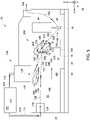
- FIG. 5is a schematic side view of an alternative embodiment of additive manufacturing system 10 (shown in FIGs. 3-4 ) illustrating exemplary flow control device 24 including a movable flow modifier system 200.
- the embodiment shown in FIGs. 3 and 4is substantially similar to the embodiment shown in FIG. 5 , except for the presence of movable flow modifier system 200 including a movable first flow feature 202 and a movable second flow feature 204.
- second flow modifier 106is an airfoil shaped second flow feature 140 and movable first flow feature 202 and movable second flow feature 204 are airfoil shaped.
- movable first flow feature 202 and movable second flow feature 204may be any of a spherical shape, a ramp shape, a nozzle shape, and a hyperbolic shape.
- movable first flow feature 202 and movable second flow feature 204are configured to rotate about axes substantially aligned with the second direction and movable first flow feature 202 is configured to translate along the third direction. More specifically, movable first flow feature 202 is configured to rotate about a first shaft 206 extending along the second direction between inner walls 142 and movable second flow feature 204 is configured to rotate about a second shaft 210 extending along the second direction between inner walls 142. In the exemplary embodiment, movable first flow feature 202 is positioned at movable first angle 214 with respect to the first direction and movable second flow feature 204 is positioned at a movable second angle 216 with respect to the first direction. In alternative embodiments, movable first flow feature 202 and movable second flow feature 204 may be configured and positioned in any manner that facilitates operation of additive manufacturing system 10 as described herein.
- a movable feature entrance distance 208is defined between upstream portions of movable first flow feature 202 and movable second flow feature 204
- a movable feature exit distance 212is defined between downstream portions of movable first flow feature 202 and movable second flow feature 204.
- movable first flow feature 202is configured to be positionable along the third direction within a slot 218 by a slot distance 220 to further facilitate placement of movable first flow feature 202.
- Movable first flow feature 202 and movable second flow feature 204are configured to cooperate with second flow feature 140 to modify at least one flow characteristic of first portion 124 and second portion 128 of gas 101 to facilitate merging first portion 124 and second portion 128 into third portion 158 of gas 101 and to facilitate directing third portion 158 of gas 101 towards debris cloud 148.
- movable first flow feature 202, movable second flow feature 204, and second flow feature 140may be positioned to cooperate in any manner that facilitates operation of additive manufacturing system 10 as described herein.
- FIG. 6is a flow chart illustrating a method 600 for fabricating a component 16 using additive manufacturing system 10 (shown in FIG. 1 ).
- method 600includes discharging 602 a gas 101 into a system enclosure 22 from a gas supply 100.
- Method 600also includes operating 604 a consolidation device 14 to direct an energy beam 20 to be incident on a build layer 36 within system enclosure 22 to form a melt pool 18 in build layer 36.
- Method 600further includes modifying 606 at least one flow characteristic of a first portion 124 of gas 101 using a first flow modifier 104 in cooperation with a second flow modifier 106.
- method 600includes modifying 608 at least one flow characteristic of a second portion 128 of gas 101 using second flow modifier 106 such that first flow modifier 104 and second flow modifier 106 are in cooperation to direct at least a portion of first portion 124 and second portion 128 of gas 101 towards melt pool 18.
- the embodiments described hereininclude a flow control device for an additive manufacturing system.
- the additive manufacturing systemdefines a first direction, a second direction, and a third direction, the three directions orthogonal to each other.
- the flow control deviceincludes a gas supply configured to discharge a gas, a first flow modifier, and a second flow modifier.
- the first flow modifieris configured to modify at least one flow characteristic of a first portion of the gas.
- the second flow modifieris configured to cooperate with the first flow modifier to modify the at least one flow characteristic of the first portion of the gas, and is further configured to modify at least one flow characteristic of a second portion of the gas.
- the first flow modifier and the second flow modifierare configured to cooperate to direct at least a portion of the first portion and the second portion of the gas towards a melt pool in the build layer.
- the flow control devicefacilitates reducing the cost to additively manufacture components and improving the quality of the additively manufactured components by reducing the amount of particulates between a build layer of the component and the consolidation device, thereby reducing the amount of power loss required to consolidate the component and reducing consolidation inconsistencies due to particulate matter interference between the consolidation device and the component being consolidated.
- An exemplary technical effect of the methods, systems, and apparatus described hereinincludes at least one of: a) improving consistency of consolidation of a component during the additive manufacturing process, b) reducing a power required to consolidate a component during the additive manufacturing process, c) improving component dimensional and surface finish consistency, and d) reducing the cost of additively manufacturing a component.
- flow control devicesincluding gas supplies and flow modifiers are described above in detail.
Landscapes
- Engineering & Computer Science (AREA)
- Physics & Mathematics (AREA)
- Optics & Photonics (AREA)
- Mechanical Engineering (AREA)
- Plasma & Fusion (AREA)
- Chemical & Material Sciences (AREA)
- Manufacturing & Machinery (AREA)
- Materials Engineering (AREA)
- Automation & Control Theory (AREA)
- Fluid Mechanics (AREA)
- Powder Metallurgy (AREA)
Description
- The subject matter described herein relates generally to additive manufacturing systems and, more particularly, to additive manufacturing systems including flow control apparatuses.
- At least some additive manufacturing systems involve the consolidation of a particulate material to make a component. Such techniques facilitate producing complex components from expensive materials at a reduced cost and with improved manufacturing efficiency. At least some known additive manufacturing systems, such as Direct Metal Laser Melting (DMLM), Selective Laser Melting (SLM), Direct Metal Laser Sintering (DMLS), and LaserCusing® systems, fabricate components using a focused energy source, such as a laser device or an electron beam generator, a build platform, and a particulate, such as, without limitation, a powdered metal. (LaserCusing is a registered trademark of Concept Laser GmbH of Lichtenfels, Germany.) In at least some DMLM systems, a melt pool is formed in the particulate by the focused energy source and the particulate is consolidated to form a build layer of the component on the build platform at an atmospheric pressure. However, in at least some known systems, soot and other small particulate matter are created during the consolidation process and may become suspended in a gas surrounding the build platform and between the build layer and the focused energy source, reducing the effective power of the energy source being used for consolidation, which may result in consolidation inconsistences including dimensional, surface finish, and particle-to-particle consolidation inconsistencies in the completed component.
DE 10 2010 052 206 A1 discloses an additive manufacturing apparatus.DE 10 2013 214 925 A1 discloses an additive manufacturing apparatus.- The invention is defined by the appended claim. In one aspect, a flow control device for an additive manufacturing system according to Claim 1 is provided.
- In another aspect, an additive manufacturing system according to Claim 5 is provided.
- In yet another aspect, a method of fabricating a component using an additive manufacturing system according to Claim 7 is provided.
- These and other features, aspects, and advantages of the present disclosure will become better understood when the following detailed description is read with reference to the accompanying drawings in which like characters represent like parts throughout the drawings, wherein:
FIG. 1 is a schematic partial cutaway view of an exemplary additive manufacturing system;FIG. 2 is a block diagram of a controller that may be used to operate the additive manufacturing system shown inFIG. 1 ;FIG. 3 is a schematic side view of the additive manufacturing system shown inFIG. 1 illustrating an exemplary flow control device;FIG. 4 is a section view of the pressurized consolidation assembly shown inFIG. 3 taken about section line 4-4;FIG. 5 is a schematic side view of an alternative embodiment of the additive manufacturing system shown inFIG. 3 illustrating an exemplary movable flow control device; andFIG. 6 is a flowchart illustrating an exemplary method that may be used to fabricate a component using the additive manufacturing system shown inFIG. 1 .- Unless otherwise indicated, the drawings provided herein are meant to illustrate features of embodiments of the disclosure. These features are believed to be applicable in a wide variety of systems comprising one or more embodiments of the disclosure. As such, the drawings are not meant to include all conventional features known by those of ordinary skill in the art to be required for the practice of the embodiments disclosed herein.
- In the following specification and the claims, reference will be made to a number of terms, which shall be defined to have the following meanings.
- The singular forms "a", "an", and "the" include plural references unless the context clearly dictates otherwise.
- "Optional" or "optionally" means that the subsequently described event or circumstance may or may not occur, and that the description includes instances where the event occurs and instances where it does not.
- Approximating language, as used herein throughout the specification and claims, may be applied to modify any quantitative representation that could permissibly vary without resulting in a change in the basic function to which it is related. Accordingly, a value modified by a term or terms, such as "about," "substantially," and "approximately," are not to be limited to the precise value specified. In at least some instances, the approximating language may correspond to the precision of an instrument for measuring the value. Here and throughout the specification and claims, range limitations may be combined and/or interchanged, such ranges are identified and include all the sub-ranges contained therein unless context or language indicates otherwise.
- As used herein, the terms "processor" and "computer," and related terms, e.g., "processing device," "computing device," and "controller" are not limited to just those integrated circuits referred to in the art as a computer, but broadly refers to a microcontroller, a microcomputer, a programmable logic controller (PLC), and application specific integrated circuit, and other programmable circuits, and these terms are used interchangeably herein. In the embodiments described herein, memory may include, but it not limited to, a computer-readable medium, such as a random access memory (RAM), a computer-readable non-volatile medium, such as a flash memory. Alternatively, a floppy disk, a compact disc - read only memory (CD-ROM), a magneto-optical disk (MOD), and/or a digital versatile disc (DVD) may also be used. Also, in the embodiments described herein, additional input channels may be, but are not limited to, computer peripherals associated with an operator interface such as a mouse and a keyboard. Alternatively, other computer peripherals may also be used that may include, for example, but not be limited to, a scanner. Furthermore, in the exemplary embodiment, additional output channels may include, but not be limited to, an operator interface monitor.
- Further, as used herein, the terms "software" and "firmware" are interchangeable, and include any computer program storage in memory for execution by personal computers, workstations, clients, and servers.
- As used herein, the term "non-transitory computer-readable media" is intended to be representative of any tangible computer-based device implemented in any method of technology for short-term and long-term storage of information, such as, computer-readable instructions, data structures, program modules and sub-modules, or other data in any device. Therefore, the methods described herein may be encoded as executable instructions embodied in a tangible, non-transitory, computer-readable medium, including, without limitation, a storage device and/or a memory device. Such instructions, when executed by a processor, cause the processor to perform at least a portion of the methods described herein. Moreover, as used herein, the term "non-transitory computer-readable media" includes all tangible, computer-readable media, including, without limitation, non-transitory computer storage devices, including without limitation, volatile and non-volatile media, and removable and non-removable media such as firmware, physical and virtual storage, CD-ROMS, DVDs, and any other digital source such as a network or the Internet, as well as yet to be developed digital means, with the sole exception being transitory, propagating signal.
- Furthermore, as used herein, the term "real-time" refers to at least one of the time of occurrence of the associated events, the time of measurement and collection of predetermined data, the time to process the data, and the time of a system response to the events and the environment. In the embodiments described herein, these activities and events occur substantially instantaneously.
- The systems and methods described herein include a flow control device for an additive manufacturing system. The additive manufacturing system defines a first direction, a second direction, and a third direction, the three directions are orthogonal to each other. The flow control device includes a gas supply configured to discharge a gas, a first flow modifier, and a second flow modifier. The first flow modifier is configured to modify at least one flow characteristic of a first portion of the gas. The second flow modifier is configured to cooperate with the first flow modifier to modify the at least one flow characteristic of the first portion of the gas, and is further configured to modify at least one flow characteristic of a second portion of the gas. The first flow modifier and the second flow modifier are configured to cooperate to direct at least a portion of the first portion and the second portion of the gas towards a melt pool in the build layer. The flow control device facilitates reducing the cost to additively manufacture components and improving the quality of the additively manufactured components by reducing the amount of particulates between a build layer of the component and the consolidation device, thereby reducing the amount of power required to consolidate the component and reducing consolidation inconsistencies due to particulate matter interference with the consolidation device and the component being consolidated.
- Additive manufacturing processes and systems include, for example, and without limitation, vat photopolymerization, powder bed fusion, binder jetting, material jetting, sheet lamination, material extrusion, directed energy deposition and hybrid systems. These processes and systems include, for example, and without limitation, SLA - Stereolithography Apparatus, DLP - Digital Light Processing, 3SP - Scan, Spin, and Selectively Photocure, CLIP - Continuous Liquid Interface Production, SLS - Selective Laser Sintering, DMLS - Direct Metal Laser Sintering, SLM - Selective Laser Melting, EBM - Electron Beam Melting, SHS - Selective Heat Sintering, MJF - Multi-Jet Fusion, 3D Printing, Voxeljet, Polyjet, SCP - Smooth Curvatures Printing, MJM - Multi-Jet Modeling Projet, LOM - Laminated Object Manufacture, SDL - Selective Deposition Lamination, UAM - Ultrasonic Additive Manufacturing, FFF - Fused Filament Fabrication, FDM - Fused Deposition Modeling, LMD - Laser Metal Deposition, LENS - Laser Engineered Net Shaping, DMD - Direct Metal Deposition, Hybrid Systems, and combinations of these processes and systems. These processes and systems may employ, for example, and without limitation, all forms of electromagnetic radiation, heating, sintering, melting, curing, binding, consolidating, pressing, embedding, and combinations thereof.
- Additive manufacturing processes and systems employ materials including, for example, and without limitation, polymers, plastics, metals, ceramics, sand, glass, waxes, fibers, biological matter, composites, and hybrids of these materials. These materials may be used in these processes and systems in a variety of forms as appropriate for a given material and the process or system, including, for example, and without limitation, as liquids, solids, powders, sheets, foils, tapes, filaments, pellets, liquids, slurries, wires, atomized, pastes, and combinations of these forms.
FIG. 1 is a schematic view of an exemplaryadditive manufacturing system 10. Acoordinate system 12 includes an X-axis defining a first, longitudinal direction, a Y-axis defining a second, horizontal direction, and a Z-axis defining a third, vertical direction. In the exemplary embodiment,additive manufacturing system 10 includes aconsolidation device 14 and aflow control device 24 for fabricating acomponent 16 using a layer-by-layer manufacturing process. Alternatively,additive manufacturing system 10 may include any component that facilitates consolidation of a material using any of the processes and systems described herein. In the exemplary embodiment,consolidation device 14 is alaser device 14 configured to provide a high-intensity heat source configured to generate a melt pool 18 (not shown to scale) in a powdered material using anenergy beam 20. Specifically,consolidation device 14 is a yttrium-based solid state laser device configured to emit alaser beam 20 having a wavelength of about 1070 nanometers (nm). In alternative embodiments,consolidation device 14 may include any type of energy source that facilitates operation ofadditive manufacturing system 10 as described herein.Consolidation device 14 andflow control device 24 are contained within asystem enclosure 22. In alternative embodiments,consolidation device 14 may be positioned outside ofsystem enclosure 22.Additive manufacturing system 10 also includes a computer control system, orcontroller 26.Consolidation device 14 is moved by an actuator or an actuator system (not shown) that is configured to moveconsolidation device 14 in the first direction, the second direction, and the third direction to facilitate fabricating a layer ofcomponent 16 withinadditive manufacturing system 10. For example, and without limitation,consolidation device 14 is pivoted about a central point, moved in a linear path, a curved path, and/or rotated to cover a portion of the powder on abuild platform 30 to facilitate directingenergy beam 20 along ascan path 32 along the surface of a plurality ofparticles 34 of abuild layer 36 to form a layer ofcomponent 16 withinsystem enclosure 22. Alternatively,system enclosure 22 andconsolidation device 14 are moved in any orientation and manner that enablesadditive manufacturing system 10 to function as described herein.- In the exemplary embodiment,
additive manufacturing system 10 is operated to fabricatecomponent 16 from a computer modeled representation of the 3D geometry ofcomponent 16. The computer modeled representation may be produced in a computer aided design (CAD) or similar file. The CAD file ofcomponent 16 is converted into a layer-by-layer format that includes a plurality of build parameters for each layer ofcomponent 16, for example, buildlayer 36 ofcomponent 16 including plurality ofparticles 34 to be consolidated byadditive manufacturing system 10. In the exemplary embodiment,component 16 is modeled in a desired orientation relative to the origin of the coordinate system used inadditive manufacturing system 10. The geometry ofcomponent 16 is sliced into a stack of layers of a desired thickness, such that the geometry of each layer is an outline of the cross-section throughcomponent 16 at that particular layer location.Scan paths 32 are generated across the geometry of a respective layer. The build parameters are applied alongscan path 32 to fabricate that layer ofcomponent 16 fromparticles 34 used to constructcomponent 16. The steps are repeated for each respective layer ofcomponent 16 geometry. Once the process is completed, an electronic computer build file (or files) is generated, including all of the layers. The build file is loaded intocontroller 26 ofadditive manufacturing system 10 to control the system during fabrication of each layer. - After the build file is loaded into
controller 26,additive manufacturing system 10 is operated to generatecomponent 16 by implementing the layer-by-layer manufacturing process, such as a direct metal laser melting method. The exemplary layer-by-layer additive manufacturing process does not use a pre-existing article as the precursor to the final component, rather the process producescomponent 16 from a raw material in a configurable form, such asparticles 34. For example, and without limitation, a steel component can be additively manufactured using a steel powder.Additive manufacturing system 10 enables fabrication of components, such ascomponent 16, using a broad range of materials, for example, and without limitation, metals, ceramics, glass, and polymers. FIG. 2 is a block diagram ofcontroller 26 that may be used to operate additive manufacturing system 10 (shown inFIG. 1 ). In an example,controller 26 is any type of controller typically provided by a manufacturer ofadditive manufacturing system 10 to control operation ofadditive manufacturing system 10.Controller 26 executes operations to control the operation ofadditive manufacturing system 10 based at least partially on instructions from human operators.Controller 26 includes, for example, a 3D model ofcomponent 16 to be fabricated byadditive manufacturing system 10. Operations executed bycontroller 26 include controlling power output of consolidation device 14 (shown inFIG. 1 ), adjusting a mounting system (not shown) to control the movement ofconsolidation device 14 and the scanning velocity ofenergy beam 20, and adjusting and controlling the movement offlow control device 24. In alternative examples,controller 26 may execute any operation that enablesadditive manufacturing system 10 to function as described herein.- In the example,
controller 26 includes amemory device 38 and aprocessor 40 coupled tomemory device 38.Processor 40 may include one or more processing units, such as, without limitation, a multi-core configuration.Processor 40 is any type of processor that permitscontroller 26 to operate as described herein. In some examples, executable instructions are stored inmemory device 38.Controller 26 is configurable to perform one or more operations described herein by programmingprocessor 40. For example,processor 40 may be programmed by encoding an operation as one or more executable instructions and providing the executable instructions inmemory device 38. In the exemplary embodiment,memory device 38 is one or more devices that enable storage and retrieval of information such as executable instructions or other data.Memory device 38 may include one or more computer readable media, such as, without limitation, random access memory (RAM), dynamic RAM, static RAM, a solid-state disk, a hard disk, read-only memory (ROM), erasable programmable ROM, electrically erasable programmable ROM, or non-volatile RAM memory. The above memory types are exemplary only, and are thus not limiting as to the types of memory usable for storage of a computer program. Memory device 38 may be configured to store any type of data, including, without limitation, build parameters associated withcomponent 16. In some embodiments,processor 40 removes or "purges" data frommemory device 38 based on the age of the data. For example,processor 40 may overwrite previously recorded and stored data associated with a subsequent time or event. In addition, or alternatively,processor 40 may remove data that exceeds a predetermined time interval. In addition,memory device 38 includes, without limitation, sufficient data, algorithms, and commands to facilitate monitoring of build parameters and the geometric conditions ofcomponent 16 being fabricated byadditive manufacturing system 10.- In some examples,
controller 26 includes apresentation interface 42 coupled toprocessor 40.Presentation interface 42 presents information, such as the operating conditions ofadditive manufacturing system 10, to auser 44. In one embodiment,presentation interface 42 includes a display adapter (not shown) coupled to a display device (not shown), such as a cathode ray tube (CRT), a liquid crystal display (LCD), an organic LED (OLED) display, or an "electronic ink" display. In some examples,presentation interface 42 includes one or more display devices. In addition, or alternatively,presentation interface 42 includes an audio output device (not shown), for example, without limitation, an audio adapter or a speaker (not shown). - In some examples,
controller 26 includes auser input interface 46. In the example,user input interface 46 is coupled toprocessor 40 and receives input fromuser 44.User input interface 46 may include, for example, without limitation, a keyboard, a pointing device, a mouse, a stylus, a touch sensitive panel, such as, without limitation, a touch pad or a touch screen, and/or an audio input interface, such as, without limitation, a microphone. A single component, such as a touch screen, may function as both a display device ofpresentation interface 42 anduser input interface 46. - In the example, a
communication interface 48 is coupled toprocessor 40 and is configured to be coupled in communication with one or more other devices, such asconsolidation device 14, and to perform input and output operations with respect to such devices while performing as an input channel. For example,communication interface 48 may include, without limitation, a wired network adapter, a wireless network adapter, a mobile telecommunications adapter, a serial communication adapter, or a parallel communication adapter.Communication interface 48 may receive a data signal from or transmit a data signal to one or more remote devices. Presentation interface 42 andcommunication interface 48 are both capable of providing information suitable for use with the methods described herein, such as, providing information touser 44 orprocessor 40. Accordingly,presentation interface 42 andcommunication interface 48 may be referred to as output devices. Similarly,user input interface 46 andcommunication interface 48 are capable of receiving information suitable for use with the methods described herein and may be referred to as input devices.FIG. 3 is a schematic side view of additive manufacturing system 10 (shown inFIG. 1 ) illustrating exemplaryflow control device 24.FIG. 4 is a section view of additive manufacturing system 10 (shown inFIG. 3 ) taken about section line 4-4. In the exemplary embodiment,flow control device 24 includes agas supply 100 configured to discharge a flow of agas 101 intosystem enclosure 22, arecoater 102 including afirst flow modifier 104, and asecond flow modifier 106. In the exemplary embodiment,system enclosure 22 includes afirst volume 108 ofgas 101 coupled in flow communication to asecond volume 110 ofgas 101 viagas supply 100. More particularly,gas 101 flows along aflow direction 112 throughgas pipes 114 fromsecond volume 110 togas supply 100, where it is discharged intofirst volume 108 withinsystem enclosure 22 through one of afirst gas discharge 116 and asecond gas discharge 118 and moves along adownstream direction 120 to an exit fromsystem enclosure 22 through adischarge port 122.- In the exemplary embodiment,
first gas discharge 116 is configured to discharge afirst portion 124 ofgas 101 intosystem enclosure 22 at a first speed along the first direction, substantially parallel to buildlayer 36, defining afirst flow path 126.Second gas discharge 118 is configured to discharge asecond portion 128 ofgas 101 intosystem enclosure 22 at a second speed along the third direction, substantially perpendicular to buildlayer 36, defining asecond flow path 130. In an alternative embodiment one offirst gas discharge 116 andsecond gas discharge 118 may be coupled in flow communication with a third volume containing a gas that is different fromgas 101 insecond volume 110. In the exemplary embodiment,second gas discharge 118 is a primary gas supply andfirst gas discharge 116 is a secondary gas supply, whereinsecond gas discharge 118 is configured to supply a greater amount ofgas 101 tofirst volume 108 withinsystem enclosure 22 thanfirst gas discharge 116 is configured to supply tosystem enclosure 22. - In the exemplary embodiment,
gas 101 is a shielding gas, and, more particularly,gas 101 is argon. In alternative embodiments,gas 101 may be at least one of carbon dioxide, helium, oxygen, nitrogen, nitric oxide, sulfur hexafluoride, and dichlorodifluoromethane. In the exemplary embodiment, a pressure ofgas 101 withinfirst volume 108 ofsystem enclosure 22 is approximately fourteen and a half pounds per square inch (psi) (atmospheric conditions). In the exemplary embodiment, a pressure ofgas 101 withinsecond volume 110 is higher than that the pressure ofgas 101 withinfirst volume 108, facilitatinggas 101 fromfirst volume 108 moving into and throughsystem enclosure 22. In alternative embodiments, the pressures ofgas 101 withinfirst volume 108 andsecond volume 110 may be any pressures that facilitate operation ofadditive manufacturing system 10 as described herein. - In the exemplary embodiment,
recoater 102 is configured to move along the first direction and to distribute a plurality ofparticles 34 acrossbuild layer 36 withinadditive manufacturing system 10.Recoater 102 includes afirst flow modifier 104 configured to modify at least one flow characteristic offirst portion 124 ofgas 101. In the exemplary embodiment,first flow modifier 104 is afirst flow feature 132 coupled to a verticallyupper portion 134 ofrecoater 102 and extending along the second direction by a firstflow feature width 136 and having a firstflow feature length 138. In the exemplary embodiment,first flow feature 132 is an airfoil shape. In alternative embodiments,first flow feature 132 is at least one of a spherical shape, a ramp shape, a nozzle shape, and a hyperbolic shape. In further alternative embodiments,first flow modifier 104 may include any component in any arrangement that facilitates operation offlow control device 24 as described herein. - In the exemplary embodiment,
second flow modifier 106 is configured to cooperate withfirst flow modifier 104 to modify the at least one flow characteristic offirst portion 124 ofgas 101 and to modify at least one flow characteristic ofsecond portion 128 ofgas 101. In the exemplary embodiment, second flow manipulator includes asecond flow feature 140.Second flow feature 140 is an airfoil shape positioned vertically abovefirst flow feature 132 and extending betweeninner walls 142 ofsystem enclosure 22 along the second direction by a secondflow feature width 144 and having a secondflow feature length 146 such that asecond trailing edge 141 ofsecond flow feature 140 is substantially aligned with afirst trailing edge 133 offirst flow feature 132, relative to the first direction. In alternative embodiments,second flow feature 140 is at least one of a spherical shape, a ramp shape, a nozzle shape, and a hyperbolic shape. - In the exemplary embodiment, during the consolidation process of
build layer 36,melt pool 18 is formed byenergy beam 20 causing a plasma plume to form betweenmelt pool 18 andconsolidation device 14 and an amount of spatter and soot to be formed, ejected radially outward frommelt pool 18, and at least partially suspended as adebris cloud 148 in the gaseous environment surroundingbuild layer 36. Exposingmelt pool 18 andconsolidation device 14 to a flow ofgas 101, specificallygas 101 having a gas velocity, relative toconsolidation device 14, sufficient to carry the suspended particles withindebris cloud 148 from betweenconsolidation device 14 and meltpool 18, facilitates reducing power requirements ofconsolidation device 14, improving dimensional precision ofcomponent 16, and reducing particulate build up withinsystem enclosure 22. - In the exemplary embodiment,
first portion 124 ofgas 101 moves alongfirst flow path 126 and contacts a leading edge and a vertically upper surface offirst flow feature 132 and a leading edge and vertically lower surface ofsecond flow feature 140. In the exemplary embodiment,first flow feature 132 is positioned at afirst angle 150 relative to the first direction andsecond flow feature 140 is positioned at asecond angle 152 relative the first direction, whereinfirst flow feature 132 andsecond flow feature 140 are positioned and oriented to act as a flow modifier, for either accelerating, damping, or otherwise altering flow with respect tofirst portion 124 ofgas 101. More specifically, anentrance distance 154 defined between upstream portions offirst flow feature 132 andsecond flow feature 140 is greater than anexit distance 156 defined between downstream portions offirst flow feature 132 andsecond flow feature 140 such thatfirst portion 124 ofgas 101 is accelerated while passing betweenfirst flow feature 132 andsecond flow feature 140. Additionally, in the exemplary embodiment,first flow feature 132 andsecond flow feature 140 are positioned to change a direction offirst flow path 126, as shown inFIG. 3 , to facilitate directingfirst portion 124 towardsdebris cloud 148 and merging withsecond portion 128 ofgas 101. - In the exemplary embodiment,
second portion 128 ofgas 101 is discharged fromsecond gas discharge 118, moves alongsecond flow path 130, and contacts a vertically upper surface ofsecond flow feature 140.Second portion 128 ofgas 101 is channeled along the upper surface ofsecond flow feature 140, andsecond angle 152 ofsecond flow feature 140 facilitates changing a direction ofsecond flow path 130 to facilitate directingsecond portion 128 towardsdebris cloud 148 and to facilitatesecond portion 128 merging withfirst portion 124. - In the exemplary embodiment,
first portion 124 mixes and combines withsecond portion 128 at aconfluence 157, downstream offirst flow feature 132 andsecond flow feature 140, forming athird portion 158 and defining athird flow path 160.Third portion 158 represents a combination offirst portion 124 andsecond portion 128, and the directionality ofthird flow path 160 is a result of a combination of vectors fromfirst portion 124 andsecond portion 128. More specifically,third flow path 160 results from the combination of a volume offirst portion 124 at a first velocity and a volume ofsecond portion 128 at a second velocity, wherein the volume and a speed ofsecond portion 128 is greater than the volume and a speed offirst portion 124 such thatthird flow path 160 defines a flow path predetermined to facilitatethird portion 158 interacting withdebris cloud 148. - In the exemplary embodiment,
third portion 158 ofgas 101 moves alongthird flow path 160 and interacts withdebris cloud 148 such that particulate matter withindebris cloud 148 that is being generated by the consolidation process is continuously substantially evacuated from betweenconsolidation device 14 and meltpool 18 bygas 101. In the exemplary embodiment,consolidation device 14 is illustrated as being positioned withinsystem enclosure 22. In alternative embodiments,gas 101 ofthird portion 158 containing an amount of particulate matter continues alongthird flow path 160 to dischargeport 122. In the exemplary embodiment,discharge port 122 is configured to facilitate dischargingthird portion 158 fromsystem enclosure 22 to a cleaning system (not shown) configured to remove the particulate matter fromgas 101 for future re-use. In an alternative embodiment,discharge port 122 is configured to facilitate dischargingthird portion 158 fromsystem enclosure 22 in any manner that facilitates operation ofadditive manufacturing system 10 as described herein. FIG. 5 is a schematic side view of an alternative embodiment of additive manufacturing system 10 (shown inFIGs. 3-4 ) illustrating exemplaryflow control device 24 including a movableflow modifier system 200. The embodiment shown inFIGs. 3 and4 is substantially similar to the embodiment shown inFIG. 5 , except for the presence of movableflow modifier system 200 including a movablefirst flow feature 202 and a movablesecond flow feature 204. In the exemplary embodiment,second flow modifier 106 is an airfoil shapedsecond flow feature 140 and movablefirst flow feature 202 and movablesecond flow feature 204 are airfoil shaped. In alternative embodiments, movablefirst flow feature 202 and movablesecond flow feature 204 may be any of a spherical shape, a ramp shape, a nozzle shape, and a hyperbolic shape.- In the exemplary embodiment, movable
first flow feature 202 and movablesecond flow feature 204 are configured to rotate about axes substantially aligned with the second direction and movablefirst flow feature 202 is configured to translate along the third direction. More specifically, movablefirst flow feature 202 is configured to rotate about afirst shaft 206 extending along the second direction betweeninner walls 142 and movablesecond flow feature 204 is configured to rotate about asecond shaft 210 extending along the second direction betweeninner walls 142. In the exemplary embodiment, movablefirst flow feature 202 is positioned at movablefirst angle 214 with respect to the first direction and movablesecond flow feature 204 is positioned at a movablesecond angle 216 with respect to the first direction. In alternative embodiments, movablefirst flow feature 202 and movablesecond flow feature 204 may be configured and positioned in any manner that facilitates operation ofadditive manufacturing system 10 as described herein. - In the exemplary embodiment, a movable
feature entrance distance 208 is defined between upstream portions of movablefirst flow feature 202 and movablesecond flow feature 204, and a movablefeature exit distance 212 is defined between downstream portions of movablefirst flow feature 202 and movablesecond flow feature 204. Additionally, movablefirst flow feature 202 is configured to be positionable along the third direction within aslot 218 by aslot distance 220 to further facilitate placement of movablefirst flow feature 202. Movablefirst flow feature 202 and movablesecond flow feature 204 are configured to cooperate withsecond flow feature 140 to modify at least one flow characteristic offirst portion 124 andsecond portion 128 ofgas 101 to facilitate mergingfirst portion 124 andsecond portion 128 intothird portion 158 ofgas 101 and to facilitate directingthird portion 158 ofgas 101 towardsdebris cloud 148. In alternative embodiments, movablefirst flow feature 202, movablesecond flow feature 204, andsecond flow feature 140 may be positioned to cooperate in any manner that facilitates operation ofadditive manufacturing system 10 as described herein. FIG. 6 is a flow chart illustrating amethod 600 for fabricating acomponent 16 using additive manufacturing system 10 (shown inFIG. 1 ). Referring to FIGs. 105,method 600 includes discharging 602 agas 101 into asystem enclosure 22 from agas supply 100.Method 600 also includes operating 604 aconsolidation device 14 to direct anenergy beam 20 to be incident on abuild layer 36 withinsystem enclosure 22 to form amelt pool 18 inbuild layer 36.Method 600 further includes modifying 606 at least one flow characteristic of afirst portion 124 ofgas 101 using afirst flow modifier 104 in cooperation with asecond flow modifier 106. Finally,method 600 includes modifying 608 at least one flow characteristic of asecond portion 128 ofgas 101 usingsecond flow modifier 106 such thatfirst flow modifier 104 andsecond flow modifier 106 are in cooperation to direct at least a portion offirst portion 124 andsecond portion 128 ofgas 101 towardsmelt pool 18.- The embodiments described herein include a flow control device for an additive manufacturing system. The additive manufacturing system defines a first direction, a second direction, and a third direction, the three directions orthogonal to each other. The flow control device includes a gas supply configured to discharge a gas, a first flow modifier, and a second flow modifier. The first flow modifier is configured to modify at least one flow characteristic of a first portion of the gas. The second flow modifier is configured to cooperate with the first flow modifier to modify the at least one flow characteristic of the first portion of the gas, and is further configured to modify at least one flow characteristic of a second portion of the gas. The first flow modifier and the second flow modifier are configured to cooperate to direct at least a portion of the first portion and the second portion of the gas towards a melt pool in the build layer. The flow control device facilitates reducing the cost to additively manufacture components and improving the quality of the additively manufactured components by reducing the amount of particulates between a build layer of the component and the consolidation device, thereby reducing the amount of power loss required to consolidate the component and reducing consolidation inconsistencies due to particulate matter interference between the consolidation device and the component being consolidated.
- An exemplary technical effect of the methods, systems, and apparatus described herein includes at least one of: a) improving consistency of consolidation of a component during the additive manufacturing process, b) reducing a power required to consolidate a component during the additive manufacturing process, c) improving component dimensional and surface finish consistency, and d) reducing the cost of additively manufacturing a component.
- Exemplary embodiments of flow control devices including gas supplies and flow modifiers are described above in detail.
- Although specific features of various embodiments of the disclosure may be shown in some drawings and not in others, this is for convenience only.
- This written description uses examples to disclose the embodiments, including the best mode, and also to enable any person skilled in the art to practice the embodiments, including making and using any devices or systems and performing any incorporated methods. The patentable scope of the disclosure is defined by the claims, and may include other examples that occur to those skilled in the art.
Claims (9)
- A flow control device (24) for an additive manufacturing system (10), the additive manufacturing system (10) defining a first, longitudinal direction, a second, horizontal direction, and a third, vertical direction], the three directions being orthogonal to each other, said flow control device (24) comprising:a gas supply (100) configured to discharge a gas, wherein said gas supply device comprises a first gas supply and a second gas supply, wherein said first gas supply is configured to discharge a first portion (124) of a gas (101) along the first direction, substantially parallel to a build layer (36) and wherein said second gas supply is configured to discharge a second portion (128) of a gas (101) along the third direction which is orthogonal to the first direction and substantially perpendicular to the build layer (36);a first flow modifier configured to modify at least one flow characteristic of the first portion (124) of the gas (101); anda second flow modifier (106) configured to cooperate with the first flow modifier (104) to modify the at least one flow characteristic of the first portion (124) of the gas (124), wherein said second flow modifier (106) is further configured to modify at least one flow characteristic of the second portion (128) of the gas (101), and wherein said first flow modifier (104) and said second flow modifier (106) are configured to cooperate to direct at least a portion of the first portion (124) and the second portion (128) of the gas (101) towards a melt pool in a build layer (36); whereinsaid first flow modifier (104) comprises a first flow feature (132) extending along the second direction, and wherein said second flow modifier (106) comprises at least one second flow feature (204) extending along the second direction; andwherein each of said first flow feature (132) and said second flow feature (204) is at least one of an airfoil shape, a spherical shape, a ramp shape, a nozzle shape, and a hyperbolic shape.
- The flow control device in accordance with Claim 1, wherein said first flow modifier (104) is coupled to a recoater configured to move along the first direction and to distribute a plurality of particles across the build layer (36).
- The flow control device in accordance with Claim 1, wherein at least one of said first flow feature (132) and said second flow feature (204) is configured to rotate about an axis substantially aligned with the second direction.
- The flow control device in accordance with Claim 3, wherein said first flow feature (132) and said second flow feature (204) are positioned such that the first portion (124) of the gas (101) is accelerated while passing between said first flow feature (132) and said second flow feature (204).
- An additive manufacturing system (10) defining a first, longitudinal direction, a second, horizontal direction, and a third, vertical direction, the three directions being orthogonal to each other, said additive manufacturing system (10) comprising:an enclosure comprising:a build layer (36) comprising a plurality of particles;a gas supply (100) configured to discharge a gas (101), wherein said gas supply device comprises a first gas supply and a second gas supply, wherein said first gas supply is configured to discharge a first portion (124) of a gas (101) along the first direction, substantially parallel to a build layer (36), and wherein said second gas supply is configured to discharge a second portion (128) of a gas (101) along the third direction which is orthogonal to the first direction and substantially perpendicular to the build layer (36);a first flow modifier (104) configured to modify at least one flow characteristic of the first portion (124) of the gas (101); anda second flow modifier (106) configured to cooperate with the first flow modifier (104) to modify the at least one flow characteristic of the first portion (124) of the gas (101), wherein said second flow modifier (106) is further configured to modify at least one flow characteristic of the second portion (128) of the gas (101); anda consolidation device configured to generate a melt pool in the build layer (36), wherein said first flow modifier (104) and said second flow modifier (106) are configured to cooperate to direct at least a portion of the first portion (124) and the second portion of the gas (101) towards the melt pool in the build layer (36); whereinsaid first flow modifier (104) comprises a first flow feature (132) extending along the second direction, and wherein said second flow modifier (106) comprises at least one second flow feature (204) extending along the second direction; andwherein each of said first flow feature (132) and said second flow feature (204) is at least one of an airfoil shape, a spherical shape, a ramp shape, a nozzle shape, and a hyperbolic shape.
- The additive manufacturing system in accordance with Claim 5, wherein said first flow modifier (104) is coupled to a recoater configured to move along the first direction and to distribute a plurality of particles across the build layer (36).
- A method of fabricating a component using an additive manufacturing system (10), the additive manufacturing system (10) defining a first, longitudinal direction, a second, horizontal direction, and a third, vertical direction, the three directions being orthogonal to each other, said method including:discharging a gas (101) into an enclosure from a gas supply (100), wherein said gas supply device (100) comprises a first gas supply and a second gas supply, wherein said first gas supply is configured to discharge a first portion (124) of a gas (101) along the first direction, substantially parallel to a build layer (36) and wherein said second gas supply is configured to discharge a second portion (128) of a gas (101) along a third direction which is orthogonal to the first direction and substantially perpendicular to the build layer (36);operating a consolidation device to direct an energy beam to form a melt pool in a build layer (36) within the enclosure;modifying at least one flow characteristic of the first portion (124) of the gas (101) using a first flow modifier (104) in cooperation with a second flow modifier (106); andmodifying at least one flow characteristic of the second portion (128) of the gas (101) using the second flow modifier (106), wherein the first flow modifier (104) and the second flow modifier (106) are configured to cooperate to direct at least a portion of the first portion (124) and the second portion (128) of the gas (101) towards the melt pool;wherein modifying at least one flow characteristic of the first portion (124) of the gas (101) comprises using a first flow feature of the first flow modifier (104) extending along the second direction and comprising at least one of an airfoil shape, a spherical shape, a ramp shape, a nozzle shape, and a hyperbolic shape; andwherein modifying at least one flow characteristic of the second portion (128) of the gas (101) andmodifying at least one flow characteristic of the first portion (124) of the gas (101) comprises using a second flow feature of the second flow modifier (106) extending along the second direction and comprising at least one of an airfoil shape, a spherical shape, a ramp shape, a nozzle shape, and a hyperbolic shape.
- The method in accordance with Claim 7, wherein modifying at least one flow characteristic of the first portion (124) of the gas (101) wherein modifying at least one flow characteristic of the first portion (124) of the gas (101) comprises using a first flow modifier (104) coupled to a recoater configured to move along the first direction and to distribute a plurality of particles across the build layer (36).
- The method in accordance with Claim 7, modifying at least one flow characteristic of the first portion (124) of the gas (101) wherein modifying at least one flow characteristic of the first portion (124) of the gas (101) comprises positioning the first flow modifier (104) and the second flow modifier (106) such that the first portion (124) of the gas (101) is accelerated while passing between the first flow modifier (104) and the second flow modifier (106).
Applications Claiming Priority (2)
| Application Number | Priority Date | Filing Date | Title |
|---|---|---|---|
| US15/948,648US10814430B2 (en) | 2018-04-09 | 2018-04-09 | Systems and methods for additive manufacturing flow control devices |
| PCT/US2019/026002WO2019199600A1 (en) | 2018-04-09 | 2019-04-05 | Systems and methods for additive manufacturing flow control devices |
Publications (2)
| Publication Number | Publication Date |
|---|---|
| EP3774130A1 EP3774130A1 (en) | 2021-02-17 |
| EP3774130B1true EP3774130B1 (en) | 2022-09-21 |
Family
ID=66223871
Family Applications (1)
| Application Number | Title | Priority Date | Filing Date |
|---|---|---|---|
| EP19718556.4AActiveEP3774130B1 (en) | 2018-04-09 | 2019-04-05 | Gas flow control device for an additive manufacturing system |
Country Status (4)
| Country | Link |
|---|---|
| US (1) | US10814430B2 (en) |
| EP (1) | EP3774130B1 (en) |
| CN (1) | CN111989177B (en) |
| WO (1) | WO2019199600A1 (en) |
Families Citing this family (4)
| Publication number | Priority date | Publication date | Assignee | Title |
|---|---|---|---|---|
| US11014304B2 (en)* | 2018-04-24 | 2021-05-25 | General Electric Company | Additive manufacturing system and method |
| US12400834B2 (en)* | 2021-05-07 | 2025-08-26 | Taiwan Semiconductor Manufacturing Company, Ltd. | Cantilever with etch chamber flow design |
| US20250185150A1 (en)* | 2022-02-28 | 2025-06-05 | Fermi Research Alliance, Llc | Particle beam assisted fused deposition modeling |
| CN116652323A (en)* | 2023-06-15 | 2023-08-29 | 湘潭大学 | A method for controlling the shape of molten pool in self-decision-making fuse additive materials |
Family Cites Families (26)
| Publication number | Priority date | Publication date | Assignee | Title |
|---|---|---|---|---|
| WO1992008592A1 (en) | 1990-11-09 | 1992-05-29 | Dtm Corporation | Controlled gas flow for selective laser sintering |
| DE19853947C1 (en) | 1998-11-23 | 2000-02-24 | Fraunhofer Ges Forschung | Process chamber for selective laser fusing of material powder comprises a raised section in the cover surface above the structure volume, in which a window is arranged for the coupling in of the laser beam |
| DE102006014694B3 (en)* | 2006-03-28 | 2007-10-31 | Eos Gmbh Electro Optical Systems | Process chamber and method for processing a material with a directed beam of electromagnetic radiation, in particular for a laser sintering device |
| DE102010052206B4 (en)* | 2010-11-10 | 2015-06-18 | Cl Schutzrechtsverwaltungs Gmbh | Device for producing three-dimensional objects |
| PL3323534T3 (en) | 2013-02-14 | 2019-09-30 | Renishaw Plc | Selective laser solidification method |
| EP3007881B1 (en) | 2013-06-11 | 2020-04-29 | Renishaw Plc. | Additive manufacturing apparatus and method |
| DE102013214925A1 (en)* | 2013-07-30 | 2015-02-05 | Bayerische Motoren Werke Aktiengesellschaft | Housing for a beam path, processing chamber and method for laser processing |
| US10434545B2 (en)* | 2014-01-17 | 2019-10-08 | United Technologies Corporation | Particle separator for an additive manufacturing system and method of operation |
| WO2015142546A1 (en) | 2014-03-21 | 2015-09-24 | Carbon3D, Inc. | Method and apparatus for three-dimensional fabrication with gas injection through carrier |
| DE102014205875A1 (en)* | 2014-03-28 | 2015-10-01 | Eos Gmbh Electro Optical Systems | Apparatus and method for layering a three-dimensional object |
| GB201410484D0 (en)* | 2014-06-12 | 2014-07-30 | Renishaw Plc | Additive manufacturing apparatus and a flow device for use with such apparatus |
| TWI529055B (en) | 2014-10-27 | 2016-04-11 | 財團法人工業技術研究院 | Additive manufacturing system and additive manufacturing method |
| JP6293643B2 (en)* | 2014-11-05 | 2018-03-14 | 株式会社東芝 | Nozzle device and processing device |
| WO2016079494A2 (en) | 2014-11-21 | 2016-05-26 | Renishaw Plc | Additive manufacturing apparatus and methods |
| EP3227090B1 (en) | 2014-12-01 | 2019-01-30 | SABIC Global Technologies B.V. | Rapid nozzle cooling for additive manufacturing |
| CN107921659A (en) | 2015-07-23 | 2018-04-17 | 瑞尼斯豪公司 | Additive manufacturing equipment and gas flow devices for such equipment |
| EP3147047B1 (en)* | 2015-09-25 | 2023-08-02 | SLM Solutions Group AG | Apparatus for producing a three-dimensional workpiece with improved gas flow and manufacturing method of a three-dimensional workpiece |
| US10232439B2 (en) | 2015-11-20 | 2019-03-19 | General Electric Company | Gas flow monitoring in additive manufacturing |
| US9989396B2 (en) | 2015-11-20 | 2018-06-05 | General Electric Company | Gas flow characterization in additive manufacturing |
| US10583532B2 (en) | 2015-12-28 | 2020-03-10 | General Electric Company | Metal additive manufacturing using gas mixture including oxygen |
| US9879795B2 (en) | 2016-01-15 | 2018-01-30 | Lam Research Corporation | Additively manufactured gas distribution manifold |
| US10215317B2 (en) | 2016-01-15 | 2019-02-26 | Lam Research Corporation | Additively manufactured gas distribution manifold |
| EP3429819B1 (en) | 2016-03-14 | 2021-04-14 | Nanogrande | Method and apparatus for forming layers of particles for use in additive manufacturing |
| US20190201980A1 (en) | 2016-05-16 | 2019-07-04 | DMG Mori USA | Systems And Methods For Additive Manufacturing Using Highly Reactive Materials |
| DE112017002704T5 (en)* | 2016-05-31 | 2019-02-14 | Hitachi, Ltd. | Additive manufacturing device |
| CN106513674B (en)* | 2016-09-20 | 2018-08-24 | 南京航空航天大学 | The protection gas circulation filter and its optimization method of 3D printing metal powder bed shaped cavity |
- 2018
- 2018-04-09USUS15/948,648patent/US10814430B2/enactiveActive
- 2019
- 2019-04-05WOPCT/US2019/026002patent/WO2019199600A1/ennot_activeCeased
- 2019-04-05EPEP19718556.4Apatent/EP3774130B1/enactiveActive
- 2019-04-05CNCN201980024712.8Apatent/CN111989177B/enactiveActive
Also Published As
| Publication number | Publication date |
|---|---|
| CN111989177A (en) | 2020-11-24 |
| US10814430B2 (en) | 2020-10-27 |
| WO2019199600A1 (en) | 2019-10-17 |
| CN111989177B (en) | 2022-04-12 |
| US20190308273A1 (en) | 2019-10-10 |
| EP3774130A1 (en) | 2021-02-17 |
Similar Documents
| Publication | Publication Date | Title |
|---|---|---|
| EP3774130B1 (en) | Gas flow control device for an additive manufacturing system | |
| US11584057B2 (en) | Systems and methods for additive manufacturing | |
| EP3435182B1 (en) | Systems and methods for advanced additive manufacturing | |
| US10514680B2 (en) | System and method for controlling an additive manufacturing system | |
| US20190210151A1 (en) | Systems and methods for additive manufacturing using pressurized consolidation devices | |
| US11571743B2 (en) | Systems and methods for additive manufacturing | |
| EP3826790B1 (en) | Systems and methods for lateral material transfer in additive manufacturing system | |
| US20190311758A1 (en) | Components including structures having decoupled load paths | |
| US10668710B2 (en) | Components including structures having decoupled structural stiffness and mass density | |
| US10919115B2 (en) | Systems and methods for finishing additive manufacturing faces with different orientations | |
| US11911848B2 (en) | Systems and methods for additive manufacturing |
Legal Events
| Date | Code | Title | Description |
|---|---|---|---|
| STAA | Information on the status of an ep patent application or granted ep patent | Free format text:STATUS: UNKNOWN | |
| STAA | Information on the status of an ep patent application or granted ep patent | Free format text:STATUS: THE INTERNATIONAL PUBLICATION HAS BEEN MADE | |
| PUAI | Public reference made under article 153(3) epc to a published international application that has entered the european phase | Free format text:ORIGINAL CODE: 0009012 | |
| STAA | Information on the status of an ep patent application or granted ep patent | Free format text:STATUS: REQUEST FOR EXAMINATION WAS MADE | |
| 17P | Request for examination filed | Effective date:20200930 | |
| AK | Designated contracting states | Kind code of ref document:A1 Designated state(s):AL AT BE BG CH CY CZ DE DK EE ES FI FR GB GR HR HU IE IS IT LI LT LU LV MC MK MT NL NO PL PT RO RS SE SI SK SM TR | |
| AX | Request for extension of the european patent | Extension state:BA ME | |
| DAV | Request for validation of the european patent (deleted) | ||
| DAX | Request for extension of the european patent (deleted) | ||
| STAA | Information on the status of an ep patent application or granted ep patent | Free format text:STATUS: EXAMINATION IS IN PROGRESS | |
| 17Q | First examination report despatched | Effective date:20211029 | |
| REG | Reference to a national code | Ref country code:DE Ref legal event code:R079 Ref document number:602019019792 Country of ref document:DE Free format text:PREVIOUS MAIN CLASS: B22F0003105000 Ipc:B22F0010280000 | |
| GRAP | Despatch of communication of intention to grant a patent | Free format text:ORIGINAL CODE: EPIDOSNIGR1 | |
| STAA | Information on the status of an ep patent application or granted ep patent | Free format text:STATUS: GRANT OF PATENT IS INTENDED | |
| RIC1 | Information provided on ipc code assigned before grant | Ipc:B33Y 30/00 20150101ALI20220228BHEP Ipc:B33Y 10/00 20150101ALI20220228BHEP Ipc:B29C 64/35 20170101ALI20220228BHEP Ipc:B23K 26/342 20140101ALI20220228BHEP Ipc:B23K 26/14 20140101ALI20220228BHEP Ipc:B22F 12/00 20210101ALI20220228BHEP Ipc:B22F 10/20 20210101AFI20220228BHEP | |
| RIC1 | Information provided on ipc code assigned before grant | Ipc:B29C 64/35 20170101ALI20220320BHEP Ipc:B23K 26/342 20140101ALI20220320BHEP Ipc:B23K 26/14 20140101ALI20220320BHEP Ipc:B33Y 30/00 20150101ALI20220320BHEP Ipc:B33Y 10/00 20150101ALI20220320BHEP Ipc:B22F 12/70 20210101ALI20220320BHEP Ipc:B22F 10/322 20210101ALI20220320BHEP Ipc:B22F 10/28 20210101AFI20220320BHEP | |
| INTG | Intention to grant announced | Effective date:20220406 | |
| GRAS | Grant fee paid | Free format text:ORIGINAL CODE: EPIDOSNIGR3 | |
| GRAA | (expected) grant | Free format text:ORIGINAL CODE: 0009210 | |
| STAA | Information on the status of an ep patent application or granted ep patent | Free format text:STATUS: THE PATENT HAS BEEN GRANTED | |
| AK | Designated contracting states | Kind code of ref document:B1 Designated state(s):AL AT BE BG CH CY CZ DE DK EE ES FI FR GB GR HR HU IE IS IT LI LT LU LV MC MK MT NL NO PL PT RO RS SE SI SK SM TR | |
| REG | Reference to a national code | Ref country code:GB Ref legal event code:FG4D | |
| REG | Reference to a national code | Ref country code:CH Ref legal event code:EP | |
| REG | Reference to a national code | Ref country code:IE Ref legal event code:FG4D | |
| REG | Reference to a national code | Ref country code:DE Ref legal event code:R096 Ref document number:602019019792 Country of ref document:DE | |
| REG | Reference to a national code | Ref country code:AT Ref legal event code:REF Ref document number:1519722 Country of ref document:AT Kind code of ref document:T Effective date:20221015 | |
| REG | Reference to a national code | Ref country code:LT Ref legal event code:MG9D | |
| REG | Reference to a national code | Ref country code:NL Ref legal event code:MP Effective date:20220921 | |
| PG25 | Lapsed in a contracting state [announced via postgrant information from national office to epo] | Ref country code:SE Free format text:LAPSE BECAUSE OF FAILURE TO SUBMIT A TRANSLATION OF THE DESCRIPTION OR TO PAY THE FEE WITHIN THE PRESCRIBED TIME-LIMIT Effective date:20220921 Ref country code:RS Free format text:LAPSE BECAUSE OF FAILURE TO SUBMIT A TRANSLATION OF THE DESCRIPTION OR TO PAY THE FEE WITHIN THE PRESCRIBED TIME-LIMIT Effective date:20220921 Ref country code:NO Free format text:LAPSE BECAUSE OF FAILURE TO SUBMIT A TRANSLATION OF THE DESCRIPTION OR TO PAY THE FEE WITHIN THE PRESCRIBED TIME-LIMIT Effective date:20221221 Ref country code:LV Free format text:LAPSE BECAUSE OF FAILURE TO SUBMIT A TRANSLATION OF THE DESCRIPTION OR TO PAY THE FEE WITHIN THE PRESCRIBED TIME-LIMIT Effective date:20220921 Ref country code:LT Free format text:LAPSE BECAUSE OF FAILURE TO SUBMIT A TRANSLATION OF THE DESCRIPTION OR TO PAY THE FEE WITHIN THE PRESCRIBED TIME-LIMIT Effective date:20220921 Ref country code:FI Free format text:LAPSE BECAUSE OF FAILURE TO SUBMIT A TRANSLATION OF THE DESCRIPTION OR TO PAY THE FEE WITHIN THE PRESCRIBED TIME-LIMIT Effective date:20220921 | |
| REG | Reference to a national code | Ref country code:AT Ref legal event code:MK05 Ref document number:1519722 Country of ref document:AT Kind code of ref document:T Effective date:20220921 | |
| PG25 | Lapsed in a contracting state [announced via postgrant information from national office to epo] | Ref country code:HR Free format text:LAPSE BECAUSE OF FAILURE TO SUBMIT A TRANSLATION OF THE DESCRIPTION OR TO PAY THE FEE WITHIN THE PRESCRIBED TIME-LIMIT Effective date:20220921 Ref country code:GR Free format text:LAPSE BECAUSE OF FAILURE TO SUBMIT A TRANSLATION OF THE DESCRIPTION OR TO PAY THE FEE WITHIN THE PRESCRIBED TIME-LIMIT Effective date:20221222 | |
| PG25 | Lapsed in a contracting state [announced via postgrant information from national office to epo] | Ref country code:SM Free format text:LAPSE BECAUSE OF FAILURE TO SUBMIT A TRANSLATION OF THE DESCRIPTION OR TO PAY THE FEE WITHIN THE PRESCRIBED TIME-LIMIT Effective date:20220921 Ref country code:RO Free format text:LAPSE BECAUSE OF FAILURE TO SUBMIT A TRANSLATION OF THE DESCRIPTION OR TO PAY THE FEE WITHIN THE PRESCRIBED TIME-LIMIT Effective date:20220921 Ref country code:PT Free format text:LAPSE BECAUSE OF FAILURE TO SUBMIT A TRANSLATION OF THE DESCRIPTION OR TO PAY THE FEE WITHIN THE PRESCRIBED TIME-LIMIT Effective date:20230123 Ref country code:ES Free format text:LAPSE BECAUSE OF FAILURE TO SUBMIT A TRANSLATION OF THE DESCRIPTION OR TO PAY THE FEE WITHIN THE PRESCRIBED TIME-LIMIT Effective date:20220921 Ref country code:CZ Free format text:LAPSE BECAUSE OF FAILURE TO SUBMIT A TRANSLATION OF THE DESCRIPTION OR TO PAY THE FEE WITHIN THE PRESCRIBED TIME-LIMIT Effective date:20220921 Ref country code:AT Free format text:LAPSE BECAUSE OF FAILURE TO SUBMIT A TRANSLATION OF THE DESCRIPTION OR TO PAY THE FEE WITHIN THE PRESCRIBED TIME-LIMIT Effective date:20220921 | |
| PG25 | Lapsed in a contracting state [announced via postgrant information from national office to epo] | Ref country code:SK Free format text:LAPSE BECAUSE OF FAILURE TO SUBMIT A TRANSLATION OF THE DESCRIPTION OR TO PAY THE FEE WITHIN THE PRESCRIBED TIME-LIMIT Effective date:20220921 Ref country code:PL Free format text:LAPSE BECAUSE OF FAILURE TO SUBMIT A TRANSLATION OF THE DESCRIPTION OR TO PAY THE FEE WITHIN THE PRESCRIBED TIME-LIMIT Effective date:20220921 Ref country code:IS Free format text:LAPSE BECAUSE OF FAILURE TO SUBMIT A TRANSLATION OF THE DESCRIPTION OR TO PAY THE FEE WITHIN THE PRESCRIBED TIME-LIMIT Effective date:20230121 Ref country code:EE Free format text:LAPSE BECAUSE OF FAILURE TO SUBMIT A TRANSLATION OF THE DESCRIPTION OR TO PAY THE FEE WITHIN THE PRESCRIBED TIME-LIMIT Effective date:20220921 | |
| P01 | Opt-out of the competence of the unified patent court (upc) registered | Effective date:20230516 | |
| REG | Reference to a national code | Ref country code:DE Ref legal event code:R097 Ref document number:602019019792 Country of ref document:DE | |
| PG25 | Lapsed in a contracting state [announced via postgrant information from national office to epo] | Ref country code:NL Free format text:LAPSE BECAUSE OF FAILURE TO SUBMIT A TRANSLATION OF THE DESCRIPTION OR TO PAY THE FEE WITHIN THE PRESCRIBED TIME-LIMIT Effective date:20220921 Ref country code:AL Free format text:LAPSE BECAUSE OF FAILURE TO SUBMIT A TRANSLATION OF THE DESCRIPTION OR TO PAY THE FEE WITHIN THE PRESCRIBED TIME-LIMIT Effective date:20220921 | |
| PLBE | No opposition filed within time limit | Free format text:ORIGINAL CODE: 0009261 | |
| STAA | Information on the status of an ep patent application or granted ep patent | Free format text:STATUS: NO OPPOSITION FILED WITHIN TIME LIMIT | |
| PG25 | Lapsed in a contracting state [announced via postgrant information from national office to epo] | Ref country code:DK Free format text:LAPSE BECAUSE OF FAILURE TO SUBMIT A TRANSLATION OF THE DESCRIPTION OR TO PAY THE FEE WITHIN THE PRESCRIBED TIME-LIMIT Effective date:20220921 | |
| 26N | No opposition filed | Effective date:20230622 | |
| PG25 | Lapsed in a contracting state [announced via postgrant information from national office to epo] | Ref country code:SI Free format text:LAPSE BECAUSE OF FAILURE TO SUBMIT A TRANSLATION OF THE DESCRIPTION OR TO PAY THE FEE WITHIN THE PRESCRIBED TIME-LIMIT Effective date:20220921 | |
| REG | Reference to a national code | Ref country code:CH Ref legal event code:PL | |
| PG25 | Lapsed in a contracting state [announced via postgrant information from national office to epo] | Ref country code:LU Free format text:LAPSE BECAUSE OF NON-PAYMENT OF DUE FEES Effective date:20230405 | |
| REG | Reference to a national code | Ref country code:BE Ref legal event code:MM Effective date:20230430 | |
| PG25 | Lapsed in a contracting state [announced via postgrant information from national office to epo] | Ref country code:MC Free format text:LAPSE BECAUSE OF FAILURE TO SUBMIT A TRANSLATION OF THE DESCRIPTION OR TO PAY THE FEE WITHIN THE PRESCRIBED TIME-LIMIT Effective date:20220921 | |
| PG25 | Lapsed in a contracting state [announced via postgrant information from national office to epo] | Ref country code:MC Free format text:LAPSE BECAUSE OF FAILURE TO SUBMIT A TRANSLATION OF THE DESCRIPTION OR TO PAY THE FEE WITHIN THE PRESCRIBED TIME-LIMIT Effective date:20220921 Ref country code:LI Free format text:LAPSE BECAUSE OF NON-PAYMENT OF DUE FEES Effective date:20230430 Ref country code:CH Free format text:LAPSE BECAUSE OF NON-PAYMENT OF DUE FEES Effective date:20230430 | |
| REG | Reference to a national code | Ref country code:IE Ref legal event code:MM4A | |
| PG25 | Lapsed in a contracting state [announced via postgrant information from national office to epo] | Ref country code:BE Free format text:LAPSE BECAUSE OF NON-PAYMENT OF DUE FEES Effective date:20230430 | |
| PG25 | Lapsed in a contracting state [announced via postgrant information from national office to epo] | Ref country code:IE Free format text:LAPSE BECAUSE OF NON-PAYMENT OF DUE FEES Effective date:20230405 | |
| PG25 | Lapsed in a contracting state [announced via postgrant information from national office to epo] | Ref country code:IE Free format text:LAPSE BECAUSE OF NON-PAYMENT OF DUE FEES Effective date:20230405 | |
| PG25 | Lapsed in a contracting state [announced via postgrant information from national office to epo] | Ref country code:IT Free format text:LAPSE BECAUSE OF FAILURE TO SUBMIT A TRANSLATION OF THE DESCRIPTION OR TO PAY THE FEE WITHIN THE PRESCRIBED TIME-LIMIT Effective date:20220921 | |
| PG25 | Lapsed in a contracting state [announced via postgrant information from national office to epo] | Ref country code:BG Free format text:LAPSE BECAUSE OF FAILURE TO SUBMIT A TRANSLATION OF THE DESCRIPTION OR TO PAY THE FEE WITHIN THE PRESCRIBED TIME-LIMIT Effective date:20220921 | |
| PG25 | Lapsed in a contracting state [announced via postgrant information from national office to epo] | Ref country code:BG Free format text:LAPSE BECAUSE OF FAILURE TO SUBMIT A TRANSLATION OF THE DESCRIPTION OR TO PAY THE FEE WITHIN THE PRESCRIBED TIME-LIMIT Effective date:20220921 | |
| PGFP | Annual fee paid to national office [announced via postgrant information from national office to epo] | Ref country code:FR Payment date:20250319 Year of fee payment:7 | |
| PGFP | Annual fee paid to national office [announced via postgrant information from national office to epo] | Ref country code:GB Payment date:20250319 Year of fee payment:7 | |
| PGFP | Annual fee paid to national office [announced via postgrant information from national office to epo] | Ref country code:DE Payment date:20250319 Year of fee payment:7 | |
| PG25 | Lapsed in a contracting state [announced via postgrant information from national office to epo] | Ref country code:CY Free format text:LAPSE BECAUSE OF FAILURE TO SUBMIT A TRANSLATION OF THE DESCRIPTION OR TO PAY THE FEE WITHIN THE PRESCRIBED TIME-LIMIT; INVALID AB INITIO Effective date:20190405 | |
| PG25 | Lapsed in a contracting state [announced via postgrant information from national office to epo] | Ref country code:HU Free format text:LAPSE BECAUSE OF FAILURE TO SUBMIT A TRANSLATION OF THE DESCRIPTION OR TO PAY THE FEE WITHIN THE PRESCRIBED TIME-LIMIT; INVALID AB INITIO Effective date:20190405 |