EP3773267B1 - Devices for aortic valve preparation prior to transcatheter prosthetic valve procedures - Google Patents
Devices for aortic valve preparation prior to transcatheter prosthetic valve proceduresDownload PDFInfo
- Publication number
- EP3773267B1 EP3773267B1EP19716697.8AEP19716697AEP3773267B1EP 3773267 B1EP3773267 B1EP 3773267B1EP 19716697 AEP19716697 AEP 19716697AEP 3773267 B1EP3773267 B1EP 3773267B1
- Authority
- EP
- European Patent Office
- Prior art keywords
- valve
- leaflet
- preparation device
- catheter
- severing
- Prior art date
- Legal status (The legal status is an assumption and is not a legal conclusion. Google has not performed a legal analysis and makes no representation as to the accuracy of the status listed.)
- Active
Links
Images


Classifications
- A—HUMAN NECESSITIES
- A61—MEDICAL OR VETERINARY SCIENCE; HYGIENE
- A61B—DIAGNOSIS; SURGERY; IDENTIFICATION
- A61B17/00—Surgical instruments, devices or methods
- A61B17/32—Surgical cutting instruments
- A61B17/3205—Excision instruments
- A61B17/32053—Punch like cutting instruments, e.g. using a cylindrical or oval knife
- A—HUMAN NECESSITIES
- A61—MEDICAL OR VETERINARY SCIENCE; HYGIENE
- A61F—FILTERS IMPLANTABLE INTO BLOOD VESSELS; PROSTHESES; DEVICES PROVIDING PATENCY TO, OR PREVENTING COLLAPSING OF, TUBULAR STRUCTURES OF THE BODY, e.g. STENTS; ORTHOPAEDIC, NURSING OR CONTRACEPTIVE DEVICES; FOMENTATION; TREATMENT OR PROTECTION OF EYES OR EARS; BANDAGES, DRESSINGS OR ABSORBENT PADS; FIRST-AID KITS
- A61F2/00—Filters implantable into blood vessels; Prostheses, i.e. artificial substitutes or replacements for parts of the body; Appliances for connecting them with the body; Devices providing patency to, or preventing collapsing of, tubular structures of the body, e.g. stents
- A61F2/02—Prostheses implantable into the body
- A61F2/24—Heart valves ; Vascular valves, e.g. venous valves; Heart implants, e.g. passive devices for improving the function of the native valve or the heart muscle; Transmyocardial revascularisation [TMR] devices; Valves implantable in the body
- A61F2/2427—Devices for manipulating or deploying heart valves during implantation
- A—HUMAN NECESSITIES
- A61—MEDICAL OR VETERINARY SCIENCE; HYGIENE
- A61B—DIAGNOSIS; SURGERY; IDENTIFICATION
- A61B17/00—Surgical instruments, devices or methods
- A61B17/32—Surgical cutting instruments
- A61B17/3205—Excision instruments
- A61B17/3207—Atherectomy devices working by cutting or abrading; Similar devices specially adapted for non-vascular obstructions
- A—HUMAN NECESSITIES
- A61—MEDICAL OR VETERINARY SCIENCE; HYGIENE
- A61B—DIAGNOSIS; SURGERY; IDENTIFICATION
- A61B18/00—Surgical instruments, devices or methods for transferring non-mechanical forms of energy to or from the body
- A61B18/04—Surgical instruments, devices or methods for transferring non-mechanical forms of energy to or from the body by heating
- A61B18/12—Surgical instruments, devices or methods for transferring non-mechanical forms of energy to or from the body by heating by passing a current through the tissue to be heated, e.g. high-frequency current
- A61B18/14—Probes or electrodes therefor
- A61B18/1492—Probes or electrodes therefor having a flexible, catheter-like structure, e.g. for heart ablation
- A—HUMAN NECESSITIES
- A61—MEDICAL OR VETERINARY SCIENCE; HYGIENE
- A61F—FILTERS IMPLANTABLE INTO BLOOD VESSELS; PROSTHESES; DEVICES PROVIDING PATENCY TO, OR PREVENTING COLLAPSING OF, TUBULAR STRUCTURES OF THE BODY, e.g. STENTS; ORTHOPAEDIC, NURSING OR CONTRACEPTIVE DEVICES; FOMENTATION; TREATMENT OR PROTECTION OF EYES OR EARS; BANDAGES, DRESSINGS OR ABSORBENT PADS; FIRST-AID KITS
- A61F2/00—Filters implantable into blood vessels; Prostheses, i.e. artificial substitutes or replacements for parts of the body; Appliances for connecting them with the body; Devices providing patency to, or preventing collapsing of, tubular structures of the body, e.g. stents
- A61F2/02—Prostheses implantable into the body
- A61F2/24—Heart valves ; Vascular valves, e.g. venous valves; Heart implants, e.g. passive devices for improving the function of the native valve or the heart muscle; Transmyocardial revascularisation [TMR] devices; Valves implantable in the body
- A61F2/2412—Heart valves ; Vascular valves, e.g. venous valves; Heart implants, e.g. passive devices for improving the function of the native valve or the heart muscle; Transmyocardial revascularisation [TMR] devices; Valves implantable in the body with soft flexible valve members, e.g. tissue valves shaped like natural valves
- A61F2/2418—Scaffolds therefor, e.g. support stents
- A—HUMAN NECESSITIES
- A61—MEDICAL OR VETERINARY SCIENCE; HYGIENE
- A61B—DIAGNOSIS; SURGERY; IDENTIFICATION
- A61B17/00—Surgical instruments, devices or methods
- A61B17/32—Surgical cutting instruments
- A61B17/320016—Endoscopic cutting instruments, e.g. arthroscopes, resectoscopes
- A—HUMAN NECESSITIES
- A61—MEDICAL OR VETERINARY SCIENCE; HYGIENE
- A61B—DIAGNOSIS; SURGERY; IDENTIFICATION
- A61B17/00—Surgical instruments, devices or methods
- A61B2017/00831—Material properties
- A61B2017/00867—Material properties shape memory effect
- A—HUMAN NECESSITIES
- A61—MEDICAL OR VETERINARY SCIENCE; HYGIENE
- A61B—DIAGNOSIS; SURGERY; IDENTIFICATION
- A61B17/00—Surgical instruments, devices or methods
- A61B17/22—Implements for squeezing-off ulcers or the like on inner organs of the body; Implements for scraping-out cavities of body organs, e.g. bones; for invasive removal or destruction of calculus using mechanical vibrations; for removing obstructions in blood vessels, not otherwise provided for
- A61B2017/22051—Implements for squeezing-off ulcers or the like on inner organs of the body; Implements for scraping-out cavities of body organs, e.g. bones; for invasive removal or destruction of calculus using mechanical vibrations; for removing obstructions in blood vessels, not otherwise provided for with an inflatable part, e.g. balloon, for positioning, blocking, or immobilisation
- A61B2017/22061—Implements for squeezing-off ulcers or the like on inner organs of the body; Implements for scraping-out cavities of body organs, e.g. bones; for invasive removal or destruction of calculus using mechanical vibrations; for removing obstructions in blood vessels, not otherwise provided for with an inflatable part, e.g. balloon, for positioning, blocking, or immobilisation for spreading elements apart
- A—HUMAN NECESSITIES
- A61—MEDICAL OR VETERINARY SCIENCE; HYGIENE
- A61B—DIAGNOSIS; SURGERY; IDENTIFICATION
- A61B17/00—Surgical instruments, devices or methods
- A61B17/22—Implements for squeezing-off ulcers or the like on inner organs of the body; Implements for scraping-out cavities of body organs, e.g. bones; for invasive removal or destruction of calculus using mechanical vibrations; for removing obstructions in blood vessels, not otherwise provided for
- A61B2017/22097—Valve removal in veins
- A—HUMAN NECESSITIES
- A61—MEDICAL OR VETERINARY SCIENCE; HYGIENE
- A61B—DIAGNOSIS; SURGERY; IDENTIFICATION
- A61B17/00—Surgical instruments, devices or methods
- A61B17/32—Surgical cutting instruments
- A61B2017/32006—Surgical cutting instruments with a cutting strip, band or chain, e.g. like a chainsaw
- A—HUMAN NECESSITIES
- A61—MEDICAL OR VETERINARY SCIENCE; HYGIENE
- A61B—DIAGNOSIS; SURGERY; IDENTIFICATION
- A61B18/00—Surgical instruments, devices or methods for transferring non-mechanical forms of energy to or from the body
- A61B2018/00315—Surgical instruments, devices or methods for transferring non-mechanical forms of energy to or from the body for treatment of particular body parts
- A61B2018/00345—Vascular system
- A61B2018/00351—Heart
- A61B2018/00369—Heart valves
- A—HUMAN NECESSITIES
- A61—MEDICAL OR VETERINARY SCIENCE; HYGIENE
- A61B—DIAGNOSIS; SURGERY; IDENTIFICATION
- A61B18/00—Surgical instruments, devices or methods for transferring non-mechanical forms of energy to or from the body
- A61B2018/00571—Surgical instruments, devices or methods for transferring non-mechanical forms of energy to or from the body for achieving a particular surgical effect
- A61B2018/00601—Cutting
- A—HUMAN NECESSITIES
- A61—MEDICAL OR VETERINARY SCIENCE; HYGIENE
- A61B—DIAGNOSIS; SURGERY; IDENTIFICATION
- A61B18/00—Surgical instruments, devices or methods for transferring non-mechanical forms of energy to or from the body
- A61B18/04—Surgical instruments, devices or methods for transferring non-mechanical forms of energy to or from the body by heating
- A61B18/12—Surgical instruments, devices or methods for transferring non-mechanical forms of energy to or from the body by heating by passing a current through the tissue to be heated, e.g. high-frequency current
- A61B18/14—Probes or electrodes therefor
- A61B2018/1405—Electrodes having a specific shape
- A61B2018/1407—Loop
- A—HUMAN NECESSITIES
- A61—MEDICAL OR VETERINARY SCIENCE; HYGIENE
- A61B—DIAGNOSIS; SURGERY; IDENTIFICATION
- A61B18/00—Surgical instruments, devices or methods for transferring non-mechanical forms of energy to or from the body
- A61B18/04—Surgical instruments, devices or methods for transferring non-mechanical forms of energy to or from the body by heating
- A61B18/12—Surgical instruments, devices or methods for transferring non-mechanical forms of energy to or from the body by heating by passing a current through the tissue to be heated, e.g. high-frequency current
- A61B18/14—Probes or electrodes therefor
- A61B2018/1405—Electrodes having a specific shape
- A61B2018/1422—Hook
- A—HUMAN NECESSITIES
- A61—MEDICAL OR VETERINARY SCIENCE; HYGIENE
- A61B—DIAGNOSIS; SURGERY; IDENTIFICATION
- A61B18/00—Surgical instruments, devices or methods for transferring non-mechanical forms of energy to or from the body
- A61B18/04—Surgical instruments, devices or methods for transferring non-mechanical forms of energy to or from the body by heating
- A61B18/12—Surgical instruments, devices or methods for transferring non-mechanical forms of energy to or from the body by heating by passing a current through the tissue to be heated, e.g. high-frequency current
- A61B18/14—Probes or electrodes therefor
- A61B2018/1405—Electrodes having a specific shape
- A61B2018/144—Wire
- A—HUMAN NECESSITIES
- A61—MEDICAL OR VETERINARY SCIENCE; HYGIENE
- A61B—DIAGNOSIS; SURGERY; IDENTIFICATION
- A61B18/00—Surgical instruments, devices or methods for transferring non-mechanical forms of energy to or from the body
- A61B18/04—Surgical instruments, devices or methods for transferring non-mechanical forms of energy to or from the body by heating
- A61B18/12—Surgical instruments, devices or methods for transferring non-mechanical forms of energy to or from the body by heating by passing a current through the tissue to be heated, e.g. high-frequency current
- A61B18/14—Probes or electrodes therefor
- A61B2018/1475—Electrodes retractable in or deployable from a housing
Definitions
- Aortic stenosisis a degenerative heart valve disease that is treated with surgical aortic valve (SAV) and transcatheter aortic valve (TAV) replacement bioprostheses having tissue leaflets that often will eventually fail.
- SAVsurgical aortic valve
- TAVtranscatheter aortic valve
- the treatment of failing bioprosthetic valves with repeat replacement bioprosthesis implantation proceduresmay present complications, including coronary artery obstruction risks and future percutaneous coronary intervention difficulties.
- US 2013/116715 A1relates to a cutting device for repairing a heart valve that may include a delivery catheter, a cutting unit including an elongate shaft and a plurality of cutting wires, and a plurality of centralizing wires configured to center the cutting unit within a treatment site.
- US 2002/173811 A1relates to a medical catheter and methods for removing a defective valve from a patient endoluminally, wherein the method may comprise inserting a medical catheter endoluminally to a site of the defective valve; deploying a coupling mechanism of said medical catheter to stabilize and immobilize a free edge of at least one valve leaflet; deploying a cutting mechanism of said medical catheter to cut a valve base of said defective valve; and removing said defective valve from the patient.
- US 2007/185513 A1relates to an apparatus for resecting a diseased heart valve, the apparatus comprising: a body portion; a first handle and a second handle; a cutting blade; a set of retaining arms; a pass-off tool having a first attachment device configured to selectively engage the first handle attached to the body portion so as to allow placement of the second handle of the body portion adjacent to the diseased heart valve, and a controller tool having a second attachment device at the distal end thereof, the second attachment device configured to selectively engage the second handle attached to the body portion so as to allow positioning of the body portion adjacent to the diseased heart valve, a cutting blade actuator configured to cause the cutting blade to selectively rotate, and a retaining arm actuator configured to selectively position the set of retaining arms from the contracted state to the expanded state.
- US 2007/0239154 A1relates to an activation device for applying energy to an implanted annuloplasty ring.
- aspects of the disclosurerelate to devices for preparing an existing, implanted transcatheter prosthetic aortic valve for subsequent transcatheter prosthetic aortic valve implantation. Such devices mitigate coronary artery obstruction risks from repeat valve replacement procedures while additionally facilitating future access for percutaneous coronary intervention. Alternatively, it is also envisioned that devices of the disclosure can be used in preparing a native aortic valve for delivery and implantation of a prosthetic valve.
- Various example methods of preparing an aortic valve for implantation of a prosthetic aortic valvecomprise the steps of providing a patient having an aortic valve (either prosthetic or native) including at least one leaflet, providing a valve preparation device including a severing apparatus and delivering the severing apparatus to the aortic valve with the valve preparation device via transcatheter delivery. Then, the severing apparatus is engaged with at least one leaflet to sever the leaflet(s) and optionally release the leaflet(s) from a remainder of the aortic valve. If necessary, the valve preparation device is then moved to another leaflet and the other leaflet is detached or slit.
- the processcould optionally continue until more or all leaflets are detached from the stent frame. Once severed, the leaflets may be removed via an embolic protection device, for example.
- the valve preparation deviceis withdrawn from the patient and the valve is ready for implantation of a prosthetic heart valve. It is noted that if the leaflets are removed or significantly altered, the patient may require a temporary valve to provide hemodynamic stability until the new valve is implanted. It is understood that any of the concepts discussed could be used in conjunction with a temporary valve (such as within the ascending or descending aorta). In some embodiments, the temporary valve could also be incorporated onto the delivery catheter(s).
- Disclosed embodimentsgenerally include a valve preparation device for severing heart valve leaflets, the valve preparation device comprising a first catheter and a severing apparatus configured to sever calcified heart valve leaflets.
- One valve preparation deviceincludes a first portion connected to a first catheter and a second portion connected to a second catheter that is coaxially aligned with the first catheter.
- the first portion and the second portionare each made of a memory shape material that is biased to bow outwardly with respect to central axis of the device.
- one capsulecontains a first portion of a severing system and a second capsule contains a second portion of the severing system.
- the first and second portionsare unsheathed so that the first and second portions expand to their natural, bowed position.
- the first and second cathetersare arranged so that the first and second portions engage each other on opposing sides of a valve leaflet or otherwise contact opposing sides of the valve leaflet. Either via engagement of the first and second portions or contact via electrodes, the first and second portions collectively sever the leaflet.
- Yet another disclosed valve preparation deviceincludes a catheter having a body defining a first lumen and a second lumen.
- the catheterfurther defining a track extending through the body from the second lumen.
- An articulation apparatusprovided within the first lumen that can be actuated to articulate the body to deliver a severing apparatus, provided in the second lumen, to a leaflet.
- the severing apparatuscan include a hook and a blade or an electrode that at least partially extends within the track for cutting a leaflet once positioned adjacent thereto.
- a valve preparation devicein a further embodiment, includes a severing apparatus including a wire and at least one arm that is biased to bow outwardly with respect to the wire. Each arm further includes an electrode that can be actuated to cut the leaflet. A tip is connected to a distal end of the wire for puncturing the leaflet to position each arm electrode adjacent the leaflet.
- the devicefurther includes a sheath movable from a delivery position in which the sheath covers the severing apparatus and a deployed position in which the sheath is proximally retracted to uncover the severing apparatus.
- a valve preparation deviceincludes a severing apparatus including a balloon and at least one wire that carries energy to severe the leaflet.
- the balloonis inflated to preferentially push the energized wire from the base of the leaflet to the free edge of the leaflet.
- a tipis connected to a distal end of the device for puncturing the leaflet to position the balloon and wire in the appropriate location.
- Example methods of preparing an aortic valve for implantation of a prosthetic aortic valveare also enclosed.
- Various methodsinclude providing a patient having an aortic valve including a first leaflet and providing a valve preparation device including a severing apparatus.
- the severing apparatusis delivered to the aortic valve with the valve preparation device via transcatheter delivery. Then, the severing apparatus is engaged with the first leaflet and the first leaflet is severed. Then, the valve preparation device from the patient.
- one or more leafletsare also removed from the patient.
- distal and proximalare used in the following description with respect to a position or direction relative to the treating clinician.
- distalor disally are a position distant from or in a direction away from the clinician.
- Proximaland “proximally” are a position near or in a direction toward the clinician.
- outflowis understood to mean downstream to the direction of blood flow
- inflowis understood to mean upstream to the direction of blood flow.
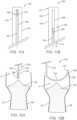
- FIGS. 1A-1Bone non-limiting example of a prosthetic heart valve 30 that may be implanted at an aortic valve is illustrated in detail in FIGS. 1A-1B .
- the prosthetic heart valve 30is shown in a normal or expanded arrangement in the views of FIGS. 1A-1B .
- the prosthetic heart valve 30includes a stent or stent frame 32 and a valve structure 34.
- the stent frame 32can assume a variety of forms and is constructed to be self-expandable from the compressed arrangement to the normal, expanded arrangement. Other frames may be constructed to be expandable via balloon or surgically implanted, for example.
- the valve structure 34 of the stented prosthesis 30can assume a variety of forms, and can be formed, for example, from one or more biocompatible synthetic materials, synthetic polymers, autograft tissue, homograft tissue, xenograft tissue, or one or more other suitable materials.
- the valve structure 34can be formed, for example, from bovine, porcine, equine, ovine and/or other suitable animal tissues.
- the valve structure 34is formed from heart valve tissue, pericardium, and/or other suitable tissue.
- the valve structure 34can include or form one or more leaflets 36.
- the valve structure 34can be in the form of a tri-leaflet bovine pericardium valve, a bi-leaflet valve, or another suitable valve.
- the valve structure 34can comprise two or three leaflets 36 that are fastened together at enlarged lateral end regions to form commissural joints 46, with the unattached edges forming coaptation edges of the valve structure 34.
- the leaflets 36can be fastened to an optional skirt 35 that in turn is attached to the stent frame 32.
- the stented prosthesis 30includes a first end 40 (inflow), an opposing second end 44 (outflow) and an intermediate section or waist 42.
- the stent frame 32can have a lattice or cell-like structure, and optionally forms or provides posts (not shown) corresponding with commissures 46 of the valve structure 34 as well as features 48 (e.g., crowns, eyelets or other shapes) at either or both of the first and second ends 40, 44. If provided, the commissure joints 46 are spaced equally around frame 32.
- the leaflets 36can fail or otherwise function inadequately, thus requiring replacement.
- Treating failing prosthetic heart valves with repeat replacement procedures in which a replacement prosthetic heart valve is positioned within the previously implanted prosthetic heart valvemay present complications, including coronary artery obstruction risks and future percutaneous coronary intervention difficulties due to blood flow blockages caused by the leaflets of the previously implanted prosthetic heart valve.
- the present inventorshave discovered devices of transcatheter aortic valve replacement of a previously implanted transcatheter aortic valve that reduce the aforementioned risks. With such devices and in such procedures, leaflets of the previously implanted transcatheter aortic valve are removed/modified so that the previously implanted leaflets do not occlude or block access to the coronaries.
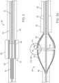
- FIG. 2illustrates the valve preparation device 50 having a severing system 51, both shown in a delivery configuration.
- the valve preparation device 50includes an inner catheter 52 extending a length of the device 50. Attached to the inner catheter 52 is a first portion 54 of the severing system 51. In some embodiments, proximal/distal movement of the inner catheter 52 correspondingly moves the first portion 54.
- the device 50further includes a middle catheter 56 positioned over and coaxially aligned with the inner catheter 52.
- a second portion 58 of the severing system 51is secured to the middle catheter 56 and proximal/distal movement of the middle catheter 56 can be transferred to correspondingly move the second portion 58 along the inner catheter 52.
- the device 50further includes first and second capsules 60, 62, each covering one of the first and second portions 54, 58 in the delivery configuration.
- the first capsule 60can be positioned over the inner catheter 52 and can compressively retain and sheathe the first portion 54 in the delivery configuration.
- the second capsule 62is connected to an outer shaft 64 that is coaxially aligned with the inner and middle catheters 52, 56 and can be moved distally and proximally to correspondingly control movement of the second capsule 62.
- FIG. 3Aillustrates the valve preparation device 50 and severing system 51 in an expanded arrangement in which the first and second portions 54, 58 have been released from their respective capsules 60, 62.
- the first and second portions 54, 58are configured to be self-expandable such that release from its respective capsule 60, 62 results in an automatic expansion of a greatest diameter of the first and second portions 54, 58.
- the first and second portions 54, 58can be made of a shape memory metal mesh. Nitinol is one suitable material.
- the first and second portions 54, 58can each include a collapsing hoop mechanism with support struts.
- first and second portions 54, 58each comprise a series of triangular faces that collapse in the delivery position within the respective capsule 60, 62 against a bias and will expand upon being unsheathed form the respective capsule 60, 62.
- first and second portions 54, 58can each include a pivot and lock mechanism.
- the outer catheter 64is proximally retracted.
- one or more push/pull wires 66extend through respective lumens in the inner catheter 52 and connect to the first capsule 60 to actuate movement of the first capsule 60 to sheathe and unsheathe the first portion 54. Movement of the inner catheter 52, middle catheter 56, outer catheter 64, and push/pull wires 66 can be optionally accomplished with a handle assembly 70.
- a handle assembly 70is illustrated in FIG. 5 .
- the handle assembly 70includes a connection end 72 in which each component 52, 56, 64, 66 can be operatively connected.
- the handle assembly 70further includes one or more respective actuators 74 to individually or collectively control proximal/distal movement of the components 52, 56, 64, 66. It will be understood in view of this disclosure that only a select portion of the inner catheter 52, middle catheter 56, outer catheter 64 and push/pull wires 66 are shown and that these components can extend as far as needed to enable transcatheter delivery of the first and second portions 54, 58 to a valve while allowing the handle assembly 70 to remain exterior to the patient for use by a clinician.
- the first and second portions 54, 58are further configured to cooperatively sever one or more leaflets 34 at a time. This may be accomplished in a variety of ways.
- the first and second portions 54, 58include a face or edge 55, 59 collectively forming a punch and die configuration (see FIGS. 3A-3B ) such that when the first and second portions 54, 58 are in their expanded arrangement and are brought together on opposing sides of one or more leaflets 34 ( FIGS. 6-7 ), the punch and die features collectively sever the leaflet(s) 34 to separate the leaflet 34 from a remainder of the prosthetic valve 30.
- Alternate embodimentscan include a perforated edge 55.
- the first and second portions 54, 58can include electrodes on faces 55, 59, actuatable via the handle assembly 70, for example, which can be actuated to sever leaflet tissue upon contact.
- the embodiments disclosed hereincan be used in combination with any known embolic protection devices.
- Example of such embolic protection devicesinclude, but are not limited to, Sentinel Cerebral Protection System (CPS) available from Claret Medical of Santa Rosa, California, Embrella(R) and Embol-X(R) devices available form Edwards Lifesciences of Irvine, California.
- CPSSentinel Cerebral Protection System
- the second portion 58can also be configured to function as an embolic protection/ removal and leaflet removal device.
- a subsequent transcatheter aortic valve delivery and implantation procedurecan be conducted in which a replacement valve is delivered and deployed in any known manner within the previously implanted stent frame.
- the replacement valveis of the type disclosed with respect to FIGS. 1A-1B .
- the valve preparation device 150includes a catheter 152 including a body 154 defining a plurality of lumens 156a, 156b.
- the first lumen 156aextends along length of the body 154 is open to a track 158 formed in the body 154, which extends radially from the first lumen 156a.
- the first lumen 156a and the track 158maintain a severing system 160 that includes a wire 162 supporting a blade 164 and a hook 166 (the blade 164 is only labeled in some figures for ease of illustration).
- the hook 166can optionally correspond to the shape of the first lumen 156a as is best shown in FIG. 9 .
- a cover 176can be affixed at a distal end 172 of the body 154 to cover the hook 166 and blade 164 during delivery of the valve preparation device 150 (the cover 176 is shown in FIGS. 8A-8B as transparent for ease of illustration and is omitted in later figures).
- the wire 162extends proximally to a handle assembly or the like (see the handle assembly 70 of FIG. 5 , for example) that can be configured to actuate distal and proximal movement of the wire 162 and, thus, the blade 164 and hook 166 along the track 158.
- a handle assembly or the likesee the handle assembly 70 of FIG. 5 , for example
- an articulation device 170Provided in the second lumen 156b is an articulation device 170, which is configured to allow the catheter 152 to articulate.
- the catheter 152could be pre-shaped, such as a J shape, to preferentially seat within a valve leaflet. It could be straightened for insertion by following a guidewire, for example.
- the blade 164could be replaced with another cutting mechanism such as a radio-frequency (RF) cutting element, an ultrasonic cutting element, a plasma cutting element, a laser cutting element or an electrode cutting element, for example.
- RFradio-frequency
- the articulation device 170can be of any known articulation devices (e.g., pull wire devices) that are known for providing articulation capabilities in catheters.
- the valve preparation device 150is inserted, via transcatheter procedure, from the ascending aorta in a generally straight fashion in FIG. 8A .
- the catheter 152is articulated to form a curved shape via the articulation device 170 to the position of FIGS. 8 and 12B and the catheter 152 is pushed against a base of one leaflet 36 on the ascending aorta side.
- the catheter 152is straightened with a guidewire for delivery proximate the aortic valve A and then transitions to the curved shape upon removal of the guidewire.
- the distal end 172can include a tip 174 having a textured surface, barbs, or an adhesive to prevent the device 150 from slipping off the base of the leaflet 36.
- the hook 166can engage the adjacent commissure joint 46 and find purchase there (indicated by the bold arrow and C in FIG. 13 ).
- the hook 166may need to be drawn out of the cover 176 with the wire 162 before it will engage the adjacent commissure joint 46.
- the wire 162is then pulled proximally via the handle assembly 70 ( FIG. 5 ) or the like so that the blade 164 will correspondingly be pulled along the base of the leaflet 36 and thereby cut the leaflet 36 away from the stent frame 32 or valve skirt (or tissue of the valve if the valve is a native valve). It is noted that in FIGS. 12D-12G , a proximal portion of the catheter 152 is omitted so that the wire 162 is visible.
- the process of positioning the device 150 and severing one leaflet 36is repeated until each desired leaflet 36 is substantially cut away and detached from the stent frame 32 or skirt.
- the blade 164can be used to form one or more slits without severing the leaflet 36.
- An embolic protection device(not shown) can be used in conjunction with the device 150 to account for any debris that may be created by the procedure.
- the embolic protection devicecan serve to capture and remove the leaflets 36, once detached. Examples of suitable embolic protection devices include, but are not limited to those listed above.
- a subsequent transcatheter aortic valve delivery and implantation procedurecan be conducted in which a replacement valve is delivered and deployed in any known manner within the previously implanted stent frame.
- the replacement valveis of the type disclosed with respect to FIGS. 1A-1B . It will be understood that the above-described valve preparation device 150 and related methods can alternatively be used on a native in valve in preparation for delivery and implantation of a prosthetic valve.
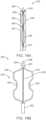
- the valve preparation device 250includes a severing system 254.
- the severing system 254includes a wire 256 and at least one arm 258 (e.g., two arms), each having an electrode 260.
- the arms 258can be of a wire form or a ribbon form having two ends; wherein at least one end is fixed to the wire 256 via a cap 257 or the like.
- a distalmost end of each arm 258can be connected either to the wire 256 (e.g., via one cap 257) or to the distal tip 264.
- Ribbon form materialis beneficial in that it provides for a flat outer surface on which the electrode 260 can contact the leaflet 36.
- Each arm 258is made of a shape memory material such as Nitinol, spring steel, polymeric shape memory materials, or wound spring constructions and is configured to be biased to the position of FIG. 14B .
- the illustrated embodimentincludes two arms 258, however, more or fewer arms are envisioned in alternate embodiments.
- the device 250includes a catheter or sheath 262 that can be slidably positioned over the arms 258.
- a distal tip 264 of the device 250includes an electrode 266 that is configured to pierce a leaflet 36 upon contact and energizing of the electrode 266. It is envisioned that the geometry of the distal tip 264 can comprise several shapes.
- the distal tip 264is configured to supply enough energy to puncture the leaflet 36 but also must be configured to guide the device 250 into position.
- the distal tip 264is generally conical.
- Other envisioned shapesinclude a blunt, rounded or hourglass shaped tip, for example.
- operation of the valve preparation device 250is conducted as follows.
- the device 250is provided with the sheath 262 covering the arms 258 so that the arms 258 are collapsed within the sheath 262 such that the device 250 has a first width or profile.
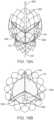
- the device 250is delivered in the delivery position ( FIG. 16A ) to the base of one leaflet 36 such that the distal tip 264 touches the leaflet 36 (the base is indicated by X in FIG. 15 ).
- the electrode 266is activated to lacerate the base of the leaflet 36 and form an opening through which the device 250 can be positioned.
- the distal tip 264is retracted into the sheath 262 so that the arms 258 naturally bow outwardly to contact the leaflet 36 as is generally illustrated in FIG. 16B .
- the leaflet 36will constrict and prevent full expansion of the arms 258 into their natural position at this stage.
- the electrodes 260Upon activating the electrodes 260, the electrodes 260 will sever the leaflet 36 and allow the arms 258 to more fully expand to their natural position as the leaflet 36 is severed.
- the wire 256is drawn proximally to further direct the electrodes 260 to move laterally to further engage the leaflet 36.
- FIG. 16Cgenerally illustrates the electrodes 260 moving in a horizontal direction
- horizontal movementmay be insufficient to effectively ablate leaflet 36 tissue when the electrode 260 approaches a commissure joint 46. Therefore, the electrodes 260 of various embodiments are configured to cut both horizontally and vertically via manipulation of the sheath 262 and the wire 256.
- the wire 256can extend proximally from the distal tip 264 to a handle assembly (not shown, see FIGS. 1A-1B and related disclosure provided as one suitable example) of the device 250, in which the actuator 74 of the handle assembly 70 ( FIG. 5 ) controls tension in the wire 256 and, therefore, control proximal and distal movement of the wire 256 with respect to the sheath 262 and the handle assembly 70.
- Severing the leaflet 36is most effectively accomplished when the arm electrodes 260 move laterally while following the curvature of the leaflet 36 up to the commissure joint 46. Collapsing the arms 258 with the wire 256 will laterally direct the electrodes 260 while manually retracting the device 250 will supply adequate elevation. During this step, the sheath 262 is maintained in the retracted position of FIG. 16C in part to anchor the arms 258 and their respective electrodes 260 in position. Once the leaflet 36 is sufficiently lacerated (i.e. separated from the stent frame 32 or skirt), the arms 258 are drawn back into the sheath 262 into the delivery position of FIG.
- the device 250can be moved to another leaflet 36, as desired, and the leaflet severing process can be repeated. Once each desired leaflet is severed, the device 250 is retracted from the patient the same way the device was delivered. The severed leaflets 36 are captured in a provided embolic protection device of the types disclosed above and then are subsequently removed along with the embolic protection device. As with the prior embodiments, once the leaflets 36 are cut away and removed via the embolic protection device, a subsequent transcatheter aortic valve delivery and implantation procedure can be conducted in which a replacement valve is delivered and deployed in any known manner within the previously implanted stent frame. In one non-limiting illustrative example, the replacement valve is of the type disclosed with respect to FIGS. 1A-1B .
- valve preparation device 250can also be used to cut a slit in the leaflet from the margin of attachment (MOA) near the area where the leaflet meets the frame to the free edge of the leaflet (the area of the leaflet closest to the center of the aortic annulus). This method does not remove any portion of the leaflet, the method simply places a slit in the leaflet to allow the leaflet to open when a second prosthetic valve is implanted in the patient to allow flow of blood to the coronary arteries which may have otherwise been blocked by the initial leaflet being pinned between the frame of the first and second implants.
- MOAmargin of attachment
- the device 250includes one arm 258 and penetrates the leaflet 36 in the same manner described above with respect to FIG 16A .
- the device 250After penetration of the leaflet 36, the device 250 would have one arm 258 that would expand from the margin of attachment toward the free edge of the leaflet 36 with radio frequency (RF) energy being applied to the electrode 260.
- RFradio frequency
- the biasing force of the shape memory biased arm 258 trying to expand and the RF energy from the electrode 260can slice or sever the leaflet 36 allowing the leaflet 36 to open with a "V" shaped slot allowing the flow of blood into the coronaries.
- the arm 258would be aligned approximately 90 degrees from what is shown in the FIG. 16C .
- the one arm 258could expand along the margin of attachment from the point of leaflet penetration up to the commissure. The result would be a leaflet that would not be severed but would be slit and could fold over or otherwise provide coronary access/perfusion as the second valve is deployed.
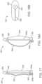
- FIGS. 17-19Billustrate another embodiment of a valve preparation device 350.
- the valve preparation device 350is largely similar to that of FIGS 14A-14C except that arms 258 are substituted with a balloon 358.
- the balloonincludes an outer surface on which an elongated, wire-form electrode 360 is positioned and extends from a tip 364 to a delivery catheter 362.
- the tip 364can be configured to puncture a leaflet 36, and can include an electrode 366, for example.
- the device 350can further include a guidewire lumen within support 356a/tip 364 and which extends through the device 350 for receiving a guidewire 357.
- the device 350can also include an inflation lumen 356b for controlling the inflation of the balloon 358 via saline without or without contrast dye, for example.
- the valve preparation device 350can include a handle, such as that of FIG. 5 .
- the handlecan, for example be connected to an inflation source (not shown) and can include one or more actuators for controlling the electrode 360.
- the device 350penetrates the leaflet 36 in the same manner described above with respect to FIG 16A .
- the balloon 358is inflated while energizing the electrode 360 to cut the leaflet 36.
- the biasing force of the balloon 358 trying to expand and the radio frequency (RF) energy from the electrode 360can slice or sever the leaflet 36 allowing the leaflet 36 to open with a "V" shaped slot allowing the flow of blood into the coronaries (see, in particular, FIGS. 18A-19B ).
- the electrode 360can be aligned via imaging to direct the cut through the center of the leaflet 36, or preferentially to one side or the other if so desired.
- the device 350can alternatively been configured to include multiple longitudinal electrodes 360. Each electrode 360 could be configured to be fired simultaneously or in sequence, as desired.
- 100% of the leaflets 34may not necessarily be removed from the stent frame, skirt, or other remaining portions of the prosthetic valve.
- removing, severing and cutting the leaflet from the remainder of the valveshall be understood to indicate that substantially all of the leaflet has been separated from the stent frame, skirt, or other remaining portions of the prosthetic valve so that any remaining leaflet proximate the margin of attachment does not present a risk of blood flow blockage after a replacement prosthetic valve is implanted adjacent the leaflet.
- temporary valvesmay need to be provided to provide hemodynamic stability when leaflets are removed.
Landscapes
- Health & Medical Sciences (AREA)
- Life Sciences & Earth Sciences (AREA)
- Surgery (AREA)
- Engineering & Computer Science (AREA)
- Biomedical Technology (AREA)
- General Health & Medical Sciences (AREA)
- Public Health (AREA)
- Veterinary Medicine (AREA)
- Animal Behavior & Ethology (AREA)
- Heart & Thoracic Surgery (AREA)
- Cardiology (AREA)
- Nuclear Medicine, Radiotherapy & Molecular Imaging (AREA)
- Molecular Biology (AREA)
- Medical Informatics (AREA)
- Vascular Medicine (AREA)
- Oral & Maxillofacial Surgery (AREA)
- Transplantation (AREA)
- Physics & Mathematics (AREA)
- Plasma & Fusion (AREA)
- Otolaryngology (AREA)
- Prostheses (AREA)
- Surgical Instruments (AREA)
Description
- Aortic stenosis is a degenerative heart valve disease that is treated with surgical aortic valve (SAV) and transcatheter aortic valve (TAV) replacement bioprostheses having tissue leaflets that often will eventually fail. The treatment of failing bioprosthetic valves with repeat replacement bioprosthesis implantation procedures may present complications, including coronary artery obstruction risks and future percutaneous coronary intervention difficulties.
US 2013/116715 A1 relates to a cutting device for repairing a heart valve that may include a delivery catheter, a cutting unit including an elongate shaft and a plurality of cutting wires, and a plurality of centralizing wires configured to center the cutting unit within a treatment site.US 2002/173811 A1 relates to a medical catheter and methods for removing a defective valve from a patient endoluminally, wherein the method may comprise inserting a medical catheter endoluminally to a site of the defective valve; deploying a coupling mechanism of said medical catheter to stabilize and immobilize a free edge of at least one valve leaflet; deploying a cutting mechanism of said medical catheter to cut a valve base of said defective valve; and removing said defective valve from the patient.US 2007/185513 A1 relates to an apparatus for resecting a diseased heart valve, the apparatus comprising: a body portion; a first handle and a second handle; a cutting blade; a set of retaining arms; a pass-off tool having a first attachment device configured to selectively engage the first handle attached to the body portion so as to allow placement of the second handle of the body portion adjacent to the diseased heart valve, and a controller tool having a second attachment device at the distal end thereof, the second attachment device configured to selectively engage the second handle attached to the body portion so as to allow positioning of the body portion adjacent to the diseased heart valve, a cutting blade actuator configured to cause the cutting blade to selectively rotate, and a retaining arm actuator configured to selectively position the set of retaining arms from the contracted state to the expanded state.US 2007/0239154 A1 relates to an activation device for applying energy to an implanted annuloplasty ring.- The present disclosure addresses problems and limitations with respect to the above.
- The invention is defined by
claim 1. Further embodiments of the invention arc defined by the dependent claims. Methods are disclosed for understanding the invention and are not claimed per se. - Aspects of the disclosure relate to devices for preparing an existing, implanted transcatheter prosthetic aortic valve for subsequent transcatheter prosthetic aortic valve implantation. Such devices mitigate coronary artery obstruction risks from repeat valve replacement procedures while additionally facilitating future access for percutaneous coronary intervention. Alternatively, it is also envisioned that devices of the disclosure can be used in preparing a native aortic valve for delivery and implantation of a prosthetic valve.
- Various example methods of preparing an aortic valve for implantation of a prosthetic aortic valve comprise the steps of providing a patient having an aortic valve (either prosthetic or native) including at least one leaflet, providing a valve preparation device including a severing apparatus and delivering the severing apparatus to the aortic valve with the valve preparation device via transcatheter delivery. Then, the severing apparatus is engaged with at least one leaflet to sever the leaflet(s) and optionally release the leaflet(s) from a remainder of the aortic valve. If necessary, the valve preparation device is then moved to another leaflet and the other leaflet is detached or slit. The process could optionally continue until more or all leaflets are detached from the stent frame. Once severed, the leaflets may be removed via an embolic protection device, for example. The valve preparation device is withdrawn from the patient and the valve is ready for implantation of a prosthetic heart valve. It is noted that if the leaflets are removed or significantly altered, the patient may require a temporary valve to provide hemodynamic stability until the new valve is implanted. It is understood that any of the concepts discussed could be used in conjunction with a temporary valve (such as within the ascending or descending aorta). In some embodiments, the temporary valve could also be incorporated onto the delivery catheter(s).
- Various valve preparation devices are disclosed. Disclosed embodiments generally include a valve preparation device for severing heart valve leaflets, the valve preparation device comprising a first catheter and a severing apparatus configured to sever calcified heart valve leaflets.
- One valve preparation device includes a first portion connected to a first catheter and a second portion connected to a second catheter that is coaxially aligned with the first catheter. The first portion and the second portion are each made of a memory shape material that is biased to bow outwardly with respect to central axis of the device. In a delivery position, one capsule contains a first portion of a severing system and a second capsule contains a second portion of the severing system. Once delivered and in position, the first and second portions are unsheathed so that the first and second portions expand to their natural, bowed position. Then, the first and second catheters are arranged so that the first and second portions engage each other on opposing sides of a valve leaflet or otherwise contact opposing sides of the valve leaflet. Either via engagement of the first and second portions or contact via electrodes, the first and second portions collectively sever the leaflet.
- Yet another disclosed valve preparation device includes a catheter having a body defining a first lumen and a second lumen. The catheter further defining a track extending through the body from the second lumen. An articulation apparatus provided within the first lumen that can be actuated to articulate the body to deliver a severing apparatus, provided in the second lumen, to a leaflet. The severing apparatus can include a hook and a blade or an electrode that at least partially extends within the track for cutting a leaflet once positioned adjacent thereto.
- In a further embodiment, a valve preparation device includes a severing apparatus including a wire and at least one arm that is biased to bow outwardly with respect to the wire. Each arm further includes an electrode that can be actuated to cut the leaflet. A tip is connected to a distal end of the wire for puncturing the leaflet to position each arm electrode adjacent the leaflet. The device further includes a sheath movable from a delivery position in which the sheath covers the severing apparatus and a deployed position in which the sheath is proximally retracted to uncover the severing apparatus.
- In a further embodiment, a valve preparation device includes a severing apparatus including a balloon and at least one wire that carries energy to severe the leaflet. The balloon is inflated to preferentially push the energized wire from the base of the leaflet to the free edge of the leaflet. A tip is connected to a distal end of the device for puncturing the leaflet to position the balloon and wire in the appropriate location.
- Example methods of preparing an aortic valve for implantation of a prosthetic aortic valve are also enclosed. Various methods include providing a patient having an aortic valve including a first leaflet and providing a valve preparation device including a severing apparatus. The severing apparatus is delivered to the aortic valve with the valve preparation device via transcatheter delivery. Then, the severing apparatus is engaged with the first leaflet and the first leaflet is severed. Then, the valve preparation device from the patient. In some embodiments, one or more leaflets are also removed from the patient.
FIGS. 1A-1B are views of one suitable prosthetic valve that can be used with the devices and example methods of the disclosure.FIG. 2 is a partial, cross-sectional, schematic illustration of a valve preparation device including first and second portions that interconnected to respective catheters and are compressed by respective distal and proximal capsules.FIG. 3A is a partial, cross-sectional, schematic illustration of the valve preparation device ofFIG. 2 illustrating the capsules moved to unsheathe the respective portions and allow the portions to self-expand.FIG. 3B is a partial, enlarged, schematic illustration of the valve preparation device ofFIG. 3A .FIGS. 4A-4B are partial, enlarged, cross-sectional view of push/pull wires provided to actuate a distal capsule.FIG. 5 is a perspective view of a handle assembly that can be used to control movement of the catheters and/or the push/pull wire of the device ofFIGS. 2-4B .FIGS. 6-7 illustrate the first and second portions positioned on opposing sides of a valve structure of the prosthetic valve ofFIGS. 1A-1B , in which the first and second portions can be brought in contact to sever leaflets of the valve structure.FIG. 8A is a partial, schematic illustration of a valve preparation device in a straight configuration.FIG. 8B is a partial, schematic illustration of the valve preparation device ofFIG. 8A in an articulated configuration.FIG. 9 is a cross-sectional illustration of the valve preparation device ofFIGS. 8A-8B .FIGS. 10-11B are partial, schematic illustrations of the valve preparation device ofFIGS. 8A-9 .FIGS. 12A-12G are partial, schematic illustrations of the valve preparation device ofFIGS. 8A-11B as the valve preparation device is positioned adjacent one leaflet of a previously implanted prosthetic valve to remove the leaflet from a remainder of a prosthetic valve (wherein a portion of the stent frame is removed for ease of illustration).FIG. 13 is a perspective view of the prosthetic valve ofFIGS. 1A-1B indicating, via a bold arrow, where a distal end of the device is to be positioned during the step as illustrated inFIG. 12C .FIG. 14A is a partial, schematic illustration of an alternate valve preparation device including a severing system covered by a sheath, in accordance with the present claimed invention (the sheath is shown as transparent for ease of illustration).FIG. 14B is a partial, schematic illustration of the valve preparation device ofFIG. 14A showing the sheath retracted to expose the severing system.FIG. 14C is a partial, schematic illustration of the valve preparation device ofFIGS. 14A-14B illustrating a tip being retracted into the sheath to force arms of the severing device outwardly.FIG. 15 is a perspective view of the prosthetic valve ofFIGS. 1A-1B illustrating a target placement (X) at a base of a leaflet at which to direct a distal tip of the valve preparation device for removal of the leaflet.FIG. 16A , is a partial, schematic illustration of the valve preparation device ofFIGS. 14A-14C being directed to the target placement (X) indicated inFIG. 15 (wherein a portion of the stent frame is removed for ease of illustration).FIG. 16B is a partial, schematic illustration of the valve preparation device ofFIGS. 14A-14C inserted through the leaflet.FIG. 16C is a partial, schematic illustration of the valve preparation device ofFIGS. 14A-14C in which an electrode on each arm is activated to sever the leaflet and allow the arms to expand.FIG. 17 is a partial, schematic illustration of an alternate valve preparation device utilizing a balloon (shown as transparent for ease of illustration); wherein the balloon is in a deflated or delivery arrangement.FIG. 18A is a partial, schematic illustration of the valve preparation device ofFIG. 17 , the balloon (shown as transparent for ease of illustration) being in a deployed, inflated arrangement.FIG. 18B is an end view of the of the valve preparation device ofFIG. 18A , the balloon (shown as transparent for ease of illustration) being in the deployed, inflated arrangement.FIG. 19A is a schematic side view of the valve preparation device ofFIG. 17 in the delivery arrangement and positioned at a leaflet to puncture the leaflet (wherein a portion of the stent frame is removed for ease of illustration).FIG. 19B is a schematic top view of the valve preparation device ofFIG. 17 in the deployed arrangement, creating a slit in one leaflet.- Specific embodiments of the present disclosure are now described with reference to the figures, wherein like reference numbers indicate identical or functionally similar elements. The terms "distal" and "proximal" are used in the following description with respect to a position or direction relative to the treating clinician. "Distal" or "distally" are a position distant from or in a direction away from the clinician. "Proximal" and "proximally" are a position near or in a direction toward the clinician. As used herein, with reference to an implanted stented prosthesis, the term "outflow" is understood to mean downstream to the direction of blood flow, and the term "inflow" is understood to mean upstream to the direction of blood flow.
- By way of background, one non-limiting example of a
prosthetic heart valve 30 that may be implanted at an aortic valve is illustrated in detail inFIGS. 1A-1B . As a point of reference, theprosthetic heart valve 30 is shown in a normal or expanded arrangement in the views ofFIGS. 1A-1B . Theprosthetic heart valve 30 includes a stent orstent frame 32 and avalve structure 34. Thestent frame 32 can assume a variety of forms and is constructed to be self-expandable from the compressed arrangement to the normal, expanded arrangement. Other frames may be constructed to be expandable via balloon or surgically implanted, for example. - The
valve structure 34 of the stentedprosthesis 30 can assume a variety of forms, and can be formed, for example, from one or more biocompatible synthetic materials, synthetic polymers, autograft tissue, homograft tissue, xenograft tissue, or one or more other suitable materials. In some embodiments, thevalve structure 34 can be formed, for example, from bovine, porcine, equine, ovine and/or other suitable animal tissues. In some embodiments, thevalve structure 34 is formed from heart valve tissue, pericardium, and/or other suitable tissue. Thevalve structure 34 can include or form one ormore leaflets 36. For example, thevalve structure 34 can be in the form of a tri-leaflet bovine pericardium valve, a bi-leaflet valve, or another suitable valve. - In some prosthetic valve constructions, such as that of
FIGS. 1A-1B , thevalve structure 34 can comprise two or threeleaflets 36 that are fastened together at enlarged lateral end regions to formcommissural joints 46, with the unattached edges forming coaptation edges of thevalve structure 34. Theleaflets 36 can be fastened to anoptional skirt 35 that in turn is attached to thestent frame 32. The stentedprosthesis 30 includes a first end 40 (inflow), an opposing second end 44 (outflow) and an intermediate section orwaist 42. As shown, thestent frame 32 can have a lattice or cell-like structure, and optionally forms or provides posts (not shown) corresponding withcommissures 46 of thevalve structure 34 as well as features 48 (e.g., crowns, eyelets or other shapes) at either or both of the first and second ends 40, 44. If provided, the commissure joints 46 are spaced equally aroundframe 32. - Over time, the
leaflets 36 can fail or otherwise function inadequately, thus requiring replacement. Treating failing prosthetic heart valves with repeat replacement procedures in which a replacement prosthetic heart valve is positioned within the previously implanted prosthetic heart valve may present complications, including coronary artery obstruction risks and future percutaneous coronary intervention difficulties due to blood flow blockages caused by the leaflets of the previously implanted prosthetic heart valve. The present inventors have discovered devices of transcatheter aortic valve replacement of a previously implanted transcatheter aortic valve that reduce the aforementioned risks. With such devices and in such procedures, leaflets of the previously implanted transcatheter aortic valve are removed/modified so that the previously implanted leaflets do not occlude or block access to the coronaries. - One embodiment of a
valve preparation device 50 is schematically illustrated inFIGS. 2-7 .FIG. 2 illustrates thevalve preparation device 50 having a severingsystem 51, both shown in a delivery configuration. Thevalve preparation device 50 includes aninner catheter 52 extending a length of thedevice 50. Attached to theinner catheter 52 is afirst portion 54 of the severingsystem 51. In some embodiments, proximal/distal movement of theinner catheter 52 correspondingly moves thefirst portion 54. Thedevice 50 further includes amiddle catheter 56 positioned over and coaxially aligned with theinner catheter 52. Asecond portion 58 of the severingsystem 51 is secured to themiddle catheter 56 and proximal/distal movement of themiddle catheter 56 can be transferred to correspondingly move thesecond portion 58 along theinner catheter 52. Thedevice 50 further includes first andsecond capsules second portions first capsule 60 can be positioned over theinner catheter 52 and can compressively retain and sheathe thefirst portion 54 in the delivery configuration. As shown, thesecond capsule 62 is connected to anouter shaft 64 that is coaxially aligned with the inner andmiddle catheters second capsule 62. FIG. 3A illustrates thevalve preparation device 50 and severingsystem 51 in an expanded arrangement in which the first andsecond portions respective capsules second portions respective capsule second portions second portions second portions second portions respective capsule respective capsule second portions - To retract the
second capsule 62, theouter catheter 64 is proximally retracted. As shown inFIGS. 4A-4B , one or more push/pullwires 66 extend through respective lumens in theinner catheter 52 and connect to thefirst capsule 60 to actuate movement of thefirst capsule 60 to sheathe and unsheathe thefirst portion 54. Movement of theinner catheter 52,middle catheter 56,outer catheter 64, and push/pull wires 66 can be optionally accomplished with ahandle assembly 70. One non-limiting example of ahandle assembly 70 is illustrated inFIG. 5 . Thehandle assembly 70 includes aconnection end 72 in which eachcomponent handle assembly 70 further includes one or morerespective actuators 74 to individually or collectively control proximal/distal movement of thecomponents inner catheter 52,middle catheter 56,outer catheter 64 and push/pull wires 66 are shown and that these components can extend as far as needed to enable transcatheter delivery of the first andsecond portions handle assembly 70 to remain exterior to the patient for use by a clinician. - The first and
second portions more leaflets 34 at a time. This may be accomplished in a variety of ways. In one such embodiment, the first andsecond portions edge FIGS. 3A-3B ) such that when the first andsecond portions FIGS. 6-7 ), the punch and die features collectively sever the leaflet(s) 34 to separate theleaflet 34 from a remainder of theprosthetic valve 30. Alternate embodiments can include aperforated edge 55. In other embodiments, the first andsecond portions faces handle assembly 70, for example, which can be actuated to sever leaflet tissue upon contact. - To collect and protect a patient from debris created during the severance of leaflets of a valve and also to remove the severed leaflet(s), the embodiments disclosed herein can be used in combination with any known embolic protection devices. Example of such embolic protection devices include, but are not limited to, Sentinel Cerebral Protection System (CPS) available from Claret Medical of Santa Rosa, California, Embrella(R) and Embol-X(R) devices available form Edwards Lifesciences of Irvine, California. In various embodiments, the
second portion 58 can also be configured to function as an embolic protection/ removal and leaflet removal device. Once the leaflets are cut away and removed via the embolic protection device, a subsequent transcatheter aortic valve delivery and implantation procedure can be conducted in which a replacement valve is delivered and deployed in any known manner within the previously implanted stent frame. In one non-limiting illustrative example, the replacement valve is of the type disclosed with respect toFIGS. 1A-1B . - An alternate
valve preparation device 150 is collectively illustrated inFIGS. 8A-12 . Thevalve preparation device 150 includes acatheter 152 including abody 154 defining a plurality oflumens first lumen 156a extends along length of thebody 154 is open to atrack 158 formed in thebody 154, which extends radially from thefirst lumen 156a. Collectively, thefirst lumen 156a and thetrack 158 maintain asevering system 160 that includes awire 162 supporting ablade 164 and a hook 166 (theblade 164 is only labeled in some figures for ease of illustration). Thehook 166 can optionally correspond to the shape of thefirst lumen 156a as is best shown inFIG. 9 . Optionally, as is shown inFIGS. 8A-8B , acover 176 can be affixed at adistal end 172 of thebody 154 to cover thehook 166 andblade 164 during delivery of the valve preparation device 150 (thecover 176 is shown inFIGS. 8A-8B as transparent for ease of illustration and is omitted in later figures). Thewire 162 extends proximally to a handle assembly or the like (see thehandle assembly 70 ofFIG. 5 , for example) that can be configured to actuate distal and proximal movement of thewire 162 and, thus, theblade 164 and hook 166 along thetrack 158. Provided in thesecond lumen 156b is anarticulation device 170, which is configured to allow thecatheter 152 to articulate. Optionally, thecatheter 152 could be pre-shaped, such as a J shape, to preferentially seat within a valve leaflet. It could be straightened for insertion by following a guidewire, for example. In other embodiments, theblade 164 could be replaced with another cutting mechanism such as a radio-frequency (RF) cutting element, an ultrasonic cutting element, a plasma cutting element, a laser cutting element or an electrode cutting element, for example. Thearticulation device 170 can be of any known articulation devices (e.g., pull wire devices) that are known for providing articulation capabilities in catheters. - During use, the
valve preparation device 150 is inserted, via transcatheter procedure, from the ascending aorta in a generally straight fashion inFIG. 8A . When thecatheter 152 is proximate the aortic valve A, thecatheter 152 is articulated to form a curved shape via thearticulation device 170 to the position ofFIGS. 8 and12B and thecatheter 152 is pushed against a base of oneleaflet 36 on the ascending aorta side. In alternate embodiments described above, thecatheter 152 is straightened with a guidewire for delivery proximate the aortic valve A and then transitions to the curved shape upon removal of the guidewire. To maintain the position of thecatheter 152, generally constant and consistent pressure is applied to thedevice 150 by a clinician to ensure that adequate contact is made between the base of theleaflet 36 and thedistal end 172 of thedevice 150. Optionally, thedistal end 172 can include atip 174 having a textured surface, barbs, or an adhesive to prevent thedevice 150 from slipping off the base of theleaflet 36. Once thedistal end 172 of the device is in contact with the base of theleaflet 36, thehook 166 can engage the adjacent commissure joint 46 and find purchase there (indicated by the bold arrow and C inFIG. 13 ). In embodiments where thecover 176 is provided, thehook 166 may need to be drawn out of thecover 176 with thewire 162 before it will engage the adjacent commissure joint 46. Thewire 162 is then pulled proximally via the handle assembly 70 (FIG. 5 ) or the like so that theblade 164 will correspondingly be pulled along the base of theleaflet 36 and thereby cut theleaflet 36 away from thestent frame 32 or valve skirt (or tissue of the valve if the valve is a native valve). It is noted that inFIGS. 12D-12G , a proximal portion of thecatheter 152 is omitted so that thewire 162 is visible. The process of positioning thedevice 150 and severing oneleaflet 36 is repeated until each desiredleaflet 36 is substantially cut away and detached from thestent frame 32 or skirt. Alternately, theblade 164 can be used to form one or more slits without severing theleaflet 36. An embolic protection device (not shown) can be used in conjunction with thedevice 150 to account for any debris that may be created by the procedure. In addition, the embolic protection device can serve to capture and remove theleaflets 36, once detached. Examples of suitable embolic protection devices include, but are not limited to those listed above. Once theleaflets 36 are cut away and removed via the embolic protection device, a subsequent transcatheter aortic valve delivery and implantation procedure can be conducted in which a replacement valve is delivered and deployed in any known manner within the previously implanted stent frame. In one non-limiting illustrative example, the replacement valve is of the type disclosed with respect toFIGS. 1A-1B . It will be understood that the above-describedvalve preparation device 150 and related methods can alternatively be used on a native in valve in preparation for delivery and implantation of a prosthetic valve. - A
valve preparation device 250 in accordance with the present claimed invention is illustrated inFIGS. 14A-14C and 16A-16C. Thevalve preparation device 250 includes asevering system 254. Thesevering system 254 includes awire 256 and at least one arm 258 (e.g., two arms), each having anelectrode 260. Thearms 258 can be of a wire form or a ribbon form having two ends; wherein at least one end is fixed to thewire 256 via acap 257 or the like. A distalmost end of eacharm 258 can be connected either to the wire 256 (e.g., via one cap 257) or to thedistal tip 264. Ribbon form material is beneficial in that it provides for a flat outer surface on which theelectrode 260 can contact theleaflet 36. Eacharm 258 is made of a shape memory material such as Nitinol, spring steel, polymeric shape memory materials, or wound spring constructions and is configured to be biased to the position ofFIG. 14B . The illustrated embodiment includes twoarms 258, however, more or fewer arms are envisioned in alternate embodiments. To collapse thearms 258 for transcatheter delivery, thedevice 250 includes a catheter orsheath 262 that can be slidably positioned over thearms 258. At adistal tip 264 of thedevice 250 includes anelectrode 266 that is configured to pierce aleaflet 36 upon contact and energizing of theelectrode 266. It is envisioned that the geometry of thedistal tip 264 can comprise several shapes. Thedistal tip 264 is configured to supply enough energy to puncture theleaflet 36 but also must be configured to guide thedevice 250 into position. In the illustrated embodiment, thedistal tip 264 is generally conical. Other envisioned shapes include a blunt, rounded or hourglass shaped tip, for example. - In one example method, operation of the
valve preparation device 250 is conducted as follows. In a delivery configuration, thedevice 250 is provided with thesheath 262 covering thearms 258 so that thearms 258 are collapsed within thesheath 262 such that thedevice 250 has a first width or profile. Thedevice 250 is delivered in the delivery position (FIG. 16A ) to the base of oneleaflet 36 such that thedistal tip 264 touches the leaflet 36 (the base is indicated by X inFIG. 15 ). Theelectrode 266 is activated to lacerate the base of theleaflet 36 and form an opening through which thedevice 250 can be positioned. Once thedevice 250 is positioned within theleaflet 36 such that the severingelectrodes 260 are generally adjacent theleaflet 36, thedistal tip 264 is retracted into thesheath 262 so that thearms 258 naturally bow outwardly to contact theleaflet 36 as is generally illustrated inFIG. 16B . As can be seen, theleaflet 36 will constrict and prevent full expansion of thearms 258 into their natural position at this stage. Upon activating theelectrodes 260, theelectrodes 260 will sever theleaflet 36 and allow thearms 258 to more fully expand to their natural position as theleaflet 36 is severed. To further direct theelectrodes 260 for cutting, thewire 256 is drawn proximally to further direct theelectrodes 260 to move laterally to further engage theleaflet 36. AlthoughFIG. 16C generally illustrates theelectrodes 260 moving in a horizontal direction, horizontal movement may be insufficient to effectively ablateleaflet 36 tissue when theelectrode 260 approaches a commissure joint 46. Therefore, theelectrodes 260 of various embodiments are configured to cut both horizontally and vertically via manipulation of thesheath 262 and thewire 256. In one embodiment, thewire 256 can extend proximally from thedistal tip 264 to a handle assembly (not shown, seeFIGS. 1A-1B and related disclosure provided as one suitable example) of thedevice 250, in which theactuator 74 of the handle assembly 70 (FIG. 5 ) controls tension in thewire 256 and, therefore, control proximal and distal movement of thewire 256 with respect to thesheath 262 and thehandle assembly 70. - Severing the
leaflet 36 is most effectively accomplished when thearm electrodes 260 move laterally while following the curvature of theleaflet 36 up to the commissure joint 46. Collapsing thearms 258 with thewire 256 will laterally direct theelectrodes 260 while manually retracting thedevice 250 will supply adequate elevation. During this step, thesheath 262 is maintained in the retracted position ofFIG. 16C in part to anchor thearms 258 and theirrespective electrodes 260 in position. Once theleaflet 36 is sufficiently lacerated (i.e. separated from thestent frame 32 or skirt), thearms 258 are drawn back into thesheath 262 into the delivery position ofFIG. 16A and then thedevice 250 can be moved to anotherleaflet 36, as desired, and the leaflet severing process can be repeated. Once each desired leaflet is severed, thedevice 250 is retracted from the patient the same way the device was delivered. The severedleaflets 36 are captured in a provided embolic protection device of the types disclosed above and then are subsequently removed along with the embolic protection device. As with the prior embodiments, once theleaflets 36 are cut away and removed via the embolic protection device, a subsequent transcatheter aortic valve delivery and implantation procedure can be conducted in which a replacement valve is delivered and deployed in any known manner within the previously implanted stent frame. In one non-limiting illustrative example, the replacement valve is of the type disclosed with respect toFIGS. 1A-1B . - It will be apparent from the present disclosure that the
valve preparation device 250 can also be used to cut a slit in the leaflet from the margin of attachment (MOA) near the area where the leaflet meets the frame to the free edge of the leaflet (the area of the leaflet closest to the center of the aortic annulus). This method does not remove any portion of the leaflet, the method simply places a slit in the leaflet to allow the leaflet to open when a second prosthetic valve is implanted in the patient to allow flow of blood to the coronary arteries which may have otherwise been blocked by the initial leaflet being pinned between the frame of the first and second implants. - In one example method, the
device 250 includes onearm 258 and penetrates theleaflet 36 in the same manner described above with respect toFIG 16A . After penetration of theleaflet 36, thedevice 250 would have onearm 258 that would expand from the margin of attachment toward the free edge of theleaflet 36 with radio frequency (RF) energy being applied to theelectrode 260. The biasing force of the shape memorybiased arm 258 trying to expand and the RF energy from theelectrode 260 can slice or sever theleaflet 36 allowing theleaflet 36 to open with a "V" shaped slot allowing the flow of blood into the coronaries. Thearm 258 would be aligned approximately 90 degrees from what is shown in theFIG. 16C . In another embodiment, the onearm 258 could expand along the margin of attachment from the point of leaflet penetration up to the commissure. The result would be a leaflet that would not be severed but would be slit and could fold over or otherwise provide coronary access/perfusion as the second valve is deployed. - Referring now in addition to
FIGS. 17-19B , which illustrate another embodiment of avalve preparation device 350. Thevalve preparation device 350 is largely similar to that ofFIGS 14A-14C except thatarms 258 are substituted with aballoon 358. The balloon includes an outer surface on which an elongated, wire-form electrode 360 is positioned and extends from atip 364 to adelivery catheter 362. As with prior disclosed embodiments, thetip 364 can be configured to puncture aleaflet 36, and can include anelectrode 366, for example. Thedevice 350 can further include a guidewire lumen withinsupport 356a/tip 364 and which extends through thedevice 350 for receiving aguidewire 357. Thedevice 350 can also include aninflation lumen 356b for controlling the inflation of theballoon 358 via saline without or without contrast dye, for example. As will be understood, thevalve preparation device 350 can include a handle, such as that ofFIG. 5 . The handle can, for example be connected to an inflation source (not shown) and can include one or more actuators for controlling theelectrode 360. - In one example method, the
device 350 penetrates theleaflet 36 in the same manner described above with respect toFIG 16A . After penetration of theleaflet 36, theballoon 358 is inflated while energizing theelectrode 360 to cut theleaflet 36. The biasing force of theballoon 358 trying to expand and the radio frequency (RF) energy from theelectrode 360 can slice or sever theleaflet 36 allowing theleaflet 36 to open with a "V" shaped slot allowing the flow of blood into the coronaries (see, in particular,FIGS. 18A-19B ). Theelectrode 360 can be aligned via imaging to direct the cut through the center of theleaflet 36, or preferentially to one side or the other if so desired. Thedevice 350 can alternatively been configured to include multiplelongitudinal electrodes 360. Eachelectrode 360 could be configured to be fired simultaneously or in sequence, as desired. - In view of the present disclosure, it will be understood that 100% of the
leaflets 34 may not necessarily be removed from the stent frame, skirt, or other remaining portions of the prosthetic valve. As used herein, removing, severing and cutting the leaflet from the remainder of the valve shall be understood to indicate that substantially all of the leaflet has been separated from the stent frame, skirt, or other remaining portions of the prosthetic valve so that any remaining leaflet proximate the margin of attachment does not present a risk of blood flow blockage after a replacement prosthetic valve is implanted adjacent the leaflet. It will be understood that temporary valves may need to be provided to provide hemodynamic stability when leaflets are removed. - Although the present disclosure has been described with reference to preferred embodiments, workers skilled in the art will recognize that changes can be made in form and detail without departing from the scope of the present disclosure.
- The invention is defined by the following claims.
Claims (5)
- A valve preparation device (250) for severing heart valve leaflets (36), the valve preparation device comprising:a first catheter (262); anda severing apparatus configured to sever calcified heart valve leaflets (36), wherein the severing apparatus includes a wire (256) and a first arm (258) that is biased to bow outwardly with respect to the wire; the first arm (258) further including a first electrode (260);a tip (264) connected to a distal end of the wire (256); andwherein the first catheter (262) is slidably movable from a delivery position in which the first catheter (262) covers the severing apparatus and a deployed position in which the first catheter (262) is proximally retracted to uncover the severing apparatus
- The valve preparation device (250) of claim 1, wherein the severing apparatus further includes a second arm (258) having a second electrode.
- The valve preparation device (250) of claim 1, wherein the tip (264) includes a piercing electrode.
- The valve preparation device (250) of claim 3, wherein the first arm is one of a plurality of arms (258) and the piercing electrode interconnects the plurality of arms.
- The valve preparation device (250) of claim 1, wherein the first arm (258) is made of ribbon wire.
Applications Claiming Priority (2)
| Application Number | Priority Date | Filing Date | Title |
|---|---|---|---|
| US201862648669P | 2018-03-27 | 2018-03-27 | |
| PCT/US2019/024080WO2019191102A1 (en) | 2018-03-27 | 2019-03-26 | Devices and methods for aortic valve preparation prior to transcatheter prosthetic valve procedures |
Publications (2)
| Publication Number | Publication Date |
|---|---|
| EP3773267A1 EP3773267A1 (en) | 2021-02-17 |
| EP3773267B1true EP3773267B1 (en) | 2024-04-24 |
Family
ID=68054567
Family Applications (1)
| Application Number | Title | Priority Date | Filing Date |
|---|---|---|---|
| EP19716697.8AActiveEP3773267B1 (en) | 2018-03-27 | 2019-03-26 | Devices for aortic valve preparation prior to transcatheter prosthetic valve procedures |
Country Status (4)
| Country | Link |
|---|---|
| US (2) | US11931257B2 (en) |
| EP (1) | EP3773267B1 (en) |
| CN (1) | CN111918616A (en) |
| WO (1) | WO2019191102A1 (en) |
Families Citing this family (45)
| Publication number | Priority date | Publication date | Assignee | Title |
|---|---|---|---|---|
| US9572666B2 (en) | 2014-03-17 | 2017-02-21 | Evalve, Inc. | Mitral valve fixation device removal devices and methods |
| US10736632B2 (en) | 2016-07-06 | 2020-08-11 | Evalve, Inc. | Methods and devices for valve clip excision |
| US11071564B2 (en) | 2016-10-05 | 2021-07-27 | Evalve, Inc. | Cardiac valve cutting device |
| EP3648678A4 (en) | 2017-07-06 | 2021-03-24 | Raghuveer Basude | TISSUE GRIPPING DEVICES AND RELATED PROCEDURES |
| CO2017012914A1 (en)* | 2017-12-15 | 2018-01-16 | Onofre Gabriel Jimenez | Device for cataract surgery |
| WO2019195860A2 (en) | 2018-04-04 | 2019-10-10 | Vdyne, Llc | Devices and methods for anchoring transcatheter heart valve |
| US11344413B2 (en) | 2018-09-20 | 2022-05-31 | Vdyne, Inc. | Transcatheter deliverable prosthetic heart valves and methods of delivery |
| US11278437B2 (en) | 2018-12-08 | 2022-03-22 | Vdyne, Inc. | Compression capable annular frames for side delivery of transcatheter heart valve replacement |
| US10595994B1 (en) | 2018-09-20 | 2020-03-24 | Vdyne, Llc | Side-delivered transcatheter heart valve replacement |
| US11071627B2 (en) | 2018-10-18 | 2021-07-27 | Vdyne, Inc. | Orthogonally delivered transcatheter heart valve frame for valve in valve prosthesis |
| US10321995B1 (en) | 2018-09-20 | 2019-06-18 | Vdyne, Llc | Orthogonally delivered transcatheter heart valve replacement |
| US12186187B2 (en) | 2018-09-20 | 2025-01-07 | Vdyne, Inc. | Transcatheter deliverable prosthetic heart valves and methods of delivery |
| US12102531B2 (en) | 2018-10-22 | 2024-10-01 | Evalve, Inc. | Tissue cutting systems, devices and methods |
| US11109969B2 (en) | 2018-10-22 | 2021-09-07 | Vdyne, Inc. | Guidewire delivery of transcatheter heart valve |
| US11253359B2 (en) | 2018-12-20 | 2022-02-22 | Vdyne, Inc. | Proximal tab for side-delivered transcatheter heart valves and methods of delivery |
| WO2020146842A1 (en) | 2019-01-10 | 2020-07-16 | Vdyne, Llc | Anchor hook for side-delivery transcatheter heart valve prosthesis |
| US11273032B2 (en) | 2019-01-26 | 2022-03-15 | Vdyne, Inc. | Collapsible inner flow control component for side-deliverable transcatheter heart valve prosthesis |
| US11185409B2 (en) | 2019-01-26 | 2021-11-30 | Vdyne, Inc. | Collapsible inner flow control component for side-delivered transcatheter heart valve prosthesis |
| WO2020181154A2 (en) | 2019-03-05 | 2020-09-10 | Vdyne, Inc. | Tricuspid regurgitation control devices for orthogonal transcatheter heart valve prosthesis |
| US11076956B2 (en) | 2019-03-14 | 2021-08-03 | Vdyne, Inc. | Proximal, distal, and anterior anchoring tabs for side-delivered transcatheter mitral valve prosthesis |
| US11173027B2 (en) | 2019-03-14 | 2021-11-16 | Vdyne, Inc. | Side-deliverable transcatheter prosthetic valves and methods for delivering and anchoring the same |
| CA3138875A1 (en) | 2019-05-04 | 2020-11-12 | Vdyne, Inc. | Cinch device and method for deployment of a side-delivered prosthetic heart valve in a native annulus |
| EP4480458A3 (en) | 2019-08-20 | 2025-04-09 | Vdyne, Inc. | Delivery devices for side-deliverable transcatheter prosthetic valves |
| CN120531525A (en) | 2019-08-26 | 2025-08-26 | 维迪内股份有限公司 | Laterally deliverable transcatheter prosthetic valve and method for its delivery and anchoring |
| WO2021113785A1 (en)* | 2019-12-05 | 2021-06-10 | David A. Wood Inc. | Catheter assembly and related methods |
| US11234813B2 (en) | 2020-01-17 | 2022-02-01 | Vdyne, Inc. | Ventricular stability elements for side-deliverable prosthetic heart valves and methods of delivery |
| EP4103108A2 (en)* | 2020-03-17 | 2022-12-21 | Edwards Lifesciences Corporation | Modification of existing valvular structures for prosthetic heart valve implantation |
| US12171486B2 (en) | 2020-05-06 | 2024-12-24 | Evalve, Inc. | Devices and methods for clip separation |
| US12414811B2 (en) | 2020-05-06 | 2025-09-16 | Evalve, Inc. | Devices and methods for leaflet cutting |
| US12178444B2 (en)* | 2020-05-06 | 2024-12-31 | Evalve, Inc. | Clip removal systems and methods |
| US12048448B2 (en) | 2020-05-06 | 2024-07-30 | Evalve, Inc. | Leaflet grasping and cutting device |
| US12171485B2 (en)* | 2020-05-06 | 2024-12-24 | Evalve, Inc. | Systems and methods for leaflet cutting using a hook catheter |
| US20220061870A1 (en)* | 2020-08-31 | 2022-03-03 | Covidien Lp | Aspiration systems and methods, and expanding-mouth catheters |
| EP4059455A1 (en)* | 2021-03-15 | 2022-09-21 | Myra Medical Sàrl | Transcatheter resection apparatus for native or bioprosthetic heart valves |
| WO2022225721A1 (en)* | 2021-04-19 | 2022-10-27 | Excision Medical, Inc. | Excision catheter system for an aortic valve |
| CN115500905A (en)* | 2021-06-07 | 2022-12-23 | 张一帆 | A combined urethral valve resection device |
| WO2023053068A1 (en)* | 2021-10-01 | 2023-04-06 | Medtronic, Inc. | Valve leaflet resection device |
| EP4432983A1 (en)* | 2021-11-19 | 2024-09-25 | Edwards Lifesciences Corporation | Methods and devices for folding leaflets of a host valve using commissures of a prosthetic valve |
| WO2024006230A1 (en)* | 2022-06-27 | 2024-01-04 | Edwards Lifesciences Corporation | Leaflet perforation tools and associated methods |
| WO2024157136A1 (en)* | 2023-01-27 | 2024-08-02 | Medtronic, Inc. | Steerable leaflet resection device |
| US20240341842A1 (en)* | 2023-03-07 | 2024-10-17 | Kar Health, LLC | Devices, systems, and methods for use during transcatheter aortic valve replacement |
| WO2024259166A2 (en)* | 2023-06-13 | 2024-12-19 | Raghuveer Basude | Cardiovascular devices and methods |
| WO2025016868A1 (en)* | 2023-07-20 | 2025-01-23 | Koninklijke Philips N.V. | Multiple electrode heart valve slitting device |
| WO2025024366A1 (en)* | 2023-07-26 | 2025-01-30 | Edwards Lifesciences Corporation | Steerable delivery catheters |
| CN119423964B (en)* | 2025-01-09 | 2025-05-16 | 上海交通大学医学院附属瑞金医院 | Valve leaf cutting device and application |
Citations (9)
| Publication number | Priority date | Publication date | Assignee | Title |
|---|---|---|---|---|
| US6071277A (en)* | 1996-03-05 | 2000-06-06 | Vnus Medical Technologies, Inc. | Method and apparatus for reducing the size of a hollow anatomical structure |
| US6142994A (en)* | 1994-10-07 | 2000-11-07 | Ep Technologies, Inc. | Surgical method and apparatus for positioning a diagnostic a therapeutic element within the body |
| US20020173811A1 (en)* | 2001-05-21 | 2002-11-21 | Hosheng Tu | Apparatus and methods for valve removal |
| US20070185513A1 (en)* | 2001-06-29 | 2007-08-09 | Woolfson Steven B | Method and apparatus for resecting and replacing an aortic valve |
| US20070239154A1 (en)* | 2006-03-24 | 2007-10-11 | Micardia Corporation | Activation device for dynamic ring manipulation |
| US20130116715A1 (en)* | 2011-11-09 | 2013-05-09 | Boston Scientific Scimed, Inc. | Medical cutting devices and methods of use |
| US20140012257A1 (en)* | 2009-04-06 | 2014-01-09 | Myra Epp | System and method for resecting a valve |
| US20160100855A1 (en)* | 2010-06-22 | 2016-04-14 | Lemaitre Vascular, Inc. | Over-the-Wire-Valvulotomes |
| US20170150984A1 (en)* | 2015-12-01 | 2017-06-01 | Cook Medical Technologies Llc | Cutting device with precise cutting depth |
Family Cites Families (19)
| Publication number | Priority date | Publication date | Assignee | Title |
|---|---|---|---|---|
| US6047700A (en) | 1998-03-30 | 2000-04-11 | Arthrocare Corporation | Systems and methods for electrosurgical removal of calcified deposits |
| US7160296B2 (en)* | 2001-05-10 | 2007-01-09 | Rita Medical Systems, Inc. | Tissue ablation apparatus and method |
| US20060271081A1 (en) | 2003-03-30 | 2006-11-30 | Fidel Realyvasquez | Apparatus and methods for valve repair |
| JP5219518B2 (en) | 2004-12-09 | 2013-06-26 | ザ ファウンドリー, エルエルシー | Aortic valve repair |
| EP2759276A1 (en)* | 2005-06-20 | 2014-07-30 | Medtronic Ablation Frontiers LLC | Ablation catheter |
| CN101505668A (en) | 2006-06-20 | 2009-08-12 | 奥尔特克斯公司 | Prosthetic valve implant site preparation techniques |
| DE102007005900A1 (en)* | 2007-02-01 | 2008-08-07 | Endosmart Gesellschaft für innovative Medizintechnik mbH | Instrument for surgically removing a defective heart valve |
| EP2231060B1 (en)* | 2007-12-10 | 2015-05-27 | Medtronic Ablation Frontiers LLC | Ablation catheter |
| US8808237B2 (en) | 2010-04-26 | 2014-08-19 | Joseph Michael Thielen | Expandable perfusion balloon |
| US20130150881A1 (en) | 2011-12-13 | 2013-06-13 | Boston Scientific Scimed, Inc. | Valvuloplasty device |
| US10292818B2 (en)* | 2012-03-14 | 2019-05-21 | Universite Catholique De Louvain | Device for excision of heart valve |
| DE102012109459A1 (en) | 2012-10-04 | 2014-04-10 | Aesculap Ag | Adjustable blade for transapical aortic valve resection |
| WO2014071372A1 (en)* | 2012-11-05 | 2014-05-08 | Boston Scientific Scimed, Inc. | Devices for delivering energy to body lumens |
| US20150011991A1 (en)* | 2013-07-03 | 2015-01-08 | St. Jude Medical, Cardiology Division, Inc. | Electrode Assembly For Catheter System |
| CA2969129A1 (en)* | 2014-12-03 | 2016-06-09 | Metavention, Inc. | Systems and methods for modulating nerves or other tissue |
| US9782099B2 (en)* | 2014-12-31 | 2017-10-10 | Biosense Webster (Israel) Ltd. | Basket catheter with improved spine flexibility |
| US20170105762A1 (en) | 2015-10-15 | 2017-04-20 | Medtronic Advanced Energy Llc | Lead extraction |
| US10952785B2 (en) | 2016-08-01 | 2021-03-23 | Medtronic Advanced Energy, Llc | Device for medical lead extraction |
| WO2018208951A1 (en)* | 2017-05-10 | 2018-11-15 | Boston Scientific Scimed Inc. | Multi-time scale waveform for display of sensor measurements |
- 2019
- 2019-03-26EPEP19716697.8Apatent/EP3773267B1/enactiveActive
- 2019-03-26USUS16/364,488patent/US11931257B2/enactiveActive
- 2019-03-26CNCN201980022726.6Apatent/CN111918616A/ennot_activeWithdrawn
- 2019-03-26WOPCT/US2019/024080patent/WO2019191102A1/ennot_activeCeased
- 2024
- 2024-02-13USUS18/440,902patent/US20240180697A1/enactivePending
Patent Citations (9)
| Publication number | Priority date | Publication date | Assignee | Title |
|---|---|---|---|---|
| US6142994A (en)* | 1994-10-07 | 2000-11-07 | Ep Technologies, Inc. | Surgical method and apparatus for positioning a diagnostic a therapeutic element within the body |
| US6071277A (en)* | 1996-03-05 | 2000-06-06 | Vnus Medical Technologies, Inc. | Method and apparatus for reducing the size of a hollow anatomical structure |
| US20020173811A1 (en)* | 2001-05-21 | 2002-11-21 | Hosheng Tu | Apparatus and methods for valve removal |
| US20070185513A1 (en)* | 2001-06-29 | 2007-08-09 | Woolfson Steven B | Method and apparatus for resecting and replacing an aortic valve |
| US20070239154A1 (en)* | 2006-03-24 | 2007-10-11 | Micardia Corporation | Activation device for dynamic ring manipulation |
| US20140012257A1 (en)* | 2009-04-06 | 2014-01-09 | Myra Epp | System and method for resecting a valve |
| US20160100855A1 (en)* | 2010-06-22 | 2016-04-14 | Lemaitre Vascular, Inc. | Over-the-Wire-Valvulotomes |
| US20130116715A1 (en)* | 2011-11-09 | 2013-05-09 | Boston Scientific Scimed, Inc. | Medical cutting devices and methods of use |
| US20170150984A1 (en)* | 2015-12-01 | 2017-06-01 | Cook Medical Technologies Llc | Cutting device with precise cutting depth |
Also Published As
| Publication number | Publication date |
|---|---|
| WO2019191102A1 (en) | 2019-10-03 |
| US20240180697A1 (en) | 2024-06-06 |
| US20190298517A1 (en) | 2019-10-03 |
| EP3773267A1 (en) | 2021-02-17 |
| CN111918616A (en) | 2020-11-10 |
| US11931257B2 (en) | 2024-03-19 |
Similar Documents
| Publication | Publication Date | Title |
|---|---|---|
| EP3773267B1 (en) | Devices for aortic valve preparation prior to transcatheter prosthetic valve procedures | |
| USRE45865E1 (en) | Prosthetic valve for transluminal delivery | |
| US8986329B2 (en) | Methods for transluminal delivery of prosthetic valves | |
| US8016877B2 (en) | Prosthetic valve for transluminal delivery | |
| EP3429508B1 (en) | Transcatheter stented prosthetic heart valve delivery devices with primary and secondary release mechanisms | |
| US20110257721A1 (en) | Prosthetic Heart Valves and Delivery Methods | |
| EP3547963A1 (en) | Prosthetic heart valve delivery system with controlled expansion | |
| WO2025199221A1 (en) | Tissue modification apparatus | |
| WO2025217385A1 (en) | Tissue perforation apparatus | |
| WO2025128425A1 (en) | Devices and methods for anchoring confirmation | |
| WO2025080703A1 (en) | Tissue perforation systems | |
| WO2024191987A1 (en) | Tissue cutting assemblies with axially movable blades |
Legal Events
| Date | Code | Title | Description |
|---|---|---|---|
| STAA | Information on the status of an ep patent application or granted ep patent | Free format text:STATUS: UNKNOWN | |
| STAA | Information on the status of an ep patent application or granted ep patent | Free format text:STATUS: THE INTERNATIONAL PUBLICATION HAS BEEN MADE | |
| PUAI | Public reference made under article 153(3) epc to a published international application that has entered the european phase | Free format text:ORIGINAL CODE: 0009012 | |
| STAA | Information on the status of an ep patent application or granted ep patent | Free format text:STATUS: REQUEST FOR EXAMINATION WAS MADE | |
| 17P | Request for examination filed | Effective date:20201023 | |
| AK | Designated contracting states | Kind code of ref document:A1 Designated state(s):AL AT BE BG CH CY CZ DE DK EE ES FI FR GB GR HR HU IE IS IT LI LT LU LV MC MK MT NL NO PL PT RO RS SE SI SK SM TR | |
| AX | Request for extension of the european patent | Extension state:BA ME | |
| DAV | Request for validation of the european patent (deleted) | ||
| DAX | Request for extension of the european patent (deleted) | ||
| PUAG | Search results despatched under rule 164(2) epc together with communication from examining division | Free format text:ORIGINAL CODE: 0009017 | |
| STAA | Information on the status of an ep patent application or granted ep patent | Free format text:STATUS: EXAMINATION IS IN PROGRESS | |
| 17Q | First examination report despatched | Effective date:20220830 | |
| B565 | Issuance of search results under rule 164(2) epc | Effective date:20220830 | |
| RIC1 | Information provided on ipc code assigned before grant | Ipc:A61B 18/14 20060101ALN20220825BHEP Ipc:A61B 17/22 20060101ALN20220825BHEP Ipc:A61B 17/32 20060101ALI20220825BHEP Ipc:A61B 17/3207 20060101ALI20220825BHEP Ipc:A61F 2/24 20060101ALI20220825BHEP Ipc:A61B 17/3205 20060101AFI20220825BHEP | |
| GRAP | Despatch of communication of intention to grant a patent | Free format text:ORIGINAL CODE: EPIDOSNIGR1 | |
| STAA | Information on the status of an ep patent application or granted ep patent | Free format text:STATUS: GRANT OF PATENT IS INTENDED | |
| RIC1 | Information provided on ipc code assigned before grant | Ipc:A61B 18/14 20060101ALN20230810BHEP Ipc:A61B 17/22 20060101ALN20230810BHEP Ipc:A61B 17/32 20060101ALI20230810BHEP Ipc:A61B 17/3207 20060101ALI20230810BHEP Ipc:A61F 2/24 20060101ALI20230810BHEP Ipc:A61B 17/3205 20060101AFI20230810BHEP | |
| INTG | Intention to grant announced | Effective date:20230906 | |
| GRAJ | Information related to disapproval of communication of intention to grant by the applicant or resumption of examination proceedings by the epo deleted | Free format text:ORIGINAL CODE: EPIDOSDIGR1 | |
| STAA | Information on the status of an ep patent application or granted ep patent | Free format text:STATUS: EXAMINATION IS IN PROGRESS | |
| GRAP | Despatch of communication of intention to grant a patent | Free format text:ORIGINAL CODE: EPIDOSNIGR1 | |
| STAA | Information on the status of an ep patent application or granted ep patent | Free format text:STATUS: GRANT OF PATENT IS INTENDED | |
| INTC | Intention to grant announced (deleted) | ||
| RIC1 | Information provided on ipc code assigned before grant | Ipc:A61B 18/14 20060101ALN20231018BHEP Ipc:A61B 17/22 20060101ALN20231018BHEP Ipc:A61B 17/32 20060101ALI20231018BHEP Ipc:A61B 17/3207 20060101ALI20231018BHEP Ipc:A61F 2/24 20060101ALI20231018BHEP Ipc:A61B 17/3205 20060101AFI20231018BHEP | |
| INTG | Intention to grant announced | Effective date:20231031 | |
| RIC1 | Information provided on ipc code assigned before grant | Ipc:A61B 18/14 20060101ALN20231020BHEP Ipc:A61B 17/22 20060101ALN20231020BHEP Ipc:A61B 17/32 20060101ALI20231020BHEP Ipc:A61B 17/3207 20060101ALI20231020BHEP Ipc:A61F 2/24 20060101ALI20231020BHEP Ipc:A61B 17/3205 20060101AFI20231020BHEP | |
| GRAS | Grant fee paid | Free format text:ORIGINAL CODE: EPIDOSNIGR3 | |
| GRAA | (expected) grant | Free format text:ORIGINAL CODE: 0009210 | |
| STAA | Information on the status of an ep patent application or granted ep patent | Free format text:STATUS: THE PATENT HAS BEEN GRANTED | |
| AK | Designated contracting states | Kind code of ref document:B1 Designated state(s):AL AT BE BG CH CY CZ DE DK EE ES FI FR GB GR HR HU IE IS IT LI LT LU LV MC MK MT NL NO PL PT RO RS SE SI SK SM TR | |
| REG | Reference to a national code | Ref country code:GB Ref legal event code:FG4D | |
| REG | Reference to a national code | Ref country code:CH Ref legal event code:EP | |
| REG | Reference to a national code | Ref country code:DE Ref legal event code:R096 Ref document number:602019050856 Country of ref document:DE | |
| REG | Reference to a national code | Ref country code:IE Ref legal event code:FG4D | |
| REG | Reference to a national code | Ref country code:LT Ref legal event code:MG9D | |
| REG | Reference to a national code | Ref country code:NL Ref legal event code:MP Effective date:20240424 | |
| REG | Reference to a national code | Ref country code:AT Ref legal event code:MK05 Ref document number:1678745 Country of ref document:AT Kind code of ref document:T Effective date:20240424 | |
| PG25 | Lapsed in a contracting state [announced via postgrant information from national office to epo] | Ref country code:NL Free format text:LAPSE BECAUSE OF FAILURE TO SUBMIT A TRANSLATION OF THE DESCRIPTION OR TO PAY THE FEE WITHIN THE PRESCRIBED TIME-LIMIT Effective date:20240424 | |
| PG25 | Lapsed in a contracting state [announced via postgrant information from national office to epo] | Ref country code:NL Free format text:LAPSE BECAUSE OF FAILURE TO SUBMIT A TRANSLATION OF THE DESCRIPTION OR TO PAY THE FEE WITHIN THE PRESCRIBED TIME-LIMIT Effective date:20240424 | |
| PG25 | Lapsed in a contracting state [announced via postgrant information from national office to epo] | Ref country code:IS Free format text:LAPSE BECAUSE OF FAILURE TO SUBMIT A TRANSLATION OF THE DESCRIPTION OR TO PAY THE FEE WITHIN THE PRESCRIBED TIME-LIMIT Effective date:20240824 | |
| PG25 | Lapsed in a contracting state [announced via postgrant information from national office to epo] | Ref country code:BG Free format text:LAPSE BECAUSE OF FAILURE TO SUBMIT A TRANSLATION OF THE DESCRIPTION OR TO PAY THE FEE WITHIN THE PRESCRIBED TIME-LIMIT Effective date:20240424 | |
| PG25 | Lapsed in a contracting state [announced via postgrant information from national office to epo] | Ref country code:HR Free format text:LAPSE BECAUSE OF FAILURE TO SUBMIT A TRANSLATION OF THE DESCRIPTION OR TO PAY THE FEE WITHIN THE PRESCRIBED TIME-LIMIT Effective date:20240424 Ref country code:FI Free format text:LAPSE BECAUSE OF FAILURE TO SUBMIT A TRANSLATION OF THE DESCRIPTION OR TO PAY THE FEE WITHIN THE PRESCRIBED TIME-LIMIT Effective date:20240424 | |
| PG25 | Lapsed in a contracting state [announced via postgrant information from national office to epo] | Ref country code:GR Free format text:LAPSE BECAUSE OF FAILURE TO SUBMIT A TRANSLATION OF THE DESCRIPTION OR TO PAY THE FEE WITHIN THE PRESCRIBED TIME-LIMIT Effective date:20240725 | |
| PG25 | Lapsed in a contracting state [announced via postgrant information from national office to epo] | Ref country code:PT Free format text:LAPSE BECAUSE OF FAILURE TO SUBMIT A TRANSLATION OF THE DESCRIPTION OR TO PAY THE FEE WITHIN THE PRESCRIBED TIME-LIMIT Effective date:20240826 | |
| PG25 | Lapsed in a contracting state [announced via postgrant information from national office to epo] | Ref country code:ES Free format text:LAPSE BECAUSE OF FAILURE TO SUBMIT A TRANSLATION OF THE DESCRIPTION OR TO PAY THE FEE WITHIN THE PRESCRIBED TIME-LIMIT Effective date:20240424 | |
| PG25 | Lapsed in a contracting state [announced via postgrant information from national office to epo] | Ref country code:AT Free format text:LAPSE BECAUSE OF FAILURE TO SUBMIT A TRANSLATION OF THE DESCRIPTION OR TO PAY THE FEE WITHIN THE PRESCRIBED TIME-LIMIT Effective date:20240424 | |
| PG25 | Lapsed in a contracting state [announced via postgrant information from national office to epo] | Ref country code:PL Free format text:LAPSE BECAUSE OF FAILURE TO SUBMIT A TRANSLATION OF THE DESCRIPTION OR TO PAY THE FEE WITHIN THE PRESCRIBED TIME-LIMIT Effective date:20240424 | |
| PG25 | Lapsed in a contracting state [announced via postgrant information from national office to epo] | Ref country code:LV Free format text:LAPSE BECAUSE OF FAILURE TO SUBMIT A TRANSLATION OF THE DESCRIPTION OR TO PAY THE FEE WITHIN THE PRESCRIBED TIME-LIMIT Effective date:20240424 | |
| PG25 | Lapsed in a contracting state [announced via postgrant information from national office to epo] | Ref country code:PT Free format text:LAPSE BECAUSE OF FAILURE TO SUBMIT A TRANSLATION OF THE DESCRIPTION OR TO PAY THE FEE WITHIN THE PRESCRIBED TIME-LIMIT Effective date:20240826 Ref country code:PL Free format text:LAPSE BECAUSE OF FAILURE TO SUBMIT A TRANSLATION OF THE DESCRIPTION OR TO PAY THE FEE WITHIN THE PRESCRIBED TIME-LIMIT Effective date:20240424 Ref country code:NO Free format text:LAPSE BECAUSE OF FAILURE TO SUBMIT A TRANSLATION OF THE DESCRIPTION OR TO PAY THE FEE WITHIN THE PRESCRIBED TIME-LIMIT Effective date:20240724 Ref country code:LV Free format text:LAPSE BECAUSE OF FAILURE TO SUBMIT A TRANSLATION OF THE DESCRIPTION OR TO PAY THE FEE WITHIN THE PRESCRIBED TIME-LIMIT Effective date:20240424 Ref country code:IS Free format text:LAPSE BECAUSE OF FAILURE TO SUBMIT A TRANSLATION OF THE DESCRIPTION OR TO PAY THE FEE WITHIN THE PRESCRIBED TIME-LIMIT Effective date:20240824 Ref country code:HR Free format text:LAPSE BECAUSE OF FAILURE TO SUBMIT A TRANSLATION OF THE DESCRIPTION OR TO PAY THE FEE WITHIN THE PRESCRIBED TIME-LIMIT Effective date:20240424 Ref country code:GR Free format text:LAPSE BECAUSE OF FAILURE TO SUBMIT A TRANSLATION OF THE DESCRIPTION OR TO PAY THE FEE WITHIN THE PRESCRIBED TIME-LIMIT Effective date:20240725 Ref country code:FI Free format text:LAPSE BECAUSE OF FAILURE TO SUBMIT A TRANSLATION OF THE DESCRIPTION OR TO PAY THE FEE WITHIN THE PRESCRIBED TIME-LIMIT Effective date:20240424 Ref country code:ES Free format text:LAPSE BECAUSE OF FAILURE TO SUBMIT A TRANSLATION OF THE DESCRIPTION OR TO PAY THE FEE WITHIN THE PRESCRIBED TIME-LIMIT Effective date:20240424 Ref country code:BG Free format text:LAPSE BECAUSE OF FAILURE TO SUBMIT A TRANSLATION OF THE DESCRIPTION OR TO PAY THE FEE WITHIN THE PRESCRIBED TIME-LIMIT Effective date:20240424 Ref country code:AT Free format text:LAPSE BECAUSE OF FAILURE TO SUBMIT A TRANSLATION OF THE DESCRIPTION OR TO PAY THE FEE WITHIN THE PRESCRIBED TIME-LIMIT Effective date:20240424 Ref country code:RS Free format text:LAPSE BECAUSE OF FAILURE TO SUBMIT A TRANSLATION OF THE DESCRIPTION OR TO PAY THE FEE WITHIN THE PRESCRIBED TIME-LIMIT Effective date:20240724 | |
| PG25 | Lapsed in a contracting state [announced via postgrant information from national office to epo] | Ref country code:DK Free format text:LAPSE BECAUSE OF FAILURE TO SUBMIT A TRANSLATION OF THE DESCRIPTION OR TO PAY THE FEE WITHIN THE PRESCRIBED TIME-LIMIT Effective date:20240424 | |
| PG25 | Lapsed in a contracting state [announced via postgrant information from national office to epo] | Ref country code:EE Free format text:LAPSE BECAUSE OF FAILURE TO SUBMIT A TRANSLATION OF THE DESCRIPTION OR TO PAY THE FEE WITHIN THE PRESCRIBED TIME-LIMIT Effective date:20240424 | |
| PG25 | Lapsed in a contracting state [announced via postgrant information from national office to epo] | Ref country code:CZ Free format text:LAPSE BECAUSE OF FAILURE TO SUBMIT A TRANSLATION OF THE DESCRIPTION OR TO PAY THE FEE WITHIN THE PRESCRIBED TIME-LIMIT Effective date:20240424 | |
| PG25 | Lapsed in a contracting state [announced via postgrant information from national office to epo] | Ref country code:SK Free format text:LAPSE BECAUSE OF FAILURE TO SUBMIT A TRANSLATION OF THE DESCRIPTION OR TO PAY THE FEE WITHIN THE PRESCRIBED TIME-LIMIT Effective date:20240424 Ref country code:RO Free format text:LAPSE BECAUSE OF FAILURE TO SUBMIT A TRANSLATION OF THE DESCRIPTION OR TO PAY THE FEE WITHIN THE PRESCRIBED TIME-LIMIT Effective date:20240424 | |
| REG | Reference to a national code | Ref country code:DE Ref legal event code:R097 Ref document number:602019050856 Country of ref document:DE | |
| PG25 | Lapsed in a contracting state [announced via postgrant information from national office to epo] | Ref country code:SM Free format text:LAPSE BECAUSE OF FAILURE TO SUBMIT A TRANSLATION OF THE DESCRIPTION OR TO PAY THE FEE WITHIN THE PRESCRIBED TIME-LIMIT Effective date:20240424 | |
| PG25 | Lapsed in a contracting state [announced via postgrant information from national office to epo] | Ref country code:SM Free format text:LAPSE BECAUSE OF FAILURE TO SUBMIT A TRANSLATION OF THE DESCRIPTION OR TO PAY THE FEE WITHIN THE PRESCRIBED TIME-LIMIT Effective date:20240424 Ref country code:SK Free format text:LAPSE BECAUSE OF FAILURE TO SUBMIT A TRANSLATION OF THE DESCRIPTION OR TO PAY THE FEE WITHIN THE PRESCRIBED TIME-LIMIT Effective date:20240424 Ref country code:RO Free format text:LAPSE BECAUSE OF FAILURE TO SUBMIT A TRANSLATION OF THE DESCRIPTION OR TO PAY THE FEE WITHIN THE PRESCRIBED TIME-LIMIT Effective date:20240424 Ref country code:EE Free format text:LAPSE BECAUSE OF FAILURE TO SUBMIT A TRANSLATION OF THE DESCRIPTION OR TO PAY THE FEE WITHIN THE PRESCRIBED TIME-LIMIT Effective date:20240424 Ref country code:DK Free format text:LAPSE BECAUSE OF FAILURE TO SUBMIT A TRANSLATION OF THE DESCRIPTION OR TO PAY THE FEE WITHIN THE PRESCRIBED TIME-LIMIT Effective date:20240424 Ref country code:CZ Free format text:LAPSE BECAUSE OF FAILURE TO SUBMIT A TRANSLATION OF THE DESCRIPTION OR TO PAY THE FEE WITHIN THE PRESCRIBED TIME-LIMIT Effective date:20240424 | |
| PLBE | No opposition filed within time limit | Free format text:ORIGINAL CODE: 0009261 | |
| STAA | Information on the status of an ep patent application or granted ep patent | Free format text:STATUS: NO OPPOSITION FILED WITHIN TIME LIMIT | |
| 26N | No opposition filed | Effective date:20250127 | |
| PGFP | Annual fee paid to national office [announced via postgrant information from national office to epo] | Ref country code:DE Payment date:20250218 Year of fee payment:7 | |
| PGFP | Annual fee paid to national office [announced via postgrant information from national office to epo] | Ref country code:IE Payment date:20250220 Year of fee payment:7 | |
| PG25 | Lapsed in a contracting state [announced via postgrant information from national office to epo] | Ref country code:SI Free format text:LAPSE BECAUSE OF FAILURE TO SUBMIT A TRANSLATION OF THE DESCRIPTION OR TO PAY THE FEE WITHIN THE PRESCRIBED TIME-LIMIT Effective date:20240424 | |
| PGFP | Annual fee paid to national office [announced via postgrant information from national office to epo] | Ref country code:FR Payment date:20250219 Year of fee payment:7 | |
| PG25 | Lapsed in a contracting state [announced via postgrant information from national office to epo] | Ref country code:SE Free format text:LAPSE BECAUSE OF FAILURE TO SUBMIT A TRANSLATION OF THE DESCRIPTION OR TO PAY THE FEE WITHIN THE PRESCRIBED TIME-LIMIT Effective date:20240424 |