EP3772394B1 - Battery pack - Google Patents
Battery packDownload PDFInfo
- Publication number
- EP3772394B1 EP3772394B1EP20190314.3AEP20190314AEP3772394B1EP 3772394 B1EP3772394 B1EP 3772394B1EP 20190314 AEP20190314 AEP 20190314AEP 3772394 B1EP3772394 B1EP 3772394B1
- Authority
- EP
- European Patent Office
- Prior art keywords
- latch
- battery pack
- housing
- longitudinal axis
- battery
- Prior art date
- Legal status (The legal status is an assumption and is not a legal conclusion. Google has not performed a legal analysis and makes no representation as to the accuracy of the status listed.)
- Active
Links
Images


Classifications
- B—PERFORMING OPERATIONS; TRANSPORTING
- B25—HAND TOOLS; PORTABLE POWER-DRIVEN TOOLS; MANIPULATORS
- B25F—COMBINATION OR MULTI-PURPOSE TOOLS NOT OTHERWISE PROVIDED FOR; DETAILS OR COMPONENTS OF PORTABLE POWER-DRIVEN TOOLS NOT PARTICULARLY RELATED TO THE OPERATIONS PERFORMED AND NOT OTHERWISE PROVIDED FOR
- B25F5/00—Details or components of portable power-driven tools not particularly related to the operations performed and not otherwise provided for
- B25F5/02—Construction of casings, bodies or handles
- H—ELECTRICITY
- H01—ELECTRIC ELEMENTS
- H01M—PROCESSES OR MEANS, e.g. BATTERIES, FOR THE DIRECT CONVERSION OF CHEMICAL ENERGY INTO ELECTRICAL ENERGY
- H01M50/00—Constructional details or processes of manufacture of the non-active parts of electrochemical cells other than fuel cells, e.g. hybrid cells
- H01M50/20—Mountings; Secondary casings or frames; Racks, modules or packs; Suspension devices; Shock absorbers; Transport or carrying devices; Holders
- H01M50/204—Racks, modules or packs for multiple batteries or multiple cells
- H01M50/207—Racks, modules or packs for multiple batteries or multiple cells characterised by their shape
- H01M50/213—Racks, modules or packs for multiple batteries or multiple cells characterised by their shape adapted for cells having curved cross-section, e.g. round or elliptic
- H—ELECTRICITY
- H02—GENERATION; CONVERSION OR DISTRIBUTION OF ELECTRIC POWER
- H02J—CIRCUIT ARRANGEMENTS OR SYSTEMS FOR SUPPLYING OR DISTRIBUTING ELECTRIC POWER; SYSTEMS FOR STORING ELECTRIC ENERGY
- H02J7/00—Circuit arrangements for charging or depolarising batteries or for supplying loads from batteries
- H02J7/0042—Circuit arrangements for charging or depolarising batteries or for supplying loads from batteries characterised by the mechanical construction
- H02J7/0044—Circuit arrangements for charging or depolarising batteries or for supplying loads from batteries characterised by the mechanical construction specially adapted for holding portable devices containing batteries
- H—ELECTRICITY
- H01—ELECTRIC ELEMENTS
- H01M—PROCESSES OR MEANS, e.g. BATTERIES, FOR THE DIRECT CONVERSION OF CHEMICAL ENERGY INTO ELECTRICAL ENERGY
- H01M2220/00—Batteries for particular applications
- H01M2220/30—Batteries in portable systems, e.g. mobile phone, laptop
- Y—GENERAL TAGGING OF NEW TECHNOLOGICAL DEVELOPMENTS; GENERAL TAGGING OF CROSS-SECTIONAL TECHNOLOGIES SPANNING OVER SEVERAL SECTIONS OF THE IPC; TECHNICAL SUBJECTS COVERED BY FORMER USPC CROSS-REFERENCE ART COLLECTIONS [XRACs] AND DIGESTS
- Y02—TECHNOLOGIES OR APPLICATIONS FOR MITIGATION OR ADAPTATION AGAINST CLIMATE CHANGE
- Y02E—REDUCTION OF GREENHOUSE GAS [GHG] EMISSIONS, RELATED TO ENERGY GENERATION, TRANSMISSION OR DISTRIBUTION
- Y02E60/00—Enabling technologies; Technologies with a potential or indirect contribution to GHG emissions mitigation
- Y02E60/10—Energy storage using batteries
Definitions
- the present inventionrelates to a battery pack.
- electrical equipmentsuch as a power tool
- a rechargeable battery packtypically can be powered by a rechargeable battery pack.
- the battery packmay be charged in a compatible battery charger.
- DE 11 2013 006567 T5describes a drill driver that may have two battery mounting sections to which two rechargeable batteries may be attached. Therefore, the drill driver can meet a demand for increased voltage or discharge capacity. Further, the two battery attachment portions may be formed as slide terminal battery attachment portions. A combined center of gravity of the rechargeable batteries attached to the first and second battery mounting portions may be on a vertical line through a center of gravity of a tool main body in a state where the two rechargeable batteries of which are solved, be positioned.
- US 2015/263592 A1describes a power tool that includes a brushless motor having a stator and a rotor, which includes a rotary shaft extending in a front-rear direction of the power tool.
- the rotary shaftrotates a spindle that extends in an up-down direction of the power tool.
- a fanis fixedly coupled to the rotary shaft and rotates therewith.
- a switchis disposed rearward of the brushless motor and a controller is disposed rearward of the switch in the front-rear direction.
- a battery packis disposed rearward of the controller.
- a main-body housinghouses the brushless motor, the switch and the controller.
- the main-body housingincludes a first tubular part, which houses the brushless motor, and a second tubular part, which houses the switch. The diameter of the second tubular part is smaller than the diameter of the first tubular part.
- JP 2012 099383 Adescribes an inclined structure on a top face of a battery pack is provided on the front side of an arrangement area of battery-side connection terminals (a connection terminal for a plus connection, a connection terminal for a minus connection, and a connection terminal for a control connection).
- this inclined structurewater around the arrangement area of the battery-side connection terminals can be made to flow in a direction away from the vicinity of the arrangement area of the battery-side connection terminals.
- water on the top face of the battery packcan be kept away from the arrangement area of the battery-side connection terminals. Consequently, the waterproofness of the battery pack can be improved by restricting infiltration of water from the outer side of a housing case into the inner side.
- the battery-side connection terminalscan be so configured that they are hardly exposed to water such as raindrop.
- EP 2329921 A1describes an anti-theft system for securing a removable battery to a power tool intended for retail display.
- the systememploys a tamper-proof retainer to ensure that the retail display of a combined power tool and its associated battery can be displayed as a single unit without fear of theft of the battery. This is achieved by the tamper-proof retainer securing a battery release latch against its release position hence securing the battery to the tool in a manner preventing the removal of the battery by a potential thief.
- the tamper-proof retainereither prevents removal of the battery from the power tool, as removal of the tamper-proof retainer is impossible, or, if it is destroyed by a thief, then it permanently secures the battery to the power tool.
- DE 10 2008 019068 A1describes a rechargeable electrical device that includes an electrical device that has a bottom side; and a bottom cover formed on the bottom side and has a bottom plate having a front side, a back side and two sides; two side edges formed on the sides of the bottom plate, respectively, and each side edge has an inner surface; two slide stops respectively formed on the inner surfaces of the side edges near the rear of the bottom plate; and two hooks each formed on the front side near the sides of the bottom plate and having each hook an extension portion connected to the bottom plate; and a hook portion laterally connected to the extension portion; and a battery which is detachably connected to the electrical device and has a battery insert.
- a similar exampleis shown in US2019199101A1 .
- DE 10 2016 203422describes a battery pack for a handheld power tool, comprising a cell holder which accommodates at least one battery cell, wherein the battery cell has a lateral surfaces running parallel to a longitudinal axis wherein the lateral surface of two perpendicular to the longitudinal axis standing end faces is limited, and wherein the lateral surface and the end faces form an outer shell of the battery cell, and a battery pack electronics.
- the battery pack electronicscomprises at least one printed circuit board with contact elements for establishing an electrical connection between the battery pack and the portable power tool, wherein at least one contact means corresponding to the battery cell is provided, wherein the contact means electrically contacts the corresponding battery cell on the lateral surfaces.
- EP 3 441 193 A1describes a battery unit which is designed to be received in a receiving bay of an electric hand tool, wherein the battery unit has a locking mechanism which in a locking state pulls out the battery unit. prevents from the receiving bay, wherein the locking mechanism via a release button with a pressure surface, by pressing and deflecting which the locking mechanism in a release state can be spent, in which the battery unit can be pulled out of the receiving bay in the extension direction, wherein the pressure surface, in the release state and in relation to the extension direction, defines a first inclined plane a vector component of an actuating force acting on the pressure surface is oriented in the extension direction.
- the disclosureprovides a battery pack including a housing having a first end, a second end, and a longitudinal axis that extends between the first end and the second end, electrical terminals positioned within the housing and configured to engage and electrically couple with electrical terminals of a power tool, and a latch mechanism including an actuator and a latch member that is spaced apart from the actuator.
- the actuatorhas a distal end that is positioned adjacent the first end of the housing, a proximal end that is spaced apart from the distal end, and an actuating surface that extends between the distal end and the proximal end.
- the actuating surfacehas a gradually decreasing slope between the distal end and the proximal end.
- the battery packmay further include a biasing mechanism positioned adjacent to the actuator.
- the biasing mechanismmay bias the latch member into a latch position in which the latch member extends from the housing.
- depressing the actuatorovercomes the bias of the biasing mechanism to move the latch member from the latch position to a release position in which the latch member is positioned within the housing.
- the distal end of the actuatormay be positioned above the proximal end of the actuator.
- the actuating surfacemay have ribs. The actuating surface may not be parallel to the longitudinal axis of the housing.
- the disclosureprovides a power tool including a housing having a handle configured to be grasped by a user and a battery receiving portion having electrical terminals, the battery receiving portion having a longitudinal axis, a motor supported by the housing, a tool element coupled to the motor, and a battery pack coupleable to the battery receiving portion of the housing of the power tool.
- the battery packincludes a housing having a first end, a second end, and a longitudinal axis that extends between the first end and the second end, electrical terminals positioned within the housing and configured to engage and electrically couple with electrical terminals of a power tool, and a latch mechanism including an actuator and a latch member that is spaced apart from the actuator and receivable within a recess in the battery receiving portion.
- the actuatorhas a distal end that is positioned adjacent the first end of the housing, a proximal end that is spaced apart from the distal end, and an actuating surface that extends between the distal end and the proximal end.
- the actuating surfacehas a gradually decreasing slope between the distal end and the proximal end.
- the distal end of the actuatormay be positioned above the proximal end of the actuator.
- the actuating surfacemay include ribs. The actuating surface may not be parallel to the longitudinal axis of the battery receiving portion or the longitudinal axis of the housing of the battery pack.
- the latch mechanismmay be movable between a latch position in which the latch member extends from the housing and a release position in which the latch member is positioned within the housing.
- the actuatormay be actuatable to move the latch member from the latch position to the release position.
- the latch membermay be retained in the latch position by a biasing mechanism.
- the disclosureprovides a battery pack including a housing having a longitudinal axis, a first surface, and a second surface, electrical terminals positioned within the housing and configured to engage and electrically couple with electrical terminals of a power tool, and a latch mechanism including an actuator that is movable within an aperture in the first surface and a latch member movable within an aperture in the second surface.
- the actuatorincludes an actuating surface that slopes inwardly and downwardly relative to the housing of the battery pack.
- the latch mechanismmay be movable between a latch position in which the latch member extends from the housing and a release position in which the latch member is positioned within the housing.
- the actuatormay be actuatable to move the latch member from the latch position to the release position.
- the latch membermay be retained in the latch position by a biasing mechanism.
- the actuatormay include a distal end that is positioned adjacent a first end of the housing and a proximal end that is spaced apart from the distal end. The distal end may be positioned above the proximal end,.
- the actuating surfacemay be extending between the distal end and the proximal end. The actuating surface may have a slope that decreases from the distal end to the proximal end. The actuating surface may not be parallel to the longitudinal axis of the housing.
- the disclosureprovides a power tool having a housing with a battery receiving portion arranged to receive the battery pack of the first or third aspect.
- the power toolmay further include the battery pack of the first or third aspect.
- FIG. 1illustrates a power tool 10 and a slidable-type battery pack 14 that is removably and electronically coupled to the power tool 10.
- the power tool 10includes a housing 40. As shown in FIG. 1 , the housing 40 has a first housing portion 44 that is coupled to a second housing portion 48. Each housing portion 44, 48 is formed of plastic; however, in some embodiments, the housing portions 44, 48 may be formed of other materials.
- the housing 40defines a handle 50, which is connected to gear case housing portion (not shown).
- the handle 50includes at least one grip surface configured to be grasped by a user.
- the handle 50can also define a battery receiving portion 64 ( FIGS. 5-7 ) for receiving the battery pack 14.
- the battery receiving portion 64defines a longitudinal axis A.
- a first rail 74 and a second rail 78extend along opposite sides of the battery pack receiving portion 64.
- a first channel 82is defined between the first rail 74 and a surface 86 of the battery receiving portion 64
- a second channel 90is defined between the second rail 78 and the surface 86 of the battery receiving portion 64.
- the surface 86includes a recess 94 having a first recess portion 98 and a second recess portion 102.
- the first recess portion 98includes a first inclined surface 106
- the second recess portion 102includes a second inclined surface 110 ( FIGS.
- the first recess portion 98has at least one dimension that is greater than a dimension of the second latch portion 102.
- the first latch portion 98is wider than the second latch portion 102.
- the inclined surface 106has a length that is longer than a length of an inclined surface 110.
- the first inclined surface 106is oriented at an angle that ranges from 35 degrees to 38 degrees relative to the longitudinal axis A
- the second inclined surface 110is oriented at an angle that ranges from 55 degrees to 58 degrees relative to the longitudinal axis A.
- the first inclined surface 106is oriented at angle of approximately 36.5 degrees relative to the longitudinal axis A and the second inclined surface 110 is oriented at an angle of approximately 56.4 degrees relative to the longitudinal axis A.
- first and second inclined surfaces 106, 110are oriented at an angle ranging from 85 degrees to 89 degrees relative to one another. In the illustrated embodiment, the first and second inclined surfaces 106, 110 are oriented at an angle of approximately 87 degrees relative to on one another.
- First and second recesses or slots 114, 116also extend along opposite sides of the battery receiving portion 64. Electrical terminals 120 are positioned within the battery receiving portion 64.
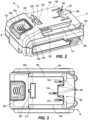
- FIG. 1-4 and 8show the battery pack 14 in greater detail.
- the battery pack 14includes a housing 150 having a longitudinal axis B that extends between a first end 152 and a second end 154, as well as an interface this is physically coupleable to the complementary interface ( FIGS. 5-7 ) of the power tool 10 or a charger (not shown).
- the interfaceincludes a first surface (e.g., top surface) 158 and a second surface (e.g., intermediate surface) 162.
- a pair rails 166, a pair of channels 178, and a pair of projections 182extend along opposite sides of the interface parallel to the longitudinal axis B.
- the channels 178are defined between the respective rails 166 and the intermediate surface 162, and the projections 182 are positioned within the channels 178 between the respective rails 166 and the intermediate surface 162.
- a terminal block 186extends between the top surface 158 and the intermediate surface 162.
- the terminal block 186includes openings 190.
- Electric terminals 194are positioned within the housing 150 and configured to engage the electrical terminals 120 of the power tool 10 for the battery pack 14 to electrically power the power tool 10.
- each of the electrical terminals 194 of the battery pack 14is aligned with one of the openings 190 of the terminal block 186, and when coupled to the power tool 10, each of the electrical terminals 120 of the power tool 10 extends into the openings 190 to engage the electrical terminals 194 of the battery pack 14.
- the electrical terminals 120 of the power toolare male terminals and the electrical terminals 194 of the battery pack are female terminals.
- the electrical terminals 120 of the power toolmay be female terminals and the electrical terminals 194 of the battery pack may be male terminals.
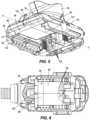
- the battery pack housing 40encloses an inner cavity that includes the components of the battery pack 14 including battery cells 198, a battery controller, and internal frames that receive and constrain the battery cells. Only the battery cells 198 are shown. The electrical terminals are electrically coupled to the battery cells and controller.
- the battery pack 14includes a latch mechanism 200 according to one embodiment of the invention.
- the latch mechanism 200includes body 202 that has a longitudinal axis C and a flange 203 that extends at least partially from a perimeter of the body 202.
- the latch mechanism 200further includes an actuator 204 (i.e., button) and a latch member 212 that are positioned on opposite ends of the body 202 and are separated by a gap 206.
- the actuator 204is movable within a first aperture 208 in the housing 150 and a latch member 212 that is moveable through a second aperture 216 in the housing 150.
- the latch member 212includes a first latch portion 220 and a second latch portion 224.
- the first latch portion 220includes a first inclined surface 228, and the second latch portion 224 includes a second inclined surface 232.
- the first latch portion 220has at least one dimension that is greater than a dimension of the second latch portion 224.
- the first latch portion 220is wider than the second latch portion 224.
- the first inclined surface 228 of the first latch portion 220has a length that is longer than a length of the second inclined surface 232 of the second latch portion 224.
- the first and second latch portions 220, 224are configured to be received respectively within the first and second recess portions 98, 102 of the power tool housing 40.
- first and second inclined surfaces 228, 232 of the first and second latch portions 220, 224are the same or similar (e.g., complementary to) to the first and second inclined surfaces 106, 110 of the first and second recess portion 98, 102 That is, the first inclined surface 228 is oriented at an angle that ranges from 35 degrees to 39 degrees relative to the longitudinal axis C, and the second inclined surface 232 is oriented at an angle that ranges from 58 degrees to 62 degrees relative to the longitudinal axis C. In the illustrated embodiment, the first inclined surface 228 is oriented at angle of approximately 37 degrees relative to the longitudinal axis C and the second inclined surface 232 is oriented at an angle of approximately 60 degrees relative to the longitudinal axis C.
- first and second inclined surfaces 228, 232intersect one another and are oriented at an angle ranging from 81 degrees to 85 degrees relative to one another. In the illustrated embodiment, the first and second inclined surfaces 228, 232 are oriented at an angle of approximately 83 degrees relative to on one another. As shown in FIG. 11 , the first and second inclined surface 228, 232 intersect at a common plane P, which is perpendicular to the longitudinal axis C. Accordingly, the first and second inclined surfaces 228, 232 extend (e.g., slope) in opposite directions from the plane P towards the longitudinal axis C.
- the actuator 204includes a distal end 250, a proximal end 254, a first surface 258 (e.g., an actuating surface) that has ribs 262 and extends between the distal and proximal ends 250, 254, and a second surface 266 that is positioned at the proximal end 254.
- the first surface 258may not include ribs.
- the distal end 250 of the actuator 204is positioned adjacent the first end 152 of the housing and the proximal end 254 of the actuator 204 is spaced apart from the first end 152 of the housing 150.
- the distal end 250 of the actuator 204is higher than (e.g., positioned above) the proximal end 254 of the actuator 204, and therefore the first surface 258 has a gradually decreasing slope from the distal end 250 to the proximal ends 254.
- the first surface 258is not parallel with the longitudinal axis C of the actuator 204.
- the first surface 258is also positioned at an obtuse angle relative to the second surface 266 are positioned. That is, the first surface 258 slopes inwardly and downwardly relative to the housing 150 of the battery pack 14.
- the first and second surfaces 258, 266intersect one another and are oriented at an angle ranging from 98 degrees to 102 degrees relative to one another.
- first and second surfaces 258, 266are oriented at an angle of approximately 100 degrees relative to on one another. Additionally, the first surface 258 is oriented at an angle that ranges from 50 degrees to 70 degrees relative to the longitudinal axis C, and the second surface 266 is oriented at an angle that ranges from 78 degrees to 82 degrees relative to the longitudinal axis C. In the illustrated embodiment, the first surface 258 is oriented at angle of approximately 60 degrees relative to the longitudinal axis C and the second surface 266 is oriented at an angle of approximately 80 degrees relative to the longitudinal axis C.
- the latch mechanism 200is movable between a latched position (shown herein) and a release position. In the latched position, the latch member 212 extends through the aperture 216 in the top surface 158 and from the top surface 158. In the release position, the latch member 212 is positioned within the housing 150.
- One or more biasing mechanisms 300i.e., springs bias the latch mechanism 200 in the latched position.
- the button portion 204is depressible (e.g., in a direction away from the top surface or a downward direction) to overcome the bias of the springs 300 and move the latch mechanism 200 from the latched position to the release position.
- the slope of the first surface 258makes it easier for the user to overcome the bias of the spring 300 and depress the actuator 204.
- the rails 166 of the battery pack 14are inserted into and slide along the respective first and second channels 82, 90 of the battery receiving portion 64.
- the surface 86 of the battery pack receiving portion 64forces the latch member 212 against the bias of the spring 300 and into the housing 150 (e.g., into the release position).
- the bias of the spring 300forces the latch member 212 into the latched position and into the recess 94 of the battery receiving cavity 64.
- first latch portion 220 of the latch member 212is received within the first recess portion 98 of the recess 94 and the second latch portion 224 of the latch member 212 is received in the second recess portion 102 of the recess 94.
- the projections 182are received in (i.e., keyed in) the first and second recesses 114, 116 of the battery receiving cavity 64.
- the terminals 120 of the power tool 10are electrically coupled to the electrical terminals 194 of the battery pack 14.
- the button portion 204 of the latch mechanism 200is depressed by the user by exerting a force on the first surface 258 of the actuator 204 to overcome the bias of the spring 300 and thereby to retract the latch member 212 into the release position and out of the recess 94 in the power tool 10.
- the userexerts a downward force (e.g., in a direction opposite the top surface 158 of the housing 150) on the first surface 258 of the actuator 204.
- the battery pack 14can slide out of the battery pack receiving portion 64 by sliding the rails 166 of the battery pack 140 along the channels 82, 90 of the battery receiving cavity 64.
- the battery packfurther includes a second surface that is positioned at the proximal end.
- the actuating surface and the second surfacemay intersect one another.
- the actuating surfacemay be positioned at an obtuse angle relative to the second surface is positioned.
- the second surfacemay be oriented at an angle that ranges from 78 degrees to 82 degrees relative to the longitudinal axis.
- the actuating surface and the second surfaceare oriented at an angle ranging from 98 degrees to 102 degrees relative to one another.
- the battery packfurther includes a biasing mechanism positioned adjacent to the actuator, the biasing mechanism biases the latch member into a latch position in which the latch member extends from the housing.
- Depressing the actuatormay overcome the bias of the biasing mechanism to move the latch member from the latch position to a release position in which the latch member is positioned within the housing.
- the distal end of the actuatormay be positioned above the proximal end of the actuator.
- the actuating surfacemay have ribs.
- the actuating surfacemay not be parallel to the longitudinal axis of the housing.
- the actuating surfacemay be oriented at an angle that ranges from 50 degrees to 70 degrees relative to the longitudinal axis.
- the power toolfurther includes a second surface that is positioned at the proximal end.
- the actuating surface and the second surfacemay intersect one another.
- the actuating surfacemay be positioned at an obtuse angle relative to the second surface is positioned.
- the second surfacemay be oriented at an angle that ranges from 78 degrees to 82 degrees relative to the longitudinal axis.
- the actuating surface and the second surfacemay be oriented at an angle ranging from 98 degrees to 102 degrees relative to one another.
- the distal end of the actuatormay be positioned above the proximal end of the actuator.
- the actuating surfacemay include ribs.
- the actuating surfacemay not be parallel to the longitudinal axis of the battery receiving portion or the longitudinal axis of the housing of the battery pack.
- the actuating surfacemay be oriented at an angle that ranges from 50 degrees to 70 degrees relative to the longitudinal axis.
- the latch mechanismmay be movable between a latch position in which the latch member extends from the housing and a release position in which the latch member is positioned within the housing.
- the actuatormay be actuatable to move the latch member from the latch position to the release position.
- the latch membermay be retained in the latch position by a biasing mechanism.
- the latch mechanismis movable between a latch position in which the latch member extends from the housing and a release position in which the latch member is positioned within the housing.
- the latch mechanismmay include an actuator that is actuatable to move the latch member from the latch position to the release position.
- the latch membermay be retained in the latch position by a biasing mechanism.
- the actuatormay include a distal end that is positioned adjacent a first end of the housing and a proximal end that is spaced apart from the distal end, the distal end being positioned above the proximal end, the actuating surface extending between the distal end and the proximal end.
- the battery packmay further include a second surface positioned at the proximal end.
- the actuating surface and the second surfacemay intersect one another.
- the actuating surfacemay be positioned at an obtuse angle relative to the second surface is positioned.
- the second surfacemay be oriented at an angle that ranges from 78 degrees to 82 degrees relative to the longitudinal axis.
- the actuating surface and the second surfacemay be oriented at an angle ranging from 98 degrees to 102 degrees relative to one another.
- the actuating surfacemay have a slope that decreases from the distal end to the proximal end.
- the actuating surfacemay not be parallel to the longitudinal axis of the housing.
- the actuating surfacemay be oriented at an angle that ranges from 50 degrees to 70 degrees relative to the longitudinal axis.
- the inventionprovides, among other things, a latch mechanism for a battery pack.
Landscapes
- Engineering & Computer Science (AREA)
- Mechanical Engineering (AREA)
- Power Engineering (AREA)
- Chemical & Material Sciences (AREA)
- Chemical Kinetics & Catalysis (AREA)
- Electrochemistry (AREA)
- General Chemical & Material Sciences (AREA)
- Battery Mounting, Suspending (AREA)
Description
- The present invention relates to a battery pack.
- Typically, electrical equipment, such as a power tool, can be powered by a rechargeable battery pack. The battery pack may be charged in a compatible battery charger.
- According to its abstract,
DE 11 2013 006567 T5 describes a drill driver that may have two battery mounting sections to which two rechargeable batteries may be attached. Therefore, the drill driver can meet a demand for increased voltage or discharge capacity. Further, the two battery attachment portions may be formed as slide terminal battery attachment portions. A combined center of gravity of the rechargeable batteries attached to the first and second battery mounting portions may be on a vertical line through a center of gravity of a tool main body in a state where the two rechargeable batteries of which are solved, be positioned. - According to its abstract,
US 2015/263592 A1 describes a power tool that includes a brushless motor having a stator and a rotor, which includes a rotary shaft extending in a front-rear direction of the power tool. The rotary shaft rotates a spindle that extends in an up-down direction of the power tool. A fan is fixedly coupled to the rotary shaft and rotates therewith. A switch is disposed rearward of the brushless motor and a controller is disposed rearward of the switch in the front-rear direction. A battery pack is disposed rearward of the controller. A main-body housing houses the brushless motor, the switch and the controller. The main-body housing includes a first tubular part, which houses the brushless motor, and a second tubular part, which houses the switch. The diameter of the second tubular part is smaller than the diameter of the first tubular part. - According to its abstract,
JP 2012 099383 A - According to its abstract,
EP 2329921 A1 describes an anti-theft system for securing a removable battery to a power tool intended for retail display. The system employs a tamper-proof retainer to ensure that the retail display of a combined power tool and its associated battery can be displayed as a single unit without fear of theft of the battery. This is achieved by the tamper-proof retainer securing a battery release latch against its release position hence securing the battery to the tool in a manner preventing the removal of the battery by a potential thief. The tamper-proof retainer either prevents removal of the battery from the power tool, as removal of the tamper-proof retainer is impossible, or, if it is destroyed by a thief, then it permanently secures the battery to the power tool. - According to its abstract,
DE 10 2008 019068 A1US2019199101A1 . - According to its abstract,
DE 10 2016 203422 - According to its abstract,
EP 3 441 193 A1 describes a battery unit which is designed to be received in a receiving bay of an electric hand tool, wherein the battery unit has a locking mechanism which in a locking state pulls out the battery unit. prevents from the receiving bay, wherein the locking mechanism via a release button with a pressure surface, by pressing and deflecting which the locking mechanism in a release state can be spent, in which the battery unit can be pulled out of the receiving bay in the extension direction, wherein the pressure surface, in the release state and in relation to the extension direction, defines a first inclined plane a vector component of an actuating force acting on the pressure surface is oriented in the extension direction. - In a first aspect, the disclosure provides a battery pack including a housing having a first end, a second end, and a longitudinal axis that extends between the first end and the second end, electrical terminals positioned within the housing and configured to engage and electrically couple with electrical terminals of a power tool, and a latch mechanism including an actuator and a latch member that is spaced apart from the actuator. The actuator has a distal end that is positioned adjacent the first end of the housing, a proximal end that is spaced apart from the distal end, and an actuating surface that extends between the distal end and the proximal end. The actuating surface has a gradually decreasing slope between the distal end and the proximal end.
- The battery pack may further include a biasing mechanism positioned adjacent to the actuator. The biasing mechanism may bias the latch member into a latch position in which the latch member extends from the housing. Optionally, depressing the actuator overcomes the bias of the biasing mechanism to move the latch member from the latch position to a release position in which the latch member is positioned within the housing. The distal end of the actuator may be positioned above the proximal end of the actuator. The actuating surface may have ribs. The actuating surface may not be parallel to the longitudinal axis of the housing.
- In a second aspect, the disclosure provides a power tool including a housing having a handle configured to be grasped by a user and a battery receiving portion having electrical terminals, the battery receiving portion having a longitudinal axis, a motor supported by the housing, a tool element coupled to the motor, and a battery pack coupleable to the battery receiving portion of the housing of the power tool. The battery pack includes a housing having a first end, a second end, and a longitudinal axis that extends between the first end and the second end, electrical terminals positioned within the housing and configured to engage and electrically couple with electrical terminals of a power tool, and a latch mechanism including an actuator and a latch member that is spaced apart from the actuator and receivable within a recess in the battery receiving portion. The actuator has a distal end that is positioned adjacent the first end of the housing, a proximal end that is spaced apart from the distal end, and an actuating surface that extends between the distal end and the proximal end. The actuating surface has a gradually decreasing slope between the distal end and the proximal end.
- The distal end of the actuator may be positioned above the proximal end of the actuator. The actuating surface may include ribs. The actuating surface may not be parallel to the longitudinal axis of the battery receiving portion or the longitudinal axis of the housing of the battery pack. The latch mechanism may be movable between a latch position in which the latch member extends from the housing and a release position in which the latch member is positioned within the housing. The actuator may be actuatable to move the latch member from the latch position to the release position. The latch member may be retained in the latch position by a biasing mechanism.
- In a third aspect, the disclosure provides a battery pack including a housing having a longitudinal axis, a first surface, and a second surface, electrical terminals positioned within the housing and configured to engage and electrically couple with electrical terminals of a power tool, and a latch mechanism including an actuator that is movable within an aperture in the first surface and a latch member movable within an aperture in the second surface. The actuator includes an actuating surface that slopes inwardly and downwardly relative to the housing of the battery pack.
- The latch mechanism may be movable between a latch position in which the latch member extends from the housing and a release position in which the latch member is positioned within the housing. The actuator may be actuatable to move the latch member from the latch position to the release position. The latch member may be retained in the latch position by a biasing mechanism. The actuator may include a distal end that is positioned adjacent a first end of the housing and a proximal end that is spaced apart from the distal end. The distal end may be positioned above the proximal end,. The actuating surface may be extending between the distal end and the proximal end. The actuating surface may have a slope that decreases from the distal end to the proximal end. The actuating surface may not be parallel to the longitudinal axis of the housing.
- In a fourth aspect, the disclosure provides a power tool having a housing with a battery receiving portion arranged to receive the battery pack of the first or third aspect. The power tool may further include the battery pack of the first or third aspect.
- Other aspects of the invention will become apparent by consideration of the detailed description and accompanying drawings. Any feature(s) described herein in relation to one aspect or embodiment may be combined with any other feature(s) described herein in relation to any other aspect or embodiment as appropriate and applicable.
- Embodiments of the invention will now be described, by way of example, with reference to the accompanying drawings, in which:
FIG. 1 is a perspective view of a power tool and a battery pack attached thereto.FIG. 2 is a perspective view of the battery pack ofFIG. 1 .FIG. 3 is a top view of the battery pack ofFIG. 1 .FIG. 4 is an exploded view of a portion of the battery pack ofFIG. 1 .FIG. 5 is a bottom perspective view of the power tool ofFIG. 1 .FIG. 6 is a bottom view of the power tool ofFIG. 1 .FIG. 7 is a cross-sectional view of portion of the power tool ofFIG. 1 along a longitudinal axis of the power tool.FIG. 8 is a cross-sectional view of the power tool and battery pack ofFIG. 1 along longitudinal axes of the power tool and battery pack.FIG. 9 is a perspective view of a latch of the battery pack ofFIG. 1 .FIG. 10 is a side view of a latch of the battery pack ofFIG. 1 .FIG. 11 is a cross-sectional view of the latch ofFIG. 1 along a longitudinal axis of the latch.- Before any embodiments of the invention are explained in detail, it is to be understood that the invention is not limited in its application to the details of construction and the arrangement of components set forth in the following description or illustrated in the following drawings. The invention is capable of other embodiments and of being practiced or of being carried out in various ways.
FIG. 1 illustrates apower tool 10 and a slidable-type battery pack 14 that is removably and electronically coupled to thepower tool 10. Thepower tool 10 includes ahousing 40. As shown inFIG. 1 , thehousing 40 has afirst housing portion 44 that is coupled to asecond housing portion 48. Eachhousing portion housing portions housing 40 defines ahandle 50, which is connected to gear case housing portion (not shown). Thehandle 50 includes at least one grip surface configured to be grasped by a user.- In the illustrated embodiment, the
handle 50 can also define a battery receiving portion 64 (FIGS. 5-7 ) for receiving thebattery pack 14. Thebattery receiving portion 64 defines a longitudinal axis A. Afirst rail 74 and asecond rail 78 extend along opposite sides of the batterypack receiving portion 64. Afirst channel 82 is defined between thefirst rail 74 and asurface 86 of thebattery receiving portion 64, and asecond channel 90 is defined between thesecond rail 78 and thesurface 86 of thebattery receiving portion 64. Thesurface 86 includes arecess 94 having afirst recess portion 98 and asecond recess portion 102. Thefirst recess portion 98 includes a firstinclined surface 106, and thesecond recess portion 102 includes a second inclined surface 110 (FIGS. 7-8 ). Thefirst recess portion 98 has at least one dimension that is greater than a dimension of thesecond latch portion 102. For example, thefirst latch portion 98 is wider than thesecond latch portion 102. Also, theinclined surface 106 has a length that is longer than a length of aninclined surface 110. The firstinclined surface 106 is oriented at an angle that ranges from 35 degrees to 38 degrees relative to the longitudinal axis A, and the secondinclined surface 110 is oriented at an angle that ranges from 55 degrees to 58 degrees relative to the longitudinal axis A. In the illustrated embodiment, the firstinclined surface 106 is oriented at angle of approximately 36.5 degrees relative to the longitudinal axis A and the secondinclined surface 110 is oriented at an angle of approximately 56.4 degrees relative to the longitudinal axis A. Approximately, as used herein, means plus or minus two degrees. Moreover, the first and secondinclined surfaces inclined surfaces slots battery receiving portion 64.Electrical terminals 120 are positioned within thebattery receiving portion 64. FIG. 1-4 and8 show thebattery pack 14 in greater detail. Thebattery pack 14 includes ahousing 150 having a longitudinal axis B that extends between afirst end 152 and asecond end 154, as well as an interface this is physically coupleable to the complementary interface (FIGS. 5-7 ) of thepower tool 10 or a charger (not shown). The interface includes a first surface (e.g., top surface) 158 and a second surface (e.g., intermediate surface) 162. Although only one of each is shown, a pair rails 166, a pair ofchannels 178, and a pair of projections 182 extend along opposite sides of the interface parallel to the longitudinal axis B. In particular, thechannels 178 are defined between therespective rails 166 and theintermediate surface 162, and the projections 182 are positioned within thechannels 178 between therespective rails 166 and theintermediate surface 162.- A
terminal block 186 extends between thetop surface 158 and theintermediate surface 162. Theterminal block 186 includesopenings 190.Electric terminals 194 are positioned within thehousing 150 and configured to engage theelectrical terminals 120 of thepower tool 10 for thebattery pack 14 to electrically power thepower tool 10. In particular, each of theelectrical terminals 194 of thebattery pack 14 is aligned with one of theopenings 190 of theterminal block 186, and when coupled to thepower tool 10, each of theelectrical terminals 120 of thepower tool 10 extends into theopenings 190 to engage theelectrical terminals 194 of thebattery pack 14. In the illustrated embodiment, theelectrical terminals 120 of the power tool are male terminals and theelectrical terminals 194 of the battery pack are female terminals. In other or additional embodiments, theelectrical terminals 120 of the power tool may be female terminals and theelectrical terminals 194 of the battery pack may be male terminals. - With reference to
FIG. 8 , thebattery pack housing 40 encloses an inner cavity that includes the components of thebattery pack 14 includingbattery cells 198, a battery controller, and internal frames that receive and constrain the battery cells. Only thebattery cells 198 are shown. The electrical terminals are electrically coupled to the battery cells and controller. - With renewed reference to
FIGS. 2-3 and8-11 thebattery pack 14 includes alatch mechanism 200 according to one embodiment of the invention. In the illustrated embodiment, thelatch mechanism 200 includesbody 202 that has a longitudinal axis C and aflange 203 that extends at least partially from a perimeter of thebody 202. When thebattery pack 14 is coupled to thepower tool 10, the longitudinal axes A and C are parallel to one another. Thelatch mechanism 200 further includes an actuator 204 (i.e., button) and alatch member 212 that are positioned on opposite ends of thebody 202 and are separated by agap 206. Theactuator 204 is movable within afirst aperture 208 in thehousing 150 and alatch member 212 that is moveable through asecond aperture 216 in thehousing 150. - Further with respect to
FIGS. 8-10 , thelatch member 212 includes afirst latch portion 220 and asecond latch portion 224. Thefirst latch portion 220 includes a firstinclined surface 228, and thesecond latch portion 224 includes a secondinclined surface 232. Thefirst latch portion 220 has at least one dimension that is greater than a dimension of thesecond latch portion 224. For example, thefirst latch portion 220 is wider than thesecond latch portion 224. Also, the firstinclined surface 228 of thefirst latch portion 220 has a length that is longer than a length of the secondinclined surface 232 of thesecond latch portion 224. The first andsecond latch portions second recess portions power tool housing 40. Accordingly, the first and secondinclined surfaces second latch portions inclined surfaces second recess portion inclined surface 228 is oriented at an angle that ranges from 35 degrees to 39 degrees relative to the longitudinal axis C, and the secondinclined surface 232 is oriented at an angle that ranges from 58 degrees to 62 degrees relative to the longitudinal axis C. In the illustrated embodiment, the firstinclined surface 228 is oriented at angle of approximately 37 degrees relative to the longitudinal axis C and the secondinclined surface 232 is oriented at an angle of approximately 60 degrees relative to the longitudinal axis C. Moreover, the first and secondinclined surfaces inclined surfaces FIG. 11 , the first and secondinclined surface inclined surfaces - With respect to
FIGS. 9-11 , theactuator 204 includes adistal end 250, aproximal end 254, a first surface 258 (e.g., an actuating surface) that hasribs 262 and extends between the distal and proximal ends 250, 254, and asecond surface 266 that is positioned at theproximal end 254. In other or additional embodiments, thefirst surface 258 may not include ribs. Thedistal end 250 of theactuator 204 is positioned adjacent thefirst end 152 of the housing and theproximal end 254 of theactuator 204 is spaced apart from thefirst end 152 of thehousing 150. As shown, thedistal end 250 of theactuator 204 is higher than (e.g., positioned above) theproximal end 254 of theactuator 204, and therefore thefirst surface 258 has a gradually decreasing slope from thedistal end 250 to the proximal ends 254. Moreover, thefirst surface 258 is not parallel with the longitudinal axis C of theactuator 204. Thefirst surface 258 is also positioned at an obtuse angle relative to thesecond surface 266 are positioned. That is, thefirst surface 258 slopes inwardly and downwardly relative to thehousing 150 of thebattery pack 14. Moreover, the first andsecond surfaces second surfaces first surface 258 is oriented at an angle that ranges from 50 degrees to 70 degrees relative to the longitudinal axis C, and thesecond surface 266 is oriented at an angle that ranges from 78 degrees to 82 degrees relative to the longitudinal axis C. In the illustrated embodiment, thefirst surface 258 is oriented at angle of approximately 60 degrees relative to the longitudinal axis C and thesecond surface 266 is oriented at an angle of approximately 80 degrees relative to the longitudinal axis C. - The
latch mechanism 200 is movable between a latched position (shown herein) and a release position. In the latched position, thelatch member 212 extends through theaperture 216 in thetop surface 158 and from thetop surface 158. In the release position, thelatch member 212 is positioned within thehousing 150. One or more biasing mechanisms 300 (i.e., springs) bias thelatch mechanism 200 in the latched position. Thebutton portion 204 is depressible (e.g., in a direction away from the top surface or a downward direction) to overcome the bias of thesprings 300 and move thelatch mechanism 200 from the latched position to the release position. The slope of thefirst surface 258 makes it easier for the user to overcome the bias of thespring 300 and depress theactuator 204. - To attach the
battery pack 14 to thepower tool 10, therails 166 of thebattery pack 14 are inserted into and slide along the respective first andsecond channels battery receiving portion 64. As thebattery pack 14 advances, thesurface 86 of the batterypack receiving portion 64 forces thelatch member 212 against the bias of thespring 300 and into the housing 150 (e.g., into the release position). When thelatch member 212 becomes aligned with therecess 94 in thesurface 86 of thepower tool 10, the bias of thespring 300 forces thelatch member 212 into the latched position and into therecess 94 of thebattery receiving cavity 64. In particular, thefirst latch portion 220 of thelatch member 212 is received within thefirst recess portion 98 of therecess 94 and thesecond latch portion 224 of thelatch member 212 is received in thesecond recess portion 102 of therecess 94. When thebattery pack 14 is attached to thepower tool 10, the projections 182 are received in (i.e., keyed in) the first andsecond recesses battery receiving cavity 64. Also, theterminals 120 of thepower tool 10 are electrically coupled to theelectrical terminals 194 of thebattery pack 14. - To remove the
battery pack 14 from thepower tool 10, thebutton portion 204 of thelatch mechanism 200 is depressed by the user by exerting a force on thefirst surface 258 of theactuator 204 to overcome the bias of thespring 300 and thereby to retract thelatch member 212 into the release position and out of therecess 94 in thepower tool 10. In particular, the user exerts a downward force (e.g., in a direction opposite thetop surface 158 of the housing 150) on thefirst surface 258 of theactuator 204. Accordingly, thebattery pack 14 can slide out of the batterypack receiving portion 64 by sliding therails 166 of the battery pack 140 along thechannels battery receiving cavity 64. - Preferably, the battery pack further includes a second surface that is positioned at the proximal end. The actuating surface and the second surface may intersect one another. The actuating surface may be positioned at an obtuse angle relative to the second surface is positioned. The second surface may be oriented at an angle that ranges from 78 degrees to 82 degrees relative to the longitudinal axis. The actuating surface and the second surface are oriented at an angle ranging from 98 degrees to 102 degrees relative to one another. Preferably, the battery pack further includes a biasing mechanism positioned adjacent to the actuator, the biasing mechanism biases the latch member into a latch position in which the latch member extends from the housing. Depressing the actuator may overcome the bias of the biasing mechanism to move the latch member from the latch position to a release position in which the latch member is positioned within the housing. The distal end of the actuator may be positioned above the proximal end of the actuator. The actuating surface may have ribs. The actuating surface may not be parallel to the longitudinal axis of the housing. The actuating surface may be oriented at an angle that ranges from 50 degrees to 70 degrees relative to the longitudinal axis.
- Preferably, the power tool further includes a second surface that is positioned at the proximal end. The actuating surface and the second surface may intersect one another. The actuating surface may be positioned at an obtuse angle relative to the second surface is positioned. The second surface may be oriented at an angle that ranges from 78 degrees to 82 degrees relative to the longitudinal axis. The actuating surface and the second surface may be oriented at an angle ranging from 98 degrees to 102 degrees relative to one another. The distal end of the actuator may be positioned above the proximal end of the actuator. The actuating surface may include ribs. The actuating surface may not be parallel to the longitudinal axis of the battery receiving portion or the longitudinal axis of the housing of the battery pack. The actuating surface may be oriented at an angle that ranges from 50 degrees to 70 degrees relative to the longitudinal axis. The latch mechanism may be movable between a latch position in which the latch member extends from the housing and a release position in which the latch member is positioned within the housing. The actuator may be actuatable to move the latch member from the latch position to the release position. The latch member may be retained in the latch position by a biasing mechanism.
- Preferably, the latch mechanism is movable between a latch position in which the latch member extends from the housing and a release position in which the latch member is positioned within the housing. The latch mechanism may include an actuator that is actuatable to move the latch member from the latch position to the release position. The latch member may be retained in the latch position by a biasing mechanism. The actuator may include a distal end that is positioned adjacent a first end of the housing and a proximal end that is spaced apart from the distal end, the distal end being positioned above the proximal end, the actuating surface extending between the distal end and the proximal end. The battery pack may further include a second surface positioned at the proximal end. The actuating surface and the second surface may intersect one another. The actuating surface may be positioned at an obtuse angle relative to the second surface is positioned. The second surface may be oriented at an angle that ranges from 78 degrees to 82 degrees relative to the longitudinal axis. The actuating surface and the second surface may be oriented at an angle ranging from 98 degrees to 102 degrees relative to one another. The actuating surface may have a slope that decreases from the distal end to the proximal end. The actuating surface may not be parallel to the longitudinal axis of the housing. The actuating surface may be oriented at an angle that ranges from 50 degrees to 70 degrees relative to the longitudinal axis.
- Thus, the invention provides, among other things, a latch mechanism for a battery pack.
Claims (13)
- A battery pack (14) comprising:a housing (150) having a first end (152), a second end (154), a longitudinal axis (B) extending between the first end (152) and the second end (154), a first surface, and a second surface (158);electrical terminals (194) positioned within the housing (150) and configured to engage and electrically couple with electrical terminals (120) of a power tool (10); anda latch mechanism (200) includinga body having a longitudinal axis (C),characterized by further includingan actuator (204), anda latch member (212) movable through an aperture (216) in the second surface (158),the actuator (204) and the latch member (212) being positioned on opposite ends of the body (202) and separated by a gap (206); andwherein the actuator (204) is arranged to move within an aperture (208) in the first surface and the actuator (204) includes:a distal end (250) relative to the longitudinal axis (C) of the body (202) of the latch mechanism (200) and positioned adjacent the first end (152) of the housing,a proximal end (254) relative to the longitudinal axis (C) of the body (202) of the latch mechanism (200) and spaced apart from the distal end (250), the distal end (250) is positioned above the proximal end (254), andan actuating surface (258) that extends between the distal end (250) and the proximal end (254) and slopes inwardly and downwardly relative to the housing (150) of the battery pack (14).
- The battery pack (14) of claim 1, wherein the latch mechanism (200) is movable between a latch position in which the latch member (212) extends from the housing (150) and a release position in which the latch member (212) is positioned within the housing (150).
- The battery pack (14) of claim 2, wherein the actuator (204) is actuatable to move the latch member (212) from the latch position to the release position.
- The battery pack of claim 2 or 3, further comprising a biasing mechanism (300) arranged to retain the latch member (212) in the latch position.
- The battery pack of any one of claims 1 to 4, wherein the actuating surface (258) is not parallel to the longitudinal axis (B) of the housing (150).
- The battery pack (14) of any one of claims 1 to 5, wherein the actuating surface (258) has a slope that decreases from the distal end (250) to the proximal end (254).
- The battery pack (14) of any one of claims 1 to 6, wherein the actuating surface (258) include ribs (262).
- The battery pack (14) of any one of claims 1 to 7, wherein the actuator (204) further comprises a second surface (266) positioned at the proximal end (254), and wherein the actuating surface (258) is positioned at an obtuse angle relative to the second surface (266).
- The battery pack (14) of any one of claims 1 to 8, wherein the latch member (212) includes a first latch portion (220) with a first inclined surface (228) and a second latch portion (224) with a second inclined surface (232).
- The battery pack (14) of claim 9, wherein the first inclined surface (228) and the second inclined surface (232) intersect at a common plane (P) perpendicular to the longitudinal axis (C) of the body (202), and the first inclined surface (228) and the second inclined surface (232) extend in opposite directions from the common plane (P) towards the longitudinal axis (C) of the body.
- The battery pack (14) of claim 9 or 10, wherein the first latch portion (220) is wider than the second latch portion (224), and wherein the first inclined surface (228) of the first latch portion (220) has a length that is longer than a length of the second inclined surface (232) of the second latch portion (224).
- A power tool (10) comprisinga housing (40) having a handle (50) configured to be grasped by a user and a battery receiving portion (64) having electrical terminals (120), the battery receiving portion (64) having a longitudinal axis (A);a motor supported by the housing (40);a tool element coupled to the motor; andthe battery pack (14) of any one of the preceding claims, being coupleable or coupled to the battery receiving portion (64).
- The power tool (10) of claim 12, wherein the actuating surface (258) is not parallel to the longitudinal axis (A) of the battery receiving portion (64).
Applications Claiming Priority (1)
| Application Number | Priority Date | Filing Date | Title |
|---|---|---|---|
| US16/536,418US11575176B2 (en) | 2019-08-09 | 2019-08-09 | Battery pack |
Publications (3)
| Publication Number | Publication Date |
|---|---|
| EP3772394A1 EP3772394A1 (en) | 2021-02-10 |
| EP3772394B1true EP3772394B1 (en) | 2023-06-21 |
| EP3772394C0 EP3772394C0 (en) | 2023-06-21 |
Family
ID=72039445
Family Applications (1)
| Application Number | Title | Priority Date | Filing Date |
|---|---|---|---|
| EP20190314.3AActiveEP3772394B1 (en) | 2019-08-09 | 2020-08-10 | Battery pack |
Country Status (5)
| Country | Link |
|---|---|
| US (1) | US11575176B2 (en) |
| EP (1) | EP3772394B1 (en) |
| CN (1) | CN213184490U (en) |
| AU (1) | AU2020101751A4 (en) |
| CA (1) | CA3089313A1 (en) |
Cited By (1)
| Publication number | Priority date | Publication date | Assignee | Title |
|---|---|---|---|---|
| US20240326224A1 (en)* | 2023-03-31 | 2024-10-03 | Andreas Stihl Ag & Co. Kg | Handheld work apparatus which is portable in use |
Families Citing this family (6)
| Publication number | Priority date | Publication date | Assignee | Title |
|---|---|---|---|---|
| CA189202S (en)* | 2017-07-26 | 2020-10-09 | Walmart Apollo Llc | Battery pack |
| US11728538B2 (en)* | 2020-09-23 | 2023-08-15 | Techtronic Cordless Gp | Power tool battery pack receptacle |
| USD1062598S1 (en)* | 2021-06-16 | 2025-02-18 | Zhejiang Rongpeng Air Tools Co., Ltd. | Battery pack |
| USD1051058S1 (en)* | 2021-10-13 | 2024-11-12 | Positec Power Tools (Suzhou) Co., Ltd. | Adaptor |
| USD1068642S1 (en)* | 2023-11-17 | 2025-04-01 | Dongguan Zheshi Electronic Technology Co., Ltd | Power tool battery |
| WO2025111819A1 (en)* | 2023-11-28 | 2025-06-05 | Techtronic Cordless Gp | Battery for use with power tool |
Citations (1)
| Publication number | Priority date | Publication date | Assignee | Title |
|---|---|---|---|---|
| US20190199101A1 (en)* | 2017-12-26 | 2019-06-27 | Black & Decker Inc. | Battery pack charger system |
Family Cites Families (41)
| Publication number | Priority date | Publication date | Assignee | Title |
|---|---|---|---|---|
| US6656626B1 (en) | 1999-06-01 | 2003-12-02 | Porter-Cable Corporation | Cordless power tool battery release mechanism |
| US6729413B2 (en)* | 2001-08-24 | 2004-05-04 | Black & Decker Inc. | Power tool with battery pack ejector |
| KR100469438B1 (en) | 2003-03-25 | 2005-02-02 | 엘지전자 주식회사 | Battery cover locking apparatus for potable phone |
| KR100580074B1 (en) | 2003-12-10 | 2006-05-16 | 주식회사 팬택앤큐리텔 | Battery pack removable device of mobile communication terminal |
| KR100587311B1 (en) | 2004-09-20 | 2006-06-08 | 엘지전자 주식회사 | Battery pack cover locking device of mobile communication terminal |
| CN2777910Y (en) | 2005-01-28 | 2006-05-03 | 深圳富泰宏精密工业有限公司 | Fastening structure for cell cover |
| US20060199072A1 (en) | 2005-03-03 | 2006-09-07 | Perpetual Green Ltd. | Battery operation device with battery pack release mechanism |
| CN1832229A (en) | 2005-03-11 | 2006-09-13 | 深圳富泰宏精密工业有限公司 | Battery cover structure |
| CN100530767C (en) | 2005-07-09 | 2009-08-19 | 深圳富泰宏精密工业有限公司 | Cell cover dog-locking structure |
| TWI276946B (en) | 2005-08-01 | 2007-03-21 | Benq Corp | Mobile electronic device |
| KR100664210B1 (en) | 2005-09-01 | 2007-01-03 | 엘지전자 주식회사 | Battery separator of mobile communication terminal |
| US20070091556A1 (en) | 2005-10-20 | 2007-04-26 | Inventec Corporation | Module assembly for locking and unlocking a battery of an electronic device |
| CN101028710A (en) | 2006-03-01 | 2007-09-05 | 春南电器制造厂有限公司 | Battery-operated devices having a battery pack release mechanism |
| US20070277987A1 (en) | 2006-05-26 | 2007-12-06 | Meyer Gary D | Power tool, battery pack, and method of operating the same |
| CN201112450Y (en) | 2007-09-25 | 2008-09-10 | 陈寅 | Easy-disassembly battery pack |
| US20090246608A1 (en)* | 2008-03-26 | 2009-10-01 | Simon Wu | Rechargeable Electric Tool with a Battery Pack Detaching Device |
| DE102008019068B4 (en) | 2008-04-15 | 2010-12-02 | Techway Industrial Co. Ltd. | A rechargeable electrical device with a battery disconnect device |
| CN101599540B (en) | 2008-06-04 | 2011-09-21 | 深圳富泰宏精密工业有限公司 | Battery cover snapclose structure |
| CN101673812A (en) | 2008-09-11 | 2010-03-17 | 深圳富泰宏精密工业有限公司 | Battery cover component |
| CN101752533A (en) | 2008-12-11 | 2010-06-23 | 深圳富泰宏精密工业有限公司 | Battery cover clamping and locking structure |
| EP2329921B1 (en)* | 2009-12-07 | 2016-03-16 | Black & Decker Inc. | Anti-theft system |
| CN102402267A (en) | 2010-09-10 | 2012-04-04 | 富泰华工业(深圳)有限公司 | Electronic device capable of locking battery |
| JP5683905B2 (en) | 2010-11-04 | 2015-03-11 | 株式会社マキタ | Battery pack |
| TWI428730B (en) | 2011-06-08 | 2014-03-01 | Acbel Polytech Inc | Power supply with battery quick release function |
| WO2013099227A1 (en)* | 2011-12-30 | 2013-07-04 | Makita Corporation | Battery pack for use with hand-held electric power tool |
| CN202702206U (en) | 2012-06-13 | 2013-01-30 | 南京德朔实业有限公司 | Battery pack mounting structure for electric tool |
| US8586225B1 (en) | 2012-08-21 | 2013-11-19 | Harris Corporation | Battery assembly for an electronic device |
| TWI498711B (en) | 2012-09-17 | 2015-09-01 | Wistron Corp | Portable electronic device and battery clamping mechanism thereof |
| JP6033698B2 (en)* | 2013-02-01 | 2016-11-30 | 株式会社マキタ | Electric tool |
| US9954418B2 (en) | 2014-03-17 | 2018-04-24 | Makita Corporation | Power tool |
| CN104242406B (en) | 2014-09-29 | 2016-08-24 | 南京视威电子科技股份有限公司 | There is battery and the power conversion output inserter of embedded power conversion interface |
| CN204068393U (en) | 2014-09-29 | 2014-12-31 | 南京视威电子科技股份有限公司 | There is battery and the power conversion output inserter of embedded power conversion interface |
| CN107251264B (en) | 2014-11-26 | 2020-10-13 | 创科实业有限公司 | Battery |
| JP6404139B2 (en)* | 2015-02-13 | 2018-10-10 | 株式会社マキタ | Battery pack |
| DE102016203422A1 (en)* | 2015-03-06 | 2016-09-08 | Robert Bosch Gmbh | Battery pack for a hand tool |
| CN105196259B (en) | 2015-10-22 | 2017-08-11 | 苏州金莱克精密机械有限公司 | A kind of retaining mechanism of the power tool battery bag of one-handed performance |
| CN205645917U (en) | 2016-03-31 | 2016-10-12 | 优利科技有限公司 | Battery structure and aircraft |
| EP3441193A1 (en) | 2017-08-08 | 2019-02-13 | HILTI Aktiengesellschaft | Battery unit with locking mechanism |
| CN108389990B (en) | 2018-03-22 | 2024-07-19 | 南京久驰机电实业有限公司 | Battery pack horizontal button unlocking mechanism and battery pack adopting same |
| CN208127272U (en) | 2018-03-22 | 2018-11-20 | 南京久驰机电实业有限公司 | Battery pack horizontal buttons unlocking mechanism and the battery pack for using the mechanism |
| US11611124B2 (en)* | 2018-07-18 | 2023-03-21 | Black & Decker Inc. | Battery pack |
- 2019
- 2019-08-09USUS16/536,418patent/US11575176B2/enactiveActive
- 2020
- 2020-08-07CACA3089313Apatent/CA3089313A1/enactivePending
- 2020-08-10CNCN202021649164.4Upatent/CN213184490U/enactiveActive
- 2020-08-10AUAU2020101751Apatent/AU2020101751A4/enactiveActive
- 2020-08-10EPEP20190314.3Apatent/EP3772394B1/enactiveActive
Patent Citations (1)
| Publication number | Priority date | Publication date | Assignee | Title |
|---|---|---|---|---|
| US20190199101A1 (en)* | 2017-12-26 | 2019-06-27 | Black & Decker Inc. | Battery pack charger system |
Cited By (2)
| Publication number | Priority date | Publication date | Assignee | Title |
|---|---|---|---|---|
| US20240326224A1 (en)* | 2023-03-31 | 2024-10-03 | Andreas Stihl Ag & Co. Kg | Handheld work apparatus which is portable in use |
| US12403581B2 (en)* | 2023-03-31 | 2025-09-02 | Andreas Stihl Ag & Co. Kg | Handheld work apparatus which is portable in use |
Also Published As
| Publication number | Publication date |
|---|---|
| CA3089313A1 (en) | 2021-02-09 |
| AU2020101751A4 (en) | 2020-09-17 |
| US11575176B2 (en) | 2023-02-07 |
| US20210043891A1 (en) | 2021-02-11 |
| CN213184490U (en) | 2021-05-11 |
| EP3772394A1 (en) | 2021-02-10 |
| EP3772394C0 (en) | 2023-06-21 |
Similar Documents
| Publication | Publication Date | Title |
|---|---|---|
| EP3772394B1 (en) | Battery pack | |
| EP2090406B1 (en) | Electric tools | |
| EP1726410B1 (en) | Power tool | |
| US11420315B2 (en) | Handheld machine tool | |
| EP3120977B1 (en) | Latching mechanism for a battery pack | |
| EP2189251B1 (en) | Battery packs | |
| EP1863107B1 (en) | Twist lock battery interface for cordless power tools | |
| EP1703619B1 (en) | Scrubber | |
| CN110198816B (en) | Cutting tool | |
| EP2956275B1 (en) | Electric device body and electric device | |
| EP2787557B1 (en) | Battery packs for electric tools | |
| JP6480782B2 (en) | Electrical equipment | |
| EP1955827A2 (en) | Adapter for a power tool battery | |
| JP2013086228A (en) | Electric power tool | |
| CN110832731A (en) | Electrical equipment systems, electrical equipment and power supply units | |
| CA2621051A1 (en) | Razors | |
| AU2020101747A4 (en) | Battery pack | |
| AU2017351400B2 (en) | Connection apparatus of an electrical device or of a stored energy source | |
| CN113395895B (en) | Autonomous working tool | |
| JP2002027675A (en) | Storage battery for power tools | |
| US9131817B2 (en) | Intelligent vacuum cleaner | |
| JP5319473B2 (en) | Plug connector | |
| CN111567206B (en) | Locking assembly, energy supply system and garden tool having the locking assembly | |
| WO2007098785A1 (en) | Appliances with battery packs | |
| JP2006172782A (en) | Battery pack fixing device |
Legal Events
| Date | Code | Title | Description |
|---|---|---|---|
| PUAI | Public reference made under article 153(3) epc to a published international application that has entered the european phase | Free format text:ORIGINAL CODE: 0009012 | |
| STAA | Information on the status of an ep patent application or granted ep patent | Free format text:STATUS: THE APPLICATION HAS BEEN PUBLISHED | |
| AK | Designated contracting states | Kind code of ref document:A1 Designated state(s):AL AT BE BG CH CY CZ DE DK EE ES FI FR GB GR HR HU IE IS IT LI LT LU LV MC MK MT NL NO PL PT RO RS SE SI SK SM TR | |
| AX | Request for extension of the european patent | Extension state:BA ME | |
| STAA | Information on the status of an ep patent application or granted ep patent | Free format text:STATUS: REQUEST FOR EXAMINATION WAS MADE | |
| 17P | Request for examination filed | Effective date:20210521 | |
| RBV | Designated contracting states (corrected) | Designated state(s):AL AT BE BG CH CY CZ DE DK EE ES FI FR GB GR HR HU IE IS IT LI LT LU LV MC MK MT NL NO PL PT RO RS SE SI SK SM TR | |
| GRAP | Despatch of communication of intention to grant a patent | Free format text:ORIGINAL CODE: EPIDOSNIGR1 | |
| STAA | Information on the status of an ep patent application or granted ep patent | Free format text:STATUS: GRANT OF PATENT IS INTENDED | |
| INTG | Intention to grant announced | Effective date:20221213 | |
| GRAS | Grant fee paid | Free format text:ORIGINAL CODE: EPIDOSNIGR3 | |
| GRAA | (expected) grant | Free format text:ORIGINAL CODE: 0009210 | |
| STAA | Information on the status of an ep patent application or granted ep patent | Free format text:STATUS: THE PATENT HAS BEEN GRANTED | |
| AK | Designated contracting states | Kind code of ref document:B1 Designated state(s):AL AT BE BG CH CY CZ DE DK EE ES FI FR GB GR HR HU IE IS IT LI LT LU LV MC MK MT NL NO PL PT RO RS SE SI SK SM TR | |
| REG | Reference to a national code | Ref country code:CH Ref legal event code:EP | |
| REG | Reference to a national code | Ref country code:DE Ref legal event code:R096 Ref document number:602020012692 Country of ref document:DE | |
| REG | Reference to a national code | Ref country code:AT Ref legal event code:REF Ref document number:1580576 Country of ref document:AT Kind code of ref document:T Effective date:20230715 | |
| REG | Reference to a national code | Ref country code:IE Ref legal event code:FG4D | |
| U01 | Request for unitary effect filed | Effective date:20230707 | |
| U07 | Unitary effect registered | Designated state(s):AT BE BG DE DK EE FI FR IT LT LU LV MT NL PT SE SI Effective date:20230719 | |
| U20 | Renewal fee for the european patent with unitary effect paid | Year of fee payment:4 Effective date:20230828 | |
| REG | Reference to a national code | Ref country code:LT Ref legal event code:MG9D | |
| PG25 | Lapsed in a contracting state [announced via postgrant information from national office to epo] | Ref country code:NO Free format text:LAPSE BECAUSE OF FAILURE TO SUBMIT A TRANSLATION OF THE DESCRIPTION OR TO PAY THE FEE WITHIN THE PRESCRIBED TIME-LIMIT Effective date:20230921 | |
| PG25 | Lapsed in a contracting state [announced via postgrant information from national office to epo] | Ref country code:RS Free format text:LAPSE BECAUSE OF FAILURE TO SUBMIT A TRANSLATION OF THE DESCRIPTION OR TO PAY THE FEE WITHIN THE PRESCRIBED TIME-LIMIT Effective date:20230621 Ref country code:HR Free format text:LAPSE BECAUSE OF FAILURE TO SUBMIT A TRANSLATION OF THE DESCRIPTION OR TO PAY THE FEE WITHIN THE PRESCRIBED TIME-LIMIT Effective date:20230621 Ref country code:GR Free format text:LAPSE BECAUSE OF FAILURE TO SUBMIT A TRANSLATION OF THE DESCRIPTION OR TO PAY THE FEE WITHIN THE PRESCRIBED TIME-LIMIT Effective date:20230922 | |
| PG25 | Lapsed in a contracting state [announced via postgrant information from national office to epo] | Ref country code:SK Free format text:LAPSE BECAUSE OF FAILURE TO SUBMIT A TRANSLATION OF THE DESCRIPTION OR TO PAY THE FEE WITHIN THE PRESCRIBED TIME-LIMIT Effective date:20230621 | |
| PG25 | Lapsed in a contracting state [announced via postgrant information from national office to epo] | Ref country code:ES Free format text:LAPSE BECAUSE OF FAILURE TO SUBMIT A TRANSLATION OF THE DESCRIPTION OR TO PAY THE FEE WITHIN THE PRESCRIBED TIME-LIMIT Effective date:20230621 | |
| PG25 | Lapsed in a contracting state [announced via postgrant information from national office to epo] | Ref country code:IS Free format text:LAPSE BECAUSE OF FAILURE TO SUBMIT A TRANSLATION OF THE DESCRIPTION OR TO PAY THE FEE WITHIN THE PRESCRIBED TIME-LIMIT Effective date:20231021 | |
| PG25 | Lapsed in a contracting state [announced via postgrant information from national office to epo] | Ref country code:SM Free format text:LAPSE BECAUSE OF FAILURE TO SUBMIT A TRANSLATION OF THE DESCRIPTION OR TO PAY THE FEE WITHIN THE PRESCRIBED TIME-LIMIT Effective date:20230621 Ref country code:SK Free format text:LAPSE BECAUSE OF FAILURE TO SUBMIT A TRANSLATION OF THE DESCRIPTION OR TO PAY THE FEE WITHIN THE PRESCRIBED TIME-LIMIT Effective date:20230621 Ref country code:RO Free format text:LAPSE BECAUSE OF FAILURE TO SUBMIT A TRANSLATION OF THE DESCRIPTION OR TO PAY THE FEE WITHIN THE PRESCRIBED TIME-LIMIT Effective date:20230621 Ref country code:IS Free format text:LAPSE BECAUSE OF FAILURE TO SUBMIT A TRANSLATION OF THE DESCRIPTION OR TO PAY THE FEE WITHIN THE PRESCRIBED TIME-LIMIT Effective date:20231021 Ref country code:ES Free format text:LAPSE BECAUSE OF FAILURE TO SUBMIT A TRANSLATION OF THE DESCRIPTION OR TO PAY THE FEE WITHIN THE PRESCRIBED TIME-LIMIT Effective date:20230621 Ref country code:CZ Free format text:LAPSE BECAUSE OF FAILURE TO SUBMIT A TRANSLATION OF THE DESCRIPTION OR TO PAY THE FEE WITHIN THE PRESCRIBED TIME-LIMIT Effective date:20230621 | |
| PG25 | Lapsed in a contracting state [announced via postgrant information from national office to epo] | Ref country code:PL Free format text:LAPSE BECAUSE OF FAILURE TO SUBMIT A TRANSLATION OF THE DESCRIPTION OR TO PAY THE FEE WITHIN THE PRESCRIBED TIME-LIMIT Effective date:20230621 | |
| PG25 | Lapsed in a contracting state [announced via postgrant information from national office to epo] | Ref country code:MC Free format text:LAPSE BECAUSE OF FAILURE TO SUBMIT A TRANSLATION OF THE DESCRIPTION OR TO PAY THE FEE WITHIN THE PRESCRIBED TIME-LIMIT Effective date:20230621 | |
| REG | Reference to a national code | Ref country code:DE Ref legal event code:R097 Ref document number:602020012692 Country of ref document:DE | |
| REG | Reference to a national code | Ref country code:CH Ref legal event code:PL | |
| PG25 | Lapsed in a contracting state [announced via postgrant information from national office to epo] | Ref country code:MC Free format text:LAPSE BECAUSE OF FAILURE TO SUBMIT A TRANSLATION OF THE DESCRIPTION OR TO PAY THE FEE WITHIN THE PRESCRIBED TIME-LIMIT Effective date:20230621 | |
| PLBE | No opposition filed within time limit | Free format text:ORIGINAL CODE: 0009261 | |
| STAA | Information on the status of an ep patent application or granted ep patent | Free format text:STATUS: NO OPPOSITION FILED WITHIN TIME LIMIT | |
| PG25 | Lapsed in a contracting state [announced via postgrant information from national office to epo] | Ref country code:CH Free format text:LAPSE BECAUSE OF NON-PAYMENT OF DUE FEES Effective date:20230831 | |
| REG | Reference to a national code | Ref country code:IE Ref legal event code:MM4A | |
| 26N | No opposition filed | Effective date:20240322 | |
| PG25 | Lapsed in a contracting state [announced via postgrant information from national office to epo] | Ref country code:IE Free format text:LAPSE BECAUSE OF NON-PAYMENT OF DUE FEES Effective date:20230810 | |
| PG25 | Lapsed in a contracting state [announced via postgrant information from national office to epo] | Ref country code:IE Free format text:LAPSE BECAUSE OF NON-PAYMENT OF DUE FEES Effective date:20230810 | |
| U20 | Renewal fee for the european patent with unitary effect paid | Year of fee payment:5 Effective date:20240827 | |
| PGFP | Annual fee paid to national office [announced via postgrant information from national office to epo] | Ref country code:GB Payment date:20240827 Year of fee payment:5 | |
| PG25 | Lapsed in a contracting state [announced via postgrant information from national office to epo] | Ref country code:CY Free format text:LAPSE BECAUSE OF FAILURE TO SUBMIT A TRANSLATION OF THE DESCRIPTION OR TO PAY THE FEE WITHIN THE PRESCRIBED TIME-LIMIT; INVALID AB INITIO Effective date:20200810 | |
| PG25 | Lapsed in a contracting state [announced via postgrant information from national office to epo] | Ref country code:HU Free format text:LAPSE BECAUSE OF FAILURE TO SUBMIT A TRANSLATION OF THE DESCRIPTION OR TO PAY THE FEE WITHIN THE PRESCRIBED TIME-LIMIT; INVALID AB INITIO Effective date:20200810 | |
| U20 | Renewal fee for the european patent with unitary effect paid | Year of fee payment:6 Effective date:20250827 |